Categories
Machinery

Bending Sheet Metal with Hydraulic Press

Bending Sheet Metal with Hydraulic Press

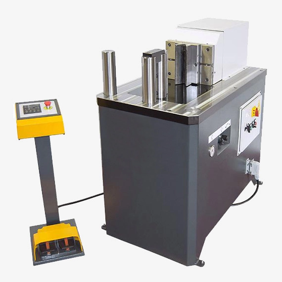
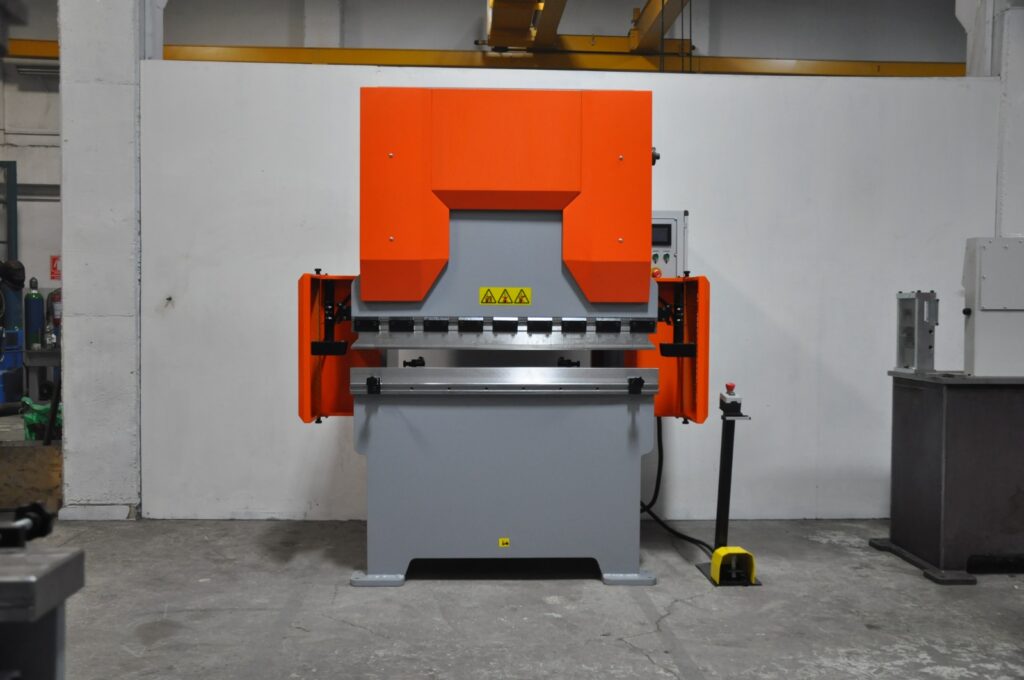
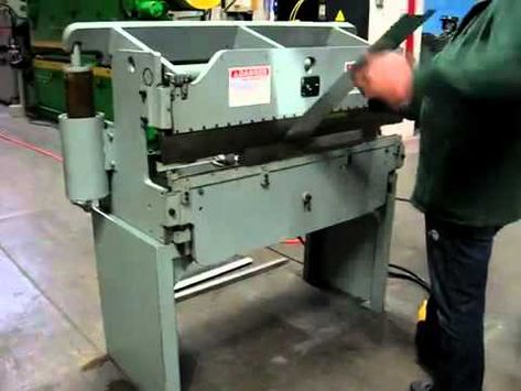
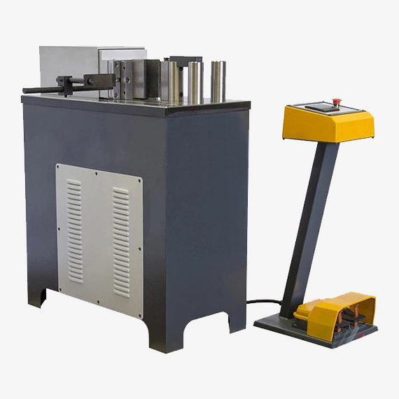
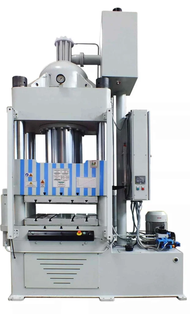
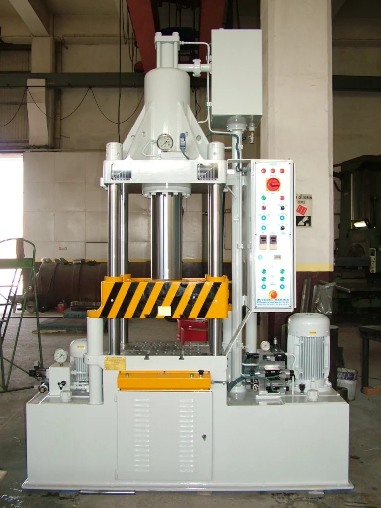
We manufacture a Bending Sheet Metal with Hydraulic Press to bend sheet metal edges. Bending Sheet Metal with Hydraulic Press is used in metalworking industries

Bending sheet metal using a hydraulic press is a common and efficient method in metal fabrication. Hydraulic presses provide the force necessary to bend the metal while maintaining control and precision. Here’s a general overview of the process:

  1. Material Preparation: Begin by selecting the appropriate sheet metal for the desired bend. Ensure that the metal is clean and free from any contaminants that could affect the bending process.
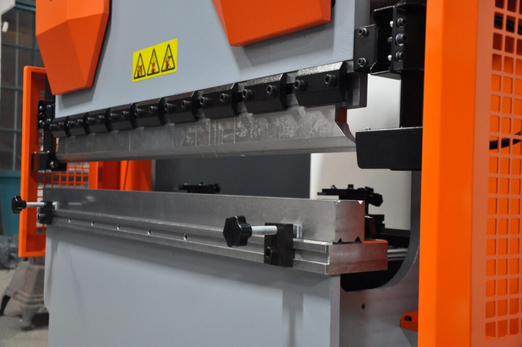
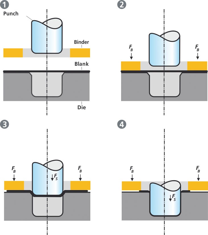
  2. Tooling Selection: Choose the appropriate tooling for the hydraulic press based on the desired bend angle and radius. The tooling typically consists of a punch (male die) and a die (female die) that work together to shape the metal. The dimensions of the tooling will depend on the specific bending requirements.
  3. Die Setup: Install the die on the hydraulic press, ensuring it is securely positioned and aligned with the punch. The die should match the desired bend angle and have the appropriate radius.
  4. Sheet Metal Placement: Position the sheet metal on the hydraulic press, aligning it with the die and punch. Ensure that the metal is flat and properly aligned to achieve an accurate and consistent bend.
  5. Pressure Adjustment: Adjust the pressure settings on the hydraulic press based on the thickness and properties of the sheet metal. The pressure should be sufficient to bend the metal without causing excessive deformation or damage.
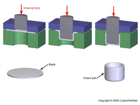
  6. Bending Process: Activate the hydraulic press to apply force to the sheet metal. The press will exert pressure on the punch, which will push the metal into the die, creating the desired bend. The operator should carefully monitor the bending process to ensure it meets the desired specifications.
  7. Repeat if Needed: Depending on the complexity of the part and the number of bends required, the process may need to be repeated multiple times to achieve the desired shape. Each subsequent bend should be carefully aligned and executed to maintain accuracy.

It is important to note that the specific steps and parameters may vary depending on the size and capabilities of the hydraulic press, the thickness and type of sheet metal, and the desired bend specifications. Safety precautions, such as wearing appropriate personal protective equipment, should always be followed during the bending process.

It is recommended to consult the manufacturer’s guidelines and seek proper training before operating a hydraulic press for bending sheet metal.

Bending Sheet Metal with Hydraulic Press

Bending sheet metal with a hydraulic press is a common and effective method for shaping metal sheets into various forms. Hydraulic presses offer a controlled and precise way to apply force, ensuring consistent and accurate bends.

Preparing for Bending

  1. Material Selection: Choose the appropriate sheet metal material based on the desired properties, such as strength, corrosion resistance, and formability.
  2. Sheet Metal Preparation: Ensure the sheet metal is clean, free from debris, and flat. Mark the desired bend location clearly on the sheet metal.
  3. Tooling Selection: Select the appropriate bending tool, such as a V-die or a U-die, based on the desired bend angle and material thickness.

Bending Process

  1. Positioning the Sheet Metal: Place the sheet metal on the hydraulic press bed, aligning the bend line with the bending tool.
  2. Adjusting the Ram and Back Gauge: Adjust the ram height to ensure the correct amount of force is applied during bending. Position the back gauge to maintain the desired bend angle.
  3. Initiating the Bending Process: Activate the hydraulic press to apply force and bend the sheet metal. Move the ram slowly and evenly to ensure a smooth bend.
  4. Checking the Bend: Once the bending process is complete, inspect the bend for accuracy and consistency. Adjust the tooling or ram position if necessary.

Safety Precautions

  1. Wear Protective Gear: Always wear safety glasses, gloves, and appropriate clothing when operating a hydraulic press.
  2. Secure the Workpiece: Clamp the sheet metal securely to the press bed to prevent movement during bending.
  3. Avoid Distractions: Stay focused on the bending operation and avoid distractions.
  4. Maintain Proper Distance: Keep hands and body clear of moving parts of the press.
  5. Follow Manufacturer Instructions: Adhere to the specific instructions provided by the hydraulic press manufacturer.

Additional Tips

  1. Lubrication: Lubricate the bending tool and sheet metal to reduce friction and prevent damage.
  2. Gradual Bending: Apply force gradually to avoid overstressing the material.
  3. Multiple Bends: For complex shapes, perform multiple bends in stages to achieve the desired form.
  4. Experience: Practice bending techniques to develop the necessary skills and achieve consistent results.

Bending sheet metal with a hydraulic press requires a combination of proper technique, safety precautions, and appropriate tooling. By following these guidelines and practicing consistently, you can effectively shape sheet metal into various forms for your projects.

Material Preparation

Material preparation is an important step in the process of bending sheet metal using a hydraulic press. Proper material preparation ensures that the sheet metal is ready for bending and helps achieve accurate and consistent results. Here are some key aspects of material preparation:

  1. Material Selection: Choose the appropriate type and thickness of sheet metal for the desired application and bending requirements. Consider factors such as the material’s strength, flexibility, and suitability for the intended use. Common materials used for sheet metal bending include steel, aluminum, stainless steel, and copper.
  2. Material Thickness: Determine the thickness of the sheet metal, which will influence the bending parameters and the force required from the hydraulic press. Measure the thickness accurately using a caliper or other suitable measuring tool.
  3. Material Condition: Ensure that the sheet metal is clean and free from any dirt, oil, or other contaminants. Clean the surface of the sheet metal using solvents, degreasers, or other appropriate cleaning methods. This helps prevent any interference or defects during the bending process.
  4. Sheet Metal Layout: Plan the layout of the sheet metal to optimize material usage and minimize waste. Consider the dimensions and shape of the final part to determine the size and shape of the sheet metal required. Marking or layout tools can be used to indicate the bending lines or reference points on the sheet metal.
  5. Cutting and Shearing: If the sheet metal needs to be cut or sheared to the desired size or shape before bending, use appropriate cutting tools such as shears, nibblers, or laser cutting machines. Ensure clean and precise cuts to maintain accuracy during the bending process.
  6. Deburring: After cutting or shearing, deburr the edges of the sheet metal to remove any sharp or rough edges. This can be done using deburring tools, files, or sandpaper. Smooth edges minimize the risk of injury and ensure proper contact between the sheet metal and the bending tools.
  7. Material Protection: Consider applying protective coatings or films to the sheet metal surface, especially if the material is susceptible to scratching or damage during handling and bending. Protective coatings help maintain the surface finish and prevent any unwanted marks or blemishes.

Proper material preparation sets the foundation for successful sheet metal bending using a hydraulic press. It ensures that the sheet metal is clean, accurately sized, and free from contaminants or defects that could affect the bending process. By paying attention to material preparation, you can enhance the overall quality and efficiency of the bending operation.

Tooling Selection

Tooling selection is a crucial aspect of sheet metal bending with a hydraulic press. The choice of appropriate tooling determines the accuracy, quality, and efficiency of the bending process. Here are some key considerations for tooling selection:

  1. Bend Angle and Radius: Determine the required bend angle and radius for the sheet metal part. These specifications will guide the selection of the appropriate tooling. The tooling should match the desired bend angle and have the appropriate radius to achieve the desired shape.
  2. Tooling Types: There are various types of tooling available for sheet metal bending with a hydraulic press. The most common types include V-dies, U-dies, and custom dies. V-dies are typically used for straight bends, while U-dies are used for creating curved or U-shaped bends. Custom dies are designed for specific bending applications and can be fabricated to match unique part geometries.
  3. Die Width: The width of the die should be suitable for the width of the sheet metal being bent. It should provide sufficient support and contact area to ensure accurate and consistent bending. The die width should also take into account any additional material allowances required for springback, which is the tendency of the material to return to its original shape after bending.
  4. Die Opening Size: The die opening size, also known as the die gap or die clearance, is the space between the punch and die. It affects the bend radius and the overall bending result. The die opening size should be properly calculated based on the material thickness, bend angle, and other factors. It should allow for proper material flow during bending without causing excessive deformation or wrinkling.
  5. Tooling Materials: Consider the materials used for the tooling. Common materials for tooling include hardened steel, tool steel, and carbide. The choice of material depends on factors such as the material being bent, the required precision, and the expected tool life. Hardened and durable materials are preferred to withstand the forces and wear associated with sheet metal bending.
  6. Tooling Compatibility: Ensure that the selected tooling is compatible with the hydraulic press being used. Consider factors such as the tooling dimensions, mounting mechanisms, and the tonnage capacity of the press. The tooling should fit securely and accurately in the press, allowing for precise and repeatable bending operations.
  7. Supplier Support: Partner with reputable tooling suppliers who can provide guidance and support in selecting the appropriate tooling for your specific bending needs. They can offer expertise in tooling design, material selection, and troubleshooting to ensure successful bending operations.

Proper tooling selection is critical for achieving accurate and high-quality bends in sheet metal with a hydraulic press. It is recommended to consult with experienced tooling suppliers or manufacturers to ensure the right tooling is chosen for your specific bending requirements.

Die Setup

Die setup is an important step in the process of sheet metal bending with a hydraulic press. It involves properly positioning and aligning the die on the press to ensure accurate and consistent bends. Here are the key steps involved in die setup:

  1. Die Selection: Choose the appropriate die for the desired bend angle and radius. The die should match the specifications of the bend to be made. Consider factors such as the die width, opening size, and compatibility with the hydraulic press being used.
  2. Die Installation: Mount the die securely onto the press bed or the appropriate tooling attachment. Ensure that the die is aligned with the press and positioned accurately for the desired bending operation. The die should be securely fixed to prevent any movement or misalignment during the bending process.
  3. Die Alignment: Align the die with the punch (male die) to ensure proper contact and precise bending. The alignment should be perpendicular to the direction of the bend and parallel to the press bed. Use alignment tools, such as dial indicators or precision gauges, to verify and adjust the alignment as necessary.
  4. Die Positioning: Position the sheet metal properly in relation to the die and punch. Align the edge of the sheet metal with the desired bending line or reference point on the die. Ensure that the sheet metal is flat and properly supported to prevent any distortion or misalignment during bending.
  5. Die Clearance Adjustment: Adjust the die opening size or die clearance based on the thickness and properties of the sheet metal. The die clearance determines the bend radius and should be properly calculated or set according to the bending requirements. Consult the manufacturer’s guidelines or bending charts to determine the appropriate die clearance for the specific material and bend angle.
  6. Die Lubrication: Apply a suitable lubricant or release agent to the die surface to reduce friction and prevent the sheet metal from sticking to the die during bending. Lubrication helps in smooth material flow and minimizes the risk of scratching or damaging the sheet metal surface.
  7. Test Bend: Before proceeding with the actual production bending, perform a test bend to ensure that the die setup is properly adjusted and aligned. Make any necessary adjustments to the die position, alignment, or clearance to achieve the desired bend angle and quality.

Proper die setup is crucial for achieving accurate and repeatable bends in sheet metal. It ensures that the die is aligned, positioned, and adjusted correctly for the specific bending operation. Careful attention to die setup helps maintain consistency and quality throughout the bending process.

Sheet Metal Placement

Sheet metal placement is a crucial step in the process of bending sheet metal with a hydraulic press. Proper placement of the sheet metal ensures accurate and consistent bends. Here are some key considerations for sheet metal placement:

  1. Alignment with Die and Punch: Position the sheet metal on the hydraulic press bed, aligning it with the die and punch (male die). Ensure that the edge of the sheet metal aligns with the desired bending line or reference point on the die. This alignment ensures that the bend occurs precisely at the intended location.
  2. Proper Support: Provide proper support to the sheet metal to prevent excessive sagging or deformation during bending. Use suitable support tools, such as V-blocks or support fingers, to hold the sheet metal securely and distribute the bending forces evenly. The support should be placed close to the bend line to minimize any unsupported sections.
  3. Flatness: Ensure that the sheet metal is flat and free from any warping or buckling. If the sheet metal is not flat, flatten it before placing it on the press bed to ensure consistent and accurate bending. Use clamps or weights if necessary to hold the sheet metal flat during the bending process.
  4. Material Overhang: Determine the amount of material overhang required for the desired bend. The material overhang refers to the distance between the bend line and the edge of the sheet metal. It allows for material flow during bending and prevents incomplete or uneven bends. Consult bending charts or guidelines to determine the appropriate material overhang for the specific bend angle and material thickness.
  5. Sheet Metal Positioning: Position the sheet metal in a way that allows for easy access to the hydraulic press controls and operator’s line of sight. The operator should have a clear view of the bending operation to ensure proper control and safety.
  6. Sheet Metal Clamping: If necessary, use clamps or hold-down devices to secure the sheet metal in place during bending. This helps prevent any movement or shifting of the sheet metal during the bending process, ensuring accurate and consistent results.
  7. Safety Considerations: Prioritize safety when placing the sheet metal on the hydraulic press. Ensure that there are no obstructions or hazards in the surrounding area that could interfere with the bending operation. Always follow proper safety procedures, such as wearing personal protective equipment (PPE) and keeping hands clear of moving parts.

Proper placement of the sheet metal is essential for achieving accurate and high-quality bends with a hydraulic press. It ensures that the sheet metal is aligned, supported, and positioned correctly for the desired bending operation. Paying attention to sheet metal placement enhances the overall efficiency, precision, and safety of the bending process.

Pressure Adjustment

Pressure adjustment is a critical aspect of bending sheet metal with a hydraulic press. It involves setting the appropriate pressure to achieve the desired bend without damaging the material or the equipment. Here are the key steps for pressure adjustment:

  1. Understand the Material: Familiarize yourself with the material properties, including its thickness, tensile strength, and ductility. Different materials have different requirements in terms of bending pressure.
  2. Start with a Low Pressure: Begin by setting the hydraulic press to a relatively low pressure. This allows for a test bend to assess the material’s response and the accuracy of the bend.
  3. Perform Test Bends: Select a scrap piece of the same material and thickness as the sheet metal being bent. Place it in the desired position and perform a test bend. Observe the result and evaluate if the bend is accurate, without any cracking or excessive deformation. Adjust the pressure as needed.
  4. Consider Material Springback: Keep in mind that some materials exhibit springback, meaning they tend to return to their original shape after bending. Take springback into account when adjusting the pressure. A higher pressure might be required to compensate for the anticipated springback.
  5. Incremental Pressure Adjustments: Make incremental adjustments to the pressure. Increase or decrease the pressure gradually, testing the result after each adjustment. This allows for fine-tuning of the pressure to achieve the desired bend angle and quality.
  6. Observe Material Behavior: Pay attention to the behavior of the material during bending. Look for signs of excessive deformation, cracking, or wrinkling. These may indicate that the pressure is too high and should be reduced.
  7. Consult Bending Charts or Guidelines: Refer to bending charts or guidelines specific to the material being used. These resources provide recommended pressure ranges based on the material’s thickness and properties. They serve as a helpful reference for initial pressure adjustment.
  8. Operator Experience: Operator experience and skill play a crucial role in pressure adjustment. Experienced operators can often assess the material’s behavior and make appropriate adjustments based on their knowledge and expertise.
  9. Safety Considerations: While adjusting the pressure, always prioritize safety. Follow proper safety procedures, including wearing appropriate personal protective equipment (PPE) and keeping hands clear of moving parts.
  10. Document the Optimal Pressure: Once you have determined the optimal pressure for bending the specific material, document the pressure setting for future reference. This helps maintain consistency and efficiency in future bending operations.

Remember that pressure adjustment is an iterative process. It may require multiple test bends and adjustments to achieve the desired result. By paying attention to material behavior and making incremental pressure adjustments, you can ensure accurate and high-quality bends while preventing material damage or equipment failure.

Bending Process

The bending process is a common technique used to shape sheet metal into desired forms and angles. It involves the application of force to deform the material along a specific axis, resulting in a bent or formed shape. Here are the key steps involved in the bending process:

  1. Material Selection: Choose the appropriate type and thickness of sheet metal for the desired application. Consider factors such as material strength, ductility, and suitability for bending.
  2. Material Preparation: Ensure that the sheet metal is clean and free from any contaminants or debris that could affect the bending process. Remove any protective coatings or films, if necessary.
  3. Tooling Selection: Select the appropriate tooling for the bending operation. This includes the die (female die) and punch (male die), which form the desired bend shape. The tooling should match the specifications of the desired bend angle and radius.
  4. Die Setup: Set up the die and punch on the bending machine or hydraulic press. Align and secure the tooling properly to ensure accurate and consistent bends. Adjust the die clearance based on the material thickness and properties.
  5. Sheet Metal Placement: Position the sheet metal on the press bed, aligning it with the die and punch. Ensure proper support and alignment to prevent distortion or misalignment during bending.
  6. Pressure Adjustment: Set the appropriate bending pressure on the machine. This involves adjusting the hydraulic press or machine to apply the necessary force to deform the sheet metal. Refer to bending charts or guidelines for recommended pressure ranges based on material thickness and properties.
  7. Bending Operation: Activate the bending machine or hydraulic press to apply pressure to the sheet metal. The punch moves toward the die, deforming the material and creating the desired bend shape. The bending process may involve a single bend or multiple bends, depending on the desired form.
  8. Bend Angle Control: Monitor and control the bend angle during the process. This can be done visually or with the help of angle-measuring devices, such as protractors or digital angle finders. Make adjustments as needed to achieve the desired bend angle.
  9. Post-Bending Inspection: After the bending process, inspect the bent part for quality and accuracy. Check for any defects, such as cracks, wrinkles, or uneven bends. Use measuring tools, such as calipers or rulers, to verify dimensions and angles.
  10. Finishing Operations: Depending on the application, further finishing operations may be required, such as deburring, trimming, or surface treatment. These steps help remove sharp edges, improve aesthetics, and prepare the bent part for its intended use.

The bending process requires precision, proper tooling, and careful attention to detail to achieve accurate and high-quality results. By following the steps outlined above and adhering to best practices, you can successfully bend sheet metal to meet your specific design and fabrication requirements.

Hydraulic Cylinder:

A hydraulic cylinder is a mechanical actuator that converts hydraulic energy into linear mechanical force and motion. It is a key component in hydraulic systems, widely used in various industries for applications requiring precise and powerful movement, such as lifting, pushing, pulling, and positioning heavy loads or equipment.

Construction: A typical hydraulic cylinder consists of several main components:

  1. Cylinder Barrel: Also known as the cylinder tube, it serves as the main body of the cylinder, housing the other internal components.
  2. Piston: The piston is a cylindrical component that separates the fluid-filled areas of the cylinder into two chambers. When hydraulic pressure is applied to one side of the piston, it moves linearly, generating force and motion.
  3. Piston Rod: The piston rod is attached to the piston and extends through one end of the cylinder barrel. It transmits the force generated by the hydraulic pressure to the external load or mechanism.
  4. Seals: Seals, such as piston seals and rod seals, prevent hydraulic fluid from leaking past the piston and cylinder barrel, maintaining pressure within the cylinder and preventing contamination of the hydraulic system.
  5. End Caps: End caps, also known as cylinder heads or caps, seal the ends of the cylinder barrel and provide mounting points for the cylinder within the hydraulic system.

Operation: Hydraulic cylinders operate based on Pascal’s principle, which states that pressure exerted at any point in a confined fluid is transmitted equally in all directions throughout the fluid. When hydraulic fluid is pumped into one side of the cylinder, it applies pressure to the piston, causing it to move linearly and exert force on the piston rod. The piston rod then extends or retracts, depending on the direction of fluid flow and the desired motion of the cylinder.

Types: There are several types of hydraulic cylinders designed for different applications:

  1. Single-Acting Cylinder: Single-acting cylinders exert force in only one direction, typically extending the piston rod when hydraulic pressure is applied and using gravity, springs, or external forces to retract it.
  2. Double-Acting Cylinder: Double-acting cylinders exert force in both directions, extending and retracting the piston rod using hydraulic pressure applied alternately to each side of the piston.
  3. Telescopic Cylinder: Telescopic cylinders consist of nested stages or sleeves that extend and retract telescopically, providing a long stroke length with a compact retracted length, making them suitable for applications with limited space.
  4. Tie-Rod Cylinder: Tie-rod cylinders feature tie rods or bolts that connect the end caps to the cylinder barrel, providing structural support and stability under high loads or pressures.
  5. Welded Cylinder: Welded cylinders have a one-piece welded construction, with the end caps welded directly to the cylinder barrel, offering a compact and lightweight design suitable for space-constrained applications.

Applications: Hydraulic cylinders find applications in various industries, including:

  • Construction: Hydraulic cylinders are used in construction equipment such as excavators, bulldozers, and cranes for lifting, digging, and pushing heavy loads.
  • Manufacturing: Hydraulic cylinders are used in manufacturing machinery such as presses, injection molding machines, and metalworking equipment for shaping, forming, and assembling parts.
  • Agriculture: Hydraulic cylinders are used in agricultural machinery such as tractors, harvesters, and irrigation systems for tasks such as plowing, seeding, and harvesting crops.
  • Transportation: Hydraulic cylinders are used in transportation vehicles such as dump trucks, garbage trucks, and trailers for lifting, tipping, and dumping loads.
  • Aerospace: Hydraulic cylinders are used in aircraft landing gear, cargo doors, and flight control systems for deploying, retracting, and controlling various components.

In conclusion, hydraulic cylinders are essential components in hydraulic systems, providing precise and powerful actuation for a wide range of industrial, mobile, and aerospace applications. Their robust construction, reliable operation, and versatility make them indispensable for tasks requiring linear force and motion in hydraulic machinery and equipment.

Actuator:

An actuator is a mechanical device used to convert energy into motion, force, or mechanical output. In the context of hydraulic systems, an actuator is specifically designed to generate linear or rotary motion using hydraulic fluid power. Actuators play a crucial role in various industrial, automotive, aerospace, and mobile applications, where precise and powerful movement is required to control valves, operate machinery, or perform mechanical tasks.

Construction and Components: While the specific construction of hydraulic actuators may vary depending on their application and design, they typically consist of the following main components:

  1. Cylinder: The cylinder serves as the primary housing for the actuator, containing the piston and hydraulic fluid. It is often made of high-strength materials such as steel or aluminum to withstand high pressures and loads.
  2. Piston: The piston is a cylindrical component that divides the cylinder into two chambers and transmits hydraulic pressure to generate linear motion. It is sealed against the cylinder walls using seals or rings to prevent fluid leakage.
  3. Piston Rod: The piston rod extends from the piston through one end of the cylinder and connects to the external load or mechanism. It transmits the force generated by the hydraulic pressure to produce linear motion or mechanical work.
  4. Seals: Seals, such as piston seals and rod seals, prevent hydraulic fluid from leaking past the piston and cylinder, maintaining pressure within the actuator and protecting against contamination.
  5. End Caps: End caps, also known as cylinder heads or caps, seal the ends of the cylinder and provide mounting points for the actuator within the hydraulic system.

Operation: Hydraulic actuators operate based on the principles of fluid power and Pascal’s law, which states that pressure exerted at any point in a confined fluid is transmitted equally in all directions. When hydraulic fluid is pumped into one side of the actuator cylinder, it applies pressure to the piston, causing it to move linearly. The piston rod attached to the piston then extends or retracts, depending on the direction of fluid flow and the desired motion of the actuator.

Types: There are several types of hydraulic actuators, each designed for specific applications and motion requirements:

  1. Linear Actuators: Linear actuators produce linear motion, extending or retracting a piston rod in a straight line.
  2. Rotary Actuators: Rotary actuators produce rotary motion, converting hydraulic pressure into rotational movement to turn a shaft or mechanism.
  3. Single-Acting Actuators: Single-acting actuators operate in one direction only, using hydraulic pressure to extend the piston rod and relying on external forces such as gravity or springs to retract it.
  4. Double-Acting Actuators: Double-acting actuators operate in both directions, using hydraulic pressure to extend and retract the piston rod alternately.
  5. Spring-Return Actuators: Spring-return actuators use hydraulic pressure to extend the piston rod, with a spring mechanism providing the force to retract it when hydraulic pressure is released.

Applications: Hydraulic actuators are used in a wide range of applications across various industries, including:

  • Industrial Machinery: Hydraulic actuators are used in manufacturing machinery, robotics, material handling equipment, and assembly lines for tasks such as lifting, pushing, pulling, clamping, and positioning.
  • Automotive: Hydraulic actuators are used in automotive applications such as brakes, steering systems, suspension systems, and convertible tops for controlling motion and providing mechanical assistance.
  • Aerospace: Hydraulic actuators are used in aircraft flight control systems, landing gear, cargo doors, and thrust vectoring systems for precise control of aircraft movement and mechanical functions.
  • Construction and Mining: Hydraulic actuators are used in construction equipment, mining machinery, and earthmoving vehicles for tasks such as excavating, lifting, loading, and dumping heavy materials.
  • Marine: Hydraulic actuators are used in marine applications such as ship steering systems, winches, cranes, and hatch covers for controlling movement and performing mechanical tasks onboard ships and offshore platforms.

In conclusion, hydraulic actuators are essential components in hydraulic systems, providing precise and powerful motion control for a wide range of industrial, automotive, aerospace, and mobile applications. Their versatility, reliability, and efficiency make them indispensable for tasks requiring linear or rotary motion in hydraulic machinery and equipment, contributing to increased productivity, performance, and safety in various industries.

Piston:

The piston is a crucial component of hydraulic cylinders and actuators, serving as the primary mechanism for converting hydraulic energy into linear mechanical force and motion. It plays a fundamental role in the operation of hydraulic systems, facilitating the movement of fluid within the cylinder and generating the desired motion of the piston rod.

Construction and Design: Pistons are typically cylindrical in shape and are precision-machined to fit snugly within the cylinder bore. They are usually made from high-strength materials such as steel, aluminum, or composite alloys to withstand the pressures and loads encountered in hydraulic applications. The surface of the piston is often coated or treated to improve wear resistance and reduce friction against the cylinder walls.

Pistons may have various designs depending on the specific requirements of the hydraulic system:

  1. Single-Acting Pistons: Single-acting pistons have a smooth surface and are designed to transmit hydraulic pressure from one side of the piston to the other, generating linear motion in one direction.
  2. Double-Acting Pistons: Double-acting pistons feature seals or grooves on both sides of the piston, allowing hydraulic pressure to act on both sides alternately. This design enables bi-directional motion, with the piston extending and retracting based on the direction of fluid flow.
  3. Multiple Pistons: Some hydraulic cylinders may incorporate multiple pistons arranged in series or parallel configurations to increase force output or distribute load evenly across the cylinder bore. Multiple pistons may be connected by a common piston rod or operate independently, depending on the application requirements.

Function and Operation: The primary function of the piston in a hydraulic system is to transmit hydraulic pressure from the fluid to the piston rod, generating linear motion or force output. When hydraulic fluid is pumped into one side of the cylinder, it applies pressure to the piston, causing it to move in the direction of the applied force. The piston rod attached to the piston then extends or retracts, depending on the direction of fluid flow and the desired motion of the hydraulic cylinder or actuator.

The design and operation of the piston are critical factors in determining the performance and efficiency of hydraulic systems. Proper sealing and lubrication of the piston are essential to prevent fluid leakage, minimize friction, and ensure smooth and reliable operation. Additionally, the size, shape, and surface finish of the piston may be optimized to enhance fluid dynamics, reduce turbulence, and improve energy efficiency within the hydraulic cylinder.

Applications: Pistons are used in a wide range of hydraulic systems and applications across various industries, including:

  • Construction Machinery: Hydraulic pistons are used in excavators, bulldozers, cranes, and other construction equipment for tasks such as lifting, pushing, digging, and material handling.
  • Manufacturing Machinery: Hydraulic pistons are used in presses, injection molding machines, metalworking equipment, and assembly lines for shaping, forming, stamping, and assembling parts.
  • Automotive Systems: Hydraulic pistons are used in automotive applications such as brakes, suspension systems, steering systems, and convertible tops for controlling motion and providing mechanical assistance.
  • Aerospace Systems: Hydraulic pistons are used in aircraft flight control systems, landing gear, cargo doors, and thrust vectoring systems for precise control of aircraft movement and mechanical functions.
  • Marine Systems: Hydraulic pistons are used in ship steering systems, winches, cranes, hatch covers, and propulsion systems for controlling movement and performing mechanical tasks onboard ships and offshore platforms.

In conclusion, pistons are essential components of hydraulic systems, providing the primary mechanism for converting hydraulic energy into linear mechanical motion. Their design, construction, and operation are critical factors in determining the performance, efficiency, and reliability of hydraulic cylinders and actuators across various industries and applications. Proper selection, maintenance, and optimization of pistons are essential to ensure smooth and reliable operation of hydraulic systems and equipment.

Cylinder Barrel:

The cylinder barrel is a fundamental component of hydraulic cylinders, providing the main housing for the piston, seals, and hydraulic fluid. It serves as the structural backbone of the cylinder, containing and guiding the movement of internal components to generate linear mechanical force and motion. The cylinder barrel is crucial for maintaining hydraulic pressure, preventing fluid leakage, and withstanding the loads and pressures encountered in hydraulic applications.

Construction and Materials: Cylinder barrels are typically cylindrical in shape, with precise dimensions and tolerances to ensure proper fit and function within the hydraulic system. They are often machined from high-strength materials such as steel, aluminum, or stainless steel, chosen for their durability, corrosion resistance, and compatibility with hydraulic fluids. The surface of the cylinder barrel may be honed or polished to reduce friction and wear and provide a smooth surface for the piston seals to glide against.

Function and Operation: The primary function of the cylinder barrel is to contain and guide the movement of the piston and piston rod within the hydraulic cylinder. When hydraulic pressure is applied to one side of the piston, it exerts force against the cylinder barrel, causing the piston to move linearly within the cylinder bore. The cylinder barrel provides a sealed chamber for the hydraulic fluid, ensuring that pressure is maintained and transmitted effectively to generate the desired motion of the piston rod.

The smoothness and roundness of the cylinder bore are critical factors in ensuring proper sealing and smooth operation of the hydraulic cylinder. Any imperfections or irregularities in the cylinder barrel surface can lead to leakage, increased friction, and reduced efficiency of the hydraulic system. Therefore, precision machining and quality control are essential in manufacturing cylinder barrels to meet the stringent requirements of hydraulic applications.

Applications: Cylinder barrels are used in a wide range of hydraulic systems and applications across various industries, including:

  • Construction Machinery: Hydraulic cylinders with cylinder barrels are used in excavators, loaders, bulldozers, cranes, and other construction equipment for tasks such as lifting, pushing, digging, and material handling.
  • Manufacturing Machinery: Hydraulic cylinders with cylinder barrels are used in presses, injection molding machines, metalworking equipment, and assembly lines for shaping, forming, stamping, and assembling parts.
  • Automotive Systems: Hydraulic cylinders with cylinder barrels are used in automotive applications such as brakes, suspension systems, steering systems, and convertible tops for controlling motion and providing mechanical assistance.
  • Aerospace Systems: Hydraulic cylinders with cylinder barrels are used in aircraft flight control systems, landing gear, cargo doors, and thrust vectoring systems for precise control of aircraft movement and mechanical functions.
  • Marine Systems: Hydraulic cylinders with cylinder barrels are used in ship steering systems, winches, cranes, hatch covers, and propulsion systems for controlling movement and performing mechanical tasks onboard ships and offshore platforms.

In conclusion, the cylinder barrel is a critical component of hydraulic cylinders, providing the main housing for the piston and seals and guiding the movement of internal components to generate linear mechanical force and motion. Its construction, materials, and surface finish are essential factors in ensuring proper sealing, smooth operation, and reliable performance of hydraulic systems across various industries and applications. Proper selection, maintenance, and quality control of cylinder barrels are essential to ensure the longevity and efficiency of hydraulic cylinders in demanding operating conditions.

Piston Rod:

The piston rod is a vital component of hydraulic cylinders, serving as the primary linkage between the piston and the external load or mechanism. It transmits the force generated by hydraulic pressure to produce linear motion or mechanical work, allowing hydraulic cylinders to perform a wide range of tasks such as lifting, pushing, pulling, and positioning heavy loads or equipment.

Construction and Materials: Piston rods are typically cylindrical in shape and are precision-machined to fit securely within the piston and extend through one end of the cylinder barrel. They are often made from high-strength materials such as steel, chrome-plated steel, stainless steel, or alloy steel to withstand the high pressures, loads, and operating conditions encountered in hydraulic applications. The surface of the piston rod may be hardened, polished, or coated to improve wear resistance, corrosion resistance, and surface finish.

Function and Operation: The primary function of the piston rod is to transmit the force generated by hydraulic pressure from the piston to the external load or mechanism. When hydraulic fluid is pumped into one side of the cylinder, it applies pressure to the piston, causing it to move linearly within the cylinder bore. The piston rod attached to the piston then extends or retracts, depending on the direction of fluid flow and the desired motion of the hydraulic cylinder or actuator.

The design and construction of the piston rod are critical factors in determining the performance and reliability of hydraulic cylinders. Proper sizing, material selection, and surface treatment of the piston rod are essential to withstand the forces, pressures, and environmental conditions encountered in hydraulic applications. Additionally, the piston rod must be precisely aligned and supported to prevent bending, deflection, or misalignment during operation.

Sealing and Protection: Piston rods are often equipped with seals or gaskets to prevent hydraulic fluid from leaking past the piston and cylinder barrel. Common types of rod seals include O-rings, lip seals, wipers, and scraper rings, which provide a tight seal and protect the piston rod from contaminants such as dirt, moisture, and debris. In addition to seals, piston rods may be equipped with protective coatings or coverings to enhance corrosion resistance and extend service life.

Applications: Piston rods are used in a wide range of hydraulic systems and applications across various industries, including:

  • Construction Machinery: Hydraulic cylinders with piston rods are used in excavators, loaders, bulldozers, cranes, and other construction equipment for tasks such as lifting, pushing, digging, and material handling.
  • Manufacturing Machinery: Hydraulic cylinders with piston rods are used in presses, injection molding machines, metalworking equipment, and assembly lines for shaping, forming, stamping, and assembling parts.
  • Automotive Systems: Hydraulic cylinders with piston rods are used in automotive applications such as brakes, suspension systems, steering systems, and convertible tops for controlling motion and providing mechanical assistance.
  • Aerospace Systems: Hydraulic cylinders with piston rods are used in aircraft flight control systems, landing gear, cargo doors, and thrust vectoring systems for precise control of aircraft movement and mechanical functions.
  • Marine Systems: Hydraulic cylinders with piston rods are used in ship steering systems, winches, cranes, hatch covers, and propulsion systems for controlling movement and performing mechanical tasks onboard ships and offshore platforms.

In conclusion, the piston rod is a critical component of hydraulic cylinders, serving as the primary linkage between the piston and the external load or mechanism. Its construction, materials, sealing, and protection are essential factors in ensuring proper transmission of force, reliable operation, and long-term performance of hydraulic systems across various industries and applications. Proper selection, maintenance, and installation of piston rods are essential to ensure the efficiency, safety, and reliability of hydraulic cylinders in demanding operating conditions.

Seals:

Seals are essential components of hydraulic systems, serving to prevent leakage of hydraulic fluid and to contain pressure within the system. They are critical for maintaining system integrity, preventing contamination, and ensuring optimal performance and reliability. Seals are used in various locations within hydraulic components such as cylinders, valves, pumps, and fittings, and they come in a variety of designs and materials to suit different operating conditions and requirements.

Types of Seals: There are several types of seals commonly used in hydraulic systems:

  1. O-Rings: O-rings are one of the most widely used types of seals in hydraulic systems. They are circular elastomeric seals with a cross-section resembling the letter “O” and are installed in grooves or glands to create a seal between mating surfaces. O-rings are simple, reliable, and cost-effective and can withstand a wide range of temperatures and pressures.
  2. Lip Seals: Lip seals, also known as shaft seals or oil seals, are used to seal rotary shafts in hydraulic pumps, motors, and actuators. They have a flexible lip that contacts the shaft surface to prevent leakage of hydraulic fluid. Lip seals may be single-lip or double-lip designs, depending on the application requirements.
  3. Wipers: Wipers, also known as scraper seals or dirt seals, are used to remove contaminants such as dirt, dust, and moisture from the surface of hydraulic cylinders or rods. They have a wiping edge that cleans the rod surface as it extends and retracts, preventing contaminants from entering the hydraulic system and damaging seals or components.
  4. Rod Seals: Rod seals are used to seal the piston rod of hydraulic cylinders and prevent leakage of hydraulic fluid from the cylinder bore. They are typically installed in the gland or housing at the end of the cylinder barrel and provide a dynamic sealing interface between the rod and cylinder bore.
  5. Piston Seals: Piston seals are used to seal the piston inside hydraulic cylinders and prevent leakage of hydraulic fluid from one side of the piston to the other. They are installed in grooves or glands on the piston and provide a static or dynamic sealing interface between the piston and cylinder barrel.
  6. Wear Rings: Wear rings are used to reduce friction and wear between moving components such as pistons and cylinders. They are typically installed between the piston and cylinder bore and provide a low-friction bearing surface that helps to maintain alignment and minimize clearance between mating parts.

Materials: Seals are made from a variety of materials to suit different operating conditions and requirements. Common materials used for hydraulic seals include:

  • Nitrile Rubber (NBR): Nitrile rubber is a versatile elastomer with good resistance to oil, fuel, and hydraulic fluids. It is commonly used for O-rings, lip seals, and wipers in hydraulic systems.
  • Polyurethane (PU): Polyurethane is a durable material with excellent wear resistance and mechanical properties. It is often used for rod seals, piston seals, and wear rings in high-pressure hydraulic applications.
  • Fluorocarbon Rubber (FKM): Fluorocarbon rubber, also known as Viton®, is a high-performance elastomer with exceptional chemical resistance and temperature tolerance. It is commonly used for seals in hydraulic systems operating at high temperatures or with aggressive fluids.
  • Polytetrafluoroethylene (PTFE): PTFE is a low-friction material with excellent chemical resistance and thermal stability. It is commonly used for lip seals, piston seals, and wear rings in hydraulic systems requiring low friction and high reliability.

Applications: Seals are used in a wide range of hydraulic systems and components across various industries, including:

  • Hydraulic Cylinders: Seals are used to seal the piston and rod of hydraulic cylinders, preventing leakage and ensuring smooth operation.
  • Hydraulic Pumps and Motors: Seals are used to seal the shafts and housings of hydraulic pumps and motors, preventing leakage and contamination of hydraulic fluid.
  • Hydraulic Valves: Seals are used in hydraulic valves to control the flow of hydraulic fluid and prevent leakage between valve components.
  • Hydraulic Fittings and Connectors: Seals are used in hydraulic fittings and connectors to create leak-tight connections between hydraulic components and piping or tubing.

In conclusion, seals are essential components of hydraulic systems, providing vital functions such as preventing leakage, containing pressure, and protecting components from contamination and wear. Proper selection, installation, and maintenance of seals are crucial to ensure the reliability, efficiency, and longevity of hydraulic systems across various industries and applications.

Rod Seal:

Rod seals are critical components of hydraulic cylinders, responsible for preventing leakage of hydraulic fluid from the cylinder bore and maintaining pressure within the system. They create a dynamic sealing interface between the piston rod and the cylinder bore, allowing the rod to move in and out of the cylinder while containing the hydraulic fluid and preventing contaminants from entering the system.

Construction and Design: Rod seals are typically made from elastomeric materials such as nitrile rubber (NBR), polyurethane (PU), fluorocarbon rubber (FKM), or polytetrafluoroethylene (PTFE). These materials offer excellent sealing properties, chemical resistance, and durability, making them suitable for use in hydraulic applications.

Rod seals may have various designs depending on the specific requirements of the hydraulic system:

  1. Single-Lip Seal: Single-lip rod seals have a single sealing lip that contacts the surface of the piston rod to create a seal. They are suitable for applications with moderate pressures and speeds and provide reliable sealing performance with low friction.
  2. Double-Lip Seal: Double-lip rod seals have two sealing lips that provide additional protection against leakage and contamination. They are ideal for applications with higher pressures, speeds, or demanding operating conditions, where enhanced sealing performance is required.
  3. Buffer Seal: Buffer seals, also known as secondary seals or backup rings, are often used in conjunction with rod seals to provide additional support and protection. They help to distribute pressure evenly across the sealing surface and prevent extrusion of the rod seal under high pressures.

Function and Operation: The primary function of the rod seal is to create a seal between the piston rod and the cylinder bore, preventing leakage of hydraulic fluid and maintaining pressure within the cylinder. When hydraulic pressure is applied to one side of the piston, it exerts force against the rod seal, causing it to compress against the rod surface and create a tight seal. As the piston rod moves in and out of the cylinder, the rod seal flexes and adapts to maintain a continuous seal, even under varying pressures and speeds.

Rod seals must provide effective sealing performance while allowing the piston rod to move smoothly and freely within the cylinder bore. They must withstand the forces, pressures, and temperatures encountered in hydraulic applications without deforming, extruding, or wearing prematurely. Proper sizing, installation, and maintenance of rod seals are essential to ensure reliable operation and long-term performance of hydraulic cylinders.

Applications: Rod seals are used in a wide range of hydraulic cylinders and applications across various industries, including:

  • Construction Machinery: Hydraulic cylinders with rod seals are used in excavators, loaders, bulldozers, cranes, and other construction equipment for tasks such as lifting, pushing, digging, and material handling.
  • Manufacturing Machinery: Hydraulic cylinders with rod seals are used in presses, injection molding machines, metalworking equipment, and assembly lines for shaping, forming, stamping, and assembling parts.
  • Automotive Systems: Hydraulic cylinders with rod seals are used in automotive applications such as brakes, suspension systems, steering systems, and convertible tops for controlling motion and providing mechanical assistance.
  • Aerospace Systems: Hydraulic cylinders with rod seals are used in aircraft flight control systems, landing gear, cargo doors, and thrust vectoring systems for precise control of aircraft movement and mechanical functions.
  • Marine Systems: Hydraulic cylinders with rod seals are used in ship steering systems, winches, cranes, hatch covers, and propulsion systems for controlling movement and performing mechanical tasks onboard ships and offshore platforms.

In conclusion, rod seals are essential components of hydraulic cylinders, providing vital functions such as preventing leakage, maintaining pressure, and protecting components from contamination and wear. Proper selection, installation, and maintenance of rod seals are crucial to ensure the reliability, efficiency, and longevity of hydraulic systems across various industries and applications.

Piston Seal:

Piston seals are critical components of hydraulic cylinders, serving to seal the piston within the cylinder bore and prevent leakage of hydraulic fluid from one side of the piston to the other. They create a dynamic sealing interface between the piston and cylinder bore, allowing the piston to move smoothly and efficiently while containing the hydraulic pressure within the cylinder.

Construction and Design: Piston seals are typically made from elastomeric materials such as nitrile rubber (NBR), polyurethane (PU), fluorocarbon rubber (FKM), or polytetrafluoroethylene (PTFE). These materials offer excellent sealing properties, chemical resistance, and durability, making them suitable for use in hydraulic applications.

Piston seals may have various designs depending on the specific requirements of the hydraulic system:

  1. Single-Acting Seal: Single-acting piston seals are designed to seal hydraulic fluid on one side of the piston only. They are typically installed in grooves or glands on the piston and provide a dynamic sealing interface between the piston and cylinder bore.
  2. Double-Acting Seal: Double-acting piston seals are designed to seal hydraulic fluid on both sides of the piston. They are often used in applications where hydraulic pressure is applied alternately to both sides of the piston, allowing bi-directional movement of the piston within the cylinder bore.
  3. U-Cup Seal: U-cup piston seals, also known as lip seals or U-seals, have a U-shaped cross-section that provides excellent sealing performance and resistance to extrusion. They are suitable for high-pressure applications and can accommodate both single-acting and double-acting piston designs.

Function and Operation: The primary function of the piston seal is to create a seal between the piston and cylinder bore, preventing leakage of hydraulic fluid and maintaining pressure within the cylinder. When hydraulic pressure is applied to one side of the piston, it exerts force against the piston seal, causing it to compress against the cylinder bore and create a tight seal. As the piston moves within the cylinder bore, the piston seal flexes and adapts to maintain continuous contact with the cylinder wall, ensuring effective sealing performance throughout the piston stroke.

Piston seals must provide reliable sealing performance while allowing the piston to move smoothly and efficiently within the cylinder bore. They must withstand the forces, pressures, and temperatures encountered in hydraulic applications without deforming, extruding, or wearing prematurely. Proper sizing, installation, and maintenance of piston seals are essential to ensure reliable operation and long-term performance of hydraulic cylinders.

Applications: Piston seals are used in a wide range of hydraulic cylinders and applications across various industries, including:

  • Construction Machinery: Hydraulic cylinders with piston seals are used in excavators, loaders, bulldozers, cranes, and other construction equipment for tasks such as lifting, pushing, digging, and material handling.
  • Manufacturing Machinery: Hydraulic cylinders with piston seals are used in presses, injection molding machines, metalworking equipment, and assembly lines for shaping, forming, stamping, and assembling parts.
  • Automotive Systems: Hydraulic cylinders with piston seals are used in automotive applications such as brakes, suspension systems, steering systems, and convertible tops for controlling motion and providing mechanical assistance.
  • Aerospace Systems: Hydraulic cylinders with piston seals are used in aircraft flight control systems, landing gear, cargo doors, and thrust vectoring systems for precise control of aircraft movement and mechanical functions.
  • Marine Systems: Hydraulic cylinders with piston seals are used in ship steering systems, winches, cranes, hatch covers, and propulsion systems for controlling movement and performing mechanical tasks onboard ships and offshore platforms.

In conclusion, piston seals are essential components of hydraulic cylinders, providing vital functions such as preventing leakage, maintaining pressure, and enabling smooth and efficient movement of the piston within the cylinder bore. Proper selection, installation, and maintenance of piston seals are crucial to ensure the reliability, efficiency, and longevity of hydraulic systems across various industries and applications.

Hydraulic Fluid:

Hydraulic fluid is a crucial element in hydraulic systems, serving as the medium for transmitting power and energy within the system. It is a specially formulated liquid or synthetic substance that is capable of transferring force from one component to another, enabling hydraulic machinery and equipment to perform a wide range of tasks with precision and efficiency.

Properties and Characteristics: Hydraulic fluids exhibit several key properties and characteristics that make them suitable for use in hydraulic systems:

  1. Viscosity: Hydraulic fluids have a specific viscosity that determines their flow characteristics and ability to transmit force within the system. Proper viscosity is essential for maintaining optimal performance and efficiency, as excessive viscosity can lead to sluggish operation, while insufficient viscosity can result in leakage and inadequate lubrication.
  2. Temperature Stability: Hydraulic fluids must maintain their viscosity and performance over a wide range of temperatures encountered in operating conditions. They should resist thinning at high temperatures and thickening at low temperatures to ensure consistent performance and protection of system components.
  3. Chemical Compatibility: Hydraulic fluids must be compatible with system materials such as seals, hoses, valves, and reservoirs to prevent degradation, corrosion, or swelling of components. They should also be resistant to oxidation, foaming, and contamination to maintain system cleanliness and reliability.
  4. Lubrication: Hydraulic fluids serve as lubricants for moving parts within hydraulic components, reducing friction, wear, and heat generation. Proper lubrication is essential for extending component life, minimizing downtime, and ensuring smooth and efficient operation of hydraulic systems.
  5. Sealing: Hydraulic fluids help to create a tight seal between moving components such as pistons, cylinders, and valves, preventing leakage and loss of hydraulic pressure. They also provide a barrier against contaminants such as dirt, moisture, and debris that can damage system components and degrade performance.

Types of Hydraulic Fluids: There are several types of hydraulic fluids available for use in hydraulic systems, each with its own advantages, limitations, and suitability for specific applications:

  1. Mineral Oil-Based Fluids: Mineral oil-based hydraulic fluids are the most common type and are derived from refined petroleum. They offer good lubrication, temperature stability, and cost-effectiveness and are suitable for general-purpose hydraulic applications.
  2. Synthetic Fluids: Synthetic hydraulic fluids are formulated from synthetic base stocks and offer superior performance characteristics compared to mineral oil-based fluids. They provide enhanced temperature stability, oxidation resistance, and wear protection and are often used in high-pressure, high-temperature, or environmentally sensitive applications.
  3. Biodegradable Fluids: Biodegradable hydraulic fluids are formulated from renewable sources such as vegetable oils or esters and are designed to minimize environmental impact in case of leakage or spillage. They offer biodegradability, low toxicity, and compatibility with environmentally sensitive areas but may have limited temperature and performance capabilities compared to mineral oil-based or synthetic fluids.
  4. Fire-Resistant Fluids: Fire-resistant hydraulic fluids are specially formulated to minimize the risk of fire or explosion in high-temperature or hazardous environments. They are available in various formulations such as water-based, phosphate ester-based, or synthetic fluids and offer enhanced safety and protection in applications where fire risk is a concern.

Applications: Hydraulic fluids are used in a wide range of hydraulic systems and applications across various industries, including:

  • Construction Machinery: Hydraulic fluids are used in excavators, loaders, bulldozers, cranes, and other construction equipment for tasks such as lifting, pushing, digging, and material handling.
  • Manufacturing Machinery: Hydraulic fluids are used in presses, injection molding machines, metalworking equipment, and assembly lines for shaping, forming, stamping, and assembling parts.
  • Automotive Systems: Hydraulic fluids are used in automotive applications such as brakes, suspension systems, steering systems, and convertible tops for controlling motion and providing mechanical assistance.
  • Aerospace Systems: Hydraulic fluids are used in aircraft flight control systems, landing gear, cargo doors, and thrust vectoring systems for precise control of aircraft movement and mechanical functions.
  • Marine Systems: Hydraulic fluids are used in ship steering systems, winches, cranes, hatch covers, and propulsion systems for controlling movement and performing mechanical tasks onboard ships and offshore platforms.

In conclusion, hydraulic fluid is a vital component of hydraulic systems, serving as the medium for transmitting power, lubricating moving parts, creating seals, and maintaining system integrity and reliability. Proper selection, maintenance, and monitoring of hydraulic fluid are essential to ensure optimal performance, efficiency, and longevity of hydraulic systems across various industries and applications.

Hydraulic Pump:

A hydraulic pump is a mechanical device used to generate hydraulic pressure by converting mechanical energy into fluid energy. It plays a crucial role in hydraulic systems by supplying pressurized hydraulic fluid to power various hydraulic actuators, such as cylinders, motors, and valves, enabling them to perform work or control movement in a wide range of applications.

Types of Hydraulic Pumps:

  1. Gear Pumps: Gear pumps are among the most common types of hydraulic pumps and operate by meshing gears to pressurize hydraulic fluid. They are simple in design, cost-effective, and suitable for medium-pressure applications. However, they are not ideal for high-pressure or high-speed operations due to their limited efficiency and noise levels.
  2. Vane Pumps: Vane pumps utilize vanes mounted on a rotor to create chambers that trap and pressurize hydraulic fluid. They offer smooth and quiet operation, making them suitable for medium-pressure applications requiring precise control and low noise levels. Vane pumps are available in fixed and variable displacement configurations to accommodate different flow and pressure requirements.
  3. Piston Pumps: Piston pumps are capable of delivering high-pressure hydraulic fluid and are commonly used in heavy-duty applications requiring high power and efficiency. They operate by reciprocating pistons within cylinders to pressurize hydraulic fluid, offering superior performance and reliability compared to gear and vane pumps. Piston pumps are available in axial, radial, and bent-axis designs, each offering specific advantages in terms of efficiency, compactness, and versatility.

Function and Operation:

The primary function of a hydraulic pump is to generate hydraulic pressure by imparting mechanical energy to hydraulic fluid. When the pump is activated, it creates suction to draw hydraulic fluid from a reservoir or tank into its inlet port. The mechanical action of the pump then pressurizes the fluid and delivers it through its outlet port to the hydraulic system.

Hydraulic pumps are typically driven by electric motors, internal combustion engines, or other power sources, depending on the application requirements. They may be operated manually, hydraulically, or electrically, with various control mechanisms such as manual valves, solenoids, or electronic controllers to regulate flow, pressure, and direction of hydraulic fluid.

Applications:

Hydraulic pumps are used in a wide range of hydraulic systems and applications across various industries, including:

  • Construction Machinery: Hydraulic pumps are used in excavators, loaders, bulldozers, cranes, and other construction equipment for tasks such as lifting, pushing, digging, and material handling.
  • Manufacturing Machinery: Hydraulic pumps are used in presses, injection molding machines, metalworking equipment, and assembly lines for shaping, forming, stamping, and assembling parts.
  • Automotive Systems: Hydraulic pumps are used in automotive applications such as power steering systems, braking systems, suspension systems, and convertible tops for providing mechanical assistance and control.
  • Aerospace Systems: Hydraulic pumps are used in aircraft flight control systems, landing gear, cargo doors, and thrust vectoring systems for precise control of aircraft movement and mechanical functions.
  • Marine Systems: Hydraulic pumps are used in ship steering systems, winches, cranes, hatch covers, and propulsion systems for controlling movement and performing mechanical tasks onboard ships and offshore platforms.

In conclusion, hydraulic pumps are essential components of hydraulic systems, providing the mechanical energy necessary to pressurize hydraulic fluid and power various hydraulic actuators and mechanisms. Proper selection, installation, and maintenance of hydraulic pumps are crucial to ensure optimal performance, efficiency, and reliability of hydraulic systems across various industries and applications.

Hydraulic Valve:

A hydraulic valve is a mechanical device used to control the flow, direction, and pressure of hydraulic fluid within a hydraulic system. It plays a crucial role in regulating the operation of hydraulic actuators, such as cylinders and motors, by opening, closing, or diverting fluid flow in response to external signals or conditions.

Types of Hydraulic Valves:

  1. Directional Control Valves: Directional control valves regulate the direction of hydraulic fluid flow within a hydraulic system. They control the movement of hydraulic actuators by selectively directing fluid flow to either side of the actuator, causing it to extend, retract, or stop. Directional control valves may be manually operated, mechanically actuated, or solenoid-controlled and are available in various configurations such as spool, poppet, and rotary valves.
  2. Pressure Control Valves: Pressure control valves regulate the pressure of hydraulic fluid within a hydraulic system by adjusting the flow rate or diverting excess flow to a reservoir or another part of the system. They help to maintain a constant pressure level within the system, prevent overpressure conditions, and protect system components from damage. Pressure control valves include relief valves, pressure reducing valves, and sequence valves, each serving specific pressure regulation functions.
  3. Flow Control Valves: Flow control valves regulate the flow rate of hydraulic fluid within a hydraulic system by restricting or controlling the passage of fluid through a valve orifice. They allow precise control of actuator speed, acceleration, and deceleration, enabling smooth and efficient operation of hydraulic machinery and equipment. Flow control valves may be adjustable, non-adjustable, or proportional, depending on the desired flow control characteristics and requirements.
  4. Check Valves: Check valves, also known as one-way valves or non-return valves, allow fluid flow in one direction while preventing reverse flow in the opposite direction. They are commonly used to maintain system pressure, prevent backflow, and protect system components from damage caused by fluid surges or shock loads. Check valves may be spring-loaded, gravity-operated, or pilot-operated, depending on the application requirements.

Function and Operation:

The primary function of a hydraulic valve is to control the flow, direction, and pressure of hydraulic fluid within a hydraulic system. When the valve is actuated or manipulated, it opens, closes, or adjusts the flow passage to regulate the movement of hydraulic actuators, control system pressure, or divert fluid flow to different parts of the system.

Hydraulic valves may be operated manually, mechanically, hydraulically, or electrically, depending on the application requirements and control mechanisms used. They may incorporate various features such as spools, poppets, pistons, or balls to control fluid flow, and they may be designed for specific flow rates, pressure levels, and environmental conditions.

Applications:

Hydraulic valves are used in a wide range of hydraulic systems and applications across various industries, including:

  • Construction Machinery: Hydraulic valves are used in excavators, loaders, bulldozers, cranes, and other construction equipment for controlling the movement of hydraulic cylinders, motors, and other actuators.
  • Manufacturing Machinery: Hydraulic valves are used in presses, injection molding machines, metalworking equipment, and assembly lines for controlling the speed, force, and direction of hydraulic actuators.
  • Automotive Systems: Hydraulic valves are used in automotive applications such as brakes, suspension systems, steering systems, and transmission systems for controlling fluid flow, pressure, and direction.
  • Aerospace Systems: Hydraulic valves are used in aircraft flight control systems, landing gear, cargo doors, and thrust vectoring systems for precise control of hydraulic actuators and mechanisms.
  • Marine Systems: Hydraulic valves are used in ship steering systems, winches, cranes, hatch covers, and propulsion systems for controlling fluid flow, pressure, and direction in marine environments.

In conclusion, hydraulic valves are essential components of hydraulic systems, providing control and regulation of fluid flow, direction, and pressure to enable the operation of hydraulic machinery and equipment. Proper selection, installation, and maintenance of hydraulic valves are crucial to ensure optimal performance, efficiency, and reliability of hydraulic systems across various industries and applications.

Hydraulic Actuator:

A hydraulic actuator is a mechanical device used to convert hydraulic pressure into mechanical motion or force. It plays a crucial role in hydraulic systems by transforming the energy stored in pressurized hydraulic fluid into linear or rotary motion, enabling the operation of various mechanical components and machinery.

Types of Hydraulic Actuators:

  1. Hydraulic Cylinder: A hydraulic cylinder is a linear actuator that consists of a cylindrical barrel, piston, and rod. When pressurized hydraulic fluid is introduced into one side of the cylinder, it exerts force on the piston, causing it to move linearly within the cylinder bore. The motion of the piston is transmitted through the rod, which can be connected to external components to perform mechanical work such as lifting, pushing, pulling, or bending.
  2. Hydraulic Motor: A hydraulic motor is a rotary actuator that converts hydraulic pressure into rotational motion. It typically consists of a housing, rotor, and output shaft. Pressurized hydraulic fluid is directed into the motor, where it interacts with internal components to create rotational force and drive the output shaft. Hydraulic motors are used in applications requiring continuous rotation, such as driving conveyor belts, winches, fans, and rotary actuators.

Function and Operation:

The primary function of a hydraulic actuator is to convert hydraulic energy into mechanical motion or force to perform work or control movement in hydraulic systems. When pressurized hydraulic fluid is introduced into the actuator, it applies force to internal components, causing them to move and generate motion or torque. The direction, speed, and force of the actuator’s movement are controlled by regulating the flow, pressure, and direction of hydraulic fluid within the system.

Hydraulic actuators may be operated manually, mechanically, hydraulically, or electrically, depending on the application requirements and control mechanisms used. They may incorporate various features such as pistons, cylinders, gears, or vanes to convert hydraulic energy into mechanical motion or force efficiently and reliably.

Applications:

Hydraulic actuators are used in a wide range of hydraulic systems and applications across various industries, including:

  • Construction Machinery: Hydraulic cylinders and motors are used in excavators, loaders, bulldozers, cranes, and other construction equipment for tasks such as lifting, pushing, digging, and material handling.
  • Manufacturing Machinery: Hydraulic actuators are used in presses, injection molding machines, metalworking equipment, and assembly lines for shaping, forming, stamping, and assembling parts.
  • Automotive Systems: Hydraulic actuators are used in automotive applications such as brakes, suspension systems, steering systems, and convertible tops for controlling motion and providing mechanical assistance.
  • Aerospace Systems: Hydraulic actuators are used in aircraft flight control systems, landing gear, cargo doors, and thrust vectoring systems for precise control of aircraft movement and mechanical functions.
  • Marine Systems: Hydraulic actuators are used in ship steering systems, winches, cranes, hatch covers, and propulsion systems for controlling movement and performing mechanical tasks onboard ships and offshore platforms.

In conclusion, hydraulic actuators are essential components of hydraulic systems, providing the mechanical force or motion necessary to perform work or control movement in various mechanical components and machinery. Proper selection, installation, and maintenance of hydraulic actuators are crucial to ensure optimal performance, efficiency, and reliability of hydraulic systems across various industries and applications.

Hydraulic Reservoir:

A hydraulic reservoir, also known as a hydraulic tank or oil reservoir, is a storage container used to hold hydraulic fluid within a hydraulic system. It plays a crucial role in hydraulic systems by providing a reservoir for storing hydraulic fluid, dissipating heat generated during operation, and allowing air and contaminants to be removed from the system.

Function and Importance:

The primary function of a hydraulic reservoir is to store hydraulic fluid and provide a source of fluid for the hydraulic system. It serves several important purposes:

  1. Storage: The reservoir holds a supply of hydraulic fluid that can be used by the hydraulic system as needed. This ensures that there is an adequate supply of fluid available to maintain system pressure and lubricate moving parts.
  2. Heat Dissipation: During operation, hydraulic systems generate heat due to friction and energy transfer. The reservoir provides a large surface area for the hydraulic fluid to dissipate heat, helping to regulate the temperature of the fluid and prevent overheating of system components.
  3. Air Separation: Hydraulic fluid may contain air bubbles or entrained air that can degrade system performance and cause cavitation. The reservoir allows air to rise to the surface of the fluid, where it can be vented or released from the system through breather vents or air bleed valves.
  4. Contaminant Settlement: Contaminants such as dirt, debris, and moisture may accumulate in the hydraulic fluid over time, leading to increased wear and damage to system components. The reservoir allows these contaminants to settle at the bottom of the tank, where they can be periodically removed during maintenance.
  5. Fluid Level Monitoring: The reservoir typically includes a sight glass, dipstick, or level gauge to allow operators to monitor the fluid level and ensure that it remains within the recommended operating range. Maintaining proper fluid levels is essential for the reliable operation of the hydraulic system.

Design and Construction:

Hydraulic reservoirs come in various sizes, shapes, and configurations to suit different hydraulic system designs and requirements. They are typically constructed from steel, aluminum, or plastic materials and may be cylindrical, rectangular, or custom-shaped to fit within the available space in the equipment or machinery.

Hydraulic reservoirs may include additional features and components to enhance their functionality and performance:

  • Fill Ports: Fill ports allow hydraulic fluid to be added to the reservoir easily. They may include filters or strainers to remove contaminants from incoming fluid.
  • Breather Vents: Breather vents allow air to enter and exit the reservoir, preventing pressure buildup and vacuum formation during fluid displacement.
  • Filters: Filters help to remove contaminants from the hydraulic fluid, ensuring that clean fluid is circulated throughout the system.
  • Cooling Fins: Cooling fins or heat exchangers may be added to the reservoir to enhance heat dissipation and maintain optimal fluid temperature.

Applications:

Hydraulic reservoirs are used in a wide range of hydraulic systems and applications across various industries, including:

  • Construction Machinery: Hydraulic reservoirs are used in excavators, loaders, bulldozers, cranes, and other construction equipment for storing hydraulic fluid and dissipating heat during operation.
  • Manufacturing Machinery: Hydraulic reservoirs are used in presses, injection molding machines, metalworking equipment, and assembly lines for storing hydraulic fluid and maintaining system performance.
  • Automotive Systems: Hydraulic reservoirs are used in automotive applications such as brakes, suspension systems, steering systems, and transmission systems for storing hydraulic fluid and ensuring reliable operation.
  • Aerospace Systems: Hydraulic reservoirs are used in aircraft flight control systems, landing gear, cargo doors, and thrust vectoring systems for storing hydraulic fluid and regulating system temperature.
  • Marine Systems: Hydraulic reservoirs are used in ship steering systems, winches, cranes, hatch covers, and propulsion systems for storing hydraulic fluid and maintaining system performance in marine environments.

In conclusion, hydraulic reservoirs are essential components of hydraulic systems, providing storage, heat dissipation, air separation, and contaminant settlement functions to ensure the reliable operation and longevity of hydraulic equipment and machinery across various industries and applications. Proper selection, installation, and maintenance of hydraulic reservoirs are crucial to optimize system performance, efficiency, and reliability.

Hydraulic Hose:

A hydraulic hose is a flexible conduit used to convey hydraulic fluid from one component to another within a hydraulic system. It plays a critical role in hydraulic systems by transmitting pressurized hydraulic fluid between hydraulic components, such as cylinders, motors, valves, and actuators, enabling the operation of machinery and equipment.

Construction and Materials:

Hydraulic hoses are typically constructed from multiple layers of synthetic rubber, thermoplastic, or Teflon materials, reinforced with braided or spiral-wound steel wire or textile fibers to withstand high pressures and provide flexibility. The inner layer, known as the tube, is designed to contain the hydraulic fluid and provide resistance to abrasion, chemicals, and heat. The reinforcement layer provides structural support and prevents the hose from expanding or bursting under pressure. The outer layer, known as the cover, protects the hose from environmental factors such as abrasion, weathering, and UV radiation.

Types of Hydraulic Hoses:

  1. Wire Braided Hoses: Wire braided hydraulic hoses consist of multiple layers of synthetic rubber or thermoplastic materials reinforced with one or more layers of braided steel wire. They offer high flexibility, durability, and resistance to abrasion and are suitable for medium to high-pressure hydraulic applications.
  2. Wire Spiral Hoses: Wire spiral hydraulic hoses feature a spiral-wound reinforcement layer, typically made of multiple layers of braided steel wire or high-tensile steel wire. They provide greater strength, resistance to pressure pulsation, and flexibility compared to wire braided hoses and are suitable for high-pressure hydraulic applications.
  3. Thermoplastic Hoses: Thermoplastic hydraulic hoses are constructed from synthetic thermoplastic materials such as nylon, polyurethane, or PVC, reinforced with braided or spiral-wound steel wire. They offer excellent flexibility, chemical resistance, and low weight, making them suitable for applications requiring tight bends, compact installations, or resistance to environmental factors.
  4. Teflon (PTFE) Hoses: Teflon hydraulic hoses are made from polytetrafluoroethylene (PTFE) material and feature a smooth bore for enhanced flow characteristics. They offer high temperature resistance, chemical compatibility, and low friction, making them suitable for applications requiring high temperature or corrosive fluid handling.

Function and Operation:

The primary function of a hydraulic hose is to transmit pressurized hydraulic fluid between hydraulic components within a hydraulic system. When pressurized hydraulic fluid is introduced into one end of the hose, it exerts force on the inner tube, causing it to expand and transmit hydraulic pressure to the opposite end of the hose. The reinforcement layer provides structural support and prevents the hose from expanding or bursting under pressure, while the outer cover protects the hose from external damage and environmental factors.

Hydraulic hoses may be connected to hydraulic components using various types of fittings, such as threaded, crimped, or quick-connect fittings, to create a secure and leak-free connection. Proper selection, installation, and maintenance of hydraulic hoses are essential to ensure reliable performance, prevent leakage, and extend the service life of hydraulic systems.

Applications:

Hydraulic hoses are used in a wide range of hydraulic systems and applications across various industries, including:

  • Construction Machinery: Hydraulic hoses are used in excavators, loaders, bulldozers, cranes, and other construction equipment for transmitting hydraulic fluid to hydraulic cylinders, motors, and valves.
  • Manufacturing Machinery: Hydraulic hoses are used in presses, injection molding machines, metalworking equipment, and assembly lines for conveying hydraulic fluid to hydraulic actuators and controls.
  • Automotive Systems: Hydraulic hoses are used in automotive applications such as brakes, suspension systems, power steering systems, and hydraulic lifts for transmitting hydraulic pressure and controlling mechanical functions.
  • Aerospace Systems: Hydraulic hoses are used in aircraft hydraulic systems, landing gear, flight control systems, and auxiliary power units for transmitting hydraulic fluid and controlling aircraft movement.
  • Marine Systems: Hydraulic hoses are used in ship steering systems, winches, cranes, hatch covers, and propulsion systems for conveying hydraulic fluid and controlling mechanical functions onboard ships and offshore platforms.

In conclusion, hydraulic hoses are essential components of hydraulic systems, providing flexible and reliable transmission of pressurized hydraulic fluid between hydraulic components in various industries and applications. Proper selection, installation, and maintenance of hydraulic hoses are crucial to ensure optimal performance, efficiency, and reliability of hydraulic systems.

Hydraulic Filter:

A hydraulic filter is a component used to remove contaminants from hydraulic fluid within a hydraulic system. It plays a critical role in maintaining the cleanliness and reliability of hydraulic systems by removing particles, dirt, debris, and other contaminants that can cause wear, damage, and malfunction of system components.

Function and Importance:

The primary function of a hydraulic filter is to remove contaminants from hydraulic fluid to ensure that clean fluid is circulated throughout the hydraulic system. Contaminants such as dirt, debris, metal particles, rust, and varnish can enter the hydraulic system through various sources, including external contamination, component wear, and system maintenance activities. These contaminants can cause abrasion, erosion, corrosion, and blockage of system components, leading to decreased performance, increased downtime, and costly repairs.

Hydraulic filters help to protect hydraulic pumps, valves, cylinders, motors, and other components from damage caused by contaminants, ensuring the reliable operation and longevity of hydraulic systems. They help to maintain optimal fluid cleanliness levels, reduce system downtime, extend component life, and improve system efficiency and reliability.

Types of Hydraulic Filters:

  1. In-line Filters: In-line hydraulic filters are installed in the hydraulic fluid line between hydraulic components, such as pumps, valves, cylinders, and reservoirs. They typically consist of a filter housing and replaceable filter element, which captures and retains contaminants as hydraulic fluid flows through the filter.
  2. Suction Strainers: Suction strainers are installed at the inlet port of hydraulic pumps or reservoirs to prevent large particles and debris from entering the hydraulic system. They feature a mesh screen or perforated plate that traps contaminants while allowing hydraulic fluid to pass through.
  3. Return Line Filters: Return line filters are installed in the return line of hydraulic systems, between hydraulic components and the reservoir, to remove contaminants from hydraulic fluid before it returns to the reservoir. They help to maintain clean fluid in the reservoir and prevent contamination of hydraulic components.
  4. Pressure Filters: Pressure filters are installed in the pressure line of hydraulic systems, downstream of hydraulic pumps or valves, to remove contaminants from pressurized hydraulic fluid. They feature a filter element that captures contaminants as hydraulic fluid flows through the filter under pressure.
  5. Breather Filters: Breather filters are installed on hydraulic reservoirs or vent ports to prevent airborne contaminants, moisture, and particles from entering the hydraulic system. They help to maintain clean and dry hydraulic fluid within the reservoir and prevent contamination of the hydraulic system.

Selection and Maintenance:

Proper selection, installation, and maintenance of hydraulic filters are essential to ensure effective contaminant removal and optimal performance of hydraulic systems. When selecting hydraulic filters, factors such as flow rate, pressure rating, filtration efficiency, particle size rating, and compatibility with hydraulic fluid and system components should be considered.

Regular inspection, replacement, and maintenance of hydraulic filters are necessary to ensure that they continue to effectively remove contaminants from hydraulic fluid. Filters should be inspected periodically for signs of contamination, clogging, or damage, and replaced or cleaned as needed according to manufacturer recommendations and maintenance schedules.

Applications:

Hydraulic filters are used in a wide range of hydraulic systems and applications across various industries, including:

  • Construction Machinery: Hydraulic filters are used in excavators, loaders, bulldozers, cranes, and other construction equipment for maintaining clean hydraulic fluid and protecting hydraulic components from contamination.
  • Manufacturing Machinery: Hydraulic filters are used in presses, injection molding machines, metalworking equipment, and assembly lines for ensuring clean hydraulic fluid and preventing contamination-related issues.
  • Automotive Systems: Hydraulic filters are used in automotive applications such as brakes, steering systems, suspension systems, and hydraulic lifts for maintaining clean hydraulic fluid and protecting system components from wear and damage.
  • Aerospace Systems: Hydraulic filters are used in aircraft hydraulic systems, landing gear, flight control systems, and auxiliary power units for ensuring clean hydraulic fluid and preventing contamination-related failures.
  • Marine Systems: Hydraulic filters are used in ship steering systems, winches, cranes, hatch covers, and propulsion systems for maintaining clean hydraulic fluid and protecting system components from corrosion and wear.

In conclusion, hydraulic filters are essential components of hydraulic systems, providing effective contaminant removal and protection of hydraulic components from wear, damage, and malfunction. Proper selection, installation, and maintenance of hydraulic filters are crucial to ensure optimal performance, efficiency, and reliability of hydraulic systems across various industries and applications.

Hydraulic Accumulator:

A hydraulic accumulator is a device used to store pressurized hydraulic fluid under high pressure. It plays a critical role in hydraulic systems by storing energy in the form of pressurized fluid and releasing it as needed to supplement pump flow, dampen pressure spikes, or provide emergency power in the event of pump failure.

Function and Importance:

The primary function of a hydraulic accumulator is to store hydraulic energy in the form of pressurized fluid and release it when required to perform work or control movement within a hydraulic system. It helps to maintain system pressure, reduce pump cycling, absorb shocks and vibrations, and provide backup power in case of pump failure or power loss.

Hydraulic accumulators are commonly used in hydraulic systems where rapid changes in flow or pressure occur, such as in mobile equipment, industrial machinery, and hydraulic presses. They help to improve system efficiency, performance, and reliability by providing supplemental energy and cushioning against pressure spikes and fluid surges.

Types of Hydraulic Accumulators:

  1. Piston Accumulators: Piston accumulators consist of a cylindrical housing, piston, and gas and fluid chambers. Pressurized hydraulic fluid is stored in the fluid chamber, while a compressible gas, such as nitrogen, is contained in the gas chamber. When hydraulic fluid is introduced into the accumulator, it compresses the gas, storing energy in the form of pressurized fluid. When fluid pressure drops, the compressed gas expands, forcing hydraulic fluid out of the accumulator to supplement system flow or pressure.
  2. Bladder Accumulators: Bladder accumulators consist of a pressure vessel, bladder, and gas and fluid chambers. The bladder, typically made of rubber or elastomeric material, separates the gas and fluid chambers. Pressurized hydraulic fluid is stored in the fluid chamber, while a compressible gas is contained in the gas chamber. When hydraulic fluid is introduced into the accumulator, it compresses the gas and expands the bladder, storing energy in the form of pressurized fluid. When fluid pressure drops, the compressed gas forces hydraulic fluid out of the accumulator to supplement system flow or pressure.
  3. Diaphragm Accumulators: Diaphragm accumulators are similar to bladder accumulators but use a flexible diaphragm instead of a bladder to separate the gas and fluid chambers. They operate on the same principle, with pressurized hydraulic fluid compressing the gas and expanding the diaphragm to store energy in the form of pressurized fluid.

Applications:

Hydraulic accumulators are used in a wide range of hydraulic systems and applications across various industries, including:

  • Mobile Equipment: Hydraulic accumulators are used in construction machinery, agricultural equipment, material handling vehicles, and mining equipment for energy storage, shock absorption, and emergency power assistance.
  • Industrial Machinery: Hydraulic accumulators are used in hydraulic presses, injection molding machines, metal forming equipment, and machine tools for energy storage, pressure control, and damping of pressure fluctuations.
  • Aerospace Systems: Hydraulic accumulators are used in aircraft landing gear, flight control systems, and emergency power units for energy storage, backup power assistance, and shock absorption during landing and maneuvering.
  • Marine Systems: Hydraulic accumulators are used in ship steering systems, winches, cranes, and propulsion systems for energy storage, pressure regulation, and emergency power assistance in marine environments.
  • Energy Storage Systems: Hydraulic accumulators are used in hydraulic hybrid vehicles, regenerative braking systems, and renewable energy systems for storing energy and supplementing power during acceleration or peak demand periods.

In conclusion, hydraulic accumulators are essential components of hydraulic systems, providing energy storage, pressure control, and emergency power assistance in various industries and applications. Proper selection, installation, and maintenance of hydraulic accumulators are crucial to ensure optimal performance, efficiency, and reliability of hydraulic systems.

Hydraulic Pump:

A hydraulic pump is a mechanical device used to generate flow and create hydraulic pressure within a hydraulic system. It plays a fundamental role in hydraulic systems by converting mechanical energy into hydraulic energy, which is then used to power hydraulic actuators, such as cylinders and motors, and perform work in various applications across industries.

Function and Importance:

The primary function of a hydraulic pump is to generate flow and create hydraulic pressure by displacing hydraulic fluid from a reservoir and forcing it into the hydraulic system. This pressurized fluid is then transmitted to hydraulic actuators, where it exerts force or motion to perform work, such as lifting, pushing, pulling, or rotating.

Hydraulic pumps are essential components of hydraulic systems, providing the motive power required to operate hydraulic machinery and equipment efficiently. They help to transmit energy from power sources, such as electric motors, internal combustion engines, or hydraulic systems, to hydraulic actuators, enabling the controlled movement of mechanical components and the performance of various tasks.

Types of Hydraulic Pumps:

  1. Gear Pumps: Gear pumps consist of two or more meshing gears that rotate within a housing. As the gears rotate, they trap and displace hydraulic fluid from the inlet to the outlet of the pump, generating flow and creating pressure. Gear pumps are simple in design, cost-effective, and suitable for low to medium-pressure applications.
  2. Vane Pumps: Vane pumps consist of a rotor with sliding vanes that are forced against the pump housing by centrifugal force or springs. As the rotor rotates, the vanes trap and displace hydraulic fluid from the inlet to the outlet of the pump, generating flow and creating pressure. Vane pumps are compact, quiet, and suitable for medium-pressure applications.
  3. Piston Pumps: Piston pumps consist of one or more pistons that reciprocate within cylinders to trap and displace hydraulic fluid from the inlet to the outlet of the pump. Piston pumps may be axial piston, radial piston, or bent axis design, with varying configurations for high-pressure applications. They are efficient, durable, and suitable for a wide range of pressure and flow requirements.

Operation and Performance:

Hydraulic pumps operate based on the principle of fluid displacement, where mechanical energy is used to move hydraulic fluid from a low-pressure reservoir to a high-pressure system. The performance of a hydraulic pump is characterized by its flow rate, pressure rating, efficiency, and reliability, which depend on factors such as pump design, size, speed, and operating conditions.

Hydraulic pumps may be operated at fixed or variable speeds, depending on the application requirements and control mechanisms used. They may incorporate features such as pressure compensators, flow control valves, and load-sensing devices to regulate flow and pressure, optimize efficiency, and protect system components from overload or damage.

Applications:

Hydraulic pumps are used in a wide range of hydraulic systems and applications across various industries, including:

  • Construction Machinery: Hydraulic pumps are used in excavators, loaders, bulldozers, cranes, and other construction equipment for powering hydraulic cylinders, motors, and controls.
  • Manufacturing Machinery: Hydraulic pumps are used in presses, injection molding machines, metalworking equipment, and assembly lines for powering hydraulic actuators and controls.
  • Automotive Systems: Hydraulic pumps are used in automotive applications such as power steering systems, braking systems, suspension systems, and convertible tops for providing hydraulic assistance and control.
  • Aerospace Systems: Hydraulic pumps are used in aircraft flight control systems, landing gear, cargo doors, and auxiliary power units for providing hydraulic power and control.
  • Marine Systems: Hydraulic pumps are used in ship steering systems, winches, cranes, hatch covers, and propulsion systems for providing hydraulic power and control in marine environments.

In conclusion, hydraulic pumps are essential components of hydraulic systems, providing the motive power required to operate hydraulic machinery and equipment efficiently. Proper selection, installation, and maintenance of hydraulic pumps are crucial to ensure optimal performance, efficiency, and reliability of hydraulic systems across various industries and applications.

Hydraulic Valve:

A hydraulic valve is a mechanical device used to control the flow, direction, and pressure of hydraulic fluid within a hydraulic system. It plays a crucial role in regulating the operation of hydraulic machinery and equipment by directing fluid flow to hydraulic actuators, such as cylinders and motors, and controlling their movement and function.

Function and Importance:

The primary function of a hydraulic valve is to regulate the flow, direction, and pressure of hydraulic fluid within a hydraulic system to perform specific tasks and control the movement of mechanical components. Hydraulic valves help to start, stop, and modulate fluid flow, change the direction of fluid flow, and regulate fluid pressure to achieve desired system performance and operation.

Hydraulic valves are essential components of hydraulic systems, providing precise and reliable control over hydraulic fluid flow and pressure to ensure the efficient and safe operation of machinery and equipment. They help to optimize system performance, energy efficiency, and productivity while protecting system components from overload, damage, and malfunction.

Types of Hydraulic Valves:

  1. Directional Control Valves: Directional control valves regulate the direction of hydraulic fluid flow within a hydraulic system. They control the movement of hydraulic actuators, such as cylinders and motors, by directing fluid flow to different ports or circuits to achieve desired motion, such as extending, retracting, stopping, or reversing.
  2. Pressure Control Valves: Pressure control valves regulate the pressure of hydraulic fluid within a hydraulic system by controlling the flow of fluid to maintain desired pressure levels. They help to prevent overpressure conditions, regulate system pressure, and protect system components from damage caused by excessive pressure.
  3. Flow Control Valves: Flow control valves regulate the flow rate of hydraulic fluid within a hydraulic system by controlling the rate of fluid flow through a valve orifice or passage. They help to control the speed of hydraulic actuators, adjust the flow distribution in hydraulic circuits, and optimize system performance and efficiency.
  4. Proportional Valves: Proportional valves provide continuous and precise control over the flow, direction, and pressure of hydraulic fluid within a hydraulic system. They use electronic or hydraulic control signals to modulate valve operation and achieve precise control over system parameters, such as flow rate, pressure, and direction.
  5. Check Valves: Check valves allow hydraulic fluid to flow in one direction while preventing reverse flow or backflow in the opposite direction. They help to maintain system integrity, prevent fluid leakage, and protect system components from damage caused by reverse flow or pressure surges.

Operation and Performance:

Hydraulic valves operate based on various principles, such as spool displacement, poppet action, or pilot control, depending on the valve type and design. They may be operated manually, mechanically, hydraulically, or electrically, depending on the application requirements and control mechanisms used.

The performance of a hydraulic valve is characterized by its flow capacity, pressure rating, response time, leakage rate, and reliability, which depend on factors such as valve design, size, materials, and operating conditions. Proper selection, installation, and maintenance of hydraulic valves are crucial to ensure optimal performance, efficiency, and reliability of hydraulic systems.

Applications:

Hydraulic valves are used in a wide range of hydraulic systems and applications across various industries, including:

  • Construction Machinery: Hydraulic valves are used in excavators, loaders, bulldozers, cranes, and other construction equipment for controlling the movement of hydraulic cylinders, motors, and controls.
  • Manufacturing Machinery: Hydraulic valves are used in presses, injection molding machines, metalworking equipment, and assembly lines for controlling the operation of hydraulic actuators and controls.
  • Automotive Systems: Hydraulic valves are used in automotive applications such as brakes, steering systems, suspension systems, and transmission systems for controlling fluid flow, direction, and pressure.
  • Aerospace Systems: Hydraulic valves are used in aircraft flight control systems, landing gear, cargo doors, and thrust vectoring systems for precise control of hydraulic fluid flow and pressure.
  • Marine Systems: Hydraulic valves are used in ship steering systems, winches, cranes, hatch covers, and propulsion systems for controlling fluid flow, direction, and pressure in marine environments.

In conclusion, hydraulic valves are essential components of hydraulic systems, providing precise and reliable control over fluid flow, direction, and pressure to achieve desired system performance and operation. Proper selection, installation, and maintenance of hydraulic valves are crucial to ensure optimal performance, efficiency, and reliability of hydraulic systems across various industries and applications.

Hydraulic Actuator:

A hydraulic actuator is a mechanical device used to convert hydraulic energy into mechanical motion or force. It plays a vital role in hydraulic systems by transforming the pressure and flow of hydraulic fluid into linear or rotary motion to perform work in various applications across industries.

Function and Importance:

The primary function of a hydraulic actuator is to translate the energy stored in pressurized hydraulic fluid into mechanical motion or force to perform specific tasks or control the movement of mechanical components within a hydraulic system. Hydraulic actuators help to convert hydraulic energy into useful work, such as lifting, pushing, pulling, rotating, or controlling the position of loads or equipment.

Hydraulic actuators are essential components of hydraulic systems, providing precise and reliable control over mechanical motion and force to operate machinery and equipment efficiently. They offer advantages such as high force-to-weight ratio, smooth and precise operation, variable speed and force control, and suitability for a wide range of applications and operating conditions.

Types of Hydraulic Actuators:

  1. Hydraulic Cylinders: Hydraulic cylinders are linear actuators that convert hydraulic energy into linear motion. They consist of a cylindrical housing, piston, and rod assembly, with hydraulic fluid acting on one side of the piston to extend or retract the rod. Hydraulic cylinders are used in various applications, such as lifting, pressing, clamping, tilting, and positioning.
  2. Hydraulic Motors: Hydraulic motors are rotary actuators that convert hydraulic energy into rotary motion. They consist of a rotor, shaft, and housing assembly, with hydraulic fluid driving the rotor to rotate the shaft. Hydraulic motors are used in applications such as driving machinery, rotating equipment, powering conveyors, and driving vehicle wheels.
  3. Hydraulic Rotary Actuators: Hydraulic rotary actuators are rotary actuators that convert hydraulic energy into rotary motion. They consist of a piston or vane mechanism housed within a cylindrical housing, with hydraulic fluid acting on the mechanism to produce rotary motion. Hydraulic rotary actuators are used in applications such as valve actuation, robotic manipulators, material handling, and positioning systems.
  4. Hydraulic Linear Actuators: Hydraulic linear actuators are specialized linear actuators designed for specific applications or requirements. They may include features such as built-in hydraulic cylinders, hydraulic motors, or customized designs to meet specific performance, size, or mounting requirements.

Operation and Performance:

Hydraulic actuators operate based on the principle of fluid power, where pressurized hydraulic fluid is used to exert force or motion on mechanical components. The performance of a hydraulic actuator is characterized by factors such as force, speed, stroke length, efficiency, accuracy, and reliability, which depend on factors such as actuator type, size, design, and operating conditions.

Hydraulic actuators may be operated manually, mechanically, hydraulically, or electrically, depending on the application requirements and control mechanisms used. They may incorporate features such as position feedback, speed control, force limiting, and overload protection to enhance performance, safety, and reliability.

Applications:

Hydraulic actuators are used in a wide range of hydraulic systems and applications across various industries, including:

  • Construction Machinery: Hydraulic actuators are used in excavators, loaders, bulldozers, cranes, and other construction equipment for lifting, pushing, pulling, and positioning heavy loads and materials.
  • Manufacturing Machinery: Hydraulic actuators are used in presses, injection molding machines, metalworking equipment, and assembly lines for pressing, clamping, bending, cutting, and positioning operations.
  • Automotive Systems: Hydraulic actuators are used in automotive applications such as brakes, steering systems, suspension systems, and convertible tops for controlling vehicle motion, stability, and comfort.
  • Aerospace Systems: Hydraulic actuators are used in aircraft flight control systems, landing gear, cargo doors, and thrust vectoring systems for controlling aircraft movement, landing, and cargo handling.
  • Marine Systems: Hydraulic actuators are used in ship steering systems, winches, cranes, hatch covers, and propulsion systems for controlling vessel movement, cargo handling, and propulsion.

In conclusion, hydraulic actuators are essential components of hydraulic systems, providing precise and reliable control over mechanical motion and force to perform work in various applications across industries. Proper selection, installation, and maintenance of hydraulic actuators are crucial to ensure optimal performance, efficiency, and reliability of hydraulic systems.

Hydraulic Reservoir:

A hydraulic reservoir, also known as a hydraulic tank or hydraulic sump, is a container used to store hydraulic fluid within a hydraulic system. It plays a crucial role in hydraulic systems by providing a reservoir for storing hydraulic fluid, dissipating heat, releasing entrained air, and allowing for fluid expansion and contraction.

Function and Importance:

The primary function of a hydraulic reservoir is to store hydraulic fluid and provide a stable supply of fluid to the hydraulic system as needed. Hydraulic reservoirs help to ensure proper fluid levels, prevent air entrapment, remove contaminants, and dissipate heat generated during system operation. They also allow for the expansion and contraction of hydraulic fluid due to temperature changes and system dynamics.

Hydraulic reservoirs are essential components of hydraulic systems, providing a centralized location for storing and managing hydraulic fluid while maintaining system integrity, performance, and reliability. They help to extend the service life of hydraulic components, reduce maintenance requirements, and optimize system efficiency and operation.

Design and Construction:

Hydraulic reservoirs are typically constructed from materials such as steel, aluminum, or plastic and may be integrated into other hydraulic system components, such as hydraulic pumps, valves, or actuators, or mounted externally as standalone units. They may feature various design elements, such as baffles, partitions, sight glasses, filters, breathers, and access ports, to facilitate fluid management, air release, filtration, and inspection.

Hydraulic reservoirs may be designed with features such as volume markings, drain plugs, level indicators, temperature gauges, and fluid level sensors to monitor fluid levels, temperature, and condition and facilitate maintenance and troubleshooting.

Operation and Maintenance:

The operation and maintenance of hydraulic reservoirs involve monitoring fluid levels, temperature, and condition, checking for leaks, replenishing fluid as needed, and periodically inspecting and cleaning the reservoir and associated components. Proper maintenance of hydraulic reservoirs helps to ensure optimal fluid quality, system performance, and reliability.

Applications:

Hydraulic reservoirs are used in a wide range of hydraulic systems and applications across various industries, including:

  • Construction Machinery: Hydraulic reservoirs are used in excavators, loaders, bulldozers, cranes, and other construction equipment for storing hydraulic fluid and providing a stable supply of fluid to hydraulic components.
  • Manufacturing Machinery: Hydraulic reservoirs are used in presses, injection molding machines, metalworking equipment, and assembly lines for storing hydraulic fluid and dissipating heat generated during system operation.
  • Automotive Systems: Hydraulic reservoirs are used in automotive applications such as brakes, steering systems, suspension systems, and convertible tops for storing hydraulic fluid and maintaining system performance and reliability.
  • Aerospace Systems: Hydraulic reservoirs are used in aircraft landing gear, flight control systems, and auxiliary power units for storing hydraulic fluid and providing a stable supply of fluid to hydraulic components during flight and ground operations.
  • Marine Systems: Hydraulic reservoirs are used in ship steering systems, winches, cranes, hatch covers, and propulsion systems for storing hydraulic fluid and maintaining system performance and reliability in marine environments.

In conclusion, hydraulic reservoirs are essential components of hydraulic systems, providing a centralized location for storing and managing hydraulic fluid while maintaining system integrity, performance, and reliability. Proper selection, installation, and maintenance of hydraulic reservoirs are crucial to ensure optimal fluid management and system operation across various industries and applications.

Hydraulic Hose:

A hydraulic hose is a flexible conduit used to transmit hydraulic fluid between hydraulic components within a hydraulic system. It plays a crucial role in hydraulic systems by providing a pathway for the flow of pressurized hydraulic fluid to power hydraulic actuators, such as cylinders and motors, and perform work in various applications across industries.

Function and Importance:

The primary function of a hydraulic hose is to convey pressurized hydraulic fluid from one hydraulic component to another within a hydraulic system. Hydraulic hoses help to transmit energy from hydraulic pumps or power sources to hydraulic actuators, allowing for controlled movement and operation of machinery and equipment.

Hydraulic hoses are essential components of hydraulic systems, providing a flexible and durable connection between hydraulic components while accommodating movement, vibration, and temperature fluctuations. They help to optimize system performance, reliability, and safety by ensuring efficient fluid transmission and minimizing leakage, downtime, and maintenance requirements.

Construction and Materials:

Hydraulic hoses are typically constructed from layers of synthetic rubber, thermoplastic, or synthetic textile fibers reinforced with high-strength steel or synthetic wire braids or spirals. The construction and materials of hydraulic hoses are selected based on factors such as operating pressure, temperature, fluid compatibility, abrasion resistance, flexibility, and environmental conditions.

Hydraulic hoses may feature various layers, such as inner tubes, reinforcement layers, and outer covers, designed to withstand the operating conditions and performance requirements of hydraulic systems. They may also incorporate features such as abrasion-resistant covers, flame-resistant covers, and conductive layers for specific applications or regulatory requirements.

Types of Hydraulic Hoses:

  1. Wire-Braided Hydraulic Hoses: Wire-braided hydraulic hoses consist of a synthetic rubber inner tube reinforced with one or more layers of high-tensile steel wire braids. They are suitable for medium to high-pressure hydraulic applications and offer flexibility, durability, and resistance to abrasion.
  2. Wire-Spiral Hydraulic Hoses: Wire-spiral hydraulic hoses consist of a synthetic rubber inner tube reinforced with multiple layers of high-tensile steel wire spirals. They are suitable for high-pressure hydraulic applications and provide enhanced strength, flexibility, and resistance to abrasion and pressure surges.
  3. Thermoplastic Hydraulic Hoses: Thermoplastic hydraulic hoses consist of a thermoplastic inner tube reinforced with one or more layers of synthetic textile or wire braids. They are suitable for medium to high-pressure hydraulic applications and offer flexibility, lightweight, and resistance to abrasion, chemicals, and UV exposure.
  4. Hybrid Hydraulic Hoses: Hybrid hydraulic hoses combine features of wire-braided and thermoplastic hoses to provide a balance of flexibility, strength, and performance. They may feature a synthetic rubber or thermoplastic inner tube reinforced with wire braids or spirals for use in various hydraulic applications.

Operation and Maintenance:

The operation and maintenance of hydraulic hoses involve proper selection, installation, inspection, and replacement to ensure optimal performance, reliability, and safety. Hydraulic hoses should be selected based on the specific requirements of the hydraulic system, including operating pressure, temperature, fluid compatibility, and environmental conditions.

Regular inspection of hydraulic hoses for signs of wear, damage, leaks, or degradation is essential to identify potential issues and prevent hydraulic system failures. Hoses should be replaced or repaired as needed according to manufacturer recommendations, maintenance schedules, and regulatory requirements to ensure safe and reliable operation of hydraulic systems.

Applications:

Hydraulic hoses are used in a wide range of hydraulic systems and applications across various industries, including:

  • Construction Machinery: Hydraulic hoses are used in excavators, loaders, bulldozers, cranes, and other construction equipment for transmitting hydraulic fluid to hydraulic cylinders, motors, and controls.
  • Manufacturing Machinery: Hydraulic hoses are used in presses, injection molding machines, metalworking equipment, and assembly lines for powering hydraulic actuators and controls.
  • Automotive Systems: Hydraulic hoses are used in automotive applications such as brakes, steering systems, suspension systems, and hydraulic lifts for transmitting hydraulic fluid and controlling vehicle motion.
  • Aerospace Systems: Hydraulic hoses are used in aircraft landing gear, flight control systems, and auxiliary power units for transmitting hydraulic fluid and controlling aircraft movement and operation.
  • Marine Systems: Hydraulic hoses are used in ship steering systems, winches, cranes, hatch covers, and propulsion systems for transmitting hydraulic fluid and controlling vessel movement and operation.

In conclusion, hydraulic hoses are essential components of hydraulic systems, providing a flexible and durable connection between hydraulic components while accommodating movement, vibration, and temperature fluctuations. Proper selection, installation, and maintenance of hydraulic hoses are crucial to ensure optimal performance, reliability, and safety of hydraulic systems across various industries and applications.

Hydraulic Filtration:

Hydraulic filtration is the process of removing contaminants, such as dirt, debris, and particles, from hydraulic fluid within a hydraulic system. It plays a critical role in maintaining the cleanliness and integrity of hydraulic fluid, preventing damage to hydraulic components, and ensuring the efficient and reliable operation of hydraulic systems.

Function and Importance:

The primary function of hydraulic filtration is to remove contaminants from hydraulic fluid to maintain fluid cleanliness and protect hydraulic components from wear, damage, and malfunction. Hydraulic filters help to trap and retain particles, debris, water, and other contaminants that can degrade fluid quality, reduce system efficiency, and cause premature component failure.

Hydraulic filtration is essential for maintaining the performance, reliability, and longevity of hydraulic systems, as contaminated fluid can lead to increased friction, corrosion, cavitation, and fluid breakdown, resulting in reduced system efficiency and increased maintenance costs.

Types of Hydraulic Filters:

  1. In-Line Filters: In-line filters are installed directly in the hydraulic fluid circuit and remove contaminants as fluid flows through them. They may be mounted in-line with hydraulic hoses, pipes, or reservoirs and come in various configurations, such as cartridge filters, spin-on filters, and suction strainers.
  2. Return Line Filters: Return line filters are installed in the return line of hydraulic systems and remove contaminants from hydraulic fluid as it returns to the reservoir. They help to ensure that only clean fluid is reintroduced into the system, preventing contamination of hydraulic components.
  3. Pressure Line Filters: Pressure line filters are installed in the pressure line of hydraulic systems and remove contaminants from hydraulic fluid before it reaches hydraulic actuators or controls. They help to protect sensitive components from damage caused by contamination and ensure proper system operation.
  4. Offline Filtration Systems: Offline filtration systems are standalone units that continuously filter hydraulic fluid outside the main hydraulic system. They may include features such as high-efficiency filtration media, multiple stages of filtration, and fluid monitoring and conditioning capabilities to provide comprehensive contamination control.

Filtration Media and Efficiency:

Hydraulic filters use various types of filtration media, such as cellulose, synthetic fibers, metal mesh, and microglass, to trap and retain contaminants of different sizes and shapes. The efficiency of a hydraulic filter depends on factors such as the filtration media, pore size, surface area, and design, which determine its ability to capture and retain contaminants at specified micron levels.

Hydraulic filters are rated based on their particle removal efficiency, expressed as a percentage of particles captured at a specific micron size. Common filtration ratings include nominal filtration, absolute filtration, and beta ratio, which provide information about the filter’s ability to remove contaminants of various sizes and concentrations.

Operation and Maintenance:

The operation and maintenance of hydraulic filtration systems involve regular inspection, replacement, and monitoring of hydraulic filters to ensure optimal performance and reliability. Hydraulic filters should be inspected periodically for signs of clogging, damage, or degradation and replaced or cleaned according to manufacturer recommendations and maintenance schedules.

Proper maintenance of hydraulic filters helps to ensure effective contamination control, minimize fluid degradation, and extend the service life of hydraulic components. In addition to filter maintenance, other best practices for hydraulic filtration include proper fluid handling, storage, and sampling to prevent contamination and maintain fluid cleanliness.

Applications:

Hydraulic filtration is used in a wide range of hydraulic systems and applications across various industries, including:

  • Construction Machinery: Hydraulic filtration is used in excavators, loaders, bulldozers, cranes, and other construction equipment for maintaining hydraulic fluid cleanliness and protecting hydraulic components from wear and damage.
  • Manufacturing Machinery: Hydraulic filtration is used in presses, injection molding machines, metalworking equipment, and assembly lines for ensuring clean hydraulic fluid and reliable operation of hydraulic systems.
  • Automotive Systems: Hydraulic filtration is used in automotive applications such as brakes, steering systems, suspension systems, and hydraulic lifts for maintaining fluid cleanliness and prolonging the service life of hydraulic components.
  • Aerospace Systems: Hydraulic filtration is used in aircraft landing gear, flight control systems, and auxiliary power units for ensuring clean hydraulic fluid and safe and reliable aircraft operation.
  • Marine Systems: Hydraulic filtration is used in ship steering systems, winches, cranes, hatch covers, and propulsion systems for maintaining fluid cleanliness and protecting hydraulic components from wear and damage in marine environments.

In conclusion, hydraulic filtration is essential for maintaining the cleanliness and integrity of hydraulic fluid, preventing damage to hydraulic components, and ensuring the efficient and reliable operation of hydraulic systems across various industries and applications. Proper selection, installation, and maintenance of hydraulic filters are crucial to ensure optimal filtration performance and system reliability.

Hydraulic Fluid:

Hydraulic fluid is a specially formulated liquid used to transmit power within hydraulic systems. It plays a crucial role in hydraulic systems by providing a medium for transmitting energy from hydraulic pumps to hydraulic actuators, lubricating moving parts, sealing hydraulic components, dissipating heat, and protecting system components from wear, corrosion, and contamination.

Function and Importance:

The primary function of hydraulic fluid is to transmit power within hydraulic systems by converting mechanical energy into hydraulic energy and vice versa. Hydraulic fluid transfers force from hydraulic pumps to hydraulic actuators, such as cylinders and motors, to perform work, such as lifting, pushing, pulling, or rotating, in various applications across industries.

Hydraulic fluid also serves other important functions in hydraulic systems, including lubricating moving parts to reduce friction and wear, sealing hydraulic components to prevent leakage and maintain system integrity, dissipating heat generated during system operation, and protecting system components from corrosion, oxidation, and contamination.

Properties of Hydraulic Fluid:

Hydraulic fluids have specific properties that make them suitable for use in hydraulic systems. These properties include:

  1. Viscosity: The viscosity of hydraulic fluid determines its resistance to flow and influences its ability to lubricate moving parts and transmit power within hydraulic systems. Hydraulic fluids with higher viscosity provide better lubrication and sealing but may require higher pump pressures to overcome friction.
  2. Flash Point and Fire Resistance: The flash point of hydraulic fluid indicates its susceptibility to ignition and combustion. Hydraulic fluids with higher flash points are less likely to ignite and burn in the presence of high temperatures or sparks, making them suitable for use in high-temperature or hazardous environments.
  3. Pour Point and Cold Weather Performance: The pour point of hydraulic fluid indicates its ability to flow at low temperatures without solidifying or becoming viscous. Hydraulic fluids with lower pour points have better cold weather performance and can flow more easily in sub-zero temperatures, ensuring reliable operation of hydraulic systems in cold climates.
  4. Anti-Wear and Extreme Pressure Properties: Hydraulic fluids contain additives such as anti-wear agents and extreme pressure additives to protect system components from wear and damage under high-pressure and high-load conditions. These additives form a protective film on metal surfaces, reducing friction and preventing metal-to-metal contact.
  5. Oxidation and Corrosion Resistance: Hydraulic fluids are formulated to resist oxidation and corrosion to maintain their chemical stability and performance over time. Oxidation inhibitors and corrosion inhibitors are added to hydraulic fluids to prevent the degradation of fluid properties and the formation of sludge, varnish, or acid buildup.

Types of Hydraulic Fluids:

  1. Mineral Oil-Based Hydraulic Fluids: Mineral oil-based hydraulic fluids are the most commonly used type of hydraulic fluid and are derived from refined petroleum crude oil. They offer good lubrication, cooling, and sealing properties and are suitable for a wide range of hydraulic applications.
  2. Synthetic Hydraulic Fluids: Synthetic hydraulic fluids are formulated from synthetic base oils and additives to provide enhanced performance and properties compared to mineral oil-based fluids. They offer improved viscosity-temperature characteristics, oxidation resistance, and fire resistance and are suitable for demanding hydraulic applications.
  3. Biodegradable Hydraulic Fluids: Biodegradable hydraulic fluids are formulated from renewable or biodegradable base oils and additives to minimize environmental impact and ecological harm in case of spills or leaks. They offer comparable performance to mineral oil-based fluids and are used in environmentally sensitive areas or applications.
  4. Water-Based Hydraulic Fluids: Water-based hydraulic fluids are formulated from water and additives such as glycols, polymers, or surfactants to provide hydraulic energy transmission and lubrication. They offer advantages such as fire resistance, biodegradability, and environmental friendliness but may require additional corrosion protection and maintenance.

Operation and Maintenance:

The operation and maintenance of hydraulic fluid involve proper selection, monitoring, and maintenance to ensure optimal performance, reliability, and longevity of hydraulic systems. Hydraulic fluid should be selected based on factors such as operating temperature, pressure, compatibility with system materials, and environmental considerations.

Regular monitoring of hydraulic fluid condition, including viscosity, cleanliness, contamination levels, and chemical properties, is essential to detect and prevent issues such as fluid degradation, contamination, or fluid loss. Hydraulic fluid should be replaced or replenished according to manufacturer recommendations, maintenance schedules, and regulatory requirements to maintain system performance and reliability.

Proper maintenance of hydraulic fluid also involves proper storage, handling, and disposal to prevent contamination, degradation, or environmental harm. Hydraulic fluid should be stored in clean, sealed containers, handled with care to avoid contamination, and disposed of according to local regulations and environmental guidelines.

Applications:

Hydraulic fluid is used in a wide range of hydraulic systems and applications across various industries, including:

  • Construction Machinery: Hydraulic fluid is used in excavators, loaders, bulldozers, cranes, and other construction equipment for powering hydraulic cylinders, motors, and controls.
  • Manufacturing Machinery: Hydraulic fluid is used in presses, injection molding machines, metalworking equipment, and assembly lines for transmitting hydraulic power and performing various manufacturing operations.
  • Automotive Systems: Hydraulic fluid is used in automotive applications such as brakes, steering systems, suspension systems, and transmissions for transmitting hydraulic power and controlling vehicle motion and operation.
  • Aerospace Systems: Hydraulic fluid is used in aircraft landing gear, flight control systems, and auxiliary power units for transmitting hydraulic power and controlling aircraft movement and operation.
  • Marine Systems: Hydraulic fluid is used in ship steering systems, winches, cranes, hatch covers, and propulsion systems for transmitting hydraulic power and controlling vessel movement and operation.

In conclusion, hydraulic fluid is a vital component of hydraulic systems, providing a medium for transmitting power, lubricating moving parts, sealing hydraulic components, dissipating heat, and protecting system components. Proper selection, monitoring, and maintenance of hydraulic fluid are essential to ensure optimal performance, reliability, and longevity of hydraulic systems across various industries and applications.

Hydraulic Pump:

A hydraulic pump is a mechanical device used to generate flow and pressure of hydraulic fluid within a hydraulic system. It plays a crucial role in hydraulic systems by converting mechanical energy into hydraulic energy to power hydraulic actuators, such as cylinders and motors, and perform work in various applications across industries.

Function and Importance:

The primary function of a hydraulic pump is to convert mechanical energy, typically provided by an electric motor, internal combustion engine, or other power source, into hydraulic energy by pressurizing hydraulic fluid. Hydraulic pumps generate flow and pressure of hydraulic fluid to transmit power from the pump to hydraulic actuators, allowing for controlled movement and operation of machinery and equipment.

Hydraulic pumps are essential components of hydraulic systems, providing the necessary flow and pressure of hydraulic fluid to drive hydraulic actuators and perform work in various applications. They help to optimize system performance, efficiency, and reliability by ensuring adequate fluid supply, pressure regulation, and control over hydraulic components.

Types of Hydraulic Pumps:

  1. Gear Pumps: Gear pumps are the simplest type of hydraulic pump and consist of two meshing gears that rotate in opposite directions within a housing. As the gears rotate, they trap and pressurize hydraulic fluid, forcing it out of the pump’s discharge port. Gear pumps are compact, efficient, and cost-effective but may produce pulsating flow and noise.
  2. Vane Pumps: Vane pumps consist of a rotor with vanes that slide in and out of slots within a circular housing. As the rotor rotates, centrifugal force pushes the vanes outward, trapping and pressurizing hydraulic fluid between the vanes and the housing. Vane pumps offer smooth and quiet operation, moderate efficiency, and resistance to contamination.
  3. Piston Pumps: Piston pumps use reciprocating pistons to pressurize hydraulic fluid within a cylinder block or housing. As the pistons move back and forth, they draw in and expel hydraulic fluid through inlet and outlet ports. Piston pumps are highly efficient, capable of high pressures and flows, and available in various configurations, such as axial piston, radial piston, and bent-axis piston pumps.

Operation and Performance:

Hydraulic pumps operate based on the principle of positive displacement, where a fixed volume of hydraulic fluid is trapped and pressurized within the pump’s chambers and expelled through outlet ports. The performance of a hydraulic pump is characterized by factors such as flow rate, pressure rating, efficiency, speed, and reliability, which depend on factors such as pump type, size, design, and operating conditions.

Hydraulic pumps may be operated manually, mechanically, hydraulically, or electrically, depending on the application requirements and control mechanisms used. They may incorporate features such as variable displacement, pressure compensation, load sensing, and hydraulic control valves to optimize performance, efficiency, and control over hydraulic systems.

Applications:

Hydraulic pumps are used in a wide range of hydraulic systems and applications across various industries, including:

  • Construction Machinery: Hydraulic pumps are used in excavators, loaders, bulldozers, cranes, and other construction equipment for powering hydraulic cylinders, motors, and controls.
  • Manufacturing Machinery: Hydraulic pumps are used in presses, injection molding machines, metalworking equipment, and assembly lines for providing hydraulic power and controlling various manufacturing operations.
  • Automotive Systems: Hydraulic pumps are used in automotive applications such as power steering systems, braking systems, suspension systems, and convertible tops for providing hydraulic power and controlling vehicle motion and operation.
  • Aerospace Systems: Hydraulic pumps are used in aircraft landing gear, flight control systems, and auxiliary power units for providing hydraulic power and controlling aircraft movement and operation.
  • Marine Systems: Hydraulic pumps are used in ship steering systems, winches, cranes, hatch covers, and propulsion systems for providing hydraulic power and controlling vessel movement and operation.

In conclusion, hydraulic pumps are essential components of hydraulic systems, providing the necessary flow and pressure of hydraulic fluid to drive hydraulic actuators and perform work in various applications across industries. Proper selection, installation, and maintenance of hydraulic pumps are crucial to ensure optimal performance, efficiency, and reliability of hydraulic systems.

Hydraulic Motor:

A hydraulic motor is a mechanical device used to convert hydraulic energy into mechanical energy in hydraulic systems. It plays a crucial role in hydraulic systems by receiving pressurized hydraulic fluid from a hydraulic pump and converting it into rotary or linear motion to drive machinery and equipment in various applications across industries.

Function and Importance:

The primary function of a hydraulic motor is to convert the pressure and flow of hydraulic fluid into mechanical torque and rotational or linear motion to drive hydraulic actuators, such as shafts, gears, wheels, or cylinders, and perform work in hydraulic systems. Hydraulic motors receive pressurized hydraulic fluid from a hydraulic pump and convert it into mechanical power to drive machinery and equipment.

Hydraulic motors are essential components of hydraulic systems, providing the necessary power and motion to drive hydraulic actuators and perform work in various applications. They help to optimize system performance, efficiency, and reliability by converting hydraulic energy into mechanical energy with high efficiency and control over speed, torque, and direction of motion.

Types of Hydraulic Motors:

  1. Gear Motors: Gear motors consist of meshing gears that rotate within a housing and convert hydraulic pressure into rotary motion. As hydraulic fluid enters the motor, it applies force to the gears, causing them to rotate and drive an output shaft. Gear motors are compact, simple, and cost-effective but may produce pulsating output and require external bearings for support.
  2. Vane Motors: Vane motors consist of a rotor with vanes that slide in and out of slots within a circular housing and convert hydraulic pressure into rotary motion. As hydraulic fluid enters the motor, it pushes the vanes outward, causing the rotor to rotate and drive an output shaft. Vane motors offer smooth operation, high starting torque, and good efficiency but may be sensitive to contamination.
  3. Piston Motors: Piston motors use reciprocating pistons to convert hydraulic pressure into rotary or linear motion. As hydraulic fluid enters the motor, it applies force to pistons within cylinders, causing them to reciprocate and drive an output shaft or piston rod. Piston motors are highly efficient, capable of high speeds and torques, and available in various configurations, such as axial piston, radial piston, and bent-axis piston motors.

Operation and Performance:

Hydraulic motors operate based on the principle of positive displacement, where pressurized hydraulic fluid enters the motor and applies force to internal components, causing them to move and generate mechanical motion. The performance of a hydraulic motor is characterized by factors such as speed, torque, efficiency, displacement, and control, which depend on factors such as motor type, size, design, and operating conditions.

Hydraulic motors may be operated at fixed or variable speeds and torques, depending on the application requirements and control mechanisms used. They may incorporate features such as variable displacement, pressure compensation, load sensing, and hydraulic control valves to optimize performance, efficiency, and control over hydraulic systems.

Applications:

Hydraulic motors are used in a wide range of hydraulic systems and applications across various industries, including:

  • Construction Machinery: Hydraulic motors are used in excavators, loaders, bulldozers, cranes, and other construction equipment for driving hydraulic pumps, winches, conveyors, and other machinery and equipment.
  • Manufacturing Machinery: Hydraulic motors are used in presses, injection molding machines, metalworking equipment, and assembly lines for driving conveyors, agitators, pumps, and other machinery and equipment.
  • Automotive Systems: Hydraulic motors are used in automotive applications such as power windows, convertible tops, seat adjustments, and windshield wipers for driving mechanisms and systems.
  • Aerospace Systems: Hydraulic motors are used in aircraft landing gear, flight control systems, and auxiliary power units for driving actuators, pumps, and other systems.
  • Marine Systems: Hydraulic motors are used in ship steering systems, winches, cranes, hatch covers, and propulsion systems for driving pumps, actuators, and other systems.

In conclusion, hydraulic motors are essential components of hydraulic systems, providing the necessary power and motion to drive machinery and equipment in various applications across industries. Proper selection, installation, and maintenance of hydraulic motors are crucial to ensure optimal performance, efficiency, and reliability of hydraulic systems.

Hydraulic Valve:

A hydraulic valve is a mechanical device used to control the flow, pressure, and direction of hydraulic fluid within a hydraulic system. It plays a crucial role in regulating the operation of hydraulic components, such as cylinders, motors, and actuators, and controlling the flow of hydraulic fluid to perform work in various applications across industries.

Function and Importance:

The primary function of a hydraulic valve is to regulate the flow, pressure, and direction of hydraulic fluid within a hydraulic system to control the operation of hydraulic components and machinery. Hydraulic valves receive signals from manual controls, electrical solenoids, or other devices and adjust their internal mechanisms to open, close, or modulate the flow of hydraulic fluid according to system requirements.

Hydraulic valves are essential components of hydraulic systems, providing precise control over fluid flow, pressure, and direction to optimize system performance, efficiency, and reliability. They help to regulate the speed, force, and direction of hydraulic actuators and perform work in various applications, including lifting, lowering, pushing, pulling, and rotating.

Types of Hydraulic Valves:

  1. Directional Control Valves: Directional control valves regulate the flow of hydraulic fluid to control the direction of movement of hydraulic actuators. They include various types such as spool valves, poppet valves, and rotary valves, and are used to control single or multiple actuators and perform functions such as forward, reverse, stop, and hold.
  2. Pressure Control Valves: Pressure control valves regulate the pressure of hydraulic fluid within a hydraulic system to maintain system pressure within desired limits. They include relief valves, pressure reducing valves, and sequence valves, and are used to protect hydraulic components from overpressure, control system pressure, and prioritize fluid flow to different circuits.
  3. Flow Control Valves: Flow control valves regulate the flow rate of hydraulic fluid within a hydraulic system to control the speed of hydraulic actuators. They include throttling valves, check valves, and flow divider/combiner valves, and are used to adjust fluid flow to actuators, control cylinder speed, and synchronize multiple actuators.
  4. Proportional Valves: Proportional valves regulate the flow, pressure, or direction of hydraulic fluid proportionally to a control signal, allowing for precise control over hydraulic system parameters. They include proportional directional control valves, proportional pressure control valves, and proportional flow control valves and are used in applications requiring accurate and responsive control.

Operation and Performance:

Hydraulic valves operate based on various principles, including spool displacement, poppet action, rotary motion, and proportional control, depending on the type and design of the valve. The performance of a hydraulic valve is characterized by factors such as flow capacity, pressure rating, response time, leakage rate, and reliability, which depend on factors such as valve type, size, design, and operating conditions.

Hydraulic valves may be operated manually, mechanically, hydraulically, pneumatically, or electrically, depending on the application requirements and control mechanisms used. They may incorporate features such as pilot-operated, servo-operated, or remote-controlled operation to optimize performance, efficiency, and control over hydraulic systems.

Applications:

Hydraulic valves are used in a wide range of hydraulic systems and applications across various industries, including:

  • Construction Machinery: Hydraulic valves are used in excavators, loaders, bulldozers, cranes, and other construction equipment for controlling hydraulic cylinders, motors, and controls.
  • Manufacturing Machinery: Hydraulic valves are used in presses, injection molding machines, metalworking equipment, and assembly lines for controlling hydraulic actuators and performing various manufacturing operations.
  • Automotive Systems: Hydraulic valves are used in automotive applications such as brakes, steering systems, suspension systems, and transmissions for controlling hydraulic pressure, flow, and direction.
  • Aerospace Systems: Hydraulic valves are used in aircraft landing gear, flight control systems, and auxiliary power units for controlling hydraulic actuators, pumps, and other systems.
  • Marine Systems: Hydraulic valves are used in ship steering systems, winches, cranes, hatch covers, and propulsion systems for controlling hydraulic power, flow, and direction.

In conclusion, hydraulic valves are essential components of hydraulic systems, providing precise control over fluid flow, pressure, and direction to regulate the operation of hydraulic components and machinery in various applications across industries. Proper selection, installation, and maintenance of hydraulic valves are crucial to ensure optimal performance, efficiency, and reliability of hydraulic systems.

Hydraulic Cylinder:

A hydraulic cylinder is a mechanical device used to convert hydraulic energy into linear motion or force in hydraulic systems. It plays a crucial role in various applications across industries by providing controlled movement or force to perform work such as lifting, pushing, pulling, or bending.

Function and Importance:

The primary function of a hydraulic cylinder is to convert the pressure and flow of hydraulic fluid into linear motion or force to drive mechanical loads or perform work in hydraulic systems. Hydraulic cylinders consist of a cylindrical barrel, piston, rod, seals, and ports for hydraulic fluid inlet and outlet. When pressurized hydraulic fluid enters the cylinder, it applies force to the piston, causing it to move linearly and exert force on the connected load or machinery.

Hydraulic cylinders are essential components of hydraulic systems, providing precise control over movement and force to perform various tasks in applications such as construction, manufacturing, automotive, aerospace, and marine industries. They offer advantages such as high force output, smooth and precise motion control, compact design, and reliability.

Types of Hydraulic Cylinders:

  1. Single-Acting Cylinders: Single-acting cylinders have a single hydraulic port for fluid inlet and rely on an external force, such as a spring or gravity, to return the piston to its initial position once hydraulic pressure is released. They are used in applications where force is required in one direction only, such as lifting or pressing.
  2. Double-Acting Cylinders: Double-acting cylinders have two hydraulic ports for fluid inlet and outlet, allowing hydraulic fluid to act on both sides of the piston for bidirectional movement. They are used in applications where force is required in both directions, such as pushing and pulling.
  3. Telescopic Cylinders: Telescopic cylinders consist of nested cylinders or stages that extend and retract telescopically to provide longer stroke lengths while maintaining a compact design. They are used in applications where space is limited or long stroke lengths are required, such as dump trucks, cranes, and agricultural equipment.
  4. Rotary Cylinders: Rotary cylinders convert hydraulic energy into rotary motion instead of linear motion, allowing for rotational movement of connected loads or machinery. They are used in applications such as rotary indexing tables, rotary actuators, and rotating fixtures.

Operation and Performance:

Hydraulic cylinders operate based on the principle of Pascal’s law, where pressure applied to hydraulic fluid in a confined space is transmitted equally in all directions, resulting in linear movement of the piston. The performance of a hydraulic cylinder is characterized by factors such as stroke length, bore size, rod diameter, force output, speed, accuracy, and reliability, which depend on factors such as cylinder type, size, design, and operating conditions.

Hydraulic cylinders may be operated manually, mechanically, hydraulically, or electrically, depending on the application requirements and control mechanisms used. They may incorporate features such as cushioning, position sensing, load sensing, and feedback control to optimize performance, efficiency, and safety.

Applications:

Hydraulic cylinders are used in a wide range of applications across various industries, including:

  • Construction Machinery: Hydraulic cylinders are used in excavators, loaders, bulldozers, cranes, and other construction equipment for lifting, pushing, digging, and moving heavy loads and materials.
  • Manufacturing Machinery: Hydraulic cylinders are used in presses, injection molding machines, metalworking equipment, and assembly lines for clamping, punching, bending, and pressing operations.
  • Automotive Systems: Hydraulic cylinders are used in automotive applications such as brakes, steering systems, suspension systems, and convertible tops for actuating mechanisms and systems.
  • Aerospace Systems: Hydraulic cylinders are used in aircraft landing gear, flight control systems, cargo doors, and auxiliary power units for actuating mechanisms and systems.
  • Marine Systems: Hydraulic cylinders are used in ship steering systems, winches, cranes, hatch covers, and propulsion systems for actuating mechanisms and systems.

In conclusion, hydraulic cylinders are essential components of hydraulic systems, providing controlled linear motion or force to perform work in various applications across industries. Proper selection, installation, and maintenance of hydraulic cylinders are crucial to ensure optimal performance, efficiency, and reliability of hydraulic systems.

Hydraulic Accumulator:

A hydraulic accumulator is a mechanical device used to store hydraulic energy in the form of pressurized hydraulic fluid. It plays a crucial role in hydraulic systems by providing auxiliary power, energy storage, pressure regulation, and shock absorption to improve system performance, efficiency, and safety in various applications across industries.

Function and Importance:

The primary function of a hydraulic accumulator is to store pressurized hydraulic fluid under high pressure and release it when needed to supplement or augment the flow and pressure of hydraulic systems. Hydraulic accumulators consist of a pressure vessel, bladder, piston, or diaphragm, and are charged with hydraulic fluid to store potential energy in the form of compressed gas or spring force.

Hydraulic accumulators are essential components of hydraulic systems, providing various functions such as energy storage, pressure regulation, shock absorption, emergency power, and leakage compensation. They help to optimize system performance, efficiency, and reliability by storing excess energy during low demand periods and releasing it during high demand periods, reducing peak power requirements and improving system response and stability.

Types of Hydraulic Accumulators:

  1. Bladder Accumulators: Bladder accumulators consist of a pressure vessel divided into two chambers by a flexible bladder or diaphragm. One chamber contains hydraulic fluid, while the other contains compressed gas, typically nitrogen. When hydraulic fluid enters the accumulator, it compresses the gas, storing potential energy. When hydraulic pressure drops, the compressed gas expands, forcing hydraulic fluid out of the accumulator.
  2. Piston Accumulators: Piston accumulators consist of a pressure vessel with a movable piston separating hydraulic fluid from compressed gas or spring force. When hydraulic fluid enters the accumulator, it compresses the gas or spring, storing potential energy. When hydraulic pressure drops, the compressed gas expands, pushing the piston and forcing hydraulic fluid out of the accumulator.
  3. Diaphragm Accumulators: Diaphragm accumulators consist of a pressure vessel divided into two chambers by a flexible diaphragm. One chamber contains hydraulic fluid, while the other contains compressed gas or spring force. When hydraulic fluid enters the accumulator, it compresses the gas or spring, storing potential energy. When hydraulic pressure drops, the compressed gas expands, deflecting the diaphragm and forcing hydraulic fluid out of the accumulator.

Operation and Performance:

Hydraulic accumulators operate based on the principle of storing potential energy in the form of compressed gas or spring force and releasing it as kinetic energy to supplement or augment hydraulic systems. The performance of a hydraulic accumulator is characterized by factors such as capacity, pressure rating, response time, leakage rate, and reliability, which depend on factors such as accumulator type, size, design, and operating conditions.

Hydraulic accumulators may be charged manually, mechanically, or hydraulically, depending on the application requirements and control mechanisms used. They may incorporate features such as gas pre-charge, volume compensation, and bladder monitoring to optimize performance, efficiency, and safety.

Applications:

Hydraulic accumulators are used in a wide range of applications across various industries, including:

  • Industrial Machinery: Hydraulic accumulators are used in presses, injection molding machines, metalworking equipment, and assembly lines for energy storage, pressure regulation, and shock absorption.
  • Mobile Equipment: Hydraulic accumulators are used in excavators, loaders, bulldozers, cranes, and other mobile equipment for energy storage, emergency power, and auxiliary functions.
  • Automotive Systems: Hydraulic accumulators are used in automotive applications such as brakes, suspension systems, and hydraulic hybrid vehicles for energy recovery, pressure regulation, and shock absorption.
  • Aerospace Systems: Hydraulic accumulators are used in aircraft landing gear, flight control systems, and emergency power units for energy storage, pressure regulation, and emergency operations.
  • Marine Systems: Hydraulic accumulators are used in ship steering systems, winches, cranes, hatch covers, and propulsion systems for energy storage, pressure regulation, and shock absorption.

In conclusion, hydraulic accumulators are essential components of hydraulic systems, providing energy storage, pressure regulation, and shock absorption to improve system performance, efficiency, and safety in various applications across industries. Proper selection, installation, and maintenance of hydraulic accumulators are crucial to ensure optimal performance, efficiency, and reliability of hydraulic systems.

Hydraulic Filter:

A hydraulic filter is a mechanical device used to remove contaminants from hydraulic fluid in hydraulic systems. It plays a crucial role in maintaining the cleanliness and integrity of hydraulic fluid to ensure optimal performance, efficiency, and reliability of hydraulic components and machinery in various applications across industries.

Function and Importance:

The primary function of a hydraulic filter is to remove solid particles, water, air, and other contaminants from hydraulic fluid to prevent damage to hydraulic components, reduce wear and tear, and extend the service life of hydraulic systems. Hydraulic filters consist of a filter element, housing, and fittings, and are installed in hydraulic systems to trap and retain contaminants while allowing clean hydraulic fluid to pass through.

Hydraulic filters are essential components of hydraulic systems, providing critical protection against contamination-induced failures, system downtime, and maintenance costs. They help to optimize system performance, efficiency, and reliability by maintaining the cleanliness and integrity of hydraulic fluid, reducing component wear and tear, and minimizing the risk of system failure and downtime.

Types of Hydraulic Filters:

  1. Suction Filters: Suction filters are installed on the inlet side of hydraulic pumps to remove contaminants from incoming hydraulic fluid before it enters the hydraulic system. They typically consist of a mesh screen or perforated metal element to trap large particles and debris.
  2. Return Filters: Return filters are installed on the return line of hydraulic systems to remove contaminants from hydraulic fluid returning to the reservoir. They typically consist of a filter element with a high dirt-holding capacity to capture contaminants suspended in hydraulic fluid.
  3. Pressure Filters: Pressure filters are installed on the pressure line of hydraulic systems to remove contaminants from pressurized hydraulic fluid before it reaches hydraulic components. They typically consist of a filter element with a high filtration efficiency to trap contaminants under high pressure.
  4. Offline Filters: Offline filters are portable or stationary filtration units installed outside the main hydraulic system to continuously or periodically filter hydraulic fluid and maintain cleanliness levels. They typically consist of a filter element, pump, motor, and reservoir for hydraulic fluid.

Operation and Performance:

Hydraulic filters operate by trapping contaminants within the filter element while allowing clean hydraulic fluid to pass through and return to the hydraulic system. The performance of a hydraulic filter is characterized by factors such as filtration efficiency, dirt-holding capacity, pressure drop, flow rate, and service life, which depend on factors such as filter type, size, media, design, and operating conditions.

Hydraulic filters may incorporate features such as bypass valves, indicator gauges, and differential pressure indicators to optimize performance, efficiency, and reliability. Bypass valves allow hydraulic fluid to bypass the filter element if it becomes clogged, preventing pressure spikes and ensuring continuous operation. Indicator gauges and differential pressure indicators provide visual or electronic signals of filter clogging and the need for maintenance.

Applications:

Hydraulic filters are used in a wide range of hydraulic systems and applications across various industries, including:

  • Industrial Machinery: Hydraulic filters are used in presses, injection molding machines, metalworking equipment, and assembly lines for maintaining cleanliness and integrity of hydraulic fluid.
  • Mobile Equipment: Hydraulic filters are used in excavators, loaders, bulldozers, cranes, and other mobile equipment for protecting hydraulic components and systems from contamination.
  • Automotive Systems: Hydraulic filters are used in automotive applications such as power steering systems, braking systems, and transmission systems for maintaining cleanliness and integrity of hydraulic fluid.
  • Aerospace Systems: Hydraulic filters are used in aircraft landing gear, flight control systems, and auxiliary power units for protecting hydraulic components and systems from contamination.
  • Marine Systems: Hydraulic filters are used in ship steering systems, winches, cranes, hatch covers, and propulsion systems for maintaining cleanliness and integrity of hydraulic fluid.

In conclusion, hydraulic filters are essential components of hydraulic systems, providing critical protection against contamination-induced failures, system downtime, and maintenance costs. Proper selection, installation, and maintenance of hydraulic filters are crucial to ensure optimal performance, efficiency, and reliability of hydraulic systems.

Hydraulic Hose:

A hydraulic hose is a flexible, reinforced tube used to transmit hydraulic fluid between hydraulic components in hydraulic systems. It plays a crucial role in conveying pressurized hydraulic fluid to power hydraulic actuators and machinery in various applications across industries.

Function and Importance:

The primary function of a hydraulic hose is to transmit pressurized hydraulic fluid between hydraulic components, such as pumps, valves, cylinders, and motors, in hydraulic systems. Hydraulic hoses provide a flexible and reliable means of conveying hydraulic fluid under high pressure and varying operating conditions while accommodating movement, vibration, and temperature fluctuations.

Hydraulic hoses are essential components of hydraulic systems, providing critical connections between hydraulic components and allowing for controlled movement and operation of machinery and equipment. They help to optimize system performance, efficiency, and reliability by transmitting hydraulic energy with minimal pressure drop, fluid leakage, and downtime.

Types of Hydraulic Hoses:

  1. Rubber Hydraulic Hoses: Rubber hydraulic hoses are the most common type of hydraulic hose and are made from synthetic rubber compounds reinforced with braided or spiral layers of high-tensile steel wire or synthetic fibers. They offer flexibility, durability, and resistance to abrasion, oil, weather, and temperature extremes.
  2. Thermoplastic Hydraulic Hoses: Thermoplastic hydraulic hoses are made from thermoplastic materials such as nylon, polyurethane, or polyester reinforced with braided or spiral layers of high-tensile synthetic fibers. They offer lightweight, flexibility, and resistance to abrasion, oil, chemicals, and ultraviolet (UV) radiation.
  3. Metal Hydraulic Hoses: Metal hydraulic hoses are made from stainless steel or other metal alloys and consist of corrugated metal tubes with welded or swaged end fittings. They offer high pressure capability, resistance to corrosion, and durability in harsh environments but may be less flexible than rubber or thermoplastic hoses.
  4. Composite Hydraulic Hoses: Composite hydraulic hoses combine the properties of rubber, thermoplastic, and metal materials to provide specific performance characteristics such as flexibility, pressure rating, chemical resistance, and temperature range. They are used in specialized applications where standard hoses may not meet requirements.

Operation and Performance:

Hydraulic hoses operate by transmitting pressurized hydraulic fluid between hydraulic components while accommodating movement, vibration, and temperature fluctuations. The performance of a hydraulic hose is characterized by factors such as pressure rating, temperature range, flexibility, abrasion resistance, oil resistance, and service life, which depend on factors such as hose type, size, reinforcement, design, and operating conditions.

Hydraulic hoses may be selected based on parameters such as maximum working pressure, burst pressure, minimum bend radius, temperature rating, and compatibility with hydraulic fluids and environmental conditions. They may incorporate features such as wire or textile reinforcement, abrasion-resistant covers, and crimped or threaded end fittings to optimize performance, durability, and reliability.

Applications:

Hydraulic hoses are used in a wide range of hydraulic systems and applications across various industries, including:

  • Construction Machinery: Hydraulic hoses are used in excavators, loaders, bulldozers, cranes, and other construction equipment for transmitting hydraulic fluid to power hydraulic cylinders, motors, and controls.
  • Manufacturing Machinery: Hydraulic hoses are used in presses, injection molding machines, metalworking equipment, and assembly lines for transmitting hydraulic fluid to operate hydraulic actuators and controls.
  • Automotive Systems: Hydraulic hoses are used in automotive applications such as brakes, steering systems, suspension systems, and transmissions for transmitting hydraulic fluid to actuate mechanisms and systems.
  • Aerospace Systems: Hydraulic hoses are used in aircraft landing gear, flight control systems, cargo doors, and auxiliary power units for transmitting hydraulic fluid to operate mechanisms and systems.
  • Marine Systems: Hydraulic hoses are used in ship steering systems, winches, cranes, hatch covers, and propulsion systems for transmitting hydraulic fluid to operate mechanisms and systems.

In conclusion, hydraulic hoses are essential components of hydraulic systems, providing flexible and reliable connections between hydraulic components to transmit pressurized hydraulic fluid and power machinery and equipment in various applications across industries. Proper selection, installation, and maintenance of hydraulic hoses are crucial to ensure optimal performance, efficiency, and reliability of hydraulic systems.

Hydraulic Pump:

A hydraulic pump is a mechanical device used to generate flow and create hydraulic pressure in hydraulic systems. It plays a crucial role in providing the primary power source to drive hydraulic actuators, motors, and machinery in various applications across industries.

Function and Importance:

The primary function of a hydraulic pump is to convert mechanical energy into hydraulic energy by generating flow and creating pressure in hydraulic fluid. Hydraulic pumps receive mechanical input, such as rotation or reciprocation, and use it to pressurize hydraulic fluid, which is then transmitted to hydraulic components to perform work.

Hydraulic pumps are essential components of hydraulic systems, providing the primary power source to drive hydraulic actuators, motors, and machinery. They help to optimize system performance, efficiency, and reliability by generating the necessary flow and pressure of hydraulic fluid to meet application requirements and control system operation.

Types of Hydraulic Pumps:

  1. Gear Pumps: Gear pumps consist of meshing gears that rotate within a housing to generate flow and create pressure in hydraulic fluid. They are simple, cost-effective, and suitable for low to medium pressure applications but may produce pulsating flow and require close tolerances for efficient operation.
  2. Vane Pumps: Vane pumps consist of vanes that slide in and out of slots within a circular housing to generate flow and create pressure in hydraulic fluid. They offer smooth and quiet operation, good efficiency, and self-priming capability but may be sensitive to contamination and require periodic maintenance.
  3. Piston Pumps: Piston pumps use reciprocating pistons to generate flow and create pressure in hydraulic fluid. They offer high efficiency, high pressure capability, and variable displacement control but may be more complex, expensive, and sensitive to system conditions than gear or vane pumps.
  4. Axial Piston Pumps: Axial piston pumps consist of pistons arranged in a circular array around a central shaft to generate flow and create pressure in hydraulic fluid. They offer high efficiency, high pressure capability, and variable displacement control and are commonly used in high-performance hydraulic systems.

Operation and Performance:

Hydraulic pumps operate based on the principle of positive displacement, where fixed or variable volumes of hydraulic fluid are moved and pressurized to generate flow and create pressure. The performance of a hydraulic pump is characterized by factors such as flow rate, pressure rating, efficiency, displacement, speed, and control, which depend on factors such as pump type, size, design, and operating conditions.

Hydraulic pumps may be operated at fixed or variable speeds and displacements, depending on the application requirements and control mechanisms used. They may incorporate features such as pressure compensation, load sensing, and hydraulic control valves to optimize performance, efficiency, and control over hydraulic systems.

Applications:

Hydraulic pumps are used in a wide range of hydraulic systems and applications across various industries, including:

  • Construction Machinery: Hydraulic pumps are used in excavators, loaders, bulldozers, cranes, and other construction equipment for powering hydraulic cylinders, motors, and controls.
  • Manufacturing Machinery: Hydraulic pumps are used in presses, injection molding machines, metalworking equipment, and assembly lines for powering hydraulic actuators and controls.
  • Automotive Systems: Hydraulic pumps are used in automotive applications such as power steering systems, braking systems, and suspension systems for powering mechanisms and systems.
  • Aerospace Systems: Hydraulic pumps are used in aircraft landing gear, flight control systems, cargo doors, and auxiliary power units for powering mechanisms and systems.
  • Marine Systems: Hydraulic pumps are used in ship steering systems, winches, cranes, hatch covers, and propulsion systems for powering mechanisms and systems.

In conclusion, hydraulic pumps are essential components of hydraulic systems, providing the primary power source to drive hydraulic actuators, motors, and machinery in various applications across industries. Proper selection, installation, and maintenance of hydraulic pumps are crucial to ensure optimal performance, efficiency, and reliability of hydraulic systems.

Hydraulic Motor:

A hydraulic motor is a mechanical device used to convert hydraulic energy into rotary motion in hydraulic systems. It plays a crucial role in powering rotating machinery, equipment, and systems in various applications across industries.

Function and Importance:

The primary function of a hydraulic motor is to convert the pressure and flow of hydraulic fluid into rotary motion to drive rotating machinery, equipment, and systems. Hydraulic motors receive pressurized hydraulic fluid from a hydraulic pump and use it to generate rotational torque, which is then transmitted to drive shafts, gears, or other mechanical components.

Hydraulic motors are essential components of hydraulic systems, providing the primary power source to drive rotary actuators, pumps, fans, conveyors, winches, and other rotating machinery. They help to optimize system performance, efficiency, and reliability by converting hydraulic energy into mechanical work with high torque, speed, and precision.

Types of Hydraulic Motors:

  1. Gear Motors: Gear motors consist of intermeshing gears that rotate within a housing to generate rotary motion in hydraulic fluid. They offer simple construction, low cost, and high torque at low speeds but may produce pulsating output and require close tolerances for efficient operation.
  2. Vane Motors: Vane motors consist of vanes that slide in and out of slots within a circular housing to generate rotary motion in hydraulic fluid. They offer smooth operation, good efficiency, and high torque at low speeds but may be sensitive to contamination and require periodic maintenance.
  3. Piston Motors: Piston motors use reciprocating pistons to generate rotary motion in hydraulic fluid. They offer high efficiency, high torque at high speeds, and variable displacement control but may be more complex, expensive, and sensitive to system conditions than gear or vane motors.
  4. Radial Piston Motors: Radial piston motors consist of pistons arranged radially around a central shaft to generate rotary motion in hydraulic fluid. They offer high torque, high efficiency, and variable displacement control and are commonly used in high-performance hydraulic systems.

Operation and Performance:

Hydraulic motors operate based on the principle of positive displacement, where pressurized hydraulic fluid is used to drive rotating components, such as gears, vanes, or pistons. The performance of a hydraulic motor is characterized by factors such as torque, speed, efficiency, displacement, control, and reliability, which depend on factors such as motor type, size, design, and operating conditions.

Hydraulic motors may be operated at fixed or variable speeds and displacements, depending on the application requirements and control mechanisms used. They may incorporate features such as pressure compensation, load sensing, and hydraulic control valves to optimize performance, efficiency, and control over hydraulic systems.

Applications:

Hydraulic motors are used in a wide range of hydraulic systems and applications across various industries, including:

  • Construction Machinery: Hydraulic motors are used in excavators, loaders, bulldozers, cranes, and other construction equipment for powering rotating machinery, such as excavator arms, buckets, and winches.
  • Manufacturing Machinery: Hydraulic motors are used in conveyors, mixers, crushers, and other manufacturing equipment for powering rotating machinery and systems.
  • Automotive Systems: Hydraulic motors are used in automotive applications such as power windows, power seats, windshield wipers, and convertible tops for powering mechanisms and systems.
  • Aerospace Systems: Hydraulic motors are used in aircraft auxiliary power units, landing gear, cargo doors, and engine actuators for powering mechanisms and systems.
  • Marine Systems: Hydraulic motors are used in ship steering systems, winches, cranes, hatch covers, and propulsion systems for powering mechanisms and systems.

In conclusion, hydraulic motors are essential components of hydraulic systems, providing the primary power source to drive rotating machinery, equipment, and systems in various applications across industries. Proper selection, installation, and maintenance of hydraulic motors are crucial to ensure optimal performance, efficiency, and reliability of hydraulic systems.

Hydraulic Valve:

A hydraulic valve is a mechanical device used to control the flow, direction, and pressure of hydraulic fluid in hydraulic systems. It plays a crucial role in regulating the operation of hydraulic components, machinery, and equipment in various applications across industries.

Function and Importance:

The primary function of a hydraulic valve is to control the flow, direction, and pressure of hydraulic fluid to regulate the operation of hydraulic systems. Hydraulic valves receive signals from control devices, such as levers, switches, or solenoids, and use them to open, close, or modulate the flow of hydraulic fluid to actuate hydraulic cylinders, motors, and other components.

Hydraulic valves are essential components of hydraulic systems, providing precise control over the movement, speed, force, and direction of hydraulic actuators and machinery. They help to optimize system performance, efficiency, and safety by controlling the flow of hydraulic fluid to meet application requirements and operational conditions.

Types of Hydraulic Valves:

  1. Directional Control Valves: Directional control valves control the flow of hydraulic fluid to actuate hydraulic actuators, such as cylinders and motors, in specific directions. They include valves such as spool valves, poppet valves, and rotary valves, and may be manually operated, mechanically actuated, or electrically controlled.
  2. Pressure Control Valves: Pressure control valves control the pressure of hydraulic fluid within hydraulic systems to prevent overloading, overspeeding, or damage to hydraulic components. They include valves such as relief valves, pressure reducing valves, and sequence valves, and may be set to open or close at predetermined pressure levels.
  3. Flow Control Valves: Flow control valves control the rate of flow of hydraulic fluid within hydraulic systems to regulate the speed, direction, or force of hydraulic actuators and machinery. They include valves such as throttle valves, check valves, and flow dividers, and may be adjustable or non-adjustable.
  4. Proportional Valves: Proportional valves control the flow, direction, and pressure of hydraulic fluid in proportion to input signals from control devices, such as voltage or current. They offer precise and variable control over hydraulic systems and are used in applications requiring fine-tuning of hydraulic parameters.

Operation and Performance:

Hydraulic valves operate based on the principles of fluid dynamics and control theory, where hydraulic fluid is directed, regulated, or modulated to achieve desired flow, direction, and pressure within hydraulic systems. The performance of a hydraulic valve is characterized by factors such as flow rate, pressure drop, response time, leakage rate, and reliability, which depend on factors such as valve type, size, design, and operating conditions.

Hydraulic valves may be operated manually, mechanically, hydraulically, or electrically, depending on the application requirements and control mechanisms used. They may incorporate features such as pilot operation, proportional control, position feedback, and load sensing to optimize performance, efficiency, and safety.

Applications:

Hydraulic valves are used in a wide range of hydraulic systems and applications across various industries, including:

  • Construction Machinery: Hydraulic valves are used in excavators, loaders, bulldozers, cranes, and other construction equipment for controlling the movement, speed, and force of hydraulic cylinders and motors.
  • Manufacturing Machinery: Hydraulic valves are used in presses, injection molding machines, metalworking equipment, and assembly lines for controlling the operation of hydraulic actuators and controls.
  • Automotive Systems: Hydraulic valves are used in automotive applications such as brakes, steering systems, suspension systems, and transmissions for controlling the flow, direction, and pressure of hydraulic fluid.
  • Aerospace Systems: Hydraulic valves are used in aircraft landing gear, flight control systems, cargo doors, and auxiliary power units for controlling the movement, speed, and force of hydraulic actuators and systems.
  • Marine Systems: Hydraulic valves are used in ship steering systems, winches, cranes, hatch covers, and propulsion systems for controlling the operation of hydraulic actuators and systems.

In conclusion, hydraulic valves are essential components of hydraulic systems, providing precise control over the flow, direction, and pressure of hydraulic fluid to regulate the operation of hydraulic components, machinery, and equipment in various applications across industries. Proper selection, installation, and maintenance of hydraulic valves are crucial to ensure optimal performance, efficiency, and reliability of hydraulic systems.

Hydraulic Cylinder:

A hydraulic cylinder is a mechanical device used to convert hydraulic energy into linear motion in hydraulic systems. It plays a crucial role in powering machinery, equipment, and systems that require linear force or motion in various applications across industries.

Function and Importance:

The primary function of a hydraulic cylinder is to convert the pressure and flow of hydraulic fluid into linear motion to actuate mechanical components, such as pistons, arms, or platforms. Hydraulic cylinders consist of a cylindrical barrel, piston, rod, and seals, and are installed in hydraulic systems to generate pushing or pulling forces in a straight line.

Hydraulic cylinders are essential components of hydraulic systems, providing the primary power source to drive mechanical motion, such as lifting, pushing, pulling, bending, or pressing. They help to optimize system performance, efficiency, and reliability by converting hydraulic energy into mechanical work with high force, precision, and control.

Types of Hydraulic Cylinders:

  1. Single-Acting Cylinders: Single-acting cylinders have one port for hydraulic fluid to enter and act on one side of the piston, while the other side is vented to the atmosphere or equipped with a spring to return the piston. They provide force in one direction only and are typically used in applications where gravity or external forces assist in retracting the piston.
  2. Double-Acting Cylinders: Double-acting cylinders have two ports for hydraulic fluid to enter and act on both sides of the piston, allowing for force generation in both directions of travel. They are commonly used in applications where precise control over extension and retraction forces is required.
  3. Telescopic Cylinders: Telescopic cylinders consist of multiple nested stages that extend and retract in a telescoping fashion to provide extended stroke lengths within a compact envelope. They are commonly used in applications with limited space or height restrictions, such as dump trucks, cranes, and aerial lifts.
  4. Rotary Cylinders: Rotary cylinders convert hydraulic energy into rotary motion instead of linear motion and are used to actuate rotary mechanisms, such as shafts, gears, or levers. They are commonly used in applications such as indexing tables, rotary actuators, and machine tools.

Operation and Performance:

Hydraulic cylinders operate based on the principle of Pascal’s Law, where pressure exerted on hydraulic fluid is transmitted equally in all directions to generate force and motion. The performance of a hydraulic cylinder is characterized by factors such as bore diameter, rod diameter, stroke length, speed, force, precision, and reliability, which depend on factors such as cylinder type, size, design, and operating conditions.

Hydraulic cylinders may be operated at fixed or variable speeds and forces, depending on the application requirements and control mechanisms used. They may incorporate features such as cushioning, position sensing, and load holding to optimize performance, efficiency, and safety.

Applications:

Hydraulic cylinders are used in a wide range of hydraulic systems and applications across various industries, including:

  • Construction Machinery: Hydraulic cylinders are used in excavators, loaders, bulldozers, cranes, and other construction equipment for lifting, pushing, pulling, and bending operations.
  • Manufacturing Machinery: Hydraulic cylinders are used in presses, injection molding machines, metalworking equipment, and assembly lines for clamping, stamping, bending, and pressing operations.
  • Automotive Systems: Hydraulic cylinders are used in automotive applications such as lifts, hoists, jacks, and tailgates for lifting, lowering, and tilting operations.
  • Aerospace Systems: Hydraulic cylinders are used in aircraft landing gear, flight control systems, cargo doors, and auxiliary power units for actuating mechanisms and systems.
  • Marine Systems: Hydraulic cylinders are used in ship steering systems, winches, cranes, hatch covers, and propulsion systems for actuating mechanisms and systems.

In conclusion, hydraulic cylinders are essential components of hydraulic systems, providing linear force and motion to power machinery, equipment, and systems in various applications across industries. Proper selection, installation, and maintenance of hydraulic cylinders are crucial to ensure optimal performance, efficiency, and reliability of hydraulic systems.

Hydraulic Accumulator:

A hydraulic accumulator is a mechanical device used to store hydraulic energy in the form of pressurized fluid in hydraulic systems. It plays a crucial role in providing supplemental power, damping pressure fluctuations, and absorbing shocks in various applications across industries.

Function and Importance:

The primary function of a hydraulic accumulator is to store pressurized hydraulic fluid under low or high pressure and release it as needed to supplement the output of hydraulic pumps, actuators, or systems. Hydraulic accumulators consist of a pressure vessel, hydraulic fluid, gas or spring, and seals, and are installed in hydraulic systems to provide energy storage, shock absorption, and pressure regulation.

Hydraulic accumulators are essential components of hydraulic systems, providing supplemental power, energy efficiency, and safety by storing excess energy during low demand periods and releasing it during peak demand or emergencies. They help to optimize system performance, efficiency, and reliability by reducing pressure fluctuations, minimizing pump load variations, and protecting hydraulic components from damage.

Types of Hydraulic Accumulators:

  1. Hydro-pneumatic Accumulators: Hydro-pneumatic accumulators consist of a pressure vessel divided into two chambers by a flexible diaphragm or piston. One chamber contains hydraulic fluid, while the other chamber contains compressed gas, typically nitrogen. They store energy in the form of compressed gas and hydraulic fluid and are commonly used in applications requiring high energy density, such as hydraulic presses, cranes, and elevators.
  2. Bladder Accumulators: Bladder accumulators consist of a pressure vessel divided into two chambers by a flexible bladder. One chamber contains hydraulic fluid, while the other chamber contains compressed gas, typically nitrogen. They store energy in the form of compressed gas and hydraulic fluid and are commonly used in applications requiring high energy density, such as hydraulic presses, cranes, and elevators.
  3. Piston Accumulators: Piston accumulators consist of a pressure vessel with a piston separating hydraulic fluid from compressed gas. They store energy in the form of compressed gas and are commonly used in applications requiring high pressure and flow rates, such as hydraulic systems in heavy machinery, offshore platforms, and power plants.

Operation and Performance:

Hydraulic accumulators operate based on the principles of gas compression and hydraulic fluid displacement, where hydraulic fluid is pressurized by compressed gas or spring force to store energy. The performance of a hydraulic accumulator is characterized by factors such as pressure rating, volume capacity, gas precharge, response time, and reliability, which depend on factors such as accumulator type, size, design, and operating conditions.

Hydraulic accumulators may be configured to provide different functions, such as energy storage, shock absorption, pressure regulation, or emergency power, depending on the application requirements and control mechanisms used. They may incorporate features such as safety valves, rupture discs, and pressure gauges to optimize performance, efficiency, and safety.

Applications:

Hydraulic accumulators are used in a wide range of hydraulic systems and applications across various industries, including:

  • Construction Machinery: Hydraulic accumulators are used in excavators, loaders, bulldozers, cranes, and other construction equipment for energy storage, shock absorption, and emergency power.
  • Manufacturing Machinery: Hydraulic accumulators are used in presses, injection molding machines, metalworking equipment, and assembly lines for energy storage, pressure regulation, and emergency power.
  • Automotive Systems: Hydraulic accumulators are used in automotive applications such as suspension systems, braking systems, and transmission systems for energy storage, damping pressure fluctuations, and emergency power.
  • Aerospace Systems: Hydraulic accumulators are used in aircraft landing gear, flight control systems, cargo doors, and auxiliary power units for energy storage, shock absorption, and emergency power.
  • Marine Systems: Hydraulic accumulators are used in ship steering systems, winches, cranes, hatch covers, and propulsion systems for energy storage, pressure regulation, and emergency power.

In conclusion, hydraulic accumulators are essential components of hydraulic systems, providing supplemental power, energy storage, shock absorption, and pressure regulation in various applications across industries. Proper selection, installation, and maintenance of hydraulic accumulators are crucial to ensure optimal performance, efficiency, and reliability of hydraulic systems.

Hydraulic Filter:

A hydraulic filter is a mechanical device used to remove contaminants from hydraulic fluid in hydraulic systems. It plays a crucial role in maintaining the cleanliness, performance, and reliability of hydraulic components, machinery, and equipment in various applications across industries.

Function and Importance:

The primary function of a hydraulic filter is to remove solid particles, water, air, and other contaminants from hydraulic fluid to prevent damage, wear, and malfunction of hydraulic components. Hydraulic filters consist of a filter element, housing, seals, and fittings, and are installed in hydraulic systems to trap and retain contaminants while allowing clean hydraulic fluid to flow through.

Hydraulic filters are essential components of hydraulic systems, providing critical protection against contamination-induced failures, downtime, and maintenance costs. They help to optimize system performance, efficiency, and reliability by maintaining the cleanliness of hydraulic fluid within specified cleanliness levels and prolonging the service life of hydraulic components and equipment.

Types of Hydraulic Filters:

  1. Suction Filters: Suction filters are installed on the inlet side of hydraulic pumps to remove contaminants from incoming hydraulic fluid before it enters the pump. They typically consist of a mesh screen or perforated metal element to trap large particles and debris.
  2. Pressure Filters: Pressure filters are installed downstream of hydraulic pumps or within hydraulic circuits to remove contaminants from pressurized hydraulic fluid. They typically consist of a filter element, housing, and bypass valve and may use pleated paper, wire mesh, or synthetic media to trap particles.
  3. Return Filters: Return filters are installed on the return line of hydraulic systems to remove contaminants from hydraulic fluid returning to the reservoir. They typically consist of a filter element, housing, and bypass valve and may use cellulose, fiberglass, or synthetic media to capture contaminants.
  4. Bypass Filters: Bypass filters are installed in parallel with main hydraulic filters to provide additional filtration of hydraulic fluid. They typically consist of a fine mesh or depth media element to remove smaller particles and may be used in high-contamination environments or critical systems.

Operation and Performance:

Hydraulic filters operate based on the principles of filtration, where contaminants are trapped and retained within the filter media while clean hydraulic fluid passes through. The performance of a hydraulic filter is characterized by factors such as filtration efficiency, pressure drop, dirt-holding capacity, flow rate, and service life, which depend on factors such as filter type, size, media, design, and operating conditions.

Hydraulic filters may be selected based on parameters such as micron rating, beta ratio, ISO cleanliness code, flow rate, pressure rating, temperature range, and compatibility with hydraulic fluids and environmental conditions. They may incorporate features such as bypass valves, differential pressure indicators, and integral magnets to optimize performance, efficiency, and reliability.

Applications:

Hydraulic filters are used in a wide range of hydraulic systems and applications across various industries, including:

  • Construction Machinery: Hydraulic filters are used in excavators, loaders, bulldozers, cranes, and other construction equipment for protecting hydraulic pumps, valves, cylinders, and motors from contamination.
  • Manufacturing Machinery: Hydraulic filters are used in presses, injection molding machines, metalworking equipment, and assembly lines for maintaining the cleanliness of hydraulic fluid and prolonging the service life of hydraulic components.
  • Automotive Systems: Hydraulic filters are used in automotive applications such as power steering systems, braking systems, and transmission systems for filtering hydraulic fluid and preventing contamination-induced failures.
  • Aerospace Systems: Hydraulic filters are used in aircraft landing gear, flight control systems, cargo doors, and auxiliary power units for ensuring the cleanliness and reliability of hydraulic systems in critical aerospace applications.
  • Marine Systems: Hydraulic filters are used in ship steering systems, winches, cranes, hatch covers, and propulsion systems for protecting hydraulic components from contamination and maintaining system performance and reliability.

In conclusion, hydraulic filters are essential components of hydraulic systems, providing critical protection against contamination-induced failures, downtime, and maintenance costs. Proper selection, installation, and maintenance of hydraulic filters are crucial to ensure optimal performance, efficiency, and reliability of hydraulic systems.

Hydraulic Hose:

A hydraulic hose is a flexible, reinforced conduit used to transmit hydraulic fluid between hydraulic components, machinery, and systems in hydraulic systems. It plays a crucial role in conveying pressurized hydraulic fluid while accommodating movement, vibration, and temperature fluctuations in various applications across industries.

Function and Importance:

The primary function of a hydraulic hose is to transmit pressurized hydraulic fluid between hydraulic components, such as pumps, valves, cylinders, and motors, while accommodating movement, vibration, and temperature fluctuations. Hydraulic hoses consist of an inner tube, reinforcement layer(s), cover, and fittings, and are installed in hydraulic systems to convey hydraulic fluid under high pressure, flow, and temperature conditions.

Hydraulic hoses are essential components of hydraulic systems, providing critical connectivity, flexibility, and durability to ensure the safe and efficient operation of hydraulic machinery, equipment, and systems. They help to optimize system performance, efficiency, and reliability by transmitting hydraulic power while withstanding mechanical stresses, environmental exposure, and chemical degradation.

Types of Hydraulic Hoses:

  1. Rubber Hoses: Rubber hydraulic hoses are commonly used in hydraulic systems due to their flexibility, durability, and resistance to abrasion, ozone, and weathering. They are typically constructed with a synthetic rubber inner tube, reinforcement layers of high-tensile steel wire or textile braids, and a synthetic rubber cover.
  2. Thermoplastic Hoses: Thermoplastic hydraulic hoses are lightweight, flexible, and resistant to abrasion, chemicals, and UV radiation. They are typically constructed with a thermoplastic inner tube, reinforcement layers of high-tensile synthetic fibers, and a thermoplastic or polyurethane cover.
  3. Metal Hoses: Metal hydraulic hoses, also known as stainless steel hoses, are used in applications requiring high pressure, temperature, or corrosive resistance. They are typically constructed with a metal inner tube, reinforcement layers of stainless steel wire braids, and a metal or synthetic cover.
  4. Composite Hoses: Composite hydraulic hoses combine the advantages of rubber, thermoplastic, and metal hoses to provide flexibility, durability, and resistance to abrasion, chemicals, and temperature extremes. They are typically constructed with multiple layers of different materials, such as rubber, thermoplastic, and metal, to meet specific application requirements.

Operation and Performance:

Hydraulic hoses operate based on the principles of fluid dynamics and material science, where pressurized hydraulic fluid is transmitted through a conduit while accommodating movement, vibration, and temperature fluctuations. The performance of a hydraulic hose is characterized by factors such as pressure rating, temperature range, flexibility, abrasion resistance, chemical compatibility, and service life, which depend on factors such as hose type, size, construction, and operating conditions.

Hydraulic hoses may be selected based on parameters such as hose diameter, length, bend radius, working pressure, burst pressure, temperature rating, and compatibility with hydraulic fluids and environmental conditions. They may incorporate features such as wire reinforcement, textile braiding, spiral wrapping, and protective covers to optimize performance, flexibility, and durability.

Applications:

Hydraulic hoses are used in a wide range of hydraulic systems and applications across various industries, including:

  • Construction Machinery: Hydraulic hoses are used in excavators, loaders, bulldozers, cranes, and other construction equipment for transmitting hydraulic fluid to actuate hydraulic cylinders, motors, and controls.
  • Manufacturing Machinery: Hydraulic hoses are used in presses, injection molding machines, metalworking equipment, and assembly lines for transmitting hydraulic fluid to power hydraulic actuators, valves, and controls.
  • Automotive Systems: Hydraulic hoses are used in automotive applications such as power steering systems, braking systems, suspension systems, and transmission systems for transmitting hydraulic fluid to actuate mechanisms and controls.
  • Aerospace Systems: Hydraulic hoses are used in aircraft landing gear, flight control systems, cargo doors, and auxiliary power units for transmitting hydraulic fluid to actuate mechanisms and controls in critical aerospace applications.
  • Marine Systems: Hydraulic hoses are used in ship steering systems, winches, cranes, hatch covers, and propulsion systems for transmitting hydraulic fluid to actuate mechanisms and controls in harsh marine environments.

In conclusion, hydraulic hoses are essential components of hydraulic systems, providing critical connectivity, flexibility, and durability to ensure the safe and efficient operation of hydraulic machinery, equipment, and systems. Proper selection, installation, and maintenance of hydraulic hoses are crucial to ensure optimal performance, efficiency, and reliability of hydraulic systems.

Hydraulic Pump:

A hydraulic pump is a mechanical device used to generate flow and pressure of hydraulic fluid in hydraulic systems. It plays a crucial role in providing the primary power source to drive hydraulic machinery, equipment, and systems in various applications across industries.

Function and Importance:

The primary function of a hydraulic pump is to convert mechanical energy, typically from an electric motor, engine, or other power source, into hydraulic energy by pressurizing hydraulic fluid. Hydraulic pumps create flow and pressure of hydraulic fluid to actuate hydraulic cylinders, motors, valves, and controls, enabling the operation of hydraulic machinery and equipment.

Hydraulic pumps are essential components of hydraulic systems, providing the primary power source to drive hydraulic actuators, controls, and systems. They help to optimize system performance, efficiency, and reliability by delivering precise flow and pressure of hydraulic fluid to meet application requirements and operational conditions.

Types of Hydraulic Pumps:

  1. Gear Pumps: Gear pumps consist of intermeshing gears that rotate within a housing to generate flow and pressure of hydraulic fluid. They offer simple construction, low cost, and smooth operation but may produce pulsating flow and require close tolerances for efficient operation.
  2. Vane Pumps: Vane pumps consist of vanes that slide in and out of slots within a circular housing to generate flow and pressure of hydraulic fluid. They offer smooth operation, low noise, and good efficiency but may be sensitive to contamination and require periodic maintenance.
  3. Piston Pumps: Piston pumps use reciprocating pistons to generate flow and pressure of hydraulic fluid. They offer high efficiency, high pressure capability, and variable displacement control but may be more complex, expensive, and sensitive to system conditions than gear or vane pumps.
  4. Axial Piston Pumps: Axial piston pumps consist of pistons arranged axially around a central shaft to generate flow and pressure of hydraulic fluid. They offer high efficiency, high pressure capability, and variable displacement control and are commonly used in high-performance hydraulic systems.

Operation and Performance:

Hydraulic pumps operate based on the principles of fluid dynamics and mechanical engineering, where mechanical energy is converted into hydraulic energy by displacing hydraulic fluid. The performance of a hydraulic pump is characterized by factors such as flow rate, pressure rating, efficiency, displacement, control, and reliability, which depend on factors such as pump type, size, design, and operating conditions.

Hydraulic pumps may be operated at fixed or variable speeds and displacements, depending on the application requirements and control mechanisms used. They may incorporate features such as pressure compensation, load sensing, and hydraulic control valves to optimize performance, efficiency, and control over hydraulic systems.

Applications:

Hydraulic pumps are used in a wide range of hydraulic systems and applications across various industries, including:

  • Construction Machinery: Hydraulic pumps are used in excavators, loaders, bulldozers, cranes, and other construction equipment for powering hydraulic cylinders, motors, valves, and controls.
  • Manufacturing Machinery: Hydraulic pumps are used in presses, injection molding machines, metalworking equipment, and assembly lines for powering hydraulic actuators, valves, and controls.
  • Automotive Systems: Hydraulic pumps are used in automotive applications such as power steering systems, braking systems, suspension systems, and transmission systems for powering hydraulic actuators and controls.
  • Aerospace Systems: Hydraulic pumps are used in aircraft landing gear, flight control systems, cargo doors, and auxiliary power units for powering hydraulic actuators and controls in critical aerospace applications.
  • Marine Systems: Hydraulic pumps are used in ship steering systems, winches, cranes, hatch covers, and propulsion systems for powering hydraulic actuators and controls in harsh marine environments.

In conclusion, hydraulic pumps are essential components of hydraulic systems, providing the primary power source to drive hydraulic machinery, equipment, and systems in various applications across industries. Proper selection, installation, and maintenance of hydraulic pumps are crucial to ensure optimal performance, efficiency, and reliability of hydraulic systems.

Hydraulic Motor:

A hydraulic motor is a mechanical device used to convert hydraulic energy into rotational motion in hydraulic systems. It plays a crucial role in powering machinery, equipment, and systems that require rotary motion in various applications across industries.

Function and Importance:

The primary function of a hydraulic motor is to convert the pressure and flow of hydraulic fluid into rotational motion to drive mechanical components, such as shafts, gears, or wheels. Hydraulic motors consist of a rotor, cylinder block, pistons, and seals, and are installed in hydraulic systems to provide rotary power output while accommodating variable speed and torque requirements.

Hydraulic motors are essential components of hydraulic systems, providing the primary power source to drive rotary machinery, equipment, and systems. They help to optimize system performance, efficiency, and reliability by converting hydraulic energy into mechanical work with high torque, precision, and control.

Types of Hydraulic Motors:

  1. Gear Motors: Gear motors use intermeshing gears to convert hydraulic energy into rotational motion. They offer simple construction, low cost, and smooth operation but may produce pulsating torque and require close tolerances for efficient operation.
  2. Vane Motors: Vane motors use sliding vanes to convert hydraulic energy into rotational motion. They offer smooth operation, low noise, and good efficiency but may be sensitive to contamination and require periodic maintenance.
  3. Piston Motors: Piston motors use reciprocating pistons to convert hydraulic energy into rotational motion. They offer high efficiency, high torque capability, and variable displacement control but may be more complex, expensive, and sensitive to system conditions than gear or vane motors.
  4. Axial Piston Motors: Axial piston motors use axial pistons arranged around a central shaft to convert hydraulic energy into rotational motion. They offer high efficiency, high torque capability, and variable displacement control and are commonly used in high-performance hydraulic systems.

Operation and Performance:

Hydraulic motors operate based on the principles of fluid dynamics and mechanical engineering, where hydraulic energy is converted into rotational motion by pushing or pulling on mechanical components. The performance of a hydraulic motor is characterized by factors such as torque, speed, efficiency, displacement, control, and reliability, which depend on factors such as motor type, size, design, and operating conditions.

Hydraulic motors may be operated at fixed or variable speeds and displacements, depending on the application requirements and control mechanisms used. They may incorporate features such as pressure compensation, load sensing, and hydraulic control valves to optimize performance, efficiency, and control over hydraulic systems.

Applications:

Hydraulic motors are used in a wide range of hydraulic systems and applications across various industries, including:

  • Construction Machinery: Hydraulic motors are used in excavators, loaders, bulldozers, cranes, and other construction equipment for powering hydraulic winches, drives, and attachments.
  • Manufacturing Machinery: Hydraulic motors are used in machine tools, conveyors, lifts, and robots for powering rotary actuators, drives, and mechanisms.
  • Automotive Systems: Hydraulic motors are used in automotive applications such as fan drives, seat adjusters, convertible tops, and power windows for powering rotary mechanisms and systems.
  • Aerospace Systems: Hydraulic motors are used in aircraft landing gear, flight control systems, cargo doors, and auxiliary power units for powering rotary mechanisms and systems in critical aerospace applications.
  • Marine Systems: Hydraulic motors are used in ship propulsion systems, steering systems, winches, and thrusters for powering rotary mechanisms and systems in harsh marine environments.

In conclusion, hydraulic motors are essential components of hydraulic systems, providing the primary power source to drive rotary machinery, equipment, and systems in various applications across industries. Proper selection, installation, and maintenance of hydraulic motors are crucial to ensure optimal performance, efficiency, and reliability of hydraulic systems.

Hydraulic Valve:

A hydraulic valve is a mechanical device used to control the flow, direction, and pressure of hydraulic fluid in hydraulic systems. It plays a crucial role in regulating the operation of hydraulic machinery, equipment, and systems in various applications across industries.

Function and Importance:

The primary function of a hydraulic valve is to regulate the flow, direction, and pressure of hydraulic fluid to control the movement and operation of hydraulic actuators, motors, and systems. Hydraulic valves consist of a valve body, spool, poppet, or other control elements, and are installed in hydraulic systems to provide precise control over hydraulic fluid flow, direction, and pressure.

Hydraulic valves are essential components of hydraulic systems, providing critical control and regulation of hydraulic fluid to ensure the safe, efficient, and reliable operation of hydraulic machinery and equipment. They help to optimize system performance, efficiency, and reliability by enabling precise control over hydraulic actuation, motion, and force.

Types of Hydraulic Valves:

  1. Directional Control Valves: Directional control valves control the direction of hydraulic fluid flow between different ports in hydraulic systems. They include various types such as spool valves, poppet valves, rotary valves, and cartridge valves, and are used to control the movement of hydraulic actuators, motors, and systems.
  2. Pressure Control Valves: Pressure control valves regulate the pressure of hydraulic fluid within hydraulic systems. They include various types such as relief valves, pressure-reducing valves, sequence valves, and counterbalance valves, and are used to protect hydraulic components from overpressure, control system pressure, and maintain system stability.
  3. Flow Control Valves: Flow control valves regulate the flow rate of hydraulic fluid within hydraulic systems. They include various types such as throttle valves, check valves, flow dividers, and flow regulators, and are used to control the speed, direction, and synchronization of hydraulic actuators, motors, and systems.
  4. Proportional Valves: Proportional valves provide proportional control over the flow, direction, and pressure of hydraulic fluid within hydraulic systems. They include various types such as proportional directional valves, proportional pressure valves, and proportional flow control valves, and are used to provide precise and variable control over hydraulic actuation, motion, and force.

Operation and Performance:

Hydraulic valves operate based on the principles of fluid dynamics and mechanical engineering, where hydraulic fluid flow is controlled by manipulating valve elements such as spools, poppets, or pistons. The performance of a hydraulic valve is characterized by factors such as flow capacity, pressure rating, response time, accuracy, repeatability, and reliability, which depend on factors such as valve type, size, design, and operating conditions.

Hydraulic valves may be operated manually, mechanically, electrically, pneumatically, or hydraulically, depending on the application requirements and control mechanisms used. They may incorporate features such as position feedback, pilot control, and proportional control to optimize performance, efficiency, and control over hydraulic systems.

Applications:

Hydraulic valves are used in a wide range of hydraulic systems and applications across various industries, including:

  • Construction Machinery: Hydraulic valves are used in excavators, loaders, bulldozers, cranes, and other construction equipment for controlling hydraulic cylinders, motors, and systems.
  • Manufacturing Machinery: Hydraulic valves are used in presses, injection molding machines, metalworking equipment, and assembly lines for controlling hydraulic actuators, valves, and controls.
  • Automotive Systems: Hydraulic valves are used in automotive applications such as power steering systems, braking systems, suspension systems, and transmission systems for controlling hydraulic actuators and controls.
  • Aerospace Systems: Hydraulic valves are used in aircraft landing gear, flight control systems, cargo doors, and auxiliary power units for controlling hydraulic actuators and controls in critical aerospace applications.
  • Marine Systems: Hydraulic valves are used in ship steering systems, winches, cranes, hatch covers, and propulsion systems for controlling hydraulic actuators and controls in harsh marine environments.

In conclusion, hydraulic valves are essential components of hydraulic systems, providing critical control and regulation of hydraulic fluid to ensure the safe, efficient, and reliable operation of hydraulic machinery, equipment, and systems. Proper selection, installation, and maintenance of hydraulic valves are crucial to ensure optimal performance, efficiency, and reliability of hydraulic systems.

Hydraulic Cylinder:

A hydraulic cylinder is a mechanical actuator used to convert hydraulic energy into linear motion in hydraulic systems. It plays a crucial role in powering machinery, equipment, and systems that require straight-line force and motion in various applications across industries.

Function and Importance:

The primary function of a hydraulic cylinder is to convert the pressure and flow of hydraulic fluid into linear motion to move mechanical components, such as pistons, rods, or platforms. Hydraulic cylinders consist of a cylindrical barrel, piston, rod, seals, and ports, and are installed in hydraulic systems to provide straight-line force and motion for actuating mechanisms, controls, and systems.

Hydraulic cylinders are essential components of hydraulic systems, providing precise control and regulation of linear motion to ensure the safe, efficient, and reliable operation of hydraulic machinery and equipment. They help to optimize system performance, efficiency, and reliability by providing high force output, precise positioning, and smooth operation.

Types of Hydraulic Cylinders:

  1. Single-Acting Cylinders: Single-acting cylinders use hydraulic pressure to extend the piston rod in one direction, while a spring, gravity, or external force returns the piston rod to its original position. They are typically used in applications requiring unidirectional force and motion, such as lifting, pressing, or clamping.
  2. Double-Acting Cylinders: Double-acting cylinders use hydraulic pressure to extend and retract the piston rod in both directions. They are typically used in applications requiring bidirectional force and motion, such as pushing, pulling, or lifting with controlled speed and force.
  3. Telescopic Cylinders: Telescopic cylinders consist of nested cylindrical sections that extend and retract to provide multiple stages of linear motion within a compact space. They are typically used in applications requiring long stroke lengths or limited installation space, such as dump trucks, cranes, or agricultural equipment.
  4. Rotary Cylinders: Rotary cylinders convert hydraulic energy into rotary motion to provide angular movement or torque. They are typically used in applications requiring rotary actuation, such as indexing, clamping, or positioning.

Operation and Performance:

Hydraulic cylinders operate based on the principles of fluid dynamics and mechanical engineering, where hydraulic pressure is applied to one side of the piston to generate linear motion of the piston rod. The performance of a hydraulic cylinder is characterized by factors such as stroke length, bore size, rod diameter, force output, speed, accuracy, and reliability, which depend on factors such as cylinder type, size, design, and operating conditions.

Hydraulic cylinders may be operated manually, mechanically, electrically, or hydraulically, depending on the application requirements and control mechanisms used. They may incorporate features such as cushioning, position feedback, and force measurement to optimize performance, efficiency, and control over hydraulic systems.

Applications:

Hydraulic cylinders are used in a wide range of hydraulic systems and applications across various industries, including:

  • Construction Machinery: Hydraulic cylinders are used in excavators, loaders, bulldozers, cranes, and other construction equipment for lifting, pushing, pulling, and positioning heavy loads and materials.
  • Manufacturing Machinery: Hydraulic cylinders are used in presses, injection molding machines, metalworking equipment, and assembly lines for clamping, forming, bending, and stamping operations.
  • Automotive Systems: Hydraulic cylinders are used in automotive applications such as lifting, lowering, tilting, and positioning vehicle components and assemblies during assembly, testing, and maintenance.
  • Aerospace Systems: Hydraulic cylinders are used in aircraft landing gear, flight control systems, cargo doors, and auxiliary power units for actuating mechanisms and controls in critical aerospace applications.
  • Marine Systems: Hydraulic cylinders are used in ship steering systems, winches, cranes, hatch covers, and propulsion systems for actuating mechanisms and controls in harsh marine environments.

In conclusion, hydraulic cylinders are essential components of hydraulic systems, providing precise control and regulation of linear motion to ensure the safe, efficient, and reliable operation of hydraulic machinery, equipment, and systems. Proper selection, installation, and maintenance of hydraulic cylinders are crucial to ensure optimal performance, efficiency, and reliability of hydraulic systems.

Hydraulic Reservoir:

A hydraulic reservoir, also known as a hydraulic tank or hydraulic oil reservoir, is a storage container used to hold hydraulic fluid in hydraulic systems. It plays a crucial role in providing a stable supply of hydraulic fluid, dissipating heat, and removing contaminants to maintain the performance and reliability of hydraulic systems.

Function and Importance:

The primary function of a hydraulic reservoir is to store hydraulic fluid and provide a stable supply to hydraulic pumps, motors, valves, cylinders, and other components within a hydraulic system. Hydraulic reservoirs also serve several important secondary functions, including:

  1. Heat Dissipation: Hydraulic reservoirs act as heat exchangers, dissipating heat generated by hydraulic components and system operation. This helps to prevent overheating of hydraulic fluid and components, which can lead to reduced performance, accelerated wear, and system failures.
  2. Air Separation: Hydraulic reservoirs allow entrained air and gases to separate from hydraulic fluid, preventing air bubbles and cavitation within the system. This helps to maintain hydraulic system efficiency, responsiveness, and stability by minimizing air-induced problems such as sponginess, noise, and reduced performance.
  3. Contaminant Settlement: Hydraulic reservoirs allow contaminants such as dirt, debris, and water to settle out of hydraulic fluid, preventing them from circulating through the system and causing damage to hydraulic components. This helps to maintain hydraulic fluid cleanliness and prolong the service life of system components.
  4. Fluid Level Monitoring: Hydraulic reservoirs typically include sight gauges, level indicators, or electronic sensors to monitor the level and condition of hydraulic fluid. This allows operators to visually inspect fluid levels, detect leaks, and perform maintenance tasks such as fluid replenishment, filtration, and contamination control.

Types of Hydraulic Reservoirs:

  1. Open Reservoirs: Open reservoirs are simple, unpressurized containers that allow hydraulic fluid to be exposed to the atmosphere. They are typically used in low-pressure, low-contamination environments and may require additional filtration and maintenance to ensure hydraulic fluid cleanliness.
  2. Closed Reservoirs: Closed reservoirs are sealed containers that prevent hydraulic fluid from being exposed to the atmosphere. They are typically pressurized to maintain system cleanliness and stability, and may include features such as breathers, filters, and baffles to control contamination, foaming, and fluid movement.
  3. Pressurized Reservoirs: Pressurized reservoirs are sealed containers that are pressurized to maintain hydraulic fluid cleanliness and stability. They are typically used in high-pressure, high-contamination environments and may include features such as bladder accumulators, diaphragm accumulators, or piston accumulators to maintain pressure and absorb fluid shocks.
  4. Integrated Reservoirs: Integrated reservoirs are hydraulic components that combine the functions of a reservoir, filter, cooler, and other accessories into a single unit. They are typically compact, space-saving designs that provide efficient and reliable hydraulic fluid storage, conditioning, and distribution in a single package.

Operation and Performance:

Hydraulic reservoirs operate based on the principles of fluid dynamics and thermodynamics, where hydraulic fluid is stored, circulated, and conditioned to maintain system performance and reliability. The performance of a hydraulic reservoir is characterized by factors such as capacity, shape, construction, material, filtration, cooling, and pressurization, which depend on factors such as reservoir type, size, design, and operating conditions.

Hydraulic reservoirs may be designed with features such as baffles, partitions, screens, magnets, breathers, filters, coolers, heaters, and level sensors to optimize performance, efficiency, and reliability. Proper selection, installation, and maintenance of hydraulic reservoirs are crucial to ensure optimal hydraulic system operation and longevity.

Applications:

Hydraulic reservoirs are used in a wide range of hydraulic systems and applications across various industries, including:

  • Construction Machinery: Hydraulic reservoirs are used in excavators, loaders, bulldozers, cranes, and other construction equipment for storing hydraulic fluid and maintaining system performance and reliability.
  • Manufacturing Machinery: Hydraulic reservoirs are used in presses, injection molding machines, metalworking equipment, and assembly lines for storing hydraulic fluid and providing a stable supply to hydraulic components and systems.
  • Automotive Systems: Hydraulic reservoirs are used in automotive applications such as power steering systems, braking systems, suspension systems, and transmission systems for storing hydraulic fluid and maintaining system performance and reliability.
  • Aerospace Systems: Hydraulic reservoirs are used in aircraft landing gear, flight control systems, cargo doors, and auxiliary power units for storing hydraulic fluid and providing a stable supply to critical hydraulic components and systems.
  • Marine Systems: Hydraulic reservoirs are used in ship steering systems, winches, cranes, hatch covers, and propulsion systems for storing hydraulic fluid and maintaining system performance and reliability in harsh marine environments.

In conclusion, hydraulic reservoirs are essential components of hydraulic systems, providing a stable supply of hydraulic fluid, dissipating heat, and removing contaminants to maintain the performance and reliability of hydraulic machinery, equipment, and systems. Proper selection, installation, and maintenance of hydraulic reservoirs are crucial to ensure optimal hydraulic system operation and longevity.

Hydraulic Filter:

A hydraulic filter is a mechanical device used to remove contaminants from hydraulic fluid in hydraulic systems. It plays a crucial role in maintaining the cleanliness and integrity of hydraulic fluid, protecting hydraulic components from damage, and ensuring the reliable operation of hydraulic machinery and equipment.

Function and Importance:

The primary function of a hydraulic filter is to remove solid particles, debris, water, and other contaminants from hydraulic fluid to prevent them from circulating through the hydraulic system and causing damage to hydraulic components. Hydraulic filters consist of a filter medium, housing, end caps, seals, and ports, and are installed in hydraulic systems to provide effective filtration of hydraulic fluid.

Hydraulic filters are essential components of hydraulic systems, providing critical protection and contamination control to ensure the safe, efficient, and reliable operation of hydraulic machinery and equipment. They help to optimize system performance, efficiency, and longevity by maintaining hydraulic fluid cleanliness within specified ISO cleanliness levels.

Types of Hydraulic Filters:

  1. Depth Filters: Depth filters use a porous filter medium, such as cellulose, paper, or fiberglass, to trap contaminants throughout the thickness of the filter element. They offer high dirt-holding capacity and are effective at capturing solid particles and debris but may have higher pressure drops and require periodic replacement.
  2. Surface Filters: Surface filters use a pleated or woven filter medium, such as polyester, nylon, or metal mesh, to capture contaminants on the surface of the filter element. They offer lower pressure drops and longer service life but may have lower dirt-holding capacity and require regular cleaning or backwashing.
  3. Micron Filters: Micron filters use a defined pore size, such as 5 microns, 10 microns, or 25 microns, to capture contaminants of specific sizes from hydraulic fluid. They offer precise filtration and are effective at removing fine particles and contaminants but may have higher pressure drops and require frequent maintenance.
  4. Bypass Filters: Bypass filters divert a portion of hydraulic fluid flow through a secondary filter circuit, allowing for continuous filtration of hydraulic fluid while minimizing pressure drops and flow restrictions. They offer extended filtration capacity and can remove contaminants down to submicron levels but may require additional plumbing and maintenance.

Operation and Performance:

Hydraulic filters operate based on the principles of fluid dynamics and filtration, where hydraulic fluid is passed through the filter medium, and contaminants are captured and retained while clean fluid flows through. The performance of a hydraulic filter is characterized by factors such as filtration efficiency, dirt-holding capacity, pressure drop, flow rate, and service life, which depend on factors such as filter type, size, media, design, and operating conditions.

Hydraulic filters may be installed in various locations within hydraulic systems, including in-line, off-line, suction, return, and pressure locations, depending on the application requirements and contamination control strategy used. They may incorporate features such as bypass valves, indicators, gauges, and heaters to optimize performance, efficiency, and reliability.

Applications:

Hydraulic filters are used in a wide range of hydraulic systems and applications across various industries, including:

  • Construction Machinery: Hydraulic filters are used in excavators, loaders, bulldozers, cranes, and other construction equipment for removing contaminants from hydraulic fluid and protecting hydraulic components from damage.
  • Manufacturing Machinery: Hydraulic filters are used in presses, injection molding machines, metalworking equipment, and assembly lines for maintaining hydraulic fluid cleanliness and ensuring the reliable operation of hydraulic systems.
  • Automotive Systems: Hydraulic filters are used in automotive applications such as power steering systems, braking systems, suspension systems, and transmission systems for removing contaminants from hydraulic fluid and protecting hydraulic components from wear and tear.
  • Aerospace Systems: Hydraulic filters are used in aircraft landing gear, flight control systems, cargo doors, and auxiliary power units for maintaining hydraulic fluid cleanliness and ensuring the reliable operation of critical hydraulic components and systems.
  • Marine Systems: Hydraulic filters are used in ship steering systems, winches, cranes, hatch covers, and propulsion systems for removing contaminants from hydraulic fluid and protecting hydraulic components from corrosion and damage in harsh marine environments.

In conclusion, hydraulic filters are essential components of hydraulic systems, providing critical protection and contamination control to ensure the safe, efficient, and reliable operation of hydraulic machinery, equipment, and systems. Proper selection, installation, and maintenance of hydraulic filters are crucial to ensure optimal hydraulic system performance, efficiency, and longevity.

Hydraulic Pump:

A hydraulic pump is a mechanical device used to generate flow and provide pressure to hydraulic fluid in hydraulic systems. It plays a crucial role in powering machinery, equipment, and systems that require hydraulic force and motion in various applications across industries.

Function and Importance:

The primary function of a hydraulic pump is to convert mechanical energy into hydraulic energy by pressurizing and circulating hydraulic fluid within a hydraulic system. Hydraulic pumps consist of a housing, inlet port, outlet port, drive shaft, pistons, gears, or vanes, and are installed in hydraulic systems to provide the primary power source for hydraulic machinery, equipment, and systems.

Hydraulic pumps are essential components of hydraulic systems, providing the force and pressure necessary to actuate hydraulic cylinders, motors, valves, and actuators. They help to optimize system performance, efficiency, and reliability by providing precise control over hydraulic fluid flow, pressure, and power output.

Types of Hydraulic Pumps:

  1. Gear Pumps: Gear pumps use intermeshing gears to pressurize and circulate hydraulic fluid within a hydraulic system. They offer simple construction, low cost, and smooth operation but may have lower efficiency and limited pressure and flow capabilities compared to other pump types.
  2. Vane Pumps: Vane pumps use sliding vanes to pressurize and circulate hydraulic fluid within a hydraulic system. They offer smooth operation, low noise, and moderate efficiency but may be sensitive to contamination and require periodic maintenance.
  3. Piston Pumps: Piston pumps use reciprocating pistons to pressurize and circulate hydraulic fluid within a hydraulic system. They offer high efficiency, high pressure, and variable displacement control but may be more complex, expensive, and sensitive to system conditions than gear or vane pumps.
  4. Axial Piston Pumps: Axial piston pumps use axial pistons arranged around a central shaft to pressurize and circulate hydraulic fluid within a hydraulic system. They offer high efficiency, high pressure, and variable displacement control and are commonly used in high-performance hydraulic systems.

Operation and Performance:

Hydraulic pumps operate based on the principles of fluid dynamics and mechanical engineering, where mechanical energy is converted into hydraulic energy by displacing hydraulic fluid and creating pressure within the system. The performance of a hydraulic pump is characterized by factors such as flow rate, pressure rating, efficiency, displacement, control, and reliability, which depend on factors such as pump type, size, design, and operating conditions.

Hydraulic pumps may be operated at fixed or variable speeds and displacements, depending on the application requirements and control mechanisms used. They may incorporate features such as pressure compensation, load sensing, and hydraulic control valves to optimize performance, efficiency, and control over hydraulic systems.

Applications:

Hydraulic pumps are used in a wide range of hydraulic systems and applications across various industries, including:

  • Construction Machinery: Hydraulic pumps are used in excavators, loaders, bulldozers, cranes, and other construction equipment for powering hydraulic cylinders, motors, valves, and controls.
  • Manufacturing Machinery: Hydraulic pumps are used in presses, injection molding machines, metalworking equipment, and assembly lines for powering hydraulic actuators, tools, and controls.
  • Automotive Systems: Hydraulic pumps are used in automotive applications such as power steering systems, braking systems, suspension systems, and convertible tops for powering hydraulic actuators and controls.
  • Aerospace Systems: Hydraulic pumps are used in aircraft landing gear, flight control systems, cargo doors, and auxiliary power units for powering hydraulic actuators and controls in critical aerospace applications.
  • Marine Systems: Hydraulic pumps are used in ship steering systems, winches, cranes, hatch covers, and propulsion systems for powering hydraulic actuators and controls in harsh marine environments.

In conclusion, hydraulic pumps are essential components of hydraulic systems, providing the primary power source for hydraulic machinery, equipment, and systems in various applications across industries. Proper selection, installation, and maintenance of hydraulic pumps are crucial to ensure optimal performance, efficiency, and reliability of hydraulic systems.

Hydraulic Motor:

A hydraulic motor is a mechanical device used to convert hydraulic energy into rotary motion in hydraulic systems. It plays a crucial role in powering machinery, equipment, and systems that require rotational force and motion in various applications across industries.

Function and Importance:

The primary function of a hydraulic motor is to convert the pressure and flow of hydraulic fluid into rotational motion to drive mechanical components, such as shafts, gears, or wheels. Hydraulic motors consist of a housing, inlet port, outlet port, drive shaft, pistons, gears, or vanes, and are installed in hydraulic systems to provide rotary power for hydraulic machinery, equipment, and systems.

Hydraulic motors are essential components of hydraulic systems, providing the rotary power necessary to drive hydraulic pumps, fans, conveyors, winches, and other rotating equipment. They help to optimize system performance, efficiency, and reliability by providing precise control over rotational speed, torque, and power output.

Types of Hydraulic Motors:

  1. Gear Motors: Gear motors use intermeshing gears to convert hydraulic energy into rotary motion. They offer simple construction, low cost, and moderate efficiency but may have limited speed and torque capabilities compared to other motor types.
  2. Vane Motors: Vane motors use sliding vanes to convert hydraulic energy into rotary motion. They offer smooth operation, low noise, and moderate efficiency but may be sensitive to contamination and require periodic maintenance.
  3. Piston Motors: Piston motors use reciprocating pistons to convert hydraulic energy into rotary motion. They offer high efficiency, high torque, and variable displacement control but may be more complex, expensive, and sensitive to system conditions than gear or vane motors.
  4. Radial Piston Motors: Radial piston motors use radial pistons arranged around a central shaft to convert hydraulic energy into rotary motion. They offer high efficiency, high torque, and variable displacement control and are commonly used in high-performance hydraulic systems.

Operation and Performance:

Hydraulic motors operate based on the principles of fluid dynamics and mechanical engineering, where hydraulic energy is converted into rotary motion by displacing hydraulic fluid and creating torque within the motor. The performance of a hydraulic motor is characterized by factors such as speed, torque, efficiency, displacement, control, and reliability, which depend on factors such as motor type, size, design, and operating conditions.

Hydraulic motors may be operated at fixed or variable speeds and displacements, depending on the application requirements and control mechanisms used. They may incorporate features such as pressure compensation, speed regulation, and directional control to optimize performance, efficiency, and control over hydraulic systems.

Applications:

Hydraulic motors are used in a wide range of hydraulic systems and applications across various industries, including:

  • Construction Machinery: Hydraulic motors are used in excavators, loaders, bulldozers, cranes, and other construction equipment for driving hydraulic pumps, fans, conveyors, winches, and other rotating equipment.
  • Manufacturing Machinery: Hydraulic motors are used in presses, injection molding machines, metalworking equipment, and assembly lines for driving hydraulic pumps, fans, conveyors, and other rotating equipment.
  • Automotive Systems: Hydraulic motors are used in automotive applications such as power steering systems, braking systems, convertible tops, and windshield wipers for driving hydraulic pumps, fans, and other rotating equipment.
  • Aerospace Systems: Hydraulic motors are used in aircraft landing gear, flight control systems, cargo doors, and auxiliary power units for driving hydraulic pumps, fans, and other rotating equipment in critical aerospace applications.
  • Marine Systems: Hydraulic motors are used in ship steering systems, winches, cranes, propulsion systems, and auxiliary power units for driving hydraulic pumps, fans, and other rotating equipment in harsh marine environments.

In conclusion, hydraulic motors are essential components of hydraulic systems, providing the rotary power necessary to drive hydraulic machinery, equipment, and systems in various applications across industries. Proper selection, installation, and maintenance of hydraulic motors are crucial to ensure optimal performance, efficiency, and reliability of hydraulic systems.

Hydraulic Valve:

A hydraulic valve is a mechanical device used to control the flow, direction, and pressure of hydraulic fluid in hydraulic systems. It plays a crucial role in regulating the operation of hydraulic machinery, equipment, and systems by directing the flow of hydraulic fluid to actuate hydraulic actuators, cylinders, motors, and other components.

Function and Importance:

The primary function of a hydraulic valve is to control the flow, direction, and pressure of hydraulic fluid within a hydraulic system to achieve desired motion, force, and performance. Hydraulic valves consist of a valve body, spool, poppet, or ball, and are installed in hydraulic systems to provide precise control over hydraulic fluid flow, direction, and pressure.

Hydraulic valves are essential components of hydraulic systems, providing critical control and regulation of hydraulic fluid to ensure the safe, efficient, and reliable operation of hydraulic machinery, equipment, and systems. They help to optimize system performance, efficiency, and reliability by providing precise control over motion, force, and speed.

Types of Hydraulic Valves:

  1. Directional Control Valves: Directional control valves control the direction of hydraulic fluid flow within a hydraulic system to actuate hydraulic actuators, cylinders, motors, and other components. They include various types such as spool valves, poppet valves, and ball valves, and may be manually operated, mechanically operated, electrically operated, or hydraulically operated.
  2. Pressure Control Valves: Pressure control valves control the pressure of hydraulic fluid within a hydraulic system to regulate system pressure, prevent overpressure conditions, and protect hydraulic components from damage. They include various types such as relief valves, pressure-reducing valves, sequence valves, and counterbalance valves, and may be set to open or close at specific pressure thresholds.
  3. Flow Control Valves: Flow control valves control the flow rate of hydraulic fluid within a hydraulic system to regulate system flow, adjust actuator speed, and optimize system performance. They include various types such as throttle valves, check valves, and flow control valves, and may be adjustable or fixed in flow rate.
  4. Proportional Control Valves: Proportional control valves control the flow, direction, and pressure of hydraulic fluid within a hydraulic system proportionally to an input signal, such as voltage or current. They offer precise control over hydraulic system operation, allowing for variable flow, speed, and force control in real-time.

Operation and Performance:

Hydraulic valves operate based on the principles of fluid dynamics and mechanical engineering, where hydraulic fluid flow is regulated by the position, configuration, and operation of valve components such as spools, poppets, or balls. The performance of a hydraulic valve is characterized by factors such as flow rate, pressure rating, response time, accuracy, repeatability, and reliability, which depend on factors such as valve type, size, design, and operating conditions.

Hydraulic valves may be operated manually, mechanically, electrically, or hydraulically, depending on the application requirements and control mechanisms used. They may incorporate features such as pressure compensation, flow regulation, position feedback, and fail-safe mechanisms to optimize performance, efficiency, and reliability.

Applications:

Hydraulic valves are used in a wide range of hydraulic systems and applications across various industries, including:

  • Construction Machinery: Hydraulic valves are used in excavators, loaders, bulldozers, cranes, and other construction equipment for controlling the operation of hydraulic actuators, cylinders, motors, and other components.
  • Manufacturing Machinery: Hydraulic valves are used in presses, injection molding machines, metalworking equipment, and assembly lines for controlling the operation of hydraulic actuators, cylinders, motors, and other components.
  • Automotive Systems: Hydraulic valves are used in automotive applications such as power steering systems, braking systems, suspension systems, and transmission systems for controlling the operation of hydraulic actuators, cylinders, motors, and other components.
  • Aerospace Systems: Hydraulic valves are used in aircraft landing gear, flight control systems, cargo doors, and auxiliary power units for controlling the operation of hydraulic actuators, cylinders, motors, and other components in critical aerospace applications.
  • Marine Systems: Hydraulic valves are used in ship steering systems, winches, cranes, propulsion systems, and auxiliary power units for controlling the operation of hydraulic actuators, cylinders, motors, and other components in harsh marine environments.

In conclusion, hydraulic valves are essential components of hydraulic systems, providing critical control and regulation of hydraulic fluid to ensure the safe, efficient, and reliable operation of hydraulic machinery, equipment, and systems. Proper selection, installation, and maintenance of hydraulic valves are crucial to ensure optimal performance, efficiency, and reliability of hydraulic systems.

Hydraulic Hose:

A hydraulic hose is a flexible, reinforced tube used to convey hydraulic fluid under high pressure in hydraulic systems. It plays a crucial role in transmitting hydraulic power between hydraulic components, allowing for the operation of hydraulic machinery, equipment, and systems across various industries.

Function and Importance:

The primary function of a hydraulic hose is to transmit hydraulic fluid under high pressure between hydraulic components such as pumps, valves, cylinders, motors, and actuators within a hydraulic system. Hydraulic hoses consist of an inner tube, reinforcement layer(s), and outer cover, and are designed to withstand high pressure, temperature, and environmental conditions encountered in hydraulic applications.

Hydraulic hoses are essential components of hydraulic systems, providing critical fluid transmission and power transfer capabilities to ensure the safe, efficient, and reliable operation of hydraulic machinery, equipment, and systems. They help to optimize system performance, flexibility, and longevity by providing a durable and reliable connection between hydraulic components.

Types of Hydraulic Hoses:

  1. Rubber Hydraulic Hoses: Rubber hydraulic hoses are the most common type of hydraulic hoses and are suitable for a wide range of hydraulic applications. They are made of synthetic rubber materials such as NBR, EPDM, or SBR and are reinforced with high-tensile steel wire or textile braids to withstand high pressure and provide flexibility.
  2. Thermoplastic Hydraulic Hoses: Thermoplastic hydraulic hoses are lightweight and flexible hoses made of thermoplastic materials such as nylon, polyurethane, or PVC. They are reinforced with synthetic fibers or aramid yarns to provide high pressure capability and resistance to abrasion, chemicals, and UV radiation.
  3. Metal Hydraulic Hoses: Metal hydraulic hoses, also known as metal hoses or flexible metal hoses, are constructed of stainless steel or other metal alloys and are used in high-temperature, high-pressure, or corrosive hydraulic applications. They provide excellent resistance to heat, chemicals, and mechanical abuse but may be less flexible than rubber or thermoplastic hoses.
  4. Composite Hydraulic Hoses: Composite hydraulic hoses are hybrid hoses made of a combination of materials such as rubber, thermoplastic, and metal layers. They offer a balance of flexibility, durability, and performance characteristics and are suitable for specialized hydraulic applications requiring specific properties.

Operation and Performance:

Hydraulic hoses operate based on the principles of fluid dynamics and material science, where hydraulic fluid is transmitted under pressure through the hose assembly to actuate hydraulic components within a hydraulic system. The performance of a hydraulic hose is characterized by factors such as pressure rating, temperature rating, flexibility, abrasion resistance, chemical compatibility, and service life, which depend on factors such as hose type, size, construction, and operating conditions.

Hydraulic hoses may be designed with various reinforcement layers, such as braids, spirals, or helices, to provide strength, flexibility, and resistance to pressure, temperature, and environmental conditions. They may incorporate features such as smooth inner surfaces, anti-static properties, and flame-resistant covers to optimize performance, safety, and reliability in specific hydraulic applications.

Applications:

Hydraulic hoses are used in a wide range of hydraulic systems and applications across various industries, including:

  • Construction Machinery: Hydraulic hoses are used in excavators, loaders, bulldozers, cranes, and other construction equipment for transmitting hydraulic power between hydraulic components such as pumps, valves, cylinders, motors, and actuators.
  • Manufacturing Machinery: Hydraulic hoses are used in presses, injection molding machines, metalworking equipment, and assembly lines for transmitting hydraulic power between hydraulic components such as pumps, valves, cylinders, motors, and actuators.
  • Automotive Systems: Hydraulic hoses are used in automotive applications such as power steering systems, braking systems, suspension systems, and transmission systems for transmitting hydraulic power between hydraulic components such as pumps, valves, cylinders, motors, and actuators.
  • Aerospace Systems: Hydraulic hoses are used in aircraft landing gear, flight control systems, cargo doors, and auxiliary power units for transmitting hydraulic power between hydraulic components such as pumps, valves, cylinders, motors, and actuators in critical aerospace applications.
  • Marine Systems: Hydraulic hoses are used in ship steering systems, winches, cranes, propulsion systems, and auxiliary power units for transmitting hydraulic power between hydraulic components such as pumps, valves, cylinders, motors, and actuators in harsh marine environments.

In conclusion, hydraulic hoses are essential components of hydraulic systems, providing critical fluid transmission and power transfer capabilities to ensure the safe, efficient, and reliable operation of hydraulic machinery, equipment, and systems. Proper selection, installation, and maintenance of hydraulic hoses are crucial to ensure optimal performance, flexibility, and longevity of hydraulic systems.

Hydraulic Fitting:

A hydraulic fitting is a mechanical device used to connect, terminate, or adapt hydraulic hoses, tubes, or components within a hydraulic system. It plays a crucial role in establishing leak-tight connections, routing hydraulic fluid, and facilitating the assembly and maintenance of hydraulic systems across various industries.

Function and Importance:

The primary function of a hydraulic fitting is to provide a secure and reliable connection between hydraulic components such as hoses, tubes, pipes, valves, cylinders, motors, and actuators within a hydraulic system. Hydraulic fittings consist of a body, threads, seals, and other features, and are designed to withstand high pressure, temperature, and environmental conditions encountered in hydraulic applications.

Hydraulic fittings are essential components of hydraulic systems, providing critical fluid transfer and containment capabilities to ensure the safe, efficient, and reliable operation of hydraulic machinery, equipment, and systems. They help to optimize system performance, integrity, and longevity by providing a durable and leak-free connection between hydraulic components.

Types of Hydraulic Fittings:

  1. Threaded Fittings: Threaded fittings use threads to connect hydraulic components such as hoses, tubes, pipes, valves, and adapters. They include various types such as NPT (National Pipe Thread), BSP (British Standard Pipe), JIC (Joint Industry Council), SAE (Society of Automotive Engineers), and metric threads, and may be straight, elbow, tee, or cross configurations.
  2. Flared Fittings: Flared fittings use flared ends to connect hydraulic components such as tubes, pipes, hoses, and adapters. They include various types such as SAE flared fittings, DIN (Deutsches Institut für Normung) flared fittings, and JIC flared fittings, and require a precise flaring process to ensure a leak-tight connection.
  3. Compression Fittings: Compression fittings use compression rings or ferrules to connect hydraulic components such as tubes, pipes, hoses, and adapters. They include various types such as single ferrule fittings, double ferrule fittings, and bite-type fittings, and require proper assembly to ensure a secure and leak-free connection.
  4. Quick Disconnect Fittings: Quick disconnect fittings use push-to-connect or pull-to-connect mechanisms to quickly and easily connect or disconnect hydraulic components such as hoses, tubes, valves, and cylinders. They include various types such as flat-face couplings, poppet-style couplings, and screw-to-connect couplings, and are commonly used in applications requiring frequent assembly and disassembly.

Operation and Performance:

Hydraulic fittings operate based on the principles of mechanical engineering and fluid dynamics, where hydraulic components are connected and sealed to prevent leaks and maintain hydraulic system integrity. The performance of a hydraulic fitting is characterized by factors such as pressure rating, temperature rating, thread type, connection type, material compatibility, and corrosion resistance, which depend on factors such as fitting type, size, design, and operating conditions.

Hydraulic fittings may be made of various materials such as steel, stainless steel, brass, aluminum, or plastic, depending on the application requirements and environmental conditions. They may incorporate features such as O-rings, seals, swivels, or locknuts to optimize performance, reliability, and ease of installation.

Applications:

Hydraulic fittings are used in a wide range of hydraulic systems and applications across various industries, including:

  • Construction Machinery: Hydraulic fittings are used in excavators, loaders, bulldozers, cranes, and other construction equipment for connecting hydraulic hoses, tubes, pipes, valves, cylinders, and motors.
  • Manufacturing Machinery: Hydraulic fittings are used in presses, injection molding machines, metalworking equipment, and assembly lines for connecting hydraulic hoses, tubes, pipes, valves, cylinders, and motors.
  • Automotive Systems: Hydraulic fittings are used in automotive applications such as power steering systems, braking systems, suspension systems, and transmission systems for connecting hydraulic hoses, tubes, pipes, valves, cylinders, and motors.
  • Aerospace Systems: Hydraulic fittings are used in aircraft landing gear, flight control systems, cargo doors, and auxiliary power units for connecting hydraulic hoses, tubes, pipes, valves, cylinders, and motors in critical aerospace applications.
  • Marine Systems: Hydraulic fittings are used in ship steering systems, winches, cranes, propulsion systems, and auxiliary power units for connecting hydraulic hoses, tubes, pipes, valves, cylinders, and motors in harsh marine environments.

In conclusion, hydraulic fittings are essential components of hydraulic systems, providing critical fluid transfer and containment capabilities to ensure the safe, efficient, and reliable operation of hydraulic machinery, equipment, and systems. Proper selection, installation, and maintenance of hydraulic fittings are crucial to ensure optimal performance, integrity, and longevity of hydraulic systems.

Hydraulic Reservoir:

A hydraulic reservoir, also known as a hydraulic tank or hydraulic reservoir tank, is a container used to store hydraulic fluid in a hydraulic system. It plays a crucial role in maintaining hydraulic fluid levels, temperature, and cleanliness to ensure the proper operation and performance of hydraulic machinery, equipment, and systems across various industries.

Function and Importance:

The primary function of a hydraulic reservoir is to store hydraulic fluid to provide a ready supply for hydraulic system operation. Hydraulic reservoirs serve several important purposes in hydraulic systems:

  1. Fluid Storage: Hydraulic reservoirs store hydraulic fluid to ensure an adequate supply for hydraulic system operation. They help to maintain consistent fluid levels and pressure within the system, preventing cavitation, aeration, and performance issues.
  2. Temperature Regulation: Hydraulic reservoirs help to regulate hydraulic fluid temperature by dissipating heat generated during system operation. They may incorporate features such as cooling fins, heat exchangers, or circulation systems to dissipate heat and maintain optimal fluid temperature.
  3. Air Separation: Hydraulic reservoirs help to separate air or gas bubbles from hydraulic fluid, allowing them to rise to the surface and escape from the system. This prevents air entrainment, foaming, and performance degradation in hydraulic systems.
  4. Contaminant Filtration: Hydraulic reservoirs may incorporate filtration systems, such as breather filters, strainers, or magnetic filters, to remove contaminants such as dirt, debris, and particles from hydraulic fluid. This helps to maintain fluid cleanliness and prevent damage to hydraulic components.
  5. Fluid Level Monitoring: Hydraulic reservoirs may be equipped with fluid level indicators, sight glasses, or sensors to monitor hydraulic fluid levels and ensure proper maintenance and replenishment of fluid as needed.

Types of Hydraulic Reservoirs:

  1. Open Reservoirs: Open reservoirs are simple containers open to the atmosphere and are commonly used in low-pressure hydraulic systems. They may be cylindrical, rectangular, or custom-shaped and are often mounted above or adjacent to hydraulic equipment for gravity-fed fluid delivery.
  2. Closed Reservoirs: Closed reservoirs are sealed containers pressurized with a bladder, diaphragm, or gas cushion and are commonly used in high-pressure hydraulic systems. They help to maintain consistent fluid pressure and prevent contamination or fluid loss due to external factors.
  3. Steel Reservoirs: Steel reservoirs are durable and corrosion-resistant and are commonly used in heavy-duty industrial applications. They may be welded or bolted construction and may incorporate features such as baffles, partitions, or compartments for fluid management.
  4. Aluminum Reservoirs: Aluminum reservoirs are lightweight and cost-effective and are commonly used in mobile equipment and vehicles. They offer good thermal conductivity and may be extruded, cast, or fabricated construction.
  5. Plastic Reservoirs: Plastic reservoirs are lightweight, corrosion-resistant, and cost-effective and are commonly used in small hydraulic systems or applications requiring portability. They may be molded or fabricated construction and are available in various materials such as polyethylene, polypropylene, or PVC.

Operation and Maintenance:

Hydraulic reservoirs operate passively, relying on gravity, pressure differentials, and fluid dynamics to store, regulate, and circulate hydraulic fluid within the system. Proper operation and maintenance of hydraulic reservoirs are crucial to ensure optimal performance, cleanliness, and reliability of hydraulic systems.

Maintenance tasks for hydraulic reservoirs may include:

  • Regular inspection of fluid levels, temperature, and cleanliness.
  • Periodic fluid sampling and analysis to monitor fluid condition and contamination levels.
  • Replacement or replenishment of hydraulic fluid as needed.
  • Cleaning or replacement of filtration elements, breathers, and other components.
  • Inspection and repair of reservoir seals, gaskets, and fittings to prevent leaks or contamination ingress.
  • Inspection of mounting brackets, supports, and accessories for proper installation and alignment.

Applications:

Hydraulic reservoirs are used in a wide range of hydraulic systems and applications across various industries, including:

  • Construction Machinery: Hydraulic reservoirs are used in excavators, loaders, bulldozers, cranes, and other construction equipment for storing hydraulic fluid and regulating fluid temperature and cleanliness.
  • Manufacturing Machinery: Hydraulic reservoirs are used in presses, injection molding machines, metalworking equipment, and assembly lines for storing hydraulic fluid and ensuring proper fluid levels and cleanliness.
  • Automotive Systems: Hydraulic reservoirs are used in automotive applications such as power steering systems, braking systems, suspension systems, and transmission systems for storing hydraulic fluid and regulating fluid temperature and cleanliness.
  • Aerospace Systems: Hydraulic reservoirs are used in aircraft landing gear, flight control systems, cargo doors, and auxiliary power units for storing hydraulic fluid and ensuring proper fluid levels and cleanliness in critical aerospace applications.
  • Marine Systems: Hydraulic reservoirs are used in ship steering systems, winches, cranes, propulsion systems, and auxiliary power units for storing hydraulic fluid and regulating fluid temperature and cleanliness in harsh marine environments.

In conclusion, hydraulic reservoirs are essential components of hydraulic systems, providing critical fluid storage, temperature regulation, and contamination control capabilities to ensure the safe, efficient, and reliable operation of hydraulic machinery, equipment, and systems. Proper selection, installation, and maintenance of hydraulic reservoirs are crucial to ensure optimal performance, cleanliness, and longevity of hydraulic systems.

Hydraulic Accumulator:

A hydraulic accumulator is a mechanical device used to store hydraulic energy in the form of pressurized fluid. It plays a crucial role in maintaining hydraulic system pressure, absorbing shocks, smoothing pressure pulsations, and providing emergency power in hydraulic systems across various industries.

Function and Importance:

The primary function of a hydraulic accumulator is to store hydraulic energy by compressing hydraulic fluid under pressure, which can be released on demand to supplement pump flow, absorb shocks, or maintain system pressure during power loss. Hydraulic accumulators consist of a pressure vessel, gas chamber, fluid port, gas port, and other components, and are installed in hydraulic systems to provide auxiliary hydraulic energy storage and control.

Hydraulic accumulators are essential components of hydraulic systems, providing critical energy storage and control capabilities to ensure the safe, efficient, and reliable operation of hydraulic machinery, equipment, and systems. They help to optimize system performance, efficiency, and reliability by providing a source of stored energy for various hydraulic functions.

Types of Hydraulic Accumulators:

  1. Bladder Accumulators: Bladder accumulators use a flexible elastomeric bladder to separate hydraulic fluid from a compressible gas charge, such as nitrogen. They offer high energy storage capacity, fast response times, and consistent pressure control but may be sensitive to fluid contamination and require periodic maintenance.
  2. Piston Accumulators: Piston accumulators use a movable piston to separate hydraulic fluid from a compressible gas charge within a cylindrical chamber. They offer high pressure ratings, precise pressure control, and durability but may have limited energy storage capacity and slower response times compared to bladder accumulators.
  3. Diaphragm Accumulators: Diaphragm accumulators use a flexible diaphragm to separate hydraulic fluid from a compressible gas charge within a cylindrical chamber. They offer moderate energy storage capacity, fast response times, and resistance to fluid contamination but may have limited pressure ratings compared to bladder or piston accumulators.
  4. Spring-loaded Accumulators: Spring-loaded accumulators use a coiled spring to store energy mechanically and are typically used in low-pressure or low-flow hydraulic systems. They offer simple construction, low cost, and compact size but may have limited energy storage capacity and pressure ratings compared to gas-charged accumulators.

Operation and Performance:

Hydraulic accumulators operate based on the principles of fluid dynamics, gas compression, and mechanical engineering, where hydraulic fluid is pressurized by compressing a gas charge within a sealed chamber. The performance of a hydraulic accumulator is characterized by factors such as energy storage capacity, pressure rating, response time, efficiency, and reliability, which depend on factors such as accumulator type, size, design, and operating conditions.

Hydraulic accumulators may be used for various functions in hydraulic systems, including:

  • Energy Storage: Hydraulic accumulators store hydraulic energy when hydraulic system pressure exceeds a set level, which can be released on demand to supplement pump flow, absorb shocks, or maintain system pressure during power loss.
  • Shock Absorption: Hydraulic accumulators absorb hydraulic shocks and pressure pulsations generated by rapid changes in flow or direction within hydraulic systems, protecting components from damage and reducing noise and vibration.
  • Emergency Power: Hydraulic accumulators provide emergency hydraulic power for critical system functions such as emergency braking, steering, or actuation in the event of pump failure or power loss.
  • Peak Demand Smoothing: Hydraulic accumulators smooth out peak demand periods in hydraulic systems by supplementing pump flow during high-demand periods and reducing pressure fluctuations, improving system efficiency and performance.

Applications:

Hydraulic accumulators are used in a wide range of hydraulic systems and applications across various industries, including:

  • Construction Machinery: Hydraulic accumulators are used in excavators, loaders, bulldozers, cranes, and other construction equipment for energy storage, shock absorption, and emergency power in hydraulic systems.
  • Manufacturing Machinery: Hydraulic accumulators are used in presses, injection molding machines, metalworking equipment, and assembly lines for energy storage, shock absorption, and peak demand smoothing in hydraulic systems.
  • Automotive Systems: Hydraulic accumulators are used in automotive applications such as power steering systems, braking systems, suspension systems, and transmission systems for energy storage, shock absorption, and emergency power in hydraulic systems.
  • Aerospace Systems: Hydraulic accumulators are used in aircraft landing gear, flight control systems, cargo doors, and auxiliary power units for energy storage, shock absorption, and emergency power in critical aerospace applications.
  • Marine Systems: Hydraulic accumulators are used in ship steering systems, winches, cranes, propulsion systems, and auxiliary power units for energy storage, shock absorption, and emergency power in harsh marine environments.

In conclusion, hydraulic accumulators are essential components of hydraulic systems, providing critical energy storage and control capabilities to ensure the safe, efficient, and reliable operation of hydraulic machinery, equipment, and systems. Proper selection, installation, and maintenance of hydraulic accumulators are crucial to ensure optimal performance, efficiency, and reliability of hydraulic systems.

Categories
Machinery

Hydraulic Press Bending Attachments

Hydraulic Press Bending Attachments

We manufacture Hydraulic Press Bending Attachments to bend sheet metal edges. Hydraulic Press Bending Attachments are used in metalworking industries

Hydraulic press bending attachments are specialized tools that can be used in conjunction with a hydraulic press to enhance the bending capabilities and efficiency. These attachments are designed to facilitate various bending operations and provide versatility in the types of bends that can be achieved. Here are some common hydraulic press bending attachments:

  1. V-Dies: V-dies are one of the most commonly used bending attachments for hydraulic presses. They consist of a pair of V-shaped grooves, one on the die (female die) and the other on the punch (male die). V-dies are versatile and can be used to create bends with different angles and radii by adjusting the position of the sheet metal within the V-grooves.
  2. U-Dies: U-dies feature a U-shaped groove on the die and a matching punch. They are typically used for creating U-shaped bends or channels in the sheet metal. U-dies are often used in applications such as forming flanges or creating curved profiles.
  3. Radius Dies: Radius dies are designed to create bends with a specific radius. They come in various sizes and shapes, allowing for precise bending of sheet metal to achieve consistent radii. Radius dies are commonly used in applications where precise curvature is required, such as in automotive or aerospace industries.
  4. Hemming Dies: Hemming dies are used to create hems or folded edges on sheet metal. They consist of a die and punch combination that allows the sheet metal to be bent over itself to form a closed hem. Hemming dies are commonly used in applications where a secure and neat edge finish is required, such as in the manufacturing of panels or enclosures.
  5. Box and Pan Brake Attachments: These attachments are used to convert a hydraulic press into a box and pan brake machine. They consist of segmented bending fingers that can be adjusted to create various box or pan shapes by bending the sheet metal along multiple points. Box and pan brake attachments are versatile and can handle complex bending operations, such as creating boxes, trays, or ductwork.
  6. Custom Bending Attachments: Depending on specific bending requirements, custom bending attachments can be designed and fabricated. These attachments are tailored to meet unique bending needs, such as forming intricate shapes, multiple bends, or specialty profiles. Custom bending attachments can enhance the versatility and productivity of a hydraulic press.

When selecting hydraulic press bending attachments, it’s important to consider factors such as the type and thickness of the sheet metal, the desired bend angles and radii, and the specific application requirements. Using the appropriate bending attachments ensures accurate and efficient bending operations while expanding the capabilities of the hydraulic press.

Hydraulic Press Bending Attachments

Hydraulic press bending attachments are accessories that extend the functionality of a hydraulic press, enabling it to perform various bending tasks on metal sheets or other materials. These attachments are designed to work seamlessly with hydraulic presses, providing precise and efficient bending operations.

Types of Hydraulic Press Bending Attachments

Hydraulic press bending attachments come in a variety of types, each catering to specific bending needs. Some common types include:

  • V-die attachments: These attachments are used for creating precise and consistent bends in sheet metal. They feature a V-shaped groove that guides the material during bending, ensuring uniform angles and smooth transitions.
  • U-die attachments: Similar to V-die attachments, U-die attachments are used for bending sheet metal, but they offer a wider opening compared to V-dies. This allows for bending wider materials or creating larger bends.
  • Hemming attachments: Hemming attachments are specifically designed for creating hems, which are folded edges on sheet metal. They provide a clean and aesthetically pleasing finish to edges, preventing fraying and adding strength to the material.
  • Beaded attachments: Beaded attachments are used for creating beads or raised ridges on sheet metal. These beads can serve various purposes, such as adding structural strength, improving rigidity, or enhancing aesthetics.
  • Channel forming attachments: Channel forming attachments are designed to create channels or grooves in sheet metal. These channels can be used for various applications, such as wiring channels, ventilation ducts, or structural reinforcements.

Benefits of Using Hydraulic Press Bending Attachments

Hydraulic press bending attachments offer several advantages over manual bending methods or using specialized bending machines:

  • Versatility: Hydraulic press bending attachments provide the flexibility to perform a wide range of bending operations, catering to various material types and shapes.
  • Precision: These attachments ensure accurate and consistent bends, minimizing imperfections and maintaining dimensional integrity.
  • Efficiency: Hydraulic presses provide rapid and powerful bending operations, significantly reducing production time compared to manual methods.
  • Convenience: Hydraulic press bending attachments are easy to install and operate, making them suitable for both experienced and novice users.
  • Cost-effectiveness: Hydraulic press bending attachments are relatively affordable, offering a cost-effective solution for enhancing the capabilities of a hydraulic press.

Applications of Hydraulic Press Bending Attachments

Hydraulic press bending attachments are widely used in various industries, including:

  • Metal fabrication: Bending sheet metal for various components, such as enclosures, brackets, structural supports, and decorative elements.
  • HVAC ductwork: Creating bends and shaping ductwork components for heating, ventilation, and air conditioning systems.
  • Automotive industry: Forming and bending sheet metal parts for vehicles, such as body panels, structural components, and trim pieces.
  • Appliance manufacturing: Bending sheet metal for appliances, such as refrigerators, ovens, washing machines, and dishwashers.
  • Electronics industry: Creating bends and shaping metal enclosures for electronic devices, such as computers, telecommunications equipment, and consumer electronics.

Factors to Consider When Choosing Hydraulic Press Bending Attachments

When selecting hydraulic press bending attachments, several factors should be considered:

  • Material type and thickness: Ensure the attachment is compatible with the material and thickness you intend to bend.
  • Desired bend angle and shape: Choose the appropriate attachment based on the required bend angle and shape.
  • Hydraulic press capacity: Verify that the attachment is suitable for the capacity of your hydraulic press.
  • Attachment dimensions: Ensure the attachment’s dimensions are compatible with your hydraulic press and the workspace.
  • Quality and reputation of the manufacturer: Opt for attachments from reputable manufacturers known for high-quality materials and construction.

Conclusion

Hydraulic press bending attachments are valuable additions to any workshop or manufacturing facility, expanding the capabilities of hydraulic presses and enabling precise, efficient bending operations. With a wide range of attachment types available, users can tailor their bending capabilities to meet specific material and application requirements.

V-Dies

V-dies are a commonly used bending attachment for hydraulic presses and are named after their distinctive V-shaped grooves. They consist of a pair of dies, one fixed (female die) and the other movable (male die or punch), with matching V-shaped grooves machined into them. V-dies are versatile tools that allow for the bending of sheet metal to create a variety of angles and radii.

Here are some key points about V-dies:

  1. Function: V-dies are primarily used for air bending, a common bending method where the sheet metal is bent by applying downward force with the punch onto the V-die. The angle of the bend is determined by the depth at which the sheet metal is placed in the V-groove.
  2. Adjustable Angle: V-dies offer adjustability in terms of bend angle. By changing the position of the sheet metal within the V-grooves, you can achieve different bend angles. This adjustability allows for flexibility in creating a range of bends without the need for changing tooling.
  3. Different V-Groove Sizes: V-dies come in various sizes to accommodate different sheet metal thicknesses and bending requirements. The size of the V-groove determines the radius of the bend that can be achieved. Smaller V-grooves produce tighter bends, while larger V-grooves result in larger bend radii.
  4. Multiple V-Die Sets: Hydraulic press machines often have multiple sets of V-dies available, each with different V-groove sizes. This allows for greater versatility in bending operations, enabling the operator to select the appropriate V-die set based on the desired bend radius and sheet metal thickness.
  5. Compatibility: V-dies can be used with various types of sheet metal, including steel, aluminum, stainless steel, and other metals that are suitable for bending. The choice of V-die depends on the specific material being used and its thickness.
  6. Support Accessories: Additional support accessories, such as backgauges and angle-measuring devices, can be used in conjunction with V-dies to assist with accurate positioning and angle control during the bending process. These accessories help ensure consistent and precise bends.

V-dies are widely used in industries such as metal fabrication, automotive, aerospace, and construction. They provide a versatile and efficient solution for bending sheet metal with a hydraulic press, offering flexibility in creating various bend angles and radii without the need for extensive tool changes.

U-Dies

U-dies are another type of bending attachment used in conjunction with hydraulic presses. They are named after their U-shaped grooves and are designed to create U-shaped bends or channels in sheet metal. U-dies consist of a fixed die (female die) and a movable punch (male die) with matching U-shaped grooves.

Here are some key points about U-dies:

  1. Function: U-dies are specifically designed for bending sheet metal to form U-shaped bends. The sheet metal is placed between the U-shaped grooves, and the downward force applied by the punch causes the material to deform and form the desired U-shape.
  2. U-Groove Size and Shape: U-dies are available in various sizes and shapes to accommodate different bending requirements. The size of the U-groove determines the depth and width of the U-shaped bend that can be achieved. Different U-die sizes allow for flexibility in creating U-shaped bends of varying dimensions.
  3. Material Compatibility: U-dies can be used with different types of sheet metal, such as steel, aluminum, stainless steel, and other metals suitable for bending. The choice of U-die depends on the specific material being used and its thickness.
  4. Bending Applications: U-dies are commonly used for applications that require U-shaped bends, such as forming flanges, channels, or curved profiles. They are widely used in industries like HVAC, automotive, and general metal fabrication.
  5. Support Accessories: Similar to V-dies, U-dies can be used in conjunction with support accessories like backgauges or angle-measuring devices to ensure accurate positioning and angle control during the bending process. These accessories assist in achieving consistent and precise U-shaped bends.
  6. Die Set Configurations: Hydraulic press machines often have multiple sets of U-dies available, each with different U-groove sizes. This allows for flexibility in creating U-shaped bends with varying dimensions and radii.

U-dies offer a practical solution for bending sheet metal into U-shaped forms. They provide versatility and efficiency in creating U-shaped bends with consistent dimensions. By selecting the appropriate U-die size and shape, operators can achieve accurate and repeatable U-shaped bends using hydraulic press machines.

Radius Dies

Radius dies are a type of bending attachment used in hydraulic presses to create bends with specific radii in sheet metal. They are designed to provide precise and consistent curvature to achieve rounded or curved bends. Radius dies consist of a fixed die (female die) and a movable punch (male die) with matching curved profiles.

Here are some key points about radius dies:

  1. Curvature and Radii: Radius dies are available in different profiles to create bends with specific radii. The radius of the die corresponds to the desired curvature of the bend. By selecting the appropriate radius die, operators can achieve consistent and accurate bends with a desired radius of curvature.
  2. Application Flexibility: Radius dies can be used for a variety of applications where precise curved bends are required. They are commonly used in industries such as automotive, aerospace, architectural, and manufacturing, where curved components or parts are needed.
  3. Material Compatibility: Radius dies can be used with various types of sheet metal, including steel, aluminum, stainless steel, and other metals suitable for bending. The choice of radius die depends on the specific material being used and its thickness.
  4. Die Configuration: Radius dies are typically available as a set consisting of multiple dies with different radii. This allows operators to choose the appropriate die for the desired bend radius. The die set may include different radii to accommodate a range of bending requirements.
  5. Precision and Consistency: Radius dies provide precise and consistent curvature to the sheet metal during the bending process. This ensures that the resulting bends have a uniform radius and meet the desired specifications.
  6. Support Accessories: To achieve accurate and repeatable bends using radius dies, operators can use support accessories such as backgauges or angle-measuring devices. These accessories assist in positioning the sheet metal and controlling the bend angle, resulting in consistent and precise curved bends.

Radius dies offer a specialized solution for creating bends with specific radii in sheet metal. They provide the ability to achieve smooth and precise curved bends, allowing for the production of components with consistent shapes and dimensions. By selecting the appropriate radius die and utilizing proper techniques, operators can achieve high-quality curved bends using hydraulic press machines.

Hemming Dies

Hemming dies are specialized bending attachments used in hydraulic presses to create folded edges or hems on sheet metal. They are designed to fold the edge of the sheet metal over itself, resulting in a secure and neat finished edge. Hemming dies consist of a fixed die (female die) and a movable punch (male die) with matching profiles that enable the folding action.

Here are some key points about hemming dies:

  1. Folding Mechanism: Hemming dies use a folding mechanism to bend the edge of the sheet metal over itself. The punch presses down on the edge of the sheet metal, while the die supports and guides the material to facilitate the folding process.
  2. Folded Edge Formation: The hemming process involves folding the edge of the sheet metal back onto itself, creating a double-layered fold. This provides enhanced strength, stability, and a clean finished appearance to the edge.
  3. Hemming Types: Hemming dies can facilitate different types of hems, such as a single hem or a double hem. A single hem involves folding the edge of the sheet metal once, while a double hem involves folding the edge twice, resulting in a more secure and reinforced edge.
  4. Material Compatibility: Hemming dies can be used with various types of sheet metal, including steel, aluminum, stainless steel, and other metals suitable for bending. The choice of hemming die depends on the specific material being used and its thickness.
  5. Applications: Hemming dies are commonly used in industries such as automotive, aerospace, appliance manufacturing, and general sheet metal fabrication. They are often employed in applications where a finished, folded edge is required, such as in the production of panels, enclosures, or structural components.
  6. Support Accessories: To ensure accurate and repeatable hemming operations, support accessories like backgauges or angle-measuring devices can be used. These accessories assist in positioning the sheet metal and controlling the folding angle, resulting in consistent and precise hemmed edges.

Hemming dies provide a reliable and efficient solution for creating folded edges or hems on sheet metal. They offer enhanced edge strength and a professional finish to the sheet metal components. By utilizing proper hemming techniques and selecting the appropriate hemming die, operators can achieve consistent and high-quality hemmed edges using hydraulic press machines.

Box and Pan Brake Attachments


Box and pan brake attachments are accessories used with hydraulic presses or other bending machines to perform box and pan bending operations. These attachments allow for the bending of sheet metal to create boxes, pans, trays, and other similar structures with multiple sides and complex shapes. They consist of segmented fingers or clamping bars that can be adjusted to accommodate various box and pan configurations.

Here are some key points about box and pan brake attachments:

  1. Adjustable Fingers or Clamping Bars: The box and pan brake attachments feature segmented fingers or clamping bars that can be individually adjusted. These segments can be moved closer or farther apart to create the desired width and depth for bending the sheet metal.
  2. Multiple Bending Options: Box and pan brake attachments provide versatility in bending operations. They can be used to create different angles and radii in the sheet metal, allowing for the formation of various box and pan shapes.
  3. Support for Complex Shapes: The adjustable fingers or clamping bars can be positioned to accommodate complex shapes, such as boxes with uneven sides, flanges, or angled bends. This versatility allows for the creation of customized structures based on specific design requirements.
  4. Material Compatibility: Box and pan brake attachments can be used with different types of sheet metal, including steel, aluminum, stainless steel, and other metals suitable for bending. The choice of attachment depends on the specific material being used and its thickness.
  5. Accuracy and Precision: The segmented fingers or clamping bars provide precise bending control, ensuring accurate and repeatable results. This allows for consistent dimensions and angles in the formed box and pan structures.
  6. Time and Labor Saving: Box and pan brake attachments streamline the process of creating boxes and pans, reducing the need for manual forming or additional tooling. They help save time and labor by simplifying complex bending operations.

Box and pan brake attachments are commonly used in industries such as metal fabrication, HVAC, electrical enclosures, and general manufacturing. They offer a practical solution for bending sheet metal into boxes, pans, and similar structures with multiple sides and varying dimensions. By adjusting the fingers or clamping bars, operators can achieve precise and customized bending results using hydraulic press machines or other compatible bending equipment.

Custom Bending Attachments

Custom bending attachments refer to specialized tools or accessories that are specifically designed and manufactured for unique or specific bending applications. These attachments are tailored to meet specific requirements, such as bending complex shapes, forming intricate patterns, or achieving precise dimensions that may not be possible with standard bending tools.

Here are some key points about custom bending attachments:

  1. Tailored Design: Custom bending attachments are designed to fit the specific needs of the application. They are often developed based on detailed specifications or drawings provided by the customer. The design takes into consideration factors such as the desired bending angles, radii, dimensions, and material characteristics.
  2. Specialized Functionality: Custom bending attachments can be engineered to perform specialized bending operations that are not achievable with standard tools. This may include bending materials with unique properties, forming intricate patterns, creating complex geometries, or achieving specific tolerances.
  3. Enhanced Versatility: Custom bending attachments offer increased versatility and flexibility compared to standard tools. They can be designed to accommodate different types of materials, thicknesses, and shapes, allowing for a wider range of bending applications.
  4. Precision and Accuracy: Custom attachments are engineered with precision to ensure accurate and repeatable bending results. They can incorporate features such as adjustable components, precise measurement systems, or specialized control mechanisms to achieve the desired bending specifications.
  5. Material Compatibility: Custom bending attachments can be designed for use with various types of materials, including metals, plastics, composites, or other specialized materials. The selection of materials for the attachment depends on factors such as the material being bent, its thickness, and the specific application requirements.
  6. Application-Specific Considerations: Custom bending attachments take into account specific application considerations, such as production volume, workflow efficiency, operator ergonomics, and safety requirements. The attachment can be designed to integrate seamlessly into the existing bending equipment or production line.

Custom bending attachments are typically developed through collaboration between the manufacturer or designer and the customer. The design process involves understanding the specific bending needs, conducting feasibility studies, creating prototypes, and performing testing to ensure the attachment meets the desired specifications.

By utilizing custom bending attachments, manufacturers can enhance their capabilities, increase productivity, and achieve precise and customized bending results. These attachments enable the bending of challenging or unique shapes, contributing to the production of specialized components or products.

Hydraulic Metal Press

Hydraulic Metal Press

A hydraulic metal press is a powerful industrial tool used to shape and form metal sheets into various components. It utilizes hydraulic pressure to apply a controlled force, enabling precise and efficient bending, forming, and stamping operations. Hydraulic metal presses are widely used in various industries, including metal fabrication, automotive manufacturing, appliance production, and electronics assembly.

Components of a Hydraulic Metal Press

A hydraulic metal press typically consists of the following components:

  1. Frame: The frame provides the rigid support for the press’s components. It typically consists of a heavy-duty steel structure.
  2. Hydraulic Ram: The hydraulic ram is the main component that applies force to the metal sheet. It is powered by hydraulic fluid, which is pressurized by a hydraulic pump.
  3. Hydraulic Pump: The hydraulic pump is responsible for generating the pressurized fluid that powers the hydraulic ram. It can be electric or hydraulically driven.
  4. Hydraulic Reservoir: The hydraulic reservoir stores the hydraulic fluid that is circulated within the system. It also helps regulate the temperature and pressure of the fluid.
  5. Control Panel: The control panel allows the operator to control the press’s functions, such as ram speed, force, and stroke length.
  6. Tooling: Tooling includes dies, punches, and other attachments that are used to shape the metal sheet into the desired form. Tooling is interchangeable, allowing the press to perform various operations.

Types of Hydraulic Metal Presses

There are several types of hydraulic metal presses, each designed for specific applications:

  1. C-Frame Presses: C-frame presses are the most common type of hydraulic metal press. They offer a simple and versatile design, suitable for a wide range of bending and forming operations.
  2. H-Frame Presses: H-frame presses are designed for heavy-duty applications, where high tonnage and precise bending are required. They feature a more robust frame and can handle thicker metal sheets.

4-Column Presses:** 4-column presses provide exceptional stability and precision, making them ideal for high-precision forming and stamping operations. They feature four vertical columns that support the frame and ensure uniform force distribution.

Applications of Hydraulic Metal Presses

Hydraulic metal presses are used in a wide range of applications, including:

  1. Bending: Hydraulic presses are commonly used to bend sheet metal into various shapes, such as boxes, enclosures, brackets, and channels.
  2. Forming: Hydraulic presses can form complex shapes in sheet metal, such as curves, domes, and flanges.
  3. Stamping: Hydraulic presses are used to stamp out metal parts from sheet metal blanks. Stamping is used to create components with intricate details and precise dimensions.
  4. Assembling: Hydraulic presses can be used to assemble metal components by pressing them together or inserting fasteners.
  5. Coining: Hydraulic presses can be used for coining operations, where metal is compressed into a die to create detailed designs or patterns.

Benefits of Using Hydraulic Metal Presses

Hydraulic metal presses offer several advantages over other metal forming methods:

  1. Precision: Hydraulic presses provide precise and consistent bending and forming operations.
  2. Force Control: Hydraulic presses allow for controlled application of force, ensuring uniform shaping and minimizing material damage.
  3. Versatility: Hydraulic presses can be used for a wide range of operations, from simple bending to complex forming and stamping.
  4. Efficiency: Hydraulic presses offer rapid cycle times, making them efficient for production environments.
  5. Safety: Hydraulic presses are designed with safety features to protect operators from hazards.

Safety Precautions for Hydraulic Metal Presses

When operating a hydraulic metal press, it is crucial to follow safety precautions to prevent injuries:

  1. Proper Training: Operators should receive proper training on the operation and safety procedures of the hydraulic press.
  2. Protective Gear: Wear safety glasses, gloves, and appropriate clothing to protect against flying debris and potential hazards.
  3. Secure Workpiece: Secure the workpiece firmly to the press bed to prevent movement during operation.
  4. Maintain Clearance: Keep hands and body clear of moving parts of the press.
  5. Emergency Stop: Be familiar with the location and operation of the emergency stop button.
  6. Regular Maintenance: Conduct regular maintenance and inspections to ensure the press is in proper working condition.

Conclusion

Hydraulic metal presses are powerful and versatile tools that play a vital role in various industries. Their ability to apply precise and controlled force makes them ideal for shaping and forming metal sheets into various components. By following proper safety precautions and operating techniques, hydraulic metal presses can be used safely and efficiently to produce high-quality metal parts.

Application Areas

Hydraulic metal presses are used in a wide range of applications, including:

Metal fabrication: Hydraulic presses are commonly used to bend, form, and stamp sheet metal into various components for metal fabrication projects. They are used to create parts for various industries, such as automotive, construction, aerospace, and appliance manufacturing.

Automotive industry: Hydraulic presses are essential tools in the automotive industry, used to produce various components such as body panels, structural supports, and trim pieces. They are also used for stamping out parts such as brackets, hinges, and fasteners.

Construction industry: Hydraulic presses are used in the construction industry to form and shape metal components for structures, such as beams, columns, and roof trusses. They are also used to manufacture components for construction equipment, such as cranes, bulldozers, and excavators.

Aerospace industry: Hydraulic presses play a crucial role in the aerospace industry, used to produce high-precision components for aircraft and spacecraft. They are used for forming and shaping complex shapes in lightweight materials such as aluminum, titanium, and composites.

Appliance manufacturing: Hydraulic presses are widely used in appliance manufacturing to produce components for various appliances, such as refrigerators, ovens, washing machines, and dishwashers. They are used for bending, forming, and stamping sheet metal components.

Electronics industry: Hydraulic presses are used in the electronics industry to create enclosures for electronic devices, such as computers, telecommunications equipment, and consumer electronics. They are also used to form and shape metal components within electronic devices.

Powder metallurgy: Hydraulic presses are used in powder metallurgy to compact and form metal powders into various shapes. This process is used to produce components with high density, precise dimensions, and complex geometries.

Recycling and scrap metal processing: Hydraulic presses are used in recycling and scrap metal processing to compact and compress scrap metal for easier transportation and processing. They are also used to separate different types of scrap metal based on their properties.

These are just a few examples of the many application areas of hydraulic metal presses. Their versatility and ability to apply precise force make them valuable tools in a wide range of industries.

A small press brake machine is a compact tool used for bending sheet metal into various shapes. It’s ideal for small-scale operations or workshops with limited space. Here’s a basic rundown of what to look for and expect:

Key Features:

  1. Capacity: Check the maximum bending length and thickness it can handle. Small machines are often used for lighter and thinner materials.
  2. Controls: Modern machines may have manual, hydraulic, or even CNC controls for precision.
  3. Tooling: Look at the types of dies and punches included or available, as these determine the range of shapes and angles you can create.
  4. Frame and Build: Ensure it’s robust enough for your needs while still being compact.
  5. Safety Features: Safety guards and emergency stops are crucial for safe operation.

Applications:

  • Prototype Development: Useful for making small runs or prototypes with custom bends.
  • Small Batch Production: Ideal for low-volume production runs.
  • DIY Projects: Great for hobbyists or small business owners.

Do you need specific recommendations or have any particular requirements for your projects?

A small press brake machine for sheet metal bending consists of several key components that work together to achieve precise bends. Here’s an overview of the main components:

1. Frame

  • Description: The frame is the backbone of the press brake, providing structural support and stability. It is typically made of heavy-duty steel to withstand the forces involved in bending.
  • Importance: A sturdy frame ensures accuracy and prevents deformation during operation.

2. Ram (or Slide)

  • Description: The ram is the moving part of the press brake that holds the upper die and moves vertically to apply force to the sheet metal.
  • Types: Can be powered by manual, hydraulic, mechanical, or electric systems, depending on the type of press brake.
  • Importance: The ram’s movement and force application are crucial for precise bending.

3. Bed

  • Description: The bed is the fixed part of the press brake that holds the lower die. It provides a stable surface against which the sheet metal is bent.
  • Importance: The bed must be level and sturdy to ensure accurate bends.

4. Punch and Die

  • Punch: The tool attached to the ram that presses the sheet metal into the die.
  • Die: The tool attached to the bed that shapes the metal as the punch presses into it.
  • Types: Different shapes and sizes for various bending operations (e.g., V-dies, U-dies, offset dies).
  • Importance: The choice of punch and die determines the bend shape and angle.

5. Back Gauge

  • Description: A mechanical or computerized device that positions the sheet metal accurately for bending.
  • Function: Allows for precise placement and repeatability in bends.
  • Importance: Ensures consistency in multi-bend operations.

6. Control System

  • Manual Controls: Levers and dials used for simple operations.
  • CNC Controls: Computerized systems that allow for complex programming and automation of bends.
  • Importance: The control system impacts ease of use, precision, and efficiency.

7. Foot Pedal or Control Panel

  • Description: A user interface for operating the press brake, typically used to control the movement of the ram.
  • Function: Allows the operator to start and stop the bending process safely.
  • Importance: Ensures safety and precision in operation.

8. Safety Features

  • Safety Guards: Protective barriers to prevent accidental contact with moving parts.
  • Emergency Stop Button: Allows for immediate cessation of machine operation in case of emergency.
  • Light Curtains or Laser Guards: Sensors that stop the machine if they detect an obstruction in the bending area.
  • Importance: Safety features are crucial to protect operators from injury.

9. Hydraulic System (if applicable)

  • Description: In hydraulic press brakes, this system uses fluid pressure to move the ram.
  • Components: Includes hydraulic pumps, valves, and cylinders.
  • Importance: Provides smooth and adjustable force for precise bending.

10. Motor and Drive System

  • Description: Powers the movement of the ram and other mechanical components.
  • Types: Can be electric or hydraulic, depending on the machine type.
  • Importance: Ensures efficient and consistent machine operation.

Conclusion

Understanding these components will help you select the right press brake for your specific needs and ensure proper operation and maintenance. If you have further questions about any of these components or need advice on a specific model, feel free to ask!

Press brakes are machines used to bend and shape sheet metal, and they come in various types to suit different applications and requirements. Each type of press brake has unique characteristics and advantages. Here’s a detailed overview of the main types of press brakes:

1. Mechanical Press Brakes

Description

  • Mechanical press brakes use a flywheel powered by an electric motor. The energy stored in the flywheel is transferred to the ram through a clutch and crank mechanism, providing precise and consistent force.

Advantages

  • Speed: They are generally faster than hydraulic press brakes, making them suitable for high-production environments.
  • Precision: Offers precise control over the bending process, ensuring consistent results.
  • Cost-Effective: Often more affordable than other types, both in terms of purchase price and maintenance.

Disadvantages

  • Limited Flexibility: Not as versatile as hydraulic models, especially for complex bends.
  • Maintenance: Requires regular maintenance of mechanical components like the clutch and crank.

Applications

  • Ideal for repetitive tasks and high-volume production of simpler bends.

2. Hydraulic Press Brakes

Description

  • Hydraulic press brakes use hydraulic cylinders to move the ram. The hydraulic fluid is pumped into the cylinders, creating pressure that moves the ram downwards for bending.

Advantages

  • Versatility: Can handle a wide range of materials and bend angles, including complex and acute bends.
  • Adjustable Force: Allows for precise control over the bending force, making it suitable for various materials and thicknesses.
  • Safety: Often equipped with advanced safety features and overload protection.

Disadvantages

  • Speed: Generally slower than mechanical press brakes.
  • Cost: Higher initial cost and maintenance expenses due to hydraulic components.

Applications

  • Suitable for a variety of bending tasks, from simple to complex, and used in industries requiring versatility and precision.

3. Pneumatic Press Brakes

Description

  • Pneumatic press brakes use compressed air to move the ram. They are generally used for lighter and less demanding applications.

Advantages

  • Simplicity: Easier to operate and maintain than hydraulic and mechanical press brakes.
  • Cost-Effective: Lower initial and operational costs.
  • Environmentally Friendly: Uses air, which is more eco-friendly than hydraulic fluid.

Disadvantages

  • Limited Force: Not suitable for heavy-duty applications or thick materials.
  • Precision: Less precise compared to hydraulic or mechanical press brakes.

Applications

  • Best for light-duty applications and smaller workshops that work with thinner materials.

4. Electric Press Brakes

Description

  • Electric press brakes, also known as servo-electric press brakes, use electric motors and ball screws to move the ram.

Advantages

  • Efficiency: Highly energy-efficient, consuming power only during operation.
  • Precision: Offers excellent accuracy and repeatability in bends.
  • Environmentally Friendly: Does not require hydraulic fluid, reducing environmental impact.

Disadvantages

  • Cost: Typically more expensive than mechanical or hydraulic models.
  • Limited Force: May not be suitable for very heavy-duty applications compared to hydraulic models.

Applications

  • Ideal for precision work in industries like electronics, aerospace, and automotive, where accuracy is crucial.

5. CNC Press Brakes

Description

  • CNC (Computer Numerical Control) press brakes use computerized controls to automate the bending process. They can be either hydraulic, mechanical, or electric.

Advantages

  • Automation: Allows for automated and highly precise bending, reducing manual intervention.
  • Versatility: Can handle complex bending tasks with ease, including multi-axis operations.
  • Efficiency: Reduces setup time and increases production speed and consistency.

Disadvantages

  • Cost: Higher initial investment and maintenance costs due to advanced technology.
  • Complexity: Requires skilled operators to program and manage the CNC system.

Applications

  • Used in high-precision industries for complex and varied bending tasks, including aerospace, automotive, and manufacturing.

6. Hydro-Mechanical Press Brakes

Description

  • Hydro-mechanical press brakes combine hydraulic and mechanical systems. They use a hydraulic system to drive a mechanical linkage, providing the force for bending.

Advantages

  • Power: Provides high bending force, suitable for heavy-duty applications.
  • Control: Offers precise control over bending operations, similar to hydraulic press brakes.

Disadvantages

  • Complexity: More complex than purely mechanical or hydraulic systems, requiring skilled maintenance.
  • Cost: Typically more expensive due to the combined system.

Applications

  • Suitable for heavy-duty applications requiring both power and precision.

Comparison Summary

TypeAdvantagesDisadvantagesApplications
MechanicalFast, precise, cost-effectiveLimited flexibility, requires maintenanceHigh-volume, repetitive tasks
HydraulicVersatile, adjustable force, safeSlower, higher costComplex bending tasks in various industries
PneumaticSimple, cost-effective, eco-friendlyLimited force, less preciseLight-duty applications with thin materials
ElectricEfficient, precise, eco-friendlyExpensive, limited forcePrecision work in electronics, aerospace, etc.
CNCAutomated, versatile, efficientExpensive, complexHigh-precision tasks in aerospace, automotive
Hydro-MechanicalPowerful, controlled bendingComplex, expensiveHeavy-duty applications requiring precision

Conclusion

Choosing the right type of press brake depends on your specific needs, including the type of materials, the complexity of the bends, production volume, and budget constraints. If you need further assistance in selecting a press brake for your specific application, feel free to ask!

General Maintenance Tips

General Maintenance Tips

1. Regular Cleaning

  • Daily Cleaning: Clean the machine surfaces and components daily to remove dust, metal shavings, and debris. Use a soft brush or cloth to clean sensitive areas.
  • Lubrication: Lubricate all moving parts regularly according to the manufacturer’s specifications. This includes the ram, guide rails, and back gauge.
  • Hydraulic System: Check for hydraulic fluid leaks and ensure that the hydraulic oil is clean and at the correct level.

2. Inspection and Monitoring

  • Visual Inspection: Conduct a visual inspection of the machine before and after each use. Look for signs of wear, damage, or misalignment.
  • Check Bolts and Fasteners: Ensure that all bolts, nuts, and fasteners are tight and secure. Loose components can lead to misalignment and damage.
  • Monitor Performance: Pay attention to any unusual noises or changes in machine performance, which may indicate potential issues.

3. Electrical System Checks

  • Wiring Inspection: Regularly inspect the wiring and electrical connections for signs of wear or damage. Replace any damaged wires immediately.
  • Control Panel: Ensure that the control panel and buttons are functioning correctly. Test all safety switches and emergency stop buttons to verify they work properly.

4. Hydraulic System Maintenance

  • Oil Quality and Level: Check the hydraulic oil regularly for contamination or degradation. Replace the oil according to the manufacturer’s recommendations.
  • Hydraulic Filters: Inspect and replace hydraulic filters as needed to prevent contamination and ensure optimal system performance.
  • Check for Leaks: Inspect hoses, seals, and connections for leaks. Repair or replace any faulty components immediately.

5. Tooling Maintenance

  • Die and Punch Inspection: Inspect the dies and punches for wear or damage. Ensure they are properly aligned and seated in the machine.
  • Tooling Alignment: Regularly check the alignment of the tooling to prevent uneven wear and ensure accurate bends.
  • Storage: Store dies and punches in a clean, dry environment to prevent rust and damage.

6. Calibration and Adjustment

  • Back Gauge Calibration: Regularly calibrate the back gauge to ensure precise positioning and accurate bends.
  • Ram Alignment: Check and adjust the ram alignment periodically to maintain consistent bending accuracy.
  • CNC System Calibration: If using a CNC press brake, regularly update and calibrate the CNC system to ensure accurate programming and operation.

Specific Maintenance Tips for Different Types of Press Brakes

Mechanical Press Brakes

  • Clutch and Brake Maintenance: Regularly inspect and adjust the clutch and brake mechanisms for wear. Replace any worn components as needed.
  • Flywheel Inspection: Check the flywheel for cracks or damage and ensure it spins smoothly without wobbling.

Hydraulic Press Brakes

  • Hydraulic Cylinder Inspection: Regularly check the hydraulic cylinders for leaks or damage and ensure they operate smoothly.
  • Pressure Settings: Verify that the hydraulic pressure settings are within the manufacturer’s specifications.

Pneumatic Press Brakes

  • Air Compressor Maintenance: Regularly inspect and maintain the air compressor, checking for leaks or damage.
  • Air Filter Replacement: Replace air filters as needed to ensure clean and efficient air supply.

Electric Press Brakes

  • Servo Motor Maintenance: Inspect and maintain servo motors, ensuring they are clean and operating efficiently.
  • Ball Screw Inspection: Regularly check ball screws for wear and ensure proper lubrication.

Safety Considerations

  • Training: Ensure that all operators are adequately trained in the safe operation and maintenance of the press brake.
  • Safety Devices: Regularly test safety devices, such as light curtains, laser guards, and emergency stop buttons, to ensure they function correctly.
  • Personal Protective Equipment (PPE): Require operators to wear appropriate PPE, such as gloves, safety glasses, and steel-toed boots.

Scheduled Maintenance

  • Daily Maintenance: Perform basic cleaning, inspection, and lubrication tasks daily.
  • Weekly Maintenance: Conduct more thorough inspections, including checking hydraulic oil levels and electrical connections.
  • Monthly Maintenance: Perform comprehensive inspections, including calibration and alignment checks.
  • Annual Maintenance: Schedule a professional service technician to conduct a detailed inspection and maintenance of the machine.

Conclusion

Regular maintenance of press brakes is essential to ensure safe and efficient operation. By following these tips and adhering to the manufacturer’s maintenance schedule, you can extend the life of your press brake and reduce the risk of unexpected breakdowns. If you have any specific maintenance questions or need further assistance, feel free to ask!

Installation Tips for Press Brake Machines

Installation Tips for Press Brake Machines

1. Site Preparation

Space Requirements

  • Measure the Area: Ensure that the installation area is large enough to accommodate the press brake, including space for operators and maintenance access. Consider the dimensions of the machine and the bending material.
  • Ceiling Height: Verify that the ceiling height is sufficient to allow for the full range of motion of the press brake’s ram and any required overhead clearances.

Floor Requirements

  • Level Surface: The floor should be level and able to support the weight of the press brake and any associated loads. Use a level to check the surface.
  • Foundation: For larger machines, consider a reinforced concrete foundation to prevent vibrations and ensure stability. Follow the manufacturer’s specifications for foundation thickness and reinforcement.

Environmental Conditions

  • Temperature and Humidity: The installation area should have a controlled environment to prevent rust and corrosion. Extreme temperatures or humidity levels can affect machine performance.
  • Ventilation: Ensure adequate ventilation to remove heat generated by the machine and prevent overheating.

2. Electrical and Power Requirements

Electrical Supply

  • Voltage and Amperage: Check the machine’s electrical specifications for required voltage, amperage, and phase. Ensure that the power supply matches these requirements.
  • Wiring and Circuit Breakers: Install appropriate wiring and circuit breakers to handle the machine’s electrical load. Use a licensed electrician to ensure compliance with local codes and standards.

Grounding

  • Proper Grounding: Ensure the machine is properly grounded to prevent electrical shocks and equipment damage. Use appropriate grounding rods and wires.

3. Hydraulic and Pneumatic Systems

Hydraulic System

  • Hydraulic Fluid: Fill the hydraulic system with the recommended hydraulic fluid. Check for leaks and ensure that all hoses and fittings are secure.
  • Pressure Settings: Set the hydraulic pressure according to the manufacturer’s specifications. Adjust pressure relief valves as needed.

Pneumatic System (if applicable)

  • Air Supply: Ensure a clean, dry air supply for pneumatic systems. Install air filters and dryers to remove moisture and contaminants.

4. Machine Setup and Alignment

Positioning

  • Alignment: Use a precision level and alignment tools to ensure the press brake is properly aligned. Check that the ram and bed are parallel and that the back gauge is aligned correctly.
  • Anchor the Machine: Secure the press brake to the foundation or floor using anchor bolts, following the manufacturer’s guidelines.

Tooling Installation

  • Die and Punch Installation: Carefully install the dies and punches, ensuring they are correctly seated and aligned. Use the correct tools and follow the manufacturer’s instructions for safe installation.

5. Control System Setup

CNC System Initialization (if applicable)

  • Software Installation: Install any required software and updates for CNC systems. Ensure compatibility with the control unit.
  • Calibration: Calibrate the CNC system, including the back gauge and ram, to ensure accurate operation.

Manual Control Setup

  • Control Panel Inspection: Verify that all buttons, switches, and indicators are functioning correctly. Check for any loose connections.

6. Safety Features and Devices

Safety Guards

  • Install Guards: Install any provided safety guards, barriers, and light curtains to protect operators from moving parts and pinch points.
  • Test Safety Devices: Test all safety devices, such as emergency stop buttons and interlocks, to ensure they function correctly.

Operator Safety Training

  • Training Programs: Provide comprehensive training for operators, covering machine operation, safety procedures, and emergency response.

7. Testing and Calibration

Initial Testing

  • Test Runs: Conduct initial test runs using scrap material to verify machine performance and accuracy. Check for alignment issues or mechanical problems.
  • Adjustments: Make any necessary adjustments to the ram, back gauge, and tooling alignment to ensure accurate bending.

Calibration Checks

  • Precision Calibration: Use precision measuring tools to check the accuracy of bends. Adjust settings as needed to achieve desired results.

8. Documentation and Compliance

Manufacturer’s Manual

  • Review Documentation: Thoroughly review the manufacturer’s manual and installation guidelines to ensure compliance with all requirements.
  • Warranty Registration: Register the machine’s warranty with the manufacturer and keep records of installation and maintenance activities.

Regulatory Compliance

  • Local Codes and Standards: Ensure that the installation complies with local building codes, electrical standards, and safety regulations.

Conclusion

Proper installation of a press brake machine is essential for safe and efficient operation. By following these detailed installation tips and adhering to the manufacturer’s instructions, you can ensure a successful setup and minimize the risk of issues during operation. If you have any specific questions or need further assistance, feel free to ask!

Categories
Machinery

Hydraulic Press Brake Kit

Hydraulic Press Brake Kit

We manufacture a Hydraulic Press Brake Kit to bend sheet metal edges. Hydraulic Press Brake Kit is used in metalworking industries

A hydraulic press brake kit is a package that includes the necessary components to convert a standard hydraulic shop press into a hydraulic press brake. It typically includes specialized tooling, such as a bending die, back gauge, and other accessories, that enable the press to perform bending operations on sheet metal or other materials.

Here are some key components typically included in a hydraulic press brake kit:

  1. Bending Die: The kit includes a specific bending die, also known as a punch and die set, which determines the angle and shape of the bend. The bending die is designed to be mounted onto the press and is available in various sizes and configurations to accommodate different bending requirements.
  2. Back Gauge: A back gauge is a device that assists in positioning the sheet metal accurately for consistent and repeatable bends. It typically consists of an adjustable stop or fence that can be moved along a calibrated scale to set the desired bend length.
  3. Clamping System: A clamping system, such as a manual or hydraulic clamping device, is often included in the kit. This system securely holds the sheet metal in place during the bending process, preventing movement or slippage.
  4. Support Accessories: The kit may include additional support accessories, such as angle-measuring devices, templates, or guides, to assist with positioning and aligning the sheet metal for precise bends.
  5. Safety Features: Some hydraulic press brake kits may include safety features, such as guards, interlocks, or emergency stop mechanisms, to ensure operator safety during the bending process.
  6. Documentation and Instructions: The kit typically includes detailed documentation and instructions on how to install and use the components effectively. This helps operators properly set up the hydraulic press brake and perform bending operations correctly.

By using a hydraulic press brake kit, operators can transform a standard hydraulic shop press into a versatile and cost-effective bending machine. The kit provides the necessary components and tooling to perform a variety of bending operations on sheet metal or other materials, offering flexibility and precision in metal fabrication processes.

It’s important to note that hydraulic press brake kits are designed for specific models and types of hydraulic presses. Therefore, it’s crucial to ensure compatibility between the kit and the press before making a purchase.

Hydraulic Press Brake Kit

The Role of Mini Press Brakes in Small and Medium Enterprises

A hydraulic press brake kit is a versatile tool that can be used to bend and form metal sheets. It is a popular choice for both hobbyists and professionals alike, due to its ease of use and affordability.

Components of a Hydraulic Press Brake Kit

A hydraulic press brake kit typically includes the following components:

  • Hydraulic ram: This is the main component of the kit, and it is responsible for applying the force that bends the metal sheet.
  • V-die: This is a grooved die that shapes the bend in the metal sheet.
  • Back gauge: This is a stop that ensures that the metal sheet is positioned correctly before it is bent.
  • Ram adjustment: This allows you to fine-tune the amount of force that is applied to the metal sheet.

Benefits of Using a Hydraulic Press Brake Kit

There are many benefits to using a hydraulic press brake kit, including:

  • Ease of use: Hydraulic press brake kits are relatively easy to use, even for beginners.
  • Versatility: Hydraulic press brake kits can be used to bend a variety of metal sheets, including steel, aluminum, and brass.
  • Accuracy: Hydraulic press brake kits can produce accurate and consistent bends.
  • Affordability: Hydraulic press brake kits are relatively affordable, making them a great option for hobbyists and small businesses.

Applications of a Hydraulic Press Brake Kit

Hydraulic press brake kits can be used for a variety of applications, including:

  • Bending sheet metal for boxes, pans, and other enclosures
  • Forming channels and grooves in sheet metal
  • Creating bends in metal tubing and pipes
  • Adding bends to metal brackets and hangers

Safety Considerations

When using a hydraulic press brake kit, it is important to follow all safety precautions, including:

  • Always wear safety glasses and gloves.
  • Keep your hands away from the moving parts of the machine.
  • Do not overload the machine.
  • Use the correct tooling for the job.

Tips for Using a Hydraulic Press Brake Kit

Here are a few tips for using a hydraulic press brake kit:

  • Use the correct V-die for the thickness of the metal sheet you are bending.
  • Adjust the back gauge to ensure that the metal sheet is positioned correctly.
  • Apply the force slowly and evenly.
  • Check the bend for accuracy before proceeding.

Conclusion

Hydraulic press brake kits are a valuable tool for anyone who needs to bend or form metal sheets. They are easy to use, versatile, and affordable, making them a great option for both hobbyists and professionals alike.

Bending Die

Customization in Mini Press Brake Usage

A bending die, also known as a punch and die set, is a specialized tooling component used in bending operations to shape sheet metal or other materials. It is typically used in conjunction with a press brake, hydraulic press, or similar bending machine.

Here are some key points about bending dies:

  1. Construction: Bending dies are typically made from hardened tool steel or other durable materials that can withstand the high pressures and forces involved in bending operations. They are designed to be robust and long-lasting.
  2. Die Design: Bending dies consist of two main components: the punch and the die. The punch is the upper part of the die set and applies the force to the material, while the die is the lower part that provides support and determines the shape of the bend.
  3. Bend Angle and Radius: Bending dies are available in various configurations to achieve different bend angles and radii. The specific design of the bending die determines the final shape and dimensions of the bend.
  4. Compatibility: Bending dies are designed to be compatible with specific press brakes or bending machines. It is important to choose a bending die that matches the specifications and capabilities of the machine being used.
  5. Tooling Options: Bending dies come in a range of sizes and profiles to accommodate different material thicknesses and bending requirements. They can be customized or standardized based on the specific application needs.
  6. Interchangeability: In some cases, bending dies can be easily interchanged to achieve different bend configurations or accommodate various sheet metal sizes. This allows for flexibility and versatility in bending operations.
  7. Wear and Maintenance: Bending dies are subject to wear over time due to repeated use and contact with the material being bent. Regular maintenance, such as cleaning, lubrication, and occasional regrinding or replacement, is necessary to maintain the quality and accuracy of the bends.

Bending dies are essential tooling components in sheet metal fabrication, metalworking, and other industries that involve bending operations. They provide the means to shape and form sheet metal into various configurations, such as V-bends, U-bends, channels, or complex profiles. By selecting the appropriate bending die and properly setting up the bending machine, operators can achieve precise and consistent bends in their sheet metal components

Back Gauge

A back gauge is a device used in bending operations to accurately position the sheet metal or workpiece for consistent and repeatable bends. It is a crucial component in press brakes, hydraulic presses, and other bending machines. The back gauge allows for precise control over the distance between the bending point and the back edge of the sheet metal, determining the length of the bend.

Here are some key points about back gauges:

  1. Function: The primary function of a back gauge is to support and position the sheet metal or workpiece accurately during the bending process. It ensures consistent bending results by maintaining a consistent distance between the bending point and the back edge of the material.
  2. Construction: Back gauges are typically comprised of a movable stop or fence, often mounted on a linear guide or a ball screw mechanism. The stop can be adjusted horizontally along a calibrated scale to set the desired bend length.
  3. Control Mechanism: Back gauges can be manually operated or controlled through a motorized system. Motorized back gauges offer greater convenience and precision, as they can be programmable and easily adjusted using digital controls.
  4. Positioning Accuracy: Back gauges are designed to provide precise positioning of the sheet metal with high accuracy. This helps achieve consistent bend lengths and ensures uniformity across multiple workpieces.
  5. Back Gauge Fingers: Back gauges can be equipped with fingers or supports that extend perpendicularly from the stop. These fingers assist in aligning the sheet metal and provide additional support during the bending process.
  6. Programming Capabilities: In advanced bending machines, back gauges can be programmed to perform complex bending sequences, including multiple bends at different lengths and angles. This allows for the automation of bending processes and improves productivity.
  7. Safety Considerations: Back gauges should be designed with safety features to prevent injuries during the bending operation. This may include sensors or interlocks that detect obstructions or ensure that the operator’s hands are clear of the bending area before the machine is activated.

The back gauge is an integral part of a bending machine, providing precise control and repeatable positioning of the sheet metal or workpiece. It plays a crucial role in achieving accurate and consistent bends in sheet metal fabrication, metalworking, and other industries that involve bending operations.

Clamping System

A clamping system is an essential component in various manufacturing processes, including machining, welding, and bending operations. In the context of bending operations, a clamping system is used to securely hold the sheet metal or workpiece in place during the bending process. It ensures that the material remains stable and prevents any movement or slippage, resulting in accurate and precise bends.

Here are some key points about clamping systems in bending operations:

  1. Function: The primary function of a clamping system in bending is to hold the sheet metal firmly in position to resist the forces applied during the bending process. It prevents the material from shifting or buckling, ensuring that the bending occurs at the desired location and angle.
  2. Types of Clamping Systems: There are different types of clamping systems used in bending operations, depending on the specific application and the design of the bending machine. Some common types include manual clamps, hydraulic clamps, pneumatic clamps, and electromechanical clamps.
  3. Manual Clamps: Manual clamps are manually operated and typically involve levers or handles that tighten or release the clamping force. They are simple and cost-effective but require manual effort from the operator.
  4. Hydraulic Clamps: Hydraulic clamps use hydraulic pressure to generate the clamping force. They provide high clamping force capabilities and are often controlled by a hydraulic system integrated into the bending machine.
  5. Pneumatic Clamps: Pneumatic clamps utilize compressed air to generate the clamping force. They are commonly used in applications where rapid clamping and release are required.
  6. Electromechanical Clamps: Electromechanical clamps use electric motors or actuators to apply and release the clamping force. They offer precise control and can be integrated into automated bending systems.
  7. Adjustable Clamping Systems: Some clamping systems allow for adjustable clamping pressure or positioning to accommodate different material thicknesses or bending requirements. This versatility enables the use of the same clamping system for various workpiece sizes.
  8. Safety Considerations: Clamping systems should be designed with safety features to protect the operator during the bending operation. This may include the use of safety interlocks or sensors to ensure that the clamping system is properly engaged before the bending process begins.

The selection of the appropriate clamping system depends on factors such as the type and thickness of the material being bent, the bending forces involved, the desired level of automation, and the specific capabilities of the bending machine. A well-designed clamping system contributes to the overall accuracy, repeatability, and safety of the bending process.

Support Accessories

Support accessories play an important role in assisting with positioning, aligning, and supporting sheet metal or workpieces during various manufacturing processes, including bending operations. These accessories provide additional stability, precision, and convenience, ensuring that the material is properly held in place for accurate and consistent bending results. Here are some common support accessories used in bending operations:

  1. Angle-Measuring Devices: Angle-measuring devices, such as protractors or angle gauges, are used to measure and verify the angle of the bend. They help operators achieve the desired bending angle and ensure consistency across multiple workpieces.
  2. Templates and Guides: Templates and guides are often used to assist with positioning and aligning the sheet metal or workpiece in the correct bending location. They can be made of metal, plastic, or other materials and are pre-shaped to match specific bending requirements.
  3. Support Blocks or Shims: Support blocks or shims are used to provide additional support under the sheet metal or workpiece at specific points during the bending process. They help distribute the bending forces evenly and prevent undesirable deformation or damage to the material.
  4. Adjustable Stops: Adjustable stops are used to limit the travel of the bending tool or back gauge, ensuring consistent bend lengths across multiple workpieces. These stops can be manually adjusted or controlled through automation, depending on the capabilities of the bending machine.
  5. Spring Back Compensation Devices: Spring back is the tendency of the material to return to its original shape after the bending process. Spring back compensation devices, such as wedges or elastic materials, are used to counteract this effect and achieve the desired final bend angle.
  6. Workpiece Supports: Workpiece supports, such as roller stands or support arms, are used to provide continuous support along the length of the sheet metal or workpiece during the bending process. They help prevent sagging or deflection, ensuring consistent and accurate bending results.
  7. Anti-Mar Materials: Anti-mar materials, such as plastic or rubber coatings, can be applied to the support accessories or bending tools to protect the surface of the sheet metal from scratches, marks, or damage during the bending process.

These support accessories enhance the accuracy, repeatability, and efficiency of bending operations by providing additional stability, alignment, and control. The specific support accessories used may vary depending on the requirements of the bending application and the capabilities of the bending machine.

Safety Features

Safety is of utmost importance in any manufacturing process, including bending operations. Bending machines are equipped with various safety features to protect operators and ensure a safe working environment. Here are some common safety features found in bending machines:

  1. Emergency Stop Button: Bending machines are equipped with easily accessible emergency stop buttons that instantly shut down the machine when pressed. This allows operators to quickly halt operations in case of an emergency or hazardous situation.
  2. Safety Guards: Bending machines are fitted with safety guards or barriers that prevent access to the bending area during operation. These guards help protect operators from moving parts, pinch points, and potential flying debris.
  3. Two-Handed Operation: Some bending machines require two-handed operation, where both hands of the operator are needed to activate the bending process. This feature ensures that the operator’s hands are clear of the bending area during the bending stroke, reducing the risk of injury.
  4. Light Curtains or Safety Sensors: Light curtains or safety sensors are used to create a protective field around the bending area. They detect the presence of any object or body part within the field and automatically stop or prevent the machine from operating, ensuring operator safety.
  5. Interlock Systems: Interlock systems ensure that certain safety conditions are met before the bending machine can be operated. For example, the safety guards must be properly closed and secured, or the emergency stop button must be released before the machine can be activated.
  6. Warning Signs and Labels: Bending machines are labeled with warning signs and safety instructions to inform operators about potential hazards, proper operating procedures, and safety precautions. This helps raise awareness and promote safe practices.
  7. Training and Operator Education: Proper training and education of operators are essential for safe operation of bending machines. Operators should be trained in machine operation, safety procedures, and emergency protocols to minimize risks and prevent accidents.

It is important to note that safety features may vary depending on the specific type and model of the bending machine. Manufacturers provide guidelines and recommendations for the safe use of their machines, and it is crucial to follow these guidelines to ensure the well-being of operators and maintain a safe working environment.

Documentation and Instructions


Documentation and instructions are crucial components of any manufacturing process, including bending operations. They provide essential information and guidance to operators, ensuring the safe and efficient use of bending machines. Here are some key aspects of documentation and instructions related to bending operations:

  1. Operating Manual: Bending machines come with an operating manual provided by the manufacturer. The manual contains detailed instructions on machine setup, operation, maintenance, and safety procedures. It should be readily available to operators and followed meticulously.
  2. Safety Guidelines: The documentation includes safety guidelines specific to the bending machine. These guidelines outline potential hazards, safety precautions, and recommended practices to ensure the well-being of operators and prevent accidents.
  3. Machine Specifications: The documentation provides detailed specifications of the bending machine, including its capabilities, limitations, and recommended operating parameters. It includes information such as maximum bending capacity, bending angles, tooling specifications, and power requirements.
  4. Machine Setup Instructions: Instructions for machine setup and tooling installation are provided to ensure proper alignment, positioning, and attachment of components. This includes guidelines for selecting and installing appropriate tooling, adjusting back gauges, and calibrating the machine.
  5. Operation Procedures: The documentation explains step-by-step procedures for operating the bending machine. This includes guidelines on material placement, clamping, programming bending parameters (if applicable), initiating the bending stroke, and verifying bend accuracy.
  6. Maintenance and Lubrication: The documentation provides instructions for routine maintenance tasks, such as cleaning, lubrication, and inspection of critical components. It outlines recommended maintenance schedules and procedures to ensure the longevity and optimal performance of the bending machine.
  7. Troubleshooting and Problem Solving: The documentation includes troubleshooting guidelines to help operators identify and resolve common issues that may arise during bending operations. It provides information on potential causes of problems and suggests corrective actions.
  8. Training Materials: Some manufacturers provide additional training materials, such as videos or interactive tutorials, to supplement the documentation and enhance operator training. These materials can be used to reinforce key concepts, demonstrate proper techniques, and ensure a thorough understanding of bending machine operation.

It is essential for operators to carefully read and understand the documentation and instructions provided by the manufacturer. They should adhere to the recommended practices, safety guidelines, and maintenance procedures to ensure safe and efficient bending operations. Regular updates to the documentation should be sought from the manufacturer to stay informed about any changes or improvements to the machine.

Press Brake

A press brake is a vital machine tool used in metalworking, particularly in sheet metal fabrication processes. Its primary function is to bend sheet metal into various shapes and angles by applying force using a punch and die system. Press brakes come in various configurations, including hydraulic, mechanical, and pneumatic, each offering unique advantages depending on the application and material being worked on.

These machines typically consist of a sturdy frame, a movable upper beam (ram), and a lower bed with a die. The sheet metal to be bent is placed between the punch and die, and the ram exerts downward force to form the desired bend. Press brakes are highly versatile and can perform a wide range of bending operations, from simple straight bends to complex, multi-bend shapes.

Hydraulic press brakes use hydraulic cylinders to generate the necessary force for bending. They offer precise control over the bending process and are well-suited for high-tonnage applications and precision bending tasks. Mechanical press brakes, on the other hand, utilize mechanical linkages and motors to generate bending force. While they may lack the precision of hydraulic brakes, they are often more cost-effective and suitable for lower-tonnage applications.

Pneumatic press brakes use air pressure to exert force, offering fast cycle times and ease of operation. They are commonly used for lighter-duty bending tasks and in environments where hydraulic fluid may not be desirable.

Press brakes are indispensable in industries such as automotive, aerospace, construction, and manufacturing, where sheet metal components are ubiquitous. They play a crucial role in the production of various products, including enclosures, brackets, chassis, panels, and structural components.

Operators of press brakes require a good understanding of metalworking principles, including material properties, bending tolerances, and safety protocols. Proper tooling selection, die setup, and machine maintenance are essential for achieving accurate and repeatable bending results.

In summary, press brakes are essential tools in sheet metal fabrication, offering versatility, precision, and efficiency in bending operations. With various types and configurations available, they cater to a wide range of bending requirements across different industries, driving innovation and productivity in metalworking processes.

Bending Machine:

A bending machine is a versatile tool used in metalworking to bend various materials, primarily sheet metal, into desired shapes and angles. These machines are integral to industries such as manufacturing, construction, automotive, and aerospace, where the fabrication of bent components is common.

Bending machines come in different types, each tailored to specific bending tasks and material requirements. One of the most common types is the press brake, which utilizes a punch and die system to apply force and bend the material. Press brakes are available in hydraulic, mechanical, and pneumatic variants, offering different levels of precision, power, and versatility.

Another type of bending machine is the roll bender or plate roll, which uses a series of rollers to gradually bend the material along its length. Roll benders are commonly used for cylindrical and conical bending operations, such as forming pipes, tubes, and structural components.

Tube and pipe benders are specialized machines designed specifically for bending cylindrical or tubular materials, such as metal pipes and tubes. These machines use mandrels or dies to support the inner diameter of the tube during bending, ensuring uniform curvature and dimensional accuracy.

In addition to these primary types, there are also specialized bending machines for specific applications, such as profile benders for bending extruded or formed profiles, and ring rollers for bending rings and curved sections.

Bending machines offer several advantages in metalworking processes. They enable precise control over bend angles, radii, and dimensions, allowing manufacturers to produce complex components with high accuracy and repeatability. Bending machines also offer increased productivity and efficiency compared to manual bending methods, reducing labor costs and turnaround times.

Operators of bending machines require training and expertise to set up the machine, select appropriate tooling, and adjust bending parameters to achieve desired results. Proper maintenance and upkeep of bending machines are also essential to ensure optimal performance and longevity.

In summary, bending machines are indispensable tools in metalworking, offering versatility, precision, and efficiency in bending operations. With various types and configurations available, they cater to a wide range of bending requirements across different industries, driving innovation and productivity in manufacturing processes.

Sheet Metal Bending:

Sheet metal bending is a fundamental metalworking process used to deform flat sheets of metal into desired shapes and angles. It is a versatile technique employed in various industries, including automotive, aerospace, construction, and manufacturing, for producing components with complex geometries and precise dimensions.

The process of sheet metal bending typically involves placing a flat sheet of metal between a punch and a die, then applying force to deform the material and create the desired bend. The punch applies pressure to the sheet metal, forcing it to conform to the shape of the die cavity. The material undergoes plastic deformation, stretching and compressing along the bend line to form the desired angle.

Several factors influence the bending process and the final outcome of the bent part. These include:

  1. Material Properties: The type of material being bent, such as aluminum, steel, stainless steel, or copper, as well as its thickness and ductility, significantly impact the bending process. Materials with higher ductility are easier to bend and typically require less force to achieve the desired bend angle.
  2. Bend Radius: The bend radius refers to the radius of the curve formed during bending. It is determined by the shape and dimensions of the die cavity and influences the minimum achievable bend radius, as well as the risk of material cracking or tearing during bending.
  3. Bend Allowance: Bend allowance is the amount of material deformation required to accommodate the bend angle and radius. It accounts for material stretch and compression along the bend line and is essential for accurately predicting the final dimensions of the bent part.
  4. Tooling Selection: The selection of appropriate punch and die tooling is critical for achieving precise and repeatable bending results. Different tooling configurations, such as V-dies, hemming dies, and radius dies, are available to accommodate various bend angles, radii, and material types.
  5. Machine Setup: Proper machine setup, including adjusting the position of the back gauge, selecting the correct bending sequence, and setting bending parameters such as tonnage and stroke length, is essential for achieving accurate and uniform bends across multiple parts.

Sheet metal bending can be performed using different types of bending machines, including press brakes, roll benders, and tube benders, each offering unique capabilities and advantages depending on the application and material requirements.

In summary, sheet metal bending is a versatile and essential metalworking process that enables the production of a wide range of components with complex shapes and precise dimensions. By understanding the principles and factors influencing the bending process, manufacturers can achieve high-quality, efficient bending operations, driving innovation and productivity in various industries.

Metal Fabrication:

Metal fabrication is a broad term that encompasses various processes involved in shaping, cutting, and assembling metal components to create finished products. It is a crucial part of manufacturing across industries such as automotive, aerospace, construction, electronics, and more. Metal fabrication involves a combination of techniques, equipment, and skilled labor to transform raw materials into usable parts and structures.

The process of metal fabrication typically includes several key steps:

  1. Design and Engineering: The fabrication process begins with the design and engineering phase, where engineers and designers create detailed drawings and specifications for the desired product or component. Computer-aided design (CAD) software is often used to create accurate 3D models and blueprints.
  2. Material Selection: Once the design is finalized, the appropriate materials are selected based on factors such as strength, durability, corrosion resistance, and cost. Common metals used in fabrication include steel, aluminum, stainless steel, copper, and brass, among others.
  3. Material Preparation: Raw metal materials are prepared for fabrication by cutting, shearing, or sawing them to the required size and shape. This may involve using manual or automated cutting tools such as band saws, plasma cutters, laser cutters, or water jet cutters.
  4. Forming and Shaping: Metal components are then formed and shaped into their final configurations using various techniques such as bending, rolling, punching, stamping, and extrusion. These processes may be performed using specialized equipment such as press brakes, roll formers, stamping presses, and CNC machining centers.
  5. Welding and Joining: Once the individual components are formed, they are assembled and joined together using welding, brazing, soldering, or adhesive bonding techniques. Welding is a common method used to permanently join metal parts by melting and fusing them together using heat and pressure.
  6. Finishing and Surface Treatment: After fabrication and assembly, metal components may undergo finishing processes to improve their appearance, durability, and functionality. This may include grinding, sanding, polishing, painting, powder coating, anodizing, or plating to achieve the desired surface finish and corrosion resistance.
  7. Quality Control: Throughout the fabrication process, quality control measures are implemented to ensure that the finished products meet the required specifications and standards. This may involve dimensional inspection, material testing, visual inspection, and performance testing to verify the integrity and quality of the fabricated parts.

Metal fabrication requires skilled labor, specialized equipment, and a thorough understanding of metallurgy, manufacturing processes, and safety protocols. It plays a critical role in producing a wide range of products and structures, from small precision components to large-scale industrial machinery and infrastructure projects.

In summary, metal fabrication is a complex and multi-step process that involves transforming raw metal materials into finished products through cutting, forming, joining, and finishing operations. By leveraging advanced technologies, skilled craftsmanship, and efficient production methods, metal fabricators can deliver high-quality, custom-made solutions to meet the diverse needs of various industries.

Forming Process:

The forming process in metalworking refers to a group of manufacturing techniques used to shape raw metal materials into desired geometries and configurations. It is a crucial step in the production of a wide range of components and products across industries such as automotive, aerospace, construction, and manufacturing.

There are several common forming processes used in metalworking, each offering unique advantages and capabilities:

  1. Bending: Bending is a process used to deform flat sheets or profiles of metal along a straight axis, resulting in curved or angled shapes. Bending operations are commonly performed using press brakes, roll benders, or tube benders, depending on the complexity and dimensions of the part.
  2. Rolling: Rolling involves passing metal stock through a series of rollers to reduce its thickness or form it into cylindrical or curved shapes. Plate rolling machines or roll forming equipment are used to achieve uniform deformation and precise dimensional control in rolled components.
  3. Drawing: Drawing is a process used to form sheet metal into hollow or concave shapes by pulling it through a die cavity using a punch or mandrel. Deep drawing is a specialized form of drawing used to create complex shapes with significant depth, such as automotive body panels and kitchen sinks.
  4. Extrusion: Extrusion is a process used to create long, continuous shapes by forcing metal billets or blanks through a shaped die under high pressure. It is commonly used to produce profiles, tubes, and structural components with complex cross-sectional geometries.
  5. Stamping: Stamping involves using a die and punch set to cut or form metal sheets into specific shapes and configurations. It is commonly used for mass production of components such as automotive body panels, appliance parts, and electronic enclosures.
  6. Forging: Forging is a process used to shape metal by applying compressive force to heated metal billets or ingots. It is commonly used to produce high-strength, precision components such as gears, crankshafts, and connecting rods in automotive and aerospace applications.
  7. Spinning: Spinning, also known as spin forming or metal spinning, is a process used to form sheet metal or tubes into symmetrical, rotational shapes such as cones, domes, and cylinders. It is commonly used in the production of lighting fixtures, cookware, and decorative components.

The choice of forming process depends on factors such as the material type, thickness, complexity of the part, production volume, and desired properties of the finished product. Each forming process requires specific equipment, tooling, and expertise to achieve the desired results efficiently and accurately.

In summary, the forming process is a fundamental aspect of metalworking that encompasses a variety of techniques for shaping raw metal materials into finished components and products. By understanding the principles and capabilities of different forming processes, manufacturers can select the most suitable methods to meet their production requirements and achieve optimal results in terms of quality, efficiency, and cost-effectiveness.

Hydraulic Press:

A hydraulic press is a versatile machine tool that utilizes hydraulic pressure to generate force for various industrial processes such as pressing, forming, stamping, and bending. It consists of a hydraulic system, a power source, a frame, and a ram or piston that applies force to the workpiece.

The operation of a hydraulic press is based on Pascal’s principle, which states that pressure applied to a confined fluid is transmitted equally in all directions. In a hydraulic press, hydraulic fluid is pumped into a cylinder, creating pressure that is transmitted through a series of interconnected pistons and cylinders to the ram or piston that applies force to the workpiece.

Hydraulic presses come in various sizes and configurations, ranging from small benchtop models used for light-duty applications to large industrial machines capable of exerting thousands of tons of force. They can be operated manually, semi-automatically, or fully automatically, depending on the application and level of automation required.

One of the key advantages of hydraulic presses is their ability to exert high levels of force with relatively low energy input. This makes them well-suited for tasks that require precise control over force, such as forming and stamping operations. Hydraulic presses also offer smooth and consistent force application, resulting in uniform and repeatable results.

Hydraulic presses are used in a wide range of industries and applications, including metalworking, automotive manufacturing, aerospace, construction, and more. They are commonly used for tasks such as pressing bearings, bushings, and shafts into housings, forming sheet metal components, stamping metal parts, and bending metal plates and profiles.

The versatility and efficiency of hydraulic presses make them indispensable tools in modern manufacturing operations. With advances in technology, hydraulic presses continue to evolve, incorporating features such as programmable controls, safety interlocks, and precision tooling to improve productivity, accuracy, and operator safety.

In summary, hydraulic presses are powerful and versatile machines used for a wide range of industrial processes. Their ability to generate high levels of force with precision and control makes them essential tools in metalworking and manufacturing operations worldwide.

CNC Control:

Computer Numerical Control (CNC) is a technology that enables the automated control of machine tools and processes using computerized systems. In the context of metalworking and manufacturing, CNC control refers to the use of computer-controlled systems to operate machines such as lathes, mills, routers, lasers, and presses with high precision and accuracy.

CNC control systems consist of several key components:

  1. Control Unit: The control unit is the brain of the CNC system, containing the computer and software responsible for interpreting instructions, executing commands, and controlling machine movements.
  2. Motion Control System: The motion control system translates digital instructions into physical movements of the machine tool. It includes motors, drives, and feedback devices such as encoders and sensors to precisely control position, velocity, and acceleration.
  3. Operator Interface: The operator interface allows users to interact with the CNC system, inputting commands, loading programs, and monitoring machine operations. It typically includes a control panel, display screen, keyboard, and/or touchscreen interface.
  4. Programming Software: CNC machines are programmed using specialized software that generates machine-readable instructions (G-code) based on CAD (Computer-Aided Design) or CAM (Computer-Aided Manufacturing) models. Programmers create instructions specifying tool paths, cutting parameters, and other machining parameters.

CNC control offers several advantages over manual or conventional machine control methods:

  • Precision and Accuracy: CNC machines can perform complex machining operations with high precision and accuracy, achieving tight tolerances and fine surface finishes that would be difficult or impossible to achieve manually.
  • Repeatability: CNC control ensures consistent and repeatable results, making it ideal for mass production and high-volume manufacturing applications where uniformity and consistency are critical.
  • Flexibility: CNC machines can be easily reconfigured and reprogrammed to perform different tasks, making them highly adaptable to changing production requirements and allowing for rapid prototyping and product customization.
  • Automation: CNC control enables the automation of manufacturing processes, reducing the need for manual intervention, increasing productivity, and lowering labor costs.

CNC control is widely used in various industries, including aerospace, automotive, electronics, medical devices, and more, where precision machining and high-quality production are essential. It has revolutionized the way complex parts and components are manufactured, enabling faster production cycles, improved quality, and greater efficiency in manufacturing operations.

Die:

In metalworking and manufacturing, a die refers to a specialized tool or mold used to shape or form materials into specific shapes or configurations. Dies are essential components in various processes such as stamping, forging, extrusion, and casting, where they facilitate the production of precise and uniform parts and components.

There are several types of dies used in metalworking, each designed for specific applications and materials:

  1. Stamping Die: Stamping dies, also known as press dies, are used in stamping operations to cut, bend, or form sheet metal into desired shapes. They consist of two main components: the punch, which applies force to the workpiece, and the die, which provides the desired shape or contour. Stamping dies are commonly used in industries such as automotive, aerospace, electronics, and appliance manufacturing to produce a wide range of components, including brackets, panels, housings, and connectors.
  2. Forging Die: Forging dies are used in forging operations to shape heated metal blanks or billets into desired forms through controlled deformation. They are typically made of hardened tool steel and are designed to withstand high temperatures and pressures associated with forging processes. Forging dies come in various configurations, including open-die, closed-die, and impression-die designs, depending on the complexity and geometry of the part being produced. They are widely used in the production of automotive components, aerospace parts, and industrial machinery.
  3. Extrusion Die: Extrusion dies are used in extrusion processes to shape heated metal or plastic materials into continuous profiles or cross-sections. They consist of a die cavity through which the material is forced under pressure to form the desired shape. Extrusion dies are commonly used in industries such as construction, automotive, and consumer goods manufacturing to produce components such as rods, tubes, bars, and profiles with consistent dimensions and properties.
  4. Casting Die: Casting dies, also known as molds, are used in casting processes to shape molten metal or plastic materials into solid objects by pouring them into a cavity and allowing them to cool and solidify. Casting dies can be made of metal, ceramic, or other materials and are designed to withstand the thermal and mechanical stresses associated with casting operations. They are used in a wide range of industries, including foundry, aerospace, and jewelry manufacturing, to produce components such as engine blocks, turbine blades, and jewelry pieces.

Dies play a critical role in metalworking and manufacturing processes, enabling the production of complex and intricate parts with high precision and repeatability. Proper design, material selection, and maintenance of dies are essential for achieving optimal performance and prolonging die life in industrial applications.

Punch:

In metalworking and manufacturing, a punch is a specialized tool used in conjunction with a die to create holes, notches, or other features in sheet metal, plates, or other materials. Punches are essential components in processes such as punching, stamping, blanking, and piercing, where they provide the cutting or forming action necessary to produce precise and uniform parts and components.

Punches come in a variety of shapes, sizes, and configurations, each designed for specific applications and materials:

  1. Round Punch: A round punch is a cylindrical tool with a sharp edge used to create round holes in sheet metal or other materials. Round punches are commonly used in punching and piercing operations to produce holes for fasteners, ventilation, or wiring in components such as brackets, panels, and enclosures.
  2. Square Punch: A square punch has a flat, square-shaped cutting edge and is used to create square or rectangular holes in sheet metal or other materials. Square punches are often used in conjunction with square dies to produce keyways, slots, or other geometric features in components such as frames, supports, and structural members.
  3. Rectangular Punch: Similar to square punches, rectangular punches have a flat, rectangular-shaped cutting edge and are used to create elongated or rectangular holes in sheet metal or other materials. Rectangular punches are commonly used in applications where longer slots or openings are required, such as in conveyor systems, machine guards, and structural frames.
  4. Notching Punch: A notching punch is a specialized tool used to create notches or cutouts in sheet metal or other materials. Notching punches are often used in conjunction with notching dies to produce precise cutouts for tabs, slots, or other features in components such as brackets, flanges, and connectors.
  5. Trimming Punch: Trimming punches are used in trimming or blanking operations to remove excess material from the edges of sheet metal or other workpieces. They have a sharp cutting edge designed to cleanly shear the material along a predetermined path, leaving behind a finished edge with minimal burrs or distortion.

Punches are typically made of hardened tool steel or carbide to withstand the mechanical stresses and wear associated with punching and forming operations. Proper selection, sharpening, and maintenance of punches are essential for achieving optimal performance and prolonging tool life in industrial applications. Additionally, punches may be customized with features such as coatings, coatings, or surface treatments to enhance wear resistance, lubricity, or corrosion resistance in specific applications.

Blanking:

Blanking is a metal forming process used to cut out a flat shape from a sheet or strip of material. It is commonly used to produce flat parts with precise dimensions and intricate geometries, such as brackets, washers, gaskets, and electronic components.

The blanking process involves placing a sheet or strip of material between a punch and a die, then applying force to the punch to shear the material and create the desired shape. The punch is typically a sharp-edged tool that penetrates through the material, while the die provides support and defines the shape of the cutout.

Key aspects of the blanking process include:

  1. Material Selection: Blanking can be performed on a variety of materials, including metals such as steel, aluminum, copper, and brass, as well as plastics and composites. The material’s thickness, strength, and ductility influence the blanking process’s feasibility and the quality of the finished parts.
  2. Tool Design: The design of the punch and die is critical for achieving accurate and consistent blanked parts. The punch’s cutting edge must be sharp and precisely aligned with the die cavity to ensure clean cuts and minimal burrs. Additionally, the clearance between the punch and die is adjusted to accommodate material thickness and prevent jamming or distortion.
  3. Cutting Parameters: Blanking parameters such as cutting speed, feed rate, and punch force are optimized to achieve efficient material removal while minimizing tool wear and deformation. High-speed blanking techniques may be employed to increase productivity and achieve finer tolerances in certain applications.
  4. Strip Layout: In high-volume blanking operations, multiple parts may be blanked from a single sheet or strip of material in a single stroke. The layout of the parts on the material strip is carefully optimized to maximize material utilization and minimize waste.
  5. Post-Processing: After blanking, the cut parts may undergo additional processing steps such as deburring, edge finishing, or surface treatment to remove any burrs, improve surface quality, or add protective coatings.

Blanking offers several advantages over alternative cutting methods such as shearing or sawing, including higher accuracy, faster production rates, and the ability to produce intricate shapes with minimal material waste. However, it may not be suitable for all applications, particularly those involving thicker or harder materials that require more forceful cutting actions.

In summary, blanking is a versatile metal forming process used to produce flat parts with precise dimensions and complex geometries. By optimizing tooling design, cutting parameters, and material utilization, manufacturers can achieve efficient and cost-effective blanking operations to meet the demands of various industries and applications.

Stamping Press:

A stamping press, also known as a stamping machine or press, is a machine tool used in metalworking and manufacturing to perform various forming, cutting, and shaping operations on sheet metal or other materials. Stamping presses are widely used in industries such as automotive, aerospace, electronics, and appliance manufacturing to produce a wide range of components, including brackets, panels, enclosures, and connectors.

Key components of a stamping press include:

  1. Frame: The frame provides the structural support and rigidity for the stamping press. It is typically made of heavy-duty steel or cast iron to withstand the forces generated during stamping operations.
  2. Bed: The bed is the flat, horizontal surface on which the workpiece is placed during stamping operations. It may be equipped with T-slots, clamping mechanisms, or other features to secure the workpiece in position.
  3. Slide: The slide, also known as the ram or platen, is the moving part of the stamping press that applies force to the workpiece. It is driven by hydraulic, mechanical, or pneumatic mechanisms and can move vertically, horizontally, or in a combination of both directions.
  4. Die Set: The die set consists of a punch and die mounted on the slide and bed, respectively. The punch is the upper tool that applies force to the workpiece, while the die provides support and defines the shape of the stamped part. Dies are typically custom-designed to produce specific shapes and features in the workpiece.
  5. Controls: Stamping presses are equipped with control systems that regulate the speed, force, and timing of the stamping operation. Modern stamping presses may feature computerized numerical control (CNC) systems for precise control and automation of the stamping process.

Types of stamping presses include:

  1. Mechanical Press: Mechanical presses use mechanical linkages and flywheels to convert rotational motion into linear motion, delivering force to the workpiece. They are suitable for high-speed operations and applications requiring high force and accuracy.
  2. Hydraulic Press: Hydraulic presses use hydraulic cylinders and fluid power to apply force to the workpiece. They offer precise control over force and speed and are suitable for a wide range of stamping applications, including deep drawing and forming operations.
  3. Servo Press: Servo presses utilize electric servo motors to drive the slide, providing precise control over speed, force, and position. They offer high accuracy, repeatability, and flexibility, making them ideal for complex stamping operations and applications requiring quick changeovers.

Stamping presses are versatile machines capable of performing a wide range of stamping operations, including blanking, piercing, bending, embossing, and coining. By selecting the appropriate press configuration, tooling, and control systems, manufacturers can achieve efficient and cost-effective stamping processes to meet the demands of various industries and applications.

Progressive Die:

A progressive die is a specialized tooling assembly used in metal stamping operations to produce a continuous progression of stamped parts from a single coil or strip of material. It consists of multiple individual stations or stages, each performing a specific forming, cutting, or shaping operation on the workpiece as it moves through the die.

Key components and features of a progressive die include:

  1. Entry Section: The entry section of the progressive die feeds the coil or strip of material into the die and guides it through the various stages of the stamping process. It may include coil handling equipment, straighteners, and feed mechanisms to ensure smooth and precise material feeding.
  2. Punching Stations: Progressive dies typically include multiple punching stations, each equipped with a punch and die set to perform specific cutting or piercing operations on the workpiece. These stations may include blanking punches, piercing punches, and forming punches to create holes, slots, or other features in the stamped parts.
  3. Bending Stations: Some progressive dies include bending stations equipped with bending punches and dies to bend or form the workpiece into specific shapes or angles. These stations may perform simple bending operations or more complex forming operations such as flanging, hemming, or curling.
  4. Transfer Mechanisms: Transfer mechanisms, such as grippers, fingers, or belts, are used to move the workpiece from one station to the next as it progresses through the die. These mechanisms ensure precise positioning and alignment of the workpiece at each stage of the stamping process, allowing for accurate and repeatable part production.
  5. Stripper Plates: Stripper plates are used to strip the stamped parts from the punch as they exit the die. They help prevent sticking or jamming of the parts in the die and ensure smooth ejection of the finished parts from the die.
  6. Cutting and Trimming Operations: In addition to punching and bending operations, progressive dies may include cutting and trimming stations equipped with shearing blades or cutting dies to trim excess material from the edges of the stamped parts or separate individual parts from the strip.

Progressive dies offer several advantages over traditional single-operation dies, including:

  • Increased Productivity: Progressive dies can produce multiple parts in a single stroke of the press, leading to higher production rates and reduced cycle times compared to single-operation dies.
  • Improved Material Utilization: Progressive dies minimize material waste by efficiently nesting multiple parts on a single strip of material, maximizing material utilization and reducing scrap.
  • Consistent Part Quality: Progressive dies ensure consistent part dimensions, tolerances, and surface finishes across all stamped parts, resulting in higher quality and greater uniformity in the finished products.

Progressive dies are commonly used in high-volume manufacturing applications, such as automotive, appliance, and electronics production, where fast, efficient, and cost-effective part production is essential. By optimizing die design, tooling, and press setup, manufacturers can achieve efficient and reliable stamping processes with progressive dies to meet the demands of modern manufacturing.

Forming:

Forming is a metalworking process that involves shaping or reshaping a workpiece into a desired geometry or configuration using various mechanical, thermal, or hydraulic forces. Forming operations can be classified into several categories, including bending, drawing, forging, rolling, and extrusion, each with its unique set of techniques and applications.

Bending: Bending is a forming operation that involves deforming a workpiece along a straight axis to create angular or curved shapes. It is commonly used to produce components such as brackets, frames, tubes, and structural members in industries such as construction, automotive, and aerospace. Bending can be performed using manual or mechanical methods, including press brakes, roll bending machines, and tube bending machines.

Drawing: Drawing is a forming operation that involves pulling a flat sheet or strip of material through a die cavity to form it into a three-dimensional shape, such as a cup, shell, or tube. It is commonly used in the production of hollow metal components such as cans, containers, and automotive body panels. Drawing can be performed using various techniques, including deep drawing, stretch drawing, and hydroforming, depending on the complexity and dimensions of the part being produced.

Forging: Forging is a forming operation that involves shaping heated metal billets or ingots into desired shapes through controlled deformation using compressive forces. It is commonly used to produce high-strength, high-performance components such as crankshafts, connecting rods, gears, and turbine blades. Forging processes include open-die forging, closed-die forging, impression-die forging, and cold forging, each suited to different materials and applications.

Rolling: Rolling is a forming operation that involves passing a workpiece between two or more rotating rollers to reduce its thickness or change its cross-sectional profile. It is commonly used in the production of sheet metal, plates, bars, and structural shapes such as I-beams and rails. Rolling processes include hot rolling, cold rolling, and profile rolling, each offering advantages in terms of material properties, surface finish, and dimensional accuracy.

Extrusion: Extrusion is a forming operation that involves forcing a heated metal or plastic material through a shaped die to produce continuous profiles or cross-sections. It is commonly used in the production of tubes, rods, bars, and complex shapes with uniform cross-sections. Extrusion processes include direct extrusion, indirect extrusion, and hydrostatic extrusion, each offering unique capabilities in terms of material flow, shape complexity, and production efficiency.

Forming processes play a critical role in modern manufacturing, enabling the production of a wide range of components and products with diverse shapes, sizes, and material properties. By selecting the appropriate forming techniques and equipment, manufacturers can achieve efficient and cost-effective production processes to meet the demands of various industries and applications.

Hydraulic Press:

A hydraulic press is a machine tool that utilizes hydraulic cylinders to generate a compressive force to perform various metalworking operations such as bending, forming, stamping, punching, and assembling. It consists of a hydraulic system, a frame, and a movable ram or piston that applies force to the workpiece.

Key Components:

  1. Hydraulic System: The hydraulic system of a hydraulic press comprises a hydraulic pump, hydraulic fluid reservoir, valves, cylinders, and hoses. The hydraulic pump pressurizes the hydraulic fluid, which is then directed to the hydraulic cylinders to generate force. The valves control the flow of hydraulic fluid to regulate the speed and force of the press.
  2. Frame: The frame of a hydraulic press provides structural support and rigidity to withstand the forces generated during operation. It is typically made of heavy-duty steel or cast iron and may include features such as T-slots, bolting patterns, and tooling mounts for securing workpieces and tooling.
  3. Ram or Piston: The ram or piston of a hydraulic press is the moving part that applies force to the workpiece. It is driven by hydraulic cylinders and can move vertically, horizontally, or in a combination of both directions. The ram may be equipped with various tooling attachments such as punches, dies, and forming tools to perform specific metalworking operations.

Operating Principles:

  1. Hydraulic Fluid Compression: When hydraulic fluid is pumped into the hydraulic cylinders, it compresses the fluid, exerting pressure on the piston or ram. This pressure is transmitted to the workpiece, causing it to deform or undergo the desired metalworking operation.
  2. Force Control: The force exerted by the hydraulic press can be controlled by adjusting the hydraulic pressure, which in turn regulates the force applied to the workpiece. This allows for precise control over the forming process and enables the production of parts with consistent dimensions and properties.
  3. Speed Control: The speed of the hydraulic press can be controlled by adjusting the flow rate of hydraulic fluid to the cylinders. This allows for varying speeds during the forming process, such as rapid approach, slow forming, and quick return, depending on the requirements of the application.

Applications:

Hydraulic presses are used in a wide range of industries and applications, including:

  • Metal Forming: Hydraulic presses are commonly used for bending, forming, and stamping operations in the production of automotive components, appliance parts, and structural elements.
  • Sheet Metal Fabrication: Hydraulic presses are used to punch, shear, and bend sheet metal to create components such as enclosures, panels, and brackets.
  • Forging: Hydraulic presses are used in forging operations to shape heated metal billets or ingots into desired shapes such as crankshafts, connecting rods, and gears.
  • Assembly: Hydraulic presses are used for assembling parts and components by pressing, riveting, or joining them together using various tooling attachments.

Overall, hydraulic presses offer versatility, precision, and efficiency in metalworking operations, making them essential equipment in modern manufacturing facilities.

Die Set:

In metalworking and manufacturing, a die set, also known as a tool set or tooling set, is a collection of specialized tools used in conjunction with a press or stamping machine to perform various forming, cutting, and shaping operations on sheet metal or other materials. Die sets are essential components in processes such as punching, blanking, bending, drawing, and embossing, where they provide the cutting or forming action necessary to produce precise and uniform parts and components.

Components of a Die Set:

  1. Punch: The punch is the upper tool in the die set and is mounted on the ram or slide of the press. It applies force to the workpiece, penetrating through the material to create holes, notches, or other features. Punches come in a variety of shapes and sizes, each designed for specific applications and materials.
  2. Die: The die is the lower tool in the die set and is mounted on the bed or bolster of the press. It provides support for the workpiece and defines the shape of the stamped part. Dies are typically custom-designed to produce specific shapes and features in the workpiece, and they come in various configurations, including blanking dies, forming dies, and bending dies.
  3. Stripper Plate: The stripper plate is a flat, movable plate located above the die cavity and is used to strip the stamped parts from the punch as they exit the die. It helps prevent sticking or jamming of the parts in the die and ensures smooth ejection of the finished parts from the die.
  4. Guide Pins and Bushings: Guide pins and bushings are used to align and guide the punch and die components during the stamping process, ensuring precise positioning and movement. They help maintain tight tolerances and prevent misalignment or damage to the tooling components.
  5. Retainers and Springs: Retainers and springs are used to hold the punch and die components in place within the die set and provide the necessary clearance for the workpiece to enter and exit the die cavity. They help absorb shock and vibration during the stamping process and ensure consistent part production.

Applications of Die Sets:

Die sets are used in a wide range of industries and applications, including:

  • Automotive manufacturing: for producing components such as brackets, panels, and frames.
  • Appliance manufacturing: for producing parts such as enclosures, housings, and handles.
  • Electronics manufacturing: for producing components such as connectors, terminals, and heat sinks.
  • Aerospace manufacturing: for producing components such as brackets, clips, and supports.
  • General metal fabrication: for producing a variety of components such as hardware, fixtures, and fittings.

Overall, die sets play a critical role in metal stamping and forming operations, enabling manufacturers to produce high-quality parts with tight tolerances and complex geometries efficiently and cost-effectively. Proper selection, design, and maintenance of die sets are essential for achieving optimal performance and prolonging tool life in industrial applications.

Punch and Die Clearance:

Punch and die clearance, also known as clearance or gapping, refers to the intentional gap between the punch and die components in a stamping or punching operation. It is a critical parameter that influences the quality, accuracy, and performance of the stamped parts and the overall efficiency of the metalworking process.

Importance of Punch and Die Clearance:

  1. Material Thickness Compensation: Punch and die clearance ensures that the punched hole or formed feature in the workpiece is accurately sized and shaped, taking into account the thickness of the material being stamped. Without proper clearance, the punched hole may be undersized or oversized, leading to dimensional inaccuracies in the finished part.
  2. Prevention of Galling and Friction: Adequate clearance between the punch and die components helps prevent galling, scoring, and excessive friction during the stamping process. Galling occurs when the metal surfaces of the punch and die come into direct contact under pressure, leading to adhesion and surface damage. Proper clearance allows for lubrication to be introduced between the mating surfaces, reducing friction and wear.
  3. Reduction of Tool Wear: Punch and die clearance plays a crucial role in extending the service life of the tooling components. Excessive clearance can cause increased tool wear and premature failure due to repeated impact and friction between the punch and die. Conversely, insufficient clearance can result in tool binding, chipping, or cracking, leading to costly repairs and downtime.
  4. Control of Burr Formation: Punch and die clearance affects the formation of burrs, which are unwanted protrusions of material around the edges of the punched hole or formed feature. Proper clearance helps minimize burr formation by shearing the material cleanly and preventing distortion or deformation of the workpiece edges.

Factors Affecting Punch and Die Clearance:

  1. Material Type and Thickness: Different materials require different punch and die clearances based on their properties, including hardness, ductility, and thickness. Harder materials generally require larger clearances to accommodate their higher resistance to deformation, while softer materials may require smaller clearances to prevent excessive material distortion.
  2. Tooling Material and Coatings: The choice of tooling material and surface coatings can affect the required clearance between the punch and die components. Hardened tool steels and wear-resistant coatings may allow for tighter clearances and improved performance in high-volume stamping operations.
  3. Stamping Process Parameters: Stamping process parameters such as punch speed, feed rate, and material feed direction can influence the optimal punch and die clearance. Faster punch speeds and higher feed rates may require larger clearances to accommodate thermal expansion and minimize tool deflection during the stamping process.
  4. Tooling Design and Geometry: The design and geometry of the punch and die components, including their size, shape, and surface finish, can impact the required clearance for effective stamping. Properly designed tooling with smooth surfaces and accurate dimensions helps ensure consistent part quality and performance.

Optimization of Punch and Die Clearance:

Optimizing punch and die clearance is essential for achieving high-quality stamped parts and maximizing the efficiency of the stamping process. This can be accomplished through:

  • Experimental Testing: Conducting experimental tests to determine the optimal clearance for specific materials, tooling configurations, and stamping process conditions.
  • Simulation and Modeling: Using computer-aided design (CAD) and finite element analysis (FEA) software to simulate and model the stamping process, allowing for virtual testing and optimization of punch and die clearances.
  • Continuous Monitoring and Adjustment: Continuously monitoring the performance of the stamping process and adjusting punch and die clearances as needed to maintain optimal part quality and tooling integrity.

Overall, punch and die clearance is a critical parameter in stamping and punching operations, influencing part quality, tool life, and process efficiency. By understanding the factors affecting clearance and employing appropriate optimization techniques, manufacturers can achieve reliable and cost-effective metalworking processes to meet the demands of various industries and applications.

Die Cushion:

In metal stamping operations, a die cushion, also known as a blankholder or counterforce system, is a hydraulic or mechanical device used to apply a controlled force to hold the blank or workpiece against the die during the forming process. The die cushion assists in maintaining uniform material flow, preventing wrinkles, reducing springback, and improving the quality of the stamped parts.

Functionality of Die Cushion:

  1. Blank Holding: The primary function of the die cushion is to hold the blank or workpiece firmly against the die surface during the forming operation. By exerting a downward force on the material, the die cushion prevents the blank from lifting or shifting during the stamping process, ensuring accurate and consistent part geometry.
  2. Material Flow Control: The die cushion helps control the flow of material in the stamping die by applying pressure evenly across the workpiece surface. This promotes uniform material deformation and distribution, minimizing thinning or stretching in critical areas and reducing the risk of defects such as tearing or wrinkling.
  3. Springback Reduction: Springback refers to the tendency of a formed part to return to its original shape after the forming force is removed. The die cushion can help reduce springback by exerting a counteracting force on the workpiece, compensating for the elastic deformation of the material and ensuring that the final part retains its desired shape and dimensions.
  4. Noise and Vibration Damping: In addition to its primary functions, the die cushion can act as a damping mechanism to absorb noise, vibration, and shock generated during the stamping process. This helps improve operator comfort, minimize tooling wear, and extend the service life of the stamping equipment.

Types of Die Cushions:

  1. Hydraulic Die Cushion: Hydraulic die cushions use hydraulic cylinders or pistons to apply force to the blank or workpiece. The hydraulic system allows for precise control of force, speed, and stroke length, making it suitable for a wide range of stamping applications. Hydraulic die cushions are commonly used in high-speed stamping presses and applications requiring variable force control.
  2. Mechanical Die Cushion: Mechanical die cushions rely on mechanical linkages, springs, or pneumatic actuators to apply force to the workpiece. While less flexible than hydraulic systems, mechanical die cushions are simpler in design, more cost-effective, and suitable for applications with lower force and speed requirements.

Applications of Die Cushions:

Die cushions are commonly used in various metal stamping operations, including:

  • Automotive body panel forming
  • Appliance component manufacturing
  • Aerospace structural part production
  • Electrical enclosure fabrication
  • Precision metal component fabrication

Benefits of Die Cushions:

  • Improved part quality and dimensional accuracy
  • Reduced material waste and scrap
  • Increased production efficiency and throughput
  • Enhanced die and tooling longevity
  • Greater flexibility and versatility in stamping operations

Overall, die cushions play a crucial role in ensuring the success of metal stamping operations by providing consistent blank holding, material flow control, and springback reduction. By selecting the appropriate type of die cushion and optimizing its parameters, manufacturers can achieve reliable and cost-effective stamping processes to meet the demands of modern manufacturing.

Die Clearance:

Die clearance refers to the gap or space between the mating surfaces of the punch and die components in a metal stamping or forming operation. It is a critical parameter that directly influences the quality, accuracy, and performance of the stamped parts and the overall efficiency of the metalworking process.

Importance of Die Clearance:

  1. Material Thickness Compensation: Die clearance ensures that the stamped part is accurately sized and shaped, taking into account the thickness of the material being stamped. Proper die clearance allows the material to flow smoothly between the punch and die without excessive deformation or distortion, resulting in parts with precise dimensions and tolerances.
  2. Prevention of Sticking and Galling: Adequate die clearance helps prevent sticking and galling between the punch and die components during the stamping process. Sticking occurs when the material adheres to the punch or die surface, causing friction and surface damage, while galling refers to the transfer of material between the mating surfaces due to excessive pressure. Proper die clearance allows for lubrication to be introduced between the mating surfaces, reducing friction and wear.
  3. Reduction of Tool Wear: Die clearance plays a crucial role in extending the service life of the punch and die components. Excessive clearance can cause increased tool wear and premature failure due to repeated impact and friction between the punch and die, while insufficient clearance can lead to tool binding, chipping, or cracking. Proper die clearance helps minimize wear and prolong tool life, resulting in cost savings and improved productivity.
  4. Control of Burr Formation: Die clearance affects the formation of burrs, which are unwanted protrusions of material around the edges of the stamped part. Proper die clearance helps minimize burr formation by shearing the material cleanly and preventing excessive material displacement or deformation. This results in parts with smooth, burr-free edges, reducing the need for secondary finishing operations and improving overall part quality.

Factors Affecting Die Clearance:

  1. Material Type and Thickness: Different materials require different die clearances based on their properties, including hardness, ductility, and thickness. Harder materials generally require larger clearances to accommodate their higher resistance to deformation, while softer materials may require smaller clearances to prevent excessive material thinning or tearing.
  2. Tooling Material and Coatings: The choice of tooling material and surface coatings can affect the required die clearance. Hardened tool steels and wear-resistant coatings may allow for tighter clearances and improved performance in high-volume stamping operations, while softer materials may require larger clearances to prevent tool damage and wear.
  3. Stamping Process Parameters: Stamping process parameters such as punch speed, feed rate, and material feed direction can influence the optimal die clearance. Faster punch speeds and higher feed rates may require larger clearances to accommodate thermal expansion and minimize tool deflection during the stamping process.
  4. Part Geometry and Complexity: The geometry and complexity of the stamped part can also impact the required die clearance. Parts with intricate features or tight tolerances may require tighter clearances to maintain dimensional accuracy and prevent part distortion or deformation during the stamping process.

Optimization of Die Clearance:

Optimizing die clearance is essential for achieving high-quality stamped parts and maximizing the efficiency of the stamping process. This can be accomplished through:

  • Experimental Testing: Conducting experimental tests to determine the optimal clearance for specific materials, tooling configurations, and stamping process conditions.
  • Simulation and Modeling: Using computer-aided design (CAD) and finite element analysis (FEA) software to simulate and model the stamping process, allowing for virtual testing and optimization of die clearances.
  • Continuous Monitoring and Adjustment: Continuously monitoring the performance of the stamping process and adjusting die clearances as needed to maintain optimal part quality and tooling integrity.

Conclusion:

Die clearance is a critical parameter in metal stamping and forming operations, influencing part quality, tool life, and process efficiency. By understanding the factors affecting clearance and employing appropriate optimization techniques, manufacturers can achieve reliable and cost-effective stamping processes to meet the demands of various industries and applications.

Die Design:

Die design is a crucial aspect of metal stamping and forming processes, involving the creation of tooling components such as punches, dies, and associated features to produce desired shapes and features in stamped parts. An effective die design ensures the production of high-quality parts with tight tolerances, minimal waste, and optimal efficiency in manufacturing operations.

Key Considerations in Die Design:

  1. Part Geometry: Understanding the geometry of the stamped part is essential in die design. This includes considerations such as part shape, size, thickness, and complexity of features. The die design must accommodate the required forming operations while ensuring that the part meets dimensional and quality requirements.
  2. Material Properties: Knowledge of the material properties being stamped is critical for die design. Factors such as material type, thickness, strength, and ductility influence the selection of tooling materials, surface treatments, and die clearance to achieve the desired forming results without material failure or deformation.
  3. Die Material and Construction: Selecting appropriate die materials and construction methods is vital for die longevity and performance. Common die materials include tool steels, carbide, and ceramic coatings, chosen based on factors such as wear resistance, toughness, and thermal conductivity. Die construction methods may involve machining, grinding, EDM (electrical discharge machining), or additive manufacturing techniques.
  4. Die Components: Die design encompasses various components, including punches, dies, strippers, retainers, guides, and springs, each serving specific functions in the stamping process. These components must be accurately dimensioned, properly aligned, and securely fastened within the die assembly to ensure consistent and reliable operation.
  5. Clearances and Tolerances: Determining appropriate clearances and tolerances between mating tooling components is crucial in die design. Die clearances influence material flow, part accuracy, and tool longevity, while tolerances dictate dimensional accuracy and surface finish of the finished parts. Optimizing clearances and tolerances based on material type, part geometry, and process requirements is essential for achieving desired outcomes.
  6. Feeding and Ejection: Die design also includes considerations for material feeding and part ejection mechanisms. Proper feeding arrangements ensure accurate placement of the material within the die, while ejection features facilitate the removal of finished parts from the die cavity without damage or distortion.
  7. Simulation and Analysis: Utilizing computer-aided design (CAD) and simulation software allows die designers to visualize, analyze, and optimize die designs before fabrication. Finite element analysis (FEA) can assess factors such as stress distribution, material flow, and forming forces, aiding in the refinement of die designs for improved performance and efficiency.
  8. Tool Maintenance and Repair: Die design should incorporate features for tool maintenance, inspection, and repair to prolong die life and minimize downtime. Accessible components, replaceable wear parts, and strategic design considerations for tooling maintenance facilitate timely upkeep and troubleshooting during production.

Conclusion:

In summary, die design is a multifaceted process that requires careful consideration of part geometry, material properties, tooling components, clearances, tolerances, and manufacturing constraints. By integrating these factors into the design process and leveraging advanced simulation tools, manufacturers can develop dies that optimize production efficiency, part quality, and overall competitiveness in the metal stamping industry.

Die Surface Finish:

Die surface finish, also known as die texture or die polish, refers to the quality and smoothness of the surfaces of die components in metal stamping and forming operations. It plays a crucial role in determining the final appearance, dimensional accuracy, and performance of stamped parts, as well as the overall efficiency and longevity of the die tooling.

Importance of Die Surface Finish:

  1. Material Flow: The surface finish of the die directly impacts the flow of material during the stamping process. A smooth and polished die surface reduces friction and resistance, allowing the material to flow more easily and uniformly, resulting in improved part quality and dimensional accuracy.
  2. Part Appearance: Die surface finish affects the surface quality and appearance of stamped parts. A high-quality surface finish produces parts with smooth, uniform surfaces, free from defects such as scratches, gouges, or tool marks. This enhances the aesthetic appeal of the parts and may eliminate the need for additional finishing operations.
  3. Reduced Friction and Wear: A polished die surface reduces friction between the die and the workpiece, as well as between the die and other tooling components such as punches and strippers. Reduced friction minimizes heat generation, tool wear, and the risk of galling or scoring, resulting in longer tool life and reduced maintenance requirements.
  4. Material Adhesion Prevention: A polished die surface helps prevent material adhesion or sticking during the stamping process. Sticking can occur when the material bonds to rough or irregular die surfaces, leading to production defects and tool damage. A smooth surface finish reduces the likelihood of sticking, allowing for smoother material flow and improved part release from the die.
  5. Dimensional Control: Die surface finish contributes to dimensional control and accuracy in stamped parts. A uniform surface finish helps maintain consistent part dimensions and tolerances, reducing variation and ensuring that parts meet specified requirements.

Methods for Achieving Die Surface Finish:

  1. Polishing: Polishing is a common method for achieving a smooth and uniform surface finish on die components. It involves using abrasive compounds, polishing wheels, or abrasive papers to remove surface imperfections and create a polished surface. Polishing can be done manually or using automated polishing equipment, depending on the complexity of the die geometry and the desired finish quality.
  2. Grinding: Grinding is another machining process used to improve the surface finish of die components. It involves using abrasive grinding wheels to remove material and create a smooth surface. Grinding can be used to achieve precise surface finishes and tight tolerances on flat or contoured die surfaces.
  3. Electrochemical Polishing: Electrochemical polishing, also known as electrolytic polishing, is a specialized surface finishing process that uses an electrolyte solution and an electric current to remove surface imperfections and enhance surface smoothness. Electrochemical polishing can produce extremely smooth and uniform surface finishes on die components with complex geometries.
  4. Coatings: Applying coatings or surface treatments to die components can improve surface finish and enhance performance. Common coatings include hard chrome plating, diamond-like carbon (DLC) coatings, and ceramic coatings, which provide wear resistance, corrosion protection, and improved release properties.

Conclusion:

In conclusion, die surface finish is a critical factor in metal stamping and forming operations, influencing material flow, part appearance, tool wear, and dimensional control. By selecting appropriate surface finishing methods and maintaining high-quality surface finishes on die components, manufacturers can achieve optimal production results and ensure the success of their stamping processes.

Die Wear:

Die wear refers to the gradual deterioration or damage to the surfaces of die components in metal stamping and forming operations due to repeated contact with the workpiece material, friction, abrasion, and other factors. It is a common issue in manufacturing processes and can affect part quality, tool life, and production efficiency if not properly managed and mitigated.

Causes of Die Wear:

  1. Abrasion: Abrasion occurs when the workpiece material rubs against the die surface, causing material removal and surface damage over time. Factors such as material hardness, surface roughness, and lubrication play a role in the severity of abrasion-induced wear.
  2. Adhesive Wear: Adhesive wear, also known as galling or scoring, occurs when material from the workpiece transfers to the die surface due to high friction and pressure. This can lead to surface deformation, material buildup, and accelerated wear of the die components.
  3. Erosive Wear: Erosive wear results from the impact of abrasive particles or contaminants present in the workpiece material or lubricants. These particles can cause surface pitting, scratching, and microstructural damage, leading to increased friction and wear of the die surfaces.
  4. Chemical Wear: Chemical wear occurs when the workpiece material reacts with the die surface or surrounding environment, leading to corrosion, oxidation, or chemical degradation of the die components. Factors such as material composition, temperature, and exposure to corrosive agents can contribute to chemical wear.
  5. Fatigue Wear: Fatigue wear occurs due to repeated cyclic loading and unloading of the die components during the stamping process. Over time, this cyclic stress can lead to microcracks, surface spalling, and ultimately, catastrophic failure of the die components.

Effects of Die Wear:

  1. Reduced Dimensional Accuracy: As die components wear, their dimensions and tolerances may change, leading to variations in the dimensions and geometry of stamped parts. This can result in part non-conformity, dimensional inaccuracies, and increased scrap rates.
  2. Poor Surface Finish: Die wear can degrade the surface finish of stamped parts, resulting in roughness, scratches, and other surface defects. Poor surface finish can impact part aesthetics, functionality, and performance, especially in applications where surface appearance is critical.
  3. Increased Friction and Heat Generation: Worn die surfaces exhibit higher friction coefficients and increased heat generation during the stamping process. This can lead to overheating, material sticking, and increased wear rates, further exacerbating die wear and reducing tool life.
  4. Tool Damage and Breakage: Severe die wear can lead to chipping, cracking, or fracture of die components, posing safety risks to operators and causing costly downtime for tool repair or replacement. Tool damage may also result in secondary damage to other tooling components and equipment.

Mitigation Strategies for Die Wear:

  1. Proper Lubrication: Using appropriate lubricants and lubrication techniques can reduce friction, heat, and wear between the die and workpiece surfaces. Lubricants act as a barrier between mating surfaces, preventing direct contact and reducing wear rates.
  2. Surface Treatments: Applying wear-resistant coatings, such as hard chrome plating, DLC (diamond-like carbon) coatings, or ceramic coatings, can improve the wear resistance and durability of die components. These coatings provide a protective barrier against abrasion, adhesive wear, and erosive wear.
  3. Material Selection: Choosing tool steels, carbides, or other wear-resistant materials for die components can enhance their resistance to wear and prolong tool life. Proper material selection should consider factors such as hardness, toughness, and thermal stability to withstand the demands of the stamping process.
  4. Regular Maintenance: Implementing a preventive maintenance program to inspect, clean, and repair die components can help identify and address wear issues before they escalate. Regular maintenance activities may include sharpening, polishing, or reconditioning worn die surfaces to restore their functionality and prolong tool life.
  5. Optimized Process Parameters: Adjusting stamping process parameters such as feed rate, punch speed, and die clearance can help minimize wear and prolong tool life. Optimized process parameters ensure that the stamping operation operates within safe and efficient limits, reducing the risk of excessive wear and damage to die components.

Conclusion:

Die wear is a common challenge in metal stamping and forming operations, with significant implications for part quality, tool life, and production efficiency. By understanding the causes and effects of die wear and implementing appropriate mitigation strategies, manufacturers can minimize wear-related issues, improve process reliability, and achieve consistent and cost-effective stamping operations.

Punch and Die Material Selection:

Punch and die materials are critical components in metal stamping and forming operations, directly impacting part quality, tool life, and manufacturing efficiency. The selection of appropriate materials for punches and dies is essential to withstand the rigors of the stamping process and ensure consistent performance over time.

Factors Influencing Material Selection:

  1. Material Properties: The mechanical properties of the punch and die materials, including hardness, toughness, strength, and wear resistance, are crucial considerations. Punch and die materials must possess sufficient hardness to withstand the forces and pressures exerted during the stamping process while maintaining toughness to resist cracking or chipping.
  2. Workpiece Material: The type and properties of the workpiece material being stamped influence the selection of punch and die materials. Harder workpiece materials require punches and dies with higher hardness and wear resistance to withstand the abrasive and compressive forces encountered during stamping. Additionally, the chemical compatibility between the workpiece material and the punch and die materials should be considered to prevent chemical reactions or corrosion.
  3. Production Volume and Cost: The anticipated production volume and associated costs play a significant role in material selection. For high-volume production runs, punches and dies made from high-performance tool steels or carbide materials may offer superior wear resistance and longer tool life, offsetting the initial higher cost of materials and tooling. In contrast, for low-volume or prototype production, less expensive tooling materials may be more economical, even if they have shorter tool life.
  4. Surface Finish Requirements: The desired surface finish of the stamped parts influences the selection of punch and die materials. Materials with high surface hardness and smoothness can help achieve superior part finish and reduce the risk of surface defects such as scratches, burrs, or galling. Additionally, the selection of wear-resistant coatings or surface treatments can further enhance surface quality and performance.
  5. Stamping Process Conditions: The operating conditions of the stamping process, including punch speed, feed rate, material thickness, and lubrication, affect the performance and durability of punch and die materials. Materials must be chosen based on their ability to withstand the specific operating conditions without excessive wear, deformation, or failure.

Common Punch and Die Materials:

  1. Tool Steels: Tool steels are widely used in punch and die manufacturing due to their excellent combination of hardness, toughness, and wear resistance. Common tool steel grades include D2, A2, O1, and S7, each offering specific advantages in terms of hardness, edge retention, and machinability.
  2. Carbide: Carbide materials, such as tungsten carbide (WC) and cemented carbides (e.g., WC-Co), are highly wear-resistant and suitable for high-volume stamping applications. Carbide punches and dies exhibit superior hardness and abrasion resistance, making them ideal for stamping abrasive materials or complex part geometries.
  3. High-Speed Steel (HSS): High-speed steel punches and dies offer enhanced heat resistance and toughness compared to standard tool steels, making them suitable for high-speed stamping operations. HSS materials, such as M2 and M4, can withstand elevated temperatures and maintain cutting performance in demanding applications.
  4. Tool Coatings: Applying wear-resistant coatings or surface treatments to punch and die materials can further enhance their performance and longevity. Common coatings include titanium nitride (TiN), titanium carbonitride (TiCN), and diamond-like carbon (DLC), which provide increased hardness, lubricity, and resistance to adhesive and abrasive wear.

Conclusion:

In conclusion, the selection of punch and die materials is a critical decision in metal stamping and forming operations, with significant implications for part quality, tool life, and production efficiency. By carefully considering factors such as material properties, workpiece characteristics, production requirements, and process conditions, manufacturers can choose the most suitable materials for their specific stamping applications and achieve optimal performance and cost-effectiveness.

Die Clearance:

Die clearance refers to the gap or distance between the punch and die components in metal stamping and forming operations. It plays a crucial role in determining the material flow, deformation characteristics, and dimensional accuracy of stamped parts, as well as the overall performance and longevity of the stamping tooling.

Importance of Die Clearance:

  1. Material Flow and Deformation: Die clearance directly influences the material flow and deformation behavior during the stamping process. The clearance allows sufficient space for the material to flow and deform between the punch and die without excessive friction or resistance, resulting in uniform material distribution and accurate forming of the desired part shape.
  2. Edge Quality and Surface Finish: Proper die clearance ensures clean and crisp edges on stamped parts, minimizing burrs, tears, or other surface defects. Insufficient clearance can cause material trapping, tearing, or wrinkling along the edges, leading to poor surface finish and dimensional inaccuracies in the finished parts.
  3. Dimensional Accuracy: Die clearance affects the dimensional accuracy and consistency of stamped parts. Optimal clearance settings ensure that parts are formed to the correct dimensions and tolerances, reducing variation and scrap rates in production. Tighter clearances may be required for precise features or tighter tolerances, while larger clearances may be suitable for thicker materials or simpler part geometries.
  4. Tool Wear and Longevity: Improper die clearance can accelerate tool wear and damage due to increased friction, heat generation, and mechanical stress during the stamping process. Excessive clearance may lead to tooling abrasion, galling, or scoring, while insufficient clearance can cause tool chipping, cracking, or deformation. Proper clearance settings help minimize tool wear and prolong tool life, reducing maintenance costs and downtime.
  5. Stamping Force and Energy Consumption: Die clearance affects the stamping force and energy required to form the parts. Excessive clearance increases the required stamping force, leading to higher energy consumption and equipment wear. Conversely, insufficient clearance may cause binding or seizing of the tooling components, requiring excessive force to overcome, and potentially damaging the equipment.

Factors Influencing Die Clearance:

  1. Material Type and Thickness: The type and thickness of the workpiece material being stamped influence the required die clearance. Softer and more ductile materials may require larger clearances to accommodate material flow and deformation, while harder or thicker materials may necessitate tighter clearances to ensure adequate forming and dimensional accuracy.
  2. Part Geometry and Complexity: The complexity of the part geometry and the presence of features such as bends, embossments, or radii affect the required die clearance. Sharp corners or intricate details may require tighter clearances to achieve accurate forming, while larger features or simpler geometries may tolerate looser clearances.
  3. Die and Punch Geometry: The design and geometry of the die and punch components also influence the required clearance. Factors such as punch diameter, die cavity dimensions, and the angle of die profiles affect the material flow and contact between the tooling components, determining the optimal clearance settings for the stamping process.
  4. Stamping Process Conditions: The operating conditions of the stamping process, including punch speed, feed rate, lubrication, and temperature, affect the material behavior and friction between the tooling components. Adjustments to these process parameters may necessitate changes in die clearance to optimize performance and part quality.

Conclusion:

In summary, die clearance is a critical parameter in metal stamping and forming operations, influencing material flow, edge quality, dimensional accuracy, tool wear, and energy consumption. By understanding the factors influencing die clearance and carefully adjusting clearance settings based on material properties, part geometry, and process conditions, manufacturers can optimize stamping performance, improve part quality, and prolong tool life in their stamping operations.

Die Design:

Die design is a fundamental aspect of metal stamping and forming operations, involving the development and optimization of tooling components such as dies, punches, and tool assemblies to efficiently produce stamped parts with the desired geometry, quality, and dimensional accuracy. A well-designed die is essential for achieving high productivity, minimizing scrap rates, and ensuring the longevity of tooling in stamping processes.

Key Considerations in Die Design:

  1. Part Geometry and Complexity: Die design begins with a thorough understanding of the part geometry and complexity. Complex part geometries may require multi-stage or progressive die designs, while simpler parts may be formed using single-stage dies. The die designer must consider factors such as material thickness, bend radii, part tolerances, and any unique features or requirements of the stamped part.
  2. Material Selection: Selecting appropriate materials for die components is critical for achieving the desired tool life, wear resistance, and dimensional accuracy. Die materials should possess high hardness, toughness, and wear resistance to withstand the forces and stresses encountered during the stamping process. Common die materials include tool steels, carbides, and specialized coatings or surface treatments.
  3. Die Clearance and Tolerance: Determining the optimal die clearance and tolerances is essential for achieving accurate part dimensions and minimizing scrap rates. Die clearance refers to the gap between the punch and die components, while tolerances specify allowable variations in part dimensions. Tighter clearances and tolerances may be required for precision parts, while looser tolerances may suffice for less critical applications.
  4. Die Layout and Configuration: The layout and configuration of the die components, including the placement of punches, cavities, and supporting structures, influence the efficiency and performance of the stamping process. Die layouts should be optimized to minimize material waste, reduce setup times, and facilitate easy access for maintenance and tooling changes. Progressive, transfer, and compound die designs are common configurations used in metal stamping.
  5. Feeding and Material Handling: Die design must consider the feeding and material handling mechanisms required to supply raw material to the stamping press and remove finished parts from the die. Feeding systems may include coil feeding, strip feeding, or individual part feeding mechanisms, depending on the production requirements and material characteristics. Proper material handling ensures smooth and efficient operation of the stamping process.
  6. Forming and Punching Operations: Designing the forming and punching operations within the die involves determining the sequence, timing, and force required to shape the material into the desired part geometry. Factors such as punch profiles, die cavities, springback compensation, and part ejection mechanisms must be carefully considered to achieve accurate and repeatable forming results.
  7. Die Maintenance and Tooling Features: Incorporating features for die maintenance, such as die lubrication systems, wear-resistant coatings, and replaceable components, is essential for prolonging tool life and minimizing downtime. Die designers should anticipate potential wear points, fatigue areas, and maintenance requirements during the design phase to facilitate efficient tooling maintenance and repairs.

Conclusion:

Die design is a complex and iterative process that requires careful consideration of part geometry, material properties, production requirements, and process conditions. By incorporating best practices in die design and leveraging advanced modeling and simulation tools, manufacturers can develop robust and efficient stamping dies that meet the demands of modern metal stamping operations, ensuring high productivity, part quality, and tool longevity.

Springback Compensation:

Springback compensation is a critical aspect of metal forming and stamping processes, involving the adjustment of tooling geometry to account for the elastic recovery of the material after forming. Springback occurs when the material undergoes plastic deformation during forming but partially rebounds to its original shape once the forming pressure is released. Springback compensation techniques aim to predict and offset this phenomenon to achieve the desired final part geometry accurately.

Importance of Springback Compensation:

  1. Dimensional Accuracy: Springback can significantly impact the dimensional accuracy of stamped parts, leading to deviations from the intended design dimensions. By compensating for springback, manufacturers can achieve tighter tolerances and ensure that stamped parts meet dimensional requirements, reducing scrap rates and rework.
  2. Part Quality: Springback compensation contributes to improved part quality by minimizing defects such as wrinkles, buckling, or excessive material thinning caused by springback-induced distortions. Properly compensated tooling ensures that parts maintain their intended shape and integrity, resulting in better surface finish and functionality.
  3. Process Stability: Springback compensation enhances process stability and repeatability by reducing variability in part dimensions and forming characteristics. Predictable springback behavior allows for more consistent production outcomes, reducing the need for manual adjustments or corrective actions during production runs.
  4. Tooling Longevity: Springback compensation can help extend the life of stamping tooling by reducing wear and fatigue caused by excessive forming forces or repeated adjustments. By optimizing tooling geometry to account for springback effects, manufacturers can minimize stress concentrations and prolong tool life, resulting in cost savings and improved equipment reliability.

Methods of Springback Compensation:

  1. Analytical Methods: Analytical methods rely on mathematical models and equations to predict springback behavior based on material properties, part geometry, and forming conditions. Finite element analysis (FEA) and analytical simulation software allow designers to simulate forming processes and evaluate the effects of springback, enabling them to adjust tooling geometry accordingly.
  2. Trial-and-Error Approach: The trial-and-error approach involves iteratively adjusting tooling geometry based on empirical observations and test runs to achieve the desired part dimensions. This method relies on experience and experimentation to fine-tune tooling settings and compensate for springback effectively.
  3. Die Design Modifications: Die design modifications, such as adding overbend features, pre-bending operations, or changing punch profiles, can help mitigate springback effects by introducing controlled deformation patterns into the material. These modifications redistribute material stresses and strains to counteract springback tendencies, resulting in more accurate final part geometry.
  4. Material and Process Optimization: Optimizing material properties, such as grain size, thickness, and annealing conditions, can influence springback behavior and reduce its impact on forming processes. Additionally, adjusting process parameters such as temperature, strain rate, and lubrication can help control material flow and mitigate springback effects during forming.

Challenges and Considerations:

  1. Material Variability: Variations in material properties, including composition, grain structure, and thickness, can affect springback behavior and complicate compensation efforts. Manufacturers must account for material variability and adjust compensation strategies accordingly to ensure consistent part quality.
  2. Complex Geometries: Springback compensation becomes more challenging for parts with complex geometries, sharp bends, or asymmetrical profiles. Designing tooling geometry to accommodate these features while minimizing springback requires careful analysis and optimization to achieve satisfactory results.
  3. Process Validation: Validating springback compensation strategies through prototyping, testing, and production trials is essential to ensure their effectiveness in real-world manufacturing environments. Continuous monitoring and adjustment may be necessary to fine-tune compensation techniques and maintain process stability over time.

Conclusion:

Springback compensation is a critical consideration in metal forming and stamping processes, with significant implications for part quality, dimensional accuracy, and process efficiency. By employing appropriate compensation techniques, such as analytical modeling, die design modifications, and process optimization, manufacturers can minimize the effects of springback and achieve consistent and reliable forming outcomes, ultimately improving product quality and reducing production costs.

Bending Radius:

The bending radius is a crucial parameter in sheet metal bending operations, defining the curvature or arc formed by the material as it is bent around a die or tooling. It plays a significant role in determining the overall part geometry, material flow, and structural integrity of bent components. Understanding the bending radius and its implications is essential for achieving accurate and consistent bending results in sheet metal fabrication.

Importance of Bending Radius:

  1. Part Geometry and Aesthetics: The bending radius directly influences the curvature and shape of bent parts, affecting their overall geometry and aesthetics. Smaller bending radii produce tighter bends with sharper corners, while larger radii result in gentler curves and smoother transitions between bends. Proper selection of the bending radius is crucial for achieving the desired part shape and appearance.
  2. Material Flow and Formability: The bending radius significantly impacts the material flow and formability of the sheet metal during bending. Smaller radii require greater deformation and stretching of the material, which may lead to increased risk of wrinkling, cracking, or material thinning. Larger radii distribute bending forces more evenly, reducing the likelihood of material defects and improving formability.
  3. Bend Quality and Surface Finish: The bending radius influences the quality and surface finish of bent parts. Sharp bends with small radii may result in localized stress concentrations, surface imperfections, or tooling marks, affecting the appearance and integrity of the finished parts. Larger radii produce smoother bends with reduced distortion and improved surface finish, enhancing part quality and aesthetics.
  4. Structural Integrity and Strength: The bending radius affects the structural integrity and strength of bent components, particularly in load-bearing or structural applications. Smaller radii concentrate bending stresses at the bend apex, increasing the risk of cracking or failure under load. Larger radii distribute stresses more evenly, reducing the likelihood of stress concentration and improving the overall strength and durability of bent parts.
  5. Tooling Selection and Wear: The selection of tooling, such as dies, punches, and press brake tooling, is influenced by the desired bending radius. Tooling with appropriate profiles and radii must be chosen to achieve the desired bend geometry while minimizing tool wear and fatigue. Matching the tooling radius to the desired bending radius ensures optimal tool performance and longevity.

Factors Influencing Bending Radius:

  1. Material Type and Thickness: The type and thickness of the sheet metal being bent influence the minimum achievable bending radius. Thinner and more ductile materials can typically be bent to smaller radii without fracturing or cracking, while thicker or less malleable materials may require larger radii to prevent material failure.
  2. Material Properties: Material properties such as yield strength, tensile strength, and elongation affect the formability and bendability of sheet metal. Materials with higher ductility and elongation properties can be bent to smaller radii with less risk of failure, whereas brittle or high-strength materials may require larger radii to avoid deformation or cracking.
  3. Tooling Limitations: The capabilities of the bending equipment, including the press brake capacity, tooling size, and tooling geometry, impose limitations on the achievable bending radius. The press brake’s tonnage, stroke length, and tooling configuration determine the range of bending radii that can be achieved reliably and efficiently.
  4. Part Geometry and Design Requirements: The specific requirements of the part geometry and design, such as bend angles, bend sequence, and clearance between bends, influence the selection of the bending radius. Design constraints and functional considerations may dictate the use of certain bending radii to meet dimensional tolerances and assembly requirements.

Conclusion:

In conclusion, the bending radius is a critical parameter in sheet metal bending operations, influencing part geometry, material flow, bend quality, and structural integrity. By understanding the implications of bending radius and considering factors such as material properties, tooling limitations, and design requirements, manufacturers can optimize bending processes, achieve desired part characteristics, and produce high-quality bent components for various applications in sheet metal fabrication.

Bottom Bending:

Bottom bending is a common sheet metal forming process used to achieve precise bends along the length of a workpiece. In bottom bending, the sheet metal is clamped between a bottom die and a punch, and a press brake exerts force on the workpiece, causing it to bend around the punch while remaining in contact with the bottom die. This process allows for accurate control of bend angles and bend radii, making it suitable for a wide range of applications in various industries.

Process of Bottom Bending:

  1. Setup: The bottom bending process begins with the setup of the press brake machine and tooling. The appropriate bottom die and punch are selected based on the desired bend angle, bend radius, and material thickness. The workpiece is positioned between the die and punch, ensuring proper alignment and clearance for the bending operation.
  2. Clamping: The workpiece is securely clamped between the bottom die and the punch using the press brake’s clamping system. This ensures that the workpiece remains in position during the bending process and prevents any shifting or slippage that could affect bend accuracy.
  3. Bending: The press brake exerts downward force on the punch, causing the workpiece to bend around the punch while maintaining contact with the bottom die. The bending force is applied gradually and evenly along the length of the workpiece to achieve a uniform bend. The operator monitors the bending process to ensure that the desired bend angle is achieved without overbending or springback.
  4. Release: Once the desired bend angle is reached, the press brake releases the bending force, and the workpiece is removed from the machine. The clamping system is disengaged, allowing the bent part to be retrieved for further processing or assembly.

Advantages of Bottom Bending:

  1. Precise Control: Bottom bending offers precise control over bend angles, bend radii, and dimensional tolerances, allowing for the production of accurate and repeatable bent parts.
  2. Versatility: Bottom bending can accommodate a wide range of materials, including aluminum, steel, stainless steel, and various alloys, making it suitable for diverse manufacturing applications.
  3. High Productivity: Bottom bending can be performed rapidly and efficiently, making it suitable for high-volume production environments. Automated press brake machines can further increase productivity by reducing setup times and cycle times.
  4. Flexibility: Bottom bending is compatible with a variety of tooling configurations, allowing for the creation of complex bends, multiple bends, and diverse part geometries.
  5. Cost-Effectiveness: Bottom bending is a cost-effective sheet metal forming process, offering low tooling costs, minimal material waste, and efficient use of resources.

Applications of Bottom Bending:

  1. Enclosures and Cabinets: Bottom bending is commonly used in the fabrication of enclosures, cabinets, and housing components for electronics, telecommunications, and industrial equipment.
  2. Automotive Components: Bottom bending is employed in the production of automotive components such as brackets, brackets, chassis, and structural elements.
  3. Aerospace Structures: Bottom bending is utilized in the aerospace industry to manufacture structural components, brackets, and mounting hardware for aircraft and spacecraft.
  4. Construction Materials: Bottom bending is applied in the construction industry to fabricate architectural elements, building facades, cladding systems, and structural supports.
  5. Consumer Goods: Bottom bending is used to produce consumer goods such as furniture, appliances, fixtures, and decorative items made from sheet metal.

Conclusion:

Bottom bending is a versatile and efficient sheet metal forming process that offers precise control, high productivity, and cost-effectiveness in the production of a wide range of bent components for various industries. With its ability to achieve accurate bend angles, tight tolerances, and complex part geometries, bottom bending plays a vital role in modern manufacturing processes, driving innovation and enabling the fabrication of diverse products and structures.

Coining:

Coining is a precision metal forming process used to create highly detailed features, intricate patterns, and precise dimensions on the surface of metal workpieces. It involves applying high pressure to a metal blank or workpiece using a specially designed die and punch set, typically in a press or coining press, to deform the material and create the desired shapes or patterns. Coining is commonly used in the production of coins, medallions, jewelry, precision components, and decorative items.

Process of Coining:

  1. Preparation: The coining process begins with the preparation of the metal blank or workpiece. The blank is typically made from a flat sheet or strip of metal, such as gold, silver, copper, brass, or aluminum, of the desired thickness and composition. The surface of the blank may be cleaned, polished, or treated to improve adhesion and finish quality.
  2. Die Design: A coining die set consisting of a male (punch) and female (die) component is designed to create the desired features or patterns on the workpiece. The die set may incorporate raised or recessed elements, text, logos, symbols, or other intricate details to be transferred onto the surface of the workpiece during the coining process.
  3. Coining Operation: The metal blank is placed between the male and female dies of the coining press. The press applies high pressure to the dies, causing the metal blank to deform and flow into the recesses of the die cavities. The applied pressure exceeds the yield strength of the metal, forcing it to conform to the shape of the die and replicate the features of the die surface with high precision.
  4. Forming and Finishing: The coining process may involve multiple forming and finishing operations to achieve the desired results. Additional coining cycles, annealing, heat treatment, or surface treatments such as polishing, plating, or engraving may be performed to enhance the appearance, durability, and quality of the coined parts.
  5. Quality Control: Quality control measures, such as dimensional inspection, surface inspection, and visual inspection, are conducted to ensure that the coined parts meet the specified tolerances, surface finish requirements, and aesthetic standards. Any defects or imperfections are identified and rectified to maintain product quality and consistency.

Advantages of Coining:

  1. High Precision: Coining offers unparalleled precision and accuracy in forming intricate shapes, patterns, and details on metal surfaces, making it ideal for producing high-quality, fine-detail components.
  2. Excellent Surface Finish: Coining produces parts with excellent surface finish, sharp edges, and crisp details, enhancing the visual appeal and aesthetic value of the finished products.
  3. Material Savings: Coining allows for precise material utilization and minimal material waste, resulting in cost savings and efficient use of resources.
  4. High Production Rates: Coining can be performed rapidly and efficiently, especially in automated or high-speed coining presses, enabling high-volume production of coined parts with consistent quality and performance.
  5. Material Consolidation: Coining can consolidate multiple manufacturing steps, such as forming, stamping, and engraving, into a single operation, streamlining production processes and reducing production lead times.

Applications of Coining:

  1. Coinage: Coining is widely used in the production of coins, tokens, commemorative medals, and numismatic collectibles for currency, commerce, and commemorative purposes.
  2. Jewelry and Ornaments: Coining is employed in the jewelry industry to create intricate patterns, textures, and designs on metal surfaces, including rings, pendants, bracelets, and earrings.
  3. Precision Components: Coining is utilized to manufacture precision components, such as watch parts, optical components, electronic connectors, and decorative hardware, requiring high accuracy and surface quality.
  4. Decorative Items: Coining is applied in the production of decorative items, such as plaques, emblems, badges, and insignias, for awards, recognition, branding, and promotional purposes.
  5. Automotive and Aerospace: Coining is used in the automotive and aerospace industries to produce precision-engineered components, including emblems, nameplates, logos, and decorative trim, for vehicles, aircraft, and spacecraft.

Conclusion:

Coining is a versatile and precise metal forming process that enables the creation of highly detailed and accurately dimensioned components with excellent surface finish and aesthetic appeal. With its ability to form intricate patterns, logos, symbols, and textures on metal surfaces, coining finds widespread applications in various industries, including coinage, jewelry, precision engineering, automotive, aerospace, and decorative arts. By leveraging advanced coining techniques and technologies, manufacturers can achieve superior quality, efficiency, and versatility in the production of coined parts for diverse applications and markets.

Coining Press:

A coining press is a specialized type of mechanical or hydraulic press used for the precision metal forming process known as coining. It is designed to exert high pressure on metal blanks or workpieces to create detailed features, intricate patterns, and precise dimensions on their surfaces. Coining presses are widely used in industries such as coinage, jewelry making, precision engineering, and decorative arts, where fine detail, accuracy, and surface finish are critical requirements.

Features of a Coining Press:

  1. High Pressure Capability: A coining press is capable of generating high pressures required for the coining process. Hydraulic coining presses can exert tremendous force on the workpiece, ensuring accurate replication of die features and crisp details on the metal surface.
  2. Rigid Frame Construction: Coining presses feature sturdy and rigid frame construction to withstand the forces generated during the coining operation. The frame is typically made from heavy-duty materials such as cast iron or steel, providing stability and minimizing deflection during press operation.
  3. Precision Control: Coining presses are equipped with advanced control systems that allow for precise adjustment of press parameters such as pressure, speed, and dwell time. This enables operators to fine-tune the coining process to achieve optimal results and maintain consistent quality.
  4. Die Mounting System: Coining presses are designed to accommodate various types of coining dies, including male and female dies, as well as compound dies for complex forming operations. The die mounting system allows for quick and easy setup of tooling, ensuring efficient changeovers and minimizing downtime.
  5. Safety Features: Coining presses are equipped with safety features to protect operators and prevent accidents during press operation. These may include safety guards, light curtains, two-hand controls, emergency stop buttons, and interlocking mechanisms to ensure safe operation of the press.
  6. Automation Capabilities: Some coining presses are equipped with automation features such as programmable controls, servo motors, and robotic handling systems for loading and unloading of workpieces. Automation enhances productivity, reduces manual labor, and improves process efficiency in high-volume coining operations.
  7. Tooling Compatibility: Coining presses are compatible with a wide range of coining tooling, including dies, punches, and holders, to accommodate various part geometries, sizes, and production requirements. Tooling can be customized to create specific patterns, textures, or features on the metal surface.

Applications of Coining Presses:

  1. Coinage: Coining presses are used in the minting industry to produce coins, tokens, and commemorative medals for currency, commerce, and collector markets. They enable the precise replication of intricate designs, logos, and text on coin surfaces with high speed and accuracy.
  2. Jewelry Making: Coining presses are employed in the jewelry industry to create finely detailed patterns, textures, and designs on metal surfaces, including rings, pendants, bracelets, and earrings. They allow jewelers to produce custom-made pieces with intricate engraving and embossing.
  3. Precision Engineering: Coining presses are utilized in precision engineering applications to manufacture precision components, such as watch parts, optical components, electronic connectors, and decorative hardware. They enable the production of parts with tight tolerances and excellent surface finish.
  4. Decorative Arts: Coining presses are used in the decorative arts to produce plaques, emblems, badges, and insignias for awards, recognition, branding, and promotional purposes. They enable artists and craftsmen to create custom-designed pieces with intricate detailing and embossing.
  5. Automotive and Aerospace: Coining presses find applications in the automotive and aerospace industries to produce precision-engineered components, including emblems, nameplates, logos, and decorative trim, for vehicles, aircraft, and spacecraft. They allow manufacturers to achieve consistent quality and branding across their product lines.

Conclusion:

Coining presses are essential equipment in industries requiring precision metal forming and surface embellishment, such as coinage, jewelry making, precision engineering, and decorative arts. With their high-pressure capability, precision control, and versatility, coining presses enable manufacturers to produce finely detailed and accurately dimensioned components with excellent surface finish and aesthetic appeal. By leveraging advanced coining press technologies and techniques, manufacturers can achieve superior quality, efficiency, and customization in their production processes, meeting the diverse needs and demands of their customers and markets.

Die Design:

Die design is a critical aspect of metalworking and manufacturing processes, involving the creation of specialized tooling to shape, form, cut, or stamp metal workpieces into desired shapes or configurations. Die design plays a crucial role in determining the accuracy, quality, and efficiency of metal forming operations, such as blanking, piercing, bending, and coining, by defining the geometry, dimensions, and features of the die components.

Key Considerations in Die Design:

  1. Part Geometry: Die design begins with a thorough understanding of the desired part geometry, including its dimensions, features, tolerances, and surface finish requirements. The die must be designed to replicate the desired part shape accurately and consistently during the metal forming process.
  2. Material Selection: The choice of die material is critical to ensure durability, wear resistance, and dimensional stability under the operating conditions. Common die materials include tool steel, carbide, and high-speed steel, selected based on factors such as hardness, toughness, and heat resistance.
  3. Die Components: A typical die assembly consists of multiple components, including the punch, die, stripper, guide pins, bushings, and retaining plates. Each component must be designed to perform specific functions, such as cutting, bending, or forming, and to withstand the forces and stresses encountered during operation.
  4. Clearance and Tolerances: Proper clearance and tolerances must be provided between the die components to allow for material flow, prevent binding or jamming, and ensure accurate part dimensions. Clearance values are determined based on material properties, thickness, and forming conditions.
  5. Tooling Configuration: The die design may incorporate various types of tooling configurations, such as single-stage or progressive dies, depending on the complexity of the part and the desired production volume. Progressive dies enable multiple forming operations to be performed in a single press stroke, increasing productivity and reducing cycle times.
  6. Die Surface Finish: The die surfaces that come into contact with the workpiece must be carefully finished to minimize friction, wear, and surface defects. Surface treatments such as polishing, grinding, coating, or nitriding may be applied to enhance durability and improve part quality.
  7. Die Maintenance: Die design should facilitate ease of maintenance, repair, and replacement to minimize downtime and ensure continuous production operations. Removable or interchangeable die components, such as inserts or inserts, can simplify maintenance tasks and extend die service life.
  8. Simulation and Validation: Advanced computer-aided design (CAD) and computer-aided engineering (CAE) tools can be used to simulate and validate die designs before manufacturing. Finite element analysis (FEA) and virtual prototyping help optimize die performance, predict material flow, and identify potential issues early in the design process.

Importance of Die Design:

  1. Quality and Accuracy: Well-designed dies ensure the production of parts with consistent quality, dimensional accuracy, and surface finish, meeting customer requirements and specifications.
  2. Efficiency and Productivity: Optimal die designs minimize material waste, reduce setup times, and increase production rates, improving overall manufacturing efficiency and productivity.
  3. Cost Reduction: Effective die designs help reduce tooling costs, machining time, and scrap rates, leading to cost savings and improved profitability for manufacturers.
  4. Flexibility and Versatility: Versatile die designs allow for quick changeovers, easy customization, and adaptation to evolving production needs, enabling manufacturers to respond quickly to market demands and customer preferences.
  5. Innovation and Differentiation: Innovative die designs enable the creation of unique, complex, and aesthetically pleasing parts, providing opportunities for product differentiation and competitive advantage in the marketplace.

Conclusion:

Die design is a fundamental aspect of metalworking and manufacturing processes, influencing the quality, efficiency, and cost-effectiveness of metal forming operations. By incorporating advanced design principles, materials, and technologies, manufacturers can develop dies that optimize part production, enhance process performance, and drive innovation in diverse industries and applications. Effective die design requires collaboration between engineers, designers, toolmakers, and operators to leverage expertise, creativity, and best practices in achieving optimal results and delivering value to customers and stakeholders.

Die Maintenance:

Die maintenance is a crucial aspect of metalworking and manufacturing operations, involving regular inspection, repair, and upkeep of dies used in various metal forming processes such as stamping, blanking, bending, and drawing. Proper die maintenance ensures prolonged die life, consistent part quality, and optimal production efficiency, ultimately contributing to reduced downtime, cost savings, and improved overall productivity.

Key Aspects of Die Maintenance:

  1. Regular Inspection: Regular inspection of dies is essential to identify signs of wear, damage, or degradation early on. Inspections should include checks for surface wear, cracks, chipping, burrs, and dimensional accuracy. Visual inspections, as well as measurements using precision tools such as micrometers and calipers, are conducted to assess die condition accurately.
  2. Cleaning and Lubrication: Cleaning and lubrication help prevent corrosion, reduce friction, and extend die life. Dies should be cleaned regularly to remove debris, contaminants, and residual materials that can cause surface damage or impair performance. Proper lubrication of die surfaces and moving components reduces wear, minimizes galling, and ensures smooth operation during metal forming processes.
  3. Die Repair and Refurbishment: Prompt repair of damaged or worn die components is critical to maintain die functionality and part quality. Repair techniques may include welding, grinding, machining, and polishing to restore damaged areas, remove defects, and improve surface finish. Refurbishment processes such as reconditioning or regrinding may be employed to extend the service life of worn die surfaces and restore dimensional accuracy.
  4. Replacement of Wear Parts: Over time, certain die components, such as punches, inserts, and springs, may experience wear and fatigue due to repeated use. These components should be regularly inspected and replaced as needed to prevent premature failure, maintain die performance, and avoid production disruptions. Wear-resistant materials or coatings may be applied to critical wear parts to enhance durability and longevity.
  5. Die Storage and Handling: Proper storage and handling practices help prevent damage, distortion, and contamination of dies when not in use. Dies should be stored in a clean, dry environment away from corrosive agents, excessive heat, or moisture. Handling procedures should ensure that dies are lifted, transported, and installed correctly using appropriate lifting equipment and techniques to prevent mishandling or accidents.
  6. Documentation and Tracking: Keeping detailed records of die maintenance activities, including inspection findings, repairs, replacements, and maintenance schedules, is essential for tracking die performance and history. Maintenance logs and databases help identify trends, track costs, and make informed decisions regarding die maintenance priorities, scheduling, and resource allocation.
  7. Training and Skills Development: Providing training and skills development opportunities for die maintenance personnel is crucial to ensure competency, proficiency, and adherence to best practices. Training programs may cover topics such as die inspection techniques, repair methods, safety protocols, and preventive maintenance procedures to equip maintenance staff with the knowledge and skills required to effectively maintain dies and optimize production processes.

Benefits of Die Maintenance:

  1. Extended Die Life: Regular maintenance helps prolong the service life of dies by preventing premature wear, damage, or failure, resulting in cost savings and reduced downtime associated with die replacement or repair.
  2. Consistent Part Quality: Well-maintained dies produce parts with consistent dimensional accuracy, surface finish, and tolerances, ensuring product quality and meeting customer specifications.
  3. Optimized Production Efficiency: Efficient die maintenance practices minimize production interruptions, downtime, and scrap rates, maximizing equipment uptime and overall manufacturing efficiency.
  4. Cost Savings: Effective die maintenance reduces the need for costly repairs, replacements, and emergency maintenance, leading to lower operating costs and improved profitability for manufacturing operations.
  5. Enhanced Safety: Properly maintained dies contribute to a safer working environment by reducing the risk of accidents, injuries, or equipment malfunctions associated with worn or damaged tooling.
  6. Improved Equipment Reliability: Die maintenance programs improve equipment reliability and performance by addressing wear, damage, and defects in a timely manner, ensuring reliable operation and productivity.

Conclusion:

Die maintenance is a critical aspect of metalworking and manufacturing operations, essential for ensuring the longevity, performance, and reliability of dies used in various metal forming processes. By implementing proactive maintenance strategies, conducting regular inspections, and investing in training and skills development, manufacturers can optimize die performance, minimize downtime, and maximize productivity, ultimately achieving operational excellence and competitive advantage in today’s dynamic manufacturing environment.

Die Lubrication:

Die lubrication is a crucial aspect of metalworking and manufacturing processes, involving the application of lubricants to die surfaces and workpiece materials to reduce friction, prevent galling, and improve metal forming operations such as stamping, punching, bending, and drawing. Proper die lubrication is essential for achieving high-quality part production, prolonging die life, and optimizing production efficiency in various industrial applications.

Types of Die Lubricants:

  1. Liquid Lubricants: Liquid lubricants, such as oils, emulsions, and synthetic lubricants, are commonly used in metal forming operations due to their ease of application and ability to provide effective lubrication over large surface areas. They can be applied using spray systems, brushes, rollers, or immersion methods, depending on the specific requirements of the application.
  2. Solid Lubricants: Solid lubricants, including graphite, molybdenum disulfide (MoS2), and PTFE (polytetrafluoroethylene), are used in applications where liquid lubricants may not be suitable or practical. Solid lubricants are often applied as coatings or powders to die surfaces or workpiece materials to reduce friction, wear, and adhesive bonding during metal forming processes.
  3. Dry Film Lubricants: Dry film lubricants, such as dry graphite or molybdenum disulfide coatings, are applied as thin films to die surfaces using spray or dip methods. These lubricants form a protective layer that reduces friction, prevents metal-to-metal contact, and improves part release during stamping, forming, or drawing operations without the need for additional liquid lubricants.
  4. Greases: Greases are semi-solid lubricants consisting of a base oil thickened with a soap or non-soap additive to form a viscous lubricating film. Greases are commonly used in applications where conventional liquid lubricants may be prone to dripping or flinging off, such as vertical or overhead stamping operations.

Functions of Die Lubrication:

  1. Reducing Friction: Die lubricants act as a barrier between the die surface and the workpiece material, reducing friction and minimizing wear on both surfaces. This helps prevent scoring, galling, and adhesive bonding, improving tool life and part quality.
  2. Enhancing Formability: Proper lubrication reduces the force required for metal forming operations, enabling smoother material flow, improved part accuracy, and reduced springback. It enhances the formability of materials, allowing for the production of complex shapes and tight tolerances.
  3. Preventing Surface Defects: Die lubricants help prevent surface defects such as scratches, abrasions, and tool marks by reducing friction and controlling material flow during forming processes. They ensure the production of parts with smooth, uniform surfaces and consistent dimensional accuracy.
  4. Improving Part Release: Effective die lubrication facilitates the easy release of formed parts from the die surface, minimizing sticking, sticking, or tearing. This improves production efficiency, reduces downtime associated with die cleaning or maintenance, and enhances overall process reliability.
  5. Cooling and Heat Dissipation: Die lubricants can also serve as heat transfer agents, dissipating heat generated during metal forming processes and reducing the risk of thermal distortion or damage to dies and workpieces. They help maintain optimal operating temperatures and prolong tool life.

Application Methods:

  1. Spray Lubrication: Spray systems deliver a fine mist of liquid lubricant onto die surfaces and workpiece materials using air pressure or pneumatic nozzles. Spray lubrication is suitable for large-scale stamping operations and provides uniform coverage and distribution of lubricant.
  2. Brush or Roller Lubrication: Brush or roller applicators are used to apply liquid lubricants directly to die surfaces or workpiece materials. These methods are suitable for small-scale or manual stamping operations and allow for precise control of lubricant application.
  3. Dip Lubrication: Dip lubrication involves immersing die components or workpieces in a bath of liquid lubricant to coat them evenly with lubricant. This method is suitable for parts with complex geometries or irregular surfaces and ensures complete coverage of all surfaces.
  4. Automatic Lubrication Systems: Automatic lubrication systems, such as centralized lubrication systems or automated spray units, can be integrated into metal forming equipment to provide continuous and consistent lubrication during production. These systems minimize operator intervention, reduce lubricant consumption, and improve process reliability.

Conclusion:

Die lubrication is a critical factor in metal forming operations, influencing part quality, tool life, and production efficiency. By selecting the appropriate lubricant type, applying it using the right method, and maintaining proper lubrication levels, manufacturers can optimize metal forming processes, reduce tooling costs, and achieve consistent, high-quality part production. Effective die lubrication strategies contribute to the overall success and competitiveness of metalworking and manufacturing operations in today’s dynamic and demanding market environment.

Blanking:

Blanking is a metal forming process used to cut flat shapes, known as blanks, from sheet metal or other flat stock materials. It is a shearing operation in which a punch and die set are used to remove material from a larger piece, leaving behind the desired shape. Blanking is commonly employed to produce components such as washers, gaskets, brackets, and electrical contacts with precise dimensions and clean edges.

Process Steps:

  1. Material Preparation: The blanking process begins with the preparation of the sheet metal or flat stock material. The material is typically sheared to size and cleaned to remove any surface contaminants or imperfections that could affect the quality of the finished blanks.
  2. Die Setup: A die set consisting of a punch and die is mounted onto a press machine. The die cavity is designed to accommodate the desired blank shape, while the punch is configured to match the size and geometry of the blank.
  3. Material Feeding: The sheet metal or flat stock material is fed into the blanking press, where it is positioned between the punch and die. Proper alignment and clamping mechanisms ensure accurate positioning and secure fixation of the material during the blanking operation.
  4. Blanking Operation: The press machine is activated, applying downward force to the punch, which penetrates through the material and into the die cavity. The punch shears the material along the perimeter of the desired blank shape, separating it from the surrounding stock material.
  5. Blank Removal: After the blanking operation is complete, the press ram is retracted, and the finished blank is ejected from the die cavity. Depending on the design of the die set, the blank may be ejected manually or automatically using ejector pins or springs.
  6. Scrap Separation: Any leftover material, known as scrap or skeleton, is separated from the finished blanks. Scrap removal mechanisms, such as scrap chutes or conveyors, may be incorporated into the die design to facilitate efficient scrap disposal and recycling.
  7. Quality Inspection: The finished blanks undergo inspection to ensure they meet the specified dimensional tolerances, surface finish requirements, and quality standards. Any defective blanks are identified and either reworked or discarded as necessary.

Key Considerations:

  1. Die Design: The design of the punch and die set is critical to achieving accurate blank dimensions, clean edges, and minimal material waste. Factors such as material thickness, hardness, and ductility must be considered in die design to optimize blanking performance.
  2. Material Selection: The selection of the appropriate sheet metal or flat stock material depends on the specific application requirements, including mechanical properties, corrosion resistance, and surface finish. Common materials used in blanking operations include steel, aluminum, copper, and stainless steel alloys.
  3. Tooling Maintenance: Proper maintenance of the punch and die is essential to ensure consistent blanking performance and prolong tool life. Regular inspection, sharpening, and replacement of worn or damaged tooling components help minimize downtime and maintain production efficiency.
  4. Production Rate: The production rate of blanking operations is influenced by factors such as press speed, material feed rate, and tooling setup time. Balancing these parameters to achieve optimal cycle times while maintaining part quality is key to maximizing productivity.
  5. Scrap Management: Effective management of scrap material is important to minimize material waste and optimize production efficiency. Scrap recycling programs, material reclamation systems, and scrap handling equipment can help reduce environmental impact and material costs.

Applications:

  1. Automotive Industry: Blanking is widely used in the automotive industry to produce various stamped components, including body panels, brackets, trim pieces, and structural reinforcements.
  2. Electrical and Electronics: Blankings are used to manufacture electrical contacts, connectors, terminals, and shielding components for electronic devices and electrical equipment.
  3. Appliance Manufacturing: In appliance manufacturing, blanking is employed to produce parts such as panels, housings, brackets, and mounting hardware for appliances such as refrigerators, ovens, washing machines, and dishwashers.
  4. Aerospace and Aviation: Blanking processes are utilized in the aerospace and aviation sectors to fabricate precision components for aircraft structures, engines, interiors, and avionics systems.
  5. Consumer Goods: Blanking is employed in the production of consumer goods such as cookware, utensils, furniture hardware, and decorative accessories, where precision, quality, and aesthetics are important considerations.

Conclusion:

Blanking is a versatile and widely used metal forming process that enables the efficient production of precision components with clean edges and consistent dimensions. By optimizing die design, material selection, tooling maintenance, and production parameters, manufacturers can achieve high productivity, cost efficiency, and quality in blanking operations across various industries and applications. Blanking plays a critical role in the manufacturing supply chain, supporting the production of diverse products that meet the demands of modern consumers and industries.

Die Clearance:

Die clearance is a critical parameter in metal stamping and forming processes, representing the gap or distance between the punch and die components of a stamping die. It plays a significant role in determining the quality, accuracy, and consistency of formed parts, as well as the overall performance of the stamping operation. Proper die clearance selection is essential to achieve optimal material flow, minimize tool wear, and prevent defects such as burrs, wrinkles, and dimensional inaccuracies.

Importance of Die Clearance:

  1. Material Flow: The die clearance directly influences the material flow behavior during the stamping process. An appropriate clearance ensures smooth material flow around the punch edges and into the die cavity, facilitating the formation of complex shapes and maintaining uniform part thickness.
  2. Edge Quality: Die clearance affects the quality of the edges formed on stamped parts. Insufficient clearance can result in shearing or tearing of the material, leading to rough or jagged edges. Excessive clearance may cause burrs or flashing, reducing edge quality and requiring additional finishing operations.
  3. Tool Wear: Improper die clearance can accelerate tool wear and deterioration due to increased friction, abrasion, and contact stress between the punch and die surfaces. Maintaining the correct clearance helps minimize tool wear, prolonging the service life of stamping dies and reducing maintenance costs.
  4. Dimensional Accuracy: Die clearance influences the dimensional accuracy and tolerances of stamped parts. By controlling material flow and deformation, proper clearance selection ensures consistent part dimensions and tight tolerances, meeting customer specifications and quality standards.
  5. Springback Control: Die clearance plays a role in controlling springback, the tendency of formed parts to return to their original shape after deformation. By optimizing clearance, manufacturers can mitigate springback effects and achieve the desired final part geometry with minimal distortion or dimensional variations.
  6. Process Stability: Maintaining consistent die clearance across multiple production runs promotes process stability and repeatability. It reduces variability in part dimensions and quality, enhances process control, and minimizes the risk of production defects or deviations.

Factors Influencing Die Clearance:

  1. Material Type and Thickness: Different materials exhibit varying degrees of ductility, elasticity, and work hardening behavior, affecting their response to stamping processes. Material thickness also influences the required die clearance, with thicker materials typically requiring larger clearances to accommodate greater material deformation.
  2. Die Design and Geometry: The design and geometry of the punch and die components, including the shape, size, and clearance angles, influence material flow and deformation behavior. Proper die design optimization considers these factors to achieve desired part characteristics and minimize forming defects.
  3. Operating Conditions: Operating conditions such as press speed, tonnage, lubrication, and temperature can affect material behavior and require adjustments to die clearance settings. High-speed stamping operations may necessitate tighter clearances to control material flow and prevent part distortion.
  4. Tooling Material and Coatings: The selection of tooling materials and surface coatings can impact friction, wear resistance, and material adhesion during stamping processes. Proper tooling selection and surface treatments help optimize die performance and extend tool life, reducing the need for frequent clearance adjustments.
  5. Experience and Expertise: The knowledge, experience, and expertise of tooling engineers, die designers, and stamping operators play a crucial role in determining the appropriate die clearance for specific applications. Experience-based insights and empirical data guide clearance selection and optimization efforts.

Optimization Techniques:

  1. Trial and Error: Initial die clearance selection often involves trial and error experimentation to determine the optimal clearance for a given material and part geometry. Incremental adjustments to clearance settings, accompanied by careful observation of part quality and tool performance, help identify the most suitable clearance range.
  2. Simulation and Modeling: Advanced simulation software and finite element analysis (FEA) techniques enable virtual modeling and analysis of stamping processes. Virtual simulations allow engineers to predict material behavior, optimize die designs, and fine-tune clearance settings to achieve desired part characteristics and process outcomes.
  3. Experimental Testing: Experimental testing using prototype tooling or test dies allows for hands-on evaluation of die clearance effects on part quality and performance. Controlled testing conditions and systematic data collection facilitate empirical analysis and validation of clearance optimization strategies.
  4. Data-Driven Approaches: Utilizing historical data, production records, and statistical analysis techniques can provide valuable insights into the relationship between die clearance settings and process variables. Data-driven approaches help identify trends, patterns, and correlations that inform clearance optimization decisions and continuous improvement initiatives.

Conclusion:

Die clearance is a critical parameter in metal stamping and forming processes, influencing material flow, edge quality, dimensional accuracy, and tool performance. By understanding the importance of die clearance, considering relevant factors, and employing optimization techniques, manufacturers can achieve consistent, high-quality stamped parts while maximizing productivity, minimizing costs, and ensuring process reliability. Continuous monitoring, adjustment, and refinement of die clearance settings contribute to the ongoing improvement and optimization of stamping operations in various industries and applications.

Punch and Die Wear:

Punch and die wear are common phenomena in metal stamping and forming processes, characterized by the gradual degradation of tooling surfaces due to repeated contact, friction, and mechanical stress. As punch and die components interact with the workpiece material during stamping operations, they experience wear mechanisms such as abrasion, adhesion, and deformation, leading to dimensional changes, surface damage, and reduced tool life. Understanding the factors influencing punch and die wear, implementing preventive measures, and performing timely maintenance are essential for minimizing tooling costs, maintaining part quality, and ensuring efficient production in metalworking applications.

Factors Influencing Punch and Die Wear:

  1. Material Properties: The properties of the workpiece material, including hardness, ductility, and abrasive characteristics, influence the rate and severity of punch and die wear. Harder materials tend to cause more abrasive wear on tooling surfaces, while ductile materials may lead to adhesive or galling wear.
  2. Operating Conditions: Factors such as press speed, tonnage, stroke length, and material feed rate affect the severity of wear on punch and die components. High-speed stamping operations, heavy tonnage applications, and aggressive material feeding can accelerate tool wear and necessitate more frequent maintenance.
  3. Lubrication: Inadequate or improper lubrication can exacerbate punch and die wear by increasing friction and heat generation during stamping processes. Effective die lubrication systems and proper selection of lubricants help reduce wear and prolong tool life by minimizing metal-to-metal contact and heat buildup.
  4. Tool Material and Coatings: The selection of tooling materials and surface coatings significantly impacts punch and die wear resistance and durability. Hardened tool steels, carbide inserts, and surface coatings such as titanium nitride (TiN) or diamond-like carbon (DLC) coatings provide enhanced wear resistance and prolong tool life in demanding stamping applications.
  5. Clearance and Alignment: Improper clearance settings and misalignment between punch and die components can lead to uneven wear patterns and premature tool failure. Maintaining proper die clearance and alignment through regular inspection and adjustment helps distribute wear evenly and extend tool life.
  6. Tool Design and Geometry: The design and geometry of punch and die components, including edge profiles, radii, and relief angles, influence wear behavior and tool life. Well-designed tooling features, such as hardened wear surfaces, optimized contact areas, and smooth transition radii, mitigate wear and improve tool performance.

Preventive Measures and Maintenance:

  1. Regular Inspection: Routine inspection of punch and die surfaces for signs of wear, damage, or dimensional changes is essential for early detection and timely intervention. Visual inspection, measurement, and monitoring of tool condition help identify wear patterns and determine appropriate maintenance actions.
  2. Sharpening and Resurfacing: Periodic sharpening or resurfacing of punch and die components helps restore cutting edges, remove surface defects, and maintain dimensional accuracy. Precision grinding, honing, or polishing techniques are employed to recondition tooling surfaces and extend tool life.
  3. Tool Maintenance Programs: Implementing structured tool maintenance programs, including preventive maintenance schedules, tooling rotation strategies, and spare parts management, helps ensure the ongoing reliability and performance of punch and die assemblies. Regular cleaning, lubrication, and storage practices are integral components of tool maintenance efforts.
  4. Tool Coatings and Treatments: Applying wear-resistant coatings, such as TiN, DLC, or ceramic coatings, to punch and die surfaces enhances wear resistance and prolongs tool life. Surface treatments, such as nitriding or carburizing, can also improve tool hardness and durability in aggressive stamping environments.
  5. Optimized Tooling Practices: Adopting optimized tooling practices, such as minimizing dwell time, reducing overloading, and optimizing cutting parameters, helps mitigate wear and prolong tool life. Balancing production requirements with tooling limitations and capabilities ensures efficient and sustainable stamping operations.

Conclusion:

Punch and die wear are inherent challenges in metal stamping and forming processes, requiring proactive management, preventive measures, and timely maintenance interventions. By understanding the factors influencing punch and die wear, implementing preventive measures, and performing regular maintenance, manufacturers can minimize tooling costs, maintain part quality, and optimize production efficiency in metalworking applications. Continuous improvement initiatives, advanced tooling technologies, and collaboration between engineering, maintenance, and production teams contribute to the ongoing enhancement of tooling performance and reliability in today’s dynamic manufacturing environments.

Tooling Material:

Tooling material refers to the type of material used to manufacture tools and dies utilized in metalworking processes such as stamping, forging, casting, and machining. The selection of the appropriate tooling material is crucial for achieving desired performance characteristics, including wear resistance, toughness, hardness, and thermal stability. Various factors such as the specific application requirements, material properties, operating conditions, and cost considerations influence the choice of tooling material. Commonly used tooling materials in metalworking applications include tool steels, carbides, ceramics, and composites, each offering unique advantages and limitations depending on the intended use and manufacturing environment.

Tool Steel:

Tool steels are a widely used category of tooling materials known for their excellent combination of hardness, toughness, and wear resistance. These steels are specially formulated to withstand high mechanical and thermal loads encountered in metalworking processes. Common types of tool steels include:

  1. A2 Tool Steel: A2 tool steel is an air-hardening, cold-work tool steel known for its high wear resistance, toughness, and dimensional stability. It is commonly used in blanking, forming, and trimming dies for medium to high-volume production applications.
  2. D2 Tool Steel: D2 tool steel is a high-carbon, high-chromium tool steel renowned for its exceptional wear resistance, edge retention, and toughness. It is widely utilized in cold-forming dies, punches, and shear blades requiring superior wear resistance and cutting performance.
  3. H13 Tool Steel: H13 tool steel is a hot-work tool steel characterized by its excellent thermal conductivity, heat resistance, and hot hardness. It is commonly employed in forging dies, extrusion tools, and hot stamping dies operating at elevated temperatures.
  4. S7 Tool Steel: S7 tool steel is a shock-resistant, air-hardening tool steel known for its high impact toughness and wear resistance. It finds applications in high-impact dies, forming tools, and punches subjected to severe mechanical loads.

Carbide:

Carbide tooling materials, primarily composed of tungsten carbide (WC) particles embedded in a metallic binder, offer exceptional hardness, wear resistance, and thermal stability. Cemented carbide grades, such as:

  1. Tungsten Carbide (WC-Co): Tungsten carbide is widely used in cutting tools, inserts, and wear parts due to its extreme hardness, abrasion resistance, and heat resistance. It is employed in high-speed machining, drilling, and milling operations where tool wear and thermal deformation are critical factors.
  2. Cobalt (Co) Binder: Cobalt serves as a metallic binder in cemented carbide formulations, providing toughness, ductility, and corrosion resistance to carbide tooling. Optimal cobalt content and distribution enhance the performance and reliability of carbide tools in demanding metalworking applications.

Ceramics:

Ceramic tooling materials, including alumina (Al2O3), silicon nitride (Si3N4), and silicon carbide (SiC), offer exceptional hardness, wear resistance, and thermal stability at high temperatures. Ceramic tooling finds applications in:

  1. High-Speed Machining: Ceramic cutting inserts and tooling are employed in high-speed machining of hardened steels, superalloys, and abrasive materials where conventional tooling materials may exhibit rapid wear or thermal degradation.
  2. High-Temperature Operations: Ceramic tooling is used in high-temperature applications such as metal forming, forging, and die casting, where superior heat resistance and thermal shock resistance are required to withstand extreme operating conditions.

Composites:

Composite tooling materials combine multiple constituents, such as fibers, resins, and fillers, to achieve tailored performance characteristics. Carbon fiber-reinforced composites, fiberglass composites, and epoxy tooling boards are utilized in:

  1. Prototyping and Modeling: Composite tooling materials are commonly used in prototyping, modeling, and low-volume production applications due to their versatility, ease of machining, and cost-effectiveness compared to traditional metal tooling materials.
  2. Forming and Molding: Composite tooling boards and molds are employed in composite layup processes, vacuum forming, and thermoforming applications requiring lightweight, dimensionally stable tooling with intricate geometries and fine surface finishes.

Selection Criteria:

  1. Application Requirements: Consider the specific requirements of the metalworking application, including material type, part geometry, production volume, and operating conditions, to determine the most suitable tooling material.
  2. Material Properties: Evaluate the hardness, toughness, wear resistance, thermal conductivity, and corrosion resistance of tooling materials to ensure compatibility with the intended application and performance objectives.
  3. Cost Considerations: Balance performance requirements with cost considerations to optimize tooling material selection for maximum efficiency and cost-effectiveness over the tool’s lifecycle.
  4. Tool Life and Maintenance: Assess the expected tool life, maintenance requirements, and ease of reconditioning or replacement for different tooling materials to minimize downtime and maximize productivity.
  5. Industry Standards and Best Practices: Adhere to industry standards, best practices, and material specifications recommended for specific metalworking applications to ensure compliance, quality, and reliability of tooling performance.

Conclusion:

Choosing the right tooling material is essential for achieving optimal performance, longevity, and cost-effectiveness in metalworking applications. By considering factors such as application requirements, material properties, operating conditions, and cost considerations, manufacturers can select the most suitable tooling material to meet their production needs and deliver high-quality, precision-engineered components efficiently and reliably. Continuous evaluation, improvement, and innovation in tooling materials contribute to advancements in metalworking technology and the ongoing enhancement of manufacturing capabilities across diverse industries and applications.

Bending Radius:

The bending radius is a critical parameter in metalworking processes such as sheet metal bending, forming, and fabrication. It refers to the inner radius or curvature achieved when a metal workpiece is bent around a die or forming tool. The bending radius plays a significant role in determining the structural integrity, dimensional accuracy, and aesthetic appearance of bent parts, as well as influencing the bending process’s complexity, tooling requirements, and material behavior. Understanding the factors affecting bending radius selection, optimizing bending operations, and maintaining compliance with industry standards are essential for achieving precise, high-quality bent components across various manufacturing applications.

Importance of Bending Radius:

  1. Structural Integrity: The bending radius directly impacts the structural integrity and mechanical properties of bent parts. Smaller bending radii may induce higher levels of stress concentration, deformation, and material thinning, potentially compromising part strength and durability. Conversely, larger bending radii distribute stress more evenly, reducing the risk of material failure and ensuring structural stability.
  2. Dimensional Accuracy: Bending radius selection influences the dimensional accuracy and tolerances of bent components. Achieving the desired bend radius requires precise control over tooling geometry, material thickness, and bending parameters to meet dimensional specifications and part requirements.
  3. Material Behavior: Different materials exhibit varying degrees of elasticity, ductility, and work hardening behavior during bending processes. The bending radius affects material deformation characteristics, springback tendencies, and forming limits, necessitating adjustments in tooling design, process parameters, and material selection to accommodate specific material properties.
  4. Aesthetic Appearance: The bending radius contributes to the aesthetic appearance and surface finish of bent parts, particularly in applications requiring smooth, uniform contours and minimal distortion. Proper selection of the bending radius helps minimize surface imperfections, wrinkles, and distortions, enhancing the visual appeal and quality of finished components.
  5. Tooling Requirements: Bending radius considerations influence the design, selection, and maintenance of bending dies, tools, and equipment. Tighter bending radii may require specialized tooling features such as radius inserts, segmented dies, or custom forming profiles to achieve desired bend geometries while minimizing tool wear and part defects.
  6. Manufacturing Efficiency: Optimal bending radius selection improves manufacturing efficiency by reducing material waste, minimizing scrap rates, and streamlining production processes. Balancing bending radius requirements with production goals, tooling capabilities, and material utilization enables efficient use of resources and maximizes throughput in metalworking operations.

Factors Influencing Bending Radius Selection:

  1. Material Type and Thickness: Different materials, such as mild steel, aluminum, stainless steel, and alloys, exhibit varying bendability and forming characteristics based on their composition, grain structure, and mechanical properties. Material thickness influences the minimum achievable bending radius, with thicker materials requiring larger bending radii to prevent cracking, deformation, and material thinning.
  2. Bend Angle and Orientation: The bend angle and orientation relative to the grain direction influence the bending radius and material behavior. Sharp bends or tight radii may result in material distortion, cracking, or springback, particularly in highly anisotropic materials with directional grain patterns.
  3. Tooling Design and Geometry: The design and geometry of bending dies, punches, and tooling components determine the achievable bending radius and part geometry. Radius size, die opening width, relief angles, and surface finishes affect material flow, tooling wear, and part quality during bending operations.
  4. Bending Method and Equipment: The bending method, whether air bending, bottoming, coining, or rotary draw bending, impacts the selection of bending radius and tooling requirements. Each bending method has unique advantages, limitations, and considerations regarding bend radius control, accuracy, and repeatability.
  5. Production Volume and Cost Considerations: Production volume, batch size, and cost considerations influence bending radius selection and tooling investment decisions. High-volume production may justify the use of dedicated tooling with optimized bending radii to maximize efficiency and minimize per-part costs.

Optimization Techniques:

  1. Bend Radius Testing and Validation: Conducting bend radius testing and validation trials using prototype tooling and sample workpieces helps determine the optimal bending radius for specific materials, thicknesses, and part geometries. Experimentation, data analysis, and iterative adjustments refine bend radius selection and process optimization efforts.
  2. Simulation and Modeling: Advanced simulation software and finite element analysis (FEA) techniques enable virtual modeling and analysis of bending processes. Virtual simulations predict material behavior, optimize tooling designs, and evaluate bending radius effects on part quality, enabling informed decision-making and process refinement.
  3. Tooling Optimization: Optimizing tooling features, such as die profiles, radii, and surface finishes, enhances bending radius control, material flow, and part consistency. Customizing tooling designs, incorporating wear-resistant coatings, and implementing precision machining techniques improve tooling performance and longevity in bending operations.
  4. Process Monitoring and Control: Implementing process monitoring systems, such as in-line sensors, vision inspection, and real-time feedback mechanisms, enables proactive monitoring and control of bending parameters, including bend radius, angle, and dimensional accuracy. Closed-loop control systems adjust process variables to maintain desired part quality and consistency.
  5. Continuous Improvement: Emphasizing continuous improvement initiatives, knowledge sharing, and cross-functional collaboration fosters innovation and best practices in bending radius selection and process optimization. Regular performance reviews, root cause analysis, and corrective actions drive ongoing enhancements in bending operations and overall manufacturing efficiency.

Conclusion:

Bending radius selection is a critical aspect of metalworking processes, influencing part quality, tooling requirements, and production efficiency. By understanding the importance of bending radius, considering relevant factors, and employing optimization techniques, manufacturers can achieve precise, high-quality bent components while maximizing productivity, minimizing costs, and ensuring compliance with industry standards. Continuous improvement efforts, technological advancements, and collaborative problem-solving contribute to the ongoing enhancement of bending operations and the overall competitiveness of metalworking industries across diverse applications and sectors.

Die Wear Analysis:

Die wear analysis is a systematic process of evaluating and assessing the wear patterns, degradation mechanisms, and performance characteristics of dies used in metal stamping, forming, and fabrication processes. It involves the examination of die surfaces, features, and components to identify wear types, quantify wear rates, and diagnose underlying factors contributing to die wear. By conducting comprehensive die wear analyses, manufacturers gain valuable insights into tooling performance, maintenance requirements, and process optimization opportunities, enabling them to enhance productivity, extend die life, and maintain part quality in metalworking operations.

Key Components of Die Wear Analysis:

  1. Wear Types Identification: Die wear analysis begins with the identification and classification of different wear types affecting die surfaces, including abrasive wear, adhesive wear, erosive wear, impact wear, and thermal wear. Each wear type exhibits distinct characteristics, mechanisms, and effects on die performance, necessitating specific analysis techniques and interventions.
  2. Wear Pattern Assessment: Examining die surfaces and features for visible wear patterns, such as abrasion marks, scoring, galling, spalling, and cratering, provides valuable insights into the severity and distribution of wear across the die geometry. Analyzing wear patterns helps diagnose wear mechanisms, localize problem areas, and prioritize maintenance or corrective actions.
  3. Dimensional Analysis: Measuring dimensional changes, deviations, and tolerances of die features and geometries before and after wear occurs enables quantitative assessment of wear severity and its impact on part dimensions, tolerances, and functionality. Dimensional analysis facilitates accurate prediction of die wear progression, aiding in proactive maintenance planning and tooling management.
  4. Surface Characterization: Characterizing die surfaces using microscopy, profilometry, and surface roughness analysis techniques reveals surface topography, texture, and microstructural changes induced by wear. Surface characterization helps identify wear mechanisms, assess material loss, and evaluate the effectiveness of surface treatments or coatings in mitigating wear.
  5. Material Property Evaluation: Assessing die material properties, including hardness, toughness, wear resistance, and thermal stability, provides crucial information on material performance under operating conditions and its susceptibility to wear-related degradation. Material property evaluation guides material selection, heat treatment processes, and tooling design improvements to enhance die wear resistance.
  6. Wear Rate Determination: Quantifying the rate of wear progression, expressed in terms of material loss per unit time or cycle, enables the estimation of die service life, replacement intervals, and maintenance schedules. Monitoring wear rates over time allows early detection of wear-related issues, facilitating timely interventions to prevent premature die failure and production disruptions.

Analytical Techniques and Tools:

  1. Visual Inspection: Visual inspection of die surfaces using magnification tools, such as microscopes, borescopes, or endoscopes, allows for the direct observation of wear features, patterns, and anomalies. Visual inspection provides initial qualitative assessment and localization of wear damage for further analysis.
  2. Microstructural Analysis: Microstructural analysis involves examining die material microstructures using metallographic techniques, such as optical microscopy or scanning electron microscopy (SEM). Microstructural analysis reveals changes in grain structure, phase composition, and defect formation associated with wear-induced deformation, cracking, or thermal degradation.
  3. Surface Profilometry: Surface profilometry measures surface roughness, waviness, and form deviations of die surfaces using contact or non-contact profilometers. Profilometry quantifies surface texture changes resulting from wear, allowing for precise characterization of wear severity and evaluation of surface finish requirements.
  4. Wear Debris Analysis: Collecting and analyzing wear debris generated during die operation provides insights into wear mechanisms, material interactions, and wear particle morphology. Wear debris analysis techniques, such as particle size distribution analysis, elemental analysis, or spectroscopic analysis, help identify wear modes and assess lubrication effectiveness.
  5. Finite Element Analysis (FEA): Finite element analysis simulates die wear behavior, stress distribution, and material response under varying loading conditions using computer-aided engineering software. FEA predicts wear-induced deformation, strain accumulation, and fatigue damage, aiding in optimizing die designs, mitigating stress concentrations, and improving tooling performance.

Benefits and Applications:

  1. Predictive Maintenance: Die wear analysis facilitates predictive maintenance strategies by identifying early signs of wear, monitoring wear progression, and predicting remaining service life based on wear rate trends. Predictive maintenance minimizes unplanned downtime, extends die longevity, and optimizes production scheduling and resource allocation.
  2. Quality Assurance: Monitoring die wear enables early detection of wear-related defects, dimensional deviations, or surface imperfections affecting part quality. By maintaining die surfaces within specified tolerances and surface finishes, die wear analysis ensures consistent part quality, dimensional accuracy, and adherence to customer specifications.
  3. Process Optimization: Analyzing die wear patterns and wear mechanisms provides valuable feedback for optimizing metalworking processes, tooling designs, and operating parameters. Process optimization initiatives aimed at reducing wear rates, improving lubrication effectiveness, or enhancing material selection lead to increased productivity, reduced costs, and enhanced competitiveness.
  4. Tooling Management: Die wear analysis informs strategic decision-making in tooling management, including die maintenance, repair, refurbishment, or replacement. By assessing wear severity, prioritizing critical components, and implementing timely interventions, tooling management practices

Die Lubrication Optimization:

Die lubrication optimization is a critical aspect of metalworking processes involving stamping, forming, and bending operations. It refers to the systematic evaluation, selection, application, and management of lubricants to minimize friction, wear, and tooling damage while enhancing part quality, process efficiency, and tool life. By optimizing die lubrication strategies, manufacturers can achieve significant improvements in production throughput, part consistency, and overall manufacturing competitiveness in diverse metalworking applications.

Key Components of Die Lubrication Optimization:

  1. Lubricant Selection: Choosing the appropriate lubricant type, formulation, and viscosity grade is essential for effective die lubrication. Considerations such as material compatibility, application method, environmental factors, and regulatory compliance influence lubricant selection decisions. Common types of die lubricants include oil-based, water-based, dry film, solid lubricants, and synthetic formulations.
  2. Application Method: Selecting the optimal lubricant application method, such as spraying, brushing, rolling, dipping, or misting, ensures uniform coverage and distribution across die surfaces and workpiece materials. Proper lubricant application techniques minimize waste, overspray, and contamination while maximizing lubricant effectiveness and adhesion.
  3. Die Surface Preparation: Preparing die surfaces through cleaning, degreasing, and surface treatment processes removes contaminants, oxidation, and residues that may inhibit lubricant adhesion and performance. Surface preparation promotes intimate contact between the die surface and lubricant, enhancing lubricant wetting, spreading, and film formation characteristics.
  4. Lubrication Monitoring: Implementing lubrication monitoring systems, such as visual inspection, film thickness measurement, or lubricant analysis techniques, enables real-time assessment of lubricant performance and die condition. Monitoring lubricant film integrity, wear patterns, and tooling temperatures helps identify lubrication deficiencies, process anomalies, and maintenance requirements.
  5. Die Design Optimization: Incorporating lubrication-friendly features into die designs, such as proper clearances, surface finishes, and geometry modifications, facilitates efficient lubricant application and distribution during metalworking operations. Optimized die designs minimize frictional losses, tooling damage, and material adhesion, enhancing overall process reliability and part quality.
  6. Lubricant Compatibility Testing: Conducting compatibility testing between lubricants and workpiece materials ensures compatibility, adhesion, and performance under specific operating conditions. Compatibility testing evaluates factors such as chemical interactions, material compatibility, corrosion resistance, and lubricant stability, guiding lubricant selection and application practices.

Analytical Techniques and Tools:

  1. Lubricant Film Thickness Measurement: Measuring lubricant film thickness using techniques such as optical interferometry, capacitance sensors, or ultrasonic gauges provides quantitative data on lubricant coverage and distribution across die surfaces. Film thickness measurements assess lubricant effectiveness, film stability, and adherence to desired thickness specifications.
  2. Surface Roughness Analysis: Analyzing die surface roughness parameters, such as Ra (average roughness), Rz (maximum peak-to-valley height), and Rt (total roughness), evaluates surface finish quality and its impact on lubricant film formation and adhesion. Surface roughness analysis guides surface preparation techniques and die polishing practices to optimize lubrication performance.
  3. Friction Testing: Conducting friction tests, such as pin-on-disc, block-on-ring, or ball-on-plate tests, quantifies frictional behavior, wear rates, and lubricant performance under simulated operating conditions. Friction testing assesses factors influencing frictional contact, including surface finish, lubricant viscosity, temperature, and contact pressure.
  4. Wear Debris Analysis: Analyzing wear debris generated during metalworking processes provides insights into wear mechanisms, material interactions, and lubricant effectiveness. Wear debris analysis techniques, such as wear particle characterization, elemental analysis, or spectroscopic analysis, help identify wear modes, assess lubricant performance, and diagnose tooling wear issues.
  5. Lubricant Performance Testing: Performing laboratory or field tests to evaluate lubricant performance parameters, including film strength, wear resistance, corrosion protection, and temperature stability, validates lubricant effectiveness under actual operating conditions. Lubricant performance testing ensures compliance with industry standards, specifications, and customer requirements.

Benefits and Applications:

  1. Improved Tool Life: Optimal die lubrication reduces friction, heat generation, and wear on tooling surfaces, extending tool life, and minimizing tooling maintenance requirements. Enhanced tool life results in reduced downtime, lower replacement costs, and improved overall equipment effectiveness (OEE) in metalworking operations.
  2. Enhanced Part Quality: Effective die lubrication minimizes surface defects, scratches, and blemishes on finished parts, enhancing part aesthetics, dimensional accuracy, and surface finish quality. Consistent lubricant application ensures uniform part geometry, reduced scrap rates, and improved customer satisfaction in metal forming applications.
  3. Increased Productivity: Optimized die lubrication strategies streamline metalworking processes, increase production throughput, and reduce cycle times by minimizing frictional losses and tooling wear. Higher productivity levels enable manufacturers to meet production targets, fulfill customer demands, and gain a competitive edge in the marketplace.
  4. Cost Savings: Efficient die lubrication practices result in cost savings through reduced lubricant consumption, lower tooling maintenance expenses, and decreased downtime associated with tool failures or part rejections. Cost-effective lubrication solutions contribute to overall manufacturing cost reductions and improved profitability for metalworking businesses.
  5. Environmental Sustainability: Implementing environmentally friendly lubricants, recycling lubricant waste, and minimizing lubricant usage contribute to sustainability initiatives and regulatory compliance in metalworking operations. Sustainable lubrication practices reduce environmental impact, resource consumption, and waste generation while promoting a safer and greener manufacturing environment.

Die Material Selection:

Die material selection is a critical aspect of metalworking processes involving stamping, forming, and shaping operations. It refers to the systematic evaluation, comparison, and selection of materials for die construction based on their mechanical properties, wear resistance, thermal stability, and compatibility with specific workpiece materials and operating conditions. Optimal die material selection is essential for ensuring tooling reliability, longevity, and performance in diverse metalworking applications, ranging from automotive manufacturing to aerospace components production.

Key Considerations in Die Material Selection:

  1. Material Properties: Evaluating material properties, such as hardness, toughness, strength, wear resistance, thermal conductivity, and corrosion resistance, helps identify suitable die materials capable of withstanding mechanical loads, thermal stresses, and abrasive wear encountered during metalworking processes. Balancing material properties ensures optimal die performance and longevity in challenging operating environments.
  2. Workpiece Material Compatibility: Considering the compatibility between die materials and workpiece materials is crucial for minimizing material transfer, galling, and surface defects during metal forming operations. Die materials should exhibit good adhesion resistance and chemical inertness when in contact with workpiece materials to prevent part contamination and tooling damage.
  3. Operating Conditions: Understanding the operating conditions, such as temperature extremes, cycle rates, lubrication methods, and contact pressures, guides die material selection decisions. Choosing die materials with high-temperature stability, thermal shock resistance, and lubricant compatibility ensures reliable performance and dimensional accuracy under variable operating conditions.
  4. Surface Finish Requirements: Considering the surface finish requirements of finished parts influences die material selection and surface treatment options. Die materials with excellent machinability, polishability, and surface hardness facilitate achieving desired part surface finishes and dimensional tolerances without excessive tool wear or surface defects.
  5. Cost Considerations: Balancing die material costs, fabrication expenses, and tooling lifecycle costs against performance requirements and production volume considerations is essential for optimizing manufacturing economics. Cost-effective die materials that offer a favorable balance of performance, durability, and maintenance requirements contribute to overall process efficiency and profitability.

Common Die Material Options:

  1. Tool Steel: Tool steels, such as D2, A2, O1, and S7, are widely used for die construction due to their high hardness, wear resistance, and toughness properties. Tool steels offer excellent machinability, heat treatability, and dimensional stability, making them suitable for various metalworking applications requiring moderate to high production volumes and part complexity.
  2. High-Speed Steel (HSS): High-speed steels, including M2, M42, and T15 grades, exhibit superior heat resistance, wear resistance, and edge retention properties compared to conventional tool steels. HSS dies are preferred for high-speed stamping, piercing, and cutting operations involving abrasive or high-temperature workpiece materials, such as stainless steel, titanium, and hardened alloys.
  3. Carbide: Cemented carbide or tungsten carbide dies offer exceptional hardness, wear resistance, and thermal conductivity, making them ideal for demanding metal forming applications requiring extended tool life and precision machining capabilities. Carbide dies excel in cold forming, extrusion, and drawing processes involving non-ferrous metals, hardened steels, and abrasive composites.
  4. Die Cast Tooling Alloys: Aluminum, zinc, and magnesium alloys are commonly used for die casting tooling due to their lightweight, thermal conductivity, and corrosion resistance properties. Die cast tooling alloys offer good dimensional stability, rapid heat dissipation, and ease of machining, making them suitable for high-volume, high-precision die casting operations in automotive, aerospace, and consumer electronics industries.
  5. Ceramics: Ceramic materials, such as silicon carbide (SiC), aluminum oxide (Al2O3), and boron carbide (B4C), exhibit exceptional hardness, abrasion resistance, and thermal stability, making them ideal for specialized die applications requiring extreme wear resistance and dimensional accuracy. Ceramic dies are utilized in wire drawing, powder compaction, and semiconductor manufacturing processes where precision and durability are paramount.

Advanced Die Coatings and Surface Treatments:

  1. TiN, TiCN, TiAlN Coatings: Titanium nitride (TiN), titanium carbonitride (TiCN), and titanium aluminum nitride (TiAlN) coatings are applied to die surfaces using physical vapor deposition (PVD) or chemical vapor deposition (CVD) processes to enhance wear resistance, lubricity, and surface hardness. These coatings reduce friction, adhesion, and galling, prolonging die life and improving part quality in metal forming operations.
  2. Diamond-Like Carbon (DLC) Coatings: Diamond-like carbon (DLC) coatings, comprising amorphous carbon and hydrogen, provide low friction, high hardness, and chemical inertness characteristics to die surfaces. DLC coatings minimize material adhesion, tool wear, and surface roughness, resulting in improved forming accuracy, reduced maintenance, and extended tool life in metalworking applications.
  3. Nitriding, Carburizing, Boriding: Surface treatment techniques, such as nitriding, carburizing, and boriding, introduce nitrogen, carbon, or boron atoms into die surfaces to form hard, wear-resistant surface layers. These thermochemical processes enhance surface hardness, wear resistance, and fatigue strength of die materials, prolonging tool life and performance under abrasive or high-temperature conditions.
  4. Diamond and CBN Inserts: Diamond and cubic boron nitride (CBN) inserts are utilized in specialized die applications requiring ultra-hard cutting, grinding, or machining capabilities. Diamond and CBN inserts offer superior wear resistance, thermal conductivity, and surface finish quality, enabling precision machining of hardened steels, ceramics, and composites in metal forming and finishing operations.
  5. Solid Lubricant Coatings: Solid lubricant coatings, such as molybdenum disulfide (MoS2) or graphite-based coatings, provide dry lubrication and anti-seizure properties to die surfaces, reducing friction, wear, and tool galling during metal forming processes. Solid lubricant coatings enhance die performance, tool life, and part quality in applications where conventional liquid lubricants are impractical or undesirable.

Benefits and Applications:

  1. Extended Tool Life: Optimal die material selection and surface treatments result in extended tool life, reduced tooling maintenance, and increased production uptime in metalworking operations. Enhanced wear resistance, thermal stability, and surface hardness of die materials contribute to prolonged tooling longevity and reliability, minimizing production disruptions and downtime.
  2. Improved Part Quality: Selecting appropriate die materials and coatings ensures consistent part quality, dimensional accuracy, and surface finish requirements in metal forming applications. Reduced tool wear, material adhesion, and surface defects lead to higher part yields, reduced scrap rates, and improved customer satisfaction with finished parts.
  3. Enhanced Productivity: Utilizing advanced die materials and coatings increases productivity levels through reduced cycle times, improved machining efficiencies, and optimized tooling performance. Higher throughput, lower tool changeover times, and reduced setup costs contribute to overall process efficiency and profitability in metalworking manufacturing environments.
  4. Cost Savings: Investing in high-performance die materials and surface treatments results in cost savings through reduced tooling replacement costs, lower maintenance expenses, and decreased production downtime associated with tool failures or part rejections. Cost-effective die solutions that offer superior wear resistance and longevity yield significant returns on investment and improved manufacturing economics.
  5. Process Versatility: Die material diversity and surface treatment

Die Temperature Control:

Die temperature control plays a crucial role in metalworking processes, particularly in stamping, forming, and molding operations. It involves the regulation and maintenance of die temperatures within specified ranges to optimize material flow, part quality, tool life, and process efficiency. Effective die temperature control techniques utilize heating, cooling, or thermal insulation methods to achieve uniform temperature distribution across die surfaces and workpiece materials, minimizing thermal gradients, residual stresses, and dimensional variations in finished parts.

Key Components of Die Temperature Control:

  1. Heating Systems: Die heating systems utilize electrical resistance heaters, induction coils, or hot oil circulation systems to raise die temperatures to desired levels for material deformation, plastic flow, and forming operations. Electric resistance heaters are commonly embedded within die structures to provide uniform heating across die surfaces, while induction heating offers rapid heating rates and localized temperature control for specific die zones.
  2. Cooling Systems: Die cooling systems employ water or oil circulation channels, spray cooling, or forced air cooling methods to dissipate excess heat generated during metalworking processes. Cooling channels integrated into die designs remove heat from critical areas, such as punch edges, forming surfaces, and die cavities, to prevent overheating, thermal distortion, and premature tool wear.
  3. Thermal Insulation: Thermal insulation materials, such as ceramic coatings, refractory bricks, or thermal barriers, are applied to die surfaces to minimize heat loss, temperature fluctuations, and energy consumption during heating or cooling cycles. Insulating die components and tooling fixtures improve thermal efficiency, reduce heating times, and maintain stable process temperatures, enhancing overall process control and consistency.
  4. Temperature Sensors: Temperature sensors, such as thermocouples, resistance temperature detectors (RTDs), or infrared pyrometers, monitor die temperatures in real-time to provide feedback for temperature control systems. Distributed temperature sensing arrays or thermal imaging cameras assess temperature uniformity, hot spots, and thermal gradients across die surfaces, enabling precise temperature adjustments and process optimization.
  5. Control Systems: Die temperature control systems integrate temperature sensors, heating/cooling elements, and feedback loops with programmable logic controllers (PLCs), supervisory control and data acquisition (SCADA) systems, or computer numerical control (CNC) machines to regulate process temperatures accurately. Closed-loop control algorithms adjust heating/cooling rates based on temperature setpoints, process variables, and material characteristics to maintain optimal die temperatures throughout metalworking operations.

Advanced Die Temperature Control Technologies:

  1. Hot Stamping Technology: Hot stamping processes utilize heated dies and workpieces to form and quench high-strength steel components with enhanced mechanical properties, such as strength, formability, and crashworthiness. Induction heating systems, infrared radiation heaters, or resistance heating elements heat blanks to elevated temperatures before rapid quenching in water-cooled dies, enabling complex part geometries and lightweighting opportunities in automotive and aerospace applications.
  2. Thermoforming Systems: Thermoforming processes employ temperature-controlled molds and vacuum forming techniques to shape thermoplastic sheets into desired part configurations. Heating elements, infrared emitters, or radiant heaters preheat thermoplastic materials to softening temperatures, followed by rapid cooling or vacuum forming actions to create precise part shapes and surface textures in packaging, automotive, and consumer product industries.
  3. Injection Molding Technology: Injection molding machines utilize temperature-controlled molds, barrels, and nozzles to melt thermoplastic resins and inject them into precise cavity geometries to produce plastic parts. Electric cartridge heaters, hot runner systems, or oil circulation units regulate mold temperatures to optimize material flow, mold filling, and part ejection processes, reducing cycle times and minimizing part defects in high-volume production environments.
  4. Metal Additive Manufacturing (AM): Metal additive manufacturing processes, such as selective laser melting (SLM) or electron beam melting (EBM), require precise temperature control of build platforms, powder beds, and laser energy inputs to achieve desired material properties and part geometries. Active cooling systems, thermal monitoring sensors, and closed-loop feedback mechanisms ensure uniform temperature distribution, melt pool stability, and build quality in metal AM processes for aerospace, medical, and tooling applications.
  5. Precision Die Casting: Precision die casting operations demand precise temperature control of molten metal temperatures, die temperatures, and cooling rates to achieve defect-free, high-integrity castings with tight dimensional tolerances. Electric resistance furnaces, induction melting systems, or gas-fired crucibles regulate molten metal temperatures, while water-cooled die inserts and ejector pins maintain die temperatures within narrow tolerances to prevent soldering, porosity, and part distortion in die casting processes.

Benefits and Applications:

  1. Improved Formability: Precise die temperature control enhances material formability, flow characteristics, and mold filling behaviors in metalworking processes, resulting in reduced cracking, tearing, and springback issues during part forming and shaping operations. Optimal temperature profiles promote uniform material deformation, improved surface finish, and tighter dimensional tolerances in stamped, drawn, or molded parts.
  2. Enhanced Tool Life: Proper die temperature management mitigates thermal cycling, fatigue, and thermal shock-induced failures in tooling components, prolonging tool life and reducing maintenance requirements in metalworking applications. Consistent temperature control minimizes thermal stresses, dimensional changes, and material degradation, preserving die surfaces, edge sharpness, and dimensional accuracy over prolonged production runs.
  3. Energy Efficiency: Efficient die temperature control systems optimize energy consumption, reduce heating/cooling cycle times, and minimize thermal losses associated with metalworking processes. Insulated die components, temperature-regulated heating/cooling systems, and energy recovery mechanisms maximize process efficiency, lower operating costs, and reduce environmental impact in manufacturing facilities.
  4. Process Flexibility: Adjustable die temperature control systems offer process flexibility, allowing operators to optimize temperature profiles, cycle times, and part quality parameters based on material variations, tooling configurations, and production requirements. Adaptive temperature control algorithms and predictive modeling techniques enable dynamic temperature adjustments, process optimization, and adaptive manufacturing strategies in response to changing production demands.
  5. Quality Assurance: Accurate die temperature control ensures consistent part quality, dimensional accuracy, and surface finish characteristics in metalworking processes, reducing scrap rates, rework costs, and customer rejects. Real-time temperature monitoring, process data logging, and statistical process control (SPC) methods enable quality assurance initiatives, traceability, and compliance with industry standards and customer specifications in diverse manufacturing sectors.

Die Maintenance and Repair:

Die maintenance and repair are essential aspects of metalworking operations aimed at preserving die integrity, maximizing tool life, and ensuring consistent part quality in stamping, forming, and molding processes. Proper maintenance practices involve routine inspection, cleaning, lubrication, and repair of die components to address wear, damage, and performance degradation issues caused by mechanical loading, thermal cycling, and abrasive wear during production cycles. Effective die maintenance and repair strategies enhance process reliability, minimize downtime, and optimize manufacturing efficiency in various industries, including automotive, aerospace, and consumer electronics.

Key Components of Die Maintenance and Repair:

  1. Routine Inspection: Regular visual inspections and dimensional measurements of die components, such as punches, dies, inserts, and wear plates, identify signs of wear, damage, or deformation caused by metal contact, thermal cycling, or material buildup. Inspection criteria include surface roughness, dimensional accuracy, edge sharpness, and wear patterns to assess die condition and performance.
  2. Cleaning and Degreasing: Cleaning and degreasing die surfaces remove contaminants, debris, and residual lubricants that can impair part quality, cause tool sticking, or promote corrosion. Ultrasonic cleaning, solvent immersion, or abrasive blasting methods remove built-up residues, scale, and oxidation from die cavities, vents, and mating surfaces to restore proper functionality and dimensional accuracy.
  3. Lubrication and Surface Treatment: Applying lubricants, corrosion inhibitors, or surface coatings to die surfaces reduces friction, wear, and material adhesion during metalworking processes. Solid or liquid lubricants, such as molybdenum disulfide (MoS2), graphite, or synthetic oils, enhance tool life, part release, and surface finish quality in stamping, drawing, and extrusion operations, while protective coatings, such as nitriding, TiN, or DLC, improve wear resistance and corrosion protection in aggressive environments.
  4. Die Repair and Refurbishment: Repairing worn or damaged die components involves various techniques, including welding, machining, grinding, and polishing, to restore original dimensions, surface finish, and functionality. Welding processes, such as TIG, MIG, or laser welding, repair cracks, chips, or tooling defects, while precision machining and grinding operations remove excess material, re-establish clearances, and restore die geometry for optimal performance.
  5. Die Component Replacement: Replacing worn or irreparably damaged die components, such as punches, inserts, springs, or guide pins, with new or refurbished parts ensures continued die functionality and performance reliability. Component replacement strategies may involve standard off-the-shelf components, custom-made inserts, or modular die assemblies designed for quick changeover and interchangeability in multi-stage forming operations.

Advanced Die Maintenance Technologies:

  1. Condition Monitoring Systems: Advanced condition monitoring systems utilize sensors, data acquisition systems, and predictive analytics algorithms to assess die health, performance trends, and maintenance requirements in real-time. Vibration sensors, acoustic emission detectors, or thermal imaging cameras monitor die vibrations, temperature variations, and wear rates, enabling proactive maintenance interventions and predictive maintenance scheduling based on machine learning models.
  2. Remote Diagnostics and Telemetry: Remote diagnostics and telemetry solutions enable remote monitoring, troubleshooting, and performance optimization of dies and tooling systems from off-site locations. Internet-of-Things (IoT) devices, wireless sensors, and cloud-based analytics platforms transmit real-time data on die conditions, production metrics, and maintenance alerts to centralized control centers or mobile devices, facilitating rapid response to equipment failures and process deviations.
  3. Additive Manufacturing (AM) Repair: Additive manufacturing technologies, such as laser powder bed fusion (LPBF) or directed energy deposition (DED), enable rapid prototyping and on-demand production of complex die components, spare parts, or tooling inserts for repair and refurbishment purposes. AM processes offer design flexibility, material customization, and reduced lead times compared to traditional machining methods, facilitating cost-effective die repair solutions for low-volume or obsolete tooling components.
  4. Predictive Maintenance Algorithms: Predictive maintenance algorithms analyze historical process data, sensor readings, and equipment performance metrics to predict future failure modes, maintenance requirements, and optimal service intervals for dies and tooling systems. Machine learning models, statistical algorithms, and pattern recognition techniques identify recurring failure patterns, wear trends, and performance anomalies, enabling proactive maintenance planning, resource allocation, and downtime mitigation strategies.
  5. Robot-Assisted Maintenance: Robot-assisted maintenance systems employ robotic arms, manipulators, or automated guided vehicles (AGVs) equipped with specialized end-effectors, sensors, and tooling to perform routine die maintenance tasks, such as cleaning, lubrication, and inspection, autonomously. Collaborative robots (cobots) or mobile robotic platforms navigate shop floors, access confined spaces, and execute predefined maintenance routines, reducing manual labor requirements, ergonomic risks, and human error in die maintenance operations.

Benefits and Applications:

  1. Improved Equipment Reliability: Effective die maintenance and repair practices enhance equipment reliability, uptime, and availability by minimizing unexpected downtime, tooling failures, and production stoppages associated with worn or damaged dies. Routine maintenance interventions, preventive inspections, and condition-based monitoring strategies prolong die life and optimize manufacturing throughput in high-volume production environments.
  2. Enhanced Product Quality: Proper die maintenance and repair procedures ensure consistent part quality, dimensional accuracy, and surface finish characteristics in metalworking processes, reducing scrap rates, rework costs, and customer rejects. Well-maintained dies produce defect-free, high-integrity parts with tight tolerances and surface finishes, meeting stringent quality standards and customer specifications in diverse manufacturing sectors.
  3. Cost Savings: Investing in proactive die maintenance and repair initiatives yields significant cost savings through reduced tooling replacement costs, lower maintenance expenses, and decreased production downtime associated with tool failures or part rejections. Predictive maintenance strategies, remote diagnostics, and additive manufacturing solutions optimize maintenance resource utilization, extend equipment lifecycle, and improve manufacturing economics in competitive markets.
  4. Process Optimization: Continuous improvement of die maintenance practices, process monitoring techniques, and performance optimization strategies enhances overall process efficiency, productivity, and competitiveness in metalworking industries. Adaptive maintenance schedules, real-time diagnostics, and data-driven decision-making enable agile manufacturing responses to changing production demands, market dynamics, and customer requirements, driving operational excellence and business growth.
  5. Sustainability Initiatives: Implementing sustainable die maintenance and repair practices aligns with environmental stewardship goals, resource conservation efforts, and regulatory compliance requirements in manufacturing operations. Energy-efficient heating/cooling systems, eco-friendly lubricants, and waste reduction measures minimize environmental impact, carbon emissions, and material waste generation, promoting sustainable manufacturing practices and corporate social responsibility (CSR) objectives.

Sheet Metal Forming:

Sheet metal forming is a versatile manufacturing process that transforms flat sheet metal into complex three-dimensional shapes and components through plastic deformation, without removing material. It encompasses a variety of techniques, including bending, stretching, deep drawing, and stamping, to produce a wide range of products with diverse geometries, sizes, and material properties. Sheet metal forming is widely used in industries such as automotive, aerospace, electronics, and construction for manufacturing components such as automotive body panels, aircraft fuselages, appliance enclosures, and architectural cladding.

Key Components of Sheet Metal Forming:

  1. Blank Material: The starting material for sheet metal forming processes is typically a flat sheet or coil of metal, known as a blank. The blank material can be made from various metals and alloys, including steel, aluminum, copper, and titanium, chosen based on desired mechanical properties, corrosion resistance, and cost considerations.
  2. Die and Punch: Sheet metal forming operations require a set of tools, consisting of a die and a punch, to shape the metal into the desired geometry. The die provides the inverse shape of the final part, while the punch applies force to deform the blank material into the die cavity. Dies and punches are often made from hardened tool steel or carbide materials to withstand the high stresses and wear associated with metal forming processes.
  3. Press or Press Brake: Presses or press brakes are machines used to apply controlled force to the punch, thereby deforming the sheet metal into the die cavity. Hydraulic, mechanical, or servo-electric presses are commonly employed in sheet metal forming operations, offering varying levels of force, speed, and precision to accommodate different part geometries and production volumes.
  4. Bending Tools: Bending is a common sheet metal forming operation that involves deforming the metal along a straight axis to create angular bends or curves. Bending tools, such as V-dies and punch holders, are used in conjunction with the press brake to clamp and support the sheet metal during bending operations, ensuring accurate bend angles, corner radii, and dimensional tolerances.
  5. Blank Holder: In deep drawing and stretching operations, a blank holder is employed to securely clamp the edges of the sheet metal blank while allowing it to deform into the die cavity. The blank holder prevents wrinkling, tearing, or excessive thinning of the metal during forming, ensuring uniform material flow and part geometry throughout the process.

Advanced Sheet Metal Forming Technologies:

  1. Incremental Forming: Incremental sheet metal forming processes, such as single-point incremental forming (SPIF) and orbital forming, create complex shapes by incrementally deforming the metal sheet using a small tool or stylus. These flexible and versatile techniques offer rapid prototyping capabilities, reduced tooling costs, and the ability to produce customized or low-volume parts with minimal setup time and material waste.
  2. Hydroforming: Hydroforming utilizes hydraulic pressure to shape sheet metal blanks into complex, hollow components using fluid-filled dies. The hydroforming process offers excellent material flow, part consolidation, and geometric flexibility, making it suitable for producing lightweight, structurally optimized parts with high strength-to-weight ratios in automotive chassis, aerospace structures, and bicycle frames.
  3. Electromagnetic Forming: Electromagnetic forming (EMF) employs electromagnetic forces to deform sheet metal blanks rapidly and uniformly into die cavities without physical contact. EMF processes offer high forming speeds, reduced tool wear, and improved formability of difficult-to-form materials, such as high-strength steels, aluminum alloys, and composites, enabling complex part geometries and lightweighting opportunities in automotive and aerospace applications.
  4. Roll Forming: Roll forming is a continuous sheet metal forming process that shapes metal strips or coils into long, uniform profiles with consistent cross-sectional geometries. Roll forming machines pass the metal through a series of rollers, gradually bending and forming it into the desired shape. This high-speed, high-volume process is commonly used to produce structural components, such as roof panels, siding, and metal framing, in construction and manufacturing industries.
  5. Flexible Forming Systems: Flexible forming systems, such as robotic sheet metal forming cells and adaptive tooling platforms, employ robotic arms, end-effectors, and programmable motion control algorithms to shape sheet metal blanks into complex parts with minimal tool changes or setup requirements. These adaptable systems offer rapid reconfiguration, production flexibility, and on-the-fly adjustments to accommodate changing part designs, production schedules, and customization demands in modern manufacturing environments.

Benefits and Applications:

  1. Design Flexibility: Sheet metal forming processes offer design flexibility, allowing engineers to create complex geometries, sharp angles, and intricate features in finished parts. By adjusting tooling configurations, material properties, and process parameters, manufacturers can produce a wide range of customized components tailored to specific application requirements in automotive, aerospace, electronics, and consumer goods industries.
  2. Material Efficiency: Sheet metal forming processes are inherently material-efficient, as they involve shaping metal blanks into near-net shapes without generating significant waste or material loss. By optimizing blank nesting, material utilization, and nesting strategies, manufacturers can minimize scrap generation, reduce material costs, and enhance overall production efficiency in metalworking operations.
  3. High Production Rates: Sheet metal forming operations, such as stamping and deep drawing, offer high production rates and throughput capabilities, making them well-suited for large-scale manufacturing of automotive body panels, appliance enclosures, and consumer electronics housings. By leveraging automated press lines, multi-stage forming processes, and progressive die designs, manufacturers can achieve cost-effective mass production of high-quality parts with minimal labor input and cycle times.
  4. Part Consolidation: Sheet metal forming technologies enable part consolidation, allowing multiple components or features to be integrated into a single, monolithic structure. By combining complex shapes, functional features, and assembly elements into a single formed part, manufacturers can reduce assembly complexity, minimize assembly operations, and enhance product durability and reliability in demanding applications.
  5. Weight Reduction: Lightweighting is a key driver in sheet metal forming applications, as it enables manufacturers to reduce material usage, improve fuel efficiency, and enhance performance characteristics of finished products. By using advanced materials, such as high-strength steels, aluminum alloys, and composite laminates, coupled with innovative forming techniques and structural optimization strategies, manufacturers can achieve significant weight reductions in automotive, aerospace, and transportation applications without compromising structural integrity or safety requirements.

Bend Allowance:

In sheet metal bending operations, the bend allowance refers to the extra length of material required to accommodate the deformation and curvature of the metal as it bends around a die or forming tool. Understanding and accurately calculating the bend allowance is crucial for achieving precise bend angles, dimensional accuracy, and overall part quality in bending processes such as press brake forming, roll bending, and tube bending. The bend allowance accounts for material elongation, thinning, and compression during bending, ensuring that the final part dimensions match the intended design specifications.

Calculation of Bend Allowance:

The bend allowance is determined based on several factors, including the material thickness, bend radius, bend angle, and bending method. Various mathematical formulas and empirical rules are used to calculate the bend allowance for different bending scenarios, taking into account the material’s mechanical properties, elastic modulus, and deformation behavior under stress.

One of the commonly used methods for calculating the bend allowance is the K-factor method, which utilizes a dimensionless factor (K) to determine the amount of material displacement during bending. The K-factor depends on factors such as material type, thickness, and bend radius, and it is typically provided by material suppliers or derived from empirical data for specific material types and bending conditions.

The general formula for calculating the bend allowance using the K-factor method is:

Bend Allowance = (π/180) × Bend Angle × (Internal Radius + K × Material Thickness)

Where:

  • Bend Allowance is the extra length of material required for bending (in the direction of bending).
  • Bend Angle is the angle of bend in degrees.
  • Internal Radius is the radius of the bend (measured on the inside surface of the bend).
  • Material Thickness is the thickness of the sheet metal being bent.
  • K is the K-factor, a dimensionless factor that depends on material properties and bending conditions.

Importance of Bend Allowance:

Accurate calculation of the bend allowance is essential for achieving precise bend angles, consistent part dimensions, and optimal fitment of bent components in assemblies or welded structures. Incorrect bend allowance calculations can lead to dimensional inaccuracies, part distortion, and mating issues, resulting in scrap, rework, and production delays.

Proper consideration of factors such as material thickness variations, springback effects, and tooling deflection helps refine bend allowance calculations and improve the predictability and repeatability of bending processes. Advanced simulation software, such as finite element analysis (FEA) and computer-aided engineering (CAE) tools, can simulate bending operations, predict material behavior, and optimize bend allowance parameters to minimize trial and error in sheet metal forming operations.

Applications of Bend Allowance:

The concept of bend allowance is widely utilized in various sheet metal fabrication processes, including:

  1. Press Brake Forming: In press brake forming operations, accurate calculation of the bend allowance is critical for programming CNC press brakes, selecting appropriate tooling setups, and determining bend sequence and order. By considering factors such as material thickness variations, bend radius limitations, and tooling deflection, manufacturers can optimize bend allowance parameters to achieve precise part geometries and dimensional tolerances in formed components.
  2. Roll Bending: In roll bending or plate rolling operations, calculating the bend allowance helps determine the initial flat length of the sheet metal required to achieve the desired curvature or arc length after bending. By accounting for material stretch, compression, and elongation along the neutral axis, roll bending machines can accurately form cylindrical, conical, or curved shapes with minimal material waste or distortion.
  3. Tube Bending: In tube bending processes, calculating the bend allowance ensures that the tubing length and curvature match the design requirements for applications such as automotive exhaust systems, HVAC ductwork, and structural frames. By accounting for springback effects, wall thinning, and material elongation during bending, tube bending machines can produce precise bends with consistent wall thickness and dimensional accuracy in bent tubes and pipes.
  4. Wire Forming: In wire forming operations, calculating the bend allowance helps determine the required length of wire or rod material to produce bent wire components with specific bend angles, radii, and configurations. By accounting for material elasticity, springback behavior, and tooling constraints, wire bending machines can accurately form complex wire shapes, loops, and coils for applications such as springs, wire forms, and architectural elements.
  5. Sheet Metal Fabrication: In general sheet metal fabrication applications, such as chassis manufacturing, enclosure assembly, and structural framing, calculating the bend allowance ensures that bent components fit together seamlessly and function as intended in the final product. By optimizing bend allowance parameters, sheet metal fabricators can minimize material waste, reduce production costs, and improve overall manufacturing efficiency in diverse industries and applications.

Overall, understanding and properly accounting for the bend allowance in sheet metal bending operations are essential for achieving high-quality, dimensionally accurate parts with minimal scrap and rework, thereby improving productivity, profitability, and customer satisfaction in metalworking industries.

Bottoming Die:

In sheet metal forming processes, a bottoming die, also known as a V-die or lower die, is a specialized tool used in conjunction with a punch and press brake to bend sheet metal into desired shapes and configurations. The bottoming die provides support and forms the bottom surface of the bend, while the punch applies downward force to deform the metal into the die cavity, creating precise bends with consistent angles and dimensions.

Functionality of Bottoming Die:

The primary function of a bottoming die is to provide a stable surface against which the sheet metal is forced by the punch during bending operations. Unlike air bending, where the punch does not fully penetrate the material, bottoming bending involves compressing the sheet metal fully into the die cavity, resulting in tighter bend radii and sharper angles. The bottoming die ensures that the metal is uniformly deformed and that the final part geometry conforms to the die profile.

Design and Construction:

Bottoming dies typically feature a V-shaped groove or channel that matches the desired bend angle and radius of the finished part. The die cavity is precision-machined to precise tolerances to ensure accurate bending results and minimal material distortion. The angle of the V-die corresponds to the desired bend angle, while the radius of the die opening determines the inside radius of the bend.

Bottoming dies are available in various configurations to accommodate different material thicknesses, bend radii, and part geometries. They may be segmented or adjustable to facilitate bending of complex shapes and profiles. Some bottoming dies incorporate replaceable inserts or liners made from hardened tool steel or wear-resistant materials to extend tool life and maintain dimensional accuracy over prolonged use.

Applications of Bottoming Die:

Bottoming dies are widely used in sheet metal fabrication and manufacturing industries for bending a variety of materials, including steel, aluminum, stainless steel, and copper, into components such as brackets, enclosures, chassis, and structural members. They are particularly suited for producing parts with tight tolerances, sharp bends, and high precision requirements.

Advantages of Using Bottoming Die:

  1. Accurate Bend Angles: Bottoming dies ensure consistent bend angles and sharp corners, resulting in parts with precise geometries and dimensional accuracy.
  2. Uniform Material Deformation: By fully compressing the sheet metal into the die cavity, bottoming bending produces uniform material flow and avoids springback issues, leading to predictable and repeatable bending results.
  3. Improved Surface Finish: Bottoming bending minimizes surface imperfections and tooling marks on the finished part, enhancing aesthetics and eliminating the need for secondary finishing operations.
  4. Enhanced Forming Limits: Bottoming dies enable bending of thicker materials and tighter radii compared to air bending techniques, expanding the range of possible part geometries and applications.
  5. Increased Productivity: By achieving precise bends in a single forming operation, bottoming bending reduces setup time, cycle times, and scrap rates, improving overall manufacturing efficiency and throughput.

Considerations for Using Bottoming Die:

  1. Material Selection: The choice of material influences the performance and longevity of bottoming dies. Hardened tool steels or wear-resistant materials are preferred for die construction to withstand the high pressures and abrasive wear associated with bending operations.
  2. Die Maintenance: Regular inspection and maintenance of bottoming dies are essential to ensure optimal performance and dimensional accuracy. Proper lubrication, cleaning, and periodic sharpening or replacement of worn components help prolong die life and maintain bending quality.
  3. Die Alignment: Proper alignment of the punch and bottoming die is critical for achieving accurate bends and preventing tooling damage. Misalignment can lead to uneven loading, excessive wear, and dimensional inconsistencies in the formed parts.
  4. Safety Precautions: Operators should follow safety protocols and use appropriate personal protective equipment when operating press brakes and handling sheet metal. Proper machine guarding, training, and adherence to safety guidelines help prevent accidents and injuries in bending operations.

Overall, bottoming dies play a vital role in sheet metal bending processes by providing stable support and precise forming capabilities, enabling manufacturers to produce high-quality, dimensionally accurate parts with efficiency and consistency.

Springback Compensation:

Springback is a common phenomenon in sheet metal forming processes where the material undergoes elastic deformation during bending and returns to its original shape after the forming load is removed. Springback occurs due to the inherent elasticity and mechanical properties of the material, such as its modulus of elasticity, yield strength, and ductility. Springback can lead to dimensional inaccuracies, deviations from the desired part geometry, and difficulties in achieving tight tolerances in formed components.

Functionality of Springback Compensation:

Springback compensation techniques aim to counteract the effects of springback by overbending the material during forming, such that when the forming load is released, the part returns to the desired final shape. Springback compensation methods involve adjusting the tooling geometry, process parameters, or material properties to account for the anticipated springback and achieve the target bend angle or curvature in the finished part.

Types of Springback Compensation Techniques:

  1. Overbending: Overbending is a straightforward method of springback compensation where the forming tool is adjusted to bend the sheet metal slightly beyond the desired final angle. By applying an additional bending force or increasing the die opening, the material is stretched beyond its elastic limit, effectively counteracting the anticipated springback and ensuring that the part returns to the intended shape after release.
  2. Pre-bending: Pre-bending involves performing a preliminary bend in the opposite direction before the final bending operation. By preloading the material in the opposite direction of the desired bend, pre-bending reduces the amount of springback in subsequent bending steps, allowing for more accurate control of the final part geometry. Pre-bending is commonly used in multi-step bending processes and complex forming operations to minimize springback effects.
  3. Die Compensation: Die compensation techniques involve modifying the die geometry to account for springback and achieve the desired final part shape. This may include adjusting the die angle, radius, or profile to accommodate the anticipated elastic recovery of the material. Die compensation can be applied manually by skilled operators or integrated into automated press brake controllers to optimize bending results and minimize post-forming adjustments.
  4. Material Selection: Choosing materials with specific mechanical properties and forming characteristics can help mitigate springback effects. High-strength steels, advanced alloys, and tailored blanks with tailored microstructures can exhibit reduced springback tendencies compared to conventional materials, allowing for more predictable and controllable forming outcomes.
  5. Simulation and Modeling: Advanced computer-aided engineering (CAE) software and finite element analysis (FEA) techniques enable virtual modeling and simulation of sheet metal forming processes, including springback behavior. By simulating the bending process and analyzing material deformation, stress distribution, and springback tendencies, engineers can optimize tooling designs, process parameters, and material selections to minimize springback and achieve accurate part geometries.

Benefits of Springback Compensation:

  1. Improved Dimensional Accuracy: Springback compensation techniques enable precise control of part dimensions and geometries, reducing variations and deviations from design specifications.
  2. Enhanced Process Control: By accounting for springback effects upfront, manufacturers can optimize tooling setups, process parameters, and material selections to achieve consistent and repeatable forming results.
  3. Reduced Scrap and Rework: Minimizing springback reduces the need for post-forming adjustments, rework, or scrap, leading to higher material utilization and production efficiency.
  4. Expanded Design Freedom: Springback compensation enables the fabrication of complex shapes, tight radii, and intricate features in formed components, allowing designers greater flexibility and creativity in product development.
  5. Cost Savings: By optimizing forming processes and minimizing material waste, springback compensation contributes to overall cost savings and improved competitiveness in sheet metal fabrication industries.

Applications of Springback Compensation:

Springback compensation techniques are applicable in various sheet metal forming processes, including press brake bending, roll forming, stretch forming, and deep drawing. They are commonly used in industries such as automotive, aerospace, appliance manufacturing, and consumer electronics to produce a wide range of components and assemblies with tight tolerances and dimensional accuracy.

Challenges and Considerations:

  1. Material Variability: Springback behavior can vary significantly depending on material properties, grain structure, and processing history. Proper characterization and understanding of material behavior are essential for effective springback compensation.
  2. Tool Wear and Maintenance: Springback compensation may increase tooling wear and fatigue due to higher forming loads and stress concentrations. Regular maintenance and inspection of forming tools are necessary to ensure consistent performance and dimensional accuracy.
  3. Process Optimization: Achieving optimal springback compensation requires iterative experimentation, process optimization, and validation to fine-tune tooling designs, process parameters, and material selections for specific applications and part geometries.

Overall, springback compensation techniques play a crucial role in sheet metal forming processes by mitigating the effects of springback and ensuring accurate and consistent part geometries, dimensional tolerances, and forming outcomes. By implementing appropriate springback compensation strategies, manufacturers can enhance process control, improve product quality, and achieve cost-effective and efficient production of formed components in various industrial applications.

Bend Deduction:

In sheet metal bending operations, bend deduction is a key parameter used to calculate the flat pattern layout or blank size of a bent component. It represents the difference in length between the flat blank and the material after bending, accounting for material elongation and compression during the bending process. Bend deduction is essential for accurately predicting the dimensions of the flat pattern and ensuring that the bent part matches the intended design specifications.

Functionality of Bend Deduction:

The primary function of bend deduction is to compensate for material deformation and stretching that occur during bending, allowing fabricators to determine the correct starting dimensions for the flat blank before bending. By accounting for the material’s mechanical properties, bend radius, bend angle, and bend allowance, bend deduction helps achieve precise bend angles and part geometries in formed components.

Calculation of Bend Deduction:

Bend deduction is calculated using mathematical formulas or empirical rules based on the specific bending process and material properties. One common method for calculating bend deduction is the K-factor method, which uses a dimensionless factor (K) to adjust the flat pattern dimensions for bending.

The general formula for calculating bend deduction using the K-factor method is:

Bend Deduction = (π/180) × Bend Angle × (Internal Radius + K × Material Thickness)

Where:

  • Bend Deduction is the difference in length between the flat blank and the material after bending.
  • Bend Angle is the angle of bend in degrees.
  • Internal Radius is the radius of the bend (measured on the inside surface of the bend).
  • Material Thickness is the thickness of the sheet metal being bent.
  • K is the K-factor, a dimensionless factor that depends on material properties and bending conditions.

Applications of Bend Deduction:

Bend deduction is widely used in various sheet metal fabrication processes, including press brake forming, roll bending, and tube bending. It is applicable in industries such as automotive, aerospace, construction, and manufacturing, where precise bending of sheet metal components is required for structural integrity, dimensional accuracy, and assembly compatibility.

Advantages of Using Bend Deduction:

  1. Accurate Flat Pattern Layout: Bend deduction ensures that the flat blank dimensions are correctly calculated to produce bent components with the desired bend angles and dimensions.
  2. Dimensional Control: By accounting for material stretching and compression during bending, bend deduction helps maintain dimensional accuracy and consistency in formed parts.
  3. Optimized Material Utilization: Calculating the correct flat pattern dimensions minimizes material waste and maximizes material utilization, leading to cost savings and improved efficiency in sheet metal fabrication.
  4. Predictable Bending Results: Bend deduction provides fabricators with a systematic approach to predict and control bending outcomes, reducing the need for trial and error and optimizing production processes.
  5. Design Flexibility: Understanding and applying bend deduction principles allow designers to create complex sheet metal geometries and assemblies with confidence, enabling innovative product designs and manufacturing solutions.

Challenges and Considerations:

  1. Material Variability: Material properties, such as yield strength, ductility, and grain orientation, can influence bend deduction calculations. Proper material characterization and testing are essential for accurate bending predictions.
  2. Tooling Effects: Tooling wear, deflection, and die clearance can affect the bending process and impact bend deduction accuracy. Regular maintenance and calibration of bending equipment are necessary to ensure consistent results.
  3. Process Optimization: Achieving optimal bend deduction requires iterative experimentation, process refinement, and validation to fine-tune bending parameters for specific materials and part geometries.
  4. Springback Compensation: Springback effects can affect bend deduction calculations and may require additional adjustments to achieve the desired final part dimensions. Implementing springback compensation techniques helps mitigate these effects and improves bending accuracy.

Overall, bend deduction is a fundamental concept in sheet metal bending operations, enabling fabricators to accurately predict and control the dimensions of bent components and achieve high-quality, dimensionally accurate parts in diverse manufacturing applications. By understanding and applying bend deduction principles, manufacturers can optimize bending processes, reduce material waste, and enhance overall productivity and competitiveness in the sheet metal fabrication industry.

Bend Allowance:

In sheet metal bending operations, bend allowance is a critical parameter used to determine the correct flat pattern dimensions or blank size before bending. It represents the amount of material that is consumed or displaced during the bending process, taking into account the bend angle, bend radius, and material thickness. Bend allowance is essential for accurately predicting the dimensions of the flat blank and ensuring that the bent part conforms to the intended design specifications.

Functionality of Bend Allowance:

The primary function of bend allowance is to compensate for the material stretching and compression that occur during bending, allowing fabricators to calculate the correct starting dimensions for the flat blank. By accounting for the material’s mechanical properties and the bending geometry, bend allowance helps achieve precise bend angles and part geometries in formed components.

Calculation of Bend Allowance:

Bend allowance can be calculated using mathematical formulas or empirical rules based on the specific bending process and material properties. One common method for calculating bend allowance is the empirical rule known as the bend deduction method, which uses a constant percentage of the material thickness to estimate the amount of material consumed in the bend.

The general formula for calculating bend allowance using the bend deduction method is:

Bend Allowance = Bend Deduction + (π/180) × Bend Angle × Material Thickness

Where:

  • Bend Allowance is the amount of material consumed or displaced during bending.
  • Bend Deduction is the difference in length between the flat blank and the material after bending.
  • Bend Angle is the angle of bend in degrees.
  • Material Thickness is the thickness of the sheet metal being bent.

Applications of Bend Allowance:

Bend allowance is utilized in various sheet metal fabrication processes, including press brake forming, roll bending, and tube bending. It finds applications in industries such as automotive, aerospace, construction, and manufacturing, where accurate bending of sheet metal components is crucial for structural integrity, dimensional accuracy, and assembly compatibility.

Advantages of Using Bend Allowance:

  1. Accurate Flat Pattern Layout: Bend allowance ensures that the flat blank dimensions are correctly calculated to produce bent components with the desired bend angles and dimensions.
  2. Dimensional Control: By accounting for material stretching and compression during bending, bend allowance helps maintain dimensional accuracy and consistency in formed parts.
  3. Optimized Material Utilization: Calculating the correct flat pattern dimensions minimizes material waste and maximizes material utilization, leading to cost savings and improved efficiency in sheet metal fabrication.
  4. Predictable Bending Results: Bend allowance provides fabricators with a systematic approach to predict and control bending outcomes, reducing the need for trial and error and optimizing production processes.
  5. Design Flexibility: Understanding and applying bend allowance principles allow designers to create complex sheet metal geometries and assemblies with confidence, enabling innovative product designs and manufacturing solutions.

Challenges and Considerations:

  1. Material Variability: Material properties, such as yield strength, ductility, and grain orientation, can influence bend allowance calculations. Proper material characterization and testing are essential for accurate bending predictions.
  2. Tooling Effects: Tooling wear, deflection, and die clearance can affect the bending process and impact bend allowance accuracy. Regular maintenance and calibration of bending equipment are necessary to ensure consistent results.
  3. Process Optimization: Achieving optimal bend allowance requires iterative experimentation, process refinement, and validation to fine-tune bending parameters for specific materials and part geometries.
  4. Springback Compensation: Springback effects can affect bend allowance calculations and may require additional adjustments to achieve the desired final part dimensions. Implementing springback compensation techniques helps mitigate these effects and improves bending accuracy.

Overall, bend allowance is a fundamental concept in sheet metal bending operations, enabling fabricators to accurately predict and control the dimensions of bent components and achieve high-quality, dimensionally accurate parts in diverse manufacturing applications. By understanding and applying bend allowance principles, manufacturers can optimize bending processes, reduce material waste, and enhance overall productivity and competitiveness in the sheet metal fabrication industry.

Wipe Bending:

Wipe bending is a common sheet metal forming technique used to bend flat metal sheets into desired shapes and angles. In wipe bending, the sheet metal is clamped along one edge and bent around a stationary or moving punch, forming a bend without the need for specialized tooling or dies. Wipe bending is suitable for producing simple bends, flanges, and contours in sheet metal components with minimal setup time and tooling costs.

Functionality of Wipe Bending:

Wipe bending relies on the relative motion between the bending punch and the clamped sheet metal to gradually form the desired bend angle. As the punch moves along the length of the sheet metal, it applies pressure to the material, causing it to deform and bend around the punch radius. The bending process continues until the desired bend angle is achieved, after which the punch is retracted, and the bent part is released from the clamps.

Process of Wipe Bending:

  1. Setup: The sheet metal to be bent is placed between clamping jaws or fixtures, securing it along one edge to prevent movement during bending. The clamping force should be sufficient to hold the material in place but not overly restrictive to allow for deformation during bending.
  2. Bending Operation: A bending punch with a desired radius is brought into contact with the free edge of the sheet metal. The punch applies pressure to the material, gradually forming the bend as it moves along the length of the sheet. The operator may control the bending process manually or use automated equipment for consistent results.
  3. Bend Angle Control: The bend angle is controlled by adjusting the position and stroke length of the bending punch. By varying these parameters, fabricators can achieve precise bend angles and radii in the formed components.
  4. Release and Inspection: Once the bending operation is complete, the punch is retracted, and the bent part is released from the clamps. The formed component is then inspected for dimensional accuracy, surface finish, and any defects or imperfections that may require correction.

Advantages of Wipe Bending:

  1. Versatility: Wipe bending can produce a wide range of bend angles and radii in sheet metal components, making it suitable for various applications in industries such as automotive, aerospace, and electronics.
  2. Minimal Tooling Costs: Unlike traditional press brake bending, wipe bending requires minimal tooling and setup costs, making it an economical choice for small batch production and prototyping.
  3. Rapid Setup and Changeover: Setup time for wipe bending is minimal, allowing for quick changeovers between different part geometries and bending requirements. This flexibility is advantageous for high-mix, low-volume manufacturing environments.
  4. Reduced Material Waste: Wipe bending minimizes material waste compared to traditional bending methods, as it does not require large tooling clearances or excess material for forming.
  5. Enhanced Forming Flexibility: Wipe bending can accommodate complex part geometries, tight radii, and irregular shapes with ease, providing greater design freedom and flexibility in sheet metal fabrication.

Limitations and Considerations:

  1. Limited Bend Angles: Wipe bending is best suited for forming shallow to moderate bend angles. Complex or deep bends may require additional forming operations or alternative bending methods.
  2. Material Thickness Restrictions: Wipe bending is most effective for thin to medium thickness sheet metal materials. Thick or high-strength materials may require specialized equipment or alternative forming techniques.
  3. Edge Quality: Wipe bending can cause edge deformation or marking due to contact with the bending punch. Proper tooling design and material selection are necessary to minimize edge defects and maintain part quality.
  4. Springback Effects: Like other bending processes, wipe bending may exhibit springback tendencies, where the material partially returns to its original shape after bending. Springback compensation techniques may be necessary to achieve the desired final part dimensions.

In summary, wipe bending is a versatile and cost-effective sheet metal forming technique suitable for producing a wide range of bend angles and contours in thin to medium thickness materials. By leveraging the simplicity and flexibility of wipe bending, manufacturers can efficiently produce high-quality, precision-formed components for various industrial applications while minimizing setup time, tooling costs, and material waste.

Die Cushion:

Die cushion, also known as blank holder or blank holder cushion, is a critical component in sheet metal stamping and forming processes. It is a hydraulic or pneumatic system integrated into the stamping die to apply controlled pressure on the blank or workpiece during the forming operation. The die cushion helps improve part quality, reduce wrinkling and tearing, and ensure consistent forming of complex sheet metal parts.

Functionality of Die Cushion:

Die cushion serves several key functions in sheet metal stamping operations:

  1. Blank Holding: The primary function of the die cushion is to securely hold the blank or workpiece against the lower die while the upper punch descends to perform the forming operation. By preventing the blank from lifting or shifting during forming, the die cushion ensures accurate and consistent part geometry.
  2. Blank Support: Die cushion provides support to the blank, preventing it from buckling or distorting under the pressure exerted by the forming punch. This helps maintain flatness and dimensional stability in the formed part, particularly in deep drawing and complex forming operations.
  3. Pressure Control: Die cushion systems allow for precise control of the pressure applied to the blank during the forming process. By adjusting the cushion pressure, manufacturers can optimize forming conditions to minimize defects such as wrinkles, tears, and material thinning.
  4. Springback Compensation: In some applications, die cushion can be used to compensate for springback effects that occur after the forming operation. By applying reverse pressure or counteracting the elastic deformation of the material, die cushion helps achieve the desired final part dimensions and geometry.

Types of Die Cushion:

  1. Hydraulic Die Cushion: Hydraulic die cushion systems use hydraulic cylinders and valves to apply and control the pressure exerted on the blank during forming. They offer precise pressure control, rapid response times, and high force capacities, making them suitable for a wide range of forming applications.
  2. Pneumatic Die Cushion: Pneumatic die cushion systems use compressed air or gas to exert pressure on the blank. They are typically used in lighter-duty applications or where rapid cycling and lower operating costs are desired. Pneumatic cushions offer simplicity, flexibility, and ease of integration into existing stamping dies.

Applications of Die Cushion:

Die cushion is widely used in various sheet metal forming processes, including:

  1. Deep Drawing: Die cushion plays a critical role in deep drawing operations, where it helps control material flow, reduce wrinkling, and maintain uniform thickness in drawn parts.
  2. Stamping: In stamping operations such as blanking, punching, and forming, die cushion ensures proper blank support and part retention, improving the quality and dimensional accuracy of stamped components.
  3. Embossing and Coining: Die cushion helps achieve crisp and precise embossed or coined features in sheet metal parts by providing uniform pressure distribution and preventing material distortion.
  4. Forming Complex Shapes: Die cushion is essential for forming complex geometries, contours, and flanges in sheet metal parts, enabling manufacturers to produce intricate components with high precision and repeatability.

Advantages of Die Cushion:

  1. Improved Part Quality: Die cushion helps reduce defects such as wrinkles, tears, and material thinning, resulting in higher quality finished parts with tighter tolerances and better surface finish.
  2. Enhanced Forming Flexibility: By providing controlled pressure and support to the blank, die cushion allows manufacturers to form a wide range of materials, thicknesses, and part geometries with greater flexibility and versatility.
  3. Increased Productivity: Die cushion systems enable faster cycle times, reduced setup times, and higher throughput in sheet metal forming operations, leading to improved productivity and efficiency in manufacturing processes.
  4. Cost Savings: By minimizing material waste, rework, and scrap rates, die cushion helps reduce overall production costs and improve the economic viability of sheet metal forming operations.

Considerations for Die Cushion Design and Use:

  1. Material and Thickness: Die cushion systems must be designed and optimized for the specific material properties and thicknesses being formed to ensure effective blank holding and pressure control.
  2. Die Design and Integration: Proper integration of die cushion into the stamping die design is crucial for optimal performance and compatibility with the forming process.
  3. Pressure Control and Monitoring: Die cushion systems should be equipped with pressure sensors, controls, and monitoring devices to ensure consistent and accurate pressure application throughout the forming operation.
  4. Maintenance and Calibration: Regular maintenance, inspection, and calibration of die cushion components are necessary to ensure reliable performance, safety, and longevity of the equipment.

In summary, die cushion is a critical component in sheet metal stamping and forming operations, providing essential blank holding, support, and pressure control functions to achieve high-quality, dimensionally accurate formed parts. By understanding the functionality, types, applications, and advantages of die cushion systems, manufacturers can optimize sheet metal forming processes, improve part quality, and enhance overall productivity and competitiveness in the manufacturing industry.

Sheet Metal:

Sheet metal refers to metal that is formed into thin and flat pieces. It is one of the most commonly used materials in manufacturing due to its versatility, strength, and ease of fabrication. Sheet metal is typically produced in large rolls or coils and is available in various materials such as steel, aluminum, copper, brass, and titanium.

The thickness of sheet metal can vary widely, ranging from extremely thin foils less than 0.006 inches (0.15 mm) thick to thicker plates exceeding 0.25 inches (6 mm) in thickness. The thickness of the sheet metal is often referred to as its gauge, with lower gauge numbers indicating thicker sheets.

Sheet metal is widely used in numerous industries for a variety of applications, including automotive manufacturing, aerospace engineering, construction, electronics, appliance manufacturing, and more. It is valued for its ability to be easily formed, cut, bent, and welded into complex shapes and structures.

In sheet metal forming processes, such as stamping, bending, and drawing, flat sheets of metal are transformed into three-dimensional parts and components. This is achieved through the application of various forming techniques and the use of specialized tools and equipment, including dies, punches, press brakes, and hydraulic presses.

The properties of sheet metal, such as its tensile strength, ductility, and formability, play a crucial role in determining its suitability for specific applications and forming processes. Engineers and manufacturers carefully consider these properties when selecting the appropriate material and forming method for a particular project.

Overall, sheet metal is a versatile and indispensable material in modern manufacturing, offering endless possibilities for creating complex and precise components across a wide range of industries. Its ability to be formed into intricate shapes, combined with its strength and durability, makes it an essential component in countless products and structures around the world.

Categories
Machinery

Metal Bender for Hydraulic Press

Metal Bender for Hydraulic Press

We manufacture a Metal Bender for Hydraulic Press to bend sheet metal edges. Metal Bender for Hydraulic Press is used in metalworking industries

A metal bender for a hydraulic press is a tooling accessory designed specifically for use with hydraulic presses to perform bending operations on various types of metal. It consists of specialized dies or tooling that can be mounted onto the hydraulic press to shape and bend the metal workpiece. Here are some key aspects of a metal bender for a hydraulic press:

  1. Tooling Design: The metal bender tooling is designed to accommodate different bending requirements and workpiece sizes. It typically includes various types of dies, such as V-dies, U-dies, radius dies, or custom-shaped dies, that are interchangeable and can be selected based on the desired bend shape.
  2. Mounting: The metal bender tooling is specifically designed to be compatible with the hydraulic press. It can be easily attached to the press using clamps, bolts, or other securing mechanisms. The tooling is typically designed to align precisely with the press’s ram or bolster to ensure accurate bending results.
  3. Adjustable Features: Metal bender tooling often includes adjustable features to accommodate different material thicknesses and bend angles. For example, some tooling may have movable components or adjustable stops that allow operators to set the desired bending position and angle.
  4. Material Compatibility: Metal bender tooling is designed to handle a wide range of metals, including steel, aluminum, copper, and more. The specific tooling material may vary depending on the application and the material being bent to ensure durability and longevity.
  5. Safety Considerations: Metal bender tooling for hydraulic presses should include safety features such as guards, shields, or protective coatings to prevent accidents and protect operators from potential hazards, such as pinch points or flying debris.
  6. Versatility: Metal bender tooling for hydraulic presses can be used for various bending applications, including box bending, tube bending, angle bending, and more. The tooling’s versatility allows for a wide range of bending possibilities and enhances the overall capabilities of the hydraulic press.

When using a metal bender for a hydraulic press, it is important to follow the manufacturer’s instructions for proper installation, tooling selection, and operating procedures. Adhering to recommended safety practices and guidelines will help ensure safe and successful bending operations.

Metal Bender for Hydraulic Press


A metal bender for a hydraulic press is a tooling attachment that transforms the hydraulic press into a versatile tool for bending sheet metal into various shapes and angles. It typically consists of a punch and die set, along with a support structure and adjustment mechanisms, that work together to form the desired bend in the workpiece.

Key Components of a Metal Bender for Hydraulic Press:

  1. Punch: The punch is the tooling component that forms the desired bend in the sheet metal. It is typically made from hardened steel or tool steel to withstand abrasion and bending forces. The punch’s profile corresponds to the desired bend angle and radius.
  2. Die: The die is the supporting component that aligns the sheet metal and provides a stable surface against which the punch forces the metal to bend. It is designed to match the punch’s profile, ensuring consistent and accurate bends.
  3. Support Structure: The support structure provides a rigid framework for the punch and die to operate within. It typically consists of a base plate, side supports, and adjustment mechanisms.
  4. Adjustment Mechanisms: Adjustment mechanisms allow for precise positioning of the punch and die relative to the workpiece. These mechanisms may include threaded rods, handwheels, or automated servo drives.

Types of Metal Benders for Hydraulic Press:

  1. V-Benders: V-benders are the most common type of metal bender for hydraulic presses. They utilize a V-shaped die that supports the sheet metal along its bend line, while the punch applies force to form the desired angle.
  2. Channel Benders: Channel benders are designed for bending sheet metal into channels or U-shapes. They typically use a U-shaped die and a punch with a corresponding profile.
  3. Rotary Benders: Rotary benders are used for bending sheet metal into cylindrical or curved shapes. They employ a rotating mandrel and a stationary die to gradually form the desired curve.
  4. Hemming Benders: Hemming benders are used to create hemmed edges on sheet metal. Hemming involves folding over the edge of the sheet metal to create a reinforced and aesthetically pleasing finish.
  5. Beading Benders: Beading benders are used to form raised ridges or beads on sheet metal. Beads can enhance structural strength, provide a decorative element, or create a location for welding.

Applications of a Metal Bender for Hydraulic Press:

Metal benders for hydraulic presses are widely used in various metal fabrication applications, including:

  1. Bending Sheet Metal Components: These attachments are employed to bend sheet metal components for enclosures, brackets, ducts, structural components, and various other sheet metal parts.
  2. Forming Extrusions: Metal benders can be used to form extrusions, such as channels and beams, by bending sheet metal into specific shapes.
  3. Creating Hemmed Edges: Hemming benders are used to create hemmed edges on sheet metal components, improving appearance and providing reinforcement.
  4. Forming Beads: Beading benders are used to form beads on sheet metal, enhancing structural strength and providing a decorative element.
  5. Prototyping Sheet Metal Designs: Metal benders are employed to create prototypes of sheet metal components to evaluate form, fit, and functionality before full-scale production.

By using a metal bender for a hydraulic press, metal fabricators can expand the capabilities of their equipment, perform a wider range of operations, and produce high-quality sheet metal components for various applications.

Tooling Design

Tooling design for a metal bender used with a hydraulic press plays a crucial role in achieving accurate and efficient bending operations. The design of the tooling depends on the specific bending requirements and the type of metal being processed. Here are some key considerations in tooling design for a metal bender:

  1. Die Types: Different bending applications require specific die types. Common die types used in metal bending include V-dies, U-dies, radius dies, and custom-shaped dies. The choice of die type depends on the desired bend shape, material thickness, and the nature of the workpiece.
  2. Die Material: Tooling materials should be selected based on the properties of the metal being bent and the expected forces and pressures involved in the bending process. Common die materials include tool steel, hardened steel, carbide, or other high-strength materials that can withstand the stresses and wear associated with bending operations.
  3. Die Dimensions: The dimensions of the die, including the width, height, and angle, should be carefully determined to match the required bend specifications. The die dimensions are typically based on the material thickness, bend radius, and the desired degree of bend.
  4. Adjustable Features: Tooling with adjustable features, such as movable components or adjustable stops, offers flexibility in accommodating different workpiece sizes, material thicknesses, and bend angles. These adjustable features allow for fine-tuning and precise control over the bending process.
  5. Support and Backing Systems: Depending on the complexity of the bending operation and the workpiece characteristics, additional support and backing systems may be incorporated into the tooling design. These systems help prevent distortion or buckling of the workpiece during the bending process, ensuring consistent and accurate bends.
  6. Material Friction and Lubrication: Consideration should be given to the friction between the workpiece and the tooling surfaces during bending. The tooling design may include features such as coatings, textures, or lubrication channels to reduce friction and facilitate smooth and controlled bending.
  7. Safety Considerations: Tooling design should prioritize operator safety. This can include incorporating safety features such as guards, shields, or sensors to protect operators from potential hazards, such as pinch points or flying debris.
  8. Tooling Maintenance and Replacement: Tooling components may experience wear and tear over time. It is important to design the tooling in a way that allows for easy maintenance, repair, and replacement of worn-out parts, ensuring consistent and reliable bending performance.

Tooling design for metal benders can vary widely depending on the specific application and the capabilities of the hydraulic press. It is essential to consult the manufacturer’s guidelines and recommendations for tooling selection, installation, and maintenance to ensure optimal performance and safety.

Mounting

Mounting refers to the process of securely attaching the tooling or dies to the hydraulic press for metal bending operations. Proper mounting is essential for ensuring accurate and safe bending results. Here are some key considerations for mounting tooling on a hydraulic press:

  1. Compatibility: Ensure that the tooling is compatible with the hydraulic press model and size. The tooling should align properly with the ram or bolster of the press to ensure precise bending.
  2. Mounting Mechanisms: Depending on the design of the hydraulic press and the tooling, various mounting mechanisms may be used. Common mounting methods include clamps, bolts, or quick-change systems. Follow the manufacturer’s instructions for the specific mounting mechanism recommended for your press and tooling.
  3. Alignment: Proper alignment of the tooling is crucial for accurate bending. Align the tooling with the centerline of the press and ensure that it is positioned correctly in relation to the workpiece. Some tooling may have alignment features or guides to assist with precise positioning.
  4. Tightening: Securely tighten the mounting bolts or clamps to ensure that the tooling is firmly held in place. Use the appropriate torque specifications provided by the manufacturer to prevent over-tightening or under-tightening.
  5. Clearance and Accessibility: Consider the clearance required for the tooling during the bending process. Ensure that there is sufficient space around the tooling to accommodate the workpiece and any necessary adjustments or tool changes. Also, verify that the tooling remains easily accessible for inspection, maintenance, and adjustments when needed.
  6. Safety Considerations: Prioritize safety during the mounting process. Use proper personal protective equipment (PPE) and follow established safety procedures. Ensure that the tooling is securely mounted to prevent any movement or dislodgment during bending, which can pose a safety risk to operators.
  7. Test and Verify: Before proceeding with bending operations, perform a test run to verify the accuracy and stability of the mounted tooling. Check for any misalignments or irregularities and make necessary adjustments before beginning full-scale production.

Proper mounting of tooling on a hydraulic press is critical for achieving consistent and reliable bending results. Follow the manufacturer’s guidelines and recommendations for mounting procedures specific to your press and tooling. Regularly inspect the mounting components for wear or damage and address any issues promptly to maintain optimal performance.

Adjustable Features

Adjustable features in tooling for metal bending allow for flexibility and customization to accommodate different bending requirements. These features enable operators to fine-tune the bending process and achieve precise results. Here are some common adjustable features in tooling for metal bending:

  1. Angle Adjustment: Some tooling designs allow for the adjustment of the bending angle. This feature is particularly useful when different bend angles are required for various workpieces. Operators can adjust the angle to meet specific design or application requirements.
  2. Thickness Adjustment: Adjustable tooling can accommodate various material thicknesses. This is especially important when working with different gauges of sheet metal. The tooling can be adjusted to provide the appropriate clearance and pressure for bending different thicknesses.
  3. Length Adjustment: In certain bending operations, the length of the bent section may need to be adjusted. Adjustable tooling can provide flexibility in controlling the length of the bend, allowing for precise customization of the workpiece.
  4. Stop Position Adjustment: Tooling with adjustable stop positions allows operators to control the starting and ending points of the bend. This feature is useful when precise positioning or multiple bends on the same workpiece are required.
  5. Die Opening Adjustment: The opening or gap between the tooling dies can be adjusted to accommodate different material thicknesses. This ensures proper material engagement during the bending process, reducing the risk of material damage or deformity.
  6. Pressure Adjustment: Adjustable tooling may offer the ability to adjust the pressure applied during the bending process. Operators can fine-tune the pressure based on the material type, thickness, and desired bend characteristics. This helps achieve consistent and accurate bends across different workpieces.
  7. Tooling Exchangeability: Some tooling systems allow for the quick and easy exchange of different dies or tooling components. This enables efficient switching between different bend shapes, radii, or profiles without the need for extensive reconfiguration.

Adjustable features in tooling provide versatility and adaptability in metal bending operations. They enhance the capabilities of the tooling, allowing operators to achieve precise bending results with efficiency and ease. It is important to follow the manufacturer’s guidelines and recommendations when adjusting tooling features to ensure safe and optimal performance.

Material Compatibility

Material compatibility is a crucial consideration in tooling design for metal bending operations. Different materials have unique characteristics and behaviors during bending, and the tooling must be selected and designed appropriately to handle specific materials. Here are some factors to consider for material compatibility in tooling design:

  1. Material Type: Different metals and alloys have varying physical properties, such as strength, hardness, and ductility. Tooling must be selected based on the specific material being bent. Common materials include mild steel, stainless steel, aluminum, copper, brass, and titanium, among others.
  2. Material Thickness: The thickness of the material affects the required tooling design and capabilities. Thicker materials may require stronger and more robust tooling to withstand the forces involved in bending. Conversely, thinner materials may require more delicate tooling to avoid excessive deformation or damage.
  3. Material Hardness: Hardness is an important consideration, as harder materials may require tooling with greater resistance to wear and deformation. Hardened tool steels or carbide inserts are often used for bending harder materials.
  4. Ductility and Formability: Materials with higher ductility and formability, such as aluminum and copper, may require different tooling designs compared to less ductile materials like stainless steel. Tooling should be designed to support the material’s ability to deform and flow during bending without excessive springback or cracking.
  5. Surface Finish: Some materials, especially those with sensitive or decorative surfaces, require extra care to prevent scratches, marks, or other surface damage during bending. Smooth and properly finished tooling surfaces, along with appropriate lubrication or protective coatings, can help minimize surface defects.
  6. Heat Sensitivity: Certain materials are sensitive to heat and can experience undesirable effects, such as discoloration or softening, during bending. Tooling should be designed to minimize heat transfer to the workpiece, and if necessary, cooling methods or lubricants can be employed.
  7. Corrosion Resistance: When working with materials that are prone to corrosion, such as certain types of stainless steel, tooling should be resistant to corrosion or appropriately coated to prevent contamination and surface damage.
  8. Longevity and Wear Resistance: Consider the anticipated volume of bending operations and the expected lifespan of the tooling. Tooling materials should be chosen to provide durability and wear resistance to ensure prolonged performance without excessive wear or deformation.

Proper consideration of material compatibility in tooling design helps ensure efficient and effective metal bending operations. Consult with material suppliers, tooling manufacturers, and industry experts to determine the most suitable tooling options for specific materials and applications. Regular maintenance and inspection of the tooling are also essential to address wear, damage, or compatibility issues that may arise during prolonged use.

Safety Considerations

Safety is of paramount importance in metal bending operations, and several key considerations should be followed to ensure a safe working environment. Here are some important safety considerations for metal bending:

  1. Operator Training: Provide comprehensive training to operators on the safe operation of the hydraulic press and associated bending equipment. This includes proper use of tooling, understanding machine controls, and adherence to safety protocols.
  2. Personal Protective Equipment (PPE): Operators should wear appropriate PPE, such as safety glasses, gloves, hearing protection, and steel-toed footwear, to protect against potential hazards during bending operations.
  3. Machine Guarding: Ensure that the hydraulic press and bending equipment are equipped with proper machine guarding, including safety barriers, interlocks, and emergency stop buttons. This helps prevent accidental contact with moving parts and provides a barrier against flying debris.
  4. Workpiece Stability: Securely clamp or hold the workpiece in place during bending to prevent movement or displacement that could lead to accidents or injuries.
  5. Tooling Inspection: Regularly inspect the tooling for wear, damage, or other defects that could compromise safety or bending accuracy. Replace worn or damaged tooling promptly to maintain safe operation.
  6. Proper Tooling Setup: Follow manufacturer guidelines for tooling setup, including proper installation, alignment, and adjustment. Improper tooling setup can result in unpredictable bending results and potential hazards.
  7. Load Capacity: Ensure that the hydraulic press and tooling are rated for the maximum load capacity of the workpiece being bent. Overloading the equipment can lead to equipment failure and safety risks.
  8. Clear Communication: Establish clear communication protocols between operators and other personnel in the work area. Use standardized hand signals or verbal cues to coordinate movements and ensure everyone’s safety.
  9. Emergency Procedures: Train operators on emergency procedures, including how to respond to equipment malfunctions, power failures, or accidents. Ensure that emergency exits are clearly marked and accessible.
  10. Housekeeping: Maintain a clean and organized work area, free of clutter and debris. This helps prevent slips, trips, and falls that can result in injuries.
  11. Regular Maintenance: Implement a routine maintenance program for the hydraulic press and bending equipment to keep them in proper working condition. Regular inspections, lubrication, and repairs help prevent breakdowns and ensure safe operation.
  12. Risk Assessment: Conduct a thorough risk assessment of the bending process, identifying potential hazards and implementing appropriate control measures to mitigate risks.

It is essential to adhere to relevant safety standards and regulations specific to your region and industry. Regular safety audits, ongoing training, and a culture of safety awareness contribute to a safe working environment during metal bending operations

Tooling Maintenance and Replacement

Proper maintenance and regular replacement of tooling are critical for maintaining the performance, accuracy, and safety of metal bending operations. Here are some important considerations for tooling maintenance and replacement:

  1. Regular Inspection: Conduct routine inspections of the tooling to identify signs of wear, damage, or deformation. Inspect for cracks, chips, excessive wear on contact surfaces, or any other abnormalities that may affect the tooling’s functionality.
  2. Cleaning: Keep the tooling clean and free from debris, lubricants, and metal shavings. Use appropriate cleaning methods and tools to ensure the tooling is in optimal condition.
  3. Lubrication: Follow the manufacturer’s guidelines for lubricating the tooling components. Proper lubrication reduces friction and wear, enhancing the tooling’s lifespan and performance.
  4. Proper Handling: Handle the tooling with care to avoid unnecessary impacts or mishandling that may cause damage. Use appropriate lifting equipment or techniques when moving heavy or large tooling components.
  5. Storage: Store the tooling in a clean and dry environment to prevent corrosion, contamination, or accidental damage. Use designated storage areas or racks to keep the tooling organized and protected.
  6. Sharpening and Resurfacing: If applicable, schedule regular sharpening or resurfacing of cutting edges or contact surfaces to maintain optimal performance. Follow recommended sharpening techniques and use appropriate sharpening tools.
  7. Replacement Schedule: Establish a tooling replacement schedule based on factors such as usage, material being processed, and wear patterns. Consult with the tooling manufacturer or supplier to determine the recommended replacement intervals for specific tooling components.
  8. Documentation: Maintain proper documentation of tooling maintenance, including inspection records, maintenance activities performed, and replacement schedules. This helps track the tooling’s history and enables proactive maintenance planning.
  9. Operator Training: Train operators on proper tooling handling, maintenance, and inspection procedures. Encourage operators to report any signs of tooling wear or damage promptly to ensure timely replacement.
  10. Quality Control: Implement quality control measures to monitor the performance of the tooling. Regularly assess the bending results, accuracy, and consistency to identify any potential issues that may be attributed to tooling wear or degradation.
  11. Replacement Criteria: Develop specific criteria for determining when tooling should be replaced. Factors to consider may include visible wear, reduced performance, decreased accuracy, safety concerns, or changes in material specifications.

Remember to follow the manufacturer’s guidelines and recommendations for tooling maintenance and replacement. They often provide specific instructions based on the tooling design, materials, and intended usage. Proactive maintenance and timely tooling replacement contribute to efficient and safe metal bending operations while ensuring consistent and high-quality results.

Hydraulic Metal Press

Hydraulic Metal Press

A hydraulic metal press is a powerful industrial tool used to shape and form metal sheets into various components. It utilizes hydraulic pressure to apply a controlled force, enabling precise and efficient bending, forming, and stamping operations. Hydraulic metal presses are widely used in various industries, including metal fabrication, automotive manufacturing, appliance production, and electronics assembly.

Components of a Hydraulic Metal Press

A hydraulic metal press typically consists of the following components:

  1. Frame: The frame provides the rigid support for the press’s components. It typically consists of a heavy-duty steel structure.
  2. Hydraulic Ram: The hydraulic ram is the main component that applies force to the metal sheet. It is powered by hydraulic fluid, which is pressurized by a hydraulic pump.
  3. Hydraulic Pump: The hydraulic pump is responsible for generating the pressurized fluid that powers the hydraulic ram. It can be electric or hydraulically driven.
  4. Hydraulic Reservoir: The hydraulic reservoir stores the hydraulic fluid that is circulated within the system. It also helps regulate the temperature and pressure of the fluid.
  5. Control Panel: The control panel allows the operator to control the press’s functions, such as ram speed, force, and stroke length.
  6. Tooling: Tooling includes dies, punches, and other attachments that are used to shape the metal sheet into the desired form. Tooling is interchangeable, allowing the press to perform various operations.

Types of Hydraulic Metal Presses

There are several types of hydraulic metal presses, each designed for specific applications:

  1. C-Frame Presses: C-frame presses are the most common type of hydraulic metal press. They offer a simple and versatile design, suitable for a wide range of bending and forming operations.
  2. H-Frame Presses: H-frame presses are designed for heavy-duty applications, where high tonnage and precise bending are required. They feature a more robust frame and can handle thicker metal sheets.

4-Column Presses:** 4-column presses provide exceptional stability and precision, making them ideal for high-precision forming and stamping operations. They feature four vertical columns that support the frame and ensure uniform force distribution.

Applications of Hydraulic Metal Presses

Hydraulic metal presses are used in a wide range of applications, including:

  1. Bending: Hydraulic presses are commonly used to bend sheet metal into various shapes, such as boxes, enclosures, brackets, and channels.
  2. Forming: Hydraulic presses can form complex shapes in sheet metal, such as curves, domes, and flanges.
  3. Stamping: Hydraulic presses are used to stamp out metal parts from sheet metal blanks. Stamping is used to create components with intricate details and precise dimensions.
  4. Assembling: Hydraulic presses can be used to assemble metal components by pressing them together or inserting fasteners.
  5. Coining: Hydraulic presses can be used for coining operations, where metal is compressed into a die to create detailed designs or patterns.

Benefits of Using Hydraulic Metal Presses

Hydraulic metal presses offer several advantages over other metal forming methods:

  1. Precision: Hydraulic presses provide precise and consistent bending and forming operations.
  2. Force Control: Hydraulic presses allow for controlled application of force, ensuring uniform shaping and minimizing material damage.
  3. Versatility: Hydraulic presses can be used for a wide range of operations, from simple bending to complex forming and stamping.
  4. Efficiency: Hydraulic presses offer rapid cycle times, making them efficient for production environments.
  5. Safety: Hydraulic presses are designed with safety features to protect operators from hazards.

Safety Precautions for Hydraulic Metal Presses

When operating a hydraulic metal press, it is crucial to follow safety precautions to prevent injuries:

  1. Proper Training: Operators should receive proper training on the operation and safety procedures of the hydraulic press.
  2. Protective Gear: Wear safety glasses, gloves, and appropriate clothing to protect against flying debris and potential hazards.
  3. Secure Workpiece: Secure the workpiece firmly to the press bed to prevent movement during operation.
  4. Maintain Clearance: Keep hands and body clear of moving parts of the press.
  5. Emergency Stop: Be familiar with the location and operation of the emergency stop button.
  6. Regular Maintenance: Conduct regular maintenance and inspections to ensure the press is in proper working condition.

Conclusion

Hydraulic metal presses are powerful and versatile tools that play a vital role in various industries. Their ability to apply precise and controlled force makes them ideal for shaping and forming metal sheets into various components. By following proper safety precautions and operating techniques, hydraulic metal presses can be used safely and efficiently to produce high-quality metal parts.

Application Areas

Hydraulic metal presses are used in a wide range of applications, including:

Metal fabrication: Hydraulic presses are commonly used to bend, form, and stamp sheet metal into various components for metal fabrication projects. They are used to create parts for various industries, such as automotive, construction, aerospace, and appliance manufacturing.

Automotive industry: Hydraulic presses are essential tools in the automotive industry, used to produce various components such as body panels, structural supports, and trim pieces. They are also used for stamping out parts such as brackets, hinges, and fasteners.

Construction industry: Hydraulic presses are used in the construction industry to form and shape metal components for structures, such as beams, columns, and roof trusses. They are also used to manufacture components for construction equipment, such as cranes, bulldozers, and excavators.

Aerospace industry: Hydraulic presses play a crucial role in the aerospace industry, used to produce high-precision components for aircraft and spacecraft. They are used for forming and shaping complex shapes in lightweight materials such as aluminum, titanium, and composites.

Appliance manufacturing: Hydraulic presses are widely used in appliance manufacturing to produce components for various appliances, such as refrigerators, ovens, washing machines, and dishwashers. They are used for bending, forming, and stamping sheet metal components.

Electronics industry: Hydraulic presses are used in the electronics industry to create enclosures for electronic devices, such as computers, telecommunications equipment, and consumer electronics. They are also used to form and shape metal components within electronic devices.

Powder metallurgy: Hydraulic presses are used in powder metallurgy to compact and form metal powders into various shapes. This process is used to produce components with high density, precise dimensions, and complex geometries.

Recycling and scrap metal processing: Hydraulic presses are used in recycling and scrap metal processing to compact and compress scrap metal for easier transportation and processing. They are also used to separate different types of scrap metal based on their properties.

These are just a few examples of the many application areas of hydraulic metal presses. Their versatility and ability to apply precise force make them valuable tools in a wide range of industries.

A small press brake machine is a compact tool used for bending sheet metal into various shapes. It’s ideal for small-scale operations or workshops with limited space. Here’s a basic rundown of what to look for and expect:

Key Features:

  1. Capacity: Check the maximum bending length and thickness it can handle. Small machines are often used for lighter and thinner materials.
  2. Controls: Modern machines may have manual, hydraulic, or even CNC controls for precision.
  3. Tooling: Look at the types of dies and punches included or available, as these determine the range of shapes and angles you can create.
  4. Frame and Build: Ensure it’s robust enough for your needs while still being compact.
  5. Safety Features: Safety guards and emergency stops are crucial for safe operation.

Applications:

  • Prototype Development: Useful for making small runs or prototypes with custom bends.
  • Small Batch Production: Ideal for low-volume production runs.
  • DIY Projects: Great for hobbyists or small business owners.

Do you need specific recommendations or have any particular requirements for your projects?

A small press brake machine for sheet metal bending consists of several key components that work together to achieve precise bends. Here’s an overview of the main components:

1. Frame

  • Description: The frame is the backbone of the press brake, providing structural support and stability. It is typically made of heavy-duty steel to withstand the forces involved in bending.
  • Importance: A sturdy frame ensures accuracy and prevents deformation during operation.

2. Ram (or Slide)

  • Description: The ram is the moving part of the press brake that holds the upper die and moves vertically to apply force to the sheet metal.
  • Types: Can be powered by manual, hydraulic, mechanical, or electric systems, depending on the type of press brake.
  • Importance: The ram’s movement and force application are crucial for precise bending.

3. Bed

  • Description: The bed is the fixed part of the press brake that holds the lower die. It provides a stable surface against which the sheet metal is bent.
  • Importance: The bed must be level and sturdy to ensure accurate bends.

4. Punch and Die

  • Punch: The tool attached to the ram that presses the sheet metal into the die.
  • Die: The tool attached to the bed that shapes the metal as the punch presses into it.
  • Types: Different shapes and sizes for various bending operations (e.g., V-dies, U-dies, offset dies).
  • Importance: The choice of punch and die determines the bend shape and angle.

5. Back Gauge

  • Description: A mechanical or computerized device that positions the sheet metal accurately for bending.
  • Function: Allows for precise placement and repeatability in bends.
  • Importance: Ensures consistency in multi-bend operations.

6. Control System

  • Manual Controls: Levers and dials used for simple operations.
  • CNC Controls: Computerized systems that allow for complex programming and automation of bends.
  • Importance: The control system impacts ease of use, precision, and efficiency.

7. Foot Pedal or Control Panel

  • Description: A user interface for operating the press brake, typically used to control the movement of the ram.
  • Function: Allows the operator to start and stop the bending process safely.
  • Importance: Ensures safety and precision in operation.

8. Safety Features

  • Safety Guards: Protective barriers to prevent accidental contact with moving parts.
  • Emergency Stop Button: Allows for immediate cessation of machine operation in case of emergency.
  • Light Curtains or Laser Guards: Sensors that stop the machine if they detect an obstruction in the bending area.
  • Importance: Safety features are crucial to protect operators from injury.

9. Hydraulic System (if applicable)

  • Description: In hydraulic press brakes, this system uses fluid pressure to move the ram.
  • Components: Includes hydraulic pumps, valves, and cylinders.
  • Importance: Provides smooth and adjustable force for precise bending.

10. Motor and Drive System

  • Description: Powers the movement of the ram and other mechanical components.
  • Types: Can be electric or hydraulic, depending on the machine type.
  • Importance: Ensures efficient and consistent machine operation.

Conclusion

Understanding these components will help you select the right press brake for your specific needs and ensure proper operation and maintenance. If you have further questions about any of these components or need advice on a specific model, feel free to ask!

Press brakes are machines used to bend and shape sheet metal, and they come in various types to suit different applications and requirements. Each type of press brake has unique characteristics and advantages. Here’s a detailed overview of the main types of press brakes:

1. Mechanical Press Brakes

Description

  • Mechanical press brakes use a flywheel powered by an electric motor. The energy stored in the flywheel is transferred to the ram through a clutch and crank mechanism, providing precise and consistent force.

Advantages

  • Speed: They are generally faster than hydraulic press brakes, making them suitable for high-production environments.
  • Precision: Offers precise control over the bending process, ensuring consistent results.
  • Cost-Effective: Often more affordable than other types, both in terms of purchase price and maintenance.

Disadvantages

  • Limited Flexibility: Not as versatile as hydraulic models, especially for complex bends.
  • Maintenance: Requires regular maintenance of mechanical components like the clutch and crank.

Applications

  • Ideal for repetitive tasks and high-volume production of simpler bends.

2. Hydraulic Press Brakes

Description

  • Hydraulic press brakes use hydraulic cylinders to move the ram. The hydraulic fluid is pumped into the cylinders, creating pressure that moves the ram downwards for bending.

Advantages

  • Versatility: Can handle a wide range of materials and bend angles, including complex and acute bends.
  • Adjustable Force: Allows for precise control over the bending force, making it suitable for various materials and thicknesses.
  • Safety: Often equipped with advanced safety features and overload protection.

Disadvantages

  • Speed: Generally slower than mechanical press brakes.
  • Cost: Higher initial cost and maintenance expenses due to hydraulic components.

Applications

  • Suitable for a variety of bending tasks, from simple to complex, and used in industries requiring versatility and precision.

3. Pneumatic Press Brakes

Description

  • Pneumatic press brakes use compressed air to move the ram. They are generally used for lighter and less demanding applications.

Advantages

  • Simplicity: Easier to operate and maintain than hydraulic and mechanical press brakes.
  • Cost-Effective: Lower initial and operational costs.
  • Environmentally Friendly: Uses air, which is more eco-friendly than hydraulic fluid.

Disadvantages

  • Limited Force: Not suitable for heavy-duty applications or thick materials.
  • Precision: Less precise compared to hydraulic or mechanical press brakes.

Applications

  • Best for light-duty applications and smaller workshops that work with thinner materials.

4. Electric Press Brakes

Description

  • Electric press brakes, also known as servo-electric press brakes, use electric motors and ball screws to move the ram.

Advantages

  • Efficiency: Highly energy-efficient, consuming power only during operation.
  • Precision: Offers excellent accuracy and repeatability in bends.
  • Environmentally Friendly: Does not require hydraulic fluid, reducing environmental impact.

Disadvantages

  • Cost: Typically more expensive than mechanical or hydraulic models.
  • Limited Force: May not be suitable for very heavy-duty applications compared to hydraulic models.

Applications

  • Ideal for precision work in industries like electronics, aerospace, and automotive, where accuracy is crucial.

5. CNC Press Brakes

Description

  • CNC (Computer Numerical Control) press brakes use computerized controls to automate the bending process. They can be either hydraulic, mechanical, or electric.

Advantages

  • Automation: Allows for automated and highly precise bending, reducing manual intervention.
  • Versatility: Can handle complex bending tasks with ease, including multi-axis operations.
  • Efficiency: Reduces setup time and increases production speed and consistency.

Disadvantages

  • Cost: Higher initial investment and maintenance costs due to advanced technology.
  • Complexity: Requires skilled operators to program and manage the CNC system.

Applications

  • Used in high-precision industries for complex and varied bending tasks, including aerospace, automotive, and manufacturing.

6. Hydro-Mechanical Press Brakes

Description

  • Hydro-mechanical press brakes combine hydraulic and mechanical systems. They use a hydraulic system to drive a mechanical linkage, providing the force for bending.

Advantages

  • Power: Provides high bending force, suitable for heavy-duty applications.
  • Control: Offers precise control over bending operations, similar to hydraulic press brakes.

Disadvantages

  • Complexity: More complex than purely mechanical or hydraulic systems, requiring skilled maintenance.
  • Cost: Typically more expensive due to the combined system.

Applications

  • Suitable for heavy-duty applications requiring both power and precision.

Comparison Summary

TypeAdvantagesDisadvantagesApplications
MechanicalFast, precise, cost-effectiveLimited flexibility, requires maintenanceHigh-volume, repetitive tasks
HydraulicVersatile, adjustable force, safeSlower, higher costComplex bending tasks in various industries
PneumaticSimple, cost-effective, eco-friendlyLimited force, less preciseLight-duty applications with thin materials
ElectricEfficient, precise, eco-friendlyExpensive, limited forcePrecision work in electronics, aerospace, etc.
CNCAutomated, versatile, efficientExpensive, complexHigh-precision tasks in aerospace, automotive
Hydro-MechanicalPowerful, controlled bendingComplex, expensiveHeavy-duty applications requiring precision

Conclusion

Choosing the right type of press brake depends on your specific needs, including the type of materials, the complexity of the bends, production volume, and budget constraints. If you need further assistance in selecting a press brake for your specific application, feel free to ask!

General Maintenance Tips

General Maintenance Tips

1. Regular Cleaning

  • Daily Cleaning: Clean the machine surfaces and components daily to remove dust, metal shavings, and debris. Use a soft brush or cloth to clean sensitive areas.
  • Lubrication: Lubricate all moving parts regularly according to the manufacturer’s specifications. This includes the ram, guide rails, and back gauge.
  • Hydraulic System: Check for hydraulic fluid leaks and ensure that the hydraulic oil is clean and at the correct level.

2. Inspection and Monitoring

  • Visual Inspection: Conduct a visual inspection of the machine before and after each use. Look for signs of wear, damage, or misalignment.
  • Check Bolts and Fasteners: Ensure that all bolts, nuts, and fasteners are tight and secure. Loose components can lead to misalignment and damage.
  • Monitor Performance: Pay attention to any unusual noises or changes in machine performance, which may indicate potential issues.

3. Electrical System Checks

  • Wiring Inspection: Regularly inspect the wiring and electrical connections for signs of wear or damage. Replace any damaged wires immediately.
  • Control Panel: Ensure that the control panel and buttons are functioning correctly. Test all safety switches and emergency stop buttons to verify they work properly.

4. Hydraulic System Maintenance

  • Oil Quality and Level: Check the hydraulic oil regularly for contamination or degradation. Replace the oil according to the manufacturer’s recommendations.
  • Hydraulic Filters: Inspect and replace hydraulic filters as needed to prevent contamination and ensure optimal system performance.
  • Check for Leaks: Inspect hoses, seals, and connections for leaks. Repair or replace any faulty components immediately.

5. Tooling Maintenance

  • Die and Punch Inspection: Inspect the dies and punches for wear or damage. Ensure they are properly aligned and seated in the machine.
  • Tooling Alignment: Regularly check the alignment of the tooling to prevent uneven wear and ensure accurate bends.
  • Storage: Store dies and punches in a clean, dry environment to prevent rust and damage.

6. Calibration and Adjustment

  • Back Gauge Calibration: Regularly calibrate the back gauge to ensure precise positioning and accurate bends.
  • Ram Alignment: Check and adjust the ram alignment periodically to maintain consistent bending accuracy.
  • CNC System Calibration: If using a CNC press brake, regularly update and calibrate the CNC system to ensure accurate programming and operation.

Specific Maintenance Tips for Different Types of Press Brakes

Mechanical Press Brakes

  • Clutch and Brake Maintenance: Regularly inspect and adjust the clutch and brake mechanisms for wear. Replace any worn components as needed.
  • Flywheel Inspection: Check the flywheel for cracks or damage and ensure it spins smoothly without wobbling.

Hydraulic Press Brakes

  • Hydraulic Cylinder Inspection: Regularly check the hydraulic cylinders for leaks or damage and ensure they operate smoothly.
  • Pressure Settings: Verify that the hydraulic pressure settings are within the manufacturer’s specifications.

Pneumatic Press Brakes

  • Air Compressor Maintenance: Regularly inspect and maintain the air compressor, checking for leaks or damage.
  • Air Filter Replacement: Replace air filters as needed to ensure clean and efficient air supply.

Electric Press Brakes

  • Servo Motor Maintenance: Inspect and maintain servo motors, ensuring they are clean and operating efficiently.
  • Ball Screw Inspection: Regularly check ball screws for wear and ensure proper lubrication.

Safety Considerations

  • Training: Ensure that all operators are adequately trained in the safe operation and maintenance of the press brake.
  • Safety Devices: Regularly test safety devices, such as light curtains, laser guards, and emergency stop buttons, to ensure they function correctly.
  • Personal Protective Equipment (PPE): Require operators to wear appropriate PPE, such as gloves, safety glasses, and steel-toed boots.

Scheduled Maintenance

  • Daily Maintenance: Perform basic cleaning, inspection, and lubrication tasks daily.
  • Weekly Maintenance: Conduct more thorough inspections, including checking hydraulic oil levels and electrical connections.
  • Monthly Maintenance: Perform comprehensive inspections, including calibration and alignment checks.
  • Annual Maintenance: Schedule a professional service technician to conduct a detailed inspection and maintenance of the machine.

Conclusion

Regular maintenance of press brakes is essential to ensure safe and efficient operation. By following these tips and adhering to the manufacturer’s maintenance schedule, you can extend the life of your press brake and reduce the risk of unexpected breakdowns. If you have any specific maintenance questions or need further assistance, feel free to ask!

Installation Tips for Press Brake Machines

Installation Tips for Press Brake Machines

1. Site Preparation

Space Requirements

  • Measure the Area: Ensure that the installation area is large enough to accommodate the press brake, including space for operators and maintenance access. Consider the dimensions of the machine and the bending material.
  • Ceiling Height: Verify that the ceiling height is sufficient to allow for the full range of motion of the press brake’s ram and any required overhead clearances.

Floor Requirements

  • Level Surface: The floor should be level and able to support the weight of the press brake and any associated loads. Use a level to check the surface.
  • Foundation: For larger machines, consider a reinforced concrete foundation to prevent vibrations and ensure stability. Follow the manufacturer’s specifications for foundation thickness and reinforcement.

Environmental Conditions

  • Temperature and Humidity: The installation area should have a controlled environment to prevent rust and corrosion. Extreme temperatures or humidity levels can affect machine performance.
  • Ventilation: Ensure adequate ventilation to remove heat generated by the machine and prevent overheating.

2. Electrical and Power Requirements

Electrical Supply

  • Voltage and Amperage: Check the machine’s electrical specifications for required voltage, amperage, and phase. Ensure that the power supply matches these requirements.
  • Wiring and Circuit Breakers: Install appropriate wiring and circuit breakers to handle the machine’s electrical load. Use a licensed electrician to ensure compliance with local codes and standards.

Grounding

  • Proper Grounding: Ensure the machine is properly grounded to prevent electrical shocks and equipment damage. Use appropriate grounding rods and wires.

3. Hydraulic and Pneumatic Systems

Hydraulic System

  • Hydraulic Fluid: Fill the hydraulic system with the recommended hydraulic fluid. Check for leaks and ensure that all hoses and fittings are secure.
  • Pressure Settings: Set the hydraulic pressure according to the manufacturer’s specifications. Adjust pressure relief valves as needed.

Pneumatic System (if applicable)

  • Air Supply: Ensure a clean, dry air supply for pneumatic systems. Install air filters and dryers to remove moisture and contaminants.

4. Machine Setup and Alignment

Positioning

  • Alignment: Use a precision level and alignment tools to ensure the press brake is properly aligned. Check that the ram and bed are parallel and that the back gauge is aligned correctly.
  • Anchor the Machine: Secure the press brake to the foundation or floor using anchor bolts, following the manufacturer’s guidelines.

Tooling Installation

  • Die and Punch Installation: Carefully install the dies and punches, ensuring they are correctly seated and aligned. Use the correct tools and follow the manufacturer’s instructions for safe installation.

5. Control System Setup

CNC System Initialization (if applicable)

  • Software Installation: Install any required software and updates for CNC systems. Ensure compatibility with the control unit.
  • Calibration: Calibrate the CNC system, including the back gauge and ram, to ensure accurate operation.

Manual Control Setup

  • Control Panel Inspection: Verify that all buttons, switches, and indicators are functioning correctly. Check for any loose connections.

6. Safety Features and Devices

Safety Guards

  • Install Guards: Install any provided safety guards, barriers, and light curtains to protect operators from moving parts and pinch points.
  • Test Safety Devices: Test all safety devices, such as emergency stop buttons and interlocks, to ensure they function correctly.

Operator Safety Training

  • Training Programs: Provide comprehensive training for operators, covering machine operation, safety procedures, and emergency response.

7. Testing and Calibration

Initial Testing

  • Test Runs: Conduct initial test runs using scrap material to verify machine performance and accuracy. Check for alignment issues or mechanical problems.
  • Adjustments: Make any necessary adjustments to the ram, back gauge, and tooling alignment to ensure accurate bending.

Calibration Checks

  • Precision Calibration: Use precision measuring tools to check the accuracy of bends. Adjust settings as needed to achieve desired results.

8. Documentation and Compliance

Manufacturer’s Manual

  • Review Documentation: Thoroughly review the manufacturer’s manual and installation guidelines to ensure compliance with all requirements.
  • Warranty Registration: Register the machine’s warranty with the manufacturer and keep records of installation and maintenance activities.

Regulatory Compliance

  • Local Codes and Standards: Ensure that the installation complies with local building codes, electrical standards, and safety regulations.

Conclusion

Proper installation of a press brake machine is essential for safe and efficient operation. By following these detailed installation tips and adhering to the manufacturer’s instructions, you can ensure a successful setup and minimize the risk of issues during operation. If you have any specific questions or need further assistance, feel free to ask!

EMS Metalworking Machinery

We design, manufacture and assembly metalworking machinery such as:

  • Hydraulic transfer press
  • Glass mosaic press
  • Hydraulic deep drawing press
  • Casting press
  • Hydraulic cold forming press
  • Hydroforming press
  • Composite press
  • Silicone rubber moulding press
  • Brake pad press
  • Melamine press
  • SMC & BMC Press
  • Labrotaroy press
  • Edge cutting trimming machine
  • Edge curling machine
  • Trimming beading machine
  • Trimming joggling machine
  • Cookware production line
  • Pipe bending machine
  • Profile bending machine
  • Bandsaw for metal
  • Cylindrical welding machine
  • Horizontal pres and cookware
  • Kitchenware, hotelware
  • Bakeware and cuttlery production machinery

as a complete line as well as an individual machine such as:

  • Edge cutting trimming beading machines
  • Polishing and grinding machines for pot and pans
  • Hydraulic drawing presses
  • Circle blanking machines
  • Riveting machine
  • Hole punching machines
  • Press feeding machine

You can check our machinery at work at: EMS Metalworking Machinery – YouTube

Applications:

  • Beading and ribbing
  • Flanging
  • Trimming
  • Curling
  • Lock-seaming
  • Ribbing
  • Flange-punching
Categories
Machinery

20 Ton Electric Hydraulic Press

20 Ton Electric Hydraulic Press

We manufacture a 20 Ton Electric Hydraulic Press to bend sheet metal edges. 20 Ton Electric Hydraulic Press is used in metalworking industries

A 20-ton electric hydraulic press is a powerful and versatile machine that utilizes electric power to drive a hydraulic system, generating the force required to press various materials into desired shapes or forms. It is commonly used for bending sheet metal, forming extrusions, and stamping or punching out shapes. Here’s a detailed overview of its key components and applications:

Key Components of a 20-Ton Electric Hydraulic Press:

  1. Frame: The sturdy frame provides a solid base for the machine and supports the pressing mechanism. It is typically constructed from heavy-duty steel or cast iron to withstand the immense forces involved in pressing.
  2. Electric Motor: The electric motor is the primary energy source, converting electrical energy into mechanical energy to drive the hydraulic pump.
  3. Hydraulic Pump: The hydraulic pump converts mechanical energy from the electric motor into pressurized hydraulic fluid. This pressurized fluid is the key to generating the force required for pressing.
  4. Hydraulic System: The hydraulic system comprises a network of hoses, valves, and a hydraulic cylinder. It circulates and controls the pressurized hydraulic fluid, directing it to the hydraulic cylinder.
  5. Hydraulic Cylinder: The hydraulic cylinder converts the pressurized hydraulic fluid into linear force, pushing the ram downward to apply pressure on the workpiece.
  6. Ram: The movable ram connects to the hydraulic cylinder and applies downward force onto the workpiece. It is guided by rails to ensure precise movement and alignment during the pressing process.
  7. Punch: The punch is a tooling component that forms the desired shape or feature in the workpiece. Typically made from hardened steel or tool steel, its profile corresponds to the desired shape.
  8. Die: The die, another tooling component, supports the workpiece during pressing. Designed to match the punch’s shape, it creates the desired shape or feature and prevents distortion. The die provides a stable surface against which the punch forces the workpiece to deform.
  9. Work Table: The adjustable work table provides a stable surface for positioning and securing the workpiece during pressing. It accommodates different workpiece sizes and orientations, ensuring precise positioning.
  10. Back Gauge: The back gauge, also known as the depth stop, controls the distance between the rear edge of the workpiece and the pressing line. It ensures consistent pressing positions and prevents the workpiece from slipping during the pressing process, maintaining accuracy and consistency.
  11. Controls: The control panel allows the operator to set and monitor the pressing process. Modern electric hydraulic presses often feature advanced computer controls for precise and automated operation. These controls enable operators to set pressing forces, pressing speeds, and other parameters, ensuring consistent and repeatable results.

Applications of a 20-Ton Electric Hydraulic Press:

20-ton electric hydraulic presses are widely used in various metal fabrication applications, including:

  1. Bending Sheet Metal: These machines are commonly used to bend sheet metal components for various products, such as enclosures, brackets, ductwork, structural components, and various other sheet metal parts.
  2. Forming Extrusions: 20-ton electric hydraulic presses can form extrusions, which are shapes created by forcing metal through a die. This process is used to create various components, such as tubes, channels, and beams.
  3. Stamping and Punching: These presses can be used for stamping and punching operations, where a punch is used to cut or form shapes in sheet metal. This process is used to create components like washers, gaskets, and electrical connectors.
  4. Prototyping Sheet Metal Designs: These machines are employed to create prototypes of sheet metal components to evaluate form, fit, and functionality before full-scale production.
  5. High-Volume Production: 20-ton electric hydraulic presses are designed for high-volume production, enabling efficient manufacturing of large quantities of sheet metal components.

20 Ton Electric Hydraulic Press

A 20-ton hydraulic press is a powerful and versatile tool commonly used in metal fabrication and other industrial applications. It utilizes hydraulic pressure to apply immense force to a ram, which in turn forces a punch down onto a workpiece, pressing it into a desired shape or form. 20-ton hydraulic presses are suitable for a wide range of applications, including:

  1. Bending Sheet Metal: These machines are widely used to bend sheet metal components for various products, such as enclosures, brackets, ductwork, structural components, and various other sheet metal parts.
  2. Forming Extrusions: 20-ton hydraulic presses can form extrusions, which are shapes created by forcing metal through a die. This process is used to create various components, such as tubes, channels, and beams.
  3. Stamping and Punching: These presses can be used for stamping and punching operations, where a punch is used to cut or form shapes in sheet metal. This process is used to create components like washers, gaskets, and electrical connectors.
  4. Prototyping Sheet Metal Designs: These machines are employed to create prototypes of sheet metal components to evaluate form, fit, and functionality before full-scale production.
  5. High-Volume Production: 20-ton hydraulic presses are designed for high-volume production, enabling efficient manufacturing of large quantities of sheet metal components.

Key Components of a 20-Ton Hydraulic Press

A 20-ton hydraulic press consists of several essential components that work together to achieve precise and efficient pressing operations:

  1. Frame: The sturdy frame provides a solid base for the machine and supports the pressing mechanism. It is typically constructed from heavy-duty steel or cast iron to withstand the immense forces involved in pressing.
  2. Hydraulic System: The heart of the machine, the hydraulic system generates and supplies pressurized hydraulic fluid to the pressing mechanism. It consists of a hydraulic pump, hoses, valves, and a hydraulic cylinder. The hydraulic cylinder applies high-pressure hydraulic fluid to the ram, providing the force required to press the workpiece.
  3. Ram: The movable ram applies downward force onto the workpiece. Connected to the hydraulic cylinder and guided by rails, it ensures precise movement and alignment during the pressing process.
  4. Punch: The punch is a tooling component that forms the desired shape or feature in the workpiece. Typically made from hardened steel or tool steel to withstand abrasion and pressing forces, its profile corresponds to the desired shape.
  5. Die: The die, another tooling component, supports the workpiece during pressing. Designed to match the punch’s shape, it creates the desired shape or feature and prevents distortion. The die provides a stable surface against which the punch forces the workpiece to deform.
  6. Work Table: The adjustable work table provides a stable surface for positioning and securing the workpiece during pressing. It accommodates different workpiece sizes and orientations, ensuring precise positioning.
  7. Back Gauge: The back gauge, also known as the depth stop, controls the distance between the rear edge of the workpiece and the pressing line. It ensures consistent pressing positions and prevents the workpiece from slipping during the pressing process, maintaining accuracy and consistency.
  8. Controls: The control panel allows the operator to set and monitor the pressing process. Modern hydraulic presses often feature advanced computer controls for precise and automated operation. These controls enable operators to set pressing forces, pressing speeds, and other parameters, ensuring consistent and repeatable results.

Safety Precautions for Operating 20-Ton Hydraulic Presses

When operating 20-ton hydraulic presses, it is crucial to adhere to strict safety protocols to prevent injuries and accidents:

  1. Thorough Training: Operators must receive comprehensive training on the specific machine model, its operation, and safety procedures.
  2. Personal Protective Equipment (PPE): Always wear appropriate PPE, including safety glasses, gloves, and hearing protection, to protect from flying debris, sharp edges, and noise.
  3. Secure the Workpiece: Ensure the workpiece is securely positioned and clamped to the work table to prevent movement during pressing operations.
  4. Clear Work Area: Keep the work area free of obstructions and potential hazards. Secure any loose objects or hanging wires.
  5. Maintain Proper Form: Maintain proper stance and posture while operating the press to avoid strain or injury.
  6. Emergency Stop Procedures: Familiarize yourself with the emergency stop procedures and be prepared to activate them in case of any unexpected malfunctions or hazards.
  7. Regular Maintenance: Follow the manufacturer’s recommended maintenance schedule to ensure the machine and tooling are functioning correctly and safely.

By following these safety precautions and adhering to proper operating procedures, individuals can safely operate 20-ton hydraulic presses and produce high-quality components for various applications.

Hydraulic Metal Press

Hydraulic Metal Press

A hydraulic metal press is a powerful industrial tool used to shape and form metal sheets into various components. It utilizes hydraulic pressure to apply a controlled force, enabling precise and efficient bending, forming, and stamping operations. Hydraulic metal presses are widely used in various industries, including metal fabrication, automotive manufacturing, appliance production, and electronics assembly.

Components of a Hydraulic Metal Press

A hydraulic metal press typically consists of the following components:

  1. Frame: The frame provides the rigid support for the press’s components. It typically consists of a heavy-duty steel structure.
  2. Hydraulic Ram: The hydraulic ram is the main component that applies force to the metal sheet. It is powered by hydraulic fluid, which is pressurized by a hydraulic pump.
  3. Hydraulic Pump: The hydraulic pump is responsible for generating the pressurized fluid that powers the hydraulic ram. It can be electric or hydraulically driven.
  4. Hydraulic Reservoir: The hydraulic reservoir stores the hydraulic fluid that is circulated within the system. It also helps regulate the temperature and pressure of the fluid.
  5. Control Panel: The control panel allows the operator to control the press’s functions, such as ram speed, force, and stroke length.
  6. Tooling: Tooling includes dies, punches, and other attachments that are used to shape the metal sheet into the desired form. Tooling is interchangeable, allowing the press to perform various operations.

Types of Hydraulic Metal Presses

There are several types of hydraulic metal presses, each designed for specific applications:

  1. C-Frame Presses: C-frame presses are the most common type of hydraulic metal press. They offer a simple and versatile design, suitable for a wide range of bending and forming operations.
  2. H-Frame Presses: H-frame presses are designed for heavy-duty applications, where high tonnage and precise bending are required. They feature a more robust frame and can handle thicker metal sheets.

4-Column Presses:** 4-column presses provide exceptional stability and precision, making them ideal for high-precision forming and stamping operations. They feature four vertical columns that support the frame and ensure uniform force distribution.

Applications of Hydraulic Metal Presses

Hydraulic metal presses are used in a wide range of applications, including:

  1. Bending: Hydraulic presses are commonly used to bend sheet metal into various shapes, such as boxes, enclosures, brackets, and channels.
  2. Forming: Hydraulic presses can form complex shapes in sheet metal, such as curves, domes, and flanges.
  3. Stamping: Hydraulic presses are used to stamp out metal parts from sheet metal blanks. Stamping is used to create components with intricate details and precise dimensions.
  4. Assembling: Hydraulic presses can be used to assemble metal components by pressing them together or inserting fasteners.
  5. Coining: Hydraulic presses can be used for coining operations, where metal is compressed into a die to create detailed designs or patterns.

Benefits of Using Hydraulic Metal Presses

Hydraulic metal presses offer several advantages over other metal forming methods:

  1. Precision: Hydraulic presses provide precise and consistent bending and forming operations.
  2. Force Control: Hydraulic presses allow for controlled application of force, ensuring uniform shaping and minimizing material damage.
  3. Versatility: Hydraulic presses can be used for a wide range of operations, from simple bending to complex forming and stamping.
  4. Efficiency: Hydraulic presses offer rapid cycle times, making them efficient for production environments.
  5. Safety: Hydraulic presses are designed with safety features to protect operators from hazards.

Safety Precautions for Hydraulic Metal Presses

When operating a hydraulic metal press, it is crucial to follow safety precautions to prevent injuries:

  1. Proper Training: Operators should receive proper training on the operation and safety procedures of the hydraulic press.
  2. Protective Gear: Wear safety glasses, gloves, and appropriate clothing to protect against flying debris and potential hazards.
  3. Secure Workpiece: Secure the workpiece firmly to the press bed to prevent movement during operation.
  4. Maintain Clearance: Keep hands and body clear of moving parts of the press.
  5. Emergency Stop: Be familiar with the location and operation of the emergency stop button.
  6. Regular Maintenance: Conduct regular maintenance and inspections to ensure the press is in proper working condition.

Conclusion

Hydraulic metal presses are powerful and versatile tools that play a vital role in various industries. Their ability to apply precise and controlled force makes them ideal for shaping and forming metal sheets into various components. By following proper safety precautions and operating techniques, hydraulic metal presses can be used safely and efficiently to produce high-quality metal parts.

Application Areas

Hydraulic metal presses are used in a wide range of applications, including:

Metal fabrication: Hydraulic presses are commonly used to bend, form, and stamp sheet metal into various components for metal fabrication projects. They are used to create parts for various industries, such as automotive, construction, aerospace, and appliance manufacturing.

Automotive industry: Hydraulic presses are essential tools in the automotive industry, used to produce various components such as body panels, structural supports, and trim pieces. They are also used for stamping out parts such as brackets, hinges, and fasteners.

Construction industry: Hydraulic presses are used in the construction industry to form and shape metal components for structures, such as beams, columns, and roof trusses. They are also used to manufacture components for construction equipment, such as cranes, bulldozers, and excavators.

Aerospace industry: Hydraulic presses play a crucial role in the aerospace industry, used to produce high-precision components for aircraft and spacecraft. They are used for forming and shaping complex shapes in lightweight materials such as aluminum, titanium, and composites.

Appliance manufacturing: Hydraulic presses are widely used in appliance manufacturing to produce components for various appliances, such as refrigerators, ovens, washing machines, and dishwashers. They are used for bending, forming, and stamping sheet metal components.

Electronics industry: Hydraulic presses are used in the electronics industry to create enclosures for electronic devices, such as computers, telecommunications equipment, and consumer electronics. They are also used to form and shape metal components within electronic devices.

Powder metallurgy: Hydraulic presses are used in powder metallurgy to compact and form metal powders into various shapes. This process is used to produce components with high density, precise dimensions, and complex geometries.

Recycling and scrap metal processing: Hydraulic presses are used in recycling and scrap metal processing to compact and compress scrap metal for easier transportation and processing. They are also used to separate different types of scrap metal based on their properties.

These are just a few examples of the many application areas of hydraulic metal presses. Their versatility and ability to apply precise force make them valuable tools in a wide range of industries.

A small press brake machine is a compact tool used for bending sheet metal into various shapes. It’s ideal for small-scale operations or workshops with limited space. Here’s a basic rundown of what to look for and expect:

Key Features:

  1. Capacity: Check the maximum bending length and thickness it can handle. Small machines are often used for lighter and thinner materials.
  2. Controls: Modern machines may have manual, hydraulic, or even CNC controls for precision.
  3. Tooling: Look at the types of dies and punches included or available, as these determine the range of shapes and angles you can create.
  4. Frame and Build: Ensure it’s robust enough for your needs while still being compact.
  5. Safety Features: Safety guards and emergency stops are crucial for safe operation.

Applications:

  • Prototype Development: Useful for making small runs or prototypes with custom bends.
  • Small Batch Production: Ideal for low-volume production runs.
  • DIY Projects: Great for hobbyists or small business owners.

Do you need specific recommendations or have any particular requirements for your projects?

A small press brake machine for sheet metal bending consists of several key components that work together to achieve precise bends. Here’s an overview of the main components:

1. Frame

  • Description: The frame is the backbone of the press brake, providing structural support and stability. It is typically made of heavy-duty steel to withstand the forces involved in bending.
  • Importance: A sturdy frame ensures accuracy and prevents deformation during operation.

2. Ram (or Slide)

  • Description: The ram is the moving part of the press brake that holds the upper die and moves vertically to apply force to the sheet metal.
  • Types: Can be powered by manual, hydraulic, mechanical, or electric systems, depending on the type of press brake.
  • Importance: The ram’s movement and force application are crucial for precise bending.

3. Bed

  • Description: The bed is the fixed part of the press brake that holds the lower die. It provides a stable surface against which the sheet metal is bent.
  • Importance: The bed must be level and sturdy to ensure accurate bends.

4. Punch and Die

  • Punch: The tool attached to the ram that presses the sheet metal into the die.
  • Die: The tool attached to the bed that shapes the metal as the punch presses into it.
  • Types: Different shapes and sizes for various bending operations (e.g., V-dies, U-dies, offset dies).
  • Importance: The choice of punch and die determines the bend shape and angle.

5. Back Gauge

  • Description: A mechanical or computerized device that positions the sheet metal accurately for bending.
  • Function: Allows for precise placement and repeatability in bends.
  • Importance: Ensures consistency in multi-bend operations.

6. Control System

  • Manual Controls: Levers and dials used for simple operations.
  • CNC Controls: Computerized systems that allow for complex programming and automation of bends.
  • Importance: The control system impacts ease of use, precision, and efficiency.

7. Foot Pedal or Control Panel

  • Description: A user interface for operating the press brake, typically used to control the movement of the ram.
  • Function: Allows the operator to start and stop the bending process safely.
  • Importance: Ensures safety and precision in operation.

8. Safety Features

  • Safety Guards: Protective barriers to prevent accidental contact with moving parts.
  • Emergency Stop Button: Allows for immediate cessation of machine operation in case of emergency.
  • Light Curtains or Laser Guards: Sensors that stop the machine if they detect an obstruction in the bending area.
  • Importance: Safety features are crucial to protect operators from injury.

9. Hydraulic System (if applicable)

  • Description: In hydraulic press brakes, this system uses fluid pressure to move the ram.
  • Components: Includes hydraulic pumps, valves, and cylinders.
  • Importance: Provides smooth and adjustable force for precise bending.

10. Motor and Drive System

  • Description: Powers the movement of the ram and other mechanical components.
  • Types: Can be electric or hydraulic, depending on the machine type.
  • Importance: Ensures efficient and consistent machine operation.

Conclusion

Understanding these components will help you select the right press brake for your specific needs and ensure proper operation and maintenance. If you have further questions about any of these components or need advice on a specific model, feel free to ask!

Press brakes are machines used to bend and shape sheet metal, and they come in various types to suit different applications and requirements. Each type of press brake has unique characteristics and advantages. Here’s a detailed overview of the main types of press brakes:

1. Mechanical Press Brakes

Description

  • Mechanical press brakes use a flywheel powered by an electric motor. The energy stored in the flywheel is transferred to the ram through a clutch and crank mechanism, providing precise and consistent force.

Advantages

  • Speed: They are generally faster than hydraulic press brakes, making them suitable for high-production environments.
  • Precision: Offers precise control over the bending process, ensuring consistent results.
  • Cost-Effective: Often more affordable than other types, both in terms of purchase price and maintenance.

Disadvantages

  • Limited Flexibility: Not as versatile as hydraulic models, especially for complex bends.
  • Maintenance: Requires regular maintenance of mechanical components like the clutch and crank.

Applications

  • Ideal for repetitive tasks and high-volume production of simpler bends.

2. Hydraulic Press Brakes

Description

  • Hydraulic press brakes use hydraulic cylinders to move the ram. The hydraulic fluid is pumped into the cylinders, creating pressure that moves the ram downwards for bending.

Advantages

  • Versatility: Can handle a wide range of materials and bend angles, including complex and acute bends.
  • Adjustable Force: Allows for precise control over the bending force, making it suitable for various materials and thicknesses.
  • Safety: Often equipped with advanced safety features and overload protection.

Disadvantages

  • Speed: Generally slower than mechanical press brakes.
  • Cost: Higher initial cost and maintenance expenses due to hydraulic components.

Applications

  • Suitable for a variety of bending tasks, from simple to complex, and used in industries requiring versatility and precision.

3. Pneumatic Press Brakes

Description

  • Pneumatic press brakes use compressed air to move the ram. They are generally used for lighter and less demanding applications.

Advantages

  • Simplicity: Easier to operate and maintain than hydraulic and mechanical press brakes.
  • Cost-Effective: Lower initial and operational costs.
  • Environmentally Friendly: Uses air, which is more eco-friendly than hydraulic fluid.

Disadvantages

  • Limited Force: Not suitable for heavy-duty applications or thick materials.
  • Precision: Less precise compared to hydraulic or mechanical press brakes.

Applications

  • Best for light-duty applications and smaller workshops that work with thinner materials.

4. Electric Press Brakes

Description

  • Electric press brakes, also known as servo-electric press brakes, use electric motors and ball screws to move the ram.

Advantages

  • Efficiency: Highly energy-efficient, consuming power only during operation.
  • Precision: Offers excellent accuracy and repeatability in bends.
  • Environmentally Friendly: Does not require hydraulic fluid, reducing environmental impact.

Disadvantages

  • Cost: Typically more expensive than mechanical or hydraulic models.
  • Limited Force: May not be suitable for very heavy-duty applications compared to hydraulic models.

Applications

  • Ideal for precision work in industries like electronics, aerospace, and automotive, where accuracy is crucial.

5. CNC Press Brakes

Description

  • CNC (Computer Numerical Control) press brakes use computerized controls to automate the bending process. They can be either hydraulic, mechanical, or electric.

Advantages

  • Automation: Allows for automated and highly precise bending, reducing manual intervention.
  • Versatility: Can handle complex bending tasks with ease, including multi-axis operations.
  • Efficiency: Reduces setup time and increases production speed and consistency.

Disadvantages

  • Cost: Higher initial investment and maintenance costs due to advanced technology.
  • Complexity: Requires skilled operators to program and manage the CNC system.

Applications

  • Used in high-precision industries for complex and varied bending tasks, including aerospace, automotive, and manufacturing.

6. Hydro-Mechanical Press Brakes

Description

  • Hydro-mechanical press brakes combine hydraulic and mechanical systems. They use a hydraulic system to drive a mechanical linkage, providing the force for bending.

Advantages

  • Power: Provides high bending force, suitable for heavy-duty applications.
  • Control: Offers precise control over bending operations, similar to hydraulic press brakes.

Disadvantages

  • Complexity: More complex than purely mechanical or hydraulic systems, requiring skilled maintenance.
  • Cost: Typically more expensive due to the combined system.

Applications

  • Suitable for heavy-duty applications requiring both power and precision.

Comparison Summary

TypeAdvantagesDisadvantagesApplications
MechanicalFast, precise, cost-effectiveLimited flexibility, requires maintenanceHigh-volume, repetitive tasks
HydraulicVersatile, adjustable force, safeSlower, higher costComplex bending tasks in various industries
PneumaticSimple, cost-effective, eco-friendlyLimited force, less preciseLight-duty applications with thin materials
ElectricEfficient, precise, eco-friendlyExpensive, limited forcePrecision work in electronics, aerospace, etc.
CNCAutomated, versatile, efficientExpensive, complexHigh-precision tasks in aerospace, automotive
Hydro-MechanicalPowerful, controlled bendingComplex, expensiveHeavy-duty applications requiring precision

Conclusion

Choosing the right type of press brake depends on your specific needs, including the type of materials, the complexity of the bends, production volume, and budget constraints. If you need further assistance in selecting a press brake for your specific application, feel free to ask!

General Maintenance Tips

General Maintenance Tips

1. Regular Cleaning

  • Daily Cleaning: Clean the machine surfaces and components daily to remove dust, metal shavings, and debris. Use a soft brush or cloth to clean sensitive areas.
  • Lubrication: Lubricate all moving parts regularly according to the manufacturer’s specifications. This includes the ram, guide rails, and back gauge.
  • Hydraulic System: Check for hydraulic fluid leaks and ensure that the hydraulic oil is clean and at the correct level.

2. Inspection and Monitoring

  • Visual Inspection: Conduct a visual inspection of the machine before and after each use. Look for signs of wear, damage, or misalignment.
  • Check Bolts and Fasteners: Ensure that all bolts, nuts, and fasteners are tight and secure. Loose components can lead to misalignment and damage.
  • Monitor Performance: Pay attention to any unusual noises or changes in machine performance, which may indicate potential issues.

3. Electrical System Checks

  • Wiring Inspection: Regularly inspect the wiring and electrical connections for signs of wear or damage. Replace any damaged wires immediately.
  • Control Panel: Ensure that the control panel and buttons are functioning correctly. Test all safety switches and emergency stop buttons to verify they work properly.

4. Hydraulic System Maintenance

  • Oil Quality and Level: Check the hydraulic oil regularly for contamination or degradation. Replace the oil according to the manufacturer’s recommendations.
  • Hydraulic Filters: Inspect and replace hydraulic filters as needed to prevent contamination and ensure optimal system performance.
  • Check for Leaks: Inspect hoses, seals, and connections for leaks. Repair or replace any faulty components immediately.

5. Tooling Maintenance

  • Die and Punch Inspection: Inspect the dies and punches for wear or damage. Ensure they are properly aligned and seated in the machine.
  • Tooling Alignment: Regularly check the alignment of the tooling to prevent uneven wear and ensure accurate bends.
  • Storage: Store dies and punches in a clean, dry environment to prevent rust and damage.

6. Calibration and Adjustment

  • Back Gauge Calibration: Regularly calibrate the back gauge to ensure precise positioning and accurate bends.
  • Ram Alignment: Check and adjust the ram alignment periodically to maintain consistent bending accuracy.
  • CNC System Calibration: If using a CNC press brake, regularly update and calibrate the CNC system to ensure accurate programming and operation.

Specific Maintenance Tips for Different Types of Press Brakes

Mechanical Press Brakes

  • Clutch and Brake Maintenance: Regularly inspect and adjust the clutch and brake mechanisms for wear. Replace any worn components as needed.
  • Flywheel Inspection: Check the flywheel for cracks or damage and ensure it spins smoothly without wobbling.

Hydraulic Press Brakes

  • Hydraulic Cylinder Inspection: Regularly check the hydraulic cylinders for leaks or damage and ensure they operate smoothly.
  • Pressure Settings: Verify that the hydraulic pressure settings are within the manufacturer’s specifications.

Pneumatic Press Brakes

  • Air Compressor Maintenance: Regularly inspect and maintain the air compressor, checking for leaks or damage.
  • Air Filter Replacement: Replace air filters as needed to ensure clean and efficient air supply.

Electric Press Brakes

  • Servo Motor Maintenance: Inspect and maintain servo motors, ensuring they are clean and operating efficiently.
  • Ball Screw Inspection: Regularly check ball screws for wear and ensure proper lubrication.

Safety Considerations

  • Training: Ensure that all operators are adequately trained in the safe operation and maintenance of the press brake.
  • Safety Devices: Regularly test safety devices, such as light curtains, laser guards, and emergency stop buttons, to ensure they function correctly.
  • Personal Protective Equipment (PPE): Require operators to wear appropriate PPE, such as gloves, safety glasses, and steel-toed boots.

Scheduled Maintenance

  • Daily Maintenance: Perform basic cleaning, inspection, and lubrication tasks daily.
  • Weekly Maintenance: Conduct more thorough inspections, including checking hydraulic oil levels and electrical connections.
  • Monthly Maintenance: Perform comprehensive inspections, including calibration and alignment checks.
  • Annual Maintenance: Schedule a professional service technician to conduct a detailed inspection and maintenance of the machine.

Conclusion

Regular maintenance of press brakes is essential to ensure safe and efficient operation. By following these tips and adhering to the manufacturer’s maintenance schedule, you can extend the life of your press brake and reduce the risk of unexpected breakdowns. If you have any specific maintenance questions or need further assistance, feel free to ask!

Installation Tips for Press Brake Machines

Installation Tips for Press Brake Machines

1. Site Preparation

Space Requirements

  • Measure the Area: Ensure that the installation area is large enough to accommodate the press brake, including space for operators and maintenance access. Consider the dimensions of the machine and the bending material.
  • Ceiling Height: Verify that the ceiling height is sufficient to allow for the full range of motion of the press brake’s ram and any required overhead clearances.

Floor Requirements

  • Level Surface: The floor should be level and able to support the weight of the press brake and any associated loads. Use a level to check the surface.
  • Foundation: For larger machines, consider a reinforced concrete foundation to prevent vibrations and ensure stability. Follow the manufacturer’s specifications for foundation thickness and reinforcement.

Environmental Conditions

  • Temperature and Humidity: The installation area should have a controlled environment to prevent rust and corrosion. Extreme temperatures or humidity levels can affect machine performance.
  • Ventilation: Ensure adequate ventilation to remove heat generated by the machine and prevent overheating.

2. Electrical and Power Requirements

Electrical Supply

  • Voltage and Amperage: Check the machine’s electrical specifications for required voltage, amperage, and phase. Ensure that the power supply matches these requirements.
  • Wiring and Circuit Breakers: Install appropriate wiring and circuit breakers to handle the machine’s electrical load. Use a licensed electrician to ensure compliance with local codes and standards.

Grounding

  • Proper Grounding: Ensure the machine is properly grounded to prevent electrical shocks and equipment damage. Use appropriate grounding rods and wires.

3. Hydraulic and Pneumatic Systems

Hydraulic System

  • Hydraulic Fluid: Fill the hydraulic system with the recommended hydraulic fluid. Check for leaks and ensure that all hoses and fittings are secure.
  • Pressure Settings: Set the hydraulic pressure according to the manufacturer’s specifications. Adjust pressure relief valves as needed.

Pneumatic System (if applicable)

  • Air Supply: Ensure a clean, dry air supply for pneumatic systems. Install air filters and dryers to remove moisture and contaminants.

4. Machine Setup and Alignment

Positioning

  • Alignment: Use a precision level and alignment tools to ensure the press brake is properly aligned. Check that the ram and bed are parallel and that the back gauge is aligned correctly.
  • Anchor the Machine: Secure the press brake to the foundation or floor using anchor bolts, following the manufacturer’s guidelines.

Tooling Installation

  • Die and Punch Installation: Carefully install the dies and punches, ensuring they are correctly seated and aligned. Use the correct tools and follow the manufacturer’s instructions for safe installation.

5. Control System Setup

CNC System Initialization (if applicable)

  • Software Installation: Install any required software and updates for CNC systems. Ensure compatibility with the control unit.
  • Calibration: Calibrate the CNC system, including the back gauge and ram, to ensure accurate operation.

Manual Control Setup

  • Control Panel Inspection: Verify that all buttons, switches, and indicators are functioning correctly. Check for any loose connections.

6. Safety Features and Devices

Safety Guards

  • Install Guards: Install any provided safety guards, barriers, and light curtains to protect operators from moving parts and pinch points.
  • Test Safety Devices: Test all safety devices, such as emergency stop buttons and interlocks, to ensure they function correctly.

Operator Safety Training

  • Training Programs: Provide comprehensive training for operators, covering machine operation, safety procedures, and emergency response.

7. Testing and Calibration

Initial Testing

  • Test Runs: Conduct initial test runs using scrap material to verify machine performance and accuracy. Check for alignment issues or mechanical problems.
  • Adjustments: Make any necessary adjustments to the ram, back gauge, and tooling alignment to ensure accurate bending.

Calibration Checks

  • Precision Calibration: Use precision measuring tools to check the accuracy of bends. Adjust settings as needed to achieve desired results.

8. Documentation and Compliance

Manufacturer’s Manual

  • Review Documentation: Thoroughly review the manufacturer’s manual and installation guidelines to ensure compliance with all requirements.
  • Warranty Registration: Register the machine’s warranty with the manufacturer and keep records of installation and maintenance activities.

Regulatory Compliance

  • Local Codes and Standards: Ensure that the installation complies with local building codes, electrical standards, and safety regulations.

Conclusion

Proper installation of a press brake machine is essential for safe and efficient operation. By following these detailed installation tips and adhering to the manufacturer’s instructions, you can ensure a successful setup and minimize the risk of issues during operation. If you have any specific questions or need further assistance, feel free to ask!

Hydraulic Press

Hydraulic Press
Hydraulic Press

A hydraulic press is a machine that uses a hydraulic cylinder to generate a compressive force. It operates based on Pascal’s Law, which states that when pressure is applied to a confined fluid, the pressure change occurs throughout the entire fluid. In a hydraulic press, this principle is used to multiply the input force applied by the user, producing a much larger output force that can be used for various industrial tasks.

Hydraulic presses are widely employed across different industries due to their ability to exert significant force with great precision and control. These machines are essential for tasks that involve compressing, shaping, or manipulating materials, especially metals. For example, they are often used to form car parts, assemble machinery, and create complex metal shapes that would otherwise require considerable manual labor.

The hydraulic press consists of a few essential components: a hydraulic cylinder, a piston, a hydraulic pump, and hydraulic fluid. The machine functions by pushing hydraulic fluid into the cylinder, which in turn pushes the piston down, applying pressure to the object being worked on. The amount of force the press can apply is determined by the size of the piston and the hydraulic system’s pressure level.

Hydraulic presses are versatile and come in various sizes, ranging from small tabletop units to massive industrial machines capable of generating thousands of tons of force. Their ability to produce immense pressure efficiently has made them invaluable in modern manufacturing and engineering processes. In addition to their use in industries like automotive, aerospace, and manufacturing, hydraulic presses are also found in smaller, more specialized applications such as plastic molding, metal forming, and even recycling industries for crushing waste materials.

The advantages of hydraulic presses are numerous. They are generally more compact than mechanical presses, requiring less space and offering smoother, more controlled operations. Additionally, they provide a higher degree of flexibility and can be used for a wider range of materials, including metals, plastics, and composites.

In summary, hydraulic presses are crucial machines in the modern industrial landscape. Their efficiency, precision, and ability to generate enormous force make them an indispensable tool across a wide array of sectors. As technology continues to advance, hydraulic presses are also evolving, becoming more energy-efficient and integrating with smart manufacturing systems to meet the growing demands of modern industry.

History and Evolution of Hydraulic Presses

2.1. Origins of Hydraulic Technology

The history of hydraulic technology can be traced back to ancient times, long before the invention of the modern hydraulic press. Early civilizations such as the Egyptians, Greeks, and Romans developed rudimentary hydraulic systems to manage water resources, including aqueducts, irrigation channels, and waterwheels. These innovations, while focused primarily on water flow, laid the groundwork for the more sophisticated hydraulic systems that would emerge in later centuries.

However, the application of hydraulics to generate mechanical force didn’t come until much later. It was during the Renaissance that scientists and inventors began to develop a deeper understanding of fluid mechanics. One of the key figures in the development of hydraulic principles was Blaise Pascal, a French mathematician and physicist, who formulated Pascal’s Law in the 17th century. Pascal’s Law states that pressure applied to a confined fluid is transmitted equally in all directions. This principle is foundational to the function of hydraulic presses, enabling them to multiply the force applied to the system.

2.2. The Invention of the Hydraulic Press

The development of the hydraulic press as we know it today is credited to Joseph Bramah, an English inventor, in the late 18th century. Bramah was primarily known for his work on the development of locks, but his interest in hydraulics led him to design the first hydraulic press in 1795. His invention, which was called the Bramah press, was a breakthrough in industrial machinery and provided a practical demonstration of Pascal’s Law.

Bramah’s hydraulic press was revolutionary because it allowed for the exertion of massive amounts of force using only a small input effort. By applying pressure to a small piston, the press could generate a significantly larger force on a larger piston, which was used to compress or shape materials. This principle of force multiplication made Bramah’s hydraulic press far more efficient than any mechanical press that had been developed up until that time.

The Bramah press found immediate use in industrial applications such as metal forming, stamping, and forging. It allowed manufacturers to shape metals and other materials with precision and ease, leading to the widespread adoption of hydraulic presses across a range of industries.

2.3. Evolution through Industrial Revolutions

The hydraulic press underwent significant evolution during the First Industrial Revolution (late 18th to early 19th century). As industries began to expand and new technologies emerged, there was a growing need for more efficient machinery capable of handling the increased demand for mass production. Hydraulic presses were instrumental in this process, as they enabled manufacturers to produce large quantities of goods with greater precision and control than was previously possible.

During the Second Industrial Revolution (late 19th to early 20th century), advances in materials science and engineering led to the development of more powerful and durable hydraulic presses. Steel became the material of choice for constructing hydraulic press frames, replacing the cast iron that had been used previously. Additionally, new hydraulic fluids were developed, improving the efficiency and reliability of the press’s hydraulic systems.

The introduction of electric motors and pumps during this period also revolutionized the hydraulic press. Previously, hydraulic systems had relied on manual pumps or steam engines to generate pressure. With the advent of electric power, hydraulic presses could operate more consistently and at higher pressures, allowing for greater force output and increased production capacity.

2.4. Major Milestones in Hydraulic Press Development

As the 20th century progressed, hydraulic presses continued to evolve and become more specialized. Several key developments marked the ongoing improvement of hydraulic press technology:

  1. Hydraulic Press in Metal Forming (Mid-20th Century) The use of hydraulic presses in metalworking industries expanded significantly during the early to mid-20th century. Presses were now capable of handling extremely high pressures, which made them ideal for tasks like deep drawingextrusion, and forging. These processes allowed manufacturers to create complex metal parts for industries like automotive, aerospace, and defense.
  2. Advancement in Control Systems (1960s – 1980s) The integration of programmable logic controllers (PLCs) and computerized numerical control (CNC) systems into hydraulic presses in the 1960s and 1970s greatly enhanced their precision and automation capabilities. These developments allowed operators to control the press with high levels of accuracy, ensuring repeatability and reducing errors in production.
  3. Servo-Hydraulic Systems (Late 20th Century) In the late 20th century, servo-hydraulic systems were introduced, which combined hydraulic power with electrical control systems. These systems offered significant advantages in terms of energy efficiency and precision. Servo-hydraulic presses allowed for precise control of speed, force, and position, making them ideal for applications requiring fine control, such as plastic molding or the production of delicate components.
  4. Emergence of Industry 4.0 Integration (21st Century) The 21st century brought with it the rise of Industry 4.0, the concept of smart manufacturing where machines are connected to the internet and can communicate data in real-time. Hydraulic presses have not been exempt from this transformation. Modern presses now feature smart sensorsremote monitoring capabilities, and predictive maintenance algorithms that help optimize performance and reduce downtime.

2.5. The Hydraulic Press Today

Today, hydraulic presses are more advanced than ever, with innovations that allow them to operate with precision, power, and efficiency. Modern presses can exert thousands of tons of force while maintaining tight tolerances, making them indispensable in industries ranging from automotive manufacturing to aerospace and beyond. Additionally, the continued development of energy-efficient systems and sustainable hydraulic fluids reflects the ongoing commitment to making hydraulic presses more environmentally friendly.

The hydraulic press remains a key player in modern industrial processes, and its evolution continues as new technologies such as artificial intelligencemachine learning, and big data are integrated into hydraulic systems to further enhance their capabilities. With this trajectory, hydraulic presses are poised to remain an essential tool in industrial manufacturing for years to come.

Components of a Hydraulic Press

Hydraulic presses are composed of various components that work together to generate and control the immense force required for tasks like metal forming, crushing, and stamping. Understanding the function and role of each part is crucial for grasping how these machines operate. Below, we’ll take an in-depth look at the main components of a hydraulic press.

3.1. Hydraulic System Overview

The hydraulic system is the heart of a hydraulic press. It uses hydraulic fluid to transmit power and amplify force. In essence, this system takes the mechanical input (manual or powered) and converts it into hydraulic pressure, which is used to perform tasks such as compressing, bending, or cutting materials.

A typical hydraulic system includes the following:

  • Hydraulic fluid reservoir
  • Hydraulic pump
  • Cylinder
  • Piston
  • Control valves
  • Pressure gauges

Let’s now examine each component in detail.

3.2. Key Components

3.2.1. Cylinder

The hydraulic cylinder is one of the most critical components of a hydraulic press. It is a mechanical actuator that converts hydraulic energy (pressure from the fluid) into linear motion. The cylinder houses the piston, which moves up and down within it.

  • Construction: Typically, hydraulic cylinders are made from high-strength materials such as steel to withstand the immense pressures generated during operation.
  • Single-acting vs. double-acting cylinders: In a single-acting cylinder, hydraulic fluid is applied to only one side of the piston, moving it in one direction, with a spring or other mechanism returning it to its original position. In contrast, a double-acting cylinder has fluid applied to both sides of the piston, allowing it to move in both directions, giving greater control and flexibility.

The force generated by the hydraulic press is directly proportional to the surface area of the cylinder and the pressure applied to the fluid.

3.2.2. Piston

The piston is another key part of the press. It is positioned inside the cylinder and moves up and down as hydraulic pressure is applied. The downward movement of the piston is what creates the compressive force used to shape or press materials.

  • Force transmission: The piston transfers the hydraulic pressure into mechanical force. The larger the surface area of the piston, the greater the force it can apply. This is why hydraulic presses are capable of exerting much more force than what is applied by the operator or motor driving the system.
  • Precision and control: Modern presses are equipped with highly responsive pistons, ensuring that they operate smoothly and with precision, even under significant loads.
3.2.3. Hydraulic Fluid

Hydraulic fluid is the medium that transmits force within the hydraulic system. It plays an essential role in the overall functioning of the hydraulic press, acting not only as a power transmitter but also as a lubricant and coolant.

  • Types of hydraulic fluids: There are various types of hydraulic fluids used in presses, including:
    • Mineral-based fluids: Most commonly used in general applications due to their affordability and effectiveness.
    • Water-based fluids: Used in presses requiring fire resistance, as these fluids are less flammable.
    • Synthetic fluids: Offer superior performance and longer lifespan in extreme conditions, such as high temperatures or where high corrosion resistance is needed.

The properties of hydraulic fluids, such as viscosity, thermal stability, and compressibility, affect the performance of the hydraulic press. Fluids must be regularly maintained and replaced to ensure consistent press operation.

3.2.4. Press Frame

The frame of the hydraulic press is its structural backbone, holding all the components together and providing the necessary rigidity to support the press’s operations. The frame design varies depending on the type of press, but the most common designs include:

  • H-frame: Shaped like the letter “H”, this frame design provides strong support and is commonly used for heavy-duty applications.
  • C-frame: Shaped like a “C”, this design is more compact and is typically used for lighter pressing tasks where space is limited.
  • Four-column frame: This design uses four columns to support the press and is typically found in large presses used for manufacturing automotive or aerospace components.

The frame must be robust and durable to withstand the repeated high pressures that the press generates during operation.

3.2.5. Power Source (Hydraulic Pump)

The hydraulic pump is responsible for converting mechanical power into hydraulic energy by moving hydraulic fluid from the reservoir into the system. The pump creates a flow of fluid that allows the press to operate under pressure.

  • Types of pumps: There are several different types of hydraulic pumps used in presses:
    • Gear pumps: Simple and cost-effective, these pumps are suitable for applications with lower pressure requirements.
    • Vane pumps: Known for being quiet and efficient, these pumps are often used in presses that require moderate pressures.
    • Piston pumps: These pumps are the most powerful and are typically used in high-pressure hydraulic presses. They offer excellent precision and control.

The pump’s capacity directly affects how quickly the press can build pressure and how much force it can generate.

3.2.6. Valves and Controls

Hydraulic systems in presses use a variety of valves to control the flow and pressure of the fluid, ensuring that the press operates safely and efficiently. The key valves used in a hydraulic press include:

  • Directional control valves: These valves control the direction of the fluid flow, determining whether the piston will move up or down.
  • Pressure relief valves: To protect the system from over-pressurization, these valves release excess fluid back into the reservoir when pressure exceeds a safe level.
  • Flow control valves: These valves regulate the speed of the press by controlling the flow rate of hydraulic fluid into the cylinder.

In modern presses, these valves are often operated electronically, providing precise control over the system’s pressure and motion.

3.2.7. Hydraulic Fluid Reservoir

The reservoir is where the hydraulic fluid is stored when not in use. It is typically a large tank that holds the fluid and allows it to be cooled, filtered, and cleaned before re-entering the hydraulic system.

  • Cooling and filtering: Hydraulic fluid heats up during use, so the reservoir is equipped with cooling systems to dissipate heat. Additionally, filters remove impurities from the fluid, which could otherwise damage the system.

A well-maintained reservoir is crucial for preventing contamination and ensuring the longevity of the press.

3.2.8. Pressure Gauges and Sensors

Pressure gauges and sensors provide real-time data about the hydraulic system’s performance, allowing operators to monitor the pressure levels during press operation.

  • Manual vs. digital gauges: Older hydraulic presses often use manual gauges, which require visual inspection. However, modern presses are equipped with digital sensors that feed information directly to the control systems, making monitoring more efficient.
  • Safety and precision: These sensors are essential for maintaining safe operating conditions and ensuring that the press applies the correct force for each job.

3.3. The Interaction Between Components

All these components work together seamlessly to ensure the efficient operation of the hydraulic press. The pump sends hydraulic fluid from the reservoir into the cylinder, where pressure is applied to the piston. As the piston moves downward, it exerts force on the material placed beneath it. The valves and sensors regulate the flow and pressure of the fluid, while the frame provides structural support to withstand the forces generated by the press.

The effectiveness of a hydraulic press is dependent on the proper functioning and maintenance of each of these components. Any failure in one part of the system can lead to inefficiencies or even dangerous malfunctions. For example, leaks in the hydraulic fluid system can result in a loss of pressure, reducing the press’s ability to perform its tasks.

3.4. Modern Innovations in Hydraulic Components

Recent advancements in hydraulic technology have led to innovations in the components used in presses. Servo-hydraulic systems, for instance, have improved the efficiency and control of hydraulic presses, allowing for faster and more precise operations. Similarly, smart sensors are now being integrated into hydraulic systems, providing real-time feedback on performance and enabling predictive maintenance to avoid breakdowns.

The continuous evolution of these components ensures that hydraulic presses remain a critical tool in industrial processes, offering unmatched force and control for a wide range of applications.

Working Principle of a Hydraulic Press

The hydraulic press operates on the simple yet powerful principle of Pascal’s Law, which states that when pressure is applied to a confined fluid, the pressure is transmitted equally in all directions. This fundamental law of fluid mechanics enables hydraulic presses to amplify a small input force into a much larger output force. By manipulating hydraulic fluid in a sealed system, the hydraulic press can perform tasks such as compressing, bending, shaping, or cutting materials with remarkable efficiency.

In this section, we will explore the detailed working principle of hydraulic presses, focusing on how pressure is generated, how force is amplified, and how hydraulic systems manage energy efficiency and control.

4.1. Pascal’s Law and its Application in Hydraulic Presses

Pascal’s Law is the foundation of hydraulic technology. The law states that the pressure change in an incompressible and confined fluid is uniformly distributed throughout the fluid. The formula for Pascal’s Law is as follows:P=FAP = \frac{F}{A}P=AF​

Where:

  • P is pressure,
  • F is force,
  • A is the area over which the force is applied.

In a hydraulic press, this law is applied to multiply force through the use of two pistons—one smaller and one larger—connected by hydraulic fluid within a sealed system. When force is applied to the smaller piston, the pressure created is transmitted through the fluid to the larger piston, which results in a much larger force being exerted.

4.2. How Pressure is Generated

The basic operation of a hydraulic press begins with the generation of hydraulic pressure. This pressure is created by the hydraulic pump, which forces hydraulic fluid from the reservoir into the system. Once the fluid enters the cylinder, it pushes against the piston, causing it to move.

The pump provides the necessary energy to create this pressure. There are several types of hydraulic pumps, including:

  • Gear pumps (common in smaller presses),
  • Vane pumps (known for their efficiency),
  • Piston pumps (used in high-pressure applications).

As the fluid is pushed into the cylinder, it creates a pressurized environment. This pressurized fluid exerts force on the piston, causing it to move in the direction of the applied pressure (usually downwards in most presses).

4.3. Force Amplification: From Small Piston to Large Piston

One of the most important aspects of a hydraulic press is its ability to amplify force. The hydraulic press uses two pistons of different sizes to achieve this amplification. Here’s how it works:

  • Small piston: This piston has a smaller surface area and is the point at which the input force is applied, either manually (in smaller presses) or via a motor (in larger presses).
  • Large piston: This piston has a much larger surface area and is responsible for generating the output force applied to the material being pressed.

Because Pascal’s Law states that pressure is constant throughout the system, the pressure generated at the small piston is transferred equally to the larger piston. However, since the larger piston has a greater surface area, the force it generates is proportionally larger.

Let’s break this down with an example:

  • If you apply 100 Newtons of force to a small piston with a surface area of 1 cm², the pressure created is 100 N/cm².
  • That same pressure is applied to the larger piston, which has a surface area of 10 cm². Therefore, the force on the larger piston will be 100 N/cm² × 10 cm² = 1000 Newtons.

This ability to amplify force makes hydraulic presses incredibly powerful. Even small input forces can generate thousands of Newtons of pressure, enabling the press to handle tasks like bending thick metal sheets or crushing large objects.

4.4. Hydraulic Fluid and Energy Transmission

The hydraulic fluid plays a crucial role in the transmission of force within the hydraulic press. As an incompressible medium, the fluid transmits pressure efficiently from the pump to the cylinder without significant losses.

  • Types of hydraulic fluids: Commonly used fluids include mineral oilswater-based fluids, and synthetic fluids. The choice of fluid depends on the operating conditions of the press, including temperature, pressure, and the need for fire resistance.

Hydraulic fluid also acts as a lubricant for the moving parts within the system, reducing wear and tear on components like pistons, seals, and valves. Additionally, the fluid helps dissipate heat generated by the system, ensuring that the press operates efficiently even under high loads.

4.5. Control of Pressure and Force

Controlling the pressure within the hydraulic system is essential for ensuring that the press operates safely and efficiently. The pressure and force applied by the press can be controlled using several methods:

  • Pressure relief valves: These valves release excess fluid back into the reservoir when the pressure exceeds safe operating limits. This prevents the system from becoming over-pressurized, which could cause damage or pose a safety hazard.
  • Directional control valves: These valves direct the flow of hydraulic fluid within the system, determining whether the piston moves up or down. They allow the operator to control the direction of force application.
  • Flow control valves: These valves regulate the flow rate of hydraulic fluid, which in turn controls the speed of the press. By adjusting the flow, operators can ensure that the press moves at the desired speed for each task.

In modern presses, these controls are often automated or managed via computer systems, allowing for precise and repeatable operations. Programmable Logic Controllers (PLCs) and Computer Numerical Control (CNC) systems enable operators to set specific pressure, force, and speed parameters, which the press then follows automatically.

4.6. Energy Efficiency and Conservation in Hydraulic Systems

One of the challenges associated with hydraulic presses is energy efficiency. Traditional hydraulic systems can be relatively inefficient because the pump runs continuously, even when the press is not in operation, consuming energy and generating heat. However, recent innovations have improved the energy efficiency of hydraulic presses:

  • Variable displacement pumps: These pumps adjust the amount of hydraulic fluid being moved depending on the demand of the system. When the press is idle or requires less pressure, the pump reduces its output, conserving energy.
  • Servo-hydraulic systems: These systems combine hydraulic power with electrical control. In servo-hydraulic presses, electric motors control the pump, adjusting its speed to match the force and speed requirements of the press. This results in lower energy consumption, reduced noise, and improved precision.
  • Hydraulic accumulators: These devices store energy in the form of pressurized fluid, which can be released when needed. Accumulators help reduce the load on the pump during peak operation, improving overall system efficiency.

These advancements have made modern hydraulic presses far more energy-efficient than their predecessors, making them more environmentally friendly and cost-effective.

4.7. Advantages of Hydraulic Press Operation

The working principle of hydraulic presses offers several key advantages:

  • Force multiplication: Hydraulic presses can amplify a relatively small input force into a much larger output force, making them ideal for heavy-duty applications like metal forming and compression.
  • Precision: Hydraulic presses allow for precise control over pressure and speed, enabling manufacturers to produce complex, high-quality parts.
  • Versatility: Hydraulic presses can be used for a wide range of materials and processes, from metal forming and plastic molding to recycling and waste management.
  • Efficiency: Modern presses with servo-hydraulic systems and variable displacement pumps are energy-efficient and can reduce operational costs.

4.8. Limitations of Hydraulic Press Operation

While hydraulic presses offer numerous advantages, they also have some limitations:

  • Energy consumption: Traditional hydraulic systems can consume significant amounts of energy, especially if the pump runs continuously.
  • Maintenance: Hydraulic systems require regular maintenance, including checking fluid levels, replacing worn seals, and cleaning filters. Contamination in the hydraulic fluid can reduce system performance and lead to component wear.
  • Noise: Hydraulic presses, particularly those with older pumps, can generate significant noise during operation, though modern systems are designed to be quieter.

Types of Hydraulic Presses

Hydraulic presses are available in various designs, each suited to specific industrial tasks. Depending on the force required, size, and operational method, different types of hydraulic presses are employed across industries, such as automotive manufacturing, aerospace, metalworking, plastic molding, and recycling. This section will explore the different types of hydraulic presses, comparing their designs and applications.

5.1. Manual Hydraulic Presses

Manual hydraulic presses are the simplest form of hydraulic presses, operated by hand. These presses are typically small, compact, and designed for tasks that require low to moderate pressure, such as small-scale metalworking, pressing bearings, or assembling components. They are often used in workshops, laboratories, and maintenance shops where precision work and control are needed, but high force is not necessary.

  • Key features:
    • Operated by a hand pump to generate hydraulic pressure.
    • Usually consist of a single-acting cylinder that moves in one direction when pressure is applied and returns to its original position using a spring.
    • Suitable for small, precise tasks like shaping or straightening metal parts, pressing in or removing bearings, and assembling components.

Advantages:

  • Inexpensive and easy to operate.
  • No need for external power sources, making them ideal for small workshops or remote locations.
  • High precision for small-scale jobs.

Limitations:

  • Limited force output compared to powered presses.
  • Slower operation due to manual pumping.
  • Suitable only for light-duty applications.

5.2. Powered Hydraulic Presses

Powered hydraulic presses are larger and more versatile than manual presses. These presses are driven by either electric or pneumatic systems and can generate much higher forces, making them suitable for industrial applications. There are several types of powered hydraulic presses, each designed for specific tasks.

5.2.1. Electric Hydraulic Presses

Electric hydraulic presses use an electric motor to drive the hydraulic pump, which generates pressure in the hydraulic system. These presses are common in manufacturing and metalworking industries, where consistent, high-force applications are required.

  • Key features:
    • Powered by an electric motor that drives the hydraulic pump.
    • Offers precise control over force and speed through adjustable settings.
    • Can be equipped with CNC or programmable control systems for automation.

Applications:

  • Metal forming, stamping, and bending.
  • Deep drawing processes in the automotive and aerospace industries.
  • Precision tasks in plastic molding or die cutting.

Advantages:

  • High force generation for heavy-duty applications.
  • Precise control over force and speed, ideal for complex, high-volume tasks.
  • Can be integrated into automated production lines for efficiency.

Limitations:

  • Higher energy consumption compared to manual or pneumatic presses.
  • Requires regular maintenance of the electrical and hydraulic systems.
  • Can be expensive to purchase and operate.
5.2.2. Pneumatic Hydraulic Presses

Pneumatic hydraulic presses use compressed air to generate hydraulic pressure. While not as powerful as electric hydraulic presses, they are more energy-efficient and often used in applications that do not require extremely high forces.

  • Key features:
    • Powered by compressed air rather than electricity.
    • Ideal for lighter tasks that still require hydraulic force but do not need the high power output of electric presses.
    • Used in environments where electrical power may not be readily available or where lower force and speed are acceptable.

Applications:

  • Assembly lines for light manufacturing tasks.
  • Punching, bending, and forming lighter materials.
  • Plastic molding and small-scale metalworking.

Advantages:

  • More energy-efficient than electric presses for lighter tasks.
  • Lower operating costs due to reduced energy consumption.
  • Suitable for environments where electrical systems pose a safety risk (e.g., explosive or flammable environments).

Limitations:

  • Limited force output compared to electric-powered presses.
  • Slower operational speeds.
  • Not suitable for heavy-duty applications.

5.3. Specialized Hydraulic Presses

In addition to manual and powered presses, there are also specialized hydraulic presses designed for specific industrial processes. These presses vary in their frame design, size, and operational capabilities.

5.3.1. H-Frame Presses

H-frame hydraulic presses are named for the shape of their frame, which resembles the letter “H.” They are among the most common hydraulic presses used in industries due to their versatility and ability to handle both light and heavy-duty applications.

  • Key features:
    • A strong, rigid frame shaped like an “H,” which provides excellent structural support and stability during operation.
    • Can be equipped with single or double-acting cylinders.
    • Available in both manual and powered configurations, making them suitable for a range of applications.

Applications:

  • Metal forming, stamping, and punching.
  • Straightening, bending, and assembling large parts.
  • Automotive repair (e.g., pressing out bearings or bushings).

Advantages:

  • Versatile and capable of handling both small and large tasks.
  • High force output, suitable for heavy-duty applications.
  • Widely used across many industries due to their robust construction.

Limitations:

  • The larger size of some models can take up significant floor space.
  • Requires careful alignment during operation to ensure even force distribution.
5.3.2. C-Frame Presses

C-frame hydraulic presses are more compact than H-frame presses and are shaped like the letter “C.” This design provides easy access to the work area from three sides, making C-frame presses ideal for tasks that require loading and unloading materials quickly.

  • Key features:
    • Open-front design allows for easy access to the pressing area.
    • Generally smaller and more compact than H-frame presses.
    • Ideal for tasks that require frequent adjustments or quick material changes.

Applications:

  • Light to medium-duty applications such as punching, bending, and forming smaller parts.
  • Assembling components in the electronics or automotive industries.
  • Precision pressing tasks where easy access to the workpiece is necessary.

Advantages:

  • Compact and space-efficient.
  • Easy access to the pressing area, reducing downtime between tasks.
  • Precise control over force and speed for smaller applications.

Limitations:

  • Limited to lighter tasks compared to H-frame presses.
  • The open design can cause slight deformation under extreme loads, reducing its effectiveness for heavy-duty tasks.
5.3.3. Four-Column Hydraulic Presses

Four-column hydraulic presses have four vertical columns that provide structural support for the press. This design is ideal for applications that require evenly distributed force across a large workpiece.

  • Key features:
    • Four vertical columns provide excellent stability and even force distribution.
    • Can handle large workpieces and high force applications.
    • Commonly used in heavy-duty industries such as automotive and aerospace manufacturing.

Applications:

  • Metal forming, die cutting, and large-scale forging.
  • Deep drawing processes that require precise, even pressure.
  • Pressing large or heavy workpieces where even force is critical.

Advantages:

  • Excellent stability and even force distribution, reducing the risk of material deformation.
  • Capable of handling large workpieces.
  • High force output, suitable for heavy-duty industrial tasks.

Limitations:

  • Large and heavy, requiring significant floor space.
  • Higher energy consumption due to the size and force capabilities of the press.
5.3.4. Bench Presses

Bench hydraulic presses are smaller presses designed to be mounted on a workbench or table. These presses are used for light-duty applications in workshops, laboratories, and small-scale manufacturing environments.

  • Key features:
    • Small, compact design that fits on a workbench or tabletop.
    • Usually operated manually or with a small hydraulic pump.
    • Ideal for light-duty tasks where precision is more important than force.

Applications:

  • Assembling small components, such as in electronics or jewelry making.
  • Light metalworking tasks, such as bending or pressing small parts.
  • Laboratory testing and material sample preparation.

Advantages:

  • Compact and easy to use in small workspaces.
  • Precise control over pressing force.
  • Inexpensive and suitable for small-scale tasks.

Limitations:

  • Limited force output, unsuitable for large or heavy-duty applications.
  • Small size limits the range of tasks that can be performed.

5.4. Comparative Analysis of Hydraulic Press Types

Each type of hydraulic press has its strengths and is suited to particular applications. The following table summarizes the key characteristics of the different press types:

TypeForce OutputSizeApplicationsAdvantagesLimitations
Manual PressLowSmallLight assembly, workshopsLow cost, portableLimited force, slower operation
Electric Hydraulic PressHighMedium-LargeManufacturing, metal formingHigh force, precision control, automationHigher energy consumption, requires maintenance
Pneumatic PressModerateMediumAssembly lines, lighter manufacturingEnergy efficient, lower operating costsLimited force output, slower than electric presses
H-Frame PressHighLargeMetal forming, straightening, heavy-duty tasksHigh force, versatileRequires floor space, careful alignment needed
C-Frame PressModerateSmall-MediumPrecision tasks, light to medium dutyCompact, easy access to work areaLimited to lighter tasks, less stable under heavy loads
Four-Column PressHighLargeLarge-scale metal forming, deep drawingExcellent force distribution, handles large workpiecesRequires significant space, high energy consumption
Bench PressLowSmallSmall-scale assembly, testingCompact, precise control, low costLimited force output, small work area

Applications of Hydraulic Presses

Hydraulic presses are versatile machines used across a broad range of industries, from automotive manufacturing and aerospace to plastic molding and recycling. Their ability to generate immense force while maintaining precision makes them essential in various industrial processes, including forming, cutting, shaping, and assembling materials. In this section, we’ll explore the key industries and applications where hydraulic presses play a vital role.

6.1. Automotive Industry

The automotive industry heavily relies on hydraulic presses for a variety of tasks, particularly in manufacturing car components, bodywork, and assemblies. The versatility of hydraulic presses allows for the precise and repeatable production of complex metal and plastic parts used in vehicles.

6.1.1. Pressing Car Parts

Hydraulic presses are used to manufacture critical car components such as:

  • Chassis parts: The frames that provide structural support for vehicles are often formed using hydraulic presses. The high force generated allows the press to mold thick sheets of metal into the desired shapes.
  • Body panels: Hydraulic presses are essential for creating body panels and hoods, where precise shaping is required to ensure proper fit and finish. The metal stamping process uses high-force hydraulic presses to cut, bend, and shape large sheets of metal into the necessary parts.
6.1.2. Brake and Clutch Plates

In the production of brake and clutch plates, hydraulic presses are used to compress and shape friction materials. These materials need to be highly durable and accurately produced to ensure vehicle safety. The controlled force of a hydraulic press ensures that each component meets the required specifications, contributing to the vehicle’s overall performance and reliability.

6.1.3. Assembly and Fabrication

Hydraulic presses also assist in the assembly of vehicle parts, such as joining or securing metal pieces together through compression. This process is particularly important in tasks like fastening bushings, bearings, and seals into their respective housings.

6.2. Manufacturing Industry

In general manufacturing, hydraulic presses are indispensable for processes like metal forming, stamping, forging, and plastic molding. The precision and power of hydraulic presses make them ideal for handling both lightweight and heavy-duty applications.

6.2.1. Metal Forming, Stamping, and Forging

One of the most significant uses of hydraulic presses is in metal forming, where the press shapes and molds metal into complex parts. Stamping and forging are specific methods within this category:

  • Stamping: Involves pressing sheet metal into a die to create precise shapes or patterns. Hydraulic presses are used to cut, bend, or punch holes in metal sheets, creating components used in everything from household appliances to industrial machinery.
  • Forging: Hydraulic presses apply immense force to a piece of metal, shaping it while it is hot. This process is used to create stronger, more durable parts, such as gears, engine components, and tools. Forging under hydraulic pressure ensures consistent material strength and structural integrity.
6.2.2. Plastic Molding

Hydraulic presses are essential in plastic injection molding and compression molding. In these processes, hydraulic presses:

  • Inject molten plastic into molds to create parts with precise dimensions, such as automotive interiors, medical devices, or packaging components.
  • In compression molding, plastic material is placed in a mold, and the hydraulic press applies force to shape the plastic. This process is often used to make large plastic components, such as housings or casings.

6.3. Aerospace Industry

The aerospace industry demands highly specialized components with precise dimensions and superior strength-to-weight ratios. Hydraulic presses are essential in forming parts for aircraft, spacecraft, and defense systems.

6.3.1. Shaping Aircraft Parts

In aerospace, hydraulic presses are used for metal formingextrusion, and deep drawing to shape metal into complex, lightweight parts that meet stringent performance and safety requirements. Examples include:

  • Fuselage panels: Large hydraulic presses shape the lightweight aluminum or composite materials used in aircraft fuselages.
  • Wings and structural components: Precision is critical when forming aircraft wings and structural components to ensure they meet aerodynamics and load-bearing specifications.

The ability of hydraulic presses to handle materials like titanium and aluminum alloys, which are commonly used in aerospace due to their strength and low weight, makes them indispensable in aircraft manufacturing.

6.3.2. Assembly of Aerospace Systems

Hydraulic presses are also used in assembling and joining parts in aerospace systems. For example:

  • Hydraulic riveting presses secure fasteners in aircraft body panels and components.
  • Assembly presses are used to install precision bearings, bushings, and other critical components.

6.4. Construction and Engineering

In the construction and heavy engineering industries, hydraulic presses are used for various applications, including compressing construction materials, assembling heavy machinery, and shaping structural components.

6.4.1. Compression of Construction Materials

Hydraulic presses are often used to compress and shape materials such as concrete, brick, and tiles. For example:

  • Pre-cast concrete components: Hydraulic presses shape and compress concrete into pre-cast blocks or panels used in building construction.
  • Brick and tile production: In this process, the press compresses raw materials like clay or cement into bricks or tiles with consistent shapes and sizes.
6.4.2. Assembly of Heavy Machinery

Hydraulic presses play a crucial role in the assembly of heavy machinery and equipment used in construction. They are often used to press bearings, bushings, or other components into machinery parts like hydraulic cylinders, engines, and gear systems. The controlled application of force ensures that parts are assembled securely and without damaging sensitive components.

6.5. Agricultural Industry

Hydraulic presses also find applications in the agricultural industry, where they are used to process materials and create equipment parts.

6.5.1. Compressing Hay Bales

Hydraulic presses are used in agriculture to compress hay, straw, or other forage into compact bales for easy storage and transport. The press applies significant pressure to reduce the volume of the material while retaining its quality for feeding livestock.

6.5.2. Farm Equipment Assembly

Similar to the automotive and construction industries, hydraulic presses are used in the assembly of farm equipment, such as pressing bearings, bushings, and other components into tractors, plows, and harvesters. The precision of hydraulic presses ensures that the parts are securely and accurately installed, enhancing the reliability of agricultural machinery.

6.6. Recycling Industry

Hydraulic presses play a critical role in the recycling industry, particularly in the processing of scrap materials and waste management. They are used to crush, compact, or bale materials to prepare them for recycling or disposal.

6.6.1. Metal Recycling

In metal recycling, hydraulic presses are used to compress scrap metal into compact blocks or bales for easier transportation and processing. For example:

  • Car body recycling: Hydraulic presses crush old car bodies into manageable sizes for melting down and recycling.
  • Scrap metal baling: Loose metal scrap, such as aluminum cans, steel, and copper, is baled using a hydraulic press, reducing its volume and making it easier to transport and store before it is reprocessed.
6.6.2. Waste Management

Hydraulic presses are also used in waste management facilities to compact household and industrial waste into dense, manageable bales. This process reduces the space needed for waste storage and simplifies transportation to recycling or disposal facilities. The ability to compress materials like plastic, cardboard, and paper ensures more efficient waste handling and disposal.

6.7. Home Workshops and DIY

Hydraulic presses are not limited to large industrial applications. Smaller hydraulic presses are commonly used in home workshops and for do-it-yourself (DIY) projects. These compact presses offer hobbyists and small businesses a versatile tool for various applications.

6.7.1. Metalworking

In home workshops, hydraulic presses are frequently used for:

  • Bending and shaping metal: Small hydraulic presses are used to bend metal bars, rods, or sheets into desired shapes for custom projects, such as making furniture, gates, or decorative items.
  • Removing or installing bearings: Home mechanics and hobbyists use hydraulic presses to remove old bearings from machines or vehicle parts and press in new ones, ensuring proper fit and function.
6.7.2. Woodworking and Crafting

Hydraulic presses are sometimes used in woodworking and crafting, particularly in tasks that require compression or molding. For example:

  • Veneer pressing: Hydraulic presses are used to compress thin sheets of wood veneer onto furniture surfaces, creating a smooth, uniform bond.
  • Custom molds: In crafting, hydraulic presses can be used to create custom molds for making unique items like jewelry, art pieces, or decorative panels.

6.8. Hydraulic Press in Research and Testing

Hydraulic presses are widely used in research and testing environments for materials testing, particularly in laboratories where the mechanical properties of materials are evaluated.

6.8.1. Compression Testing

In materials science, hydraulic presses are used for compression testing to determine the strength and durability of materials. For example, concrete, metals, plastics, and composites are tested to see how much force they can withstand before deforming or breaking. The controlled pressure applied by the hydraulic press allows researchers to study how materials behave under stress.

6.8.2. Product Testing and Prototyping

Hydraulic presses are also used to test the durability and performance of finished products or prototypes. This includes tasks like:

  • Durability testing: Products like car parts, electronics, or industrial components are subjected to high pressures to determine their durability and resistance to wear.
  • Prototyping: In the development phase of new products, hydraulic presses can be used to shape or mold prototype parts to ensure that they meet design specifications before mass production begins.

6.9. Other Specialized Applications

Hydraulic presses can also be found in many other specialized applications, ranging from medical device manufacturing to the production of consumer goods.

6.9.1. Medical Device Manufacturing

In the medical field, hydraulic presses are used to manufacture precision components for devices like pacemakers, prosthetics, and surgical tools. The high precision offered by hydraulic presses ensures that each component meets strict medical standards for quality and safety.

6.9.2. Jewelry and Watchmaking

Hydraulic presses are also used in the jewelry and watchmaking industries to create intricate designs and shapes. For example:

  • Metal stamping: Hydraulic presses are used to stamp designs onto metal sheets for jewelry making.
  • Shaping watch components: Precision hydraulic presses form parts like watch cases, bezels, and straps, ensuring a perfect fit and high-quality finish.

Outline for Components of a Hydraulic Press

Types of Single-Acting Hydraulic Presses

hydraulic press is a mechanical machine that uses hydraulic pressure to compress, bend, shape, or cut materials. The core principle behind a hydraulic press is Pascal’s Law, which states that pressure applied to a confined fluid is transmitted equally in all directions. This principle allows hydraulic presses to amplify force, enabling the machine to perform heavy-duty tasks with minimal input force.

At the heart of a hydraulic press is its hydraulic system, which consists of several key components: the hydraulic cylinder, piston, hydraulic fluid, pump, valves, and reservoir. These components work together to generate pressure, transmit force, and control the operation of the press. The hydraulic system allows for smooth, consistent application of force, making the press highly efficient and reliable.

Hydraulic presses are used in a wide range of industries, from automotive manufacturing and metalworking to plastic molding and recycling. Understanding the components of a hydraulic press is essential for maintaining its performance, optimizing its efficiency, and preventing breakdowns. Each part of the hydraulic system plays a critical role in its overall operation, and even minor issues with one component can impact the entire machine.

The hydraulic press system is highly adaptable, with different types of presses and configurations designed for specific applications. From small bench presses used in workshops to massive four-column presses in automotive plants, hydraulic systems can be tailored to the task at hand, whether it involves forming metal parts, shaping plastic components, or compressing scrap materials for recycling.

The efficiency of hydraulic presses has also improved significantly over the years, thanks to innovations in hydraulic fluid, pump design, and control systems. Modern hydraulic presses now integrate smart sensorsprogrammable controls, and servo-hydraulic systems, allowing operators to control pressure, force, and speed with extreme precision.

Maintaining a hydraulic press involves regular monitoring of components like the hydraulic cylinder, pump, and fluid system. Regular maintenance ensures that the press operates safely and effectively, minimizing downtime and extending the life of the equipment.

In summary, the hydraulic press system is a finely tuned machine composed of various interdependent components. A well-maintained hydraulic system ensures that the press operates efficiently, delivering the force and precision required for industrial applications.

Hydraulic Cylinder

The hydraulic cylinder is one of the most crucial components of a hydraulic press, responsible for converting hydraulic pressure into linear motion. It is the part of the system that directly generates the force required to press, compress, or shape the material. The cylinder houses the piston and is filled with hydraulic fluid, which, when pressurized, pushes the piston forward to perform the desired task.

2.1. Function and Significance of the Hydraulic Cylinder

The primary role of the hydraulic cylinder is to create the force needed to perform the press’s work. When hydraulic fluid is pumped into the cylinder, the resulting pressure pushes against the piston, causing it to move in a linear motion. This movement is transferred to the material being worked on, whether it involves compressing metal, forming plastic, or bending steel.

Hydraulic cylinders are designed to handle immense pressures, often in the range of several hundred to several thousand PSI (pounds per square inch), depending on the size and capacity of the press. The strength of the cylinder, along with its design and material construction, determines the overall force output of the press.

2.2. Types of Hydraulic Cylinders

There are several types of hydraulic cylinders, each designed for specific applications and press designs.

2.2.1. Single-Acting Cylinders

single-acting cylinder uses hydraulic pressure to move the piston in one direction only. The return stroke is typically powered by a spring or gravity. These cylinders are simpler in design and are often used in presses where the return stroke does not require significant force.

  • Advantages:
    • Simple and cost-effective design
    • Requires less hydraulic fluid and a smaller pump
    • Commonly used in manual presses or lighter-duty applications

2.2.1. Single-Acting Cylinders (Continued)

  • Limitations (continued):
    • The return stroke relies on external forces (such as springs or gravity), which may result in slower or less controlled movements.
    • They are less suitable for applications requiring consistent force in both directions (pressing and releasing).

Single-acting cylinders are often found in smaller hydraulic presses, especially in tasks such as light pressing, assembling, or simple bending. They are typically used when the return stroke does not need to be fast or forceful, such as in certain assembly line tasks or in small workshops where simplicity and cost-effectiveness are prioritized.

2.2.2. Double-Acting Cylinders

In contrast to single-acting cylinders, double-acting cylinders are designed to exert force in both directions—both during the forward (pressing) and the return strokes. This is achieved by applying hydraulic pressure alternately to either side of the piston. Double-acting cylinders are more versatile and powerful, as they offer full control over the press’s movements.

  • Advantages:
    • Force can be applied in both directions, offering greater control over the entire operation.
    • They are faster and more efficient than single-acting cylinders, as the return stroke can be powered hydraulically rather than relying on gravity or springs.
    • Ideal for applications that require high precision and speed, such as metal forming, stamping, and forging.
  • Limitations:
    • More complex and expensive than single-acting cylinders.
    • Requires a larger hydraulic pump and more hydraulic fluid to operate effectively.

Double-acting cylinders are commonly used in heavy-duty hydraulic presses, especially those found in large-scale industrial applications like automotive manufacturing and metalworking. Their ability to exert force in both directions makes them ideal for tasks requiring precision and speed, such as deep drawing, metal extrusion, and heavy-duty forging.

2.2.3. Telescopic Cylinders

telescopic hydraulic cylinder, also known as a multi-stage cylinder, consists of several smaller cylinders nested within each other. These cylinders extend in stages, allowing for a longer stroke in a more compact design. Telescopic cylinders are often used in applications where space is limited, but a long stroke length is required, such as in lifting or pressing operations.

  • Advantages:
    • Capable of delivering a very long stroke in a compact form.
    • Useful for applications where space is limited but the press needs to extend over a large distance.
    • Commonly used in heavy machinery, dump trucks, and other lifting devices.
  • Limitations:
    • More complex design and construction lead to higher costs.
    • Potential for more frequent maintenance due to the multiple stages of extension and retraction.

In hydraulic presses, telescopic cylinders are typically used when space is a concern, and a longer extension is needed to reach or compress materials. They are often found in construction equipment, large industrial presses, and certain custom-designed presses where long reach is essential.

2.3. Construction of Hydraulic Cylinders

The construction of a hydraulic cylinder is critical to its performance and longevity. The materials and manufacturing methods used must ensure that the cylinder can withstand high pressure, friction, and repeated use without failure.

2.3.1. Materials Used

Most hydraulic cylinders are made from high-strength steel or alloy materials. Steel is favored for its durability and ability to withstand the extreme pressures generated by hydraulic systems. Some components, such as the cylinder’s rod, are often plated with chrome or other anti-corrosive coatings to reduce friction and wear, and to protect the rod from corrosion.

  • Steel: The primary material used in heavy-duty cylinders due to its high strength and resistance to deformation under pressure.
  • Composite materials: In some specialized applications, lightweight composite materials may be used to reduce the weight of the cylinder while maintaining strength.
2.3.2. Seals and Rod Coatings

The seals used within hydraulic cylinders are critical to maintaining pressure and preventing fluid leaks. Common types of seals include O-ringsU-cups, and rod seals, all designed to prevent the escape of hydraulic fluid around the piston and rod.

  • Seals: Typically made from materials like rubberpolyurethane, or PTFE (Teflon), seals are chosen based on their resistance to heat, wear, and hydraulic fluid. High-performance presses may use self-lubricating seals, which reduce the friction between moving parts and extend the lifespan of the cylinder.
  • Rod coatings: To reduce wear and increase longevity, hydraulic cylinders often have chrome-plated rods. The chrome plating provides a hard, smooth surface that resists corrosion and minimizes friction between the rod and seals.

2.4. Cylinder Dynamics: Fluid Movement and Force Transmission

The movement of the hydraulic fluid within the cylinder is what enables the press to generate force. When the hydraulic pump pushes fluid into the cylinder, it creates pressure behind the piston, causing it to move forward. The size of the cylinder, the amount of hydraulic fluid pumped into it, and the surface area of the piston all affect how much force is generated.

  • Force transmission: Pascal’s Law is central to the operation of a hydraulic press. The pressure applied to the fluid in the cylinder is transmitted equally in all directions, pushing the piston forward with amplified force. The size of the piston and cylinder determines the force multiplication.
  • Cylinder size and pressure: Larger cylinders can exert more force because of the greater surface area over which the hydraulic pressure acts. However, the larger the cylinder, the more hydraulic fluid is required to move the piston, which means the press’s pump and reservoir must be appropriately sized.

2.5. Innovations in Cylinder Design for Longevity and Efficiency

Recent advancements in hydraulic cylinder design have focused on improving efficiencydurability, and energy savings. Some innovations include:

  • Servo-hydraulic systems: These systems allow for more precise control over the movement of the piston, improving the accuracy of the press’s operation and reducing energy consumption. Servo-hydraulic systems adjust the pressure and flow of hydraulic fluid based on the task, resulting in less wasted energy.
  • Lightweight materials: While most hydraulic cylinders are made from steel, some newer designs use composite materials to reduce the weight of the press without sacrificing strength. This is especially useful in mobile or lightweight presses where portability is a concern.
  • Improved seal technology: Advances in sealing materials, such as the use of self-lubricating seals, have extended the lifespan of hydraulic cylinders by reducing wear and preventing leaks.

2.6. Common Hydraulic Cylinder Issues

Despite their robust design, hydraulic cylinders can experience problems, often related to wear and tear or improper maintenance.

2.6.1. Leaks

Leaks are one of the most common issues in hydraulic cylinders, often caused by worn or damaged seals. A leaking cylinder will lose pressure, reducing the press’s effectiveness and potentially causing the machine to malfunction. Regular maintenance and timely replacement of seals can prevent leaks.

2.6.2. Pressure Loss

Pressure loss can occur if there is damage to the cylinder or its seals, or if there is air trapped in the hydraulic system. Low pressure reduces the force generated by the press and can lead to uneven or incomplete pressing.

2.6.3. Wear and Tear

Over time, the piston rod, seals, and cylinder walls can become worn due to friction and repeated use. Wear and tear are particularly common in presses that operate under high pressures or in harsh environments. Regular inspection and maintenance are necessary to extend the life of the hydraulic cylinder.

3. Pistons

The piston in a hydraulic press is a critical component responsible for transferring the hydraulic pressure generated in the cylinder to the material being pressed. It is the moving part that directly interacts with the hydraulic fluid and converts this pressure into mechanical force.

3.1. Role of the Piston in a Hydraulic Press

The piston’s primary role is to convert the pressure from the hydraulic fluid into the linear motion required for pressing, forming, or compressing materials. When the hydraulic fluid enters the cylinder, it pushes against the piston, causing it to move. This motion is what allows the press to apply force to the material being worked on, whether it’s bending metal, compressing plastic, or cutting sheet metal.

3.2. Force Transmission: Amplification of Input Force

The piston in a hydraulic press works in tandem with the hydraulic cylinder to amplify the input force. Through Pascal’s Law, the small force applied to the hydraulic fluid at the pump is multiplied when transmitted to the larger piston surface area inside the cylinder. The larger the piston, the greater the force that can be applied to the material.

For example:

  • In a hydraulic press with a small input piston and a large output piston, even a small amount of pressure at the input results in a much larger force being applied by the output piston. This is the key to the hydraulic press’s ability to generate high forces with minimal input effort.

3.3. Materials and Coatings: Ensuring Durability Under Pressure

The materials used in the construction of the piston are crucial to its durability, as it must withstand high pressures and repeated cycles of movement. Most pistons are made from high-strength steel, with certain coatings applied to reduce friction and prevent corrosion.

  • Steel pistons: Steel is the most commonly used material for pistons due to its strength and durability. Steel pistons can handle the high pressures typically found in hydraulic presses without deforming or wearing down quickly.
  • Coatings: To reduce friction and extend the life of the piston, it is often coated with materials such as chrome or nickel. These coatings provide a hard, smooth surface that resists wear and corrosion, allowing the piston to operate smoothly over time.

3.4. Interaction with Hydraulic Fluid: Sealing and Pressure Maintenance

The piston must maintain a perfect seal with the cylinder walls to ensure that hydraulic pressure is contained and transmitted effectively. To achieve this, piston seals are used. These seals prevent hydraulic fluid from leaking past the piston, which would reduce the press’s effectiveness and lead to pressure loss.

  • Seals: Piston seals are typically made from rubberPTFE (Teflon), or polyurethane, depending on the press’s operating conditions. These materials are chosen for their ability to withstand high pressures, temperatures, and exposure to hydraulic fluids.

A well-maintained seal ensures that the piston can move freely within the cylinder while maintaining constant pressure on the material being pressed.

3.5. Types of Pistons for Different Press Designs

Different types of pistons are used in hydraulic presses, depending on the press’s design and intended application. Some of the common piston designs include:

  • Single-piece pistons: These are the most common type of piston used in hydraulic presses. They are made from a single piece of material, typically steel, and are designed for standard pressing tasks.
  • Telescopic pistons: Used in presses where a longer stroke is needed, telescopic pistons consist of multiple segments that extend outward during operation, allowing the press to apply force over a longer distance.
  • Custom pistons: In specialized presses, pistons may be custom-designed to meet the unique requirements of the application. These pistons may include additional features, such as integrated sensors or advanced coatings to handle extreme conditions.

3.6. Common Problems with Pistons and Solutions

Like hydraulic cylinders, pistons are subject to wear and tear, and issues can arise if they are not properly maintained. Common problems include:

3.6.1. Wear and Scoring

Over time, the piston can become worn or develop scoring (scratches or grooves) due to friction between the piston and the cylinder walls. This can reduce the piston’s effectiveness and lead to pressure loss. Regular inspection and replacement of worn pistons can prevent this issue.

3.6.2. Seal Failures

If the piston seals wear out or become damaged, hydraulic fluid can leak past the piston, reducing pressure and force. Replacing worn seals regularly and ensuring that the piston is properly lubricated can prevent seal failures.

3.6.3. Piston Deformation

In high-pressure applications, the piston can become deformed if it is not designed to handle the force generated by the press. Deformed pistons can lead to uneven pressure distribution and inefficient operation. Using pistons made from high-strength materials and ensuring that they are correctly sized for the application can prevent deformation.

Hydraulic Fluid

Hydraulic fluid is the lifeblood of any hydraulic press, responsible for transmitting the force generated by the pump to the cylinder and piston. It plays a critical role in ensuring the smooth operation of the press, lubricating moving parts, and dissipating heat generated during operation. The choice of hydraulic fluid has a significant impact on the performance, efficiency, and longevity of the hydraulic system.

4.1. Importance of Hydraulic Fluid in Force Transmission

The primary function of hydraulic fluid is to transmit force within the press. When the hydraulic pump pressurizes the fluid, the pressure is transmitted through the fluid to the cylinder and piston. Hydraulic fluid is incompressible, meaning that any pressure applied to it is transmitted equally throughout the system, ensuring efficient force transmission.

  • Force transmission: Pascal’s Law is the guiding principle behind the use of hydraulic fluid. The pressure applied to the fluid at the pump is transmitted to the piston, where it is converted into mechanical force. This allows the hydraulic press to exert significant force with relatively low input effort.
  • Fluid dynamics: The movement of hydraulic fluid within the system must be smooth and consistent to avoid pressure spikes or drops. Proper fluid management, including filtering and temperature control, is essential for maintaining consistent pressure throughout the hydraulic system.

4.2. Types of Hydraulic Fluids

The type of hydraulic fluid used in a press depends on the specific requirements of the application, including operating temperature, pressure, and environmental considerations. The most common types of hydraulic fluids are:

4.2.1. Mineral Oils

Mineral oils are the most commonly used hydraulic fluids in presses due to their affordability, availability, and overall effectiveness. Derived from petroleum, mineral oils offer good lubricating properties and are capable of withstanding the high pressures typically found in hydraulic systems.

  • Advantages:
    • Widely available and cost-effective.
    • Good lubrication and anti-wear properties.
    • Suitable for a wide range of hydraulic press applications.
  • Disadvantages:
    • Mineral oils can degrade at high temperatures.
    • They are not environmentally friendly and can pose disposal challenges.
4.2.2. Water-Based Fluids

Water-based hydraulic fluids are typically used in applications where fire resistance is a concern. These fluids are less flammable than mineral oils and are often used in presses that operate in environments with high heat or where the risk of fire is present.

  • Advantages:
    • Non-flammable, making them ideal for high-heat environments.
    • Provide good cooling properties due to their water content.
  • Disadvantages:
    • Water-based fluids offer less lubrication than mineral oils.
    • They are prone to corrosion and must be carefully managed to prevent damage to the hydraulic system.
4.2.3. Synthetic Fluids

Synthetic hydraulic fluids are engineered to provide superior performance in extreme conditions, such as high temperatures or environments requiring high resistance to oxidation and wear. These fluids are often used in high-performance hydraulic presses that operate under demanding conditions.

  • Advantages:
    • Excellent thermal stability and resistance to oxidation.
    • Long lifespan and reduced maintenance requirements.
    • Suitable for high-pressure and high-temperature applications.
  • Disadvantages:
    • More expensive than mineral oils and water-based fluids.
    • Disposal can be more complex due to their chemical composition.
4.2.4. Biodegradable Fluids

Biodegradable hydraulic fluids are gaining popularity due to their reduced environmental impact. These fluids are made from renewable sources, such as vegetable oils, and are designed to degrade naturally without harming the environment.

  • Advantages:
    • Environmentally friendly and biodegradable.
    • Suitable for presses used in environmentally sensitive applications, such as agriculture or marine industries.
  • Disadvantages:
    • Biodegradable fluids may not perform as well at extreme temperatures or pressures.
    • More expensive than traditional mineral oils.

4.3. Properties of Hydraulic Fluid

The properties of hydraulic fluid have a significant impact on the performance and efficiency of the hydraulic press. The most important properties include:

4.3.1. Viscosity

Viscosity refers to the fluid’s resistance to flow. Hydraulic fluids with the proper viscosity ensure smooth operation and efficient force transmission within the system.

  • Low viscosity: Fluids with low viscosity flow more easily, but may not provide enough lubrication, leading to increased wear on moving parts.
  • High viscosity: Fluids with high viscosity provide better lubrication but may flow too slowly, resulting in inefficient force transmission.

Selecting a hydraulic fluid with the appropriate viscosity for the operating conditions of the press is essential for maintaining performance and preventing wear.

4.3.2. Compressibility

Hydraulic fluids must be incompressible to effectively transmit force. Any compressibility in the fluid would result in energy loss and reduced efficiency. Fluids designed for hydraulic presses are formulated to minimize compressibility, ensuring that all applied pressure is transferred directly to the piston.

4.3.3. Thermal Stability

Hydraulic presses generate heat during operation, and the hydraulic fluid must be able to withstand high temperatures without breaking down. Thermal stability refers to the fluid’s ability to maintain its properties under heat. Fluids with high thermal stability resist oxidation and degradation, ensuring consistent performance even under heavy loads.

4.3.4. Lubricity

Hydraulic fluids must also act as a lubricant, reducing friction between moving parts within the hydraulic system. Proper lubrication reduces wear and extends the lifespan of components such as the cylinder, piston, and seals.

4.4. Fluid Contamination: Causes, Effects, and Prevention

Contamination of hydraulic fluid is one of the most common causes of hydraulic press failure. Contaminants such as dirt, metal particles, or water can enter the hydraulic system and reduce the effectiveness of the fluid, leading to damage and system failure.

4.4.1. Causes of Contamination
  • External contamination: Dust, dirt, and debris can enter the hydraulic system through leaks, worn seals, or during fluid changes.
  • Internal contamination: Wear and tear on the system’s components can generate metal particles or other debris, which then circulate within the fluid.
  • Water ingress: Moisture can enter the system through condensation or leaks, leading to corrosion and reduced fluid performance.
4.4.2. Effects of Contamination
  • Reduced fluid efficiency: Contaminants reduce the fluid’s ability to transmit pressure effectively, leading to inefficiencies in force transmission.
  • Increased wear: Contaminated fluid can accelerate wear on the cylinder, piston, and seals, leading to premature failure of these components.
  • Corrosion: Water contamination can cause corrosion within the hydraulic system, leading to leaks and system failure.
4.4.3. Preventing Fluid Contamination
  • Filtration: Installing high-quality filters in the hydraulic system helps remove contaminants before they can cause damage. Regularly changing or cleaning filters is essential for preventing contamination.
  • Seals and gaskets: Ensuring that seals and gaskets are in good condition prevents external contaminants from entering the system.
  • Proper fluid handling: When adding or replacing hydraulic fluid, it’s important to ensure that the new fluid is clean and free of contaminants. Using proper containers and handling methods can prevent contamination during fluid changes.

4.5. Hydraulic Fluid Maintenance: Filtering, Cooling, and Fluid Replacement

Maintaining the hydraulic fluid is critical for the press’s long-term performance. This includes regular filteringcooling, and fluid replacement.

4.5.1. Filtering

Regular filtering removes particles and contaminants from the fluid, preventing them from circulating through the system. Presses are typically equipped with inline filters that capture debris as the fluid moves through the system.

  • Filter replacement: Filters should be inspected and replaced at regular intervals to ensure that they remain effective. A clogged or worn filter can reduce fluid flow and cause pressure loss.
4.5.2. Cooling

Hydraulic fluid can become hot during operation, leading to degradation and reduced performance. A cooling system, such as a heat exchanger or a reservoir with cooling fins, helps regulate the fluid’s temperature and prevents overheating.

  • Fluid cooling systems: Some hydraulic presses are equipped with active cooling systems, such as liquid cooling or air-cooled heat exchangers, which help maintain optimal fluid temperatures during operation.
4.5.3. Fluid Replacement

Over time, hydraulic fluid degrades and loses its effectiveness. Regularly replacing the fluid ensures that the press continues to operate efficiently. Fluid replacement intervals depend on the type of fluid used, the operating conditions, and the press’s workload.

5. Press Frame

The press frame is the backbone of a hydraulic press, providing the structural support necessary to handle the immense forces generated during operation. The frame plays a crucial role in maintaining the alignment of the hydraulic cylinder, piston, and other components, ensuring that force is applied evenly to the material being worked on. In this section, we will explore the different types of press frames, their construction materials, and how frame design impacts the performance and durability of a hydraulic press.

5.1. Role of the Press Frame

The primary role of the press frame is to support the components of the hydraulic press and to withstand the forces generated during pressing operations. The frame must be rigid enough to prevent deformation or flexing under pressure, which could lead to misalignment of components and uneven force application. A strong, well-designed frame ensures that the press operates efficiently and safely, especially when handling high-force applications such as metal stamping, forging, or deep drawing.

Additionally, the frame must be designed to accommodate the specific tasks for which the press is used. For example, presses designed for metal forming may require larger, more robust frames to handle the increased stresses, while smaller presses for light assembly work can utilize more compact frames.

5.2. Types of Press Frames

There are several types of hydraulic press frames, each designed for specific applications. The choice of frame design depends on factors such as the size of the press, the force required, and the type of material being worked on.

5.2.1. H-Frame Hydraulic Press

The H-frame press is one of the most common types of hydraulic press frames, named for its resemblance to the letter “H.” This design features two vertical columns (the “legs” of the H) connected by horizontal beams (the “crossbar” of the H). The hydraulic cylinder and piston are mounted in the center of the crossbar, with the workpiece placed between the legs.

  • Key features:
    • Versatility: H-frame presses are used in a wide variety of applications, from metal forming and punching to straightening and bending.
    • Strength: The frame provides excellent structural support, allowing the press to generate high forces without flexing or deforming.
    • Open design: The open structure of the H-frame allows for easy access to the work area, making it easier to load and unload materials.
  • Applications: H-frame presses are commonly used in heavy-duty applications such as automotive repair, metal fabrication, and industrial manufacturing.
5.2.2. C-Frame Hydraulic Press

The C-frame press, also known as a gap-frame press, is designed with an open front that resembles the letter “C.” This design provides easy access to the work area from three sides, allowing operators to load and unload materials quickly. C-frame presses are typically more compact than H-frame presses and are often used for smaller, lighter-duty tasks.

  • Key features:
    • Compact design: C-frame presses are ideal for applications where space is limited, as they take up less floor space than larger H-frame presses.
    • Easy access: The open-front design allows operators to access the work area from multiple sides, making it easier to position materials and tools.
    • Moderate force: While C-frame presses can handle moderate forces, they are generally not suitable for heavy-duty applications.
  • Applications: C-frame presses are commonly used for tasks such as punching, stamping, and light assembly work. They are often found in workshops, small manufacturing facilities, and maintenance shops.
5.2.3. Four-Column Hydraulic Press

The four-column press features four vertical columns that provide structural support for the press. This design is often used in large, high-force applications where even pressure distribution and structural rigidity are critical. Four-column presses are typically used in industries such as automotive manufacturing, aerospace, and heavy machinery production.

  • Key features:
    • Even force distribution: The four-column design ensures that force is applied evenly across the entire workpiece, reducing the risk of material deformation.
    • Large work area: Four-column presses can accommodate large workpieces, making them ideal for tasks such as metal forming, die cutting, and deep drawing.
    • High force capacity: These presses are capable of generating extremely high forces, making them suitable for heavy-duty applications.
  • Applications: Four-column presses are commonly used in large-scale industrial operations, such as metal forming, forging, and deep drawing in the automotive and aerospace industries.
5.2.4. Custom-Designed Frames

In some cases, hydraulic presses are designed with custom frames to meet the specific needs of the application. Custom-designed frames may incorporate elements of H-frame, C-frame, or four-column designs, but are tailored to the unique requirements of the press, such as handling irregularly shaped materials or operating in confined spaces.

  • Key features:
    • Tailored design: Custom frames are engineered to meet the specific demands of the task, ensuring optimal performance and efficiency.
    • Specialized materials: Custom frames may be made from specialized materials or alloys to withstand extreme forces, temperatures, or environmental conditions.
  • Applications: Custom hydraulic press frames are often used in specialized industries such as medical device manufacturing, electronics production, and advanced materials processing.

5.3. Frame Materials: Steel, Composites, and Lightweight Designs

The materials used in the construction of a press frame have a significant impact on its strength, durability, and performance. Most hydraulic press frames are made from high-strength steel, which offers excellent resistance to deformation under pressure. However, advances in materials science have led to the development of composite materials and lightweight designs that offer similar strength with reduced weight.

5.3.1. Steel Frames

Steel is the most commonly used material in hydraulic press frames due to its high tensile strength, durability, and ability to withstand heavy loads. Steel frames can be manufactured to handle both light and heavy-duty applications, making them versatile and reliable.

  • Advantages:
    • High strength and durability.
    • Suitable for a wide range of applications, from light assembly to heavy metal forming.
    • Can be easily fabricated into various frame designs (H-frame, C-frame, four-column).
  • Disadvantages:
    • Steel frames are heavy, which can make installation and transportation more difficult.
    • Susceptible to corrosion if not properly treated or maintained.
5.3.2. Composite Materials and Lightweight Frames

In some specialized applications, composite materials are used to reduce the weight of the press frame without sacrificing strength. Composites such as carbon fiber or fiberglass-reinforced plastics offer high strength-to-weight ratios, making them ideal for presses that need to be portable or operate in weight-sensitive environments.

  • Advantages:
    • Lightweight, making the press easier to move and install.
    • Resistant to corrosion and environmental degradation.
    • Suitable for specialized applications where weight is a concern.
  • Disadvantages:
    • More expensive to manufacture than steel frames.
    • May not offer the same level of durability as steel in heavy-duty applications.

5.4. Stress Distribution and Frame Performance

The design of the press frame plays a crucial role in how well it distributes the forces generated during pressing operations. Stress distribution refers to how evenly the force is spread across the frame and the workpiece. A well-designed frame ensures that the force is applied uniformly, reducing the risk of material deformation and improving the quality of the final product.

5.4.1. Preventing Frame Deformation

Press frames must be designed to resist deformation, which can occur if the frame is not strong enough to handle the forces generated by the hydraulic system. Deformation can lead to misalignment of the hydraulic cylinder and piston, reducing the efficiency of the press and potentially causing damage to the workpiece.

  • Reinforcement: Frames can be reinforced with additional supports or crossbeams to increase their rigidity and prevent bending or flexing under pressure.
  • Material selection: Using high-strength materials such as steel or composites can reduce the risk of frame deformation.
5.4.2. Impact on Press Performance

The rigidity and design of the press frame directly impact the performance of the hydraulic press. A strong, well-designed frame ensures that the press operates efficiently and consistently, allowing for precise control over force application. This is particularly important in industries such as automotive and aerospace, where even small deviations in force distribution can affect the quality and safety of the final product.

Power Source: Hydraulic Pump

The hydraulic pump is the heart of the hydraulic press, responsible for generating the hydraulic pressure that powers the press’s operations. The pump converts mechanical energy into hydraulic energy by moving hydraulic fluid from the reservoir into the system, creating the pressure necessary to move the piston and apply force to the material. In this section, we will explore the different types of hydraulic pumps, their efficiency, and recent innovations in pump design.

6.1. Function of the Hydraulic Pump

The primary function of the hydraulic pump is to create a flow of hydraulic fluid that is pressurized and directed into the hydraulic cylinder. The pump determines the amount of force that the press can generate, as the pressure in the system is directly related to the flow rate and the size of the hydraulic cylinder.

When the hydraulic pump is activated, it draws fluid from the reservoir and forces it into the cylinder. As the fluid enters the cylinder, it pushes the piston forward, creating the force needed to press, compress, or shape the material. The amount of pressure generated by the pump is a key factor in determining the overall force output of the hydraulic press.

6.2. Types of Hydraulic Pumps

There are several types of hydraulic pumps used in presses, each with its own advantages and limitations. The choice of pump depends on the specific requirements of the press, such as the desired pressure, flow rate, and energy efficiency.

6.2.1. Gear Pumps

Gear pumps are one of the most common types of hydraulic pumps used in smaller hydraulic presses. They are simple, reliable, and cost-effective, making them ideal for applications where moderate pressure and flow rates are required.

  • Advantages:
    • Simple design with few moving parts, reducing the risk of mechanical failure.
    • Inexpensive and easy to maintain.
    • Suitable for low to moderate pressure applications.
  • Disadvantages:
    • Less efficient than other types of pumps, especially at higher pressures.
    • Limited pressure output, making them unsuitable for heavy-duty applications.
6.2.2. Vane Pumps

Vane pumps are known for their quiet operation and efficient performance. These pumps use rotating vanes to move fluid through the system, providing smooth, consistent flow. Vane pumps are often used in presses that require moderate pressure and flow rates, such as those found in plastic molding or assembly operations.

  • Advantages:
    • Quiet operation and smooth fluid flow.
    • Efficient and reliable in moderate pressure applications.
    • Longer lifespan due to reduced wear on components.
  • Disadvantages:
    • More expensive than gear pumps.
    • Not suitable for high-pressure applications.
6.2.3. Piston Pumps

Piston pumps are the most powerful type of hydraulic pump, capable of generating extremely high pressures. These pumps use a series of pistons to move fluid through the system, providing precise control over pressure and flow rate. Piston pumps are commonly used in heavy-duty hydraulic presses, such as those found in metal forging, deep drawing, and large-scale manufacturing.

  • Advantages:
    • Capable of generating very high pressures, making them ideal for heavy-duty applications.
    • Precise control over pressure and flow rate, allowing for accurate operation.
    • Durable and long-lasting, even under extreme conditions.
  • Disadvantages:
    • More complex and expensive than gear or vane pumps.
    • Requires regular maintenance to prevent wear and mechanical failure.
6.2.4. Fixed vs. Variable Displacement Pumps

Hydraulic pumps can be categorized as either fixed displacement or variable displacement based on how they control the flow of fluid.

  • Fixed displacement pumps deliver a constant flow of hydraulic fluid at a set rate, regardless of the pressure in the system. These pumps are simpler and less expensive but are less energy-efficient, as they cannot adjust the flow rate to match the demands of the press.
  • Variable displacement pumps can adjust the flow rate of hydraulic fluid based on the system’s needs. These pumps are more energy-efficient, as they only deliver the amount of fluid necessary to perform the task. Variable displacement pumps are commonly used in modern hydraulic presses, where energy efficiency and precision are important.

6.3. Pump Efficiency: Power-to-Pressure Ratio

The efficiency of a hydraulic pump is determined by its power-to-pressure ratio, which refers to how much mechanical energy is required to generate a given amount of hydraulic pressure. Efficient pumps can generate high pressures with minimal energy input, reducing operating costs and energy consumption.

  • Energy-efficient pumps: Pumps with variable displacement designs are generally more energy-efficient than fixed displacement pumps, as they can adjust their output based on the press’s needs. This reduces the amount of energy wasted when the press is operating at lower pressures or during idle periods.
  • Servo-hydraulic pumps: Some modern hydraulic presses use servo-hydraulic pumps, which combine hydraulic power with electrical control. These pumps use a servo motor to control the speed and flow of the hydraulic fluid, allowing for precise pressure control and reduced energy consumption. Servo-hydraulic systems are becoming more common in high-performance presses due to their energy efficiency and improved control.

6.4. Innovations in Pump Design: Energy-Efficient Models

Recent advancements in pump design have focused on improving energy efficiency and reducing the environmental impact of hydraulic presses. Some of the key innovations include:

  • Servo-hydraulic systems: As mentioned earlier, servo-hydraulic systems offer precise control over the pump’s operation, allowing the press to adjust its pressure and flow rate in real-time based on the task at hand. This leads to significant energy savings and improved performance.
  • Variable speed pumps: Pumps that can adjust their speed based on the press’s needs are becoming increasingly popular in industrial presses. By reducing the pump’s speed during low-demand periods, these systems reduce energy consumption and heat generation, improving the overall efficiency of the press.
  • Compact pump designs: Advances in materials and manufacturing techniques have led to the development of compact hydraulic pumps that offer high pressure in a smaller footprint. These pumps are ideal for presses where space is limited, such as portable or bench-mounted presses.

6.5. Pump Maintenance and Common Issues

Hydraulic pumps are subject to wear and tear over time, and regular maintenance is essential for ensuring that the press continues to operate efficiently. Some of the most common issues with hydraulic pumps include:

6.5.1. Wear and Mechanical Failure

Over time, the internal components of the pump, such as gears, vanes, or pistons, can become worn due to friction and heat. This can lead to reduced efficiency, noise, and eventual mechanical failure. Regular inspection and maintenance of the pump’s moving parts are essential for preventing breakdowns.

  • Preventive maintenance: Replacing worn components and ensuring that the hydraulic fluid is clean and free of contaminants can extend the lifespan of the pump and reduce the risk of mechanical failure.
6.5.2. Fluid Flow Issues

Pumps can experience problems with fluid flow due to blockages, leaks, or air bubbles in the system. These issues can reduce the pump’s efficiency and lead to pressure loss, reducing the overall performance of the press.

  • Troubleshooting: Regularly checking the hydraulic system for leaks, blockages, and proper fluid levels can help identify and resolve flow issues before they impact the press’s operation.
6.5.3. Noise and Vibration

Excessive noise and vibration are often signs of issues with the hydraulic pump, such as worn bearings or misaligned components. If left unchecked, these problems can lead to mechanical failure and reduced performance.

  • Inspection: Regularly inspecting the pump for signs of wear, alignment issues, or abnormal noise can help prevent more serious problems from developing.

7. Valves and Controls

Valves and controls are crucial elements of a hydraulic press, managing the flow and pressure of hydraulic fluid to ensure smooth, efficient, and safe operation. These components determine the direction of fluid movement, regulate pressure, and control the flow rate, allowing the hydraulic press to perform precise operations such as pressing, stamping, molding, or forging. This section will cover the types of valves used in hydraulic presses, their function, modern control systems, and common issues related to valves and control mechanisms.

7.1. Control Systems in a Hydraulic Press

The control system in a hydraulic press consists of a series of valves, switches, and sensors that regulate the movement of hydraulic fluid through the system. The operator can adjust these controls to manage the speed, pressure, and direction of the press’s movement. The main components of the control system include:

  • Valves: These control the flow and pressure of the hydraulic fluid within the system.
  • Sensors: These monitor the system’s pressure, position, and temperature, providing real-time feedback to the control system.
  • Programmable Logic Controllers (PLCs): In modern presses, PLCs are used to automate and manage the operation of the press. They allow the operator to program specific tasks and control the press remotely.

Together, these components ensure that the press operates with precision, safety, and efficiency, allowing for repeatable and accurate results in industrial applications.

7.2. Types of Valves in Hydraulic Presses

Hydraulic systems use a variety of valves to control the direction, pressure, and flow rate of the fluid. The main types of valves include directional control valvespressure relief valves, and flow control valves.

7.2.1. Directional Control Valves

Directional control valves are responsible for directing the flow of hydraulic fluid within the system. These valves determine whether the fluid is sent to the piston to extend or retract the press. Directional control valves can be manually operated or automated, depending on the press’s design.

  • Types of directional control valves:
    • Manual valves: Operated by hand, these are typically used in smaller, simpler presses.
    • Solenoid valves: Electrically operated, solenoid valves are commonly used in modern hydraulic presses for more precise control of fluid direction.
    • Pilot-operated valves: These valves use hydraulic or pneumatic signals to control the flow of fluid, allowing for faster and more efficient operation.
7.2.2. Pressure Relief Valves

Pressure relief valves play a critical safety role in hydraulic presses by preventing over-pressurization. These valves automatically release hydraulic fluid when the pressure in the system exceeds a predetermined level, protecting the press from damage and ensuring safe operation.

  • Adjustable pressure relief valves: Operators can adjust the pressure threshold at which the valve opens, allowing for flexibility in different applications.
  • Safety function: Pressure relief valves prevent damage to the hydraulic system by releasing excess pressure and returning fluid to the reservoir.
7.2.3. Flow Control Valves

Flow control valves regulate the speed at which hydraulic fluid flows through the system. By controlling the flow rate, these valves determine how fast the press moves, ensuring smooth operation and precise control over pressing tasks.

  • Types of flow control valves:
    • Throttle valves: These allow the operator to manually adjust the flow rate, providing precise control over the press’s speed.
    • Pressure-compensated valves: These valves automatically adjust the flow rate based on the system’s pressure, ensuring consistent speed even under varying load conditions.

7.3. Modern Control Innovations

Advancements in hydraulic press technology have led to the development of more sophisticated control systems, including PLCsCNC integration, and smart sensors. These innovations allow for greater automation, precision, and safety in hydraulic press operations.

7.3.1. Programmable Logic Controllers (PLCs)

PLCs are computerized control systems that allow operators to program and automate the operation of the hydraulic press. PLCs enable the press to perform complex tasks with minimal human intervention, improving efficiency and repeatability in industrial applications.

  • Automation: PLCs allow operators to program specific pressing sequences, adjust pressure and speed settings, and monitor performance remotely.
  • Improved accuracy: PLCs ensure that pressing tasks are performed consistently, reducing errors and improving product quality.
7.3.2. CNC Integration

Some hydraulic presses are equipped with CNC (Computer Numerical Control) systems, which provide even greater precision and control over pressing operations. CNC systems allow for highly accurate positioning and force control, making them ideal for tasks such as metal forming, stamping, and precision assembly.

  • Precision: CNC systems provide real-time feedback and adjustments, ensuring that the press operates within exact tolerances.
  • Flexibility: CNC-controlled presses can be programmed to handle a wide range of tasks, from simple pressing to complex multi-step operations.
7.3.3. Smart Sensors and Remote Monitoring

Modern hydraulic presses are increasingly equipped with smart sensors that provide real-time data on the system’s pressure, temperature, and position. These sensors allow operators to monitor the press’s performance remotely, enabling predictive maintenance and reducing downtime.

  • Remote monitoring: Sensors send data to a centralized control system, allowing operators to monitor the press’s performance and detect potential issues before they cause breakdowns.
  • Predictive maintenance: By analyzing data from smart sensors, operators can schedule maintenance based on the actual condition of the press, reducing the risk of unexpected failures and extending the lifespan of the machine.

7.4. Valve Issues and Maintenance

Valves are subject to wear and tear over time, and issues with valves can lead to poor press performance or system failure. Common problems with valves in hydraulic presses include leaksblockages, and pressure loss.

7.4.1. Leaks

Leaks in directional control valves or pressure relief valves can cause a drop in hydraulic pressure, reducing the force generated by the press. Leaks are often caused by worn seals, damaged valve components, or contamination in the hydraulic fluid.

  • Solution: Regular inspection and maintenance of valves can help identify and fix leaks before they lead to larger issues. Replacing worn seals and cleaning valve components are common preventive measures.
7.4.2. Blockages

Blockages in flow control valves can disrupt the smooth movement of hydraulic fluid through the system, causing the press to operate erratically. Blockages are typically caused by dirt, debris, or contamination in the hydraulic fluid.

  • Solution: Installing high-quality filters in the hydraulic system can prevent contaminants from entering the valves. Regularly cleaning or replacing filters is essential to preventing blockages.
7.4.3. Pressure Loss

Pressure loss in the system can occur if pressure relief valves open prematurely or if directional control valves are not functioning properly. This can result in reduced pressing force and inconsistent operation.

  • Solution: Calibrating the pressure relief valves and ensuring that all valves are functioning correctly can help maintain consistent pressure levels in the system.

Reservoir and Cooling System

The reservoir and cooling system of a hydraulic press play a crucial role in maintaining the performance and longevity of the machine. The reservoir stores the hydraulic fluid, while the cooling system regulates the fluid’s temperature, preventing overheating and ensuring efficient operation. This section will explore the design and function of the hydraulic reservoir and cooling system, as well as the importance of regular maintenance.

8.1. Role of the Reservoir

The hydraulic reservoir serves as the storage tank for the hydraulic fluid used in the press. Its primary functions include:

  • Storing hydraulic fluid: The reservoir holds the hydraulic fluid when it is not being circulated through the system, ensuring that there is always a sufficient supply of fluid for the press to operate.
  • Cooling: As hydraulic fluid passes through the system, it absorbs heat generated by the press’s components. The reservoir allows the fluid to cool before it is recirculated back into the system.
  • Contamination management: The reservoir also serves as a settling tank where contaminants such as dirt, metal particles, and air bubbles can be removed from the fluid before it re-enters the hydraulic system.

The size and design of the reservoir depend on the size of the press and the amount of fluid required for its operation. Larger presses require larger reservoirs to ensure an adequate supply of fluid and efficient cooling.

8.2. Reservoir Design Considerations

The design of the hydraulic reservoir is critical to the performance of the press. Key design considerations include:

  • Size and capacity: The reservoir must be large enough to store sufficient hydraulic fluid to keep the press operating smoothly. A well-sized reservoir also allows enough time for the fluid to cool before it is recirculated.
  • Ventilation: Reservoirs are typically designed with vented lids or breathers to allow air to escape as the fluid level changes. Proper ventilation prevents pressure build-up and reduces the risk of contamination entering the system.
  • Filtration: Many reservoirs are equipped with filters or strainers to remove contaminants from the fluid. Filtering the fluid before it is recirculated helps prevent damage to the hydraulic system and improves overall performance.

8.3. Cooling Systems

Hydraulic presses generate heat during operation, primarily due to the friction between moving parts and the compression of hydraulic fluid. If the fluid becomes too hot, it can degrade, reducing its effectiveness and causing damage to the hydraulic system. The cooling system is essential for maintaining optimal fluid temperature and ensuring the longevity of the press.

8.3.1. Types of Cooling Systems

There are several types of cooling systems used in hydraulic presses, each designed to manage the heat generated during operation.

  • Air-Cooled Systems: In air-cooled systems, the hydraulic fluid is circulated through a radiator or cooling fins, where it is cooled by air flow. This type of cooling system is typically used in smaller presses or applications where heat generation is minimal.
    • Advantages: Simple and cost-effective design. No need for additional coolant.
    • Disadvantages: Less effective in high-temperature environments or for heavy-duty presses.
  • Liquid-Cooled SystemsLiquid cooling systems use water or another coolant to absorb heat from the hydraulic fluid. The coolant circulates through a heat exchanger, where it transfers the heat away from the fluid. Liquid-cooled systems are more efficient than air-cooled systems and are typically used in larger or high-performance presses.
    • Advantages: More effective at managing high heat loads. Suitable for heavy-duty and high-speed presses.
    • Disadvantages: Requires more complex maintenance, including regular coolant checks and potential leaks.
8.3.2. Heat Exchangers

In many hydraulic presses, heat exchangers are used to transfer heat from the hydraulic fluid to the surrounding air or coolant. These devices are critical in maintaining the optimal operating temperature of the fluid, especially in large or high-speed presses where heat generation is significant.

  • Plate heat exchangers: These devices use a series of metal plates to transfer heat between the hydraulic fluid and the coolant. Plate heat exchangers are compact and efficient, making them ideal for modern hydraulic systems.
  • Shell-and-tube heat exchangers: These are larger, more industrial heat exchangers used in heavy-duty presses. They consist of a series of tubes through which the hydraulic fluid and coolant flow, transferring heat between them.

8.4. Reservoir and Cooling System Maintenance

Proper maintenance of the hydraulic reservoir and cooling system is essential for ensuring the longevity and performance of the press. Key maintenance tasks include:

8.4.1. Fluid Level Checks

The hydraulic fluid level in the reservoir should be checked regularly to ensure that there is always sufficient fluid to operate the press. Low fluid levels can lead to overheating, cavitation, and reduced system performance.

  • Topping off fluid: If the fluid level is low, the reservoir should be topped off with the appropriate hydraulic fluid to prevent damage to the system.
8.4.2. Cleaning and Filtering

The reservoir and cooling system should be cleaned regularly to remove dirt, debris, and contaminants that can degrade the performance of the press. Filters and strainers should be checked and replaced as needed to ensure that the fluid remains clean and free of debris.

  • Changing filters: Filters should be replaced at regular intervals, as recommended by the manufacturer. Dirty or clogged filters can reduce fluid flow and increase pressure, leading to system inefficiencies.
8.4.3. Coolant Checks

In liquid-cooled systems, the coolant should be checked regularly for proper levels and potential contamination. Leaks in the cooling system can lead to overheating, reducing the performance and lifespan of the press.

  • Leak prevention: Inspecting hoses, connections, and heat exchangers for signs of leaks or damage is critical to maintaining the effectiveness of the cooling system.

8.5. Impact of Overheating and Fluid Degradation

Overheating can have a detrimental effect on the hydraulic fluid, causing it to degrade and lose its effectiveness. Thermal breakdown of the fluid can lead to reduced lubrication, increased wear on components, and eventual system failure. Regular maintenance of the reservoir and cooling system is essential to preventing overheating and ensuring that the press operates efficiently and reliably.

9. Seals and Gaskets (600 words)

Seals and gaskets play an essential role in maintaining the pressure and fluid integrity of a hydraulic press. These components ensure that the hydraulic fluid is contained within the system, preventing leaks and maintaining consistent pressure. Without effective seals and gaskets, the hydraulic system would suffer from pressure loss, contamination, and inefficient operation, which could lead to damage to the press and costly downtime.

9.1. Importance of Seals in Maintaining Fluid Pressure

The primary function of seals in a hydraulic press is to prevent hydraulic fluid from leaking out of the system. Hydraulic systems operate under extremely high pressure, and even a small leak can lead to significant pressure loss and reduced efficiency. Seals are used in various parts of the press, including the hydraulic cylinderpiston, and valves, to ensure that hydraulic fluid is contained and pressure is maintained.

Seals also play a secondary role in lubricating the moving parts of the press. Many seals are designed to retain a thin film of hydraulic fluid between the moving parts, reducing friction and wear. This ensures that components such as the piston and cylinder walls move smoothly and efficiently without excessive heat or damage.

9.2. Types of Seals Used in Hydraulic Presses

There are several types of seals used in hydraulic presses, each designed for specific functions and operating conditions. The most common types of seals include O-ringsU-cupsrod seals, and piston seals.

9.2.1. O-Rings

O-rings are the most common type of seal used in hydraulic systems. They are typically made from rubber or synthetic materials like Nitrile or Viton and are designed to sit in grooves between two surfaces, creating a tight seal to prevent fluid leakage.

  • Applications: O-rings are commonly used in static applications, such as sealing the joints between two non-moving components.
  • Advantages: They are inexpensive, easy to replace, and suitable for a wide range of operating pressures and temperatures.
9.2.2. U-Cups

U-cups are used in dynamic applications, such as sealing the piston or rod in a hydraulic cylinder. Their “U”-shaped design allows them to flex under pressure, providing a tight seal even when the piston or rod is in motion.

  • Applications: U-cups are often found in the hydraulic cylinder and rod assemblies.
  • Advantages: Their flexible design ensures a strong seal while allowing for the movement of components.
9.2.3. Rod Seals

Rod seals are used to seal the area where the piston rod exits the hydraulic cylinder. They prevent hydraulic fluid from leaking out of the cylinder and also keep contaminants, such as dirt or dust, from entering the system.

  • Applications: Found in the rod assembly of hydraulic cylinders.
  • Advantages: Rod seals ensure long-term performance by preventing leakage while protecting the cylinder from external contamination.
9.2.4. Piston Seals

Piston seals are used to seal the gap between the piston and the cylinder walls, ensuring that hydraulic fluid does not pass from one side of the piston to the other. Piston seals are critical in maintaining pressure within the cylinder and ensuring that the piston moves smoothly and efficiently.

  • Applications: Installed on the piston head within hydraulic cylinders.
  • Advantages: Provide a tight seal and reduce friction, improving the efficiency of the hydraulic press.

9.3. Seal Materials: Rubber, Polyurethane, and PTFE

Seals are typically made from materials that offer high durability, resistance to wear, and the ability to withstand the high pressures and temperatures found in hydraulic systems. The most common materials used in hydraulic seals include:

  • Rubber: Rubber seals are widely used due to their flexibility, resilience, and affordability. However, rubber can degrade over time when exposed to extreme heat or certain types of hydraulic fluid.
  • Polyurethane: Polyurethane seals are known for their excellent abrasion resistance and durability, making them ideal for applications where seals are subjected to significant wear.
  • PTFE (Teflon): PTFE seals offer high resistance to heat and chemical degradation, making them ideal for use in hydraulic systems that operate at high temperatures or with aggressive fluids.

9.4. Common Seal Failures: Causes and Prevention

While seals are designed to last, they can wear out or fail over time, leading to leaks and reduced system performance. Common causes of seal failure include:

9.4.1. Wear and Tearing

Seals are subject to wear and tear due to friction between moving parts. Over time, this can cause seals to crack, degrade, or lose their flexibility, leading to leaks. Using high-quality materials and maintaining proper lubrication can help extend the life of seals.

9.4.2. Contamination

Contaminants such as dirt, dust, or metal particles can damage seals by causing them to wear out faster. Installing proper filters and regularly maintaining the hydraulic system can prevent contamination and reduce seal wear.

9.4.3. Improper Installation

Seals that are improperly installed can become pinched, twisted, or damaged during operation. Ensuring that seals are installed correctly and in the right position can prevent these issues.

9.5. Innovations in Seal Technology

Recent advances in seal technology have led to the development of self-lubricating seals and longer-lasting materials, which can help reduce maintenance costs and extend the lifespan of hydraulic presses.

  • Self-lubricating seals: These seals are made from materials that naturally reduce friction between the moving parts, reducing wear and extending the life of the seal.
  • Improved materials: Seals made from advanced materials such as PTFE or reinforced polyurethane offer better resistance to heat, wear, and chemical degradation, improving their durability in demanding applications.

Sensors, Gauges, and Monitoring Systems

The integration of sensorsgauges, and monitoring systems into hydraulic presses has revolutionized how these machines operate, providing real-time data on the press’s performance and condition. These components enhance the safety, accuracy, and efficiency of the press by monitoring key parameters such as pressure, temperature, and piston position. In this section, we will explore the role of sensors, gauges, and monitoring systems in hydraulic presses and how they improve the operation and maintenance of the machine.

10.1. Monitoring Systems in Hydraulic Presses

Monitoring systems in hydraulic presses track the system’s performance and provide real-time feedback to operators and control systems. These systems help detect potential issues before they lead to system failure, enabling predictive maintenance and reducing downtime. Monitoring systems also improve the precision of pressing operations by providing accurate data on force, pressure, and piston position.

10.2. Types of Sensors in Hydraulic Presses

Sensors are used throughout the hydraulic press to measure different parameters. The most common types of sensors include pressure sensorstemperature sensors, and position sensors.

10.2.1. Pressure Sensors

Pressure sensors measure the hydraulic pressure within the system, providing real-time data on the force being applied during pressing operations. Pressure sensors ensure that the press is operating within safe limits and help maintain consistent force application.

  • Application: Pressure sensors are typically placed in the hydraulic cylinder or near the pump to monitor the fluid pressure.
10.2.2. Temperature Sensors

Temperature sensors monitor the temperature of the hydraulic fluid and other components to prevent overheating. If the fluid temperature rises too high, it can degrade the fluid and reduce the efficiency of the system.

  • Application: Temperature sensors are often installed in the hydraulic reservoir or near heat-generating components such as the pump or cylinder.
10.2.3. Position Sensors

Position sensors track the movement and position of the piston within the hydraulic cylinder. These sensors help ensure that the press applies the correct amount of force over the desired distance, improving the accuracy and repeatability of pressing operations.

  • Application: Position sensors are typically placed on the hydraulic cylinder to monitor the piston’s movement.

10.3. Pressure Gauges: Analog vs. Digital

Pressure gauges are used to visually monitor the hydraulic pressure within the system. Traditional analog gauges use mechanical components to display the pressure, while modern digital gauges provide more precise, real-time data.

  • Analog gauges: Simple, reliable, and easy to read, analog gauges are commonly used in smaller or older presses.
  • Digital gauges: Digital gauges provide more accurate readings and can be integrated with monitoring systems to provide real-time data for automated control.

10.4. Role of Monitoring Systems in Improving Performance and Safety

The integration of sensors and monitoring systems improves the safetyperformance, and efficiency of hydraulic presses in several ways:

  • Real-time feedback: Monitoring systems provide real-time data on key performance metrics, allowing operators to make adjustments on the fly and ensure consistent press operation.
  • Predictive maintenance: By tracking parameters such as pressure, temperature, and component wear, monitoring systems can help operators schedule maintenance before issues lead to costly breakdowns.
  • Improved accuracy: Position sensors and digital pressure gauges allow for more precise control over pressing operations, ensuring that the press applies the correct force and completes tasks with high accuracy.

10.5. Predictive Maintenance Using Real-Time Data

One of the most significant benefits of modern monitoring systems is their ability to facilitate predictive maintenance. By analyzing real-time data from sensors, operators can identify potential issues, such as fluid leaks, overheating, or pressure loss, before they lead to system failure.

  • Predictive maintenance: This approach reduces the risk of unexpected downtime and extends the life of the press by addressing issues early. Monitoring data can also be used to schedule routine maintenance tasks based on the actual wear and condition of components, rather than following a fixed maintenance schedule.

Introduction to Hydraulic Presses

Hydroforming Press Manufacturers

hydraulic press is a mechanical device that uses hydraulic force to compress, shape, or mold materials into specific forms. It is widely regarded as one of the most important machines in industrial manufacturing due to its ability to apply immense force with precision and control. This force is generated by the hydraulic system, which operates based on Pascal’s Law, allowing a small input force to be multiplied into a much larger output force. Hydraulic presses are used in a variety of industries, including automotive manufacturing, aerospace, metalworking, and plastic molding, where they perform tasks such as metal forming, stamping, deep drawing, and forging.

The working principle of a hydraulic press revolves around the movement of hydraulic fluid under pressure, which is directed into a cylinder to push a piston. This piston, in turn, applies a compressive force on the material placed beneath it. By manipulating the size of the cylinder and piston, hydraulic presses can generate forces ranging from a few tons to thousands of tons, making them highly versatile machines.

Hydraulic presses are favored for their precision and control, enabling manufacturers to produce consistent, high-quality parts. They are also more compact compared to mechanical presses, and their force can be applied more evenly, which is particularly important in tasks requiring smooth, controlled deformation of materials.

This principle of multiplying force has applications far beyond presses. Hydraulic systems are used in a wide range of machinery and tools, including hydraulic lifts, jacks, and braking systems in vehicles. The versatility and efficiency of hydraulic systems make them a cornerstone of modern engineering and manufacturing.

Despite their widespread use and importance, the operation of hydraulic presses remains based on a simple concept—containing and controlling fluid pressure to achieve a desired mechanical outcome. The ability to harness the power of fluid dynamics enables hydraulic presses to perform complex and demanding tasks with minimal input force.

In the following sections, we will explore in detail the scientific principles that underpin hydraulic press operation, the components that make up these systems, and the various types of hydraulic presses used across industries. Additionally, we will delve into the energy efficiencycontrol mechanisms, and future innovations that continue to make hydraulic presses indispensable in the modern industrial landscape.

Fundamental Science Behind Hydraulic Presses

What is Deep Drawing in Manufacturing Process

The working principle of a hydraulic press is based on the foundational concept of Pascal’s Law, which governs the behavior of fluids in confined spaces. Understanding the physics behind hydraulic systems is essential to grasp how hydraulic presses can generate such significant force with relatively little input.

2.1. Pascal’s Law and Its Application in Hydraulic Systems

Pascal’s Law, named after the French mathematician Blaise Pascal, states that when pressure is applied to a confined fluid, it is transmitted equally in all directions. This means that any change in pressure in one part of a confined fluid is reflected throughout the entire fluid. In a hydraulic press, this principle is used to multiply force and transfer it efficiently across a system.

The mathematical expression of Pascal’s Law is:P=FAP = \frac{F}{A}P=AF​

Where:

  • P is pressure,
  • F is force, and
  • A is the area over which the force is applied.

In a hydraulic press, this equation explains how a small input force can be transformed into a much larger output force. By increasing the area of the output piston while keeping the pressure constant, the force exerted by the press can be amplified. This is the fundamental principle behind force multiplication in hydraulic systems.

2.2. Force Multiplication in Hydraulic Systems

To understand how Pascal’s Law applies in a hydraulic press, consider a simple system with two connected cylinders of different sizes. A small input force is applied to the smaller piston (called the master cylinder), creating pressure in the hydraulic fluid. Because pressure is transmitted equally in all directions, this pressure is also applied to the larger piston (called the slave cylinder). Since the area of the larger piston is greater, the force it exerts is proportionally larger, even though the pressure in the system remains constant.

For example, if a 100 Newton force is applied to a small piston with an area of 1 square centimeter, the resulting pressure is 100 N/cm². If this pressure is applied to a larger piston with an area of 10 cm², the force exerted by the larger piston will be 100 N/cm² × 10 cm² = 1,000 Newtons. This ability to multiply force makes hydraulic systems incredibly powerful and efficient.

This concept is the core of how hydraulic presses operate: a small force applied at the input is transformed into a much larger force at the output, allowing for tasks such as metal formingforgingstamping, and crushing to be carried out with great efficiency.

2.3. How Pressure is Distributed Through a Confined Fluid

In a hydraulic press, the hydraulic fluid plays a critical role in force transmission. Hydraulic fluids are generally incompressible, meaning they do not significantly change in volume when subjected to pressure. This property allows the fluid to transmit force consistently and efficiently.

When pressure is applied to the fluid, the fluid distributes that pressure equally in all directions within the confined space of the hydraulic cylinder. This even distribution is key to ensuring that the press applies uniform pressure across the material being worked on. Whether the press is used to form metal sheets, mold plastics, or perform deep drawing operations, the hydraulic fluid ensures that the force is applied consistently across the entire surface area of the workpiece.

In practical terms, this means that the hydraulic press can handle complex shapes and materials that require smooth, even deformation, such as in metal forming or precision assembly tasks.

2.4. Real-World Examples of Pascal’s Law Beyond Hydraulic Presses

While hydraulic presses are perhaps the most well-known application of Pascal’s Law, this principle is utilized in many other areas of engineering and machinery. Some real-world examples include:

  • Hydraulic car jacks: Used to lift heavy vehicles with minimal input force. A small pump applies pressure to the hydraulic fluid, lifting the vehicle with the help of a larger piston.
  • Hydraulic braking systems: Found in cars, trucks, and airplanes, hydraulic brakes use fluid pressure to multiply the force applied by the driver’s foot on the brake pedal, applying enough force to stop the vehicle.
  • Hydraulic lifts: Commonly used in construction, warehouses, and factories, hydraulic lifts use Pascal’s Law to raise and lower heavy loads with great precision.

In each of these examples, the ability to multiply force using hydraulic systems allows for efficient operation of equipment, reducing the need for manual labor and increasing productivity.

2.5. Hydraulic Force vs. Mechanical Force

Hydraulic presses differ from mechanical presses in how they generate and apply force. While both types of presses are used to deform, shape, or compress materials, the mechanisms they use are quite different.

  • Hydraulic presses use hydraulic fluid to apply pressure, allowing for smoother and more controlled force application. The force in a hydraulic press is applied uniformly, which is ideal for tasks that require precision, such as metal forming and plastic molding.
  • Mechanical presses, on the other hand, rely on mechanical linkages and flywheels to generate force. While mechanical presses can be faster and are suitable for repetitive tasks like stamping, they are less versatile when it comes to handling complex shapes or materials.

The key advantage of hydraulic presses is their ability to apply constant pressure over a long stroke length. This makes them ideal for tasks like deep drawingmetal extrusion, and compression molding, where materials need to be shaped gradually and with high precision.

Components of a Hydraulic Press and Their Roles in the Working Principle

Types of Single-Acting Hydraulic Presses

A hydraulic press consists of several key components, each of which plays an essential role in converting hydraulic energy into mechanical force. Understanding how these components function and interact with each other is crucial to comprehending the overall working principle of hydraulic presses. In this section, we will explore the most important components of a hydraulic press and their specific contributions to the system’s operation.

3.1. Hydraulic Cylinder

The hydraulic cylinder is the heart of the hydraulic press. It is responsible for converting hydraulic pressure into linear mechanical force, which is then used to deform or shape the material. The cylinder houses the piston, and the pressurized hydraulic fluid is pumped into the cylinder, creating pressure behind the piston. This pressure causes the piston to move, applying force to the material beneath the press.

Types of Hydraulic Cylinders

Hydraulic cylinders come in different designs depending on the application of the press:

  • Single-acting cylinders: These cylinders have hydraulic fluid applied to only one side of the piston, causing the piston to move in one direction. The return stroke is powered by external forces, such as springs or gravity.
  • Double-acting cylinders: In these cylinders, hydraulic fluid is applied to both sides of the piston, allowing it to move in both directions. This design offers more control over the movement of the piston and is commonly used in modern hydraulic presses that require precision and speed.
Function of the Cylinder in the Hydraulic Press

The force generated by the hydraulic press is proportional to the surface area of the cylinder and the pressure applied to the hydraulic fluid. This makes the cylinder’s design critical to determining how much force the press can exert. Larger cylinders can generate more force due to the increased area over which the hydraulic fluid applies pressure.

In a typical operation cycle, the press’s hydraulic pump forces fluid into the cylinder, pushing the piston downward. The material placed beneath the press is deformed or compressed as the piston moves. Once the task is completed, the hydraulic fluid is either released (in single-acting cylinders) or pumped back (in double-acting cylinders) to retract the piston.

3.2. Piston

The piston is another vital component of a hydraulic press, as it is responsible for transferring the hydraulic pressure into mechanical force. The piston moves within the hydraulic cylinder as pressurized fluid is pumped in, causing it to push down on the material being pressed. The force exerted by the piston depends on its size, the pressure of the hydraulic fluid, and the area over which the pressure is applied.

Piston’s Role in Force Transmission

In hydraulic systems, the piston acts as the intermediary between hydraulic pressure and mechanical action. The movement of the piston is what ultimately causes the deformation, compression, or shaping of the material. The larger the surface area of the piston, the greater the force it can exert. For example, a larger piston will apply a higher force to the material even with the same amount of hydraulic pressure.

Pistons are typically made from high-strength materials like steel or cast iron, ensuring they can withstand the immense pressures generated by the hydraulic system. To ensure smooth operation, pistons are often coated with chrome or other wear-resistant materials to reduce friction and prevent corrosion.

Precision and Control

Modern hydraulic presses rely on highly precise pistons that can handle extremely high loads while maintaining smooth, controlled movement. In presses used for precision tasks, such as in the automotive or aerospace industries, the piston’s movement must be carefully controlled to ensure that the material is shaped or pressed accurately. The responsiveness of the piston allows operators to achieve fine control over the force and speed of the press, ensuring high-quality results.

3.3. Hydraulic Fluid

Hydraulic fluid plays a critical role in the operation of a hydraulic press by serving as the medium through which force is transmitted. When hydraulic fluid is pressurized, it transmits this pressure to the piston, causing the piston to move. The properties of hydraulic fluid, such as viscosity, thermal stability, and compressibility, directly impact the performance and efficiency of the press.

Types of Hydraulic Fluids

Several types of hydraulic fluids are used in hydraulic presses, each with different properties suited to specific operating conditions:

  • Mineral-based hydraulic fluids: These are the most common and cost-effective fluids used in general-purpose presses. They offer good lubrication and heat dissipation properties but may not perform well in extreme temperatures.
  • Water-based hydraulic fluids: These fluids are used in applications where fire resistance is important. They are less flammable than mineral oils, making them suitable for presses used in environments with a higher risk of fire.
  • Synthetic hydraulic fluids: These are high-performance fluids designed for extreme conditions, such as high temperatures or heavy loads. They offer superior stability and performance but are more expensive than other types of hydraulic fluids.
Role of Hydraulic Fluid in Energy Transmission

The hydraulic fluid is incompressible, which allows it to transmit force efficiently. When pressurized by the hydraulic pump, the fluid moves through the system and into the cylinder, where it applies pressure to the piston. This pressure causes the piston to move, exerting force on the material. The ability of hydraulic fluid to transmit force without significant loss is what makes hydraulic systems so efficient.

In addition to transmitting force, hydraulic fluid also acts as a lubricant, reducing friction between the moving parts of the press, such as the piston and cylinder walls. It also helps dissipate heat generated during operation, preventing the system from overheating and maintaining consistent performance.

3.4. Hydraulic Pump

The hydraulic pump is responsible for pressurizing the hydraulic fluid and driving the movement of the piston. It converts mechanical energy (from a motor or engine) into hydraulic energy by moving the fluid through the system. The pump is a critical component in determining the overall performance and speed of the hydraulic press, as it directly affects how quickly pressure builds up in the system.

Types of Hydraulic Pumps

Hydraulic presses use several types of pumps, depending on the press’s size, application, and desired performance:

  • Gear pumps: These are simple, cost-effective pumps that are commonly used in smaller presses or low-pressure applications. They are less efficient than other types of pumps but are reliable and easy to maintain.
  • Vane pumps: Known for their quiet operation and smooth fluid flow, vane pumps are used in presses that require moderate pressure and efficiency.
  • Piston pumps: These are the most powerful and efficient hydraulic pumps, capable of generating extremely high pressures. Piston pumps are typically used in heavy-duty industrial presses that require precise control and high force.
Pump’s Role in Generating Pressure

The hydraulic pump draws fluid from the reservoir and forces it into the hydraulic system, creating pressure. This pressure is what drives the movement of the piston, allowing the press to apply force to the material. The pump’s efficiency and capacity determine how quickly pressure builds up in the system and how much force the press can generate.

Modern hydraulic pumps are often designed to adjust their output based on the press’s operating conditions. For example, variable displacement pumps can change the amount of fluid they move depending on the press’s needs, improving energy efficiency and reducing waste.

3.5. Valves and Controls

Valves and control systems in a hydraulic press manage the flow of hydraulic fluid and ensure that pressure is applied safely and efficiently. Valves are used to control the direction, speed, and pressure of the fluid as it moves through the system.

Types of Valves
  • Directional control valves: These valves control the direction of the hydraulic fluid, determining whether the piston moves up or down. They are essential for controlling the operation of the press.
  • Pressure relief valves: These valves protect the system from over-pressurization by releasing excess fluid back into the reservoir when the pressure exceeds a safe limit.
  • Flow control valves: These valves regulate the speed of the press by controlling the flow rate of hydraulic fluid into the cylinder. This allows operators to adjust the press’s speed for different tasks.
Control Systems and Automation

In modern hydraulic presses, valves are often controlled electronically, using Programmable Logic Controllers (PLCs) or Computer Numerical Control (CNC) systems. These control systems allow operators to automate the press’s operation, adjusting parameters such as pressure, speed, and stroke length with high precision.

Automation improves the efficiency and accuracy of hydraulic presses, making them suitable for tasks that require repetitive or precise operations. Smart control systems also enable real-time monitoring of the press’s performance, helping operators identify potential issues before they cause downtime or damage.

3.6. Reservoir and Cooling System

The reservoir stores the hydraulic fluid when it is not in use and provides a place for the fluid to cool before it is recirculated back into the system. The reservoir plays an important role in maintaining the efficiency and longevity of the hydraulic press by ensuring that the fluid remains clean and at an optimal temperature.

Reservoir’s Role in Fluid Management

The hydraulic fluid in the system heats up during operation due to friction and pressure. The reservoir allows the fluid to cool before it is pumped back into the system, preventing overheating and maintaining consistent pressure. In addition, the reservoir often contains filters that remove impurities from the fluid, preventing contamination that could damage the hydraulic components.

Cooling Systems

Some hydraulic presses are equipped with cooling systems, such as heat exchangers or radiators, to further control the temperature of the hydraulic fluid. Keeping the fluid at the correct temperature is essential for maintaining the press’s performance and preventing premature wear on components.

Pascal’s Law in Detail

Pascal’s Law is the fundamental scientific principle behind the operation of hydraulic presses. It explains how hydraulic systems can efficiently multiply force, making hydraulic presses capable of performing heavy-duty tasks such as forming, molding, and cutting with minimal input force. In this section, we will delve deeper into the mathematical foundation of Pascal’s Law, explore the concept of force multiplication in hydraulic systems, and discuss how pressure is transmitted through hydraulic fluid. Understanding Pascal’s Law is crucial to appreciating the inner workings and efficiency of hydraulic presses.

4.1. Mathematics of Pascal’s Law

Pascal’s Law, formulated by the French mathematician Blaise Pascal in the 17th century, states that when pressure is applied to a confined fluid, it is transmitted equally in all directions within the fluid. This simple yet powerful concept is the key to understanding how hydraulic systems work.

The equation for Pascal’s Law can be expressed as:P=FAP = \frac{F}{A}P=AF​

Where:

  • P is the pressure in the system (measured in Pascals, Pa),
  • F is the force applied (measured in Newtons, N), and
  • A is the area over which the force is applied (measured in square meters, m²).

This equation shows that pressure in a hydraulic system is a function of the force applied to the fluid and the area over which that force is distributed. By rearranging the formula to solve for force, we get:F=P×AF = P \times AF=P×A

This tells us that the force generated by the hydraulic system is directly proportional to the pressure applied and the surface area of the piston or cylinder. This relationship allows hydraulic presses to generate enormous forces with relatively small input pressures, making them highly efficient and powerful machines.

4.2. Pressure and Force Distribution

In a hydraulic press, Pascal’s Law ensures that the pressure applied to the hydraulic fluid is transmitted uniformly throughout the system. This means that the force generated by the press is distributed evenly across the entire surface area of the piston, resulting in uniform force application to the material being worked on.

For example, consider a hydraulic system with two pistons: a smaller input piston and a larger output piston. When pressure is applied to the input piston, the hydraulic fluid transmits that pressure to the larger output piston. Since pressure is constant throughout the fluid, the larger piston generates a much greater force because it has a larger surface area over which the pressure is applied.

If the input piston has an area of 1 square centimeter and the output piston has an area of 10 square centimeters, the force exerted by the output piston will be 10 times greater than the force applied to the input piston. This is known as force multiplication, and it is the reason why hydraulic presses can generate such large forces with minimal input effort.

The concept of force multiplication can be further illustrated using the example of a car jack. When you pump the handle of a hydraulic jack, you are applying a small force to a small piston. The hydraulic fluid then transmits this pressure to a larger piston, which exerts enough force to lift a car. The principle at work is the same as in a hydraulic press: pressure is distributed evenly, and the force is multiplied based on the difference in piston areas.

4.3. Formula for Force Multiplication

To better understand the concept of force multiplication, let’s break down the calculation:

Consider a hydraulic press with an input piston that has an area of 2 cm² and an output piston with an area of 50 cm². If you apply a force of 100 Newtons to the input piston, we can calculate the pressure applied to the hydraulic fluid using the following formula:P=FA=100 N2 cm2=50 N/cm2P = \frac{F}{A} = \frac{100 \, \text{N}}{2 \, \text{cm}^2} = 50 \, \text{N/cm}^2P=AF​=2cm2100N​=50N/cm2

This pressure is transmitted equally throughout the hydraulic fluid, so the same pressure (50 N/cm²) is applied to the output piston. To calculate the force exerted by the output piston, we multiply the pressure by the area of the output piston:Foutput=P×Aoutput=50 N/cm2×50 cm2=2500 NF_{\text{output}} = P \times A_{\text{output}} = 50 \, \text{N/cm}^2 \times 50 \, \text{cm}^2 = 2500 \, \text{N}Foutput​=P×Aoutput​=50N/cm2×50cm2=2500N

In this example, a small input force of 100 N is multiplied into a much larger output force of 2500 N. This illustrates how hydraulic presses can generate extremely high forces by applying relatively small forces at the input.

The ratio of the areas of the pistons is what allows the system to multiply force. In this case, the ratio of the areas is 50 cm² (output piston) to 2 cm² (input piston), or 25:1. This means that for every 1 unit of force applied to the input piston, 25 units of force are generated at the output piston.

4.4. Pressure Applied to Different Pistons

In hydraulic systems, pressure is the same throughout the fluid, regardless of the size of the pistons. However, the force generated at each piston varies depending on the surface area of the piston. This is what allows hydraulic presses to achieve force multiplication.

Let’s take another example where the hydraulic press has two pistons—an input piston with an area of 5 cm² and an output piston with an area of 25 cm². If a force of 200 N is applied to the input piston, the pressure in the system will be:P=FinputAinput=200 N5 cm2=40 N/cm2P = \frac{F_{\text{input}}}{A_{\text{input}}} = \frac{200 \, \text{N}}{5 \, \text{cm}^2} = 40 \, \text{N/cm}^2P=Ainput​Finput​​=5cm2200N​=40N/cm2

This pressure is transmitted to the output piston, and the force generated by the output piston will be:Foutput=P×Aoutput=40 N/cm2×25 cm2=1000 NF_{\text{output}} = P \times A_{\text{output}} = 40 \, \text{N/cm}^2 \times 25 \, \text{cm}^2 = 1000 \, \text{N}Foutput​=P×Aoutput​=40N/cm2×25cm2=1000N

As seen here, the output force is five times greater than the input force because the area of the output piston is five times larger than the area of the input piston. This proportional relationship between piston area and output force is the foundation of the hydraulic press’s ability to generate large amounts of force.

4.5. Hydraulic Press Efficiency

One of the key benefits of hydraulic presses is their efficiency in converting input force into output force. Hydraulic systems are typically more efficient than mechanical systems because they transmit force directly through the incompressible fluid. This allows hydraulic presses to maintain consistent pressure and smooth force application over long distances, making them ideal for tasks that require precision and uniformity.

However, the overall efficiency of a hydraulic press depends on several factors, including:

  • Hydraulic fluid properties: The viscosity and compressibility of the hydraulic fluid can affect how efficiently pressure is transmitted. High-quality hydraulic fluids with low compressibility are essential for maintaining efficient operation.
  • System leaks: Leaks in the hydraulic system can result in pressure loss, reducing the efficiency of the press. Proper sealing and regular maintenance are necessary to prevent fluid leaks.
  • Friction and heat: Friction between moving parts can generate heat, which reduces the overall efficiency of the system. Proper lubrication and cooling systems are needed to minimize friction and prevent overheating.

Hydraulic presses are particularly efficient when performing tasks such as deep drawingforging, and stamping, where smooth and consistent force application is required over extended periods. The ability of hydraulic systems to maintain constant pressure ensures that the material is shaped uniformly, resulting in high-quality products with minimal defects.

4.6. Real-World Applications of Pascal’s Law in Hydraulic Presses

The principles of Pascal’s Law are applied in various industries where hydraulic presses are used to perform tasks that require large amounts of force. Some common applications of hydraulic presses include:

  • Automotive manufacturing: Hydraulic presses are used to shape metal parts such as car body panels, engine components, and chassis frames.
  • Aerospace: Hydraulic presses are essential for manufacturing high-strength metal parts used in aircraft, such as wing components, landing gear, and turbine blades.
  • Metalworking: Hydraulic presses are used in metal forming, stamping, forging, and extrusion processes to shape and mold metals into complex shapes.
  • Plastic molding: Hydraulic presses are used in the plastic molding industry to shape plastic materials into various products, such as automotive interiors, packaging, and consumer goods.
  • Recycling: Hydraulic presses are used to compact scrap metal, plastics, and other materials into dense bales for easy transportation and recycling.

Working Process of a Hydraulic Press

Deep Drawing Process in Sheet Metal

The working process of a hydraulic press is a well-orchestrated mechanical and fluid dynamic cycle. It involves the application of pressure through a hydraulic system, causing a piston to move, which in turn applies force to the material being worked on. The entire process revolves around the efficient transmission of force through hydraulic fluid, ensuring that large forces can be applied to the material with precision and control. This section will provide a step-by-step explanation of how a hydraulic press operates, from the input of hydraulic pressure to the final force application on the material.

5.1. Basic Operation Cycle of a Hydraulic Press

The operation of a hydraulic press involves several key steps, each of which plays a vital role in shaping or compressing the material being processed. The entire cycle can be divided into three primary stages: fluid pressurizationpiston movement, and material deformation.

Step 1: Pressurizing the Hydraulic Fluid

The first step in the operation of a hydraulic press is pressurizing the hydraulic fluid, which is stored in a reservoir. The hydraulic pump is responsible for drawing the fluid from the reservoir and pressurizing it. This pump can be powered by an electric motor or a pneumatic system, depending on the design of the press.

As the hydraulic pump operates, it forces the hydraulic fluid into the hydraulic cylinder. This fluid, being incompressible, transmits the pressure evenly throughout the cylinder. The pressure applied to the fluid is what creates the force needed to move the piston.

  • Hydraulic fluid pressurization: The pump applies mechanical energy to the fluid, increasing its pressure. The pressure level depends on the type of press and the amount of force required for the task. For example, in high-force applications such as forging or deep drawing, the pressure might reach thousands of PSI (pounds per square inch).
Step 2: Piston Movement

Once the hydraulic fluid is pressurized, the next step is the movement of the piston within the hydraulic cylinder. The pressurized fluid pushes against the surface area of the piston, causing it to move downward (in the case of a vertical press) or in another direction, depending on the press design.

As the piston moves, it transfers the hydraulic force to the material placed on the press’s bed or anvil. The force is applied uniformly across the material, enabling tasks such as compression, bending, cutting, or molding.

  • Control over piston movement: The movement of the piston is controlled by directional control valves, which determine whether the fluid enters one side of the piston or the other. For presses that require precision, the flow control valves can also regulate the speed at which the piston moves, ensuring smooth and controlled operation.
  • Force generation: The force applied by the piston is proportional to the pressure in the hydraulic system and the surface area of the piston. Larger pistons with greater surface areas generate more force, making hydraulic presses highly efficient for heavy-duty applications like metal stamping or forging.
Step 3: Material Deformation

The final stage in the operation of a hydraulic press is the deformation of the material being processed. As the piston applies force to the material, the material is compressed, bent, or shaped according to the specific requirements of the task.

  • Material behavior under pressure: Different materials respond to pressure in various ways. Metals, for example, deform plastically when subjected to enough force, allowing them to be shaped into desired forms without breaking. Plastics, on the other hand, may require less force but must be handled carefully to avoid cracking or warping.
  • Even force distribution: One of the advantages of hydraulic presses is their ability to apply force evenly across the surface of the material. This even distribution of force ensures that the material is deformed consistently, reducing the risk of defects such as uneven thickness, cracks, or warping.

Once the task is complete, the hydraulic system reduces the pressure, and the piston retracts, either by releasing the hydraulic fluid or by using a return spring (in single-acting cylinders) or applying pressure to the opposite side of the piston (in double-acting cylinders). This completes the operational cycle.

5.2. Input Force to Output Force: A Detailed Breakdown

One of the key principles behind the working process of a hydraulic press is the multiplication of force. Hydraulic presses are designed to take a small input force and amplify it into a much larger output force, thanks to the mechanics of Pascal’s Law and the difference in surface areas between the input and output pistons.

Let’s break down this process in more detail:

  • Small input force: In a hydraulic press, the operator or an automated system applies a relatively small input force to the hydraulic fluid, either by operating the hydraulic pump or using a manual lever (in the case of manual presses).
  • Pressure generation: This input force creates pressure within the hydraulic fluid, which is then transmitted through the system. Since the fluid is incompressible, the pressure is distributed evenly throughout the hydraulic system.
  • Force amplification: The force applied by the piston to the material is determined by the surface area of the piston and the pressure in the hydraulic system. Because the piston typically has a much larger surface area than the input mechanism, the force exerted by the piston is amplified many times over.

For example, if a hydraulic press has an input piston with an area of 2 square centimeters and an output piston with an area of 50 square centimeters, the output force will be 25 times greater than the input force. This ability to multiply force is what makes hydraulic presses so effective in tasks that require immense force, such as forgingstamping, or metal forming.

5.3. Stroke Length and Speed Control

The stroke length refers to the distance the piston travels during the operation of the hydraulic press. Stroke length is an important parameter in press operation because it determines how far the material is compressed, bent, or shaped. In many applications, precise control over stroke length is necessary to ensure that the material is processed correctly.

  • Adjusting stroke length: Hydraulic presses are typically equipped with controls that allow operators to adjust the stroke length. For example, when pressing large or thick materials, the stroke length may need to be longer to ensure full compression. In contrast, for smaller, more delicate tasks, a shorter stroke length is often sufficient.
  • Speed control: The speed at which the piston moves is another critical factor in the operation of a hydraulic press. The speed is controlled by regulating the flow rate of the hydraulic fluid through the system. Flow control valves are used to adjust the fluid flow, allowing operators to slow down or speed up the piston’s movement based on the requirements of the task.

In applications that require precision forming, such as in the automotive or aerospace industries, the ability to control the speed of the press is essential. Slower speeds allow for greater precision and help avoid defects, while faster speeds increase productivity when handling simpler tasks.

5.4. Reverse Stroke: The Return Process

In addition to the pressing stroke, hydraulic presses also have a reverse stroke, where the piston is retracted after the pressing operation is complete. The reverse stroke is essential for resetting the press so that the next operation can be performed.

Single-Acting Cylinders

In hydraulic presses with single-acting cylinders, the piston is powered by hydraulic pressure in only one direction—typically the downward stroke. After the pressing operation is completed, the piston is returned to its starting position using either a return spring or gravity. These systems are simpler but may not offer as much control over the reverse stroke.

  • Return spring: A spring attached to the piston helps pull it back to the starting position once the hydraulic pressure is released.
  • Gravity return: In vertical presses, the weight of the piston itself can help it return to the starting position.
Double-Acting Cylinders

In double-acting cylinders, hydraulic pressure is applied to both sides of the piston, allowing for controlled movement in both directions. This means the piston can be powered both during the pressing stroke and the reverse stroke. Double-acting cylinders are more versatile and allow for greater control over the reverse stroke, making them ideal for precision tasks.

  • Hydraulic return: Pressure is applied to the opposite side of the piston to move it back to its starting position after the operation. This offers more control and ensures that the piston retracts at a consistent speed.

5.5. Hydraulic Press Cycle Time

The cycle time of a hydraulic press refers to the amount of time it takes to complete one full operation, including the pressing stroke, the reverse stroke, and the resetting of the press. Several factors affect the cycle time, including:

  • Hydraulic pump capacity: The pump’s ability to generate pressure quickly can reduce the cycle time. High-capacity pumps allow for faster pressurization of the hydraulic fluid, resulting in quicker piston movement.
  • Piston speed: The speed at which the piston moves during both the pressing and reverse strokes also affects the cycle time. Flow control valves help regulate this speed to achieve the desired balance between precision and productivity.
  • Material properties: The material being pressed can impact cycle time. Harder materials, such as metals, may require more time for compression, while softer materials like plastics can be processed more quickly.
  • Stroke length: Longer strokes require more time to complete, extending the overall cycle time. Shorter strokes are faster but may not be suitable for all applications.

In high-volume production environments, minimizing cycle time is crucial to maintaining efficiency and productivity. Modern hydraulic presses are designed with automated controls and efficient hydraulic systems to optimize cycle time while maintaining high levels of precision and quality.

Types of Hydraulic Presses and Their Variations in Working Principles

Hydraulic presses come in a wide variety of designs, each tailored to specific applications and industries. While the basic principle of operation—applying hydraulic pressure to a piston to generate force—remains the same, the differences in frame construction, force output, and functionality make each type of hydraulic press suited for particular tasks. In this section, we will explore several common types of hydraulic presses and the variations in their working principles.

6.1. Manual Hydraulic Presses

Manual hydraulic presses are operated by hand, typically using a lever or hand pump to generate hydraulic pressure. These presses are simple in design and do not require external power sources like electricity or pneumatic systems. Manual presses are most commonly used for small-scale tasks where precision and high force are needed but speed is not a priority.

Working Principle of Manual Hydraulic Presses
  • Hand-powered pump: In a manual press, the operator applies force to a lever or hand pump, which drives the hydraulic fluid into the cylinder. This creates pressure in the hydraulic system and moves the piston to apply force to the material.
  • Force application: Despite being manually powered, these presses can generate significant force, thanks to Pascal’s Law. The operator can apply a relatively small amount of force, which is multiplied through the hydraulic system, allowing for tasks like pressing bearings, small metal forming, or assembly work.
  • Control: Manual presses allow for precise control over the amount of force applied, as the operator can stop or adjust the lever or pump as needed. However, the process can be slow compared to automated systems.
Applications
  • Workshops and laboratories: Manual hydraulic presses are often found in small workshops and laboratories where precision and control are more important than speed. They are used for tasks such as press fittingbearing insertionjewelry making, and small metal forming.
  • Low-volume production: These presses are ideal for low-volume or one-off production runs, as they are cost-effective and easy to operate.
Advantages
  • Portability: Manual hydraulic presses are often compact and portable, making them easy to move and set up in different locations.
  • Low cost: They are more affordable than powered hydraulic presses, making them ideal for smaller operations or hobbyists.
  • Precision: The operator has full control over the amount of force applied, allowing for precise and careful operations.
Limitations
  • Limited force: While manual presses can generate significant force, they are limited in comparison to powered hydraulic presses. They are not suitable for tasks requiring very high pressure or force.
  • Slower operation: Manual presses are slower than powered presses, as the operator must manually pump the hydraulic fluid into the cylinder.

6.2. Powered Hydraulic Presses

Powered hydraulic presses use an external power source, such as an electric motor or pneumatic system, to drive the hydraulic pump. This allows for faster and more consistent operation compared to manual presses, making them ideal for industrial applications that require high force and rapid cycle times.

Electric Hydraulic Presses

Electric hydraulic presses are driven by electric motors that power the hydraulic pump, generating fluid pressure automatically. These presses are commonly used in large-scale manufacturing environments where high force and precision are required.

Working Principle of Electric Hydraulic Presses
  • Electric motor: The electric motor drives the hydraulic pump, which pressurizes the hydraulic fluid. The pressurized fluid is then directed into the cylinder, moving the piston and applying force to the material.
  • Automated control: Electric presses often feature programmable controls, allowing operators to set specific parameters such as pressure, stroke length, and speed. This automation improves consistency and reduces operator error.
  • Continuous operation: Unlike manual presses, electric hydraulic presses can operate continuously, making them suitable for high-volume production environments.
Applications
  • Metal forming and stamping: Electric hydraulic presses are widely used in the metalworking industry, where they perform tasks such as metal stamping, bending, and punching.
  • Plastic molding: These presses are also used in the plastic molding industry, where they shape plastic materials into various components.
  • Automotive manufacturing: Electric hydraulic presses are essential in automotive production, where they are used to press car body panels, engine components, and structural elements.
Advantages
  • High force output: Electric presses can generate much higher force than manual presses, making them suitable for heavy-duty applications.
  • Precision and automation: Programmable controls allow for precise force application, ensuring consistency and reducing the need for manual intervention.
  • Faster cycle times: Electric presses operate more quickly than manual presses, allowing for higher productivity in industrial settings.
Limitations
  • Higher cost: Electric hydraulic presses are more expensive than manual presses, both in terms of initial investment and ongoing energy costs.
  • Maintenance: These presses require more maintenance due to their complex electrical and hydraulic systems.
Pneumatic Hydraulic Presses

Pneumatic hydraulic presses are driven by compressed air, which is used to power the hydraulic pump. These presses are often used in light industrial applications where lower force is required, but speed and efficiency are still important.

Working Principle of Pneumatic Hydraulic Presses
  • Compressed air: The press is powered by an air compressor, which provides the energy needed to drive the hydraulic pump. The compressed air creates pressure in the hydraulic fluid, which moves the piston and applies force to the material.
  • Faster operation: Pneumatic presses are known for their quick operation, making them suitable for tasks that require rapid cycle times.
Applications
  • Light assembly work: Pneumatic hydraulic presses are often used for assembly line tasks such as pressing bearings, fasteners, and small components into place.
  • Low to moderate force applications: These presses are ideal for tasks that require moderate force, such as plastic forming, light metal forming, and punching.
Advantages
  • Energy efficiency: Pneumatic presses are more energy-efficient for light-duty tasks, as they consume less power than electric presses.
  • Fast operation: These presses offer rapid cycle times, making them ideal for repetitive tasks in assembly lines.
  • Environmentally friendly: Pneumatic systems are often considered environmentally friendly, as they use compressed air instead of electricity.
Limitations
  • Lower force output: Pneumatic presses cannot generate the same level of force as electric hydraulic presses, limiting their use in heavy-duty applications.
  • Air consumption: They require a constant supply of compressed air, which may not be practical in all environments.

6.3. H-Frame Hydraulic Presses

H-frame hydraulic presses are named for their distinctive frame shape, which resembles the letter “H.” This frame design provides excellent stability and force distribution, making H-frame presses one of the most versatile and widely used types of hydraulic presses in manufacturing and repair applications.

Working Principle of H-Frame Hydraulic Presses
  • H-frame structure: The press consists of two vertical columns (the legs of the “H”) connected by horizontal crossbars. The hydraulic cylinder and piston are mounted in the center of the crossbar, allowing the piston to move vertically and apply force to the material placed between the columns.
  • High force capacity: H-frame presses are capable of generating large amounts of force, making them suitable for tasks such as metal formingstampingbending, and forging. The frame design ensures that the force is evenly distributed across the material, preventing deformation or misalignment.
  • Manual or powered operation: H-frame presses can be operated manually, with a hand pump, or powered by an electric or pneumatic system, depending on the size and force requirements.
Applications
  • Metalworking and fabrication: H-frame hydraulic presses are commonly used in the metalworking industry for tasks such as bending, straightening, stamping, and forming metal components.
  • Automotive repair: These presses are often found in automotive repair shops, where they are used for tasks such as pressing bearings, straightening chassis components, and forming metal parts.
  • General manufacturing: H-frame presses are versatile machines used in a wide range of manufacturing industries, including constructionaerospace, and machinery production.
Advantages
  • Versatility: H-frame presses can be used for a wide range of tasks, from small-scale repairs to large-scale industrial manufacturing.
  • High stability: The H-frame design provides excellent structural stability, ensuring that the force is applied evenly and accurately.
  • Customizability: H-frame presses can be customized with different hydraulic systems, bed sizes, and accessories to meet specific production needs.
Limitations
  • Large footprint: H-frame presses require a significant amount of floor space, making them less suitable for small workshops or facilities with limited space.
  • Heavier: These presses tend to be heavier and more difficult to move compared to other types of hydraulic presses.

6.4. C-Frame Hydraulic Presses

C-frame hydraulic presses are designed with an open-front structure that resembles the letter “C.” This design provides easy access to the work area, making C-frame presses ideal for tasks that require quick loading and unloading of materials. C-frame presses are commonly used for smaller-scale applications where precision and speed are important.

Working Principle of C-Frame Hydraulic Presses
  • Open-front design: The C-frame design allows for easy access to the pressing area from three sides, making it easier to position and remove materials. The hydraulic cylinder is mounted at the top of the frame, with the piston moving downward to apply force to the material placed on the bed.
  • Single-point force application: In C-frame presses, the force is applied at a single point directly beneath the piston. While this provides precise control, it can also result in uneven force distribution if the material is not properly aligned.
Applications
  • Precision metalworking: C-frame presses are often used in precision metalworking tasks such as punchingstamping, and forming small metal components.
  • Assembly line work: These presses are commonly found in assembly lines for tasks such as pressing fasteners or components into place, particularly in industries like electronics and automotive.
  • Small part production: C-frame presses are ideal for producing small parts or components that require high precision and frequent handling.
Advantages
  • Compact and space-efficient: C-frame presses have a smaller footprint than H-frame presses, making them ideal for smaller workshops or production lines with limited space.
  • Easy access: The open-front design allows for quick and easy loading and unloading of materials, improving productivity in high-volume applications.
  • Precision: These presses offer excellent precision, making them ideal for tasks that require careful control of force and alignment.
Limitations
  • Lower force capacity: C-frame presses typically generate less force than H-frame presses, limiting their use in heavy-duty applications.
  • Frame deformation risk: The open-front design can result in frame deformation under extreme loads, so these presses are best suited for lighter tasks.

Fluid Dynamics in Hydraulic Presses

Fluid dynamics is a critical aspect of hydraulic press operation, governing how hydraulic fluid behaves within the system and ensuring the efficient transmission of force from the hydraulic pump to the piston. The properties of hydraulic fluid—such as viscosity, compressibility, and temperature tolerance—play a significant role in the performance of the hydraulic press. Understanding the principles of fluid dynamics in hydraulic systems helps in optimizing press efficiency, minimizing losses, and maintaining consistent pressure during operation.

In this section, we will explore how hydraulic fluid behaves under pressure, the role of flow rate and pressure regulation, the importance of cooling systems, and the effects of fluid contamination on press performance.

7.1. Understanding Fluid Behavior in Hydraulic Systems

Hydraulic presses rely on hydraulic fluid to transmit force from the pump to the piston. The fluid must be incompressible and able to withstand high pressures without degrading or causing system failures. The key properties of hydraulic fluid, which directly impact the operation of the press, are viscositycompressibility, and thermal stability.

Viscosity

Viscosity refers to the resistance of a fluid to flow. In hydraulic systems, the viscosity of the hydraulic fluid is crucial because it determines how easily the fluid can move through the system and how effectively it can transmit force.

  • Low viscosity fluids: Fluids with low viscosity flow easily, which can reduce friction and allow for faster operation of the press. However, if the viscosity is too low, the fluid may not provide sufficient lubrication for the moving parts of the hydraulic system, leading to increased wear and tear.
  • High viscosity fluids: Fluids with higher viscosity provide better lubrication, which helps protect the components of the hydraulic press from friction and wear. However, high-viscosity fluids flow more slowly, which can reduce the overall speed of the press and cause energy losses due to internal friction in the fluid.

Maintaining the optimal viscosity for the hydraulic fluid is essential for ensuring that the press operates efficiently. The viscosity of the fluid can change with temperature, so hydraulic systems often include temperature control features to keep the fluid within its optimal viscosity range.

Compressibility

Compressibility is the degree to which a fluid can be compressed when subjected to pressure. In hydraulic presses, the ideal hydraulic fluid is incompressible, meaning that it does not significantly change in volume when pressure is applied. Incompressibility allows the fluid to transmit pressure efficiently and consistently across the system.

  • Incompressible fluids: When the hydraulic fluid is incompressible, the pressure generated by the pump is transmitted directly to the piston, allowing for smooth and precise operation. Most hydraulic fluids are designed to be nearly incompressible, which is why they are effective in generating and transmitting large forces.
  • Compressible fluids: If the hydraulic fluid were compressible, it would absorb some of the pressure applied by the pump, leading to losses in force transmission. This would result in inefficiencies in the press’s operation and potential inconsistencies in the application of force to the material.
Thermal Stability

Hydraulic fluid absorbs heat generated by the operation of the press, particularly due to the friction between moving parts and the compression of fluid under pressure. Thermal stability refers to the fluid’s ability to maintain its properties, such as viscosity and pressure tolerance, even at elevated temperatures.

  • Thermally stable fluids: Hydraulic fluids with high thermal stability can withstand high operating temperatures without degrading. This ensures that the fluid continues to transmit force effectively, even during prolonged use or under heavy loads.
  • Degradation at high temperatures: If the hydraulic fluid is not thermally stable, it may break down at high temperatures, losing its viscosity and becoming less effective at transmitting pressure. This can lead to reduced performance, increased wear on components, and eventual system failure.

For presses that operate at high speeds or under heavy loads, it is important to use hydraulic fluids that can tolerate high temperatures without losing their essential properties.

7.2. Flow Rate and Pressure Regulation

The flow rate and pressure of hydraulic fluid within the system are two of the most important factors that determine the performance of a hydraulic press. The flow rate affects the speed at which the piston moves, while the pressure determines how much force is applied to the material. Proper regulation of both flow and pressure is critical to ensuring that the press operates efficiently and effectively.

Flow Control in Hydraulic Presses

The flow rate of hydraulic fluid refers to how quickly the fluid moves through the system. Flow rate is typically measured in liters per minute (LPM) or gallons per minute (GPM), and it directly influences the speed of the piston.

  • High flow rate: A higher flow rate allows the hydraulic press to complete its stroke more quickly, increasing the speed of operation. This is particularly useful in high-volume production environments where short cycle times are essential.
  • Low flow rate: Lower flow rates result in slower piston movement, which can be beneficial in applications that require precise control or gradual deformation of the material, such as deep drawing or precision molding.

Flow control is managed by flow control valves, which adjust the rate at which hydraulic fluid is supplied to the cylinder. These valves allow operators to regulate the speed of the press, ensuring that the flow rate is appropriate for the task at hand. For example, tasks that require high precision may benefit from slower piston movement, while tasks that prioritize speed over precision may require higher flow rates.

Pressure Regulation in Hydraulic Presses

The pressure in a hydraulic system is what generates the force that moves the piston and applies pressure to the material. Pressure is measured in pounds per square inch (PSI) or bars, and it determines the amount of force that the hydraulic press can exert.

  • High pressure: Higher pressures result in greater force being applied by the piston, allowing the press to handle heavy-duty tasks such as forging, metal forming, and cutting.
  • Low pressure: Lower pressures may be used for tasks that require less force, such as assembly work, light metal forming, or plastic molding.

Pressure regulation is achieved using pressure control valves, including pressure relief valves and pressure-reducing valves. These valves ensure that the hydraulic system maintains a safe and consistent pressure level, preventing over-pressurization that could damage the press or the material being worked on.

  • Pressure relief valves: These valves open when the pressure in the system exceeds a certain limit, allowing excess fluid to return to the reservoir. This prevents the system from becoming over-pressurized, which could lead to component failure or safety hazards.
  • Pressure-reducing valves: These valves reduce the pressure to a specific level required for certain tasks. For example, when working with delicate materials that cannot withstand high pressure, a pressure-reducing valve can lower the force applied by the press to avoid damaging the material.

7.3. Heat Generation and Fluid Cooling

Hydraulic systems generate heat as a result of fluid compression, friction between moving parts, and resistance within the hydraulic lines. If the hydraulic fluid becomes too hot, its viscosity may decrease, leading to reduced efficiency and potential damage to the hydraulic components. Cooling systems are therefore an essential part of most hydraulic presses, ensuring that the fluid remains at an optimal temperature during operation.

Heat Generation in Hydraulic Systems

Several factors contribute to heat generation in hydraulic presses:

  • Fluid compression: When hydraulic fluid is pressurized, it generates heat. This is particularly true in high-force applications where the fluid is subjected to extreme pressures.
  • Friction: As the hydraulic fluid moves through the system, it encounters friction between the various components, including valves, hoses, and cylinders. This friction generates heat, particularly in systems that operate at high speeds.
  • Energy losses: Some of the energy applied to the hydraulic fluid is lost in the form of heat due to internal resistance within the fluid. This is why hydraulic systems are often equipped with cooling systems to dissipate the heat and maintain fluid performance.
Cooling Systems for Hydraulic Presses

To prevent the hydraulic fluid from overheating, most hydraulic presses are equipped with cooling systems. These systems help regulate the temperature of the hydraulic fluid, ensuring that it remains within the optimal range for efficient operation. Common types of cooling systems include:

  • Air-cooled systems: In air-cooled systems, the hydraulic fluid is passed through a heat exchanger or cooling fins, where it is cooled by ambient air. These systems are simple and cost-effective but may not be sufficient for heavy-duty presses that generate a lot of heat.
  • Liquid-cooled systems: Liquid cooling systems use water or another coolant to absorb heat from the hydraulic fluid. The coolant is circulated through a heat exchanger, where it transfers the heat away from the fluid. Liquid-cooled systems are more effective at managing high heat loads and are commonly used in large or high-performance presses.
  • Reservoir cooling: The hydraulic reservoir itself can act as a cooling mechanism by allowing the hydraulic fluid to cool before being recirculated through the system. Larger reservoirs provide more surface area for heat dissipation, improving cooling efficiency.

Maintaining the proper temperature of the hydraulic fluid is critical to preventing performance degradation and prolonging the life of the press. Overheating can cause the fluid to break down, leading to reduced lubrication, increased wear, and potential system failure.

7.4. Fluid Contamination and Its Effect on Performance

One of the most common causes of hydraulic press failure is fluid contamination. Contaminants such as dirt, metal particles, and water can enter the hydraulic system and degrade the performance of the hydraulic fluid. This can lead to inefficiencies in force transmission, increased wear on components, and eventual system failure.

Causes of Fluid Contamination

Contamination of hydraulic fluid can occur for several reasons:

  • External contamination: Dirt, dust, and other debris can enter the hydraulic system through leaks, damaged seals, or during fluid changes. External contamination is especially common in presses that operate in harsh or dirty environments, such as factories or construction sites.
  • Internal contamination: Over time, the components of the hydraulic system—such as seals, hoses, and cylinders—can wear down, generating metal particles or other debris. These contaminants then circulate within the fluid, causing further damage to the system.
  • Water ingress: Water can enter the hydraulic system through condensation, leaks, or improper fluid handling. Water contamination can lead to corrosion of hydraulic components and reduce the effectiveness of the hydraulic fluid.
Effects of Contamination on Hydraulic Press Performance

Fluid contamination can have several negative effects on the performance of a hydraulic press:

  • Reduced efficiency: Contaminants can reduce the efficiency of the hydraulic fluid by obstructing fluid flow, leading to pressure losses and reduced force output.
  • Increased wear: Contaminants such as metal particles or dirt can increase the wear on hydraulic components, leading to premature failure of seals, cylinders, and valves.
  • Corrosion: Water contamination can cause corrosion of the press’s metal components, leading to leaks, reduced pressure, and potential system failure.
  • Cavitation: If air bubbles enter the hydraulic system, they can cause cavitation, where the air pockets collapse under pressure, damaging the components and reducing system efficiency.
Preventing Fluid Contamination

Proper fluid management is essential to preventing contamination and maintaining the performance of the hydraulic press. Some common preventive measures include:

  • Using high-quality filters: Installing filters in the hydraulic system helps remove contaminants from the fluid before they can cause damage. Regularly inspecting and replacing filters is crucial to preventing contamination.
  • Proper fluid handling: When adding or replacing hydraulic fluid, it is important to ensure that the new fluid is clean and free of contaminants. Using clean containers and handling the fluid in a controlled environment can prevent contamination.
  • Seal maintenance: Ensuring that seals and gaskets are in good condition can prevent external contaminants from entering the system. Regular inspection and replacement of seals are essential for maintaining system integrity.

EMS Metalworking Machinery

We design, manufacture and assembly metalworking machinery such as:

  • Hydraulic transfer press
  • Glass mosaic press
  • Hydraulic deep drawing press
  • Casting press
  • Hydraulic cold forming press
  • Hydroforming press
  • Composite press
  • Silicone rubber moulding press
  • Brake pad press
  • Melamine press
  • SMC & BMC Press
  • Labrotaroy press
  • Edge cutting trimming machine
  • Edge curling machine
  • Trimming beading machine
  • Trimming joggling machine
  • Cookware production line
  • Pipe bending machine
  • Profile bending machine
  • Bandsaw for metal
  • Cylindrical welding machine
  • Horizontal pres and cookware
  • Kitchenware, hotelware
  • Bakeware and cuttlery production machinery

as a complete line as well as an individual machine such as:

  • Edge cutting trimming beading machines
  • Polishing and grinding machines for pot and pans
  • Hydraulic drawing presses
  • Circle blanking machines
  • Riveting machine
  • Hole punching machines
  • Press feeding machine

You can check our machinery at work at: EMS Metalworking Machinery – YouTube

Applications:

  • Beading and ribbing
  • Flanging
  • Trimming
  • Curling
  • Lock-seaming
  • Ribbing
  • Flange-punching
Categories
Machinery

Used 20 Ton Hydraulic Press for Sale

Used 20 Ton Hydraulic Press for Sale

We manufacture a Used 20 Ton Hydraulic Press for Sale to bend sheet metal edges. Used 20 Ton Hydraulic Press for Sale are used in metalworking industries

A used 20-ton hydraulic press refers to a hydraulic press machine with a maximum force capacity of 20 tons. Hydraulic presses are used for various applications, such as bending, forming, punching, stamping, and pressing operations.

When considering a used 20-ton hydraulic press, here are some important factors to consider:

  1. Condition: Assess the overall condition of the hydraulic press, including the structural integrity, hydraulic system, electrical components, and any signs of wear or damage. Inspect the machine thoroughly or seek professional assistance to ensure its reliability and performance.
  2. Maintenance History: Inquire about the maintenance history of the hydraulic press, including any repairs or servicing conducted in the past. Well-maintained machines tend to have better performance and longevity.
  3. Brand and Reputation: Research the brand and reputation of the hydraulic press manufacturer. Well-established and reputable brands often provide higher-quality machines and better customer support.
  4. Machine Specifications: Review the specifications of the hydraulic press, such as its maximum force capacity (20 tons in this case), stroke length, bed size, and any additional features or capabilities that may be relevant to your specific application requirements.
  5. Safety Features: Ensure that the hydraulic press is equipped with necessary safety features, such as emergency stop buttons, safety guards, and overload protection systems. Safety should always be a top priority when operating any machinery.
  6. Compatibility: Verify if the used hydraulic press is suitable for the materials and applications you intend to use it for. Consider factors such as the type of material being processed, its thickness, and the specific bending or forming requirements.
  7. Support and Spare Parts: Determine the availability of support services and spare parts for the specific make and model of the hydraulic press. This ensures that you can obtain assistance or replacement parts if needed.
  8. Price and Value: Evaluate the price of the used hydraulic press in relation to its condition, age, and features. Consider the value it offers for your specific needs, taking into account factors like productivity, efficiency, and durability.
  9. Warranty or Guarantee: Check if any warranty or guarantee is provided by the seller or manufacturer. A warranty can provide peace of mind and protection against unexpected issues.
  10. Seller Reputation: Research the reputation and credibility of the seller or reseller. Look for reviews, testimonials, or references from previous customers to ensure a reliable purchase.

It’s recommended to inspect the machine in person, if possible, or seek the assistance of a knowledgeable technician or machinery expert before making a purchase. They can provide insights into the machine’s condition and offer guidance on its suitability for your intended applications.

20 Ton Hydraulic Press

A 20-ton hydraulic press is a powerful and versatile tool commonly used in metal fabrication and other industrial applications. It utilizes hydraulic pressure to apply immense force to a ram, which in turn forces a punch down onto a workpiece, pressing it into a desired shape or form. 20-ton hydraulic presses are suitable for a wide range of applications, including:

  1. Bending Sheet Metal: These machines are widely used to bend sheet metal components for various products, such as enclosures, brackets, ductwork, structural components, and various other sheet metal parts.
  2. Forming Extrusions: 20-ton hydraulic presses can form extrusions, which are shapes created by forcing metal through a die. This process is used to create various components, such as tubes, channels, and beams.
  3. Stamping and Punching: These presses can be used for stamping and punching operations, where a punch is used to cut or form shapes in sheet metal. This process is used to create components like washers, gaskets, and electrical connectors.
  4. Prototyping Sheet Metal Designs: These machines are employed to create prototypes of sheet metal components to evaluate form, fit, and functionality before full-scale production.
  5. High-Volume Production: 20-ton hydraulic presses are designed for high-volume production, enabling efficient manufacturing of large quantities of sheet metal components.

Key Components of a 20-Ton Hydraulic Press

A 20-ton hydraulic press consists of several essential components that work together to achieve precise and efficient pressing operations:

  1. Frame: The sturdy frame provides a solid base for the machine and supports the pressing mechanism. It is typically constructed from heavy-duty steel or cast iron to withstand the immense forces involved in pressing.
  2. Hydraulic System: The heart of the machine, the hydraulic system generates and supplies pressurized hydraulic fluid to the pressing mechanism. It consists of a hydraulic pump, hoses, valves, and a hydraulic cylinder. The hydraulic cylinder applies high-pressure hydraulic fluid to the ram, providing the force required to press the workpiece.
  3. Ram: The movable ram applies downward force onto the workpiece. Connected to the hydraulic cylinder and guided by rails, it ensures precise movement and alignment during the pressing process.
  4. Punch: The punch is a tooling component that forms the desired shape or feature in the workpiece. Typically made from hardened steel or tool steel to withstand abrasion and pressing forces, its profile corresponds to the desired shape.
  5. Die: The die, another tooling component, supports the workpiece during pressing. Designed to match the punch’s shape, it creates the desired shape or feature and prevents distortion. The die provides a stable surface against which the punch forces the workpiece to deform.
  6. Work Table: The adjustable work table provides a stable surface for positioning and securing the workpiece during pressing. It accommodates different workpiece sizes and orientations, ensuring precise positioning.
  7. Back Gauge: The back gauge, also known as the depth stop, controls the distance between the rear edge of the workpiece and the pressing line. It ensures consistent pressing positions and prevents the workpiece from slipping during the pressing process, maintaining accuracy and consistency.
  8. Controls: The control panel allows the operator to set and monitor the pressing process. Modern hydraulic presses often feature advanced computer controls for precise and automated operation. These controls enable operators to set pressing forces, pressing speeds, and other parameters, ensuring consistent and repeatable results.

Safety Precautions for Operating 20-Ton Hydraulic Presses

When operating 20-ton hydraulic presses, it is crucial to adhere to strict safety protocols to prevent injuries and accidents:

  1. Thorough Training: Operators must receive comprehensive training on the specific machine model, its operation, and safety procedures.
  2. Personal Protective Equipment (PPE): Always wear appropriate PPE, including safety glasses, gloves, and hearing protection, to protect from flying debris, sharp edges, and noise.
  3. Secure the Workpiece: Ensure the workpiece is securely positioned and clamped to the work table to prevent movement during pressing operations.
  4. Clear Work Area: Keep the work area free of obstructions and potential hazards. Secure any loose objects or hanging wires.
  5. Maintain Proper Form: Maintain proper stance and posture while operating the press to avoid strain or injury.
  6. Emergency Stop Procedures: Familiarize yourself with the emergency stop procedures and be prepared to activate them in case of any unexpected malfunctions or hazards.
  7. Regular Maintenance: Follow the manufacturer’s recommended maintenance schedule to ensure the machine and tooling are functioning correctly and safely.

By following these safety precautions and adhering to proper operating procedures, individuals can safely operate 20-ton hydraulic presses and produce high-quality components for various applications.

A horizontal hydraulic press is a powerful and versatile machine used for a wide range of metal fabrication tasks, including bending, straightening, and forming sheet metal components. It utilizes hydraulic pressure to apply force to a movable ram, which in turn forces a punch down onto a workpiece, pressing it into the desired shape or form. Unlike vertical hydraulic presses, horizontal presses operate with the ram and punch moving horizontally, offering unique advantages for specific applications.

Key Components of a Horizontal Hydraulic Press

  1. Frame: The sturdy frame provides a solid base for the machine and supports the pressing mechanism. It is typically constructed from heavy-duty steel or cast iron to withstand the immense forces involved in pressing.
  2. Hydraulic System: The heart of the machine, the hydraulic system generates and supplies pressurized hydraulic fluid to the pressing mechanism. It consists of a hydraulic pump, hoses, valves, and a hydraulic cylinder. The hydraulic cylinder applies high-pressure hydraulic fluid to the ram, providing the force required to press the workpiece.
  3. Ram: The movable ram applies force onto the workpiece, moving horizontally along the press bed. Connected to the hydraulic cylinder and guided by rails, it ensures precise movement and alignment during the pressing process.
  4. Punch: The punch is a tooling component that forms the desired shape or feature in the workpiece. Typically made from hardened steel or tool steel to withstand abrasion and pressing forces, its profile corresponds to the desired shape.
  5. Die: The die, another tooling component, supports the workpiece during pressing. Designed to match the punch’s shape, it creates the desired shape or feature and prevents distortion. The die provides a stable surface against

Hydraulic Metal Press

Hydraulic Metal Press

A hydraulic metal press is a powerful industrial tool used to shape and form metal sheets into various components. It utilizes hydraulic pressure to apply a controlled force, enabling precise and efficient bending, forming, and stamping operations. Hydraulic metal presses are widely used in various industries, including metal fabrication, automotive manufacturing, appliance production, and electronics assembly.

Components of a Hydraulic Metal Press

A hydraulic metal press typically consists of the following components:

  1. Frame: The frame provides the rigid support for the press’s components. It typically consists of a heavy-duty steel structure.
  2. Hydraulic Ram: The hydraulic ram is the main component that applies force to the metal sheet. It is powered by hydraulic fluid, which is pressurized by a hydraulic pump.
  3. Hydraulic Pump: The hydraulic pump is responsible for generating the pressurized fluid that powers the hydraulic ram. It can be electric or hydraulically driven.
  4. Hydraulic Reservoir: The hydraulic reservoir stores the hydraulic fluid that is circulated within the system. It also helps regulate the temperature and pressure of the fluid.
  5. Control Panel: The control panel allows the operator to control the press’s functions, such as ram speed, force, and stroke length.
  6. Tooling: Tooling includes dies, punches, and other attachments that are used to shape the metal sheet into the desired form. Tooling is interchangeable, allowing the press to perform various operations.

Types of Hydraulic Metal Presses

There are several types of hydraulic metal presses, each designed for specific applications:

  1. C-Frame Presses: C-frame presses are the most common type of hydraulic metal press. They offer a simple and versatile design, suitable for a wide range of bending and forming operations.
  2. H-Frame Presses: H-frame presses are designed for heavy-duty applications, where high tonnage and precise bending are required. They feature a more robust frame and can handle thicker metal sheets.

4-Column Presses:** 4-column presses provide exceptional stability and precision, making them ideal for high-precision forming and stamping operations. They feature four vertical columns that support the frame and ensure uniform force distribution.

Applications of Hydraulic Metal Presses

Hydraulic metal presses are used in a wide range of applications, including:

  1. Bending: Hydraulic presses are commonly used to bend sheet metal into various shapes, such as boxes, enclosures, brackets, and channels.
  2. Forming: Hydraulic presses can form complex shapes in sheet metal, such as curves, domes, and flanges.
  3. Stamping: Hydraulic presses are used to stamp out metal parts from sheet metal blanks. Stamping is used to create components with intricate details and precise dimensions.
  4. Assembling: Hydraulic presses can be used to assemble metal components by pressing them together or inserting fasteners.
  5. Coining: Hydraulic presses can be used for coining operations, where metal is compressed into a die to create detailed designs or patterns.

Benefits of Using Hydraulic Metal Presses

Hydraulic metal presses offer several advantages over other metal forming methods:

  1. Precision: Hydraulic presses provide precise and consistent bending and forming operations.
  2. Force Control: Hydraulic presses allow for controlled application of force, ensuring uniform shaping and minimizing material damage.
  3. Versatility: Hydraulic presses can be used for a wide range of operations, from simple bending to complex forming and stamping.
  4. Efficiency: Hydraulic presses offer rapid cycle times, making them efficient for production environments.
  5. Safety: Hydraulic presses are designed with safety features to protect operators from hazards.

Safety Precautions for Hydraulic Metal Presses

When operating a hydraulic metal press, it is crucial to follow safety precautions to prevent injuries:

  1. Proper Training: Operators should receive proper training on the operation and safety procedures of the hydraulic press.
  2. Protective Gear: Wear safety glasses, gloves, and appropriate clothing to protect against flying debris and potential hazards.
  3. Secure Workpiece: Secure the workpiece firmly to the press bed to prevent movement during operation.
  4. Maintain Clearance: Keep hands and body clear of moving parts of the press.
  5. Emergency Stop: Be familiar with the location and operation of the emergency stop button.
  6. Regular Maintenance: Conduct regular maintenance and inspections to ensure the press is in proper working condition.

Conclusion

Hydraulic metal presses are powerful and versatile tools that play a vital role in various industries. Their ability to apply precise and controlled force makes them ideal for shaping and forming metal sheets into various components. By following proper safety precautions and operating techniques, hydraulic metal presses can be used safely and efficiently to produce high-quality metal parts.

Application Areas

Hydraulic metal presses are used in a wide range of applications, including:

Metal fabrication: Hydraulic presses are commonly used to bend, form, and stamp sheet metal into various components for metal fabrication projects. They are used to create parts for various industries, such as automotive, construction, aerospace, and appliance manufacturing.

Automotive industry: Hydraulic presses are essential tools in the automotive industry, used to produce various components such as body panels, structural supports, and trim pieces. They are also used for stamping out parts such as brackets, hinges, and fasteners.

Construction industry: Hydraulic presses are used in the construction industry to form and shape metal components for structures, such as beams, columns, and roof trusses. They are also used to manufacture components for construction equipment, such as cranes, bulldozers, and excavators.

Aerospace industry: Hydraulic presses play a crucial role in the aerospace industry, used to produce high-precision components for aircraft and spacecraft. They are used for forming and shaping complex shapes in lightweight materials such as aluminum, titanium, and composites.

Appliance manufacturing: Hydraulic presses are widely used in appliance manufacturing to produce components for various appliances, such as refrigerators, ovens, washing machines, and dishwashers. They are used for bending, forming, and stamping sheet metal components.

Electronics industry: Hydraulic presses are used in the electronics industry to create enclosures for electronic devices, such as computers, telecommunications equipment, and consumer electronics. They are also used to form and shape metal components within electronic devices.

Powder metallurgy: Hydraulic presses are used in powder metallurgy to compact and form metal powders into various shapes. This process is used to produce components with high density, precise dimensions, and complex geometries.

Recycling and scrap metal processing: Hydraulic presses are used in recycling and scrap metal processing to compact and compress scrap metal for easier transportation and processing. They are also used to separate different types of scrap metal based on their properties.

These are just a few examples of the many application areas of hydraulic metal presses. Their versatility and ability to apply precise force make them valuable tools in a wide range of industries.

A small press brake machine is a compact tool used for bending sheet metal into various shapes. It’s ideal for small-scale operations or workshops with limited space. Here’s a basic rundown of what to look for and expect:

Key Features:

  1. Capacity: Check the maximum bending length and thickness it can handle. Small machines are often used for lighter and thinner materials.
  2. Controls: Modern machines may have manual, hydraulic, or even CNC controls for precision.
  3. Tooling: Look at the types of dies and punches included or available, as these determine the range of shapes and angles you can create.
  4. Frame and Build: Ensure it’s robust enough for your needs while still being compact.
  5. Safety Features: Safety guards and emergency stops are crucial for safe operation.

Applications:

  • Prototype Development: Useful for making small runs or prototypes with custom bends.
  • Small Batch Production: Ideal for low-volume production runs.
  • DIY Projects: Great for hobbyists or small business owners.

Do you need specific recommendations or have any particular requirements for your projects?

A small press brake machine for sheet metal bending consists of several key components that work together to achieve precise bends. Here’s an overview of the main components:

1. Frame

  • Description: The frame is the backbone of the press brake, providing structural support and stability. It is typically made of heavy-duty steel to withstand the forces involved in bending.
  • Importance: A sturdy frame ensures accuracy and prevents deformation during operation.

2. Ram (or Slide)

  • Description: The ram is the moving part of the press brake that holds the upper die and moves vertically to apply force to the sheet metal.
  • Types: Can be powered by manual, hydraulic, mechanical, or electric systems, depending on the type of press brake.
  • Importance: The ram’s movement and force application are crucial for precise bending.

3. Bed

  • Description: The bed is the fixed part of the press brake that holds the lower die. It provides a stable surface against which the sheet metal is bent.
  • Importance: The bed must be level and sturdy to ensure accurate bends.

4. Punch and Die

  • Punch: The tool attached to the ram that presses the sheet metal into the die.
  • Die: The tool attached to the bed that shapes the metal as the punch presses into it.
  • Types: Different shapes and sizes for various bending operations (e.g., V-dies, U-dies, offset dies).
  • Importance: The choice of punch and die determines the bend shape and angle.

5. Back Gauge

  • Description: A mechanical or computerized device that positions the sheet metal accurately for bending.
  • Function: Allows for precise placement and repeatability in bends.
  • Importance: Ensures consistency in multi-bend operations.

6. Control System

  • Manual Controls: Levers and dials used for simple operations.
  • CNC Controls: Computerized systems that allow for complex programming and automation of bends.
  • Importance: The control system impacts ease of use, precision, and efficiency.

7. Foot Pedal or Control Panel

  • Description: A user interface for operating the press brake, typically used to control the movement of the ram.
  • Function: Allows the operator to start and stop the bending process safely.
  • Importance: Ensures safety and precision in operation.

8. Safety Features

  • Safety Guards: Protective barriers to prevent accidental contact with moving parts.
  • Emergency Stop Button: Allows for immediate cessation of machine operation in case of emergency.
  • Light Curtains or Laser Guards: Sensors that stop the machine if they detect an obstruction in the bending area.
  • Importance: Safety features are crucial to protect operators from injury.

9. Hydraulic System (if applicable)

  • Description: In hydraulic press brakes, this system uses fluid pressure to move the ram.
  • Components: Includes hydraulic pumps, valves, and cylinders.
  • Importance: Provides smooth and adjustable force for precise bending.

10. Motor and Drive System

  • Description: Powers the movement of the ram and other mechanical components.
  • Types: Can be electric or hydraulic, depending on the machine type.
  • Importance: Ensures efficient and consistent machine operation.

Conclusion

Understanding these components will help you select the right press brake for your specific needs and ensure proper operation and maintenance. If you have further questions about any of these components or need advice on a specific model, feel free to ask!

Press brakes are machines used to bend and shape sheet metal, and they come in various types to suit different applications and requirements. Each type of press brake has unique characteristics and advantages. Here’s a detailed overview of the main types of press brakes:

1. Mechanical Press Brakes

Description

  • Mechanical press brakes use a flywheel powered by an electric motor. The energy stored in the flywheel is transferred to the ram through a clutch and crank mechanism, providing precise and consistent force.

Advantages

  • Speed: They are generally faster than hydraulic press brakes, making them suitable for high-production environments.
  • Precision: Offers precise control over the bending process, ensuring consistent results.
  • Cost-Effective: Often more affordable than other types, both in terms of purchase price and maintenance.

Disadvantages

  • Limited Flexibility: Not as versatile as hydraulic models, especially for complex bends.
  • Maintenance: Requires regular maintenance of mechanical components like the clutch and crank.

Applications

  • Ideal for repetitive tasks and high-volume production of simpler bends.

2. Hydraulic Press Brakes

Description

  • Hydraulic press brakes use hydraulic cylinders to move the ram. The hydraulic fluid is pumped into the cylinders, creating pressure that moves the ram downwards for bending.

Advantages

  • Versatility: Can handle a wide range of materials and bend angles, including complex and acute bends.
  • Adjustable Force: Allows for precise control over the bending force, making it suitable for various materials and thicknesses.
  • Safety: Often equipped with advanced safety features and overload protection.

Disadvantages

  • Speed: Generally slower than mechanical press brakes.
  • Cost: Higher initial cost and maintenance expenses due to hydraulic components.

Applications

  • Suitable for a variety of bending tasks, from simple to complex, and used in industries requiring versatility and precision.

3. Pneumatic Press Brakes

Description

  • Pneumatic press brakes use compressed air to move the ram. They are generally used for lighter and less demanding applications.

Advantages

  • Simplicity: Easier to operate and maintain than hydraulic and mechanical press brakes.
  • Cost-Effective: Lower initial and operational costs.
  • Environmentally Friendly: Uses air, which is more eco-friendly than hydraulic fluid.

Disadvantages

  • Limited Force: Not suitable for heavy-duty applications or thick materials.
  • Precision: Less precise compared to hydraulic or mechanical press brakes.

Applications

  • Best for light-duty applications and smaller workshops that work with thinner materials.

4. Electric Press Brakes

Description

  • Electric press brakes, also known as servo-electric press brakes, use electric motors and ball screws to move the ram.

Advantages

  • Efficiency: Highly energy-efficient, consuming power only during operation.
  • Precision: Offers excellent accuracy and repeatability in bends.
  • Environmentally Friendly: Does not require hydraulic fluid, reducing environmental impact.

Disadvantages

  • Cost: Typically more expensive than mechanical or hydraulic models.
  • Limited Force: May not be suitable for very heavy-duty applications compared to hydraulic models.

Applications

  • Ideal for precision work in industries like electronics, aerospace, and automotive, where accuracy is crucial.

5. CNC Press Brakes

Description

  • CNC (Computer Numerical Control) press brakes use computerized controls to automate the bending process. They can be either hydraulic, mechanical, or electric.

Advantages

  • Automation: Allows for automated and highly precise bending, reducing manual intervention.
  • Versatility: Can handle complex bending tasks with ease, including multi-axis operations.
  • Efficiency: Reduces setup time and increases production speed and consistency.

Disadvantages

  • Cost: Higher initial investment and maintenance costs due to advanced technology.
  • Complexity: Requires skilled operators to program and manage the CNC system.

Applications

  • Used in high-precision industries for complex and varied bending tasks, including aerospace, automotive, and manufacturing.

6. Hydro-Mechanical Press Brakes

Description

  • Hydro-mechanical press brakes combine hydraulic and mechanical systems. They use a hydraulic system to drive a mechanical linkage, providing the force for bending.

Advantages

  • Power: Provides high bending force, suitable for heavy-duty applications.
  • Control: Offers precise control over bending operations, similar to hydraulic press brakes.

Disadvantages

  • Complexity: More complex than purely mechanical or hydraulic systems, requiring skilled maintenance.
  • Cost: Typically more expensive due to the combined system.

Applications

  • Suitable for heavy-duty applications requiring both power and precision.

Comparison Summary

TypeAdvantagesDisadvantagesApplications
MechanicalFast, precise, cost-effectiveLimited flexibility, requires maintenanceHigh-volume, repetitive tasks
HydraulicVersatile, adjustable force, safeSlower, higher costComplex bending tasks in various industries
PneumaticSimple, cost-effective, eco-friendlyLimited force, less preciseLight-duty applications with thin materials
ElectricEfficient, precise, eco-friendlyExpensive, limited forcePrecision work in electronics, aerospace, etc.
CNCAutomated, versatile, efficientExpensive, complexHigh-precision tasks in aerospace, automotive
Hydro-MechanicalPowerful, controlled bendingComplex, expensiveHeavy-duty applications requiring precision

Conclusion

Choosing the right type of press brake depends on your specific needs, including the type of materials, the complexity of the bends, production volume, and budget constraints. If you need further assistance in selecting a press brake for your specific application, feel free to ask!

General Maintenance Tips

General Maintenance Tips

1. Regular Cleaning

  • Daily Cleaning: Clean the machine surfaces and components daily to remove dust, metal shavings, and debris. Use a soft brush or cloth to clean sensitive areas.
  • Lubrication: Lubricate all moving parts regularly according to the manufacturer’s specifications. This includes the ram, guide rails, and back gauge.
  • Hydraulic System: Check for hydraulic fluid leaks and ensure that the hydraulic oil is clean and at the correct level.

2. Inspection and Monitoring

  • Visual Inspection: Conduct a visual inspection of the machine before and after each use. Look for signs of wear, damage, or misalignment.
  • Check Bolts and Fasteners: Ensure that all bolts, nuts, and fasteners are tight and secure. Loose components can lead to misalignment and damage.
  • Monitor Performance: Pay attention to any unusual noises or changes in machine performance, which may indicate potential issues.

3. Electrical System Checks

  • Wiring Inspection: Regularly inspect the wiring and electrical connections for signs of wear or damage. Replace any damaged wires immediately.
  • Control Panel: Ensure that the control panel and buttons are functioning correctly. Test all safety switches and emergency stop buttons to verify they work properly.

4. Hydraulic System Maintenance

  • Oil Quality and Level: Check the hydraulic oil regularly for contamination or degradation. Replace the oil according to the manufacturer’s recommendations.
  • Hydraulic Filters: Inspect and replace hydraulic filters as needed to prevent contamination and ensure optimal system performance.
  • Check for Leaks: Inspect hoses, seals, and connections for leaks. Repair or replace any faulty components immediately.

5. Tooling Maintenance

  • Die and Punch Inspection: Inspect the dies and punches for wear or damage. Ensure they are properly aligned and seated in the machine.
  • Tooling Alignment: Regularly check the alignment of the tooling to prevent uneven wear and ensure accurate bends.
  • Storage: Store dies and punches in a clean, dry environment to prevent rust and damage.

6. Calibration and Adjustment

  • Back Gauge Calibration: Regularly calibrate the back gauge to ensure precise positioning and accurate bends.
  • Ram Alignment: Check and adjust the ram alignment periodically to maintain consistent bending accuracy.
  • CNC System Calibration: If using a CNC press brake, regularly update and calibrate the CNC system to ensure accurate programming and operation.

Specific Maintenance Tips for Different Types of Press Brakes

Mechanical Press Brakes

  • Clutch and Brake Maintenance: Regularly inspect and adjust the clutch and brake mechanisms for wear. Replace any worn components as needed.
  • Flywheel Inspection: Check the flywheel for cracks or damage and ensure it spins smoothly without wobbling.

Hydraulic Press Brakes

  • Hydraulic Cylinder Inspection: Regularly check the hydraulic cylinders for leaks or damage and ensure they operate smoothly.
  • Pressure Settings: Verify that the hydraulic pressure settings are within the manufacturer’s specifications.

Pneumatic Press Brakes

  • Air Compressor Maintenance: Regularly inspect and maintain the air compressor, checking for leaks or damage.
  • Air Filter Replacement: Replace air filters as needed to ensure clean and efficient air supply.

Electric Press Brakes

  • Servo Motor Maintenance: Inspect and maintain servo motors, ensuring they are clean and operating efficiently.
  • Ball Screw Inspection: Regularly check ball screws for wear and ensure proper lubrication.

Safety Considerations

  • Training: Ensure that all operators are adequately trained in the safe operation and maintenance of the press brake.
  • Safety Devices: Regularly test safety devices, such as light curtains, laser guards, and emergency stop buttons, to ensure they function correctly.
  • Personal Protective Equipment (PPE): Require operators to wear appropriate PPE, such as gloves, safety glasses, and steel-toed boots.

Scheduled Maintenance

  • Daily Maintenance: Perform basic cleaning, inspection, and lubrication tasks daily.
  • Weekly Maintenance: Conduct more thorough inspections, including checking hydraulic oil levels and electrical connections.
  • Monthly Maintenance: Perform comprehensive inspections, including calibration and alignment checks.
  • Annual Maintenance: Schedule a professional service technician to conduct a detailed inspection and maintenance of the machine.

Conclusion

Regular maintenance of press brakes is essential to ensure safe and efficient operation. By following these tips and adhering to the manufacturer’s maintenance schedule, you can extend the life of your press brake and reduce the risk of unexpected breakdowns. If you have any specific maintenance questions or need further assistance, feel free to ask!

Installation Tips for Press Brake Machines

Installation Tips for Press Brake Machines

1. Site Preparation

Space Requirements

  • Measure the Area: Ensure that the installation area is large enough to accommodate the press brake, including space for operators and maintenance access. Consider the dimensions of the machine and the bending material.
  • Ceiling Height: Verify that the ceiling height is sufficient to allow for the full range of motion of the press brake’s ram and any required overhead clearances.

Floor Requirements

  • Level Surface: The floor should be level and able to support the weight of the press brake and any associated loads. Use a level to check the surface.
  • Foundation: For larger machines, consider a reinforced concrete foundation to prevent vibrations and ensure stability. Follow the manufacturer’s specifications for foundation thickness and reinforcement.

Environmental Conditions

  • Temperature and Humidity: The installation area should have a controlled environment to prevent rust and corrosion. Extreme temperatures or humidity levels can affect machine performance.
  • Ventilation: Ensure adequate ventilation to remove heat generated by the machine and prevent overheating.

2. Electrical and Power Requirements

Electrical Supply

  • Voltage and Amperage: Check the machine’s electrical specifications for required voltage, amperage, and phase. Ensure that the power supply matches these requirements.
  • Wiring and Circuit Breakers: Install appropriate wiring and circuit breakers to handle the machine’s electrical load. Use a licensed electrician to ensure compliance with local codes and standards.

Grounding

  • Proper Grounding: Ensure the machine is properly grounded to prevent electrical shocks and equipment damage. Use appropriate grounding rods and wires.

3. Hydraulic and Pneumatic Systems

Hydraulic System

  • Hydraulic Fluid: Fill the hydraulic system with the recommended hydraulic fluid. Check for leaks and ensure that all hoses and fittings are secure.
  • Pressure Settings: Set the hydraulic pressure according to the manufacturer’s specifications. Adjust pressure relief valves as needed.

Pneumatic System (if applicable)

  • Air Supply: Ensure a clean, dry air supply for pneumatic systems. Install air filters and dryers to remove moisture and contaminants.

4. Machine Setup and Alignment

Positioning

  • Alignment: Use a precision level and alignment tools to ensure the press brake is properly aligned. Check that the ram and bed are parallel and that the back gauge is aligned correctly.
  • Anchor the Machine: Secure the press brake to the foundation or floor using anchor bolts, following the manufacturer’s guidelines.

Tooling Installation

  • Die and Punch Installation: Carefully install the dies and punches, ensuring they are correctly seated and aligned. Use the correct tools and follow the manufacturer’s instructions for safe installation.

5. Control System Setup

CNC System Initialization (if applicable)

  • Software Installation: Install any required software and updates for CNC systems. Ensure compatibility with the control unit.
  • Calibration: Calibrate the CNC system, including the back gauge and ram, to ensure accurate operation.

Manual Control Setup

  • Control Panel Inspection: Verify that all buttons, switches, and indicators are functioning correctly. Check for any loose connections.

6. Safety Features and Devices

Safety Guards

  • Install Guards: Install any provided safety guards, barriers, and light curtains to protect operators from moving parts and pinch points.
  • Test Safety Devices: Test all safety devices, such as emergency stop buttons and interlocks, to ensure they function correctly.

Operator Safety Training

  • Training Programs: Provide comprehensive training for operators, covering machine operation, safety procedures, and emergency response.

7. Testing and Calibration

Initial Testing

  • Test Runs: Conduct initial test runs using scrap material to verify machine performance and accuracy. Check for alignment issues or mechanical problems.
  • Adjustments: Make any necessary adjustments to the ram, back gauge, and tooling alignment to ensure accurate bending.

Calibration Checks

  • Precision Calibration: Use precision measuring tools to check the accuracy of bends. Adjust settings as needed to achieve desired results.

8. Documentation and Compliance

Manufacturer’s Manual

  • Review Documentation: Thoroughly review the manufacturer’s manual and installation guidelines to ensure compliance with all requirements.
  • Warranty Registration: Register the machine’s warranty with the manufacturer and keep records of installation and maintenance activities.

Regulatory Compliance

  • Local Codes and Standards: Ensure that the installation complies with local building codes, electrical standards, and safety regulations.

Conclusion

Proper installation of a press brake machine is essential for safe and efficient operation. By following these detailed installation tips and adhering to the manufacturer’s instructions, you can ensure a successful setup and minimize the risk of issues during operation. If you have any specific questions or need further assistance, feel free to ask!

Hydraulic Press

Hydraulic Press
Hydraulic Press

A hydraulic press is a machine that uses a hydraulic cylinder to generate a compressive force. It operates based on Pascal’s Law, which states that when pressure is applied to a confined fluid, the pressure change occurs throughout the entire fluid. In a hydraulic press, this principle is used to multiply the input force applied by the user, producing a much larger output force that can be used for various industrial tasks.

Hydraulic presses are widely employed across different industries due to their ability to exert significant force with great precision and control. These machines are essential for tasks that involve compressing, shaping, or manipulating materials, especially metals. For example, they are often used to form car parts, assemble machinery, and create complex metal shapes that would otherwise require considerable manual labor.

The hydraulic press consists of a few essential components: a hydraulic cylinder, a piston, a hydraulic pump, and hydraulic fluid. The machine functions by pushing hydraulic fluid into the cylinder, which in turn pushes the piston down, applying pressure to the object being worked on. The amount of force the press can apply is determined by the size of the piston and the hydraulic system’s pressure level.

Hydraulic presses are versatile and come in various sizes, ranging from small tabletop units to massive industrial machines capable of generating thousands of tons of force. Their ability to produce immense pressure efficiently has made them invaluable in modern manufacturing and engineering processes. In addition to their use in industries like automotive, aerospace, and manufacturing, hydraulic presses are also found in smaller, more specialized applications such as plastic molding, metal forming, and even recycling industries for crushing waste materials.

The advantages of hydraulic presses are numerous. They are generally more compact than mechanical presses, requiring less space and offering smoother, more controlled operations. Additionally, they provide a higher degree of flexibility and can be used for a wider range of materials, including metals, plastics, and composites.

In summary, hydraulic presses are crucial machines in the modern industrial landscape. Their efficiency, precision, and ability to generate enormous force make them an indispensable tool across a wide array of sectors. As technology continues to advance, hydraulic presses are also evolving, becoming more energy-efficient and integrating with smart manufacturing systems to meet the growing demands of modern industry.

History and Evolution of Hydraulic Presses

2.1. Origins of Hydraulic Technology

The history of hydraulic technology can be traced back to ancient times, long before the invention of the modern hydraulic press. Early civilizations such as the Egyptians, Greeks, and Romans developed rudimentary hydraulic systems to manage water resources, including aqueducts, irrigation channels, and waterwheels. These innovations, while focused primarily on water flow, laid the groundwork for the more sophisticated hydraulic systems that would emerge in later centuries.

However, the application of hydraulics to generate mechanical force didn’t come until much later. It was during the Renaissance that scientists and inventors began to develop a deeper understanding of fluid mechanics. One of the key figures in the development of hydraulic principles was Blaise Pascal, a French mathematician and physicist, who formulated Pascal’s Law in the 17th century. Pascal’s Law states that pressure applied to a confined fluid is transmitted equally in all directions. This principle is foundational to the function of hydraulic presses, enabling them to multiply the force applied to the system.

2.2. The Invention of the Hydraulic Press

The development of the hydraulic press as we know it today is credited to Joseph Bramah, an English inventor, in the late 18th century. Bramah was primarily known for his work on the development of locks, but his interest in hydraulics led him to design the first hydraulic press in 1795. His invention, which was called the Bramah press, was a breakthrough in industrial machinery and provided a practical demonstration of Pascal’s Law.

Bramah’s hydraulic press was revolutionary because it allowed for the exertion of massive amounts of force using only a small input effort. By applying pressure to a small piston, the press could generate a significantly larger force on a larger piston, which was used to compress or shape materials. This principle of force multiplication made Bramah’s hydraulic press far more efficient than any mechanical press that had been developed up until that time.

The Bramah press found immediate use in industrial applications such as metal forming, stamping, and forging. It allowed manufacturers to shape metals and other materials with precision and ease, leading to the widespread adoption of hydraulic presses across a range of industries.

2.3. Evolution through Industrial Revolutions

The hydraulic press underwent significant evolution during the First Industrial Revolution (late 18th to early 19th century). As industries began to expand and new technologies emerged, there was a growing need for more efficient machinery capable of handling the increased demand for mass production. Hydraulic presses were instrumental in this process, as they enabled manufacturers to produce large quantities of goods with greater precision and control than was previously possible.

During the Second Industrial Revolution (late 19th to early 20th century), advances in materials science and engineering led to the development of more powerful and durable hydraulic presses. Steel became the material of choice for constructing hydraulic press frames, replacing the cast iron that had been used previously. Additionally, new hydraulic fluids were developed, improving the efficiency and reliability of the press’s hydraulic systems.

The introduction of electric motors and pumps during this period also revolutionized the hydraulic press. Previously, hydraulic systems had relied on manual pumps or steam engines to generate pressure. With the advent of electric power, hydraulic presses could operate more consistently and at higher pressures, allowing for greater force output and increased production capacity.

2.4. Major Milestones in Hydraulic Press Development

As the 20th century progressed, hydraulic presses continued to evolve and become more specialized. Several key developments marked the ongoing improvement of hydraulic press technology:

  1. Hydraulic Press in Metal Forming (Mid-20th Century) The use of hydraulic presses in metalworking industries expanded significantly during the early to mid-20th century. Presses were now capable of handling extremely high pressures, which made them ideal for tasks like deep drawingextrusion, and forging. These processes allowed manufacturers to create complex metal parts for industries like automotive, aerospace, and defense.
  2. Advancement in Control Systems (1960s – 1980s) The integration of programmable logic controllers (PLCs) and computerized numerical control (CNC) systems into hydraulic presses in the 1960s and 1970s greatly enhanced their precision and automation capabilities. These developments allowed operators to control the press with high levels of accuracy, ensuring repeatability and reducing errors in production.
  3. Servo-Hydraulic Systems (Late 20th Century) In the late 20th century, servo-hydraulic systems were introduced, which combined hydraulic power with electrical control systems. These systems offered significant advantages in terms of energy efficiency and precision. Servo-hydraulic presses allowed for precise control of speed, force, and position, making them ideal for applications requiring fine control, such as plastic molding or the production of delicate components.
  4. Emergence of Industry 4.0 Integration (21st Century) The 21st century brought with it the rise of Industry 4.0, the concept of smart manufacturing where machines are connected to the internet and can communicate data in real-time. Hydraulic presses have not been exempt from this transformation. Modern presses now feature smart sensorsremote monitoring capabilities, and predictive maintenance algorithms that help optimize performance and reduce downtime.

2.5. The Hydraulic Press Today

Today, hydraulic presses are more advanced than ever, with innovations that allow them to operate with precision, power, and efficiency. Modern presses can exert thousands of tons of force while maintaining tight tolerances, making them indispensable in industries ranging from automotive manufacturing to aerospace and beyond. Additionally, the continued development of energy-efficient systems and sustainable hydraulic fluids reflects the ongoing commitment to making hydraulic presses more environmentally friendly.

The hydraulic press remains a key player in modern industrial processes, and its evolution continues as new technologies such as artificial intelligencemachine learning, and big data are integrated into hydraulic systems to further enhance their capabilities. With this trajectory, hydraulic presses are poised to remain an essential tool in industrial manufacturing for years to come.

Components of a Hydraulic Press

Hydraulic presses are composed of various components that work together to generate and control the immense force required for tasks like metal forming, crushing, and stamping. Understanding the function and role of each part is crucial for grasping how these machines operate. Below, we’ll take an in-depth look at the main components of a hydraulic press.

3.1. Hydraulic System Overview

The hydraulic system is the heart of a hydraulic press. It uses hydraulic fluid to transmit power and amplify force. In essence, this system takes the mechanical input (manual or powered) and converts it into hydraulic pressure, which is used to perform tasks such as compressing, bending, or cutting materials.

A typical hydraulic system includes the following:

  • Hydraulic fluid reservoir
  • Hydraulic pump
  • Cylinder
  • Piston
  • Control valves
  • Pressure gauges

Let’s now examine each component in detail.

3.2. Key Components

3.2.1. Cylinder

The hydraulic cylinder is one of the most critical components of a hydraulic press. It is a mechanical actuator that converts hydraulic energy (pressure from the fluid) into linear motion. The cylinder houses the piston, which moves up and down within it.

  • Construction: Typically, hydraulic cylinders are made from high-strength materials such as steel to withstand the immense pressures generated during operation.
  • Single-acting vs. double-acting cylinders: In a single-acting cylinder, hydraulic fluid is applied to only one side of the piston, moving it in one direction, with a spring or other mechanism returning it to its original position. In contrast, a double-acting cylinder has fluid applied to both sides of the piston, allowing it to move in both directions, giving greater control and flexibility.

The force generated by the hydraulic press is directly proportional to the surface area of the cylinder and the pressure applied to the fluid.

3.2.2. Piston

The piston is another key part of the press. It is positioned inside the cylinder and moves up and down as hydraulic pressure is applied. The downward movement of the piston is what creates the compressive force used to shape or press materials.

  • Force transmission: The piston transfers the hydraulic pressure into mechanical force. The larger the surface area of the piston, the greater the force it can apply. This is why hydraulic presses are capable of exerting much more force than what is applied by the operator or motor driving the system.
  • Precision and control: Modern presses are equipped with highly responsive pistons, ensuring that they operate smoothly and with precision, even under significant loads.
3.2.3. Hydraulic Fluid

Hydraulic fluid is the medium that transmits force within the hydraulic system. It plays an essential role in the overall functioning of the hydraulic press, acting not only as a power transmitter but also as a lubricant and coolant.

  • Types of hydraulic fluids: There are various types of hydraulic fluids used in presses, including:
    • Mineral-based fluids: Most commonly used in general applications due to their affordability and effectiveness.
    • Water-based fluids: Used in presses requiring fire resistance, as these fluids are less flammable.
    • Synthetic fluids: Offer superior performance and longer lifespan in extreme conditions, such as high temperatures or where high corrosion resistance is needed.

The properties of hydraulic fluids, such as viscosity, thermal stability, and compressibility, affect the performance of the hydraulic press. Fluids must be regularly maintained and replaced to ensure consistent press operation.

3.2.4. Press Frame

The frame of the hydraulic press is its structural backbone, holding all the components together and providing the necessary rigidity to support the press’s operations. The frame design varies depending on the type of press, but the most common designs include:

  • H-frame: Shaped like the letter “H”, this frame design provides strong support and is commonly used for heavy-duty applications.
  • C-frame: Shaped like a “C”, this design is more compact and is typically used for lighter pressing tasks where space is limited.
  • Four-column frame: This design uses four columns to support the press and is typically found in large presses used for manufacturing automotive or aerospace components.

The frame must be robust and durable to withstand the repeated high pressures that the press generates during operation.

3.2.5. Power Source (Hydraulic Pump)

The hydraulic pump is responsible for converting mechanical power into hydraulic energy by moving hydraulic fluid from the reservoir into the system. The pump creates a flow of fluid that allows the press to operate under pressure.

  • Types of pumps: There are several different types of hydraulic pumps used in presses:
    • Gear pumps: Simple and cost-effective, these pumps are suitable for applications with lower pressure requirements.
    • Vane pumps: Known for being quiet and efficient, these pumps are often used in presses that require moderate pressures.
    • Piston pumps: These pumps are the most powerful and are typically used in high-pressure hydraulic presses. They offer excellent precision and control.

The pump’s capacity directly affects how quickly the press can build pressure and how much force it can generate.

3.2.6. Valves and Controls

Hydraulic systems in presses use a variety of valves to control the flow and pressure of the fluid, ensuring that the press operates safely and efficiently. The key valves used in a hydraulic press include:

  • Directional control valves: These valves control the direction of the fluid flow, determining whether the piston will move up or down.
  • Pressure relief valves: To protect the system from over-pressurization, these valves release excess fluid back into the reservoir when pressure exceeds a safe level.
  • Flow control valves: These valves regulate the speed of the press by controlling the flow rate of hydraulic fluid into the cylinder.

In modern presses, these valves are often operated electronically, providing precise control over the system’s pressure and motion.

3.2.7. Hydraulic Fluid Reservoir

The reservoir is where the hydraulic fluid is stored when not in use. It is typically a large tank that holds the fluid and allows it to be cooled, filtered, and cleaned before re-entering the hydraulic system.

  • Cooling and filtering: Hydraulic fluid heats up during use, so the reservoir is equipped with cooling systems to dissipate heat. Additionally, filters remove impurities from the fluid, which could otherwise damage the system.

A well-maintained reservoir is crucial for preventing contamination and ensuring the longevity of the press.

3.2.8. Pressure Gauges and Sensors

Pressure gauges and sensors provide real-time data about the hydraulic system’s performance, allowing operators to monitor the pressure levels during press operation.

  • Manual vs. digital gauges: Older hydraulic presses often use manual gauges, which require visual inspection. However, modern presses are equipped with digital sensors that feed information directly to the control systems, making monitoring more efficient.
  • Safety and precision: These sensors are essential for maintaining safe operating conditions and ensuring that the press applies the correct force for each job.

3.3. The Interaction Between Components

All these components work together seamlessly to ensure the efficient operation of the hydraulic press. The pump sends hydraulic fluid from the reservoir into the cylinder, where pressure is applied to the piston. As the piston moves downward, it exerts force on the material placed beneath it. The valves and sensors regulate the flow and pressure of the fluid, while the frame provides structural support to withstand the forces generated by the press.

The effectiveness of a hydraulic press is dependent on the proper functioning and maintenance of each of these components. Any failure in one part of the system can lead to inefficiencies or even dangerous malfunctions. For example, leaks in the hydraulic fluid system can result in a loss of pressure, reducing the press’s ability to perform its tasks.

3.4. Modern Innovations in Hydraulic Components

Recent advancements in hydraulic technology have led to innovations in the components used in presses. Servo-hydraulic systems, for instance, have improved the efficiency and control of hydraulic presses, allowing for faster and more precise operations. Similarly, smart sensors are now being integrated into hydraulic systems, providing real-time feedback on performance and enabling predictive maintenance to avoid breakdowns.

The continuous evolution of these components ensures that hydraulic presses remain a critical tool in industrial processes, offering unmatched force and control for a wide range of applications.

Working Principle of a Hydraulic Press

The hydraulic press operates on the simple yet powerful principle of Pascal’s Law, which states that when pressure is applied to a confined fluid, the pressure is transmitted equally in all directions. This fundamental law of fluid mechanics enables hydraulic presses to amplify a small input force into a much larger output force. By manipulating hydraulic fluid in a sealed system, the hydraulic press can perform tasks such as compressing, bending, shaping, or cutting materials with remarkable efficiency.

In this section, we will explore the detailed working principle of hydraulic presses, focusing on how pressure is generated, how force is amplified, and how hydraulic systems manage energy efficiency and control.

4.1. Pascal’s Law and its Application in Hydraulic Presses

Pascal’s Law is the foundation of hydraulic technology. The law states that the pressure change in an incompressible and confined fluid is uniformly distributed throughout the fluid. The formula for Pascal’s Law is as follows:P=FAP = \frac{F}{A}P=AF​

Where:

  • P is pressure,
  • F is force,
  • A is the area over which the force is applied.

In a hydraulic press, this law is applied to multiply force through the use of two pistons—one smaller and one larger—connected by hydraulic fluid within a sealed system. When force is applied to the smaller piston, the pressure created is transmitted through the fluid to the larger piston, which results in a much larger force being exerted.

4.2. How Pressure is Generated

The basic operation of a hydraulic press begins with the generation of hydraulic pressure. This pressure is created by the hydraulic pump, which forces hydraulic fluid from the reservoir into the system. Once the fluid enters the cylinder, it pushes against the piston, causing it to move.

The pump provides the necessary energy to create this pressure. There are several types of hydraulic pumps, including:

  • Gear pumps (common in smaller presses),
  • Vane pumps (known for their efficiency),
  • Piston pumps (used in high-pressure applications).

As the fluid is pushed into the cylinder, it creates a pressurized environment. This pressurized fluid exerts force on the piston, causing it to move in the direction of the applied pressure (usually downwards in most presses).

4.3. Force Amplification: From Small Piston to Large Piston

One of the most important aspects of a hydraulic press is its ability to amplify force. The hydraulic press uses two pistons of different sizes to achieve this amplification. Here’s how it works:

  • Small piston: This piston has a smaller surface area and is the point at which the input force is applied, either manually (in smaller presses) or via a motor (in larger presses).
  • Large piston: This piston has a much larger surface area and is responsible for generating the output force applied to the material being pressed.

Because Pascal’s Law states that pressure is constant throughout the system, the pressure generated at the small piston is transferred equally to the larger piston. However, since the larger piston has a greater surface area, the force it generates is proportionally larger.

Let’s break this down with an example:

  • If you apply 100 Newtons of force to a small piston with a surface area of 1 cm², the pressure created is 100 N/cm².
  • That same pressure is applied to the larger piston, which has a surface area of 10 cm². Therefore, the force on the larger piston will be 100 N/cm² × 10 cm² = 1000 Newtons.

This ability to amplify force makes hydraulic presses incredibly powerful. Even small input forces can generate thousands of Newtons of pressure, enabling the press to handle tasks like bending thick metal sheets or crushing large objects.

4.4. Hydraulic Fluid and Energy Transmission

The hydraulic fluid plays a crucial role in the transmission of force within the hydraulic press. As an incompressible medium, the fluid transmits pressure efficiently from the pump to the cylinder without significant losses.

  • Types of hydraulic fluids: Commonly used fluids include mineral oilswater-based fluids, and synthetic fluids. The choice of fluid depends on the operating conditions of the press, including temperature, pressure, and the need for fire resistance.

Hydraulic fluid also acts as a lubricant for the moving parts within the system, reducing wear and tear on components like pistons, seals, and valves. Additionally, the fluid helps dissipate heat generated by the system, ensuring that the press operates efficiently even under high loads.

4.5. Control of Pressure and Force

Controlling the pressure within the hydraulic system is essential for ensuring that the press operates safely and efficiently. The pressure and force applied by the press can be controlled using several methods:

  • Pressure relief valves: These valves release excess fluid back into the reservoir when the pressure exceeds safe operating limits. This prevents the system from becoming over-pressurized, which could cause damage or pose a safety hazard.
  • Directional control valves: These valves direct the flow of hydraulic fluid within the system, determining whether the piston moves up or down. They allow the operator to control the direction of force application.
  • Flow control valves: These valves regulate the flow rate of hydraulic fluid, which in turn controls the speed of the press. By adjusting the flow, operators can ensure that the press moves at the desired speed for each task.

In modern presses, these controls are often automated or managed via computer systems, allowing for precise and repeatable operations. Programmable Logic Controllers (PLCs) and Computer Numerical Control (CNC) systems enable operators to set specific pressure, force, and speed parameters, which the press then follows automatically.

4.6. Energy Efficiency and Conservation in Hydraulic Systems

One of the challenges associated with hydraulic presses is energy efficiency. Traditional hydraulic systems can be relatively inefficient because the pump runs continuously, even when the press is not in operation, consuming energy and generating heat. However, recent innovations have improved the energy efficiency of hydraulic presses:

  • Variable displacement pumps: These pumps adjust the amount of hydraulic fluid being moved depending on the demand of the system. When the press is idle or requires less pressure, the pump reduces its output, conserving energy.
  • Servo-hydraulic systems: These systems combine hydraulic power with electrical control. In servo-hydraulic presses, electric motors control the pump, adjusting its speed to match the force and speed requirements of the press. This results in lower energy consumption, reduced noise, and improved precision.
  • Hydraulic accumulators: These devices store energy in the form of pressurized fluid, which can be released when needed. Accumulators help reduce the load on the pump during peak operation, improving overall system efficiency.

These advancements have made modern hydraulic presses far more energy-efficient than their predecessors, making them more environmentally friendly and cost-effective.

4.7. Advantages of Hydraulic Press Operation

The working principle of hydraulic presses offers several key advantages:

  • Force multiplication: Hydraulic presses can amplify a relatively small input force into a much larger output force, making them ideal for heavy-duty applications like metal forming and compression.
  • Precision: Hydraulic presses allow for precise control over pressure and speed, enabling manufacturers to produce complex, high-quality parts.
  • Versatility: Hydraulic presses can be used for a wide range of materials and processes, from metal forming and plastic molding to recycling and waste management.
  • Efficiency: Modern presses with servo-hydraulic systems and variable displacement pumps are energy-efficient and can reduce operational costs.

4.8. Limitations of Hydraulic Press Operation

While hydraulic presses offer numerous advantages, they also have some limitations:

  • Energy consumption: Traditional hydraulic systems can consume significant amounts of energy, especially if the pump runs continuously.
  • Maintenance: Hydraulic systems require regular maintenance, including checking fluid levels, replacing worn seals, and cleaning filters. Contamination in the hydraulic fluid can reduce system performance and lead to component wear.
  • Noise: Hydraulic presses, particularly those with older pumps, can generate significant noise during operation, though modern systems are designed to be quieter.

Types of Hydraulic Presses

Hydraulic presses are available in various designs, each suited to specific industrial tasks. Depending on the force required, size, and operational method, different types of hydraulic presses are employed across industries, such as automotive manufacturing, aerospace, metalworking, plastic molding, and recycling. This section will explore the different types of hydraulic presses, comparing their designs and applications.

5.1. Manual Hydraulic Presses

Manual hydraulic presses are the simplest form of hydraulic presses, operated by hand. These presses are typically small, compact, and designed for tasks that require low to moderate pressure, such as small-scale metalworking, pressing bearings, or assembling components. They are often used in workshops, laboratories, and maintenance shops where precision work and control are needed, but high force is not necessary.

  • Key features:
    • Operated by a hand pump to generate hydraulic pressure.
    • Usually consist of a single-acting cylinder that moves in one direction when pressure is applied and returns to its original position using a spring.
    • Suitable for small, precise tasks like shaping or straightening metal parts, pressing in or removing bearings, and assembling components.

Advantages:

  • Inexpensive and easy to operate.
  • No need for external power sources, making them ideal for small workshops or remote locations.
  • High precision for small-scale jobs.

Limitations:

  • Limited force output compared to powered presses.
  • Slower operation due to manual pumping.
  • Suitable only for light-duty applications.

5.2. Powered Hydraulic Presses

Powered hydraulic presses are larger and more versatile than manual presses. These presses are driven by either electric or pneumatic systems and can generate much higher forces, making them suitable for industrial applications. There are several types of powered hydraulic presses, each designed for specific tasks.

5.2.1. Electric Hydraulic Presses

Electric hydraulic presses use an electric motor to drive the hydraulic pump, which generates pressure in the hydraulic system. These presses are common in manufacturing and metalworking industries, where consistent, high-force applications are required.

  • Key features:
    • Powered by an electric motor that drives the hydraulic pump.
    • Offers precise control over force and speed through adjustable settings.
    • Can be equipped with CNC or programmable control systems for automation.

Applications:

  • Metal forming, stamping, and bending.
  • Deep drawing processes in the automotive and aerospace industries.
  • Precision tasks in plastic molding or die cutting.

Advantages:

  • High force generation for heavy-duty applications.
  • Precise control over force and speed, ideal for complex, high-volume tasks.
  • Can be integrated into automated production lines for efficiency.

Limitations:

  • Higher energy consumption compared to manual or pneumatic presses.
  • Requires regular maintenance of the electrical and hydraulic systems.
  • Can be expensive to purchase and operate.
5.2.2. Pneumatic Hydraulic Presses

Pneumatic hydraulic presses use compressed air to generate hydraulic pressure. While not as powerful as electric hydraulic presses, they are more energy-efficient and often used in applications that do not require extremely high forces.

  • Key features:
    • Powered by compressed air rather than electricity.
    • Ideal for lighter tasks that still require hydraulic force but do not need the high power output of electric presses.
    • Used in environments where electrical power may not be readily available or where lower force and speed are acceptable.

Applications:

  • Assembly lines for light manufacturing tasks.
  • Punching, bending, and forming lighter materials.
  • Plastic molding and small-scale metalworking.

Advantages:

  • More energy-efficient than electric presses for lighter tasks.
  • Lower operating costs due to reduced energy consumption.
  • Suitable for environments where electrical systems pose a safety risk (e.g., explosive or flammable environments).

Limitations:

  • Limited force output compared to electric-powered presses.
  • Slower operational speeds.
  • Not suitable for heavy-duty applications.

5.3. Specialized Hydraulic Presses

In addition to manual and powered presses, there are also specialized hydraulic presses designed for specific industrial processes. These presses vary in their frame design, size, and operational capabilities.

5.3.1. H-Frame Presses

H-frame hydraulic presses are named for the shape of their frame, which resembles the letter “H.” They are among the most common hydraulic presses used in industries due to their versatility and ability to handle both light and heavy-duty applications.

  • Key features:
    • A strong, rigid frame shaped like an “H,” which provides excellent structural support and stability during operation.
    • Can be equipped with single or double-acting cylinders.
    • Available in both manual and powered configurations, making them suitable for a range of applications.

Applications:

  • Metal forming, stamping, and punching.
  • Straightening, bending, and assembling large parts.
  • Automotive repair (e.g., pressing out bearings or bushings).

Advantages:

  • Versatile and capable of handling both small and large tasks.
  • High force output, suitable for heavy-duty applications.
  • Widely used across many industries due to their robust construction.

Limitations:

  • The larger size of some models can take up significant floor space.
  • Requires careful alignment during operation to ensure even force distribution.
5.3.2. C-Frame Presses

C-frame hydraulic presses are more compact than H-frame presses and are shaped like the letter “C.” This design provides easy access to the work area from three sides, making C-frame presses ideal for tasks that require loading and unloading materials quickly.

  • Key features:
    • Open-front design allows for easy access to the pressing area.
    • Generally smaller and more compact than H-frame presses.
    • Ideal for tasks that require frequent adjustments or quick material changes.

Applications:

  • Light to medium-duty applications such as punching, bending, and forming smaller parts.
  • Assembling components in the electronics or automotive industries.
  • Precision pressing tasks where easy access to the workpiece is necessary.

Advantages:

  • Compact and space-efficient.
  • Easy access to the pressing area, reducing downtime between tasks.
  • Precise control over force and speed for smaller applications.

Limitations:

  • Limited to lighter tasks compared to H-frame presses.
  • The open design can cause slight deformation under extreme loads, reducing its effectiveness for heavy-duty tasks.
5.3.3. Four-Column Hydraulic Presses

Four-column hydraulic presses have four vertical columns that provide structural support for the press. This design is ideal for applications that require evenly distributed force across a large workpiece.

  • Key features:
    • Four vertical columns provide excellent stability and even force distribution.
    • Can handle large workpieces and high force applications.
    • Commonly used in heavy-duty industries such as automotive and aerospace manufacturing.

Applications:

  • Metal forming, die cutting, and large-scale forging.
  • Deep drawing processes that require precise, even pressure.
  • Pressing large or heavy workpieces where even force is critical.

Advantages:

  • Excellent stability and even force distribution, reducing the risk of material deformation.
  • Capable of handling large workpieces.
  • High force output, suitable for heavy-duty industrial tasks.

Limitations:

  • Large and heavy, requiring significant floor space.
  • Higher energy consumption due to the size and force capabilities of the press.
5.3.4. Bench Presses

Bench hydraulic presses are smaller presses designed to be mounted on a workbench or table. These presses are used for light-duty applications in workshops, laboratories, and small-scale manufacturing environments.

  • Key features:
    • Small, compact design that fits on a workbench or tabletop.
    • Usually operated manually or with a small hydraulic pump.
    • Ideal for light-duty tasks where precision is more important than force.

Applications:

  • Assembling small components, such as in electronics or jewelry making.
  • Light metalworking tasks, such as bending or pressing small parts.
  • Laboratory testing and material sample preparation.

Advantages:

  • Compact and easy to use in small workspaces.
  • Precise control over pressing force.
  • Inexpensive and suitable for small-scale tasks.

Limitations:

  • Limited force output, unsuitable for large or heavy-duty applications.
  • Small size limits the range of tasks that can be performed.

5.4. Comparative Analysis of Hydraulic Press Types

Each type of hydraulic press has its strengths and is suited to particular applications. The following table summarizes the key characteristics of the different press types:

TypeForce OutputSizeApplicationsAdvantagesLimitations
Manual PressLowSmallLight assembly, workshopsLow cost, portableLimited force, slower operation
Electric Hydraulic PressHighMedium-LargeManufacturing, metal formingHigh force, precision control, automationHigher energy consumption, requires maintenance
Pneumatic PressModerateMediumAssembly lines, lighter manufacturingEnergy efficient, lower operating costsLimited force output, slower than electric presses
H-Frame PressHighLargeMetal forming, straightening, heavy-duty tasksHigh force, versatileRequires floor space, careful alignment needed
C-Frame PressModerateSmall-MediumPrecision tasks, light to medium dutyCompact, easy access to work areaLimited to lighter tasks, less stable under heavy loads
Four-Column PressHighLargeLarge-scale metal forming, deep drawingExcellent force distribution, handles large workpiecesRequires significant space, high energy consumption
Bench PressLowSmallSmall-scale assembly, testingCompact, precise control, low costLimited force output, small work area

Applications of Hydraulic Presses

Hydraulic presses are versatile machines used across a broad range of industries, from automotive manufacturing and aerospace to plastic molding and recycling. Their ability to generate immense force while maintaining precision makes them essential in various industrial processes, including forming, cutting, shaping, and assembling materials. In this section, we’ll explore the key industries and applications where hydraulic presses play a vital role.

6.1. Automotive Industry

The automotive industry heavily relies on hydraulic presses for a variety of tasks, particularly in manufacturing car components, bodywork, and assemblies. The versatility of hydraulic presses allows for the precise and repeatable production of complex metal and plastic parts used in vehicles.

6.1.1. Pressing Car Parts

Hydraulic presses are used to manufacture critical car components such as:

  • Chassis parts: The frames that provide structural support for vehicles are often formed using hydraulic presses. The high force generated allows the press to mold thick sheets of metal into the desired shapes.
  • Body panels: Hydraulic presses are essential for creating body panels and hoods, where precise shaping is required to ensure proper fit and finish. The metal stamping process uses high-force hydraulic presses to cut, bend, and shape large sheets of metal into the necessary parts.
6.1.2. Brake and Clutch Plates

In the production of brake and clutch plates, hydraulic presses are used to compress and shape friction materials. These materials need to be highly durable and accurately produced to ensure vehicle safety. The controlled force of a hydraulic press ensures that each component meets the required specifications, contributing to the vehicle’s overall performance and reliability.

6.1.3. Assembly and Fabrication

Hydraulic presses also assist in the assembly of vehicle parts, such as joining or securing metal pieces together through compression. This process is particularly important in tasks like fastening bushings, bearings, and seals into their respective housings.

6.2. Manufacturing Industry

In general manufacturing, hydraulic presses are indispensable for processes like metal forming, stamping, forging, and plastic molding. The precision and power of hydraulic presses make them ideal for handling both lightweight and heavy-duty applications.

6.2.1. Metal Forming, Stamping, and Forging

One of the most significant uses of hydraulic presses is in metal forming, where the press shapes and molds metal into complex parts. Stamping and forging are specific methods within this category:

  • Stamping: Involves pressing sheet metal into a die to create precise shapes or patterns. Hydraulic presses are used to cut, bend, or punch holes in metal sheets, creating components used in everything from household appliances to industrial machinery.
  • Forging: Hydraulic presses apply immense force to a piece of metal, shaping it while it is hot. This process is used to create stronger, more durable parts, such as gears, engine components, and tools. Forging under hydraulic pressure ensures consistent material strength and structural integrity.
6.2.2. Plastic Molding

Hydraulic presses are essential in plastic injection molding and compression molding. In these processes, hydraulic presses:

  • Inject molten plastic into molds to create parts with precise dimensions, such as automotive interiors, medical devices, or packaging components.
  • In compression molding, plastic material is placed in a mold, and the hydraulic press applies force to shape the plastic. This process is often used to make large plastic components, such as housings or casings.

6.3. Aerospace Industry

The aerospace industry demands highly specialized components with precise dimensions and superior strength-to-weight ratios. Hydraulic presses are essential in forming parts for aircraft, spacecraft, and defense systems.

6.3.1. Shaping Aircraft Parts

In aerospace, hydraulic presses are used for metal formingextrusion, and deep drawing to shape metal into complex, lightweight parts that meet stringent performance and safety requirements. Examples include:

  • Fuselage panels: Large hydraulic presses shape the lightweight aluminum or composite materials used in aircraft fuselages.
  • Wings and structural components: Precision is critical when forming aircraft wings and structural components to ensure they meet aerodynamics and load-bearing specifications.

The ability of hydraulic presses to handle materials like titanium and aluminum alloys, which are commonly used in aerospace due to their strength and low weight, makes them indispensable in aircraft manufacturing.

6.3.2. Assembly of Aerospace Systems

Hydraulic presses are also used in assembling and joining parts in aerospace systems. For example:

  • Hydraulic riveting presses secure fasteners in aircraft body panels and components.
  • Assembly presses are used to install precision bearings, bushings, and other critical components.

6.4. Construction and Engineering

In the construction and heavy engineering industries, hydraulic presses are used for various applications, including compressing construction materials, assembling heavy machinery, and shaping structural components.

6.4.1. Compression of Construction Materials

Hydraulic presses are often used to compress and shape materials such as concrete, brick, and tiles. For example:

  • Pre-cast concrete components: Hydraulic presses shape and compress concrete into pre-cast blocks or panels used in building construction.
  • Brick and tile production: In this process, the press compresses raw materials like clay or cement into bricks or tiles with consistent shapes and sizes.
6.4.2. Assembly of Heavy Machinery

Hydraulic presses play a crucial role in the assembly of heavy machinery and equipment used in construction. They are often used to press bearings, bushings, or other components into machinery parts like hydraulic cylinders, engines, and gear systems. The controlled application of force ensures that parts are assembled securely and without damaging sensitive components.

6.5. Agricultural Industry

Hydraulic presses also find applications in the agricultural industry, where they are used to process materials and create equipment parts.

6.5.1. Compressing Hay Bales

Hydraulic presses are used in agriculture to compress hay, straw, or other forage into compact bales for easy storage and transport. The press applies significant pressure to reduce the volume of the material while retaining its quality for feeding livestock.

6.5.2. Farm Equipment Assembly

Similar to the automotive and construction industries, hydraulic presses are used in the assembly of farm equipment, such as pressing bearings, bushings, and other components into tractors, plows, and harvesters. The precision of hydraulic presses ensures that the parts are securely and accurately installed, enhancing the reliability of agricultural machinery.

6.6. Recycling Industry

Hydraulic presses play a critical role in the recycling industry, particularly in the processing of scrap materials and waste management. They are used to crush, compact, or bale materials to prepare them for recycling or disposal.

6.6.1. Metal Recycling

In metal recycling, hydraulic presses are used to compress scrap metal into compact blocks or bales for easier transportation and processing. For example:

  • Car body recycling: Hydraulic presses crush old car bodies into manageable sizes for melting down and recycling.
  • Scrap metal baling: Loose metal scrap, such as aluminum cans, steel, and copper, is baled using a hydraulic press, reducing its volume and making it easier to transport and store before it is reprocessed.
6.6.2. Waste Management

Hydraulic presses are also used in waste management facilities to compact household and industrial waste into dense, manageable bales. This process reduces the space needed for waste storage and simplifies transportation to recycling or disposal facilities. The ability to compress materials like plastic, cardboard, and paper ensures more efficient waste handling and disposal.

6.7. Home Workshops and DIY

Hydraulic presses are not limited to large industrial applications. Smaller hydraulic presses are commonly used in home workshops and for do-it-yourself (DIY) projects. These compact presses offer hobbyists and small businesses a versatile tool for various applications.

6.7.1. Metalworking

In home workshops, hydraulic presses are frequently used for:

  • Bending and shaping metal: Small hydraulic presses are used to bend metal bars, rods, or sheets into desired shapes for custom projects, such as making furniture, gates, or decorative items.
  • Removing or installing bearings: Home mechanics and hobbyists use hydraulic presses to remove old bearings from machines or vehicle parts and press in new ones, ensuring proper fit and function.
6.7.2. Woodworking and Crafting

Hydraulic presses are sometimes used in woodworking and crafting, particularly in tasks that require compression or molding. For example:

  • Veneer pressing: Hydraulic presses are used to compress thin sheets of wood veneer onto furniture surfaces, creating a smooth, uniform bond.
  • Custom molds: In crafting, hydraulic presses can be used to create custom molds for making unique items like jewelry, art pieces, or decorative panels.

6.8. Hydraulic Press in Research and Testing

Hydraulic presses are widely used in research and testing environments for materials testing, particularly in laboratories where the mechanical properties of materials are evaluated.

6.8.1. Compression Testing

In materials science, hydraulic presses are used for compression testing to determine the strength and durability of materials. For example, concrete, metals, plastics, and composites are tested to see how much force they can withstand before deforming or breaking. The controlled pressure applied by the hydraulic press allows researchers to study how materials behave under stress.

6.8.2. Product Testing and Prototyping

Hydraulic presses are also used to test the durability and performance of finished products or prototypes. This includes tasks like:

  • Durability testing: Products like car parts, electronics, or industrial components are subjected to high pressures to determine their durability and resistance to wear.
  • Prototyping: In the development phase of new products, hydraulic presses can be used to shape or mold prototype parts to ensure that they meet design specifications before mass production begins.

6.9. Other Specialized Applications

Hydraulic presses can also be found in many other specialized applications, ranging from medical device manufacturing to the production of consumer goods.

6.9.1. Medical Device Manufacturing

In the medical field, hydraulic presses are used to manufacture precision components for devices like pacemakers, prosthetics, and surgical tools. The high precision offered by hydraulic presses ensures that each component meets strict medical standards for quality and safety.

6.9.2. Jewelry and Watchmaking

Hydraulic presses are also used in the jewelry and watchmaking industries to create intricate designs and shapes. For example:

  • Metal stamping: Hydraulic presses are used to stamp designs onto metal sheets for jewelry making.
  • Shaping watch components: Precision hydraulic presses form parts like watch cases, bezels, and straps, ensuring a perfect fit and high-quality finish.

Outline for Components of a Hydraulic Press

Types of Single-Acting Hydraulic Presses

hydraulic press is a mechanical machine that uses hydraulic pressure to compress, bend, shape, or cut materials. The core principle behind a hydraulic press is Pascal’s Law, which states that pressure applied to a confined fluid is transmitted equally in all directions. This principle allows hydraulic presses to amplify force, enabling the machine to perform heavy-duty tasks with minimal input force.

At the heart of a hydraulic press is its hydraulic system, which consists of several key components: the hydraulic cylinder, piston, hydraulic fluid, pump, valves, and reservoir. These components work together to generate pressure, transmit force, and control the operation of the press. The hydraulic system allows for smooth, consistent application of force, making the press highly efficient and reliable.

Hydraulic presses are used in a wide range of industries, from automotive manufacturing and metalworking to plastic molding and recycling. Understanding the components of a hydraulic press is essential for maintaining its performance, optimizing its efficiency, and preventing breakdowns. Each part of the hydraulic system plays a critical role in its overall operation, and even minor issues with one component can impact the entire machine.

The hydraulic press system is highly adaptable, with different types of presses and configurations designed for specific applications. From small bench presses used in workshops to massive four-column presses in automotive plants, hydraulic systems can be tailored to the task at hand, whether it involves forming metal parts, shaping plastic components, or compressing scrap materials for recycling.

The efficiency of hydraulic presses has also improved significantly over the years, thanks to innovations in hydraulic fluid, pump design, and control systems. Modern hydraulic presses now integrate smart sensorsprogrammable controls, and servo-hydraulic systems, allowing operators to control pressure, force, and speed with extreme precision.

Maintaining a hydraulic press involves regular monitoring of components like the hydraulic cylinder, pump, and fluid system. Regular maintenance ensures that the press operates safely and effectively, minimizing downtime and extending the life of the equipment.

In summary, the hydraulic press system is a finely tuned machine composed of various interdependent components. A well-maintained hydraulic system ensures that the press operates efficiently, delivering the force and precision required for industrial applications.

Hydraulic Cylinder

The hydraulic cylinder is one of the most crucial components of a hydraulic press, responsible for converting hydraulic pressure into linear motion. It is the part of the system that directly generates the force required to press, compress, or shape the material. The cylinder houses the piston and is filled with hydraulic fluid, which, when pressurized, pushes the piston forward to perform the desired task.

2.1. Function and Significance of the Hydraulic Cylinder

The primary role of the hydraulic cylinder is to create the force needed to perform the press’s work. When hydraulic fluid is pumped into the cylinder, the resulting pressure pushes against the piston, causing it to move in a linear motion. This movement is transferred to the material being worked on, whether it involves compressing metal, forming plastic, or bending steel.

Hydraulic cylinders are designed to handle immense pressures, often in the range of several hundred to several thousand PSI (pounds per square inch), depending on the size and capacity of the press. The strength of the cylinder, along with its design and material construction, determines the overall force output of the press.

2.2. Types of Hydraulic Cylinders

There are several types of hydraulic cylinders, each designed for specific applications and press designs.

2.2.1. Single-Acting Cylinders

single-acting cylinder uses hydraulic pressure to move the piston in one direction only. The return stroke is typically powered by a spring or gravity. These cylinders are simpler in design and are often used in presses where the return stroke does not require significant force.

  • Advantages:
    • Simple and cost-effective design
    • Requires less hydraulic fluid and a smaller pump
    • Commonly used in manual presses or lighter-duty applications

2.2.1. Single-Acting Cylinders (Continued)

  • Limitations (continued):
    • The return stroke relies on external forces (such as springs or gravity), which may result in slower or less controlled movements.
    • They are less suitable for applications requiring consistent force in both directions (pressing and releasing).

Single-acting cylinders are often found in smaller hydraulic presses, especially in tasks such as light pressing, assembling, or simple bending. They are typically used when the return stroke does not need to be fast or forceful, such as in certain assembly line tasks or in small workshops where simplicity and cost-effectiveness are prioritized.

2.2.2. Double-Acting Cylinders

In contrast to single-acting cylinders, double-acting cylinders are designed to exert force in both directions—both during the forward (pressing) and the return strokes. This is achieved by applying hydraulic pressure alternately to either side of the piston. Double-acting cylinders are more versatile and powerful, as they offer full control over the press’s movements.

  • Advantages:
    • Force can be applied in both directions, offering greater control over the entire operation.
    • They are faster and more efficient than single-acting cylinders, as the return stroke can be powered hydraulically rather than relying on gravity or springs.
    • Ideal for applications that require high precision and speed, such as metal forming, stamping, and forging.
  • Limitations:
    • More complex and expensive than single-acting cylinders.
    • Requires a larger hydraulic pump and more hydraulic fluid to operate effectively.

Double-acting cylinders are commonly used in heavy-duty hydraulic presses, especially those found in large-scale industrial applications like automotive manufacturing and metalworking. Their ability to exert force in both directions makes them ideal for tasks requiring precision and speed, such as deep drawing, metal extrusion, and heavy-duty forging.

2.2.3. Telescopic Cylinders

telescopic hydraulic cylinder, also known as a multi-stage cylinder, consists of several smaller cylinders nested within each other. These cylinders extend in stages, allowing for a longer stroke in a more compact design. Telescopic cylinders are often used in applications where space is limited, but a long stroke length is required, such as in lifting or pressing operations.

  • Advantages:
    • Capable of delivering a very long stroke in a compact form.
    • Useful for applications where space is limited but the press needs to extend over a large distance.
    • Commonly used in heavy machinery, dump trucks, and other lifting devices.
  • Limitations:
    • More complex design and construction lead to higher costs.
    • Potential for more frequent maintenance due to the multiple stages of extension and retraction.

In hydraulic presses, telescopic cylinders are typically used when space is a concern, and a longer extension is needed to reach or compress materials. They are often found in construction equipment, large industrial presses, and certain custom-designed presses where long reach is essential.

2.3. Construction of Hydraulic Cylinders

The construction of a hydraulic cylinder is critical to its performance and longevity. The materials and manufacturing methods used must ensure that the cylinder can withstand high pressure, friction, and repeated use without failure.

2.3.1. Materials Used

Most hydraulic cylinders are made from high-strength steel or alloy materials. Steel is favored for its durability and ability to withstand the extreme pressures generated by hydraulic systems. Some components, such as the cylinder’s rod, are often plated with chrome or other anti-corrosive coatings to reduce friction and wear, and to protect the rod from corrosion.

  • Steel: The primary material used in heavy-duty cylinders due to its high strength and resistance to deformation under pressure.
  • Composite materials: In some specialized applications, lightweight composite materials may be used to reduce the weight of the cylinder while maintaining strength.
2.3.2. Seals and Rod Coatings

The seals used within hydraulic cylinders are critical to maintaining pressure and preventing fluid leaks. Common types of seals include O-ringsU-cups, and rod seals, all designed to prevent the escape of hydraulic fluid around the piston and rod.

  • Seals: Typically made from materials like rubberpolyurethane, or PTFE (Teflon), seals are chosen based on their resistance to heat, wear, and hydraulic fluid. High-performance presses may use self-lubricating seals, which reduce the friction between moving parts and extend the lifespan of the cylinder.
  • Rod coatings: To reduce wear and increase longevity, hydraulic cylinders often have chrome-plated rods. The chrome plating provides a hard, smooth surface that resists corrosion and minimizes friction between the rod and seals.

2.4. Cylinder Dynamics: Fluid Movement and Force Transmission

The movement of the hydraulic fluid within the cylinder is what enables the press to generate force. When the hydraulic pump pushes fluid into the cylinder, it creates pressure behind the piston, causing it to move forward. The size of the cylinder, the amount of hydraulic fluid pumped into it, and the surface area of the piston all affect how much force is generated.

  • Force transmission: Pascal’s Law is central to the operation of a hydraulic press. The pressure applied to the fluid in the cylinder is transmitted equally in all directions, pushing the piston forward with amplified force. The size of the piston and cylinder determines the force multiplication.
  • Cylinder size and pressure: Larger cylinders can exert more force because of the greater surface area over which the hydraulic pressure acts. However, the larger the cylinder, the more hydraulic fluid is required to move the piston, which means the press’s pump and reservoir must be appropriately sized.

2.5. Innovations in Cylinder Design for Longevity and Efficiency

Recent advancements in hydraulic cylinder design have focused on improving efficiencydurability, and energy savings. Some innovations include:

  • Servo-hydraulic systems: These systems allow for more precise control over the movement of the piston, improving the accuracy of the press’s operation and reducing energy consumption. Servo-hydraulic systems adjust the pressure and flow of hydraulic fluid based on the task, resulting in less wasted energy.
  • Lightweight materials: While most hydraulic cylinders are made from steel, some newer designs use composite materials to reduce the weight of the press without sacrificing strength. This is especially useful in mobile or lightweight presses where portability is a concern.
  • Improved seal technology: Advances in sealing materials, such as the use of self-lubricating seals, have extended the lifespan of hydraulic cylinders by reducing wear and preventing leaks.

2.6. Common Hydraulic Cylinder Issues

Despite their robust design, hydraulic cylinders can experience problems, often related to wear and tear or improper maintenance.

2.6.1. Leaks

Leaks are one of the most common issues in hydraulic cylinders, often caused by worn or damaged seals. A leaking cylinder will lose pressure, reducing the press’s effectiveness and potentially causing the machine to malfunction. Regular maintenance and timely replacement of seals can prevent leaks.

2.6.2. Pressure Loss

Pressure loss can occur if there is damage to the cylinder or its seals, or if there is air trapped in the hydraulic system. Low pressure reduces the force generated by the press and can lead to uneven or incomplete pressing.

2.6.3. Wear and Tear

Over time, the piston rod, seals, and cylinder walls can become worn due to friction and repeated use. Wear and tear are particularly common in presses that operate under high pressures or in harsh environments. Regular inspection and maintenance are necessary to extend the life of the hydraulic cylinder.

3. Pistons

The piston in a hydraulic press is a critical component responsible for transferring the hydraulic pressure generated in the cylinder to the material being pressed. It is the moving part that directly interacts with the hydraulic fluid and converts this pressure into mechanical force.

3.1. Role of the Piston in a Hydraulic Press

The piston’s primary role is to convert the pressure from the hydraulic fluid into the linear motion required for pressing, forming, or compressing materials. When the hydraulic fluid enters the cylinder, it pushes against the piston, causing it to move. This motion is what allows the press to apply force to the material being worked on, whether it’s bending metal, compressing plastic, or cutting sheet metal.

3.2. Force Transmission: Amplification of Input Force

The piston in a hydraulic press works in tandem with the hydraulic cylinder to amplify the input force. Through Pascal’s Law, the small force applied to the hydraulic fluid at the pump is multiplied when transmitted to the larger piston surface area inside the cylinder. The larger the piston, the greater the force that can be applied to the material.

For example:

  • In a hydraulic press with a small input piston and a large output piston, even a small amount of pressure at the input results in a much larger force being applied by the output piston. This is the key to the hydraulic press’s ability to generate high forces with minimal input effort.

3.3. Materials and Coatings: Ensuring Durability Under Pressure

The materials used in the construction of the piston are crucial to its durability, as it must withstand high pressures and repeated cycles of movement. Most pistons are made from high-strength steel, with certain coatings applied to reduce friction and prevent corrosion.

  • Steel pistons: Steel is the most commonly used material for pistons due to its strength and durability. Steel pistons can handle the high pressures typically found in hydraulic presses without deforming or wearing down quickly.
  • Coatings: To reduce friction and extend the life of the piston, it is often coated with materials such as chrome or nickel. These coatings provide a hard, smooth surface that resists wear and corrosion, allowing the piston to operate smoothly over time.

3.4. Interaction with Hydraulic Fluid: Sealing and Pressure Maintenance

The piston must maintain a perfect seal with the cylinder walls to ensure that hydraulic pressure is contained and transmitted effectively. To achieve this, piston seals are used. These seals prevent hydraulic fluid from leaking past the piston, which would reduce the press’s effectiveness and lead to pressure loss.

  • Seals: Piston seals are typically made from rubberPTFE (Teflon), or polyurethane, depending on the press’s operating conditions. These materials are chosen for their ability to withstand high pressures, temperatures, and exposure to hydraulic fluids.

A well-maintained seal ensures that the piston can move freely within the cylinder while maintaining constant pressure on the material being pressed.

3.5. Types of Pistons for Different Press Designs

Different types of pistons are used in hydraulic presses, depending on the press’s design and intended application. Some of the common piston designs include:

  • Single-piece pistons: These are the most common type of piston used in hydraulic presses. They are made from a single piece of material, typically steel, and are designed for standard pressing tasks.
  • Telescopic pistons: Used in presses where a longer stroke is needed, telescopic pistons consist of multiple segments that extend outward during operation, allowing the press to apply force over a longer distance.
  • Custom pistons: In specialized presses, pistons may be custom-designed to meet the unique requirements of the application. These pistons may include additional features, such as integrated sensors or advanced coatings to handle extreme conditions.

3.6. Common Problems with Pistons and Solutions

Like hydraulic cylinders, pistons are subject to wear and tear, and issues can arise if they are not properly maintained. Common problems include:

3.6.1. Wear and Scoring

Over time, the piston can become worn or develop scoring (scratches or grooves) due to friction between the piston and the cylinder walls. This can reduce the piston’s effectiveness and lead to pressure loss. Regular inspection and replacement of worn pistons can prevent this issue.

3.6.2. Seal Failures

If the piston seals wear out or become damaged, hydraulic fluid can leak past the piston, reducing pressure and force. Replacing worn seals regularly and ensuring that the piston is properly lubricated can prevent seal failures.

3.6.3. Piston Deformation

In high-pressure applications, the piston can become deformed if it is not designed to handle the force generated by the press. Deformed pistons can lead to uneven pressure distribution and inefficient operation. Using pistons made from high-strength materials and ensuring that they are correctly sized for the application can prevent deformation.

Hydraulic Fluid

Hydraulic fluid is the lifeblood of any hydraulic press, responsible for transmitting the force generated by the pump to the cylinder and piston. It plays a critical role in ensuring the smooth operation of the press, lubricating moving parts, and dissipating heat generated during operation. The choice of hydraulic fluid has a significant impact on the performance, efficiency, and longevity of the hydraulic system.

4.1. Importance of Hydraulic Fluid in Force Transmission

The primary function of hydraulic fluid is to transmit force within the press. When the hydraulic pump pressurizes the fluid, the pressure is transmitted through the fluid to the cylinder and piston. Hydraulic fluid is incompressible, meaning that any pressure applied to it is transmitted equally throughout the system, ensuring efficient force transmission.

  • Force transmission: Pascal’s Law is the guiding principle behind the use of hydraulic fluid. The pressure applied to the fluid at the pump is transmitted to the piston, where it is converted into mechanical force. This allows the hydraulic press to exert significant force with relatively low input effort.
  • Fluid dynamics: The movement of hydraulic fluid within the system must be smooth and consistent to avoid pressure spikes or drops. Proper fluid management, including filtering and temperature control, is essential for maintaining consistent pressure throughout the hydraulic system.

4.2. Types of Hydraulic Fluids

The type of hydraulic fluid used in a press depends on the specific requirements of the application, including operating temperature, pressure, and environmental considerations. The most common types of hydraulic fluids are:

4.2.1. Mineral Oils

Mineral oils are the most commonly used hydraulic fluids in presses due to their affordability, availability, and overall effectiveness. Derived from petroleum, mineral oils offer good lubricating properties and are capable of withstanding the high pressures typically found in hydraulic systems.

  • Advantages:
    • Widely available and cost-effective.
    • Good lubrication and anti-wear properties.
    • Suitable for a wide range of hydraulic press applications.
  • Disadvantages:
    • Mineral oils can degrade at high temperatures.
    • They are not environmentally friendly and can pose disposal challenges.
4.2.2. Water-Based Fluids

Water-based hydraulic fluids are typically used in applications where fire resistance is a concern. These fluids are less flammable than mineral oils and are often used in presses that operate in environments with high heat or where the risk of fire is present.

  • Advantages:
    • Non-flammable, making them ideal for high-heat environments.
    • Provide good cooling properties due to their water content.
  • Disadvantages:
    • Water-based fluids offer less lubrication than mineral oils.
    • They are prone to corrosion and must be carefully managed to prevent damage to the hydraulic system.
4.2.3. Synthetic Fluids

Synthetic hydraulic fluids are engineered to provide superior performance in extreme conditions, such as high temperatures or environments requiring high resistance to oxidation and wear. These fluids are often used in high-performance hydraulic presses that operate under demanding conditions.

  • Advantages:
    • Excellent thermal stability and resistance to oxidation.
    • Long lifespan and reduced maintenance requirements.
    • Suitable for high-pressure and high-temperature applications.
  • Disadvantages:
    • More expensive than mineral oils and water-based fluids.
    • Disposal can be more complex due to their chemical composition.
4.2.4. Biodegradable Fluids

Biodegradable hydraulic fluids are gaining popularity due to their reduced environmental impact. These fluids are made from renewable sources, such as vegetable oils, and are designed to degrade naturally without harming the environment.

  • Advantages:
    • Environmentally friendly and biodegradable.
    • Suitable for presses used in environmentally sensitive applications, such as agriculture or marine industries.
  • Disadvantages:
    • Biodegradable fluids may not perform as well at extreme temperatures or pressures.
    • More expensive than traditional mineral oils.

4.3. Properties of Hydraulic Fluid

The properties of hydraulic fluid have a significant impact on the performance and efficiency of the hydraulic press. The most important properties include:

4.3.1. Viscosity

Viscosity refers to the fluid’s resistance to flow. Hydraulic fluids with the proper viscosity ensure smooth operation and efficient force transmission within the system.

  • Low viscosity: Fluids with low viscosity flow more easily, but may not provide enough lubrication, leading to increased wear on moving parts.
  • High viscosity: Fluids with high viscosity provide better lubrication but may flow too slowly, resulting in inefficient force transmission.

Selecting a hydraulic fluid with the appropriate viscosity for the operating conditions of the press is essential for maintaining performance and preventing wear.

4.3.2. Compressibility

Hydraulic fluids must be incompressible to effectively transmit force. Any compressibility in the fluid would result in energy loss and reduced efficiency. Fluids designed for hydraulic presses are formulated to minimize compressibility, ensuring that all applied pressure is transferred directly to the piston.

4.3.3. Thermal Stability

Hydraulic presses generate heat during operation, and the hydraulic fluid must be able to withstand high temperatures without breaking down. Thermal stability refers to the fluid’s ability to maintain its properties under heat. Fluids with high thermal stability resist oxidation and degradation, ensuring consistent performance even under heavy loads.

4.3.4. Lubricity

Hydraulic fluids must also act as a lubricant, reducing friction between moving parts within the hydraulic system. Proper lubrication reduces wear and extends the lifespan of components such as the cylinder, piston, and seals.

4.4. Fluid Contamination: Causes, Effects, and Prevention

Contamination of hydraulic fluid is one of the most common causes of hydraulic press failure. Contaminants such as dirt, metal particles, or water can enter the hydraulic system and reduce the effectiveness of the fluid, leading to damage and system failure.

4.4.1. Causes of Contamination
  • External contamination: Dust, dirt, and debris can enter the hydraulic system through leaks, worn seals, or during fluid changes.
  • Internal contamination: Wear and tear on the system’s components can generate metal particles or other debris, which then circulate within the fluid.
  • Water ingress: Moisture can enter the system through condensation or leaks, leading to corrosion and reduced fluid performance.
4.4.2. Effects of Contamination
  • Reduced fluid efficiency: Contaminants reduce the fluid’s ability to transmit pressure effectively, leading to inefficiencies in force transmission.
  • Increased wear: Contaminated fluid can accelerate wear on the cylinder, piston, and seals, leading to premature failure of these components.
  • Corrosion: Water contamination can cause corrosion within the hydraulic system, leading to leaks and system failure.
4.4.3. Preventing Fluid Contamination
  • Filtration: Installing high-quality filters in the hydraulic system helps remove contaminants before they can cause damage. Regularly changing or cleaning filters is essential for preventing contamination.
  • Seals and gaskets: Ensuring that seals and gaskets are in good condition prevents external contaminants from entering the system.
  • Proper fluid handling: When adding or replacing hydraulic fluid, it’s important to ensure that the new fluid is clean and free of contaminants. Using proper containers and handling methods can prevent contamination during fluid changes.

4.5. Hydraulic Fluid Maintenance: Filtering, Cooling, and Fluid Replacement

Maintaining the hydraulic fluid is critical for the press’s long-term performance. This includes regular filteringcooling, and fluid replacement.

4.5.1. Filtering

Regular filtering removes particles and contaminants from the fluid, preventing them from circulating through the system. Presses are typically equipped with inline filters that capture debris as the fluid moves through the system.

  • Filter replacement: Filters should be inspected and replaced at regular intervals to ensure that they remain effective. A clogged or worn filter can reduce fluid flow and cause pressure loss.
4.5.2. Cooling

Hydraulic fluid can become hot during operation, leading to degradation and reduced performance. A cooling system, such as a heat exchanger or a reservoir with cooling fins, helps regulate the fluid’s temperature and prevents overheating.

  • Fluid cooling systems: Some hydraulic presses are equipped with active cooling systems, such as liquid cooling or air-cooled heat exchangers, which help maintain optimal fluid temperatures during operation.
4.5.3. Fluid Replacement

Over time, hydraulic fluid degrades and loses its effectiveness. Regularly replacing the fluid ensures that the press continues to operate efficiently. Fluid replacement intervals depend on the type of fluid used, the operating conditions, and the press’s workload.

5. Press Frame

The press frame is the backbone of a hydraulic press, providing the structural support necessary to handle the immense forces generated during operation. The frame plays a crucial role in maintaining the alignment of the hydraulic cylinder, piston, and other components, ensuring that force is applied evenly to the material being worked on. In this section, we will explore the different types of press frames, their construction materials, and how frame design impacts the performance and durability of a hydraulic press.

5.1. Role of the Press Frame

The primary role of the press frame is to support the components of the hydraulic press and to withstand the forces generated during pressing operations. The frame must be rigid enough to prevent deformation or flexing under pressure, which could lead to misalignment of components and uneven force application. A strong, well-designed frame ensures that the press operates efficiently and safely, especially when handling high-force applications such as metal stamping, forging, or deep drawing.

Additionally, the frame must be designed to accommodate the specific tasks for which the press is used. For example, presses designed for metal forming may require larger, more robust frames to handle the increased stresses, while smaller presses for light assembly work can utilize more compact frames.

5.2. Types of Press Frames

There are several types of hydraulic press frames, each designed for specific applications. The choice of frame design depends on factors such as the size of the press, the force required, and the type of material being worked on.

5.2.1. H-Frame Hydraulic Press

The H-frame press is one of the most common types of hydraulic press frames, named for its resemblance to the letter “H.” This design features two vertical columns (the “legs” of the H) connected by horizontal beams (the “crossbar” of the H). The hydraulic cylinder and piston are mounted in the center of the crossbar, with the workpiece placed between the legs.

  • Key features:
    • Versatility: H-frame presses are used in a wide variety of applications, from metal forming and punching to straightening and bending.
    • Strength: The frame provides excellent structural support, allowing the press to generate high forces without flexing or deforming.
    • Open design: The open structure of the H-frame allows for easy access to the work area, making it easier to load and unload materials.
  • Applications: H-frame presses are commonly used in heavy-duty applications such as automotive repair, metal fabrication, and industrial manufacturing.
5.2.2. C-Frame Hydraulic Press

The C-frame press, also known as a gap-frame press, is designed with an open front that resembles the letter “C.” This design provides easy access to the work area from three sides, allowing operators to load and unload materials quickly. C-frame presses are typically more compact than H-frame presses and are often used for smaller, lighter-duty tasks.

  • Key features:
    • Compact design: C-frame presses are ideal for applications where space is limited, as they take up less floor space than larger H-frame presses.
    • Easy access: The open-front design allows operators to access the work area from multiple sides, making it easier to position materials and tools.
    • Moderate force: While C-frame presses can handle moderate forces, they are generally not suitable for heavy-duty applications.
  • Applications: C-frame presses are commonly used for tasks such as punching, stamping, and light assembly work. They are often found in workshops, small manufacturing facilities, and maintenance shops.
5.2.3. Four-Column Hydraulic Press

The four-column press features four vertical columns that provide structural support for the press. This design is often used in large, high-force applications where even pressure distribution and structural rigidity are critical. Four-column presses are typically used in industries such as automotive manufacturing, aerospace, and heavy machinery production.

  • Key features:
    • Even force distribution: The four-column design ensures that force is applied evenly across the entire workpiece, reducing the risk of material deformation.
    • Large work area: Four-column presses can accommodate large workpieces, making them ideal for tasks such as metal forming, die cutting, and deep drawing.
    • High force capacity: These presses are capable of generating extremely high forces, making them suitable for heavy-duty applications.
  • Applications: Four-column presses are commonly used in large-scale industrial operations, such as metal forming, forging, and deep drawing in the automotive and aerospace industries.
5.2.4. Custom-Designed Frames

In some cases, hydraulic presses are designed with custom frames to meet the specific needs of the application. Custom-designed frames may incorporate elements of H-frame, C-frame, or four-column designs, but are tailored to the unique requirements of the press, such as handling irregularly shaped materials or operating in confined spaces.

  • Key features:
    • Tailored design: Custom frames are engineered to meet the specific demands of the task, ensuring optimal performance and efficiency.
    • Specialized materials: Custom frames may be made from specialized materials or alloys to withstand extreme forces, temperatures, or environmental conditions.
  • Applications: Custom hydraulic press frames are often used in specialized industries such as medical device manufacturing, electronics production, and advanced materials processing.

5.3. Frame Materials: Steel, Composites, and Lightweight Designs

The materials used in the construction of a press frame have a significant impact on its strength, durability, and performance. Most hydraulic press frames are made from high-strength steel, which offers excellent resistance to deformation under pressure. However, advances in materials science have led to the development of composite materials and lightweight designs that offer similar strength with reduced weight.

5.3.1. Steel Frames

Steel is the most commonly used material in hydraulic press frames due to its high tensile strength, durability, and ability to withstand heavy loads. Steel frames can be manufactured to handle both light and heavy-duty applications, making them versatile and reliable.

  • Advantages:
    • High strength and durability.
    • Suitable for a wide range of applications, from light assembly to heavy metal forming.
    • Can be easily fabricated into various frame designs (H-frame, C-frame, four-column).
  • Disadvantages:
    • Steel frames are heavy, which can make installation and transportation more difficult.
    • Susceptible to corrosion if not properly treated or maintained.
5.3.2. Composite Materials and Lightweight Frames

In some specialized applications, composite materials are used to reduce the weight of the press frame without sacrificing strength. Composites such as carbon fiber or fiberglass-reinforced plastics offer high strength-to-weight ratios, making them ideal for presses that need to be portable or operate in weight-sensitive environments.

  • Advantages:
    • Lightweight, making the press easier to move and install.
    • Resistant to corrosion and environmental degradation.
    • Suitable for specialized applications where weight is a concern.
  • Disadvantages:
    • More expensive to manufacture than steel frames.
    • May not offer the same level of durability as steel in heavy-duty applications.

5.4. Stress Distribution and Frame Performance

The design of the press frame plays a crucial role in how well it distributes the forces generated during pressing operations. Stress distribution refers to how evenly the force is spread across the frame and the workpiece. A well-designed frame ensures that the force is applied uniformly, reducing the risk of material deformation and improving the quality of the final product.

5.4.1. Preventing Frame Deformation

Press frames must be designed to resist deformation, which can occur if the frame is not strong enough to handle the forces generated by the hydraulic system. Deformation can lead to misalignment of the hydraulic cylinder and piston, reducing the efficiency of the press and potentially causing damage to the workpiece.

  • Reinforcement: Frames can be reinforced with additional supports or crossbeams to increase their rigidity and prevent bending or flexing under pressure.
  • Material selection: Using high-strength materials such as steel or composites can reduce the risk of frame deformation.
5.4.2. Impact on Press Performance

The rigidity and design of the press frame directly impact the performance of the hydraulic press. A strong, well-designed frame ensures that the press operates efficiently and consistently, allowing for precise control over force application. This is particularly important in industries such as automotive and aerospace, where even small deviations in force distribution can affect the quality and safety of the final product.

Power Source: Hydraulic Pump

The hydraulic pump is the heart of the hydraulic press, responsible for generating the hydraulic pressure that powers the press’s operations. The pump converts mechanical energy into hydraulic energy by moving hydraulic fluid from the reservoir into the system, creating the pressure necessary to move the piston and apply force to the material. In this section, we will explore the different types of hydraulic pumps, their efficiency, and recent innovations in pump design.

6.1. Function of the Hydraulic Pump

The primary function of the hydraulic pump is to create a flow of hydraulic fluid that is pressurized and directed into the hydraulic cylinder. The pump determines the amount of force that the press can generate, as the pressure in the system is directly related to the flow rate and the size of the hydraulic cylinder.

When the hydraulic pump is activated, it draws fluid from the reservoir and forces it into the cylinder. As the fluid enters the cylinder, it pushes the piston forward, creating the force needed to press, compress, or shape the material. The amount of pressure generated by the pump is a key factor in determining the overall force output of the hydraulic press.

6.2. Types of Hydraulic Pumps

There are several types of hydraulic pumps used in presses, each with its own advantages and limitations. The choice of pump depends on the specific requirements of the press, such as the desired pressure, flow rate, and energy efficiency.

6.2.1. Gear Pumps

Gear pumps are one of the most common types of hydraulic pumps used in smaller hydraulic presses. They are simple, reliable, and cost-effective, making them ideal for applications where moderate pressure and flow rates are required.

  • Advantages:
    • Simple design with few moving parts, reducing the risk of mechanical failure.
    • Inexpensive and easy to maintain.
    • Suitable for low to moderate pressure applications.
  • Disadvantages:
    • Less efficient than other types of pumps, especially at higher pressures.
    • Limited pressure output, making them unsuitable for heavy-duty applications.
6.2.2. Vane Pumps

Vane pumps are known for their quiet operation and efficient performance. These pumps use rotating vanes to move fluid through the system, providing smooth, consistent flow. Vane pumps are often used in presses that require moderate pressure and flow rates, such as those found in plastic molding or assembly operations.

  • Advantages:
    • Quiet operation and smooth fluid flow.
    • Efficient and reliable in moderate pressure applications.
    • Longer lifespan due to reduced wear on components.
  • Disadvantages:
    • More expensive than gear pumps.
    • Not suitable for high-pressure applications.
6.2.3. Piston Pumps

Piston pumps are the most powerful type of hydraulic pump, capable of generating extremely high pressures. These pumps use a series of pistons to move fluid through the system, providing precise control over pressure and flow rate. Piston pumps are commonly used in heavy-duty hydraulic presses, such as those found in metal forging, deep drawing, and large-scale manufacturing.

  • Advantages:
    • Capable of generating very high pressures, making them ideal for heavy-duty applications.
    • Precise control over pressure and flow rate, allowing for accurate operation.
    • Durable and long-lasting, even under extreme conditions.
  • Disadvantages:
    • More complex and expensive than gear or vane pumps.
    • Requires regular maintenance to prevent wear and mechanical failure.
6.2.4. Fixed vs. Variable Displacement Pumps

Hydraulic pumps can be categorized as either fixed displacement or variable displacement based on how they control the flow of fluid.

  • Fixed displacement pumps deliver a constant flow of hydraulic fluid at a set rate, regardless of the pressure in the system. These pumps are simpler and less expensive but are less energy-efficient, as they cannot adjust the flow rate to match the demands of the press.
  • Variable displacement pumps can adjust the flow rate of hydraulic fluid based on the system’s needs. These pumps are more energy-efficient, as they only deliver the amount of fluid necessary to perform the task. Variable displacement pumps are commonly used in modern hydraulic presses, where energy efficiency and precision are important.

6.3. Pump Efficiency: Power-to-Pressure Ratio

The efficiency of a hydraulic pump is determined by its power-to-pressure ratio, which refers to how much mechanical energy is required to generate a given amount of hydraulic pressure. Efficient pumps can generate high pressures with minimal energy input, reducing operating costs and energy consumption.

  • Energy-efficient pumps: Pumps with variable displacement designs are generally more energy-efficient than fixed displacement pumps, as they can adjust their output based on the press’s needs. This reduces the amount of energy wasted when the press is operating at lower pressures or during idle periods.
  • Servo-hydraulic pumps: Some modern hydraulic presses use servo-hydraulic pumps, which combine hydraulic power with electrical control. These pumps use a servo motor to control the speed and flow of the hydraulic fluid, allowing for precise pressure control and reduced energy consumption. Servo-hydraulic systems are becoming more common in high-performance presses due to their energy efficiency and improved control.

6.4. Innovations in Pump Design: Energy-Efficient Models

Recent advancements in pump design have focused on improving energy efficiency and reducing the environmental impact of hydraulic presses. Some of the key innovations include:

  • Servo-hydraulic systems: As mentioned earlier, servo-hydraulic systems offer precise control over the pump’s operation, allowing the press to adjust its pressure and flow rate in real-time based on the task at hand. This leads to significant energy savings and improved performance.
  • Variable speed pumps: Pumps that can adjust their speed based on the press’s needs are becoming increasingly popular in industrial presses. By reducing the pump’s speed during low-demand periods, these systems reduce energy consumption and heat generation, improving the overall efficiency of the press.
  • Compact pump designs: Advances in materials and manufacturing techniques have led to the development of compact hydraulic pumps that offer high pressure in a smaller footprint. These pumps are ideal for presses where space is limited, such as portable or bench-mounted presses.

6.5. Pump Maintenance and Common Issues

Hydraulic pumps are subject to wear and tear over time, and regular maintenance is essential for ensuring that the press continues to operate efficiently. Some of the most common issues with hydraulic pumps include:

6.5.1. Wear and Mechanical Failure

Over time, the internal components of the pump, such as gears, vanes, or pistons, can become worn due to friction and heat. This can lead to reduced efficiency, noise, and eventual mechanical failure. Regular inspection and maintenance of the pump’s moving parts are essential for preventing breakdowns.

  • Preventive maintenance: Replacing worn components and ensuring that the hydraulic fluid is clean and free of contaminants can extend the lifespan of the pump and reduce the risk of mechanical failure.
6.5.2. Fluid Flow Issues

Pumps can experience problems with fluid flow due to blockages, leaks, or air bubbles in the system. These issues can reduce the pump’s efficiency and lead to pressure loss, reducing the overall performance of the press.

  • Troubleshooting: Regularly checking the hydraulic system for leaks, blockages, and proper fluid levels can help identify and resolve flow issues before they impact the press’s operation.
6.5.3. Noise and Vibration

Excessive noise and vibration are often signs of issues with the hydraulic pump, such as worn bearings or misaligned components. If left unchecked, these problems can lead to mechanical failure and reduced performance.

  • Inspection: Regularly inspecting the pump for signs of wear, alignment issues, or abnormal noise can help prevent more serious problems from developing.

7. Valves and Controls

Valves and controls are crucial elements of a hydraulic press, managing the flow and pressure of hydraulic fluid to ensure smooth, efficient, and safe operation. These components determine the direction of fluid movement, regulate pressure, and control the flow rate, allowing the hydraulic press to perform precise operations such as pressing, stamping, molding, or forging. This section will cover the types of valves used in hydraulic presses, their function, modern control systems, and common issues related to valves and control mechanisms.

7.1. Control Systems in a Hydraulic Press

The control system in a hydraulic press consists of a series of valves, switches, and sensors that regulate the movement of hydraulic fluid through the system. The operator can adjust these controls to manage the speed, pressure, and direction of the press’s movement. The main components of the control system include:

  • Valves: These control the flow and pressure of the hydraulic fluid within the system.
  • Sensors: These monitor the system’s pressure, position, and temperature, providing real-time feedback to the control system.
  • Programmable Logic Controllers (PLCs): In modern presses, PLCs are used to automate and manage the operation of the press. They allow the operator to program specific tasks and control the press remotely.

Together, these components ensure that the press operates with precision, safety, and efficiency, allowing for repeatable and accurate results in industrial applications.

7.2. Types of Valves in Hydraulic Presses

Hydraulic systems use a variety of valves to control the direction, pressure, and flow rate of the fluid. The main types of valves include directional control valvespressure relief valves, and flow control valves.

7.2.1. Directional Control Valves

Directional control valves are responsible for directing the flow of hydraulic fluid within the system. These valves determine whether the fluid is sent to the piston to extend or retract the press. Directional control valves can be manually operated or automated, depending on the press’s design.

  • Types of directional control valves:
    • Manual valves: Operated by hand, these are typically used in smaller, simpler presses.
    • Solenoid valves: Electrically operated, solenoid valves are commonly used in modern hydraulic presses for more precise control of fluid direction.
    • Pilot-operated valves: These valves use hydraulic or pneumatic signals to control the flow of fluid, allowing for faster and more efficient operation.
7.2.2. Pressure Relief Valves

Pressure relief valves play a critical safety role in hydraulic presses by preventing over-pressurization. These valves automatically release hydraulic fluid when the pressure in the system exceeds a predetermined level, protecting the press from damage and ensuring safe operation.

  • Adjustable pressure relief valves: Operators can adjust the pressure threshold at which the valve opens, allowing for flexibility in different applications.
  • Safety function: Pressure relief valves prevent damage to the hydraulic system by releasing excess pressure and returning fluid to the reservoir.
7.2.3. Flow Control Valves

Flow control valves regulate the speed at which hydraulic fluid flows through the system. By controlling the flow rate, these valves determine how fast the press moves, ensuring smooth operation and precise control over pressing tasks.

  • Types of flow control valves:
    • Throttle valves: These allow the operator to manually adjust the flow rate, providing precise control over the press’s speed.
    • Pressure-compensated valves: These valves automatically adjust the flow rate based on the system’s pressure, ensuring consistent speed even under varying load conditions.

7.3. Modern Control Innovations

Advancements in hydraulic press technology have led to the development of more sophisticated control systems, including PLCsCNC integration, and smart sensors. These innovations allow for greater automation, precision, and safety in hydraulic press operations.

7.3.1. Programmable Logic Controllers (PLCs)

PLCs are computerized control systems that allow operators to program and automate the operation of the hydraulic press. PLCs enable the press to perform complex tasks with minimal human intervention, improving efficiency and repeatability in industrial applications.

  • Automation: PLCs allow operators to program specific pressing sequences, adjust pressure and speed settings, and monitor performance remotely.
  • Improved accuracy: PLCs ensure that pressing tasks are performed consistently, reducing errors and improving product quality.
7.3.2. CNC Integration

Some hydraulic presses are equipped with CNC (Computer Numerical Control) systems, which provide even greater precision and control over pressing operations. CNC systems allow for highly accurate positioning and force control, making them ideal for tasks such as metal forming, stamping, and precision assembly.

  • Precision: CNC systems provide real-time feedback and adjustments, ensuring that the press operates within exact tolerances.
  • Flexibility: CNC-controlled presses can be programmed to handle a wide range of tasks, from simple pressing to complex multi-step operations.
7.3.3. Smart Sensors and Remote Monitoring

Modern hydraulic presses are increasingly equipped with smart sensors that provide real-time data on the system’s pressure, temperature, and position. These sensors allow operators to monitor the press’s performance remotely, enabling predictive maintenance and reducing downtime.

  • Remote monitoring: Sensors send data to a centralized control system, allowing operators to monitor the press’s performance and detect potential issues before they cause breakdowns.
  • Predictive maintenance: By analyzing data from smart sensors, operators can schedule maintenance based on the actual condition of the press, reducing the risk of unexpected failures and extending the lifespan of the machine.

7.4. Valve Issues and Maintenance

Valves are subject to wear and tear over time, and issues with valves can lead to poor press performance or system failure. Common problems with valves in hydraulic presses include leaksblockages, and pressure loss.

7.4.1. Leaks

Leaks in directional control valves or pressure relief valves can cause a drop in hydraulic pressure, reducing the force generated by the press. Leaks are often caused by worn seals, damaged valve components, or contamination in the hydraulic fluid.

  • Solution: Regular inspection and maintenance of valves can help identify and fix leaks before they lead to larger issues. Replacing worn seals and cleaning valve components are common preventive measures.
7.4.2. Blockages

Blockages in flow control valves can disrupt the smooth movement of hydraulic fluid through the system, causing the press to operate erratically. Blockages are typically caused by dirt, debris, or contamination in the hydraulic fluid.

  • Solution: Installing high-quality filters in the hydraulic system can prevent contaminants from entering the valves. Regularly cleaning or replacing filters is essential to preventing blockages.
7.4.3. Pressure Loss

Pressure loss in the system can occur if pressure relief valves open prematurely or if directional control valves are not functioning properly. This can result in reduced pressing force and inconsistent operation.

  • Solution: Calibrating the pressure relief valves and ensuring that all valves are functioning correctly can help maintain consistent pressure levels in the system.

Reservoir and Cooling System

The reservoir and cooling system of a hydraulic press play a crucial role in maintaining the performance and longevity of the machine. The reservoir stores the hydraulic fluid, while the cooling system regulates the fluid’s temperature, preventing overheating and ensuring efficient operation. This section will explore the design and function of the hydraulic reservoir and cooling system, as well as the importance of regular maintenance.

8.1. Role of the Reservoir

The hydraulic reservoir serves as the storage tank for the hydraulic fluid used in the press. Its primary functions include:

  • Storing hydraulic fluid: The reservoir holds the hydraulic fluid when it is not being circulated through the system, ensuring that there is always a sufficient supply of fluid for the press to operate.
  • Cooling: As hydraulic fluid passes through the system, it absorbs heat generated by the press’s components. The reservoir allows the fluid to cool before it is recirculated back into the system.
  • Contamination management: The reservoir also serves as a settling tank where contaminants such as dirt, metal particles, and air bubbles can be removed from the fluid before it re-enters the hydraulic system.

The size and design of the reservoir depend on the size of the press and the amount of fluid required for its operation. Larger presses require larger reservoirs to ensure an adequate supply of fluid and efficient cooling.

8.2. Reservoir Design Considerations

The design of the hydraulic reservoir is critical to the performance of the press. Key design considerations include:

  • Size and capacity: The reservoir must be large enough to store sufficient hydraulic fluid to keep the press operating smoothly. A well-sized reservoir also allows enough time for the fluid to cool before it is recirculated.
  • Ventilation: Reservoirs are typically designed with vented lids or breathers to allow air to escape as the fluid level changes. Proper ventilation prevents pressure build-up and reduces the risk of contamination entering the system.
  • Filtration: Many reservoirs are equipped with filters or strainers to remove contaminants from the fluid. Filtering the fluid before it is recirculated helps prevent damage to the hydraulic system and improves overall performance.

8.3. Cooling Systems

Hydraulic presses generate heat during operation, primarily due to the friction between moving parts and the compression of hydraulic fluid. If the fluid becomes too hot, it can degrade, reducing its effectiveness and causing damage to the hydraulic system. The cooling system is essential for maintaining optimal fluid temperature and ensuring the longevity of the press.

8.3.1. Types of Cooling Systems

There are several types of cooling systems used in hydraulic presses, each designed to manage the heat generated during operation.

  • Air-Cooled Systems: In air-cooled systems, the hydraulic fluid is circulated through a radiator or cooling fins, where it is cooled by air flow. This type of cooling system is typically used in smaller presses or applications where heat generation is minimal.
    • Advantages: Simple and cost-effective design. No need for additional coolant.
    • Disadvantages: Less effective in high-temperature environments or for heavy-duty presses.
  • Liquid-Cooled SystemsLiquid cooling systems use water or another coolant to absorb heat from the hydraulic fluid. The coolant circulates through a heat exchanger, where it transfers the heat away from the fluid. Liquid-cooled systems are more efficient than air-cooled systems and are typically used in larger or high-performance presses.
    • Advantages: More effective at managing high heat loads. Suitable for heavy-duty and high-speed presses.
    • Disadvantages: Requires more complex maintenance, including regular coolant checks and potential leaks.
8.3.2. Heat Exchangers

In many hydraulic presses, heat exchangers are used to transfer heat from the hydraulic fluid to the surrounding air or coolant. These devices are critical in maintaining the optimal operating temperature of the fluid, especially in large or high-speed presses where heat generation is significant.

  • Plate heat exchangers: These devices use a series of metal plates to transfer heat between the hydraulic fluid and the coolant. Plate heat exchangers are compact and efficient, making them ideal for modern hydraulic systems.
  • Shell-and-tube heat exchangers: These are larger, more industrial heat exchangers used in heavy-duty presses. They consist of a series of tubes through which the hydraulic fluid and coolant flow, transferring heat between them.

8.4. Reservoir and Cooling System Maintenance

Proper maintenance of the hydraulic reservoir and cooling system is essential for ensuring the longevity and performance of the press. Key maintenance tasks include:

8.4.1. Fluid Level Checks

The hydraulic fluid level in the reservoir should be checked regularly to ensure that there is always sufficient fluid to operate the press. Low fluid levels can lead to overheating, cavitation, and reduced system performance.

  • Topping off fluid: If the fluid level is low, the reservoir should be topped off with the appropriate hydraulic fluid to prevent damage to the system.
8.4.2. Cleaning and Filtering

The reservoir and cooling system should be cleaned regularly to remove dirt, debris, and contaminants that can degrade the performance of the press. Filters and strainers should be checked and replaced as needed to ensure that the fluid remains clean and free of debris.

  • Changing filters: Filters should be replaced at regular intervals, as recommended by the manufacturer. Dirty or clogged filters can reduce fluid flow and increase pressure, leading to system inefficiencies.
8.4.3. Coolant Checks

In liquid-cooled systems, the coolant should be checked regularly for proper levels and potential contamination. Leaks in the cooling system can lead to overheating, reducing the performance and lifespan of the press.

  • Leak prevention: Inspecting hoses, connections, and heat exchangers for signs of leaks or damage is critical to maintaining the effectiveness of the cooling system.

8.5. Impact of Overheating and Fluid Degradation

Overheating can have a detrimental effect on the hydraulic fluid, causing it to degrade and lose its effectiveness. Thermal breakdown of the fluid can lead to reduced lubrication, increased wear on components, and eventual system failure. Regular maintenance of the reservoir and cooling system is essential to preventing overheating and ensuring that the press operates efficiently and reliably.

9. Seals and Gaskets (600 words)

Seals and gaskets play an essential role in maintaining the pressure and fluid integrity of a hydraulic press. These components ensure that the hydraulic fluid is contained within the system, preventing leaks and maintaining consistent pressure. Without effective seals and gaskets, the hydraulic system would suffer from pressure loss, contamination, and inefficient operation, which could lead to damage to the press and costly downtime.

9.1. Importance of Seals in Maintaining Fluid Pressure

The primary function of seals in a hydraulic press is to prevent hydraulic fluid from leaking out of the system. Hydraulic systems operate under extremely high pressure, and even a small leak can lead to significant pressure loss and reduced efficiency. Seals are used in various parts of the press, including the hydraulic cylinderpiston, and valves, to ensure that hydraulic fluid is contained and pressure is maintained.

Seals also play a secondary role in lubricating the moving parts of the press. Many seals are designed to retain a thin film of hydraulic fluid between the moving parts, reducing friction and wear. This ensures that components such as the piston and cylinder walls move smoothly and efficiently without excessive heat or damage.

9.2. Types of Seals Used in Hydraulic Presses

There are several types of seals used in hydraulic presses, each designed for specific functions and operating conditions. The most common types of seals include O-ringsU-cupsrod seals, and piston seals.

9.2.1. O-Rings

O-rings are the most common type of seal used in hydraulic systems. They are typically made from rubber or synthetic materials like Nitrile or Viton and are designed to sit in grooves between two surfaces, creating a tight seal to prevent fluid leakage.

  • Applications: O-rings are commonly used in static applications, such as sealing the joints between two non-moving components.
  • Advantages: They are inexpensive, easy to replace, and suitable for a wide range of operating pressures and temperatures.
9.2.2. U-Cups

U-cups are used in dynamic applications, such as sealing the piston or rod in a hydraulic cylinder. Their “U”-shaped design allows them to flex under pressure, providing a tight seal even when the piston or rod is in motion.

  • Applications: U-cups are often found in the hydraulic cylinder and rod assemblies.
  • Advantages: Their flexible design ensures a strong seal while allowing for the movement of components.
9.2.3. Rod Seals

Rod seals are used to seal the area where the piston rod exits the hydraulic cylinder. They prevent hydraulic fluid from leaking out of the cylinder and also keep contaminants, such as dirt or dust, from entering the system.

  • Applications: Found in the rod assembly of hydraulic cylinders.
  • Advantages: Rod seals ensure long-term performance by preventing leakage while protecting the cylinder from external contamination.
9.2.4. Piston Seals

Piston seals are used to seal the gap between the piston and the cylinder walls, ensuring that hydraulic fluid does not pass from one side of the piston to the other. Piston seals are critical in maintaining pressure within the cylinder and ensuring that the piston moves smoothly and efficiently.

  • Applications: Installed on the piston head within hydraulic cylinders.
  • Advantages: Provide a tight seal and reduce friction, improving the efficiency of the hydraulic press.

9.3. Seal Materials: Rubber, Polyurethane, and PTFE

Seals are typically made from materials that offer high durability, resistance to wear, and the ability to withstand the high pressures and temperatures found in hydraulic systems. The most common materials used in hydraulic seals include:

  • Rubber: Rubber seals are widely used due to their flexibility, resilience, and affordability. However, rubber can degrade over time when exposed to extreme heat or certain types of hydraulic fluid.
  • Polyurethane: Polyurethane seals are known for their excellent abrasion resistance and durability, making them ideal for applications where seals are subjected to significant wear.
  • PTFE (Teflon): PTFE seals offer high resistance to heat and chemical degradation, making them ideal for use in hydraulic systems that operate at high temperatures or with aggressive fluids.

9.4. Common Seal Failures: Causes and Prevention

While seals are designed to last, they can wear out or fail over time, leading to leaks and reduced system performance. Common causes of seal failure include:

9.4.1. Wear and Tearing

Seals are subject to wear and tear due to friction between moving parts. Over time, this can cause seals to crack, degrade, or lose their flexibility, leading to leaks. Using high-quality materials and maintaining proper lubrication can help extend the life of seals.

9.4.2. Contamination

Contaminants such as dirt, dust, or metal particles can damage seals by causing them to wear out faster. Installing proper filters and regularly maintaining the hydraulic system can prevent contamination and reduce seal wear.

9.4.3. Improper Installation

Seals that are improperly installed can become pinched, twisted, or damaged during operation. Ensuring that seals are installed correctly and in the right position can prevent these issues.

9.5. Innovations in Seal Technology

Recent advances in seal technology have led to the development of self-lubricating seals and longer-lasting materials, which can help reduce maintenance costs and extend the lifespan of hydraulic presses.

  • Self-lubricating seals: These seals are made from materials that naturally reduce friction between the moving parts, reducing wear and extending the life of the seal.
  • Improved materials: Seals made from advanced materials such as PTFE or reinforced polyurethane offer better resistance to heat, wear, and chemical degradation, improving their durability in demanding applications.

Sensors, Gauges, and Monitoring Systems

The integration of sensorsgauges, and monitoring systems into hydraulic presses has revolutionized how these machines operate, providing real-time data on the press’s performance and condition. These components enhance the safety, accuracy, and efficiency of the press by monitoring key parameters such as pressure, temperature, and piston position. In this section, we will explore the role of sensors, gauges, and monitoring systems in hydraulic presses and how they improve the operation and maintenance of the machine.

10.1. Monitoring Systems in Hydraulic Presses

Monitoring systems in hydraulic presses track the system’s performance and provide real-time feedback to operators and control systems. These systems help detect potential issues before they lead to system failure, enabling predictive maintenance and reducing downtime. Monitoring systems also improve the precision of pressing operations by providing accurate data on force, pressure, and piston position.

10.2. Types of Sensors in Hydraulic Presses

Sensors are used throughout the hydraulic press to measure different parameters. The most common types of sensors include pressure sensorstemperature sensors, and position sensors.

10.2.1. Pressure Sensors

Pressure sensors measure the hydraulic pressure within the system, providing real-time data on the force being applied during pressing operations. Pressure sensors ensure that the press is operating within safe limits and help maintain consistent force application.

  • Application: Pressure sensors are typically placed in the hydraulic cylinder or near the pump to monitor the fluid pressure.
10.2.2. Temperature Sensors

Temperature sensors monitor the temperature of the hydraulic fluid and other components to prevent overheating. If the fluid temperature rises too high, it can degrade the fluid and reduce the efficiency of the system.

  • Application: Temperature sensors are often installed in the hydraulic reservoir or near heat-generating components such as the pump or cylinder.
10.2.3. Position Sensors

Position sensors track the movement and position of the piston within the hydraulic cylinder. These sensors help ensure that the press applies the correct amount of force over the desired distance, improving the accuracy and repeatability of pressing operations.

  • Application: Position sensors are typically placed on the hydraulic cylinder to monitor the piston’s movement.

10.3. Pressure Gauges: Analog vs. Digital

Pressure gauges are used to visually monitor the hydraulic pressure within the system. Traditional analog gauges use mechanical components to display the pressure, while modern digital gauges provide more precise, real-time data.

  • Analog gauges: Simple, reliable, and easy to read, analog gauges are commonly used in smaller or older presses.
  • Digital gauges: Digital gauges provide more accurate readings and can be integrated with monitoring systems to provide real-time data for automated control.

10.4. Role of Monitoring Systems in Improving Performance and Safety

The integration of sensors and monitoring systems improves the safetyperformance, and efficiency of hydraulic presses in several ways:

  • Real-time feedback: Monitoring systems provide real-time data on key performance metrics, allowing operators to make adjustments on the fly and ensure consistent press operation.
  • Predictive maintenance: By tracking parameters such as pressure, temperature, and component wear, monitoring systems can help operators schedule maintenance before issues lead to costly breakdowns.
  • Improved accuracy: Position sensors and digital pressure gauges allow for more precise control over pressing operations, ensuring that the press applies the correct force and completes tasks with high accuracy.

10.5. Predictive Maintenance Using Real-Time Data

One of the most significant benefits of modern monitoring systems is their ability to facilitate predictive maintenance. By analyzing real-time data from sensors, operators can identify potential issues, such as fluid leaks, overheating, or pressure loss, before they lead to system failure.

  • Predictive maintenance: This approach reduces the risk of unexpected downtime and extends the life of the press by addressing issues early. Monitoring data can also be used to schedule routine maintenance tasks based on the actual wear and condition of components, rather than following a fixed maintenance schedule.

Introduction to Hydraulic Presses

Hydroforming Press Manufacturers

hydraulic press is a mechanical device that uses hydraulic force to compress, shape, or mold materials into specific forms. It is widely regarded as one of the most important machines in industrial manufacturing due to its ability to apply immense force with precision and control. This force is generated by the hydraulic system, which operates based on Pascal’s Law, allowing a small input force to be multiplied into a much larger output force. Hydraulic presses are used in a variety of industries, including automotive manufacturing, aerospace, metalworking, and plastic molding, where they perform tasks such as metal forming, stamping, deep drawing, and forging.

The working principle of a hydraulic press revolves around the movement of hydraulic fluid under pressure, which is directed into a cylinder to push a piston. This piston, in turn, applies a compressive force on the material placed beneath it. By manipulating the size of the cylinder and piston, hydraulic presses can generate forces ranging from a few tons to thousands of tons, making them highly versatile machines.

Hydraulic presses are favored for their precision and control, enabling manufacturers to produce consistent, high-quality parts. They are also more compact compared to mechanical presses, and their force can be applied more evenly, which is particularly important in tasks requiring smooth, controlled deformation of materials.

This principle of multiplying force has applications far beyond presses. Hydraulic systems are used in a wide range of machinery and tools, including hydraulic lifts, jacks, and braking systems in vehicles. The versatility and efficiency of hydraulic systems make them a cornerstone of modern engineering and manufacturing.

Despite their widespread use and importance, the operation of hydraulic presses remains based on a simple concept—containing and controlling fluid pressure to achieve a desired mechanical outcome. The ability to harness the power of fluid dynamics enables hydraulic presses to perform complex and demanding tasks with minimal input force.

In the following sections, we will explore in detail the scientific principles that underpin hydraulic press operation, the components that make up these systems, and the various types of hydraulic presses used across industries. Additionally, we will delve into the energy efficiencycontrol mechanisms, and future innovations that continue to make hydraulic presses indispensable in the modern industrial landscape.

Fundamental Science Behind Hydraulic Presses

What is Deep Drawing in Manufacturing Process

The working principle of a hydraulic press is based on the foundational concept of Pascal’s Law, which governs the behavior of fluids in confined spaces. Understanding the physics behind hydraulic systems is essential to grasp how hydraulic presses can generate such significant force with relatively little input.

2.1. Pascal’s Law and Its Application in Hydraulic Systems

Pascal’s Law, named after the French mathematician Blaise Pascal, states that when pressure is applied to a confined fluid, it is transmitted equally in all directions. This means that any change in pressure in one part of a confined fluid is reflected throughout the entire fluid. In a hydraulic press, this principle is used to multiply force and transfer it efficiently across a system.

The mathematical expression of Pascal’s Law is:P=FAP = \frac{F}{A}P=AF​

Where:

  • P is pressure,
  • F is force, and
  • A is the area over which the force is applied.

In a hydraulic press, this equation explains how a small input force can be transformed into a much larger output force. By increasing the area of the output piston while keeping the pressure constant, the force exerted by the press can be amplified. This is the fundamental principle behind force multiplication in hydraulic systems.

2.2. Force Multiplication in Hydraulic Systems

To understand how Pascal’s Law applies in a hydraulic press, consider a simple system with two connected cylinders of different sizes. A small input force is applied to the smaller piston (called the master cylinder), creating pressure in the hydraulic fluid. Because pressure is transmitted equally in all directions, this pressure is also applied to the larger piston (called the slave cylinder). Since the area of the larger piston is greater, the force it exerts is proportionally larger, even though the pressure in the system remains constant.

For example, if a 100 Newton force is applied to a small piston with an area of 1 square centimeter, the resulting pressure is 100 N/cm². If this pressure is applied to a larger piston with an area of 10 cm², the force exerted by the larger piston will be 100 N/cm² × 10 cm² = 1,000 Newtons. This ability to multiply force makes hydraulic systems incredibly powerful and efficient.

This concept is the core of how hydraulic presses operate: a small force applied at the input is transformed into a much larger force at the output, allowing for tasks such as metal formingforgingstamping, and crushing to be carried out with great efficiency.

2.3. How Pressure is Distributed Through a Confined Fluid

In a hydraulic press, the hydraulic fluid plays a critical role in force transmission. Hydraulic fluids are generally incompressible, meaning they do not significantly change in volume when subjected to pressure. This property allows the fluid to transmit force consistently and efficiently.

When pressure is applied to the fluid, the fluid distributes that pressure equally in all directions within the confined space of the hydraulic cylinder. This even distribution is key to ensuring that the press applies uniform pressure across the material being worked on. Whether the press is used to form metal sheets, mold plastics, or perform deep drawing operations, the hydraulic fluid ensures that the force is applied consistently across the entire surface area of the workpiece.

In practical terms, this means that the hydraulic press can handle complex shapes and materials that require smooth, even deformation, such as in metal forming or precision assembly tasks.

2.4. Real-World Examples of Pascal’s Law Beyond Hydraulic Presses

While hydraulic presses are perhaps the most well-known application of Pascal’s Law, this principle is utilized in many other areas of engineering and machinery. Some real-world examples include:

  • Hydraulic car jacks: Used to lift heavy vehicles with minimal input force. A small pump applies pressure to the hydraulic fluid, lifting the vehicle with the help of a larger piston.
  • Hydraulic braking systems: Found in cars, trucks, and airplanes, hydraulic brakes use fluid pressure to multiply the force applied by the driver’s foot on the brake pedal, applying enough force to stop the vehicle.
  • Hydraulic lifts: Commonly used in construction, warehouses, and factories, hydraulic lifts use Pascal’s Law to raise and lower heavy loads with great precision.

In each of these examples, the ability to multiply force using hydraulic systems allows for efficient operation of equipment, reducing the need for manual labor and increasing productivity.

2.5. Hydraulic Force vs. Mechanical Force

Hydraulic presses differ from mechanical presses in how they generate and apply force. While both types of presses are used to deform, shape, or compress materials, the mechanisms they use are quite different.

  • Hydraulic presses use hydraulic fluid to apply pressure, allowing for smoother and more controlled force application. The force in a hydraulic press is applied uniformly, which is ideal for tasks that require precision, such as metal forming and plastic molding.
  • Mechanical presses, on the other hand, rely on mechanical linkages and flywheels to generate force. While mechanical presses can be faster and are suitable for repetitive tasks like stamping, they are less versatile when it comes to handling complex shapes or materials.

The key advantage of hydraulic presses is their ability to apply constant pressure over a long stroke length. This makes them ideal for tasks like deep drawingmetal extrusion, and compression molding, where materials need to be shaped gradually and with high precision.

Components of a Hydraulic Press and Their Roles in the Working Principle

Types of Single-Acting Hydraulic Presses

A hydraulic press consists of several key components, each of which plays an essential role in converting hydraulic energy into mechanical force. Understanding how these components function and interact with each other is crucial to comprehending the overall working principle of hydraulic presses. In this section, we will explore the most important components of a hydraulic press and their specific contributions to the system’s operation.

3.1. Hydraulic Cylinder

The hydraulic cylinder is the heart of the hydraulic press. It is responsible for converting hydraulic pressure into linear mechanical force, which is then used to deform or shape the material. The cylinder houses the piston, and the pressurized hydraulic fluid is pumped into the cylinder, creating pressure behind the piston. This pressure causes the piston to move, applying force to the material beneath the press.

Types of Hydraulic Cylinders

Hydraulic cylinders come in different designs depending on the application of the press:

  • Single-acting cylinders: These cylinders have hydraulic fluid applied to only one side of the piston, causing the piston to move in one direction. The return stroke is powered by external forces, such as springs or gravity.
  • Double-acting cylinders: In these cylinders, hydraulic fluid is applied to both sides of the piston, allowing it to move in both directions. This design offers more control over the movement of the piston and is commonly used in modern hydraulic presses that require precision and speed.
Function of the Cylinder in the Hydraulic Press

The force generated by the hydraulic press is proportional to the surface area of the cylinder and the pressure applied to the hydraulic fluid. This makes the cylinder’s design critical to determining how much force the press can exert. Larger cylinders can generate more force due to the increased area over which the hydraulic fluid applies pressure.

In a typical operation cycle, the press’s hydraulic pump forces fluid into the cylinder, pushing the piston downward. The material placed beneath the press is deformed or compressed as the piston moves. Once the task is completed, the hydraulic fluid is either released (in single-acting cylinders) or pumped back (in double-acting cylinders) to retract the piston.

3.2. Piston

The piston is another vital component of a hydraulic press, as it is responsible for transferring the hydraulic pressure into mechanical force. The piston moves within the hydraulic cylinder as pressurized fluid is pumped in, causing it to push down on the material being pressed. The force exerted by the piston depends on its size, the pressure of the hydraulic fluid, and the area over which the pressure is applied.

Piston’s Role in Force Transmission

In hydraulic systems, the piston acts as the intermediary between hydraulic pressure and mechanical action. The movement of the piston is what ultimately causes the deformation, compression, or shaping of the material. The larger the surface area of the piston, the greater the force it can exert. For example, a larger piston will apply a higher force to the material even with the same amount of hydraulic pressure.

Pistons are typically made from high-strength materials like steel or cast iron, ensuring they can withstand the immense pressures generated by the hydraulic system. To ensure smooth operation, pistons are often coated with chrome or other wear-resistant materials to reduce friction and prevent corrosion.

Precision and Control

Modern hydraulic presses rely on highly precise pistons that can handle extremely high loads while maintaining smooth, controlled movement. In presses used for precision tasks, such as in the automotive or aerospace industries, the piston’s movement must be carefully controlled to ensure that the material is shaped or pressed accurately. The responsiveness of the piston allows operators to achieve fine control over the force and speed of the press, ensuring high-quality results.

3.3. Hydraulic Fluid

Hydraulic fluid plays a critical role in the operation of a hydraulic press by serving as the medium through which force is transmitted. When hydraulic fluid is pressurized, it transmits this pressure to the piston, causing the piston to move. The properties of hydraulic fluid, such as viscosity, thermal stability, and compressibility, directly impact the performance and efficiency of the press.

Types of Hydraulic Fluids

Several types of hydraulic fluids are used in hydraulic presses, each with different properties suited to specific operating conditions:

  • Mineral-based hydraulic fluids: These are the most common and cost-effective fluids used in general-purpose presses. They offer good lubrication and heat dissipation properties but may not perform well in extreme temperatures.
  • Water-based hydraulic fluids: These fluids are used in applications where fire resistance is important. They are less flammable than mineral oils, making them suitable for presses used in environments with a higher risk of fire.
  • Synthetic hydraulic fluids: These are high-performance fluids designed for extreme conditions, such as high temperatures or heavy loads. They offer superior stability and performance but are more expensive than other types of hydraulic fluids.
Role of Hydraulic Fluid in Energy Transmission

The hydraulic fluid is incompressible, which allows it to transmit force efficiently. When pressurized by the hydraulic pump, the fluid moves through the system and into the cylinder, where it applies pressure to the piston. This pressure causes the piston to move, exerting force on the material. The ability of hydraulic fluid to transmit force without significant loss is what makes hydraulic systems so efficient.

In addition to transmitting force, hydraulic fluid also acts as a lubricant, reducing friction between the moving parts of the press, such as the piston and cylinder walls. It also helps dissipate heat generated during operation, preventing the system from overheating and maintaining consistent performance.

3.4. Hydraulic Pump

The hydraulic pump is responsible for pressurizing the hydraulic fluid and driving the movement of the piston. It converts mechanical energy (from a motor or engine) into hydraulic energy by moving the fluid through the system. The pump is a critical component in determining the overall performance and speed of the hydraulic press, as it directly affects how quickly pressure builds up in the system.

Types of Hydraulic Pumps

Hydraulic presses use several types of pumps, depending on the press’s size, application, and desired performance:

  • Gear pumps: These are simple, cost-effective pumps that are commonly used in smaller presses or low-pressure applications. They are less efficient than other types of pumps but are reliable and easy to maintain.
  • Vane pumps: Known for their quiet operation and smooth fluid flow, vane pumps are used in presses that require moderate pressure and efficiency.
  • Piston pumps: These are the most powerful and efficient hydraulic pumps, capable of generating extremely high pressures. Piston pumps are typically used in heavy-duty industrial presses that require precise control and high force.
Pump’s Role in Generating Pressure

The hydraulic pump draws fluid from the reservoir and forces it into the hydraulic system, creating pressure. This pressure is what drives the movement of the piston, allowing the press to apply force to the material. The pump’s efficiency and capacity determine how quickly pressure builds up in the system and how much force the press can generate.

Modern hydraulic pumps are often designed to adjust their output based on the press’s operating conditions. For example, variable displacement pumps can change the amount of fluid they move depending on the press’s needs, improving energy efficiency and reducing waste.

3.5. Valves and Controls

Valves and control systems in a hydraulic press manage the flow of hydraulic fluid and ensure that pressure is applied safely and efficiently. Valves are used to control the direction, speed, and pressure of the fluid as it moves through the system.

Types of Valves
  • Directional control valves: These valves control the direction of the hydraulic fluid, determining whether the piston moves up or down. They are essential for controlling the operation of the press.
  • Pressure relief valves: These valves protect the system from over-pressurization by releasing excess fluid back into the reservoir when the pressure exceeds a safe limit.
  • Flow control valves: These valves regulate the speed of the press by controlling the flow rate of hydraulic fluid into the cylinder. This allows operators to adjust the press’s speed for different tasks.
Control Systems and Automation

In modern hydraulic presses, valves are often controlled electronically, using Programmable Logic Controllers (PLCs) or Computer Numerical Control (CNC) systems. These control systems allow operators to automate the press’s operation, adjusting parameters such as pressure, speed, and stroke length with high precision.

Automation improves the efficiency and accuracy of hydraulic presses, making them suitable for tasks that require repetitive or precise operations. Smart control systems also enable real-time monitoring of the press’s performance, helping operators identify potential issues before they cause downtime or damage.

3.6. Reservoir and Cooling System

The reservoir stores the hydraulic fluid when it is not in use and provides a place for the fluid to cool before it is recirculated back into the system. The reservoir plays an important role in maintaining the efficiency and longevity of the hydraulic press by ensuring that the fluid remains clean and at an optimal temperature.

Reservoir’s Role in Fluid Management

The hydraulic fluid in the system heats up during operation due to friction and pressure. The reservoir allows the fluid to cool before it is pumped back into the system, preventing overheating and maintaining consistent pressure. In addition, the reservoir often contains filters that remove impurities from the fluid, preventing contamination that could damage the hydraulic components.

Cooling Systems

Some hydraulic presses are equipped with cooling systems, such as heat exchangers or radiators, to further control the temperature of the hydraulic fluid. Keeping the fluid at the correct temperature is essential for maintaining the press’s performance and preventing premature wear on components.

Pascal’s Law in Detail

Pascal’s Law is the fundamental scientific principle behind the operation of hydraulic presses. It explains how hydraulic systems can efficiently multiply force, making hydraulic presses capable of performing heavy-duty tasks such as forming, molding, and cutting with minimal input force. In this section, we will delve deeper into the mathematical foundation of Pascal’s Law, explore the concept of force multiplication in hydraulic systems, and discuss how pressure is transmitted through hydraulic fluid. Understanding Pascal’s Law is crucial to appreciating the inner workings and efficiency of hydraulic presses.

4.1. Mathematics of Pascal’s Law

Pascal’s Law, formulated by the French mathematician Blaise Pascal in the 17th century, states that when pressure is applied to a confined fluid, it is transmitted equally in all directions within the fluid. This simple yet powerful concept is the key to understanding how hydraulic systems work.

The equation for Pascal’s Law can be expressed as:P=FAP = \frac{F}{A}P=AF​

Where:

  • P is the pressure in the system (measured in Pascals, Pa),
  • F is the force applied (measured in Newtons, N), and
  • A is the area over which the force is applied (measured in square meters, m²).

This equation shows that pressure in a hydraulic system is a function of the force applied to the fluid and the area over which that force is distributed. By rearranging the formula to solve for force, we get:F=P×AF = P \times AF=P×A

This tells us that the force generated by the hydraulic system is directly proportional to the pressure applied and the surface area of the piston or cylinder. This relationship allows hydraulic presses to generate enormous forces with relatively small input pressures, making them highly efficient and powerful machines.

4.2. Pressure and Force Distribution

In a hydraulic press, Pascal’s Law ensures that the pressure applied to the hydraulic fluid is transmitted uniformly throughout the system. This means that the force generated by the press is distributed evenly across the entire surface area of the piston, resulting in uniform force application to the material being worked on.

For example, consider a hydraulic system with two pistons: a smaller input piston and a larger output piston. When pressure is applied to the input piston, the hydraulic fluid transmits that pressure to the larger output piston. Since pressure is constant throughout the fluid, the larger piston generates a much greater force because it has a larger surface area over which the pressure is applied.

If the input piston has an area of 1 square centimeter and the output piston has an area of 10 square centimeters, the force exerted by the output piston will be 10 times greater than the force applied to the input piston. This is known as force multiplication, and it is the reason why hydraulic presses can generate such large forces with minimal input effort.

The concept of force multiplication can be further illustrated using the example of a car jack. When you pump the handle of a hydraulic jack, you are applying a small force to a small piston. The hydraulic fluid then transmits this pressure to a larger piston, which exerts enough force to lift a car. The principle at work is the same as in a hydraulic press: pressure is distributed evenly, and the force is multiplied based on the difference in piston areas.

4.3. Formula for Force Multiplication

To better understand the concept of force multiplication, let’s break down the calculation:

Consider a hydraulic press with an input piston that has an area of 2 cm² and an output piston with an area of 50 cm². If you apply a force of 100 Newtons to the input piston, we can calculate the pressure applied to the hydraulic fluid using the following formula:P=FA=100 N2 cm2=50 N/cm2P = \frac{F}{A} = \frac{100 \, \text{N}}{2 \, \text{cm}^2} = 50 \, \text{N/cm}^2P=AF​=2cm2100N​=50N/cm2

This pressure is transmitted equally throughout the hydraulic fluid, so the same pressure (50 N/cm²) is applied to the output piston. To calculate the force exerted by the output piston, we multiply the pressure by the area of the output piston:Foutput=P×Aoutput=50 N/cm2×50 cm2=2500 NF_{\text{output}} = P \times A_{\text{output}} = 50 \, \text{N/cm}^2 \times 50 \, \text{cm}^2 = 2500 \, \text{N}Foutput​=P×Aoutput​=50N/cm2×50cm2=2500N

In this example, a small input force of 100 N is multiplied into a much larger output force of 2500 N. This illustrates how hydraulic presses can generate extremely high forces by applying relatively small forces at the input.

The ratio of the areas of the pistons is what allows the system to multiply force. In this case, the ratio of the areas is 50 cm² (output piston) to 2 cm² (input piston), or 25:1. This means that for every 1 unit of force applied to the input piston, 25 units of force are generated at the output piston.

4.4. Pressure Applied to Different Pistons

In hydraulic systems, pressure is the same throughout the fluid, regardless of the size of the pistons. However, the force generated at each piston varies depending on the surface area of the piston. This is what allows hydraulic presses to achieve force multiplication.

Let’s take another example where the hydraulic press has two pistons—an input piston with an area of 5 cm² and an output piston with an area of 25 cm². If a force of 200 N is applied to the input piston, the pressure in the system will be:P=FinputAinput=200 N5 cm2=40 N/cm2P = \frac{F_{\text{input}}}{A_{\text{input}}} = \frac{200 \, \text{N}}{5 \, \text{cm}^2} = 40 \, \text{N/cm}^2P=Ainput​Finput​​=5cm2200N​=40N/cm2

This pressure is transmitted to the output piston, and the force generated by the output piston will be:Foutput=P×Aoutput=40 N/cm2×25 cm2=1000 NF_{\text{output}} = P \times A_{\text{output}} = 40 \, \text{N/cm}^2 \times 25 \, \text{cm}^2 = 1000 \, \text{N}Foutput​=P×Aoutput​=40N/cm2×25cm2=1000N

As seen here, the output force is five times greater than the input force because the area of the output piston is five times larger than the area of the input piston. This proportional relationship between piston area and output force is the foundation of the hydraulic press’s ability to generate large amounts of force.

4.5. Hydraulic Press Efficiency

One of the key benefits of hydraulic presses is their efficiency in converting input force into output force. Hydraulic systems are typically more efficient than mechanical systems because they transmit force directly through the incompressible fluid. This allows hydraulic presses to maintain consistent pressure and smooth force application over long distances, making them ideal for tasks that require precision and uniformity.

However, the overall efficiency of a hydraulic press depends on several factors, including:

  • Hydraulic fluid properties: The viscosity and compressibility of the hydraulic fluid can affect how efficiently pressure is transmitted. High-quality hydraulic fluids with low compressibility are essential for maintaining efficient operation.
  • System leaks: Leaks in the hydraulic system can result in pressure loss, reducing the efficiency of the press. Proper sealing and regular maintenance are necessary to prevent fluid leaks.
  • Friction and heat: Friction between moving parts can generate heat, which reduces the overall efficiency of the system. Proper lubrication and cooling systems are needed to minimize friction and prevent overheating.

Hydraulic presses are particularly efficient when performing tasks such as deep drawingforging, and stamping, where smooth and consistent force application is required over extended periods. The ability of hydraulic systems to maintain constant pressure ensures that the material is shaped uniformly, resulting in high-quality products with minimal defects.

4.6. Real-World Applications of Pascal’s Law in Hydraulic Presses

The principles of Pascal’s Law are applied in various industries where hydraulic presses are used to perform tasks that require large amounts of force. Some common applications of hydraulic presses include:

  • Automotive manufacturing: Hydraulic presses are used to shape metal parts such as car body panels, engine components, and chassis frames.
  • Aerospace: Hydraulic presses are essential for manufacturing high-strength metal parts used in aircraft, such as wing components, landing gear, and turbine blades.
  • Metalworking: Hydraulic presses are used in metal forming, stamping, forging, and extrusion processes to shape and mold metals into complex shapes.
  • Plastic molding: Hydraulic presses are used in the plastic molding industry to shape plastic materials into various products, such as automotive interiors, packaging, and consumer goods.
  • Recycling: Hydraulic presses are used to compact scrap metal, plastics, and other materials into dense bales for easy transportation and recycling.

Working Process of a Hydraulic Press

Deep Drawing Process in Sheet Metal

The working process of a hydraulic press is a well-orchestrated mechanical and fluid dynamic cycle. It involves the application of pressure through a hydraulic system, causing a piston to move, which in turn applies force to the material being worked on. The entire process revolves around the efficient transmission of force through hydraulic fluid, ensuring that large forces can be applied to the material with precision and control. This section will provide a step-by-step explanation of how a hydraulic press operates, from the input of hydraulic pressure to the final force application on the material.

5.1. Basic Operation Cycle of a Hydraulic Press

The operation of a hydraulic press involves several key steps, each of which plays a vital role in shaping or compressing the material being processed. The entire cycle can be divided into three primary stages: fluid pressurizationpiston movement, and material deformation.

Step 1: Pressurizing the Hydraulic Fluid

The first step in the operation of a hydraulic press is pressurizing the hydraulic fluid, which is stored in a reservoir. The hydraulic pump is responsible for drawing the fluid from the reservoir and pressurizing it. This pump can be powered by an electric motor or a pneumatic system, depending on the design of the press.

As the hydraulic pump operates, it forces the hydraulic fluid into the hydraulic cylinder. This fluid, being incompressible, transmits the pressure evenly throughout the cylinder. The pressure applied to the fluid is what creates the force needed to move the piston.

  • Hydraulic fluid pressurization: The pump applies mechanical energy to the fluid, increasing its pressure. The pressure level depends on the type of press and the amount of force required for the task. For example, in high-force applications such as forging or deep drawing, the pressure might reach thousands of PSI (pounds per square inch).
Step 2: Piston Movement

Once the hydraulic fluid is pressurized, the next step is the movement of the piston within the hydraulic cylinder. The pressurized fluid pushes against the surface area of the piston, causing it to move downward (in the case of a vertical press) or in another direction, depending on the press design.

As the piston moves, it transfers the hydraulic force to the material placed on the press’s bed or anvil. The force is applied uniformly across the material, enabling tasks such as compression, bending, cutting, or molding.

  • Control over piston movement: The movement of the piston is controlled by directional control valves, which determine whether the fluid enters one side of the piston or the other. For presses that require precision, the flow control valves can also regulate the speed at which the piston moves, ensuring smooth and controlled operation.
  • Force generation: The force applied by the piston is proportional to the pressure in the hydraulic system and the surface area of the piston. Larger pistons with greater surface areas generate more force, making hydraulic presses highly efficient for heavy-duty applications like metal stamping or forging.
Step 3: Material Deformation

The final stage in the operation of a hydraulic press is the deformation of the material being processed. As the piston applies force to the material, the material is compressed, bent, or shaped according to the specific requirements of the task.

  • Material behavior under pressure: Different materials respond to pressure in various ways. Metals, for example, deform plastically when subjected to enough force, allowing them to be shaped into desired forms without breaking. Plastics, on the other hand, may require less force but must be handled carefully to avoid cracking or warping.
  • Even force distribution: One of the advantages of hydraulic presses is their ability to apply force evenly across the surface of the material. This even distribution of force ensures that the material is deformed consistently, reducing the risk of defects such as uneven thickness, cracks, or warping.

Once the task is complete, the hydraulic system reduces the pressure, and the piston retracts, either by releasing the hydraulic fluid or by using a return spring (in single-acting cylinders) or applying pressure to the opposite side of the piston (in double-acting cylinders). This completes the operational cycle.

5.2. Input Force to Output Force: A Detailed Breakdown

One of the key principles behind the working process of a hydraulic press is the multiplication of force. Hydraulic presses are designed to take a small input force and amplify it into a much larger output force, thanks to the mechanics of Pascal’s Law and the difference in surface areas between the input and output pistons.

Let’s break down this process in more detail:

  • Small input force: In a hydraulic press, the operator or an automated system applies a relatively small input force to the hydraulic fluid, either by operating the hydraulic pump or using a manual lever (in the case of manual presses).
  • Pressure generation: This input force creates pressure within the hydraulic fluid, which is then transmitted through the system. Since the fluid is incompressible, the pressure is distributed evenly throughout the hydraulic system.
  • Force amplification: The force applied by the piston to the material is determined by the surface area of the piston and the pressure in the hydraulic system. Because the piston typically has a much larger surface area than the input mechanism, the force exerted by the piston is amplified many times over.

For example, if a hydraulic press has an input piston with an area of 2 square centimeters and an output piston with an area of 50 square centimeters, the output force will be 25 times greater than the input force. This ability to multiply force is what makes hydraulic presses so effective in tasks that require immense force, such as forgingstamping, or metal forming.

5.3. Stroke Length and Speed Control

The stroke length refers to the distance the piston travels during the operation of the hydraulic press. Stroke length is an important parameter in press operation because it determines how far the material is compressed, bent, or shaped. In many applications, precise control over stroke length is necessary to ensure that the material is processed correctly.

  • Adjusting stroke length: Hydraulic presses are typically equipped with controls that allow operators to adjust the stroke length. For example, when pressing large or thick materials, the stroke length may need to be longer to ensure full compression. In contrast, for smaller, more delicate tasks, a shorter stroke length is often sufficient.
  • Speed control: The speed at which the piston moves is another critical factor in the operation of a hydraulic press. The speed is controlled by regulating the flow rate of the hydraulic fluid through the system. Flow control valves are used to adjust the fluid flow, allowing operators to slow down or speed up the piston’s movement based on the requirements of the task.

In applications that require precision forming, such as in the automotive or aerospace industries, the ability to control the speed of the press is essential. Slower speeds allow for greater precision and help avoid defects, while faster speeds increase productivity when handling simpler tasks.

5.4. Reverse Stroke: The Return Process

In addition to the pressing stroke, hydraulic presses also have a reverse stroke, where the piston is retracted after the pressing operation is complete. The reverse stroke is essential for resetting the press so that the next operation can be performed.

Single-Acting Cylinders

In hydraulic presses with single-acting cylinders, the piston is powered by hydraulic pressure in only one direction—typically the downward stroke. After the pressing operation is completed, the piston is returned to its starting position using either a return spring or gravity. These systems are simpler but may not offer as much control over the reverse stroke.

  • Return spring: A spring attached to the piston helps pull it back to the starting position once the hydraulic pressure is released.
  • Gravity return: In vertical presses, the weight of the piston itself can help it return to the starting position.
Double-Acting Cylinders

In double-acting cylinders, hydraulic pressure is applied to both sides of the piston, allowing for controlled movement in both directions. This means the piston can be powered both during the pressing stroke and the reverse stroke. Double-acting cylinders are more versatile and allow for greater control over the reverse stroke, making them ideal for precision tasks.

  • Hydraulic return: Pressure is applied to the opposite side of the piston to move it back to its starting position after the operation. This offers more control and ensures that the piston retracts at a consistent speed.

5.5. Hydraulic Press Cycle Time

The cycle time of a hydraulic press refers to the amount of time it takes to complete one full operation, including the pressing stroke, the reverse stroke, and the resetting of the press. Several factors affect the cycle time, including:

  • Hydraulic pump capacity: The pump’s ability to generate pressure quickly can reduce the cycle time. High-capacity pumps allow for faster pressurization of the hydraulic fluid, resulting in quicker piston movement.
  • Piston speed: The speed at which the piston moves during both the pressing and reverse strokes also affects the cycle time. Flow control valves help regulate this speed to achieve the desired balance between precision and productivity.
  • Material properties: The material being pressed can impact cycle time. Harder materials, such as metals, may require more time for compression, while softer materials like plastics can be processed more quickly.
  • Stroke length: Longer strokes require more time to complete, extending the overall cycle time. Shorter strokes are faster but may not be suitable for all applications.

In high-volume production environments, minimizing cycle time is crucial to maintaining efficiency and productivity. Modern hydraulic presses are designed with automated controls and efficient hydraulic systems to optimize cycle time while maintaining high levels of precision and quality.

Types of Hydraulic Presses and Their Variations in Working Principles

Hydraulic presses come in a wide variety of designs, each tailored to specific applications and industries. While the basic principle of operation—applying hydraulic pressure to a piston to generate force—remains the same, the differences in frame construction, force output, and functionality make each type of hydraulic press suited for particular tasks. In this section, we will explore several common types of hydraulic presses and the variations in their working principles.

6.1. Manual Hydraulic Presses

Manual hydraulic presses are operated by hand, typically using a lever or hand pump to generate hydraulic pressure. These presses are simple in design and do not require external power sources like electricity or pneumatic systems. Manual presses are most commonly used for small-scale tasks where precision and high force are needed but speed is not a priority.

Working Principle of Manual Hydraulic Presses
  • Hand-powered pump: In a manual press, the operator applies force to a lever or hand pump, which drives the hydraulic fluid into the cylinder. This creates pressure in the hydraulic system and moves the piston to apply force to the material.
  • Force application: Despite being manually powered, these presses can generate significant force, thanks to Pascal’s Law. The operator can apply a relatively small amount of force, which is multiplied through the hydraulic system, allowing for tasks like pressing bearings, small metal forming, or assembly work.
  • Control: Manual presses allow for precise control over the amount of force applied, as the operator can stop or adjust the lever or pump as needed. However, the process can be slow compared to automated systems.
Applications
  • Workshops and laboratories: Manual hydraulic presses are often found in small workshops and laboratories where precision and control are more important than speed. They are used for tasks such as press fittingbearing insertionjewelry making, and small metal forming.
  • Low-volume production: These presses are ideal for low-volume or one-off production runs, as they are cost-effective and easy to operate.
Advantages
  • Portability: Manual hydraulic presses are often compact and portable, making them easy to move and set up in different locations.
  • Low cost: They are more affordable than powered hydraulic presses, making them ideal for smaller operations or hobbyists.
  • Precision: The operator has full control over the amount of force applied, allowing for precise and careful operations.
Limitations
  • Limited force: While manual presses can generate significant force, they are limited in comparison to powered hydraulic presses. They are not suitable for tasks requiring very high pressure or force.
  • Slower operation: Manual presses are slower than powered presses, as the operator must manually pump the hydraulic fluid into the cylinder.

6.2. Powered Hydraulic Presses

Powered hydraulic presses use an external power source, such as an electric motor or pneumatic system, to drive the hydraulic pump. This allows for faster and more consistent operation compared to manual presses, making them ideal for industrial applications that require high force and rapid cycle times.

Electric Hydraulic Presses

Electric hydraulic presses are driven by electric motors that power the hydraulic pump, generating fluid pressure automatically. These presses are commonly used in large-scale manufacturing environments where high force and precision are required.

Working Principle of Electric Hydraulic Presses
  • Electric motor: The electric motor drives the hydraulic pump, which pressurizes the hydraulic fluid. The pressurized fluid is then directed into the cylinder, moving the piston and applying force to the material.
  • Automated control: Electric presses often feature programmable controls, allowing operators to set specific parameters such as pressure, stroke length, and speed. This automation improves consistency and reduces operator error.
  • Continuous operation: Unlike manual presses, electric hydraulic presses can operate continuously, making them suitable for high-volume production environments.
Applications
  • Metal forming and stamping: Electric hydraulic presses are widely used in the metalworking industry, where they perform tasks such as metal stamping, bending, and punching.
  • Plastic molding: These presses are also used in the plastic molding industry, where they shape plastic materials into various components.
  • Automotive manufacturing: Electric hydraulic presses are essential in automotive production, where they are used to press car body panels, engine components, and structural elements.
Advantages
  • High force output: Electric presses can generate much higher force than manual presses, making them suitable for heavy-duty applications.
  • Precision and automation: Programmable controls allow for precise force application, ensuring consistency and reducing the need for manual intervention.
  • Faster cycle times: Electric presses operate more quickly than manual presses, allowing for higher productivity in industrial settings.
Limitations
  • Higher cost: Electric hydraulic presses are more expensive than manual presses, both in terms of initial investment and ongoing energy costs.
  • Maintenance: These presses require more maintenance due to their complex electrical and hydraulic systems.
Pneumatic Hydraulic Presses

Pneumatic hydraulic presses are driven by compressed air, which is used to power the hydraulic pump. These presses are often used in light industrial applications where lower force is required, but speed and efficiency are still important.

Working Principle of Pneumatic Hydraulic Presses
  • Compressed air: The press is powered by an air compressor, which provides the energy needed to drive the hydraulic pump. The compressed air creates pressure in the hydraulic fluid, which moves the piston and applies force to the material.
  • Faster operation: Pneumatic presses are known for their quick operation, making them suitable for tasks that require rapid cycle times.
Applications
  • Light assembly work: Pneumatic hydraulic presses are often used for assembly line tasks such as pressing bearings, fasteners, and small components into place.
  • Low to moderate force applications: These presses are ideal for tasks that require moderate force, such as plastic forming, light metal forming, and punching.
Advantages
  • Energy efficiency: Pneumatic presses are more energy-efficient for light-duty tasks, as they consume less power than electric presses.
  • Fast operation: These presses offer rapid cycle times, making them ideal for repetitive tasks in assembly lines.
  • Environmentally friendly: Pneumatic systems are often considered environmentally friendly, as they use compressed air instead of electricity.
Limitations
  • Lower force output: Pneumatic presses cannot generate the same level of force as electric hydraulic presses, limiting their use in heavy-duty applications.
  • Air consumption: They require a constant supply of compressed air, which may not be practical in all environments.

6.3. H-Frame Hydraulic Presses

H-frame hydraulic presses are named for their distinctive frame shape, which resembles the letter “H.” This frame design provides excellent stability and force distribution, making H-frame presses one of the most versatile and widely used types of hydraulic presses in manufacturing and repair applications.

Working Principle of H-Frame Hydraulic Presses
  • H-frame structure: The press consists of two vertical columns (the legs of the “H”) connected by horizontal crossbars. The hydraulic cylinder and piston are mounted in the center of the crossbar, allowing the piston to move vertically and apply force to the material placed between the columns.
  • High force capacity: H-frame presses are capable of generating large amounts of force, making them suitable for tasks such as metal formingstampingbending, and forging. The frame design ensures that the force is evenly distributed across the material, preventing deformation or misalignment.
  • Manual or powered operation: H-frame presses can be operated manually, with a hand pump, or powered by an electric or pneumatic system, depending on the size and force requirements.
Applications
  • Metalworking and fabrication: H-frame hydraulic presses are commonly used in the metalworking industry for tasks such as bending, straightening, stamping, and forming metal components.
  • Automotive repair: These presses are often found in automotive repair shops, where they are used for tasks such as pressing bearings, straightening chassis components, and forming metal parts.
  • General manufacturing: H-frame presses are versatile machines used in a wide range of manufacturing industries, including constructionaerospace, and machinery production.
Advantages
  • Versatility: H-frame presses can be used for a wide range of tasks, from small-scale repairs to large-scale industrial manufacturing.
  • High stability: The H-frame design provides excellent structural stability, ensuring that the force is applied evenly and accurately.
  • Customizability: H-frame presses can be customized with different hydraulic systems, bed sizes, and accessories to meet specific production needs.
Limitations
  • Large footprint: H-frame presses require a significant amount of floor space, making them less suitable for small workshops or facilities with limited space.
  • Heavier: These presses tend to be heavier and more difficult to move compared to other types of hydraulic presses.

6.4. C-Frame Hydraulic Presses

C-frame hydraulic presses are designed with an open-front structure that resembles the letter “C.” This design provides easy access to the work area, making C-frame presses ideal for tasks that require quick loading and unloading of materials. C-frame presses are commonly used for smaller-scale applications where precision and speed are important.

Working Principle of C-Frame Hydraulic Presses
  • Open-front design: The C-frame design allows for easy access to the pressing area from three sides, making it easier to position and remove materials. The hydraulic cylinder is mounted at the top of the frame, with the piston moving downward to apply force to the material placed on the bed.
  • Single-point force application: In C-frame presses, the force is applied at a single point directly beneath the piston. While this provides precise control, it can also result in uneven force distribution if the material is not properly aligned.
Applications
  • Precision metalworking: C-frame presses are often used in precision metalworking tasks such as punchingstamping, and forming small metal components.
  • Assembly line work: These presses are commonly found in assembly lines for tasks such as pressing fasteners or components into place, particularly in industries like electronics and automotive.
  • Small part production: C-frame presses are ideal for producing small parts or components that require high precision and frequent handling.
Advantages
  • Compact and space-efficient: C-frame presses have a smaller footprint than H-frame presses, making them ideal for smaller workshops or production lines with limited space.
  • Easy access: The open-front design allows for quick and easy loading and unloading of materials, improving productivity in high-volume applications.
  • Precision: These presses offer excellent precision, making them ideal for tasks that require careful control of force and alignment.
Limitations
  • Lower force capacity: C-frame presses typically generate less force than H-frame presses, limiting their use in heavy-duty applications.
  • Frame deformation risk: The open-front design can result in frame deformation under extreme loads, so these presses are best suited for lighter tasks.

Fluid Dynamics in Hydraulic Presses

Fluid dynamics is a critical aspect of hydraulic press operation, governing how hydraulic fluid behaves within the system and ensuring the efficient transmission of force from the hydraulic pump to the piston. The properties of hydraulic fluid—such as viscosity, compressibility, and temperature tolerance—play a significant role in the performance of the hydraulic press. Understanding the principles of fluid dynamics in hydraulic systems helps in optimizing press efficiency, minimizing losses, and maintaining consistent pressure during operation.

In this section, we will explore how hydraulic fluid behaves under pressure, the role of flow rate and pressure regulation, the importance of cooling systems, and the effects of fluid contamination on press performance.

7.1. Understanding Fluid Behavior in Hydraulic Systems

Hydraulic presses rely on hydraulic fluid to transmit force from the pump to the piston. The fluid must be incompressible and able to withstand high pressures without degrading or causing system failures. The key properties of hydraulic fluid, which directly impact the operation of the press, are viscositycompressibility, and thermal stability.

Viscosity

Viscosity refers to the resistance of a fluid to flow. In hydraulic systems, the viscosity of the hydraulic fluid is crucial because it determines how easily the fluid can move through the system and how effectively it can transmit force.

  • Low viscosity fluids: Fluids with low viscosity flow easily, which can reduce friction and allow for faster operation of the press. However, if the viscosity is too low, the fluid may not provide sufficient lubrication for the moving parts of the hydraulic system, leading to increased wear and tear.
  • High viscosity fluids: Fluids with higher viscosity provide better lubrication, which helps protect the components of the hydraulic press from friction and wear. However, high-viscosity fluids flow more slowly, which can reduce the overall speed of the press and cause energy losses due to internal friction in the fluid.

Maintaining the optimal viscosity for the hydraulic fluid is essential for ensuring that the press operates efficiently. The viscosity of the fluid can change with temperature, so hydraulic systems often include temperature control features to keep the fluid within its optimal viscosity range.

Compressibility

Compressibility is the degree to which a fluid can be compressed when subjected to pressure. In hydraulic presses, the ideal hydraulic fluid is incompressible, meaning that it does not significantly change in volume when pressure is applied. Incompressibility allows the fluid to transmit pressure efficiently and consistently across the system.

  • Incompressible fluids: When the hydraulic fluid is incompressible, the pressure generated by the pump is transmitted directly to the piston, allowing for smooth and precise operation. Most hydraulic fluids are designed to be nearly incompressible, which is why they are effective in generating and transmitting large forces.
  • Compressible fluids: If the hydraulic fluid were compressible, it would absorb some of the pressure applied by the pump, leading to losses in force transmission. This would result in inefficiencies in the press’s operation and potential inconsistencies in the application of force to the material.
Thermal Stability

Hydraulic fluid absorbs heat generated by the operation of the press, particularly due to the friction between moving parts and the compression of fluid under pressure. Thermal stability refers to the fluid’s ability to maintain its properties, such as viscosity and pressure tolerance, even at elevated temperatures.

  • Thermally stable fluids: Hydraulic fluids with high thermal stability can withstand high operating temperatures without degrading. This ensures that the fluid continues to transmit force effectively, even during prolonged use or under heavy loads.
  • Degradation at high temperatures: If the hydraulic fluid is not thermally stable, it may break down at high temperatures, losing its viscosity and becoming less effective at transmitting pressure. This can lead to reduced performance, increased wear on components, and eventual system failure.

For presses that operate at high speeds or under heavy loads, it is important to use hydraulic fluids that can tolerate high temperatures without losing their essential properties.

7.2. Flow Rate and Pressure Regulation

The flow rate and pressure of hydraulic fluid within the system are two of the most important factors that determine the performance of a hydraulic press. The flow rate affects the speed at which the piston moves, while the pressure determines how much force is applied to the material. Proper regulation of both flow and pressure is critical to ensuring that the press operates efficiently and effectively.

Flow Control in Hydraulic Presses

The flow rate of hydraulic fluid refers to how quickly the fluid moves through the system. Flow rate is typically measured in liters per minute (LPM) or gallons per minute (GPM), and it directly influences the speed of the piston.

  • High flow rate: A higher flow rate allows the hydraulic press to complete its stroke more quickly, increasing the speed of operation. This is particularly useful in high-volume production environments where short cycle times are essential.
  • Low flow rate: Lower flow rates result in slower piston movement, which can be beneficial in applications that require precise control or gradual deformation of the material, such as deep drawing or precision molding.

Flow control is managed by flow control valves, which adjust the rate at which hydraulic fluid is supplied to the cylinder. These valves allow operators to regulate the speed of the press, ensuring that the flow rate is appropriate for the task at hand. For example, tasks that require high precision may benefit from slower piston movement, while tasks that prioritize speed over precision may require higher flow rates.

Pressure Regulation in Hydraulic Presses

The pressure in a hydraulic system is what generates the force that moves the piston and applies pressure to the material. Pressure is measured in pounds per square inch (PSI) or bars, and it determines the amount of force that the hydraulic press can exert.

  • High pressure: Higher pressures result in greater force being applied by the piston, allowing the press to handle heavy-duty tasks such as forging, metal forming, and cutting.
  • Low pressure: Lower pressures may be used for tasks that require less force, such as assembly work, light metal forming, or plastic molding.

Pressure regulation is achieved using pressure control valves, including pressure relief valves and pressure-reducing valves. These valves ensure that the hydraulic system maintains a safe and consistent pressure level, preventing over-pressurization that could damage the press or the material being worked on.

  • Pressure relief valves: These valves open when the pressure in the system exceeds a certain limit, allowing excess fluid to return to the reservoir. This prevents the system from becoming over-pressurized, which could lead to component failure or safety hazards.
  • Pressure-reducing valves: These valves reduce the pressure to a specific level required for certain tasks. For example, when working with delicate materials that cannot withstand high pressure, a pressure-reducing valve can lower the force applied by the press to avoid damaging the material.

7.3. Heat Generation and Fluid Cooling

Hydraulic systems generate heat as a result of fluid compression, friction between moving parts, and resistance within the hydraulic lines. If the hydraulic fluid becomes too hot, its viscosity may decrease, leading to reduced efficiency and potential damage to the hydraulic components. Cooling systems are therefore an essential part of most hydraulic presses, ensuring that the fluid remains at an optimal temperature during operation.

Heat Generation in Hydraulic Systems

Several factors contribute to heat generation in hydraulic presses:

  • Fluid compression: When hydraulic fluid is pressurized, it generates heat. This is particularly true in high-force applications where the fluid is subjected to extreme pressures.
  • Friction: As the hydraulic fluid moves through the system, it encounters friction between the various components, including valves, hoses, and cylinders. This friction generates heat, particularly in systems that operate at high speeds.
  • Energy losses: Some of the energy applied to the hydraulic fluid is lost in the form of heat due to internal resistance within the fluid. This is why hydraulic systems are often equipped with cooling systems to dissipate the heat and maintain fluid performance.
Cooling Systems for Hydraulic Presses

To prevent the hydraulic fluid from overheating, most hydraulic presses are equipped with cooling systems. These systems help regulate the temperature of the hydraulic fluid, ensuring that it remains within the optimal range for efficient operation. Common types of cooling systems include:

  • Air-cooled systems: In air-cooled systems, the hydraulic fluid is passed through a heat exchanger or cooling fins, where it is cooled by ambient air. These systems are simple and cost-effective but may not be sufficient for heavy-duty presses that generate a lot of heat.
  • Liquid-cooled systems: Liquid cooling systems use water or another coolant to absorb heat from the hydraulic fluid. The coolant is circulated through a heat exchanger, where it transfers the heat away from the fluid. Liquid-cooled systems are more effective at managing high heat loads and are commonly used in large or high-performance presses.
  • Reservoir cooling: The hydraulic reservoir itself can act as a cooling mechanism by allowing the hydraulic fluid to cool before being recirculated through the system. Larger reservoirs provide more surface area for heat dissipation, improving cooling efficiency.

Maintaining the proper temperature of the hydraulic fluid is critical to preventing performance degradation and prolonging the life of the press. Overheating can cause the fluid to break down, leading to reduced lubrication, increased wear, and potential system failure.

7.4. Fluid Contamination and Its Effect on Performance

One of the most common causes of hydraulic press failure is fluid contamination. Contaminants such as dirt, metal particles, and water can enter the hydraulic system and degrade the performance of the hydraulic fluid. This can lead to inefficiencies in force transmission, increased wear on components, and eventual system failure.

Causes of Fluid Contamination

Contamination of hydraulic fluid can occur for several reasons:

  • External contamination: Dirt, dust, and other debris can enter the hydraulic system through leaks, damaged seals, or during fluid changes. External contamination is especially common in presses that operate in harsh or dirty environments, such as factories or construction sites.
  • Internal contamination: Over time, the components of the hydraulic system—such as seals, hoses, and cylinders—can wear down, generating metal particles or other debris. These contaminants then circulate within the fluid, causing further damage to the system.
  • Water ingress: Water can enter the hydraulic system through condensation, leaks, or improper fluid handling. Water contamination can lead to corrosion of hydraulic components and reduce the effectiveness of the hydraulic fluid.
Effects of Contamination on Hydraulic Press Performance

Fluid contamination can have several negative effects on the performance of a hydraulic press:

  • Reduced efficiency: Contaminants can reduce the efficiency of the hydraulic fluid by obstructing fluid flow, leading to pressure losses and reduced force output.
  • Increased wear: Contaminants such as metal particles or dirt can increase the wear on hydraulic components, leading to premature failure of seals, cylinders, and valves.
  • Corrosion: Water contamination can cause corrosion of the press’s metal components, leading to leaks, reduced pressure, and potential system failure.
  • Cavitation: If air bubbles enter the hydraulic system, they can cause cavitation, where the air pockets collapse under pressure, damaging the components and reducing system efficiency.
Preventing Fluid Contamination

Proper fluid management is essential to preventing contamination and maintaining the performance of the hydraulic press. Some common preventive measures include:

  • Using high-quality filters: Installing filters in the hydraulic system helps remove contaminants from the fluid before they can cause damage. Regularly inspecting and replacing filters is crucial to preventing contamination.
  • Proper fluid handling: When adding or replacing hydraulic fluid, it is important to ensure that the new fluid is clean and free of contaminants. Using clean containers and handling the fluid in a controlled environment can prevent contamination.
  • Seal maintenance: Ensuring that seals and gaskets are in good condition can prevent external contaminants from entering the system. Regular inspection and replacement of seals are essential for maintaining system integrity.

EMS Metalworking Machinery

We design, manufacture and assembly metalworking machinery such as:

  • Hydraulic transfer press
  • Glass mosaic press
  • Hydraulic deep drawing press
  • Casting press
  • Hydraulic cold forming press
  • Hydroforming press
  • Composite press
  • Silicone rubber moulding press
  • Brake pad press
  • Melamine press
  • SMC & BMC Press
  • Labrotaroy press
  • Edge cutting trimming machine
  • Edge curling machine
  • Trimming beading machine
  • Trimming joggling machine
  • Cookware production line
  • Pipe bending machine
  • Profile bending machine
  • Bandsaw for metal
  • Cylindrical welding machine
  • Horizontal pres and cookware
  • Kitchenware, hotelware
  • Bakeware and cuttlery production machinery

as a complete line as well as an individual machine such as:

  • Edge cutting trimming beading machines
  • Polishing and grinding machines for pot and pans
  • Hydraulic drawing presses
  • Circle blanking machines
  • Riveting machine
  • Hole punching machines
  • Press feeding machine

You can check our machinery at work at: EMS Metalworking Machinery – YouTube

Applications:

  • Beading and ribbing
  • Flanging
  • Trimming
  • Curling
  • Lock-seaming
  • Ribbing
  • Flange-punching
Categories
Machinery

20 Ton Hydraulic Press with Gauge

20 Ton Hydraulic Press with Gauge

We manufacture a 20 Ton Hydraulic Press with Gauge to bend sheet metal edges. 20 Ton Hydraulic Press with Gauge are used in metalworking industries

A 20-ton hydraulic press with a gauge is a piece of equipment used for various tasks, including compressing, bending, straightening, and shaping materials. The “20-ton” rating indicates the maximum force or pressure that the press can exert, which is 20 tons or 40,000 pounds. The gauge on the press allows the operator to monitor and control the force applied during operations. Here’s an overview of the key components and functions of a 20-ton hydraulic press with a gauge:

Components of a 20-Ton Hydraulic Press with Gauge:

  1. Frame: The frame provides the structure and support for the hydraulic press. It is typically made of sturdy steel to withstand the forces generated during pressing operations.
  2. Hydraulic Cylinder: The hydraulic cylinder is responsible for generating the pressing force. It contains a piston and cylinder filled with hydraulic fluid (usually oil). When hydraulic pressure is applied, the piston extends, creating the force necessary for pressing.
  3. Pump: The pump is used to build hydraulic pressure within the system. It can be operated manually, pneumatically, or electrically, depending on the specific press model. The pump draws hydraulic fluid from a reservoir and pressurizes it.
  4. Hydraulic Hose: The hydraulic hose connects the pump to the hydraulic cylinder, allowing the pressurized fluid to flow to the cylinder and extend the piston.
  5. Gauge: The gauge is an essential component that provides a visual indication of the force or pressure being exerted by the hydraulic press. It allows the operator to monitor and control the pressing force accurately. The gauge is typically calibrated in tons or pounds and provides real-time feedback during operations.
  6. Control Valve: The control valve regulates the flow of hydraulic fluid to the hydraulic cylinder. It can be manually operated to control the rate at which the piston extends or retracts, enabling precise force control.
  7. Press Plates or Dies: The press plates or dies are the surfaces between which the object to be pressed or shaped is positioned. They come in various sizes and shapes, depending on the specific task and the material being worked on.

Operation of a 20-Ton Hydraulic Press with Gauge:

  1. Preparation: The operator places the object to be pressed or shaped between the press plates or dies, ensuring it is properly aligned and secured.
  2. Setting Force: The operator sets the desired pressing force on the gauge by adjusting the control valve. This force is typically specified in tons or pounds.
  3. Pressing: The operator activates the pump, which pressurizes the hydraulic fluid. As the hydraulic pressure builds, it extends the piston in the hydraulic cylinder, generating the desired force. The gauge provides a visual indication of the force being applied.
  4. Monitoring: The operator closely monitors the gauge to ensure that the pressing force reaches the desired level. If adjustments are needed, they can be made by adjusting the control valve.
  5. Completion: Once the object has been pressed or shaped to the desired specifications, the operator releases the pressure by operating the control valve in the opposite direction. The piston retracts, relieving the force on the object.

A 20-ton hydraulic press with a gauge is a versatile tool used in various industries, including metalworking, automotive, woodworking, and manufacturing, for tasks such as bending metal sheets, pressing bearings, assembling components, and more. The gauge is a crucial feature for precision and safety during pressing operations.

A 20-ton hydraulic press is a powerful and versatile tool commonly used in metal fabrication and other industrial applications. It utilizes hydraulic pressure to apply immense force to a ram, which in turn forces a punch down onto a workpiece, pressing it into a desired shape or form. 20-ton hydraulic presses are suitable for a wide range of applications, including:

  1. Bending Sheet Metal: These machines are widely used to bend sheet metal components for various products, such as enclosures, brackets, ductwork, structural components, and various other sheet metal parts.
  2. Forming Extrusions: 20-ton hydraulic presses can form extrusions, which are shapes created by forcing metal through a die. This process is used to create various components, such as tubes, channels, and beams.
  3. Stamping and Punching: These presses can be used for stamping and punching operations, where a punch is used to cut or form shapes in sheet metal. This process is used to create components like washers, gaskets, and electrical connectors.
  4. Prototyping Sheet Metal Designs: These machines are employed to create prototypes of sheet metal components to evaluate form, fit, and functionality before full-scale production.
  5. High-Volume Production: 20-ton hydraulic presses are designed for high-volume production, enabling efficient manufacturing of large quantities of sheet metal components.

Key Components of a 20-Ton Hydraulic Press

A 20-ton hydraulic press consists of several essential components that work together to achieve precise and efficient pressing operations:

  1. Frame: The sturdy frame provides a solid base for the machine and supports the pressing mechanism. It is typically constructed from heavy-duty steel or cast iron to withstand the immense forces involved in pressing.
  2. Hydraulic System: The heart of the machine, the hydraulic system generates and supplies pressurized hydraulic fluid to the pressing mechanism. It consists of a hydraulic pump, hoses, valves, and a hydraulic cylinder. The hydraulic cylinder applies high-pressure hydraulic fluid to the ram, providing the force required to press the workpiece.
  3. Ram: The movable ram applies downward force onto the workpiece. Connected to the hydraulic cylinder and guided by rails, it ensures precise movement and alignment during the pressing process.
  4. Punch: The punch is a tooling component that forms the desired shape or feature in the workpiece. Typically made from hardened steel or tool steel to withstand abrasion and pressing forces, its profile corresponds to the desired shape.
  5. Die: The die, another tooling component, supports the workpiece during pressing. Designed to match the punch’s shape, it creates the desired shape or feature and prevents distortion. The die provides a stable surface against which the punch forces the workpiece to deform.
  6. Work Table: The adjustable work table provides a stable surface for positioning and securing the workpiece during pressing. It accommodates different workpiece sizes and orientations, ensuring precise positioning.
  7. Back Gauge: The back gauge, also known as the depth stop, controls the distance between the rear edge of the workpiece and the pressing line. It ensures consistent pressing positions and prevents the workpiece from slipping during the pressing process, maintaining accuracy and consistency.
  8. Controls: The control panel allows the operator to set and monitor the pressing process. Modern hydraulic presses often feature advanced computer controls for precise and automated operation. These controls enable operators to set pressing forces, pressing speeds, and other parameters, ensuring consistent and repeatable results.

Safety Precautions for Operating 20-Ton Hydraulic Presses

When operating 20-ton hydraulic presses, it is crucial to adhere to strict safety protocols to prevent injuries and accidents:

  1. Thorough Training: Operators must receive comprehensive training on the specific machine model, its operation, and safety procedures.
  2. Personal Protective Equipment (PPE): Always wear appropriate PPE, including safety glasses, gloves, and hearing protection, to protect from flying debris, sharp edges, and noise.
  3. Secure the Workpiece: Ensure the workpiece is securely positioned and clamped to the work table to prevent movement during pressing operations.
  4. Clear Work Area: Keep the work area free of obstructions and potential hazards. Secure any loose objects or hanging wires.
  5. Maintain Proper Form: Maintain proper stance and posture while operating the press to avoid strain or injury.
  6. Emergency Stop Procedures: Familiarize yourself with the emergency stop procedures and be prepared to activate them in case of any unexpected malfunctions or hazards.
  7. Regular Maintenance: Follow the manufacturer’s recommended maintenance schedule to ensure the machine and tooling are functioning correctly and safely.

By following these safety precautions and adhering to proper operating procedures, individuals can safely operate 20-ton hydraulic presses and produce high-quality components for various applications.

20 Ton Hydraulic Press with Gauge

A 20-ton hydraulic press with gauge is a powerful and versatile machine used for a wide range of metal fabrication tasks, including bending, straightening, and forming sheet metal components. It utilizes hydraulic pressure to apply force to a movable ram, which in turn forces a punch down onto a workpiece, pressing it into the desired shape or form. The addition of a gauge provides precise control over the bending angle or pressing depth, ensuring consistent and accurate results.

Key Components of a 20-Ton Hydraulic Press with Gauge

  1. Frame: The sturdy frame provides a solid base for the machine and supports the pressing mechanism. It is typically constructed from heavy-duty steel or cast iron to withstand the immense forces involved in pressing.
  2. Hydraulic System: The heart of the machine, the hydraulic system generates and supplies pressurized hydraulic fluid to the pressing mechanism. It consists of a hydraulic pump, hoses, valves, and a hydraulic cylinder. The hydraulic cylinder applies high-pressure hydraulic fluid to the ram, providing the force required to press the workpiece.
  3. Ram: The movable ram applies force onto the workpiece, typically moving vertically along the press bed. Connected to the hydraulic cylinder and guided by rails, it ensures precise movement and alignment during the pressing process.
  4. Punch: The punch is a tooling component that forms the desired shape or feature in the workpiece. Typically made from hardened steel or tool steel to withstand abrasion and pressing forces, its profile corresponds to the desired shape.
  5. Die: The die, another tooling component, supports the workpiece during pressing. Designed to match the punch’s shape, it creates the desired shape or feature and prevents distortion. The die provides a stable surface against which the punch forces the workpiece to deform.
  6. Gauge: The gauge is a measuring device that provides precise feedback on the bending angle or pressing depth. It typically consists of a graduated scale and a pointer or indicator that measures the distance between the ram and the workpiece.

Benefits of Using a 20-Ton Hydraulic Press with Gauge

  1. Precision Control: The gauge enables precise control over the bending angle or pressing depth, ensuring consistent and accurate results. This is particularly important for applications where precise dimensions are critical.
  2. Repeatability: The gauge allows for repeatable bending or pressing operations, even for complex shapes or multiple workpieces. This enhances productivity and reduces the need for rework.
  3. Reduced Errors: The gauge helps minimize errors caused by manual estimation or visual judgement, leading to higher quality products and reduced waste.
  4. Simplified Operation: The gauge simplifies the operation of the press, making it easier for operators to achieve the desired results.
  5. Versatility: The gauge expands the versatility of the press, enabling it to perform a wider range of tasks beyond standard bending operations.

Applications of a 20-Ton Hydraulic Press with Gauge

20-ton hydraulic presses with gauges are widely used in various metal fabrication applications, including:

  1. Precise Bending of Sheet Metal: The gauge ensures accurate bending angles for various sheet metal components, such as brackets, enclosures, and structural parts.
  2. Forming of Extrusions: The gauge enables precise control over the extrusion process, creating consistent shapes and dimensions for tubes, channels, and beams.
  3. Stamping and Punching: The gauge assists in precise stamping and punching operations, ensuring accurate alignment and consistent depth for creating washers, gaskets, and other components.
  4. Prototyping Sheet Metal Designs: The gauge facilitates accurate prototyping of sheet metal designs, ensuring proper fit and function before full-scale production.
  5. High-Volume Production: The gauge allows for efficient and repeatable production of sheet metal components, maintaining consistent quality and reducing rework.

In summary, a 20-ton hydraulic press with gauge is a valuable tool for metal fabrication, offering precise control, repeatability, and reduced errors, making it suitable for a wide range of applications

Frame

In the context of machinery and structures, a frame refers to a structural component that provides support, shape, and rigidity to an object, whether it’s a machine, building, vehicle, or other construction. Frames are designed to distribute loads and stresses, maintain the structural integrity of the object, and provide a framework for other components or materials to be attached. The concept of a frame is fundamental in engineering and construction. Here are some key aspects of frames:

Key Characteristics and Functions of Frames:

  1. Support and Load Distribution: Frames serve as a structural skeleton that supports the weight of the object or structure and distributes loads (forces and moments) applied to it. This load distribution helps prevent deformation and structural failure.
  2. Shape and Geometry: Frames define the shape and geometry of an object or structure. They determine its overall dimensions and provide a framework for other components to be attached or integrated.
  3. Rigidity: Frames are designed to provide rigidity and stability to the object they support. This prevents unwanted movement or deformation under load.
  4. Attachment Points: Frames often include attachment points, such as holes, brackets, or mounting surfaces, where other components or materials can be connected or secured. These attachment points facilitate the assembly of complex systems.
  5. Versatility: Frames can be designed for a wide range of applications, from simple structures like bicycle frames to complex machinery, vehicles, and buildings. They come in various shapes, sizes, and materials to suit specific needs.
  6. Materials: Frames can be constructed from various materials, including metals (steel, aluminum), wood, composites, concrete, and plastics. The choice of material depends on factors like strength requirements, weight constraints, and environmental conditions.
  7. Engineering Analysis: Engineers often perform structural analysis and design to ensure that frames can withstand expected loads and forces while adhering to safety standards and codes. Finite element analysis (FEA) and computer-aided design (CAD) software are commonly used tools for frame design and analysis.

Examples of Frames:

  • Bicycle Frame: A bicycle frame is a classic example of a simple frame. It supports the rider’s weight and provides attachment points for wheels, handlebars, pedals, and other components.
  • Building Frame: In construction, the frame of a building consists of structural elements like beams, columns, and trusses that support the walls, floors, and roof. This frame distributes loads and shapes the building.
  • Machine Frame: Industrial machines, such as CNC machines and printing presses, often have a rigid frame that supports moving parts, tooling, and controls. The frame provides stability and precision during operation.
  • Vehicle Chassis: In automobiles, trucks, and other vehicles, the chassis is a frame-like structure that supports the vehicle’s body, engine, suspension, and wheels. It also determines the vehicle’s shape and dimensions.
  • Picture Frame: Even in everyday items like picture frames, the frame provides support for the image and serves as a decorative element.

Frames are a fundamental concept in engineering and construction, and they play a crucial role in the design, functionality, and safety of a wide range of objects and structures. The choice of frame design and material depends on the specific application and engineering requirements.

Hydraulic Cylinder

A hydraulic cylinder is a mechanical actuator that converts hydraulic energy (pressurized hydraulic fluid) into linear mechanical force and motion. These devices are commonly used in various applications, such as construction equipment, manufacturing machinery, automotive systems, and more, where they perform tasks such as lifting, pushing, pulling, and positioning heavy loads. Here are the key components and functions of a hydraulic cylinder:

Components of a Hydraulic Cylinder:

  1. Cylinder Barrel: The cylinder barrel is the outer cylindrical housing of the hydraulic cylinder. It provides structural support and contains the other internal components. The inside surface of the barrel is typically precision-machined to reduce friction and ensure a proper seal with the piston.
  2. Piston: The piston is a cylindrical component that fits inside the cylinder barrel. It separates the cylinder into two chambers: the rod side (or pressure side) and the cap side (or return side). The piston is responsible for generating linear motion in response to hydraulic pressure.
  3. Piston Rod: The piston rod is attached to the piston and extends outside the cylinder barrel through a sealed opening. It is the part of the hydraulic cylinder that connects to external loads or mechanisms. The piston rod transmits the force generated by the piston to the load.
  4. Seals: Various seals, including O-rings, U-cups, and wipers, are used within the hydraulic cylinder to prevent hydraulic fluid from leaking between the piston and cylinder walls. These seals also help maintain hydraulic pressure within the cylinder.
  5. Hydraulic Ports: Hydraulic fluid enters and exits the hydraulic cylinder through hydraulic ports. These ports are connected to a hydraulic fluid supply system, which pressurizes and controls the flow of hydraulic fluid into and out of the cylinder.

Working Principle of a Hydraulic Cylinder:

The operation of a hydraulic cylinder is based on Pascal’s law, which states that when pressure is applied to an enclosed fluid, the pressure is transmitted undiminished in all directions throughout the fluid. Here’s how a hydraulic cylinder works:

  1. Pressurization: Hydraulic fluid (usually oil) is supplied to the hydraulic cylinder through one of the hydraulic ports. This fluid is pressurized by a hydraulic pump, creating pressure within the cylinder.
  2. Piston Movement: The pressurized hydraulic fluid is directed to the rod side or cap side of the cylinder, depending on the direction in which the operator wants the piston to move. The pressure forces the piston to move in the desired direction.
  3. Linear Motion: As the piston moves, it pushes or pulls the piston rod, resulting in linear mechanical motion. This motion can be used to perform various tasks, such as lifting a load or moving a component.
  4. Load Application: The piston rod extends or retracts, depending on the direction of hydraulic pressure and the application’s requirements. The piston rod is connected to external loads, which are moved or controlled by the hydraulic cylinder’s motion.
  5. Pressure Release: When the hydraulic pressure is released or redirected to the opposite side of the piston, the piston retracts, and the hydraulic fluid is returned to the hydraulic fluid reservoir.

Hydraulic cylinders are valued for their ability to provide powerful and precise linear motion. They come in various sizes and configurations to suit different applications, and their performance can be adjusted by controlling the hydraulic pressure. Hydraulic cylinders are widely used in industries where heavy lifting, precise positioning, or controlled motion is required.

Pump

A pump is a mechanical device or machine used to transfer fluids (liquids or gases) from one place to another by applying mechanical force. Pumps are an essential component in various industries and applications, including water supply, wastewater treatment, chemical processing, oil and gas production, and more. They are designed to move fluids by increasing their kinetic energy, which results in flow and pressure. Here are some key aspects of pumps:

Basic Components of a Pump:

  1. Impeller or Rotor: The impeller is a rotating component within the pump that is responsible for generating kinetic energy in the fluid. The design of the impeller, including its shape and number of blades, determines the pump’s performance characteristics.
  2. Casing or Housing: The casing or housing surrounds the impeller and directs the fluid flow. It may have various shapes and configurations, depending on the pump type and application. The casing helps maintain fluid flow and pressure.
  3. Inlet and Outlet Ports: Pumps have inlet and outlet ports or connections that allow fluid to enter and exit the pump. Inlet ports are typically positioned near the impeller, while outlet ports are located further downstream in the casing.
  4. Drive Mechanism: Pumps require a drive mechanism to power the impeller’s rotation. This can be an electric motor, internal combustion engine, or other power sources, depending on the pump’s design and application.
  5. Seals and Bearings: Seals are used to prevent fluid from leaking out of the pump, and bearings support the rotating components, such as the impeller and drive shaft, ensuring smooth operation.

Working Principle of a Pump:

The operation of a pump depends on its type and design, but the general working principle involves the following steps:

  1. Fluid Intake: The pump’s inlet port is connected to the source of the fluid to be pumped. When the pump is activated, it begins to draw fluid into the pump through the inlet port.
  2. Kinetic Energy Generation: Inside the pump, the fluid encounters the impeller, which is rotating rapidly. The impeller’s blades impart kinetic energy to the fluid, causing it to move in a specific direction.
  3. Fluid Discharge: The moving fluid is directed by the casing or housing towards the outlet port of the pump. As the fluid moves through the pump, it experiences an increase in pressure due to the impeller’s kinetic energy transfer.
  4. Outlet: The pressurized fluid exits the pump through the outlet port and is directed to the desired location or application. The level of pressure and flow rate depends on the pump’s design and the impeller’s speed.

Types of Pumps:

There are numerous types of pumps, each designed for specific applications and fluid types. Common types include:

  • Centrifugal Pumps: These pumps use a rotating impeller to impart kinetic energy to the fluid, which is then converted into pressure. They are widely used for water supply, chemical processing, and wastewater treatment.
  • Positive Displacement Pumps: These pumps trap a fixed volume of fluid and then force it into the discharge pipe. Common types include piston pumps, diaphragm pumps, and gear pumps.
  • Rotary Pumps: Rotary pumps use a rotating mechanism, such as gears or screws, to move fluid through the pump. Examples include gear pumps and screw pumps.
  • Axial Flow Pumps: Axial flow pumps are designed to move large volumes of fluid at low pressure differentials, commonly used in irrigation and flood control.

Pumps are essential in a wide range of industrial, commercial, and residential applications, and their selection depends on factors such as flow rate, pressure requirements, fluid type, and efficiency.

Hydraulikflüssigkeit

Hydraulikflüssigkeit, auch bekannt als Hydrauliköl oder Hydraulikfluid, ist eine spezielle Art von Flüssigkeit, die in hydraulischen Systemen verwendet wird, um Energie zu übertragen und mechanische Arbeit auszuführen. Sie spielt eine entscheidende Rolle für die Funktion und Leistungsfähigkeit von Hydraulikanlagen in verschiedenen industriellen Anwendungen, von Baumaschinen bis hin zu Flugzeugsystemen.

Hydraulikflüssigkeiten werden sorgfältig ausgewählt und formuliert, um eine optimale Leistung und Zuverlässigkeit in hydraulischen Systemen zu gewährleisten. Die wichtigsten Eigenschaften von Hydraulikflüssigkeiten sind:

  1. Viskosität: Die Viskosität ist ein Maß für die Fließfähigkeit der Hydraulikflüssigkeit und beeinflusst die Leistungsfähigkeit des Systems. Eine geeignete Viskosität gewährleistet eine reibungslose Durchflussbewegung in den Hydraulikleitungen und Komponenten, während gleichzeitig ausreichende Schmierung bereitgestellt wird, um Verschleiß und Reibung zu reduzieren.
  2. Schmierfähigkeit: Hydraulikflüssigkeiten müssen eine hohe Schmierfähigkeit aufweisen, um bewegliche Teile wie Pumpen, Ventile, Zylinder und Motoren wirksam zu schmieren und vor Verschleiß zu schützen. Eine gute Schmierleistung verlängert die Lebensdauer der Systemkomponenten und verbessert die Gesamteffizienz der Anlage.
  3. Oxidationsbeständigkeit: Hydraulikflüssigkeiten müssen gegen Oxidation beständig sein, um die Bildung von Ablagerungen, Schlamm und anderen Verunreinigungen zu verhindern, die die Systemleistung beeinträchtigen könnten. Stabile Hydraulikflüssigkeiten bieten eine langfristige Stabilität und reduzieren Wartungsanforderungen.
  4. Temperaturstabilität: Hydraulikflüssigkeiten müssen über einen weiten Temperaturbereich stabil sein, um bei extremen Bedingungen wie hohen Betriebstemperaturen oder Kälteeinwirkungen eine zuverlässige Leistung zu gewährleisten. Eine gute Temperaturstabilität verhindert Viskositätsänderungen und ermöglicht einen zuverlässigen Betrieb des Systems.
  5. Korrosionsschutz: Hydraulikflüssigkeiten sollten korrosionsbeständige Additive enthalten, um Metallkomponenten vor Rost und Korrosion zu schützen. Dies gewährleistet eine lange Lebensdauer der Anlage und reduziert Ausfallzeiten aufgrund von Beschädigungen oder Funktionsstörungen.
  6. Wasserabscheidung: Hydraulikflüssigkeiten müssen in der Lage sein, Wasser effektiv abzuscheiden und zu emulgieren, um die Bildung von Wasseransammlungen und Feuchtigkeit im System zu verhindern. Wasser kann die Hydraulikflüssigkeit verdünnen, Korrosion verursachen und die Leistungsfähigkeit des Systems beeinträchtigen.

Hydraulikflüssigkeiten werden nach spezifischen Standards und Spezifikationen formuliert, die von Industrieverbänden und Herstellern festgelegt werden. Sie sind in verschiedenen Viskositätsklassen, Qualitätsstufen und Zusammensetzungen erhältlich, um den Anforderungen verschiedener Anwendungen gerecht zu werden. Die Auswahl der richtigen Hydraulikflüssigkeit ist entscheidend für die Sicherheit, Leistungsfähigkeit und Lebensdauer von hydraulischen Systemen. Regelmäßige Überwachung, Wartung und Austausch der Hydraulikflüssigkeit sind notwendig, um eine optimale Betriebsfähigkeit und Zuverlässigkeit des Systems sicherzustellen.

Hydraulikpumpe

Eine Hydraulikpumpe ist eine mechanische Vorrichtung, die in hydraulischen Systemen verwendet wird, um mechanische Energie in hydraulische Energie umzuwandeln. Sie spielt eine entscheidende Rolle bei der Bereitstellung des erforderlichen Drucks und Volumens von Hydraulikflüssigkeit, um Zylinder, Motoren, Ventile und andere hydraulische Komponenten anzutreiben und zu steuern.

Hier sind einige wichtige Komponenten und Merkmale von Hydraulikpumpen:

  1. Pumpentypen: Es gibt verschiedene Arten von Hydraulikpumpen, die jeweils unterschiedliche Funktionsweisen und Anwendungen haben. Zu den häufigsten Typen gehören:
    • Zahnradpumpen: Zahnradpumpen verwenden zwei oder mehr ineinandergreifende Zahnräder, um hydraulische Flüssigkeit zu fördern. Sie sind einfach im Aufbau, kostengünstig und eignen sich gut für mittlere Drücke und Flussraten.
    • Kolbenpumpen: Kolbenpumpen verwenden Kolben, die sich in einem Zylinder hin und her bewegen, um hydraulische Flüssigkeit zu fördern. Sie bieten hohe Leistung, Effizienz und Druckkapazität und sind in verschiedenen Bauarten wie Axialkolben-, Radialkolben- und Schrägscheibenkolbenpumpen erhältlich.
    • Flügelzellenpumpen: Flügelzellenpumpen verwenden drehbare Flügel, die in einem exzentrischen Gehäuse rotieren, um hydraulische Flüssigkeit zu fördern. Sie bieten eine gleichmäßige und pulsationsfreie Förderung sowie eine hohe Effizienz und sind gut geeignet für Anwendungen mit hohen Drücken und niedrigen bis mittleren Flussraten.
  2. Fördervolumen und Druck: Das Fördervolumen und der Druck einer Hydraulikpumpe bestimmen ihre Leistungsfähigkeit und ihre Einsatzmöglichkeiten in einem hydraulischen System. Das Fördervolumen wird in Kubikzentimetern pro Umdrehung (cc/rev) oder in Litern pro Minute (L/min) gemessen, während der Druck in Bar oder Psi angegeben wird. Die Auswahl der richtigen Pumpe hängt von den Anforderungen der Anwendung ab, einschließlich des benötigten Volumens und Drucks.
  3. Wirkungsgrad: Der Wirkungsgrad einer Hydraulikpumpe gibt an, wie effizient sie mechanische Energie in hydraulische Energie umwandelt. Ein hoher Wirkungsgrad bedeutet, dass weniger Energie verloren geht und mehr Leistung für die Anwendung verfügbar ist. Faktoren wie interne Reibung, Dichtungseffizienz und hydraulische Verluste beeinflussen den Wirkungsgrad einer Pumpe.
  4. Bauweise: Hydraulikpumpen können in verschiedenen Bauarten ausgeführt sein, je nach den Anforderungen der Anwendung und den Betriebsbedingungen. Dies umfasst die Anordnung der Komponenten wie Pumpengehäuse, Saug- und Druckanschlüsse, Kolben oder Zahnräder, Dichtungen und Lager. Die Bauweise beeinflusst die Leistung, Zuverlässigkeit und Wartungsfreundlichkeit der Pumpe.
  5. Steuerung: Hydraulikpumpen können manuell, elektrisch, hydraulisch oder pneumatisch gesteuert werden, um den Fluss und Druck der hydraulischen Flüssigkeit zu regeln. Dies kann durch Verwendung von Ventilen, Drosseln, Regelkreisen, Reglern oder anderen Steuerungselementen erfolgen, um die Leistung und Funktionalität des Systems zu optimieren.

Hydraulikpumpen sind entscheidende Komponenten in hydraulischen Systemen und werden nach spezifischen Anwendungsanforderungen ausgewählt und dimensioniert. Eine sorgfältige Auswahl, Installation und Wartung von Hydraulikpumpen ist entscheidend für die Leistungsfähigkeit, Zuverlässigkeit und Lebensdauer von hydraulischen Systemen.

Hydraulikzylinder

Ein Hydraulikzylinder ist ein mechanischer Aktuator, der lineare Bewegung und Kraft erzeugt, indem er hydraulische Energie in mechanische Energie umwandelt. Er spielt eine wesentliche Rolle in verschiedenen Anwendungen über verschiedene Branchen hinweg, einschließlich Bauwesen, Fertigung, Landwirtschaft und Luft- und Raumfahrt, wo präzise und leistungsstarke lineare Bewegungen erforderlich sind.

Wichtige Komponenten und Merkmale von Hydraulikzylindern sind:

  1. Zylinderrohr: Das Zylinderrohr ist das Hauptgehäuse, das die beweglichen Komponenten des Hydraulikzylinders enthält, wie den Kolben, die Stange und die Dichtungen. Es besteht typischerweise aus hochfesten Materialien wie Stahl oder Aluminium und ist so konstruiert, dass es hydraulischem Druck und mechanischen Belastungen standhält.
  2. Kolben: Der Kolben ist eine zylindrische oder scheibenförmige Komponente, die den Zylinder in zwei Kammern unterteilt: die Stangen- und die Deckelseite. Er ist mit Dichtungen versehen, um das Auslaufen hydraulischer Flüssigkeit zu verhindern, und überträgt den hydraulischen Druck von einer Kammer auf die andere, um eine lineare Bewegung zu erzeugen. Der Kolben kann einseitig wirkend sein, wobei der hydraulische Druck nur auf einer Seite wirkt, oder doppelt wirkend, wobei der hydraulische Druck auf beiden Seiten wirkt, um eine bidirektionale Bewegung zu ermöglichen.
  3. Stange: Die Stange ist eine zylindrische Welle, die vom Kolben durch eine abgedichtete Öffnung im Zylinder verläuft und den Verbindungspunkt für externe Lasten oder Ausrüstungen bildet. Sie überträgt die durch den hydraulischen Druck erzeugte Kraft, um Arbeit zu verrichten, und kann mit Endarmaturen, Gabeln oder Augenhalterungen für die Montage von Anbaugeräten ausgestattet sein. Die Stange besteht typischerweise aus gehärtetem und verchromtem Stahl, um Verschleiß, Korrosion und Beschädigungen zu widerstehen.
  4. Dichtungen: Dichtungen werden verwendet, um das Auslaufen hydraulischer Flüssigkeit zu verhindern und den Druck und die Integrität im Hydraulikzylinder aufrechtzuerhalten. Sie befinden sich an verschiedenen Stellen entlang des Zylinders, des Kolbens und der Stange und sind während des Betriebs hydraulischer Flüssigkeit und hohen Drücken ausgesetzt. Zu den gängigen Arten von Dichtungen in Hydraulikzylindern gehören O-Ringe, Lippenabdichtungen, Kolbendichtungen und Stangendichtungen, die je nach Temperatur, Druck, Flüssigkeitskompatibilität und Anforderungen ausgewählt werden.
  5. Montagevorrichtungen: Hydraulikzylinder können Montagevorrichtungen oder Befestigungspunkte enthalten, um den Zylinder an externen Strukturen, Rahmen oder Ausrüstungen zu sichern. Montagevorrichtungen können Flansche, Gabeln, Augenhalterungen oder Drehzapfenhalterungen umfassen, die eine einfache Installation und Ausrichtung des Zylinders in verschiedenen Ausrichtungen ermöglichen. Eine ordnungsgemäße Montage und Ausrichtung sind entscheidend, um einen reibungslosen Betrieb und eine gute Leistung von Hydraulikzylindern zu gewährleisten.

Hydraulikzylinder werden je nach ihrer Konstruktion, ihrem Funktionsprinzip und ihrer Anwendung in verschiedene Typen eingeteilt, darunter:

  • Einzelwirkende Zylinder: Einzelwirkende Zylinder haben hydraulischen Druck, der auf einer Seite des Kolbens wirkt, und erzeugen eine lineare Bewegung nur in eine Richtung. Der Rückhub wird in der Regel durch eine Feder oder eine äußere Kraft bewirkt.
  • Doppelwirkende Zylinder: Doppelwirkende Zylinder haben hydraulischen Druck, der auf beiden Seiten des Kolbens wirkt, was eine bidirektionale lineare Bewegung ermöglicht. Hydraulikflüssigkeit wird abwechselnd zugeführt und aus dem Zylinder abgelassen, um den Kolben auszufahren und zurückzuziehen.
  • Teleskopzylinder: Teleskopzylinder bestehen aus mehreren ineinander geschachtelten Stufen, die sich teleskopartig ausfahren und einfahren, um lange Hublängen in einem kompakten Gehäuse zu bieten. Sie werden häufig in Anwendungen mit begrenztem Platzangebot oder langen Verfahrwegen eingesetzt, wie zum Beispiel bei Kippern, Kränen und Hubarbeitsbühnen.

Die richtige Auswahl, Dimensionierung, Installation und Wartung von Hydraulikzylindern ist entscheidend, um eine optimale Leistung, Zuverlässigkeit und Sicherheit in hydraulischen Systemen zu gewährleisten. Ingenieure und Techniker müssen Faktoren wie Zylindertyp, Größe, Hublänge, Bohrungsdurchmesser, Stangendurchmesser, Betriebsdruck, Montagekonfiguration und Anforderungen der Anwendung berücksichtigen, wenn sie Hydraulikzylinder für spezifische Aufgaben auswählen. Regelmäßige Inspektion, Schmierung und vorbeugende Wartung sind erforderlich, um Anzeichen von Verschleiß, Undichtigkeiten oder Beschädigungen zu erkennen und Hydraulikzylinderfehler und Leistungsminderungen vorzubeugen.

Hydraulic Motor

A hydraulic motor is a mechanical device used to convert hydraulic pressure into rotational mechanical power. It is a key component in hydraulic systems, providing the means to drive various machinery, equipment, and systems that require rotary motion. Hydraulic motors are commonly found in applications such as construction machinery, agricultural equipment, industrial machinery, and marine propulsion systems.

Here are some key components and features of hydraulic motors:

  1. Motor Types: Hydraulic motors come in various types, each with specific designs, operating principles, and performance characteristics. Common types of hydraulic motors include:
    • Gear Motors: Gear motors use meshing gears to convert hydraulic pressure into rotational motion. They are simple in design, cost-effective, and suitable for applications with moderate speeds and loads.
    • Vane Motors: Vane motors use sliding vanes to convert hydraulic pressure into rotational motion. They offer higher efficiency and smoother operation compared to gear motors and are suitable for applications requiring higher speeds and loads.
    • Piston Motors: Piston motors use reciprocating pistons to convert hydraulic pressure into rotational motion. They offer high efficiency, power density, and torque output, making them suitable for demanding applications with high speeds and loads.
  2. Operating Principle: Hydraulic motors operate based on the principle of fluid pressure acting on motor components to generate rotational motion. Hydraulic fluid is directed into the motor, causing internal components such as gears, vanes, or pistons to move and produce rotational force on the motor output shaft.
  3. Speed and Torque: Hydraulic motors provide variable speed and torque output depending on the flow rate and pressure of the hydraulic fluid. The speed and torque characteristics of the motor are determined by its design, displacement, and operating conditions, allowing for precise control and adaptation to different application requirements.
  4. Efficiency: The efficiency of a hydraulic motor refers to the ratio of output power to input power, indicating how effectively it converts hydraulic energy into mechanical work. Factors such as internal friction, leakage, and fluid viscosity affect the efficiency of hydraulic motors, with higher efficiency motors providing greater power output for a given input.
  5. Construction and Materials: Hydraulic motors are typically constructed from materials such as steel, aluminum, cast iron, or bronze, chosen for their strength, durability, and corrosion resistance. Motor components may include housings, shafts, bearings, seals, and hydraulic connections, assembled into robust and reliable units suitable for harsh operating environments.
  6. Mounting and Installation: Hydraulic motors are mounted and installed within machinery, equipment, or systems using mounting brackets, flanges, couplings, or other attachment methods. Proper mounting and alignment are essential to ensure smooth operation, minimize vibration, and prevent premature wear or damage to the motor and associated components.

Hydraulic motors are selected based on factors such as application requirements, speed, torque, power output, efficiency, space constraints, environmental conditions, and regulatory compliance. Proper integration, calibration, and maintenance of hydraulic motors are essential to ensure optimal performance, reliability, and safety in hydraulic systems. Regular inspection, lubrication, and preventive maintenance are necessary to detect signs of wear, leakage, or malfunction and prevent hydraulic motor failure and system downtime.

Hydraulic Valve

A hydraulic valve is a crucial component in hydraulic systems, responsible for controlling the flow, direction, and pressure of hydraulic fluid within the system. It serves as the gateway that directs the hydraulic energy to various actuators, allowing for precise control and manipulation of machinery and equipment. Hydraulic valves come in various types and configurations, each serving specific functions and purposes within the hydraulic system.

Here are some key components and features of hydraulic valves:

  1. Valve Types: Hydraulic valves are available in different types to accommodate various control requirements and system configurations. Common types include:
    • Directional Control Valves: These valves control the direction of fluid flow within the hydraulic system, allowing for forward, reverse, or stopping motion of actuators. They come in different configurations such as 2-way, 3-way, 4-way, and 5-way valves, with options for manual, solenoid, or pilot-operated controls.
    • Pressure Control Valves: Pressure control valves regulate the pressure of hydraulic fluid within the system to maintain safe operating conditions and prevent damage to components. They include relief valves, pressure reducing valves, sequence valves, and counterbalance valves, each serving specific pressure control functions.
    • Flow Control Valves: Flow control valves regulate the rate of fluid flow within the system, allowing for precise speed control of hydraulic actuators. They can be adjustable or fixed and come in various designs such as needle valves, throttle valves, and flow regulators.
    • Proportional Valves: Proportional valves provide variable control of flow, pressure, or direction proportional to an input signal, such as voltage or current. They offer precise control and are often used in applications requiring dynamic response and fine-tuning, such as servo systems and motion control.
  2. Actuation Methods: Hydraulic valves can be actuated using various methods, including manual levers, push buttons, solenoids, pilot valves, and hydraulic or pneumatic actuators. Actuation methods determine how the valve responds to control signals and operator commands, affecting the speed, accuracy, and reliability of the hydraulic system.
  3. Construction and Materials: Hydraulic valves are typically constructed from durable materials such as steel, aluminum, brass, or cast iron, chosen for their strength, corrosion resistance, and compatibility with hydraulic fluids. Valve components may include valve bodies, spools, poppets, seals, springs, and actuators, assembled into compact and robust units suitable for harsh operating conditions.
  4. Sealing Technology: Seals and gaskets are critical components of hydraulic valves, ensuring leak-free operation and maintaining pressure integrity within the system. They are made from materials such as rubber, polyurethane, or fluorocarbon, selected for their compatibility with hydraulic fluids and resistance to wear, temperature, and pressure.
  5. Mounting and Installation: Hydraulic valves are mounted and installed within hydraulic circuits or systems using threaded connections, flanges, manifolds, or subplates. Proper mounting and installation are essential to ensure proper alignment, sealing, and operation of valves and prevent leakage, vibration, or damage during system operation.

Hydraulic valves are selected based on factors such as system requirements, flow rate, pressure rating, valve type, actuation method, and application considerations. Proper integration, calibration, and maintenance of hydraulic valves are essential to ensure optimal performance, reliability, and safety in hydraulic systems. Regular inspection, testing, and adjustment of valves are necessary to detect signs of wear, leakage, or malfunction and prevent hydraulic system failures and safety hazards.

Hydraulic Filter

A hydraulic filter is an essential component in hydraulic systems, designed to remove contaminants from the hydraulic fluid to ensure the cleanliness and proper functioning of the system. It plays a critical role in maintaining the performance, reliability, and longevity of hydraulic components and equipment by preventing damage caused by contaminants such as dirt, debris, metal particles, and moisture.

Here are some key components and features of hydraulic filters:

  1. Filtration Media: Hydraulic filters use various types of filtration media to capture and retain contaminants from the hydraulic fluid. Common filtration media include cellulose, synthetic fibers, metal mesh, and microglass fibers. The choice of filtration media depends on factors such as the size and type of contaminants, flow rate, pressure rating, and filtration efficiency requirements.
  2. Filtration Efficiency: Filtration efficiency refers to the ability of the hydraulic filter to remove contaminants from the fluid at specified particle sizes. Filters are rated based on their efficiency levels, typically expressed as a percentage of particles removed at a specific micron size. High-efficiency filters can remove a greater percentage of contaminants, providing cleaner hydraulic fluid and better system protection.
  3. Filter Housing: The filter housing encloses the filtration media and provides a secure mounting point within the hydraulic system. It is typically made of materials such as steel, aluminum, or plastic and is designed to withstand the pressure, temperature, and vibration encountered in hydraulic systems. The housing may include inlet and outlet ports, bypass valves, and pressure indicators for monitoring filter status and performance.
  4. Bypass Valve: Some hydraulic filters are equipped with a bypass valve that allows fluid to bypass the filter element under certain conditions, such as high differential pressure or cold start-up. The bypass valve prevents excessive pressure drop across the filter, ensuring continuous flow of hydraulic fluid to the system even if the filter becomes clogged or saturated. However, prolonged bypass operation can reduce filtration efficiency and compromise system cleanliness.
  5. Filter Element: The filter element is the heart of the hydraulic filter, where the actual filtration process takes place. It consists of the filtration media arranged in pleats, discs, or cartridges to maximize surface area and capture contaminants effectively. Filter elements are available in various configurations, including depth filters, surface filters, and absolute filters, each offering specific filtration performance and efficiency characteristics.
  6. Change Interval: Hydraulic filters require periodic replacement or maintenance to ensure continued effectiveness and system protection. The change interval depends on factors such as operating conditions, fluid cleanliness requirements, contamination levels, and manufacturer recommendations. Regular inspection and monitoring of filter condition, pressure drop, and fluid analysis are essential to determine the optimal change interval and prevent premature filter failure.
  7. Installation and Maintenance: Proper installation and maintenance of hydraulic filters are critical to their performance and reliability. Filters should be installed according to manufacturer guidelines, with proper sealing, orientation, and torque specifications. Regular inspection, cleaning, and replacement of filters, as well as monitoring of system cleanliness and fluid condition, are necessary to ensure optimal filtration and system operation.

Hydraulic filters are available in various types, sizes, and configurations to suit different hydraulic systems and applications. They are an integral part of hydraulic system design and maintenance, providing essential protection against contamination and ensuring the longevity and performance of hydraulic equipment. Regular inspection, monitoring, and replacement of hydraulic filters are essential preventive maintenance practices to minimize downtime, reduce component wear, and optimize hydraulic system reliability and efficiency.

Hydraulic Reservoir

A hydraulic reservoir, also known as a hydraulic tank or hydraulic sump, is a storage container within a hydraulic system that holds hydraulic fluid. It serves several important functions in hydraulic systems, including fluid storage, thermal management, air separation, and system maintenance.

Here are some key components and features of hydraulic reservoirs:

  1. Fluid Storage: The primary function of a hydraulic reservoir is to store hydraulic fluid for use in the hydraulic system. The reservoir holds an adequate volume of fluid to meet the system’s operational requirements, ensuring a constant supply of fluid to hydraulic components such as pumps, valves, cylinders, and motors.
  2. Thermal Management: Hydraulic reservoirs help manage the temperature of the hydraulic fluid by dissipating heat generated during system operation. Heat exchangers or cooling fins may be incorporated into the reservoir design to facilitate heat transfer and maintain the fluid within the desired temperature range. Controlling fluid temperature is essential for preventing fluid degradation, component wear, and system overheating.
  3. Air Separation: Hydraulic reservoirs allow for the separation of air from the hydraulic fluid, ensuring that only clean and air-free fluid enters the hydraulic components. Air can enter the system during fluid replenishment, component operation, or system maintenance, leading to cavitation, aeration, and reduced system performance. Proper reservoir design and fluid management help minimize air entrapment and maintain system efficiency.
  4. Fluid Filtration: Some hydraulic reservoirs are equipped with filtration systems or strainers to remove contaminants from the hydraulic fluid. Filtration helps maintain fluid cleanliness and prolong the life of hydraulic components by preventing damage caused by dirt, debris, and particulate matter. Filters may be integrated into the reservoir or installed as separate units in the hydraulic circuit.
  5. Fluid Level Monitoring: Hydraulic reservoirs are often equipped with fluid level indicators or sight gauges to monitor the fluid level within the tank. Fluid level monitoring allows operators to assess fluid availability, detect leaks or losses, and schedule fluid replenishment or maintenance activities as needed. Proper fluid level management is essential for ensuring uninterrupted system operation and preventing damage due to fluid starvation.
  6. Breather Cap or Vent: Hydraulic reservoirs feature a breather cap or vent to allow for the exchange of air between the reservoir and the surrounding environment. The breather prevents the buildup of pressure or vacuum within the reservoir, which can cause seals to leak, fluid to foam, or components to malfunction. Additionally, the breather cap may include a filter element to prevent airborne contaminants from entering the reservoir.
  7. Mounting and Installation: Hydraulic reservoirs are typically mounted within the hydraulic system using brackets, straps, or mounting feet. Proper installation ensures that the reservoir is securely positioned and aligned to facilitate fluid flow, component access, and maintenance. Reservoirs may be located above, below, or adjacent to other system components, depending on space constraints, fluid dynamics, and accessibility requirements.

Hydraulic reservoirs come in various shapes, sizes, and materials to suit different system configurations and operating conditions. They are integral components of hydraulic systems, providing essential fluid storage, thermal management, air separation, and maintenance functions. Regular inspection, monitoring, and maintenance of hydraulic reservoirs are essential to ensure proper fluid management, system performance, and reliability.

Hydraulic Hose

A hydraulic hose is a flexible tube used to convey hydraulic fluid from one component to another within a hydraulic system. It serves as a vital link in transmitting hydraulic energy and facilitating the operation of hydraulic machinery and equipment. Hydraulic hoses are designed to withstand high pressures, accommodate dynamic motion, and resist wear, abrasion, and chemical degradation.

Here are some key components and features of hydraulic hoses:

  1. Inner Tube: The inner tube is the innermost layer of the hydraulic hose and comes into direct contact with the hydraulic fluid. It is typically made of synthetic rubber, thermoplastic, or polytetrafluoroethylene (PTFE) and is selected for its compatibility with various hydraulic fluids, resistance to oil, heat, and abrasion, and flexibility to accommodate bending and movement.
  2. Reinforcement Layer: The reinforcement layer provides structural support and reinforcement to the hydraulic hose, allowing it to withstand high pressures and prevent burst failures. Common reinforcement materials include braided steel wire, spiral-wound wire, textile fibers, or aramid fibers, arranged in multiple layers to increase strength, flexibility, and durability.
  3. Cover: The cover is the outermost layer of the hydraulic hose and serves as a protective barrier against external factors such as abrasion, weathering, chemicals, and UV radiation. It is typically made of synthetic rubber or thermoplastic material with additional reinforcement for added durability and resistance to wear and tear. The cover may also be colored for identification purposes and may incorporate markings indicating hose specifications, ratings, and manufacturer information.
  4. Fittings and Couplings: Hydraulic hoses are fitted with end connectors or couplings to facilitate the connection and sealing of the hose to hydraulic components such as pumps, valves, cylinders, and motors. Fittings are typically made of steel, brass, or stainless steel and come in various configurations, including straight, elbow, tee, and cross fittings, to accommodate different installation requirements and connection types such as threaded, flanged, or crimped connections.
  5. Size and Pressure Rating: Hydraulic hoses come in various sizes and pressure ratings to suit different system requirements and operating conditions. The size of the hose refers to its internal diameter, while the pressure rating indicates the maximum pressure the hose can safely withstand without failure. Hoses are rated based on factors such as burst pressure, working pressure, temperature range, and compatibility with specific hydraulic fluids and operating environments.
  6. Flexibility and Bend Radius: Hydraulic hoses are designed to be flexible and capable of bending and flexing without kinking or collapsing, allowing for easy installation and routing within hydraulic systems. The bend radius of a hose refers to the minimum radius at which it can be bent without causing damage or reducing performance. Hoses with smaller bend radii offer greater flexibility and maneuverability in tight spaces and complex routing configurations.
  7. Temperature Range: Hydraulic hoses are designed to operate within specific temperature ranges, ensuring that they maintain their performance and integrity under varying environmental conditions. The temperature range is determined by factors such as the materials used in the hose construction, the type of hydraulic fluid being conveyed, and the application requirements. Specialized hoses with high or low-temperature ratings are available for extreme operating conditions.

Hydraulic hoses are essential components in hydraulic systems, providing the necessary fluid conveyance and connectivity to enable the operation of hydraulic machinery and equipment. Proper selection, installation, and maintenance of hydraulic hoses are crucial to ensure safe, efficient, and reliable system operation. Regular inspection, testing, and replacement of hoses are necessary to detect signs of wear, damage, or degradation and prevent hydraulic fluid leaks, system failures, and safety hazards.

Hydraulic Fitting

A hydraulic fitting is a component used to connect hydraulic hoses, pipes, or tubing to hydraulic components such as pumps, valves, cylinders, and motors within a hydraulic system. It serves as the interface that ensures a secure and leak-free connection between hydraulic components, allowing for the transmission of hydraulic fluid and energy throughout the system. Hydraulic fittings come in various types, sizes, and configurations to accommodate different hose or pipe sizes, connection methods, and operating pressures.

Here are some key components and features of hydraulic fittings:

  1. Material: Hydraulic fittings are typically made of materials such as steel, stainless steel, brass, or aluminum, chosen for their strength, corrosion resistance, and compatibility with hydraulic fluids and operating conditions. The material selection depends on factors such as system pressure, temperature, fluid compatibility, and environmental exposure.
  2. Type: Hydraulic fittings are available in various types to suit different connection methods and installation requirements. Common types of hydraulic fittings include:
    • Threaded Fittings: Threaded fittings feature male or female threads that screw onto matching threads on hoses, pipes, or components. They are available in different thread types, such as NPT (National Pipe Thread), BSP (British Standard Pipe), JIC (Joint Industry Council), and SAE (Society of Automotive Engineers), to accommodate different connection standards and preferences.
    • Crimp Fittings: Crimp fittings utilize a crimping tool to permanently attach the fitting to the hose or tubing, creating a secure and leak-free connection. Crimp fittings are commonly used in high-pressure applications and offer superior performance and reliability compared to threaded fittings.
    • Flange Fittings: Flange fittings feature flat mating surfaces with bolt holes for attaching the fitting to a matching flange on the hydraulic component. Flange fittings provide a robust and sealed connection suitable for high-pressure and high-vibration applications, such as hydraulic pumps, motors, and cylinders.
    • Quick Disconnect Couplings: Quick disconnect couplings allow for fast and easy connection and disconnection of hydraulic hoses or tubing without the need for tools. They are ideal for applications requiring frequent hose changes or maintenance, such as mobile equipment, hydraulic tools, and industrial machinery.
  3. Size and Configuration: Hydraulic fittings come in various sizes, configurations, and angles to accommodate different hose or pipe sizes, routing requirements, and installation preferences. Common configurations include straight, elbow (90 degrees or 45 degrees), tee, cross, and adapter fittings, allowing for versatile and customizable hydraulic system designs.
  4. Sealing Method: Hydraulic fittings use different sealing methods to ensure a leak-free connection between components. Common sealing methods include O-rings, sealing washers, cone seat fittings, and compression fittings, each offering specific advantages in terms of sealing performance, ease of installation, and compatibility with different fluids and pressures.
  5. Pressure Rating: Hydraulic fittings are rated based on their maximum working pressure, which indicates the maximum pressure the fitting can safely withstand without leaking or failing. Pressure ratings vary depending on factors such as fitting size, material, design, and application requirements, with higher-pressure fittings typically featuring stronger construction and tighter tolerances.
  6. Installation: Proper installation of hydraulic fittings is crucial to ensure a secure and leak-free connection and prevent premature failure or fluid leakage. Installation procedures may vary depending on the type of fitting and connection method used, but generally involve cleaning and inspecting the mating surfaces, lubricating O-rings or seals, tightening fittings to the recommended torque, and testing for leaks using hydraulic pressure or a leak detection solution.

Hydraulic fittings play a critical role in hydraulic systems, providing the necessary connections and interfaces to enable the transmission of hydraulic fluid and energy between components. Proper selection, installation, and maintenance of hydraulic fittings are essential to ensure system integrity, performance, and safety. Regular inspection, testing, and replacement of fittings are necessary to detect signs of wear, damage, or deterioration and prevent hydraulic fluid leaks, system failures, and safety hazards.

Hydraulic Pump

A hydraulic pump is a mechanical device used to generate hydraulic pressure by converting mechanical energy into hydraulic energy. It serves as the primary power source in hydraulic systems, providing the force necessary to move hydraulic fluid through the system and actuate hydraulic actuators such as cylinders, motors, and valves. Hydraulic pumps are essential components in a wide range of applications across industries such as construction, manufacturing, agriculture, aerospace, and automotive.

Here are some key components and features of hydraulic pumps:

  1. Types of Hydraulic Pumps: Hydraulic pumps are available in various types, each with unique operating principles, performance characteristics, and applications. Common types of hydraulic pumps include:
    • Gear Pumps: Gear pumps utilize rotating gears to create hydraulic pressure by trapping and displacing hydraulic fluid between the gear teeth. They are simple in design, cost-effective, and suitable for low to medium-pressure applications with relatively constant flow rates.
    • Vane Pumps: Vane pumps use sliding vanes mounted on a rotor to create hydraulic pressure by trapping and displacing hydraulic fluid between the vanes and the pump housing. They offer higher efficiency, smoother operation, and quieter performance compared to gear pumps and are suitable for medium-pressure applications with variable flow rates.
    • Piston Pumps: Piston pumps use reciprocating pistons to create hydraulic pressure by drawing in hydraulic fluid on the suction stroke and forcing it out on the discharge stroke. They provide high efficiency, power density, and precision control, making them suitable for high-pressure applications with variable flow rates and precise motion control requirements.
  2. Operating Principle: Hydraulic pumps operate based on the principle of positive displacement, where a fixed volume of hydraulic fluid is displaced and pressurized with each rotation or stroke of the pump. The mechanical energy supplied to the pump is converted into hydraulic energy, which is then used to perform work within the hydraulic system.
  3. Flow Rate and Pressure Rating: Hydraulic pumps are rated based on their flow rate, which indicates the volume of hydraulic fluid delivered per unit of time, and their pressure rating, which indicates the maximum pressure the pump can generate. Pump selection depends on factors such as system flow requirements, pressure demands, operating conditions, and application specifications.
  4. Construction and Materials: Hydraulic pumps are typically constructed from materials such as cast iron, aluminum, steel, or bronze, chosen for their strength, durability, and corrosion resistance. Pump components may include pump housings, rotors, vanes, pistons, cylinders, valves, seals, and bearings, assembled into robust and reliable units capable of withstanding high pressures and demanding operating conditions.
  5. Mounting and Installation: Hydraulic pumps are mounted and installed within hydraulic systems using mounting brackets, baseplates, or flanges. Proper installation ensures proper alignment, support, and connection to the driving source, such as an electric motor, internal combustion engine, or power take-off (PTO). Pump orientation, coupling alignment, and fluid connections must be carefully configured to ensure optimal performance and reliability.
  6. Control and Regulation: Hydraulic pumps may incorporate control and regulation mechanisms to adjust flow rate, pressure, or direction of fluid flow within the system. Control methods include manual valves, pressure relief valves, flow control valves, variable displacement mechanisms, and electronic control systems, allowing for precise and efficient operation of hydraulic machinery and equipment.

Hydraulic pumps are critical components in hydraulic systems, providing the necessary hydraulic pressure and flow to drive hydraulic actuators and perform work. Proper selection, installation, and maintenance of hydraulic pumps are essential to ensure optimal system performance, efficiency, and reliability. Regular inspection, monitoring, and servicing of pumps are necessary to detect signs of wear, leakage, or malfunction and prevent hydraulic system failures and downtime.

Hydraulic Cylinder

A hydraulic cylinder is a mechanical actuator that converts hydraulic energy into linear motion. It consists of a cylindrical barrel, piston, and rod assembly, along with seals and other components, and is commonly used in hydraulic systems to provide force and motion for various applications such as lifting, pushing, pulling, and positioning.

Here are key components and features of hydraulic cylinders:

  1. Cylinder Barrel: The cylinder barrel is a cylindrical tube that forms the main body of the hydraulic cylinder. It provides housing for the piston, rod, and seals and contains the hydraulic fluid under pressure. Cylinder barrels are typically made of materials such as steel, stainless steel, aluminum, or composite materials, chosen for their strength, durability, and corrosion resistance.
  2. Piston: The piston is a cylindrical component that moves back and forth within the cylinder barrel in response to hydraulic pressure. It separates the fluid on either side of the piston, creating a pressure difference that generates force to move the piston and connected load. Pistons are typically made of materials such as steel, aluminum, or composite materials, chosen for their strength, stiffness, and wear resistance.
  3. Rod: The rod, also known as the piston rod or plunger, is a solid or hollow cylindrical shaft connected to the piston and protruding from one end of the cylinder barrel. It transmits the force generated by the piston to the external load or application. Rods are typically made of materials such as steel, stainless steel, or chrome-plated steel, chosen for their strength, stiffness, and resistance to bending and wear.
  4. Seals: Seals are essential components of hydraulic cylinders, used to prevent leakage of hydraulic fluid and maintain pressure within the cylinder. Common types of seals used in hydraulic cylinders include piston seals, rod seals, wipers, and gland seals. Seals are typically made of materials such as rubber, polyurethane, or PTFE (polytetrafluoroethylene), chosen for their resilience, durability, and compatibility with hydraulic fluids.
  5. Mounting and Connection: Hydraulic cylinders are mounted and connected to other components within the hydraulic system using mounting brackets, clevises, trunnions, or other connection methods. Proper mounting and alignment are essential to ensure smooth operation, minimize side loading, and prevent premature wear or damage to the cylinder and associated components.
  6. Stroke Length: The stroke length of a hydraulic cylinder refers to the distance that the piston can travel within the cylinder barrel, typically measured in inches or millimeters. Stroke length determines the maximum extension or retraction of the cylinder and affects the range of motion and positioning capability of the connected load or application.
  7. Force and Pressure: Hydraulic cylinders generate force and pressure based on the hydraulic fluid pressure acting on the piston area. The force exerted by the cylinder is calculated as the product of pressure and effective piston area, and it determines the lifting, pushing, or pulling capability of the cylinder. Pressure ratings of hydraulic cylinders depend on factors such as cylinder construction, seals, and mounting configuration, with higher-pressure cylinders designed for more demanding applications.

Hydraulic cylinders come in various types, sizes, and configurations to suit different application requirements, operating conditions, and performance specifications. They are integral components in hydraulic systems, providing reliable and efficient linear motion for a wide range of industrial, mobile, and aerospace applications. Proper selection, installation, and maintenance of hydraulic cylinders are essential to ensure optimal performance, reliability, and safety in hydraulic systems. Regular inspection, lubrication, and replacement of seals and components are necessary to detect and prevent leaks, malfunctions, or failures and maintain the integrity and functionality of hydraulic cylinders over their operational lifespan.

Hydraulic Accumulator

A hydraulic accumulator is a device used in hydraulic systems to store hydraulic energy in the form of pressurized fluid. It consists of a pressure vessel, a piston or bladder, and inlet/outlet ports, and it serves various functions such as energy storage, shock absorption, pressure regulation, and emergency power supply. Hydraulic accumulators play a crucial role in improving the efficiency, performance, and safety of hydraulic systems in a wide range of applications.

Here are key components and features of hydraulic accumulators:

  1. Pressure Vessel: The pressure vessel is the main body of the hydraulic accumulator and provides housing for the stored hydraulic fluid. It is typically made of materials such as steel, aluminum, or composite materials, chosen for their strength, durability, and compatibility with hydraulic fluids and operating conditions. The pressure vessel is designed to withstand high pressures and contain the stored energy safely.
  2. Piston or Bladder: Hydraulic accumulators may contain a piston or bladder assembly that separates the hydraulic fluid from a gas (usually nitrogen) within the pressure vessel. The piston or bladder moves within the pressure vessel to accommodate changes in fluid volume and pressure, allowing the accumulator to store and release hydraulic energy as needed. Pistons are commonly used in piston-type accumulators, while bladders are used in bladder-type accumulators.
  3. Inlet/Outlet Ports: Hydraulic accumulators are equipped with inlet and outlet ports that allow hydraulic fluid to enter and exit the pressure vessel. The inlet port is connected to the hydraulic system, allowing fluid to enter the accumulator during charging or hydraulic energy storage. The outlet port is connected to the hydraulic system, allowing fluid to exit the accumulator and supply energy to hydraulic actuators or components when needed.
  4. Gas Precharge: In bladder-type accumulators, a precharge of gas (usually nitrogen) is added to the pressure vessel above the bladder. The gas precharge provides initial pressure to the hydraulic fluid, allowing the accumulator to store energy efficiently and respond quickly to system demands. The precharge pressure is carefully selected based on factors such as system pressure, fluid volume, temperature, and application requirements.
  5. Functions and Applications: Hydraulic accumulators serve various functions in hydraulic systems, including:
    • Energy Storage: Accumulators store hydraulic energy during periods of low demand and release it during peak demand, providing supplemental power and reducing peak power requirements from the hydraulic pump.
    • Shock Absorption: Accumulators absorb and dampen hydraulic shocks and pressure spikes caused by sudden changes in system conditions, preventing damage to components and improving system performance and reliability.
    • Pressure Regulation: Accumulators help regulate system pressure by absorbing excess fluid during pressure surges and supplying fluid during pressure drops, maintaining consistent pressure levels and preventing pressure fluctuations.
    • Emergency Power Supply: Accumulators can provide emergency power to hydraulic systems in the event of pump failure or power loss, allowing critical functions such as braking, steering, or lifting to be performed safely and effectively.
  6. Types of Hydraulic Accumulators: Hydraulic accumulators come in various types, including:
    • Bladder Accumulators: Bladder accumulators feature a flexible bladder that separates the gas and hydraulic fluid within the pressure vessel. The bladder expands and contracts as fluid enters and exits the accumulator, providing efficient energy storage and release.
    • Piston Accumulators: Piston accumulators use a movable piston to separate the gas and hydraulic fluid within the pressure vessel. The piston moves back and forth to accommodate changes in fluid volume and pressure, providing effective energy storage and regulation.
  7. Mounting and Installation: Hydraulic accumulators are mounted within hydraulic systems using mounting brackets, supports, or baseplates. Proper installation ensures that the accumulator is securely positioned and aligned to facilitate fluid flow, gas precharge, and connection to other system components. Accumulator orientation, mounting location, and fluid connections must be carefully configured to ensure optimal performance and safety.

Hydraulic accumulators are essential components in hydraulic systems, providing energy storage, shock absorption, pressure regulation, and emergency power supply functions. Proper selection, installation, and maintenance of hydraulic accumulators are crucial to ensure optimal system performance, efficiency, and safety. Regular inspection, monitoring, and testing of accumulators are necessary to detect signs of wear, damage, or malfunction and prevent hydraulic system failures and safety hazards.

Hydraulic Motor

A hydraulic motor is a mechanical device that converts hydraulic pressure into rotational motion. It serves as the primary power source in hydraulic systems, driving various machinery and equipment such as winches, conveyors, cranes, and vehicle propulsion systems. Hydraulic motors are widely used in industrial, mobile, and aerospace applications due to their compact size, high power density, and precise control capabilities.

Here are key components and features of hydraulic motors:

  1. Operating Principle: Hydraulic motors operate based on the principle of fluid power transmission, where pressurized hydraulic fluid is directed into the motor to create mechanical motion. The hydraulic fluid applies force to internal components such as pistons, vanes, or gears, causing them to rotate and generate torque. The rotational motion of the motor shaft is then used to drive external loads or machinery.
  2. Types of Hydraulic Motors: Hydraulic motors are available in various types, each with unique operating principles, performance characteristics, and applications. Common types of hydraulic motors include:
    • Gear Motors: Gear motors use a gear mechanism to convert hydraulic pressure into rotational motion. They are simple in design, cost-effective, and suitable for low-speed, high-torque applications such as winches, conveyor systems, and agricultural machinery.
    • Vane Motors: Vane motors utilize sliding vanes mounted on a rotor to convert hydraulic pressure into rotational motion. They offer higher efficiency, smoother operation, and quieter performance compared to gear motors and are suitable for medium-speed applications such as machine tools, industrial equipment, and marine propulsion systems.
    • Piston Motors: Piston motors use reciprocating pistons to convert hydraulic pressure into rotational motion. They provide high efficiency, power density, and precise control, making them suitable for high-speed, high-power applications such as construction equipment, aerospace systems, and vehicle propulsion.
  3. Construction and Materials: Hydraulic motors are typically constructed from materials such as cast iron, aluminum, steel, or composite materials, chosen for their strength, durability, and compatibility with hydraulic fluids and operating conditions. Motor components may include housings, pistons, vanes, gears, bearings, seals, and ports, assembled into compact and robust units capable of withstanding high pressures and demanding operating conditions.
  4. Flow and Pressure Rating: Hydraulic motors are rated based on their flow capacity, which indicates the volume of hydraulic fluid required to operate the motor effectively, and their pressure rating, which indicates the maximum pressure the motor can withstand without failure. Motor selection depends on factors such as flow requirements, pressure demands, operating conditions, and application specifications.
  5. Speed and Torque: Hydraulic motors provide rotational motion at a specific speed and torque output, determined by factors such as fluid flow rate, pressure, motor displacement, and efficiency. Motors can be configured to deliver high-speed, low-torque output or low-speed, high-torque output, depending on the application requirements and load characteristics.
  6. Control and Regulation: Hydraulic motors may incorporate control and regulation mechanisms to adjust speed, torque, or direction of rotation within the system. Control methods include manual valves, flow control valves, pressure relief valves, proportional valves, and electronic control systems, allowing for precise and efficient operation of hydraulic machinery and equipment.

Hydraulic motors play a critical role in hydraulic systems, providing the necessary rotational motion and power to drive machinery and equipment across various industries and applications. Proper selection, installation, and maintenance of hydraulic motors are essential to ensure optimal performance, efficiency, and reliability in hydraulic systems. Regular inspection, lubrication, and testing of motors are necessary to detect signs of wear, damage, or malfunction and prevent hydraulic system failures and downtime.

Hydraulic Valve

A hydraulic valve is a crucial component in hydraulic systems responsible for controlling the flow, pressure, and direction of hydraulic fluid. It regulates the movement of hydraulic actuators such as cylinders and motors by directing the flow of fluid to different parts of the system. Hydraulic valves come in various types, each serving specific functions and applications within hydraulic systems.

Here are key components and features of hydraulic valves:

  1. Operating Principle: Hydraulic valves operate based on the principle of fluid control, where the position of the valve determines the flow path and pressure of hydraulic fluid within the system. Valves can be opened, closed, or modulated to regulate fluid flow, pressure, and direction, enabling precise control of hydraulic actuators and machinery.
  2. Types of Hydraulic Valves: Hydraulic valves are available in various types, each with unique functions, configurations, and operating principles. Common types of hydraulic valves include:
    • Directional Control Valves: Directional control valves regulate the direction of hydraulic fluid flow within the system. They control the actuation of hydraulic actuators such as cylinders and motors by directing fluid flow to the desired direction (e.g., extend, retract, stop). Directional control valves can be manual, solenoid-operated, or pilot-operated, and they come in configurations such as spool, poppet, and rotary valves.
    • Pressure Control Valves: Pressure control valves regulate the pressure of hydraulic fluid within the system to maintain safe operating conditions and prevent damage to components. They include relief valves, pressure reducing valves, sequence valves, and counterbalance valves, which control pressure levels, limit maximum pressure, and ensure smooth operation of hydraulic actuators under varying loads and conditions.
    • Flow Control Valves: Flow control valves regulate the flow rate of hydraulic fluid within the system to control the speed and motion of hydraulic actuators. They include throttle valves, flow control valves, and proportional valves, which adjust fluid flow by restricting or bypassing fluid passages, allowing for precise control of actuator speed, acceleration, and deceleration.
    • Check Valves: Check valves allow fluid flow in one direction while preventing flow in the opposite direction, ensuring unidirectional flow within the system. They prevent backflow, pressure loss, and system instability by maintaining fluid pressure and direction during operation. Check valves are commonly used in hydraulic circuits to protect pumps, cylinders, and other components from damage caused by reverse flow.
  3. Construction and Materials: Hydraulic valves are typically constructed from materials such as steel, brass, aluminum, or composite materials, chosen for their strength, durability, and compatibility with hydraulic fluids and operating conditions. Valve components may include bodies, spools, poppets, seats, springs, seals, and ports, assembled into robust and reliable units capable of withstanding high pressures and demanding operating conditions.
  4. Mounting and Installation: Hydraulic valves are mounted and installed within hydraulic systems using mounting brackets, subplates, or manifold blocks. Proper installation ensures that the valve is securely positioned, aligned, and connected to other system components, such as actuators, pumps, and reservoirs. Valve orientation, port connections, and fluid pathways must be carefully configured to ensure optimal performance and reliability.
  5. Control and Actuation: Hydraulic valves may incorporate manual, mechanical, pneumatic, hydraulic, or electronic actuators to control valve position and operation within the system. Actuators provide the force or energy necessary to open, close, or modulate the valve, allowing for remote or automated control of hydraulic functions and processes.

Hydraulic valves are critical components in hydraulic systems, providing essential control and regulation of fluid flow, pressure, and direction. Proper selection, installation, and maintenance of hydraulic valves are essential to ensure optimal performance, efficiency, and reliability in hydraulic systems. Regular inspection, testing, and servicing of valves are necessary to detect signs of wear, leakage, or malfunction and prevent hydraulic system failures and safety hazards.

Hydraulic Filter

A hydraulic filter is an essential component in hydraulic systems designed to remove contaminants from hydraulic fluid and maintain fluid cleanliness. It serves to protect hydraulic components such as pumps, valves, cylinders, and motors from damage caused by dirt, debris, particulates, and contaminants present in the hydraulic fluid. Hydraulic filters come in various types, configurations, and filtration ratings to suit different system requirements and operating conditions.

Here are key components and features of hydraulic filters:

  1. Filtration Media: The filtration media is the heart of the hydraulic filter and is responsible for capturing and retaining contaminants present in the hydraulic fluid. Common types of filtration media used in hydraulic filters include:
    • Cellulose: Cellulose-based filter media are made from natural fibers and provide efficient filtration of solid contaminants such as dirt, rust, and metal particles. They offer high dirt-holding capacity, low initial pressure drop, and cost-effective filtration for general-purpose hydraulic applications.
    • Synthetic: Synthetic filter media are made from synthetic fibers such as polyester, polypropylene, or fiberglass and offer superior filtration performance and durability compared to cellulose media. They provide fine filtration of submicron particles, extended service life, and resistance to hydraulic fluid degradation, making them suitable for demanding applications with high contamination levels and critical system requirements.
    • Wire Mesh: Wire mesh filter media consist of woven or sintered metal wires arranged in a mesh pattern to trap and retain solid contaminants. They provide coarse filtration of large particles and offer high mechanical strength, temperature resistance, and compatibility with aggressive fluids and environments.
  2. Filtration Rating: The filtration rating of a hydraulic filter indicates the size of particles that the filter can effectively capture and retain. It is typically expressed in microns (µm) and represents the maximum particle size allowed to pass through the filter media. Hydraulic filters are available in various filtration ratings, ranging from coarse (e.g., 25 µm) to fine (e.g., 3 µm or less), depending on the desired level of cleanliness and system requirements.
  3. Filter Housing: The filter housing encloses the filtration media and provides structural support, sealing, and fluid connections within the hydraulic system. It is typically made of materials such as steel, aluminum, or composite materials and is designed to withstand system pressures, fluid flow rates, and environmental conditions. The filter housing may include features such as inlet/outlet ports, mounting brackets, pressure indicators, and bypass valves to facilitate installation, operation, and maintenance of the filter.
  4. Bypass Valve: Some hydraulic filters are equipped with a bypass valve or relief valve that allows hydraulic fluid to bypass the filter element under certain conditions, such as high differential pressure or cold start-up. The bypass valve ensures continuous fluid flow and system operation in case of filter clogging or restriction, preventing pressure buildup, pump cavitation, and system failure. However, bypass valve activation indicates reduced filtration efficiency and the need for filter replacement or maintenance.
  5. Service Life and Maintenance: The service life of a hydraulic filter depends on factors such as fluid contamination levels, system operating conditions, and filter design. Regular maintenance and replacement of hydraulic filters are essential to ensure proper filtration, prevent component wear and damage, and maintain system performance and reliability. Filters should be inspected, cleaned, or replaced at recommended intervals or when pressure differentials exceed specified limits.
  6. Installation and Replacement: Hydraulic filters should be installed in accordance with manufacturer guidelines and system requirements to ensure proper fluid flow, sealing, and filtration. Filters should be securely mounted, aligned, and connected to the hydraulic system using appropriate fittings, seals, and fasteners. During filter replacement, care should be taken to avoid contamination of the clean side of the system,

properly dispose of used filters, and prime the new filter with clean hydraulic fluid before installation.

  1. Types of Hydraulic Filters: Hydraulic filters are available in various types and configurations to suit different system requirements and applications. Common types of hydraulic filters include:
    • In-line Filters: In-line filters are installed directly in the hydraulic line and provide continuous filtration of hydraulic fluid as it flows through the system. They are available in various shapes and sizes, including spin-on, cartridge, and stackable filters, and can be mounted in horizontal, vertical, or angled orientations to accommodate space constraints and installation preferences.
    • Tank-mounted Filters: Tank-mounted filters are installed inside hydraulic reservoirs or tanks and filter hydraulic fluid as it returns to the tank. They are typically submerged in the fluid and may include suction strainers, pick-up filters, or return line filters to remove contaminants before the fluid is recirculated back into the system.
    • Off-line Filters: Off-line filters are standalone units that are connected to the hydraulic system through dedicated ports or fittings. They provide additional filtration capacity and flexibility for system maintenance, flushing, or bypass filtration without interrupting system operation. Off-line filters may include kidney loop filters, kidney bypass filters, or portable filtration units for on-site servicing.
    • Pressure Filters: Pressure filters are installed on the high-pressure side of the hydraulic system and operate under system pressure to provide continuous filtration of hydraulic fluid. They are capable of handling high flow rates and pressures and offer efficient removal of solid contaminants and particulates to protect critical system components.
    • Return Line Filters: Return line filters are installed on the low-pressure side of the hydraulic system and filter hydraulic fluid as it returns to the reservoir or tank. They are designed to remove contaminants before the fluid is recirculated back into the system, preventing contamination buildup and maintaining fluid cleanliness.

Hydraulic filters play a critical role in maintaining the cleanliness and integrity of hydraulic fluid and ensuring the reliable and efficient operation of hydraulic systems. Proper selection, installation, and maintenance of hydraulic filters are essential to protect system components, extend equipment lifespan, and minimize downtime and maintenance costs. Regular inspection, testing, and replacement of filters are necessary to detect and prevent contamination, optimize filtration performance, and ensure system reliability and performance.

Hydraulic Reservoir

A hydraulic reservoir, also known as a hydraulic tank or reservoir tank, is a vital component in hydraulic systems designed to store hydraulic fluid and provide additional functions such as fluid cooling, air separation, and contamination settlement. It serves as a central reservoir for hydraulic fluid, ensuring proper fluid levels, temperatures, and cleanliness to optimize the performance and reliability of hydraulic systems.

Here are key components and features of hydraulic reservoirs:

  1. Fluid Storage: The primary function of a hydraulic reservoir is to store hydraulic fluid required for system operation. The reservoir holds an adequate volume of hydraulic fluid to meet system demands, compensate for fluid losses due to leakage or evaporation, and maintain proper fluid levels during operation. The fluid level within the reservoir is monitored and controlled to ensure uninterrupted system operation and prevent damage to hydraulic components.
  2. Fluid Cooling: Hydraulic reservoirs may incorporate cooling elements such as fins, coils, or heat exchangers to dissipate heat generated during system operation. As hydraulic fluid passes through the reservoir, it comes into contact with the cooling elements, allowing excess heat to transfer to the surrounding air or coolant. Cooling helps maintain optimal operating temperatures, prevent fluid degradation, and prolong the lifespan of hydraulic components such as pumps, valves, and actuators.
  3. Air Separation: Hydraulic reservoirs may include air separation devices such as baffles, diffusers, or air vents to remove entrained air or gases from the hydraulic fluid. Entrained air can cause foaming, cavitation, and reduced system performance by affecting fluid properties, lubrication, and hydraulic component operation. Air separation devices help minimize air ingestion and maintain fluid stability and efficiency within the system.
  4. Contamination Settlement: Hydraulic reservoirs provide a settling space for contaminants such as dirt, debris, and particulates to settle out of the hydraulic fluid. As fluid flows into the reservoir, contaminants heavier than the fluid settle to the bottom of the reservoir, where they can be removed during maintenance or servicing. Settlement helps prevent contamination buildup in the system, protect hydraulic components, and maintain fluid cleanliness and integrity.
  5. Filtration: Some hydraulic reservoirs are equipped with built-in filters or filter elements to remove contaminants from the hydraulic fluid as it enters or exits the reservoir. Reservoir filters capture solid particles, debris, and contaminants to prevent them from circulating within the hydraulic system and causing damage to sensitive components. Filtration helps maintain fluid cleanliness, extend equipment lifespan, and minimize maintenance requirements.
  6. Fluid Level Monitoring: Hydraulic reservoirs may include fluid level indicators or sight gauges to monitor the fluid level within the reservoir. Fluid level monitoring allows operators to ensure proper fluid levels, detect leaks or losses, and schedule maintenance or replenishment of hydraulic fluid as needed. Fluid level indicators may be equipped with alarms or sensors to provide alerts for low fluid levels or abnormal conditions.
  7. Material and Construction: Hydraulic reservoirs are typically constructed from materials such as steel, aluminum, stainless steel, or plastic, chosen for their strength, durability, and compatibility with hydraulic fluids and operating conditions. Reservoirs may be welded, bolted, or molded into various shapes and configurations to suit space constraints, mounting requirements, and installation preferences. Additionally, reservoirs may be coated or lined with corrosion-resistant materials to protect against fluid degradation and environmental exposure.
  8. Mounting and Installation: Hydraulic reservoirs are mounted and installed within hydraulic systems using mounting brackets, supports, or baseplates. Proper installation ensures that the reservoir is securely positioned, aligned, and connected to other system components, such as pumps, valves, filters, and actuators. Reservoir orientation, fluid connections, and venting arrangements must be carefully configured to ensure optimal performance, fluid circulation, and system integrity.

Hydraulic reservoirs play a critical role in hydraulic systems, providing storage, cooling, air separation, and contamination settlement functions to ensure the reliable and efficient operation of hydraulic equipment and machinery. Proper selection, installation, and maintenance of hydraulic reservoirs are essential to optimize system performance, extend component lifespan, and minimize downtime and maintenance costs. Regular inspection, cleaning, and servicing of reservoirs are necessary to detect and prevent fluid contamination, degradation, or leakage and ensure system reliability and safety.

Hydraulic Hose

A hydraulic hose is a flexible, reinforced tube used to convey hydraulic fluid between hydraulic components such as pumps, valves, cylinders, and motors within a hydraulic system. It serves as a vital connection in hydraulic systems, allowing for the transmission of pressurized hydraulic fluid to power various machinery and equipment. Hydraulic hoses are engineered to withstand high pressures, extreme temperatures, and harsh operating conditions encountered in industrial, mobile, and aerospace applications.

Here are key components and features of hydraulic hoses:

  1. Inner Tube: The inner tube is the innermost layer of the hydraulic hose and serves as the conduit for hydraulic fluid flow. It is typically made of synthetic rubber, thermoplastic, or elastomeric materials chosen for their compatibility with hydraulic fluids, resistance to abrasion, and flexibility. The inner tube is designed to withstand high pressures and fluid velocities without leaking or bursting, ensuring reliable fluid transmission within the hydraulic system.
  2. Reinforcement: The reinforcement layer(s) of the hydraulic hose provides strength, stability, and structural integrity to withstand internal pressures and external forces encountered during operation. Common types of reinforcement include:
    • Wire Braid: Wire braid reinforcement consists of one or more layers of high-tensile steel wire braided around the inner tube. It provides moderate to high-pressure resistance, flexibility, and durability, making it suitable for a wide range of hydraulic applications.
    • Wire Spiral: Wire spiral reinforcement consists of multiple layers of high-tensile steel wire helically wound around the inner tube. It offers superior strength, stability, and resistance to kinking, crushing, and abrasion, making it ideal for high-pressure, high-impulse applications such as construction equipment and heavy machinery.
    • Textile Braid: Textile braid reinforcement consists of one or more layers of synthetic or natural textile fibers braided around the inner tube. It provides moderate pressure resistance, flexibility, and ease of handling, making it suitable for low to medium-pressure hydraulic applications.
  3. Cover: The cover is the outermost layer of the hydraulic hose and serves to protect the inner tube and reinforcement from abrasion, weathering, chemicals, and other external hazards. It is typically made of synthetic rubber, thermoplastic, or elastomeric materials chosen for their durability, flexibility, and resistance to environmental factors. The cover may be smooth or corrugated and may include additional features such as abrasion resistance, UV resistance, or flame retardance, depending on the application requirements.
  4. Hydraulic Fluid Compatibility: Hydraulic hoses are designed to be compatible with various types of hydraulic fluids used in hydraulic systems, including mineral oils, synthetic oils, water-based fluids, and biodegradable fluids. The materials used in the construction of the inner tube, reinforcement, and cover are selected to resist degradation, swelling, or chemical attack when exposed to specific hydraulic fluids, ensuring long-term performance and reliability in diverse operating environments.
  5. Fittings and Connections: Hydraulic hoses are connected to hydraulic components using fittings, couplings, or adapters designed to secure the hose ends and provide leak-free connections. Common types of hose fittings include:
    • Crimp Fittings: Crimp fittings are permanently attached to the hose ends using a crimping machine or tool, providing a secure and reliable connection that withstands high pressures and vibrations. Crimp fittings may be reusable or disposable, depending on the design and application requirements.
    • Threaded Fittings: Threaded fittings feature male or female threads that screw onto corresponding ports or adapters on hydraulic components. They provide a simple and versatile connection method for low to medium-pressure applications and allow for easy installation and removal of hoses.
    • Quick Disconnect Couplings: Quick disconnect couplings allow for fast and easy connection and disconnection of hydraulic hoses without the need for tools or wrenches. They are commonly used in mobile equipment, agricultural machinery, and industrial applications where frequent hose changes or maintenance are required.
  6. Size and Length: Hydraulic hoses come in various sizes, lengths, and configurations to suit different system requirements, operating conditions, and installation preferences. Hose size refers to the internal diameter of the hose, typically measured in inches or millimeters, and determines the flow capacity and pressure rating of the hose. Hose length depends on factors such as system layout, equipment placement, and routing requirements, with custom lengths available to accommodate specific applications.
  7. Temperature and Pressure Ratings: Hydraulic hoses are rated based on their temperature and pressure capabilities, which dictate their suitability for specific operating conditions and applications. Temperature ratings indicate the minimum and maximum temperatures at which the hose can safely operate without compromising performance or integrity. Pressure ratings indicate the maximum working pressure that the hose can withstand without failure or leakage. Hoses should be selected based on the expected temperature range, pressure levels, and dynamic operating conditions encountered in the hydraulic system.
  8. Installation and Maintenance: Proper installation and maintenance of hydraulic hoses are essential to ensure safe and reliable operation of hydraulic systems. Hoses should be routed and secured to prevent kinking, chafing, or abrasion, and they should have adequate clearance to accommodate movement and expansion during operation. Regular inspection, testing, and replacement of hoses are necessary to detect signs of wear, damage, or degradation and prevent hydraulic system failures and safety hazards.

Hydraulic hoses are critical components in hydraulic systems, providing a flexible and reliable means of transmitting hydraulic fluid to power various machinery and equipment. Proper selection, installation, and maintenance of hydraulic hoses are essential to ensure optimal performance, efficiency, and safety in hydraulic systems. Regular inspection, testing, and replacement of hoses are necessary to detect and prevent hose failures, leaks, or ruptures and ensure the integrity and reliability of hydraulic systems over their operational lifespan.

Hydraulic Pump

A hydraulic pump is a mechanical device used to generate flow and create pressure within a hydraulic system by converting mechanical energy into hydraulic energy. It plays a fundamental role in hydraulic systems by supplying pressurized hydraulic fluid to power various actuators such as cylinders, motors, and valves. Hydraulic pumps are available in different types, configurations, and designs to suit various applications and operating conditions.

Here are key components and features of hydraulic pumps:

  1. Operating Principle: Hydraulic pumps operate based on the principle of fluid displacement, where mechanical motion is used to force hydraulic fluid from a low-pressure reservoir into a high-pressure system. The pump’s internal components create suction, draw in hydraulic fluid, and then pressurize and deliver it to the hydraulic circuit to perform work. The pump continuously cycles fluid through the system to maintain pressure and flow required for hydraulic actuation.
  2. Types of Hydraulic Pumps: Hydraulic pumps are classified into several types based on their operating principles and construction. Common types of hydraulic pumps include:
    • Gear Pumps: Gear pumps consist of two meshing gears housed within a casing. As the gears rotate, they trap and displace hydraulic fluid from the inlet to the outlet, generating flow and pressure. Gear pumps are simple, compact, and cost-effective, making them suitable for low to medium-pressure applications.
    • Vane Pumps: Vane pumps utilize sliding vanes or blades mounted on a rotor within a circular chamber. As the rotor rotates, centrifugal force extends the vanes, creating chambers that trap and move hydraulic fluid from the inlet to the outlet. Vane pumps offer higher efficiency, smoother operation, and quieter performance compared to gear pumps and are suitable for medium-pressure applications.
    • Piston Pumps: Piston pumps use reciprocating pistons or plungers to displace hydraulic fluid within cylinders or chambers. As the pistons move back and forth, they draw in and expel fluid, generating flow and pressure. Piston pumps provide high efficiency, power density, and precision control, making them suitable for high-pressure applications and demanding conditions.
  3. Construction and Materials: Hydraulic pumps are typically constructed from materials such as cast iron, aluminum, steel, or composite materials, chosen for their strength, durability, and compatibility with hydraulic fluids and operating conditions. Pump components may include housings, rotors, gears, vanes, pistons, cylinders, valves, seals, and bearings, assembled into robust and reliable units capable of withstanding high pressures and demanding operating conditions.
  4. Flow and Pressure Ratings: Hydraulic pumps are rated based on their flow capacity, which indicates the volume of hydraulic fluid delivered per unit of time, and their pressure rating, which indicates the maximum pressure the pump can generate within the hydraulic system. Pump selection depends on factors such as flow requirements, pressure demands, system efficiency, and application specifications.
  5. Drive Mechanisms: Hydraulic pumps are typically driven by external power sources such as electric motors, internal combustion engines, or hydraulic motors. The drive mechanism provides the mechanical energy necessary to rotate the pump’s internal components and generate hydraulic pressure. Pump speed, torque, and power output are determined by the drive system’s characteristics and operating parameters.
  6. Control and Regulation: Hydraulic pumps may incorporate control and regulation mechanisms to adjust flow rate, pressure, or direction within the hydraulic system. Control methods include manual valves, pressure relief valves, flow control valves, proportional valves, and electronic control systems, allowing for precise and efficient operation of hydraulic machinery and equipment.
  7. Mounting and Installation: Hydraulic pumps are mounted and installed within hydraulic systems using mounting brackets, supports, or baseplates. Proper installation ensures that the pump is securely positioned, aligned, and connected to other system components, such as reservoirs, valves, filters, and actuators. Pump orientation, fluid connections, and drive system alignment must be carefully configured to ensure optimal performance, efficiency, and reliability.

Hydraulic pumps are essential components in hydraulic systems, providing the primary power source for generating flow and pressure to drive hydraulic actuators and perform work. Proper selection, installation, and maintenance of hydraulic pumps are crucial to ensure optimal performance, efficiency, and reliability in hydraulic systems. Regular inspection, monitoring, and testing of pumps are necessary to detect signs of wear, damage, or malfunction and prevent hydraulic system failures and downtime.

Hydraulic Cylinder

A hydraulic cylinder is a mechanical actuator used to convert hydraulic energy into linear mechanical motion. It consists of a cylindrical barrel, a piston, and hydraulic fluid, and is widely used in hydraulic systems to power various machinery and equipment by applying force in a linear direction. Hydraulic cylinders come in different types, sizes, and configurations to suit a wide range of applications across industries such as construction, manufacturing, agriculture, and transportation.

Here are key components and features of hydraulic cylinders:

  1. Operating Principle: Hydraulic cylinders operate based on the principle of fluid pressure exerted on a piston within a sealed chamber. When pressurized hydraulic fluid is introduced into the cylinder, it acts on the piston, generating force that pushes or pulls the piston in a linear direction. The movement of the piston is transmitted to an external load or mechanism, allowing for precise control and positioning of equipment and components within the hydraulic system.
  2. Types of Hydraulic Cylinders: Hydraulic cylinders are classified into several types based on their construction, mounting, and operating characteristics. Common types of hydraulic cylinders include:
    • Single-Acting Cylinders: Single-acting cylinders have one port for hydraulic fluid to enter the cylinder, typically on one side of the piston. Hydraulic pressure applied to the piston extends or retracts the cylinder in one direction, while a spring or external force returns the piston to its original position when pressure is released. Single-acting cylinders are simple, economical, and suitable for applications requiring uni-directional movement.
    • Double-Acting Cylinders: Double-acting cylinders have two ports for hydraulic fluid, allowing pressure to be applied to both sides of the piston. Hydraulic pressure extends the cylinder in one direction, while pressure on the opposite side retracts the cylinder in the opposite direction. Double-acting cylinders provide bi-directional movement and are commonly used in applications requiring controlled and precise positioning.
    • Telescopic Cylinders: Telescopic cylinders consist of multiple nested stages or sleeves that extend and retract telescopically to provide extended stroke lengths within a compact footprint. They offer high stroke-to-length ratios, reduced space requirements, and increased flexibility for applications with limited installation space or travel requirements.
    • Rodless Cylinders: Rodless cylinders feature a piston connected to an external load or mechanism through a carriage or slide mechanism, eliminating the need for an exposed piston rod. They offer improved durability, safety, and space-saving advantages compared to traditional rod-style cylinders and are suitable for applications requiring long stroke lengths, high speeds, and precise positioning.
  3. Construction and Materials: Hydraulic cylinders are typically constructed from materials such as steel, aluminum, stainless steel, or composite materials, chosen for their strength, durability, and compatibility with hydraulic fluids and operating conditions. Cylinder components may include barrels, pistons, rods, seals, bearings, end caps, and mounting hardware, assembled into robust and reliable units capable of withstanding high pressures and demanding operating conditions.
  4. Sealing and Lubrication: Hydraulic cylinders rely on seals and lubrication to maintain fluid containment, prevent leakage, and minimize friction between moving components. Common types of seals used in hydraulic cylinders include O-rings, lip seals, wipers, and wear rings, which are selected based on factors such as pressure, temperature, fluid compatibility, and operating environment. Proper sealing and lubrication are essential to ensure long-term performance, reliability, and efficiency of hydraulic cylinders.
  5. Mounting and Installation: Hydraulic cylinders are mounted and installed within hydraulic systems using mounting brackets, clevises, trunnions, or flanges. Proper installation ensures that the cylinder is securely positioned, aligned, and connected to other system components, such as valves, hoses, and actuators. Cylinder orientation, stroke length, and mounting arrangement must be carefully configured to ensure optimal performance, efficiency, and reliability.
  6. Force and Stroke: Hydraulic cylinders are rated based on their force capacity, which indicates the maximum force or load that the cylinder can exert, and their stroke length, which indicates the maximum linear displacement or travel of the piston. Cylinder selection depends on factors such as load requirements, stroke lengths, operating pressures, and application specifications. Cylinders may be custom-designed or selected from standard catalog options to meet specific performance and application requirements.

Hydraulic cylinders are essential components in hydraulic systems, providing reliable and efficient means of generating linear mechanical motion to power various machinery and equipment. Proper selection, installation, and maintenance of hydraulic cylinders are crucial to ensure optimal performance, efficiency, and reliability in hydraulic systems. Regular inspection, lubrication, and testing of cylinders are necessary to detect signs of wear, leakage, or malfunction and prevent hydraulic system failures and downtime.

Hydraulic Motor

A hydraulic motor is a mechanical device used to convert hydraulic pressure and fluid flow into rotational mechanical motion. It functions as the counterpart to hydraulic pumps in hydraulic systems, providing power to drive machinery and equipment such as conveyors, winches, cranes, and industrial machinery. Hydraulic motors come in various types, sizes, and configurations to suit different applications and operating conditions.

Here are key components and features of hydraulic motors:

  1. Operating Principle: Hydraulic motors operate based on the principle of fluid pressure acting on internal components to generate rotational motion. Pressurized hydraulic fluid enters the motor through inlet ports, exerting force on pistons, vanes, or gears within the motor’s internal mechanism. The resulting torque rotates the motor’s output shaft, which is connected to an external load or mechanism, allowing for the transmission of mechanical power.
  2. Types of Hydraulic Motors: Hydraulic motors are classified into several types based on their operating principles, internal construction, and performance characteristics. Common types of hydraulic motors include:
    • Gear Motors: Gear motors consist of interlocking gears housed within a casing. As pressurized hydraulic fluid enters the motor, it forces the gears to rotate, generating torque and rotational motion. Gear motors are simple, compact, and cost-effective, making them suitable for low-speed, high-torque applications such as conveyor systems and winches.
    • Vane Motors: Vane motors utilize sliding vanes or blades mounted on a rotor within a circular chamber. Pressurized hydraulic fluid extends the vanes, creating chambers that trap and move fluid, generating torque and rotational motion. Vane motors offer higher efficiency, smoother operation, and quieter performance compared to gear motors and are suitable for medium-speed applications such as industrial machinery and agricultural equipment.
    • Piston Motors: Piston motors use reciprocating pistons or plungers to displace hydraulic fluid within cylinders or chambers. As pressurized fluid acts on the pistons, they move back and forth, generating torque and rotational motion. Piston motors provide high efficiency, power density, and precision control, making them suitable for high-speed, high-power applications such as hydraulic drives and marine propulsion systems.
  3. Construction and Materials: Hydraulic motors are typically constructed from materials such as cast iron, aluminum, steel, or composite materials, chosen for their strength, durability, and compatibility with hydraulic fluids and operating conditions. Motor components may include housings, rotors, gears, vanes, pistons, cylinders, valves, seals, bearings, and shafts, assembled into robust and reliable units capable of withstanding high pressures and demanding operating conditions.
  4. Mounting and Installation: Hydraulic motors are mounted and installed within hydraulic systems using mounting brackets, supports, or flanges. Proper installation ensures that the motor is securely positioned, aligned, and connected to other system components, such as pumps, valves, hoses, and actuators. Motor orientation, fluid connections, and drive system alignment must be carefully configured to ensure optimal performance, efficiency, and reliability.
  5. Flow and Pressure Ratings: Hydraulic motors are rated based on their flow capacity, which indicates the volume of hydraulic fluid required to drive the motor, and their pressure rating, which indicates the maximum pressure the motor can withstand within the hydraulic system. Motor selection depends on factors such as flow requirements, pressure demands, system efficiency, and application specifications.
  6. Control and Regulation: Hydraulic motors may incorporate control and regulation mechanisms to adjust speed, torque, or direction within the hydraulic system. Control methods include manual valves, flow control valves, pressure relief valves, proportional valves, and electronic control systems, allowing for precise and efficient operation of hydraulic machinery and equipment.
  7. Drive Mechanisms: Hydraulic motors are typically driven by hydraulic pumps or power units that supply pressurized hydraulic fluid to the motor’s inlet ports. The drive mechanism provides the energy necessary to rotate the motor’s internal components and generate rotational motion. Motor speed, torque, and power output are determined by the drive system’s characteristics and operating parameters.

Hydraulic motors are essential components in hydraulic systems, providing reliable and efficient means of converting hydraulic energy into mechanical motion to drive various machinery and equipment. Proper selection, installation, and maintenance of hydraulic motors are crucial to ensure optimal performance, efficiency, and reliability in hydraulic systems. Regular inspection, lubrication, and testing of motors are necessary to detect signs of wear, leakage, or malfunction and prevent hydraulic system failures and downtime.

Hydraulic Valve

A hydraulic valve is a mechanical device used to control the flow, pressure, and direction of hydraulic fluid within a hydraulic system. It regulates the operation of hydraulic actuators such as cylinders, motors, and valves by opening, closing, or modulating the flow of fluid through different passages and ports. Hydraulic valves come in various types, sizes, and configurations to suit different applications and operating conditions.

Here are key components and features of hydraulic valves:

  1. Operating Principle: Hydraulic valves operate based on the principle of fluid pressure acting on internal components to control the flow and direction of hydraulic fluid. They consist of movable elements such as spools, poppets, discs, or balls that block, redirect, or allow fluid flow through various passages and ports within the valve body. By adjusting the position or configuration of these elements, hydraulic valves regulate the flow rate, pressure, and direction of fluid to perform specific functions within the hydraulic system.
  2. Types of Hydraulic Valves: Hydraulic valves are classified into several types based on their function, design, and operating characteristics. Common types of hydraulic valves include:
    • Directional Control Valves: Directional control valves control the direction of fluid flow within the hydraulic system, allowing for the actuation and control of hydraulic actuators such as cylinders and motors. They include spool valves, poppet valves, and rotary valves, with configurations such as 2-way, 3-way, 4-way, and 5-way valves to control single or multiple hydraulic circuits.
    • Pressure Control Valves: Pressure control valves regulate the pressure of hydraulic fluid within the system by limiting or relieving excess pressure to maintain safe operating conditions. They include relief valves, pressure-reducing valves, sequence valves, and counterbalance valves, which protect system components from overpressure, control system pressure levels, and ensure smooth and efficient operation.
    • Flow Control Valves: Flow control valves regulate the flow rate of hydraulic fluid within the system by restricting or modulating fluid flow through adjustable orifice sizes, throttling valves, or variable displacement mechanisms. They include flow control valves, needle valves, check valves, and throttle valves, which control fluid speed, direction, and volume to optimize system performance and efficiency.
    • Proportional Valves: Proportional valves provide variable and precise control of flow, pressure, or direction within the hydraulic system by adjusting the valve opening in proportion to an external signal such as voltage, current, or pressure. They include proportional directional valves, proportional pressure valves, and proportional flow control valves, which offer fine-tuned control and dynamic response for applications requiring precise motion control and positioning.
  3. Construction and Materials: Hydraulic valves are typically constructed from materials such as steel, aluminum, brass, or composite materials, chosen for their strength, durability, and compatibility with hydraulic fluids and operating conditions. Valve components may include bodies, spools, poppets, seals, springs, pistons, and solenoids, assembled into robust and reliable units capable of withstanding high pressures and demanding operating conditions.
  4. Mounting and Installation: Hydraulic valves are mounted and installed within hydraulic systems using mounting brackets, manifolds, subplates, or valve blocks. Proper installation ensures that the valve is securely positioned, aligned, and connected to other system components, such as pumps, cylinders, hoses, and actuators. Valve orientation, fluid connections, and control mechanisms must be carefully configured to ensure optimal performance, efficiency, and reliability.
  5. Control and Actuation: Hydraulic valves may incorporate manual, mechanical, hydraulic, pneumatic, or electric actuators to control valve operation remotely or automatically. Control methods include hand levers, knobs, push buttons, solenoid valves, pilot valves, and servo valves, allowing for precise and responsive operation of hydraulic machinery and equipment.
  6. Sealing and Leakage Control: Hydraulic valves rely on seals and gaskets to maintain fluid containment and prevent leakage between valve components and fluid passages. Common types of seals used in hydraulic valves include O-rings, lip seals, piston seals, and gland seals, which are selected based on factors such as pressure, temperature, fluid compatibility, and operating environment. Proper sealing and leakage control are essential to ensure long-term performance, reliability, and efficiency of hydraulic valves.

Hydraulic valves are essential components in hydraulic systems, providing precise and reliable control of fluid flow, pressure, and direction to power various machinery and equipment. Proper selection, installation, and maintenance of hydraulic valves are crucial to ensure optimal performance, efficiency, and reliability in hydraulic systems. Regular inspection, testing, and adjustment of valves are necessary to detect signs of wear, leakage, or malfunction and prevent hydraulic system failures and downtime.

Hydraulic Accumulator

A hydraulic accumulator is a mechanical device used in hydraulic systems to store hydraulic energy in the form of pressurized fluid. It serves as a supplementary power source to compensate for fluctuations in fluid demand, absorb shock, dampen pulsations, and maintain system pressure during peak load conditions. Hydraulic accumulators come in various types, sizes, and configurations to suit different applications and operating conditions.

Here are key components and features of hydraulic accumulators:

  1. Operating Principle: Hydraulic accumulators operate based on the principle of compressing and storing hydraulic fluid under pressure within a sealed chamber. They consist of a gas-tight vessel or bladder that separates the hydraulic fluid from a compressible gas such as nitrogen. As hydraulic fluid enters the accumulator, it compresses the gas, storing potential energy in the form of pressurized fluid. When fluid demand decreases, the stored energy is released to supplement system flow and pressure, ensuring smooth and continuous operation.
  2. Types of Hydraulic Accumulators: Hydraulic accumulators are classified into several types based on their construction, operation, and energy storage mechanism. Common types of hydraulic accumulators include:
    • Bladder Accumulators: Bladder accumulators feature a flexible bladder or diaphragm that separates the hydraulic fluid from the gas charge within the accumulator vessel. As fluid enters the accumulator, it compresses the bladder, displacing gas and storing energy. Bladder accumulators offer high energy storage capacity, fast response times, and minimal gas permeation, making them suitable for dynamic applications with high flow rates and pressure fluctuations.
    • Piston Accumulators: Piston accumulators utilize a movable piston or piston assembly to separate the hydraulic fluid from the gas charge within the accumulator cylinder. As fluid enters the accumulator, it displaces the piston against the gas, compressing the gas and storing energy. Piston accumulators offer precise control, high-pressure capabilities, and suitability for high-volume applications such as heavy machinery, presses, and offshore equipment.
    • Diaphragm Accumulators: Diaphragm accumulators feature a flexible diaphragm or membrane that separates the hydraulic fluid from the gas charge within the accumulator shell. As fluid enters the accumulator, it deforms the diaphragm, compressing the gas and storing energy. Diaphragm accumulators offer low-maintenance operation, resistance to contamination, and suitability for applications requiring compact size and high reliability.
    • Spring-loaded Accumulators: Spring-loaded accumulators utilize a mechanical spring or set of springs to store energy within the accumulator chamber. As fluid enters the accumulator, it compresses the spring against the gas charge, storing potential energy. Spring-loaded accumulators offer simplicity, reliability, and suitability for low-pressure applications such as clamping, braking, and damping systems.
  3. Construction and Materials: Hydraulic accumulators are typically constructed from materials such as steel, aluminum, stainless steel, or composite materials, chosen for their strength, durability, and compatibility with hydraulic fluids and operating conditions. Accumulator components may include shells, bladders, pistons, springs, seals, fittings, and gas valves, assembled into robust and reliable units capable of withstanding high pressures and demanding operating conditions.
  4. Mounting and Installation: Hydraulic accumulators are mounted and installed within hydraulic systems using mounting brackets, supports, or baseplates. Proper installation ensures that the accumulator is securely positioned, aligned, and connected to other system components, such as pumps, valves, hoses, and actuators. Accumulator orientation, fluid connections, and gas charging procedures must be carefully configured to ensure optimal performance, efficiency, and reliability.
  5. Pressure Maintenance and Safety: Hydraulic accumulators may incorporate pressure maintenance devices such as gas valves, check valves, and pressure relief valves to ensure safe and reliable operation within the specified pressure range. Gas valves allow for the adjustment and monitoring of gas precharge pressure, while check valves prevent backflow of hydraulic fluid and maintain gas separation. Pressure relief valves protect the accumulator and hydraulic system from overpressure conditions by releasing excess fluid or gas to the reservoir.
  6. Applications and Benefits: Hydraulic accumulators are used in a wide range of applications across industries such as manufacturing, construction, marine, automotive, and aerospace. They provide benefits such as:
    • Energy Storage: Hydraulic accumulators store hydraulic energy for use during peak demand periods or transient conditions, reducing the need for oversized pumps and actuators.
    • Shock Absorption: Hydraulic accumulators absorb and dampen shocks and vibrations within the hydraulic system, protecting equipment and machinery from damage and wear.
    • Pressure Stabilization: Hydraulic accumulators maintain system pressure within desired limits, ensuring consistent performance and efficiency during variable load conditions.
    • Emergency Backup: Hydraulic accumulators serve as emergency backup power sources in the event of pump failure, allowing for controlled shutdown or operation of critical functions.

Hydraulic accumulators play a critical role in hydraulic systems, providing energy storage, shock absorption, pressure stabilization, and emergency backup capabilities to ensure smooth and reliable operation of machinery and equipment. Proper selection, installation, and maintenance of hydraulic accumulators are crucial to maximize performance, efficiency, and safety in hydraulic systems. Regular inspection, testing, and monitoring of accumulators are necessary to detect signs of wear, leakage, or malfunction and prevent hydraulic system failures and downtime.

Hydraulic Reservoir

A hydraulic reservoir, also known as a hydraulic tank or hydraulic fluid reservoir, is a storage container used in hydraulic systems to hold hydraulic fluid and provide additional functions such as fluid cooling, filtration, and air separation. It serves as a central reservoir for storing hydraulic fluid and maintaining system integrity by replenishing fluid levels, removing contaminants, and allowing for thermal expansion and contraction. Hydraulic reservoirs come in various types, sizes, and configurations to suit different applications and operating conditions.

Here are key components and features of hydraulic reservoirs:

  1. Fluid Storage: The primary function of a hydraulic reservoir is to store hydraulic fluid used in the hydraulic system. The reservoir provides a centralized location for storing fluid and ensures a continuous supply of fluid to the system components such as pumps, valves, cylinders, and motors. Hydraulic fluid is typically stored at atmospheric pressure within the reservoir, allowing for easy access, maintenance, and replenishment.
  2. Fluid Cooling: Hydraulic reservoirs may incorporate cooling elements such as fins, coils, or heat exchangers to dissipate heat generated during system operation. As hydraulic fluid circulates through the system, it absorbs heat from components such as pumps, valves, and actuators, raising its temperature. The cooling elements within the reservoir help dissipate this heat, maintaining optimal fluid temperature and preventing overheating, which can lead to reduced efficiency and system failures.
  3. Fluid Filtration: Hydraulic reservoirs may include filtration components such as filters, strainers, or baffles to remove contaminants and impurities from the hydraulic fluid. Contaminants such as dirt, debris, and particles can degrade system performance, cause component wear, and lead to system failures. Filtration components within the reservoir help ensure clean and contaminant-free fluid circulation, prolonging the life of system components and reducing maintenance requirements.
  4. Air Separation: Hydraulic reservoirs may feature air separation components such as baffles, diffusers, or de-aeration devices to remove entrained air bubbles from the hydraulic fluid. Air bubbles can cause cavitation, foaming, and reduced system efficiency, leading to erratic operation and component damage. Air separation components within the reservoir help remove entrained air, ensuring smooth and reliable fluid circulation and minimizing the risk of system failures.
  5. Fluid Level Monitoring: Hydraulic reservoirs may incorporate fluid level monitoring devices such as sight gauges, dipsticks, or level sensors to monitor fluid levels within the reservoir. Proper fluid level monitoring is essential to ensure adequate fluid supply to the hydraulic system and prevent dry running, cavitation, or overheating. Fluid level monitoring devices provide visual or electronic indications of fluid levels, allowing for timely refilling or replenishment of hydraulic fluid as needed.
  6. Reservoir Design and Construction: Hydraulic reservoirs are typically constructed from materials such as steel, aluminum, stainless steel, or plastic, chosen for their strength, durability, and compatibility with hydraulic fluids and operating conditions. Reservoir designs may vary from simple open-top tanks to complex integrated systems with multiple compartments, partitions, and internal components. The size, shape, and configuration of the reservoir depend on factors such as system capacity, space constraints, installation requirements, and application specifications.
  7. Fluid Management and Maintenance: Proper management and maintenance of hydraulic fluid within the reservoir are essential to ensure optimal system performance, efficiency, and reliability. This includes regular inspection, testing, and analysis of fluid quality, viscosity, and contamination levels. Fluid should be replaced or replenished as needed to maintain proper levels and condition, and filters or filtration media should be cleaned or replaced to ensure effective contaminant removal.
  8. Safety and Environmental Considerations: Hydraulic reservoirs should be designed, installed, and operated in compliance with safety regulations and environmental standards to prevent spills, leaks, or contamination of the surrounding environment. Proper containment measures, leak detection systems, and spill prevention procedures should be implemented to minimize the risk of fluid loss or environmental damage. Reservoirs should also be equipped with venting or pressure relief devices to prevent overpressure conditions and ensure safe operation.

Hydraulic reservoirs play a critical role in hydraulic systems, providing storage, cooling, filtration, and air separation functions to ensure optimal performance, efficiency, and reliability. Proper selection, installation, and maintenance of hydraulic reservoirs are crucial to maximize system performance and lifespan. Regular inspection, monitoring, and servicing of reservoir components are necessary to detect and prevent issues such as fluid contamination, overheating, or air entrapment, ensuring safe and reliable operation of hydraulic systems.

Hydraulic Filter

A hydraulic filter is a vital component in hydraulic systems designed to remove contaminants and impurities from hydraulic fluid, ensuring the cleanliness and efficiency of the system. It plays a crucial role in preventing damage to hydraulic components, reducing wear and tear, and maintaining system performance and reliability. Hydraulic filters come in various types, sizes, and configurations to suit different applications and operating conditions.

Here are key components and features of hydraulic filters:

  1. Filtration Media: Hydraulic filters utilize different types of filtration media to capture contaminants and impurities from the hydraulic fluid. Common filtration media include cellulose, synthetic fibers, wire mesh, metal screens, and porous ceramics, each offering specific filtration efficiency, dirt-holding capacity, and compatibility with hydraulic fluids and operating conditions.
  2. Filtration Rating: Hydraulic filters are rated based on their filtration efficiency, expressed as the filter’s micron rating or Beta ratio. The micron rating indicates the size of particles that the filter can effectively capture, while the Beta ratio represents the ratio of particles retained by the filter to the total number of particles passing through it. Filters with higher micron ratings or Beta ratios provide finer filtration and better protection against contaminants.
  3. Types of Hydraulic Filters: Hydraulic filters are classified into several types based on their design, construction, and filtration mechanism. Common types of hydraulic filters include:
    • In-Line Filters: In-line filters are installed directly in the hydraulic fluid line and remove contaminants as fluid passes through the filter media. They come in various configurations such as spin-on filters, cartridge filters, and duplex filters, offering flexibility in installation and maintenance.
    • Suction Filters: Suction filters are placed at the inlet of hydraulic pumps to prevent contaminants from entering the system. They remove particles and debris from incoming fluid before it enters the pump, protecting the pump and downstream components from damage and wear.
    • Return Line Filters: Return line filters are installed in the return line of hydraulic systems to remove contaminants from fluid returning to the reservoir. They capture particles and impurities picked up during system operation, preventing contamination of the hydraulic fluid and maintaining fluid cleanliness.
    • Pressure Filters: Pressure filters are installed downstream of hydraulic pumps or actuators to remove contaminants under high-pressure conditions. They provide continuous filtration of hydraulic fluid and protect sensitive components such as valves, cylinders, and motors from damage and wear.
  4. Filter Housing: Hydraulic filters are housed in a filter assembly or housing, which provides structural support, sealing, and fluid connections. The filter housing is typically constructed from materials such as aluminum, steel, or plastic, chosen for their strength, durability, and compatibility with hydraulic fluids and operating conditions. The housing may include features such as threaded connections, flanges, or quick-release mechanisms for easy installation and maintenance.
  5. Bypass and Indicator Systems: Hydraulic filters may incorporate bypass valves or indicators to alert users of filter clogging or bypass conditions. Bypass valves allow fluid to bypass the filter element when it becomes clogged or overloaded, ensuring continuous fluid flow and preventing system damage. Indicator systems provide visual or electronic indications of filter status, such as pressure differentials or contamination levels, allowing for timely filter replacement or servicing.
  6. Installation and Maintenance: Proper installation and maintenance of hydraulic filters are crucial to ensure optimal filtration performance and system reliability. Filters should be installed according to manufacturer recommendations, with proper orientation, sealing, and fluid connections. Regular inspection, monitoring, and replacement of filters are necessary to prevent clogging, maximize filtration efficiency, and maintain system cleanliness.
  7. Environmental Considerations: Hydraulic filters should be disposed of or recycled in compliance with environmental regulations and standards to minimize environmental impact. Used filters may contain residual hydraulic fluid and contaminants, which should be properly drained, collected, and disposed of according to local regulations. Recycling programs for used filters are available to recover and reuse materials and reduce waste generation.

Hydraulic filters are essential components in hydraulic systems, providing critical protection against contaminants and impurities to ensure the cleanliness, efficiency, and reliability of the system. Proper selection, installation, and maintenance of hydraulic filters are essential to maximize filtration performance and prolong the lifespan of hydraulic components. Regular inspection, monitoring, and replacement of filters are necessary to prevent system damage, reduce maintenance costs, and ensure safe and reliable operation of hydraulic systems.

Hydraulic Pump

A hydraulic pump is a mechanical device used to generate flow and create hydraulic pressure within a hydraulic system. It is responsible for converting mechanical energy into hydraulic energy by pressurizing hydraulic fluid and supplying it to various components such as cylinders, motors, and valves. Hydraulic pumps come in various types, sizes, and configurations to suit different applications and operating conditions.

Here are key components and features of hydraulic pumps:

  1. Operating Principle: Hydraulic pumps operate based on the principle of displacement, wherein mechanical energy is used to displace hydraulic fluid and create pressure. They consist of rotating or reciprocating components such as gears, pistons, vanes, or screws that trap and move hydraulic fluid from the pump inlet to the pump outlet. As fluid is displaced, pressure is generated, providing the force necessary to power hydraulic actuators and perform work within the system.
  2. Types of Hydraulic Pumps: Hydraulic pumps are classified into several types based on their design, construction, and operating characteristics. Common types of hydraulic pumps include:
    • Gear Pumps: Gear pumps utilize interlocking gears within a housing to trap and move hydraulic fluid from the inlet to the outlet. They are simple, economical, and suitable for low to medium-pressure applications, offering constant flow rates and reliable performance.
    • Piston Pumps: Piston pumps use reciprocating pistons within cylinders to displace hydraulic fluid. They offer high efficiency, pressure capability, and precision control, making them suitable for high-pressure applications such as industrial machinery, presses, and hydraulic systems.
    • Vane Pumps: Vane pumps utilize sliding vanes or blades within a circular chamber to trap and move hydraulic fluid. They offer smooth operation, low noise levels, and medium-pressure capabilities, making them suitable for applications such as mobile equipment, power steering systems, and hydraulic lifts.
    • Screw Pumps: Screw pumps use rotating screws or helical rotors within a chamber to trap and move hydraulic fluid. They offer high efficiency, self-priming capabilities, and low pulsation, making them suitable for high-pressure and high-viscosity applications such as lubrication systems, hydraulic presses, and marine propulsion.
  3. Construction and Materials: Hydraulic pumps are typically constructed from materials such as cast iron, aluminum, stainless steel, or composite materials, chosen for their strength, durability, and compatibility with hydraulic fluids and operating conditions. Pump components may include housings, shafts, gears, pistons, vanes, bearings, seals, and fluid ports, assembled into robust and reliable units capable of withstanding high pressures and demanding operating conditions.
  4. Mounting and Installation: Hydraulic pumps are mounted and installed within hydraulic systems using mounting brackets, supports, or flanges. Proper installation ensures that the pump is securely positioned, aligned, and connected to other system components, such as reservoirs, valves, hoses, and actuators. Pump orientation, fluid connections, and drive system alignment must be carefully configured to ensure optimal performance, efficiency, and reliability.
  5. Flow and Pressure Ratings: Hydraulic pumps are rated based on their flow capacity, which indicates the volume of hydraulic fluid delivered per unit of time, and their pressure rating, which indicates the maximum pressure the pump can generate within the hydraulic system. Pump selection depends on factors such as flow requirements, pressure demands, system efficiency, and application specifications. Pumps may be sized accordingly to meet specific performance and application requirements.
  6. Control and Regulation: Hydraulic pumps may incorporate control and regulation mechanisms to adjust flow rates, pressure levels, or direction within the hydraulic system. Control methods include manual valves, flow control valves, pressure relief valves, proportional valves, and electronic control systems, allowing for precise and efficient operation of hydraulic machinery and equipment.

Hydraulic pumps are essential components in hydraulic systems, providing the primary source of hydraulic power to drive various machinery and equipment. Proper selection, installation, and maintenance of hydraulic pumps are crucial to ensure optimal performance, efficiency, and reliability in hydraulic systems. Regular inspection, lubrication, and testing of pumps are necessary to detect signs of wear, leakage, or malfunction and prevent hydraulic system failures and downtime.

Hydraulic Cylinder

A hydraulic cylinder is a mechanical actuator used to convert hydraulic energy into linear mechanical motion. It consists of a cylindrical barrel, a piston, and a rod assembly, which work together to extend or retract the cylinder in response to fluid pressure changes. Hydraulic cylinders are essential components in hydraulic systems, commonly used in various applications such as construction equipment, industrial machinery, and aerospace systems.

Here are key components and features of hydraulic cylinders:

  1. Operating Principle: Hydraulic cylinders operate based on the principle of fluid pressure acting on a piston to generate linear motion. They consist of a cylindrical barrel or tube, a piston assembly, and a rod assembly. Pressurized hydraulic fluid enters the cylinder through inlet ports, exerting force on the piston, which moves linearly within the cylinder. The piston is connected to a rod assembly that extends or retracts from the cylinder, depending on the direction of fluid flow and pressure changes.
  2. Types of Hydraulic Cylinders: Hydraulic cylinders are classified into several types based on their design, construction, and application. Common types of hydraulic cylinders include:
    • Single-Acting Cylinders: Single-acting cylinders have a single port for fluid entry, typically on one end of the cylinder. Hydraulic pressure is applied to one side of the piston, causing it to move in one direction. Return motion is achieved by external forces such as gravity, springs, or a separate fluid return line.
    • Double-Acting Cylinders: Double-acting cylinders have two ports for fluid entry and exit, allowing hydraulic pressure to be applied to both sides of the piston. This enables bi-directional movement of the piston, with hydraulic fluid controlling both extension and retraction motions. Double-acting cylinders are commonly used in applications requiring precise control of linear motion.
    • Telescopic Cylinders: Telescopic cylinders consist of multiple nested stages that extend and retract telescopically, providing increased stroke length in a compact design. They are commonly used in applications with space constraints, such as dump trucks, cranes, and material handling equipment.
    • Rotary Cylinders: Rotary cylinders convert hydraulic energy into rotary motion, allowing for the rotation of shafts or components within the hydraulic system. They are used in applications such as indexing tables, material handling, and machine tooling.
  3. Construction and Materials: Hydraulic cylinders are typically constructed from materials such as steel, aluminum, stainless steel, or composite materials, chosen for their strength, durability, and compatibility with hydraulic fluids and operating conditions. Cylinder components may include barrels, pistons, rods, seals, bearings, and mounting attachments, assembled into robust and reliable units capable of withstanding high pressures and demanding operating conditions.
  4. Mounting and Installation: Hydraulic cylinders are mounted and installed within hydraulic systems using mounting brackets, clevises, eye mounts, or flanges. Proper installation ensures that the cylinder is securely positioned, aligned, and connected to other system components, such as pumps, valves, hoses, and actuators. Cylinder orientation, fluid connections, and stroke length must be carefully configured to ensure optimal performance, efficiency, and reliability.
  5. Sealing and Leakage Control: Hydraulic cylinders rely on seals and gaskets to maintain fluid containment and prevent leakage between cylinder components and fluid passages. Common types of seals used in hydraulic cylinders include piston seals, rod seals, wipers, and gland seals, which are selected based on factors such as pressure, temperature, fluid compatibility, and operating environment. Proper sealing and leakage control are essential to ensure long-term performance, reliability, and efficiency of hydraulic cylinders.
  6. Force and Stroke: Hydraulic cylinders are sized and rated based on their force output, which is determined by the surface area of the piston and the pressure of the hydraulic fluid. Stroke length refers to the distance that the piston can travel within the cylinder, which determines the maximum extension or retraction distance of the cylinder. Cylinder selection depends on factors such as load requirements, speed, acceleration, and operating conditions.

Hydraulic cylinders play a critical role in hydraulic systems, providing linear motion and force to drive various machinery and equipment. Proper selection, installation, and maintenance of hydraulic cylinders are crucial to ensure optimal performance, efficiency, and reliability in hydraulic systems. Regular inspection, lubrication, and testing of cylinders are necessary to detect signs of wear, leakage, or malfunction and prevent hydraulic system failures and downtime.

Hydraulic Hose

A hydraulic hose is a flexible conduit used to convey hydraulic fluid under high pressure within hydraulic systems. It serves as a critical link between hydraulic components such as pumps, cylinders, valves, and actuators, allowing for the transmission of power and control signals. Hydraulic hoses are designed to withstand high pressure, temperature fluctuations, and mechanical stress, making them essential components in various industries such as construction, agriculture, manufacturing, and transportation.

Here are key components and features of hydraulic hoses:

  1. Construction: Hydraulic hoses are typically constructed from layers of rubber or thermoplastic materials reinforced with braided or spiraled wire, textile, or synthetic fibers. The inner tube, made of synthetic rubber or thermoplastic material, provides a barrier for hydraulic fluid, while the reinforcement layers enhance strength, flexibility, and resistance to pressure. The outer cover, usually made of synthetic rubber or thermoplastic material, protects the hose assembly from abrasion, weathering, and environmental damage.
  2. Types of Hydraulic Hoses: Hydraulic hoses are classified into several types based on their construction, materials, and application requirements. Common types of hydraulic hoses include:
    • Wire-Braided Hoses: Wire-braided hoses feature one or more layers of high-tensile steel wire reinforcement, providing excellent strength, flexibility, and resistance to high pressures. They are suitable for medium to high-pressure applications and offer good flexibility and durability.
    • Wire-Spiral Hoses: Wire-spiral hoses consist of multiple layers of high-tensile steel wire spiraled around the inner tube, providing superior strength, abrasion resistance, and pressure containment. They are designed for high-pressure applications such as heavy machinery, construction equipment, and mining operations.
    • Textile-Reinforced Hoses: Textile-reinforced hoses use layers of textile fibers such as cotton, polyester, or nylon for reinforcement, offering flexibility, lightweight, and cost-effectiveness. They are suitable for low to medium-pressure applications such as hydraulic fluids, fuel, and lubricating oils.
    • Thermoplastic Hoses: Thermoplastic hoses are made from thermoplastic materials such as nylon, polyethylene, or polyurethane, offering high flexibility, chemical resistance, and low permeation rates. They are suitable for applications requiring resistance to harsh chemicals, abrasion, and environmental conditions.
  3. Pressure Ratings: Hydraulic hoses are rated based on their maximum working pressure, which indicates the maximum pressure the hose can withstand under normal operating conditions. Pressure ratings vary depending on hose size, construction, and reinforcement type. Hoses may be classified into categories such as low-pressure, medium-pressure, high-pressure, and ultra-high-pressure hoses to suit different application requirements.
  4. End Fittings and Couplings: Hydraulic hoses are fitted with end fittings or couplings at each end to connect the hose assembly to hydraulic components such as pumps, cylinders, valves, and reservoirs. End fittings may be crimped, swaged, or threaded onto the hose ends, providing a secure and leak-free connection. Common types of end fittings include JIC, NPT, SAE, ORFS, and metric fittings, which are selected based on hose size, pressure rating, and application specifications.
  5. Installation and Maintenance: Proper installation and maintenance of hydraulic hoses are crucial to ensure optimal performance, safety, and reliability in hydraulic systems. Hoses should be installed according to manufacturer recommendations, with proper routing, support, and protection from abrasion, kinking, and sharp edges. Regular inspection, testing, and replacement of hoses are necessary to detect signs of wear, leakage, or damage and prevent hydraulic system failures and downtime.
  6. Environmental Considerations: Hydraulic hoses should be selected, installed, and operated in compliance with environmental regulations and standards to minimize environmental impact. Proper containment measures, spill prevention procedures, and leak detection systems should be implemented to prevent spills, leaks, or contamination of the surrounding environment. Used hoses should be disposed of or recycled according to local regulations to minimize waste generation.

Hydraulic hoses are essential components in hydraulic systems, providing a flexible and reliable means of transmitting hydraulic power and control signals. Proper selection, installation, and maintenance of hydraulic hoses are crucial to ensure optimal performance, efficiency, and safety in hydraulic systems. Regular inspection, testing, and replacement of hoses are necessary to detect and prevent issues such as wear, leakage, or damage and ensure safe and reliable operation of hydraulic systems.

Hydraulic Valve

A hydraulic valve is a mechanical device used to control the flow, direction, and pressure of hydraulic fluid within a hydraulic system. It regulates the movement of hydraulic actuators such as cylinders and motors, as well as the operation of other system components such as pumps, reservoirs, and filters. Hydraulic valves play a crucial role in enabling precise control, safety, and efficiency in hydraulic systems across various industries and applications.

Here are key components and features of hydraulic valves:

  1. Operating Principle: Hydraulic valves operate based on the principle of fluid pressure acting on movable components to control fluid flow and direction. They consist of a valve body, ports, passages, and internal components such as spools, poppets, balls, or discs that regulate fluid flow. By adjusting the position of these internal components, hydraulic valves can open, close, or redirect fluid flow to achieve desired system functions such as actuation, regulation, or isolation.
  2. Types of Hydraulic Valves: Hydraulic valves are classified into several types based on their function, design, and operation. Common types of hydraulic valves include:
    • Directional Control Valves: Directional control valves control the direction of hydraulic fluid flow within the system, allowing for the actuation of hydraulic actuators such as cylinders and motors. They include types such as spool valves, poppet valves, rotary valves, and check valves, which are selected based on factors such as flow direction, pressure rating, and actuation method.
    • Pressure Control Valves: Pressure control valves regulate the pressure of hydraulic fluid within the system, ensuring that it remains within safe operating limits. They include types such as relief valves, pressure reducing valves, sequence valves, and counterbalance valves, which protect system components from overpressure conditions, maintain pressure levels, and enable precise control of system operation.
    • Flow Control Valves: Flow control valves regulate the flow rate of hydraulic fluid within the system, allowing for precise control of actuator speed and system performance. They include types such as throttle valves, flow control valves, and proportional valves, which adjust flow rates based on factors such as valve opening, pressure differentials, or electrical signals, enabling precise control of flow rates and system functions.
    • Check Valves: Check valves allow hydraulic fluid to flow in one direction while preventing reverse flow or backflow. They are used to maintain system pressure, prevent fluid contamination, and protect system components from damage caused by fluid surges or shock loads.
  3. Construction and Materials: Hydraulic valves are typically constructed from materials such as steel, aluminum, brass, or synthetic materials, chosen for their strength, durability, and compatibility with hydraulic fluids and operating conditions. Valve components may include bodies, spools, poppets, balls, seals, springs, and fluid ports, assembled into robust and reliable units capable of withstanding high pressures and demanding operating conditions.
  4. Mounting and Installation: Hydraulic valves are mounted and installed within hydraulic systems using mounting brackets, manifold blocks, or subplates. Proper installation ensures that the valve is securely positioned, aligned, and connected to other system components, such as pumps, cylinders, hoses, and reservoirs. Valve orientation, fluid connections, and actuation methods must be carefully configured to ensure optimal performance, efficiency, and reliability.
  5. Control and Actuation: Hydraulic valves may be manually operated, mechanically actuated, or electronically controlled depending on system requirements and application specifications. Manual valves are operated by hand levers, knobs, or buttons, providing direct control over fluid flow and direction. Mechanical valves are actuated by external forces such as springs, cams, or solenoids, enabling automated operation based on system conditions or operator inputs. Electronic valves are controlled by electrical signals, sensors, or programmable logic controllers (PLCs), allowing for precise control, remote operation, and integration with automated systems.
  6. Safety and Reliability: Hydraulic valves are designed and tested to meet industry standards and regulatory requirements for safety, reliability, and performance. They may incorporate features such as pressure relief valves, check valves, position indicators, and locking mechanisms to ensure safe operation, prevent system failures, and protect personnel and equipment from damage or injury.

Hydraulic valves are essential components in hydraulic systems, providing critical control over fluid flow, direction, and pressure to enable precise operation and efficient performance. Proper selection, installation, and maintenance of hydraulic valves are crucial to ensure optimal system performance, efficiency, and safety. Regular inspection, testing, and servicing of valves are necessary to detect and prevent issues such as leakage, wear, or malfunction and ensure safe and reliable operation of hydraulic systems.

Hydraulic Motor

A hydraulic motor is a mechanical device that converts hydraulic pressure and flow into rotary mechanical motion. It is a crucial component in hydraulic systems, providing power to drive various machinery and equipment such as conveyors, winches, cranes, and industrial machinery. Hydraulic motors come in various types, sizes, and configurations to suit different applications and operating conditions, offering high efficiency, torque output, and reliability.

Here are key components and features of hydraulic motors:

  1. Operating Principle: Hydraulic motors operate based on the principle of fluid pressure acting on a rotating component to produce mechanical motion. They consist of a housing, rotor, and internal components such as gears, pistons, vanes, or screws that convert hydraulic energy into rotary motion. Pressurized hydraulic fluid enters the motor through inlet ports, exerting force on the rotor, which rotates within the housing. The rotation of the rotor is transmitted to the output shaft, which drives the load or machinery connected to the motor.
  2. Types of Hydraulic Motors: Hydraulic motors are classified into several types based on their design, construction, and operating characteristics. Common types of hydraulic motors include:
    • Gear Motors: Gear motors utilize interlocking gears within a housing to convert hydraulic pressure into rotary motion. They are simple, economical, and suitable for low to medium-speed applications, offering compact size, high torque output, and reliable performance.
    • Piston Motors: Piston motors use reciprocating pistons within cylinders to convert hydraulic pressure into rotary motion. They offer high efficiency, torque, and speed control, making them suitable for high-power applications such as heavy machinery, construction equipment, and industrial drives.
    • Vane Motors: Vane motors use sliding vanes or blades within a circular chamber to convert hydraulic pressure into rotary motion. They offer smooth operation, low noise levels, and medium-speed capabilities, making them suitable for applications such as material handling, machine tools, and agricultural machinery.
    • Screw Motors: Screw motors use rotating screws or helical rotors within a chamber to convert hydraulic pressure into rotary motion. They offer high efficiency, torque, and speed control, making them suitable for high-power and high-speed applications such as marine propulsion, vehicle drives, and industrial machinery.
  3. Construction and Materials: Hydraulic motors are typically constructed from materials such as cast iron, aluminum, stainless steel, or composite materials, chosen for their strength, durability, and compatibility with hydraulic fluids and operating conditions. Motor components may include housings, rotors, gears, pistons, vanes, bearings, seals, and fluid ports, assembled into robust and reliable units capable of withstanding high pressures and demanding operating conditions.
  4. Mounting and Installation: Hydraulic motors are mounted and installed within hydraulic systems using mounting brackets, couplings, or flanges. Proper installation ensures that the motor is securely positioned, aligned, and connected to other system components, such as pumps, valves, hoses, and reservoirs. Motor orientation, fluid connections, and speed control methods must be carefully configured to ensure optimal performance, efficiency, and reliability.
  5. Control and Speed Regulation: Hydraulic motors may incorporate control and regulation mechanisms to adjust speed, torque, and direction within the hydraulic system. Control methods include manual valves, flow control valves, pressure relief valves, proportional valves, and electronic control systems, allowing for precise and efficient operation of hydraulic machinery and equipment.
  6. Environmental Considerations: Hydraulic motors should be selected, installed, and operated in compliance with environmental regulations and standards to minimize environmental impact. Proper containment measures, spill prevention procedures, and leak detection systems should be implemented to prevent spills, leaks, or contamination of the surrounding environment. Used motors should be disposed of or recycled according to local regulations to minimize waste generation.

Hydraulic motors are essential components in hydraulic systems, providing rotary mechanical motion to drive various machinery and equipment. Proper selection, installation, and maintenance of hydraulic motors are crucial to ensure optimal performance, efficiency, and reliability in hydraulic systems. Regular inspection, lubrication, and testing of motors are necessary to detect signs of wear, leakage, or malfunction and prevent hydraulic system failures and downtime.

Hydraulic Reservoir

A hydraulic reservoir, also known as a hydraulic tank or fluid reservoir, is a container used to store hydraulic fluid within a hydraulic system. It serves multiple functions, including storing hydraulic fluid, dissipating heat, removing air and contaminants, and providing a location for fluid level monitoring and maintenance. Hydraulic reservoirs come in various sizes, shapes, and configurations to suit different applications and operating conditions, offering efficient fluid management and system performance.

Here are key components and features of hydraulic reservoirs:

  1. Fluid Storage: The primary function of a hydraulic reservoir is to store hydraulic fluid, ensuring an adequate supply for the hydraulic system’s operation. The reservoir holds a volume of hydraulic fluid, which is circulated through the system to power hydraulic components such as pumps, cylinders, motors, and valves. The size and capacity of the reservoir are determined based on factors such as system volume, flow rate, operating pressure, and temperature fluctuations.
  2. Heat Dissipation: Hydraulic reservoirs help dissipate heat generated during system operation, which can result from friction, inefficiencies, and external sources such as ambient temperature. The reservoir’s large surface area allows for heat exchange between the hydraulic fluid and surrounding air, promoting cooling and preventing overheating of the system. Some reservoirs may incorporate cooling fins, heat exchangers, or circulation systems to enhance heat dissipation and maintain optimal operating temperatures.
  3. Air Separation: Hydraulic reservoirs aid in the removal of air and gases from the hydraulic fluid, which can cause cavitation, foaming, and reduced system performance. As hydraulic fluid is circulated through the system, air bubbles may entrain and accumulate within the fluid. The reservoir provides a space for air to rise and escape from the fluid, allowing for the separation and venting of air through breather vents or air release valves. Proper air removal helps maintain system efficiency, performance, and reliability.
  4. Contaminant Removal: Hydraulic reservoirs help remove contaminants such as dirt, debris, and moisture from the hydraulic fluid, preventing damage to system components and maintaining fluid cleanliness. The reservoir may incorporate features such as baffles, filters, screens, or sediment traps to trap and collect contaminants as they settle out of the fluid. Periodic inspection, cleaning, and maintenance of the reservoir and filtration system are necessary to ensure proper contaminant removal and fluid cleanliness.
  5. Fluid Level Monitoring: Hydraulic reservoirs provide a means for monitoring fluid levels and performing maintenance tasks such as fluid replenishment, sampling, and draining. The reservoir may include sight gauges, dipsticks, level sensors, or sight glasses to indicate fluid levels and allow operators to monitor fluid condition and levels. Proper fluid level maintenance is essential to ensure adequate lubrication, cooling, and hydraulic power within the system.
  6. Materials and Construction: Hydraulic reservoirs are typically constructed from materials such as steel, aluminum, stainless steel, or plastic, chosen for their strength, durability, and compatibility with hydraulic fluids and operating conditions. Reservoir components may include tanks, baffles, covers, vents, filters, fittings, and fluid ports, assembled into robust and reliable units capable of withstanding high pressures and demanding operating conditions.
  7. Mounting and Installation: Hydraulic reservoirs are mounted and installed within hydraulic systems using mounting brackets, straps, or supports. Proper installation ensures that the reservoir is securely positioned, aligned, and connected to other system components, such as pumps, valves, hoses, and filters. Reservoir orientation, fluid connections, and venting methods must be carefully configured to ensure optimal performance, efficiency, and reliability.

Hydraulic reservoirs are essential components in hydraulic systems, providing storage, cooling, air separation, and contaminant removal functions to ensure proper operation and longevity of the system. Proper selection, installation, and maintenance of hydraulic reservoirs are crucial to ensure optimal fluid management, system performance, and reliability. Regular inspection, cleaning, and fluid analysis are necessary to detect and prevent issues such as contamination, degradation, or fluid loss and ensure safe and reliable operation of hydraulic systems.

Hydraulic Filter

A hydraulic filter is a mechanical device used to remove contaminants from hydraulic fluid within a hydraulic system. It plays a crucial role in maintaining fluid cleanliness, protecting system components, and ensuring optimal performance and reliability. Hydraulic filters come in various types, sizes, and configurations to suit different applications and operating conditions, offering efficient filtration and contaminant removal.

Here are key components and features of hydraulic filters:

  1. Filtration Media: The filtration media is the porous material used to trap and remove contaminants from the hydraulic fluid as it passes through the filter. Common types of filtration media include cellulose, synthetic fibers, metal mesh, and glass fibers. The media’s pore size and filtration efficiency are selected based on the type and size of contaminants present in the hydraulic fluid and the desired level of filtration performance.
  2. Filter Housing: The filter housing is the outer casing that contains the filtration media and provides structural support and protection. It is typically made of materials such as steel, aluminum, or plastic, chosen for their strength, durability, and compatibility with hydraulic fluids and operating conditions. The housing may include inlet and outlet ports, fluid channels, bypass valves, and mounting brackets or flanges for installation within the hydraulic system.
  3. Bypass Valve: The bypass valve is a safety feature that allows hydraulic fluid to bypass the filter element in case of clogging or excessive pressure drop. It prevents fluid starvation and system damage by maintaining fluid flow during filter maintenance or in emergency situations. The bypass valve may be integral to the filter housing or incorporated into the filter element, opening at a predetermined pressure to allow fluid to bypass the filter.
  4. Micron Rating: The micron rating indicates the size of particles that the filter can effectively capture and retain. It defines the filter’s filtration efficiency and determines its ability to remove contaminants of various sizes from the hydraulic fluid. Filters with lower micron ratings can trap smaller particles but may experience higher pressure drops and require more frequent maintenance, while filters with higher micron ratings offer less fine filtration but may have lower pressure drops and longer service intervals.
  5. Filter Type: Hydraulic filters are classified into several types based on their design, construction, and filtration method. Common types of hydraulic filters include:
    • In-line Filters: In-line filters are installed directly in the hydraulic fluid line and remove contaminants as fluid passes through the filter element. They are compact, easy to install, and suitable for various hydraulic system applications.
    • Tank-mounted Filters: Tank-mounted filters are installed within the hydraulic reservoir or tank and remove contaminants from the fluid as it circulates through the reservoir. They are ideal for applications with limited space or where in-line filtration is not feasible.
    • Return Line Filters: Return line filters are installed in the hydraulic return line and remove contaminants from fluid returning to the reservoir from the hydraulic system. They prevent contaminants from re-entering the system and maintain fluid cleanliness.
    • Pressure Filters: Pressure filters are installed on the high-pressure side of the hydraulic system and remove contaminants from fluid under pressure. They are designed to withstand high pressures and offer efficient filtration in demanding applications.
  6. Change-out Interval: The change-out interval refers to the frequency at which the hydraulic filter should be replaced or serviced to maintain proper filtration performance. It depends on factors such as system operating conditions, fluid contamination levels, filter type, and micron rating. Regular inspection, monitoring of pressure differentials, and fluid analysis are necessary to determine the appropriate change-out interval and prevent filter clogging or bypass.
  7. Installation and Maintenance: Proper installation and maintenance of hydraulic filters are crucial to ensure optimal filtration performance, system cleanliness, and component protection. Filters should be installed according to manufacturer recommendations, with proper sealing, alignment, and fluid flow direction. Regular inspection, cleaning, and replacement of filters are necessary to prevent clogging, bypass, or filter element degradation and ensure continued system reliability and performance.

Hydraulic filters play a critical role in maintaining fluid cleanliness, protecting system components, and ensuring optimal performance and reliability in hydraulic systems. Proper selection, installation, and maintenance of hydraulic filters are essential to prevent fluid contamination, minimize system downtime, and prolong the service life of hydraulic components. Regular inspection, monitoring, and replacement of filters are necessary to maintain proper filtration performance and ensure safe and reliable operation of hydraulic systems.

Hydraulic Pump

A hydraulic pump is a mechanical device used to generate flow and provide hydraulic pressure within a hydraulic system. It converts mechanical energy from a prime mover such as an electric motor, engine, or turbine into hydraulic energy, which is used to power hydraulic actuators such as cylinders, motors, and valves. Hydraulic pumps come in various types, sizes, and configurations to suit different applications and operating conditions, offering efficient fluid transfer and pressure generation.

Here are key components and features of hydraulic pumps:

  1. Operating Principle: Hydraulic pumps operate based on the principle of fluid displacement, which involves moving hydraulic fluid from a low-pressure reservoir to a high-pressure system. They consist of a pump housing, inlet port, outlet port, impeller, or piston assembly that draws in hydraulic fluid and pressurizes it, creating flow and generating hydraulic pressure within the system. The pump’s displacement volume, rotation speed, and efficiency determine the flow rate and pressure output.
  2. Types of Hydraulic Pumps: Hydraulic pumps are classified into several types based on their design, construction, and operating characteristics. Common types of hydraulic pumps include:
    • Gear Pumps: Gear pumps use interlocking gears within a housing to displace hydraulic fluid and create flow. They are simple, economical, and suitable for low to medium-pressure applications, offering compact size, smooth operation, and reliability.
    • Vane Pumps: Vane pumps use sliding vanes or blades within a circular chamber to displace hydraulic fluid and create flow. They offer higher efficiency, smoother operation, and lower noise levels compared to gear pumps, making them suitable for medium-pressure applications such as machine tools, industrial machinery, and mobile equipment.
    • Piston Pumps: Piston pumps use reciprocating pistons within cylinders to displace hydraulic fluid and create flow. They offer high efficiency, pressure capability, and speed control, making them suitable for high-pressure applications such as heavy machinery, construction equipment, and hydraulic presses.
    • Screw Pumps: Screw pumps use rotating screws or helical rotors within a chamber to displace hydraulic fluid and create flow. They offer high efficiency, low pulsation, and self-priming capabilities, making them suitable for high-pressure and high-viscosity fluid applications such as marine propulsion, oil and gas, and chemical processing.
  3. Construction and Materials: Hydraulic pumps are typically constructed from materials such as cast iron, aluminum, stainless steel, or composite materials, chosen for their strength, durability, and compatibility with hydraulic fluids and operating conditions. Pump components may include housings, rotors, gears, pistons, vanes, bearings, seals, and fluid ports, assembled into robust and reliable units capable of withstanding high pressures and demanding operating conditions.
  4. Mounting and Installation: Hydraulic pumps are mounted and installed within hydraulic systems using mounting brackets, couplings, or flanges. Proper installation ensures that the pump is securely positioned, aligned, and connected to other system components, such as reservoirs, valves, hoses, and actuators. Pump orientation, fluid connections, and drive methods must be carefully configured to ensure optimal performance, efficiency, and reliability.
  5. Control and Regulation: Hydraulic pumps may incorporate control and regulation mechanisms to adjust flow rate, pressure, and direction within the hydraulic system. Control methods include variable displacement pumps, pressure compensating pumps, load sensing pumps, and electro-hydraulic control systems, allowing for precise and efficient operation of hydraulic machinery and equipment.
  6. Maintenance and Service: Proper maintenance and service of hydraulic pumps are crucial to ensure optimal performance, efficiency, and reliability in hydraulic systems. Pumps should be inspected regularly for signs of wear, leakage, or malfunction and serviced as needed to prevent system downtime and damage. Routine maintenance tasks may include lubrication, seal replacement, bearing inspection, and performance testing to detect and address issues before they escalate.

Hydraulic pumps are essential components in hydraulic systems, providing flow and pressure generation to power various machinery and equipment. Proper selection, installation, and maintenance of hydraulic pumps are crucial to ensure optimal system performance, efficiency, and reliability. Regular inspection, monitoring, and servicing of pumps are necessary to detect and prevent issues such as wear, leakage, or malfunction and ensure safe and reliable operation of hydraulic systems.

Hydraulic Cylinder

A hydraulic cylinder is a mechanical actuator that converts hydraulic energy into linear mechanical force and motion. It is a critical component in hydraulic systems, used to perform various tasks such as lifting, pushing, pulling, and positioning heavy loads or equipment. Hydraulic cylinders come in various types, sizes, and configurations to suit different applications and operating conditions, offering high force output, precision control, and reliability.

Here are key components and features of hydraulic cylinders:

  1. Operating Principle: Hydraulic cylinders operate based on the principle of fluid pressure acting on a piston within a cylindrical chamber to produce linear motion. They consist of a cylinder barrel, piston, piston rod, seals, and fluid ports that control the flow of hydraulic fluid into and out of the cylinder. Pressurized hydraulic fluid enters the cylinder through inlet ports, exerting force on the piston, which moves linearly within the cylinder barrel. The movement of the piston is transmitted to the piston rod, which extends or retracts to perform work or actuate external machinery.
  2. Types of Hydraulic Cylinders: Hydraulic cylinders are classified into several types based on their design, construction, and operating characteristics. Common types of hydraulic cylinders include:
    • Single-Acting Cylinders: Single-acting cylinders have a single hydraulic port for fluid inlet and use external forces such as gravity or springs to retract the piston. They are suitable for applications requiring uni-directional force and are commonly used in dump trucks, agricultural machinery, and material handling equipment.
    • Double-Acting Cylinders: Double-acting cylinders have two hydraulic ports for fluid inlet and outlet, allowing for bi-directional force generation. Pressurized fluid is supplied alternately to each side of the piston, enabling both extension and retraction of the piston rod. They are widely used in industrial machinery, construction equipment, and hydraulic presses.
    • Telescopic Cylinders: Telescopic cylinders consist of nested sections that extend and retract telescopically to provide long stroke lengths within a compact footprint. They are used in applications requiring extended reach or stroke length, such as dump trailers, cranes, and aerial work platforms.
    • Tie-Rod Cylinders: Tie-rod cylinders feature external tie rods that secure the end caps to the cylinder barrel, providing structural support and enabling easy maintenance and repair. They are suitable for medium to high-pressure applications and are commonly used in machine tools, presses, and automotive machinery.
    • Welded Cylinders: Welded cylinders have end caps welded directly to the cylinder barrel, eliminating the need for external tie rods. They offer compact size, high strength, and resistance to leakage, making them suitable for heavy-duty applications such as construction equipment, mining machinery, and agricultural implements.
  3. Construction and Materials: Hydraulic cylinders are typically constructed from materials such as steel, aluminum, stainless steel, or composite materials, chosen for their strength, durability, and compatibility with hydraulic fluids and operating conditions. Cylinder components may include cylinder barrels, piston rods, pistons, seals, bearings, and fluid ports, assembled into robust and reliable units capable of withstanding high pressures and demanding operating conditions.
  4. Mounting and Installation: Hydraulic cylinders are mounted and installed within hydraulic systems using mounting brackets, clevises, or flanges. Proper installation ensures that the cylinder is securely positioned, aligned, and connected to other system components, such as actuators, valves, hoses, and reservoirs. Cylinder orientation, stroke length, and end-of-stroke cushioning methods must be carefully configured to ensure optimal performance, efficiency, and reliability.
  5. Stroke Length and Force Output: Hydraulic cylinders are selected based on factors such as stroke length, force output, speed, and operating conditions to match the specific requirements of the application. Stroke length refers to the distance the piston rod can extend or retract, while force output is the maximum force that the cylinder can exert. Calculations such as force multiplication, pressure rating, and cylinder sizing are used to determine the appropriate cylinder for the desired application.
  6. Control and Actuation: Hydraulic cylinders may incorporate control and actuation mechanisms to adjust stroke length, speed, and force within the hydraulic system. Control methods include manual valves, directional control valves, flow control valves, pressure relief valves, and electro-hydraulic control systems, allowing for precise and efficient operation of hydraulic machinery and equipment.
  7. Maintenance and Service: Proper maintenance and service of hydraulic cylinders are crucial to ensure optimal performance, efficiency, and reliability in hydraulic systems. Cylinders should be inspected regularly for signs of wear, leakage, or malfunction and serviced as needed to prevent system downtime and damage. Routine maintenance tasks may include seal replacement, lubrication, piston rod alignment, and performance testing to detect and address issues before they escalate.

Hydraulic cylinders are essential components in hydraulic systems, providing linear mechanical force and motion to perform a wide range of tasks in various industries and applications. Proper selection, installation, and maintenance of hydraulic cylinders are crucial to ensure optimal system performance, efficiency, and reliability. Regular inspection, monitoring, and servicing of cylinders are necessary to detect and prevent issues such as wear, leakage, or malfunction and ensure safe and reliable operation of hydraulic systems.

Hydraulic Fluid

Hydraulic fluid is a specially formulated liquid medium used in hydraulic systems to transmit power, lubricate components, and dissipate heat. It plays a crucial role in the performance, efficiency, and longevity of hydraulic systems by providing lubrication, sealing, and energy transmission functions. Hydraulic fluids come in various types, compositions, and viscosities to suit different applications and operating conditions, offering optimal performance and reliability.

Here are key components and features of hydraulic fluids:

  1. Functionality: Hydraulic fluids serve multiple functions within hydraulic systems, including:
    • Energy Transmission: Hydraulic fluids transmit power from hydraulic pumps to hydraulic actuators such as cylinders and motors, converting mechanical energy into hydraulic pressure and mechanical motion.
    • Lubrication: Hydraulic fluids lubricate moving parts such as pistons, cylinders, valves, and bearings within the hydraulic system, reducing friction, wear, and corrosion and prolonging component life.
    • Sealing: Hydraulic fluids provide a sealing function by filling gaps and voids between moving parts, preventing leakage of hydraulic fluid and maintaining system integrity and performance.
    • Heat Dissipation: Hydraulic fluids absorb and dissipate heat generated during system operation, helping to maintain optimal operating temperatures and prevent overheating of system components.
  2. Types of Hydraulic Fluids: Hydraulic fluids are classified into several types based on their composition, base stock, and additives. Common types of hydraulic fluids include:
    • Mineral Oil-Based Fluids: Mineral oil-based fluids are petroleum-based fluids formulated with additives to improve lubrication, oxidation stability, and anti-wear properties. They are suitable for general-purpose hydraulic systems operating under moderate temperatures and pressures.
    • Synthetic Fluids: Synthetic fluids are formulated from synthetic base stocks such as esters, polyalphaolefins (PAO), or polyglycols, offering superior performance and stability compared to mineral oil-based fluids. They provide enhanced lubrication, oxidation resistance, and temperature stability, making them suitable for high-performance hydraulic systems operating in extreme temperatures and conditions.
    • Biodegradable Fluids: Biodegradable fluids are environmentally friendly hydraulic fluids formulated from renewable sources such as vegetable oils or synthetic esters. They offer biodegradability, low toxicity, and high performance, making them suitable for environmentally sensitive applications such as forestry, agriculture, and marine operations.
    • Fire-Resistant Fluids: Fire-resistant fluids are specially formulated hydraulic fluids designed to withstand high temperatures and resist ignition in the presence of flames or sparks. They include types such as water-based fluids, phosphate ester fluids, and silicone fluids, which offer varying degrees of fire resistance and performance characteristics.
  3. Viscosity: Viscosity is a measure of a fluid’s resistance to flow and deformation. Hydraulic fluids are available in different viscosity grades, which determine their flow characteristics and performance under varying operating conditions. Proper viscosity selection is crucial to ensure optimal lubrication, energy transmission, and system performance. Viscosity index improvers and viscosity modifiers may be added to hydraulic fluids to enhance viscosity stability and performance over a wide range of temperatures.
  4. Additives: Additives are chemical compounds added to hydraulic fluids to enhance specific performance characteristics such as lubrication, oxidation resistance, anti-wear properties, and foam suppression. Common additives include anti-wear agents, antioxidants, corrosion inhibitors, anti-foaming agents, and viscosity modifiers, which improve fluid performance and longevity in hydraulic systems.
  5. Compatibility: Hydraulic fluids must be compatible with system materials such as seals, hoses, valves, and reservoirs to prevent degradation, swelling, or leakage. Compatibility testing should be conducted to ensure that the selected hydraulic fluid is compatible with system materials and operating conditions.
  6. Contamination Control: Contamination control is essential to maintain hydraulic fluid cleanliness and prevent damage to system components. Contaminants such as dirt, debris, water, and air can degrade fluid performance and cause system failures. Proper filtration, sealing, storage, handling, and maintenance practices are necessary to minimize contamination and ensure optimal hydraulic system operation.

Hydraulic fluid is a critical component in hydraulic systems, providing lubrication, sealing, energy transmission, and heat dissipation functions to ensure optimal performance and reliability. Proper selection, monitoring, and maintenance of hydraulic fluids are crucial to ensure system integrity, efficiency, and longevity. Regular fluid analysis, filtration, and replacement are necessary to maintain fluid cleanliness, performance, and compatibility with system components and operating conditions.

Hydraulic Valve

A hydraulic valve is a mechanical device used to control the flow, direction, and pressure of hydraulic fluid within a hydraulic system. It plays a crucial role in regulating fluid flow, actuating hydraulic actuators such as cylinders and motors, and performing various functions such as directional control, pressure regulation, and flow control. Hydraulic valves come in various types, sizes, and configurations to suit different applications and operating conditions, offering precise control, reliability, and efficiency.

Here are key components and features of hydraulic valves:

  1. Operating Principle: Hydraulic valves operate based on the principle of fluid pressure acting on movable components such as spools, poppets, or discs to control fluid flow and direction within the hydraulic system. They consist of a valve body, actuator, ports, and internal components such as spools, poppets, or discs that open, close, or modulate flow paths to regulate fluid movement and pressure. Hydraulic valves may be manually operated, mechanically actuated, or controlled electronically using solenoids, servos, or other actuators.
  2. Types of Hydraulic Valves: Hydraulic valves are classified into several types based on their design, construction, and operating characteristics. Common types of hydraulic valves include:
    • Directional Control Valves: Directional control valves control the flow of hydraulic fluid between various ports to direct fluid flow and actuate hydraulic actuators such as cylinders and motors. They include types such as spool valves, poppet valves, and rotary valves, which offer different flow paths, actuation methods, and flow control capabilities.
    • Pressure Control Valves: Pressure control valves regulate hydraulic system pressure by opening or closing flow paths to maintain desired pressure levels. They include types such as relief valves, pressure reducing valves, and sequence valves, which protect system components from overpressure, regulate pressure in specific circuits, and sequence operations in multi-actuator systems.
    • Flow Control Valves: Flow control valves regulate the flow rate of hydraulic fluid within the system to control actuator speed, direction, and force. They include types such as throttle valves, flow control valves, and servo valves, which adjust flow by restricting or bypassing fluid paths, controlling valve openings, or modulating flow rates using feedback signals.
    • Check Valves: Check valves allow fluid flow in one direction while preventing reverse flow or backflow in the opposite direction. They maintain system integrity, prevent fluid loss, and protect system components from damage caused by reverse flow or pressure surges.
    • Proportional Valves: Proportional valves control fluid flow, pressure, or direction in proportion to an input signal such as voltage, current, or pressure. They offer precise control, dynamic response, and variable performance characteristics, making them suitable for applications requiring accurate positioning, speed control, or force regulation.
  3. Construction and Materials: Hydraulic valves are typically constructed from materials such as steel, aluminum, stainless steel, or brass, chosen for their strength, durability, and compatibility with hydraulic fluids and operating conditions. Valve components may include valve bodies, spools, poppets, seals, springs, and fluid ports, assembled into robust and reliable units capable of withstanding high pressures and demanding operating conditions.
  4. Mounting and Installation: Hydraulic valves are mounted and installed within hydraulic systems using mounting brackets, manifolds, or subplates. Proper installation ensures that the valve is securely positioned, aligned, and connected to other system components, such as actuators, pumps, hoses, and reservoirs. Valve orientation, port connections, and actuation methods must be carefully configured to ensure optimal performance, efficiency, and reliability.
  5. Control and Actuation: Hydraulic valves may incorporate control and actuation mechanisms to adjust valve position, flow rate, pressure, or direction within the hydraulic system. Control methods include manual levers, knobs, or handles, mechanical linkages, hydraulic pilots, pneumatic actuators, or electronic solenoids, which allow for precise and efficient operation of hydraulic machinery and equipment.
  6. Maintenance and Service: Proper maintenance and service of hydraulic valves are crucial to ensure optimal performance, efficiency, and reliability in hydraulic systems. Valves should be inspected regularly for signs of wear, leakage, or malfunction and serviced as needed to prevent system downtime and damage. Routine maintenance tasks may include seal replacement, valve cleaning, adjustment, or calibration to detect and address issues before they escalate.

Hydraulic valves are essential components in hydraulic systems, providing precise control of fluid flow, pressure, and direction to ensure optimal performance and reliability. Proper selection, installation, and maintenance of hydraulic valves are crucial to ensure system integrity, efficiency, and longevity. Regular inspection, monitoring, and servicing of valves are necessary to detect and prevent issues such as wear, leakage, or malfunction and ensure safe and reliable operation of hydraulic systems.

Hydraulic Hose

A hydraulic hose is a flexible conduit used to transmit hydraulic fluid between hydraulic components within a hydraulic system. It plays a crucial role in facilitating fluid transfer, providing a reliable connection between hydraulic pumps, valves, actuators, and other system components. Hydraulic hoses come in various types, sizes, and configurations to suit different applications and operating conditions, offering flexibility, durability, and resistance to high pressures and environmental factors.

Here are key components and features of hydraulic hoses:

  1. Construction: Hydraulic hoses are typically constructed from an inner tube, reinforcement layer, and outer cover, designed to withstand high pressures, fluid flow, and environmental conditions. The inner tube is made of synthetic rubber or thermoplastic material, chosen for its compatibility with hydraulic fluids and resistance to abrasion, corrosion, and chemical attack. The reinforcement layer provides structural support and strength, typically consisting of braided or spiral-wound high-tensile steel wire or synthetic fibers. The outer cover protects the hose from external damage, abrasion, UV radiation, and environmental factors such as oil, weather, and ozone.
  2. Types of Hydraulic Hoses: Hydraulic hoses are classified into several types based on their construction, reinforcement, and application requirements. Common types of hydraulic hoses include:
    • Wire Braided Hoses: Wire braided hoses feature one or more layers of high-tensile steel wire braiding around the inner tube to provide strength, flexibility, and resistance to high pressures. They are suitable for medium to high-pressure applications and offer good flexibility, durability, and abrasion resistance.
    • Wire Spiral Hoses: Wire spiral hoses feature multiple layers of high-tensile steel wire spiraled around the inner tube to provide enhanced strength, flexibility, and resistance to high pressures and impacts. They are suitable for high-pressure applications such as heavy machinery, construction equipment, and mining operations, offering superior performance and durability in demanding conditions.
    • Textile Braided Hoses: Textile braided hoses feature one or more layers of textile reinforcement such as cotton, polyester, or nylon fibers around the inner tube to provide flexibility, strength, and resistance to low to medium pressures. They are suitable for low-pressure applications such as hydraulic fluids, lubricants, and water, offering economical and lightweight solutions for various industrial and automotive applications.
    • Thermoplastic Hoses: Thermoplastic hoses are constructed from thermoplastic materials such as nylon, polyurethane, or polyester, offering flexibility, chemical resistance, and high-pressure capabilities. They are suitable for applications requiring compatibility with hydraulic fluids, gases, and chemicals, offering lightweight, compact, and durable solutions for mobile equipment, aerial lifts, and material handling systems.
  3. End Fittings and Couplings: Hydraulic hoses are connected to system components using end fittings and couplings, which provide a secure and leak-free connection. End fittings may include types such as hose barbs, flanges, JIC (Joint Industry Council) fittings, NPT (National Pipe Thread) fittings, or ORFS (O-Ring Face Seal) fittings, which are selected based on hose size, type, and application requirements. Couplings may be crimped, swaged, or threaded onto the hose ends to provide a permanent or removable connection, allowing for easy installation, maintenance, and replacement of hydraulic hoses.
  4. Size and Length: Hydraulic hoses are available in various sizes, inner diameters (ID), and lengths to suit different flow rates, pressure ratings, and installation requirements. Hose size and length are selected based on factors such as system pressure, flow rate, temperature, fluid compatibility, and routing constraints. Proper hose sizing and routing are crucial to ensure optimal performance, efficiency, and safety within the hydraulic system.
  5. Temperature and Pressure Ratings: Hydraulic hoses are designed to withstand a wide range of temperatures and pressures encountered in hydraulic systems. They are rated based on their maximum operating temperature, pressure, and compatibility with hydraulic fluids, which determine their suitability for specific applications and operating conditions. Proper hose selection and installation are essential to ensure that hoses meet the required temperature and pressure ratings and perform reliably under varying environmental and operational factors.
  6. Maintenance and Inspection: Proper maintenance and inspection of hydraulic hoses are crucial to ensure optimal performance, reliability, and safety in hydraulic systems. Hoses should be inspected regularly for signs of wear, abrasion, leakage, or damage and replaced as needed to prevent system downtime and potential hazards. Routine maintenance tasks may include cleaning, lubrication, inspection of end fittings and couplings, and pressure testing to detect and address issues before they escalate.

Hydraulic hoses are essential components in hydraulic systems, providing flexible and reliable fluid transfer between hydraulic components. Proper selection, installation, and maintenance of hydraulic hoses are crucial to ensure system integrity, efficiency, and safety. Regular inspection, monitoring, and replacement of hoses are necessary to detect and prevent issues such as wear, leakage, or damage and ensure safe and reliable operation of hydraulic systems.

Hydraulic Reservoir

A hydraulic reservoir, also known as a hydraulic tank or hydraulic fluid reservoir, is a storage container used to hold hydraulic fluid within a hydraulic system. It plays a crucial role in maintaining fluid levels, dissipating heat, removing air and contaminants, and ensuring proper operation and performance of hydraulic systems. Hydraulic reservoirs come in various types, sizes, and configurations to suit different applications and operating conditions, offering efficient fluid storage, cooling, and maintenance capabilities.

Here are key components and features of hydraulic reservoirs:

  1. Storage Capacity: Hydraulic reservoirs are designed to store a sufficient volume of hydraulic fluid to meet the requirements of the hydraulic system. The storage capacity depends on factors such as system size, fluid flow rate, operating conditions, and service intervals. Reservoirs may range in size from small, compact units for mobile equipment to large, integrated tanks for industrial machinery and power units.
  2. Construction: Hydraulic reservoirs are typically constructed from materials such as steel, aluminum, stainless steel, or plastic, chosen for their strength, durability, and compatibility with hydraulic fluids and operating conditions. Reservoir components may include tank bodies, baffles, covers, access ports, sight glasses, filler/breather caps, drain plugs, and mounting brackets, assembled into robust and reliable units capable of withstanding high pressures and demanding operating conditions.
  3. Fluid Cooling: Hydraulic reservoirs may incorporate cooling features such as cooling fins, coils, or heat exchangers to dissipate heat generated during system operation. Heat generated by hydraulic pumps, valves, and actuators is transferred to the surrounding reservoir walls or cooling elements, allowing for efficient heat dissipation and temperature regulation within the hydraulic system. Proper cooling is essential to prevent overheating of hydraulic fluid, maintain system efficiency, and prolong component life.
  4. Air and Contaminant Removal: Hydraulic reservoirs may include features such as breathers, filters, and air vents to remove air and contaminants from the hydraulic fluid. Breathers allow for the exchange of air between the reservoir and the atmosphere, preventing vacuum or pressure buildup within the reservoir and minimizing moisture ingress. Filters remove contaminants such as dirt, debris, and particles from the hydraulic fluid, ensuring fluid cleanliness and system integrity.
  5. Fluid Level Monitoring: Hydraulic reservoirs may incorporate level gauges, sight glasses, or sensors to monitor fluid levels and ensure proper fluid management within the system. Level gauges provide visual indication of fluid levels, allowing operators to monitor fluid levels and detect potential issues such as leaks or low fluid levels. Sensors may be used to provide electronic feedback or alarms for remote monitoring and control of fluid levels.
  6. Filtration and Maintenance: Proper filtration and maintenance of hydraulic reservoirs are crucial to ensure optimal fluid cleanliness, system performance, and component protection. Reservoirs should be inspected regularly for signs of contamination, leakage, or damage and serviced as needed to prevent system downtime and damage. Routine maintenance tasks may include fluid sampling, analysis, filtration, and replacement to maintain proper fluid cleanliness and quality.
  7. Mounting and Installation: Hydraulic reservoirs are mounted and installed within hydraulic systems using mounting brackets, straps, or brackets. Proper installation ensures that the reservoir is securely positioned, aligned, and connected to other system components, such as pumps, valves, hoses, and actuators. Reservoir orientation, fluid connections, and mounting methods must be carefully configured to ensure optimal performance, efficiency, and reliability within the hydraulic system.

Hydraulic reservoirs are essential components in hydraulic systems, providing storage, cooling, and maintenance capabilities for hydraulic fluid. Proper selection, installation, and maintenance of hydraulic reservoirs are crucial to ensure system integrity, efficiency, and reliability. Regular inspection, monitoring, and servicing of reservoirs are necessary to detect and prevent issues such as contamination, leakage, or damage and ensure safe and reliable operation of hydraulic systems.

Hydraulic Filter

A hydraulic filter is a component used to remove contaminants from hydraulic fluid within a hydraulic system. It plays a critical role in maintaining fluid cleanliness, protecting system components, and ensuring optimal performance and reliability of hydraulic systems. Hydraulic filters come in various types, sizes, and configurations to suit different applications and operating conditions, offering efficient filtration, contaminant removal, and fluid quality maintenance.

Here are key components and features of hydraulic filters:

  1. Filtration Media: Hydraulic filters utilize various types of filtration media to capture contaminants and particles suspended in the hydraulic fluid. Common filtration media include:
    • Cellulose: Cellulose-based filter media consist of cellulose fibers arranged in a dense matrix to trap contaminants such as dirt, debris, and particles. They offer high dirt-holding capacity, low cost, and compatibility with a wide range of hydraulic fluids.
    • Synthetic: Synthetic filter media are made from synthetic fibers such as polyester, polypropylene, or glass fibers, offering enhanced filtration efficiency, particle retention, and resistance to degradation and collapse. They are suitable for high-pressure, high-temperature, or corrosive fluid applications.
    • Wire Mesh: Wire mesh filter media consist of woven wire mesh screens or layers of metallic mesh to capture large particles and debris. They offer durability, reusability, and compatibility with high-pressure and high-temperature fluid applications.
    • Microglass: Microglass filter media consist of microscopic glass fibers arranged in a dense matrix to capture fine particles and contaminants down to sub-micron sizes. They offer high filtration efficiency, dirt-holding capacity, and compatibility with synthetic and fire-resistant hydraulic fluids.
  2. Filtration Rating: Hydraulic filters are rated based on their filtration efficiency and particle retention capabilities. Filtration ratings typically range from absolute filtration (captures all particles above a certain size) to nominal filtration (captures a percentage of particles above a certain size). The filtration rating determines the filter’s ability to remove contaminants and maintain fluid cleanliness within the hydraulic system.
  3. Filter Configuration: Hydraulic filters come in various configurations, including:
    • In-Line Filters: In-line filters are installed within hydraulic fluid lines or circuits to remove contaminants as fluid flows through the system. They may be mounted vertically, horizontally, or at an angle, depending on space constraints and installation requirements.
    • Tank-Mounted Filters: Tank-mounted filters are integrated into hydraulic reservoirs or fluid tanks to provide filtration and contamination control directly within the reservoir. They may include suction strainers, return line filters, or filler/breather filters to remove contaminants at various points within the hydraulic system.
    • Off-Line Filters: Off-line filters are standalone units installed externally to the hydraulic system, providing additional filtration and contamination control beyond the primary in-line or tank-mounted filters. They may include kidney loop filtration systems, bypass filters, or portable filter carts for periodic or temporary filtration of hydraulic fluid.
  4. Bypass and Relief Valves: Hydraulic filters may incorporate bypass or relief valves to prevent excessive pressure drop across the filter element and ensure continuous fluid flow in the event of filter clogging or saturation. Bypass valves allow fluid to bypass the filter element when pressure drop exceeds a certain threshold, preventing system starvation and damage. Relief valves protect the filter housing and element from excessive pressure buildup by opening to release excess pressure to the reservoir.
  5. Filter Housing and Element: Hydraulic filters consist of a filter housing and filter element, which may be disposable or reusable, depending on the filter type and design. The filter housing encloses the filter element and provides mounting, sealing, and fluid connections for the filter assembly. The filter element is the actual filtration media that captures contaminants and particles suspended in the hydraulic fluid, preventing them from circulating through the system.
  6. Maintenance and Service: Proper maintenance and service of hydraulic filters are crucial to ensure optimal filtration performance, fluid cleanliness, and system integrity. Filters should be inspected regularly for signs of clogging, saturation, or damage and replaced or cleaned as needed to prevent system downtime and damage. Routine maintenance tasks may include filter element replacement, housing cleaning, seal inspection, and pressure drop monitoring to detect and address issues before they escalate.

Hydraulic filters are essential components in hydraulic systems, providing efficient filtration and contamination control to maintain fluid cleanliness and protect system components. Proper selection, installation, and maintenance of hydraulic filters are crucial to ensure system performance, efficiency, and reliability. Regular inspection, monitoring, and servicing of filters are necessary to detect and prevent issues such as clogging, saturation, or damage and ensure safe and reliable operation of hydraulic systems.

Hydraulic Pump

A hydraulic pump is a mechanical device used to generate hydraulic pressure within a hydraulic system by converting mechanical energy into fluid energy. It plays a crucial role in providing the motive force to drive hydraulic actuators such as cylinders and motors, enabling the transmission of power and motion in various industrial, mobile, and aerospace applications. Hydraulic pumps come in various types, designs, and configurations to suit different flow rates, pressures, and operating conditions, offering efficient fluid transfer, pressure generation, and system performance.

Here are key components and features of hydraulic pumps:

  1. Operating Principle: Hydraulic pumps operate based on the principle of fluid displacement, wherein mechanical energy is applied to move fluid from a low-pressure inlet to a high-pressure outlet within the hydraulic system. They consist of a pump housing, rotating shaft, impeller, pistons, gears, vanes, or lobes that create a positive displacement or dynamic action to generate hydraulic pressure. As the pump rotates or reciprocates, fluid is drawn into the pump inlet, compressed, and discharged at high pressure through the pump outlet, providing the motive force to actuate hydraulic actuators and perform work.
  2. Types of Hydraulic Pumps: Hydraulic pumps are classified into several types based on their operating principle, design, and construction. Common types of hydraulic pumps include:
    • Gear Pumps: Gear pumps consist of intermeshing gears or lobes that rotate within a pump housing to displace fluid and generate hydraulic pressure. They offer simple construction, compact size, and moderate pressure and flow capabilities, making them suitable for a wide range of industrial and mobile applications.
    • Vane Pumps: Vane pumps consist of vanes or blades that slide in and out of slots within a rotating rotor to trap and displace fluid. They offer smooth, quiet operation, high efficiency, and moderate pressure and flow capabilities, making them suitable for medium-pressure hydraulic systems such as machine tools, presses, and material handling equipment.
    • Piston Pumps: Piston pumps consist of reciprocating pistons or plungers that move within cylinders to displace fluid and generate hydraulic pressure. They offer high pressure, high efficiency, and precise control, making them suitable for demanding applications such as aerospace, construction, and mining equipment.
    • Radial Piston Pumps: Radial piston pumps consist of multiple pistons arranged radially around a central cam or swash plate to generate fluid displacement. They offer high pressure, compact size, and smooth operation, making them suitable for high-pressure hydraulic systems such as hydraulic presses, injection molding machines, and marine propulsion systems.
    • Axial Piston Pumps: Axial piston pumps consist of pistons arranged axially along a rotating swash plate or cylinder block to generate fluid displacement. They offer high pressure, efficiency, and flexibility, with variable displacement and control options suitable for a wide range of industrial and mobile hydraulic applications.
  3. Flow and Pressure Ratings: Hydraulic pumps are rated based on their flow rate (in liters per minute or gallons per minute) and pressure rating (in bars or pounds per square inch). The flow rate determines the volume of fluid delivered by the pump per unit of time, while the pressure rating determines the maximum pressure that the pump can generate within the hydraulic system. Proper pump selection is crucial to match the flow and pressure requirements of the hydraulic system and ensure optimal performance and efficiency.
  4. Control and Actuation: Hydraulic pumps may incorporate control and actuation mechanisms to adjust flow rate, pressure, or displacement within the hydraulic system. Control methods include manual valves, variable displacement pumps, pressure compensators, load-sensing systems, and electro-hydraulic control systems, which allow for precise and efficient operation of hydraulic machinery and equipment.
  5. Mounting and Installation: Hydraulic pumps are mounted and installed within hydraulic systems using mounting brackets, couplings, or flanges. Proper installation ensures that the pump is securely positioned, aligned, and connected to other system components, such as reservoirs, valves, hoses, and actuators. Pump orientation, fluid connections, and drive methods must be carefully configured to ensure optimal performance, efficiency, and reliability within the hydraulic system.
  6. Maintenance and Service: Proper maintenance and service of hydraulic pumps are crucial to ensure optimal performance, efficiency, and reliability in hydraulic systems. Pumps should be inspected regularly for signs of wear, leakage, or malfunction and serviced as needed to prevent system downtime and damage. Routine maintenance tasks may include seal replacement, bearing lubrication, shaft alignment, and performance testing to detect and address issues before they escalate.

Hydraulic pumps are essential components in hydraulic systems, providing the motive force to drive hydraulic actuators and perform work in various industrial, mobile, and aerospace applications. Proper selection, installation, and maintenance of hydraulic pumps are crucial to ensure system performance, efficiency, and reliability. Regular inspection, monitoring, and servicing of pumps are necessary to detect and prevent issues such as wear, leakage, or malfunction and ensure safe and reliable operation of hydraulic systems.

Hydraulic Cylinder

A hydraulic cylinder is a mechanical actuator used to convert hydraulic fluid power into linear mechanical force and motion. It plays a crucial role in various industrial, mobile, and aerospace applications, providing the motive force to move loads, perform work, and actuate machinery and equipment. Hydraulic cylinders come in various types, sizes, and configurations to suit different loads, stroke lengths, speeds, and operating conditions, offering efficient and reliable linear motion control in hydraulic systems.

Here are key components and features of hydraulic cylinders:

  1. Cylinder Body: The cylinder body, also known as the barrel or tube, is the main structural component of the hydraulic cylinder, housing the piston, rod, seals, and other internal components. It is typically made of high-strength steel, aluminum, or stainless steel, chosen for its durability, corrosion resistance, and compatibility with hydraulic fluids and operating conditions. The cylinder body may be welded, bolted, or threaded to mounting brackets, machinery, or equipment, providing a secure and rigid mounting structure for the cylinder assembly.
  2. Piston and Rod: The piston is a cylindrical component that moves back and forth within the cylinder body to generate linear mechanical force and motion. It is attached to a piston rod, also known as a shaft or stem, which extends through one end of the cylinder body to transmit force to external loads or machinery. The piston and rod may be made of materials such as steel, aluminum, or composite materials, chosen for their strength, rigidity, and resistance to wear and corrosion. Seals and bearings are used to seal the interface between the piston and cylinder body, preventing leakage of hydraulic fluid and ensuring smooth operation of the cylinder.
  3. Seals and Bearings: Seals and bearings are critical components of hydraulic cylinders, providing sealing, lubrication, and guidance functions to prevent leakage, friction, and wear. Common types of seals used in hydraulic cylinders include:
    • Rod Seals: Rod seals are located at the interface between the piston rod and cylinder body, preventing leakage of hydraulic fluid and contamination ingress into the cylinder. They may be single-acting seals (sealing in one direction) or double-acting seals (sealing in both directions), depending on the cylinder design and application requirements.
    • Piston Seals: Piston seals are located at the interface between the piston and cylinder body, preventing leakage of hydraulic fluid and contamination ingress into the cylinder. They may be single-acting or double-acting seals, designed to withstand high pressures and provide reliable sealing performance in dynamic applications.
    • Wiper Seals: Wiper seals are located at the outer end of the cylinder body, preventing ingress of contaminants such as dirt, dust, and moisture into the cylinder. They help protect the rod seals and bearings from damage and extend the service life of the cylinder assembly.
    • Guide Rings: Guide rings are used to support and guide the piston rod within the cylinder body, reducing friction, wear, and side loading and ensuring smooth and stable operation of the cylinder.
  4. Mounting and Installation: Hydraulic cylinders are mounted and installed within hydraulic systems using mounting brackets, clevises, trunnions, or flanges. Proper installation ensures that the cylinder is securely positioned, aligned, and connected to other system components, such as pumps, valves, hoses, and reservoirs. Cylinder orientation, stroke length, and mounting methods must be carefully configured to ensure optimal performance, efficiency, and reliability within the hydraulic system.
  5. Types of Hydraulic Cylinders: Hydraulic cylinders are classified into several types based on their design, construction, and operating characteristics. Common types of hydraulic cylinders include:
    • Single-Acting Cylinders: Single-acting cylinders utilize hydraulic pressure to extend the piston rod, with an external force or spring returning the rod to its retracted position. They are suitable for applications requiring uni-directional force and motion, such as lifting, pushing, or clamping.
    • Double-Acting Cylinders: Double-acting cylinders utilize hydraulic pressure to extend and retract the piston rod, providing bi-directional force and motion. They are suitable for applications requiring precise control of speed, force, and position, such as material handling, machine tools, and construction equipment.
    • Telescopic Cylinders: Telescopic cylinders consist of nested stages or sleeves that extend and retract to provide extended stroke lengths in a compact package. They are suitable for applications requiring long stroke lengths, such as dump trucks, aerial lifts, and telescopic cranes.
    • Rotary Cylinders: Rotary cylinders convert hydraulic pressure into rotary motion, providing angular displacement and torque. They are suitable for applications requiring rotary actuation, such as indexing tables, rotary actuators, and material handling systems.
  6. Maintenance and Service: Proper maintenance and service of hydraulic cylinders are crucial to ensure optimal performance, efficiency, and reliability in hydraulic systems. Cylinders should be inspected regularly for signs of wear, leakage, or malfunction and serviced as needed to prevent system downtime and damage. Routine maintenance tasks may include seal replacement, lubrication, rod alignment, and pressure testing to detect and address issues before they escalate.

Hydraulic cylinders are essential components in hydraulic systems, providing efficient and reliable linear motion control for various industrial, mobile, and aerospace applications. Proper selection, installation, and maintenance of hydraulic cylinders are crucial to ensure system performance, efficiency, and reliability. Regular inspection, monitoring, and servicing of cylinders are necessary to detect and prevent issues such as leakage, wear, or malfunction and ensure safe and reliable operation of hydraulic systems.

Hydraulic Fluid

Hydraulic fluid, also known as hydraulic oil or hydraulic fluid oil, is a specialized fluid used in hydraulic systems to transmit power, lubricate components, and dissipate heat. It plays a crucial role in facilitating fluid power transmission, motion control, and energy transfer within hydraulic machinery and equipment. Hydraulic fluids come in various types, compositions, and viscosity grades to suit different operating conditions, temperatures, pressures, and equipment requirements, offering efficient performance, durability, and reliability in hydraulic systems.

Here are key components and features of hydraulic fluids:

  1. Composition: Hydraulic fluids are formulated from base oils and additives to meet the specific performance and operating requirements of hydraulic systems. Base oils may be mineral-based, synthetic, or bio-based, chosen for their viscosity, lubricity, thermal stability, and compatibility with system components. Additives such as anti-wear agents, antioxidants, corrosion inhibitors, viscosity modifiers, and foam suppressants are blended into the fluid to enhance performance, protect components, and extend fluid life.
  2. Viscosity: Viscosity is a critical property of hydraulic fluids that determines their flow behavior, film thickness, and lubricating ability within the hydraulic system. Hydraulic fluids are available in various viscosity grades, ranging from low to high viscosity, to suit different temperature ranges, flow rates, and equipment requirements. Proper viscosity selection is crucial to ensure proper fluid flow, lubrication, and sealing performance within the hydraulic system under varying operating conditions.
  3. Operating Temperature Range: Hydraulic fluids are designed to operate within specific temperature ranges, from low temperatures in cold climates to high temperatures in hot environments. They must maintain proper viscosity, fluidity, and lubricating properties within the operating temperature range to ensure optimal performance, efficiency, and reliability of hydraulic systems. Hydraulic fluids may be formulated with additives such as pour-point depressants, viscosity index improvers, and thermal stabilizers to enhance temperature stability and performance in extreme operating conditions.
  4. Hydraulic System Compatibility: Hydraulic fluids must be compatible with system components such as pumps, valves, hoses, seals, and reservoirs to prevent corrosion, wear, and degradation. They should be formulated to minimize fluid contamination, oxidation, and chemical reactions that can affect system performance and longevity. Compatibility testing and approval by equipment manufacturers ensure that hydraulic fluids meet the specific requirements and standards of hydraulic systems and components.
  5. Fluid Contamination Control: Contamination control is crucial to maintain fluid cleanliness, system performance, and component integrity within hydraulic systems. Hydraulic fluids should be filtered, monitored, and maintained to remove contaminants such as dirt, debris, water, and air, which can cause damage, wear, and malfunction. Filtration systems, breathers, desiccants, and fluid analysis programs are used to control contamination levels and ensure proper fluid cleanliness and quality within the hydraulic system.
  6. Fluid Life and Maintenance: Proper maintenance and service of hydraulic fluids are essential to ensure optimal performance, efficiency, and reliability in hydraulic systems. Fluids should be monitored regularly for signs of degradation, contamination, or depletion and replaced or replenished as needed to prevent system downtime and damage. Routine maintenance tasks may include fluid sampling, analysis, filtration, and additive replenishment to maintain proper fluid cleanliness, viscosity, and performance.
  7. Environmental and Safety Considerations: Hydraulic fluids should be selected and handled with consideration for environmental and safety factors such as biodegradability, toxicity, flammability, and regulatory compliance. Environmentally friendly hydraulic fluids such as bio-based, biodegradable, or environmentally acceptable fluids (EAFs) are available to minimize environmental impact and comply with regulations such as EPA regulations, REACH directives, and ISO standards.

Hydraulic fluids are essential components in hydraulic systems, providing lubrication, power transmission, and heat dissipation capabilities for various industrial, mobile, and aerospace applications. Proper selection, handling, and maintenance of hydraulic fluids are crucial to ensure system performance, efficiency, and reliability. Regular monitoring, analysis, and servicing of fluids are necessary to detect and prevent issues such as contamination, degradation, or depletion and ensure safe and reliable operation of hydraulic systems.

Hydraulic Valve

A hydraulic valve is a mechanical device used to control the flow, direction, pressure, and fluid distribution within a hydraulic system. It plays a crucial role in regulating the operation of hydraulic machinery and equipment, enabling precise control of fluid power and motion. Hydraulic valves come in various types, designs, and configurations to suit different applications, flow rates, pressures, and operating conditions, offering efficient and reliable fluid control in hydraulic systems.

Here are key components and features of hydraulic valves:

  1. Valve Types: Hydraulic valves are classified into several types based on their function, operation, and control mechanisms. Common types of hydraulic valves include:
    • Directional Control Valves: Directional control valves regulate the flow of hydraulic fluid and control the direction of fluid flow within the hydraulic system. They include types such as spool valves, poppet valves, rotary valves, and check valves, which are used to direct fluid flow to different hydraulic actuators such as cylinders or motors.
    • Pressure Control Valves: Pressure control valves regulate the pressure of hydraulic fluid within the system to maintain desired pressure levels and prevent overpressure conditions. They include types such as relief valves, pressure reducing valves, sequence valves, and counterbalance valves, which are used to limit maximum pressure, reduce pressure, or maintain pressure in specific hydraulic circuits or components.
    • Flow Control Valves: Flow control valves regulate the flow rate of hydraulic fluid within the system to control the speed, force, and motion of hydraulic actuators. They include types such as flow control valves, throttle valves, and metering valves, which are used to adjust flow rates, limit flow, or provide precise flow control in hydraulic circuits.
    • Proportional Valves: Proportional valves provide variable or proportional control of flow, pressure, or direction within the hydraulic system, allowing for precise and proportional control of hydraulic actuators. They include types such as proportional directional valves, proportional pressure control valves, and proportional flow control valves, which are used in applications requiring precise control of speed, force, or position.
    • Servo Valves: Servo valves are high-performance valves used to provide precise and dynamic control of hydraulic systems, with fast response times and accurate positioning capabilities. They include types such as pilot-operated servo valves and digital servo valves, which are used in applications requiring high-speed, high-precision motion control, such as aerospace, robotics, and industrial automation.
  2. Valve Construction: Hydraulic valves are typically constructed from materials such as steel, aluminum, brass, or stainless steel, chosen for their strength, durability, and compatibility with hydraulic fluids and operating conditions. Valve components may include valve bodies, spools, poppets, seats, springs, seals, ports, and connections, assembled into robust and reliable units capable of withstanding high pressures and demanding operating conditions.
  3. Valve Actuation: Hydraulic valves may be actuated manually, mechanically, pneumatically, electrically, or hydraulically, depending on the application requirements and control methods. Actuation methods include lever, knob, handwheel, solenoid, pilot, servo, or proportional control, which allow for manual or automated operation of hydraulic valves to control fluid flow, pressure, or direction within the hydraulic system.
  4. Valve Configuration: Hydraulic valves come in various configurations, including:
    • Modular Valves: Modular valves consist of individual valve elements or cartridges that can be assembled and stacked together to create custom valve assemblies for specific hydraulic applications. They offer flexibility, scalability, and ease of configuration, allowing for modular and expandable hydraulic systems.
    • Inline Valves: Inline valves are standalone units installed directly within hydraulic fluid lines or circuits to control fluid flow, pressure, or direction. They may be mounted vertically, horizontally, or at an angle, depending on space constraints and installation requirements.
    • Manifold Valves: Manifold valves consist of integrated valve blocks or manifolds that house multiple valve elements or cartridges within a single housing. They offer compact size, reduced piping, and simplified installation, allowing for centralized control and distribution of hydraulic fluid within the system.
  5. Mounting and Installation: Hydraulic valves are mounted and installed within hydraulic systems using mounting brackets, subplates, or manifold blocks. Proper installation ensures that the valve is securely positioned, aligned, and connected to other system components, such as pumps, actuators, hoses, and reservoirs. Valve orientation, fluid connections, and control methods must be carefully configured to ensure optimal performance, efficiency, and reliability within the hydraulic system.
  6. Maintenance and Service: Proper maintenance and service of hydraulic valves are crucial to ensure optimal performance, efficiency, and reliability in hydraulic systems. Valves should be inspected regularly for signs of wear, leakage, or malfunction and serviced as needed to prevent system downtime and damage. Routine maintenance tasks may include seal replacement, lubrication, adjustment, and testing to detect and address issues before they escalate.

Hydraulic valves are essential components in hydraulic systems, providing precise control of fluid flow, pressure, and direction for various industrial, mobile, and aerospace applications. Proper selection, installation, and maintenance of hydraulic valves are crucial to ensure system performance, efficiency, and reliability. Regular inspection, monitoring, and servicing of valves are necessary to detect and prevent issues such as leakage, wear, or malfunction and ensure safe and reliable operation of hydraulic systems.

Hydraulic Hose

A hydraulic hose is a flexible, reinforced tube used to transmit hydraulic fluid between hydraulic components within a hydraulic system. It serves as a conduit for the flow of pressurized hydraulic fluid, enabling power transmission, motion control, and energy transfer in various industrial, mobile, and aerospace applications. Hydraulic hoses come in various types, sizes, and configurations to suit different pressure ratings, temperature ranges, fluid compatibility, and application requirements, offering efficient and reliable fluid transfer in hydraulic systems.

Here are key components and features of hydraulic hoses:

  1. Construction: Hydraulic hoses are typically constructed from three main layers: the inner tube, reinforcement layer, and outer cover. Each layer serves a specific purpose in providing strength, flexibility, and protection to the hose assembly.
    • Inner Tube: The inner tube is the innermost layer of the hose, directly in contact with the hydraulic fluid. It is made of synthetic rubber or thermoplastic materials chosen for their compatibility with hydraulic fluids and resistance to abrasion, corrosion, and chemical degradation. The inner tube provides a smooth and seamless surface for fluid flow, minimizing friction and pressure drop within the hose.
    • Reinforcement Layer: The reinforcement layer, also known as the reinforcement braid or spiral, provides structural support and strength to the hose assembly to withstand high pressures and mechanical loads. It may consist of one or multiple layers of high-tensile steel wire, textile yarn, or synthetic fibers arranged in a helical or braided configuration. The reinforcement layer enhances hose durability, flexibility, and resistance to kinking, bending, and crushing during operation.
    • Outer Cover: The outer cover is the outermost layer of the hose, providing protection against external factors such as abrasion, UV radiation, ozone, weathering, and environmental hazards. It is made of synthetic rubber, thermoplastic, or elastomeric materials reinforced with additives such as abrasion-resistant compounds or textile braids. The outer cover also serves as a barrier to prevent fluid leakage, contamination, and moisture ingress into the hose assembly.
  2. Types of Hydraulic Hoses: Hydraulic hoses are classified into several types based on their construction, reinforcement, and performance characteristics. Common types of hydraulic hoses include:
    • Wire-Reinforced Hoses: Wire-reinforced hoses, also known as braided hoses, feature a single or multiple layers of high-tensile steel wire reinforcement embedded within the hose structure. They offer high pressure ratings, flexibility, and durability, making them suitable for demanding applications such as high-pressure hydraulic systems, construction equipment, and mobile machinery.
    • Spiral Wire Hoses: Spiral wire hoses feature a spiral-wire reinforcement layer, consisting of multiple layers of high-tensile steel wire arranged in a helical or spiral configuration. They offer higher pressure ratings, improved flexibility, and resistance to kinking and crushing, making them suitable for ultra-high-pressure hydraulic systems, heavy-duty equipment, and mining applications.
    • Textile-Reinforced Hoses: Textile-reinforced hoses feature a reinforcement layer made of textile yarn or fabric, providing moderate pressure ratings, flexibility, and affordability. They are suitable for low to medium-pressure hydraulic systems, general-purpose applications, and pneumatic systems where high flexibility and lightweight construction are required.
    • Thermoplastic Hoses: Thermoplastic hoses are made of thermoplastic materials such as nylon, polyethylene, or polyurethane, offering lightweight, flexible, and abrasion-resistant properties. They are suitable for high-pressure hydraulic systems, mobile equipment, and aerospace applications where weight reduction, flexibility, and performance are critical.
  3. Pressure Ratings: Hydraulic hoses are rated based on their maximum working pressure, which is the maximum pressure that the hose can withstand within its design parameters. Pressure ratings are typically expressed in pounds per square inch (psi) or bars and depend on factors such as hose size, construction, reinforcement, and application requirements. Proper selection of hoses with the appropriate pressure rating is crucial to ensure safe and reliable operation within the hydraulic system.
  4. Temperature Range: Hydraulic hoses are designed to operate within specific temperature ranges, from low temperatures in cold climates to high temperatures in hot environments. They must maintain proper flexibility, elasticity, and mechanical properties within the operating temperature range to ensure optimal performance and reliability in hydraulic systems. Hydraulic hoses may be formulated with additives such as heat stabilizers, antioxidants, and UV inhibitors to enhance temperature resistance and durability in extreme operating conditions.
  5. Fluid Compatibility: Hydraulic hoses must be compatible with the hydraulic fluid used within the system to prevent chemical reactions, degradation, and damage to hose materials. They should be selected based on compatibility with hydraulic fluids such as mineral oils, synthetic oils, water-based fluids, and specialty fluids used in specific applications. Compatibility testing and approval by hose manufacturers ensure that hoses meet the specific requirements and standards of hydraulic systems and components.
  6. End Fittings and Couplings: Hydraulic hoses are terminated with end fittings or couplings to provide fluid connections and secure attachment to hydraulic components such as pumps, valves, cylinders, and reservoirs. End fittings may include types such as crimped fittings, reusable fittings, swaged fittings, quick-connect couplings, or flare fittings, depending on the hose type, size, and application requirements. Proper selection and installation of end fittings

Hydraulic Reservoir

A hydraulic reservoir, also known as a hydraulic tank or hydraulic fluid reservoir, is a storage container used to hold hydraulic fluid within a hydraulic system. It plays a crucial role in maintaining fluid volume, temperature, cleanliness, and air elimination in the hydraulic system, ensuring proper operation, efficiency, and reliability of hydraulic machinery and equipment. Hydraulic reservoirs come in various types, sizes, and configurations to suit different fluid capacities, mounting options, and system requirements, offering efficient fluid management and storage in hydraulic systems.

Here are key components and features of hydraulic reservoirs:

  1. Reservoir Construction: Hydraulic reservoirs are typically constructed from materials such as steel, aluminum, stainless steel, or plastic, chosen for their strength, durability, and compatibility with hydraulic fluids and operating conditions. Reservoirs may be fabricated using welding, casting, or molding processes, with features such as welded seams, rolled edges, reinforced corners, and baffle plates to enhance structural integrity and fluid containment.
  2. Fluid Capacity: Hydraulic reservoirs are available in various capacities, ranging from small tanks for mobile equipment to large tanks for industrial machinery. The fluid capacity of the reservoir is determined based on factors such as system volume, flow rate, operating conditions, and duty cycle. Proper reservoir sizing ensures an adequate supply of hydraulic fluid to meet system requirements and prevent issues such as fluid starvation, cavitation, or overheating during operation.
  3. Fluid Level Monitoring: Hydraulic reservoirs may be equipped with fluid level indicators, sight glasses, dipsticks, or electronic sensors to monitor the fluid level within the tank. Fluid level monitoring allows operators to visually or electronically check the fluid level and replenish or top up the reservoir as needed to maintain proper fluid volume and system operation. Some reservoirs may also feature low-level alarms or shutdown systems to alert operators of low fluid levels and prevent equipment damage or downtime.
  4. Fluid Temperature Control: Hydraulic reservoirs may incorporate temperature control features such as cooling fins, heat exchangers, or circulation systems to regulate fluid temperature within the tank. Heat generated during hydraulic system operation is dissipated to the surrounding environment or transferred to external cooling devices to prevent fluid overheating and maintain optimal operating temperature. Proper temperature control helps prevent fluid degradation, viscosity changes, and component damage, ensuring long-term system performance and reliability.
  5. Fluid Filtration and Contamination Control: Hydraulic reservoirs are equipped with fluid filtration and contamination control systems to remove contaminants such as dirt, debris, moisture, and air from the hydraulic fluid. Filtration systems may include strainers, filters, breathers, and magnetic separators to capture and remove contaminants before they can cause damage or degrade system performance. Proper contamination control helps extend fluid life, protect system components, and maintain system cleanliness and reliability.
  6. Air Elimination and Deaeration: Hydraulic reservoirs may incorporate air elimination and deaeration systems to remove trapped air bubbles or entrained air from the hydraulic fluid. Air elimination devices such as baffles, diffusers, or air vents allow trapped air to escape from the fluid, preventing issues such as cavitation, foaming, or reduced system efficiency. Proper air elimination ensures smooth fluid flow, optimal system performance, and reduced risk of damage to hydraulic components.
  7. Mounting and Installation: Hydraulic reservoirs are mounted and installed within hydraulic systems using mounting brackets, straps, or supports. Proper installation ensures that the reservoir is securely positioned, aligned, and connected to other system components, such as pumps, valves, hoses, and filters. Reservoir orientation, fluid connections, and venting methods must be carefully configured to ensure optimal fluid management, air elimination, and system performance within the hydraulic system.
  8. Maintenance and Service: Proper maintenance and service of hydraulic reservoirs are crucial to ensure optimal fluid management, cleanliness, and system performance. Reservoirs should be inspected regularly for signs of leaks, corrosion, or contamination and serviced as needed to prevent system downtime and damage. Routine maintenance tasks may include fluid sampling, analysis, filtration, and fluid replacement to maintain proper fluid cleanliness, volume, and temperature within the reservoir.

Hydraulic reservoirs are essential components in hydraulic systems, providing storage, fluid management, and contamination control for hydraulic fluids. Proper selection, installation, and maintenance of hydraulic reservoirs are crucial to ensure system performance, efficiency, and reliability. Regular inspection, monitoring, and servicing of reservoirs are necessary to detect and prevent issues such as leaks, contamination, or fluid degradation and ensure safe and reliable operation of hydraulic systems.

Hydraulic Pump

A hydraulic pump is a mechanical device used to generate fluid flow and create hydraulic pressure within a hydraulic system. It plays a crucial role in converting mechanical power into hydraulic power, enabling the transmission of force and motion to hydraulic actuators such as cylinders, motors, and valves. Hydraulic pumps come in various types, designs, and configurations to suit different flow rates, pressure ratings, and application requirements, offering efficient and reliable fluid power generation in hydraulic systems.

Here are key components and features of hydraulic pumps:

  1. Pump Types: Hydraulic pumps are classified into several types based on their operating principle, design, and construction. Common types of hydraulic pumps include:
    • Gear Pumps: Gear pumps utilize meshing gears to generate fluid flow and create pressure within the hydraulic system. They consist of two or more gears, typically external or internal gears, housed within a pump casing. As the gears rotate, they trap and transport hydraulic fluid from the inlet to the outlet, producing a continuous flow of pressurized fluid. Gear pumps are known for their simplicity, reliability, and cost-effectiveness, making them suitable for a wide range of low to medium-pressure hydraulic applications.
    • Vane Pumps: Vane pumps utilize sliding vanes or blades to generate fluid flow and create pressure within the hydraulic system. They consist of a rotor with multiple vanes housed within a pump casing. As the rotor rotates, centrifugal force pushes the vanes outward against the pump casing, creating chambers of varying volume that trap and transport hydraulic fluid from the inlet to the outlet. Vane pumps offer smooth and quiet operation, with higher efficiency and lower noise levels compared to gear pumps, making them suitable for medium-pressure hydraulic applications.
    • Piston Pumps: Piston pumps utilize reciprocating pistons or plungers to generate fluid flow and create pressure within the hydraulic system. They consist of a cylinder block with multiple pistons or plungers arranged in a radial or axial configuration. As the pistons reciprocate or rotate, they create alternating suction and discharge strokes that draw in and expel hydraulic fluid from the pump chambers. Piston pumps offer high-pressure capability, efficiency, and precision control, making them suitable for high-pressure hydraulic systems, industrial machinery, and mobile equipment.
  2. Pump Construction: Hydraulic pumps are typically constructed from materials such as cast iron, aluminum, stainless steel, or composites, chosen for their strength, durability, and compatibility with hydraulic fluids and operating conditions. Pump components may include pump housings, casings, rotors, vanes, pistons, plungers, shafts, bearings, seals, and gaskets, assembled into robust and reliable units capable of withstanding high pressures and demanding operating conditions.
  3. Flow Rate and Pressure Ratings: Hydraulic pumps are rated based on their maximum flow rate and pressure capability, which determine their performance and suitability for specific applications. Flow rates are typically expressed in gallons per minute (GPM) or liters per minute (LPM), while pressure ratings are expressed in pounds per square inch (psi) or bars. Proper pump selection ensures that the pump can deliver the required flow and pressure to meet system requirements and perform reliably under various operating conditions.
  4. Operating Efficiency: Hydraulic pumps may be classified based on their operating efficiency, which is a measure of the pump’s ability to convert mechanical power into hydraulic power with minimal energy losses. Pump efficiency depends on factors such as pump design, internal clearances, fluid viscosity, speed, and operating conditions. Efficient hydraulic pumps help minimize energy consumption, heat generation, and system losses, improving overall system performance and reducing operating costs.
  5. Control and Regulation: Hydraulic pumps may be equipped with control and regulation features to adjust flow rate, pressure, and performance based on system requirements. Control methods may include variable displacement, variable speed, pressure compensation, load sensing, or electronic control, which allow for precise and responsive control of fluid flow and pressure within the hydraulic system. Proper pump control and regulation help optimize system performance, efficiency, and safety in various operating conditions.
  6. Mounting and Installation: Hydraulic pumps are mounted and installed within hydraulic systems using mounting brackets, couplings, adapters, or flanges. Proper installation ensures that the pump is securely positioned, aligned, and connected to other system components, such as reservoirs, valves, hoses, and actuators. Pump orientation, fluid connections, and drive methods must be carefully configured to ensure optimal performance, efficiency, and reliability within the hydraulic system.
  7. Maintenance and Service: Proper maintenance and service of hydraulic pumps are crucial to ensure optimal performance, efficiency, and reliability in hydraulic systems. Pumps should be inspected regularly for signs of wear, leakage, or malfunction and serviced as needed to prevent system downtime and damage. Routine maintenance tasks may include fluid level checks, oil changes, filter replacement, seal inspection, and bearing lubrication to maintain proper pump operation and extend pump life.

Hydraulic pumps are essential components in hydraulic systems, providing fluid power generation and transmission for various industrial, mobile, and aerospace applications. Proper selection, installation, and maintenance of hydraulic pumps are crucial to ensure system performance, efficiency, and reliability. Regular inspection, monitoring, and servicing of pumps are necessary to detect and prevent issues such as leakage, wear, or malfunction and ensure safe and reliable operation of hydraulic systems.

Hydraulic Cylinder

A hydraulic cylinder is a mechanical actuator used to convert hydraulic fluid power into linear mechanical force and motion. It consists of a cylindrical barrel, piston, and rod assembly, which work together to generate linear motion in response to fluid pressure applied within the cylinder. Hydraulic cylinders play a crucial role in various industrial, mobile, and aerospace applications, providing precise and powerful actuation for machinery, equipment, and systems.

Here are key components and features of hydraulic cylinders:

  1. Cylinder Construction: Hydraulic cylinders are typically constructed from materials such as steel, aluminum, stainless steel, or composites, chosen for their strength, durability, and compatibility with hydraulic fluids and operating conditions. Cylinder components may include:
    • Cylinder Barrel: The cylinder barrel is a cylindrical tube that houses the piston and provides a containment structure for hydraulic fluid. It is precision-machined to ensure smooth and consistent operation of the piston within the cylinder bore.
    • Piston: The piston is a cylindrical component that separates the fluid-filled areas of the cylinder and transmits hydraulic pressure to generate linear motion. It is fitted with seals or rings to maintain hydraulic pressure and prevent fluid leakage between the piston and cylinder bore.
    • Piston Rod: The piston rod is a rod-like extension of the piston that extends through one end of the cylinder and connects to external loads or mechanisms. It transmits the force generated by the hydraulic pressure to the load or actuator, producing linear motion or force output.
    • Seals and Bearings: Hydraulic cylinders are equipped with seals and bearings to maintain fluid containment, prevent leakage, and reduce friction between moving components. Seals such as O-rings, wipers, and rod seals prevent fluid leakage between the piston and cylinder bore, while bearings such as bushings or bearings support the piston rod and reduce friction during operation.
  2. Types of Hydraulic Cylinders: Hydraulic cylinders are classified into several types based on their construction, mounting, and application requirements. Common types of hydraulic cylinders include:
    • Single-Acting Cylinders: Single-acting cylinders utilize hydraulic pressure to generate force and motion in one direction, typically extending or retracting the piston rod. They feature a single port for fluid inlet and may use gravity, springs, or external forces to return the piston to its original position.
    • Double-Acting Cylinders: Double-acting cylinders utilize hydraulic pressure to generate force and motion in both directions, extending and retracting the piston rod. They feature two ports for fluid inlet and outlet, allowing hydraulic fluid to enter and exit the cylinder alternately to produce bi-directional motion.
    • Telescopic Cylinders: Telescopic cylinders consist of multiple nested stages or sleeves that extend and retract telescopically to achieve long stroke lengths with a compact overall length. They are used in applications requiring extended reach or stroke length, such as dump trucks, cranes, and aerial lifts.
    • Tie-Rod Cylinders: Tie-rod cylinders feature tie rods or bolts that connect the end caps to the cylinder barrel, providing structural support and stability under high loads or pressures. They are commonly used in industrial applications requiring heavy-duty construction and precise control of linear motion.
    • Welded Cylinders: Welded cylinders feature a one-piece welded construction, with the end caps welded directly to the cylinder barrel. They offer a compact and lightweight design suitable for space-constrained applications and provide high strength and durability in demanding operating conditions.
  3. Force and Stroke: Hydraulic cylinders are rated based on their maximum force output, stroke length, and operating pressure, which determine their performance and suitability for specific applications. Force output is typically expressed in pounds or Newtons, while stroke length is expressed in inches or millimeters. Proper cylinder selection ensures that the cylinder can provide the required force and stroke to meet application requirements and perform reliably under various operating conditions.
  4. Mounting and Installation: Hydraulic cylinders are mounted and installed within hydraulic systems using mounting brackets, clevises, trunnions, or flanges. Proper installation ensures that the cylinder is securely positioned, aligned, and connected to other system components, such as actuators, valves, hoses, and reservoirs. Cylinder orientation, fluid connections, and stroke limits must be carefully configured to ensure optimal performance, efficiency, and reliability within the hydraulic system.
  5. Maintenance and Service: Proper maintenance and service of hydraulic cylinders are crucial to ensure optimal performance, efficiency, and reliability in hydraulic systems. Cylinders should be inspected regularly for signs of wear, leakage, or malfunction and serviced as needed to prevent system downtime and damage. Routine maintenance tasks may include seal replacement, lubrication, cylinder honing, and rod polishing to maintain proper cylinder operation and extend cylinder life.

Hydraulic cylinders are essential components in hydraulic systems, providing precise and powerful actuation for various industrial, mobile, and aerospace applications. Proper selection, installation, and maintenance of hydraulic cylinders are crucial to ensure system performance, efficiency, and reliability. Regular inspection, monitoring, and servicing of cylinders are necessary to detect and prevent issues such as leakage, wear, or malfunction and ensure safe and reliable operation of hydraulic systems.

Hydraulic Fluid

Hydraulic fluid, also known as hydraulic oil or hydraulic fluid oil, is a specially formulated liquid used to transmit power within hydraulic systems. It serves as the medium for transmitting force and motion between hydraulic components such as pumps, cylinders, valves, and motors. Hydraulic fluid plays a crucial role in lubricating, cooling, sealing, and protecting hydraulic system components, ensuring smooth and efficient operation in various industrial, mobile, and aerospace applications.

Here are key components and features of hydraulic fluid:

  1. Composition: Hydraulic fluids are formulated from base oils and additives chosen for their lubricating, thermal, and chemical properties. Base oils may be mineral oils, synthetic oils, or water-based fluids, selected based on factors such as viscosity, temperature range, and application requirements. Additives such as anti-wear agents, rust inhibitors, antioxidants, viscosity modifiers, and foam suppressants are added to enhance fluid performance and longevity in hydraulic systems.
  2. Viscosity: Viscosity is a measure of a fluid’s resistance to flow and deformation. Hydraulic fluids are classified based on their viscosity grade, which determines their flow characteristics and suitability for specific operating conditions. Viscosity grades are expressed using standardized scales such as ISO VG (International Standards Organization Viscosity Grade) or SAE (Society of Automotive Engineers). Proper viscosity selection ensures that the hydraulic fluid can provide adequate lubrication, sealing, and flow performance within the hydraulic system.
  3. Temperature Range: Hydraulic fluids are designed to operate within specific temperature ranges, from low temperatures in cold climates to high temperatures in hot environments. They must maintain proper viscosity, flowability, and thermal stability within the operating temperature range to ensure optimal performance and reliability in hydraulic systems. Hydraulic fluids may be formulated with additives such as pour point depressants, viscosity index improvers, and thermal stabilizers to enhance temperature resistance and protect against fluid degradation.
  4. Fluid Compatibility: Hydraulic fluids must be compatible with system materials such as seals, hoses, valves, and components to prevent chemical reactions, degradation, and damage. They should be selected based on compatibility with system materials and hydraulic components to ensure long-term reliability and performance. Compatibility testing and approval by fluid manufacturers ensure that fluids meet the specific requirements and standards of hydraulic systems and components.
  5. Contamination Control: Contamination control is crucial to maintaining hydraulic fluid cleanliness and system performance. Hydraulic fluids may become contaminated with particles, water, air, or other contaminants during operation, leading to component wear, fluid degradation, and system malfunction. Contamination control measures such as filtration, breathers, desiccants, and reservoir maintenance help remove contaminants and maintain fluid cleanliness within acceptable limits.
  6. Fluid Life and Maintenance: Hydraulic fluids have a finite service life and must be monitored and maintained regularly to ensure proper performance and longevity. Fluid life depends on factors such as operating conditions, fluid quality, contamination levels, and maintenance practices. Routine maintenance tasks such as fluid sampling, analysis, filtration, and replacement help extend fluid life, prevent system downtime, and protect hydraulic components from damage or wear.
  7. Environmental Considerations: Hydraulic fluids may pose environmental risks if leaked or spilled into the environment. Biodegradable hydraulic fluids, such as vegetable oils or synthetic esters, offer environmentally friendly alternatives to conventional mineral oils, reducing the ecological impact of hydraulic systems. Proper fluid management, containment, and spill prevention measures help minimize environmental risks and ensure compliance with regulations and standards.

Hydraulic fluid is a critical component in hydraulic systems, providing lubrication, cooling, sealing, and power transmission for various industrial, mobile, and aerospace applications. Proper selection, monitoring, and maintenance of hydraulic fluid are essential to ensure system performance, efficiency, and reliability. Regular fluid analysis, contamination control, and maintenance practices help extend fluid life, prevent system downtime, and protect hydraulic components from damage or wear.

Hydraulic Valve

A hydraulic valve is a mechanical device used to control the flow, pressure, and direction of hydraulic fluid within a hydraulic system. It plays a crucial role in regulating the operation of hydraulic components such as cylinders, motors, and actuators, enabling precise and efficient control of fluid power in various industrial, mobile, and aerospace applications. Hydraulic valves come in various types, designs, and configurations to suit different flow rates, pressure ratings, and application requirements, offering reliable fluid control and system performance.

Here are key components and features of hydraulic valves:

  1. Valve Types: Hydraulic valves are classified into several types based on their function, operation, and control mechanism. Common types of hydraulic valves include:
    • Directional Control Valves: Directional control valves regulate the flow of hydraulic fluid and control the direction of fluid flow within the hydraulic system. They include valves such as spool valves, poppet valves, rotary valves, and slide valves, which allow fluid to flow in one or more directions, forward, reverse, or neutral, to actuate hydraulic actuators or control system functions.
    • Pressure Control Valves: Pressure control valves regulate the pressure of hydraulic fluid within the system by controlling the flow rate or restricting fluid flow to maintain desired pressure levels. They include valves such as relief valves, pressure reducing valves, pressure sequence valves, and pressure-compensated valves, which protect hydraulic components from overpressure, regulate system pressure, and ensure safe and efficient operation.
    • Flow Control Valves: Flow control valves regulate the flow rate of hydraulic fluid within the system to control actuator speed, direction, or force output. They include valves such as throttle valves, needle valves, flow control valves, and flow dividers, which adjust fluid flow through orifices, passages, or adjustable ports to achieve precise control of flow rate and system performance.
    • Check Valves: Check valves allow fluid to flow in one direction while preventing reverse flow or backflow within the hydraulic system. They include valves such as ball check valves, spring-loaded check valves, pilot-operated check valves, and shuttle valves, which maintain system pressure, prevent cylinder drift, and protect system components from damage or malfunction caused by fluid reversal.
    • Proportional Valves: Proportional valves control the flow, pressure, or direction of hydraulic fluid proportionally to an electrical or hydraulic input signal. They include valves such as proportional directional valves, proportional pressure control valves, and proportional flow control valves, which offer precise and dynamic control of fluid power for advanced motion control, positioning, and automation applications.
  2. Valve Construction: Hydraulic valves are typically constructed from materials such as steel, aluminum, brass, or cast iron, chosen for their strength, durability, and compatibility with hydraulic fluids and operating conditions. Valve components may include valve bodies, spools, poppets, seats, springs, seals, and actuators, assembled into robust and reliable units capable of withstanding high pressures and demanding operating conditions.
  3. Valve Actuation: Hydraulic valves may be actuated manually, mechanically, pneumatically, or electrically, depending on the application requirements and control method. Actuation methods include lever operation, knob rotation, push-button control, solenoid activation, pilot control, or servo control, which provide various levels of operator control, automation, and remote operation for hydraulic systems.
  4. Valve Mounting and Installation: Hydraulic valves are mounted and installed within hydraulic systems using mounting brackets, valve bodies, manifolds, or subplates. Proper installation ensures that the valve is securely positioned, aligned, and connected to other system components, such as pumps, cylinders, hoses, and reservoirs. Valve orientation, fluid connections, and actuation methods must be carefully configured to ensure optimal performance, efficiency, and reliability within the hydraulic system.
  5. Maintenance and Service: Proper maintenance and service of hydraulic valves are crucial to ensure optimal performance, efficiency, and reliability in hydraulic systems. Valves should be inspected regularly for signs of wear, leakage, or malfunction and serviced as needed to prevent system downtime and damage. Routine maintenance tasks may include seal replacement, valve cleaning, adjustment, or calibration to maintain proper valve operation and extend valve life.

Hydraulic valves are essential components in hydraulic systems, providing precise and reliable fluid control for various industrial, mobile, and aerospace applications. Proper selection, installation, and maintenance of hydraulic valves are crucial to ensure system performance, efficiency, and reliability. Regular inspection, monitoring, and servicing of valves are necessary to detect and prevent issues such as leakage, wear, or malfunction and ensure safe and reliable operation of hydraulic systems.

Hydraulic Filter

A hydraulic filter is a mechanical device used to remove contaminants such as dirt, debris, moisture, and particles from hydraulic fluid within a hydraulic system. It plays a crucial role in maintaining fluid cleanliness, extending component life, and ensuring optimal performance and reliability of hydraulic machinery and equipment. Hydraulic filters come in various types, designs, and configurations to suit different flow rates, pressure ratings, and contamination levels, offering efficient and effective filtration for hydraulic systems.

Here are key components and features of hydraulic filters:

  1. Filtration Media: Hydraulic filters utilize various types of filtration media to capture and remove contaminants from hydraulic fluid. Common types of filtration media include:
    • Cellulose: Cellulose-based filter media are composed of cellulose fibers and are effective at capturing large particles and contaminants. They offer high dirt-holding capacity and low initial pressure drop, making them suitable for general-purpose hydraulic filtration applications.
    • Synthetic: Synthetic filter media are composed of synthetic fibers such as polyester, polypropylene, or nylon. They offer superior filtration efficiency, chemical resistance, and temperature tolerance compared to cellulose media, making them suitable for demanding hydraulic applications requiring fine filtration and extended service life.
    • Metal: Metal filter media are composed of metal mesh or wire cloth and are used for high-temperature, high-pressure, or abrasive fluid applications. They offer excellent mechanical strength, durability, and resistance to chemical and thermal degradation, making them suitable for harsh operating conditions.
  2. Filter Types: Hydraulic filters are classified into several types based on their design, construction, and filtration mechanism. Common types of hydraulic filters include:
    • In-Line Filters: In-line filters are installed within hydraulic lines or hoses and remove contaminants as fluid flows through the filter element. They may be mounted directly in the fluid line or integrated into hydraulic components such as pumps, valves, or actuators.
    • Return Line Filters: Return line filters are installed in the return line of hydraulic systems and remove contaminants from fluid returning to the reservoir. They prevent contaminated fluid from re-entering the system and maintain fluid cleanliness and quality.
    • Suction Filters: Suction filters are installed at the inlet or suction side of hydraulic pumps to prevent contaminants from entering the pump and hydraulic system. They protect pump components from damage and extend pump life by removing large particles and debris from the fluid.
    • Pressure Filters: Pressure filters are installed in the pressure line of hydraulic systems and remove contaminants under pressure. They maintain fluid cleanliness and protect system components such as valves, cylinders, and actuators from damage caused by contaminated fluid.
  3. Filter Efficiency: Filter efficiency is a measure of a filter’s ability to remove contaminants from hydraulic fluid. It is expressed as a percentage of particles removed at a specified particle size, typically in microns. Hydraulic filters may be rated based on their beta ratio, micron rating, or multi-pass test results, indicating their filtration efficiency and performance characteristics.
  4. Filter Housing: Hydraulic filters are housed in filter housings or filter assemblies, which provide structural support, fluid containment, and sealing for the filter element. Filter housings may be constructed from materials such as steel, aluminum, or stainless steel, chosen for their strength, durability, and compatibility with hydraulic fluids and operating conditions.
  5. Bypass Valve: Some hydraulic filters may be equipped with a bypass valve or bypass indicator to allow fluid to bypass the filter element in case of excessive pressure drop or clogging. The bypass valve prevents filter collapse or fluid starvation during high-flow or high-contamination conditions, ensuring continuous fluid flow and system operation.
  6. Filter Maintenance and Replacement: Proper maintenance and replacement of hydraulic filters are crucial to ensure optimal filtration performance and system reliability. Filters should be inspected regularly for signs of clogging, contamination, or damage and replaced as needed to prevent system downtime and damage. Routine filter maintenance tasks may include filter element replacement, housing cleaning, or fluid sampling and analysis to maintain proper fluid cleanliness and quality.

Hydraulic filters are essential components in hydraulic systems, providing critical contamination control and fluid cleanliness for various industrial, mobile, and aerospace applications. Proper selection, installation, and maintenance of hydraulic filters are crucial to ensure system performance, efficiency, and reliability. Regular inspection, monitoring, and servicing of filters are necessary to detect and prevent issues such as clogging, contamination, or bypass and ensure safe and reliable operation of hydraulic systems.

EMS Metalworking Machinery

We design, manufacture and assembly metalworking machinery such as:

  • Hydraulic transfer press
  • Glass mosaic press
  • Hydraulic deep drawing press
  • Casting press
  • Hydraulic cold forming press
  • Hydroforming press
  • Composite press
  • Silicone rubber moulding press
  • Brake pad press
  • Melamine press
  • SMC & BMC Press
  • Labrotaroy press
  • Edge cutting trimming machine
  • Edge curling machine
  • Trimming beading machine
  • Trimming joggling machine
  • Cookware production line
  • Pipe bending machine
  • Profile bending machine
  • Bandsaw for metal
  • Cylindrical welding machine
  • Horizontal pres and cookware
  • Kitchenware, hotelware
  • Bakeware and cuttlery production machinery

as a complete line as well as an individual machine such as:

  • Edge cutting trimming beading machines
  • Polishing and grinding machines for pot and pans
  • Hydraulic drawing presses
  • Circle blanking machines
  • Riveting machine
  • Hole punching machines
  • Press feeding machine

You can check our machinery at work at: EMS Metalworking Machinery – YouTube

Applications:

  • Beading and ribbing
  • Flanging
  • Trimming
  • Curling
  • Lock-seaming
  • Ribbing
  • Flange-punching
Categories
Machinery

20 Ton Hydraulic Press for Sale

20 Ton Hydraulic Press for Sale

We manufacture a 20 Ton Hydraulic Press for Sale to bend sheet metal edges. 20 Ton Hydraulic Press for Sale are used in metalworking industries

A 20-ton hydraulic press is a powerful and versatile tool commonly used in metal fabrication and other industrial applications. It utilizes hydraulic pressure to apply immense force to a ram, which in turn forces a punch down onto a workpiece, pressing it into a desired shape or form. 20-ton hydraulic presses are suitable for a wide range of applications, including:

  1. Bending Sheet Metal: These machines are widely used to bend sheet metal components for various products, such as enclosures, brackets, ductwork, structural components, and various other sheet metal parts.
  2. Forming Extrusions: 20-ton hydraulic presses can form extrusions, which are shapes created by forcing metal through a die. This process is used to create various components, such as tubes, channels, and beams.
  3. Stamping and Punching: These presses can be used for stamping and punching operations, where a punch is used to cut or form shapes in sheet metal. This process is used to create components like washers, gaskets, and electrical connectors.
  4. Prototyping Sheet Metal Designs: These machines are employed to create prototypes of sheet metal components to evaluate form, fit, and functionality before full-scale production.
  5. High-Volume Production: 20-ton hydraulic presses are designed for high-volume production, enabling efficient manufacturing of large quantities of sheet metal components.

Key Components of a 20-Ton Hydraulic Press

A 20-ton hydraulic press consists of several essential components that work together to achieve precise and efficient pressing operations:

  1. Frame: The sturdy frame provides a solid base for the machine and supports the pressing mechanism. It is typically constructed from heavy-duty steel or cast iron to withstand the immense forces involved in pressing.
  2. Hydraulic System: The heart of the machine, the hydraulic system generates and supplies pressurized hydraulic fluid to the pressing mechanism. It consists of a hydraulic pump, hoses, valves, and a hydraulic cylinder. The hydraulic cylinder applies high-pressure hydraulic fluid to the ram, providing the force required to press the workpiece.
  3. Ram: The movable ram applies downward force onto the workpiece. Connected to the hydraulic cylinder and guided by rails, it ensures precise movement and alignment during the pressing process.
  4. Punch: The punch is a tooling component that forms the desired shape or feature in the workpiece. Typically made from hardened steel or tool steel to withstand abrasion and pressing forces, its profile corresponds to the desired shape.
  5. Die: The die, another tooling component, supports the workpiece during pressing. Designed to match the punch’s shape, it creates the desired shape or feature and prevents distortion. The die provides a stable surface against which the punch forces the workpiece to deform.
  6. Work Table: The adjustable work table provides a stable surface for positioning and securing the workpiece during pressing. It accommodates different workpiece sizes and orientations, ensuring precise positioning.
  7. Back Gauge: The back gauge, also known as the depth stop, controls the distance between the rear edge of the workpiece and the pressing line. It ensures consistent pressing positions and prevents the workpiece from slipping during the pressing process, maintaining accuracy and consistency.
  8. Controls: The control panel allows the operator to set and monitor the pressing process. Modern hydraulic presses often feature advanced computer controls for precise and automated operation. These controls enable operators to set pressing forces, pressing speeds, and other parameters, ensuring consistent and repeatable results.

Safety Precautions for Operating 20-Ton Hydraulic Presses

When operating 20-ton hydraulic presses, it is crucial to adhere to strict safety protocols to prevent injuries and accidents:

  1. Thorough Training: Operators must receive comprehensive training on the specific machine model, its operation, and safety procedures.
  2. Personal Protective Equipment (PPE): Always wear appropriate PPE, including safety glasses, gloves, and hearing protection, to protect from flying debris, sharp edges, and noise.
  3. Secure the Workpiece: Ensure the workpiece is securely positioned and clamped to the work table to prevent movement during pressing operations.
  4. Clear Work Area: Keep the work area free of obstructions and potential hazards. Secure any loose objects or hanging wires.
  5. Maintain Proper Form: Maintain proper stance and posture while operating the press to avoid strain or injury.
  6. Emergency Stop Procedures: Familiarize yourself with the emergency stop procedures and be prepared to activate them in case of any unexpected malfunctions or hazards.
  7. Regular Maintenance: Follow the manufacturer’s recommended maintenance schedule to ensure the machine and tooling are functioning correctly and safely.

By following these safety precautions and adhering to proper operating procedures, individuals can safely operate 20-ton hydraulic presses and produce high-quality components for various applications.

20 Ton Hydraulic Press for Sale

A horizontal hydraulic press is a powerful and versatile machine used for a wide range of metal fabrication tasks, including bending, straightening, and forming sheet metal components. It utilizes hydraulic pressure to apply force to a movable ram, which in turn forces a punch down onto a workpiece, pressing it into the desired shape or form. Unlike vertical hydraulic presses, horizontal presses operate with the ram and punch moving horizontally, offering unique advantages for specific applications.

Key Components of a Horizontal Hydraulic Press

  1. Frame: The sturdy frame provides a solid base for the machine and supports the pressing mechanism. It is typically constructed from heavy-duty steel or cast iron to withstand the immense forces involved in pressing.
  2. Hydraulic System: The heart of the machine, the hydraulic system generates and supplies pressurized hydraulic fluid to the pressing mechanism. It consists of a hydraulic pump, hoses, valves, and a hydraulic cylinder. The hydraulic cylinder applies high-pressure hydraulic fluid to the ram, providing the force required to press the workpiece.
  3. Ram: The movable ram applies force onto the workpiece, moving horizontally along the press bed. Connected to the hydraulic cylinder and guided by rails, it ensures precise movement and alignment during the pressing process.
  4. Punch: The punch is a tooling component that forms the desired shape or feature in the workpiece. Typically made from hardened steel or tool steel to withstand abrasion and pressing forces, its profile corresponds to the desired shape.
  5. Die: The die, another tooling component, supports the workpiece during pressing. Designed to match the punch’s shape, it creates the desired shape or feature and prevents distortion. The die provides a stable surface against


Fluid Power

Fluid power is a broad engineering discipline encompassing the generation, control, and transmission of power using pressurized fluids, typically either liquids (hydraulic systems) or gases (pneumatic systems). The fundamental principle underlying fluid power systems is Pascal’s Law, which states that pressure exerted on a confined fluid is transmitted undiminished in all directions. This principle forms the basis for the operation of hydraulic and pneumatic systems.

In hydraulic systems, hydraulic fluid (usually oil) is pressurized by a hydraulic pump and then directed through control valves to act upon hydraulic cylinders or motors, generating linear or rotary motion, respectively. Hydraulic systems are known for their high power density, precise control, and ability to generate large forces, making them suitable for a wide range of applications including construction equipment, manufacturing machinery, and aerospace systems.

Pneumatic systems, on the other hand, use compressed air as the working fluid. Compressed air is generated by pneumatic compressors and stored in reservoirs before being directed through control valves to pneumatic actuators, such as cylinders or motors. Pneumatic systems are valued for their simplicity, cleanliness, and relatively low cost, though they typically offer lower power density compared to hydraulic systems.

Both hydraulic and pneumatic systems utilize a variety of components including pumps, valves, actuators, and control systems to perform specific tasks. These systems are commonly employed in industrial automation, manufacturing processes, automotive systems, and mobile machinery due to their versatility, efficiency, and reliability.

Fluid power engineers are responsible for designing, implementing, and maintaining fluid power systems to meet specific performance requirements. This involves considerations such as fluid selection, system layout, component sizing, and control strategies. Additionally, fluid power engineers must address challenges related to system efficiency, safety, and reliability, often employing advanced technologies such as computational fluid dynamics (CFD) and simulation tools to optimize system performance and minimize energy consumption.

In summary, fluid power plays a critical role in modern engineering by providing efficient and flexible means of transmitting power for a diverse range of applications. Understanding the principles and applications of fluid power is essential for engineers working in fields such as mechanical, aerospace, and industrial engineering.

Hydraulic Systems

Hydraulic systems are a cornerstone of modern engineering, utilizing the principles of fluid mechanics to transmit power through the controlled movement of hydraulic fluids. These systems are widely employed across various industries due to their high power density, precise control, and ability to generate substantial forces.

At the heart of a hydraulic system is the hydraulic pump, which pressurizes the hydraulic fluid, typically oil, to a level necessary for the intended application. The pressurized fluid is then directed through a network of hydraulic lines and control valves to hydraulic actuators, such as cylinders or motors, where it exerts force to perform mechanical work.

Hydraulic cylinders are commonly used for linear motion applications, such as lifting heavy loads or actuating machinery components. These cylinders consist of a cylindrical barrel, a piston, and hydraulic fluid. When pressure is applied to one side of the piston, it moves linearly, exerting force in the process. Hydraulic motors, on the other hand, convert hydraulic energy into rotary motion, making them suitable for applications such as driving conveyor belts or rotating equipment.

Control valves play a crucial role in regulating the flow and direction of hydraulic fluid within the system. Directional control valves determine the path of fluid flow, while pressure control valves regulate the pressure levels to ensure safe and efficient operation. Proportional valves offer finer control by modulating the flow or pressure based on input signals, enabling precise positioning and velocity control.

Hydraulic systems find extensive use in various industries, including construction, manufacturing, agriculture, and aerospace. Excavators, bulldozers, and cranes in the construction industry rely on hydraulic systems for their lifting and digging operations. Manufacturing machinery, such as presses and injection molding machines, utilize hydraulic power for precise control over force and speed. Aircraft and spacecraft employ hydraulic systems for functions like landing gear deployment and flight control surfaces’ actuation.

Maintaining hydraulic systems is essential to ensure their continued reliability and performance. Regular inspection of components, monitoring fluid quality, and addressing leaks are vital aspects of hydraulic system maintenance. Additionally, proper fluid filtration and temperature control help prolong the lifespan of system components and prevent damage due to contamination or overheating.

In conclusion, hydraulic systems represent a versatile and efficient means of power transmission in modern engineering. Their ability to generate high forces, precise control, and adaptability to various applications make them indispensable across a wide range of industries. Understanding the principles and components of hydraulic systems is essential for engineers working in fields such as mechanical, civil, and aerospace engineering.

Pneumatic Systems

Pneumatic systems are essential components of modern engineering, utilizing compressed air or inert gases to transmit power and control mechanical motion. These systems offer advantages such as simplicity, cleanliness, and relatively low cost, making them ubiquitous in a wide range of applications across industries.

At the core of a pneumatic system is the pneumatic compressor, which compresses ambient air or gases to a desired pressure level. The compressed air is stored in reservoirs or tanks, ready to be used when needed. Unlike hydraulic systems, which use incompressible fluids, pneumatic systems rely on the compressibility of gases to transmit force and motion.

Pneumatic actuators, such as cylinders and motors, are the primary components responsible for converting compressed air energy into mechanical motion. Pneumatic cylinders, also known as air cylinders, consist of a cylindrical barrel with a piston inside. When compressed air is introduced into one side of the cylinder, it pushes the piston, causing linear motion. This linear motion can be used for tasks such as lifting, clamping, or pushing objects.

Similarly, pneumatic motors convert compressed air energy into rotary motion, allowing for the operation of various machinery and equipment. These motors are lightweight, compact, and offer high power-to-weight ratios, making them suitable for applications where space and weight constraints are critical.

Control valves play a crucial role in pneumatic systems, regulating the flow of compressed air and directing it to different actuators as needed. Directional control valves determine the direction of airflow, while pressure control valves maintain the desired pressure levels within the system. Proportional valves offer precise control by modulating airflow based on input signals, enabling fine adjustments to actuator speed and position.

Pneumatic systems find widespread use in industries such as manufacturing, automotive, pharmaceuticals, and packaging. Automated assembly lines rely on pneumatic actuators for tasks such as part positioning, gripping, and sorting. Pneumatic tools, such as drills, impact wrenches, and paint sprayers, utilize compressed air for powering their operation. In the automotive industry, pneumatic systems are employed in brake systems, suspension systems, and tire inflation.

Maintenance of pneumatic systems involves regular inspection of components, ensuring proper lubrication, and addressing leaks or pressure losses. Proper filtration of compressed air is essential to prevent contamination and ensure the longevity of system components. Additionally, safety measures such as pressure relief valves and lockout/tagout procedures are implemented to protect personnel and equipment from potential hazards.

In conclusion, pneumatic systems offer a versatile and cost-effective solution for power transmission and motion control in various engineering applications. Their simplicity, reliability, and ease of operation make them indispensable in industries where rapid and precise motion is required. Understanding the principles and components of pneumatic systems is essential for engineers and technicians working in fields such as manufacturing, automation, and robotics.

Pascal’s Law

Pascal’s Law, named after the French mathematician and physicist Blaise Pascal, is a fundamental principle in fluid mechanics that describes how pressure changes in a fluid are transmitted undiminished throughout the fluid and to the walls of its container. The law is the cornerstone of hydraulic and pneumatic systems, forming the basis for their operation and enabling the transmission of force and motion over distances.

Pascal’s Law states that when pressure is applied to a confined fluid in a closed system, the pressure change is transmitted equally in all directions within the fluid. In other words, if pressure is exerted at one point in the fluid, that pressure is distributed uniformly throughout the fluid and transmitted to all points within the system. Additionally, this pressure is also transmitted to the walls of the container that holds the fluid.

Mathematically, Pascal’s Law can be expressed as P = F/A, where P is the pressure exerted on the fluid, F is the force applied to the fluid, and A is the area over which the force is applied. This relationship illustrates that pressure is directly proportional to force and inversely proportional to the area over which the force is distributed.

In practical terms, Pascal’s Law allows hydraulic and pneumatic systems to generate and transmit large forces and motions using relatively small input forces. For example, in a hydraulic system, a small force applied to a small piston can generate a much larger force on a larger piston connected to the same system, allowing for the amplification of force and the performance of heavy-duty tasks such as lifting heavy loads or bending metal.

Pascal’s Law has numerous applications across various industries, including automotive, aerospace, construction, and manufacturing. Hydraulic systems, such as hydraulic presses, cranes, and excavators, rely on Pascal’s Law to generate the force required for their operation. Similarly, pneumatic systems, including pneumatic tools, actuators, and control systems, utilize Pascal’s Law to transmit compressed air pressure and achieve desired mechanical motion.

Understanding Pascal’s Law is essential for engineers and technicians working with fluid power systems, as it provides the foundational principles necessary for designing, analyzing, and troubleshooting hydraulic and pneumatic systems. By applying Pascal’s Law, engineers can optimize system performance, ensure safety, and achieve desired outcomes in various engineering applications.

Pressure Generation

Pressure generation is a fundamental aspect of fluid mechanics and plays a crucial role in various engineering applications, particularly in hydraulic and pneumatic systems. Pressure is defined as the force exerted per unit area and is measured in units such as Pascals (Pa), pounds per square inch (psi), or bar.

In fluid power systems, pressure is generated by applying a force to a confined fluid within a closed system. This force can be generated through mechanical means, such as by a hydraulic pump or a pneumatic compressor, or by other methods such as gravity or external pressure sources. Regardless of the method used, the key objective is to increase the energy stored in the fluid, resulting in an increase in pressure.

In hydraulic systems, pressure generation typically involves using a hydraulic pump to pressurize hydraulic fluid, usually oil, to a desired level. The pump applies mechanical force to the fluid, causing it to flow and build up pressure within the system. The generated pressure is then utilized to perform mechanical work, such as actuating hydraulic cylinders or motors to produce motion or force.

Similarly, in pneumatic systems, pressure generation is achieved by compressing air or inert gases using a pneumatic compressor. The compressor applies mechanical energy to the gas molecules, reducing their volume and increasing their pressure. The pressurized gas is stored in reservoirs or tanks and can be directed to pneumatic actuators to produce mechanical motion or force as required.

The ability to generate and control pressure is essential for the proper operation of fluid power systems. The level of pressure required depends on the specific application and dictates the type and capacity of the components used within the system. For example, high-pressure hydraulic systems are often used in heavy-duty applications where substantial force is required, such as in construction equipment or metal forming processes. Conversely, low-pressure pneumatic systems are suitable for lighter-duty applications where precise control and rapid motion are essential, such as in robotics or assembly lines.

Maintaining the desired pressure level within a fluid power system is critical for ensuring optimal performance and safety. Pressure regulation is achieved using various control mechanisms, including pressure relief valves, pressure switches, and regulators, which monitor and adjust the pressure as needed to prevent overpressure conditions and system failures.

In summary, pressure generation is a fundamental concept in fluid power engineering, enabling the transmission of force and motion in hydraulic and pneumatic systems. Understanding the principles of pressure generation is essential for engineers and technicians working with fluid power systems, as it forms the basis for designing, operating, and maintaining efficient and reliable hydraulic and pneumatic systems.

Pascal’s Law

Pascal’s Law, named after the French mathematician Blaise Pascal, is a foundational principle in fluid mechanics that describes the behavior of fluids under pressure. This law is fundamental to understanding the operation of hydraulic systems and plays a crucial role in various engineering applications.

The essence of Pascal’s Law lies in the concept of pressure transmission within a confined fluid. It states that when pressure is applied to a fluid in a closed container, that pressure is transmitted undiminished throughout the fluid and acts equally in all directions. In simpler terms, any change in pressure applied to a fluid in an enclosed system will be distributed uniformly throughout the fluid and will be felt by all parts of the container’s walls.

Pascal’s Law has profound implications for hydraulic systems, where it forms the basis for their operation. In a hydraulic system, a small force exerted on a small piston can generate a much larger force on a larger piston, provided that both pistons are interconnected and filled with the same fluid. This phenomenon is due to the pressure being transmitted equally throughout the fluid, resulting in a force multiplication effect.

The applications of Pascal’s Law are widespread across numerous industries. Hydraulic systems are commonly found in heavy machinery, such as construction equipment, cranes, and hydraulic presses, where they provide the necessary force for lifting, pushing, or bending heavy loads. Additionally, hydraulic brakes in vehicles utilize Pascal’s Law to transmit force from the brake pedal to the brake calipers, allowing for effective braking action.

Understanding Pascal’s Law is essential for engineers working with fluid power systems, as it provides the theoretical foundation for designing, analyzing, and troubleshooting hydraulic systems. By applying Pascal’s Law, engineers can predict and control the behavior of fluids under pressure, ensuring the efficient and reliable operation of hydraulic systems in various engineering applications.

Force Multiplication in Hydraulic Systems

Force multiplication is a fundamental concept in hydraulic systems that enables the generation of large forces using relatively small input forces. This principle is based on Pascal’s Law, which states that pressure applied to a confined fluid is transmitted undiminished throughout the fluid and to the walls of its container.

In hydraulic systems, force multiplication occurs through the use of interconnected pistons of different sizes within hydraulic cylinders. When a force is applied to a small piston, it generates pressure within the fluid, which is transmitted equally throughout the system. This pressure acts on a larger piston connected to the same fluid, resulting in a proportionally larger force being exerted on the larger piston.

Force multiplication is utilized in various hydraulic applications where high forces are required, such as in construction equipment (e.g., hydraulic excavators, bulldozers), manufacturing machinery (e.g., hydraulic presses, injection molding machines), and aerospace systems (e.g., hydraulic actuators for flight control surfaces).

Understanding force multiplication in hydraulic systems is crucial for engineers designing hydraulic systems, as it enables them to optimize system efficiency, select appropriate components, and ensure the system can meet the required force output for a given application. Additionally, proper maintenance and troubleshooting of hydraulic systems involve consideration of force multiplication principles to diagnose and address issues related to force transmission within the system.

Hydraulic Fluid

Hydraulic fluid is a specialized liquid medium used in hydraulic systems to transmit power and lubricate components. It serves as the primary means of energy transmission within hydraulic systems, providing the necessary force to actuate hydraulic cylinders, motors, and other components. Hydraulic fluids are carefully formulated to meet specific performance requirements and operating conditions, making them integral to the efficient and reliable operation of hydraulic systems.

Several characteristics distinguish hydraulic fluids and determine their suitability for particular applications:

  1. Viscosity: Hydraulic fluids exhibit a specific viscosity range that influences their flow characteristics and lubricating properties. Proper viscosity ensures efficient power transmission and protects components from wear and frictional damage.
  2. Viscosity Index: The viscosity index measures the fluid’s viscosity variation with temperature changes. Hydraulic fluids with high viscosity index maintain consistent performance across a wide temperature range, ensuring system reliability in diverse operating conditions.
  3. Chemical Stability: Hydraulic fluids must resist chemical degradation and oxidation to maintain their performance and prolong service life. Stable fluids prevent the formation of sludge, varnish, and other contaminants that can compromise system efficiency and reliability.
  4. Corrosion Resistance: Hydraulic fluids should protect system components from corrosion caused by exposure to moisture, oxygen, and other contaminants. Corrosion-resistant fluids prevent damage to critical components, extending system longevity and reliability.
  5. Foaming Characteristics: Excessive foaming reduces hydraulic system efficiency and can lead to cavitation, component wear, and performance degradation. Hydraulic fluids with low foaming tendencies maintain system integrity and ensure consistent performance under dynamic operating conditions.
  6. Compatibility: Hydraulic fluids must be compatible with system materials, seals, and components to prevent deterioration and ensure long-term reliability. Incompatible fluids can cause seal swelling, material degradation, and system malfunctions, compromising overall performance.
  7. Fire Resistance: In applications where fire hazards are present, such as in industrial settings or aircraft hydraulic systems, fire-resistant hydraulic fluids are essential to mitigate the risk of fire and ensure personnel safety.

Common types of hydraulic fluids include mineral oils, synthetic oils, water-based fluids, and biodegradable fluids. Each type offers specific advantages and is selected based on factors such as operating temperature range, environmental considerations, and performance requirements.

Proper maintenance of hydraulic fluid involves regular monitoring of fluid condition, filtration, and periodic replacement to ensure optimal system performance and longevity. Contaminated or degraded fluid can impair system efficiency, cause component wear, and lead to costly downtime and repairs.

In summary, hydraulic fluid is a critical component of hydraulic systems, serving as the primary medium for power transmission and component lubrication. Understanding the characteristics and requirements of hydraulic fluids is essential for selecting the appropriate fluid type and ensuring the reliable operation of hydraulic systems in various industrial applications.

Hydraulic Pump

A hydraulic pump is a mechanical device used to convert mechanical power into hydraulic energy by pressurizing hydraulic fluid. It serves as the heart of a hydraulic system, providing the force necessary to move fluid through the system and create the pressure required for actuating hydraulic cylinders, motors, and other components. Hydraulic pumps are integral to various applications across industries, including construction, manufacturing, agriculture, and aerospace.

There are several types of hydraulic pumps, each with its unique operating principles, advantages, and applications:

  1. Gear Pumps: Gear pumps utilize meshing gears to trap and pressurize hydraulic fluid, which is then discharged through the outlet port. They are simple in design, cost-effective, and suitable for applications requiring low to moderate pressure and flow rates.
  2. Vane Pumps: Vane pumps consist of vanes mounted on a rotor that rotates within a housing. As the rotor spins, centrifugal force pushes the vanes outward, trapping and pressurizing fluid between the vanes and the housing. Vane pumps offer higher efficiency and quieter operation compared to gear pumps and are commonly used in medium-pressure applications.
  3. Piston Pumps: Piston pumps feature reciprocating pistons housed within cylinders, which move back and forth to draw in and pressurize hydraulic fluid. Piston pumps offer high efficiency, precise control, and the ability to generate high pressure and flow rates, making them ideal for demanding applications where performance is critical.

Hydraulic pumps can further be classified based on their operating principles as:

  • Fixed Displacement Pumps: These pumps deliver a constant volume of fluid per rotation, regardless of system pressure. Common types include gear pumps and vane pumps.
  • Variable Displacement Pumps: Variable displacement pumps allow for the adjustment of output flow rate or pressure based on system requirements. This flexibility is achieved through mechanisms such as swash plates (in axial piston pumps) or tilting cylinders (in bent-axis piston pumps), allowing for precise control over system performance.

Proper selection of a hydraulic pump is essential to ensure optimal system performance and efficiency. Factors such as required flow rate, pressure rating, operating conditions (temperature, environment), and system compatibility must be considered when choosing the appropriate pump for a specific application.

Maintenance of hydraulic pumps involves regular inspection, monitoring of fluid levels and condition, and addressing issues such as leaks, wear, or contamination. Proper maintenance practices help prolong pump life, prevent costly downtime, and ensure the reliable operation of hydraulic systems.

In summary, hydraulic pumps play a vital role in converting mechanical power into hydraulic energy, enabling the operation of hydraulic systems in various industrial applications. Understanding the types, operating principles, and selection criteria of hydraulic pumps is essential for engineers and technicians working with hydraulic systems to achieve optimal performance and reliability.

Hydraulic Valve

Hydraulic valves are essential components in hydraulic systems, serving to control the flow, direction, and pressure of hydraulic fluid within the system. These valves play a crucial role in regulating the operation of hydraulic actuators, such as cylinders and motors, and are integral to achieving precise control and efficient performance in hydraulic systems.

There are several types of hydraulic valves, each designed to perform specific functions within the system:

  1. Directional Control Valves: Directional control valves, also known as directional valves, regulate the direction of hydraulic fluid flow within the system. They typically have multiple ports and positions, allowing the operator to control the direction of fluid flow and consequently the direction of motion of hydraulic actuators. Directional control valves are available in various configurations, including spool valves, poppet valves, and rotary valves, each suitable for different applications and operating conditions.
  2. Pressure Control Valves: Pressure control valves regulate the pressure of hydraulic fluid within the system to maintain it within specified limits. These valves protect system components from overpressure conditions, prevent damage due to excessive loads, and ensure safe and efficient operation. Common types of pressure control valves include relief valves, pressure-reducing valves, and sequence valves.
  3. Flow Control Valves: Flow control valves regulate the rate of fluid flow within the system, allowing for precise control over the speed and movement of hydraulic actuators. These valves are essential for achieving uniform motion, controlling acceleration and deceleration, and optimizing energy efficiency. Flow control valves can be either fixed or adjustable and are available in various configurations, including throttle valves, needle valves, and flow divider valves.
  4. Check Valves: Check valves, also known as non-return valves, allow fluid to flow in one direction while preventing reverse flow. They ensure that hydraulic actuators maintain their position and prevent unintended movement when pressure is released. Check valves are commonly used in applications where backflow prevention is critical, such as in hydraulic circuits with multiple actuators or in load-holding applications.
  5. Proportional Valves: Proportional valves provide precise control over fluid flow, pressure, and direction by modulating their output based on input signals. These valves offer continuous and variable control over system parameters, allowing for fine adjustments to be made to achieve desired performance characteristics. Proportional valves are used in applications where accurate control, smooth operation, and dynamic response are required, such as in closed-loop control systems and servo applications.

Hydraulic valves are selected based on factors such as system requirements, operating conditions, flow rates, pressure ratings, and compatibility with other system components. Proper installation, maintenance, and troubleshooting of hydraulic valves are essential to ensure optimal system performance, reliability, and safety.

In summary, hydraulic valves are critical components in hydraulic systems, providing control over fluid flow, direction, and pressure to achieve precise and efficient operation. Understanding the different types of hydraulic valves, their functions, and their applications is essential for engineers and technicians working with hydraulic systems to design, operate, and maintain hydraulic systems effectively.

Hydraulic Control

Hydraulic control is the process of regulating and managing the flow, pressure, and direction of hydraulic fluid within a hydraulic system to achieve desired mechanical outcomes. It involves the use of various control components, such as valves, pumps, actuators, and sensors, to ensure precise and efficient operation of hydraulic machinery and equipment.

Key aspects of hydraulic control include:

  1. Flow Control: Flow control involves regulating the rate of hydraulic fluid flow within the system to achieve specific performance requirements. This can be accomplished using flow control valves, which adjust the size of the flow passage or restrict the flow rate to control the speed and movement of hydraulic actuators.
  2. Pressure Control: Pressure control is essential for maintaining hydraulic system integrity and ensuring the safety of system components. Pressure control valves, such as relief valves, pressure-reducing valves, and sequence valves, are used to regulate hydraulic fluid pressure within predetermined limits and protect system components from damage due to excessive pressure.
  3. Directional Control: Directional control refers to managing the direction of hydraulic fluid flow within the system to control the movement of hydraulic actuators. Directional control valves, including spool valves, poppet valves, and rotary valves, are employed to direct fluid flow to different hydraulic actuators and control the direction of their movement.
  4. Position Control: Position control involves regulating the position of hydraulic actuators, such as cylinders and motors, to achieve precise movement and positioning of mechanical components. This can be accomplished using proportional valves, servo valves, or closed-loop control systems that monitor actuator position and adjust control inputs accordingly to maintain desired positions.
  5. Load Control: Load control is the ability to regulate the force exerted by hydraulic actuators to accommodate varying loads or resistances encountered during operation. Load-sensing systems, pressure-compensated control valves, and load-holding valves are commonly used to adjust hydraulic system performance based on load conditions and ensure consistent operation under changing load demands.
  6. Feedback Control: Feedback control systems use sensors and feedback mechanisms to monitor hydraulic system parameters, such as pressure, flow, temperature, and position, and provide real-time feedback to the control system. This enables automatic adjustment of control inputs to maintain desired system performance and respond dynamically to changing operating conditions.

Hydraulic control systems can vary in complexity depending on the specific application requirements and performance criteria. Advanced control strategies, such as proportional control, servo control, and closed-loop feedback control, are employed in sophisticated hydraulic systems to achieve precise motion control, dynamic response, and energy efficiency.

Effective hydraulic control requires careful system design, component selection, installation, calibration, and maintenance to ensure optimal performance, reliability, and safety. Engineers and technicians responsible for hydraulic systems must possess a thorough understanding of hydraulic control principles and techniques to design, operate, and maintain hydraulic systems effectively in various industrial applications.

Hydraulic Accumulator

A hydraulic accumulator is a device used in hydraulic systems to store and release hydraulic energy in the form of pressurized fluid. It serves as a reservoir for hydraulic fluid under pressure, enabling the system to store energy during periods of low demand and release it rapidly when needed. Hydraulic accumulators play a crucial role in improving system efficiency, stability, and performance, particularly in applications with fluctuating loads or intermittent operation.

Key components and characteristics of hydraulic accumulators include:

  1. Cylinder: The main body of the accumulator, typically cylindrical in shape, houses the hydraulic fluid and separates it from the gas or fluid used to provide the compressive force.
  2. Piston or Bladder: Inside the cylinder, a piston or bladder separates the hydraulic fluid from the compressible gas or fluid. As hydraulic fluid enters the accumulator, it compresses the gas or fluid, storing potential energy in the form of pressurized gas or fluid.
  3. Gas or Fluid Chamber: The space above the piston or bladder contains the compressible gas or fluid, which provides the counterforce to the hydraulic fluid pressure. This chamber allows the accumulator to store energy by compressing the gas or fluid, which expands when the stored energy is released.
  4. Check Valve: A check valve located at the inlet/outlet port of the accumulator allows hydraulic fluid to enter and exit the accumulator while preventing backflow.
  5. Gas Valve: In gas-charged accumulators, a gas valve allows for the adjustment of gas pressure to suit specific system requirements.

Hydraulic accumulators offer several benefits in hydraulic systems:

  • Energy Storage: Accumulators store hydraulic energy, allowing the system to respond quickly to sudden demands for power or compensate for fluctuations in flow or pressure.
  • Shock Absorption: Accumulators absorb pressure spikes and hydraulic shocks, protecting system components from damage and reducing wear and tear.
  • Emergency Power Source: In the event of a power failure or pump shutdown, accumulators can provide temporary hydraulic power to critical system functions, such as emergency braking or lifting.
  • Peak Power Augmentation: By releasing stored energy rapidly, accumulators can supplement the hydraulic pump’s output during peak demand periods, enhancing system performance and responsiveness.

Hydraulic accumulators are commonly used in various industrial applications, including:

  • Mobile Equipment: Such as excavators, cranes, and forklifts, where accumulator-based systems provide responsive and efficient hydraulic power for lifting, braking, and steering.
  • Machine Tools: Where accumulators absorb shock and vibration, improving machining precision and extending tool life.
  • Pressurization Systems: In hydraulic presses, molding machines, and test rigs, where accumulators maintain constant pressure and compensate for flow fluctuations.

Proper selection, sizing, installation, and maintenance of hydraulic accumulators are essential to ensure optimal performance, reliability, and safety in hydraulic systems. Engineers and technicians working with hydraulic systems must have a thorough understanding of accumulator principles and applications to design, operate, and maintain hydraulic systems effectively in various industrial settings.

Hydraulic Cylinder

A hydraulic cylinder is a mechanical actuator used to produce linear motion and force in hydraulic systems. It converts hydraulic energy into mechanical energy by applying fluid pressure against a piston within a cylindrical housing, generating linear movement along the axis of the cylinder. Hydraulic cylinders are essential components in various industrial applications, including construction equipment, manufacturing machinery, agricultural implements, and aerospace systems.

Key components and characteristics of hydraulic cylinders include:

  1. Cylinder Barrel: The main body of the hydraulic cylinder, typically made of high-strength steel, houses the piston and provides structural support.
  2. Piston: A cylindrical or disk-shaped component that divides the cylinder into two chambers: the rod side (or head end) and the cap side (or blind end). The piston is sealed against the cylinder barrel to prevent fluid leakage between the two chambers.
  3. Rod: A rod extends from the piston through a sealed opening in one end of the cylinder barrel, transmitting the force generated by hydraulic pressure to the external load. The rod is typically made of hardened steel and is subject to bending and torsional forces during operation.
  4. Seals: O-ring or lip seals are used to prevent fluid leakage between the piston and cylinder barrel and around the rod. Proper seal selection and maintenance are critical to ensure hydraulic cylinder performance and longevity.
  5. Ports: Hydraulic fluid enters and exits the cylinder through ports located on either end of the cylinder barrel. Directional control valves regulate the flow of fluid into and out of the cylinder, controlling the direction of motion and speed of the piston.
  6. End Caps: End caps are securely attached to the cylinder barrel and house the ports and seals. They provide structural support and help maintain cylinder alignment during operation.

Hydraulic cylinders operate based on Pascal’s Law, which states that pressure applied to a confined fluid is transmitted undiminished in all directions. When hydraulic fluid is pumped into one chamber of the cylinder, it applies pressure against the piston, causing it to move linearly along the cylinder barrel. This movement exerts force on the rod, which can be used to lift, push, or pull external loads, depending on the application.

Hydraulic cylinders come in various types and configurations to suit different application requirements:

  • Single-Acting Cylinders: These cylinders have hydraulic pressure applied to one side of the piston, with the return stroke typically achieved by a spring or external force. They are commonly used in applications where the load is moved in one direction only, such as lifting platforms or dump truck beds.
  • Double-Acting Cylinders: These cylinders have hydraulic pressure applied to both sides of the piston, allowing for bidirectional movement and force generation. They are widely used in applications requiring precise control over both extension and retraction, such as in hydraulic presses, machine tools, and construction equipment.

Proper selection, sizing, installation, and maintenance of hydraulic cylinders are essential to ensure optimal performance, reliability, and safety in hydraulic systems. Engineers and technicians working with hydraulic systems must have a thorough understanding of hydraulic cylinder principles and applications to design, operate, and maintain hydraulic systems effectively in various industrial settings.

Hydraulic Fluid Contamination

Hydraulic fluid contamination refers to the presence of foreign substances or particles within the hydraulic fluid, which can adversely affect the performance, reliability, and lifespan of hydraulic systems. Contamination can occur during fluid handling, storage, or operation and can manifest in various forms, including solid particles, water, air, and chemical contaminants.

Common sources of hydraulic fluid contamination include:

  1. External Contaminants: Dirt, dust, debris, and other particulate matter can enter the hydraulic system through breather vents, seals, hoses, fittings, or reservoir openings. External contaminants are often introduced during maintenance, repairs, or operation in harsh environments such as construction sites or industrial facilities.
  2. Internal Contaminants: Internal sources of contamination include wear particles, corrosion products, and degradation by-products generated within the hydraulic system itself. Components such as pumps, valves, cylinders, and hoses can wear over time, releasing particles into the hydraulic fluid. Additionally, chemical degradation of the fluid due to high temperatures or oxidation can produce harmful by-products.
  3. Water Contamination: Water can enter the hydraulic system through condensation, leaks, or improper maintenance practices. Water contamination can lead to fluid degradation, corrosion of system components, and reduced lubricating properties, resulting in decreased system performance and reliability.
  4. Air Contamination: Air entrainment, or the presence of air bubbles in the hydraulic fluid, can occur due to cavitation, agitation, or improper system design. Air bubbles can cause reduced system efficiency, increased noise and vibration, and decreased component life due to fluid oxidation and loss of lubrication.
  5. Chemical Contaminants: Chemical contaminants such as acids, solvents, and cleaning agents can enter the hydraulic system through improper fluid handling, maintenance, or accidental spills. Chemical contamination can degrade fluid properties, cause corrosion of system components, and compromise system safety and performance.

Effects of hydraulic fluid contamination include:

  • Reduced Efficiency: Contaminants can interfere with the smooth operation of hydraulic components, causing increased friction, wear, and energy losses within the system. This can lead to reduced system efficiency and increased energy consumption.
  • Component Wear: Abrasive particles and contaminants can accelerate wear and tear on hydraulic components, leading to premature failure and downtime. Excessive wear can result in leaks, reduced system performance, and costly repairs or replacements.
  • Fluid Degradation: Contaminants can degrade the quality and performance of hydraulic fluid, leading to decreased lubricating properties, increased viscosity, and reduced thermal stability. Degraded fluid can compromise system performance and reliability and necessitate more frequent fluid changes and maintenance.
  • System Failure: Severe contamination can lead to system malfunctions, component failures, and catastrophic system damage. Contaminants such as water, air, and chemical contaminants can cause corrosion, erosion, and cavitation within the system, resulting in leaks, loss of pressure, and system failure.

Preventing hydraulic fluid contamination involves implementing proper maintenance practices, including:

  • Regularly inspecting and replacing hydraulic fluid filters to remove contaminants.
  • Ensuring proper fluid storage and handling procedures to prevent external contamination.
  • Performing routine maintenance and inspections to identify and address internal sources of contamination.
  • Using high-quality hydraulic fluids that meet system requirements and performance specifications.
  • Implementing proper system design and component selection to minimize the risk of air entrainment, cavitation, and fluid degradation.
  • Monitoring fluid condition and performing regular fluid analysis to detect contamination and degradation early and take corrective action.

By implementing proactive measures to prevent hydraulic fluid contamination, engineers and technicians can ensure the reliable operation, longevity, and performance of hydraulic systems in various industrial applications.

Hydraulic Filter

A hydraulic filter is a critical component in hydraulic systems designed to remove contaminants from hydraulic fluid, ensuring the cleanliness and integrity of the fluid and protecting system components from damage and premature wear. Hydraulic filters trap solid particles, water, air, and other contaminants present in the fluid, preventing them from circulating through the system and causing damage to pumps, valves, cylinders, and other hydraulic components.

Key components and characteristics of hydraulic filters include:

  1. Filter Element: The filter element is the primary component responsible for trapping contaminants in the hydraulic fluid. It consists of a porous medium, such as paper, mesh, or synthetic fibers, through which the hydraulic fluid flows. Contaminants are captured within the filter element, allowing only clean fluid to pass through.
  2. Filter Housing: The filter housing encloses the filter element and provides structural support and protection. It is typically made of metal or plastic and is designed to withstand hydraulic pressure and fluid flow rates while maintaining the integrity of the filter assembly.
  3. End Caps and Seals: End caps and seals are used to secure the filter element within the filter housing and prevent bypass or leakage of unfiltered fluid. They ensure proper sealing and alignment of the filter assembly and prevent fluid from bypassing the filter element.
  4. Filter Rating: The filter rating refers to the size of particles that the filter can effectively capture and retain. It is typically expressed in microns (µm) and indicates the minimum particle size that the filter can remove with a specified efficiency. Common filter ratings range from 1 µm to 100 µm, with finer ratings providing higher levels of filtration.
  5. Bypass Valve: Some hydraulic filters are equipped with a bypass valve that allows fluid to bypass the filter element under certain conditions, such as when the filter becomes clogged or the fluid viscosity is too high. The bypass valve prevents excessive pressure drop across the filter and ensures continuous fluid flow to critical system components, albeit with reduced filtration efficiency.

Hydraulic filters play a crucial role in maintaining the cleanliness and performance of hydraulic systems by:

  • Removing solid particles, debris, and contaminants from the hydraulic fluid, preventing them from causing abrasion, erosion, or blockages in system components.
  • Removing water and moisture from the hydraulic fluid, preventing corrosion, oxidation, and degradation of system components and fluid properties.
  • Removing air and entrained gases from the hydraulic fluid, preventing cavitation, foaming, and reduced system efficiency and performance.
  • Extending the service life of hydraulic system components, including pumps, valves, cylinders, and seals, by reducing wear and preventing damage caused by contaminants.

Proper selection, installation, and maintenance of hydraulic filters are essential to ensure optimal filtration performance and system reliability. Engineers and technicians must consider factors such as flow rate, pressure rating, filter rating, and compatibility with hydraulic fluid when selecting hydraulic filters for specific applications. Regular inspection, replacement, and monitoring of hydraulic filters are necessary to maintain proper filtration efficiency and protect hydraulic systems from contamination-related issues.

Hydraulic Hose

A hydraulic hose is a flexible, reinforced conduit used to transmit hydraulic fluid between hydraulic components, such as pumps, valves, cylinders, and motors, within a hydraulic system. It serves as a critical link in the hydraulic circuit, providing a pathway for the flow of pressurized fluid while accommodating movement, vibration, and thermal expansion within the system.

Key components and characteristics of hydraulic hoses include:

  1. Inner Tube: The inner tube is the innermost layer of the hydraulic hose and comes into direct contact with the hydraulic fluid. It is typically made of synthetic rubber or thermoplastic material resistant to the specific hydraulic fluid being used. The inner tube provides a smooth surface for fluid flow and prevents leakage.
  2. Reinforcement: The reinforcement layer(s) provide(s) strength, stability, and flexibility to the hydraulic hose, allowing it to withstand high-pressure hydraulic pulses and bending stresses without collapsing or rupturing. Common reinforcement materials include braided steel wire, spiral-wound steel wire, or textile fibers.
  3. Outer Cover: The outer cover is the outermost layer of the hydraulic hose and serves to protect the inner tube and reinforcement layers from environmental factors, abrasion, UV radiation, and mechanical damage. It is typically made of synthetic rubber, thermoplastic, or elastomeric material with excellent abrasion resistance and weathering properties.
  4. Fittings and Couplings: Fittings and couplings are used to connect hydraulic hoses to hydraulic components, forming leak-proof seals and providing a secure attachment point. Common types of fittings include crimped, swaged, or threaded fittings, which are selected based on hose size, pressure rating, and application requirements.
  5. Size and Pressure Rating: Hydraulic hoses are available in various sizes and pressure ratings to accommodate different flow rates, operating pressures, and application requirements. Hose size is determined by the inner diameter (ID) of the hose, typically measured in inches or millimeters, while pressure rating indicates the maximum allowable working pressure of the hose in pounds per square inch (psi) or bar.
  6. Temperature Range: Hydraulic hoses are designed to operate within specific temperature ranges, ranging from extreme cold to high heat environments. The temperature range depends on the materials used in the construction of the hose and the intended application. Specialized hoses with high-temperature or low-temperature capabilities are available for extreme operating conditions.

Hydraulic hoses are classified into several types based on construction and application:

  • Wire-Reinforced Hoses: These hoses feature one or more layers of braided or spiral-wound steel wire reinforcement for high-pressure applications, such as heavy-duty machinery and industrial equipment.
  • Textile-Reinforced Hoses: Textile-reinforced hoses utilize layers of high-strength textile fibers, such as nylon or polyester, for low to medium-pressure applications, such as agricultural machinery and mobile equipment.
  • Thermoplastic Hoses: Thermoplastic hoses are lightweight, flexible hoses made of thermoplastic materials, offering excellent chemical resistance and flexibility for various industrial and mobile hydraulic applications.

Proper selection, installation, and maintenance of hydraulic hoses are essential to ensure optimal performance, reliability, and safety in hydraulic systems. Engineers and technicians must consider factors such as hose size, pressure rating, temperature range, compatibility with hydraulic fluid, and environmental conditions when selecting hydraulic hoses for specific applications. Regular inspection, replacement, and monitoring of hydraulic hoses are necessary to detect signs of wear, leakage, or damage and prevent costly downtime and hydraulic system failures.

Hydraulic Actuator

A hydraulic actuator is a device used in hydraulic systems to convert hydraulic energy into mechanical motion or force. It utilizes the pressure and flow of hydraulic fluid to generate linear or rotary motion, enabling the actuation of various mechanical components, such as valves, levers, arms, and machinery. Hydraulic actuators play a vital role in a wide range of industrial, automotive, aerospace, and construction applications, providing precise control, high force output, and reliable performance.

Key components and characteristics of hydraulic actuators include:

  1. Cylinder: In linear hydraulic actuators, a cylinder is used to convert fluid pressure into linear motion. The cylinder typically consists of a cylindrical barrel, a piston, and a rod. When hydraulic fluid is pressurized and applied to one side of the piston, it moves linearly, extending or retracting the rod depending on the direction of fluid flow.
  2. Motor: In rotary hydraulic actuators, a hydraulic motor is used to convert fluid pressure into rotary motion. The motor typically consists of a rotor, stator, and hydraulic ports. Pressurized hydraulic fluid enters the motor through ports, causing the rotor to rotate within the stator, generating rotary motion.
  3. Seals: Seals are used to prevent fluid leakage and maintain pressure within the hydraulic actuator. They are typically made of elastomeric materials, such as rubber or polyurethane, and are installed at various points within the actuator to ensure proper sealing between moving components.
  4. Valves: Hydraulic valves control the flow of hydraulic fluid into and out of the actuator, regulating its movement and speed. Directional control valves, flow control valves, and pressure control valves are commonly used to control hydraulic actuators based on system requirements.
  5. Mounting Arrangements: Hydraulic actuators are mounted or integrated into mechanical systems using various mounting arrangements, such as flange mounts, clevis mounts, trunnion mounts, or foot mounts. These mounting arrangements provide secure attachment points and ensure proper alignment and operation of the actuator within the system.

Hydraulic actuators can be classified into two main types based on their mode of operation:

  • Linear Hydraulic Actuators: Linear actuators produce linear motion along a single axis and are commonly used in applications such as lifting, pushing, pulling, and positioning. They include hydraulic cylinders, telescopic cylinders, and hydraulic presses.
  • Rotary Hydraulic Actuators: Rotary actuators produce rotary motion around a central axis and are used in applications such as valve actuation, material handling, and machinery operation. They include hydraulic motors, rotary vane actuators, and rotary hydraulic cylinders.

Hydraulic actuators offer several advantages over other types of actuators, including:

  • High Force Output: Hydraulic actuators can generate high forces and torque outputs, making them suitable for applications requiring heavy lifting, pushing, or pulling.
  • Precise Control: Hydraulic systems offer precise control over actuator speed, position, and force, allowing for accurate and repeatable motion control in various applications.
  • Compact Design: Hydraulic actuators have a high power-to-weight ratio and can be designed in compact sizes, making them suitable for applications with limited space or weight constraints.

Proper selection, installation, and maintenance of hydraulic actuators are essential to ensure optimal performance, reliability, and safety in hydraulic systems. Engineers and technicians must consider factors such as actuator type, size, force output, speed, stroke length, and compatibility with hydraulic fluid when selecting hydraulic actuators for specific applications. Regular inspection, lubrication, and preventive maintenance are necessary to detect signs of wear, leakage, or damage and prevent costly downtime and hydraulic system failures.

Hydraulic Power Unit (HPU)

A Hydraulic Power Unit (HPU) is a self-contained system that generates, controls, and distributes hydraulic power to various components within a hydraulic system. It serves as the power source for hydraulic machinery and equipment, providing the necessary pressure, flow, and direction of hydraulic fluid to actuate hydraulic cylinders, motors, valves, and other hydraulic components. Hydraulic power units are widely used in various industrial, mobile, and marine applications where precise control, high force output, and reliable performance are required.

Key components and characteristics of hydraulic power units include:

  1. Prime Mover: The prime mover is the component responsible for generating mechanical energy to drive the hydraulic pump within the power unit. Common prime movers include electric motors, internal combustion engines (diesel or gasoline), and hydraulic motors. The selection of the prime mover depends on factors such as power requirements, operating environment, and energy source availability.
  2. Hydraulic Pump: The hydraulic pump is the primary component responsible for generating hydraulic pressure by converting mechanical energy from the prime mover into fluid energy. Various types of hydraulic pumps are used in hydraulic power units, including gear pumps, vane pumps, piston pumps, and axial piston pumps. The pump provides the necessary flow rate and pressure to meet the demands of the hydraulic system.
  3. Reservoir: The reservoir, also known as the hydraulic fluid tank, stores hydraulic fluid and provides a supply of fluid to the hydraulic pump. It also serves as a heat exchanger, dissipating heat generated during system operation and helping to maintain fluid temperature within acceptable limits. The reservoir is equipped with breather vents, filters, and level indicators to ensure proper fluid management and contamination control.
  4. Valves and Manifolds: Valves and manifolds control the flow, pressure, and direction of hydraulic fluid within the power unit and the hydraulic system. Directional control valves, pressure control valves, flow control valves, and check valves are commonly used to regulate fluid flow and pressure based on system requirements. Manifolds provide a compact and efficient means of connecting hydraulic components within the power unit and facilitating fluid distribution.
  5. Filtration System: The filtration system is essential for maintaining the cleanliness and integrity of the hydraulic fluid within the power unit. It consists of hydraulic filters and strainers that remove contaminants, such as dirt, debris, and particles, from the fluid to prevent damage to system components and ensure reliable operation. Proper filtration helps extend the service life of hydraulic components and reduce maintenance costs.
  6. Control System: The control system includes electrical, electronic, or hydraulic controls that regulate the operation of the hydraulic power unit and the hydraulic system. Control systems may include switches, sensors, relays, PLCs (Programmable Logic Controllers), and HMI (Human-Machine Interface) panels for monitoring system parameters, controlling pump operation, and providing user interface functionalities.

Hydraulic power units can be classified into several types based on their configuration, power source, and application:

  • Standard Power Units: Standard power units are pre-engineered, off-the-shelf units designed for general-purpose hydraulic applications. They are available in various configurations, capacities, and power ratings to meet common hydraulic system requirements.
  • Custom Power Units: Custom power units are specially designed and engineered to meet specific application requirements, such as unique performance specifications, environmental conditions, or space constraints. They are tailored to the needs of a particular application and may include specialized components, features, or controls.
  • Portable Power Units: Portable power units are compact, lightweight units designed for mobile or temporary hydraulic applications, such as maintenance, repair, or rescue operations. They are equipped with wheels, handles, and integrated reservoirs for easy transport and deployment in the field.

Proper selection, installation, and maintenance of hydraulic power units are essential to ensure optimal performance, reliability, and safety in hydraulic systems. Engineers and technicians must consider factors such as system requirements, operating conditions, power ratings, control options, and environmental considerations when selecting hydraulic power units for specific applications. Regular inspection, preventive maintenance, and fluid analysis are necessary to detect and address issues such as leaks, contamination, and component wear and ensure the long-term integrity and performance of hydraulic power units and hydraulic systems.

Hydraulic Pressure

Hydraulic pressure is the force exerted by hydraulic fluid within a confined space or hydraulic system, resulting from the application of hydraulic force or the resistance to fluid flow. It is a fundamental concept in hydraulic systems and plays a crucial role in determining the performance, efficiency, and safety of hydraulic machinery and equipment.

Key aspects and characteristics of hydraulic pressure include:

  1. Force Transmission: Hydraulic pressure is used to transmit force from one point to another within a hydraulic system. When hydraulic fluid is pressurized by a hydraulic pump, the force is transmitted through the fluid to actuate hydraulic actuators, such as cylinders or motors, causing them to move or exert force on external loads.
  2. Pascal’s Law: Hydraulic pressure operates according to Pascal’s Law, which states that pressure applied to a confined fluid is transmitted undiminished in all directions. This principle allows hydraulic pressure to be effectively transmitted through hydraulic fluid to various points within a hydraulic system, enabling precise control and manipulation of mechanical components.
  3. Pressure Generation: Hydraulic pressure is generated by hydraulic pumps, which convert mechanical energy into hydraulic energy by pressurizing hydraulic fluid. The pump creates flow resistance within the system, causing pressure to build up, which is then transmitted through the fluid to actuate hydraulic components.
  4. Pressure Measurement: Hydraulic pressure is typically measured in pounds per square inch (psi), bar, or pascals (Pa). Pressure sensors, gauges, or transducers are used to measure hydraulic pressure at various points within the hydraulic system, providing operators with real-time feedback on system performance and operating conditions.
  5. Pressure Control: Hydraulic pressure is controlled and regulated using hydraulic valves, such as relief valves, pressure-reducing valves, and sequence valves. These valves adjust the flow rate, restrict fluid passage, or release excess pressure to maintain hydraulic pressure within specified limits and protect system components from damage due to overpressure conditions.
  6. Pressure Loss: Hydraulic pressure may experience losses due to friction, flow resistance, leakage, and other factors within the hydraulic system. Pressure losses can affect system efficiency, performance, and responsiveness and must be minimized through proper system design, component selection, and maintenance.

Hydraulic pressure is a critical parameter in hydraulic systems and directly influences system performance, efficiency, and safety. Engineers and technicians must carefully consider factors such as pressure requirements, flow rates, system design, component compatibility, and operating conditions when designing, operating, and maintaining hydraulic systems to ensure optimal performance and reliability. Proper pressure control, monitoring, and maintenance are essential to prevent overpressure conditions, system failures, and safety hazards in hydraulic machinery and equipment.

Hydraulic Fluid

Hydraulic fluid, also known as hydraulic oil or hydraulic fluid, is a specially formulated fluid used in hydraulic systems to transmit power, lubricate moving parts, and dissipate heat. It serves as the medium through which hydraulic force is transferred within the system, enabling the operation of hydraulic machinery and equipment in various industrial, mobile, and marine applications.

Key characteristics and properties of hydraulic fluid include:

  1. Viscosity: Viscosity refers to the resistance of a fluid to flow and is a critical property of hydraulic fluid. Hydraulic fluids are designed to have a specific viscosity range that ensures proper lubrication and hydraulic performance across a wide range of operating temperatures and conditions. Low-viscosity fluids flow more easily at low temperatures, while high-viscosity fluids provide better lubrication and film strength at high temperatures.
  2. Wear Protection: Hydraulic fluid must provide effective wear protection to reduce friction, wear, and abrasion between moving parts within the hydraulic system. Anti-wear additives, such as zinc dialkyldithiophosphate (ZDDP) and zinc di-n-butyl dithiophosphate (ZDDP), are commonly used to protect system components from wear and extend their service life.
  3. Oxidation Stability: Hydraulic fluid must resist oxidation and degradation when exposed to high temperatures, air, and moisture. Oxidation stability additives, such as antioxidants and anti-oxidation inhibitors, help prevent the formation of sludge, varnish, and deposits within the hydraulic system, maintaining fluid cleanliness and performance over time.
  4. Corrosion Protection: Hydraulic fluid must protect system components from corrosion and rust, particularly in systems exposed to moisture or harsh operating environments. Corrosion inhibitors, such as rust inhibitors and metal deactivators, are added to hydraulic fluid formulations to protect metal surfaces and extend component life.
  5. Foam Resistance: Hydraulic fluid must resist foaming, cavitation, and air entrainment to ensure proper hydraulic performance and component operation. Foam inhibitors and anti-foam additives are used to reduce foam formation and entrained air within the hydraulic system, maintaining system efficiency and stability.
  6. Water Separation: Hydraulic fluid must have the ability to separate from water and moisture to prevent emulsification and degradation of fluid properties. Water separation additives, such as demulsifiers and surfactants, help facilitate the separation of water from hydraulic fluid, allowing for efficient water removal and system protection.
  7. Compatibility: Hydraulic fluid must be compatible with system materials, seals, hoses, and components to prevent swelling, degradation, and leakage. Compatibility testing and compatibility charts provided by fluid manufacturers help ensure proper fluid selection and compatibility with system components.

Hydraulic fluids are available in various formulations and types, including mineral-based fluids, synthetic fluids, and water-based fluids, each offering different performance characteristics and suitability for specific applications. Proper fluid selection is essential to ensure optimal system performance, reliability, and longevity in hydraulic systems.

Regular monitoring, testing, and maintenance of hydraulic fluid are necessary to ensure proper fluid condition and performance. This includes routine fluid analysis, filtration, and periodic fluid replacement to remove contaminants, maintain proper fluid properties, and extend the service life of hydraulic systems. Proper fluid management practices, such as proper storage, handling, and disposal, are also important to ensure safe and efficient operation of hydraulic systems.

Hydraulic Valve

A hydraulic valve is a mechanical device used to control the flow, direction, and pressure of hydraulic fluid within a hydraulic system. It regulates the movement of hydraulic actuators, such as cylinders and motors, by directing the flow of fluid to different paths or blocking fluid flow altogether. Hydraulic valves play a crucial role in maintaining precise control, safety, and efficiency in hydraulic machinery and equipment across various industrial, mobile, and marine applications.

Key components and characteristics of hydraulic valves include:

  1. Valve Body: The valve body is the main housing of the hydraulic valve, containing internal passages, ports, and chambers through which hydraulic fluid flows. It provides structural support and serves as a mounting point for valve components.
  2. Valve Element: The valve element, such as a spool, poppet, or rotary disc, is the moving part of the valve that controls the flow of hydraulic fluid. It is actuated by external forces, such as mechanical actuators, solenoids, or pilot pressure, to open, close, or modulate fluid flow through the valve.
  3. Ports: Ports are openings in the valve body through which hydraulic fluid enters and exits the valve. Ports are connected to hydraulic lines, hoses, or components within the hydraulic system, allowing fluid to be directed to and from different parts of the system.
  4. Actuation Mechanism: The actuation mechanism is the mechanism responsible for moving the valve element to control fluid flow. It may include manual levers, knobs, handles, hydraulic actuators, pneumatic actuators, electric solenoids, or proportional control devices, depending on the type of valve and application requirements.
  5. Seals and Gaskets: Seals and gaskets are used to prevent leakage of hydraulic fluid from the valve and ensure proper sealing between moving parts. They are typically made of elastomeric materials, such as rubber or polyurethane, and are installed at critical points within the valve to maintain fluid integrity and prevent contamination.
  6. Valve Types: Hydraulic valves are available in various types and configurations to suit different application requirements, including:
    • Directional Control Valves: These valves control the direction of hydraulic fluid flow within the system, allowing fluid to be directed to different hydraulic actuators or circuits. Common types include spool valves, poppet valves, and rotary valves.
    • Pressure Control Valves: These valves regulate hydraulic fluid pressure within the system, maintaining pressure within predetermined limits to protect system components from damage. Examples include relief valves, pressure-reducing valves, and sequence valves.
    • Flow Control Valves: These valves control the rate of hydraulic fluid flow within the system, allowing precise adjustment of flow rates to match system requirements. Types include flow control valves, throttle valves, and check valves.
    • Proportional Control Valves: These valves provide variable control over flow, pressure, or direction of hydraulic fluid using proportional solenoids or pilot control mechanisms. They offer precise and proportional control over hydraulic system parameters, enabling advanced motion control and automation.

Hydraulic valves must be selected, installed, and maintained properly to ensure optimal performance, reliability, and safety in hydraulic systems. Factors such as valve type, size, flow capacity, pressure rating, actuation method, and compatibility with hydraulic fluid must be considered when selecting hydraulic valves for specific applications. Regular inspection, testing, and maintenance of hydraulic valves are necessary to detect and address issues such as leakage, wear, or malfunction and ensure the long-term integrity and performance of hydraulic systems.

Hydraulic Accumulator

A hydraulic accumulator is a device used in hydraulic systems to store and release hydraulic energy, providing a source of pressure and flow for various hydraulic components. It consists of a pressure vessel containing compressed gas (such as nitrogen) and hydraulic fluid, separated by a movable piston or bladder. Hydraulic accumulators are utilized in hydraulic systems to improve energy efficiency, absorb shocks and pressure fluctuations, supplement pump flow, and provide emergency backup power in case of pump failure.

Key components and characteristics of hydraulic accumulators include:

  1. Pressure Vessel: The pressure vessel is a cylindrical container that holds the compressed gas and hydraulic fluid. It is typically made of steel or composite materials capable of withstanding high pressure and fluid volumes. The pressure vessel is designed to be robust and leak-proof to ensure safe operation within the hydraulic system.
  2. Gas Charge: The gas charge, usually nitrogen, occupies the upper portion of the pressure vessel and is separated from the hydraulic fluid by a movable piston or bladder. The gas charge provides the stored energy potential in the accumulator and exerts pressure on the hydraulic fluid when compressed.
  3. Hydraulic Fluid: The hydraulic fluid fills the lower portion of the pressure vessel and surrounds the gas charge. It acts as a medium for storing and transferring hydraulic energy within the accumulator. Common hydraulic fluids used in accumulators include mineral oil, synthetic oil, and water-based fluids, depending on the application requirements.
  4. Piston or Bladder: The piston or bladder separates the gas charge from the hydraulic fluid and allows for the expansion and contraction of the gas volume as pressure changes occur. Pistons are typically used in piston-type accumulators, while bladder-type accumulators utilize a flexible bladder made of elastomeric material.
  5. Valves: Valves are used to control the flow of hydraulic fluid into and out of the accumulator, allowing for charging, discharging, and pressure regulation. Common valve types include inlet valves, outlet valves, check valves, and safety valves, which ensure proper operation and prevent overpressure conditions within the accumulator.
  6. Mounting and Installation: Hydraulic accumulators are mounted within the hydraulic system using appropriate brackets, supports, or mounting flanges. They are installed at strategic locations to optimize energy storage and delivery and minimize pressure fluctuations and shocks within the system.

Hydraulic accumulators are classified into several types based on their construction and operation:

  • Piston-Type Accumulators: Piston accumulators consist of a cylindrical pressure vessel with a movable piston separating the gas and hydraulic fluid. The piston moves up and down within the cylinder as pressure changes occur, compressing or expanding the gas charge.
  • Bladder-Type Accumulators: Bladder accumulators utilize a flexible bladder made of elastomeric material to separate the gas and hydraulic fluid. The bladder expands and contracts within the pressure vessel as pressure changes occur, providing a means of storing and releasing hydraulic energy.
  • Diaphragm-Type Accumulators: Diaphragm accumulators use a flexible diaphragm instead of a bladder to separate the gas and hydraulic fluid. The diaphragm flexes in response to pressure changes, allowing for energy storage and release within the accumulator.

Hydraulic accumulators offer several advantages in hydraulic systems, including:

  • Energy Storage: Accumulators store hydraulic energy, allowing for the release of stored energy during peak demand periods or when additional power is required.
  • Pressure Stabilization: Accumulators help stabilize hydraulic system pressure by absorbing pressure spikes and fluctuations, ensuring smooth and consistent operation of hydraulic components.
  • Emergency Backup: Accumulators provide emergency backup power in case of pump failure or power loss, allowing critical hydraulic functions to be maintained until normal operation is restored.

Proper selection, sizing, installation, and maintenance of hydraulic accumulators are essential to ensure optimal performance, reliability, and safety in hydraulic systems. Engineers and technicians must consider factors such as accumulator type, size, pressure rating, gas precharge pressure, and compatibility with hydraulic fluid when selecting accumulators for specific applications. Regular inspection, testing, and maintenance of accumulators are necessary to detect and address issues such as leakage, bladder degradation, or overpressure conditions and ensure the long-term integrity and performance of hydraulic systems.

Hydraulic Cylinder

A hydraulic cylinder is a mechanical actuator used to generate linear motion or force in hydraulic systems. It converts hydraulic energy into mechanical energy to perform various tasks, such as lifting, pushing, pulling, and positioning heavy loads or machinery. Hydraulic cylinders are essential components in a wide range of industrial, mobile, and marine applications, providing reliable and precise motion control in hydraulic machinery and equipment.

Key components and characteristics of hydraulic cylinders include:

  1. Cylinder Barrel: The cylinder barrel is the main body of the hydraulic cylinder, housing the piston, piston rod, and hydraulic fluid. It is typically made of high-strength steel or other durable materials capable of withstanding high pressure and loads. The inner surface of the cylinder barrel is honed to ensure smooth movement of the piston and reduce friction.
  2. Piston: The piston is a cylindrical component that divides the cylinder barrel into two chambers: the rod side and the cap side. It is sealed against the cylinder barrel to prevent leakage of hydraulic fluid between the chambers. The piston is connected to the piston rod and moves linearly within the cylinder barrel in response to changes in hydraulic pressure.
  3. Piston Rod: The piston rod is a cylindrical shaft that extends from the piston through a sealed opening in the cylinder barrel. It transmits the force generated by the piston to the external load or mechanism being actuated. The piston rod is typically made of hardened steel or other high-strength materials capable of withstanding bending and torsional forces.
  4. Seals and Gaskets: Seals and gaskets are used to prevent leakage of hydraulic fluid between the piston, piston rod, and cylinder barrel. They are typically made of elastomeric materials, such as rubber or polyurethane, and are installed at various points within the hydraulic cylinder to maintain fluid integrity and prevent contamination.
  5. End Caps: End caps are mounted on each end of the cylinder barrel to provide structural support and sealing for the hydraulic cylinder. They contain ports for hydraulic fluid inlet and outlet, as well as mounting provisions for attaching the cylinder to external components or machinery.
  6. Mounting Arrangements: Hydraulic cylinders are mounted or integrated into mechanical systems using various mounting arrangements, such as clevis mounts, trunnion mounts, flange mounts, or foot mounts. These mounting arrangements provide secure attachment points and ensure proper alignment and operation of the cylinder within the system.

Hydraulic cylinders are available in various types and configurations to suit different application requirements, including:

  • Single-Acting Cylinders: Single-acting cylinders exert force in one direction only, typically using hydraulic pressure to extend the piston rod. A spring or gravity returns the piston rod to its original position when hydraulic pressure is released.
  • Double-Acting Cylinders: Double-acting cylinders exert force in both directions, using hydraulic pressure to extend and retract the piston rod. Hydraulic fluid is supplied alternately to the rod side and cap side of the cylinder to control the direction of motion.
  • Telescopic Cylinders: Telescopic cylinders consist of multiple nested stages that extend and retract telescopically, providing a long stroke length in a compact package. They are commonly used in applications where space constraints or long stroke lengths are required.

Proper selection, sizing, installation, and maintenance of hydraulic cylinders are essential to ensure optimal performance, reliability, and safety in hydraulic systems. Engineers and technicians must consider factors such as cylinder type, size, stroke length, force output, speed, and mounting configuration when selecting hydraulic cylinders for specific applications. Regular inspection, lubrication, and preventive maintenance are necessary to detect signs of wear, leakage, or damage and prevent costly downtime and hydraulic system failures.

Hydraulic Motor

A hydraulic motor is a mechanical device used to convert hydraulic pressure and fluid flow into rotational mechanical power. It serves as the actuator in hydraulic systems to drive machinery, equipment, and vehicles by providing rotary motion. Hydraulic motors are widely used in various industrial, mobile, and marine applications where high torque, variable speed, and precise control are required.

Key components and characteristics of hydraulic motors include:

  1. Rotor: The rotor is the rotating component of the hydraulic motor that converts hydraulic energy into mechanical energy. It typically consists of a shaft or spindle connected to an output mechanism, such as gears, pistons, or vanes, that interacts with the hydraulic fluid to produce rotational motion.
  2. Stator: The stator is the stationary component of the hydraulic motor that contains the hydraulic fluid and provides a housing for the rotor. It is typically mounted within the hydraulic system and acts as a support structure for the rotor, guiding the flow of hydraulic fluid and controlling the direction of rotation.
  3. Hydraulic Ports: Hydraulic ports are openings in the hydraulic motor through which hydraulic fluid enters and exits the motor. Pressurized hydraulic fluid is supplied to the motor through inlet ports, causing the rotor to rotate, while outlet ports allow fluid to exit the motor after energy conversion has occurred.
  4. Actuation Mechanism: The actuation mechanism controls the flow of hydraulic fluid into and out of the motor, regulating the speed, direction, and torque output of the motor. It may include valves, throttles, or control devices that adjust the flow rate and pressure of hydraulic fluid to match the requirements of the application.
  5. Seals and Bearings: Seals and bearings are used to prevent leakage of hydraulic fluid and provide support and alignment for the rotating components of the hydraulic motor. Seals prevent fluid from escaping between the rotor and stator, while bearings reduce friction and wear on moving parts.
  6. Mounting Arrangements: Hydraulic motors are mounted or integrated into mechanical systems using various mounting arrangements, such as flange mounts, foot mounts, or shaft mounts. These mounting arrangements provide secure attachment points and ensure proper alignment and operation of the motor within the system.

Hydraulic motors are classified into several types based on their operating principle and construction, including:

  • Gear Motors: Gear motors utilize meshing gears to transfer hydraulic energy from the fluid to the rotor, producing rotational motion. They are compact, efficient, and suitable for low to moderate torque applications.
  • Vane Motors: Vane motors use sliding vanes or blades to interact with the hydraulic fluid and convert energy into rotational motion. They offer high efficiency, smooth operation, and variable speed control, making them ideal for medium to high torque applications.
  • Piston Motors: Piston motors use reciprocating pistons to generate rotary motion by alternately pressurizing and displacing hydraulic fluid within the motor. They offer high torque output, precise control, and variable displacement capabilities, making them suitable for heavy-duty applications.

Hydraulic motors offer several advantages over other types of motors, including:

  • High Torque Output: Hydraulic motors can generate high torque output at low speeds, making them ideal for applications requiring high starting torque or heavy load handling.
  • Variable Speed Control: Hydraulic motors offer variable speed control by adjusting the flow rate and pressure of hydraulic fluid, allowing for precise speed regulation and control over machine operation.
  • Compact Design: Hydraulic motors have a high power-to-weight ratio and can be designed in compact sizes, making them suitable for applications with limited space or weight constraints.

Proper selection, sizing, installation, and maintenance of hydraulic motors are essential to ensure optimal performance, reliability, and safety in hydraulic systems. Engineers and technicians must consider factors such as motor type, size, speed, torque, efficiency, and compatibility with hydraulic fluid when selecting hydraulic motors for specific applications. Regular inspection, lubrication, and preventive maintenance are necessary to detect signs of wear, leakage, or damage and prevent costly downtime and hydraulic system failures.

Hydraulic Pump

A hydraulic pump is a mechanical device used to generate flow and pressure of hydraulic fluid within a hydraulic system. It serves as the primary power source for hydraulic machinery and equipment, providing the force necessary to actuate hydraulic cylinders, motors, valves, and other components. Hydraulic pumps are essential components in various industrial, mobile, and marine applications where precise control, high pressure, and reliable performance are required.

Key components and characteristics of hydraulic pumps include:

  1. Pump Housing: The pump housing, also known as the pump body or casing, contains the internal components of the hydraulic pump and provides structural support and protection. It is typically made of durable materials such as cast iron, aluminum, or steel and is designed to withstand high pressure and loads.
  2. Rotating Element: The rotating element, such as gears, pistons, or vanes, is the component responsible for generating flow and pressure within the hydraulic pump. It interacts with the hydraulic fluid to create hydraulic energy and transmit it to the hydraulic system. Different types of hydraulic pumps use different types of rotating elements, each with its advantages and limitations.
  3. Inlet Port: The inlet port is the opening through which hydraulic fluid enters the pump from the hydraulic reservoir or supply line. It directs fluid into the pump’s suction chamber, where it is pressurized and sent to the pump’s discharge side.
  4. Outlet Port: The outlet port is the opening through which pressurized hydraulic fluid exits the pump and is directed to the hydraulic system’s components. It delivers flow and pressure to actuate hydraulic cylinders, motors, valves, and other devices within the system.
  5. Seals and Bearings: Seals and bearings are used to prevent leakage of hydraulic fluid and provide support and alignment for the rotating elements of the hydraulic pump. Seals prevent fluid from escaping between moving parts, while bearings reduce friction and wear on pump components.
  6. Drive Mechanism: The drive mechanism is the method by which the hydraulic pump is powered and driven. It may include a motor, engine, or other power source that drives the rotating element of the pump to generate hydraulic pressure and flow.

Hydraulic pumps are classified into several types based on their operating principle and construction, including:

  • Gear Pumps: Gear pumps use meshing gears to create flow and pressure within the hydraulic system. They are simple, compact, and cost-effective, making them suitable for low to moderate pressure and flow applications.
  • Piston Pumps: Piston pumps use reciprocating pistons to generate flow and pressure by alternately pressurizing and displacing hydraulic fluid within the pump. They offer high efficiency, variable displacement capabilities, and precise control, making them suitable for high-pressure applications.
  • Vane Pumps: Vane pumps use sliding vanes or blades to create flow and pressure by displacing hydraulic fluid within the pump. They offer smooth operation, low noise levels, and moderate pressure and flow capabilities, making them suitable for a wide range of applications.

Hydraulic pumps play a critical role in hydraulic systems by providing the energy necessary to operate hydraulic machinery and equipment. Proper selection, sizing, installation, and maintenance of hydraulic pumps are essential to ensure optimal performance, reliability, and safety in hydraulic systems. Engineers and technicians must consider factors such as pump type, size, flow rate, pressure rating, efficiency, and compatibility with hydraulic fluid when selecting hydraulic pumps for specific applications. Regular inspection, lubrication, and preventive maintenance are necessary to detect signs of wear, leakage, or damage and prevent costly downtime and hydraulic system failures.

Hydraulic Filter

A hydraulic filter is a crucial component in hydraulic systems designed to remove contaminants and impurities from hydraulic fluid, ensuring the cleanliness and proper operation of hydraulic machinery and equipment. It plays a vital role in maintaining system performance, reliability, and longevity by preventing damage to sensitive hydraulic components and minimizing the risk of system failures.

Key components and characteristics of hydraulic filters include:

  1. Filter Element: The filter element is the heart of the hydraulic filter, responsible for capturing and retaining contaminants present in the hydraulic fluid. It is typically made of a porous material, such as cellulose, synthetic fibers, metal mesh, or micro-glass fibers, with specific filtration ratings to trap particles of varying sizes. The filter element may be cylindrical, pleated, or disc-shaped, depending on the filter design and application requirements.
  2. Filter Housing: The filter housing is the outer casing or enclosure that holds the filter element and directs hydraulic fluid through the filtration process. It is typically made of metal, plastic, or other durable materials capable of withstanding hydraulic pressure and fluid flow. The housing provides structural support, protection, and sealing for the filter element and ensures proper alignment within the hydraulic system.
  3. Inlet and Outlet Ports: The inlet and outlet ports are openings in the filter housing through which hydraulic fluid enters and exits the filter. Pressurized hydraulic fluid flows into the filter through the inlet port, passes through the filter element, and exits the filter through the outlet port, having been cleaned of contaminants. The ports may be threaded, flanged, or connected to hydraulic lines or hoses, depending on the filter design and installation requirements.
  4. Bypass Valve: The bypass valve is a safety feature built into some hydraulic filters to prevent excessive pressure drop across the filter element in case of clogging or blockage. It allows a controlled amount of unfiltered fluid to bypass the filter element and continue circulating within the hydraulic system, ensuring continuous operation and preventing damage to sensitive components during filter maintenance or replacement.
  5. Indicator or Gauge: Some hydraulic filters are equipped with an indicator or gauge to monitor filter condition and performance. The indicator may be a visual indicator, such as a colored pop-up flag or a pressure gauge, that provides a visual indication of filter clogging or pressure drop. This allows operators to monitor filter condition and schedule maintenance or replacement as needed to ensure optimal system performance.

Hydraulic filters are available in various types and configurations to suit different application requirements, including:

  • Suction Strainers: Suction strainers are located at the inlet port of hydraulic pumps to prevent large particles and debris from entering the pump and causing damage. They typically consist of a wire mesh or perforated screen that traps contaminants while allowing hydraulic fluid to flow freely.
  • In-line Filters: In-line filters are installed in hydraulic lines or hoses to remove contaminants from hydraulic fluid as it circulates through the system. They can be installed in various orientations, such as in-line, T-line, or manifold-mounted, and are available in disposable or reusable cartridge styles.
  • Return Line Filters: Return line filters are installed in the return line of hydraulic systems to remove contaminants before hydraulic fluid returns to the reservoir. They help maintain cleanliness and integrity of hydraulic fluid and prevent contamination of sensitive system components.

Proper selection, sizing, installation, and maintenance of hydraulic filters are essential to ensure optimal performance, reliability, and safety in hydraulic systems. Engineers and technicians must consider factors such as filter type, size, filtration rating, flow capacity, pressure rating, and compatibility with hydraulic fluid when selecting hydraulic filters for specific applications. Regular inspection, monitoring, and replacement of hydraulic filters are necessary to ensure proper filtration and prevent contamination-related issues in hydraulic systems.

Hydraulic Reservoir

A hydraulic reservoir, also known as a hydraulic tank or hydraulic fluid reservoir, is a container used to store hydraulic fluid in a hydraulic system. It serves several essential functions, including storing hydraulic fluid, dissipating heat, removing air and contaminants, and providing a reservoir for fluid expansion and contraction. Hydraulic reservoirs are integral components of hydraulic systems and play a crucial role in maintaining system performance, reliability, and longevity.

Key components and characteristics of hydraulic reservoirs include:

  1. Reservoir Body: The reservoir body is the main container or enclosure that holds the hydraulic fluid. It is typically made of steel, aluminum, or plastic and is designed to withstand hydraulic pressure, fluid volume, and environmental conditions. The reservoir body may be cylindrical, rectangular, or custom-shaped, depending on space constraints and installation requirements.
  2. Fluid Level Sight Gauge: The fluid level sight gauge is a transparent or translucent tube or window installed on the side of the reservoir to visually indicate the fluid level inside the reservoir. It allows operators to monitor fluid level and determine when fluid needs to be added or replenished. Some reservoirs may also include electronic level sensors or switches for automated monitoring and control.
  3. Filler Breather Cap: The filler breather cap is a component installed on top of the reservoir to provide access for filling and replenishing hydraulic fluid. It typically includes a breather vent to allow air to enter and exit the reservoir as fluid level changes and to prevent pressure buildup inside the reservoir. The filler breather cap may also incorporate a filter or strainer to prevent contaminants from entering the reservoir during fluid replenishment.
  4. Return Line Connection: The return line connection is an opening or port located at the top or side of the reservoir through which hydraulic fluid returns from the hydraulic system. It is connected to the return line of hydraulic components or valves, allowing fluid to flow back into the reservoir after performing work in the system. The return line connection may include a diffuser or baffle to minimize fluid agitation and foaming.
  5. Drain Port: The drain port is an opening or port located at the bottom of the reservoir to facilitate draining and maintenance of hydraulic fluid. It allows operators to remove old or contaminated fluid from the reservoir and replace it with fresh fluid during routine maintenance or servicing. The drain port may include a plug, valve, or quick-disconnect fitting for easy access and operation.
  6. Heat Exchanger: Some hydraulic reservoirs are equipped with built-in heat exchangers or cooling fins to dissipate heat generated during system operation. The heat exchanger helps maintain optimal fluid temperature and prevents overheating, which can degrade fluid properties and reduce system performance and efficiency.

Hydraulic reservoirs are available in various sizes, shapes, and configurations to suit different application requirements, including:

  • Integral Reservoirs: Integral reservoirs are built into hydraulic components or machinery, such as hydraulic pumps, motors, or cylinders, and serve as an integrated part of the system. They are compact and space-saving, ideal for applications with limited space or weight constraints.
  • Stand-Alone Reservoirs: Stand-alone reservoirs are separate containers or tanks mounted externally to hydraulic systems and connected via hoses or tubing. They provide flexibility in system layout and installation and allow for easy access and maintenance of hydraulic fluid.

Proper selection, sizing, installation, and maintenance of hydraulic reservoirs are essential to ensure optimal performance, reliability, and safety in hydraulic systems. Engineers and technicians must consider factors such as reservoir capacity, shape, mounting options, fluid compatibility, and environmental conditions when selecting hydraulic reservoirs for specific applications. Regular inspection, cleaning, and fluid analysis are necessary to maintain proper fluid level, cleanliness, and temperature within hydraulic reservoirs and prevent contamination-related issues in hydraulic systems.

Hydraulic Hose

A hydraulic hose is a flexible tube designed to transport hydraulic fluid between hydraulic components, such as pumps, valves, cylinders, and motors, within a hydraulic system. It serves as the conduit through which hydraulic pressure, flow, and energy are transmitted, enabling the operation of hydraulic machinery and equipment in various industrial, mobile, and marine applications.

Key components and characteristics of hydraulic hoses include:

  1. Inner Tube: The inner tube is the innermost layer of the hydraulic hose and comes into direct contact with hydraulic fluid. It is typically made of synthetic rubber, thermoplastic, or synthetic elastomeric materials resistant to hydraulic fluid, temperature, and pressure. The inner tube provides a smooth, seamless surface for fluid flow and prevents leakage or absorption of hydraulic fluid.
  2. Reinforcement Layer: The reinforcement layer provides structural support and strength to the hydraulic hose, allowing it to withstand high pressure, bending, and vibration within the hydraulic system. It may consist of one or more layers of braided wire, spiral wire, or textile fibers embedded within or wrapped around the inner tube. The reinforcement layer enhances hose durability, flexibility, and resistance to kinking, abrasion, and external damage.
  3. Outer Cover: The outer cover is the outermost layer of the hydraulic hose and provides protection against environmental factors, abrasion, UV radiation, chemicals, and mechanical damage. It is typically made of synthetic rubber, thermoplastic, or elastomeric materials with excellent weathering and abrasion resistance. The outer cover may also be reinforced with additional layers for added strength and durability.
  4. Fittings and Connectors: Fittings and connectors are used to attach hydraulic hoses to hydraulic components, such as pumps, valves, cylinders, and motors, and create sealed connections for fluid transfer. They come in various types, sizes, and configurations, including threaded fittings, flange fittings, quick-disconnect couplings, and crimped or reusable fittings. Proper selection and installation of fittings and connectors are essential to ensure leak-free connections and optimal performance of hydraulic hoses.
  5. Hose Assembly: A hose assembly consists of a hydraulic hose and associated fittings and connectors assembled together to form a complete hydraulic line or circuit. Hose assemblies are customized to specific lengths, sizes, and configurations to suit the requirements of the hydraulic system and application. They are typically assembled and crimped or swaged by trained technicians using specialized equipment to ensure proper fit and integrity.

Hydraulic hoses are available in various types, sizes, pressure ratings, and temperature ranges to suit different application requirements, including:

  • Low-Pressure Hoses: Low-pressure hoses are designed for applications with operating pressures up to 3000 psi and are commonly used for hydraulic return lines, suction lines, and low-pressure fluid transfer.
  • Medium-Pressure Hoses: Medium-pressure hoses are designed for applications with operating pressures ranging from 3000 psi to 6000 psi and are used for hydraulic systems, mobile equipment, and industrial machinery.
  • High-Pressure Hoses: High-pressure hoses are designed for applications with operating pressures exceeding 6000 psi and are used in heavy-duty hydraulic systems, construction equipment, mining machinery, and hydraulic power units.

Proper selection, sizing, installation, and maintenance of hydraulic hoses are essential to ensure optimal performance, reliability, and safety in hydraulic systems. Engineers and technicians must consider factors such as hose type, size, pressure rating, temperature rating, bend radius, compatibility with hydraulic fluid, and environmental conditions when selecting hydraulic hoses for specific applications. Regular inspection, testing, and replacement of hydraulic hoses are necessary to detect signs of wear, damage, or leakage and prevent hydraulic system failures and safety hazards.

Hydraulic Fluid

Hydraulic fluid, also known as hydraulic oil or hydraulic fluid, is a specialized liquid used in hydraulic systems to transmit power, lubricate components, dissipate heat, and protect against corrosion and wear. It serves as the medium through which hydraulic energy is transferred within the system, enabling the operation of hydraulic machinery and equipment in various industrial, mobile, and marine applications.

Key components and characteristics of hydraulic fluid include:

  1. Base Oil: The base oil is the primary component of hydraulic fluid and provides lubrication and hydraulic transmission properties. It is typically derived from refined petroleum crude oil or synthetic sources, such as synthetic hydrocarbons, esters, or glycols. Base oils are selected based on factors such as viscosity, thermal stability, oxidation resistance, and compatibility with system materials and seals.
  2. Additives: Additives are chemical compounds added to hydraulic fluid to enhance its performance and properties. Common additives include anti-wear agents, antioxidants, corrosion inhibitors, viscosity modifiers, anti-foaming agents, and anti-rust agents. Additives help improve fluid stability, lubricity, cleanliness, and longevity, and protect hydraulic components against wear, oxidation, and degradation.
  3. Viscosity: Viscosity is a measure of a fluid’s resistance to flow and deformation and is a critical property of hydraulic fluid. Proper viscosity ensures efficient hydraulic energy transmission, lubrication, and component protection within the system. Hydraulic fluids are available in different viscosity grades, such as ISO VG (viscosity grade), to suit specific operating temperatures, flow rates, and pressure ranges.
  4. Temperature Stability: Temperature stability refers to the ability of hydraulic fluid to maintain its viscosity and performance characteristics over a wide range of temperatures. Hydraulic systems operate in various environmental conditions, from extreme cold to high heat, and require fluid that can withstand temperature fluctuations without compromising performance. Synthetic hydraulic fluids offer superior temperature stability compared to mineral-based fluids and are suitable for demanding applications.
  5. Water Content: Water content in hydraulic fluid can lead to fluid degradation, corrosion, and reduced lubrication and performance. Hydraulic fluids should have low water content to maintain system integrity and prevent damage to hydraulic components. Water-contaminated hydraulic fluid should be promptly drained and replaced with fresh fluid to avoid system failure and damage.
  6. Compatibility: Hydraulic fluid compatibility refers to its ability to interact safely with system materials, seals, hoses, and components without causing deterioration or degradation. Proper fluid compatibility ensures system reliability, longevity, and performance. It is essential to use hydraulic fluid recommended by equipment manufacturers and avoid mixing different types or brands of fluid to prevent compatibility issues.

Hydraulic fluids are available in various types and formulations to suit different application requirements and operating conditions, including:

  • Mineral-Based Hydraulic Fluids: Mineral-based hydraulic fluids, also known as petroleum-based fluids, are derived from refined petroleum crude oil and are widely used in hydraulic systems. They offer good lubrication, temperature stability, and cost-effectiveness and are suitable for general-purpose hydraulic applications.
  • Synthetic Hydraulic Fluids: Synthetic hydraulic fluids are formulated from synthetic base oils and additives and offer superior performance and properties compared to mineral-based fluids. They provide excellent temperature stability, oxidation resistance, wear protection, and compatibility with system materials. Synthetic hydraulic fluids are used in high-performance hydraulic systems, extreme operating conditions, and environmentally sensitive applications.

Proper selection, handling, storage, and maintenance of hydraulic fluid are essential to ensure optimal performance, reliability, and safety in hydraulic systems. Engineers and technicians must consider factors such as fluid type, viscosity grade, temperature stability, water content, compatibility, and manufacturer recommendations when selecting hydraulic fluid for specific applications. Regular fluid analysis, monitoring, and replacement are necessary to maintain proper fluid condition and prevent contamination, degradation, and hydraulic system failures.

Hydraulic Valve

A hydraulic valve is a mechanical device used to control the flow, pressure, and direction of hydraulic fluid within a hydraulic system. It serves as the key component for regulating the operation of hydraulic machinery and equipment, enabling precise control and manipulation of hydraulic energy to perform various tasks in industrial, mobile, and marine applications.

Key components and characteristics of hydraulic valves include:

  1. Valve Body: The valve body is the main housing or enclosure that contains the internal components of the hydraulic valve and provides structural support and protection. It is typically made of metal, such as steel or aluminum, and is designed to withstand high pressure, fluid flow, and environmental conditions. The valve body may include inlet and outlet ports, mounting provisions, and connection points for hydraulic lines or hoses.
  2. Internal Components: Hydraulic valves contain various internal components, such as spools, poppets, discs, balls, and seats, that control the flow, pressure, and direction of hydraulic fluid within the valve. These components move or actuate in response to changes in hydraulic pressure, flow rate, or external signals, such as manual, electrical, or mechanical inputs.
  3. Actuation Mechanism: The actuation mechanism is the method by which the hydraulic valve is operated and controlled. It may include manual levers, knobs, or handles for manual operation, solenoids or electric motors for electrical operation, or pneumatic actuators for pneumatic operation. The actuation mechanism controls the position or movement of internal components within the valve to regulate fluid flow and pressure according to system requirements.
  4. Flow Path: The flow path refers to the internal passages or channels within the hydraulic valve through which hydraulic fluid flows. It includes inlet and outlet ports, control orifice, and flow passages that direct fluid flow through the valve. The flow path may be configured to provide various flow control functions, such as on/off, proportional, directional, or pressure control.
  5. Spool or Poppet: The spool or poppet is a movable element within the hydraulic valve that controls fluid flow by blocking, diverting, or allowing flow through the valve. Spool valves use cylindrical or tapered spools that slide within a valve body to regulate flow, while poppet valves use spring-loaded discs or balls that seat against valve openings to control flow. Spools and poppets are actuated by external forces or signals to change valve position and function.

Hydraulic valves are classified into several types based on their function, configuration, and operation, including:

  • Directional Control Valves: Directional control valves regulate the direction of hydraulic fluid flow within a hydraulic system, allowing fluid to be directed to specific actuators or hydraulic components. They include various types such as spool valves, poppet valves, rotary valves, and check valves, and can be manually operated, electrically actuated, or mechanically controlled.
  • Pressure Control Valves: Pressure control valves regulate the pressure of hydraulic fluid within a hydraulic system, ensuring that it stays within safe operating limits. They include relief valves, pressure reducing valves, sequence valves, and pressure-compensated valves, which control pressure by diverting excess fluid flow or adjusting flow rates in response to changes in system pressure.
  • Flow Control Valves: Flow control valves regulate the rate of hydraulic fluid flow within a hydraulic system, allowing precise control of actuator speed and movement. They include throttle valves, flow control valves, and flow dividers, which restrict or regulate fluid flow through adjustable orifices, valves, or bypass circuits.

Proper selection, sizing, installation, and maintenance of hydraulic valves are essential to ensure optimal performance, reliability, and safety in hydraulic systems. Engineers and technicians must consider factors such as valve type, size, flow capacity, pressure rating, actuation method, and compatibility with hydraulic fluid when selecting hydraulic valves for specific applications. Regular inspection, testing, and adjustment of hydraulic valves are necessary to ensure proper function, responsiveness, and efficiency in hydraulic systems.

Hydraulic Accumulator

A hydraulic accumulator is a device used to store hydraulic energy in the form of pressurized fluid, typically hydraulic oil, for later use in hydraulic systems. It serves as a supplementary power source to improve system performance, efficiency, and responsiveness by providing temporary energy storage, pressure stabilization, and shock absorption capabilities.

Key components and characteristics of hydraulic accumulators include:

  1. Pressure Vessel: The pressure vessel is the main housing or container of the hydraulic accumulator, designed to withstand high pressure and store pressurized hydraulic fluid. It is typically cylindrical or spherical in shape and made of durable materials, such as steel or aluminum, capable of withstanding hydraulic pressure and fluid volume. The pressure vessel may be welded or bolted together and equipped with end caps, seals, and fittings to contain hydraulic fluid and maintain pressure.
  2. Diaphragm or Piston: The diaphragm or piston is the movable element within the hydraulic accumulator that separates the hydraulic fluid from a gas or spring chamber. It flexes or moves in response to changes in hydraulic pressure, compressing or expanding the gas or spring to store or release hydraulic energy. Diaphragm-type accumulators use a flexible elastomeric diaphragm, while piston-type accumulators use a solid piston to separate the fluid and gas chambers.
  3. Gas or Spring Chamber: The gas or spring chamber is the space within the hydraulic accumulator containing compressed gas or a spring mechanism. It serves as the energy storage medium and provides the force necessary to compress or expand the diaphragm or piston when hydraulic fluid is introduced or discharged from the accumulator. Compressed gas, such as nitrogen, is commonly used due to its compressibility and stability over a wide pressure range.
  4. Inlet and Outlet Ports: The inlet and outlet ports are openings or connections on the hydraulic accumulator through which hydraulic fluid enters and exits the accumulator. Pressurized hydraulic fluid is supplied to the accumulator through the inlet port, compressing the gas or spring and storing energy. When hydraulic energy is required, fluid is discharged from the accumulator through the outlet port, releasing stored energy to the hydraulic system.
  5. Safety Features: Hydraulic accumulators may include safety features to prevent over-pressurization, leakage, or failure during operation. These features may include pressure relief valves, rupture discs, burst plugs, or pressure gauges that monitor and control accumulator pressure within safe limits. Proper sizing, installation, and maintenance of safety features are essential to ensure accumulator integrity and prevent safety hazards.

Hydraulic accumulators are classified into several types based on their operating principle and construction, including:

  • Diaphragm Accumulators: Diaphragm accumulators use a flexible elastomeric diaphragm to separate the hydraulic fluid and gas chambers. They offer compact size, high energy storage capacity, and excellent gas-sealing properties, making them suitable for a wide range of hydraulic applications.
  • Piston Accumulators: Piston accumulators use a solid piston to separate the hydraulic fluid and gas chambers. They offer precise control of gas precharge pressure, fast response times, and high efficiency, making them ideal for high-performance hydraulic systems and applications requiring rapid energy release.
  • Bladder Accumulators: Bladder accumulators use a flexible elastomeric bladder to separate the hydraulic fluid and gas chambers. They offer high energy storage capacity, low gas permeation, and compatibility with a wide range of fluids and gases, making them suitable for demanding hydraulic systems and harsh operating conditions.

Hydraulic accumulators play a critical role in hydraulic systems by providing energy storage, pressure stabilization, and shock absorption capabilities. Proper selection, sizing, installation, and maintenance of hydraulic accumulators are essential to ensure optimal performance, reliability, and safety in hydraulic systems. Engineers and technicians must consider factors such as accumulator type, size, pressure rating, gas precharge, fluid compatibility, and safety features when selecting hydraulic accumulators for specific applications. Regular inspection, testing, and maintenance of hydraulic accumulators are necessary to detect signs of wear, leakage, or failure and prevent hydraulic system downtime and safety hazards.

Hydraulic Cylinder

A hydraulic cylinder is a mechanical actuator that converts hydraulic energy into linear mechanical force and motion. It consists of a cylindrical barrel, piston, and rod assembly, which work together to exert force in a straight-line direction. Hydraulic cylinders are widely used in various industrial, mobile, and marine applications to perform tasks such as lifting, pushing, pulling, and positioning heavy loads or equipment.

Key components and characteristics of hydraulic cylinders include:

  1. Cylinder Barrel: The cylinder barrel is the main body or housing of the hydraulic cylinder, typically made of high-strength steel or aluminum alloy. It provides structural support and contains the internal components of the cylinder, such as the piston, seals, and hydraulic fluid. The cylinder barrel is precision machined to ensure smooth operation, precise alignment, and minimal friction between moving parts.
  2. Piston: The piston is a cylindrical or disc-shaped component that divides the cylinder barrel into two chambers: the rod side and the cap side. It is fitted with seals to prevent leakage of hydraulic fluid and transmits hydraulic pressure from one chamber to the other to generate linear motion. The piston may be single-acting, with hydraulic pressure acting on one side only, or double-acting, with hydraulic pressure acting on both sides for bi-directional movement.
  3. Piston Rod: The piston rod is a cylindrical shaft that extends from the piston through a sealed opening in the cylinder barrel. It transmits the force generated by the hydraulic pressure to external loads or equipment and provides the connection point for mounting attachments, such as end fittings, clevises, or eye brackets. The piston rod is typically made of hardened and chrome-plated steel to resist wear, corrosion, and damage.
  4. Seals: Seals are used to prevent leakage of hydraulic fluid and maintain pressure and integrity within the hydraulic cylinder. They are located at various points along the cylinder assembly, including the piston, piston rod, and cylinder end caps, and are exposed to hydraulic fluid and high pressures during operation. Common types of seals used in hydraulic cylinders include O-rings, lip seals, piston seals, and rod seals, which are selected based on factors such as temperature, pressure, fluid compatibility, and application requirements.
  5. End Caps: The end caps are cylindrical or disc-shaped components attached to the ends of the cylinder barrel to enclose and seal the cylinder assembly. They provide mounting surfaces for attaching the hydraulic cylinder to external equipment or structures and may include ports or connections for hydraulic fluid inlet and outlet. End caps are typically made of steel or aluminum and are securely fastened to the cylinder barrel using bolts or welds.

Hydraulic cylinders are classified into several types based on their construction, mounting, and application, including:

  • Single-Acting Cylinders: Single-acting cylinders utilize hydraulic pressure to act on one side of the piston, generating linear motion in one direction. They rely on external forces, such as gravity or springs, to return the piston to its original position when hydraulic pressure is released.
  • Double-Acting Cylinders: Double-acting cylinders utilize hydraulic pressure to act on both sides of the piston, generating bi-directional linear motion. They are commonly used in applications requiring precise control over both extension and retraction movements.
  • Telescopic Cylinders: Telescopic cylinders consist of multiple nested stages or sleeves that extend and retract telescopically, providing a compact and extended stroke length. They are used in applications with limited space or where extended reach is required, such as dump trucks, cranes, and aerial lifts.

Proper selection, sizing, installation, and maintenance of hydraulic cylinders are essential to ensure optimal performance, reliability, and safety in hydraulic systems. Engineers and technicians must consider factors such as cylinder type, size, stroke length, bore diameter, rod diameter, operating pressure, mounting configuration, and application requirements when selecting hydraulic cylinders for specific tasks. Regular inspection, lubrication, and preventive maintenance are necessary to detect signs of wear, leakage, or damage and prevent hydraulic cylinder failure and safety hazards.

Hydraulic Motor

A hydraulic motor is a mechanical device that converts hydraulic pressure and flow into rotational mechanical energy, providing power to drive various types of machinery and equipment. It operates in a similar manner to a hydraulic pump but in reverse, utilizing the energy of pressurized hydraulic fluid to produce rotary motion instead of linear motion. Hydraulic motors are widely used in industrial, mobile, and marine applications to drive machinery such as conveyor belts, winches, cranes, and rotary actuators.

Key components and characteristics of hydraulic motors include:

  1. Rotor: The rotor is the rotating element of the hydraulic motor, typically consisting of a shaft and one or more gears, pistons, vanes, or rollers that interact with pressurized hydraulic fluid to generate rotational motion. The rotor is housed within a fixed stator and is connected to the driven equipment or load, transferring mechanical energy from the hydraulic motor to perform work.
  2. Stator: The stator is the stationary outer housing or casing that surrounds the rotor and provides support and containment for the internal components of the hydraulic motor. It contains inlet and outlet ports for hydraulic fluid and directs fluid flow to interact with the rotor to generate rotational motion. The stator may be made of cast iron, aluminum, or steel and is designed to withstand hydraulic pressure and loads.
  3. Internal Components: Hydraulic motors contain various internal components, such as gears, pistons, vanes, or rollers, that interact with pressurized hydraulic fluid to generate rotary motion. These components may operate on different principles, including gear motors, piston motors, vane motors, and roller motors, each with its advantages and limitations in terms of efficiency, speed, torque, and operating characteristics.
  4. Inlet and Outlet Ports: The inlet and outlet ports are openings or connections on the hydraulic motor through which pressurized hydraulic fluid enters and exits the motor. Hydraulic fluid is supplied to the motor through the inlet port, where it interacts with the internal components to generate rotational motion. Fluid exits the motor through the outlet port after transferring energy to the rotor.
  5. Seals and Bearings: Seals and bearings are used to prevent leakage of hydraulic fluid and provide support and alignment for the rotating components of the hydraulic motor. Seals prevent fluid from escaping between moving parts, while bearings reduce friction and wear on motor components. Proper sealing and lubrication are essential to ensure efficient operation and longevity of hydraulic motors.

Hydraulic motors are classified into several types based on their operating principle and construction, including:

  • Gear Motors: Gear motors utilize meshing gears to transfer energy from pressurized hydraulic fluid to the rotor, generating rotational motion. They are compact, cost-effective, and suitable for low to moderate torque and speed applications.
  • Piston Motors: Piston motors use reciprocating pistons to transfer energy from pressurized hydraulic fluid to the rotor, generating high torque and speed. They offer high efficiency, variable displacement capabilities, and precise control, making them suitable for high-performance applications.
  • Vane Motors: Vane motors use sliding vanes or blades to transfer energy from pressurized hydraulic fluid to the rotor, generating smooth and continuous rotation. They offer low noise levels, moderate torque and speed capabilities, and good efficiency, making them suitable for a wide range of applications.

Proper selection, sizing, installation, and maintenance of hydraulic motors are essential to ensure optimal performance, reliability, and safety in hydraulic systems. Engineers and technicians must consider factors such as motor type, size, displacement, speed, torque, efficiency, and compatibility with hydraulic fluid when selecting hydraulic motors for specific applications. Regular inspection, lubrication, and preventive maintenance are necessary to detect signs of wear, leakage, or damage and prevent hydraulic motor failure and performance degradation.

Hydraulic Pump

A hydraulic pump is a mechanical device that converts mechanical energy into hydraulic energy by pressurizing hydraulic fluid, typically oil. It plays a crucial role in hydraulic systems by generating the flow and pressure required to power hydraulic machinery and equipment. Hydraulic pumps are widely used in various industrial, mobile, and marine applications to provide the force necessary for lifting, pushing, pulling, and moving heavy loads or materials.

Key components and characteristics of hydraulic pumps include:

  1. Pump Housing: The pump housing, also known as the pump casing or body, is the outer enclosure that contains the internal components of the hydraulic pump. It provides structural support, protection, and alignment for the pump components and is typically made of cast iron, aluminum, or steel to withstand hydraulic pressure and loads.
  2. Rotating Element: The rotating element of the hydraulic pump is responsible for generating hydraulic pressure and flow by moving hydraulic fluid from the pump inlet to the pump outlet. It may consist of gears, pistons, vanes, or screws that rotate within the pump housing to trap and pressurize hydraulic fluid. The rotating element may be driven by an external power source, such as an electric motor or an internal combustion engine, via a shaft or coupling.
  3. Inlet and Outlet Ports: The inlet and outlet ports are openings or connections on the hydraulic pump through which hydraulic fluid enters and exits the pump. Hydraulic fluid is drawn into the pump through the inlet port, where it is pressurized and discharged through the outlet port at a higher pressure and flow rate. Inlet and outlet ports may be threaded, flanged, or connected to hydraulic lines or hoses, depending on the pump design and installation requirements.
  4. Seals and Bearings: Seals and bearings are used to prevent leakage of hydraulic fluid and provide support and alignment for the rotating components of the hydraulic pump. Seals prevent fluid from escaping between moving parts, while bearings reduce friction and wear on pump components. Proper sealing and lubrication are essential to ensure efficient operation and longevity of hydraulic pumps.
  5. Control Mechanism: Some hydraulic pumps include a control mechanism to regulate flow rate, pressure, or direction of hydraulic fluid. Control mechanisms may include variable displacement mechanisms, such as swashplate, axial piston, or radial piston designs, that adjust pump output according to system demand. Control valves or regulators may also be incorporated into the pump design to provide additional control over pump operation.

Hydraulic pumps are classified into several types based on their operating principle and construction, including:

  • Gear Pumps: Gear pumps utilize meshing gears to transfer hydraulic fluid from the pump inlet to the pump outlet, generating flow and pressure. They are simple in design, cost-effective, and suitable for low to moderate pressure and flow applications.
  • Piston Pumps: Piston pumps use reciprocating pistons to transfer hydraulic fluid from the pump inlet to the pump outlet, generating high pressure and flow. They offer high efficiency, variable displacement capabilities, and precise control, making them suitable for high-performance applications.
  • Vane Pumps: Vane pumps use sliding vanes or blades to transfer hydraulic fluid from the pump inlet to the pump outlet, generating smooth and continuous flow. They offer low noise levels, moderate pressure and flow capabilities, and good efficiency, making them suitable for a wide range of applications.

Proper selection, sizing, installation, and maintenance of hydraulic pumps are essential to ensure optimal performance, reliability, and safety in hydraulic systems. Engineers and technicians must consider factors such as pump type, size, displacement, speed, pressure, flow rate, efficiency, and compatibility with hydraulic fluid when selecting hydraulic pumps for specific applications. Regular inspection, lubrication, and preventive maintenance are necessary to detect signs of wear, leakage, or damage and prevent hydraulic pump failure and performance degradation.

Hydraulic Filter

A hydraulic filter is a device used to remove contaminants and impurities from hydraulic fluid, ensuring clean and reliable operation of hydraulic systems. It plays a critical role in maintaining the performance, efficiency, and longevity of hydraulic components by preventing abrasive particles, dirt, debris, and other contaminants from circulating and causing damage or wear.

Key components and characteristics of hydraulic filters include:

  1. Filter Element: The filter element is the heart of the hydraulic filter and is responsible for capturing and retaining contaminants from the hydraulic fluid. It may consist of a porous media, such as cellulose, paper, synthetic fibers, wire mesh, or metal screens, arranged in layers or pleats to maximize surface area and filtration efficiency. The filter element traps particles of various sizes as hydraulic fluid passes through, preventing them from circulating and causing damage to hydraulic components.
  2. Filter Housing: The filter housing, also known as the filter body or casing, encloses and supports the filter element and provides a sealed environment for filtration. It is typically made of metal or plastic and is designed to withstand hydraulic pressure, fluid flow, and environmental conditions. The filter housing may include inlet and outlet ports, mounting provisions, and connection points for hydraulic lines or hoses.
  3. Bypass Valve: Some hydraulic filters are equipped with a bypass valve or bypass indicator that activates when the filter becomes clogged or reaches its maximum filtration capacity. The bypass valve allows hydraulic fluid to bypass the filter element temporarily, ensuring uninterrupted flow to hydraulic components and preventing system damage due to restricted flow or pressure drop. Bypass indicators provide visual or audible alerts when the filter is bypassing fluid, indicating the need for filter replacement or maintenance.
  4. Micron Rating: The micron rating of a hydraulic filter refers to the size of particles it can effectively capture and retain during filtration. It is a measure of the filter’s efficiency in removing contaminants from hydraulic fluid and is typically expressed in microns (μm). Hydraulic filters are available in various micron ratings to suit different application requirements, with finer ratings capable of capturing smaller particles and providing higher levels of filtration.
  5. Filter Media: Hydraulic filters use different types of filter media, including depth media, surface media, and combination media, to achieve effective filtration of hydraulic fluid. Depth media filters rely on the depth of the media to trap particles throughout the thickness of the filter element, while surface media filters capture particles on the surface of the media. Combination media filters combine both depth and surface filtration mechanisms to achieve optimal filtration efficiency.

Hydraulic filters are classified into several types based on their construction, filtration mechanism, and application, including:

  • Suction Strainers: Suction strainers are located at the inlet port of hydraulic pumps or reservoirs and prevent large particles and debris from entering the hydraulic system. They are typically made of wire mesh or perforated metal screens and provide coarse filtration to protect pump components from damage.
  • Inline Filters: Inline filters are installed in hydraulic lines or hoses and provide fine filtration of hydraulic fluid as it flows through the system. They are available in various configurations, including cartridge filters, spin-on filters, and filter assemblies, and offer efficient removal of contaminants to protect hydraulic components from wear and damage.
  • Return Line Filters: Return line filters are located in the return line of hydraulic systems and remove contaminants from hydraulic fluid returning to the reservoir. They are designed to handle high flow rates and provide continuous filtration to maintain clean hydraulic fluid and prevent contamination buildup in the system.

Proper selection, sizing, installation, and maintenance of hydraulic filters are essential to ensure optimal performance, reliability, and safety in hydraulic systems. Engineers and technicians must consider factors such as filter type, micron rating, flow capacity, pressure rating, compatibility with hydraulic fluid, and maintenance requirements when selecting hydraulic filters for specific applications. Regular inspection, replacement, and monitoring of hydraulic filters are necessary to maintain proper filtration efficiency, prevent contamination-related issues, and extend the service life of hydraulic components.

Hydraulic Reservoir

A hydraulic reservoir, also known as a hydraulic tank or hydraulic oil reservoir, is a storage container used to hold hydraulic fluid within a hydraulic system. It serves as a vital component for storing, cooling, filtering, and supplying hydraulic fluid to various hydraulic components, such as pumps, valves, cylinders, and motors, while also providing space for air separation and fluid expansion.

Key components and characteristics of hydraulic reservoirs include:

  1. Reservoir Body: The reservoir body is the main enclosure or container that holds hydraulic fluid and provides structural support and protection for the internal components of the reservoir. It is typically made of metal, such as steel or aluminum, or plastic, and is designed to withstand hydraulic pressure, fluid volume, and environmental conditions. The reservoir body may be cylindrical, rectangular, or custom-shaped, depending on space constraints and installation requirements.
  2. Fluid Level Indicator: A fluid level indicator is a device used to monitor the hydraulic fluid level inside the reservoir and provide visual or electrical feedback to operators or control systems. Common types of fluid level indicators include sight glasses, dipsticks, float switches, and level sensors, which indicate whether the fluid level is within the desired operating range and alert when fluid levels are low or high.
  3. Breather Filter: A breather filter is a component mounted on the top of the reservoir to allow air to enter and exit the reservoir while preventing contaminants, moisture, and airborne particles from entering the hydraulic system. Breather filters typically include a desiccant or silica gel to absorb moisture from incoming air and maintain hydraulic fluid cleanliness and integrity.
  4. Filtration System: Some hydraulic reservoirs include a filtration system or filter assembly to remove contaminants and impurities from hydraulic fluid as it enters or exits the reservoir. Filters may be located at the reservoir inlet or outlet ports and help maintain hydraulic fluid cleanliness, extend component life, and prevent system contamination.
  5. Cooling System: Hydraulic reservoirs may incorporate a cooling system or heat exchanger to dissipate heat generated during hydraulic system operation and maintain hydraulic fluid within the desired temperature range. Cooling systems may include air-cooled or water-cooled heat exchangers, fans, radiators, or heat sinks that transfer heat from the hydraulic fluid to the surrounding environment.
  6. Fluid Sight Glass: A fluid sight glass is a transparent window or viewport mounted on the side of the reservoir to allow visual inspection of hydraulic fluid condition, level, and cleanliness. Sight glasses provide operators and maintenance personnel with a clear view of the hydraulic fluid inside the reservoir and help detect signs of contamination, foaming, or discoloration.

Hydraulic reservoirs are available in various sizes, shapes, capacities, and configurations to suit different hydraulic system requirements and installation constraints. They may be mounted vertically, horizontally, or custom-configured to fit specific equipment layouts and space limitations. Proper sizing, installation, and maintenance of hydraulic reservoirs are essential to ensure optimal performance, reliability, and safety in hydraulic systems. Engineers and technicians must consider factors such as reservoir capacity, fluid volume, operating temperature, fluid level control, filtration requirements, and cooling needs when selecting hydraulic reservoirs for specific applications. Regular inspection, cleaning, and maintenance of hydraulic reservoirs and associated components are necessary to maintain proper fluid levels, cleanliness, and temperature control and prevent contamination, overheating, or system failures.

Hydraulic Hose

A hydraulic hose is a flexible tube used to convey hydraulic fluid from one component to another within a hydraulic system. It serves as a vital link for transmitting pressurized hydraulic fluid between hydraulic pumps, valves, cylinders, motors, and other hydraulic components, enabling the operation of machinery and equipment in various industrial, mobile, and marine applications.

Key components and characteristics of hydraulic hoses include:

  1. Inner Tube: The inner tube is the innermost layer of the hydraulic hose and is in direct contact with the hydraulic fluid. It is typically made of synthetic rubber or thermoplastic material resistant to hydraulic oil, abrasion, and chemical exposure. The inner tube provides a barrier between the hydraulic fluid and other layers of the hose and prevents fluid leakage or absorption.
  2. Reinforcement: The reinforcement layer(s) of the hydraulic hose provide structural strength and support to withstand internal pressure, external forces, and bending or flexing during operation. Common reinforcement materials include braided steel wire, spiral-wound steel wire, textile fibers, or synthetic yarns, which are embedded or woven into the hose construction to increase strength and flexibility.
  3. Cover: The cover is the outermost layer of the hydraulic hose and protects the inner tube and reinforcement layers from environmental factors, abrasion, UV radiation, and mechanical damage. It is typically made of synthetic rubber, thermoplastic, or elastomeric material resistant to oil, weathering, ozone, and abrasion. The cover may also include additional features such as color-coded markings, branding, or protective sleeves for identification and added durability.
  4. End Fittings: End fittings, also known as hydraulic couplings or connectors, are attached to the ends of the hydraulic hose to facilitate connection to hydraulic components and equipment. They provide a leak-proof seal and secure attachment to hydraulic ports, pumps, valves, cylinders, or motors and may be crimped, swaged, or threaded onto the hose ends. End fittings are available in various types, sizes, and configurations, including straight, elbow, tee, flange, quick-connect, and reusable fittings, to suit different installation requirements and system designs.
  5. Pressure Rating: The pressure rating of a hydraulic hose refers to the maximum pressure it can safely withstand while conveying hydraulic fluid. It is determined by factors such as hose construction, reinforcement type, material strength, and design standards and is typically expressed in pounds per square inch (psi) or bar. Hydraulic hoses are available in various pressure ratings to suit different application requirements, ranging from low-pressure to high-pressure applications.
  6. Temperature Range: The temperature range of a hydraulic hose refers to the range of temperatures at which it can safely operate without degradation or failure. It is determined by factors such as hose material, reinforcement type, and fluid compatibility and is typically specified by the manufacturer. Hydraulic hoses are designed to withstand a wide range of temperatures, from extreme cold to high heat, depending on the application and environmental conditions.

Hydraulic hoses are classified into several types based on their construction, reinforcement, and application, including:

  • Wire Braided Hoses: Wire braided hoses feature one or more layers of braided steel wire reinforcement for moderate to high-pressure applications. They offer flexibility, durability, and resistance to abrasion and are suitable for general-purpose hydraulic systems.
  • Wire Spiral Hoses: Wire spiral hoses feature multiple layers of spiral-wound steel wire reinforcement for high-pressure applications. They offer superior strength, stability, and resistance to flexing and are commonly used in heavy-duty hydraulic systems and equipment.
  • Thermoplastic Hoses: Thermoplastic hoses are made of synthetic thermoplastic materials such as nylon, polyethylene, or polyurethane and are reinforced with textile fibers or braided steel wire for moderate-pressure applications. They offer flexibility, lightweight, and resistance to abrasion, chemicals, and UV radiation, making them suitable for mobile and marine hydraulic systems.

Proper selection, installation, and maintenance of hydraulic hoses are essential to ensure optimal performance, reliability, and safety in hydraulic systems. Engineers and technicians must consider factors such as hose type, size, length, pressure rating, temperature range, fluid compatibility, end fittings, and installation requirements when selecting hydraulic hoses for specific applications. Regular inspection, testing, and replacement of hydraulic hoses are necessary to detect signs of wear, leakage, or damage and prevent hydraulic system failures and safety hazards.

Hydraulic Actuator

A hydraulic actuator is a mechanical device used to convert hydraulic energy into mechanical motion or force. It plays a crucial role in hydraulic systems by translating the pressure and flow of hydraulic fluid into linear or rotary motion to perform various tasks, such as lifting, pushing, pulling, rotating, or controlling the movement of loads or equipment.

Key components and characteristics of hydraulic actuators include:

  1. Cylinder: In a hydraulic actuator, the cylinder is the main housing or enclosure that contains the moving components, such as pistons, rods, or plungers, and provides support and guidance for their motion. It is typically made of high-strength materials, such as steel or aluminum, and is designed to withstand hydraulic pressure, fluid flow, and mechanical loads. The cylinder may be single-acting, with hydraulic pressure acting on one side only, or double-acting, with hydraulic pressure acting on both sides for bi-directional movement.
  2. Piston: The piston is a cylindrical or disc-shaped component that divides the cylinder into two chambers: the rod side and the cap side. It is fitted with seals to prevent leakage of hydraulic fluid and transmits hydraulic pressure from one chamber to the other to generate linear motion. The piston may be single-acting, with hydraulic pressure acting on one side only, or double-acting, with hydraulic pressure acting on both sides for bi-directional movement.
  3. Rod: The rod is a cylindrical shaft that extends from the piston through a sealed opening in the cylinder and provides the connection point for external loads or equipment. It transmits the force generated by the hydraulic pressure to perform work and may be equipped with end fittings, clevises, or eye brackets for mounting attachments. The rod is typically made of hardened and chrome-plated steel to resist wear, corrosion, and damage.
  4. Seals: Seals are used to prevent leakage of hydraulic fluid and maintain pressure and integrity within the hydraulic actuator. They are located at various points along the cylinder, piston, and rod and are exposed to hydraulic fluid and high pressures during operation. Common types of seals used in hydraulic actuators include O-rings, lip seals, piston seals, and rod seals, which are selected based on factors such as temperature, pressure, fluid compatibility, and application requirements.
  5. Mounting Provisions: Hydraulic actuators may include mounting provisions or attachment points for securing the actuator to external structures, frames, or equipment. Mounting provisions may include flanges, clevises, eye brackets, or trunnion mounts that allow for easy installation and alignment of the actuator in various orientations. Proper mounting and alignment are essential to ensure smooth operation and performance of hydraulic actuators.

Hydraulic actuators are classified into several types based on their operating principle, construction, and application, including:

  • Hydraulic Cylinders: Hydraulic cylinders use the linear motion of pistons and rods to perform lifting, pushing, pulling, or positioning tasks. They are commonly used in applications such as material handling, construction equipment, agricultural machinery, and industrial automation.
  • Hydraulic Motors: Hydraulic motors use the rotary motion of gears, pistons, vanes, or rollers to perform rotational tasks such as driving conveyors, winches, cranes, and rotary actuators. They are commonly used in applications requiring continuous rotation or variable speed control.
  • Hydraulic Rotary Actuators: Hydraulic rotary actuators convert hydraulic pressure into rotary motion to control the position or movement of rotary components such as valves, dampers, gates, or shafts. They are commonly used in industrial, marine, and aerospace applications requiring precise positioning or torque control.

Proper selection, sizing, installation, and maintenance of hydraulic actuators are essential to ensure optimal performance, reliability, and safety in hydraulic systems. Engineers and technicians must consider factors such as actuator type, size, stroke length, bore diameter, rod diameter, operating pressure, mounting configuration, and application requirements when selecting hydraulic actuators for specific tasks. Regular inspection, lubrication, and preventive maintenance are necessary to detect signs of wear, leakage, or damage and prevent hydraulic actuator failure and performance degradation.

Hydraulic Valve

A hydraulic valve is a mechanical device used to control the flow, pressure, and direction of hydraulic fluid within a hydraulic system. It plays a critical role in regulating the operation of hydraulic components such as pumps, cylinders, motors, and actuators, allowing for precise control and manipulation of fluid power to perform various tasks in industrial, mobile, and marine applications.

Key components and characteristics of hydraulic valves include:

  1. Valve Body: The valve body is the main housing or enclosure that contains the internal components of the hydraulic valve and provides structural support and protection. It is typically made of metal, such as steel or aluminum, and is designed to withstand hydraulic pressure, fluid flow, and mechanical loads. The valve body may include inlet and outlet ports, mounting provisions, and connection points for hydraulic lines or hoses.
  2. Internal Components: Hydraulic valves contain various internal components, including spools, poppets, discs, balls, or plungers, that control the flow, pressure, and direction of hydraulic fluid. These components are arranged within the valve body and interact with each other to open, close, or modulate fluid flow in response to external signals or commands. Internal components may be actuated mechanically, electrically, pneumatically, or hydraulically, depending on the valve type and application.
  3. Actuation Mechanism: The actuation mechanism of a hydraulic valve determines how it is operated or controlled to change its position or configuration. Hydraulic valves may be actuated manually, using hand levers, knobs, or handles, or automatically, using solenoids, electric motors, pneumatic actuators, or hydraulic actuators. Actuation mechanisms may be simple on-off devices or complex proportional or servo-controlled systems that provide precise and variable control over fluid flow, pressure, and direction.
  4. Valve Types: Hydraulic valves are available in various types and configurations to suit different application requirements and operating conditions. Common types of hydraulic valves include:
    • Directional Control Valves: Directional control valves regulate the flow of hydraulic fluid to control the direction of movement of hydraulic actuators, such as cylinders or motors. They include spool valves, poppet valves, and rotary valves, with configurations such as 2-way, 3-way, 4-way, and 5-way valves to control single or multiple hydraulic circuits.
    • Pressure Control Valves: Pressure control valves regulate the pressure of hydraulic fluid within a hydraulic system to prevent overloading, overpressure, or damage to system components. They include relief valves, pressure-reducing valves, sequence valves, and pressure-compensated valves, which maintain hydraulic pressure within safe and desired limits.
    • Flow Control Valves: Flow control valves regulate the rate of flow of hydraulic fluid within a hydraulic system to control the speed, force, or timing of hydraulic actuators. They include throttle valves, needle valves, check valves, and flow regulators, which adjust fluid flow rates based on system demand and load conditions.
    • Proportional and Servo Valves: Proportional and servo valves provide precise and variable control over fluid flow, pressure, and direction in hydraulic systems. They use electronic or hydraulic signals to modulate the position or movement of internal components, allowing for fine-tuning and optimization of system performance.

Proper selection, sizing, installation, and maintenance of hydraulic valves are essential to ensure optimal performance, reliability, and safety in hydraulic systems. Engineers and technicians must consider factors such as valve type, size, flow capacity, pressure rating, actuation mechanism, control method, compatibility with hydraulic fluid, and application requirements when selecting hydraulic valves for specific tasks. Regular inspection, testing, and maintenance of hydraulic valves are necessary to detect signs of wear, leakage, or malfunction and prevent hydraulic system failures and safety hazards.

Hydraulic Accumulator

A hydraulic accumulator is a device used to store hydraulic energy in the form of pressurized fluid, providing a temporary reservoir of hydraulic power for use in hydraulic systems. It plays a crucial role in maintaining system pressure, damping pressure fluctuations, absorbing shocks, and supplementing pump flow during peak demand periods, enhancing the performance, efficiency, and reliability of hydraulic equipment.

Key components and characteristics of hydraulic accumulators include:

  1. Pressure Vessel: The pressure vessel is the main enclosure or container that holds hydraulic fluid and provides a sealed environment for pressurization. It is typically made of high-strength materials such as steel, aluminum, or composite materials and is designed to withstand high pressures and loads. The pressure vessel may be cylindrical, spherical, or bladder-shaped, depending on the accumulator type and application requirements.
  2. Gas Chamber: The gas chamber is an enclosed space within the pressure vessel that contains a compressible gas, such as nitrogen or air. It acts as a cushion or spring, absorbing hydraulic fluid under pressure and providing the force necessary to maintain system pressure during periods of low demand or pump downtime. The gas chamber may be separated from the hydraulic fluid by a flexible bladder, piston, or diaphragm to prevent mixing and ensure gas purity.
  3. Fluid Connection Ports: Hydraulic accumulators include fluid connection ports or fittings for connecting to hydraulic lines or circuits within the system. These ports allow hydraulic fluid to enter and exit the accumulator during charging and discharging cycles, facilitating energy storage and release as needed. Fluid connection ports may be threaded, flanged, or welded onto the pressure vessel, depending on the accumulator design and installation requirements.
  4. Gas Charging Valve: The gas charging valve is a port or fitting used to introduce or remove gas from the gas chamber to adjust accumulator pressure. It allows for periodic maintenance, inspection, and recharging of the accumulator with the appropriate gas to maintain desired pressure levels. Gas charging valves may include manual or automatic valves, pressure gauges, and safety devices to ensure proper operation and prevent overcharging or overpressure conditions.
  5. Safety Devices: Hydraulic accumulators may include safety devices or features to prevent overpressure, overcharging, or leakage and ensure safe operation within the hydraulic system. Common safety devices include pressure relief valves, rupture discs, burst plugs, and pressure sensors that monitor and control accumulator pressure and activate protective measures if pressure exceeds safe limits.

Hydraulic accumulators are classified into several types based on their operating principle, construction, and application, including:

  • Bladder Accumulators: Bladder accumulators use a flexible elastomeric bladder to separate hydraulic fluid from the gas chamber, allowing for efficient energy storage and release. They offer high energy density, fast response times, and minimal gas absorption into hydraulic fluid, making them suitable for dynamic applications such as mobile equipment, machine tools, and industrial machinery.
  • Piston Accumulators: Piston accumulators use a movable piston to separate hydraulic fluid from the gas chamber, providing reliable energy storage and release. They offer high pressure and flow capacity, low gas permeation, and long service life, making them suitable for heavy-duty applications such as hydraulic presses, cranes, and marine systems.
  • Diaphragm Accumulators: Diaphragm accumulators use a flexible diaphragm to separate hydraulic fluid from the gas chamber, providing compact energy storage and release. They offer high efficiency, low gas permeation, and compatibility with a wide range of fluids, making them suitable for aerospace, automotive, and process industry applications.

Proper selection, sizing, installation, and maintenance of hydraulic accumulators are essential to ensure optimal performance, reliability, and safety in hydraulic systems. Engineers and technicians must consider factors such as accumulator type, size, pressure rating, gas precharge, fluid volume, operating temperature, and application requirements when selecting hydraulic accumulators for specific tasks. Regular inspection, testing, and maintenance of hydraulic accumulators are necessary to detect signs of wear, leakage, or malfunction and prevent hydraulic system failures and safety hazards.

Hydraulic Filter Element

The hydraulic filter element is a crucial component within hydraulic filtration systems, responsible for capturing and retaining contaminants and impurities from hydraulic fluid to maintain system cleanliness and performance. It serves as the primary barrier against particles, debris, and other contaminants that can cause wear, damage, and malfunction in hydraulic components.

Key features and characteristics of hydraulic filter elements include:

  1. Filtration Media: The filtration media is the material within the filter element that captures and retains contaminants from the hydraulic fluid. Common types of filtration media include cellulose, paper, synthetic fibers, wire mesh, metal screens, and microglass fibers, each offering different levels of filtration efficiency, dirt-holding capacity, and fluid compatibility.
  2. Micron Rating: The micron rating of a hydraulic filter element refers to the size of particles it can effectively capture and retain during filtration. It is a measure of the filter’s efficiency in removing contaminants from hydraulic fluid and is typically expressed in microns (μm). Hydraulic filter elements are available in various micron ratings to suit different application requirements, with finer ratings capable of capturing smaller particles.
  3. Construction: Hydraulic filter elements are typically constructed as cylindrical or pleated cartridges, with the filtration media enclosed within a rigid or flexible frame. The construction design influences factors such as surface area, flow rate, dirt-holding capacity, and compatibility with different types of filter housings and systems.
  4. End Caps: The end caps of a hydraulic filter element provide structural support and sealing to ensure proper fit and alignment within the filter housing. They may be made of metal, plastic, or rubber and are designed to withstand hydraulic pressure, fluid flow, and mechanical loads without deformation or leakage.
  5. Seals: Seals are used to prevent leakage of hydraulic fluid and ensure a tight seal between the filter element and the filter housing. They may be made of elastomeric materials such as Buna-N, Viton, or EPDM and are positioned at the end caps or interface points of the filter element to maintain integrity and efficiency.
  6. Compatibility: Hydraulic filter elements must be compatible with the hydraulic fluid used in the system to ensure proper filtration performance and system reliability. Factors such as fluid type, viscosity, temperature, pressure, and chemical additives must be considered when selecting filter elements to prevent degradation, swelling, or failure.

Hydraulic filter elements are available in various configurations, sizes, shapes, and materials to suit different filter housings, system designs, and operating conditions. Proper selection, installation, and maintenance of hydraulic filter elements are essential to ensure optimal filtration performance, system cleanliness, and component longevity in hydraulic systems. Regular inspection, replacement, and monitoring of filter elements are necessary to maintain proper filtration efficiency, prevent contamination-related issues, and extend the service life of hydraulic components.

Hydraulic Fluid

Hydraulic fluid is a specialized liquid medium used to transmit power in hydraulic systems, where it serves as the primary means of transferring force from one component to another. It plays a critical role in hydraulic systems by transmitting energy, lubricating moving parts, dissipating heat, sealing hydraulic components, and protecting against corrosion and wear.

Key characteristics and properties of hydraulic fluids include:

  1. Viscosity: Viscosity refers to the resistance of a fluid to flow and is a critical property of hydraulic fluids. The viscosity of hydraulic fluid affects its ability to flow through hydraulic components, such as pumps, valves, cylinders, and motors, and influences system efficiency, performance, and response. Hydraulic fluids are available in different viscosity grades, ranging from low-viscosity fluids for high-speed applications to high-viscosity fluids for high-pressure applications.
  2. Viscosity Index: The viscosity index (VI) is a measure of how a hydraulic fluid’s viscosity changes with temperature variations. A higher VI indicates that the fluid’s viscosity changes less with temperature, providing better lubrication and protection over a wider temperature range. Hydraulic fluids with a high VI are preferred for applications where temperature fluctuations are significant.
  3. Fluid Base: Hydraulic fluids may be formulated using different base stocks, including mineral oils, synthetic oils, and water-based fluids. Mineral oil-based hydraulic fluids are the most common and offer good lubrication, stability, and compatibility with hydraulic system components. Synthetic hydraulic fluids offer improved performance in extreme temperatures, higher pressures, and harsh operating conditions. Water-based hydraulic fluids are environmentally friendly and used in applications where fire resistance, biodegradability, or non-toxicity are required.
  4. Additives: Additives are chemical compounds added to hydraulic fluids to enhance their performance, stability, and properties. Common additives include anti-wear agents, anti-foam agents, corrosion inhibitors, oxidation stabilizers, viscosity modifiers, and friction modifiers. Additives help improve lubrication, reduce wear, prevent oxidation, control foam formation, and extend the service life of hydraulic components.
  5. Fire Resistance: Fire resistance is an important property of hydraulic fluids, especially in applications where fire hazards are present, such as in steel mills, foundries, and mining operations. Fire-resistant hydraulic fluids are formulated to withstand high temperatures without igniting or sustaining combustion, reducing the risk of fire and minimizing damage to equipment and personnel.
  6. Biodegradability: Biodegradability refers to the ability of hydraulic fluids to break down into harmless substances by natural biological processes, such as microbial action. Environmentally friendly hydraulic fluids are formulated with biodegradable base stocks and additives to minimize environmental impact and comply with regulations governing spills, leaks, and disposal.
  7. Compatibility: Hydraulic fluids must be compatible with system components such as seals, hoses, valves, pumps, and cylinders to ensure proper operation and longevity. Compatibility issues can lead to seal swelling, material degradation, leakage, and reduced performance. It is essential to select hydraulic fluids that are compatible with the materials used in the hydraulic system and to avoid mixing different types of fluids.

Hydraulic fluids are selected based on factors such as system requirements, operating conditions, temperature range, pressure range, environmental considerations, and regulatory compliance. Proper handling, storage, and maintenance of hydraulic fluids are essential to ensure system reliability, performance, and safety. Regular fluid analysis, filtration, and replacement are necessary to maintain proper fluid cleanliness, viscosity, and performance and prevent contamination-related issues in hydraulic systems.

Hydraulic Pump

A hydraulic pump is a mechanical device used to generate flow and create pressure within a hydraulic system, enabling the transmission of hydraulic power to perform work. It serves as the heart of a hydraulic system by converting mechanical energy, typically from an electric motor or an internal combustion engine, into hydraulic energy in the form of fluid flow and pressure.

Key components and characteristics of hydraulic pumps include:

  1. Pump Types: Hydraulic pumps are available in various types, each with unique operating principles, performance characteristics, and applications. Common types of hydraulic pumps include:
    • Gear Pumps: Gear pumps use intermeshing gears to create flow and generate pressure by trapping and displacing hydraulic fluid between the gear teeth. They are simple in design, cost-effective, and suitable for low to medium-pressure applications.
    • Vane Pumps: Vane pumps use sliding vanes or blades to create flow and generate pressure by eccentrically rotating within a cylindrical chamber. They offer smooth and quiet operation, good efficiency, and moderate pressure capability.
    • Piston Pumps: Piston pumps use reciprocating pistons or plungers to create flow and generate pressure by alternately drawing in and displacing hydraulic fluid within cylinder bores. They offer high efficiency, high pressure capability, and variable displacement options for precise control and performance.
  2. Displacement: Displacement refers to the volume of hydraulic fluid displaced by the pump per revolution or stroke and is typically measured in cubic inches or cubic centimeters. Hydraulic pumps may be fixed displacement, where the output flow rate is constant, or variable displacement, where the output flow rate can be adjusted to match system demand.
  3. Pressure Rating: The pressure rating of a hydraulic pump refers to the maximum pressure it can generate within the hydraulic system. It is typically measured in pounds per square inch (psi) or bar and is determined by factors such as pump design, construction, materials, and operating conditions. Hydraulic pumps are available in various pressure ratings to suit different application requirements, ranging from low-pressure to high-pressure systems.
  4. Flow Rate: The flow rate of a hydraulic pump refers to the volume of hydraulic fluid delivered by the pump per unit of time and is typically measured in gallons per minute (gpm) or liters per minute (lpm). The flow rate of a hydraulic pump depends on factors such as pump displacement, rotational speed, and operating pressure, and it determines the system’s ability to perform work and meet operational requirements.
  5. Drive Shaft: The drive shaft is the component of the hydraulic pump that connects to the prime mover, such as an electric motor or an internal combustion engine, to transmit mechanical power to the pump. It may be splined, keyed, or threaded to ensure proper alignment and secure attachment between the pump and the prime mover.
  6. Mounting Configuration: Hydraulic pumps may have different mounting configurations to accommodate various installation requirements and space constraints. Common mounting configurations include flange mounting, foot mounting, vertical mounting, and horizontal mounting, which allow for flexible integration into hydraulic systems and equipment.

Hydraulic pumps are selected based on factors such as system requirements, flow rate, pressure rating, displacement, speed, efficiency, and application considerations. Proper installation, operation, and maintenance of hydraulic pumps are essential to ensure optimal performance, reliability, and longevity in hydraulic systems. Regular inspection, lubrication, and preventive maintenance are necessary to detect signs of wear, leakage, or malfunction and prevent hydraulic pump failure and system downtime.

Hydraulic Motor

A hydraulic motor is a mechanical device used to convert hydraulic energy into rotational mechanical energy, providing power to drive machinery and equipment in hydraulic systems. It serves as the counterpart to hydraulic pumps, utilizing pressurized hydraulic fluid to generate rotary motion and perform work.

Key components and characteristics of hydraulic motors include:

  1. Motor Types: Hydraulic motors are available in various types, each with unique operating principles, performance characteristics, and applications. Common types of hydraulic motors include:
    • Gear Motors: Gear motors use intermeshing gears to convert hydraulic pressure into rotational motion. They are simple in design, cost-effective, and suitable for low to medium-speed applications.
    • Vane Motors: Vane motors use sliding vanes or blades to convert hydraulic pressure into rotational motion by eccentrically rotating within a cylindrical chamber. They offer smooth operation, good efficiency, and moderate speed capability.
    • Piston Motors: Piston motors use reciprocating pistons or plungers to convert hydraulic pressure into rotational motion by alternately pushing against a swash plate or cam within the motor housing. They offer high efficiency, high torque capability, and variable displacement options for precise control and performance.
  2. Displacement: Displacement refers to the volume of hydraulic fluid displaced by the motor per revolution and is typically measured in cubic inches or cubic centimeters. Hydraulic motors may be fixed displacement, where the output speed is constant, or variable displacement, where the output speed can be adjusted to match system demand.
  3. Torque Output: Torque output refers to the rotational force generated by the hydraulic motor and is typically measured in pound-feet (lb-ft) or Newton-meters (Nm). The torque output of a hydraulic motor depends on factors such as motor displacement, pressure, and efficiency and determines the motor’s ability to drive loads and perform work.
  4. Speed: The speed of a hydraulic motor refers to the rotational speed at which it operates and is typically measured in revolutions per minute (rpm). The speed of a hydraulic motor depends on factors such as motor displacement, pressure, flow rate, and load conditions and determines the motor’s ability to drive machinery and equipment at the desired speed.
  5. Mounting Configuration: Hydraulic motors may have different mounting configurations to accommodate various installation requirements and space constraints. Common mounting configurations include flange mounting, foot mounting, shaft mounting, and face mounting, which allow for flexible integration into hydraulic systems and equipment.
  6. Seals and Bearings: Hydraulic motors include seals and bearings to prevent leakage of hydraulic fluid and ensure smooth operation and longevity. Seals are used to contain hydraulic fluid within the motor housing and prevent contamination from entering, while bearings support and guide rotating components to minimize friction and wear.

Hydraulic motors are selected based on factors such as system requirements, torque output, speed, displacement, efficiency, and application considerations. Proper installation, operation, and maintenance of hydraulic motors are essential to ensure optimal performance, reliability, and longevity in hydraulic systems. Regular inspection, lubrication, and preventive maintenance are necessary to detect signs of wear, leakage, or malfunction and prevent hydraulic motor failure and system downtime.

Hydraulic Reservoir

A hydraulic reservoir, also known as a hydraulic tank or hydraulic oil reservoir, is a container or vessel used to store hydraulic fluid in a hydraulic system. It serves as a vital component by providing several functions essential for the proper operation and maintenance of hydraulic systems.

Key components and characteristics of hydraulic reservoirs include:

  1. Fluid Storage: The primary function of a hydraulic reservoir is to store hydraulic fluid for use in the hydraulic system. The reservoir holds an adequate volume of hydraulic fluid to meet the system’s operational requirements, ensuring a constant and reliable supply of fluid for transmission of power and lubrication of components.
  2. Fluid Cooling: Hydraulic reservoirs often incorporate cooling mechanisms or features to dissipate heat generated during system operation. Excessive heat can degrade hydraulic fluid and reduce system performance and efficiency. Cooling methods may include the use of cooling fins, heat exchangers, fans, or circulating coolants to maintain optimal operating temperatures.
  3. Air Separation: Hydraulic reservoirs may include provisions for separating air or gases from the hydraulic fluid to prevent aeration or cavitation within the system. Aeration occurs when air bubbles are introduced into the hydraulic fluid, leading to decreased performance, increased noise, and potential damage to components. Air separation devices such as baffles, diffusers, or air vents help maintain fluid purity and system integrity.
  4. Fluid Filtration: Hydraulic reservoirs often incorporate filtration systems or elements to remove contaminants, debris, and impurities from the hydraulic fluid. Clean fluid is essential for maintaining system reliability, performance, and longevity. Filtration systems may include suction strainers, in-tank filters, or offline filtration units to ensure proper fluid cleanliness and protect system components from damage.
  5. Fluid Level Monitoring: Hydraulic reservoirs may include sight gauges, dipsticks, level switches, or electronic sensors to monitor fluid levels and ensure proper fluid management within the system. Monitoring fluid levels helps prevent overfilling or underfilling of the reservoir, which can lead to operational issues and damage to components.
  6. Fluid Breathing: Hydraulic reservoirs must allow for the expansion and contraction of hydraulic fluid due to temperature changes and system operation. Breather caps, vents, or expansion chambers provide a means for the reservoir to “breathe” and accommodate fluid volume changes without creating pressure build-up or vacuum conditions within the system.
  7. Construction and Material: Hydraulic reservoirs are typically constructed from materials such as steel, aluminum, or plastic, chosen for their strength, durability, and resistance to corrosion and environmental conditions. Reservoirs may be fabricated as integral components of hydraulic equipment or as standalone units mounted separately within the system.

Hydraulic reservoirs are designed and selected based on factors such as system requirements, fluid volume, temperature range, pressure rating, space constraints, and environmental considerations. Proper installation, maintenance, and inspection of hydraulic reservoirs are essential to ensure optimal system performance, fluid cleanliness, and component longevity. Regular monitoring of fluid levels, temperature, and cleanliness, along with periodic servicing and fluid analysis, help detect and prevent issues that could lead to system failure or downtime.

Hydraulic Cylinder

A hydraulic cylinder is a mechanical actuator used to produce linear motion and force by converting hydraulic energy into mechanical energy. It plays a crucial role in various applications across industries, including construction, manufacturing, agriculture, and aerospace, where precise and powerful linear motion is required.

Key components and characteristics of hydraulic cylinders include:

  1. Cylinder Barrel: The cylinder barrel is the main cylindrical housing that contains the moving components of the hydraulic cylinder, such as the piston, rod, and seals. It is typically made of high-strength materials such as steel or aluminum and is designed to withstand hydraulic pressure and mechanical loads.
  2. Piston: The piston is a cylindrical or disc-shaped component that divides the cylinder into two chambers: the rod side and the cap side. It is fitted with seals to prevent leakage of hydraulic fluid and transmits hydraulic pressure from one chamber to the other to generate linear motion. The piston may be single-acting, with hydraulic pressure acting on one side only, or double-acting, with hydraulic pressure acting on both sides for bi-directional movement.
  3. Rod: The rod is a cylindrical shaft that extends from the piston through a sealed opening in the cylinder and provides the connection point for external loads or equipment. It transmits the force generated by the hydraulic pressure to perform work and may be equipped with end fittings, clevises, or eye brackets for mounting attachments. The rod is typically made of hardened and chrome-plated steel to resist wear, corrosion, and damage.
  4. Seals: Seals are used to prevent leakage of hydraulic fluid and maintain pressure and integrity within the hydraulic cylinder. They are located at various points along the cylinder, piston, and rod and are exposed to hydraulic fluid and high pressures during operation. Common types of seals used in hydraulic cylinders include O-rings, lip seals, piston seals, and rod seals, which are selected based on factors such as temperature, pressure, fluid compatibility, and application requirements.
  5. Mounting Provisions: Hydraulic cylinders may include mounting provisions or attachment points for securing the cylinder to external structures, frames, or equipment. Mounting provisions may include flanges, clevises, eye brackets, or trunnion mounts that allow for easy installation and alignment of the cylinder in various orientations. Proper mounting and alignment are essential to ensure smooth operation and performance of hydraulic cylinders.

Hydraulic cylinders are classified into several types based on their construction, operating principle, and application, including:

  • Single-Acting Cylinders: Single-acting cylinders have hydraulic pressure applied to one side of the piston, generating linear motion in one direction only. The return stroke is typically accomplished by a spring or external force.
  • Double-Acting Cylinders: Double-acting cylinders have hydraulic pressure applied to both sides of the piston, allowing for bi-directional linear motion. Hydraulic fluid is alternately supplied and exhausted from the cylinder to extend and retract the piston.
  • Telescopic Cylinders: Telescopic cylinders consist of multiple nested stages that extend and retract in a telescoping fashion, providing long stroke lengths in a compact package. They are commonly used in applications with limited space or long travel requirements, such as dump trucks, cranes, and aerial platforms.

Proper selection, sizing, installation, and maintenance of hydraulic cylinders are essential to ensure optimal performance, reliability, and safety in hydraulic systems. Engineers and technicians must consider factors such as cylinder type, size, stroke length, bore diameter, rod diameter, operating pressure, mounting configuration, and application requirements when selecting hydraulic cylinders for specific tasks. Regular inspection, lubrication, and preventive maintenance are necessary to detect signs of wear, leakage, or damage and prevent hydraulic cylinder failure and performance degradation.

Hydraulic Hose

A hydraulic hose is a flexible conduit used to transmit hydraulic fluid from one component to another within a hydraulic system. It serves as a vital link in hydraulic systems, facilitating the transfer of pressurized fluid to actuate cylinders, motors, valves, and other hydraulic components.

Key components and characteristics of hydraulic hoses include:

  1. Inner Tube: The inner tube is the innermost layer of the hydraulic hose and comes into direct contact with the hydraulic fluid. It is typically made of synthetic rubber or thermoplastic materials that are resistant to the type of hydraulic fluid being used and compatible with the operating pressure and temperature range of the system. The inner tube provides a barrier against fluid leakage and erosion caused by hydraulic pressure and fluid abrasion.
  2. Reinforcement: The reinforcement layer(s) provide structural support and reinforcement to the hydraulic hose, allowing it to withstand high pressures and mechanical loads without bursting or collapsing. Common reinforcement materials include high-tensile steel wire, textile fibers, or synthetic yarns arranged in braided, spiral, or helical patterns. The reinforcement layer(s) enhance the hose’s strength, flexibility, and resistance to kinking, twisting, and fatigue.
  3. Cover: The cover is the outermost layer of the hydraulic hose and serves as a protective barrier against external environmental conditions, abrasion, impact, UV radiation, and chemical exposure. It is typically made of synthetic rubber, thermoplastic, or elastomeric materials that are resistant to oil, weathering, ozone, and abrasion. The cover may be smooth, wrapped, or corrugated, depending on the application requirements and operating conditions.
  4. Fittings: Fittings are end connectors or couplings attached to the hydraulic hose to facilitate connection to hydraulic components such as pumps, cylinders, valves, and reservoirs. They provide a secure and leak-free interface between the hose and the component, ensuring proper fluid transfer and system integrity. Common types of hose fittings include threaded connectors, flanges, quick couplings, and crimped or reusable fittings, which are selected based on factors such as hose size, pressure rating, and connection method.
  5. Size and Length: Hydraulic hoses are available in various sizes and lengths to suit different system requirements, flow rates, pressure ratings, and installation configurations. The size of a hydraulic hose refers to its inside diameter (ID), while the length refers to the distance between the end fittings. Proper selection of hose size and length is essential to ensure optimal fluid flow, system performance, and compatibility with hydraulic components.
  6. Pressure Rating: The pressure rating of a hydraulic hose refers to the maximum pressure it can withstand within the operating temperature range specified by the manufacturer. It is typically measured in pounds per square inch (psi) or bar and is determined by factors such as hose construction, reinforcement type, and materials. Hydraulic hoses are available in various pressure ratings, ranging from low-pressure to high-pressure applications.

Hydraulic hoses are selected based on factors such as system requirements, operating pressure, temperature range, fluid compatibility, environmental conditions, and application considerations. Proper installation, routing, and maintenance of hydraulic hoses are essential to ensure optimal performance, reliability, and safety in hydraulic systems. Regular inspection, testing, and replacement of hoses are necessary to detect signs of wear, leakage, or damage and prevent hydraulic system failures and safety hazards.

Hydraulic Filtration System

A hydraulic filtration system is an essential component within hydraulic systems, designed to remove contaminants and impurities from hydraulic fluid to maintain system cleanliness, reliability, and performance. It plays a critical role in preventing wear, damage, and malfunction of hydraulic components by ensuring that the hydraulic fluid meets specified cleanliness standards.

Key components and characteristics of hydraulic filtration systems include:

  1. Filter Elements: Filter elements are the primary components responsible for capturing and retaining contaminants from the hydraulic fluid. They consist of porous media, such as paper, cellulose, synthetic fibers, or microglass, arranged in pleated, cylindrical, or disc-shaped configurations. Filter elements are selected based on factors such as filtration efficiency, dirt-holding capacity, fluid compatibility, and system requirements.
  2. Filter Housing: The filter housing is the enclosure or vessel that contains the filter elements and provides structural support and protection. It is typically made of materials such as steel, aluminum, or plastic and is designed to withstand hydraulic pressure, fluid flow, and environmental conditions. The filter housing includes inlet and outlet ports, mounting provisions, and connection points for hydraulic lines or hoses.
  3. Bypass Valve: The bypass valve is a safety feature incorporated into hydraulic filters to prevent excessive pressure drop across the filter element. It allows hydraulic fluid to bypass the filter element if the pressure drop exceeds a predetermined threshold, ensuring continuous flow to critical components and preventing system shutdown in case of filter clogging or saturation. The bypass valve may be integral to the filter housing or installed as a separate bypass assembly.
  4. Differential Pressure Gauge: The differential pressure gauge is a monitoring device used to measure the pressure drop across the filter element and indicate the condition of the filter. It consists of two pressure ports connected to the inlet and outlet of the filter housing, with a gauge or indicator displaying the pressure difference between the two points. An increase in pressure drop indicates that the filter is becoming clogged and requires maintenance or replacement.
  5. Fluid Sampling Ports: Fluid sampling ports are access points provided on the filter housing to extract samples of hydraulic fluid for analysis and testing. Fluid sampling allows for periodic assessment of fluid cleanliness, condition, and contamination levels, helping to identify potential issues and implement preventive maintenance measures to maintain system reliability and performance.
  6. Filter Maintenance: Proper maintenance of hydraulic filtration systems is essential to ensure optimal performance and longevity. Maintenance tasks include regular inspection of filter elements, housing integrity, and bypass valve operation; periodic replacement of filter elements based on manufacturer recommendations or fluid analysis results; and monitoring of differential pressure readings to detect signs of filter clogging or saturation.
  7. System Integration: Hydraulic filtration systems are integrated into hydraulic circuits or systems at strategic locations to effectively remove contaminants and protect critical components. Filtration systems may be installed upstream of pumps, valves, actuators, and other sensitive equipment to prevent damage and ensure reliable operation. Multiple filtration stages with different filtration ratings may be used to achieve desired cleanliness levels and meet specific application requirements.

Proper selection, sizing, installation, and maintenance of hydraulic filtration systems are essential to ensure optimal performance, reliability, and safety in hydraulic systems. Engineers and technicians must consider factors such as filtration efficiency, dirt-holding capacity, pressure rating, flow rate, fluid compatibility, environmental conditions, and system requirements when designing and implementing hydraulic filtration systems. Regular inspection, testing, and maintenance of filtration systems are necessary to detect signs of filter degradation, contamination buildup, or bypass valve malfunction and prevent hydraulic system failures and safety hazards.

Hydraulic Valve

A hydraulic valve is a mechanical device used to control the flow, direction, and pressure of hydraulic fluid within a hydraulic system. It serves as a crucial component in regulating the operation of hydraulic cylinders, motors, actuators, and other hydraulic components to achieve desired performance, functionality, and safety.

Key components and characteristics of hydraulic valves include:

  1. Valve Types: Hydraulic valves are available in various types, each with specific functions, operating principles, and applications. Common types of hydraulic valves include:
    • Directional Control Valves: Directional control valves control the flow of hydraulic fluid and determine the direction of motion in hydraulic circuits. They include spool valves, poppet valves, and rotary valves, with configurations such as 2-way, 3-way, 4-way, and 5-way valves to control single or multiple hydraulic actuators.
    • Pressure Control Valves: Pressure control valves regulate hydraulic pressure within the system to maintain desired pressure levels and protect components from overpressure conditions. They include relief valves, pressure reducing valves, pressure sequence valves, and counterbalance valves, which release excess pressure, reduce incoming pressure, or maintain pressure balance as needed.
    • Flow Control Valves: Flow control valves regulate the flow rate of hydraulic fluid to control the speed and direction of hydraulic actuators. They include throttle valves, needle valves, and flow regulators, which restrict or regulate fluid flow to achieve precise control and synchronization of hydraulic system components.
    • Proportional Valves: Proportional valves provide variable control of flow, pressure, or direction in proportion to an input signal, such as voltage, current, or pressure. They offer precise and smooth control of hydraulic system parameters and are commonly used in applications requiring fine-tuning and dynamic response, such as servo systems and motion control.
  2. Valve Actuation: Hydraulic valves are actuated using mechanical, electrical, pneumatic, or hydraulic methods to open, close, or modulate fluid flow within the system. Actuation methods include manual levers, push buttons, solenoids, pilot valves, servo valves, and proportional control systems, depending on the valve type, application requirements, and control strategy.
  3. Valve Construction: Hydraulic valves are typically constructed from materials such as steel, aluminum, brass, or plastic, chosen for their strength, durability, and corrosion resistance. Valve components may include a valve body, spool or poppet, seals, springs, actuators, ports, and connections, assembled into compact and robust units suitable for harsh operating environments.
  4. Seals and Gaskets: Seals and gaskets are used to prevent leakage of hydraulic fluid and ensure proper sealing and functionality of hydraulic valves. They are made of elastomeric materials such as Buna-N, Viton, or polyurethane and are designed to withstand high pressures, temperatures, and fluid compatibility requirements.
  5. Mounting and Installation: Hydraulic valves are mounted and installed within hydraulic circuits or systems using threaded connections, flanges, manifolds, or subplates. Proper mounting and installation are essential to ensure proper alignment, sealing, and operation of valves and prevent leakage, vibration, or damage during system operation.

Hydraulic valves are selected based on factors such as system requirements, flow rate, pressure rating, valve type, actuation method, and application considerations. Proper integration, calibration, and maintenance of hydraulic valves are essential to ensure optimal performance, reliability, and safety in hydraulic systems. Regular inspection, testing, and adjustment of valves are necessary to detect signs of wear, leakage, or malfunction and prevent hydraulic system failures and safety hazards.

Hydraulic Actuator

A hydraulic actuator is a mechanical device used to convert hydraulic energy into mechanical motion or force. It plays a crucial role in various applications across industries, providing powerful and precise movement for machinery, equipment, and systems.

Key components and characteristics of hydraulic actuators include:

  1. Actuator Types: Hydraulic actuators are available in various types, each with specific functions, operating principles, and applications. Common types of hydraulic actuators include:
    • Hydraulic Cylinders: Hydraulic cylinders are linear actuators that produce linear motion in response to hydraulic pressure. They consist of a cylindrical housing (barrel), a piston, and a rod, with hydraulic fluid acting on one side of the piston to extend or retract the rod and produce linear movement. Hydraulic cylinders are widely used in applications such as industrial machinery, construction equipment, agricultural implements, and aerospace systems.
    • Hydraulic Motors: Hydraulic motors are rotary actuators that produce rotational motion in response to hydraulic pressure. They consist of a rotor, stator, and fluid ports, with hydraulic fluid entering and exiting the motor to drive the rotor and produce rotary movement. Hydraulic motors are used in applications such as winches, cranes, conveyors, and vehicle propulsion systems.
  2. Operating Principle: Hydraulic actuators operate based on the principles of Pascal’s law, which states that pressure exerted at any point in a confined fluid is transmitted undiminished in all directions. Hydraulic fluid is pressurized by a pump and directed to the actuator, where it applies force to produce motion or torque. The actuator’s design and configuration determine the direction, speed, and force of the resulting mechanical output.
  3. Force and Torque: Hydraulic actuators generate force (in the case of cylinders) or torque (in the case of motors) to perform work and overcome resistance. The force or torque produced by the actuator depends on factors such as hydraulic pressure, piston or rotor size, operating conditions, and mechanical efficiency. Actuators are selected based on their ability to provide the required force or torque to move or manipulate loads within the system.
  4. Control and Feedback: Hydraulic actuators may be controlled manually, electrically, pneumatically, or hydraulically, depending on the application requirements and control strategy. Control systems may include valves, sensors, actuators, and feedback mechanisms to regulate fluid flow, pressure, direction, and speed and achieve precise positioning, speed control, and force/torque modulation.
  5. Construction and Materials: Hydraulic actuators are typically constructed from materials such as steel, aluminum, bronze, or cast iron, chosen for their strength, durability, and corrosion resistance. Actuator components may include cylinders, pistons, rods, seals, bearings, valves, and housings, assembled into robust and reliable units suitable for demanding operating environments.
  6. Mounting and Installation: Hydraulic actuators are mounted and installed within machinery, equipment, or systems using mounting brackets, flanges, clevises, or other attachment methods. Proper mounting and installation are essential to ensure alignment, stability, and structural integrity and prevent vibration, misalignment, or damage during operation.

Hydraulic actuators are selected based on factors such as application requirements, load characteristics, speed, force/torque requirements, space constraints, environmental conditions, and regulatory compliance. Proper integration, calibration, and maintenance of hydraulic actuators are essential to ensure optimal performance, reliability, and safety in hydraulic systems. Regular inspection, lubrication, and preventive maintenance are necessary to detect signs of wear, leakage, or malfunction and prevent hydraulic actuator failure and system downtime.

Hydraulic Press

Hydraulic Press
Hydraulic Press

A hydraulic press is a machine that uses a hydraulic cylinder to generate a compressive force. It operates based on Pascal’s Law, which states that when pressure is applied to a confined fluid, the pressure change occurs throughout the entire fluid. In a hydraulic press, this principle is used to multiply the input force applied by the user, producing a much larger output force that can be used for various industrial tasks.

Hydraulic presses are widely employed across different industries due to their ability to exert significant force with great precision and control. These machines are essential for tasks that involve compressing, shaping, or manipulating materials, especially metals. For example, they are often used to form car parts, assemble machinery, and create complex metal shapes that would otherwise require considerable manual labor.

The hydraulic press consists of a few essential components: a hydraulic cylinder, a piston, a hydraulic pump, and hydraulic fluid. The machine functions by pushing hydraulic fluid into the cylinder, which in turn pushes the piston down, applying pressure to the object being worked on. The amount of force the press can apply is determined by the size of the piston and the hydraulic system’s pressure level.

Hydraulic presses are versatile and come in various sizes, ranging from small tabletop units to massive industrial machines capable of generating thousands of tons of force. Their ability to produce immense pressure efficiently has made them invaluable in modern manufacturing and engineering processes. In addition to their use in industries like automotive, aerospace, and manufacturing, hydraulic presses are also found in smaller, more specialized applications such as plastic molding, metal forming, and even recycling industries for crushing waste materials.

The advantages of hydraulic presses are numerous. They are generally more compact than mechanical presses, requiring less space and offering smoother, more controlled operations. Additionally, they provide a higher degree of flexibility and can be used for a wider range of materials, including metals, plastics, and composites.

In summary, hydraulic presses are crucial machines in the modern industrial landscape. Their efficiency, precision, and ability to generate enormous force make them an indispensable tool across a wide array of sectors. As technology continues to advance, hydraulic presses are also evolving, becoming more energy-efficient and integrating with smart manufacturing systems to meet the growing demands of modern industry.

History and Evolution of Hydraulic Presses

2.1. Origins of Hydraulic Technology

The history of hydraulic technology can be traced back to ancient times, long before the invention of the modern hydraulic press. Early civilizations such as the Egyptians, Greeks, and Romans developed rudimentary hydraulic systems to manage water resources, including aqueducts, irrigation channels, and waterwheels. These innovations, while focused primarily on water flow, laid the groundwork for the more sophisticated hydraulic systems that would emerge in later centuries.

However, the application of hydraulics to generate mechanical force didn’t come until much later. It was during the Renaissance that scientists and inventors began to develop a deeper understanding of fluid mechanics. One of the key figures in the development of hydraulic principles was Blaise Pascal, a French mathematician and physicist, who formulated Pascal’s Law in the 17th century. Pascal’s Law states that pressure applied to a confined fluid is transmitted equally in all directions. This principle is foundational to the function of hydraulic presses, enabling them to multiply the force applied to the system.

2.2. The Invention of the Hydraulic Press

The development of the hydraulic press as we know it today is credited to Joseph Bramah, an English inventor, in the late 18th century. Bramah was primarily known for his work on the development of locks, but his interest in hydraulics led him to design the first hydraulic press in 1795. His invention, which was called the Bramah press, was a breakthrough in industrial machinery and provided a practical demonstration of Pascal’s Law.

Bramah’s hydraulic press was revolutionary because it allowed for the exertion of massive amounts of force using only a small input effort. By applying pressure to a small piston, the press could generate a significantly larger force on a larger piston, which was used to compress or shape materials. This principle of force multiplication made Bramah’s hydraulic press far more efficient than any mechanical press that had been developed up until that time.

The Bramah press found immediate use in industrial applications such as metal forming, stamping, and forging. It allowed manufacturers to shape metals and other materials with precision and ease, leading to the widespread adoption of hydraulic presses across a range of industries.

2.3. Evolution through Industrial Revolutions

The hydraulic press underwent significant evolution during the First Industrial Revolution (late 18th to early 19th century). As industries began to expand and new technologies emerged, there was a growing need for more efficient machinery capable of handling the increased demand for mass production. Hydraulic presses were instrumental in this process, as they enabled manufacturers to produce large quantities of goods with greater precision and control than was previously possible.

During the Second Industrial Revolution (late 19th to early 20th century), advances in materials science and engineering led to the development of more powerful and durable hydraulic presses. Steel became the material of choice for constructing hydraulic press frames, replacing the cast iron that had been used previously. Additionally, new hydraulic fluids were developed, improving the efficiency and reliability of the press’s hydraulic systems.

The introduction of electric motors and pumps during this period also revolutionized the hydraulic press. Previously, hydraulic systems had relied on manual pumps or steam engines to generate pressure. With the advent of electric power, hydraulic presses could operate more consistently and at higher pressures, allowing for greater force output and increased production capacity.

2.4. Major Milestones in Hydraulic Press Development

As the 20th century progressed, hydraulic presses continued to evolve and become more specialized. Several key developments marked the ongoing improvement of hydraulic press technology:

  1. Hydraulic Press in Metal Forming (Mid-20th Century) The use of hydraulic presses in metalworking industries expanded significantly during the early to mid-20th century. Presses were now capable of handling extremely high pressures, which made them ideal for tasks like deep drawingextrusion, and forging. These processes allowed manufacturers to create complex metal parts for industries like automotive, aerospace, and defense.
  2. Advancement in Control Systems (1960s – 1980s) The integration of programmable logic controllers (PLCs) and computerized numerical control (CNC) systems into hydraulic presses in the 1960s and 1970s greatly enhanced their precision and automation capabilities. These developments allowed operators to control the press with high levels of accuracy, ensuring repeatability and reducing errors in production.
  3. Servo-Hydraulic Systems (Late 20th Century) In the late 20th century, servo-hydraulic systems were introduced, which combined hydraulic power with electrical control systems. These systems offered significant advantages in terms of energy efficiency and precision. Servo-hydraulic presses allowed for precise control of speed, force, and position, making them ideal for applications requiring fine control, such as plastic molding or the production of delicate components.
  4. Emergence of Industry 4.0 Integration (21st Century) The 21st century brought with it the rise of Industry 4.0, the concept of smart manufacturing where machines are connected to the internet and can communicate data in real-time. Hydraulic presses have not been exempt from this transformation. Modern presses now feature smart sensorsremote monitoring capabilities, and predictive maintenance algorithms that help optimize performance and reduce downtime.

2.5. The Hydraulic Press Today

Today, hydraulic presses are more advanced than ever, with innovations that allow them to operate with precision, power, and efficiency. Modern presses can exert thousands of tons of force while maintaining tight tolerances, making them indispensable in industries ranging from automotive manufacturing to aerospace and beyond. Additionally, the continued development of energy-efficient systems and sustainable hydraulic fluids reflects the ongoing commitment to making hydraulic presses more environmentally friendly.

The hydraulic press remains a key player in modern industrial processes, and its evolution continues as new technologies such as artificial intelligencemachine learning, and big data are integrated into hydraulic systems to further enhance their capabilities. With this trajectory, hydraulic presses are poised to remain an essential tool in industrial manufacturing for years to come.

Components of a Hydraulic Press

Hydraulic presses are composed of various components that work together to generate and control the immense force required for tasks like metal forming, crushing, and stamping. Understanding the function and role of each part is crucial for grasping how these machines operate. Below, we’ll take an in-depth look at the main components of a hydraulic press.

3.1. Hydraulic System Overview

The hydraulic system is the heart of a hydraulic press. It uses hydraulic fluid to transmit power and amplify force. In essence, this system takes the mechanical input (manual or powered) and converts it into hydraulic pressure, which is used to perform tasks such as compressing, bending, or cutting materials.

A typical hydraulic system includes the following:

  • Hydraulic fluid reservoir
  • Hydraulic pump
  • Cylinder
  • Piston
  • Control valves
  • Pressure gauges

Let’s now examine each component in detail.

3.2. Key Components

3.2.1. Cylinder

The hydraulic cylinder is one of the most critical components of a hydraulic press. It is a mechanical actuator that converts hydraulic energy (pressure from the fluid) into linear motion. The cylinder houses the piston, which moves up and down within it.

  • Construction: Typically, hydraulic cylinders are made from high-strength materials such as steel to withstand the immense pressures generated during operation.
  • Single-acting vs. double-acting cylinders: In a single-acting cylinder, hydraulic fluid is applied to only one side of the piston, moving it in one direction, with a spring or other mechanism returning it to its original position. In contrast, a double-acting cylinder has fluid applied to both sides of the piston, allowing it to move in both directions, giving greater control and flexibility.

The force generated by the hydraulic press is directly proportional to the surface area of the cylinder and the pressure applied to the fluid.

3.2.2. Piston

The piston is another key part of the press. It is positioned inside the cylinder and moves up and down as hydraulic pressure is applied. The downward movement of the piston is what creates the compressive force used to shape or press materials.

  • Force transmission: The piston transfers the hydraulic pressure into mechanical force. The larger the surface area of the piston, the greater the force it can apply. This is why hydraulic presses are capable of exerting much more force than what is applied by the operator or motor driving the system.
  • Precision and control: Modern presses are equipped with highly responsive pistons, ensuring that they operate smoothly and with precision, even under significant loads.
3.2.3. Hydraulic Fluid

Hydraulic fluid is the medium that transmits force within the hydraulic system. It plays an essential role in the overall functioning of the hydraulic press, acting not only as a power transmitter but also as a lubricant and coolant.

  • Types of hydraulic fluids: There are various types of hydraulic fluids used in presses, including:
    • Mineral-based fluids: Most commonly used in general applications due to their affordability and effectiveness.
    • Water-based fluids: Used in presses requiring fire resistance, as these fluids are less flammable.
    • Synthetic fluids: Offer superior performance and longer lifespan in extreme conditions, such as high temperatures or where high corrosion resistance is needed.

The properties of hydraulic fluids, such as viscosity, thermal stability, and compressibility, affect the performance of the hydraulic press. Fluids must be regularly maintained and replaced to ensure consistent press operation.

3.2.4. Press Frame

The frame of the hydraulic press is its structural backbone, holding all the components together and providing the necessary rigidity to support the press’s operations. The frame design varies depending on the type of press, but the most common designs include:

  • H-frame: Shaped like the letter “H”, this frame design provides strong support and is commonly used for heavy-duty applications.
  • C-frame: Shaped like a “C”, this design is more compact and is typically used for lighter pressing tasks where space is limited.
  • Four-column frame: This design uses four columns to support the press and is typically found in large presses used for manufacturing automotive or aerospace components.

The frame must be robust and durable to withstand the repeated high pressures that the press generates during operation.

3.2.5. Power Source (Hydraulic Pump)

The hydraulic pump is responsible for converting mechanical power into hydraulic energy by moving hydraulic fluid from the reservoir into the system. The pump creates a flow of fluid that allows the press to operate under pressure.

  • Types of pumps: There are several different types of hydraulic pumps used in presses:
    • Gear pumps: Simple and cost-effective, these pumps are suitable for applications with lower pressure requirements.
    • Vane pumps: Known for being quiet and efficient, these pumps are often used in presses that require moderate pressures.
    • Piston pumps: These pumps are the most powerful and are typically used in high-pressure hydraulic presses. They offer excellent precision and control.

The pump’s capacity directly affects how quickly the press can build pressure and how much force it can generate.

3.2.6. Valves and Controls

Hydraulic systems in presses use a variety of valves to control the flow and pressure of the fluid, ensuring that the press operates safely and efficiently. The key valves used in a hydraulic press include:

  • Directional control valves: These valves control the direction of the fluid flow, determining whether the piston will move up or down.
  • Pressure relief valves: To protect the system from over-pressurization, these valves release excess fluid back into the reservoir when pressure exceeds a safe level.
  • Flow control valves: These valves regulate the speed of the press by controlling the flow rate of hydraulic fluid into the cylinder.

In modern presses, these valves are often operated electronically, providing precise control over the system’s pressure and motion.

3.2.7. Hydraulic Fluid Reservoir

The reservoir is where the hydraulic fluid is stored when not in use. It is typically a large tank that holds the fluid and allows it to be cooled, filtered, and cleaned before re-entering the hydraulic system.

  • Cooling and filtering: Hydraulic fluid heats up during use, so the reservoir is equipped with cooling systems to dissipate heat. Additionally, filters remove impurities from the fluid, which could otherwise damage the system.

A well-maintained reservoir is crucial for preventing contamination and ensuring the longevity of the press.

3.2.8. Pressure Gauges and Sensors

Pressure gauges and sensors provide real-time data about the hydraulic system’s performance, allowing operators to monitor the pressure levels during press operation.

  • Manual vs. digital gauges: Older hydraulic presses often use manual gauges, which require visual inspection. However, modern presses are equipped with digital sensors that feed information directly to the control systems, making monitoring more efficient.
  • Safety and precision: These sensors are essential for maintaining safe operating conditions and ensuring that the press applies the correct force for each job.

3.3. The Interaction Between Components

All these components work together seamlessly to ensure the efficient operation of the hydraulic press. The pump sends hydraulic fluid from the reservoir into the cylinder, where pressure is applied to the piston. As the piston moves downward, it exerts force on the material placed beneath it. The valves and sensors regulate the flow and pressure of the fluid, while the frame provides structural support to withstand the forces generated by the press.

The effectiveness of a hydraulic press is dependent on the proper functioning and maintenance of each of these components. Any failure in one part of the system can lead to inefficiencies or even dangerous malfunctions. For example, leaks in the hydraulic fluid system can result in a loss of pressure, reducing the press’s ability to perform its tasks.

3.4. Modern Innovations in Hydraulic Components

Recent advancements in hydraulic technology have led to innovations in the components used in presses. Servo-hydraulic systems, for instance, have improved the efficiency and control of hydraulic presses, allowing for faster and more precise operations. Similarly, smart sensors are now being integrated into hydraulic systems, providing real-time feedback on performance and enabling predictive maintenance to avoid breakdowns.

The continuous evolution of these components ensures that hydraulic presses remain a critical tool in industrial processes, offering unmatched force and control for a wide range of applications.

Working Principle of a Hydraulic Press

The hydraulic press operates on the simple yet powerful principle of Pascal’s Law, which states that when pressure is applied to a confined fluid, the pressure is transmitted equally in all directions. This fundamental law of fluid mechanics enables hydraulic presses to amplify a small input force into a much larger output force. By manipulating hydraulic fluid in a sealed system, the hydraulic press can perform tasks such as compressing, bending, shaping, or cutting materials with remarkable efficiency.

In this section, we will explore the detailed working principle of hydraulic presses, focusing on how pressure is generated, how force is amplified, and how hydraulic systems manage energy efficiency and control.

4.1. Pascal’s Law and its Application in Hydraulic Presses

Pascal’s Law is the foundation of hydraulic technology. The law states that the pressure change in an incompressible and confined fluid is uniformly distributed throughout the fluid. The formula for Pascal’s Law is as follows:P=FAP = \frac{F}{A}P=AF​

Where:

  • P is pressure,
  • F is force,
  • A is the area over which the force is applied.

In a hydraulic press, this law is applied to multiply force through the use of two pistons—one smaller and one larger—connected by hydraulic fluid within a sealed system. When force is applied to the smaller piston, the pressure created is transmitted through the fluid to the larger piston, which results in a much larger force being exerted.

4.2. How Pressure is Generated

The basic operation of a hydraulic press begins with the generation of hydraulic pressure. This pressure is created by the hydraulic pump, which forces hydraulic fluid from the reservoir into the system. Once the fluid enters the cylinder, it pushes against the piston, causing it to move.

The pump provides the necessary energy to create this pressure. There are several types of hydraulic pumps, including:

  • Gear pumps (common in smaller presses),
  • Vane pumps (known for their efficiency),
  • Piston pumps (used in high-pressure applications).

As the fluid is pushed into the cylinder, it creates a pressurized environment. This pressurized fluid exerts force on the piston, causing it to move in the direction of the applied pressure (usually downwards in most presses).

4.3. Force Amplification: From Small Piston to Large Piston

One of the most important aspects of a hydraulic press is its ability to amplify force. The hydraulic press uses two pistons of different sizes to achieve this amplification. Here’s how it works:

  • Small piston: This piston has a smaller surface area and is the point at which the input force is applied, either manually (in smaller presses) or via a motor (in larger presses).
  • Large piston: This piston has a much larger surface area and is responsible for generating the output force applied to the material being pressed.

Because Pascal’s Law states that pressure is constant throughout the system, the pressure generated at the small piston is transferred equally to the larger piston. However, since the larger piston has a greater surface area, the force it generates is proportionally larger.

Let’s break this down with an example:

  • If you apply 100 Newtons of force to a small piston with a surface area of 1 cm², the pressure created is 100 N/cm².
  • That same pressure is applied to the larger piston, which has a surface area of 10 cm². Therefore, the force on the larger piston will be 100 N/cm² × 10 cm² = 1000 Newtons.

This ability to amplify force makes hydraulic presses incredibly powerful. Even small input forces can generate thousands of Newtons of pressure, enabling the press to handle tasks like bending thick metal sheets or crushing large objects.

4.4. Hydraulic Fluid and Energy Transmission

The hydraulic fluid plays a crucial role in the transmission of force within the hydraulic press. As an incompressible medium, the fluid transmits pressure efficiently from the pump to the cylinder without significant losses.

  • Types of hydraulic fluids: Commonly used fluids include mineral oilswater-based fluids, and synthetic fluids. The choice of fluid depends on the operating conditions of the press, including temperature, pressure, and the need for fire resistance.

Hydraulic fluid also acts as a lubricant for the moving parts within the system, reducing wear and tear on components like pistons, seals, and valves. Additionally, the fluid helps dissipate heat generated by the system, ensuring that the press operates efficiently even under high loads.

4.5. Control of Pressure and Force

Controlling the pressure within the hydraulic system is essential for ensuring that the press operates safely and efficiently. The pressure and force applied by the press can be controlled using several methods:

  • Pressure relief valves: These valves release excess fluid back into the reservoir when the pressure exceeds safe operating limits. This prevents the system from becoming over-pressurized, which could cause damage or pose a safety hazard.
  • Directional control valves: These valves direct the flow of hydraulic fluid within the system, determining whether the piston moves up or down. They allow the operator to control the direction of force application.
  • Flow control valves: These valves regulate the flow rate of hydraulic fluid, which in turn controls the speed of the press. By adjusting the flow, operators can ensure that the press moves at the desired speed for each task.

In modern presses, these controls are often automated or managed via computer systems, allowing for precise and repeatable operations. Programmable Logic Controllers (PLCs) and Computer Numerical Control (CNC) systems enable operators to set specific pressure, force, and speed parameters, which the press then follows automatically.

4.6. Energy Efficiency and Conservation in Hydraulic Systems

One of the challenges associated with hydraulic presses is energy efficiency. Traditional hydraulic systems can be relatively inefficient because the pump runs continuously, even when the press is not in operation, consuming energy and generating heat. However, recent innovations have improved the energy efficiency of hydraulic presses:

  • Variable displacement pumps: These pumps adjust the amount of hydraulic fluid being moved depending on the demand of the system. When the press is idle or requires less pressure, the pump reduces its output, conserving energy.
  • Servo-hydraulic systems: These systems combine hydraulic power with electrical control. In servo-hydraulic presses, electric motors control the pump, adjusting its speed to match the force and speed requirements of the press. This results in lower energy consumption, reduced noise, and improved precision.
  • Hydraulic accumulators: These devices store energy in the form of pressurized fluid, which can be released when needed. Accumulators help reduce the load on the pump during peak operation, improving overall system efficiency.

These advancements have made modern hydraulic presses far more energy-efficient than their predecessors, making them more environmentally friendly and cost-effective.

4.7. Advantages of Hydraulic Press Operation

The working principle of hydraulic presses offers several key advantages:

  • Force multiplication: Hydraulic presses can amplify a relatively small input force into a much larger output force, making them ideal for heavy-duty applications like metal forming and compression.
  • Precision: Hydraulic presses allow for precise control over pressure and speed, enabling manufacturers to produce complex, high-quality parts.
  • Versatility: Hydraulic presses can be used for a wide range of materials and processes, from metal forming and plastic molding to recycling and waste management.
  • Efficiency: Modern presses with servo-hydraulic systems and variable displacement pumps are energy-efficient and can reduce operational costs.

4.8. Limitations of Hydraulic Press Operation

While hydraulic presses offer numerous advantages, they also have some limitations:

  • Energy consumption: Traditional hydraulic systems can consume significant amounts of energy, especially if the pump runs continuously.
  • Maintenance: Hydraulic systems require regular maintenance, including checking fluid levels, replacing worn seals, and cleaning filters. Contamination in the hydraulic fluid can reduce system performance and lead to component wear.
  • Noise: Hydraulic presses, particularly those with older pumps, can generate significant noise during operation, though modern systems are designed to be quieter.

Types of Hydraulic Presses

Hydraulic presses are available in various designs, each suited to specific industrial tasks. Depending on the force required, size, and operational method, different types of hydraulic presses are employed across industries, such as automotive manufacturing, aerospace, metalworking, plastic molding, and recycling. This section will explore the different types of hydraulic presses, comparing their designs and applications.

5.1. Manual Hydraulic Presses

Manual hydraulic presses are the simplest form of hydraulic presses, operated by hand. These presses are typically small, compact, and designed for tasks that require low to moderate pressure, such as small-scale metalworking, pressing bearings, or assembling components. They are often used in workshops, laboratories, and maintenance shops where precision work and control are needed, but high force is not necessary.

  • Key features:
    • Operated by a hand pump to generate hydraulic pressure.
    • Usually consist of a single-acting cylinder that moves in one direction when pressure is applied and returns to its original position using a spring.
    • Suitable for small, precise tasks like shaping or straightening metal parts, pressing in or removing bearings, and assembling components.

Advantages:

  • Inexpensive and easy to operate.
  • No need for external power sources, making them ideal for small workshops or remote locations.
  • High precision for small-scale jobs.

Limitations:

  • Limited force output compared to powered presses.
  • Slower operation due to manual pumping.
  • Suitable only for light-duty applications.

5.2. Powered Hydraulic Presses

Powered hydraulic presses are larger and more versatile than manual presses. These presses are driven by either electric or pneumatic systems and can generate much higher forces, making them suitable for industrial applications. There are several types of powered hydraulic presses, each designed for specific tasks.

5.2.1. Electric Hydraulic Presses

Electric hydraulic presses use an electric motor to drive the hydraulic pump, which generates pressure in the hydraulic system. These presses are common in manufacturing and metalworking industries, where consistent, high-force applications are required.

  • Key features:
    • Powered by an electric motor that drives the hydraulic pump.
    • Offers precise control over force and speed through adjustable settings.
    • Can be equipped with CNC or programmable control systems for automation.

Applications:

  • Metal forming, stamping, and bending.
  • Deep drawing processes in the automotive and aerospace industries.
  • Precision tasks in plastic molding or die cutting.

Advantages:

  • High force generation for heavy-duty applications.
  • Precise control over force and speed, ideal for complex, high-volume tasks.
  • Can be integrated into automated production lines for efficiency.

Limitations:

  • Higher energy consumption compared to manual or pneumatic presses.
  • Requires regular maintenance of the electrical and hydraulic systems.
  • Can be expensive to purchase and operate.
5.2.2. Pneumatic Hydraulic Presses

Pneumatic hydraulic presses use compressed air to generate hydraulic pressure. While not as powerful as electric hydraulic presses, they are more energy-efficient and often used in applications that do not require extremely high forces.

  • Key features:
    • Powered by compressed air rather than electricity.
    • Ideal for lighter tasks that still require hydraulic force but do not need the high power output of electric presses.
    • Used in environments where electrical power may not be readily available or where lower force and speed are acceptable.

Applications:

  • Assembly lines for light manufacturing tasks.
  • Punching, bending, and forming lighter materials.
  • Plastic molding and small-scale metalworking.

Advantages:

  • More energy-efficient than electric presses for lighter tasks.
  • Lower operating costs due to reduced energy consumption.
  • Suitable for environments where electrical systems pose a safety risk (e.g., explosive or flammable environments).

Limitations:

  • Limited force output compared to electric-powered presses.
  • Slower operational speeds.
  • Not suitable for heavy-duty applications.

5.3. Specialized Hydraulic Presses

In addition to manual and powered presses, there are also specialized hydraulic presses designed for specific industrial processes. These presses vary in their frame design, size, and operational capabilities.

5.3.1. H-Frame Presses

H-frame hydraulic presses are named for the shape of their frame, which resembles the letter “H.” They are among the most common hydraulic presses used in industries due to their versatility and ability to handle both light and heavy-duty applications.

  • Key features:
    • A strong, rigid frame shaped like an “H,” which provides excellent structural support and stability during operation.
    • Can be equipped with single or double-acting cylinders.
    • Available in both manual and powered configurations, making them suitable for a range of applications.

Applications:

  • Metal forming, stamping, and punching.
  • Straightening, bending, and assembling large parts.
  • Automotive repair (e.g., pressing out bearings or bushings).

Advantages:

  • Versatile and capable of handling both small and large tasks.
  • High force output, suitable for heavy-duty applications.
  • Widely used across many industries due to their robust construction.

Limitations:

  • The larger size of some models can take up significant floor space.
  • Requires careful alignment during operation to ensure even force distribution.
5.3.2. C-Frame Presses

C-frame hydraulic presses are more compact than H-frame presses and are shaped like the letter “C.” This design provides easy access to the work area from three sides, making C-frame presses ideal for tasks that require loading and unloading materials quickly.

  • Key features:
    • Open-front design allows for easy access to the pressing area.
    • Generally smaller and more compact than H-frame presses.
    • Ideal for tasks that require frequent adjustments or quick material changes.

Applications:

  • Light to medium-duty applications such as punching, bending, and forming smaller parts.
  • Assembling components in the electronics or automotive industries.
  • Precision pressing tasks where easy access to the workpiece is necessary.

Advantages:

  • Compact and space-efficient.
  • Easy access to the pressing area, reducing downtime between tasks.
  • Precise control over force and speed for smaller applications.

Limitations:

  • Limited to lighter tasks compared to H-frame presses.
  • The open design can cause slight deformation under extreme loads, reducing its effectiveness for heavy-duty tasks.
5.3.3. Four-Column Hydraulic Presses

Four-column hydraulic presses have four vertical columns that provide structural support for the press. This design is ideal for applications that require evenly distributed force across a large workpiece.

  • Key features:
    • Four vertical columns provide excellent stability and even force distribution.
    • Can handle large workpieces and high force applications.
    • Commonly used in heavy-duty industries such as automotive and aerospace manufacturing.

Applications:

  • Metal forming, die cutting, and large-scale forging.
  • Deep drawing processes that require precise, even pressure.
  • Pressing large or heavy workpieces where even force is critical.

Advantages:

  • Excellent stability and even force distribution, reducing the risk of material deformation.
  • Capable of handling large workpieces.
  • High force output, suitable for heavy-duty industrial tasks.

Limitations:

  • Large and heavy, requiring significant floor space.
  • Higher energy consumption due to the size and force capabilities of the press.
5.3.4. Bench Presses

Bench hydraulic presses are smaller presses designed to be mounted on a workbench or table. These presses are used for light-duty applications in workshops, laboratories, and small-scale manufacturing environments.

  • Key features:
    • Small, compact design that fits on a workbench or tabletop.
    • Usually operated manually or with a small hydraulic pump.
    • Ideal for light-duty tasks where precision is more important than force.

Applications:

  • Assembling small components, such as in electronics or jewelry making.
  • Light metalworking tasks, such as bending or pressing small parts.
  • Laboratory testing and material sample preparation.

Advantages:

  • Compact and easy to use in small workspaces.
  • Precise control over pressing force.
  • Inexpensive and suitable for small-scale tasks.

Limitations:

  • Limited force output, unsuitable for large or heavy-duty applications.
  • Small size limits the range of tasks that can be performed.

5.4. Comparative Analysis of Hydraulic Press Types

Each type of hydraulic press has its strengths and is suited to particular applications. The following table summarizes the key characteristics of the different press types:

TypeForce OutputSizeApplicationsAdvantagesLimitations
Manual PressLowSmallLight assembly, workshopsLow cost, portableLimited force, slower operation
Electric Hydraulic PressHighMedium-LargeManufacturing, metal formingHigh force, precision control, automationHigher energy consumption, requires maintenance
Pneumatic PressModerateMediumAssembly lines, lighter manufacturingEnergy efficient, lower operating costsLimited force output, slower than electric presses
H-Frame PressHighLargeMetal forming, straightening, heavy-duty tasksHigh force, versatileRequires floor space, careful alignment needed
C-Frame PressModerateSmall-MediumPrecision tasks, light to medium dutyCompact, easy access to work areaLimited to lighter tasks, less stable under heavy loads
Four-Column PressHighLargeLarge-scale metal forming, deep drawingExcellent force distribution, handles large workpiecesRequires significant space, high energy consumption
Bench PressLowSmallSmall-scale assembly, testingCompact, precise control, low costLimited force output, small work area

Applications of Hydraulic Presses

Hydraulic presses are versatile machines used across a broad range of industries, from automotive manufacturing and aerospace to plastic molding and recycling. Their ability to generate immense force while maintaining precision makes them essential in various industrial processes, including forming, cutting, shaping, and assembling materials. In this section, we’ll explore the key industries and applications where hydraulic presses play a vital role.

6.1. Automotive Industry

The automotive industry heavily relies on hydraulic presses for a variety of tasks, particularly in manufacturing car components, bodywork, and assemblies. The versatility of hydraulic presses allows for the precise and repeatable production of complex metal and plastic parts used in vehicles.

6.1.1. Pressing Car Parts

Hydraulic presses are used to manufacture critical car components such as:

  • Chassis parts: The frames that provide structural support for vehicles are often formed using hydraulic presses. The high force generated allows the press to mold thick sheets of metal into the desired shapes.
  • Body panels: Hydraulic presses are essential for creating body panels and hoods, where precise shaping is required to ensure proper fit and finish. The metal stamping process uses high-force hydraulic presses to cut, bend, and shape large sheets of metal into the necessary parts.
6.1.2. Brake and Clutch Plates

In the production of brake and clutch plates, hydraulic presses are used to compress and shape friction materials. These materials need to be highly durable and accurately produced to ensure vehicle safety. The controlled force of a hydraulic press ensures that each component meets the required specifications, contributing to the vehicle’s overall performance and reliability.

6.1.3. Assembly and Fabrication

Hydraulic presses also assist in the assembly of vehicle parts, such as joining or securing metal pieces together through compression. This process is particularly important in tasks like fastening bushings, bearings, and seals into their respective housings.

6.2. Manufacturing Industry

In general manufacturing, hydraulic presses are indispensable for processes like metal forming, stamping, forging, and plastic molding. The precision and power of hydraulic presses make them ideal for handling both lightweight and heavy-duty applications.

6.2.1. Metal Forming, Stamping, and Forging

One of the most significant uses of hydraulic presses is in metal forming, where the press shapes and molds metal into complex parts. Stamping and forging are specific methods within this category:

  • Stamping: Involves pressing sheet metal into a die to create precise shapes or patterns. Hydraulic presses are used to cut, bend, or punch holes in metal sheets, creating components used in everything from household appliances to industrial machinery.
  • Forging: Hydraulic presses apply immense force to a piece of metal, shaping it while it is hot. This process is used to create stronger, more durable parts, such as gears, engine components, and tools. Forging under hydraulic pressure ensures consistent material strength and structural integrity.
6.2.2. Plastic Molding

Hydraulic presses are essential in plastic injection molding and compression molding. In these processes, hydraulic presses:

  • Inject molten plastic into molds to create parts with precise dimensions, such as automotive interiors, medical devices, or packaging components.
  • In compression molding, plastic material is placed in a mold, and the hydraulic press applies force to shape the plastic. This process is often used to make large plastic components, such as housings or casings.

6.3. Aerospace Industry

The aerospace industry demands highly specialized components with precise dimensions and superior strength-to-weight ratios. Hydraulic presses are essential in forming parts for aircraft, spacecraft, and defense systems.

6.3.1. Shaping Aircraft Parts

In aerospace, hydraulic presses are used for metal formingextrusion, and deep drawing to shape metal into complex, lightweight parts that meet stringent performance and safety requirements. Examples include:

  • Fuselage panels: Large hydraulic presses shape the lightweight aluminum or composite materials used in aircraft fuselages.
  • Wings and structural components: Precision is critical when forming aircraft wings and structural components to ensure they meet aerodynamics and load-bearing specifications.

The ability of hydraulic presses to handle materials like titanium and aluminum alloys, which are commonly used in aerospace due to their strength and low weight, makes them indispensable in aircraft manufacturing.

6.3.2. Assembly of Aerospace Systems

Hydraulic presses are also used in assembling and joining parts in aerospace systems. For example:

  • Hydraulic riveting presses secure fasteners in aircraft body panels and components.
  • Assembly presses are used to install precision bearings, bushings, and other critical components.

6.4. Construction and Engineering

In the construction and heavy engineering industries, hydraulic presses are used for various applications, including compressing construction materials, assembling heavy machinery, and shaping structural components.

6.4.1. Compression of Construction Materials

Hydraulic presses are often used to compress and shape materials such as concrete, brick, and tiles. For example:

  • Pre-cast concrete components: Hydraulic presses shape and compress concrete into pre-cast blocks or panels used in building construction.
  • Brick and tile production: In this process, the press compresses raw materials like clay or cement into bricks or tiles with consistent shapes and sizes.
6.4.2. Assembly of Heavy Machinery

Hydraulic presses play a crucial role in the assembly of heavy machinery and equipment used in construction. They are often used to press bearings, bushings, or other components into machinery parts like hydraulic cylinders, engines, and gear systems. The controlled application of force ensures that parts are assembled securely and without damaging sensitive components.

6.5. Agricultural Industry

Hydraulic presses also find applications in the agricultural industry, where they are used to process materials and create equipment parts.

6.5.1. Compressing Hay Bales

Hydraulic presses are used in agriculture to compress hay, straw, or other forage into compact bales for easy storage and transport. The press applies significant pressure to reduce the volume of the material while retaining its quality for feeding livestock.

6.5.2. Farm Equipment Assembly

Similar to the automotive and construction industries, hydraulic presses are used in the assembly of farm equipment, such as pressing bearings, bushings, and other components into tractors, plows, and harvesters. The precision of hydraulic presses ensures that the parts are securely and accurately installed, enhancing the reliability of agricultural machinery.

6.6. Recycling Industry

Hydraulic presses play a critical role in the recycling industry, particularly in the processing of scrap materials and waste management. They are used to crush, compact, or bale materials to prepare them for recycling or disposal.

6.6.1. Metal Recycling

In metal recycling, hydraulic presses are used to compress scrap metal into compact blocks or bales for easier transportation and processing. For example:

  • Car body recycling: Hydraulic presses crush old car bodies into manageable sizes for melting down and recycling.
  • Scrap metal baling: Loose metal scrap, such as aluminum cans, steel, and copper, is baled using a hydraulic press, reducing its volume and making it easier to transport and store before it is reprocessed.
6.6.2. Waste Management

Hydraulic presses are also used in waste management facilities to compact household and industrial waste into dense, manageable bales. This process reduces the space needed for waste storage and simplifies transportation to recycling or disposal facilities. The ability to compress materials like plastic, cardboard, and paper ensures more efficient waste handling and disposal.

6.7. Home Workshops and DIY

Hydraulic presses are not limited to large industrial applications. Smaller hydraulic presses are commonly used in home workshops and for do-it-yourself (DIY) projects. These compact presses offer hobbyists and small businesses a versatile tool for various applications.

6.7.1. Metalworking

In home workshops, hydraulic presses are frequently used for:

  • Bending and shaping metal: Small hydraulic presses are used to bend metal bars, rods, or sheets into desired shapes for custom projects, such as making furniture, gates, or decorative items.
  • Removing or installing bearings: Home mechanics and hobbyists use hydraulic presses to remove old bearings from machines or vehicle parts and press in new ones, ensuring proper fit and function.
6.7.2. Woodworking and Crafting

Hydraulic presses are sometimes used in woodworking and crafting, particularly in tasks that require compression or molding. For example:

  • Veneer pressing: Hydraulic presses are used to compress thin sheets of wood veneer onto furniture surfaces, creating a smooth, uniform bond.
  • Custom molds: In crafting, hydraulic presses can be used to create custom molds for making unique items like jewelry, art pieces, or decorative panels.

6.8. Hydraulic Press in Research and Testing

Hydraulic presses are widely used in research and testing environments for materials testing, particularly in laboratories where the mechanical properties of materials are evaluated.

6.8.1. Compression Testing

In materials science, hydraulic presses are used for compression testing to determine the strength and durability of materials. For example, concrete, metals, plastics, and composites are tested to see how much force they can withstand before deforming or breaking. The controlled pressure applied by the hydraulic press allows researchers to study how materials behave under stress.

6.8.2. Product Testing and Prototyping

Hydraulic presses are also used to test the durability and performance of finished products or prototypes. This includes tasks like:

  • Durability testing: Products like car parts, electronics, or industrial components are subjected to high pressures to determine their durability and resistance to wear.
  • Prototyping: In the development phase of new products, hydraulic presses can be used to shape or mold prototype parts to ensure that they meet design specifications before mass production begins.

6.9. Other Specialized Applications

Hydraulic presses can also be found in many other specialized applications, ranging from medical device manufacturing to the production of consumer goods.

6.9.1. Medical Device Manufacturing

In the medical field, hydraulic presses are used to manufacture precision components for devices like pacemakers, prosthetics, and surgical tools. The high precision offered by hydraulic presses ensures that each component meets strict medical standards for quality and safety.

6.9.2. Jewelry and Watchmaking

Hydraulic presses are also used in the jewelry and watchmaking industries to create intricate designs and shapes. For example:

  • Metal stamping: Hydraulic presses are used to stamp designs onto metal sheets for jewelry making.
  • Shaping watch components: Precision hydraulic presses form parts like watch cases, bezels, and straps, ensuring a perfect fit and high-quality finish.

Outline for Components of a Hydraulic Press

Types of Single-Acting Hydraulic Presses

hydraulic press is a mechanical machine that uses hydraulic pressure to compress, bend, shape, or cut materials. The core principle behind a hydraulic press is Pascal’s Law, which states that pressure applied to a confined fluid is transmitted equally in all directions. This principle allows hydraulic presses to amplify force, enabling the machine to perform heavy-duty tasks with minimal input force.

At the heart of a hydraulic press is its hydraulic system, which consists of several key components: the hydraulic cylinder, piston, hydraulic fluid, pump, valves, and reservoir. These components work together to generate pressure, transmit force, and control the operation of the press. The hydraulic system allows for smooth, consistent application of force, making the press highly efficient and reliable.

Hydraulic presses are used in a wide range of industries, from automotive manufacturing and metalworking to plastic molding and recycling. Understanding the components of a hydraulic press is essential for maintaining its performance, optimizing its efficiency, and preventing breakdowns. Each part of the hydraulic system plays a critical role in its overall operation, and even minor issues with one component can impact the entire machine.

The hydraulic press system is highly adaptable, with different types of presses and configurations designed for specific applications. From small bench presses used in workshops to massive four-column presses in automotive plants, hydraulic systems can be tailored to the task at hand, whether it involves forming metal parts, shaping plastic components, or compressing scrap materials for recycling.

The efficiency of hydraulic presses has also improved significantly over the years, thanks to innovations in hydraulic fluid, pump design, and control systems. Modern hydraulic presses now integrate smart sensorsprogrammable controls, and servo-hydraulic systems, allowing operators to control pressure, force, and speed with extreme precision.

Maintaining a hydraulic press involves regular monitoring of components like the hydraulic cylinder, pump, and fluid system. Regular maintenance ensures that the press operates safely and effectively, minimizing downtime and extending the life of the equipment.

In summary, the hydraulic press system is a finely tuned machine composed of various interdependent components. A well-maintained hydraulic system ensures that the press operates efficiently, delivering the force and precision required for industrial applications.

Hydraulic Cylinder

The hydraulic cylinder is one of the most crucial components of a hydraulic press, responsible for converting hydraulic pressure into linear motion. It is the part of the system that directly generates the force required to press, compress, or shape the material. The cylinder houses the piston and is filled with hydraulic fluid, which, when pressurized, pushes the piston forward to perform the desired task.

2.1. Function and Significance of the Hydraulic Cylinder

The primary role of the hydraulic cylinder is to create the force needed to perform the press’s work. When hydraulic fluid is pumped into the cylinder, the resulting pressure pushes against the piston, causing it to move in a linear motion. This movement is transferred to the material being worked on, whether it involves compressing metal, forming plastic, or bending steel.

Hydraulic cylinders are designed to handle immense pressures, often in the range of several hundred to several thousand PSI (pounds per square inch), depending on the size and capacity of the press. The strength of the cylinder, along with its design and material construction, determines the overall force output of the press.

2.2. Types of Hydraulic Cylinders

There are several types of hydraulic cylinders, each designed for specific applications and press designs.

2.2.1. Single-Acting Cylinders

single-acting cylinder uses hydraulic pressure to move the piston in one direction only. The return stroke is typically powered by a spring or gravity. These cylinders are simpler in design and are often used in presses where the return stroke does not require significant force.

  • Advantages:
    • Simple and cost-effective design
    • Requires less hydraulic fluid and a smaller pump
    • Commonly used in manual presses or lighter-duty applications

2.2.1. Single-Acting Cylinders (Continued)

  • Limitations (continued):
    • The return stroke relies on external forces (such as springs or gravity), which may result in slower or less controlled movements.
    • They are less suitable for applications requiring consistent force in both directions (pressing and releasing).

Single-acting cylinders are often found in smaller hydraulic presses, especially in tasks such as light pressing, assembling, or simple bending. They are typically used when the return stroke does not need to be fast or forceful, such as in certain assembly line tasks or in small workshops where simplicity and cost-effectiveness are prioritized.

2.2.2. Double-Acting Cylinders

In contrast to single-acting cylinders, double-acting cylinders are designed to exert force in both directions—both during the forward (pressing) and the return strokes. This is achieved by applying hydraulic pressure alternately to either side of the piston. Double-acting cylinders are more versatile and powerful, as they offer full control over the press’s movements.

  • Advantages:
    • Force can be applied in both directions, offering greater control over the entire operation.
    • They are faster and more efficient than single-acting cylinders, as the return stroke can be powered hydraulically rather than relying on gravity or springs.
    • Ideal for applications that require high precision and speed, such as metal forming, stamping, and forging.
  • Limitations:
    • More complex and expensive than single-acting cylinders.
    • Requires a larger hydraulic pump and more hydraulic fluid to operate effectively.

Double-acting cylinders are commonly used in heavy-duty hydraulic presses, especially those found in large-scale industrial applications like automotive manufacturing and metalworking. Their ability to exert force in both directions makes them ideal for tasks requiring precision and speed, such as deep drawing, metal extrusion, and heavy-duty forging.

2.2.3. Telescopic Cylinders

telescopic hydraulic cylinder, also known as a multi-stage cylinder, consists of several smaller cylinders nested within each other. These cylinders extend in stages, allowing for a longer stroke in a more compact design. Telescopic cylinders are often used in applications where space is limited, but a long stroke length is required, such as in lifting or pressing operations.

  • Advantages:
    • Capable of delivering a very long stroke in a compact form.
    • Useful for applications where space is limited but the press needs to extend over a large distance.
    • Commonly used in heavy machinery, dump trucks, and other lifting devices.
  • Limitations:
    • More complex design and construction lead to higher costs.
    • Potential for more frequent maintenance due to the multiple stages of extension and retraction.

In hydraulic presses, telescopic cylinders are typically used when space is a concern, and a longer extension is needed to reach or compress materials. They are often found in construction equipment, large industrial presses, and certain custom-designed presses where long reach is essential.

2.3. Construction of Hydraulic Cylinders

The construction of a hydraulic cylinder is critical to its performance and longevity. The materials and manufacturing methods used must ensure that the cylinder can withstand high pressure, friction, and repeated use without failure.

2.3.1. Materials Used

Most hydraulic cylinders are made from high-strength steel or alloy materials. Steel is favored for its durability and ability to withstand the extreme pressures generated by hydraulic systems. Some components, such as the cylinder’s rod, are often plated with chrome or other anti-corrosive coatings to reduce friction and wear, and to protect the rod from corrosion.

  • Steel: The primary material used in heavy-duty cylinders due to its high strength and resistance to deformation under pressure.
  • Composite materials: In some specialized applications, lightweight composite materials may be used to reduce the weight of the cylinder while maintaining strength.
2.3.2. Seals and Rod Coatings

The seals used within hydraulic cylinders are critical to maintaining pressure and preventing fluid leaks. Common types of seals include O-ringsU-cups, and rod seals, all designed to prevent the escape of hydraulic fluid around the piston and rod.

  • Seals: Typically made from materials like rubberpolyurethane, or PTFE (Teflon), seals are chosen based on their resistance to heat, wear, and hydraulic fluid. High-performance presses may use self-lubricating seals, which reduce the friction between moving parts and extend the lifespan of the cylinder.
  • Rod coatings: To reduce wear and increase longevity, hydraulic cylinders often have chrome-plated rods. The chrome plating provides a hard, smooth surface that resists corrosion and minimizes friction between the rod and seals.

2.4. Cylinder Dynamics: Fluid Movement and Force Transmission

The movement of the hydraulic fluid within the cylinder is what enables the press to generate force. When the hydraulic pump pushes fluid into the cylinder, it creates pressure behind the piston, causing it to move forward. The size of the cylinder, the amount of hydraulic fluid pumped into it, and the surface area of the piston all affect how much force is generated.

  • Force transmission: Pascal’s Law is central to the operation of a hydraulic press. The pressure applied to the fluid in the cylinder is transmitted equally in all directions, pushing the piston forward with amplified force. The size of the piston and cylinder determines the force multiplication.
  • Cylinder size and pressure: Larger cylinders can exert more force because of the greater surface area over which the hydraulic pressure acts. However, the larger the cylinder, the more hydraulic fluid is required to move the piston, which means the press’s pump and reservoir must be appropriately sized.

2.5. Innovations in Cylinder Design for Longevity and Efficiency

Recent advancements in hydraulic cylinder design have focused on improving efficiencydurability, and energy savings. Some innovations include:

  • Servo-hydraulic systems: These systems allow for more precise control over the movement of the piston, improving the accuracy of the press’s operation and reducing energy consumption. Servo-hydraulic systems adjust the pressure and flow of hydraulic fluid based on the task, resulting in less wasted energy.
  • Lightweight materials: While most hydraulic cylinders are made from steel, some newer designs use composite materials to reduce the weight of the press without sacrificing strength. This is especially useful in mobile or lightweight presses where portability is a concern.
  • Improved seal technology: Advances in sealing materials, such as the use of self-lubricating seals, have extended the lifespan of hydraulic cylinders by reducing wear and preventing leaks.

2.6. Common Hydraulic Cylinder Issues

Despite their robust design, hydraulic cylinders can experience problems, often related to wear and tear or improper maintenance.

2.6.1. Leaks

Leaks are one of the most common issues in hydraulic cylinders, often caused by worn or damaged seals. A leaking cylinder will lose pressure, reducing the press’s effectiveness and potentially causing the machine to malfunction. Regular maintenance and timely replacement of seals can prevent leaks.

2.6.2. Pressure Loss

Pressure loss can occur if there is damage to the cylinder or its seals, or if there is air trapped in the hydraulic system. Low pressure reduces the force generated by the press and can lead to uneven or incomplete pressing.

2.6.3. Wear and Tear

Over time, the piston rod, seals, and cylinder walls can become worn due to friction and repeated use. Wear and tear are particularly common in presses that operate under high pressures or in harsh environments. Regular inspection and maintenance are necessary to extend the life of the hydraulic cylinder.

3. Pistons

The piston in a hydraulic press is a critical component responsible for transferring the hydraulic pressure generated in the cylinder to the material being pressed. It is the moving part that directly interacts with the hydraulic fluid and converts this pressure into mechanical force.

3.1. Role of the Piston in a Hydraulic Press

The piston’s primary role is to convert the pressure from the hydraulic fluid into the linear motion required for pressing, forming, or compressing materials. When the hydraulic fluid enters the cylinder, it pushes against the piston, causing it to move. This motion is what allows the press to apply force to the material being worked on, whether it’s bending metal, compressing plastic, or cutting sheet metal.

3.2. Force Transmission: Amplification of Input Force

The piston in a hydraulic press works in tandem with the hydraulic cylinder to amplify the input force. Through Pascal’s Law, the small force applied to the hydraulic fluid at the pump is multiplied when transmitted to the larger piston surface area inside the cylinder. The larger the piston, the greater the force that can be applied to the material.

For example:

  • In a hydraulic press with a small input piston and a large output piston, even a small amount of pressure at the input results in a much larger force being applied by the output piston. This is the key to the hydraulic press’s ability to generate high forces with minimal input effort.

3.3. Materials and Coatings: Ensuring Durability Under Pressure

The materials used in the construction of the piston are crucial to its durability, as it must withstand high pressures and repeated cycles of movement. Most pistons are made from high-strength steel, with certain coatings applied to reduce friction and prevent corrosion.

  • Steel pistons: Steel is the most commonly used material for pistons due to its strength and durability. Steel pistons can handle the high pressures typically found in hydraulic presses without deforming or wearing down quickly.
  • Coatings: To reduce friction and extend the life of the piston, it is often coated with materials such as chrome or nickel. These coatings provide a hard, smooth surface that resists wear and corrosion, allowing the piston to operate smoothly over time.

3.4. Interaction with Hydraulic Fluid: Sealing and Pressure Maintenance

The piston must maintain a perfect seal with the cylinder walls to ensure that hydraulic pressure is contained and transmitted effectively. To achieve this, piston seals are used. These seals prevent hydraulic fluid from leaking past the piston, which would reduce the press’s effectiveness and lead to pressure loss.

  • Seals: Piston seals are typically made from rubberPTFE (Teflon), or polyurethane, depending on the press’s operating conditions. These materials are chosen for their ability to withstand high pressures, temperatures, and exposure to hydraulic fluids.

A well-maintained seal ensures that the piston can move freely within the cylinder while maintaining constant pressure on the material being pressed.

3.5. Types of Pistons for Different Press Designs

Different types of pistons are used in hydraulic presses, depending on the press’s design and intended application. Some of the common piston designs include:

  • Single-piece pistons: These are the most common type of piston used in hydraulic presses. They are made from a single piece of material, typically steel, and are designed for standard pressing tasks.
  • Telescopic pistons: Used in presses where a longer stroke is needed, telescopic pistons consist of multiple segments that extend outward during operation, allowing the press to apply force over a longer distance.
  • Custom pistons: In specialized presses, pistons may be custom-designed to meet the unique requirements of the application. These pistons may include additional features, such as integrated sensors or advanced coatings to handle extreme conditions.

3.6. Common Problems with Pistons and Solutions

Like hydraulic cylinders, pistons are subject to wear and tear, and issues can arise if they are not properly maintained. Common problems include:

3.6.1. Wear and Scoring

Over time, the piston can become worn or develop scoring (scratches or grooves) due to friction between the piston and the cylinder walls. This can reduce the piston’s effectiveness and lead to pressure loss. Regular inspection and replacement of worn pistons can prevent this issue.

3.6.2. Seal Failures

If the piston seals wear out or become damaged, hydraulic fluid can leak past the piston, reducing pressure and force. Replacing worn seals regularly and ensuring that the piston is properly lubricated can prevent seal failures.

3.6.3. Piston Deformation

In high-pressure applications, the piston can become deformed if it is not designed to handle the force generated by the press. Deformed pistons can lead to uneven pressure distribution and inefficient operation. Using pistons made from high-strength materials and ensuring that they are correctly sized for the application can prevent deformation.

Hydraulic Fluid

Hydraulic fluid is the lifeblood of any hydraulic press, responsible for transmitting the force generated by the pump to the cylinder and piston. It plays a critical role in ensuring the smooth operation of the press, lubricating moving parts, and dissipating heat generated during operation. The choice of hydraulic fluid has a significant impact on the performance, efficiency, and longevity of the hydraulic system.

4.1. Importance of Hydraulic Fluid in Force Transmission

The primary function of hydraulic fluid is to transmit force within the press. When the hydraulic pump pressurizes the fluid, the pressure is transmitted through the fluid to the cylinder and piston. Hydraulic fluid is incompressible, meaning that any pressure applied to it is transmitted equally throughout the system, ensuring efficient force transmission.

  • Force transmission: Pascal’s Law is the guiding principle behind the use of hydraulic fluid. The pressure applied to the fluid at the pump is transmitted to the piston, where it is converted into mechanical force. This allows the hydraulic press to exert significant force with relatively low input effort.
  • Fluid dynamics: The movement of hydraulic fluid within the system must be smooth and consistent to avoid pressure spikes or drops. Proper fluid management, including filtering and temperature control, is essential for maintaining consistent pressure throughout the hydraulic system.

4.2. Types of Hydraulic Fluids

The type of hydraulic fluid used in a press depends on the specific requirements of the application, including operating temperature, pressure, and environmental considerations. The most common types of hydraulic fluids are:

4.2.1. Mineral Oils

Mineral oils are the most commonly used hydraulic fluids in presses due to their affordability, availability, and overall effectiveness. Derived from petroleum, mineral oils offer good lubricating properties and are capable of withstanding the high pressures typically found in hydraulic systems.

  • Advantages:
    • Widely available and cost-effective.
    • Good lubrication and anti-wear properties.
    • Suitable for a wide range of hydraulic press applications.
  • Disadvantages:
    • Mineral oils can degrade at high temperatures.
    • They are not environmentally friendly and can pose disposal challenges.
4.2.2. Water-Based Fluids

Water-based hydraulic fluids are typically used in applications where fire resistance is a concern. These fluids are less flammable than mineral oils and are often used in presses that operate in environments with high heat or where the risk of fire is present.

  • Advantages:
    • Non-flammable, making them ideal for high-heat environments.
    • Provide good cooling properties due to their water content.
  • Disadvantages:
    • Water-based fluids offer less lubrication than mineral oils.
    • They are prone to corrosion and must be carefully managed to prevent damage to the hydraulic system.
4.2.3. Synthetic Fluids

Synthetic hydraulic fluids are engineered to provide superior performance in extreme conditions, such as high temperatures or environments requiring high resistance to oxidation and wear. These fluids are often used in high-performance hydraulic presses that operate under demanding conditions.

  • Advantages:
    • Excellent thermal stability and resistance to oxidation.
    • Long lifespan and reduced maintenance requirements.
    • Suitable for high-pressure and high-temperature applications.
  • Disadvantages:
    • More expensive than mineral oils and water-based fluids.
    • Disposal can be more complex due to their chemical composition.
4.2.4. Biodegradable Fluids

Biodegradable hydraulic fluids are gaining popularity due to their reduced environmental impact. These fluids are made from renewable sources, such as vegetable oils, and are designed to degrade naturally without harming the environment.

  • Advantages:
    • Environmentally friendly and biodegradable.
    • Suitable for presses used in environmentally sensitive applications, such as agriculture or marine industries.
  • Disadvantages:
    • Biodegradable fluids may not perform as well at extreme temperatures or pressures.
    • More expensive than traditional mineral oils.

4.3. Properties of Hydraulic Fluid

The properties of hydraulic fluid have a significant impact on the performance and efficiency of the hydraulic press. The most important properties include:

4.3.1. Viscosity

Viscosity refers to the fluid’s resistance to flow. Hydraulic fluids with the proper viscosity ensure smooth operation and efficient force transmission within the system.

  • Low viscosity: Fluids with low viscosity flow more easily, but may not provide enough lubrication, leading to increased wear on moving parts.
  • High viscosity: Fluids with high viscosity provide better lubrication but may flow too slowly, resulting in inefficient force transmission.

Selecting a hydraulic fluid with the appropriate viscosity for the operating conditions of the press is essential for maintaining performance and preventing wear.

4.3.2. Compressibility

Hydraulic fluids must be incompressible to effectively transmit force. Any compressibility in the fluid would result in energy loss and reduced efficiency. Fluids designed for hydraulic presses are formulated to minimize compressibility, ensuring that all applied pressure is transferred directly to the piston.

4.3.3. Thermal Stability

Hydraulic presses generate heat during operation, and the hydraulic fluid must be able to withstand high temperatures without breaking down. Thermal stability refers to the fluid’s ability to maintain its properties under heat. Fluids with high thermal stability resist oxidation and degradation, ensuring consistent performance even under heavy loads.

4.3.4. Lubricity

Hydraulic fluids must also act as a lubricant, reducing friction between moving parts within the hydraulic system. Proper lubrication reduces wear and extends the lifespan of components such as the cylinder, piston, and seals.

4.4. Fluid Contamination: Causes, Effects, and Prevention

Contamination of hydraulic fluid is one of the most common causes of hydraulic press failure. Contaminants such as dirt, metal particles, or water can enter the hydraulic system and reduce the effectiveness of the fluid, leading to damage and system failure.

4.4.1. Causes of Contamination
  • External contamination: Dust, dirt, and debris can enter the hydraulic system through leaks, worn seals, or during fluid changes.
  • Internal contamination: Wear and tear on the system’s components can generate metal particles or other debris, which then circulate within the fluid.
  • Water ingress: Moisture can enter the system through condensation or leaks, leading to corrosion and reduced fluid performance.
4.4.2. Effects of Contamination
  • Reduced fluid efficiency: Contaminants reduce the fluid’s ability to transmit pressure effectively, leading to inefficiencies in force transmission.
  • Increased wear: Contaminated fluid can accelerate wear on the cylinder, piston, and seals, leading to premature failure of these components.
  • Corrosion: Water contamination can cause corrosion within the hydraulic system, leading to leaks and system failure.
4.4.3. Preventing Fluid Contamination
  • Filtration: Installing high-quality filters in the hydraulic system helps remove contaminants before they can cause damage. Regularly changing or cleaning filters is essential for preventing contamination.
  • Seals and gaskets: Ensuring that seals and gaskets are in good condition prevents external contaminants from entering the system.
  • Proper fluid handling: When adding or replacing hydraulic fluid, it’s important to ensure that the new fluid is clean and free of contaminants. Using proper containers and handling methods can prevent contamination during fluid changes.

4.5. Hydraulic Fluid Maintenance: Filtering, Cooling, and Fluid Replacement

Maintaining the hydraulic fluid is critical for the press’s long-term performance. This includes regular filteringcooling, and fluid replacement.

4.5.1. Filtering

Regular filtering removes particles and contaminants from the fluid, preventing them from circulating through the system. Presses are typically equipped with inline filters that capture debris as the fluid moves through the system.

  • Filter replacement: Filters should be inspected and replaced at regular intervals to ensure that they remain effective. A clogged or worn filter can reduce fluid flow and cause pressure loss.
4.5.2. Cooling

Hydraulic fluid can become hot during operation, leading to degradation and reduced performance. A cooling system, such as a heat exchanger or a reservoir with cooling fins, helps regulate the fluid’s temperature and prevents overheating.

  • Fluid cooling systems: Some hydraulic presses are equipped with active cooling systems, such as liquid cooling or air-cooled heat exchangers, which help maintain optimal fluid temperatures during operation.
4.5.3. Fluid Replacement

Over time, hydraulic fluid degrades and loses its effectiveness. Regularly replacing the fluid ensures that the press continues to operate efficiently. Fluid replacement intervals depend on the type of fluid used, the operating conditions, and the press’s workload.

5. Press Frame

The press frame is the backbone of a hydraulic press, providing the structural support necessary to handle the immense forces generated during operation. The frame plays a crucial role in maintaining the alignment of the hydraulic cylinder, piston, and other components, ensuring that force is applied evenly to the material being worked on. In this section, we will explore the different types of press frames, their construction materials, and how frame design impacts the performance and durability of a hydraulic press.

5.1. Role of the Press Frame

The primary role of the press frame is to support the components of the hydraulic press and to withstand the forces generated during pressing operations. The frame must be rigid enough to prevent deformation or flexing under pressure, which could lead to misalignment of components and uneven force application. A strong, well-designed frame ensures that the press operates efficiently and safely, especially when handling high-force applications such as metal stamping, forging, or deep drawing.

Additionally, the frame must be designed to accommodate the specific tasks for which the press is used. For example, presses designed for metal forming may require larger, more robust frames to handle the increased stresses, while smaller presses for light assembly work can utilize more compact frames.

5.2. Types of Press Frames

There are several types of hydraulic press frames, each designed for specific applications. The choice of frame design depends on factors such as the size of the press, the force required, and the type of material being worked on.

5.2.1. H-Frame Hydraulic Press

The H-frame press is one of the most common types of hydraulic press frames, named for its resemblance to the letter “H.” This design features two vertical columns (the “legs” of the H) connected by horizontal beams (the “crossbar” of the H). The hydraulic cylinder and piston are mounted in the center of the crossbar, with the workpiece placed between the legs.

  • Key features:
    • Versatility: H-frame presses are used in a wide variety of applications, from metal forming and punching to straightening and bending.
    • Strength: The frame provides excellent structural support, allowing the press to generate high forces without flexing or deforming.
    • Open design: The open structure of the H-frame allows for easy access to the work area, making it easier to load and unload materials.
  • Applications: H-frame presses are commonly used in heavy-duty applications such as automotive repair, metal fabrication, and industrial manufacturing.
5.2.2. C-Frame Hydraulic Press

The C-frame press, also known as a gap-frame press, is designed with an open front that resembles the letter “C.” This design provides easy access to the work area from three sides, allowing operators to load and unload materials quickly. C-frame presses are typically more compact than H-frame presses and are often used for smaller, lighter-duty tasks.

  • Key features:
    • Compact design: C-frame presses are ideal for applications where space is limited, as they take up less floor space than larger H-frame presses.
    • Easy access: The open-front design allows operators to access the work area from multiple sides, making it easier to position materials and tools.
    • Moderate force: While C-frame presses can handle moderate forces, they are generally not suitable for heavy-duty applications.
  • Applications: C-frame presses are commonly used for tasks such as punching, stamping, and light assembly work. They are often found in workshops, small manufacturing facilities, and maintenance shops.
5.2.3. Four-Column Hydraulic Press

The four-column press features four vertical columns that provide structural support for the press. This design is often used in large, high-force applications where even pressure distribution and structural rigidity are critical. Four-column presses are typically used in industries such as automotive manufacturing, aerospace, and heavy machinery production.

  • Key features:
    • Even force distribution: The four-column design ensures that force is applied evenly across the entire workpiece, reducing the risk of material deformation.
    • Large work area: Four-column presses can accommodate large workpieces, making them ideal for tasks such as metal forming, die cutting, and deep drawing.
    • High force capacity: These presses are capable of generating extremely high forces, making them suitable for heavy-duty applications.
  • Applications: Four-column presses are commonly used in large-scale industrial operations, such as metal forming, forging, and deep drawing in the automotive and aerospace industries.
5.2.4. Custom-Designed Frames

In some cases, hydraulic presses are designed with custom frames to meet the specific needs of the application. Custom-designed frames may incorporate elements of H-frame, C-frame, or four-column designs, but are tailored to the unique requirements of the press, such as handling irregularly shaped materials or operating in confined spaces.

  • Key features:
    • Tailored design: Custom frames are engineered to meet the specific demands of the task, ensuring optimal performance and efficiency.
    • Specialized materials: Custom frames may be made from specialized materials or alloys to withstand extreme forces, temperatures, or environmental conditions.
  • Applications: Custom hydraulic press frames are often used in specialized industries such as medical device manufacturing, electronics production, and advanced materials processing.

5.3. Frame Materials: Steel, Composites, and Lightweight Designs

The materials used in the construction of a press frame have a significant impact on its strength, durability, and performance. Most hydraulic press frames are made from high-strength steel, which offers excellent resistance to deformation under pressure. However, advances in materials science have led to the development of composite materials and lightweight designs that offer similar strength with reduced weight.

5.3.1. Steel Frames

Steel is the most commonly used material in hydraulic press frames due to its high tensile strength, durability, and ability to withstand heavy loads. Steel frames can be manufactured to handle both light and heavy-duty applications, making them versatile and reliable.

  • Advantages:
    • High strength and durability.
    • Suitable for a wide range of applications, from light assembly to heavy metal forming.
    • Can be easily fabricated into various frame designs (H-frame, C-frame, four-column).
  • Disadvantages:
    • Steel frames are heavy, which can make installation and transportation more difficult.
    • Susceptible to corrosion if not properly treated or maintained.
5.3.2. Composite Materials and Lightweight Frames

In some specialized applications, composite materials are used to reduce the weight of the press frame without sacrificing strength. Composites such as carbon fiber or fiberglass-reinforced plastics offer high strength-to-weight ratios, making them ideal for presses that need to be portable or operate in weight-sensitive environments.

  • Advantages:
    • Lightweight, making the press easier to move and install.
    • Resistant to corrosion and environmental degradation.
    • Suitable for specialized applications where weight is a concern.
  • Disadvantages:
    • More expensive to manufacture than steel frames.
    • May not offer the same level of durability as steel in heavy-duty applications.

5.4. Stress Distribution and Frame Performance

The design of the press frame plays a crucial role in how well it distributes the forces generated during pressing operations. Stress distribution refers to how evenly the force is spread across the frame and the workpiece. A well-designed frame ensures that the force is applied uniformly, reducing the risk of material deformation and improving the quality of the final product.

5.4.1. Preventing Frame Deformation

Press frames must be designed to resist deformation, which can occur if the frame is not strong enough to handle the forces generated by the hydraulic system. Deformation can lead to misalignment of the hydraulic cylinder and piston, reducing the efficiency of the press and potentially causing damage to the workpiece.

  • Reinforcement: Frames can be reinforced with additional supports or crossbeams to increase their rigidity and prevent bending or flexing under pressure.
  • Material selection: Using high-strength materials such as steel or composites can reduce the risk of frame deformation.
5.4.2. Impact on Press Performance

The rigidity and design of the press frame directly impact the performance of the hydraulic press. A strong, well-designed frame ensures that the press operates efficiently and consistently, allowing for precise control over force application. This is particularly important in industries such as automotive and aerospace, where even small deviations in force distribution can affect the quality and safety of the final product.

Power Source: Hydraulic Pump

The hydraulic pump is the heart of the hydraulic press, responsible for generating the hydraulic pressure that powers the press’s operations. The pump converts mechanical energy into hydraulic energy by moving hydraulic fluid from the reservoir into the system, creating the pressure necessary to move the piston and apply force to the material. In this section, we will explore the different types of hydraulic pumps, their efficiency, and recent innovations in pump design.

6.1. Function of the Hydraulic Pump

The primary function of the hydraulic pump is to create a flow of hydraulic fluid that is pressurized and directed into the hydraulic cylinder. The pump determines the amount of force that the press can generate, as the pressure in the system is directly related to the flow rate and the size of the hydraulic cylinder.

When the hydraulic pump is activated, it draws fluid from the reservoir and forces it into the cylinder. As the fluid enters the cylinder, it pushes the piston forward, creating the force needed to press, compress, or shape the material. The amount of pressure generated by the pump is a key factor in determining the overall force output of the hydraulic press.

6.2. Types of Hydraulic Pumps

There are several types of hydraulic pumps used in presses, each with its own advantages and limitations. The choice of pump depends on the specific requirements of the press, such as the desired pressure, flow rate, and energy efficiency.

6.2.1. Gear Pumps

Gear pumps are one of the most common types of hydraulic pumps used in smaller hydraulic presses. They are simple, reliable, and cost-effective, making them ideal for applications where moderate pressure and flow rates are required.

  • Advantages:
    • Simple design with few moving parts, reducing the risk of mechanical failure.
    • Inexpensive and easy to maintain.
    • Suitable for low to moderate pressure applications.
  • Disadvantages:
    • Less efficient than other types of pumps, especially at higher pressures.
    • Limited pressure output, making them unsuitable for heavy-duty applications.
6.2.2. Vane Pumps

Vane pumps are known for their quiet operation and efficient performance. These pumps use rotating vanes to move fluid through the system, providing smooth, consistent flow. Vane pumps are often used in presses that require moderate pressure and flow rates, such as those found in plastic molding or assembly operations.

  • Advantages:
    • Quiet operation and smooth fluid flow.
    • Efficient and reliable in moderate pressure applications.
    • Longer lifespan due to reduced wear on components.
  • Disadvantages:
    • More expensive than gear pumps.
    • Not suitable for high-pressure applications.
6.2.3. Piston Pumps

Piston pumps are the most powerful type of hydraulic pump, capable of generating extremely high pressures. These pumps use a series of pistons to move fluid through the system, providing precise control over pressure and flow rate. Piston pumps are commonly used in heavy-duty hydraulic presses, such as those found in metal forging, deep drawing, and large-scale manufacturing.

  • Advantages:
    • Capable of generating very high pressures, making them ideal for heavy-duty applications.
    • Precise control over pressure and flow rate, allowing for accurate operation.
    • Durable and long-lasting, even under extreme conditions.
  • Disadvantages:
    • More complex and expensive than gear or vane pumps.
    • Requires regular maintenance to prevent wear and mechanical failure.
6.2.4. Fixed vs. Variable Displacement Pumps

Hydraulic pumps can be categorized as either fixed displacement or variable displacement based on how they control the flow of fluid.

  • Fixed displacement pumps deliver a constant flow of hydraulic fluid at a set rate, regardless of the pressure in the system. These pumps are simpler and less expensive but are less energy-efficient, as they cannot adjust the flow rate to match the demands of the press.
  • Variable displacement pumps can adjust the flow rate of hydraulic fluid based on the system’s needs. These pumps are more energy-efficient, as they only deliver the amount of fluid necessary to perform the task. Variable displacement pumps are commonly used in modern hydraulic presses, where energy efficiency and precision are important.

6.3. Pump Efficiency: Power-to-Pressure Ratio

The efficiency of a hydraulic pump is determined by its power-to-pressure ratio, which refers to how much mechanical energy is required to generate a given amount of hydraulic pressure. Efficient pumps can generate high pressures with minimal energy input, reducing operating costs and energy consumption.

  • Energy-efficient pumps: Pumps with variable displacement designs are generally more energy-efficient than fixed displacement pumps, as they can adjust their output based on the press’s needs. This reduces the amount of energy wasted when the press is operating at lower pressures or during idle periods.
  • Servo-hydraulic pumps: Some modern hydraulic presses use servo-hydraulic pumps, which combine hydraulic power with electrical control. These pumps use a servo motor to control the speed and flow of the hydraulic fluid, allowing for precise pressure control and reduced energy consumption. Servo-hydraulic systems are becoming more common in high-performance presses due to their energy efficiency and improved control.

6.4. Innovations in Pump Design: Energy-Efficient Models

Recent advancements in pump design have focused on improving energy efficiency and reducing the environmental impact of hydraulic presses. Some of the key innovations include:

  • Servo-hydraulic systems: As mentioned earlier, servo-hydraulic systems offer precise control over the pump’s operation, allowing the press to adjust its pressure and flow rate in real-time based on the task at hand. This leads to significant energy savings and improved performance.
  • Variable speed pumps: Pumps that can adjust their speed based on the press’s needs are becoming increasingly popular in industrial presses. By reducing the pump’s speed during low-demand periods, these systems reduce energy consumption and heat generation, improving the overall efficiency of the press.
  • Compact pump designs: Advances in materials and manufacturing techniques have led to the development of compact hydraulic pumps that offer high pressure in a smaller footprint. These pumps are ideal for presses where space is limited, such as portable or bench-mounted presses.

6.5. Pump Maintenance and Common Issues

Hydraulic pumps are subject to wear and tear over time, and regular maintenance is essential for ensuring that the press continues to operate efficiently. Some of the most common issues with hydraulic pumps include:

6.5.1. Wear and Mechanical Failure

Over time, the internal components of the pump, such as gears, vanes, or pistons, can become worn due to friction and heat. This can lead to reduced efficiency, noise, and eventual mechanical failure. Regular inspection and maintenance of the pump’s moving parts are essential for preventing breakdowns.

  • Preventive maintenance: Replacing worn components and ensuring that the hydraulic fluid is clean and free of contaminants can extend the lifespan of the pump and reduce the risk of mechanical failure.
6.5.2. Fluid Flow Issues

Pumps can experience problems with fluid flow due to blockages, leaks, or air bubbles in the system. These issues can reduce the pump’s efficiency and lead to pressure loss, reducing the overall performance of the press.

  • Troubleshooting: Regularly checking the hydraulic system for leaks, blockages, and proper fluid levels can help identify and resolve flow issues before they impact the press’s operation.
6.5.3. Noise and Vibration

Excessive noise and vibration are often signs of issues with the hydraulic pump, such as worn bearings or misaligned components. If left unchecked, these problems can lead to mechanical failure and reduced performance.

  • Inspection: Regularly inspecting the pump for signs of wear, alignment issues, or abnormal noise can help prevent more serious problems from developing.

7. Valves and Controls

Valves and controls are crucial elements of a hydraulic press, managing the flow and pressure of hydraulic fluid to ensure smooth, efficient, and safe operation. These components determine the direction of fluid movement, regulate pressure, and control the flow rate, allowing the hydraulic press to perform precise operations such as pressing, stamping, molding, or forging. This section will cover the types of valves used in hydraulic presses, their function, modern control systems, and common issues related to valves and control mechanisms.

7.1. Control Systems in a Hydraulic Press

The control system in a hydraulic press consists of a series of valves, switches, and sensors that regulate the movement of hydraulic fluid through the system. The operator can adjust these controls to manage the speed, pressure, and direction of the press’s movement. The main components of the control system include:

  • Valves: These control the flow and pressure of the hydraulic fluid within the system.
  • Sensors: These monitor the system’s pressure, position, and temperature, providing real-time feedback to the control system.
  • Programmable Logic Controllers (PLCs): In modern presses, PLCs are used to automate and manage the operation of the press. They allow the operator to program specific tasks and control the press remotely.

Together, these components ensure that the press operates with precision, safety, and efficiency, allowing for repeatable and accurate results in industrial applications.

7.2. Types of Valves in Hydraulic Presses

Hydraulic systems use a variety of valves to control the direction, pressure, and flow rate of the fluid. The main types of valves include directional control valvespressure relief valves, and flow control valves.

7.2.1. Directional Control Valves

Directional control valves are responsible for directing the flow of hydraulic fluid within the system. These valves determine whether the fluid is sent to the piston to extend or retract the press. Directional control valves can be manually operated or automated, depending on the press’s design.

  • Types of directional control valves:
    • Manual valves: Operated by hand, these are typically used in smaller, simpler presses.
    • Solenoid valves: Electrically operated, solenoid valves are commonly used in modern hydraulic presses for more precise control of fluid direction.
    • Pilot-operated valves: These valves use hydraulic or pneumatic signals to control the flow of fluid, allowing for faster and more efficient operation.
7.2.2. Pressure Relief Valves

Pressure relief valves play a critical safety role in hydraulic presses by preventing over-pressurization. These valves automatically release hydraulic fluid when the pressure in the system exceeds a predetermined level, protecting the press from damage and ensuring safe operation.

  • Adjustable pressure relief valves: Operators can adjust the pressure threshold at which the valve opens, allowing for flexibility in different applications.
  • Safety function: Pressure relief valves prevent damage to the hydraulic system by releasing excess pressure and returning fluid to the reservoir.
7.2.3. Flow Control Valves

Flow control valves regulate the speed at which hydraulic fluid flows through the system. By controlling the flow rate, these valves determine how fast the press moves, ensuring smooth operation and precise control over pressing tasks.

  • Types of flow control valves:
    • Throttle valves: These allow the operator to manually adjust the flow rate, providing precise control over the press’s speed.
    • Pressure-compensated valves: These valves automatically adjust the flow rate based on the system’s pressure, ensuring consistent speed even under varying load conditions.

7.3. Modern Control Innovations

Advancements in hydraulic press technology have led to the development of more sophisticated control systems, including PLCsCNC integration, and smart sensors. These innovations allow for greater automation, precision, and safety in hydraulic press operations.

7.3.1. Programmable Logic Controllers (PLCs)

PLCs are computerized control systems that allow operators to program and automate the operation of the hydraulic press. PLCs enable the press to perform complex tasks with minimal human intervention, improving efficiency and repeatability in industrial applications.

  • Automation: PLCs allow operators to program specific pressing sequences, adjust pressure and speed settings, and monitor performance remotely.
  • Improved accuracy: PLCs ensure that pressing tasks are performed consistently, reducing errors and improving product quality.
7.3.2. CNC Integration

Some hydraulic presses are equipped with CNC (Computer Numerical Control) systems, which provide even greater precision and control over pressing operations. CNC systems allow for highly accurate positioning and force control, making them ideal for tasks such as metal forming, stamping, and precision assembly.

  • Precision: CNC systems provide real-time feedback and adjustments, ensuring that the press operates within exact tolerances.
  • Flexibility: CNC-controlled presses can be programmed to handle a wide range of tasks, from simple pressing to complex multi-step operations.
7.3.3. Smart Sensors and Remote Monitoring

Modern hydraulic presses are increasingly equipped with smart sensors that provide real-time data on the system’s pressure, temperature, and position. These sensors allow operators to monitor the press’s performance remotely, enabling predictive maintenance and reducing downtime.

  • Remote monitoring: Sensors send data to a centralized control system, allowing operators to monitor the press’s performance and detect potential issues before they cause breakdowns.
  • Predictive maintenance: By analyzing data from smart sensors, operators can schedule maintenance based on the actual condition of the press, reducing the risk of unexpected failures and extending the lifespan of the machine.

7.4. Valve Issues and Maintenance

Valves are subject to wear and tear over time, and issues with valves can lead to poor press performance or system failure. Common problems with valves in hydraulic presses include leaksblockages, and pressure loss.

7.4.1. Leaks

Leaks in directional control valves or pressure relief valves can cause a drop in hydraulic pressure, reducing the force generated by the press. Leaks are often caused by worn seals, damaged valve components, or contamination in the hydraulic fluid.

  • Solution: Regular inspection and maintenance of valves can help identify and fix leaks before they lead to larger issues. Replacing worn seals and cleaning valve components are common preventive measures.
7.4.2. Blockages

Blockages in flow control valves can disrupt the smooth movement of hydraulic fluid through the system, causing the press to operate erratically. Blockages are typically caused by dirt, debris, or contamination in the hydraulic fluid.

  • Solution: Installing high-quality filters in the hydraulic system can prevent contaminants from entering the valves. Regularly cleaning or replacing filters is essential to preventing blockages.
7.4.3. Pressure Loss

Pressure loss in the system can occur if pressure relief valves open prematurely or if directional control valves are not functioning properly. This can result in reduced pressing force and inconsistent operation.

  • Solution: Calibrating the pressure relief valves and ensuring that all valves are functioning correctly can help maintain consistent pressure levels in the system.

Reservoir and Cooling System

The reservoir and cooling system of a hydraulic press play a crucial role in maintaining the performance and longevity of the machine. The reservoir stores the hydraulic fluid, while the cooling system regulates the fluid’s temperature, preventing overheating and ensuring efficient operation. This section will explore the design and function of the hydraulic reservoir and cooling system, as well as the importance of regular maintenance.

8.1. Role of the Reservoir

The hydraulic reservoir serves as the storage tank for the hydraulic fluid used in the press. Its primary functions include:

  • Storing hydraulic fluid: The reservoir holds the hydraulic fluid when it is not being circulated through the system, ensuring that there is always a sufficient supply of fluid for the press to operate.
  • Cooling: As hydraulic fluid passes through the system, it absorbs heat generated by the press’s components. The reservoir allows the fluid to cool before it is recirculated back into the system.
  • Contamination management: The reservoir also serves as a settling tank where contaminants such as dirt, metal particles, and air bubbles can be removed from the fluid before it re-enters the hydraulic system.

The size and design of the reservoir depend on the size of the press and the amount of fluid required for its operation. Larger presses require larger reservoirs to ensure an adequate supply of fluid and efficient cooling.

8.2. Reservoir Design Considerations

The design of the hydraulic reservoir is critical to the performance of the press. Key design considerations include:

  • Size and capacity: The reservoir must be large enough to store sufficient hydraulic fluid to keep the press operating smoothly. A well-sized reservoir also allows enough time for the fluid to cool before it is recirculated.
  • Ventilation: Reservoirs are typically designed with vented lids or breathers to allow air to escape as the fluid level changes. Proper ventilation prevents pressure build-up and reduces the risk of contamination entering the system.
  • Filtration: Many reservoirs are equipped with filters or strainers to remove contaminants from the fluid. Filtering the fluid before it is recirculated helps prevent damage to the hydraulic system and improves overall performance.

8.3. Cooling Systems

Hydraulic presses generate heat during operation, primarily due to the friction between moving parts and the compression of hydraulic fluid. If the fluid becomes too hot, it can degrade, reducing its effectiveness and causing damage to the hydraulic system. The cooling system is essential for maintaining optimal fluid temperature and ensuring the longevity of the press.

8.3.1. Types of Cooling Systems

There are several types of cooling systems used in hydraulic presses, each designed to manage the heat generated during operation.

  • Air-Cooled Systems: In air-cooled systems, the hydraulic fluid is circulated through a radiator or cooling fins, where it is cooled by air flow. This type of cooling system is typically used in smaller presses or applications where heat generation is minimal.
    • Advantages: Simple and cost-effective design. No need for additional coolant.
    • Disadvantages: Less effective in high-temperature environments or for heavy-duty presses.
  • Liquid-Cooled SystemsLiquid cooling systems use water or another coolant to absorb heat from the hydraulic fluid. The coolant circulates through a heat exchanger, where it transfers the heat away from the fluid. Liquid-cooled systems are more efficient than air-cooled systems and are typically used in larger or high-performance presses.
    • Advantages: More effective at managing high heat loads. Suitable for heavy-duty and high-speed presses.
    • Disadvantages: Requires more complex maintenance, including regular coolant checks and potential leaks.
8.3.2. Heat Exchangers

In many hydraulic presses, heat exchangers are used to transfer heat from the hydraulic fluid to the surrounding air or coolant. These devices are critical in maintaining the optimal operating temperature of the fluid, especially in large or high-speed presses where heat generation is significant.

  • Plate heat exchangers: These devices use a series of metal plates to transfer heat between the hydraulic fluid and the coolant. Plate heat exchangers are compact and efficient, making them ideal for modern hydraulic systems.
  • Shell-and-tube heat exchangers: These are larger, more industrial heat exchangers used in heavy-duty presses. They consist of a series of tubes through which the hydraulic fluid and coolant flow, transferring heat between them.

8.4. Reservoir and Cooling System Maintenance

Proper maintenance of the hydraulic reservoir and cooling system is essential for ensuring the longevity and performance of the press. Key maintenance tasks include:

8.4.1. Fluid Level Checks

The hydraulic fluid level in the reservoir should be checked regularly to ensure that there is always sufficient fluid to operate the press. Low fluid levels can lead to overheating, cavitation, and reduced system performance.

  • Topping off fluid: If the fluid level is low, the reservoir should be topped off with the appropriate hydraulic fluid to prevent damage to the system.
8.4.2. Cleaning and Filtering

The reservoir and cooling system should be cleaned regularly to remove dirt, debris, and contaminants that can degrade the performance of the press. Filters and strainers should be checked and replaced as needed to ensure that the fluid remains clean and free of debris.

  • Changing filters: Filters should be replaced at regular intervals, as recommended by the manufacturer. Dirty or clogged filters can reduce fluid flow and increase pressure, leading to system inefficiencies.
8.4.3. Coolant Checks

In liquid-cooled systems, the coolant should be checked regularly for proper levels and potential contamination. Leaks in the cooling system can lead to overheating, reducing the performance and lifespan of the press.

  • Leak prevention: Inspecting hoses, connections, and heat exchangers for signs of leaks or damage is critical to maintaining the effectiveness of the cooling system.

8.5. Impact of Overheating and Fluid Degradation

Overheating can have a detrimental effect on the hydraulic fluid, causing it to degrade and lose its effectiveness. Thermal breakdown of the fluid can lead to reduced lubrication, increased wear on components, and eventual system failure. Regular maintenance of the reservoir and cooling system is essential to preventing overheating and ensuring that the press operates efficiently and reliably.

9. Seals and Gaskets (600 words)

Seals and gaskets play an essential role in maintaining the pressure and fluid integrity of a hydraulic press. These components ensure that the hydraulic fluid is contained within the system, preventing leaks and maintaining consistent pressure. Without effective seals and gaskets, the hydraulic system would suffer from pressure loss, contamination, and inefficient operation, which could lead to damage to the press and costly downtime.

9.1. Importance of Seals in Maintaining Fluid Pressure

The primary function of seals in a hydraulic press is to prevent hydraulic fluid from leaking out of the system. Hydraulic systems operate under extremely high pressure, and even a small leak can lead to significant pressure loss and reduced efficiency. Seals are used in various parts of the press, including the hydraulic cylinderpiston, and valves, to ensure that hydraulic fluid is contained and pressure is maintained.

Seals also play a secondary role in lubricating the moving parts of the press. Many seals are designed to retain a thin film of hydraulic fluid between the moving parts, reducing friction and wear. This ensures that components such as the piston and cylinder walls move smoothly and efficiently without excessive heat or damage.

9.2. Types of Seals Used in Hydraulic Presses

There are several types of seals used in hydraulic presses, each designed for specific functions and operating conditions. The most common types of seals include O-ringsU-cupsrod seals, and piston seals.

9.2.1. O-Rings

O-rings are the most common type of seal used in hydraulic systems. They are typically made from rubber or synthetic materials like Nitrile or Viton and are designed to sit in grooves between two surfaces, creating a tight seal to prevent fluid leakage.

  • Applications: O-rings are commonly used in static applications, such as sealing the joints between two non-moving components.
  • Advantages: They are inexpensive, easy to replace, and suitable for a wide range of operating pressures and temperatures.
9.2.2. U-Cups

U-cups are used in dynamic applications, such as sealing the piston or rod in a hydraulic cylinder. Their “U”-shaped design allows them to flex under pressure, providing a tight seal even when the piston or rod is in motion.

  • Applications: U-cups are often found in the hydraulic cylinder and rod assemblies.
  • Advantages: Their flexible design ensures a strong seal while allowing for the movement of components.
9.2.3. Rod Seals

Rod seals are used to seal the area where the piston rod exits the hydraulic cylinder. They prevent hydraulic fluid from leaking out of the cylinder and also keep contaminants, such as dirt or dust, from entering the system.

  • Applications: Found in the rod assembly of hydraulic cylinders.
  • Advantages: Rod seals ensure long-term performance by preventing leakage while protecting the cylinder from external contamination.
9.2.4. Piston Seals

Piston seals are used to seal the gap between the piston and the cylinder walls, ensuring that hydraulic fluid does not pass from one side of the piston to the other. Piston seals are critical in maintaining pressure within the cylinder and ensuring that the piston moves smoothly and efficiently.

  • Applications: Installed on the piston head within hydraulic cylinders.
  • Advantages: Provide a tight seal and reduce friction, improving the efficiency of the hydraulic press.

9.3. Seal Materials: Rubber, Polyurethane, and PTFE

Seals are typically made from materials that offer high durability, resistance to wear, and the ability to withstand the high pressures and temperatures found in hydraulic systems. The most common materials used in hydraulic seals include:

  • Rubber: Rubber seals are widely used due to their flexibility, resilience, and affordability. However, rubber can degrade over time when exposed to extreme heat or certain types of hydraulic fluid.
  • Polyurethane: Polyurethane seals are known for their excellent abrasion resistance and durability, making them ideal for applications where seals are subjected to significant wear.
  • PTFE (Teflon): PTFE seals offer high resistance to heat and chemical degradation, making them ideal for use in hydraulic systems that operate at high temperatures or with aggressive fluids.

9.4. Common Seal Failures: Causes and Prevention

While seals are designed to last, they can wear out or fail over time, leading to leaks and reduced system performance. Common causes of seal failure include:

9.4.1. Wear and Tearing

Seals are subject to wear and tear due to friction between moving parts. Over time, this can cause seals to crack, degrade, or lose their flexibility, leading to leaks. Using high-quality materials and maintaining proper lubrication can help extend the life of seals.

9.4.2. Contamination

Contaminants such as dirt, dust, or metal particles can damage seals by causing them to wear out faster. Installing proper filters and regularly maintaining the hydraulic system can prevent contamination and reduce seal wear.

9.4.3. Improper Installation

Seals that are improperly installed can become pinched, twisted, or damaged during operation. Ensuring that seals are installed correctly and in the right position can prevent these issues.

9.5. Innovations in Seal Technology

Recent advances in seal technology have led to the development of self-lubricating seals and longer-lasting materials, which can help reduce maintenance costs and extend the lifespan of hydraulic presses.

  • Self-lubricating seals: These seals are made from materials that naturally reduce friction between the moving parts, reducing wear and extending the life of the seal.
  • Improved materials: Seals made from advanced materials such as PTFE or reinforced polyurethane offer better resistance to heat, wear, and chemical degradation, improving their durability in demanding applications.

Sensors, Gauges, and Monitoring Systems

The integration of sensorsgauges, and monitoring systems into hydraulic presses has revolutionized how these machines operate, providing real-time data on the press’s performance and condition. These components enhance the safety, accuracy, and efficiency of the press by monitoring key parameters such as pressure, temperature, and piston position. In this section, we will explore the role of sensors, gauges, and monitoring systems in hydraulic presses and how they improve the operation and maintenance of the machine.

10.1. Monitoring Systems in Hydraulic Presses

Monitoring systems in hydraulic presses track the system’s performance and provide real-time feedback to operators and control systems. These systems help detect potential issues before they lead to system failure, enabling predictive maintenance and reducing downtime. Monitoring systems also improve the precision of pressing operations by providing accurate data on force, pressure, and piston position.

10.2. Types of Sensors in Hydraulic Presses

Sensors are used throughout the hydraulic press to measure different parameters. The most common types of sensors include pressure sensorstemperature sensors, and position sensors.

10.2.1. Pressure Sensors

Pressure sensors measure the hydraulic pressure within the system, providing real-time data on the force being applied during pressing operations. Pressure sensors ensure that the press is operating within safe limits and help maintain consistent force application.

  • Application: Pressure sensors are typically placed in the hydraulic cylinder or near the pump to monitor the fluid pressure.
10.2.2. Temperature Sensors

Temperature sensors monitor the temperature of the hydraulic fluid and other components to prevent overheating. If the fluid temperature rises too high, it can degrade the fluid and reduce the efficiency of the system.

  • Application: Temperature sensors are often installed in the hydraulic reservoir or near heat-generating components such as the pump or cylinder.
10.2.3. Position Sensors

Position sensors track the movement and position of the piston within the hydraulic cylinder. These sensors help ensure that the press applies the correct amount of force over the desired distance, improving the accuracy and repeatability of pressing operations.

  • Application: Position sensors are typically placed on the hydraulic cylinder to monitor the piston’s movement.

10.3. Pressure Gauges: Analog vs. Digital

Pressure gauges are used to visually monitor the hydraulic pressure within the system. Traditional analog gauges use mechanical components to display the pressure, while modern digital gauges provide more precise, real-time data.

  • Analog gauges: Simple, reliable, and easy to read, analog gauges are commonly used in smaller or older presses.
  • Digital gauges: Digital gauges provide more accurate readings and can be integrated with monitoring systems to provide real-time data for automated control.

10.4. Role of Monitoring Systems in Improving Performance and Safety

The integration of sensors and monitoring systems improves the safetyperformance, and efficiency of hydraulic presses in several ways:

  • Real-time feedback: Monitoring systems provide real-time data on key performance metrics, allowing operators to make adjustments on the fly and ensure consistent press operation.
  • Predictive maintenance: By tracking parameters such as pressure, temperature, and component wear, monitoring systems can help operators schedule maintenance before issues lead to costly breakdowns.
  • Improved accuracy: Position sensors and digital pressure gauges allow for more precise control over pressing operations, ensuring that the press applies the correct force and completes tasks with high accuracy.

10.5. Predictive Maintenance Using Real-Time Data

One of the most significant benefits of modern monitoring systems is their ability to facilitate predictive maintenance. By analyzing real-time data from sensors, operators can identify potential issues, such as fluid leaks, overheating, or pressure loss, before they lead to system failure.

  • Predictive maintenance: This approach reduces the risk of unexpected downtime and extends the life of the press by addressing issues early. Monitoring data can also be used to schedule routine maintenance tasks based on the actual wear and condition of components, rather than following a fixed maintenance schedule.

Introduction to Hydraulic Presses

Hydroforming Press Manufacturers

hydraulic press is a mechanical device that uses hydraulic force to compress, shape, or mold materials into specific forms. It is widely regarded as one of the most important machines in industrial manufacturing due to its ability to apply immense force with precision and control. This force is generated by the hydraulic system, which operates based on Pascal’s Law, allowing a small input force to be multiplied into a much larger output force. Hydraulic presses are used in a variety of industries, including automotive manufacturing, aerospace, metalworking, and plastic molding, where they perform tasks such as metal forming, stamping, deep drawing, and forging.

The working principle of a hydraulic press revolves around the movement of hydraulic fluid under pressure, which is directed into a cylinder to push a piston. This piston, in turn, applies a compressive force on the material placed beneath it. By manipulating the size of the cylinder and piston, hydraulic presses can generate forces ranging from a few tons to thousands of tons, making them highly versatile machines.

Hydraulic presses are favored for their precision and control, enabling manufacturers to produce consistent, high-quality parts. They are also more compact compared to mechanical presses, and their force can be applied more evenly, which is particularly important in tasks requiring smooth, controlled deformation of materials.

This principle of multiplying force has applications far beyond presses. Hydraulic systems are used in a wide range of machinery and tools, including hydraulic lifts, jacks, and braking systems in vehicles. The versatility and efficiency of hydraulic systems make them a cornerstone of modern engineering and manufacturing.

Despite their widespread use and importance, the operation of hydraulic presses remains based on a simple concept—containing and controlling fluid pressure to achieve a desired mechanical outcome. The ability to harness the power of fluid dynamics enables hydraulic presses to perform complex and demanding tasks with minimal input force.

In the following sections, we will explore in detail the scientific principles that underpin hydraulic press operation, the components that make up these systems, and the various types of hydraulic presses used across industries. Additionally, we will delve into the energy efficiencycontrol mechanisms, and future innovations that continue to make hydraulic presses indispensable in the modern industrial landscape.

Fundamental Science Behind Hydraulic Presses

What is Deep Drawing in Manufacturing Process

The working principle of a hydraulic press is based on the foundational concept of Pascal’s Law, which governs the behavior of fluids in confined spaces. Understanding the physics behind hydraulic systems is essential to grasp how hydraulic presses can generate such significant force with relatively little input.

2.1. Pascal’s Law and Its Application in Hydraulic Systems

Pascal’s Law, named after the French mathematician Blaise Pascal, states that when pressure is applied to a confined fluid, it is transmitted equally in all directions. This means that any change in pressure in one part of a confined fluid is reflected throughout the entire fluid. In a hydraulic press, this principle is used to multiply force and transfer it efficiently across a system.

The mathematical expression of Pascal’s Law is:P=FAP = \frac{F}{A}P=AF​

Where:

  • P is pressure,
  • F is force, and
  • A is the area over which the force is applied.

In a hydraulic press, this equation explains how a small input force can be transformed into a much larger output force. By increasing the area of the output piston while keeping the pressure constant, the force exerted by the press can be amplified. This is the fundamental principle behind force multiplication in hydraulic systems.

2.2. Force Multiplication in Hydraulic Systems

To understand how Pascal’s Law applies in a hydraulic press, consider a simple system with two connected cylinders of different sizes. A small input force is applied to the smaller piston (called the master cylinder), creating pressure in the hydraulic fluid. Because pressure is transmitted equally in all directions, this pressure is also applied to the larger piston (called the slave cylinder). Since the area of the larger piston is greater, the force it exerts is proportionally larger, even though the pressure in the system remains constant.

For example, if a 100 Newton force is applied to a small piston with an area of 1 square centimeter, the resulting pressure is 100 N/cm². If this pressure is applied to a larger piston with an area of 10 cm², the force exerted by the larger piston will be 100 N/cm² × 10 cm² = 1,000 Newtons. This ability to multiply force makes hydraulic systems incredibly powerful and efficient.

This concept is the core of how hydraulic presses operate: a small force applied at the input is transformed into a much larger force at the output, allowing for tasks such as metal formingforgingstamping, and crushing to be carried out with great efficiency.

2.3. How Pressure is Distributed Through a Confined Fluid

In a hydraulic press, the hydraulic fluid plays a critical role in force transmission. Hydraulic fluids are generally incompressible, meaning they do not significantly change in volume when subjected to pressure. This property allows the fluid to transmit force consistently and efficiently.

When pressure is applied to the fluid, the fluid distributes that pressure equally in all directions within the confined space of the hydraulic cylinder. This even distribution is key to ensuring that the press applies uniform pressure across the material being worked on. Whether the press is used to form metal sheets, mold plastics, or perform deep drawing operations, the hydraulic fluid ensures that the force is applied consistently across the entire surface area of the workpiece.

In practical terms, this means that the hydraulic press can handle complex shapes and materials that require smooth, even deformation, such as in metal forming or precision assembly tasks.

2.4. Real-World Examples of Pascal’s Law Beyond Hydraulic Presses

While hydraulic presses are perhaps the most well-known application of Pascal’s Law, this principle is utilized in many other areas of engineering and machinery. Some real-world examples include:

  • Hydraulic car jacks: Used to lift heavy vehicles with minimal input force. A small pump applies pressure to the hydraulic fluid, lifting the vehicle with the help of a larger piston.
  • Hydraulic braking systems: Found in cars, trucks, and airplanes, hydraulic brakes use fluid pressure to multiply the force applied by the driver’s foot on the brake pedal, applying enough force to stop the vehicle.
  • Hydraulic lifts: Commonly used in construction, warehouses, and factories, hydraulic lifts use Pascal’s Law to raise and lower heavy loads with great precision.

In each of these examples, the ability to multiply force using hydraulic systems allows for efficient operation of equipment, reducing the need for manual labor and increasing productivity.

2.5. Hydraulic Force vs. Mechanical Force

Hydraulic presses differ from mechanical presses in how they generate and apply force. While both types of presses are used to deform, shape, or compress materials, the mechanisms they use are quite different.

  • Hydraulic presses use hydraulic fluid to apply pressure, allowing for smoother and more controlled force application. The force in a hydraulic press is applied uniformly, which is ideal for tasks that require precision, such as metal forming and plastic molding.
  • Mechanical presses, on the other hand, rely on mechanical linkages and flywheels to generate force. While mechanical presses can be faster and are suitable for repetitive tasks like stamping, they are less versatile when it comes to handling complex shapes or materials.

The key advantage of hydraulic presses is their ability to apply constant pressure over a long stroke length. This makes them ideal for tasks like deep drawingmetal extrusion, and compression molding, where materials need to be shaped gradually and with high precision.

Components of a Hydraulic Press and Their Roles in the Working Principle

Types of Single-Acting Hydraulic Presses

A hydraulic press consists of several key components, each of which plays an essential role in converting hydraulic energy into mechanical force. Understanding how these components function and interact with each other is crucial to comprehending the overall working principle of hydraulic presses. In this section, we will explore the most important components of a hydraulic press and their specific contributions to the system’s operation.

3.1. Hydraulic Cylinder

The hydraulic cylinder is the heart of the hydraulic press. It is responsible for converting hydraulic pressure into linear mechanical force, which is then used to deform or shape the material. The cylinder houses the piston, and the pressurized hydraulic fluid is pumped into the cylinder, creating pressure behind the piston. This pressure causes the piston to move, applying force to the material beneath the press.

Types of Hydraulic Cylinders

Hydraulic cylinders come in different designs depending on the application of the press:

  • Single-acting cylinders: These cylinders have hydraulic fluid applied to only one side of the piston, causing the piston to move in one direction. The return stroke is powered by external forces, such as springs or gravity.
  • Double-acting cylinders: In these cylinders, hydraulic fluid is applied to both sides of the piston, allowing it to move in both directions. This design offers more control over the movement of the piston and is commonly used in modern hydraulic presses that require precision and speed.
Function of the Cylinder in the Hydraulic Press

The force generated by the hydraulic press is proportional to the surface area of the cylinder and the pressure applied to the hydraulic fluid. This makes the cylinder’s design critical to determining how much force the press can exert. Larger cylinders can generate more force due to the increased area over which the hydraulic fluid applies pressure.

In a typical operation cycle, the press’s hydraulic pump forces fluid into the cylinder, pushing the piston downward. The material placed beneath the press is deformed or compressed as the piston moves. Once the task is completed, the hydraulic fluid is either released (in single-acting cylinders) or pumped back (in double-acting cylinders) to retract the piston.

3.2. Piston

The piston is another vital component of a hydraulic press, as it is responsible for transferring the hydraulic pressure into mechanical force. The piston moves within the hydraulic cylinder as pressurized fluid is pumped in, causing it to push down on the material being pressed. The force exerted by the piston depends on its size, the pressure of the hydraulic fluid, and the area over which the pressure is applied.

Piston’s Role in Force Transmission

In hydraulic systems, the piston acts as the intermediary between hydraulic pressure and mechanical action. The movement of the piston is what ultimately causes the deformation, compression, or shaping of the material. The larger the surface area of the piston, the greater the force it can exert. For example, a larger piston will apply a higher force to the material even with the same amount of hydraulic pressure.

Pistons are typically made from high-strength materials like steel or cast iron, ensuring they can withstand the immense pressures generated by the hydraulic system. To ensure smooth operation, pistons are often coated with chrome or other wear-resistant materials to reduce friction and prevent corrosion.

Precision and Control

Modern hydraulic presses rely on highly precise pistons that can handle extremely high loads while maintaining smooth, controlled movement. In presses used for precision tasks, such as in the automotive or aerospace industries, the piston’s movement must be carefully controlled to ensure that the material is shaped or pressed accurately. The responsiveness of the piston allows operators to achieve fine control over the force and speed of the press, ensuring high-quality results.

3.3. Hydraulic Fluid

Hydraulic fluid plays a critical role in the operation of a hydraulic press by serving as the medium through which force is transmitted. When hydraulic fluid is pressurized, it transmits this pressure to the piston, causing the piston to move. The properties of hydraulic fluid, such as viscosity, thermal stability, and compressibility, directly impact the performance and efficiency of the press.

Types of Hydraulic Fluids

Several types of hydraulic fluids are used in hydraulic presses, each with different properties suited to specific operating conditions:

  • Mineral-based hydraulic fluids: These are the most common and cost-effective fluids used in general-purpose presses. They offer good lubrication and heat dissipation properties but may not perform well in extreme temperatures.
  • Water-based hydraulic fluids: These fluids are used in applications where fire resistance is important. They are less flammable than mineral oils, making them suitable for presses used in environments with a higher risk of fire.
  • Synthetic hydraulic fluids: These are high-performance fluids designed for extreme conditions, such as high temperatures or heavy loads. They offer superior stability and performance but are more expensive than other types of hydraulic fluids.
Role of Hydraulic Fluid in Energy Transmission

The hydraulic fluid is incompressible, which allows it to transmit force efficiently. When pressurized by the hydraulic pump, the fluid moves through the system and into the cylinder, where it applies pressure to the piston. This pressure causes the piston to move, exerting force on the material. The ability of hydraulic fluid to transmit force without significant loss is what makes hydraulic systems so efficient.

In addition to transmitting force, hydraulic fluid also acts as a lubricant, reducing friction between the moving parts of the press, such as the piston and cylinder walls. It also helps dissipate heat generated during operation, preventing the system from overheating and maintaining consistent performance.

3.4. Hydraulic Pump

The hydraulic pump is responsible for pressurizing the hydraulic fluid and driving the movement of the piston. It converts mechanical energy (from a motor or engine) into hydraulic energy by moving the fluid through the system. The pump is a critical component in determining the overall performance and speed of the hydraulic press, as it directly affects how quickly pressure builds up in the system.

Types of Hydraulic Pumps

Hydraulic presses use several types of pumps, depending on the press’s size, application, and desired performance:

  • Gear pumps: These are simple, cost-effective pumps that are commonly used in smaller presses or low-pressure applications. They are less efficient than other types of pumps but are reliable and easy to maintain.
  • Vane pumps: Known for their quiet operation and smooth fluid flow, vane pumps are used in presses that require moderate pressure and efficiency.
  • Piston pumps: These are the most powerful and efficient hydraulic pumps, capable of generating extremely high pressures. Piston pumps are typically used in heavy-duty industrial presses that require precise control and high force.
Pump’s Role in Generating Pressure

The hydraulic pump draws fluid from the reservoir and forces it into the hydraulic system, creating pressure. This pressure is what drives the movement of the piston, allowing the press to apply force to the material. The pump’s efficiency and capacity determine how quickly pressure builds up in the system and how much force the press can generate.

Modern hydraulic pumps are often designed to adjust their output based on the press’s operating conditions. For example, variable displacement pumps can change the amount of fluid they move depending on the press’s needs, improving energy efficiency and reducing waste.

3.5. Valves and Controls

Valves and control systems in a hydraulic press manage the flow of hydraulic fluid and ensure that pressure is applied safely and efficiently. Valves are used to control the direction, speed, and pressure of the fluid as it moves through the system.

Types of Valves
  • Directional control valves: These valves control the direction of the hydraulic fluid, determining whether the piston moves up or down. They are essential for controlling the operation of the press.
  • Pressure relief valves: These valves protect the system from over-pressurization by releasing excess fluid back into the reservoir when the pressure exceeds a safe limit.
  • Flow control valves: These valves regulate the speed of the press by controlling the flow rate of hydraulic fluid into the cylinder. This allows operators to adjust the press’s speed for different tasks.
Control Systems and Automation

In modern hydraulic presses, valves are often controlled electronically, using Programmable Logic Controllers (PLCs) or Computer Numerical Control (CNC) systems. These control systems allow operators to automate the press’s operation, adjusting parameters such as pressure, speed, and stroke length with high precision.

Automation improves the efficiency and accuracy of hydraulic presses, making them suitable for tasks that require repetitive or precise operations. Smart control systems also enable real-time monitoring of the press’s performance, helping operators identify potential issues before they cause downtime or damage.

3.6. Reservoir and Cooling System

The reservoir stores the hydraulic fluid when it is not in use and provides a place for the fluid to cool before it is recirculated back into the system. The reservoir plays an important role in maintaining the efficiency and longevity of the hydraulic press by ensuring that the fluid remains clean and at an optimal temperature.

Reservoir’s Role in Fluid Management

The hydraulic fluid in the system heats up during operation due to friction and pressure. The reservoir allows the fluid to cool before it is pumped back into the system, preventing overheating and maintaining consistent pressure. In addition, the reservoir often contains filters that remove impurities from the fluid, preventing contamination that could damage the hydraulic components.

Cooling Systems

Some hydraulic presses are equipped with cooling systems, such as heat exchangers or radiators, to further control the temperature of the hydraulic fluid. Keeping the fluid at the correct temperature is essential for maintaining the press’s performance and preventing premature wear on components.

Pascal’s Law in Detail

Pascal’s Law is the fundamental scientific principle behind the operation of hydraulic presses. It explains how hydraulic systems can efficiently multiply force, making hydraulic presses capable of performing heavy-duty tasks such as forming, molding, and cutting with minimal input force. In this section, we will delve deeper into the mathematical foundation of Pascal’s Law, explore the concept of force multiplication in hydraulic systems, and discuss how pressure is transmitted through hydraulic fluid. Understanding Pascal’s Law is crucial to appreciating the inner workings and efficiency of hydraulic presses.

4.1. Mathematics of Pascal’s Law

Pascal’s Law, formulated by the French mathematician Blaise Pascal in the 17th century, states that when pressure is applied to a confined fluid, it is transmitted equally in all directions within the fluid. This simple yet powerful concept is the key to understanding how hydraulic systems work.

The equation for Pascal’s Law can be expressed as:P=FAP = \frac{F}{A}P=AF​

Where:

  • P is the pressure in the system (measured in Pascals, Pa),
  • F is the force applied (measured in Newtons, N), and
  • A is the area over which the force is applied (measured in square meters, m²).

This equation shows that pressure in a hydraulic system is a function of the force applied to the fluid and the area over which that force is distributed. By rearranging the formula to solve for force, we get:F=P×AF = P \times AF=P×A

This tells us that the force generated by the hydraulic system is directly proportional to the pressure applied and the surface area of the piston or cylinder. This relationship allows hydraulic presses to generate enormous forces with relatively small input pressures, making them highly efficient and powerful machines.

4.2. Pressure and Force Distribution

In a hydraulic press, Pascal’s Law ensures that the pressure applied to the hydraulic fluid is transmitted uniformly throughout the system. This means that the force generated by the press is distributed evenly across the entire surface area of the piston, resulting in uniform force application to the material being worked on.

For example, consider a hydraulic system with two pistons: a smaller input piston and a larger output piston. When pressure is applied to the input piston, the hydraulic fluid transmits that pressure to the larger output piston. Since pressure is constant throughout the fluid, the larger piston generates a much greater force because it has a larger surface area over which the pressure is applied.

If the input piston has an area of 1 square centimeter and the output piston has an area of 10 square centimeters, the force exerted by the output piston will be 10 times greater than the force applied to the input piston. This is known as force multiplication, and it is the reason why hydraulic presses can generate such large forces with minimal input effort.

The concept of force multiplication can be further illustrated using the example of a car jack. When you pump the handle of a hydraulic jack, you are applying a small force to a small piston. The hydraulic fluid then transmits this pressure to a larger piston, which exerts enough force to lift a car. The principle at work is the same as in a hydraulic press: pressure is distributed evenly, and the force is multiplied based on the difference in piston areas.

4.3. Formula for Force Multiplication

To better understand the concept of force multiplication, let’s break down the calculation:

Consider a hydraulic press with an input piston that has an area of 2 cm² and an output piston with an area of 50 cm². If you apply a force of 100 Newtons to the input piston, we can calculate the pressure applied to the hydraulic fluid using the following formula:P=FA=100 N2 cm2=50 N/cm2P = \frac{F}{A} = \frac{100 \, \text{N}}{2 \, \text{cm}^2} = 50 \, \text{N/cm}^2P=AF​=2cm2100N​=50N/cm2

This pressure is transmitted equally throughout the hydraulic fluid, so the same pressure (50 N/cm²) is applied to the output piston. To calculate the force exerted by the output piston, we multiply the pressure by the area of the output piston:Foutput=P×Aoutput=50 N/cm2×50 cm2=2500 NF_{\text{output}} = P \times A_{\text{output}} = 50 \, \text{N/cm}^2 \times 50 \, \text{cm}^2 = 2500 \, \text{N}Foutput​=P×Aoutput​=50N/cm2×50cm2=2500N

In this example, a small input force of 100 N is multiplied into a much larger output force of 2500 N. This illustrates how hydraulic presses can generate extremely high forces by applying relatively small forces at the input.

The ratio of the areas of the pistons is what allows the system to multiply force. In this case, the ratio of the areas is 50 cm² (output piston) to 2 cm² (input piston), or 25:1. This means that for every 1 unit of force applied to the input piston, 25 units of force are generated at the output piston.

4.4. Pressure Applied to Different Pistons

In hydraulic systems, pressure is the same throughout the fluid, regardless of the size of the pistons. However, the force generated at each piston varies depending on the surface area of the piston. This is what allows hydraulic presses to achieve force multiplication.

Let’s take another example where the hydraulic press has two pistons—an input piston with an area of 5 cm² and an output piston with an area of 25 cm². If a force of 200 N is applied to the input piston, the pressure in the system will be:P=FinputAinput=200 N5 cm2=40 N/cm2P = \frac{F_{\text{input}}}{A_{\text{input}}} = \frac{200 \, \text{N}}{5 \, \text{cm}^2} = 40 \, \text{N/cm}^2P=Ainput​Finput​​=5cm2200N​=40N/cm2

This pressure is transmitted to the output piston, and the force generated by the output piston will be:Foutput=P×Aoutput=40 N/cm2×25 cm2=1000 NF_{\text{output}} = P \times A_{\text{output}} = 40 \, \text{N/cm}^2 \times 25 \, \text{cm}^2 = 1000 \, \text{N}Foutput​=P×Aoutput​=40N/cm2×25cm2=1000N

As seen here, the output force is five times greater than the input force because the area of the output piston is five times larger than the area of the input piston. This proportional relationship between piston area and output force is the foundation of the hydraulic press’s ability to generate large amounts of force.

4.5. Hydraulic Press Efficiency

One of the key benefits of hydraulic presses is their efficiency in converting input force into output force. Hydraulic systems are typically more efficient than mechanical systems because they transmit force directly through the incompressible fluid. This allows hydraulic presses to maintain consistent pressure and smooth force application over long distances, making them ideal for tasks that require precision and uniformity.

However, the overall efficiency of a hydraulic press depends on several factors, including:

  • Hydraulic fluid properties: The viscosity and compressibility of the hydraulic fluid can affect how efficiently pressure is transmitted. High-quality hydraulic fluids with low compressibility are essential for maintaining efficient operation.
  • System leaks: Leaks in the hydraulic system can result in pressure loss, reducing the efficiency of the press. Proper sealing and regular maintenance are necessary to prevent fluid leaks.
  • Friction and heat: Friction between moving parts can generate heat, which reduces the overall efficiency of the system. Proper lubrication and cooling systems are needed to minimize friction and prevent overheating.

Hydraulic presses are particularly efficient when performing tasks such as deep drawingforging, and stamping, where smooth and consistent force application is required over extended periods. The ability of hydraulic systems to maintain constant pressure ensures that the material is shaped uniformly, resulting in high-quality products with minimal defects.

4.6. Real-World Applications of Pascal’s Law in Hydraulic Presses

The principles of Pascal’s Law are applied in various industries where hydraulic presses are used to perform tasks that require large amounts of force. Some common applications of hydraulic presses include:

  • Automotive manufacturing: Hydraulic presses are used to shape metal parts such as car body panels, engine components, and chassis frames.
  • Aerospace: Hydraulic presses are essential for manufacturing high-strength metal parts used in aircraft, such as wing components, landing gear, and turbine blades.
  • Metalworking: Hydraulic presses are used in metal forming, stamping, forging, and extrusion processes to shape and mold metals into complex shapes.
  • Plastic molding: Hydraulic presses are used in the plastic molding industry to shape plastic materials into various products, such as automotive interiors, packaging, and consumer goods.
  • Recycling: Hydraulic presses are used to compact scrap metal, plastics, and other materials into dense bales for easy transportation and recycling.

Working Process of a Hydraulic Press

Deep Drawing Process in Sheet Metal

The working process of a hydraulic press is a well-orchestrated mechanical and fluid dynamic cycle. It involves the application of pressure through a hydraulic system, causing a piston to move, which in turn applies force to the material being worked on. The entire process revolves around the efficient transmission of force through hydraulic fluid, ensuring that large forces can be applied to the material with precision and control. This section will provide a step-by-step explanation of how a hydraulic press operates, from the input of hydraulic pressure to the final force application on the material.

5.1. Basic Operation Cycle of a Hydraulic Press

The operation of a hydraulic press involves several key steps, each of which plays a vital role in shaping or compressing the material being processed. The entire cycle can be divided into three primary stages: fluid pressurizationpiston movement, and material deformation.

Step 1: Pressurizing the Hydraulic Fluid

The first step in the operation of a hydraulic press is pressurizing the hydraulic fluid, which is stored in a reservoir. The hydraulic pump is responsible for drawing the fluid from the reservoir and pressurizing it. This pump can be powered by an electric motor or a pneumatic system, depending on the design of the press.

As the hydraulic pump operates, it forces the hydraulic fluid into the hydraulic cylinder. This fluid, being incompressible, transmits the pressure evenly throughout the cylinder. The pressure applied to the fluid is what creates the force needed to move the piston.

  • Hydraulic fluid pressurization: The pump applies mechanical energy to the fluid, increasing its pressure. The pressure level depends on the type of press and the amount of force required for the task. For example, in high-force applications such as forging or deep drawing, the pressure might reach thousands of PSI (pounds per square inch).
Step 2: Piston Movement

Once the hydraulic fluid is pressurized, the next step is the movement of the piston within the hydraulic cylinder. The pressurized fluid pushes against the surface area of the piston, causing it to move downward (in the case of a vertical press) or in another direction, depending on the press design.

As the piston moves, it transfers the hydraulic force to the material placed on the press’s bed or anvil. The force is applied uniformly across the material, enabling tasks such as compression, bending, cutting, or molding.

  • Control over piston movement: The movement of the piston is controlled by directional control valves, which determine whether the fluid enters one side of the piston or the other. For presses that require precision, the flow control valves can also regulate the speed at which the piston moves, ensuring smooth and controlled operation.
  • Force generation: The force applied by the piston is proportional to the pressure in the hydraulic system and the surface area of the piston. Larger pistons with greater surface areas generate more force, making hydraulic presses highly efficient for heavy-duty applications like metal stamping or forging.
Step 3: Material Deformation

The final stage in the operation of a hydraulic press is the deformation of the material being processed. As the piston applies force to the material, the material is compressed, bent, or shaped according to the specific requirements of the task.

  • Material behavior under pressure: Different materials respond to pressure in various ways. Metals, for example, deform plastically when subjected to enough force, allowing them to be shaped into desired forms without breaking. Plastics, on the other hand, may require less force but must be handled carefully to avoid cracking or warping.
  • Even force distribution: One of the advantages of hydraulic presses is their ability to apply force evenly across the surface of the material. This even distribution of force ensures that the material is deformed consistently, reducing the risk of defects such as uneven thickness, cracks, or warping.

Once the task is complete, the hydraulic system reduces the pressure, and the piston retracts, either by releasing the hydraulic fluid or by using a return spring (in single-acting cylinders) or applying pressure to the opposite side of the piston (in double-acting cylinders). This completes the operational cycle.

5.2. Input Force to Output Force: A Detailed Breakdown

One of the key principles behind the working process of a hydraulic press is the multiplication of force. Hydraulic presses are designed to take a small input force and amplify it into a much larger output force, thanks to the mechanics of Pascal’s Law and the difference in surface areas between the input and output pistons.

Let’s break down this process in more detail:

  • Small input force: In a hydraulic press, the operator or an automated system applies a relatively small input force to the hydraulic fluid, either by operating the hydraulic pump or using a manual lever (in the case of manual presses).
  • Pressure generation: This input force creates pressure within the hydraulic fluid, which is then transmitted through the system. Since the fluid is incompressible, the pressure is distributed evenly throughout the hydraulic system.
  • Force amplification: The force applied by the piston to the material is determined by the surface area of the piston and the pressure in the hydraulic system. Because the piston typically has a much larger surface area than the input mechanism, the force exerted by the piston is amplified many times over.

For example, if a hydraulic press has an input piston with an area of 2 square centimeters and an output piston with an area of 50 square centimeters, the output force will be 25 times greater than the input force. This ability to multiply force is what makes hydraulic presses so effective in tasks that require immense force, such as forgingstamping, or metal forming.

5.3. Stroke Length and Speed Control

The stroke length refers to the distance the piston travels during the operation of the hydraulic press. Stroke length is an important parameter in press operation because it determines how far the material is compressed, bent, or shaped. In many applications, precise control over stroke length is necessary to ensure that the material is processed correctly.

  • Adjusting stroke length: Hydraulic presses are typically equipped with controls that allow operators to adjust the stroke length. For example, when pressing large or thick materials, the stroke length may need to be longer to ensure full compression. In contrast, for smaller, more delicate tasks, a shorter stroke length is often sufficient.
  • Speed control: The speed at which the piston moves is another critical factor in the operation of a hydraulic press. The speed is controlled by regulating the flow rate of the hydraulic fluid through the system. Flow control valves are used to adjust the fluid flow, allowing operators to slow down or speed up the piston’s movement based on the requirements of the task.

In applications that require precision forming, such as in the automotive or aerospace industries, the ability to control the speed of the press is essential. Slower speeds allow for greater precision and help avoid defects, while faster speeds increase productivity when handling simpler tasks.

5.4. Reverse Stroke: The Return Process

In addition to the pressing stroke, hydraulic presses also have a reverse stroke, where the piston is retracted after the pressing operation is complete. The reverse stroke is essential for resetting the press so that the next operation can be performed.

Single-Acting Cylinders

In hydraulic presses with single-acting cylinders, the piston is powered by hydraulic pressure in only one direction—typically the downward stroke. After the pressing operation is completed, the piston is returned to its starting position using either a return spring or gravity. These systems are simpler but may not offer as much control over the reverse stroke.

  • Return spring: A spring attached to the piston helps pull it back to the starting position once the hydraulic pressure is released.
  • Gravity return: In vertical presses, the weight of the piston itself can help it return to the starting position.
Double-Acting Cylinders

In double-acting cylinders, hydraulic pressure is applied to both sides of the piston, allowing for controlled movement in both directions. This means the piston can be powered both during the pressing stroke and the reverse stroke. Double-acting cylinders are more versatile and allow for greater control over the reverse stroke, making them ideal for precision tasks.

  • Hydraulic return: Pressure is applied to the opposite side of the piston to move it back to its starting position after the operation. This offers more control and ensures that the piston retracts at a consistent speed.

5.5. Hydraulic Press Cycle Time

The cycle time of a hydraulic press refers to the amount of time it takes to complete one full operation, including the pressing stroke, the reverse stroke, and the resetting of the press. Several factors affect the cycle time, including:

  • Hydraulic pump capacity: The pump’s ability to generate pressure quickly can reduce the cycle time. High-capacity pumps allow for faster pressurization of the hydraulic fluid, resulting in quicker piston movement.
  • Piston speed: The speed at which the piston moves during both the pressing and reverse strokes also affects the cycle time. Flow control valves help regulate this speed to achieve the desired balance between precision and productivity.
  • Material properties: The material being pressed can impact cycle time. Harder materials, such as metals, may require more time for compression, while softer materials like plastics can be processed more quickly.
  • Stroke length: Longer strokes require more time to complete, extending the overall cycle time. Shorter strokes are faster but may not be suitable for all applications.

In high-volume production environments, minimizing cycle time is crucial to maintaining efficiency and productivity. Modern hydraulic presses are designed with automated controls and efficient hydraulic systems to optimize cycle time while maintaining high levels of precision and quality.

Types of Hydraulic Presses and Their Variations in Working Principles

Hydraulic presses come in a wide variety of designs, each tailored to specific applications and industries. While the basic principle of operation—applying hydraulic pressure to a piston to generate force—remains the same, the differences in frame construction, force output, and functionality make each type of hydraulic press suited for particular tasks. In this section, we will explore several common types of hydraulic presses and the variations in their working principles.

6.1. Manual Hydraulic Presses

Manual hydraulic presses are operated by hand, typically using a lever or hand pump to generate hydraulic pressure. These presses are simple in design and do not require external power sources like electricity or pneumatic systems. Manual presses are most commonly used for small-scale tasks where precision and high force are needed but speed is not a priority.

Working Principle of Manual Hydraulic Presses
  • Hand-powered pump: In a manual press, the operator applies force to a lever or hand pump, which drives the hydraulic fluid into the cylinder. This creates pressure in the hydraulic system and moves the piston to apply force to the material.
  • Force application: Despite being manually powered, these presses can generate significant force, thanks to Pascal’s Law. The operator can apply a relatively small amount of force, which is multiplied through the hydraulic system, allowing for tasks like pressing bearings, small metal forming, or assembly work.
  • Control: Manual presses allow for precise control over the amount of force applied, as the operator can stop or adjust the lever or pump as needed. However, the process can be slow compared to automated systems.
Applications
  • Workshops and laboratories: Manual hydraulic presses are often found in small workshops and laboratories where precision and control are more important than speed. They are used for tasks such as press fittingbearing insertionjewelry making, and small metal forming.
  • Low-volume production: These presses are ideal for low-volume or one-off production runs, as they are cost-effective and easy to operate.
Advantages
  • Portability: Manual hydraulic presses are often compact and portable, making them easy to move and set up in different locations.
  • Low cost: They are more affordable than powered hydraulic presses, making them ideal for smaller operations or hobbyists.
  • Precision: The operator has full control over the amount of force applied, allowing for precise and careful operations.
Limitations
  • Limited force: While manual presses can generate significant force, they are limited in comparison to powered hydraulic presses. They are not suitable for tasks requiring very high pressure or force.
  • Slower operation: Manual presses are slower than powered presses, as the operator must manually pump the hydraulic fluid into the cylinder.

6.2. Powered Hydraulic Presses

Powered hydraulic presses use an external power source, such as an electric motor or pneumatic system, to drive the hydraulic pump. This allows for faster and more consistent operation compared to manual presses, making them ideal for industrial applications that require high force and rapid cycle times.

Electric Hydraulic Presses

Electric hydraulic presses are driven by electric motors that power the hydraulic pump, generating fluid pressure automatically. These presses are commonly used in large-scale manufacturing environments where high force and precision are required.

Working Principle of Electric Hydraulic Presses
  • Electric motor: The electric motor drives the hydraulic pump, which pressurizes the hydraulic fluid. The pressurized fluid is then directed into the cylinder, moving the piston and applying force to the material.
  • Automated control: Electric presses often feature programmable controls, allowing operators to set specific parameters such as pressure, stroke length, and speed. This automation improves consistency and reduces operator error.
  • Continuous operation: Unlike manual presses, electric hydraulic presses can operate continuously, making them suitable for high-volume production environments.
Applications
  • Metal forming and stamping: Electric hydraulic presses are widely used in the metalworking industry, where they perform tasks such as metal stamping, bending, and punching.
  • Plastic molding: These presses are also used in the plastic molding industry, where they shape plastic materials into various components.
  • Automotive manufacturing: Electric hydraulic presses are essential in automotive production, where they are used to press car body panels, engine components, and structural elements.
Advantages
  • High force output: Electric presses can generate much higher force than manual presses, making them suitable for heavy-duty applications.
  • Precision and automation: Programmable controls allow for precise force application, ensuring consistency and reducing the need for manual intervention.
  • Faster cycle times: Electric presses operate more quickly than manual presses, allowing for higher productivity in industrial settings.
Limitations
  • Higher cost: Electric hydraulic presses are more expensive than manual presses, both in terms of initial investment and ongoing energy costs.
  • Maintenance: These presses require more maintenance due to their complex electrical and hydraulic systems.
Pneumatic Hydraulic Presses

Pneumatic hydraulic presses are driven by compressed air, which is used to power the hydraulic pump. These presses are often used in light industrial applications where lower force is required, but speed and efficiency are still important.

Working Principle of Pneumatic Hydraulic Presses
  • Compressed air: The press is powered by an air compressor, which provides the energy needed to drive the hydraulic pump. The compressed air creates pressure in the hydraulic fluid, which moves the piston and applies force to the material.
  • Faster operation: Pneumatic presses are known for their quick operation, making them suitable for tasks that require rapid cycle times.
Applications
  • Light assembly work: Pneumatic hydraulic presses are often used for assembly line tasks such as pressing bearings, fasteners, and small components into place.
  • Low to moderate force applications: These presses are ideal for tasks that require moderate force, such as plastic forming, light metal forming, and punching.
Advantages
  • Energy efficiency: Pneumatic presses are more energy-efficient for light-duty tasks, as they consume less power than electric presses.
  • Fast operation: These presses offer rapid cycle times, making them ideal for repetitive tasks in assembly lines.
  • Environmentally friendly: Pneumatic systems are often considered environmentally friendly, as they use compressed air instead of electricity.
Limitations
  • Lower force output: Pneumatic presses cannot generate the same level of force as electric hydraulic presses, limiting their use in heavy-duty applications.
  • Air consumption: They require a constant supply of compressed air, which may not be practical in all environments.

6.3. H-Frame Hydraulic Presses

H-frame hydraulic presses are named for their distinctive frame shape, which resembles the letter “H.” This frame design provides excellent stability and force distribution, making H-frame presses one of the most versatile and widely used types of hydraulic presses in manufacturing and repair applications.

Working Principle of H-Frame Hydraulic Presses
  • H-frame structure: The press consists of two vertical columns (the legs of the “H”) connected by horizontal crossbars. The hydraulic cylinder and piston are mounted in the center of the crossbar, allowing the piston to move vertically and apply force to the material placed between the columns.
  • High force capacity: H-frame presses are capable of generating large amounts of force, making them suitable for tasks such as metal formingstampingbending, and forging. The frame design ensures that the force is evenly distributed across the material, preventing deformation or misalignment.
  • Manual or powered operation: H-frame presses can be operated manually, with a hand pump, or powered by an electric or pneumatic system, depending on the size and force requirements.
Applications
  • Metalworking and fabrication: H-frame hydraulic presses are commonly used in the metalworking industry for tasks such as bending, straightening, stamping, and forming metal components.
  • Automotive repair: These presses are often found in automotive repair shops, where they are used for tasks such as pressing bearings, straightening chassis components, and forming metal parts.
  • General manufacturing: H-frame presses are versatile machines used in a wide range of manufacturing industries, including constructionaerospace, and machinery production.
Advantages
  • Versatility: H-frame presses can be used for a wide range of tasks, from small-scale repairs to large-scale industrial manufacturing.
  • High stability: The H-frame design provides excellent structural stability, ensuring that the force is applied evenly and accurately.
  • Customizability: H-frame presses can be customized with different hydraulic systems, bed sizes, and accessories to meet specific production needs.
Limitations
  • Large footprint: H-frame presses require a significant amount of floor space, making them less suitable for small workshops or facilities with limited space.
  • Heavier: These presses tend to be heavier and more difficult to move compared to other types of hydraulic presses.

6.4. C-Frame Hydraulic Presses

C-frame hydraulic presses are designed with an open-front structure that resembles the letter “C.” This design provides easy access to the work area, making C-frame presses ideal for tasks that require quick loading and unloading of materials. C-frame presses are commonly used for smaller-scale applications where precision and speed are important.

Working Principle of C-Frame Hydraulic Presses
  • Open-front design: The C-frame design allows for easy access to the pressing area from three sides, making it easier to position and remove materials. The hydraulic cylinder is mounted at the top of the frame, with the piston moving downward to apply force to the material placed on the bed.
  • Single-point force application: In C-frame presses, the force is applied at a single point directly beneath the piston. While this provides precise control, it can also result in uneven force distribution if the material is not properly aligned.
Applications
  • Precision metalworking: C-frame presses are often used in precision metalworking tasks such as punchingstamping, and forming small metal components.
  • Assembly line work: These presses are commonly found in assembly lines for tasks such as pressing fasteners or components into place, particularly in industries like electronics and automotive.
  • Small part production: C-frame presses are ideal for producing small parts or components that require high precision and frequent handling.
Advantages
  • Compact and space-efficient: C-frame presses have a smaller footprint than H-frame presses, making them ideal for smaller workshops or production lines with limited space.
  • Easy access: The open-front design allows for quick and easy loading and unloading of materials, improving productivity in high-volume applications.
  • Precision: These presses offer excellent precision, making them ideal for tasks that require careful control of force and alignment.
Limitations
  • Lower force capacity: C-frame presses typically generate less force than H-frame presses, limiting their use in heavy-duty applications.
  • Frame deformation risk: The open-front design can result in frame deformation under extreme loads, so these presses are best suited for lighter tasks.

Fluid Dynamics in Hydraulic Presses

Fluid dynamics is a critical aspect of hydraulic press operation, governing how hydraulic fluid behaves within the system and ensuring the efficient transmission of force from the hydraulic pump to the piston. The properties of hydraulic fluid—such as viscosity, compressibility, and temperature tolerance—play a significant role in the performance of the hydraulic press. Understanding the principles of fluid dynamics in hydraulic systems helps in optimizing press efficiency, minimizing losses, and maintaining consistent pressure during operation.

In this section, we will explore how hydraulic fluid behaves under pressure, the role of flow rate and pressure regulation, the importance of cooling systems, and the effects of fluid contamination on press performance.

7.1. Understanding Fluid Behavior in Hydraulic Systems

Hydraulic presses rely on hydraulic fluid to transmit force from the pump to the piston. The fluid must be incompressible and able to withstand high pressures without degrading or causing system failures. The key properties of hydraulic fluid, which directly impact the operation of the press, are viscositycompressibility, and thermal stability.

Viscosity

Viscosity refers to the resistance of a fluid to flow. In hydraulic systems, the viscosity of the hydraulic fluid is crucial because it determines how easily the fluid can move through the system and how effectively it can transmit force.

  • Low viscosity fluids: Fluids with low viscosity flow easily, which can reduce friction and allow for faster operation of the press. However, if the viscosity is too low, the fluid may not provide sufficient lubrication for the moving parts of the hydraulic system, leading to increased wear and tear.
  • High viscosity fluids: Fluids with higher viscosity provide better lubrication, which helps protect the components of the hydraulic press from friction and wear. However, high-viscosity fluids flow more slowly, which can reduce the overall speed of the press and cause energy losses due to internal friction in the fluid.

Maintaining the optimal viscosity for the hydraulic fluid is essential for ensuring that the press operates efficiently. The viscosity of the fluid can change with temperature, so hydraulic systems often include temperature control features to keep the fluid within its optimal viscosity range.

Compressibility

Compressibility is the degree to which a fluid can be compressed when subjected to pressure. In hydraulic presses, the ideal hydraulic fluid is incompressible, meaning that it does not significantly change in volume when pressure is applied. Incompressibility allows the fluid to transmit pressure efficiently and consistently across the system.

  • Incompressible fluids: When the hydraulic fluid is incompressible, the pressure generated by the pump is transmitted directly to the piston, allowing for smooth and precise operation. Most hydraulic fluids are designed to be nearly incompressible, which is why they are effective in generating and transmitting large forces.
  • Compressible fluids: If the hydraulic fluid were compressible, it would absorb some of the pressure applied by the pump, leading to losses in force transmission. This would result in inefficiencies in the press’s operation and potential inconsistencies in the application of force to the material.
Thermal Stability

Hydraulic fluid absorbs heat generated by the operation of the press, particularly due to the friction between moving parts and the compression of fluid under pressure. Thermal stability refers to the fluid’s ability to maintain its properties, such as viscosity and pressure tolerance, even at elevated temperatures.

  • Thermally stable fluids: Hydraulic fluids with high thermal stability can withstand high operating temperatures without degrading. This ensures that the fluid continues to transmit force effectively, even during prolonged use or under heavy loads.
  • Degradation at high temperatures: If the hydraulic fluid is not thermally stable, it may break down at high temperatures, losing its viscosity and becoming less effective at transmitting pressure. This can lead to reduced performance, increased wear on components, and eventual system failure.

For presses that operate at high speeds or under heavy loads, it is important to use hydraulic fluids that can tolerate high temperatures without losing their essential properties.

7.2. Flow Rate and Pressure Regulation

The flow rate and pressure of hydraulic fluid within the system are two of the most important factors that determine the performance of a hydraulic press. The flow rate affects the speed at which the piston moves, while the pressure determines how much force is applied to the material. Proper regulation of both flow and pressure is critical to ensuring that the press operates efficiently and effectively.

Flow Control in Hydraulic Presses

The flow rate of hydraulic fluid refers to how quickly the fluid moves through the system. Flow rate is typically measured in liters per minute (LPM) or gallons per minute (GPM), and it directly influences the speed of the piston.

  • High flow rate: A higher flow rate allows the hydraulic press to complete its stroke more quickly, increasing the speed of operation. This is particularly useful in high-volume production environments where short cycle times are essential.
  • Low flow rate: Lower flow rates result in slower piston movement, which can be beneficial in applications that require precise control or gradual deformation of the material, such as deep drawing or precision molding.

Flow control is managed by flow control valves, which adjust the rate at which hydraulic fluid is supplied to the cylinder. These valves allow operators to regulate the speed of the press, ensuring that the flow rate is appropriate for the task at hand. For example, tasks that require high precision may benefit from slower piston movement, while tasks that prioritize speed over precision may require higher flow rates.

Pressure Regulation in Hydraulic Presses

The pressure in a hydraulic system is what generates the force that moves the piston and applies pressure to the material. Pressure is measured in pounds per square inch (PSI) or bars, and it determines the amount of force that the hydraulic press can exert.

  • High pressure: Higher pressures result in greater force being applied by the piston, allowing the press to handle heavy-duty tasks such as forging, metal forming, and cutting.
  • Low pressure: Lower pressures may be used for tasks that require less force, such as assembly work, light metal forming, or plastic molding.

Pressure regulation is achieved using pressure control valves, including pressure relief valves and pressure-reducing valves. These valves ensure that the hydraulic system maintains a safe and consistent pressure level, preventing over-pressurization that could damage the press or the material being worked on.

  • Pressure relief valves: These valves open when the pressure in the system exceeds a certain limit, allowing excess fluid to return to the reservoir. This prevents the system from becoming over-pressurized, which could lead to component failure or safety hazards.
  • Pressure-reducing valves: These valves reduce the pressure to a specific level required for certain tasks. For example, when working with delicate materials that cannot withstand high pressure, a pressure-reducing valve can lower the force applied by the press to avoid damaging the material.

7.3. Heat Generation and Fluid Cooling

Hydraulic systems generate heat as a result of fluid compression, friction between moving parts, and resistance within the hydraulic lines. If the hydraulic fluid becomes too hot, its viscosity may decrease, leading to reduced efficiency and potential damage to the hydraulic components. Cooling systems are therefore an essential part of most hydraulic presses, ensuring that the fluid remains at an optimal temperature during operation.

Heat Generation in Hydraulic Systems

Several factors contribute to heat generation in hydraulic presses:

  • Fluid compression: When hydraulic fluid is pressurized, it generates heat. This is particularly true in high-force applications where the fluid is subjected to extreme pressures.
  • Friction: As the hydraulic fluid moves through the system, it encounters friction between the various components, including valves, hoses, and cylinders. This friction generates heat, particularly in systems that operate at high speeds.
  • Energy losses: Some of the energy applied to the hydraulic fluid is lost in the form of heat due to internal resistance within the fluid. This is why hydraulic systems are often equipped with cooling systems to dissipate the heat and maintain fluid performance.
Cooling Systems for Hydraulic Presses

To prevent the hydraulic fluid from overheating, most hydraulic presses are equipped with cooling systems. These systems help regulate the temperature of the hydraulic fluid, ensuring that it remains within the optimal range for efficient operation. Common types of cooling systems include:

  • Air-cooled systems: In air-cooled systems, the hydraulic fluid is passed through a heat exchanger or cooling fins, where it is cooled by ambient air. These systems are simple and cost-effective but may not be sufficient for heavy-duty presses that generate a lot of heat.
  • Liquid-cooled systems: Liquid cooling systems use water or another coolant to absorb heat from the hydraulic fluid. The coolant is circulated through a heat exchanger, where it transfers the heat away from the fluid. Liquid-cooled systems are more effective at managing high heat loads and are commonly used in large or high-performance presses.
  • Reservoir cooling: The hydraulic reservoir itself can act as a cooling mechanism by allowing the hydraulic fluid to cool before being recirculated through the system. Larger reservoirs provide more surface area for heat dissipation, improving cooling efficiency.

Maintaining the proper temperature of the hydraulic fluid is critical to preventing performance degradation and prolonging the life of the press. Overheating can cause the fluid to break down, leading to reduced lubrication, increased wear, and potential system failure.

7.4. Fluid Contamination and Its Effect on Performance

One of the most common causes of hydraulic press failure is fluid contamination. Contaminants such as dirt, metal particles, and water can enter the hydraulic system and degrade the performance of the hydraulic fluid. This can lead to inefficiencies in force transmission, increased wear on components, and eventual system failure.

Causes of Fluid Contamination

Contamination of hydraulic fluid can occur for several reasons:

  • External contamination: Dirt, dust, and other debris can enter the hydraulic system through leaks, damaged seals, or during fluid changes. External contamination is especially common in presses that operate in harsh or dirty environments, such as factories or construction sites.
  • Internal contamination: Over time, the components of the hydraulic system—such as seals, hoses, and cylinders—can wear down, generating metal particles or other debris. These contaminants then circulate within the fluid, causing further damage to the system.
  • Water ingress: Water can enter the hydraulic system through condensation, leaks, or improper fluid handling. Water contamination can lead to corrosion of hydraulic components and reduce the effectiveness of the hydraulic fluid.
Effects of Contamination on Hydraulic Press Performance

Fluid contamination can have several negative effects on the performance of a hydraulic press:

  • Reduced efficiency: Contaminants can reduce the efficiency of the hydraulic fluid by obstructing fluid flow, leading to pressure losses and reduced force output.
  • Increased wear: Contaminants such as metal particles or dirt can increase the wear on hydraulic components, leading to premature failure of seals, cylinders, and valves.
  • Corrosion: Water contamination can cause corrosion of the press’s metal components, leading to leaks, reduced pressure, and potential system failure.
  • Cavitation: If air bubbles enter the hydraulic system, they can cause cavitation, where the air pockets collapse under pressure, damaging the components and reducing system efficiency.
Preventing Fluid Contamination

Proper fluid management is essential to preventing contamination and maintaining the performance of the hydraulic press. Some common preventive measures include:

  • Using high-quality filters: Installing filters in the hydraulic system helps remove contaminants from the fluid before they can cause damage. Regularly inspecting and replacing filters is crucial to preventing contamination.
  • Proper fluid handling: When adding or replacing hydraulic fluid, it is important to ensure that the new fluid is clean and free of contaminants. Using clean containers and handling the fluid in a controlled environment can prevent contamination.
  • Seal maintenance: Ensuring that seals and gaskets are in good condition can prevent external contaminants from entering the system. Regular inspection and replacement of seals are essential for maintaining system integrity.

EMS Metalworking Machinery

We design, manufacture and assembly metalworking machinery such as:

  • Hydraulic transfer press
  • Glass mosaic press
  • Hydraulic deep drawing press
  • Casting press
  • Hydraulic cold forming press
  • Hydroforming press
  • Composite press
  • Silicone rubber moulding press
  • Brake pad press
  • Melamine press
  • SMC & BMC Press
  • Labrotaroy press
  • Edge cutting trimming machine
  • Edge curling machine
  • Trimming beading machine
  • Trimming joggling machine
  • Cookware production line
  • Pipe bending machine
  • Profile bending machine
  • Bandsaw for metal
  • Cylindrical welding machine
  • Horizontal pres and cookware
  • Kitchenware, hotelware
  • Bakeware and cuttlery production machinery

as a complete line as well as an individual machine such as:

  • Edge cutting trimming beading machines
  • Polishing and grinding machines for pot and pans
  • Hydraulic drawing presses
  • Circle blanking machines
  • Riveting machine
  • Hole punching machines
  • Press feeding machine

You can check our machinery at work at: EMS Metalworking Machinery – YouTube

Applications:

  • Beading and ribbing
  • Flanging
  • Trimming
  • Curling
  • Lock-seaming
  • Ribbing
  • Flange-punching
Categories
Machinery

20 Ton Hydraulic Press Accessories

20 Ton Hydraulic Press Accessories

We manufacture 20 Ton Hydraulic Press Accessories to bend sheet metal edges. 20 Ton Hydraulic Press Accessories are used in metalworking industries

20-ton hydraulic press accessories are essential tools that enhance the functionality and versatility of 20-ton hydraulic presses. These accessories enable users to perform a wider range of operations beyond standard pressing, expanding the machine’s capabilities and increasing its overall value.

Common Types of 20-Ton Hydraulic Press Accessories

  1. Ram Push Adapters: These adapters provide various contact surfaces for the press ram, allowing it to accommodate different workpiece shapes and sizes. They are particularly useful for pressing irregular or non-flat objects.
  2. Step Discs: Step discs, also known as spacer blocks, are used to adjust the working height of the press, creating the necessary clearance between the ram and the workpiece. They come in various thicknesses to suit different pressing requirements.
  3. Punch and Mountng Dies: Punches and dies are the core components for creating specific shapes or features in sheet metal during pressing operations. They come in various sizes, shapes, and materials to suit different pressing needs.
  4. Corner Radius Punches: Corner radius punches are designed to create rounded corners in sheet metal, preventing sharp edges and enhancing the aesthetic appeal or functionality of the workpiece.
  5. Mounting Kits: Mounting kits provide the necessary hardware and brackets to securely attach tooling, such as punches, dies, and adapters, to the press frame.
  6. Press Blocks: Press blocks, also known as bolster plates, are used to distribute the pressing force evenly over the workpiece and protect the press frame from damage. They are typically made from durable materials like steel or cast iron.
  7. 90-Degree Bend Tools: These tools are specifically designed to create precise 90-degree bends in sheet metal, ensuring consistent and accurate angle formation.
  8. Arbor Press Plates: Arbor press plates, also known as V-blocks, are used to provide support and alignment for round or cylindrical workpieces during pressing operations.
  9. Bushing Bearing & Seal Driver Sets: These sets include a variety of bushings and drivers for installing and removing bearings, seals, and other components in various applications.
  10. Transmission Wheel Axle Bearing Race Installer: This specialized tool is designed to install and remove wheel bearing races in automotive transmissions.
  11. Seal Remover: Seal removers are used to safely and effectively remove various types of seals, gaskets, and o-rings without damaging the surrounding components.
  12. Press Tool Kits: Press tool kits provide a comprehensive selection of punches, dies, adapters, and other accessories for various pressing applications.

Benefits of Using 20-Ton Hydraulic Press Accessories

  1. Increased Versatility: Accessories expand the capabilities of the press, enabling it to perform a wider range of operations and handle a variety of workpieces.
  2. Enhanced Precision: Specialized accessories, such as corner radius punches and 90-degree bend tools, ensure precise and consistent results for specific forming tasks.
  3. Improved Efficiency: Accessories can streamline pressing processes, reducing setup time and increasing productivity.
  4. Reduced Costs: Accessories can eliminate the need for additional equipment, saving money on purchasing specialized tools for specific applications.
  5. Extended Press Life: Accessories help protect the press frame and components from damage, extending the machine’s lifespan.

Considerations for Choosing 20-Ton Hydraulic Press Accessories

  1. Compatibility: Ensure the accessory is compatible with the specific model and capacity of the press.
  2. Application Needs: Select accessories that best suit the required operations, workpiece materials, and desired outcomes.
  3. Quality and Durability: Choose accessories from reputable manufacturers that use high-quality materials and construction for long-lasting performance.
  4. Safety Features: Verify that accessories incorporate safety features to protect operators from potential hazards.
  5. Ease of Use: Consider the ease of attachment, operation, and maintenance of the accessories.
  6. Cost-Effectiveness: Evaluate the cost of accessories in relation to their benefits and the potential labor savings they offer.

By carefully evaluating these factors, users can select the most suitable 20-ton hydraulic press accessories to enhance their equipment’s versatility, improve efficiency, and achieve precise results in various pressing applications.

20 Ton Hydraulic Press

A 20-ton hydraulic press is a powerful and versatile tool commonly used in metal fabrication and other industrial applications. It utilizes hydraulic pressure to apply immense force to a ram, which in turn forces a punch down onto a workpiece, pressing it into a desired shape or form. 20-ton hydraulic presses are suitable for a wide range of applications, including:

  1. Bending Sheet Metal: These machines are widely used to bend sheet metal components for various products, such as enclosures, brackets, ductwork, structural components, and various other sheet metal parts.
  2. Forming Extrusions: 20-ton hydraulic presses can form extrusions, which are shapes created by forcing metal through a die. This process is used to create various components, such as tubes, channels, and beams.
  3. Stamping and Punching: These presses can be used for stamping and punching operations, where a punch is used to cut or form shapes in sheet metal. This process is used to create components like washers, gaskets, and electrical connectors.
  4. Prototyping Sheet Metal Designs: These machines are employed to create prototypes of sheet metal components to evaluate form, fit, and functionality before full-scale production.
  5. High-Volume Production: 20-ton hydraulic presses are designed for high-volume production, enabling efficient manufacturing of large quantities of sheet metal components.

Key Components of a 20-Ton Hydraulic Press

A 20-ton hydraulic press consists of several essential components that work together to achieve precise and efficient pressing operations:

  1. Frame: The sturdy frame provides a solid base for the machine and supports the pressing mechanism. It is typically constructed from heavy-duty steel or cast iron to withstand the immense forces involved in pressing.
  2. Hydraulic System: The heart of the machine, the hydraulic system generates and supplies pressurized hydraulic fluid to the pressing mechanism. It consists of a hydraulic pump, hoses, valves, and a hydraulic cylinder. The hydraulic cylinder applies high-pressure hydraulic fluid to the ram, providing the force required to press the workpiece.
  3. Ram: The movable ram applies downward force onto the workpiece. Connected to the hydraulic cylinder and guided by rails, it ensures precise movement and alignment during the pressing process.
  4. Punch: The punch is a tooling component that forms the desired shape or feature in the workpiece. Typically made from hardened steel or tool steel to withstand abrasion and pressing forces, its profile corresponds to the desired shape.
  5. Die: The die, another tooling component, supports the workpiece during pressing. Designed to match the punch’s shape, it creates the desired shape or feature and prevents distortion. The die provides a stable surface against which the punch forces the workpiece to deform.
  6. Work Table: The adjustable work table provides a stable surface for positioning and securing the workpiece during pressing. It accommodates different workpiece sizes and orientations, ensuring precise positioning.
  7. Back Gauge: The back gauge, also known as the depth stop, controls the distance between the rear edge of the workpiece and the pressing line. It ensures consistent pressing positions and prevents the workpiece from slipping during the pressing process, maintaining accuracy and consistency.
  8. Controls: The control panel allows the operator to set and monitor the pressing process. Modern hydraulic presses often feature advanced computer controls for precise and automated operation. These controls enable operators to set pressing forces, pressing speeds, and other parameters, ensuring consistent and repeatable results.

Safety Precautions for Operating 20-Ton Hydraulic Presses

When operating 20-ton hydraulic presses, it is crucial to adhere to strict safety protocols to prevent injuries and accidents:

  1. Thorough Training: Operators must receive comprehensive training on the specific machine model, its operation, and safety procedures.
  2. Personal Protective Equipment (PPE): Always wear appropriate PPE, including safety glasses, gloves, and hearing protection, to protect from flying debris, sharp edges, and noise.
  3. Secure the Workpiece: Ensure the workpiece is securely positioned and clamped to the work table to prevent movement during pressing operations.
  4. Clear Work Area: Keep the work area free of obstructions and potential hazards. Secure any loose objects or hanging wires.
  5. Maintain Proper Form: Maintain proper stance and posture while operating the press to avoid strain or injury.
  6. Emergency Stop Procedures: Familiarize yourself with the emergency stop procedures and be prepared to activate them in case of any unexpected malfunctions or hazards.
  7. Regular Maintenance: Follow the manufacturer’s recommended maintenance schedule to ensure the machine and tooling are functioning correctly and safely.

By following these safety precautions and adhering to proper operating procedures, individuals can safely operate 20-ton hydraulic presses and produce high-quality components for various applications.

Hydraulic Metal Press

Hydraulic Metal Press

A hydraulic metal press is a powerful industrial tool used to shape and form metal sheets into various components. It utilizes hydraulic pressure to apply a controlled force, enabling precise and efficient bending, forming, and stamping operations. Hydraulic metal presses are widely used in various industries, including metal fabrication, automotive manufacturing, appliance production, and electronics assembly.

Components of a Hydraulic Metal Press

A hydraulic metal press typically consists of the following components:

  1. Frame: The frame provides the rigid support for the press’s components. It typically consists of a heavy-duty steel structure.
  2. Hydraulic Ram: The hydraulic ram is the main component that applies force to the metal sheet. It is powered by hydraulic fluid, which is pressurized by a hydraulic pump.
  3. Hydraulic Pump: The hydraulic pump is responsible for generating the pressurized fluid that powers the hydraulic ram. It can be electric or hydraulically driven.
  4. Hydraulic Reservoir: The hydraulic reservoir stores the hydraulic fluid that is circulated within the system. It also helps regulate the temperature and pressure of the fluid.
  5. Control Panel: The control panel allows the operator to control the press’s functions, such as ram speed, force, and stroke length.
  6. Tooling: Tooling includes dies, punches, and other attachments that are used to shape the metal sheet into the desired form. Tooling is interchangeable, allowing the press to perform various operations.

Types of Hydraulic Metal Presses

There are several types of hydraulic metal presses, each designed for specific applications:

  1. C-Frame Presses: C-frame presses are the most common type of hydraulic metal press. They offer a simple and versatile design, suitable for a wide range of bending and forming operations.
  2. H-Frame Presses: H-frame presses are designed for heavy-duty applications, where high tonnage and precise bending are required. They feature a more robust frame and can handle thicker metal sheets.

4-Column Presses:** 4-column presses provide exceptional stability and precision, making them ideal for high-precision forming and stamping operations. They feature four vertical columns that support the frame and ensure uniform force distribution.

Applications of Hydraulic Metal Presses

Hydraulic metal presses are used in a wide range of applications, including:

  1. Bending: Hydraulic presses are commonly used to bend sheet metal into various shapes, such as boxes, enclosures, brackets, and channels.
  2. Forming: Hydraulic presses can form complex shapes in sheet metal, such as curves, domes, and flanges.
  3. Stamping: Hydraulic presses are used to stamp out metal parts from sheet metal blanks. Stamping is used to create components with intricate details and precise dimensions.
  4. Assembling: Hydraulic presses can be used to assemble metal components by pressing them together or inserting fasteners.
  5. Coining: Hydraulic presses can be used for coining operations, where metal is compressed into a die to create detailed designs or patterns.

Benefits of Using Hydraulic Metal Presses

Hydraulic metal presses offer several advantages over other metal forming methods:

  1. Precision: Hydraulic presses provide precise and consistent bending and forming operations.
  2. Force Control: Hydraulic presses allow for controlled application of force, ensuring uniform shaping and minimizing material damage.
  3. Versatility: Hydraulic presses can be used for a wide range of operations, from simple bending to complex forming and stamping.
  4. Efficiency: Hydraulic presses offer rapid cycle times, making them efficient for production environments.
  5. Safety: Hydraulic presses are designed with safety features to protect operators from hazards.

Safety Precautions for Hydraulic Metal Presses

When operating a hydraulic metal press, it is crucial to follow safety precautions to prevent injuries:

  1. Proper Training: Operators should receive proper training on the operation and safety procedures of the hydraulic press.
  2. Protective Gear: Wear safety glasses, gloves, and appropriate clothing to protect against flying debris and potential hazards.
  3. Secure Workpiece: Secure the workpiece firmly to the press bed to prevent movement during operation.
  4. Maintain Clearance: Keep hands and body clear of moving parts of the press.
  5. Emergency Stop: Be familiar with the location and operation of the emergency stop button.
  6. Regular Maintenance: Conduct regular maintenance and inspections to ensure the press is in proper working condition.

Conclusion

Hydraulic metal presses are powerful and versatile tools that play a vital role in various industries. Their ability to apply precise and controlled force makes them ideal for shaping and forming metal sheets into various components. By following proper safety precautions and operating techniques, hydraulic metal presses can be used safely and efficiently to produce high-quality metal parts.

Application Areas

Hydraulic metal presses are used in a wide range of applications, including:

Metal fabrication: Hydraulic presses are commonly used to bend, form, and stamp sheet metal into various components for metal fabrication projects. They are used to create parts for various industries, such as automotive, construction, aerospace, and appliance manufacturing.

Automotive industry: Hydraulic presses are essential tools in the automotive industry, used to produce various components such as body panels, structural supports, and trim pieces. They are also used for stamping out parts such as brackets, hinges, and fasteners.

Construction industry: Hydraulic presses are used in the construction industry to form and shape metal components for structures, such as beams, columns, and roof trusses. They are also used to manufacture components for construction equipment, such as cranes, bulldozers, and excavators.

Aerospace industry: Hydraulic presses play a crucial role in the aerospace industry, used to produce high-precision components for aircraft and spacecraft. They are used for forming and shaping complex shapes in lightweight materials such as aluminum, titanium, and composites.

Appliance manufacturing: Hydraulic presses are widely used in appliance manufacturing to produce components for various appliances, such as refrigerators, ovens, washing machines, and dishwashers. They are used for bending, forming, and stamping sheet metal components.

Electronics industry: Hydraulic presses are used in the electronics industry to create enclosures for electronic devices, such as computers, telecommunications equipment, and consumer electronics. They are also used to form and shape metal components within electronic devices.

Powder metallurgy: Hydraulic presses are used in powder metallurgy to compact and form metal powders into various shapes. This process is used to produce components with high density, precise dimensions, and complex geometries.

Recycling and scrap metal processing: Hydraulic presses are used in recycling and scrap metal processing to compact and compress scrap metal for easier transportation and processing. They are also used to separate different types of scrap metal based on their properties.

These are just a few examples of the many application areas of hydraulic metal presses. Their versatility and ability to apply precise force make them valuable tools in a wide range of industries.

A small press brake machine is a compact tool used for bending sheet metal into various shapes. It’s ideal for small-scale operations or workshops with limited space. Here’s a basic rundown of what to look for and expect:

Key Features:

  1. Capacity: Check the maximum bending length and thickness it can handle. Small machines are often used for lighter and thinner materials.
  2. Controls: Modern machines may have manual, hydraulic, or even CNC controls for precision.
  3. Tooling: Look at the types of dies and punches included or available, as these determine the range of shapes and angles you can create.
  4. Frame and Build: Ensure it’s robust enough for your needs while still being compact.
  5. Safety Features: Safety guards and emergency stops are crucial for safe operation.

Applications:

  • Prototype Development: Useful for making small runs or prototypes with custom bends.
  • Small Batch Production: Ideal for low-volume production runs.
  • DIY Projects: Great for hobbyists or small business owners.

Do you need specific recommendations or have any particular requirements for your projects?

A small press brake machine for sheet metal bending consists of several key components that work together to achieve precise bends. Here’s an overview of the main components:

1. Frame

  • Description: The frame is the backbone of the press brake, providing structural support and stability. It is typically made of heavy-duty steel to withstand the forces involved in bending.
  • Importance: A sturdy frame ensures accuracy and prevents deformation during operation.

2. Ram (or Slide)

  • Description: The ram is the moving part of the press brake that holds the upper die and moves vertically to apply force to the sheet metal.
  • Types: Can be powered by manual, hydraulic, mechanical, or electric systems, depending on the type of press brake.
  • Importance: The ram’s movement and force application are crucial for precise bending.

3. Bed

  • Description: The bed is the fixed part of the press brake that holds the lower die. It provides a stable surface against which the sheet metal is bent.
  • Importance: The bed must be level and sturdy to ensure accurate bends.

4. Punch and Die

  • Punch: The tool attached to the ram that presses the sheet metal into the die.
  • Die: The tool attached to the bed that shapes the metal as the punch presses into it.
  • Types: Different shapes and sizes for various bending operations (e.g., V-dies, U-dies, offset dies).
  • Importance: The choice of punch and die determines the bend shape and angle.

5. Back Gauge

  • Description: A mechanical or computerized device that positions the sheet metal accurately for bending.
  • Function: Allows for precise placement and repeatability in bends.
  • Importance: Ensures consistency in multi-bend operations.

6. Control System

  • Manual Controls: Levers and dials used for simple operations.
  • CNC Controls: Computerized systems that allow for complex programming and automation of bends.
  • Importance: The control system impacts ease of use, precision, and efficiency.

7. Foot Pedal or Control Panel

  • Description: A user interface for operating the press brake, typically used to control the movement of the ram.
  • Function: Allows the operator to start and stop the bending process safely.
  • Importance: Ensures safety and precision in operation.

8. Safety Features

  • Safety Guards: Protective barriers to prevent accidental contact with moving parts.
  • Emergency Stop Button: Allows for immediate cessation of machine operation in case of emergency.
  • Light Curtains or Laser Guards: Sensors that stop the machine if they detect an obstruction in the bending area.
  • Importance: Safety features are crucial to protect operators from injury.

9. Hydraulic System (if applicable)

  • Description: In hydraulic press brakes, this system uses fluid pressure to move the ram.
  • Components: Includes hydraulic pumps, valves, and cylinders.
  • Importance: Provides smooth and adjustable force for precise bending.

10. Motor and Drive System

  • Description: Powers the movement of the ram and other mechanical components.
  • Types: Can be electric or hydraulic, depending on the machine type.
  • Importance: Ensures efficient and consistent machine operation.

Conclusion

Understanding these components will help you select the right press brake for your specific needs and ensure proper operation and maintenance. If you have further questions about any of these components or need advice on a specific model, feel free to ask!

Press brakes are machines used to bend and shape sheet metal, and they come in various types to suit different applications and requirements. Each type of press brake has unique characteristics and advantages. Here’s a detailed overview of the main types of press brakes:

1. Mechanical Press Brakes

Description

  • Mechanical press brakes use a flywheel powered by an electric motor. The energy stored in the flywheel is transferred to the ram through a clutch and crank mechanism, providing precise and consistent force.

Advantages

  • Speed: They are generally faster than hydraulic press brakes, making them suitable for high-production environments.
  • Precision: Offers precise control over the bending process, ensuring consistent results.
  • Cost-Effective: Often more affordable than other types, both in terms of purchase price and maintenance.

Disadvantages

  • Limited Flexibility: Not as versatile as hydraulic models, especially for complex bends.
  • Maintenance: Requires regular maintenance of mechanical components like the clutch and crank.

Applications

  • Ideal for repetitive tasks and high-volume production of simpler bends.

2. Hydraulic Press Brakes

Description

  • Hydraulic press brakes use hydraulic cylinders to move the ram. The hydraulic fluid is pumped into the cylinders, creating pressure that moves the ram downwards for bending.

Advantages

  • Versatility: Can handle a wide range of materials and bend angles, including complex and acute bends.
  • Adjustable Force: Allows for precise control over the bending force, making it suitable for various materials and thicknesses.
  • Safety: Often equipped with advanced safety features and overload protection.

Disadvantages

  • Speed: Generally slower than mechanical press brakes.
  • Cost: Higher initial cost and maintenance expenses due to hydraulic components.

Applications

  • Suitable for a variety of bending tasks, from simple to complex, and used in industries requiring versatility and precision.

3. Pneumatic Press Brakes

Description

  • Pneumatic press brakes use compressed air to move the ram. They are generally used for lighter and less demanding applications.

Advantages

  • Simplicity: Easier to operate and maintain than hydraulic and mechanical press brakes.
  • Cost-Effective: Lower initial and operational costs.
  • Environmentally Friendly: Uses air, which is more eco-friendly than hydraulic fluid.

Disadvantages

  • Limited Force: Not suitable for heavy-duty applications or thick materials.
  • Precision: Less precise compared to hydraulic or mechanical press brakes.

Applications

  • Best for light-duty applications and smaller workshops that work with thinner materials.

4. Electric Press Brakes

Description

  • Electric press brakes, also known as servo-electric press brakes, use electric motors and ball screws to move the ram.

Advantages

  • Efficiency: Highly energy-efficient, consuming power only during operation.
  • Precision: Offers excellent accuracy and repeatability in bends.
  • Environmentally Friendly: Does not require hydraulic fluid, reducing environmental impact.

Disadvantages

  • Cost: Typically more expensive than mechanical or hydraulic models.
  • Limited Force: May not be suitable for very heavy-duty applications compared to hydraulic models.

Applications

  • Ideal for precision work in industries like electronics, aerospace, and automotive, where accuracy is crucial.

5. CNC Press Brakes

Description

  • CNC (Computer Numerical Control) press brakes use computerized controls to automate the bending process. They can be either hydraulic, mechanical, or electric.

Advantages

  • Automation: Allows for automated and highly precise bending, reducing manual intervention.
  • Versatility: Can handle complex bending tasks with ease, including multi-axis operations.
  • Efficiency: Reduces setup time and increases production speed and consistency.

Disadvantages

  • Cost: Higher initial investment and maintenance costs due to advanced technology.
  • Complexity: Requires skilled operators to program and manage the CNC system.

Applications

  • Used in high-precision industries for complex and varied bending tasks, including aerospace, automotive, and manufacturing.

6. Hydro-Mechanical Press Brakes

Description

  • Hydro-mechanical press brakes combine hydraulic and mechanical systems. They use a hydraulic system to drive a mechanical linkage, providing the force for bending.

Advantages

  • Power: Provides high bending force, suitable for heavy-duty applications.
  • Control: Offers precise control over bending operations, similar to hydraulic press brakes.

Disadvantages

  • Complexity: More complex than purely mechanical or hydraulic systems, requiring skilled maintenance.
  • Cost: Typically more expensive due to the combined system.

Applications

  • Suitable for heavy-duty applications requiring both power and precision.

Comparison Summary

TypeAdvantagesDisadvantagesApplications
MechanicalFast, precise, cost-effectiveLimited flexibility, requires maintenanceHigh-volume, repetitive tasks
HydraulicVersatile, adjustable force, safeSlower, higher costComplex bending tasks in various industries
PneumaticSimple, cost-effective, eco-friendlyLimited force, less preciseLight-duty applications with thin materials
ElectricEfficient, precise, eco-friendlyExpensive, limited forcePrecision work in electronics, aerospace, etc.
CNCAutomated, versatile, efficientExpensive, complexHigh-precision tasks in aerospace, automotive
Hydro-MechanicalPowerful, controlled bendingComplex, expensiveHeavy-duty applications requiring precision

Conclusion

Choosing the right type of press brake depends on your specific needs, including the type of materials, the complexity of the bends, production volume, and budget constraints. If you need further assistance in selecting a press brake for your specific application, feel free to ask!

General Maintenance Tips

General Maintenance Tips

1. Regular Cleaning

  • Daily Cleaning: Clean the machine surfaces and components daily to remove dust, metal shavings, and debris. Use a soft brush or cloth to clean sensitive areas.
  • Lubrication: Lubricate all moving parts regularly according to the manufacturer’s specifications. This includes the ram, guide rails, and back gauge.
  • Hydraulic System: Check for hydraulic fluid leaks and ensure that the hydraulic oil is clean and at the correct level.

2. Inspection and Monitoring

  • Visual Inspection: Conduct a visual inspection of the machine before and after each use. Look for signs of wear, damage, or misalignment.
  • Check Bolts and Fasteners: Ensure that all bolts, nuts, and fasteners are tight and secure. Loose components can lead to misalignment and damage.
  • Monitor Performance: Pay attention to any unusual noises or changes in machine performance, which may indicate potential issues.

3. Electrical System Checks

  • Wiring Inspection: Regularly inspect the wiring and electrical connections for signs of wear or damage. Replace any damaged wires immediately.
  • Control Panel: Ensure that the control panel and buttons are functioning correctly. Test all safety switches and emergency stop buttons to verify they work properly.

4. Hydraulic System Maintenance

  • Oil Quality and Level: Check the hydraulic oil regularly for contamination or degradation. Replace the oil according to the manufacturer’s recommendations.
  • Hydraulic Filters: Inspect and replace hydraulic filters as needed to prevent contamination and ensure optimal system performance.
  • Check for Leaks: Inspect hoses, seals, and connections for leaks. Repair or replace any faulty components immediately.

5. Tooling Maintenance

  • Die and Punch Inspection: Inspect the dies and punches for wear or damage. Ensure they are properly aligned and seated in the machine.
  • Tooling Alignment: Regularly check the alignment of the tooling to prevent uneven wear and ensure accurate bends.
  • Storage: Store dies and punches in a clean, dry environment to prevent rust and damage.

6. Calibration and Adjustment

  • Back Gauge Calibration: Regularly calibrate the back gauge to ensure precise positioning and accurate bends.
  • Ram Alignment: Check and adjust the ram alignment periodically to maintain consistent bending accuracy.
  • CNC System Calibration: If using a CNC press brake, regularly update and calibrate the CNC system to ensure accurate programming and operation.

Specific Maintenance Tips for Different Types of Press Brakes

Mechanical Press Brakes

  • Clutch and Brake Maintenance: Regularly inspect and adjust the clutch and brake mechanisms for wear. Replace any worn components as needed.
  • Flywheel Inspection: Check the flywheel for cracks or damage and ensure it spins smoothly without wobbling.

Hydraulic Press Brakes

  • Hydraulic Cylinder Inspection: Regularly check the hydraulic cylinders for leaks or damage and ensure they operate smoothly.
  • Pressure Settings: Verify that the hydraulic pressure settings are within the manufacturer’s specifications.

Pneumatic Press Brakes

  • Air Compressor Maintenance: Regularly inspect and maintain the air compressor, checking for leaks or damage.
  • Air Filter Replacement: Replace air filters as needed to ensure clean and efficient air supply.

Electric Press Brakes

  • Servo Motor Maintenance: Inspect and maintain servo motors, ensuring they are clean and operating efficiently.
  • Ball Screw Inspection: Regularly check ball screws for wear and ensure proper lubrication.

Safety Considerations

  • Training: Ensure that all operators are adequately trained in the safe operation and maintenance of the press brake.
  • Safety Devices: Regularly test safety devices, such as light curtains, laser guards, and emergency stop buttons, to ensure they function correctly.
  • Personal Protective Equipment (PPE): Require operators to wear appropriate PPE, such as gloves, safety glasses, and steel-toed boots.

Scheduled Maintenance

  • Daily Maintenance: Perform basic cleaning, inspection, and lubrication tasks daily.
  • Weekly Maintenance: Conduct more thorough inspections, including checking hydraulic oil levels and electrical connections.
  • Monthly Maintenance: Perform comprehensive inspections, including calibration and alignment checks.
  • Annual Maintenance: Schedule a professional service technician to conduct a detailed inspection and maintenance of the machine.

Conclusion

Regular maintenance of press brakes is essential to ensure safe and efficient operation. By following these tips and adhering to the manufacturer’s maintenance schedule, you can extend the life of your press brake and reduce the risk of unexpected breakdowns. If you have any specific maintenance questions or need further assistance, feel free to ask!

Installation Tips for Press Brake Machines

Installation Tips for Press Brake Machines

1. Site Preparation

Space Requirements

  • Measure the Area: Ensure that the installation area is large enough to accommodate the press brake, including space for operators and maintenance access. Consider the dimensions of the machine and the bending material.
  • Ceiling Height: Verify that the ceiling height is sufficient to allow for the full range of motion of the press brake’s ram and any required overhead clearances.

Floor Requirements

  • Level Surface: The floor should be level and able to support the weight of the press brake and any associated loads. Use a level to check the surface.
  • Foundation: For larger machines, consider a reinforced concrete foundation to prevent vibrations and ensure stability. Follow the manufacturer’s specifications for foundation thickness and reinforcement.

Environmental Conditions

  • Temperature and Humidity: The installation area should have a controlled environment to prevent rust and corrosion. Extreme temperatures or humidity levels can affect machine performance.
  • Ventilation: Ensure adequate ventilation to remove heat generated by the machine and prevent overheating.

2. Electrical and Power Requirements

Electrical Supply

  • Voltage and Amperage: Check the machine’s electrical specifications for required voltage, amperage, and phase. Ensure that the power supply matches these requirements.
  • Wiring and Circuit Breakers: Install appropriate wiring and circuit breakers to handle the machine’s electrical load. Use a licensed electrician to ensure compliance with local codes and standards.

Grounding

  • Proper Grounding: Ensure the machine is properly grounded to prevent electrical shocks and equipment damage. Use appropriate grounding rods and wires.

3. Hydraulic and Pneumatic Systems

Hydraulic System

  • Hydraulic Fluid: Fill the hydraulic system with the recommended hydraulic fluid. Check for leaks and ensure that all hoses and fittings are secure.
  • Pressure Settings: Set the hydraulic pressure according to the manufacturer’s specifications. Adjust pressure relief valves as needed.

Pneumatic System (if applicable)

  • Air Supply: Ensure a clean, dry air supply for pneumatic systems. Install air filters and dryers to remove moisture and contaminants.

4. Machine Setup and Alignment

Positioning

  • Alignment: Use a precision level and alignment tools to ensure the press brake is properly aligned. Check that the ram and bed are parallel and that the back gauge is aligned correctly.
  • Anchor the Machine: Secure the press brake to the foundation or floor using anchor bolts, following the manufacturer’s guidelines.

Tooling Installation

  • Die and Punch Installation: Carefully install the dies and punches, ensuring they are correctly seated and aligned. Use the correct tools and follow the manufacturer’s instructions for safe installation.

5. Control System Setup

CNC System Initialization (if applicable)

  • Software Installation: Install any required software and updates for CNC systems. Ensure compatibility with the control unit.
  • Calibration: Calibrate the CNC system, including the back gauge and ram, to ensure accurate operation.

Manual Control Setup

  • Control Panel Inspection: Verify that all buttons, switches, and indicators are functioning correctly. Check for any loose connections.

6. Safety Features and Devices

Safety Guards

  • Install Guards: Install any provided safety guards, barriers, and light curtains to protect operators from moving parts and pinch points.
  • Test Safety Devices: Test all safety devices, such as emergency stop buttons and interlocks, to ensure they function correctly.

Operator Safety Training

  • Training Programs: Provide comprehensive training for operators, covering machine operation, safety procedures, and emergency response.

7. Testing and Calibration

Initial Testing

  • Test Runs: Conduct initial test runs using scrap material to verify machine performance and accuracy. Check for alignment issues or mechanical problems.
  • Adjustments: Make any necessary adjustments to the ram, back gauge, and tooling alignment to ensure accurate bending.

Calibration Checks

  • Precision Calibration: Use precision measuring tools to check the accuracy of bends. Adjust settings as needed to achieve desired results.

8. Documentation and Compliance

Manufacturer’s Manual

  • Review Documentation: Thoroughly review the manufacturer’s manual and installation guidelines to ensure compliance with all requirements.
  • Warranty Registration: Register the machine’s warranty with the manufacturer and keep records of installation and maintenance activities.

Regulatory Compliance

  • Local Codes and Standards: Ensure that the installation complies with local building codes, electrical standards, and safety regulations.

Conclusion

Proper installation of a press brake machine is essential for safe and efficient operation. By following these detailed installation tips and adhering to the manufacturer’s instructions, you can ensure a successful setup and minimize the risk of issues during operation. If you have any specific questions or need further assistance, feel free to ask!

Hydraulic Press

Hydraulic Press
Hydraulic Press

A hydraulic press is a machine that uses a hydraulic cylinder to generate a compressive force. It operates based on Pascal’s Law, which states that when pressure is applied to a confined fluid, the pressure change occurs throughout the entire fluid. In a hydraulic press, this principle is used to multiply the input force applied by the user, producing a much larger output force that can be used for various industrial tasks.

Hydraulic presses are widely employed across different industries due to their ability to exert significant force with great precision and control. These machines are essential for tasks that involve compressing, shaping, or manipulating materials, especially metals. For example, they are often used to form car parts, assemble machinery, and create complex metal shapes that would otherwise require considerable manual labor.

The hydraulic press consists of a few essential components: a hydraulic cylinder, a piston, a hydraulic pump, and hydraulic fluid. The machine functions by pushing hydraulic fluid into the cylinder, which in turn pushes the piston down, applying pressure to the object being worked on. The amount of force the press can apply is determined by the size of the piston and the hydraulic system’s pressure level.

Hydraulic presses are versatile and come in various sizes, ranging from small tabletop units to massive industrial machines capable of generating thousands of tons of force. Their ability to produce immense pressure efficiently has made them invaluable in modern manufacturing and engineering processes. In addition to their use in industries like automotive, aerospace, and manufacturing, hydraulic presses are also found in smaller, more specialized applications such as plastic molding, metal forming, and even recycling industries for crushing waste materials.

The advantages of hydraulic presses are numerous. They are generally more compact than mechanical presses, requiring less space and offering smoother, more controlled operations. Additionally, they provide a higher degree of flexibility and can be used for a wider range of materials, including metals, plastics, and composites.

In summary, hydraulic presses are crucial machines in the modern industrial landscape. Their efficiency, precision, and ability to generate enormous force make them an indispensable tool across a wide array of sectors. As technology continues to advance, hydraulic presses are also evolving, becoming more energy-efficient and integrating with smart manufacturing systems to meet the growing demands of modern industry.

History and Evolution of Hydraulic Presses

2.1. Origins of Hydraulic Technology

The history of hydraulic technology can be traced back to ancient times, long before the invention of the modern hydraulic press. Early civilizations such as the Egyptians, Greeks, and Romans developed rudimentary hydraulic systems to manage water resources, including aqueducts, irrigation channels, and waterwheels. These innovations, while focused primarily on water flow, laid the groundwork for the more sophisticated hydraulic systems that would emerge in later centuries.

However, the application of hydraulics to generate mechanical force didn’t come until much later. It was during the Renaissance that scientists and inventors began to develop a deeper understanding of fluid mechanics. One of the key figures in the development of hydraulic principles was Blaise Pascal, a French mathematician and physicist, who formulated Pascal’s Law in the 17th century. Pascal’s Law states that pressure applied to a confined fluid is transmitted equally in all directions. This principle is foundational to the function of hydraulic presses, enabling them to multiply the force applied to the system.

2.2. The Invention of the Hydraulic Press

The development of the hydraulic press as we know it today is credited to Joseph Bramah, an English inventor, in the late 18th century. Bramah was primarily known for his work on the development of locks, but his interest in hydraulics led him to design the first hydraulic press in 1795. His invention, which was called the Bramah press, was a breakthrough in industrial machinery and provided a practical demonstration of Pascal’s Law.

Bramah’s hydraulic press was revolutionary because it allowed for the exertion of massive amounts of force using only a small input effort. By applying pressure to a small piston, the press could generate a significantly larger force on a larger piston, which was used to compress or shape materials. This principle of force multiplication made Bramah’s hydraulic press far more efficient than any mechanical press that had been developed up until that time.

The Bramah press found immediate use in industrial applications such as metal forming, stamping, and forging. It allowed manufacturers to shape metals and other materials with precision and ease, leading to the widespread adoption of hydraulic presses across a range of industries.

2.3. Evolution through Industrial Revolutions

The hydraulic press underwent significant evolution during the First Industrial Revolution (late 18th to early 19th century). As industries began to expand and new technologies emerged, there was a growing need for more efficient machinery capable of handling the increased demand for mass production. Hydraulic presses were instrumental in this process, as they enabled manufacturers to produce large quantities of goods with greater precision and control than was previously possible.

During the Second Industrial Revolution (late 19th to early 20th century), advances in materials science and engineering led to the development of more powerful and durable hydraulic presses. Steel became the material of choice for constructing hydraulic press frames, replacing the cast iron that had been used previously. Additionally, new hydraulic fluids were developed, improving the efficiency and reliability of the press’s hydraulic systems.

The introduction of electric motors and pumps during this period also revolutionized the hydraulic press. Previously, hydraulic systems had relied on manual pumps or steam engines to generate pressure. With the advent of electric power, hydraulic presses could operate more consistently and at higher pressures, allowing for greater force output and increased production capacity.

2.4. Major Milestones in Hydraulic Press Development

As the 20th century progressed, hydraulic presses continued to evolve and become more specialized. Several key developments marked the ongoing improvement of hydraulic press technology:

  1. Hydraulic Press in Metal Forming (Mid-20th Century) The use of hydraulic presses in metalworking industries expanded significantly during the early to mid-20th century. Presses were now capable of handling extremely high pressures, which made them ideal for tasks like deep drawingextrusion, and forging. These processes allowed manufacturers to create complex metal parts for industries like automotive, aerospace, and defense.
  2. Advancement in Control Systems (1960s – 1980s) The integration of programmable logic controllers (PLCs) and computerized numerical control (CNC) systems into hydraulic presses in the 1960s and 1970s greatly enhanced their precision and automation capabilities. These developments allowed operators to control the press with high levels of accuracy, ensuring repeatability and reducing errors in production.
  3. Servo-Hydraulic Systems (Late 20th Century) In the late 20th century, servo-hydraulic systems were introduced, which combined hydraulic power with electrical control systems. These systems offered significant advantages in terms of energy efficiency and precision. Servo-hydraulic presses allowed for precise control of speed, force, and position, making them ideal for applications requiring fine control, such as plastic molding or the production of delicate components.
  4. Emergence of Industry 4.0 Integration (21st Century) The 21st century brought with it the rise of Industry 4.0, the concept of smart manufacturing where machines are connected to the internet and can communicate data in real-time. Hydraulic presses have not been exempt from this transformation. Modern presses now feature smart sensorsremote monitoring capabilities, and predictive maintenance algorithms that help optimize performance and reduce downtime.

2.5. The Hydraulic Press Today

Today, hydraulic presses are more advanced than ever, with innovations that allow them to operate with precision, power, and efficiency. Modern presses can exert thousands of tons of force while maintaining tight tolerances, making them indispensable in industries ranging from automotive manufacturing to aerospace and beyond. Additionally, the continued development of energy-efficient systems and sustainable hydraulic fluids reflects the ongoing commitment to making hydraulic presses more environmentally friendly.

The hydraulic press remains a key player in modern industrial processes, and its evolution continues as new technologies such as artificial intelligencemachine learning, and big data are integrated into hydraulic systems to further enhance their capabilities. With this trajectory, hydraulic presses are poised to remain an essential tool in industrial manufacturing for years to come.

Components of a Hydraulic Press

Hydraulic presses are composed of various components that work together to generate and control the immense force required for tasks like metal forming, crushing, and stamping. Understanding the function and role of each part is crucial for grasping how these machines operate. Below, we’ll take an in-depth look at the main components of a hydraulic press.

3.1. Hydraulic System Overview

The hydraulic system is the heart of a hydraulic press. It uses hydraulic fluid to transmit power and amplify force. In essence, this system takes the mechanical input (manual or powered) and converts it into hydraulic pressure, which is used to perform tasks such as compressing, bending, or cutting materials.

A typical hydraulic system includes the following:

  • Hydraulic fluid reservoir
  • Hydraulic pump
  • Cylinder
  • Piston
  • Control valves
  • Pressure gauges

Let’s now examine each component in detail.

3.2. Key Components

3.2.1. Cylinder

The hydraulic cylinder is one of the most critical components of a hydraulic press. It is a mechanical actuator that converts hydraulic energy (pressure from the fluid) into linear motion. The cylinder houses the piston, which moves up and down within it.

  • Construction: Typically, hydraulic cylinders are made from high-strength materials such as steel to withstand the immense pressures generated during operation.
  • Single-acting vs. double-acting cylinders: In a single-acting cylinder, hydraulic fluid is applied to only one side of the piston, moving it in one direction, with a spring or other mechanism returning it to its original position. In contrast, a double-acting cylinder has fluid applied to both sides of the piston, allowing it to move in both directions, giving greater control and flexibility.

The force generated by the hydraulic press is directly proportional to the surface area of the cylinder and the pressure applied to the fluid.

3.2.2. Piston

The piston is another key part of the press. It is positioned inside the cylinder and moves up and down as hydraulic pressure is applied. The downward movement of the piston is what creates the compressive force used to shape or press materials.

  • Force transmission: The piston transfers the hydraulic pressure into mechanical force. The larger the surface area of the piston, the greater the force it can apply. This is why hydraulic presses are capable of exerting much more force than what is applied by the operator or motor driving the system.
  • Precision and control: Modern presses are equipped with highly responsive pistons, ensuring that they operate smoothly and with precision, even under significant loads.
3.2.3. Hydraulic Fluid

Hydraulic fluid is the medium that transmits force within the hydraulic system. It plays an essential role in the overall functioning of the hydraulic press, acting not only as a power transmitter but also as a lubricant and coolant.

  • Types of hydraulic fluids: There are various types of hydraulic fluids used in presses, including:
    • Mineral-based fluids: Most commonly used in general applications due to their affordability and effectiveness.
    • Water-based fluids: Used in presses requiring fire resistance, as these fluids are less flammable.
    • Synthetic fluids: Offer superior performance and longer lifespan in extreme conditions, such as high temperatures or where high corrosion resistance is needed.

The properties of hydraulic fluids, such as viscosity, thermal stability, and compressibility, affect the performance of the hydraulic press. Fluids must be regularly maintained and replaced to ensure consistent press operation.

3.2.4. Press Frame

The frame of the hydraulic press is its structural backbone, holding all the components together and providing the necessary rigidity to support the press’s operations. The frame design varies depending on the type of press, but the most common designs include:

  • H-frame: Shaped like the letter “H”, this frame design provides strong support and is commonly used for heavy-duty applications.
  • C-frame: Shaped like a “C”, this design is more compact and is typically used for lighter pressing tasks where space is limited.
  • Four-column frame: This design uses four columns to support the press and is typically found in large presses used for manufacturing automotive or aerospace components.

The frame must be robust and durable to withstand the repeated high pressures that the press generates during operation.

3.2.5. Power Source (Hydraulic Pump)

The hydraulic pump is responsible for converting mechanical power into hydraulic energy by moving hydraulic fluid from the reservoir into the system. The pump creates a flow of fluid that allows the press to operate under pressure.

  • Types of pumps: There are several different types of hydraulic pumps used in presses:
    • Gear pumps: Simple and cost-effective, these pumps are suitable for applications with lower pressure requirements.
    • Vane pumps: Known for being quiet and efficient, these pumps are often used in presses that require moderate pressures.
    • Piston pumps: These pumps are the most powerful and are typically used in high-pressure hydraulic presses. They offer excellent precision and control.

The pump’s capacity directly affects how quickly the press can build pressure and how much force it can generate.

3.2.6. Valves and Controls

Hydraulic systems in presses use a variety of valves to control the flow and pressure of the fluid, ensuring that the press operates safely and efficiently. The key valves used in a hydraulic press include:

  • Directional control valves: These valves control the direction of the fluid flow, determining whether the piston will move up or down.
  • Pressure relief valves: To protect the system from over-pressurization, these valves release excess fluid back into the reservoir when pressure exceeds a safe level.
  • Flow control valves: These valves regulate the speed of the press by controlling the flow rate of hydraulic fluid into the cylinder.

In modern presses, these valves are often operated electronically, providing precise control over the system’s pressure and motion.

3.2.7. Hydraulic Fluid Reservoir

The reservoir is where the hydraulic fluid is stored when not in use. It is typically a large tank that holds the fluid and allows it to be cooled, filtered, and cleaned before re-entering the hydraulic system.

  • Cooling and filtering: Hydraulic fluid heats up during use, so the reservoir is equipped with cooling systems to dissipate heat. Additionally, filters remove impurities from the fluid, which could otherwise damage the system.

A well-maintained reservoir is crucial for preventing contamination and ensuring the longevity of the press.

3.2.8. Pressure Gauges and Sensors

Pressure gauges and sensors provide real-time data about the hydraulic system’s performance, allowing operators to monitor the pressure levels during press operation.

  • Manual vs. digital gauges: Older hydraulic presses often use manual gauges, which require visual inspection. However, modern presses are equipped with digital sensors that feed information directly to the control systems, making monitoring more efficient.
  • Safety and precision: These sensors are essential for maintaining safe operating conditions and ensuring that the press applies the correct force for each job.

3.3. The Interaction Between Components

All these components work together seamlessly to ensure the efficient operation of the hydraulic press. The pump sends hydraulic fluid from the reservoir into the cylinder, where pressure is applied to the piston. As the piston moves downward, it exerts force on the material placed beneath it. The valves and sensors regulate the flow and pressure of the fluid, while the frame provides structural support to withstand the forces generated by the press.

The effectiveness of a hydraulic press is dependent on the proper functioning and maintenance of each of these components. Any failure in one part of the system can lead to inefficiencies or even dangerous malfunctions. For example, leaks in the hydraulic fluid system can result in a loss of pressure, reducing the press’s ability to perform its tasks.

3.4. Modern Innovations in Hydraulic Components

Recent advancements in hydraulic technology have led to innovations in the components used in presses. Servo-hydraulic systems, for instance, have improved the efficiency and control of hydraulic presses, allowing for faster and more precise operations. Similarly, smart sensors are now being integrated into hydraulic systems, providing real-time feedback on performance and enabling predictive maintenance to avoid breakdowns.

The continuous evolution of these components ensures that hydraulic presses remain a critical tool in industrial processes, offering unmatched force and control for a wide range of applications.

Working Principle of a Hydraulic Press

The hydraulic press operates on the simple yet powerful principle of Pascal’s Law, which states that when pressure is applied to a confined fluid, the pressure is transmitted equally in all directions. This fundamental law of fluid mechanics enables hydraulic presses to amplify a small input force into a much larger output force. By manipulating hydraulic fluid in a sealed system, the hydraulic press can perform tasks such as compressing, bending, shaping, or cutting materials with remarkable efficiency.

In this section, we will explore the detailed working principle of hydraulic presses, focusing on how pressure is generated, how force is amplified, and how hydraulic systems manage energy efficiency and control.

4.1. Pascal’s Law and its Application in Hydraulic Presses

Pascal’s Law is the foundation of hydraulic technology. The law states that the pressure change in an incompressible and confined fluid is uniformly distributed throughout the fluid. The formula for Pascal’s Law is as follows:P=FAP = \frac{F}{A}P=AF​

Where:

  • P is pressure,
  • F is force,
  • A is the area over which the force is applied.

In a hydraulic press, this law is applied to multiply force through the use of two pistons—one smaller and one larger—connected by hydraulic fluid within a sealed system. When force is applied to the smaller piston, the pressure created is transmitted through the fluid to the larger piston, which results in a much larger force being exerted.

4.2. How Pressure is Generated

The basic operation of a hydraulic press begins with the generation of hydraulic pressure. This pressure is created by the hydraulic pump, which forces hydraulic fluid from the reservoir into the system. Once the fluid enters the cylinder, it pushes against the piston, causing it to move.

The pump provides the necessary energy to create this pressure. There are several types of hydraulic pumps, including:

  • Gear pumps (common in smaller presses),
  • Vane pumps (known for their efficiency),
  • Piston pumps (used in high-pressure applications).

As the fluid is pushed into the cylinder, it creates a pressurized environment. This pressurized fluid exerts force on the piston, causing it to move in the direction of the applied pressure (usually downwards in most presses).

4.3. Force Amplification: From Small Piston to Large Piston

One of the most important aspects of a hydraulic press is its ability to amplify force. The hydraulic press uses two pistons of different sizes to achieve this amplification. Here’s how it works:

  • Small piston: This piston has a smaller surface area and is the point at which the input force is applied, either manually (in smaller presses) or via a motor (in larger presses).
  • Large piston: This piston has a much larger surface area and is responsible for generating the output force applied to the material being pressed.

Because Pascal’s Law states that pressure is constant throughout the system, the pressure generated at the small piston is transferred equally to the larger piston. However, since the larger piston has a greater surface area, the force it generates is proportionally larger.

Let’s break this down with an example:

  • If you apply 100 Newtons of force to a small piston with a surface area of 1 cm², the pressure created is 100 N/cm².
  • That same pressure is applied to the larger piston, which has a surface area of 10 cm². Therefore, the force on the larger piston will be 100 N/cm² × 10 cm² = 1000 Newtons.

This ability to amplify force makes hydraulic presses incredibly powerful. Even small input forces can generate thousands of Newtons of pressure, enabling the press to handle tasks like bending thick metal sheets or crushing large objects.

4.4. Hydraulic Fluid and Energy Transmission

The hydraulic fluid plays a crucial role in the transmission of force within the hydraulic press. As an incompressible medium, the fluid transmits pressure efficiently from the pump to the cylinder without significant losses.

  • Types of hydraulic fluids: Commonly used fluids include mineral oilswater-based fluids, and synthetic fluids. The choice of fluid depends on the operating conditions of the press, including temperature, pressure, and the need for fire resistance.

Hydraulic fluid also acts as a lubricant for the moving parts within the system, reducing wear and tear on components like pistons, seals, and valves. Additionally, the fluid helps dissipate heat generated by the system, ensuring that the press operates efficiently even under high loads.

4.5. Control of Pressure and Force

Controlling the pressure within the hydraulic system is essential for ensuring that the press operates safely and efficiently. The pressure and force applied by the press can be controlled using several methods:

  • Pressure relief valves: These valves release excess fluid back into the reservoir when the pressure exceeds safe operating limits. This prevents the system from becoming over-pressurized, which could cause damage or pose a safety hazard.
  • Directional control valves: These valves direct the flow of hydraulic fluid within the system, determining whether the piston moves up or down. They allow the operator to control the direction of force application.
  • Flow control valves: These valves regulate the flow rate of hydraulic fluid, which in turn controls the speed of the press. By adjusting the flow, operators can ensure that the press moves at the desired speed for each task.

In modern presses, these controls are often automated or managed via computer systems, allowing for precise and repeatable operations. Programmable Logic Controllers (PLCs) and Computer Numerical Control (CNC) systems enable operators to set specific pressure, force, and speed parameters, which the press then follows automatically.

4.6. Energy Efficiency and Conservation in Hydraulic Systems

One of the challenges associated with hydraulic presses is energy efficiency. Traditional hydraulic systems can be relatively inefficient because the pump runs continuously, even when the press is not in operation, consuming energy and generating heat. However, recent innovations have improved the energy efficiency of hydraulic presses:

  • Variable displacement pumps: These pumps adjust the amount of hydraulic fluid being moved depending on the demand of the system. When the press is idle or requires less pressure, the pump reduces its output, conserving energy.
  • Servo-hydraulic systems: These systems combine hydraulic power with electrical control. In servo-hydraulic presses, electric motors control the pump, adjusting its speed to match the force and speed requirements of the press. This results in lower energy consumption, reduced noise, and improved precision.
  • Hydraulic accumulators: These devices store energy in the form of pressurized fluid, which can be released when needed. Accumulators help reduce the load on the pump during peak operation, improving overall system efficiency.

These advancements have made modern hydraulic presses far more energy-efficient than their predecessors, making them more environmentally friendly and cost-effective.

4.7. Advantages of Hydraulic Press Operation

The working principle of hydraulic presses offers several key advantages:

  • Force multiplication: Hydraulic presses can amplify a relatively small input force into a much larger output force, making them ideal for heavy-duty applications like metal forming and compression.
  • Precision: Hydraulic presses allow for precise control over pressure and speed, enabling manufacturers to produce complex, high-quality parts.
  • Versatility: Hydraulic presses can be used for a wide range of materials and processes, from metal forming and plastic molding to recycling and waste management.
  • Efficiency: Modern presses with servo-hydraulic systems and variable displacement pumps are energy-efficient and can reduce operational costs.

4.8. Limitations of Hydraulic Press Operation

While hydraulic presses offer numerous advantages, they also have some limitations:

  • Energy consumption: Traditional hydraulic systems can consume significant amounts of energy, especially if the pump runs continuously.
  • Maintenance: Hydraulic systems require regular maintenance, including checking fluid levels, replacing worn seals, and cleaning filters. Contamination in the hydraulic fluid can reduce system performance and lead to component wear.
  • Noise: Hydraulic presses, particularly those with older pumps, can generate significant noise during operation, though modern systems are designed to be quieter.

Types of Hydraulic Presses

Hydraulic presses are available in various designs, each suited to specific industrial tasks. Depending on the force required, size, and operational method, different types of hydraulic presses are employed across industries, such as automotive manufacturing, aerospace, metalworking, plastic molding, and recycling. This section will explore the different types of hydraulic presses, comparing their designs and applications.

5.1. Manual Hydraulic Presses

Manual hydraulic presses are the simplest form of hydraulic presses, operated by hand. These presses are typically small, compact, and designed for tasks that require low to moderate pressure, such as small-scale metalworking, pressing bearings, or assembling components. They are often used in workshops, laboratories, and maintenance shops where precision work and control are needed, but high force is not necessary.

  • Key features:
    • Operated by a hand pump to generate hydraulic pressure.
    • Usually consist of a single-acting cylinder that moves in one direction when pressure is applied and returns to its original position using a spring.
    • Suitable for small, precise tasks like shaping or straightening metal parts, pressing in or removing bearings, and assembling components.

Advantages:

  • Inexpensive and easy to operate.
  • No need for external power sources, making them ideal for small workshops or remote locations.
  • High precision for small-scale jobs.

Limitations:

  • Limited force output compared to powered presses.
  • Slower operation due to manual pumping.
  • Suitable only for light-duty applications.

5.2. Powered Hydraulic Presses

Powered hydraulic presses are larger and more versatile than manual presses. These presses are driven by either electric or pneumatic systems and can generate much higher forces, making them suitable for industrial applications. There are several types of powered hydraulic presses, each designed for specific tasks.

5.2.1. Electric Hydraulic Presses

Electric hydraulic presses use an electric motor to drive the hydraulic pump, which generates pressure in the hydraulic system. These presses are common in manufacturing and metalworking industries, where consistent, high-force applications are required.

  • Key features:
    • Powered by an electric motor that drives the hydraulic pump.
    • Offers precise control over force and speed through adjustable settings.
    • Can be equipped with CNC or programmable control systems for automation.

Applications:

  • Metal forming, stamping, and bending.
  • Deep drawing processes in the automotive and aerospace industries.
  • Precision tasks in plastic molding or die cutting.

Advantages:

  • High force generation for heavy-duty applications.
  • Precise control over force and speed, ideal for complex, high-volume tasks.
  • Can be integrated into automated production lines for efficiency.

Limitations:

  • Higher energy consumption compared to manual or pneumatic presses.
  • Requires regular maintenance of the electrical and hydraulic systems.
  • Can be expensive to purchase and operate.
5.2.2. Pneumatic Hydraulic Presses

Pneumatic hydraulic presses use compressed air to generate hydraulic pressure. While not as powerful as electric hydraulic presses, they are more energy-efficient and often used in applications that do not require extremely high forces.

  • Key features:
    • Powered by compressed air rather than electricity.
    • Ideal for lighter tasks that still require hydraulic force but do not need the high power output of electric presses.
    • Used in environments where electrical power may not be readily available or where lower force and speed are acceptable.

Applications:

  • Assembly lines for light manufacturing tasks.
  • Punching, bending, and forming lighter materials.
  • Plastic molding and small-scale metalworking.

Advantages:

  • More energy-efficient than electric presses for lighter tasks.
  • Lower operating costs due to reduced energy consumption.
  • Suitable for environments where electrical systems pose a safety risk (e.g., explosive or flammable environments).

Limitations:

  • Limited force output compared to electric-powered presses.
  • Slower operational speeds.
  • Not suitable for heavy-duty applications.

5.3. Specialized Hydraulic Presses

In addition to manual and powered presses, there are also specialized hydraulic presses designed for specific industrial processes. These presses vary in their frame design, size, and operational capabilities.

5.3.1. H-Frame Presses

H-frame hydraulic presses are named for the shape of their frame, which resembles the letter “H.” They are among the most common hydraulic presses used in industries due to their versatility and ability to handle both light and heavy-duty applications.

  • Key features:
    • A strong, rigid frame shaped like an “H,” which provides excellent structural support and stability during operation.
    • Can be equipped with single or double-acting cylinders.
    • Available in both manual and powered configurations, making them suitable for a range of applications.

Applications:

  • Metal forming, stamping, and punching.
  • Straightening, bending, and assembling large parts.
  • Automotive repair (e.g., pressing out bearings or bushings).

Advantages:

  • Versatile and capable of handling both small and large tasks.
  • High force output, suitable for heavy-duty applications.
  • Widely used across many industries due to their robust construction.

Limitations:

  • The larger size of some models can take up significant floor space.
  • Requires careful alignment during operation to ensure even force distribution.
5.3.2. C-Frame Presses

C-frame hydraulic presses are more compact than H-frame presses and are shaped like the letter “C.” This design provides easy access to the work area from three sides, making C-frame presses ideal for tasks that require loading and unloading materials quickly.

  • Key features:
    • Open-front design allows for easy access to the pressing area.
    • Generally smaller and more compact than H-frame presses.
    • Ideal for tasks that require frequent adjustments or quick material changes.

Applications:

  • Light to medium-duty applications such as punching, bending, and forming smaller parts.
  • Assembling components in the electronics or automotive industries.
  • Precision pressing tasks where easy access to the workpiece is necessary.

Advantages:

  • Compact and space-efficient.
  • Easy access to the pressing area, reducing downtime between tasks.
  • Precise control over force and speed for smaller applications.

Limitations:

  • Limited to lighter tasks compared to H-frame presses.
  • The open design can cause slight deformation under extreme loads, reducing its effectiveness for heavy-duty tasks.
5.3.3. Four-Column Hydraulic Presses

Four-column hydraulic presses have four vertical columns that provide structural support for the press. This design is ideal for applications that require evenly distributed force across a large workpiece.

  • Key features:
    • Four vertical columns provide excellent stability and even force distribution.
    • Can handle large workpieces and high force applications.
    • Commonly used in heavy-duty industries such as automotive and aerospace manufacturing.

Applications:

  • Metal forming, die cutting, and large-scale forging.
  • Deep drawing processes that require precise, even pressure.
  • Pressing large or heavy workpieces where even force is critical.

Advantages:

  • Excellent stability and even force distribution, reducing the risk of material deformation.
  • Capable of handling large workpieces.
  • High force output, suitable for heavy-duty industrial tasks.

Limitations:

  • Large and heavy, requiring significant floor space.
  • Higher energy consumption due to the size and force capabilities of the press.
5.3.4. Bench Presses

Bench hydraulic presses are smaller presses designed to be mounted on a workbench or table. These presses are used for light-duty applications in workshops, laboratories, and small-scale manufacturing environments.

  • Key features:
    • Small, compact design that fits on a workbench or tabletop.
    • Usually operated manually or with a small hydraulic pump.
    • Ideal for light-duty tasks where precision is more important than force.

Applications:

  • Assembling small components, such as in electronics or jewelry making.
  • Light metalworking tasks, such as bending or pressing small parts.
  • Laboratory testing and material sample preparation.

Advantages:

  • Compact and easy to use in small workspaces.
  • Precise control over pressing force.
  • Inexpensive and suitable for small-scale tasks.

Limitations:

  • Limited force output, unsuitable for large or heavy-duty applications.
  • Small size limits the range of tasks that can be performed.

5.4. Comparative Analysis of Hydraulic Press Types

Each type of hydraulic press has its strengths and is suited to particular applications. The following table summarizes the key characteristics of the different press types:

TypeForce OutputSizeApplicationsAdvantagesLimitations
Manual PressLowSmallLight assembly, workshopsLow cost, portableLimited force, slower operation
Electric Hydraulic PressHighMedium-LargeManufacturing, metal formingHigh force, precision control, automationHigher energy consumption, requires maintenance
Pneumatic PressModerateMediumAssembly lines, lighter manufacturingEnergy efficient, lower operating costsLimited force output, slower than electric presses
H-Frame PressHighLargeMetal forming, straightening, heavy-duty tasksHigh force, versatileRequires floor space, careful alignment needed
C-Frame PressModerateSmall-MediumPrecision tasks, light to medium dutyCompact, easy access to work areaLimited to lighter tasks, less stable under heavy loads
Four-Column PressHighLargeLarge-scale metal forming, deep drawingExcellent force distribution, handles large workpiecesRequires significant space, high energy consumption
Bench PressLowSmallSmall-scale assembly, testingCompact, precise control, low costLimited force output, small work area

Applications of Hydraulic Presses

Hydraulic presses are versatile machines used across a broad range of industries, from automotive manufacturing and aerospace to plastic molding and recycling. Their ability to generate immense force while maintaining precision makes them essential in various industrial processes, including forming, cutting, shaping, and assembling materials. In this section, we’ll explore the key industries and applications where hydraulic presses play a vital role.

6.1. Automotive Industry

The automotive industry heavily relies on hydraulic presses for a variety of tasks, particularly in manufacturing car components, bodywork, and assemblies. The versatility of hydraulic presses allows for the precise and repeatable production of complex metal and plastic parts used in vehicles.

6.1.1. Pressing Car Parts

Hydraulic presses are used to manufacture critical car components such as:

  • Chassis parts: The frames that provide structural support for vehicles are often formed using hydraulic presses. The high force generated allows the press to mold thick sheets of metal into the desired shapes.
  • Body panels: Hydraulic presses are essential for creating body panels and hoods, where precise shaping is required to ensure proper fit and finish. The metal stamping process uses high-force hydraulic presses to cut, bend, and shape large sheets of metal into the necessary parts.
6.1.2. Brake and Clutch Plates

In the production of brake and clutch plates, hydraulic presses are used to compress and shape friction materials. These materials need to be highly durable and accurately produced to ensure vehicle safety. The controlled force of a hydraulic press ensures that each component meets the required specifications, contributing to the vehicle’s overall performance and reliability.

6.1.3. Assembly and Fabrication

Hydraulic presses also assist in the assembly of vehicle parts, such as joining or securing metal pieces together through compression. This process is particularly important in tasks like fastening bushings, bearings, and seals into their respective housings.

6.2. Manufacturing Industry

In general manufacturing, hydraulic presses are indispensable for processes like metal forming, stamping, forging, and plastic molding. The precision and power of hydraulic presses make them ideal for handling both lightweight and heavy-duty applications.

6.2.1. Metal Forming, Stamping, and Forging

One of the most significant uses of hydraulic presses is in metal forming, where the press shapes and molds metal into complex parts. Stamping and forging are specific methods within this category:

  • Stamping: Involves pressing sheet metal into a die to create precise shapes or patterns. Hydraulic presses are used to cut, bend, or punch holes in metal sheets, creating components used in everything from household appliances to industrial machinery.
  • Forging: Hydraulic presses apply immense force to a piece of metal, shaping it while it is hot. This process is used to create stronger, more durable parts, such as gears, engine components, and tools. Forging under hydraulic pressure ensures consistent material strength and structural integrity.
6.2.2. Plastic Molding

Hydraulic presses are essential in plastic injection molding and compression molding. In these processes, hydraulic presses:

  • Inject molten plastic into molds to create parts with precise dimensions, such as automotive interiors, medical devices, or packaging components.
  • In compression molding, plastic material is placed in a mold, and the hydraulic press applies force to shape the plastic. This process is often used to make large plastic components, such as housings or casings.

6.3. Aerospace Industry

The aerospace industry demands highly specialized components with precise dimensions and superior strength-to-weight ratios. Hydraulic presses are essential in forming parts for aircraft, spacecraft, and defense systems.

6.3.1. Shaping Aircraft Parts

In aerospace, hydraulic presses are used for metal formingextrusion, and deep drawing to shape metal into complex, lightweight parts that meet stringent performance and safety requirements. Examples include:

  • Fuselage panels: Large hydraulic presses shape the lightweight aluminum or composite materials used in aircraft fuselages.
  • Wings and structural components: Precision is critical when forming aircraft wings and structural components to ensure they meet aerodynamics and load-bearing specifications.

The ability of hydraulic presses to handle materials like titanium and aluminum alloys, which are commonly used in aerospace due to their strength and low weight, makes them indispensable in aircraft manufacturing.

6.3.2. Assembly of Aerospace Systems

Hydraulic presses are also used in assembling and joining parts in aerospace systems. For example:

  • Hydraulic riveting presses secure fasteners in aircraft body panels and components.
  • Assembly presses are used to install precision bearings, bushings, and other critical components.

6.4. Construction and Engineering

In the construction and heavy engineering industries, hydraulic presses are used for various applications, including compressing construction materials, assembling heavy machinery, and shaping structural components.

6.4.1. Compression of Construction Materials

Hydraulic presses are often used to compress and shape materials such as concrete, brick, and tiles. For example:

  • Pre-cast concrete components: Hydraulic presses shape and compress concrete into pre-cast blocks or panels used in building construction.
  • Brick and tile production: In this process, the press compresses raw materials like clay or cement into bricks or tiles with consistent shapes and sizes.
6.4.2. Assembly of Heavy Machinery

Hydraulic presses play a crucial role in the assembly of heavy machinery and equipment used in construction. They are often used to press bearings, bushings, or other components into machinery parts like hydraulic cylinders, engines, and gear systems. The controlled application of force ensures that parts are assembled securely and without damaging sensitive components.

6.5. Agricultural Industry

Hydraulic presses also find applications in the agricultural industry, where they are used to process materials and create equipment parts.

6.5.1. Compressing Hay Bales

Hydraulic presses are used in agriculture to compress hay, straw, or other forage into compact bales for easy storage and transport. The press applies significant pressure to reduce the volume of the material while retaining its quality for feeding livestock.

6.5.2. Farm Equipment Assembly

Similar to the automotive and construction industries, hydraulic presses are used in the assembly of farm equipment, such as pressing bearings, bushings, and other components into tractors, plows, and harvesters. The precision of hydraulic presses ensures that the parts are securely and accurately installed, enhancing the reliability of agricultural machinery.

6.6. Recycling Industry

Hydraulic presses play a critical role in the recycling industry, particularly in the processing of scrap materials and waste management. They are used to crush, compact, or bale materials to prepare them for recycling or disposal.

6.6.1. Metal Recycling

In metal recycling, hydraulic presses are used to compress scrap metal into compact blocks or bales for easier transportation and processing. For example:

  • Car body recycling: Hydraulic presses crush old car bodies into manageable sizes for melting down and recycling.
  • Scrap metal baling: Loose metal scrap, such as aluminum cans, steel, and copper, is baled using a hydraulic press, reducing its volume and making it easier to transport and store before it is reprocessed.
6.6.2. Waste Management

Hydraulic presses are also used in waste management facilities to compact household and industrial waste into dense, manageable bales. This process reduces the space needed for waste storage and simplifies transportation to recycling or disposal facilities. The ability to compress materials like plastic, cardboard, and paper ensures more efficient waste handling and disposal.

6.7. Home Workshops and DIY

Hydraulic presses are not limited to large industrial applications. Smaller hydraulic presses are commonly used in home workshops and for do-it-yourself (DIY) projects. These compact presses offer hobbyists and small businesses a versatile tool for various applications.

6.7.1. Metalworking

In home workshops, hydraulic presses are frequently used for:

  • Bending and shaping metal: Small hydraulic presses are used to bend metal bars, rods, or sheets into desired shapes for custom projects, such as making furniture, gates, or decorative items.
  • Removing or installing bearings: Home mechanics and hobbyists use hydraulic presses to remove old bearings from machines or vehicle parts and press in new ones, ensuring proper fit and function.
6.7.2. Woodworking and Crafting

Hydraulic presses are sometimes used in woodworking and crafting, particularly in tasks that require compression or molding. For example:

  • Veneer pressing: Hydraulic presses are used to compress thin sheets of wood veneer onto furniture surfaces, creating a smooth, uniform bond.
  • Custom molds: In crafting, hydraulic presses can be used to create custom molds for making unique items like jewelry, art pieces, or decorative panels.

6.8. Hydraulic Press in Research and Testing

Hydraulic presses are widely used in research and testing environments for materials testing, particularly in laboratories where the mechanical properties of materials are evaluated.

6.8.1. Compression Testing

In materials science, hydraulic presses are used for compression testing to determine the strength and durability of materials. For example, concrete, metals, plastics, and composites are tested to see how much force they can withstand before deforming or breaking. The controlled pressure applied by the hydraulic press allows researchers to study how materials behave under stress.

6.8.2. Product Testing and Prototyping

Hydraulic presses are also used to test the durability and performance of finished products or prototypes. This includes tasks like:

  • Durability testing: Products like car parts, electronics, or industrial components are subjected to high pressures to determine their durability and resistance to wear.
  • Prototyping: In the development phase of new products, hydraulic presses can be used to shape or mold prototype parts to ensure that they meet design specifications before mass production begins.

6.9. Other Specialized Applications

Hydraulic presses can also be found in many other specialized applications, ranging from medical device manufacturing to the production of consumer goods.

6.9.1. Medical Device Manufacturing

In the medical field, hydraulic presses are used to manufacture precision components for devices like pacemakers, prosthetics, and surgical tools. The high precision offered by hydraulic presses ensures that each component meets strict medical standards for quality and safety.

6.9.2. Jewelry and Watchmaking

Hydraulic presses are also used in the jewelry and watchmaking industries to create intricate designs and shapes. For example:

  • Metal stamping: Hydraulic presses are used to stamp designs onto metal sheets for jewelry making.
  • Shaping watch components: Precision hydraulic presses form parts like watch cases, bezels, and straps, ensuring a perfect fit and high-quality finish.

Outline for Components of a Hydraulic Press

Types of Single-Acting Hydraulic Presses

hydraulic press is a mechanical machine that uses hydraulic pressure to compress, bend, shape, or cut materials. The core principle behind a hydraulic press is Pascal’s Law, which states that pressure applied to a confined fluid is transmitted equally in all directions. This principle allows hydraulic presses to amplify force, enabling the machine to perform heavy-duty tasks with minimal input force.

At the heart of a hydraulic press is its hydraulic system, which consists of several key components: the hydraulic cylinder, piston, hydraulic fluid, pump, valves, and reservoir. These components work together to generate pressure, transmit force, and control the operation of the press. The hydraulic system allows for smooth, consistent application of force, making the press highly efficient and reliable.

Hydraulic presses are used in a wide range of industries, from automotive manufacturing and metalworking to plastic molding and recycling. Understanding the components of a hydraulic press is essential for maintaining its performance, optimizing its efficiency, and preventing breakdowns. Each part of the hydraulic system plays a critical role in its overall operation, and even minor issues with one component can impact the entire machine.

The hydraulic press system is highly adaptable, with different types of presses and configurations designed for specific applications. From small bench presses used in workshops to massive four-column presses in automotive plants, hydraulic systems can be tailored to the task at hand, whether it involves forming metal parts, shaping plastic components, or compressing scrap materials for recycling.

The efficiency of hydraulic presses has also improved significantly over the years, thanks to innovations in hydraulic fluid, pump design, and control systems. Modern hydraulic presses now integrate smart sensorsprogrammable controls, and servo-hydraulic systems, allowing operators to control pressure, force, and speed with extreme precision.

Maintaining a hydraulic press involves regular monitoring of components like the hydraulic cylinder, pump, and fluid system. Regular maintenance ensures that the press operates safely and effectively, minimizing downtime and extending the life of the equipment.

In summary, the hydraulic press system is a finely tuned machine composed of various interdependent components. A well-maintained hydraulic system ensures that the press operates efficiently, delivering the force and precision required for industrial applications.

Hydraulic Cylinder

The hydraulic cylinder is one of the most crucial components of a hydraulic press, responsible for converting hydraulic pressure into linear motion. It is the part of the system that directly generates the force required to press, compress, or shape the material. The cylinder houses the piston and is filled with hydraulic fluid, which, when pressurized, pushes the piston forward to perform the desired task.

2.1. Function and Significance of the Hydraulic Cylinder

The primary role of the hydraulic cylinder is to create the force needed to perform the press’s work. When hydraulic fluid is pumped into the cylinder, the resulting pressure pushes against the piston, causing it to move in a linear motion. This movement is transferred to the material being worked on, whether it involves compressing metal, forming plastic, or bending steel.

Hydraulic cylinders are designed to handle immense pressures, often in the range of several hundred to several thousand PSI (pounds per square inch), depending on the size and capacity of the press. The strength of the cylinder, along with its design and material construction, determines the overall force output of the press.

2.2. Types of Hydraulic Cylinders

There are several types of hydraulic cylinders, each designed for specific applications and press designs.

2.2.1. Single-Acting Cylinders

single-acting cylinder uses hydraulic pressure to move the piston in one direction only. The return stroke is typically powered by a spring or gravity. These cylinders are simpler in design and are often used in presses where the return stroke does not require significant force.

  • Advantages:
    • Simple and cost-effective design
    • Requires less hydraulic fluid and a smaller pump
    • Commonly used in manual presses or lighter-duty applications

2.2.1. Single-Acting Cylinders (Continued)

  • Limitations (continued):
    • The return stroke relies on external forces (such as springs or gravity), which may result in slower or less controlled movements.
    • They are less suitable for applications requiring consistent force in both directions (pressing and releasing).

Single-acting cylinders are often found in smaller hydraulic presses, especially in tasks such as light pressing, assembling, or simple bending. They are typically used when the return stroke does not need to be fast or forceful, such as in certain assembly line tasks or in small workshops where simplicity and cost-effectiveness are prioritized.

2.2.2. Double-Acting Cylinders

In contrast to single-acting cylinders, double-acting cylinders are designed to exert force in both directions—both during the forward (pressing) and the return strokes. This is achieved by applying hydraulic pressure alternately to either side of the piston. Double-acting cylinders are more versatile and powerful, as they offer full control over the press’s movements.

  • Advantages:
    • Force can be applied in both directions, offering greater control over the entire operation.
    • They are faster and more efficient than single-acting cylinders, as the return stroke can be powered hydraulically rather than relying on gravity or springs.
    • Ideal for applications that require high precision and speed, such as metal forming, stamping, and forging.
  • Limitations:
    • More complex and expensive than single-acting cylinders.
    • Requires a larger hydraulic pump and more hydraulic fluid to operate effectively.

Double-acting cylinders are commonly used in heavy-duty hydraulic presses, especially those found in large-scale industrial applications like automotive manufacturing and metalworking. Their ability to exert force in both directions makes them ideal for tasks requiring precision and speed, such as deep drawing, metal extrusion, and heavy-duty forging.

2.2.3. Telescopic Cylinders

telescopic hydraulic cylinder, also known as a multi-stage cylinder, consists of several smaller cylinders nested within each other. These cylinders extend in stages, allowing for a longer stroke in a more compact design. Telescopic cylinders are often used in applications where space is limited, but a long stroke length is required, such as in lifting or pressing operations.

  • Advantages:
    • Capable of delivering a very long stroke in a compact form.
    • Useful for applications where space is limited but the press needs to extend over a large distance.
    • Commonly used in heavy machinery, dump trucks, and other lifting devices.
  • Limitations:
    • More complex design and construction lead to higher costs.
    • Potential for more frequent maintenance due to the multiple stages of extension and retraction.

In hydraulic presses, telescopic cylinders are typically used when space is a concern, and a longer extension is needed to reach or compress materials. They are often found in construction equipment, large industrial presses, and certain custom-designed presses where long reach is essential.

2.3. Construction of Hydraulic Cylinders

The construction of a hydraulic cylinder is critical to its performance and longevity. The materials and manufacturing methods used must ensure that the cylinder can withstand high pressure, friction, and repeated use without failure.

2.3.1. Materials Used

Most hydraulic cylinders are made from high-strength steel or alloy materials. Steel is favored for its durability and ability to withstand the extreme pressures generated by hydraulic systems. Some components, such as the cylinder’s rod, are often plated with chrome or other anti-corrosive coatings to reduce friction and wear, and to protect the rod from corrosion.

  • Steel: The primary material used in heavy-duty cylinders due to its high strength and resistance to deformation under pressure.
  • Composite materials: In some specialized applications, lightweight composite materials may be used to reduce the weight of the cylinder while maintaining strength.
2.3.2. Seals and Rod Coatings

The seals used within hydraulic cylinders are critical to maintaining pressure and preventing fluid leaks. Common types of seals include O-ringsU-cups, and rod seals, all designed to prevent the escape of hydraulic fluid around the piston and rod.

  • Seals: Typically made from materials like rubberpolyurethane, or PTFE (Teflon), seals are chosen based on their resistance to heat, wear, and hydraulic fluid. High-performance presses may use self-lubricating seals, which reduce the friction between moving parts and extend the lifespan of the cylinder.
  • Rod coatings: To reduce wear and increase longevity, hydraulic cylinders often have chrome-plated rods. The chrome plating provides a hard, smooth surface that resists corrosion and minimizes friction between the rod and seals.

2.4. Cylinder Dynamics: Fluid Movement and Force Transmission

The movement of the hydraulic fluid within the cylinder is what enables the press to generate force. When the hydraulic pump pushes fluid into the cylinder, it creates pressure behind the piston, causing it to move forward. The size of the cylinder, the amount of hydraulic fluid pumped into it, and the surface area of the piston all affect how much force is generated.

  • Force transmission: Pascal’s Law is central to the operation of a hydraulic press. The pressure applied to the fluid in the cylinder is transmitted equally in all directions, pushing the piston forward with amplified force. The size of the piston and cylinder determines the force multiplication.
  • Cylinder size and pressure: Larger cylinders can exert more force because of the greater surface area over which the hydraulic pressure acts. However, the larger the cylinder, the more hydraulic fluid is required to move the piston, which means the press’s pump and reservoir must be appropriately sized.

2.5. Innovations in Cylinder Design for Longevity and Efficiency

Recent advancements in hydraulic cylinder design have focused on improving efficiencydurability, and energy savings. Some innovations include:

  • Servo-hydraulic systems: These systems allow for more precise control over the movement of the piston, improving the accuracy of the press’s operation and reducing energy consumption. Servo-hydraulic systems adjust the pressure and flow of hydraulic fluid based on the task, resulting in less wasted energy.
  • Lightweight materials: While most hydraulic cylinders are made from steel, some newer designs use composite materials to reduce the weight of the press without sacrificing strength. This is especially useful in mobile or lightweight presses where portability is a concern.
  • Improved seal technology: Advances in sealing materials, such as the use of self-lubricating seals, have extended the lifespan of hydraulic cylinders by reducing wear and preventing leaks.

2.6. Common Hydraulic Cylinder Issues

Despite their robust design, hydraulic cylinders can experience problems, often related to wear and tear or improper maintenance.

2.6.1. Leaks

Leaks are one of the most common issues in hydraulic cylinders, often caused by worn or damaged seals. A leaking cylinder will lose pressure, reducing the press’s effectiveness and potentially causing the machine to malfunction. Regular maintenance and timely replacement of seals can prevent leaks.

2.6.2. Pressure Loss

Pressure loss can occur if there is damage to the cylinder or its seals, or if there is air trapped in the hydraulic system. Low pressure reduces the force generated by the press and can lead to uneven or incomplete pressing.

2.6.3. Wear and Tear

Over time, the piston rod, seals, and cylinder walls can become worn due to friction and repeated use. Wear and tear are particularly common in presses that operate under high pressures or in harsh environments. Regular inspection and maintenance are necessary to extend the life of the hydraulic cylinder.

3. Pistons

The piston in a hydraulic press is a critical component responsible for transferring the hydraulic pressure generated in the cylinder to the material being pressed. It is the moving part that directly interacts with the hydraulic fluid and converts this pressure into mechanical force.

3.1. Role of the Piston in a Hydraulic Press

The piston’s primary role is to convert the pressure from the hydraulic fluid into the linear motion required for pressing, forming, or compressing materials. When the hydraulic fluid enters the cylinder, it pushes against the piston, causing it to move. This motion is what allows the press to apply force to the material being worked on, whether it’s bending metal, compressing plastic, or cutting sheet metal.

3.2. Force Transmission: Amplification of Input Force

The piston in a hydraulic press works in tandem with the hydraulic cylinder to amplify the input force. Through Pascal’s Law, the small force applied to the hydraulic fluid at the pump is multiplied when transmitted to the larger piston surface area inside the cylinder. The larger the piston, the greater the force that can be applied to the material.

For example:

  • In a hydraulic press with a small input piston and a large output piston, even a small amount of pressure at the input results in a much larger force being applied by the output piston. This is the key to the hydraulic press’s ability to generate high forces with minimal input effort.

3.3. Materials and Coatings: Ensuring Durability Under Pressure

The materials used in the construction of the piston are crucial to its durability, as it must withstand high pressures and repeated cycles of movement. Most pistons are made from high-strength steel, with certain coatings applied to reduce friction and prevent corrosion.

  • Steel pistons: Steel is the most commonly used material for pistons due to its strength and durability. Steel pistons can handle the high pressures typically found in hydraulic presses without deforming or wearing down quickly.
  • Coatings: To reduce friction and extend the life of the piston, it is often coated with materials such as chrome or nickel. These coatings provide a hard, smooth surface that resists wear and corrosion, allowing the piston to operate smoothly over time.

3.4. Interaction with Hydraulic Fluid: Sealing and Pressure Maintenance

The piston must maintain a perfect seal with the cylinder walls to ensure that hydraulic pressure is contained and transmitted effectively. To achieve this, piston seals are used. These seals prevent hydraulic fluid from leaking past the piston, which would reduce the press’s effectiveness and lead to pressure loss.

  • Seals: Piston seals are typically made from rubberPTFE (Teflon), or polyurethane, depending on the press’s operating conditions. These materials are chosen for their ability to withstand high pressures, temperatures, and exposure to hydraulic fluids.

A well-maintained seal ensures that the piston can move freely within the cylinder while maintaining constant pressure on the material being pressed.

3.5. Types of Pistons for Different Press Designs

Different types of pistons are used in hydraulic presses, depending on the press’s design and intended application. Some of the common piston designs include:

  • Single-piece pistons: These are the most common type of piston used in hydraulic presses. They are made from a single piece of material, typically steel, and are designed for standard pressing tasks.
  • Telescopic pistons: Used in presses where a longer stroke is needed, telescopic pistons consist of multiple segments that extend outward during operation, allowing the press to apply force over a longer distance.
  • Custom pistons: In specialized presses, pistons may be custom-designed to meet the unique requirements of the application. These pistons may include additional features, such as integrated sensors or advanced coatings to handle extreme conditions.

3.6. Common Problems with Pistons and Solutions

Like hydraulic cylinders, pistons are subject to wear and tear, and issues can arise if they are not properly maintained. Common problems include:

3.6.1. Wear and Scoring

Over time, the piston can become worn or develop scoring (scratches or grooves) due to friction between the piston and the cylinder walls. This can reduce the piston’s effectiveness and lead to pressure loss. Regular inspection and replacement of worn pistons can prevent this issue.

3.6.2. Seal Failures

If the piston seals wear out or become damaged, hydraulic fluid can leak past the piston, reducing pressure and force. Replacing worn seals regularly and ensuring that the piston is properly lubricated can prevent seal failures.

3.6.3. Piston Deformation

In high-pressure applications, the piston can become deformed if it is not designed to handle the force generated by the press. Deformed pistons can lead to uneven pressure distribution and inefficient operation. Using pistons made from high-strength materials and ensuring that they are correctly sized for the application can prevent deformation.

Hydraulic Fluid

Hydraulic fluid is the lifeblood of any hydraulic press, responsible for transmitting the force generated by the pump to the cylinder and piston. It plays a critical role in ensuring the smooth operation of the press, lubricating moving parts, and dissipating heat generated during operation. The choice of hydraulic fluid has a significant impact on the performance, efficiency, and longevity of the hydraulic system.

4.1. Importance of Hydraulic Fluid in Force Transmission

The primary function of hydraulic fluid is to transmit force within the press. When the hydraulic pump pressurizes the fluid, the pressure is transmitted through the fluid to the cylinder and piston. Hydraulic fluid is incompressible, meaning that any pressure applied to it is transmitted equally throughout the system, ensuring efficient force transmission.

  • Force transmission: Pascal’s Law is the guiding principle behind the use of hydraulic fluid. The pressure applied to the fluid at the pump is transmitted to the piston, where it is converted into mechanical force. This allows the hydraulic press to exert significant force with relatively low input effort.
  • Fluid dynamics: The movement of hydraulic fluid within the system must be smooth and consistent to avoid pressure spikes or drops. Proper fluid management, including filtering and temperature control, is essential for maintaining consistent pressure throughout the hydraulic system.

4.2. Types of Hydraulic Fluids

The type of hydraulic fluid used in a press depends on the specific requirements of the application, including operating temperature, pressure, and environmental considerations. The most common types of hydraulic fluids are:

4.2.1. Mineral Oils

Mineral oils are the most commonly used hydraulic fluids in presses due to their affordability, availability, and overall effectiveness. Derived from petroleum, mineral oils offer good lubricating properties and are capable of withstanding the high pressures typically found in hydraulic systems.

  • Advantages:
    • Widely available and cost-effective.
    • Good lubrication and anti-wear properties.
    • Suitable for a wide range of hydraulic press applications.
  • Disadvantages:
    • Mineral oils can degrade at high temperatures.
    • They are not environmentally friendly and can pose disposal challenges.
4.2.2. Water-Based Fluids

Water-based hydraulic fluids are typically used in applications where fire resistance is a concern. These fluids are less flammable than mineral oils and are often used in presses that operate in environments with high heat or where the risk of fire is present.

  • Advantages:
    • Non-flammable, making them ideal for high-heat environments.
    • Provide good cooling properties due to their water content.
  • Disadvantages:
    • Water-based fluids offer less lubrication than mineral oils.
    • They are prone to corrosion and must be carefully managed to prevent damage to the hydraulic system.
4.2.3. Synthetic Fluids

Synthetic hydraulic fluids are engineered to provide superior performance in extreme conditions, such as high temperatures or environments requiring high resistance to oxidation and wear. These fluids are often used in high-performance hydraulic presses that operate under demanding conditions.

  • Advantages:
    • Excellent thermal stability and resistance to oxidation.
    • Long lifespan and reduced maintenance requirements.
    • Suitable for high-pressure and high-temperature applications.
  • Disadvantages:
    • More expensive than mineral oils and water-based fluids.
    • Disposal can be more complex due to their chemical composition.
4.2.4. Biodegradable Fluids

Biodegradable hydraulic fluids are gaining popularity due to their reduced environmental impact. These fluids are made from renewable sources, such as vegetable oils, and are designed to degrade naturally without harming the environment.

  • Advantages:
    • Environmentally friendly and biodegradable.
    • Suitable for presses used in environmentally sensitive applications, such as agriculture or marine industries.
  • Disadvantages:
    • Biodegradable fluids may not perform as well at extreme temperatures or pressures.
    • More expensive than traditional mineral oils.

4.3. Properties of Hydraulic Fluid

The properties of hydraulic fluid have a significant impact on the performance and efficiency of the hydraulic press. The most important properties include:

4.3.1. Viscosity

Viscosity refers to the fluid’s resistance to flow. Hydraulic fluids with the proper viscosity ensure smooth operation and efficient force transmission within the system.

  • Low viscosity: Fluids with low viscosity flow more easily, but may not provide enough lubrication, leading to increased wear on moving parts.
  • High viscosity: Fluids with high viscosity provide better lubrication but may flow too slowly, resulting in inefficient force transmission.

Selecting a hydraulic fluid with the appropriate viscosity for the operating conditions of the press is essential for maintaining performance and preventing wear.

4.3.2. Compressibility

Hydraulic fluids must be incompressible to effectively transmit force. Any compressibility in the fluid would result in energy loss and reduced efficiency. Fluids designed for hydraulic presses are formulated to minimize compressibility, ensuring that all applied pressure is transferred directly to the piston.

4.3.3. Thermal Stability

Hydraulic presses generate heat during operation, and the hydraulic fluid must be able to withstand high temperatures without breaking down. Thermal stability refers to the fluid’s ability to maintain its properties under heat. Fluids with high thermal stability resist oxidation and degradation, ensuring consistent performance even under heavy loads.

4.3.4. Lubricity

Hydraulic fluids must also act as a lubricant, reducing friction between moving parts within the hydraulic system. Proper lubrication reduces wear and extends the lifespan of components such as the cylinder, piston, and seals.

4.4. Fluid Contamination: Causes, Effects, and Prevention

Contamination of hydraulic fluid is one of the most common causes of hydraulic press failure. Contaminants such as dirt, metal particles, or water can enter the hydraulic system and reduce the effectiveness of the fluid, leading to damage and system failure.

4.4.1. Causes of Contamination
  • External contamination: Dust, dirt, and debris can enter the hydraulic system through leaks, worn seals, or during fluid changes.
  • Internal contamination: Wear and tear on the system’s components can generate metal particles or other debris, which then circulate within the fluid.
  • Water ingress: Moisture can enter the system through condensation or leaks, leading to corrosion and reduced fluid performance.
4.4.2. Effects of Contamination
  • Reduced fluid efficiency: Contaminants reduce the fluid’s ability to transmit pressure effectively, leading to inefficiencies in force transmission.
  • Increased wear: Contaminated fluid can accelerate wear on the cylinder, piston, and seals, leading to premature failure of these components.
  • Corrosion: Water contamination can cause corrosion within the hydraulic system, leading to leaks and system failure.
4.4.3. Preventing Fluid Contamination
  • Filtration: Installing high-quality filters in the hydraulic system helps remove contaminants before they can cause damage. Regularly changing or cleaning filters is essential for preventing contamination.
  • Seals and gaskets: Ensuring that seals and gaskets are in good condition prevents external contaminants from entering the system.
  • Proper fluid handling: When adding or replacing hydraulic fluid, it’s important to ensure that the new fluid is clean and free of contaminants. Using proper containers and handling methods can prevent contamination during fluid changes.

4.5. Hydraulic Fluid Maintenance: Filtering, Cooling, and Fluid Replacement

Maintaining the hydraulic fluid is critical for the press’s long-term performance. This includes regular filteringcooling, and fluid replacement.

4.5.1. Filtering

Regular filtering removes particles and contaminants from the fluid, preventing them from circulating through the system. Presses are typically equipped with inline filters that capture debris as the fluid moves through the system.

  • Filter replacement: Filters should be inspected and replaced at regular intervals to ensure that they remain effective. A clogged or worn filter can reduce fluid flow and cause pressure loss.
4.5.2. Cooling

Hydraulic fluid can become hot during operation, leading to degradation and reduced performance. A cooling system, such as a heat exchanger or a reservoir with cooling fins, helps regulate the fluid’s temperature and prevents overheating.

  • Fluid cooling systems: Some hydraulic presses are equipped with active cooling systems, such as liquid cooling or air-cooled heat exchangers, which help maintain optimal fluid temperatures during operation.
4.5.3. Fluid Replacement

Over time, hydraulic fluid degrades and loses its effectiveness. Regularly replacing the fluid ensures that the press continues to operate efficiently. Fluid replacement intervals depend on the type of fluid used, the operating conditions, and the press’s workload.

5. Press Frame

The press frame is the backbone of a hydraulic press, providing the structural support necessary to handle the immense forces generated during operation. The frame plays a crucial role in maintaining the alignment of the hydraulic cylinder, piston, and other components, ensuring that force is applied evenly to the material being worked on. In this section, we will explore the different types of press frames, their construction materials, and how frame design impacts the performance and durability of a hydraulic press.

5.1. Role of the Press Frame

The primary role of the press frame is to support the components of the hydraulic press and to withstand the forces generated during pressing operations. The frame must be rigid enough to prevent deformation or flexing under pressure, which could lead to misalignment of components and uneven force application. A strong, well-designed frame ensures that the press operates efficiently and safely, especially when handling high-force applications such as metal stamping, forging, or deep drawing.

Additionally, the frame must be designed to accommodate the specific tasks for which the press is used. For example, presses designed for metal forming may require larger, more robust frames to handle the increased stresses, while smaller presses for light assembly work can utilize more compact frames.

5.2. Types of Press Frames

There are several types of hydraulic press frames, each designed for specific applications. The choice of frame design depends on factors such as the size of the press, the force required, and the type of material being worked on.

5.2.1. H-Frame Hydraulic Press

The H-frame press is one of the most common types of hydraulic press frames, named for its resemblance to the letter “H.” This design features two vertical columns (the “legs” of the H) connected by horizontal beams (the “crossbar” of the H). The hydraulic cylinder and piston are mounted in the center of the crossbar, with the workpiece placed between the legs.

  • Key features:
    • Versatility: H-frame presses are used in a wide variety of applications, from metal forming and punching to straightening and bending.
    • Strength: The frame provides excellent structural support, allowing the press to generate high forces without flexing or deforming.
    • Open design: The open structure of the H-frame allows for easy access to the work area, making it easier to load and unload materials.
  • Applications: H-frame presses are commonly used in heavy-duty applications such as automotive repair, metal fabrication, and industrial manufacturing.
5.2.2. C-Frame Hydraulic Press

The C-frame press, also known as a gap-frame press, is designed with an open front that resembles the letter “C.” This design provides easy access to the work area from three sides, allowing operators to load and unload materials quickly. C-frame presses are typically more compact than H-frame presses and are often used for smaller, lighter-duty tasks.

  • Key features:
    • Compact design: C-frame presses are ideal for applications where space is limited, as they take up less floor space than larger H-frame presses.
    • Easy access: The open-front design allows operators to access the work area from multiple sides, making it easier to position materials and tools.
    • Moderate force: While C-frame presses can handle moderate forces, they are generally not suitable for heavy-duty applications.
  • Applications: C-frame presses are commonly used for tasks such as punching, stamping, and light assembly work. They are often found in workshops, small manufacturing facilities, and maintenance shops.
5.2.3. Four-Column Hydraulic Press

The four-column press features four vertical columns that provide structural support for the press. This design is often used in large, high-force applications where even pressure distribution and structural rigidity are critical. Four-column presses are typically used in industries such as automotive manufacturing, aerospace, and heavy machinery production.

  • Key features:
    • Even force distribution: The four-column design ensures that force is applied evenly across the entire workpiece, reducing the risk of material deformation.
    • Large work area: Four-column presses can accommodate large workpieces, making them ideal for tasks such as metal forming, die cutting, and deep drawing.
    • High force capacity: These presses are capable of generating extremely high forces, making them suitable for heavy-duty applications.
  • Applications: Four-column presses are commonly used in large-scale industrial operations, such as metal forming, forging, and deep drawing in the automotive and aerospace industries.
5.2.4. Custom-Designed Frames

In some cases, hydraulic presses are designed with custom frames to meet the specific needs of the application. Custom-designed frames may incorporate elements of H-frame, C-frame, or four-column designs, but are tailored to the unique requirements of the press, such as handling irregularly shaped materials or operating in confined spaces.

  • Key features:
    • Tailored design: Custom frames are engineered to meet the specific demands of the task, ensuring optimal performance and efficiency.
    • Specialized materials: Custom frames may be made from specialized materials or alloys to withstand extreme forces, temperatures, or environmental conditions.
  • Applications: Custom hydraulic press frames are often used in specialized industries such as medical device manufacturing, electronics production, and advanced materials processing.

5.3. Frame Materials: Steel, Composites, and Lightweight Designs

The materials used in the construction of a press frame have a significant impact on its strength, durability, and performance. Most hydraulic press frames are made from high-strength steel, which offers excellent resistance to deformation under pressure. However, advances in materials science have led to the development of composite materials and lightweight designs that offer similar strength with reduced weight.

5.3.1. Steel Frames

Steel is the most commonly used material in hydraulic press frames due to its high tensile strength, durability, and ability to withstand heavy loads. Steel frames can be manufactured to handle both light and heavy-duty applications, making them versatile and reliable.

  • Advantages:
    • High strength and durability.
    • Suitable for a wide range of applications, from light assembly to heavy metal forming.
    • Can be easily fabricated into various frame designs (H-frame, C-frame, four-column).
  • Disadvantages:
    • Steel frames are heavy, which can make installation and transportation more difficult.
    • Susceptible to corrosion if not properly treated or maintained.
5.3.2. Composite Materials and Lightweight Frames

In some specialized applications, composite materials are used to reduce the weight of the press frame without sacrificing strength. Composites such as carbon fiber or fiberglass-reinforced plastics offer high strength-to-weight ratios, making them ideal for presses that need to be portable or operate in weight-sensitive environments.

  • Advantages:
    • Lightweight, making the press easier to move and install.
    • Resistant to corrosion and environmental degradation.
    • Suitable for specialized applications where weight is a concern.
  • Disadvantages:
    • More expensive to manufacture than steel frames.
    • May not offer the same level of durability as steel in heavy-duty applications.

5.4. Stress Distribution and Frame Performance

The design of the press frame plays a crucial role in how well it distributes the forces generated during pressing operations. Stress distribution refers to how evenly the force is spread across the frame and the workpiece. A well-designed frame ensures that the force is applied uniformly, reducing the risk of material deformation and improving the quality of the final product.

5.4.1. Preventing Frame Deformation

Press frames must be designed to resist deformation, which can occur if the frame is not strong enough to handle the forces generated by the hydraulic system. Deformation can lead to misalignment of the hydraulic cylinder and piston, reducing the efficiency of the press and potentially causing damage to the workpiece.

  • Reinforcement: Frames can be reinforced with additional supports or crossbeams to increase their rigidity and prevent bending or flexing under pressure.
  • Material selection: Using high-strength materials such as steel or composites can reduce the risk of frame deformation.
5.4.2. Impact on Press Performance

The rigidity and design of the press frame directly impact the performance of the hydraulic press. A strong, well-designed frame ensures that the press operates efficiently and consistently, allowing for precise control over force application. This is particularly important in industries such as automotive and aerospace, where even small deviations in force distribution can affect the quality and safety of the final product.

Power Source: Hydraulic Pump

The hydraulic pump is the heart of the hydraulic press, responsible for generating the hydraulic pressure that powers the press’s operations. The pump converts mechanical energy into hydraulic energy by moving hydraulic fluid from the reservoir into the system, creating the pressure necessary to move the piston and apply force to the material. In this section, we will explore the different types of hydraulic pumps, their efficiency, and recent innovations in pump design.

6.1. Function of the Hydraulic Pump

The primary function of the hydraulic pump is to create a flow of hydraulic fluid that is pressurized and directed into the hydraulic cylinder. The pump determines the amount of force that the press can generate, as the pressure in the system is directly related to the flow rate and the size of the hydraulic cylinder.

When the hydraulic pump is activated, it draws fluid from the reservoir and forces it into the cylinder. As the fluid enters the cylinder, it pushes the piston forward, creating the force needed to press, compress, or shape the material. The amount of pressure generated by the pump is a key factor in determining the overall force output of the hydraulic press.

6.2. Types of Hydraulic Pumps

There are several types of hydraulic pumps used in presses, each with its own advantages and limitations. The choice of pump depends on the specific requirements of the press, such as the desired pressure, flow rate, and energy efficiency.

6.2.1. Gear Pumps

Gear pumps are one of the most common types of hydraulic pumps used in smaller hydraulic presses. They are simple, reliable, and cost-effective, making them ideal for applications where moderate pressure and flow rates are required.

  • Advantages:
    • Simple design with few moving parts, reducing the risk of mechanical failure.
    • Inexpensive and easy to maintain.
    • Suitable for low to moderate pressure applications.
  • Disadvantages:
    • Less efficient than other types of pumps, especially at higher pressures.
    • Limited pressure output, making them unsuitable for heavy-duty applications.
6.2.2. Vane Pumps

Vane pumps are known for their quiet operation and efficient performance. These pumps use rotating vanes to move fluid through the system, providing smooth, consistent flow. Vane pumps are often used in presses that require moderate pressure and flow rates, such as those found in plastic molding or assembly operations.

  • Advantages:
    • Quiet operation and smooth fluid flow.
    • Efficient and reliable in moderate pressure applications.
    • Longer lifespan due to reduced wear on components.
  • Disadvantages:
    • More expensive than gear pumps.
    • Not suitable for high-pressure applications.
6.2.3. Piston Pumps

Piston pumps are the most powerful type of hydraulic pump, capable of generating extremely high pressures. These pumps use a series of pistons to move fluid through the system, providing precise control over pressure and flow rate. Piston pumps are commonly used in heavy-duty hydraulic presses, such as those found in metal forging, deep drawing, and large-scale manufacturing.

  • Advantages:
    • Capable of generating very high pressures, making them ideal for heavy-duty applications.
    • Precise control over pressure and flow rate, allowing for accurate operation.
    • Durable and long-lasting, even under extreme conditions.
  • Disadvantages:
    • More complex and expensive than gear or vane pumps.
    • Requires regular maintenance to prevent wear and mechanical failure.
6.2.4. Fixed vs. Variable Displacement Pumps

Hydraulic pumps can be categorized as either fixed displacement or variable displacement based on how they control the flow of fluid.

  • Fixed displacement pumps deliver a constant flow of hydraulic fluid at a set rate, regardless of the pressure in the system. These pumps are simpler and less expensive but are less energy-efficient, as they cannot adjust the flow rate to match the demands of the press.
  • Variable displacement pumps can adjust the flow rate of hydraulic fluid based on the system’s needs. These pumps are more energy-efficient, as they only deliver the amount of fluid necessary to perform the task. Variable displacement pumps are commonly used in modern hydraulic presses, where energy efficiency and precision are important.

6.3. Pump Efficiency: Power-to-Pressure Ratio

The efficiency of a hydraulic pump is determined by its power-to-pressure ratio, which refers to how much mechanical energy is required to generate a given amount of hydraulic pressure. Efficient pumps can generate high pressures with minimal energy input, reducing operating costs and energy consumption.

  • Energy-efficient pumps: Pumps with variable displacement designs are generally more energy-efficient than fixed displacement pumps, as they can adjust their output based on the press’s needs. This reduces the amount of energy wasted when the press is operating at lower pressures or during idle periods.
  • Servo-hydraulic pumps: Some modern hydraulic presses use servo-hydraulic pumps, which combine hydraulic power with electrical control. These pumps use a servo motor to control the speed and flow of the hydraulic fluid, allowing for precise pressure control and reduced energy consumption. Servo-hydraulic systems are becoming more common in high-performance presses due to their energy efficiency and improved control.

6.4. Innovations in Pump Design: Energy-Efficient Models

Recent advancements in pump design have focused on improving energy efficiency and reducing the environmental impact of hydraulic presses. Some of the key innovations include:

  • Servo-hydraulic systems: As mentioned earlier, servo-hydraulic systems offer precise control over the pump’s operation, allowing the press to adjust its pressure and flow rate in real-time based on the task at hand. This leads to significant energy savings and improved performance.
  • Variable speed pumps: Pumps that can adjust their speed based on the press’s needs are becoming increasingly popular in industrial presses. By reducing the pump’s speed during low-demand periods, these systems reduce energy consumption and heat generation, improving the overall efficiency of the press.
  • Compact pump designs: Advances in materials and manufacturing techniques have led to the development of compact hydraulic pumps that offer high pressure in a smaller footprint. These pumps are ideal for presses where space is limited, such as portable or bench-mounted presses.

6.5. Pump Maintenance and Common Issues

Hydraulic pumps are subject to wear and tear over time, and regular maintenance is essential for ensuring that the press continues to operate efficiently. Some of the most common issues with hydraulic pumps include:

6.5.1. Wear and Mechanical Failure

Over time, the internal components of the pump, such as gears, vanes, or pistons, can become worn due to friction and heat. This can lead to reduced efficiency, noise, and eventual mechanical failure. Regular inspection and maintenance of the pump’s moving parts are essential for preventing breakdowns.

  • Preventive maintenance: Replacing worn components and ensuring that the hydraulic fluid is clean and free of contaminants can extend the lifespan of the pump and reduce the risk of mechanical failure.
6.5.2. Fluid Flow Issues

Pumps can experience problems with fluid flow due to blockages, leaks, or air bubbles in the system. These issues can reduce the pump’s efficiency and lead to pressure loss, reducing the overall performance of the press.

  • Troubleshooting: Regularly checking the hydraulic system for leaks, blockages, and proper fluid levels can help identify and resolve flow issues before they impact the press’s operation.
6.5.3. Noise and Vibration

Excessive noise and vibration are often signs of issues with the hydraulic pump, such as worn bearings or misaligned components. If left unchecked, these problems can lead to mechanical failure and reduced performance.

  • Inspection: Regularly inspecting the pump for signs of wear, alignment issues, or abnormal noise can help prevent more serious problems from developing.

7. Valves and Controls

Valves and controls are crucial elements of a hydraulic press, managing the flow and pressure of hydraulic fluid to ensure smooth, efficient, and safe operation. These components determine the direction of fluid movement, regulate pressure, and control the flow rate, allowing the hydraulic press to perform precise operations such as pressing, stamping, molding, or forging. This section will cover the types of valves used in hydraulic presses, their function, modern control systems, and common issues related to valves and control mechanisms.

7.1. Control Systems in a Hydraulic Press

The control system in a hydraulic press consists of a series of valves, switches, and sensors that regulate the movement of hydraulic fluid through the system. The operator can adjust these controls to manage the speed, pressure, and direction of the press’s movement. The main components of the control system include:

  • Valves: These control the flow and pressure of the hydraulic fluid within the system.
  • Sensors: These monitor the system’s pressure, position, and temperature, providing real-time feedback to the control system.
  • Programmable Logic Controllers (PLCs): In modern presses, PLCs are used to automate and manage the operation of the press. They allow the operator to program specific tasks and control the press remotely.

Together, these components ensure that the press operates with precision, safety, and efficiency, allowing for repeatable and accurate results in industrial applications.

7.2. Types of Valves in Hydraulic Presses

Hydraulic systems use a variety of valves to control the direction, pressure, and flow rate of the fluid. The main types of valves include directional control valvespressure relief valves, and flow control valves.

7.2.1. Directional Control Valves

Directional control valves are responsible for directing the flow of hydraulic fluid within the system. These valves determine whether the fluid is sent to the piston to extend or retract the press. Directional control valves can be manually operated or automated, depending on the press’s design.

  • Types of directional control valves:
    • Manual valves: Operated by hand, these are typically used in smaller, simpler presses.
    • Solenoid valves: Electrically operated, solenoid valves are commonly used in modern hydraulic presses for more precise control of fluid direction.
    • Pilot-operated valves: These valves use hydraulic or pneumatic signals to control the flow of fluid, allowing for faster and more efficient operation.
7.2.2. Pressure Relief Valves

Pressure relief valves play a critical safety role in hydraulic presses by preventing over-pressurization. These valves automatically release hydraulic fluid when the pressure in the system exceeds a predetermined level, protecting the press from damage and ensuring safe operation.

  • Adjustable pressure relief valves: Operators can adjust the pressure threshold at which the valve opens, allowing for flexibility in different applications.
  • Safety function: Pressure relief valves prevent damage to the hydraulic system by releasing excess pressure and returning fluid to the reservoir.
7.2.3. Flow Control Valves

Flow control valves regulate the speed at which hydraulic fluid flows through the system. By controlling the flow rate, these valves determine how fast the press moves, ensuring smooth operation and precise control over pressing tasks.

  • Types of flow control valves:
    • Throttle valves: These allow the operator to manually adjust the flow rate, providing precise control over the press’s speed.
    • Pressure-compensated valves: These valves automatically adjust the flow rate based on the system’s pressure, ensuring consistent speed even under varying load conditions.

7.3. Modern Control Innovations

Advancements in hydraulic press technology have led to the development of more sophisticated control systems, including PLCsCNC integration, and smart sensors. These innovations allow for greater automation, precision, and safety in hydraulic press operations.

7.3.1. Programmable Logic Controllers (PLCs)

PLCs are computerized control systems that allow operators to program and automate the operation of the hydraulic press. PLCs enable the press to perform complex tasks with minimal human intervention, improving efficiency and repeatability in industrial applications.

  • Automation: PLCs allow operators to program specific pressing sequences, adjust pressure and speed settings, and monitor performance remotely.
  • Improved accuracy: PLCs ensure that pressing tasks are performed consistently, reducing errors and improving product quality.
7.3.2. CNC Integration

Some hydraulic presses are equipped with CNC (Computer Numerical Control) systems, which provide even greater precision and control over pressing operations. CNC systems allow for highly accurate positioning and force control, making them ideal for tasks such as metal forming, stamping, and precision assembly.

  • Precision: CNC systems provide real-time feedback and adjustments, ensuring that the press operates within exact tolerances.
  • Flexibility: CNC-controlled presses can be programmed to handle a wide range of tasks, from simple pressing to complex multi-step operations.
7.3.3. Smart Sensors and Remote Monitoring

Modern hydraulic presses are increasingly equipped with smart sensors that provide real-time data on the system’s pressure, temperature, and position. These sensors allow operators to monitor the press’s performance remotely, enabling predictive maintenance and reducing downtime.

  • Remote monitoring: Sensors send data to a centralized control system, allowing operators to monitor the press’s performance and detect potential issues before they cause breakdowns.
  • Predictive maintenance: By analyzing data from smart sensors, operators can schedule maintenance based on the actual condition of the press, reducing the risk of unexpected failures and extending the lifespan of the machine.

7.4. Valve Issues and Maintenance

Valves are subject to wear and tear over time, and issues with valves can lead to poor press performance or system failure. Common problems with valves in hydraulic presses include leaksblockages, and pressure loss.

7.4.1. Leaks

Leaks in directional control valves or pressure relief valves can cause a drop in hydraulic pressure, reducing the force generated by the press. Leaks are often caused by worn seals, damaged valve components, or contamination in the hydraulic fluid.

  • Solution: Regular inspection and maintenance of valves can help identify and fix leaks before they lead to larger issues. Replacing worn seals and cleaning valve components are common preventive measures.
7.4.2. Blockages

Blockages in flow control valves can disrupt the smooth movement of hydraulic fluid through the system, causing the press to operate erratically. Blockages are typically caused by dirt, debris, or contamination in the hydraulic fluid.

  • Solution: Installing high-quality filters in the hydraulic system can prevent contaminants from entering the valves. Regularly cleaning or replacing filters is essential to preventing blockages.
7.4.3. Pressure Loss

Pressure loss in the system can occur if pressure relief valves open prematurely or if directional control valves are not functioning properly. This can result in reduced pressing force and inconsistent operation.

  • Solution: Calibrating the pressure relief valves and ensuring that all valves are functioning correctly can help maintain consistent pressure levels in the system.

Reservoir and Cooling System

The reservoir and cooling system of a hydraulic press play a crucial role in maintaining the performance and longevity of the machine. The reservoir stores the hydraulic fluid, while the cooling system regulates the fluid’s temperature, preventing overheating and ensuring efficient operation. This section will explore the design and function of the hydraulic reservoir and cooling system, as well as the importance of regular maintenance.

8.1. Role of the Reservoir

The hydraulic reservoir serves as the storage tank for the hydraulic fluid used in the press. Its primary functions include:

  • Storing hydraulic fluid: The reservoir holds the hydraulic fluid when it is not being circulated through the system, ensuring that there is always a sufficient supply of fluid for the press to operate.
  • Cooling: As hydraulic fluid passes through the system, it absorbs heat generated by the press’s components. The reservoir allows the fluid to cool before it is recirculated back into the system.
  • Contamination management: The reservoir also serves as a settling tank where contaminants such as dirt, metal particles, and air bubbles can be removed from the fluid before it re-enters the hydraulic system.

The size and design of the reservoir depend on the size of the press and the amount of fluid required for its operation. Larger presses require larger reservoirs to ensure an adequate supply of fluid and efficient cooling.

8.2. Reservoir Design Considerations

The design of the hydraulic reservoir is critical to the performance of the press. Key design considerations include:

  • Size and capacity: The reservoir must be large enough to store sufficient hydraulic fluid to keep the press operating smoothly. A well-sized reservoir also allows enough time for the fluid to cool before it is recirculated.
  • Ventilation: Reservoirs are typically designed with vented lids or breathers to allow air to escape as the fluid level changes. Proper ventilation prevents pressure build-up and reduces the risk of contamination entering the system.
  • Filtration: Many reservoirs are equipped with filters or strainers to remove contaminants from the fluid. Filtering the fluid before it is recirculated helps prevent damage to the hydraulic system and improves overall performance.

8.3. Cooling Systems

Hydraulic presses generate heat during operation, primarily due to the friction between moving parts and the compression of hydraulic fluid. If the fluid becomes too hot, it can degrade, reducing its effectiveness and causing damage to the hydraulic system. The cooling system is essential for maintaining optimal fluid temperature and ensuring the longevity of the press.

8.3.1. Types of Cooling Systems

There are several types of cooling systems used in hydraulic presses, each designed to manage the heat generated during operation.

  • Air-Cooled Systems: In air-cooled systems, the hydraulic fluid is circulated through a radiator or cooling fins, where it is cooled by air flow. This type of cooling system is typically used in smaller presses or applications where heat generation is minimal.
    • Advantages: Simple and cost-effective design. No need for additional coolant.
    • Disadvantages: Less effective in high-temperature environments or for heavy-duty presses.
  • Liquid-Cooled SystemsLiquid cooling systems use water or another coolant to absorb heat from the hydraulic fluid. The coolant circulates through a heat exchanger, where it transfers the heat away from the fluid. Liquid-cooled systems are more efficient than air-cooled systems and are typically used in larger or high-performance presses.
    • Advantages: More effective at managing high heat loads. Suitable for heavy-duty and high-speed presses.
    • Disadvantages: Requires more complex maintenance, including regular coolant checks and potential leaks.
8.3.2. Heat Exchangers

In many hydraulic presses, heat exchangers are used to transfer heat from the hydraulic fluid to the surrounding air or coolant. These devices are critical in maintaining the optimal operating temperature of the fluid, especially in large or high-speed presses where heat generation is significant.

  • Plate heat exchangers: These devices use a series of metal plates to transfer heat between the hydraulic fluid and the coolant. Plate heat exchangers are compact and efficient, making them ideal for modern hydraulic systems.
  • Shell-and-tube heat exchangers: These are larger, more industrial heat exchangers used in heavy-duty presses. They consist of a series of tubes through which the hydraulic fluid and coolant flow, transferring heat between them.

8.4. Reservoir and Cooling System Maintenance

Proper maintenance of the hydraulic reservoir and cooling system is essential for ensuring the longevity and performance of the press. Key maintenance tasks include:

8.4.1. Fluid Level Checks

The hydraulic fluid level in the reservoir should be checked regularly to ensure that there is always sufficient fluid to operate the press. Low fluid levels can lead to overheating, cavitation, and reduced system performance.

  • Topping off fluid: If the fluid level is low, the reservoir should be topped off with the appropriate hydraulic fluid to prevent damage to the system.
8.4.2. Cleaning and Filtering

The reservoir and cooling system should be cleaned regularly to remove dirt, debris, and contaminants that can degrade the performance of the press. Filters and strainers should be checked and replaced as needed to ensure that the fluid remains clean and free of debris.

  • Changing filters: Filters should be replaced at regular intervals, as recommended by the manufacturer. Dirty or clogged filters can reduce fluid flow and increase pressure, leading to system inefficiencies.
8.4.3. Coolant Checks

In liquid-cooled systems, the coolant should be checked regularly for proper levels and potential contamination. Leaks in the cooling system can lead to overheating, reducing the performance and lifespan of the press.

  • Leak prevention: Inspecting hoses, connections, and heat exchangers for signs of leaks or damage is critical to maintaining the effectiveness of the cooling system.

8.5. Impact of Overheating and Fluid Degradation

Overheating can have a detrimental effect on the hydraulic fluid, causing it to degrade and lose its effectiveness. Thermal breakdown of the fluid can lead to reduced lubrication, increased wear on components, and eventual system failure. Regular maintenance of the reservoir and cooling system is essential to preventing overheating and ensuring that the press operates efficiently and reliably.

9. Seals and Gaskets (600 words)

Seals and gaskets play an essential role in maintaining the pressure and fluid integrity of a hydraulic press. These components ensure that the hydraulic fluid is contained within the system, preventing leaks and maintaining consistent pressure. Without effective seals and gaskets, the hydraulic system would suffer from pressure loss, contamination, and inefficient operation, which could lead to damage to the press and costly downtime.

9.1. Importance of Seals in Maintaining Fluid Pressure

The primary function of seals in a hydraulic press is to prevent hydraulic fluid from leaking out of the system. Hydraulic systems operate under extremely high pressure, and even a small leak can lead to significant pressure loss and reduced efficiency. Seals are used in various parts of the press, including the hydraulic cylinderpiston, and valves, to ensure that hydraulic fluid is contained and pressure is maintained.

Seals also play a secondary role in lubricating the moving parts of the press. Many seals are designed to retain a thin film of hydraulic fluid between the moving parts, reducing friction and wear. This ensures that components such as the piston and cylinder walls move smoothly and efficiently without excessive heat or damage.

9.2. Types of Seals Used in Hydraulic Presses

There are several types of seals used in hydraulic presses, each designed for specific functions and operating conditions. The most common types of seals include O-ringsU-cupsrod seals, and piston seals.

9.2.1. O-Rings

O-rings are the most common type of seal used in hydraulic systems. They are typically made from rubber or synthetic materials like Nitrile or Viton and are designed to sit in grooves between two surfaces, creating a tight seal to prevent fluid leakage.

  • Applications: O-rings are commonly used in static applications, such as sealing the joints between two non-moving components.
  • Advantages: They are inexpensive, easy to replace, and suitable for a wide range of operating pressures and temperatures.
9.2.2. U-Cups

U-cups are used in dynamic applications, such as sealing the piston or rod in a hydraulic cylinder. Their “U”-shaped design allows them to flex under pressure, providing a tight seal even when the piston or rod is in motion.

  • Applications: U-cups are often found in the hydraulic cylinder and rod assemblies.
  • Advantages: Their flexible design ensures a strong seal while allowing for the movement of components.
9.2.3. Rod Seals

Rod seals are used to seal the area where the piston rod exits the hydraulic cylinder. They prevent hydraulic fluid from leaking out of the cylinder and also keep contaminants, such as dirt or dust, from entering the system.

  • Applications: Found in the rod assembly of hydraulic cylinders.
  • Advantages: Rod seals ensure long-term performance by preventing leakage while protecting the cylinder from external contamination.
9.2.4. Piston Seals

Piston seals are used to seal the gap between the piston and the cylinder walls, ensuring that hydraulic fluid does not pass from one side of the piston to the other. Piston seals are critical in maintaining pressure within the cylinder and ensuring that the piston moves smoothly and efficiently.

  • Applications: Installed on the piston head within hydraulic cylinders.
  • Advantages: Provide a tight seal and reduce friction, improving the efficiency of the hydraulic press.

9.3. Seal Materials: Rubber, Polyurethane, and PTFE

Seals are typically made from materials that offer high durability, resistance to wear, and the ability to withstand the high pressures and temperatures found in hydraulic systems. The most common materials used in hydraulic seals include:

  • Rubber: Rubber seals are widely used due to their flexibility, resilience, and affordability. However, rubber can degrade over time when exposed to extreme heat or certain types of hydraulic fluid.
  • Polyurethane: Polyurethane seals are known for their excellent abrasion resistance and durability, making them ideal for applications where seals are subjected to significant wear.
  • PTFE (Teflon): PTFE seals offer high resistance to heat and chemical degradation, making them ideal for use in hydraulic systems that operate at high temperatures or with aggressive fluids.

9.4. Common Seal Failures: Causes and Prevention

While seals are designed to last, they can wear out or fail over time, leading to leaks and reduced system performance. Common causes of seal failure include:

9.4.1. Wear and Tearing

Seals are subject to wear and tear due to friction between moving parts. Over time, this can cause seals to crack, degrade, or lose their flexibility, leading to leaks. Using high-quality materials and maintaining proper lubrication can help extend the life of seals.

9.4.2. Contamination

Contaminants such as dirt, dust, or metal particles can damage seals by causing them to wear out faster. Installing proper filters and regularly maintaining the hydraulic system can prevent contamination and reduce seal wear.

9.4.3. Improper Installation

Seals that are improperly installed can become pinched, twisted, or damaged during operation. Ensuring that seals are installed correctly and in the right position can prevent these issues.

9.5. Innovations in Seal Technology

Recent advances in seal technology have led to the development of self-lubricating seals and longer-lasting materials, which can help reduce maintenance costs and extend the lifespan of hydraulic presses.

  • Self-lubricating seals: These seals are made from materials that naturally reduce friction between the moving parts, reducing wear and extending the life of the seal.
  • Improved materials: Seals made from advanced materials such as PTFE or reinforced polyurethane offer better resistance to heat, wear, and chemical degradation, improving their durability in demanding applications.

Sensors, Gauges, and Monitoring Systems

The integration of sensorsgauges, and monitoring systems into hydraulic presses has revolutionized how these machines operate, providing real-time data on the press’s performance and condition. These components enhance the safety, accuracy, and efficiency of the press by monitoring key parameters such as pressure, temperature, and piston position. In this section, we will explore the role of sensors, gauges, and monitoring systems in hydraulic presses and how they improve the operation and maintenance of the machine.

10.1. Monitoring Systems in Hydraulic Presses

Monitoring systems in hydraulic presses track the system’s performance and provide real-time feedback to operators and control systems. These systems help detect potential issues before they lead to system failure, enabling predictive maintenance and reducing downtime. Monitoring systems also improve the precision of pressing operations by providing accurate data on force, pressure, and piston position.

10.2. Types of Sensors in Hydraulic Presses

Sensors are used throughout the hydraulic press to measure different parameters. The most common types of sensors include pressure sensorstemperature sensors, and position sensors.

10.2.1. Pressure Sensors

Pressure sensors measure the hydraulic pressure within the system, providing real-time data on the force being applied during pressing operations. Pressure sensors ensure that the press is operating within safe limits and help maintain consistent force application.

  • Application: Pressure sensors are typically placed in the hydraulic cylinder or near the pump to monitor the fluid pressure.
10.2.2. Temperature Sensors

Temperature sensors monitor the temperature of the hydraulic fluid and other components to prevent overheating. If the fluid temperature rises too high, it can degrade the fluid and reduce the efficiency of the system.

  • Application: Temperature sensors are often installed in the hydraulic reservoir or near heat-generating components such as the pump or cylinder.
10.2.3. Position Sensors

Position sensors track the movement and position of the piston within the hydraulic cylinder. These sensors help ensure that the press applies the correct amount of force over the desired distance, improving the accuracy and repeatability of pressing operations.

  • Application: Position sensors are typically placed on the hydraulic cylinder to monitor the piston’s movement.

10.3. Pressure Gauges: Analog vs. Digital

Pressure gauges are used to visually monitor the hydraulic pressure within the system. Traditional analog gauges use mechanical components to display the pressure, while modern digital gauges provide more precise, real-time data.

  • Analog gauges: Simple, reliable, and easy to read, analog gauges are commonly used in smaller or older presses.
  • Digital gauges: Digital gauges provide more accurate readings and can be integrated with monitoring systems to provide real-time data for automated control.

10.4. Role of Monitoring Systems in Improving Performance and Safety

The integration of sensors and monitoring systems improves the safetyperformance, and efficiency of hydraulic presses in several ways:

  • Real-time feedback: Monitoring systems provide real-time data on key performance metrics, allowing operators to make adjustments on the fly and ensure consistent press operation.
  • Predictive maintenance: By tracking parameters such as pressure, temperature, and component wear, monitoring systems can help operators schedule maintenance before issues lead to costly breakdowns.
  • Improved accuracy: Position sensors and digital pressure gauges allow for more precise control over pressing operations, ensuring that the press applies the correct force and completes tasks with high accuracy.

10.5. Predictive Maintenance Using Real-Time Data

One of the most significant benefits of modern monitoring systems is their ability to facilitate predictive maintenance. By analyzing real-time data from sensors, operators can identify potential issues, such as fluid leaks, overheating, or pressure loss, before they lead to system failure.

  • Predictive maintenance: This approach reduces the risk of unexpected downtime and extends the life of the press by addressing issues early. Monitoring data can also be used to schedule routine maintenance tasks based on the actual wear and condition of components, rather than following a fixed maintenance schedule.

Introduction to Hydraulic Presses

Hydroforming Press Manufacturers

hydraulic press is a mechanical device that uses hydraulic force to compress, shape, or mold materials into specific forms. It is widely regarded as one of the most important machines in industrial manufacturing due to its ability to apply immense force with precision and control. This force is generated by the hydraulic system, which operates based on Pascal’s Law, allowing a small input force to be multiplied into a much larger output force. Hydraulic presses are used in a variety of industries, including automotive manufacturing, aerospace, metalworking, and plastic molding, where they perform tasks such as metal forming, stamping, deep drawing, and forging.

The working principle of a hydraulic press revolves around the movement of hydraulic fluid under pressure, which is directed into a cylinder to push a piston. This piston, in turn, applies a compressive force on the material placed beneath it. By manipulating the size of the cylinder and piston, hydraulic presses can generate forces ranging from a few tons to thousands of tons, making them highly versatile machines.

Hydraulic presses are favored for their precision and control, enabling manufacturers to produce consistent, high-quality parts. They are also more compact compared to mechanical presses, and their force can be applied more evenly, which is particularly important in tasks requiring smooth, controlled deformation of materials.

This principle of multiplying force has applications far beyond presses. Hydraulic systems are used in a wide range of machinery and tools, including hydraulic lifts, jacks, and braking systems in vehicles. The versatility and efficiency of hydraulic systems make them a cornerstone of modern engineering and manufacturing.

Despite their widespread use and importance, the operation of hydraulic presses remains based on a simple concept—containing and controlling fluid pressure to achieve a desired mechanical outcome. The ability to harness the power of fluid dynamics enables hydraulic presses to perform complex and demanding tasks with minimal input force.

In the following sections, we will explore in detail the scientific principles that underpin hydraulic press operation, the components that make up these systems, and the various types of hydraulic presses used across industries. Additionally, we will delve into the energy efficiencycontrol mechanisms, and future innovations that continue to make hydraulic presses indispensable in the modern industrial landscape.

Fundamental Science Behind Hydraulic Presses

What is Deep Drawing in Manufacturing Process

The working principle of a hydraulic press is based on the foundational concept of Pascal’s Law, which governs the behavior of fluids in confined spaces. Understanding the physics behind hydraulic systems is essential to grasp how hydraulic presses can generate such significant force with relatively little input.

2.1. Pascal’s Law and Its Application in Hydraulic Systems

Pascal’s Law, named after the French mathematician Blaise Pascal, states that when pressure is applied to a confined fluid, it is transmitted equally in all directions. This means that any change in pressure in one part of a confined fluid is reflected throughout the entire fluid. In a hydraulic press, this principle is used to multiply force and transfer it efficiently across a system.

The mathematical expression of Pascal’s Law is:P=FAP = \frac{F}{A}P=AF​

Where:

  • P is pressure,
  • F is force, and
  • A is the area over which the force is applied.

In a hydraulic press, this equation explains how a small input force can be transformed into a much larger output force. By increasing the area of the output piston while keeping the pressure constant, the force exerted by the press can be amplified. This is the fundamental principle behind force multiplication in hydraulic systems.

2.2. Force Multiplication in Hydraulic Systems

To understand how Pascal’s Law applies in a hydraulic press, consider a simple system with two connected cylinders of different sizes. A small input force is applied to the smaller piston (called the master cylinder), creating pressure in the hydraulic fluid. Because pressure is transmitted equally in all directions, this pressure is also applied to the larger piston (called the slave cylinder). Since the area of the larger piston is greater, the force it exerts is proportionally larger, even though the pressure in the system remains constant.

For example, if a 100 Newton force is applied to a small piston with an area of 1 square centimeter, the resulting pressure is 100 N/cm². If this pressure is applied to a larger piston with an area of 10 cm², the force exerted by the larger piston will be 100 N/cm² × 10 cm² = 1,000 Newtons. This ability to multiply force makes hydraulic systems incredibly powerful and efficient.

This concept is the core of how hydraulic presses operate: a small force applied at the input is transformed into a much larger force at the output, allowing for tasks such as metal formingforgingstamping, and crushing to be carried out with great efficiency.

2.3. How Pressure is Distributed Through a Confined Fluid

In a hydraulic press, the hydraulic fluid plays a critical role in force transmission. Hydraulic fluids are generally incompressible, meaning they do not significantly change in volume when subjected to pressure. This property allows the fluid to transmit force consistently and efficiently.

When pressure is applied to the fluid, the fluid distributes that pressure equally in all directions within the confined space of the hydraulic cylinder. This even distribution is key to ensuring that the press applies uniform pressure across the material being worked on. Whether the press is used to form metal sheets, mold plastics, or perform deep drawing operations, the hydraulic fluid ensures that the force is applied consistently across the entire surface area of the workpiece.

In practical terms, this means that the hydraulic press can handle complex shapes and materials that require smooth, even deformation, such as in metal forming or precision assembly tasks.

2.4. Real-World Examples of Pascal’s Law Beyond Hydraulic Presses

While hydraulic presses are perhaps the most well-known application of Pascal’s Law, this principle is utilized in many other areas of engineering and machinery. Some real-world examples include:

  • Hydraulic car jacks: Used to lift heavy vehicles with minimal input force. A small pump applies pressure to the hydraulic fluid, lifting the vehicle with the help of a larger piston.
  • Hydraulic braking systems: Found in cars, trucks, and airplanes, hydraulic brakes use fluid pressure to multiply the force applied by the driver’s foot on the brake pedal, applying enough force to stop the vehicle.
  • Hydraulic lifts: Commonly used in construction, warehouses, and factories, hydraulic lifts use Pascal’s Law to raise and lower heavy loads with great precision.

In each of these examples, the ability to multiply force using hydraulic systems allows for efficient operation of equipment, reducing the need for manual labor and increasing productivity.

2.5. Hydraulic Force vs. Mechanical Force

Hydraulic presses differ from mechanical presses in how they generate and apply force. While both types of presses are used to deform, shape, or compress materials, the mechanisms they use are quite different.

  • Hydraulic presses use hydraulic fluid to apply pressure, allowing for smoother and more controlled force application. The force in a hydraulic press is applied uniformly, which is ideal for tasks that require precision, such as metal forming and plastic molding.
  • Mechanical presses, on the other hand, rely on mechanical linkages and flywheels to generate force. While mechanical presses can be faster and are suitable for repetitive tasks like stamping, they are less versatile when it comes to handling complex shapes or materials.

The key advantage of hydraulic presses is their ability to apply constant pressure over a long stroke length. This makes them ideal for tasks like deep drawingmetal extrusion, and compression molding, where materials need to be shaped gradually and with high precision.

Components of a Hydraulic Press and Their Roles in the Working Principle

Types of Single-Acting Hydraulic Presses

A hydraulic press consists of several key components, each of which plays an essential role in converting hydraulic energy into mechanical force. Understanding how these components function and interact with each other is crucial to comprehending the overall working principle of hydraulic presses. In this section, we will explore the most important components of a hydraulic press and their specific contributions to the system’s operation.

3.1. Hydraulic Cylinder

The hydraulic cylinder is the heart of the hydraulic press. It is responsible for converting hydraulic pressure into linear mechanical force, which is then used to deform or shape the material. The cylinder houses the piston, and the pressurized hydraulic fluid is pumped into the cylinder, creating pressure behind the piston. This pressure causes the piston to move, applying force to the material beneath the press.

Types of Hydraulic Cylinders

Hydraulic cylinders come in different designs depending on the application of the press:

  • Single-acting cylinders: These cylinders have hydraulic fluid applied to only one side of the piston, causing the piston to move in one direction. The return stroke is powered by external forces, such as springs or gravity.
  • Double-acting cylinders: In these cylinders, hydraulic fluid is applied to both sides of the piston, allowing it to move in both directions. This design offers more control over the movement of the piston and is commonly used in modern hydraulic presses that require precision and speed.
Function of the Cylinder in the Hydraulic Press

The force generated by the hydraulic press is proportional to the surface area of the cylinder and the pressure applied to the hydraulic fluid. This makes the cylinder’s design critical to determining how much force the press can exert. Larger cylinders can generate more force due to the increased area over which the hydraulic fluid applies pressure.

In a typical operation cycle, the press’s hydraulic pump forces fluid into the cylinder, pushing the piston downward. The material placed beneath the press is deformed or compressed as the piston moves. Once the task is completed, the hydraulic fluid is either released (in single-acting cylinders) or pumped back (in double-acting cylinders) to retract the piston.

3.2. Piston

The piston is another vital component of a hydraulic press, as it is responsible for transferring the hydraulic pressure into mechanical force. The piston moves within the hydraulic cylinder as pressurized fluid is pumped in, causing it to push down on the material being pressed. The force exerted by the piston depends on its size, the pressure of the hydraulic fluid, and the area over which the pressure is applied.

Piston’s Role in Force Transmission

In hydraulic systems, the piston acts as the intermediary between hydraulic pressure and mechanical action. The movement of the piston is what ultimately causes the deformation, compression, or shaping of the material. The larger the surface area of the piston, the greater the force it can exert. For example, a larger piston will apply a higher force to the material even with the same amount of hydraulic pressure.

Pistons are typically made from high-strength materials like steel or cast iron, ensuring they can withstand the immense pressures generated by the hydraulic system. To ensure smooth operation, pistons are often coated with chrome or other wear-resistant materials to reduce friction and prevent corrosion.

Precision and Control

Modern hydraulic presses rely on highly precise pistons that can handle extremely high loads while maintaining smooth, controlled movement. In presses used for precision tasks, such as in the automotive or aerospace industries, the piston’s movement must be carefully controlled to ensure that the material is shaped or pressed accurately. The responsiveness of the piston allows operators to achieve fine control over the force and speed of the press, ensuring high-quality results.

3.3. Hydraulic Fluid

Hydraulic fluid plays a critical role in the operation of a hydraulic press by serving as the medium through which force is transmitted. When hydraulic fluid is pressurized, it transmits this pressure to the piston, causing the piston to move. The properties of hydraulic fluid, such as viscosity, thermal stability, and compressibility, directly impact the performance and efficiency of the press.

Types of Hydraulic Fluids

Several types of hydraulic fluids are used in hydraulic presses, each with different properties suited to specific operating conditions:

  • Mineral-based hydraulic fluids: These are the most common and cost-effective fluids used in general-purpose presses. They offer good lubrication and heat dissipation properties but may not perform well in extreme temperatures.
  • Water-based hydraulic fluids: These fluids are used in applications where fire resistance is important. They are less flammable than mineral oils, making them suitable for presses used in environments with a higher risk of fire.
  • Synthetic hydraulic fluids: These are high-performance fluids designed for extreme conditions, such as high temperatures or heavy loads. They offer superior stability and performance but are more expensive than other types of hydraulic fluids.
Role of Hydraulic Fluid in Energy Transmission

The hydraulic fluid is incompressible, which allows it to transmit force efficiently. When pressurized by the hydraulic pump, the fluid moves through the system and into the cylinder, where it applies pressure to the piston. This pressure causes the piston to move, exerting force on the material. The ability of hydraulic fluid to transmit force without significant loss is what makes hydraulic systems so efficient.

In addition to transmitting force, hydraulic fluid also acts as a lubricant, reducing friction between the moving parts of the press, such as the piston and cylinder walls. It also helps dissipate heat generated during operation, preventing the system from overheating and maintaining consistent performance.

3.4. Hydraulic Pump

The hydraulic pump is responsible for pressurizing the hydraulic fluid and driving the movement of the piston. It converts mechanical energy (from a motor or engine) into hydraulic energy by moving the fluid through the system. The pump is a critical component in determining the overall performance and speed of the hydraulic press, as it directly affects how quickly pressure builds up in the system.

Types of Hydraulic Pumps

Hydraulic presses use several types of pumps, depending on the press’s size, application, and desired performance:

  • Gear pumps: These are simple, cost-effective pumps that are commonly used in smaller presses or low-pressure applications. They are less efficient than other types of pumps but are reliable and easy to maintain.
  • Vane pumps: Known for their quiet operation and smooth fluid flow, vane pumps are used in presses that require moderate pressure and efficiency.
  • Piston pumps: These are the most powerful and efficient hydraulic pumps, capable of generating extremely high pressures. Piston pumps are typically used in heavy-duty industrial presses that require precise control and high force.
Pump’s Role in Generating Pressure

The hydraulic pump draws fluid from the reservoir and forces it into the hydraulic system, creating pressure. This pressure is what drives the movement of the piston, allowing the press to apply force to the material. The pump’s efficiency and capacity determine how quickly pressure builds up in the system and how much force the press can generate.

Modern hydraulic pumps are often designed to adjust their output based on the press’s operating conditions. For example, variable displacement pumps can change the amount of fluid they move depending on the press’s needs, improving energy efficiency and reducing waste.

3.5. Valves and Controls

Valves and control systems in a hydraulic press manage the flow of hydraulic fluid and ensure that pressure is applied safely and efficiently. Valves are used to control the direction, speed, and pressure of the fluid as it moves through the system.

Types of Valves
  • Directional control valves: These valves control the direction of the hydraulic fluid, determining whether the piston moves up or down. They are essential for controlling the operation of the press.
  • Pressure relief valves: These valves protect the system from over-pressurization by releasing excess fluid back into the reservoir when the pressure exceeds a safe limit.
  • Flow control valves: These valves regulate the speed of the press by controlling the flow rate of hydraulic fluid into the cylinder. This allows operators to adjust the press’s speed for different tasks.
Control Systems and Automation

In modern hydraulic presses, valves are often controlled electronically, using Programmable Logic Controllers (PLCs) or Computer Numerical Control (CNC) systems. These control systems allow operators to automate the press’s operation, adjusting parameters such as pressure, speed, and stroke length with high precision.

Automation improves the efficiency and accuracy of hydraulic presses, making them suitable for tasks that require repetitive or precise operations. Smart control systems also enable real-time monitoring of the press’s performance, helping operators identify potential issues before they cause downtime or damage.

3.6. Reservoir and Cooling System

The reservoir stores the hydraulic fluid when it is not in use and provides a place for the fluid to cool before it is recirculated back into the system. The reservoir plays an important role in maintaining the efficiency and longevity of the hydraulic press by ensuring that the fluid remains clean and at an optimal temperature.

Reservoir’s Role in Fluid Management

The hydraulic fluid in the system heats up during operation due to friction and pressure. The reservoir allows the fluid to cool before it is pumped back into the system, preventing overheating and maintaining consistent pressure. In addition, the reservoir often contains filters that remove impurities from the fluid, preventing contamination that could damage the hydraulic components.

Cooling Systems

Some hydraulic presses are equipped with cooling systems, such as heat exchangers or radiators, to further control the temperature of the hydraulic fluid. Keeping the fluid at the correct temperature is essential for maintaining the press’s performance and preventing premature wear on components.

Pascal’s Law in Detail

Pascal’s Law is the fundamental scientific principle behind the operation of hydraulic presses. It explains how hydraulic systems can efficiently multiply force, making hydraulic presses capable of performing heavy-duty tasks such as forming, molding, and cutting with minimal input force. In this section, we will delve deeper into the mathematical foundation of Pascal’s Law, explore the concept of force multiplication in hydraulic systems, and discuss how pressure is transmitted through hydraulic fluid. Understanding Pascal’s Law is crucial to appreciating the inner workings and efficiency of hydraulic presses.

4.1. Mathematics of Pascal’s Law

Pascal’s Law, formulated by the French mathematician Blaise Pascal in the 17th century, states that when pressure is applied to a confined fluid, it is transmitted equally in all directions within the fluid. This simple yet powerful concept is the key to understanding how hydraulic systems work.

The equation for Pascal’s Law can be expressed as:P=FAP = \frac{F}{A}P=AF​

Where:

  • P is the pressure in the system (measured in Pascals, Pa),
  • F is the force applied (measured in Newtons, N), and
  • A is the area over which the force is applied (measured in square meters, m²).

This equation shows that pressure in a hydraulic system is a function of the force applied to the fluid and the area over which that force is distributed. By rearranging the formula to solve for force, we get:F=P×AF = P \times AF=P×A

This tells us that the force generated by the hydraulic system is directly proportional to the pressure applied and the surface area of the piston or cylinder. This relationship allows hydraulic presses to generate enormous forces with relatively small input pressures, making them highly efficient and powerful machines.

4.2. Pressure and Force Distribution

In a hydraulic press, Pascal’s Law ensures that the pressure applied to the hydraulic fluid is transmitted uniformly throughout the system. This means that the force generated by the press is distributed evenly across the entire surface area of the piston, resulting in uniform force application to the material being worked on.

For example, consider a hydraulic system with two pistons: a smaller input piston and a larger output piston. When pressure is applied to the input piston, the hydraulic fluid transmits that pressure to the larger output piston. Since pressure is constant throughout the fluid, the larger piston generates a much greater force because it has a larger surface area over which the pressure is applied.

If the input piston has an area of 1 square centimeter and the output piston has an area of 10 square centimeters, the force exerted by the output piston will be 10 times greater than the force applied to the input piston. This is known as force multiplication, and it is the reason why hydraulic presses can generate such large forces with minimal input effort.

The concept of force multiplication can be further illustrated using the example of a car jack. When you pump the handle of a hydraulic jack, you are applying a small force to a small piston. The hydraulic fluid then transmits this pressure to a larger piston, which exerts enough force to lift a car. The principle at work is the same as in a hydraulic press: pressure is distributed evenly, and the force is multiplied based on the difference in piston areas.

4.3. Formula for Force Multiplication

To better understand the concept of force multiplication, let’s break down the calculation:

Consider a hydraulic press with an input piston that has an area of 2 cm² and an output piston with an area of 50 cm². If you apply a force of 100 Newtons to the input piston, we can calculate the pressure applied to the hydraulic fluid using the following formula:P=FA=100 N2 cm2=50 N/cm2P = \frac{F}{A} = \frac{100 \, \text{N}}{2 \, \text{cm}^2} = 50 \, \text{N/cm}^2P=AF​=2cm2100N​=50N/cm2

This pressure is transmitted equally throughout the hydraulic fluid, so the same pressure (50 N/cm²) is applied to the output piston. To calculate the force exerted by the output piston, we multiply the pressure by the area of the output piston:Foutput=P×Aoutput=50 N/cm2×50 cm2=2500 NF_{\text{output}} = P \times A_{\text{output}} = 50 \, \text{N/cm}^2 \times 50 \, \text{cm}^2 = 2500 \, \text{N}Foutput​=P×Aoutput​=50N/cm2×50cm2=2500N

In this example, a small input force of 100 N is multiplied into a much larger output force of 2500 N. This illustrates how hydraulic presses can generate extremely high forces by applying relatively small forces at the input.

The ratio of the areas of the pistons is what allows the system to multiply force. In this case, the ratio of the areas is 50 cm² (output piston) to 2 cm² (input piston), or 25:1. This means that for every 1 unit of force applied to the input piston, 25 units of force are generated at the output piston.

4.4. Pressure Applied to Different Pistons

In hydraulic systems, pressure is the same throughout the fluid, regardless of the size of the pistons. However, the force generated at each piston varies depending on the surface area of the piston. This is what allows hydraulic presses to achieve force multiplication.

Let’s take another example where the hydraulic press has two pistons—an input piston with an area of 5 cm² and an output piston with an area of 25 cm². If a force of 200 N is applied to the input piston, the pressure in the system will be:P=FinputAinput=200 N5 cm2=40 N/cm2P = \frac{F_{\text{input}}}{A_{\text{input}}} = \frac{200 \, \text{N}}{5 \, \text{cm}^2} = 40 \, \text{N/cm}^2P=Ainput​Finput​​=5cm2200N​=40N/cm2

This pressure is transmitted to the output piston, and the force generated by the output piston will be:Foutput=P×Aoutput=40 N/cm2×25 cm2=1000 NF_{\text{output}} = P \times A_{\text{output}} = 40 \, \text{N/cm}^2 \times 25 \, \text{cm}^2 = 1000 \, \text{N}Foutput​=P×Aoutput​=40N/cm2×25cm2=1000N

As seen here, the output force is five times greater than the input force because the area of the output piston is five times larger than the area of the input piston. This proportional relationship between piston area and output force is the foundation of the hydraulic press’s ability to generate large amounts of force.

4.5. Hydraulic Press Efficiency

One of the key benefits of hydraulic presses is their efficiency in converting input force into output force. Hydraulic systems are typically more efficient than mechanical systems because they transmit force directly through the incompressible fluid. This allows hydraulic presses to maintain consistent pressure and smooth force application over long distances, making them ideal for tasks that require precision and uniformity.

However, the overall efficiency of a hydraulic press depends on several factors, including:

  • Hydraulic fluid properties: The viscosity and compressibility of the hydraulic fluid can affect how efficiently pressure is transmitted. High-quality hydraulic fluids with low compressibility are essential for maintaining efficient operation.
  • System leaks: Leaks in the hydraulic system can result in pressure loss, reducing the efficiency of the press. Proper sealing and regular maintenance are necessary to prevent fluid leaks.
  • Friction and heat: Friction between moving parts can generate heat, which reduces the overall efficiency of the system. Proper lubrication and cooling systems are needed to minimize friction and prevent overheating.

Hydraulic presses are particularly efficient when performing tasks such as deep drawingforging, and stamping, where smooth and consistent force application is required over extended periods. The ability of hydraulic systems to maintain constant pressure ensures that the material is shaped uniformly, resulting in high-quality products with minimal defects.

4.6. Real-World Applications of Pascal’s Law in Hydraulic Presses

The principles of Pascal’s Law are applied in various industries where hydraulic presses are used to perform tasks that require large amounts of force. Some common applications of hydraulic presses include:

  • Automotive manufacturing: Hydraulic presses are used to shape metal parts such as car body panels, engine components, and chassis frames.
  • Aerospace: Hydraulic presses are essential for manufacturing high-strength metal parts used in aircraft, such as wing components, landing gear, and turbine blades.
  • Metalworking: Hydraulic presses are used in metal forming, stamping, forging, and extrusion processes to shape and mold metals into complex shapes.
  • Plastic molding: Hydraulic presses are used in the plastic molding industry to shape plastic materials into various products, such as automotive interiors, packaging, and consumer goods.
  • Recycling: Hydraulic presses are used to compact scrap metal, plastics, and other materials into dense bales for easy transportation and recycling.

Working Process of a Hydraulic Press

Deep Drawing Process in Sheet Metal

The working process of a hydraulic press is a well-orchestrated mechanical and fluid dynamic cycle. It involves the application of pressure through a hydraulic system, causing a piston to move, which in turn applies force to the material being worked on. The entire process revolves around the efficient transmission of force through hydraulic fluid, ensuring that large forces can be applied to the material with precision and control. This section will provide a step-by-step explanation of how a hydraulic press operates, from the input of hydraulic pressure to the final force application on the material.

5.1. Basic Operation Cycle of a Hydraulic Press

The operation of a hydraulic press involves several key steps, each of which plays a vital role in shaping or compressing the material being processed. The entire cycle can be divided into three primary stages: fluid pressurizationpiston movement, and material deformation.

Step 1: Pressurizing the Hydraulic Fluid

The first step in the operation of a hydraulic press is pressurizing the hydraulic fluid, which is stored in a reservoir. The hydraulic pump is responsible for drawing the fluid from the reservoir and pressurizing it. This pump can be powered by an electric motor or a pneumatic system, depending on the design of the press.

As the hydraulic pump operates, it forces the hydraulic fluid into the hydraulic cylinder. This fluid, being incompressible, transmits the pressure evenly throughout the cylinder. The pressure applied to the fluid is what creates the force needed to move the piston.

  • Hydraulic fluid pressurization: The pump applies mechanical energy to the fluid, increasing its pressure. The pressure level depends on the type of press and the amount of force required for the task. For example, in high-force applications such as forging or deep drawing, the pressure might reach thousands of PSI (pounds per square inch).
Step 2: Piston Movement

Once the hydraulic fluid is pressurized, the next step is the movement of the piston within the hydraulic cylinder. The pressurized fluid pushes against the surface area of the piston, causing it to move downward (in the case of a vertical press) or in another direction, depending on the press design.

As the piston moves, it transfers the hydraulic force to the material placed on the press’s bed or anvil. The force is applied uniformly across the material, enabling tasks such as compression, bending, cutting, or molding.

  • Control over piston movement: The movement of the piston is controlled by directional control valves, which determine whether the fluid enters one side of the piston or the other. For presses that require precision, the flow control valves can also regulate the speed at which the piston moves, ensuring smooth and controlled operation.
  • Force generation: The force applied by the piston is proportional to the pressure in the hydraulic system and the surface area of the piston. Larger pistons with greater surface areas generate more force, making hydraulic presses highly efficient for heavy-duty applications like metal stamping or forging.
Step 3: Material Deformation

The final stage in the operation of a hydraulic press is the deformation of the material being processed. As the piston applies force to the material, the material is compressed, bent, or shaped according to the specific requirements of the task.

  • Material behavior under pressure: Different materials respond to pressure in various ways. Metals, for example, deform plastically when subjected to enough force, allowing them to be shaped into desired forms without breaking. Plastics, on the other hand, may require less force but must be handled carefully to avoid cracking or warping.
  • Even force distribution: One of the advantages of hydraulic presses is their ability to apply force evenly across the surface of the material. This even distribution of force ensures that the material is deformed consistently, reducing the risk of defects such as uneven thickness, cracks, or warping.

Once the task is complete, the hydraulic system reduces the pressure, and the piston retracts, either by releasing the hydraulic fluid or by using a return spring (in single-acting cylinders) or applying pressure to the opposite side of the piston (in double-acting cylinders). This completes the operational cycle.

5.2. Input Force to Output Force: A Detailed Breakdown

One of the key principles behind the working process of a hydraulic press is the multiplication of force. Hydraulic presses are designed to take a small input force and amplify it into a much larger output force, thanks to the mechanics of Pascal’s Law and the difference in surface areas between the input and output pistons.

Let’s break down this process in more detail:

  • Small input force: In a hydraulic press, the operator or an automated system applies a relatively small input force to the hydraulic fluid, either by operating the hydraulic pump or using a manual lever (in the case of manual presses).
  • Pressure generation: This input force creates pressure within the hydraulic fluid, which is then transmitted through the system. Since the fluid is incompressible, the pressure is distributed evenly throughout the hydraulic system.
  • Force amplification: The force applied by the piston to the material is determined by the surface area of the piston and the pressure in the hydraulic system. Because the piston typically has a much larger surface area than the input mechanism, the force exerted by the piston is amplified many times over.

For example, if a hydraulic press has an input piston with an area of 2 square centimeters and an output piston with an area of 50 square centimeters, the output force will be 25 times greater than the input force. This ability to multiply force is what makes hydraulic presses so effective in tasks that require immense force, such as forgingstamping, or metal forming.

5.3. Stroke Length and Speed Control

The stroke length refers to the distance the piston travels during the operation of the hydraulic press. Stroke length is an important parameter in press operation because it determines how far the material is compressed, bent, or shaped. In many applications, precise control over stroke length is necessary to ensure that the material is processed correctly.

  • Adjusting stroke length: Hydraulic presses are typically equipped with controls that allow operators to adjust the stroke length. For example, when pressing large or thick materials, the stroke length may need to be longer to ensure full compression. In contrast, for smaller, more delicate tasks, a shorter stroke length is often sufficient.
  • Speed control: The speed at which the piston moves is another critical factor in the operation of a hydraulic press. The speed is controlled by regulating the flow rate of the hydraulic fluid through the system. Flow control valves are used to adjust the fluid flow, allowing operators to slow down or speed up the piston’s movement based on the requirements of the task.

In applications that require precision forming, such as in the automotive or aerospace industries, the ability to control the speed of the press is essential. Slower speeds allow for greater precision and help avoid defects, while faster speeds increase productivity when handling simpler tasks.

5.4. Reverse Stroke: The Return Process

In addition to the pressing stroke, hydraulic presses also have a reverse stroke, where the piston is retracted after the pressing operation is complete. The reverse stroke is essential for resetting the press so that the next operation can be performed.

Single-Acting Cylinders

In hydraulic presses with single-acting cylinders, the piston is powered by hydraulic pressure in only one direction—typically the downward stroke. After the pressing operation is completed, the piston is returned to its starting position using either a return spring or gravity. These systems are simpler but may not offer as much control over the reverse stroke.

  • Return spring: A spring attached to the piston helps pull it back to the starting position once the hydraulic pressure is released.
  • Gravity return: In vertical presses, the weight of the piston itself can help it return to the starting position.
Double-Acting Cylinders

In double-acting cylinders, hydraulic pressure is applied to both sides of the piston, allowing for controlled movement in both directions. This means the piston can be powered both during the pressing stroke and the reverse stroke. Double-acting cylinders are more versatile and allow for greater control over the reverse stroke, making them ideal for precision tasks.

  • Hydraulic return: Pressure is applied to the opposite side of the piston to move it back to its starting position after the operation. This offers more control and ensures that the piston retracts at a consistent speed.

5.5. Hydraulic Press Cycle Time

The cycle time of a hydraulic press refers to the amount of time it takes to complete one full operation, including the pressing stroke, the reverse stroke, and the resetting of the press. Several factors affect the cycle time, including:

  • Hydraulic pump capacity: The pump’s ability to generate pressure quickly can reduce the cycle time. High-capacity pumps allow for faster pressurization of the hydraulic fluid, resulting in quicker piston movement.
  • Piston speed: The speed at which the piston moves during both the pressing and reverse strokes also affects the cycle time. Flow control valves help regulate this speed to achieve the desired balance between precision and productivity.
  • Material properties: The material being pressed can impact cycle time. Harder materials, such as metals, may require more time for compression, while softer materials like plastics can be processed more quickly.
  • Stroke length: Longer strokes require more time to complete, extending the overall cycle time. Shorter strokes are faster but may not be suitable for all applications.

In high-volume production environments, minimizing cycle time is crucial to maintaining efficiency and productivity. Modern hydraulic presses are designed with automated controls and efficient hydraulic systems to optimize cycle time while maintaining high levels of precision and quality.

Types of Hydraulic Presses and Their Variations in Working Principles

Hydraulic presses come in a wide variety of designs, each tailored to specific applications and industries. While the basic principle of operation—applying hydraulic pressure to a piston to generate force—remains the same, the differences in frame construction, force output, and functionality make each type of hydraulic press suited for particular tasks. In this section, we will explore several common types of hydraulic presses and the variations in their working principles.

6.1. Manual Hydraulic Presses

Manual hydraulic presses are operated by hand, typically using a lever or hand pump to generate hydraulic pressure. These presses are simple in design and do not require external power sources like electricity or pneumatic systems. Manual presses are most commonly used for small-scale tasks where precision and high force are needed but speed is not a priority.

Working Principle of Manual Hydraulic Presses
  • Hand-powered pump: In a manual press, the operator applies force to a lever or hand pump, which drives the hydraulic fluid into the cylinder. This creates pressure in the hydraulic system and moves the piston to apply force to the material.
  • Force application: Despite being manually powered, these presses can generate significant force, thanks to Pascal’s Law. The operator can apply a relatively small amount of force, which is multiplied through the hydraulic system, allowing for tasks like pressing bearings, small metal forming, or assembly work.
  • Control: Manual presses allow for precise control over the amount of force applied, as the operator can stop or adjust the lever or pump as needed. However, the process can be slow compared to automated systems.
Applications
  • Workshops and laboratories: Manual hydraulic presses are often found in small workshops and laboratories where precision and control are more important than speed. They are used for tasks such as press fittingbearing insertionjewelry making, and small metal forming.
  • Low-volume production: These presses are ideal for low-volume or one-off production runs, as they are cost-effective and easy to operate.
Advantages
  • Portability: Manual hydraulic presses are often compact and portable, making them easy to move and set up in different locations.
  • Low cost: They are more affordable than powered hydraulic presses, making them ideal for smaller operations or hobbyists.
  • Precision: The operator has full control over the amount of force applied, allowing for precise and careful operations.
Limitations
  • Limited force: While manual presses can generate significant force, they are limited in comparison to powered hydraulic presses. They are not suitable for tasks requiring very high pressure or force.
  • Slower operation: Manual presses are slower than powered presses, as the operator must manually pump the hydraulic fluid into the cylinder.

6.2. Powered Hydraulic Presses

Powered hydraulic presses use an external power source, such as an electric motor or pneumatic system, to drive the hydraulic pump. This allows for faster and more consistent operation compared to manual presses, making them ideal for industrial applications that require high force and rapid cycle times.

Electric Hydraulic Presses

Electric hydraulic presses are driven by electric motors that power the hydraulic pump, generating fluid pressure automatically. These presses are commonly used in large-scale manufacturing environments where high force and precision are required.

Working Principle of Electric Hydraulic Presses
  • Electric motor: The electric motor drives the hydraulic pump, which pressurizes the hydraulic fluid. The pressurized fluid is then directed into the cylinder, moving the piston and applying force to the material.
  • Automated control: Electric presses often feature programmable controls, allowing operators to set specific parameters such as pressure, stroke length, and speed. This automation improves consistency and reduces operator error.
  • Continuous operation: Unlike manual presses, electric hydraulic presses can operate continuously, making them suitable for high-volume production environments.
Applications
  • Metal forming and stamping: Electric hydraulic presses are widely used in the metalworking industry, where they perform tasks such as metal stamping, bending, and punching.
  • Plastic molding: These presses are also used in the plastic molding industry, where they shape plastic materials into various components.
  • Automotive manufacturing: Electric hydraulic presses are essential in automotive production, where they are used to press car body panels, engine components, and structural elements.
Advantages
  • High force output: Electric presses can generate much higher force than manual presses, making them suitable for heavy-duty applications.
  • Precision and automation: Programmable controls allow for precise force application, ensuring consistency and reducing the need for manual intervention.
  • Faster cycle times: Electric presses operate more quickly than manual presses, allowing for higher productivity in industrial settings.
Limitations
  • Higher cost: Electric hydraulic presses are more expensive than manual presses, both in terms of initial investment and ongoing energy costs.
  • Maintenance: These presses require more maintenance due to their complex electrical and hydraulic systems.
Pneumatic Hydraulic Presses

Pneumatic hydraulic presses are driven by compressed air, which is used to power the hydraulic pump. These presses are often used in light industrial applications where lower force is required, but speed and efficiency are still important.

Working Principle of Pneumatic Hydraulic Presses
  • Compressed air: The press is powered by an air compressor, which provides the energy needed to drive the hydraulic pump. The compressed air creates pressure in the hydraulic fluid, which moves the piston and applies force to the material.
  • Faster operation: Pneumatic presses are known for their quick operation, making them suitable for tasks that require rapid cycle times.
Applications
  • Light assembly work: Pneumatic hydraulic presses are often used for assembly line tasks such as pressing bearings, fasteners, and small components into place.
  • Low to moderate force applications: These presses are ideal for tasks that require moderate force, such as plastic forming, light metal forming, and punching.
Advantages
  • Energy efficiency: Pneumatic presses are more energy-efficient for light-duty tasks, as they consume less power than electric presses.
  • Fast operation: These presses offer rapid cycle times, making them ideal for repetitive tasks in assembly lines.
  • Environmentally friendly: Pneumatic systems are often considered environmentally friendly, as they use compressed air instead of electricity.
Limitations
  • Lower force output: Pneumatic presses cannot generate the same level of force as electric hydraulic presses, limiting their use in heavy-duty applications.
  • Air consumption: They require a constant supply of compressed air, which may not be practical in all environments.

6.3. H-Frame Hydraulic Presses

H-frame hydraulic presses are named for their distinctive frame shape, which resembles the letter “H.” This frame design provides excellent stability and force distribution, making H-frame presses one of the most versatile and widely used types of hydraulic presses in manufacturing and repair applications.

Working Principle of H-Frame Hydraulic Presses
  • H-frame structure: The press consists of two vertical columns (the legs of the “H”) connected by horizontal crossbars. The hydraulic cylinder and piston are mounted in the center of the crossbar, allowing the piston to move vertically and apply force to the material placed between the columns.
  • High force capacity: H-frame presses are capable of generating large amounts of force, making them suitable for tasks such as metal formingstampingbending, and forging. The frame design ensures that the force is evenly distributed across the material, preventing deformation or misalignment.
  • Manual or powered operation: H-frame presses can be operated manually, with a hand pump, or powered by an electric or pneumatic system, depending on the size and force requirements.
Applications
  • Metalworking and fabrication: H-frame hydraulic presses are commonly used in the metalworking industry for tasks such as bending, straightening, stamping, and forming metal components.
  • Automotive repair: These presses are often found in automotive repair shops, where they are used for tasks such as pressing bearings, straightening chassis components, and forming metal parts.
  • General manufacturing: H-frame presses are versatile machines used in a wide range of manufacturing industries, including constructionaerospace, and machinery production.
Advantages
  • Versatility: H-frame presses can be used for a wide range of tasks, from small-scale repairs to large-scale industrial manufacturing.
  • High stability: The H-frame design provides excellent structural stability, ensuring that the force is applied evenly and accurately.
  • Customizability: H-frame presses can be customized with different hydraulic systems, bed sizes, and accessories to meet specific production needs.
Limitations
  • Large footprint: H-frame presses require a significant amount of floor space, making them less suitable for small workshops or facilities with limited space.
  • Heavier: These presses tend to be heavier and more difficult to move compared to other types of hydraulic presses.

6.4. C-Frame Hydraulic Presses

C-frame hydraulic presses are designed with an open-front structure that resembles the letter “C.” This design provides easy access to the work area, making C-frame presses ideal for tasks that require quick loading and unloading of materials. C-frame presses are commonly used for smaller-scale applications where precision and speed are important.

Working Principle of C-Frame Hydraulic Presses
  • Open-front design: The C-frame design allows for easy access to the pressing area from three sides, making it easier to position and remove materials. The hydraulic cylinder is mounted at the top of the frame, with the piston moving downward to apply force to the material placed on the bed.
  • Single-point force application: In C-frame presses, the force is applied at a single point directly beneath the piston. While this provides precise control, it can also result in uneven force distribution if the material is not properly aligned.
Applications
  • Precision metalworking: C-frame presses are often used in precision metalworking tasks such as punchingstamping, and forming small metal components.
  • Assembly line work: These presses are commonly found in assembly lines for tasks such as pressing fasteners or components into place, particularly in industries like electronics and automotive.
  • Small part production: C-frame presses are ideal for producing small parts or components that require high precision and frequent handling.
Advantages
  • Compact and space-efficient: C-frame presses have a smaller footprint than H-frame presses, making them ideal for smaller workshops or production lines with limited space.
  • Easy access: The open-front design allows for quick and easy loading and unloading of materials, improving productivity in high-volume applications.
  • Precision: These presses offer excellent precision, making them ideal for tasks that require careful control of force and alignment.
Limitations
  • Lower force capacity: C-frame presses typically generate less force than H-frame presses, limiting their use in heavy-duty applications.
  • Frame deformation risk: The open-front design can result in frame deformation under extreme loads, so these presses are best suited for lighter tasks.

Fluid Dynamics in Hydraulic Presses

Fluid dynamics is a critical aspect of hydraulic press operation, governing how hydraulic fluid behaves within the system and ensuring the efficient transmission of force from the hydraulic pump to the piston. The properties of hydraulic fluid—such as viscosity, compressibility, and temperature tolerance—play a significant role in the performance of the hydraulic press. Understanding the principles of fluid dynamics in hydraulic systems helps in optimizing press efficiency, minimizing losses, and maintaining consistent pressure during operation.

In this section, we will explore how hydraulic fluid behaves under pressure, the role of flow rate and pressure regulation, the importance of cooling systems, and the effects of fluid contamination on press performance.

7.1. Understanding Fluid Behavior in Hydraulic Systems

Hydraulic presses rely on hydraulic fluid to transmit force from the pump to the piston. The fluid must be incompressible and able to withstand high pressures without degrading or causing system failures. The key properties of hydraulic fluid, which directly impact the operation of the press, are viscositycompressibility, and thermal stability.

Viscosity

Viscosity refers to the resistance of a fluid to flow. In hydraulic systems, the viscosity of the hydraulic fluid is crucial because it determines how easily the fluid can move through the system and how effectively it can transmit force.

  • Low viscosity fluids: Fluids with low viscosity flow easily, which can reduce friction and allow for faster operation of the press. However, if the viscosity is too low, the fluid may not provide sufficient lubrication for the moving parts of the hydraulic system, leading to increased wear and tear.
  • High viscosity fluids: Fluids with higher viscosity provide better lubrication, which helps protect the components of the hydraulic press from friction and wear. However, high-viscosity fluids flow more slowly, which can reduce the overall speed of the press and cause energy losses due to internal friction in the fluid.

Maintaining the optimal viscosity for the hydraulic fluid is essential for ensuring that the press operates efficiently. The viscosity of the fluid can change with temperature, so hydraulic systems often include temperature control features to keep the fluid within its optimal viscosity range.

Compressibility

Compressibility is the degree to which a fluid can be compressed when subjected to pressure. In hydraulic presses, the ideal hydraulic fluid is incompressible, meaning that it does not significantly change in volume when pressure is applied. Incompressibility allows the fluid to transmit pressure efficiently and consistently across the system.

  • Incompressible fluids: When the hydraulic fluid is incompressible, the pressure generated by the pump is transmitted directly to the piston, allowing for smooth and precise operation. Most hydraulic fluids are designed to be nearly incompressible, which is why they are effective in generating and transmitting large forces.
  • Compressible fluids: If the hydraulic fluid were compressible, it would absorb some of the pressure applied by the pump, leading to losses in force transmission. This would result in inefficiencies in the press’s operation and potential inconsistencies in the application of force to the material.
Thermal Stability

Hydraulic fluid absorbs heat generated by the operation of the press, particularly due to the friction between moving parts and the compression of fluid under pressure. Thermal stability refers to the fluid’s ability to maintain its properties, such as viscosity and pressure tolerance, even at elevated temperatures.

  • Thermally stable fluids: Hydraulic fluids with high thermal stability can withstand high operating temperatures without degrading. This ensures that the fluid continues to transmit force effectively, even during prolonged use or under heavy loads.
  • Degradation at high temperatures: If the hydraulic fluid is not thermally stable, it may break down at high temperatures, losing its viscosity and becoming less effective at transmitting pressure. This can lead to reduced performance, increased wear on components, and eventual system failure.

For presses that operate at high speeds or under heavy loads, it is important to use hydraulic fluids that can tolerate high temperatures without losing their essential properties.

7.2. Flow Rate and Pressure Regulation

The flow rate and pressure of hydraulic fluid within the system are two of the most important factors that determine the performance of a hydraulic press. The flow rate affects the speed at which the piston moves, while the pressure determines how much force is applied to the material. Proper regulation of both flow and pressure is critical to ensuring that the press operates efficiently and effectively.

Flow Control in Hydraulic Presses

The flow rate of hydraulic fluid refers to how quickly the fluid moves through the system. Flow rate is typically measured in liters per minute (LPM) or gallons per minute (GPM), and it directly influences the speed of the piston.

  • High flow rate: A higher flow rate allows the hydraulic press to complete its stroke more quickly, increasing the speed of operation. This is particularly useful in high-volume production environments where short cycle times are essential.
  • Low flow rate: Lower flow rates result in slower piston movement, which can be beneficial in applications that require precise control or gradual deformation of the material, such as deep drawing or precision molding.

Flow control is managed by flow control valves, which adjust the rate at which hydraulic fluid is supplied to the cylinder. These valves allow operators to regulate the speed of the press, ensuring that the flow rate is appropriate for the task at hand. For example, tasks that require high precision may benefit from slower piston movement, while tasks that prioritize speed over precision may require higher flow rates.

Pressure Regulation in Hydraulic Presses

The pressure in a hydraulic system is what generates the force that moves the piston and applies pressure to the material. Pressure is measured in pounds per square inch (PSI) or bars, and it determines the amount of force that the hydraulic press can exert.

  • High pressure: Higher pressures result in greater force being applied by the piston, allowing the press to handle heavy-duty tasks such as forging, metal forming, and cutting.
  • Low pressure: Lower pressures may be used for tasks that require less force, such as assembly work, light metal forming, or plastic molding.

Pressure regulation is achieved using pressure control valves, including pressure relief valves and pressure-reducing valves. These valves ensure that the hydraulic system maintains a safe and consistent pressure level, preventing over-pressurization that could damage the press or the material being worked on.

  • Pressure relief valves: These valves open when the pressure in the system exceeds a certain limit, allowing excess fluid to return to the reservoir. This prevents the system from becoming over-pressurized, which could lead to component failure or safety hazards.
  • Pressure-reducing valves: These valves reduce the pressure to a specific level required for certain tasks. For example, when working with delicate materials that cannot withstand high pressure, a pressure-reducing valve can lower the force applied by the press to avoid damaging the material.

7.3. Heat Generation and Fluid Cooling

Hydraulic systems generate heat as a result of fluid compression, friction between moving parts, and resistance within the hydraulic lines. If the hydraulic fluid becomes too hot, its viscosity may decrease, leading to reduced efficiency and potential damage to the hydraulic components. Cooling systems are therefore an essential part of most hydraulic presses, ensuring that the fluid remains at an optimal temperature during operation.

Heat Generation in Hydraulic Systems

Several factors contribute to heat generation in hydraulic presses:

  • Fluid compression: When hydraulic fluid is pressurized, it generates heat. This is particularly true in high-force applications where the fluid is subjected to extreme pressures.
  • Friction: As the hydraulic fluid moves through the system, it encounters friction between the various components, including valves, hoses, and cylinders. This friction generates heat, particularly in systems that operate at high speeds.
  • Energy losses: Some of the energy applied to the hydraulic fluid is lost in the form of heat due to internal resistance within the fluid. This is why hydraulic systems are often equipped with cooling systems to dissipate the heat and maintain fluid performance.
Cooling Systems for Hydraulic Presses

To prevent the hydraulic fluid from overheating, most hydraulic presses are equipped with cooling systems. These systems help regulate the temperature of the hydraulic fluid, ensuring that it remains within the optimal range for efficient operation. Common types of cooling systems include:

  • Air-cooled systems: In air-cooled systems, the hydraulic fluid is passed through a heat exchanger or cooling fins, where it is cooled by ambient air. These systems are simple and cost-effective but may not be sufficient for heavy-duty presses that generate a lot of heat.
  • Liquid-cooled systems: Liquid cooling systems use water or another coolant to absorb heat from the hydraulic fluid. The coolant is circulated through a heat exchanger, where it transfers the heat away from the fluid. Liquid-cooled systems are more effective at managing high heat loads and are commonly used in large or high-performance presses.
  • Reservoir cooling: The hydraulic reservoir itself can act as a cooling mechanism by allowing the hydraulic fluid to cool before being recirculated through the system. Larger reservoirs provide more surface area for heat dissipation, improving cooling efficiency.

Maintaining the proper temperature of the hydraulic fluid is critical to preventing performance degradation and prolonging the life of the press. Overheating can cause the fluid to break down, leading to reduced lubrication, increased wear, and potential system failure.

7.4. Fluid Contamination and Its Effect on Performance

One of the most common causes of hydraulic press failure is fluid contamination. Contaminants such as dirt, metal particles, and water can enter the hydraulic system and degrade the performance of the hydraulic fluid. This can lead to inefficiencies in force transmission, increased wear on components, and eventual system failure.

Causes of Fluid Contamination

Contamination of hydraulic fluid can occur for several reasons:

  • External contamination: Dirt, dust, and other debris can enter the hydraulic system through leaks, damaged seals, or during fluid changes. External contamination is especially common in presses that operate in harsh or dirty environments, such as factories or construction sites.
  • Internal contamination: Over time, the components of the hydraulic system—such as seals, hoses, and cylinders—can wear down, generating metal particles or other debris. These contaminants then circulate within the fluid, causing further damage to the system.
  • Water ingress: Water can enter the hydraulic system through condensation, leaks, or improper fluid handling. Water contamination can lead to corrosion of hydraulic components and reduce the effectiveness of the hydraulic fluid.
Effects of Contamination on Hydraulic Press Performance

Fluid contamination can have several negative effects on the performance of a hydraulic press:

  • Reduced efficiency: Contaminants can reduce the efficiency of the hydraulic fluid by obstructing fluid flow, leading to pressure losses and reduced force output.
  • Increased wear: Contaminants such as metal particles or dirt can increase the wear on hydraulic components, leading to premature failure of seals, cylinders, and valves.
  • Corrosion: Water contamination can cause corrosion of the press’s metal components, leading to leaks, reduced pressure, and potential system failure.
  • Cavitation: If air bubbles enter the hydraulic system, they can cause cavitation, where the air pockets collapse under pressure, damaging the components and reducing system efficiency.
Preventing Fluid Contamination

Proper fluid management is essential to preventing contamination and maintaining the performance of the hydraulic press. Some common preventive measures include:

  • Using high-quality filters: Installing filters in the hydraulic system helps remove contaminants from the fluid before they can cause damage. Regularly inspecting and replacing filters is crucial to preventing contamination.
  • Proper fluid handling: When adding or replacing hydraulic fluid, it is important to ensure that the new fluid is clean and free of contaminants. Using clean containers and handling the fluid in a controlled environment can prevent contamination.
  • Seal maintenance: Ensuring that seals and gaskets are in good condition can prevent external contaminants from entering the system. Regular inspection and replacement of seals are essential for maintaining system integrity.

EMS Metalworking Machinery

We design, manufacture and assembly metalworking machinery such as:

  • Hydraulic transfer press
  • Glass mosaic press
  • Hydraulic deep drawing press
  • Casting press
  • Hydraulic cold forming press
  • Hydroforming press
  • Composite press
  • Silicone rubber moulding press
  • Brake pad press
  • Melamine press
  • SMC & BMC Press
  • Labrotaroy press
  • Edge cutting trimming machine
  • Edge curling machine
  • Trimming beading machine
  • Trimming joggling machine
  • Cookware production line
  • Pipe bending machine
  • Profile bending machine
  • Bandsaw for metal
  • Cylindrical welding machine
  • Horizontal pres and cookware
  • Kitchenware, hotelware
  • Bakeware and cuttlery production machinery

as a complete line as well as an individual machine such as:

  • Edge cutting trimming beading machines
  • Polishing and grinding machines for pot and pans
  • Hydraulic drawing presses
  • Circle blanking machines
  • Riveting machine
  • Hole punching machines
  • Press feeding machine

You can check our machinery at work at: EMS Metalworking Machinery – YouTube

Applications:

  • Beading and ribbing
  • Flanging
  • Trimming
  • Curling
  • Lock-seaming
  • Ribbing
  • Flange-punching
Categories
Machinery

Hydraulic Press Attachments

Hydraulic Press Attachments

We manufacture Hydraulic Press Attachments to bend sheet metal edges. Hydraulic Press Attachments are used in metalworking industries

Hydraulic press attachments are additional tools or accessories that can be used in conjunction with a hydraulic press to expand its capabilities and perform specific tasks. Here are some common hydraulic press attachments:

  1. V-Dies: V-dies are attachments used for bending and forming sheet metal into V-shaped profiles. They are often used in conjunction with a punch and a die to achieve precise bends in the material.
  2. U-Dies: U-dies are similar to V-dies but have a U-shaped profile. They are used for bending and forming sheet metal into U-shaped profiles.
  3. Radius Dies: Radius dies are used to achieve curved bends or radii in sheet metal. They come in various sizes to accommodate different bending requirements.
  4. Hemming Attachments: Hemming attachments are used for folding and creating hems or flanges in sheet metal. They are commonly used in applications where two edges need to be joined or folded over.
  5. Punches and Dies: Punches and dies are versatile attachments used for various punching and forming operations. They can be customized to specific shapes and sizes based on the desired application.
  6. Press Brake Tooling: Press brake tooling includes a range of attachments and tooling sets specifically designed for bending and forming sheet metal. They typically consist of upper and lower dies that can be easily mounted and adjusted on the hydraulic press.
  7. Tube Bending Attachments: Tube bending attachments allow the hydraulic press to be used for bending and forming tubes or pipes. They provide precise control and accuracy in achieving desired bends in the tubing.
  8. Cutting Attachments: Some hydraulic presses can be equipped with cutting attachments for shearing or cutting operations. These attachments are designed to cut through various materials, such as metal sheets or bars.
  9. Flanging Attachments: Flanging attachments are used for creating flanges or raised edges on sheet metal. They are commonly used in automotive or aerospace applications.
  10. Custom Attachments: Depending on the specific requirements of your application, custom attachments can be designed and fabricated to suit your needs. These can include specialized tooling, fixtures, or adapters that enhance the capabilities of the hydraulic press for unique bending or forming operations.

When considering hydraulic press attachments, it is important to ensure compatibility with your specific hydraulic press model and capacity. Consult with the manufacturer or a knowledgeable expert to ensure the attachments are suitable for your intended applications and meet necessary safety standards.

Hydraulic Press Attachments

Hydraulic press attachments are essential accessories that expand the capabilities of hydraulic press brakes, enabling them to perform a wider range of operations beyond standard bending. These attachments can be easily attached and detached from the press brake, providing versatility and flexibility in metal fabrication applications.

Common Types of Hydraulic Press Attachments

  1. Shearing Attachment: This attachment converts the press brake into a shearing machine, allowing it to cut sheet metal into various shapes and sizes. It is a cost-effective solution for cutting straight or angled edges in sheet metal.
  2. Notching Attachment: This attachment enables the press brake to create notches or corner cuts in sheet metal, often used for connecting components or creating clearance holes. It is particularly useful for intricate designs or repetitive notch patterns.
  3. Beader Attachment: This attachment allows the press brake to form beads or ridges on sheet metal, adding strength and rigidity to the workpiece. Beaded edges can enhance structural integrity and provide a decorative element.
  4. Flanging Attachment: This attachment enables the press brake to create flanges, which are raised edges or lips on sheet metal, often used for joining or reinforcing components. Flanges provide a stronger connection point and can increase the load-bearing capacity of the sheet metal.
  5. Embossing Attachment: This attachment allows the press brake to emboss patterns or designs onto sheet metal, creating decorative or functional features. Embossed patterns can add aesthetic appeal or provide texture for specific applications.
  6. Louvering Attachment: This attachment enables the press brake to create louvers, which are ventilation slits or openings in sheet metal, often used for airflow or heat dissipation. Louvers can be customized in size and pattern to suit specific ventilation requirements.
  7. Rolling Attachment: This attachment converts the press brake into a rolling mill, allowing it to form curved or cylindrical shapes from sheet metal. Rolling is ideal for creating curved components like ducts, pipes, and tanks.

Benefits of Using Hydraulic Press Attachments

  1. Increased Versatility: Attachments expand the capabilities of the press brake, enabling it to perform a wider range of operations, reducing the need for additional equipment.
  2. Cost-Effectiveness: Attachments are often more cost-effective than purchasing dedicated machines for each specific operation.
  3. Space-Saving: Attachments can be easily removed and stored, reducing the overall footprint of the press brake in the workshop.
  4. Efficient Metal Fabrication: Attachments allow for efficient and streamlined metal fabrication, reducing the need for multiple setup changes and workpiece transfers.
  5. Enhanced Productivity: Attachments can increase productivity by enabling faster and more efficient operations compared to hand tools or manual methods.

Considerations for Choosing Hydraulic Press Attachments

  1. Compatibility: Ensure the attachment is compatible with the specific model and capacity of the press brake.
  2. Application Needs: Select the attachment that best suits the required operations and the types of sheet metal being processed.
  3. Quality and Durability: Choose attachments from reputable manufacturers that use high-quality materials and construction for long-lasting performance.
  4. Safety Features: Verify that the attachment incorporates safety features to protect operators from potential hazards.
  5. Ease of Use: Consider the ease of attachment and detachment, as well as the user-friendliness of the attachment’s operation.
  6. Maintenance Requirements: Understand the maintenance requirements of the attachment to ensure proper upkeep and longevity.

By carefully evaluating these factors, metal fabricators can select the most suitable hydraulic press brake attachments to enhance their equipment’s versatility, expand their capabilities, and streamline metal fabrication processes.

Hydraulic Press Attachments: V-Dies

V-Dies are a type of hydraulic press attachment used for bending and forming sheet metal into V-shaped profiles. They consist of two components: an upper die and a lower die. The upper die has a V-shaped groove, while the lower die has a corresponding V-shaped ridge or edge. When the sheet metal is placed between the upper and lower dies and the hydraulic press is activated, the metal is compressed and bent along the V-shaped groove, resulting in a V-shaped bend.

Here are some key features and considerations regarding V-Dies:

  1. V-Die Sizes: V-Dies are available in various sizes and V-groove angles to accommodate different bending requirements. The size and angle of the V-Die should be selected based on the desired bend radius and the thickness of the sheet metal being bent.
  2. Compatibility: Ensure that the V-Dies are compatible with your hydraulic press model in terms of size, mounting, and attachment mechanism. Consult the manufacturer’s guidelines or specifications to determine the appropriate V-Die dimensions for your specific press.
  3. Adjustability: Some V-Dies offer adjustability to accommodate different bend radii or sheet metal thicknesses. These adjustable V-Dies typically have movable inserts or shims that can be positioned to achieve the desired bending results.
  4. Material Selection: V-Dies are typically made from hardened steel or other durable materials to withstand the high forces involved in the bending process. Consider the material composition of the V-Dies to ensure they are suitable for the type of sheet metal being bent and can withstand repeated use without excessive wear.
  5. Back Gauge Compatibility: If your hydraulic press is equipped with a back gauge, ensure that the V-Dies are designed to work in conjunction with the back gauge system. The back gauge helps position the sheet metal accurately for consistent bends and can enhance the precision of the bending operation.
  6. Specialized V-Dies: In addition to standard V-Dies, there are specialized V-Dies available for specific applications. For example, offset V-Dies allow for bends closer to an existing edge or flange, while hemming V-Dies are designed for creating hems or flanges in sheet metal.
  7. Safety Considerations: When using V-Dies or any hydraulic press attachments, always follow proper safety procedures. Ensure the press is securely mounted and that the V-Dies are properly installed and aligned. Use appropriate personal protective equipment (PPE) and adhere to safe operating practices to minimize the risk of accidents or injuries.

V-Dies are versatile tools that can be used in various industries, including metal fabrication, automotive, aerospace, and construction. They offer precise control over bending operations and can help achieve consistent and accurate V-shaped bends in sheet metal.

Hydraulic Press Attachments: U-Dies

U-Dies are hydraulic press attachments used for bending and forming sheet metal into U-shaped profiles. They are similar to V-Dies but have a U-shaped groove instead of a V-shaped groove. U-Dies are commonly used in metal fabrication, automotive manufacturing, and other industries where U-shaped bends are required.

Here are some key points to know about U-Dies:

  1. U-Die Construction: U-Dies consist of two components—an upper die and a lower die. The upper die has a U-shaped groove, while the lower die has a corresponding U-shaped ridge or edge. The sheet metal is placed between the upper and lower dies, and when pressure is applied through the hydraulic press, the metal is bent along the U-shaped groove, resulting in a U-shaped bend.
  2. U-Die Sizes: U-Dies come in various sizes and U-groove configurations to accommodate different bending requirements. The size of the U-Die should be selected based on the desired bend radius and the thickness of the sheet metal being bent.
  3. Compatibility: Ensure that the U-Dies are compatible with your hydraulic press model in terms of size, mounting, and attachment mechanism. Refer to the manufacturer’s guidelines or specifications to determine the appropriate U-Die dimensions for your specific press.
  4. Adjustability: Some U-Dies offer adjustability to accommodate different bend radii or sheet metal thicknesses. These adjustable U-Dies typically have movable inserts or shims that can be positioned to achieve the desired bending results.
  5. Material Selection: U-Dies are typically made from hardened steel or other durable materials to withstand the high forces involved in the bending process. Consider the material composition of the U-Dies to ensure they are suitable for the type of sheet metal being bent and can withstand repeated use without excessive wear.
  6. Back Gauge Compatibility: If your hydraulic press is equipped with a back gauge, ensure that the U-Dies are designed to work in conjunction with the back gauge system. The back gauge helps position the sheet metal accurately for consistent bends and enhances the precision of the bending operation.
  7. Safety Considerations: When using U-Dies or any hydraulic press attachments, follow proper safety procedures. Ensure the press is securely mounted, and the U-Dies are properly installed and aligned. Use appropriate personal protective equipment (PPE) and adhere to safe operating practices to minimize the risk of accidents or injuries.

U-Dies offer versatility and precision in creating U-shaped bends in sheet metal. They are valuable tools in metalworking processes where U-shaped profiles are needed, such as creating channels, frames, or brackets. Proper selection and use of U-Dies can result in accurate and consistent U-shaped bends in sheet metal fabrication.

Hydraulic Press Attachments: Radius Dies

Radius dies are hydraulic press attachments used for creating curved bends or radii in sheet metal. They are designed to provide precise and consistent bending results. Radius dies are commonly used in metal fabrication, automotive manufacturing, and other industries where curved or rounded bends are required.

Here are some key points to understand about radius dies:

  1. Radius Die Construction: Radius dies consist of an upper die and a lower die. The upper die has a curved groove or contour, while the lower die has a corresponding curved ridge or edge. When the sheet metal is placed between the upper and lower dies and pressure is applied through the hydraulic press, the metal is bent along the curved groove, resulting in a curved or rounded bend with a specific radius.
  2. Radius Options: Radius dies are available in different sizes and radius options to accommodate various bending requirements. The radius size refers to the desired curvature or bend radius of the sheet metal. Common radius options include 1/4″, 1/2″, 1″, and larger radii depending on the specific application.
  3. Compatibility: Ensure that the radius dies are compatible with your hydraulic press model in terms of size, mounting, and attachment mechanism. Refer to the manufacturer’s guidelines or specifications to determine the appropriate radius die dimensions for your specific press.
  4. Adjustability: Some radius dies offer adjustability to accommodate different bend radii or sheet metal thicknesses. These adjustable radius dies may have movable inserts or shims that can be positioned to achieve the desired bending results.
  5. Material Selection: Radius dies are typically made from hardened steel or other durable materials to withstand the forces involved in the bending process. Consider the material composition of the radius dies to ensure they are suitable for the type of sheet metal being bent and can withstand repeated use without excessive wear.
  6. Safety Considerations: When using radius dies or any hydraulic press attachments, follow proper safety procedures. Ensure the press is securely mounted, and the dies are properly installed and aligned. Use appropriate personal protective equipment (PPE) and adhere to safe operating practices to minimize the risk of accidents or injuries.

Radius dies allow for precise and consistent bending of sheet metal into curved or rounded shapes. They are commonly used in applications where smooth and accurate bends with specific radii are required, such as forming pipes, tubes, or curved components. Proper selection and use of radius dies can help achieve high-quality and aesthetically pleasing curved bends in sheet metal fabrication.

Hydraulic Press Attachments: Hemming Attachments

Hemming attachments are hydraulic press tools used for performing hemming operations on sheet metal. Hemming is a process of folding or bending the edge of a sheet metal component to create a secure and finished edge. It is commonly used in automotive manufacturing, aerospace, and other industries where a clean and aesthetically pleasing edge is desired.

Here are some key points to understand about hemming attachments:

  1. Hemming Process: The hemming process involves folding or bending the edge of a sheet metal component onto itself. This creates a double-layered edge that provides strength, protection, and a neat appearance. Hemming attachments are designed to facilitate this process by applying the necessary force and forming the hemmed edge.
  2. Attachment Types: Hemming attachments come in various forms depending on the specific hemming requirements. Some common types include hemming dies, hemming punches, and hemming anvils. These attachments are often customized to match the shape and size of the desired hem.
  3. Compatibility: Ensure that the hemming attachments are compatible with your hydraulic press model in terms of size, mounting, and attachment mechanism. Refer to the manufacturer’s guidelines or specifications to determine the appropriate hemming attachment dimensions for your specific press.
  4. Adjustability: Depending on the application, some hemming attachments may offer adjustability to accommodate different sheet metal thicknesses or hemming configurations. This adjustability allows for flexibility and adaptability to different hemming requirements.
  5. Material Selection: Hemming attachments are typically made from hardened steel or other durable materials to withstand the forces involved in the hemming process. The material should be chosen to ensure longevity and resistance to wear during repeated use.
  6. Safety Considerations: When using hemming attachments or any hydraulic press tools, it is important to follow proper safety procedures. Ensure the press is securely mounted, and the attachments are properly installed and aligned. Use appropriate personal protective equipment (PPE) and adhere to safe operating practices to minimize the risk of accidents or injuries.

Hemming attachments provide a precise and efficient solution for achieving clean and secure edges in sheet metal components. They are essential tools in various industries where hemming operations are required. Proper selection, compatibility, and use of hemming attachments can contribute to high-quality and visually appealing hemmed edges in sheet metal fabrication.

Punches and Dies


Punches and dies are essential tools used in hydraulic press operations for cutting, forming, and shaping sheet metal and other materials. They are commonly used in metal fabrication, stamping, and other manufacturing processes where precise and repeatable operations are required.

Here are some key points to understand about punches and dies:

  1. Punch and Die Construction: A punch is a tool with a protruding head or tip, while a die is a tool with a recessed cavity or hole. When the punch is driven into the die, the material placed between them undergoes the desired cutting, forming, or shaping operation.
  2. Types of Punches: Punches come in various shapes and configurations depending on the specific application. Some common types include round punches, square punches, rectangular punches, oblong punches, and custom-shaped punches. The shape of the punch determines the shape of the cut or form created in the material.
  3. Types of Dies: Dies are designed to match the shape of the desired cut, form, or shape. Common types include round dies, square dies, rectangular dies, oblong dies, and custom-shaped dies. The die provides the counter surface to the punch and determines the final shape or form of the material being worked on.
  4. Compatibility: Punches and dies should be compatible with each other in terms of size, shape, and alignment. They should be carefully matched to ensure accurate and consistent results. Refer to the manufacturer’s guidelines or specifications to select the appropriate punches and dies for your specific hydraulic press.
  5. Material Selection: Punches and dies are typically made from hardened tool steel or other durable materials to withstand the forces involved in the punching or forming process. The material should be chosen based on factors such as the type of material being worked on, the required precision, and the expected tool life.
  6. Maintenance and Replacement: Punches and dies may wear out over time due to repeated use. Regular inspection, cleaning, and maintenance are important to ensure optimal performance and extend their lifespan. When signs of wear or damage become noticeable, it is necessary to replace the punches or dies to maintain the quality of the operations.
  7. Safety Considerations: When using punches and dies or any hydraulic press tools, follow proper safety procedures. Ensure the press is securely mounted, and the punches and dies are properly installed and aligned. Use appropriate personal protective equipment (PPE) and adhere to safe operating practices to minimize the risk of accidents or injuries.

Punches and dies are versatile tools that enable a wide range of cutting, forming, and shaping operations in sheet metal fabrication and other manufacturing processes. Proper selection, compatibility, maintenance, and safety measures contribute to achieving accurate and high-quality results when using punches and dies in hydraulic press applications.

Press Brake Tooling

Press brake tooling refers to the set of tools and dies used in a press brake machine for bending and forming sheet metal. Press brake tooling plays a crucial role in achieving precise and accurate bends, shapes, and forms in sheet metal fabrication. It includes various components that work together to apply force and shape the metal according to the desired specifications.

Here are some key points to understand about press brake tooling:

  1. Punches: Punches are the upper tooling components that apply downward force to the sheet metal during the bending process. They come in different shapes and sizes to create specific bend profiles, such as V-shaped punches for creating V-bends or straight punches for straight bends.
  2. Dies: Dies are the lower tooling components that provide the forming surface for the sheet metal. They have corresponding profiles to match the desired bend shape. Common types of dies include V-dies, U-dies, radius dies, and specialty dies for complex forms. The choice of die depends on the required bend angle and shape.
  3. Tool Holders: Tool holders secure the punches and dies in the press brake machine. They ensure proper alignment and stability during the bending process. Tool holders may have different mechanisms for quick tool changes and adjustment, allowing for flexibility in tooling setups.
  4. Back Gauges: Back gauges are used to position the sheet metal accurately in the press brake machine, ensuring consistent bend locations and angles. They can be manually adjusted or computer-controlled, depending on the level of automation in the press brake system.
  5. Tooling Accessories: Various accessories can enhance the functionality and versatility of press brake tooling. This includes segmented punches and dies for creating multiple bends in a single stroke, gooseneck punches for reaching into deep profiles, and specialized tooling for specific applications such as hemming or flanging.
  6. Material Selection: Press brake tooling is typically made from high-quality tool steel or other durable materials. The material should have excellent wear resistance, strength, and durability to withstand the forces involved in bending and forming operations. Hardened and ground tooling surfaces are common to ensure precision and prolong tool life.
  7. Compatibility and Setup: It is crucial to ensure that the press brake tooling is compatible with the specific press brake machine being used. This includes considerations such as tooling size, mounting system, and clamping mechanism. Proper setup and alignment of the tooling are essential for achieving accurate and consistent results.
  8. Maintenance and Replacement: Regular maintenance of press brake tooling, such as cleaning, lubrication, and inspection for wear or damage, is important to ensure optimal performance and tool life. When signs of wear or damage are observed, it is necessary to replace the tooling components to maintain quality and accuracy in the bending operations.

Press brake tooling is essential for achieving precise and high-quality bends and forms in sheet metal fabrication. Proper selection, setup, maintenance, and compatibility with the press brake machine are crucial for achieving accurate and consistent results.

Tube Bending Attachment

A tube bending attachment is a tool or accessory that can be used with a hydraulic press or other bending equipment to bend tubes or pipes into desired shapes. It is designed to provide precise and controlled bending of tubes for various applications in industries such as automotive, HVAC, plumbing, and construction.

Here are some key points to understand about tube bending attachments:

  1. Attachment Types: Tube bending attachments come in different forms depending on the specific bending requirements. Some common types include mandrels, bending dies, wiper dies, and clamp dies. These attachments are designed to support and shape the tube during the bending process.
  2. Mandrels: Mandrels are used to support the inside of the tube during bending to prevent collapsing or wrinkling. They are inserted into the tube to maintain its shape and prevent deformation. Mandrels can be straight or have a specific contour to achieve different bend radii.
  3. Bending Dies: Bending dies are used to create the desired bend shape in the tube. They come in various sizes and profiles to accommodate different tube diameters and bend radii. Bending dies are typically made from hardened steel or other durable materials to withstand the forces involved in tube bending.
  4. Wiper Dies: Wiper dies are used to control the wall thinning and maintain the roundness of the tube during bending. They are positioned close to the point of contact between the tube and the bending die to provide additional support and control.
  5. Clamp Dies: Clamp dies are used to hold the tube securely in place during bending to prevent slippage or movement. They ensure proper alignment and positioning of the tube within the bending attachment, enabling accurate and repeatable bends.
  6. Compatibility: Ensure that the tube bending attachment is compatible with your hydraulic press or bending equipment in terms of size, mounting, and attachment mechanism. Refer to the manufacturer’s guidelines or specifications to select the appropriate tube bending attachment for your specific equipment.
  7. Adjustability: Some tube bending attachments offer adjustability to accommodate different tube diameters, wall thicknesses, and bend angles. This adjustability allows for flexibility and adaptability to various tube bending requirements.
  8. Safety Considerations: When using tube bending attachments or any bending equipment, it is important to follow proper safety procedures. Ensure the equipment is securely mounted, and the attachments are properly installed and aligned. Use appropriate personal protective equipment (PPE) and adhere to safe operating practices to minimize the risk of accidents or injuries.

Tube bending attachments provide a reliable and efficient solution for bending tubes into precise shapes and configurations. They are essential tools in various industries where tube bending operations are required. Proper selection, compatibility, and use of tube bending attachments can contribute to high-quality and accurate tube bends for different applications.

Cutting Attachments

Cutting attachments are tools or accessories that can be used with a hydraulic press or other cutting equipment to perform cutting operations on various materials. They are designed to provide precise and controlled cutting of different shapes, sizes, and thicknesses of materials such as sheet metal, plates, tubes, and profiles. Here are some common types of cutting attachments:

  1. Shearing Attachments: Shearing attachments are used for straight cutting of sheet metal or plates. They typically consist of upper and lower blades that perform a scissor-like cutting action to shear the material. Shearing attachments are available in different sizes and configurations to accommodate various material thicknesses and widths.
  2. Punching Attachments: Punching attachments are used to create holes or other shapes in materials. They typically feature a punch and die set, where the punch applies downward force to penetrate the material and the die provides support underneath. Punching attachments can be customized with different punch and die shapes to achieve specific hole sizes and configurations.
  3. Notching Attachments: Notching attachments are used to create notches or grooves in materials. They are commonly used for preparing materials for welding or fitting purposes. Notching attachments can have various configurations, including V-notching, corner notching, or custom-shaped notches, depending on the specific cutting requirements.
  4. Slitting Attachments: Slitting attachments are used to cut long strips or narrow widths of material. They consist of multiple slitting blades arranged in parallel, allowing for precise and continuous slitting operations. Slitting attachments are commonly used in industries such as metal fabrication, roll forming, and packaging.
  5. Tube and Pipe Cutting Attachments: Tube and pipe cutting attachments are specifically designed to cut tubes and pipes to desired lengths or shapes. They can include cutting wheels, saw blades, or other cutting mechanisms depending on the material and application. These attachments are often adjustable to accommodate different tube or pipe diameters and wall thicknesses.
  6. Profile Cutting Attachments: Profile cutting attachments are used to cut complex shapes and profiles in materials. They can be used for cutting irregular contours, curves, or specific profiles in materials such as steel, aluminum, or plastic. Profile cutting attachments may utilize CNC technology or other advanced cutting methods to achieve precise and intricate cuts.
  7. Compatibility and Mounting: Ensure that the cutting attachments are compatible with your hydraulic press or cutting equipment in terms of size, mounting, and attachment mechanism. Follow the manufacturer’s guidelines or specifications to select the appropriate cutting attachment for your specific equipment.
  8. Safety Considerations: When using cutting attachments or any cutting equipment, it is important to follow proper safety procedures. Ensure the equipment is securely mounted, and the attachments are properly installed and aligned. Use appropriate personal protective equipment (PPE) and adhere to safe operating practices to minimize the risk of accidents or injuries.

Cutting attachments provide a versatile and efficient solution for performing various cutting operations on different materials. They enhance the capabilities of hydraulic presses and cutting equipment, allowing for precise and controlled cuts in a wide range of applications. Proper selection, compatibility, and use of cutting attachments can contribute to accurate and efficient cutting processes.

Flanging Attachments

Flanging attachments are tools or accessories used in conjunction with a hydraulic press or other flanging equipment to create flanges on sheet metal or other materials. Flanging is a process that involves bending or forming a rim or edge on a workpiece to create a raised or folded section. Flanges are commonly used for joining or connecting multiple parts together, providing strength, stability, and a mating surface for fasteners.

Here are some key points to understand about flanging attachments:

  1. Attachment Types: Flanging attachments come in various forms depending on the specific flanging requirements. Some common types include flanging dies, flanging rolls, flanging punches, and flanging anvils. These attachments are designed to shape and form the material to create the desired flange.
  2. Flanging Dies: Flanging dies are typically used to create a flat, raised flange around the perimeter of a workpiece. They are mounted on the hydraulic press or flanging machine and exert force to bend the material into the desired flange shape. Flanging dies may have different profiles, such as straight, curved, or custom-shaped, to achieve specific flange designs.
  3. Flanging Rolls: Flanging rolls are used to roll-form a flange on cylindrical or tubular workpieces. They consist of a set of rolls with specially shaped contours that gradually bend and form the material to create the flange. Flanging rolls are commonly used in industries such as HVAC, automotive, and pipe manufacturing.
  4. Flanging Punches: Flanging punches are utilized to create punched or pierced flanges on sheet metal or other thin materials. They feature a punch and die set that penetrates the material, creating a hole with a surrounding flange. Flanging punches can be customized with different punch and die shapes to achieve specific flange sizes and configurations.
  5. Flanging Anvils: Flanging anvils provide support and a mating surface for the flanging operation. They are positioned opposite to the flanging die or punch and assist in shaping the material during the flanging process. Flanging anvils are typically made from hardened steel or other durable materials to withstand the forces involved in flanging.
  6. Compatibility: Ensure that the flanging attachments are compatible with your hydraulic press or flanging equipment in terms of size, mounting, and attachment mechanism. Refer to the manufacturer’s guidelines or specifications to select the appropriate flanging attachment for your specific equipment.
  7. Adjustability: Some flanging attachments offer adjustability to accommodate different material thicknesses, flange widths, and flange shapes. This adjustability allows for flexibility and adaptability to various flanging requirements.
  8. Safety Considerations: When using flanging attachments or any flanging equipment, it is important to follow proper safety procedures. Ensure the equipment is securely mounted, and the attachments are properly installed and aligned. Use appropriate personal protective equipment (PPE) and adhere to safe operating practices to minimize the risk of accidents or injuries.

Flanging attachments provide a reliable and efficient solution for creating flanges on various materials. They are essential tools in industries where flanging operations are required, such as sheet metal fabrication, automotive manufacturing, and aerospace. Proper selection, compatibility, and use of flanging attachments can contribute to high-quality and accurate flanges for different applications.

Custom Attachments

Custom attachments are specialized tools or accessories that are designed and built to meet specific requirements and perform unique functions on a hydraulic press. These attachments are tailored to the specific needs of the application and are not typically available as standard off-the-shelf products. Here are some key considerations when it comes to custom attachments for hydraulic presses:

  1. Application-specific Design: Custom attachments are designed with the specific application in mind. This involves understanding the requirements, functionality, and desired outcome of the operation. The design process may involve collaboration between engineers, designers, and the end-user to ensure that the attachment meets the exact specifications.
  2. Material Selection: The choice of materials for custom attachments depends on factors such as the type of operation, the material being processed, and the required strength and durability. Common materials used for custom attachments include hardened steel, tool steel, aluminum alloys, and various high-strength alloys. Material selection is critical to ensure that the custom attachment can withstand the forces, pressures, and wear associated with the specific application.
  3. Mounting and Compatibility: Custom attachments need to be designed to fit and integrate seamlessly with the hydraulic press. This includes considerations such as the attachment mechanism, mounting points, and compatibility with the existing tooling or accessories. Proper alignment and secure attachment are essential for safe and efficient operation.
  4. Functionality and Operation: Custom attachments can be designed to perform a wide range of functions, including bending, forming, cutting, punching, embossing, and more. The design should take into account factors such as the required force, stroke length, speed, and precision of the operation. The attachment may include features such as adjustable components, guiding mechanisms, or specialized tooling to achieve the desired function.
  5. Safety Considerations: Safety is a critical aspect when designing and using custom attachments. The attachment should be designed with appropriate safety features, such as guarding, emergency stop mechanisms, or interlocks to protect operators from potential hazards. It is important to assess potential risks and implement safety measures during the design and operation of the custom attachment.
  6. Testing and Validation: Before deploying the custom attachment for production or operational use, it is crucial to conduct thorough testing and validation. This ensures that the attachment performs as intended, meets the required specifications, and operates safely and reliably. Testing may involve load testing, functionality checks, and operational trials to verify the performance of the custom attachment.
  7. Customization and Adaptability: Custom attachments offer the advantage of being tailored to specific needs and can be designed with adjustable or interchangeable components to accommodate different materials, sizes, or operations. This adaptability allows for versatility and flexibility when using the hydraulic press for various applications.

Custom attachments for hydraulic presses provide the ability to perform specialized operations and enhance the capabilities of the equipment. By working with experienced engineers and manufacturers, custom attachments can be designed, built, and integrated seamlessly into existing hydraulic press systems to meet unique requirements and optimize productivity and efficiency in specific applications.

Hydraulic Metal Press

Hydraulic Metal Press

A hydraulic metal press is a powerful industrial tool used to shape and form metal sheets into various components. It utilizes hydraulic pressure to apply a controlled force, enabling precise and efficient bending, forming, and stamping operations. Hydraulic metal presses are widely used in various industries, including metal fabrication, automotive manufacturing, appliance production, and electronics assembly.

Components of a Hydraulic Metal Press

A hydraulic metal press typically consists of the following components:

  1. Frame: The frame provides the rigid support for the press’s components. It typically consists of a heavy-duty steel structure.
  2. Hydraulic Ram: The hydraulic ram is the main component that applies force to the metal sheet. It is powered by hydraulic fluid, which is pressurized by a hydraulic pump.
  3. Hydraulic Pump: The hydraulic pump is responsible for generating the pressurized fluid that powers the hydraulic ram. It can be electric or hydraulically driven.
  4. Hydraulic Reservoir: The hydraulic reservoir stores the hydraulic fluid that is circulated within the system. It also helps regulate the temperature and pressure of the fluid.
  5. Control Panel: The control panel allows the operator to control the press’s functions, such as ram speed, force, and stroke length.
  6. Tooling: Tooling includes dies, punches, and other attachments that are used to shape the metal sheet into the desired form. Tooling is interchangeable, allowing the press to perform various operations.

Types of Hydraulic Metal Presses

There are several types of hydraulic metal presses, each designed for specific applications:

  1. C-Frame Presses: C-frame presses are the most common type of hydraulic metal press. They offer a simple and versatile design, suitable for a wide range of bending and forming operations.
  2. H-Frame Presses: H-frame presses are designed for heavy-duty applications, where high tonnage and precise bending are required. They feature a more robust frame and can handle thicker metal sheets.

4-Column Presses:** 4-column presses provide exceptional stability and precision, making them ideal for high-precision forming and stamping operations. They feature four vertical columns that support the frame and ensure uniform force distribution.

Applications of Hydraulic Metal Presses

Hydraulic metal presses are used in a wide range of applications, including:

  1. Bending: Hydraulic presses are commonly used to bend sheet metal into various shapes, such as boxes, enclosures, brackets, and channels.
  2. Forming: Hydraulic presses can form complex shapes in sheet metal, such as curves, domes, and flanges.
  3. Stamping: Hydraulic presses are used to stamp out metal parts from sheet metal blanks. Stamping is used to create components with intricate details and precise dimensions.
  4. Assembling: Hydraulic presses can be used to assemble metal components by pressing them together or inserting fasteners.
  5. Coining: Hydraulic presses can be used for coining operations, where metal is compressed into a die to create detailed designs or patterns.

Benefits of Using Hydraulic Metal Presses

Hydraulic metal presses offer several advantages over other metal forming methods:

  1. Precision: Hydraulic presses provide precise and consistent bending and forming operations.
  2. Force Control: Hydraulic presses allow for controlled application of force, ensuring uniform shaping and minimizing material damage.
  3. Versatility: Hydraulic presses can be used for a wide range of operations, from simple bending to complex forming and stamping.
  4. Efficiency: Hydraulic presses offer rapid cycle times, making them efficient for production environments.
  5. Safety: Hydraulic presses are designed with safety features to protect operators from hazards.

Safety Precautions for Hydraulic Metal Presses

When operating a hydraulic metal press, it is crucial to follow safety precautions to prevent injuries:

  1. Proper Training: Operators should receive proper training on the operation and safety procedures of the hydraulic press.
  2. Protective Gear: Wear safety glasses, gloves, and appropriate clothing to protect against flying debris and potential hazards.
  3. Secure Workpiece: Secure the workpiece firmly to the press bed to prevent movement during operation.
  4. Maintain Clearance: Keep hands and body clear of moving parts of the press.
  5. Emergency Stop: Be familiar with the location and operation of the emergency stop button.
  6. Regular Maintenance: Conduct regular maintenance and inspections to ensure the press is in proper working condition.

Conclusion

Hydraulic metal presses are powerful and versatile tools that play a vital role in various industries. Their ability to apply precise and controlled force makes them ideal for shaping and forming metal sheets into various components. By following proper safety precautions and operating techniques, hydraulic metal presses can be used safely and efficiently to produce high-quality metal parts.

Application Areas

Hydraulic metal presses are used in a wide range of applications, including:

Metal fabrication: Hydraulic presses are commonly used to bend, form, and stamp sheet metal into various components for metal fabrication projects. They are used to create parts for various industries, such as automotive, construction, aerospace, and appliance manufacturing.

Automotive industry: Hydraulic presses are essential tools in the automotive industry, used to produce various components such as body panels, structural supports, and trim pieces. They are also used for stamping out parts such as brackets, hinges, and fasteners.

Construction industry: Hydraulic presses are used in the construction industry to form and shape metal components for structures, such as beams, columns, and roof trusses. They are also used to manufacture components for construction equipment, such as cranes, bulldozers, and excavators.

Aerospace industry: Hydraulic presses play a crucial role in the aerospace industry, used to produce high-precision components for aircraft and spacecraft. They are used for forming and shaping complex shapes in lightweight materials such as aluminum, titanium, and composites.

Appliance manufacturing: Hydraulic presses are widely used in appliance manufacturing to produce components for various appliances, such as refrigerators, ovens, washing machines, and dishwashers. They are used for bending, forming, and stamping sheet metal components.

Electronics industry: Hydraulic presses are used in the electronics industry to create enclosures for electronic devices, such as computers, telecommunications equipment, and consumer electronics. They are also used to form and shape metal components within electronic devices.

Powder metallurgy: Hydraulic presses are used in powder metallurgy to compact and form metal powders into various shapes. This process is used to produce components with high density, precise dimensions, and complex geometries.

Recycling and scrap metal processing: Hydraulic presses are used in recycling and scrap metal processing to compact and compress scrap metal for easier transportation and processing. They are also used to separate different types of scrap metal based on their properties.

These are just a few examples of the many application areas of hydraulic metal presses. Their versatility and ability to apply precise force make them valuable tools in a wide range of industries.

A small press brake machine is a compact tool used for bending sheet metal into various shapes. It’s ideal for small-scale operations or workshops with limited space. Here’s a basic rundown of what to look for and expect:

Key Features:

  1. Capacity: Check the maximum bending length and thickness it can handle. Small machines are often used for lighter and thinner materials.
  2. Controls: Modern machines may have manual, hydraulic, or even CNC controls for precision.
  3. Tooling: Look at the types of dies and punches included or available, as these determine the range of shapes and angles you can create.
  4. Frame and Build: Ensure it’s robust enough for your needs while still being compact.
  5. Safety Features: Safety guards and emergency stops are crucial for safe operation.

Applications:

  • Prototype Development: Useful for making small runs or prototypes with custom bends.
  • Small Batch Production: Ideal for low-volume production runs.
  • DIY Projects: Great for hobbyists or small business owners.

Do you need specific recommendations or have any particular requirements for your projects?

A small press brake machine for sheet metal bending consists of several key components that work together to achieve precise bends. Here’s an overview of the main components:

1. Frame

  • Description: The frame is the backbone of the press brake, providing structural support and stability. It is typically made of heavy-duty steel to withstand the forces involved in bending.
  • Importance: A sturdy frame ensures accuracy and prevents deformation during operation.

2. Ram (or Slide)

  • Description: The ram is the moving part of the press brake that holds the upper die and moves vertically to apply force to the sheet metal.
  • Types: Can be powered by manual, hydraulic, mechanical, or electric systems, depending on the type of press brake.
  • Importance: The ram’s movement and force application are crucial for precise bending.

3. Bed

  • Description: The bed is the fixed part of the press brake that holds the lower die. It provides a stable surface against which the sheet metal is bent.
  • Importance: The bed must be level and sturdy to ensure accurate bends.

4. Punch and Die

  • Punch: The tool attached to the ram that presses the sheet metal into the die.
  • Die: The tool attached to the bed that shapes the metal as the punch presses into it.
  • Types: Different shapes and sizes for various bending operations (e.g., V-dies, U-dies, offset dies).
  • Importance: The choice of punch and die determines the bend shape and angle.

5. Back Gauge

  • Description: A mechanical or computerized device that positions the sheet metal accurately for bending.
  • Function: Allows for precise placement and repeatability in bends.
  • Importance: Ensures consistency in multi-bend operations.

6. Control System

  • Manual Controls: Levers and dials used for simple operations.
  • CNC Controls: Computerized systems that allow for complex programming and automation of bends.
  • Importance: The control system impacts ease of use, precision, and efficiency.

7. Foot Pedal or Control Panel

  • Description: A user interface for operating the press brake, typically used to control the movement of the ram.
  • Function: Allows the operator to start and stop the bending process safely.
  • Importance: Ensures safety and precision in operation.

8. Safety Features

  • Safety Guards: Protective barriers to prevent accidental contact with moving parts.
  • Emergency Stop Button: Allows for immediate cessation of machine operation in case of emergency.
  • Light Curtains or Laser Guards: Sensors that stop the machine if they detect an obstruction in the bending area.
  • Importance: Safety features are crucial to protect operators from injury.

9. Hydraulic System (if applicable)

  • Description: In hydraulic press brakes, this system uses fluid pressure to move the ram.
  • Components: Includes hydraulic pumps, valves, and cylinders.
  • Importance: Provides smooth and adjustable force for precise bending.

10. Motor and Drive System

  • Description: Powers the movement of the ram and other mechanical components.
  • Types: Can be electric or hydraulic, depending on the machine type.
  • Importance: Ensures efficient and consistent machine operation.

Conclusion

Understanding these components will help you select the right press brake for your specific needs and ensure proper operation and maintenance. If you have further questions about any of these components or need advice on a specific model, feel free to ask!

Press brakes are machines used to bend and shape sheet metal, and they come in various types to suit different applications and requirements. Each type of press brake has unique characteristics and advantages. Here’s a detailed overview of the main types of press brakes:

1. Mechanical Press Brakes

Description

  • Mechanical press brakes use a flywheel powered by an electric motor. The energy stored in the flywheel is transferred to the ram through a clutch and crank mechanism, providing precise and consistent force.

Advantages

  • Speed: They are generally faster than hydraulic press brakes, making them suitable for high-production environments.
  • Precision: Offers precise control over the bending process, ensuring consistent results.
  • Cost-Effective: Often more affordable than other types, both in terms of purchase price and maintenance.

Disadvantages

  • Limited Flexibility: Not as versatile as hydraulic models, especially for complex bends.
  • Maintenance: Requires regular maintenance of mechanical components like the clutch and crank.

Applications

  • Ideal for repetitive tasks and high-volume production of simpler bends.

2. Hydraulic Press Brakes

Description

  • Hydraulic press brakes use hydraulic cylinders to move the ram. The hydraulic fluid is pumped into the cylinders, creating pressure that moves the ram downwards for bending.

Advantages

  • Versatility: Can handle a wide range of materials and bend angles, including complex and acute bends.
  • Adjustable Force: Allows for precise control over the bending force, making it suitable for various materials and thicknesses.
  • Safety: Often equipped with advanced safety features and overload protection.

Disadvantages

  • Speed: Generally slower than mechanical press brakes.
  • Cost: Higher initial cost and maintenance expenses due to hydraulic components.

Applications

  • Suitable for a variety of bending tasks, from simple to complex, and used in industries requiring versatility and precision.

3. Pneumatic Press Brakes

Description

  • Pneumatic press brakes use compressed air to move the ram. They are generally used for lighter and less demanding applications.

Advantages

  • Simplicity: Easier to operate and maintain than hydraulic and mechanical press brakes.
  • Cost-Effective: Lower initial and operational costs.
  • Environmentally Friendly: Uses air, which is more eco-friendly than hydraulic fluid.

Disadvantages

  • Limited Force: Not suitable for heavy-duty applications or thick materials.
  • Precision: Less precise compared to hydraulic or mechanical press brakes.

Applications

  • Best for light-duty applications and smaller workshops that work with thinner materials.

4. Electric Press Brakes

Description

  • Electric press brakes, also known as servo-electric press brakes, use electric motors and ball screws to move the ram.

Advantages

  • Efficiency: Highly energy-efficient, consuming power only during operation.
  • Precision: Offers excellent accuracy and repeatability in bends.
  • Environmentally Friendly: Does not require hydraulic fluid, reducing environmental impact.

Disadvantages

  • Cost: Typically more expensive than mechanical or hydraulic models.
  • Limited Force: May not be suitable for very heavy-duty applications compared to hydraulic models.

Applications

  • Ideal for precision work in industries like electronics, aerospace, and automotive, where accuracy is crucial.

5. CNC Press Brakes

Description

  • CNC (Computer Numerical Control) press brakes use computerized controls to automate the bending process. They can be either hydraulic, mechanical, or electric.

Advantages

  • Automation: Allows for automated and highly precise bending, reducing manual intervention.
  • Versatility: Can handle complex bending tasks with ease, including multi-axis operations.
  • Efficiency: Reduces setup time and increases production speed and consistency.

Disadvantages

  • Cost: Higher initial investment and maintenance costs due to advanced technology.
  • Complexity: Requires skilled operators to program and manage the CNC system.

Applications

  • Used in high-precision industries for complex and varied bending tasks, including aerospace, automotive, and manufacturing.

6. Hydro-Mechanical Press Brakes

Description

  • Hydro-mechanical press brakes combine hydraulic and mechanical systems. They use a hydraulic system to drive a mechanical linkage, providing the force for bending.

Advantages

  • Power: Provides high bending force, suitable for heavy-duty applications.
  • Control: Offers precise control over bending operations, similar to hydraulic press brakes.

Disadvantages

  • Complexity: More complex than purely mechanical or hydraulic systems, requiring skilled maintenance.
  • Cost: Typically more expensive due to the combined system.

Applications

  • Suitable for heavy-duty applications requiring both power and precision.

Comparison Summary

TypeAdvantagesDisadvantagesApplications
MechanicalFast, precise, cost-effectiveLimited flexibility, requires maintenanceHigh-volume, repetitive tasks
HydraulicVersatile, adjustable force, safeSlower, higher costComplex bending tasks in various industries
PneumaticSimple, cost-effective, eco-friendlyLimited force, less preciseLight-duty applications with thin materials
ElectricEfficient, precise, eco-friendlyExpensive, limited forcePrecision work in electronics, aerospace, etc.
CNCAutomated, versatile, efficientExpensive, complexHigh-precision tasks in aerospace, automotive
Hydro-MechanicalPowerful, controlled bendingComplex, expensiveHeavy-duty applications requiring precision

Conclusion

Choosing the right type of press brake depends on your specific needs, including the type of materials, the complexity of the bends, production volume, and budget constraints. If you need further assistance in selecting a press brake for your specific application, feel free to ask!

General Maintenance Tips

General Maintenance Tips

1. Regular Cleaning

  • Daily Cleaning: Clean the machine surfaces and components daily to remove dust, metal shavings, and debris. Use a soft brush or cloth to clean sensitive areas.
  • Lubrication: Lubricate all moving parts regularly according to the manufacturer’s specifications. This includes the ram, guide rails, and back gauge.
  • Hydraulic System: Check for hydraulic fluid leaks and ensure that the hydraulic oil is clean and at the correct level.

2. Inspection and Monitoring

  • Visual Inspection: Conduct a visual inspection of the machine before and after each use. Look for signs of wear, damage, or misalignment.
  • Check Bolts and Fasteners: Ensure that all bolts, nuts, and fasteners are tight and secure. Loose components can lead to misalignment and damage.
  • Monitor Performance: Pay attention to any unusual noises or changes in machine performance, which may indicate potential issues.

3. Electrical System Checks

  • Wiring Inspection: Regularly inspect the wiring and electrical connections for signs of wear or damage. Replace any damaged wires immediately.
  • Control Panel: Ensure that the control panel and buttons are functioning correctly. Test all safety switches and emergency stop buttons to verify they work properly.

4. Hydraulic System Maintenance

  • Oil Quality and Level: Check the hydraulic oil regularly for contamination or degradation. Replace the oil according to the manufacturer’s recommendations.
  • Hydraulic Filters: Inspect and replace hydraulic filters as needed to prevent contamination and ensure optimal system performance.
  • Check for Leaks: Inspect hoses, seals, and connections for leaks. Repair or replace any faulty components immediately.

5. Tooling Maintenance

  • Die and Punch Inspection: Inspect the dies and punches for wear or damage. Ensure they are properly aligned and seated in the machine.
  • Tooling Alignment: Regularly check the alignment of the tooling to prevent uneven wear and ensure accurate bends.
  • Storage: Store dies and punches in a clean, dry environment to prevent rust and damage.

6. Calibration and Adjustment

  • Back Gauge Calibration: Regularly calibrate the back gauge to ensure precise positioning and accurate bends.
  • Ram Alignment: Check and adjust the ram alignment periodically to maintain consistent bending accuracy.
  • CNC System Calibration: If using a CNC press brake, regularly update and calibrate the CNC system to ensure accurate programming and operation.

Specific Maintenance Tips for Different Types of Press Brakes

Mechanical Press Brakes

  • Clutch and Brake Maintenance: Regularly inspect and adjust the clutch and brake mechanisms for wear. Replace any worn components as needed.
  • Flywheel Inspection: Check the flywheel for cracks or damage and ensure it spins smoothly without wobbling.

Hydraulic Press Brakes

  • Hydraulic Cylinder Inspection: Regularly check the hydraulic cylinders for leaks or damage and ensure they operate smoothly.
  • Pressure Settings: Verify that the hydraulic pressure settings are within the manufacturer’s specifications.

Pneumatic Press Brakes

  • Air Compressor Maintenance: Regularly inspect and maintain the air compressor, checking for leaks or damage.
  • Air Filter Replacement: Replace air filters as needed to ensure clean and efficient air supply.

Electric Press Brakes

  • Servo Motor Maintenance: Inspect and maintain servo motors, ensuring they are clean and operating efficiently.
  • Ball Screw Inspection: Regularly check ball screws for wear and ensure proper lubrication.

Safety Considerations

  • Training: Ensure that all operators are adequately trained in the safe operation and maintenance of the press brake.
  • Safety Devices: Regularly test safety devices, such as light curtains, laser guards, and emergency stop buttons, to ensure they function correctly.
  • Personal Protective Equipment (PPE): Require operators to wear appropriate PPE, such as gloves, safety glasses, and steel-toed boots.

Scheduled Maintenance

  • Daily Maintenance: Perform basic cleaning, inspection, and lubrication tasks daily.
  • Weekly Maintenance: Conduct more thorough inspections, including checking hydraulic oil levels and electrical connections.
  • Monthly Maintenance: Perform comprehensive inspections, including calibration and alignment checks.
  • Annual Maintenance: Schedule a professional service technician to conduct a detailed inspection and maintenance of the machine.

Conclusion

Regular maintenance of press brakes is essential to ensure safe and efficient operation. By following these tips and adhering to the manufacturer’s maintenance schedule, you can extend the life of your press brake and reduce the risk of unexpected breakdowns. If you have any specific maintenance questions or need further assistance, feel free to ask!

Installation Tips for Press Brake Machines

Installation Tips for Press Brake Machines

1. Site Preparation

Space Requirements

  • Measure the Area: Ensure that the installation area is large enough to accommodate the press brake, including space for operators and maintenance access. Consider the dimensions of the machine and the bending material.
  • Ceiling Height: Verify that the ceiling height is sufficient to allow for the full range of motion of the press brake’s ram and any required overhead clearances.

Floor Requirements

  • Level Surface: The floor should be level and able to support the weight of the press brake and any associated loads. Use a level to check the surface.
  • Foundation: For larger machines, consider a reinforced concrete foundation to prevent vibrations and ensure stability. Follow the manufacturer’s specifications for foundation thickness and reinforcement.

Environmental Conditions

  • Temperature and Humidity: The installation area should have a controlled environment to prevent rust and corrosion. Extreme temperatures or humidity levels can affect machine performance.
  • Ventilation: Ensure adequate ventilation to remove heat generated by the machine and prevent overheating.

2. Electrical and Power Requirements

Electrical Supply

  • Voltage and Amperage: Check the machine’s electrical specifications for required voltage, amperage, and phase. Ensure that the power supply matches these requirements.
  • Wiring and Circuit Breakers: Install appropriate wiring and circuit breakers to handle the machine’s electrical load. Use a licensed electrician to ensure compliance with local codes and standards.

Grounding

  • Proper Grounding: Ensure the machine is properly grounded to prevent electrical shocks and equipment damage. Use appropriate grounding rods and wires.

3. Hydraulic and Pneumatic Systems

Hydraulic System

  • Hydraulic Fluid: Fill the hydraulic system with the recommended hydraulic fluid. Check for leaks and ensure that all hoses and fittings are secure.
  • Pressure Settings: Set the hydraulic pressure according to the manufacturer’s specifications. Adjust pressure relief valves as needed.

Pneumatic System (if applicable)

  • Air Supply: Ensure a clean, dry air supply for pneumatic systems. Install air filters and dryers to remove moisture and contaminants.

4. Machine Setup and Alignment

Positioning

  • Alignment: Use a precision level and alignment tools to ensure the press brake is properly aligned. Check that the ram and bed are parallel and that the back gauge is aligned correctly.
  • Anchor the Machine: Secure the press brake to the foundation or floor using anchor bolts, following the manufacturer’s guidelines.

Tooling Installation

  • Die and Punch Installation: Carefully install the dies and punches, ensuring they are correctly seated and aligned. Use the correct tools and follow the manufacturer’s instructions for safe installation.

5. Control System Setup

CNC System Initialization (if applicable)

  • Software Installation: Install any required software and updates for CNC systems. Ensure compatibility with the control unit.
  • Calibration: Calibrate the CNC system, including the back gauge and ram, to ensure accurate operation.

Manual Control Setup

  • Control Panel Inspection: Verify that all buttons, switches, and indicators are functioning correctly. Check for any loose connections.

6. Safety Features and Devices

Safety Guards

  • Install Guards: Install any provided safety guards, barriers, and light curtains to protect operators from moving parts and pinch points.
  • Test Safety Devices: Test all safety devices, such as emergency stop buttons and interlocks, to ensure they function correctly.

Operator Safety Training

  • Training Programs: Provide comprehensive training for operators, covering machine operation, safety procedures, and emergency response.

7. Testing and Calibration

Initial Testing

  • Test Runs: Conduct initial test runs using scrap material to verify machine performance and accuracy. Check for alignment issues or mechanical problems.
  • Adjustments: Make any necessary adjustments to the ram, back gauge, and tooling alignment to ensure accurate bending.

Calibration Checks

  • Precision Calibration: Use precision measuring tools to check the accuracy of bends. Adjust settings as needed to achieve desired results.

8. Documentation and Compliance

Manufacturer’s Manual

  • Review Documentation: Thoroughly review the manufacturer’s manual and installation guidelines to ensure compliance with all requirements.
  • Warranty Registration: Register the machine’s warranty with the manufacturer and keep records of installation and maintenance activities.

Regulatory Compliance

  • Local Codes and Standards: Ensure that the installation complies with local building codes, electrical standards, and safety regulations.

Conclusion

Proper installation of a press brake machine is essential for safe and efficient operation. By following these detailed installation tips and adhering to the manufacturer’s instructions, you can ensure a successful setup and minimize the risk of issues during operation. If you have any specific questions or need further assistance, feel free to ask!