
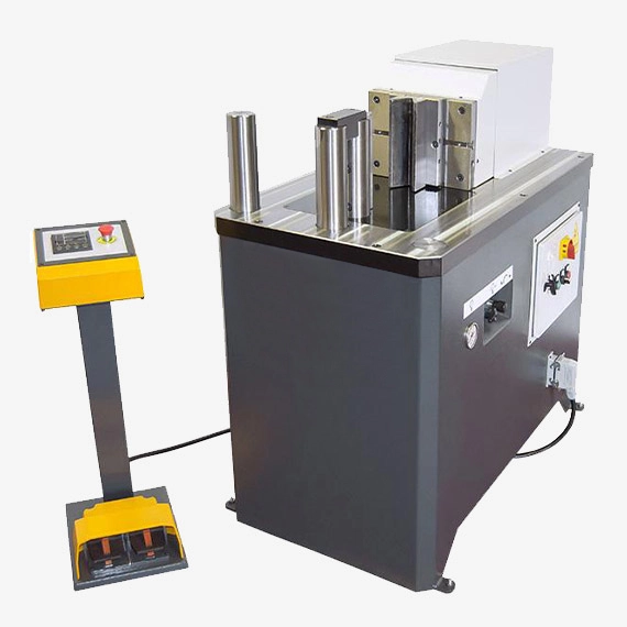
We manufacture a Hydraulic Press Brake Kit to bend sheet metal edges. Hydraulic Press Brake Kit is used in metalworking industries
A hydraulic press brake kit is a package that includes the necessary components to convert a standard hydraulic shop press into a hydraulic press brake. It typically includes specialized tooling, such as a bending die, back gauge, and other accessories, that enable the press to perform bending operations on sheet metal or other materials.
Here are some key components typically included in a hydraulic press brake kit:
- Bending Die: The kit includes a specific bending die, also known as a punch and die set, which determines the angle and shape of the bend. The bending die is designed to be mounted onto the press and is available in various sizes and configurations to accommodate different bending requirements.
- Back Gauge: A back gauge is a device that assists in positioning the sheet metal accurately for consistent and repeatable bends. It typically consists of an adjustable stop or fence that can be moved along a calibrated scale to set the desired bend length.
- Clamping System: A clamping system, such as a manual or hydraulic clamping device, is often included in the kit. This system securely holds the sheet metal in place during the bending process, preventing movement or slippage.
- Support Accessories: The kit may include additional support accessories, such as angle-measuring devices, templates, or guides, to assist with positioning and aligning the sheet metal for precise bends.
- Safety Features: Some hydraulic press brake kits may include safety features, such as guards, interlocks, or emergency stop mechanisms, to ensure operator safety during the bending process.
- Documentation and Instructions: The kit typically includes detailed documentation and instructions on how to install and use the components effectively. This helps operators properly set up the hydraulic press brake and perform bending operations correctly.
By using a hydraulic press brake kit, operators can transform a standard hydraulic shop press into a versatile and cost-effective bending machine. The kit provides the necessary components and tooling to perform a variety of bending operations on sheet metal or other materials, offering flexibility and precision in metal fabrication processes.
It’s important to note that hydraulic press brake kits are designed for specific models and types of hydraulic presses. Therefore, it’s crucial to ensure compatibility between the kit and the press before making a purchase.
Hydraulic Press Brake Kit
A hydraulic press brake kit is a versatile tool that can be used to bend and form metal sheets. It is a popular choice for both hobbyists and professionals alike, due to its ease of use and affordability.
Components of a Hydraulic Press Brake Kit
A hydraulic press brake kit typically includes the following components:
- Hydraulic ram: This is the main component of the kit, and it is responsible for applying the force that bends the metal sheet.
- V-die: This is a grooved die that shapes the bend in the metal sheet.
- Back gauge: This is a stop that ensures that the metal sheet is positioned correctly before it is bent.
- Ram adjustment: This allows you to fine-tune the amount of force that is applied to the metal sheet.
Benefits of Using a Hydraulic Press Brake Kit
There are many benefits to using a hydraulic press brake kit, including:
- Ease of use: Hydraulic press brake kits are relatively easy to use, even for beginners.
- Versatility: Hydraulic press brake kits can be used to bend a variety of metal sheets, including steel, aluminum, and brass.
- Accuracy: Hydraulic press brake kits can produce accurate and consistent bends.
- Affordability: Hydraulic press brake kits are relatively affordable, making them a great option for hobbyists and small businesses.
Applications of a Hydraulic Press Brake Kit
Hydraulic press brake kits can be used for a variety of applications, including:
- Bending sheet metal for boxes, pans, and other enclosures
- Forming channels and grooves in sheet metal
- Creating bends in metal tubing and pipes
- Adding bends to metal brackets and hangers
Safety Considerations
When using a hydraulic press brake kit, it is important to follow all safety precautions, including:
- Always wear safety glasses and gloves.
- Keep your hands away from the moving parts of the machine.
- Do not overload the machine.
- Use the correct tooling for the job.
Tips for Using a Hydraulic Press Brake Kit
Here are a few tips for using a hydraulic press brake kit:
- Use the correct V-die for the thickness of the metal sheet you are bending.
- Adjust the back gauge to ensure that the metal sheet is positioned correctly.
- Apply the force slowly and evenly.
- Check the bend for accuracy before proceeding.
Conclusion
Hydraulic press brake kits are a valuable tool for anyone who needs to bend or form metal sheets. They are easy to use, versatile, and affordable, making them a great option for both hobbyists and professionals alike.
Bending Die
A bending die, also known as a punch and die set, is a specialized tooling component used in bending operations to shape sheet metal or other materials. It is typically used in conjunction with a press brake, hydraulic press, or similar bending machine.
Here are some key points about bending dies:
- Construction: Bending dies are typically made from hardened tool steel or other durable materials that can withstand the high pressures and forces involved in bending operations. They are designed to be robust and long-lasting.
- Die Design: Bending dies consist of two main components: the punch and the die. The punch is the upper part of the die set and applies the force to the material, while the die is the lower part that provides support and determines the shape of the bend.
- Bend Angle and Radius: Bending dies are available in various configurations to achieve different bend angles and radii. The specific design of the bending die determines the final shape and dimensions of the bend.
- Compatibility: Bending dies are designed to be compatible with specific press brakes or bending machines. It is important to choose a bending die that matches the specifications and capabilities of the machine being used.
- Tooling Options: Bending dies come in a range of sizes and profiles to accommodate different material thicknesses and bending requirements. They can be customized or standardized based on the specific application needs.
- Interchangeability: In some cases, bending dies can be easily interchanged to achieve different bend configurations or accommodate various sheet metal sizes. This allows for flexibility and versatility in bending operations.
- Wear and Maintenance: Bending dies are subject to wear over time due to repeated use and contact with the material being bent. Regular maintenance, such as cleaning, lubrication, and occasional regrinding or replacement, is necessary to maintain the quality and accuracy of the bends.
Bending dies are essential tooling components in sheet metal fabrication, metalworking, and other industries that involve bending operations. They provide the means to shape and form sheet metal into various configurations, such as V-bends, U-bends, channels, or complex profiles. By selecting the appropriate bending die and properly setting up the bending machine, operators can achieve precise and consistent bends in their sheet metal components
Back Gauge
A back gauge is a device used in bending operations to accurately position the sheet metal or workpiece for consistent and repeatable bends. It is a crucial component in press brakes, hydraulic presses, and other bending machines. The back gauge allows for precise control over the distance between the bending point and the back edge of the sheet metal, determining the length of the bend.
Here are some key points about back gauges:
- Function: The primary function of a back gauge is to support and position the sheet metal or workpiece accurately during the bending process. It ensures consistent bending results by maintaining a consistent distance between the bending point and the back edge of the material.
- Construction: Back gauges are typically comprised of a movable stop or fence, often mounted on a linear guide or a ball screw mechanism. The stop can be adjusted horizontally along a calibrated scale to set the desired bend length.
- Control Mechanism: Back gauges can be manually operated or controlled through a motorized system. Motorized back gauges offer greater convenience and precision, as they can be programmable and easily adjusted using digital controls.
- Positioning Accuracy: Back gauges are designed to provide precise positioning of the sheet metal with high accuracy. This helps achieve consistent bend lengths and ensures uniformity across multiple workpieces.
- Back Gauge Fingers: Back gauges can be equipped with fingers or supports that extend perpendicularly from the stop. These fingers assist in aligning the sheet metal and provide additional support during the bending process.
- Programming Capabilities: In advanced bending machines, back gauges can be programmed to perform complex bending sequences, including multiple bends at different lengths and angles. This allows for the automation of bending processes and improves productivity.
- Safety Considerations: Back gauges should be designed with safety features to prevent injuries during the bending operation. This may include sensors or interlocks that detect obstructions or ensure that the operator’s hands are clear of the bending area before the machine is activated.
The back gauge is an integral part of a bending machine, providing precise control and repeatable positioning of the sheet metal or workpiece. It plays a crucial role in achieving accurate and consistent bends in sheet metal fabrication, metalworking, and other industries that involve bending operations.
Clamping System
A clamping system is an essential component in various manufacturing processes, including machining, welding, and bending operations. In the context of bending operations, a clamping system is used to securely hold the sheet metal or workpiece in place during the bending process. It ensures that the material remains stable and prevents any movement or slippage, resulting in accurate and precise bends.
Here are some key points about clamping systems in bending operations:
- Function: The primary function of a clamping system in bending is to hold the sheet metal firmly in position to resist the forces applied during the bending process. It prevents the material from shifting or buckling, ensuring that the bending occurs at the desired location and angle.
- Types of Clamping Systems: There are different types of clamping systems used in bending operations, depending on the specific application and the design of the bending machine. Some common types include manual clamps, hydraulic clamps, pneumatic clamps, and electromechanical clamps.
- Manual Clamps: Manual clamps are manually operated and typically involve levers or handles that tighten or release the clamping force. They are simple and cost-effective but require manual effort from the operator.
- Hydraulic Clamps: Hydraulic clamps use hydraulic pressure to generate the clamping force. They provide high clamping force capabilities and are often controlled by a hydraulic system integrated into the bending machine.
- Pneumatic Clamps: Pneumatic clamps utilize compressed air to generate the clamping force. They are commonly used in applications where rapid clamping and release are required.
- Electromechanical Clamps: Electromechanical clamps use electric motors or actuators to apply and release the clamping force. They offer precise control and can be integrated into automated bending systems.
- Adjustable Clamping Systems: Some clamping systems allow for adjustable clamping pressure or positioning to accommodate different material thicknesses or bending requirements. This versatility enables the use of the same clamping system for various workpiece sizes.
- Safety Considerations: Clamping systems should be designed with safety features to protect the operator during the bending operation. This may include the use of safety interlocks or sensors to ensure that the clamping system is properly engaged before the bending process begins.
The selection of the appropriate clamping system depends on factors such as the type and thickness of the material being bent, the bending forces involved, the desired level of automation, and the specific capabilities of the bending machine. A well-designed clamping system contributes to the overall accuracy, repeatability, and safety of the bending process.
Support Accessories
Support accessories play an important role in assisting with positioning, aligning, and supporting sheet metal or workpieces during various manufacturing processes, including bending operations. These accessories provide additional stability, precision, and convenience, ensuring that the material is properly held in place for accurate and consistent bending results. Here are some common support accessories used in bending operations:
- Angle-Measuring Devices: Angle-measuring devices, such as protractors or angle gauges, are used to measure and verify the angle of the bend. They help operators achieve the desired bending angle and ensure consistency across multiple workpieces.
- Templates and Guides: Templates and guides are often used to assist with positioning and aligning the sheet metal or workpiece in the correct bending location. They can be made of metal, plastic, or other materials and are pre-shaped to match specific bending requirements.
- Support Blocks or Shims: Support blocks or shims are used to provide additional support under the sheet metal or workpiece at specific points during the bending process. They help distribute the bending forces evenly and prevent undesirable deformation or damage to the material.
- Adjustable Stops: Adjustable stops are used to limit the travel of the bending tool or back gauge, ensuring consistent bend lengths across multiple workpieces. These stops can be manually adjusted or controlled through automation, depending on the capabilities of the bending machine.
- Spring Back Compensation Devices: Spring back is the tendency of the material to return to its original shape after the bending process. Spring back compensation devices, such as wedges or elastic materials, are used to counteract this effect and achieve the desired final bend angle.
- Workpiece Supports: Workpiece supports, such as roller stands or support arms, are used to provide continuous support along the length of the sheet metal or workpiece during the bending process. They help prevent sagging or deflection, ensuring consistent and accurate bending results.
- Anti-Mar Materials: Anti-mar materials, such as plastic or rubber coatings, can be applied to the support accessories or bending tools to protect the surface of the sheet metal from scratches, marks, or damage during the bending process.
These support accessories enhance the accuracy, repeatability, and efficiency of bending operations by providing additional stability, alignment, and control. The specific support accessories used may vary depending on the requirements of the bending application and the capabilities of the bending machine.
Safety Features
Safety is of utmost importance in any manufacturing process, including bending operations. Bending machines are equipped with various safety features to protect operators and ensure a safe working environment. Here are some common safety features found in bending machines:
- Emergency Stop Button: Bending machines are equipped with easily accessible emergency stop buttons that instantly shut down the machine when pressed. This allows operators to quickly halt operations in case of an emergency or hazardous situation.
- Safety Guards: Bending machines are fitted with safety guards or barriers that prevent access to the bending area during operation. These guards help protect operators from moving parts, pinch points, and potential flying debris.
- Two-Handed Operation: Some bending machines require two-handed operation, where both hands of the operator are needed to activate the bending process. This feature ensures that the operator’s hands are clear of the bending area during the bending stroke, reducing the risk of injury.
- Light Curtains or Safety Sensors: Light curtains or safety sensors are used to create a protective field around the bending area. They detect the presence of any object or body part within the field and automatically stop or prevent the machine from operating, ensuring operator safety.
- Interlock Systems: Interlock systems ensure that certain safety conditions are met before the bending machine can be operated. For example, the safety guards must be properly closed and secured, or the emergency stop button must be released before the machine can be activated.
- Warning Signs and Labels: Bending machines are labeled with warning signs and safety instructions to inform operators about potential hazards, proper operating procedures, and safety precautions. This helps raise awareness and promote safe practices.
- Training and Operator Education: Proper training and education of operators are essential for safe operation of bending machines. Operators should be trained in machine operation, safety procedures, and emergency protocols to minimize risks and prevent accidents.
It is important to note that safety features may vary depending on the specific type and model of the bending machine. Manufacturers provide guidelines and recommendations for the safe use of their machines, and it is crucial to follow these guidelines to ensure the well-being of operators and maintain a safe working environment.
Documentation and Instructions
Documentation and instructions are crucial components of any manufacturing process, including bending operations. They provide essential information and guidance to operators, ensuring the safe and efficient use of bending machines. Here are some key aspects of documentation and instructions related to bending operations:
- Operating Manual: Bending machines come with an operating manual provided by the manufacturer. The manual contains detailed instructions on machine setup, operation, maintenance, and safety procedures. It should be readily available to operators and followed meticulously.
- Safety Guidelines: The documentation includes safety guidelines specific to the bending machine. These guidelines outline potential hazards, safety precautions, and recommended practices to ensure the well-being of operators and prevent accidents.
- Machine Specifications: The documentation provides detailed specifications of the bending machine, including its capabilities, limitations, and recommended operating parameters. It includes information such as maximum bending capacity, bending angles, tooling specifications, and power requirements.
- Machine Setup Instructions: Instructions for machine setup and tooling installation are provided to ensure proper alignment, positioning, and attachment of components. This includes guidelines for selecting and installing appropriate tooling, adjusting back gauges, and calibrating the machine.
- Operation Procedures: The documentation explains step-by-step procedures for operating the bending machine. This includes guidelines on material placement, clamping, programming bending parameters (if applicable), initiating the bending stroke, and verifying bend accuracy.
- Maintenance and Lubrication: The documentation provides instructions for routine maintenance tasks, such as cleaning, lubrication, and inspection of critical components. It outlines recommended maintenance schedules and procedures to ensure the longevity and optimal performance of the bending machine.
- Troubleshooting and Problem Solving: The documentation includes troubleshooting guidelines to help operators identify and resolve common issues that may arise during bending operations. It provides information on potential causes of problems and suggests corrective actions.
- Training Materials: Some manufacturers provide additional training materials, such as videos or interactive tutorials, to supplement the documentation and enhance operator training. These materials can be used to reinforce key concepts, demonstrate proper techniques, and ensure a thorough understanding of bending machine operation.
It is essential for operators to carefully read and understand the documentation and instructions provided by the manufacturer. They should adhere to the recommended practices, safety guidelines, and maintenance procedures to ensure safe and efficient bending operations. Regular updates to the documentation should be sought from the manufacturer to stay informed about any changes or improvements to the machine.
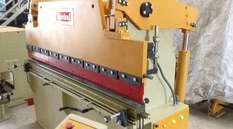
Press Brake
A press brake is a vital machine tool used in metalworking, particularly in sheet metal fabrication processes. Its primary function is to bend sheet metal into various shapes and angles by applying force using a punch and die system. Press brakes come in various configurations, including hydraulic, mechanical, and pneumatic, each offering unique advantages depending on the application and material being worked on.
These machines typically consist of a sturdy frame, a movable upper beam (ram), and a lower bed with a die. The sheet metal to be bent is placed between the punch and die, and the ram exerts downward force to form the desired bend. Press brakes are highly versatile and can perform a wide range of bending operations, from simple straight bends to complex, multi-bend shapes.
Hydraulic press brakes use hydraulic cylinders to generate the necessary force for bending. They offer precise control over the bending process and are well-suited for high-tonnage applications and precision bending tasks. Mechanical press brakes, on the other hand, utilize mechanical linkages and motors to generate bending force. While they may lack the precision of hydraulic brakes, they are often more cost-effective and suitable for lower-tonnage applications.
Pneumatic press brakes use air pressure to exert force, offering fast cycle times and ease of operation. They are commonly used for lighter-duty bending tasks and in environments where hydraulic fluid may not be desirable.
Press brakes are indispensable in industries such as automotive, aerospace, construction, and manufacturing, where sheet metal components are ubiquitous. They play a crucial role in the production of various products, including enclosures, brackets, chassis, panels, and structural components.
Operators of press brakes require a good understanding of metalworking principles, including material properties, bending tolerances, and safety protocols. Proper tooling selection, die setup, and machine maintenance are essential for achieving accurate and repeatable bending results.
In summary, press brakes are essential tools in sheet metal fabrication, offering versatility, precision, and efficiency in bending operations. With various types and configurations available, they cater to a wide range of bending requirements across different industries, driving innovation and productivity in metalworking processes.
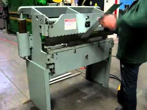
Bending Machine:
A bending machine is a versatile tool used in metalworking to bend various materials, primarily sheet metal, into desired shapes and angles. These machines are integral to industries such as manufacturing, construction, automotive, and aerospace, where the fabrication of bent components is common.
Bending machines come in different types, each tailored to specific bending tasks and material requirements. One of the most common types is the press brake, which utilizes a punch and die system to apply force and bend the material. Press brakes are available in hydraulic, mechanical, and pneumatic variants, offering different levels of precision, power, and versatility.
Another type of bending machine is the roll bender or plate roll, which uses a series of rollers to gradually bend the material along its length. Roll benders are commonly used for cylindrical and conical bending operations, such as forming pipes, tubes, and structural components.
Tube and pipe benders are specialized machines designed specifically for bending cylindrical or tubular materials, such as metal pipes and tubes. These machines use mandrels or dies to support the inner diameter of the tube during bending, ensuring uniform curvature and dimensional accuracy.
In addition to these primary types, there are also specialized bending machines for specific applications, such as profile benders for bending extruded or formed profiles, and ring rollers for bending rings and curved sections.
Bending machines offer several advantages in metalworking processes. They enable precise control over bend angles, radii, and dimensions, allowing manufacturers to produce complex components with high accuracy and repeatability. Bending machines also offer increased productivity and efficiency compared to manual bending methods, reducing labor costs and turnaround times.
Operators of bending machines require training and expertise to set up the machine, select appropriate tooling, and adjust bending parameters to achieve desired results. Proper maintenance and upkeep of bending machines are also essential to ensure optimal performance and longevity.
In summary, bending machines are indispensable tools in metalworking, offering versatility, precision, and efficiency in bending operations. With various types and configurations available, they cater to a wide range of bending requirements across different industries, driving innovation and productivity in manufacturing processes.
Sheet Metal Bending:
Sheet metal bending is a fundamental metalworking process used to deform flat sheets of metal into desired shapes and angles. It is a versatile technique employed in various industries, including automotive, aerospace, construction, and manufacturing, for producing components with complex geometries and precise dimensions.
The process of sheet metal bending typically involves placing a flat sheet of metal between a punch and a die, then applying force to deform the material and create the desired bend. The punch applies pressure to the sheet metal, forcing it to conform to the shape of the die cavity. The material undergoes plastic deformation, stretching and compressing along the bend line to form the desired angle.
Several factors influence the bending process and the final outcome of the bent part. These include:
- Material Properties: The type of material being bent, such as aluminum, steel, stainless steel, or copper, as well as its thickness and ductility, significantly impact the bending process. Materials with higher ductility are easier to bend and typically require less force to achieve the desired bend angle.
- Bend Radius: The bend radius refers to the radius of the curve formed during bending. It is determined by the shape and dimensions of the die cavity and influences the minimum achievable bend radius, as well as the risk of material cracking or tearing during bending.
- Bend Allowance: Bend allowance is the amount of material deformation required to accommodate the bend angle and radius. It accounts for material stretch and compression along the bend line and is essential for accurately predicting the final dimensions of the bent part.
- Tooling Selection: The selection of appropriate punch and die tooling is critical for achieving precise and repeatable bending results. Different tooling configurations, such as V-dies, hemming dies, and radius dies, are available to accommodate various bend angles, radii, and material types.
- Machine Setup: Proper machine setup, including adjusting the position of the back gauge, selecting the correct bending sequence, and setting bending parameters such as tonnage and stroke length, is essential for achieving accurate and uniform bends across multiple parts.
Sheet metal bending can be performed using different types of bending machines, including press brakes, roll benders, and tube benders, each offering unique capabilities and advantages depending on the application and material requirements.
In summary, sheet metal bending is a versatile and essential metalworking process that enables the production of a wide range of components with complex shapes and precise dimensions. By understanding the principles and factors influencing the bending process, manufacturers can achieve high-quality, efficient bending operations, driving innovation and productivity in various industries.
Metal Fabrication:
Metal fabrication is a broad term that encompasses various processes involved in shaping, cutting, and assembling metal components to create finished products. It is a crucial part of manufacturing across industries such as automotive, aerospace, construction, electronics, and more. Metal fabrication involves a combination of techniques, equipment, and skilled labor to transform raw materials into usable parts and structures.
The process of metal fabrication typically includes several key steps:
- Design and Engineering: The fabrication process begins with the design and engineering phase, where engineers and designers create detailed drawings and specifications for the desired product or component. Computer-aided design (CAD) software is often used to create accurate 3D models and blueprints.
- Material Selection: Once the design is finalized, the appropriate materials are selected based on factors such as strength, durability, corrosion resistance, and cost. Common metals used in fabrication include steel, aluminum, stainless steel, copper, and brass, among others.
- Material Preparation: Raw metal materials are prepared for fabrication by cutting, shearing, or sawing them to the required size and shape. This may involve using manual or automated cutting tools such as band saws, plasma cutters, laser cutters, or water jet cutters.
- Forming and Shaping: Metal components are then formed and shaped into their final configurations using various techniques such as bending, rolling, punching, stamping, and extrusion. These processes may be performed using specialized equipment such as press brakes, roll formers, stamping presses, and CNC machining centers.
- Welding and Joining: Once the individual components are formed, they are assembled and joined together using welding, brazing, soldering, or adhesive bonding techniques. Welding is a common method used to permanently join metal parts by melting and fusing them together using heat and pressure.
- Finishing and Surface Treatment: After fabrication and assembly, metal components may undergo finishing processes to improve their appearance, durability, and functionality. This may include grinding, sanding, polishing, painting, powder coating, anodizing, or plating to achieve the desired surface finish and corrosion resistance.
- Quality Control: Throughout the fabrication process, quality control measures are implemented to ensure that the finished products meet the required specifications and standards. This may involve dimensional inspection, material testing, visual inspection, and performance testing to verify the integrity and quality of the fabricated parts.
Metal fabrication requires skilled labor, specialized equipment, and a thorough understanding of metallurgy, manufacturing processes, and safety protocols. It plays a critical role in producing a wide range of products and structures, from small precision components to large-scale industrial machinery and infrastructure projects.
In summary, metal fabrication is a complex and multi-step process that involves transforming raw metal materials into finished products through cutting, forming, joining, and finishing operations. By leveraging advanced technologies, skilled craftsmanship, and efficient production methods, metal fabricators can deliver high-quality, custom-made solutions to meet the diverse needs of various industries.
Forming Process:
The forming process in metalworking refers to a group of manufacturing techniques used to shape raw metal materials into desired geometries and configurations. It is a crucial step in the production of a wide range of components and products across industries such as automotive, aerospace, construction, and manufacturing.
There are several common forming processes used in metalworking, each offering unique advantages and capabilities:
- Bending: Bending is a process used to deform flat sheets or profiles of metal along a straight axis, resulting in curved or angled shapes. Bending operations are commonly performed using press brakes, roll benders, or tube benders, depending on the complexity and dimensions of the part.
- Rolling: Rolling involves passing metal stock through a series of rollers to reduce its thickness or form it into cylindrical or curved shapes. Plate rolling machines or roll forming equipment are used to achieve uniform deformation and precise dimensional control in rolled components.
- Drawing: Drawing is a process used to form sheet metal into hollow or concave shapes by pulling it through a die cavity using a punch or mandrel. Deep drawing is a specialized form of drawing used to create complex shapes with significant depth, such as automotive body panels and kitchen sinks.
- Extrusion: Extrusion is a process used to create long, continuous shapes by forcing metal billets or blanks through a shaped die under high pressure. It is commonly used to produce profiles, tubes, and structural components with complex cross-sectional geometries.
- Stamping: Stamping involves using a die and punch set to cut or form metal sheets into specific shapes and configurations. It is commonly used for mass production of components such as automotive body panels, appliance parts, and electronic enclosures.
- Forging: Forging is a process used to shape metal by applying compressive force to heated metal billets or ingots. It is commonly used to produce high-strength, precision components such as gears, crankshafts, and connecting rods in automotive and aerospace applications.
- Spinning: Spinning, also known as spin forming or metal spinning, is a process used to form sheet metal or tubes into symmetrical, rotational shapes such as cones, domes, and cylinders. It is commonly used in the production of lighting fixtures, cookware, and decorative components.
The choice of forming process depends on factors such as the material type, thickness, complexity of the part, production volume, and desired properties of the finished product. Each forming process requires specific equipment, tooling, and expertise to achieve the desired results efficiently and accurately.
In summary, the forming process is a fundamental aspect of metalworking that encompasses a variety of techniques for shaping raw metal materials into finished components and products. By understanding the principles and capabilities of different forming processes, manufacturers can select the most suitable methods to meet their production requirements and achieve optimal results in terms of quality, efficiency, and cost-effectiveness.
Hydraulic Press:
A hydraulic press is a versatile machine tool that utilizes hydraulic pressure to generate force for various industrial processes such as pressing, forming, stamping, and bending. It consists of a hydraulic system, a power source, a frame, and a ram or piston that applies force to the workpiece.
The operation of a hydraulic press is based on Pascal’s principle, which states that pressure applied to a confined fluid is transmitted equally in all directions. In a hydraulic press, hydraulic fluid is pumped into a cylinder, creating pressure that is transmitted through a series of interconnected pistons and cylinders to the ram or piston that applies force to the workpiece.
Hydraulic presses come in various sizes and configurations, ranging from small benchtop models used for light-duty applications to large industrial machines capable of exerting thousands of tons of force. They can be operated manually, semi-automatically, or fully automatically, depending on the application and level of automation required.
One of the key advantages of hydraulic presses is their ability to exert high levels of force with relatively low energy input. This makes them well-suited for tasks that require precise control over force, such as forming and stamping operations. Hydraulic presses also offer smooth and consistent force application, resulting in uniform and repeatable results.
Hydraulic presses are used in a wide range of industries and applications, including metalworking, automotive manufacturing, aerospace, construction, and more. They are commonly used for tasks such as pressing bearings, bushings, and shafts into housings, forming sheet metal components, stamping metal parts, and bending metal plates and profiles.
The versatility and efficiency of hydraulic presses make them indispensable tools in modern manufacturing operations. With advances in technology, hydraulic presses continue to evolve, incorporating features such as programmable controls, safety interlocks, and precision tooling to improve productivity, accuracy, and operator safety.
In summary, hydraulic presses are powerful and versatile machines used for a wide range of industrial processes. Their ability to generate high levels of force with precision and control makes them essential tools in metalworking and manufacturing operations worldwide.
CNC Control:
Computer Numerical Control (CNC) is a technology that enables the automated control of machine tools and processes using computerized systems. In the context of metalworking and manufacturing, CNC control refers to the use of computer-controlled systems to operate machines such as lathes, mills, routers, lasers, and presses with high precision and accuracy.
CNC control systems consist of several key components:
- Control Unit: The control unit is the brain of the CNC system, containing the computer and software responsible for interpreting instructions, executing commands, and controlling machine movements.
- Motion Control System: The motion control system translates digital instructions into physical movements of the machine tool. It includes motors, drives, and feedback devices such as encoders and sensors to precisely control position, velocity, and acceleration.
- Operator Interface: The operator interface allows users to interact with the CNC system, inputting commands, loading programs, and monitoring machine operations. It typically includes a control panel, display screen, keyboard, and/or touchscreen interface.
- Programming Software: CNC machines are programmed using specialized software that generates machine-readable instructions (G-code) based on CAD (Computer-Aided Design) or CAM (Computer-Aided Manufacturing) models. Programmers create instructions specifying tool paths, cutting parameters, and other machining parameters.
CNC control offers several advantages over manual or conventional machine control methods:
- Precision and Accuracy: CNC machines can perform complex machining operations with high precision and accuracy, achieving tight tolerances and fine surface finishes that would be difficult or impossible to achieve manually.
- Repeatability: CNC control ensures consistent and repeatable results, making it ideal for mass production and high-volume manufacturing applications where uniformity and consistency are critical.
- Flexibility: CNC machines can be easily reconfigured and reprogrammed to perform different tasks, making them highly adaptable to changing production requirements and allowing for rapid prototyping and product customization.
- Automation: CNC control enables the automation of manufacturing processes, reducing the need for manual intervention, increasing productivity, and lowering labor costs.
CNC control is widely used in various industries, including aerospace, automotive, electronics, medical devices, and more, where precision machining and high-quality production are essential. It has revolutionized the way complex parts and components are manufactured, enabling faster production cycles, improved quality, and greater efficiency in manufacturing operations.
Die:
In metalworking and manufacturing, a die refers to a specialized tool or mold used to shape or form materials into specific shapes or configurations. Dies are essential components in various processes such as stamping, forging, extrusion, and casting, where they facilitate the production of precise and uniform parts and components.
There are several types of dies used in metalworking, each designed for specific applications and materials:
- Stamping Die: Stamping dies, also known as press dies, are used in stamping operations to cut, bend, or form sheet metal into desired shapes. They consist of two main components: the punch, which applies force to the workpiece, and the die, which provides the desired shape or contour. Stamping dies are commonly used in industries such as automotive, aerospace, electronics, and appliance manufacturing to produce a wide range of components, including brackets, panels, housings, and connectors.
- Forging Die: Forging dies are used in forging operations to shape heated metal blanks or billets into desired forms through controlled deformation. They are typically made of hardened tool steel and are designed to withstand high temperatures and pressures associated with forging processes. Forging dies come in various configurations, including open-die, closed-die, and impression-die designs, depending on the complexity and geometry of the part being produced. They are widely used in the production of automotive components, aerospace parts, and industrial machinery.
- Extrusion Die: Extrusion dies are used in extrusion processes to shape heated metal or plastic materials into continuous profiles or cross-sections. They consist of a die cavity through which the material is forced under pressure to form the desired shape. Extrusion dies are commonly used in industries such as construction, automotive, and consumer goods manufacturing to produce components such as rods, tubes, bars, and profiles with consistent dimensions and properties.
- Casting Die: Casting dies, also known as molds, are used in casting processes to shape molten metal or plastic materials into solid objects by pouring them into a cavity and allowing them to cool and solidify. Casting dies can be made of metal, ceramic, or other materials and are designed to withstand the thermal and mechanical stresses associated with casting operations. They are used in a wide range of industries, including foundry, aerospace, and jewelry manufacturing, to produce components such as engine blocks, turbine blades, and jewelry pieces.
Dies play a critical role in metalworking and manufacturing processes, enabling the production of complex and intricate parts with high precision and repeatability. Proper design, material selection, and maintenance of dies are essential for achieving optimal performance and prolonging die life in industrial applications.
Punch:
In metalworking and manufacturing, a punch is a specialized tool used in conjunction with a die to create holes, notches, or other features in sheet metal, plates, or other materials. Punches are essential components in processes such as punching, stamping, blanking, and piercing, where they provide the cutting or forming action necessary to produce precise and uniform parts and components.
Punches come in a variety of shapes, sizes, and configurations, each designed for specific applications and materials:
- Round Punch: A round punch is a cylindrical tool with a sharp edge used to create round holes in sheet metal or other materials. Round punches are commonly used in punching and piercing operations to produce holes for fasteners, ventilation, or wiring in components such as brackets, panels, and enclosures.
- Square Punch: A square punch has a flat, square-shaped cutting edge and is used to create square or rectangular holes in sheet metal or other materials. Square punches are often used in conjunction with square dies to produce keyways, slots, or other geometric features in components such as frames, supports, and structural members.
- Rectangular Punch: Similar to square punches, rectangular punches have a flat, rectangular-shaped cutting edge and are used to create elongated or rectangular holes in sheet metal or other materials. Rectangular punches are commonly used in applications where longer slots or openings are required, such as in conveyor systems, machine guards, and structural frames.
- Notching Punch: A notching punch is a specialized tool used to create notches or cutouts in sheet metal or other materials. Notching punches are often used in conjunction with notching dies to produce precise cutouts for tabs, slots, or other features in components such as brackets, flanges, and connectors.
- Trimming Punch: Trimming punches are used in trimming or blanking operations to remove excess material from the edges of sheet metal or other workpieces. They have a sharp cutting edge designed to cleanly shear the material along a predetermined path, leaving behind a finished edge with minimal burrs or distortion.
Punches are typically made of hardened tool steel or carbide to withstand the mechanical stresses and wear associated with punching and forming operations. Proper selection, sharpening, and maintenance of punches are essential for achieving optimal performance and prolonging tool life in industrial applications. Additionally, punches may be customized with features such as coatings, coatings, or surface treatments to enhance wear resistance, lubricity, or corrosion resistance in specific applications.
Blanking:
Blanking is a metal forming process used to cut out a flat shape from a sheet or strip of material. It is commonly used to produce flat parts with precise dimensions and intricate geometries, such as brackets, washers, gaskets, and electronic components.
The blanking process involves placing a sheet or strip of material between a punch and a die, then applying force to the punch to shear the material and create the desired shape. The punch is typically a sharp-edged tool that penetrates through the material, while the die provides support and defines the shape of the cutout.
Key aspects of the blanking process include:
- Material Selection: Blanking can be performed on a variety of materials, including metals such as steel, aluminum, copper, and brass, as well as plastics and composites. The material’s thickness, strength, and ductility influence the blanking process’s feasibility and the quality of the finished parts.
- Tool Design: The design of the punch and die is critical for achieving accurate and consistent blanked parts. The punch’s cutting edge must be sharp and precisely aligned with the die cavity to ensure clean cuts and minimal burrs. Additionally, the clearance between the punch and die is adjusted to accommodate material thickness and prevent jamming or distortion.
- Cutting Parameters: Blanking parameters such as cutting speed, feed rate, and punch force are optimized to achieve efficient material removal while minimizing tool wear and deformation. High-speed blanking techniques may be employed to increase productivity and achieve finer tolerances in certain applications.
- Strip Layout: In high-volume blanking operations, multiple parts may be blanked from a single sheet or strip of material in a single stroke. The layout of the parts on the material strip is carefully optimized to maximize material utilization and minimize waste.
- Post-Processing: After blanking, the cut parts may undergo additional processing steps such as deburring, edge finishing, or surface treatment to remove any burrs, improve surface quality, or add protective coatings.
Blanking offers several advantages over alternative cutting methods such as shearing or sawing, including higher accuracy, faster production rates, and the ability to produce intricate shapes with minimal material waste. However, it may not be suitable for all applications, particularly those involving thicker or harder materials that require more forceful cutting actions.
In summary, blanking is a versatile metal forming process used to produce flat parts with precise dimensions and complex geometries. By optimizing tooling design, cutting parameters, and material utilization, manufacturers can achieve efficient and cost-effective blanking operations to meet the demands of various industries and applications.
Stamping Press:
A stamping press, also known as a stamping machine or press, is a machine tool used in metalworking and manufacturing to perform various forming, cutting, and shaping operations on sheet metal or other materials. Stamping presses are widely used in industries such as automotive, aerospace, electronics, and appliance manufacturing to produce a wide range of components, including brackets, panels, enclosures, and connectors.
Key components of a stamping press include:
- Frame: The frame provides the structural support and rigidity for the stamping press. It is typically made of heavy-duty steel or cast iron to withstand the forces generated during stamping operations.
- Bed: The bed is the flat, horizontal surface on which the workpiece is placed during stamping operations. It may be equipped with T-slots, clamping mechanisms, or other features to secure the workpiece in position.
- Slide: The slide, also known as the ram or platen, is the moving part of the stamping press that applies force to the workpiece. It is driven by hydraulic, mechanical, or pneumatic mechanisms and can move vertically, horizontally, or in a combination of both directions.
- Die Set: The die set consists of a punch and die mounted on the slide and bed, respectively. The punch is the upper tool that applies force to the workpiece, while the die provides support and defines the shape of the stamped part. Dies are typically custom-designed to produce specific shapes and features in the workpiece.
- Controls: Stamping presses are equipped with control systems that regulate the speed, force, and timing of the stamping operation. Modern stamping presses may feature computerized numerical control (CNC) systems for precise control and automation of the stamping process.
Types of stamping presses include:
- Mechanical Press: Mechanical presses use mechanical linkages and flywheels to convert rotational motion into linear motion, delivering force to the workpiece. They are suitable for high-speed operations and applications requiring high force and accuracy.
- Hydraulic Press: Hydraulic presses use hydraulic cylinders and fluid power to apply force to the workpiece. They offer precise control over force and speed and are suitable for a wide range of stamping applications, including deep drawing and forming operations.
- Servo Press: Servo presses utilize electric servo motors to drive the slide, providing precise control over speed, force, and position. They offer high accuracy, repeatability, and flexibility, making them ideal for complex stamping operations and applications requiring quick changeovers.
Stamping presses are versatile machines capable of performing a wide range of stamping operations, including blanking, piercing, bending, embossing, and coining. By selecting the appropriate press configuration, tooling, and control systems, manufacturers can achieve efficient and cost-effective stamping processes to meet the demands of various industries and applications.
Progressive Die:
A progressive die is a specialized tooling assembly used in metal stamping operations to produce a continuous progression of stamped parts from a single coil or strip of material. It consists of multiple individual stations or stages, each performing a specific forming, cutting, or shaping operation on the workpiece as it moves through the die.
Key components and features of a progressive die include:
- Entry Section: The entry section of the progressive die feeds the coil or strip of material into the die and guides it through the various stages of the stamping process. It may include coil handling equipment, straighteners, and feed mechanisms to ensure smooth and precise material feeding.
- Punching Stations: Progressive dies typically include multiple punching stations, each equipped with a punch and die set to perform specific cutting or piercing operations on the workpiece. These stations may include blanking punches, piercing punches, and forming punches to create holes, slots, or other features in the stamped parts.
- Bending Stations: Some progressive dies include bending stations equipped with bending punches and dies to bend or form the workpiece into specific shapes or angles. These stations may perform simple bending operations or more complex forming operations such as flanging, hemming, or curling.
- Transfer Mechanisms: Transfer mechanisms, such as grippers, fingers, or belts, are used to move the workpiece from one station to the next as it progresses through the die. These mechanisms ensure precise positioning and alignment of the workpiece at each stage of the stamping process, allowing for accurate and repeatable part production.
- Stripper Plates: Stripper plates are used to strip the stamped parts from the punch as they exit the die. They help prevent sticking or jamming of the parts in the die and ensure smooth ejection of the finished parts from the die.
- Cutting and Trimming Operations: In addition to punching and bending operations, progressive dies may include cutting and trimming stations equipped with shearing blades or cutting dies to trim excess material from the edges of the stamped parts or separate individual parts from the strip.
Progressive dies offer several advantages over traditional single-operation dies, including:
- Increased Productivity: Progressive dies can produce multiple parts in a single stroke of the press, leading to higher production rates and reduced cycle times compared to single-operation dies.
- Improved Material Utilization: Progressive dies minimize material waste by efficiently nesting multiple parts on a single strip of material, maximizing material utilization and reducing scrap.
- Consistent Part Quality: Progressive dies ensure consistent part dimensions, tolerances, and surface finishes across all stamped parts, resulting in higher quality and greater uniformity in the finished products.
Progressive dies are commonly used in high-volume manufacturing applications, such as automotive, appliance, and electronics production, where fast, efficient, and cost-effective part production is essential. By optimizing die design, tooling, and press setup, manufacturers can achieve efficient and reliable stamping processes with progressive dies to meet the demands of modern manufacturing.
Forming:
Forming is a metalworking process that involves shaping or reshaping a workpiece into a desired geometry or configuration using various mechanical, thermal, or hydraulic forces. Forming operations can be classified into several categories, including bending, drawing, forging, rolling, and extrusion, each with its unique set of techniques and applications.
Bending: Bending is a forming operation that involves deforming a workpiece along a straight axis to create angular or curved shapes. It is commonly used to produce components such as brackets, frames, tubes, and structural members in industries such as construction, automotive, and aerospace. Bending can be performed using manual or mechanical methods, including press brakes, roll bending machines, and tube bending machines.
Drawing: Drawing is a forming operation that involves pulling a flat sheet or strip of material through a die cavity to form it into a three-dimensional shape, such as a cup, shell, or tube. It is commonly used in the production of hollow metal components such as cans, containers, and automotive body panels. Drawing can be performed using various techniques, including deep drawing, stretch drawing, and hydroforming, depending on the complexity and dimensions of the part being produced.
Forging: Forging is a forming operation that involves shaping heated metal billets or ingots into desired shapes through controlled deformation using compressive forces. It is commonly used to produce high-strength, high-performance components such as crankshafts, connecting rods, gears, and turbine blades. Forging processes include open-die forging, closed-die forging, impression-die forging, and cold forging, each suited to different materials and applications.
Rolling: Rolling is a forming operation that involves passing a workpiece between two or more rotating rollers to reduce its thickness or change its cross-sectional profile. It is commonly used in the production of sheet metal, plates, bars, and structural shapes such as I-beams and rails. Rolling processes include hot rolling, cold rolling, and profile rolling, each offering advantages in terms of material properties, surface finish, and dimensional accuracy.
Extrusion: Extrusion is a forming operation that involves forcing a heated metal or plastic material through a shaped die to produce continuous profiles or cross-sections. It is commonly used in the production of tubes, rods, bars, and complex shapes with uniform cross-sections. Extrusion processes include direct extrusion, indirect extrusion, and hydrostatic extrusion, each offering unique capabilities in terms of material flow, shape complexity, and production efficiency.
Forming processes play a critical role in modern manufacturing, enabling the production of a wide range of components and products with diverse shapes, sizes, and material properties. By selecting the appropriate forming techniques and equipment, manufacturers can achieve efficient and cost-effective production processes to meet the demands of various industries and applications.
Hydraulic Press:
A hydraulic press is a machine tool that utilizes hydraulic cylinders to generate a compressive force to perform various metalworking operations such as bending, forming, stamping, punching, and assembling. It consists of a hydraulic system, a frame, and a movable ram or piston that applies force to the workpiece.
Key Components:
- Hydraulic System: The hydraulic system of a hydraulic press comprises a hydraulic pump, hydraulic fluid reservoir, valves, cylinders, and hoses. The hydraulic pump pressurizes the hydraulic fluid, which is then directed to the hydraulic cylinders to generate force. The valves control the flow of hydraulic fluid to regulate the speed and force of the press.
- Frame: The frame of a hydraulic press provides structural support and rigidity to withstand the forces generated during operation. It is typically made of heavy-duty steel or cast iron and may include features such as T-slots, bolting patterns, and tooling mounts for securing workpieces and tooling.
- Ram or Piston: The ram or piston of a hydraulic press is the moving part that applies force to the workpiece. It is driven by hydraulic cylinders and can move vertically, horizontally, or in a combination of both directions. The ram may be equipped with various tooling attachments such as punches, dies, and forming tools to perform specific metalworking operations.
Operating Principles:
- Hydraulic Fluid Compression: When hydraulic fluid is pumped into the hydraulic cylinders, it compresses the fluid, exerting pressure on the piston or ram. This pressure is transmitted to the workpiece, causing it to deform or undergo the desired metalworking operation.
- Force Control: The force exerted by the hydraulic press can be controlled by adjusting the hydraulic pressure, which in turn regulates the force applied to the workpiece. This allows for precise control over the forming process and enables the production of parts with consistent dimensions and properties.
- Speed Control: The speed of the hydraulic press can be controlled by adjusting the flow rate of hydraulic fluid to the cylinders. This allows for varying speeds during the forming process, such as rapid approach, slow forming, and quick return, depending on the requirements of the application.
Applications:
Hydraulic presses are used in a wide range of industries and applications, including:
- Metal Forming: Hydraulic presses are commonly used for bending, forming, and stamping operations in the production of automotive components, appliance parts, and structural elements.
- Sheet Metal Fabrication: Hydraulic presses are used to punch, shear, and bend sheet metal to create components such as enclosures, panels, and brackets.
- Forging: Hydraulic presses are used in forging operations to shape heated metal billets or ingots into desired shapes such as crankshafts, connecting rods, and gears.
- Assembly: Hydraulic presses are used for assembling parts and components by pressing, riveting, or joining them together using various tooling attachments.
Overall, hydraulic presses offer versatility, precision, and efficiency in metalworking operations, making them essential equipment in modern manufacturing facilities.
Die Set:
In metalworking and manufacturing, a die set, also known as a tool set or tooling set, is a collection of specialized tools used in conjunction with a press or stamping machine to perform various forming, cutting, and shaping operations on sheet metal or other materials. Die sets are essential components in processes such as punching, blanking, bending, drawing, and embossing, where they provide the cutting or forming action necessary to produce precise and uniform parts and components.
Components of a Die Set:
- Punch: The punch is the upper tool in the die set and is mounted on the ram or slide of the press. It applies force to the workpiece, penetrating through the material to create holes, notches, or other features. Punches come in a variety of shapes and sizes, each designed for specific applications and materials.
- Die: The die is the lower tool in the die set and is mounted on the bed or bolster of the press. It provides support for the workpiece and defines the shape of the stamped part. Dies are typically custom-designed to produce specific shapes and features in the workpiece, and they come in various configurations, including blanking dies, forming dies, and bending dies.
- Stripper Plate: The stripper plate is a flat, movable plate located above the die cavity and is used to strip the stamped parts from the punch as they exit the die. It helps prevent sticking or jamming of the parts in the die and ensures smooth ejection of the finished parts from the die.
- Guide Pins and Bushings: Guide pins and bushings are used to align and guide the punch and die components during the stamping process, ensuring precise positioning and movement. They help maintain tight tolerances and prevent misalignment or damage to the tooling components.
- Retainers and Springs: Retainers and springs are used to hold the punch and die components in place within the die set and provide the necessary clearance for the workpiece to enter and exit the die cavity. They help absorb shock and vibration during the stamping process and ensure consistent part production.
Applications of Die Sets:
Die sets are used in a wide range of industries and applications, including:
- Automotive manufacturing: for producing components such as brackets, panels, and frames.
- Appliance manufacturing: for producing parts such as enclosures, housings, and handles.
- Electronics manufacturing: for producing components such as connectors, terminals, and heat sinks.
- Aerospace manufacturing: for producing components such as brackets, clips, and supports.
- General metal fabrication: for producing a variety of components such as hardware, fixtures, and fittings.
Overall, die sets play a critical role in metal stamping and forming operations, enabling manufacturers to produce high-quality parts with tight tolerances and complex geometries efficiently and cost-effectively. Proper selection, design, and maintenance of die sets are essential for achieving optimal performance and prolonging tool life in industrial applications.
Punch and Die Clearance:
Punch and die clearance, also known as clearance or gapping, refers to the intentional gap between the punch and die components in a stamping or punching operation. It is a critical parameter that influences the quality, accuracy, and performance of the stamped parts and the overall efficiency of the metalworking process.
Importance of Punch and Die Clearance:
- Material Thickness Compensation: Punch and die clearance ensures that the punched hole or formed feature in the workpiece is accurately sized and shaped, taking into account the thickness of the material being stamped. Without proper clearance, the punched hole may be undersized or oversized, leading to dimensional inaccuracies in the finished part.
- Prevention of Galling and Friction: Adequate clearance between the punch and die components helps prevent galling, scoring, and excessive friction during the stamping process. Galling occurs when the metal surfaces of the punch and die come into direct contact under pressure, leading to adhesion and surface damage. Proper clearance allows for lubrication to be introduced between the mating surfaces, reducing friction and wear.
- Reduction of Tool Wear: Punch and die clearance plays a crucial role in extending the service life of the tooling components. Excessive clearance can cause increased tool wear and premature failure due to repeated impact and friction between the punch and die. Conversely, insufficient clearance can result in tool binding, chipping, or cracking, leading to costly repairs and downtime.
- Control of Burr Formation: Punch and die clearance affects the formation of burrs, which are unwanted protrusions of material around the edges of the punched hole or formed feature. Proper clearance helps minimize burr formation by shearing the material cleanly and preventing distortion or deformation of the workpiece edges.
Factors Affecting Punch and Die Clearance:
- Material Type and Thickness: Different materials require different punch and die clearances based on their properties, including hardness, ductility, and thickness. Harder materials generally require larger clearances to accommodate their higher resistance to deformation, while softer materials may require smaller clearances to prevent excessive material distortion.
- Tooling Material and Coatings: The choice of tooling material and surface coatings can affect the required clearance between the punch and die components. Hardened tool steels and wear-resistant coatings may allow for tighter clearances and improved performance in high-volume stamping operations.
- Stamping Process Parameters: Stamping process parameters such as punch speed, feed rate, and material feed direction can influence the optimal punch and die clearance. Faster punch speeds and higher feed rates may require larger clearances to accommodate thermal expansion and minimize tool deflection during the stamping process.
- Tooling Design and Geometry: The design and geometry of the punch and die components, including their size, shape, and surface finish, can impact the required clearance for effective stamping. Properly designed tooling with smooth surfaces and accurate dimensions helps ensure consistent part quality and performance.
Optimization of Punch and Die Clearance:
Optimizing punch and die clearance is essential for achieving high-quality stamped parts and maximizing the efficiency of the stamping process. This can be accomplished through:
- Experimental Testing: Conducting experimental tests to determine the optimal clearance for specific materials, tooling configurations, and stamping process conditions.
- Simulation and Modeling: Using computer-aided design (CAD) and finite element analysis (FEA) software to simulate and model the stamping process, allowing for virtual testing and optimization of punch and die clearances.
- Continuous Monitoring and Adjustment: Continuously monitoring the performance of the stamping process and adjusting punch and die clearances as needed to maintain optimal part quality and tooling integrity.
Overall, punch and die clearance is a critical parameter in stamping and punching operations, influencing part quality, tool life, and process efficiency. By understanding the factors affecting clearance and employing appropriate optimization techniques, manufacturers can achieve reliable and cost-effective metalworking processes to meet the demands of various industries and applications.
Die Cushion:
In metal stamping operations, a die cushion, also known as a blankholder or counterforce system, is a hydraulic or mechanical device used to apply a controlled force to hold the blank or workpiece against the die during the forming process. The die cushion assists in maintaining uniform material flow, preventing wrinkles, reducing springback, and improving the quality of the stamped parts.
Functionality of Die Cushion:
- Blank Holding: The primary function of the die cushion is to hold the blank or workpiece firmly against the die surface during the forming operation. By exerting a downward force on the material, the die cushion prevents the blank from lifting or shifting during the stamping process, ensuring accurate and consistent part geometry.
- Material Flow Control: The die cushion helps control the flow of material in the stamping die by applying pressure evenly across the workpiece surface. This promotes uniform material deformation and distribution, minimizing thinning or stretching in critical areas and reducing the risk of defects such as tearing or wrinkling.
- Springback Reduction: Springback refers to the tendency of a formed part to return to its original shape after the forming force is removed. The die cushion can help reduce springback by exerting a counteracting force on the workpiece, compensating for the elastic deformation of the material and ensuring that the final part retains its desired shape and dimensions.
- Noise and Vibration Damping: In addition to its primary functions, the die cushion can act as a damping mechanism to absorb noise, vibration, and shock generated during the stamping process. This helps improve operator comfort, minimize tooling wear, and extend the service life of the stamping equipment.
Types of Die Cushions:
- Hydraulic Die Cushion: Hydraulic die cushions use hydraulic cylinders or pistons to apply force to the blank or workpiece. The hydraulic system allows for precise control of force, speed, and stroke length, making it suitable for a wide range of stamping applications. Hydraulic die cushions are commonly used in high-speed stamping presses and applications requiring variable force control.
- Mechanical Die Cushion: Mechanical die cushions rely on mechanical linkages, springs, or pneumatic actuators to apply force to the workpiece. While less flexible than hydraulic systems, mechanical die cushions are simpler in design, more cost-effective, and suitable for applications with lower force and speed requirements.
Applications of Die Cushions:
Die cushions are commonly used in various metal stamping operations, including:
- Automotive body panel forming
- Appliance component manufacturing
- Aerospace structural part production
- Electrical enclosure fabrication
- Precision metal component fabrication
Benefits of Die Cushions:
- Improved part quality and dimensional accuracy
- Reduced material waste and scrap
- Increased production efficiency and throughput
- Enhanced die and tooling longevity
- Greater flexibility and versatility in stamping operations
Overall, die cushions play a crucial role in ensuring the success of metal stamping operations by providing consistent blank holding, material flow control, and springback reduction. By selecting the appropriate type of die cushion and optimizing its parameters, manufacturers can achieve reliable and cost-effective stamping processes to meet the demands of modern manufacturing.
Die Clearance:
Die clearance refers to the gap or space between the mating surfaces of the punch and die components in a metal stamping or forming operation. It is a critical parameter that directly influences the quality, accuracy, and performance of the stamped parts and the overall efficiency of the metalworking process.
Importance of Die Clearance:
- Material Thickness Compensation: Die clearance ensures that the stamped part is accurately sized and shaped, taking into account the thickness of the material being stamped. Proper die clearance allows the material to flow smoothly between the punch and die without excessive deformation or distortion, resulting in parts with precise dimensions and tolerances.
- Prevention of Sticking and Galling: Adequate die clearance helps prevent sticking and galling between the punch and die components during the stamping process. Sticking occurs when the material adheres to the punch or die surface, causing friction and surface damage, while galling refers to the transfer of material between the mating surfaces due to excessive pressure. Proper die clearance allows for lubrication to be introduced between the mating surfaces, reducing friction and wear.
- Reduction of Tool Wear: Die clearance plays a crucial role in extending the service life of the punch and die components. Excessive clearance can cause increased tool wear and premature failure due to repeated impact and friction between the punch and die, while insufficient clearance can lead to tool binding, chipping, or cracking. Proper die clearance helps minimize wear and prolong tool life, resulting in cost savings and improved productivity.
- Control of Burr Formation: Die clearance affects the formation of burrs, which are unwanted protrusions of material around the edges of the stamped part. Proper die clearance helps minimize burr formation by shearing the material cleanly and preventing excessive material displacement or deformation. This results in parts with smooth, burr-free edges, reducing the need for secondary finishing operations and improving overall part quality.
Factors Affecting Die Clearance:
- Material Type and Thickness: Different materials require different die clearances based on their properties, including hardness, ductility, and thickness. Harder materials generally require larger clearances to accommodate their higher resistance to deformation, while softer materials may require smaller clearances to prevent excessive material thinning or tearing.
- Tooling Material and Coatings: The choice of tooling material and surface coatings can affect the required die clearance. Hardened tool steels and wear-resistant coatings may allow for tighter clearances and improved performance in high-volume stamping operations, while softer materials may require larger clearances to prevent tool damage and wear.
- Stamping Process Parameters: Stamping process parameters such as punch speed, feed rate, and material feed direction can influence the optimal die clearance. Faster punch speeds and higher feed rates may require larger clearances to accommodate thermal expansion and minimize tool deflection during the stamping process.
- Part Geometry and Complexity: The geometry and complexity of the stamped part can also impact the required die clearance. Parts with intricate features or tight tolerances may require tighter clearances to maintain dimensional accuracy and prevent part distortion or deformation during the stamping process.
Optimization of Die Clearance:
Optimizing die clearance is essential for achieving high-quality stamped parts and maximizing the efficiency of the stamping process. This can be accomplished through:
- Experimental Testing: Conducting experimental tests to determine the optimal clearance for specific materials, tooling configurations, and stamping process conditions.
- Simulation and Modeling: Using computer-aided design (CAD) and finite element analysis (FEA) software to simulate and model the stamping process, allowing for virtual testing and optimization of die clearances.
- Continuous Monitoring and Adjustment: Continuously monitoring the performance of the stamping process and adjusting die clearances as needed to maintain optimal part quality and tooling integrity.
Conclusion:
Die clearance is a critical parameter in metal stamping and forming operations, influencing part quality, tool life, and process efficiency. By understanding the factors affecting clearance and employing appropriate optimization techniques, manufacturers can achieve reliable and cost-effective stamping processes to meet the demands of various industries and applications.
Die Design:
Die design is a crucial aspect of metal stamping and forming processes, involving the creation of tooling components such as punches, dies, and associated features to produce desired shapes and features in stamped parts. An effective die design ensures the production of high-quality parts with tight tolerances, minimal waste, and optimal efficiency in manufacturing operations.
Key Considerations in Die Design:
- Part Geometry: Understanding the geometry of the stamped part is essential in die design. This includes considerations such as part shape, size, thickness, and complexity of features. The die design must accommodate the required forming operations while ensuring that the part meets dimensional and quality requirements.
- Material Properties: Knowledge of the material properties being stamped is critical for die design. Factors such as material type, thickness, strength, and ductility influence the selection of tooling materials, surface treatments, and die clearance to achieve the desired forming results without material failure or deformation.
- Die Material and Construction: Selecting appropriate die materials and construction methods is vital for die longevity and performance. Common die materials include tool steels, carbide, and ceramic coatings, chosen based on factors such as wear resistance, toughness, and thermal conductivity. Die construction methods may involve machining, grinding, EDM (electrical discharge machining), or additive manufacturing techniques.
- Die Components: Die design encompasses various components, including punches, dies, strippers, retainers, guides, and springs, each serving specific functions in the stamping process. These components must be accurately dimensioned, properly aligned, and securely fastened within the die assembly to ensure consistent and reliable operation.
- Clearances and Tolerances: Determining appropriate clearances and tolerances between mating tooling components is crucial in die design. Die clearances influence material flow, part accuracy, and tool longevity, while tolerances dictate dimensional accuracy and surface finish of the finished parts. Optimizing clearances and tolerances based on material type, part geometry, and process requirements is essential for achieving desired outcomes.
- Feeding and Ejection: Die design also includes considerations for material feeding and part ejection mechanisms. Proper feeding arrangements ensure accurate placement of the material within the die, while ejection features facilitate the removal of finished parts from the die cavity without damage or distortion.
- Simulation and Analysis: Utilizing computer-aided design (CAD) and simulation software allows die designers to visualize, analyze, and optimize die designs before fabrication. Finite element analysis (FEA) can assess factors such as stress distribution, material flow, and forming forces, aiding in the refinement of die designs for improved performance and efficiency.
- Tool Maintenance and Repair: Die design should incorporate features for tool maintenance, inspection, and repair to prolong die life and minimize downtime. Accessible components, replaceable wear parts, and strategic design considerations for tooling maintenance facilitate timely upkeep and troubleshooting during production.
Conclusion:
In summary, die design is a multifaceted process that requires careful consideration of part geometry, material properties, tooling components, clearances, tolerances, and manufacturing constraints. By integrating these factors into the design process and leveraging advanced simulation tools, manufacturers can develop dies that optimize production efficiency, part quality, and overall competitiveness in the metal stamping industry.
Die Surface Finish:
Die surface finish, also known as die texture or die polish, refers to the quality and smoothness of the surfaces of die components in metal stamping and forming operations. It plays a crucial role in determining the final appearance, dimensional accuracy, and performance of stamped parts, as well as the overall efficiency and longevity of the die tooling.
Importance of Die Surface Finish:
- Material Flow: The surface finish of the die directly impacts the flow of material during the stamping process. A smooth and polished die surface reduces friction and resistance, allowing the material to flow more easily and uniformly, resulting in improved part quality and dimensional accuracy.
- Part Appearance: Die surface finish affects the surface quality and appearance of stamped parts. A high-quality surface finish produces parts with smooth, uniform surfaces, free from defects such as scratches, gouges, or tool marks. This enhances the aesthetic appeal of the parts and may eliminate the need for additional finishing operations.
- Reduced Friction and Wear: A polished die surface reduces friction between the die and the workpiece, as well as between the die and other tooling components such as punches and strippers. Reduced friction minimizes heat generation, tool wear, and the risk of galling or scoring, resulting in longer tool life and reduced maintenance requirements.
- Material Adhesion Prevention: A polished die surface helps prevent material adhesion or sticking during the stamping process. Sticking can occur when the material bonds to rough or irregular die surfaces, leading to production defects and tool damage. A smooth surface finish reduces the likelihood of sticking, allowing for smoother material flow and improved part release from the die.
- Dimensional Control: Die surface finish contributes to dimensional control and accuracy in stamped parts. A uniform surface finish helps maintain consistent part dimensions and tolerances, reducing variation and ensuring that parts meet specified requirements.
Methods for Achieving Die Surface Finish:
- Polishing: Polishing is a common method for achieving a smooth and uniform surface finish on die components. It involves using abrasive compounds, polishing wheels, or abrasive papers to remove surface imperfections and create a polished surface. Polishing can be done manually or using automated polishing equipment, depending on the complexity of the die geometry and the desired finish quality.
- Grinding: Grinding is another machining process used to improve the surface finish of die components. It involves using abrasive grinding wheels to remove material and create a smooth surface. Grinding can be used to achieve precise surface finishes and tight tolerances on flat or contoured die surfaces.
- Electrochemical Polishing: Electrochemical polishing, also known as electrolytic polishing, is a specialized surface finishing process that uses an electrolyte solution and an electric current to remove surface imperfections and enhance surface smoothness. Electrochemical polishing can produce extremely smooth and uniform surface finishes on die components with complex geometries.
- Coatings: Applying coatings or surface treatments to die components can improve surface finish and enhance performance. Common coatings include hard chrome plating, diamond-like carbon (DLC) coatings, and ceramic coatings, which provide wear resistance, corrosion protection, and improved release properties.
Conclusion:
In conclusion, die surface finish is a critical factor in metal stamping and forming operations, influencing material flow, part appearance, tool wear, and dimensional control. By selecting appropriate surface finishing methods and maintaining high-quality surface finishes on die components, manufacturers can achieve optimal production results and ensure the success of their stamping processes.
Die Wear:
Die wear refers to the gradual deterioration or damage to the surfaces of die components in metal stamping and forming operations due to repeated contact with the workpiece material, friction, abrasion, and other factors. It is a common issue in manufacturing processes and can affect part quality, tool life, and production efficiency if not properly managed and mitigated.
Causes of Die Wear:
- Abrasion: Abrasion occurs when the workpiece material rubs against the die surface, causing material removal and surface damage over time. Factors such as material hardness, surface roughness, and lubrication play a role in the severity of abrasion-induced wear.
- Adhesive Wear: Adhesive wear, also known as galling or scoring, occurs when material from the workpiece transfers to the die surface due to high friction and pressure. This can lead to surface deformation, material buildup, and accelerated wear of the die components.
- Erosive Wear: Erosive wear results from the impact of abrasive particles or contaminants present in the workpiece material or lubricants. These particles can cause surface pitting, scratching, and microstructural damage, leading to increased friction and wear of the die surfaces.
- Chemical Wear: Chemical wear occurs when the workpiece material reacts with the die surface or surrounding environment, leading to corrosion, oxidation, or chemical degradation of the die components. Factors such as material composition, temperature, and exposure to corrosive agents can contribute to chemical wear.
- Fatigue Wear: Fatigue wear occurs due to repeated cyclic loading and unloading of the die components during the stamping process. Over time, this cyclic stress can lead to microcracks, surface spalling, and ultimately, catastrophic failure of the die components.
Effects of Die Wear:
- Reduced Dimensional Accuracy: As die components wear, their dimensions and tolerances may change, leading to variations in the dimensions and geometry of stamped parts. This can result in part non-conformity, dimensional inaccuracies, and increased scrap rates.
- Poor Surface Finish: Die wear can degrade the surface finish of stamped parts, resulting in roughness, scratches, and other surface defects. Poor surface finish can impact part aesthetics, functionality, and performance, especially in applications where surface appearance is critical.
- Increased Friction and Heat Generation: Worn die surfaces exhibit higher friction coefficients and increased heat generation during the stamping process. This can lead to overheating, material sticking, and increased wear rates, further exacerbating die wear and reducing tool life.
- Tool Damage and Breakage: Severe die wear can lead to chipping, cracking, or fracture of die components, posing safety risks to operators and causing costly downtime for tool repair or replacement. Tool damage may also result in secondary damage to other tooling components and equipment.
Mitigation Strategies for Die Wear:
- Proper Lubrication: Using appropriate lubricants and lubrication techniques can reduce friction, heat, and wear between the die and workpiece surfaces. Lubricants act as a barrier between mating surfaces, preventing direct contact and reducing wear rates.
- Surface Treatments: Applying wear-resistant coatings, such as hard chrome plating, DLC (diamond-like carbon) coatings, or ceramic coatings, can improve the wear resistance and durability of die components. These coatings provide a protective barrier against abrasion, adhesive wear, and erosive wear.
- Material Selection: Choosing tool steels, carbides, or other wear-resistant materials for die components can enhance their resistance to wear and prolong tool life. Proper material selection should consider factors such as hardness, toughness, and thermal stability to withstand the demands of the stamping process.
- Regular Maintenance: Implementing a preventive maintenance program to inspect, clean, and repair die components can help identify and address wear issues before they escalate. Regular maintenance activities may include sharpening, polishing, or reconditioning worn die surfaces to restore their functionality and prolong tool life.
- Optimized Process Parameters: Adjusting stamping process parameters such as feed rate, punch speed, and die clearance can help minimize wear and prolong tool life. Optimized process parameters ensure that the stamping operation operates within safe and efficient limits, reducing the risk of excessive wear and damage to die components.
Conclusion:
Die wear is a common challenge in metal stamping and forming operations, with significant implications for part quality, tool life, and production efficiency. By understanding the causes and effects of die wear and implementing appropriate mitigation strategies, manufacturers can minimize wear-related issues, improve process reliability, and achieve consistent and cost-effective stamping operations.
Punch and Die Material Selection:
Punch and die materials are critical components in metal stamping and forming operations, directly impacting part quality, tool life, and manufacturing efficiency. The selection of appropriate materials for punches and dies is essential to withstand the rigors of the stamping process and ensure consistent performance over time.
Factors Influencing Material Selection:
- Material Properties: The mechanical properties of the punch and die materials, including hardness, toughness, strength, and wear resistance, are crucial considerations. Punch and die materials must possess sufficient hardness to withstand the forces and pressures exerted during the stamping process while maintaining toughness to resist cracking or chipping.
- Workpiece Material: The type and properties of the workpiece material being stamped influence the selection of punch and die materials. Harder workpiece materials require punches and dies with higher hardness and wear resistance to withstand the abrasive and compressive forces encountered during stamping. Additionally, the chemical compatibility between the workpiece material and the punch and die materials should be considered to prevent chemical reactions or corrosion.
- Production Volume and Cost: The anticipated production volume and associated costs play a significant role in material selection. For high-volume production runs, punches and dies made from high-performance tool steels or carbide materials may offer superior wear resistance and longer tool life, offsetting the initial higher cost of materials and tooling. In contrast, for low-volume or prototype production, less expensive tooling materials may be more economical, even if they have shorter tool life.
- Surface Finish Requirements: The desired surface finish of the stamped parts influences the selection of punch and die materials. Materials with high surface hardness and smoothness can help achieve superior part finish and reduce the risk of surface defects such as scratches, burrs, or galling. Additionally, the selection of wear-resistant coatings or surface treatments can further enhance surface quality and performance.
- Stamping Process Conditions: The operating conditions of the stamping process, including punch speed, feed rate, material thickness, and lubrication, affect the performance and durability of punch and die materials. Materials must be chosen based on their ability to withstand the specific operating conditions without excessive wear, deformation, or failure.
Common Punch and Die Materials:
- Tool Steels: Tool steels are widely used in punch and die manufacturing due to their excellent combination of hardness, toughness, and wear resistance. Common tool steel grades include D2, A2, O1, and S7, each offering specific advantages in terms of hardness, edge retention, and machinability.
- Carbide: Carbide materials, such as tungsten carbide (WC) and cemented carbides (e.g., WC-Co), are highly wear-resistant and suitable for high-volume stamping applications. Carbide punches and dies exhibit superior hardness and abrasion resistance, making them ideal for stamping abrasive materials or complex part geometries.
- High-Speed Steel (HSS): High-speed steel punches and dies offer enhanced heat resistance and toughness compared to standard tool steels, making them suitable for high-speed stamping operations. HSS materials, such as M2 and M4, can withstand elevated temperatures and maintain cutting performance in demanding applications.
- Tool Coatings: Applying wear-resistant coatings or surface treatments to punch and die materials can further enhance their performance and longevity. Common coatings include titanium nitride (TiN), titanium carbonitride (TiCN), and diamond-like carbon (DLC), which provide increased hardness, lubricity, and resistance to adhesive and abrasive wear.
Conclusion:
In conclusion, the selection of punch and die materials is a critical decision in metal stamping and forming operations, with significant implications for part quality, tool life, and production efficiency. By carefully considering factors such as material properties, workpiece characteristics, production requirements, and process conditions, manufacturers can choose the most suitable materials for their specific stamping applications and achieve optimal performance and cost-effectiveness.
Die Clearance:
Die clearance refers to the gap or distance between the punch and die components in metal stamping and forming operations. It plays a crucial role in determining the material flow, deformation characteristics, and dimensional accuracy of stamped parts, as well as the overall performance and longevity of the stamping tooling.
Importance of Die Clearance:
- Material Flow and Deformation: Die clearance directly influences the material flow and deformation behavior during the stamping process. The clearance allows sufficient space for the material to flow and deform between the punch and die without excessive friction or resistance, resulting in uniform material distribution and accurate forming of the desired part shape.
- Edge Quality and Surface Finish: Proper die clearance ensures clean and crisp edges on stamped parts, minimizing burrs, tears, or other surface defects. Insufficient clearance can cause material trapping, tearing, or wrinkling along the edges, leading to poor surface finish and dimensional inaccuracies in the finished parts.
- Dimensional Accuracy: Die clearance affects the dimensional accuracy and consistency of stamped parts. Optimal clearance settings ensure that parts are formed to the correct dimensions and tolerances, reducing variation and scrap rates in production. Tighter clearances may be required for precise features or tighter tolerances, while larger clearances may be suitable for thicker materials or simpler part geometries.
- Tool Wear and Longevity: Improper die clearance can accelerate tool wear and damage due to increased friction, heat generation, and mechanical stress during the stamping process. Excessive clearance may lead to tooling abrasion, galling, or scoring, while insufficient clearance can cause tool chipping, cracking, or deformation. Proper clearance settings help minimize tool wear and prolong tool life, reducing maintenance costs and downtime.
- Stamping Force and Energy Consumption: Die clearance affects the stamping force and energy required to form the parts. Excessive clearance increases the required stamping force, leading to higher energy consumption and equipment wear. Conversely, insufficient clearance may cause binding or seizing of the tooling components, requiring excessive force to overcome, and potentially damaging the equipment.
Factors Influencing Die Clearance:
- Material Type and Thickness: The type and thickness of the workpiece material being stamped influence the required die clearance. Softer and more ductile materials may require larger clearances to accommodate material flow and deformation, while harder or thicker materials may necessitate tighter clearances to ensure adequate forming and dimensional accuracy.
- Part Geometry and Complexity: The complexity of the part geometry and the presence of features such as bends, embossments, or radii affect the required die clearance. Sharp corners or intricate details may require tighter clearances to achieve accurate forming, while larger features or simpler geometries may tolerate looser clearances.
- Die and Punch Geometry: The design and geometry of the die and punch components also influence the required clearance. Factors such as punch diameter, die cavity dimensions, and the angle of die profiles affect the material flow and contact between the tooling components, determining the optimal clearance settings for the stamping process.
- Stamping Process Conditions: The operating conditions of the stamping process, including punch speed, feed rate, lubrication, and temperature, affect the material behavior and friction between the tooling components. Adjustments to these process parameters may necessitate changes in die clearance to optimize performance and part quality.
Conclusion:
In summary, die clearance is a critical parameter in metal stamping and forming operations, influencing material flow, edge quality, dimensional accuracy, tool wear, and energy consumption. By understanding the factors influencing die clearance and carefully adjusting clearance settings based on material properties, part geometry, and process conditions, manufacturers can optimize stamping performance, improve part quality, and prolong tool life in their stamping operations.
Die Design:
Die design is a fundamental aspect of metal stamping and forming operations, involving the development and optimization of tooling components such as dies, punches, and tool assemblies to efficiently produce stamped parts with the desired geometry, quality, and dimensional accuracy. A well-designed die is essential for achieving high productivity, minimizing scrap rates, and ensuring the longevity of tooling in stamping processes.
Key Considerations in Die Design:
- Part Geometry and Complexity: Die design begins with a thorough understanding of the part geometry and complexity. Complex part geometries may require multi-stage or progressive die designs, while simpler parts may be formed using single-stage dies. The die designer must consider factors such as material thickness, bend radii, part tolerances, and any unique features or requirements of the stamped part.
- Material Selection: Selecting appropriate materials for die components is critical for achieving the desired tool life, wear resistance, and dimensional accuracy. Die materials should possess high hardness, toughness, and wear resistance to withstand the forces and stresses encountered during the stamping process. Common die materials include tool steels, carbides, and specialized coatings or surface treatments.
- Die Clearance and Tolerance: Determining the optimal die clearance and tolerances is essential for achieving accurate part dimensions and minimizing scrap rates. Die clearance refers to the gap between the punch and die components, while tolerances specify allowable variations in part dimensions. Tighter clearances and tolerances may be required for precision parts, while looser tolerances may suffice for less critical applications.
- Die Layout and Configuration: The layout and configuration of the die components, including the placement of punches, cavities, and supporting structures, influence the efficiency and performance of the stamping process. Die layouts should be optimized to minimize material waste, reduce setup times, and facilitate easy access for maintenance and tooling changes. Progressive, transfer, and compound die designs are common configurations used in metal stamping.
- Feeding and Material Handling: Die design must consider the feeding and material handling mechanisms required to supply raw material to the stamping press and remove finished parts from the die. Feeding systems may include coil feeding, strip feeding, or individual part feeding mechanisms, depending on the production requirements and material characteristics. Proper material handling ensures smooth and efficient operation of the stamping process.
- Forming and Punching Operations: Designing the forming and punching operations within the die involves determining the sequence, timing, and force required to shape the material into the desired part geometry. Factors such as punch profiles, die cavities, springback compensation, and part ejection mechanisms must be carefully considered to achieve accurate and repeatable forming results.
- Die Maintenance and Tooling Features: Incorporating features for die maintenance, such as die lubrication systems, wear-resistant coatings, and replaceable components, is essential for prolonging tool life and minimizing downtime. Die designers should anticipate potential wear points, fatigue areas, and maintenance requirements during the design phase to facilitate efficient tooling maintenance and repairs.
Conclusion:
Die design is a complex and iterative process that requires careful consideration of part geometry, material properties, production requirements, and process conditions. By incorporating best practices in die design and leveraging advanced modeling and simulation tools, manufacturers can develop robust and efficient stamping dies that meet the demands of modern metal stamping operations, ensuring high productivity, part quality, and tool longevity.
Springback Compensation:
Springback compensation is a critical aspect of metal forming and stamping processes, involving the adjustment of tooling geometry to account for the elastic recovery of the material after forming. Springback occurs when the material undergoes plastic deformation during forming but partially rebounds to its original shape once the forming pressure is released. Springback compensation techniques aim to predict and offset this phenomenon to achieve the desired final part geometry accurately.
Importance of Springback Compensation:
- Dimensional Accuracy: Springback can significantly impact the dimensional accuracy of stamped parts, leading to deviations from the intended design dimensions. By compensating for springback, manufacturers can achieve tighter tolerances and ensure that stamped parts meet dimensional requirements, reducing scrap rates and rework.
- Part Quality: Springback compensation contributes to improved part quality by minimizing defects such as wrinkles, buckling, or excessive material thinning caused by springback-induced distortions. Properly compensated tooling ensures that parts maintain their intended shape and integrity, resulting in better surface finish and functionality.
- Process Stability: Springback compensation enhances process stability and repeatability by reducing variability in part dimensions and forming characteristics. Predictable springback behavior allows for more consistent production outcomes, reducing the need for manual adjustments or corrective actions during production runs.
- Tooling Longevity: Springback compensation can help extend the life of stamping tooling by reducing wear and fatigue caused by excessive forming forces or repeated adjustments. By optimizing tooling geometry to account for springback effects, manufacturers can minimize stress concentrations and prolong tool life, resulting in cost savings and improved equipment reliability.
Methods of Springback Compensation:
- Analytical Methods: Analytical methods rely on mathematical models and equations to predict springback behavior based on material properties, part geometry, and forming conditions. Finite element analysis (FEA) and analytical simulation software allow designers to simulate forming processes and evaluate the effects of springback, enabling them to adjust tooling geometry accordingly.
- Trial-and-Error Approach: The trial-and-error approach involves iteratively adjusting tooling geometry based on empirical observations and test runs to achieve the desired part dimensions. This method relies on experience and experimentation to fine-tune tooling settings and compensate for springback effectively.
- Die Design Modifications: Die design modifications, such as adding overbend features, pre-bending operations, or changing punch profiles, can help mitigate springback effects by introducing controlled deformation patterns into the material. These modifications redistribute material stresses and strains to counteract springback tendencies, resulting in more accurate final part geometry.
- Material and Process Optimization: Optimizing material properties, such as grain size, thickness, and annealing conditions, can influence springback behavior and reduce its impact on forming processes. Additionally, adjusting process parameters such as temperature, strain rate, and lubrication can help control material flow and mitigate springback effects during forming.
Challenges and Considerations:
- Material Variability: Variations in material properties, including composition, grain structure, and thickness, can affect springback behavior and complicate compensation efforts. Manufacturers must account for material variability and adjust compensation strategies accordingly to ensure consistent part quality.
- Complex Geometries: Springback compensation becomes more challenging for parts with complex geometries, sharp bends, or asymmetrical profiles. Designing tooling geometry to accommodate these features while minimizing springback requires careful analysis and optimization to achieve satisfactory results.
- Process Validation: Validating springback compensation strategies through prototyping, testing, and production trials is essential to ensure their effectiveness in real-world manufacturing environments. Continuous monitoring and adjustment may be necessary to fine-tune compensation techniques and maintain process stability over time.
Conclusion:
Springback compensation is a critical consideration in metal forming and stamping processes, with significant implications for part quality, dimensional accuracy, and process efficiency. By employing appropriate compensation techniques, such as analytical modeling, die design modifications, and process optimization, manufacturers can minimize the effects of springback and achieve consistent and reliable forming outcomes, ultimately improving product quality and reducing production costs.
Bending Radius:
The bending radius is a crucial parameter in sheet metal bending operations, defining the curvature or arc formed by the material as it is bent around a die or tooling. It plays a significant role in determining the overall part geometry, material flow, and structural integrity of bent components. Understanding the bending radius and its implications is essential for achieving accurate and consistent bending results in sheet metal fabrication.
Importance of Bending Radius:
- Part Geometry and Aesthetics: The bending radius directly influences the curvature and shape of bent parts, affecting their overall geometry and aesthetics. Smaller bending radii produce tighter bends with sharper corners, while larger radii result in gentler curves and smoother transitions between bends. Proper selection of the bending radius is crucial for achieving the desired part shape and appearance.
- Material Flow and Formability: The bending radius significantly impacts the material flow and formability of the sheet metal during bending. Smaller radii require greater deformation and stretching of the material, which may lead to increased risk of wrinkling, cracking, or material thinning. Larger radii distribute bending forces more evenly, reducing the likelihood of material defects and improving formability.
- Bend Quality and Surface Finish: The bending radius influences the quality and surface finish of bent parts. Sharp bends with small radii may result in localized stress concentrations, surface imperfections, or tooling marks, affecting the appearance and integrity of the finished parts. Larger radii produce smoother bends with reduced distortion and improved surface finish, enhancing part quality and aesthetics.
- Structural Integrity and Strength: The bending radius affects the structural integrity and strength of bent components, particularly in load-bearing or structural applications. Smaller radii concentrate bending stresses at the bend apex, increasing the risk of cracking or failure under load. Larger radii distribute stresses more evenly, reducing the likelihood of stress concentration and improving the overall strength and durability of bent parts.
- Tooling Selection and Wear: The selection of tooling, such as dies, punches, and press brake tooling, is influenced by the desired bending radius. Tooling with appropriate profiles and radii must be chosen to achieve the desired bend geometry while minimizing tool wear and fatigue. Matching the tooling radius to the desired bending radius ensures optimal tool performance and longevity.
Factors Influencing Bending Radius:
- Material Type and Thickness: The type and thickness of the sheet metal being bent influence the minimum achievable bending radius. Thinner and more ductile materials can typically be bent to smaller radii without fracturing or cracking, while thicker or less malleable materials may require larger radii to prevent material failure.
- Material Properties: Material properties such as yield strength, tensile strength, and elongation affect the formability and bendability of sheet metal. Materials with higher ductility and elongation properties can be bent to smaller radii with less risk of failure, whereas brittle or high-strength materials may require larger radii to avoid deformation or cracking.
- Tooling Limitations: The capabilities of the bending equipment, including the press brake capacity, tooling size, and tooling geometry, impose limitations on the achievable bending radius. The press brake’s tonnage, stroke length, and tooling configuration determine the range of bending radii that can be achieved reliably and efficiently.
- Part Geometry and Design Requirements: The specific requirements of the part geometry and design, such as bend angles, bend sequence, and clearance between bends, influence the selection of the bending radius. Design constraints and functional considerations may dictate the use of certain bending radii to meet dimensional tolerances and assembly requirements.
Conclusion:
In conclusion, the bending radius is a critical parameter in sheet metal bending operations, influencing part geometry, material flow, bend quality, and structural integrity. By understanding the implications of bending radius and considering factors such as material properties, tooling limitations, and design requirements, manufacturers can optimize bending processes, achieve desired part characteristics, and produce high-quality bent components for various applications in sheet metal fabrication.
Bottom Bending:
Bottom bending is a common sheet metal forming process used to achieve precise bends along the length of a workpiece. In bottom bending, the sheet metal is clamped between a bottom die and a punch, and a press brake exerts force on the workpiece, causing it to bend around the punch while remaining in contact with the bottom die. This process allows for accurate control of bend angles and bend radii, making it suitable for a wide range of applications in various industries.
Process of Bottom Bending:
- Setup: The bottom bending process begins with the setup of the press brake machine and tooling. The appropriate bottom die and punch are selected based on the desired bend angle, bend radius, and material thickness. The workpiece is positioned between the die and punch, ensuring proper alignment and clearance for the bending operation.
- Clamping: The workpiece is securely clamped between the bottom die and the punch using the press brake’s clamping system. This ensures that the workpiece remains in position during the bending process and prevents any shifting or slippage that could affect bend accuracy.
- Bending: The press brake exerts downward force on the punch, causing the workpiece to bend around the punch while maintaining contact with the bottom die. The bending force is applied gradually and evenly along the length of the workpiece to achieve a uniform bend. The operator monitors the bending process to ensure that the desired bend angle is achieved without overbending or springback.
- Release: Once the desired bend angle is reached, the press brake releases the bending force, and the workpiece is removed from the machine. The clamping system is disengaged, allowing the bent part to be retrieved for further processing or assembly.
Advantages of Bottom Bending:
- Precise Control: Bottom bending offers precise control over bend angles, bend radii, and dimensional tolerances, allowing for the production of accurate and repeatable bent parts.
- Versatility: Bottom bending can accommodate a wide range of materials, including aluminum, steel, stainless steel, and various alloys, making it suitable for diverse manufacturing applications.
- High Productivity: Bottom bending can be performed rapidly and efficiently, making it suitable for high-volume production environments. Automated press brake machines can further increase productivity by reducing setup times and cycle times.
- Flexibility: Bottom bending is compatible with a variety of tooling configurations, allowing for the creation of complex bends, multiple bends, and diverse part geometries.
- Cost-Effectiveness: Bottom bending is a cost-effective sheet metal forming process, offering low tooling costs, minimal material waste, and efficient use of resources.
Applications of Bottom Bending:
- Enclosures and Cabinets: Bottom bending is commonly used in the fabrication of enclosures, cabinets, and housing components for electronics, telecommunications, and industrial equipment.
- Automotive Components: Bottom bending is employed in the production of automotive components such as brackets, brackets, chassis, and structural elements.
- Aerospace Structures: Bottom bending is utilized in the aerospace industry to manufacture structural components, brackets, and mounting hardware for aircraft and spacecraft.
- Construction Materials: Bottom bending is applied in the construction industry to fabricate architectural elements, building facades, cladding systems, and structural supports.
- Consumer Goods: Bottom bending is used to produce consumer goods such as furniture, appliances, fixtures, and decorative items made from sheet metal.
Conclusion:
Bottom bending is a versatile and efficient sheet metal forming process that offers precise control, high productivity, and cost-effectiveness in the production of a wide range of bent components for various industries. With its ability to achieve accurate bend angles, tight tolerances, and complex part geometries, bottom bending plays a vital role in modern manufacturing processes, driving innovation and enabling the fabrication of diverse products and structures.
Coining:
Coining is a precision metal forming process used to create highly detailed features, intricate patterns, and precise dimensions on the surface of metal workpieces. It involves applying high pressure to a metal blank or workpiece using a specially designed die and punch set, typically in a press or coining press, to deform the material and create the desired shapes or patterns. Coining is commonly used in the production of coins, medallions, jewelry, precision components, and decorative items.
Process of Coining:
- Preparation: The coining process begins with the preparation of the metal blank or workpiece. The blank is typically made from a flat sheet or strip of metal, such as gold, silver, copper, brass, or aluminum, of the desired thickness and composition. The surface of the blank may be cleaned, polished, or treated to improve adhesion and finish quality.
- Die Design: A coining die set consisting of a male (punch) and female (die) component is designed to create the desired features or patterns on the workpiece. The die set may incorporate raised or recessed elements, text, logos, symbols, or other intricate details to be transferred onto the surface of the workpiece during the coining process.
- Coining Operation: The metal blank is placed between the male and female dies of the coining press. The press applies high pressure to the dies, causing the metal blank to deform and flow into the recesses of the die cavities. The applied pressure exceeds the yield strength of the metal, forcing it to conform to the shape of the die and replicate the features of the die surface with high precision.
- Forming and Finishing: The coining process may involve multiple forming and finishing operations to achieve the desired results. Additional coining cycles, annealing, heat treatment, or surface treatments such as polishing, plating, or engraving may be performed to enhance the appearance, durability, and quality of the coined parts.
- Quality Control: Quality control measures, such as dimensional inspection, surface inspection, and visual inspection, are conducted to ensure that the coined parts meet the specified tolerances, surface finish requirements, and aesthetic standards. Any defects or imperfections are identified and rectified to maintain product quality and consistency.
Advantages of Coining:
- High Precision: Coining offers unparalleled precision and accuracy in forming intricate shapes, patterns, and details on metal surfaces, making it ideal for producing high-quality, fine-detail components.
- Excellent Surface Finish: Coining produces parts with excellent surface finish, sharp edges, and crisp details, enhancing the visual appeal and aesthetic value of the finished products.
- Material Savings: Coining allows for precise material utilization and minimal material waste, resulting in cost savings and efficient use of resources.
- High Production Rates: Coining can be performed rapidly and efficiently, especially in automated or high-speed coining presses, enabling high-volume production of coined parts with consistent quality and performance.
- Material Consolidation: Coining can consolidate multiple manufacturing steps, such as forming, stamping, and engraving, into a single operation, streamlining production processes and reducing production lead times.
Applications of Coining:
- Coinage: Coining is widely used in the production of coins, tokens, commemorative medals, and numismatic collectibles for currency, commerce, and commemorative purposes.
- Jewelry and Ornaments: Coining is employed in the jewelry industry to create intricate patterns, textures, and designs on metal surfaces, including rings, pendants, bracelets, and earrings.
- Precision Components: Coining is utilized to manufacture precision components, such as watch parts, optical components, electronic connectors, and decorative hardware, requiring high accuracy and surface quality.
- Decorative Items: Coining is applied in the production of decorative items, such as plaques, emblems, badges, and insignias, for awards, recognition, branding, and promotional purposes.
- Automotive and Aerospace: Coining is used in the automotive and aerospace industries to produce precision-engineered components, including emblems, nameplates, logos, and decorative trim, for vehicles, aircraft, and spacecraft.
Conclusion:
Coining is a versatile and precise metal forming process that enables the creation of highly detailed and accurately dimensioned components with excellent surface finish and aesthetic appeal. With its ability to form intricate patterns, logos, symbols, and textures on metal surfaces, coining finds widespread applications in various industries, including coinage, jewelry, precision engineering, automotive, aerospace, and decorative arts. By leveraging advanced coining techniques and technologies, manufacturers can achieve superior quality, efficiency, and versatility in the production of coined parts for diverse applications and markets.
Coining Press:
A coining press is a specialized type of mechanical or hydraulic press used for the precision metal forming process known as coining. It is designed to exert high pressure on metal blanks or workpieces to create detailed features, intricate patterns, and precise dimensions on their surfaces. Coining presses are widely used in industries such as coinage, jewelry making, precision engineering, and decorative arts, where fine detail, accuracy, and surface finish are critical requirements.
Features of a Coining Press:
- High Pressure Capability: A coining press is capable of generating high pressures required for the coining process. Hydraulic coining presses can exert tremendous force on the workpiece, ensuring accurate replication of die features and crisp details on the metal surface.
- Rigid Frame Construction: Coining presses feature sturdy and rigid frame construction to withstand the forces generated during the coining operation. The frame is typically made from heavy-duty materials such as cast iron or steel, providing stability and minimizing deflection during press operation.
- Precision Control: Coining presses are equipped with advanced control systems that allow for precise adjustment of press parameters such as pressure, speed, and dwell time. This enables operators to fine-tune the coining process to achieve optimal results and maintain consistent quality.
- Die Mounting System: Coining presses are designed to accommodate various types of coining dies, including male and female dies, as well as compound dies for complex forming operations. The die mounting system allows for quick and easy setup of tooling, ensuring efficient changeovers and minimizing downtime.
- Safety Features: Coining presses are equipped with safety features to protect operators and prevent accidents during press operation. These may include safety guards, light curtains, two-hand controls, emergency stop buttons, and interlocking mechanisms to ensure safe operation of the press.
- Automation Capabilities: Some coining presses are equipped with automation features such as programmable controls, servo motors, and robotic handling systems for loading and unloading of workpieces. Automation enhances productivity, reduces manual labor, and improves process efficiency in high-volume coining operations.
- Tooling Compatibility: Coining presses are compatible with a wide range of coining tooling, including dies, punches, and holders, to accommodate various part geometries, sizes, and production requirements. Tooling can be customized to create specific patterns, textures, or features on the metal surface.
Applications of Coining Presses:
- Coinage: Coining presses are used in the minting industry to produce coins, tokens, and commemorative medals for currency, commerce, and collector markets. They enable the precise replication of intricate designs, logos, and text on coin surfaces with high speed and accuracy.
- Jewelry Making: Coining presses are employed in the jewelry industry to create finely detailed patterns, textures, and designs on metal surfaces, including rings, pendants, bracelets, and earrings. They allow jewelers to produce custom-made pieces with intricate engraving and embossing.
- Precision Engineering: Coining presses are utilized in precision engineering applications to manufacture precision components, such as watch parts, optical components, electronic connectors, and decorative hardware. They enable the production of parts with tight tolerances and excellent surface finish.
- Decorative Arts: Coining presses are used in the decorative arts to produce plaques, emblems, badges, and insignias for awards, recognition, branding, and promotional purposes. They enable artists and craftsmen to create custom-designed pieces with intricate detailing and embossing.
- Automotive and Aerospace: Coining presses find applications in the automotive and aerospace industries to produce precision-engineered components, including emblems, nameplates, logos, and decorative trim, for vehicles, aircraft, and spacecraft. They allow manufacturers to achieve consistent quality and branding across their product lines.
Conclusion:
Coining presses are essential equipment in industries requiring precision metal forming and surface embellishment, such as coinage, jewelry making, precision engineering, and decorative arts. With their high-pressure capability, precision control, and versatility, coining presses enable manufacturers to produce finely detailed and accurately dimensioned components with excellent surface finish and aesthetic appeal. By leveraging advanced coining press technologies and techniques, manufacturers can achieve superior quality, efficiency, and customization in their production processes, meeting the diverse needs and demands of their customers and markets.
Die Design:
Die design is a critical aspect of metalworking and manufacturing processes, involving the creation of specialized tooling to shape, form, cut, or stamp metal workpieces into desired shapes or configurations. Die design plays a crucial role in determining the accuracy, quality, and efficiency of metal forming operations, such as blanking, piercing, bending, and coining, by defining the geometry, dimensions, and features of the die components.
Key Considerations in Die Design:
- Part Geometry: Die design begins with a thorough understanding of the desired part geometry, including its dimensions, features, tolerances, and surface finish requirements. The die must be designed to replicate the desired part shape accurately and consistently during the metal forming process.
- Material Selection: The choice of die material is critical to ensure durability, wear resistance, and dimensional stability under the operating conditions. Common die materials include tool steel, carbide, and high-speed steel, selected based on factors such as hardness, toughness, and heat resistance.
- Die Components: A typical die assembly consists of multiple components, including the punch, die, stripper, guide pins, bushings, and retaining plates. Each component must be designed to perform specific functions, such as cutting, bending, or forming, and to withstand the forces and stresses encountered during operation.
- Clearance and Tolerances: Proper clearance and tolerances must be provided between the die components to allow for material flow, prevent binding or jamming, and ensure accurate part dimensions. Clearance values are determined based on material properties, thickness, and forming conditions.
- Tooling Configuration: The die design may incorporate various types of tooling configurations, such as single-stage or progressive dies, depending on the complexity of the part and the desired production volume. Progressive dies enable multiple forming operations to be performed in a single press stroke, increasing productivity and reducing cycle times.
- Die Surface Finish: The die surfaces that come into contact with the workpiece must be carefully finished to minimize friction, wear, and surface defects. Surface treatments such as polishing, grinding, coating, or nitriding may be applied to enhance durability and improve part quality.
- Die Maintenance: Die design should facilitate ease of maintenance, repair, and replacement to minimize downtime and ensure continuous production operations. Removable or interchangeable die components, such as inserts or inserts, can simplify maintenance tasks and extend die service life.
- Simulation and Validation: Advanced computer-aided design (CAD) and computer-aided engineering (CAE) tools can be used to simulate and validate die designs before manufacturing. Finite element analysis (FEA) and virtual prototyping help optimize die performance, predict material flow, and identify potential issues early in the design process.
Importance of Die Design:
- Quality and Accuracy: Well-designed dies ensure the production of parts with consistent quality, dimensional accuracy, and surface finish, meeting customer requirements and specifications.
- Efficiency and Productivity: Optimal die designs minimize material waste, reduce setup times, and increase production rates, improving overall manufacturing efficiency and productivity.
- Cost Reduction: Effective die designs help reduce tooling costs, machining time, and scrap rates, leading to cost savings and improved profitability for manufacturers.
- Flexibility and Versatility: Versatile die designs allow for quick changeovers, easy customization, and adaptation to evolving production needs, enabling manufacturers to respond quickly to market demands and customer preferences.
- Innovation and Differentiation: Innovative die designs enable the creation of unique, complex, and aesthetically pleasing parts, providing opportunities for product differentiation and competitive advantage in the marketplace.
Conclusion:
Die design is a fundamental aspect of metalworking and manufacturing processes, influencing the quality, efficiency, and cost-effectiveness of metal forming operations. By incorporating advanced design principles, materials, and technologies, manufacturers can develop dies that optimize part production, enhance process performance, and drive innovation in diverse industries and applications. Effective die design requires collaboration between engineers, designers, toolmakers, and operators to leverage expertise, creativity, and best practices in achieving optimal results and delivering value to customers and stakeholders.
Die Maintenance:
Die maintenance is a crucial aspect of metalworking and manufacturing operations, involving regular inspection, repair, and upkeep of dies used in various metal forming processes such as stamping, blanking, bending, and drawing. Proper die maintenance ensures prolonged die life, consistent part quality, and optimal production efficiency, ultimately contributing to reduced downtime, cost savings, and improved overall productivity.
Key Aspects of Die Maintenance:
- Regular Inspection: Regular inspection of dies is essential to identify signs of wear, damage, or degradation early on. Inspections should include checks for surface wear, cracks, chipping, burrs, and dimensional accuracy. Visual inspections, as well as measurements using precision tools such as micrometers and calipers, are conducted to assess die condition accurately.
- Cleaning and Lubrication: Cleaning and lubrication help prevent corrosion, reduce friction, and extend die life. Dies should be cleaned regularly to remove debris, contaminants, and residual materials that can cause surface damage or impair performance. Proper lubrication of die surfaces and moving components reduces wear, minimizes galling, and ensures smooth operation during metal forming processes.
- Die Repair and Refurbishment: Prompt repair of damaged or worn die components is critical to maintain die functionality and part quality. Repair techniques may include welding, grinding, machining, and polishing to restore damaged areas, remove defects, and improve surface finish. Refurbishment processes such as reconditioning or regrinding may be employed to extend the service life of worn die surfaces and restore dimensional accuracy.
- Replacement of Wear Parts: Over time, certain die components, such as punches, inserts, and springs, may experience wear and fatigue due to repeated use. These components should be regularly inspected and replaced as needed to prevent premature failure, maintain die performance, and avoid production disruptions. Wear-resistant materials or coatings may be applied to critical wear parts to enhance durability and longevity.
- Die Storage and Handling: Proper storage and handling practices help prevent damage, distortion, and contamination of dies when not in use. Dies should be stored in a clean, dry environment away from corrosive agents, excessive heat, or moisture. Handling procedures should ensure that dies are lifted, transported, and installed correctly using appropriate lifting equipment and techniques to prevent mishandling or accidents.
- Documentation and Tracking: Keeping detailed records of die maintenance activities, including inspection findings, repairs, replacements, and maintenance schedules, is essential for tracking die performance and history. Maintenance logs and databases help identify trends, track costs, and make informed decisions regarding die maintenance priorities, scheduling, and resource allocation.
- Training and Skills Development: Providing training and skills development opportunities for die maintenance personnel is crucial to ensure competency, proficiency, and adherence to best practices. Training programs may cover topics such as die inspection techniques, repair methods, safety protocols, and preventive maintenance procedures to equip maintenance staff with the knowledge and skills required to effectively maintain dies and optimize production processes.
Benefits of Die Maintenance:
- Extended Die Life: Regular maintenance helps prolong the service life of dies by preventing premature wear, damage, or failure, resulting in cost savings and reduced downtime associated with die replacement or repair.
- Consistent Part Quality: Well-maintained dies produce parts with consistent dimensional accuracy, surface finish, and tolerances, ensuring product quality and meeting customer specifications.
- Optimized Production Efficiency: Efficient die maintenance practices minimize production interruptions, downtime, and scrap rates, maximizing equipment uptime and overall manufacturing efficiency.
- Cost Savings: Effective die maintenance reduces the need for costly repairs, replacements, and emergency maintenance, leading to lower operating costs and improved profitability for manufacturing operations.
- Enhanced Safety: Properly maintained dies contribute to a safer working environment by reducing the risk of accidents, injuries, or equipment malfunctions associated with worn or damaged tooling.
- Improved Equipment Reliability: Die maintenance programs improve equipment reliability and performance by addressing wear, damage, and defects in a timely manner, ensuring reliable operation and productivity.
Conclusion:
Die maintenance is a critical aspect of metalworking and manufacturing operations, essential for ensuring the longevity, performance, and reliability of dies used in various metal forming processes. By implementing proactive maintenance strategies, conducting regular inspections, and investing in training and skills development, manufacturers can optimize die performance, minimize downtime, and maximize productivity, ultimately achieving operational excellence and competitive advantage in today’s dynamic manufacturing environment.
Die Lubrication:
Die lubrication is a crucial aspect of metalworking and manufacturing processes, involving the application of lubricants to die surfaces and workpiece materials to reduce friction, prevent galling, and improve metal forming operations such as stamping, punching, bending, and drawing. Proper die lubrication is essential for achieving high-quality part production, prolonging die life, and optimizing production efficiency in various industrial applications.
Types of Die Lubricants:
- Liquid Lubricants: Liquid lubricants, such as oils, emulsions, and synthetic lubricants, are commonly used in metal forming operations due to their ease of application and ability to provide effective lubrication over large surface areas. They can be applied using spray systems, brushes, rollers, or immersion methods, depending on the specific requirements of the application.
- Solid Lubricants: Solid lubricants, including graphite, molybdenum disulfide (MoS2), and PTFE (polytetrafluoroethylene), are used in applications where liquid lubricants may not be suitable or practical. Solid lubricants are often applied as coatings or powders to die surfaces or workpiece materials to reduce friction, wear, and adhesive bonding during metal forming processes.
- Dry Film Lubricants: Dry film lubricants, such as dry graphite or molybdenum disulfide coatings, are applied as thin films to die surfaces using spray or dip methods. These lubricants form a protective layer that reduces friction, prevents metal-to-metal contact, and improves part release during stamping, forming, or drawing operations without the need for additional liquid lubricants.
- Greases: Greases are semi-solid lubricants consisting of a base oil thickened with a soap or non-soap additive to form a viscous lubricating film. Greases are commonly used in applications where conventional liquid lubricants may be prone to dripping or flinging off, such as vertical or overhead stamping operations.
Functions of Die Lubrication:
- Reducing Friction: Die lubricants act as a barrier between the die surface and the workpiece material, reducing friction and minimizing wear on both surfaces. This helps prevent scoring, galling, and adhesive bonding, improving tool life and part quality.
- Enhancing Formability: Proper lubrication reduces the force required for metal forming operations, enabling smoother material flow, improved part accuracy, and reduced springback. It enhances the formability of materials, allowing for the production of complex shapes and tight tolerances.
- Preventing Surface Defects: Die lubricants help prevent surface defects such as scratches, abrasions, and tool marks by reducing friction and controlling material flow during forming processes. They ensure the production of parts with smooth, uniform surfaces and consistent dimensional accuracy.
- Improving Part Release: Effective die lubrication facilitates the easy release of formed parts from the die surface, minimizing sticking, sticking, or tearing. This improves production efficiency, reduces downtime associated with die cleaning or maintenance, and enhances overall process reliability.
- Cooling and Heat Dissipation: Die lubricants can also serve as heat transfer agents, dissipating heat generated during metal forming processes and reducing the risk of thermal distortion or damage to dies and workpieces. They help maintain optimal operating temperatures and prolong tool life.
Application Methods:
- Spray Lubrication: Spray systems deliver a fine mist of liquid lubricant onto die surfaces and workpiece materials using air pressure or pneumatic nozzles. Spray lubrication is suitable for large-scale stamping operations and provides uniform coverage and distribution of lubricant.
- Brush or Roller Lubrication: Brush or roller applicators are used to apply liquid lubricants directly to die surfaces or workpiece materials. These methods are suitable for small-scale or manual stamping operations and allow for precise control of lubricant application.
- Dip Lubrication: Dip lubrication involves immersing die components or workpieces in a bath of liquid lubricant to coat them evenly with lubricant. This method is suitable for parts with complex geometries or irregular surfaces and ensures complete coverage of all surfaces.
- Automatic Lubrication Systems: Automatic lubrication systems, such as centralized lubrication systems or automated spray units, can be integrated into metal forming equipment to provide continuous and consistent lubrication during production. These systems minimize operator intervention, reduce lubricant consumption, and improve process reliability.
Conclusion:
Die lubrication is a critical factor in metal forming operations, influencing part quality, tool life, and production efficiency. By selecting the appropriate lubricant type, applying it using the right method, and maintaining proper lubrication levels, manufacturers can optimize metal forming processes, reduce tooling costs, and achieve consistent, high-quality part production. Effective die lubrication strategies contribute to the overall success and competitiveness of metalworking and manufacturing operations in today’s dynamic and demanding market environment.
Blanking:
Blanking is a metal forming process used to cut flat shapes, known as blanks, from sheet metal or other flat stock materials. It is a shearing operation in which a punch and die set are used to remove material from a larger piece, leaving behind the desired shape. Blanking is commonly employed to produce components such as washers, gaskets, brackets, and electrical contacts with precise dimensions and clean edges.
Process Steps:
- Material Preparation: The blanking process begins with the preparation of the sheet metal or flat stock material. The material is typically sheared to size and cleaned to remove any surface contaminants or imperfections that could affect the quality of the finished blanks.
- Die Setup: A die set consisting of a punch and die is mounted onto a press machine. The die cavity is designed to accommodate the desired blank shape, while the punch is configured to match the size and geometry of the blank.
- Material Feeding: The sheet metal or flat stock material is fed into the blanking press, where it is positioned between the punch and die. Proper alignment and clamping mechanisms ensure accurate positioning and secure fixation of the material during the blanking operation.
- Blanking Operation: The press machine is activated, applying downward force to the punch, which penetrates through the material and into the die cavity. The punch shears the material along the perimeter of the desired blank shape, separating it from the surrounding stock material.
- Blank Removal: After the blanking operation is complete, the press ram is retracted, and the finished blank is ejected from the die cavity. Depending on the design of the die set, the blank may be ejected manually or automatically using ejector pins or springs.
- Scrap Separation: Any leftover material, known as scrap or skeleton, is separated from the finished blanks. Scrap removal mechanisms, such as scrap chutes or conveyors, may be incorporated into the die design to facilitate efficient scrap disposal and recycling.
- Quality Inspection: The finished blanks undergo inspection to ensure they meet the specified dimensional tolerances, surface finish requirements, and quality standards. Any defective blanks are identified and either reworked or discarded as necessary.
Key Considerations:
- Die Design: The design of the punch and die set is critical to achieving accurate blank dimensions, clean edges, and minimal material waste. Factors such as material thickness, hardness, and ductility must be considered in die design to optimize blanking performance.
- Material Selection: The selection of the appropriate sheet metal or flat stock material depends on the specific application requirements, including mechanical properties, corrosion resistance, and surface finish. Common materials used in blanking operations include steel, aluminum, copper, and stainless steel alloys.
- Tooling Maintenance: Proper maintenance of the punch and die is essential to ensure consistent blanking performance and prolong tool life. Regular inspection, sharpening, and replacement of worn or damaged tooling components help minimize downtime and maintain production efficiency.
- Production Rate: The production rate of blanking operations is influenced by factors such as press speed, material feed rate, and tooling setup time. Balancing these parameters to achieve optimal cycle times while maintaining part quality is key to maximizing productivity.
- Scrap Management: Effective management of scrap material is important to minimize material waste and optimize production efficiency. Scrap recycling programs, material reclamation systems, and scrap handling equipment can help reduce environmental impact and material costs.
Applications:
- Automotive Industry: Blanking is widely used in the automotive industry to produce various stamped components, including body panels, brackets, trim pieces, and structural reinforcements.
- Electrical and Electronics: Blankings are used to manufacture electrical contacts, connectors, terminals, and shielding components for electronic devices and electrical equipment.
- Appliance Manufacturing: In appliance manufacturing, blanking is employed to produce parts such as panels, housings, brackets, and mounting hardware for appliances such as refrigerators, ovens, washing machines, and dishwashers.
- Aerospace and Aviation: Blanking processes are utilized in the aerospace and aviation sectors to fabricate precision components for aircraft structures, engines, interiors, and avionics systems.
- Consumer Goods: Blanking is employed in the production of consumer goods such as cookware, utensils, furniture hardware, and decorative accessories, where precision, quality, and aesthetics are important considerations.
Conclusion:
Blanking is a versatile and widely used metal forming process that enables the efficient production of precision components with clean edges and consistent dimensions. By optimizing die design, material selection, tooling maintenance, and production parameters, manufacturers can achieve high productivity, cost efficiency, and quality in blanking operations across various industries and applications. Blanking plays a critical role in the manufacturing supply chain, supporting the production of diverse products that meet the demands of modern consumers and industries.
Die Clearance:
Die clearance is a critical parameter in metal stamping and forming processes, representing the gap or distance between the punch and die components of a stamping die. It plays a significant role in determining the quality, accuracy, and consistency of formed parts, as well as the overall performance of the stamping operation. Proper die clearance selection is essential to achieve optimal material flow, minimize tool wear, and prevent defects such as burrs, wrinkles, and dimensional inaccuracies.
Importance of Die Clearance:
- Material Flow: The die clearance directly influences the material flow behavior during the stamping process. An appropriate clearance ensures smooth material flow around the punch edges and into the die cavity, facilitating the formation of complex shapes and maintaining uniform part thickness.
- Edge Quality: Die clearance affects the quality of the edges formed on stamped parts. Insufficient clearance can result in shearing or tearing of the material, leading to rough or jagged edges. Excessive clearance may cause burrs or flashing, reducing edge quality and requiring additional finishing operations.
- Tool Wear: Improper die clearance can accelerate tool wear and deterioration due to increased friction, abrasion, and contact stress between the punch and die surfaces. Maintaining the correct clearance helps minimize tool wear, prolonging the service life of stamping dies and reducing maintenance costs.
- Dimensional Accuracy: Die clearance influences the dimensional accuracy and tolerances of stamped parts. By controlling material flow and deformation, proper clearance selection ensures consistent part dimensions and tight tolerances, meeting customer specifications and quality standards.
- Springback Control: Die clearance plays a role in controlling springback, the tendency of formed parts to return to their original shape after deformation. By optimizing clearance, manufacturers can mitigate springback effects and achieve the desired final part geometry with minimal distortion or dimensional variations.
- Process Stability: Maintaining consistent die clearance across multiple production runs promotes process stability and repeatability. It reduces variability in part dimensions and quality, enhances process control, and minimizes the risk of production defects or deviations.
Factors Influencing Die Clearance:
- Material Type and Thickness: Different materials exhibit varying degrees of ductility, elasticity, and work hardening behavior, affecting their response to stamping processes. Material thickness also influences the required die clearance, with thicker materials typically requiring larger clearances to accommodate greater material deformation.
- Die Design and Geometry: The design and geometry of the punch and die components, including the shape, size, and clearance angles, influence material flow and deformation behavior. Proper die design optimization considers these factors to achieve desired part characteristics and minimize forming defects.
- Operating Conditions: Operating conditions such as press speed, tonnage, lubrication, and temperature can affect material behavior and require adjustments to die clearance settings. High-speed stamping operations may necessitate tighter clearances to control material flow and prevent part distortion.
- Tooling Material and Coatings: The selection of tooling materials and surface coatings can impact friction, wear resistance, and material adhesion during stamping processes. Proper tooling selection and surface treatments help optimize die performance and extend tool life, reducing the need for frequent clearance adjustments.
- Experience and Expertise: The knowledge, experience, and expertise of tooling engineers, die designers, and stamping operators play a crucial role in determining the appropriate die clearance for specific applications. Experience-based insights and empirical data guide clearance selection and optimization efforts.
Optimization Techniques:
- Trial and Error: Initial die clearance selection often involves trial and error experimentation to determine the optimal clearance for a given material and part geometry. Incremental adjustments to clearance settings, accompanied by careful observation of part quality and tool performance, help identify the most suitable clearance range.
- Simulation and Modeling: Advanced simulation software and finite element analysis (FEA) techniques enable virtual modeling and analysis of stamping processes. Virtual simulations allow engineers to predict material behavior, optimize die designs, and fine-tune clearance settings to achieve desired part characteristics and process outcomes.
- Experimental Testing: Experimental testing using prototype tooling or test dies allows for hands-on evaluation of die clearance effects on part quality and performance. Controlled testing conditions and systematic data collection facilitate empirical analysis and validation of clearance optimization strategies.
- Data-Driven Approaches: Utilizing historical data, production records, and statistical analysis techniques can provide valuable insights into the relationship between die clearance settings and process variables. Data-driven approaches help identify trends, patterns, and correlations that inform clearance optimization decisions and continuous improvement initiatives.
Conclusion:
Die clearance is a critical parameter in metal stamping and forming processes, influencing material flow, edge quality, dimensional accuracy, and tool performance. By understanding the importance of die clearance, considering relevant factors, and employing optimization techniques, manufacturers can achieve consistent, high-quality stamped parts while maximizing productivity, minimizing costs, and ensuring process reliability. Continuous monitoring, adjustment, and refinement of die clearance settings contribute to the ongoing improvement and optimization of stamping operations in various industries and applications.
Punch and Die Wear:
Punch and die wear are common phenomena in metal stamping and forming processes, characterized by the gradual degradation of tooling surfaces due to repeated contact, friction, and mechanical stress. As punch and die components interact with the workpiece material during stamping operations, they experience wear mechanisms such as abrasion, adhesion, and deformation, leading to dimensional changes, surface damage, and reduced tool life. Understanding the factors influencing punch and die wear, implementing preventive measures, and performing timely maintenance are essential for minimizing tooling costs, maintaining part quality, and ensuring efficient production in metalworking applications.
Factors Influencing Punch and Die Wear:
- Material Properties: The properties of the workpiece material, including hardness, ductility, and abrasive characteristics, influence the rate and severity of punch and die wear. Harder materials tend to cause more abrasive wear on tooling surfaces, while ductile materials may lead to adhesive or galling wear.
- Operating Conditions: Factors such as press speed, tonnage, stroke length, and material feed rate affect the severity of wear on punch and die components. High-speed stamping operations, heavy tonnage applications, and aggressive material feeding can accelerate tool wear and necessitate more frequent maintenance.
- Lubrication: Inadequate or improper lubrication can exacerbate punch and die wear by increasing friction and heat generation during stamping processes. Effective die lubrication systems and proper selection of lubricants help reduce wear and prolong tool life by minimizing metal-to-metal contact and heat buildup.
- Tool Material and Coatings: The selection of tooling materials and surface coatings significantly impacts punch and die wear resistance and durability. Hardened tool steels, carbide inserts, and surface coatings such as titanium nitride (TiN) or diamond-like carbon (DLC) coatings provide enhanced wear resistance and prolong tool life in demanding stamping applications.
- Clearance and Alignment: Improper clearance settings and misalignment between punch and die components can lead to uneven wear patterns and premature tool failure. Maintaining proper die clearance and alignment through regular inspection and adjustment helps distribute wear evenly and extend tool life.
- Tool Design and Geometry: The design and geometry of punch and die components, including edge profiles, radii, and relief angles, influence wear behavior and tool life. Well-designed tooling features, such as hardened wear surfaces, optimized contact areas, and smooth transition radii, mitigate wear and improve tool performance.
Preventive Measures and Maintenance:
- Regular Inspection: Routine inspection of punch and die surfaces for signs of wear, damage, or dimensional changes is essential for early detection and timely intervention. Visual inspection, measurement, and monitoring of tool condition help identify wear patterns and determine appropriate maintenance actions.
- Sharpening and Resurfacing: Periodic sharpening or resurfacing of punch and die components helps restore cutting edges, remove surface defects, and maintain dimensional accuracy. Precision grinding, honing, or polishing techniques are employed to recondition tooling surfaces and extend tool life.
- Tool Maintenance Programs: Implementing structured tool maintenance programs, including preventive maintenance schedules, tooling rotation strategies, and spare parts management, helps ensure the ongoing reliability and performance of punch and die assemblies. Regular cleaning, lubrication, and storage practices are integral components of tool maintenance efforts.
- Tool Coatings and Treatments: Applying wear-resistant coatings, such as TiN, DLC, or ceramic coatings, to punch and die surfaces enhances wear resistance and prolongs tool life. Surface treatments, such as nitriding or carburizing, can also improve tool hardness and durability in aggressive stamping environments.
- Optimized Tooling Practices: Adopting optimized tooling practices, such as minimizing dwell time, reducing overloading, and optimizing cutting parameters, helps mitigate wear and prolong tool life. Balancing production requirements with tooling limitations and capabilities ensures efficient and sustainable stamping operations.
Conclusion:
Punch and die wear are inherent challenges in metal stamping and forming processes, requiring proactive management, preventive measures, and timely maintenance interventions. By understanding the factors influencing punch and die wear, implementing preventive measures, and performing regular maintenance, manufacturers can minimize tooling costs, maintain part quality, and optimize production efficiency in metalworking applications. Continuous improvement initiatives, advanced tooling technologies, and collaboration between engineering, maintenance, and production teams contribute to the ongoing enhancement of tooling performance and reliability in today’s dynamic manufacturing environments.
Tooling Material:
Tooling material refers to the type of material used to manufacture tools and dies utilized in metalworking processes such as stamping, forging, casting, and machining. The selection of the appropriate tooling material is crucial for achieving desired performance characteristics, including wear resistance, toughness, hardness, and thermal stability. Various factors such as the specific application requirements, material properties, operating conditions, and cost considerations influence the choice of tooling material. Commonly used tooling materials in metalworking applications include tool steels, carbides, ceramics, and composites, each offering unique advantages and limitations depending on the intended use and manufacturing environment.
Tool Steel:
Tool steels are a widely used category of tooling materials known for their excellent combination of hardness, toughness, and wear resistance. These steels are specially formulated to withstand high mechanical and thermal loads encountered in metalworking processes. Common types of tool steels include:
- A2 Tool Steel: A2 tool steel is an air-hardening, cold-work tool steel known for its high wear resistance, toughness, and dimensional stability. It is commonly used in blanking, forming, and trimming dies for medium to high-volume production applications.
- D2 Tool Steel: D2 tool steel is a high-carbon, high-chromium tool steel renowned for its exceptional wear resistance, edge retention, and toughness. It is widely utilized in cold-forming dies, punches, and shear blades requiring superior wear resistance and cutting performance.
- H13 Tool Steel: H13 tool steel is a hot-work tool steel characterized by its excellent thermal conductivity, heat resistance, and hot hardness. It is commonly employed in forging dies, extrusion tools, and hot stamping dies operating at elevated temperatures.
- S7 Tool Steel: S7 tool steel is a shock-resistant, air-hardening tool steel known for its high impact toughness and wear resistance. It finds applications in high-impact dies, forming tools, and punches subjected to severe mechanical loads.
Carbide:
Carbide tooling materials, primarily composed of tungsten carbide (WC) particles embedded in a metallic binder, offer exceptional hardness, wear resistance, and thermal stability. Cemented carbide grades, such as:
- Tungsten Carbide (WC-Co): Tungsten carbide is widely used in cutting tools, inserts, and wear parts due to its extreme hardness, abrasion resistance, and heat resistance. It is employed in high-speed machining, drilling, and milling operations where tool wear and thermal deformation are critical factors.
- Cobalt (Co) Binder: Cobalt serves as a metallic binder in cemented carbide formulations, providing toughness, ductility, and corrosion resistance to carbide tooling. Optimal cobalt content and distribution enhance the performance and reliability of carbide tools in demanding metalworking applications.
Ceramics:
Ceramic tooling materials, including alumina (Al2O3), silicon nitride (Si3N4), and silicon carbide (SiC), offer exceptional hardness, wear resistance, and thermal stability at high temperatures. Ceramic tooling finds applications in:
- High-Speed Machining: Ceramic cutting inserts and tooling are employed in high-speed machining of hardened steels, superalloys, and abrasive materials where conventional tooling materials may exhibit rapid wear or thermal degradation.
- High-Temperature Operations: Ceramic tooling is used in high-temperature applications such as metal forming, forging, and die casting, where superior heat resistance and thermal shock resistance are required to withstand extreme operating conditions.
Composites:
Composite tooling materials combine multiple constituents, such as fibers, resins, and fillers, to achieve tailored performance characteristics. Carbon fiber-reinforced composites, fiberglass composites, and epoxy tooling boards are utilized in:
- Prototyping and Modeling: Composite tooling materials are commonly used in prototyping, modeling, and low-volume production applications due to their versatility, ease of machining, and cost-effectiveness compared to traditional metal tooling materials.
- Forming and Molding: Composite tooling boards and molds are employed in composite layup processes, vacuum forming, and thermoforming applications requiring lightweight, dimensionally stable tooling with intricate geometries and fine surface finishes.
Selection Criteria:
- Application Requirements: Consider the specific requirements of the metalworking application, including material type, part geometry, production volume, and operating conditions, to determine the most suitable tooling material.
- Material Properties: Evaluate the hardness, toughness, wear resistance, thermal conductivity, and corrosion resistance of tooling materials to ensure compatibility with the intended application and performance objectives.
- Cost Considerations: Balance performance requirements with cost considerations to optimize tooling material selection for maximum efficiency and cost-effectiveness over the tool’s lifecycle.
- Tool Life and Maintenance: Assess the expected tool life, maintenance requirements, and ease of reconditioning or replacement for different tooling materials to minimize downtime and maximize productivity.
- Industry Standards and Best Practices: Adhere to industry standards, best practices, and material specifications recommended for specific metalworking applications to ensure compliance, quality, and reliability of tooling performance.
Conclusion:
Choosing the right tooling material is essential for achieving optimal performance, longevity, and cost-effectiveness in metalworking applications. By considering factors such as application requirements, material properties, operating conditions, and cost considerations, manufacturers can select the most suitable tooling material to meet their production needs and deliver high-quality, precision-engineered components efficiently and reliably. Continuous evaluation, improvement, and innovation in tooling materials contribute to advancements in metalworking technology and the ongoing enhancement of manufacturing capabilities across diverse industries and applications.
Bending Radius:
The bending radius is a critical parameter in metalworking processes such as sheet metal bending, forming, and fabrication. It refers to the inner radius or curvature achieved when a metal workpiece is bent around a die or forming tool. The bending radius plays a significant role in determining the structural integrity, dimensional accuracy, and aesthetic appearance of bent parts, as well as influencing the bending process’s complexity, tooling requirements, and material behavior. Understanding the factors affecting bending radius selection, optimizing bending operations, and maintaining compliance with industry standards are essential for achieving precise, high-quality bent components across various manufacturing applications.
Importance of Bending Radius:
- Structural Integrity: The bending radius directly impacts the structural integrity and mechanical properties of bent parts. Smaller bending radii may induce higher levels of stress concentration, deformation, and material thinning, potentially compromising part strength and durability. Conversely, larger bending radii distribute stress more evenly, reducing the risk of material failure and ensuring structural stability.
- Dimensional Accuracy: Bending radius selection influences the dimensional accuracy and tolerances of bent components. Achieving the desired bend radius requires precise control over tooling geometry, material thickness, and bending parameters to meet dimensional specifications and part requirements.
- Material Behavior: Different materials exhibit varying degrees of elasticity, ductility, and work hardening behavior during bending processes. The bending radius affects material deformation characteristics, springback tendencies, and forming limits, necessitating adjustments in tooling design, process parameters, and material selection to accommodate specific material properties.
- Aesthetic Appearance: The bending radius contributes to the aesthetic appearance and surface finish of bent parts, particularly in applications requiring smooth, uniform contours and minimal distortion. Proper selection of the bending radius helps minimize surface imperfections, wrinkles, and distortions, enhancing the visual appeal and quality of finished components.
- Tooling Requirements: Bending radius considerations influence the design, selection, and maintenance of bending dies, tools, and equipment. Tighter bending radii may require specialized tooling features such as radius inserts, segmented dies, or custom forming profiles to achieve desired bend geometries while minimizing tool wear and part defects.
- Manufacturing Efficiency: Optimal bending radius selection improves manufacturing efficiency by reducing material waste, minimizing scrap rates, and streamlining production processes. Balancing bending radius requirements with production goals, tooling capabilities, and material utilization enables efficient use of resources and maximizes throughput in metalworking operations.
Factors Influencing Bending Radius Selection:
- Material Type and Thickness: Different materials, such as mild steel, aluminum, stainless steel, and alloys, exhibit varying bendability and forming characteristics based on their composition, grain structure, and mechanical properties. Material thickness influences the minimum achievable bending radius, with thicker materials requiring larger bending radii to prevent cracking, deformation, and material thinning.
- Bend Angle and Orientation: The bend angle and orientation relative to the grain direction influence the bending radius and material behavior. Sharp bends or tight radii may result in material distortion, cracking, or springback, particularly in highly anisotropic materials with directional grain patterns.
- Tooling Design and Geometry: The design and geometry of bending dies, punches, and tooling components determine the achievable bending radius and part geometry. Radius size, die opening width, relief angles, and surface finishes affect material flow, tooling wear, and part quality during bending operations.
- Bending Method and Equipment: The bending method, whether air bending, bottoming, coining, or rotary draw bending, impacts the selection of bending radius and tooling requirements. Each bending method has unique advantages, limitations, and considerations regarding bend radius control, accuracy, and repeatability.
- Production Volume and Cost Considerations: Production volume, batch size, and cost considerations influence bending radius selection and tooling investment decisions. High-volume production may justify the use of dedicated tooling with optimized bending radii to maximize efficiency and minimize per-part costs.
Optimization Techniques:
- Bend Radius Testing and Validation: Conducting bend radius testing and validation trials using prototype tooling and sample workpieces helps determine the optimal bending radius for specific materials, thicknesses, and part geometries. Experimentation, data analysis, and iterative adjustments refine bend radius selection and process optimization efforts.
- Simulation and Modeling: Advanced simulation software and finite element analysis (FEA) techniques enable virtual modeling and analysis of bending processes. Virtual simulations predict material behavior, optimize tooling designs, and evaluate bending radius effects on part quality, enabling informed decision-making and process refinement.
- Tooling Optimization: Optimizing tooling features, such as die profiles, radii, and surface finishes, enhances bending radius control, material flow, and part consistency. Customizing tooling designs, incorporating wear-resistant coatings, and implementing precision machining techniques improve tooling performance and longevity in bending operations.
- Process Monitoring and Control: Implementing process monitoring systems, such as in-line sensors, vision inspection, and real-time feedback mechanisms, enables proactive monitoring and control of bending parameters, including bend radius, angle, and dimensional accuracy. Closed-loop control systems adjust process variables to maintain desired part quality and consistency.
- Continuous Improvement: Emphasizing continuous improvement initiatives, knowledge sharing, and cross-functional collaboration fosters innovation and best practices in bending radius selection and process optimization. Regular performance reviews, root cause analysis, and corrective actions drive ongoing enhancements in bending operations and overall manufacturing efficiency.
Conclusion:
Bending radius selection is a critical aspect of metalworking processes, influencing part quality, tooling requirements, and production efficiency. By understanding the importance of bending radius, considering relevant factors, and employing optimization techniques, manufacturers can achieve precise, high-quality bent components while maximizing productivity, minimizing costs, and ensuring compliance with industry standards. Continuous improvement efforts, technological advancements, and collaborative problem-solving contribute to the ongoing enhancement of bending operations and the overall competitiveness of metalworking industries across diverse applications and sectors.
Die Wear Analysis:
Die wear analysis is a systematic process of evaluating and assessing the wear patterns, degradation mechanisms, and performance characteristics of dies used in metal stamping, forming, and fabrication processes. It involves the examination of die surfaces, features, and components to identify wear types, quantify wear rates, and diagnose underlying factors contributing to die wear. By conducting comprehensive die wear analyses, manufacturers gain valuable insights into tooling performance, maintenance requirements, and process optimization opportunities, enabling them to enhance productivity, extend die life, and maintain part quality in metalworking operations.
Key Components of Die Wear Analysis:
- Wear Types Identification: Die wear analysis begins with the identification and classification of different wear types affecting die surfaces, including abrasive wear, adhesive wear, erosive wear, impact wear, and thermal wear. Each wear type exhibits distinct characteristics, mechanisms, and effects on die performance, necessitating specific analysis techniques and interventions.
- Wear Pattern Assessment: Examining die surfaces and features for visible wear patterns, such as abrasion marks, scoring, galling, spalling, and cratering, provides valuable insights into the severity and distribution of wear across the die geometry. Analyzing wear patterns helps diagnose wear mechanisms, localize problem areas, and prioritize maintenance or corrective actions.
- Dimensional Analysis: Measuring dimensional changes, deviations, and tolerances of die features and geometries before and after wear occurs enables quantitative assessment of wear severity and its impact on part dimensions, tolerances, and functionality. Dimensional analysis facilitates accurate prediction of die wear progression, aiding in proactive maintenance planning and tooling management.
- Surface Characterization: Characterizing die surfaces using microscopy, profilometry, and surface roughness analysis techniques reveals surface topography, texture, and microstructural changes induced by wear. Surface characterization helps identify wear mechanisms, assess material loss, and evaluate the effectiveness of surface treatments or coatings in mitigating wear.
- Material Property Evaluation: Assessing die material properties, including hardness, toughness, wear resistance, and thermal stability, provides crucial information on material performance under operating conditions and its susceptibility to wear-related degradation. Material property evaluation guides material selection, heat treatment processes, and tooling design improvements to enhance die wear resistance.
- Wear Rate Determination: Quantifying the rate of wear progression, expressed in terms of material loss per unit time or cycle, enables the estimation of die service life, replacement intervals, and maintenance schedules. Monitoring wear rates over time allows early detection of wear-related issues, facilitating timely interventions to prevent premature die failure and production disruptions.
Analytical Techniques and Tools:
- Visual Inspection: Visual inspection of die surfaces using magnification tools, such as microscopes, borescopes, or endoscopes, allows for the direct observation of wear features, patterns, and anomalies. Visual inspection provides initial qualitative assessment and localization of wear damage for further analysis.
- Microstructural Analysis: Microstructural analysis involves examining die material microstructures using metallographic techniques, such as optical microscopy or scanning electron microscopy (SEM). Microstructural analysis reveals changes in grain structure, phase composition, and defect formation associated with wear-induced deformation, cracking, or thermal degradation.
- Surface Profilometry: Surface profilometry measures surface roughness, waviness, and form deviations of die surfaces using contact or non-contact profilometers. Profilometry quantifies surface texture changes resulting from wear, allowing for precise characterization of wear severity and evaluation of surface finish requirements.
- Wear Debris Analysis: Collecting and analyzing wear debris generated during die operation provides insights into wear mechanisms, material interactions, and wear particle morphology. Wear debris analysis techniques, such as particle size distribution analysis, elemental analysis, or spectroscopic analysis, help identify wear modes and assess lubrication effectiveness.
- Finite Element Analysis (FEA): Finite element analysis simulates die wear behavior, stress distribution, and material response under varying loading conditions using computer-aided engineering software. FEA predicts wear-induced deformation, strain accumulation, and fatigue damage, aiding in optimizing die designs, mitigating stress concentrations, and improving tooling performance.
Benefits and Applications:
- Predictive Maintenance: Die wear analysis facilitates predictive maintenance strategies by identifying early signs of wear, monitoring wear progression, and predicting remaining service life based on wear rate trends. Predictive maintenance minimizes unplanned downtime, extends die longevity, and optimizes production scheduling and resource allocation.
- Quality Assurance: Monitoring die wear enables early detection of wear-related defects, dimensional deviations, or surface imperfections affecting part quality. By maintaining die surfaces within specified tolerances and surface finishes, die wear analysis ensures consistent part quality, dimensional accuracy, and adherence to customer specifications.
- Process Optimization: Analyzing die wear patterns and wear mechanisms provides valuable feedback for optimizing metalworking processes, tooling designs, and operating parameters. Process optimization initiatives aimed at reducing wear rates, improving lubrication effectiveness, or enhancing material selection lead to increased productivity, reduced costs, and enhanced competitiveness.
- Tooling Management: Die wear analysis informs strategic decision-making in tooling management, including die maintenance, repair, refurbishment, or replacement. By assessing wear severity, prioritizing critical components, and implementing timely interventions, tooling management practices
Die Lubrication Optimization:
Die lubrication optimization is a critical aspect of metalworking processes involving stamping, forming, and bending operations. It refers to the systematic evaluation, selection, application, and management of lubricants to minimize friction, wear, and tooling damage while enhancing part quality, process efficiency, and tool life. By optimizing die lubrication strategies, manufacturers can achieve significant improvements in production throughput, part consistency, and overall manufacturing competitiveness in diverse metalworking applications.
Key Components of Die Lubrication Optimization:
- Lubricant Selection: Choosing the appropriate lubricant type, formulation, and viscosity grade is essential for effective die lubrication. Considerations such as material compatibility, application method, environmental factors, and regulatory compliance influence lubricant selection decisions. Common types of die lubricants include oil-based, water-based, dry film, solid lubricants, and synthetic formulations.
- Application Method: Selecting the optimal lubricant application method, such as spraying, brushing, rolling, dipping, or misting, ensures uniform coverage and distribution across die surfaces and workpiece materials. Proper lubricant application techniques minimize waste, overspray, and contamination while maximizing lubricant effectiveness and adhesion.
- Die Surface Preparation: Preparing die surfaces through cleaning, degreasing, and surface treatment processes removes contaminants, oxidation, and residues that may inhibit lubricant adhesion and performance. Surface preparation promotes intimate contact between the die surface and lubricant, enhancing lubricant wetting, spreading, and film formation characteristics.
- Lubrication Monitoring: Implementing lubrication monitoring systems, such as visual inspection, film thickness measurement, or lubricant analysis techniques, enables real-time assessment of lubricant performance and die condition. Monitoring lubricant film integrity, wear patterns, and tooling temperatures helps identify lubrication deficiencies, process anomalies, and maintenance requirements.
- Die Design Optimization: Incorporating lubrication-friendly features into die designs, such as proper clearances, surface finishes, and geometry modifications, facilitates efficient lubricant application and distribution during metalworking operations. Optimized die designs minimize frictional losses, tooling damage, and material adhesion, enhancing overall process reliability and part quality.
- Lubricant Compatibility Testing: Conducting compatibility testing between lubricants and workpiece materials ensures compatibility, adhesion, and performance under specific operating conditions. Compatibility testing evaluates factors such as chemical interactions, material compatibility, corrosion resistance, and lubricant stability, guiding lubricant selection and application practices.
Analytical Techniques and Tools:
- Lubricant Film Thickness Measurement: Measuring lubricant film thickness using techniques such as optical interferometry, capacitance sensors, or ultrasonic gauges provides quantitative data on lubricant coverage and distribution across die surfaces. Film thickness measurements assess lubricant effectiveness, film stability, and adherence to desired thickness specifications.
- Surface Roughness Analysis: Analyzing die surface roughness parameters, such as Ra (average roughness), Rz (maximum peak-to-valley height), and Rt (total roughness), evaluates surface finish quality and its impact on lubricant film formation and adhesion. Surface roughness analysis guides surface preparation techniques and die polishing practices to optimize lubrication performance.
- Friction Testing: Conducting friction tests, such as pin-on-disc, block-on-ring, or ball-on-plate tests, quantifies frictional behavior, wear rates, and lubricant performance under simulated operating conditions. Friction testing assesses factors influencing frictional contact, including surface finish, lubricant viscosity, temperature, and contact pressure.
- Wear Debris Analysis: Analyzing wear debris generated during metalworking processes provides insights into wear mechanisms, material interactions, and lubricant effectiveness. Wear debris analysis techniques, such as wear particle characterization, elemental analysis, or spectroscopic analysis, help identify wear modes, assess lubricant performance, and diagnose tooling wear issues.
- Lubricant Performance Testing: Performing laboratory or field tests to evaluate lubricant performance parameters, including film strength, wear resistance, corrosion protection, and temperature stability, validates lubricant effectiveness under actual operating conditions. Lubricant performance testing ensures compliance with industry standards, specifications, and customer requirements.
Benefits and Applications:
- Improved Tool Life: Optimal die lubrication reduces friction, heat generation, and wear on tooling surfaces, extending tool life, and minimizing tooling maintenance requirements. Enhanced tool life results in reduced downtime, lower replacement costs, and improved overall equipment effectiveness (OEE) in metalworking operations.
- Enhanced Part Quality: Effective die lubrication minimizes surface defects, scratches, and blemishes on finished parts, enhancing part aesthetics, dimensional accuracy, and surface finish quality. Consistent lubricant application ensures uniform part geometry, reduced scrap rates, and improved customer satisfaction in metal forming applications.
- Increased Productivity: Optimized die lubrication strategies streamline metalworking processes, increase production throughput, and reduce cycle times by minimizing frictional losses and tooling wear. Higher productivity levels enable manufacturers to meet production targets, fulfill customer demands, and gain a competitive edge in the marketplace.
- Cost Savings: Efficient die lubrication practices result in cost savings through reduced lubricant consumption, lower tooling maintenance expenses, and decreased downtime associated with tool failures or part rejections. Cost-effective lubrication solutions contribute to overall manufacturing cost reductions and improved profitability for metalworking businesses.
- Environmental Sustainability: Implementing environmentally friendly lubricants, recycling lubricant waste, and minimizing lubricant usage contribute to sustainability initiatives and regulatory compliance in metalworking operations. Sustainable lubrication practices reduce environmental impact, resource consumption, and waste generation while promoting a safer and greener manufacturing environment.
Die Material Selection:
Die material selection is a critical aspect of metalworking processes involving stamping, forming, and shaping operations. It refers to the systematic evaluation, comparison, and selection of materials for die construction based on their mechanical properties, wear resistance, thermal stability, and compatibility with specific workpiece materials and operating conditions. Optimal die material selection is essential for ensuring tooling reliability, longevity, and performance in diverse metalworking applications, ranging from automotive manufacturing to aerospace components production.
Key Considerations in Die Material Selection:
- Material Properties: Evaluating material properties, such as hardness, toughness, strength, wear resistance, thermal conductivity, and corrosion resistance, helps identify suitable die materials capable of withstanding mechanical loads, thermal stresses, and abrasive wear encountered during metalworking processes. Balancing material properties ensures optimal die performance and longevity in challenging operating environments.
- Workpiece Material Compatibility: Considering the compatibility between die materials and workpiece materials is crucial for minimizing material transfer, galling, and surface defects during metal forming operations. Die materials should exhibit good adhesion resistance and chemical inertness when in contact with workpiece materials to prevent part contamination and tooling damage.
- Operating Conditions: Understanding the operating conditions, such as temperature extremes, cycle rates, lubrication methods, and contact pressures, guides die material selection decisions. Choosing die materials with high-temperature stability, thermal shock resistance, and lubricant compatibility ensures reliable performance and dimensional accuracy under variable operating conditions.
- Surface Finish Requirements: Considering the surface finish requirements of finished parts influences die material selection and surface treatment options. Die materials with excellent machinability, polishability, and surface hardness facilitate achieving desired part surface finishes and dimensional tolerances without excessive tool wear or surface defects.
- Cost Considerations: Balancing die material costs, fabrication expenses, and tooling lifecycle costs against performance requirements and production volume considerations is essential for optimizing manufacturing economics. Cost-effective die materials that offer a favorable balance of performance, durability, and maintenance requirements contribute to overall process efficiency and profitability.
Common Die Material Options:
- Tool Steel: Tool steels, such as D2, A2, O1, and S7, are widely used for die construction due to their high hardness, wear resistance, and toughness properties. Tool steels offer excellent machinability, heat treatability, and dimensional stability, making them suitable for various metalworking applications requiring moderate to high production volumes and part complexity.
- High-Speed Steel (HSS): High-speed steels, including M2, M42, and T15 grades, exhibit superior heat resistance, wear resistance, and edge retention properties compared to conventional tool steels. HSS dies are preferred for high-speed stamping, piercing, and cutting operations involving abrasive or high-temperature workpiece materials, such as stainless steel, titanium, and hardened alloys.
- Carbide: Cemented carbide or tungsten carbide dies offer exceptional hardness, wear resistance, and thermal conductivity, making them ideal for demanding metal forming applications requiring extended tool life and precision machining capabilities. Carbide dies excel in cold forming, extrusion, and drawing processes involving non-ferrous metals, hardened steels, and abrasive composites.
- Die Cast Tooling Alloys: Aluminum, zinc, and magnesium alloys are commonly used for die casting tooling due to their lightweight, thermal conductivity, and corrosion resistance properties. Die cast tooling alloys offer good dimensional stability, rapid heat dissipation, and ease of machining, making them suitable for high-volume, high-precision die casting operations in automotive, aerospace, and consumer electronics industries.
- Ceramics: Ceramic materials, such as silicon carbide (SiC), aluminum oxide (Al2O3), and boron carbide (B4C), exhibit exceptional hardness, abrasion resistance, and thermal stability, making them ideal for specialized die applications requiring extreme wear resistance and dimensional accuracy. Ceramic dies are utilized in wire drawing, powder compaction, and semiconductor manufacturing processes where precision and durability are paramount.
Advanced Die Coatings and Surface Treatments:
- TiN, TiCN, TiAlN Coatings: Titanium nitride (TiN), titanium carbonitride (TiCN), and titanium aluminum nitride (TiAlN) coatings are applied to die surfaces using physical vapor deposition (PVD) or chemical vapor deposition (CVD) processes to enhance wear resistance, lubricity, and surface hardness. These coatings reduce friction, adhesion, and galling, prolonging die life and improving part quality in metal forming operations.
- Diamond-Like Carbon (DLC) Coatings: Diamond-like carbon (DLC) coatings, comprising amorphous carbon and hydrogen, provide low friction, high hardness, and chemical inertness characteristics to die surfaces. DLC coatings minimize material adhesion, tool wear, and surface roughness, resulting in improved forming accuracy, reduced maintenance, and extended tool life in metalworking applications.
- Nitriding, Carburizing, Boriding: Surface treatment techniques, such as nitriding, carburizing, and boriding, introduce nitrogen, carbon, or boron atoms into die surfaces to form hard, wear-resistant surface layers. These thermochemical processes enhance surface hardness, wear resistance, and fatigue strength of die materials, prolonging tool life and performance under abrasive or high-temperature conditions.
- Diamond and CBN Inserts: Diamond and cubic boron nitride (CBN) inserts are utilized in specialized die applications requiring ultra-hard cutting, grinding, or machining capabilities. Diamond and CBN inserts offer superior wear resistance, thermal conductivity, and surface finish quality, enabling precision machining of hardened steels, ceramics, and composites in metal forming and finishing operations.
- Solid Lubricant Coatings: Solid lubricant coatings, such as molybdenum disulfide (MoS2) or graphite-based coatings, provide dry lubrication and anti-seizure properties to die surfaces, reducing friction, wear, and tool galling during metal forming processes. Solid lubricant coatings enhance die performance, tool life, and part quality in applications where conventional liquid lubricants are impractical or undesirable.
Benefits and Applications:
- Extended Tool Life: Optimal die material selection and surface treatments result in extended tool life, reduced tooling maintenance, and increased production uptime in metalworking operations. Enhanced wear resistance, thermal stability, and surface hardness of die materials contribute to prolonged tooling longevity and reliability, minimizing production disruptions and downtime.
- Improved Part Quality: Selecting appropriate die materials and coatings ensures consistent part quality, dimensional accuracy, and surface finish requirements in metal forming applications. Reduced tool wear, material adhesion, and surface defects lead to higher part yields, reduced scrap rates, and improved customer satisfaction with finished parts.
- Enhanced Productivity: Utilizing advanced die materials and coatings increases productivity levels through reduced cycle times, improved machining efficiencies, and optimized tooling performance. Higher throughput, lower tool changeover times, and reduced setup costs contribute to overall process efficiency and profitability in metalworking manufacturing environments.
- Cost Savings: Investing in high-performance die materials and surface treatments results in cost savings through reduced tooling replacement costs, lower maintenance expenses, and decreased production downtime associated with tool failures or part rejections. Cost-effective die solutions that offer superior wear resistance and longevity yield significant returns on investment and improved manufacturing economics.
- Process Versatility: Die material diversity and surface treatment
Die Temperature Control:
Die temperature control plays a crucial role in metalworking processes, particularly in stamping, forming, and molding operations. It involves the regulation and maintenance of die temperatures within specified ranges to optimize material flow, part quality, tool life, and process efficiency. Effective die temperature control techniques utilize heating, cooling, or thermal insulation methods to achieve uniform temperature distribution across die surfaces and workpiece materials, minimizing thermal gradients, residual stresses, and dimensional variations in finished parts.
Key Components of Die Temperature Control:
- Heating Systems: Die heating systems utilize electrical resistance heaters, induction coils, or hot oil circulation systems to raise die temperatures to desired levels for material deformation, plastic flow, and forming operations. Electric resistance heaters are commonly embedded within die structures to provide uniform heating across die surfaces, while induction heating offers rapid heating rates and localized temperature control for specific die zones.
- Cooling Systems: Die cooling systems employ water or oil circulation channels, spray cooling, or forced air cooling methods to dissipate excess heat generated during metalworking processes. Cooling channels integrated into die designs remove heat from critical areas, such as punch edges, forming surfaces, and die cavities, to prevent overheating, thermal distortion, and premature tool wear.
- Thermal Insulation: Thermal insulation materials, such as ceramic coatings, refractory bricks, or thermal barriers, are applied to die surfaces to minimize heat loss, temperature fluctuations, and energy consumption during heating or cooling cycles. Insulating die components and tooling fixtures improve thermal efficiency, reduce heating times, and maintain stable process temperatures, enhancing overall process control and consistency.
- Temperature Sensors: Temperature sensors, such as thermocouples, resistance temperature detectors (RTDs), or infrared pyrometers, monitor die temperatures in real-time to provide feedback for temperature control systems. Distributed temperature sensing arrays or thermal imaging cameras assess temperature uniformity, hot spots, and thermal gradients across die surfaces, enabling precise temperature adjustments and process optimization.
- Control Systems: Die temperature control systems integrate temperature sensors, heating/cooling elements, and feedback loops with programmable logic controllers (PLCs), supervisory control and data acquisition (SCADA) systems, or computer numerical control (CNC) machines to regulate process temperatures accurately. Closed-loop control algorithms adjust heating/cooling rates based on temperature setpoints, process variables, and material characteristics to maintain optimal die temperatures throughout metalworking operations.
Advanced Die Temperature Control Technologies:
- Hot Stamping Technology: Hot stamping processes utilize heated dies and workpieces to form and quench high-strength steel components with enhanced mechanical properties, such as strength, formability, and crashworthiness. Induction heating systems, infrared radiation heaters, or resistance heating elements heat blanks to elevated temperatures before rapid quenching in water-cooled dies, enabling complex part geometries and lightweighting opportunities in automotive and aerospace applications.
- Thermoforming Systems: Thermoforming processes employ temperature-controlled molds and vacuum forming techniques to shape thermoplastic sheets into desired part configurations. Heating elements, infrared emitters, or radiant heaters preheat thermoplastic materials to softening temperatures, followed by rapid cooling or vacuum forming actions to create precise part shapes and surface textures in packaging, automotive, and consumer product industries.
- Injection Molding Technology: Injection molding machines utilize temperature-controlled molds, barrels, and nozzles to melt thermoplastic resins and inject them into precise cavity geometries to produce plastic parts. Electric cartridge heaters, hot runner systems, or oil circulation units regulate mold temperatures to optimize material flow, mold filling, and part ejection processes, reducing cycle times and minimizing part defects in high-volume production environments.
- Metal Additive Manufacturing (AM): Metal additive manufacturing processes, such as selective laser melting (SLM) or electron beam melting (EBM), require precise temperature control of build platforms, powder beds, and laser energy inputs to achieve desired material properties and part geometries. Active cooling systems, thermal monitoring sensors, and closed-loop feedback mechanisms ensure uniform temperature distribution, melt pool stability, and build quality in metal AM processes for aerospace, medical, and tooling applications.
- Precision Die Casting: Precision die casting operations demand precise temperature control of molten metal temperatures, die temperatures, and cooling rates to achieve defect-free, high-integrity castings with tight dimensional tolerances. Electric resistance furnaces, induction melting systems, or gas-fired crucibles regulate molten metal temperatures, while water-cooled die inserts and ejector pins maintain die temperatures within narrow tolerances to prevent soldering, porosity, and part distortion in die casting processes.
Benefits and Applications:
- Improved Formability: Precise die temperature control enhances material formability, flow characteristics, and mold filling behaviors in metalworking processes, resulting in reduced cracking, tearing, and springback issues during part forming and shaping operations. Optimal temperature profiles promote uniform material deformation, improved surface finish, and tighter dimensional tolerances in stamped, drawn, or molded parts.
- Enhanced Tool Life: Proper die temperature management mitigates thermal cycling, fatigue, and thermal shock-induced failures in tooling components, prolonging tool life and reducing maintenance requirements in metalworking applications. Consistent temperature control minimizes thermal stresses, dimensional changes, and material degradation, preserving die surfaces, edge sharpness, and dimensional accuracy over prolonged production runs.
- Energy Efficiency: Efficient die temperature control systems optimize energy consumption, reduce heating/cooling cycle times, and minimize thermal losses associated with metalworking processes. Insulated die components, temperature-regulated heating/cooling systems, and energy recovery mechanisms maximize process efficiency, lower operating costs, and reduce environmental impact in manufacturing facilities.
- Process Flexibility: Adjustable die temperature control systems offer process flexibility, allowing operators to optimize temperature profiles, cycle times, and part quality parameters based on material variations, tooling configurations, and production requirements. Adaptive temperature control algorithms and predictive modeling techniques enable dynamic temperature adjustments, process optimization, and adaptive manufacturing strategies in response to changing production demands.
- Quality Assurance: Accurate die temperature control ensures consistent part quality, dimensional accuracy, and surface finish characteristics in metalworking processes, reducing scrap rates, rework costs, and customer rejects. Real-time temperature monitoring, process data logging, and statistical process control (SPC) methods enable quality assurance initiatives, traceability, and compliance with industry standards and customer specifications in diverse manufacturing sectors.
Die Maintenance and Repair:
Die maintenance and repair are essential aspects of metalworking operations aimed at preserving die integrity, maximizing tool life, and ensuring consistent part quality in stamping, forming, and molding processes. Proper maintenance practices involve routine inspection, cleaning, lubrication, and repair of die components to address wear, damage, and performance degradation issues caused by mechanical loading, thermal cycling, and abrasive wear during production cycles. Effective die maintenance and repair strategies enhance process reliability, minimize downtime, and optimize manufacturing efficiency in various industries, including automotive, aerospace, and consumer electronics.
Key Components of Die Maintenance and Repair:
- Routine Inspection: Regular visual inspections and dimensional measurements of die components, such as punches, dies, inserts, and wear plates, identify signs of wear, damage, or deformation caused by metal contact, thermal cycling, or material buildup. Inspection criteria include surface roughness, dimensional accuracy, edge sharpness, and wear patterns to assess die condition and performance.
- Cleaning and Degreasing: Cleaning and degreasing die surfaces remove contaminants, debris, and residual lubricants that can impair part quality, cause tool sticking, or promote corrosion. Ultrasonic cleaning, solvent immersion, or abrasive blasting methods remove built-up residues, scale, and oxidation from die cavities, vents, and mating surfaces to restore proper functionality and dimensional accuracy.
- Lubrication and Surface Treatment: Applying lubricants, corrosion inhibitors, or surface coatings to die surfaces reduces friction, wear, and material adhesion during metalworking processes. Solid or liquid lubricants, such as molybdenum disulfide (MoS2), graphite, or synthetic oils, enhance tool life, part release, and surface finish quality in stamping, drawing, and extrusion operations, while protective coatings, such as nitriding, TiN, or DLC, improve wear resistance and corrosion protection in aggressive environments.
- Die Repair and Refurbishment: Repairing worn or damaged die components involves various techniques, including welding, machining, grinding, and polishing, to restore original dimensions, surface finish, and functionality. Welding processes, such as TIG, MIG, or laser welding, repair cracks, chips, or tooling defects, while precision machining and grinding operations remove excess material, re-establish clearances, and restore die geometry for optimal performance.
- Die Component Replacement: Replacing worn or irreparably damaged die components, such as punches, inserts, springs, or guide pins, with new or refurbished parts ensures continued die functionality and performance reliability. Component replacement strategies may involve standard off-the-shelf components, custom-made inserts, or modular die assemblies designed for quick changeover and interchangeability in multi-stage forming operations.
Advanced Die Maintenance Technologies:
- Condition Monitoring Systems: Advanced condition monitoring systems utilize sensors, data acquisition systems, and predictive analytics algorithms to assess die health, performance trends, and maintenance requirements in real-time. Vibration sensors, acoustic emission detectors, or thermal imaging cameras monitor die vibrations, temperature variations, and wear rates, enabling proactive maintenance interventions and predictive maintenance scheduling based on machine learning models.
- Remote Diagnostics and Telemetry: Remote diagnostics and telemetry solutions enable remote monitoring, troubleshooting, and performance optimization of dies and tooling systems from off-site locations. Internet-of-Things (IoT) devices, wireless sensors, and cloud-based analytics platforms transmit real-time data on die conditions, production metrics, and maintenance alerts to centralized control centers or mobile devices, facilitating rapid response to equipment failures and process deviations.
- Additive Manufacturing (AM) Repair: Additive manufacturing technologies, such as laser powder bed fusion (LPBF) or directed energy deposition (DED), enable rapid prototyping and on-demand production of complex die components, spare parts, or tooling inserts for repair and refurbishment purposes. AM processes offer design flexibility, material customization, and reduced lead times compared to traditional machining methods, facilitating cost-effective die repair solutions for low-volume or obsolete tooling components.
- Predictive Maintenance Algorithms: Predictive maintenance algorithms analyze historical process data, sensor readings, and equipment performance metrics to predict future failure modes, maintenance requirements, and optimal service intervals for dies and tooling systems. Machine learning models, statistical algorithms, and pattern recognition techniques identify recurring failure patterns, wear trends, and performance anomalies, enabling proactive maintenance planning, resource allocation, and downtime mitigation strategies.
- Robot-Assisted Maintenance: Robot-assisted maintenance systems employ robotic arms, manipulators, or automated guided vehicles (AGVs) equipped with specialized end-effectors, sensors, and tooling to perform routine die maintenance tasks, such as cleaning, lubrication, and inspection, autonomously. Collaborative robots (cobots) or mobile robotic platforms navigate shop floors, access confined spaces, and execute predefined maintenance routines, reducing manual labor requirements, ergonomic risks, and human error in die maintenance operations.
Benefits and Applications:
- Improved Equipment Reliability: Effective die maintenance and repair practices enhance equipment reliability, uptime, and availability by minimizing unexpected downtime, tooling failures, and production stoppages associated with worn or damaged dies. Routine maintenance interventions, preventive inspections, and condition-based monitoring strategies prolong die life and optimize manufacturing throughput in high-volume production environments.
- Enhanced Product Quality: Proper die maintenance and repair procedures ensure consistent part quality, dimensional accuracy, and surface finish characteristics in metalworking processes, reducing scrap rates, rework costs, and customer rejects. Well-maintained dies produce defect-free, high-integrity parts with tight tolerances and surface finishes, meeting stringent quality standards and customer specifications in diverse manufacturing sectors.
- Cost Savings: Investing in proactive die maintenance and repair initiatives yields significant cost savings through reduced tooling replacement costs, lower maintenance expenses, and decreased production downtime associated with tool failures or part rejections. Predictive maintenance strategies, remote diagnostics, and additive manufacturing solutions optimize maintenance resource utilization, extend equipment lifecycle, and improve manufacturing economics in competitive markets.
- Process Optimization: Continuous improvement of die maintenance practices, process monitoring techniques, and performance optimization strategies enhances overall process efficiency, productivity, and competitiveness in metalworking industries. Adaptive maintenance schedules, real-time diagnostics, and data-driven decision-making enable agile manufacturing responses to changing production demands, market dynamics, and customer requirements, driving operational excellence and business growth.
- Sustainability Initiatives: Implementing sustainable die maintenance and repair practices aligns with environmental stewardship goals, resource conservation efforts, and regulatory compliance requirements in manufacturing operations. Energy-efficient heating/cooling systems, eco-friendly lubricants, and waste reduction measures minimize environmental impact, carbon emissions, and material waste generation, promoting sustainable manufacturing practices and corporate social responsibility (CSR) objectives.
Sheet Metal Forming:
Sheet metal forming is a versatile manufacturing process that transforms flat sheet metal into complex three-dimensional shapes and components through plastic deformation, without removing material. It encompasses a variety of techniques, including bending, stretching, deep drawing, and stamping, to produce a wide range of products with diverse geometries, sizes, and material properties. Sheet metal forming is widely used in industries such as automotive, aerospace, electronics, and construction for manufacturing components such as automotive body panels, aircraft fuselages, appliance enclosures, and architectural cladding.
Key Components of Sheet Metal Forming:
- Blank Material: The starting material for sheet metal forming processes is typically a flat sheet or coil of metal, known as a blank. The blank material can be made from various metals and alloys, including steel, aluminum, copper, and titanium, chosen based on desired mechanical properties, corrosion resistance, and cost considerations.
- Die and Punch: Sheet metal forming operations require a set of tools, consisting of a die and a punch, to shape the metal into the desired geometry. The die provides the inverse shape of the final part, while the punch applies force to deform the blank material into the die cavity. Dies and punches are often made from hardened tool steel or carbide materials to withstand the high stresses and wear associated with metal forming processes.
- Press or Press Brake: Presses or press brakes are machines used to apply controlled force to the punch, thereby deforming the sheet metal into the die cavity. Hydraulic, mechanical, or servo-electric presses are commonly employed in sheet metal forming operations, offering varying levels of force, speed, and precision to accommodate different part geometries and production volumes.
- Bending Tools: Bending is a common sheet metal forming operation that involves deforming the metal along a straight axis to create angular bends or curves. Bending tools, such as V-dies and punch holders, are used in conjunction with the press brake to clamp and support the sheet metal during bending operations, ensuring accurate bend angles, corner radii, and dimensional tolerances.
- Blank Holder: In deep drawing and stretching operations, a blank holder is employed to securely clamp the edges of the sheet metal blank while allowing it to deform into the die cavity. The blank holder prevents wrinkling, tearing, or excessive thinning of the metal during forming, ensuring uniform material flow and part geometry throughout the process.
Advanced Sheet Metal Forming Technologies:
- Incremental Forming: Incremental sheet metal forming processes, such as single-point incremental forming (SPIF) and orbital forming, create complex shapes by incrementally deforming the metal sheet using a small tool or stylus. These flexible and versatile techniques offer rapid prototyping capabilities, reduced tooling costs, and the ability to produce customized or low-volume parts with minimal setup time and material waste.
- Hydroforming: Hydroforming utilizes hydraulic pressure to shape sheet metal blanks into complex, hollow components using fluid-filled dies. The hydroforming process offers excellent material flow, part consolidation, and geometric flexibility, making it suitable for producing lightweight, structurally optimized parts with high strength-to-weight ratios in automotive chassis, aerospace structures, and bicycle frames.
- Electromagnetic Forming: Electromagnetic forming (EMF) employs electromagnetic forces to deform sheet metal blanks rapidly and uniformly into die cavities without physical contact. EMF processes offer high forming speeds, reduced tool wear, and improved formability of difficult-to-form materials, such as high-strength steels, aluminum alloys, and composites, enabling complex part geometries and lightweighting opportunities in automotive and aerospace applications.
- Roll Forming: Roll forming is a continuous sheet metal forming process that shapes metal strips or coils into long, uniform profiles with consistent cross-sectional geometries. Roll forming machines pass the metal through a series of rollers, gradually bending and forming it into the desired shape. This high-speed, high-volume process is commonly used to produce structural components, such as roof panels, siding, and metal framing, in construction and manufacturing industries.
- Flexible Forming Systems: Flexible forming systems, such as robotic sheet metal forming cells and adaptive tooling platforms, employ robotic arms, end-effectors, and programmable motion control algorithms to shape sheet metal blanks into complex parts with minimal tool changes or setup requirements. These adaptable systems offer rapid reconfiguration, production flexibility, and on-the-fly adjustments to accommodate changing part designs, production schedules, and customization demands in modern manufacturing environments.
Benefits and Applications:
- Design Flexibility: Sheet metal forming processes offer design flexibility, allowing engineers to create complex geometries, sharp angles, and intricate features in finished parts. By adjusting tooling configurations, material properties, and process parameters, manufacturers can produce a wide range of customized components tailored to specific application requirements in automotive, aerospace, electronics, and consumer goods industries.
- Material Efficiency: Sheet metal forming processes are inherently material-efficient, as they involve shaping metal blanks into near-net shapes without generating significant waste or material loss. By optimizing blank nesting, material utilization, and nesting strategies, manufacturers can minimize scrap generation, reduce material costs, and enhance overall production efficiency in metalworking operations.
- High Production Rates: Sheet metal forming operations, such as stamping and deep drawing, offer high production rates and throughput capabilities, making them well-suited for large-scale manufacturing of automotive body panels, appliance enclosures, and consumer electronics housings. By leveraging automated press lines, multi-stage forming processes, and progressive die designs, manufacturers can achieve cost-effective mass production of high-quality parts with minimal labor input and cycle times.
- Part Consolidation: Sheet metal forming technologies enable part consolidation, allowing multiple components or features to be integrated into a single, monolithic structure. By combining complex shapes, functional features, and assembly elements into a single formed part, manufacturers can reduce assembly complexity, minimize assembly operations, and enhance product durability and reliability in demanding applications.
- Weight Reduction: Lightweighting is a key driver in sheet metal forming applications, as it enables manufacturers to reduce material usage, improve fuel efficiency, and enhance performance characteristics of finished products. By using advanced materials, such as high-strength steels, aluminum alloys, and composite laminates, coupled with innovative forming techniques and structural optimization strategies, manufacturers can achieve significant weight reductions in automotive, aerospace, and transportation applications without compromising structural integrity or safety requirements.
Bend Allowance:
In sheet metal bending operations, the bend allowance refers to the extra length of material required to accommodate the deformation and curvature of the metal as it bends around a die or forming tool. Understanding and accurately calculating the bend allowance is crucial for achieving precise bend angles, dimensional accuracy, and overall part quality in bending processes such as press brake forming, roll bending, and tube bending. The bend allowance accounts for material elongation, thinning, and compression during bending, ensuring that the final part dimensions match the intended design specifications.
Calculation of Bend Allowance:
The bend allowance is determined based on several factors, including the material thickness, bend radius, bend angle, and bending method. Various mathematical formulas and empirical rules are used to calculate the bend allowance for different bending scenarios, taking into account the material’s mechanical properties, elastic modulus, and deformation behavior under stress.
One of the commonly used methods for calculating the bend allowance is the K-factor method, which utilizes a dimensionless factor (K) to determine the amount of material displacement during bending. The K-factor depends on factors such as material type, thickness, and bend radius, and it is typically provided by material suppliers or derived from empirical data for specific material types and bending conditions.
The general formula for calculating the bend allowance using the K-factor method is:
Bend Allowance = (π/180) × Bend Angle × (Internal Radius + K × Material Thickness)
Where:
- Bend Allowance is the extra length of material required for bending (in the direction of bending).
- Bend Angle is the angle of bend in degrees.
- Internal Radius is the radius of the bend (measured on the inside surface of the bend).
- Material Thickness is the thickness of the sheet metal being bent.
- K is the K-factor, a dimensionless factor that depends on material properties and bending conditions.
Importance of Bend Allowance:
Accurate calculation of the bend allowance is essential for achieving precise bend angles, consistent part dimensions, and optimal fitment of bent components in assemblies or welded structures. Incorrect bend allowance calculations can lead to dimensional inaccuracies, part distortion, and mating issues, resulting in scrap, rework, and production delays.
Proper consideration of factors such as material thickness variations, springback effects, and tooling deflection helps refine bend allowance calculations and improve the predictability and repeatability of bending processes. Advanced simulation software, such as finite element analysis (FEA) and computer-aided engineering (CAE) tools, can simulate bending operations, predict material behavior, and optimize bend allowance parameters to minimize trial and error in sheet metal forming operations.
Applications of Bend Allowance:
The concept of bend allowance is widely utilized in various sheet metal fabrication processes, including:
- Press Brake Forming: In press brake forming operations, accurate calculation of the bend allowance is critical for programming CNC press brakes, selecting appropriate tooling setups, and determining bend sequence and order. By considering factors such as material thickness variations, bend radius limitations, and tooling deflection, manufacturers can optimize bend allowance parameters to achieve precise part geometries and dimensional tolerances in formed components.
- Roll Bending: In roll bending or plate rolling operations, calculating the bend allowance helps determine the initial flat length of the sheet metal required to achieve the desired curvature or arc length after bending. By accounting for material stretch, compression, and elongation along the neutral axis, roll bending machines can accurately form cylindrical, conical, or curved shapes with minimal material waste or distortion.
- Tube Bending: In tube bending processes, calculating the bend allowance ensures that the tubing length and curvature match the design requirements for applications such as automotive exhaust systems, HVAC ductwork, and structural frames. By accounting for springback effects, wall thinning, and material elongation during bending, tube bending machines can produce precise bends with consistent wall thickness and dimensional accuracy in bent tubes and pipes.
- Wire Forming: In wire forming operations, calculating the bend allowance helps determine the required length of wire or rod material to produce bent wire components with specific bend angles, radii, and configurations. By accounting for material elasticity, springback behavior, and tooling constraints, wire bending machines can accurately form complex wire shapes, loops, and coils for applications such as springs, wire forms, and architectural elements.
- Sheet Metal Fabrication: In general sheet metal fabrication applications, such as chassis manufacturing, enclosure assembly, and structural framing, calculating the bend allowance ensures that bent components fit together seamlessly and function as intended in the final product. By optimizing bend allowance parameters, sheet metal fabricators can minimize material waste, reduce production costs, and improve overall manufacturing efficiency in diverse industries and applications.
Overall, understanding and properly accounting for the bend allowance in sheet metal bending operations are essential for achieving high-quality, dimensionally accurate parts with minimal scrap and rework, thereby improving productivity, profitability, and customer satisfaction in metalworking industries.
Bottoming Die:
In sheet metal forming processes, a bottoming die, also known as a V-die or lower die, is a specialized tool used in conjunction with a punch and press brake to bend sheet metal into desired shapes and configurations. The bottoming die provides support and forms the bottom surface of the bend, while the punch applies downward force to deform the metal into the die cavity, creating precise bends with consistent angles and dimensions.
Functionality of Bottoming Die:
The primary function of a bottoming die is to provide a stable surface against which the sheet metal is forced by the punch during bending operations. Unlike air bending, where the punch does not fully penetrate the material, bottoming bending involves compressing the sheet metal fully into the die cavity, resulting in tighter bend radii and sharper angles. The bottoming die ensures that the metal is uniformly deformed and that the final part geometry conforms to the die profile.
Design and Construction:
Bottoming dies typically feature a V-shaped groove or channel that matches the desired bend angle and radius of the finished part. The die cavity is precision-machined to precise tolerances to ensure accurate bending results and minimal material distortion. The angle of the V-die corresponds to the desired bend angle, while the radius of the die opening determines the inside radius of the bend.
Bottoming dies are available in various configurations to accommodate different material thicknesses, bend radii, and part geometries. They may be segmented or adjustable to facilitate bending of complex shapes and profiles. Some bottoming dies incorporate replaceable inserts or liners made from hardened tool steel or wear-resistant materials to extend tool life and maintain dimensional accuracy over prolonged use.
Applications of Bottoming Die:
Bottoming dies are widely used in sheet metal fabrication and manufacturing industries for bending a variety of materials, including steel, aluminum, stainless steel, and copper, into components such as brackets, enclosures, chassis, and structural members. They are particularly suited for producing parts with tight tolerances, sharp bends, and high precision requirements.
Advantages of Using Bottoming Die:
- Accurate Bend Angles: Bottoming dies ensure consistent bend angles and sharp corners, resulting in parts with precise geometries and dimensional accuracy.
- Uniform Material Deformation: By fully compressing the sheet metal into the die cavity, bottoming bending produces uniform material flow and avoids springback issues, leading to predictable and repeatable bending results.
- Improved Surface Finish: Bottoming bending minimizes surface imperfections and tooling marks on the finished part, enhancing aesthetics and eliminating the need for secondary finishing operations.
- Enhanced Forming Limits: Bottoming dies enable bending of thicker materials and tighter radii compared to air bending techniques, expanding the range of possible part geometries and applications.
- Increased Productivity: By achieving precise bends in a single forming operation, bottoming bending reduces setup time, cycle times, and scrap rates, improving overall manufacturing efficiency and throughput.
Considerations for Using Bottoming Die:
- Material Selection: The choice of material influences the performance and longevity of bottoming dies. Hardened tool steels or wear-resistant materials are preferred for die construction to withstand the high pressures and abrasive wear associated with bending operations.
- Die Maintenance: Regular inspection and maintenance of bottoming dies are essential to ensure optimal performance and dimensional accuracy. Proper lubrication, cleaning, and periodic sharpening or replacement of worn components help prolong die life and maintain bending quality.
- Die Alignment: Proper alignment of the punch and bottoming die is critical for achieving accurate bends and preventing tooling damage. Misalignment can lead to uneven loading, excessive wear, and dimensional inconsistencies in the formed parts.
- Safety Precautions: Operators should follow safety protocols and use appropriate personal protective equipment when operating press brakes and handling sheet metal. Proper machine guarding, training, and adherence to safety guidelines help prevent accidents and injuries in bending operations.
Overall, bottoming dies play a vital role in sheet metal bending processes by providing stable support and precise forming capabilities, enabling manufacturers to produce high-quality, dimensionally accurate parts with efficiency and consistency.
Springback Compensation:
Springback is a common phenomenon in sheet metal forming processes where the material undergoes elastic deformation during bending and returns to its original shape after the forming load is removed. Springback occurs due to the inherent elasticity and mechanical properties of the material, such as its modulus of elasticity, yield strength, and ductility. Springback can lead to dimensional inaccuracies, deviations from the desired part geometry, and difficulties in achieving tight tolerances in formed components.
Functionality of Springback Compensation:
Springback compensation techniques aim to counteract the effects of springback by overbending the material during forming, such that when the forming load is released, the part returns to the desired final shape. Springback compensation methods involve adjusting the tooling geometry, process parameters, or material properties to account for the anticipated springback and achieve the target bend angle or curvature in the finished part.
Types of Springback Compensation Techniques:
- Overbending: Overbending is a straightforward method of springback compensation where the forming tool is adjusted to bend the sheet metal slightly beyond the desired final angle. By applying an additional bending force or increasing the die opening, the material is stretched beyond its elastic limit, effectively counteracting the anticipated springback and ensuring that the part returns to the intended shape after release.
- Pre-bending: Pre-bending involves performing a preliminary bend in the opposite direction before the final bending operation. By preloading the material in the opposite direction of the desired bend, pre-bending reduces the amount of springback in subsequent bending steps, allowing for more accurate control of the final part geometry. Pre-bending is commonly used in multi-step bending processes and complex forming operations to minimize springback effects.
- Die Compensation: Die compensation techniques involve modifying the die geometry to account for springback and achieve the desired final part shape. This may include adjusting the die angle, radius, or profile to accommodate the anticipated elastic recovery of the material. Die compensation can be applied manually by skilled operators or integrated into automated press brake controllers to optimize bending results and minimize post-forming adjustments.
- Material Selection: Choosing materials with specific mechanical properties and forming characteristics can help mitigate springback effects. High-strength steels, advanced alloys, and tailored blanks with tailored microstructures can exhibit reduced springback tendencies compared to conventional materials, allowing for more predictable and controllable forming outcomes.
- Simulation and Modeling: Advanced computer-aided engineering (CAE) software and finite element analysis (FEA) techniques enable virtual modeling and simulation of sheet metal forming processes, including springback behavior. By simulating the bending process and analyzing material deformation, stress distribution, and springback tendencies, engineers can optimize tooling designs, process parameters, and material selections to minimize springback and achieve accurate part geometries.
Benefits of Springback Compensation:
- Improved Dimensional Accuracy: Springback compensation techniques enable precise control of part dimensions and geometries, reducing variations and deviations from design specifications.
- Enhanced Process Control: By accounting for springback effects upfront, manufacturers can optimize tooling setups, process parameters, and material selections to achieve consistent and repeatable forming results.
- Reduced Scrap and Rework: Minimizing springback reduces the need for post-forming adjustments, rework, or scrap, leading to higher material utilization and production efficiency.
- Expanded Design Freedom: Springback compensation enables the fabrication of complex shapes, tight radii, and intricate features in formed components, allowing designers greater flexibility and creativity in product development.
- Cost Savings: By optimizing forming processes and minimizing material waste, springback compensation contributes to overall cost savings and improved competitiveness in sheet metal fabrication industries.
Applications of Springback Compensation:
Springback compensation techniques are applicable in various sheet metal forming processes, including press brake bending, roll forming, stretch forming, and deep drawing. They are commonly used in industries such as automotive, aerospace, appliance manufacturing, and consumer electronics to produce a wide range of components and assemblies with tight tolerances and dimensional accuracy.
Challenges and Considerations:
- Material Variability: Springback behavior can vary significantly depending on material properties, grain structure, and processing history. Proper characterization and understanding of material behavior are essential for effective springback compensation.
- Tool Wear and Maintenance: Springback compensation may increase tooling wear and fatigue due to higher forming loads and stress concentrations. Regular maintenance and inspection of forming tools are necessary to ensure consistent performance and dimensional accuracy.
- Process Optimization: Achieving optimal springback compensation requires iterative experimentation, process optimization, and validation to fine-tune tooling designs, process parameters, and material selections for specific applications and part geometries.
Overall, springback compensation techniques play a crucial role in sheet metal forming processes by mitigating the effects of springback and ensuring accurate and consistent part geometries, dimensional tolerances, and forming outcomes. By implementing appropriate springback compensation strategies, manufacturers can enhance process control, improve product quality, and achieve cost-effective and efficient production of formed components in various industrial applications.
Bend Deduction:
In sheet metal bending operations, bend deduction is a key parameter used to calculate the flat pattern layout or blank size of a bent component. It represents the difference in length between the flat blank and the material after bending, accounting for material elongation and compression during the bending process. Bend deduction is essential for accurately predicting the dimensions of the flat pattern and ensuring that the bent part matches the intended design specifications.
Functionality of Bend Deduction:
The primary function of bend deduction is to compensate for material deformation and stretching that occur during bending, allowing fabricators to determine the correct starting dimensions for the flat blank before bending. By accounting for the material’s mechanical properties, bend radius, bend angle, and bend allowance, bend deduction helps achieve precise bend angles and part geometries in formed components.
Calculation of Bend Deduction:
Bend deduction is calculated using mathematical formulas or empirical rules based on the specific bending process and material properties. One common method for calculating bend deduction is the K-factor method, which uses a dimensionless factor (K) to adjust the flat pattern dimensions for bending.
The general formula for calculating bend deduction using the K-factor method is:
Bend Deduction = (π/180) × Bend Angle × (Internal Radius + K × Material Thickness)
Where:
- Bend Deduction is the difference in length between the flat blank and the material after bending.
- Bend Angle is the angle of bend in degrees.
- Internal Radius is the radius of the bend (measured on the inside surface of the bend).
- Material Thickness is the thickness of the sheet metal being bent.
- K is the K-factor, a dimensionless factor that depends on material properties and bending conditions.
Applications of Bend Deduction:
Bend deduction is widely used in various sheet metal fabrication processes, including press brake forming, roll bending, and tube bending. It is applicable in industries such as automotive, aerospace, construction, and manufacturing, where precise bending of sheet metal components is required for structural integrity, dimensional accuracy, and assembly compatibility.
Advantages of Using Bend Deduction:
- Accurate Flat Pattern Layout: Bend deduction ensures that the flat blank dimensions are correctly calculated to produce bent components with the desired bend angles and dimensions.
- Dimensional Control: By accounting for material stretching and compression during bending, bend deduction helps maintain dimensional accuracy and consistency in formed parts.
- Optimized Material Utilization: Calculating the correct flat pattern dimensions minimizes material waste and maximizes material utilization, leading to cost savings and improved efficiency in sheet metal fabrication.
- Predictable Bending Results: Bend deduction provides fabricators with a systematic approach to predict and control bending outcomes, reducing the need for trial and error and optimizing production processes.
- Design Flexibility: Understanding and applying bend deduction principles allow designers to create complex sheet metal geometries and assemblies with confidence, enabling innovative product designs and manufacturing solutions.
Challenges and Considerations:
- Material Variability: Material properties, such as yield strength, ductility, and grain orientation, can influence bend deduction calculations. Proper material characterization and testing are essential for accurate bending predictions.
- Tooling Effects: Tooling wear, deflection, and die clearance can affect the bending process and impact bend deduction accuracy. Regular maintenance and calibration of bending equipment are necessary to ensure consistent results.
- Process Optimization: Achieving optimal bend deduction requires iterative experimentation, process refinement, and validation to fine-tune bending parameters for specific materials and part geometries.
- Springback Compensation: Springback effects can affect bend deduction calculations and may require additional adjustments to achieve the desired final part dimensions. Implementing springback compensation techniques helps mitigate these effects and improves bending accuracy.
Overall, bend deduction is a fundamental concept in sheet metal bending operations, enabling fabricators to accurately predict and control the dimensions of bent components and achieve high-quality, dimensionally accurate parts in diverse manufacturing applications. By understanding and applying bend deduction principles, manufacturers can optimize bending processes, reduce material waste, and enhance overall productivity and competitiveness in the sheet metal fabrication industry.
Bend Allowance:
In sheet metal bending operations, bend allowance is a critical parameter used to determine the correct flat pattern dimensions or blank size before bending. It represents the amount of material that is consumed or displaced during the bending process, taking into account the bend angle, bend radius, and material thickness. Bend allowance is essential for accurately predicting the dimensions of the flat blank and ensuring that the bent part conforms to the intended design specifications.
Functionality of Bend Allowance:
The primary function of bend allowance is to compensate for the material stretching and compression that occur during bending, allowing fabricators to calculate the correct starting dimensions for the flat blank. By accounting for the material’s mechanical properties and the bending geometry, bend allowance helps achieve precise bend angles and part geometries in formed components.
Calculation of Bend Allowance:
Bend allowance can be calculated using mathematical formulas or empirical rules based on the specific bending process and material properties. One common method for calculating bend allowance is the empirical rule known as the bend deduction method, which uses a constant percentage of the material thickness to estimate the amount of material consumed in the bend.
The general formula for calculating bend allowance using the bend deduction method is:
Bend Allowance = Bend Deduction + (π/180) × Bend Angle × Material Thickness
Where:
- Bend Allowance is the amount of material consumed or displaced during bending.
- Bend Deduction is the difference in length between the flat blank and the material after bending.
- Bend Angle is the angle of bend in degrees.
- Material Thickness is the thickness of the sheet metal being bent.
Applications of Bend Allowance:
Bend allowance is utilized in various sheet metal fabrication processes, including press brake forming, roll bending, and tube bending. It finds applications in industries such as automotive, aerospace, construction, and manufacturing, where accurate bending of sheet metal components is crucial for structural integrity, dimensional accuracy, and assembly compatibility.
Advantages of Using Bend Allowance:
- Accurate Flat Pattern Layout: Bend allowance ensures that the flat blank dimensions are correctly calculated to produce bent components with the desired bend angles and dimensions.
- Dimensional Control: By accounting for material stretching and compression during bending, bend allowance helps maintain dimensional accuracy and consistency in formed parts.
- Optimized Material Utilization: Calculating the correct flat pattern dimensions minimizes material waste and maximizes material utilization, leading to cost savings and improved efficiency in sheet metal fabrication.
- Predictable Bending Results: Bend allowance provides fabricators with a systematic approach to predict and control bending outcomes, reducing the need for trial and error and optimizing production processes.
- Design Flexibility: Understanding and applying bend allowance principles allow designers to create complex sheet metal geometries and assemblies with confidence, enabling innovative product designs and manufacturing solutions.
Challenges and Considerations:
- Material Variability: Material properties, such as yield strength, ductility, and grain orientation, can influence bend allowance calculations. Proper material characterization and testing are essential for accurate bending predictions.
- Tooling Effects: Tooling wear, deflection, and die clearance can affect the bending process and impact bend allowance accuracy. Regular maintenance and calibration of bending equipment are necessary to ensure consistent results.
- Process Optimization: Achieving optimal bend allowance requires iterative experimentation, process refinement, and validation to fine-tune bending parameters for specific materials and part geometries.
- Springback Compensation: Springback effects can affect bend allowance calculations and may require additional adjustments to achieve the desired final part dimensions. Implementing springback compensation techniques helps mitigate these effects and improves bending accuracy.
Overall, bend allowance is a fundamental concept in sheet metal bending operations, enabling fabricators to accurately predict and control the dimensions of bent components and achieve high-quality, dimensionally accurate parts in diverse manufacturing applications. By understanding and applying bend allowance principles, manufacturers can optimize bending processes, reduce material waste, and enhance overall productivity and competitiveness in the sheet metal fabrication industry.
Wipe Bending:
Wipe bending is a common sheet metal forming technique used to bend flat metal sheets into desired shapes and angles. In wipe bending, the sheet metal is clamped along one edge and bent around a stationary or moving punch, forming a bend without the need for specialized tooling or dies. Wipe bending is suitable for producing simple bends, flanges, and contours in sheet metal components with minimal setup time and tooling costs.
Functionality of Wipe Bending:
Wipe bending relies on the relative motion between the bending punch and the clamped sheet metal to gradually form the desired bend angle. As the punch moves along the length of the sheet metal, it applies pressure to the material, causing it to deform and bend around the punch radius. The bending process continues until the desired bend angle is achieved, after which the punch is retracted, and the bent part is released from the clamps.
Process of Wipe Bending:
- Setup: The sheet metal to be bent is placed between clamping jaws or fixtures, securing it along one edge to prevent movement during bending. The clamping force should be sufficient to hold the material in place but not overly restrictive to allow for deformation during bending.
- Bending Operation: A bending punch with a desired radius is brought into contact with the free edge of the sheet metal. The punch applies pressure to the material, gradually forming the bend as it moves along the length of the sheet. The operator may control the bending process manually or use automated equipment for consistent results.
- Bend Angle Control: The bend angle is controlled by adjusting the position and stroke length of the bending punch. By varying these parameters, fabricators can achieve precise bend angles and radii in the formed components.
- Release and Inspection: Once the bending operation is complete, the punch is retracted, and the bent part is released from the clamps. The formed component is then inspected for dimensional accuracy, surface finish, and any defects or imperfections that may require correction.
Advantages of Wipe Bending:
- Versatility: Wipe bending can produce a wide range of bend angles and radii in sheet metal components, making it suitable for various applications in industries such as automotive, aerospace, and electronics.
- Minimal Tooling Costs: Unlike traditional press brake bending, wipe bending requires minimal tooling and setup costs, making it an economical choice for small batch production and prototyping.
- Rapid Setup and Changeover: Setup time for wipe bending is minimal, allowing for quick changeovers between different part geometries and bending requirements. This flexibility is advantageous for high-mix, low-volume manufacturing environments.
- Reduced Material Waste: Wipe bending minimizes material waste compared to traditional bending methods, as it does not require large tooling clearances or excess material for forming.
- Enhanced Forming Flexibility: Wipe bending can accommodate complex part geometries, tight radii, and irregular shapes with ease, providing greater design freedom and flexibility in sheet metal fabrication.
Limitations and Considerations:
- Limited Bend Angles: Wipe bending is best suited for forming shallow to moderate bend angles. Complex or deep bends may require additional forming operations or alternative bending methods.
- Material Thickness Restrictions: Wipe bending is most effective for thin to medium thickness sheet metal materials. Thick or high-strength materials may require specialized equipment or alternative forming techniques.
- Edge Quality: Wipe bending can cause edge deformation or marking due to contact with the bending punch. Proper tooling design and material selection are necessary to minimize edge defects and maintain part quality.
- Springback Effects: Like other bending processes, wipe bending may exhibit springback tendencies, where the material partially returns to its original shape after bending. Springback compensation techniques may be necessary to achieve the desired final part dimensions.
In summary, wipe bending is a versatile and cost-effective sheet metal forming technique suitable for producing a wide range of bend angles and contours in thin to medium thickness materials. By leveraging the simplicity and flexibility of wipe bending, manufacturers can efficiently produce high-quality, precision-formed components for various industrial applications while minimizing setup time, tooling costs, and material waste.
Die Cushion:
Die cushion, also known as blank holder or blank holder cushion, is a critical component in sheet metal stamping and forming processes. It is a hydraulic or pneumatic system integrated into the stamping die to apply controlled pressure on the blank or workpiece during the forming operation. The die cushion helps improve part quality, reduce wrinkling and tearing, and ensure consistent forming of complex sheet metal parts.
Functionality of Die Cushion:
Die cushion serves several key functions in sheet metal stamping operations:
- Blank Holding: The primary function of the die cushion is to securely hold the blank or workpiece against the lower die while the upper punch descends to perform the forming operation. By preventing the blank from lifting or shifting during forming, the die cushion ensures accurate and consistent part geometry.
- Blank Support: Die cushion provides support to the blank, preventing it from buckling or distorting under the pressure exerted by the forming punch. This helps maintain flatness and dimensional stability in the formed part, particularly in deep drawing and complex forming operations.
- Pressure Control: Die cushion systems allow for precise control of the pressure applied to the blank during the forming process. By adjusting the cushion pressure, manufacturers can optimize forming conditions to minimize defects such as wrinkles, tears, and material thinning.
- Springback Compensation: In some applications, die cushion can be used to compensate for springback effects that occur after the forming operation. By applying reverse pressure or counteracting the elastic deformation of the material, die cushion helps achieve the desired final part dimensions and geometry.
Types of Die Cushion:
- Hydraulic Die Cushion: Hydraulic die cushion systems use hydraulic cylinders and valves to apply and control the pressure exerted on the blank during forming. They offer precise pressure control, rapid response times, and high force capacities, making them suitable for a wide range of forming applications.
- Pneumatic Die Cushion: Pneumatic die cushion systems use compressed air or gas to exert pressure on the blank. They are typically used in lighter-duty applications or where rapid cycling and lower operating costs are desired. Pneumatic cushions offer simplicity, flexibility, and ease of integration into existing stamping dies.
Applications of Die Cushion:
Die cushion is widely used in various sheet metal forming processes, including:
- Deep Drawing: Die cushion plays a critical role in deep drawing operations, where it helps control material flow, reduce wrinkling, and maintain uniform thickness in drawn parts.
- Stamping: In stamping operations such as blanking, punching, and forming, die cushion ensures proper blank support and part retention, improving the quality and dimensional accuracy of stamped components.
- Embossing and Coining: Die cushion helps achieve crisp and precise embossed or coined features in sheet metal parts by providing uniform pressure distribution and preventing material distortion.
- Forming Complex Shapes: Die cushion is essential for forming complex geometries, contours, and flanges in sheet metal parts, enabling manufacturers to produce intricate components with high precision and repeatability.
Advantages of Die Cushion:
- Improved Part Quality: Die cushion helps reduce defects such as wrinkles, tears, and material thinning, resulting in higher quality finished parts with tighter tolerances and better surface finish.
- Enhanced Forming Flexibility: By providing controlled pressure and support to the blank, die cushion allows manufacturers to form a wide range of materials, thicknesses, and part geometries with greater flexibility and versatility.
- Increased Productivity: Die cushion systems enable faster cycle times, reduced setup times, and higher throughput in sheet metal forming operations, leading to improved productivity and efficiency in manufacturing processes.
- Cost Savings: By minimizing material waste, rework, and scrap rates, die cushion helps reduce overall production costs and improve the economic viability of sheet metal forming operations.
Considerations for Die Cushion Design and Use:
- Material and Thickness: Die cushion systems must be designed and optimized for the specific material properties and thicknesses being formed to ensure effective blank holding and pressure control.
- Die Design and Integration: Proper integration of die cushion into the stamping die design is crucial for optimal performance and compatibility with the forming process.
- Pressure Control and Monitoring: Die cushion systems should be equipped with pressure sensors, controls, and monitoring devices to ensure consistent and accurate pressure application throughout the forming operation.
- Maintenance and Calibration: Regular maintenance, inspection, and calibration of die cushion components are necessary to ensure reliable performance, safety, and longevity of the equipment.
In summary, die cushion is a critical component in sheet metal stamping and forming operations, providing essential blank holding, support, and pressure control functions to achieve high-quality, dimensionally accurate formed parts. By understanding the functionality, types, applications, and advantages of die cushion systems, manufacturers can optimize sheet metal forming processes, improve part quality, and enhance overall productivity and competitiveness in the manufacturing industry.
Sheet Metal:
Sheet metal refers to metal that is formed into thin and flat pieces. It is one of the most commonly used materials in manufacturing due to its versatility, strength, and ease of fabrication. Sheet metal is typically produced in large rolls or coils and is available in various materials such as steel, aluminum, copper, brass, and titanium.
The thickness of sheet metal can vary widely, ranging from extremely thin foils less than 0.006 inches (0.15 mm) thick to thicker plates exceeding 0.25 inches (6 mm) in thickness. The thickness of the sheet metal is often referred to as its gauge, with lower gauge numbers indicating thicker sheets.
Sheet metal is widely used in numerous industries for a variety of applications, including automotive manufacturing, aerospace engineering, construction, electronics, appliance manufacturing, and more. It is valued for its ability to be easily formed, cut, bent, and welded into complex shapes and structures.
In sheet metal forming processes, such as stamping, bending, and drawing, flat sheets of metal are transformed into three-dimensional parts and components. This is achieved through the application of various forming techniques and the use of specialized tools and equipment, including dies, punches, press brakes, and hydraulic presses.
The properties of sheet metal, such as its tensile strength, ductility, and formability, play a crucial role in determining its suitability for specific applications and forming processes. Engineers and manufacturers carefully consider these properties when selecting the appropriate material and forming method for a particular project.
Overall, sheet metal is a versatile and indispensable material in modern manufacturing, offering endless possibilities for creating complex and precise components across a wide range of industries. Its ability to be formed into intricate shapes, combined with its strength and durability, makes it an essential component in countless products and structures around the world.