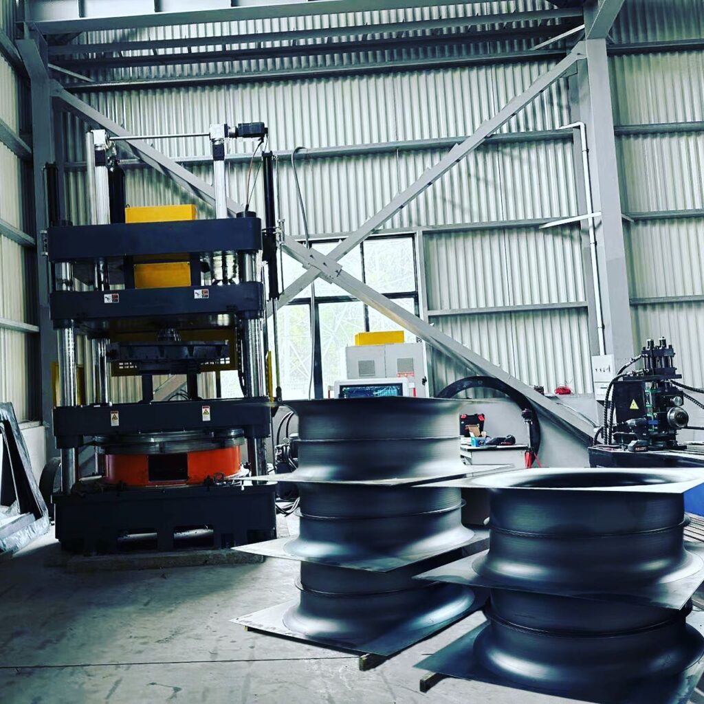
A hydraulic deep drawing press is used due to its versatility in sheet metal and plastic molding. Pressing forces, ram stroke, and speeds are adjustable. Further economic aspects are developed through the design of the drive and the use of modern control technology. Hydraulic units of deep drawing presses that embody tailor-made systems with high demands on the press technology are developed by internationally recognized specialists.
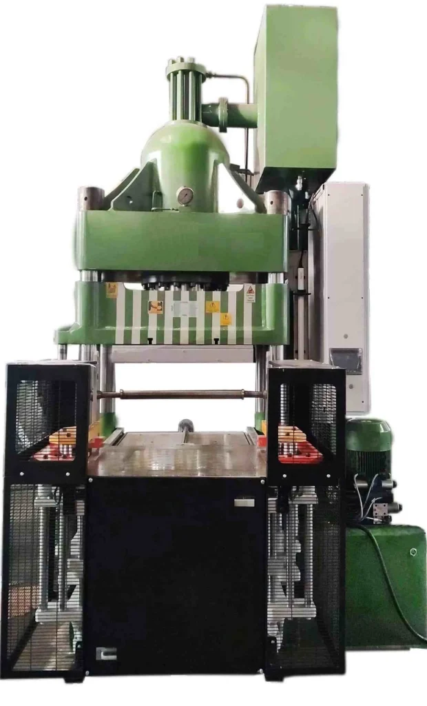
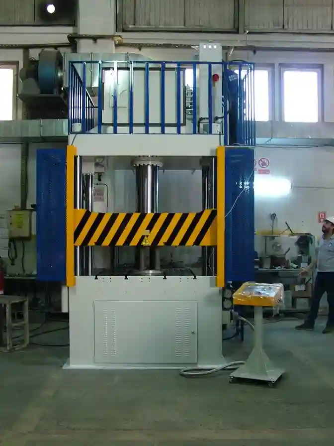
A deep drawing press is a type of machine used in the manufacturing industry to form sheet metal into shapes using a process known as deep drawing. The press is designed to exert a high amount of force on the metal in order to shape it into the desired form. The main parts of a typical deep drawing press include:
- Frame: The frame is the main structural component of the press, which provides support for all of the other parts.
- Bed: The bed is the flat surface on which the metal sheet is placed for processing. It must be sturdy and level to ensure proper operation of the press.
- Ram: The ram is the movable component of the press that exerts a force on the metal sheet. It is driven by a hydraulic or mechanical system.
- Blankholder: The blank holder is a device that holds the metal sheet in place during the deep drawing process, preventing it from slipping or wrinkling.
- Die: The die is the tool that is used to shape the metal sheet. It is typically made of hardened steel and can be customized to create a specific shape.
- Punch: The punch is the component of the press that presses the metal sheet into the die, creating the desired shape.
- Hydraulic System: The hydraulic system provides the power necessary to operate the press. It typically consists of a hydraulic pump, a reservoir, and a series of valves and cylinders.
- Control Panel: The control panel is used to monitor and adjust the various settings of the press, such as the force applied, the speed of operation, and the position of the ram.
Overall, a deep drawing press is a complex machine that requires precise engineering and careful operation to ensure proper functioning. Each of its main parts plays an important role in the deep drawing process, and the press must be properly maintained to ensure long-term performance and reliability.
Hydraulic deep drawing presses are critical tools in modern manufacturing, enabling the production of complex metal components with precision and efficiency. These machines use hydraulic power to form metal sheets into desired shapes, offering unmatched versatility in various industries, from automotive to aerospace.
At its core, a hydraulic deep drawing press applies controlled pressure to metal blanks, forcing them to flow into a die cavity and create intricate parts. The process is known for its ability to produce deep, seamless shapes without compromising material strength. By relying on hydraulic power, these presses deliver consistent force throughout the entire stroke, providing greater control over the forming process. This advantage is particularly important for parts with complex geometries, varying thicknesses, or materials with unique forming characteristics.
For potential buyers, understanding the significance of a hydraulic deep drawing press is crucial. These machines are ideal for manufacturers seeking high-quality, precision-formed products across various applications. Whether you are producing automotive parts, household appliances, or aerospace components, hydraulic deep drawing presses offer a range of capabilities that make them indispensable in the production line.
Why Choose Hydraulic Deep Drawing Presses?
Hydraulic presses are a preferred choice for deep drawing processes due to their superior ability to control pressure and speed, as well as their flexibility in working with different materials and shapes. Unlike mechanical presses that rely on fixed stroke lengths and speeds, hydraulic presses can be adjusted to meet specific forming needs, making them suitable for a wide range of applications. This precision enables manufacturers to achieve consistent results, reduce material waste, and improve overall production efficiency.
In industries where metal forming plays a vital role in product design and functionality, hydraulic presses stand out for their ability to produce complex parts with high repeatability and minimal defects. They are commonly used to create items like car body panels, kitchen sinks, pressure vessels, and fuel tanks—all products that require precise shaping and reliable performance.
Moreover, with increasing demands for lightweight materials and fuel-efficient designs, especially in the automotive and aerospace sectors, hydraulic deep drawing presses are becoming even more valuable. Their ability to handle aluminum, stainless steel, and high-strength alloys makes them ideal for manufacturers aiming to meet these evolving market requirements.
2. Working Principles and Technology
The core of a hydraulic deep drawing press lies in its reliance on hydraulic power to apply pressure and shape metal into specific forms. The process is highly precise and enables the production of complex, deep-drawn parts that mechanical presses often struggle to achieve. To understand how a hydraulic deep drawing press works, it’s essential to grasp the basic principles of hydraulic technology and how it is applied to the deep drawing process.
Basic Mechanism of Hydraulic Deep Drawing Presses
Hydraulic presses operate based on Pascal’s Law, which states that pressure applied to a confined fluid is transmitted equally in all directions. This principle is used to generate immense force by exerting pressure on hydraulic fluid within a confined system. In the case of deep drawing presses, this pressure is directed to a hydraulic cylinder, which moves the press ram vertically. The ram applies force to a metal blank, pushing it into a die cavity, forming the required shape.
The process begins when a blank holder secures the metal sheet in place, ensuring it does not wrinkle during the operation. As the press ram moves downwards, the punch forces the metal into the die cavity. The hydraulic system allows for precise control over the force, ensuring that the metal flows smoothly into the die without tearing or cracking.
Hydraulic deep drawing presses are distinguished by their ability to provide constant pressure throughout the forming process. Unlike mechanical presses, which generate force based on momentum and reach peak force at the bottom of the stroke, hydraulic presses apply continuous force throughout the entire stroke length. This makes them ideal for drawing deep, intricate shapes with even material distribution and minimal defects.
Hydraulic System Functionality: Fluid Power Principles
The hydraulic system consists of several critical components that work together to generate and control the force needed for deep drawing. Key elements include:
- Hydraulic Pump: This component converts mechanical energy into hydraulic energy by pressurizing the hydraulic fluid. Pumps can vary in design, with gear pumps, vane pumps, and piston pumps being common in hydraulic press systems. The type of pump used affects the flow rate, pressure capacity, and efficiency of the system.
- Hydraulic Fluid: The pressurized medium that transmits force from the pump to the hydraulic cylinders. Maintaining the correct fluid levels and quality is crucial for smooth operation and consistent force output. The fluid also acts as a lubricant for internal parts, reducing wear and tear.
- Hydraulic Cylinder: The component that converts hydraulic energy into linear mechanical force, allowing the press to perform the deep drawing action. Hydraulic cylinders consist of a piston inside a barrel, which moves in response to the pressurized fluid.
- Pressure Control Valves: These regulate the pressure within the system, ensuring that the desired force is applied during the deep drawing process. Overpressure can damage the press or the part being formed, so these valves maintain operational safety and precision.
- Reservoir: Stores the hydraulic fluid when not in use and helps in temperature control by allowing the fluid to cool between cycles. Proper reservoir management ensures long-term system efficiency and prevents overheating.
The Deep Drawing Process
Deep drawing is a metal forming technique that involves the transformation of a flat metal sheet (or blank) into a hollow object with depth greater than its diameter. This process is typically carried out in several stages to prevent material failure, such as tearing or wrinkling, especially for deep or complex shapes. The main stages include:
- Clamping: The metal blank is securely clamped between a blank holder and the die.
- Punching: The hydraulic ram, equipped with a punch, presses the metal into the die cavity, forcing it to take the die’s shape.
- Material Flow: As the punch pushes the blank into the die, the metal flows radially inward. The hydraulic press’s control over force and speed ensures that this flow happens smoothly, without stretching the material too thin or causing defects.
- Release and Ejection: Once the part has been formed, the punch retracts, and the newly formed part is ejected from the die.
This process can be repeated multiple times for particularly deep parts, where intermediate stages (known as redrawing) might be necessary. These stages allow the metal to progressively form deeper shapes without inducing stress or weakening the material.
Factors Affecting Precision and Performance
Several factors impact the precision and performance of hydraulic deep drawing presses, including:
- Pressure Control: The ability to finely adjust pressure during the drawing process is one of the key advantages of hydraulic presses. This ensures a smooth flow of material and reduces the likelihood of defects.
- Speed Regulation: Unlike mechanical presses that operate at fixed speeds, hydraulic presses allow for variable speed control, offering flexibility in working with different materials and drawing depths.
- Force Distribution: Hydraulic presses maintain a consistent force distribution, which is crucial for creating uniform parts. This is especially important when working with thin metals or when deep drawing shapes with intricate details.
- Temperature and Lubrication: Heat can accumulate in the press and affect both the hydraulic fluid and the metal being formed. Effective lubrication and fluid management are critical to prevent overheating and ensure consistent operation.
Hydraulic deep drawing presses are an essential piece of equipment in the manufacturing industry, utilized for forming sheet metal into desired shapes through a process called “deep drawing.” These presses use hydraulic fluid to exert force on a punch, which then presses a metal blank into a die, creating complex geometries with high precision.
The deep drawing process allows for the creation of cylindrical, box-shaped, and irregularly shaped components with a high degree of consistency. Hydraulic presses are favored for their ability to exert constant force over long distances, making them ideal for deep drawing processes that involve high-strength materials.
Historically, deep drawing presses were mechanical, relying on mechanical linkages to drive the punch. The evolution to hydraulic systems brought greater control over the force and speed of the press, leading to improvements in precision, safety, and operational efficiency. This shift has cemented hydraulic deep drawing presses as the technology of choice for industries requiring high-quality, complex metal forming.
Hydraulic deep drawing presses are widely used in automotive, aerospace, consumer electronics, medical devices, and more. Their ability to handle high-strength materials and produce intricate, precise shapes makes them invaluable in industries requiring both durability and complex designs.
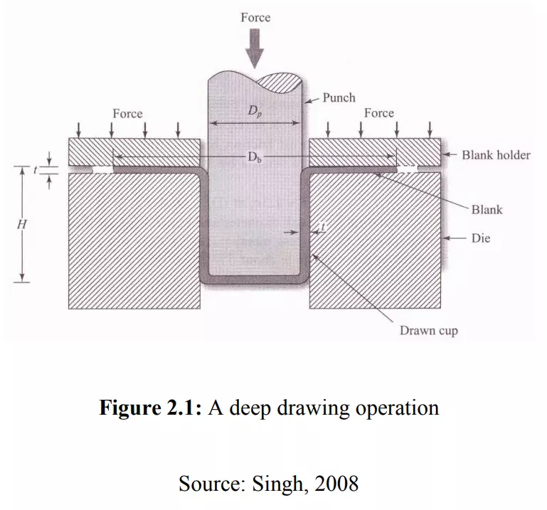
Basic Principles of Deep Drawing Process

Deep drawing is a metal-forming process in which a flat sheet metal blank is radially drawn into a forming die by the mechanical action of a punch. The result is a part with a depth that exceeds its diameter, such as a cup or can.
The deep drawing process can be divided into several key stages:
- Blanking: The flat metal sheet is cut into a blank, typically a circular shape.
- Drawing: The blank is placed over a die cavity, and the punch pushes the blank into the die, forming the desired shape.
- Redrawing: If the depth of the part is greater than what can be achieved in a single stroke, the part may be redrawn through a series of dies to gradually achieve the final shape.
- Trimming and Finishing: After the deep drawing process, excess material is trimmed, and the part may undergo finishing processes to smooth out any rough edges.
The main characteristic of deep drawing is that the material undergoes plastic deformation, which is necessary for forming complex, deep geometries. The process requires careful control of various parameters, including the force applied, the speed of the punch, and the quality of the material to avoid common defects like tearing, wrinkling, or excessive thinning.
Hydraulic deep drawing presses play a critical role in this process. The hydraulic system provides consistent pressure, which is essential for achieving uniform part dimensions. Unlike mechanical presses, where the force can fluctuate, hydraulic presses offer precise control over the pressure applied during the drawing process, allowing for more accurate results. This is particularly important in high-volume production environments where consistency and quality are paramount.
Components of a Hydraulic Deep Drawing Press
The hydraulic deep drawing press is composed of several critical components, each playing a crucial role in the successful operation of the machine. Understanding these components is essential for optimizing the performance of the press and ensuring that the deep drawing process is both efficient and accurate.
- Hydraulic Cylinder: The hydraulic cylinder is the heart of the press, responsible for generating the force necessary for deep drawing. Hydraulic fluid is pumped into the cylinder, which moves the piston and creates the downward force needed to push the punch into the die.
- Punch and Die: The punch and die are the tools used to shape the metal blank. The punch is attached to the hydraulic cylinder and presses the blank into the die, which has the shape of the final part. The design and precision of the punch and die are critical for producing high-quality parts.
- Pressure System: The hydraulic pressure system controls the flow and pressure of the hydraulic fluid. It includes components such as pumps, valves, and reservoirs, which work together to ensure the correct amount of pressure is applied throughout the deep drawing process.
- Control System: Modern hydraulic deep drawing presses are equipped with computerized control systems that allow operators to precisely control the speed, force, and timing of the press. These systems also provide real-time feedback on press performance, allowing for adjustments to be made on the fly.
- Safety Mechanisms: Hydraulic presses are equipped with safety features to protect operators and equipment. These include emergency stop buttons, pressure relief valves, and guarding systems that prevent accidental contact with moving parts.
Each of these components plays a crucial role in ensuring that the hydraulic deep drawing press operates smoothly and efficiently. The integration of advanced control systems and safety mechanisms has made modern hydraulic presses more reliable and user-friendly than ever before.
Hydraulic System and Working Mechanism
At the core of any hydraulic deep drawing press is the hydraulic system, which powers the press and controls the force applied during the deep drawing process. Understanding how this system works is essential for comprehending the advantages that hydraulic deep drawing presses offer in terms of precision, control, and adaptability.
How Hydraulic Systems Work
Hydraulic systems operate based on Pascal’s Law, which states that when a fluid is placed under pressure in a confined space, the pressure is transmitted equally in all directions. This principle allows hydraulic systems to generate large amounts of force with minimal input. In a hydraulic deep drawing press, a hydraulic pump is used to pressurize hydraulic fluid, which then moves through a series of valves and pipes to reach the hydraulic cylinder. The pressurized fluid exerts force on a piston within the cylinder, which in turn pushes the punch against the metal blank.
A key advantage of hydraulic systems is their ability to apply constant pressure over the full stroke of the piston. This ensures uniform force throughout the deep drawing process, allowing for more consistent and accurate parts compared to mechanical presses, where the force may vary at different points of the stroke.
Key Components of the Hydraulic System
The hydraulic system of a deep drawing press includes several important components that work together to ensure smooth and reliable operation:
- Hydraulic Fluid: The hydraulic fluid is the medium through which force is transmitted in the system. Typically, specialized hydraulic oils are used because they possess the right combination of viscosity, temperature stability, and lubricating properties. The quality and maintenance of hydraulic fluids are critical since contaminants or degraded fluids can lead to inefficiencies and even damage the system.
- Hydraulic Pump: The pump is responsible for generating pressure in the system by forcing the hydraulic fluid through the pipes and into the cylinder. There are different types of pumps used in hydraulic presses, including gear pumps, vane pumps, and piston pumps. The choice of pump depends on the specific requirements of the press, such as the pressure needed and the speed of operation.
- Valves and Regulators: Valves are used to control the flow of hydraulic fluid within the system, allowing the operator to precisely regulate the amount of pressure applied to the cylinder. Regulators are also used to ensure that the pressure does not exceed safe limits, preventing damage to the press and maintaining a safe working environment.
- Hydraulic Cylinder: The hydraulic cylinder is the component that converts the fluid pressure into mechanical force. The cylinder contains a piston that moves when the fluid is pressurized, creating the motion needed to drive the punch into the metal blank. Cylinders are typically made from high-strength materials to withstand the enormous forces generated during the deep drawing process.
- Pressure Accumulators: In some hydraulic systems, accumulators are used to store hydraulic fluid under pressure, which can then be released when needed. This allows for more efficient operation and provides a buffer to handle fluctuations in demand for pressure.
Working Mechanism of a Hydraulic Deep Drawing Press
The operation of a hydraulic deep drawing press can be broken down into several key stages:
- Initial Setup: Before the press is operated, the blank (a flat sheet of metal) is prepared and placed over the die. The die is mounted onto the lower bed of the press, while the punch is attached to the piston of the hydraulic cylinder.
- Pressure Build-up: Once the machine is set up, hydraulic fluid is pumped into the system, building pressure in the hydraulic cylinder. This pressure is carefully controlled to ensure that the correct amount of force is applied during the drawing process.
- Drawing Process: The press is activated, causing the hydraulic cylinder to drive the punch downward. As the punch moves into the die, it forces the blank into the desired shape. The constant pressure provided by the hydraulic system ensures that the blank deforms evenly, reducing the likelihood of defects such as wrinkling or tearing.
- Reversing the Cycle: After the drawing process is complete, the hydraulic system reverses the flow of fluid, retracting the piston and lifting the punch out of the die. The completed part is then removed, and the press is ready for the next cycle.
Advantages of Hydraulic Systems in Deep Drawing Presses
- Precise Control of Force: Hydraulic systems provide highly precise control over the force applied during the drawing process. Operators can adjust the pressure based on the specific requirements of each job, ensuring that the right amount of force is applied for different materials and part geometries.
- Constant Pressure Throughout Stroke: One of the key benefits of hydraulic presses is that they can maintain constant pressure throughout the entire stroke of the piston. This results in more uniform part quality and reduces the risk of defects compared to mechanical presses.
- Adaptability and Flexibility: Hydraulic presses are highly adaptable and can be adjusted to perform a wide range of tasks. For example, operators can modify the stroke length, pressure, and speed to accommodate different materials, part shapes, and production volumes.
- Reduced Wear and Tear: The smooth operation of hydraulic systems results in less wear and tear on the machine components compared to mechanical presses, where the high impact forces can cause damage over time. This reduces maintenance costs and extends the lifespan of the press.
A hydraulic press is a mechanical device that uses a hydraulic cylinder to generate a compressive force. It operates based on Pascal’s Law, which states that pressure applied to a confined fluid is transmitted equally in all directions. This principle allows hydraulic presses to exert significant force with minimal input, making them essential tools in industries requiring high-pressure applications.
A single-acting hydraulic press uses hydraulic pressure to move the piston in one direction, typically the downward or compressive stroke. After the press completes this action, the piston returns to its original position using an external force such as a spring or the weight of the cylinder. This differs from a double-acting hydraulic press, where hydraulic pressure is applied in both the forward and return strokes.
The simplicity and cost-effectiveness of single-acting hydraulic presses make them ideal for a variety of applications, including small to medium-scale production, metal fabrication, and mechanical testing. These presses are widely used in industries such as automotive, aerospace, manufacturing, and even laboratories for precision tasks.
The core advantage of a single-acting hydraulic press lies in its simplicity. Fewer moving parts and a straightforward design reduce both the initial cost and ongoing maintenance requirements. However, the trade-off is that the press lacks the stroke control and power range of more complex systems, limiting its effectiveness in higher-end or more precise applications.
How Single-Acting Hydraulic Presses Work
The fundamental operation of a single-acting hydraulic press relies on Pascal’s Law, which underpins all hydraulic systems. According to this principle, when a force is applied to a fluid inside a closed system, the pressure is transmitted evenly throughout the fluid. In a hydraulic press, this means that the force generated by a pump acting on a small volume of hydraulic fluid can be magnified to create a much larger output force.
Key Components of a Single-Acting Hydraulic Press:
- Cylinder and Piston: The hydraulic cylinder contains a piston that moves up and down. In a single-acting press, hydraulic fluid forces the piston downwards, creating the press action.
- Hydraulic Pump: The pump generates pressure within the hydraulic system, pushing the fluid into the cylinder to drive the piston.
- Reservoir: This stores hydraulic fluid, which is pumped into the cylinder during operation.
- Valves: Control the flow of hydraulic fluid, directing it into the cylinder for the pressing stroke.
- Return Mechanism: In single-acting systems, this is usually a spring or gravitational force that returns the piston to its original position after the pressing action.
Pressing and Return Process:
- Pressing: When the press operator activates the system, hydraulic fluid is pumped into the cylinder. The increase in pressure forces the piston downward, applying force to the material placed under the press head. The force can range from several tons to hundreds of tons, depending on the press’s specifications.
- Return Stroke: Once the pressing action is complete, the external force—usually a spring or gravity—returns the piston to its starting position. Unlike double-acting presses, where hydraulic pressure can control both strokes, single-acting presses rely on this mechanical or natural return.
Advantages and Limitations:
- Advantages: Single-acting presses are simple, affordable, and easy to maintain. They are ideal for tasks that do not require precise control over the return stroke or where the pressing force is the primary concern.
- Limitations: The primary limitation is the lack of control over the piston’s return stroke, which can make single-acting presses less suited to precision applications. Additionally, since only one stroke is powered, these presses are less efficient in tasks requiring continuous motion or high-speed operation.
Types of Single-Acting Hydraulic Presses
Single-acting hydraulic presses come in several varieties, each suited to different applications and operational needs.
1. Manually Operated Hydraulic Presses:
These presses are powered by a hand-operated pump, which provides the hydraulic pressure needed to move the piston. They are ideal for small-scale applications or environments where electricity is not available. These presses are portable and commonly used in repair shops, garages, or remote field locations. Their affordability and ease of use make them popular for light-duty tasks like pressing bearings or removing shafts.
2. Electric-Powered Hydraulic Presses:
Electric-powered hydraulic presses use an electric motor to drive the hydraulic pump, offering greater efficiency and consistency compared to manual models. These presses are suitable for more intensive industrial applications where higher force or faster operation is required. They are commonly found in manufacturing plants, where they can be integrated into production lines for repetitive tasks such as stamping, forging, or cutting.
3. Air-Driven Hydraulic Presses:
In these systems, compressed air is used to generate hydraulic pressure. They are commonly used in industrial environments where compressed air is readily available. Air-driven hydraulic presses are often employed in applications where speed and convenience are critical, and they offer a middle ground between manually operated and electric-powered presses in terms of power and cost.
Applications of Each Type:
- Manually Operated: Ideal for low-volume tasks, repair work, or environments lacking electrical infrastructure.
- Electric-Powered: Suitable for continuous, heavy-duty applications in factories and production environments.
- Air-Driven: Often used in automotive workshops and for lighter industrial tasks where compressed air is available.
Applications of Single-Acting Hydraulic Presses
Single-acting hydraulic presses are versatile tools used across a wide range of industries for different applications.
1. Metal Forming and Fabrication:
In the metalworking industry, hydraulic presses are used to shape, bend, punch, and cut metal sheets and components. Single-acting presses are especially useful in tasks where the return stroke is less critical, such as metal stamping or bending. These presses are commonly used in fabrication shops, tool and die manufacturing, and custom metalwork projects.
2. Press Fitting and Assembly Tasks:
Single-acting presses are commonly employed in press fitting, where parts are mechanically forced together using high pressure. This includes tasks such as pressing bushings, bearings, gears, and other components into place. These presses are widely used in the automotive industry for assembly operations, as well as in machinery and equipment manufacturing.
3. Material Testing and Laboratory Uses:
In laboratories, single-acting hydraulic presses are often used for testing materials under compressive force. For example, engineers and scientists may use hydraulic presses to measure the compressive strength of materials like concrete, metals, or plastics. The simplicity of single-acting presses makes them ideal for controlled experiments where large forces are required without complex control systems.
4. Automotive and Aerospace Industries:
In the automotive sector, single-acting hydraulic presses play a crucial role in various assembly and maintenance tasks, such as pressing in bushings, removing bearings, and straightening parts. Their use extends to aerospace industries for tasks such as forming lightweight components, shaping metal parts, or assembling intricate systems that require precise force application.
Examples of Practical Applications:
- Metal Stamping: Single-acting presses are used to punch or stamp metal parts for various industries, including automotive and electronics.
- Bearing Installation: Presses ensure that bearings are seated correctly without causing damage to delicate components.
- Cutting and Trimming: Hydraulic presses can be used to cut metal, plastic, or composite materials, making them essential in production environments.
Advantages of Single-Acting Hydraulic Presses
Single-acting hydraulic presses have several advantages, making them a popular choice in a variety of applications.
1. Simplicity and Cost-Effectiveness:
Due to their basic design, single-acting hydraulic presses are more affordable than their double-acting counterparts. They have fewer moving parts and require less complex control systems, reducing both the upfront cost and the likelihood of mechanical failure. This makes them ideal for smaller operations or businesses looking for cost-effective solutions.
2. Efficiency in Force Delivery:
Despite their simplicity, single-acting hydraulic presses can deliver tremendous force, making them suitable for heavy-duty tasks like metal forming or assembly. They can generate forces ranging from a few tons to several hundred tons, depending on the size and type of the press, enabling them to handle a wide range of materials and tasks.
3. Reduced Maintenance:
With fewer components, single-acting presses are easier and less costly to maintain. Routine maintenance is generally limited to inspecting seals, checking hydraulic fluid levels, and ensuring that the return mechanism (spring or gravity) is functioning properly.
4. Portability and Space Efficiency:
Single-acting presses are typically more compact than double-acting presses, making them easier to move and install in smaller workspaces. This portability is especially valuable in environments where space is limited, such as small workshops or laboratories.
Challenges and Limitations of Single-Acting Hydraulic Presses

While single-acting hydraulic presses offer many benefits, they also have certain limitations that can affect their performance in specific applications.
1. Limited Stroke Control and Precision:
Because the return stroke is not powered by hydraulics, single-acting presses lack the precise control over the piston’s movement during the return phase. This makes them less suitable for applications requiring fine control of both the forward and return strokes.
2. External Force Required for Return Stroke:
The reliance on springs or gravity for the return stroke introduces limitations. Springs can wear out over time, reducing the efficiency of the press, and gravitational return may be too slow for certain high-speed applications.
3. Power Limitations:
Single-acting presses typically have less power and speed compared to double-acting systems. For tasks requiring high force or rapid cycling, a double-acting press may be more appropriate.
4. Environmental Considerations:
Hydraulic systems, including single-acting presses, can pose environmental risks if not properly maintained. Leaking hydraulic fluid, for instance, can cause environmental contamination, making proper maintenance and disposal of used fluids critical.
Maintenance and Safety Considerations
Proper maintenance and adherence to safety protocols are essential to ensure the safe and efficient operation of single-acting hydraulic presses.
Maintenance Procedures:
- Hydraulic Fluid Levels: Regularly check and maintain the hydraulic fluid to ensure smooth operation. Low fluid levels can reduce press efficiency and lead to mechanical wear.
- Seals and Hoses: Inspect seals and hoses for wear and tear, as leaks can cause pressure loss and reduce the effectiveness of the press.
- Return Mechanism: Check the spring or gravity-based return system for signs of fatigue or failure. Over time, springs may lose tension, reducing the effectiveness of the return stroke.
Safety Protocols:
- Personal Protective Equipment (PPE): Operators should wear appropriate PPE, including safety goggles, gloves, and hearing protection.
- Proper Training: Ensure that all operators are trained in the correct use of the press and are aware of potential hazards.
- Emergency Stops: Hydraulic presses should be equipped with emergency stop buttons to allow operators to quickly halt the machine in case of malfunction or danger.
Future of Single-Acting Hydraulic Presses
Advancements in technology are opening new possibilities for single-acting hydraulic presses. As industries evolve, the demand for more efficient and eco-friendly machinery is growing.
1. Advancements in Hydraulic Technology:
Innovations in hydraulic systems are leading to more efficient and powerful single-acting presses. For instance, new hydraulic fluids with better thermal stability and lower environmental impact are being developed, reducing the ecological footprint of hydraulic systems.
2. Energy Efficiency Improvements:
Modern hydraulic presses are being designed with energy efficiency in mind. Enhanced pump designs, variable speed motors, and more efficient control systems are reducing energy consumption and operational costs.
3. Integration with Automation:
The future of hydraulic presses lies in their integration with automated and smart systems. Automated single-acting presses equipped with sensors and computer control systems can adjust force, speed, and stroke in real time, enhancing precision and adaptability.
4. Future Applications and Innovations:
As industries continue to demand more from hydraulic systems, single-acting presses are likely to be used in new applications such as additive manufacturing (3D printing) and precision engineering. The increasing focus on sustainability may also drive the development of greener, more energy-efficient presses.
Introduction to Double-Acting Hydraulic Presses
Hydraulic presses are mechanical devices that use fluid pressure to generate significant force, commonly employed in industries where large-scale pressing, forming, or molding is required. They operate on Pascal’s Law, which states that pressure applied to a fluid in a confined space is transmitted equally in all directions. This principle allows hydraulic presses to amplify force, making them crucial in metalworking, manufacturing, automotive industries, and beyond.
A double-acting hydraulic press differs from its single-acting counterpart in that it applies hydraulic pressure in both directions—both for the pressing stroke and the return stroke. In contrast, a single-acting press relies on external forces, like springs or gravity, for the return motion, which limits control and precision.
The use of double-acting hydraulic presses has revolutionized several industrial processes due to the enhanced control and precision they offer. With powered movement in both directions, these presses are capable of handling more complex and demanding tasks, such as deep drawing, forging, or any process where high precision and consistent force are essential. These presses are widely used in automotive production, aerospace manufacturing, and large-scale industrial operations.
How Double-Acting Hydraulic Presses Work
Double-acting hydraulic presses function based on hydraulic principles, which utilize fluid power to amplify force. The critical difference from single-acting presses is that double-acting presses can apply hydraulic pressure in both the pressing and return strokes. This provides enhanced control and versatility.
Core Components of a Double-Acting Hydraulic Press:
- Cylinder and Piston: A double-acting press has a hydraulic cylinder with a piston that moves in two directions. Hydraulic fluid is directed into the cylinder on either side of the piston to control both the downward and upward strokes.
- Hydraulic Pump: The hydraulic pump provides pressure by moving hydraulic fluid into the cylinder. In double-acting presses, the pump must be capable of routing the fluid to either side of the piston, depending on whether it is the pressing or return stroke.
- Valves and Control Systems: Double-acting presses require more sophisticated valve systems to control the flow of hydraulic fluid. These valves direct fluid pressure to either side of the piston, enabling the precise control of both strokes.
- Power Source: These presses can be powered by manual pumps, electric motors, or pneumatic systems, depending on the scale and application of the press.
The Pressing and Return Strokes:
- Pressing Stroke: The hydraulic pump directs fluid into the top of the cylinder, pushing the piston downward. This downward force can range from a few tons to hundreds of tons, depending on the press’s size and design. The press head applies this force to the material being processed, whether it’s for stamping, molding, or cutting.
- Return Stroke: After the pressing operation, hydraulic pressure is redirected to the bottom of the piston. This lifts the piston back to its starting position, ensuring precise and controlled movement. The ability to hydraulically control both strokes eliminates the reliance on gravity or springs, allowing for faster cycle times and more complex tasks.
Precision and Control:
The ability to control both strokes of the piston provides greater accuracy in industrial processes. Unlike single-acting presses, where the return stroke can vary in speed and efficiency, double-acting presses offer consistent performance across all movements. This precision makes them ideal for complex forming processes, deep drawing, and precision cutting operations, where both the force and the return timing must be tightly controlled.
Types of Double-Acting Hydraulic Presses
Double-acting hydraulic presses come in various forms, each tailored for specific industrial applications. Here are some of the main types:
1. Manual Double-Acting Hydraulic Presses:
Manual versions of double-acting presses are powered by hand-operated hydraulic pumps. These are typically used in small workshops or repair facilities where tasks like pressing, bending, or assembling components do not require extensive automation. These presses are portable, cost-effective, and often used in low-production environments.
2. Electric-Powered Double-Acting Hydraulic Presses:
Electric-powered double-acting presses are more common in industrial settings where high force and consistent operation are required. The hydraulic pump is driven by an electric motor, allowing for automated control of both strokes. These presses are essential for high-volume operations, such as metal stamping, die forming, and precision cutting. The electric-powered system allows for greater precision, repeatability, and faster cycle times.
3. Pneumatic Double-Acting Hydraulic Presses:
Pneumatic-powered double-acting presses use compressed air to drive the hydraulic fluid in both strokes. These presses are favored in industries where pneumatic systems are already integrated into the production environment, such as in automotive assembly lines. Pneumatic systems provide rapid action, and the integration with hydraulics ensures the generation of high forces, making them suitable for mid-sized industrial applications.
4. Specialized Double-Acting Presses:
Some double-acting hydraulic presses are designed for specific applications, such as hydraulic press brakes used in bending and shaping metal sheets. These presses provide precise control over the angle and force applied, making them ideal for custom metal fabrication. Another example includes forging presses, where high tonnage and precise control are required to shape metal components.
Applications of Double-Acting Hydraulic Presses
Double-acting hydraulic presses are widely employed across a variety of industries due to their versatility and ability to handle complex tasks with precision. Here are some of the key applications:
1. Metal Forming and Deep Drawing:
One of the primary uses of double-acting hydraulic presses is in metal forming, particularly deep drawing. Deep drawing is a manufacturing process where a sheet metal blank is radially drawn into a forming die by the mechanical action of a punch. Double-acting presses provide the precise control necessary to form complex shapes in metals like aluminum, steel, and copper without cracking or deforming the material.
2. Punching, Forging, and Die Forming:
In punching and forging operations, double-acting presses apply controlled force to deform or cut metal parts. This is commonly used in the automotive and aerospace industries, where high-strength materials are forged into critical components like gears, axles, and structural parts. The ability to control both the pressing and return strokes ensures consistent quality and reduces the risk of material damage.
3. Composite Material Molding:
As industries increasingly adopt composite materials, double-acting hydraulic presses have become essential for forming and molding these materials. Composites, such as carbon fiber or fiberglass, require careful handling during the molding process to maintain their strength and durability. Double-acting presses allow for precise pressure application during both the pressing and release phases, making them indispensable in industries like aerospace and automotive, where lightweight, high-strength components are essential.
4. Automotive and Aerospace Industries:
The automotive industry relies heavily on double-acting hydraulic presses for the production of body panels, frames, and engine components. The precision and repeatability of these presses ensure that every part is manufactured to exact specifications. In the aerospace industry, where weight, strength, and safety are critical, double-acting presses are used to form lightweight components like aircraft skin panels, structural parts, and engine elements.
5. Examples of Industrial Applications:
- Automotive: Deep drawing for body panels, stamping parts like hoods, doors, and roofs.
- Aerospace: Forming of lightweight metal and composite parts for aircraft and spacecraft.
- Heavy Machinery: Forging of large components for construction equipment and industrial machinery.
- Consumer Electronics: Precision forming of metal casings and components.
Advantages of Double-Acting Hydraulic Presses
Double-acting hydraulic presses offer several significant advantages that make them indispensable in many industries.
1. Precise Control Over Both Strokes:
The ability to apply hydraulic force in both the pressing and return strokes gives double-acting presses greater control over the entire operation. This precision is particularly valuable in tasks that require consistent force and motion, such as deep drawing, forging, and punching. Both strokes can be finely adjusted to meet the exact requirements of the material and application, leading to superior product quality.
2. Higher Efficiency in Repetitive Operations:
In manufacturing environments where tasks must be repeated at high speed, double-acting presses outperform single-acting models. Since both the press and return strokes are powered, cycle times are faster, and operators have more control over the movement of the piston, which boosts productivity in high-volume production lines.
3. Versatility in Complex Tasks:
Double-acting presses are incredibly versatile, able to handle a wide variety of materials and tasks. They can be used for pressing, forming, bending, cutting, and molding, which makes them highly adaptable to different industries and processes. Whether the task requires the shaping of metals, molding of composites, or assembly of mechanical components, these presses can be fine-tuned to meet the needs of the job.
4. Suitability for Heavy-Duty and Continuous Use:
Double-acting hydraulic presses are built for heavy-duty applications and continuous use in industrial settings. The ability to power both strokes ensures that even the toughest materials, such as steel and titanium, can be shaped and formed without compromising on speed or accuracy. Their robust design and advanced control systems make them ideal for industries where durability and long-term performance are critical.
Challenges and Limitations of Double-Acting Hydraulic Presses
Despite their advantages, double-acting hydraulic presses also come with challenges and limitations that must be considered before implementation.
1. Higher Cost and Complexity:
Double-acting hydraulic presses are generally more expensive than single-acting presses due to their more complex design and the additional control systems required to power both strokes. This can make them less appealing for small-scale operations or businesses with tight budgets.
2. Increased Maintenance Requirements:
With more moving parts and components to manage, double-acting presses require more frequent and thorough maintenance than their single-acting counterparts. Components like seals, valves, and hydraulic lines must be regularly inspected and serviced to prevent leaks and ensure optimal performance. This adds to the operational costs over the lifespan of the machine.
3. Space and Energy Requirements:
Double-acting hydraulic presses tend to be larger and consume more energy than simpler presses. This means they require more space and have higher energy costs, which can be a limiting factor in smaller workshops or facilities with limited energy resources.
4. Specialized Training and Safety Considerations:
Operators of double-acting hydraulic presses must be thoroughly trained to handle the complex control systems and high pressures involved. The increased force and speed of these presses mean that strict safety protocols must be followed to prevent accidents and equipment damage.
Maintenance and Safety Considerations
Proper maintenance and safety protocols are crucial for ensuring the long-term operation and safety of double-acting hydraulic presses.
Maintenance Procedures:
- Hydraulic Fluid Levels: Maintaining appropriate hydraulic fluid levels is essential for the proper operation of both strokes. Low fluid levels can result in uneven pressure distribution and lead to damage.
- Seal and Hose Inspections: Double-acting presses have more seals and hoses than single-acting models, which makes regular inspections critical. Leaks in these components can cause a loss of pressure, reduced efficiency, and safety hazards.
- System Pressure Checks: Monitoring and adjusting the system’s pressure levels ensures that the press operates within its designed parameters, preventing over-pressurization and component failure.
Safety Protocols:
- Operator Training: Given the complexity of double-acting presses, operators must be trained in their safe use. They should understand the machine’s control systems, emergency stop features, and troubleshooting procedures.
- Regular Inspections: Presses should be inspected regularly for signs of wear or malfunction. Safety devices like pressure relief valves and emergency stops should be tested to ensure they are functioning properly.
- Personal Protective Equipment (PPE): Operators should always wear appropriate PPE, including gloves, goggles, and ear protection, especially in high-noise environments.
Future Trends in Double-Acting Hydraulic Press Technology
As technology evolves, double-acting hydraulic presses are expected to undergo several advancements that will enhance their performance and broaden their applications.
1. Technological Advancements:
Innovations in hydraulic control systems, such as the integration of proportional valves and servo-driven pumps, are improving the precision and efficiency of double-acting presses. These systems allow for finer control of pressure and movement, resulting in higher-quality output and reduced material waste.
2. Energy Efficiency:
One of the key areas of development is the push for more energy-efficient hydraulic systems. With the increasing focus on sustainability, new technologies are emerging that reduce energy consumption, such as variable-speed pumps that adjust output based on demand. These advancements not only lower operational costs but also reduce the environmental impact of hydraulic presses.
3. Automation and Industry 4.0:
The integration of double-acting hydraulic presses with automation and smart manufacturing systems is another significant trend. By connecting presses to factory networks, manufacturers can monitor machine performance in real-time, predict maintenance needs, and optimize press cycles. This leads to increased productivity and minimizes downtime due to unexpected equipment failure.
4. Future Innovations:
Looking ahead, double-acting presses may see further improvements in force capacity, miniaturization for precise applications, and modular designs that allow presses to be easily reconfigured for different tasks. Additionally, advancements in green hydraulic fluids will reduce the environmental risks associated with hydraulic systems.
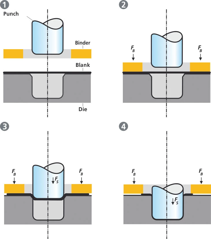
Triple Action Deep Drawing Press
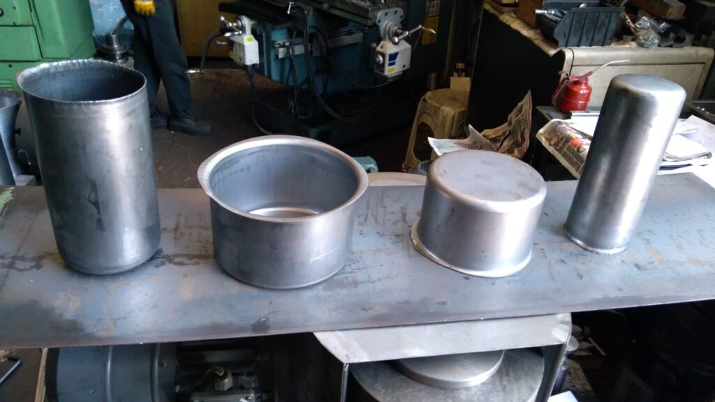
Deep drawing is a popular metal forming process used to shape flat sheet metal into cylindrical or box-like shapes. The process involves placing a metal blank over a die and pressing it into the die cavity with a punch. This transforms the flat blank into a three-dimensional shape, making it essential for producing components like automotive body panels, kitchen sinks, and various enclosures. The process can be repeated to achieve more complex shapes with greater depth, but the challenges increase as the material undergoes severe deformation.
A Triple Action Deep Drawing Press is a specialized machine designed to address the complexity of the deep drawing process. Unlike conventional single-acting or double-acting presses, a triple action press incorporates three independent force mechanisms:
- Blank Holder Action: Keeps the metal blank firmly in place, controlling material flow and preventing wrinkling.
- Punch Action: The primary force that shapes the blank by pushing it into the die.
- Ejector Action: Removes the finished part from the die after the drawing process is complete.
This triple-action mechanism provides greater control over the deep drawing process, allowing for the production of more complex shapes, with fewer defects, and better efficiency. The ability to control all three forces independently is particularly important in producing deep-drawn components for industries like automotive, aerospace, and consumer goods, where precision and quality are critical.
How Triple Action Deep Drawing Presses Work (500 words)
To understand how triple action deep drawing presses function, it’s essential to break down the mechanics of the deep drawing process and how each action contributes to shaping the material.
The Deep Drawing Process:
The deep drawing process transforms a flat metal blank into a three-dimensional component. The key stages include:
- Blank Placement: A flat metal blank is placed over the die cavity.
- Blank Holder Engagement: The blank holder clamps the blank around its edges, preventing movement or wrinkling during drawing.
- Punch Stroke: The punch moves downward, pressing the blank into the die cavity, forming the desired shape. This action stretches and deforms the material, thinning it in certain areas.
- Ejection: Once the part is formed, the ejector mechanism releases the part from the die, ready for the next cycle.
Components of a Triple Action Deep Drawing Press:
- Blank Holder: The blank holder is crucial in controlling material flow. Its force must be precisely regulated to avoid wrinkling, which can occur if the material is allowed to move too freely. At the same time, too much force from the blank holder can result in tearing.
- Punch: The punch is the main shaping tool. In triple-action presses, the punch force is adjustable, allowing for greater flexibility in handling different materials or thicknesses. As the punch presses the blank into the die, it forms the desired shape.
- Ejector: The ejector action ensures the formed part is smoothly removed from the die without causing damage to the component or slowing down the production process. The ejector often uses hydraulic or mechanical systems to push the part upward, releasing it from the die.
Key Advantages of the Triple Action System:
- Independent Control of Forces: One of the main benefits of triple action presses is that each force (blank holder, punch, ejector) can be independently controlled. This ensures optimal pressure at each stage, reducing the risk of defects such as wrinkling, tearing, or excessive thinning.
- Complex Shapes: By using all three actions in a coordinated manner, triple action presses can produce complex, deep-drawn components that would be difficult or impossible with a standard press.
- Minimized Defects: The precise control over material flow, punch pressure, and ejection force allows manufacturers to achieve higher-quality products with fewer defects, making triple-action presses ideal for high-precision industries.
Types of Triple Action Deep Drawing Presses
Triple action deep drawing presses come in various types, each suited to different applications and production environments. The main types include mechanical, hydraulic, and servo-electric presses.
1. Mechanical Triple Action Presses:
Mechanical triple action presses use mechanical linkages, cams, and gears to generate and control the forces required for the blank holder, punch, and ejector. These presses are known for their high speed and are commonly used in high-volume production environments, such as automotive manufacturing. However, they tend to offer less precision than hydraulic presses, making them less suitable for complex or precision deep drawing applications.
2. Hydraulic Triple Action Presses:
Hydraulic presses are the most common type of triple action deep drawing presses. These machines use hydraulic cylinders to apply force independently to the blank holder, punch, and ejector. Hydraulic presses are favored for their precision and the ability to control force and speed at every stage of the process. This makes them ideal for deep drawing applications that require complex shapes, deep draws, or challenging materials. Additionally, hydraulic systems can apply constant force throughout the entire stroke, providing a smooth and consistent draw.
3. Servo-Electric Triple Action Presses:
Servo-electric presses use electric motors to control the movement of the blank holder, punch, and ejector. These presses offer the highest level of precision and flexibility, allowing manufacturers to program specific force and speed profiles for different stages of the drawing process. Servo-electric presses are energy-efficient and offer precise control, making them ideal for applications requiring high precision, such as aerospace components and medical devices.
Comparison of Press Types:
- Mechanical: Best for high-speed, large-volume production; less precise.
- Hydraulic: Ideal for precision deep drawing, complex shapes, and variable materials; slower but more controlled.
- Servo-Electric: Offers the highest precision and flexibility, with energy efficiency; often used in highly specialized applications.
Applications of Triple Action Deep Drawing Presses
The versatility and precision of triple action deep drawing presses make them indispensable across a wide range of industries. Their ability to form complex, deep-drawn parts with minimal defects and high repeatability is a key reason for their widespread use.
1. Automotive Industry:
In the automotive sector, deep drawing presses are essential for producing a wide array of components, including body panels, fuel tanks, and engine components. Triple action presses are particularly well-suited for forming large, complex parts such as car doors, hoods, and trunk lids, which require high precision to ensure they meet the industry’s stringent safety and performance standards.
For example, the ability to control the blank holder force ensures that body panels are formed without wrinkling, a common defect in deep drawing. Additionally, the precision of triple-action presses allows for tight tolerances in the production of complex components like fuel tanks, which must be leak-proof and structurally sound.
2. Aerospace Industry:
In the aerospace industry, the demand for lightweight yet strong components is paramount. Triple action deep drawing presses are used to form aircraft skin panels, engine housings, and other structural components. The ability to control every aspect of the drawing process, including the exact force applied by the blank holder and punch, ensures that aerospace parts meet the high standards required for safety and performance.
Additionally, the triple action mechanism is crucial for working with materials like titanium, aluminum, and composites, which are commonly used in the aerospace industry but can be difficult to form due to their strength and tendency to crack under stress.
3. Consumer Goods:
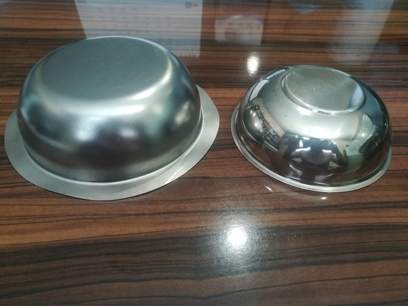
Triple action deep drawing presses are widely used to manufacture various consumer goods, particularly in the production of kitchenware (e.g., stainless steel sinks, pots, and pans) and household appliances (e.g., washing machine drums, microwave enclosures). The ability to form deep, complex shapes in materials like stainless steel or aluminum with smooth surfaces and minimal defects is essential for consumer products where aesthetics and durability are key selling points.
4. Industrial Containers and Enclosures:
Industries requiring industrial containers, cylindrical tanks, or enclosures for sensitive equipment often rely on triple action deep drawing presses. These presses allow for the formation of durable, uniform containers with precise dimensions, ensuring that they meet stringent industry standards for storage and protection.
Case Studies and Real-World Examples:
- Automotive: A major automotive manufacturer uses triple action presses to produce seamless body panels for luxury vehicles, ensuring high quality and eliminating the need for secondary finishing processes.
- Aerospace: Leading aerospace companies utilize triple action deep drawing presses for the production of lightweight, high-strength structural components, ensuring aircraft performance while reducing weight.
- Consumer Goods: A well-known kitchenware brand uses triple action presses to manufacture stainless steel cookware with flawless surfaces and uniform thickness, enhancing both performance and aesthetics.
Advantages of Triple Action Deep Drawing Presses
Triple action deep drawing presses offer numerous advantages that make them essential in industries requiring precision metal forming.
1. Enhanced Control Over the Deep Drawing Process:
One of the most significant advantages of a triple action press is the ability to independently control the blank holder, punch, and ejector forces. This precision control allows for adjustments throughout the deep drawing process, ensuring consistent material flow and reducing the risk of defects such as wrinkling, tearing, or excessive thinning.
2. Ability to Form Complex, Precise Shapes:
The precise control offered by triple action presses enables the formation of intricate shapes and deep-drawn components. The ability to fine-tune the force applied at each stage ensures that even challenging materials can be drawn without damage. This is especially important in industries like aerospace and automotive, where components must meet exacting standards for performance and safety.
3. Minimization of Defects:
Triple action presses significantly reduce common defects in the deep drawing process, such as wrinkling, cracking, and material thinning. The blank holder’s independent force ensures that the material is held securely, while the punch and ejector forces can be adjusted to optimize material flow. This results in higher-quality parts and reduced scrap, making triple action presses more efficient and cost-effective in large-scale production.
4. High Efficiency for Large-Scale Production:
Triple action presses are ideal for high-volume production, offering fast cycle times and repeatable precision. The automation of these presses allows for continuous operation, reducing downtime and increasing throughput. This efficiency is critical in industries where large quantities of parts must be produced quickly and to tight tolerances, such as automotive manufacturing.
Challenges and Limitations of Triple Action Deep Drawing Presses
Despite their numerous advantages, triple action deep drawing presses also present certain challenges and limitations.
1. High Initial Investment and Complexity:
Triple action deep drawing presses are more expensive than single or double-action presses due to their complexity and advanced control systems. The cost of purchasing and setting up a triple action press can be prohibitive for smaller operations or manufacturers with limited budgets. Additionally, these presses require more sophisticated control systems and software, which can increase the initial investment.
2. Greater Maintenance Requirements:
The complexity of triple action presses means that they require more frequent and thorough maintenance compared to simpler presses. The hydraulic systems, punch, blank holder, and ejector mechanisms all need regular inspection and servicing to prevent breakdowns and ensure the press operates at peak efficiency. Maintenance costs and downtime can be a challenge, especially in high-production environments.
3. Limitations in Smaller-Scale Operations:
For smaller-scale manufacturers or those producing limited quantities of deep-drawn parts, the high cost and complexity of triple action presses may not be justified. These presses are best suited to large-scale operations where the benefits of increased precision, efficiency, and reduced scrap outweigh the higher costs.
4. Energy and Space Requirements:
Triple action presses require significant amounts of energy to operate, especially hydraulic models, which need continuous power to maintain pressure. They are also large machines that require a substantial amount of floor space, limiting their use in smaller production facilities or workshops.
Maintenance and Safety Considerations
Proper maintenance and safety protocols are essential to ensure the longevity and safe operation of triple action deep drawing presses.
Maintenance Procedures:
- Hydraulic System Maintenance: Hydraulic presses rely on clean, properly pressurized fluid systems to function efficiently. Regular checks of hydraulic fluid levels, cleanliness, and pressure are necessary. Dirty or low fluid can cause increased wear on components or lead to system failure.
- Lubrication: Proper lubrication of moving parts, including the punch, blank holder, and ejector, is critical to reduce friction and wear. Over time, insufficient lubrication can lead to damage and expensive repairs.
- Seal and Hose Inspections: Hydraulic seals and hoses should be regularly inspected for wear and leaks. Any signs of leakage must be addressed immediately to prevent pressure loss, damage to components, or safety hazards.
- Alignment Checks: Regular alignment checks for the punch, die, and blank holder ensure that parts are being formed accurately and uniformly. Misalignment can lead to defective parts and increased machine wear.
Safety Protocols:
- Operator Training: Operators should be thoroughly trained in the use of triple action presses, including how to safely load blanks, adjust controls, and handle finished parts. Understanding how to safely manage the hydraulic systems and high forces involved is critical for preventing accidents.
- Emergency Stops and Safety Guards: Triple action presses should be equipped with emergency stop systems and safety guards to protect operators. These features ensure that the machine can be immediately stopped in the event of a malfunction or danger.
- Personal Protective Equipment (PPE): Operators must wear appropriate PPE, including gloves, goggles, and protective clothing, to reduce the risk of injury from moving parts, flying debris, or hydraulic fluid leaks.
Future Trends in Triple Action Deep Drawing Press Technology
The future of triple action deep drawing presses is being shaped by advancements in technology, materials, and manufacturing processes.
1. Innovations in Press Control Systems:
As manufacturing becomes more automated and digital, the control systems used in triple action presses are becoming more sophisticated. Proportional hydraulic control valves and servo-driven systems are allowing for even more precise control over the forces applied during the deep drawing process. This enhanced control not only improves part quality but also reduces waste and increases efficiency.
2. Material Advancements:
As industries increasingly demand stronger, lighter, and more durable materials, triple action presses are evolving to handle these new challenges. Advances in high-strength steel, aluminum alloys, and composites are pushing the limits of what deep drawing presses can do. Modern presses are being designed with enhanced force capabilities and precision to work with these advanced materials, enabling the production of lightweight, high-strength components for the automotive, aerospace, and electronics industries.
3. Integration with Industry 4.0:
The integration of Industry 4.0 technologies, such as sensors, real-time data monitoring, and predictive maintenance systems, is helping manufacturers optimize the performance of their triple action presses. Smart systems can monitor machine performance in real-time, automatically adjust press settings, and even predict when maintenance is needed, reducing downtime and improving overall productivity.
4. Environmental Sustainability and Energy Efficiency:
Energy efficiency is becoming a priority for manufacturers using triple action presses. New designs are focusing on reducing energy consumption through variable-speed hydraulic pumps, energy recovery systems, and servo-electric technologies. These advancements not only reduce operational costs but also help companies meet their environmental sustainability goals by reducing the energy footprint of their manufacturing processes.
Double-Acting Hydraulic Presses
Double-acting hydraulic presses provide more control and flexibility during the deep drawing process, particularly for applications that require more complex or deeper shapes. In a double-acting press, two separate hydraulic systems work in tandem—one controls the downward motion of the punch, while the other operates the blank holder, applying force independently to hold the material in place.
- Structure: The press has two rams or cylinders—one for the punch and another for the blank holder. This setup allows for precise control of both the drawing force and the holding force, preventing material slippage or wrinkling during the drawing process.
- Applications: Double-acting presses are commonly used in automotive, aerospace, and household appliance manufacturing, where complex shapes and deeper draws are required. For instance, components like fuel tanks, car body panels, and aircraft parts are often made using double-acting hydraulic presses.
- Advantages: The independent control over the punch and blank holder forces allows for more precise and uniform drawing, reducing the risk of defects such as tearing or wrinkling. These presses are suitable for larger and more intricate parts and offer greater flexibility in handling a variety of materials and shapes.
Triple-Action Hydraulic Presses
For the most demanding and complex deep drawing applications, triple-action hydraulic presses provide unparalleled performance. These presses add a third hydraulic system to control additional movements or processes during the drawing operation.
- Structure: In addition to the punch and blank holder, triple-action presses feature a third force, often applied from the bottom of the press. This additional motion allows for processes like reverse drawing or extrusion, enabling the machine to handle extremely deep or complex shapes that require multiple stages of forming.
- Applications: Triple-action presses are typically used in highly specialized industries such as aerospace and defense, where precision and complexity are paramount. Components like deep drawn fuel cells, engine components, and structural parts for aircraft or heavy machinery are ideal for these machines.
- Advantages: These presses provide maximum control and precision, allowing manufacturers to produce parts with extreme depth or complexity without compromising on quality. They also offer higher productivity by enabling multiple forming operations in a single press cycle.
Automated vs. Manual Hydraulic Presses
Automation is an important factor in modern manufacturing, and hydraulic deep drawing presses are no exception. Buyers can choose between manual presses, which require human intervention for loading, unloading, and controlling the operation, or automated presses, which integrate robotic systems and computerized controls to manage the entire process.
- Manual Hydraulic Presses: These presses are operated by technicians who manually load the blank, initiate the drawing process, and remove the formed part. While manual presses are typically less expensive and easier to maintain, they are best suited for low-volume production runs or applications where flexibility is required.
- Automated Hydraulic Presses: Automated presses use Programmable Logic Controllers (PLCs) or Computer Numerical Control (CNC) systems to control the drawing process. Automation allows for higher precision, increased production speed, and greater consistency in the final product. Automated presses are ideal for high-volume production environments where efficiency and accuracy are critical.
Specialized Hydraulic Presses for Tailor-Made Applications
In addition to the standard configurations, there are specialized hydraulic presses designed for specific industries or applications. These machines are often custom-built to meet unique production requirements, such as forming particular shapes, materials, or sizes. For example:
- Automotive Industry: Hydraulic presses tailored for producing large, complex automotive parts, such as chassis components, doors, and structural parts.
- Aerospace Industry: Presses designed for handling high-strength alloys and lightweight materials, where the precision and complexity of the shapes are critical.
- Consumer Goods: Smaller, more compact hydraulic presses used to produce kitchenware, metal containers, and packaging components.
Types of Hydraulic Deep Drawing Presses
Hydraulic deep drawing presses come in various configurations, each designed to meet specific manufacturing requirements. The main types of hydraulic presses used in deep drawing applications include single-action, double-action, and triple-action presses. Understanding the differences between these types is crucial for selecting the right press for a particular application.
1. Single-Action Hydraulic Press
A single-action hydraulic press is the simplest type of press, using a single hydraulic cylinder to apply force. In this configuration, the blank is placed over the die, and the punch is driven into the die by the hydraulic cylinder. The force is applied in a single direction, hence the name “single-action.”
- Applications: Single-action presses are ideal for simpler deep drawing tasks, where the shape of the part is not too complex, and only moderate drawing depths are required. They are often used for producing parts such as cups, bowls, and shallow containers.
- Advantages: These presses are generally more affordable and easier to maintain compared to multi-action presses. They are also more compact, making them suitable for smaller manufacturing facilities.
- Limitations: Single-action presses are not as versatile as their double- and triple-action counterparts, as they lack the ability to handle more complex shapes or deeper draws.
2. Double-Action Hydraulic Press
Double-action hydraulic presses have two separate cylinders: one for the punch and another for the blank holder. This allows for more precise control over the drawing process, as the blank holder can be independently controlled to hold the metal blank in place while the punch draws it into the die.
- Applications: Double-action presses are commonly used for more complex parts that require greater precision and deeper draws. They are widely used in the automotive industry for forming large body panels, such as doors and hoods, where maintaining uniform material flow is critical.
- Advantages: The ability to control both the punch and the blank holder independently results in better control over the material flow, reducing the risk of defects like wrinkling or tearing. Double-action presses are also more versatile, as they can handle a wider range of part shapes and sizes.
- Limitations: These presses are more expensive and larger than single-action presses, making them more suitable for high-volume production environments.
3. Triple-Action Hydraulic Press
Triple-action hydraulic presses feature three separate cylinders: one for the punch, one for the blank holder, and a third for the ejector. The ejector is used to remove the finished part from the die after the drawing process is complete, allowing for continuous production with minimal downtime.
- Applications: Triple-action presses are used for highly complex deep drawing applications that require precise control over every aspect of the process. They are commonly used in industries such as aerospace, where parts often have intricate geometries and tight tolerances.
- Advantages: Triple-action presses offer the highest level of control and versatility, making them suitable for the most demanding deep drawing tasks. The use of an ejector system also improves production efficiency, as it reduces the time required to remove finished parts from the die.
- Limitations: These presses are the most expensive and require the largest amount of floor space. They also require more maintenance due to the increased complexity of the hydraulic system.
Key Considerations for Selecting a Hydraulic Deep Drawing Press
When selecting a hydraulic deep drawing press, several factors must be considered to ensure that the press meets the specific requirements of the production environment:
- Part Complexity: More complex parts with deeper draws and intricate geometries may require double- or triple-action presses for precise control.
- Production Volume: High-volume production environments may benefit from the continuous operation and efficiency offered by triple-action presses.
- Material Type: The type of material being formed will also influence the choice of press, as some materials require higher forces or more precise control over the drawing process.
Process Parameters Affecting Deep Drawing
The deep drawing process is highly sensitive to a range of parameters that can directly impact the quality, consistency, and overall success of the formed parts. Proper management of these parameters ensures defect-free production, reduces material waste, and improves production efficiency. The key parameters that influence deep drawing include blank holder force, drawing speed, lubrication, blank material properties, and the geometry of the die and punch.
1. Blank Holder Force
The blank holder force is the pressure applied to hold the metal blank in place during the drawing process. Its primary role is to control the material flow as the punch moves the blank into the die. If the blank holder force is too low, the material may wrinkle due to excessive material flow. On the other hand, if the force is too high, it can lead to tearing or cracking because the material cannot move freely enough into the die.
Achieving the correct balance in blank holder force is essential. Modern hydraulic deep drawing presses often feature adjustable blank holder systems, allowing operators to fine-tune the force to suit the specific material and part geometry. The use of dynamic control systems can further improve the process by automatically adjusting the force in real time as the press operates.
2. Drawing Speed
Drawing speed refers to the rate at which the punch moves into the die during the deep drawing process. It directly affects the material’s flow, the heat generated during forming, and the risk of defects like tearing or thinning. If the drawing speed is too fast, the material may not have enough time to flow into the die, leading to defects such as cracking or excessive thinning in certain areas.
Conversely, if the speed is too slow, production efficiency may suffer, and excessive friction between the blank and the die may result in surface defects or increased tool wear. Advanced hydraulic deep drawing presses often allow operators to control the drawing speed with great precision, enabling them to optimize the process for different materials and part geometries.
3. Lubrication Quality
Lubrication is a critical aspect of the deep drawing process, as it reduces friction between the blank and the die, minimizing wear on the tools and preventing surface defects on the finished part. The type and quality of lubrication used can significantly influence the success of the drawing operation.
- Metalworking Fluids (MWFs): Special lubricants known as MWFs are often used in deep drawing applications to ensure smooth material flow and reduce friction. These lubricants must be chosen based on factors such as material type, part geometry, and the drawing speed.
- Lubrication Techniques: Lubrication can be applied in different ways, including spraying, rolling, or coating the blank with a thin layer before the drawing process. Ensuring uniform lubrication is important to prevent localized friction, which can lead to defects like galling or surface scratches.
Improper or inadequate lubrication can result in an increase in tool wear, shortening the life of the die and punch, and may lead to inconsistent part quality.
4. Blank Material and Thickness
The material properties of the blank play a crucial role in the deep drawing process. Common materials used in deep drawing include aluminum, steel, brass, copper, and stainless steel, each with different formability characteristics. The choice of material is typically influenced by the requirements of the final part, such as strength, weight, corrosion resistance, and surface finish.
- Material Ductility: Ductile materials, which can undergo significant deformation without breaking, are ideal for deep drawing as they can be stretched into the desired shape without tearing. However, highly ductile materials also require precise control over process parameters to prevent wrinkling.
- Material Thickness: The thickness of the blank is another key factor. Thicker blanks require higher forces to be drawn into the die and may be prone to wrinkling if the blank holder force is not properly calibrated. Thinner blanks, while easier to form, are more susceptible to tearing or excessive thinning in high-stress areas.
Operators must take material properties into account when selecting press settings, including blank holder force, drawing speed, and lubrication requirements, to avoid defects and ensure optimal performance.
5. Die and Punch Geometry
The geometry of the die and punch determines the final shape of the part and plays a significant role in the material flow during the deep drawing process. Important aspects of die and punch design include:
- Corner Radius: The corner radius of the die and punch must be carefully designed to ensure smooth material flow and avoid excessive thinning or tearing. Sharp corners can cause the material to crack, while overly large radii may result in wrinkling.
- Die Clearance: The clearance between the punch and the die must be sufficient to allow for smooth material flow, but not so large that it causes wrinkling or uneven material distribution. The clearance is typically determined based on the thickness of the blank material.
- Draw Depth: The depth of the draw, or how far the punch pushes the blank into the die, is a critical parameter. Deeper draws require greater force and increase the risk of defects like tearing or thinning, especially in high-stress areas of the part. Proper control of the punch speed and blank holder force is essential to manage these risks.
6. Strategies to Avoid Defects
Several common defects can arise in the deep drawing process, including wrinkling, tearing, and thinning. By carefully controlling the key process parameters, operators can minimize the likelihood of these defects:
- Wrinkling: Wrinkling occurs when the material flows too freely into the die, often due to insufficient blank holder force. Adjusting the blank holder force and optimizing the lubrication can reduce wrinkling.
- Tearing: Tearing typically happens when the material is overstressed, either due to excessive drawing speed or insufficient lubrication. Reducing the punch speed and using high-quality lubricants can help prevent tearing.
- Thinning: Excessive thinning occurs when the material is stretched too much during the drawing process. Proper control of the punch speed and careful selection of the die and punch geometry are critical to minimizing thinning.
Advantages and Limitations of Hydraulic Deep Drawing Presses
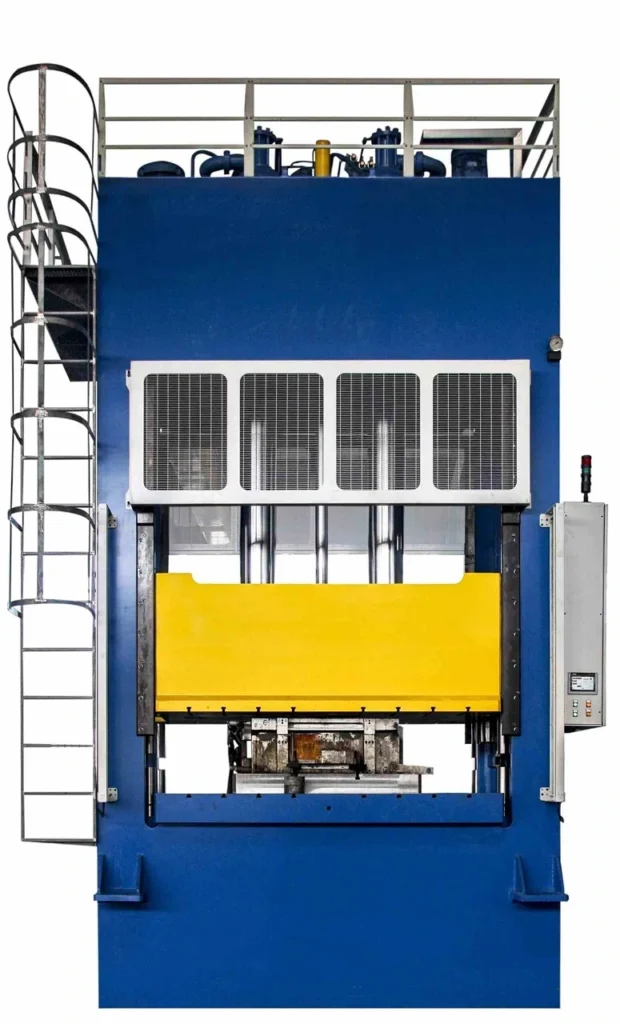
Hydraulic deep drawing presses offer several advantages over traditional mechanical presses, particularly in terms of control, versatility, and performance. However, like any piece of industrial equipment, they also come with certain limitations that manufacturers must consider when choosing the right press for their operations.
Advantages of Hydraulic Deep Drawing Presses
- Precise Control Over Force and Speed Hydraulic presses allow for highly precise control over the force and speed applied during the deep drawing process. This precision is crucial for ensuring consistent part quality, especially
Advantages and Limitations of Hydraulic Deep Drawing Presses
- Precise Control Over Force and Speed (continued)
Hydraulic presses allow for highly precise control over the force and speed applied during the deep drawing process. This precision is crucial for ensuring consistent part quality, especially for complex geometries and high-strength materials. The pressure can be adjusted throughout the stroke, which means that hydraulic presses are capable of maintaining a constant force over the entire cycle. This feature makes hydraulic presses ideal for deep drawing operations where material properties and thickness can vary significantly. - Versatility in Operation
Hydraulic deep drawing presses are extremely versatile and can be used for a wide variety of applications across different industries. Unlike mechanical presses, which are designed for specific tasks, hydraulic presses can be easily adjusted to accommodate different materials, part shapes, and production volumes. They can handle large, complex parts or multiple smaller parts simultaneously, making them well-suited for industries such as automotive, aerospace, and electronics manufacturing.Additionally, hydraulic presses are capable of multi-action operations, such as double- or triple-action presses, allowing them to perform different forming tasks in a single machine. This flexibility is a significant advantage in production environments that require a range of forming operations, reducing the need for multiple machines and minimizing setup times. - Handling of Complex Shapes and Deep Draws
Hydraulic deep drawing presses excel at handling parts with complex geometries and deep draws, which are often difficult or impossible to achieve with mechanical presses. The constant pressure and speed control provided by hydraulic systems make it easier to form intricate shapes without risking defects such as tearing, wrinkling, or excessive thinning. This capability is essential for industries like aerospace and automotive, where components often feature deep cavities and complex shapes that require precise forming. - Improved Safety and Operator Control
Modern hydraulic deep drawing presses are equipped with advanced safety features and control systems that protect both the operator and the equipment. These systems include emergency stop buttons, pressure relief valves, automatic overload protection, and guarding mechanisms that prevent accidental contact with moving parts. Additionally, the smooth and controlled motion of hydraulic systems reduces the risk of sudden mechanical failures or excessive forces that could cause injury or damage. - Energy Efficiency in High-Volume Production
Hydraulic presses have become more energy-efficient with the advent of modern control systems and the integration of servo-driven hydraulic systems. These innovations allow for better energy management by adjusting the power output based on the demand at each stage of the deep drawing process. As a result, hydraulic presses can be more energy-efficient in high-volume production compared to traditional mechanical presses, where energy consumption remains constant regardless of the workload. - Reduced Wear and Tear on Components
The smooth, controlled motion of hydraulic presses leads to reduced wear and tear on both the press components and the tooling used during the deep drawing process. Mechanical presses, by contrast, often experience higher levels of impact and stress, which can result in premature wear of critical components. This reduction in wear extends the lifespan of the machine and reduces the frequency and cost of maintenance.
Limitations of Hydraulic Deep Drawing Presses
- Higher Initial Cost
One of the primary limitations of hydraulic deep drawing presses is their higher initial cost compared to mechanical presses. The complexity of the hydraulic system, along with the need for specialized components such as pumps, valves, and hydraulic fluid reservoirs, contributes to a higher upfront investment. For manufacturers with limited budgets, this can be a significant barrier to adopting hydraulic technology. - Maintenance Complexity
While hydraulic presses tend to experience less wear and tear during operation, their maintenance requirements can be more complex than those of mechanical presses. Hydraulic systems rely on a variety of components, including pumps, valves, and fluid reservoirs, all of which must be regularly inspected and maintained to ensure optimal performance. Contaminants in the hydraulic fluid, such as dirt or metal particles, can cause system failures if not properly filtered out, adding to the maintenance burden.Furthermore, hydraulic fluid itself must be monitored and replaced periodically to prevent system inefficiencies or damage to the press. This ongoing need for fluid management adds to the operational costs and requires specialized knowledge. - Energy Consumption and Heat Generation
Although modern hydraulic presses are more energy-efficient than older models, they can still consume more energy than mechanical presses during certain operations. This is especially true in applications where high pressures or prolonged press cycles are required. Hydraulic systems can also generate a significant amount of heat during operation, particularly in high-volume production environments. Excessive heat can cause the hydraulic fluid to degrade over time, potentially leading to system inefficiencies or component failure.To mitigate these issues, manufacturers often invest in cooling systems or heat exchangers to manage the temperature of the hydraulic fluid, adding to the overall cost of the machine. - Larger Footprint and Space Requirements
Hydraulic presses typically require more floor space than mechanical presses due to the additional components involved, such as hydraulic fluid reservoirs, pumps, and control units. This larger footprint can be a disadvantage for manufacturers with limited space in their production facilities. Additionally, the installation process for a hydraulic press is more involved and may require specialized foundations or supports to accommodate the increased size and weight of the machine. - Slower Cycle Times for Certain Applications
Hydraulic presses generally operate more slowly than mechanical presses, particularly in applications that require fast cycle times. While the controlled, constant pressure of a hydraulic press is beneficial for complex deep drawing operations, it can result in slower production speeds compared to mechanical presses, which are capable of higher cycle rates. In high-volume, mass production environments where speed is critical, this slower cycle time may be a limitation.
Comparison with Mechanical Deep Drawing Presses
- Control and Precision: Hydraulic presses offer better control over the drawing process, particularly when handling complex parts or deep draws, whereas mechanical presses are typically faster but less precise.
- Cost: Mechanical presses are often less expensive and easier to maintain, but they may require more frequent repairs due to the higher impact forces involved.
- Efficiency: Hydraulic presses can be more energy-efficient in high-precision applications, while mechanical presses tend to be more efficient in high-speed, high-volume production environments.
Applications of Hydraulic Deep Drawing Presses in Different Industries

Hydraulic deep drawing presses play a vital role in numerous industries where precise metal forming is required. Their versatility, ability to handle complex shapes, and capacity for high-strength materials make them indispensable in fields ranging from automotive manufacturing to medical device production. Below are key industries where hydraulic deep drawing presses have a significant impact, along with specific applications.
1. Automotive Industry
The automotive industry is one of the largest consumers of hydraulic deep drawing presses. These presses are crucial for forming various metal components that require high precision and strength. The demand for lightweight, yet durable materials in vehicles has made deep drawing an essential process for car manufacturers.
- Car Body Panels: Hydraulic deep drawing presses are used to form large, complex panels such as doors, hoods, roof panels, and fenders. These parts must be manufactured with tight tolerances to ensure a proper fit and structural integrity.
- Fuel Tanks and Exhaust Components: Due to the need for high-strength materials in fuel tanks and exhaust systems, hydraulic deep drawing presses are widely used in the production of these components. The ability to maintain precise control over the drawing force and speed ensures the integrity of the material without compromising the structure.
- Chassis and Frame Components: Many chassis components, including cross members, brackets, and reinforcements, are deep drawn to ensure the highest levels of durability. The deep drawing process allows for the production of these parts with minimal material waste and consistent thickness, which is critical for safety.
2. Aerospace Industry
The aerospace industry requires components with extremely high precision, strength, and durability due to the harsh operational environments in which these parts must function. Hydraulic deep drawing presses are frequently used to manufacture complex, lightweight components that meet the rigorous standards of the industry.
- Aircraft Body Panels and Structural Components: Aerospace manufacturers use deep drawing presses to form structural components such as fuselage panels, wing components, and bulkheads. These parts must withstand high levels of stress and fatigue, making the deep drawing process ideal for ensuring uniform material distribution and strength.
- Engine Components: In jet engines and other aerospace propulsion systems, hydraulic presses are employed to form heat-resistant alloys and other high-strength materials into complex shapes. The precise control offered by hydraulic presses ensures that these critical components meet strict performance requirements.
- Landing Gear Components: Hydraulic deep drawing presses are also used to manufacture parts of landing gear systems, which need to be both lightweight and capable of withstanding extreme forces during takeoff and landing.
3. Consumer Electronics Industry
In the consumer electronics sector, hydraulic deep drawing presses are essential for producing thin, lightweight enclosures and components for devices like smartphones, laptops, and wearables. With the trend toward more compact and sleek designs, manufacturers rely on deep drawing technology to achieve high precision and finish quality.
- Device Enclosures and Casings: The metal enclosures for smartphones, tablets, and laptops are typically deep drawn to achieve seamless, lightweight structures that are both durable and aesthetically pleasing. The hydraulic press ensures that the material is evenly distributed and free from defects like thinning or tearing.
- Heat Sinks and Other Thermal Management Components: Many electronic devices rely on heat sinks and thermal management components made from metals such as aluminum or copper. Hydraulic deep drawing presses are used to form these components, ensuring they can effectively dissipate heat while maintaining a compact size.
4. Household Appliances
Hydraulic deep drawing presses are widely used in the production of household appliances such as washing machines, refrigerators, and microwave ovens. The need for large, robust metal components that are formed with precision makes deep drawing an ideal process for these products.
- Washer and Dryer Drums: The drums in washing machines and dryers are typically deep drawn from stainless steel to ensure durability and corrosion resistance. Hydraulic presses provide the necessary force to form these large, cylindrical parts without compromising their structural integrity.
- Refrigerator Liners and Panels: Hydraulic deep drawing presses are used to form the inner liners and panels of refrigerators. These components must be manufactured with tight tolerances to ensure proper insulation and assembly, while also being durable enough to withstand years of use.
5. Medical Devices and Equipment
The medical device industry requires high-precision, often small, components made from biocompatible materials such as stainless steel and titanium. Hydraulic deep drawing presses play a key role in manufacturing these critical parts, ensuring the highest levels of accuracy and consistency.
- Surgical Instruments and Implantable Devices: Many surgical instruments, such as forceps, scalpels, and clamps, are deep drawn from stainless steel or titanium. The hydraulic deep drawing process ensures these components are formed to precise specifications with smooth edges and surfaces, reducing the risk of contamination or material failure during use.
- Medical Implants: Complex medical implants, such as pacemaker enclosures and stents, require intricate forming processes that can only be achieved using hydraulic presses. The ability to control the force and speed of the drawing process ensures these delicate components are produced without defects, enhancing patient safety.
6. Packaging Industry
In the packaging industry, hydraulic deep drawing presses are used to manufacture various metal containers, including food and beverage cans, aerosol cans, and cosmetic containers. The deep drawing process is ideal for creating seamless, lightweight containers that are both functional and visually appealing.
- Metal Cans for Food and Beverages: Aluminum and steel cans for food and beverages are often deep drawn using hydraulic presses to ensure uniform thickness and high strength. The smooth surface finish and consistent dimensions of deep-drawn cans make them ideal for mass production and consumer use.
- Aerosol and Cosmetic Containers: Hydraulic deep drawing presses are also used to manufacture aerosol cans and cosmetic containers, which require precise forming to ensure proper functionality and aesthetic quality.
Future Trends in Industry Applications
As industries continue to push the boundaries of innovation, the demand for advanced deep drawing processes is expected to grow. Key trends influencing the future of hydraulic deep drawing presses include:
- Lightweight Materials: The use of lightweight materials such as aluminum and composites is becoming increasingly important, particularly in the automotive and aerospace industries. Hydraulic presses, with their precise control and versatility, are well-suited to forming these materials without compromising strength.
- Electrification and E-Mobility: The rise of electric vehicles (EVs) and other e-mobility solutions is driving demand for complex, high-strength components such as battery enclosures and electric motor housings. Hydraulic deep drawing presses are expected to play a crucial role in producing these parts efficiently.
- Sustainability: Manufacturers are increasingly focused on sustainability and reducing material waste. The deep drawing process, which can produce complex parts from a single piece of material, aligns with these goals by minimizing scrap and optimizing material use.
Recent Developments and Technological Advances
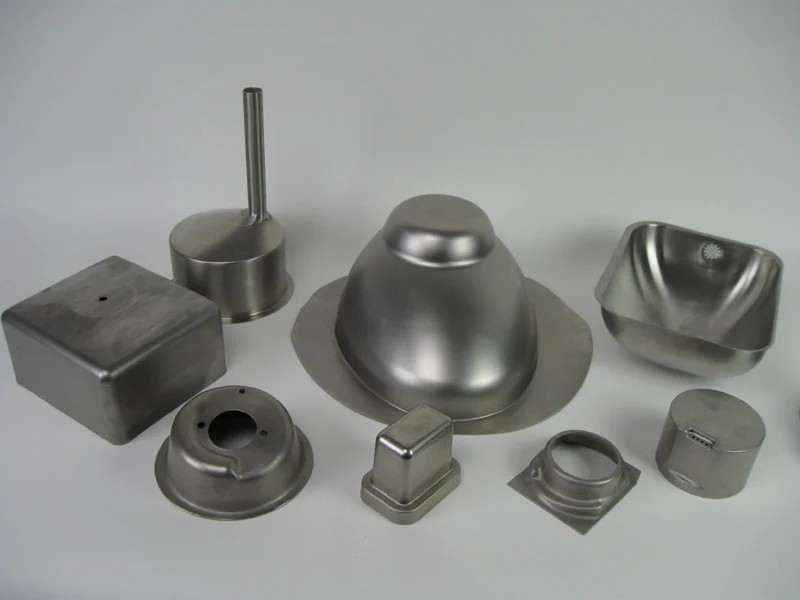
The technology behind hydraulic deep drawing presses has evolved significantly in recent years, driven by advancements in automation, digitalization, and material science. These developments have improved the performance, efficiency, and versatility of hydraulic presses, making them an essential part of modern manufacturing.
1. Digitalization and Automation
One of the most significant technological advances in hydraulic deep drawing presses is the integration of digital control systems and automation. These innovations have transformed the way hydraulic presses are operated, providing manufacturers with greater precision, flexibility, and productivity.
- CNC and PLC Systems: Modern hydraulic presses are often equipped with computer numerical control (CNC) or programmable logic controller (PLC) systems, which allow for automated control of the press parameters such as force, speed, and stroke length. These systems enable manufacturers to program complex forming sequences, reducing the need for manual adjustments and improving production consistency.
- Automated Tool Change Systems: In high-volume production environments, the ability to quickly change tools is critical for maintaining efficiency. Automated tool change systems have been developed to reduce downtime between production runs, allowing manufacturers to switch between different parts and materials with minimal disruption.
2. Integration with Industry 4.0 and Smart Manufacturing
The rise of Industry 4.0 has introduced new opportunities for hydraulic deep drawing presses to integrate with smart manufacturing systems. Through the use of sensors, data analytics, and machine learning, presses can now provide real-time feedback on performance and optimize production processes.
Maintenance and Troubleshooting of Hydraulic Deep Drawing Presses
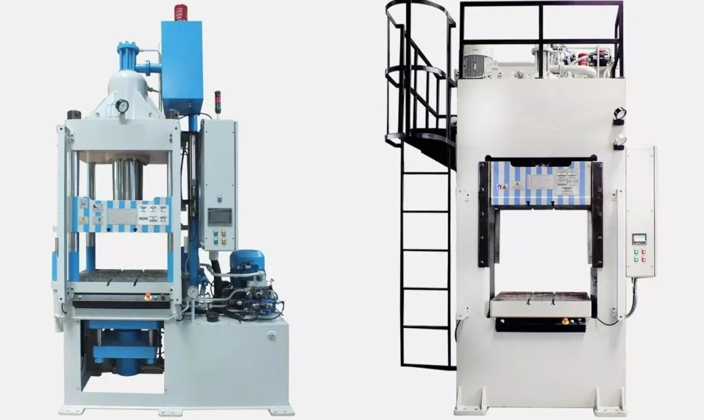
Maintenance is essential for ensuring the long-term performance, safety, and efficiency of hydraulic deep drawing presses. Given the complex nature of hydraulic systems, neglecting regular maintenance can lead to increased downtime, expensive repairs, and even equipment failure. To avoid these issues, manufacturers must implement a comprehensive maintenance program, which includes regular inspections, preventive maintenance, and troubleshooting.
1. Common Maintenance Practices
Routine maintenance practices for hydraulic deep drawing presses revolve around monitoring and maintaining the hydraulic system components, mechanical elements, and control systems. Some key maintenance tasks include:
- Hydraulic Fluid Monitoring: The hydraulic fluid is the lifeblood of the press. Over time, contaminants such as dirt, metal particles, and moisture can accumulate in the fluid, degrading its performance and causing damage to hydraulic components. Regularly checking the fluid for signs of contamination or degradation is crucial. In addition, hydraulic fluid levels should be monitored and maintained at the correct levels to avoid air entering the system, which can cause cavitation and system inefficiencies.
- Filter Replacement: Hydraulic systems include filters to remove contaminants from the fluid. Over time, these filters become clogged and must be replaced to maintain system performance. Clogged filters can cause reduced pressure, overheating, and wear on the hydraulic pump and valves.
- Seal Inspection and Replacement: The seals used in hydraulic cylinders and valves are prone to wear and tear over time. Leaking seals can lead to a loss of pressure and reduced performance. Regularly inspecting and replacing seals is an important preventive measure that ensures consistent press performance.
- Lubrication of Mechanical Components: While the hydraulic system provides the force required for deep drawing, mechanical components such as bearings, gears, and guideways still require proper lubrication to minimize friction and wear. Applying the appropriate lubricants at regular intervals is essential to prevent mechanical failures and extend the life of the press.
- System Calibration: Periodic calibration of the press’s control system ensures that the applied force, speed, and other critical parameters remain within acceptable tolerances. Calibration is particularly important in high-precision applications, where even small deviations can lead to defects in the finished parts.
2. Predictive Maintenance Techniques
Predictive maintenance has become an increasingly popular approach in modern manufacturing due to its ability to prevent costly breakdowns and extend the lifespan of hydraulic deep drawing presses. This approach leverages real-time data and advanced analytics to predict when maintenance is needed, rather than relying on fixed maintenance schedules.
- Condition Monitoring: Sensors are installed on key components such as hydraulic pumps, motors, and valves to monitor parameters like pressure, temperature, vibration, and oil quality. By continuously analyzing this data, manufacturers can detect early signs of wear or failure and schedule maintenance before a serious issue arises.
- Data Analytics and AI: Predictive maintenance systems often use machine learning algorithms to analyze historical data and identify patterns that indicate potential problems. This allows manufacturers to anticipate when components are likely to fail and perform maintenance only when necessary, reducing both downtime and maintenance costs.
3. Common Issues and Troubleshooting
Despite regular maintenance, hydraulic deep drawing presses can experience problems due to wear, environmental conditions, or unexpected failures. The most common issues include hydraulic system failures, mechanical malfunctions, and control system errors. Some common issues and their troubleshooting methods include:
- Hydraulic Fluid Leaks: Leaks can occur due to damaged seals, cracked hoses, or worn components. If a leak is detected, the source must be identified and repaired immediately to prevent a loss of pressure and damage to the system. Replacing worn seals, tightening fittings, or replacing damaged hoses can resolve the issue.
- Pressure Loss: If the press is unable to generate the required force, the cause is often a loss of hydraulic pressure. Possible causes include low hydraulic fluid levels, a clogged filter, or a malfunctioning pump. Checking fluid levels, replacing filters, and inspecting the pump can help restore pressure.
- Overheating: Hydraulic systems generate heat during operation, and if the system overheats, it can cause the hydraulic fluid to degrade and reduce system efficiency. Overheating may be caused by insufficient fluid levels, clogged filters, or excessive operating pressure. Addressing these issues by ensuring proper fluid levels and replacing filters can prevent overheating.
- Excessive Vibration or Noise: Excessive vibration or noise can be a sign of cavitation in the hydraulic system, which occurs when air enters the fluid. This can be caused by low fluid levels or a loose fitting. Ensuring the system is properly sealed and fluid levels are maintained can eliminate cavitation.
4. Ensuring Safety During Maintenance
Safety is paramount when performing maintenance on hydraulic deep drawing presses. The high pressures involved in the hydraulic system can pose serious hazards if not properly managed. Key safety measures include:
- Lockout/Tagout Procedures: Before performing any maintenance, the press should be de-energized, and lockout/tagout procedures should be followed to ensure the machine cannot be inadvertently started during maintenance.
- Pressure Release: Hydraulic systems should always be depressurized before any work is done on the system. This prevents accidental fluid release, which can cause injury or equipment damage.
- Personal Protective Equipment (PPE): Maintenance personnel should wear appropriate PPE, such as gloves, goggles, and protective clothing, to protect themselves from potential hazards.
Conclusion
Hydraulic deep drawing presses are an essential tool in modern manufacturing, offering unparalleled precision, control, and versatility for forming complex metal parts. Their ability to handle high-strength materials and produce parts with intricate geometries has made them indispensable in industries such as automotive, aerospace, consumer electronics, and medical devices.
The deep drawing process, powered by hydraulic systems, ensures uniform pressure throughout the entire stroke, resulting in consistent part quality and reduced risk of defects. With advancements in digital control systems, automation, and smart manufacturing technologies, hydraulic presses continue to evolve, offering greater efficiency, precision, and flexibility than ever before.
While hydraulic deep drawing presses have several advantages over traditional mechanical presses, including better control over pressure and the ability to handle more complex parts, they also come with challenges. These challenges include higher initial costs, more complex maintenance requirements, and larger space requirements. However, with proper maintenance and the use of predictive maintenance techniques, manufacturers can maximize the lifespan and efficiency of their hydraulic presses while minimizing downtime.
Looking to the future, hydraulic deep drawing presses will continue to play a crucial role in driving innovation across a range of industries, from the production of electric vehicle components to advanced medical devices. As manufacturing trends move toward increased automation, sustainability, and lightweight materials, hydraulic deep drawing presses will remain at the forefront of cutting-edge manufacturing technologies.
3. Types of Hydraulic Deep Drawing Press
Hydraulic deep drawing presses are available in a variety of designs and configurations to cater to different industrial applications and manufacturing needs. Understanding the different types is crucial for potential buyers as it allows them to choose the best-suited machine for their specific requirements. Here, we will explore the main types of hydraulic deep drawing presses, including their distinctive features, applications, and advantages.
Single-Acting Hydraulic Presses
Single-acting hydraulic presses are among the simplest and most commonly used in various industries. As the name suggests, they have a single action of force applied in one direction, typically downwards. These presses are ideal for basic drawing operations where the blank material needs to be drawn into a die with minimal complexity.
- Structure: A single-acting press consists of a ram that moves in a vertical direction, applying pressure to the blank to shape it. The return of the ram to its original position is usually facilitated by mechanical means, such as springs or counterweights.
- Applications: Single-acting presses are used for forming relatively shallow and simple parts, such as metal casings, cooking utensils, and small automotive components. They are also used in cases where precision is less critical, or the depth of the draw is limited.
- Advantages: These presses are cost-effective, easy to operate, and maintain. They also have a compact design, making them suitable for smaller production facilities or applications with space constraints.
A hydraulic press is a mechanical device that uses a hydraulic cylinder to generate a compressive force. It operates based on Pascal’s Law, which states that pressure applied to a confined fluid is transmitted equally in all directions. This principle allows hydraulic presses to exert significant force with minimal input, making them essential tools in industries requiring high-pressure applications.
A single-acting hydraulic press uses hydraulic pressure to move the piston in one direction, typically the downward or compressive stroke. After the press completes this action, the piston returns to its original position using an external force such as a spring or the weight of the cylinder. This differs from a double-acting hydraulic press, where hydraulic pressure is applied in both the forward and return strokes.
The simplicity and cost-effectiveness of single-acting hydraulic presses make them ideal for a variety of applications, including small to medium-scale production, metal fabrication, and mechanical testing. These presses are widely used in industries such as automotive, aerospace, manufacturing, and even laboratories for precision tasks.
The core advantage of a single-acting hydraulic press lies in its simplicity. Fewer moving parts and a straightforward design reduce both the initial cost and ongoing maintenance requirements. However, the trade-off is that the press lacks the stroke control and power range of more complex systems, limiting its effectiveness in higher-end or more precise applications.
How Single-Acting Hydraulic Presses Work
The fundamental operation of a single-acting hydraulic press relies on Pascal’s Law, which underpins all hydraulic systems. According to this principle, when a force is applied to a fluid inside a closed system, the pressure is transmitted evenly throughout the fluid. In a hydraulic press, this means that the force generated by a pump acting on a small volume of hydraulic fluid can be magnified to create a much larger output force.
Key Components of a Single-Acting Hydraulic Press:
- Cylinder and Piston: The hydraulic cylinder contains a piston that moves up and down. In a single-acting press, hydraulic fluid forces the piston downwards, creating the press action.
- Hydraulic Pump: The pump generates pressure within the hydraulic system, pushing the fluid into the cylinder to drive the piston.
- Reservoir: This stores hydraulic fluid, which is pumped into the cylinder during operation.
- Valves: Control the flow of hydraulic fluid, directing it into the cylinder for the pressing stroke.
- Return Mechanism: In single-acting systems, this is usually a spring or gravitational force that returns the piston to its original position after the pressing action.
Pressing and Return Process:
- Pressing: When the press operator activates the system, hydraulic fluid is pumped into the cylinder. The increase in pressure forces the piston downward, applying force to the material placed under the press head. The force can range from several tons to hundreds of tons, depending on the press’s specifications.
- Return Stroke: Once the pressing action is complete, the external force—usually a spring or gravity—returns the piston to its starting position. Unlike double-acting presses, where hydraulic pressure can control both strokes, single-acting presses rely on this mechanical or natural return.
Advantages and Limitations:
- Advantages: Single-acting presses are simple, affordable, and easy to maintain. They are ideal for tasks that do not require precise control over the return stroke or where the pressing force is the primary concern.
- Limitations: The primary limitation is the lack of control over the piston’s return stroke, which can make single-acting presses less suited to precision applications. Additionally, since only one stroke is powered, these presses are less efficient in tasks requiring continuous motion or high-speed operation.
Types of Single-Acting Hydraulic Presses
Single-acting hydraulic presses come in several varieties, each suited to different applications and operational needs.
1. Manually Operated Hydraulic Presses:
These presses are powered by a hand-operated pump, which provides the hydraulic pressure needed to move the piston. They are ideal for small-scale applications or environments where electricity is not available. These presses are portable and commonly used in repair shops, garages, or remote field locations. Their affordability and ease of use make them popular for light-duty tasks like pressing bearings or removing shafts.
2. Electric-Powered Hydraulic Presses:
Electric-powered hydraulic presses use an electric motor to drive the hydraulic pump, offering greater efficiency and consistency compared to manual models. These presses are suitable for more intensive industrial applications where higher force or faster operation is required. They are commonly found in manufacturing plants, where they can be integrated into production lines for repetitive tasks such as stamping, forging, or cutting.
3. Air-Driven Hydraulic Presses:
In these systems, compressed air is used to generate hydraulic pressure. They are commonly used in industrial environments where compressed air is readily available. Air-driven hydraulic presses are often employed in applications where speed and convenience are critical, and they offer a middle ground between manually operated and electric-powered presses in terms of power and cost.
Applications of Each Type:
- Manually Operated: Ideal for low-volume tasks, repair work, or environments lacking electrical infrastructure.
- Electric-Powered: Suitable for continuous, heavy-duty applications in factories and production environments.
- Air-Driven: Often used in automotive workshops and for lighter industrial tasks where compressed air is available.
Applications of Single-Acting Hydraulic Presses
Single-acting hydraulic presses are versatile tools used across a wide range of industries for different applications.
1. Metal Forming and Fabrication:
In the metalworking industry, hydraulic presses are used to shape, bend, punch, and cut metal sheets and components. Single-acting presses are especially useful in tasks where the return stroke is less critical, such as metal stamping or bending. These presses are commonly used in fabrication shops, tool and die manufacturing, and custom metalwork projects.
2. Press Fitting and Assembly Tasks:
Single-acting presses are commonly employed in press fitting, where parts are mechanically forced together using high pressure. This includes tasks such as pressing bushings, bearings, gears, and other components into place. These presses are widely used in the automotive industry for assembly operations, as well as in machinery and equipment manufacturing.
3. Material Testing and Laboratory Uses:
In laboratories, single-acting hydraulic presses are often used for testing materials under compressive force. For example, engineers and scientists may use hydraulic presses to measure the compressive strength of materials like concrete, metals, or plastics. The simplicity of single-acting presses makes them ideal for controlled experiments where large forces are required without complex control systems.
4. Automotive and Aerospace Industries:
In the automotive sector, single-acting hydraulic presses play a crucial role in various assembly and maintenance tasks, such as pressing in bushings, removing bearings, and straightening parts. Their use extends to aerospace industries for tasks such as forming lightweight components, shaping metal parts, or assembling intricate systems that require precise force application.
Examples of Practical Applications:
- Metal Stamping: Single-acting presses are used to punch or stamp metal parts for various industries, including automotive and electronics.
- Bearing Installation: Presses ensure that bearings are seated correctly without causing damage to delicate components.
- Cutting and Trimming: Hydraulic presses can be used to cut metal, plastic, or composite materials, making them essential in production environments.
Advantages of Single-Acting Hydraulic Presses
Single-acting hydraulic presses have several advantages, making them a popular choice in a variety of applications.
1. Simplicity and Cost-Effectiveness:
Due to their basic design, single-acting hydraulic presses are more affordable than their double-acting counterparts. They have fewer moving parts and require less complex control systems, reducing both the upfront cost and the likelihood of mechanical failure. This makes them ideal for smaller operations or businesses looking for cost-effective solutions.
2. Efficiency in Force Delivery:
Despite their simplicity, single-acting hydraulic presses can deliver tremendous force, making them suitable for heavy-duty tasks like metal forming or assembly. They can generate forces ranging from a few tons to several hundred tons, depending on the size and type of the press, enabling them to handle a wide range of materials and tasks.
3. Reduced Maintenance:
With fewer components, single-acting presses are easier and less costly to maintain. Routine maintenance is generally limited to inspecting seals, checking hydraulic fluid levels, and ensuring that the return mechanism (spring or gravity) is functioning properly.
4. Portability and Space Efficiency:
Single-acting presses are typically more compact than double-acting presses, making them easier to move and install in smaller workspaces. This portability is especially valuable in environments where space is limited, such as small workshops or laboratories.
Challenges and Limitations of Single-Acting Hydraulic Presses
While single-acting hydraulic presses offer many benefits, they also have certain limitations that can affect their performance in specific applications.
1. Limited Stroke Control and Precision:
Because the return stroke is not powered by hydraulics, single-acting presses lack the precise control over the piston’s movement during the return phase. This makes them less suitable for applications requiring fine control of both the forward and return strokes.
2. External Force Required for Return Stroke:
The reliance on springs or gravity for the return stroke introduces limitations. Springs can wear out over time, reducing the efficiency of the press, and gravitational return may be too slow for certain high-speed applications.
3. Power Limitations:
Single-acting presses typically have less power and speed compared to double-acting systems. For tasks requiring high force or rapid cycling, a double-acting press may be more appropriate.
4. Environmental Considerations:
Hydraulic systems, including single-acting presses, can pose environmental risks if not properly maintained. Leaking hydraulic fluid, for instance, can cause environmental contamination, making proper maintenance and disposal of used fluids critical.
Maintenance and Safety Considerations
Proper maintenance and adherence to safety protocols are essential to ensure the safe and efficient operation of single-acting hydraulic presses.
Maintenance Procedures:
- Hydraulic Fluid Levels: Regularly check and maintain the hydraulic fluid to ensure smooth operation. Low fluid levels can reduce press efficiency and lead to mechanical wear.
- Seals and Hoses: Inspect seals and hoses for wear and tear, as leaks can cause pressure loss and reduce the effectiveness of the press.
- Return Mechanism: Check the spring or gravity-based return system for signs of fatigue or failure. Over time, springs may lose tension, reducing the effectiveness of the return stroke.
Safety Protocols:
- Personal Protective Equipment (PPE): Operators should wear appropriate PPE, including safety goggles, gloves, and hearing protection.
- Proper Training: Ensure that all operators are trained in the correct use of the press and are aware of potential hazards.
- Emergency Stops: Hydraulic presses should be equipped with emergency stop buttons to allow operators to quickly halt the machine in case of malfunction or danger.
Future of Single-Acting Hydraulic Presses
Advancements in technology are opening new possibilities for single-acting hydraulic presses. As industries evolve, the demand for more efficient and eco-friendly machinery is growing.
1. Advancements in Hydraulic Technology:
Innovations in hydraulic systems are leading to more efficient and powerful single-acting presses. For instance, new hydraulic fluids with better thermal stability and lower environmental impact are being developed, reducing the ecological footprint of hydraulic systems.
2. Energy Efficiency Improvements:
Modern hydraulic presses are being designed with energy efficiency in mind. Enhanced pump designs, variable speed motors, and more efficient control systems are reducing energy consumption and operational costs.
3. Integration with Automation:
The future of hydraulic presses lies in their integration with automated and smart systems. Automated single-acting presses equipped with sensors and computer control systems can adjust force, speed, and stroke in real time, enhancing precision and adaptability.
4. Future Applications and Innovations:
As industries continue to demand more from hydraulic systems, single-acting presses are likely to be used in new applications such as additive manufacturing (3D printing) and precision engineering. The increasing focus on sustainability may also drive the development of greener, more energy-efficient presses.
Introduction to Double-Acting Hydraulic Presses
Hydraulic presses are mechanical devices that use fluid pressure to generate significant force, commonly employed in industries where large-scale pressing, forming, or molding is required. They operate on Pascal’s Law, which states that pressure applied to a fluid in a confined space is transmitted equally in all directions. This principle allows hydraulic presses to amplify force, making them crucial in metalworking, manufacturing, automotive industries, and beyond.
A double-acting hydraulic press differs from its single-acting counterpart in that it applies hydraulic pressure in both directions—both for the pressing stroke and the return stroke. In contrast, a single-acting press relies on external forces, like springs or gravity, for the return motion, which limits control and precision.
The use of double-acting hydraulic presses has revolutionized several industrial processes due to the enhanced control and precision they offer. With powered movement in both directions, these presses are capable of handling more complex and demanding tasks, such as deep drawing, forging, or any process where high precision and consistent force are essential. These presses are widely used in automotive production, aerospace manufacturing, and large-scale industrial operations.
How Double-Acting Hydraulic Presses Work
Double-acting hydraulic presses function based on hydraulic principles, which utilize fluid power to amplify force. The critical difference from single-acting presses is that double-acting presses can apply hydraulic pressure in both the pressing and return strokes. This provides enhanced control and versatility.
Core Components of a Double-Acting Hydraulic Press:
- Cylinder and Piston: A double-acting press has a hydraulic cylinder with a piston that moves in two directions. Hydraulic fluid is directed into the cylinder on either side of the piston to control both the downward and upward strokes.
- Hydraulic Pump: The hydraulic pump provides pressure by moving hydraulic fluid into the cylinder. In double-acting presses, the pump must be capable of routing the fluid to either side of the piston, depending on whether it is the pressing or return stroke.
- Valves and Control Systems: Double-acting presses require more sophisticated valve systems to control the flow of hydraulic fluid. These valves direct fluid pressure to either side of the piston, enabling the precise control of both strokes.
- Power Source: These presses can be powered by manual pumps, electric motors, or pneumatic systems, depending on the scale and application of the press.
The Pressing and Return Strokes:
- Pressing Stroke: The hydraulic pump directs fluid into the top of the cylinder, pushing the piston downward. This downward force can range from a few tons to hundreds of tons, depending on the press’s size and design. The press head applies this force to the material being processed, whether it’s for stamping, molding, or cutting.
- Return Stroke: After the pressing operation, hydraulic pressure is redirected to the bottom of the piston. This lifts the piston back to its starting position, ensuring precise and controlled movement. The ability to hydraulically control both strokes eliminates the reliance on gravity or springs, allowing for faster cycle times and more complex tasks.
Precision and Control:
The ability to control both strokes of the piston provides greater accuracy in industrial processes. Unlike single-acting presses, where the return stroke can vary in speed and efficiency, double-acting presses offer consistent performance across all movements. This precision makes them ideal for complex forming processes, deep drawing, and precision cutting operations, where both the force and the return timing must be tightly controlled.
Types of Double-Acting Hydraulic Presses
Double-acting hydraulic presses come in various forms, each tailored for specific industrial applications. Here are some of the main types:
1. Manual Double-Acting Hydraulic Presses:
Manual versions of double-acting presses are powered by hand-operated hydraulic pumps. These are typically used in small workshops or repair facilities where tasks like pressing, bending, or assembling components do not require extensive automation. These presses are portable, cost-effective, and often used in low-production environments.
2. Electric-Powered Double-Acting Hydraulic Presses:
Electric-powered double-acting presses are more common in industrial settings where high force and consistent operation are required. The hydraulic pump is driven by an electric motor, allowing for automated control of both strokes. These presses are essential for high-volume operations, such as metal stamping, die forming, and precision cutting. The electric-powered system allows for greater precision, repeatability, and faster cycle times.
3. Pneumatic Double-Acting Hydraulic Presses:
Pneumatic-powered double-acting presses use compressed air to drive the hydraulic fluid in both strokes. These presses are favored in industries where pneumatic systems are already integrated into the production environment, such as in automotive assembly lines. Pneumatic systems provide rapid action, and the integration with hydraulics ensures the generation of high forces, making them suitable for mid-sized industrial applications.
4. Specialized Double-Acting Presses:
Some double-acting hydraulic presses are designed for specific applications, such as hydraulic press brakes used in bending and shaping metal sheets. These presses provide precise control over the angle and force applied, making them ideal for custom metal fabrication. Another example includes forging presses, where high tonnage and precise control are required to shape metal components.
Applications of Double-Acting Hydraulic Presses
Double-acting hydraulic presses are widely employed across a variety of industries due to their versatility and ability to handle complex tasks with precision. Here are some of the key applications:
1. Metal Forming and Deep Drawing:
One of the primary uses of double-acting hydraulic presses is in metal forming, particularly deep drawing. Deep drawing is a manufacturing process where a sheet metal blank is radially drawn into a forming die by the mechanical action of a punch. Double-acting presses provide the precise control necessary to form complex shapes in metals like aluminum, steel, and copper without cracking or deforming the material.
2. Punching, Forging, and Die Forming:
In punching and forging operations, double-acting presses apply controlled force to deform or cut metal parts. This is commonly used in the automotive and aerospace industries, where high-strength materials are forged into critical components like gears, axles, and structural parts. The ability to control both the pressing and return strokes ensures consistent quality and reduces the risk of material damage.
3. Composite Material Molding:
As industries increasingly adopt composite materials, double-acting hydraulic presses have become essential for forming and molding these materials. Composites, such as carbon fiber or fiberglass, require careful handling during the molding process to maintain their strength and durability. Double-acting presses allow for precise pressure application during both the pressing and release phases, making them indispensable in industries like aerospace and automotive, where lightweight, high-strength components are essential.
4. Automotive and Aerospace Industries:
The automotive industry relies heavily on double-acting hydraulic presses for the production of body panels, frames, and engine components. The precision and repeatability of these presses ensure that every part is manufactured to exact specifications. In the aerospace industry, where weight, strength, and safety are critical, double-acting presses are used to form lightweight components like aircraft skin panels, structural parts, and engine elements.
5. Examples of Industrial Applications:
- Automotive: Deep drawing for body panels, stamping parts like hoods, doors, and roofs.
- Aerospace: Forming of lightweight metal and composite parts for aircraft and spacecraft.
- Heavy Machinery: Forging of large components for construction equipment and industrial machinery.
- Consumer Electronics: Precision forming of metal casings and components.
Advantages of Double-Acting Hydraulic Presses
Double-acting hydraulic presses offer several significant advantages that make them indispensable in many industries.
1. Precise Control Over Both Strokes:
The ability to apply hydraulic force in both the pressing and return strokes gives double-acting presses greater control over the entire operation. This precision is particularly valuable in tasks that require consistent force and motion, such as deep drawing, forging, and punching. Both strokes can be finely adjusted to meet the exact requirements of the material and application, leading to superior product quality.
2. Higher Efficiency in Repetitive Operations:
In manufacturing environments where tasks must be repeated at high speed, double-acting presses outperform single-acting models. Since both the press and return strokes are powered, cycle times are faster, and operators have more control over the movement of the piston, which boosts productivity in high-volume production lines.
3. Versatility in Complex Tasks:
Double-acting presses are incredibly versatile, able to handle a wide variety of materials and tasks. They can be used for pressing, forming, bending, cutting, and molding, which makes them highly adaptable to different industries and processes. Whether the task requires the shaping of metals, molding of composites, or assembly of mechanical components, these presses can be fine-tuned to meet the needs of the job.
4. Suitability for Heavy-Duty and Continuous Use:
Double-acting hydraulic presses are built for heavy-duty applications and continuous use in industrial settings. The ability to power both strokes ensures that even the toughest materials, such as steel and titanium, can be shaped and formed without compromising on speed or accuracy. Their robust design and advanced control systems make them ideal for industries where durability and long-term performance are critical.
Challenges and Limitations of Double-Acting Hydraulic Presses
Despite their advantages, double-acting hydraulic presses also come with challenges and limitations that must be considered before implementation.
1. Higher Cost and Complexity:
Double-acting hydraulic presses are generally more expensive than single-acting presses due to their more complex design and the additional control systems required to power both strokes. This can make them less appealing for small-scale operations or businesses with tight budgets.
2. Increased Maintenance Requirements:
With more moving parts and components to manage, double-acting presses require more frequent and thorough maintenance than their single-acting counterparts. Components like seals, valves, and hydraulic lines must be regularly inspected and serviced to prevent leaks and ensure optimal performance. This adds to the operational costs over the lifespan of the machine.
3. Space and Energy Requirements:
Double-acting hydraulic presses tend to be larger and consume more energy than simpler presses. This means they require more space and have higher energy costs, which can be a limiting factor in smaller workshops or facilities with limited energy resources.
4. Specialized Training and Safety Considerations:
Operators of double-acting hydraulic presses must be thoroughly trained to handle the complex control systems and high pressures involved. The increased force and speed of these presses mean that strict safety protocols must be followed to prevent accidents and equipment damage.
Maintenance and Safety Considerations
Proper maintenance and safety protocols are crucial for ensuring the long-term operation and safety of double-acting hydraulic presses.
Maintenance Procedures:
- Hydraulic Fluid Levels: Maintaining appropriate hydraulic fluid levels is essential for the proper operation of both strokes. Low fluid levels can result in uneven pressure distribution and lead to damage.
- Seal and Hose Inspections: Double-acting presses have more seals and hoses than single-acting models, which makes regular inspections critical. Leaks in these components can cause a loss of pressure, reduced efficiency, and safety hazards.
- System Pressure Checks: Monitoring and adjusting the system’s pressure levels ensures that the press operates within its designed parameters, preventing over-pressurization and component failure.
Safety Protocols:
- Operator Training: Given the complexity of double-acting presses, operators must be trained in their safe use. They should understand the machine’s control systems, emergency stop features, and troubleshooting procedures.
- Regular Inspections: Presses should be inspected regularly for signs of wear or malfunction. Safety devices like pressure relief valves and emergency stops should be tested to ensure they are functioning properly.
- Personal Protective Equipment (PPE): Operators should always wear appropriate PPE, including gloves, goggles, and ear protection, especially in high-noise environments.
Future Trends in Double-Acting Hydraulic Press Technology
As technology evolves, double-acting hydraulic presses are expected to undergo several advancements that will enhance their performance and broaden their applications.
1. Technological Advancements:
Innovations in hydraulic control systems, such as the integration of proportional valves and servo-driven pumps, are improving the precision and efficiency of double-acting presses. These systems allow for finer control of pressure and movement, resulting in higher-quality output and reduced material waste.
2. Energy Efficiency:
One of the key areas of development is the push for more energy-efficient hydraulic systems. With the increasing focus on sustainability, new technologies are emerging that reduce energy consumption, such as variable-speed pumps that adjust output based on demand. These advancements not only lower operational costs but also reduce the environmental impact of hydraulic presses.
3. Automation and Industry 4.0:
The integration of double-acting hydraulic presses with automation and smart manufacturing systems is another significant trend. By connecting presses to factory networks, manufacturers can monitor machine performance in real-time, predict maintenance needs, and optimize press cycles. This leads to increased productivity and minimizes downtime due to unexpected equipment failure.
4. Future Innovations:
Looking ahead, double-acting presses may see further improvements in force capacity, miniaturization for precise applications, and modular designs that allow presses to be easily reconfigured for different tasks. Additionally, advancements in green hydraulic fluids will reduce the environmental risks associated with hydraulic systems.
Triple Action Deep Drawing Press
Deep drawing is a popular metal forming process used to shape flat sheet metal into cylindrical or box-like shapes. The process involves placing a metal blank over a die and pressing it into the die cavity with a punch. This transforms the flat blank into a three-dimensional shape, making it essential for producing components like automotive body panels, kitchen sinks, and various enclosures. The process can be repeated to achieve more complex shapes with greater depth, but the challenges increase as the material undergoes severe deformation.
A Triple Action Deep Drawing Press is a specialized machine designed to address the complexity of the deep drawing process. Unlike conventional single-acting or double-acting presses, a triple action press incorporates three independent force mechanisms:
- Blank Holder Action: Keeps the metal blank firmly in place, controlling material flow and preventing wrinkling.
- Punch Action: The primary force that shapes the blank by pushing it into the die.
- Ejector Action: Removes the finished part from the die after the drawing process is complete.
This triple-action mechanism provides greater control over the deep drawing process, allowing for the production of more complex shapes, with fewer defects, and better efficiency. The ability to control all three forces independently is particularly important in producing deep-drawn components for industries like automotive, aerospace, and consumer goods, where precision and quality are critical.
How Triple Action Deep Drawing Presses Work (500 words)
To understand how triple action deep drawing presses function, it’s essential to break down the mechanics of the deep drawing process and how each action contributes to shaping the material.
The Deep Drawing Process:
The deep drawing process transforms a flat metal blank into a three-dimensional component. The key stages include:
- Blank Placement: A flat metal blank is placed over the die cavity.
- Blank Holder Engagement: The blank holder clamps the blank around its edges, preventing movement or wrinkling during drawing.
- Punch Stroke: The punch moves downward, pressing the blank into the die cavity, forming the desired shape. This action stretches and deforms the material, thinning it in certain areas.
- Ejection: Once the part is formed, the ejector mechanism releases the part from the die, ready for the next cycle.
Components of a Triple Action Deep Drawing Press:
- Blank Holder: The blank holder is crucial in controlling material flow. Its force must be precisely regulated to avoid wrinkling, which can occur if the material is allowed to move too freely. At the same time, too much force from the blank holder can result in tearing.
- Punch: The punch is the main shaping tool. In triple-action presses, the punch force is adjustable, allowing for greater flexibility in handling different materials or thicknesses. As the punch presses the blank into the die, it forms the desired shape.
- Ejector: The ejector action ensures the formed part is smoothly removed from the die without causing damage to the component or slowing down the production process. The ejector often uses hydraulic or mechanical systems to push the part upward, releasing it from the die.
Key Advantages of the Triple Action System:
- Independent Control of Forces: One of the main benefits of triple action presses is that each force (blank holder, punch, ejector) can be independently controlled. This ensures optimal pressure at each stage, reducing the risk of defects such as wrinkling, tearing, or excessive thinning.
- Complex Shapes: By using all three actions in a coordinated manner, triple action presses can produce complex, deep-drawn components that would be difficult or impossible with a standard press.
- Minimized Defects: The precise control over material flow, punch pressure, and ejection force allows manufacturers to achieve higher-quality products with fewer defects, making triple-action presses ideal for high-precision industries.
Types of Triple Action Deep Drawing Presses
Triple action deep drawing presses come in various types, each suited to different applications and production environments. The main types include mechanical, hydraulic, and servo-electric presses.
1. Mechanical Triple Action Presses:
Mechanical triple action presses use mechanical linkages, cams, and gears to generate and control the forces required for the blank holder, punch, and ejector. These presses are known for their high speed and are commonly used in high-volume production environments, such as automotive manufacturing. However, they tend to offer less precision than hydraulic presses, making them less suitable for complex or precision deep drawing applications.
2. Hydraulic Triple Action Presses:
Hydraulic presses are the most common type of triple action deep drawing presses. These machines use hydraulic cylinders to apply force independently to the blank holder, punch, and ejector. Hydraulic presses are favored for their precision and the ability to control force and speed at every stage of the process. This makes them ideal for deep drawing applications that require complex shapes, deep draws, or challenging materials. Additionally, hydraulic systems can apply constant force throughout the entire stroke, providing a smooth and consistent draw.
3. Servo-Electric Triple Action Presses:
Servo-electric presses use electric motors to control the movement of the blank holder, punch, and ejector. These presses offer the highest level of precision and flexibility, allowing manufacturers to program specific force and speed profiles for different stages of the drawing process. Servo-electric presses are energy-efficient and offer precise control, making them ideal for applications requiring high precision, such as aerospace components and medical devices.
Comparison of Press Types:
- Mechanical: Best for high-speed, large-volume production; less precise.
- Hydraulic: Ideal for precision deep drawing, complex shapes, and variable materials; slower but more controlled.
- Servo-Electric: Offers the highest precision and flexibility, with energy efficiency; often used in highly specialized applications.
Applications of Triple Action Deep Drawing Presses
The versatility and precision of triple action deep drawing presses make them indispensable across a wide range of industries. Their ability to form complex, deep-drawn parts with minimal defects and high repeatability is a key reason for their widespread use.
1. Automotive Industry:
In the automotive sector, deep drawing presses are essential for producing a wide array of components, including body panels, fuel tanks, and engine components. Triple action presses are particularly well-suited for forming large, complex parts such as car doors, hoods, and trunk lids, which require high precision to ensure they meet the industry’s stringent safety and performance standards.
For example, the ability to control the blank holder force ensures that body panels are formed without wrinkling, a common defect in deep drawing. Additionally, the precision of triple-action presses allows for tight tolerances in the production of complex components like fuel tanks, which must be leak-proof and structurally sound.
2. Aerospace Industry:
In the aerospace industry, the demand for lightweight yet strong components is paramount. Triple action deep drawing presses are used to form aircraft skin panels, engine housings, and other structural components. The ability to control every aspect of the drawing process, including the exact force applied by the blank holder and punch, ensures that aerospace parts meet the high standards required for safety and performance.
Additionally, the triple action mechanism is crucial for working with materials like titanium, aluminum, and composites, which are commonly used in the aerospace industry but can be difficult to form due to their strength and tendency to crack under stress.
3. Consumer Goods:
Triple action deep drawing presses are widely used to manufacture various consumer goods, particularly in the production of kitchenware (e.g., stainless steel sinks, pots, and pans) and household appliances (e.g., washing machine drums, microwave enclosures). The ability to form deep, complex shapes in materials like stainless steel or aluminum with smooth surfaces and minimal defects is essential for consumer products where aesthetics and durability are key selling points.
4. Industrial Containers and Enclosures:
Industries requiring industrial containers, cylindrical tanks, or enclosures for sensitive equipment often rely on triple action deep drawing presses. These presses allow for the formation of durable, uniform containers with precise dimensions, ensuring that they meet stringent industry standards for storage and protection.
Case Studies and Real-World Examples:
- Automotive: A major automotive manufacturer uses triple action presses to produce seamless body panels for luxury vehicles, ensuring high quality and eliminating the need for secondary finishing processes.
- Aerospace: Leading aerospace companies utilize triple action deep drawing presses for the production of lightweight, high-strength structural components, ensuring aircraft performance while reducing weight.
- Consumer Goods: A well-known kitchenware brand uses triple action presses to manufacture stainless steel cookware with flawless surfaces and uniform thickness, enhancing both performance and aesthetics.
Advantages of Triple Action Deep Drawing Presses
Triple action deep drawing presses offer numerous advantages that make them essential in industries requiring precision metal forming.
1. Enhanced Control Over the Deep Drawing Process:
One of the most significant advantages of a triple action press is the ability to independently control the blank holder, punch, and ejector forces. This precision control allows for adjustments throughout the deep drawing process, ensuring consistent material flow and reducing the risk of defects such as wrinkling, tearing, or excessive thinning.
2. Ability to Form Complex, Precise Shapes:
The precise control offered by triple action presses enables the formation of intricate shapes and deep-drawn components. The ability to fine-tune the force applied at each stage ensures that even challenging materials can be drawn without damage. This is especially important in industries like aerospace and automotive, where components must meet exacting standards for performance and safety.
3. Minimization of Defects:
Triple action presses significantly reduce common defects in the deep drawing process, such as wrinkling, cracking, and material thinning. The blank holder’s independent force ensures that the material is held securely, while the punch and ejector forces can be adjusted to optimize material flow. This results in higher-quality parts and reduced scrap, making triple action presses more efficient and cost-effective in large-scale production.
4. High Efficiency for Large-Scale Production:
Triple action presses are ideal for high-volume production, offering fast cycle times and repeatable precision. The automation of these presses allows for continuous operation, reducing downtime and increasing throughput. This efficiency is critical in industries where large quantities of parts must be produced quickly and to tight tolerances, such as automotive manufacturing.
Challenges and Limitations of Triple Action Deep Drawing Presses
Despite their numerous advantages, triple action deep drawing presses also present certain challenges and limitations.
1. High Initial Investment and Complexity:
Triple action deep drawing presses are more expensive than single or double-action presses due to their complexity and advanced control systems. The cost of purchasing and setting up a triple action press can be prohibitive for smaller operations or manufacturers with limited budgets. Additionally, these presses require more sophisticated control systems and software, which can increase the initial investment.
2. Greater Maintenance Requirements:
The complexity of triple action presses means that they require more frequent and thorough maintenance compared to simpler presses. The hydraulic systems, punch, blank holder, and ejector mechanisms all need regular inspection and servicing to prevent breakdowns and ensure the press operates at peak efficiency. Maintenance costs and downtime can be a challenge, especially in high-production environments.
3. Limitations in Smaller-Scale Operations:
For smaller-scale manufacturers or those producing limited quantities of deep-drawn parts, the high cost and complexity of triple action presses may not be justified. These presses are best suited to large-scale operations where the benefits of increased precision, efficiency, and reduced scrap outweigh the higher costs.
4. Energy and Space Requirements:
Triple action presses require significant amounts of energy to operate, especially hydraulic models, which need continuous power to maintain pressure. They are also large machines that require a substantial amount of floor space, limiting their use in smaller production facilities or workshops.
Maintenance and Safety Considerations
Proper maintenance and safety protocols are essential to ensure the longevity and safe operation of triple action deep drawing presses.
Maintenance Procedures:
- Hydraulic System Maintenance: Hydraulic presses rely on clean, properly pressurized fluid systems to function efficiently. Regular checks of hydraulic fluid levels, cleanliness, and pressure are necessary. Dirty or low fluid can cause increased wear on components or lead to system failure.
- Lubrication: Proper lubrication of moving parts, including the punch, blank holder, and ejector, is critical to reduce friction and wear. Over time, insufficient lubrication can lead to damage and expensive repairs.
- Seal and Hose Inspections: Hydraulic seals and hoses should be regularly inspected for wear and leaks. Any signs of leakage must be addressed immediately to prevent pressure loss, damage to components, or safety hazards.
- Alignment Checks: Regular alignment checks for the punch, die, and blank holder ensure that parts are being formed accurately and uniformly. Misalignment can lead to defective parts and increased machine wear.
Safety Protocols:
- Operator Training: Operators should be thoroughly trained in the use of triple action presses, including how to safely load blanks, adjust controls, and handle finished parts. Understanding how to safely manage the hydraulic systems and high forces involved is critical for preventing accidents.
- Emergency Stops and Safety Guards: Triple action presses should be equipped with emergency stop systems and safety guards to protect operators. These features ensure that the machine can be immediately stopped in the event of a malfunction or danger.
- Personal Protective Equipment (PPE): Operators must wear appropriate PPE, including gloves, goggles, and protective clothing, to reduce the risk of injury from moving parts, flying debris, or hydraulic fluid leaks.
Future Trends in Triple Action Deep Drawing Press Technology
The future of triple action deep drawing presses is being shaped by advancements in technology, materials, and manufacturing processes.
1. Innovations in Press Control Systems:
As manufacturing becomes more automated and digital, the control systems used in triple action presses are becoming more sophisticated. Proportional hydraulic control valves and servo-driven systems are allowing for even more precise control over the forces applied during the deep drawing process. This enhanced control not only improves part quality but also reduces waste and increases efficiency.
2. Material Advancements:
As industries increasingly demand stronger, lighter, and more durable materials, triple action presses are evolving to handle these new challenges. Advances in high-strength steel, aluminum alloys, and composites are pushing the limits of what deep drawing presses can do. Modern presses are being designed with enhanced force capabilities and precision to work with these advanced materials, enabling the production of lightweight, high-strength components for the automotive, aerospace, and electronics industries.
3. Integration with Industry 4.0:
The integration of Industry 4.0 technologies, such as sensors, real-time data monitoring, and predictive maintenance systems, is helping manufacturers optimize the performance of their triple action presses. Smart systems can monitor machine performance in real-time, automatically adjust press settings, and even predict when maintenance is needed, reducing downtime and improving overall productivity.
4. Environmental Sustainability and Energy Efficiency:
Energy efficiency is becoming a priority for manufacturers using triple action presses. New designs are focusing on reducing energy consumption through variable-speed hydraulic pumps, energy recovery systems, and servo-electric technologies. These advancements not only reduce operational costs but also help companies meet their environmental sustainability goals by reducing the energy footprint of their manufacturing processes.
Double-Acting Hydraulic Presses
Double-acting hydraulic presses provide more control and flexibility during the deep drawing process, particularly for applications that require more complex or deeper shapes. In a double-acting press, two separate hydraulic systems work in tandem—one controls the downward motion of the punch, while the other operates the blank holder, applying force independently to hold the material in place.
- Structure: The press has two rams or cylinders—one for the punch and another for the blank holder. This setup allows for precise control of both the drawing force and the holding force, preventing material slippage or wrinkling during the drawing process.
- Applications: Double-acting presses are commonly used in automotive, aerospace, and household appliance manufacturing, where complex shapes and deeper draws are required. For instance, components like fuel tanks, car body panels, and aircraft parts are often made using double-acting hydraulic presses.
- Advantages: The independent control over the punch and blank holder forces allows for more precise and uniform drawing, reducing the risk of defects such as tearing or wrinkling. These presses are suitable for larger and more intricate parts and offer greater flexibility in handling a variety of materials and shapes.
Triple-Action Hydraulic Presses
For the most demanding and complex deep drawing applications, triple-action hydraulic presses provide unparalleled performance. These presses add a third hydraulic system to control additional movements or processes during the drawing operation.
- Structure: In addition to the punch and blank holder, triple-action presses feature a third force, often applied from the bottom of the press. This additional motion allows for processes like reverse drawing or extrusion, enabling the machine to handle extremely deep or complex shapes that require multiple stages of forming.
- Applications: Triple-action presses are typically used in highly specialized industries such as aerospace and defense, where precision and complexity are paramount. Components like deep drawn fuel cells, engine components, and structural parts for aircraft or heavy machinery are ideal for these machines.
- Advantages: These presses provide maximum control and precision, allowing manufacturers to produce parts with extreme depth or complexity without compromising on quality. They also offer higher productivity by enabling multiple forming operations in a single press cycle.
Automated vs. Manual Hydraulic Presses
Automation is an important factor in modern manufacturing, and hydraulic deep drawing presses are no exception. Buyers can choose between manual presses, which require human intervention for loading, unloading, and controlling the operation, or automated presses, which integrate robotic systems and computerized controls to manage the entire process.
- Manual Hydraulic Presses: These presses are operated by technicians who manually load the blank, initiate the drawing process, and remove the formed part. While manual presses are typically less expensive and easier to maintain, they are best suited for low-volume production runs or applications where flexibility is required.
- Automated Hydraulic Presses: Automated presses use Programmable Logic Controllers (PLCs) or Computer Numerical Control (CNC) systems to control the drawing process. Automation allows for higher precision, increased production speed, and greater consistency in the final product. Automated presses are ideal for high-volume production environments where efficiency and accuracy are critical.
Specialized Hydraulic Presses for Tailor-Made Applications
In addition to the standard configurations, there are specialized hydraulic presses designed for specific industries or applications. These machines are often custom-built to meet unique production requirements, such as forming particular shapes, materials, or sizes. For example:
- Automotive Industry: Hydraulic presses tailored for producing large, complex automotive parts, such as chassis components, doors, and structural parts.
- Aerospace Industry: Presses designed for handling high-strength alloys and lightweight materials, where the precision and complexity of the shapes are critical.
- Consumer Goods: Smaller, more compact hydraulic presses used to produce kitchenware, metal containers, and packaging components.
Applications in Different Industries
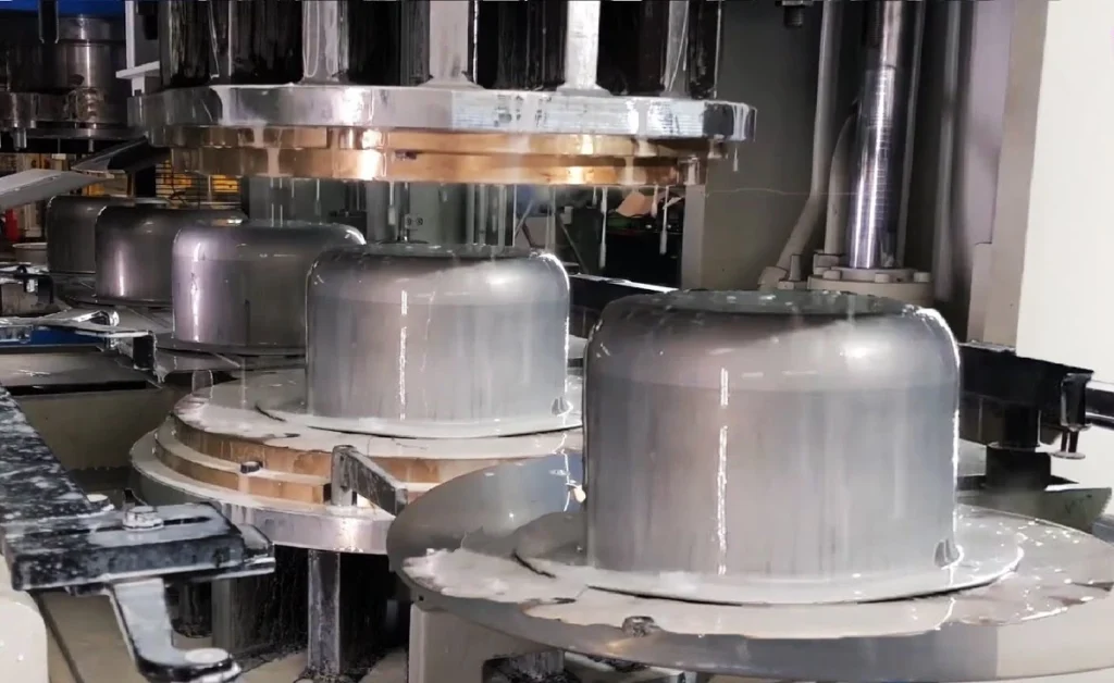
Hydraulic deep drawing presses are widely used across various industries due to their versatility and precision in shaping metal parts. From high-volume automotive production to specialized aerospace components, these presses play a crucial role in modern manufacturing. Below are some key industries where hydraulic deep drawing presses have become indispensable, along with specific examples of their applications.
Automotive Industry
One of the largest users of hydraulic deep drawing presses is the automotive industry. These presses are essential in the production of various automotive components that require complex shapes, precise dimensions, and high structural integrity. The deep drawing process is particularly well-suited for creating parts with high strength-to-weight ratios, which are critical for improving vehicle performance and fuel efficiency.
- Applications: Hydraulic deep drawing presses are used to manufacture a wide range of automotive parts, including:
- Car body panels: such as doors, fenders, and hoods.
- Fuel tanks: ensuring seamless, leak-proof construction.
- Engine components: where deep-drawn shapes are essential for housing and enclosures.
- Heat shields: used to protect various engine parts from high temperatures.
The demand for lightweight materials such as aluminum and advanced alloys has further increased the reliance on hydraulic presses, as they can easily handle these materials without compromising strength or accuracy.
Aerospace Industry
In the aerospace sector, hydraulic deep drawing presses are crucial for forming lightweight and high-strength components. The precision and control offered by these presses allow manufacturers to work with a variety of metals, including titanium, aluminum, and high-strength alloys that are commonly used in aerospace applications.
- Applications:
- Aircraft structural components: such as fuselage sections and bulkheads, which require precise forming to meet strict safety and performance standards.
- Fuel cells and tanks: deep drawing presses are used to produce seamless, high-strength fuel storage solutions for aircraft.
- Engine components: including housings, ducts, and other complex shapes that must withstand extreme temperatures and stresses during flight.
Given the aerospace industry’s stringent quality requirements, hydraulic presses’ ability to deliver consistent, defect-free parts makes them an essential piece of equipment in this sector.
Consumer Goods and Packaging Industry
Hydraulic deep drawing presses are also widely used in the production of consumer goods and packaging materials, where they shape metal into household products and packaging components. The precision of the press ensures high-quality finishes and uniform shapes, which are important for consumer-facing products.
- Applications:
- Kitchenware: such as sinks, pots, and pans, which are often deep drawn from stainless steel or aluminum sheets.
- Metal cans and containers: used in food, beverage, and cosmetic industries, where smooth, seamless shapes are required for both aesthetic and functional reasons.
- Aerosol cans: hydraulic presses are used to manufacture seamless aluminum and tinplate containers for products like deodorants, hairsprays, and cooking oils.
These presses offer the flexibility needed to produce small-to-medium-sized batches of high-quality consumer goods with consistent precision.
Electrical and Electronics Industry
In the electrical and electronics industry, hydraulic deep drawing presses are essential for producing housings, enclosures, and components that require high levels of accuracy and durability. These presses enable the manufacturing of parts with intricate geometries, thin walls, and tight tolerances, which are essential in electronic devices and systems.
- Applications:
- Enclosures for electrical equipment: such as circuit breakers, transformers, and switchgear components.
- Heat sinks: used in electronics to dissipate heat from sensitive components like CPUs and power transistors.
- Metal cases: for mobile phones, tablets, and other portable devices, where sleek designs and durability are critical.
Other Industries
Beyond the sectors mentioned above, hydraulic deep drawing presses are used in several other industries, such as medical devices, heavy machinery, and defense. For example:
- Medical devices: hydraulic presses are used to form components for surgical instruments and medical equipment.
- Heavy machinery: they are employed to manufacture large, robust parts for construction and industrial equipment.
- Defense: components such as shell casings and armor plates are deep drawn using hydraulic presses to ensure structural integrity and durability.
5. Key Components of Hydraulic Deep Drawing Press
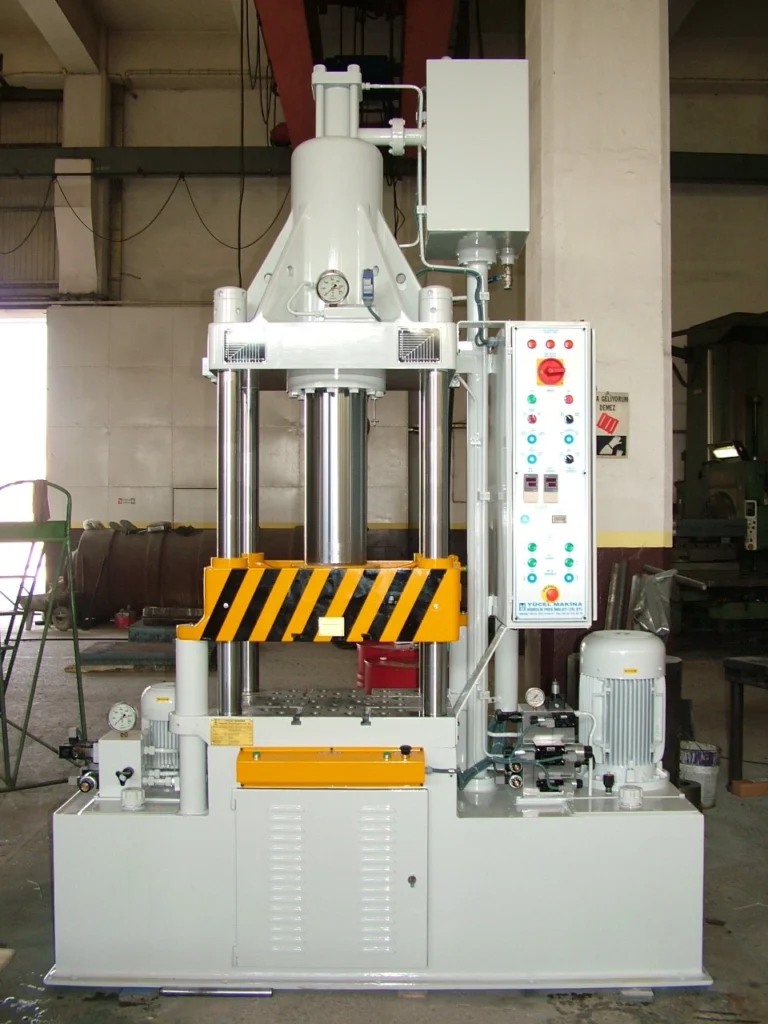
Hydraulic deep drawing presses consist of several critical components that work in harmony to ensure smooth, precise, and efficient operation. Understanding these key components helps buyers assess the quality, performance, and reliability of a press, making it easier to choose the right machine for their production needs.
1. Press Frame
The press frame serves as the foundation of the hydraulic deep drawing press, providing structural support and stability during operation. It must withstand the immense forces generated during the deep drawing process while maintaining alignment between the die and the punch. The frame is usually made from high-strength steel or cast iron to ensure durability and long-term reliability.
- Types of Frames:
- C-frame presses: Characterized by their C-shaped open structure, these presses are easy to operate and load but may lack the rigidity required for very high tonnage applications.
- H-frame presses: These have a more robust, closed design that provides greater strength and stability. H-frame presses are typically used for heavier, high-pressure deep drawing tasks, offering better alignment control.
- Importance: A strong and well-designed frame ensures that the press can operate at high loads without deforming, which is crucial for maintaining precision and part quality. The frame must also absorb vibration to prevent misalignment and minimize wear on other components.
2. Hydraulic Cylinders
The hydraulic cylinder is one of the most vital components of a hydraulic deep drawing press. It converts hydraulic energy into mechanical force, driving the movement of the ram (the part that pushes the punch into the metal blank). Hydraulic cylinders consist of a piston, barrel, and seals to contain the hydraulic fluid and ensure efficient force transmission.
- Types of Hydraulic Cylinders:
- Single-acting cylinders: These cylinders provide force in one direction only (downward) and are common in simpler press designs.
- Double-acting cylinders: More advanced presses use double-acting cylinders that can apply force in both directions, allowing for greater control over both the drawing and retraction phases of the process.
- Importance: The quality of the hydraulic cylinder directly impacts the force output, precision, and speed of the press. Efficient cylinders minimize energy loss, ensuring that the press operates with maximum efficiency while maintaining consistent force throughout the stroke.
3. Die and Punch
The die and punch are the forming tools of the deep drawing press. These components shape the metal blank during the drawing process. The punch, which is attached to the ram, pushes the metal into the die cavity, forcing it to take the desired shape.
- Die: The die is the stationary part of the press where the metal is shaped. It is designed according to the final product’s specifications, and its geometry plays a significant role in determining the quality of the drawn part. Dies are typically made from tool steel or carbide to withstand repeated impacts and high pressure.
- Punch: The punch presses the metal blank into the die, and its shape dictates the interior dimensions of the formed part. Like the die, the punch is made from durable materials to resist wear.
- Importance: The precision and quality of the die and punch are crucial to achieving high-accuracy, defect-free parts. For industries requiring exact dimensions and tight tolerances, such as aerospace or medical, the design and durability of the die and punch are critical factors in choosing a press.
4. Control System
The control system of a hydraulic deep drawing press plays an essential role in regulating the press’s movements, pressure, and speed. Modern presses are equipped with sophisticated control systems that allow for precise adjustments during the drawing process.
- PLC (Programmable Logic Controller): PLC systems offer automation and control of the press cycle, including the movement of the ram, pressure application, and timing. They allow operators to program specific parameters, ensuring repeatability and consistency in production.
- CNC (Computer Numerical Control): CNC systems are even more advanced, allowing for intricate control of the press’s operations with high levels of precision. These systems are typically used in presses that need to produce highly complex or precise parts, such as in aerospace or electronics manufacturing.
- Importance: The control system directly affects the precision, speed, and safety of the press. Advanced control systems allow for greater automation, which increases production efficiency and reduces the risk of operator error.
5. Pressure Valves, Pumps, and Hydraulic Reservoir
These components work together to control the flow and pressure of the hydraulic fluid, which powers the press. The hydraulic pump is responsible for generating the necessary pressure, while pressure control valves ensure that the press operates within safe limits. The hydraulic reservoir stores the fluid when not in use and helps regulate its temperature, ensuring consistent performance over time.
- Hydraulic Pump: There are several types of pumps, such as gear pumps, vane pumps, and piston pumps, each suited for different pressure and flow requirements. The pump ensures that enough force is generated to perform deep drawing operations efficiently.
- Pressure Control Valves: These valves are crucial for maintaining the desired pressure levels. They prevent overpressure situations, which could cause damage to the press or result in defective parts.
- Hydraulic Reservoir: The reservoir ensures that the press has a sufficient supply of hydraulic fluid and helps cool and filter the fluid to maintain optimal performance.
- Importance: The efficiency and reliability of these components directly affect the press’s power output, safety, and operational lifespan. Poorly maintained hydraulic systems can lead to fluid leaks, pressure loss, or overheating, which can reduce productivity and increase maintenance costs.
6. Comparison with Mechanical Presses
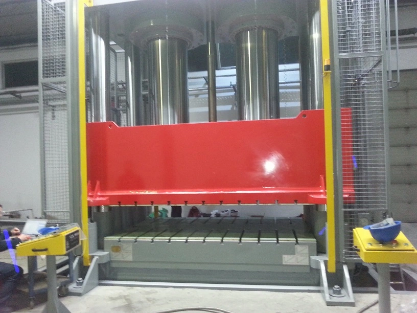
For potential buyers of deep drawing presses, understanding the differences between hydraulic presses and mechanical presses is critical to making an informed purchasing decision. Both types of presses have their unique advantages, depending on the specific requirements of the production process. This section will compare hydraulic and mechanical presses based on their operation, flexibility, efficiency, and applications, helping buyers determine which system best suits their needs.
Differences in Operation: Hydraulic vs. Mechanical Force Generation
The most fundamental difference between hydraulic and mechanical presses lies in how they generate force.
- Hydraulic Presses: These presses use hydraulic fluid to generate force, applying consistent pressure throughout the entire stroke. By leveraging Pascal’s Law, hydraulic presses exert a continuous, adjustable force, allowing for better control over the drawing process. This enables operators to regulate the press’s pressure, speed, and force, making hydraulic presses ideal for processes that require variable tonnage and precision.
- Mechanical Presses: Mechanical presses, on the other hand, rely on flywheels and crankshafts to generate force. The flywheel stores energy and transfers it to the crankshaft, creating motion that drives the ram into the die. Mechanical presses provide force only at the bottom of the stroke, which means the peak force is limited to a specific point in the cycle. This design is more suitable for high-speed operations with uniform force requirements, such as stamping or shallow forming.
Advantages of Hydraulic Presses: Flexibility and Precision
One of the key advantages of hydraulic presses over mechanical presses is their flexibility. Hydraulic systems allow for precise control over tonnage, meaning that the press can be adjusted for a wide range of materials, part sizes, and shapes. This makes hydraulic presses particularly useful for deep drawing, where the ability to finely tune the pressure is essential for producing parts with consistent quality.
- Variable Force: Hydraulic presses can be set to apply the exact force needed for a specific application, reducing the risk of damaging materials or producing defective parts. This makes them well-suited for working with thin metals, delicate alloys, or complex geometries.
- Adjustable Stroke Length and Speed: Hydraulic presses offer variable stroke lengths and the ability to control the ram speed, allowing for greater precision during the forming process. This is particularly useful for deep drawing operations, where slower, more controlled movement is necessary to prevent tearing or wrinkling of the material.
Mechanical presses, by contrast, are limited to a fixed stroke and speed, making them less adaptable for jobs requiring deep or complex shapes. However, they are more efficient for high-speed, high-volume production runs that require repetitive tasks, such as stamping and shallow drawing.
Specific Scenarios Where Mechanical Presses Excel
Despite the advantages of hydraulic presses, mechanical presses still hold several key advantages in certain scenarios, particularly for high-speed, high-volume production.
- Speed and Efficiency: Mechanical presses are faster than hydraulic presses, making them ideal for applications that require rapid cycling and short press times. In high-speed stamping operations, mechanical presses can produce parts more quickly, allowing manufacturers to meet high production targets.
- Energy Efficiency: Mechanical presses are generally more energy-efficient for high-volume operations because they store energy in the flywheel and release it at the point of impact. This contrasts with hydraulic presses, which consume energy continuously throughout the stroke. For manufacturers looking to reduce energy costs, mechanical presses may offer a cost-effective solution for simple tasks.
Energy Efficiency and Operational Costs
When comparing the operational efficiency of the two types of presses, hydraulic presses often require more energy to operate due to the continuous need for hydraulic fluid pressure. However, they make up for this in their versatility and precision, particularly for lower-volume runs that require more complex forming tasks.
- Hydraulic Presses: Typically have higher energy consumption, especially when running continuously. However, their ability to handle multiple operations—such as deep drawing, forming, and blanking—on a single machine can offset some of the additional energy costs in multi-stage processes.
- Mechanical Presses: Mechanical presses are more cost-effective in energy usage for high-volume, high-speed applications, as their force generation occurs only at specific points, using energy stored in the flywheel. This makes them ideal for industries focused on mass production of simple parts where speed is prioritized over flexibility.
Suitability for Different Applications
- Hydraulic Presses: Best suited for deep drawing, forming intricate shapes, and applications requiring flexibility in material and part geometry. Industries such as aerospace, automotive, and consumer goods manufacturing benefit most from hydraulic presses’ ability to handle complex, custom parts.
- Mechanical Presses: Ideal for stamping, blanking, and shallow forming operations where high-speed production is crucial. Mechanical presses are most commonly used in industries where large volumes of standardized parts are needed quickly, such as automotive stamping plants and metal packaging manufacturers.
7. Advantages and Disadvantages of Hydraulic Deep Drawing Press
Hydraulic deep drawing presses offer numerous benefits for manufacturers seeking precision and versatility in metal forming operations. However, like any technology, they also come with certain drawbacks that buyers need to consider. In this section, we will explore the advantages and disadvantages of hydraulic deep drawing presses, giving potential buyers a comprehensive understanding of what to expect when choosing this technology.
Advantages of Hydraulic Deep Drawing Presses
1. Greater Forming Depth and Capacity for Complex Shapes
Hydraulic presses excel at forming deep, intricate shapes with consistent accuracy, which is essential for applications requiring complex geometries. The ability to apply continuous and adjustable pressure throughout the entire stroke allows hydraulic presses to form deep-drawn parts without material tearing or wrinkling. This makes them the preferred choice for industries like automotive, aerospace, and consumer goods, where complex parts such as fuel tanks, car body panels, and metal containers are produced.
- Deep Drawing: Hydraulic presses are highly effective for deep drawing operations, enabling the creation of parts with depths greater than their diameters. They can handle even challenging materials, such as stainless steel or aluminum, while maintaining part integrity.
2. Precision Control Over Pressure, Speed, and Force
One of the key advantages of hydraulic presses is their ability to provide precise control over force during the entire forming process. Unlike mechanical presses that apply peak force only at the bottom of the stroke, hydraulic presses deliver constant pressure, making it easier to control the flow of material into the die.
- Adjustability: Hydraulic systems allow operators to adjust the pressure, ram speed, and stroke length to suit different materials, part sizes, and shapes. This level of control is essential for producing parts with tight tolerances and consistent quality.
- Versatility: The adjustability of hydraulic presses also allows for versatility in forming various materials, from soft metals like aluminum to high-strength alloys. Manufacturers can use the same press for multiple operations, including deep drawing, bending, forming, and punching, enhancing overall production flexibility.
3. Versatility with Various Materials and Shapes
Hydraulic deep drawing presses can handle a wide range of metal types and sheet thicknesses. This versatility makes them suitable for a variety of industries that work with diverse materials, such as lightweight metals for automotive and aerospace components or thicker steel sheets for heavy-duty machinery parts.
- Multiple Applications: The ability to adjust force and speed for different applications means that manufacturers can use hydraulic presses for short-run custom jobs as well as high-volume production.
4. Lower Maintenance Requirements Compared to Mechanical Presses
Hydraulic presses tend to have fewer moving parts compared to mechanical presses, which often results in lower maintenance requirements. The absence of complex flywheels, crankshafts, and gears in hydraulic systems means fewer components are subject to wear and tear, leading to longer service intervals and reduced downtime for repairs.
- Simplified Design: The simplified design of hydraulic systems results in easier troubleshooting and lower costs for spare parts and repairs. Maintenance generally focuses on hydraulic fluid levels, seals, and filters, all of which are relatively straightforward to monitor and replace.
5. Flexibility in Production Volume
Hydraulic presses are well-suited for both low-volume custom jobs and high-volume production runs, thanks to their versatility and adjustable settings. Manufacturers can use them for prototype development, short production runs, or mass production, making hydraulic presses a valuable investment for companies that require flexibility in their manufacturing operations.
Disadvantages of Hydraulic Deep Drawing Presses
1. Slower Operation Compared to Mechanical Presses
While hydraulic presses excel in flexibility and precision, they are generally slower than mechanical presses, especially in high-speed production environments. Mechanical presses can cycle much faster, making them better suited for industries that need to produce large volumes of simple parts quickly, such as in stamping or blanking operations.
- Cycle Time: The longer cycle time in hydraulic presses can limit their use in high-volume production runs where speed is a critical factor. For manufacturers focused on maximizing output speed, mechanical presses may be a better choice.
2. Higher Initial Cost
Hydraulic deep drawing presses tend to have a higher initial cost compared to mechanical presses, especially when considering advanced models with PLC or CNC control systems. The investment in hydraulic technology is often justified by the versatility and precision it offers, but for manufacturers with more straightforward stamping needs, the upfront cost may be a significant consideration.
- Advanced Features: Features like programmable pressure control, automated die changes, and precision force regulation add to the cost of hydraulic presses, but they also provide enhanced capabilities that can improve overall production efficiency and reduce long-term costs.
3. Fluid Leakage and Maintenance of Hydraulic Systems
One of the common challenges with hydraulic presses is the potential for hydraulic fluid leakage, which can lead to reduced pressure and operational efficiency. Seals, hoses, and pumps must be regularly inspected and maintained to prevent leaks and ensure that the hydraulic system remains effective.
- Environmental Concerns: Leaking hydraulic fluid can also pose environmental risks, particularly if the press is operating in industries with stringent environmental regulations. Proper disposal of hydraulic fluid is essential to prevent contamination.
- Maintenance: While hydraulic presses generally have fewer moving parts than mechanical presses, maintaining the hydraulic fluid, seals, and pumps requires regular attention to avoid breakdowns and ensure consistent performance.
4. Energy Consumption
Hydraulic presses typically consume more energy compared to mechanical presses, particularly in continuous operation. Hydraulic systems rely on fluid pressure to generate force, which requires constant energy input. This can result in higher operational costs over time, especially in high-production environments.
- Energy Efficiency: Advances in energy-efficient hydraulic systems, such as the integration of servo-hydraulic systems, are helping to mitigate this disadvantage by reducing power consumption during idle times and optimizing fluid pressure only when needed.
8. Important Considerations for Selecting a Hydraulic Deep Drawing Press
When investing in a hydraulic deep drawing press, potential buyers must carefully evaluate several key factors to ensure the machine meets their production needs. Making the right selection can significantly enhance productivity, product quality, and operational efficiency. This section outlines the most important considerations for buyers, including specifications, material compatibility, production volume requirements, automation options, and after-sales support.
1. Key Specifications to Evaluate
Choosing the right hydraulic deep drawing press starts with understanding the key technical specifications that determine the machine’s performance and suitability for specific applications. These specifications should align with the nature of the parts being produced and the materials used.
- Tonnage (Force Capacity): The press’s tonnage refers to the maximum force it can apply during the deep drawing process. Tonnage requirements vary depending on the material type, sheet thickness, and depth of the draw. It’s important to select a press with sufficient tonnage to form parts without overstressing the material or the machine itself.
- For example, thin aluminum sheets may require lower tonnage, whereas thicker steel plates will need higher force to achieve the desired shape.
- Bed Size and Stroke Length:
- Bed Size: The size of the press’s working area (or bed) determines the maximum size of the blank that can be formed. Buyers should choose a bed size that accommodates their largest parts while leaving enough room for proper tool installation.
- Stroke Length: The stroke length refers to the distance the ram travels during each press cycle. A longer stroke is necessary for deeper drawing operations, ensuring the punch can form the metal blank into the die without excessive force at the bottom of the stroke.
- Speed: Ram speed is a critical factor, especially for high-production environments. While hydraulic presses are typically slower than mechanical presses, modern presses offer variable speed settings that can be adjusted for specific jobs, balancing precision with efficiency.
2. Material Type and Thickness Compatibility
Hydraulic deep drawing presses need to be compatible with the materials used in production. Different materials have unique properties that affect the force required to form them, as well as the potential for defects like cracking, wrinkling, or tearing during deep drawing.
- Common Materials: The most commonly used materials in deep drawing processes include stainless steel, aluminum, copper, and mild steel. Each material has its own characteristics in terms of ductility, strength, and formability.
- Forming Capability: If the production process involves lightweight alloys, such as those used in automotive and aerospace applications, it’s important to select a press with precise pressure control to avoid over-stressing the material. On the other hand, for heavier-duty materials like high-strength steel, the press must have enough power to shape the metal without causing excessive strain or defects.
3. Production Volume Requirements
Manufacturers need to consider their production volume when selecting a hydraulic deep drawing press. Different press models cater to varying levels of production, from small-batch prototyping to mass production.
- Low to Medium Volume Production: Hydraulic presses are ideal for low to medium volume production runs due to their versatility and ability to handle different part designs without significant retooling. Manufacturers who produce a variety of parts in small quantities can benefit from the flexibility of hydraulic presses.
- High Volume Production: For high-volume production, buyers should consider presses with automated systems to improve efficiency and reduce cycle times. Automated material feeding systems, robotic handling, and programmable controls can significantly enhance productivity and ensure consistent part quality over long production runs.
4. Automation Options and Integration
Automation has become increasingly important in manufacturing, and integrating it into a hydraulic deep drawing press can offer significant advantages in terms of efficiency, precision, and cost-effectiveness.
- PLC (Programmable Logic Controller): A PLC system allows for automation of the press’s movements, enabling more precise control over the drawing process. PLCs can store multiple programs for different jobs, making it easy to switch between part designs and reduce setup time. This is especially useful in facilities where diverse products are manufactured.
- CNC Control Systems: For even greater automation and precision, CNC-controlled hydraulic presses can deliver highly accurate force, position, and speed adjustments. CNC systems are ideal for complex and high-tolerance applications, ensuring consistency and repeatability in every part.
- Robotic Integration: For high-volume operations, robotic systems can be integrated to handle tasks such as loading and unloading materials, reducing the need for manual labor and increasing overall efficiency. Robots can also assist in secondary operations, like part inspection, further streamlining production.
5. Warranty, Support, and After-Sales Service
When purchasing a hydraulic deep drawing press, it’s crucial to consider the manufacturer’s warranty, technical support, and after-sales services. A robust support network can help reduce downtime and ensure that the press operates at peak performance throughout its lifecycle.
- Warranty: Most reputable manufacturers offer a comprehensive warranty covering the press’s main components, such as the hydraulic system, control electronics, and frame. Buyers should carefully review the warranty terms, including the coverage period and what specific repairs or replacements are included.
- Technical Support: Having access to technical support is vital, especially in the event of machine malfunctions or performance issues. Many manufacturers provide remote troubleshooting services, on-site technician visits, and detailed operator training to help resolve issues quickly.
- After-Sales Service: Regular maintenance is essential to keep the press in good working condition. Buyers should look for manufacturers that offer scheduled maintenance plans, replacement part availability, and service agreements to minimize downtime and maximize machine lifespan.
6. Total Cost of Ownership (TCO)
In addition to the initial purchase price, buyers must also consider the total cost of ownership (TCO) of the hydraulic deep drawing press. This includes the long-term costs of energy consumption, maintenance, replacement parts, and potential downtime. While hydraulic presses may have a higher upfront cost than mechanical presses, their versatility and lower maintenance requirements can result in lower TCO over time.
Hydraulic Deep Drawing Press
A hydraulic deep drawing press is a powerful machine that utilizes hydraulic pressure to form metal blanks into desired shapes. It is a versatile tool used in various industries, including automotive, aerospace, and appliance manufacturing, to produce a wide range of components with complex geometries and precise dimensions.
Key Components of a Hydraulic Deep Drawing Press
- Frame: The frame provides the structural support for the entire press, ensuring stability and rigidity during the forming process.
- Hydraulic System: The hydraulic system comprises a pump, reservoir, valves, and cylinders that generate and regulate the pressurized fluid responsible for applying force to the blank.
- Press Platens: The press platens are horizontal plates that sandwich the blank between them, with the lower platen fixed to the frame and the upper platen attached to the hydraulic cylinders.
- Dies: Dies are the shaped tools that define the final form of the part. They consist of a punch, which forces the blank into the desired shape, and a die ring, which supports and guides the blank during forming.
- Blank Holder: The blank holder applies a clamping force to the periphery of the blank, preventing wrinkles and ensuring uniform material flow during forming.
Operation of a Hydraulic Deep Drawing Press
- Blank Positioning: The blank is accurately positioned between the dies and the blank holder.
- Hydraulic Pressure Application: The hydraulic cylinders extend, applying force to the upper platen and forcing the punch into the blank.
- Material Flow: The blank material flows over the punch and takes on the desired shape, gradually conforming to the contour of the die.
- Ejection: Once the forming process is complete, the punch retracts, and the formed part is ejected from the dies.
Advantages of Hydraulic Deep Drawing Presses
- High Precision: Hydraulic deep drawing presses can produce parts with high dimensional accuracy and consistent surface finish.
- Complex Shapes: They are capable of forming complex shapes with intricate details and tight tolerances.
- High Production Rates: These presses can achieve high production rates, suitable for mass production environments.
- Versatility: They can handle a wide range of materials, including steel, aluminum, and brass.
- Automation Potential: Hydraulic deep drawing presses can be automated, reducing labor requirements and enhancing productivity.
Limitations of Hydraulic Deep Drawing Presses
- Initial Investment: Hydraulic deep drawing presses can be costly to purchase and install.
- Tooling Complexity: The design and manufacturing of dies can be complex and expensive.
- Material Limitations: Some materials, such as high-strength steels, may require specialized equipment or processes.
- Scrap Generation: The deep drawing process can generate scrap material, which adds to production costs.
Safety Considerations for Hydraulic Deep Drawing Presses
- Proper Training: Operators must receive comprehensive training on the safe operation of the press, including emergency procedures.
- Protective Equipment: Operators must wear appropriate PPE, including safety glasses, gloves, and sturdy footwear.
- Safety Guards: Safety guards should be installed to prevent operator contact with moving parts and potential hazards.
- Emergency Stop Buttons: Easily accessible emergency stop buttons should be located throughout the press area.
- Regular Maintenance: Regular maintenance and inspection of the press and its components are essential to ensure their proper functioning and prevent potential failures.
Conclusion
Hydraulic deep drawing presses are powerful and versatile machines that play a critical role in the production of complex metal components. Their ability to generate high forces and precisely control the forming process makes them essential for various manufacturing industries. By implementing proper safety measures, maintaining regular maintenance schedules, and ensuring operator training, manufacturers can maximize the benefits of these machines while minimizing potential hazards.
The Frame of a Hydraulic Deep Drawing Press
The frame of a deep drawing press is a critical component that provides structural support for the entire machine. It must be designed to withstand the high forces generated during the deep drawing process while remaining stable and free from deflection.
The frame is typically made from high-strength steel or cast iron, which is selected for its durability and ability to resist deformation under high loads. The design of the frame is carefully engineered to distribute the load evenly across the structure, minimizing stress concentrations that can lead to failure.
The frame is usually constructed from several large plates, which are bolted or welded together to form a rigid structure. The plates are machined to ensure precise alignment and to provide a flat mounting surface for the bed and other components.
The frame also contains a series of guide rails, which are used to guide the movement of the ram and the blank holder. These rails must be precisely aligned to ensure smooth and accurate operation of the press.
Overall, the frame is a critical component of a deep drawing press, providing the foundation for the machine and ensuring its long-term performance and reliability. It must be designed and manufactured to the highest standards to ensure the safe and efficient operation of the press.
The Bed of the Hydraulic Deep Drawing Press
The bed of a deep drawing press is the flat surface on which the metal sheet is placed for processing. It is a critical component that must be designed to provide a stable and level surface to ensure proper operation of the press.
The bed is typically made from a high-strength steel plate that is machined to provide a smooth and level surface. It is usually mounted on the frame of the press and is designed to withstand the high forces generated during the deep drawing process.
The surface of the bed is often covered with a layer of material, such as polyurethane or rubber, to protect the metal sheet from damage during processing. This layer also helps to reduce friction between the metal sheet and the bed, ensuring the smooth and consistent movement of the sheet during the deep drawing process.
The bed may also include a series of holes or slots that are used to secure the blank holder and die in place. These holes or slots are typically designed to accommodate a range of different sizes and shapes of tooling, allowing the press to be used for a variety of different deep drawing applications.
Overall, the bed of a deep drawing press is a critical component that must be carefully designed and manufactured to ensure the proper operation of the press. It must be sturdy, level, and able to withstand the high forces generated during the deep drawing process, while also providing a smooth and consistent surface for the metal sheet to be processed.
The Ram of the Hydraulic Deep Drawing Press
The ram of a deep drawing press is a critical component that is responsible for exerting the force necessary to shape the metal sheet. The ram is typically driven by a hydraulic or mechanical system, and it moves up and down in a vertical direction.
The ram is usually made from a high-strength steel or cast iron, which is selected for its durability and ability to withstand the high forces generated during the deep drawing process. The ram is typically mounted on a set of guide rails, which ensure that it moves smoothly and accurately in a vertical direction.
At the end of the ram, there is a tool holder that holds the punch, which is the component that presses the metal sheet into the die. The tool holder is usually designed to allow for quick and easy changing of the punch, allowing the press to be used for a variety of different deep drawing applications.
The force applied by the ram can be controlled by adjusting the pressure in the hydraulic or mechanical system. This allows the press operator to vary the force applied to the metal sheet, depending on the requirements of the specific deep drawing application.
Overall, the ram of a deep drawing press is a critical component that must be carefully designed and manufactured to ensure proper operation of the press. It must be sturdy and able to withstand the high forces generated during the deep drawing process, while also moving smoothly and accurately in a vertical direction. The design of the tool holder must also allow for quick and easy changing of the punch, allowing the press to be used for a variety of different deep drawing applications.
The Hydraulic System of the Hydraulic Deep Drawing Press
The hydraulic system is an essential component of a deep drawing press that provides the force required to drive the ram and punch. The hydraulic system typically consists of a hydraulic pump, a hydraulic fluid reservoir, valves, and hoses or pipes that connect the various components.
The hydraulic pump is responsible for pressurizing the hydraulic fluid and delivering it to the ram and punch of the press. The hydraulic fluid reservoir stores the hydraulic fluid, which is typically a specialized oil that has been selected for its ability to withstand the high temperatures and pressures associated with the deep drawing process.
The valves in the hydraulic system are used to control the flow of hydraulic fluid and to regulate the pressure applied to the ram and punch. The valves can be manually or automatically controlled, depending on the specific deep drawing application.
The hoses or pipes that connect the various components of the hydraulic system must be carefully designed and manufactured to withstand the high pressures and temperatures associated with the deep drawing process. They must also be routed in a way that minimizes the risk of damage or interference with other components of the press.
Overall, the hydraulic system is a critical component of a deep drawing press that must be carefully designed and maintained to ensure proper operation of the press. The system must be able to deliver the high forces required for the deep drawing process, while also being reliable and easy to control. The hydraulic system must also be able to withstand the high temperatures and pressures associated with the deep drawing process, and the various components of the system must be carefully designed and installed to minimize the risk of damage or failure.
The Blankholder of the Hydraulic Deep Drawing Press
The blankholder of a deep drawing press is a component that is responsible for holding the metal sheet in place during the deep drawing process. The blankholder is designed to exert a clamping force on the metal sheet, which prevents it from wrinkling or tearing as it is drawn into the die.
The blankholder is typically mounted on the ram of the press, and it is usually made from a high-strength steel or cast iron that is capable of withstanding the high forces generated during the deep drawing process.
The blankholder is typically designed to accommodate a range of different sheet sizes and thicknesses. It may include a set of clamps or jaws that can be adjusted to hold the metal sheet securely in place, or it may use a pneumatic or hydraulic system to apply a controlled clamping force.
The force applied by the blankholder can be adjusted to suit the specific requirements of the deep drawing application. In some cases, a lower clamping force may be required to prevent wrinkling or tearing of the metal sheet, while in other cases a higher clamping force may be necessary to ensure proper material flow and draw depth.
Overall, the blankholder is a critical component of a deep drawing press that must be carefully designed and manufactured to ensure proper operation of the press. It must be sturdy and able to withstand the high forces generated during the deep drawing process, while also providing a secure and adjustable clamping force to prevent wrinkling or tearing of the metal sheet.
The Die of the Hydraulic Deep Drawing Press
The die is a critical component of a deep drawing press that is responsible for shaping the metal sheet into the desired shape. The die is typically made from high-strength steel or carbide, which is selected for its ability to withstand the high forces and wear associated with the deep drawing process.
The die is typically mounted on the bed of the press and is designed to provide a cavity or recess that matches the desired shape of the finished product. The metal sheet is placed on top of the die, and the ram of the press is then lowered onto the sheet, pressing it into the die cavity and forming it into the desired shape.
The design of the die can vary depending on the specific deep drawing application. For example, the die may be a single-stage die that forms the metal sheet into the desired shape in one operation, or it may be a multiple-stage die that uses a series of smaller dies to gradually form the sheet into the final shape.
The die may also incorporate features such as vents or ejector pins, which are used to ensure proper material flow and to remove the finished product from the die after the deep drawing process is complete.
Overall, the die is a critical component of a deep drawing press that must be carefully designed and manufactured to ensure proper operation of the press. It must be able to withstand the high forces and wear associated with the deep drawing process, while also providing a cavity or recess that matches the desired shape of the finished product.
The Punch of the Deep Drawing Press
The punch is another critical component of a deep drawing press that is responsible for pressing the metal sheet into the die to form the desired shape. The punch is typically mounted on the end of the ram and is designed to fit into the die cavity.
The punch is usually made from high-strength steel or carbide, which is selected for its ability to withstand the high forces and wear associated with the deep drawing process. The design of the punch can vary depending on the specific deep drawing application, but it typically includes a head or tip that matches the desired shape of the finished product.
The force applied by the punch can be controlled by adjusting the pressure in the hydraulic or mechanical system that drives the ram of the press. This allows the press operator to vary the force applied to the metal sheet, depending on the requirements of the specific deep drawing application.
The punch is also designed to be easily replaceable, allowing the press to be used for a variety of different deep drawing applications. In some cases, the punch may be designed to be adjustable, allowing the press operator to vary the height or angle of the punch to achieve the desired shape.
Overall, the punch is a critical component of a deep drawing press that must be carefully designed and manufactured to ensure proper operation of the press. It must be able to withstand the high forces and wear associated with the deep drawing process, while also providing a head or tip that matches the desired shape of the finished product. The design of the punch must also allow for quick and easy replacement, and in some cases, adjustability to suit the specific requirements of the deep drawing application.
The Control Panel of the Deep Drawing Press
The control panel of a deep drawing press is the interface between the operator and the press. It contains various controls and indicators that allow the operator to monitor and adjust the operation of the press. The control panel typically includes the following components:
- Power Switch: This switch is used to turn the press on and off.
- Emergency Stop Button: This button is used to immediately stop the press in the event of an emergency.
- Cycle Start Button: This button is used to start the deep drawing cycle after the operator has loaded the metal sheet and adjusted the punch and die.
- Pressure Gauge: This gauge displays the hydraulic pressure applied to the ram and punch.
- Temperature Gauge: This gauge displays the temperature of the hydraulic fluid in the reservoir.
- Cycle Counter: This counter displays the number of completed deep drawing cycles.
- Control Knobs: These knobs are used to adjust the pressure and speed of the ram and punch during the deep drawing cycle.
- Display Screen: This screen displays important information such as the cycle time, pressure, and temperature.
- Alarm Indicators: These indicators provide visual or audible alerts when certain conditions are met, such as when the hydraulic pressure is too high or the temperature is too hot.
The control panel is typically located on the front of the press and is designed to be easily accessible by the operator. It must be carefully designed and manufactured to ensure proper operation of the press and the safety of the operator. The controls and indicators on the control panel must be clearly labeled and easy to use, and the panel must be designed to withstand the high temperatures, pressures, and vibrations associated with the deep drawing process.
Sheet Metal Forming with a Hydraulic Deep Drawing Press
Sheet metal forming is used to produce various products from mild steel, stainless steel, copper, aluminum, gold, platinum, tin, nickel, brass, and titanium. To reduce costs and increase the performance of manufactured products, more and more lightweight and high-strength materials have been used as a substitute for conventional steel.
These materials usually have limited formability, thus, a thorough understanding of deformation processes and the factors limiting the forming of sound parts is important, from both engineering and economic viewpoints. In sheet metal forming, a piece of material is plastically deformed between tools to obtain the desired product.
Sheet metal forming is characterized by the conditions in which the stress component normal to the plane of the sheet is generally much smaller than the stresses in the plane of the sheet. The common defects that occur in sheet metal forming are wrinkling, necking, scratching, and cracks. Wrinkling occurs in areas with high compressive strains and necking in areas with high tensile strains. Scratching is caused by defects on the tool surface and orange peel may occur after excessive deformation depending on the grain size of the material. Companies use automatic edge-trimming beading machines to trim the edges of parts that are deep drawn
Stages in Deformation of the Work in Deep Drawing
- Punch makes initial contact with work
- Bending
- Straightening
- Friction & Compression
Final cup shape showing effects of thinning in the cup
The Drawing Force of a Hydraulic Deep Drawing Press
The force in the punch required to produce a cup is the summation of the ideal deformation force, the frictional forces, and the force required to produce ironing.
Tools and Molds
A double-action mechanical press is generally used for deep drawing, hydraulic presses are also used. The double-action press controls the punch and blank holder independently and forms the part at a constant speed. Since blank holder force controls the flow of the sheet metal within the die, now presses have been designed with variable blank-holder force. In these presses, the blank holder force is varied with
punch stroke.
The most important factor in the die design is the corner radius (Rd) of the die. This radius must have an optimum value since the material is pulled over it. The value for the optimum radius of the die depends upon the print requirement and the type of material being drawn. Obviously, the smaller the die radius, the greater the force needed to draw the cup. The radius of the die may be between four to eight times the thicknesses of the blank.
Die sets are an essential component of a deep drawing press. They are used to shape and form the metal into the desired shape. The die set consists of two parts, the upper die (punch) and the lower die (die shoe). These two parts work together to form the metal into the desired shape.
The upper die is the punch, which is mounted on the ram of the press. The lower die, also known as the die shoe, is mounted on the press bed. The metal is placed between these two dies, and pressure is applied to the punch. The punch presses the metal into the die, causing it to take on the desired shape.
Die sets can be designed for a wide range of shapes and sizes, depending on the specific needs of the deep drawing process. They can be used to create shapes such as cylinders, cones, and boxes. Some die sets are designed to create more complex shapes, such as those used in the automotive and aerospace industries.
Die Set Design
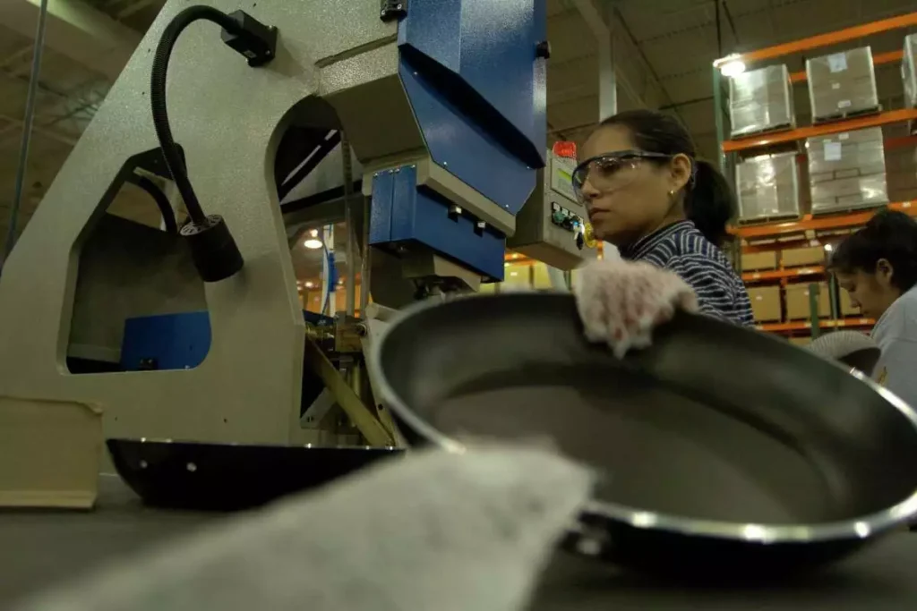
The design of the die set is critical to the success of the deep drawing process. The angle of the punch and die, the clearance between the punch and die, and the type of material used all play a crucial role in the final product. The angle of the punch and die is critical because it determines the amount of metal that will be drawn into the die. The clearance between the punch and die is also critical because it affects the quality of the finished product. If the clearance is too tight, the metal will tear, and if it is too loose, the metal will buckle.
The material used for the die set must also be carefully considered. The material must be able to withstand the high pressures and temperatures of the deep drawing process. Typically, the upper die (punch) is made from a high-speed steel or a tungsten carbide, which is extremely hard and can withstand the high pressures of the deep drawing process. The lower die (die shoe) is usually made from a softer steel to allow for easier machining.
In addition to the design and material of the die set, the lubrication used during the deep drawing process is also critical. Lubrication is essential to reduce friction between the metal and the die, which can lead to tearing and wrinkling of the metal. Various types of lubricants are used, including oils, greases, and dry lubricants.
In conclusion, die sets are an essential component of a deep drawing press. They play a critical role in the success of the deep drawing process by shaping and forming the metal into the desired shape. The design and material of the die set, as well as the lubrication used, all play a critical role in the final product. As such, it is important to carefully consider these factors when designing and using die sets for deep drawing processes.
Pressure Plate
The pressure plate is a little less in dimension than the base plate or top plate as it has to move up and down in the machine. This plate will move up and down with the help of two piston rods which will hold it at the two ends. This plate will hold the metal sheet and then the punch will come down and punch the metal sheet. It has a center hole through which the punch moves up and down. This is an important part of the system as it has to hold the metal sheet. Due to this plate, there are fewer chances of wrinkles on the workpiece
Pillars
There are a total of four pillars in this machine. These pillars are mounted between the top plate and the bottom plate. They are fixed with top and bottom plates with bolt arrangement. They support the whole weight of cylinders and the top plate. They reduce vibrations of the machine to transfer to the base plate and ultimately to the die set. This avoids any variation in the workpiece.
Frame
This is the component of the system that takes all load of the machine. This takes a load of hydraulic cylinders, base plates, top plates, and pillars. It also holds an ejection system which helps in the ejection of the workpiece from the die set.
C Clamp
This component of the system helps in the ejection of the workpiece from the die. It also limits the movement of the pressure plate. This C- clamp is connected to the piston rod of the punching cylinder. It also has one limiting movement mechanism. With this mechanism, the armature of the C-clamp is made contact with the pressure switch is used to stop the C-clamp.
Construction of a Deep Drawing Press
The machine is basically made up of mild steel. The reasons are:
- Mild steel is readily available in the market.
- It is economical to use.
- It is available in standard sizes.
- It has good mechanical properties.
- It has a moderate factor of safety.
- It has high tensile strength.
- Low co-efficient of thermal expansion
Properties of Mild Steel
M.S. has carbon content from 0.15% to 0.30%. They are easily wieldable and thus can be hardened only. They are similar to wrought iron in properties. Both the ultimate tensile and compressive strength of these steel increases with increasing carbon content. They can be easily gas welded or electric or arc welded. With the increase in the carbon percentage, weldability decreases. Mild steel served the purpose and was selected for the above purpose.
Construction and Welding of a Hydraulic Deep Drawing Press
Double Action Deep Drawing Hydraulic Press Machine Automation plane uses a hydraulic cylinder for both direction movement and stroke, a hydraulic motor is used to drive the hydraulic cylinder, and a pleasure switch to control the movement of the press pad and punch. Solenoid valves are widely used on compressed air or hydraulic fluid for powering actuators on mechanical components.
While motors are used to supply continuous rotary motion, actuators are typically a better choice for intermittently creating a limited range of movement for a mechanical component, such as moving various mechanical arms, opening or closing valves, raising heavy press rolls, and applying pressure to presses. Control circuits are often drawn using ladder logic, so named because the wiring diagram resembles a ladder. First of all base plate is mounted on the frame.
Base Plate of a Hydraulic Deep Drawing Press
The base plate is welded to the frame. Then take four pillars were situated vertically on the base plate and in they are fitted to the base plate with help of a bolt and lock nut. Over that pillar, the top plate is situated and it is fixed with the nut and bolt. After that, the round plate is welded to the top plate at its center. Over that round plate cylinder of 20 tones is fixed with nut and bolt. Which are situated in the holes on the circumference of the round plate. After this situation of the center cylinder is used for the punching operation.
Then and edges of the top plate square blocks are welded and over that block cylinder of 2.5 tones is fixed. With the same process that of the center cylinder. After that piston of the cylinder which is of 2.5 tones brought down and the pressure plate is fixed with it at the edges and with help of a square block. In that Allen bolts and nuts. After that clamp is situated in the center cylinder piston by cutting and milling it into that shape. Another part of the c-clamp is assembling the top of the ejection system.
Which is situated below the base plate Pressure switch is situated on the top plate to limit the movement of the c-clamp in the upward and downward direction. The hydraulic system is brought near the machine and its pipes and ports are connected to the values of the cylinder. There is a system of switches. The white switch is for the downward movement of the center piston which acts as the punch.
And the black switch is for the downward movement of the pressure plate with the help of the downward movement of side pistons. The red switch is for the upward movement center piston which acts as a punch. The blue switch is for the upward movement side piston which acts to move the pressure plate.
Feedback Control
Feedback control is accomplished with a controller. To function properly a controller must provide correction in a manner that maintains stability. Maintaining stability is a principle objective of control theory.
Sequential control and logical sequence control
Sequential control may be either a fixed sequence or a logical one that will perform different actions depending on various system states. An example of an adjustable but otherwise fixed sequence is a timer on a pressure switch. In a typical hard-wired motor start and stop circuit (called a control circuit) a motor is started by pushing a “Start” or “Run” button that activates a pair of electrical relays.
The “lock-in” relay locks in contacts that keep the control circuit energized when the push button is released. (The start button is a normally open contact and the stop button is normally closed contact.) Another relay energizes a switch that powers the device that throws the motor starter switch (three sets of contacts for three-phase industrial power) in the main power circuit. All contacts are held engaged by their respective electromagnets until a “stop” or “off” button is pressed that de-energizes the lock-in relay.
Note- Large motors use high voltage and experience high in-rush current, making speed important in making and breaking contact. This can be dangerous for personnel and property with manual switches
Parts made with Hydraulic Deep Drawing Press
Automotive Parts
| Part | Description |
|---|---|
| Body panels | Large, flat components that form the outer skin of a vehicle, such as doors, hoods, and fenders. |
| Hoods | The hinged cover that opens to access the engine compartment. |
| Doors | The panels that provide entry and exit points for passengers and cargo. |
| Fenders | Curved panels that cover the wheels and protect the vehicle from debris. |
| Bumpers | Energy-absorbing components that protect the vehicle from collisions. |
Aerospace Parts
| Part | Description |
|---|---|
| Fuselage skins | The outer skin of the aircraft body, which provides structural support and aerodynamic efficiency. |
| Wing spars | The main structural beams of the wings, which support the weight of the aircraft and generate lift. |
| Rudder and elevator components | The movable surfaces on the tail of the aircraft that control yaw and pitch, respectively. |
| Landing gear components | The struts and wheels that support the aircraft during landing and takeoff. |
| Engine cowlings | The enclosures that cover the aircraft engines and direct airflow to improve cooling and performance. |
Appliance Parts
| Part | Description |
|---|---|
| Refrigerator doors | The hinged panels that provide access to the interior of the refrigerator. |
| Washing machine tubs | The rotating drum-shaped containers that hold the laundry and water during the washing cycle. |
| Dishwasher racks | The trays and holders that secure dishes and utensils in the dishwasher. |
| Microwave oven door panels | The hinged panels that protect the interior of the microwave oven and provide access to the cooking chamber. |
| Stovetop grates | The removable metal grids that support pans and pots on the stovetop. |
Other Parts
| Part | Description |
|---|---|
| Helmets | Protective headgear used in a variety of activities, such as sports, construction, and firefighting. |
| Pots and pans | Cooking utensils used for preparing food. |
| Toys | Playthings for children, often made from plastic or metal. |
| Tools | Implements used for various tasks, such as construction, repair, or manufacturing. |
| Jewelry | Decorative items, such as rings, necklaces, and earrings, often made from precious metals or gemstones. |
Please note that these are just a few examples, and there are many other types of parts that can be made with hydraulic deep drawing presses. The specific parts that can be made will depend on the size, capacity, and capabilities of the press.
Deep Drawing Process
Sheet metal forming is one of the most important manufacturing processes, which is inexpensive for mass production in industries. Sheet metal forming involves the conversion of flat thin sheet metal blanks into parts of desired shape and size by subjecting the material to large plastic deformation. Metal forming processes are classified into bulk forming processes and sheet metal forming processes.
In both types of processes, the surface of the deforming metal and tools in contact and friction between them may have major influences on material flow. The bulk-forming processes are rolling, forging, wire drawing, and extrusion. Sheet metal forming processes like deep drawing, stretching, bending, etc. are widely used to produce a large number of simple to complex components in automotive and aircraft industries, household appliances, etc.
1
Deep drawing is a metal forming process in which a sheet metal blank is drawn into a forming die by the mechanical action of a punch. It is thus a shape transformation process with material retention. The process is considered “deep” drawing when the depth of the drawn part exceeds its diameter.
Stages of the Deep Drawing Process
- Blank Preparation: The metal blank is cut to the appropriate size and shape, ensuring proper surface finish and edge condition.
- Blank Loading: The blank is placed onto the blank holder, which securely grips it in position.
- Punch Movement: The punch, driven by hydraulic or mechanical force, descends into the die, causing the blank to deform and flow over the punch.
- Material Flow: The blank material flows radially inward, conforming to the shape of the die.
- Ejection: Once the desired form is achieved, the punch retracts, and the formed part is ejected from the die.
Key Factors Influencing Deep Drawing
- Blank Material: The material properties of the blank, such as ductility, strength, and work hardening rate, influence the formability and potential defects during the process.
- Blank Thickness: The thickness of the blank affects the material flow and the likelihood of thinning or tearing during forming.
- Punch and Die Design: The geometry and dimensions of the punch and die determine the final shape of the formed part.
- Blank Holder Force: The clamping force applied by the blank holder prevents wrinkling and ensures uniform material flow.
- Lubrication: Proper lubrication reduces friction and wear, preventing galling and enhancing formability.
Applications of Deep Drawing
Deep drawing is a versatile process used to produce a wide range of parts, including:
- Automotive components: Body panels, hoods, doors, fenders, bumpers, fuel tanks, exhaust manifolds
- Appliance parts: Refrigerator doors, washing machine tubs, dishwasher racks, microwave oven door panels, stovetop grates
- Electrical enclosures: Housings for motors, transformers, and electronic components
- Kitchenware and utensils: Pots, pans, bowls, cutlery
- Aerospace components: Fuselage skins, wing spars, engine cowlings
Advantages of Deep Drawing
- High Production Rates: Deep drawing presses can achieve high cycle rates, suitable for mass production environments.
- Complex Shapes: The process can produce parts with intricate geometries and tight tolerances.
- Material Efficiency: Deep drawing utilizes the starting blank effectively, minimizing material waste.
- Dimensional Accuracy: Deep drawing presses can produce parts with consistent dimensional accuracy.
Limitations of Deep Drawing
- Material Limitations: Not all materials are suitable for deep drawing, and some may require specialized techniques or annealing processes.
- Tooling Complexity: The design and manufacturing of dies can be complex and expensive.
- Thinning and Tearing: Excessive thinning or tearing can occur if the process parameters are not optimized.
- Wrinkling: Wrinkling can occur if the blank holder force is insufficient or if the blank is not properly lubricated.
Conclusion
Deep drawing is a fundamental and widely used metal forming process, capable of producing a vast array of components with complex shapes and precise dimensions. Its versatility, efficiency, and ability to utilize material effectively make it an essential tool in various manufacturing industries. By carefully considering the material properties, blank preparation, tooling design, and process parameters, manufacturers can optimize deep drawing to produce high-quality parts consistently.
Basics of Deep Drawing
Deep Drawing (DD) is the sheet metal forming process that is used to produce containers from flat circular blanks. The central portion of the sheet of blank is subjected to pressure applied by punch into a die opening to get a sheet metal of the required shape without folding the corners. This generally requires the use of presses having a double action for blank holding force and punch force. DD can also be defined as the combined tensile and compression deformation of a sheet to form a hollow body, without intentional change in sheet thickness.
Deep drawing is a metal forming process used to create parts with complex geometries from sheet metal blanks. It is a versatile and efficient technique that is widely used in various industries, including automotive, aerospace, and appliance manufacturing.
Key Elements of Deep Drawing
- Blank Material: The blank material is the sheet metal that is to be formed into the desired shape. The material properties, such as ductility, strength, and work hardening rate, play a crucial role in determining the formability and potential defects during the process.
- Die and Punch: The die is the shaped cavity into which the blank is forced, while the punch is the tool that pushes the blank into the die. The design of the die and punch determines the final shape of the formed part.
- Blank Holder: The blank holder is a clamping mechanism that secures the blank in place and prevents it from wrinkling during the forming process. The applied blank holder force is crucial for ensuring uniform material flow and preventing defects.
- Lubrication: Lubrication is essential for reducing friction and wear between the blank and the die and punch. Proper lubrication minimizes galling and enhances formability, allowing for smoother material flow and preventing surface damage.
Stages of the Deep Drawing Process
- Blank Preparation: The sheet metal blank is cut to the appropriate size and shape, ensuring a clean edge and proper surface finish.
- Blank Loading: The blank is carefully placed onto the blank holder, ensuring it is properly centered and securely clamped in position.
- Punch Movement: The punch, driven by hydraulic or mechanical force, descends into the die, causing the blank to deform and flow over the punch. The punch force must be controlled to avoid tearing or excessive thinning of the material.
- Material Flow: The blank material flows radially inward, conforming to the shape of the die. The material flow pattern is influenced by various factors, including the blank thickness, punch geometry, and lubrication.
- Ejection: Once the desired form is achieved, the punch retracts, and the formed part is ejected from the die. The ejection process should be carefully controlled to prevent damage to the formed part.
Applications of Deep Drawing
Deep drawing is a versatile process used to produce a wide range of parts with complex shapes and precise dimensions. Some common applications include:
- Automotive Components: Body panels, hoods, doors, fenders, bumpers, fuel tanks, exhaust manifolds
- Appliance Parts: Refrigerator doors, washing machine tubs, dishwasher racks, microwave oven door panels, stovetop grates
- Electrical Enclosures: Housings for motors, transformers, and electronic components
- Kitchenware and Utensils: Pots, pans, bowls, cutlery
- Aerospace Components: Fuselage skins, wing spars, engine cowlings
Advantages of Deep Drawing
- High Production Rates: Deep drawing presses can achieve high cycle rates, suitable for mass production environments.
- Complex Shapes: The process can produce parts with intricate geometries and tight tolerances.
- Material Efficiency: Deep drawing utilizes the starting blank effectively, minimizing material waste.
- Dimensional Accuracy: Deep drawing presses can produce parts with consistent dimensional accuracy.
- Cost-Effectiveness: Deep drawing is a relatively cost-effective process compared to other metal forming techniques.
Limitations of Deep Drawing
- Material Limitations: Not all materials are suitable for deep drawing, and some may require specialized techniques or annealing processes.
- Tooling Complexity: The design and manufacturing of dies can be complex and expensive.
- Thinning and Tearing: Excessive thinning or tearing can occur if the process parameters are not optimized.
- Wrinkling: Wrinkling can occur if the blank holder force is insufficient or if the blank is not properly lubricated.
- Springback: Springback, the tendency of the formed part to return to its original shape after unloading, can be a challenge to control.
Conclusion
Deep drawing is a fundamental and widely used metal forming process, capable of producing a vast array of components with complex shapes and precise dimensions. Its versatility, efficiency, and ability to utilize material effectively make it an essential tool in various manufacturing industries. By carefully considering the material properties, blank preparation, tooling design, and process parameters, manufacturers can optimize deep drawing to produce high-quality parts consistently.
Principles of Deep Drawing
A flat blank of sheet metal is formed into a cylindrical cup by forcing a punch against the centre portion of a blank that rests on the die
ring. The blank may be circular or rectangular, or of a more complex outline. The blank holder is loaded by a blank holder force, which
is necessary to prevent wrinkling and control the material flow into the die cavity. The punch is pushed into the die cavity simultaneously transferring the specific shape of the punch and the die to the blank. Material is drawn out of the blank holder die region during the forming stage and the material is subjected to compressive and tensile stresses in this portion.
Deep drawing is a metal forming process that uses a punch to force a sheet metal blank into a die cavity to produce a tall, smooth, closed-ended part with the same sheet thickness as the blank. It is a versatile and efficient technique that is widely used in various industries, including automotive, aerospace, and appliance manufacturing.
Principles of Deep Drawing
The principles of deep drawing are based on the following concepts:
- Plastic Deformation: Deep drawing involves plastic deformation of the sheet metal blank, where the material is stretched and compressed to conform to the shape of the die.
- Material Flow: The blank material flows radially inward during the forming process, conforming to the shape of the die. The flow pattern is influenced by various factors, including the blank thickness, punch geometry, lubrication, and blank holder force.
- Friction: Friction between the blank and the die and punch plays a significant role in the deep drawing process. Excessive friction can lead to galling, tearing, and other defects. Proper lubrication is essential to minimize friction and ensure smooth material flow.
- Blank Holder Force: The blank holder force is applied to prevent wrinkling and ensure uniform material flow during the forming process. The appropriate blank holder force depends on the blank material, blank thickness, part geometry, and lubrication.
- Springback: Springback is the tendency of the formed part to return to its original shape after unloading. Springback is influenced by the material properties, blank thickness, part geometry, and forming parameters.
Factors Affecting Deep Drawing
Several factors influence the successful deep drawing process:
- Material Properties: The formability of the blank material significantly impacts the deep drawing process. Ductility, strength, strain hardening rate, and grain size are crucial material properties that affect the material’s ability to deform without tearing or thinning.
- Blank Thickness: The thickness of the blank plays a role in the material flow and the likelihood of defects. Thinner blanks are more prone to tearing, while thicker blanks may require more force and may experience excessive thinning.
- Punch and Die Design: The geometry and dimensions of the punch and die determine the final shape of the formed part. The design should consider the material properties, blank thickness, and potential for springback.
- Lubrication: Proper lubrication is essential to reduce friction and wear, preventing galling and enhancing formability. The type and amount of lubrication depend on the material properties, blank thickness, and forming parameters.
- Blank Holder Force: The blank holder force must be sufficient to prevent wrinkling but not so excessive that it causes excessive thinning or material tearing. The appropriate force depends on the material properties, blank thickness, part geometry, and lubrication.
- Punch Speed: The speed at which the punch descends into the die affects the material flow and the likelihood of defects. Excessive punch speed can lead to tearing, while too slow speed may result in increased springback.
- Temperature: The temperature of the blank and the tooling can influence the formability of the material. Elevated temperatures can improve formability, but excessive heating may lead to recrystallization and loss of strength.
Optimizing Deep Drawing
Optimizing the deep drawing process involves careful consideration of the factors mentioned above. By selecting appropriate materials, designing suitable dies and punches, applying proper lubrication, and controlling process parameters, manufacturers can produce high-quality deep drawn parts efficiently and consistently.
EMS Metalworking Machinery: Your Trusted Partner in Precision Metalworking

EMS Metalworking Machinery is a leading manufacturer of high-quality metalworking equipment, dedicated to providing innovative solutions that meet the evolving needs of industries worldwide. With a rich history of excellence and a commitment to technological advancement, we have earned a reputation for delivering cutting-edge machinery that ensures precision, efficiency, and durability.
Our Product Range:
- CNC Spinning Lathes: From precision bench lathes to heavy-duty industrial models, our lathes offer unmatched accuracy and performance for a wide range of applications, including machining shafts, gears, and other cylindrical components.
- Milling Machines: Our milling machines are designed to provide exceptional cutting capabilities and versatility, enabling you to create complex shapes and intricate details with ease. Whether you need a horizontal or vertical milling machine, we have the perfect solution for your needs.
- Drilling Machines: Our drilling machines are built to deliver precise and powerful drilling operations, ensuring clean holes and exceptional surface finishes. From sensitive bench drills to heavy-duty radial drills, we offer a comprehensive range to suit various applications.
- Grinding Machines: Our grinding machines are engineered for precision and efficiency, allowing you to achieve the highest levels of surface finish and dimensional accuracy. Whether you need a surface grinder, cylindrical grinder, or tool grinder, we have the equipment to meet your specific requirements.
- Sawing Machines: Our sawing machines are designed for fast and accurate cutting of metals, providing clean cuts and minimal burrs. From band saws to circular saws, we offer a variety of options to suit different materials and cutting needs.
- Custom Machinery: In addition to our standard product line, we also specialize in custom machinery fabrication. Our experienced engineers can work with you to design and build tailored solutions that meet your unique requirements and optimize your production processes.
Why Choose EMS Metalworking Machinery:
- Quality: Our machines are crafted with the highest quality materials and components, ensuring long-lasting performance and reliability.
- Precision: We are committed to delivering machinery that meets the most stringent tolerances and standards, ensuring exceptional accuracy in your metalworking operations.
- Innovation: We continuously invest in research and development to stay at the forefront of technological advancements, offering innovative solutions that enhance your productivity and efficiency.
- Customer Support: Our dedicated team of experts is always available to provide comprehensive support, from machine selection and installation to maintenance and troubleshooting.
- Customization: We understand that every business has unique needs, and we offer flexible customization options to tailor our machines to your specific requirements.
At EMS Metalworking Machinery, we are more than just a supplier of equipment; we are your trusted partner in metalworking success. By choosing EMS, you can be confident in the quality, reliability, and performance of your machinery, enabling you to achieve your business goals and stay ahead of the competition.
EMS Metalworking Machinery
We design, manufacture and assembly metalworking machinery such as:
- Hydraulic transfer press
- Glass mosaic press
- Hydraulic deep drawing press
- Casting press
- Hydraulic cold forming press
- Hydroforming press
- Composite press
- Silicone rubber moulding press
- Brake pad press
- Melamine press
- SMC & BMC Press
- Labrotaroy press
- Edge cutting trimming machine
- Edge curling machine
- Trimming beading machine
- Trimming joggling machine
- Cookware production line
- Pipe bending machine
- Profile bending machine
- Bandsaw for metal
- Cylindrical welding machine
- Horizontal pres and cookware
- Kitchenware, hotelware
- Bakeware and cuttlery production machinery
as a complete line as well as an individual machine such as:
- Edge cutting trimming beading machines
- Polishing and grinding machines for pot and pans
- Hydraulic drawing presses
- Circle blanking machines
- Riveting machine
- Hole punching machines
- Press feeding machine
You can check our machinery at work at: EMS Metalworking Machinery – YouTube
Applications:
- Beading and ribbing
- Flanging
- Trimming
- Curling
- Lock-seaming
- Ribbing
- Flange-punching