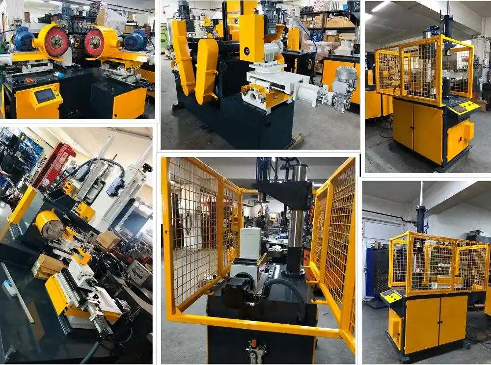
Metalworking machinery such as edge cutting trimming curling machine, trimming beading machine, edge curling machine, burr removing machine, inside and outside polishing machine for stainless steel pots, circle cutting machine, bandsaw for metal, profile bending machine, cylindrical welding machine, pipe bending machine and horizontal pres
Metalworking Machinery Range
Our Metalworking Machines are:
- Pipe Bending Machine
- Horizontal Press
- Bandsaw for Metal
- Profile Bending Machine
- Deep Drawing Press
- Circular Welding Machine
- Edge Cutting Trimming Beading Machine
- Trimming Beading Machine
- Edge Curling Machine
- Pot and Pan Polishing Machine
- Flat Surface Polishing Machine
- Hydraulic Cold Press
- Hydraulic Hot Press
- Hydraulic Transfer Press
- Friction Screw Press
Cutlery Production Line: A Cutlery Production Line is a type of machinery that manufactures cutlery in a continuous process. It comprises various types of machinery such as the knife grinder, the knife sharpener, and the blade polisher.
Cookware Manufacturing Machine: A Cookware Manufacturing Machine is a type of machinery that manufactures cookware in a continuous process. It comprises various types of machinery such as the pot maker, the pan maker, and the wok maker.
Kitchenware Production Machine: A Kitchenware Production Machine is a type of machinery that manufactures kitchenware in a continuous process. It comprises various types of machinery such teakettle making machines, cutlery production lines, pots and pans production lines
We design, manufacture, and assembly complete lines for cookware kitchenware hotelware, and cutlery production as well as individual machines for a specific purpose.
Our Metalworking Machinery:
Metal Spinning and Flow Forming Machines
Metal spinning is an ancient technique for shaping metal sheets into symmetrical, often hollow forms. While the basic concept remains the same, the machines used for metal spinning have undergone significant advancements. Today, metal spinning machines, also known as spinforming lathes, offer a versatile and efficient method for producing a wide range of metal components.
From Humble Beginnings to Modern Marvels
The history of metal spinning stretches back centuries, with evidence of its use in ancient Egypt. Early metal spinning lathes were rudimentary, relying on human power and basic tools to form the metal. The Industrial Revolution brought about a turning point with the introduction of water, steam, and eventually electric motors. These advancements enabled faster spinning speeds and the ability to work with a wider range of metals, including brass, copper, aluminum, and even stainless steel.
The Rise of CNC Metal Spinning
Traditionally, metal spinning has been a skilled craft requiring a high degree of hand-eye coordination and experience. While the core principles remain the same, the introduction of Computer Numerical Control (CNC) technology in the 1980s revolutionized metal spinning. CNC machines automate the tool path, allowing for precise and repeatable production. This shift opened doors for:
- Increased Efficiency: CNC metal spinning machines can produce parts much faster than manual methods, significantly reducing production times.
- Enhanced Accuracy: CNC controls ensure consistent wall thickness and precise geometries, leading to parts with superior quality.
- Greater Design Flexibility: CNC technology allows for the creation of complex shapes with intricate details, expanding the design possibilities for metal spun parts.
Metal Spinning and Flow Forming Machines
The Complete Guide to Metal Spinning Lathes, Flow Forming Machines, Processes, Tooling, and Industrial Applications
Table of Contents
• 1. Introduction to Metal Spinning and Flow Forming
• 2. What Is a Metal Spinning Machine?
• 3. What Is a Flow Forming Machine?
• 4. How the Metal Spinning Process Works
• 5. How the Flow Forming Process Works
• 6. Types of Metal Spinning Machines
• 7. Types of Flow Forming Machines
• 8. Tooling: Mandrels, Rollers, and Chucks
• 9. Key Process Parameters
• 10. Materials Used in Spinning and Flow Forming
• 11. Common Defects and How to Prevent Them
• 12. Metal Spinning vs. Flow Forming vs. Deep Drawing
• 13. Applications Across Industries
• 14. Advantages and Limitations
• 15. Selecting the Right Machine for Your Application
• 16. Maintenance and Safety Considerations
• 17. Emerging Trends: CNC, Automation, and Industry 4.0
• 18. Frequently Asked Questions (FAQ)
• 19. Conclusion
1. Introduction to Metal Spinning and Flow Forming
Metal spinning and flow forming are among the oldest and most versatile metal forming technologies still in wide industrial use today. Both processes shape flat or tubular metal blanks into axially symmetric, hollow components by pressing a roller tool against a rotating workpiece, gradually forcing the material to conform to the profile of a mandrel. From satellite dish reflectors and rocket nose cones to cookware, lighting fixtures, and automotive wheels, these processes produce some of the strongest, most precise, and most material-efficient round metal parts manufactured anywhere in the world.
While metal spinning primarily reshapes a flat disc into a hollow, curved, or conical form with relatively uniform wall thickness, flow forming (also called shear forming or power spinning in some of its variants) intentionally reduces wall thickness while elongating the part, producing exceptionally strong, thin-walled tubular or conical components. Both processes are performed on specialized rotating machines — spinning lathes and flow forming machines — that have evolved from manually operated tools into highly sophisticated, multi-axis CNC systems capable of forming complex, high-strength aerospace and defense components with micron-level precision.
This guide provides a complete overview of metal spinning and flow forming machines: how they work, the different machine architectures available, tooling considerations, process parameters, material selection, common defects, industry applications, and the latest technological trends shaping the field. Whether you are a process engineer specifying new equipment, a student studying advanced manufacturing, or a business exploring these processes for a new product line, this article is designed as a thorough, practical reference.
2. What Is a Metal Spinning Machine?
A metal spinning machine, sometimes called a spinning lathe, is a rotational forming machine that clamps a flat metal disc or preformed blank against a rotating mandrel and uses one or more rollers to progressively press the spinning material outward and along the mandrel’s contour. As the workpiece rotates at high speed, the roller applies localized, incremental pressure, causing the metal to flow plastically and take the exact shape of the mandrel without cutting or removing any material.
Unlike stamping or deep drawing, which forms an entire part in a single press stroke, metal spinning is an incremental forming process: the final shape emerges gradually over multiple roller passes. This incremental nature allows spinning machines to produce large-diameter, deep, or complex axisymmetric parts using comparatively low forming forces and relatively inexpensive tooling compared to matched-die processes, making it especially attractive for low-to-medium production volumes and large parts where die costs would otherwise be prohibitive.
2.1 Core Components of a Metal Spinning Machine
• Headstock and Spindle: Rotates the mandrel and workpiece at controlled speed.
• Mandrel: A shaped tool, usually mounted on the headstock, that defines the internal profile of the finished part.
• Tailstock: Applies axial clamping pressure to hold the blank firmly against the mandrel during forming.
• Roller Tool(s): The forming tool(s) that press against the rotating blank, driven along programmed or manually guided paths.
• Tool Slide / Carriage: Carries the roller tool and controls its position, feed rate, and pressure relative to the mandrel.
• Bed and Frame: The structural base that resists deflection under forming loads and maintains alignment accuracy.
• Control System: Ranges from manual hand-wheel control on traditional lathes to fully programmable CNC control on modern machines.
3. What Is a Flow Forming Machine?
A flow forming machine is a specialized rotational forming machine designed to reduce and control wall thickness while elongating a tubular or cup-shaped preform over a rotating mandrel. Unlike conventional spinning, where wall thickness remains approximately constant, flow forming deliberately thins the material using one, two, or three synchronized rollers positioned around the workpiece, applying intense radial pressure that causes the metal to flow axially along the mandrel, much like squeezing toothpaste from a tube.
Flow forming machines are used to manufacture exceptionally strong, lightweight, and dimensionally precise tubular components, including rocket motor cases, high-pressure gas cylinders, automotive wheel rims, and drive shafts. Because the process work-hardens the material as it thins the wall, flow-formed parts often achieve mechanical properties — tensile strength in particular — considerably higher than the same alloy in its unformed condition.
3.1 Core Components of a Flow Forming Machine
• Mandrel: A precision-ground cylindrical or contoured tool over which the preform is thinned and elongated.
• Rollers (typically 2 or 3): Synchronized forming rollers arranged radially around the mandrel, each contributing equal, balanced pressure to avoid deflection.
• Headstock/Spindle Drive: Rotates the mandrel and workpiece assembly at controlled, programmable speed.
• Roller Carriages: Independently or synchronously controlled axial slides that move the rollers along the mandrel length during forming.
• CNC Control System: Coordinates roller position, feed rate, and rotational speed with high precision, essential for tight wall-thickness tolerances.
• Tailstock or Preform Clamp: Secures the preform blank axially against the mandrel throughout the multi-pass forming cycle.
4. How the Metal Spinning Process Works
4.1 Step-by-Step Process Overview
1. Blank Preparation: A flat circular disc (or a pre-cut, pre-formed shape) is cut to the calculated blank diameter needed to form the finished part.
2. Mounting: The blank is clamped between the rotating mandrel and the tailstock, centered precisely on the machine’s axis.
3. Spindle Rotation: The headstock spins the mandrel and blank at a controlled speed, typically several hundred to over a thousand RPM depending on material and diameter.
4. Roller Engagement: The roller tool contacts the spinning blank near its center or edge, depending on technique, and begins applying localized pressure.
5. Progressive Forming Passes: The roller moves along a programmed or manually guided path, making multiple passes that gradually push the material outward and over the mandrel’s contour.
6. Wall Formation: With each pass, more of the blank conforms to the mandrel shape, and the part’s final height, wall angle, and profile take form.
7. Trimming: Excess material at the rim is trimmed away, often on the same machine, to achieve the final edge dimension.
8. Part Removal: The finished part is released from the mandrel and tailstock, ready for secondary operations such as heat treatment, polishing, or machining.
Because the forming force at any instant is applied only to the small area of contact beneath the roller, rather than across the entire part as in deep drawing, metal spinning can shape very large or thick blanks using relatively modest machine tonnage. This is one of the primary reasons spinning remains economical for large parts such as satellite dish reflectors, industrial tank heads, and large decorative architectural domes.
4.2 Manual vs. CNC Spinning Technique
Traditional manual spinning relies on a skilled operator guiding a hand lever to control roller position and pressure by feel, a technique still used for artisanal, low-volume, or highly customized work. Modern CNC spinning machines instead follow a precisely programmed toolpath, replicating the exact roller motion for every part, which dramatically improves repeatability, reduces scrap, and enables complex multi-pass forming strategies that would be extremely difficult to reproduce manually.
5. How the Flow Forming Process Works
5.1 Step-by-Step Process Overview
9. Preform Production: A cup- or tube-shaped preform, typically produced by deep drawing, extrusion, or machining, is prepared with a wall thickness greater than the final target thickness.
10. Mounting on the Mandrel: The preform is slid over and clamped against a precision mandrel that matches the desired internal diameter of the finished part.
11. Spindle Rotation: The mandrel and preform rotate together at a controlled, programmed speed.
12. Synchronized Roller Engagement: Two or three rollers, positioned symmetrically around the workpiece, advance radially inward to a calculated depth that determines the wall thickness reduction.
13. Axial Roller Feed: As the rollers press into the material, they simultaneously move axially along the mandrel, causing the compressed metal to flow lengthwise and elongate the part.
14. Multi-Pass Thinning (if required): For large thickness reductions, multiple passes are made, sometimes with intermediate annealing to restore ductility lost to work hardening.
15. Final Sizing and Trimming: The part is trimmed to final length and inspected for wall thickness uniformity, straightness, and surface finish.
Because the rollers are synchronized and positioned symmetrically, radial forces on the mandrel largely cancel out, allowing flow forming to achieve extremely tight wall-thickness tolerances — often within a few hundredths of a millimeter — even on long, thin-walled parts. This precision, combined with the significant strain hardening produced by the process, is what makes flow forming indispensable for high-performance, weight-critical components such as rocket motor casings and aerospace structural tubes.
5.2 Forward vs. Backward Flow Forming
In forward flow forming, material flows in the same direction as the roller feed motion, typically used when the preform is open at the tailstock end. In backward flow forming, material flows opposite to the roller feed direction, useful for preforms closed at one end. Machine selection and tooling design depend heavily on which technique a given part geometry requires.
6. Types of Metal Spinning Machines
6.1 Manual Spinning Lathes
The traditional form of spinning equipment, manual lathes rely on operator skill to guide the roller using a hand lever and fulcrum-based tool rest. These machines remain valuable for artisanal work, prototyping, short production runs, and repair work where CNC programming would not be cost-effective.
6.2 CNC Metal Spinning Machines
CNC spinning machines use servo-controlled axes to precisely replicate programmed roller paths, dramatically improving consistency, reducing operator dependency, and enabling complex multi-pass forming strategies. Most industrial-scale spinning today, especially for aerospace, automotive, and cookware production, is performed on CNC machines with two, three, or more controlled axes.
6.3 Shear Spinning Machines
Shear spinning is a variant in which the roller deliberately thins the material as it forms the part, producing a wall thickness that follows the sine law relative to the mandrel’s cone angle. This blurs the boundary between conventional spinning and flow forming and is used for conical parts requiring both shape and controlled thickness reduction in a single operation.
6.4 Multi-Roller Spinning Machines
Machines equipped with two or three synchronized rollers acting simultaneously around the workpiece reduce radial deflection, improve dimensional accuracy, and allow faster cycle times than single-roller machines, particularly valuable for larger or thicker blanks.
6.5 Hot Spinning Machines
For thick-walled or hard-to-form materials such as certain titanium and nickel alloys, hot spinning machines incorporate induction heaters or torches to locally heat the workpiece ahead of the roller, increasing ductility and reducing forming forces, enabling shapes that would otherwise crack if formed cold.
7. Types of Flow Forming Machines
7.1 Tube Flow Forming Machines
Designed specifically for open-ended tubular preforms, these machines elongate and thin tube walls to produce long, precise cylindrical components such as pressure vessels, gun barrels, and structural tubing.
7.2 Cone/Shear Forming Machines
Optimized for conical geometries, these machines combine shape-forming and wall-thinning in a single pass, commonly used for nose cones, reducers, and conical transition sections in aerospace and defense applications.
7.3 Wheel Flow Forming Machines
A major automotive application, these specialized machines flow-form the rim section of a partially cast or forged wheel blank, thinning and strengthening the rim while reducing overall wheel weight — a technique widely used for lightweight alloy wheels in performance and fuel-efficient vehicles.
7.4 Two-Roller and Three-Roller CNC Flow Forming Machines
Roller count affects both cycle time and force balance. Two-roller machines are common for small-to-medium parts, while three-roller machines distribute forming force more evenly, favored for larger-diameter or higher-precision aerospace and defense components.
8. Tooling: Mandrels, Rollers, and Chucks
Tooling quality and design directly determine the achievable precision, surface finish, and production efficiency of both spinning and flow forming operations.
• Mandrels: Precision-machined, often from hardened tool steel or aluminum for prototype work, defining the internal geometry of the finished part; surface finish on the mandrel directly transfers to the part’s inner surface.
• Rollers: Hardened steel or carbide forming wheels, available in various profiles (radiused, flat, or specialized contours) chosen based on material, wall thickness change, and desired surface finish.
• Chucks and Clamping Fixtures: Secure the blank or preform against the mandrel with sufficient axial force to prevent slippage during high-speed rotation.
• Backup Rollers/Idlers: Used in some multi-roller configurations to support the workpiece opposite the primary forming roller, reducing deflection.
• Lubrication Delivery Systems: Apply cutting or forming oil continuously to the roller-workpiece interface, critical for reducing friction, heat, and tool wear during flow forming’s high-pressure passes.
9. Key Process Parameters
Both spinning and flow forming success depend on precise control of interrelated variables. The following table summarizes the most critical parameters.
| Parameter | Description | Typical Effect if Incorrect |
| Roller Feed Rate | Speed at which the roller travels along the mandrel axis | Too fast → wrinkling/tearing; Too slow → excess heat, tool wear |
| Spindle Speed (RPM) | Rotational speed of the mandrel and workpiece | Too high → vibration/chatter; Too low → poor surface finish |
| Roller Depth/Reduction | Radial penetration of roller determining wall thinning | Excessive reduction per pass → cracking or delamination |
| Number of Passes | How many roller passes are used to reach final geometry | Too few → incomplete forming; too many → unnecessary work hardening |
| Lubrication | Forming fluid applied at the roller-workpiece contact | Insufficient → galling, heat buildup, tool wear |
| Mandrel Precision | Dimensional accuracy and surface finish of mandrel | Poor mandrel quality → dimensional and surface defects in part |
| Material Temper | Starting hardness/ductility of the blank or preform | Too hard → cracking; requires intermediate annealing |
10. Materials Used in Spinning and Flow Forming
Spinnability and flow-formability depend on a material’s ductility, work-hardening rate, and grain structure. Commonly processed materials include:
• Aluminum alloys (1000, 3000, 5000, 6000, and 2000/7000 series) — widely spun for cookware, lighting reflectors, and flow-formed for aerospace and automotive wheel applications.
• Low-carbon and stainless steel — used for tank heads, exhaust components, and architectural elements, favored for strength and corrosion resistance.
• Titanium alloys — spun and flow-formed for aerospace structural parts and medical devices, often requiring hot spinning due to titanium’s limited cold ductility.
• Nickel-based superalloys (Inconel, Hastelloy) — flow-formed for high-temperature aerospace and rocket motor components, typically requiring elevated-temperature processing.
• Copper and brass — spun for decorative items, musical instruments, and electrical components due to excellent ductility.
• High-strength alloy steels — flow-formed for gun barrels, drive shafts, and pressure vessels where strain hardening significantly boosts final tensile strength.
11. Common Defects and How to Prevent Them
11.1 Wrinkling
Wrinkling occurs when the flange or unsupported material buckles under compressive stress during forming, typically from insufficient tailstock pressure or excessive material in an unsupported zone. Prevention includes optimizing blank size, adding support rollers, and adjusting roller path strategy.
11.2 Cracking and Tearing
Excessive reduction per pass, inadequate lubrication, or insufficient material ductility can cause cracking, particularly at high-strain zones. Solutions include reducing per-pass thickness reduction, adding intermediate annealing steps, and improving lubrication.
11.3 Chatter and Vibration Marks
Excessive spindle speed, worn machine bearings, or poor roller support can cause chatter, leaving visible ripple marks on the part surface. Reducing spindle speed, tightening machine tolerances, and using additional support rollers typically resolves this.
11.4 Wall Thickness Variation
Inconsistent roller pressure, mandrel wear, or misalignment can cause uneven wall thickness along the part length, a particularly critical defect in flow-formed pressure vessels and rocket casings. Regular mandrel inspection and precise CNC roller synchronization minimize this risk.
11.5 Surface Defects
Galling, scoring, or a rough, torn surface finish typically stems from inadequate lubrication, a damaged roller profile, or excessive feed rate. Proper lubrication delivery and roller maintenance are the primary preventive measures.
12. Metal Spinning vs. Flow Forming vs. Deep Drawing
| Process | Wall Thickness Behavior | Best Suited For |
| Metal Spinning | Approximately constant (minor thinning) | Large, axisymmetric parts; low-to-medium volume; conical/curved shapes |
| Flow Forming | Significantly and precisely reduced | Long, thin-walled, high-strength tubular or conical parts |
| Deep Drawing | Moderate thinning, especially near punch radius | High-volume, non-axisymmetric or axisymmetric hollow parts (cups, panels) |
A key distinguishing advantage of spinning and flow forming over deep drawing is tooling cost and flexibility: because forming force is applied incrementally by a roller rather than across the entire part by a matched die set, spinning and flow forming machines can produce a wide range of part diameters and shapes using a single mandrel change, without the enormous die investment required for deep drawing large parts. This makes spinning and flow forming especially attractive for low-to-medium volume production, large-diameter parts, and situations where design flexibility is valued over the raw cycle-time speed of deep drawing.
13. Applications Across Industries
13.1 Aerospace and Defense
Rocket motor casings, missile bodies, satellite components, nose cones, and pressure vessels rely heavily on flow forming for their exceptional strength-to-weight ratio and dimensional precision, while metal spinning produces radar dish reflectors, engine nacelle components, and various structural cones and domes.
13.2 Automotive Industry
Flow forming is widely used to manufacture lightweight, high-strength alloy wheel rims, drive shafts, and transmission components, while metal spinning produces wheel covers, exhaust components, catalytic converter shells, and various decorative trim pieces.
13.3 Lighting and Architectural Products
Metal spinning is the standard process for producing light fixture reflectors, decorative domes, architectural cladding elements, and cylindrical or conical building facade components, valued for its ability to economically produce large, smooth, seamless shapes.
13.4 Cookware and Consumer Goods
Pots, pans, mixing bowls, and various stainless steel and aluminum kitchenware items are commonly spun, taking advantage of the process’s ability to produce smooth, seamless, food-safe surfaces at moderate production volumes.
13.5 Industrial Equipment and Pressure Vessels
Tank heads, funnels, hoppers, gas cylinders, and various pressure vessel components are produced via spinning and flow forming, where seamless construction and predictable mechanical properties are essential for safety-critical applications.
13.6 Musical Instruments
Brass and bronze instrument bells (trumpets, French horns, tubas) and cymbals are traditionally shaped through metal spinning, a technique that has remained largely unchanged in principle for over a century.
13.7 Medical and Scientific Equipment
Precision spun and flow-formed components appear in medical device housings, laboratory equipment, and scientific instrumentation requiring seamless, corrosion-resistant, dimensionally accurate cylindrical or conical parts.
14. Advantages and Limitations
14.1 Advantages
• Significantly lower tooling cost compared to matched-die processes like deep drawing, especially for large parts.
• Excellent for large-diameter and deep parts that would require prohibitively expensive draw dies.
• Flow forming produces exceptional strength through controlled strain hardening.
• High material utilization with minimal scrap generation.
• Design flexibility — mandrel changes allow rapid transitions between part variants.
• Seamless, high-integrity parts suitable for pressure-critical applications.
14.2 Limitations
• Generally slower cycle times than deep drawing or stamping, limiting suitability for very high-volume production.
• Requires skilled operators or sophisticated CNC programming for complex geometries.
• Primarily limited to axisymmetric (rotationally symmetric) part geometries.
• Flow forming machines and precision mandrels represent significant capital investment for high-tolerance work.
• Material selection constrained by ductility and work-hardening behavior.
15. Selecting the Right Machine for Your Application
Choosing between metal spinning and flow forming equipment, and specifying the right machine configuration, involves evaluating several key factors:
• Part geometry: Simple curved or conical shapes with near-constant wall thickness favor spinning; long, thin-walled tubular parts requiring precise thickness control favor flow forming.
• Production volume: Low-to-medium volumes favor spinning and flow forming over high-tooling-cost processes like deep drawing.
• Required mechanical properties: Applications demanding maximum strength-to-weight ratio, such as rocket casings, benefit from flow forming’s strain-hardening effect.
• Machine axis count and control sophistication: Complex, multi-contour parts require CNC machines with multiple synchronized axes.
• Roller configuration: Single-roller machines suit simpler parts and lower budgets; two- or three-roller machines improve precision and reduce cycle time for demanding applications.
• Heating capability: Hard-to-form materials such as titanium or thick sections may require hot spinning capability.
• Total cost of ownership: Includes tooling life, mandrel replacement cost, energy consumption, and floor space requirements.
16. Maintenance and Safety Considerations
16.1 Preventive Maintenance
• Regular inspection and resurfacing of mandrels to maintain dimensional accuracy and surface finish.
• Roller bearing lubrication and periodic replacement to prevent chatter and vibration defects.
• Calibration of CNC axes and servo drives to maintain positioning accuracy over time.
• Monitoring and replacement of worn chuck jaws and clamping fixtures.
• Regular inspection of lubrication delivery systems to ensure consistent coolant/lubricant flow during forming.
16.2 Operator and Workplace Safety
• Machine guarding around the rotating spindle and workpiece to prevent operator contact during high-speed rotation.
• Emergency stop systems accessible from the primary operator position.
• Personal protective equipment, including eye protection, given the presence of forming lubricants and metal chips.
• Lockout/tagout procedures during mandrel changes, roller replacement, and maintenance work.
• Training on safe handling of heated workpieces when hot spinning is used.
17. Emerging Trends: CNC, Automation, and Industry 4.0
17.1 Advanced Multi-Axis CNC Systems
Modern spinning and flow forming machines increasingly feature five or more programmable axes, enabling complex, variable-wall-thickness geometries and highly repeatable multi-pass forming strategies that would be impractical to achieve manually.
17.2 Simulation-Driven Process Design
Finite element analysis (FEA) tools now allow engineers to simulate roller paths, predict wall thickness distribution, and identify potential wrinkling or cracking risks before cutting any physical tooling, significantly reducing development time and material waste.
17.3 In-Process Sensing and Adaptive Control
Sensors monitoring roller force, spindle torque, and part temperature in real time allow modern machines to automatically adjust feed rates and roller pressure mid-process, improving consistency and catching defects before they propagate through a production batch.
17.4 Robotic Loading and Automated Cells
Robotic blank loading, part unloading, and inline inspection are increasingly integrated into spinning and flow forming cells, reducing labor costs and enabling continuous, lights-out production for medium-to-high volume applications.
17.5 Additive-Hybrid and Near-Net-Shape Preforms
Combining additive manufacturing or precision casting to produce near-net-shape preforms, followed by spinning or flow forming for final geometry and strengthening, is an emerging hybrid strategy gaining traction in aerospace and defense manufacturing for reducing material waste and lead time.
18. Frequently Asked Questions (FAQ)
What is the difference between metal spinning and flow forming?
Metal spinning shapes a blank into a hollow form while keeping wall thickness roughly constant, whereas flow forming intentionally and precisely reduces wall thickness while elongating the part, producing higher-strength, thinner-walled components through controlled strain hardening.
What materials can be spun or flow formed?
Aluminum, steel, stainless steel, titanium, nickel superalloys, copper, and brass are all commonly processed, with material choice depending on required ductility, strength, corrosion resistance, and whether hot forming capability is available for harder-to-form alloys.
Is metal spinning suitable for high-volume production?
Metal spinning is generally best suited to low-to-medium production volumes due to its incremental, roller-based forming approach. For very high volumes, deep drawing or stamping is often more cost-effective, though CNC spinning has narrowed this gap considerably for medium-volume runs.
Why is flow forming used for rocket motor casings?
Flow forming produces exceptionally strong, lightweight, thin-walled tubular structures with tightly controlled wall thickness and enhanced tensile strength from strain hardening — properties that are critical for the weight-sensitive, high-pressure environment of rocket motor casings.
What is the typical tolerance achievable in flow forming?
Modern CNC flow forming machines can achieve wall thickness tolerances within a few hundredths of a millimeter, though achievable tolerance depends on material, part length, machine rigidity, and mandrel precision.
Do spinning and flow forming require expensive tooling?
Compared to deep drawing, tooling costs are generally much lower since a single mandrel and roller set can often produce a range of related part sizes, and no matched female die is required, making these processes attractive for lower-volume or large-diameter parts.
19. Conclusion
Metal spinning and flow forming machines occupy a unique and enduring position in the world of metal forming technology. By applying controlled, incremental force through rotating rollers rather than a single matched-die stroke, these processes achieve a combination of strength, precision, material efficiency, and tooling flexibility that few other manufacturing methods can match — particularly for large, axisymmetric, or exceptionally strong thin-walled components.
As CNC control, simulation software, in-process sensing, and automation continue to advance, spinning and flow forming machines are becoming faster, more precise, and more accessible across a widening range of industries, from aerospace and defense to automotive lightweighting and consumer products. For manufacturers evaluating these processes, understanding machine types, tooling requirements, material behavior, and process parameters — as outlined throughout this guide — provides the essential foundation for producing high-quality, high-performance rotationally formed metal components.
Whether the goal is a lightweight racing wheel, a precision rocket motor casing, or a handcrafted decorative bowl, metal spinning and flow forming technology continues to demonstrate that some of the most demanding manufacturing challenges are best solved not by cutting away material, but by patiently and precisely coaxing it into shape.
Friction Screw Press
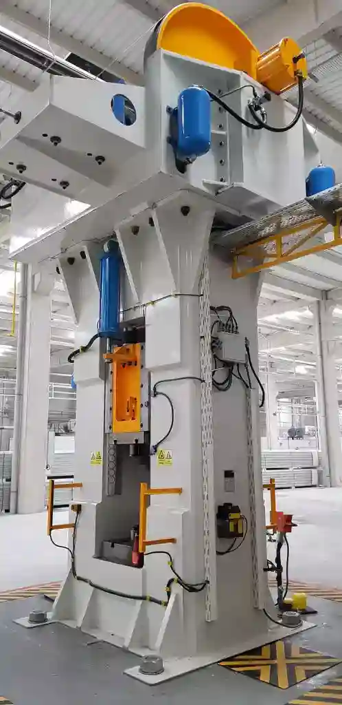
A friction screw press, also known as a screw press or screw press machine, is a mechanical device used for various industrial processes, including forging, forming, and pressing operations. It operates on the principle of converting rotary motion into linear force through the use of a screw mechanism. Friction screw presses are widely used in metalworking, automotive, aerospace, and other manufacturing industries.
Friction Screw Press
A friction screw press is a mechanical press that utilizes friction to generate a pressing force. It is a versatile and powerful machine used in various manufacturing processes, including forging, stamping, and assembly.
Friction Screw Press Machine
A friction screw press machine consists of a rotating flywheel, a friction clutch, and a screw mechanism. The rotating flywheel stores kinetic energy, while the friction clutch engages and disengages the flywheel’s power to the screw mechanism.
Friction Screw Press Working Principle
The working principle of a friction screw press is based on the conversion of rotational energy into linear motion. As the flywheel rotates, the friction clutch engages, transferring energy to the screw mechanism. The screw mechanism then converts this rotational energy into linear motion, driving the press ram downward to perform the desired pressing operation.
Friction Screw Press Working
The operation of a friction screw press involves the following steps:
- Rotational Energy Storage: The flywheel is rotated using an electric motor or other power source, storing kinetic energy.
- Clutch Engagement: The friction clutch is engaged, transferring energy from the flywheel to the screw mechanism.
- Linear Motion Conversion: The screw mechanism converts the rotational energy into linear motion, driving the press ram downward.
- Pressing Operation: The press ram applies pressure to the workpiece, performing the desired pressing operation.
- Clutch Disengagement: The friction clutch is disengaged, stopping the press ram’s downward motion.
- Ram Return: The press ram returns to its starting position using springs or counterweights.
Friction Press
Friction press is a general term that can refer to various types of presses that utilize friction to generate pressing force. Friction screw presses are a specific type of friction press that employs a screw mechanism to convert rotational energy into linear motion.
Friction Screw
A friction screw is a type of screw that utilizes friction to provide a locking mechanism. It is often used in fasteners and other applications where a secure connection is required.
Press Fit Screw
A press fit screw is a type of screw that is designed to be inserted into a hole with a slightly smaller diameter. The interference between the screw and the hole creates a friction fit, providing a secure connection.
How Does a Screw Press Work?
A screw press works by converting rotational energy into linear motion. As the screw rotates, it pushes against a nut or other stationary component, forcing it downward. This downward force is used to perform various pressing operations.
Screw Friction Definition
Screw friction is the resistance to motion between two surfaces that are in contact and subjected to a normal force. In the context of a screw press, screw friction plays a crucial role in converting rotational energy into linear motion. The friction between the screw threads and the nut or other stationary component provides the driving force that pushes the press ram downward.
Glass Mosaic Press
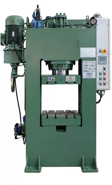
A glass mosaic press is a machine used for pressing glass mosaic tiles into a sheet or a tile. It is an essential tool for creating intricate designs and patterns with glass tiles. The press applies pressure to the tiles, ensuring that they adhere together and form a smooth, flat surface. Some glass mosaic presses are operated manually, while others are automated for higher production rates. The machines come in various sizes and capacities, depending on the needs of the manufacturer.
Glass Mosaic Press
A glass mosaic press is a specialized tool used to create mosaic patterns or designs by pressing small pieces of glass into a backing material or adhesive sheet. Glass mosaic presses are typically used for larger mosaic projects and offer precision and consistency in producing intricate designs.
Pressed Mosaic Glass
Pressed mosaic glass refers to glass mosaic tiles that have been created using a glass mosaic press. These tiles are characterized by their flat, even surface and uniform shape, making them suitable for creating smooth, seamless mosaic patterns.
Hydraulic Deep Drawing Press
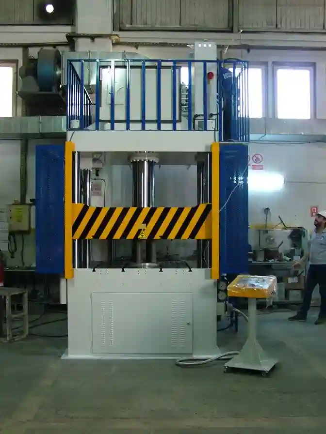
Deep Drawing Press and Applications
The Complete Guide to Deep Drawing Press Technology, Process Design, Tooling, Industries, and Emerging Trends
Table of Contents
• 1. Introduction to Deep Drawing
• 2. What Is a Deep Drawing Press?
• 3. How the Deep Drawing Process Works
• 4. Types of Deep Drawing Presses
• 5. Anatomy of a Deep Drawing Die Set
• 6. Key Process Parameters in Deep Drawing
• 7. Materials Used in Deep Drawing
• 8. Deep Drawing Ratio, Limiting Draw Ratio, and Redrawing
• 9. Common Defects in Deep Drawing and How to Prevent Them
• 10. Deep Drawing vs. Other Sheet Metal Forming Processes
• 11. Applications of Deep Drawing Presses Across Industries
• 12. Advantages and Limitations of Deep Drawing
• 13. Selecting the Right Deep Drawing Press for Your Application
• 14. Maintenance and Safety Considerations
• 15. Emerging Trends: Automation, Simulation, and Industry 4.0
• 16. Frequently Asked Questions (FAQ)
• 17. Conclusion
1. Introduction to Deep Drawing
Deep drawing is one of the most important and widely used metal forming processes in modern manufacturing. It allows flat sheet metal blanks to be transformed into hollow, seamless, three-dimensional shapes such as cups, cans, enclosures, and complex structural components. From the aluminum beverage can in your hand to the stainless steel sink in your kitchen and the body panels of the car you drive, deep drawing technology touches nearly every aspect of modern life.
At the heart of this process is a specialized piece of industrial equipment known as the deep drawing press. This machine applies controlled, precise mechanical or hydraulic force to push a metal blank through a die cavity, reshaping it into a finished part without cutting or removing material. Because deep drawing is a near-net-shape process, it produces strong, lightweight, and dimensionally consistent parts with minimal material waste, making it a cornerstone of cost-effective mass production.
In this comprehensive guide, we will explore everything you need to know about deep drawing presses and their applications: how they work, the different press types available, the tooling and process parameters involved, the industries that depend on this technology, and where the field is heading in the era of automation and Industry 4.0. Whether you are a manufacturing engineer, a procurement specialist evaluating press options, a student researching metal forming, or a business owner exploring deep drawing as a production method, this article is designed to serve as a complete, practical reference.
2. What Is a Deep Drawing Press?
A deep drawing press is a metal forming machine specifically engineered to perform the deep drawing process, in which a flat sheet metal blank is drawn into a die cavity by a punch to form a hollow shape whose depth is typically greater than its diameter. Unlike simple stamping or blanking presses that primarily cut or shallow-form metal, a deep drawing press must precisely control multiple simultaneous forces: the downward force of the punch, the clamping force of the blank holder (also called a hold-down ring or pressure pad), and the resistance of the metal as it flows plastically over the die radius.
Deep drawing presses range from small benchtop machines producing tiny electronic enclosures to massive transfer presses in automotive stamping plants capable of exerting thousands of tons of force to form entire vehicle body panels in a single stroke. Despite this wide range in scale, all deep drawing presses share the same fundamental goal: to convert flat sheet stock into a dimensionally accurate, structurally sound, hollow part while avoiding tearing, wrinkling, or excessive thinning of the material.
2.1 Core Components of a Deep Drawing Press
• Punch: The moving tool that pushes the blank into the die cavity, forming the internal shape of the part.
• Die (Die Ring): The stationary tool with a cavity that defines the outer shape of the drawn part.
• Blank Holder (Hold-Down Ring): Clamps the edge of the blank to control material flow and prevent wrinkling.
• Cushion System: Provides controlled counter-force beneath the die or blank holder, often pneumatic, hydraulic, or spring-based.
• Press Frame: The structural body of the machine, typically a C-frame or straight-side (box) frame, that resists deflection under load.
• Drive System: The mechanism that powers the ram — mechanical (crankshaft, eccentric, or servo-driven) or hydraulic (fluid-powered cylinders).
• Control System: Modern presses use programmable logic controllers (PLCs) and servo drives to precisely regulate ram speed, position, and force throughout the stroke.
3. How the Deep Drawing Process Works
Understanding the mechanics of deep drawing helps explain why press design matters so much. The process can be broken down into a sequence of controlled stages, each of which must be carefully managed to produce a defect-free part.
3.1 Step-by-Step Process Overview
1. Blank Preparation: A flat, circular (or shaped) blank is cut from coil or sheet stock, typically via blanking dies or laser cutting, and lubricated to reduce friction.
2. Blank Placement: The blank is positioned over the die cavity, centered precisely to ensure symmetrical material flow.
3. Blank Holder Engagement: The blank holder descends and clamps the outer edge of the blank against the die surface with a controlled, calibrated force.
4. Punch Descent: The punch moves downward, contacting the center of the blank and beginning to push it into the die cavity.
5. Plastic Deformation and Material Flow: As the punch advances, the metal in the flange area is drawn radially inward and stretched over the die radius, undergoing plastic deformation to form the vertical walls of the part.
6. Wall Formation: The metal flows around the punch nose and die radius, forming the sidewalls of the cup or shell while the base remains largely flat, supported by the punch face.
7. Bottom-of-Stroke (Full Draw): The punch reaches its lowest point, completing the drawn shape to full depth.
8. Part Ejection: The punch retracts, and the finished part is ejected or stripped from the die using a knockout pin, air blast, or mechanical stripper.
Throughout this sequence, the blank holder force is the single most critical variable. Too little force allows the flange to wrinkle as it is compressed circumferentially during inward flow. Too much force restricts material flow excessively, causing the part to tear, typically at the punch radius where the material is thinnest and under the highest tensile stress. Achieving the correct balance is both a science and an art, guided by material properties, part geometry, lubrication, and press control precision.
3.2 Single-Draw vs. Multi-Draw (Redraw) Operations
Shallow parts with a modest depth-to-diameter ratio can often be formed in a single draw operation. However, many practical parts — such as tall cans, deep enclosures, or complex shells — exceed the maximum deformation a single draw can safely achieve without tearing. In these cases, manufacturers use a series of progressive redrawing operations, each incrementally increasing the depth and reducing the diameter of the part, sometimes with intermediate annealing steps to restore ductility lost through work hardening.
4. Types of Deep Drawing Presses
Deep drawing presses are classified primarily by their drive mechanism and frame design. Each type offers distinct advantages suited to different production volumes, part sizes, and complexity requirements.
4.1 Mechanical Deep Drawing Presses
Mechanical presses use a flywheel-driven crankshaft or eccentric gear system to convert rotational motion into the linear reciprocating motion of the ram. They are prized for high speed and high-volume output, making them the workhorse of automotive and appliance stamping lines. Mechanical presses deliver maximum force only near the bottom of the stroke, which requires careful process design to ensure drawing occurs within the optimal force window.
4.2 Hydraulic Deep Drawing Presses
Hydraulic presses use fluid pressure acting on a piston to drive the ram. Unlike mechanical presses, they deliver constant, fully controllable force and speed throughout the entire stroke, which is especially valuable for deep draws, thick materials, and parts prone to wrinkling or tearing. Hydraulic presses also allow dwell time at the bottom of the stroke, useful for coining or stabilizing the drawn shape. Their main trade-off is typically slower cycle times compared to mechanical presses of similar tonnage.
4.3 Servo-Mechanical (Servo-Driven) Presses
Servo presses combine the speed advantages of mechanical presses with the programmable flexibility of hydraulic systems. A servo motor directly drives the crankshaft or a direct-drive linkage, allowing engineers to program custom ram velocity profiles — slowing down during critical drawing phases and speeding up during non-forming portions of the stroke. This flexibility reduces defects, extends tool life, and enables quick changeovers between part programs without physical tooling changes.
4.4 Hydraulic Deep Drawing Presses with Double-Action or Triple-Action Design
For complex or large-diameter parts, double-action presses use two independently controlled rams — one for the blank holder and one for the punch — allowing precise, independent tuning of blank holder force versus punch stroke. Triple-action presses add a third action, often for integrated redrawing or ejection, and are common in large-scale automotive body panel production.
4.5 Transfer Presses and Progressive Die Presses
In high-volume manufacturing, transfer presses move the part automatically from station to station within a single large press, performing blanking, drawing, redrawing, trimming, and piercing operations in sequence. Progressive die presses achieve a similar multi-stage result by feeding a continuous strip of metal through a single die set containing multiple stations. Both approaches dramatically increase throughput and reduce labor for high-volume parts such as beverage cans, food containers, and automotive panels.
4.6 Hydroforming and Specialized Deep Drawing Variants
Hydroforming presses replace the rigid punch or die with pressurized fluid, allowing the sheet metal to conform to a die cavity under fluid pressure alone. This approach excels at forming complex, asymmetric shapes with excellent surface quality and is widely used for aerospace components, exhaust systems, and structural automotive parts. Other specialized variants include ironing presses (which thin and elongate walls after initial drawing, common in aluminum can manufacturing) and spin-forming or flow-forming machines, which combine rotational forming with axial force.
5. Anatomy of a Deep Drawing Die Set
The press supplies force, but the die set determines the final geometry of the part. A well-engineered die set is essential to consistent, defect-free production.
• Punch: Machined to the internal profile of the finished part; punch nose radius greatly affects material flow and thinning.
• Die Ring: Contains the cavity and die radius over which the metal is drawn; die radius must be large enough to avoid tearing but small enough to control the part profile.
• Blank Holder / Draw Pad: Applies controlled clamping pressure to the flange to regulate metal flow and prevent wrinkling.
• Draw Beads: Raised ribs on the blank holder or die surface that locally restrict material flow, fine-tuning the effective blank holder force without needing to change the overall clamping force.
• Pilot Pins and Guide Posts: Ensure precise alignment of the blank and repeatable die closure across thousands of cycles.
• Knockout / Ejector System: Removes the finished part cleanly from the punch or die cavity after forming.
• Lubrication System: Delivers drawing compound or oil to reduce friction between the blank, punch, and die surfaces.
6. Key Process Parameters in Deep Drawing
Successful deep drawing depends on the careful control of several interrelated variables. Getting any one of these wrong can result in scrapped parts, excessive tool wear, or inconsistent quality.
| Parameter | Description | Typical Effect if Incorrect |
| Blank Holder Force | Clamping pressure applied to the flange during drawing | Too low → wrinkling; Too high → tearing |
| Punch/Die Clearance | Gap between punch and die wall | Too tight → excess thinning/tearing; Too loose → wrinkling on wall |
| Die Radius | Curvature at the die edge where metal bends | Too sharp → tearing; Too large → wrinkling and reduced control |
| Punch Speed | Velocity of the punch during the draw stroke | Too fast → localized heating, tearing, or splitting |
| Lubrication | Friction-reducing compound between tooling and blank | Insufficient → increased friction, tearing, tool wear |
| Blank Diameter/Shape | Size and geometry of the starting sheet blank | Incorrect sizing → excess trim waste or incomplete forming |
| Draw Ratio | Ratio of blank diameter to punch diameter | Exceeding limiting draw ratio → tearing in a single draw |
7. Materials Used in Deep Drawing
Not all metals draw equally well. Deep drawability depends on a material’s ductility, strain-hardening behavior, and anisotropy (directional variation in mechanical properties). The most commonly deep-drawn materials include:
• Low-carbon (mild) steel — widely used for automotive body panels and general enclosures due to excellent formability and low cost.
• Deep drawing quality (DDQ) and extra deep drawing quality (EDDQ) steel — specially processed low-carbon steels with high plastic strain ratio (r-value) for demanding draws.
• Stainless steel (300 series, especially 304 and 316) — used for sinks, cookware, food processing equipment, and medical devices, prized for corrosion resistance.
• Aluminum alloys (1000, 3000, and 5000 series) — lightweight and highly formable, standard for beverage cans, aerospace panels, and automotive lightweighting.
• Copper and brass — used in ammunition casings, electrical components, and decorative hardware for excellent ductility and conductivity.
• Titanium alloys — used in aerospace and medical applications requiring high strength-to-weight ratio, though they require slower forming speeds and specialized lubrication.
• Advanced High-Strength Steels (AHSS) — increasingly used in automotive crash structures, requiring precise press control due to lower formability and higher springback.
8. Deep Drawing Ratio, Limiting Draw Ratio, and Redrawing
The draw ratio (DR) is defined as the ratio of the blank diameter to the punch diameter. Every material and thickness combination has a limiting draw ratio (LDR) — the maximum draw ratio achievable in a single draw operation without tearing. Typical LDR values range from about 1.8 to 2.2 for common deep drawing steels, though this varies with material grade, thickness, lubrication, and tooling geometry.
When a design requires a draw ratio beyond the material’s LDR, manufacturers use redrawing: the part is drawn again through a second, smaller die to further reduce diameter and increase depth. Each redraw stage work-hardens the material, so complex or very deep parts may require intermediate process annealing to restore ductility before subsequent draws. Beverage can bodies, for example, undergo drawing followed by multiple ironing passes to achieve their characteristic thin, tall walls.
9. Common Defects in Deep Drawing and How to Prevent Them
9.1 Wrinkling
Wrinkling occurs when the flange or sidewall buckles due to insufficient blank holder force or excessive material in the flange area. Prevention includes increasing blank holder pressure, adding or repositioning draw beads, and optimizing blank shape.
9.2 Tearing and Splitting
Tearing typically occurs at the punch radius, where tensile stress is highest during drawing. Causes include excessive blank holder force, insufficient die radius, poor lubrication, or exceeding the material’s limiting draw ratio. Solutions include reducing blank holder force, increasing die radius, improving lubrication, and introducing redraw stages.
9.3 Earing
Earing produces wavy, uneven edges at the top of a drawn cup due to planar anisotropy in the sheet material (different mechanical properties in the rolling direction versus transverse direction). This is typically addressed by selecting material with lower anisotropy or adjusting blank orientation relative to the rolling direction.
9.4 Surface Defects and Scratching
Galling, scoring, and orange-peel surface texture can result from inadequate lubrication, worn tooling, or excessive friction. Regular tool maintenance, proper lubricant selection, and polished die surfaces help minimize these issues.
9.5 Springback
After the punch retracts, elastic recovery causes the part to deviate slightly from the exact die geometry, a phenomenon called springback. This is especially pronounced in high-strength steels and requires compensation in die design or additional restrike operations.
9.6 Thinning
Excessive wall thinning, especially near the punch radius, can compromise part strength. Thinning is minimized through optimized punch/die clearance, controlled blank holder force, and appropriate material selection.
10. Deep Drawing vs. Other Sheet Metal Forming Processes
| Process | Typical Use Case | Key Difference from Deep Drawing |
| Stamping (Shallow Forming) | Flat brackets, shallow trays | Minimal depth change; less material flow |
| Hydroforming | Complex asymmetric tubes and panels | Uses fluid pressure instead of a rigid punch |
| Spinning | Axially symmetric cones, cylinders | Forms via rotation and localized roller pressure |
| Stretch Forming | Large, shallow-curved panels (e.g., aircraft skin) | Stretches sheet over a form block without a die cavity |
| Roll Forming | Long constant-profile sections (channels, tubes) | Continuous process using sequential rollers |
11. Applications of Deep Drawing Presses Across Industries
Deep drawing presses are foundational to countless manufacturing sectors. Below is a detailed look at the industries and products that rely on this process.
11.1 Automotive Industry
The automotive sector is one of the largest consumers of deep drawing press technology. Applications include body panels (doors, hoods, roofs, fenders), fuel tanks, wheel rims, transmission housings, oil pans, exhaust system components, and structural crash-absorption parts. High-tonnage mechanical and servo presses in automotive stamping plants can produce a finished body panel every few seconds, making deep drawing indispensable to modern vehicle manufacturing at scale.
11.2 Packaging Industry
Aluminum and steel beverage and food cans are perhaps the most recognizable deep-drawn products in the world. High-speed transfer presses draw and iron thin aluminum discs into tall, thin-walled can bodies at rates of hundreds of parts per minute. Deep drawing is also used for aerosol cans, bottle caps, and metal tubes for cosmetics and pharmaceuticals.
11.3 Appliance and Consumer Goods Manufacturing
Kitchen sinks, cookware (pots and pans), washing machine drums, refrigerator liners, oven components, and various housings for consumer electronics are commonly produced via deep drawing, valued for their seamless, leak-proof construction and clean aesthetic finish.
11.4 Aerospace Industry
Aircraft manufacturers use deep drawing and hydroforming presses to produce lightweight structural panels, engine nacelles, ducting components, and fuselage skin sections from aluminum and titanium alloys, where strength-to-weight ratio and dimensional precision are critical.
11.5 Medical Device Manufacturing
Surgical instrument housings, sterilization trays, implant components, and medical device enclosures are frequently deep drawn from stainless steel and titanium, taking advantage of the process’s ability to produce smooth, seamless, easy-to-sterilize surfaces.
11.6 Electrical and Electronics Industry
Deep drawing produces motor housings, transformer casings, battery enclosures, connector shells, and shielding cans for electronic components, where dimensional consistency and electromagnetic shielding integrity are essential.
11.7 Defense and Ammunition Manufacturing
Cartridge cases and shell casings are classic deep drawing applications, typically formed from brass or steel through multiple draw and ironing stages to achieve precise wall thickness and structural reliability.
11.8 Industrial and HVAC Equipment
Pressure vessel end caps, ductwork components, filter housings, and various HVAC enclosures rely on deep drawing for their combination of strength, leak resistance, and manufacturing efficiency at scale.
12. Advantages and Limitations of Deep Drawing
12.1 Advantages
• High production rates suitable for mass manufacturing.
• Excellent material utilization with minimal scrap compared to machining.
• Produces seamless, structurally strong parts without welds or joints.
• Good dimensional repeatability across large production runs.
• Compatible with a wide range of metals and thicknesses.
• Can achieve complex geometries in a relatively small number of process steps.
12.2 Limitations
• High upfront tooling and press investment cost, especially for large or complex parts.
• Design changes can require expensive die rework or replacement.
• Not economical for very low production volumes.
• Material selection is constrained by formability requirements.
• Process design requires specialized engineering expertise to avoid defects.
13. Selecting the Right Deep Drawing Press for Your Application
Choosing the correct deep drawing press involves evaluating several interconnected factors:
• Required tonnage: Determined by part size, material strength, and thickness — undersized presses cause incomplete forming or premature wear.
• Drive type: Mechanical for high-speed volume production; hydraulic or servo for deep, complex, or defect-sensitive parts.
• Stroke length and bed size: Must accommodate part depth and blank dimensions with adequate clearance.
• Number of actions: Single-action for simple shallow parts; double- or triple-action for parts requiring independent blank holder control.
• Automation compatibility: Integration with coil feeders, robotic transfer systems, and in-die sensors for high-volume, low-labor operation.
• Control system sophistication: Programmable force and velocity profiles reduce scrap and enable quick product changeovers.
• Total cost of ownership: Includes energy consumption, maintenance requirements, tooling life, and floor space, not just initial purchase price.
14. Maintenance and Safety Considerations
Deep drawing presses exert enormous forces and require rigorous maintenance and safety protocols to operate reliably and protect personnel.
14.1 Preventive Maintenance
• Regular lubrication of press slides, guides, and drive components.
• Periodic inspection and replacement of wear-prone die components such as draw beads and punch radii.
• Monitoring hydraulic fluid condition and seal integrity on hydraulic presses.
• Calibration checks on load cells, position sensors, and cushion systems.
• Scheduled inspection of press frame alignment to prevent off-center loading and premature tool wear.
14.2 Operator and Workplace Safety
• Point-of-operation guarding, light curtains, and two-hand control systems to prevent hand injuries.
• Lockout/tagout (LOTO) procedures during die changes and maintenance.
• Regular training on emergency stop systems and safe material handling.
• Compliance with relevant regional safety standards such as OSHA (United States), ANSI B11, or EN ISO 16092 (Europe).
15. Emerging Trends: Automation, Simulation, and Industry 4.0
15.1 Servo-Driven Press Adoption
Manufacturers increasingly favor servo-driven presses for their programmable velocity profiles, energy efficiency, and ability to reduce defects on difficult-to-form materials such as advanced high-strength steel and aluminum.
15.2 Finite Element Analysis (FEA) and Forming Simulation
Modern die design relies heavily on computer simulation to predict material flow, thinning, springback, and wrinkling before any physical tooling is cut, dramatically reducing costly trial-and-error tooling iterations and shortening time-to-production.
15.3 In-Die Sensing and Real-Time Process Monitoring
Smart dies equipped with force, displacement, and temperature sensors feed real-time data to press controllers, enabling automatic adjustment of blank holder force and immediate detection of part defects before they propagate through a production run.
15.4 Robotic Automation and Smart Factories
Robotic blank loading, part transfer, and quality inspection are increasingly standard on deep drawing lines, reducing labor costs, improving consistency, and enabling lights-out manufacturing for high-volume applications.
15.5 Sustainability and Lightweighting
Growing demand for lightweight vehicles and reduced material consumption is driving increased use of aluminum and advanced high-strength steel in deep drawing applications, along with servo press technology that reduces energy consumption per part compared to traditional flywheel-driven mechanical presses.
16. Frequently Asked Questions (FAQ)
What is the difference between deep drawing and regular stamping?
Regular stamping typically involves shallow forming, cutting, or bending operations with minimal change in material depth. Deep drawing specifically involves significant plastic deformation that transforms a flat blank into a hollow part whose depth often exceeds its diameter, requiring precise control of blank holder force to prevent wrinkling or tearing.
What tonnage press is needed for deep drawing?
Required tonnage depends on the part’s diameter, material type, thickness, and draw depth. Small electronic enclosures may require only a few tons of force, while large automotive body panels can require presses exceeding 1,000 tons. Press tonnage is typically calculated using material yield strength, blank geometry, and friction coefficients.
What materials are best suited for deep drawing?
Materials with high ductility, a high plastic strain ratio (r-value), and low strain-rate sensitivity draw best. Deep drawing quality (DDQ) steel, aluminum alloys, and austenitic stainless steels are commonly favored, though the best choice depends on the specific mechanical, corrosion, and cost requirements of the application.
Can deep drawing be used for small production runs?
Deep drawing is most economical at medium-to-high production volumes due to significant tooling costs. For very low volumes or prototyping, alternative processes such as spinning, hydroforming with simpler tooling, or additive manufacturing may be more cost-effective.
What causes tearing in a deep drawing operation?
Tearing usually results from excessive blank holder force, a die radius that is too small, inadequate lubrication, or attempting to exceed the material’s limiting draw ratio in a single draw. Addressing these factors, or adding redraw stages, typically resolves the issue.
What industries use deep drawing presses the most?
The automotive, packaging (cans), appliance, aerospace, medical device, electronics, and defense industries are the largest users of deep drawing press technology, given their need for high-volume, structurally sound, seamless metal components.
17. Conclusion
The deep drawing press remains one of the most versatile and economically significant machines in modern manufacturing. By precisely orchestrating the interaction between punch, die, and blank holder, this technology enables the mass production of strong, lightweight, seamless metal components across virtually every major industry — from the cars we drive and the cans we recycle to the aircraft that carry us across continents and the medical devices that save lives.
As manufacturing continues to evolve, deep drawing press technology is advancing alongside it. Servo-driven presses, real-time process monitoring, advanced simulation software, and growing automation are making the process faster, more precise, and more adaptable to new lightweight materials and increasingly complex part geometries. For manufacturers evaluating deep drawing as a production method, understanding press types, tooling design, material behavior, and process parameters — as outlined throughout this guide — is the essential foundation for achieving consistent, high-quality, cost-effective results.
Whether you are designing a new production line, sourcing a press for a specific application, or simply seeking to understand how everyday metal products are made, deep drawing press technology represents a compelling intersection of engineering precision, material science, and industrial efficiency that will continue to shape manufacturing for decades to come.
A hydraulic deep drawing press is a type of industrial machine used in metalworking applications. The press uses hydraulic force to shape and form metal sheets into complex three-dimensional shapes. It is often used in the production of items such as automotive body parts, household appliances, and metal containers.
The hydraulic deep drawing press works by placing a metal sheet onto a blank holder and then using hydraulic cylinders to apply pressure to the sheet. The pressure causes the metal to flow into a die cavity, which shapes the metal into the desired form. The process can be repeated multiple times to achieve greater depth and complexity.
Hydraulic deep drawing presses can vary in size and capacity, with some machines able to exert several hundred tons of force. They can be operated manually, semi-automatically, or fully automatically depending on the needs of the production process.
Hydraulic Deep Drawing Press
A hydraulic deep drawing press is a powerful machine that utilizes hydraulic pressure to form sheet metal into various shapes. It is widely used in various industries to produce a wide range of products, including automotive parts, appliances, and cookware.
Hydraulic Deep Drawing Press Machine
A hydraulic deep drawing press machine consists of a hydraulic cylinder, a press ram, a drawing die, and a blank holder. The hydraulic cylinder generates hydraulic pressure, which forces the press ram downward to draw the sheet metal into the desired shape.
Deep Drawing Hydraulic Press Design
Hydraulic deep drawing presses can be designed with single action, double action, or triple action capabilities. Single-action presses utilize a single hydraulic ram for drawing, while double-action presses employ an additional hydraulic ram to hold the blank material during the drawing process, providing better control and reducing wrinkles. Triple-action presses add a third hydraulic ram to apply a pressure cushion behind the blank material, further enhancing control and preventing tearing.
Hydraulic Deep Drawing Press Double Action
A hydraulic deep drawing press with double action capabilities offers several advantages over single-action presses:
- Improved formability: The blank holder helps control material flow during drawing, reducing wrinkling and improving formability.
- Reduced thickness variations: The blank holder provides uniform pressure distribution, minimizing thickness variations in the formed part.
- Enhanced control: Double-action presses offer better control over the drawing process, allowing for more complex shapes and deeper draws.
How Does a Hydraulic Press Work?
A hydraulic press works by converting hydraulic pressure into linear force. Hydraulic fluid is pumped into a hydraulic cylinder, creating pressure that acts on a piston. The piston’s movement is transferred to a press ram, which exerts a downward force on the workpiece.
Hydraulic Press Explained
Hydraulic presses are preferred over mechanical presses in many applications due to their advantages:
- Versatility: Hydraulic presses can handle a wide range of materials and thicknesses.
- Precision: Hydraulic presses offer precise control over force and stroke, enabling consistent results.
- Safety: Hydraulic presses are generally safer than mechanical presses due to the enclosed hydraulic system.
Difference Between Hydraulic Depth and Hydraulic Mean Depth
Hydraulic depth and hydraulic mean depth are two important parameters in hydraulics:
- Hydraulic depth: The hydraulic depth is the ratio of the flow area to the wetted perimeter. It is a measure of the efficiency of a hydraulic channel.
- Hydraulic mean depth: The hydraulic mean depth is the cross-sectional area of a hydraulic channel divided by its wetted perimeter. It is used to calculate fluid flow characteristics and pressure losses.
Bearing Hydraulic Press
A bearing hydraulic press is a type of hydraulic press specifically designed for pressing bearings onto shafts or into housings. These presses offer precise control and ensure proper bearing installation.
Deep Draw Press
Deep draw press is a general term that refers to any press used for deep drawing operations. Hydraulic deep drawing presses are the most common type due to their ability to generate the high forces required for deep drawing.
Hydraulic Press Drawing
Hydraulic press drawing is the process of forming sheet metal into various shapes using a hydraulic deep drawing press. It is a versatile manufacturing process used to produce a wide range of products.
Deep Drawing Press Machine Specification
When selecting a deep drawing press machine, consider the following specifications:
- Press capacity: The maximum force the press can exert.
- Stroke length: The maximum distance the press ram can travel.
- Bed size: The size of the work area.
- Daylight opening: The maximum distance between the press ram and the bed.
- Shut height: The minimum distance between the press ram and the bed.
- Control system: The type of control system used to operate the press.
Hydraulic Press Function
Hydraulic presses perform various functions in manufacturing, including:
- Forming: Shaping sheet metal into various shapes using deep drawing, stamping, or embossing.
- Assembling: Joining components together using force or pressure fitting.
- Compacting: Compressing powders or granules into solid forms.
- Stamping: Cutting and shaping sheet metal using dies.
- Straightening: Correcting misalignments or bends in metal components.
Drawing Hydraulic Press Diagram
A drawing hydraulic press diagram illustrates the various components of a hydraulic deep drawing press, including the hydraulic cylinder, press ram, drawing die, blank holder, control system, and hydraulic lines.
Hydraulic Press Explanation
Hydraulic presses utilize Pascal’s principle, which states that pressure applied anywhere in a closed fluid system is transmitted equally in all directions. This principle allows hydraulic presses to generate high forces with relatively low pressure.
Casting Press
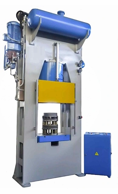
A casting press is a machine used in the casting process to shape and form molten metal into a desired shape or size. It applies pressure to the molten metal in a mold, which causes the metal to take the shape of the mold. The casting press can be operated manually or through automation.
The casting press is an important tool in the casting process, allowing manufacturers to produce large quantities of identical parts quickly and efficiently. The process can be used to produce a wide range of metal products, including automotive parts, machine components, and household appliances.
Casting Press
A casting press is a powerful machine used to force molten metal into a mold or die cavity to create a desired shape. It is a versatile and essential tool in various manufacturing industries, producing a wide range of metal components, from intricate jewelry to large automotive parts.
Casting Pressure Pot
A casting pressure pot is a specialized type of casting press that utilizes pressurized air or gas to force molten metal into a mold. It is commonly used for low-melting-point metals, such as aluminum and zinc, and offers precision and consistency in producing smaller castings.
Die Casting Press
A die casting press is a high-pressure casting press that utilizes a die cavity to create complex and precise metal parts. It is typically used for high-strength alloys, such as aluminum, magnesium, and zinc, and offers rapid production rates and dimensional accuracy.
Casting Press Tools
Casting press tools are essential components that play a crucial role in the casting process. They include molds, dies, cores, and ejectors, each designed to shape, form, and release the molten metal into the desired shape.
Cast Aluminum Press
A cast aluminum press specifically designed for casting aluminum components. It typically employs a die casting process due to aluminum’s high strength-to-weight ratio and ease of casting.
Casting Process
The casting process involves several steps to transform molten metal into a solid cast component:
- Pattern Preparation: A pattern or model of the desired shape is created using various materials, such as wood, plastic, or metal.
- Mold Making: A mold is created by replicating the pattern using sand, plaster, or other materials. The mold cavity replicates the desired shape of the casting.
- Metal Melting: The metal to be cast is melted in a furnace until it reaches the desired molten state.
- Metal Pouring: Molten metal is poured into the mold cavity, filling the desired shape.
- Solidification: The molten metal cools and solidifies within the mold, taking the shape of the mold cavity.
- Ejection: Once solidified, the casting is ejected from the mold using ejector pins or other mechanisms.
- Finishing: The casting may undergo further processing, such as trimming, machining, or polishing, to achieve the desired dimensions and surface finish.
Hydraulic Cold Forming Press
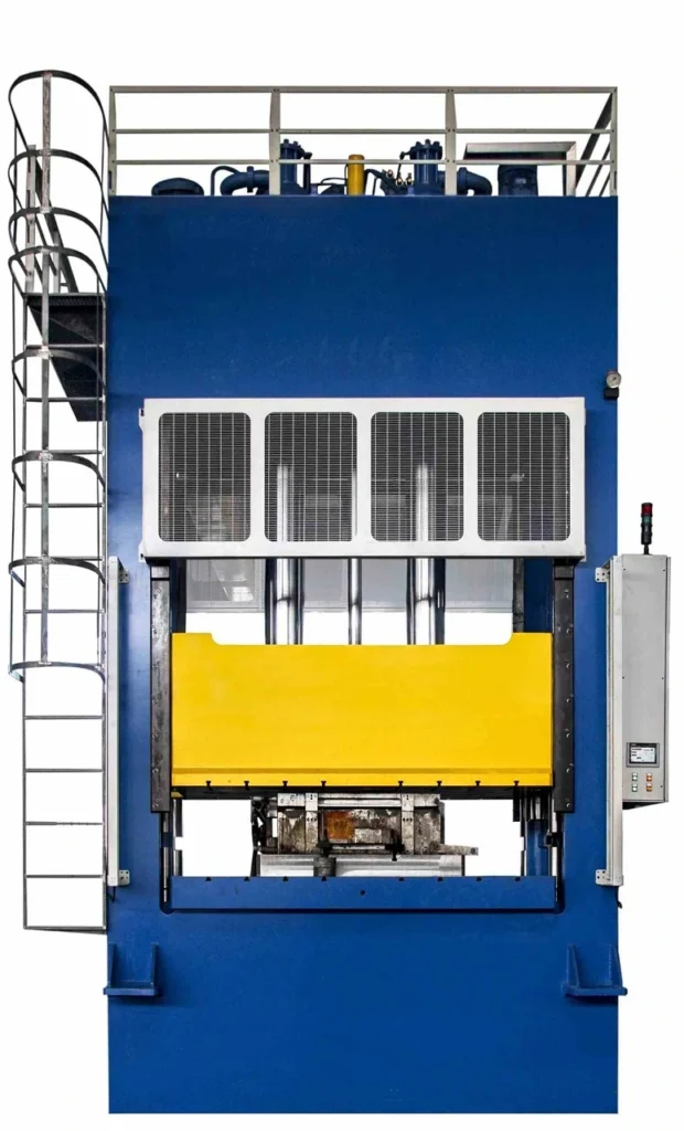
A hydraulic cold forming press is a type of hydraulic press that is designed for the cold forming process. In this process, metal is formed at room temperature, rather than being heated to a high temperature before forming. Hydraulic cold forming presses are used for a wide range of applications, including the production of fasteners, fittings, and other metal parts.
These presses use hydraulic power to apply force to the metal being formed. The hydraulic system consists of a pump, cylinders, and valves that control the flow of hydraulic fluid. The press is designed with a frame that holds the tooling and the workpiece, which is then clamped in place. When the hydraulic system is activated, the cylinders apply force to the tooling, which in turn applies force to the workpiece.
Hydraulic cold forming presses come in a range of sizes and capacities to accommodate different types of applications. They can be used for both small and large-scale production runs, depending on the needs of the manufacturer. These presses can be operated manually or automatically, with the latter often being used for high-volume production.
Overall, hydraulic cold forming presses are an essential tool in the metal forming industry. They offer a reliable, efficient, and precise way to produce high-quality metal parts for a range of applications.
Hydraulic Cold Forming Press
A hydraulic cold forming press is a specialized type of hydraulic press designed for cold forming operations. It utilizes high hydraulic pressure to deform metal at room temperature, creating various shapes and components. Cold forming is a preferred method over hot forging due to its reduced energy consumption, improved dimensional accuracy, and minimal material waste.
Cold Forming Press
A cold forming press is a general term that encompasses various types of presses used for cold forming operations. Hydraulic cold forming presses are the most common due to their versatility and ability to generate high forces at room temperature.
Hydraulic Press Forming
Hydraulic press forming is the process of shaping metal using a hydraulic press. It can involve various techniques, such as cold forming, stamping, and embossing. Hydraulic presses offer precise control over force and stroke, making them suitable for forming intricate shapes.
Hydraulic Cold Press
Hydraulic cold press is a synonym for hydraulic cold forming press. Both terms refer to hydraulic presses specifically designed for cold forming operations.
Hydraulic Press Forging
Hydraulic press forging is a specialized cold forming process that utilizes a hydraulic press to deform metal into desired shapes. It is commonly used for producing high-strength components with minimal material waste.
A Hydraulic Press for Compacting Powdered Samples
Hydraulic presses can be used to compact powdered samples into dense, solid forms. This process is known as powder compaction and is used in various industries, such as ceramics, pharmaceuticals, and metallurgy.
A Hydraulic Press
A hydraulic press is a machine that utilizes hydraulic pressure to generate a pressing force. It consists of a hydraulic cylinder, a press ram, a control system, and hydraulic lines. Hydraulic presses are versatile and powerful tools used in various manufacturing processes.
Hydraulic Forming Press
Hydraulic forming press is a synonym for hydraulic cold forming press. Both terms refer to hydraulic presses specifically designed for cold forming operations.
C-Frame Hydraulic Press
A C-frame hydraulic press is a type of hydraulic press with a C-shaped frame. It is a common design due to its simplicity, strength, and ease of use.
Cold Forging Hydraulic Press
A cold forging hydraulic press is specifically designed for cold forging operations. It typically features high pressing forces and precise stroke control to achieve the desired deformation without heating the metal.
Forging Hydraulic Press
Forging hydraulic press is a general term that encompasses hydraulic presses used for forging operations, which can include both hot forging and cold forging. Cold forging hydraulic presses are more common due to their energy efficiency and dimensional accuracy.
Hydraulic Press Metal Forming
Hydraulic press metal forming is a broad term that encompasses various metal forming processes using hydraulic presses. These processes include cold forming, stamping, embossing, and forging.
Hydraulic Cold Forging Press
A hydraulic cold forging press is specifically designed for cold forging operations. It offers high pressing forces, precise stroke control, and rapid cycle times to efficiently produce complex cold-forged components.
Hydraulic Tee Cold Forming Machine
A hydraulic tee cold forming machine is a specialized type of hydraulic press designed for cold forming tee fittings. It utilizes precise forming techniques to create the desired shape and dimensions of tee fittings.
Hydraulic Press Procedure
The hydraulic press procedure typically involves the following steps:
- Workpiece Preparation: The workpiece is prepared by cleaning, deburring, and ensuring proper alignment.
- Die Placement: The appropriate dies are selected and placed in the press.
- Press Settings: The press settings, including force, stroke, and speed, are adjusted according to the workpiece material and desired forming operation.
- Press Operation: The press cycle is initiated, applying hydraulic pressure to the press ram, which forces the workpiece into the dies, forming the desired shape.
- Part Ejection: Once formed, the part is ejected from the dies using ejector pins or other mechanisms.
- Part Inspection: The formed part is inspected for dimensional accuracy, surface finish, and any defects.
Hydraulic Press Function
Hydraulic presses perform various functions in manufacturing, including:
- Forming: Shaping sheet metal or metal components into various shapes using cold forming, stamping, embossing, or forging.
- Assembling: Joining components together using force fitting or press fitting.
- Compacting: Compressing powders or granules into solid forms.
- Stamping: Cutting and shaping sheet metal using dies.
- Straightening: Correcting misalignments or bends in metal components.
Hydraulic Press Theory
Hydraulic presses operate based on Pascal’s principle, which states that pressure applied anywhere in a closed fluid system is transmitted equally in all directions. This principle allows hydraulic presses to generate high forces with relatively low pressure.
Hydroforming Press
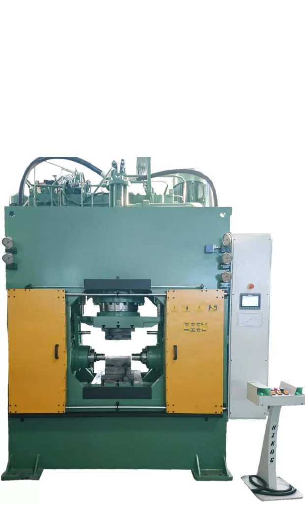
Hydroforming Press is a type of hydraulic press that is used to create complex metal shapes using fluid pressure. Hydroforming is a process in which a sheet metal blank is placed in a specially designed die and fluid pressure is applied to force the metal into the desired shape. This process is commonly used in the automotive industry to create complex shapes for car body parts, such as fenders and hoods. The advantage of using a hydroforming press is that it can produce parts with high accuracy and consistency, and with minimal material, waste compared to traditional stamping methods. Hydroforming presses come in various sizes and capacities, depending on the specific application and the size of the parts being produced.
Hydroforming Press
A hydroforming press is a specialized machine that utilizes pressurized fluid, typically water or oil, to form sheet metal or tubing into various shapes. Hydroforming offers several advantages over traditional forming methods, such as reduced material waste, improved formability, and the ability to produce complex shapes.
Hydroforming Pressure
Hydroforming pressure is the hydraulic pressure applied to the forming medium, typically water or oil, to force the sheet metal or tubing into the desired shape. The required hydroforming pressure depends on various factors, including the material properties, the desired shape, and the thickness of the workpiece.
Sheet Hydroforming Press
A sheet hydroforming press is specifically designed for hydroforming sheet metal into various shapes. These presses typically feature a closed die cavity or a flexible diaphragm to apply pressure to the sheet metal and force it into the desired shape.
Hydroforming Pressure Calculation
Hydroforming pressure calculation involves considering various factors, such as the material yield strength, the desired shape complexity, and the thickness of the workpiece. Theoretical and empirical formulas are used to estimate the required hydroforming pressure based on these parameters.
Tube Hydroforming Press
A tube hydroforming press is specifically designed for hydroforming tubes into various shapes. These presses typically utilize internal mandrels or external dies to control the deformation of the tube and produce the desired shape.
What Is Hydroforming Process?
Hydroforming is a metal forming process that utilizes pressurized fluid to form sheet metal or tubing into various shapes. It is a versatile and efficient process that offers several advantages over traditional forming methods.
Hydropress Forming
Hydropress forming is a synonym for hydroforming. Both terms refer to the metal forming process that utilizes pressurized fluid to shape sheet metal or tubing.
Hydroforming with Pressure Washer
While it is technically possible to use a high-pressure water jet from a pressure washer for hydroforming, it is not recommended due to the lack of control over the forming process and the potential safety hazards. Commercial hydroforming presses provide precise pressure control and safety measures.
Hydro-Forming
Hydro-forming is an alternative spelling for hydroforming. Both terms refer to the same metal forming process.
Power Press Process
A power press process is a mechanical forming process that utilizes a flywheel and clutch to generate a sudden impact force to form sheet metal. Power presses are commonly used for stamping, blanking, and embossing operations.
Hydroforming Pump
A hydroforming pump is a high-pressure pump that supplies the pressurized fluid to the hydroforming press. The pump must be capable of delivering the required pressure and flow rate for the specific hydroforming operation.
Hydroforming Rubber
Hydroforming can be used to form rubber components, particularly in the automotive industry. Hydroforming rubber offers advantages in terms of dimensional accuracy, surface finish, and the ability to produce complex shapes.
Hydroforming Machine
Hydroforming machine is a synonym for hydroforming press. Both terms refer to the machine that utilizes pressurized fluid to form sheet metal or tubing.
Hydraulic Forming Press
A hydraulic forming press is a broader term that encompasses hydroforming presses, as well as other types of presses that utilize hydraulic pressure for forming operations. Hydroforming presses are a specific type of hydraulic forming press.
Composite Press for Ballistic Panels
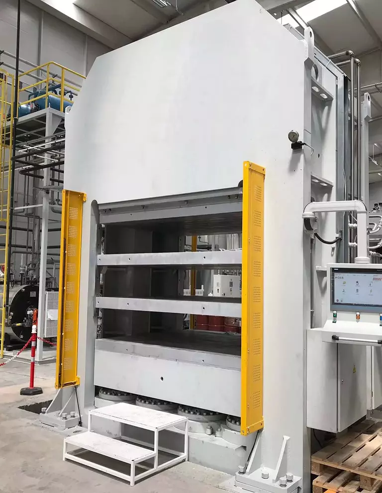
Composite presses are often used to manufacture ballistic panels for various applications, including bulletproof vests, armored vehicles, and aircraft. These presses are capable of producing composite panels with high strength and durability, while also being lightweight.
The process typically involves layering multiple sheets of composite materials, such as fiberglass or aramid fibers, and bonding them together with a resin. The composite material is then placed into a mold and subjected to heat and pressure to cure the resin and create the desired shape.
Hydraulic composite presses are often used for this process because they can provide precise and uniform pressure across the entire surface area of the mold, ensuring consistent and high-quality parts. These presses also allow for a wide range of pressure and temperature control, making them suitable for a variety of composite materials and manufacturing processes.
In the case of ballistic panels, the final product must be able to withstand high impact forces without breaking or deforming, and must also be lightweight and easy to handle. Composite presses help to achieve these properties by allowing for precise control of the material properties and processing conditions
Composite Press for Ballistic Panels
A composite press for ballistic panels is a specialized machine used to manufacture ballistic panels, which are protective armor panels designed to stop bullets and other projectiles. These presses utilize high pressure and heat to combine layers of composite materials, such as fiberglass, Kevlar, and polyethylene, into a single, dense panel.
Composite Ballistic Plates
Composite ballistic plates are panels made from a combination of composite materials that offer protection against ballistic threats. They are commonly used in personal protective equipment, such as body armor, and in armored vehicles.
Ballistic Composite Materials
Ballistic composite materials are materials that have been specifically designed to resist ballistic impacts. They typically consist of high-strength fibers embedded in a resin matrix.
Composite Panel Repair
Composite panel repair involves restoring the structural integrity and appearance of damaged composite panels. This can be done using various techniques, such as patching, bonding, and resurfacing.
Composite Press
A composite press is a machine used to compress and cure composite materials into desired shapes. It is a versatile tool used in various industries, including aerospace, automotive, and marine.
Aluminum Composite Panel Installation Procedure
The installation procedure for aluminum composite panels typically involves:
- Surface Preparation: Ensuring the surface is clean, level, and free from debris.
- Panel Cutting: Cutting the panels to the desired dimensions.
- Panel Positioning: Positioning the panels correctly on the substrate.
- Fastener Placement: Marking and drilling holes for fasteners.
- Fastener Installation: Securing the panels to the substrate using appropriate fasteners.
- Sealant Application: Applying sealant around fasteners and joints to prevent moisture intrusion.
Foam Composite Panels
Foam composite panels are panels that consist of a lightweight foam core sandwiched between two layers of composite material. They offer a combination of strength, stiffness, and insulation.
Metal Composite Panels
Metal composite panels are panels that consist of a metal core sandwiched between two layers of composite material. They offer a combination of strength, stiffness, and corrosion resistance.
Metal Composite Material Panels
Metal composite material panels are a synonym for metal composite panels. Both terms refer to panels that consist of a metal core sandwiched between two layers of composite material.
Plastic Composite Panels
Plastic composite panels are panels that consist of a plastic core sandwiched between two layers of composite material. They offer a combination of strength, stiffness, and lightweight properties.
Ballistic Panels for Vehicles
Ballistic panels for vehicles are designed to protect occupants from ballistic threats. They are typically installed in the doors, windows, and underbody of the vehicle.
Composite Panel Building Systems
Composite panel building systems are construction systems that utilize composite panels as the primary structural components. They offer advantages in terms of strength, lightweight properties, and ease of installation.
Silicone Rubber Moulding Press
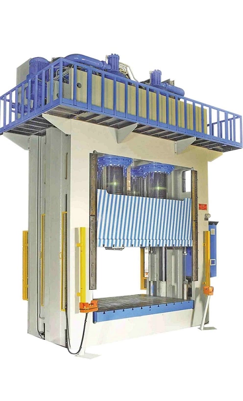
Silicone rubber molding presses are machines used for the molding of silicone rubber into different shapes and sizes. These presses are commonly used in the production of a wide range of silicone rubber products, including gaskets, seals, O-rings, and other components.
The molding process involves the use of a hydraulic press, which applies pressure and heat to the silicone rubber material. The press is equipped with a mold, which is used to shape the silicone rubber material into the desired shape. The mold is made of a durable material, such as steel or aluminum, and is designed to withstand the high pressures and temperatures involved in the molding process.
The silicone rubber material is first prepared by mixing together different components, including the base material, catalyst, and other additives. This mixture is then poured into the mold, and the press is activated. The press applies pressure to the mold, compressing the silicone rubber material and forcing it to take the shape of the mold. Heat is also applied to the mold, which helps to cure the silicone rubber and set it into its final form.
Silicone rubber molding presses are available in a range of sizes and configurations, depending on the specific application requirements. They are commonly used in a variety of industries, including automotive, aerospace, electronics, and medical device manufacturing, among others.
Silicone Rubber Molding Press
A silicone rubber molding press is a specialized machine used to create silicone rubber molds for various applications, including casting, potting, and encapsulation. These presses typically utilize hydraulic or pneumatic pressure to compress silicone rubber into a mold cavity, replicating the desired shape of the mold.
Silicone Rubber Molding Kit
A silicone rubber molding kit is a collection of essential materials and tools for silicone rubber molding. These kits typically include silicone rubber compound, mixing cups, mixing sticks, spatula, mold release agent, and curing instructions.
Silicone Rubber Molding
Silicone rubber molding is a process of creating molds using silicone rubber compound. Silicone rubber is a versatile material known for its flexibility, durability, and heat resistance, making it suitable for various molding applications.
Silicone Rubber Mold Release
Silicone rubber mold release is a specialized lubricant used to prevent silicone rubber from sticking to the mold. It is typically applied to the mold cavity before molding to ensure easy release of the cured silicone rubber part.
Blow Molding Silicone Rubber
Blow molding silicone rubber is a process of creating hollow silicone rubber parts using a blow molding machine. This technique involves injecting molten silicone rubber into a mold cavity and then expanding the rubber using pressurized air or gas, forming the desired shape.
Rubber Molding Press
A rubber molding press is a specialized machine used to shape and cure rubber into various forms. It applies pressure and heat to rubber compounds, forcing them into mold cavities to create the desired shape. Rubber molding presses are widely used in various industries, including automotive, aerospace, and medical.
Silicone Press Machine
A silicone press machine is a type of rubber molding press specifically designed for molding silicone rubber. Silicone rubber is a versatile material known for its flexibility, durability, and heat resistance, making it suitable for various molding applications.
Flexible Rubber Molding
Flexible rubber molding is a technique that utilizes flexible molds to create rubber parts. Flexible molds allow for easy removal of the cured rubber part and are often used for producing intricate or undercut shapes.
Rubber Mold Press
Rubber mold press is a synonym for rubber molding press. Both terms refer to the machine used to shape and cure rubber into various forms.
Foam Rubber Molding
Foam rubber molding is a process of creating foam rubber components using a rubber molding press. Foam rubber is a lightweight and resilient material used in various applications, including cushioning, insulation, and packaging.
Molding Silicone Rubber Parts
Molding silicone rubber parts involves shaping and curing silicone rubber into various forms using a silicone press machine. Silicone rubber is a versatile material known for its flexibility, durability, and heat resistance, making it suitable for various applications.
Injection Molding Silicone Rubber
Injection molding silicone rubber is a process of injecting molten silicone rubber into a mold cavity to create silicone rubber parts. This technique is suitable for high-volume production and offers dimensional accuracy and consistency.
Liquid Silicone Rubber Molding Process
Liquid silicone rubber molding process refers to molding techniques that utilize liquid silicone rubber (LSR). LSR is a two-part silicone rubber system that is cured at high temperatures. It is known for its high tear strength, biocompatibility, and resistance to extreme temperatures.
Liquid Silicone Rubber Injection Molding Process
Liquid silicone rubber injection molding process is a specialized injection molding technique that utilizes LSR. It offers advantages in terms of precision, consistency, and the ability to produce complex shapes.
Liquid Silicone Rubber Molding
Liquid silicone rubber molding encompasses various techniques that utilize LSR to create silicone rubber parts. These techniques include injection molding, compression molding, and transfer molding.
Silicone Rubber O-Rings
Silicone rubber o-rings are circular gaskets made from silicone rubber that are used to seal joints and prevent leakage. They are known for their durability, flexibility, and resistance to various chemicals and temperatures.
O Ring Mold
An o-ring mold is a specialized mold used to create o-rings. It typically consists of two halves that come together to form a circular cavity with the desired o-ring dimensions.
Brake Pad Press
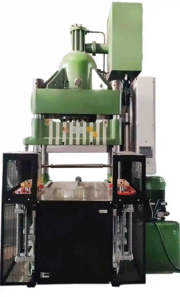
A brake pad press is a type of hydraulic press used in the manufacturing of brake pads for various types of vehicles. The press is designed to apply high pressure and temperature to compress and shape the friction material into the desired form for the brake pad. The brake pad press typically consists of a hydraulic system, heating system, and a die for shaping the friction material. The hydraulic system provides the necessary force to compress the material while the heating system ensures that the material is heated to the required temperature for molding. The die is designed to give the brake pad its final shape and size. Brake pad presses can be designed for small-scale production or for mass production depending on the needs of the manufacturer.
Brake Pad Press
A brake pad press is a specialized tool used to compress brake pads into their final shape before installation in brake calipers. It is an essential tool in brake pad manufacturing and brake repair. Brake pad presses typically utilize hydraulic or pneumatic pressure to apply force to the brake pad material, compressing it into the desired shape.
Brake Pad Press Tool
A brake pad press tool is a synonym for a brake pad press. Both terms refer to the specialized tool used to compress brake pads into their final shape.
Brake Pad Press Machine
A brake pad press machine is a type of brake pad press that is equipped with a motorized mechanism to apply pressure. These machines offer increased efficiency and consistency compared to manual brake pad presses.
Melamine Press
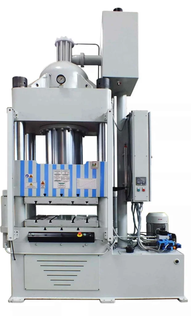
A Melamine Press is a machine used in the production of melamine tableware, such as plates, bowls, and cups. Melamine is a type of plastic that is molded under high pressure and temperature into the desired shape. The melamine press uses a hydraulic system to apply pressure to a mold containing the melamine powder. Once the powder is compressed into the desired shape, it is then cured and cooled to harden the material. Melamine presses are often used in large-scale manufacturing operations to produce a high volume of melamine products quickly and efficiently.
Melamine Press
A melamine press is a specialized machine used to laminate melamine paper onto particleboard or MDF (medium-density fiberboard) to create melamine board, a durable and cost-effective material widely used in furniture manufacturing and interior design.
Melamine Pressed Wood
Melamine pressed wood is a synonym for melamine board. Both terms refer to the composite material made by laminating melamine paper onto particleboard or MDF.
Melamine Press Machine
A melamine press machine is a type of hydraulic press specifically designed for melamine pressing operations. These machines utilize high pressure and heat to effectively bond melamine paper to the substrate board.
Melamine Pressure
Melamine pressure refers to the pressure applied during the melamine pressing process. The required pressure varies depending on the type of substrate board and the desired melamine bond strength.
Melamine Hot Press Machine
A melamine hot press machine is a synonym for a melamine press machine. Both terms refer to the hydraulic press specifically designed for melamine pressing operations.
Melamine Short Cycle Press
A melamine short cycle press is a type of melamine press machine designed to achieve fast production cycles. These machines utilize advanced heating and cooling systems to reduce cycle times, increasing efficiency and productivity.
Hot Press Melamine
Hot press melamine refers to the melamine pressing process that utilizes a heated press to bond melamine paper to the substrate board. Heat is essential for activating the adhesive and achieving a strong bond.
Heat Press for Melamine
A heat press for melamine is a type of press that can be used for melamine pressing operations. While specialized melamine press machines are preferred for high-volume production, heat presses can be used for smaller projects or in-house melamine laminating.
SMC & BMC Moulding Press
SMC (Sheet Molding Compound) and BMC (Bulk Molding Compound) are two types of materials used in the manufacturing of composite parts. SMC and BMC Moulding Presses are hydraulic presses used for the compression molding of these materials.
SMC is a mixture of chopped fiberglass strands, thermosetting resin, fillers, and pigments, while BMC is made up of a similar mixture with the addition of low-profile additives to improve flow and fill. These materials are typically used to produce large and complex parts with high strength-to-weight ratios and excellent dimensional stability.
SMC and BMC Moulding Presses typically have a heated platen system to aid in the curing of the composite material, and they can range in size from small laboratory presses to large industrial presses capable of producing parts several meters in size. These presses use high pressure and temperature to shape the composite material into the desired form, and they can produce parts with high accuracy and consistency.
SMC & BMC Molding Press
SMC (Sheet Molding Compound) and BMC (Bulk Molding Compound) molding presses are specialized machines used to shape and cure SMC and BMC compounds into various forms. SMC and BMC are thermoset resin-based materials reinforced with fiberglass or other fillers. These materials offer a combination of strength, lightweight properties, and electrical insulation, making them suitable for various applications in the automotive, aerospace, and electrical industries.
SMC Molding Process
SMC molding process involves several steps:
- Compound Preparation: SMC or BMC is cut into sheets or pellets according to the mold size and part requirements.
- Mold Preparation: The mold is cleaned, coated with a mold release agent, and preheated to the desired temperature.
- Compound Placement: SMC or BMC sheets or pellets are placed into the mold cavity.
- Mold Closing: The mold is closed under pressure, applying force to the compound.
- Curing: Heat is applied to the mold to cure the SMC or BMC compound, causing the resin to crosslink and solidify.
- Ejection: Once cured, the mold is opened, and the molded part is ejected.
- Trimming: Excess material is trimmed from the molded part to achieve the desired dimensions and finish.
SMC Molding
SMC molding encompasses various techniques for shaping SMC into desired forms, including compression molding, transfer molding, and injection molding. Compression molding is the most common method for SMC molding.
SMC Molding and Manufacturing
SMC molding and manufacturing involves the production of SMC components using SMC molding presses. It is a versatile and cost-effective manufacturing process used to produce a wide range of parts.
SMC Compression Molding
SMC compression molding is a specific type of SMC molding that utilizes a compression molding press to apply pressure and heat to the SMC compound. This method is suitable for producing large and complex SMC parts.
BMC SMC
BMC (Bulk Molding Compound) is a variant of SMC with a putty-like consistency, making it easier to handle and suitable for manual molding processes.
SMC Mould
An SMC mold is a specialized mold used for SMC molding. It typically consists of two halves that come together to form the desired cavity for the SMC part.
BMC Compression Molding
BMC compression molding is a specific type of BMC molding that utilizes a compression molding press to apply pressure and heat to the BMC compound. This method is suitable for producing smaller and less complex BMC parts.
C C Moulding
C C Moulding is a synonym for SMC and BMC molding. Both terms refer to the molding processes that utilize SMC and BMC compounds.
C & M Precision
C & M Precision is a manufacturer of SMC and BMC molding presses. They offer a range of presses for various applications and production requirements.
SMC BMC DMC
SMC (Sheet Molding Compound), BMC (Bulk Molding Compound), and DMC (Dough Molding Compound) are all thermoset resin-based molding compounds with different handling characteristics. SMC is in sheet form, BMC is putty-like, and DMC is dough-like.
SMC and BMC
SMC and BMC are both thermoset resin-based molding compounds reinforced with fiberglass or other fillers. They offer similar properties and are often used interchangeably for various applications.
SMC and DMC Moulding
SMC and DMC molding are similar processes that involve shaping and curing SMC or DMC compounds into desired forms. The choice between SMC and DMC depends on the specific part requirements and production considerations.
Laboratory Press
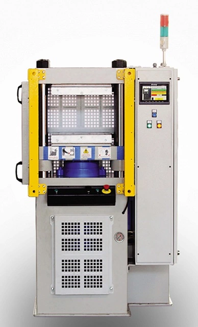
Laboratory presses are machines used in scientific research and development to process small-scale samples of various materials. These presses are often used to prepare samples for analysis, test new materials or processes, and to scale-up to larger production processes. They are designed to provide precise and repeatable force and temperature control to accurately mimic industrial-scale production processes. Laboratory presses can be used in a variety of fields, including materials science, chemistry, biology, and engineering. They come in various sizes, from small benchtop models to larger floor models, and can be powered by hydraulic, pneumatic, or electrical means.
Hydraulic Deep Drawing Press as Metalworking Machinery
Deep drawing press: deep drawing press is a hydraulic press machine, that forms parts made of sheet metal. The deep drawing manufacturing process is a metalworking operation where the hydraulic drawing press forms one side of closed cylinder-shaped parts by drawing the sheet metal
Hydraulic Deep Drawing Press
A hydraulic deep drawing press is a powerful machine that utilizes hydraulic pressure to form sheet metal into various shapes. It is widely used in various industries to produce a wide range of products, including automotive parts, appliances, and cookware.
Hydraulic Deep Drawing Press Machine
A hydraulic deep drawing press machine consists of a hydraulic cylinder, a press ram, a drawing die, and a blank holder. The hydraulic cylinder generates hydraulic pressure, which forces the press ram downward to draw the sheet metal into the desired shape.
Deep Drawing Hydraulic Press Design
Hydraulic deep drawing presses can be designed with single action, double action, or triple action capabilities. Single-action presses utilize a single hydraulic ram for drawing, while double-action presses employ an additional hydraulic ram to hold the blank material during the drawing process, providing better control and reducing wrinkles. Triple-action presses add a third hydraulic ram to apply a pressure cushion behind the blank material, further enhancing control and preventing tearing.
Hydraulic Deep Drawing Press Double Action
A hydraulic deep drawing press with double action capabilities offers several advantages over single-action presses:
- Improved formability: The blank holder helps control material flow during drawing, reducing wrinkling and improving formability.
- Reduced thickness variations: The blank holder provides uniform pressure distribution, minimizing thickness variations in the formed part.
- Enhanced control: Double-action presses offer better control over the drawing process, allowing for more complex shapes and deeper draws.
How Does a Hydraulic Press Work?
A hydraulic press works by converting hydraulic pressure into linear force. Hydraulic fluid is pumped into a hydraulic cylinder, creating pressure that acts on a piston. The piston’s movement is transferred to a press ram, which exerts a downward force on the workpiece.
Hydraulic Press Explained
Hydraulic presses are preferred over mechanical presses in many applications due to their advantages:
- Versatility: Hydraulic presses can handle a wide range of materials and thicknesses.
- Precision: Hydraulic presses offer precise control over force and stroke, enabling consistent results.
- Safety: Hydraulic presses are generally safer than mechanical presses due to the enclosed hydraulic system.
How to Design a Hydraulic Press
Designing a hydraulic press involves several considerations, including:
- Press capacity: The maximum force the press can exert.
- Stroke length: The maximum distance the press ram can travel.
- Bed size: The size of the work area.
- Daylight opening: The maximum distance between the press ram and the bed.
- Shut height: The minimum distance between the press ram and the bed.
- Control system: The type of control system used to operate the press.
- Application requirements: The specific material, part dimensions, and production volume.
Deep Draw Press
Deep draw press is a general term that refers to any press used for deep drawing operations. Hydraulic deep drawing presses are the most common type due to their ability to generate the high forces required for deep drawing.
Deep Drawing Press Machine Specification
When selecting a deep drawing press machine, consider the following specifications:
- Press capacity: The maximum force the press can exert.
- Stroke length: The maximum distance the press ram can travel.
- Bed size: The size of the work area.
- Daylight opening: The maximum distance between the press ram and the bed.
- Shut height: The minimum distance between the press ram and the bed.
- Control system: The type of control system used to operate the press.
- Application requirements: The specific material, part dimensions, and production volume.
Hydraulic Deep Draw Press Machine
A hydraulic deep draw press machine is a synonym for a hydraulic deep drawing press. Both terms refer to the machine that utilizes hydraulic pressure to form sheet metal into various shapes through deep drawing operations.
Drawing Hydraulic Press Diagram
A drawing hydraulic press diagram illustrates the various components of a hydraulic deep drawing press, including the hydraulic cylinder, press ram, drawing die, blank holder, control system, and hydraulic lines.
Drawing of Hydraulic Press
A drawing of a hydraulic press typically depicts the arrangement of the hydraulic cylinder, press ram, dies, and other components, providing a visual representation of the machine’s layout.
Hydraulic Transfer Press
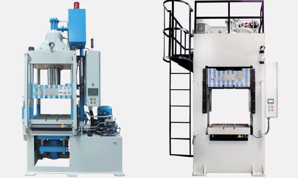
Hydraulic transfer press is a type of hydraulic press that is designed to transfer parts or components between multiple workstations. It is widely used in manufacturing processes that require the transfer of parts or components between different stations.
Hydraulic transfer presses typically consist of a main press body, a transfer mechanism, and multiple workstations. The main press body is responsible for applying pressure to the part being formed or processed. The transfer mechanism moves the part between workstations, which are typically arranged in a circular or linear pattern around the press body.
Hydraulic transfer presses are commonly used in industries such as automotive, aerospace, and consumer goods manufacturing. They are often used in the production of components such as gears, bearings, and engine parts. They offer a high level of precision, repeatability, and speed, making them an ideal choice for high-volume manufacturing applications.
Hydraulic Transfer Press
A hydraulic transfer press is a specialized type of hydraulic press designed for transfer molding operations. It utilizes a combination of hydraulic pressure and transfer mechanisms to shape and cure plastic or composite materials into various forms. Transfer presses offer advantages in terms of precision, consistency, and the ability to produce complex shapes.
How Does a Hydraulic Press Work?
A hydraulic press operates based on Pascal’s principle, which states that pressure applied anywhere in a closed fluid system is transmitted equally in all directions. This principle allows hydraulic presses to generate high forces with relatively low pressure.
The basic working principle of a hydraulic press involves:
- Hydraulic Fluid Supply: Hydraulic fluid is pumped into a hydraulic cylinder using a hydraulic pump.
- Pressure Generation: The hydraulic fluid creates pressure within the cylinder, acting on a piston.
- Force Transmission: The force generated by the pressurized fluid is transferred to a press ram via the piston’s movement.
- Workpiece Deformation: The press ram applies the force to the workpiece, deforming it into the desired shape.
Hydraulic Press Procedure
The typical hydraulic press procedure involves the following steps:
- Workpiece Preparation: The workpiece is prepared by cleaning, deburring, and ensuring proper alignment.
- Die Placement: The appropriate dies are selected and placed in the press.
- Press Settings: The press settings, including force, stroke, and speed, are adjusted according to the workpiece material and desired forming operation.
- Press Operation: The press cycle is initiated, applying hydraulic pressure to the press ram, which forces the workpiece into the dies, forming the desired shape.
- Part Ejection: Once formed, the part is ejected from the dies using ejector pins or other mechanisms.
- Part Inspection: The formed part is inspected for dimensional accuracy, surface finish, and any defects.
Transfer Lines
Transfer lines with hydraulic presses are a type of automated production line that combines several hydraulic presses in a single process. They are used in manufacturing industries to produce large volumes of parts with high precision and consistency.
The process begins with raw material being fed into the first press in the line, where it is shaped or formed into a specific part. The finished part is then transferred to the next press in the line, where additional operations such as trimming, piercing, or bending may be performed. This process continues until the final part is complete.
The advantage of transfer lines with hydraulic presses is that they can produce a large number of parts in a short amount of time, with minimal manual labor required. The automated process also ensures high precision and consistency in the finished parts, resulting in a high-quality product.
Bandsaw for Metal Cutting
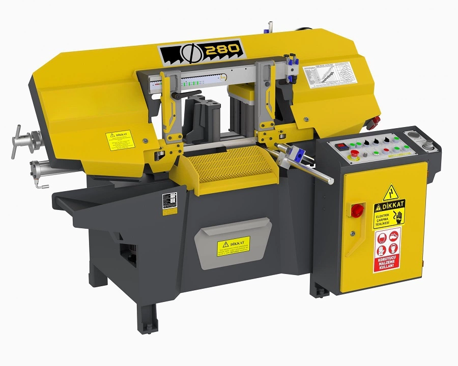
Bandsaw for metal cutting: Bandsaw for metal are cutting machines with a bandsaw on it. the bandsaw can cut sheet metals as well as full steel bars with the smallest diameter of 200 mm up to 2000 mm. Our bandsaw can cut automatically and manually.
A bandsaw for metal cutting is a power tool that uses a continuous band saw blade with teeth to cut metal workpieces. The blade is stretched over two wheels, one of which is driven by an electric motor, and it passes through a workpiece while it is being cut. The teeth on the blade are designed to remove material as it moves through the workpiece, allowing for precise and efficient cutting of metal. Bandsaws are commonly used in metalworking shops for cutting metal bars, pipes, and other shapes. They come in a range of sizes and capacities, with larger machines capable of cutting thicker and harder materials.
Bandsaw for Metal Cutting
A bandsaw is a versatile tool that can be used to cut a variety of materials, including metal. Metal-cutting bandsaws are specifically designed to handle the rigors of cutting through tough metals like steel, aluminum, and stainless steel. They feature heavier-duty construction, more powerful motors, and specialized blades designed to cut metal cleanly and efficiently.
Vertical Bandsaw for Metal Cutting
Vertical bandsaws are the most common type of bandsaw used for metal cutting. They are characterized by their upright orientation, with the cutting blade running vertically through a worktable. This design provides better stability and control when cutting metal, especially for larger or heavier workpieces.
Bandsaw Speeds for Cutting Metal
The ideal bandsaw speed for cutting metal depends on the specific material being cut and the desired cutting speed. Generally, slower speeds are used for harder metals, while faster speeds can be used for softer metals.
Metal Cutting Blade for Bandsaw
Metal-cutting bandsaws require specialized blades designed to withstand the stresses of cutting metal. These blades typically have finer teeth made from harder materials like high-speed steel or bimetallic alloys to provide a clean, precise cut without damaging the blade.
Bandsaw RPM for Cutting Metal
Bandsaw RPM (revolutions per minute) is a measure of how fast the blade is rotating. The ideal RPM for cutting metal depends on the blade size and the material being cut. Generally, smaller blades require higher RPMs, while larger blades require lower RPMs.
Band Saw for Cutting Metal and Wood
While some bandsaws can be used to cut both metal and wood, it is generally recommended to have separate saws for each material. This is because metal-cutting blades are not designed for the softer fibers of wood and can quickly dull or become damaged.
Can You Use a Band Saw to Cut Metal?
Yes, you can use a band saw to cut metal, provided you have the right equipment. A metal-cutting bandsaw with the appropriate blade and settings can handle a variety of metal cutting tasks.
Can Any Bandsaw Cut Metal?
Not all bandsaws are designed to cut metal. Standard wood-cutting bandsaws typically lack the power and blade strength to handle the rigors of metal cutting. Metal-cutting bandsaws are specifically designed for this purpose and feature heavier-duty construction, more powerful motors, and specialized blades.
Band Saw Metal Cutting Blade
Metal-cutting bandsaw blades are essential for achieving clean, precise cuts in metal. They feature finer teeth made from harder materials like high-speed steel or bimetallic alloys to provide a smooth, burr-free cut without damaging the blade.
Choosing Bandsaw Blades for Metal Cutting
When choosing bandsaw blades for metal cutting, consider the following factors:
- Blade Material: High-speed steel or bimetallic blades are recommended for metal cutting.
- Tooth Pitch: Finer tooth pitches are generally used for harder metals, while coarser tooth pitches can be used for softer metals.
- Blade Thickness: Thinner blades are suitable for cutting thinner materials, while thicker blades are better suited for thicker materials.
Coolant for Metal Cutting Bandsaw
Using coolant when cutting metal with a bandsaw can help extend blade life, improve cutting performance, and reduce heat buildup. Coolant can be applied in various forms, such as mist or flood, depending on the specific application.
Can You Cut Steel with a Bandsaw?
Yes, you can cut steel with a bandsaw, provided you have the right equipment and follow proper cutting techniques. A metal-cutting bandsaw with the appropriate blade and settings can handle a variety of steel cutting tasks.
Profile Bending Machine
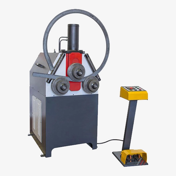
Profile bending machine: profile bending machine or a profile bender is used to bend profiles as circles.
A profile bending machine, also known as a section bending machine or a profile bending roll, is a type of machine used in the metalworking industry to bend and shape different types of profiles and sections. These machines are typically used for producing curved or rounded components and structures from metal bars, tubes, and other sections.
The profile bending machine works by using a set of three or four rollers, which are usually arranged in a pyramid-shaped configuration. The two lower rollers are fixed in place and provide the initial support for the workpiece, while the upper rollers can be adjusted to create the desired bend radius. As the workpiece is fed through the machine, the rollers apply pressure to the material, causing it to deform and bend into the desired shape.
There are several different types of profile bending machines, each of which is designed to handle specific types of profiles and sections. For example, a roll bending machine is designed for bending cylindrical or conical sections, while a pyramid rolling machine is used for bending flat or rectangular sections.
One of the main advantages of using a profile bending machine is its ability to produce complex curves and shapes that would be difficult or impossible to achieve with other metalworking techniques. This makes it an essential tool for industries such as construction, manufacturing, and automotive engineering, where curved and shaped components are commonly used.
In addition to their versatility, profile bending machines are also highly efficient and can produce a large number of bent components in a short amount of time. This makes them ideal for high-volume production environments where speed and efficiency are critical.
Overall, the profile bending machine is a highly valuable tool for any metalworking operation that requires the ability to create curved or shaped components from a variety of profiles and sections. With their versatility, efficiency, and precision, these machines are essential for a wide range of industries and applications
Profile Bending Machine
A profile bending machine is a specialized machine designed to bend various types of profiles, including metal bars, tubes, and extrusions, into various shapes. These machines are widely used in construction, manufacturing, and other industries to create curved components for various applications.
Aluminum Profile Bending Machine
An aluminum profile bending machine is specifically designed to bend aluminum profiles, which are commonly used in construction, furniture, and other applications. These machines utilize specialized dies and tooling to handle the unique properties of aluminum, ensuring precise and consistent bending results.
CNC Aluminum Profile Bending Machine
A CNC aluminum profile bending machine utilizes computer numerical control (CNC) technology to automate the bending process. This allows for precise control over the bending angle, radius, and position, enabling the production of complex and intricate shapes with high accuracy.
CNC Profile Bending Machine
A CNC profile bending machine is a broader term that encompasses CNC-controlled bending machines for various types of profiles, including aluminum, steel, and other materials. These machines offer enhanced precision and automation capabilities compared to manual or semi-automated bending machines.
Hydraulic Profile Bending Machine
A hydraulic profile bending machine utilizes hydraulic pressure to apply the force required for bending the profile. These machines are known for their powerful and versatile bending capabilities, making them suitable for a wide range of applications.
CNC Hydraulic Profile Bending Machine
A CNC hydraulic profile bending machine combines the power of hydraulic bending with the precision of CNC control. This provides a robust and accurate solution for bending various profiles, including aluminum, steel, and other materials.
Hydraulic and Mechanical Profile Bending Machine
Hydraulic and mechanical profile bending machines represent two distinct types of bending mechanisms:
- Hydraulic bending: Utilizes hydraulic pressure to apply force for bending.
- Mechanical bending: Utilizes mechanical gears, cams, or other mechanisms to apply force for bending.
The choice between hydraulic and mechanical bending depends on factors such as material properties, desired bending radius, and production volume.
Circular Welding Machine in Metalworking Machinery

Circular welding machine: Circular welding machine is used to weld cylinders made from sheet metals. The circular welding machine can weld vertically or horizontally.
A circular welding machine is a type of welding machine used to join two pieces of circular metal together. This type of welding is commonly used in the production of pipes, tubes, and cylinders. The circular welding machine works by rotating the workpiece while a welding torch applies heat to the joint. As the workpiece rotates, the torch moves along the length of the joint, melting the metal and fusing the two pieces together.
Circular welding machines are used in a variety of industries, including automotive, aerospace, construction, and manufacturing. They are particularly useful in the production of pipes and tubes for the oil and gas industry, as well as for the production of cylindrical tanks for storage and transportation.
There are several different types of circular welding machines, including manual, semi-automatic, and fully automatic machines. Manual machines require an operator to move the welding torch along the joint by hand, while semi-automatic machines use a motorized carriage to move the torch. Fully automatic machines are controlled by a computer program and require minimal operator input.
Circular welding machines are capable of welding a variety of materials, including steel, stainless steel, aluminum, and copper. They are also capable of producing high-quality welds with minimal distortion or warping, making them ideal for high-precision applications.
In summary, circular welding machines are an essential tool in the production of cylindrical metal objects, and they offer a reliable and efficient way to join circular metal pieces together.
Circular Welding Machine
A circular welding machine is a specialized machine designed to weld circular joints, typically in cylindrical or tubular workpieces. These machines are commonly used in the manufacturing of pipes, tanks, pressure vessels, and other cylindrical components.
Automatic Circular Welding Machine
An automatic circular welding machine utilizes automation to perform the welding process, reducing manual intervention and improving efficiency. These machines typically employ CNC (Computer Numerical Control) technology to precisely control the welding torch’s movement, ensuring consistent and accurate welds.
CNC Machine Welding
CNC machine welding refers to the use of CNC technology to automate welding operations. CNC welding machines provide precise control over the welding parameters, including torch position, speed, and heat input, resulting in high-quality welds with minimal defects.
Circular Seam Welding Machine
A circular seam welding machine is specifically designed to weld circular seams, which are continuous welds around the circumference of a cylindrical or tubular workpiece. These machines are essential for manufacturing seamless pipes, tanks, and other cylindrical components.
How Many Types of Welding Machine
There are numerous types of welding machines, each with its specific applications and capabilities. Some common types include:
- Gas Metal Arc Welding (GMAW): Uses a continuous wire electrode and shielding gas to weld metals.
- Flux-Cored Arc Welding (FCAW): Uses a tubular wire electrode filled with flux to weld metals.
- Submerged Arc Welding (SAW): Uses a continuous wire electrode and flux submerged in granular flux to weld metals.
- Shielded Metal Arc Welding (SMAW): Uses a coated consumable electrode to weld metals.
- Gas Tungsten Arc Welding (GTAW): Uses a non-consumable tungsten electrode and shielding gas to weld metals.
- Electron Beam Welding (EBW): Uses a high-energy beam of electrons to weld metals.
- Laser Beam Welding (LBW): Uses a high-energy beam of laser light to weld metals.
What Are the Parts of a Welding Machine
The key components of a welding machine typically include:
- Power Source: Supplies the electrical current required for the welding process.
- Welding Torch: Directs the welding arc or energy beam towards the workpiece.
- Welding Electrode (or Filler Metal): Provides the material for filling and bonding the weld joint.
- Control System: Regulates the welding parameters, such as current, voltage, and travel speed.
What Are the 4 Types of Welding Machines
The four main types of welding machines are:
- Arc Welding: Uses an electric arc to generate heat for melting and fusing the weld joint.
- Resistance Welding: Uses electrical resistance to generate heat for fusing the weld joint.
- Beam Welding: Uses high-energy beams, such as electrons or lasers, to melt and fuse the weld joint.
- Thermoplastic Welding: Melts and fuses thermoplastic materials to create a weld joint.
What Is the Working Principle of a Welding Machine
The working principle of a welding machine depends on the specific welding process. In general, welding involves applying heat to melt and fuse the base metal of the workpieces, allowing the filler metal to flow into the joint and create a strong bond.
Circular Welder
A circular welder is a general term for any machine designed to weld circular joints. It encompasses various types, including automatic circular welding machines, CNC circular welding machines, and circular seam welding machines.
Circular Welding
Circular welding refers to the process of welding circular joints, typically in cylindrical or tubular workpieces. It is a critical process in the manufacturing of pipes, tanks, pressure vessels, and other cylindrical components.
Pipe Bending Machine
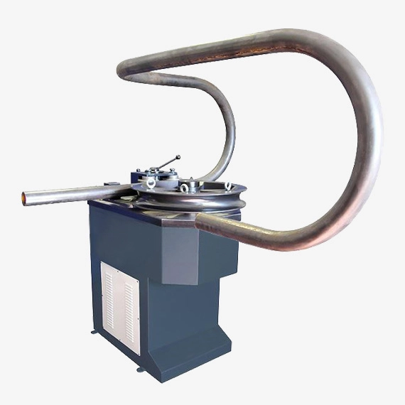
Pipe bending machine: Also called pipe bender or tube bender. It is used to bend metal pipes with the required angles.
A pipe bending machine is a piece of equipment used in the metalworking industry to bend metal pipes and tubes into different shapes and angles. Pipe bending machines are essential tools in many industries, including construction, automotive, aerospace, and marine.
There are several types of pipe bending machines, including manual, semi-automatic, and fully automatic machines. Manual pipe bending machines are operated by hand and are suitable for small-scale applications. Semi-automatic machines have hydraulic or electric motors that automate some of the bending processes, making them more efficient and suitable for medium-scale applications. Fully automatic machines are computer-controlled and are designed for large-scale industrial applications.
Pipe bending machines work by using force to bend metal pipes or tubes to a specific angle or radius. The machine’s mechanism varies depending on the type of machine used, but most pipe bending machines use either rollers or mandrels to bend the pipe. The rollers or mandrels apply pressure to the pipe, causing it to bend into the desired shape.
Pipe bending machines come in a variety of sizes, with some capable of bending pipes up to several inches in diameter. They can also bend pipes made of different materials, including steel, stainless steel, copper, and aluminum.
In conclusion, pipe bending machines are essential tools in many industries, allowing metal pipes and tubes to be bent into different shapes and angles. The type of pipe bending machine used depends on the scale of the application, and they are available in manual, semi-automatic, and fully automatic versions.
Pipe Bending Machine
A pipe bending machine is a specialized tool designed to bend pipes into various shapes. It is a versatile tool used in various industries, including plumbing, construction, and manufacturing, to create curved pipes for various applications.
Hydraulic Pipe Bending Machine
A hydraulic pipe bending machine utilizes hydraulic pressure to apply the force required for bending the pipe. These machines are known for their powerful and versatile bending capabilities, making them suitable for a wide range of pipe materials and sizes.
CNC Pipe Bending Machine
A CNC pipe bending machine employs computer numerical control (CNC) technology to automate the bending process. This allows for precise control over the bending angle, radius, and position, enabling the production of complex and intricate shapes with high accuracy.
Manual Pipe Bending Machine
A manual pipe bending machine requires manual operation to bend the pipe. These machines are typically used for smaller pipes and simpler bending tasks, offering a cost-effective solution for low-volume applications.
Square Pipe Bending Machine
A square pipe bending machine is specifically designed to bend square pipes, which are commonly used in structural applications. These machines utilize specialized dies and tooling to handle the unique properties of square pipes, ensuring precise and consistent bending results.
Automatic Pipe Bending Machine
An automatic pipe bending machine utilizes automation to perform the bending process, reducing manual intervention and improving efficiency. These machines typically employ CNC technology or other automated systems to control the bending parameters, resulting in consistent and high-quality bends.
Steel Pipe Bending Machine
A steel pipe bending machine is designed specifically for bending steel pipes, which are widely used in various industries due to their strength and durability. These machines are capable of handling different grades of steel and various pipe sizes.
Copper Pipe Bending Machine
A copper pipe bending machine is specifically designed for bending copper pipes, which are commonly used in plumbing and HVAC applications due to their corrosion resistance and ease of working. These machines are equipped with specialized dies and tooling to prevent damage to the soft copper material.
Electric Pipe Bending Machine
An electric pipe bending machine utilizes an electric motor to provide the power for bending the pipe. These machines are typically smaller and more portable than hydraulic bending machines, making them suitable for use in confined spaces or for lighter-duty applications.
Pipe Bending Machine Automatic
A pipe bending machine automatic refers to any machine that can bend pipes automatically, reducing manual effort and improving efficiency. This includes CNC pipe bending machines, automated bending machines, and machines with automatic control systems.
Pipe Bending Machine Aluminium
An aluminum pipe bending machine is specifically designed for bending aluminum pipes, which are lightweight and corrosion-resistant but require special handling due to their softer properties. These machines utilize specialized dies and tooling to prevent deformation and maintain the integrity of the aluminum pipe.
Pipe Bending and Machine
Pipe bending and machine refers to the combination of pipe bending techniques and the machines used to perform those techniques. It encompasses various methods, including hydraulic bending, CNC bending, manual bending, and automated bending.
Pipe Bender Automatic Machine
An automatic pipe bender machine refers to any machine that can bend pipes automatically, reducing manual effort and improving efficiency. This includes CNC pipe bending machines, automated bending machines, and machines with automatic control systems.
Aluminium Pipe Bending Machine
An aluminum pipe bending machine is specifically designed for bending aluminum pipes, which are lightweight and corrosion-resistant but require special handling due to their softer properties. These machines utilize specialized dies and tooling to prevent deformation and maintain the integrity of the aluminum pipe.
Auto Pipe Bending Machine
An auto pipe bending machine is a synonym for an automatic pipe bending machine. Both terms refer to machines that can bend pipes automatically, reducing manual effort and improving efficiency.
Horizontal Press as Metalworking Machinery
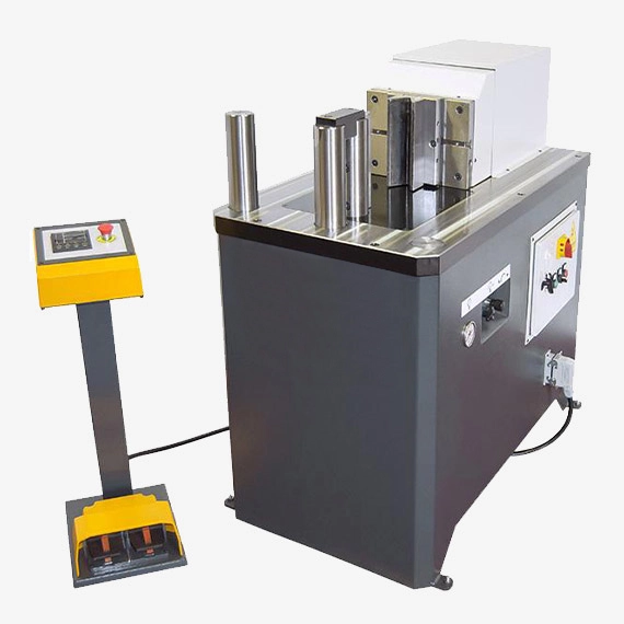
Horizontal press: the horizontal press is a metalworking machine that works as a small press brake to bend sheet metal parts.
A horizontal press is a type of hydraulic press that operates in a horizontal position. It is used to apply pressure to a workpiece or material by exerting force on it from the side. The horizontal press can be used for a variety of applications, including bending, straightening, punching, and pressing.
The horizontal press is commonly used in metalworking, fabrication, and manufacturing industries. It is especially useful for applications where space is limited, as it can be easily integrated into a production line or workshop. Horizontal presses come in different sizes and tonnages, and can be customized to suit specific applications.
The press consists of a hydraulic system that is powered by an electric motor. The hydraulic system operates a ram, which applies pressure to the workpiece. The workpiece is placed on a bed or table, which can be adjusted to position the workpiece for the desired operation. Some horizontal presses have additional features such as automatic feeding and cutting systems.
One of the advantages of a horizontal press is its versatility. It can be used for a variety of applications, including bending, straightening, and pressing. Additionally, the horizontal position allows for easy loading and unloading of workpieces, as well as greater accessibility for operators. However, one of the disadvantages of a horizontal press is that it may have lower capacity than a vertical press, as the force of gravity is not assisting in the pressing process.
In summary, a horizontal press is a versatile hydraulic press that is used in a variety of industries for bending, straightening, punching, and pressing operations. It is a useful tool for applications where space is limited, and can be customized to suit specific applications.
Horizontal Press
A horizontal press is a specialized machine that applies pressure horizontally to shape or compress materials. It is a versatile tool used in various industries, including manufacturing, construction, and metalworking, for a wide range of applications, such as forming, bending, straightening, and stamping.
Horizontal Press Brake
A horizontal press brake is a type of horizontal press specifically designed for bending and forming sheet metal. It utilizes a horizontal ram and dies to apply pressure and force the sheet metal into the desired shape. Horizontal press brakes are known for their precision and ability to handle large and complex sheet metal parts.
Horizontal Press Machine
A horizontal press machine is a synonym for a horizontal press. Both terms refer to machines that apply pressure horizontally to shape or compress materials.
Hydraulic Horizontal Press
A hydraulic horizontal press utilizes hydraulic pressure to generate the force required for pressing or forming materials. These machines offer precise control over pressure and force distribution, making them suitable for delicate or intricate operations.
Here is a table summarizing the key differences between the three types of horizontal presses:
| Feature | Horizontal Press | Horizontal Press Brake | Hydraulic Horizontal Press |
|---|---|---|---|
| Primary function | Shaping or compressing various materials | Bending and forming sheet metal | Shaping or compressing materials using hydraulic pressure |
| Applications | Manufacturing, construction, metalworking | Sheet metal fabrication, automotive industry | Manufacturing, construction, metalworking, electronics, assembly |
| Advantages | Versatility, high force capacity | Precision, accuracy, large workpiece capacity | Precise control over pressure, force distribution, and speed |
| Disadvantages | May require specialized tooling for specific applications | Limited to sheet metal forming | More complex design and higher cost |
Edge Cutting Trimming Machine
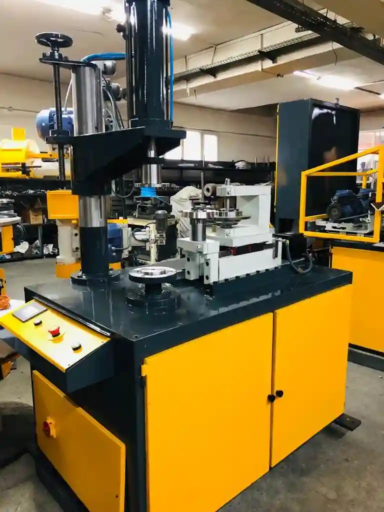
Hydraulic edge cutting trimming beading curling forming flanging crimping machine is used to perform circular bending, edge bending, border crimping, sheet metal edge cutting and trimming, edge beading on edges of sheet metal round parts.
Edge cutting and trimming machines are used for cutting and trimming the edges of different materials such as metal, plastic, and wood. They are widely used in the manufacturing industry, especially in the sheet metal industry, to trim and shape the edges of sheet metal parts.
There are various types of edge cutting and trimming machines available in the market, including manual, semi-automatic, and fully automatic machines. Manual machines require the operator to manually feed the material through the machine and control the cutting process. Semi-automatic machines are partially automated and require some manual intervention, while fully automatic machines are fully automated and can operate without any human intervention.
Edge cutting and trimming machines use different cutting methods, including shearing, sawing, and laser cutting, depending on the material being cut and the required precision. The machines are designed to provide high precision cuts, with minimal waste and maximum efficiency.
In the sheet metal industry, edge cutting and trimming machines are used to cut and trim the edges of sheet metal parts for use in various applications, including automotive, aerospace, and construction industries. They are also used to create complex shapes and designs in sheet metal parts, which are then used to create different products such as enclosures, cabinets, and chassis.
Overall, edge cutting and trimming machines play an essential role in the manufacturing industry by providing precise cuts and trimming of different materials, improving efficiency and reducing waste in the production process
Edge Cutting Trimming Machine
An edge cutting trimming machine is a specialized tool designed to precisely cut and trim edges of various materials, including wood, plastic, paper, and textiles. These machines are used in various industries, including woodworking, manufacturing, and packaging, to create clean, finished edges and enhance the appearance and functionality of products.
Edge Cutting Tool
An edge cutting tool is a general term for any tool used to cut or trim edges. This includes a wide range of tools, such as knives, blades, saws, trimmers, and routers, each with specific applications and characteristics.
Edge Machining Tools
Edge machining tools encompass a variety of tools and machines used for processing and shaping edges. This includes edge trimmers, edge routers, edge sanders, and edge polishers, each designed to perform specific edge finishing tasks.
Manual Edge Trimmer
A manual edge trimmer is a hand-held tool used for trimming edges. These trimmers typically feature a blade or cutting mechanism that is manually operated to remove excess material from the edge. Manual edge trimmers are often used for small-scale projects or for trimming edges in hard-to-reach areas.
Edge Trimming
Edge trimming refers to the process of cutting or removing excess material from the edge of a material. This is done for various purposes, such as creating a clean and finished appearance, ensuring dimensional accuracy, and preparing the edge for further processing.
Edge Trim Chopper
An edge trim chopper is a type of edge cutting tool that utilizes a chopping or shearing action to cut edges. These choppers are often used for trimming thick or tough materials, such as leather or rubber.
Here is a table summarizing the key differences between the three types of edge cutting tools:
| Feature | Edge Cutting Tool | Edge Machining Tools | Manual Edge Trimmer |
|---|---|---|---|
| Type of tool | Handheld or machine-mounted | Machine-mounted | Handheld |
| Applications | Wide range of materials, including wood, plastic, paper, and textiles | Woodworking, manufacturing, packaging | Small-scale projects, hard-to-reach areas |
| Operation | Manual or automated | Automated | Manual |
| Precision | Varies depending on the tool | High precision | Lower precision |
| Efficiency | Lower efficiency | High efficiency | Lower efficiency |
Trimming Beading Machine
The trimming beading machine is used for trimming beading cutting and curling round sheet metal parts. It is also used for square and rectangular-shaped objects. Multi-head hydraulic or pneumatic trimming, curling, and beading machine is a new type of shear type trimming curling and beading machine. It can also be used for square objects as well as round parts.
A trimming and beading machine is a type of metalworking machine used to cut and shape sheet metal into a desired size and shape. This machine is commonly used in the automotive industry to produce wheel rims, fenders, and other automotive parts.
The machine works by feeding the sheet metal into a set of rollers that gradually bend and shape the metal into the desired profile. The machine then trims the excess material from the edges of the metal sheet, leaving behind a clean and precise edge.
Some machines are also equipped with a beading function, which allows the machine to create a bead or flange along the edge of the sheet metal. This bead can be used to provide additional strength and rigidity to the finished product.
The use of trimming and beading machines can greatly increase the efficiency and accuracy of sheet metal fabrication. These machines are capable of producing large quantities of high-quality parts with minimal waste, making them a cost-effective solution for manufacturers in a variety of industries
Trimming Beading Machine
A trimming beading machine is a specialized machine that combines the functions of trimming and beading. It is used to cut and shape the edges of various materials, particularly sheet metal, and create decorative or functional beads along the edges. These machines are widely used in various industries, including metal fabrication, automotive manufacturing, and appliance production.
How to Cut Beaded Trim
Cutting beaded trim requires careful handling to avoid damaging the delicate beads. The specific method depends on the type of trim and the desired cutting technique. Here are some general guidelines:
- Protect the Beads: Use a sharp blade or cutting tool to minimize damage to the beads. Consider using a beading board or similar surface to protect the trim while cutting.
- Follow the Bead Design: Cut along the pattern of the beads, ensuring a clean and precise cut without disrupting the beading pattern.
- Handle with Care: Avoid excessive force or bending while cutting to prevent the beads from breaking or deforming.
- Finishing Touches: Once cut, smooth out any rough edges or imperfections using a sanding block or emery paper.
How to Cut Metal Beading
Cutting metal beading requires more robust tools and techniques to handle the strength of the metal. Here are some general guidelines:
- Appropriate Tools: Use a dedicated metal cutting tool, such as a metal shears, tin snips, or a power saw, depending on the thickness of the metal.
- Secure the Metal: Clamp the metal securely to a stable work surface to prevent it from moving during cutting.
- Controlled Cuts: Make controlled cuts along the desired line, following the beading pattern.
- Deburr the Edges: Deburr the edges of the cut metal using a file or deburring tool to remove sharp edges and prevent injury.
Trimming and Beading Machine
A trimming and beading machine is a synonym for a trimming beading machine. Both terms refer to machines that combine the functions of trimming and beading.
CNC Trimming
CNC trimming utilizes computer numerical control (CNC) technology to automate the trimming process. This provides precise control over the cutting path, ensuring consistent and accurate trimming results.
Electric Beading Machine
An electric beading machine utilizes an electric motor to power the beading rollers or forming mechanisms. These machines offer convenient operation and adjustable beading parameters.
Electric Trimming Machine
An electric trimming machine utilizes an electric motor to power the cutting blade or mechanism. These machines provide efficient and powerful trimming capabilities.
Tube Beading Machine
A tube beading machine is specifically designed for beading and forming tubes. It utilizes specialized tooling and rollers to create various beading profiles on the circumference of tubes.
Auto Trimming Machine
An auto trimming machine is a synonym for an automatic trimming machine. Both terms refer to machines that automatically perform the trimming process, reducing manual intervention and improving efficiency.
Here is a table summarizing the key differences between the four types of trimming and beading machines:
| Feature | Trimming Beading Machine | CNC Trimming | Electric Beading Machine | Electric Trimming Machine |
|---|---|---|---|---|
| Primary function | Trimming and beading | Trimming | Beading | Trimming |
| Automation | Manual or automated | Automated | Manual or automated | Manual or automated |
| Applications | Sheet metal fabrication, automotive manufacturing | Metalworking, manufacturing | Metal fabrication, automotive manufacturing | Sheet metal fabrication, woodworking |
| Advantages | Versatility, combined trimming and beading | Precision, accuracy | Efficient beading | Efficient trimming |
| Disadvantages | May require skill and precision for manual operation | Higher cost | May require specialized tools for specific beading profiles | May require tool changes for different materials |
Edge Curling Machine
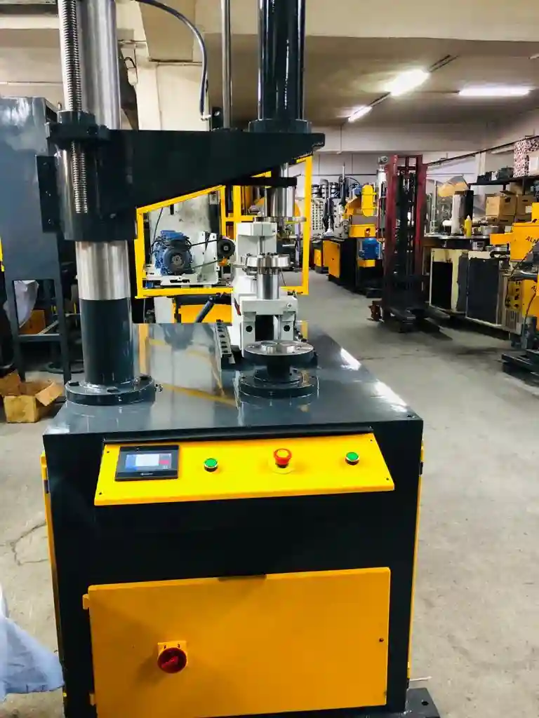
An edge curling machine is a metalworking machine, specialized in curling the edges of round sheet metal parts. Curling is a metal forming process carried out by a sheet metal curling tool. The round part is put on the turning mold. The mold is rotated from the downside rotating shaft. There is also an upper mold that is idle. The part between the downside and upside molds is rotated while the edge curling tool moves into the part direction.
An edge curling machine is a piece of equipment used in the manufacturing process of sheet metal products. It is used to bend the edge of the metal sheet into a curved shape, which not only adds an aesthetic value to the final product but also provides protection against sharp edges.
The machine consists of a stationary base, a moving arm, and a die set. The die set is custom-made according to the required curve, and it is attached to the moving arm. The metal sheet is then placed on the stationary base, and the arm is lowered onto the sheet, forcing it to bend into the desired shape.
Edge curling machines come in different sizes, depending on the thickness and size of the metal sheet being processed. They can be manually operated or automated, with the latter being more efficient and faster.
Edge curling machines are widely used in various industries, such as HVAC, automotive, and construction, for the production of products like air ducts, exhaust systems, and metal cabinets. They are also used in the manufacturing of household appliances, such as ovens and refrigerators, to provide a finished look and smooth edges.
Edge Curling Machine
An edge curling machine, also known as an edge roller or edge rounding machine, is a specialized tool designed to curl or roll the edges of various materials, particularly sheet metal. It creates a smooth, rounded edge that enhances the appearance and functionality of the workpiece. These machines are widely used in various industries, including metal fabrication, automotive manufacturing, and appliance production.
Sheet Metal Edge Curling Machine
A sheet metal edge curling machine is specifically designed for curling the edges of sheet metal components. It utilizes specialized rollers or forming mechanisms to apply pressure and curl the edge into the desired shape. These machines are essential for creating clean, safe edges and reducing the risk of sharp corners or burrs.
How to Curl Edges
The specific method for curling edges depends on the material, desired edge profile, and available tools. However, some general guidelines include:
- Prepare the Material: Ensure the material is clean, free from debris, and properly aligned.
- Select the Edge Profile: Choose the appropriate edge profile, such as a rounded edge, a flanged edge, or a specific radius.
- Adjust the Machine Settings: Set the machine’s rollers, pressure, and speed according to the material thickness and desired edge curl.
- Curling Process: Carefully feed the material through the machine, ensuring the edge is properly positioned between the rollers.
- Inspection and Finishing: Inspect the curled edge for consistency, smoothness, and adherence to the desired profile. If necessary, perform finishing touches using deburring tools or sanding blocks.
Border Edger Machine
A border edger machine is a synonym for an edge curling machine. Both terms refer to machines that curl or roll the edges of various materials.
Edge Rounding Machine
An edge rounding machine is a specific type of edge curling machine that creates a rounded edge profile on the workpiece. It is commonly used for sheet metal components, plastics, and other materials.
Edge Rounding Deburring Machine
An edge rounding deburring machine combines the functions of edge rounding and deburring. It curls the edge and simultaneously removes any burrs or rough edges, creating a smooth, clean finish.
Edge Rolling Machine
An edge rolling machine is a synonym for an edge curling machine. Both terms refer to machines that curl or roll the edges of various materials.
Here is a table summarizing the key differences between the four types of edge curling machines:
| Feature | Edge Curling Machine | Sheet Metal Edge Curling Machine | Border Edger Machine | Edge Rounding Machine |
|---|---|---|---|---|
| Primary function | Curling or rolling edges | Curling edges of sheet metal | Curling or rolling edges | Curling edges to a rounded profile |
| Applications | Metal fabrication, automotive manufacturing | Metal fabrication, appliance production | Various materials, woodworking | Sheet metal fabrication, plastics |
| Advantages | Versatility, various edge profiles | Specialized for sheet metal | Wide range of materials | Smooth, rounded edge profile |
| Disadvantages | May require skill and precision for manual operation | Requires specific tooling for different materials | May not be suitable for very thick or hard materials | Not suitable for creating sharp or non-rounded edge profiles |
Polishing machines for pot, pan, teapot, tea kettle, and lid polishing
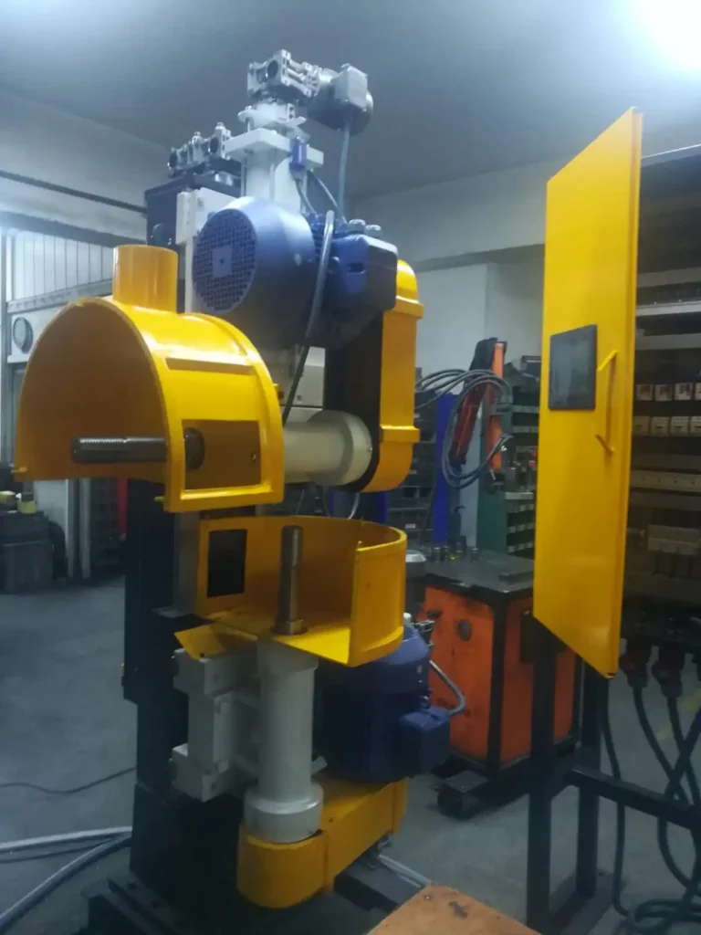
A cookware polishing machine is a machine that is used to polish cookware. It can be used to polish the inside or outside of cookware.
Polishing machines are essential equipment in the kitchenware industry, especially for the final stage of production, where the products’ surface quality is critical. Polishing machines are designed to smooth out surface imperfections, remove burrs, and create a glossy finish on various kitchenware products such as pots, pans, teapots, tea kettles, and lids.
There are different types of polishing machines available, including vibratory polishing machines, centrifugal polishing machines, and rotary barrel polishing machines. Vibratory polishing machines use a vibrating motion to agitate the polishing media and the workpieces, resulting in a smoother and more uniform finish. Centrifugal polishing machines use a high-speed spinning motion to create a more aggressive polishing action, which is particularly useful for removing burrs and surface imperfections. Rotary barrel polishing machines use a rotating motion to tumble the workpieces and the polishing media, creating a more rounded and uniform finish.
Polishing machines can be manual or automated, depending on the volume of production and the level of precision required. Automated polishing machines are preferred for high-volume production, as they are faster, more consistent, and require less labor. However, manual polishing machines are more flexible and can be used for smaller batches or for products that require more intricate polishing.
In summary, polishing machines are essential equipment in the kitchenware industry, providing the final touch to high-quality products such as pots, pans, teapots, tea kettles, and lids. There are different types of polishing machines available, and the choice of the right machine depends on the volume of production, the level of precision required, and the type of product being polished.
Polishing Machines for Pots and Pans
Polishing machines for pots and pans are specially designed to restore the shine and luster of cookware. These machines typically utilize rotating buffing wheels or belts coated with polishing compounds to remove scratches, oxidation, and tarnish from the surface of pots and pans.
Polishing Machine for Granite
Polishing machines for granite are specifically designed to polish granite countertops, slabs, and other granite surfaces. These machines utilize specialized polishing pads and abrasive compounds to achieve a smooth, glossy finish on the granite.
Polishing Machine for Metal
Polishing machines for metal are versatile tools used to polish various metals, including stainless steel, aluminum, brass, and copper. These machines employ a variety of polishing techniques, such as buffing, linishing, and lapping, to achieve the desired surface finish.
Stainless Steel Polishing Machines
Stainless steel polishing machines are specifically designed to polish stainless steel surfaces. These machines utilize specialized buffing wheels, belts, and compounds to remove imperfections and achieve a polished, mirror-like finish on stainless steel.
How to Polish Pots and Pans
Polishing pots and pans involves several steps:
- Cleaning: Thoroughly clean the pots and pans to remove any food debris, grease, or burnt-on residue.
- Drying: Ensure the pots and pans are completely dry before polishing to prevent water spots.
- Polishing Compound: Apply a polishing compound suitable for the material of the pot or pan.
- Polishing Machine: Use a polishing machine with appropriate buffing wheels or belts.
- Polishing Technique: Apply gentle, even pressure while polishing, following the contours of the pot or pan.
- Cleaning and Finishing: Clean off any polishing compound residue and buff the surface to a shine.
Brass Polisher Machine
A brass polisher machine is a specialized tool designed to polish brass surfaces. These machines utilize buffing wheels, brushes, and polishing compounds to remove tarnish and achieve a bright, shiny finish on brass.
CNC Polishing Machine
A CNC polishing machine utilizes computer numerical control (CNC) technology to automate the polishing process. This provides precise control over the polishing parameters, ensuring consistent and accurate results for complex shapes and intricate details.
Automatic Polishing Machine for Stainless Steel
An automatic polishing machine for stainless steel is designed to automate the polishing process for stainless steel components. These machines typically utilize multiple polishing stages with different polishing compounds to achieve a high-quality finish.
Industrial Polishing Machine
An industrial polishing machine is a robust and powerful machine designed for high-volume polishing applications in industrial settings. These machines can handle large workpieces and withstand continuous use.
Industrial Polishing Equipment
Industrial polishing equipment encompasses a wide range of machines, tools, and accessories used for polishing various materials in industrial settings. This includes polishing machines, buffing wheels, belts, polishing compounds, and specialized fixtures.
Polishing Pot Metal
Polishing pot metal involves removing scratches, oxidation, and tarnish from pot metal cookware. This can be done using hand polishing techniques with polishing compounds or by using a polishing machine.
Polishing Lathe Machine
A polishing lathe machine is a specialized type of lathe designed for polishing cylindrical workpieces, such as spindles, shafts, and tubes. It utilizes a rotating polishing wheel or belt to achieve a smooth, polished surface.
Lapping and Polishing Machine
A lapping and polishing machine is a versatile tool that combines lapping and polishing operations to achieve high precision surface finishes. Lapping removes microscopic imperfections, while polishing creates a smooth, reflective surface.
Cookware grinding machine for stainless steel and aluminum
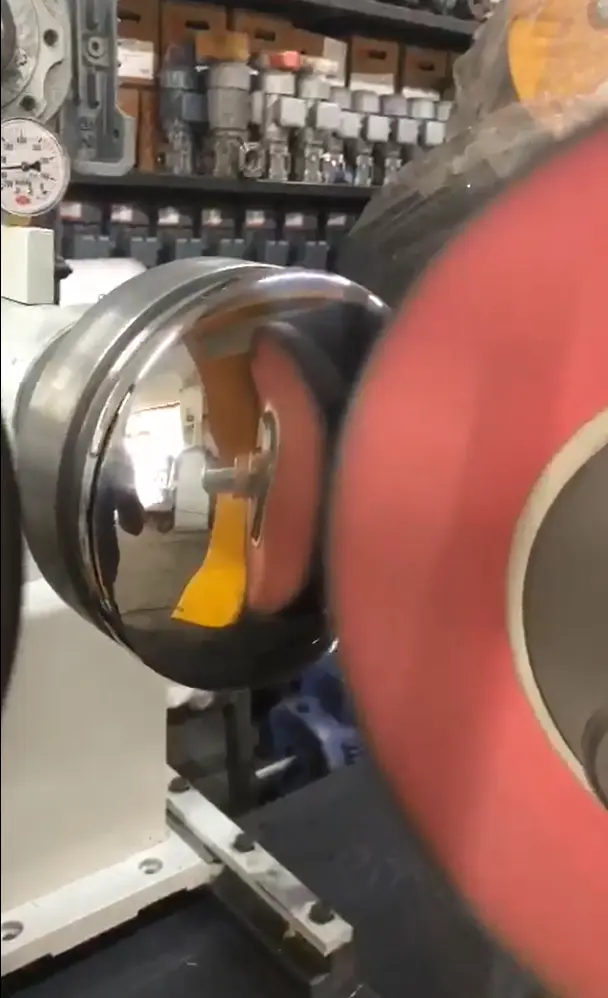
A cookware grinding machine for stainless steel and aluminum is a machine that is used to grind and polish the surfaces of cookware made of these metals. It is commonly used in the cookware manufacturing industry to provide a smooth and even finish on the cookware surface.
The grinding process typically involves the use of an abrasive belt or wheel that removes material from the cookware surface to create a smooth and polished finish. The machine may also use a polishing wheel or buffing wheel to provide a final polish on the surface of the cookware.
Cookware grinding machines come in a range of sizes and designs to accommodate different types of cookware, from small pots and pans to large stockpots and woks. They may be operated manually or automatically, depending on the level of automation required by the manufacturer.
In addition to providing a smooth and polished finish on the cookware surface, grinding machines may also be used to remove any burrs or rough edges that may have been left over from the manufacturing process. This ensures that the cookware is safe to handle and use, without any sharp edges that could cause injury.
A cookware grinding machine is a specialized machine designed to grind and polish cookware, particularly stainless steel and aluminum pots and pans. These machines utilize rotating grinding wheels or belts coated with abrasive compounds to remove scratches, oxidation, and tarnish from the surface of cookware, restoring its shine and luster.
Applications of Cookware Grinding Machines
Cookware grinding machines are commonly used in commercial kitchens, restaurants, and industrial cookware manufacturing facilities to maintain the appearance and functionality of cookware. They are also used by individual consumers to restore the shine of their cookware at home.
Benefits of Using Cookware Grinding Machines
- Improved Appearance: Grinding removes scratches, oxidation, and tarnish, restoring the cookware’s shine and enhancing its overall appearance.
- Extended Lifespan: Regular grinding helps prolong the lifespan of cookware by preventing deterioration and preserving its integrity.
- Enhanced Functionality: A smooth, polished surface promotes even heat distribution and prevents food from sticking, improving cooking performance.
Types of Cookware Grinding Machines
- Hand-Grinding Machines: These require manual operation, offering more control over the grinding process.
- Automatic Grinding Machines: These operate automatically, providing consistent and efficient grinding results.
Considerations When Choosing a Cookware Grinding Machine
- Material Compatibility: Ensure the machine is suitable for the type of cookware material, such as stainless steel, aluminum, or cast iron.
- Grinding Capacity: Choose a machine with sufficient capacity to handle the size and quantity of cookware you need to grind.
- Grinding Speed and Control: Consider the machine’s speed and control options to adjust the grinding intensity for different materials and desired finishes.
Cookware Granite
Granite is not a common cookware material due to its porous and brittle nature. However, some cookware manufacturers have developed granite-coated cookware that offers a non-stick surface and heat resistance. Granite cookware requires gentle care to maintain its coating and avoid chipping or cracking.
Here is a table summarizing the key differences between cookware grinding machines and cookware granite:
| Feature | Cookware Grinding Machine | Cookware Granite |
|---|---|---|
| Purpose | Grind and polish cookware | Cookware material |
| Applications | Commercial kitchens, restaurants, industrial cookware manufacturing, home use | Cooking, baking |
| Benefits | Improves appearance, extends lifespan, enhances functionality | Non-stick surface, heat resistance |
| Considerations | Material compatibility, grinding capacity, grinding speed and control | Coating maintenance, gentle care |
Radial Riveting Machines
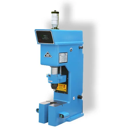
Radial riveting machines are specialized machines used for the process of riveting, which involves joining two pieces of material together using a rivet. A rivet is a metal pin with a head that is inserted through a hole in the materials being joined, and then the end of the pin is hammered or pressed to form a second head, called a shop head, that secures the materials together.
Radial riveting machines work by rotating the rivet and hammering it into the materials being joined from a radial angle, meaning the hammering occurs at a perpendicular angle to the surface of the material being riveted. This creates a strong and secure joint that is commonly used in the manufacturing of a wide range of products, including appliances, electronics, and automotive parts.
Radial riveting machines are available in a variety of sizes and styles to accommodate different types of rivets and materials. They may be manually operated or automated, and can be designed for high volume production or smaller scale operations.
Radial Riveting Machines
Radial riveting machines are specialized tools designed to join two or more workpieces using rivets. They are characterized by their radial orientation, with the riveting head moving radially towards the workpiece to insert and clinch the rivet. These machines are widely used in various industries, including aerospace, automotive, and construction, to create strong and durable joints in a variety of materials.
Radial Rivet Machine
A radial rivet machine is a synonym for a radial riveting machine. Both terms refer to machines that join workpieces using rivets and utilize a radial riveting mechanism.
Radial Riveter
A radial riveter is another synonym for a radial riveting machine. It specifically refers to the tool itself, while “radial riveting machine” encompasses the entire machine system.
CNC Riveting Machine
A CNC riveting machine utilizes computer numerical control (CNC) technology to automate the riveting process. This provides precise control over the riveting parameters, including rivet placement, force, and dwell time, ensuring consistent and accurate riveting results for complex designs and repetitive tasks.
Hydraulic Riveting
Hydraulic riveting utilizes hydraulic pressure to apply the force required for inserting and clinching the rivet. These machines offer powerful riveting capabilities and precise control over the riveting force.
Industrial Riveting Machine
An industrial riveting machine is a robust and powerful machine designed for high-volume riveting applications in industrial settings. These machines can handle large workpieces and withstand continuous use.
Radial Riveting
Radial riveting is a specific riveting technique that utilizes a radial riveting machine. The riveting head moves radially towards the workpiece, allowing for access to hard-to-reach areas and the ability to rivet workpieces from one side.
Radial Rivet
A radial rivet is a type of rivet specifically designed for use with radial riveting machines. It features a head that is designed to be inserted and clinched from one side of the workpiece.
Here is a table summarizing the key differences between the different types of riveting machines:
| Feature | Radial Riveting Machine | CNC Riveting Machine | Hydraulic Riveting Machine |
|---|---|---|---|
| Primary function | Joining workpieces using rivets | Automated riveting | Hydraulically powered riveting |
| Applications | Aerospace, automotive, construction | Complex designs, repetitive tasks | High-force riveting |
| Advantages | Radial movement for access, one-sided riveting | Precise control, consistency, automation | Powerful riveting, control over force |
| Disadvantages | May require manual operation | Higher cost | Limited to hydraulic riveting |
Flat Surface Polishing Machine
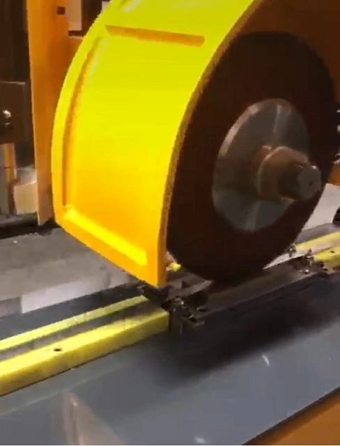
A flat surface polishing machine is a machine that is designed to give a mirror finish to the surface of the metal.
A flat surface polishing machine is a type of polishing machine used to polish and buff flat surfaces of materials such as metal, plastic, glass, and ceramics. The machine typically consists of a rotating disc or plate that is covered with an abrasive material, such as polishing pads or diamond discs. The material to be polished is placed on the rotating plate, which moves the material back and forth across the abrasive surface, gradually smoothing and polishing the surface.
Flat surface polishing machines are commonly used in the metalworking industry to polish flat metal surfaces, such as aluminum, stainless steel, and brass, to a high luster. They are also used in the automotive industry for polishing car body panels and in the woodworking industry for sanding and polishing wooden surfaces.
Flat surface polishing machines come in a variety of sizes and configurations, from small benchtop models for use in home workshops to large industrial models capable of polishing large metal sheets or parts. They can be manual or automatic, and some models can be programmed to polish specific shapes or contours.
Overall, flat surface polishing machines are an essential tool for achieving a high-quality finish on flat surfaces, and they are widely used in many industries where a polished finish is required.
Flat Surface Polishing Machine
A flat surface polishing machine is a specialized tool designed to polish flat surfaces of various materials, including metals, plastics, and composites. These machines utilize rotating polishing wheels, belts, or pads coated with polishing compounds to remove scratches, imperfections, and tarnish from the surface, creating a smooth, reflective finish.
Purpose of Surface Grinding Machine
The primary purpose of a surface grinding machine is to precisely remove a small amount of material from a workpiece to achieve a flat, accurate surface finish. These machines are commonly used in metalworking, manufacturing, and toolmaking applications to prepare surfaces for further processing or to restore a smooth finish to worn or damaged parts.
What is a Surface Grinding Machine
A surface grinding machine is a type of grinding machine that utilizes a rotating grinding wheel to remove material from the surface of a workpiece. The workpiece is typically held stationary on a table while the grinding wheel moves across it, gradually grinding away the material.
Polishing Machine Types
Polishing machines come in various types, each with its specific applications and capabilities. Some common types include:
- Buffing machines: Utilize rotating buffing wheels to create a high-gloss finish.
- Linishing machines: Employ abrasive belts to produce a smooth, matte finish.
- Lapping machines: Use fine abrasives to achieve ultra-fine surface finishes.
- Polishing lathes: Rotate cylindrical workpieces against a polishing wheel.
Flat Polishing Machine
A flat polishing machine is a synonym for a flat surface polishing machine. Both terms refer to machines that polish flat surfaces.
Machining Flat Surface
Machining flat surfaces involves using various machine tools, such as surface grinders, milling machines, and planers, to remove material from a workpiece and create a flat, accurate surface.
Surface Polishing
Surface polishing is the process of removing imperfections, scratches, and tarnish from a surface to create a smooth, reflective finish. Polishing is typically performed using polishing machines, polishing wheels, belts, or pads, and polishing compounds.
Metal Surface Polishing Machine
A metal surface polishing machine is a specialized polishing machine designed to polish metal surfaces. These machines utilize polishing compounds and abrasive tools that are suitable for the specific type of metal being polished.
Here is a table summarizing the key differences between the different types of surface finishing machines:
| Feature | Surface Grinding Machine | Flat Surface Polishing Machine |
|---|---|---|
| Primary function | Remove material to achieve a flat, accurate surface | Remove imperfections and create a smooth, reflective finish |
| Applications | Metalworking, manufacturing, toolmaking | Various materials, including metals, plastics, composites |
| Finishing capabilities | Precision flatness, accuracy | Smoothness, reflectivity |
| Material removal | Higher material removal rate | Lower material removal rate |
Polishing Machine for Stainless Steel Cookware
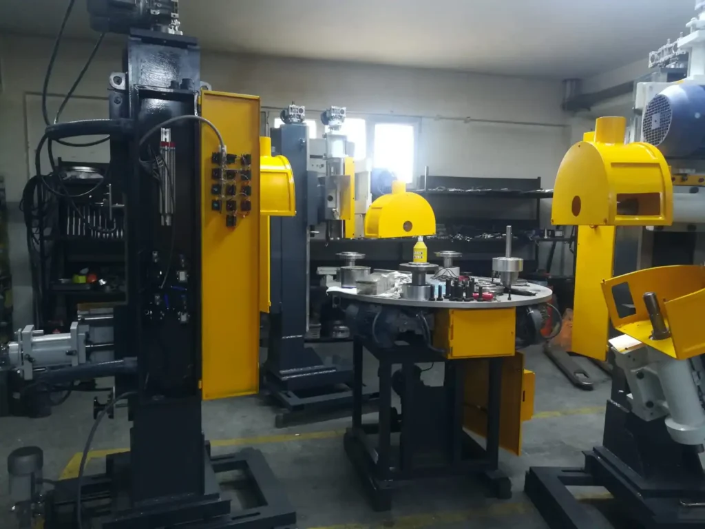
Polishing machines for stainless steel cookware are specialized equipment designed to provide a smooth and shiny finish to the cookware’s surface. These machines are used to remove any roughness, scratches, or imperfections from the surface of the cookware. They use a variety of polishing heads and abrasive materials to achieve the desired finish.
The polishing process involves several steps, starting with the preparation of the cookware’s surface by cleaning and drying it thoroughly. The cookware is then placed on the polishing machine, and the machine’s polishing heads are adjusted to the required pressure and speed. The heads can be made of different materials, such as cotton, sisal, or felt, depending on the type of surface finish required.
The machine’s motor drives the polishing heads, which rotate and move across the surface of the cookware. The abrasive material is applied to the surface of the polishing head, and it removes any imperfections from the surface of the cookware. The process continues until the desired finish is achieved.
Polishing machines for stainless steel cookware can be manual or automatic, depending on the manufacturer and the intended use. Automatic machines are equipped with advanced features, such as computerized controls, sensors, and monitoring systems, that allow for precise control of the polishing process.
Overall, polishing machines for stainless steel cookware are essential for achieving a high-quality, polished finish that enhances the cookware’s appearance and durability.
Polishing Machine for Stainless Steel Cookware
A polishing machine for stainless steel cookware is a specialized tool designed to restore the shine and luster of stainless steel pots and pans. These machines typically utilize rotating buffing wheels or belts coated with polishing compounds to remove scratches, oxidation, and tarnish from the surface of cookware, restoring its shine and promoting even heat distribution during cooking.
Polishing Stainless Steel Cookware
Polishing stainless steel cookware involves using specialized polishing machines, polishing compounds, and proper techniques to remove imperfections and create a smooth, reflective surface. Regular polishing helps maintain the appearance and functionality of stainless steel cookware, extending its lifespan and enhancing its cooking performance.
Stainless Steel Polishing Machines
Stainless steel polishing machines are specifically designed to polish stainless steel surfaces. These machines utilize various polishing techniques, such as buffing, linishing, and lapping, to achieve the desired surface finish. They are available in various sizes and capacities, suitable for both commercial and home use.
Best Stainless Steel Polish for Appliances
The best stainless steel polish for appliances depends on the specific appliance and the desired finish. Some popular stainless steel polishes include:
- Bar Keepers Friend: A versatile polish suitable for removing stubborn stains, tarnish, and scratches.
- 3M Stainless Steel Cleaner and Polish: A gentle polish that cleans and polishes without scratching the surface.
- Wright’s Stainless Steel Polish: A cream-based polish that leaves a shiny, protective finish.
Polishing Machine for Stainless Steel
Polishing machines for stainless steel are widely used in various industries, including cookware manufacturing, kitchen equipment production, and metal fabrication, to achieve a high-quality finish on stainless steel components.
Stainless Steel Polishing Equipment
Stainless steel polishing equipment encompasses a range of tools and accessories used for polishing stainless steel, including polishing machines, buffing wheels, belts, polishing compounds, and specialized fixtures.
Electropolishing Stainless Steel Machine
An electropolishing stainless steel machine utilizes an electrochemical process to remove a microscopically thin layer of material from the stainless steel surface, creating a smooth, highly polished finish. This method is often used for medical devices, precision components, and decorative stainless steel products.
How to Polish Stainless Steel Pots and Pans
Polishing stainless steel pots and pans involves several steps:
- Cleaning: Thoroughly clean the pots and pans to remove any food debris, grease, or burnt-on residue.
- Drying: Ensure the pots and pans are completely dry before polishing to prevent water spots.
- Polishing Compound: Apply a polishing compound suitable for stainless steel.
- Polishing Machine: Use a polishing machine with appropriate buffing wheels or belts.
- Polishing Technique: Apply gentle, even pressure while polishing, following the contours of the pot or pan.
- Cleaning and Finishing: Clean off any polishing compound residue and buff the surface to a shine.
How to Use Stainless Steel Polishing Compound
Stainless steel polishing compound is a specialized abrasive paste or liquid used to polish stainless steel surfaces. To use stainless steel polishing compound:
- Apply a small amount of compound to a clean, soft cloth or polishing wheel.
- Apply gentle pressure while polishing the stainless steel surface.
- Work in small sections, following the contours of the surface.
- Wipe off any excess compound with a clean, dry cloth.
Stainless Steel Pot Polish
Stainless steel pot polish is a synonym for stainless steel cookware polish. Both terms refer to polishing compounds specifically designed for stainless steel cookware.
Knife Polishing Machine
A knife polishing machine is a specialized tool designed to polish knife blades. These machines typically utilize rotating buffing wheels or belts coated with polishing compounds to remove scratches, imperfections, and tarnish from the blade, restoring its sharpness and shine.
Stainless Steel Plate Polishing Machine
A stainless steel plate polishing machine is specifically designed to polish stainless steel plates. These machines utilize specialized polishing wheels, belts, and compounds to achieve a smooth, reflective finish on stainless steel plates, suitable for various applications, including kitchenware, appliances, and decorative pieces.
Polishing Machine for Stainless Steel Cookware
The Complete Guide to Stainless Steel Cookware Polishing Machines, Buffing Processes, Abrasives, and Mirror-Finish Production
Table of Contents
• 1. Introduction to Polishing Machines for Stainless Steel Cookware
• 2. What Is a Cookware Polishing Machine?
• 3. Why Polishing Matters for Stainless Steel Cookware
• 4. How the Polishing and Buffing Process Works
• 5. Types of Polishing Machines
• 6. Polishing Stages: From Grinding to Mirror Finish
• 7. Abrasives, Belts, and Buffing Wheels
• 8. Polishing Compounds and Consumables
• 9. Key Process Parameters
• 10. Surface Finish Types on Stainless Steel Cookware
• 11. Common Defects and How to Prevent Them
• 12. Manual vs. Automatic vs. Robotic Polishing
• 13. Applications Across Cookware Product Types
• 14. Advantages and Limitations
• 15. Selecting the Right Polishing Machine
• 16. Maintenance and Safety Considerations
• 17. Emerging Trends: Automation, Robotics, and Industry 4.0
• 18. Frequently Asked Questions (FAQ)
• 19. Conclusion
1. Introduction to Polishing Machines for Stainless Steel Cookware
Stainless steel cookware — pots, pans, saucepans, woks, mixing bowls, and lids — owes much of its appeal not just to its corrosion resistance and durability, but to its distinctive bright, reflective surface finish. Achieving that mirror-like shine, or alternatively a smooth satin or brushed texture, is the job of the polishing machine: a critical piece of industrial equipment found in virtually every cookware manufacturing facility around the world.
Polishing machines for stainless steel cookware use a combination of abrasive belts, buffing wheels, and polishing compounds to progressively remove surface imperfections left over from deep drawing, spinning, welding, or stamping operations, gradually refining the surface from a rough, matte, as-formed texture to a smooth, uniform, and often highly reflective final finish. This process is not merely cosmetic — proper polishing also improves corrosion resistance by removing embedded contaminants and surface irregularities where corrosion could otherwise initiate, and it enhances the ease of cleaning by eliminating microscopic crevices where food residue and bacteria could accumulate.
This guide provides a comprehensive overview of polishing machines used in stainless steel cookware manufacturing: how they work, the range of machine types available, the multi-stage polishing process, abrasives and compounds, key process parameters, common defects, and the latest trends in automation and robotics reshaping this traditionally labor-intensive industry. Whether you are a cookware manufacturer evaluating new equipment, a process engineer optimizing a finishing line, or simply curious how your favorite stainless steel pan gets its shine, this article offers a thorough and practical reference.
2. What Is a Cookware Polishing Machine?
A cookware polishing machine is a mechanical finishing system designed to smooth, refine, and brighten the surface of stainless steel cookware components through the controlled application of abrasive belts, wheels, or compounds against the rotating or moving workpiece. These machines range from simple single-spindle buffing lathes operated by a skilled technician to fully automated, multi-station robotic polishing cells capable of processing thousands of pieces per shift with minimal human intervention.
At its core, every polishing machine performs the same fundamental task: bringing an abrasive medium into controlled contact with the metal surface, under appropriate pressure and speed, to mechanically remove a microscopic layer of material and reduce surface roughness with each pass. What differentiates machine types is how this contact is generated and controlled — whether by a handheld or fixed buffing wheel, a moving abrasive belt, a rotating brush, or a robotic arm following a programmed path over complex cookware geometry such as curved pan walls, rounded rims, or handle attachment points.
2.1 Core Components of a Polishing Machine
• Spindle/Motor Assembly: Drives the buffing wheel, abrasive belt, or brush at controlled rotational speed.
• Buffing Wheels or Abrasive Belts: The contact media that perform the actual material removal and surface refinement.
• Workpiece Fixture or Robotic Arm: Holds and positions the cookware piece, either manually by an operator or automatically via a jig, turntable, or multi-axis robot.
• Pressure/Contact Control System: Regulates the force between the abrasive medium and the workpiece, critical for consistent finish quality.
• Dust and Debris Extraction System: Captures polishing dust and swarf, essential for both product cleanliness and workplace air quality.
• Compound/Lubricant Delivery System: Applies polishing compounds or coolants to the contact zone to improve cutting action and reduce heat buildup.
• Control System: Ranges from simple manual switches on basic buffing lathes to full CNC or robotic programming on advanced automated lines.
3. Why Polishing Matters for Stainless Steel Cookware
Polishing is far more than a finishing touch — it directly affects the performance, safety, and marketability of stainless steel cookware in several important ways.
3.1 Corrosion Resistance
Although stainless steel is inherently corrosion-resistant due to its chromium oxide passive layer, surface imperfections, embedded iron particles from tooling, and micro-scratches can create localized sites where this passive layer is disrupted, potentially initiating pitting corrosion over time. Proper polishing removes these imperfections and can enhance passivation, extending the cookware’s service life and appearance.
3.2 Hygiene and Cleanability
A smoother surface has fewer microscopic crevices where food particles, grease, and bacteria can lodge, making polished cookware easier to clean thoroughly and more hygienic for repeated food contact use — an important consideration for both consumer cookware and commercial foodservice equipment.
3.3 Aesthetic and Brand Value
The bright, mirror-like shine associated with premium stainless steel cookware is a major driver of perceived quality and consumer purchasing decisions. Consistent, high-quality polishing is often what visually distinguishes a premium product line from a budget alternative, even when the underlying material and construction are similar.
3.4 Removal of Manufacturing Marks
Deep drawing, spinning, welding, and stamping operations inevitably leave behind tool marks, weld discoloration, oxide scale, and minor surface irregularities. Polishing is the finishing step that removes these marks, revealing a clean, defect-free surface ready for final inspection and packaging.
4. How the Polishing and Buffing Process Works
4.1 Step-by-Step Process Overview
1. Incoming Inspection: The formed cookware piece (pot, pan, or lid) is inspected for weld seams, tool marks, and surface condition to determine the required polishing sequence.
2. Coarse Grinding (if needed): Heavier surface defects, weld beads, or deep scratches are removed using coarse abrasive belts or grinding wheels, establishing a uniform base surface.
3. Progressive Abrasive Refinement: The workpiece passes through a sequence of progressively finer abrasive grits, each pass removing the scratch pattern left by the previous, coarser abrasive.
4. Intermediate Cleaning: Between stages, the piece is often cleaned to remove abrasive debris and compound residue that could contaminate the next, finer polishing stage.
5. Fine Buffing: Soft cloth or felt buffing wheels charged with polishing compound are applied to develop the final surface brightness, whether satin, brushed, or mirror finish.
6. Final Cleaning and Passivation: The polished piece is thoroughly cleaned to remove all compound residue, and may undergo a chemical passivation treatment to maximize corrosion resistance.
7. Quality Inspection: The finished surface is inspected under controlled lighting for scratches, haze, compound residue, or inconsistent finish before packaging.
Throughout this sequence, contact pressure, belt or wheel speed, and abrasive grit progression must be carefully controlled. Skipping grit stages or applying excessive pressure at any point can leave deep scratches that later, finer stages are unable to fully remove, resulting in a flawed final finish that may require costly rework or scrapping of the part.
5. Types of Polishing Machines
5.1 Manual Buffing Lathes
The traditional starting point for cookware polishing, manual buffing lathes consist of a motor-driven spindle holding a buffing wheel, with a skilled operator manually pressing and manipulating the workpiece against the rotating wheel. These machines remain common in smaller workshops and for handling complex geometries or premium, low-volume cookware where hand-finishing quality is valued.
5.2 Belt Grinding and Polishing Machines
These machines use a continuous abrasive belt looped around driven and idler rollers, against which the workpiece is pressed. Belt polishers are especially effective for flat or gently curved surfaces such as pan bottoms and lids, offering fast material removal rates and easy belt changes for different grit progressions.
5.3 Automatic Rotary Table Polishing Machines
Featuring multiple buffing or grinding stations arranged around a rotating indexing table, these machines automatically move workpieces from station to station, each performing a different stage of the polishing sequence, significantly increasing throughput compared to manual methods while maintaining reasonably consistent quality.
5.4 CNC and Robotic Polishing Machines
The most advanced category, robotic polishing machines use multi-axis robotic arms equipped with force-controlled polishing tools to follow precisely programmed paths over complex cookware geometries, including curved walls, rounded corners, and handle junctions. These systems deliver highly consistent finish quality regardless of operator skill and are increasingly standard in high-volume, quality-critical cookware manufacturing.
5.5 Vibratory and Mass Finishing Systems
For smaller components such as knobs, handles, and hardware, vibratory tumbling or centrifugal mass finishing systems agitate parts together with abrasive media in a bulk container, achieving a uniform surface finish on batches of small parts without individual handling.
5.6 Drag Finishing Machines
A specialized automated system in which parts are mounted on fixtures and dragged through a rotating bowl of abrasive media at high speed, drag finishing is increasingly used for cookware components requiring aggressive, consistent edge and surface finishing without the marking risk of direct contact polishing wheels.
6. Polishing Stages: From Grinding to Mirror Finish
Achieving a premium mirror finish on stainless steel cookware is a multi-stage process, with each stage building on the previous one to progressively refine the surface.
| Stage | Typical Grit Range | Purpose |
| Coarse Grinding | 60–120 grit | Remove weld beads, deep tool marks, and major surface defects |
| Medium Grinding | 150–240 grit | Smooth out coarse grinding marks and establish uniform texture |
| Fine Grinding | 320–400 grit | Remove medium-stage scratches, prepare for buffing |
| Pre-Polish (Cut Buffing) | 400–600 grit equivalent (buffing compound) | Begin developing reflectivity, remove fine grinding lines |
| Final/Mirror Buffing | 800 grit equivalent and finer (fine rouge compound) | Develop full mirror brightness and reflectivity |
Satin or brushed finishes intentionally stop the progression at an earlier, medium-fine grinding stage, using a consistent unidirectional abrasive pattern rather than proceeding to full mirror buffing, producing the soft, non-reflective texture common on many mid-range and professional cookware lines.
7. Abrasives, Belts, and Buffing Wheels
Selecting the right abrasive media at each stage is essential to efficient, defect-free polishing.
• Aluminum Oxide Belts: Durable, cost-effective abrasive commonly used for coarse-to-medium grinding stages on stainless steel.
• Zirconia Alumina Belts: Offer faster cutting rates and longer life than standard aluminum oxide, favored for heavier stock removal on thicker cookware bases.
• Silicon Carbide Belts: Sharp, fast-cutting abrasive often used for fine grinding stages preceding buffing.
• Cotton and Sisal Buffing Wheels: Firm wheels used with cutting compounds for aggressive pre-polish (cut) buffing stages.
• Soft Cotton and Flannel Buffing Wheels: Used with fine rouge compounds for the final mirror-finish buffing stage.
• Nylon and Non-Woven Abrasive Wheels: Provide a controlled, uniform satin finish without the aggressive cut of traditional abrasive belts.
• Wire and Brass Brushes: Used to create distinctive brushed textures or to clean weld areas prior to grinding.
8. Polishing Compounds and Consumables
Polishing compounds — abrasive particles suspended in a wax or grease binder — are applied to buffing wheels to enhance cutting action and surface development at each stage.
• Emery Compound: An aggressive, coarse compound used for initial cut buffing to remove grinding marks quickly.
• Tripoli Compound: A medium-cut compound commonly used as an intermediate cutting stage on stainless steel prior to fine finishing.
• White Rouge / Chrome Compound: A fine finishing compound specifically formulated for stainless steel, producing bright, streak-free mirror finishes.
• Green Chromium Oxide Compound: An extremely fine compound used for the final high-luster mirror polish on premium cookware.
• Coolants and Lubricants: Reduce frictional heat during grinding stages, preventing discoloration (heat tinting) and preserving abrasive belt life.
9. Key Process Parameters
| Parameter | Description | Typical Effect if Incorrect |
| Contact Pressure | Force applied between abrasive/wheel and workpiece | Too high → deep scratches, heat marks; too low → incomplete finish |
| Belt/Wheel Speed | Surface speed of the abrasive belt or buffing wheel | Too fast → overheating, discoloration; too slow → poor cutting efficiency |
| Grit Progression | Sequence of abrasive grits used across stages | Skipping grits → visible residual scratch pattern |
| Dwell Time | Duration of contact at each area of the workpiece | Too long → localized overheating or over-polishing; too short → uneven finish |
| Compound Application | Type and amount of buffing compound used | Too little → poor cutting; too much → smearing, residue buildup |
| Workpiece Orientation | Angle/path of workpiece relative to abrasive motion | Incorrect angle → inconsistent finish direction, missed areas |
10. Surface Finish Types on Stainless Steel Cookware
• Mirror (Bright) Finish: Highly reflective, glass-like finish achieved through full progressive polishing to fine rouge compound stages, common on premium tri-ply and clad cookware exteriors.
• Satin (Matte) Finish: Soft, low-glare, uniform texture achieved by stopping at a medium-fine abrasive stage without proceeding to mirror buffing, popular for cookware interiors and professional-grade product lines.
• Brushed Finish: Directional linear texture created with abrasive belts or wire brushes moved in a single consistent direction, offering a distinctive appearance while helping to mask minor handling scratches in daily use.
• Bead-Blasted / Textured Finish: A non-directional matte texture achieved through media blasting rather than mechanical abrasive contact, sometimes used on cookware handles or lids for grip and aesthetic contrast.
11. Common Defects and How to Prevent Them
11.1 Visible Scratch Patterns (Grit Lines)
Residual fine scratch lines visible under inspection lighting typically result from skipping abrasive grit stages or insufficient dwell time at a given stage. Prevention involves following a complete, properly sequenced grit progression and verifying scratch removal between stages.
11.2 Heat Discoloration (Heat Tint)
Excessive contact pressure, speed, or dwell time can generate enough frictional heat to discolor the stainless steel surface, producing a bluish or brownish tint. This is prevented through proper speed and pressure control, adequate cooling, and avoiding prolonged dwell in one location.
11.3 Orange Peel Texture
A dimpled, uneven surface texture resembling orange peel can result from inconsistent buffing pressure or worn, glazed buffing wheels. Regular wheel dressing and consistent pressure control help prevent this defect.
11.4 Compound Residue and Staining
Inadequate cleaning between polishing stages or after final buffing can leave compound residue embedded in the surface, causing staining or an inconsistent appearance. Thorough intermediate and final cleaning, often using ultrasonic or solvent cleaning systems, resolves this issue.
11.5 Uneven Finish or Missed Areas
Complex cookware geometries, such as handle junctions and rounded corners, are prone to incomplete polishing coverage, especially with manual methods. Robotic or fixture-guided polishing with programmed paths significantly reduces this risk compared to freehand manual buffing.
12. Manual vs. Automatic vs. Robotic Polishing
| Method | Consistency | Best Suited For |
| Manual Buffing | Operator-dependent; variable | Low-volume, premium, or highly customized cookware |
| Automatic (Rotary Table) | High for standard, repeatable shapes | Medium-to-high volume production of common cookware forms |
| Robotic/CNC Polishing | Very high, fully programmable | High-volume production with complex geometries and strict quality standards |
13. Applications Across Cookware Product Types
13.1 Pots and Saucepans
Exterior and interior surfaces, along with rims and pouring lips, require careful polishing to achieve both aesthetic appeal and smooth, easy-to-clean cooking surfaces.
13.2 Frying Pans and Skillets
Flat bottoms and gently sloped walls are commonly finished on belt polishing machines, while rims and handle attachment areas often require robotic or manual buffing for complete coverage.
13.3 Lids and Covers
Often polished separately due to their distinct geometry, lids commonly receive a mirror or satin finish matching the corresponding cookware body, along with careful attention to the knob attachment area.
13.4 Mixing Bowls and Prep Containers
Deep, curved interior surfaces of mixing bowls are frequently polished using flexible buffing wheels or robotic tooling capable of following the bowl’s continuous curvature.
13.5 Woks and Specialty Cookware
The deep, curved geometry of woks presents particular polishing challenges, often requiring specialized fixture tooling or robotic systems to achieve consistent finish quality across the entire interior and exterior surface.
13.6 Handles, Knobs, and Hardware
Smaller components are frequently processed using vibratory or mass finishing systems rather than individual buffing, achieving efficient, consistent results across large batches of small parts.
14. Advantages and Limitations
14.1 Advantages
• Significantly enhances corrosion resistance by removing surface imperfections and contaminants.
• Improves hygiene and cleanability of the finished cookware surface.
• Enhances perceived product quality and brand value through consistent, attractive finishes.
• Automated and robotic systems dramatically increase throughput and finish consistency compared to manual methods.
• Flexible process capable of producing multiple finish types (mirror, satin, brushed) from the same base equipment platform.
14.2 Limitations
• Labor-intensive when performed manually, contributing significantly to overall production cost.
• Generates dust, swarf, and compound waste requiring proper extraction and disposal systems.
• Automated and robotic systems represent significant capital investment, particularly for complex multi-axis robotic cells.
• Skipping process stages or improper parameter control can create defects requiring costly rework.
• Complex geometries (handles, deep curves) remain challenging to fully automate without custom tooling.
15. Selecting the Right Polishing Machine
Choosing the appropriate polishing equipment involves evaluating several interconnected factors:
• Production volume: Low volumes may favor manual or semi-automatic buffing lathes; high volumes justify automatic or robotic systems.
• Part geometry complexity: Simple flat or gently curved parts suit belt polishers; complex curves and handle junctions favor robotic tooling.
• Required finish type: Mirror finishes demand a longer, more refined polishing sequence than satin or brushed finishes.
• Consistency requirements: Premium brands with strict quality standards benefit significantly from automated or robotic process control.
• Labor availability and cost: Regions with higher labor costs often see faster returns on automation investment.
• Floor space and workflow integration: Machine footprint and compatibility with upstream/downstream production stages.
• Total cost of ownership: Includes abrasive consumable costs, energy consumption, dust extraction system requirements, and maintenance needs.
16. Maintenance and Safety Considerations
16.1 Preventive Maintenance
• Regular replacement and dressing of buffing wheels to maintain consistent cutting action and prevent glazing.
• Scheduled inspection and replacement of abrasive belts before excessive wear affects finish quality.
• Maintenance of dust and debris extraction systems to ensure consistent airflow and filtration efficiency.
• Calibration of robotic tooling force sensors and path programming to maintain finish consistency over time.
• Regular cleaning of compound delivery systems to prevent buildup and inconsistent application.
16.2 Operator and Workplace Safety
• Machine guarding around rotating buffing wheels and abrasive belts to prevent operator contact injuries.
• Respiratory and eye protection for operators, given airborne polishing dust and compound particles.
• Effective local exhaust ventilation and dust collection to maintain safe air quality standards.
• Fire safety precautions, as buffing dust combined with certain compounds can present a combustible dust hazard.
• Training on safe handling of workpieces and lockout/tagout procedures during wheel or belt changes.
17. Emerging Trends: Automation, Robotics, and Industry 4.0
17.1 Force-Controlled Robotic Polishing
Modern robotic polishing systems increasingly incorporate force feedback sensors, allowing the robot to maintain consistent contact pressure across complex, varying cookware geometries automatically, closely replicating and exceeding the consistency of a skilled human operator.
17.2 Vision-Guided Quality Inspection
Automated optical inspection systems using high-resolution cameras and machine learning algorithms are increasingly integrated into polishing lines to detect scratches, haze, and finish inconsistencies in real time, reducing reliance on manual visual inspection.
17.3 Digital Twin and Simulation-Based Programming
Robotic polishing paths for new cookware designs can increasingly be programmed and validated using digital twin simulation software before physical implementation, reducing setup time and material waste during process development.
17.4 Sustainable Abrasive and Compound Management
Growing environmental awareness is driving adoption of dust and compound recycling systems, longer-life abrasive materials, and water-based compound formulations that reduce waste and improve workplace air quality compared to traditional wax-based compounds.
17.5 Integrated Finishing Cells
Increasingly, manufacturers are combining grinding, buffing, cleaning, and inspection into single integrated automated cells, reducing part handling, minimizing work-in-process inventory, and improving overall finishing line efficiency.
18. Frequently Asked Questions (FAQ)
What is the difference between grinding and polishing in cookware finishing?
Grinding uses coarser abrasive belts or wheels to remove significant surface material and defects, establishing a uniform base surface, while polishing uses progressively finer abrasives and buffing compounds to refine that surface into a smooth, bright, or satin final finish.
How many polishing stages does it take to achieve a mirror finish?
A typical mirror finish sequence involves four to six progressive stages, moving from coarse grinding through medium and fine grinding to pre-polish cut buffing and finally fine rouge mirror buffing, with each stage removing the scratch pattern left by the previous one.
Can polishing improve the corrosion resistance of stainless steel cookware?
Yes. Polishing removes surface imperfections, embedded particles, and irregularities where the protective chromium oxide passive layer could otherwise be disrupted, and is often followed by chemical passivation to further enhance corrosion resistance.
Is robotic polishing better than manual polishing?
Robotic polishing offers superior consistency, repeatability, and throughput, particularly valuable for high-volume production and complex geometries, though manual polishing retains advantages for low-volume, highly customized, or artisanal cookware where hand-finishing quality is specifically valued.
What causes heat discoloration during polishing?
Excessive contact pressure, buffing speed, or prolonged dwell time in one area generates frictional heat that can discolor the stainless steel surface. Proper speed, pressure control, and cooling prevent this defect.
What is the difference between satin and mirror finishes?
A satin finish stops the polishing sequence at a medium-fine abrasive stage, producing a soft, low-glare texture, while a mirror finish continues through additional fine buffing stages with progressively finer compounds to achieve a highly reflective, glass-like surface.
19. Conclusion
Polishing machines are an essential, often underappreciated link in the stainless steel cookware manufacturing chain, transforming rough, as-formed metal surfaces into the smooth, bright, corrosion-resistant finishes that define premium cookware quality. From manual buffing lathes to advanced force-controlled robotic polishing cells, the equipment and techniques used at this stage directly determine not only the visual appeal of the finished product but also its hygiene, durability, and long-term performance in the kitchen.
As automation, robotics, and vision-guided quality inspection continue to advance, cookware manufacturers are increasingly able to achieve the consistency and throughput demanded by modern production volumes without sacrificing the fine finish quality that consumers expect from premium stainless steel products. For manufacturers evaluating polishing equipment, understanding machine types, abrasive progression, process parameters, and finish requirements — as outlined throughout this guide — provides the essential foundation for producing consistently high-quality, market-ready stainless steel cookware.
Whether the goal is a brilliant mirror-polished stockpot or a subtly brushed professional-grade skillet, the polishing machine remains the technology that turns a simple formed metal shell into a finished product ready for the modern kitchen.
Edge cutting trimming and beading machine for fire extinguisher production
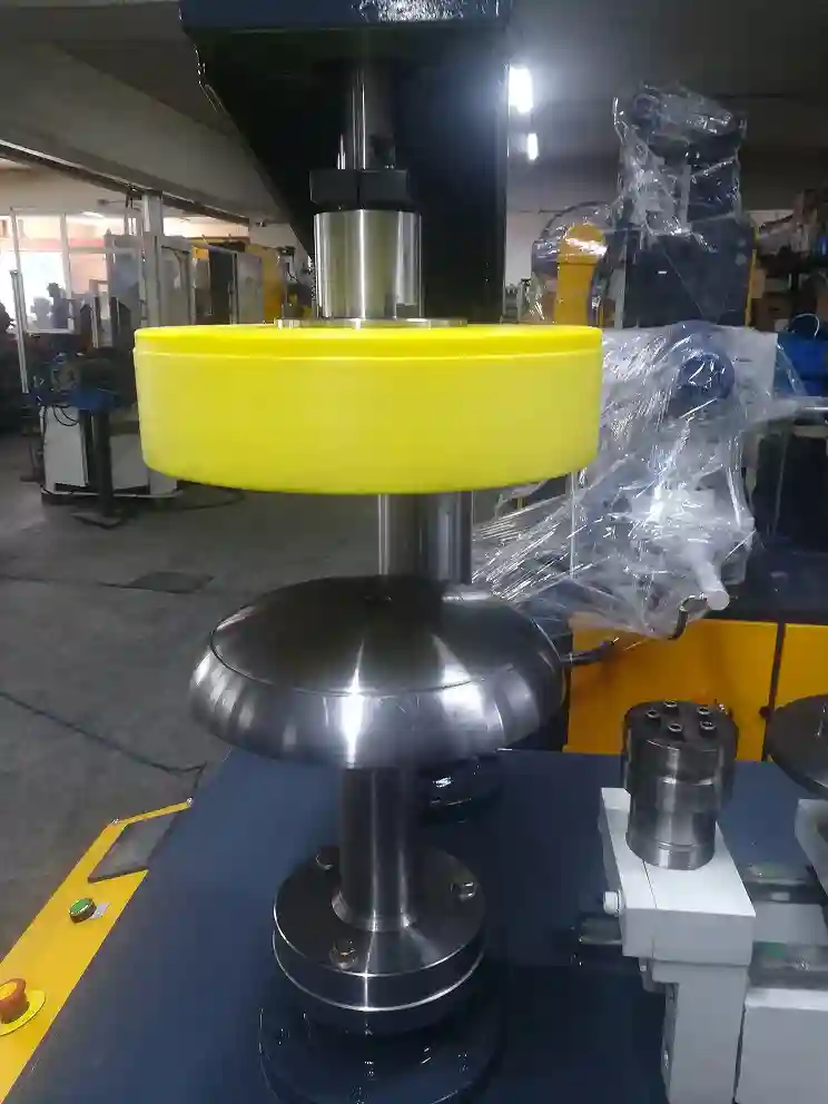
An edge cutting, trimming, and beading machine for fire extinguisher production is a specialized machine that is designed to cut, trim, and bead the edges of cylindrical metal parts, such as fire extinguisher shells. The machine is used in the manufacturing process to prepare the metal parts for subsequent operations such as welding and assembly.
The edge cutting, trimming, and beading machine typically consists of a motor-driven cutting blade, a trimming tool, and a beading tool. The cylindrical metal parts are placed on a rotating table, and the cutting blade and trimming tool are adjusted to the desired position. The cutting blade is used to cut the excess metal from the edges of the parts, and the trimming tool is used to remove any burrs or sharp edges.
After the parts are cut and trimmed, the beading tool is used to create a bead around the edge of the metal part. The bead provides additional strength and rigidity to the part and also improves its appearance. The beading tool can be adjusted to produce a bead of various sizes and shapes.
Overall, the edge cutting, trimming, and beading machine is an important tool in the production of cylindrical metal parts, such as those used in fire extinguishers, and helps to ensure that these parts are made to the required specifications and quality standards.
Edge Cutting Trimming and Beading Machine
An edge cutting trimming and beading machine is a versatile tool that combines the functions of edge cutting, trimming, and beading. It is used to create clean, finished edges on various materials, particularly sheet metal, and form decorative or functional beads along the edges. These machines are widely used in various industries, including metal fabrication, automotive manufacturing, and appliance production.
Edge Trimming
Edge trimming involves removing excess material from the edge of a material to create a clean, straight, or defined edge. This is often done for aesthetic purposes, to improve the appearance of the workpiece, or to prepare the edge for further processing.
Edge Trim Chopper
An edge trim chopper is a specialized tool designed to chop or shear off excess material from the edge of a material. These choppers are typically used for trimming thick or tough materials, such as leather or rubber.
Here is a table summarizing the key differences between the three types of edge finishing machines:
| Feature | Edge Cutting Trimming and Beading Machine | Edge Trimming Machine | Edge Trim Chopper |
|---|---|---|---|
| Primary function | Edge cutting, trimming, and beading | Edge trimming | Edge trimming |
| Applications | Sheet metal fabrication, automotive manufacturing, appliance production | Various materials, including wood, plastic, paper, and textiles | Thick or tough materials, such as leather or rubber |
| Advantages | Versatility, combined edge cutting, trimming, and beading | Efficient trimming | Powerful trimming for thick or tough materials |
| Disadvantages | May require skill and precision for manual operation | Limited to edge trimming | Limited to specific materials |
Edge Cutting, Trimming, and Beading Machine
The Complete Guide to Edge Trimming, Curling, and Wire-Beading Machines for Cookware and Sheet Metal Manufacturing
Table of Contents
• 1. Introduction to Edge Cutting, Trimming, and Beading Machines
• 2. What Is an Edge Cutting and Trimming Machine?
• 3. What Is a Beading Machine?
• 4. Why Edge Finishing Matters
• 5. How the Edge Cutting and Trimming Process Works
• 6. How the Beading and Curling Process Works
• 7. Types of Edge Cutting and Trimming Machines
• 8. Types of Beading and Curling Machines
• 9. Tooling: Cutters, Rollers, and Dies
• 10. Key Process Parameters
• 11. Bead and Edge Profile Types
• 12. Common Defects and How to Prevent Them
• 13. Manual vs. Semi-Automatic vs. Fully Automatic Lines
• 14. Applications Across Industries
• 15. Advantages and Limitations
• 16. Selecting the Right Machine
• 17. Maintenance and Safety Considerations
• 18. Emerging Trends: Automation and Industry 4.0
• 19. Frequently Asked Questions (FAQ)
• 20. Conclusion
1. Introduction to Edge Cutting, Trimming, and Beading Machines
After a metal component has been deep drawn, spun, or otherwise formed into its basic shape, its edges are almost never ready for final use. Drawn cups, pans, bowls, and tanks typically emerge from the forming press with an uneven, wavy rim of excess material, often called the flange or trim allowance. Before the part can be polished, assembled, or sold, this excess material must be precisely removed and the resulting edge must be finished — either cut clean, folded over, or reinforced with a rolled wire bead — to create a safe, strong, and dimensionally accurate rim.
This is the job of edge cutting and trimming machines and beading (curling) machines, two closely related categories of finishing equipment found on virtually every metal cookware, container, and sheet metal production line. Edge cutting and trimming machines remove excess flange material and establish the final diameter and edge profile of a drawn or spun part. Beading machines then roll, curl, or fold that trimmed edge — often around a reinforcing wire — to eliminate sharp edges, add structural rigidity, and create the smooth, rounded rim that consumers recognize on pots, pans, buckets, and countless other rolled-edge metal products.
This guide provides a complete overview of edge cutting, trimming, and beading machines: how they work, the range of machine types and tooling available, key process parameters, common defects, industry applications, and the latest automation trends. Whether you are specifying new finishing equipment for a cookware or container production line, studying sheet metal processing, or simply want to understand how a rolled, wire-reinforced pot rim is actually made, this article offers a thorough, practical reference.
2. What Is an Edge Cutting and Trimming Machine?
An edge cutting and trimming machine is a piece of finishing equipment designed to remove excess flange material from a drawn, spun, or otherwise formed metal part, cutting it to a precise final diameter and edge geometry. As deep-drawn cups, pans, or tank shells come off the forming press, their rim is typically uneven in height due to the natural anisotropic material flow of the drawing process (a phenomenon related to earing, discussed in deep drawing literature), and this irregular excess must be trimmed away to achieve a clean, uniform edge before any further finishing can occur.
Trimming machines accomplish this using a rotating cutting tool — commonly a circular blade, roller cutter, or a fixed trim die combined with a rotating chuck — that follows the circumference of the part with high precision, shearing away the excess flange in a single continuous pass. For non-round or irregular parts, trimming may instead use a punch-and-die trim station integrated into a press line, or a CNC-guided cutting head following a programmed contour.
2.1 Core Components of a Trimming Machine
• Rotating Chuck or Fixture: Holds and spins the workpiece at controlled speed during circular trimming operations.
• Cutting Wheel or Blade: The tool that shears away excess flange material, available in various profiles depending on cut type and material thickness.
• Backup/Support Roller: Supports the opposite side of the workpiece to maintain stability and cutting accuracy during the trim pass.
• Feed/Positioning System: Controls the radial position of the cutting tool relative to the workpiece, establishing the final trimmed diameter.
• Scrap Removal System: Collects and removes the trimmed flange scrap, often via a chute or conveyor for recycling.
• Control System: Ranges from simple mechanical stops on manual trimming lathes to programmable CNC control on advanced automated lines.
3. What Is a Beading Machine?
A beading machine (also called a curling machine or edge-rolling machine) forms the trimmed edge of a metal part into a rounded, rolled profile, most commonly by curling the raw edge over itself or around a reinforcing steel or stainless steel wire. This rolled bead eliminates the sharp, potentially hazardous raw edge left after trimming, adds significant structural rigidity to the rim (which is otherwise one of the weakest points on a thin-walled drawn or spun part), and provides the smooth, comfortable, and visually finished edge expected on cookware, buckets, tanks, and many other rolled-rim metal products.
Like trimming machines, beading machines typically use a rotating chuck to spin the workpiece against a set of contoured forming rollers. As the part rotates, the rollers progressively fold the edge inward and around the reinforcing wire (if used) over a series of passes, each roller station advancing the curl a bit further until the edge is fully closed into its final rounded bead profile.
3.1 Core Components of a Beading Machine
• Rotating Chuck: Holds and spins the workpiece against the forming rollers at controlled speed.
• Forming Roller Set: A series of progressively contoured rollers that incrementally curl the edge into its final beaded profile.
• Wire Feed Mechanism: Feeds and positions the reinforcing wire into the curling edge for wire-beaded rim designs.
• Roller Pressure Control: Regulates the radial force applied by each roller station, critical for consistent bead formation without cracking or deforming the part wall.
• Indexing/Multi-Station System: On automated machines, advances the workpiece through sequential roller stations for progressive bead formation.
• Control System: Manages spindle speed, roller position, and wire feed synchronization, from manual hand-operated levers to fully programmable CNC control.
4. Why Edge Finishing Matters
4.1 Safety
A freshly trimmed metal edge is razor-sharp and presents a significant cutting hazard to both factory workers during subsequent handling and end consumers using the finished product. Beading and curling eliminates this hazard entirely by rolling the sharp edge into a smooth, rounded profile.
4.2 Structural Rigidity
The rim of a thin-walled drawn or spun part is inherently one of its weakest points, prone to denting, deforming, or losing its round shape under normal handling stress. A rolled bead, especially one reinforced with a steel wire core, dramatically increases the rim’s resistance to deformation, helping the part maintain its shape and function throughout its service life.
4.3 Dimensional Precision
Trimming establishes the exact final diameter of the part, which is essential for proper lid fit on cookware, correct stacking and nesting of containers, and compatibility with mating components in assembled products.
4.4 Aesthetic Finish
A cleanly trimmed and evenly beaded edge is one of the most visually scrutinized features on finished cookware and containers; an uneven, wavy, or poorly formed bead is immediately noticeable to consumers and reflects directly on perceived product quality.
5. How the Edge Cutting and Trimming Process Works
5.1 Step-by-Step Process Overview
1. Part Loading: The drawn or spun part is loaded onto a rotating chuck or fixture, centered precisely on the machine’s axis.
2. Chuck Clamping: The chuck secures the part firmly, often using vacuum, mechanical clamps, or an expanding collet, to prevent slippage during high-speed rotation.
3. Spindle Rotation: The chuck spins the part at a controlled speed appropriate to the material and diameter.
4. Cutter Engagement: The cutting wheel or blade advances radially until it contacts the flange at the predetermined trim diameter.
5. Circumferential Cut: As the part continues rotating, the cutter shears through the flange in a single continuous pass, separating the excess material.
6. Scrap Separation: The trimmed flange ring or scrap falls away or is guided into a collection chute or conveyor for recycling.
7. Edge Inspection: The trimmed edge is inspected for burrs, uniform diameter, and cut quality before proceeding to beading or polishing.
For non-circular parts, such as rectangular trays or shaped containers, trimming is instead typically performed using a punch-and-die shearing station, often integrated directly into the drawing press line as a secondary operation, or via a CNC-guided cutting head that follows the part’s programmed contour.
6. How the Beading and Curling Process Works
6.1 Step-by-Step Process Overview
8. Part Loading: The trimmed part is mounted on the beading machine’s rotating chuck.
9. Wire Positioning (if applicable): For wire-reinforced beads, a length of wire is fed and positioned along the inside of the part’s edge.
10. Initial Curl Pass: The first forming roller contacts the raw edge and begins folding it inward at a shallow angle.
11. Progressive Curling Passes: Subsequent roller stations, each with a more pronounced contour, continue folding the edge further around itself or around the wire core.
12. Final Closing Pass: The last roller station fully closes the curl, compressing the folded edge tightly around the wire (if used) to form the finished, rounded bead.
13. Bead Inspection: The finished bead is inspected for roundness, consistent diameter, tight wire encapsulation, and absence of gaps or wrinkles.
The number of roller passes required depends on material thickness, ductility, and the target bead diameter — thicker or less ductile materials typically require more gradual, incremental passes to avoid cracking or wrinkling the material as it is folded through nearly 360 degrees of curl.
7. Types of Edge Cutting and Trimming Machines
7.1 Manual/Semi-Automatic Trimming Lathes
Simple rotating chuck machines where an operator manually advances the cutting wheel into the spinning part, commonly used for lower-volume production, prototyping, or shops handling a wide variety of part sizes.
7.2 Automatic CNC Trimming Machines
Programmable machines that automatically control spindle speed, cutter feed rate, and trim diameter, offering high repeatability and quick changeover between different part programs, standard on medium-to-high volume cookware and container lines.
7.3 Rotary Shear Trimming Machines
Use a pair of rotating disc cutters (similar to a circular shear) that meet at the part’s edge, providing a clean, burr-minimized cut suitable for thinner gauge materials at high production speeds.
7.4 Press-Integrated Trim Dies
For non-round or complex-shaped parts, trimming is performed as a secondary operation within the same press line used for drawing, using a matched punch-and-die trim station that shears the flange in a single press stroke.
7.5 Laser Trimming Systems
An increasingly common alternative for complex contours or premium applications, laser trimming uses a focused laser beam guided by CNC programming to cut the part edge with high precision and no mechanical tool wear, though typically at a higher equipment cost than mechanical trimming.
8. Types of Beading and Curling Machines
8.1 Manual Beading Lathes
Operator-guided machines using hand levers to advance forming rollers against the rotating part, suited to low-volume, custom, or repair work where flexibility outweighs the need for high throughput.
8.2 Automatic Multi-Roller Beading Machines
CNC or cam-controlled machines that automatically sequence multiple forming roller stations through a programmed curling cycle, standard for medium-to-high volume cookware and container production.
8.3 Wire Beading Machines
Specialized machines equipped with an integrated wire feed and cutoff system, precisely synchronized with the roller forming stations to encapsulate a continuous wire ring within the curled edge.
8.4 Rotary Multi-Station Indexing Machines
High-throughput machines that rotate the workpiece through a series of fixed roller stations arranged around a turntable, each station performing one incremental stage of the curl, maximizing production speed for high-volume standard cookware and container shapes.
8.5 Combination Trim-and-Bead Machines
Integrated machines that perform both trimming and beading in a single fixturing and machine cycle, reducing part handling, floor space, and cycle time compared to separate standalone trimming and beading operations.
9. Tooling: Cutters, Rollers, and Dies
• Cutting Wheels/Blades: Hardened steel or carbide-tipped wheels ground to precise cutting angles, selected based on material thickness and desired cut quality.
• Forming Roller Sets: Precision-machined, progressively contoured steel rollers that define each stage of the curling profile; roller sequence and contour design directly determine final bead shape and quality.
• Wire Guides and Feed Rollers: Precisely position and feed reinforcing wire into the curling edge, synchronized with the part’s rotation and roller advancement.
• Chucks and Collets: Hold the workpiece securely and concentrically during high-speed rotation, available in fixed, expanding, or vacuum-actuated designs depending on part geometry.
• Trim and Bead Dies (Press-Integrated): Matched punch-and-die tooling used for non-round parts processed within a press line rather than a rotary machine.
• Backup/Support Tooling: Rollers or fixtures that stabilize the opposite side of thin-walled parts during trimming or beading to prevent distortion under tool pressure.
10. Key Process Parameters
| Parameter | Description | Typical Effect if Incorrect |
| Spindle Speed (RPM) | Rotational speed of the chuck during trimming/beading | Too high → vibration, uneven cut; too low → poor finish, slow cycle |
| Cutter/Roller Feed Rate | Speed of radial tool advancement into the part | Too fast → burrs, tearing; too slow → excess cycle time, tool wear |
| Number of Roller Passes | How many incremental stages form the final bead | Too few → cracking/wrinkling; too many → unnecessary cycle time |
| Roller Pressure | Force applied by forming rollers during curling | Too high → wall deformation/cracking; too low → incomplete curl |
| Wire Diameter/Tension | Size and feed tension of reinforcing wire | Mismatched wire → loose or oversized bead, wire slippage |
| Trim Diameter Accuracy | Precision of the final trimmed edge dimension | Off-spec diameter → poor lid fit, assembly mismatch |
11. Bead and Edge Profile Types
• Plain Trimmed Edge: Simply cut to final diameter with no further folding, typically deburred or lightly rolled for safety on non-critical or internal parts.
• Single Curl (Open Curl): The edge is folded over itself into a rounded profile without an internal wire, offering moderate rigidity and a smooth finished edge.
• Wire-Reinforced Bead (Closed Curl): The most common cookware rim design, where the edge is fully curled around a steel or stainless wire core, providing maximum rigidity and a durable, rounded rim.
• Double Bead: Two parallel rolled beads, sometimes used on larger containers or tanks for additional structural reinforcement or to create a stacking/handling lip.
• Flanged/Hemmed Edge: The trimmed edge is folded flat against itself (rather than rolled into a round bead), commonly used where a mating lid or gasket seal is required.
12. Common Defects and How to Prevent Them
12.1 Burrs and Sharp Edges
Worn or improperly aligned cutting wheels can leave burrs along the trimmed edge, creating a safety hazard and interfering with subsequent beading. Regular cutter sharpening/replacement and precise tool alignment prevent this defect.
12.2 Wrinkling During Curling
Excessive roller pressure or too few progressive forming passes can cause the edge material to wrinkle or buckle as it is folded, particularly on thicker or less ductile materials. Adding intermediate roller stages and optimizing pressure resolves this.
12.3 Cracking at the Bead
Aggressive curling in too few passes, especially on harder tempers or thicker material, can crack the metal at the tightest point of the curl. Solutions include increasing the number of progressive passes and, where necessary, using a softer material temper for the trim allowance.
12.4 Uneven or Out-of-Round Bead
Inconsistent chuck centering, worn rollers, or fluctuating spindle speed can produce a bead that varies in diameter or shape around the part’s circumference. Preventive maintenance of chucks and rollers, along with consistent process parameters, resolves this.
12.5 Wire Slippage or Gaps
Incorrect wire tension, diameter mismatch, or synchronization errors between wire feed and roller advancement can leave gaps in the wire core or cause the wire to shift within the bead. Careful calibration of the wire feed system prevents this defect.
13. Manual vs. Semi-Automatic vs. Fully Automatic Lines
| Method | Throughput | Best Suited For |
| Manual/Semi-Automatic | Low; operator-paced | Low-volume, custom, or prototype production; repair work |
| Automatic CNC (Single Station) | Medium; consistent cycle time | Medium-volume production of a limited range of part sizes |
| Fully Automatic Multi-Station | High; continuous indexing | High-volume cookware and container manufacturing |
14. Applications Across Industries
14.1 Cookware Manufacturing
Pots, pans, saucepans, and lids universally require edge trimming after drawing or spinning, followed by wire-beading to produce the smooth, rigid, rolled rim that defines finished cookware quality and consumer safety.
14.2 Metal Container and Pail Manufacturing
Steel and aluminum pails, drums, and buckets rely on beading not only for edge safety but for the structural rigidity the rolled rim provides, which is essential for handle attachment points and stacking strength.
14.3 Food and Beverage Can Manufacturing
While beverage can ends use specialized double-seaming rather than traditional wire beading, related trimming and curling technology is used extensively in the production of larger food cans, tins, and canisters.
14.4 HVAC and Ductwork
Sheet metal ductwork components frequently use beading and curling to stiffen thin-gauge panel edges and create safe, interlocking connection points between duct sections.
14.5 Automotive and Industrial Components
Various automotive fluid reservoirs, filter housings, and industrial tank components use edge trimming and beading to achieve both structural reinforcement and safe, finished edges on formed sheet metal shells.
14.6 Lighting and Decorative Metalware
Lamp shades, decorative bowls, and architectural metal elements often use curling and beading both functionally, to eliminate sharp edges, and aesthetically, to create a refined, finished rim profile.
15. Advantages and Limitations
15.1 Advantages
• Eliminates sharp, hazardous raw edges, critical for both worker and consumer safety.
• Significantly increases rim rigidity and resistance to denting or deformation.
• Establishes precise final part dimensions essential for lid fit and component assembly.
• Automated multi-station systems achieve high throughput with excellent consistency.
• Relatively low tooling cost compared to full matched-die forming processes.
15.2 Limitations
• Adds process steps and cycle time to the overall manufacturing sequence.
• Wire beading requires precise synchronization between wire feed and roller systems, adding process complexity.
• Thicker or less ductile materials require more forming passes, increasing cycle time and tooling wear.
• Non-round or irregular part geometries require more complex, often press-integrated trimming solutions rather than simple rotary machines.
• Achieving a defect-free bead on new part designs often requires iterative roller tooling development.
16. Selecting the Right Machine
Choosing appropriate trimming and beading equipment involves evaluating several factors:
• Part geometry: Round parts suit rotary chuck-based trimming and beading machines; non-round parts require press-integrated trim dies or CNC-guided cutting.
• Production volume: Low volumes favor manual or semi-automatic machines; high volumes justify fully automatic multi-station systems.
• Edge design requirements: Plain trim, open curl, or wire-reinforced bead each require different tooling and, in some cases, different machine capability.
• Material type and thickness: Harder or thicker materials require more robust tooling and additional progressive forming passes.
• Integration with upstream/downstream processes: Combination trim-and-bead machines or in-line integration with drawing presses can reduce handling and floor space.
• Changeover flexibility: CNC-programmable machines allow faster changeover between part sizes than fixed mechanical tooling.
• Total cost of ownership: Includes tooling replacement costs, wire consumable costs (for wire beading), energy consumption, and maintenance requirements.
17. Maintenance and Safety Considerations
17.1 Preventive Maintenance
• Regular sharpening or replacement of cutting wheels to maintain clean, burr-free trims.
• Periodic inspection and dressing of forming rollers to prevent surface wear from transferring defects to the part.
• Calibration of chuck centering and spindle alignment to maintain consistent trim diameter and bead roundness.
• Inspection and maintenance of wire feed mechanisms, including tension control and cutoff blade sharpness.
• Lubrication of rotating and sliding machine components per manufacturer schedules to ensure smooth, consistent operation.
17.2 Operator and Workplace Safety
• Machine guarding around rotating chucks and cutting tools to prevent operator contact injuries.
• Careful handling procedures for freshly trimmed scrap and parts, which retain sharp edges until beaded.
• Emergency stop systems accessible from the primary operator position.
• Personal protective equipment, including cut-resistant gloves, when handling untrimmed or freshly trimmed parts.
• Lockout/tagout procedures during tooling changes, roller replacement, and maintenance work.
18. Emerging Trends: Automation and Industry 4.0
18.1 Fully Integrated Trim-Bead-Inspect Cells
Manufacturers are increasingly combining trimming, beading, and automated dimensional inspection into single integrated production cells, reducing part handling, floor space, and cycle time while improving overall quality control.
18.2 Servo-Driven Roller Control
Servo-controlled forming rollers allow precise, programmable pressure and position profiles for each curling pass, improving consistency across different materials and part designs without requiring physical tooling changes.
18.3 Vision-Guided Quality Inspection
Automated camera-based inspection systems increasingly verify trim diameter, bead roundness, and wire encapsulation in real time, flagging defective parts immediately rather than relying on downstream manual inspection.
18.4 Robotic Part Handling
Robotic loading and unloading between trimming, beading, and subsequent polishing stations is increasingly standard on high-volume cookware lines, reducing labor costs and improving overall line throughput consistency.
18.5 Quick-Change Tooling Systems
Modular, quick-change roller and cutter tooling systems are reducing changeover time between different part sizes, improving manufacturing flexibility for product lines with multiple cookware or container diameters.
19. Frequently Asked Questions (FAQ)
What is the difference between trimming and beading?
Trimming removes excess flange material from a drawn or spun part to establish its final diameter and edge, while beading (curling) subsequently rolls that trimmed edge into a rounded profile, often around a reinforcing wire, to eliminate sharp edges and add rim rigidity.
Why do cookware rims have a wire inside them?
The internal wire reinforces the rolled edge, significantly increasing the rim’s resistance to denting, deformation, and out-of-round distortion during normal handling, which is especially important on thin-walled stainless steel or aluminum cookware.
Can beading be done without trimming first?
Generally no — the edge must first be trimmed to a clean, precise, uniform diameter before beading, since an uneven or wavy raw edge (typical of an as-drawn flange) cannot be consistently curled into a uniform bead.
What causes cracking during the beading process?
Cracking typically results from too aggressive a curl in too few forming passes, particularly on thicker or harder-tempered material. Adding intermediate progressive roller stages and, if needed, using a more ductile material temper resolves this.
Are trimming and beading machines the same equipment?
They can be separate, specialized machines, or combined into a single integrated trim-and-bead machine that performs both operations in one fixturing cycle, which is increasingly common on modern high-volume cookware production lines.
What materials can be trimmed and beaded?
Stainless steel, aluminum, and coated or galvanized carbon steel are all commonly trimmed and beaded, with material thickness and ductility determining the required number of forming passes and appropriate tooling design.
20. Conclusion
Edge cutting, trimming, and beading machines perform one of the most functionally important yet often overlooked steps in metal cookware and container manufacturing. By precisely removing excess material and rolling the raw edge into a smooth, rigid, wire-reinforced bead, these machines transform a freshly drawn or spun metal shell into a safe, structurally sound, and visually finished product ready for polishing, assembly, or direct use.
As automation, servo-driven roller control, and vision-guided inspection continue to advance, trimming and beading lines are becoming faster, more consistent, and more flexible across a widening range of part sizes and edge designs. For manufacturers evaluating this equipment, understanding machine types, tooling design, process parameters, and bead profile options — as outlined throughout this guide — provides the essential foundation for producing consistently safe, durable, and well-finished rolled-edge metal products.
From the wire-beaded rim of a stainless steel stockpot to the rolled edge of a steel pail, edge cutting, trimming, and beading technology remains the quiet, essential finishing step that turns a rough-edged metal shell into a product ready for the hands of a factory worker, a chef, or a consumer.
Edge cutting trimming machine for hot water boilers
An edge cutting trimming beading curling machine is a device that has a set of blades that rotate at high speed in order to cut and trim sheet metal. The machine is used in the production of round parts, rim cuts, beading, and edge cuts. It is also used for edging and trimming sheet metal.
An edge cutting and trimming machine is a device used in metalworking to remove excess material and create a clean edge on the workpiece. This is important for ensuring the quality and safety of the final product, especially in industries such as fire extinguisher production and hot water boiler manufacturing.
In the case of a hot water boiler, the edge cutting and trimming machine would be used to remove any excess material from the edges of the boiler, as well as create a precise and uniform shape. This is necessary to ensure the boiler can function properly and efficiently, and to prevent any sharp edges that could cause injury to workers or users.
The machine would typically include a cutting blade or tool, as well as a means of clamping and holding the workpiece in place. Some machines may also include additional features such as beading or forming tools, which can further shape and refine the workpiece.
Overall, the edge cutting and trimming machine plays an important role in the production of hot water boilers, and is essential for ensuring the quality and safety of these products.
Cookware Production Line and Metalworking Machinery
“Why cookware is used” is a question that we mostly never think or talk about but we know that cookware, kitchenware, bakeware or all other items we use for nourishment have the same history as humanity itself. Cookware products are classified into 2 main subcategories by using purposes: professional and non-professional. Professional cookware is considered as the pots, pans, plates, and cutlery mainly used in commercial places such as restaurants, hotels, and catering companies. Non-professional cookware products are the ones we use in our houses.
Cookware or Kitchenware producers that manufacture mainly food preparation equipment such as stainless steel pots, pans, pressure cookers, teapots, kettles, baking sheets, fry pans, sauce or saute pan, braiser pan, wok, baking dish, baking tray, cake pan, coffee press, mixing bowls, saucepan, sheet pan, skillet, stockpot, strainer, and tray. This food preparation or serving equipment needs to go through some manufacturing process.
Cookware Production Line
The cookware production line involves a series of steps that transform raw materials into finished cookware products. These steps typically include:
- Material Preparation: Raw materials, such as stainless steel, aluminum, or cast iron, are inspected and prepared for processing.
- Blanking: Sheet metal is cut into the desired shapes using blanking presses or laser cutting machines.
- Deep Drawing: The cut blanks are formed into the desired shape of the cookware using deep drawing presses.
- Trimming: Excess material is trimmed from the edges of the cookware using trimming machines.
- Forming: The cookware is shaped into the final desired form using forming machines, such as stamping presses or roll forming machines.
- Handle Attachment: Handles are attached to the cookware using welding, brazing, or riveting techniques.
- Surface Finishing: The surface of the cookware is polished or treated to achieve the desired finish, such as a mirror finish or a non-stick coating.
- Quality Control: Each cookware piece undergoes quality control inspections to ensure it meets the desired specifications.
- Packaging: The finished cookware is packaged and labeled for shipping.
Non-Stick Cookware Manufacturing Process
The manufacturing process for non-stick cookware involves additional steps to apply the non-stick coating. These steps typically include:
- Sandblasting: The cookware surface is sandblasted to create a rough texture for better adhesion of the coating.
- Priming: A primer layer is applied to the cookware surface to enhance the bond between the coating and the metal.
- Coating Application: The non-stick coating is applied to the cookware surface using various methods, such as spray coating, dip coating, or sol-gel coating.
- Curing: The coated cookware is baked or cured in an oven to harden and bond the coating to the metal.
- Quality Control: The non-stick coating is inspected for uniformity, thickness, and durability.
The specific steps and techniques involved in the cookware production line and the non-stick cookware manufacturing process may vary depending on the type of cookware, the desired finish, and the manufacturing facility.
Why is kitchenware made of so many different materials?
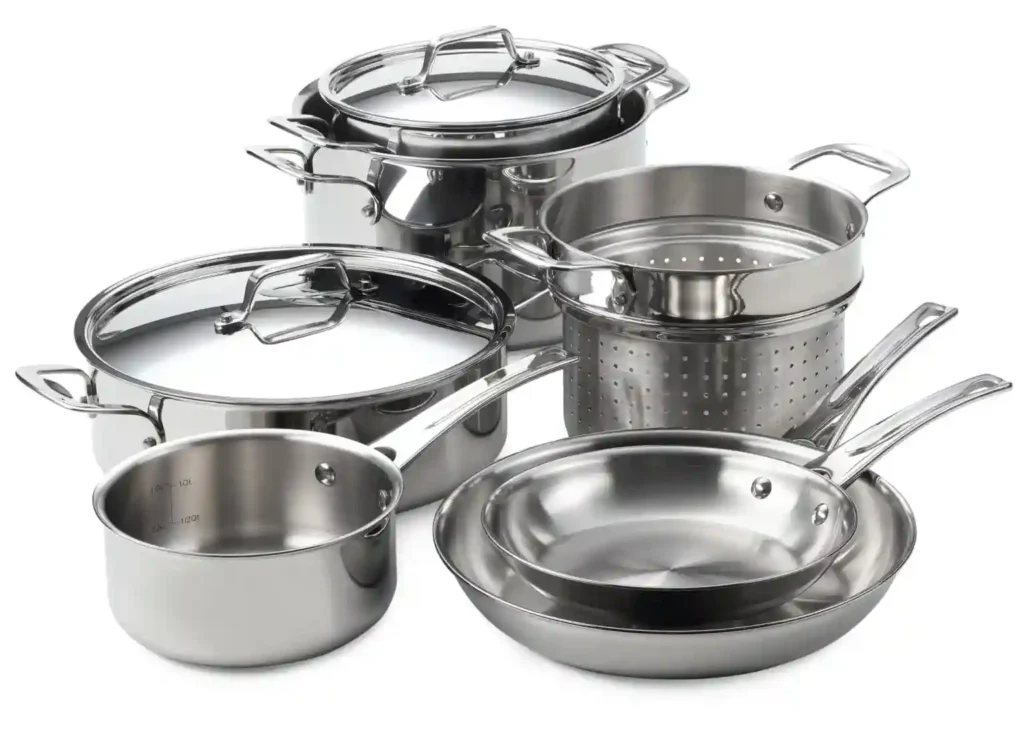
Kitchenware is made of various materials because different materials have different properties that make them suitable for different types of cooking and different cooking methods. For example, stainless steel is durable, non-reactive, and easy to clean, making it a popular choice for cookware. Cast iron retains heat well and is excellent for searing and sautéing, while copper conducts heat quickly and evenly, making it ideal for tasks that require precise temperature control.
Other factors that influence material choice include cost, availability, and aesthetic appeal. Additionally, some people prefer certain materials for health or environmental reasons, such as avoiding non-stick coatings that may contain harmful chemicals or choosing sustainable materials like bamboo or recycled materials.
Overall, the choice of material for kitchenware depends on the needs and preferences of the cook, as well as the intended use of the item.
What is Kitchenware made of? and How is kitchenware made?
Kitchenware is manufactured and made of various materials, depending on their usage. The most common ones are metals. Metals are widely used in the kitchenware industry because of its affordable price, long service life, and characteristics. The metal types used in kitchenware can be listed as:
- Stainless Steel
- Copper
- Aluminum
- Cast Iron
From the picture below, you can check some of the images of cookware and kitchenware products that we manufactured till now
The main reason why metal is used in the cookware industry is that metal conducts heat well and metal doesn’t get into reaction with the food that it contacts. In some cases, some metals can be reactive when heated and in such situations, the part that will be used as kitchenware needs to be coated or clad with another material. Metals also have a long shelf life and are durable in terms of usage and transport.
Our customers are cookware and kitchenware wholesalers and products manufacturers
Our machinery is marketed globally and wholesalers for kitchenware or companies that manufacture products such as stainless steel pots, pans, pressure cookers, teapots, kettles, baking sheets, fry pans, sauce or saute pans, braiser pans, wok, baking dishes, baking trays, cake pan, coffee press, mixing bowls, saucepan, sheet pan, skillet, stockpot, strainer, and tray need to have some basic machinery to manufacture them. The process starts with sheet metal and then ends with products already packed and ready for sale. Here below we list the necessary production machinery for each kitchenware product type:
All types of metal pots, pans, bowls, woks and trays:
- Circle Cutting Machine
- Deep Drawing Press
- Clipper or Vertical Edge Cutting Machine
- Horizontal Edge Cutting Trimming and Beading Machine (for rim cutting and trimming)
- Polishing Machine for Inside and Outside Polishing or Grinding
- Riveting Machine for riveting the handle to the pot body
All types of kettles, teapots and coffee pots
- Circle Cutting Machine
- Deep Drawing Press or a Mechanical Eccentric Press
- Horizontal Edge Cutting Trimming and Beading Machine (for rim cutting and trimming)
- Polishing Machine for Inside and Outside Polishing or Grinding
- Riveting Machine for riveting the handle to the pot body
Machinery for the Production of Cookware Stainless Steel
There are a variety of machinery used in the production of stainless steel cookware. Here are some examples:
- Shearing Machines: These machines are used to cut the stainless steel sheets into the required size and shape.
- Presses: Hydraulic presses are used to form the cut stainless steel sheets into the desired shapes, such as pans, pots, and bowls.
- Polishing Machines: These machines are used to give the cookware a polished finish. There are different types of polishing machines, including flat surface polishing machines and polishing machines specifically designed for cookware.
- Punching Machines: These machines are used to create the necessary holes and slots in the cookware.
- Welding Machines: Welding machines are used to join different parts of the cookware together, such as handles and lids.
- Coating Machines: Some stainless steel cookware may be coated with non-stick coatings, and coating machines are used to apply the coating.
- Quality Control Equipment: Various equipment is used to check the quality of the cookware, including thickness gauges, surface finish testers, and hardness testers.
All of these machines and equipment work together to create high-quality stainless steel cookware that is durable and long-lasting.
We, as EMS Metalworking Machinery, are specialized in the production of cookware, kitchenware, hotelware, bakeware, and cutlery production machines for 3 decades already. We have an end-to-end production in our facility and delivery our products to wholesale cookware, kitchenware, hotelware, and bakeware suppliers in Singapore, Malaysia, UK, India, South Africa, Delhi, Mumbai, Kolkata, Cyprus, Europe, Ahmedabad, Chennai, Vasai, USA, and Egypt.