
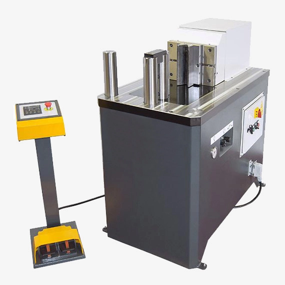
We manufacture a 20 Ton Hydraulic Press with Gauge to bend sheet metal edges. 20 Ton Hydraulic Press with Gauge are used in metalworking industries
A 20-ton hydraulic press with a gauge is a piece of equipment used for various tasks, including compressing, bending, straightening, and shaping materials. The “20-ton” rating indicates the maximum force or pressure that the press can exert, which is 20 tons or 40,000 pounds. The gauge on the press allows the operator to monitor and control the force applied during operations. Here’s an overview of the key components and functions of a 20-ton hydraulic press with a gauge:
Components of a 20-Ton Hydraulic Press with Gauge:
- Frame: The frame provides the structure and support for the hydraulic press. It is typically made of sturdy steel to withstand the forces generated during pressing operations.
- Hydraulic Cylinder: The hydraulic cylinder is responsible for generating the pressing force. It contains a piston and cylinder filled with hydraulic fluid (usually oil). When hydraulic pressure is applied, the piston extends, creating the force necessary for pressing.
- Pump: The pump is used to build hydraulic pressure within the system. It can be operated manually, pneumatically, or electrically, depending on the specific press model. The pump draws hydraulic fluid from a reservoir and pressurizes it.
- Hydraulic Hose: The hydraulic hose connects the pump to the hydraulic cylinder, allowing the pressurized fluid to flow to the cylinder and extend the piston.
- Gauge: The gauge is an essential component that provides a visual indication of the force or pressure being exerted by the hydraulic press. It allows the operator to monitor and control the pressing force accurately. The gauge is typically calibrated in tons or pounds and provides real-time feedback during operations.
- Control Valve: The control valve regulates the flow of hydraulic fluid to the hydraulic cylinder. It can be manually operated to control the rate at which the piston extends or retracts, enabling precise force control.
- Press Plates or Dies: The press plates or dies are the surfaces between which the object to be pressed or shaped is positioned. They come in various sizes and shapes, depending on the specific task and the material being worked on.
Operation of a 20-Ton Hydraulic Press with Gauge:
- Preparation: The operator places the object to be pressed or shaped between the press plates or dies, ensuring it is properly aligned and secured.
- Setting Force: The operator sets the desired pressing force on the gauge by adjusting the control valve. This force is typically specified in tons or pounds.
- Pressing: The operator activates the pump, which pressurizes the hydraulic fluid. As the hydraulic pressure builds, it extends the piston in the hydraulic cylinder, generating the desired force. The gauge provides a visual indication of the force being applied.
- Monitoring: The operator closely monitors the gauge to ensure that the pressing force reaches the desired level. If adjustments are needed, they can be made by adjusting the control valve.
- Completion: Once the object has been pressed or shaped to the desired specifications, the operator releases the pressure by operating the control valve in the opposite direction. The piston retracts, relieving the force on the object.
A 20-ton hydraulic press with a gauge is a versatile tool used in various industries, including metalworking, automotive, woodworking, and manufacturing, for tasks such as bending metal sheets, pressing bearings, assembling components, and more. The gauge is a crucial feature for precision and safety during pressing operations.
A 20-ton hydraulic press is a powerful and versatile tool commonly used in metal fabrication and other industrial applications. It utilizes hydraulic pressure to apply immense force to a ram, which in turn forces a punch down onto a workpiece, pressing it into a desired shape or form. 20-ton hydraulic presses are suitable for a wide range of applications, including:
- Bending Sheet Metal: These machines are widely used to bend sheet metal components for various products, such as enclosures, brackets, ductwork, structural components, and various other sheet metal parts.
- Forming Extrusions: 20-ton hydraulic presses can form extrusions, which are shapes created by forcing metal through a die. This process is used to create various components, such as tubes, channels, and beams.
- Stamping and Punching: These presses can be used for stamping and punching operations, where a punch is used to cut or form shapes in sheet metal. This process is used to create components like washers, gaskets, and electrical connectors.
- Prototyping Sheet Metal Designs: These machines are employed to create prototypes of sheet metal components to evaluate form, fit, and functionality before full-scale production.
- High-Volume Production: 20-ton hydraulic presses are designed for high-volume production, enabling efficient manufacturing of large quantities of sheet metal components.
Key Components of a 20-Ton Hydraulic Press
A 20-ton hydraulic press consists of several essential components that work together to achieve precise and efficient pressing operations:
- Frame: The sturdy frame provides a solid base for the machine and supports the pressing mechanism. It is typically constructed from heavy-duty steel or cast iron to withstand the immense forces involved in pressing.
- Hydraulic System: The heart of the machine, the hydraulic system generates and supplies pressurized hydraulic fluid to the pressing mechanism. It consists of a hydraulic pump, hoses, valves, and a hydraulic cylinder. The hydraulic cylinder applies high-pressure hydraulic fluid to the ram, providing the force required to press the workpiece.
- Ram: The movable ram applies downward force onto the workpiece. Connected to the hydraulic cylinder and guided by rails, it ensures precise movement and alignment during the pressing process.
- Punch: The punch is a tooling component that forms the desired shape or feature in the workpiece. Typically made from hardened steel or tool steel to withstand abrasion and pressing forces, its profile corresponds to the desired shape.
- Die: The die, another tooling component, supports the workpiece during pressing. Designed to match the punch’s shape, it creates the desired shape or feature and prevents distortion. The die provides a stable surface against which the punch forces the workpiece to deform.
- Work Table: The adjustable work table provides a stable surface for positioning and securing the workpiece during pressing. It accommodates different workpiece sizes and orientations, ensuring precise positioning.
- Back Gauge: The back gauge, also known as the depth stop, controls the distance between the rear edge of the workpiece and the pressing line. It ensures consistent pressing positions and prevents the workpiece from slipping during the pressing process, maintaining accuracy and consistency.
- Controls: The control panel allows the operator to set and monitor the pressing process. Modern hydraulic presses often feature advanced computer controls for precise and automated operation. These controls enable operators to set pressing forces, pressing speeds, and other parameters, ensuring consistent and repeatable results.
Safety Precautions for Operating 20-Ton Hydraulic Presses
When operating 20-ton hydraulic presses, it is crucial to adhere to strict safety protocols to prevent injuries and accidents:
- Thorough Training: Operators must receive comprehensive training on the specific machine model, its operation, and safety procedures.
- Personal Protective Equipment (PPE): Always wear appropriate PPE, including safety glasses, gloves, and hearing protection, to protect from flying debris, sharp edges, and noise.
- Secure the Workpiece: Ensure the workpiece is securely positioned and clamped to the work table to prevent movement during pressing operations.
- Clear Work Area: Keep the work area free of obstructions and potential hazards. Secure any loose objects or hanging wires.
- Maintain Proper Form: Maintain proper stance and posture while operating the press to avoid strain or injury.
- Emergency Stop Procedures: Familiarize yourself with the emergency stop procedures and be prepared to activate them in case of any unexpected malfunctions or hazards.
- Regular Maintenance: Follow the manufacturer’s recommended maintenance schedule to ensure the machine and tooling are functioning correctly and safely.
By following these safety precautions and adhering to proper operating procedures, individuals can safely operate 20-ton hydraulic presses and produce high-quality components for various applications.
20 Ton Hydraulic Press with Gauge
A 20-ton hydraulic press with gauge is a powerful and versatile machine used for a wide range of metal fabrication tasks, including bending, straightening, and forming sheet metal components. It utilizes hydraulic pressure to apply force to a movable ram, which in turn forces a punch down onto a workpiece, pressing it into the desired shape or form. The addition of a gauge provides precise control over the bending angle or pressing depth, ensuring consistent and accurate results.
Key Components of a 20-Ton Hydraulic Press with Gauge
- Frame: The sturdy frame provides a solid base for the machine and supports the pressing mechanism. It is typically constructed from heavy-duty steel or cast iron to withstand the immense forces involved in pressing.
- Hydraulic System: The heart of the machine, the hydraulic system generates and supplies pressurized hydraulic fluid to the pressing mechanism. It consists of a hydraulic pump, hoses, valves, and a hydraulic cylinder. The hydraulic cylinder applies high-pressure hydraulic fluid to the ram, providing the force required to press the workpiece.
- Ram: The movable ram applies force onto the workpiece, typically moving vertically along the press bed. Connected to the hydraulic cylinder and guided by rails, it ensures precise movement and alignment during the pressing process.
- Punch: The punch is a tooling component that forms the desired shape or feature in the workpiece. Typically made from hardened steel or tool steel to withstand abrasion and pressing forces, its profile corresponds to the desired shape.
- Die: The die, another tooling component, supports the workpiece during pressing. Designed to match the punch’s shape, it creates the desired shape or feature and prevents distortion. The die provides a stable surface against which the punch forces the workpiece to deform.
- Gauge: The gauge is a measuring device that provides precise feedback on the bending angle or pressing depth. It typically consists of a graduated scale and a pointer or indicator that measures the distance between the ram and the workpiece.
Benefits of Using a 20-Ton Hydraulic Press with Gauge
- Precision Control: The gauge enables precise control over the bending angle or pressing depth, ensuring consistent and accurate results. This is particularly important for applications where precise dimensions are critical.
- Repeatability: The gauge allows for repeatable bending or pressing operations, even for complex shapes or multiple workpieces. This enhances productivity and reduces the need for rework.
- Reduced Errors: The gauge helps minimize errors caused by manual estimation or visual judgement, leading to higher quality products and reduced waste.
- Simplified Operation: The gauge simplifies the operation of the press, making it easier for operators to achieve the desired results.
- Versatility: The gauge expands the versatility of the press, enabling it to perform a wider range of tasks beyond standard bending operations.
Applications of a 20-Ton Hydraulic Press with Gauge
20-ton hydraulic presses with gauges are widely used in various metal fabrication applications, including:
- Precise Bending of Sheet Metal: The gauge ensures accurate bending angles for various sheet metal components, such as brackets, enclosures, and structural parts.
- Forming of Extrusions: The gauge enables precise control over the extrusion process, creating consistent shapes and dimensions for tubes, channels, and beams.
- Stamping and Punching: The gauge assists in precise stamping and punching operations, ensuring accurate alignment and consistent depth for creating washers, gaskets, and other components.
- Prototyping Sheet Metal Designs: The gauge facilitates accurate prototyping of sheet metal designs, ensuring proper fit and function before full-scale production.
- High-Volume Production: The gauge allows for efficient and repeatable production of sheet metal components, maintaining consistent quality and reducing rework.
In summary, a 20-ton hydraulic press with gauge is a valuable tool for metal fabrication, offering precise control, repeatability, and reduced errors, making it suitable for a wide range of applications
Frame
In the context of machinery and structures, a frame refers to a structural component that provides support, shape, and rigidity to an object, whether it’s a machine, building, vehicle, or other construction. Frames are designed to distribute loads and stresses, maintain the structural integrity of the object, and provide a framework for other components or materials to be attached. The concept of a frame is fundamental in engineering and construction. Here are some key aspects of frames:
Key Characteristics and Functions of Frames:
- Support and Load Distribution: Frames serve as a structural skeleton that supports the weight of the object or structure and distributes loads (forces and moments) applied to it. This load distribution helps prevent deformation and structural failure.
- Shape and Geometry: Frames define the shape and geometry of an object or structure. They determine its overall dimensions and provide a framework for other components to be attached or integrated.
- Rigidity: Frames are designed to provide rigidity and stability to the object they support. This prevents unwanted movement or deformation under load.
- Attachment Points: Frames often include attachment points, such as holes, brackets, or mounting surfaces, where other components or materials can be connected or secured. These attachment points facilitate the assembly of complex systems.
- Versatility: Frames can be designed for a wide range of applications, from simple structures like bicycle frames to complex machinery, vehicles, and buildings. They come in various shapes, sizes, and materials to suit specific needs.
- Materials: Frames can be constructed from various materials, including metals (steel, aluminum), wood, composites, concrete, and plastics. The choice of material depends on factors like strength requirements, weight constraints, and environmental conditions.
- Engineering Analysis: Engineers often perform structural analysis and design to ensure that frames can withstand expected loads and forces while adhering to safety standards and codes. Finite element analysis (FEA) and computer-aided design (CAD) software are commonly used tools for frame design and analysis.
Examples of Frames:
- Bicycle Frame: A bicycle frame is a classic example of a simple frame. It supports the rider’s weight and provides attachment points for wheels, handlebars, pedals, and other components.
- Building Frame: In construction, the frame of a building consists of structural elements like beams, columns, and trusses that support the walls, floors, and roof. This frame distributes loads and shapes the building.
- Machine Frame: Industrial machines, such as CNC machines and printing presses, often have a rigid frame that supports moving parts, tooling, and controls. The frame provides stability and precision during operation.
- Vehicle Chassis: In automobiles, trucks, and other vehicles, the chassis is a frame-like structure that supports the vehicle’s body, engine, suspension, and wheels. It also determines the vehicle’s shape and dimensions.
- Picture Frame: Even in everyday items like picture frames, the frame provides support for the image and serves as a decorative element.
Frames are a fundamental concept in engineering and construction, and they play a crucial role in the design, functionality, and safety of a wide range of objects and structures. The choice of frame design and material depends on the specific application and engineering requirements.
Hydraulic Cylinder
A hydraulic cylinder is a mechanical actuator that converts hydraulic energy (pressurized hydraulic fluid) into linear mechanical force and motion. These devices are commonly used in various applications, such as construction equipment, manufacturing machinery, automotive systems, and more, where they perform tasks such as lifting, pushing, pulling, and positioning heavy loads. Here are the key components and functions of a hydraulic cylinder:
Components of a Hydraulic Cylinder:
- Cylinder Barrel: The cylinder barrel is the outer cylindrical housing of the hydraulic cylinder. It provides structural support and contains the other internal components. The inside surface of the barrel is typically precision-machined to reduce friction and ensure a proper seal with the piston.
- Piston: The piston is a cylindrical component that fits inside the cylinder barrel. It separates the cylinder into two chambers: the rod side (or pressure side) and the cap side (or return side). The piston is responsible for generating linear motion in response to hydraulic pressure.
- Piston Rod: The piston rod is attached to the piston and extends outside the cylinder barrel through a sealed opening. It is the part of the hydraulic cylinder that connects to external loads or mechanisms. The piston rod transmits the force generated by the piston to the load.
- Seals: Various seals, including O-rings, U-cups, and wipers, are used within the hydraulic cylinder to prevent hydraulic fluid from leaking between the piston and cylinder walls. These seals also help maintain hydraulic pressure within the cylinder.
- Hydraulic Ports: Hydraulic fluid enters and exits the hydraulic cylinder through hydraulic ports. These ports are connected to a hydraulic fluid supply system, which pressurizes and controls the flow of hydraulic fluid into and out of the cylinder.
Working Principle of a Hydraulic Cylinder:
The operation of a hydraulic cylinder is based on Pascal’s law, which states that when pressure is applied to an enclosed fluid, the pressure is transmitted undiminished in all directions throughout the fluid. Here’s how a hydraulic cylinder works:
- Pressurization: Hydraulic fluid (usually oil) is supplied to the hydraulic cylinder through one of the hydraulic ports. This fluid is pressurized by a hydraulic pump, creating pressure within the cylinder.
- Piston Movement: The pressurized hydraulic fluid is directed to the rod side or cap side of the cylinder, depending on the direction in which the operator wants the piston to move. The pressure forces the piston to move in the desired direction.
- Linear Motion: As the piston moves, it pushes or pulls the piston rod, resulting in linear mechanical motion. This motion can be used to perform various tasks, such as lifting a load or moving a component.
- Load Application: The piston rod extends or retracts, depending on the direction of hydraulic pressure and the application’s requirements. The piston rod is connected to external loads, which are moved or controlled by the hydraulic cylinder’s motion.
- Pressure Release: When the hydraulic pressure is released or redirected to the opposite side of the piston, the piston retracts, and the hydraulic fluid is returned to the hydraulic fluid reservoir.
Hydraulic cylinders are valued for their ability to provide powerful and precise linear motion. They come in various sizes and configurations to suit different applications, and their performance can be adjusted by controlling the hydraulic pressure. Hydraulic cylinders are widely used in industries where heavy lifting, precise positioning, or controlled motion is required.
Pump
A pump is a mechanical device or machine used to transfer fluids (liquids or gases) from one place to another by applying mechanical force. Pumps are an essential component in various industries and applications, including water supply, wastewater treatment, chemical processing, oil and gas production, and more. They are designed to move fluids by increasing their kinetic energy, which results in flow and pressure. Here are some key aspects of pumps:
Basic Components of a Pump:
- Impeller or Rotor: The impeller is a rotating component within the pump that is responsible for generating kinetic energy in the fluid. The design of the impeller, including its shape and number of blades, determines the pump’s performance characteristics.
- Casing or Housing: The casing or housing surrounds the impeller and directs the fluid flow. It may have various shapes and configurations, depending on the pump type and application. The casing helps maintain fluid flow and pressure.
- Inlet and Outlet Ports: Pumps have inlet and outlet ports or connections that allow fluid to enter and exit the pump. Inlet ports are typically positioned near the impeller, while outlet ports are located further downstream in the casing.
- Drive Mechanism: Pumps require a drive mechanism to power the impeller’s rotation. This can be an electric motor, internal combustion engine, or other power sources, depending on the pump’s design and application.
- Seals and Bearings: Seals are used to prevent fluid from leaking out of the pump, and bearings support the rotating components, such as the impeller and drive shaft, ensuring smooth operation.
Working Principle of a Pump:
The operation of a pump depends on its type and design, but the general working principle involves the following steps:
- Fluid Intake: The pump’s inlet port is connected to the source of the fluid to be pumped. When the pump is activated, it begins to draw fluid into the pump through the inlet port.
- Kinetic Energy Generation: Inside the pump, the fluid encounters the impeller, which is rotating rapidly. The impeller’s blades impart kinetic energy to the fluid, causing it to move in a specific direction.
- Fluid Discharge: The moving fluid is directed by the casing or housing towards the outlet port of the pump. As the fluid moves through the pump, it experiences an increase in pressure due to the impeller’s kinetic energy transfer.
- Outlet: The pressurized fluid exits the pump through the outlet port and is directed to the desired location or application. The level of pressure and flow rate depends on the pump’s design and the impeller’s speed.
Types of Pumps:
There are numerous types of pumps, each designed for specific applications and fluid types. Common types include:
- Centrifugal Pumps: These pumps use a rotating impeller to impart kinetic energy to the fluid, which is then converted into pressure. They are widely used for water supply, chemical processing, and wastewater treatment.
- Positive Displacement Pumps: These pumps trap a fixed volume of fluid and then force it into the discharge pipe. Common types include piston pumps, diaphragm pumps, and gear pumps.
- Rotary Pumps: Rotary pumps use a rotating mechanism, such as gears or screws, to move fluid through the pump. Examples include gear pumps and screw pumps.
- Axial Flow Pumps: Axial flow pumps are designed to move large volumes of fluid at low pressure differentials, commonly used in irrigation and flood control.
Pumps are essential in a wide range of industrial, commercial, and residential applications, and their selection depends on factors such as flow rate, pressure requirements, fluid type, and efficiency.
Hydraulikflüssigkeit
Hydraulikflüssigkeit, auch bekannt als Hydrauliköl oder Hydraulikfluid, ist eine spezielle Art von Flüssigkeit, die in hydraulischen Systemen verwendet wird, um Energie zu übertragen und mechanische Arbeit auszuführen. Sie spielt eine entscheidende Rolle für die Funktion und Leistungsfähigkeit von Hydraulikanlagen in verschiedenen industriellen Anwendungen, von Baumaschinen bis hin zu Flugzeugsystemen.
Hydraulikflüssigkeiten werden sorgfältig ausgewählt und formuliert, um eine optimale Leistung und Zuverlässigkeit in hydraulischen Systemen zu gewährleisten. Die wichtigsten Eigenschaften von Hydraulikflüssigkeiten sind:
- Viskosität: Die Viskosität ist ein Maß für die Fließfähigkeit der Hydraulikflüssigkeit und beeinflusst die Leistungsfähigkeit des Systems. Eine geeignete Viskosität gewährleistet eine reibungslose Durchflussbewegung in den Hydraulikleitungen und Komponenten, während gleichzeitig ausreichende Schmierung bereitgestellt wird, um Verschleiß und Reibung zu reduzieren.
- Schmierfähigkeit: Hydraulikflüssigkeiten müssen eine hohe Schmierfähigkeit aufweisen, um bewegliche Teile wie Pumpen, Ventile, Zylinder und Motoren wirksam zu schmieren und vor Verschleiß zu schützen. Eine gute Schmierleistung verlängert die Lebensdauer der Systemkomponenten und verbessert die Gesamteffizienz der Anlage.
- Oxidationsbeständigkeit: Hydraulikflüssigkeiten müssen gegen Oxidation beständig sein, um die Bildung von Ablagerungen, Schlamm und anderen Verunreinigungen zu verhindern, die die Systemleistung beeinträchtigen könnten. Stabile Hydraulikflüssigkeiten bieten eine langfristige Stabilität und reduzieren Wartungsanforderungen.
- Temperaturstabilität: Hydraulikflüssigkeiten müssen über einen weiten Temperaturbereich stabil sein, um bei extremen Bedingungen wie hohen Betriebstemperaturen oder Kälteeinwirkungen eine zuverlässige Leistung zu gewährleisten. Eine gute Temperaturstabilität verhindert Viskositätsänderungen und ermöglicht einen zuverlässigen Betrieb des Systems.
- Korrosionsschutz: Hydraulikflüssigkeiten sollten korrosionsbeständige Additive enthalten, um Metallkomponenten vor Rost und Korrosion zu schützen. Dies gewährleistet eine lange Lebensdauer der Anlage und reduziert Ausfallzeiten aufgrund von Beschädigungen oder Funktionsstörungen.
- Wasserabscheidung: Hydraulikflüssigkeiten müssen in der Lage sein, Wasser effektiv abzuscheiden und zu emulgieren, um die Bildung von Wasseransammlungen und Feuchtigkeit im System zu verhindern. Wasser kann die Hydraulikflüssigkeit verdünnen, Korrosion verursachen und die Leistungsfähigkeit des Systems beeinträchtigen.
Hydraulikflüssigkeiten werden nach spezifischen Standards und Spezifikationen formuliert, die von Industrieverbänden und Herstellern festgelegt werden. Sie sind in verschiedenen Viskositätsklassen, Qualitätsstufen und Zusammensetzungen erhältlich, um den Anforderungen verschiedener Anwendungen gerecht zu werden. Die Auswahl der richtigen Hydraulikflüssigkeit ist entscheidend für die Sicherheit, Leistungsfähigkeit und Lebensdauer von hydraulischen Systemen. Regelmäßige Überwachung, Wartung und Austausch der Hydraulikflüssigkeit sind notwendig, um eine optimale Betriebsfähigkeit und Zuverlässigkeit des Systems sicherzustellen.
Hydraulikpumpe
Eine Hydraulikpumpe ist eine mechanische Vorrichtung, die in hydraulischen Systemen verwendet wird, um mechanische Energie in hydraulische Energie umzuwandeln. Sie spielt eine entscheidende Rolle bei der Bereitstellung des erforderlichen Drucks und Volumens von Hydraulikflüssigkeit, um Zylinder, Motoren, Ventile und andere hydraulische Komponenten anzutreiben und zu steuern.
Hier sind einige wichtige Komponenten und Merkmale von Hydraulikpumpen:
- Pumpentypen: Es gibt verschiedene Arten von Hydraulikpumpen, die jeweils unterschiedliche Funktionsweisen und Anwendungen haben. Zu den häufigsten Typen gehören:
- Zahnradpumpen: Zahnradpumpen verwenden zwei oder mehr ineinandergreifende Zahnräder, um hydraulische Flüssigkeit zu fördern. Sie sind einfach im Aufbau, kostengünstig und eignen sich gut für mittlere Drücke und Flussraten.
- Kolbenpumpen: Kolbenpumpen verwenden Kolben, die sich in einem Zylinder hin und her bewegen, um hydraulische Flüssigkeit zu fördern. Sie bieten hohe Leistung, Effizienz und Druckkapazität und sind in verschiedenen Bauarten wie Axialkolben-, Radialkolben- und Schrägscheibenkolbenpumpen erhältlich.
- Flügelzellenpumpen: Flügelzellenpumpen verwenden drehbare Flügel, die in einem exzentrischen Gehäuse rotieren, um hydraulische Flüssigkeit zu fördern. Sie bieten eine gleichmäßige und pulsationsfreie Förderung sowie eine hohe Effizienz und sind gut geeignet für Anwendungen mit hohen Drücken und niedrigen bis mittleren Flussraten.
- Fördervolumen und Druck: Das Fördervolumen und der Druck einer Hydraulikpumpe bestimmen ihre Leistungsfähigkeit und ihre Einsatzmöglichkeiten in einem hydraulischen System. Das Fördervolumen wird in Kubikzentimetern pro Umdrehung (cc/rev) oder in Litern pro Minute (L/min) gemessen, während der Druck in Bar oder Psi angegeben wird. Die Auswahl der richtigen Pumpe hängt von den Anforderungen der Anwendung ab, einschließlich des benötigten Volumens und Drucks.
- Wirkungsgrad: Der Wirkungsgrad einer Hydraulikpumpe gibt an, wie effizient sie mechanische Energie in hydraulische Energie umwandelt. Ein hoher Wirkungsgrad bedeutet, dass weniger Energie verloren geht und mehr Leistung für die Anwendung verfügbar ist. Faktoren wie interne Reibung, Dichtungseffizienz und hydraulische Verluste beeinflussen den Wirkungsgrad einer Pumpe.
- Bauweise: Hydraulikpumpen können in verschiedenen Bauarten ausgeführt sein, je nach den Anforderungen der Anwendung und den Betriebsbedingungen. Dies umfasst die Anordnung der Komponenten wie Pumpengehäuse, Saug- und Druckanschlüsse, Kolben oder Zahnräder, Dichtungen und Lager. Die Bauweise beeinflusst die Leistung, Zuverlässigkeit und Wartungsfreundlichkeit der Pumpe.
- Steuerung: Hydraulikpumpen können manuell, elektrisch, hydraulisch oder pneumatisch gesteuert werden, um den Fluss und Druck der hydraulischen Flüssigkeit zu regeln. Dies kann durch Verwendung von Ventilen, Drosseln, Regelkreisen, Reglern oder anderen Steuerungselementen erfolgen, um die Leistung und Funktionalität des Systems zu optimieren.
Hydraulikpumpen sind entscheidende Komponenten in hydraulischen Systemen und werden nach spezifischen Anwendungsanforderungen ausgewählt und dimensioniert. Eine sorgfältige Auswahl, Installation und Wartung von Hydraulikpumpen ist entscheidend für die Leistungsfähigkeit, Zuverlässigkeit und Lebensdauer von hydraulischen Systemen.
Hydraulikzylinder
Ein Hydraulikzylinder ist ein mechanischer Aktuator, der lineare Bewegung und Kraft erzeugt, indem er hydraulische Energie in mechanische Energie umwandelt. Er spielt eine wesentliche Rolle in verschiedenen Anwendungen über verschiedene Branchen hinweg, einschließlich Bauwesen, Fertigung, Landwirtschaft und Luft- und Raumfahrt, wo präzise und leistungsstarke lineare Bewegungen erforderlich sind.
Wichtige Komponenten und Merkmale von Hydraulikzylindern sind:
- Zylinderrohr: Das Zylinderrohr ist das Hauptgehäuse, das die beweglichen Komponenten des Hydraulikzylinders enthält, wie den Kolben, die Stange und die Dichtungen. Es besteht typischerweise aus hochfesten Materialien wie Stahl oder Aluminium und ist so konstruiert, dass es hydraulischem Druck und mechanischen Belastungen standhält.
- Kolben: Der Kolben ist eine zylindrische oder scheibenförmige Komponente, die den Zylinder in zwei Kammern unterteilt: die Stangen- und die Deckelseite. Er ist mit Dichtungen versehen, um das Auslaufen hydraulischer Flüssigkeit zu verhindern, und überträgt den hydraulischen Druck von einer Kammer auf die andere, um eine lineare Bewegung zu erzeugen. Der Kolben kann einseitig wirkend sein, wobei der hydraulische Druck nur auf einer Seite wirkt, oder doppelt wirkend, wobei der hydraulische Druck auf beiden Seiten wirkt, um eine bidirektionale Bewegung zu ermöglichen.
- Stange: Die Stange ist eine zylindrische Welle, die vom Kolben durch eine abgedichtete Öffnung im Zylinder verläuft und den Verbindungspunkt für externe Lasten oder Ausrüstungen bildet. Sie überträgt die durch den hydraulischen Druck erzeugte Kraft, um Arbeit zu verrichten, und kann mit Endarmaturen, Gabeln oder Augenhalterungen für die Montage von Anbaugeräten ausgestattet sein. Die Stange besteht typischerweise aus gehärtetem und verchromtem Stahl, um Verschleiß, Korrosion und Beschädigungen zu widerstehen.
- Dichtungen: Dichtungen werden verwendet, um das Auslaufen hydraulischer Flüssigkeit zu verhindern und den Druck und die Integrität im Hydraulikzylinder aufrechtzuerhalten. Sie befinden sich an verschiedenen Stellen entlang des Zylinders, des Kolbens und der Stange und sind während des Betriebs hydraulischer Flüssigkeit und hohen Drücken ausgesetzt. Zu den gängigen Arten von Dichtungen in Hydraulikzylindern gehören O-Ringe, Lippenabdichtungen, Kolbendichtungen und Stangendichtungen, die je nach Temperatur, Druck, Flüssigkeitskompatibilität und Anforderungen ausgewählt werden.
- Montagevorrichtungen: Hydraulikzylinder können Montagevorrichtungen oder Befestigungspunkte enthalten, um den Zylinder an externen Strukturen, Rahmen oder Ausrüstungen zu sichern. Montagevorrichtungen können Flansche, Gabeln, Augenhalterungen oder Drehzapfenhalterungen umfassen, die eine einfache Installation und Ausrichtung des Zylinders in verschiedenen Ausrichtungen ermöglichen. Eine ordnungsgemäße Montage und Ausrichtung sind entscheidend, um einen reibungslosen Betrieb und eine gute Leistung von Hydraulikzylindern zu gewährleisten.
Hydraulikzylinder werden je nach ihrer Konstruktion, ihrem Funktionsprinzip und ihrer Anwendung in verschiedene Typen eingeteilt, darunter:
- Einzelwirkende Zylinder: Einzelwirkende Zylinder haben hydraulischen Druck, der auf einer Seite des Kolbens wirkt, und erzeugen eine lineare Bewegung nur in eine Richtung. Der Rückhub wird in der Regel durch eine Feder oder eine äußere Kraft bewirkt.
- Doppelwirkende Zylinder: Doppelwirkende Zylinder haben hydraulischen Druck, der auf beiden Seiten des Kolbens wirkt, was eine bidirektionale lineare Bewegung ermöglicht. Hydraulikflüssigkeit wird abwechselnd zugeführt und aus dem Zylinder abgelassen, um den Kolben auszufahren und zurückzuziehen.
- Teleskopzylinder: Teleskopzylinder bestehen aus mehreren ineinander geschachtelten Stufen, die sich teleskopartig ausfahren und einfahren, um lange Hublängen in einem kompakten Gehäuse zu bieten. Sie werden häufig in Anwendungen mit begrenztem Platzangebot oder langen Verfahrwegen eingesetzt, wie zum Beispiel bei Kippern, Kränen und Hubarbeitsbühnen.
Die richtige Auswahl, Dimensionierung, Installation und Wartung von Hydraulikzylindern ist entscheidend, um eine optimale Leistung, Zuverlässigkeit und Sicherheit in hydraulischen Systemen zu gewährleisten. Ingenieure und Techniker müssen Faktoren wie Zylindertyp, Größe, Hublänge, Bohrungsdurchmesser, Stangendurchmesser, Betriebsdruck, Montagekonfiguration und Anforderungen der Anwendung berücksichtigen, wenn sie Hydraulikzylinder für spezifische Aufgaben auswählen. Regelmäßige Inspektion, Schmierung und vorbeugende Wartung sind erforderlich, um Anzeichen von Verschleiß, Undichtigkeiten oder Beschädigungen zu erkennen und Hydraulikzylinderfehler und Leistungsminderungen vorzubeugen.
Hydraulic Motor
A hydraulic motor is a mechanical device used to convert hydraulic pressure into rotational mechanical power. It is a key component in hydraulic systems, providing the means to drive various machinery, equipment, and systems that require rotary motion. Hydraulic motors are commonly found in applications such as construction machinery, agricultural equipment, industrial machinery, and marine propulsion systems.
Here are some key components and features of hydraulic motors:
- Motor Types: Hydraulic motors come in various types, each with specific designs, operating principles, and performance characteristics. Common types of hydraulic motors include:
- Gear Motors: Gear motors use meshing gears to convert hydraulic pressure into rotational motion. They are simple in design, cost-effective, and suitable for applications with moderate speeds and loads.
- Vane Motors: Vane motors use sliding vanes to convert hydraulic pressure into rotational motion. They offer higher efficiency and smoother operation compared to gear motors and are suitable for applications requiring higher speeds and loads.
- Piston Motors: Piston motors use reciprocating pistons to convert hydraulic pressure into rotational motion. They offer high efficiency, power density, and torque output, making them suitable for demanding applications with high speeds and loads.
- Operating Principle: Hydraulic motors operate based on the principle of fluid pressure acting on motor components to generate rotational motion. Hydraulic fluid is directed into the motor, causing internal components such as gears, vanes, or pistons to move and produce rotational force on the motor output shaft.
- Speed and Torque: Hydraulic motors provide variable speed and torque output depending on the flow rate and pressure of the hydraulic fluid. The speed and torque characteristics of the motor are determined by its design, displacement, and operating conditions, allowing for precise control and adaptation to different application requirements.
- Efficiency: The efficiency of a hydraulic motor refers to the ratio of output power to input power, indicating how effectively it converts hydraulic energy into mechanical work. Factors such as internal friction, leakage, and fluid viscosity affect the efficiency of hydraulic motors, with higher efficiency motors providing greater power output for a given input.
- Construction and Materials: Hydraulic motors are typically constructed from materials such as steel, aluminum, cast iron, or bronze, chosen for their strength, durability, and corrosion resistance. Motor components may include housings, shafts, bearings, seals, and hydraulic connections, assembled into robust and reliable units suitable for harsh operating environments.
- Mounting and Installation: Hydraulic motors are mounted and installed within machinery, equipment, or systems using mounting brackets, flanges, couplings, or other attachment methods. Proper mounting and alignment are essential to ensure smooth operation, minimize vibration, and prevent premature wear or damage to the motor and associated components.
Hydraulic motors are selected based on factors such as application requirements, speed, torque, power output, efficiency, space constraints, environmental conditions, and regulatory compliance. Proper integration, calibration, and maintenance of hydraulic motors are essential to ensure optimal performance, reliability, and safety in hydraulic systems. Regular inspection, lubrication, and preventive maintenance are necessary to detect signs of wear, leakage, or malfunction and prevent hydraulic motor failure and system downtime.
Hydraulic Valve
A hydraulic valve is a crucial component in hydraulic systems, responsible for controlling the flow, direction, and pressure of hydraulic fluid within the system. It serves as the gateway that directs the hydraulic energy to various actuators, allowing for precise control and manipulation of machinery and equipment. Hydraulic valves come in various types and configurations, each serving specific functions and purposes within the hydraulic system.
Here are some key components and features of hydraulic valves:
- Valve Types: Hydraulic valves are available in different types to accommodate various control requirements and system configurations. Common types include:
- Directional Control Valves: These valves control the direction of fluid flow within the hydraulic system, allowing for forward, reverse, or stopping motion of actuators. They come in different configurations such as 2-way, 3-way, 4-way, and 5-way valves, with options for manual, solenoid, or pilot-operated controls.
- Pressure Control Valves: Pressure control valves regulate the pressure of hydraulic fluid within the system to maintain safe operating conditions and prevent damage to components. They include relief valves, pressure reducing valves, sequence valves, and counterbalance valves, each serving specific pressure control functions.
- Flow Control Valves: Flow control valves regulate the rate of fluid flow within the system, allowing for precise speed control of hydraulic actuators. They can be adjustable or fixed and come in various designs such as needle valves, throttle valves, and flow regulators.
- Proportional Valves: Proportional valves provide variable control of flow, pressure, or direction proportional to an input signal, such as voltage or current. They offer precise control and are often used in applications requiring dynamic response and fine-tuning, such as servo systems and motion control.
- Actuation Methods: Hydraulic valves can be actuated using various methods, including manual levers, push buttons, solenoids, pilot valves, and hydraulic or pneumatic actuators. Actuation methods determine how the valve responds to control signals and operator commands, affecting the speed, accuracy, and reliability of the hydraulic system.
- Construction and Materials: Hydraulic valves are typically constructed from durable materials such as steel, aluminum, brass, or cast iron, chosen for their strength, corrosion resistance, and compatibility with hydraulic fluids. Valve components may include valve bodies, spools, poppets, seals, springs, and actuators, assembled into compact and robust units suitable for harsh operating conditions.
- Sealing Technology: Seals and gaskets are critical components of hydraulic valves, ensuring leak-free operation and maintaining pressure integrity within the system. They are made from materials such as rubber, polyurethane, or fluorocarbon, selected for their compatibility with hydraulic fluids and resistance to wear, temperature, and pressure.
- Mounting and Installation: Hydraulic valves are mounted and installed within hydraulic circuits or systems using threaded connections, flanges, manifolds, or subplates. Proper mounting and installation are essential to ensure proper alignment, sealing, and operation of valves and prevent leakage, vibration, or damage during system operation.
Hydraulic valves are selected based on factors such as system requirements, flow rate, pressure rating, valve type, actuation method, and application considerations. Proper integration, calibration, and maintenance of hydraulic valves are essential to ensure optimal performance, reliability, and safety in hydraulic systems. Regular inspection, testing, and adjustment of valves are necessary to detect signs of wear, leakage, or malfunction and prevent hydraulic system failures and safety hazards.
Hydraulic Filter
A hydraulic filter is an essential component in hydraulic systems, designed to remove contaminants from the hydraulic fluid to ensure the cleanliness and proper functioning of the system. It plays a critical role in maintaining the performance, reliability, and longevity of hydraulic components and equipment by preventing damage caused by contaminants such as dirt, debris, metal particles, and moisture.
Here are some key components and features of hydraulic filters:
- Filtration Media: Hydraulic filters use various types of filtration media to capture and retain contaminants from the hydraulic fluid. Common filtration media include cellulose, synthetic fibers, metal mesh, and microglass fibers. The choice of filtration media depends on factors such as the size and type of contaminants, flow rate, pressure rating, and filtration efficiency requirements.
- Filtration Efficiency: Filtration efficiency refers to the ability of the hydraulic filter to remove contaminants from the fluid at specified particle sizes. Filters are rated based on their efficiency levels, typically expressed as a percentage of particles removed at a specific micron size. High-efficiency filters can remove a greater percentage of contaminants, providing cleaner hydraulic fluid and better system protection.
- Filter Housing: The filter housing encloses the filtration media and provides a secure mounting point within the hydraulic system. It is typically made of materials such as steel, aluminum, or plastic and is designed to withstand the pressure, temperature, and vibration encountered in hydraulic systems. The housing may include inlet and outlet ports, bypass valves, and pressure indicators for monitoring filter status and performance.
- Bypass Valve: Some hydraulic filters are equipped with a bypass valve that allows fluid to bypass the filter element under certain conditions, such as high differential pressure or cold start-up. The bypass valve prevents excessive pressure drop across the filter, ensuring continuous flow of hydraulic fluid to the system even if the filter becomes clogged or saturated. However, prolonged bypass operation can reduce filtration efficiency and compromise system cleanliness.
- Filter Element: The filter element is the heart of the hydraulic filter, where the actual filtration process takes place. It consists of the filtration media arranged in pleats, discs, or cartridges to maximize surface area and capture contaminants effectively. Filter elements are available in various configurations, including depth filters, surface filters, and absolute filters, each offering specific filtration performance and efficiency characteristics.
- Change Interval: Hydraulic filters require periodic replacement or maintenance to ensure continued effectiveness and system protection. The change interval depends on factors such as operating conditions, fluid cleanliness requirements, contamination levels, and manufacturer recommendations. Regular inspection and monitoring of filter condition, pressure drop, and fluid analysis are essential to determine the optimal change interval and prevent premature filter failure.
- Installation and Maintenance: Proper installation and maintenance of hydraulic filters are critical to their performance and reliability. Filters should be installed according to manufacturer guidelines, with proper sealing, orientation, and torque specifications. Regular inspection, cleaning, and replacement of filters, as well as monitoring of system cleanliness and fluid condition, are necessary to ensure optimal filtration and system operation.
Hydraulic filters are available in various types, sizes, and configurations to suit different hydraulic systems and applications. They are an integral part of hydraulic system design and maintenance, providing essential protection against contamination and ensuring the longevity and performance of hydraulic equipment. Regular inspection, monitoring, and replacement of hydraulic filters are essential preventive maintenance practices to minimize downtime, reduce component wear, and optimize hydraulic system reliability and efficiency.
Hydraulic Reservoir
A hydraulic reservoir, also known as a hydraulic tank or hydraulic sump, is a storage container within a hydraulic system that holds hydraulic fluid. It serves several important functions in hydraulic systems, including fluid storage, thermal management, air separation, and system maintenance.
Here are some key components and features of hydraulic reservoirs:
- Fluid Storage: The primary function of a hydraulic reservoir is to store hydraulic fluid for use in the hydraulic system. The reservoir holds an adequate volume of fluid to meet the system’s operational requirements, ensuring a constant supply of fluid to hydraulic components such as pumps, valves, cylinders, and motors.
- Thermal Management: Hydraulic reservoirs help manage the temperature of the hydraulic fluid by dissipating heat generated during system operation. Heat exchangers or cooling fins may be incorporated into the reservoir design to facilitate heat transfer and maintain the fluid within the desired temperature range. Controlling fluid temperature is essential for preventing fluid degradation, component wear, and system overheating.
- Air Separation: Hydraulic reservoirs allow for the separation of air from the hydraulic fluid, ensuring that only clean and air-free fluid enters the hydraulic components. Air can enter the system during fluid replenishment, component operation, or system maintenance, leading to cavitation, aeration, and reduced system performance. Proper reservoir design and fluid management help minimize air entrapment and maintain system efficiency.
- Fluid Filtration: Some hydraulic reservoirs are equipped with filtration systems or strainers to remove contaminants from the hydraulic fluid. Filtration helps maintain fluid cleanliness and prolong the life of hydraulic components by preventing damage caused by dirt, debris, and particulate matter. Filters may be integrated into the reservoir or installed as separate units in the hydraulic circuit.
- Fluid Level Monitoring: Hydraulic reservoirs are often equipped with fluid level indicators or sight gauges to monitor the fluid level within the tank. Fluid level monitoring allows operators to assess fluid availability, detect leaks or losses, and schedule fluid replenishment or maintenance activities as needed. Proper fluid level management is essential for ensuring uninterrupted system operation and preventing damage due to fluid starvation.
- Breather Cap or Vent: Hydraulic reservoirs feature a breather cap or vent to allow for the exchange of air between the reservoir and the surrounding environment. The breather prevents the buildup of pressure or vacuum within the reservoir, which can cause seals to leak, fluid to foam, or components to malfunction. Additionally, the breather cap may include a filter element to prevent airborne contaminants from entering the reservoir.
- Mounting and Installation: Hydraulic reservoirs are typically mounted within the hydraulic system using brackets, straps, or mounting feet. Proper installation ensures that the reservoir is securely positioned and aligned to facilitate fluid flow, component access, and maintenance. Reservoirs may be located above, below, or adjacent to other system components, depending on space constraints, fluid dynamics, and accessibility requirements.
Hydraulic reservoirs come in various shapes, sizes, and materials to suit different system configurations and operating conditions. They are integral components of hydraulic systems, providing essential fluid storage, thermal management, air separation, and maintenance functions. Regular inspection, monitoring, and maintenance of hydraulic reservoirs are essential to ensure proper fluid management, system performance, and reliability.
Hydraulic Hose
A hydraulic hose is a flexible tube used to convey hydraulic fluid from one component to another within a hydraulic system. It serves as a vital link in transmitting hydraulic energy and facilitating the operation of hydraulic machinery and equipment. Hydraulic hoses are designed to withstand high pressures, accommodate dynamic motion, and resist wear, abrasion, and chemical degradation.
Here are some key components and features of hydraulic hoses:
- Inner Tube: The inner tube is the innermost layer of the hydraulic hose and comes into direct contact with the hydraulic fluid. It is typically made of synthetic rubber, thermoplastic, or polytetrafluoroethylene (PTFE) and is selected for its compatibility with various hydraulic fluids, resistance to oil, heat, and abrasion, and flexibility to accommodate bending and movement.
- Reinforcement Layer: The reinforcement layer provides structural support and reinforcement to the hydraulic hose, allowing it to withstand high pressures and prevent burst failures. Common reinforcement materials include braided steel wire, spiral-wound wire, textile fibers, or aramid fibers, arranged in multiple layers to increase strength, flexibility, and durability.
- Cover: The cover is the outermost layer of the hydraulic hose and serves as a protective barrier against external factors such as abrasion, weathering, chemicals, and UV radiation. It is typically made of synthetic rubber or thermoplastic material with additional reinforcement for added durability and resistance to wear and tear. The cover may also be colored for identification purposes and may incorporate markings indicating hose specifications, ratings, and manufacturer information.
- Fittings and Couplings: Hydraulic hoses are fitted with end connectors or couplings to facilitate the connection and sealing of the hose to hydraulic components such as pumps, valves, cylinders, and motors. Fittings are typically made of steel, brass, or stainless steel and come in various configurations, including straight, elbow, tee, and cross fittings, to accommodate different installation requirements and connection types such as threaded, flanged, or crimped connections.
- Size and Pressure Rating: Hydraulic hoses come in various sizes and pressure ratings to suit different system requirements and operating conditions. The size of the hose refers to its internal diameter, while the pressure rating indicates the maximum pressure the hose can safely withstand without failure. Hoses are rated based on factors such as burst pressure, working pressure, temperature range, and compatibility with specific hydraulic fluids and operating environments.
- Flexibility and Bend Radius: Hydraulic hoses are designed to be flexible and capable of bending and flexing without kinking or collapsing, allowing for easy installation and routing within hydraulic systems. The bend radius of a hose refers to the minimum radius at which it can be bent without causing damage or reducing performance. Hoses with smaller bend radii offer greater flexibility and maneuverability in tight spaces and complex routing configurations.
- Temperature Range: Hydraulic hoses are designed to operate within specific temperature ranges, ensuring that they maintain their performance and integrity under varying environmental conditions. The temperature range is determined by factors such as the materials used in the hose construction, the type of hydraulic fluid being conveyed, and the application requirements. Specialized hoses with high or low-temperature ratings are available for extreme operating conditions.
Hydraulic hoses are essential components in hydraulic systems, providing the necessary fluid conveyance and connectivity to enable the operation of hydraulic machinery and equipment. Proper selection, installation, and maintenance of hydraulic hoses are crucial to ensure safe, efficient, and reliable system operation. Regular inspection, testing, and replacement of hoses are necessary to detect signs of wear, damage, or degradation and prevent hydraulic fluid leaks, system failures, and safety hazards.
Hydraulic Fitting
A hydraulic fitting is a component used to connect hydraulic hoses, pipes, or tubing to hydraulic components such as pumps, valves, cylinders, and motors within a hydraulic system. It serves as the interface that ensures a secure and leak-free connection between hydraulic components, allowing for the transmission of hydraulic fluid and energy throughout the system. Hydraulic fittings come in various types, sizes, and configurations to accommodate different hose or pipe sizes, connection methods, and operating pressures.
Here are some key components and features of hydraulic fittings:
- Material: Hydraulic fittings are typically made of materials such as steel, stainless steel, brass, or aluminum, chosen for their strength, corrosion resistance, and compatibility with hydraulic fluids and operating conditions. The material selection depends on factors such as system pressure, temperature, fluid compatibility, and environmental exposure.
- Type: Hydraulic fittings are available in various types to suit different connection methods and installation requirements. Common types of hydraulic fittings include:
- Threaded Fittings: Threaded fittings feature male or female threads that screw onto matching threads on hoses, pipes, or components. They are available in different thread types, such as NPT (National Pipe Thread), BSP (British Standard Pipe), JIC (Joint Industry Council), and SAE (Society of Automotive Engineers), to accommodate different connection standards and preferences.
- Crimp Fittings: Crimp fittings utilize a crimping tool to permanently attach the fitting to the hose or tubing, creating a secure and leak-free connection. Crimp fittings are commonly used in high-pressure applications and offer superior performance and reliability compared to threaded fittings.
- Flange Fittings: Flange fittings feature flat mating surfaces with bolt holes for attaching the fitting to a matching flange on the hydraulic component. Flange fittings provide a robust and sealed connection suitable for high-pressure and high-vibration applications, such as hydraulic pumps, motors, and cylinders.
- Quick Disconnect Couplings: Quick disconnect couplings allow for fast and easy connection and disconnection of hydraulic hoses or tubing without the need for tools. They are ideal for applications requiring frequent hose changes or maintenance, such as mobile equipment, hydraulic tools, and industrial machinery.
- Size and Configuration: Hydraulic fittings come in various sizes, configurations, and angles to accommodate different hose or pipe sizes, routing requirements, and installation preferences. Common configurations include straight, elbow (90 degrees or 45 degrees), tee, cross, and adapter fittings, allowing for versatile and customizable hydraulic system designs.
- Sealing Method: Hydraulic fittings use different sealing methods to ensure a leak-free connection between components. Common sealing methods include O-rings, sealing washers, cone seat fittings, and compression fittings, each offering specific advantages in terms of sealing performance, ease of installation, and compatibility with different fluids and pressures.
- Pressure Rating: Hydraulic fittings are rated based on their maximum working pressure, which indicates the maximum pressure the fitting can safely withstand without leaking or failing. Pressure ratings vary depending on factors such as fitting size, material, design, and application requirements, with higher-pressure fittings typically featuring stronger construction and tighter tolerances.
- Installation: Proper installation of hydraulic fittings is crucial to ensure a secure and leak-free connection and prevent premature failure or fluid leakage. Installation procedures may vary depending on the type of fitting and connection method used, but generally involve cleaning and inspecting the mating surfaces, lubricating O-rings or seals, tightening fittings to the recommended torque, and testing for leaks using hydraulic pressure or a leak detection solution.
Hydraulic fittings play a critical role in hydraulic systems, providing the necessary connections and interfaces to enable the transmission of hydraulic fluid and energy between components. Proper selection, installation, and maintenance of hydraulic fittings are essential to ensure system integrity, performance, and safety. Regular inspection, testing, and replacement of fittings are necessary to detect signs of wear, damage, or deterioration and prevent hydraulic fluid leaks, system failures, and safety hazards.
Hydraulic Pump
A hydraulic pump is a mechanical device used to generate hydraulic pressure by converting mechanical energy into hydraulic energy. It serves as the primary power source in hydraulic systems, providing the force necessary to move hydraulic fluid through the system and actuate hydraulic actuators such as cylinders, motors, and valves. Hydraulic pumps are essential components in a wide range of applications across industries such as construction, manufacturing, agriculture, aerospace, and automotive.
Here are some key components and features of hydraulic pumps:
- Types of Hydraulic Pumps: Hydraulic pumps are available in various types, each with unique operating principles, performance characteristics, and applications. Common types of hydraulic pumps include:
- Gear Pumps: Gear pumps utilize rotating gears to create hydraulic pressure by trapping and displacing hydraulic fluid between the gear teeth. They are simple in design, cost-effective, and suitable for low to medium-pressure applications with relatively constant flow rates.
- Vane Pumps: Vane pumps use sliding vanes mounted on a rotor to create hydraulic pressure by trapping and displacing hydraulic fluid between the vanes and the pump housing. They offer higher efficiency, smoother operation, and quieter performance compared to gear pumps and are suitable for medium-pressure applications with variable flow rates.
- Piston Pumps: Piston pumps use reciprocating pistons to create hydraulic pressure by drawing in hydraulic fluid on the suction stroke and forcing it out on the discharge stroke. They provide high efficiency, power density, and precision control, making them suitable for high-pressure applications with variable flow rates and precise motion control requirements.
- Operating Principle: Hydraulic pumps operate based on the principle of positive displacement, where a fixed volume of hydraulic fluid is displaced and pressurized with each rotation or stroke of the pump. The mechanical energy supplied to the pump is converted into hydraulic energy, which is then used to perform work within the hydraulic system.
- Flow Rate and Pressure Rating: Hydraulic pumps are rated based on their flow rate, which indicates the volume of hydraulic fluid delivered per unit of time, and their pressure rating, which indicates the maximum pressure the pump can generate. Pump selection depends on factors such as system flow requirements, pressure demands, operating conditions, and application specifications.
- Construction and Materials: Hydraulic pumps are typically constructed from materials such as cast iron, aluminum, steel, or bronze, chosen for their strength, durability, and corrosion resistance. Pump components may include pump housings, rotors, vanes, pistons, cylinders, valves, seals, and bearings, assembled into robust and reliable units capable of withstanding high pressures and demanding operating conditions.
- Mounting and Installation: Hydraulic pumps are mounted and installed within hydraulic systems using mounting brackets, baseplates, or flanges. Proper installation ensures proper alignment, support, and connection to the driving source, such as an electric motor, internal combustion engine, or power take-off (PTO). Pump orientation, coupling alignment, and fluid connections must be carefully configured to ensure optimal performance and reliability.
- Control and Regulation: Hydraulic pumps may incorporate control and regulation mechanisms to adjust flow rate, pressure, or direction of fluid flow within the system. Control methods include manual valves, pressure relief valves, flow control valves, variable displacement mechanisms, and electronic control systems, allowing for precise and efficient operation of hydraulic machinery and equipment.
Hydraulic pumps are critical components in hydraulic systems, providing the necessary hydraulic pressure and flow to drive hydraulic actuators and perform work. Proper selection, installation, and maintenance of hydraulic pumps are essential to ensure optimal system performance, efficiency, and reliability. Regular inspection, monitoring, and servicing of pumps are necessary to detect signs of wear, leakage, or malfunction and prevent hydraulic system failures and downtime.
Hydraulic Cylinder
A hydraulic cylinder is a mechanical actuator that converts hydraulic energy into linear motion. It consists of a cylindrical barrel, piston, and rod assembly, along with seals and other components, and is commonly used in hydraulic systems to provide force and motion for various applications such as lifting, pushing, pulling, and positioning.
Here are key components and features of hydraulic cylinders:
- Cylinder Barrel: The cylinder barrel is a cylindrical tube that forms the main body of the hydraulic cylinder. It provides housing for the piston, rod, and seals and contains the hydraulic fluid under pressure. Cylinder barrels are typically made of materials such as steel, stainless steel, aluminum, or composite materials, chosen for their strength, durability, and corrosion resistance.
- Piston: The piston is a cylindrical component that moves back and forth within the cylinder barrel in response to hydraulic pressure. It separates the fluid on either side of the piston, creating a pressure difference that generates force to move the piston and connected load. Pistons are typically made of materials such as steel, aluminum, or composite materials, chosen for their strength, stiffness, and wear resistance.
- Rod: The rod, also known as the piston rod or plunger, is a solid or hollow cylindrical shaft connected to the piston and protruding from one end of the cylinder barrel. It transmits the force generated by the piston to the external load or application. Rods are typically made of materials such as steel, stainless steel, or chrome-plated steel, chosen for their strength, stiffness, and resistance to bending and wear.
- Seals: Seals are essential components of hydraulic cylinders, used to prevent leakage of hydraulic fluid and maintain pressure within the cylinder. Common types of seals used in hydraulic cylinders include piston seals, rod seals, wipers, and gland seals. Seals are typically made of materials such as rubber, polyurethane, or PTFE (polytetrafluoroethylene), chosen for their resilience, durability, and compatibility with hydraulic fluids.
- Mounting and Connection: Hydraulic cylinders are mounted and connected to other components within the hydraulic system using mounting brackets, clevises, trunnions, or other connection methods. Proper mounting and alignment are essential to ensure smooth operation, minimize side loading, and prevent premature wear or damage to the cylinder and associated components.
- Stroke Length: The stroke length of a hydraulic cylinder refers to the distance that the piston can travel within the cylinder barrel, typically measured in inches or millimeters. Stroke length determines the maximum extension or retraction of the cylinder and affects the range of motion and positioning capability of the connected load or application.
- Force and Pressure: Hydraulic cylinders generate force and pressure based on the hydraulic fluid pressure acting on the piston area. The force exerted by the cylinder is calculated as the product of pressure and effective piston area, and it determines the lifting, pushing, or pulling capability of the cylinder. Pressure ratings of hydraulic cylinders depend on factors such as cylinder construction, seals, and mounting configuration, with higher-pressure cylinders designed for more demanding applications.
Hydraulic cylinders come in various types, sizes, and configurations to suit different application requirements, operating conditions, and performance specifications. They are integral components in hydraulic systems, providing reliable and efficient linear motion for a wide range of industrial, mobile, and aerospace applications. Proper selection, installation, and maintenance of hydraulic cylinders are essential to ensure optimal performance, reliability, and safety in hydraulic systems. Regular inspection, lubrication, and replacement of seals and components are necessary to detect and prevent leaks, malfunctions, or failures and maintain the integrity and functionality of hydraulic cylinders over their operational lifespan.
Hydraulic Accumulator
A hydraulic accumulator is a device used in hydraulic systems to store hydraulic energy in the form of pressurized fluid. It consists of a pressure vessel, a piston or bladder, and inlet/outlet ports, and it serves various functions such as energy storage, shock absorption, pressure regulation, and emergency power supply. Hydraulic accumulators play a crucial role in improving the efficiency, performance, and safety of hydraulic systems in a wide range of applications.
Here are key components and features of hydraulic accumulators:
- Pressure Vessel: The pressure vessel is the main body of the hydraulic accumulator and provides housing for the stored hydraulic fluid. It is typically made of materials such as steel, aluminum, or composite materials, chosen for their strength, durability, and compatibility with hydraulic fluids and operating conditions. The pressure vessel is designed to withstand high pressures and contain the stored energy safely.
- Piston or Bladder: Hydraulic accumulators may contain a piston or bladder assembly that separates the hydraulic fluid from a gas (usually nitrogen) within the pressure vessel. The piston or bladder moves within the pressure vessel to accommodate changes in fluid volume and pressure, allowing the accumulator to store and release hydraulic energy as needed. Pistons are commonly used in piston-type accumulators, while bladders are used in bladder-type accumulators.
- Inlet/Outlet Ports: Hydraulic accumulators are equipped with inlet and outlet ports that allow hydraulic fluid to enter and exit the pressure vessel. The inlet port is connected to the hydraulic system, allowing fluid to enter the accumulator during charging or hydraulic energy storage. The outlet port is connected to the hydraulic system, allowing fluid to exit the accumulator and supply energy to hydraulic actuators or components when needed.
- Gas Precharge: In bladder-type accumulators, a precharge of gas (usually nitrogen) is added to the pressure vessel above the bladder. The gas precharge provides initial pressure to the hydraulic fluid, allowing the accumulator to store energy efficiently and respond quickly to system demands. The precharge pressure is carefully selected based on factors such as system pressure, fluid volume, temperature, and application requirements.
- Functions and Applications: Hydraulic accumulators serve various functions in hydraulic systems, including:
- Energy Storage: Accumulators store hydraulic energy during periods of low demand and release it during peak demand, providing supplemental power and reducing peak power requirements from the hydraulic pump.
- Shock Absorption: Accumulators absorb and dampen hydraulic shocks and pressure spikes caused by sudden changes in system conditions, preventing damage to components and improving system performance and reliability.
- Pressure Regulation: Accumulators help regulate system pressure by absorbing excess fluid during pressure surges and supplying fluid during pressure drops, maintaining consistent pressure levels and preventing pressure fluctuations.
- Emergency Power Supply: Accumulators can provide emergency power to hydraulic systems in the event of pump failure or power loss, allowing critical functions such as braking, steering, or lifting to be performed safely and effectively.
- Types of Hydraulic Accumulators: Hydraulic accumulators come in various types, including:
- Bladder Accumulators: Bladder accumulators feature a flexible bladder that separates the gas and hydraulic fluid within the pressure vessel. The bladder expands and contracts as fluid enters and exits the accumulator, providing efficient energy storage and release.
- Piston Accumulators: Piston accumulators use a movable piston to separate the gas and hydraulic fluid within the pressure vessel. The piston moves back and forth to accommodate changes in fluid volume and pressure, providing effective energy storage and regulation.
- Mounting and Installation: Hydraulic accumulators are mounted within hydraulic systems using mounting brackets, supports, or baseplates. Proper installation ensures that the accumulator is securely positioned and aligned to facilitate fluid flow, gas precharge, and connection to other system components. Accumulator orientation, mounting location, and fluid connections must be carefully configured to ensure optimal performance and safety.
Hydraulic accumulators are essential components in hydraulic systems, providing energy storage, shock absorption, pressure regulation, and emergency power supply functions. Proper selection, installation, and maintenance of hydraulic accumulators are crucial to ensure optimal system performance, efficiency, and safety. Regular inspection, monitoring, and testing of accumulators are necessary to detect signs of wear, damage, or malfunction and prevent hydraulic system failures and safety hazards.
Hydraulic Motor
A hydraulic motor is a mechanical device that converts hydraulic pressure into rotational motion. It serves as the primary power source in hydraulic systems, driving various machinery and equipment such as winches, conveyors, cranes, and vehicle propulsion systems. Hydraulic motors are widely used in industrial, mobile, and aerospace applications due to their compact size, high power density, and precise control capabilities.
Here are key components and features of hydraulic motors:
- Operating Principle: Hydraulic motors operate based on the principle of fluid power transmission, where pressurized hydraulic fluid is directed into the motor to create mechanical motion. The hydraulic fluid applies force to internal components such as pistons, vanes, or gears, causing them to rotate and generate torque. The rotational motion of the motor shaft is then used to drive external loads or machinery.
- Types of Hydraulic Motors: Hydraulic motors are available in various types, each with unique operating principles, performance characteristics, and applications. Common types of hydraulic motors include:
- Gear Motors: Gear motors use a gear mechanism to convert hydraulic pressure into rotational motion. They are simple in design, cost-effective, and suitable for low-speed, high-torque applications such as winches, conveyor systems, and agricultural machinery.
- Vane Motors: Vane motors utilize sliding vanes mounted on a rotor to convert hydraulic pressure into rotational motion. They offer higher efficiency, smoother operation, and quieter performance compared to gear motors and are suitable for medium-speed applications such as machine tools, industrial equipment, and marine propulsion systems.
- Piston Motors: Piston motors use reciprocating pistons to convert hydraulic pressure into rotational motion. They provide high efficiency, power density, and precise control, making them suitable for high-speed, high-power applications such as construction equipment, aerospace systems, and vehicle propulsion.
- Construction and Materials: Hydraulic motors are typically constructed from materials such as cast iron, aluminum, steel, or composite materials, chosen for their strength, durability, and compatibility with hydraulic fluids and operating conditions. Motor components may include housings, pistons, vanes, gears, bearings, seals, and ports, assembled into compact and robust units capable of withstanding high pressures and demanding operating conditions.
- Flow and Pressure Rating: Hydraulic motors are rated based on their flow capacity, which indicates the volume of hydraulic fluid required to operate the motor effectively, and their pressure rating, which indicates the maximum pressure the motor can withstand without failure. Motor selection depends on factors such as flow requirements, pressure demands, operating conditions, and application specifications.
- Speed and Torque: Hydraulic motors provide rotational motion at a specific speed and torque output, determined by factors such as fluid flow rate, pressure, motor displacement, and efficiency. Motors can be configured to deliver high-speed, low-torque output or low-speed, high-torque output, depending on the application requirements and load characteristics.
- Control and Regulation: Hydraulic motors may incorporate control and regulation mechanisms to adjust speed, torque, or direction of rotation within the system. Control methods include manual valves, flow control valves, pressure relief valves, proportional valves, and electronic control systems, allowing for precise and efficient operation of hydraulic machinery and equipment.
Hydraulic motors play a critical role in hydraulic systems, providing the necessary rotational motion and power to drive machinery and equipment across various industries and applications. Proper selection, installation, and maintenance of hydraulic motors are essential to ensure optimal performance, efficiency, and reliability in hydraulic systems. Regular inspection, lubrication, and testing of motors are necessary to detect signs of wear, damage, or malfunction and prevent hydraulic system failures and downtime.
Hydraulic Valve
A hydraulic valve is a crucial component in hydraulic systems responsible for controlling the flow, pressure, and direction of hydraulic fluid. It regulates the movement of hydraulic actuators such as cylinders and motors by directing the flow of fluid to different parts of the system. Hydraulic valves come in various types, each serving specific functions and applications within hydraulic systems.
Here are key components and features of hydraulic valves:
- Operating Principle: Hydraulic valves operate based on the principle of fluid control, where the position of the valve determines the flow path and pressure of hydraulic fluid within the system. Valves can be opened, closed, or modulated to regulate fluid flow, pressure, and direction, enabling precise control of hydraulic actuators and machinery.
- Types of Hydraulic Valves: Hydraulic valves are available in various types, each with unique functions, configurations, and operating principles. Common types of hydraulic valves include:
- Directional Control Valves: Directional control valves regulate the direction of hydraulic fluid flow within the system. They control the actuation of hydraulic actuators such as cylinders and motors by directing fluid flow to the desired direction (e.g., extend, retract, stop). Directional control valves can be manual, solenoid-operated, or pilot-operated, and they come in configurations such as spool, poppet, and rotary valves.
- Pressure Control Valves: Pressure control valves regulate the pressure of hydraulic fluid within the system to maintain safe operating conditions and prevent damage to components. They include relief valves, pressure reducing valves, sequence valves, and counterbalance valves, which control pressure levels, limit maximum pressure, and ensure smooth operation of hydraulic actuators under varying loads and conditions.
- Flow Control Valves: Flow control valves regulate the flow rate of hydraulic fluid within the system to control the speed and motion of hydraulic actuators. They include throttle valves, flow control valves, and proportional valves, which adjust fluid flow by restricting or bypassing fluid passages, allowing for precise control of actuator speed, acceleration, and deceleration.
- Check Valves: Check valves allow fluid flow in one direction while preventing flow in the opposite direction, ensuring unidirectional flow within the system. They prevent backflow, pressure loss, and system instability by maintaining fluid pressure and direction during operation. Check valves are commonly used in hydraulic circuits to protect pumps, cylinders, and other components from damage caused by reverse flow.
- Construction and Materials: Hydraulic valves are typically constructed from materials such as steel, brass, aluminum, or composite materials, chosen for their strength, durability, and compatibility with hydraulic fluids and operating conditions. Valve components may include bodies, spools, poppets, seats, springs, seals, and ports, assembled into robust and reliable units capable of withstanding high pressures and demanding operating conditions.
- Mounting and Installation: Hydraulic valves are mounted and installed within hydraulic systems using mounting brackets, subplates, or manifold blocks. Proper installation ensures that the valve is securely positioned, aligned, and connected to other system components, such as actuators, pumps, and reservoirs. Valve orientation, port connections, and fluid pathways must be carefully configured to ensure optimal performance and reliability.
- Control and Actuation: Hydraulic valves may incorporate manual, mechanical, pneumatic, hydraulic, or electronic actuators to control valve position and operation within the system. Actuators provide the force or energy necessary to open, close, or modulate the valve, allowing for remote or automated control of hydraulic functions and processes.
Hydraulic valves are critical components in hydraulic systems, providing essential control and regulation of fluid flow, pressure, and direction. Proper selection, installation, and maintenance of hydraulic valves are essential to ensure optimal performance, efficiency, and reliability in hydraulic systems. Regular inspection, testing, and servicing of valves are necessary to detect signs of wear, leakage, or malfunction and prevent hydraulic system failures and safety hazards.
Hydraulic Filter
A hydraulic filter is an essential component in hydraulic systems designed to remove contaminants from hydraulic fluid and maintain fluid cleanliness. It serves to protect hydraulic components such as pumps, valves, cylinders, and motors from damage caused by dirt, debris, particulates, and contaminants present in the hydraulic fluid. Hydraulic filters come in various types, configurations, and filtration ratings to suit different system requirements and operating conditions.
Here are key components and features of hydraulic filters:
- Filtration Media: The filtration media is the heart of the hydraulic filter and is responsible for capturing and retaining contaminants present in the hydraulic fluid. Common types of filtration media used in hydraulic filters include:
- Cellulose: Cellulose-based filter media are made from natural fibers and provide efficient filtration of solid contaminants such as dirt, rust, and metal particles. They offer high dirt-holding capacity, low initial pressure drop, and cost-effective filtration for general-purpose hydraulic applications.
- Synthetic: Synthetic filter media are made from synthetic fibers such as polyester, polypropylene, or fiberglass and offer superior filtration performance and durability compared to cellulose media. They provide fine filtration of submicron particles, extended service life, and resistance to hydraulic fluid degradation, making them suitable for demanding applications with high contamination levels and critical system requirements.
- Wire Mesh: Wire mesh filter media consist of woven or sintered metal wires arranged in a mesh pattern to trap and retain solid contaminants. They provide coarse filtration of large particles and offer high mechanical strength, temperature resistance, and compatibility with aggressive fluids and environments.
- Filtration Rating: The filtration rating of a hydraulic filter indicates the size of particles that the filter can effectively capture and retain. It is typically expressed in microns (µm) and represents the maximum particle size allowed to pass through the filter media. Hydraulic filters are available in various filtration ratings, ranging from coarse (e.g., 25 µm) to fine (e.g., 3 µm or less), depending on the desired level of cleanliness and system requirements.
- Filter Housing: The filter housing encloses the filtration media and provides structural support, sealing, and fluid connections within the hydraulic system. It is typically made of materials such as steel, aluminum, or composite materials and is designed to withstand system pressures, fluid flow rates, and environmental conditions. The filter housing may include features such as inlet/outlet ports, mounting brackets, pressure indicators, and bypass valves to facilitate installation, operation, and maintenance of the filter.
- Bypass Valve: Some hydraulic filters are equipped with a bypass valve or relief valve that allows hydraulic fluid to bypass the filter element under certain conditions, such as high differential pressure or cold start-up. The bypass valve ensures continuous fluid flow and system operation in case of filter clogging or restriction, preventing pressure buildup, pump cavitation, and system failure. However, bypass valve activation indicates reduced filtration efficiency and the need for filter replacement or maintenance.
- Service Life and Maintenance: The service life of a hydraulic filter depends on factors such as fluid contamination levels, system operating conditions, and filter design. Regular maintenance and replacement of hydraulic filters are essential to ensure proper filtration, prevent component wear and damage, and maintain system performance and reliability. Filters should be inspected, cleaned, or replaced at recommended intervals or when pressure differentials exceed specified limits.
- Installation and Replacement: Hydraulic filters should be installed in accordance with manufacturer guidelines and system requirements to ensure proper fluid flow, sealing, and filtration. Filters should be securely mounted, aligned, and connected to the hydraulic system using appropriate fittings, seals, and fasteners. During filter replacement, care should be taken to avoid contamination of the clean side of the system,
properly dispose of used filters, and prime the new filter with clean hydraulic fluid before installation.
- Types of Hydraulic Filters: Hydraulic filters are available in various types and configurations to suit different system requirements and applications. Common types of hydraulic filters include:
- In-line Filters: In-line filters are installed directly in the hydraulic line and provide continuous filtration of hydraulic fluid as it flows through the system. They are available in various shapes and sizes, including spin-on, cartridge, and stackable filters, and can be mounted in horizontal, vertical, or angled orientations to accommodate space constraints and installation preferences.
- Tank-mounted Filters: Tank-mounted filters are installed inside hydraulic reservoirs or tanks and filter hydraulic fluid as it returns to the tank. They are typically submerged in the fluid and may include suction strainers, pick-up filters, or return line filters to remove contaminants before the fluid is recirculated back into the system.
- Off-line Filters: Off-line filters are standalone units that are connected to the hydraulic system through dedicated ports or fittings. They provide additional filtration capacity and flexibility for system maintenance, flushing, or bypass filtration without interrupting system operation. Off-line filters may include kidney loop filters, kidney bypass filters, or portable filtration units for on-site servicing.
- Pressure Filters: Pressure filters are installed on the high-pressure side of the hydraulic system and operate under system pressure to provide continuous filtration of hydraulic fluid. They are capable of handling high flow rates and pressures and offer efficient removal of solid contaminants and particulates to protect critical system components.
- Return Line Filters: Return line filters are installed on the low-pressure side of the hydraulic system and filter hydraulic fluid as it returns to the reservoir or tank. They are designed to remove contaminants before the fluid is recirculated back into the system, preventing contamination buildup and maintaining fluid cleanliness.
Hydraulic filters play a critical role in maintaining the cleanliness and integrity of hydraulic fluid and ensuring the reliable and efficient operation of hydraulic systems. Proper selection, installation, and maintenance of hydraulic filters are essential to protect system components, extend equipment lifespan, and minimize downtime and maintenance costs. Regular inspection, testing, and replacement of filters are necessary to detect and prevent contamination, optimize filtration performance, and ensure system reliability and performance.
Hydraulic Reservoir
A hydraulic reservoir, also known as a hydraulic tank or reservoir tank, is a vital component in hydraulic systems designed to store hydraulic fluid and provide additional functions such as fluid cooling, air separation, and contamination settlement. It serves as a central reservoir for hydraulic fluid, ensuring proper fluid levels, temperatures, and cleanliness to optimize the performance and reliability of hydraulic systems.
Here are key components and features of hydraulic reservoirs:
- Fluid Storage: The primary function of a hydraulic reservoir is to store hydraulic fluid required for system operation. The reservoir holds an adequate volume of hydraulic fluid to meet system demands, compensate for fluid losses due to leakage or evaporation, and maintain proper fluid levels during operation. The fluid level within the reservoir is monitored and controlled to ensure uninterrupted system operation and prevent damage to hydraulic components.
- Fluid Cooling: Hydraulic reservoirs may incorporate cooling elements such as fins, coils, or heat exchangers to dissipate heat generated during system operation. As hydraulic fluid passes through the reservoir, it comes into contact with the cooling elements, allowing excess heat to transfer to the surrounding air or coolant. Cooling helps maintain optimal operating temperatures, prevent fluid degradation, and prolong the lifespan of hydraulic components such as pumps, valves, and actuators.
- Air Separation: Hydraulic reservoirs may include air separation devices such as baffles, diffusers, or air vents to remove entrained air or gases from the hydraulic fluid. Entrained air can cause foaming, cavitation, and reduced system performance by affecting fluid properties, lubrication, and hydraulic component operation. Air separation devices help minimize air ingestion and maintain fluid stability and efficiency within the system.
- Contamination Settlement: Hydraulic reservoirs provide a settling space for contaminants such as dirt, debris, and particulates to settle out of the hydraulic fluid. As fluid flows into the reservoir, contaminants heavier than the fluid settle to the bottom of the reservoir, where they can be removed during maintenance or servicing. Settlement helps prevent contamination buildup in the system, protect hydraulic components, and maintain fluid cleanliness and integrity.
- Filtration: Some hydraulic reservoirs are equipped with built-in filters or filter elements to remove contaminants from the hydraulic fluid as it enters or exits the reservoir. Reservoir filters capture solid particles, debris, and contaminants to prevent them from circulating within the hydraulic system and causing damage to sensitive components. Filtration helps maintain fluid cleanliness, extend equipment lifespan, and minimize maintenance requirements.
- Fluid Level Monitoring: Hydraulic reservoirs may include fluid level indicators or sight gauges to monitor the fluid level within the reservoir. Fluid level monitoring allows operators to ensure proper fluid levels, detect leaks or losses, and schedule maintenance or replenishment of hydraulic fluid as needed. Fluid level indicators may be equipped with alarms or sensors to provide alerts for low fluid levels or abnormal conditions.
- Material and Construction: Hydraulic reservoirs are typically constructed from materials such as steel, aluminum, stainless steel, or plastic, chosen for their strength, durability, and compatibility with hydraulic fluids and operating conditions. Reservoirs may be welded, bolted, or molded into various shapes and configurations to suit space constraints, mounting requirements, and installation preferences. Additionally, reservoirs may be coated or lined with corrosion-resistant materials to protect against fluid degradation and environmental exposure.
- Mounting and Installation: Hydraulic reservoirs are mounted and installed within hydraulic systems using mounting brackets, supports, or baseplates. Proper installation ensures that the reservoir is securely positioned, aligned, and connected to other system components, such as pumps, valves, filters, and actuators. Reservoir orientation, fluid connections, and venting arrangements must be carefully configured to ensure optimal performance, fluid circulation, and system integrity.
Hydraulic reservoirs play a critical role in hydraulic systems, providing storage, cooling, air separation, and contamination settlement functions to ensure the reliable and efficient operation of hydraulic equipment and machinery. Proper selection, installation, and maintenance of hydraulic reservoirs are essential to optimize system performance, extend component lifespan, and minimize downtime and maintenance costs. Regular inspection, cleaning, and servicing of reservoirs are necessary to detect and prevent fluid contamination, degradation, or leakage and ensure system reliability and safety.
Hydraulic Hose
A hydraulic hose is a flexible, reinforced tube used to convey hydraulic fluid between hydraulic components such as pumps, valves, cylinders, and motors within a hydraulic system. It serves as a vital connection in hydraulic systems, allowing for the transmission of pressurized hydraulic fluid to power various machinery and equipment. Hydraulic hoses are engineered to withstand high pressures, extreme temperatures, and harsh operating conditions encountered in industrial, mobile, and aerospace applications.
Here are key components and features of hydraulic hoses:
- Inner Tube: The inner tube is the innermost layer of the hydraulic hose and serves as the conduit for hydraulic fluid flow. It is typically made of synthetic rubber, thermoplastic, or elastomeric materials chosen for their compatibility with hydraulic fluids, resistance to abrasion, and flexibility. The inner tube is designed to withstand high pressures and fluid velocities without leaking or bursting, ensuring reliable fluid transmission within the hydraulic system.
- Reinforcement: The reinforcement layer(s) of the hydraulic hose provides strength, stability, and structural integrity to withstand internal pressures and external forces encountered during operation. Common types of reinforcement include:
- Wire Braid: Wire braid reinforcement consists of one or more layers of high-tensile steel wire braided around the inner tube. It provides moderate to high-pressure resistance, flexibility, and durability, making it suitable for a wide range of hydraulic applications.
- Wire Spiral: Wire spiral reinforcement consists of multiple layers of high-tensile steel wire helically wound around the inner tube. It offers superior strength, stability, and resistance to kinking, crushing, and abrasion, making it ideal for high-pressure, high-impulse applications such as construction equipment and heavy machinery.
- Textile Braid: Textile braid reinforcement consists of one or more layers of synthetic or natural textile fibers braided around the inner tube. It provides moderate pressure resistance, flexibility, and ease of handling, making it suitable for low to medium-pressure hydraulic applications.
- Cover: The cover is the outermost layer of the hydraulic hose and serves to protect the inner tube and reinforcement from abrasion, weathering, chemicals, and other external hazards. It is typically made of synthetic rubber, thermoplastic, or elastomeric materials chosen for their durability, flexibility, and resistance to environmental factors. The cover may be smooth or corrugated and may include additional features such as abrasion resistance, UV resistance, or flame retardance, depending on the application requirements.
- Hydraulic Fluid Compatibility: Hydraulic hoses are designed to be compatible with various types of hydraulic fluids used in hydraulic systems, including mineral oils, synthetic oils, water-based fluids, and biodegradable fluids. The materials used in the construction of the inner tube, reinforcement, and cover are selected to resist degradation, swelling, or chemical attack when exposed to specific hydraulic fluids, ensuring long-term performance and reliability in diverse operating environments.
- Fittings and Connections: Hydraulic hoses are connected to hydraulic components using fittings, couplings, or adapters designed to secure the hose ends and provide leak-free connections. Common types of hose fittings include:
- Crimp Fittings: Crimp fittings are permanently attached to the hose ends using a crimping machine or tool, providing a secure and reliable connection that withstands high pressures and vibrations. Crimp fittings may be reusable or disposable, depending on the design and application requirements.
- Threaded Fittings: Threaded fittings feature male or female threads that screw onto corresponding ports or adapters on hydraulic components. They provide a simple and versatile connection method for low to medium-pressure applications and allow for easy installation and removal of hoses.
- Quick Disconnect Couplings: Quick disconnect couplings allow for fast and easy connection and disconnection of hydraulic hoses without the need for tools or wrenches. They are commonly used in mobile equipment, agricultural machinery, and industrial applications where frequent hose changes or maintenance are required.
- Size and Length: Hydraulic hoses come in various sizes, lengths, and configurations to suit different system requirements, operating conditions, and installation preferences. Hose size refers to the internal diameter of the hose, typically measured in inches or millimeters, and determines the flow capacity and pressure rating of the hose. Hose length depends on factors such as system layout, equipment placement, and routing requirements, with custom lengths available to accommodate specific applications.
- Temperature and Pressure Ratings: Hydraulic hoses are rated based on their temperature and pressure capabilities, which dictate their suitability for specific operating conditions and applications. Temperature ratings indicate the minimum and maximum temperatures at which the hose can safely operate without compromising performance or integrity. Pressure ratings indicate the maximum working pressure that the hose can withstand without failure or leakage. Hoses should be selected based on the expected temperature range, pressure levels, and dynamic operating conditions encountered in the hydraulic system.
- Installation and Maintenance: Proper installation and maintenance of hydraulic hoses are essential to ensure safe and reliable operation of hydraulic systems. Hoses should be routed and secured to prevent kinking, chafing, or abrasion, and they should have adequate clearance to accommodate movement and expansion during operation. Regular inspection, testing, and replacement of hoses are necessary to detect signs of wear, damage, or degradation and prevent hydraulic system failures and safety hazards.
Hydraulic hoses are critical components in hydraulic systems, providing a flexible and reliable means of transmitting hydraulic fluid to power various machinery and equipment. Proper selection, installation, and maintenance of hydraulic hoses are essential to ensure optimal performance, efficiency, and safety in hydraulic systems. Regular inspection, testing, and replacement of hoses are necessary to detect and prevent hose failures, leaks, or ruptures and ensure the integrity and reliability of hydraulic systems over their operational lifespan.
Hydraulic Pump
A hydraulic pump is a mechanical device used to generate flow and create pressure within a hydraulic system by converting mechanical energy into hydraulic energy. It plays a fundamental role in hydraulic systems by supplying pressurized hydraulic fluid to power various actuators such as cylinders, motors, and valves. Hydraulic pumps are available in different types, configurations, and designs to suit various applications and operating conditions.
Here are key components and features of hydraulic pumps:
- Operating Principle: Hydraulic pumps operate based on the principle of fluid displacement, where mechanical motion is used to force hydraulic fluid from a low-pressure reservoir into a high-pressure system. The pump’s internal components create suction, draw in hydraulic fluid, and then pressurize and deliver it to the hydraulic circuit to perform work. The pump continuously cycles fluid through the system to maintain pressure and flow required for hydraulic actuation.
- Types of Hydraulic Pumps: Hydraulic pumps are classified into several types based on their operating principles and construction. Common types of hydraulic pumps include:
- Gear Pumps: Gear pumps consist of two meshing gears housed within a casing. As the gears rotate, they trap and displace hydraulic fluid from the inlet to the outlet, generating flow and pressure. Gear pumps are simple, compact, and cost-effective, making them suitable for low to medium-pressure applications.
- Vane Pumps: Vane pumps utilize sliding vanes or blades mounted on a rotor within a circular chamber. As the rotor rotates, centrifugal force extends the vanes, creating chambers that trap and move hydraulic fluid from the inlet to the outlet. Vane pumps offer higher efficiency, smoother operation, and quieter performance compared to gear pumps and are suitable for medium-pressure applications.
- Piston Pumps: Piston pumps use reciprocating pistons or plungers to displace hydraulic fluid within cylinders or chambers. As the pistons move back and forth, they draw in and expel fluid, generating flow and pressure. Piston pumps provide high efficiency, power density, and precision control, making them suitable for high-pressure applications and demanding conditions.
- Construction and Materials: Hydraulic pumps are typically constructed from materials such as cast iron, aluminum, steel, or composite materials, chosen for their strength, durability, and compatibility with hydraulic fluids and operating conditions. Pump components may include housings, rotors, gears, vanes, pistons, cylinders, valves, seals, and bearings, assembled into robust and reliable units capable of withstanding high pressures and demanding operating conditions.
- Flow and Pressure Ratings: Hydraulic pumps are rated based on their flow capacity, which indicates the volume of hydraulic fluid delivered per unit of time, and their pressure rating, which indicates the maximum pressure the pump can generate within the hydraulic system. Pump selection depends on factors such as flow requirements, pressure demands, system efficiency, and application specifications.
- Drive Mechanisms: Hydraulic pumps are typically driven by external power sources such as electric motors, internal combustion engines, or hydraulic motors. The drive mechanism provides the mechanical energy necessary to rotate the pump’s internal components and generate hydraulic pressure. Pump speed, torque, and power output are determined by the drive system’s characteristics and operating parameters.
- Control and Regulation: Hydraulic pumps may incorporate control and regulation mechanisms to adjust flow rate, pressure, or direction within the hydraulic system. Control methods include manual valves, pressure relief valves, flow control valves, proportional valves, and electronic control systems, allowing for precise and efficient operation of hydraulic machinery and equipment.
- Mounting and Installation: Hydraulic pumps are mounted and installed within hydraulic systems using mounting brackets, supports, or baseplates. Proper installation ensures that the pump is securely positioned, aligned, and connected to other system components, such as reservoirs, valves, filters, and actuators. Pump orientation, fluid connections, and drive system alignment must be carefully configured to ensure optimal performance, efficiency, and reliability.
Hydraulic pumps are essential components in hydraulic systems, providing the primary power source for generating flow and pressure to drive hydraulic actuators and perform work. Proper selection, installation, and maintenance of hydraulic pumps are crucial to ensure optimal performance, efficiency, and reliability in hydraulic systems. Regular inspection, monitoring, and testing of pumps are necessary to detect signs of wear, damage, or malfunction and prevent hydraulic system failures and downtime.
Hydraulic Cylinder
A hydraulic cylinder is a mechanical actuator used to convert hydraulic energy into linear mechanical motion. It consists of a cylindrical barrel, a piston, and hydraulic fluid, and is widely used in hydraulic systems to power various machinery and equipment by applying force in a linear direction. Hydraulic cylinders come in different types, sizes, and configurations to suit a wide range of applications across industries such as construction, manufacturing, agriculture, and transportation.
Here are key components and features of hydraulic cylinders:
- Operating Principle: Hydraulic cylinders operate based on the principle of fluid pressure exerted on a piston within a sealed chamber. When pressurized hydraulic fluid is introduced into the cylinder, it acts on the piston, generating force that pushes or pulls the piston in a linear direction. The movement of the piston is transmitted to an external load or mechanism, allowing for precise control and positioning of equipment and components within the hydraulic system.
- Types of Hydraulic Cylinders: Hydraulic cylinders are classified into several types based on their construction, mounting, and operating characteristics. Common types of hydraulic cylinders include:
- Single-Acting Cylinders: Single-acting cylinders have one port for hydraulic fluid to enter the cylinder, typically on one side of the piston. Hydraulic pressure applied to the piston extends or retracts the cylinder in one direction, while a spring or external force returns the piston to its original position when pressure is released. Single-acting cylinders are simple, economical, and suitable for applications requiring uni-directional movement.
- Double-Acting Cylinders: Double-acting cylinders have two ports for hydraulic fluid, allowing pressure to be applied to both sides of the piston. Hydraulic pressure extends the cylinder in one direction, while pressure on the opposite side retracts the cylinder in the opposite direction. Double-acting cylinders provide bi-directional movement and are commonly used in applications requiring controlled and precise positioning.
- Telescopic Cylinders: Telescopic cylinders consist of multiple nested stages or sleeves that extend and retract telescopically to provide extended stroke lengths within a compact footprint. They offer high stroke-to-length ratios, reduced space requirements, and increased flexibility for applications with limited installation space or travel requirements.
- Rodless Cylinders: Rodless cylinders feature a piston connected to an external load or mechanism through a carriage or slide mechanism, eliminating the need for an exposed piston rod. They offer improved durability, safety, and space-saving advantages compared to traditional rod-style cylinders and are suitable for applications requiring long stroke lengths, high speeds, and precise positioning.
- Construction and Materials: Hydraulic cylinders are typically constructed from materials such as steel, aluminum, stainless steel, or composite materials, chosen for their strength, durability, and compatibility with hydraulic fluids and operating conditions. Cylinder components may include barrels, pistons, rods, seals, bearings, end caps, and mounting hardware, assembled into robust and reliable units capable of withstanding high pressures and demanding operating conditions.
- Sealing and Lubrication: Hydraulic cylinders rely on seals and lubrication to maintain fluid containment, prevent leakage, and minimize friction between moving components. Common types of seals used in hydraulic cylinders include O-rings, lip seals, wipers, and wear rings, which are selected based on factors such as pressure, temperature, fluid compatibility, and operating environment. Proper sealing and lubrication are essential to ensure long-term performance, reliability, and efficiency of hydraulic cylinders.
- Mounting and Installation: Hydraulic cylinders are mounted and installed within hydraulic systems using mounting brackets, clevises, trunnions, or flanges. Proper installation ensures that the cylinder is securely positioned, aligned, and connected to other system components, such as valves, hoses, and actuators. Cylinder orientation, stroke length, and mounting arrangement must be carefully configured to ensure optimal performance, efficiency, and reliability.
- Force and Stroke: Hydraulic cylinders are rated based on their force capacity, which indicates the maximum force or load that the cylinder can exert, and their stroke length, which indicates the maximum linear displacement or travel of the piston. Cylinder selection depends on factors such as load requirements, stroke lengths, operating pressures, and application specifications. Cylinders may be custom-designed or selected from standard catalog options to meet specific performance and application requirements.
Hydraulic cylinders are essential components in hydraulic systems, providing reliable and efficient means of generating linear mechanical motion to power various machinery and equipment. Proper selection, installation, and maintenance of hydraulic cylinders are crucial to ensure optimal performance, efficiency, and reliability in hydraulic systems. Regular inspection, lubrication, and testing of cylinders are necessary to detect signs of wear, leakage, or malfunction and prevent hydraulic system failures and downtime.
Hydraulic Motor
A hydraulic motor is a mechanical device used to convert hydraulic pressure and fluid flow into rotational mechanical motion. It functions as the counterpart to hydraulic pumps in hydraulic systems, providing power to drive machinery and equipment such as conveyors, winches, cranes, and industrial machinery. Hydraulic motors come in various types, sizes, and configurations to suit different applications and operating conditions.
Here are key components and features of hydraulic motors:
- Operating Principle: Hydraulic motors operate based on the principle of fluid pressure acting on internal components to generate rotational motion. Pressurized hydraulic fluid enters the motor through inlet ports, exerting force on pistons, vanes, or gears within the motor’s internal mechanism. The resulting torque rotates the motor’s output shaft, which is connected to an external load or mechanism, allowing for the transmission of mechanical power.
- Types of Hydraulic Motors: Hydraulic motors are classified into several types based on their operating principles, internal construction, and performance characteristics. Common types of hydraulic motors include:
- Gear Motors: Gear motors consist of interlocking gears housed within a casing. As pressurized hydraulic fluid enters the motor, it forces the gears to rotate, generating torque and rotational motion. Gear motors are simple, compact, and cost-effective, making them suitable for low-speed, high-torque applications such as conveyor systems and winches.
- Vane Motors: Vane motors utilize sliding vanes or blades mounted on a rotor within a circular chamber. Pressurized hydraulic fluid extends the vanes, creating chambers that trap and move fluid, generating torque and rotational motion. Vane motors offer higher efficiency, smoother operation, and quieter performance compared to gear motors and are suitable for medium-speed applications such as industrial machinery and agricultural equipment.
- Piston Motors: Piston motors use reciprocating pistons or plungers to displace hydraulic fluid within cylinders or chambers. As pressurized fluid acts on the pistons, they move back and forth, generating torque and rotational motion. Piston motors provide high efficiency, power density, and precision control, making them suitable for high-speed, high-power applications such as hydraulic drives and marine propulsion systems.
- Construction and Materials: Hydraulic motors are typically constructed from materials such as cast iron, aluminum, steel, or composite materials, chosen for their strength, durability, and compatibility with hydraulic fluids and operating conditions. Motor components may include housings, rotors, gears, vanes, pistons, cylinders, valves, seals, bearings, and shafts, assembled into robust and reliable units capable of withstanding high pressures and demanding operating conditions.
- Mounting and Installation: Hydraulic motors are mounted and installed within hydraulic systems using mounting brackets, supports, or flanges. Proper installation ensures that the motor is securely positioned, aligned, and connected to other system components, such as pumps, valves, hoses, and actuators. Motor orientation, fluid connections, and drive system alignment must be carefully configured to ensure optimal performance, efficiency, and reliability.
- Flow and Pressure Ratings: Hydraulic motors are rated based on their flow capacity, which indicates the volume of hydraulic fluid required to drive the motor, and their pressure rating, which indicates the maximum pressure the motor can withstand within the hydraulic system. Motor selection depends on factors such as flow requirements, pressure demands, system efficiency, and application specifications.
- Control and Regulation: Hydraulic motors may incorporate control and regulation mechanisms to adjust speed, torque, or direction within the hydraulic system. Control methods include manual valves, flow control valves, pressure relief valves, proportional valves, and electronic control systems, allowing for precise and efficient operation of hydraulic machinery and equipment.
- Drive Mechanisms: Hydraulic motors are typically driven by hydraulic pumps or power units that supply pressurized hydraulic fluid to the motor’s inlet ports. The drive mechanism provides the energy necessary to rotate the motor’s internal components and generate rotational motion. Motor speed, torque, and power output are determined by the drive system’s characteristics and operating parameters.
Hydraulic motors are essential components in hydraulic systems, providing reliable and efficient means of converting hydraulic energy into mechanical motion to drive various machinery and equipment. Proper selection, installation, and maintenance of hydraulic motors are crucial to ensure optimal performance, efficiency, and reliability in hydraulic systems. Regular inspection, lubrication, and testing of motors are necessary to detect signs of wear, leakage, or malfunction and prevent hydraulic system failures and downtime.
Hydraulic Valve
A hydraulic valve is a mechanical device used to control the flow, pressure, and direction of hydraulic fluid within a hydraulic system. It regulates the operation of hydraulic actuators such as cylinders, motors, and valves by opening, closing, or modulating the flow of fluid through different passages and ports. Hydraulic valves come in various types, sizes, and configurations to suit different applications and operating conditions.
Here are key components and features of hydraulic valves:
- Operating Principle: Hydraulic valves operate based on the principle of fluid pressure acting on internal components to control the flow and direction of hydraulic fluid. They consist of movable elements such as spools, poppets, discs, or balls that block, redirect, or allow fluid flow through various passages and ports within the valve body. By adjusting the position or configuration of these elements, hydraulic valves regulate the flow rate, pressure, and direction of fluid to perform specific functions within the hydraulic system.
- Types of Hydraulic Valves: Hydraulic valves are classified into several types based on their function, design, and operating characteristics. Common types of hydraulic valves include:
- Directional Control Valves: Directional control valves control the direction of fluid flow within the hydraulic system, allowing for the actuation and control of hydraulic actuators such as cylinders and motors. They include spool valves, poppet valves, and rotary valves, with configurations such as 2-way, 3-way, 4-way, and 5-way valves to control single or multiple hydraulic circuits.
- Pressure Control Valves: Pressure control valves regulate the pressure of hydraulic fluid within the system by limiting or relieving excess pressure to maintain safe operating conditions. They include relief valves, pressure-reducing valves, sequence valves, and counterbalance valves, which protect system components from overpressure, control system pressure levels, and ensure smooth and efficient operation.
- Flow Control Valves: Flow control valves regulate the flow rate of hydraulic fluid within the system by restricting or modulating fluid flow through adjustable orifice sizes, throttling valves, or variable displacement mechanisms. They include flow control valves, needle valves, check valves, and throttle valves, which control fluid speed, direction, and volume to optimize system performance and efficiency.
- Proportional Valves: Proportional valves provide variable and precise control of flow, pressure, or direction within the hydraulic system by adjusting the valve opening in proportion to an external signal such as voltage, current, or pressure. They include proportional directional valves, proportional pressure valves, and proportional flow control valves, which offer fine-tuned control and dynamic response for applications requiring precise motion control and positioning.
- Construction and Materials: Hydraulic valves are typically constructed from materials such as steel, aluminum, brass, or composite materials, chosen for their strength, durability, and compatibility with hydraulic fluids and operating conditions. Valve components may include bodies, spools, poppets, seals, springs, pistons, and solenoids, assembled into robust and reliable units capable of withstanding high pressures and demanding operating conditions.
- Mounting and Installation: Hydraulic valves are mounted and installed within hydraulic systems using mounting brackets, manifolds, subplates, or valve blocks. Proper installation ensures that the valve is securely positioned, aligned, and connected to other system components, such as pumps, cylinders, hoses, and actuators. Valve orientation, fluid connections, and control mechanisms must be carefully configured to ensure optimal performance, efficiency, and reliability.
- Control and Actuation: Hydraulic valves may incorporate manual, mechanical, hydraulic, pneumatic, or electric actuators to control valve operation remotely or automatically. Control methods include hand levers, knobs, push buttons, solenoid valves, pilot valves, and servo valves, allowing for precise and responsive operation of hydraulic machinery and equipment.
- Sealing and Leakage Control: Hydraulic valves rely on seals and gaskets to maintain fluid containment and prevent leakage between valve components and fluid passages. Common types of seals used in hydraulic valves include O-rings, lip seals, piston seals, and gland seals, which are selected based on factors such as pressure, temperature, fluid compatibility, and operating environment. Proper sealing and leakage control are essential to ensure long-term performance, reliability, and efficiency of hydraulic valves.
Hydraulic valves are essential components in hydraulic systems, providing precise and reliable control of fluid flow, pressure, and direction to power various machinery and equipment. Proper selection, installation, and maintenance of hydraulic valves are crucial to ensure optimal performance, efficiency, and reliability in hydraulic systems. Regular inspection, testing, and adjustment of valves are necessary to detect signs of wear, leakage, or malfunction and prevent hydraulic system failures and downtime.
Hydraulic Accumulator
A hydraulic accumulator is a mechanical device used in hydraulic systems to store hydraulic energy in the form of pressurized fluid. It serves as a supplementary power source to compensate for fluctuations in fluid demand, absorb shock, dampen pulsations, and maintain system pressure during peak load conditions. Hydraulic accumulators come in various types, sizes, and configurations to suit different applications and operating conditions.
Here are key components and features of hydraulic accumulators:
- Operating Principle: Hydraulic accumulators operate based on the principle of compressing and storing hydraulic fluid under pressure within a sealed chamber. They consist of a gas-tight vessel or bladder that separates the hydraulic fluid from a compressible gas such as nitrogen. As hydraulic fluid enters the accumulator, it compresses the gas, storing potential energy in the form of pressurized fluid. When fluid demand decreases, the stored energy is released to supplement system flow and pressure, ensuring smooth and continuous operation.
- Types of Hydraulic Accumulators: Hydraulic accumulators are classified into several types based on their construction, operation, and energy storage mechanism. Common types of hydraulic accumulators include:
- Bladder Accumulators: Bladder accumulators feature a flexible bladder or diaphragm that separates the hydraulic fluid from the gas charge within the accumulator vessel. As fluid enters the accumulator, it compresses the bladder, displacing gas and storing energy. Bladder accumulators offer high energy storage capacity, fast response times, and minimal gas permeation, making them suitable for dynamic applications with high flow rates and pressure fluctuations.
- Piston Accumulators: Piston accumulators utilize a movable piston or piston assembly to separate the hydraulic fluid from the gas charge within the accumulator cylinder. As fluid enters the accumulator, it displaces the piston against the gas, compressing the gas and storing energy. Piston accumulators offer precise control, high-pressure capabilities, and suitability for high-volume applications such as heavy machinery, presses, and offshore equipment.
- Diaphragm Accumulators: Diaphragm accumulators feature a flexible diaphragm or membrane that separates the hydraulic fluid from the gas charge within the accumulator shell. As fluid enters the accumulator, it deforms the diaphragm, compressing the gas and storing energy. Diaphragm accumulators offer low-maintenance operation, resistance to contamination, and suitability for applications requiring compact size and high reliability.
- Spring-loaded Accumulators: Spring-loaded accumulators utilize a mechanical spring or set of springs to store energy within the accumulator chamber. As fluid enters the accumulator, it compresses the spring against the gas charge, storing potential energy. Spring-loaded accumulators offer simplicity, reliability, and suitability for low-pressure applications such as clamping, braking, and damping systems.
- Construction and Materials: Hydraulic accumulators are typically constructed from materials such as steel, aluminum, stainless steel, or composite materials, chosen for their strength, durability, and compatibility with hydraulic fluids and operating conditions. Accumulator components may include shells, bladders, pistons, springs, seals, fittings, and gas valves, assembled into robust and reliable units capable of withstanding high pressures and demanding operating conditions.
- Mounting and Installation: Hydraulic accumulators are mounted and installed within hydraulic systems using mounting brackets, supports, or baseplates. Proper installation ensures that the accumulator is securely positioned, aligned, and connected to other system components, such as pumps, valves, hoses, and actuators. Accumulator orientation, fluid connections, and gas charging procedures must be carefully configured to ensure optimal performance, efficiency, and reliability.
- Pressure Maintenance and Safety: Hydraulic accumulators may incorporate pressure maintenance devices such as gas valves, check valves, and pressure relief valves to ensure safe and reliable operation within the specified pressure range. Gas valves allow for the adjustment and monitoring of gas precharge pressure, while check valves prevent backflow of hydraulic fluid and maintain gas separation. Pressure relief valves protect the accumulator and hydraulic system from overpressure conditions by releasing excess fluid or gas to the reservoir.
- Applications and Benefits: Hydraulic accumulators are used in a wide range of applications across industries such as manufacturing, construction, marine, automotive, and aerospace. They provide benefits such as:
- Energy Storage: Hydraulic accumulators store hydraulic energy for use during peak demand periods or transient conditions, reducing the need for oversized pumps and actuators.
- Shock Absorption: Hydraulic accumulators absorb and dampen shocks and vibrations within the hydraulic system, protecting equipment and machinery from damage and wear.
- Pressure Stabilization: Hydraulic accumulators maintain system pressure within desired limits, ensuring consistent performance and efficiency during variable load conditions.
- Emergency Backup: Hydraulic accumulators serve as emergency backup power sources in the event of pump failure, allowing for controlled shutdown or operation of critical functions.
Hydraulic accumulators play a critical role in hydraulic systems, providing energy storage, shock absorption, pressure stabilization, and emergency backup capabilities to ensure smooth and reliable operation of machinery and equipment. Proper selection, installation, and maintenance of hydraulic accumulators are crucial to maximize performance, efficiency, and safety in hydraulic systems. Regular inspection, testing, and monitoring of accumulators are necessary to detect signs of wear, leakage, or malfunction and prevent hydraulic system failures and downtime.
Hydraulic Reservoir
A hydraulic reservoir, also known as a hydraulic tank or hydraulic fluid reservoir, is a storage container used in hydraulic systems to hold hydraulic fluid and provide additional functions such as fluid cooling, filtration, and air separation. It serves as a central reservoir for storing hydraulic fluid and maintaining system integrity by replenishing fluid levels, removing contaminants, and allowing for thermal expansion and contraction. Hydraulic reservoirs come in various types, sizes, and configurations to suit different applications and operating conditions.
Here are key components and features of hydraulic reservoirs:
- Fluid Storage: The primary function of a hydraulic reservoir is to store hydraulic fluid used in the hydraulic system. The reservoir provides a centralized location for storing fluid and ensures a continuous supply of fluid to the system components such as pumps, valves, cylinders, and motors. Hydraulic fluid is typically stored at atmospheric pressure within the reservoir, allowing for easy access, maintenance, and replenishment.
- Fluid Cooling: Hydraulic reservoirs may incorporate cooling elements such as fins, coils, or heat exchangers to dissipate heat generated during system operation. As hydraulic fluid circulates through the system, it absorbs heat from components such as pumps, valves, and actuators, raising its temperature. The cooling elements within the reservoir help dissipate this heat, maintaining optimal fluid temperature and preventing overheating, which can lead to reduced efficiency and system failures.
- Fluid Filtration: Hydraulic reservoirs may include filtration components such as filters, strainers, or baffles to remove contaminants and impurities from the hydraulic fluid. Contaminants such as dirt, debris, and particles can degrade system performance, cause component wear, and lead to system failures. Filtration components within the reservoir help ensure clean and contaminant-free fluid circulation, prolonging the life of system components and reducing maintenance requirements.
- Air Separation: Hydraulic reservoirs may feature air separation components such as baffles, diffusers, or de-aeration devices to remove entrained air bubbles from the hydraulic fluid. Air bubbles can cause cavitation, foaming, and reduced system efficiency, leading to erratic operation and component damage. Air separation components within the reservoir help remove entrained air, ensuring smooth and reliable fluid circulation and minimizing the risk of system failures.
- Fluid Level Monitoring: Hydraulic reservoirs may incorporate fluid level monitoring devices such as sight gauges, dipsticks, or level sensors to monitor fluid levels within the reservoir. Proper fluid level monitoring is essential to ensure adequate fluid supply to the hydraulic system and prevent dry running, cavitation, or overheating. Fluid level monitoring devices provide visual or electronic indications of fluid levels, allowing for timely refilling or replenishment of hydraulic fluid as needed.
- Reservoir Design and Construction: Hydraulic reservoirs are typically constructed from materials such as steel, aluminum, stainless steel, or plastic, chosen for their strength, durability, and compatibility with hydraulic fluids and operating conditions. Reservoir designs may vary from simple open-top tanks to complex integrated systems with multiple compartments, partitions, and internal components. The size, shape, and configuration of the reservoir depend on factors such as system capacity, space constraints, installation requirements, and application specifications.
- Fluid Management and Maintenance: Proper management and maintenance of hydraulic fluid within the reservoir are essential to ensure optimal system performance, efficiency, and reliability. This includes regular inspection, testing, and analysis of fluid quality, viscosity, and contamination levels. Fluid should be replaced or replenished as needed to maintain proper levels and condition, and filters or filtration media should be cleaned or replaced to ensure effective contaminant removal.
- Safety and Environmental Considerations: Hydraulic reservoirs should be designed, installed, and operated in compliance with safety regulations and environmental standards to prevent spills, leaks, or contamination of the surrounding environment. Proper containment measures, leak detection systems, and spill prevention procedures should be implemented to minimize the risk of fluid loss or environmental damage. Reservoirs should also be equipped with venting or pressure relief devices to prevent overpressure conditions and ensure safe operation.
Hydraulic reservoirs play a critical role in hydraulic systems, providing storage, cooling, filtration, and air separation functions to ensure optimal performance, efficiency, and reliability. Proper selection, installation, and maintenance of hydraulic reservoirs are crucial to maximize system performance and lifespan. Regular inspection, monitoring, and servicing of reservoir components are necessary to detect and prevent issues such as fluid contamination, overheating, or air entrapment, ensuring safe and reliable operation of hydraulic systems.
Hydraulic Filter
A hydraulic filter is a vital component in hydraulic systems designed to remove contaminants and impurities from hydraulic fluid, ensuring the cleanliness and efficiency of the system. It plays a crucial role in preventing damage to hydraulic components, reducing wear and tear, and maintaining system performance and reliability. Hydraulic filters come in various types, sizes, and configurations to suit different applications and operating conditions.
Here are key components and features of hydraulic filters:
- Filtration Media: Hydraulic filters utilize different types of filtration media to capture contaminants and impurities from the hydraulic fluid. Common filtration media include cellulose, synthetic fibers, wire mesh, metal screens, and porous ceramics, each offering specific filtration efficiency, dirt-holding capacity, and compatibility with hydraulic fluids and operating conditions.
- Filtration Rating: Hydraulic filters are rated based on their filtration efficiency, expressed as the filter’s micron rating or Beta ratio. The micron rating indicates the size of particles that the filter can effectively capture, while the Beta ratio represents the ratio of particles retained by the filter to the total number of particles passing through it. Filters with higher micron ratings or Beta ratios provide finer filtration and better protection against contaminants.
- Types of Hydraulic Filters: Hydraulic filters are classified into several types based on their design, construction, and filtration mechanism. Common types of hydraulic filters include:
- In-Line Filters: In-line filters are installed directly in the hydraulic fluid line and remove contaminants as fluid passes through the filter media. They come in various configurations such as spin-on filters, cartridge filters, and duplex filters, offering flexibility in installation and maintenance.
- Suction Filters: Suction filters are placed at the inlet of hydraulic pumps to prevent contaminants from entering the system. They remove particles and debris from incoming fluid before it enters the pump, protecting the pump and downstream components from damage and wear.
- Return Line Filters: Return line filters are installed in the return line of hydraulic systems to remove contaminants from fluid returning to the reservoir. They capture particles and impurities picked up during system operation, preventing contamination of the hydraulic fluid and maintaining fluid cleanliness.
- Pressure Filters: Pressure filters are installed downstream of hydraulic pumps or actuators to remove contaminants under high-pressure conditions. They provide continuous filtration of hydraulic fluid and protect sensitive components such as valves, cylinders, and motors from damage and wear.
- Filter Housing: Hydraulic filters are housed in a filter assembly or housing, which provides structural support, sealing, and fluid connections. The filter housing is typically constructed from materials such as aluminum, steel, or plastic, chosen for their strength, durability, and compatibility with hydraulic fluids and operating conditions. The housing may include features such as threaded connections, flanges, or quick-release mechanisms for easy installation and maintenance.
- Bypass and Indicator Systems: Hydraulic filters may incorporate bypass valves or indicators to alert users of filter clogging or bypass conditions. Bypass valves allow fluid to bypass the filter element when it becomes clogged or overloaded, ensuring continuous fluid flow and preventing system damage. Indicator systems provide visual or electronic indications of filter status, such as pressure differentials or contamination levels, allowing for timely filter replacement or servicing.
- Installation and Maintenance: Proper installation and maintenance of hydraulic filters are crucial to ensure optimal filtration performance and system reliability. Filters should be installed according to manufacturer recommendations, with proper orientation, sealing, and fluid connections. Regular inspection, monitoring, and replacement of filters are necessary to prevent clogging, maximize filtration efficiency, and maintain system cleanliness.
- Environmental Considerations: Hydraulic filters should be disposed of or recycled in compliance with environmental regulations and standards to minimize environmental impact. Used filters may contain residual hydraulic fluid and contaminants, which should be properly drained, collected, and disposed of according to local regulations. Recycling programs for used filters are available to recover and reuse materials and reduce waste generation.
Hydraulic filters are essential components in hydraulic systems, providing critical protection against contaminants and impurities to ensure the cleanliness, efficiency, and reliability of the system. Proper selection, installation, and maintenance of hydraulic filters are essential to maximize filtration performance and prolong the lifespan of hydraulic components. Regular inspection, monitoring, and replacement of filters are necessary to prevent system damage, reduce maintenance costs, and ensure safe and reliable operation of hydraulic systems.
Hydraulic Pump
A hydraulic pump is a mechanical device used to generate flow and create hydraulic pressure within a hydraulic system. It is responsible for converting mechanical energy into hydraulic energy by pressurizing hydraulic fluid and supplying it to various components such as cylinders, motors, and valves. Hydraulic pumps come in various types, sizes, and configurations to suit different applications and operating conditions.
Here are key components and features of hydraulic pumps:
- Operating Principle: Hydraulic pumps operate based on the principle of displacement, wherein mechanical energy is used to displace hydraulic fluid and create pressure. They consist of rotating or reciprocating components such as gears, pistons, vanes, or screws that trap and move hydraulic fluid from the pump inlet to the pump outlet. As fluid is displaced, pressure is generated, providing the force necessary to power hydraulic actuators and perform work within the system.
- Types of Hydraulic Pumps: Hydraulic pumps are classified into several types based on their design, construction, and operating characteristics. Common types of hydraulic pumps include:
- Gear Pumps: Gear pumps utilize interlocking gears within a housing to trap and move hydraulic fluid from the inlet to the outlet. They are simple, economical, and suitable for low to medium-pressure applications, offering constant flow rates and reliable performance.
- Piston Pumps: Piston pumps use reciprocating pistons within cylinders to displace hydraulic fluid. They offer high efficiency, pressure capability, and precision control, making them suitable for high-pressure applications such as industrial machinery, presses, and hydraulic systems.
- Vane Pumps: Vane pumps utilize sliding vanes or blades within a circular chamber to trap and move hydraulic fluid. They offer smooth operation, low noise levels, and medium-pressure capabilities, making them suitable for applications such as mobile equipment, power steering systems, and hydraulic lifts.
- Screw Pumps: Screw pumps use rotating screws or helical rotors within a chamber to trap and move hydraulic fluid. They offer high efficiency, self-priming capabilities, and low pulsation, making them suitable for high-pressure and high-viscosity applications such as lubrication systems, hydraulic presses, and marine propulsion.
- Construction and Materials: Hydraulic pumps are typically constructed from materials such as cast iron, aluminum, stainless steel, or composite materials, chosen for their strength, durability, and compatibility with hydraulic fluids and operating conditions. Pump components may include housings, shafts, gears, pistons, vanes, bearings, seals, and fluid ports, assembled into robust and reliable units capable of withstanding high pressures and demanding operating conditions.
- Mounting and Installation: Hydraulic pumps are mounted and installed within hydraulic systems using mounting brackets, supports, or flanges. Proper installation ensures that the pump is securely positioned, aligned, and connected to other system components, such as reservoirs, valves, hoses, and actuators. Pump orientation, fluid connections, and drive system alignment must be carefully configured to ensure optimal performance, efficiency, and reliability.
- Flow and Pressure Ratings: Hydraulic pumps are rated based on their flow capacity, which indicates the volume of hydraulic fluid delivered per unit of time, and their pressure rating, which indicates the maximum pressure the pump can generate within the hydraulic system. Pump selection depends on factors such as flow requirements, pressure demands, system efficiency, and application specifications. Pumps may be sized accordingly to meet specific performance and application requirements.
- Control and Regulation: Hydraulic pumps may incorporate control and regulation mechanisms to adjust flow rates, pressure levels, or direction within the hydraulic system. Control methods include manual valves, flow control valves, pressure relief valves, proportional valves, and electronic control systems, allowing for precise and efficient operation of hydraulic machinery and equipment.
Hydraulic pumps are essential components in hydraulic systems, providing the primary source of hydraulic power to drive various machinery and equipment. Proper selection, installation, and maintenance of hydraulic pumps are crucial to ensure optimal performance, efficiency, and reliability in hydraulic systems. Regular inspection, lubrication, and testing of pumps are necessary to detect signs of wear, leakage, or malfunction and prevent hydraulic system failures and downtime.
Hydraulic Cylinder
A hydraulic cylinder is a mechanical actuator used to convert hydraulic energy into linear mechanical motion. It consists of a cylindrical barrel, a piston, and a rod assembly, which work together to extend or retract the cylinder in response to fluid pressure changes. Hydraulic cylinders are essential components in hydraulic systems, commonly used in various applications such as construction equipment, industrial machinery, and aerospace systems.
Here are key components and features of hydraulic cylinders:
- Operating Principle: Hydraulic cylinders operate based on the principle of fluid pressure acting on a piston to generate linear motion. They consist of a cylindrical barrel or tube, a piston assembly, and a rod assembly. Pressurized hydraulic fluid enters the cylinder through inlet ports, exerting force on the piston, which moves linearly within the cylinder. The piston is connected to a rod assembly that extends or retracts from the cylinder, depending on the direction of fluid flow and pressure changes.
- Types of Hydraulic Cylinders: Hydraulic cylinders are classified into several types based on their design, construction, and application. Common types of hydraulic cylinders include:
- Single-Acting Cylinders: Single-acting cylinders have a single port for fluid entry, typically on one end of the cylinder. Hydraulic pressure is applied to one side of the piston, causing it to move in one direction. Return motion is achieved by external forces such as gravity, springs, or a separate fluid return line.
- Double-Acting Cylinders: Double-acting cylinders have two ports for fluid entry and exit, allowing hydraulic pressure to be applied to both sides of the piston. This enables bi-directional movement of the piston, with hydraulic fluid controlling both extension and retraction motions. Double-acting cylinders are commonly used in applications requiring precise control of linear motion.
- Telescopic Cylinders: Telescopic cylinders consist of multiple nested stages that extend and retract telescopically, providing increased stroke length in a compact design. They are commonly used in applications with space constraints, such as dump trucks, cranes, and material handling equipment.
- Rotary Cylinders: Rotary cylinders convert hydraulic energy into rotary motion, allowing for the rotation of shafts or components within the hydraulic system. They are used in applications such as indexing tables, material handling, and machine tooling.
- Construction and Materials: Hydraulic cylinders are typically constructed from materials such as steel, aluminum, stainless steel, or composite materials, chosen for their strength, durability, and compatibility with hydraulic fluids and operating conditions. Cylinder components may include barrels, pistons, rods, seals, bearings, and mounting attachments, assembled into robust and reliable units capable of withstanding high pressures and demanding operating conditions.
- Mounting and Installation: Hydraulic cylinders are mounted and installed within hydraulic systems using mounting brackets, clevises, eye mounts, or flanges. Proper installation ensures that the cylinder is securely positioned, aligned, and connected to other system components, such as pumps, valves, hoses, and actuators. Cylinder orientation, fluid connections, and stroke length must be carefully configured to ensure optimal performance, efficiency, and reliability.
- Sealing and Leakage Control: Hydraulic cylinders rely on seals and gaskets to maintain fluid containment and prevent leakage between cylinder components and fluid passages. Common types of seals used in hydraulic cylinders include piston seals, rod seals, wipers, and gland seals, which are selected based on factors such as pressure, temperature, fluid compatibility, and operating environment. Proper sealing and leakage control are essential to ensure long-term performance, reliability, and efficiency of hydraulic cylinders.
- Force and Stroke: Hydraulic cylinders are sized and rated based on their force output, which is determined by the surface area of the piston and the pressure of the hydraulic fluid. Stroke length refers to the distance that the piston can travel within the cylinder, which determines the maximum extension or retraction distance of the cylinder. Cylinder selection depends on factors such as load requirements, speed, acceleration, and operating conditions.
Hydraulic cylinders play a critical role in hydraulic systems, providing linear motion and force to drive various machinery and equipment. Proper selection, installation, and maintenance of hydraulic cylinders are crucial to ensure optimal performance, efficiency, and reliability in hydraulic systems. Regular inspection, lubrication, and testing of cylinders are necessary to detect signs of wear, leakage, or malfunction and prevent hydraulic system failures and downtime.
Hydraulic Hose
A hydraulic hose is a flexible conduit used to convey hydraulic fluid under high pressure within hydraulic systems. It serves as a critical link between hydraulic components such as pumps, cylinders, valves, and actuators, allowing for the transmission of power and control signals. Hydraulic hoses are designed to withstand high pressure, temperature fluctuations, and mechanical stress, making them essential components in various industries such as construction, agriculture, manufacturing, and transportation.
Here are key components and features of hydraulic hoses:
- Construction: Hydraulic hoses are typically constructed from layers of rubber or thermoplastic materials reinforced with braided or spiraled wire, textile, or synthetic fibers. The inner tube, made of synthetic rubber or thermoplastic material, provides a barrier for hydraulic fluid, while the reinforcement layers enhance strength, flexibility, and resistance to pressure. The outer cover, usually made of synthetic rubber or thermoplastic material, protects the hose assembly from abrasion, weathering, and environmental damage.
- Types of Hydraulic Hoses: Hydraulic hoses are classified into several types based on their construction, materials, and application requirements. Common types of hydraulic hoses include:
- Wire-Braided Hoses: Wire-braided hoses feature one or more layers of high-tensile steel wire reinforcement, providing excellent strength, flexibility, and resistance to high pressures. They are suitable for medium to high-pressure applications and offer good flexibility and durability.
- Wire-Spiral Hoses: Wire-spiral hoses consist of multiple layers of high-tensile steel wire spiraled around the inner tube, providing superior strength, abrasion resistance, and pressure containment. They are designed for high-pressure applications such as heavy machinery, construction equipment, and mining operations.
- Textile-Reinforced Hoses: Textile-reinforced hoses use layers of textile fibers such as cotton, polyester, or nylon for reinforcement, offering flexibility, lightweight, and cost-effectiveness. They are suitable for low to medium-pressure applications such as hydraulic fluids, fuel, and lubricating oils.
- Thermoplastic Hoses: Thermoplastic hoses are made from thermoplastic materials such as nylon, polyethylene, or polyurethane, offering high flexibility, chemical resistance, and low permeation rates. They are suitable for applications requiring resistance to harsh chemicals, abrasion, and environmental conditions.
- Pressure Ratings: Hydraulic hoses are rated based on their maximum working pressure, which indicates the maximum pressure the hose can withstand under normal operating conditions. Pressure ratings vary depending on hose size, construction, and reinforcement type. Hoses may be classified into categories such as low-pressure, medium-pressure, high-pressure, and ultra-high-pressure hoses to suit different application requirements.
- End Fittings and Couplings: Hydraulic hoses are fitted with end fittings or couplings at each end to connect the hose assembly to hydraulic components such as pumps, cylinders, valves, and reservoirs. End fittings may be crimped, swaged, or threaded onto the hose ends, providing a secure and leak-free connection. Common types of end fittings include JIC, NPT, SAE, ORFS, and metric fittings, which are selected based on hose size, pressure rating, and application specifications.
- Installation and Maintenance: Proper installation and maintenance of hydraulic hoses are crucial to ensure optimal performance, safety, and reliability in hydraulic systems. Hoses should be installed according to manufacturer recommendations, with proper routing, support, and protection from abrasion, kinking, and sharp edges. Regular inspection, testing, and replacement of hoses are necessary to detect signs of wear, leakage, or damage and prevent hydraulic system failures and downtime.
- Environmental Considerations: Hydraulic hoses should be selected, installed, and operated in compliance with environmental regulations and standards to minimize environmental impact. Proper containment measures, spill prevention procedures, and leak detection systems should be implemented to prevent spills, leaks, or contamination of the surrounding environment. Used hoses should be disposed of or recycled according to local regulations to minimize waste generation.
Hydraulic hoses are essential components in hydraulic systems, providing a flexible and reliable means of transmitting hydraulic power and control signals. Proper selection, installation, and maintenance of hydraulic hoses are crucial to ensure optimal performance, efficiency, and safety in hydraulic systems. Regular inspection, testing, and replacement of hoses are necessary to detect and prevent issues such as wear, leakage, or damage and ensure safe and reliable operation of hydraulic systems.
Hydraulic Valve
A hydraulic valve is a mechanical device used to control the flow, direction, and pressure of hydraulic fluid within a hydraulic system. It regulates the movement of hydraulic actuators such as cylinders and motors, as well as the operation of other system components such as pumps, reservoirs, and filters. Hydraulic valves play a crucial role in enabling precise control, safety, and efficiency in hydraulic systems across various industries and applications.
Here are key components and features of hydraulic valves:
- Operating Principle: Hydraulic valves operate based on the principle of fluid pressure acting on movable components to control fluid flow and direction. They consist of a valve body, ports, passages, and internal components such as spools, poppets, balls, or discs that regulate fluid flow. By adjusting the position of these internal components, hydraulic valves can open, close, or redirect fluid flow to achieve desired system functions such as actuation, regulation, or isolation.
- Types of Hydraulic Valves: Hydraulic valves are classified into several types based on their function, design, and operation. Common types of hydraulic valves include:
- Directional Control Valves: Directional control valves control the direction of hydraulic fluid flow within the system, allowing for the actuation of hydraulic actuators such as cylinders and motors. They include types such as spool valves, poppet valves, rotary valves, and check valves, which are selected based on factors such as flow direction, pressure rating, and actuation method.
- Pressure Control Valves: Pressure control valves regulate the pressure of hydraulic fluid within the system, ensuring that it remains within safe operating limits. They include types such as relief valves, pressure reducing valves, sequence valves, and counterbalance valves, which protect system components from overpressure conditions, maintain pressure levels, and enable precise control of system operation.
- Flow Control Valves: Flow control valves regulate the flow rate of hydraulic fluid within the system, allowing for precise control of actuator speed and system performance. They include types such as throttle valves, flow control valves, and proportional valves, which adjust flow rates based on factors such as valve opening, pressure differentials, or electrical signals, enabling precise control of flow rates and system functions.
- Check Valves: Check valves allow hydraulic fluid to flow in one direction while preventing reverse flow or backflow. They are used to maintain system pressure, prevent fluid contamination, and protect system components from damage caused by fluid surges or shock loads.
- Construction and Materials: Hydraulic valves are typically constructed from materials such as steel, aluminum, brass, or synthetic materials, chosen for their strength, durability, and compatibility with hydraulic fluids and operating conditions. Valve components may include bodies, spools, poppets, balls, seals, springs, and fluid ports, assembled into robust and reliable units capable of withstanding high pressures and demanding operating conditions.
- Mounting and Installation: Hydraulic valves are mounted and installed within hydraulic systems using mounting brackets, manifold blocks, or subplates. Proper installation ensures that the valve is securely positioned, aligned, and connected to other system components, such as pumps, cylinders, hoses, and reservoirs. Valve orientation, fluid connections, and actuation methods must be carefully configured to ensure optimal performance, efficiency, and reliability.
- Control and Actuation: Hydraulic valves may be manually operated, mechanically actuated, or electronically controlled depending on system requirements and application specifications. Manual valves are operated by hand levers, knobs, or buttons, providing direct control over fluid flow and direction. Mechanical valves are actuated by external forces such as springs, cams, or solenoids, enabling automated operation based on system conditions or operator inputs. Electronic valves are controlled by electrical signals, sensors, or programmable logic controllers (PLCs), allowing for precise control, remote operation, and integration with automated systems.
- Safety and Reliability: Hydraulic valves are designed and tested to meet industry standards and regulatory requirements for safety, reliability, and performance. They may incorporate features such as pressure relief valves, check valves, position indicators, and locking mechanisms to ensure safe operation, prevent system failures, and protect personnel and equipment from damage or injury.
Hydraulic valves are essential components in hydraulic systems, providing critical control over fluid flow, direction, and pressure to enable precise operation and efficient performance. Proper selection, installation, and maintenance of hydraulic valves are crucial to ensure optimal system performance, efficiency, and safety. Regular inspection, testing, and servicing of valves are necessary to detect and prevent issues such as leakage, wear, or malfunction and ensure safe and reliable operation of hydraulic systems.
Hydraulic Motor
A hydraulic motor is a mechanical device that converts hydraulic pressure and flow into rotary mechanical motion. It is a crucial component in hydraulic systems, providing power to drive various machinery and equipment such as conveyors, winches, cranes, and industrial machinery. Hydraulic motors come in various types, sizes, and configurations to suit different applications and operating conditions, offering high efficiency, torque output, and reliability.
Here are key components and features of hydraulic motors:
- Operating Principle: Hydraulic motors operate based on the principle of fluid pressure acting on a rotating component to produce mechanical motion. They consist of a housing, rotor, and internal components such as gears, pistons, vanes, or screws that convert hydraulic energy into rotary motion. Pressurized hydraulic fluid enters the motor through inlet ports, exerting force on the rotor, which rotates within the housing. The rotation of the rotor is transmitted to the output shaft, which drives the load or machinery connected to the motor.
- Types of Hydraulic Motors: Hydraulic motors are classified into several types based on their design, construction, and operating characteristics. Common types of hydraulic motors include:
- Gear Motors: Gear motors utilize interlocking gears within a housing to convert hydraulic pressure into rotary motion. They are simple, economical, and suitable for low to medium-speed applications, offering compact size, high torque output, and reliable performance.
- Piston Motors: Piston motors use reciprocating pistons within cylinders to convert hydraulic pressure into rotary motion. They offer high efficiency, torque, and speed control, making them suitable for high-power applications such as heavy machinery, construction equipment, and industrial drives.
- Vane Motors: Vane motors use sliding vanes or blades within a circular chamber to convert hydraulic pressure into rotary motion. They offer smooth operation, low noise levels, and medium-speed capabilities, making them suitable for applications such as material handling, machine tools, and agricultural machinery.
- Screw Motors: Screw motors use rotating screws or helical rotors within a chamber to convert hydraulic pressure into rotary motion. They offer high efficiency, torque, and speed control, making them suitable for high-power and high-speed applications such as marine propulsion, vehicle drives, and industrial machinery.
- Construction and Materials: Hydraulic motors are typically constructed from materials such as cast iron, aluminum, stainless steel, or composite materials, chosen for their strength, durability, and compatibility with hydraulic fluids and operating conditions. Motor components may include housings, rotors, gears, pistons, vanes, bearings, seals, and fluid ports, assembled into robust and reliable units capable of withstanding high pressures and demanding operating conditions.
- Mounting and Installation: Hydraulic motors are mounted and installed within hydraulic systems using mounting brackets, couplings, or flanges. Proper installation ensures that the motor is securely positioned, aligned, and connected to other system components, such as pumps, valves, hoses, and reservoirs. Motor orientation, fluid connections, and speed control methods must be carefully configured to ensure optimal performance, efficiency, and reliability.
- Control and Speed Regulation: Hydraulic motors may incorporate control and regulation mechanisms to adjust speed, torque, and direction within the hydraulic system. Control methods include manual valves, flow control valves, pressure relief valves, proportional valves, and electronic control systems, allowing for precise and efficient operation of hydraulic machinery and equipment.
- Environmental Considerations: Hydraulic motors should be selected, installed, and operated in compliance with environmental regulations and standards to minimize environmental impact. Proper containment measures, spill prevention procedures, and leak detection systems should be implemented to prevent spills, leaks, or contamination of the surrounding environment. Used motors should be disposed of or recycled according to local regulations to minimize waste generation.
Hydraulic motors are essential components in hydraulic systems, providing rotary mechanical motion to drive various machinery and equipment. Proper selection, installation, and maintenance of hydraulic motors are crucial to ensure optimal performance, efficiency, and reliability in hydraulic systems. Regular inspection, lubrication, and testing of motors are necessary to detect signs of wear, leakage, or malfunction and prevent hydraulic system failures and downtime.
Hydraulic Reservoir
A hydraulic reservoir, also known as a hydraulic tank or fluid reservoir, is a container used to store hydraulic fluid within a hydraulic system. It serves multiple functions, including storing hydraulic fluid, dissipating heat, removing air and contaminants, and providing a location for fluid level monitoring and maintenance. Hydraulic reservoirs come in various sizes, shapes, and configurations to suit different applications and operating conditions, offering efficient fluid management and system performance.
Here are key components and features of hydraulic reservoirs:
- Fluid Storage: The primary function of a hydraulic reservoir is to store hydraulic fluid, ensuring an adequate supply for the hydraulic system’s operation. The reservoir holds a volume of hydraulic fluid, which is circulated through the system to power hydraulic components such as pumps, cylinders, motors, and valves. The size and capacity of the reservoir are determined based on factors such as system volume, flow rate, operating pressure, and temperature fluctuations.
- Heat Dissipation: Hydraulic reservoirs help dissipate heat generated during system operation, which can result from friction, inefficiencies, and external sources such as ambient temperature. The reservoir’s large surface area allows for heat exchange between the hydraulic fluid and surrounding air, promoting cooling and preventing overheating of the system. Some reservoirs may incorporate cooling fins, heat exchangers, or circulation systems to enhance heat dissipation and maintain optimal operating temperatures.
- Air Separation: Hydraulic reservoirs aid in the removal of air and gases from the hydraulic fluid, which can cause cavitation, foaming, and reduced system performance. As hydraulic fluid is circulated through the system, air bubbles may entrain and accumulate within the fluid. The reservoir provides a space for air to rise and escape from the fluid, allowing for the separation and venting of air through breather vents or air release valves. Proper air removal helps maintain system efficiency, performance, and reliability.
- Contaminant Removal: Hydraulic reservoirs help remove contaminants such as dirt, debris, and moisture from the hydraulic fluid, preventing damage to system components and maintaining fluid cleanliness. The reservoir may incorporate features such as baffles, filters, screens, or sediment traps to trap and collect contaminants as they settle out of the fluid. Periodic inspection, cleaning, and maintenance of the reservoir and filtration system are necessary to ensure proper contaminant removal and fluid cleanliness.
- Fluid Level Monitoring: Hydraulic reservoirs provide a means for monitoring fluid levels and performing maintenance tasks such as fluid replenishment, sampling, and draining. The reservoir may include sight gauges, dipsticks, level sensors, or sight glasses to indicate fluid levels and allow operators to monitor fluid condition and levels. Proper fluid level maintenance is essential to ensure adequate lubrication, cooling, and hydraulic power within the system.
- Materials and Construction: Hydraulic reservoirs are typically constructed from materials such as steel, aluminum, stainless steel, or plastic, chosen for their strength, durability, and compatibility with hydraulic fluids and operating conditions. Reservoir components may include tanks, baffles, covers, vents, filters, fittings, and fluid ports, assembled into robust and reliable units capable of withstanding high pressures and demanding operating conditions.
- Mounting and Installation: Hydraulic reservoirs are mounted and installed within hydraulic systems using mounting brackets, straps, or supports. Proper installation ensures that the reservoir is securely positioned, aligned, and connected to other system components, such as pumps, valves, hoses, and filters. Reservoir orientation, fluid connections, and venting methods must be carefully configured to ensure optimal performance, efficiency, and reliability.
Hydraulic reservoirs are essential components in hydraulic systems, providing storage, cooling, air separation, and contaminant removal functions to ensure proper operation and longevity of the system. Proper selection, installation, and maintenance of hydraulic reservoirs are crucial to ensure optimal fluid management, system performance, and reliability. Regular inspection, cleaning, and fluid analysis are necessary to detect and prevent issues such as contamination, degradation, or fluid loss and ensure safe and reliable operation of hydraulic systems.
Hydraulic Filter
A hydraulic filter is a mechanical device used to remove contaminants from hydraulic fluid within a hydraulic system. It plays a crucial role in maintaining fluid cleanliness, protecting system components, and ensuring optimal performance and reliability. Hydraulic filters come in various types, sizes, and configurations to suit different applications and operating conditions, offering efficient filtration and contaminant removal.
Here are key components and features of hydraulic filters:
- Filtration Media: The filtration media is the porous material used to trap and remove contaminants from the hydraulic fluid as it passes through the filter. Common types of filtration media include cellulose, synthetic fibers, metal mesh, and glass fibers. The media’s pore size and filtration efficiency are selected based on the type and size of contaminants present in the hydraulic fluid and the desired level of filtration performance.
- Filter Housing: The filter housing is the outer casing that contains the filtration media and provides structural support and protection. It is typically made of materials such as steel, aluminum, or plastic, chosen for their strength, durability, and compatibility with hydraulic fluids and operating conditions. The housing may include inlet and outlet ports, fluid channels, bypass valves, and mounting brackets or flanges for installation within the hydraulic system.
- Bypass Valve: The bypass valve is a safety feature that allows hydraulic fluid to bypass the filter element in case of clogging or excessive pressure drop. It prevents fluid starvation and system damage by maintaining fluid flow during filter maintenance or in emergency situations. The bypass valve may be integral to the filter housing or incorporated into the filter element, opening at a predetermined pressure to allow fluid to bypass the filter.
- Micron Rating: The micron rating indicates the size of particles that the filter can effectively capture and retain. It defines the filter’s filtration efficiency and determines its ability to remove contaminants of various sizes from the hydraulic fluid. Filters with lower micron ratings can trap smaller particles but may experience higher pressure drops and require more frequent maintenance, while filters with higher micron ratings offer less fine filtration but may have lower pressure drops and longer service intervals.
- Filter Type: Hydraulic filters are classified into several types based on their design, construction, and filtration method. Common types of hydraulic filters include:
- In-line Filters: In-line filters are installed directly in the hydraulic fluid line and remove contaminants as fluid passes through the filter element. They are compact, easy to install, and suitable for various hydraulic system applications.
- Tank-mounted Filters: Tank-mounted filters are installed within the hydraulic reservoir or tank and remove contaminants from the fluid as it circulates through the reservoir. They are ideal for applications with limited space or where in-line filtration is not feasible.
- Return Line Filters: Return line filters are installed in the hydraulic return line and remove contaminants from fluid returning to the reservoir from the hydraulic system. They prevent contaminants from re-entering the system and maintain fluid cleanliness.
- Pressure Filters: Pressure filters are installed on the high-pressure side of the hydraulic system and remove contaminants from fluid under pressure. They are designed to withstand high pressures and offer efficient filtration in demanding applications.
- Change-out Interval: The change-out interval refers to the frequency at which the hydraulic filter should be replaced or serviced to maintain proper filtration performance. It depends on factors such as system operating conditions, fluid contamination levels, filter type, and micron rating. Regular inspection, monitoring of pressure differentials, and fluid analysis are necessary to determine the appropriate change-out interval and prevent filter clogging or bypass.
- Installation and Maintenance: Proper installation and maintenance of hydraulic filters are crucial to ensure optimal filtration performance, system cleanliness, and component protection. Filters should be installed according to manufacturer recommendations, with proper sealing, alignment, and fluid flow direction. Regular inspection, cleaning, and replacement of filters are necessary to prevent clogging, bypass, or filter element degradation and ensure continued system reliability and performance.
Hydraulic filters play a critical role in maintaining fluid cleanliness, protecting system components, and ensuring optimal performance and reliability in hydraulic systems. Proper selection, installation, and maintenance of hydraulic filters are essential to prevent fluid contamination, minimize system downtime, and prolong the service life of hydraulic components. Regular inspection, monitoring, and replacement of filters are necessary to maintain proper filtration performance and ensure safe and reliable operation of hydraulic systems.
Hydraulic Pump
A hydraulic pump is a mechanical device used to generate flow and provide hydraulic pressure within a hydraulic system. It converts mechanical energy from a prime mover such as an electric motor, engine, or turbine into hydraulic energy, which is used to power hydraulic actuators such as cylinders, motors, and valves. Hydraulic pumps come in various types, sizes, and configurations to suit different applications and operating conditions, offering efficient fluid transfer and pressure generation.
Here are key components and features of hydraulic pumps:
- Operating Principle: Hydraulic pumps operate based on the principle of fluid displacement, which involves moving hydraulic fluid from a low-pressure reservoir to a high-pressure system. They consist of a pump housing, inlet port, outlet port, impeller, or piston assembly that draws in hydraulic fluid and pressurizes it, creating flow and generating hydraulic pressure within the system. The pump’s displacement volume, rotation speed, and efficiency determine the flow rate and pressure output.
- Types of Hydraulic Pumps: Hydraulic pumps are classified into several types based on their design, construction, and operating characteristics. Common types of hydraulic pumps include:
- Gear Pumps: Gear pumps use interlocking gears within a housing to displace hydraulic fluid and create flow. They are simple, economical, and suitable for low to medium-pressure applications, offering compact size, smooth operation, and reliability.
- Vane Pumps: Vane pumps use sliding vanes or blades within a circular chamber to displace hydraulic fluid and create flow. They offer higher efficiency, smoother operation, and lower noise levels compared to gear pumps, making them suitable for medium-pressure applications such as machine tools, industrial machinery, and mobile equipment.
- Piston Pumps: Piston pumps use reciprocating pistons within cylinders to displace hydraulic fluid and create flow. They offer high efficiency, pressure capability, and speed control, making them suitable for high-pressure applications such as heavy machinery, construction equipment, and hydraulic presses.
- Screw Pumps: Screw pumps use rotating screws or helical rotors within a chamber to displace hydraulic fluid and create flow. They offer high efficiency, low pulsation, and self-priming capabilities, making them suitable for high-pressure and high-viscosity fluid applications such as marine propulsion, oil and gas, and chemical processing.
- Construction and Materials: Hydraulic pumps are typically constructed from materials such as cast iron, aluminum, stainless steel, or composite materials, chosen for their strength, durability, and compatibility with hydraulic fluids and operating conditions. Pump components may include housings, rotors, gears, pistons, vanes, bearings, seals, and fluid ports, assembled into robust and reliable units capable of withstanding high pressures and demanding operating conditions.
- Mounting and Installation: Hydraulic pumps are mounted and installed within hydraulic systems using mounting brackets, couplings, or flanges. Proper installation ensures that the pump is securely positioned, aligned, and connected to other system components, such as reservoirs, valves, hoses, and actuators. Pump orientation, fluid connections, and drive methods must be carefully configured to ensure optimal performance, efficiency, and reliability.
- Control and Regulation: Hydraulic pumps may incorporate control and regulation mechanisms to adjust flow rate, pressure, and direction within the hydraulic system. Control methods include variable displacement pumps, pressure compensating pumps, load sensing pumps, and electro-hydraulic control systems, allowing for precise and efficient operation of hydraulic machinery and equipment.
- Maintenance and Service: Proper maintenance and service of hydraulic pumps are crucial to ensure optimal performance, efficiency, and reliability in hydraulic systems. Pumps should be inspected regularly for signs of wear, leakage, or malfunction and serviced as needed to prevent system downtime and damage. Routine maintenance tasks may include lubrication, seal replacement, bearing inspection, and performance testing to detect and address issues before they escalate.
Hydraulic pumps are essential components in hydraulic systems, providing flow and pressure generation to power various machinery and equipment. Proper selection, installation, and maintenance of hydraulic pumps are crucial to ensure optimal system performance, efficiency, and reliability. Regular inspection, monitoring, and servicing of pumps are necessary to detect and prevent issues such as wear, leakage, or malfunction and ensure safe and reliable operation of hydraulic systems.
Hydraulic Cylinder
A hydraulic cylinder is a mechanical actuator that converts hydraulic energy into linear mechanical force and motion. It is a critical component in hydraulic systems, used to perform various tasks such as lifting, pushing, pulling, and positioning heavy loads or equipment. Hydraulic cylinders come in various types, sizes, and configurations to suit different applications and operating conditions, offering high force output, precision control, and reliability.
Here are key components and features of hydraulic cylinders:
- Operating Principle: Hydraulic cylinders operate based on the principle of fluid pressure acting on a piston within a cylindrical chamber to produce linear motion. They consist of a cylinder barrel, piston, piston rod, seals, and fluid ports that control the flow of hydraulic fluid into and out of the cylinder. Pressurized hydraulic fluid enters the cylinder through inlet ports, exerting force on the piston, which moves linearly within the cylinder barrel. The movement of the piston is transmitted to the piston rod, which extends or retracts to perform work or actuate external machinery.
- Types of Hydraulic Cylinders: Hydraulic cylinders are classified into several types based on their design, construction, and operating characteristics. Common types of hydraulic cylinders include:
- Single-Acting Cylinders: Single-acting cylinders have a single hydraulic port for fluid inlet and use external forces such as gravity or springs to retract the piston. They are suitable for applications requiring uni-directional force and are commonly used in dump trucks, agricultural machinery, and material handling equipment.
- Double-Acting Cylinders: Double-acting cylinders have two hydraulic ports for fluid inlet and outlet, allowing for bi-directional force generation. Pressurized fluid is supplied alternately to each side of the piston, enabling both extension and retraction of the piston rod. They are widely used in industrial machinery, construction equipment, and hydraulic presses.
- Telescopic Cylinders: Telescopic cylinders consist of nested sections that extend and retract telescopically to provide long stroke lengths within a compact footprint. They are used in applications requiring extended reach or stroke length, such as dump trailers, cranes, and aerial work platforms.
- Tie-Rod Cylinders: Tie-rod cylinders feature external tie rods that secure the end caps to the cylinder barrel, providing structural support and enabling easy maintenance and repair. They are suitable for medium to high-pressure applications and are commonly used in machine tools, presses, and automotive machinery.
- Welded Cylinders: Welded cylinders have end caps welded directly to the cylinder barrel, eliminating the need for external tie rods. They offer compact size, high strength, and resistance to leakage, making them suitable for heavy-duty applications such as construction equipment, mining machinery, and agricultural implements.
- Construction and Materials: Hydraulic cylinders are typically constructed from materials such as steel, aluminum, stainless steel, or composite materials, chosen for their strength, durability, and compatibility with hydraulic fluids and operating conditions. Cylinder components may include cylinder barrels, piston rods, pistons, seals, bearings, and fluid ports, assembled into robust and reliable units capable of withstanding high pressures and demanding operating conditions.
- Mounting and Installation: Hydraulic cylinders are mounted and installed within hydraulic systems using mounting brackets, clevises, or flanges. Proper installation ensures that the cylinder is securely positioned, aligned, and connected to other system components, such as actuators, valves, hoses, and reservoirs. Cylinder orientation, stroke length, and end-of-stroke cushioning methods must be carefully configured to ensure optimal performance, efficiency, and reliability.
- Stroke Length and Force Output: Hydraulic cylinders are selected based on factors such as stroke length, force output, speed, and operating conditions to match the specific requirements of the application. Stroke length refers to the distance the piston rod can extend or retract, while force output is the maximum force that the cylinder can exert. Calculations such as force multiplication, pressure rating, and cylinder sizing are used to determine the appropriate cylinder for the desired application.
- Control and Actuation: Hydraulic cylinders may incorporate control and actuation mechanisms to adjust stroke length, speed, and force within the hydraulic system. Control methods include manual valves, directional control valves, flow control valves, pressure relief valves, and electro-hydraulic control systems, allowing for precise and efficient operation of hydraulic machinery and equipment.
- Maintenance and Service: Proper maintenance and service of hydraulic cylinders are crucial to ensure optimal performance, efficiency, and reliability in hydraulic systems. Cylinders should be inspected regularly for signs of wear, leakage, or malfunction and serviced as needed to prevent system downtime and damage. Routine maintenance tasks may include seal replacement, lubrication, piston rod alignment, and performance testing to detect and address issues before they escalate.
Hydraulic cylinders are essential components in hydraulic systems, providing linear mechanical force and motion to perform a wide range of tasks in various industries and applications. Proper selection, installation, and maintenance of hydraulic cylinders are crucial to ensure optimal system performance, efficiency, and reliability. Regular inspection, monitoring, and servicing of cylinders are necessary to detect and prevent issues such as wear, leakage, or malfunction and ensure safe and reliable operation of hydraulic systems.
Hydraulic Fluid
Hydraulic fluid is a specially formulated liquid medium used in hydraulic systems to transmit power, lubricate components, and dissipate heat. It plays a crucial role in the performance, efficiency, and longevity of hydraulic systems by providing lubrication, sealing, and energy transmission functions. Hydraulic fluids come in various types, compositions, and viscosities to suit different applications and operating conditions, offering optimal performance and reliability.
Here are key components and features of hydraulic fluids:
- Functionality: Hydraulic fluids serve multiple functions within hydraulic systems, including:
- Energy Transmission: Hydraulic fluids transmit power from hydraulic pumps to hydraulic actuators such as cylinders and motors, converting mechanical energy into hydraulic pressure and mechanical motion.
- Lubrication: Hydraulic fluids lubricate moving parts such as pistons, cylinders, valves, and bearings within the hydraulic system, reducing friction, wear, and corrosion and prolonging component life.
- Sealing: Hydraulic fluids provide a sealing function by filling gaps and voids between moving parts, preventing leakage of hydraulic fluid and maintaining system integrity and performance.
- Heat Dissipation: Hydraulic fluids absorb and dissipate heat generated during system operation, helping to maintain optimal operating temperatures and prevent overheating of system components.
- Types of Hydraulic Fluids: Hydraulic fluids are classified into several types based on their composition, base stock, and additives. Common types of hydraulic fluids include:
- Mineral Oil-Based Fluids: Mineral oil-based fluids are petroleum-based fluids formulated with additives to improve lubrication, oxidation stability, and anti-wear properties. They are suitable for general-purpose hydraulic systems operating under moderate temperatures and pressures.
- Synthetic Fluids: Synthetic fluids are formulated from synthetic base stocks such as esters, polyalphaolefins (PAO), or polyglycols, offering superior performance and stability compared to mineral oil-based fluids. They provide enhanced lubrication, oxidation resistance, and temperature stability, making them suitable for high-performance hydraulic systems operating in extreme temperatures and conditions.
- Biodegradable Fluids: Biodegradable fluids are environmentally friendly hydraulic fluids formulated from renewable sources such as vegetable oils or synthetic esters. They offer biodegradability, low toxicity, and high performance, making them suitable for environmentally sensitive applications such as forestry, agriculture, and marine operations.
- Fire-Resistant Fluids: Fire-resistant fluids are specially formulated hydraulic fluids designed to withstand high temperatures and resist ignition in the presence of flames or sparks. They include types such as water-based fluids, phosphate ester fluids, and silicone fluids, which offer varying degrees of fire resistance and performance characteristics.
- Viscosity: Viscosity is a measure of a fluid’s resistance to flow and deformation. Hydraulic fluids are available in different viscosity grades, which determine their flow characteristics and performance under varying operating conditions. Proper viscosity selection is crucial to ensure optimal lubrication, energy transmission, and system performance. Viscosity index improvers and viscosity modifiers may be added to hydraulic fluids to enhance viscosity stability and performance over a wide range of temperatures.
- Additives: Additives are chemical compounds added to hydraulic fluids to enhance specific performance characteristics such as lubrication, oxidation resistance, anti-wear properties, and foam suppression. Common additives include anti-wear agents, antioxidants, corrosion inhibitors, anti-foaming agents, and viscosity modifiers, which improve fluid performance and longevity in hydraulic systems.
- Compatibility: Hydraulic fluids must be compatible with system materials such as seals, hoses, valves, and reservoirs to prevent degradation, swelling, or leakage. Compatibility testing should be conducted to ensure that the selected hydraulic fluid is compatible with system materials and operating conditions.
- Contamination Control: Contamination control is essential to maintain hydraulic fluid cleanliness and prevent damage to system components. Contaminants such as dirt, debris, water, and air can degrade fluid performance and cause system failures. Proper filtration, sealing, storage, handling, and maintenance practices are necessary to minimize contamination and ensure optimal hydraulic system operation.
Hydraulic fluid is a critical component in hydraulic systems, providing lubrication, sealing, energy transmission, and heat dissipation functions to ensure optimal performance and reliability. Proper selection, monitoring, and maintenance of hydraulic fluids are crucial to ensure system integrity, efficiency, and longevity. Regular fluid analysis, filtration, and replacement are necessary to maintain fluid cleanliness, performance, and compatibility with system components and operating conditions.
Hydraulic Valve
A hydraulic valve is a mechanical device used to control the flow, direction, and pressure of hydraulic fluid within a hydraulic system. It plays a crucial role in regulating fluid flow, actuating hydraulic actuators such as cylinders and motors, and performing various functions such as directional control, pressure regulation, and flow control. Hydraulic valves come in various types, sizes, and configurations to suit different applications and operating conditions, offering precise control, reliability, and efficiency.
Here are key components and features of hydraulic valves:
- Operating Principle: Hydraulic valves operate based on the principle of fluid pressure acting on movable components such as spools, poppets, or discs to control fluid flow and direction within the hydraulic system. They consist of a valve body, actuator, ports, and internal components such as spools, poppets, or discs that open, close, or modulate flow paths to regulate fluid movement and pressure. Hydraulic valves may be manually operated, mechanically actuated, or controlled electronically using solenoids, servos, or other actuators.
- Types of Hydraulic Valves: Hydraulic valves are classified into several types based on their design, construction, and operating characteristics. Common types of hydraulic valves include:
- Directional Control Valves: Directional control valves control the flow of hydraulic fluid between various ports to direct fluid flow and actuate hydraulic actuators such as cylinders and motors. They include types such as spool valves, poppet valves, and rotary valves, which offer different flow paths, actuation methods, and flow control capabilities.
- Pressure Control Valves: Pressure control valves regulate hydraulic system pressure by opening or closing flow paths to maintain desired pressure levels. They include types such as relief valves, pressure reducing valves, and sequence valves, which protect system components from overpressure, regulate pressure in specific circuits, and sequence operations in multi-actuator systems.
- Flow Control Valves: Flow control valves regulate the flow rate of hydraulic fluid within the system to control actuator speed, direction, and force. They include types such as throttle valves, flow control valves, and servo valves, which adjust flow by restricting or bypassing fluid paths, controlling valve openings, or modulating flow rates using feedback signals.
- Check Valves: Check valves allow fluid flow in one direction while preventing reverse flow or backflow in the opposite direction. They maintain system integrity, prevent fluid loss, and protect system components from damage caused by reverse flow or pressure surges.
- Proportional Valves: Proportional valves control fluid flow, pressure, or direction in proportion to an input signal such as voltage, current, or pressure. They offer precise control, dynamic response, and variable performance characteristics, making them suitable for applications requiring accurate positioning, speed control, or force regulation.
- Construction and Materials: Hydraulic valves are typically constructed from materials such as steel, aluminum, stainless steel, or brass, chosen for their strength, durability, and compatibility with hydraulic fluids and operating conditions. Valve components may include valve bodies, spools, poppets, seals, springs, and fluid ports, assembled into robust and reliable units capable of withstanding high pressures and demanding operating conditions.
- Mounting and Installation: Hydraulic valves are mounted and installed within hydraulic systems using mounting brackets, manifolds, or subplates. Proper installation ensures that the valve is securely positioned, aligned, and connected to other system components, such as actuators, pumps, hoses, and reservoirs. Valve orientation, port connections, and actuation methods must be carefully configured to ensure optimal performance, efficiency, and reliability.
- Control and Actuation: Hydraulic valves may incorporate control and actuation mechanisms to adjust valve position, flow rate, pressure, or direction within the hydraulic system. Control methods include manual levers, knobs, or handles, mechanical linkages, hydraulic pilots, pneumatic actuators, or electronic solenoids, which allow for precise and efficient operation of hydraulic machinery and equipment.
- Maintenance and Service: Proper maintenance and service of hydraulic valves are crucial to ensure optimal performance, efficiency, and reliability in hydraulic systems. Valves should be inspected regularly for signs of wear, leakage, or malfunction and serviced as needed to prevent system downtime and damage. Routine maintenance tasks may include seal replacement, valve cleaning, adjustment, or calibration to detect and address issues before they escalate.
Hydraulic valves are essential components in hydraulic systems, providing precise control of fluid flow, pressure, and direction to ensure optimal performance and reliability. Proper selection, installation, and maintenance of hydraulic valves are crucial to ensure system integrity, efficiency, and longevity. Regular inspection, monitoring, and servicing of valves are necessary to detect and prevent issues such as wear, leakage, or malfunction and ensure safe and reliable operation of hydraulic systems.
Hydraulic Hose
A hydraulic hose is a flexible conduit used to transmit hydraulic fluid between hydraulic components within a hydraulic system. It plays a crucial role in facilitating fluid transfer, providing a reliable connection between hydraulic pumps, valves, actuators, and other system components. Hydraulic hoses come in various types, sizes, and configurations to suit different applications and operating conditions, offering flexibility, durability, and resistance to high pressures and environmental factors.
Here are key components and features of hydraulic hoses:
- Construction: Hydraulic hoses are typically constructed from an inner tube, reinforcement layer, and outer cover, designed to withstand high pressures, fluid flow, and environmental conditions. The inner tube is made of synthetic rubber or thermoplastic material, chosen for its compatibility with hydraulic fluids and resistance to abrasion, corrosion, and chemical attack. The reinforcement layer provides structural support and strength, typically consisting of braided or spiral-wound high-tensile steel wire or synthetic fibers. The outer cover protects the hose from external damage, abrasion, UV radiation, and environmental factors such as oil, weather, and ozone.
- Types of Hydraulic Hoses: Hydraulic hoses are classified into several types based on their construction, reinforcement, and application requirements. Common types of hydraulic hoses include:
- Wire Braided Hoses: Wire braided hoses feature one or more layers of high-tensile steel wire braiding around the inner tube to provide strength, flexibility, and resistance to high pressures. They are suitable for medium to high-pressure applications and offer good flexibility, durability, and abrasion resistance.
- Wire Spiral Hoses: Wire spiral hoses feature multiple layers of high-tensile steel wire spiraled around the inner tube to provide enhanced strength, flexibility, and resistance to high pressures and impacts. They are suitable for high-pressure applications such as heavy machinery, construction equipment, and mining operations, offering superior performance and durability in demanding conditions.
- Textile Braided Hoses: Textile braided hoses feature one or more layers of textile reinforcement such as cotton, polyester, or nylon fibers around the inner tube to provide flexibility, strength, and resistance to low to medium pressures. They are suitable for low-pressure applications such as hydraulic fluids, lubricants, and water, offering economical and lightweight solutions for various industrial and automotive applications.
- Thermoplastic Hoses: Thermoplastic hoses are constructed from thermoplastic materials such as nylon, polyurethane, or polyester, offering flexibility, chemical resistance, and high-pressure capabilities. They are suitable for applications requiring compatibility with hydraulic fluids, gases, and chemicals, offering lightweight, compact, and durable solutions for mobile equipment, aerial lifts, and material handling systems.
- End Fittings and Couplings: Hydraulic hoses are connected to system components using end fittings and couplings, which provide a secure and leak-free connection. End fittings may include types such as hose barbs, flanges, JIC (Joint Industry Council) fittings, NPT (National Pipe Thread) fittings, or ORFS (O-Ring Face Seal) fittings, which are selected based on hose size, type, and application requirements. Couplings may be crimped, swaged, or threaded onto the hose ends to provide a permanent or removable connection, allowing for easy installation, maintenance, and replacement of hydraulic hoses.
- Size and Length: Hydraulic hoses are available in various sizes, inner diameters (ID), and lengths to suit different flow rates, pressure ratings, and installation requirements. Hose size and length are selected based on factors such as system pressure, flow rate, temperature, fluid compatibility, and routing constraints. Proper hose sizing and routing are crucial to ensure optimal performance, efficiency, and safety within the hydraulic system.
- Temperature and Pressure Ratings: Hydraulic hoses are designed to withstand a wide range of temperatures and pressures encountered in hydraulic systems. They are rated based on their maximum operating temperature, pressure, and compatibility with hydraulic fluids, which determine their suitability for specific applications and operating conditions. Proper hose selection and installation are essential to ensure that hoses meet the required temperature and pressure ratings and perform reliably under varying environmental and operational factors.
- Maintenance and Inspection: Proper maintenance and inspection of hydraulic hoses are crucial to ensure optimal performance, reliability, and safety in hydraulic systems. Hoses should be inspected regularly for signs of wear, abrasion, leakage, or damage and replaced as needed to prevent system downtime and potential hazards. Routine maintenance tasks may include cleaning, lubrication, inspection of end fittings and couplings, and pressure testing to detect and address issues before they escalate.
Hydraulic hoses are essential components in hydraulic systems, providing flexible and reliable fluid transfer between hydraulic components. Proper selection, installation, and maintenance of hydraulic hoses are crucial to ensure system integrity, efficiency, and safety. Regular inspection, monitoring, and replacement of hoses are necessary to detect and prevent issues such as wear, leakage, or damage and ensure safe and reliable operation of hydraulic systems.
Hydraulic Reservoir
A hydraulic reservoir, also known as a hydraulic tank or hydraulic fluid reservoir, is a storage container used to hold hydraulic fluid within a hydraulic system. It plays a crucial role in maintaining fluid levels, dissipating heat, removing air and contaminants, and ensuring proper operation and performance of hydraulic systems. Hydraulic reservoirs come in various types, sizes, and configurations to suit different applications and operating conditions, offering efficient fluid storage, cooling, and maintenance capabilities.
Here are key components and features of hydraulic reservoirs:
- Storage Capacity: Hydraulic reservoirs are designed to store a sufficient volume of hydraulic fluid to meet the requirements of the hydraulic system. The storage capacity depends on factors such as system size, fluid flow rate, operating conditions, and service intervals. Reservoirs may range in size from small, compact units for mobile equipment to large, integrated tanks for industrial machinery and power units.
- Construction: Hydraulic reservoirs are typically constructed from materials such as steel, aluminum, stainless steel, or plastic, chosen for their strength, durability, and compatibility with hydraulic fluids and operating conditions. Reservoir components may include tank bodies, baffles, covers, access ports, sight glasses, filler/breather caps, drain plugs, and mounting brackets, assembled into robust and reliable units capable of withstanding high pressures and demanding operating conditions.
- Fluid Cooling: Hydraulic reservoirs may incorporate cooling features such as cooling fins, coils, or heat exchangers to dissipate heat generated during system operation. Heat generated by hydraulic pumps, valves, and actuators is transferred to the surrounding reservoir walls or cooling elements, allowing for efficient heat dissipation and temperature regulation within the hydraulic system. Proper cooling is essential to prevent overheating of hydraulic fluid, maintain system efficiency, and prolong component life.
- Air and Contaminant Removal: Hydraulic reservoirs may include features such as breathers, filters, and air vents to remove air and contaminants from the hydraulic fluid. Breathers allow for the exchange of air between the reservoir and the atmosphere, preventing vacuum or pressure buildup within the reservoir and minimizing moisture ingress. Filters remove contaminants such as dirt, debris, and particles from the hydraulic fluid, ensuring fluid cleanliness and system integrity.
- Fluid Level Monitoring: Hydraulic reservoirs may incorporate level gauges, sight glasses, or sensors to monitor fluid levels and ensure proper fluid management within the system. Level gauges provide visual indication of fluid levels, allowing operators to monitor fluid levels and detect potential issues such as leaks or low fluid levels. Sensors may be used to provide electronic feedback or alarms for remote monitoring and control of fluid levels.
- Filtration and Maintenance: Proper filtration and maintenance of hydraulic reservoirs are crucial to ensure optimal fluid cleanliness, system performance, and component protection. Reservoirs should be inspected regularly for signs of contamination, leakage, or damage and serviced as needed to prevent system downtime and damage. Routine maintenance tasks may include fluid sampling, analysis, filtration, and replacement to maintain proper fluid cleanliness and quality.
- Mounting and Installation: Hydraulic reservoirs are mounted and installed within hydraulic systems using mounting brackets, straps, or brackets. Proper installation ensures that the reservoir is securely positioned, aligned, and connected to other system components, such as pumps, valves, hoses, and actuators. Reservoir orientation, fluid connections, and mounting methods must be carefully configured to ensure optimal performance, efficiency, and reliability within the hydraulic system.
Hydraulic reservoirs are essential components in hydraulic systems, providing storage, cooling, and maintenance capabilities for hydraulic fluid. Proper selection, installation, and maintenance of hydraulic reservoirs are crucial to ensure system integrity, efficiency, and reliability. Regular inspection, monitoring, and servicing of reservoirs are necessary to detect and prevent issues such as contamination, leakage, or damage and ensure safe and reliable operation of hydraulic systems.
Hydraulic Filter
A hydraulic filter is a component used to remove contaminants from hydraulic fluid within a hydraulic system. It plays a critical role in maintaining fluid cleanliness, protecting system components, and ensuring optimal performance and reliability of hydraulic systems. Hydraulic filters come in various types, sizes, and configurations to suit different applications and operating conditions, offering efficient filtration, contaminant removal, and fluid quality maintenance.
Here are key components and features of hydraulic filters:
- Filtration Media: Hydraulic filters utilize various types of filtration media to capture contaminants and particles suspended in the hydraulic fluid. Common filtration media include:
- Cellulose: Cellulose-based filter media consist of cellulose fibers arranged in a dense matrix to trap contaminants such as dirt, debris, and particles. They offer high dirt-holding capacity, low cost, and compatibility with a wide range of hydraulic fluids.
- Synthetic: Synthetic filter media are made from synthetic fibers such as polyester, polypropylene, or glass fibers, offering enhanced filtration efficiency, particle retention, and resistance to degradation and collapse. They are suitable for high-pressure, high-temperature, or corrosive fluid applications.
- Wire Mesh: Wire mesh filter media consist of woven wire mesh screens or layers of metallic mesh to capture large particles and debris. They offer durability, reusability, and compatibility with high-pressure and high-temperature fluid applications.
- Microglass: Microglass filter media consist of microscopic glass fibers arranged in a dense matrix to capture fine particles and contaminants down to sub-micron sizes. They offer high filtration efficiency, dirt-holding capacity, and compatibility with synthetic and fire-resistant hydraulic fluids.
- Filtration Rating: Hydraulic filters are rated based on their filtration efficiency and particle retention capabilities. Filtration ratings typically range from absolute filtration (captures all particles above a certain size) to nominal filtration (captures a percentage of particles above a certain size). The filtration rating determines the filter’s ability to remove contaminants and maintain fluid cleanliness within the hydraulic system.
- Filter Configuration: Hydraulic filters come in various configurations, including:
- In-Line Filters: In-line filters are installed within hydraulic fluid lines or circuits to remove contaminants as fluid flows through the system. They may be mounted vertically, horizontally, or at an angle, depending on space constraints and installation requirements.
- Tank-Mounted Filters: Tank-mounted filters are integrated into hydraulic reservoirs or fluid tanks to provide filtration and contamination control directly within the reservoir. They may include suction strainers, return line filters, or filler/breather filters to remove contaminants at various points within the hydraulic system.
- Off-Line Filters: Off-line filters are standalone units installed externally to the hydraulic system, providing additional filtration and contamination control beyond the primary in-line or tank-mounted filters. They may include kidney loop filtration systems, bypass filters, or portable filter carts for periodic or temporary filtration of hydraulic fluid.
- Bypass and Relief Valves: Hydraulic filters may incorporate bypass or relief valves to prevent excessive pressure drop across the filter element and ensure continuous fluid flow in the event of filter clogging or saturation. Bypass valves allow fluid to bypass the filter element when pressure drop exceeds a certain threshold, preventing system starvation and damage. Relief valves protect the filter housing and element from excessive pressure buildup by opening to release excess pressure to the reservoir.
- Filter Housing and Element: Hydraulic filters consist of a filter housing and filter element, which may be disposable or reusable, depending on the filter type and design. The filter housing encloses the filter element and provides mounting, sealing, and fluid connections for the filter assembly. The filter element is the actual filtration media that captures contaminants and particles suspended in the hydraulic fluid, preventing them from circulating through the system.
- Maintenance and Service: Proper maintenance and service of hydraulic filters are crucial to ensure optimal filtration performance, fluid cleanliness, and system integrity. Filters should be inspected regularly for signs of clogging, saturation, or damage and replaced or cleaned as needed to prevent system downtime and damage. Routine maintenance tasks may include filter element replacement, housing cleaning, seal inspection, and pressure drop monitoring to detect and address issues before they escalate.
Hydraulic filters are essential components in hydraulic systems, providing efficient filtration and contamination control to maintain fluid cleanliness and protect system components. Proper selection, installation, and maintenance of hydraulic filters are crucial to ensure system performance, efficiency, and reliability. Regular inspection, monitoring, and servicing of filters are necessary to detect and prevent issues such as clogging, saturation, or damage and ensure safe and reliable operation of hydraulic systems.
Hydraulic Pump
A hydraulic pump is a mechanical device used to generate hydraulic pressure within a hydraulic system by converting mechanical energy into fluid energy. It plays a crucial role in providing the motive force to drive hydraulic actuators such as cylinders and motors, enabling the transmission of power and motion in various industrial, mobile, and aerospace applications. Hydraulic pumps come in various types, designs, and configurations to suit different flow rates, pressures, and operating conditions, offering efficient fluid transfer, pressure generation, and system performance.
Here are key components and features of hydraulic pumps:
- Operating Principle: Hydraulic pumps operate based on the principle of fluid displacement, wherein mechanical energy is applied to move fluid from a low-pressure inlet to a high-pressure outlet within the hydraulic system. They consist of a pump housing, rotating shaft, impeller, pistons, gears, vanes, or lobes that create a positive displacement or dynamic action to generate hydraulic pressure. As the pump rotates or reciprocates, fluid is drawn into the pump inlet, compressed, and discharged at high pressure through the pump outlet, providing the motive force to actuate hydraulic actuators and perform work.
- Types of Hydraulic Pumps: Hydraulic pumps are classified into several types based on their operating principle, design, and construction. Common types of hydraulic pumps include:
- Gear Pumps: Gear pumps consist of intermeshing gears or lobes that rotate within a pump housing to displace fluid and generate hydraulic pressure. They offer simple construction, compact size, and moderate pressure and flow capabilities, making them suitable for a wide range of industrial and mobile applications.
- Vane Pumps: Vane pumps consist of vanes or blades that slide in and out of slots within a rotating rotor to trap and displace fluid. They offer smooth, quiet operation, high efficiency, and moderate pressure and flow capabilities, making them suitable for medium-pressure hydraulic systems such as machine tools, presses, and material handling equipment.
- Piston Pumps: Piston pumps consist of reciprocating pistons or plungers that move within cylinders to displace fluid and generate hydraulic pressure. They offer high pressure, high efficiency, and precise control, making them suitable for demanding applications such as aerospace, construction, and mining equipment.
- Radial Piston Pumps: Radial piston pumps consist of multiple pistons arranged radially around a central cam or swash plate to generate fluid displacement. They offer high pressure, compact size, and smooth operation, making them suitable for high-pressure hydraulic systems such as hydraulic presses, injection molding machines, and marine propulsion systems.
- Axial Piston Pumps: Axial piston pumps consist of pistons arranged axially along a rotating swash plate or cylinder block to generate fluid displacement. They offer high pressure, efficiency, and flexibility, with variable displacement and control options suitable for a wide range of industrial and mobile hydraulic applications.
- Flow and Pressure Ratings: Hydraulic pumps are rated based on their flow rate (in liters per minute or gallons per minute) and pressure rating (in bars or pounds per square inch). The flow rate determines the volume of fluid delivered by the pump per unit of time, while the pressure rating determines the maximum pressure that the pump can generate within the hydraulic system. Proper pump selection is crucial to match the flow and pressure requirements of the hydraulic system and ensure optimal performance and efficiency.
- Control and Actuation: Hydraulic pumps may incorporate control and actuation mechanisms to adjust flow rate, pressure, or displacement within the hydraulic system. Control methods include manual valves, variable displacement pumps, pressure compensators, load-sensing systems, and electro-hydraulic control systems, which allow for precise and efficient operation of hydraulic machinery and equipment.
- Mounting and Installation: Hydraulic pumps are mounted and installed within hydraulic systems using mounting brackets, couplings, or flanges. Proper installation ensures that the pump is securely positioned, aligned, and connected to other system components, such as reservoirs, valves, hoses, and actuators. Pump orientation, fluid connections, and drive methods must be carefully configured to ensure optimal performance, efficiency, and reliability within the hydraulic system.
- Maintenance and Service: Proper maintenance and service of hydraulic pumps are crucial to ensure optimal performance, efficiency, and reliability in hydraulic systems. Pumps should be inspected regularly for signs of wear, leakage, or malfunction and serviced as needed to prevent system downtime and damage. Routine maintenance tasks may include seal replacement, bearing lubrication, shaft alignment, and performance testing to detect and address issues before they escalate.
Hydraulic pumps are essential components in hydraulic systems, providing the motive force to drive hydraulic actuators and perform work in various industrial, mobile, and aerospace applications. Proper selection, installation, and maintenance of hydraulic pumps are crucial to ensure system performance, efficiency, and reliability. Regular inspection, monitoring, and servicing of pumps are necessary to detect and prevent issues such as wear, leakage, or malfunction and ensure safe and reliable operation of hydraulic systems.
Hydraulic Cylinder
A hydraulic cylinder is a mechanical actuator used to convert hydraulic fluid power into linear mechanical force and motion. It plays a crucial role in various industrial, mobile, and aerospace applications, providing the motive force to move loads, perform work, and actuate machinery and equipment. Hydraulic cylinders come in various types, sizes, and configurations to suit different loads, stroke lengths, speeds, and operating conditions, offering efficient and reliable linear motion control in hydraulic systems.
Here are key components and features of hydraulic cylinders:
- Cylinder Body: The cylinder body, also known as the barrel or tube, is the main structural component of the hydraulic cylinder, housing the piston, rod, seals, and other internal components. It is typically made of high-strength steel, aluminum, or stainless steel, chosen for its durability, corrosion resistance, and compatibility with hydraulic fluids and operating conditions. The cylinder body may be welded, bolted, or threaded to mounting brackets, machinery, or equipment, providing a secure and rigid mounting structure for the cylinder assembly.
- Piston and Rod: The piston is a cylindrical component that moves back and forth within the cylinder body to generate linear mechanical force and motion. It is attached to a piston rod, also known as a shaft or stem, which extends through one end of the cylinder body to transmit force to external loads or machinery. The piston and rod may be made of materials such as steel, aluminum, or composite materials, chosen for their strength, rigidity, and resistance to wear and corrosion. Seals and bearings are used to seal the interface between the piston and cylinder body, preventing leakage of hydraulic fluid and ensuring smooth operation of the cylinder.
- Seals and Bearings: Seals and bearings are critical components of hydraulic cylinders, providing sealing, lubrication, and guidance functions to prevent leakage, friction, and wear. Common types of seals used in hydraulic cylinders include:
- Rod Seals: Rod seals are located at the interface between the piston rod and cylinder body, preventing leakage of hydraulic fluid and contamination ingress into the cylinder. They may be single-acting seals (sealing in one direction) or double-acting seals (sealing in both directions), depending on the cylinder design and application requirements.
- Piston Seals: Piston seals are located at the interface between the piston and cylinder body, preventing leakage of hydraulic fluid and contamination ingress into the cylinder. They may be single-acting or double-acting seals, designed to withstand high pressures and provide reliable sealing performance in dynamic applications.
- Wiper Seals: Wiper seals are located at the outer end of the cylinder body, preventing ingress of contaminants such as dirt, dust, and moisture into the cylinder. They help protect the rod seals and bearings from damage and extend the service life of the cylinder assembly.
- Guide Rings: Guide rings are used to support and guide the piston rod within the cylinder body, reducing friction, wear, and side loading and ensuring smooth and stable operation of the cylinder.
- Mounting and Installation: Hydraulic cylinders are mounted and installed within hydraulic systems using mounting brackets, clevises, trunnions, or flanges. Proper installation ensures that the cylinder is securely positioned, aligned, and connected to other system components, such as pumps, valves, hoses, and reservoirs. Cylinder orientation, stroke length, and mounting methods must be carefully configured to ensure optimal performance, efficiency, and reliability within the hydraulic system.
- Types of Hydraulic Cylinders: Hydraulic cylinders are classified into several types based on their design, construction, and operating characteristics. Common types of hydraulic cylinders include:
- Single-Acting Cylinders: Single-acting cylinders utilize hydraulic pressure to extend the piston rod, with an external force or spring returning the rod to its retracted position. They are suitable for applications requiring uni-directional force and motion, such as lifting, pushing, or clamping.
- Double-Acting Cylinders: Double-acting cylinders utilize hydraulic pressure to extend and retract the piston rod, providing bi-directional force and motion. They are suitable for applications requiring precise control of speed, force, and position, such as material handling, machine tools, and construction equipment.
- Telescopic Cylinders: Telescopic cylinders consist of nested stages or sleeves that extend and retract to provide extended stroke lengths in a compact package. They are suitable for applications requiring long stroke lengths, such as dump trucks, aerial lifts, and telescopic cranes.
- Rotary Cylinders: Rotary cylinders convert hydraulic pressure into rotary motion, providing angular displacement and torque. They are suitable for applications requiring rotary actuation, such as indexing tables, rotary actuators, and material handling systems.
- Maintenance and Service: Proper maintenance and service of hydraulic cylinders are crucial to ensure optimal performance, efficiency, and reliability in hydraulic systems. Cylinders should be inspected regularly for signs of wear, leakage, or malfunction and serviced as needed to prevent system downtime and damage. Routine maintenance tasks may include seal replacement, lubrication, rod alignment, and pressure testing to detect and address issues before they escalate.
Hydraulic cylinders are essential components in hydraulic systems, providing efficient and reliable linear motion control for various industrial, mobile, and aerospace applications. Proper selection, installation, and maintenance of hydraulic cylinders are crucial to ensure system performance, efficiency, and reliability. Regular inspection, monitoring, and servicing of cylinders are necessary to detect and prevent issues such as leakage, wear, or malfunction and ensure safe and reliable operation of hydraulic systems.
Hydraulic Fluid
Hydraulic fluid, also known as hydraulic oil or hydraulic fluid oil, is a specialized fluid used in hydraulic systems to transmit power, lubricate components, and dissipate heat. It plays a crucial role in facilitating fluid power transmission, motion control, and energy transfer within hydraulic machinery and equipment. Hydraulic fluids come in various types, compositions, and viscosity grades to suit different operating conditions, temperatures, pressures, and equipment requirements, offering efficient performance, durability, and reliability in hydraulic systems.
Here are key components and features of hydraulic fluids:
- Composition: Hydraulic fluids are formulated from base oils and additives to meet the specific performance and operating requirements of hydraulic systems. Base oils may be mineral-based, synthetic, or bio-based, chosen for their viscosity, lubricity, thermal stability, and compatibility with system components. Additives such as anti-wear agents, antioxidants, corrosion inhibitors, viscosity modifiers, and foam suppressants are blended into the fluid to enhance performance, protect components, and extend fluid life.
- Viscosity: Viscosity is a critical property of hydraulic fluids that determines their flow behavior, film thickness, and lubricating ability within the hydraulic system. Hydraulic fluids are available in various viscosity grades, ranging from low to high viscosity, to suit different temperature ranges, flow rates, and equipment requirements. Proper viscosity selection is crucial to ensure proper fluid flow, lubrication, and sealing performance within the hydraulic system under varying operating conditions.
- Operating Temperature Range: Hydraulic fluids are designed to operate within specific temperature ranges, from low temperatures in cold climates to high temperatures in hot environments. They must maintain proper viscosity, fluidity, and lubricating properties within the operating temperature range to ensure optimal performance, efficiency, and reliability of hydraulic systems. Hydraulic fluids may be formulated with additives such as pour-point depressants, viscosity index improvers, and thermal stabilizers to enhance temperature stability and performance in extreme operating conditions.
- Hydraulic System Compatibility: Hydraulic fluids must be compatible with system components such as pumps, valves, hoses, seals, and reservoirs to prevent corrosion, wear, and degradation. They should be formulated to minimize fluid contamination, oxidation, and chemical reactions that can affect system performance and longevity. Compatibility testing and approval by equipment manufacturers ensure that hydraulic fluids meet the specific requirements and standards of hydraulic systems and components.
- Fluid Contamination Control: Contamination control is crucial to maintain fluid cleanliness, system performance, and component integrity within hydraulic systems. Hydraulic fluids should be filtered, monitored, and maintained to remove contaminants such as dirt, debris, water, and air, which can cause damage, wear, and malfunction. Filtration systems, breathers, desiccants, and fluid analysis programs are used to control contamination levels and ensure proper fluid cleanliness and quality within the hydraulic system.
- Fluid Life and Maintenance: Proper maintenance and service of hydraulic fluids are essential to ensure optimal performance, efficiency, and reliability in hydraulic systems. Fluids should be monitored regularly for signs of degradation, contamination, or depletion and replaced or replenished as needed to prevent system downtime and damage. Routine maintenance tasks may include fluid sampling, analysis, filtration, and additive replenishment to maintain proper fluid cleanliness, viscosity, and performance.
- Environmental and Safety Considerations: Hydraulic fluids should be selected and handled with consideration for environmental and safety factors such as biodegradability, toxicity, flammability, and regulatory compliance. Environmentally friendly hydraulic fluids such as bio-based, biodegradable, or environmentally acceptable fluids (EAFs) are available to minimize environmental impact and comply with regulations such as EPA regulations, REACH directives, and ISO standards.
Hydraulic fluids are essential components in hydraulic systems, providing lubrication, power transmission, and heat dissipation capabilities for various industrial, mobile, and aerospace applications. Proper selection, handling, and maintenance of hydraulic fluids are crucial to ensure system performance, efficiency, and reliability. Regular monitoring, analysis, and servicing of fluids are necessary to detect and prevent issues such as contamination, degradation, or depletion and ensure safe and reliable operation of hydraulic systems.
Hydraulic Valve
A hydraulic valve is a mechanical device used to control the flow, direction, pressure, and fluid distribution within a hydraulic system. It plays a crucial role in regulating the operation of hydraulic machinery and equipment, enabling precise control of fluid power and motion. Hydraulic valves come in various types, designs, and configurations to suit different applications, flow rates, pressures, and operating conditions, offering efficient and reliable fluid control in hydraulic systems.
Here are key components and features of hydraulic valves:
- Valve Types: Hydraulic valves are classified into several types based on their function, operation, and control mechanisms. Common types of hydraulic valves include:
- Directional Control Valves: Directional control valves regulate the flow of hydraulic fluid and control the direction of fluid flow within the hydraulic system. They include types such as spool valves, poppet valves, rotary valves, and check valves, which are used to direct fluid flow to different hydraulic actuators such as cylinders or motors.
- Pressure Control Valves: Pressure control valves regulate the pressure of hydraulic fluid within the system to maintain desired pressure levels and prevent overpressure conditions. They include types such as relief valves, pressure reducing valves, sequence valves, and counterbalance valves, which are used to limit maximum pressure, reduce pressure, or maintain pressure in specific hydraulic circuits or components.
- Flow Control Valves: Flow control valves regulate the flow rate of hydraulic fluid within the system to control the speed, force, and motion of hydraulic actuators. They include types such as flow control valves, throttle valves, and metering valves, which are used to adjust flow rates, limit flow, or provide precise flow control in hydraulic circuits.
- Proportional Valves: Proportional valves provide variable or proportional control of flow, pressure, or direction within the hydraulic system, allowing for precise and proportional control of hydraulic actuators. They include types such as proportional directional valves, proportional pressure control valves, and proportional flow control valves, which are used in applications requiring precise control of speed, force, or position.
- Servo Valves: Servo valves are high-performance valves used to provide precise and dynamic control of hydraulic systems, with fast response times and accurate positioning capabilities. They include types such as pilot-operated servo valves and digital servo valves, which are used in applications requiring high-speed, high-precision motion control, such as aerospace, robotics, and industrial automation.
- Valve Construction: Hydraulic valves are typically constructed from materials such as steel, aluminum, brass, or stainless steel, chosen for their strength, durability, and compatibility with hydraulic fluids and operating conditions. Valve components may include valve bodies, spools, poppets, seats, springs, seals, ports, and connections, assembled into robust and reliable units capable of withstanding high pressures and demanding operating conditions.
- Valve Actuation: Hydraulic valves may be actuated manually, mechanically, pneumatically, electrically, or hydraulically, depending on the application requirements and control methods. Actuation methods include lever, knob, handwheel, solenoid, pilot, servo, or proportional control, which allow for manual or automated operation of hydraulic valves to control fluid flow, pressure, or direction within the hydraulic system.
- Valve Configuration: Hydraulic valves come in various configurations, including:
- Modular Valves: Modular valves consist of individual valve elements or cartridges that can be assembled and stacked together to create custom valve assemblies for specific hydraulic applications. They offer flexibility, scalability, and ease of configuration, allowing for modular and expandable hydraulic systems.
- Inline Valves: Inline valves are standalone units installed directly within hydraulic fluid lines or circuits to control fluid flow, pressure, or direction. They may be mounted vertically, horizontally, or at an angle, depending on space constraints and installation requirements.
- Manifold Valves: Manifold valves consist of integrated valve blocks or manifolds that house multiple valve elements or cartridges within a single housing. They offer compact size, reduced piping, and simplified installation, allowing for centralized control and distribution of hydraulic fluid within the system.
- Mounting and Installation: Hydraulic valves are mounted and installed within hydraulic systems using mounting brackets, subplates, or manifold blocks. Proper installation ensures that the valve is securely positioned, aligned, and connected to other system components, such as pumps, actuators, hoses, and reservoirs. Valve orientation, fluid connections, and control methods must be carefully configured to ensure optimal performance, efficiency, and reliability within the hydraulic system.
- Maintenance and Service: Proper maintenance and service of hydraulic valves are crucial to ensure optimal performance, efficiency, and reliability in hydraulic systems. Valves should be inspected regularly for signs of wear, leakage, or malfunction and serviced as needed to prevent system downtime and damage. Routine maintenance tasks may include seal replacement, lubrication, adjustment, and testing to detect and address issues before they escalate.
Hydraulic valves are essential components in hydraulic systems, providing precise control of fluid flow, pressure, and direction for various industrial, mobile, and aerospace applications. Proper selection, installation, and maintenance of hydraulic valves are crucial to ensure system performance, efficiency, and reliability. Regular inspection, monitoring, and servicing of valves are necessary to detect and prevent issues such as leakage, wear, or malfunction and ensure safe and reliable operation of hydraulic systems.
Hydraulic Hose
A hydraulic hose is a flexible, reinforced tube used to transmit hydraulic fluid between hydraulic components within a hydraulic system. It serves as a conduit for the flow of pressurized hydraulic fluid, enabling power transmission, motion control, and energy transfer in various industrial, mobile, and aerospace applications. Hydraulic hoses come in various types, sizes, and configurations to suit different pressure ratings, temperature ranges, fluid compatibility, and application requirements, offering efficient and reliable fluid transfer in hydraulic systems.
Here are key components and features of hydraulic hoses:
- Construction: Hydraulic hoses are typically constructed from three main layers: the inner tube, reinforcement layer, and outer cover. Each layer serves a specific purpose in providing strength, flexibility, and protection to the hose assembly.
- Inner Tube: The inner tube is the innermost layer of the hose, directly in contact with the hydraulic fluid. It is made of synthetic rubber or thermoplastic materials chosen for their compatibility with hydraulic fluids and resistance to abrasion, corrosion, and chemical degradation. The inner tube provides a smooth and seamless surface for fluid flow, minimizing friction and pressure drop within the hose.
- Reinforcement Layer: The reinforcement layer, also known as the reinforcement braid or spiral, provides structural support and strength to the hose assembly to withstand high pressures and mechanical loads. It may consist of one or multiple layers of high-tensile steel wire, textile yarn, or synthetic fibers arranged in a helical or braided configuration. The reinforcement layer enhances hose durability, flexibility, and resistance to kinking, bending, and crushing during operation.
- Outer Cover: The outer cover is the outermost layer of the hose, providing protection against external factors such as abrasion, UV radiation, ozone, weathering, and environmental hazards. It is made of synthetic rubber, thermoplastic, or elastomeric materials reinforced with additives such as abrasion-resistant compounds or textile braids. The outer cover also serves as a barrier to prevent fluid leakage, contamination, and moisture ingress into the hose assembly.
- Types of Hydraulic Hoses: Hydraulic hoses are classified into several types based on their construction, reinforcement, and performance characteristics. Common types of hydraulic hoses include:
- Wire-Reinforced Hoses: Wire-reinforced hoses, also known as braided hoses, feature a single or multiple layers of high-tensile steel wire reinforcement embedded within the hose structure. They offer high pressure ratings, flexibility, and durability, making them suitable for demanding applications such as high-pressure hydraulic systems, construction equipment, and mobile machinery.
- Spiral Wire Hoses: Spiral wire hoses feature a spiral-wire reinforcement layer, consisting of multiple layers of high-tensile steel wire arranged in a helical or spiral configuration. They offer higher pressure ratings, improved flexibility, and resistance to kinking and crushing, making them suitable for ultra-high-pressure hydraulic systems, heavy-duty equipment, and mining applications.
- Textile-Reinforced Hoses: Textile-reinforced hoses feature a reinforcement layer made of textile yarn or fabric, providing moderate pressure ratings, flexibility, and affordability. They are suitable for low to medium-pressure hydraulic systems, general-purpose applications, and pneumatic systems where high flexibility and lightweight construction are required.
- Thermoplastic Hoses: Thermoplastic hoses are made of thermoplastic materials such as nylon, polyethylene, or polyurethane, offering lightweight, flexible, and abrasion-resistant properties. They are suitable for high-pressure hydraulic systems, mobile equipment, and aerospace applications where weight reduction, flexibility, and performance are critical.
- Pressure Ratings: Hydraulic hoses are rated based on their maximum working pressure, which is the maximum pressure that the hose can withstand within its design parameters. Pressure ratings are typically expressed in pounds per square inch (psi) or bars and depend on factors such as hose size, construction, reinforcement, and application requirements. Proper selection of hoses with the appropriate pressure rating is crucial to ensure safe and reliable operation within the hydraulic system.
- Temperature Range: Hydraulic hoses are designed to operate within specific temperature ranges, from low temperatures in cold climates to high temperatures in hot environments. They must maintain proper flexibility, elasticity, and mechanical properties within the operating temperature range to ensure optimal performance and reliability in hydraulic systems. Hydraulic hoses may be formulated with additives such as heat stabilizers, antioxidants, and UV inhibitors to enhance temperature resistance and durability in extreme operating conditions.
- Fluid Compatibility: Hydraulic hoses must be compatible with the hydraulic fluid used within the system to prevent chemical reactions, degradation, and damage to hose materials. They should be selected based on compatibility with hydraulic fluids such as mineral oils, synthetic oils, water-based fluids, and specialty fluids used in specific applications. Compatibility testing and approval by hose manufacturers ensure that hoses meet the specific requirements and standards of hydraulic systems and components.
- End Fittings and Couplings: Hydraulic hoses are terminated with end fittings or couplings to provide fluid connections and secure attachment to hydraulic components such as pumps, valves, cylinders, and reservoirs. End fittings may include types such as crimped fittings, reusable fittings, swaged fittings, quick-connect couplings, or flare fittings, depending on the hose type, size, and application requirements. Proper selection and installation of end fittings
Hydraulic Reservoir
A hydraulic reservoir, also known as a hydraulic tank or hydraulic fluid reservoir, is a storage container used to hold hydraulic fluid within a hydraulic system. It plays a crucial role in maintaining fluid volume, temperature, cleanliness, and air elimination in the hydraulic system, ensuring proper operation, efficiency, and reliability of hydraulic machinery and equipment. Hydraulic reservoirs come in various types, sizes, and configurations to suit different fluid capacities, mounting options, and system requirements, offering efficient fluid management and storage in hydraulic systems.
Here are key components and features of hydraulic reservoirs:
- Reservoir Construction: Hydraulic reservoirs are typically constructed from materials such as steel, aluminum, stainless steel, or plastic, chosen for their strength, durability, and compatibility with hydraulic fluids and operating conditions. Reservoirs may be fabricated using welding, casting, or molding processes, with features such as welded seams, rolled edges, reinforced corners, and baffle plates to enhance structural integrity and fluid containment.
- Fluid Capacity: Hydraulic reservoirs are available in various capacities, ranging from small tanks for mobile equipment to large tanks for industrial machinery. The fluid capacity of the reservoir is determined based on factors such as system volume, flow rate, operating conditions, and duty cycle. Proper reservoir sizing ensures an adequate supply of hydraulic fluid to meet system requirements and prevent issues such as fluid starvation, cavitation, or overheating during operation.
- Fluid Level Monitoring: Hydraulic reservoirs may be equipped with fluid level indicators, sight glasses, dipsticks, or electronic sensors to monitor the fluid level within the tank. Fluid level monitoring allows operators to visually or electronically check the fluid level and replenish or top up the reservoir as needed to maintain proper fluid volume and system operation. Some reservoirs may also feature low-level alarms or shutdown systems to alert operators of low fluid levels and prevent equipment damage or downtime.
- Fluid Temperature Control: Hydraulic reservoirs may incorporate temperature control features such as cooling fins, heat exchangers, or circulation systems to regulate fluid temperature within the tank. Heat generated during hydraulic system operation is dissipated to the surrounding environment or transferred to external cooling devices to prevent fluid overheating and maintain optimal operating temperature. Proper temperature control helps prevent fluid degradation, viscosity changes, and component damage, ensuring long-term system performance and reliability.
- Fluid Filtration and Contamination Control: Hydraulic reservoirs are equipped with fluid filtration and contamination control systems to remove contaminants such as dirt, debris, moisture, and air from the hydraulic fluid. Filtration systems may include strainers, filters, breathers, and magnetic separators to capture and remove contaminants before they can cause damage or degrade system performance. Proper contamination control helps extend fluid life, protect system components, and maintain system cleanliness and reliability.
- Air Elimination and Deaeration: Hydraulic reservoirs may incorporate air elimination and deaeration systems to remove trapped air bubbles or entrained air from the hydraulic fluid. Air elimination devices such as baffles, diffusers, or air vents allow trapped air to escape from the fluid, preventing issues such as cavitation, foaming, or reduced system efficiency. Proper air elimination ensures smooth fluid flow, optimal system performance, and reduced risk of damage to hydraulic components.
- Mounting and Installation: Hydraulic reservoirs are mounted and installed within hydraulic systems using mounting brackets, straps, or supports. Proper installation ensures that the reservoir is securely positioned, aligned, and connected to other system components, such as pumps, valves, hoses, and filters. Reservoir orientation, fluid connections, and venting methods must be carefully configured to ensure optimal fluid management, air elimination, and system performance within the hydraulic system.
- Maintenance and Service: Proper maintenance and service of hydraulic reservoirs are crucial to ensure optimal fluid management, cleanliness, and system performance. Reservoirs should be inspected regularly for signs of leaks, corrosion, or contamination and serviced as needed to prevent system downtime and damage. Routine maintenance tasks may include fluid sampling, analysis, filtration, and fluid replacement to maintain proper fluid cleanliness, volume, and temperature within the reservoir.
Hydraulic reservoirs are essential components in hydraulic systems, providing storage, fluid management, and contamination control for hydraulic fluids. Proper selection, installation, and maintenance of hydraulic reservoirs are crucial to ensure system performance, efficiency, and reliability. Regular inspection, monitoring, and servicing of reservoirs are necessary to detect and prevent issues such as leaks, contamination, or fluid degradation and ensure safe and reliable operation of hydraulic systems.
Hydraulic Pump
A hydraulic pump is a mechanical device used to generate fluid flow and create hydraulic pressure within a hydraulic system. It plays a crucial role in converting mechanical power into hydraulic power, enabling the transmission of force and motion to hydraulic actuators such as cylinders, motors, and valves. Hydraulic pumps come in various types, designs, and configurations to suit different flow rates, pressure ratings, and application requirements, offering efficient and reliable fluid power generation in hydraulic systems.
Here are key components and features of hydraulic pumps:
- Pump Types: Hydraulic pumps are classified into several types based on their operating principle, design, and construction. Common types of hydraulic pumps include:
- Gear Pumps: Gear pumps utilize meshing gears to generate fluid flow and create pressure within the hydraulic system. They consist of two or more gears, typically external or internal gears, housed within a pump casing. As the gears rotate, they trap and transport hydraulic fluid from the inlet to the outlet, producing a continuous flow of pressurized fluid. Gear pumps are known for their simplicity, reliability, and cost-effectiveness, making them suitable for a wide range of low to medium-pressure hydraulic applications.
- Vane Pumps: Vane pumps utilize sliding vanes or blades to generate fluid flow and create pressure within the hydraulic system. They consist of a rotor with multiple vanes housed within a pump casing. As the rotor rotates, centrifugal force pushes the vanes outward against the pump casing, creating chambers of varying volume that trap and transport hydraulic fluid from the inlet to the outlet. Vane pumps offer smooth and quiet operation, with higher efficiency and lower noise levels compared to gear pumps, making them suitable for medium-pressure hydraulic applications.
- Piston Pumps: Piston pumps utilize reciprocating pistons or plungers to generate fluid flow and create pressure within the hydraulic system. They consist of a cylinder block with multiple pistons or plungers arranged in a radial or axial configuration. As the pistons reciprocate or rotate, they create alternating suction and discharge strokes that draw in and expel hydraulic fluid from the pump chambers. Piston pumps offer high-pressure capability, efficiency, and precision control, making them suitable for high-pressure hydraulic systems, industrial machinery, and mobile equipment.
- Pump Construction: Hydraulic pumps are typically constructed from materials such as cast iron, aluminum, stainless steel, or composites, chosen for their strength, durability, and compatibility with hydraulic fluids and operating conditions. Pump components may include pump housings, casings, rotors, vanes, pistons, plungers, shafts, bearings, seals, and gaskets, assembled into robust and reliable units capable of withstanding high pressures and demanding operating conditions.
- Flow Rate and Pressure Ratings: Hydraulic pumps are rated based on their maximum flow rate and pressure capability, which determine their performance and suitability for specific applications. Flow rates are typically expressed in gallons per minute (GPM) or liters per minute (LPM), while pressure ratings are expressed in pounds per square inch (psi) or bars. Proper pump selection ensures that the pump can deliver the required flow and pressure to meet system requirements and perform reliably under various operating conditions.
- Operating Efficiency: Hydraulic pumps may be classified based on their operating efficiency, which is a measure of the pump’s ability to convert mechanical power into hydraulic power with minimal energy losses. Pump efficiency depends on factors such as pump design, internal clearances, fluid viscosity, speed, and operating conditions. Efficient hydraulic pumps help minimize energy consumption, heat generation, and system losses, improving overall system performance and reducing operating costs.
- Control and Regulation: Hydraulic pumps may be equipped with control and regulation features to adjust flow rate, pressure, and performance based on system requirements. Control methods may include variable displacement, variable speed, pressure compensation, load sensing, or electronic control, which allow for precise and responsive control of fluid flow and pressure within the hydraulic system. Proper pump control and regulation help optimize system performance, efficiency, and safety in various operating conditions.
- Mounting and Installation: Hydraulic pumps are mounted and installed within hydraulic systems using mounting brackets, couplings, adapters, or flanges. Proper installation ensures that the pump is securely positioned, aligned, and connected to other system components, such as reservoirs, valves, hoses, and actuators. Pump orientation, fluid connections, and drive methods must be carefully configured to ensure optimal performance, efficiency, and reliability within the hydraulic system.
- Maintenance and Service: Proper maintenance and service of hydraulic pumps are crucial to ensure optimal performance, efficiency, and reliability in hydraulic systems. Pumps should be inspected regularly for signs of wear, leakage, or malfunction and serviced as needed to prevent system downtime and damage. Routine maintenance tasks may include fluid level checks, oil changes, filter replacement, seal inspection, and bearing lubrication to maintain proper pump operation and extend pump life.
Hydraulic pumps are essential components in hydraulic systems, providing fluid power generation and transmission for various industrial, mobile, and aerospace applications. Proper selection, installation, and maintenance of hydraulic pumps are crucial to ensure system performance, efficiency, and reliability. Regular inspection, monitoring, and servicing of pumps are necessary to detect and prevent issues such as leakage, wear, or malfunction and ensure safe and reliable operation of hydraulic systems.
Hydraulic Cylinder
A hydraulic cylinder is a mechanical actuator used to convert hydraulic fluid power into linear mechanical force and motion. It consists of a cylindrical barrel, piston, and rod assembly, which work together to generate linear motion in response to fluid pressure applied within the cylinder. Hydraulic cylinders play a crucial role in various industrial, mobile, and aerospace applications, providing precise and powerful actuation for machinery, equipment, and systems.
Here are key components and features of hydraulic cylinders:
- Cylinder Construction: Hydraulic cylinders are typically constructed from materials such as steel, aluminum, stainless steel, or composites, chosen for their strength, durability, and compatibility with hydraulic fluids and operating conditions. Cylinder components may include:
- Cylinder Barrel: The cylinder barrel is a cylindrical tube that houses the piston and provides a containment structure for hydraulic fluid. It is precision-machined to ensure smooth and consistent operation of the piston within the cylinder bore.
- Piston: The piston is a cylindrical component that separates the fluid-filled areas of the cylinder and transmits hydraulic pressure to generate linear motion. It is fitted with seals or rings to maintain hydraulic pressure and prevent fluid leakage between the piston and cylinder bore.
- Piston Rod: The piston rod is a rod-like extension of the piston that extends through one end of the cylinder and connects to external loads or mechanisms. It transmits the force generated by the hydraulic pressure to the load or actuator, producing linear motion or force output.
- Seals and Bearings: Hydraulic cylinders are equipped with seals and bearings to maintain fluid containment, prevent leakage, and reduce friction between moving components. Seals such as O-rings, wipers, and rod seals prevent fluid leakage between the piston and cylinder bore, while bearings such as bushings or bearings support the piston rod and reduce friction during operation.
- Types of Hydraulic Cylinders: Hydraulic cylinders are classified into several types based on their construction, mounting, and application requirements. Common types of hydraulic cylinders include:
- Single-Acting Cylinders: Single-acting cylinders utilize hydraulic pressure to generate force and motion in one direction, typically extending or retracting the piston rod. They feature a single port for fluid inlet and may use gravity, springs, or external forces to return the piston to its original position.
- Double-Acting Cylinders: Double-acting cylinders utilize hydraulic pressure to generate force and motion in both directions, extending and retracting the piston rod. They feature two ports for fluid inlet and outlet, allowing hydraulic fluid to enter and exit the cylinder alternately to produce bi-directional motion.
- Telescopic Cylinders: Telescopic cylinders consist of multiple nested stages or sleeves that extend and retract telescopically to achieve long stroke lengths with a compact overall length. They are used in applications requiring extended reach or stroke length, such as dump trucks, cranes, and aerial lifts.
- Tie-Rod Cylinders: Tie-rod cylinders feature tie rods or bolts that connect the end caps to the cylinder barrel, providing structural support and stability under high loads or pressures. They are commonly used in industrial applications requiring heavy-duty construction and precise control of linear motion.
- Welded Cylinders: Welded cylinders feature a one-piece welded construction, with the end caps welded directly to the cylinder barrel. They offer a compact and lightweight design suitable for space-constrained applications and provide high strength and durability in demanding operating conditions.
- Force and Stroke: Hydraulic cylinders are rated based on their maximum force output, stroke length, and operating pressure, which determine their performance and suitability for specific applications. Force output is typically expressed in pounds or Newtons, while stroke length is expressed in inches or millimeters. Proper cylinder selection ensures that the cylinder can provide the required force and stroke to meet application requirements and perform reliably under various operating conditions.
- Mounting and Installation: Hydraulic cylinders are mounted and installed within hydraulic systems using mounting brackets, clevises, trunnions, or flanges. Proper installation ensures that the cylinder is securely positioned, aligned, and connected to other system components, such as actuators, valves, hoses, and reservoirs. Cylinder orientation, fluid connections, and stroke limits must be carefully configured to ensure optimal performance, efficiency, and reliability within the hydraulic system.
- Maintenance and Service: Proper maintenance and service of hydraulic cylinders are crucial to ensure optimal performance, efficiency, and reliability in hydraulic systems. Cylinders should be inspected regularly for signs of wear, leakage, or malfunction and serviced as needed to prevent system downtime and damage. Routine maintenance tasks may include seal replacement, lubrication, cylinder honing, and rod polishing to maintain proper cylinder operation and extend cylinder life.
Hydraulic cylinders are essential components in hydraulic systems, providing precise and powerful actuation for various industrial, mobile, and aerospace applications. Proper selection, installation, and maintenance of hydraulic cylinders are crucial to ensure system performance, efficiency, and reliability. Regular inspection, monitoring, and servicing of cylinders are necessary to detect and prevent issues such as leakage, wear, or malfunction and ensure safe and reliable operation of hydraulic systems.
Hydraulic Fluid
Hydraulic fluid, also known as hydraulic oil or hydraulic fluid oil, is a specially formulated liquid used to transmit power within hydraulic systems. It serves as the medium for transmitting force and motion between hydraulic components such as pumps, cylinders, valves, and motors. Hydraulic fluid plays a crucial role in lubricating, cooling, sealing, and protecting hydraulic system components, ensuring smooth and efficient operation in various industrial, mobile, and aerospace applications.
Here are key components and features of hydraulic fluid:
- Composition: Hydraulic fluids are formulated from base oils and additives chosen for their lubricating, thermal, and chemical properties. Base oils may be mineral oils, synthetic oils, or water-based fluids, selected based on factors such as viscosity, temperature range, and application requirements. Additives such as anti-wear agents, rust inhibitors, antioxidants, viscosity modifiers, and foam suppressants are added to enhance fluid performance and longevity in hydraulic systems.
- Viscosity: Viscosity is a measure of a fluid’s resistance to flow and deformation. Hydraulic fluids are classified based on their viscosity grade, which determines their flow characteristics and suitability for specific operating conditions. Viscosity grades are expressed using standardized scales such as ISO VG (International Standards Organization Viscosity Grade) or SAE (Society of Automotive Engineers). Proper viscosity selection ensures that the hydraulic fluid can provide adequate lubrication, sealing, and flow performance within the hydraulic system.
- Temperature Range: Hydraulic fluids are designed to operate within specific temperature ranges, from low temperatures in cold climates to high temperatures in hot environments. They must maintain proper viscosity, flowability, and thermal stability within the operating temperature range to ensure optimal performance and reliability in hydraulic systems. Hydraulic fluids may be formulated with additives such as pour point depressants, viscosity index improvers, and thermal stabilizers to enhance temperature resistance and protect against fluid degradation.
- Fluid Compatibility: Hydraulic fluids must be compatible with system materials such as seals, hoses, valves, and components to prevent chemical reactions, degradation, and damage. They should be selected based on compatibility with system materials and hydraulic components to ensure long-term reliability and performance. Compatibility testing and approval by fluid manufacturers ensure that fluids meet the specific requirements and standards of hydraulic systems and components.
- Contamination Control: Contamination control is crucial to maintaining hydraulic fluid cleanliness and system performance. Hydraulic fluids may become contaminated with particles, water, air, or other contaminants during operation, leading to component wear, fluid degradation, and system malfunction. Contamination control measures such as filtration, breathers, desiccants, and reservoir maintenance help remove contaminants and maintain fluid cleanliness within acceptable limits.
- Fluid Life and Maintenance: Hydraulic fluids have a finite service life and must be monitored and maintained regularly to ensure proper performance and longevity. Fluid life depends on factors such as operating conditions, fluid quality, contamination levels, and maintenance practices. Routine maintenance tasks such as fluid sampling, analysis, filtration, and replacement help extend fluid life, prevent system downtime, and protect hydraulic components from damage or wear.
- Environmental Considerations: Hydraulic fluids may pose environmental risks if leaked or spilled into the environment. Biodegradable hydraulic fluids, such as vegetable oils or synthetic esters, offer environmentally friendly alternatives to conventional mineral oils, reducing the ecological impact of hydraulic systems. Proper fluid management, containment, and spill prevention measures help minimize environmental risks and ensure compliance with regulations and standards.
Hydraulic fluid is a critical component in hydraulic systems, providing lubrication, cooling, sealing, and power transmission for various industrial, mobile, and aerospace applications. Proper selection, monitoring, and maintenance of hydraulic fluid are essential to ensure system performance, efficiency, and reliability. Regular fluid analysis, contamination control, and maintenance practices help extend fluid life, prevent system downtime, and protect hydraulic components from damage or wear.
Hydraulic Valve
A hydraulic valve is a mechanical device used to control the flow, pressure, and direction of hydraulic fluid within a hydraulic system. It plays a crucial role in regulating the operation of hydraulic components such as cylinders, motors, and actuators, enabling precise and efficient control of fluid power in various industrial, mobile, and aerospace applications. Hydraulic valves come in various types, designs, and configurations to suit different flow rates, pressure ratings, and application requirements, offering reliable fluid control and system performance.
Here are key components and features of hydraulic valves:
- Valve Types: Hydraulic valves are classified into several types based on their function, operation, and control mechanism. Common types of hydraulic valves include:
- Directional Control Valves: Directional control valves regulate the flow of hydraulic fluid and control the direction of fluid flow within the hydraulic system. They include valves such as spool valves, poppet valves, rotary valves, and slide valves, which allow fluid to flow in one or more directions, forward, reverse, or neutral, to actuate hydraulic actuators or control system functions.
- Pressure Control Valves: Pressure control valves regulate the pressure of hydraulic fluid within the system by controlling the flow rate or restricting fluid flow to maintain desired pressure levels. They include valves such as relief valves, pressure reducing valves, pressure sequence valves, and pressure-compensated valves, which protect hydraulic components from overpressure, regulate system pressure, and ensure safe and efficient operation.
- Flow Control Valves: Flow control valves regulate the flow rate of hydraulic fluid within the system to control actuator speed, direction, or force output. They include valves such as throttle valves, needle valves, flow control valves, and flow dividers, which adjust fluid flow through orifices, passages, or adjustable ports to achieve precise control of flow rate and system performance.
- Check Valves: Check valves allow fluid to flow in one direction while preventing reverse flow or backflow within the hydraulic system. They include valves such as ball check valves, spring-loaded check valves, pilot-operated check valves, and shuttle valves, which maintain system pressure, prevent cylinder drift, and protect system components from damage or malfunction caused by fluid reversal.
- Proportional Valves: Proportional valves control the flow, pressure, or direction of hydraulic fluid proportionally to an electrical or hydraulic input signal. They include valves such as proportional directional valves, proportional pressure control valves, and proportional flow control valves, which offer precise and dynamic control of fluid power for advanced motion control, positioning, and automation applications.
- Valve Construction: Hydraulic valves are typically constructed from materials such as steel, aluminum, brass, or cast iron, chosen for their strength, durability, and compatibility with hydraulic fluids and operating conditions. Valve components may include valve bodies, spools, poppets, seats, springs, seals, and actuators, assembled into robust and reliable units capable of withstanding high pressures and demanding operating conditions.
- Valve Actuation: Hydraulic valves may be actuated manually, mechanically, pneumatically, or electrically, depending on the application requirements and control method. Actuation methods include lever operation, knob rotation, push-button control, solenoid activation, pilot control, or servo control, which provide various levels of operator control, automation, and remote operation for hydraulic systems.
- Valve Mounting and Installation: Hydraulic valves are mounted and installed within hydraulic systems using mounting brackets, valve bodies, manifolds, or subplates. Proper installation ensures that the valve is securely positioned, aligned, and connected to other system components, such as pumps, cylinders, hoses, and reservoirs. Valve orientation, fluid connections, and actuation methods must be carefully configured to ensure optimal performance, efficiency, and reliability within the hydraulic system.
- Maintenance and Service: Proper maintenance and service of hydraulic valves are crucial to ensure optimal performance, efficiency, and reliability in hydraulic systems. Valves should be inspected regularly for signs of wear, leakage, or malfunction and serviced as needed to prevent system downtime and damage. Routine maintenance tasks may include seal replacement, valve cleaning, adjustment, or calibration to maintain proper valve operation and extend valve life.
Hydraulic valves are essential components in hydraulic systems, providing precise and reliable fluid control for various industrial, mobile, and aerospace applications. Proper selection, installation, and maintenance of hydraulic valves are crucial to ensure system performance, efficiency, and reliability. Regular inspection, monitoring, and servicing of valves are necessary to detect and prevent issues such as leakage, wear, or malfunction and ensure safe and reliable operation of hydraulic systems.
Hydraulic Filter
A hydraulic filter is a mechanical device used to remove contaminants such as dirt, debris, moisture, and particles from hydraulic fluid within a hydraulic system. It plays a crucial role in maintaining fluid cleanliness, extending component life, and ensuring optimal performance and reliability of hydraulic machinery and equipment. Hydraulic filters come in various types, designs, and configurations to suit different flow rates, pressure ratings, and contamination levels, offering efficient and effective filtration for hydraulic systems.
Here are key components and features of hydraulic filters:
- Filtration Media: Hydraulic filters utilize various types of filtration media to capture and remove contaminants from hydraulic fluid. Common types of filtration media include:
- Cellulose: Cellulose-based filter media are composed of cellulose fibers and are effective at capturing large particles and contaminants. They offer high dirt-holding capacity and low initial pressure drop, making them suitable for general-purpose hydraulic filtration applications.
- Synthetic: Synthetic filter media are composed of synthetic fibers such as polyester, polypropylene, or nylon. They offer superior filtration efficiency, chemical resistance, and temperature tolerance compared to cellulose media, making them suitable for demanding hydraulic applications requiring fine filtration and extended service life.
- Metal: Metal filter media are composed of metal mesh or wire cloth and are used for high-temperature, high-pressure, or abrasive fluid applications. They offer excellent mechanical strength, durability, and resistance to chemical and thermal degradation, making them suitable for harsh operating conditions.
- Filter Types: Hydraulic filters are classified into several types based on their design, construction, and filtration mechanism. Common types of hydraulic filters include:
- In-Line Filters: In-line filters are installed within hydraulic lines or hoses and remove contaminants as fluid flows through the filter element. They may be mounted directly in the fluid line or integrated into hydraulic components such as pumps, valves, or actuators.
- Return Line Filters: Return line filters are installed in the return line of hydraulic systems and remove contaminants from fluid returning to the reservoir. They prevent contaminated fluid from re-entering the system and maintain fluid cleanliness and quality.
- Suction Filters: Suction filters are installed at the inlet or suction side of hydraulic pumps to prevent contaminants from entering the pump and hydraulic system. They protect pump components from damage and extend pump life by removing large particles and debris from the fluid.
- Pressure Filters: Pressure filters are installed in the pressure line of hydraulic systems and remove contaminants under pressure. They maintain fluid cleanliness and protect system components such as valves, cylinders, and actuators from damage caused by contaminated fluid.
- Filter Efficiency: Filter efficiency is a measure of a filter’s ability to remove contaminants from hydraulic fluid. It is expressed as a percentage of particles removed at a specified particle size, typically in microns. Hydraulic filters may be rated based on their beta ratio, micron rating, or multi-pass test results, indicating their filtration efficiency and performance characteristics.
- Filter Housing: Hydraulic filters are housed in filter housings or filter assemblies, which provide structural support, fluid containment, and sealing for the filter element. Filter housings may be constructed from materials such as steel, aluminum, or stainless steel, chosen for their strength, durability, and compatibility with hydraulic fluids and operating conditions.
- Bypass Valve: Some hydraulic filters may be equipped with a bypass valve or bypass indicator to allow fluid to bypass the filter element in case of excessive pressure drop or clogging. The bypass valve prevents filter collapse or fluid starvation during high-flow or high-contamination conditions, ensuring continuous fluid flow and system operation.
- Filter Maintenance and Replacement: Proper maintenance and replacement of hydraulic filters are crucial to ensure optimal filtration performance and system reliability. Filters should be inspected regularly for signs of clogging, contamination, or damage and replaced as needed to prevent system downtime and damage. Routine filter maintenance tasks may include filter element replacement, housing cleaning, or fluid sampling and analysis to maintain proper fluid cleanliness and quality.
Hydraulic filters are essential components in hydraulic systems, providing critical contamination control and fluid cleanliness for various industrial, mobile, and aerospace applications. Proper selection, installation, and maintenance of hydraulic filters are crucial to ensure system performance, efficiency, and reliability. Regular inspection, monitoring, and servicing of filters are necessary to detect and prevent issues such as clogging, contamination, or bypass and ensure safe and reliable operation of hydraulic systems.
EMS Metalworking Machinery
We design, manufacture and assembly metalworking machinery such as:
- Hydraulic transfer press
- Glass mosaic press
- Hydraulic deep drawing press
- Casting press
- Hydraulic cold forming press
- Hydroforming press
- Composite press
- Silicone rubber moulding press
- Brake pad press
- Melamine press
- SMC & BMC Press
- Labrotaroy press
- Edge cutting trimming machine
- Edge curling machine
- Trimming beading machine
- Trimming joggling machine
- Cookware production line
- Pipe bending machine
- Profile bending machine
- Bandsaw for metal
- Cylindrical welding machine
- Horizontal pres and cookware
- Kitchenware, hotelware
- Bakeware and cuttlery production machinery
as a complete line as well as an individual machine such as:
- Edge cutting trimming beading machines
- Polishing and grinding machines for pot and pans
- Hydraulic drawing presses
- Circle blanking machines
- Riveting machine
- Hole punching machines
- Press feeding machine
You can check our machinery at work at: EMS Metalworking Machinery – YouTube
Applications:
- Beading and ribbing
- Flanging
- Trimming
- Curling
- Lock-seaming
- Ribbing
- Flange-punching