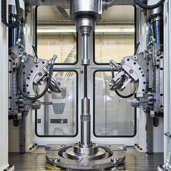
Tool-Changing Shear Forming Machine: A flow forming machine is a type of metalworking equipment used to shape and form thin-walled tubular or conical parts, usually from sheet metal or metal billets. The process, known as flow forming (or rotary swaging), involves rotating a workpiece at high speeds while applying radial forces to the material through rollers or tools. These forces cause the material to “flow” and shape into the desired form.
Key Features and Uses of Flow Forming Machines
- Precision and Strength: The flow forming process allows for the creation of complex, high-strength, and precise components, often used in industries such as aerospace, automotive, and energy.
- Applications:
- Aerospace: Flow forming is commonly used to produce parts like turbine blades, engine components, and lightweight structural elements.
- Automotive: It’s used for making precision components such as wheels, hubs, and parts for high-performance vehicles.
- Energy: Components such as pressure vessels, heat exchangers, and other parts for energy systems may also be made using flow forming.
- Process Steps:
- The machine typically uses rollers or dies that apply radial pressure to the rotating workpiece, thinning and elongating the material while it moves along its axis.
- The workpiece is usually clamped at both ends while rotating, and the material flows into the desired shape through repeated cycles.
- Advantages:
- Material Conservation: Since the material flows into shape rather than being cut away, waste is minimized.
- High Strength and Quality: The process improves material properties, especially in the case of metals, by aligning the grain structure in the direction of the forming.
- Cost-Effectiveness for High-Volume Production: Once set up, flow forming machines are well-suited for mass production, particularly for cylindrical or tubular components.
- Common Materials:
- Flow forming is used with a variety of metals including aluminum, titanium, steel, and nickel-based alloys, making it versatile for many industries.
Flow forming machines are highly versatile and efficient tools used for producing complex, thin-walled metal components. The process begins with a workpiece, often in the form of a tube or billet, which is mounted onto a rotating spindle. The machine uses rollers or dies to apply radial pressure to the material, causing it to deform and gradually take on the desired shape. This shaping process can result in parts that are not only precise in their dimensions but also exhibit enhanced material strength, thanks to the realignment of the metal’s grain structure during deformation.
One of the standout features of flow forming is its ability to create parts with uniform wall thickness and high structural integrity, making it ideal for industries that require high-performance materials. For example, aerospace companies use flow forming to produce turbine blades and structural components that need to withstand extreme forces and temperatures. The automotive industry also benefits from this process, especially in the production of lightweight, strong components such as wheels, hubs, and fuel tanks. In the energy sector, flow forming machines are used to make components for power plants, including pressure vessels and heat exchangers, where both strength and durability are crucial.
The machine’s operation is relatively straightforward. Once the workpiece is securely mounted, the rollers move radially toward the center, applying pressure as the piece rotates. As the material flows, it elongates and thins, with the machine operator adjusting the rollers to control the final shape and dimensions of the piece. The precision of the machine allows for a high degree of control, which is vital for creating parts with exacting tolerances.
This process is particularly beneficial for producing parts from high-performance metals, such as titanium or nickel alloys, which are difficult to work with using traditional machining methods. By using flow forming, manufacturers can conserve material, as the process is highly efficient and generates minimal waste. Additionally, because the material is being shaped rather than cut away, it reduces the risk of material defects like cracking or warping.
While flow forming is a great choice for mass production, it is also flexible enough to handle custom, one-off components. The machine’s adaptability allows for changes in part size and shape during production, making it ideal for industries that require a range of sizes or specialized shapes.
Flow forming continues to be an important manufacturing process, especially as industries push for higher material efficiency and performance. The technology behind these machines has evolved significantly, and today’s flow forming equipment is designed to handle a broader range of materials, including advanced alloys and composites. The core principles of the process remain the same, but innovations in automation, control systems, and tooling have made the machines even more precise and versatile.
Modern flow forming machines typically feature advanced CNC (computer numerical control) systems, which allow for highly accurate control over the forming process. These systems enable operators to input detailed specifications for the part being produced, and the machine adjusts its settings accordingly, ensuring each part meets the desired specifications with minimal human intervention. This reduces the potential for error and makes it possible to maintain high-quality output over long production runs.
One of the key advancements in flow forming is the integration of multi-roll forming. Traditional flow forming machines might use two or three rollers to apply force to the workpiece, but newer designs often incorporate more rollers, which can simultaneously apply pressure from different angles. This results in more consistent deformation and can be particularly helpful when producing parts with complex geometries or varying thicknesses.
Additionally, advances in material handling have made flow forming machines capable of processing larger or more difficult-to-handle workpieces. For example, some systems can automatically load and unload material from the machine, reducing manual labor and improving throughput. This automation is especially useful in high-volume production environments, where speed and efficiency are key.
Another trend is the integration of real-time monitoring systems. These systems allow for continuous observation of the forming process, checking for variables like temperature, pressure, and material strain. By tracking these metrics in real-time, manufacturers can adjust the process on the fly to prevent defects and ensure the final product meets stringent requirements.
Flow forming also has applications in the production of parts with specialized surface finishes. The material flow during the forming process can lead to a smooth, defect-free surface, which is particularly beneficial for parts that will be exposed to harsh environments or need to meet strict aesthetic standards. In industries like aerospace, where surface integrity is critical, this can save significant time and cost compared to secondary finishing processes.
Despite its numerous advantages, flow forming isn’t suitable for every application. The process is primarily used for parts that are cylindrical, conical, or have other rotational symmetries. Non-rotational geometries or highly irregular shapes are less suitable for flow forming, as the process relies on the rotational movement of the workpiece to create the desired form. In such cases, traditional machining techniques like CNC milling or casting might be more appropriate.
Additionally, while flow forming can create parts with uniform thickness and enhanced material properties, there are limits to the complexity of shapes that can be achieved without additional tooling or processing. Some designs may require hybrid manufacturing approaches, combining flow forming with other methods such as welding or machining to achieve the final product.
For companies looking to integrate flow forming into their operations, the key considerations typically include the upfront investment in the machine, tooling costs, and the training required to operate the equipment efficiently. However, once established, the process offers significant cost savings in material waste, labor, and post-production finishing.
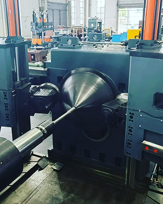
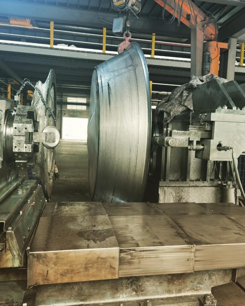
Horizontal Flow Forming Machine
A horizontal flow forming machine is a specific type of flow forming equipment where the workpiece is rotated horizontally during the forming process, as opposed to the traditional vertical setup. This type of machine is typically used for creating long, cylindrical, or conical parts where the piece is rotated around its horizontal axis while radial pressure is applied through rollers or dies.
Key Features of Horizontal Flow Forming Machines:
- Horizontal Setup: In a horizontal flow forming machine, the workpiece is horizontally mounted, and the rollers are positioned to apply radial pressure as the workpiece rotates. The horizontal orientation can provide better handling for certain workpiece shapes and is often more stable when dealing with larger, heavier parts.
- Process Flexibility: Horizontal machines are often better suited for larger or longer components compared to vertical machines. This makes them ideal for manufacturing items like pipes, tubes, or aerospace components that require precision shaping over longer lengths.
- Enhanced Material Control: The horizontal position of the workpiece allows for more effective control over material flow, particularly when producing long or thin-walled components. This orientation can help to reduce the risk of material sagging or misalignment, which can sometimes occur in vertical machines with longer pieces.
- Automated Systems: Many modern horizontal flow forming machines are equipped with advanced CNC controls, which allow for precise adjustments to the rollers and tooling. Automation helps optimize the forming process and reduces the chance of operator error, leading to higher consistency and quality in production.
- Larger Workpieces: Horizontal flow forming machines are often chosen for applications where the workpieces are larger or need to maintain a uniform thickness over a longer length. Parts like cylindrical structures for aerospace or energy industries can be effectively produced using this setup.
- Versatile Rollers: Horizontal flow forming machines often use multi-roll setups (three or more rollers) that work in tandem to apply pressure at various angles to ensure that the material is evenly shaped. This helps in reducing material distortion and ensures that the final part is within tight tolerances.
Common Applications:
- Aerospace: Horizontal flow forming is used for producing larger components such as turbine casings, compressor housings, or other structural elements. These parts often need to maintain a consistent shape and strength, which is achievable through the flow forming process.
- Automotive: Parts like wheel rims, hubs, and other high-performance components are produced using horizontal flow forming machines, especially in high-volume manufacturing.
- Energy: Large, high-pressure components like pressure vessels, heat exchangers, and even parts used in nuclear or hydroelectric power plants are made using horizontal flow forming, where material integrity and strength are key.
- Heavy Industry: Horizontal flow forming is also used in manufacturing components that require high precision and strength, like pipes and large industrial bearings.
Advantages:
- Greater Stability and Precision: The horizontal configuration provides stability, especially for larger, heavier parts, which minimizes deflection and improves dimensional accuracy during the forming process.
- Higher Throughput: Horizontal machines are often designed to handle larger workpieces in a more efficient manner, leading to higher throughput in production runs.
- Reduced Material Waste: Like other flow forming processes, horizontal flow forming is highly efficient in material usage, reducing scrap and making it a cost-effective option for producing large quantities of parts.
- Enhanced Part Quality: The ability to use multiple rollers ensures a smoother surface finish and more uniform material properties, which are crucial for high-performance parts that undergo extreme stresses.
Challenges:
- Size Limitations: While horizontal flow forming machines excel with larger and longer parts, there are still size limits based on the machine’s capacity. Extremely large or heavy components may require custom solutions or specialized equipment.
- Setup Complexity: Due to the larger scale of the parts being formed, horizontal flow forming setups can be more complex to calibrate and maintain, requiring skilled operators and potentially longer setup times.
- Tooling Wear: With larger parts and longer production runs, tooling wear can become more pronounced, leading to increased maintenance needs and the potential for more frequent tool replacement.
Horizontal flow forming is especially valuable when dealing with larger parts that require high precision and uniformity, making it ideal for industries like aerospace, automotive, and energy. If you’re interested in specific models or technical considerations for a particular application, let me know, and I can help further!
A horizontal flow forming machine is designed to rotate workpieces horizontally, providing a stable setup for forming larger or longer components. This orientation allows for precise control of material flow, especially useful for cylindrical, tubular, or conical parts that need to maintain consistent thickness and shape over extended lengths. The machine uses rollers positioned to apply radial pressure to the rotating workpiece, which causes the material to elongate and thin in the desired shape. The horizontal positioning provides advantages in terms of stability, as it helps prevent sagging or misalignment in longer pieces, ensuring the production of high-precision parts. Horizontal flow forming is commonly used in industries like aerospace, automotive, and energy for manufacturing large components, such as turbine casings, pipes, pressure vessels, and structural elements. The machine setup often includes automated systems, such as CNC controls, for precise adjustments, enhancing production efficiency and part quality. In some advanced machines, multiple rollers may be used to apply force from various angles, allowing for smoother surface finishes and reducing material defects. The process is material-efficient, reducing waste compared to traditional machining methods, which is particularly beneficial for high-performance materials like titanium, aluminum, and nickel alloys. Horizontal flow forming machines are ideal for parts that require both strength and precision, such as aerospace components subjected to extreme forces. However, these machines can be complex to set up and maintain, particularly when handling very large or heavy workpieces. Tooling wear is also a consideration for long production runs, requiring periodic maintenance and replacement. Despite these challenges, the horizontal configuration offers higher throughput and more stable production for large-scale manufacturing runs, making it a go-to solution for industries where size and precision are key factors.
Horizontal flow forming continues to be an important method for the production of large, high-precision components. One of the main advantages is its ability to handle larger and heavier workpieces with greater stability. The horizontal orientation reduces the risk of part distortion, which can sometimes occur in vertical machines when dealing with long, thin-walled parts. The ability to apply uniform radial pressure across a longer workpiece also ensures that material flow is more consistent, resulting in more uniform wall thickness and better part integrity.
In addition to handling larger parts, horizontal flow forming machines offer improved efficiency in certain applications. For example, the process is well-suited for making cylindrical or conical components, where the material is continually shaped without excessive material removal. This results in less waste compared to traditional machining techniques that rely on cutting or milling. By eliminating much of the material removal process, flow forming can produce components faster and with greater material conservation, making it cost-effective for large production volumes.
Horizontal flow forming also allows for high levels of customization. With advanced CNC systems and adjustable tooling, manufacturers can produce parts with varying wall thicknesses, diameters, or taper angles, providing the flexibility to meet specific design requirements. This adaptability makes horizontal flow forming suitable for industries where part geometries are not standard and require precise, customized solutions. Furthermore, because the process allows for continuous shaping and thinning of the material, parts can often be produced with enhanced mechanical properties, such as improved strength and resistance to fatigue, due to the alignment of the grain structure in the material.
As technology continues to advance, modern horizontal flow forming machines are becoming more automated and integrated with real-time monitoring systems. These systems track key process parameters such as temperature, pressure, and material strain, ensuring that the part meets strict quality standards. This capability reduces the likelihood of defects and ensures that any issues can be detected and addressed during production, improving both product quality and operational efficiency.
Despite these advantages, horizontal flow forming isn’t suitable for every type of part. The process is most effective for parts with rotational symmetry or simple geometries. Complex or irregular shapes may still require additional manufacturing processes, such as machining or welding, to complete the part. Additionally, while horizontal flow forming machines can handle larger workpieces, they may still have size limitations based on the machine’s capacity. For extremely large parts, customized machines may be required.
Overall, horizontal flow forming represents a highly efficient and versatile solution for producing large, precise, and strong components in industries where material efficiency, part strength, and quality are paramount.
Multi-Spindle Flow Forming Machine

A multi-spindle flow forming machine is an advanced variation of the traditional flow forming equipment that utilizes multiple spindles or rollers to apply radial pressure to the rotating workpiece. This configuration allows for greater control over the forming process and enhances the machine’s ability to produce parts with more complex shapes, tighter tolerances, and higher efficiency in production. In essence, the use of multiple spindles enables simultaneous shaping from multiple directions, providing a more uniform distribution of forces and improving the overall quality and consistency of the parts.
Multi-spindle flow forming machines typically involve several rollers positioned around the workpiece, all of which rotate at different speeds or apply pressure from different angles. This multi-point application of force leads to several key benefits:
- Enhanced Precision and Uniformity: The simultaneous application of pressure from multiple spindles ensures that the material flows evenly in all directions, resulting in parts with consistent wall thickness and better mechanical properties. This is particularly beneficial when creating parts that need to meet stringent dimensional tolerances and strength requirements.
- Increased Production Efficiency: Because multiple spindles can be used to shape a part simultaneously, the forming process is often faster than single-spindle systems, which typically require more cycles to achieve the same result. This increased efficiency can significantly reduce production time and costs, especially for high-volume manufacturing.
- Ability to Form Complex Shapes: Multi-spindle flow forming allows for greater flexibility in terms of part design. The ability to apply pressure from different directions makes it possible to form more complex shapes that would be difficult or time-consuming to achieve with traditional flow forming machines. This makes the machine suitable for a wider range of industries, including aerospace, automotive, and energy, where components often have intricate geometries or require non-uniform wall thicknesses.
- Higher Strength and Material Integrity: The uniform application of pressure and the ability to adjust the roller settings in multi-spindle systems improve the material flow, reducing the likelihood of defects such as cracking or uneven wall thickness. Additionally, the process helps to align the metal grain structure in the direction of the material flow, resulting in parts that are stronger and more durable.
- Increased Flexibility and Adaptability: Multi-spindle flow forming machines are often equipped with CNC controls, which allow for precise adjustments to the rollers, spindles, and process parameters. This makes the machines adaptable to a wide range of part sizes, materials, and designs, increasing their usefulness for manufacturers that produce a diverse set of components.
Applications:
- Aerospace Industry: Multi-spindle flow forming machines are ideal for producing complex aerospace components like turbine casings, compressor housings, and structural elements, which require both strength and precision. The ability to form large, thin-walled parts with uniform thickness makes these machines a good fit for such high-performance applications.
- Automotive Industry: These machines can be used for creating lightweight, high-strength parts such as wheels, hubs, and suspension components, where precise control over the material’s properties is crucial.
- Energy Industry: Large parts used in power generation, such as pressure vessels, heat exchangers, and reactor components, benefit from the material conservation and strength-enhancing properties of multi-spindle flow forming.
Advantages:
- Faster Cycle Times: With multiple spindles working at once, the forming process becomes quicker, reducing cycle times and increasing overall production throughput.
- Better Quality Control: The simultaneous application of forces from multiple directions reduces the risk of defects and inconsistencies, ensuring that parts meet strict quality standards.
- Flexibility in Design: The ability to shape parts with more complex geometries makes the machine adaptable for a wider range of applications.
- Material Efficiency: Like traditional flow forming, multi-spindle machines minimize material waste, making them highly efficient and cost-effective, particularly in high-volume production.
Challenges:
- Higher Initial Investment: Multi-spindle flow forming machines typically require a higher initial investment than single-spindle systems due to the additional components and complexity.
- Maintenance and Tooling: With multiple spindles and rollers in operation, there may be more wear and tear on the tooling, leading to higher maintenance costs and more frequent tool replacements.
- Complex Setup and Calibration: Multi-spindle systems require precise calibration and setup to ensure that all spindles are working in sync and applying the correct amount of pressure. This can require skilled operators and may lead to longer setup times.
Overall, multi-spindle flow forming machines offer significant advantages in terms of efficiency, precision, and flexibility, particularly for industries that require high-performance parts with complex geometries. Their ability to produce parts with uniform thickness and enhanced material properties makes them a valuable tool in fields like aerospace, automotive, and energy.
A multi-spindle flow forming machine offers an advanced approach to the flow forming process by utilizing multiple spindles or rollers to apply radial pressure to a rotating workpiece simultaneously. This setup enhances the forming process, allowing for greater precision, efficiency, and the ability to produce more complex shapes compared to traditional single-spindle systems. The use of multiple spindles enables a more uniform distribution of force around the workpiece, leading to consistent wall thickness, stronger mechanical properties, and reduced material defects such as cracking or uneven deformation. The increased production speed is one of the key advantages, as multiple spindles can shape the part at once, reducing cycle times and increasing throughput for high-volume manufacturing. This increased efficiency makes multi-spindle flow forming particularly beneficial in industries like aerospace, automotive, and energy, where precision, part complexity, and material strength are critical. The ability to create parts with intricate geometries or varying wall thicknesses also makes multi-spindle systems highly versatile, allowing manufacturers to tackle a wider range of designs. The machines are often equipped with advanced CNC controls, which allow for fine adjustments to the rollers and spindles, improving adaptability to different materials, part sizes, and production requirements. While the initial investment in a multi-spindle system may be higher, the long-term benefits, such as faster production times, reduced material waste, and the ability to produce high-quality parts, make it a valuable addition to many manufacturing operations. However, the complexity of these machines can lead to higher maintenance costs, as the increased number of spindles and tooling requires more attention to prevent wear and tear, as well as careful calibration to ensure consistent operation. Despite these challenges, the multi-spindle flow forming machine remains a powerful tool for producing high-performance, precision parts across a range of industries.
The versatility of multi-spindle flow forming machines is further highlighted by their ability to handle a wide variety of materials. These machines are often used to form metals like titanium, aluminum, steel, and other high-performance alloys, which are essential in industries that require materials with specific mechanical properties. The ability to work with such materials, combined with the multi-point application of pressure, ensures that the final parts maintain high strength and durability, making them suitable for high-stress environments, such as aerospace engine components or automotive suspension parts.
The process also benefits from the material’s ability to flow in a controlled manner, which not only reduces waste but also ensures that the material’s grain structure is aligned in the direction of forming. This alignment enhances the mechanical properties of the finished part, improving its resistance to fatigue and extending its service life. These properties are particularly valuable when producing components that must withstand cyclical loading or harsh conditions, such as parts for gas turbines, compressors, or pressure vessels.
Moreover, multi-spindle flow forming machines excel at creating parts that need precise surface finishes. The process tends to produce smooth, defect-free surfaces due to the gradual and controlled deformation of the material. This is an advantage in industries like aerospace, where surface integrity is critical for part performance. It can also minimize the need for secondary finishing processes, reducing costs and lead times.
While the process offers numerous advantages, it’s important to note that the complexity of multi-spindle systems requires a high level of expertise in machine operation and maintenance. The setup, calibration, and operation of these machines demand skilled technicians to ensure that all spindles are synchronized and applying the correct amount of pressure. This ensures the machine runs optimally and minimizes the risk of defects.
Another challenge is the tooling wear, especially in high-volume production settings. With multiple spindles working on the part simultaneously, the wear on the rollers or spindles can be higher, necessitating regular inspection and maintenance. This is a consideration for manufacturers when evaluating the long-term costs of operating a multi-spindle flow forming system. However, the overall benefits, including the reduction in material waste, increased production speed, and enhanced part quality, often outweigh these challenges.
For companies seeking to remain competitive in industries where performance and precision are non-negotiable, multi-spindle flow forming represents a powerful manufacturing solution. The ability to produce complex, high-strength components with minimal material waste and a high level of precision makes these machines indispensable in fields where part integrity and production efficiency are paramount. As technology advances, we may see further refinements in multi-spindle flow forming systems, allowing for even greater control over the process, improved automation, and the ability to handle an even broader range of materials and part geometries.
Single-Spindle Flow Forming Machine
A single-spindle flow forming machine is a more traditional form of flow forming equipment where a single rotating spindle or roller is used to apply radial pressure to a rotating workpiece. This machine setup is typically used for producing cylindrical, conical, or other rotationally symmetric parts. The spindle rotates the workpiece, while the roller applies controlled pressure, gradually forming the material into the desired shape. The process involves a combination of high-speed rotation and localized deformation, which causes the material to elongate and thin while maintaining a uniform structure.
Single-spindle flow forming machines are ideal for producing parts that do not require the complexities of multiple-directional pressure or intricate geometries. They are especially suitable for creating parts with consistent wall thickness and smooth surface finishes. The simplicity of the design makes single-spindle systems easier to operate and maintain compared to multi-spindle machines, which often require more precise calibration and synchronization between rollers.
These machines are commonly used in industries such as aerospace, automotive, and energy for producing components like turbine blades, wheels, cylinders, hubs, and other parts that need to be lightweight yet strong. The process allows for high material efficiency, minimizing waste and reducing costs associated with material handling. The single-spindle machine is effective for producing parts from high-performance alloys, such as titanium, aluminum, and steel, which require precise control over material flow to achieve the desired mechanical properties.
One of the advantages of single-spindle flow forming is that it can handle a wide variety of materials with relative ease, offering flexibility in terms of material selection. The process is less complex than multi-spindle systems, which can make it more cost-effective for smaller production runs or custom parts. The process also generates less heat than traditional forging or casting methods, reducing the risk of material defects related to thermal stress.
However, single-spindle flow forming is generally better suited for parts with simpler geometries or those that need to be uniform in shape. The limitation of a single spindle means that the system may be less effective for parts with complex or intricate features that require shaping from multiple directions. Additionally, while the machine is capable of producing high-quality parts, it may not achieve the same level of efficiency and precision as a multi-spindle machine when producing high volumes of parts with varying shapes.
Despite these limitations, single-spindle flow forming remains an essential tool in the manufacturing of high-precision, strong, and lightweight parts, particularly for applications that do not require the additional complexity of multiple spindles. The simplicity of the system, combined with its ability to produce high-quality parts with minimal material waste, makes it an effective solution for a range of industries, particularly where part volume is moderate, and cost efficiency is a key factor.
Single-spindle flow forming machines are ideal for producing parts where simplicity and cost-effectiveness are prioritized. While these machines may not have the versatility or speed of multi-spindle systems, they excel in creating parts with consistent shapes and uniform material distribution, especially for cylindrical or conical components. The process involves applying pressure from a single roller, which gradually deforms the material as the workpiece rotates, allowing it to achieve the desired geometry. This method is highly effective for parts like tubes, wheels, and structural components in the aerospace, automotive, and energy sectors. The main advantage of single-spindle flow forming lies in its ability to produce high-quality parts with minimal material waste. This is especially beneficial for expensive materials like titanium or high-strength alloys, where conserving material is crucial. The simplicity of the system also translates to easier setup, operation, and maintenance, which makes it a more cost-effective option for low- to medium-volume production. Though it lacks the multi-directional shaping capabilities of more advanced machines, the single-spindle system is highly efficient for parts that require uniform thickness and high mechanical integrity. Furthermore, this machine type is adaptable to a range of materials, allowing manufacturers to process a variety of alloys and composites with precision. While single-spindle flow forming machines are not ideal for highly complex shapes, they are widely used in applications that demand reliability, strength, and high dimensional accuracy.
Despite its more straightforward design, single-spindle flow forming can still produce parts with impressive mechanical properties due to the way the material is formed. The controlled radial pressure applied during the process aligns the material’s grain structure in the direction of flow, which can enhance the part’s strength and resistance to fatigue. This is particularly beneficial in applications where the component will undergo repeated stresses or high-impact loads, such as turbine casings or automotive wheels. Additionally, because the material is progressively shaped rather than cut or machined, the flow forming process can reduce the likelihood of internal defects, like porosity or cracks, which can sometimes occur in casting or traditional machining.
While the system is best suited for parts with simpler geometries, it is also capable of producing parts with good surface finishes. The smooth, consistent deformation of the material during forming minimizes the need for additional finishing steps, which can reduce both the time and cost associated with post-processing. In cases where the surface finish is critical, some post-forming processes, like light machining or polishing, can still be applied, but the need for these steps is typically reduced compared to traditional manufacturing methods.
Another benefit of single-spindle flow forming is its material efficiency. Since the process involves minimal material waste, manufacturers can maximize the usage of expensive materials, reducing production costs over time. This is particularly important for industries dealing with rare or costly alloys, where material cost plays a significant role in the overall production cost. The process can also accommodate materials that are difficult to machine or shape using other methods, further increasing its value in certain high-performance applications.
However, the limitations of single-spindle flow forming should not be overlooked. The inability to apply pressure from multiple angles means that the machine might struggle with parts that require non-uniform thicknesses or highly complex shapes. Parts that feature intricate geometries or require specific features that are difficult to achieve with radial pressure alone may need additional processes such as welding or machining, which adds to the overall cost and complexity of the manufacturing process. Additionally, while the single-spindle system is capable of high precision, it may not be as suitable for mass production compared to multi-spindle systems, which can handle larger volumes and more complex part requirements at a faster rate.
Overall, single-spindle flow forming remains a valuable process for manufacturers producing medium to large quantities of relatively simple parts where material strength, precision, and cost-effectiveness are key priorities. Its ability to deliver high-quality, consistent parts with minimal waste and reduced finishing requirements makes it an ideal choice for many industries, even though it may not be suitable for all types of geometries or highly complex components.
Single-spindle flow forming machines, while simpler in design than their multi-spindle counterparts, are a highly effective tool in many industrial applications where part geometry is relatively straightforward, and material efficiency is a priority. These machines apply radial pressure from a single rotating spindle to shape a workpiece that is also rotating. As the spindle pushes the material outward, the metal gradually thins and elongates to form the desired shape. One of the most significant advantages of this process is its ability to maintain precise control over the material, ensuring uniformity in wall thickness and a consistent final shape.
The simplicity of the single-spindle design makes these machines relatively easy to operate and maintain. With fewer moving parts compared to multi-spindle systems, single-spindle flow forming is less complex to set up and calibrate. This characteristic makes it an appealing choice for smaller manufacturers or those with lower production volumes. Additionally, these machines tend to have lower capital costs than multi-spindle systems, making them a more accessible option for companies looking to adopt flow forming without a large upfront investment.
One of the standout features of single-spindle flow forming is its ability to produce components with excellent material efficiency. Since the process works by gradually deforming the material rather than cutting or machining it, much less material is wasted. This makes it an ideal method for working with expensive materials, such as titanium, high-strength alloys, or specialty metals, which are commonly used in aerospace, automotive, and energy industries. In these sectors, where material costs are often a significant portion of overall manufacturing expenses, the ability to minimize waste is an essential benefit. The reduction in material waste also means that manufacturers can reduce overall production costs and improve their bottom line.
The process also offers benefits in terms of the mechanical properties of the finished parts. As the material is deformed in a controlled manner, the grain structure is aligned along the direction of flow. This alignment typically results in improved material strength and fatigue resistance, particularly in high-stress applications. Parts such as turbine blades, pressure vessels, and automotive wheels often require excellent strength-to-weight ratios, and single-spindle flow forming can provide these characteristics. The gradual deformation process helps to avoid the introduction of internal defects, such as porosity, cracks, or other flaws that might arise from traditional casting or forging methods. As a result, parts made through flow forming are often stronger and more reliable in their intended applications.
Additionally, single-spindle flow forming machines are well-suited for applications that require parts with consistent surface finishes. The material is shaped in a smooth and continuous flow, which can reduce the need for extensive post-processing or finishing work. While some parts may still require light machining or polishing to meet precise surface finish specifications, the flow forming process reduces the amount of additional labor and time required, which can be a significant advantage in a production environment.
Despite these benefits, single-spindle flow forming is not without its limitations. The main restriction of this method is its suitability for producing relatively simple, symmetrical parts. The process is most effective for components that have a cylindrical or conical shape, as these parts allow for the most efficient use of radial pressure. When it comes to more complex shapes, such as parts with highly irregular geometries, deep recesses, or non-symmetrical features, the single-spindle machine may struggle to achieve the desired results. In such cases, the part may require secondary operations, such as welding or additional machining, to complete its final shape, which can increase production time and costs.
Furthermore, while single-spindle flow forming is efficient for parts with uniform wall thickness, it may not be as effective for parts with varying thicknesses or complex internal features. In cases where parts need to have a tapered or varying wall thickness, a multi-spindle system, or additional post-forming processes may be necessary. Multi-spindle machines, with their ability to apply pressure from multiple directions, are better suited to handling parts with these types of geometries, but they come at a higher cost.
Another consideration is the machine’s speed. While single-spindle flow forming machines can produce parts at a relatively fast rate compared to traditional machining methods, they may not be as quick as multi-spindle systems, which can work on multiple areas of the part simultaneously. For high-volume production environments, the speed of a single-spindle system may limit its ability to compete with more complex, multi-spindle machines.
Despite these limitations, single-spindle flow forming remains an invaluable tool for many industries. The process is especially useful when manufacturing high-precision, lightweight components with excellent mechanical properties, such as those found in aerospace, automotive, and energy applications. Its material efficiency, ease of use, and cost-effectiveness make it particularly attractive for manufacturers that produce parts in moderate volumes or those that require high-performance materials but do not need the complexity or speed of multi-spindle systems. Furthermore, the ability to create parts with excellent strength-to-weight ratios and minimal internal defects positions single-spindle flow forming as a leading solution for producing robust, reliable components in critical industries.
In conclusion, single-spindle flow forming continues to play a crucial role in modern manufacturing, offering a balance of precision, efficiency, and material savings. It is particularly valuable in industries where strength, durability, and cost control are paramount. While its capabilities are best suited to simpler geometries, it remains a powerful tool for producing high-quality, lightweight components. As manufacturing technologies evolve, single-spindle flow forming machines will likely continue to see advancements, offering even greater precision, flexibility, and efficiency for manufacturers.
Vertical Flow Forming Machine
A vertical flow forming machine is a type of flow forming equipment that employs a vertical orientation of the workpiece and forming tools to apply radial pressure during the material shaping process. In contrast to horizontal flow forming machines, which position the workpiece horizontally, the vertical configuration offers distinct advantages in certain applications, especially in the handling of large, heavy, or vertically oriented components.
In a vertical flow forming system, the workpiece is typically mounted on a rotating spindle that is aligned vertically. The forming rollers or tools apply radial pressure to the rotating part, gradually shaping it into the desired geometry. This method can be used to create cylindrical, conical, or other rotationally symmetric shapes, similar to other types of flow forming, but with the added benefit of the vertical setup.
One of the primary advantages of a vertical flow forming machine is its ability to handle large, heavy workpieces more effectively. The vertical orientation provides greater stability and control during the forming process, especially when working with large-diameter parts. In a vertical setup, the forces are distributed more evenly across the workpiece, reducing the risk of distortion or deflection during the forming process. This stability is particularly important when working with materials that require high precision and strength, such as titanium or high-strength steel, which are commonly used in aerospace, automotive, and energy applications.
The vertical orientation also facilitates the handling of longer workpieces or parts with greater lengths. When parts need to be formed along their length, such as tubes, pipes, or other elongated shapes, the vertical setup ensures better alignment and more consistent shaping, as gravity helps to stabilize the part during the process. This configuration is particularly useful when working with parts that have a long axial direction, as it minimizes the risk of sagging or misalignment that can occur with horizontal machines, especially for heavier or larger components.
Vertical flow forming machines are particularly effective in applications where the workpieces need to be formed in a vertical direction due to their natural shape or end-use. For example, when creating large cylindrical or conical components like pressure vessels, turbine casings, and other high-performance parts, the vertical orientation allows for smoother material flow and easier material management. The process also benefits from gravity, as it assists in the natural downward flow of the material, reducing the chance of material buildup or deformation at the part’s top.
Additionally, vertical flow forming machines can be more compact in terms of their footprint. The vertical setup allows for a more efficient use of floor space, which is particularly beneficial in manufacturing environments where space is limited. This can result in better layout optimization within production facilities, especially in large-scale manufacturing operations where maximizing floor space is a priority.
However, like all flow forming systems, vertical machines are primarily suited for parts that are rotationally symmetric or have relatively simple geometries. While they can achieve impressive results in forming cylindrical and conical shapes, more complex parts with irregular geometries may require additional processing or a different type of machine. Moreover, the vertical design can introduce challenges in terms of tool accessibility and part handling, especially for very large or heavy components. Additional equipment, such as cranes or specialized fixtures, may be required to load and unload workpieces efficiently.
Another consideration with vertical flow forming is the initial investment and maintenance costs. While the machine’s compact footprint may offer cost benefits in terms of space utilization, vertical flow forming systems may still require significant investment due to the precision and complexity involved in manufacturing large, high-quality parts. Additionally, maintenance can be more challenging compared to horizontal systems, as the vertical setup may necessitate specific maintenance procedures for proper machine operation and tool alignment.
Despite these considerations, vertical flow forming remains a powerful tool for producing high-precision, large-scale components with excellent mechanical properties. The combination of material efficiency, precision, and the ability to handle large workpieces makes vertical flow forming particularly valuable in industries such as aerospace, energy, and heavy equipment manufacturing. As with other types of flow forming, the process also results in reduced material waste, helping manufacturers improve both sustainability and cost-effectiveness.
In conclusion, vertical flow forming machines offer several advantages in terms of handling large, heavy workpieces, improving stability and precision during the forming process. Their ability to create high-strength, uniform parts with minimal material waste makes them essential for applications that require high performance and reliability. While their primary use is for parts with simple, rotationally symmetric geometries, vertical flow forming is an invaluable technique in industries that demand large, high-quality components with specific material properties. As manufacturing technologies continue to evolve, the vertical flow forming machine is likely to remain a key tool in the production of precision-engineered parts.
Vertical flow forming machines provide a unique advantage in producing large, heavy, or long parts that require high precision and strength. The vertical orientation of the machine allows for better distribution of forces across the workpiece, which minimizes the risk of distortion and deflection, especially for large-diameter or heavy components. This setup is particularly beneficial in industries such as aerospace, energy, and automotive, where components need to maintain their integrity under high stress and in demanding environments. The ability to work with large parts, such as turbine casings, pressure vessels, or large pipes, is another key benefit. Since gravity assists in the downward flow of material, it helps to stabilize the part and ensures a smoother and more consistent deformation process. In cases where workpieces are long or require shaping along their length, like tubes or pipes, the vertical configuration ensures better alignment and reduces the chances of misalignment or sagging that can occur with horizontal machines. Moreover, vertical machines are often more compact in terms of their footprint. This allows for a more efficient use of space in manufacturing environments, which is an important consideration in large-scale operations where floor space is at a premium. Despite the advantages, vertical flow forming machines are primarily suitable for simpler, rotationally symmetric shapes, as more complex geometries may require additional post-processing or other manufacturing techniques. The complexity of handling large or heavy workpieces also means that additional equipment, such as specialized fixtures or cranes, may be needed for loading and unloading, adding another layer of logistical consideration. While vertical machines are advantageous in some cases, they can also have higher initial investment costs, particularly when the machines are designed for high precision and large parts. Maintenance of these systems can also be more complex, requiring specific procedures to ensure proper alignment and tool maintenance. However, the benefits of vertical flow forming—such as material efficiency, part quality, and the ability to handle large-scale components—make it an invaluable technique in industries where high-strength, precision-engineered parts are required.
The vertical flow forming machine’s design inherently offers improved material handling, especially when dealing with larger and heavier components. Its orientation allows for easier gravity-assisted alignment, ensuring the part is stable throughout the forming process, which is crucial for parts that need to maintain precise tolerances and structural integrity under load. This is particularly important in the aerospace and energy industries, where components like large turbine casings, pressure vessels, or structural supports require flawless mechanical properties, uniform wall thickness, and strength-to-weight ratios.
Another key benefit of vertical flow forming is its ability to produce complex parts without the need for extensive secondary operations. Since the material is deformed gradually and uniformly, the need for further machining or finishing steps is often minimized. This can significantly reduce production time and cost. For manufacturers producing components with long lead times or high-performance material requirements, vertical flow forming presents a compelling alternative to traditional methods like forging, casting, or machining, all of which can be more resource-intensive and slower.
Vertical machines also shine in applications where part orientation is crucial. Certain components, such as pipes, tubes, and cylindrical structures, benefit from being formed vertically as they naturally align with the forming direction. This minimizes the potential for material distortion that might occur if formed horizontally, where the gravitational pull could affect the part’s stability, especially when dealing with long or heavy workpieces.
In terms of operational flexibility, vertical flow forming machines can be equipped with advanced CNC (Computer Numerical Control) systems that allow for fine-tuned adjustments in pressure, speed, and roller positioning. This level of precision ensures that each part meets exact specifications, which is crucial for industries where tolerances are tight, and the cost of failure is high. For example, in the aerospace industry, where every component must meet stringent quality standards to ensure safety and performance, vertical flow forming’s ability to produce high-strength, defect-free parts with minimal material waste is invaluable.
While vertical flow forming machines have many advantages, they also come with certain challenges. The complexity of handling large, heavy parts requires a more sophisticated approach to workpiece loading and unloading, which often necessitates the use of specialized cranes, automated loaders, or robotic systems. This can add to the overall system complexity and cost. Additionally, vertical systems may require custom tooling or fixtures to ensure the part is properly secured and oriented during the process. Maintenance of the machine also requires careful attention to ensure that the vertical alignment is preserved and that all components are functioning smoothly.
Moreover, as with any flow forming machine, the suitability of vertical flow forming is primarily for parts that are rotationally symmetric or have simple, linear geometries. While it excels in forming cylindrical or conical components, more intricate designs may require additional processing or a different manufacturing approach. As industries continue to evolve and demand more complex and diverse parts, manufacturers may need to consider hybrid approaches that integrate flow forming with other methods, such as additive manufacturing, to meet these needs.
Despite these challenges, vertical flow forming remains an essential process for industries that require large, high-performance components. Its ability to efficiently form large, heavy parts with high precision and minimal material waste makes it a valuable tool in production environments focused on quality, efficiency, and material conservation. With continued advancements in automation, tooling, and machine design, vertical flow forming is likely to remain at the forefront of manufacturing technologies, particularly in sectors where component integrity and strength are non-negotiable. As manufacturers increasingly look for ways to streamline production while reducing costs, vertical flow forming will continue to be a key player in producing complex, high-strength components for a variety of applications.
Mechanical Flow Forming Machine
A mechanical flow forming machine is a type of flow forming equipment that uses mechanical force to shape metal workpieces into specific geometries. Unlike other flow forming machines that may use hydraulic or electrical drives, mechanical flow forming machines rely on mechanical drives, often involving gears, levers, or cams to transfer force to the workpiece. This method provides precise control over the forming process and is widely used for producing cylindrical, conical, and rotationally symmetric components.
In mechanical flow forming, the workpiece is placed on a rotating spindle, and rollers are used to apply pressure to the material. As the workpiece rotates, the rollers gradually shape the material, causing it to elongate and thin while maintaining its structural integrity. This process allows for the creation of parts with consistent wall thicknesses and high-dimensional accuracy, making it ideal for applications in industries like aerospace, automotive, and energy, where precision and material performance are critical.
One of the significant advantages of mechanical flow forming machines is their ability to deliver high precision and repeatability, which is essential when manufacturing parts with tight tolerances. The mechanical systems used in these machines allow for fine control over the applied force, rotational speed, and roller position, ensuring that each part is formed according to the required specifications. This control also minimizes material waste, as the metal is shaped rather than cut away, which can be particularly beneficial when working with high-cost materials like titanium, aluminum, or specialty alloys.
Mechanical flow forming machines are also known for their durability and reliability. Because they do not rely on hydraulic fluid systems or complex electrical components, they tend to have fewer maintenance requirements and can operate in harsh environments with less risk of breakdown. This makes them suitable for high-volume manufacturing or for operations in industries where downtime must be minimized.
Another benefit is that mechanical flow forming is highly efficient in terms of energy consumption. Since the mechanical system operates based on physical force, it typically consumes less energy than hydraulic systems, which require high-pressure pumps to generate force. This energy efficiency can translate into lower operational costs, making mechanical flow forming machines more cost-effective over the long term, particularly for manufacturers producing parts at scale.
Mechanical flow forming is especially beneficial when producing parts with consistent wall thickness and high strength. Since the material is continuously deformed, the grain structure of the metal is aligned in the direction of the flow, improving the strength of the final component. This is particularly advantageous for parts that need to withstand high stresses or impacts, such as turbine casings, automotive wheels, and pressure vessels. The mechanical flow forming process enhances the material’s fatigue resistance, which is critical in applications where components are subject to repeated loading or harsh operational conditions.
While mechanical flow forming machines offer numerous advantages, they do have limitations. The primary drawback is that they are best suited for parts with simple, rotationally symmetric geometries. More complex shapes with varying thicknesses or intricate features may require additional processing or a different type of machine. For example, parts with non-circular cross-sections or those that require features like internal threads or irregular surfaces may not be ideal candidates for mechanical flow forming.
Additionally, while mechanical systems are generally more durable and require less maintenance than hydraulic or electrical systems, they can still be subject to wear and tear, particularly in the gears, rollers, and other moving parts. Regular maintenance is essential to ensure the machine continues to operate at peak efficiency, and excessive wear could lead to issues with part quality or consistency.
Mechanical flow forming is also typically slower than some other flow forming methods, especially when compared to high-speed hydraulic systems. While this may not be an issue for certain applications or lower-volume production runs, it could limit the machine’s efficiency in high-volume manufacturing environments, where rapid cycle times are essential.
Despite these limitations, mechanical flow forming machines remain a valuable tool for producing high-quality, high-precision components. Their durability, energy efficiency, and ability to create strong, lightweight parts make them a popular choice in industries such as aerospace, automotive, and heavy machinery. The versatility and reliability of mechanical flow forming machines continue to make them an integral part of modern manufacturing, particularly in applications that prioritize precision, material conservation, and long-term operational efficiency.
Mechanical flow forming machines are a cornerstone of modern manufacturing for industries that demand precision, durability, and material efficiency. The mechanical drive systems, often consisting of gears, cams, or levers, offer a reliable and cost-effective method of shaping materials without the complexity of hydraulic systems. This simplicity leads to a more durable system that can operate in environments with less risk of mechanical failure due to the absence of complex hydraulic or electrical components. These machines excel in creating high-precision, rotationally symmetric parts, which makes them ideal for industries like aerospace, automotive, and energy, where tolerances and material performance are critical.
The use of mechanical force in flow forming allows for better control over the shaping process, ensuring consistent wall thickness and tight tolerances throughout the entire production run. This precision is particularly important when dealing with high-performance materials like titanium or advanced alloys, which are commonly used in high-stress applications. The inherent energy efficiency of mechanical flow forming systems is another advantage. Compared to hydraulic machines, which consume significant amounts of energy due to high-pressure systems, mechanical machines require less power to operate, reducing operational costs. This lower energy consumption translates into cost savings, especially in environments where large quantities of parts need to be produced. However, the trade-off is that mechanical flow forming is not ideal for parts with complex, non-symmetrical geometries. The process is primarily suited for simple shapes such as cylindrical, conical, or spherical parts.
Complex features like internal threads, irregular cross-sections, or intricate surface details might require additional post-processing or a different manufacturing method. While these machines provide reliable, high-quality results for standard parts, their limitations become evident when parts need features that extend beyond the capabilities of a simple radial deformation. Furthermore, while the mechanical drive systems are robust and require less maintenance than their hydraulic counterparts, regular care is still necessary to prevent excessive wear on gears, rollers, and other moving parts. Over time, these components can experience wear that affects the machine’s performance, leading to potential inconsistencies in part quality or operational slowdowns.
Despite these challenges, mechanical flow forming machines remain invaluable for industries that require large quantities of precise, strong, and lightweight components. Their ability to reduce material waste by gradually forming the part rather than cutting away excess material makes them highly efficient, especially when working with expensive or high-performance materials. The consistent, uniform parts produced by mechanical flow forming are crucial for applications where the structural integrity and fatigue resistance of the part are paramount, such as turbine casings, pressure vessels, and certain automotive components. In conclusion, mechanical flow forming machines provide an excellent balance of precision, efficiency, and durability, making them an ideal choice for producing high-quality, high-performance parts in industries where material integrity and cost-effectiveness are critical. While they are best suited for simpler, rotationally symmetric parts, their ability to produce strong, lightweight components with minimal material waste makes them a valuable asset to modern manufacturing processes.
The versatility of mechanical flow forming machines extends beyond their efficiency and durability, especially when considering their role in the production of critical components in various high-demand industries. For example, in aerospace, these machines are used to produce turbine components, compressor casings, and aerospace structural elements that must meet the highest safety and performance standards. The ability of mechanical flow forming machines to create these parts with excellent fatigue resistance and uniform strength across the material is a vital factor in ensuring the reliability of components that are exposed to extreme conditions, such as high temperatures, pressure fluctuations, and mechanical stresses.
In the automotive industry, mechanical flow forming is similarly valuable for manufacturing components like wheel rims, brake drums, and other high-performance parts that require a combination of strength, lightweight properties, and precise dimensional accuracy. The cost-effective material conservation of the process is particularly beneficial here, as it reduces waste while ensuring that the parts can endure the demanding mechanical loads they face during their service life. The consistent thickness and enhanced mechanical properties offered by mechanical flow forming are also essential for components that need to be lightweight yet strong to contribute to overall vehicle efficiency and performance.
Another application where mechanical flow forming proves beneficial is in the energy sector, particularly in the production of pressure vessels, turbine housings, and casing components used in power generation, including gas and steam turbines. The process is well-suited for creating parts with high resistance to fatigue and stress, which is essential for the long-term operation of turbines that experience constant mechanical loads and thermal cycles. As energy production demands increasingly focus on high-efficiency and low-waste methods, the use of mechanical flow forming contributes to the reduction of raw material consumption and minimizes part failure risks in these critical systems.
Despite these advantages, the limitations of mechanical flow forming cannot be overlooked. As mentioned earlier, the process is most effective for simpler geometries—typically rotationally symmetric parts—limiting its flexibility in creating more complex or intricate shapes. Manufacturers looking to create parts with intricate internal features, varying thicknesses, or multi-axis deformations might need to explore alternative methods, such as additive manufacturing, casting, or more advanced multi-axis machining. The need for these alternative processes may result in a hybrid approach, combining flow forming with other manufacturing techniques to meet the exact specifications of more complex parts.
Furthermore, the speed of mechanical flow forming can be a limiting factor in high-volume production environments. Although the process is relatively efficient for small to medium-sized production runs, it might not match the throughput capabilities of other methods, such as high-speed stamping or casting, especially when used for simpler parts. However, for manufacturers focused on producing high-quality, low-to-medium-volume parts that require high material strength and precision, mechanical flow forming continues to be a reliable and efficient solution.
In addition, although mechanical flow forming systems are less maintenance-intensive compared to hydraulic systems, they still require careful attention to ensure long-term reliability. Regular maintenance schedules are necessary to ensure that moving components like gears, rollers, and spindles remain in optimal condition. Monitoring system performance, checking for wear on critical parts, and ensuring proper lubrication are all essential for maintaining the precision and consistency of the process. Any failure in these components could potentially result in part defects, delayed production timelines, and increased operational costs.
Despite these drawbacks, mechanical flow forming remains a key technology in manufacturing, especially in industries where precision, material efficiency, and part performance are paramount. As manufacturing technologies continue to evolve, the integration of automation, advanced sensors, and computer-controlled systems may further enhance the capabilities of mechanical flow forming machines. The addition of these technologies can improve real-time process monitoring, allow for better quality control, and potentially address some of the limitations in speed and part complexity.
In conclusion, mechanical flow forming is a reliable and efficient method for producing high-strength, precision-engineered parts, particularly in industries like aerospace, automotive, and energy. While its primary application is for simpler, rotationally symmetric components, the benefits of material efficiency, reduced waste, and enhanced mechanical properties make it an indispensable tool in modern manufacturing. As the demands for more complex and high-performance parts increase, mechanical flow forming is likely to evolve and integrate with other manufacturing technologies, further cementing its role in the production of high-quality, durable components for a wide range of applications.
Hydraulic Flow Forming Machine
A hydraulic flow forming machine utilizes hydraulic power to apply force to a rotating workpiece, deforming it into a desired shape through radial pressure. This type of flow forming machine is distinct from mechanical flow forming machines, which use mechanical drives, by relying on hydraulic cylinders and fluid systems to exert high levels of force, allowing for the formation of more complex shapes or larger parts with greater precision.
In hydraulic flow forming, the process begins with the workpiece being mounted on a rotating spindle. As the spindle turns, hydraulic cylinders with forming rollers are positioned around the workpiece. These rollers apply pressure to the material, gradually stretching and thinning it, creating cylindrical, conical, or other rotationally symmetric shapes. The force exerted by the hydraulic system can be finely controlled, enabling the production of parts with consistent wall thicknesses and tight tolerances.
The primary advantage of hydraulic flow forming machines is their ability to generate significantly higher forces than mechanical systems, making them well-suited for larger and more complex parts. Because the hydraulic system allows for precise control of the force and speed applied during the forming process, hydraulic flow forming is ideal for materials that require high deformation forces to shape, such as titanium, high-strength steels, and aluminum alloys. This makes hydraulic flow forming a go-to method for producing parts used in demanding applications, such as aerospace, automotive, and energy.
One of the most notable benefits of hydraulic flow forming is its versatility. Unlike mechanical systems, which may be limited by the force that can be applied through mechanical means, hydraulic systems can achieve much higher forces, making them more effective for forming large and thick-walled parts. This capability enables hydraulic flow forming to be used for a wide range of applications, from smaller, high-precision components like aerospace turbine casings and wheel rims to larger, thicker components like pressure vessels or large-diameter pipes.
The precision offered by hydraulic flow forming is also a significant advantage. By carefully controlling the force and speed of the rollers, manufacturers can achieve high levels of accuracy in the final product. The wall thickness can be maintained consistently throughout the part, and the geometry can be shaped to precise tolerances. This is particularly important in industries where the components need to meet stringent safety and performance standards, such as aerospace, energy, and defense.
Another advantage is the ability to work with a variety of materials. Hydraulic flow forming machines can handle a broader range of metals, including hard-to-form materials that require significant force for shaping. In addition, the process can be used to create parts with complex geometries, such as tapered or conical shapes, that might be difficult or impossible to achieve using mechanical flow forming methods. This flexibility allows for the production of more sophisticated parts without the need for additional tooling or processing.
However, hydraulic flow forming machines come with some challenges. The primary concern is the complexity of the hydraulic systems. These systems require regular maintenance to ensure that the fluid pressures remain stable and the cylinders are functioning properly. Hydraulic fluid leakage or contamination can also cause performance issues, so proper monitoring and maintenance procedures are critical. Additionally, the need for a hydraulic fluid reservoir and other associated components adds to the overall system’s complexity and maintenance requirements.
Another limitation is that hydraulic systems can be less energy-efficient than mechanical systems, particularly in high-speed production environments. The pumps and fluid systems used to generate hydraulic force consume significant energy, which can result in higher operational costs, especially if the machine is running at full capacity for long periods. However, for manufacturers that prioritize the ability to form large, complex parts with high precision, this trade-off may be worthwhile.
In addition, hydraulic flow forming machines can be larger and more expensive than mechanical systems, which may limit their use in smaller operations or for companies with limited space. The larger size of these machines often requires specialized facilities with sufficient floor space to accommodate them. The increased complexity of hydraulic systems can also result in higher initial investment and maintenance costs, making them more suitable for high-volume or high-performance manufacturing environments where the benefits of increased force and precision outweigh the costs.
Despite these challenges, hydraulic flow forming remains an essential technology in manufacturing, especially for high-performance industries where precision and material properties are crucial. The ability to create complex, high-strength components with minimal material waste makes hydraulic flow forming highly desirable for applications like aerospace turbine casings, pressure vessels, automotive wheels, and energy sector components. As technology advances, improvements in energy efficiency, system reliability, and automation will continue to make hydraulic flow forming more cost-effective and accessible for a broader range of manufacturers. The combination of high-force capabilities, precision, and material versatility ensures that hydraulic flow forming will remain a key process in the production of critical, high-quality components across various industries.
Hydraulic flow forming machines stand out for their ability to generate substantial force and handle more complex parts compared to mechanical flow forming machines. This makes them particularly advantageous for industries that demand precision and strength in large or thick-walled components. With the ability to exert significant pressure, hydraulic systems can shape materials that are difficult to form by other methods, such as high-strength alloys or specialized metals used in the aerospace, automotive, and energy industries. The versatility of hydraulic flow forming allows it to create parts with a variety of geometries, from simple cylinders to more intricate shapes like tapered and conical components. These machines also allow for greater flexibility in adjusting the forming force and speed, which is essential when working with different materials or creating parts with specific mechanical properties.
One of the major benefits of hydraulic flow forming is the precision it offers. Since the hydraulic system allows for fine control of the applied force, it enables manufacturers to produce parts with consistent wall thickness and dimensional accuracy. This precision is crucial in industries like aerospace, where parts like turbine casings, structural components, and engine parts need to meet extremely tight tolerances and withstand harsh operational conditions. Additionally, hydraulic flow forming is an energy-efficient process when compared to other high-force manufacturing methods like forging, as it avoids the need for high-speed operations while maintaining consistent force application throughout the forming process.
This energy efficiency helps reduce operational costs, especially in industries where the need for high-volume production of robust, precision-engineered parts is critical. Despite these advantages, hydraulic flow forming machines do require significant maintenance. Hydraulic systems are prone to wear and tear due to the high-pressure fluid dynamics involved, which means the system’s components must be monitored regularly for issues like fluid contamination, leaks, or pressure imbalances. Maintaining the hydraulic fluid at optimal levels and ensuring the seals and cylinders are functioning properly are essential for long-term operation. Additionally, the initial investment for hydraulic flow forming machines is typically higher than for mechanical systems.
This makes hydraulic machines more suitable for large-scale manufacturing operations where the demand for high-performance, high-precision components justifies the upfront cost and maintenance requirements. While the complexity of hydraulic systems may seem daunting, advancements in automation and monitoring technologies are helping to streamline maintenance processes, making it easier for manufacturers to maintain these machines efficiently. Furthermore, the energy consumption of hydraulic machines, while higher than mechanical systems, is justifiable for manufacturers focused on producing parts that require the kind of force and precision that only hydraulic systems can offer.
As the manufacturing industry continues to evolve, hydraulic flow forming machines are likely to become even more advanced. The integration of modern control systems, energy-efficient pumps, and advanced diagnostics will further enhance their capabilities. These improvements will help make hydraulic flow forming more cost-effective and accessible, even for smaller operations, while continuing to meet the high standards of precision and material strength required in critical industries. With the continued development of hydraulic technology, these machines will remain a cornerstone of production for industries that prioritize part performance, structural integrity, and manufacturing flexibility.
As the demand for more complex, high-performance parts grows, the role of hydraulic flow forming machines becomes even more critical. In sectors such as aerospace, energy, and defense, the ability to produce large, durable, and precisely shaped components is not just a matter of convenience but a necessity. Hydraulic flow forming enables manufacturers to produce components that are not only lightweight but also capable of withstanding extreme stresses, temperatures, and environments. For example, in the aerospace industry, components like jet engine casings, landing gear, and pressure vessels need to meet stringent strength-to-weight ratios while maintaining impeccable quality and dimensional precision. Hydraulic flow forming is capable of meeting these demands by applying controlled, uniform pressure to the material, allowing for high-strength parts with reduced material waste.
The versatility of hydraulic flow forming machines in terms of materials is another significant advantage. These machines can handle a wide range of materials, from traditional metals like steel and aluminum to advanced alloys, titanium, and even composite materials. Hydraulic forming allows manufacturers to work with high-performance materials that would typically be difficult or expensive to shape using conventional methods. This flexibility is especially important as industries push toward the use of more specialized and advanced materials that offer superior mechanical properties, but may require higher forces to shape correctly.
The combination of high-force capabilities and precision makes hydraulic flow forming particularly effective for producing parts that need to be both structurally sound and light in weight. For example, in the automotive industry, where the push for lightweight but strong components is constant to improve fuel efficiency and performance, hydraulic flow forming offers a clear advantage. Parts like wheel rims, structural frames, and high-performance engine components can be made using this process, benefiting from its ability to ensure uniform material distribution and strength.
Moreover, hydraulic flow forming’s ability to minimize material waste through a near-net-shape process is an essential factor for companies that focus on sustainability and reducing production costs. Unlike traditional subtractive methods, such as machining or casting, where significant portions of the material are often removed, hydraulic flow forming deforms the material rather than cutting it away, meaning less material is lost in the process. This reduction in material waste not only leads to cost savings but also reduces the environmental impact, an increasingly important consideration for manufacturers focused on eco-friendly practices.
Despite the many advantages, there are still challenges to be addressed, particularly in terms of the machine’s size and cost. Hydraulic flow forming machines are generally larger and more expensive than their mechanical counterparts, making them less accessible for smaller manufacturers or those with limited capital. Additionally, the complexity of hydraulic systems can create barriers to entry for companies that lack the expertise or infrastructure to support such machines. However, as automation technology improves and the industry focuses more on improving the energy efficiency and reliability of hydraulic systems, the barriers to adopting hydraulic flow forming are likely to decrease.
The continued evolution of hydraulic flow forming machines, particularly with advancements in computer numerical control (CNC) and real-time monitoring systems, will further enhance their capability to meet increasingly complex production needs. With integrated software, manufacturers can program precise forming sequences, adjust pressures and speeds dynamically, and continuously monitor part quality throughout the process. This level of automation improves both the speed and accuracy of production runs, making hydraulic flow forming machines more competitive with other manufacturing methods, even in high-volume settings.
Furthermore, the trend toward Industry 4.0, with its focus on smart manufacturing, is pushing hydraulic flow forming to new levels of efficiency. Through the use of IoT (Internet of Things) sensors and predictive maintenance technologies, manufacturers can optimize the performance of their hydraulic flow forming machines. Sensors can monitor factors like fluid temperature, pressure levels, and component wear in real time, providing valuable data that can be used to predict when maintenance is required before a failure occurs, reducing downtime and extending the life of the machine. This predictive maintenance approach is increasingly becoming a standard in industries that rely on high-precision machines, ensuring that hydraulic flow forming remains a reliable, long-term solution for complex manufacturing needs.
In conclusion, hydraulic flow forming continues to be an essential technology for manufacturing high-precision, high-performance components across various industries. Its ability to generate substantial force, handle diverse materials, and create complex geometries makes it a valuable tool in sectors that demand the highest levels of material performance and part integrity. While challenges such as cost and maintenance complexity remain, ongoing advancements in automation, energy efficiency, and smart technologies are making hydraulic flow forming more accessible and cost-effective. As manufacturing processes continue to evolve, hydraulic flow forming will remain a vital component in producing components that meet the demanding requirements of industries like aerospace, automotive, energy, and beyond.
CNC Flow Forming Machine
CNC flow forming machines represent the most advanced and precise form of flow forming technology available today. These machines combine the mechanical or hydraulic fundamentals of traditional flow forming with computer numerical control (CNC), allowing for highly automated, programmable, and repeatable manufacturing processes. CNC flow forming machines provide unmatched control over every parameter of the forming operation—roller position, speed, feed rate, force application, and rotation—ensuring that even the most complex geometries and demanding tolerances can be achieved with consistency. This level of control is critical in industries where even minute deviations can lead to part failure or underperformance, such as aerospace, defense, nuclear, and high-performance automotive manufacturing.
In a CNC flow forming machine, the forming process is governed by a digital program that defines the precise movements of the rollers and the spindle. Once the parameters are set and the machine is programmed, the forming process can be executed automatically with minimal human intervention. This not only reduces the potential for operator error but also allows for extremely high repeatability, essential in the production of large batches of identical components. Moreover, CNC systems enable rapid changeover between different parts or specifications, improving flexibility in a manufacturing setting where multiple product variants or custom components are required.
A significant advantage of CNC flow forming machines is their ability to produce complex profiles and tapered sections with exact dimensions. Unlike manual or semi-automatic systems, which are limited in the complexity of shapes they can produce, CNC flow forming machines can perform multi-pass operations with synchronized roller movements to gradually shape the material into intricate, high-performance geometries. This capability is particularly valuable for parts like rocket motor casings, gas turbine engine components, military-grade tubes, and medical-grade cylindrical parts where both geometry and material properties must be tightly controlled.
CNC flow forming also enhances process efficiency through real-time monitoring and adaptive feedback systems. These machines often integrate advanced sensors that measure torque, forming force, temperature, vibration, and roller position throughout the process. This data can be used not only to ensure quality during production but also to make immediate corrections if deviations are detected. This type of adaptive control allows for greater material savings, improved part accuracy, and reduced scrap rates, all of which are crucial in high-cost, high-performance manufacturing environments.
Furthermore, CNC flow forming machines are designed to work with a wide variety of metals and alloys, including aluminum, steel, stainless steel, titanium, and nickel-based superalloys. These materials are often used in critical applications where strength-to-weight ratio, fatigue resistance, and dimensional precision are essential. The CNC system ensures that regardless of the material, the forming parameters can be precisely tailored to achieve the optimal mechanical properties in the final part. The process induces favorable grain flow and enhances tensile strength and fatigue resistance without the need for extensive post-processing.
Despite their many advantages, CNC flow forming machines come with significant capital investment costs. These machines are highly specialized and require skilled programming and setup. The initial purchase, installation, and training expenses can be substantial, making them most suitable for manufacturers with high-performance demands and long-term production goals. However, the long-term return on investment is often justified by the increased productivity, reduced waste, and consistently high part quality. Additionally, as technology continues to advance and CNC systems become more user-friendly and widely adopted, the cost of entry is gradually decreasing, making this technology more accessible to a broader range of manufacturers.
CNC flow forming also supports the principles of smart manufacturing and Industry 4.0 by allowing full integration into digital manufacturing environments. Machines can be linked into larger networks where data from each forming operation can be collected, analyzed, and used to optimize future processes. This interconnected approach improves not only product quality but also operational efficiency across the entire production chain. Predictive maintenance, remote diagnostics, and digital twin modeling are just some of the capabilities that become possible when CNC flow forming machines are integrated into a smart factory ecosystem.
In summary, CNC flow forming machines offer the highest level of precision, control, and efficiency in modern metal forming technology. They are ideally suited for producing complex, high-strength components with minimal material waste and maximum process control. Although the investment is higher compared to mechanical or even standard hydraulic flow forming machines, the benefits in terms of repeatability, flexibility, and product performance are unmatched. As industries continue to demand stronger, lighter, and more precise components, CNC flow forming will remain at the forefront of advanced manufacturing solutions.
CNC flow forming machines continue to shape the future of precision manufacturing by offering unparalleled consistency and adaptability in the production of rotationally symmetrical parts. Their ability to precisely replicate complex shapes at high volumes without sacrificing dimensional integrity makes them indispensable in applications where safety, performance, and longevity are non-negotiable. In sectors like aerospace, for instance, the stakes are extraordinarily high—jet engine components, rocket shells, and structural fuselage parts must adhere to exacting standards. CNC flow forming provides the level of repeatable accuracy needed to meet these requirements, forming parts that are not only geometrically precise but also possess superior mechanical properties due to the aligned grain structure produced during the forming process. Unlike casting or forging, which can introduce material inconsistencies, flow forming realigns the grain flow in a favorable direction, enhancing strength and fatigue resistance while minimizing residual stresses.
This technology also significantly reduces production time compared to traditional forming or machining methods. Once a part is programmed and the system is calibrated, CNC flow forming machines can operate autonomously, forming components quickly with minimal human intervention. Because material removal is virtually nonexistent in flow forming—unlike subtractive manufacturing—there is little to no need for finishing or secondary operations. This makes it highly efficient and cost-effective over time, especially in high-volume production environments. Additionally, the closed-loop control systems in CNC machines make real-time adjustments during forming to maintain exact specifications, ensuring that each part conforms perfectly to design tolerances regardless of minor material inconsistencies or external conditions.
CNC flow forming is particularly beneficial when it comes to manufacturing thin-walled, high-strength components. These parts often pose a challenge for other manufacturing methods because maintaining wall thickness uniformity while preserving structural integrity can be difficult. Flow forming, however, excels in this area, and CNC control allows for dynamic adjustments to roller position and pressure to maintain uniformity throughout the forming cycle. This makes CNC flow forming the preferred choice for manufacturing parts like aerospace flanges, gas cylinders, missile casings, and drive shafts that require a balance between reduced weight and high load-bearing capacity. Moreover, the adaptability of CNC programming makes it easy to tweak part geometries and produce multiple component variations using the same machine platform, enhancing flexibility and reducing the need for costly retooling.
Another advantage is the reduction in overall material waste. Since flow forming reshapes the original blank with minimal cutting or trimming, nearly all of the input material becomes part of the final product. This high material efficiency is crucial for expensive materials like titanium or nickel-based alloys, where minimizing scrap directly correlates to lower production costs. The tight control over deformation also reduces the likelihood of defects like wrinkling, tearing, or dimensional drift, resulting in higher yields and less rework. Furthermore, CNC systems can be integrated with simulation tools and virtual modeling software to test forming parameters before production begins. This capability allows engineers to anticipate challenges, optimize tool paths, and minimize trial-and-error iterations, which saves time and resources during prototyping and design changes.
The evolution of CNC flow forming technology also intersects with growing trends in digital manufacturing and the push toward zero-defect production environments. These machines are increasingly equipped with advanced software and communication protocols that enable full connectivity with enterprise systems for traceability, quality management, and production analytics. By linking real-time sensor data with digital twins or manufacturing execution systems (MES), manufacturers can gain insight into every aspect of the forming process, from roller loads to thermal expansion, and use this data to continuously refine processes or even predict part behavior in service. This kind of data-rich environment not only improves part quality but also enhances operational efficiency and decision-making across the organization.
As the demand for stronger, lighter, and more complex components continues to rise in critical industries, CNC flow forming machines will play a pivotal role in meeting those needs. Their ability to deliver high-performance, high-precision parts with minimal waste and maximum reliability makes them indispensable tools in modern manufacturing. While the cost of entry remains high, ongoing improvements in software, automation, and sensor technology are making these machines more intuitive to use and more accessible to a broader range of manufacturers. As innovation continues, CNC flow forming will likely expand into new areas, supporting the development of next-generation components in electric mobility, renewable energy systems, defense technologies, and space exploration. With each advancement, these machines are redefining the boundaries of what is possible in metal forming and establishing new standards for manufacturing excellence.
The continued development of CNC flow forming machines is tightly linked to advancements in both material science and manufacturing automation. As new, high-performance materials become more widely adopted—such as high-strength titanium alloys, nickel-based superalloys, and corrosion-resistant stainless steels—CNC flow forming systems are being refined to handle the unique properties of these materials, including their high strength, low ductility, and sensitivity to heat and strain. The programmable nature of CNC machines allows for fine-tuned control over the forming parameters, making it possible to work with materials that were once considered too difficult or too expensive to shape using traditional methods. This has opened the door for innovation in industries that require highly customized or mission-critical parts, particularly in the fields of aerospace propulsion, nuclear energy containment, and advanced military systems.
Another important dimension of CNC flow forming’s growth is its ability to integrate seamlessly with upstream and downstream manufacturing processes. Because the parts formed on CNC machines typically require minimal post-processing, they can move quickly into finishing operations like heat treatment, non-destructive testing, and assembly without bottlenecks. Additionally, CNC machines can be programmed for multiple forming operations within the same cycle, such as producing stepped diameters, internal tapers, or transition zones, thereby reducing the need for multiple machines or forming stations. This consolidation not only reduces floor space requirements but also simplifies material handling and logistics across the production line.
CNC flow forming also supports increased innovation in product design. Engineers are no longer restricted to simplified geometries to meet forming or machining limitations; instead, they can now design components based on optimal performance characteristics and rely on CNC flow forming to replicate even the most complex designs. This design freedom is particularly valuable in lightweighting efforts, where the ability to reduce wall thickness in non-load-bearing areas while reinforcing critical sections can result in dramatic weight reductions without compromising structural integrity. In automotive and aerospace sectors, where every gram matters, CNC flow forming becomes a strategic advantage.
Training and workforce development are also evolving in tandem with CNC technology. With user-friendly interfaces, simulation software, and even AI-assisted parameter tuning, today’s CNC flow forming machines are becoming more accessible to operators without years of specialized experience. Instead of manually adjusting rollers or relying on trial-and-error, technicians can now use digital interfaces to model the forming process, simulate the outcome, and optimize the sequence before a single part is made. This shortens the learning curve, reduces errors, and allows organizations to scale up their production with fewer risks and lower training overhead.
CNC flow forming machines are increasingly being equipped with hybrid capabilities, integrating additive manufacturing technologies such as wire arc additive manufacturing (WAAM) or direct energy deposition (DED) with flow forming heads to create multifunctional machines capable of both building and shaping parts in a single setup. This hybridization brings together the advantages of additive manufacturing—such as rapid prototyping and complex part creation—with the superior mechanical properties provided by flow forming’s grain alignment and strain hardening. Such combinations are pushing the boundaries of what can be manufactured in terms of both geometry and material performance, setting the stage for entirely new classes of components.
In environmental terms, CNC flow forming supports the broader sustainability goals of modern manufacturing. The near-net-shape forming process greatly reduces raw material waste and lowers the carbon footprint associated with machining and remelting scrap. Because CNC systems are highly efficient and precise, energy usage is minimized through optimal roller paths and reduced rework. Additionally, with the advent of eco-efficient hydraulic and servo-electric systems, even the power demands of high-force forming machines are being reduced without compromising performance. Manufacturers seeking to align with stricter environmental standards or green certification programs increasingly see CNC flow forming as part of their long-term sustainability strategy.
In the long term, CNC flow forming is poised to take on an even more transformative role in the global manufacturing ecosystem. As digital twins, real-time monitoring, and AI-based decision support become standard, flow forming machines will be able to self-optimize, adapt to minor fluctuations in material properties, and detect anomalies before they result in defective parts. This shift from reactive to predictive and ultimately prescriptive manufacturing will significantly boost overall equipment effectiveness (OEE) and reduce waste, downtime, and quality costs. With increased integration into digital supply chains, CNC flow forming machines will become critical nodes in connected, intelligent factories that deliver not just parts, but real-time insights and production flexibility.
Ultimately, CNC flow forming combines the strengths of traditional forming processes with the precision and power of modern control systems, providing an ideal solution for manufacturers seeking to meet the complex demands of tomorrow’s engineering challenges. Whether producing spacecraft fuel tanks, lightweight vehicle chassis, ultra-high-pressure vessels, or specialized industrial rollers, CNC flow forming offers the control, repeatability, and performance necessary for success in an increasingly competitive and demanding global market.
Customizable Shear Forming Machine
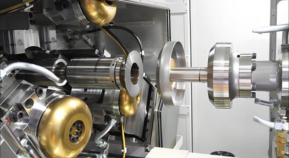
A customizable shear forming machine is a highly flexible tool designed to create precision-formed parts from sheet metal or other flat materials using a combination of shear force and controlled deformation. This type of machine is particularly useful in industries where parts require specific geometric shapes and dimensions, with applications ranging from aerospace and automotive to heavy equipment and industrial manufacturing.
The primary function of a shear forming machine is to apply a shear force to the material, gradually shaping it into the desired form. In contrast to traditional forming methods that rely primarily on compressive forces, shear forming uses a combination of cutting and stretching forces to form the material, which allows for the creation of complex geometries, including those with asymmetric or tapered features. The customizable aspect of the machine lies in its ability to adjust key forming parameters, such as force, tool speed, angle of attack, and tooling configurations, enabling it to accommodate a wide variety of part designs and material types.
One of the significant benefits of a customizable shear forming machine is its versatility. By adjusting the machine’s parameters, it can handle a range of materials with varying thicknesses and properties, including metals like aluminum, steel, titanium, and even some advanced alloys. For example, in the aerospace industry, shear forming machines can be used to create parts with complex curves or contoured surfaces, such as aircraft fuselages, structural components, and turbine blades. The ability to work with different materials and create intricate forms makes these machines a valuable asset in industries that require high precision and performance.
In addition to its flexibility, the customizable shear forming machine also offers improved material efficiency. Since shear forming is a cold-working process, it can significantly reduce material waste when compared to traditional cutting methods, such as stamping or machining, which typically result in higher scrap rates. The precision of the machine allows for parts to be formed to near-net shapes, reducing the need for secondary operations like machining or welding. This helps to lower overall production costs, particularly in industries where material costs are high.
The adaptability of a customizable shear forming machine also makes it suitable for both low- and high-volume production runs. For low-volume runs or prototype development, manufacturers can easily modify machine settings to accommodate different part designs, ensuring that the process remains cost-effective and efficient. For high-volume production, the machine can be set up to form parts with minimal supervision, allowing for continuous production with reduced cycle times and high consistency across batches. The automated nature of many shear forming machines also contributes to higher throughput, ensuring that production quotas are met without sacrificing quality.
In terms of customization, modern shear forming machines can be equipped with various features to meet the specific needs of different applications. These include adjustable tooling systems, programmable control interfaces, and real-time monitoring capabilities. Adjustable tooling allows for the use of different dies, molds, and rollers to accommodate various part shapes, while programmable control interfaces enable precise control over the forming process. Real-time monitoring ensures that the machine is operating within the desired parameters, which helps maintain product consistency and quality throughout the production cycle. These features make shear forming machines highly adaptable to specific part designs and manufacturing processes.
For manufacturers seeking to maximize the capabilities of their shear forming machines, incorporating advanced features like CNC (computer numerical control) systems and robotic integration is increasingly common. CNC systems provide precise control over the forming process, ensuring that even complex geometries are replicated with high accuracy. Robotic systems can be integrated to automate material handling and part manipulation, reducing the need for manual intervention and further improving process efficiency. This integration of automation and control systems enables shear forming machines to operate seamlessly within larger, more complex manufacturing ecosystems, contributing to overall production optimization.
Furthermore, customizable shear forming machines can be utilized in the creation of parts with unique shapes and structures that would be difficult or costly to achieve with other manufacturing methods. For example, shear forming can be used to produce cylindrical, conical, or tapered shapes with varying wall thicknesses, as well as parts with intricate internal features. This capability is invaluable in industries where custom, highly specialized parts are required. Examples include turbine blades with cooling channels for the power generation sector or complex frame structures in the automotive and aerospace industries.
The overall cost-effectiveness of customizable shear forming machines also makes them a compelling choice for manufacturers looking to streamline their production processes. Since they can handle multiple part designs with minimal adjustments, they eliminate the need for costly tooling changes or retooling during production runs. The reduced cycle times, coupled with the high degree of automation, help lower labor costs and improve overall productivity. Additionally, the ability to form parts with minimal material waste not only reduces production costs but also aligns with sustainability goals by minimizing environmental impact.
In summary, a customizable shear forming machine offers a highly adaptable and efficient solution for manufacturers needing precision-formed parts with complex geometries. Its flexibility, material efficiency, and cost-effectiveness make it suitable for a wide range of industries, from aerospace to automotive and heavy machinery. The combination of shear forming with advanced control systems, adjustable tooling, and automation allows manufacturers to create parts that meet the highest standards of quality and performance. Whether for low-volume prototyping or high-volume production, customizable shear forming machines play a critical role in modern manufacturing processes, helping companies achieve both economic and technological advancements.
Customizable shear forming machines provide a unique solution for manufacturers looking to produce parts with complex shapes, high precision, and minimal waste. These machines are ideal for situations where the geometry of the parts requires gradual, controlled deformation rather than abrupt changes in shape. The process of shear forming allows the material to be progressively stretched, bent, or cut, ensuring that the end product maintains its structural integrity while achieving the desired shape. This capability is particularly valuable in industries like aerospace, automotive, and defense, where both the performance of the parts and the efficiency of the manufacturing process are critical.
The flexibility of customizable shear forming machines extends beyond just the types of materials they can handle. These machines are designed to accommodate a wide range of thicknesses and alloys, from soft metals like aluminum to tougher materials like high-strength steel and titanium. The adaptability to work with different materials and thicknesses enables manufacturers to create a variety of components, from thin-walled structural elements to more substantial, heavy-duty parts. In the aerospace sector, for instance, shear forming machines are used to produce parts that must withstand extreme conditions while maintaining lightweight properties, such as fuselage skins, wing spars, or structural frames. Similarly, in automotive manufacturing, parts like wheel rims, chassis components, and structural beams are formed with high precision to meet both strength and weight reduction targets.
A key advantage of customizable shear forming is its ability to produce parts with minimal waste, especially when compared to traditional cutting or stamping methods. The near-net-shape capabilities of shear forming mean that the material is used more efficiently, with fewer offcuts or scrap produced during the process. This results in significant cost savings, particularly when working with expensive materials like titanium or specialized alloys. Additionally, because shear forming involves cold working the material rather than removing material through cutting or machining, the process tends to produce fewer defects related to heat or thermal distortion, making it ideal for precision applications.
Another important factor is the speed and efficiency with which customizable shear forming machines can operate. These machines are designed to maximize throughput by incorporating advanced automation and control features, which allow for rapid setup and adjustment. For low-volume production runs or custom parts, the machine can be quickly reprogrammed to accommodate different part designs, reducing the need for time-consuming retooling. For high-volume production, the machine’s ability to run with minimal human intervention and continuous, automated forming makes it highly productive, capable of producing large quantities of parts with high repeatability and consistency. This efficiency is particularly valuable in industries where demand for parts is high and lead times are critical, such as in the production of automotive components or large industrial machinery.
Customization is at the core of these machines, offering the ability to adjust a wide variety of parameters to meet the specific needs of a part design. The machine’s settings can be programmed to change factors such as the shear force, tool speed, and material feed rate, allowing for precise control over the deformation process. This flexibility is crucial in producing parts with complex features, such as variable thicknesses, intricate curves, or tapered sections, which may not be easily achieved using traditional forming methods. Additionally, the machine can be equipped with adjustable tooling systems that enable different molds or dies to be used for various parts, further enhancing its versatility.
One of the most significant advancements in customizable shear forming machines is the integration of CNC (computer numerical control) technology, which offers fine-tuned control over the forming process. By utilizing digital programs, manufacturers can optimize the machine’s performance for each part, ensuring that the forming parameters are precisely aligned with the part’s specifications. This digital approach also allows for real-time monitoring and feedback, enabling operators to make immediate adjustments if the machine is not operating within the desired parameters. CNC technology also enhances repeatability, ensuring that each part produced meets the same high-quality standards with minimal variation, even across large production runs.
In addition to CNC, many customizable shear forming machines are being integrated with other advanced technologies, such as robotics and AI-powered control systems. Robotic arms can be used to handle materials, load parts, or even manipulate components during the forming process, reducing the need for manual labor and increasing automation in the production cycle. AI algorithms can analyze real-time data from the machine and automatically adjust forming parameters to optimize part quality and reduce defects, making the process more efficient and reliable. These technologies not only improve productivity but also contribute to reducing the likelihood of human error, ensuring that the process remains consistent and highly controlled.
Environmental considerations are also an important aspect of customizable shear forming machines. By reducing material waste and optimizing energy use, these machines align with the broader goals of sustainability in manufacturing. The reduction in scrap material is especially important in industries where the raw materials used are expensive or resource-intensive. Moreover, because the shear forming process does not involve heat, there is less risk of damaging the material’s properties due to thermal stresses. This also means that the process is more environmentally friendly than traditional methods like forging or casting, which can produce harmful emissions or require significant energy input.
Furthermore, customizable shear forming machines can be used in combination with other manufacturing techniques, such as additive manufacturing, to create hybrid production processes that take advantage of the strengths of both methods. For example, a shear forming machine could be used to produce a base structure, while additive manufacturing could be employed to build up additional material in specific areas of the part. This hybrid approach allows manufacturers to produce highly complex, customized components that are both lightweight and strong, meeting the increasingly stringent demands of modern engineering.
In conclusion, customizable shear forming machines offer a highly flexible, efficient, and cost-effective solution for producing high-precision, complex parts across a wide range of industries. Their ability to handle various materials, produce near-net-shape parts with minimal waste, and offer advanced automation and control makes them indispensable tools in modern manufacturing. Whether used for low-volume, custom parts or high-volume production, these machines are transforming the way manufacturers approach precision forming, offering improved efficiency, reduced costs, and enhanced product quality. As technologies continue to evolve, customizable shear forming machines will play an even more critical role in helping manufacturers meet the challenges of tomorrow’s production needs.
As industries continue to push the boundaries of innovation, the role of customizable shear forming machines will only expand. One of the most exciting future developments lies in the integration of digital twins and predictive maintenance technologies. Digital twins are virtual replicas of physical systems that can simulate real-time conditions and behaviors of a machine. By using sensors and data analytics, manufacturers can monitor every aspect of the shear forming machine’s performance, from material behavior to tooling wear. This real-time data not only helps identify potential issues before they arise but also provides insights into how to optimize the process for better part quality and reduced downtime.
Predictive maintenance, powered by AI and machine learning, will further enhance the reliability and efficiency of shear forming machines. Instead of following a traditional, scheduled maintenance approach, predictive systems can forecast when parts of the machine are likely to fail or require service based on usage patterns and sensor data. This minimizes unscheduled downtime, extends the machine’s lifespan, and ensures that the production line runs smoothly without interruptions. Over time, this will lead to a more cost-effective operation and greater productivity.
As part of the broader trend of automation and Industry 4.0, customizable shear forming machines are also expected to become more interconnected. This means that the machines could integrate with other systems within the factory, such as enterprise resource planning (ERP) software, production planning systems, and inventory management tools. Such integration would enable real-time communication between machines, optimizing the flow of materials, parts, and data throughout the entire manufacturing process. This interconnectedness also supports just-in-time manufacturing strategies, where parts are produced and delivered exactly when needed, reducing inventory costs and increasing overall production efficiency.
Another area of growth for customizable shear forming machines is in the realm of additive manufacturing (3D printing). While shear forming traditionally works with flat materials like sheet metal, the growing popularity of hybrid manufacturing methods—where additive techniques are combined with traditional forming—will offer new possibilities. For example, shear forming could be used to create a base structure or initial shape, while 3D printing adds intricate features or material layers in targeted areas to achieve a part with enhanced functionality or performance. This hybrid approach allows for the optimization of both material properties and design complexity, expanding the potential for customized parts in industries like medical devices, aerospace, and automotive engineering.
The continuous improvement in materials science will also influence the future of customizable shear forming machines. As new, high-performance materials—such as composite alloys, ultra-lightweight metals, and advanced polymers—become more widely available, shear forming machines will evolve to process these new materials effectively. For example, high-temperature alloys used in turbine engines, or super-strength composites designed for lightweight automotive applications, will require specific shear forming parameters. Advanced modeling and simulation software can be employed to determine the optimal forming conditions for these materials, ensuring that the machine can be quickly reprogrammed to adapt to new material specifications without extensive downtime.
On the sustainability front, the increasing demand for eco-friendly manufacturing processes will drive further innovations in customizable shear forming machines. The ability to reduce waste by working with near-net-shape parts, minimizing scrap material, and optimizing energy consumption will be key factors in meeting stricter environmental regulations. Additionally, as more manufacturers look to reduce their carbon footprint, the use of renewable energy sources and energy-efficient technologies will become standard features in new shear forming systems. This aligns with broader global trends toward greener manufacturing practices and is particularly relevant as industries like automotive and aerospace are increasingly focused on reducing their environmental impact.
As the technology continues to evolve, it is also likely that customizable shear forming machines will become more user-friendly, requiring less specialized training to operate. The integration of AI-driven interfaces, augmented reality (AR), and virtual reality (VR) could simplify the operation and setup of these machines, allowing operators to virtually “see” the forming process, make adjustments, and troubleshoot in real-time. This level of accessibility and intuitive design could lower barriers to entry for smaller manufacturers and open up new opportunities for innovation across various industries.
Another potential area for innovation is in the creation of even more specialized machines tailored to specific manufacturing needs. While current customizable shear forming machines are highly versatile, the demand for specific part types could lead to the development of machines with even more targeted capabilities, such as machines designed for the formation of ultra-thin metal foils or high-strength, corrosion-resistant components for extreme environments. These machines would combine the same principles of shear forming with specialized features or tooling to meet the growing demand for highly specific parts in niche industries.
Finally, as the world continues to move toward more complex and interconnected production systems, the role of customizable shear forming machines in the larger manufacturing ecosystem will become even more critical. These machines, with their ability to form precision parts quickly and efficiently, will support industries that are at the forefront of technological advancements, such as renewable energy, electric vehicles (EVs), and 3D printed products. As these sectors continue to expand, the need for specialized, high-performance components will grow, and customizable shear forming machines will be at the center of this shift, enabling the production of parts that meet the demands of future technologies.
In summary, customizable shear forming machines are poised to remain a cornerstone of precision manufacturing. With their flexibility, efficiency, and ability to produce high-quality parts with minimal waste, they will continue to evolve in response to new technological advancements, materials, and industry requirements. As automation, digitalization, and sustainability drive future manufacturing practices, these machines will become even more integrated into the larger production ecosystem, helping manufacturers stay competitive in an increasingly complex and demanding global market. Their role in producing custom, high-performance components will be indispensable, making them a key enabler of innovation in a variety of industries.
Spinning and Shear Forming Machine
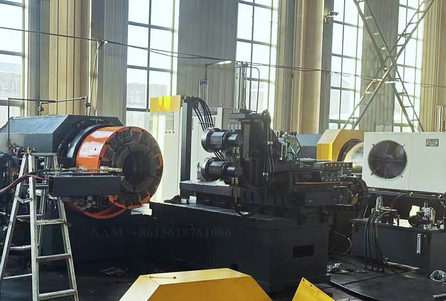
A spinning and shear forming machine combines two distinct metalworking processes—spinning and shear forming—into a single, versatile piece of equipment. This type of machine is designed to handle a wide range of materials, shapes, and production requirements, allowing manufacturers to produce complex, high-precision parts with reduced waste and increased efficiency.
Spinning is a process in which a flat metal disc or sheet is rotated at high speed while a forming tool is used to shape the material against a mold or die. As the material is spun, it is progressively deformed into a desired shape, typically cylindrical or conical. Spinning is often used to create parts with symmetrical shapes, such as containers, cones, and tanks. This process allows for high material utilization, with minimal scrap generated, and it is particularly well-suited for thin-walled parts.
Shear forming, on the other hand, involves applying a shear force to the material to gradually deform it into the desired shape. This process is often used to form parts with more complex geometries, such as those with varying wall thicknesses, tapered sections, or asymmetric features. The shear force is applied via a set of rollers or dies that progressively shape the material, making shear forming ideal for creating intricate and customized designs.
By integrating both spinning and shear forming into one machine, manufacturers can take advantage of the strengths of both processes, enabling them to produce a wider variety of parts with different geometries and material requirements. This combination allows for greater flexibility, as the machine can be easily reconfigured to produce both simple, symmetric shapes and more complex, asymmetrical designs.
The machine typically operates by spinning the material at high speeds while simultaneously applying shear forces to progressively shape it. In some configurations, the spinning tool and shear forming rollers may be controlled independently, allowing for precise control over the forming process. This capability enables manufacturers to create parts with varying wall thicknesses, contours, and complex features while maintaining high precision and surface finish quality.
One of the key advantages of a spinning and shear forming machine is its ability to work with a wide range of materials, including metals like aluminum, steel, titanium, and high-strength alloys. These materials are commonly used in industries such as aerospace, automotive, and defense, where both the strength and lightweight nature of the parts are crucial. The combined process allows manufacturers to achieve near-net shapes, reducing the amount of material that needs to be machined or welded later in the production process.
In aerospace applications, spinning and shear forming machines are particularly valuable for producing parts like aircraft fuselages, pressure vessels, or turbine casings, where high strength-to-weight ratios are essential. Similarly, in the automotive industry, the process can be used to form parts like wheel rims, fuel tanks, or structural components that require a balance of strength, durability, and lightweight performance.
The integration of spinning and shear forming also contributes to increased material efficiency. Since the machine can produce parts with minimal waste, manufacturers can significantly reduce raw material consumption, which is particularly important when working with expensive or high-performance materials. The ability to form near-net shapes means less material is lost to scrap, and the parts can often be used without requiring extensive post-processing, which helps lower production costs.
Customization is another significant benefit of spinning and shear forming machines. The machine’s parameters—such as speed, pressure, and tooling configurations—can be easily adjusted to accommodate different part designs, material types, and production volumes. For example, when working with thicker materials or more intricate designs, the machine can be fine-tuned to ensure that the shear forces applied are optimal for the specific material and geometry. This adaptability makes the machine suitable for both low-volume prototype production and high-volume manufacturing.
Another advantage of these machines is their ability to handle parts with asymmetric shapes. Traditional spinning is typically limited to creating parts with radial symmetry, but by incorporating shear forming into the process, manufacturers can produce parts with more complex geometries. This includes parts with varying wall thicknesses, complex internal features, or non-circular cross-sections, which would be challenging or impossible to produce using spinning alone.
The use of advanced control systems, such as CNC (computer numerical control) and robotics, has further enhanced the capabilities of spinning and shear forming machines. CNC systems allow for precise control over the forming process, enabling operators to adjust machine parameters with high accuracy. This ensures that each part meets the required specifications, with minimal variation between parts. Additionally, robotic arms can be integrated into the machine to automate material handling, loading, and unloading, further improving efficiency and reducing labor costs.
Another area where spinning and shear forming machines have shown promise is in the integration with additive manufacturing (3D printing). As manufacturers seek to create even more complex geometries or hybrid parts, combining spinning and shear forming with additive manufacturing offers the potential to produce parts that are both lightweight and highly functional. For example, shear forming could be used to create the base shape of a part, and 3D printing could be used to add specific features or internal structures to improve strength or reduce weight.
As sustainability becomes an increasingly important consideration in manufacturing, the material efficiency offered by spinning and shear forming machines aligns well with green manufacturing practices. By reducing scrap and waste, the machine helps minimize the environmental impact of the production process. Furthermore, the ability to work with a wide range of materials, including those with high strength and corrosion resistance, supports the growing demand for parts that can withstand harsh environments while maintaining long service lives.
The combination of spinning and shear forming will continue to evolve as new materials and technologies emerge. The versatility and efficiency of these machines make them an essential tool for manufacturers looking to stay competitive in industries that require high-precision, custom parts. With ongoing advancements in automation, digital control systems, and hybrid manufacturing, spinning and shear forming machines will remain central to the production of complex, high-performance components across a variety of sectors.
In summary, the spinning and shear forming machine represents a powerful solution for producing complex, high-precision parts with minimal material waste. By combining the strengths of spinning and shear forming, these machines enable manufacturers to create a wide range of geometries and material types, making them ideal for industries like aerospace, automotive, and heavy machinery. With advanced control systems, robotics, and customization capabilities, spinning and shear forming machines are poised to play a key role in the future of precision manufacturing.
Spinning and shear forming machines are becoming increasingly vital in modern manufacturing due to their versatility and efficiency. By combining spinning, which is ideal for creating rotationally symmetric parts, with shear forming, which allows for more complex, non-symmetric geometries, these machines enable the production of a broader range of components with varying material properties and shapes. This integration provides significant advantages in terms of part quality, material utilization, and the ability to produce intricate designs that may be difficult to achieve with traditional methods alone.
The capability to handle various metals and alloys, including lightweight materials like aluminum, durable metals such as titanium, and high-strength steels, makes these machines valuable across multiple industries. In the aerospace sector, for instance, the combination of spinning and shear forming is used to produce high-performance parts, such as turbine components, fuselage sections, and pressure vessels. The need for parts with excellent strength-to-weight ratios in these applications demands the precision and efficiency that spinning and shear forming machines can provide. Additionally, the automotive industry also benefits from this technology, especially in the production of components like structural beams, wheel rims, and fuel tanks, where both strength and weight considerations are crucial.
One of the key benefits of using a spinning and shear forming machine is the reduction in material waste. Traditional methods like machining or stamping often produce significant amounts of scrap, which increases costs and environmental impact. In contrast, the near-net-shape capability of spinning and shear forming means that less material is wasted, and parts can often be produced with minimal post-processing. This is particularly valuable when working with expensive materials or materials that require special handling, as the reduction in scrap material can result in significant cost savings over the long term.
Another advantage is the machine’s flexibility in handling complex geometries. While spinning is traditionally limited to symmetric shapes, the integration of shear forming allows for the production of parts with varying wall thicknesses, tapered sections, or more intricate, asymmetric features. This makes the process suitable for a wide variety of applications, including the creation of parts that are not feasible with traditional spinning alone. The ability to form parts with more complex shapes also opens up possibilities for producing highly customized products in lower volumes, which is beneficial for industries like medical device manufacturing or custom automotive components.
The ability to adjust machine parameters such as speed, pressure, and tooling configurations further enhances the machine’s adaptability. For different material types and geometries, operators can fine-tune the settings to ensure the material is formed correctly and without defects. This level of control is particularly important for maintaining high part quality across production runs, whether in low-volume or high-volume manufacturing.
Incorporating advanced technologies, such as CNC (computer numerical control), robotics, and AI-powered feedback systems, further optimizes the performance of spinning and shear forming machines. CNC allows for precise control of the forming process, enabling high repeatability and accuracy. Robotics can automate tasks such as material handling, part loading and unloading, reducing human intervention and improving cycle times. AI and machine learning algorithms can analyze real-time data from the forming process, adjusting parameters to optimize quality and minimize defects. These technologies enhance the overall efficiency and consistency of the machine, making it ideal for both large-scale production and customized runs.
Furthermore, the integration of spinning and shear forming with other manufacturing techniques, such as additive manufacturing (3D printing), is becoming more common. This hybrid approach combines the strengths of both methods, where spinning and shear forming create the base structure of a part, and additive manufacturing is used to add intricate features or structures. This could be particularly useful for creating highly complex parts with internal geometries or specific functional attributes, such as lightweight lattice structures or integrated cooling channels in aerospace components.
Sustainability continues to be a driving force in manufacturing, and the material efficiency offered by spinning and shear forming machines plays a key role in reducing the environmental impact of production. By minimizing scrap and optimizing material usage, these machines contribute to a more sustainable manufacturing process. In addition, the ability to form parts without generating significant heat reduces energy consumption compared to other methods like casting or forging, further contributing to a reduction in the carbon footprint of production.
As manufacturing technologies evolve, spinning and shear forming machines will continue to play a crucial role in meeting the growing demands for high-performance, precision parts across various sectors. With their ability to handle a wide range of materials, produce complex shapes, and minimize waste, these machines provide manufacturers with a competitive edge in industries that require both efficiency and quality. The future of spinning and shear forming will likely see even more advanced automation, increased integration with digital technologies, and the continued development of hybrid manufacturing processes that combine the best of traditional and additive techniques. These advancements will further enhance the machine’s capabilities, making it an even more essential tool in the production of complex, high-performance components.
As the demand for more advanced and high-performance components increases, the role of spinning and shear forming machines will expand even further. One of the key areas where this technology is poised for growth is in the production of lightweight, yet high-strength components. The aerospace, automotive, and energy sectors, in particular, are pushing the envelope when it comes to developing parts that need to be both structurally robust and as light as possible to improve fuel efficiency and performance. By enabling manufacturers to create parts with complex, customized geometries and excellent strength-to-weight ratios, spinning and shear forming machines will continue to meet these stringent demands.
In industries such as aerospace, for example, parts like turbine blades, nacelles, and structural frames require not only high strength but also the ability to withstand extreme operating conditions, including high temperatures and mechanical stresses. Spinning and shear forming machines offer the precise control required to produce such parts with exceptional strength properties, making them a preferred choice for producing critical components. With the integration of advanced materials, like composites and high-strength alloys, these machines will continue to evolve to meet the changing demands of the aerospace industry. The potential to form highly specialized components—such as lightweight yet durable housing for electronic systems, propulsion components, and wing spars—will be vital for supporting next-generation aircraft and spacecraft designs.
The automotive industry also stands to benefit greatly from the advancements in spinning and shear forming technologies. The push for electric vehicles (EVs) and autonomous cars requires the production of parts that are both lightweight and strong, enabling the overall vehicle to be more efficient and capable of meeting safety standards. Parts such as battery casings, lightweight chassis components, and even intricate designs for interior structures can be efficiently produced using spinning and shear forming machines. These machines also enable manufacturers to create complex geometries like hollow structures, which reduce weight while maintaining the required strength.
In the energy sector, particularly in the production of renewable energy components, spinning and shear forming machines can be used to manufacture parts like wind turbine housings, high-pressure containment vessels, and heat exchangers. These components often need to withstand extreme environmental conditions while maintaining high performance and durability. The ability to produce these parts with minimal material waste and high precision ensures they are both cost-effective and capable of performing optimally for extended periods.
Another area where spinning and shear forming machines will play an important role is in additive manufacturing. While 3D printing has revolutionized the production of intricate, customized parts, there are still limitations related to the speed and material properties of printed components. The combination of spinning and shear forming with additive manufacturing processes allows for the creation of hybrid parts, where the basic structure is spun or shear-formed, and specific features or internal structures are built up using additive techniques. This hybrid approach allows manufacturers to produce parts with optimized material distribution, reduced weight, and enhanced functionality, while still being able to produce them in a more time-efficient and cost-effective manner.
The use of digital technologies, such as Artificial Intelligence (AI) and the Internet of Things (IoT), will also continue to advance the capabilities of spinning and shear forming machines. For example, AI-powered predictive analytics can be integrated into the machine’s operation to anticipate and prevent issues, such as tooling wear or material inconsistencies, before they become problems. This predictive capability not only improves the machine’s efficiency but also extends its operational lifespan and reduces downtime, which is crucial for high-volume production environments. IoT integration allows for real-time monitoring of machine parameters, enabling operators to make adjustments or troubleshoot remotely, leading to faster and more responsive manufacturing processes.
Additionally, the ongoing trend towards automation will continue to shape the development of spinning and shear forming machines. As manufacturers seek to improve productivity and reduce labor costs, the integration of robotic systems for tasks like loading, unloading, and part handling will become more common. Robots can also be used for precision tasks like tool changes or component inspection, ensuring that the parts being produced meet the required specifications. Automation will allow these machines to run continuously with minimal human intervention, increasing throughput and reducing the risk of human error.
As the world continues to focus on sustainability, the importance of reducing the environmental impact of manufacturing processes grows. Spinning and shear forming machines are inherently more sustainable than many traditional methods, as they generate less waste, require less energy, and can utilize a wide range of materials, including those that are recycled or recyclable. The reduced material waste associated with these processes contributes to a more sustainable approach to manufacturing, and the potential for using eco-friendly materials like biodegradable composites or recycled metals will further enhance the environmental benefits of these machines.
Looking ahead, the evolution of spinning and shear forming machines will likely involve even more advanced materials and processes. The ability to process advanced composites, such as carbon fiber-reinforced polymers, alongside metals will be increasingly important as industries move towards lighter, more durable materials for parts that experience high stress or thermal conditions. These advanced materials often require highly specialized processing, and the combination of spinning and shear forming, with its precision and ability to handle different material properties, will be an essential tool for creating parts that meet the rigorous demands of modern engineering.
Furthermore, as industries continue to demand more customized products, the role of spinning and shear forming machines in producing low-volume, high-precision parts will only become more prominent. Customization in industries like medical device manufacturing, consumer electronics, and even fashion (for custom-fit components) is becoming more prevalent, and these machines offer the flexibility needed to meet those demands. Whether it’s creating a one-off part or producing a small batch of highly specialized components, the adaptability of spinning and shear forming machines makes them an ideal solution for a broad range of applications.
In conclusion, the future of spinning and shear forming machines is bright. Their combination of precision, material efficiency, and adaptability positions them as a key player in the manufacturing of complex, high-performance parts across a wide range of industries. As automation, digital technologies, and advanced materials continue to shape the manufacturing landscape, these machines will play an integral role in meeting the evolving demands of modern production. Their ability to reduce waste, work with advanced materials, and produce both high-volume and custom parts will ensure that they remain an essential part of the manufacturing process for years to come.
Cylindrical Shear Forming Machine
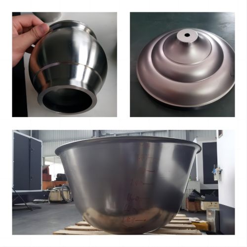
A Cylindrical Shear Forming Machine is a specialized piece of equipment used in the metalworking industry for forming cylindrical parts through the application of shear forces. This machine is designed to process metal sheets, tubes, or pre-formed components by gradually shaping them into cylindrical or tubular forms. The process involves the material being subjected to rotational forces while being deformed by shear forces applied via rollers or dies. This method allows manufacturers to create parts with complex geometries, including varying wall thicknesses, tapered sections, or cylindrical components with asymmetric features.
The cylindrical shear forming process is highly effective for producing parts that require high precision and minimal waste. The machine works by rotating the workpiece while a forming tool applies pressure, causing the material to stretch and reshape into the desired cylindrical form. The process is well-suited for creating components such as tubes, rings, housings, and sleeves, which are common in industries like aerospace, automotive, energy, and heavy machinery.
Key Features and Benefits:
- Precision Forming: Cylindrical shear forming machines provide excellent control over the material’s deformation, allowing for the production of parts with consistent wall thicknesses, smooth surfaces, and tight tolerances. The process is ideal for creating cylindrical components that must meet stringent engineering requirements.
- Material Efficiency: This machine is capable of producing near-net shapes, meaning that parts are formed to their final dimensions with minimal need for additional machining. This results in significant material savings, as less waste is generated during the forming process.
- Flexibility in Material Types: Cylindrical shear forming machines can work with a wide variety of materials, including metals like steel, aluminum, titanium, and high-strength alloys. These materials are often used in industries that demand high-performance components that can withstand extreme conditions such as high pressure, temperature, or mechanical stress.
- Complex Geometries: While traditional forming methods may be limited to simpler, symmetric shapes, cylindrical shear forming allows for the creation of parts with varying wall thicknesses, tapered sections, or even asymmetrical profiles. This makes it suitable for producing complex designs that require precision but may not be achievable with conventional processes like casting or forging.
- Reduced Post-Processing: Because cylindrical shear forming machines create near-net shapes, they often reduce the need for extensive post-processing, such as machining or welding. This not only saves time but also lowers overall production costs.
- Customization: With the right adjustments to speed, pressure, and tooling configurations, the machine can be tailored to form parts of various sizes, wall thicknesses, and geometries. This adaptability makes it ideal for both low-volume and high-volume production runs.
- High-Volume Production: While the process allows for customized parts, cylindrical shear forming machines are also highly efficient for high-volume manufacturing. The machines can operate continuously with minimal downtime, making them suitable for industries that require large quantities of identical parts, such as automotive or heavy machinery manufacturing.
Applications:
- Aerospace: In the aerospace industry, cylindrical shear forming machines are used to produce turbine components, pressure vessels, housings, and other critical parts that require both high strength and lightweight properties. These parts are typically exposed to high stress and extreme temperatures, which necessitates precise forming and the use of advanced materials.
- Automotive: The automotive sector uses cylindrical shear forming machines to produce components such as wheel rims, fuel tanks, and structural parts that need to be both lightweight and durable. The process ensures that these parts can withstand the mechanical demands of the automotive environment.
- Energy: In energy applications, especially in the production of pressure vessels, heat exchangers, and nuclear reactor components, cylindrical shear forming machines help create parts that must endure high pressure and thermal stresses. The ability to produce parts with uniform wall thicknesses and smooth surfaces ensures that these critical components meet stringent safety and performance standards.
- Heavy Machinery: Cylindrical parts used in construction equipment, mining machinery, and other industrial applications often require the precision and durability that cylindrical shear forming can provide. The ability to produce large, complex parts with minimal material waste is especially beneficial in these industries.
- General Manufacturing: Cylindrical shear forming machines can also be used to produce a wide variety of general manufacturing components, such as metal rings, bushings, sleeves, and other cylindrical parts. These machines offer a flexible and cost-effective solution for manufacturers that need to create cylindrical components in a variety of sizes and materials.
Technological Advancements:
As with other metalworking machines, advancements in automation, CNC control, and robotics are increasingly being integrated into cylindrical shear forming machines. CNC systems allow for precise control of the forming process, enabling operators to program specific parameters for different part designs. Automation, including robotic arms for loading and unloading parts, reduces labor requirements and improves production efficiency.
The integration of real-time monitoring systems that use sensors and AI-based analytics can optimize machine performance by detecting potential issues, such as material inconsistencies or tool wear, before they lead to defects. These systems can also adjust parameters on the fly, ensuring that the parts are consistently produced to the desired specifications.
Future Trends:
The development of new, high-performance materials, including advanced composites and lightweight alloys, is likely to drive further innovation in cylindrical shear forming machines. These machines will need to adapt to handle materials with varying properties, ensuring that manufacturers can produce the next generation of lightweight, high-strength parts for industries like aerospace and automotive.
In addition, the increasing demand for customization and low-volume production will likely lead to more flexible and adaptable machines capable of processing a wide range of geometries and materials. The continued integration of smart manufacturing technologies, including the Industrial Internet of Things (IIoT) and artificial intelligence, will further enhance the capabilities of cylindrical shear forming machines, enabling them to operate autonomously and make real-time adjustments for optimal performance.
In conclusion, a cylindrical shear forming machine offers a highly efficient, precise, and flexible solution for manufacturing cylindrical parts with complex geometries and minimal material waste. Its versatility makes it suitable for a wide range of industries, from aerospace and automotive to energy and general manufacturing. As technological advancements continue to enhance these machines’ capabilities, they will play an increasingly vital role in the production of high-performance components for critical applications.
Cylindrical shear forming machines are a key component in the manufacturing industry, particularly in sectors requiring the production of cylindrical components with high precision and material efficiency. These machines allow manufacturers to produce parts such as tubes, rings, and casings with varying wall thicknesses, tapered sections, and even complex geometries that would be difficult to achieve with traditional forming methods. The shear forming process works by applying pressure to the material, causing it to stretch and form into a cylindrical shape as the workpiece rotates. This technique can be applied to a variety of metals, including steel, aluminum, and titanium, and is well-suited for industries that require durable, high-performance components.
The main advantage of cylindrical shear forming is its ability to produce near-net shapes, which minimizes the amount of material waste compared to traditional machining processes. By utilizing less material, manufacturers can lower production costs and reduce their environmental impact. The process also reduces the need for extensive post-processing, as the formed parts are already close to their final shape, reducing the need for machining, welding, or other finishing steps. This leads to significant time and cost savings in production.
One of the key features of cylindrical shear forming machines is their versatility. They are capable of handling a wide range of materials, from common metals like steel and aluminum to more specialized alloys and composites. This adaptability makes them suitable for industries such as aerospace, automotive, energy, and heavy machinery, where components must meet specific performance criteria such as high strength, resistance to extreme temperatures, and durability. For example, in the aerospace sector, cylindrical shear forming machines can be used to produce turbine housings, engine components, and pressure vessels, all of which need to withstand high mechanical stresses and temperature extremes.
The automotive industry also benefits from cylindrical shear forming technology. With the increasing demand for lightweight, fuel-efficient vehicles, manufacturers rely on these machines to produce components like wheel rims, fuel tanks, and structural parts. By forming these parts with minimal material waste and tight tolerances, cylindrical shear forming machines help manufacturers meet the need for high-strength, lightweight components that contribute to overall vehicle performance. Additionally, the process can be used to create parts with complex shapes, such as tapered tubes or rings with varying wall thicknesses, which are often required for automotive designs.
In the energy sector, cylindrical shear forming machines play a crucial role in producing components used in power plants, nuclear reactors, and renewable energy systems. Parts like pressure vessels, heat exchangers, and reactor casings are subjected to extreme conditions, and the precision and strength required for these components make cylindrical shear forming an ideal solution. The ability to form these parts with consistent wall thicknesses and high-quality surfaces ensures that they meet stringent safety standards while maintaining their strength and durability under high-pressure and high-temperature environments.
Another significant advantage of cylindrical shear forming machines is their ability to handle low to medium production runs with high efficiency. Traditional manufacturing methods, such as casting or forging, may not be suitable for small-batch production due to the costs associated with tooling and setup. However, cylindrical shear forming machines can be adjusted to produce small quantities of parts with minimal waste, making them an excellent choice for custom or low-volume production. This flexibility also allows manufacturers to experiment with new designs and materials without incurring excessive costs, enabling them to bring innovative products to market more quickly.
Technological advancements continue to enhance the capabilities of cylindrical shear forming machines. The integration of computer numerical control (CNC) systems allows for precise control of the forming process, ensuring that parts are produced to exact specifications. CNC technology enables the machine to automatically adjust parameters such as pressure, speed, and tool position, resulting in highly accurate and repeatable production. In addition, robotics and automation systems are increasingly being used to handle tasks such as loading and unloading parts, reducing the need for manual labor and improving overall production efficiency. These automation systems can work around the clock, allowing manufacturers to maximize throughput and reduce downtime, which is essential for high-volume production environments.
The implementation of real-time monitoring systems and advanced sensors is also transforming the way cylindrical shear forming machines operate. These systems provide valuable data on parameters such as material temperature, tool wear, and pressure distribution during the forming process. By analyzing this data, manufacturers can optimize machine settings in real-time to improve part quality and reduce the likelihood of defects. Additionally, predictive analytics can be used to anticipate potential issues, such as tool failures or material inconsistencies, allowing operators to make adjustments before problems arise. This predictive capability not only increases the quality of the parts being produced but also reduces downtime and maintenance costs.
As industries move toward more sustainable manufacturing practices, cylindrical shear forming machines offer significant environmental benefits. The reduction in material waste and the efficiency of the forming process contribute to lower overall energy consumption and reduced environmental impact. In addition, the ability to use recycled metals and advanced materials further enhances the sustainability of this manufacturing process. As manufacturers continue to focus on reducing their carbon footprint and improving material efficiency, cylindrical shear forming machines will play an important role in achieving these goals.
Looking to the future, cylindrical shear forming machines are expected to evolve with advancements in materials science and manufacturing technology. The development of new materials, including lightweight alloys and advanced composites, will require machines that can adapt to handle a broader range of materials with varying properties. The continued integration of artificial intelligence (AI) and machine learning into the forming process will enable machines to become even more autonomous, capable of learning from past production runs and optimizing the process for each new part design. As manufacturers demand greater flexibility and customization, cylindrical shear forming machines will become more adaptable to produce a wide range of parts, from small, intricate components to large, complex assemblies.
In conclusion, cylindrical shear forming machines offer manufacturers a powerful and efficient solution for producing high-precision cylindrical components. The process provides a range of benefits, including material efficiency, flexibility, and the ability to handle complex geometries. As industries continue to demand lightweight, high-performance parts with reduced environmental impact, cylindrical shear forming machines will remain an essential tool in the production of critical components for aerospace, automotive, energy, and other high-demand industries. The integration of advanced technologies, such as CNC control, automation, and real-time monitoring, will further enhance the capabilities of these machines, allowing manufacturers to meet the ever-evolving demands of modern manufacturing.
As we look to the future of cylindrical shear forming machines, several exciting trends and developments are likely to further shape their role in modern manufacturing. One such trend is the growing integration of additive manufacturing (AM) technologies. While additive manufacturing, or 3D printing, is primarily known for its ability to create complex geometries and customized parts layer by layer, its combination with traditional forming methods like cylindrical shear forming can create hybrid production systems. This hybrid approach can optimize material use and production speed by forming the basic geometry through shear forming and then using additive manufacturing to build up intricate details or internal features. Such advancements are expected to expand the capabilities of cylindrical shear forming machines, enabling them to produce even more specialized, high-performance parts.
Moreover, smart manufacturing is becoming increasingly important, with digital technologies revolutionizing the entire production process. The integration of IoT (Internet of Things) devices into cylindrical shear forming machines will enable real-time communication between the machine, operators, and other production equipment. This interconnected network will provide insights into machine performance, material conditions, and production workflows, offering a more efficient and data-driven approach to manufacturing. The collected data can be used to analyze production trends, predict maintenance needs, and continuously optimize the machine settings to enhance overall efficiency.
In addition to improving the machines themselves, the materials used in cylindrical shear forming are also evolving. As industries push for greater material performance in applications such as lightweight, high-strength alloys and composites, manufacturers will need shear forming machines that can process these advanced materials effectively. For example, aerospace manufacturers are increasingly using titanium alloys and carbon fiber composites, both of which pose challenges in forming due to their unique properties. Cylindrical shear forming machines will need to adapt to accommodate these materials while maintaining precision and efficiency, potentially incorporating new tool designs or heating methods to facilitate the forming process.
Another noteworthy development is the trend towards eco-friendly and sustainable manufacturing. With a heightened focus on reducing carbon footprints and minimizing waste, cylindrical shear forming presents an excellent opportunity for manufacturers to meet sustainability goals. The inherent material efficiency of shear forming, which reduces the need for excess raw materials and minimizes scrap, aligns with industry efforts to lower environmental impacts. Furthermore, with increasing regulations surrounding the environmental impact of manufacturing processes, companies are turning to more energy-efficient and waste-minimizing techniques. Cylindrical shear forming fits well into this shift, offering manufacturers a method that inherently supports sustainability by using fewer resources and generating less waste compared to traditional processes like casting or forging.
At the same time, globalization and the push for on-demand, localized production will continue to influence the design and use of cylindrical shear forming machines. With supply chains becoming more complex and customers demanding faster production times, the need for machines capable of producing components on-demand will grow. Flexible, versatile machines that can produce both high volumes and low volumes of customized parts with rapid setup and adjustment capabilities will be in high demand. The ability to rapidly switch between different part types, materials, and sizes without significant retooling or delays will be crucial to meet the needs of industries like automotive, aerospace, and medical device manufacturing, which require quick turnaround times for prototypes and small-batch production.
The trend toward lightweighting in industries such as automotive and aerospace will continue to be a driving force behind the adoption of cylindrical shear forming machines. By reducing the weight of components without sacrificing strength or safety, manufacturers can improve fuel efficiency, reduce emissions, and enhance the overall performance of vehicles and aircraft. Cylindrical shear forming offers a way to produce lightweight yet strong parts, such as structural components for cars and planes, which often require both high strength and reduced weight. The process’s ability to form parts with optimized material distribution will make it an ideal solution for lightweighting applications.
Additionally, cylindrical shear forming machines are likely to become more user-friendly and accessible, with increased automation and intuitive software interfaces. This will make it easier for operators to use the machines and reduce the skill gap required to run such complex systems. The evolution of operator interfaces, integrating touchscreens and advanced software, will make setup and operation more intuitive. Manufacturers will be able to quickly program machine parameters and make adjustments without requiring deep technical expertise. The ease of use combined with the increasing automation and intelligent systems will further improve efficiency and lower the barrier for small and medium-sized enterprises (SMEs) to access advanced manufacturing technology.
Furthermore, the growing importance of quality assurance in the manufacturing process is expected to lead to more integrated inspection systems. Advanced in-line inspection technologies, such as laser scanning and X-ray imaging, can be incorporated into cylindrical shear forming machines to ensure that each part meets the required specifications during the production process. These technologies allow for real-time quality control, reducing the need for separate quality inspection stages and improving overall product consistency. Continuous monitoring during the forming process can also help identify defects early in the production cycle, reducing waste and improving efficiency.
Finally, as demand for customized products grows, cylindrical shear forming machines are likely to become more adept at producing unique, low-volume parts. This ability to rapidly produce customized or small-batch components will be a significant advantage in markets where personalized or specialized products are required. From bespoke automotive parts to custom industrial components, the ability to quickly adjust machine settings and tooling to meet specific customer needs will make cylindrical shear forming machines indispensable in industries that require high levels of product differentiation.
In summary, cylindrical shear forming machines are set to play an increasingly important role in modern manufacturing. Their ability to produce high-precision, complex cylindrical components efficiently and with minimal waste is essential to industries such as aerospace, automotive, energy, and heavy machinery. As technological advancements continue to drive innovation, these machines will become even more versatile, efficient, and adaptable, making them an essential tool for manufacturers looking to stay competitive in an ever-evolving market. The integration of smart technologies, automation, and sustainable practices will shape the future of cylindrical shear forming, ensuring its continued relevance in the production of high-performance components.
Deep Drawing and Shear Forming Machine
A Deep Drawing and Shear Forming Machine is a versatile piece of equipment used in the manufacturing process to shape metal sheets into complex, three-dimensional parts. This machine combines the principles of both deep drawing and shear forming, making it highly effective for producing a wide variety of parts with deep or intricate geometries, such as automotive body panels, appliances, containers, and other precision components.
Deep Drawing Process
The deep drawing process involves transforming a flat metal sheet into a hollow shape by drawing it through a die using a punch. This method is typically used to produce parts with a significant depth-to-diameter ratio, such as cups, cylinders, or enclosures. The material undergoes plastic deformation as the punch forces it into the die cavity, creating a desired shape. In deep drawing, the material is stretched and compressed, and the metal flows from the center of the sheet towards the edges to create a uniform thickness.
This process can be performed in multiple stages, with each stage drawing the material deeper into the die. The deep drawing process is widely used in industries such as automotive manufacturing for producing body panels, kitchenware for making pots or pans, and aerospace for components that require strength and durability.
Shear Forming Process
On the other hand, shear forming is a process that uses rotational forces combined with pressure to shape material. It involves the application of shear forces by rotating a workpiece while a forming tool applies pressure, causing the material to deform and take shape. Shear forming is typically used for producing cylindrical or conical parts and is highly effective for achieving smooth surfaces and precise geometries. This technique can be used to create parts like rings, tubes, and cylindrical housings with varying wall thicknesses and tapered features.
Combining Deep Drawing and Shear Forming
When combined, deep drawing and shear forming techniques allow manufacturers to produce parts with complex geometries that require both deep, hollow shapes and specific surface qualities or variable thicknesses. For example, a deep drawing and shear forming machine could be used to produce a part that has a deep, cylindrical body with a tapered neck or varying thickness along different sections of the part.
This hybrid machine is particularly beneficial in industries where precision, strength, and surface quality are essential. The machine can handle both the stretching and deformation of materials through deep drawing, as well as the shaping and thinning or thickening of parts through shear forming.
Key Benefits and Features
- Complex Geometries: The combination of deep drawing and shear forming allows the production of parts with both deep, hollow sections and complex, shaped surfaces. This versatility makes the machine ideal for a wide range of applications, including producing parts with varying wall thicknesses or tapered sections.
- Material Efficiency: Both deep drawing and shear forming are material-efficient processes. Deep drawing can produce parts from flat sheets with minimal material waste, and shear forming reduces the need for additional machining, further improving material utilization. These processes can also be used to form parts close to their final dimensions, reducing the need for post-processing.
- Versatility in Materials: This type of machine can work with a wide variety of metals and alloys, such as steel, aluminum, brass, copper, and high-strength materials like titanium. This adaptability is particularly important in industries such as aerospace, automotive, and energy, where parts need to be strong, durable, and lightweight.
- Precision and Consistency: The use of advanced controls and automated systems ensures that deep drawing and shear forming processes can be repeated with high precision. Parts are formed consistently within tight tolerances, reducing the likelihood of defects and ensuring high-quality finished products.
- Cost-Effective for High-Volume Production: The efficiency of these processes makes them ideal for high-volume production runs, where consistent quality and low production costs are essential. The ability to form parts close to their final shape reduces the need for expensive post-machining, making this combination of processes cost-effective for mass production.
- Improved Surface Finish: Shear forming, when combined with deep drawing, often results in parts with superior surface finishes. The material is deformed evenly, reducing the occurrence of surface defects, which is especially important in industries where aesthetics or smoothness are critical, such as in the production of consumer goods or automotive parts.
- Customization and Flexibility: Deep drawing and shear forming machines can be customized to meet specific requirements for different industries. The tooling can be adjusted to produce parts with various shapes, sizes, and material thicknesses, making these machines highly flexible for both small and large production runs.
Applications
- Automotive Industry: In the automotive sector, deep drawing and shear forming machines are used to create body panels, fuel tanks, and other structural components. These parts need to meet strict performance standards for safety, strength, and lightweight design, and this combination of processes allows for both the complex shaping and material optimization needed in the production of automotive components.
- Aerospace: Aerospace parts, such as aircraft fuselages, engine components, and pressure vessels, often require a combination of deep drawing and shear forming to achieve the necessary strength-to-weight ratio. The ability to handle materials like titanium and high-strength steel makes this hybrid machine valuable for producing aerospace components.
- Consumer Goods: Kitchenware, such as pots, pans, and other household appliances, are often manufactured using deep drawing techniques. When combined with shear forming, these machines can produce parts with intricate designs and varying thicknesses, all while maintaining high material efficiency and a smooth finish.
- Energy Sector: In energy production, particularly for wind and nuclear power, deep drawing and shear forming machines can be used to produce large, high-strength components like housings, flanges, and pressure vessels. These parts often need to withstand extreme pressure and temperature conditions, making the precision and material integrity ensured by these processes critical.
- Medical Devices: Medical components that require intricate geometries, high precision, and biocompatible materials can benefit from the deep drawing and shear forming process. This is especially relevant for parts used in surgical instruments, implants, and diagnostic equipment.
Technological Advancements
Modern CNC controls and robotic automation are increasingly integrated into deep drawing and shear forming machines. These technological advancements help to improve the consistency and accuracy of the forming process, while also reducing human error and increasing production speed. Additionally, real-time monitoring systems provide valuable insights into the forming process, ensuring that parts are produced to specification without defects.
Furthermore, the use of advanced materials is pushing the development of specialized dies, tools, and machine settings to accommodate new materials such as composites or ultra-high-strength alloys. The ongoing development of smart manufacturing techniques will also enhance the ability to fine-tune the deep drawing and shear forming processes, ensuring that manufacturers can meet the demands of increasingly complex part designs.
Conclusion
A Deep Drawing and Shear Forming Machine is an advanced piece of equipment that combines the strengths of two distinct forming techniques to create complex, high-precision parts. By integrating both processes, manufacturers can produce parts with varying thicknesses, deep geometries, and intricate shapes, while maintaining material efficiency and reducing waste. The versatility of this hybrid machine makes it suitable for a wide range of industries, including automotive, aerospace, energy, and consumer goods. With continuous advancements in automation, control systems, and materials science, the capabilities of these machines will only continue to expand, ensuring they remain essential tools for modern manufacturing.
A Deep Drawing and Shear Forming Machine integrates two distinct processes to offer a highly efficient solution for producing complex, high-precision components. Combining deep drawing and shear forming allows manufacturers to create parts that require both deep geometries and specific shaping features, offering unparalleled versatility for industries such as automotive, aerospace, and energy. Deep drawing forms deep, hollow shapes by drawing metal sheets through a die, while shear forming applies rotational forces to shape materials into cylindrical or conical parts with precise wall thicknesses. By combining these processes, manufacturers can produce parts with intricate shapes and varying material thicknesses, reducing waste and improving material efficiency.
This hybrid process ensures material efficiency by reducing scrap and minimizing the need for post-processing, which leads to cost savings and higher productivity. The use of both deep drawing and shear forming allows manufacturers to handle a wide range of materials, including metals like steel, aluminum, and high-strength alloys. These materials are often used in industries requiring strength and durability, such as aerospace, automotive, and energy, where parts need to withstand harsh conditions. The hybrid machine is designed to produce consistent, high-quality parts within tight tolerances, making it ideal for mass production while maintaining product quality.
By combining deep drawing with shear forming, manufacturers can produce parts with features such as tapered sections, varying wall thicknesses, and smooth surface finishes. This versatility is critical in industries where complex parts are required, such as for automotive body panels, aerospace engine components, or pressure vessels used in power plants. In automotive manufacturing, for example, the machine can produce body panels with smooth surfaces while also forming the part into the required depth, all while maintaining material integrity. The aerospace industry benefits from the machine’s ability to create components that need to be lightweight yet strong, such as turbine casings or aircraft fuselages.
The hybrid machine also offers flexibility in terms of production volumes. It is suitable for both high-volume mass production as well as smaller, custom production runs. This makes it valuable in industries where customization is important, such as in medical device manufacturing, where parts often need to be tailored to specific specifications. The adaptability of these machines allows manufacturers to quickly change tooling and machine settings to produce a variety of parts without extensive reconfiguration or downtime.
As with many modern manufacturing processes, automation and advanced control systems are integral to optimizing the performance of deep drawing and shear forming machines. The integration of CNC controls and robotic automation helps ensure that the process is efficient, consistent, and precise. Real-time monitoring systems also play a critical role by providing operators with data on the forming process, enabling them to make adjustments as needed to optimize the production process and reduce defects. The ability to monitor the machine in real-time also helps predict maintenance needs and minimize downtime, contributing to overall productivity.
Looking forward, the continued development of smart manufacturing technologies will further enhance the capabilities of deep drawing and shear forming machines. By incorporating AI and machine learning, these machines can automatically adjust settings based on real-time feedback, optimizing the forming process and improving the quality of the finished parts. The integration of IoT technologies will allow for better communication between the machine and other production equipment, improving the overall efficiency of the manufacturing process.
In terms of material innovation, the need for advanced materials in industries such as aerospace and automotive is pushing the development of new tooling and techniques to handle materials like composites, titanium alloys, and other high-strength alloys. These materials present challenges in terms of formability, but advancements in machine design and tool technology are making it possible to process them with deep drawing and shear forming methods, ensuring that the components retain their strength while being lightweight.
Environmental sustainability is another key area where deep drawing and shear forming machines excel. These processes inherently reduce material waste, making them more eco-friendly compared to other traditional manufacturing methods. As companies continue to focus on sustainability and reducing their carbon footprints, the ability to minimize waste and improve energy efficiency will be a significant driver in the adoption of these hybrid machines. With the potential to use recycled materials and advanced alloys that require less energy to process, deep drawing and shear forming machines support the transition to greener manufacturing practices.
Finally, the growing demand for customized products is set to increase the importance of machines that can handle low-volume production with high precision. Deep drawing and shear forming machines are well-suited for this purpose, as they allow manufacturers to quickly adapt to different production requirements. Whether it’s producing a small batch of custom parts for a specific application or scaling up to mass production, these hybrid machines provide the flexibility and efficiency needed to meet the demands of modern manufacturing.
In conclusion, Deep Drawing and Shear Forming Machines offer significant advantages in terms of flexibility, material efficiency, and precision. By combining two powerful forming techniques, manufacturers can produce a wide variety of parts with complex geometries, reduced material waste, and a high degree of consistency. With the ongoing advancements in automation, control systems, and material science, these machines will continue to play a crucial role in industries such as automotive, aerospace, energy, and consumer goods. As manufacturing processes evolve and adapt to the demands of a rapidly changing market, the deep drawing and shear forming machine will remain an essential tool for producing high-performance, cost-effective components.
The future of Deep Drawing and Shear Forming Machines is increasingly intertwined with the evolution of Industry 4.0 and smart manufacturing technologies. With the ongoing push toward automation and real-time data integration, these machines are expected to become even more intelligent and efficient. The integration of AI-driven algorithms and predictive maintenance systems will enable these machines to detect subtle variations in material behavior and automatically adjust parameters to maintain optimal production quality. For example, sensors can monitor the pressure, temperature, and material flow during the forming process, allowing for proactive adjustments that prevent defects and reduce the likelihood of scrap material.
Increased robotic automation will also play a significant role in improving the efficiency of deep drawing and shear forming machines. Robots can assist with the handling of materials, parts, and tooling, reducing manual labor and human error. Automated systems can replace traditional human tasks, such as loading and unloading materials or positioning dies and tooling, resulting in shorter cycle times and more consistent results. Additionally, robots can work alongside these machines to perform post-processing tasks such as trimming, welding, or assembling components, further enhancing the overall production process.
The development of more advanced material-handling systems will enable the efficient processing of new, non-metallic materials like composites and plastics, which are becoming increasingly common in automotive and aerospace manufacturing due to their lightweight and high-strength properties. As industries continue to move toward lightweighting to meet fuel efficiency and performance targets, the ability to process these advanced materials with deep drawing and shear forming machines will become essential. These systems will also likely incorporate advanced feeding and alignment mechanisms to handle materials with varying thicknesses, textures, and properties, ensuring that the material flows smoothly through the forming process.
One of the most exciting developments in the future of deep drawing and shear forming machines will be the continued integration of augmented reality (AR) and virtual reality (VR) technologies. These technologies will allow operators to visualize the entire production process before it begins, simulating different tool paths and material behavior under various conditions. Operators can then optimize tooling setups and machine parameters before production starts, saving time on adjustments and improving production efficiency. In the event of a machine malfunction or failure, AR and VR can also be used for remote diagnostics, allowing technicians to troubleshoot and fix problems quickly without being physically present on the shop floor.
Furthermore, the concept of digital twins—virtual replicas of physical machines—will likely become more prevalent. These digital twins will provide manufacturers with real-time data on the performance of their deep drawing and shear forming machines, offering insights into everything from wear and tear on components to production efficiency. By continuously monitoring and analyzing machine performance, manufacturers can predict when components need maintenance or replacement, preventing unexpected downtime and reducing the likelihood of costly repairs.
As the demand for customization and shorter production runs continues to grow, deep drawing and shear forming machines will need to become even more flexible and adaptable. Modular systems that allow for easy reconfiguration will become increasingly popular. For example, tooling and dies could be easily swapped out or adjusted to accommodate different material types or part geometries, enabling manufacturers to quickly switch from one product design to another without significant retooling or downtime. This flexibility will be particularly valuable for industries such as medical device manufacturing, where customization is often required for each individual product.
The sustainability trend will continue to shape the development of deep drawing and shear forming technologies. With increasing global awareness of environmental issues and stricter regulations around manufacturing emissions and waste, there will be even more emphasis on reducing energy consumption, minimizing waste, and improving the recyclability of materials. This may lead to the use of green technologies such as electro-mechanical actuators and energy-efficient motors, which use less power while delivering the same performance. Additionally, the ability to process recycled materials more efficiently with deep drawing and shear forming machines will be a critical factor in meeting the sustainability goals of many manufacturers. The growth of the circular economy—where materials are continuously reused and recycled—will drive the need for these machines to handle a wider variety of materials, including those that have been previously used and need to be reformed into new products.
The importance of quality control in deep drawing and shear forming processes will only increase as part complexity rises. In response, inline inspection systems will become more advanced, offering real-time feedback on part quality throughout the production process. These systems will utilize machine vision, laser scanning, and X-ray technology to detect defects such as cracks, warping, and inconsistencies in material thickness, ensuring that only high-quality parts are produced. The integration of AI into quality control systems will further enhance defect detection by recognizing patterns and anomalies that may be difficult for human operators to identify.
As more industries adopt smart factory concepts, where machines and systems are interconnected and work autonomously, deep drawing and shear forming machines will become increasingly integrated into broader production ecosystems. These machines will communicate with other equipment in the factory, exchanging data and adjusting operations to optimize the entire production process. For example, they may coordinate with other forming machines, material handling systems, and even the supply chain management system to ensure that materials arrive on time and are processed efficiently, reducing production delays and enhancing overall throughput.
The growing emphasis on globalization and the need for on-demand production will drive the adoption of deep drawing and shear forming machines that are highly customizable and scalable. The ability to quickly produce low-volume, high-mix parts in response to shifting market demands will become increasingly important. As a result, manufacturers will require machines that can handle a wide range of part types, materials, and production volumes without compromising on quality or efficiency.
In conclusion, the future of Deep Drawing and Shear Forming Machines looks incredibly promising. With advancements in automation, digital technologies, smart manufacturing, and sustainability, these machines will become even more efficient, adaptable, and capable of meeting the demands of modern manufacturing. By continuing to evolve with technological developments and market needs, these machines will remain at the forefront of the manufacturing industry, offering solutions for a wide range of applications, from automotive and aerospace to consumer goods and medical devices. The ongoing innovation in these technologies will ensure that deep drawing and shear forming machines continue to play a vital role in shaping the future of high-performance manufacturing.
Rotary Bending Shear Forming Machine
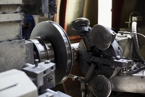
A Rotary Bending Shear Forming Machine is an advanced piece of equipment that combines rotary bending and shear forming processes to create high-precision parts with specific geometric features. This machine is designed to work with sheet metals and other materials to produce components with smooth, continuous curves, varying thicknesses, and complex shapes. It is commonly used in industries like automotive, aerospace, and manufacturing where precision and material efficiency are critical.
Rotary Bending Process
The rotary bending process is a type of bend forming in which the material is bent around a rotating tool or mandrel. In this process, the material is fed into the machine, and a bending tool rotates around a fixed axis. This rotation allows the material to be bent without the risk of kinking, wrinkling, or damaging the material, which can occur in traditional bending methods. Rotary bending is ideal for producing smooth, controlled curves, especially in large or thick materials.
The rotation allows for better control over the bending radius and can accommodate a wider range of material thicknesses compared to other bending methods. It is particularly useful for bending sheets into large radii or even complex 3D shapes, such as cylindrical or conical parts. The process ensures that the material maintains its structural integrity and reduces the need for post-processing, such as straightening or welding.
Shear Forming Process
The shear forming process is used to shape metal by applying rotational forces combined with axial pressure. The workpiece is rotated while a tool, usually a forming roller or die, applies pressure to the material. This pressure causes the material to deform along the tool’s shape, forming the desired geometry. Shear forming is often used to produce cylindrical or conical parts, such as tubes, rings, or housings, by thinning or thickening specific areas of the workpiece.
Shear forming provides several advantages, including the ability to produce smooth surfaces and precise shapes while maintaining material strength. The material is stretched evenly during the process, leading to reduced defects and improved dimensional consistency. The process is also highly efficient, as it eliminates the need for significant material removal or secondary operations like machining.
Combining Rotary Bending and Shear Forming
When combined, rotary bending and shear forming offer a powerful solution for creating parts with both complex curves and precise dimensional characteristics. The Rotary Bending Shear Forming Machine leverages both processes to produce parts that require both the ability to bend metal into controlled curves and shear it into specific shapes. The machine can create parts with smooth, flowing curves, while also allowing for specific thickness variations, such as thicker rims or tapered walls, depending on the part’s requirements.
This combination of processes is particularly advantageous when working with materials that are difficult to form using traditional methods, such as high-strength steels, alloys, and composites. The ability to both bend and shear the material with high precision ensures that the final product meets strict tolerances and performance standards.
Key Benefits and Features
- Precision and Quality: The combination of rotary bending and shear forming allows for precise control over part geometry and surface finish. This ensures that the final product meets high-quality standards without the need for post-processing.
- Material Efficiency: These processes minimize material waste and energy consumption by shaping the material close to its final form, reducing the need for additional machining or material removal.
- Complex Geometries: The rotary bending shear forming machine can create parts with complex geometries that would be difficult or impossible to achieve using traditional forming methods. This is particularly beneficial for industries requiring intricate or non-linear shapes.
- High-Strength Materials: The process is well-suited for handling high-strength materials, such as titanium, aluminum alloys, and advanced composites, making it ideal for aerospace, automotive, and other high-performance applications.
- Versatility: The machine can be adapted for a wide range of applications, from small-scale custom parts to large-volume production. It is highly flexible and can handle various material types and part designs, allowing manufacturers to produce a wide array of components.
- Reduced Tooling Costs: Since the machine combines two processes into one, the need for multiple sets of tooling and dies is reduced, lowering overall tooling costs. This is especially beneficial for manufacturers working with a variety of part designs or materials.
- Improved Production Efficiency: The integrated processes reduce the need for multiple machines and steps, streamlining production and reducing overall cycle times. This results in higher throughput and reduced lead times for manufacturing.
Applications
- Automotive Industry: Rotary bending shear forming machines are used in the production of automotive parts that require complex shapes, such as chassis components, brackets, and frames. The ability to form high-strength materials while maintaining precision makes these machines ideal for creating lightweight yet durable automotive components.
- Aerospace: In aerospace, the machine is used to create components such as engine parts, turbine casings, and structural components for aircraft. These parts must meet strict performance standards, including lightweight design and high strength, which makes the precision and material handling capabilities of the rotary bending shear forming machine invaluable.
- Energy Sector: For energy-related industries, including wind, nuclear, and oil and gas, rotary bending shear forming machines can produce large, high-strength components like flanges, pressure vessels, and housings. These parts need to withstand extreme pressure and temperature conditions, and the machine’s ability to handle such requirements is critical.
- Medical Devices: Rotary bending shear forming machines are also used in the production of medical components, including surgical tools, implants, and housings for medical devices. The precision and ability to form complex shapes are essential in the production of these high-precision parts.
- Consumer Goods: In the consumer goods sector, machines are used to form parts for kitchen appliances, household goods, and decorative items that require specific shapes, thicknesses, or curves. The ability to produce these parts efficiently and cost-effectively is important for manufacturers in this sector.
Technological Advancements
The integration of CNC controls into rotary bending shear forming machines has significantly improved their performance. CNC systems enable highly accurate control of the bending and shear processes, ensuring that each part is formed to the desired specifications. Advanced sensors and feedback loops monitor the material’s behavior in real time, automatically adjusting parameters to optimize the forming process.
In addition, the integration of robotic automation allows for faster and more consistent handling of materials, reducing human error and improving efficiency. Robots can assist in tasks such as loading and unloading materials, positioning workpieces, and even performing secondary operations like trimming and inspection.
The use of AI and machine learning is also expanding, providing the machine with the ability to predict and optimize forming processes based on real-time data. These technologies can help minimize defects and ensure that parts are consistently produced to exacting standards.
Conclusion
The Rotary Bending Shear Forming Machine is a highly advanced piece of equipment that combines two powerful forming processes to produce parts with intricate geometries, high precision, and minimal material waste. Its ability to handle high-strength materials and create complex shapes makes it invaluable in industries like automotive, aerospace, energy, and medical manufacturing. As technology continues to evolve, the integration of automation, AI, and CNC controls will further enhance the capabilities of these machines, improving efficiency, reducing costs, and expanding their range of applications.
The Rotary Bending Shear Forming Machine continues to evolve, incorporating innovative technologies to increase productivity and enhance its capability in producing complex, high-precision parts. One of the key advancements is the integration of smart manufacturing techniques, which enable the machine to adapt dynamically to different materials, designs, and production conditions. This adaptation is achieved through advanced sensors and monitoring systems that track the material properties during the forming process, such as strain, temperature, and thickness variations. The data collected can be analyzed in real-time, enabling the machine to make adjustments to maintain optimal forming conditions.
Incorporating artificial intelligence (AI) into these machines is also making a significant impact. AI algorithms can analyze large amounts of production data to optimize the bending and shear processes, improving consistency and minimizing defects. For instance, AI systems can predict when tooling might need maintenance or when material changes might affect the forming process, reducing the risk of downtime. This predictive capability is especially useful in high-volume production environments where even minor interruptions can cause significant delays and costs.
The customization aspect of rotary bending shear forming machines is also expanding, with more advanced modular design features. Manufacturers can now adjust the machine configuration quickly to accommodate different material types, sizes, and part shapes. This modularity allows for faster transitions between different production runs, making it ideal for industries where small batches of customized parts are frequently required. This feature is particularly valuable in industries like aerospace, where custom parts are often needed for different models or configurations of aircraft.
Additionally, robotic integration has enabled more efficient material handling and automation of secondary processes. Robots can assist in loading and unloading workpieces, moving them between different stages of production, or even performing quality control checks. The use of robots reduces manual labor, minimizes human error, and accelerates production times, all of which contribute to overall operational efficiency.
Energy efficiency is another area where rotary bending shear forming machines have seen improvements. Manufacturers are increasingly focused on sustainable production practices, and these machines have been designed to operate with lower energy consumption compared to traditional machines. The ability to recycle materials more effectively, combined with reduced material waste, not only benefits the environment but also helps manufacturers reduce costs.
The future of rotary bending shear forming machines will likely see even more advancements in material science. As industries continue to push the boundaries of what is possible with new materials, such as lightweight alloys and advanced composites, these machines will need to be able to handle a wider range of materials with different properties. For example, the ability to form composites while maintaining structural integrity and dimensional accuracy will be a critical feature for future machines in sectors like aerospace, where composite materials are becoming more common due to their lightweight and high-strength properties.
As global supply chains continue to shift and production requirements become more flexible, manufacturers will require machines that can rapidly adapt to changing conditions. The combination of rotary bending and shear forming provides a highly adaptable solution that can be tailored to a wide range of applications, from small-scale, custom production to large-scale, mass manufacturing.
Another trend is the increased focus on data-driven decision-making within production environments. With more connected devices and systems, manufacturers will be able to collect and analyze data from the rotary bending shear forming machine, other machines in the factory, and even supply chain logistics. This comprehensive view of the entire production process enables manufacturers to make informed decisions on everything from maintenance schedules to production workflows, further increasing efficiency and reducing costs.
Furthermore, the growing demand for on-demand production and mass customization is pushing rotary bending shear forming machines to become even more versatile. The ability to produce small batches of customized parts, whether for automotive applications, medical devices, or consumer products, requires machines that can quickly switch between different production runs while maintaining high precision and low scrap rates.
With ongoing advancements in IoT (Internet of Things), the future rotary bending shear forming machine will likely be fully integrated into a network of machines and systems that can communicate with each other. This connectivity will allow for real-time data exchange between machines, enabling them to optimize their operations autonomously. For example, a machine could adjust its forming parameters based on the real-time data received from another machine in the production line, further enhancing overall efficiency and product quality.
Ultimately, the ongoing development of rotary bending shear forming technology will continue to push the boundaries of manufacturing capabilities. These machines will play a vital role in producing highly complex, high-performance parts across various industries, contributing to the creation of products that are not only functional and durable but also lightweight and environmentally friendly. As manufacturers demand greater flexibility, precision, and sustainability, the rotary bending shear forming machine will remain a cornerstone of modern manufacturing processes.
As the demands of the modern manufacturing landscape evolve, Rotary Bending Shear Forming Machines are becoming even more sophisticated and capable. One key trend is the integration of Industry 4.0 principles. The concept of a smart factory, where machines are interconnected and capable of autonomously sharing data and adjusting their operations in real-time, is becoming increasingly important. For rotary bending shear forming machines, this could mean not only greater precision and efficiency but also an improvement in predictive maintenance. With real-time monitoring and data analysis, the machine can detect potential issues before they become serious, significantly reducing downtime and maintenance costs.
The digital twin technology is another significant advancement, where a virtual model of the rotary bending shear forming machine is created to simulate its performance in a virtual environment. By using this digital twin, manufacturers can test different material properties, adjust the machine settings, and optimize the forming process virtually before making physical adjustments. This simulation allows for quick and cost-effective iterations, ensuring that the machine is always operating at peak performance, even as part designs change.
Additionally, the growth of advanced materials in industries such as aerospace and automotive is influencing the development of rotary bending shear forming machines. These materials often require specialized processes to achieve the necessary strength-to-weight ratios or performance characteristics. Materials like carbon fiber composites, titanium alloys, and superalloys present unique challenges due to their distinct forming characteristics, and rotary bending shear forming machines are evolving to address these challenges. The machines will need more adaptable tooling, stronger forming forces, and advanced heating and cooling capabilities to handle the specific demands of these materials.
The need for increased production flexibility is another factor driving innovation. Modern rotary bending shear forming machines are being designed to process a wide variety of materials and part designs with minimal downtime. Advanced modular tooling systems allow operators to quickly change tooling and adjust settings to suit different production runs. This flexibility is particularly important for industries that produce a large number of parts with varying geometries, such as automotive suppliers or aerospace manufacturers, where rapid prototyping and low-volume, high-mix production are becoming more common.
To further improve operational efficiency, manufacturers are also adopting automated loading and unloading systems. These systems can integrate seamlessly with rotary bending shear forming machines, improving the speed and consistency of material handling while reducing the potential for errors. Automation can help streamline workflows, shorten cycle times, and reduce labor costs. The ability to integrate these machines with robotic arms or automated guided vehicles (AGVs) enhances the machine’s capability to operate in a fully automated, lights-out production environment.
In the realm of sustainability, there is increasing pressure for manufacturing processes to be more energy-efficient and environmentally friendly. Rotary bending shear forming machines are no exception. Manufacturers are focusing on reducing energy consumption by incorporating energy-efficient motors and actuators that use less power while still delivering optimal performance. Additionally, there is a growing interest in using more sustainable materials and reducing material waste in the forming process. By carefully controlling the material deformation during bending and shear forming, manufacturers can minimize the amount of scrap material produced, improving both cost-efficiency and environmental impact.
One other important aspect of the future development of rotary bending shear forming machines is their ability to handle more complex, multi-functional parts. As industries strive for higher levels of product integration, parts that combine multiple functions (such as structural and aesthetic components) are becoming increasingly common. Rotary bending shear forming machines will need to produce these parts efficiently, ensuring that both the functional and design requirements are met. This could mean not only bending and shearing the material but also incorporating features such as holes, slots, or textured surfaces into the same operation, which traditionally may have required multiple machines or processes.
The role of advanced software in managing and optimizing the rotary bending shear forming process cannot be overstated. Sophisticated CAD/CAM systems allow engineers to design and simulate parts with high precision, ensuring that they can predict how the material will behave during forming. These systems can also generate tool paths and machine settings that minimize errors and optimize cycle times. The integration of simulation software further enhances this process, allowing manufacturers to simulate the entire forming process before actual production begins. This reduces the risk of defects and improves overall product quality.
Looking ahead, data analytics will play a central role in improving machine performance and part quality. By collecting vast amounts of data from machine sensors, operators will be able to track the behavior of both the machine and the material in real time. This data will not only provide insights into the overall performance but also allow for in-depth analysis of the forming process itself. By correlating data on material flow, tool wear, temperature, and pressure, manufacturers can identify subtle patterns and make continuous improvements to the process, reducing scrap rates, improving part consistency, and enhancing overall machine efficiency.
The concept of collaborative robots (cobots) is also gaining traction in the rotary bending shear forming machine landscape. Cobots are designed to work alongside human operators in a shared workspace. These robots can assist with tasks such as part inspection, material handling, or even light assembly work, enhancing both the speed and precision of operations. By integrating cobots into the workflow, operators can focus on higher-value tasks while the cobots handle repetitive, time-consuming processes, creating a more efficient and safer production environment.
In conclusion, the future of Rotary Bending Shear Forming Machines is extremely promising, with ongoing developments in automation, smart manufacturing, sustainability, and advanced materials. The machines are becoming increasingly capable of handling a wider range of materials and part designs, all while improving production efficiency, reducing waste, and minimizing energy consumption. As manufacturers continue to adapt to evolving market demands, these machines will play an integral role in producing high-precision, high-performance parts across a variety of industries. By integrating AI, IoT, robotics, and advanced data analytics, rotary bending shear forming machines will not only become more efficient but will also be key enablers of the next generation of manufacturing.
Multi-Station Shear Forming Machine
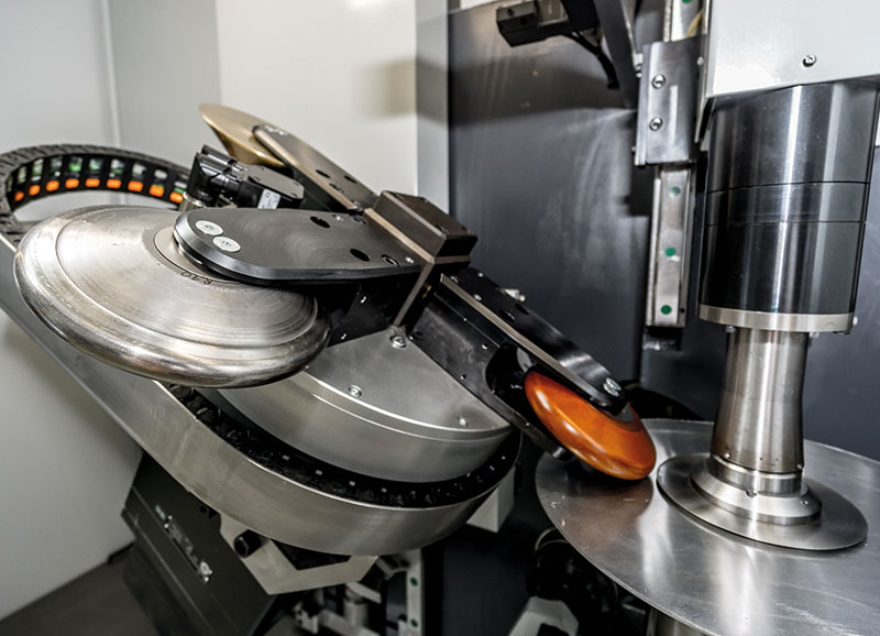
A Multi-Station Shear Forming Machine is a highly advanced piece of equipment used for producing complex, high-precision components through a shear forming process. This machine operates with multiple stations, each performing a specific function, to shape the material into its desired form in one continuous process. The multi-station approach increases efficiency by allowing multiple forming steps to occur simultaneously or sequentially, reducing cycle times and improving production throughput. It is widely used in industries such as automotive, aerospace, and heavy equipment manufacturing, where components require high precision, complex geometries, and consistent material properties.
Functionality
The core principle behind a multi-station shear forming machine is to apply rotational forces combined with axial pressure to a workpiece. The material is typically fed through several stations, where it undergoes incremental deformation. Each station performs a specific task in the forming process, such as preliminary shaping, thinning, stretching, or thickening of certain sections of the material, depending on the component’s design.
The shear forming process involves the workpiece rotating while a forming tool, such as a roller or die, applies pressure to the material. As the workpiece moves through the different stations, each tool progressively shapes the material, often in a controlled manner to produce a final part with the desired dimensions and characteristics. This process allows for the creation of parts with complex geometries, including conical, cylindrical, or even non-linear forms.
Key Features of Multi-Station Shear Forming Machines
- Multiple Stations: The defining feature of this machine is its ability to perform several steps of the forming process in a series of stations. Each station typically has a different tool or die that performs a specific forming task, such as bending, stretching, or thinning the material. This multi-step process minimizes the need for multiple machines or reloading the material, leading to increased efficiency.
- High Precision: Each station in the machine is designed for high precision. The forming tools and dies are often custom-designed to meet the specific requirements of the part being produced. Advanced CNC (Computer Numerical Control) systems are used to control the motion of the machine, ensuring that each forming operation is performed with accuracy and consistency.
- Increased Throughput: Because the machine operates multiple forming stations in sequence or simultaneously, the overall production time for each part is significantly reduced. This leads to higher throughput, making it ideal for high-volume production.
- Complex Geometries: Multi-station shear forming machines excel in producing components with intricate or complex shapes. They can form parts with varying wall thicknesses, tapered sections, or specific geometric features that would be difficult or impossible to achieve with single-station machines.
- Material Handling: The workpiece is typically rotated throughout the stations, allowing for uniform deformation across the material. Some systems incorporate robotic automation for loading and unloading workpieces, which helps reduce human error and further optimizes production flow.
- Customizable Tooling: The ability to change or customize tooling at each station allows manufacturers to create a wide range of parts, from small, precise components to large, heavy-duty parts. Tooling can be designed to accommodate different materials, sizes, and shapes, providing manufacturers with the flexibility to meet diverse production needs.
- Reduced Scrap and Material Waste: By utilizing shear forming, which controls the material flow in a controlled manner, the machine minimizes material waste. This is especially important when working with high-cost materials like aluminum alloys, titanium, or advanced composites, where material efficiency is crucial.
Process Overview
In a typical multi-station shear forming machine, the process proceeds as follows:
- Loading: The material, usually in the form of a flat sheet or blank, is loaded into the machine. Some systems incorporate automated material handling to reduce manual labor and improve efficiency.
- Initial Shaping: The first station typically involves the initial forming of the workpiece, where basic shaping is done. This may involve simple bending or stretching operations to prepare the workpiece for more detailed shaping in subsequent stations.
- Intermediate Forming: In the following stations, the workpiece undergoes more specific shaping. For example, material may be stretched, thinned, or thickened in certain areas, depending on the design requirements. These stations use specialized tools that can apply varying amounts of force to achieve the desired part geometry.
- Fine-Tuning: The final stations refine the part’s shape and dimensions, achieving the final form with tight tolerances. In some cases, these stations may also include processes like trimming, deburring, or surface finishing to ensure the part meets aesthetic or functional requirements.
- Unload and Inspection: After the part has passed through all the stations, it is unloaded, and typically subjected to final quality control inspections to ensure it meets all the necessary specifications. Some systems integrate automated inspection stations to check dimensions and surface finish automatically.
Applications
Multi-station shear forming machines are used across a wide range of industries, including:
- Automotive: In automotive manufacturing, multi-station shear forming machines are used to produce components like wheel rims, brackets, and structural parts. These parts require high strength, precision, and complex shapes, all of which can be achieved through shear forming.
- Aerospace: Aerospace manufacturers use multi-station shear forming machines to produce parts such as turbine casings, aircraft fuselage components, and engine parts. These parts often need to meet stringent weight and strength requirements, and the precision offered by multi-station forming machines ensures they meet these standards.
- Energy: In the energy sector, components such as flanges, pressure vessels, and turbine blades are often formed using this method. The ability to handle high-strength materials and create parts with specific dimensions is critical in these applications.
- Heavy Equipment: For industries producing heavy machinery or structural components, multi-station shear forming machines are used to form heavy-duty parts like frames, chassis, and hydraulic components. The machines can handle large workpieces and apply the necessary forces to shape them accurately.
- Medical Devices: In the medical device industry, where high precision and strict tolerances are required, multi-station shear forming machines can create parts like surgical tools, implants, and medical instrument housings.
Advantages
- Efficiency: Multi-station shear forming machines can reduce the need for additional forming, trimming, or machining operations, cutting down the overall production time for complex parts.
- Versatility: These machines can accommodate a wide range of material types and sizes, making them ideal for custom or low-volume production runs in addition to high-volume manufacturing.
- Precision: The combination of multiple forming steps ensures high-quality results, even for parts with complex geometries and tight tolerances.
- Automation: Automated systems for part handling and inspection enhance the overall production flow, reducing labor costs and human error.
- Material Savings: By minimizing material waste and controlling the flow of the material during forming, manufacturers can achieve significant cost savings, especially when working with high-value materials.
Challenges
- Tooling Costs: While the machines provide flexibility, the initial investment in custom tooling for each station can be significant. Manufacturers must ensure that the benefits of the machine outweigh the tooling costs, especially for low-volume production.
- Complexity: The complexity of these machines may require highly skilled operators and advanced training, as managing multiple stations requires careful attention to the machine settings and part specifications.
- Maintenance: With the increased number of moving parts and tooling involved, maintenance requirements can be higher, and downtime due to maintenance may be costly.
Conclusion
The Multi-Station Shear Forming Machine is a vital tool in industries that require high-precision parts with complex geometries. By performing multiple forming steps in sequence, it significantly improves efficiency, reduces cycle times, and ensures consistent part quality. With its ability to work with a wide range of materials and produce intricate designs, it plays a critical role in sectors like automotive, aerospace, energy, and medical device manufacturing. While it requires significant investment in tooling and maintenance, the advantages in terms of precision, material efficiency, and production flexibility make it an essential asset for modern manufacturers.
A Multi-Station Shear Forming Machine is highly beneficial in industries that demand high-precision components with complex shapes and minimal material waste. The versatility of these machines is evident in their ability to handle various materials, from metals like aluminum and steel to more advanced alloys and composites, which require precise control during the forming process. In industries such as aerospace, automotive, and energy, where part complexity and performance are critical, multi-station machines are indispensable.
As the need for customization and precision increases, these machines are evolving to meet the challenges of modern manufacturing. For example, advanced simulation software integrated with the machine can predict the behavior of materials during the forming process. This software helps optimize parameters such as pressure, temperature, and material flow, ensuring that parts meet stringent specifications before the physical forming even begins. The implementation of real-time feedback systems has further enhanced the machines’ capabilities, allowing for dynamic adjustments to tooling or process parameters based on in-process monitoring.
Another driving force behind the evolution of multi-station shear forming machines is the integration of automation. As manufacturers increasingly adopt smart factory concepts, these machines are becoming more automated and integrated into the broader production system. For example, robotic systems are often used for part handling, including loading, unloading, and transferring parts between stations. This reduces cycle time, minimizes human error, and allows for faster transitions between production runs. Additionally, automated systems can inspect parts during production, ensuring that they meet the required standards without the need for manual intervention.
The customization of tooling at each station further enhances the flexibility of the multi-station shear forming machine. Tooling can be adjusted to accommodate a wide range of material types and part designs, making it possible to quickly switch between different production runs without major downtime. This adaptability is especially important in industries where low-volume, high-mix production is common, such as in the aerospace sector, where parts are often produced in small batches with highly specific requirements.
These machines are designed to maximize material efficiency. Traditional forming processes may produce significant waste, especially when working with expensive materials. However, multi-station shear forming allows for better material utilization by applying force more efficiently, controlling material flow, and producing parts with minimal scrap. This results in cost savings, particularly when working with materials such as titanium, superalloys, or carbon fiber composites, which have high material costs.
The growing emphasis on sustainability in manufacturing processes has led to the development of machines that consume less energy while maintaining performance. By incorporating energy-efficient motors, reducing cycle times, and minimizing scrap material, multi-station shear forming machines contribute to eco-friendly production practices. In addition to energy savings, the ability to recycle scrap materials generated during the process can reduce the environmental impact of manufacturing operations.
As industries continue to push the boundaries of part design, the need for advanced forming technologies will only grow. Multi-station shear forming machines are well-positioned to address the increasing complexity and demand for lightweight, high-performance components. Whether producing aerospace parts that need to withstand extreme conditions or automotive components that must meet stringent safety and performance standards, these machines provide the accuracy, speed, and material efficiency that modern manufacturing requires.
Looking ahead, Industry 4.0 technologies will further enhance the functionality of multi-station shear forming machines. The integration of artificial intelligence and machine learning will allow these machines to autonomously adjust their operations based on real-time data, improving the overall production process. These technologies will enable machines to detect potential issues early, predict maintenance needs, and optimize production without human intervention.
Furthermore, connected devices and IoT systems will enable seamless communication between machines and other parts of the production line, creating a fully integrated and intelligent manufacturing system. This will not only improve efficiency but also allow manufacturers to track production metrics in real-time, ensuring that parts are made to the highest standards and on schedule.
In summary, the evolution of multi-station shear forming machines is being driven by a need for greater precision, flexibility, and efficiency in modern manufacturing. As technologies like automation, AI, and smart manufacturing become more prevalent, these machines will continue to evolve to meet the demands of industries that require high-quality, complex components. By improving material efficiency, reducing cycle times, and minimizing scrap, they help manufacturers produce parts that meet the highest standards while maintaining cost-effectiveness. As manufacturers strive for greater sustainability, customization, and automation, multi-station shear forming machines will play a central role in the future of precision manufacturing.
As industries demand faster production times and higher precision, multi-station shear forming machines are becoming integral to achieving these goals. These machines allow for the simultaneous execution of multiple forming operations, significantly reducing the overall time required to produce complex parts. The use of advanced sensors and feedback systems in these machines enables constant monitoring of critical parameters like temperature, pressure, and material flow, ensuring consistent part quality and minimizing the risk of defects.
Furthermore, the integration of robotic automation in multi-station machines is changing the way parts are handled. Robots can take over repetitive tasks like part loading, unloading, and transportation between stations, reducing the need for manual labor. This not only enhances productivity but also reduces the chances of human error. By allowing the machine to operate continuously without interruption, manufacturers can achieve higher production volumes and lower unit costs.
In addition, additive manufacturing (3D printing) is influencing how parts are designed for shear forming processes. While additive manufacturing is typically used for producing parts layer by layer, its integration with traditional forming methods like shear forming is gaining momentum. This hybrid approach can be particularly useful when designing tools or even producing complex geometries for low-volume or prototyping runs. For example, tools or dies for shear forming machines can be optimized through 3D printing, making them lighter, stronger, and more efficient at producing the desired shapes. This combination of technologies allows manufacturers to take advantage of both the high-speed production of shear forming and the flexibility of additive manufacturing.
Another key advancement in multi-station shear forming machines is the development of adaptive forming techniques. These techniques allow machines to adjust their forming parameters based on the specific material properties and geometry of each workpiece. Materials can be unpredictable, especially when dealing with composites or advanced alloys that respond differently to forming forces. Adaptive forming techniques, coupled with AI-driven algorithms, allow the machine to continuously optimize the process, ensuring the highest levels of precision and quality, even with variations in material properties.
The machine’s flexibility extends to its ability to handle not only standard metal alloys but also advanced composites and other high-performance materials that require more specialized forming processes. With an increasing demand for lightweight and strong components, such as those used in the aerospace and automotive industries, the ability to handle advanced materials effectively is crucial. Fiber-reinforced composites, for instance, require careful control of pressure and temperature during forming to prevent fiber breakage or delamination, making multi-station shear forming an ideal solution.
Energy-efficient designs are also a significant trend in the development of multi-station shear forming machines. Manufacturers are increasingly focused on reducing energy consumption throughout the production process. The integration of variable speed drives and more efficient hydraulic systems helps reduce power usage during the forming process, making the machine more environmentally friendly and cost-effective. Additionally, the energy saved can be reinvested into the production line, further boosting operational efficiency.
As industries face tighter regulations around sustainability and environmental impact, multi-station shear forming machines are evolving to meet these challenges. The ability to produce parts with minimal material waste, efficient energy use, and the potential for recycling scrap materials is becoming an essential feature for modern manufacturing. With these capabilities, manufacturers can produce high-quality components while simultaneously reducing their environmental footprint.
The integration of big data and cloud computing is another trend that is shaping the future of multi-station shear forming machines. By collecting vast amounts of data from the machine’s sensors and other connected devices, manufacturers can gain deeper insights into the performance of the machine and the quality of the parts being produced. Data analytics can help identify patterns in machine performance, predict potential failures before they occur, and suggest adjustments to the forming parameters to enhance part quality or optimize production rates. The ability to store and analyze this data in the cloud allows manufacturers to make data-driven decisions that improve long-term efficiency and reduce operational costs.
As more companies embrace the digitalization of their manufacturing processes, the role of digital twins is becoming more prominent in multi-station shear forming. A digital twin is a virtual model of the machine that simulates its operations in real-time. Using data from sensors, the digital twin can mimic the machine’s behavior during production, allowing for virtual testing of new processes, tooling, or materials before making physical changes to the machine. This reduces the risk of errors and improves the overall speed of design and development for new parts.
As the demand for customized products grows, multi-station shear forming machines are becoming more flexible and adaptable. They are now capable of producing parts in a wider range of sizes, shapes, and materials. By using modular tooling systems and adjustable machine configurations, manufacturers can quickly adapt the machine to produce a variety of components without needing significant retooling or setup time. This makes multi-station machines an ideal choice for industries with changing customer demands, such as automotive suppliers and aerospace manufacturers.
The future of multi-station shear forming is not only about improving machine capabilities but also about enhancing the user experience. Operators will benefit from intuitive touchscreen interfaces, augmented reality (AR), and virtual reality (VR) training programs that allow them to interact with the machine in more immersive and intuitive ways. These technologies will provide operators with real-time feedback and performance monitoring, enabling them to adjust machine settings quickly and effectively.
In conclusion, multi-station shear forming machines are at the forefront of precision manufacturing, offering unmatched versatility, efficiency, and precision. With continued advancements in automation, smart manufacturing, AI, and sustainability, these machines will continue to evolve to meet the demands of industries that require complex, high-performance components. As manufacturers push for greater speed, flexibility, and environmental responsibility, multi-station shear forming machines will remain an essential part of the modern manufacturing landscape, helping companies meet both market and regulatory challenges while producing high-quality products.
Tool-Changing Shear Forming Machine
A Tool-Changing Shear Forming Machine is a highly specialized piece of manufacturing equipment designed to improve flexibility and efficiency in the shear forming process. It is equipped with an automatic or semi-automatic tool-changing mechanism that allows the machine to switch between different tools quickly and seamlessly. This capability is particularly important in industries where a wide variety of parts are produced, requiring different tooling configurations to achieve specific shapes and tolerances.
The primary function of a tool-changing shear forming machine is to apply rotational forces and axial pressure to deform a workpiece. It combines both rotational and axial motion, utilizing tools such as rollers, dies, or mandrels to shape the material. With the tool-changing feature, this machine offers greater versatility, enabling manufacturers to perform a variety of forming operations without needing to manually swap tools or reset the machine for each different part. This not only speeds up production but also improves overall operational efficiency, especially in high-mix, low-volume manufacturing environments.
Key Features
- Automatic Tool-Changing System: One of the most important aspects of this machine is its automatic tool-changing system, which allows for fast and precise switching between tools. This system minimizes downtime by eliminating the need for manual tool swaps, which can often take considerable time and effort. The tool-changing system is typically controlled via the machine’s CNC (Computer Numerical Control) interface, allowing operators to input the required tool configuration for the specific part being produced.
- Increased Flexibility: Tool-changing shear forming machines can accommodate a wide variety of forming tools, enabling manufacturers to produce components with different geometries, sizes, and material types without extensive retooling or reconfiguration. This flexibility makes these machines ideal for industries with diverse product lines, such as aerospace, automotive, medical devices, and energy, where part specifications can change frequently.
- Enhanced Efficiency: The ability to change tools automatically and quickly reduces the need for manual intervention, which in turn minimizes machine downtime. The tool-changing process can occur in parallel with other machine functions, such as rotating or feeding the workpiece, allowing the machine to keep running while the tool change takes place. This greatly improves overall throughput, especially in high-volume production scenarios.
- Precision Tooling: These machines are designed with high precision in mind, ensuring that tools are securely and accurately positioned during the forming process. CNC control systems not only manage tool changes but also allow operators to fine-tune tool parameters, such as pressure and speed, based on the specific requirements of the part being produced.
- Versatile Tooling Options: Depending on the application, a wide variety of tools can be used with a tool-changing shear forming machine. These include rollers, mandrels, dies, cutting tools, and trimming tools. The ability to easily swap between tools allows manufacturers to handle complex parts that require multiple forming steps or different tool geometries to achieve the desired result.
- Reduced Setup Time: The automatic tool-changing feature significantly reduces setup time compared to traditional machines, where the operator has to manually change the tooling between production runs. This is especially beneficial for manufacturers that produce small batches or custom components, where tooling changes are frequent.
- Improved Accuracy and Repeatability: By automating the tool change process, the risk of human error is minimized. This leads to better consistency and repeatability of the formed parts. The machine can also monitor the condition of the tools, ensuring that any wear or damage is detected early, which helps maintain consistent part quality over time.
Process Overview
In a typical tool-changing shear forming machine, the process proceeds as follows:
- Part Setup: The workpiece is positioned on the machine, often using an automated loading system. The machine may have a rotating spindle or mandrel to hold the part in place while the tool performs the forming operation.
- Tool Selection: Based on the part’s specifications, the operator selects the appropriate tools through the CNC control system. The machine’s automatic tool changer selects the necessary tool and positions it in the working area.
- Shear Forming Operation: The machine applies rotational and axial forces to the material, gradually shaping it according to the design. This may involve stretching, bending, thinning, or thickening certain sections of the workpiece, depending on the design requirements.
- Tool Change: If the part requires multiple forming steps, the machine can automatically change tools without stopping production. The tool changer removes the current tool and replaces it with the next tool in the sequence. This can be done swiftly, allowing the machine to continue its operation with minimal delay.
- Final Shaping and Inspection: Once the forming process is complete, the part is removed from the machine. Some machines may incorporate an inspection station to verify the part’s dimensions and quality. If necessary, the part may undergo additional post-processing steps such as trimming or surface finishing.
Applications
Tool-changing shear forming machines are used in various industries where precision and efficiency are crucial. Key applications include:
- Aerospace: In the aerospace industry, where components are required to meet stringent quality standards and complex geometries, tool-changing shear forming machines can produce parts such as turbine blades, fuselage components, and engine casings. These parts often need multiple forming operations, and the tool-changing capability ensures that the machine can handle the various requirements without significant downtime.
- Automotive: In automotive manufacturing, tool-changing shear forming machines are ideal for producing parts like wheel rims, brackets, chassis components, and exterior body panels. These parts often require multiple forming steps and varying tool configurations, which makes the tool-changing feature essential for high-volume production.
- Medical Devices: For the medical industry, tool-changing shear forming machines are used to create precision parts like surgical tools, implants, and medical device housings. These components require high accuracy and often need different forming tools to achieve the desired features, such as complex internal structures or smooth external surfaces.
- Energy: In energy sectors, particularly for producing turbine components, flanges, and pressure vessels, tool-changing shear forming machines help reduce production times and ensure parts meet the necessary performance standards. These components are often large and complex, requiring different tooling for each stage of the forming process.
- Heavy Equipment: For industries involved in manufacturing heavy machinery or structural components, tool-changing shear forming machines are essential for producing machine frames, hydraulic components, and structural steel parts. The ability to handle large, complex parts with varying geometries and sizes makes these machines invaluable in heavy-duty manufacturing.
Advantages
- Reduced Downtime: The tool-changing feature eliminates the need for manual tool changes, reducing downtime between production runs. This is particularly beneficial in high-mix, low-volume production environments.
- Increased Flexibility: Manufacturers can quickly switch between different parts and tooling configurations, allowing for the production of a wide range of components without needing to set up new machines.
- Improved Efficiency: The automatic tool change process enhances overall production efficiency by keeping the machine running without interruptions. This results in higher throughput and more consistent production rates.
- Cost-Effectiveness: Although the initial investment in a tool-changing shear forming machine may be higher, the reduced downtime, improved throughput, and ability to handle complex parts more efficiently lead to cost savings in the long term.
Challenges
- Tooling Costs: The cost of acquiring a wide range of tools for different forming operations can be high. Manufacturers must carefully assess the cost-benefit ratio to ensure that the investment in tooling is justified by the savings in production time and flexibility.
- Machine Complexity: Tool-changing systems add complexity to the machine, which may require more advanced maintenance and operation skills. Operators need specialized training to manage and maintain the tool-changing system effectively.
- Maintenance: The automatic tool changer mechanism itself may require regular maintenance to ensure it functions correctly. Failures in the tool changer can lead to downtime, affecting production schedules.
Conclusion
A Tool-Changing Shear Forming Machine offers significant advantages in terms of flexibility, efficiency, and precision in the manufacturing process. Its ability to automatically change tools allows manufacturers to produce a variety of parts with different geometries and sizes without significant setup time or manual intervention. This is particularly valuable in industries with high-mix, low-volume production, where parts require frequent tooling changes. While the upfront investment may be higher than traditional machines, the long-term benefits in terms of productivity, cost savings, and the ability to handle complex parts make it an essential tool in modern manufacturing operations. As industries continue to demand higher precision, greater customization, and faster production times, tool-changing shear forming machines will play an increasingly important role in meeting these challenges.
Tool-Changing Shear Forming Machines are becoming increasingly essential in industries where the need for flexibility, high precision, and efficiency are critical. The automatic tool-changing feature of these machines significantly enhances productivity by reducing downtime between production runs. In traditional manufacturing setups, the time taken to change tools manually can be substantial, especially when different tooling configurations are required for various components. By automating this process, the tool-changing shear forming machine eliminates the need for operators to stop production, thus minimizing interruption and maximizing machine uptime.
One of the key benefits of these machines is the ability to seamlessly transition between multiple tooling options. This feature is particularly valuable for industries that need to produce a variety of parts with complex geometries. For example, in the aerospace and automotive sectors, where parts like turbine blades, engine components, and body panels need different tooling for forming operations, a tool-changing shear forming machine can handle the task without requiring an entire reconfiguration. As industries shift towards low-volume, high-mix production, this flexibility becomes even more important. Manufacturers can quickly switch between different part designs, ensuring they meet customer demands without excessive delays.
Another significant advantage of tool-changing shear forming machines is their ability to optimize production cycles. Since the tool changes are quick and automated, the machines can continue their operations without human intervention, allowing for smoother, uninterrupted production runs. This leads to a higher production rate, which is especially important in mass production environments where meeting tight deadlines is crucial. By enhancing operational efficiency, manufacturers can lower production costs per part and improve profitability over time.
Additionally, these machines offer improved consistency and quality. When tools are automatically changed by the system, there is a reduced chance of human error in tool placement or calibration, ensuring that the parts produced maintain the required tolerances and quality standards. This is particularly important for industries like medical device manufacturing, where even minor defects can lead to serious consequences. Tool-changing shear forming machines ensure that every part is formed with the same level of precision, even when producing high volumes of varied components.
The ability to quickly change tools also leads to significant reductions in setup time, which has a direct impact on overall manufacturing throughput. In traditional manufacturing settings, setups and tool changes can account for a large percentage of downtime, especially if there are frequent changes in production runs. In contrast, a tool-changing shear forming machine minimizes this downtime by rapidly switching to the correct tooling. This helps meet the demands of modern manufacturing, where customers expect shorter lead times and more tailored solutions. Furthermore, the ability to reduce setup time ensures that machines are utilized more effectively, leading to better return on investment (ROI) for manufacturers.
In terms of material usage, tool-changing shear forming machines can contribute to improved material efficiency. By minimizing scrap and waste during the forming process, these machines help manufacturers make the most of their raw materials. Advanced tooling can apply forces more precisely, reducing material waste while still achieving the desired part geometry. This is particularly important in industries dealing with high-cost materials like titanium or composites, where the price per unit can be significantly high. Lower material waste contributes directly to cost savings and supports sustainability initiatives by reducing overall material consumption.
The evolving integration of smart technologies also plays a key role in enhancing the functionality of tool-changing shear forming machines. Artificial intelligence (AI) and machine learning can be employed to monitor machine performance in real-time, making adjustments to tooling and process parameters as needed. For instance, if a particular tool starts to show signs of wear, the system can automatically alert operators, preventing defects in the final product. Additionally, predictive maintenance models can forecast potential failures, allowing manufacturers to perform maintenance activities proactively rather than reactively, which reduces downtime and enhances the overall reliability of the machine.
The integration of Industry 4.0 concepts further elevates the capabilities of tool-changing shear forming machines. With IoT (Internet of Things) connectivity, these machines can be integrated into a wider smart manufacturing network, enabling seamless data flow between machines, production lines, and even supply chain management systems. Manufacturers can monitor machine status remotely, gather data on production efficiency, and identify areas for process improvement. Real-time data collection also helps track part performance and quality, providing valuable insights into how the process can be optimized further.
Another factor contributing to the popularity of tool-changing shear forming machines is their ability to produce complex, high-performance components. With the increasing demand for lightweight materials and complex geometries in sectors like aerospace, automotive, and energy, these machines provide the flexibility to create parts that would be challenging or impossible to produce with traditional manufacturing methods. For example, advanced composite materials or metal alloys that require special forming processes can be easily handled by these machines. The automatic tool-changing mechanism ensures that the appropriate tools are always in place, regardless of the complexity of the material or design.
As manufacturers continue to focus on sustainability and cost-effectiveness, tool-changing shear forming machines will likely become even more important. By reducing material waste, enhancing energy efficiency, and shortening production cycles, these machines align well with the growing demand for eco-friendly manufacturing practices. Additionally, the ability to quickly switch tools means that machines can handle a wider variety of materials, helping manufacturers reduce the need for multiple machines dedicated to specific tasks.
Despite these advantages, the use of tool-changing shear forming machines does come with some challenges. The initial investment for such equipment is typically higher than that of traditional forming machines, and the complexity of the automated tool-changing system may require additional maintenance and operator training. However, the long-term benefits—such as increased production speed, reduced waste, and improved flexibility—often outweigh the initial costs. As the technology continues to evolve, manufacturers can expect even more user-friendly features, further enhancing their value proposition.
Overall, tool-changing shear forming machines represent a significant leap forward in precision manufacturing. Their ability to automate the tool-changing process, combined with their flexibility, speed, and precision, makes them an invaluable asset in industries that require high-quality, complex components. As manufacturing demands continue to evolve, these machines will play a critical role in helping manufacturers meet the challenges of today’s fast-paced and ever-changing production environment. By reducing downtime, improving efficiency, and enhancing the ability to produce a variety of parts, tool-changing shear forming machines are setting the standard for the future of advanced manufacturing.
As the manufacturing landscape continues to shift towards more dynamic and complex production needs, the role of tool-changing shear forming machines is becoming increasingly pivotal. The growing demand for customization, precision, and speed in manufacturing processes necessitates advanced machinery that can handle diverse production requirements without compromising on quality. Tool-changing shear forming machines offer the flexibility and adaptability to meet these demands, making them highly sought after in industries that prioritize high-mix, low-volume production.
One of the significant trends driving the adoption of tool-changing shear forming machines is the emphasis on digitalization and automation in manufacturing. As part of the broader movement toward smart factories, these machines can be integrated with other automated systems and connected to centralized production management software. This level of integration allows for real-time monitoring of machine performance, predictive maintenance, and supply chain coordination, creating a seamless workflow that minimizes delays and maximizes operational efficiency.
The incorporation of robotics into tool-changing shear forming machines is another advancement that enhances their versatility and productivity. Robotics can be employed to handle tasks such as part loading, unloading, and transportation between different stations in the manufacturing process. By automating these tasks, manufacturers can reduce the need for manual labor, minimize the risk of human error, and ensure that parts are consistently handled with the utmost precision. Furthermore, robots can work in tandem with the machine’s tool-changing system, performing auxiliary functions during tool transitions, further reducing downtime.
In terms of sustainability, tool-changing shear forming machines also contribute to green manufacturing initiatives. These machines help reduce energy consumption through more efficient tool management and forming processes. As many of these machines are designed with energy-efficient features, such as variable speed drives and advanced hydraulic systems, they use less power while maintaining high levels of productivity. Additionally, the reduction in material waste, as a result of more precise forming operations, supports manufacturers’ goals of minimizing their environmental impact.
Moreover, the integration of machine learning algorithms into tool-changing shear forming machines is enhancing their ability to adapt and optimize performance in real-time. These algorithms can analyze vast amounts of data from machine sensors and adjust parameters such as pressure, speed, and temperature based on the specific requirements of each part. This dynamic adjustment ensures that the forming process is always running at its most efficient, regardless of changes in material properties or part complexity. Machine learning also plays a significant role in predictive maintenance, enabling the system to detect early signs of wear or malfunction before they lead to machine downtime. By reducing the need for reactive maintenance, manufacturers can ensure higher uptime and longer machine lifecycles.
The ongoing evolution of material science is also pushing the capabilities of tool-changing shear forming machines. As new, more advanced materials are developed—such as high-strength composites, alloy steels, and lightweight metals—the need for more specialized tooling increases. Tool-changing machines are perfectly suited to this challenge, as they can accommodate a wide range of tools designed for different materials, ensuring that the machine can handle various materials without sacrificing performance or quality. These advancements make tool-changing shear forming machines particularly valuable in industries like aerospace, where lightweight materials are critical for reducing fuel consumption and improving performance.
In addition to improving material efficiency and precision, tool-changing shear forming machines can also enhance the aesthetic quality of the parts produced. In sectors such as consumer electronics and luxury goods, where visual appeal is paramount, these machines can produce parts with smooth, consistent surfaces, free from defects such as surface waviness or tool marks. By using the right tool for each step of the forming process, manufacturers can achieve superior surface finishes that meet the strictest aesthetic standards.
Another area where tool-changing shear forming machines are proving valuable is in the realm of rapid prototyping and small-batch production. In industries like automotive and medical device manufacturing, where the demand for prototypes and customized parts is growing, these machines provide a fast and cost-effective solution. The ability to switch tools quickly means manufacturers can easily adjust to the demands of prototype production or produce low volumes of specialized parts without the need for extensive retooling or reconfiguration. This capability is especially important in industries where design changes are frequent, and speed-to-market is critical for gaining a competitive advantage.
Despite the numerous benefits, the adoption of tool-changing shear forming machines does come with some considerations. The initial investment in such advanced equipment can be significant, and manufacturers must ensure that the long-term savings in efficiency and reduced downtime justify the cost. Additionally, the increased complexity of these machines requires skilled operators and maintenance personnel who are trained to manage and troubleshoot the tool-changing mechanisms, CNC systems, and other advanced features. While these machines are highly automated, having a skilled workforce is crucial to ensuring smooth operation and minimizing potential issues.
The future of tool-changing shear forming machines is bright, with ongoing research and development focused on making them even more efficient, flexible, and intelligent. Advanced sensor technologies, such as machine vision systems and force feedback sensors, will further enhance the machine’s ability to adapt to various material properties and part geometries in real time. Cloud-based data storage and big data analytics will also play a larger role in optimizing the manufacturing process, providing manufacturers with deeper insights into production trends and areas for improvement.
In conclusion, tool-changing shear forming machines represent a significant leap forward in precision manufacturing. With their ability to automate tool changes, adapt to diverse material requirements, and improve production efficiency, these machines are becoming indispensable in industries where customization, speed, and quality are paramount. As manufacturers continue to embrace digitalization, automation, and sustainability, tool-changing shear forming machines will play an increasingly critical role in meeting the demands of modern production. By reducing downtime, improving part quality, and enhancing flexibility, these machines help manufacturers stay competitive in a rapidly evolving marketplace. As technology continues to advance, the capabilities of tool-changing shear forming machines will expand, allowing them to tackle even more complex production challenges and contribute to the development of new, high-performance materials and components.
Horizontal Shear Forming Machine
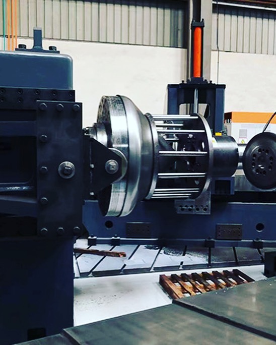
A Horizontal Shear Forming Machine is a type of forming equipment used in manufacturing processes where materials, such as metal, are reshaped using shear forces. These machines are specifically designed to provide horizontal movement for the workpiece during the forming process. In this type of machine, the part is typically rotated while being subjected to force by tools like rollers, mandrels, or dies. The horizontal configuration of the machine offers specific advantages when dealing with large or heavy parts, particularly in industries that require precision in reshaping, bending, or thinning materials.
Features of a Horizontal Shear Forming Machine:
- Horizontal Setup: The defining characteristic of a horizontal shear forming machine is its alignment, where the material is fed horizontally into the machine, often via a rotating spindle or mandrel. This allows for consistent force application over a large part or material, ensuring smooth and even shaping.
- Rotational and Axial Movement: The machine typically combines both rotational and axial motion. The workpiece rotates around its axis while the tools exert forces along the axis of the part, allowing it to change shape, typically in a controlled, incremental manner. This type of motion is critical for producing components that have complex geometries or require significant deformation.
- Multiple Tooling Options: Horizontal shear forming machines are often capable of using a variety of tools, including rollers, dies, cutting tools, and mandrels, depending on the desired outcome. The tools are typically designed to work together in a sequence of forming operations, with different tools being used for different stages of the process.
- Material Handling: These machines often come with specialized material handling systems that allow for the easy loading and unloading of workpieces, especially in high-volume production environments. The horizontal configuration may also make it easier to manage large, bulky parts that would be difficult to handle in vertical or other configurations.
- Customization of Forming Process: Horizontal shear forming machines can be programmed and adjusted to suit a wide range of materials, including metals, composites, and plastics. The machine’s control system can adjust parameters like speed, pressure, and tool position, allowing it to produce components with varying thicknesses, shapes, and dimensions.
- CNC Integration: Many horizontal shear forming machines are equipped with CNC (Computer Numerical Control) systems. This allows for high levels of automation, repeatability, and precision in the forming process. Operators can input specific part designs, and the CNC system ensures that the tools follow the exact instructions to create the desired part.
- High Precision and Surface Quality: The horizontal configuration, combined with controlled shear forces, results in high-precision parts with smooth, defect-free surfaces. This makes horizontal shear forming machines ideal for industries where tight tolerances and superior surface finishes are required, such as aerospace, automotive, and medical device manufacturing.
Advantages:
- Improved Efficiency in Large-Scale Production: Horizontal shear forming machines are particularly effective in producing large quantities of parts that require complex geometries. Their ability to handle larger, heavier parts makes them suitable for industries like aerospace, automotive, and energy, where parts may have large diameters or significant material thickness.
- Greater Control Over Material Deformation: The horizontal shear forming process offers more control over the deformation of the material, ensuring that the material is consistently shaped with minimal waste or scrap. This makes the process more cost-effective and material-efficient, which is especially important when dealing with high-cost materials such as titanium or specialized alloys.
- Versatility: Horizontal shear forming machines are versatile and can be used for various forming operations, including stretching, bending, thinning, and cutting. They are suitable for creating parts like turbine blades, wheel rims, flanges, and chassis components, among many others.
- Improved Safety: The horizontal setup provides a more stable and ergonomic working environment for operators. Larger parts can be safely handled, reducing the risk of accidents or injuries that might occur with vertical machines, where parts can be difficult to position and manipulate.
- Space Efficiency: The horizontal configuration often requires less vertical space than other types of machines, which is particularly beneficial in facilities with limited height clearance or where floor space is a premium. It allows manufacturers to maximize their shop floor usage and reduce overall space requirements.
- Better Heat Dissipation: Horizontal machines tend to have better heat dissipation properties. This is especially beneficial when forming parts made from materials that are sensitive to high temperatures, such as alloys or composites. The machine’s design allows for more efficient cooling and temperature control, which contributes to better part quality.
Applications:
- Aerospace: In aerospace manufacturing, horizontal shear forming machines are used to create complex, high-performance parts, such as turbine blades, wing spars, and engine components. The ability to form large parts with precise tolerances makes these machines ideal for this industry, where safety and performance are paramount.
- Automotive: Automotive manufacturers use horizontal shear forming machines to produce parts like wheel rims, suspension components, and body panels. The machine’s ability to work with various materials and produce complex shapes efficiently makes it an essential tool for automotive production.
- Energy: In the energy sector, horizontal shear forming machines are used to produce parts for turbines, pressure vessels, and piping systems. The ability to form large and heavy components with high precision is crucial in this industry, where the performance and safety of the parts are critical.
- Heavy Equipment: Manufacturers of heavy machinery use horizontal shear forming machines to produce machine frames, hydraulic components, and other structural parts. The machine’s ability to handle large parts with varying thicknesses and materials makes it perfect for producing durable, high-strength components used in heavy equipment.
- Medical Devices: The medical device industry benefits from horizontal shear forming machines when producing parts like implants, surgical tools, and prosthetics. The precision offered by these machines ensures that critical components meet stringent safety and quality standards.
Challenges:
- Initial Investment: Horizontal shear forming machines are typically more expensive than conventional forming machines due to their advanced features, including CNC control, tooling variety, and automated material handling systems. However, the return on investment can be significant for manufacturers who require high-volume, high-precision production capabilities.
- Complexity in Operation: Although CNC-controlled, horizontal shear forming machines require skilled operators to ensure the machine runs efficiently and safely. Operators must have a deep understanding of the machine’s capabilities, tooling options, and material properties to achieve the best results. Training and experience are key factors in maximizing machine performance.
- Maintenance: Horizontal shear forming machines have a higher number of moving parts and tools, which can increase maintenance needs. Regular checks and servicing are required to maintain the machine’s performance, especially when dealing with heavy or abrasive materials that can wear out tools more quickly.
- Tooling Costs: The tooling for horizontal shear forming machines can be expensive, particularly when working with specialized materials or complex part geometries. Manufacturers must carefully manage their tooling inventory to ensure cost-effectiveness over the long term.
Conclusion:
Horizontal shear forming machines are essential for industries that require high-precision forming of large, complex parts. Their ability to handle large workpieces, apply consistent shear forces, and offer flexibility in tooling and forming operations makes them an invaluable tool in aerospace, automotive, energy, and other sectors. While they come with a higher upfront cost and may require specialized training to operate effectively, the benefits they offer in terms of material efficiency, production speed, and quality make them a worthwhile investment. As the demand for more customized, high-performance components increases, horizontal shear forming machines will continue to play a vital role in modern manufacturing processes.
Horizontal shear forming machines are integral to a wide variety of industries, especially those that require the production of large, complex, and high-performance components. The horizontal setup allows these machines to handle large and heavy parts that would be difficult to manage with vertical or other configurations. By offering a stable and consistent forming process, these machines provide the precision and versatility needed to meet modern manufacturing demands.
The primary advantage of horizontal shear forming machines is their ability to apply uniform shear forces to materials, ensuring even deformation and high-quality output. This capability is crucial in sectors like aerospace, automotive, and energy, where the need for precision and tight tolerances is paramount. The horizontal design ensures that heavy or bulky parts are easier to handle and process, reducing the risk of accidents or mishandling during production. Additionally, the machine’s ergonomic design provides better working conditions for operators, as the workpieces are positioned horizontally, making it easier to load and unload without the need for lifting large parts.
Beyond just handling large parts, these machines are also known for their material efficiency. Horizontal shear forming machines can handle a wide range of materials, including metals, alloys, composites, and plastics. The ability to apply controlled forces to shape the material reduces the amount of waste and scrap that is typically generated in traditional forming processes. This not only contributes to significant cost savings but also aligns with sustainability goals by minimizing material consumption and waste. In industries dealing with high-cost materials like titanium, carbon fiber, or stainless steel, reducing waste and improving material yield is a critical benefit.
Another key feature of horizontal shear forming machines is their adaptability to varied production needs. They can easily switch between different tooling configurations to handle multiple product types. The CNC integration in these machines allows for greater automation and precision. By inputting specific part designs and parameters, the machine can automatically adjust tool positions, pressure, and speed, reducing human error and ensuring that each part is formed according to the exact specifications. This capability makes these machines ideal for high-mix, low-volume production, where frequent changes in part design are required without sacrificing efficiency.
In industries such as aerospace and automotive, the demand for lightweight, high-strength materials is growing. Horizontal shear forming machines are designed to work with such materials, creating parts like turbine blades, engine components, and chassis parts with intricate geometries and precise tolerances. These machines offer the flexibility to form a variety of part shapes, including curved surfaces, hollow sections, and complex contours, all of which are common in these high-performance sectors.
The ability to manage these diverse materials and complex shapes also extends to medical device manufacturing. Parts such as implants, surgical tools, and prosthetics require not only precision but also a smooth surface finish, which horizontal shear forming machines can provide. The quality and precision of the formed parts are critical in the medical industry, where even minor defects can have serious consequences.
As industries continue to adopt advanced manufacturing techniques, the role of horizontal shear forming machines becomes even more important. With the integration of robotics, machine vision, and AI-driven optimization, these machines are poised to become even more efficient and intelligent. Machine vision, for example, can help monitor the forming process in real time, identifying any deviations or defects during production and making adjustments accordingly. AI algorithms can analyze large amounts of data to optimize process parameters, predict potential issues before they arise, and ensure the highest quality in production.
Despite these benefits, the initial investment for horizontal shear forming machines can be high, especially for small or medium-sized manufacturers. The technology required for such advanced machinery, including CNC controls, tooling systems, and automation features, can add to the upfront cost. However, as production volumes increase and the need for flexibility and precision becomes more critical, the long-term benefits of reduced waste, faster production cycles, and higher-quality parts often outweigh the initial investment. Moreover, the potential for reduced downtime and the ability to handle complex, high-value parts means that manufacturers can achieve a quicker return on investment.
Horizontal shear forming machines also require a skilled workforce to operate and maintain the equipment. While CNC programming can help automate many of the machine’s functions, operators still need to have an understanding of material properties, tooling configurations, and machine operations to ensure the machine runs at peak efficiency. Proper training and ongoing skill development are crucial for manufacturers to maximize the value derived from these machines.
Additionally, regular maintenance is essential to keep the machines in good working condition, especially when producing high volumes of parts or working with materials that are particularly abrasive or hard. Maintenance schedules must be adhered to, with attention paid to key components like tooling, hydraulic systems, spindles, and CNC control units. Proper maintenance helps prevent breakdowns, extend machine life, and ensure consistent production quality.
The increasing trend toward smart manufacturing and Industry 4.0 will further enhance the role of horizontal shear forming machines. With features like predictive analytics and remote monitoring, manufacturers will be able to gather and analyze data from multiple machines on the shop floor, improving overall decision-making and efficiency. This kind of connectivity allows for real-time monitoring and feedback, enabling manufacturers to quickly identify and address any production bottlenecks or quality issues before they escalate into larger problems.
As more companies strive to meet the growing demand for customized, high-performance parts, the horizontal shear forming machine will continue to be an indispensable tool in the modern manufacturing process. Whether producing complex parts for aerospace, automotive, energy, or medical industries, these machines offer the precision, flexibility, and efficiency needed to meet the challenges of today’s fast-paced and competitive marketplace. As technological advancements continue to evolve, these machines will become even more intelligent, autonomous, and integrated, further elevating their role in precision manufacturing.
The future of horizontal shear forming machines looks promising as they continue to evolve with emerging technologies and trends in manufacturing. The ongoing integration of smart factory concepts and digital twins is expected to enhance the capabilities of these machines, enabling them to become even more responsive to real-time data and adaptive to dynamic production needs. Digital twins, a virtual replica of a physical machine or system, will allow manufacturers to simulate, test, and optimize machine operations before executing them on the physical machine. This reduces trial-and-error in the production process and improves both efficiency and quality.
With the integration of cloud computing, manufacturers will be able to leverage vast amounts of data from their horizontal shear forming machines and other connected systems across the factory floor. Cloud-based systems allow for remote diagnostics, predictive maintenance, and data-driven decision-making, which will enhance the overall productivity and reliability of these machines. Machine operators and production managers will have access to real-time analytics and insights, allowing them to adjust parameters, optimize workflows, and anticipate issues before they occur, reducing costly downtime.
Furthermore, the use of additive manufacturing in conjunction with horizontal shear forming machines is another exciting development. In certain applications, 3D printing can be used to create intricate parts or tool inserts that can then be used in the forming process. This hybrid manufacturing approach enables manufacturers to produce highly customized, complex components that may have been impossible or cost-prohibitive to make using traditional methods. The combination of subtractive forming techniques with additive technologies offers unparalleled flexibility and creativity in part design.
The continued push for energy efficiency in manufacturing will also drive further improvements in horizontal shear forming machines. As energy costs rise and environmental concerns grow, manufacturers are under increasing pressure to reduce their energy consumption. These machines will increasingly incorporate energy-efficient features such as low-power motors, regenerative braking systems, and advanced cooling mechanisms. The goal is to optimize energy usage while maintaining performance, which will help manufacturers reduce operating costs and meet sustainability goals.
Moreover, advanced materials such as composite materials, graphene-based alloys, and superalloys are poised to become more common in industries such as aerospace, automotive, and medical device manufacturing. Horizontal shear forming machines will need to be capable of handling these advanced materials, which often have unique properties such as higher strength-to-weight ratios, corrosion resistance, and thermal stability. The ability to adapt to these new materials without compromising the forming process will be key for manufacturers that need to keep pace with technological advancements.
As industries demand more complex geometries, higher precision, and faster production cycles, the role of horizontal shear forming machines will become even more essential. These machines will continue to provide solutions for producing parts with complex curves, tapered profiles, and hollow sections. Additionally, the machines’ ability to handle large-scale production while maintaining tight tolerances ensures that they will remain at the forefront of industries where quality, performance, and precision are critical.
In the context of supply chain optimization, horizontal shear forming machines will also play a crucial role in creating flexible, agile manufacturing systems. With more emphasis being placed on localized production and on-demand manufacturing, these machines will enable manufacturers to quickly switch between part designs and production runs, minimizing the need for extensive lead times and inventories. This adaptability will allow companies to meet just-in-time manufacturing demands and respond to market changes more efficiently.
The ability to quickly retool horizontal shear forming machines will also be enhanced with more advanced tool-changing systems. These systems will allow for faster and more efficient tool swaps, making it easier to switch between different materials or part designs without causing significant delays in the production process. This flexibility is especially important in industries where the production of multiple variants or configurations is common, such as automotive or consumer electronics.
As manufacturers face increased competition, horizontal shear forming machines will help provide a competitive edge by offering cost-effective, high-quality production. Manufacturers that adopt these machines will be better equipped to meet customer demands for customization, precision, and rapid turnaround times. The ability to scale production based on demand and maintain high levels of quality control will ensure these machines remain a key asset in any modern manufacturing facility.
In addition to these technological advancements, horizontal shear forming machines will continue to evolve in terms of ergonomics and user-friendliness. As part of the broader trend toward more operator-centric manufacturing, these machines will feature more intuitive interfaces, augmented reality (AR) support for training, and collaborative robots (cobots) that can assist operators in handling parts and tooling. This will improve safety, reduce operator fatigue, and ensure that operators can work efficiently and comfortably.
Cybersecurity will also be a growing concern as these machines become increasingly connected. Manufacturers will need to implement robust security measures to protect their machines, data, and intellectual property from cyber threats. Ensuring that horizontal shear forming machines are protected from hacking and unauthorized access will be a key part of the ongoing digital transformation of manufacturing.
Finally, as global supply chains become more interconnected and as manufacturers look to tap into emerging markets, the versatility and adaptability of horizontal shear forming machines will be crucial. The ability to produce parts quickly and with high precision will allow manufacturers to serve a global customer base and meet diverse production requirements, all while maintaining cost-effectiveness and operational efficiency.
In summary, the future of horizontal shear forming machines is driven by advancements in automation, energy efficiency, material science, and digital technologies. As industries continue to push for greater precision, shorter lead times, and sustainable production practices, these machines will play an increasingly central role in meeting those demands. Manufacturers that leverage the full potential of horizontal shear forming machines will be better positioned to remain competitive in an ever-evolving global marketplace. With continued innovations in robotics, AI, and smart manufacturing, the possibilities for these machines are vast, making them an essential tool for precision manufacturing well into the future.
Vertical Shear Forming Machine
A Vertical Shear Forming Machine is a type of forming equipment where the workpiece is processed while positioned in a vertical orientation. Similar to horizontal shear forming machines, vertical shear forming machines use shear forces to reshape materials such as metals, plastics, or composites. The key difference lies in the machine’s configuration, where the material is held vertically, allowing for different types of forces to be applied during the process. This configuration is suitable for specific applications that require more control over material deformation or when working with smaller or lighter parts.
Features and Operation of Vertical Shear Forming Machines
- Vertical Setup: The most defining feature of this machine is its vertical configuration. In vertical shear forming, the workpiece is generally rotated about its axis or held in place while tools apply forces in a vertical plane. This allows for the reshaping of the material in specific directions, which is useful for applications where precision and specific geometry control are required.
- Rotational and Vertical Forces: The vertical shear forming machine utilizes both rotational and vertical forces to manipulate the material. Typically, the workpiece is mounted on a rotating spindle or mandrel, and tools like rollers or dies apply vertical pressure to form the material into the desired shape. The force applied is precisely controlled to ensure minimal material wastage and deformation while achieving the desired specifications.
- Versatile Tooling: Vertical shear forming machines often feature a variety of tooling options, including rollers, cutting tools, presses, and mandrels. These tools are typically used in stages, and the machine is designed to change tooling configurations as needed to perform various forming operations, such as bending, stretching, sizing, and cutting.
- Automated and Manual Controls: Many vertical shear forming machines incorporate CNC (Computer Numerical Control) systems for automated control of the machine. These controls allow precise adjustments to be made in real-time, ensuring that the parts meet the exact specifications. In some cases, manual controls may also be used, depending on the complexity and volume of production.
- Material Handling: Vertical shear forming machines are often equipped with automated material handling systems, especially in high-production environments. These systems ensure that the workpieces are correctly positioned and fed into the machine without the need for manual intervention, reducing the risk of errors and increasing throughput.
- High Precision and Quality: The vertical orientation of the machine allows for precise alignment of the tools and workpiece, which can result in superior surface finish and tolerances. The machine is well-suited for parts that require tight dimensional accuracy, making it ideal for industries that demand high-quality components.
Advantages of Vertical Shear Forming Machines
- Space Efficiency: Vertical machines typically require less horizontal space than their horizontal counterparts. This is advantageous in manufacturing environments where floor space is limited. It also allows for the production of taller parts without the need for excessive floor area.
- Stability and Precision: The vertical orientation offers more stability when working with smaller, lighter parts. Since the tools and workpiece are typically in a more upright position, the forces applied can be more evenly distributed, which helps prevent deformation and improves overall precision.
- Improved Accessibility: Vertical shear forming machines provide easier access to the workpiece, especially when parts are vertically oriented. This can improve the ergonomic design of the machine, as operators can position themselves more comfortably while loading or unloading parts.
- Efficient for Smaller Parts: These machines are ideal for forming smaller components or parts that require significant deformation. The vertical setup provides a better vantage point for handling small parts, making them more suitable for precision machining and fine-tuning.
- Suitable for Specific Material Types: Certain materials that require specific force application or orientation to avoid deformation can be processed more effectively in a vertical shear forming machine. These materials may include alloys, composites, or softer metals, where controlling the direction of the forces can enhance the quality of the finished product.
Applications
- Automotive Industry: Vertical shear forming machines are used to create components such as brake components, bushings, and small structural parts. These machines offer high precision and efficiency in creating automotive parts that require minimal material wastage and tight dimensional tolerances.
- Aerospace: In the aerospace sector, vertical shear forming machines are often used for parts such as landing gear components, turbine blades, and small engine parts. These machines can handle the complex geometries and demanding tolerances required in the aerospace industry.
- Electronics and Consumer Goods: Vertical shear forming is used in producing small, intricate parts for the electronics industry. Enclosures, connectors, and heat sinks can be efficiently manufactured with high accuracy in vertical shear forming machines.
- Medical Devices: In the medical device sector, where parts need to be extremely precise and meet regulatory standards, vertical shear forming machines can be used to create surgical tools, implants, and other precision components.
- Heavy Equipment: Vertical shear forming is applied in the production of machine components, hydraulic parts, and other structural parts in the heavy equipment industry. The ability to work with larger, more durable materials while maintaining precision makes these machines useful in this sector.
Challenges and Considerations
- Initial Investment and Maintenance: As with most advanced forming technologies, vertical shear forming machines come with significant initial investment costs. These machines often require specialized tooling and skilled operators to maintain and optimize performance. Ongoing maintenance is also critical to ensuring that the machine performs reliably over time.
- Tooling and Material Costs: Tooling for vertical shear forming can be expensive, especially if the machine needs to handle a wide range of materials and part designs. Specialized tooling may also be required for certain applications, which can drive up costs.
- Limited Size Range: Vertical shear forming machines are generally better suited for smaller to medium-sized parts. For larger components, horizontal shear forming machines may be more effective, as they provide better handling and force application over larger surfaces.
- Complexity in Operations: While vertical shear forming machines can be highly efficient, their complexity in setup and operation may require specialized training for operators. Ensuring proper alignment, controlling force application, and adjusting machine parameters all require a high level of expertise to achieve optimal results.
Future Trends
The future of vertical shear forming machines will likely see advancements in automation, CNC programming, and machine learning. These technologies will make it easier to integrate vertical shear forming machines into Industry 4.0-based smart factories, where machines can communicate with one another, adjust parameters autonomously, and predict maintenance needs.
Additionally, energy-efficient designs and eco-friendly materials will continue to drive innovations in machine technology. As manufacturers strive to reduce their environmental impact, vertical shear forming machines will evolve to offer better energy management and the ability to work with more sustainable materials.
The integration of additive manufacturing and hybrid technologies will also provide new opportunities for vertical shear forming machines. Combining traditional shear forming with 3D printing will enable manufacturers to produce parts with complex geometries that may be difficult or impossible to achieve with conventional forming techniques alone.
Conclusion
Vertical shear forming machines offer a high level of precision, efficiency, and versatility, making them ideal for industries that require detailed and high-quality parts. Their ability to handle smaller parts, precise tolerances, and specialized materials gives them a unique edge in sectors such as aerospace, automotive, medical, and electronics. As technology continues to evolve, vertical shear forming machines will remain an essential tool for manufacturers, offering increasingly sophisticated capabilities to meet the demands of modern production environments.
Vertical shear forming machines are highly specialized tools used in the manufacturing industry to shape materials by applying shear forces while the workpiece is positioned vertically. These machines play a key role in precision forming, offering the ability to create intricate shapes and parts that demand high accuracy. The vertical setup of these machines provides several advantages, including better accessibility for operators, especially for smaller or lighter parts. The arrangement also ensures that the forces are applied more evenly, enhancing the overall quality of the formed parts.
One of the primary benefits of vertical shear forming machines is their ability to work with high precision. The vertical positioning of the workpiece allows for more direct control over material deformation, leading to reduced material waste and improved surface finishes. The ability to apply consistent pressure ensures that the parts meet the exact specifications required by industries such as aerospace, automotive, and medical manufacturing, where precision is critical. The vertical machine configuration also offers improved ergonomics for operators, as it allows easier access to the workpieces without the need for excessive bending or lifting.
In terms of versatility, vertical shear forming machines are capable of handling a wide range of materials, from metals and alloys to plastics and composites. This makes them highly adaptable to different industries. For instance, in the automotive industry, they are used to manufacture smaller components like brake parts, bushings, and engine components. These machines are also employed in aerospace for producing parts such as turbine blades, brackets, and small structural components. Their ability to handle lighter, smaller parts also extends to the electronics sector, where precise, small-scale components are needed for devices such as connectors, housings, and heat sinks.
The technological integration in vertical shear forming machines is another area where significant advances have been made. Modern machines often feature CNC controls, which allow for greater precision and automation. These machines can be programmed to perform a variety of operations, such as bending, cutting, and sizing, with minimal intervention from operators. The automation reduces the likelihood of human error, improves consistency across batches, and enhances the speed of production, all while maintaining high levels of precision.
Despite the numerous advantages, vertical shear forming machines also come with challenges. Their initial investment cost can be substantial, particularly for machines equipped with advanced CNC controls and automated features. Additionally, the tooling required for these machines can be expensive and might need to be changed frequently depending on the materials and parts being processed. Moreover, operators require specialized training to ensure that the machines are set up and run correctly, especially when working with materials that have specific forming requirements. Regular maintenance is also essential to keep the machines in optimal working condition, ensuring that production schedules are met without delays due to machine downtime.
Looking ahead, the future of vertical shear forming machines seems promising. As industries move toward smart manufacturing and Industry 4.0, these machines will become increasingly integrated with digital technologies. The use of machine learning, predictive maintenance, and real-time monitoring will further improve their efficiency and reduce operational costs. By analyzing data from the machines, manufacturers can anticipate wear and tear, optimize machine settings, and predict potential issues before they lead to costly downtime. This shift toward smarter machines will allow manufacturers to stay competitive by reducing waste, improving production speeds, and ensuring consistent product quality.
Another trend in vertical shear forming machines is their potential integration with additive manufacturing. Hybrid machines that combine shear forming with 3D printing capabilities could revolutionize part production, allowing for more complex geometries and reducing the need for traditional tooling. These hybrid systems could enable manufacturers to produce intricate parts in a single step, bypassing the limitations of conventional forming methods.
Moreover, as sustainability continues to be a key concern for manufacturers, vertical shear forming machines will be expected to adopt energy-efficient features, such as regenerative braking systems and low-energy motors. These innovations will help reduce the environmental impact of manufacturing processes while cutting down on operating costs. Additionally, the ability to work with recycled materials or more eco-friendly materials will align with the growing demand for sustainable production practices across industries.
As the demand for customization and rapid prototyping increases, the flexibility of vertical shear forming machines will become even more valuable. Manufacturers will need to be able to quickly switch between different part designs and configurations without sacrificing quality or production efficiency. Vertical shear forming machines, particularly those with advanced automation and tool-changing capabilities, will be crucial in meeting these demands. Their ability to handle smaller, intricate parts while maintaining high accuracy positions them as essential tools in industries that require quick turnarounds and customized solutions.
In summary, vertical shear forming machines are an integral part of modern manufacturing, offering advantages in precision, material handling, and adaptability. As technology continues to advance, these machines will become even more efficient and versatile, helping manufacturers meet the growing demands for high-quality, cost-effective, and sustainable parts. With the integration of smart technologies, hybrid manufacturing, and energy-efficient features, the future of vertical shear forming machines holds significant potential for revolutionizing precision manufacturing across various industries.
As the industry progresses, the role of vertical shear forming machines will continue to expand, influenced by key technological developments and shifting market demands. The ability to create high-quality, precision-engineered parts remains a cornerstone of vertical shear forming, and these machines are increasingly being incorporated into environments where speed, flexibility, and quality control are paramount. These machines will likely evolve to integrate more advanced features that drive productivity and streamline manufacturing processes.
Automation and robotics will play an even larger role in the future of vertical shear forming. The incorporation of robotic arms to handle parts and tools during the forming process will improve safety, reduce operator fatigue, and speed up the production cycle. For example, robotic arms can automate the loading and unloading of parts, as well as tool changes, minimizing downtime between production cycles. This automation also supports the trend of lights-out manufacturing, where machines can operate autonomously with minimal human supervision, optimizing operational efficiency, and reducing labor costs.
Moreover, the rise of adaptive manufacturing systems means that vertical shear forming machines will become more responsive to variations in materials and part designs. The machines could incorporate sensors and machine vision to continuously monitor the forming process and adjust parameters in real-time. This capability could significantly improve consistency and reduce the likelihood of defects in complex parts. For example, if a workpiece begins to deform unexpectedly due to an issue with material properties, the system could automatically adjust the force applied by the machine to maintain the desired shape, ensuring minimal material waste.
Another aspect of the future of vertical shear forming machines is the continued development of advanced materials. As industries demand more durable and lightweight components, these machines will be required to work with innovative materials such as composites, graphene, and titanium alloys. These materials often present unique challenges in terms of forming, as they can be more rigid, heat-resistant, or difficult to manipulate compared to traditional metals. Vertical shear forming machines, with their precision control over force application, will need to evolve to handle these materials without compromising quality or production efficiency.
The data-driven aspect of manufacturing will also have a significant impact on vertical shear forming machines. In a connected factory, where machines are linked to centralized control systems and each machine’s performance is continuously monitored, operators will be able to gather real-time data on every aspect of the forming process. This information can be used for predictive analytics to foresee potential failures or inefficiencies, allowing for adjustments to be made before issues arise. For example, a drop in machine performance or an abnormal reading in force application can trigger maintenance protocols before a machine malfunctions, preventing costly downtime.
One key challenge in the continued adoption of vertical shear forming machines will be their integration with existing manufacturing systems. Many manufacturers still operate with older equipment, and the transition to machines with advanced CNC controls, automation, and data integration may require significant investment and training. However, as more companies embrace Industry 4.0, the benefits of interconnected systems, real-time data exchange, and adaptive manufacturing will far outweigh the initial challenges. The long-term gains in efficiency, flexibility, and production capabilities will be crucial for companies aiming to remain competitive in fast-paced global markets.
The demand for customized parts is also shaping the future of vertical shear forming. Small-batch manufacturing and on-demand production will require machines that can quickly adapt to new part designs without long setup times or expensive tooling changes. Vertical shear forming machines that feature tool-changing automation, combined with adaptive forming techniques, will allow manufacturers to produce a diverse range of components efficiently. This is particularly relevant in industries like aerospace, where parts are often highly specialized and require frequent design changes. Additionally, in sectors such as consumer electronics, where fast iterations of new products are common, vertical shear forming machines will be critical to producing prototypes and limited runs with speed and precision.
Looking toward sustainability in manufacturing, vertical shear forming machines will need to contribute to the growing focus on energy efficiency and eco-friendly production. Advanced motor technologies, regenerative braking systems, and systems designed to minimize carbon emissions will help reduce the environmental footprint of vertical shear forming processes. Furthermore, as the demand for recycled materials grows, these machines will increasingly be required to process reclaimed metals, plastics, and composites without sacrificing part quality or consistency. The ability to handle recycled materials effectively will help manufacturers align with global sustainability initiatives and reduce reliance on virgin resources.
Additionally, with global supply chain disruptions becoming more frequent, the ability to localize production and manufacture parts on demand will become more critical. Vertical shear forming machines, with their ability to produce precise parts quickly, are well-suited to support decentralized manufacturing hubs that serve local markets. By reducing the dependence on large-scale overseas production and long shipping times, vertical shear forming can help companies better respond to local demand while also reducing their carbon footprint.
Another promising trend is the use of augmented reality (AR) in conjunction with vertical shear forming machines. By integrating AR technology, operators can receive real-time guidance on machine setup, part alignment, and adjustments during the forming process. This could help streamline machine operation, reduce the learning curve for new operators, and provide real-time troubleshooting to address issues as they arise. With AR, operators will be able to visualize the part in its forming stages, monitor the performance of different processes, and receive immediate feedback on how to adjust parameters for optimal results.
Moreover, smart tooling will become an increasingly important feature in vertical shear forming machines. Tools embedded with sensors that track wear and deformation can provide real-time data to the machine control system, alerting operators when tools need to be replaced or adjusted. This predictive tool management will minimize downtime and prevent the production of defective parts due to worn or damaged tooling.
As industries continue to demand higher quality, lower costs, and shorter lead times, the evolution of vertical shear forming machines will be essential to meeting these demands. With ongoing advancements in automation, material handling, and digitalization, these machines will not only continue to deliver high-precision components but will also enable manufacturers to embrace more sustainable, adaptable, and efficient production practices. The continued development of vertical shear forming machines will undoubtedly shape the future of precision manufacturing, driving innovation and maintaining the competitiveness of manufacturers in a rapidly changing global marketplace.
Heavy-Duty Shear Forming Machine
Heavy-duty shear forming machines are specialized industrial machines designed to handle the most demanding forming applications, particularly those involving thick-walled or high-strength materials. These machines are built with reinforced frames, powerful drives, and robust forming tools to ensure consistent and accurate deformation of tough metals and alloys under extreme loads. They are commonly used in industries such as aerospace, defense, heavy machinery, and energy, where components often require high structural integrity, large dimensions, and complex geometries.
Unlike standard shear forming machines, heavy-duty versions are engineered to deliver exceptionally high torque and axial force, enabling them to shape large-diameter components or parts with considerable wall thickness. These machines are often equipped with custom hydraulic or servo-driven systems capable of generating the immense forming forces necessary to maintain dimensional accuracy without inducing defects like wrinkling, tearing, or thinning beyond tolerance. The rigidity of their construction allows them to operate continuously under stress, which is crucial for meeting high-volume production demands in sectors where downtime is costly.
One of the most notable advantages of heavy-duty shear forming machines is their versatility in forming hard-to-work materials, such as titanium, Inconel, stainless steel, and high-carbon steels. These materials are typically used in applications that require resistance to extreme temperatures, pressures, or corrosive environments. The machines’ powerful systems make it possible to shear form these materials with high fidelity to design specifications, even when the parts must meet strict aerospace or nuclear industry standards. In turbine or pressure vessel manufacturing, for example, heavy-duty shear forming ensures uniform material distribution and maintains the mechanical properties critical to safety and performance.
Precision is a defining feature of modern heavy-duty shear forming machines. Despite their size and capacity, these machines often come equipped with advanced control systems, including CNC and PLC-based automation, to ensure that every component is formed to tight tolerances. These systems enable precise adjustments to feed rate, rotation speed, tool position, and force application, which is vital when forming parts that are both large and intricate. Operators can program the machine for multi-stage forming processes, allowing complex geometries to be created in a single setup with minimal manual intervention.
Furthermore, heavy-duty shear forming machines often integrate auxiliary technologies such as temperature control systems, lubrication units, and real-time monitoring sensors. In high-friction forming processes, localized heating can be applied to reduce material resistance and improve flow characteristics. Real-time sensors help track tool wear, material deformation, and forming pressures, feeding data into predictive maintenance systems that alert operators to potential issues before they lead to failure or quality deviations.
Given the scale and complexity of parts processed on heavy-duty shear forming machines, safety and ergonomics are also key considerations in their design. Enclosures, emergency shutoffs, interlock systems, and operator assistance technologies are standard features to ensure safe operation. For instance, automatic material handling systems can load and position large workpieces, reducing the need for manual lifting and minimizing the risk of injury. These features are especially important in heavy manufacturing environments where component weight and machine size present unique challenges.
The cost of ownership of heavy-duty shear forming machines is significant, but so are the long-term returns. Their ability to process challenging materials and large components with repeatable accuracy makes them indispensable for mission-critical industries. Companies investing in these machines benefit from faster cycle times, reduced reliance on secondary processes, and greater control over product quality. In sectors like defense and aerospace, where failure is not an option, the reliability and precision offered by these machines are not just valuable—they’re essential.
As manufacturing evolves, heavy-duty shear forming machines are also expected to keep pace with trends in digitalization and sustainability. Future models will likely include enhanced data connectivity for seamless integration into smart factories, supporting initiatives like real-time quality tracking, remote diagnostics, and process optimization. Energy-efficient drives, low-friction bearings, and eco-friendly lubrication systems will also become more prevalent, helping manufacturers meet environmental regulations and reduce their carbon footprint.
In summary, heavy-duty shear forming machines are the backbone of advanced metal forming operations where strength, size, and accuracy converge. Their role is critical in shaping the components that power industries and infrastructure around the world. As demands grow for stronger, lighter, and more complex parts, these machines will continue to be refined and expanded in capability, maintaining their status as indispensable assets in high-performance manufacturing.
Heavy-duty shear forming machines continue to evolve alongside the industries they serve, becoming more intelligent, more efficient, and more versatile in response to rising expectations for precision and productivity. Their role is expanding in complex fabrication environments where parts must meet not only mechanical specifications but also strict regulatory, environmental, and cost constraints. As these machines are increasingly integrated into digitally connected manufacturing ecosystems, their capabilities are enhanced by real-time data feedback, adaptive control systems, and advanced modeling algorithms that can predict material behavior during the forming process. This digital intelligence allows for fine-tuned process control, reduced trial-and-error cycles, and greater confidence in part consistency, particularly in aerospace, energy, and defense sectors where tolerances are unforgiving and certifications are stringent.
At the same time, heavy-duty shear forming machines are helping manufacturers address the growing need for material and energy efficiency. These machines are being redesigned to consume less power without compromising performance by using servo-hydraulic systems, energy recovery technologies, and improved thermal management. With rising material costs and a global push toward sustainability, minimizing waste is more important than ever. Shear forming inherently reduces scrap by shaping near-net parts from preforms, and heavy-duty machines amplify that advantage by accommodating thicker or more expensive materials in a single, controlled process. This efficiency translates into significant cost savings over time, especially when the machines are used in high-throughput operations or for forming exotic metals with high raw material value.
In terms of versatility, heavy-duty shear forming machines are increasingly being adapted to support hybrid manufacturing models. Some systems are being paired with additive manufacturing capabilities or downstream finishing stations to enable end-to-end component production within a compact footprint. This is especially useful in facilities focused on rapid prototyping, just-in-time production, or manufacturing for customized applications. The integration of such functions enables more agile operations where large-scale components can be designed, formed, finished, and inspected with minimal setup time or material handling. This aligns with the broader industry shift toward flexible manufacturing systems that can quickly switch between different product types or batch sizes with minimal downtime.
The machines’ growing interoperability also contributes to their strategic value. As part of a smart factory, a heavy-duty shear forming machine doesn’t function in isolation; it communicates with upstream and downstream systems, from raw material inventory to quality assurance databases. Operators can remotely monitor machine health, receive alerts about tool wear or forming anomalies, and even initiate batch runs or diagnostic routines from centralized control rooms. These capabilities not only reduce unplanned downtime but also enhance traceability and compliance, especially in industries where documentation and accountability are critical.
Training and workforce development are also being transformed by the digital interfaces and simulation tools that now accompany heavy-duty shear forming machines. Through virtual setups, operators can simulate forming operations, adjust process parameters, and analyze outcomes without committing resources or occupying machine time. This supports faster onboarding of new personnel, reduces training-related errors, and improves overall operational readiness. With the skilled labor shortage affecting manufacturing sectors worldwide, such innovations are vital to maintaining production quality and output levels.
Looking ahead, heavy-duty shear forming machines are expected to become even more autonomous and predictive in nature. As machine learning algorithms continue to develop, future systems will be capable of dynamically adjusting forming parameters in real time based on subtle changes in material behavior, tool condition, or environmental factors. This would allow the machines to self-correct mid-process, ensuring that each part meets quality specifications without manual intervention. Such advancements will be especially valuable in unmanned or remote manufacturing operations, including those associated with aerospace or defense applications where reliability and consistency must be guaranteed in even the harshest environments.
Overall, heavy-duty shear forming machines represent a convergence of brute strength and refined intelligence, uniquely positioned to meet the challenges of modern industrial manufacturing. Their evolution mirrors the industry’s drive toward smarter, leaner, and more sustainable production methods. As technology continues to advance, these machines will play a foundational role in reshaping how large-scale, high-integrity components are produced, providing manufacturers with the tools they need to remain competitive, responsive, and innovative in a global marketplace.
As the demands on heavy-duty shear forming machines continue to escalate, their design and application are increasingly informed by both performance-driven innovation and operational economics. Manufacturers are now placing more emphasis on lifecycle cost rather than just upfront investment, pushing machine builders to deliver systems that not only meet technical expectations but also excel in durability, maintainability, and ease of integration. To that end, many modern machines are constructed with modular designs, allowing users to upgrade specific components—such as control systems, drives, or forming heads—without replacing the entire machine. This modularity also facilitates easier customization, letting end users tailor machines to unique application needs or industry standards without compromising structural integrity or long-term reliability.
The importance of reliability in these systems cannot be overstated, especially when dealing with parts for critical infrastructure, aviation, or nuclear power. One mechanical failure or dimensional deviation could compromise entire systems downstream. Consequently, machine builders are integrating redundant monitoring systems that use vibration analysis, thermographic inspection, and even acoustic signature analysis to detect early signs of wear or malfunction. These features enable true predictive maintenance strategies, drastically reducing the likelihood of catastrophic failures and extending machine uptime. Coupled with cloud-based analytics platforms, the data collected can be synthesized and analyzed across entire production networks, allowing fleet-wide optimization and benchmarking across facilities.
The growing sophistication of heavy-duty shear forming machines is also paralleled by changes in tooling technology. Advanced tool steels, surface coatings such as titanium nitride or diamond-like carbon, and even the incorporation of sensor-equipped “smart tools” are becoming commonplace. These developments not only prolong tool life and enhance surface finish quality but also provide real-time data on stress distribution and wear patterns during the forming process. This level of insight allows for closed-loop control where the machine continuously adjusts forming parameters in response to tool feedback, maximizing both efficiency and part quality. For parts requiring high surface integrity, such as those used in pressurized systems or rotating equipment, this capability is particularly valuable.
Despite their heavy-duty designation, these machines are also becoming more precise in motion and control. Thanks to developments in CNC motion systems, backlash-free drives, and high-resolution encoders, the forming heads on these machines can now perform multi-axis movements with exceptional accuracy. This makes it possible to perform complex, multi-feature forming operations in a single pass, which not only reduces cycle time but also minimizes the risk of handling damage or geometric misalignment between stages. For example, a large aerospace part that previously required three separate forming operations with repositioning can now often be produced in one uninterrupted cycle.
The materials landscape is also pushing the limits of what these machines must handle. With the increasing use of hybrid structures combining metals and composites, as well as emerging metallic foams or laminated structures, machines must be able to form these materials without delamination, excessive stress risers, or distortion. Heavy-duty shear forming machines are adapting by incorporating intelligent clamping and support systems that dynamically conform to the shape and stiffness of the workpiece, allowing even pressure distribution and precise material control throughout the forming path.
Regulatory and environmental considerations are also shaping machine development. As regulations around industrial emissions and energy use become more stringent, manufacturers are demanding machines that comply with standards such as ISO 50001 (energy management systems) and those enforced by regional authorities like the EU or U.S. EPA. Machine builders are responding with features like power factor correction, idle power reduction systems, and closed-loop hydraulic systems that recycle fluid to reduce waste heat. For many organizations, these efficiencies are not just about environmental compliance—they’re about competitiveness, as energy costs and environmental impact now directly affect procurement decisions, especially in government and defense contracts.
Another important area of development is the integration of artificial intelligence and digital twins. By creating digital replicas of the shear forming process, engineers can simulate and optimize everything from material flow and tool path to thermal effects and residual stresses before any physical forming takes place. These digital twins, when linked with AI-driven analytics platforms, can even suggest design improvements or machine settings that were previously overlooked by human operators. Over time, these simulations can be fine-tuned with actual production data, making them increasingly accurate and enabling near-perfect first-run parts.
In the context of global supply chains, the reliability and self-sufficiency enabled by heavy-duty shear forming machines are more valuable than ever. With disruptions to overseas manufacturing and shipping delays, domestic or nearshore production has become a strategic priority for many industries. Machines that can handle multiple materials, form varied geometries, and operate autonomously with minimal oversight are critical enablers of this shift. They reduce dependence on complex supply chains by allowing companies to bring more manufacturing in-house and rapidly respond to changes in demand or product design.
As we look ahead, it’s evident that the next generation of heavy-duty shear forming machines will not just be bigger or stronger—they will be smarter, more responsive, and more adaptable than ever before. These machines will continue to set the standard for high-force forming while also redefining what’s possible in terms of speed, accuracy, and integration with the digital factory. Their presence on a shop floor will signal not just capability but also a commitment to excellence, resilience, and forward-looking production strategy.
High-Speed Shear Forming Machine
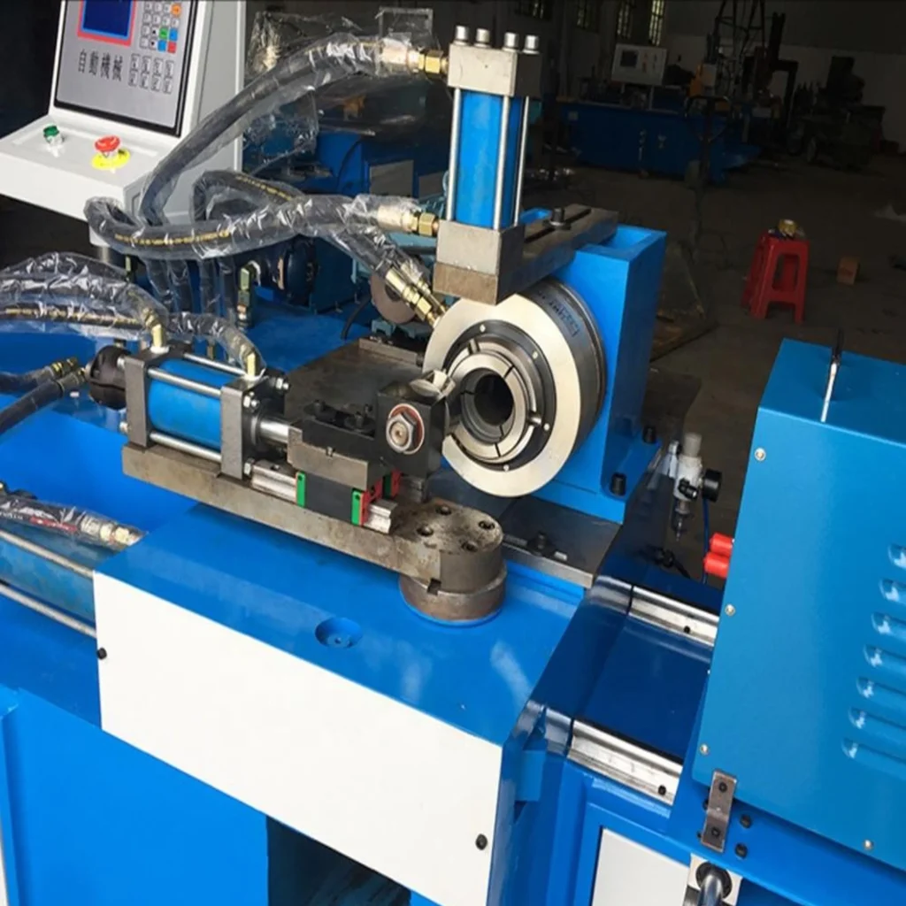
High-speed shear forming machines represent the fusion of traditional shear forming techniques with cutting-edge engineering focused on speed, precision, and efficiency. These machines are specifically designed to operate at significantly higher rotational and feed rates than standard shear forming equipment, enabling faster cycle times without compromising the dimensional accuracy or structural integrity of the final product. They are particularly useful in high-volume production environments such as the automotive, aerospace, and consumer goods industries, where throughput is just as critical as part quality. The primary appeal of high-speed machines lies in their ability to form complex, thin-walled, or lightweight components rapidly while maintaining exceptional consistency and repeatability.
To achieve such high operational speeds, every aspect of the machine—from spindle design and forming head mechanics to material clamping and tool control—must be engineered for stability and dynamic balance. These machines typically incorporate lightweight, high-strength materials in their rotating components to reduce inertia and vibration, and they use direct-drive motors or high-torque servomotors that offer rapid acceleration and deceleration. This allows the forming tools to move swiftly while maintaining a stable contact with the workpiece, preventing defects such as chatter, galling, or uneven wall thinning. Sophisticated damping systems and structural reinforcements ensure that the increased speed does not translate into reduced accuracy or mechanical wear, which is especially important in continuous production lines.
The control systems of high-speed shear forming machines are another critical differentiator. Advanced CNC platforms with real-time feedback loops, high-speed data processing, and adaptive motion control algorithms enable precise manipulation of forming parameters on the fly. These systems are often integrated with sensors that monitor material flow, temperature, and tool load in real time, automatically adjusting tool paths and forces to maintain optimal forming conditions. This high degree of process control allows manufacturers to produce parts with very tight tolerances—even at elevated speeds—and helps reduce the need for downstream inspection or rework.
In addition to speed and precision, these machines also offer enhanced material efficiency. Because they can maintain more consistent forming pressure and deformation rates, high-speed shear forming machines tend to produce less scrap and more uniform wall thicknesses across parts. This is particularly valuable when working with expensive or exotic materials such as titanium or high-grade aluminum alloys, where even minor waste can lead to significant cost increases. Furthermore, the reduced processing time helps lower energy consumption per part, aligning with broader efforts to improve sustainability in industrial operations.
Another advantage of high-speed shear forming machines is their compatibility with automation and Industry 4.0 frameworks. Many models are designed to integrate seamlessly into fully automated lines with robotic loading/unloading systems, in-line inspection equipment, and centralized manufacturing execution systems (MES). This makes them ideal for smart factories aiming to optimize labor efficiency, reduce lead times, and ensure consistent quality at scale. In applications such as automotive wheel or structural part production, where demand is constant and variation is limited, these machines enable lean manufacturing with minimal downtime or manual intervention.
Despite their sophistication, high-speed shear forming machines are also designed with operator usability in mind. Modern interfaces, touchscreens, and intuitive programming environments reduce the learning curve for new operators while allowing experienced users to push the machines’ capabilities even further. Integrated diagnostics and maintenance alerts also help keep machines running smoothly and prevent unexpected breakdowns, which is critical in high-throughput environments where even brief downtime can result in significant production losses.
As production demands continue to evolve, high-speed shear forming machines will likely grow in importance across a range of industries. Their combination of speed, precision, and adaptability positions them as essential tools for meeting the modern manufacturing challenges of cost efficiency, product performance, and rapid market response. Whether producing aerospace ducting, automotive structural components, or precision housings for electronics, these machines enable manufacturers to deliver complex metal parts faster and more reliably than ever before, solidifying their place at the forefront of advanced metal forming technology.
As high-speed shear forming machines continue to gain traction across advanced manufacturing sectors, their design is becoming increasingly refined to support ultra-fast yet highly stable operation over long production runs. The demand for near-perfect surface finishes, complex contours, and ultra-consistent wall thicknesses is driving the adoption of even tighter control systems and mechatronic integration. To maintain precision at high speeds, these machines rely on synchronized servo axes and intelligent real-time correction mechanisms that adjust tool pressure, rotational velocity, and forming trajectory within milliseconds of detecting deviation. These capabilities are not only essential for maintaining part geometry but also critical for ensuring uniform material flow, especially when dealing with anisotropic or thermally sensitive metals.
Because the shear forming process generates significant localized heat through deformation—especially at elevated speeds—thermal management is a growing focus. High-speed machines often incorporate advanced cooling systems that regulate both tooling and workpiece temperatures to prevent thermal distortion or premature tool degradation. In some cases, integrated temperature sensors enable predictive modeling of heat buildup, allowing the machine to modulate feed rate or apply intermittent cooling cycles. This dynamic thermal compensation enhances dimensional accuracy and extends tool life, supporting consistent operation even during long-duration, high-intensity runs.
The durability and performance of the forming tools themselves are also a critical factor in high-speed shear forming. These tools must not only resist wear and fatigue but also maintain sharp, consistent profiles at high rotational speeds and under cyclic loading conditions. To meet these challenges, manufacturers employ ultra-hard tool materials such as tungsten carbide, high-speed steels with cryogenic treatments, or ceramics for specific applications. Advanced coatings—like titanium aluminum nitride or chromium nitride—are applied to further reduce friction, enhance hardness, and protect against thermal and chemical degradation. Tool geometry is optimized for specific materials and part shapes, with simulation software used to predict material flow and stress concentrations before any physical tooling is produced.
In addition to physical performance, software plays an increasingly important role in optimizing high-speed shear forming processes. Many machines now include simulation modules that allow users to visualize and refine tool paths, predict thinning patterns, and evaluate potential defect zones before the first part is formed. These simulations are often based on finite element analysis (FEA) models and can be fed with live production data to improve accuracy over time. With AI-driven pattern recognition, machines can even detect trends in material behavior or tool wear and preemptively adjust forming conditions to maintain output quality. This level of intelligence reduces reliance on operator experience alone and supports more autonomous, lights-out manufacturing operations.
In industries like aerospace and automotive, where lightweighting is a constant priority, high-speed shear forming offers a reliable method for producing high-strength, thin-walled components with minimal material waste. The process is particularly well-suited to the forming of axisymmetric parts—such as cones, domes, or cylinders—that require precise contour control and a smooth surface finish. Compared to traditional machining or multi-stage forming techniques, shear forming can achieve comparable or superior results in fewer steps and with less raw material input. This not only reduces direct costs but also shortens development cycles and lead times, which are key metrics in competitive manufacturing environments.
The speed advantage also allows manufacturers to scale up production without proportionally increasing floor space or labor. A single high-speed shear forming machine, running efficiently with minimal downtime, can replace multiple conventional machines or manual forming operations. Combined with automated material handling systems, such machines become integral components of high-output production cells capable of running 24/7. These cells can be remotely monitored and maintained using industrial IoT technologies, providing visibility into everything from cycle efficiency and energy usage to tool wear and machine health. As the data pool grows, predictive models become more accurate, supporting proactive decision-making and continual process improvement.
Ultimately, high-speed shear forming machines represent the convergence of mechanical power, digital intelligence, and materials science. They reflect a broader shift in manufacturing toward integrated, data-driven systems that offer not just better performance, but also smarter, more sustainable operations. As materials continue to evolve—particularly with the introduction of ultra-high-strength steels, advanced aluminum alloys, and temperature-resistant superalloys—these machines will adapt with enhanced forming strategies, more robust structures, and deeper automation integration. Their contribution to industries requiring high-precision, high-volume metal forming will only grow, making them an essential tool in the next generation of advanced manufacturing ecosystems.
The ongoing evolution of high-speed shear forming machines is increasingly intertwined with broader manufacturing trends such as digital twins, augmented reality (AR) for maintenance, and full-factory synchronization under Industry 4.0 frameworks. By integrating with digital twin environments, these machines can simulate and optimize production scenarios with remarkable fidelity. Engineers and operators are able to test how different tool paths, forming speeds, and material characteristics will affect a part’s quality—virtually—before initiating the actual forming process. This reduces setup time, avoids costly trial-and-error runs, and ensures that only validated process parameters are used in production. As the simulation is continuously refined using real-world sensor data from the machine itself, it becomes a self-correcting system that delivers increasing accuracy over time.
Augmented reality is beginning to play a role in both operator training and maintenance for high-speed machines. With AR headsets or tablets, technicians can view layered visualizations of machine internals, receive step-by-step repair guidance, or access real-time diagnostic information overlaid on physical components. This reduces machine downtime, improves service precision, and helps less experienced staff carry out complex procedures under remote supervision. For facilities operating multiple machines with limited technical personnel, AR tools offer a scalable solution to skill gaps and maintenance delays, especially when combined with machine learning algorithms that preemptively identify potential issues before they escalate into critical failures.
As manufacturers seek to improve their environmental footprint, high-speed shear forming machines are also being evaluated for their sustainability. These machines tend to use material more efficiently than subtractive processes and generate significantly less waste, which aligns with green manufacturing goals. Furthermore, innovations such as energy-recovery systems in braking mechanisms, smart power distribution, and cooling systems that recycle process heat into facility-wide heating networks are being integrated into new designs. By minimizing waste, energy consumption, and resource intensity, high-speed machines help companies meet ESG (Environmental, Social, and Governance) criteria without sacrificing productivity or quality.
A crucial frontier in this development is adaptability—machines that can not only produce parts quickly and accurately, but also switch between product types with minimal downtime. Quick-change tooling systems, automatic tool recognition, and machine-learning-enhanced setup protocols now allow high-speed shear forming machines to shift from one production run to another with a level of flexibility once thought impossible in high-throughput operations. This is particularly valuable in contract manufacturing or sectors where product life cycles are short and variant complexity is high. The ability to retool rapidly without reprogramming or extensive calibration translates to greater responsiveness to market demand and reduced inventory costs.
In terms of market expansion, we are also seeing increased application of these machines in non-traditional industries. For example, high-speed shear forming is now used in the medical device sector to produce lightweight and high-strength surgical housings or structural components for imaging systems. In renewable energy, components for wind turbine hubs, hydrogen storage tanks, and even parts for next-gen nuclear reactors are now being formed using this technique. As industries converge in their need for precision, speed, and structural performance, the versatility of shear forming makes it a viable choice far beyond its traditional aerospace and automotive roots.
Looking ahead, the future of high-speed shear forming machines lies in even deeper integration with AI and advanced sensing. Machines will not only respond to in-process feedback but predict material behavior at a granular level—accounting for grain orientation, inclusions, or microstructural anomalies. With AI managing the balance between force application, feed rate, and thermal control, the result will be a virtually autonomous forming process that requires minimal operator oversight. This “cognitive forming” paradigm will drive consistent quality even across variable input material lots, ensuring zero-defect manufacturing becomes a realistic and sustainable target.
In sum, the high-speed shear forming machine stands as a flagship of modern manufacturing capabilities—combining brute force and delicate precision, analog forming techniques and digital intelligence, all in one continuously evolving system. As the manufacturing landscape shifts toward greater customization, agility, and efficiency, the role of these machines will not only remain vital but become emblematic of what high-performance, future-ready production truly looks like.
Automated Shear Forming Machine
An automated shear forming machine represents a significant leap in manufacturing efficiency, precision, and repeatability, combining the mechanical advantages of shear forming with sophisticated automation systems that reduce human intervention, increase throughput, and ensure consistent product quality. These machines are designed to autonomously perform the entire forming cycle—from material loading and alignment to forming, unloading, and quality control—using programmable logic controllers (PLCs), CNC systems, and often robotic arms. The integration of automation transforms the traditional forming process into a smart, highly responsive production cell that is ideal for mass production and for environments where downtime and variability must be minimized.
At the heart of an automated shear forming machine is a robust CNC system capable of executing complex tool paths and adjusting forming parameters in real time based on input from integrated sensors. These sensors monitor variables such as forming force, spindle speed, temperature, and material deformation, allowing the machine to make continuous adjustments to maintain dimensional accuracy and prevent material defects like tearing or wrinkling. This feedback loop not only improves process reliability but also supports predictive maintenance and adaptive control, which are critical in high-volume, lights-out manufacturing environments.
Material handling is fully automated in these machines, often utilizing conveyors, robotic loaders, or gantry systems to move workpieces into and out of the forming zone. These systems are precisely synchronized with the forming cycle to eliminate idle time and ensure a steady flow of parts. In some configurations, the machine may be integrated into a larger production line, seamlessly handing off formed components to subsequent processes such as trimming, heat treating, or surface finishing. This modularity makes automated shear forming machines ideal for integrated manufacturing systems that prioritize lean operation and traceability.
Tooling changes and machine setup are also automated in advanced models. Quick-change tool heads with automatic tool recognition systems enable the machine to switch between different part geometries or materials with minimal downtime. This is especially beneficial in facilities that produce a variety of components on the same equipment. Machine vision systems can verify tool condition and alignment before and after each run, ensuring consistent results and reducing the risk of operator error or equipment damage. Combined with recipe-based control systems, this makes switching production between parts nearly instantaneous and highly reliable.
In addition to mechanical and control advancements, automated shear forming machines are built with connectivity in mind. They can be integrated into enterprise resource planning (ERP) and manufacturing execution systems (MES), providing real-time production data for scheduling, inventory management, and performance monitoring. This connectivity enables data-driven decision-making and supports Industry 4.0 strategies such as digital twin modeling, process simulation, and AI-assisted optimization. As a result, manufacturers gain better insight into their operations and can quickly respond to issues such as tool wear, process drift, or material inconsistencies before they impact final product quality.
Energy efficiency is another hallmark of automated shear forming systems. Because the forming process is tightly controlled and optimized for each operation, these machines tend to use only the energy necessary for precise deformation, minimizing waste heat and excess load. Some systems incorporate regenerative braking or power management modules that return unused energy to the grid or distribute it across other equipment. This helps reduce the overall environmental footprint of the operation while also lowering operating costs, a win-win for sustainability and profitability.
Safety and ergonomics are improved in automated setups as well. With robots and enclosed forming areas handling the bulk of the process, operators are no longer exposed to the physical demands or hazards of manual forming. Instead, human oversight shifts to system monitoring and decision support, which can often be performed remotely. This allows for a safer, more efficient workforce deployment while supporting higher levels of machine uptime and availability.
In applications such as aerospace, defense, high-end automotive, and energy infrastructure, the demand for precise, repeatable, and cost-efficient metal forming continues to rise. Automated shear forming machines meet these demands head-on, offering unmatched control over complex geometries, high-strength materials, and stringent tolerances. Their ability to operate continuously, self-correct in real time, and produce with near-zero waste makes them an essential component of the next generation of smart factories. As automation technologies continue to evolve, these machines will only become more intelligent, adaptable, and indispensable in advanced manufacturing ecosystems.
The evolution of automated shear forming machines continues to accelerate as manufacturers seek greater efficiency, flexibility, and precision in metal forming operations. These machines are increasingly designed to perform not just as isolated production units but as interconnected nodes in fully automated manufacturing environments. The level of intelligence embedded in their systems allows for continuous adaptation to varying production conditions, such as changes in material properties, ambient temperatures, or production speed demands. Through machine learning algorithms, they can detect subtle shifts in forming behavior and autonomously recalibrate parameters like tool pressure, rotational velocity, and feed rates, ensuring uniform part quality over extended runs without human intervention. This capability is particularly valuable when working with materials that are prone to inconsistency, such as certain aluminum or high-strength steel alloys, where manual correction would otherwise slow production or introduce error.
Automated shear forming machines also benefit from advancements in artificial vision and laser-based metrology. Inline inspection systems are now standard in many models, allowing for the immediate measurement of formed parts for diameter, wall thickness, and surface finish before they leave the forming station. These measurements can be compared with digital specifications in real time, and any deviation beyond tolerance thresholds will automatically trigger adjustments or flag the component for rework. This immediate feedback loop reduces waste and virtually eliminates the need for post-process inspection, helping to streamline quality assurance in high-volume environments. Furthermore, the captured data can be logged into central databases to support traceability, audit readiness, and compliance with industry standards in fields like aerospace or medical device manufacturing.
As customer demands shift toward shorter product life cycles and greater customization, automated shear forming machines are evolving to offer not only speed and precision but also unparalleled flexibility. Newer generations of these machines feature multi-axis forming heads capable of manipulating the tool path in more dynamic ways, enabling the production of parts with non-traditional profiles or variable wall thicknesses in a single pass. These machines can interpret complex CAD models directly, converting digital design files into real-world components without the need for intermediate programming. Combined with tool libraries and automated tool changers, this allows rapid switching between product variants, making small-batch or just-in-time production not only possible but economically viable.
Another critical area of development is predictive maintenance. Modern automated machines are equipped with an array of sensors that constantly monitor vibration levels, temperature gradients, motor loads, and wear characteristics. This data is analyzed in real time to identify patterns that precede mechanical failures or process degradation. Maintenance is then scheduled proactively, avoiding unexpected downtime and extending the overall life of the equipment. This predictive approach contrasts sharply with traditional reactive or time-based maintenance models and has become essential in facilities that operate continuously or under strict uptime constraints.
Connectivity is key to the expanding role of automated shear forming machines in larger industrial ecosystems. Through industrial Ethernet or wireless protocols, these machines can communicate directly with upstream and downstream equipment, as well as with supervisory control systems. For example, they can receive material property data from upstream quality scanners and automatically adjust forming parameters, or they can notify robotic arms when parts are ready for transfer. This synchronization enables tightly integrated production lines where material moves seamlessly from one operation to the next without manual handling or data entry, minimizing latency and maximizing throughput.
The environmental advantages of automation extend beyond energy efficiency. Because these machines produce less scrap, operate with optimized force application, and run with fewer human-induced errors, they support broader sustainability goals while also improving the economic efficiency of production. Water-based lubrication systems, enclosed coolant cycles, and recyclable tool components further reduce the environmental impact of the forming process. In regions where regulatory pressure is increasing, and in industries where ESG reporting is now a competitive differentiator, these features contribute to a cleaner, leaner, and more accountable operation.
Ultimately, automated shear forming machines are reshaping the landscape of metal forming by enabling a shift from operator-dependent, batch-based manufacturing to intelligent, continuous, and adaptable production. Their ability to learn, self-correct, and integrate into broader digital infrastructure makes them central to the next generation of manufacturing systems—ones that are not only faster and more accurate, but also more responsive to the complex demands of global supply chains. As these machines continue to evolve, driven by advancements in AI, robotics, and edge computing, they will further blur the lines between physical machinery and digital intelligence, embodying the principles of smart manufacturing in their most advanced form.
The integration of digital intelligence into automated shear forming machines is enabling new paradigms of autonomous decision-making, where machines are not just following pre-programmed sequences but actively interpreting sensor inputs, historical data, and contextual variables to make informed adjustments mid-process. This convergence of hardware and artificial intelligence transforms the forming operation into a living system that adapts continuously to both internal and external stimuli. For example, if the machine detects a pattern of minor fluctuations in wall thickness across successive parts, it can automatically recalibrate feed rates, pressure, or tool engagement angles to correct the deviation before it impacts quality. These kinds of micro-adjustments, once reliant on operator judgment and experience, are now handled in milliseconds by algorithms that evaluate thousands of data points in real time.
Such autonomy also supports advanced forms of process validation and certification, particularly important in aerospace, medical, and defense sectors where traceability and compliance are paramount. Each component formed can be assigned a digital birth certificate that includes a complete profile of its production parameters—tool settings, machine temperatures, forming forces, inspection results, and even ambient environmental data at the time of production. This information can be stored in decentralized ledgers or cloud-based databases for secure, tamper-resistant auditing. The ability to instantly retrieve a digital trail for any part greatly simplifies quality assurance and regulatory compliance while also offering new capabilities for root-cause analysis if defects are discovered in service.
Moreover, as additive manufacturing continues to mature and blend with traditional subtractive and forming technologies, we are beginning to see hybrid production cells where shear forming machines are paired with 3D printers or CNC machining centers. These hybrid lines allow for the creation of preforms or intermediate shapes via additive methods, which are then shear formed to final dimensions with superior strength and precision. Alternatively, formed components can be machined or coated post-forming in a fully automated workflow. Such integration maximizes the strengths of each process and opens the door to manufacturing parts that were previously impossible or uneconomical to produce using a single technique.
Human-machine interaction is also becoming more intuitive and efficient. Rather than relying solely on complex HMI panels, operators can now interact with machines via natural language commands, touchscreen interfaces, or even gesture-based controls in augmented reality environments. This not only reduces training time but also democratizes machine operation, making it easier for less experienced workers to manage sophisticated equipment safely and effectively. With cloud-based support systems, remote experts can log into machines anywhere in the world to assist with setup, diagnostics, or process optimization, creating a distributed knowledge network that helps bridge skill gaps across the workforce.
The influence of automated shear forming machines is extending into supply chain strategy as well. Because these machines can rapidly switch between parts, operate with minimal oversight, and maintain high quality across different materials and geometries, they are ideal for decentralized or on-demand manufacturing models. Instead of relying on large, centralized facilities with long lead times and inflexible production schedules, companies can deploy smaller, agile manufacturing hubs closer to end markets. This reduces shipping costs, shortens delivery timelines, and enables localized customization—strategies that are increasingly critical in a global economy marked by volatility and shifting demand patterns.
As the technology matures, we can also expect further miniaturization and modularity in shear forming machines. Portable or compact units, possibly mounted on mobile platforms or within containerized factories, could bring high-precision forming to field operations or disaster zones. This would be particularly valuable in military or space applications, where the ability to fabricate critical components on-site, on-demand, without full-scale infrastructure could be a game changer. Additionally, modular components could allow users to reconfigure machines for specific applications, such as switching between aluminum and titanium forming with minimal hardware changes.
All these developments underscore the transition of automated shear forming from a niche high-speed process into a cornerstone of modern, intelligent manufacturing. No longer constrained by static capabilities or limited flexibility, these machines represent a dynamic, evolving class of equipment that aligns with broader industrial trends toward agility, resilience, and digital integration. Their future lies not just in mechanical enhancement but in becoming adaptive, collaborative systems that work in concert with humans and other machines to deliver faster, smarter, and more sustainable production across virtually every sector.
Multi-Spindle Shear Forming Machine
A multi-spindle shear forming machine is an advanced version of the traditional shear forming technology, designed to enhance production efficiency by using multiple spindles or forming heads simultaneously. This configuration allows for the processing of several workpieces or different sections of a single part in parallel, significantly increasing throughput and reducing cycle times. Multi-spindle systems are particularly useful in high-volume manufacturing environments, where the ability to maintain consistent quality while increasing production speed is a critical factor.
In a typical multi-spindle shear forming machine, each spindle is equipped with its own set of tools, which can operate independently of each other. This independence enables the machine to perform multiple operations at once, such as forming, trimming, or deburring, on different areas of a workpiece or on different parts. The simultaneous processing of multiple parts reduces the need for downtime associated with tool changes, loading, and unloading, and can make the entire process more streamlined and efficient. The reduction in cycle time allows for a faster return on investment, as the system can produce more parts in a given time frame.
These machines are often fully automated, integrating with robotic loading and unloading systems that handle parts without requiring operator intervention. The automation also extends to tool changes, where quick-change systems or automated tool presetting mechanisms enable the machine to switch between different forming tools based on the specific requirements of the part being processed. This flexibility makes multi-spindle shear forming machines adaptable to a wide range of components, from small, intricate parts to larger, heavier workpieces, all within the same production run.
The precision of multi-spindle shear forming machines is crucial. Each spindle operates under the same exacting tolerances, and any deviation in one of the spindles can lead to quality issues across all processed parts. To prevent this, advanced control systems are used to synchronize the movements of each spindle, ensuring uniformity in the forces applied and maintaining tight tolerances across multiple parts. Furthermore, integrated feedback loops using sensors and vision systems monitor key parameters, such as material thickness, deformation, and tool wear, allowing for real-time adjustments and maintaining part quality throughout the run.
One of the major benefits of a multi-spindle setup is its ability to form parts with complex geometries or features in a single pass. For example, when producing a component with multiple flanges or indentations, a multi-spindle machine can form all of these features simultaneously, ensuring uniformity and precision across the entire part. This is particularly valuable in industries like aerospace, automotive, and heavy machinery, where parts often require multiple, precise features that must be formed in a single, coordinated process.
In terms of applications, multi-spindle shear forming machines are particularly well-suited for industries that require large quantities of components with high precision, such as automotive, where they are used to form parts like wheels, rims, and structural components, and aerospace, where they are used for lightweight but durable parts like turbine housings and pressure vessels. The ability to scale production while maintaining accuracy is one of the defining characteristics of these systems.
In addition to their use in high-volume production, multi-spindle shear forming machines also play a role in reducing operational costs. The efficient use of tooling, combined with reduced cycle times and automated operations, minimizes labor costs and material waste. This is crucial in industries where profit margins are tightly controlled, and operational efficiency is a key driver of competitiveness.
Energy consumption is another area where these machines excel. By distributing the load across multiple spindles, the system can operate at higher speeds without overloading any single spindle, which can help optimize power usage. Some systems are equipped with regenerative energy recovery, where energy generated during braking or deceleration phases is recaptured and fed back into the system, reducing overall energy consumption.
Overall, multi-spindle shear forming machines represent a significant advancement in metal forming technology, offering improved production efficiency, reduced cycle times, and enhanced flexibility. As manufacturing continues to evolve, these machines are becoming integral components of automated production lines that demand both high precision and high output, helping to meet the needs of modern manufacturing while maintaining the strict quality standards required by industries like aerospace, automotive, and defense. Their ability to simultaneously process multiple parts with tight tolerances makes them an invaluable asset for manufacturers looking to optimize production and meet increasing global demand for complex, high-quality components.
The multi-spindle shear forming machine’s ability to operate with precision and high throughput is further enhanced by its integration with advanced manufacturing technologies. These machines are increasingly equipped with IoT sensors and data analytics capabilities that enable them to communicate with other machines and systems within a smart factory environment. By collecting real-time data on parameters such as tool wear, vibration, and material properties, the machine can make automatic adjustments or send alerts for maintenance needs, further improving uptime and reducing the likelihood of defects. This integration into a broader digital ecosystem allows for predictive analytics, where potential issues are identified before they can impact production, enabling manufacturers to take corrective action without interrupting the workflow.
The adaptability of multi-spindle shear forming machines also plays a pivotal role in enhancing their usefulness across a range of industries. As manufacturing demands shift towards smaller batches of customized products, these machines can accommodate variations in part geometry or material type by reconfiguring tools and adjusting settings on the fly. For instance, a system that previously produced a series of components with similar geometries can quickly pivot to handle parts with entirely different shapes or sizes, all while maintaining the same level of efficiency and precision. This ability to switch between different part configurations quickly without compromising production speed is essential in industries where fast time-to-market and flexibility are crucial competitive advantages.
In terms of scalability, multi-spindle machines also offer significant benefits. As demand for a particular product or component increases, manufacturers can scale production by adding additional spindles or integrating more machines into the production line, thus maintaining production speed while ensuring that quality control standards are upheld. This scalability is especially useful for businesses that experience fluctuations in production volume or are entering new markets with different product requirements. Furthermore, many multi-spindle shear forming machines can operate in tandem with other automated manufacturing processes, such as CNC machining, additive manufacturing, or robotic assembly systems, forming a fully integrated, end-to-end production line.
When it comes to material versatility, multi-spindle shear forming machines are designed to handle a wide range of metals, including high-strength alloys, titanium, aluminum, and more. The ability to process materials that are difficult to form using traditional methods gives manufacturers the flexibility to produce components for highly specialized industries such as aerospace, defense, and medical devices. These materials often require the highest levels of precision and care during processing to avoid defects, and the multi-spindle system’s ability to maintain uniformity across multiple parts at once ensures that even the most demanding material properties can be managed efficiently.
The environmental benefits of multi-spindle shear forming machines are also notable. These systems, with their ability to minimize waste and optimize material usage, help reduce the environmental impact of manufacturing. By forming multiple parts simultaneously, the overall material utilization rate is higher, and the amount of scrap material produced is minimized. Additionally, the machines’ automated nature allows for tighter control of the forming process, reducing energy consumption and ensuring that only the necessary amount of power is used. Advanced cooling and lubrication systems, which are often integrated into multi-spindle machines, also contribute to their efficiency by maintaining optimal operating temperatures, preventing overheating and reducing the need for excessive cooling fluids, further lowering the environmental footprint.
These machines are also paving the way for the future of decentralized manufacturing. The ability to operate with minimal human intervention and handle complex tasks efficiently makes multi-spindle shear forming machines ideal candidates for remote or distributed manufacturing operations. Whether in a factory with limited space or in a facility located in a region with fewer resources, these machines offer manufacturers the ability to produce high-quality parts with a lean, automated workforce. As remote monitoring and control technologies continue to improve, operators can oversee the production process from anywhere in the world, ensuring continuous production with minimal disruptions.
In summary, multi-spindle shear forming machines represent a significant evolution in metal forming technology, offering unprecedented levels of speed, precision, and flexibility. By integrating advanced sensors, data analytics, and IoT capabilities, these machines provide manufacturers with a level of control and adaptability that was previously unattainable. Whether for high-volume production, customized part manufacturing, or environmentally conscious production processes, multi-spindle shear forming machines are poised to play an increasingly vital role in the future of manufacturing, driving efficiency, reducing costs, and improving the overall quality of formed components.
The future of multi-spindle shear forming machines is closely tied to the ongoing evolution of industry 4.0 principles, where automation, data exchange, and digital integration play pivotal roles in reshaping manufacturing landscapes. As factories transition to more interconnected, autonomous systems, multi-spindle shear forming machines will continue to become more intelligent, responsive, and adaptable. Advanced machine learning algorithms will enable these systems to learn from past production runs, optimizing not only machine settings but also material handling and tooling strategies for improved efficiency. These self-optimizing systems will be capable of adjusting the forming process in real time based on sensor data, feedback from downstream processes, and even predictive analytics about future production requirements.
Furthermore, as sustainability becomes an increasingly pressing concern, multi-spindle shear forming machines will incorporate more advanced energy-saving features. Some of these machines are already incorporating regenerative braking systems, where energy generated during certain movements is captured and used to power other parts of the system or returned to the power grid. This energy-efficient design reduces the overall energy consumption of the machine and helps manufacturers meet sustainability targets. Additionally, as materials like lightweight metals, composites, and advanced alloys become more common in industries like aerospace and automotive, multi-spindle shear forming machines will be further optimized to handle these materials with minimal waste and superior precision.
The increased use of robotics within these systems also contributes to efficiency and precision. Automated robotic arms can be integrated to perform tasks such as part loading and unloading, tool changing, or even inline inspection, reducing the need for human intervention and ensuring a more consistent, error-free production process. These robotic systems can be programmed to handle a variety of tasks at different stages of production, allowing multi-spindle shear forming machines to operate with greater autonomy and flexibility. This robotic integration not only speeds up production but also minimizes human exposure to dangerous or high-risk environments, enhancing workplace safety.
In addition to automation and robotics, the use of artificial intelligence (AI) and machine learning will further advance the capabilities of multi-spindle shear forming machines. AI-driven predictive maintenance algorithms, for instance, will monitor machine health and detect early signs of wear or potential failures, prompting preventive maintenance before significant issues occur. By analyzing historical machine data and detecting patterns of abnormal behavior, AI can predict failures with remarkable accuracy, reducing downtime and unplanned maintenance events. This predictive approach not only increases the reliability of the system but also optimizes the lifecycle of machine components, reducing the frequency and cost of repairs.
Another area where multi-spindle shear forming machines are evolving is in their capability to handle more complex geometries and demanding part features. As industries demand more intricate and customized components, multi-spindle machines will incorporate advanced forming techniques, such as multi-axis forming, which allows the tool to move along more than just the standard axes. These machines can produce parts with features that would have been impossible or impractical using traditional shear forming methods. The integration of hybrid manufacturing technologies, where additive manufacturing (3D printing) is used in conjunction with shear forming, also expands the scope of what these machines can create, enabling the production of parts that combine the strengths of both additive and subtractive processes.
The rise of digital twins is also an important trend influencing multi-spindle shear forming machines. A digital twin is a virtual representation of a physical machine that simulates its real-world performance. Manufacturers can use digital twins to model different production scenarios, test new settings or configurations, and even simulate the effects of varying environmental conditions before they are implemented in the real machine. This predictive modeling capability allows for better planning, fewer trial-and-error approaches, and improved production outcomes, as manufacturers can optimize machine operations based on virtual simulations before making changes to the physical system.
The continued improvement in human-machine interfaces (HMIs) will also make it easier for operators to interact with and manage these advanced machines. While traditional HMIs have relied on physical buttons and complex screens, future systems will likely incorporate intuitive interfaces such as voice commands, augmented reality (AR) displays, or gesture recognition. This will allow operators to interact with machines in a more natural, user-friendly manner, making it easier for them to monitor production processes, adjust settings, and troubleshoot potential issues with minimal training. AR could also be used for real-time guidance and remote troubleshooting, where field technicians or engineers could visually guide operators through complex procedures without being physically present at the machine.
As regulatory requirements continue to evolve, multi-spindle shear forming machines will play an essential role in ensuring compliance with stricter quality standards, especially in industries such as aerospace, medical devices, and automotive. The ability to collect and store data on every aspect of the forming process—from material properties to machine settings and final part dimensions—ensures that manufacturers can provide full traceability and prove compliance with industry regulations. This data also serves as a valuable tool for continuous improvement, as manufacturers can analyze trends over time to identify areas for process optimization and quality enhancement.
With all these advancements, multi-spindle shear forming machines are becoming a cornerstone of modern manufacturing. Their adaptability, precision, and integration with the latest technologies make them essential for industries looking to remain competitive in a rapidly changing global market. As the demand for high-quality, complex components continues to grow, these machines will be pivotal in enabling faster, more efficient production while maintaining the highest standards of quality, precision, and sustainability. The future of multi-spindle shear forming technology is bright, as it evolves to meet the increasingly sophisticated needs of manufacturers across various industries, from automotive to aerospace to medical devices and beyond.
EMS Metalworking Machines
We design, manufacture and assembly metalworking machinery such as:
- Hydraulic transfer press
- Glass mosaic press
- Hydraulic deep drawing press
- Casting press
- Hydraulic cold forming press
- Hydroforming press
- Composite press
- Silicone rubber moulding press
- Brake pad press
- Melamine press
- SMC & BMC Press
- Labrotaroy press
- Edge cutting trimming machine
- Edge curling machine
- Trimming beading machine
- Trimming joggling machine
- Cookware production line
- Pipe bending machine
- Profile bending machine
- Bandsaw for metal
- Cylindrical welding machine
- Horizontal pres and cookware
- Kitchenware, hotelware
- Bakeware and cuttlery production machinery
as a complete line as well as an individual machine such as:
- Edge cutting trimming beading machines
- Polishing and grinding machines for pot and pans
- Hydraulic drawing presses
- Circle blanking machines
- Riveting machine
- Hole punching machines
- Press feeding machine
You can check our machinery at work at: EMS Metalworking Machinery – YouTube
Applications:
Flange-punching
Beading and ribbing
Flanging
Trimming
Curling
Lock-seaming
Ribbing