Metal Sheet Hydroforming: Hydroforming is a specialized manufacturing process that uses hydraulic fluid pressure to shape metal components. Unlike traditional stamping or pressing, where mechanical forces are applied directly to the material, hydroforming involves pressurizing a fluid to shape a metal sheet or tube against a die. This method allows for the creation of complex, lightweight, and structurally robust components that are difficult or impossible to produce using other methods.
The roots of hydroforming date back to the 1950s, when it was first developed for use in the automotive industry. With the growing need for lightweight yet strong vehicle components, hydroforming offered an efficient solution by reducing the number of welded joints and allowing the formation of intricate shapes in a single step. Over time, hydroforming has evolved to be applied in a wide range of industries, including aerospace, consumer products, and even electronics.
Advantages of Hydroforming: One of the key advantages of hydroforming is its ability to create lightweight structures with a high strength-to-weight ratio, which is critical for industries such as automotive and aerospace where fuel efficiency and strength are paramount. The process allows manufacturers to create more complex shapes with fewer parts, reducing the need for assembly, minimizing material waste, and improving overall production efficiency.
Hydroforming is also more material-efficient compared to other processes such as stamping or forging, as it allows manufacturers to use thinner materials while maintaining the required strength and durability. This makes it particularly suitable for working with high-strength materials such as aluminum and steel. Additionally, hydroforming reduces the number of welds and joins in components, enhancing the overall strength and aesthetic quality of the final product.
Sheet Hydroforming Process
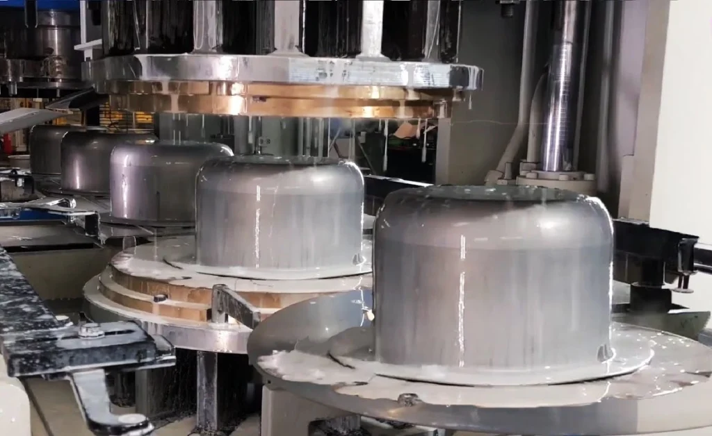
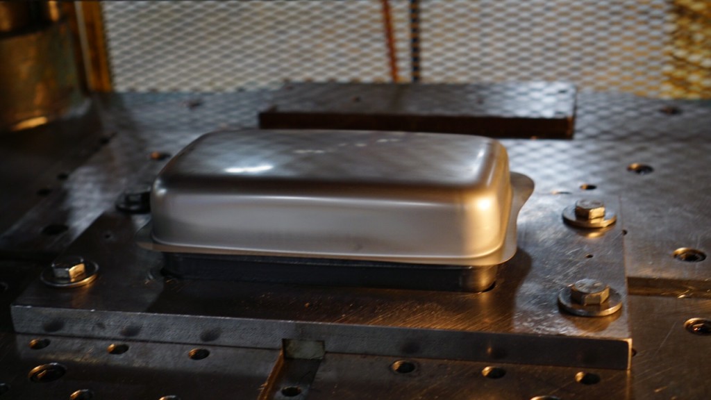
Overview of Sheet Hydroforming: Sheet hydroforming involves the use of hydraulic fluid to press a sheet of metal against a die to form complex shapes. The process typically starts with placing a metal sheet on a male die, and hydraulic pressure is applied to force the sheet into conformity with the die. This allows for the creation of high-precision, detailed parts with minimal material stress.
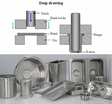
There are two primary types of sheet hydroforming: conventional sheet hydroforming and deep-draw hydroforming. In conventional sheet hydroforming, the sheet is pressed between a punch and a die using hydraulic fluid. The fluid distributes the force evenly over the surface of the metal, which helps in producing intricate shapes. In contrast, deep-draw hydroforming involves drawing the metal deeper into the die cavity to form more complex shapes. This process is often used to create parts that require a higher depth-to-width ratio.
Applications in Industry: Hydroforming is widely used in various industries due to its ability to produce lightweight, high-strength components. One of the key sectors that benefit from sheet hydroforming is the automotive industry. For example, automotive manufacturers use the process to create components such as body panels, chassis parts, and engine cradles, which need to be strong, durable, and lightweight. In addition, the aerospace industry uses sheet hydroforming to create parts like fuselage sections and wing structures, where precision and strength are critical.
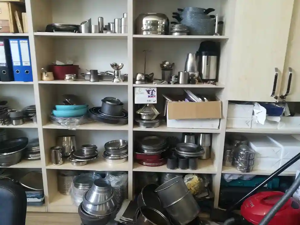
The process is also used in the production of consumer goods such as kitchen appliances and lighting fixtures, where manufacturers can benefit from hydroforming’s ability to create aesthetically pleasing and functional shapes.
Challenges and Limitations: While sheet hydroforming offers many advantages, it also has certain limitations. One of the primary challenges is material compatibility. Not all metals are suitable for hydroforming, as some materials may not respond well to the high pressures involved. For example, very thick materials or brittle metals can crack under pressure, limiting the types of products that can be produced using this method.
Another limitation is the tooling cost. Hydroforming requires specialized tools such as high-strength dies and presses capable of withstanding immense pressures. This makes it less cost-effective for small production runs, where the cost of tooling may outweigh the benefits of the process.
Hydroforming Machines
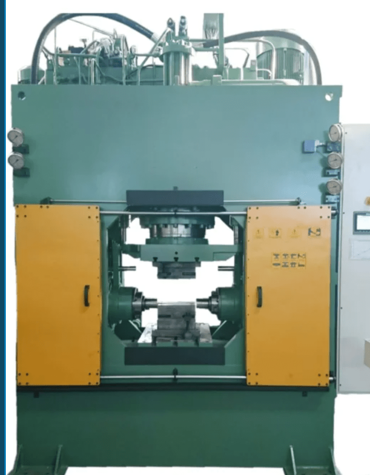
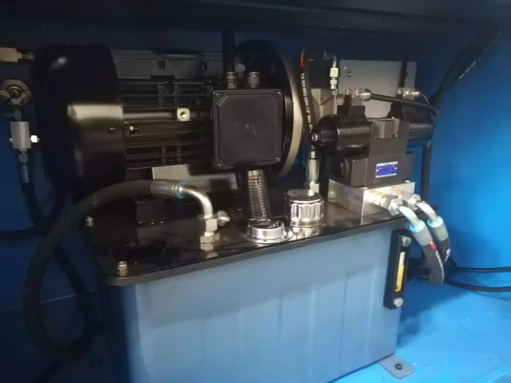
Key Components of Hydroforming Machines: Hydroforming machines are complex systems made up of several critical components. At the heart of every hydroforming machine is the hydraulic system, which generates the high-pressure fluid needed to shape the metal. The hydraulic system consists of pumps, valves, and pressure controllers that ensure the right amount of force is applied during the forming process.
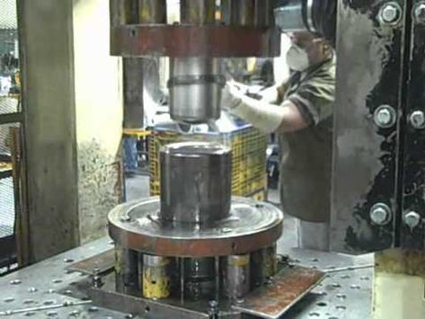
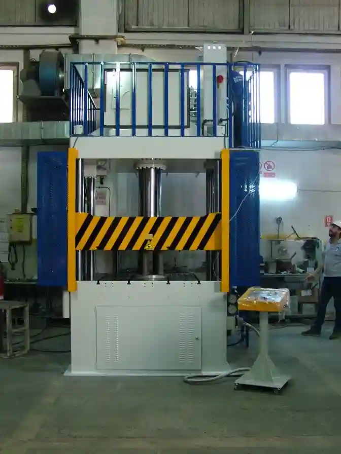
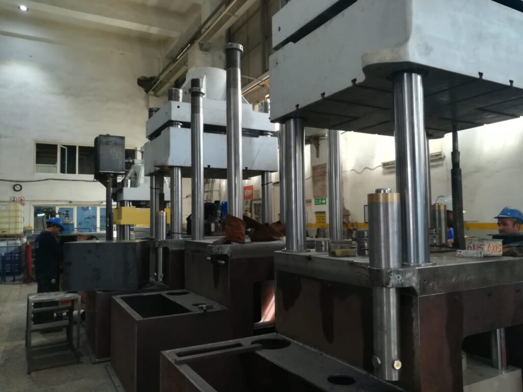
Another essential component is the press, which houses the die and holds the metal sheet or tube in place. Dies, which can be custom-made depending on the required shape, are typically made from high-strength materials such as hardened steel or carbide to withstand repeated high-pressure forming cycles. The forming chamber, where the metal is placed, is sealed to prevent leaks, ensuring that hydraulic pressure is evenly distributed during the process.
Types of Hydroforming Machines: Hydroforming machines are generally categorized into sheet hydroforming machines and tube hydroforming machines, depending on the type of metal being formed. Sheet hydroforming machines are used for flat or slightly curved materials, while tube hydroforming machines are designed specifically for shaping hollow tubes and pipes.
Custom-built hydroforming machines are also available for specific applications, such as forming large, complex parts for aerospace or military uses. These machines often incorporate advanced automation and CNC (computer numerical control) systems for enhanced precision and control over the forming process.
Hydroforming Machine Design Considerations: Designing a hydroforming machine requires careful consideration of various factors, including the type of material being formed, the pressure capacity needed, and the size and complexity of the parts being produced.
Pressure control is a key consideration in hydroforming machine design. The hydraulic system must be capable of generating and maintaining the necessary pressure to form the metal without causing it to crack or tear. This is particularly challenging when working with materials like aluminum, which are prone to work-hardening under pressure. Therefore, advanced pressure monitoring systems and feedback loops are often incorporated to ensure consistent and precise forming.
In addition to pressure control, machine automation is an important feature of modern hydroforming systems. Automation helps improve production efficiency, reduce operator error, and enhance safety. Many machines are now equipped with CNC systems, which allow for precise control over the forming process, from adjusting pressure levels to controlling the movement of the dies and punches. This level of control is especially critical in industries such as aerospace and automotive, where tight tolerances and consistency are essential.
Hydroforming Presses
Types of Hydroforming Presses: Hydroforming presses are specifically designed to handle the unique challenges of forming metal using hydraulic pressure. They are categorized based on the type of metal forming process they support, the most common being sheet hydroforming presses, deep-draw hydroforming presses, and tubular hydroforming presses.
- Sheet Hydroforming Presses:
- These presses are used to form flat metal sheets into complex shapes. They use a single die, and hydraulic fluid is applied on one side of the sheet, pressing it against the die. Sheet hydroforming presses are ideal for producing large, intricately shaped components with minimal joints and welds.
- Deep-Draw Hydroforming Presses:
- Deep-draw presses are designed for forming deeper components, where the material needs to be pulled deeper into the die cavity. This type of press is commonly used in the automotive industry to create parts like fuel tanks, body panels, and structural components.
- Tubular Hydroforming Presses:
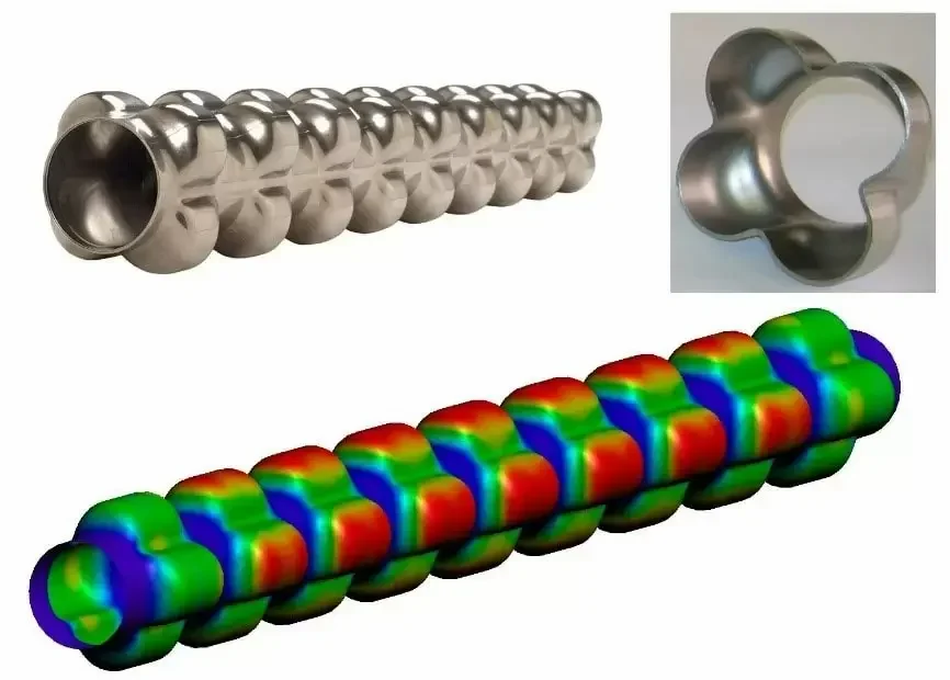
- Tubular hydroforming presses are specialized for forming hollow tubes and pipes. These presses use hydraulic fluid to expand the tube against a die, creating parts with varying diameters and cross-sections. The automotive industry, in particular, benefits from tubular hydroforming to produce lightweight and structurally strong components like exhaust systems and chassis frames.
Hydroforming Press Capacity and Features: The capacity of a hydroforming press is determined by the maximum pressure it can exert, which typically ranges from 5,000 psi to over 100,000 psi, depending on the material being formed and the complexity of the part. Modern hydroforming presses are equipped with various advanced features to enhance efficiency, precision, and safety.
- Modular Designs: Many presses feature modular designs that allow manufacturers to customize the machine to their specific needs. This could include interchangeable dies for different part geometries, as well as adjustable pressure settings to accommodate different materials.
- Speed and Accuracy: The speed at which the press operates is another critical factor, especially for high-volume production environments. Some presses are equipped with high-speed hydraulics to reduce cycle times, while still maintaining the accuracy required for complex shapes.
- Automation and Safety: Automation systems play a significant role in modern hydroforming presses. CNC controls, robotic loading systems, and automatic pressure adjustments all contribute to improved safety and efficiency. Additionally, safety features such as pressure sensors, overload protection, and emergency shut-off systems are standard in most industrial presses to protect both the operator and the machine.
Hydroforming of Tubes
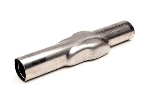
Tube Hydroforming Process: Tube hydroforming is a process specifically used for shaping hollow metal tubes. Unlike sheet hydroforming, which works with flat materials, tube hydroforming involves placing a hollow tube into a die and applying internal hydraulic pressure. As pressure is applied, the tube expands and conforms to the shape of the die, creating a part with complex cross-sections and varying diameters.
The tube hydroforming process typically follows these steps:
- Tube Placement: A metal tube, often made of aluminum, steel, or stainless steel, is placed into a die.
- Sealing and Pressurization: The ends of the tube are sealed, and hydraulic fluid is injected into the tube. This creates internal pressure.
- Tube Expansion: The hydraulic pressure forces the tube to expand against the die, forming it into the desired shape.
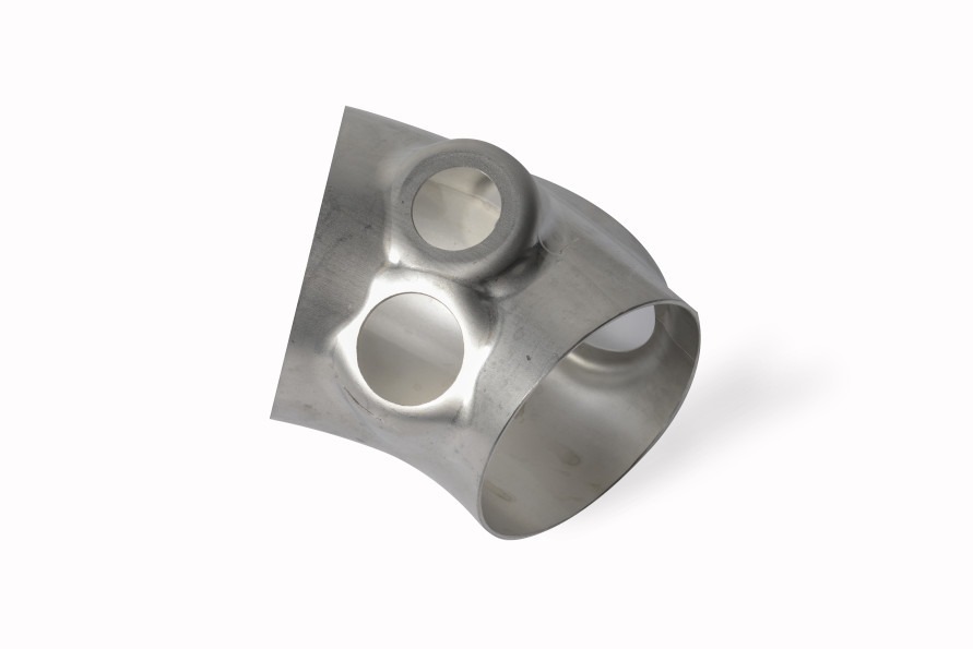
- Final Forming: In some cases, additional tools, such as external punches, may be used to create specific features like holes or bends in the tube.
- Cooling and Removal: After forming, the part is cooled and removed from the die.
Advantages for Manufacturing Lightweight, Structurally Strong Components: Tube hydroforming offers several advantages over traditional methods like stamping or welding for manufacturing hollow components:
- Weight Reduction: Tube hydroforming allows for the creation of lightweight, structurally strong parts by using thinner materials without sacrificing strength. This is crucial for industries like automotive and aerospace, where reducing weight improves fuel efficiency and performance.
- Complex Geometries: The process enables manufacturers to create components with complex shapes, such as varying cross-sections and intricate contours, in a single forming step. This reduces the need for multiple parts and welding, which in turn enhances strength and durability.
- Enhanced Structural Integrity: Since the process uses internal pressure to shape the tube, there are fewer seams or welds in the final part, which improves the overall structural integrity of the component.
Applications in the Automotive Industry: Tube hydroforming has revolutionized the automotive industry by enabling manufacturers to produce lightweight, high-strength components with improved performance. Common applications include:
- Chassis Components: Hydroformed tubes are used to create vehicle chassis components such as frame rails, subframes, and crossmembers. These parts need to be strong enough to support the weight of the vehicle while remaining lightweight to improve fuel efficiency.
- Exhaust Systems: Tube hydroforming is used to produce exhaust systems with complex shapes and bends, which are necessary for fitting into tight spaces within the vehicle while maintaining optimal airflow and performance.
- Suspension Parts: Hydroforming is also used to create lightweight suspension parts that can withstand the stress of driving while contributing to the vehicle’s overall weight reduction.
Tubular Hydroforming in Aerospace: The aerospace industry also benefits from tube hydroforming for the production of lightweight, durable components that meet the strict performance and safety standards required for aircraft. Hydroformed tubes are used in applications such as:
- Fuel and Fluid Transmission Systems: Tubular hydroforming is used to create intricate fuel and fluid transmission systems that are lightweight and resistant to pressure.
- Structural Components: In addition to fuel systems, hydroformed tubes are used for structural components that need to withstand high levels of stress while minimizing weight.
Hydroforming of Aluminum
Why Aluminum?: Aluminum is one of the most commonly used materials in hydroforming due to its excellent properties, including a high strength-to-weight ratio, corrosion resistance, and ease of formability. Its lightweight nature makes it an ideal choice for industries such as automotive and aerospace, where reducing weight is critical for improving fuel efficiency and overall performance.
Aluminum’s ductility allows it to be formed into complex shapes without cracking or breaking, making it well-suited for the hydroforming process. However, its work-hardening properties require precise control of the forming pressure to avoid material failure during the process.
Hydroforming Aluminum Tubes: Hydroforming aluminum tubes involves placing a hollow aluminum tube into a die and applying internal hydraulic pressure to expand the tube into the desired shape. Aluminum tubes are commonly used in automotive applications, such as exhaust systems and structural components, where lightweight materials are essential for improving fuel efficiency.
The process of hydroforming aluminum tubes includes several key steps:
- Preforming: The aluminum tube is first pre-formed into a rough shape that approximates the final geometry.
- Hydraulic Pressurization: Internal hydraulic pressure is applied, expanding the tube against the die.
- Cooling and Removal: After the part has been formed, it is cooled and removed from the die.
Challenges in Hydroforming Aluminum: While aluminum offers many advantages, there are also challenges in hydroforming this material. One of the primary challenges is managing the material’s tendency to harden as it is deformed, known as work-hardening. If not properly controlled, this can lead to cracking or failure during the forming process. As a result, precise pressure control and temperature management are crucial when hydroforming aluminum.
Additionally, aluminum’s relatively low melting point means that heat generated during the forming process needs to be carefully monitored to avoid softening the material and compromising the integrity of the final part.
Hydroforming Aluminum Sheets: In addition to tubes, hydroforming is also used to shape aluminum sheets. This process follows a similar approach, where hydraulic pressure is used to press the sheet against a die to form complex, high-precision shapes. Aluminum sheet hydroforming is commonly used in the automotive industry to produce body panels, as well as in the aerospace industry for fuselage and wing components.
The benefits of using aluminum sheets in hydroforming include:
- Lightweight Structures: Aluminum sheets allow for the creation of lightweight structures that improve fuel efficiency without sacrificing strength.
- Corrosion Resistance: Aluminum’s natural resistance to corrosion makes it an ideal material for components exposed to the elements, such as vehicle body panels and aircraft parts.
Industrial Hydroforming Equipment
Sheet Metal Hydroforming Equipment: Sheet metal hydroforming machines are designed to form large, flat sheets of metal into complex shapes using hydraulic pressure. These machines typically feature a hydraulic press with a die, into which the metal sheet is placed. The press then uses hydraulic fluid to apply pressure uniformly across the sheet, pressing it into the die and forming the desired shape.
Features of high-performance sheet metal hydroforming equipment include:
- Precision Forming: Modern sheet metal hydroforming machines are equipped with advanced pressure control systems to ensure that the metal is formed with high precision and consistency.
- High Capacity: These machines are capable of handling large sheets of metal, making them ideal for producing large parts such as automotive body panels, aircraft fuselages, and structural components.
- Automation: Many sheet metal hydroforming machines are equipped with automated loading and unloading systems to increase efficiency and reduce operator involvement.
Advanced Equipment for Deep-Draw Hydroforming: Deep-draw hydroforming machines are specialized for creating parts with significant depth, such as fuel tanks, structural components, and other deep-drawn parts. These machines typically feature a hydraulic press with a deep cavity die, into which the metal is drawn by applying hydraulic pressure.
Advanced Equipment for Deep-Draw Hydroforming: Deep-draw hydroforming equipment is engineered to handle the forming of materials into shapes that have a deep cavity relative to their surface dimensions. This process requires specialized machinery that can control both the hydraulic pressure and the drawing force to avoid tearing or thinning the material excessively. These machines are often equipped with multi-axis systems that allow for precise control over the movement of the material and the die, ensuring that complex, high-depth parts are formed with high accuracy.
- Multi-stage Forming: For parts with very deep draws, the equipment may be capable of multi-stage forming. This involves a series of steps where the material is progressively drawn deeper into the die, reducing the risk of material failure and ensuring the part maintains its structural integrity throughout the process.
- Pressure Monitoring: Deep-draw hydroforming presses are equipped with advanced pressure monitoring systems that can detect and adjust the hydraulic pressure in real-time to prevent defects such as wrinkling or tearing.
- Custom Tooling: Because deep-draw parts often have unique geometries, custom tooling is an essential feature of these machines. The dies and punches are designed specifically for the part being produced, ensuring that the metal is formed into the desired shape without compromising quality.
Tubular Hydroforming Equipment: Tubular hydroforming machines are specifically designed to shape hollow tubes into complex cross-sectional geometries. These machines use internal hydraulic pressure to expand the tube within a die, allowing for the production of lightweight and structurally strong parts, often with varying diameters and contours. Tubular hydroforming machines are commonly used in the automotive and aerospace industries, where lightweight yet strong components are essential.
Key features of tubular hydroforming equipment include:
- Multi-axis Control: Advanced tubular hydroforming machines use multi-axis control systems that allow for precise movement of the tube and the die. This ensures that complex geometries, such as varying diameters and shapes, can be formed in a single operation.
- Internal Pressure Control: Tubular hydroforming relies heavily on the precise control of internal hydraulic pressure. Too much pressure can cause the tube to burst, while too little can result in incomplete forming. Modern machines are equipped with pressure sensors that provide real-time feedback and adjust the pressure accordingly.
- Tooling and Dies: Similar to sheet and deep-draw hydroforming equipment, tubular hydroforming machines require custom tooling. The dies are designed to match the final shape of the tube, ensuring accurate and repeatable results across multiple production runs.
Explosive Hydroforming
Overview of Explosive Hydroforming: Explosive hydroforming is a unique variation of the traditional hydroforming process that utilizes the energy generated by controlled explosions to form metal components. This method is particularly useful for forming large, complex parts that require high forces, which would be difficult to achieve with conventional hydraulic presses.
In explosive hydroforming, a metal blank is placed inside a die, and a controlled explosive charge is detonated in a surrounding fluid medium, typically water. The explosion generates a shockwave that applies uniform pressure to the metal, forcing it to conform to the shape of the die. Because of the intense forces involved, explosive hydroforming is often used for large-scale applications in the aerospace, military, and heavy industrial sectors.
Advantages and Challenges: Explosive hydroforming offers several unique advantages:
- High Force Generation: The explosive energy used in this process can generate extremely high forces, making it possible to form very thick or hard-to-shape metals, such as titanium or Inconel, into complex geometries.
- Single-Step Forming: In many cases, explosive hydroforming can produce complex parts in a single step, reducing the need for additional forming or welding operations.
- Cost-Effective for Large Parts: For large-scale parts that require substantial forming forces, explosive hydroforming can be more cost-effective than building large hydraulic presses, especially for low-volume production.
However, there are also significant challenges and limitations:
- Safety Concerns: The use of explosives introduces inherent safety risks, requiring strict safety protocols and specialized facilities.
- Environmental Impact: The detonation of explosives can have environmental consequences, including noise pollution and potential water contamination, depending on the medium used.
- Precision Limitations: While explosive hydroforming is effective for large-scale parts, it lacks the precision of conventional hydroforming processes, making it less suitable for applications where tight tolerances are required.
Hydroforming Press for Dished Ends
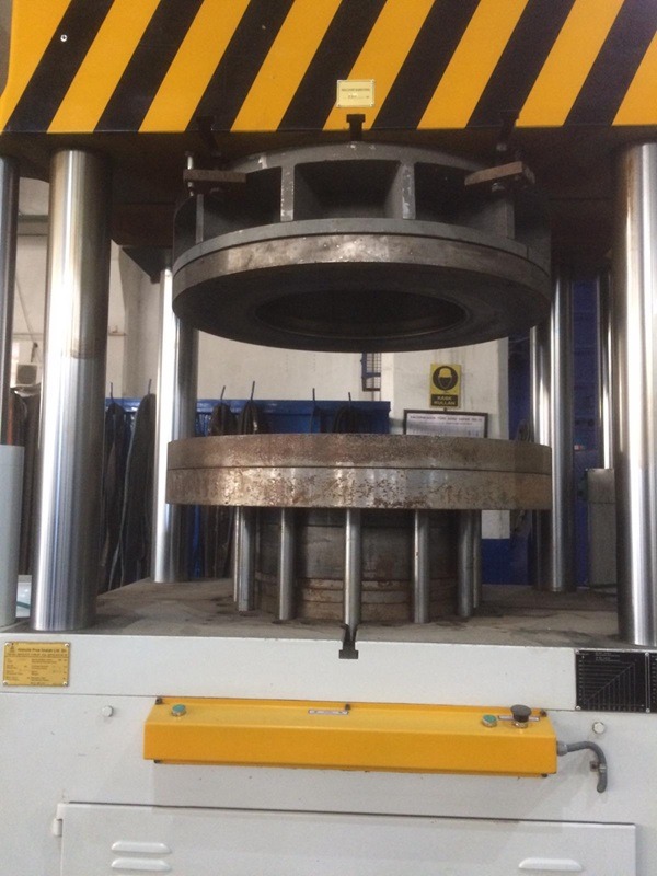
Specialized Applications: Hydroforming presses designed for forming dished ends are used in industries such as oil and gas, chemical processing, and manufacturing, where pressure vessels and tanks are common. Dished ends are the concave or convex ends of cylindrical tanks, and they need to be formed with high precision and strength to withstand internal pressure. These parts are typically made from steel or other high-strength materials, and hydroforming allows for the production of dished ends with minimal welding, which improves their structural integrity.
In the traditional manufacturing of dished ends, multiple pieces of metal may be welded together to form the final part. Hydroforming eliminates much of this by shaping a single piece of metal into the desired shape, reducing the risk of weak points where the metal has been joined.
Press Design and Pressure Requirements: Hydroforming presses for dished ends are designed to handle large, thick metal sheets. The press must apply uniform hydraulic pressure to form the sheet into a dished shape while maintaining the material’s structural integrity.
- High Pressure: The pressure requirements for forming dished ends are typically very high, especially when working with thicker materials like steel. Presses designed for this application must be able to generate and sustain the necessary pressure to form the metal without causing defects such as thinning or cracking.
- Precision and Forming Accuracy: Given that dished ends must withstand significant internal pressure once installed, precision is critical. The hydroforming process must ensure that the thickness of the material remains uniform across the part and that the final shape matches the required specifications exactly.
Deep-Draw Hydroforming
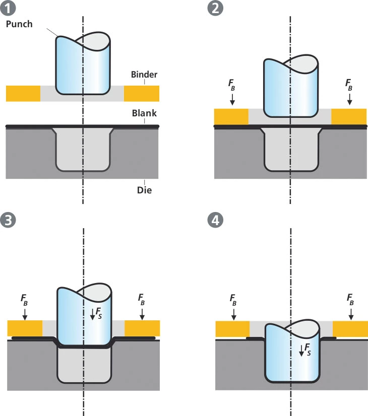
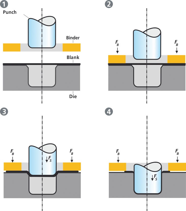
Deep-Draw Hydroforming Process: Deep-draw hydroforming is an advanced metal forming technique used to produce parts with a high depth-to-width ratio. It is an alternative to conventional deep drawing, where a punch is used to mechanically force the material into a die. In hydroforming, hydraulic pressure replaces the punch, which reduces the mechanical stress on the material and allows for the production of more complex geometries.
The process involves the following steps:
- Blank Placement: A flat metal blank is placed over a die cavity.
- Hydraulic Pressure Application: Hydraulic fluid is pressurized to force the metal into the die cavity, drawing it into the desired shape. This pressure is applied gradually to avoid material tearing.
- Forming: The metal is stretched and drawn deeper into the die, forming a part with high precision and minimal wrinkling or thinning.
- Cooling and Removal: After the part is formed, it is cooled and removed from the die.
Advantages Over Conventional Deep Drawing: Deep-draw hydroforming offers several advantages compared to traditional deep drawing:
- Reduced Material Stress: Because the process uses hydraulic pressure rather than mechanical force, the material is subjected to less stress, which reduces the likelihood of tearing or cracking during the forming process.
- Improved Precision: The uniform pressure provided by the hydraulic fluid results in higher precision and fewer defects, such as wrinkling or thinning of the material.
- Complex Geometries: Deep-draw hydroforming allows for the production of parts with complex geometries that would be difficult to achieve using conventional deep drawing techniques.
Applications in Manufacturing: Deep-draw hydroforming is widely used in industries where high-strength, lightweight components are essential. Some common applications include:
- Automotive Industry: Fuel tanks, transmission housings, and other structural components that require deep, complex shapes are often produced using deep-draw hydroforming. The ability to create lightweight, high-strength parts improves vehicle performance and fuel efficiency.
- Aerospace Industry: The aerospace sector uses deep-draw hydroforming to produce parts like fuselage sections, engine housings, and structural supports. The process allows for the creation of lightweight, high-strength components that meet the strict performance and safety standards required in aviation.
- Medical Devices: The medical industry also benefits from deep-draw hydroforming for producing components like surgical instruments and implantable devices. These parts often require complex shapes and tight tolerances, which hydroforming can provide.
Hydroforming Steel
Steel in Hydroforming: Steel is one of the most commonly used materials in hydroforming due to its strength, durability, and availability. High-strength steels, stainless steel, and alloy steels are frequently used in applications that require components to withstand significant mechanical stress and pressure, such as automotive chassis parts, pressure vessels, and structural components in buildings and bridges.
Steel’s formability, particularly when it is subjected to high pressure during the hydroforming process, makes it an ideal material for producing large, intricate parts that require a combination of strength and precision.
Challenges of Hydroforming Steel: Although steel is well-suited to hydroforming, it presents certain challenges due to its high strength and hardness. These challenges include:
- High Pressure Requirements: Steel requires significantly higher pressures than softer materials like aluminum to achieve the desired shapes. Hydroforming equipment must be designed to handle these higher pressures, which can increase the cost of the process.
- Springback: Steel tends to spring back after forming, meaning that it attempts to return to its original shape once the pressure is released. To compensate for this, hydroforming dies must be carefully designed to account for springback and ensure that the final part meets the desired specifications.
- Material Thickness: Thicker steel sheets or tubes require more pressure to form, and there are limits to how thick the material can be before it becomes impractical to hydroform.
Hydroforming Tools and Equipment
Types of Hydroforming Tools: Hydroforming requires specialized tooling, including dies, punches, and seals. These tools are critical to the success of the hydroforming process, as they define the shape of the final part and ensure that the metal is formed with high precision and accuracy.
- Dies: The dies used in hydroforming are typically made from hardened steel or carbide to withstand the high pressures involved in the process. These dies are custom-designed for each part, and they determine the final shape of the component being formed.
- Punches: In some hydroforming processes, such as deep-draw hydroforming, punches are used to push the material into the die. The punch works in conjunction with the hydraulic pressure to form the metal.
- Seals: To prevent hydraulic fluid from leaking during the process, seals are used around the edges of the die. These seals are critical for maintaining the high pressures needed to form the metal effectively.
Tool Maintenance and Longevity: Hydroforming tools, especially dies and punches, are subjected to significant wear and tear due to the high pressures involved in the process. To ensure the longevity of these tools and maintain consistent part quality, regular maintenance is essential.
- Die Wear: Over time, dies can become worn, especially when working with hard materials like steel. Regular inspection and refurbishment of dies are necessary to ensure they continue to produce parts with the correct dimensions.
- Tool Material Selection: The materials used for hydroforming tools play a key role in their longevity. Hardened steels and carbide are commonly used due to their durability and resistance to wear.
- Lubrication: Proper lubrication is critical to reduce friction and prevent excessive wear on tools. Many hydroforming processes use specialized lubricants to reduce tool wear and improve the overall efficiency of the process.
Hydroforming Pressure
Hydraulic Pressure in Hydroforming: Hydraulic pressure is the driving force behind the hydroforming process. The amount of pressure required depends on the material being formed, the thickness of the material, and the complexity of the part’s geometry. For example, materials like aluminum require lower pressure compared to steel, while thick or complex parts require higher pressures to achieve the desired shape.
The pressure applied during hydroforming serves two primary functions:
- Shaping the Metal: The hydraulic pressure forces the metal into the die, shaping it according to the desired geometry.
- Maintaining Uniform Thickness: The pressure also helps to maintain uniform material thickness throughout the part, which is important for structural integrity and aesthetic quality.
Factors Influencing Pressure Requirements: Several factors influence the amount of pressure required in a hydroforming process:
- Material Properties: Softer materials like aluminum require less pressure, while harder materials like steel need significantly higher pressures to achieve the same results.
- Part Geometry: Complex geometries with deep draws or sharp angles require higher pressures to ensure that the metal conforms to the die without wrinkling or tearing.
- Material Thickness: Thicker materials require more pressure to deform, while thinner materials need less pressure but are more prone to tearing if the pressure is not carefully controlled.
Pressure Control in Modern Machines: Modern hydroforming machines are equipped with advanced pressure control systems that allow for precise regulation of hydraulic pressure throughout the forming process. These systems often include feedback loops that monitor the pressure in real-time and adjust it as needed to prevent defects.
- Real-Time Monitoring: Pressure sensors monitor the hydraulic pressure during forming, ensuring that it remains within the required range for the material and part being produced.
- Automatic Adjustments: If the pressure deviates from the desired level, modern machines can automatically adjust the hydraulic system to bring the pressure back into range. This helps to prevent issues such as material cracking or incomplete forming.
Environmental and Economic Impact of Hydroforming
Material Efficiency and Waste Reduction: One of the major environmental benefits of hydroforming is its ability to minimize material waste. Traditional metal forming processes, such as stamping or forging, often result in significant material waste, especially when complex shapes are involved. In contrast, hydroforming allows manufacturers to use thinner materials and form parts in a single step, reducing the need for additional trimming, welding, or joining.
- Minimization of Scrap: Because hydroforming forms parts with fewer steps, less material is wasted in the process. This is particularly beneficial when working with expensive materials like aluminum or titanium, where material costs can represent a significant portion of the overall production expense.
- Optimized Material Use: Hydroforming makes it possible to use thinner materials without sacrificing strength, which further reduces material consumption. For industries such as automotive and aerospace, this leads to lighter components that improve fuel efficiency and reduce emissions over the product’s life cycle.
Cost Considerations: While hydroforming equipment can represent a significant upfront investment, the long-term economic benefits often outweigh the initial costs. The ability to produce parts with fewer operations, reduced material waste, and higher precision can lead to substantial cost savings over time.
- Reduction in Manufacturing Steps: Hydroforming allows for the creation of complex parts in a single forming step, which reduces the number of operations required in the manufacturing process. This, in turn, leads to reduced labor costs, shorter production times, and lower overall costs per part.
- Lower Material Costs: The material savings achieved through hydroforming also contribute to cost reductions. By using thinner, high-strength materials, manufacturers can achieve the same or better performance compared to traditional forming methods while using less raw material.
- Longer Tool Life: Although hydroforming tools and dies are subjected to high pressures, the overall wear on these tools is often lower compared to traditional methods due to the even distribution of pressure. This can result in longer tool life and reduced tooling costs over time.
Environmental Benefits: In addition to material efficiency, hydroforming offers several environmental benefits that make it an attractive option for manufacturers focused on sustainability:
- Reduced Energy Consumption: Hydroforming processes typically consume less energy compared to other metal forming methods, such as forging or stamping. This is because hydroforming uses hydraulic pressure rather than mechanical force, which reduces the amount of energy required to shape the metal.
- Lower Emissions: The production of lighter components, especially in the automotive and aerospace industries, leads to reduced fuel consumption and lower emissions over the lifetime of the vehicle or aircraft. By enabling the production of lighter, stronger parts, hydroforming contributes to the overall reduction of greenhouse gas emissions.
- Minimized Secondary Processing: Since hydroforming often produces near-net-shape parts, there is less need for secondary processing steps such as machining, welding, or grinding. This reduces the overall energy consumption and environmental impact associated with manufacturing.
Conclusion
Hydroforming is a transformative manufacturing technology that offers significant advantages in terms of material efficiency, structural integrity, and the ability to produce complex geometries. From its origins in the automotive industry to its widespread adoption across aerospace, medical, and consumer goods sectors, hydroforming continues to evolve as new materials and technologies emerge.
The ability to form lightweight, high-strength components with minimal material waste makes hydroforming a crucial process for industries focused on improving performance while reducing environmental impact. With advances in equipment, tooling, and automation, hydroforming is poised to play an even more significant role in future manufacturing trends.
Whether it’s deep-draw hydroforming, sheet hydroforming, or tubular hydroforming, the process allows for the creation of parts that meet the increasingly stringent demands for strength, durability, and precision. As industries continue to prioritize sustainability and efficiency, hydroforming’s role in shaping the future of manufacturing will only continue to grow.
In conclusion, the diverse applications of hydroforming, from the automotive to the aerospace industries, underscore its versatility and efficiency. With ongoing innovations in technology, tooling, and pressure control, hydroforming will remain at the forefront of advanced manufacturing processes for years to come.
Comprehensive Guide to the Sheet Hydroforming Process
Definition and History: Sheet hydroforming is an advanced metal forming process that uses hydraulic pressure to shape metal sheets into complex geometries. Unlike traditional stamping or pressing methods, where mechanical force is applied directly to the sheet, sheet hydroforming involves applying fluid pressure to push the metal sheet against a die. This results in higher precision, minimal material waste, and the ability to form complex shapes in one step.
The history of hydroforming can be traced back to the 1950s when it was first developed for the automotive industry to create lightweight, strong components. Over time, the process has evolved and found applications in a variety of industries, including aerospace, consumer electronics, and medical devices.
Importance in Modern Manufacturing: Sheet hydroforming has become a cornerstone in industries where precision, lightweight materials, and strength are critical. It enables manufacturers to create intricate designs with fewer components, reducing the need for welding and joints, which enhances the structural integrity of the final product. In addition, the ability to work with a wide range of metals, from aluminum to titanium, makes sheet hydroforming versatile and applicable to high-performance industries.
Principles of Sheet Hydroforming
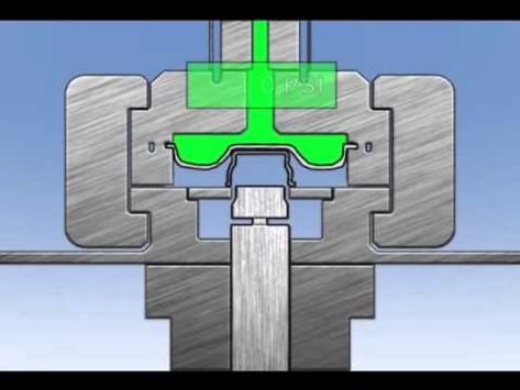
Fundamental Concepts: The core principle of sheet hydroforming revolves around the use of hydraulic pressure to shape metal sheets. A flat sheet of metal is placed over a die, and a flexible diaphragm (or similar mechanism) is used to apply hydraulic pressure on the sheet, forcing it to conform to the shape of the die. The hydraulic fluid distributes the pressure evenly across the surface, reducing stress on the material and enabling the formation of complex geometries without cracking or tearing.
The forming process typically requires high pressure, ranging from 3,000 psi to over 20,000 psi, depending on the material’s thickness and properties. The uniform application of pressure is one of the main reasons hydroforming produces superior results compared to traditional stamping or mechanical pressing.
Comparison to Traditional Metal Forming Methods: Traditional metal forming methods like stamping, forging, and deep drawing rely on mechanical force to shape metal sheets. While these methods are efficient for certain applications, they often result in high material waste, particularly in the production of complex shapes. Stamping can also lead to inconsistent material thickness and weak points due to the localized force applied during the process.
In contrast, hydroforming allows for more uniform material distribution, reducing thinning in critical areas and improving the overall strength of the part. This makes it a preferred choice for industries that demand lightweight yet strong components, such as aerospace and automotive manufacturing.
Key Terminology:
- Hydraulic Press: A machine that uses hydraulic pressure to shape the material.
- Diaphragm: A flexible membrane used to apply hydraulic pressure to the sheet.
- Blank: The flat metal sheet placed over the die before the forming process.
- Die: The tool that provides the shape to be formed by the sheet.
Types of Sheet Hydroforming Processes
There are several variations of sheet hydroforming, each suited for different applications and types of parts. These include conventional sheet hydroforming, deep-draw hydroforming, and matched-die hydroforming.
Conventional Sheet Hydroforming: In conventional sheet hydroforming, a flat metal sheet is placed over a single die, and hydraulic pressure is applied using a diaphragm or fluid chamber. The pressure forces the sheet into the die, shaping it into the desired geometry. This method is particularly useful for forming large, shallow parts with smooth curves, such as automotive body panels or aerospace fuselage sections.
- Applications: Automotive body parts, consumer electronics cases, and aircraft skin panels.
- Advantages: High precision, minimal material waste, and the ability to form large parts with complex geometries.
- Limitations: Not suitable for parts requiring deep draws or sharp angles.
Deep-Draw Sheet Hydroforming: Deep-draw hydroforming is used for parts with a high depth-to-width ratio, such as fuel tanks or complex structural components. The process involves drawing the metal deeper into the die cavity using hydraulic pressure, which stretches the material more than in conventional hydroforming.
- Applications: Fuel tanks, transmission housings, and deep-cavity components.
- Advantages: Ability to create deep, complex shapes with high structural integrity.
- Limitations: Requires careful pressure control to prevent tearing or wrinkling of the material.
Matched-Die Hydroforming: In matched-die hydroforming, two dies are used—one on the top and one on the bottom—similar to traditional stamping. However, hydraulic pressure is applied during the forming process to provide more control and precision. This method is used when high levels of detail and sharp corners are required.
- Applications: High-precision parts with complex geometries and sharp features.
- Advantages: Superior accuracy and control, ideal for intricate part designs.
- Limitations: More expensive tooling compared to single-die processes.
Materials Used in Sheet Hydroforming
Sheet hydroforming is highly versatile and can be used to form a wide range of materials, including aluminum, steel, titanium, and specialty alloys.
Aluminum: Aluminum is one of the most commonly used materials in sheet hydroforming due to its lightweight properties and high strength-to-weight ratio. It is widely used in industries like automotive and aerospace, where weight reduction is critical for performance and fuel efficiency.
- Properties: Lightweight, corrosion-resistant, and highly formable.
- Applications: Automotive body panels, aerospace components, and consumer electronics.
Steel: Steel, including high-strength steel and stainless steel, is another popular material for sheet hydroforming. Steel’s durability and strength make it suitable for parts that need to withstand heavy loads or extreme conditions.
- Properties: Strong, durable, and capable of handling high pressures during forming.
- Applications: Automotive chassis components, structural parts, and pressure vessels.
Titanium: Titanium is valued for its exceptional strength, lightweight, and corrosion resistance. While it is more challenging to form than aluminum or steel, hydroforming allows manufacturers to take advantage of titanium’s unique properties, making it a key material in aerospace and medical applications.
- Properties: Lightweight, highly resistant to corrosion, and extremely strong.
- Applications: Aircraft components, medical implants, and high-performance sports equipment.
Material Properties and Compatibility: The selection of material for hydroforming depends on several factors, including the required strength, weight, and formability. Softer metals like aluminum are easier to form but may not offer the same durability as steel or titanium. Conversely, harder metals require higher pressures and more precise control to avoid tearing or cracking during the forming process.
Material Thickness and Formability Considerations: Material thickness is a critical factor in sheet hydroforming. Thinner materials are more prone to tearing during the forming process, especially when subjected to high pressures or deep draws. On the other hand, thicker materials require more pressure to form, which may necessitate more advanced equipment. Finding the right balance between material thickness and formability is essential for successful hydroforming.
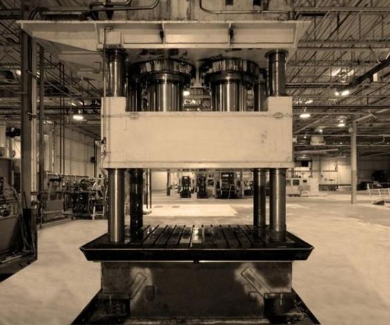
Sheet Hydroforming Equipment
The equipment used in sheet hydroforming is designed to handle the high pressures and precision required to shape metal sheets into complex geometries. Key components of this equipment include hydraulic presses, tooling and dies, and seals and pressure control systems.
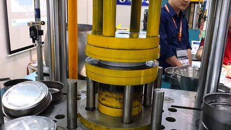
Hydraulic Presses: The hydraulic press is the centerpiece of the hydroforming process. It generates the hydraulic pressure needed to force the metal sheet into the die and create the desired shape. Hydraulic presses used in sheet hydroforming typically have large capacities, ranging from 5,000 psi to over 20,000 psi, depending on the material and complexity of the part.
- High-Pressure Capabilities: Modern hydraulic presses are equipped with advanced pressure control systems that allow for precise adjustment of pressure levels throughout the forming process.
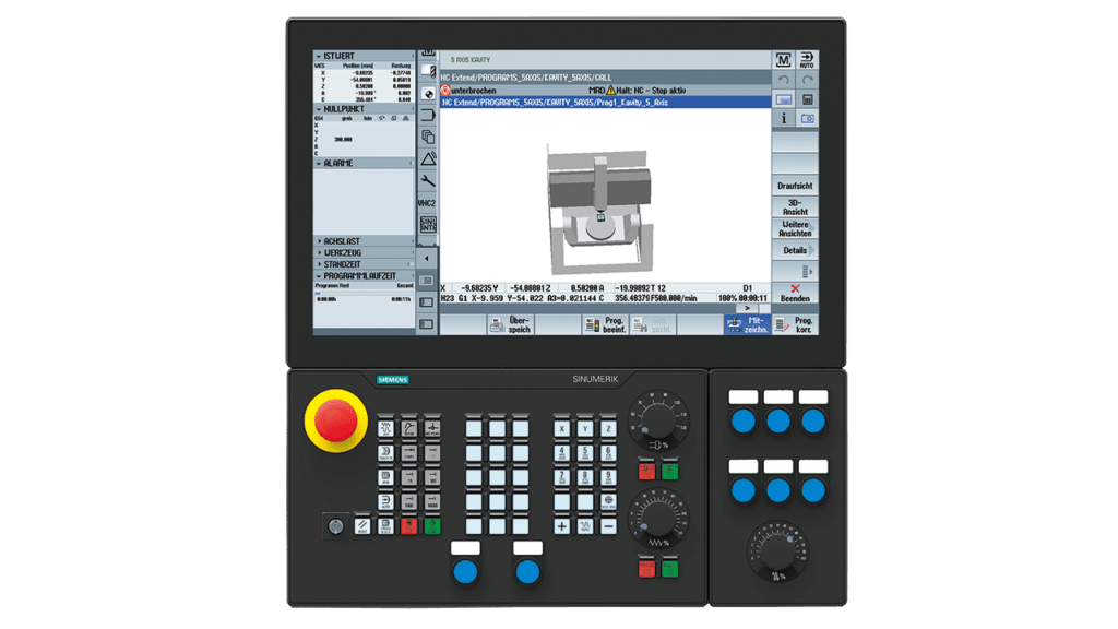
- CNC Integration: Many presses are now integrated with CNC (Computer Numerical Control) systems, enabling automated control over pressure, timing, and movement of the forming tools for enhanced accuracy and repeatability.
Tooling and Dies: Dies are custom-designed tools that give the final shape to the metal sheet. They are made from high-strength materials such as hardened steel or carbide to withstand the extreme pressures involved in the hydroforming process. Depending on the complexity of the part, dies can be either simple single-cavity designs or more complex, multi-part tools.
- Die Design: The design of the die is crucial to achieving the desired part geometry. Factors such as material thickness, depth of draw, and the presence of intricate details all influence the die design.
- Tool Longevity: Tooling materials are selected to ensure longevity, as hydroforming tools are subjected to repeated high-pressure cycles. Regular maintenance and refurbishment of tools are necessary to prevent wear and maintain part accuracy.
Seals and Pressure Control Systems: Seals play a critical role in the hydroforming process by preventing hydraulic fluid from leaking during forming. The seals are located around the edges of the die and the diaphragm and are designed to maintain the high pressures needed for effective forming.
- Pressure Control Systems: Advanced hydraulic presses are equipped with pressure control systems that monitor and adjust the pressure in real-time. These systems ensure that the pressure remains within the optimal range for the material and part being formed, reducing the risk of defects such as tearing or wrinkling.
- Sealing Materials: Seals are typically made from high-strength elastomers or composite materials that can withstand repeated exposure to high pressures and temperatures.
Step-by-Step Breakdown of the Sheet Hydroforming Process
The sheet hydroforming process can be broken down into several key steps, from die design and material preparation to forming, cooling, and finishing.
1. Design and Setup of Dies: Before the forming process begins, the dies must be designed to match the desired part geometry. This involves using CAD (Computer-Aided Design) software to model the part and create the necessary tooling. Once the design is finalized, the dies are manufactured from high-strength materials capable of withstanding the pressures involved in hydroforming.
2. Preparing the Material Sheet: The metal sheet, also known as a blank, is prepared for forming. The blank is typically cut to size and shape using laser cutting, waterjet cutting, or other precision cutting methods. The surface of the sheet may also be treated with lubricants to reduce friction during the forming process and prevent damage to the tooling.
3. Placing the Blank Over the Die: Once the material sheet is prepared, it is placed over the die in the hydraulic press. The press may be equipped with an alignment system to ensure the sheet is positioned correctly before forming begins.
4. Forming Process Using Hydraulic Pressure: The core of the hydroforming process involves applying hydraulic pressure to the metal sheet using a diaphragm or fluid chamber. The pressure is applied gradually to avoid tearing or wrinkling the material, and it forces the sheet to conform to the shape of the die. The hydraulic fluid distributes the pressure evenly across the sheet, ensuring that the material forms uniformly.
- Pressure Application: Depending on the material and complexity of the part, the pressure may be applied in stages, with adjustments made to prevent defects. In deep-draw hydroforming, additional pressure may be needed to stretch the material into the deeper parts of the die.
- Cooling Systems: In some cases, cooling systems may be used to control the temperature of the sheet and the die during forming. This is particularly important for materials like aluminum, which can soften if overheated.
5. Cooling, Removal, and Finishing: Once the forming process is complete, the part is allowed to cool, and the pressure is released. The formed part is then removed from the die, and any excess material is trimmed away. Depending on the part’s requirements, additional finishing operations, such as deburring, polishing, or heat treatment, may be performed to achieve the desired surface finish and mechanical properties.
- Inspection and Quality Control: After forming, the part is inspected for dimensional accuracy, surface finish, and any potential defects. Non-destructive testing methods, such as ultrasonic or dye-penetrant inspection, may be used to identify internal defects or surface cracks.
- Post-Processing: Depending on the application, the formed part may undergo additional processes such as welding, machining, or coating to prepare it for assembly or final use.
Applications of Sheet Hydroforming
Sheet hydroforming is a versatile process used in a wide range of industries, including automotive, aerospace, consumer products, and medical devices. Each industry benefits from hydroforming’s ability to produce lightweight, high-strength components with complex geometries.
Automotive Industry: In the automotive sector, sheet hydroforming is commonly used to create body panels, chassis components, and structural parts. These parts need to be lightweight to improve fuel efficiency while maintaining the strength necessary to meet safety standards.
- Body Panels: Sheet hydroforming allows manufacturers to produce large, intricately shaped body panels with minimal joints or seams. This improves both the aesthetics and the structural integrity of the vehicle.
- Chassis Components: Hydroformed chassis components, such as engine cradles and subframes, are lighter and stronger than those produced using traditional stamping or welding methods. This contributes to overall vehicle performance and fuel economy.
Aerospace Industry: The aerospace industry relies heavily on hydroforming to produce lightweight, high-strength components that meet stringent performance and safety requirements.
- Fuselage Sections: Hydroforming is used to create large sections of aircraft fuselages, which need to be both lightweight and capable of withstanding the stresses of flight.
- Wing Components: Hydroforming is also used to form complex wing structures that require high precision and uniform material thickness.
Consumer Products and Electronics: In the consumer products sector, hydroforming is used to create aesthetically pleasing and functional designs. From smartphone casings to high-end kitchen appliances, hydroforming allows for the production of sleek, intricate designs with smooth, curved surfaces.
- Smartphone Housings: The sleek, seamless designs of modern smartphones often rely on hydroforming to create complex, curved shapes that are both lightweight and durable.
- Appliances: Kitchen appliances, such as refrigerators and ovens, benefit from hydroforming’s ability to create smooth, aesthetically pleasing surfaces that are easy to clean and maintain.
Medical Devices: In the medical field, hydroforming is used to produce components that require high precision and biocompatibility.
- Surgical Instruments: Many surgical instruments are made using hydroforming due to the process’s ability to produce intricate, high-precision shapes with minimal material stress.
- Implants: Hydroformed titanium implants, such as joint replacements and dental implants, are lightweight, strong, and biocompatible, making them ideal for medical applications.
Advantages of the Sheet Hydroforming Process
Sheet hydroforming offers numerous advantages over traditional metal forming processes, making it a popular choice for industries that require high precision, material efficiency, and complex geometries.
Material Efficiency and Reduction of Waste: One of the most significant advantages of sheet hydroforming is its ability to minimize material waste. Because the process uses hydraulic pressure to form the sheet, there is less material thinning and fewer scraps compared to stamping or forging.
- Thinner Materials: Hydroforming allows manufacturers to use thinner materials without compromising strength, which reduces the overall amount of material used in production.
- Reduction in Scrap: Traditional stamping processes often result in significant material waste due to excess trimming and cutting. Hydroforming, by contrast, produces near-net-shape parts, minimizing the need for additional material removal.
Lightweight and High-Strength Component Production: Hydroforming enables the production of lightweight components with high structural integrity, which is critical in industries such as automotive and aerospace.
- Improved Strength-to-Weight Ratio: Hydroformed parts typically have a higher strength-to-weight ratio than parts produced using traditional methods. This is particularly important in automotive and aerospace applications, where weight reduction leads to improved fuel efficiency and performance.
- Uniform Material Thickness: The hydraulic pressure used in hydroforming ensures that the material thickness remains uniform throughout the part, reducing weak points and improving overall strength.
Cost-Effectiveness in Large-Scale Manufacturing: While the initial investment in hydroforming equipment can be high, the process is highly cost-effective in large-scale manufacturing due to its material efficiency and reduced need for secondary operations.
- Fewer Operations: Hydroforming allows for the production of complex parts in a single forming step, reducing the need for additional processes such as welding, machining, or finishing.
- Lower Tooling Costs: Compared to traditional stamping, which requires multiple dies for different stages of forming, hydroforming often requires only one die, reducing tooling costs over time.
Challenges and Limitations of Sheet Hydroforming
While sheet hydroforming offers many advantages, it also comes with certain challenges and limitations.
Material Constraints (Thicker vs. Thinner Sheets): One of the primary challenges in sheet hydroforming is balancing material thickness with the pressure required to form the part. Thicker sheets require more pressure to form, which can strain the equipment and increase the risk of material cracking. On the other hand, thinner sheets are more prone to tearing or wrinkling under high pressure.
- Pressure Requirements: Materials with higher strength, such as steel or titanium, require significantly higher pressures to form, which may necessitate specialized equipment.
- Risk of Material Failure: Without precise control over the pressure and forming process, there is a risk of material failure, particularly when working with complex shapes or deep draws.
Dimensional Accuracy and Forming Complexities: Hydroforming offers high precision, but it can still present challenges when working with complex geometries or tight tolerances.
- Springback: Some materials, particularly high-strength steels, have a tendency to spring back after forming, meaning they attempt to return to their original shape once the pressure is released. This can affect the dimensional accuracy of the part.
- Complex Geometries: While hydroforming excels at forming large, smooth shapes, it can struggle with intricate details or sharp angles. These complexities may require additional post-processing or more advanced die designs.
Technological Innovations in Sheet Hydroforming
Recent technological innovations have significantly improved the capabilities and efficiency of sheet hydroforming, making it even more valuable for modern manufacturing.
CNC-Controlled Hydraulic Systems: The integration of CNC systems with hydraulic presses has revolutionized the hydroforming process. CNC control allows for precise regulation of hydraulic pressure, timing, and movement of the die, ensuring consistent results across production runs.
- Automated Pressure Control: CNC systems can monitor and adjust hydraulic pressure in real-time, reducing the risk of material defects and improving overall process efficiency.
- Repeatability and Consistency: CNC-controlled presses ensure that each part is formed with the same precision, reducing variability in large-scale manufacturing.
Advanced Tooling and Die Materials: Advances in materials science have led to the development of more durable and wear-resistant tooling materials. These materials, such as carbide and ceramic composites, extend the life of hydroforming dies and improve their ability to withstand high pressures.
- Tool Coatings: Specialized coatings, such as diamond-like carbon (DLC) or titanium nitride (TiN), can be applied to dies to reduce friction, improve wear resistance, and extend tool life.
- Multi-Die Systems: Some advanced hydroforming systems now use multi-die setups, allowing for the simultaneous production of multiple parts or more complex geometries.
Integration of Sensors and Automation: Modern hydroforming equipment is increasingly equipped with sensors that monitor various aspects of the process, from pressure levels to material deformation. These sensors provide real-time feedback to the CNC system, allowing for immediate adjustments to ensure optimal forming conditions.
- Force Sensors: These sensors detect the amount of force being applied to the material, ensuring that the pressure remains within the required range for the specific material and part.
- Deformation Monitoring: Sensors can also monitor how the material is deforming during the process, alerting operators to potential issues such as wrinkling or tearing.
Environmental Impact of Sheet Hydroforming
Sheet hydroforming offers several environmental benefits, making it an attractive option for manufacturers focused on sustainability.
Energy Efficiency in Manufacturing: Compared to traditional metal forming processes like stamping or forging, hydroforming is generally more energy-efficient. This is because it uses hydraulic pressure rather than mechanical force, which requires less energy to achieve the same results.
- Reduced Energy Consumption: Hydraulic systems are more efficient than mechanical presses, particularly when forming complex parts or deep draws. This reduces the overall energy consumption of the manufacturing process.
- Lower Emissions: By reducing the energy required for forming, hydroforming also helps lower the carbon emissions associated with manufacturing, contributing to a more sustainable production process.
Waste Reduction and Material Recycling: Hydroforming is a near-net-shape forming process, meaning that it produces parts that are very close to their final dimensions, reducing the need for additional trimming or machining. This leads to less material waste compared to traditional methods like stamping or forging.
- Minimized Scrap: The precision of hydroforming results in less scrap material, which not only reduces waste but also lowers the cost of raw materials.
- Recyclable Materials: Many of the metals used in hydroforming, such as aluminum and steel, are fully recyclable. The reduced material waste and the ability to recycle scrap metal contribute to a more environmentally friendly manufacturing process.
Role in Sustainable Manufacturing: As industries move toward more sustainable manufacturing practices, hydroforming is playing a key role in helping manufacturers reduce their environmental impact. The process’s ability to produce lightweight, high-strength components with minimal waste makes it ideal for industries like automotive and aerospace, where reducing weight and improving fuel efficiency are critical for sustainability.
- Lightweight Parts for Fuel Efficiency: In the automotive and aerospace industries, reducing the weight of vehicles and aircraft is essential for improving fuel efficiency and reducing emissions. Hydroforming allows manufacturers to produce lightweight components that meet the required strength and safety standards.
- Sustainable Design Practices: Many manufacturers are incorporating hydroforming into their sustainable design practices, using the process to create parts that are both environmentally friendly and cost-effective.
Case Studies in Sheet Hydroforming
Several industries have successfully integrated sheet hydroforming into their manufacturing processes, resulting in improved product quality, material efficiency, and cost savings. Here are some case studies that highlight the versatility of the hydroforming process.
Automotive Chassis Production: In the automotive industry, hydroforming is used to produce chassis components that are lighter and stronger than those produced using traditional methods. For example, a major automotive manufacturer used hydroforming to create engine cradles and subframes for a new line of vehicles.
- Results: The hydroformed parts were 20% lighter than their stamped counterparts, resulting in improved fuel efficiency and lower emissions. The reduced number of joints and welds also enhanced the structural integrity of the chassis components, leading to better crash performance.
- Cost Savings: By using hydroforming, the manufacturer reduced the number of forming steps and the amount of material waste, resulting in significant cost savings over the course of the production run.
Aerospace Structural Components: In the aerospace industry, hydroforming has been used to produce lightweight structural components for aircraft. A leading aerospace company employed sheet hydroforming to create fuselage sections and wing components for a new commercial aircraft.
- Results: The hydroformed parts met the strict weight and strength requirements for the aircraft, helping to reduce overall weight and improve fuel efficiency. The process also allowed for the creation of complex shapes that would have been difficult to achieve using traditional methods.
- Improved Durability: The uniform material thickness achieved through hydroforming improved the durability and lifespan of the components, reducing the need for maintenance and repairs.
Manufacturing of Complex, High-Precision Consumer Goods: Hydroforming is also used in the production of high-precision consumer goods, such as smartphone housings and kitchen appliances. A leading electronics manufacturer used hydroforming to create sleek, curved smartphone cases that were both lightweight and durable.
- Results: The hydroformed cases had a seamless design with no visible joints, improving the aesthetics and strength of the product. The process also allowed for the creation of thinner, more lightweight cases without compromising durability.
- Production Efficiency: By using hydroforming, the manufacturer was able to produce the cases in a single forming step, reducing the need for additional machining or finishing operations.
Future Trends in Sheet Hydroforming
As industries continue to push the boundaries of manufacturing technology, several trends are emerging that could shape the future of sheet hydroforming.
Emerging Materials in Hydroforming: New materials are constantly being developed, and many of these materials are being adapted for use in the hydroforming process. Advanced alloys, composites, and lightweight metals such as magnesium are being tested for their formability and compatibility with hydroforming.
- Magnesium Alloys: Magnesium is lighter than aluminum but offers comparable strength. As manufacturers look for ways to further reduce the weight of their products, magnesium alloys could become a popular choice for hydroforming, particularly in the automotive and aerospace sectors.
- High-Strength Alloys: Advances in metallurgy are leading to the development of new high-strength alloys that are more resistant to wear and corrosion. These materials could expand the range of applications for hydroforming, particularly in industries such as oil and gas, where components need to withstand harsh environments.
Hybrid Manufacturing Techniques: As manufacturing technology continues to evolve, hybrid techniques that combine hydroforming with other processes are emerging. For example, manufacturers are experimenting with combining hydroforming and additive manufacturing (3D printing) to create complex parts with enhanced performance characteristics.
- Additive Manufacturing and Hydroforming: By using 3D printing to create the initial part and then using hydroforming to fine-tune its shape and structural integrity, manufacturers can produce highly complex components that would be difficult or impossible to achieve using traditional methods alone.
- Integration with Machining: In some cases, hydroforming can be combined with precision machining to create parts with intricate features and tight tolerances. This hybrid approach allows manufacturers to take advantage of the strengths of both processes, resulting in parts that are both strong and precise.
Integration with 3D Printing and Additive Manufacturing: Additive manufacturing has gained significant traction in recent years, and its integration with hydroforming could open up new possibilities for producing highly customized parts. For example, 3D-printed tools or dies could be used in the hydroforming process, reducing the cost and time required to produce custom tooling.
- 3D-Printed Dies: By using 3D printing to create custom dies, manufacturers can reduce the lead time and cost associated with producing dies for short production runs. This is particularly useful in industries like aerospace and medical devices, where highly customized parts are required.
- Custom Part Production: The combination of 3D printing and hydroforming could also enable the production of highly customized parts, such as prosthetics or medical implants, that are tailored to the specific needs of the individual.
Conclusion: The Evolution of Sheet Hydroforming
Sheet hydroforming has come a long way since its inception in the mid-20th century, evolving into one of the most versatile and efficient metal forming processes available today. Its ability to produce lightweight, high-strength components with minimal material waste has made it a vital tool in industries ranging from automotive and aerospace to consumer electronics and medical devices.
As technology continues to advance, the capabilities of sheet hydroforming are only set to expand. The integration of CNC-controlled hydraulic systems, advanced tooling materials, and sensors has already improved the precision and efficiency of the process, while emerging trends such as additive manufacturing and new materials like magnesium alloys promise to take hydroforming to the next level.
In an era where sustainability and efficiency are increasingly important, sheet hydroforming stands out as a process that can meet the demands of modern manufacturing while minimizing environmental impact. Its ability to produce parts with fewer materials, lower energy consumption, and reduced emissions makes it an ideal choice for manufacturers looking to improve both their performance and their sustainability.
Looking ahead, the future of sheet hydroforming is bright. As industries continue to explore new applications and technologies, hydroforming will remain at the forefront of advanced manufacturing, helping to shape the future of everything from automobiles to airplanes, smartphones to surgical instruments.
In conclusion, the sheet hydroforming process represents the perfect blend of precision, efficiency, and sustainability, making it an indispensable part of modern manufacturing. Its continued evolution and adaptation to new materials, technologies, and applications will ensure that hydroforming remains a critical process for many industries in the years to come.
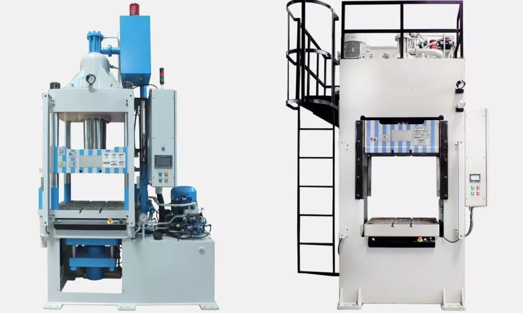
Comprehensive Guide to Hydroforming Machines
Hydroforming machines represent a specialized category of metal-forming equipment that utilize hydraulic pressure to shape metals into complex, high-strength components. Unlike traditional metal forming processes like stamping or forging, which rely on mechanical force, hydroforming uses pressurized fluid to force metal sheets or tubes into a die, creating intricate shapes with minimal material stress and waste.
Historical Background: The concept of hydroforming was developed in the early 1950s, primarily for the automotive industry, to produce lighter, stronger, and more intricate components. The method has since evolved, finding applications in industries like aerospace, consumer goods, and even medical devices. Hydroforming machines have become critical tools in modern manufacturing, allowing for the production of lightweight, high-performance components that are essential in today’s increasingly competitive market.
Role in Modern Manufacturing: Today, hydroforming machines are used in the production of everything from car body panels to aircraft structural components and medical devices. Their ability to create complex shapes from a single piece of metal reduces the need for welding and assembly, which enhances the strength and integrity of the final product. The precision and efficiency offered by hydroforming machines have made them indispensable in industries where weight reduction, strength, and material efficiency are key priorities.
Principles of Hydroforming
What is Hydroforming?: Hydroforming is a metal-forming process that uses high-pressure hydraulic fluid to shape metal sheets or tubes into predefined shapes. Unlike traditional forming methods, hydroforming evenly distributes the pressure across the entire surface of the metal, resulting in high-precision parts with minimal material waste and better mechanical properties. This makes it particularly suited for applications requiring lightweight, structurally strong components.
Hydroforming machines are designed to generate and control the hydraulic pressure required to form the metal into the desired shape. The process typically involves placing a sheet or tube of metal into a die, after which hydraulic fluid is injected, pressurizing the material and forcing it to take the shape of the die.
Key Concepts:
- Hydraulic Pressure: The defining feature of hydroforming is the use of fluid pressure to shape the metal. Depending on the material and the complexity of the part, pressures can range from 3,000 psi to over 20,000 psi.
- Dies: Dies are specially designed molds that define the final shape of the metal part. They are typically made from high-strength materials like steel or carbide to withstand the extreme pressures involved in the hydroforming process.
- Material Forming: The hydraulic pressure forces the metal sheet or tube to stretch and conform to the shape of the die. This process is highly controlled to prevent tearing, wrinkling, or other defects.
Comparison with Traditional Metal Forming: Hydroforming differs from traditional metal forming processes such as stamping, forging, or deep drawing in several key ways:
- Uniform Pressure Application: Traditional methods often apply localized mechanical force to specific areas of the material, which can result in thinning, uneven material distribution, and weak points. Hydroforming, on the other hand, applies uniform pressure across the entire surface, producing more consistent results.
- Complex Geometries: Hydroforming is particularly well-suited for creating complex shapes and contours that would be difficult or impossible to achieve using other methods.
- Material Efficiency: Since hydroforming uses less material and reduces the need for welding or assembly, it is generally more material-efficient than traditional forming processes.
Types of Hydroforming Machines
Hydroforming machines can be broadly classified based on the type of material they form and the specific process they use. The four primary types of hydroforming machines are sheet hydroforming machines, tube hydroforming machines, deep-draw hydroforming machines, and hybrid hydroforming machines.
1. Sheet Hydroforming Machines: Sheet hydroforming machines are designed to form large, flat metal sheets into complex shapes. These machines use a combination of hydraulic pressure and a single die to press the sheet into the desired shape. A flexible diaphragm or fluid chamber is used to apply uniform pressure to the metal sheet, which is then pressed into a die.
- Applications: Automotive body panels, aerospace fuselage sections, and large consumer product components.
- Advantages: Precision forming with minimal material waste, ideal for large, shallow parts with complex curves.
2. Tube Hydroforming Machines: Tube hydroforming machines are specifically designed to form hollow metal tubes into complex, three-dimensional shapes. These machines use internal hydraulic pressure to expand the tube within a die, forming parts with variable cross-sections and intricate geometries. Tube hydroforming is widely used in industries that require lightweight yet strong components, such as the automotive and aerospace industries.
- Applications: Automotive chassis frames, exhaust systems, structural components in aircraft.
- Advantages: Allows for the creation of lightweight, structurally strong components with fewer joints and welds, improving both strength and durability.
3. Deep-Draw Hydroforming Machines: Deep-draw hydroforming machines are used to create parts with a high depth-to-width ratio. This process involves drawing the metal deeper into the die, often using a combination of hydraulic pressure and mechanical force to achieve greater depth.
- Applications: Fuel tanks, transmission housings, and other deep-cavity components.
- Advantages: Capable of forming deeper parts without compromising material integrity, reducing stress on the material compared to traditional deep drawing.
4. Hybrid Hydroforming Machines: Hybrid hydroforming machines combine different forming techniques, such as explosive hydroforming or hydro-pneumatic forming, with traditional hydraulic pressure. Explosive hydroforming, for example, uses a controlled explosion to create high-pressure shockwaves that form the metal into the desired shape. These hybrid machines are typically used for specialized applications, such as forming very thick or hard-to-shape metals.
- Applications: Aerospace components, military applications, and heavy industrial equipment.
- Advantages: Capable of generating extremely high forces, ideal for forming tough or hard-to-shape materials.
Components of Hydroforming Machines
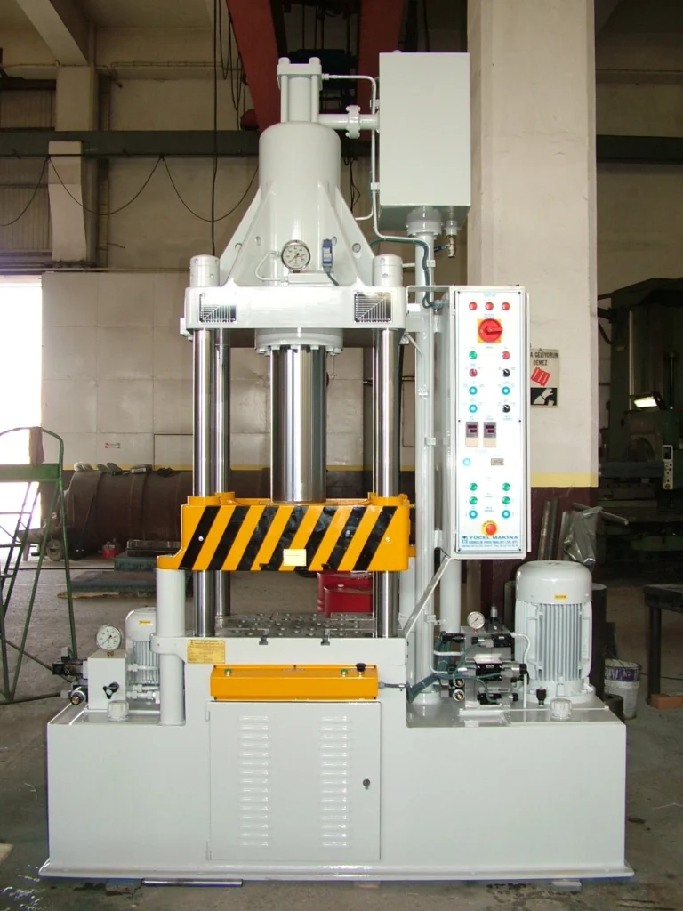
Hydroforming machines are made up of several key components, each of which plays a critical role in the forming process. The major components include the hydraulic system, dies and tooling, seals and diaphragms, and the control system.
1. Hydraulic Systems: The hydraulic system is the heart of every hydroforming machine. It generates the pressure needed to form the metal, typically using a combination of hydraulic pumps, valves, and pressure regulators. The system must be capable of generating and maintaining extremely high pressures, sometimes in excess of 20,000 psi.
- Hydraulic Pumps: These pumps generate the fluid pressure needed for forming. Modern machines often use high-efficiency pumps to reduce energy consumption and improve cycle times.
- Pressure Regulators: These devices monitor and control the hydraulic pressure throughout the process, ensuring that the material is formed within the desired parameters without tearing or wrinkling.
- Pressure Accumulators: These components store hydraulic pressure and release it as needed, helping to maintain consistent pressure levels during forming.
2. Dies and Tooling: The dies used in hydroforming are critical to shaping the final part. Dies are typically made from hardened steel or other high-strength materials to withstand the high pressures involved in the process. The design of the die is crucial for ensuring that the final part meets the required specifications.
- Die Design: The design of the die depends on the complexity of the part being formed. For simple parts, a single-cavity die may be sufficient, while more complex parts may require multi-part dies with intricate details.
- Tooling Materials: Dies are often coated with wear-resistant materials such as carbide or diamond-like coatings to improve their durability and extend their lifespan.
3. Seals, Diaphragms, and Containment Systems: Seals and diaphragms are used to contain the hydraulic fluid and prevent leaks during the forming process. These components must be able to withstand high pressures and repeated cycles of expansion and contraction.
- Seals: Made from high-strength elastomers or composite materials, seals are critical for maintaining the integrity of the hydraulic system. They prevent hydraulic fluid from escaping during the forming process.
- Diaphragms: These flexible membranes are used to apply hydraulic pressure to the metal sheet or tube. Diaphragms must be durable enough to withstand repeated cycles of expansion without tearing or degrading.
4. Control Systems and CNC Integration: Modern hydroforming machines are equipped with advanced control systems, often integrated with CNC (Computer Numerical Control) technology. These control systems allow for precise regulation of pressure, timing, and die movement, ensuring consistent and accurate forming across production runs.
- Pressure Control: The control system monitors and adjusts hydraulic pressure in real-time, preventing over-pressurization and reducing the risk of defects.
- CNC Automation: CNC integration enables automated control over the forming process, from pressure application to die movement. This improves both accuracy and repeatability, particularly in high-volume production.
Design and Functionality of Hydroforming Machines
The design and functionality of hydroforming machines are critical to their performance and efficiency. Several key factors must be considered when designing a hydroforming machine, including pressure capacity, material compatibility, and machine size.
1. Key Design Parameters: The design of a hydroforming machine depends on the specific application and material being formed. Some of the key design parameters include:
- Pressure Range: The machine must be capable of generating the necessary pressure to form the material. For example, forming aluminum may require lower pressures (3,000–10,000 psi), while forming high-strength steel or titanium may require pressures above 20,000 psi.
- Die Design: The complexity of the part being formed influences the design of the die. For more intricate geometries, multi-part dies or complex tool designs may be required.
- Machine Size: The size of the machine is determined by the size of the parts being formed. Machines designed for automotive body panels, for example, are much larger than those used for forming medical devices.
2. Material Compatibility: Hydroforming machines must be designed to handle a wide range of materials, each with its own unique properties and forming requirements.
- Aluminum: A popular material for hydroforming due to its lightweight and high formability. Aluminum can be hydroformed at lower pressures compared to steel or titanium.
- Steel: High-strength steels are commonly used in automotive and aerospace applications, but they require higher pressures and more robust equipment to form.
- Titanium: Known for its strength and corrosion resistance, titanium is used in aerospace and medical applications. However, it is more challenging to form due to its work-hardening properties.
3. Machine Cycle Times and Throughput: The speed at which a hydroforming machine operates is a key consideration for manufacturers, particularly in high-volume production environments. The cycle time—the amount of time it takes to form a part—depends on several factors, including the material, part complexity, and pressure required.
- Cycle Times: High-pressure forming processes may take longer than low-pressure processes, but advances in hydraulic systems and control technologies have improved cycle times.
- Throughput: For large-scale manufacturing, throughput is critical. CNC automation and multi-part forming capabilities can help increase the number of parts produced in a given time frame.
Hydroforming Process
The hydroforming process involves several distinct stages, from material preparation and die setup to forming, cooling, and post-forming operations. The following is a step-by-step overview of the hydroforming process.
1. Material Preparation: Before the hydroforming process can begin, the metal sheet or tube must be prepared. This typically involves cutting the material to size and ensuring that it is free from defects or contaminants that could affect the forming process.
- Material Cutting: The blank (the sheet or tube of metal) is cut to the appropriate size using laser cutting, water jet cutting, or mechanical shearing methods.
- Surface Preparation: The surface of the metal may be treated with lubricants to reduce friction during forming and prevent damage to the die or material.
2. Die Setup: The dies are placed into the hydraulic press, and the material is positioned over or inside the die. The dies must be aligned precisely to ensure that the material is formed correctly.
- Die Alignment: Proper alignment of the dies is critical for achieving consistent results. Misalignment can lead to defects such as wrinkling, tearing, or incomplete forming.
- Tool Setup: Depending on the complexity of the part, additional tools such as punches or clamps may be used to help control the flow of the material during forming.
3. Hydraulic Pressure Application: Once the material is in place and the dies are set, hydraulic fluid is injected into the forming chamber. The pressure is gradually increased, forcing the metal sheet or tube to conform to the shape of the die.
- Pressure Ramp-Up: The hydraulic pressure is applied gradually to avoid shocking the material, which can lead to tearing or other defects. The pressure is adjusted based on the material and the complexity of the part.
- Forming Process: As the pressure increases, the metal stretches and conforms to the shape of the die. This step is carefully controlled to ensure that the material does not exceed its formability limits.
4. Cooling and Removal: After the part has been formed, the hydraulic pressure is released, and the part is allowed to cool. The cooling process helps stabilize the material and prevent it from deforming after removal from the die.
- Cooling Systems: Some machines are equipped with cooling systems to help accelerate the cooling process, particularly for materials that are sensitive to temperature changes.
- Part Removal: Once the part has cooled, it is removed from the die. Depending on the complexity of the part, additional trimming or finishing operations may be required.
5. Post-Forming Processes: After forming, the part may undergo additional processes to improve its surface finish, dimensional accuracy, or structural integrity.
- Trimming: Excess material is trimmed away from the part, typically using laser cutting or mechanical shearing.
- Inspection and Quality Control: The part is inspected for defects, dimensional accuracy, and surface finish. Non-destructive testing methods, such as ultrasonic inspection or dye penetrant testing, may be used to identify internal defects.
- Finishing: Depending on the application, the part may undergo additional finishing processes such as polishing, anodizing, or coating to improve its appearance and durability.
Applications of Hydroforming Machines
Hydroforming machines are used across a wide range of industries, each benefiting from the process’s ability to produce lightweight, high-strength components with complex geometries. Below are some of the key industries that rely on hydroforming machines.
1. Automotive Industry: The automotive sector was one of the first to adopt hydroforming technology, and it remains a primary user of hydroformed components. Hydroforming is used to produce lightweight, structurally strong parts that improve fuel efficiency, vehicle performance, and safety.
- Body Panels: Hydroforming machines are used to form large, complex body panels with minimal seams or welds, improving the aesthetic appeal and structural integrity of the vehicle.
- Exhaust Systems: Tube hydroforming is commonly used to create exhaust systems with intricate bends and contours, optimizing the flow of exhaust gases and improving engine performance.
- Chassis Components: Hydroformed chassis components, such as engine cradles and subframes, are lighter and stronger than those produced using traditional methods, contributing to better vehicle handling and crash safety.
2. Aerospace Industry: The aerospace industry relies on hydroforming to produce lightweight, high-strength components that meet strict performance and safety standards. Aircraft components must withstand extreme forces and temperatures, making hydroforming an ideal solution for creating parts with consistent material properties.
- Fuselage Sections: Large fuselage sections are hydroformed to ensure uniform thickness and strength, reducing the need for welding and assembly, which can introduce weak points in the structure.
- Wing Components: Hydroformed parts are also used in the construction of wings, where precision and structural integrity are critical. The ability to form complex shapes with high accuracy makes hydroforming an ideal process for these components.
3. Consumer Products: Hydroforming is widely used in the production of consumer goods, particularly those that require sleek, complex designs and high-strength materials. From kitchen appliances to electronic devices, hydroforming allows manufacturers to create visually appealing products with smooth, curved surfaces.
- Appliances: Hydroformed components are used in the production of kitchen appliances such as refrigerators, ovens, and dishwashers. These parts are not only lightweight and durable but also aesthetically pleasing, thanks to hydroforming’s ability to create smooth, seamless surfaces.
- Electronics: The sleek, curved designs of modern smartphones, laptops, and other electronic devices are often created using hydroforming. This process allows manufacturers to produce durable, lightweight casings that protect delicate internal components.
4. Medical Industry: The medical industry benefits from hydroforming’s ability to produce high-precision, lightweight, and biocompatible components. Surgical instruments, medical implants, and diagnostic equipment all rely on hydroformed parts to ensure accuracy and reliability.
- Surgical Instruments: Many surgical instruments are made using hydroforming due to the process’s ability to produce intricate, high-precision shapes with minimal material stress. Hydroformed instruments are lightweight, durable, and easy to sterilize.
- Medical Implants: Titanium implants, such as joint replacements and dental implants, are often hydroformed to ensure that they are both strong and biocompatible. Hydroforming allows for the creation of customized shapes that fit the patient’s anatomy perfectly.
Advantages of Hydroforming Machines
Hydroforming machines offer several advantages over traditional metal-forming processes, making them a preferred choice for manufacturers in a variety of industries. Below are some of the key advantages of hydroforming machines.
1. Precision in Complex Geometries: One of the primary benefits of hydroforming is its ability to create complex shapes and geometries that would be difficult or impossible to achieve using other methods. The uniform application of hydraulic pressure ensures that the material conforms to the die without thinning or creating weak points.
- Intricate Shapes: Hydroforming allows for the creation of parts with complex contours, curves, and varying thicknesses. This is particularly useful in industries such as automotive and aerospace, where parts must fit together precisely.
- Reduced Stress on Material: The hydraulic pressure used in hydroforming is evenly distributed across the surface of the material, reducing the risk of tearing, wrinkling, or other defects that can occur with traditional stamping or mechanical forming methods.
2. Reduction of Waste and Material Efficiency: Hydroforming is a near-net-shape process, meaning that the parts produced are very close to their final dimensions. This minimizes the need for additional trimming or machining, reducing material waste.
- Less Scrap: Compared to traditional stamping or forging processes, hydroforming generates significantly less scrap material. This is especially beneficial when working with expensive materials such as titanium or high-strength steel.
- Optimized Material Usage: Hydroforming allows manufacturers to use thinner materials without sacrificing strength, which further reduces material consumption.
3. Lightweight and High-Strength Component Production: Hydroforming is particularly well-suited for industries where weight reduction is critical, such as automotive and aerospace manufacturing. The process allows for the production of lightweight parts with high structural integrity, improving fuel efficiency and performance.
- Improved Strength-to-Weight Ratio: Hydroformed parts typically have a higher strength-to-weight ratio than parts produced using traditional methods. This is because the material is uniformly stretched and formed, reducing weak points and ensuring consistent thickness throughout the part.
- Lighter Components: By reducing the need for welding and assembly, hydroforming produces parts that are lighter and more structurally sound, contributing to better overall performance in vehicles and aircraft.
4. Cost-Effectiveness in High-Volume Manufacturing: While the initial investment in hydroforming machines can be high, the process is highly cost-effective in large-scale manufacturing due to its material efficiency and reduced need for secondary operations.
- Fewer Manufacturing Steps: Hydroforming allows for the production of complex parts in a single forming step, reducing the need for additional processes such as welding, machining, or finishing.
- Lower Tooling Costs: Compared to traditional stamping, which often requires multiple dies for different stages of forming, hydroforming typically requires only one die, reducing tooling costs over time.
- Faster Production: With advances in automation and CNC integration, hydroforming machines can produce parts quickly and with high precision, making them ideal for high-volume production environments.
Challenges and Limitations of Hydroforming Machines
While hydroforming machines offer numerous advantages, they also come with certain challenges and limitations. Understanding these limitations is essential for manufacturers considering hydroforming as a part of their production process.
1. Material Constraints (Thicker vs. Thinner Sheets): One of the primary challenges in hydroforming is balancing material thickness with the pressure required to form the part. Thicker sheets require more pressure to form, which can strain the equipment and increase the risk of material cracking. On the other hand, thinner sheets are more prone to tearing or wrinkling under high pressure.
- Pressure Requirements: Materials like steel and titanium require significantly higher pressures to form, which may necessitate specialized equipment capable of handling these forces.
- Risk of Material Failure: Without precise control over the pressure and forming process, there is a risk of material failure, particularly when working with complex shapes or deep draws. This is especially true for thicker materials or materials with limited formability.
2. Equipment Constraints: Hydroforming machines must be designed to handle the specific materials and parts being formed. Machines that are not properly configured may struggle to achieve the necessary pressure levels or fail to produce parts with the required accuracy.
- Pressure Capacity: Machines with insufficient pressure capacity may not be able to form high-strength materials or achieve the desired part geometries. This can limit the range of materials that can be processed and may require significant investment in higher-capacity equipment.
- Maintenance Requirements: Hydroforming machines are subjected to high pressures and repeated cycles, which can cause wear and tear on components such as seals, diaphragms, and dies. Regular maintenance is essential to ensure consistent performance and avoid costly downtime.
3. Dimensional Accuracy and Tolerances: While hydroforming is known for its precision, achieving tight dimensional tolerances can be challenging, particularly when working with complex shapes or materials with a high degree of springback.
- Springback: Some materials, particularly high-strength steels, tend to spring back after forming, meaning they attempt to return to their original shape once the pressure is released. This can affect the dimensional accuracy of the part and may require additional post-processing to achieve the desired specifications.
- Tool Wear: Over time, the dies and tooling used in hydroforming can wear down, particularly when working with hard materials like steel or titanium. This can lead to variations in part dimensions and may require frequent tool replacement or refurbishment.
Technological Advancements in Hydroforming Machines
Technological advancements in hydroforming machines have significantly improved their capabilities, making the process more efficient, precise, and versatile. Below are some of the key innovations that are driving the evolution of hydroforming technology.
1. CNC-Controlled Hydroforming Machines: The integration of CNC (Computer Numerical Control) technology with hydroforming machines has revolutionized the process by enabling precise control over every aspect of the forming operation. CNC systems allow manufacturers to automate the process, improving accuracy, repeatability, and overall efficiency.
- Automated Pressure Control: CNC systems can monitor and adjust hydraulic pressure in real-time, ensuring that the material is formed within the optimal parameters. This reduces the risk of defects and improves the quality of the final part.
- Multi-Axis Control: CNC integration allows for multi-axis control of the die and forming tools, enabling the production of more complex geometries with greater precision. This is particularly useful in industries like aerospace and automotive, where parts must meet tight tolerances.
2. Automation and Robotics in Hydroforming: Automation and robotics are playing an increasingly important role in hydroforming, particularly in high-volume production environments. Automated loading and unloading systems, robotic handling of parts, and fully automated quality control processes are becoming more common in modern hydroforming facilities.
- Robotic Handling: Robots can be used to load and unload parts from the hydroforming machine, reducing cycle times and improving overall efficiency. This is especially useful for large, heavy parts that would be difficult to handle manually.
- Automated Inspection: Quality control processes can be automated using vision systems and sensors to inspect parts for defects, dimensional accuracy, and surface finish. This reduces the need for manual inspection and helps ensure consistent quality across production runs.
3. Advanced Sensors for Pressure and Forming Control: Modern hydroforming machines are equipped with advanced sensors that monitor various aspects of the process, from hydraulic pressure to material deformation. These sensors provide real-time feedback to the control system, allowing for immediate adjustments to ensure optimal forming conditions.
- Pressure Sensors: Pressure sensors monitor the hydraulic pressure during the forming process, ensuring that it remains within the required range for the material and part being produced. This helps prevent issues such as material cracking or incomplete forming.
- Deformation Monitoring: Sensors can also monitor how the material is deforming during the process, alerting operators to potential issues such as wrinkling or tearing. This allows for immediate adjustments to the process, reducing the risk of defects.
4. Die Material Innovations: Advances in materials science have led to the development of more durable and wear-resistant materials for dies and tooling. These materials improve the longevity of hydroforming tools and allow for more efficient forming of high-strength materials such as steel and titanium.
- Wear-Resistant Coatings: Coatings such as diamond-like carbon (DLC) or titanium nitride (TiN) can be applied to dies to reduce friction, improve wear resistance, and extend tool life. These coatings are particularly useful when working with hard materials or producing parts with intricate details.
- Advanced Tooling Materials: New materials such as carbide composites and ceramic-based tooling offer superior wear resistance and durability compared to traditional steel dies. These materials are ideal for high-volume production environments where tool wear is a significant concern.
5. Integration with Additive Manufacturing: Additive manufacturing, also known as 3D printing, is beginning to be integrated with hydroforming to create hybrid manufacturing processes. This combination allows manufacturers to produce highly customized parts with enhanced performance characteristics.
- 3D-Printed Dies: 3D printing can be used to produce custom dies for hydroforming, reducing the lead time and cost associated with creating traditional dies. This is particularly useful for short production runs or highly customized parts.
- Custom Part Production: Additive manufacturing can also be used to create pre-forms or inserts that are then finished using hydroforming. This allows for the production of parts with complex internal structures or variable wall thicknesses.
Economic and Environmental Impact of Hydroforming Machines
Hydroforming machines offer both economic and environmental benefits, making them an attractive option for manufacturers looking to improve their efficiency and reduce their environmental impact.
1. Energy Efficiency of Hydraulic Systems: Compared to traditional metal-forming processes like stamping or forging, hydroforming is generally more energy-efficient. This is because hydraulic systems can generate the necessary pressure with less energy than mechanical presses, particularly when forming complex parts.
- Reduced Energy Consumption: Hydraulic presses used in hydroforming are designed to be energy-efficient, consuming less power compared to mechanical presses of similar capacity. This leads to lower operational costs and a reduced carbon footprint.
- Energy Recovery Systems: Some modern hydroforming machines are equipped with energy recovery systems that capture and reuse energy generated during the forming process. This further reduces energy consumption and operational costs.
2. Reduced Material Waste and Scrap: Hydroforming is a near-net-shape forming process, meaning that parts produced using this method are very close to their final dimensions. This minimizes the need for additional trimming or machining, reducing material waste.
- Minimized Scrap: Compared to traditional forming methods, hydroforming generates significantly less scrap material. This not only reduces material costs but also lowers the environmental impact associated with material waste.
- Material Efficiency: Hydroforming allows manufacturers to use thinner materials without compromising strength, which further reduces material consumption and waste.
3. Cost Considerations: Machine Investment vs. Operational Savings: While the upfront cost of purchasing a hydroforming machine can be high, the long-term economic benefits often outweigh the initial investment. Hydroforming machines offer significant operational savings due to their material efficiency, reduced labor costs, and faster production times.
- Lower Labor Costs: Hydroforming is a highly automated process, which reduces the need for manual labor. This leads to lower labor costs and improved production efficiency, particularly in high-volume manufacturing environments.
- Reduced Tooling Costs: Hydroforming typically requires fewer dies compared to traditional forming methods, reducing tooling costs over time. In addition, advances in die materials and coatings have improved the longevity of hydroforming tools, further reducing costs.
4. Role in Sustainable Manufacturing: As industries move toward more sustainable manufacturing practices, hydroforming is playing a key role in helping manufacturers reduce their environmental impact. The process’s ability to produce lightweight, high-strength components with minimal waste makes it an ideal choice for industries such as automotive and aerospace, where reducing weight and improving fuel efficiency are critical for sustainability.
- Lightweight Parts for Fuel Efficiency: In the automotive and aerospace industries, reducing the weight of vehicles and aircraft is essential for improving fuel efficiency and reducing emissions. Hydroforming allows manufacturers to produce lightweight components that meet the required strength and safety standards.
- Sustainable Design Practices: Many manufacturers are incorporating hydroforming into their sustainable design practices, using the process to create parts that are both environmentally friendly and cost-effective.
Case Studies in Hydroforming Machine Applications
The versatility of hydroforming machines has led to their adoption in a wide range of industries, each benefiting from the process’s ability to produce lightweight, high-strength components with complex geometries. Below are several case studies that highlight the advantages of hydroforming machines in various applications.
1. Automotive Sector: Hydroformed Chassis Components: A leading automotive manufacturer implemented hydroforming technology to produce chassis components for a new line of vehicles. The goal was to reduce vehicle weight without sacrificing strength or safety.
- Challenges: The manufacturer needed to produce lightweight chassis components that could withstand high loads and meet stringent crash safety standards. Traditional forming methods were unable to achieve the desired balance of weight reduction and strength.
- Solution: The manufacturer used tube hydroforming to create engine cradles and subframes. The hydroformed parts were 20% lighter than those produced using traditional methods, resulting in improved fuel efficiency and lower emissions.
- Results: The hydroformed chassis components met all safety standards and contributed to a significant reduction in vehicle weight. The use of hydroforming also reduced the number of joints and welds, improving the overall strength and durability of the chassis.
2. Aerospace Applications: Lightweight Structures: An aerospace company adopted hydroforming technology to produce lightweight fuselage sections and structural components for a new commercial aircraft. The company needed to reduce the weight of the aircraft while maintaining the strength and durability of the components.
- Challenges: The aerospace industry requires components that are both lightweight and capable of withstanding extreme forces. Traditional forming methods were unable to produce the complex geometries needed for the fuselage sections while maintaining the required strength-to-weight ratio.
- Solution: The company used sheet hydroforming to create large fuselage sections with uniform material thickness and minimal joints. The hydroforming process allowed for the creation of complex shapes with high precision, reducing the need for welding and assembly.
- Results: The hydroformed components were lighter and stronger than those produced using traditional methods, contributing to improved fuel efficiency and performance. The process also reduced production time and costs by eliminating the need for additional forming and assembly operations.
3. Consumer Electronics: Complex Metal Casings: A leading electronics manufacturer used hydroforming to produce sleek, curved metal casings for a new line of smartphones. The company needed to create durable, lightweight casings with complex shapes and smooth, seamless surfaces.
- Challenges: The manufacturer needed to produce casings that were both lightweight and strong, with a high level of aesthetic appeal. Traditional stamping methods were unable to achieve the desired level of precision and surface finish.
- Solution: The company used sheet hydroforming to create the smartphone casings. The process allowed for the creation of complex, curved shapes with minimal material waste and a smooth, seamless surface finish.
- Results: The hydroformed casings were lightweight, durable, and visually appealing, meeting the manufacturer’s design and performance requirements. The process also reduced the need for additional finishing operations, improving production efficiency.
4. Medical Device Manufacturing: High-Precision Instruments: A medical device company used hydroforming technology to produce high-precision surgical instruments. The company needed to create lightweight, durable instruments with complex geometries and tight tolerances.
- Challenges: The medical industry requires instruments that are both lightweight and highly precise. Traditional forming methods were unable to achieve the level of precision needed for these complex, high-performance instruments.
- Solution: The company used deep-draw hydroforming to create the surgical instruments. The process allowed for the creation of intricate shapes with high precision and minimal material stress.
- Results: The hydroformed instruments were lightweight, durable, and easy to sterilize, meeting the company’s performance and safety standards. The process also reduced the need for secondary machining operations, improving production efficiency.
Future Trends in Hydroforming Machine Technology
As industries continue to push the boundaries of manufacturing technology, several trends are emerging that could shape the future of hydroforming machines.
1. Integration of Additive Manufacturing with Hydroforming: Additive manufacturing, also known as 3D printing, is beginning to be integrated with hydroforming to create hybrid manufacturing processes. This combination allows manufacturers to produce highly customized parts with enhanced performance characteristics.
- 3D-Printed Dies: 3D printing can be used to produce custom dies for hydroforming, reducing the lead time and cost associated with creating traditional dies. This is particularly useful for short production runs or highly customized parts.
- Custom Part Production: Additive manufacturing can also be used to create pre-forms or inserts that are then finished using hydroforming. This allows for the production of parts with complex internal structures or variable wall thicknesses.
2. Development of High-Pressure Machines for Exotic Materials: As industries like aerospace and defense continue to demand stronger, lighter materials, the development of high-pressure hydroforming machines capable of forming exotic materials such as titanium and Inconel is becoming increasingly important.
- Titanium and Inconel: These materials are known for their high strength and resistance to corrosion, but they are also difficult to form using traditional methods. High-pressure hydroforming machines are being developed to handle these materials, allowing manufacturers to produce lightweight, high-strength components for critical applications.
- Increased Pressure Capacity: Future hydroforming machines will likely have increased pressure capacity, enabling the forming of thicker and harder materials. This will expand the range of materials that can be used in hydroforming and open up new possibilities for advanced manufacturing.
3. Smart Manufacturing and Industry 4.0 in Hydroforming: The concept of Industry 4.0—also known as the fourth industrial revolution—is transforming manufacturing by integrating digital technologies, automation, and data exchange into production processes. Hydroforming machines are beginning to adopt these smart manufacturing practices, enabling greater efficiency, customization, and flexibility.
- Real-Time Monitoring and Data Analytics: Smart hydroforming machines are equipped with sensors that collect data on every aspect of the process, from hydraulic pressure to material deformation. This data can be analyzed in real-time to optimize the process and identify potential issues before they lead to defects or downtime.
- Predictive Maintenance: Using data analytics, manufacturers can implement predictive maintenance programs that monitor the health of the machine and predict when maintenance will be needed. This reduces unplanned downtime and extends the lifespan of the equipment.
4. Increased Customization and Flexibility: As demand for customized products continues to grow, hydroforming machines are being designed with greater flexibility to accommodate a wider range of part geometries and materials. Future hydroforming machines will be capable of handling smaller production runs and more frequent design changes, enabling manufacturers to respond quickly to customer demands.
- Flexible Tooling: New advances in tooling materials and design are allowing hydroforming machines to switch between different part geometries with minimal downtime. This increases production flexibility and enables manufacturers to offer more customized solutions to their customers.
- Shorter Lead Times: As hydroforming machines become more flexible and automated, lead times for new product development will continue to shorten. This will allow manufacturers to bring new products to market more quickly and respond to changes in demand with greater agility.
Conclusion: The Future of Hydroforming Machines
Hydroforming machines have come a long way since their introduction in the mid-20th century, evolving into one of the most versatile and efficient metal-forming technologies available today. Their ability to produce lightweight, high-strength components with complex geometries has made them indispensable in industries ranging from automotive and aerospace to consumer electronics and medical devices.
As technological advancements continue to shape the future of manufacturing, hydroforming machines are poised to play an even more significant role. The integration of CNC control, automation, and smart manufacturing technologies has already improved the precision, efficiency, and flexibility of hydroforming processes. Looking ahead, the development of high-pressure machines for exotic materials, combined with the growing trend toward additive manufacturing, promises to expand the capabilities of hydroforming even further.
In an era where sustainability and efficiency are increasingly important, hydroforming machines stand out as a solution that can meet the demands of modern manufacturing while minimizing environmental impact. By reducing material waste, improving energy efficiency, and producing lightweight components that contribute to fuel savings, hydroforming is helping manufacturers achieve their sustainability goals.
As industries continue to explore new materials, technologies, and applications, the future of hydroforming machines is bright. Whether it’s producing the next generation of fuel-efficient vehicles, lightweight aircraft, or cutting-edge medical devices, hydroforming machines will remain at the forefront of advanced manufacturing, helping to shape the future of products across a wide range of industries.
In conclusion, hydroforming machines represent a perfect blend of precision, efficiency, and sustainability, making them an indispensable tool for manufacturers around the world. Their continued evolution and adaptation to new materials, technologies, and applications will ensure that hydroforming remains a critical process for many industries in the years to come.
Introduction to Hydroforming Presses
Definition and Overview: Hydroforming presses are specialized hydraulic systems used in the hydroforming process to shape metal sheets or tubes into complex, high-strength components. Unlike traditional metal forming techniques such as stamping or forging, hydroforming presses rely on hydraulic pressure to shape the metal uniformly, allowing for intricate designs with minimal material stress. These presses play a critical role in industries that require lightweight yet strong materials, such as automotive, aerospace, and consumer electronics manufacturing.
The hydroforming process has revolutionized metal forming by enabling manufacturers to produce parts that are both structurally robust and lightweight. The versatility of hydroforming presses allows for the creation of everything from automotive body panels and exhaust systems to complex medical devices and aerospace components.
Importance of Hydroforming Presses in Modern Manufacturing: As industries continue to innovate and prioritize efficiency, hydroforming presses are becoming increasingly vital to the production process. Their ability to form complex geometries with minimal material waste makes them indispensable in reducing overall production costs while maintaining high quality. Automotive manufacturers, for instance, rely heavily on hydroforming presses to create lighter vehicles that improve fuel efficiency and reduce emissions. Aerospace manufacturers similarly benefit from the precision and strength offered by hydroformed components, helping them meet stringent safety and performance standards.
In summary, hydroforming presses are at the forefront of modern manufacturing technology, driving advances in material efficiency, component strength, and production speed.
Principles of Hydroforming and Role of Presses
Fundamental Concepts of Hydroforming: At its core, hydroforming is a metal-forming process that uses hydraulic fluid to press metal into a die, forming it into a desired shape. The process involves placing a metal blank (either a sheet or a tube) into a die cavity, then applying hydraulic pressure to force the metal to conform to the shape of the die. The use of pressurized fluid ensures that the metal is shaped uniformly, reducing the risk of defects like thinning, wrinkling, or cracking.
Hydroforming is particularly suited for forming metals like aluminum, steel, titanium, and high-strength alloys, which require precision forming without excessive material stress. The process can create complex shapes that are difficult or impossible to achieve with traditional stamping or forging techniques.
Hydraulic Presses and Their Role in Hydroforming: The hydroforming press is the heart of the hydroforming process. It generates and controls the hydraulic pressure necessary to form the metal. Presses typically have large hydraulic pistons that generate high-pressure fluid—ranging from 5,000 to over 20,000 psi—depending on the material and the complexity of the part. The press also houses the die set, which provides the shape into which the metal is formed.
Unlike traditional mechanical presses, which rely on direct mechanical force, hydroforming presses use fluid pressure to distribute force evenly across the material. This leads to more uniform material thickness, better surface finish, and stronger parts with fewer weak points.
Key Differences Between Hydroforming and Traditional Metal Forming: Hydroforming offers several advantages over traditional metal forming methods such as stamping, forging, and deep drawing:
- Uniform Pressure Application: Hydraulic presses apply even pressure across the entire surface of the material, reducing stress and improving part quality.
- Complex Geometries: Hydroforming allows for the creation of parts with intricate shapes, curves, and contours that are difficult to achieve using other methods.
- Material Efficiency: Hydroforming produces parts with less material waste and often requires fewer post-forming operations, reducing costs.
- Reduction of Welds: By producing parts with complex geometries in a single piece, hydroforming minimizes the need for welding and joining, which improves overall strength and durability.
In conclusion, hydroforming presses enable manufacturers to produce lightweight, high-strength components with greater precision and efficiency compared to traditional methods.
Types of Hydroforming Presses
Hydroforming presses come in various types, each designed for specific applications and materials. The most common types include sheet hydroforming presses, deep-draw hydroforming presses, tube hydroforming presses, and specialized hydroforming presses for unique applications like forming dished ends or multi-layer components.
Sheet Hydroforming Presses: Sheet hydroforming presses are used to form large, flat metal sheets into complex shapes. These presses use a single-sided die, where the sheet metal is placed on top of the die, and hydraulic pressure is applied using a flexible diaphragm or fluid chamber. The hydraulic fluid pushes the metal sheet against the die, forming it into the desired shape.
- Applications: These presses are commonly used to create automotive body panels, aerospace fuselage sections, and large consumer products like appliances and electronics casings.
- Advantages: Sheet hydroforming presses are ideal for producing large, shallow parts with smooth curves and minimal material thinning. The process allows for high precision and repeatability in large-scale production.
Deep-Draw Hydroforming Presses: Deep-draw hydroforming presses are designed for creating parts with a high depth-to-width ratio. This process involves drawing the metal sheet into the die cavity using a combination of hydraulic pressure and mechanical force, which stretches the material more than in conventional hydroforming. These presses are particularly suited for producing components like fuel tanks, engine housings, and other deep-cavity parts.
- Applications: Automotive fuel tanks, transmission housings, and deep-cavity components for aerospace and industrial applications.
- Advantages: Deep-draw hydroforming presses enable the production of deeper parts while maintaining uniform thickness and structural integrity. The process is highly controlled to prevent material tearing or wrinkling during forming.
Tube Hydroforming Presses: Tube hydroforming presses are used to form hollow metal tubes into complex, three-dimensional shapes. This process involves placing a metal tube inside a die, sealing the ends, and applying internal hydraulic pressure to expand the tube against the die. Tube hydroforming is commonly used in the automotive industry to produce chassis components, exhaust systems, and structural parts that require lightweight yet strong materials.
- Applications: Automotive chassis frames, subframes, exhaust systems, and aerospace structural components.
- Advantages: Tube hydroforming presses allow for the creation of parts with complex cross-sectional shapes and varying diameters, reducing the need for multiple components and welding. This results in stronger, lighter parts with fewer joints and welds.
Specialized Hydroforming Presses: In addition to the standard types of hydroforming presses, there are specialized presses designed for specific applications, such as forming dished ends for pressure vessels or multi-layer components for aerospace and defense applications.
- Dished-End Hydroforming Presses: These presses are designed to form the convex or concave ends of pressure vessels and tanks. The hydroforming process ensures uniform thickness and strength across the dished end, which is critical for vessels that must withstand high internal pressures.
- Multi-Layer Hydroforming Presses: Used in advanced applications, such as aerospace, multi-layer hydroforming presses can form components made from multiple layers of material, providing additional strength and performance benefits.
Comparison of Different Presses:
- Sheet Hydroforming Presses: Best suited for large, shallow parts with smooth surfaces.
- Deep-Draw Hydroforming Presses: Ideal for creating deep, intricate shapes with high depth-to-width ratios.
- Tube Hydroforming Presses: Designed for forming hollow tubes with complex geometries and varying cross-sections.
- Specialized Presses: Tailored for specific applications like dished-end forming or multi-layer part production.
Components of Hydroforming Presses
Hydroforming presses are composed of several key components that work together to form metal parts. These components include the hydraulic system, pressure vessels, die sets, seals and diaphragms, and automation/control systems.
Hydraulic Systems: The hydraulic system is the core component of a hydroforming press. It generates the hydraulic pressure needed to form the metal, typically using a combination of pumps, valves, and pressure regulators. Hydraulic systems must be capable of generating high pressure—often exceeding 20,000 psi—to shape the metal effectively.
- Hydraulic Pumps: These pumps generate the fluid pressure required for forming. Modern presses use efficient pumps to reduce energy consumption and ensure consistent pressure during the forming process.
- Pressure Regulators: Pressure regulators monitor and control the hydraulic pressure, ensuring that it remains within the specified range for the material and part being formed. Maintaining accurate pressure levels is critical to prevent material defects.
- Pressure Accumulators: Accumulators store hydraulic fluid under pressure and release it when needed, helping to maintain consistent pressure throughout the forming process.
Pressure Vessels and Fluid Chambers: Pressure vessels or fluid chambers contain the hydraulic fluid and direct it to apply pressure to the metal. The design of the pressure vessel is critical for ensuring uniform pressure distribution and preventing fluid leakage.
- Fluid Containment: High-pressure fluid chambers are designed to withstand extreme pressures and prevent leaks. These chambers are typically made from high-strength materials like steel or composites.
- Diaphragm Systems: In sheet hydroforming, a flexible diaphragm is used to apply hydraulic pressure to the metal sheet. The diaphragm must be durable enough to withstand repeated cycles of expansion without tearing.
Die Sets and Tooling for Hydroforming Presses: The dies used in hydroforming presses are custom-made to define the final shape of the part. Dies are typically made from hardened steel or carbide to withstand the high pressures involved in the process. Depending on the complexity of the part, single or multi-part dies may be used.
- Die Design: The design of the die is critical for achieving the desired part geometry. Factors such as material thickness, depth of draw, and surface finish requirements all influence the die design.
- Tool Longevity: Dies and tooling are subjected to significant wear during the hydroforming process. Advanced tooling materials and coatings, such as diamond-like carbon (DLC) or titanium nitride (TiN), help extend tool life by reducing friction and wear.
Seals, Diaphragms, and Containment Systems: Seals and diaphragms are essential for maintaining hydraulic pressure during the forming process. They must be able to withstand the high pressures generated during hydroforming without degrading or leaking.
- Sealing Materials: Seals are typically made from high-strength elastomers or composite materials that can handle the extreme pressure and repeated cycles of use. Ensuring proper sealing is essential to maintaining pressure and preventing fluid loss.
- Diaphragm Materials: Diaphragms used in sheet hydroforming must be flexible and durable. They are typically made from rubber, elastomers, or reinforced composites that can endure the stretching and bending required during forming.
Automation and Control Systems (CNC Integration): Modern hydroforming presses are equipped with advanced automation and control systems that enable precise control of the forming process. These systems are often integrated with CNC technology, which allows for automated control over pressure levels, die movement, and cycle times.
- Pressure Monitoring: Automated systems monitor hydraulic pressure in real-time, ensuring that it remains within the required range for the specific material and part being formed. This reduces the risk of material defects and improves overall quality.
- CNC Automation: CNC-controlled hydroforming presses offer greater precision and repeatability, particularly for complex parts that require tight tolerances. Automation also reduces cycle times and improves throughput, making the process more efficient for large-scale production.
Design and Functionality of Hydroforming Presses
The design and functionality of hydroforming presses are critical to their performance and the quality of the parts they produce. Several key factors influence the design of a hydroforming press, including pressure capacity, material compatibility, and the specific requirements of the application.
Key Design Parameters: The design of a hydroforming press depends on the type of parts being formed, the material used, and the desired production volume. Some of the key design parameters include:
- Pressure Range: Hydroforming presses must be capable of generating the appropriate pressure to form the material. For softer materials like aluminum, pressures of 5,000 to 10,000 psi may be sufficient. However, harder materials like steel or titanium may require pressures exceeding 20,000 psi.
- Die Design and Geometry: The complexity of the part determines the design of the die. Multi-part dies may be required for more intricate shapes, while simpler parts can be formed using single-cavity dies.
- Machine Size: The size of the hydroforming press is determined by the dimensions of the parts being formed. Larger presses are required for forming large automotive body panels or aerospace components, while smaller presses may be used for medical devices or consumer electronics.
Pressure Capacities and Ranges: Hydroforming presses are available in various pressure capacities to suit different materials and applications. The pressure capacity of a press is one of its most critical specifications, as it determines the types of materials that can be formed and the complexity of the shapes that can be achieved.
- Low-Pressure Presses: Used for forming softer materials like aluminum or copper, these presses typically operate at pressures below 10,000 psi.
- High-Pressure Presses: Designed for forming high-strength materials like steel, titanium, or Inconel, these presses can generate pressures of 20,000 psi or more. High-pressure presses are essential for producing parts that require exceptional strength and durability.
Material Compatibility: Hydroforming presses must be compatible with a wide range of materials, each of which has its own unique properties and forming requirements. Common materials used in hydroforming include:
- Aluminum: A popular material for hydroforming due to its lightweight and high formability. Aluminum can be formed at lower pressures compared to other metals, making it ideal for automotive and aerospace applications.
- Steel: High-strength steel alloys are commonly used in automotive and aerospace components that require superior strength. However, steel requires higher pressures to form and may necessitate specialized tooling to prevent material failure.
- Titanium: Known for its strength, lightweight properties, and corrosion resistance, titanium is widely used in aerospace and medical applications. However, titanium is more challenging to form due to its work-hardening characteristics, requiring precise pressure control and advanced tooling.
Cycle Time, Efficiency, and Throughput: The efficiency of a hydroforming press is largely determined by its cycle time—the amount of time it takes to form a part. Factors such as material thickness, part complexity, and pressure requirements all influence cycle times.
- Cycle Time: High-pressure forming processes generally take longer than low-pressure processes, but advancements in hydraulic technology and CNC control systems have significantly reduced cycle times in modern presses.
- Throughput: For large-scale production, throughput is a critical factor. Automation and CNC integration help improve throughput by reducing manual intervention and increasing the speed and accuracy of the forming process.
Step-by-Step Hydroforming Press Process
The hydroforming process follows a series of steps, from setup and material preparation to press operation, cooling, and part removal. The following is a step-by-step overview of the hydroforming process using a hydraulic press.
1. Setup and Material Preparation: Before the forming process begins, the metal blank (sheet or tube) is prepared and cut to the required size. The blank is typically cleaned to remove any contaminants that could affect the forming process.
- Material Cutting: The metal blank is cut to the appropriate dimensions using precision cutting methods such as laser cutting, water jet cutting, or mechanical shearing.
- Surface Preparation: To reduce friction during forming and prevent damage to the die or material, the surface of the blank may be coated with a lubricant.
2. Die Alignment and Loading: Once the material is prepared, it is placed into the hydraulic press, and the die is aligned. Proper alignment is critical for ensuring that the material forms correctly and that the final part meets the required specifications.
- Die Setup: The die is positioned within the press, and the material blank is placed over or inside the die cavity.
- Alignment: Precise alignment of the die and material is essential to achieving accurate part geometry and preventing defects such as wrinkling or tearing.
3. Press Operation: Pressure Application, Forming Process: Once the material and die are in place, the hydraulic press is activated, and the forming process begins. Hydraulic fluid is injected into the press chamber, applying pressure to the metal and forcing it to conform to the shape of the die.
- Pressure Application: The hydraulic pressure is gradually increased to avoid shocking the material, which can cause defects. The pressure is carefully controlled throughout the forming process to ensure that the material forms uniformly and without thinning or cracking.
- Forming Process: As the pressure increases, the metal stretches and conforms to the shape of the die. This stage of the process is highly controlled to ensure that the material does not exceed its formability limits.
4. Cooling, Removal, and Finishing: After the forming process is complete, the hydraulic pressure is released, and the part is allowed to cool. The cooling process helps stabilize the material and prevent distortion.
- Cooling: Some presses are equipped with cooling systems to accelerate the cooling process, especially when working with materials that are sensitive to temperature changes.
- Part Removal: Once the part has cooled, it is removed from the die. Depending on the complexity of the part, additional finishing operations, such as trimming or machining, may be required.
5. Post-Forming Operations: After the part is removed from the die, it may undergo additional post-forming operations to achieve the desired surface finish, dimensional accuracy, or mechanical properties.
- Trimming: Any excess material is trimmed away from the part, usually using precision cutting methods such as laser trimming.
- Inspection: The part is inspected for defects, dimensional accuracy, and surface finish. Non-destructive testing methods, such as ultrasonic or X-ray inspection, may be used to detect internal defects or cracks.
- Finishing: Additional finishing processes, such as polishing, anodizing, or painting, may be applied to improve the appearance and durability of the final part.
Applications of Hydroforming Presses
Hydroforming presses are used in a wide range of industries to produce high-strength, lightweight components with complex geometries. Some of the most common applications of hydroforming presses include automotive, aerospace, consumer products, and medical devices.
1. Automotive Industry: The automotive sector is one of the largest users of hydroforming technology, with hydroforming presses playing a crucial role in producing lightweight, high-performance components. Hydroformed parts are used to improve vehicle fuel efficiency, safety, and performance.
- Body Panels: Hydroforming is used to create large, intricately shaped body panels that are lightweight yet strong. These panels often require minimal welding or assembly, which improves both structural integrity and aesthetic appeal.
- Exhaust Systems: Tube hydroforming is commonly used to produce exhaust systems with complex bends and contours. These systems are designed to optimize airflow while reducing weight, contributing to improved engine performance and fuel efficiency.
- Chassis Components: Hydroformed chassis components, such as engine cradles, subframes, and crossmembers, are lighter and stronger than those produced using traditional methods. This reduces vehicle weight, improves handling, and enhances crash safety.
2. Aerospace Industry: The aerospace industry relies heavily on hydroforming to produce lightweight, high-strength components that meet stringent performance and safety standards. Aircraft components must withstand extreme forces and temperatures, making hydroforming an ideal solution for creating parts with consistent material properties.
- Fuselage Sections: Hydroforming is used to produce large fuselage sections with uniform thickness and strength. These sections are typically lighter and stronger than those produced using traditional forming methods, contributing to improved fuel efficiency and overall performance.
- Wing Components: Hydroformed parts are also used in the construction of wings, where precision and structural integrity are critical. The ability to form complex shapes with high accuracy makes hydroforming an ideal process for these components.
3. Consumer Products: Hydroforming is widely used in the production of consumer goods, particularly those that require sleek, complex designs and high-strength materials. From kitchen appliances to electronic devices, hydroforming allows manufacturers to create visually appealing products with smooth, curved surfaces.
- Appliances: Hydroformed components are used in the production of kitchen appliances such as refrigerators, ovens, and dishwashers. These parts are not only lightweight and durable but also aesthetically pleasing, thanks to hydroforming’s ability to create smooth, seamless surfaces.
- Electronics: The sleek, curved designs of modern smartphones, laptops, and other electronic devices are often created using hydroforming. This process allows manufacturers to produce durable, lightweight casings that protect delicate internal components.
4. Medical Devices: The medical industry benefits from hydroforming’s ability to produce high-precision, lightweight, and biocompatible components. Surgical instruments, medical implants, and diagnostic equipment all rely on hydroformed parts to ensure accuracy and reliability.
- Surgical Instruments: Many surgical instruments are made using hydroforming due to the process’s ability to produce intricate, high-precision shapes with minimal material stress. Hydroformed instruments are lightweight, durable, and easy to sterilize.
- Medical Implants: Titanium implants, such as joint replacements and dental implants, are often hydroformed to ensure that they are both strong and biocompatible. Hydroforming allows for the creation of customized shapes that fit the patient’s anatomy perfectly.
Advantages of Hydroforming Presses
Hydroforming presses offer several advantages over traditional metal-forming processes, making them a preferred choice for manufacturers in a variety of industries. Below are some of the key advantages of hydroforming presses.
1. Precision in Forming Complex Geometries: Hydroforming is ideal for producing parts with complex shapes and geometries that are difficult or impossible to achieve using other forming methods. The use of hydraulic pressure ensures that the metal conforms precisely to the die, resulting in high levels of accuracy and repeatability.
- Complex Contours and Curves: Hydroforming allows for the creation of parts with intricate shapes, curves, and varying thicknesses. This is particularly useful in industries such as automotive and aerospace, where parts must fit together precisely and withstand extreme forces.
- Dimensional Accuracy: The hydraulic pressure used in hydroforming is evenly distributed across the surface of the material, ensuring that the part forms uniformly and maintains dimensional accuracy.
2. Material Efficiency and Waste Reduction: Hydroforming is a near-net-shape process, meaning that the parts produced are very close to their final dimensions. This minimizes the need for additional trimming or machining, reducing material waste and lowering production costs.
- Less Scrap: Compared to traditional forming methods, hydroforming generates significantly less scrap material. This is especially beneficial when working with expensive materials such as titanium or high-strength steel.
- Optimized Material Usage: Hydroforming allows manufacturers to use thinner materials without sacrificing strength, further reducing material consumption and waste.
3. Lightweight and High-Strength Component Production: Hydroforming is particularly well-suited for industries where weight reduction is critical, such as automotive and aerospace manufacturing. The process allows for the production of lightweight parts with high structural integrity, improving fuel efficiency and performance.
- Improved Strength-to-Weight Ratio: Hydroformed parts typically have a higher strength-to-weight ratio than parts produced using traditional methods. This is because the material is uniformly stretched and formed, reducing weak points and ensuring consistent thickness throughout the part.
- Lighter Components: By reducing the need for welding and assembly, hydroforming produces parts that are lighter and more structurally sound, contributing to better overall performance in vehicles and aircraft.
4. Cost-Effectiveness in High-Volume Production: While the initial investment in hydroforming presses can be high, the process is highly cost-effective in large-scale manufacturing due to its material efficiency and reduced need for secondary operations.
- Fewer Manufacturing Steps: Hydroforming allows for the production of complex parts in a single forming step, reducing the need for additional processes such as welding, machining, or finishing.
- Lower Tooling Costs: Compared to traditional stamping, which often requires multiple dies for different stages of forming, hydroforming typically requires only one die, reducing tooling costs over time.
- Faster Production: With advances in automation and CNC integration, hydroforming presses can produce parts quickly and with high precision, making them ideal for high-volume production environments.
Challenges and Limitations of Hydroforming Presses
While hydroforming presses offer numerous advantages, they also come with certain challenges and limitations. Understanding these limitations is essential for manufacturers considering hydroforming as a part of their production process.
1. Pressure Limitations and Material Constraints: One of the primary challenges in hydroforming is the pressure required to form certain materials. Some materials, such as high-strength steel or titanium, require extremely high pressures to form, which can strain the equipment and increase the risk of material failure.
- High-Pressure Requirements: Forming high-strength materials like steel or titanium requires presses with high-pressure capacities, which can be costly to install and maintain.
- Material Failure: Without precise control over the pressure and forming process, there is a risk of material failure, particularly when working with complex shapes or deep draws.
2. Equipment Wear and Maintenance: Hydroforming presses are subjected to high pressures and repeated cycles, which can cause wear and tear on components such as seals, diaphragms, and dies. Regular maintenance is essential to ensure consistent performance and avoid costly downtime.
- Tool Wear: Dies and tooling can wear down over time, particularly when working with hard materials like steel or titanium. This can lead to variations in part dimensions and may require frequent tool replacement or refurbishment.
- Seal and Diaphragm Degradation: Seals and diaphragms used in hydroforming must withstand high pressures and repeated cycles. Over time, these components can degrade, leading to leaks or pressure loss.
3. Material Springback and Dimensional Accuracy: While hydroforming is known for its precision, achieving tight dimensional tolerances can be challenging, particularly when working with materials that exhibit springback.
- Springback: Some materials, particularly high-strength steels, have a tendency to spring back after forming, meaning they attempt to return to their original shape once the pressure is released. This can affect the dimensional accuracy of the part and may require additional post-processing to achieve the desired specifications.
- Complex Geometries: Forming parts with sharp corners or intricate details can be difficult using hydroforming, as the process is better suited to producing parts with smooth, curved shapes.
Technological Innovations in Hydroforming Presses
Advances in technology have significantly improved the capabilities and efficiency of hydroforming presses, making them more versatile and cost-effective for a wider range of applications. Below are some of the key technological innovations driving the evolution of hydroforming presses.
1. CNC-Controlled Hydroforming Presses: The integration of CNC (Computer Numerical Control) technology with hydroforming presses has revolutionized the process by enabling precise control over every aspect of the forming operation. CNC systems allow manufacturers to automate the process, improving accuracy, repeatability, and overall efficiency.
- Automated Pressure Control: CNC systems can monitor and adjust hydraulic pressure in real-time, ensuring that the material is formed within the optimal parameters. This reduces the risk of defects and improves the quality of the final part.
- Multi-Axis Control: CNC integration allows for multi-axis control of the die and forming tools, enabling the production of more complex geometries with greater precision. This is particularly useful in industries like aerospace and automotive, where parts must meet tight tolerances.
2. Integration of Sensors and Automated Monitoring Systems: Modern hydroforming presses are equipped with advanced sensors that monitor various aspects of the process, from hydraulic pressure to material deformation. These sensors provide real-time feedback to the control system, allowing for immediate adjustments to ensure optimal forming conditions.
- Pressure Sensors: Pressure sensors monitor the hydraulic pressure during the forming process, ensuring that it remains within the required range for the material and part being produced. This helps prevent issues such as material cracking or incomplete forming.
- Deformation Monitoring: Sensors can also monitor how the material is deforming during the process, alerting operators to potential issues such as wrinkling or tearing. This allows for immediate adjustments to the process, reducing the risk of defects.
3. Advanced Tooling Materials and Die Design Innovations: Advances in materials science have led to the development of more durable and wear-resistant materials for dies and tooling. These materials improve the longevity of hydroforming tools and allow for more efficient forming of high-strength materials such as steel and titanium.
- Wear-Resistant Coatings: Coatings such as diamond-like carbon (DLC) or titanium nitride (TiN) can be applied to dies to reduce friction, improve wear resistance, and extend tool life. These coatings are particularly useful when working with hard materials or producing parts with intricate details.
- Advanced Tooling Materials: New materials such as carbide composites and ceramic-based tooling offer superior wear resistance and durability compared to traditional steel dies. These materials are ideal for high-volume production environments where tool wear is a significant concern.
4. High-Pressure Presses for Exotic Materials: As industries like aerospace and defense continue to demand stronger, lighter materials, the development of high-pressure hydroforming presses capable of forming exotic materials such as titanium and Inconel is becoming increasingly important.
- Titanium and Inconel: These materials are known for their high strength and resistance to corrosion, but they are also difficult to form using traditional methods. High-pressure hydroforming presses are being developed to handle these materials, allowing manufacturers to produce lightweight, high-strength components for critical applications.
- Increased Pressure Capacity: Future hydroforming presses will likely have increased pressure capacity, enabling the forming of thicker and harder materials. This will expand the range of materials that can be used in hydroforming and open up new possibilities for advanced manufacturing.
Economic and Environmental Impact of Hydroforming Presses
Hydroforming presses offer both economic and environmental benefits, making them an attractive option for manufacturers looking to improve efficiency and reduce their environmental impact.
1. Energy Efficiency in Hydraulic Systems: Compared to traditional metal-forming processes like stamping or forging, hydroforming is generally more energy-efficient. This is because hydraulic systems can generate the necessary pressure with less energy than mechanical presses, particularly when forming complex parts.
- Reduced Energy Consumption: Hydraulic presses used in hydroforming are designed to be energy-efficient, consuming less power compared to mechanical presses of similar capacity. This leads to lower operational costs and a reduced carbon footprint.
- Energy Recovery Systems: Some modern hydroforming presses are equipped with energy recovery systems that capture and reuse energy generated during the forming process. This further reduces energy consumption and operational costs.
2. Material Savings and Waste Reduction: Hydroforming is a near-net-shape forming process, meaning that parts produced using this method are very close to their final dimensions. This minimizes the need for additional trimming or machining, reducing material waste.
- Minimized Scrap: Compared to traditional forming methods, hydroforming generates significantly less scrap material. This not only reduces material costs but also lowers the environmental impact associated with material waste.
- Material Efficiency: Hydroforming allows manufacturers to use thinner materials without sacrificing strength, which further reduces material consumption and waste.
3. Long-Term Cost Savings vs. Initial Investment: While the upfront cost of purchasing a hydroforming press can be high, the long-term economic benefits often outweigh the initial investment. Hydroforming presses offer significant operational savings due to their material efficiency, reduced labor costs, and faster production times.
- Lower Labor Costs: Hydroforming is a highly automated process, which reduces the need for manual labor. This leads to lower labor costs and improved production efficiency, particularly in high-volume manufacturing environments.
- Reduced Tooling Costs: Hydroforming typically requires fewer dies compared to traditional forming methods, reducing tooling costs over time. In addition, advances in die materials and coatings have improved the longevity of hydroforming tools, further reducing costs.
4. Role in Sustainable Manufacturing: As industries move toward more sustainable manufacturing practices, hydroforming is playing a key role in helping manufacturers reduce their environmental impact. The process’s ability to produce lightweight, high-strength components with minimal waste makes it an ideal choice for industries such as automotive and aerospace, where reducing weight and improving fuel efficiency are critical for sustainability.
- Lightweight Parts for Fuel Efficiency: In the automotive and aerospace industries, reducing the weight of vehicles and aircraft is essential for improving fuel efficiency and reducing emissions. Hydroforming allows manufacturers to produce lightweight components that meet the required strength and safety standards.
- Sustainable Design Practices: Many manufacturers are incorporating hydroforming into their sustainable design practices, using the process to create parts that are both environmentally friendly and cost-effective.
Case Studies: Successes with Hydroforming Presses
Hydroforming presses have been successfully implemented in a variety of industries, demonstrating their versatility, efficiency, and ability to produce high-quality components. Below are several case studies that highlight the benefits of hydroforming presses in real-world applications.
1. Automotive: Lightweight Components for Fuel Efficiency: An automotive manufacturer implemented hydroforming technology to produce lightweight components for a new line of vehicles. The goal was to reduce vehicle weight without compromising strength or safety.
- Challenges: The manufacturer needed to produce lightweight components that could withstand high loads and meet stringent safety standards. Traditional forming methods were unable to achieve the desired balance of weight reduction and strength.
- Solution: The company used tube hydroforming presses to create chassis components such as engine cradles and subframes. The hydroformed components were 20% lighter than those produced using traditional methods, contributing to improved fuel efficiency and reduced emissions.
- Results: The hydroformed components met all safety standards and contributed to a significant reduction in vehicle weight. The use of hydroforming also reduced the number of joints and welds, improving the overall strength and durability of the chassis.
2. Aerospace: Precision Forming of Structural Components: A leading aerospace company adopted hydroforming technology to produce precision-formed structural components for a new commercial aircraft. The goal was to reduce the weight of the aircraft while maintaining the strength and durability of the components.
- Challenges: The aerospace industry requires components that are both lightweight and capable of withstanding extreme forces. Traditional forming methods were unable to produce the complex geometries needed for the fuselage sections while maintaining the required strength-to-weight ratio.
- Solution: The company used sheet hydroforming presses to create large fuselage sections with uniform material thickness and minimal joints. The hydroforming process allowed for the creation of complex shapes with high precision, reducing the need for welding and assembly.
- Results: The hydroformed components were lighter and stronger than those produced using traditional methods, contributing to improved fuel efficiency and overall performance. The process also reduced production time and costs by eliminating the need for additional forming and assembly operations.
3. Consumer Electronics: Complex Casings for Devices: A consumer electronics manufacturer used hydroforming presses to produce lightweight, durable casings for a new line of smartphones. The goal was to create sleek, seamless designs while maintaining the structural integrity of the devices.
- Challenges: The manufacturer needed to produce casings that were both lightweight and strong, with a high level of aesthetic appeal. Traditional stamping methods were unable to achieve the desired level of precision and surface finish.
- Solution: The company used sheet hydroforming presses to create the smartphone casings. The process allowed for the creation of complex, curved shapes with minimal material waste and a smooth, seamless surface finish.
- Results: The hydroformed casings were lightweight, durable, and visually appealing, meeting the manufacturer’s design and performance requirements. The process also reduced the need for additional finishing operations, improving production efficiency.
4. Medical Devices: Customized Implants and Surgical Tools: A medical device manufacturer used hydroforming technology to produce customized implants and surgical tools for a new line of medical products. The goal was to create lightweight, durable, and biocompatible components with precise geometries.
- Challenges: The medical industry requires components that are both lightweight and highly precise. Traditional forming methods were unable to achieve the level of precision needed for these complex, high-performance medical devices.
- Solution: The manufacturer used deep-draw hydroforming presses to create the surgical instruments and implants. The hydroforming process allowed for the production of intricate shapes with high precision and minimal material stress, ensuring that the devices were both strong and biocompatible.
- Results: The hydroformed medical devices met all performance and safety standards, providing the necessary strength and precision for use in surgery and patient care. The process also reduced production costs by minimizing material waste and reducing the need for secondary machining operations.
Future Trends in Hydroforming Presses
As manufacturing technology continues to evolve, several trends are emerging that are likely to shape the future of hydroforming presses. These trends include the integration of Industry 4.0 technologies, the development of high-pressure presses for exotic materials, and the use of hybrid manufacturing techniques.
1. Industry 4.0 and the Future of Automated Hydroforming Presses: Industry 4.0, also known as the fourth industrial revolution, is transforming manufacturing by integrating digital technologies, automation, and data exchange into production processes. Hydroforming presses are beginning to adopt these smart manufacturing practices, enabling greater efficiency, customization, and flexibility.
- Real-Time Monitoring and Data Analytics: Smart hydroforming presses are equipped with sensors that collect data on every aspect of the process, from hydraulic pressure to material deformation. This data can be analyzed in real-time to optimize the process and identify potential issues before they lead to defects or downtime.
- Predictive Maintenance: Using data analytics, manufacturers can implement predictive maintenance programs that monitor the health of the machine and predict when maintenance will be needed. This reduces unplanned downtime and extends the lifespan of the equipment.
- Digital Twins: Digital twin technology is being used to create virtual replicas of hydroforming presses, allowing manufacturers to simulate and optimize the forming process before production begins. This reduces the risk of defects and improves overall efficiency.
2. Hybrid Manufacturing: Integration with 3D Printing and Additive Manufacturing: As additive manufacturing (3D printing) becomes more prevalent, manufacturers are beginning to explore hybrid manufacturing techniques that combine hydroforming with 3D printing. This allows for the production of highly customized parts with enhanced performance characteristics.
- 3D-Printed Dies: Additive manufacturing can be used to produce custom dies for hydroforming presses, reducing the lead time and cost associated with creating traditional dies. This is particularly useful for short production runs or highly customized parts.
- Custom Part Production: Additive manufacturing can also be used to create pre-forms or inserts that are then finished using hydroforming. This allows for the production of parts with complex internal structures or variable wall thicknesses.
3. High-Pressure Forming for New Materials: As industries like aerospace and defense continue to demand stronger, lighter materials, the development of high-pressure hydroforming presses capable of forming exotic materials such as titanium, Inconel, and carbon fiber composites is becoming increasingly important.
- Titanium and Inconel: These materials are known for their high strength and resistance to corrosion, but they are also difficult to form using traditional methods. High-pressure hydroforming presses are being developed to handle these materials, allowing manufacturers to produce lightweight, high-strength components for critical applications.
- Carbon Fiber Composites: Carbon fiber composites are becoming increasingly popular in industries such as automotive and aerospace due to their lightweight properties and high strength. Future hydroforming presses may be capable of forming carbon fiber composites, opening up new possibilities for advanced manufacturing.
4. The Role of Hydroforming in Lightweighting and Green Manufacturing: As industries continue to prioritize sustainability and efficiency, hydroforming presses are expected to play a key role in lightweighting and green manufacturing practices.
- Lightweighting for Automotive and Aerospace: Reducing the weight of vehicles and aircraft is essential for improving fuel efficiency and reducing emissions. Hydroforming presses allow manufacturers to produce lightweight components that meet the required strength and safety standards, contributing to the overall goal of reducing environmental impact.
- Sustainable Manufacturing Practices: Hydroforming is already a relatively sustainable process due to its material efficiency and reduced waste. However, future advancements in hydroforming technology, such as energy recovery systems and advanced tooling materials, will further reduce the environmental impact of the process.
Conclusion: The Future of Hydroforming Presses
Hydroforming presses have come a long way since their introduction in the mid-20th century, evolving into one of the most versatile and efficient metal-forming technologies available today. Their ability to produce lightweight, high-strength components with complex geometries has made them indispensable in industries ranging from automotive and aerospace to consumer electronics and medical devices.
As technological advancements continue to shape the future of manufacturing, hydroforming presses are poised to play an even more significant role. The integration of CNC control, automation, and smart manufacturing technologies has already improved the precision, efficiency, and flexibility of hydroforming processes. Looking ahead, the development of high-pressure presses for exotic materials, combined with the growing trend toward additive manufacturing, promises to expand the capabilities of hydroforming even further.
In an era where sustainability and efficiency are increasingly important, hydroforming presses stand out as a solution that can meet the demands of modern manufacturing while minimizing environmental impact. By reducing material waste, improving energy efficiency, and producing lightweight components that contribute to fuel savings, hydroforming is helping manufacturers achieve their sustainability goals.
As industries continue to explore new materials, technologies, and applications, the future of hydroforming presses is bright. Whether it’s producing the next generation of fuel-efficient vehicles, lightweight aircraft, or cutting-edge medical devices, hydroforming presses will remain at the forefront of advanced manufacturing, helping to shape the future of products across a wide range of industries.
In conclusion, hydroforming presses represent a perfect blend of precision, efficiency, and sustainability, making them an indispensable tool for manufacturers around the world. Their continued evolution and adaptation to new materials, technologies, and applications will ensure that hydroforming remains a critical process for many industries in the years to come.
Introduction to Hydroforming Machines
Overview of Hydroforming: Hydroforming is an advanced metal forming process that utilizes high-pressure hydraulic fluid to shape metals into intricate, durable forms. The technology enables manufacturers to form metal components with complex geometries while maintaining structural integrity. Hydroforming is widely used in the automotive, aerospace, electronics, and medical industries, where strength, precision, and lightweight materials are paramount.
In hydroforming, metal sheets or tubes are placed in a mold or die, and hydraulic pressure is applied to deform the material into the desired shape. The fluid pressure distributes evenly, resulting in smoother, more uniform parts compared to traditional stamping, forging, or deep drawing techniques.
Importance of Hydroforming Machines in Manufacturing: Hydroforming machines are critical tools in modern manufacturing, offering the ability to produce parts that meet stringent requirements for weight, strength, and dimensional accuracy. The ability to create lightweight parts without compromising structural integrity is particularly valuable in industries such as automotive and aerospace, where reducing weight leads to improved fuel efficiency and performance.
As demand for high-strength, lightweight components grows, hydroforming machines have become essential for manufacturers looking to improve productivity and reduce material waste. The versatility of hydroforming enables production of a wide range of products, from car body panels and engine cradles to medical implants and consumer electronics.
Principles of Hydroforming
The Science Behind Hydroforming: Hydroforming is based on the principle of using hydraulic fluid to apply uniform pressure to a metal blank or tube, causing it to conform to the shape of a die. The process relies on Pascal’s law, which states that pressure applied to a confined fluid is transmitted equally in all directions. This even distribution of force ensures that the material forms uniformly, reducing the likelihood of defects such as thinning, tearing, or wrinkling.
The core advantage of hydroforming is its ability to shape metals without significant stress concentration, which is common in mechanical forming methods like stamping. Hydroforming machines allow manufacturers to form metals with intricate geometries, sharp angles, and smooth curves that would be challenging or impossible to achieve through traditional methods.
Hydraulic Pressure in Forming Processes: Hydraulic pressure is the driving force behind hydroforming. Depending on the material being formed and the complexity of the part, pressures can range from 5,000 to 20,000 psi. This pressure is applied either internally (in the case of tube hydroforming) or externally (in sheet hydroforming) to force the metal into the die cavity.
- External Pressure (Sheet Hydroforming): A metal sheet is placed over a die, and pressure is applied to push the sheet into the die cavity, creating the desired shape. A flexible diaphragm or fluid chamber is often used to apply pressure evenly across the surface of the sheet.
- Internal Pressure (Tube Hydroforming): In tube hydroforming, hydraulic pressure is applied inside the tube, expanding it to fill the mold. This technique allows for the creation of complex, hollow components with varying diameters and shapes.
How Hydroforming Differs from Traditional Metal Forming: Traditional metal forming techniques like stamping, deep drawing, and forging rely on mechanical force to shape the material. These methods often result in uneven material distribution, leading to thinning in some areas and thickening in others. The localized stress can cause defects, reducing the strength and durability of the final part.
Hydroforming, by contrast, uses fluid pressure to apply force evenly across the entire surface of the material, resulting in parts that have consistent wall thickness, fewer weak points, and a superior surface finish. This even application of pressure also allows hydroforming to create more complex shapes than traditional methods.
Another significant advantage of hydroforming is the reduction of manufacturing steps. In many cases, hydroforming can produce parts in a single operation, eliminating the need for additional trimming, welding, or finishing.
Types of Hydroforming Machines
Hydroforming machines are designed to perform specific types of hydroforming processes. The most common types of hydroforming machines include sheet hydroforming machines, tube hydroforming machines, deep-draw hydroforming machines, and specialized hydroforming machines for unique applications such as explosive hydroforming or hydro-pneumatic forming.
Sheet Hydroforming Machines: Sheet hydroforming machines are used to shape flat metal sheets into complex 3D forms. This process is ideal for creating large, shallow components with smooth curves and high surface quality. Sheet hydroforming is commonly used in industries that require lightweight parts with high strength, such as automotive and aerospace manufacturing.
- Single-Sided Die Setup: In sheet hydroforming, the metal sheet is pressed into a die using hydraulic pressure. Unlike traditional methods, where two dies are used to sandwich the material, sheet hydroforming typically uses a single-sided die, with hydraulic fluid pushing the sheet into the die cavity.
- Applications: Automotive body panels, aircraft fuselage sections, consumer electronics, and large appliances.
Tube Hydroforming Machines: Tube hydroforming machines are designed to form hollow metal tubes into intricate, lightweight structures. Tube hydroforming is especially useful for applications requiring lightweight components with complex cross-sections, such as automotive chassis frames, bicycle frames, and exhaust systems.
- Internal Hydraulic Pressure: The process involves placing a tube inside a die and sealing both ends. Hydraulic fluid is then injected into the tube, expanding it outward until it conforms to the shape of the die.
- Applications: Automotive chassis components, exhaust systems, bicycle frames, and structural aerospace components.
Deep-Draw Hydroforming Machines: Deep-draw hydroforming machines are used to create parts with a high depth-to-width ratio, such as fuel tanks, engine housings, and structural components for aerospace and automotive industries. The process involves drawing the metal deeper into the die cavity using hydraulic pressure, allowing for the creation of deeper and more complex shapes than traditional deep drawing methods.
- Increased Depth: Deep-draw hydroforming enables the formation of deep cavities without thinning the material excessively, a challenge faced by traditional deep drawing.
- Applications: Fuel tanks, deep structural components, transmission housings, and other deep-drawn parts.
Specialized Hydroforming Machines: Some hydroforming machines are designed for specialized applications that require unique forming methods, such as explosive hydroforming or hydro-pneumatic forming.
- Explosive Hydroforming: In explosive hydroforming, a controlled explosion is used to generate the hydraulic pressure needed to form large, complex parts. This method is primarily used in aerospace and defense industries for parts that require extremely high forces to shape.
- Hydro-Pneumatic Forming: This hybrid process combines hydraulic and pneumatic pressures to shape materials. It is often used for forming thick or multi-layered materials that require additional pressure to form correctly.
Comparison of Hydroforming Machine Types:
- Sheet Hydroforming: Best suited for large, shallow parts with smooth curves and intricate surface detail.
- Tube Hydroforming: Ideal for creating hollow structures with complex shapes and varying cross-sections.
- Deep-Draw Hydroforming: Used for producing deep parts with high structural integrity, such as tanks and housings.
- Specialized Machines: Designed for specific applications that require unconventional forming techniques, such as explosive or hydro-pneumatic forming.
Key Components of Hydroforming Machines
Hydroforming machines consist of several critical components that enable the precise application of hydraulic pressure and the accurate formation of metal parts. These include hydraulic systems, die and tooling mechanisms, pressure and control systems, and seals, diaphragms, and fluid chambers.
Hydraulic Systems: The hydraulic system is the core of any hydroforming machine, responsible for generating the pressure needed to deform the metal. These systems typically include hydraulic pumps, pressure accumulators, valves, and pressure regulators.
- Hydraulic Pumps: These pumps generate the hydraulic fluid pressure necessary for forming. Pumps must be capable of providing consistent pressure throughout the forming process, ensuring that the metal conforms uniformly to the die.
- Pressure Accumulators: Accumulators store hydraulic fluid under pressure, allowing for smooth and consistent pressure application during forming. This helps prevent pressure spikes or drops that could damage the material or die.
- Pressure Regulators: These devices monitor and control the hydraulic pressure to ensure that it remains within the required range for the material being formed. Accurate pressure control is essential for preventing defects such as thinning or tearing of the metal.
Die and Tooling Mechanisms: The die is the part of the hydroforming machine that provides the shape of the final part. Dies are typically made from hardened steel or other durable materials that can withstand the high pressures involved in hydroforming. Tooling mechanisms, including punches and clamping systems, help hold the material in place during forming.
- Die Design: The design of the die is crucial for achieving the desired part geometry. For simple parts, a single-sided die may be sufficient, while more complex parts may require multi-part dies with intricate details.
- Tooling Materials: Dies and tooling are often coated with wear-resistant materials such as carbide or diamond-like carbon (DLC) to extend their lifespan and improve performance under high-pressure conditions.
Pressure and Control Systems: Hydroforming machines are equipped with sophisticated control systems that regulate the hydraulic pressure and monitor the forming process. These systems are often integrated with CNC (Computer Numerical Control) technology to automate and optimize the process.
- Pressure Control: Pressure sensors monitor the hydraulic fluid’s pressure throughout the forming process, ensuring that it remains within the optimal range for the specific material and part being formed.
- CNC Integration: CNC-controlled hydroforming machines allow for precise control over pressure levels, die movement, and cycle times. This level of automation improves part accuracy, repeatability, and production speed.
Seals, Diaphragms, and Fluid Chambers: Seals, diaphragms, and fluid chambers are critical components that contain and direct the hydraulic fluid during the forming process. These components must be designed to withstand the high pressures and repeated cycles involved in hydroforming.
- Seals: Seals are used to prevent hydraulic fluid from leaking during the forming process. They are typically made from high-strength elastomers or composites that can withstand the extreme pressures involved in hydroforming.
- Diaphragms: In sheet hydroforming, a flexible diaphragm is used to apply hydraulic pressure to the metal sheet. The diaphragm must be strong enough to withstand repeated cycles of expansion and contraction without tearing or degrading.
- Fluid Chambers: Fluid chambers are designed to contain the hydraulic fluid and direct it toward the metal blank or tube. These chambers are typically made from durable materials such as steel or composite alloys to ensure longevity and prevent leaks.
Design and Operation of Hydroforming Machines
The design and operation of hydroforming machines are critical to their performance, efficiency, and the quality of the parts they produce. Hydroforming machines are designed with specific parameters in mind, such as pressure capacity, material compatibility, and production speed.
Design Principles: Hydroforming machines are typically designed based on the type of material being formed, the size of the parts, and the production volume. Key design considerations include:
- Pressure Capacity: Hydroforming machines must be capable of generating the necessary pressure to form the material. For softer metals like aluminum, pressures of 5,000 to 10,000 psi may be sufficient. However, for harder metals like steel or titanium, higher pressures (up to 20,000 psi or more) are required.
- Die Design: The die used in hydroforming machines is custom-designed to match the desired part geometry. The design of the die is influenced by factors such as material thickness, depth of draw, and the complexity of the part’s shape.
- Machine Size: Hydroforming machines are designed in various sizes to accommodate different part dimensions. Larger machines are used for producing large automotive or aerospace components, while smaller machines are ideal for medical devices or consumer electronics.
Functionality and Efficiency: Hydroforming machines are designed to operate with high efficiency, allowing manufacturers to produce high-quality parts quickly and with minimal material waste. The hydraulic system and control mechanisms play a critical role in ensuring smooth, precise forming.
- Cycle Times: The cycle time of a hydroforming machine is determined by the material thickness, pressure levels, and part complexity. Advances in hydraulic systems and CNC technology have significantly reduced cycle times, making hydroforming suitable for high-volume production.
- Material Efficiency: Hydroforming is known for its material efficiency, as it allows manufacturers to produce parts with minimal waste. The process often results in parts that require little or no additional finishing, reducing the need for secondary operations like trimming or welding.
Operating Hydroforming Machines for Various Applications: Operating a hydroforming machine involves several key steps, including material loading, pressure application, and part removal. Proper operation is essential for achieving consistent part quality and minimizing defects.
- Material Loading: The metal sheet or tube is loaded into the machine and positioned over the die. Depending on the part’s complexity, the material may be clamped or held in place using mechanical fixtures or automated systems.
- Pressure Application: Once the material is in place, hydraulic fluid is injected into the forming chamber, applying pressure to the metal. The pressure is carefully controlled to ensure that the metal forms uniformly and without defects.
- Part Removal: After the forming process is complete, the pressure is released, and the formed part is removed from the die. Depending on the material and part complexity, additional operations such as trimming, polishing, or heat treatment may be required.
The Hydroforming Process
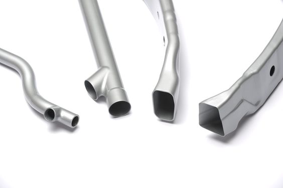
The hydroforming process involves several distinct steps, from material preparation to forming, cooling, and part removal. The process varies slightly depending on whether sheet hydroforming or tube hydroforming is being used, but the basic principles remain the same.
1. Material Preparation: Before the forming process begins, the metal sheet or tube must be prepared. This involves cutting the material to the appropriate size and shape, ensuring that it is free from defects or contaminants that could affect the forming process.
- Material Cutting: The blank is typically cut using precision methods such as laser cutting, waterjet cutting, or mechanical shearing to ensure accurate dimensions.
- Surface Preparation: The material may also be coated with lubricants to reduce friction during the forming process and prevent damage to the die or tooling.
2. Loading the Material into the Machine: Once the material is prepared, it is loaded into the hydroforming machine. The material is positioned over the die (for sheet hydroforming) or inside the die cavity (for tube hydroforming).
- Alignment: Proper alignment of the material with the die is crucial for achieving accurate part geometry. Many hydroforming machines are equipped with automated alignment systems to ensure that the material is positioned correctly before forming begins.
- Clamping: The material is held in place using clamps or mechanical fixtures to prevent it from shifting during the forming process.
3. Pressure Application and Forming: Once the material is loaded, hydraulic pressure is applied to shape the material into the desired form. In sheet hydroforming, the hydraulic fluid presses the sheet against the die, while in tube hydroforming, pressure is applied internally to expand the tube.
- Pressure Ramp-Up: The hydraulic pressure is gradually increased to prevent sudden stress on the material, which could lead to defects such as tearing or wrinkling.
- Forming Process: As the pressure increases, the material is forced to conform to the shape of the die. The forming process is carefully controlled to ensure that the material does not exceed its formability limits.
4. Cooling and Part Removal: After the forming process is complete, the hydraulic pressure is released, and the part is allowed to cool. Cooling helps stabilize the material and prevent deformation after removal from the die.
- Cooling Systems: Some hydroforming machines are equipped with cooling systems that help accelerate the cooling process, especially for materials that are sensitive to temperature changes.
- Part Removal: Once the part has cooled, it is removed from the die. Depending on the complexity of the part, additional finishing operations such as trimming or polishing may be required.
5. Post-Forming Operations: After forming, the part may undergo additional operations to achieve the desired finish or mechanical properties. These operations can include trimming, deburring, heat treatment, or surface finishing.
- Trimming: Excess material around the edges of the part is trimmed away to achieve the final dimensions.
- Finishing: The part may undergo polishing, coating, or anodizing to improve its surface finish and durability, depending on the application.
Applications of Hydroforming Machines
Hydroforming machines are used across a wide range of industries due to their ability to produce high-strength, lightweight components with complex geometries. The following sections explore some of the most common applications of hydroforming machines.
1. Automotive Industry: The automotive industry has been one of the largest adopters of hydroforming technology, using hydroforming machines to produce lightweight, structurally strong parts that improve vehicle fuel efficiency, safety, and performance.
- Body Panels: Hydroforming is used to create large, intricate body panels that are lightweight yet strong. By reducing the number of seams and welds, hydroformed body panels improve the vehicle’s aesthetics and structural integrity.
- Exhaust Systems: Tube hydroforming is widely used to produce exhaust systems with complex shapes. These systems optimize the flow of exhaust gases while reducing the overall weight of the vehicle.
- Chassis Components: Hydroformed chassis components, such as subframes, engine cradles, and crossmembers, are lighter and stronger than those produced using traditional methods. This leads to better handling, increased fuel efficiency, and enhanced crash safety.
2. Aerospace Industry: Hydroforming plays a critical role in the aerospace industry, where precision, strength, and lightweight materials are essential. Hydroforming machines are used to produce large fuselage sections, wing components, and structural parts for aircraft.
- Fuselage Sections: Hydroforming allows for the creation of large, smooth fuselage sections with consistent material thickness. This reduces the need for welding, which improves the structural integrity and durability of the aircraft.
- Wing Components: Hydroformed wing components benefit from the process’s ability to create complex shapes with high precision. These parts are lightweight yet strong enough to withstand the extreme forces encountered during flight.
3. Consumer Products and Electronics: Hydroforming machines are also used in the production of consumer products and electronics, particularly where complex shapes, sleek designs, and lightweight materials are required.
- Smartphone Casings: The sleek, curved designs of modern smartphones are often created using hydroforming. This process allows manufacturers to produce lightweight, durable casings with smooth, seamless surfaces.
- Appliances: Hydroforming is used to produce high-quality metal components for kitchen appliances, such as refrigerators, ovens, and dishwashers. These parts are not only functional but also aesthetically appealing, thanks to hydroforming’s ability to create smooth surfaces and intricate details.
4. Medical Devices: In the medical industry, hydroforming is used to produce high-precision, biocompatible components for surgical instruments and medical implants.
- Surgical Instruments: Hydroforming is ideal for producing intricate, high-precision surgical instruments. These instruments must be lightweight, durable, and easy to sterilize, making hydroformed parts a preferred choice.
- Medical Implants: Hydroformed implants, such as joint replacements and dental implants, are strong, lightweight, and biocompatible. The ability to form complex, customized shapes makes hydroforming ideal for producing implants that fit a patient’s anatomy precisely.
Advantages of Hydroforming Machines
Hydroforming machines offer several key advantages over traditional metal-forming processes, making them a preferred choice for manufacturers in a variety of industries.
1. Precision in Forming Complex Geometries: One of the most significant advantages of hydroforming is its ability to produce parts with complex shapes and intricate geometries that would be difficult or impossible to achieve using other methods. The even application of hydraulic pressure ensures that the material conforms precisely to the die, resulting in high levels of accuracy and repeatability.
- Complex Shapes: Hydroforming allows for the creation of parts with curves, bends, and varying thicknesses that are difficult to achieve through stamping or forging.
- Dimensional Accuracy: The hydraulic pressure used in hydroforming distributes force evenly across the material, ensuring uniform wall thickness and minimal distortion.
2. Lightweight and High-Strength Components: Hydroforming is especially well-suited for industries that require lightweight components without compromising strength, such as automotive and aerospace manufacturing.
- High Strength-to-Weight Ratio: Hydroformed parts typically have a higher strength-to-weight ratio than parts produced using traditional methods. This is due to the uniform stretching and forming of the material, which reduces weak points and ensures consistent thickness throughout the part.
- Lighter Components: By eliminating the need for multiple parts and joints, hydroforming produces parts that are lighter and stronger, contributing to improved fuel efficiency in vehicles and better performance in aircraft.
3. Efficiency and Reduction of Material Waste: Hydroforming is a near-net-shape process, meaning that the parts produced are very close to their final dimensions. This minimizes the need for additional trimming or machining, reducing material waste and lowering production costs.
- Less Scrap: Compared to traditional stamping or forging, hydroforming generates significantly less scrap material. This is especially important when working with expensive materials such as titanium or high-strength steel.
- Optimized Material Usage: Hydroforming allows manufacturers to use thinner materials without sacrificing strength, further reducing material consumption and costs.
4. Cost-Effectiveness in High-Volume Manufacturing: While the initial investment in hydroforming machines can be high, the process offers long-term cost savings in high-volume production due to its efficiency and reduced need for secondary operations.
- Fewer Manufacturing Steps: Hydroforming can often produce parts in a single operation, reducing the need for additional steps such as welding, trimming, or machining.
- Lower Tooling Costs: Compared to traditional stamping, which requires multiple dies for different stages of forming, hydroforming typically requires only one die, reducing tooling costs over time.
Challenges and Limitations of Hydroforming Machines
While hydroforming machines offer numerous advantages, they also present certain challenges and limitations. Understanding these limitations is essential for manufacturers considering hydroforming as part of their production process.
1. Material Constraints: Different materials respond differently to the hydroforming process, and not all materials are suitable for hydroforming. While hydroforming works well with metals such as aluminum, steel, and titanium, certain materials may be more challenging to form.
- Thicker Materials: Hydroforming is better suited for forming thinner materials, as thicker materials require higher pressures and are more prone to defects such as wrinkling or tearing.
- High-Strength Materials: While hydroforming can be used to form high-strength materials, such as titanium or steel, these materials require significantly higher pressures, which can strain the equipment.
2. Pressure and Equipment Limitations: Hydroforming machines must be capable of generating the necessary hydraulic pressure to form the material. For harder materials or more complex parts, higher pressures are required, which can increase the cost and complexity of the equipment.
- Pressure Requirements: Materials with higher tensile strength require higher hydraulic pressure to form. If the machine is not capable of generating sufficient pressure, the material may not conform properly to the die.
- Equipment Wear: Hydroforming machines are subjected to high pressures and repeated cycles, which can cause wear and tear on components such as seals, diaphragms, and dies. Regular maintenance is essential to ensure consistent performance and prevent downtime.
3. Maintaining Dimensional Accuracy: While hydroforming is known for its precision, achieving tight dimensional tolerances can be challenging, particularly for complex shapes or materials with high springback.
- Springback: Some materials, particularly high-strength steels, tend to spring back after forming, meaning they attempt to return to their original shape once the pressure is released. This can affect the dimensional accuracy of the part.
- Tool Wear: Over time, the dies and tooling used in hydroforming can wear down, especially when forming hard materials like titanium or steel. Worn tools can lead to variations in part dimensions and may require frequent replacement or refurbishment.
Technological Advancements in Hydroforming Machines
Advances in technology have significantly improved the capabilities and efficiency of hydroforming machines, making them more versatile and cost-effective for a wider range of applications. Below are some of the key technological innovations driving the evolution of hydroforming machines.
1. CNC Integration and Automation: The integration of CNC (Computer Numerical Control) technology with hydroforming machines has revolutionized the process by enabling precise control over every aspect of the forming operation. CNC systems allow manufacturers to automate the process, improving accuracy, repeatability, and overall efficiency.
- Automated Pressure Control: CNC systems can monitor and adjust hydraulic pressure in real-time, ensuring that the material is formed within the optimal parameters. This reduces the risk of defects and improves the quality of the final part.
- Multi-Axis Control: CNC integration allows for multi-axis control of the die and forming tools, enabling the production of more complex geometries with greater precision. This is particularly useful in industries like aerospace and automotive, where parts must meet tight tolerances.
2. Advanced Tooling and Sensors: Modern hydroforming machines are equipped with advanced sensors that monitor various aspects of the process, from hydraulic pressure to material deformation. These sensors provide real-time feedback to the control system, allowing for immediate adjustments to ensure optimal forming conditions.
- Pressure Sensors: Pressure sensors monitor the hydraulic pressure during the forming process, ensuring that it remains within the required range for the material and part being produced. This helps prevent issues such as material cracking or incomplete forming.
- Deformation Monitoring: Sensors can also monitor how the material is deforming during the process, alerting operators to potential issues such as wrinkling or tearing. This allows for immediate adjustments to the process, reducing the risk of defects.
3. Higher Pressure Capacity Machines: As demand for high-strength, lightweight materials such as titanium and Inconel grows, hydroforming machines are being developed with higher pressure capacities to handle these tougher materials.
- Titanium and Inconel: These materials are known for their high strength and corrosion resistance, making them ideal for aerospace, medical, and automotive applications. However, they require significantly higher pressures to form, which has led to the development of more powerful hydroforming machines.
- Increased Pressure Capacity: Modern hydroforming machines are capable of generating pressures of 20,000 psi or more, enabling the efficient forming of hard-to-shape materials like titanium and high-strength steel.
4. Automation and Robotics: Automation and robotics are playing an increasingly important role in hydroforming, particularly in high-volume production environments. Automated systems can handle tasks such as loading and unloading parts, monitoring the forming process, and performing quality control inspections.
- Robotic Handling: Robots can be used to load and unload parts from the hydroforming machine, reducing cycle times and improving overall efficiency. This is especially useful for large, heavy parts that would be difficult to handle manually.
- Automated Quality Control: Automated inspection systems, such as vision sensors and laser measurement tools, can inspect parts for defects and dimensional accuracy, reducing the need for manual inspection and ensuring consistent quality across production runs.
Economic and Environmental Impact of Hydroforming Machines
Hydroforming machines offer both economic and environmental benefits, making them an attractive option for manufacturers looking to improve efficiency and reduce their environmental impact.
1. Energy Efficiency in Hydroforming: Hydroforming machines are generally more energy-efficient than traditional mechanical presses, particularly when forming complex parts. Hydraulic systems can generate the necessary pressure with less energy than mechanical presses, leading to lower energy consumption and reduced operating costs.
- Reduced Energy Consumption: Hydraulic presses used in hydroforming are designed to consume less power compared to traditional mechanical presses, leading to lower energy costs and a smaller carbon footprint.
- Energy Recovery Systems: Some modern hydroforming machines are equipped with energy recovery systems that capture and reuse energy generated during the forming process. This further reduces energy consumption and operational costs.
2. Material Efficiency and Cost Savings: Hydroforming is a near-net-shape forming process, meaning that parts are produced with minimal waste. This leads to significant material savings, particularly when working with expensive materials like titanium or high-strength steel.
- Reduced Scrap: Compared to traditional forming methods, hydroforming generates significantly less scrap material. This reduces the cost of raw materials and minimizes the environmental impact associated with waste.
- Optimized Material Usage: Hydroforming allows manufacturers to use thinner materials without sacrificing strength, resulting in further material savings.
3. Environmental Benefits and Sustainable Manufacturing: Hydroforming is a more environmentally friendly manufacturing process compared to traditional methods due to its energy efficiency, material efficiency, and reduced waste. As industries move toward more sustainable manufacturing practices, hydroforming is playing an increasingly important role in reducing the environmental impact of production.
- Lightweighting for Automotive and Aerospace: One of the key benefits of hydroforming is its ability to produce lightweight components that improve fuel efficiency and reduce emissions in vehicles and aircraft. By reducing the weight of vehicles, manufacturers can achieve significant reductions in fuel consumption and greenhouse gas emissions.
- Sustainable Design Practices: Many manufacturers are incorporating hydroforming into their sustainable design practices, using the process to create parts that are both environmentally friendly and cost-effective.
Case Studies: Industry Use of Hydroforming Machines
Hydroforming machines have been successfully implemented across various industries, helping manufacturers achieve significant improvements in product quality, material efficiency, and cost savings. The following case studies highlight the use of hydroforming machines in different sectors.
1. Automotive Sector: A leading automotive manufacturer used hydroforming machines to produce lightweight chassis components for a new line of vehicles. The goal was to reduce vehicle weight without compromising strength or safety.
- Challenges: The manufacturer needed to create lightweight components that could withstand high loads and meet stringent safety standards. Traditional forming methods were unable to achieve the desired balance of weight reduction and strength.
- Solution: The company used tube hydroforming machines to produce engine cradles and subframes. The hydroformed parts were 20% lighter than those produced using traditional methods, contributing to improved fuel efficiency and reduced emissions.
- Results: The hydroformed components met all safety and performance standards, while also reducing the overall weight of the vehicle. This resulted in improved fuel efficiency and lower emissions.
2. Aerospace Innovations: An aerospace company employed hydroforming machines to produce lightweight fuselage sections and wing components for a new commercial aircraft. The goal was to reduce the weight of the aircraft while maintaining strength and structural integrity.
- Challenges: Aircraft components must be lightweight yet strong enough to withstand the stresses of flight. Traditional forming methods were unable to produce the complex shapes needed for the fuselage and wings without adding excess weight.
- Solution: The company used sheet hydroforming machines to create large fuselage sections with uniform thickness and minimal joints. This reduced the need for welding, which improved the strength and durability of the aircraft.
- Results: The hydroformed components were lighter and stronger than those produced using traditional methods, contributing to improved fuel efficiency and overall performance. The use of hydroforming also reduced production time and costs by eliminating the need for additional forming and assembly operations.
3. Consumer Electronics: A consumer electronics manufacturer used hydroforming machines to produce the sleek, curved metal casings for a new line of smartphones. The goal was to create lightweight, durable casings with a high level of aesthetic appeal.
- Challenges: The manufacturer needed to produce casings that were both lightweight and strong, with a smooth, seamless finish. Traditional stamping methods were unable to achieve the desired level of precision and surface quality.
- Solution: The company used sheet hydroforming machines to produce the smartphone casings. The process allowed for the creation of complex, curved shapes with minimal material waste and a smooth, seamless surface finish.
- Results: The hydroformed casings were lightweight, durable, and visually appealing, meeting the manufacturer’s design and performance requirements. The process also reduced the need for additional finishing operations, improving production efficiency.
4. Medical Equipment Manufacturing: A medical device manufacturer used hydroforming machines to produce customized surgical instruments and implants. The goal was to create lightweight, high-precision instruments with complex geometries that could be used in minimally invasive surgeries.
- Challenges: The medical industry requires instruments that are both lightweight and highly precise. Traditional forming methods were unable to achieve the level of precision needed for these complex, high-performance instruments.
- Solution: The manufacturer used deep-draw hydroforming machines to create the surgical instruments. The hydroforming process allowed for the production of intricate shapes with high precision and minimal material stress, ensuring that the instruments were both strong and easy to sterilize.
- Results: The hydroformed instruments met all performance and safety standards, providing the necessary strength and precision for use in surgery. The process also reduced production costs by minimizing material waste and reducing the need for secondary machining operations.
Future Trends in Hydroforming Machine Technology
As industries continue to evolve, several trends are shaping the future of hydroforming machine technology. These trends include the integration of Industry 4.0 technologies, advancements in lightweight materials, and the adoption of hybrid manufacturing techniques.
1. Hybrid Manufacturing: Combining Hydroforming with Additive Manufacturing: Additive manufacturing, also known as 3D printing, is being integrated with hydroforming to create hybrid manufacturing processes. This combination allows manufacturers to produce highly customized parts with enhanced performance characteristics.
- 3D-Printed Dies: Additive manufacturing can be used to produce custom dies for hydroforming machines, reducing the lead time and cost associated with creating traditional dies. This is particularly useful for short production runs or highly customized parts.
- Custom Part Production: The combination of 3D printing and hydroforming allows manufacturers to create complex, customized parts with features such as variable wall thicknesses or internal structures that would be difficult to achieve using traditional methods alone.
2. Lightweighting and Material Innovations: The trend toward lightweighting in industries such as automotive and aerospace is driving the development of new materials and manufacturing techniques. Hydroforming is playing a key role in this trend by enabling the production of lightweight components with high structural integrity.
- Magnesium and Titanium Alloys: Magnesium and titanium alloys are being increasingly used in lightweighting applications due to their high strength-to-weight ratios. Hydroforming machines are being developed to handle these materials, allowing manufacturers to produce even lighter components without sacrificing strength.
- Advanced Composites: Carbon fiber composites are becoming more common in aerospace and automotive applications due to their lightweight properties and high strength. Future hydroforming machines may be capable of forming these advanced composites, opening up new possibilities for lightweight manufacturing.
3. Industry 4.0 and Smart Manufacturing in Hydroforming: Industry 4.0, also known as the fourth industrial revolution, is transforming manufacturing by integrating digital technologies, automation, and data exchange into production processes. Hydroforming machines are beginning to adopt these smart manufacturing practices, enabling greater efficiency, customization, and flexibility.
- Real-Time Monitoring and Data Analytics: Smart hydroforming machines are equipped with sensors that collect data on every aspect of the process, from hydraulic pressure to material deformation. This data can be analyzed in real-time to optimize the process and identify potential issues before they lead to defects or downtime.
- Predictive Maintenance: Using data analytics, manufacturers can implement predictive maintenance programs that monitor the health of the machine and predict when maintenance will be needed. This reduces unplanned downtime and extends the lifespan of the equipment.
- Digital Twins: Digital twin technology is being used to create virtual replicas of hydroforming machines, allowing manufacturers to simulate and optimize the forming process before production begins. This reduces the risk of defects and improves overall efficiency.
4. High-Pressure Forming for New Materials: As demand for stronger, lighter materials continues to grow, hydroforming machines are being developed with higher pressure capacities to handle more challenging materials such as titanium, Inconel, and carbon fiber composites.
- Titanium and Inconel: These materials are known for their high strength and corrosion resistance, making them ideal for aerospace, medical, and automotive applications. However, they require significantly higher pressures to form, which has led to the development of more powerful hydroforming machines.
- Carbon Fiber Composites: As carbon fiber composites become more common in aerospace and automotive applications, hydroforming machines are being adapted to form these advanced materials, offering new possibilities for lightweight component production.
Conclusion: The Future of Hydroforming Machines
Hydroforming machines have evolved into one of the most versatile and efficient metal-forming technologies available today. Their ability to produce lightweight, high-strength components with complex geometries has made them indispensable in industries ranging from automotive and aerospace to consumer electronics and medical devices.
As technology continues to advance, hydroforming machines are poised to play an even more significant role in modern manufacturing. The integration of CNC control, automation, and smart manufacturing technologies has already improved the precision, efficiency, and flexibility of hydroforming processes. Looking ahead, the development of high-pressure machines for exotic materials and the integration of additive manufacturing are expected to further expand the capabilities of hydroforming.
In an era where sustainability and efficiency are increasingly important, hydroforming machines stand out as a solution that can meet the demands of modern manufacturing while minimizing environmental impact. By reducing material waste, improving energy efficiency, and producing lightweight components that contribute to fuel savings, hydroforming is helping manufacturers achieve their sustainability goals.
As industries continue to explore new materials, technologies, and applications, the future of hydroforming machines is bright. Whether it’s producing the next generation of fuel-efficient vehicles, lightweight aircraft, or cutting-edge medical devices, hydroforming machines will remain at the forefront of advanced manufacturing, helping to shape the future of products across a wide range of industries.
In conclusion, hydroforming machines represent a perfect blend of precision, efficiency, and sustainability, making them an indispensable tool for manufacturers around the world. Their continued evolution and adaptation to new materials, technologies, and applications will ensure that hydroforming remains a critical process for many industries in the years to come.
Introduction to Hydroforming Presses
Overview and Definition: Hydroforming presses are specialized hydraulic machines used in the hydroforming process, a modern method of shaping metal into intricate, high-strength parts. Unlike traditional mechanical forming methods like stamping, forging, or extrusion, hydroforming relies on hydraulic fluid to press metal into a mold or die under high pressure. This technique allows for the creation of parts with complex geometries, smooth surfaces, and minimal material stress.
Hydroforming presses are essential in various industries such as automotive, aerospace, electronics, and medical devices, where precision, durability, and weight reduction are key factors. These machines enable manufacturers to produce lightweight components with fewer joints and welds, enhancing the overall strength and efficiency of the parts.
Importance in Modern Manufacturing: The growing demand for lightweight, high-strength materials in industries like automotive and aerospace has driven the adoption of hydroforming presses. These machines enable manufacturers to produce components that are not only strong but also light, improving performance and fuel efficiency. In the automotive industry, for instance, hydroformed components are used to build lightweight chassis frames, exhaust systems, and body panels, all of which contribute to reducing a vehicle’s weight without compromising its strength or safety.
In aerospace, hydroforming presses are used to manufacture aircraft fuselage sections, wings, and structural components that must withstand extreme forces while minimizing weight. The medical device industry uses hydroforming to create precise, biocompatible implants and surgical tools, while electronics manufacturers rely on hydroforming presses for sleek, durable casings for smartphones, laptops, and other consumer products.
The combination of precision, strength, and efficiency that hydroforming presses offer has made them indispensable in high-tech manufacturing, where innovation and performance are continually evolving.
Principles of Hydroforming and the Role of Presses
Hydroforming Process Fundamentals: At its core, hydroforming is a metal-forming process that uses fluid pressure to shape metal into the desired form. Unlike traditional forming processes that rely on mechanical force applied directly to the metal, hydroforming uses hydraulic fluid to apply uniform pressure to a metal sheet or tube, forcing it into a mold or die. The key advantage of this approach is that it allows the material to be formed evenly, with minimal stress and strain.
The hydroforming press serves as the engine of this process, generating the necessary pressure to deform the metal without causing tearing, thinning, or other defects. Hydraulic presses, specifically designed for hydroforming, can exert forces in the range of 5,000 to 20,000 psi, depending on the material and complexity of the part.
Hydroforming presses are typically designed to perform either sheet hydroforming or tube hydroforming:
- Sheet Hydroforming: In this method, a flat metal sheet is placed over a single-sided die, and hydraulic pressure is applied from above, pushing the sheet into the die cavity. The process is ideal for creating large, shallow parts like body panels or appliance casings.
- Tube Hydroforming: This process involves placing a hollow tube inside a die, sealing both ends, and applying internal hydraulic pressure. The tube expands to fill the die, creating complex, hollow structures like automotive chassis components or bicycle frames.
How Presses Create Precision Parts: The success of the hydroforming process depends heavily on the precision of the press. Hydroforming presses must apply consistent, controlled pressure to ensure that the metal deforms uniformly without defects. The accuracy of the pressure application allows for the creation of parts with tight tolerances and smooth surface finishes. This precision is critical in industries like aerospace and automotive, where even small deviations in part dimensions can impact performance and safety.
The design of the press, including its hydraulic system, die configuration, and control mechanisms, plays a crucial role in achieving the desired level of precision. Advanced hydroforming presses are often equipped with CNC (Computer Numerical Control) systems that allow for automated control of pressure, timing, and die movement, further improving the accuracy and repeatability of the process.
Differences from Traditional Metal Forming: Hydroforming differs from traditional metal forming methods in several key ways:
- Uniform Pressure Application: Traditional methods like stamping or forging often apply force at specific points, leading to uneven material distribution. Hydroforming, by contrast, applies fluid pressure uniformly across the entire surface of the material, resulting in more consistent thickness and fewer weak points.
- Complex Geometries: Hydroforming allows for the creation of intricate shapes and contours that would be difficult or impossible to achieve using mechanical force. This is particularly valuable in industries that require lightweight components with complex designs, such as automotive and aerospace.
- Material Efficiency: Hydroforming produces near-net-shape parts, meaning that the final product requires little to no additional machining or trimming. This reduces material waste and overall production costs, especially when working with expensive metals like titanium or high-strength steel.
Types of Hydroforming Presses
Hydroforming presses are designed to handle different types of hydroforming processes. The most common types of hydroforming presses are sheet hydroforming presses, tube hydroforming presses, deep-draw hydroforming presses, and specialized hydroforming presses. Each type of press is tailored to specific applications, materials, and production requirements.
Sheet Hydroforming Presses: Sheet hydroforming presses are used to form large, flat metal sheets into complex shapes. These presses use a single-sided die, where the metal sheet is placed over the die, and hydraulic pressure is applied using a flexible diaphragm or fluid chamber. The pressure forces the sheet into the die cavity, forming the desired shape.
- Applications: Automotive body panels, aerospace fuselage sections, appliance components, and large consumer products.
- Advantages: Sheet hydroforming presses are ideal for producing shallow parts with smooth curves and high-quality surface finishes. The process allows for greater design flexibility and is particularly useful for forming lightweight parts with minimal material waste.
Tube Hydroforming Presses: Tube hydroforming presses are used to form hollow metal tubes into complex, three-dimensional shapes. This process is ideal for applications that require lightweight, structurally strong components with intricate geometries.
- Process: In tube hydroforming, the metal tube is placed inside a die, and hydraulic pressure is applied internally to expand the tube outward until it conforms to the shape of the die. The press ensures that the tube’s walls are evenly distributed and free from defects like wrinkling or thinning.
- Applications: Automotive chassis frames, subframes, exhaust systems, bicycle frames, and structural aerospace components.
- Advantages: Tube hydroforming produces stronger, lighter parts with fewer welds and joints, improving both strength and durability. This process is particularly effective for creating components with complex cross-sectional shapes and varying diameters.
Deep-Draw Hydroforming Presses: Deep-draw hydroforming presses are designed for creating parts with a high depth-to-width ratio, such as fuel tanks, engine housings, and structural components. The deep-draw process involves stretching the metal sheet more than in conventional hydroforming, allowing for the creation of deep, intricate shapes.
- Process: A metal blank is placed over a die, and hydraulic pressure is applied to stretch the material into the die cavity. Deep-draw hydroforming requires precise control of pressure and die movement to prevent defects like wrinkling or tearing.
- Applications: Fuel tanks, transmission housings, deep structural parts for aerospace and automotive industries.
- Advantages: Deep-draw hydroforming presses are capable of producing parts with significant depth without excessive thinning of the material, which is crucial for maintaining part strength and integrity.
Specialized Hydroforming Presses: In addition to standard sheet and tube hydroforming presses, there are specialized presses designed for unique applications, such as explosive hydroforming and multi-layer forming. These presses are used in industries that require extreme precision, strength, or unique material properties.
- Explosive Hydroforming: This process uses controlled explosions to generate the hydraulic pressure needed to form large, complex parts. It is primarily used in the aerospace and defense industries for applications that require extremely high forces to shape metals.
- Multi-Layer Hydroforming: Some specialized presses are designed to form multi-layered materials, which are commonly used in aerospace and defense applications. These presses apply varying pressures to form each layer, ensuring that the final component meets the required specifications.
Comparison of Different Hydroforming Press Types:
- Sheet Hydroforming Presses: Best for large, shallow parts with intricate surface details.
- Tube Hydroforming Presses: Ideal for forming hollow structures with complex geometries.
- Deep-Draw Hydroforming Presses: Suited for deep, intricate parts with a high depth-to-width ratio.
- Specialized Presses: Tailored for unique applications such as explosive or multi-layer forming.
Key Components of Hydroforming Presses
Hydroforming presses are composed of several critical components that work together to apply hydraulic pressure and shape the metal parts. The most important components include hydraulic systems, die and tooling mechanisms, seals and diaphragms, and control systems.
Hydraulic Systems: The hydraulic system is the core of any hydroforming press, responsible for generating and controlling the fluid pressure needed to deform the metal. These systems typically include hydraulic pumps, pressure accumulators, valves, and regulators.
- Hydraulic Pumps: These pumps generate the high pressure needed for forming the metal. The pumps must be capable of producing consistent pressure levels throughout the entire forming process to ensure that the metal conforms evenly to the die.
- Pressure Accumulators: Accumulators store hydraulic fluid under pressure and release it as needed, ensuring that the pressure remains steady during forming. This helps maintain consistent part quality and reduces the risk of defects caused by pressure fluctuations.
- Pressure Regulators: Pressure regulators control the hydraulic pressure throughout the forming process, ensuring that it remains within the specified range for the material being formed. Accurate pressure control is essential for preventing defects like thinning, tearing, or wrinkling of the metal.
Die and Tooling Mechanisms: The die is the part of the hydroforming press that shapes the metal into the desired form. Dies are typically made from hardened steel or other durable materials that can withstand the high pressures involved in hydroforming.
- Die Design: The design of the die is critical for achieving the desired part geometry. For simple parts, a single-sided die may be sufficient, while more complex parts may require multi-part dies with intricate details. The accuracy of the die directly impacts the quality of the final part.
- Tooling Materials: Dies and tooling are often coated with wear-resistant materials like carbide or diamond-like carbon (DLC) to extend their lifespan and improve performance under high-pressure conditions. The durability of the tooling is especially important in high-volume production environments where dies may be subjected to repeated cycles.
Seals, Diaphragms, and Containment Systems: Seals, diaphragms, and fluid chambers are crucial components that contain and direct the hydraulic fluid during the forming process. These components must be able to withstand the high pressures involved in hydroforming without degrading over time.
- Seals: Seals prevent hydraulic fluid from leaking during the forming process. They are typically made from high-strength elastomers or composite materials that can handle the extreme pressures involved in hydroforming. Proper sealing is essential for maintaining consistent pressure and preventing fluid loss.
- Diaphragms: In sheet hydroforming, a flexible diaphragm is used to apply hydraulic pressure to the metal sheet. The diaphragm must be durable enough to withstand repeated cycles of expansion and contraction without tearing.
- Fluid Chambers: Fluid chambers contain the hydraulic fluid and direct it toward the metal blank or tube. These chambers must be strong enough to handle the extreme pressures involved in the process while preventing leaks.
Automated Control Systems (CNC Integration): Modern hydroforming presses are equipped with sophisticated control systems that allow for precise regulation of hydraulic pressure, die movement, and other critical parameters. Many presses are integrated with CNC (Computer Numerical Control) systems, which enable automated control of the forming process.
- Pressure Monitoring: Automated systems monitor the hydraulic pressure in real-time, ensuring that it remains within the required range for the specific material and part being formed. This helps prevent defects and improves overall part quality.
- CNC Automation: CNC-controlled hydroforming presses allow for greater precision and repeatability, particularly for complex parts that require tight tolerances. Automation also improves production efficiency by reducing the need for manual intervention and increasing throughput.
Design and Functionality of Hydroforming Presses
The design and functionality of hydroforming presses are key to their performance and the quality of the parts they produce. Several factors influence the design of a hydroforming press, including pressure capacity, material compatibility, and production speed.
Key Design Parameters: Hydroforming presses are designed to meet specific production requirements, such as part complexity, material type, and production volume. The key design parameters include:
- Pressure Capacity: Hydroforming presses must be capable of generating the appropriate pressure for the material being formed. For softer metals like aluminum, lower pressures (5,000 to 10,000 psi) may be sufficient, while harder metals like steel or titanium may require pressures exceeding 20,000 psi.
- Die Design: The die used in a hydroforming press is custom-designed to match the desired part geometry. The design of the die is influenced by factors such as material thickness, part complexity, and the depth of draw required.
- Machine Size: Hydroforming presses come in various sizes, depending on the dimensions of the parts being produced. Larger presses are used for forming automotive or aerospace components, while smaller presses may be used for medical devices or consumer electronics.
Pressure Capacities and Operating Ranges: Hydroforming presses are available in different pressure capacities to suit a variety of materials and applications. The pressure capacity of a press is one of its most critical specifications, as it determines the types of materials that can be processed and the complexity of the shapes that can be formed.
- Low-Pressure Presses: These presses are used for forming softer metals like aluminum or copper, where pressures below 10,000 psi are sufficient.
- High-Pressure Presses: High-pressure presses are designed for forming stronger materials like steel or titanium. These presses can generate pressures of 20,000 psi or more, making them suitable for complex, high-strength parts.
Material Compatibility and Customization: Hydroforming presses must be compatible with a wide range of materials, each with its own forming requirements. Common materials used in hydroforming include aluminum, steel, and titanium, but presses can also be customized to work with more exotic materials like Inconel or magnesium alloys.
- Aluminum: Aluminum is widely used in hydroforming because of its lightweight properties and high formability. It can be formed at lower pressures compared to steel or titanium, making it ideal for automotive and aerospace applications.
- Steel: High-strength steel alloys are often used in automotive and aerospace components due to their superior strength. However, steel requires higher pressures to form, and presses must be capable of generating sufficient force to shape the material without defects.
- Titanium: Known for its strength and corrosion resistance, titanium is used in aerospace, medical, and defense applications. Titanium is more difficult to form than steel or aluminum, requiring precise pressure control and specialized tooling.
Hydroforming Press Process
The hydroforming press process involves several key steps, from material preparation to forming, cooling, and part removal. The process varies slightly depending on whether sheet hydroforming or tube hydroforming is being used, but the basic principles remain the same.
1. Material Preparation: Before the forming process begins, the metal sheet or tube must be prepared. This involves cutting the material to the appropriate size and ensuring that it is free from contaminants or defects that could affect the forming process.
- Material Cutting: The blank is typically cut using precision methods such as laser cutting, waterjet cutting, or mechanical shearing to ensure accurate dimensions.
- Surface Preparation: The surface of the material may be coated with a lubricant to reduce friction during forming and prevent damage to the die.
2. Loading the Material into the Press: Once the material is prepared, it is loaded into the hydroforming press. The material is positioned over the die (for sheet hydroforming) or inside the die cavity (for tube hydroforming).
- Alignment: Proper alignment of the material with the die is crucial for achieving accurate part geometry. Many hydroforming presses are equipped with automated alignment systems to ensure that the material is positioned correctly before forming begins.
- Clamping: The material is held in place using clamps or mechanical fixtures to prevent it from shifting during the forming process.
3. Pressure Application and Forming: Once the material is loaded, hydraulic pressure is applied to shape the material into the desired form. In sheet hydroforming, the hydraulic fluid presses the sheet into the die, while in tube hydroforming, pressure is applied internally to expand the tube.
- Pressure Ramp-Up: The hydraulic pressure is gradually increased to prevent sudden stress on the material, which could lead to defects such as tearing or wrinkling.
- Forming Process: As the pressure increases, the material conforms to the shape of the die. The forming process is carefully controlled to ensure that the material does not exceed its formability limits.
4. Cooling and Part Removal: After the forming process is complete, the hydraulic pressure is released, and the part is allowed to cool. Cooling helps stabilize the material and prevent deformation after removal from the die.
- Cooling Systems: Some hydroforming presses are equipped with cooling systems to accelerate the cooling process, especially for materials that are sensitive to temperature changes.
- Part Removal: Once the part has cooled, it is removed from the die. Depending on the complexity of the part, additional finishing operations such as trimming or polishing may be required.
5. Post-Forming Operations: After forming, the part may undergo additional operations to achieve the desired finish or mechanical properties. These operations can include trimming, deburring, heat treatment, or surface finishing.
- Trimming: Excess material around the edges of the part is trimmed away to achieve the final dimensions.
- Finishing: The part may undergo polishing, coating, or anodizing to improve its surface finish and durability, depending on the application.
Applications of Hydroforming Presses
Hydroforming presses are used across a wide range of industries to produce high-strength, lightweight components with complex geometries. Some of the most common applications of hydroforming presses include the automotive industry, aerospace industry, consumer goods, and medical devices.
1. Automotive Industry: The automotive industry has been one of the largest adopters of hydroforming technology. Hydroforming presses are used to produce lightweight, structurally strong components that improve vehicle fuel efficiency, safety, and performance.
- Chassis Components: Hydroformed chassis components, such as engine cradles, subframes, and crossmembers, are lighter and stronger than those produced using traditional methods. This leads to better handling, increased fuel efficiency, and enhanced crash safety.
- Body Panels: Hydroforming is used to create large, intricately shaped body panels that are lightweight yet strong. By reducing the number of seams and welds, hydroformed body panels improve the vehicle’s aesthetics and structural integrity.
- Exhaust Systems: Tube hydroforming is commonly used to produce exhaust systems with complex shapes and varying cross-sections. These systems optimize the flow of exhaust gases while reducing the overall weight of the vehicle.
2. Aerospace Industry: Hydroforming plays a critical role in the aerospace industry, where precision, strength, and lightweight materials are essential. Hydroforming presses are used to produce large fuselage sections, wing components, and structural parts for aircraft.
- Fuselage Sections: Hydroforming allows for the creation of large, smooth fuselage sections with consistent material thickness. This reduces the need for welding, which improves the structural integrity and durability of the aircraft.
- Wing Components: Hydroformed wing components benefit from the process’s ability to create complex shapes with high precision. These parts are lightweight yet strong enough to withstand the extreme forces encountered during flight.
- Landing Gear: Hydroforming is also used to create parts for aircraft landing gear, where strength and durability are critical for withstanding the forces of takeoff and landing.
3. Consumer Goods: Hydroforming presses are also used in the production of consumer goods, particularly for products that require lightweight, durable, and aesthetically pleasing components.
- Electronics Casings: Hydroforming is widely used to create sleek, curved metal casings for smartphones, laptops, and other electronic devices. The process allows manufacturers to produce lightweight, durable casings with smooth, seamless surfaces.
- Appliances: Hydroformed components are used in the production of high-quality kitchen appliances, such as refrigerators, ovens, and dishwashers. These parts are not only functional but also visually appealing, thanks to the smooth surfaces and intricate details achievable with hydroforming.
4. Medical Devices: In the medical industry, hydroforming is used to produce high-precision, biocompatible components for surgical instruments and implants.
- Surgical Instruments: Hydroforming is ideal for producing intricate, high-precision surgical instruments. These instruments must be lightweight, durable, and easy to sterilize, making hydroformed parts a preferred choice.
- Medical Implants: Hydroformed implants, such as joint replacements and dental implants, are strong, lightweight, and biocompatible. The ability to form complex, customized shapes makes hydroforming ideal for producing implants that fit a patient’s anatomy precisely.
Advantages of Hydroforming Presses
Hydroforming presses offer several advantages over traditional metal-forming processes, making them a preferred choice for manufacturers in various industries. These advantages include precision in forming complex geometries, lightweight and high-strength component production, material efficiency, and cost-effectiveness in high-volume production.
1. Precision in Forming Complex Geometries: Hydroforming presses are ideal for producing parts with complex shapes and geometries that are difficult or impossible to achieve using traditional forming methods. The use of hydraulic pressure ensures that the material conforms precisely to the die, resulting in high levels of accuracy and repeatability.
- Complex Shapes: Hydroforming allows for the creation of parts with intricate curves, bends, and varying thicknesses that would be challenging to produce with stamping or forging.
- Dimensional Accuracy: The hydraulic pressure used in hydroforming is applied uniformly across the surface of the material, ensuring that the part forms evenly and maintains dimensional accuracy.
2. Lightweight and High-Strength Component Production: Hydroforming is particularly well-suited for industries where weight reduction is critical, such as automotive and aerospace manufacturing. The process allows for the production of lightweight parts with high structural integrity, improving fuel efficiency and performance.
- Strength-to-Weight Ratio: Hydroformed parts typically have a higher strength-to-weight ratio than those produced using traditional methods. This is due to the uniform stretching and forming of the material, which reduces weak points and ensures consistent thickness throughout the part.
- Lighter Components: Hydroforming allows manufacturers to reduce the need for welding and assembly, producing parts that are lighter and more structurally sound.
3. Material Efficiency and Reduced Waste: Hydroforming is a near-net-shape process, meaning that parts are produced very close to their final dimensions. This minimizes the need for additional machining or trimming, reducing material waste and lowering production costs.
- Less Scrap: Compared to traditional stamping or forging, hydroforming generates significantly less scrap material. This is especially beneficial when working with expensive materials such as titanium or high-strength steel.
- Optimized Material Usage: Hydroforming allows manufacturers to use thinner materials without sacrificing strength, further reducing material consumption and waste.
4. Cost-Effectiveness in High-Volume Manufacturing: While the initial investment in hydroforming presses can be high, the process is highly cost-effective in large-scale production due to its material efficiency and reduced need for secondary operations.
- Fewer Manufacturing Steps: Hydroforming can often produce complex parts in a single operation, reducing the need for additional steps such as welding, machining, or finishing.
- Lower Tooling Costs: Compared to traditional stamping, which requires multiple dies for different stages of forming, hydroforming typically requires only one die, reducing tooling costs over time.
- Faster Production: Advances in automation and CNC integration have significantly improved the speed and accuracy of hydroforming presses, making them ideal for high-volume production environments.
Challenges and Limitations of Hydroforming Presses
While hydroforming presses offer numerous advantages, they also come with certain challenges and limitations. Understanding these limitations is essential for manufacturers considering hydroforming as part of their production process.
1. Material Constraints: Different materials respond differently to the hydroforming process, and not all materials are suitable for hydroforming. While hydroforming works well with metals such as aluminum, steel, and titanium, certain materials may be more challenging to form.
- Thicker Materials: Hydroforming is better suited for forming thinner materials, as thicker materials require higher pressures and are more prone to defects such as wrinkling or tearing.
- High-Strength Materials: While hydroforming can be used to form high-strength materials like steel or titanium, these materials require significantly higher pressures, which can strain the equipment and increase the risk of material failure.
2. Pressure Requirements and Machine Capabilities: Hydroforming presses must be capable of generating the necessary hydraulic pressure to form the material. For harder materials or more complex parts, higher pressures are required, which can increase the cost and complexity of the equipment.
- Pressure Limitations: Materials with higher tensile strength require higher hydraulic pressure to form. If the machine is not capable of generating sufficient pressure, the material may not conform properly to the die, leading to defects.
- Equipment Wear: Hydroforming presses are subjected to high pressures and repeated cycles, which can cause wear and tear on components such as seals, diaphragms, and dies. Regular maintenance is essential to ensure consistent performance and prevent downtime.
3. Dimensional Accuracy and Springback: While hydroforming is known for its precision, achieving tight dimensional tolerances can be challenging, particularly for materials with high springback.
- Springback: Some materials, particularly high-strength steels, have a tendency to spring back after forming, meaning they attempt to return to their original shape once the pressure is released. This can affect the dimensional accuracy of the part and may require additional post-processing to achieve the desired specifications.
- Tool Wear: Over time, the dies and tooling used in hydroforming can wear down, especially when forming hard materials like titanium or steel. Worn tools can lead to variations in part dimensions and may require frequent replacement or refurbishment.
Technological Innovations in Hydroforming Presses
Technological advancements in hydroforming presses have significantly improved their capabilities and efficiency. Some of the most notable innovations include the integration of CNC (Computer Numerical Control) systems, advances in sensor technology, and the development of high-pressure presses for exotic materials.
1. CNC-Controlled Presses: The integration of CNC technology into hydroforming presses has revolutionized the forming process by allowing for precise control over every aspect of the operation. CNC systems automate the process, improving accuracy, repeatability, and overall efficiency.
- Automated Pressure Control: CNC systems can monitor and adjust hydraulic pressure in real-time, ensuring that the material is formed within the optimal parameters. This reduces the risk of defects and improves the quality of the final part.
- Multi-Axis Control: CNC integration allows for multi-axis control of the die and forming tools, enabling the production of more complex geometries with greater precision. This is particularly useful in industries like aerospace and automotive, where parts must meet tight tolerances.
2. Advances in Tooling and Sensor Technology: Modern hydroforming presses are equipped with advanced sensors that monitor various aspects of the process, from hydraulic pressure to material deformation. These sensors provide real-time feedback to the control system, allowing for immediate adjustments to ensure optimal forming conditions.
- Pressure Sensors: Pressure sensors monitor the hydraulic pressure during the forming process, ensuring that it remains within the required range for the material and part being produced. This helps prevent issues such as material cracking or incomplete forming.
- Deformation Monitoring: Sensors can also monitor how the material is deforming during the process, alerting operators to potential issues such as wrinkling or tearing. This allows for immediate adjustments to the process, reducing the risk of defects.
3. High-Pressure Systems for Exotic Materials: As demand for lightweight, high-strength materials such as titanium and Inconel grows, hydroforming presses are being developed with higher pressure capacities to handle these tougher materials.
- Titanium and Inconel: These materials are known for their high strength and resistance to corrosion, making them ideal for aerospace, medical, and automotive applications. However, they require significantly higher pressures to form, which has led to the development of more powerful hydroforming presses.
- Increased Pressure Capacity: Modern hydroforming presses are capable of generating pressures of 20,000 psi or more, enabling the efficient forming of hard-to-shape materials like titanium and high-strength steel.
4. Automation and Robotics: Automation and robotics are playing an increasingly important role in hydroforming, particularly in high-volume production environments. Automated systems can handle tasks such as loading and unloading parts, monitoring the forming process, and performing quality control inspections.
- Robotic Handling: Robots can be used to load and unload parts from the hydroforming press, reducing cycle times and improving overall efficiency. This is especially useful for large, heavy parts that would be difficult to handle manually.
- Automated Quality Control: Automated inspection systems, such as vision sensors and laser measurement tools, can inspect parts for defects and dimensional accuracy, reducing the need for manual inspection and ensuring consistent quality across production runs.
Economic and Environmental Impact of Hydroforming Presses
Hydroforming presses offer both economic and environmental benefits, making them an attractive option for manufacturers looking to improve efficiency and reduce their environmental impact.
1. Energy Efficiency: Hydroforming presses are generally more energy-efficient than traditional mechanical presses, particularly when forming complex parts. Hydraulic systems can generate the necessary pressure with less energy than mechanical presses, leading to lower energy consumption and reduced operating costs.
- Reduced Energy Consumption: Hydraulic presses used in hydroforming are designed to consume less power compared to traditional mechanical presses, leading to lower energy costs and a smaller carbon footprint.
- Energy Recovery Systems: Some modern hydroforming presses are equipped with energy recovery systems that capture and reuse energy generated during the forming process. This further reduces energy consumption and operational costs.
2. Material Efficiency and Waste Reduction: Hydroforming is a near-net-shape forming process, meaning that parts are produced with minimal waste. This leads to significant material savings, particularly when working with expensive materials like titanium or high-strength steel.
- Reduced Scrap: Compared to traditional forming methods, hydroforming generates significantly less scrap material. This reduces the cost of raw materials and minimizes the environmental impact associated with waste.
- Optimized Material Usage: Hydroforming allows manufacturers to use thinner materials without sacrificing strength, resulting in further material savings.
3. Environmental Benefits and Sustainability: Hydroforming is a more environmentally friendly manufacturing process compared to traditional methods due to its energy efficiency, material efficiency, and reduced waste. As industries move toward more sustainable manufacturing practices, hydroforming is playing an increasingly important role in reducing the environmental impact of production.
- Lightweighting for Automotive and Aerospace: One of the key benefits of hydroforming is its ability to produce lightweight components that improve fuel efficiency and reduce emissions in vehicles and aircraft. By reducing the weight of vehicles, manufacturers can achieve significant reductions in fuel consumption and greenhouse gas emissions.
- Sustainable Design Practices: Many manufacturers are incorporating hydroforming into their sustainable design practices, using the process to create parts that are both environmentally friendly and cost-effective.
Case Studies: Hydroforming Press Applications in Different Industries
Hydroforming presses have been successfully implemented across various industries, helping manufacturers achieve significant improvements in product quality, material efficiency, and cost savings. The following case studies highlight the use of hydroforming presses in different sectors.
1. Automotive Sector: Lightweight Components for Fuel Efficiency: A leading automotive manufacturer used hydroforming presses to produce lightweight chassis components for a new line of vehicles. The goal was to reduce vehicle weight without compromising strength or safety.
- Challenges: The manufacturer needed to create lightweight components that could withstand high loads and meet stringent safety standards. Traditional forming methods were unable to achieve the desired balance of weight reduction and strength.
- Solution: The company used tube hydroforming presses to produce engine cradles and subframes. The hydroformed parts were 20% lighter than those produced using traditional methods, contributing to improved fuel efficiency and reduced emissions.
- Results: The hydroformed components met all safety and performance standards, while also reducing the overall weight of the vehicle. This resulted in improved fuel efficiency and lower emissions.
2. Aerospace Sector: Precision Structural Parts: An aerospace company employed hydroforming presses to produce lightweight fuselage sections and wing components for a new commercial aircraft. The goal was to reduce the weight of the aircraft while maintaining strength and structural integrity.
- Challenges: Aircraft components must be lightweight yet strong enough to withstand the stresses of flight. Traditional forming methods were unable to produce the complex shapes needed for the fuselage and wings without adding excess weight.
- Solution: The company used sheet hydroforming presses to create large fuselage sections with uniform thickness and minimal joints. This reduced the need for welding, which improved the strength and durability of the aircraft.
- Results: The hydroformed components were lighter and stronger than those produced using traditional methods, contributing to improved fuel efficiency and overall performance. The use of hydroforming also reduced production time and costs by eliminating the need for additional forming and assembly operations.
3. Consumer Electronics: Complex Casings for Devices: A consumer electronics manufacturer used hydroforming presses to produce sleek, curved metal casings for a new line of smartphones. The goal was to create lightweight, durable casings with a high level of aesthetic appeal.
- Challenges: The manufacturer needed to produce casings that were both lightweight and strong, with a smooth, seamless finish. Traditional stamping methods were unable to achieve the desired level of precision and surface quality.
- Solution: The company used sheet hydroforming presses to produce the smartphone casings. The process allowed for the creation of complex, curved shapes with minimal material waste and a smooth, seamless surface finish.
- Results: The hydroformed casings were lightweight, durable, and visually appealing, meeting the manufacturer’s design and performance requirements. The process also reduced the need for additional finishing operations, improving production efficiency.
4. Medical Sector: High-Precision Surgical Tools: A medical device manufacturer used hydroforming presses to produce customized surgical instruments and implants. The goal was to create lightweight, high-precision instruments with complex geometries that could be used in minimally invasive surgeries.
- Challenges: The medical industry requires instruments that are both lightweight and highly precise. Traditional forming methods were unable to achieve the level of precision needed for these complex, high-performance instruments.
- Solution: The manufacturer used deep-draw hydroforming presses to create the surgical instruments. The hydroforming process allowed for the production of intricate shapes with high precision and minimal material stress, ensuring that the instruments were both strong and easy to sterilize.
- Results: The hydroformed instruments met all performance and safety standards, providing the necessary strength and precision for use in surgery. The process also reduced production costs by minimizing material waste and reducing the need for secondary machining operations.
Future Trends in Hydroforming Press Technology
As industries continue to evolve, several trends are shaping the future of hydroforming press technology. These trends include the integration of Industry 4.0 technologies, advancements in lightweight materials, and the adoption of hybrid manufacturing techniques.
1. Industry 4.0 and Smart Presses: Industry 4.0, also known as the fourth industrial revolution, is transforming manufacturing by integrating digital technologies, automation, and data exchange into production processes. Hydroforming presses are beginning to adopt these smart manufacturing practices, enabling greater efficiency, customization, and flexibility.
- Real-Time Monitoring and Data Analytics: Smart hydroforming presses are equipped with sensors that collect data on every aspect of the process, from hydraulic pressure to material deformation. This data can be analyzed in real-time to optimize the process and identify potential issues before they lead to defects or downtime.
- Predictive Maintenance: Using data analytics, manufacturers can implement predictive maintenance programs that monitor the health of the machine and predict when maintenance will be needed. This reduces unplanned downtime and extends the lifespan of the equipment.
- Digital Twins: Digital twin technology is being used to create virtual replicas of hydroforming presses, allowing manufacturers to simulate and optimize the forming process before production begins. This reduces the risk of defects and improves overall efficiency.
2. Hybrid Processes: Combining Hydroforming with Additive Manufacturing: As additive manufacturing (3D printing) becomes more prevalent, manufacturers are beginning to explore hybrid manufacturing techniques that combine hydroforming with 3D printing. This allows for the production of highly customized parts with enhanced performance characteristics.
- 3D-Printed Dies: Additive manufacturing can be used to produce custom dies for hydroforming presses, reducing the lead time and cost associated with creating traditional dies. This is particularly useful for short production runs or highly customized parts.
- Custom Part Production: Additive manufacturing can also be used to create pre-forms or inserts that are then finished using hydroforming. This allows for the production of parts with complex internal structures or variable wall thicknesses.
3. High-Pressure Forming for New Materials: As demand for stronger, lighter materials continues to grow, hydroforming presses are being developed with higher pressure capacities to handle more challenging materials such as titanium, Inconel, and carbon fiber composites.
- Titanium and Inconel: These materials are known for their high strength and corrosion resistance, making them ideal for aerospace, medical, and automotive applications. However, they require significantly higher pressures to form, which has led to the development of more powerful hydroforming presses.
- Carbon Fiber Composites: As carbon fiber composites become more common in aerospace and automotive applications, hydroforming presses are being adapted to form these advanced materials, offering new possibilities for lightweight component production.
4. Lightweighting and Material Innovations: The trend toward lightweighting in industries such as automotive and aerospace is driving the development of new materials and manufacturing techniques. Hydroforming is playing a key role in this trend by enabling the production of lightweight components with high structural integrity.
- Magnesium and Titanium Alloys: Magnesium and titanium alloys are being increasingly used in lightweighting applications due to their high strength-to-weight ratios. Hydroforming presses are being developed to handle these materials, allowing manufacturers to produce even lighter components without sacrificing strength.
- Advanced Composites: Carbon fiber composites are becoming more common in aerospace and automotive applications due to their lightweight properties and high strength. Future hydroforming presses may be capable of forming these advanced composites, opening up new possibilities for lightweight manufacturing.
Conclusion: The Future of Hydroforming Presses
Hydroforming presses have evolved into one of the most versatile and efficient metal-forming technologies available today. Their ability to produce lightweight, high-strength components with complex geometries has made them indispensable in industries ranging from automotive and aerospace to consumer electronics and medical devices.
As technology continues to advance, hydroforming presses are poised to play an even more significant role in modern manufacturing. The integration of CNC control, automation, and smart manufacturing technologies has already improved the precision, efficiency, and flexibility of hydroforming processes. Looking ahead, the development of high-pressure presses for exotic materials and the integration of additive manufacturing are expected to further expand the capabilities of hydroforming.
In an era where sustainability and efficiency are increasingly important, hydroforming presses stand out as a solution that can meet the demands of modern manufacturing while minimizing environmental impact. By reducing material waste, improving energy efficiency, and producing lightweight components that contribute to fuel savings, hydroforming is helping manufacturers achieve their sustainability goals.
As industries continue to explore new materials, technologies, and applications, the future of hydroforming presses is bright. Whether it’s producing the next generation of fuel-efficient vehicles, lightweight aircraft, or cutting-edge medical devices, hydroforming presses will remain at the forefront of advanced manufacturing, helping to shape the future of products across a wide range of industries.
In conclusion, hydroforming presses represent a perfect blend of precision, efficiency, and sustainability, making them an indispensable tool for manufacturers around the world. Their continued evolution and adaptation to new materials, technologies, and applications will ensure that hydroforming remains a critical process for many industries in the years to come.
Introduction to Sheet Metal Hydroforming Equipment
Overview and Definition of Hydroforming Equipment: Sheet metal hydroforming equipment refers to specialized machines designed to shape metal sheets using hydraulic pressure, producing parts with complex geometries, smooth surfaces, and enhanced material properties. Unlike traditional stamping or mechanical forming processes, hydroforming uses pressurized hydraulic fluid to deform metal sheets against a die, enabling the production of lightweight, high-strength components with fewer welds and joints.
This equipment is integral to modern manufacturing, particularly in industries such as automotive, aerospace, electronics, and medical devices. The ability to precisely form metals without causing defects like thinning, tearing, or wrinkling makes hydroforming a preferred technique for creating high-performance parts with intricate shapes and superior surface quality.
Importance in Modern Manufacturing: Sheet metal hydroforming equipment plays a crucial role in industries where lightweight, strong, and cost-efficient components are essential. In automotive manufacturing, for instance, hydroforming enables the creation of lightweight vehicle components, contributing to improved fuel efficiency and reduced emissions. Aerospace applications also benefit from hydroformed parts that offer strength and durability without excess weight.
The medical industry relies on this equipment for producing biocompatible, precise surgical instruments and implants, while consumer electronics manufacturers use hydroforming to create sleek, durable casings for smartphones and other devices.
As industries continue to demand higher precision, reduced material waste, and increased energy efficiency, sheet metal hydroforming equipment has become indispensable in achieving these goals.
Principles of Hydroforming and Role of Equipment
Fundamentals of Hydroforming: Hydroforming is a process that uses fluid pressure to shape metal into a die, forming it into intricate, high-strength components. In sheet metal hydroforming, a flat metal sheet is placed over a single-sided die, and hydraulic pressure is applied from above, forcing the sheet to conform to the shape of the die. The even distribution of pressure reduces material stress and ensures uniform thickness across the part.
Hydroforming equipment enables this process by generating the high hydraulic pressure required to form the material. Unlike mechanical presses, which apply force at specific points, hydroforming presses apply pressure evenly across the entire surface of the sheet metal, leading to better material distribution and fewer defects.
How Equipment Shapes Sheet Metal: Sheet metal hydroforming equipment is designed to exert high hydraulic pressure through a flexible diaphragm or fluid chamber, which pushes the metal sheet into the die. The hydraulic fluid, typically oil or water, is pressurized using hydraulic pumps, and this pressure is transferred uniformly to the sheet, creating a highly controlled forming process.
This ability to apply pressure evenly allows manufacturers to form complex shapes and intricate geometries that would be difficult to achieve with traditional metal-forming methods like stamping or bending. Additionally, hydroforming minimizes material thinning and tearing, resulting in stronger, lighter components.
Differences from Traditional Metal Forming Methods: Traditional metal forming techniques, such as stamping, forging, and deep drawing, rely on mechanical force applied directly to the metal, often leading to uneven material distribution and defects like wrinkling, cracking, or thinning. In contrast, hydroforming uses fluid pressure, which is distributed uniformly across the material, ensuring a more consistent and defect-free part.
Another key difference is the ability of hydroforming to create complex shapes in a single step. Traditional methods may require multiple forming steps, including trimming, welding, and finishing, whereas hydroforming often produces near-net-shape parts, reducing the need for additional processing and minimizing material waste.
Types of Sheet Metal Hydroforming Equipment
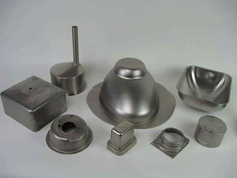
Hydroforming equipment comes in several types, each tailored to different applications and material requirements. The most common types of sheet metal hydroforming equipment include sheet hydroforming presses, deep-draw hydroforming machines, tube hydroforming machines for sheet metal applications, and specialized hydroforming equipment for advanced or unique processes like explosive hydroforming.
Sheet Hydroforming Presses: Sheet hydroforming presses are the most common type of equipment used for shaping flat metal sheets into complex, three-dimensional forms. These presses utilize hydraulic pressure to push the metal sheet into a die, creating parts with intricate geometries, smooth curves, and superior surface finishes.
- Applications: Automotive body panels, aerospace fuselage sections, appliance components, and electronic device casings.
- Advantages: Sheet hydroforming presses are ideal for producing large, shallow parts with smooth, high-quality surface finishes. The use of hydraulic pressure allows for greater design flexibility and material efficiency, making it possible to form parts with minimal material waste and fewer welds.
Deep-Draw Hydroforming Equipment: Deep-draw hydroforming machines are designed for forming parts with significant depth relative to their width, such as fuel tanks, engine housings, and structural aerospace components. Deep-drawing involves stretching the metal more than in standard sheet hydroforming, making this type of equipment ideal for creating deep, intricate parts.
- Applications: Fuel tanks, transmission housings, deep structural parts for aerospace and automotive industries.
- Advantages: Deep-draw hydroforming equipment allows for the creation of parts with complex, deep geometries without excessive thinning or material defects, which is essential for maintaining structural integrity in high-stress applications.
Tube Hydroforming Machines for Sheet Metal Applications: Although tube hydroforming is primarily used to form hollow tubes, some specialized tube hydroforming machines can also be adapted for sheet metal applications. This equipment can shape sheet metal into hollow structures or complex, lightweight components with varying cross-sections.
- Applications: Automotive chassis components, subframes, and exhaust systems; aerospace structural parts.
- Advantages: Tube hydroforming machines allow for the creation of strong, lightweight parts with fewer welds and joints, which increases durability and reduces overall material costs.
Specialized Hydroforming Equipment (Explosive, High-Pressure, etc.): Some hydroforming processes require specialized equipment, such as explosive hydroforming machines or high-pressure hydroforming presses. These machines are used for advanced applications where extreme precision, strength, or unique material properties are required.
- Explosive Hydroforming: This process uses controlled explosions to generate the hydraulic pressure needed to form large or complex parts. It is primarily used in aerospace and defense applications.
- High-Pressure Hydroforming: For applications requiring exceptionally high pressure (e.g., forming titanium or other high-strength alloys), specialized high-pressure machines are used. These machines can generate pressure levels well beyond those of standard hydroforming equipment.
Comparison of Different Equipment Types:
- Sheet Hydroforming Presses: Best for large, shallow parts with smooth surface finishes.
- Deep-Draw Hydroforming Machines: Ideal for forming deep parts with high depth-to-width ratios.
- Tube Hydroforming Machines: Useful for forming hollow structures or parts with varying cross-sections.
- Specialized Equipment: Designed for unique processes like explosive or high-pressure hydroforming, typically used in aerospace and defense industries.
Key Components of Sheet Metal Hydroforming Equipment
Sheet metal hydroforming equipment comprises several critical components that enable precise control of hydraulic pressure, material deformation, and part production. These components include the hydraulic system, die and tooling mechanisms, pressure containment systems, and automated control systems.
Hydraulic Systems: The hydraulic system is the heart of any hydroforming machine, responsible for generating the fluid pressure necessary to shape the metal sheet. These systems typically include pumps, accumulators, valves, and regulators to manage the pressure throughout the forming process.
- Hydraulic Pumps: Hydraulic pumps generate the high pressure needed for the forming process. Depending on the material and part complexity, pressures can range from 5,000 to 20,000 psi or more.
- Pressure Accumulators: These components store hydraulic fluid under pressure and release it as needed to maintain consistent pressure during the forming process. Accumulators help prevent pressure spikes or drops, which could cause defects in the material.
- Pressure Regulators: Regulators ensure that the hydraulic pressure stays within the required range for the material being formed. Proper regulation of pressure is critical to prevent thinning, tearing, or wrinkling of the sheet metal.
Die Design and Tooling Mechanisms: The die is the part of the hydroforming machine that shapes the metal. Dies are typically custom-designed for each part and made from hardened steel or other durable materials that can withstand high pressure and repeated use.
- Die Construction: Dies are designed to provide the final shape of the part. They must be precisely machined to ensure that the metal conforms accurately to the desired geometry without defects.
- Tooling Mechanisms: Tooling mechanisms, such as clamps and punches, are used to position and hold the sheet metal in place during forming. Proper positioning is essential for achieving accurate part dimensions.
Pressure Containment, Seals, and Diaphragms: Hydroforming equipment relies on pressure containment systems, including seals, diaphragms, and fluid chambers, to apply pressure evenly to the metal sheet.
- Seals: High-strength seals are used to prevent hydraulic fluid from leaking during the forming process. These seals must be durable enough to withstand repeated cycles and high pressures.
- Diaphragms: In sheet hydroforming, a flexible diaphragm is used to apply hydraulic pressure to the metal sheet. The diaphragm must be made from materials that can stretch without tearing or degrading, such as rubber or elastomeric composites.
- Fluid Chambers: The fluid chamber contains the hydraulic fluid and directs it toward the metal sheet. These chambers must be strong enough to withstand high pressures and prevent leaks or fluid loss.
CNC Integration and Automation: Modern sheet metal hydroforming equipment is often integrated with CNC (Computer Numerical Control) systems, which allow for precise control over the entire forming process. Automation improves accuracy, repeatability, and production speed.
- Automated Pressure Control: CNC systems monitor and adjust hydraulic pressure in real-time, ensuring that the material forms correctly without defects.
- Multi-Axis Control: CNC integration allows for control over multiple axes, enabling the production of more complex geometries with greater precision. This is particularly important in industries like aerospace, where tight tolerances are critical.
Design and Functionality of Hydroforming Equipment
The design and functionality of sheet metal hydroforming equipment are critical to its performance and the quality of the parts it produces. The key design parameters include pressure capacity, material compatibility, and production speed.
Pressure Capacities and Ranges: Hydroforming equipment is available in different pressure capacities to suit various materials and applications. The pressure capacity is one of the most critical specifications of the machine, as it determines the types of materials that can be processed and the complexity of the parts that can be formed.
- Low-Pressure Systems: These systems are used for forming softer materials like aluminum, where lower pressures (5,000 to 10,000 psi) are sufficient to achieve the desired part geometry.
- High-Pressure Systems: High-pressure hydroforming equipment is designed for forming high-strength materials like steel or titanium. These systems can generate pressures of 20,000 psi or more, enabling the efficient forming of harder metals without causing defects.
Material Compatibility and Cycle Efficiency: Sheet metal hydroforming equipment must be compatible with a wide range of materials, including aluminum, steel, titanium, and exotic alloys. Each material has its own forming characteristics and requires specific pressure levels and forming times.
- Aluminum: Aluminum is widely used in hydroforming due to its lightweight properties and ease of formability. It requires lower pressures compared to other metals, making it ideal for automotive and aerospace applications.
- Steel: High-strength steels are commonly used in automotive and aerospace components for their superior strength. However, steel requires higher pressures to form, and the equipment must be capable of generating sufficient force to shape the material without defects.
- Titanium: Titanium is used in applications that require a combination of lightweight properties, strength, and corrosion resistance, such as aerospace and medical devices. Titanium is more challenging to form than steel or aluminum and requires precise control over pressure and forming time.
Customization and Design for Specific Applications: Hydroforming equipment can be customized to meet the specific needs of different industries and applications. Customization options include varying pressure capacities, die configurations, and control systems to accommodate different materials and part geometries.
- Automotive Applications: In the automotive industry, hydroforming equipment is often customized to produce lightweight components like body panels, chassis frames, and exhaust systems. These parts must meet strict safety and performance standards while minimizing weight and material usage.
- Aerospace Applications: Aerospace components require high precision and structural integrity, and hydroforming equipment must be designed to handle the specific alloys and geometries used in aircraft and spacecraft. This may involve customizing the die design, pressure systems, and cycle times to meet the unique demands of aerospace manufacturing.
Step-by-Step Process of Sheet Metal Hydroforming
The sheet metal hydroforming process involves several distinct steps, each of which plays a critical role in ensuring the successful formation of high-quality parts. These steps include material preparation, die setup, pressure application, cooling, and post-forming operations.
1. Material Preparation: Before the hydroforming process begins, the metal sheet must be prepared. This involves cutting the sheet to the desired size and shape and ensuring that it is free of defects or contaminants that could interfere with the forming process.
- Material Cutting: The metal sheet is typically cut to the required dimensions using precision cutting methods such as laser cutting, waterjet cutting, or mechanical shearing. The accuracy of the cut is important for ensuring that the sheet fits correctly in the die.
- Surface Cleaning: To reduce friction and prevent defects, the surface of the metal sheet may be cleaned and treated with a lubricant before being placed in the hydroforming press.
2. Die Setup and Alignment: Once the material is prepared, it is placed into the hydroforming press, and the die is aligned. Proper alignment is critical for achieving accurate part geometry and preventing defects such as wrinkling or tearing.
- Die Placement: The die is positioned within the press, and the metal sheet is placed over or into the die cavity, depending on the type of part being formed.
- Alignment Systems: Many hydroforming presses are equipped with automated alignment systems that ensure the sheet is positioned correctly before forming begins. This helps prevent misalignment, which can lead to defective parts.
3. Pressure Application and Forming: Once the material and die are in place, hydraulic pressure is applied to form the metal sheet into the desired shape. The pressure is carefully controlled to prevent defects and ensure that the part meets the required specifications.
- Pressure Ramp-Up: Hydraulic pressure is gradually increased to avoid shocking the material, which could cause tearing or other defects. The pressure is carefully monitored and adjusted throughout the forming process.
- Forming Process: As the pressure increases, the metal sheet is forced to conform to the shape of the die. The forming process is typically completed in a single operation, reducing the need for additional trimming or machining.
4. Cooling, Removal, and Post-Forming Operations: After the forming process is complete, the hydraulic pressure is released, and the part is allowed to cool. Cooling helps stabilize the material and prevent distortion or warping.
- Cooling Systems: Some hydroforming presses are equipped with cooling systems that accelerate the cooling process, particularly for materials that are sensitive to temperature changes, such as aluminum or titanium.
- Part Removal: Once the part has cooled, it is removed from the die. Depending on the complexity of the part, additional post-forming operations may be required, such as trimming or surface finishing.
5. Post-Forming Operations: After the part has been formed and cooled, it may undergo additional operations to achieve the final dimensions or surface finish required for the application.
- Trimming and Machining: Any excess material is trimmed away, and the part may be machined to meet precise dimensional tolerances.
- Surface Finishing: Depending on the application, the part may undergo surface finishing processes such as polishing, painting, or anodizing to improve its appearance and durability.
Applications of Sheet Metal Hydroforming Equipment
Sheet metal hydroforming equipment is used across a wide range of industries to produce lightweight, high-strength components with complex geometries. Some of the most common applications include the automotive industry, aerospace industry, consumer goods, and medical devices.
1. Automotive Industry: The automotive industry is one of the largest users of sheet metal hydroforming technology, as it allows manufacturers to produce lightweight, high-strength components that improve vehicle performance and fuel efficiency.
- Body Panels: Hydroforming is used to produce large body panels with smooth surfaces and intricate shapes, reducing the need for welding and improving the overall structural integrity of the vehicle. These panels are lighter and stronger than those produced using traditional stamping methods.
- Chassis Components: Hydroforming is also used to create lightweight chassis components, such as subframes, engine cradles, and crossmembers. These parts are essential for improving vehicle handling, reducing weight, and increasing crash safety.
- Exhaust Systems: Hydroformed exhaust systems are designed to optimize airflow and reduce backpressure, improving engine performance while also reducing weight. Tube hydroforming is often used to produce exhaust components with complex shapes and varying cross-sections.
2. Aerospace Industry: Hydroforming is widely used in the aerospace industry to produce lightweight, high-strength components that meet the stringent performance and safety requirements of aircraft and spacecraft.
- Fuselage Sections: Sheet metal hydroforming is used to produce large fuselage sections with smooth, consistent material thickness. These sections are lighter and stronger than those produced using traditional forming methods, contributing to improved fuel efficiency and overall performance.
- Wing Components: Hydroformed wing components benefit from the precision and complexity that hydroforming allows, making it possible to create lightweight parts with high structural integrity. These parts must withstand extreme forces during flight while minimizing weight.
- Landing Gear Components: Hydroforming is used to create strong, lightweight parts for landing gear, where strength and durability are critical for withstanding the forces of takeoff and landing.
3. Consumer Goods: In the consumer goods industry, hydroforming is used to produce a wide range of products, from sleek electronic devices to high-quality kitchen appliances.
- Electronics Casings: Hydroforming is widely used in the electronics industry to create sleek, curved casings for smartphones, laptops, and other devices. The ability to produce lightweight, durable casings with smooth, seamless surfaces makes hydroforming a preferred method for high-end electronics.
- Appliances: Hydroforming is also used to produce high-quality components for appliances, such as refrigerators, ovens, and dishwashers. These parts are not only functional but also aesthetically appealing, thanks to the smooth surfaces and intricate details achievable with hydroforming.
4. Medical Devices: The medical industry relies on hydroforming to produce precise, biocompatible components for surgical instruments and implants.
- Surgical Instruments: Hydroforming is ideal for producing lightweight, high-precision surgical instruments that are easy to sterilize and durable enough for repeated use. The ability to form intricate shapes without stressing the material is essential for ensuring the performance of these instruments.
- Medical Implants: Hydroforming is also used to produce biocompatible implants, such as joint replacements and dental implants. These implants must meet strict biocompatibility and strength requirements, and hydroforming allows manufacturers to create custom shapes that fit the patient’s anatomy precisely.
Advantages of Sheet Metal Hydroforming Equipment
Hydroforming offers several key advantages over traditional metal-forming processes, making it a preferred choice for manufacturers across a range of industries. Some of the main advantages include precision in forming complex geometries, the ability to produce lightweight, high-strength components, material efficiency, and cost-effectiveness.
1. Precision for Complex Geometries: One of the most significant advantages of sheet metal hydroforming equipment is its ability to produce parts with complex geometries and intricate shapes. The use of hydraulic pressure ensures that the material conforms precisely to the die, resulting in high levels of accuracy and repeatability.
- Complex Contours and Curves: Hydroforming allows for the creation of parts with intricate curves, bends, and varying thicknesses, which would be challenging or impossible to achieve using traditional methods like stamping or deep drawing.
- Dimensional Accuracy: The hydraulic pressure is distributed evenly across the entire surface of the material, ensuring that the part forms uniformly without thinning, tearing, or other defects.
2. Lightweight and High-Strength Components: Hydroforming is particularly well-suited for industries where weight reduction is critical, such as automotive and aerospace manufacturing. The process allows for the production of lightweight parts with high structural integrity, improving performance, fuel efficiency, and safety.
- Improved Strength-to-Weight Ratio: Hydroformed parts typically have a higher strength-to-weight ratio than parts produced using traditional methods. This is because the material is uniformly stretched and formed, reducing weak points and ensuring consistent thickness throughout the part.
- Lighter Components: Hydroforming allows manufacturers to reduce the need for multiple parts and joints, producing components that are both lighter and stronger. This is particularly important in industries where weight reduction directly impacts performance, such as automotive and aerospace.
3. Material Efficiency and Reduced Waste: Hydroforming is a near-net-shape process, meaning that parts are produced very close to their final dimensions. This minimizes the need for additional machining or trimming, reducing material waste and lowering production costs.
- Reduced Scrap: Compared to traditional stamping or forging methods, hydroforming generates significantly less scrap material. This is particularly beneficial when working with expensive materials like titanium or high-strength steel.
- Optimized Material Usage: Hydroforming allows manufacturers to use thinner materials without sacrificing strength, further reducing material consumption and costs.
4. Cost-Effectiveness in High-Volume Production: While the initial investment in hydroforming equipment can be high, the process offers significant cost savings in high-volume production due to its efficiency and reduced need for secondary operations.
- Fewer Manufacturing Steps: Hydroforming can often produce complex parts in a single operation, reducing the need for additional processes such as welding, trimming, or machining.
- Lower Tooling Costs: Compared to traditional stamping, which requires multiple dies for different stages of forming, hydroforming typically requires only one die, reducing tooling costs over time.
- Faster Production: Advances in automation and CNC integration have significantly improved the speed and accuracy of hydroforming equipment, making it ideal for high-volume production environments.
Challenges and Limitations of Sheet Metal Hydroforming Equipment (800 words)
While hydroforming offers many advantages, it also presents certain challenges and limitations that manufacturers need to consider. These challenges include material constraints, pressure limitations, and issues related to maintaining dimensional accuracy.
1. Material Constraints: Different materials respond differently to the hydroforming process, and not all materials are equally suited to hydroforming. While hydroforming works well with materials like aluminum, steel, and titanium, certain materials may be more challenging to form.
- Thicker Materials: Hydroforming is generally more suited to thinner materials. Thicker materials require higher pressures to form, which can increase the risk of defects like wrinkling or tearing.
- High-Strength Materials: While hydroforming is capable of forming high-strength materials like steel and titanium, these materials require significantly higher pressures, which can strain the equipment and increase production costs.
2. Pressure and Equipment Limitations: Hydroforming presses must be capable of generating the necessary hydraulic pressure to form the material. For harder materials or more complex parts, higher pressures are required, which can increase the cost and complexity of the equipment.
- Pressure Requirements: Materials with higher tensile strength require higher hydraulic pressure to form. If the machine is not capable of generating sufficient pressure, the material may not conform properly to the die, leading to defects.
- Equipment Wear: Hydroforming equipment is subjected to high pressures and repeated cycles, which can cause wear and tear on components such as seals, diaphragms, and dies. Regular maintenance is essential to ensure consistent performance and prevent costly downtime.
3. Dimensional Accuracy and Springback: While hydroforming is known for its precision, achieving tight dimensional tolerances can be challenging, particularly for materials that exhibit springback.
- Springback: Some materials, particularly high-strength steels, have a tendency to spring back after forming, meaning they attempt to return to their original shape once the pressure is released. This can affect the dimensional accuracy of the part and may require additional post-processing to achieve the desired specifications.
- Complex Geometries: While hydroforming is capable of forming complex shapes, parts with sharp corners or intricate details may be more difficult to produce, as the process is better suited to creating smooth, curved shapes.
Technological Advancements in Sheet Metal Hydroforming Equipment
Advancements in technology have significantly improved the capabilities of sheet metal hydroforming equipment, making it more efficient, precise, and versatile. Some of the most important technological innovations include the integration of CNC control systems, advances in tooling materials, and the development of high-pressure hydroforming machines for exotic materials.
1. CNC-Controlled Hydroforming Equipment: The integration of CNC (Computer Numerical Control) technology into hydroforming equipment has revolutionized the forming process by allowing for precise control over hydraulic pressure, die movement, and cycle timing. CNC systems automate the process, improving accuracy, repeatability, and overall efficiency.
- Automated Pressure Control: CNC systems can monitor and adjust hydraulic pressure in real-time, ensuring that the material is formed within the optimal parameters. This reduces the risk of defects like thinning or tearing and improves the quality of the final part.
- Multi-Axis Control: CNC integration allows for multi-axis control of the die and forming tools, enabling the production of more complex geometries with greater precision. This is particularly useful in industries like aerospace and automotive, where tight tolerances are critical.
2. Advances in Tooling and Sensor Technology: Modern hydroforming equipment is equipped with advanced sensors and tooling materials that enhance the precision and durability of the forming process.
- Pressure Sensors: Sensors monitor the hydraulic pressure throughout the forming process, ensuring that it remains within the required range for the material and part being produced. Accurate pressure control helps prevent defects and improves part quality.
- Wear-Resistant Tooling: Advances in materials science have led to the development of more durable and wear-resistant tooling materials, such as carbide and diamond-like carbon (DLC). These materials improve the longevity of dies and tooling, reducing maintenance costs and downtime.
3. High-Pressure Machines for Exotic Materials: As industries like aerospace and defense continue to demand stronger, lighter materials, the development of high-pressure hydroforming machines capable of forming exotic materials like titanium and Inconel has become increasingly important.
- Titanium and Inconel: These materials are known for their high strength and resistance to corrosion, but they are also difficult to form using traditional methods. High-pressure hydroforming machines can generate the necessary force to form these materials, allowing manufacturers to produce lightweight, high-strength components for critical applications.
- Increased Pressure Capacity: Modern hydroforming equipment is capable of generating pressures of 20,000 psi or more, enabling the efficient forming of hard-to-shape materials without causing defects.
4. Hybrid Manufacturing Techniques: The integration of hydroforming with other manufacturing processes, such as additive manufacturing (3D printing), is an emerging trend that is opening up new possibilities for part design and production.
- 3D-Printed Dies: Additive manufacturing can be used to produce custom dies for hydroforming equipment, reducing the lead time and cost associated with traditional die production. This is particularly useful for low-volume or highly customized parts.
- Hybrid Part Production: By combining hydroforming with 3D printing, manufacturers can create parts with complex internal structures or variable wall thicknesses, improving performance and reducing material usage.
Economic and Environmental Impact of Hydroforming Equipment
Hydroforming equipment offers significant economic and environmental benefits, making it an attractive option for manufacturers looking to improve efficiency and reduce their environmental impact. Some of the key benefits include energy efficiency, material savings, and long-term cost reductions.
1. Energy Efficiency: Hydroforming equipment is generally more energy-efficient than traditional mechanical presses, particularly when forming complex parts. Hydraulic systems generate the necessary pressure with less energy than mechanical presses, leading to lower energy consumption and reduced operating costs.
- Reduced Energy Consumption: Hydraulic presses used in hydroforming consume less power than traditional mechanical presses, leading to lower energy costs and a smaller carbon footprint. This is especially important in high-volume production environments where energy costs can significantly impact the bottom line.
- Energy Recovery Systems: Some modern hydroforming machines are equipped with energy recovery systems that capture and reuse energy generated during the forming process. This further reduces energy consumption and operational costs.
2. Material Efficiency and Waste Reduction: Hydroforming is a near-net-shape forming process, meaning that parts are produced with minimal waste. This leads to significant material savings, particularly when working with expensive materials like titanium or high-strength steel.
- Minimized Scrap: Compared to traditional forming methods, hydroforming generates significantly less scrap material. This reduces material costs and minimizes the environmental impact associated with waste.
- Optimized Material Usage: Hydroforming allows manufacturers to use thinner materials without sacrificing strength, further reducing material consumption and costs.
3. Long-Term Cost Savings and Environmental Sustainability: While the initial investment in hydroforming equipment can be high, the long-term economic benefits often outweigh the upfront costs. Hydroforming equipment offers significant operational savings due to its efficiency, reduced labor costs, and faster production times.
- Lower Tooling Costs: Hydroforming typically requires fewer dies compared to traditional forming methods, reducing tooling costs over time. In addition, advances in die materials and coatings have improved the longevity of hydroforming tools, further reducing costs.
- Reduced Labor Costs: Hydroforming is a highly automated process, which reduces the need for manual labor. This leads to lower labor costs and improved production efficiency, particularly in high-volume manufacturing environments.
4. Contribution to Sustainable Manufacturing: As industries move toward more sustainable manufacturing practices, hydroforming is playing a key role in helping manufacturers reduce their environmental impact. The process’s ability to produce lightweight, high-strength components with minimal waste makes it an ideal choice for industries such as automotive and aerospace, where reducing weight and improving fuel efficiency are critical for sustainability.
- Lightweighting for Fuel Efficiency: In the automotive and aerospace industries, reducing the weight of vehicles and aircraft is essential for improving fuel efficiency and reducing emissions. Hydroforming allows manufacturers to produce lightweight components that meet the required strength and safety standards, contributing to the overall goal of reducing environmental impact.
- Sustainable Design Practices: Many manufacturers are incorporating hydroforming into their sustainable design practices, using the process to create parts that are both environmentally friendly and cost-effective.
Case Studies: Industrial Applications of Sheet Metal Hydroforming
Hydroforming equipment has been successfully implemented in a variety of industries, demonstrating its versatility, efficiency, and ability to produce high-quality components. Below are several case studies that highlight the benefits of hydroforming in real-world applications.
1. Automotive Industry: Lightweight Body Panels: An automotive manufacturer used sheet metal hydroforming equipment to produce lightweight body panels for a new line of vehicles. The goal was to reduce the weight of the vehicle without compromising safety or performance.
- Challenges: The manufacturer needed to create lightweight body panels that could withstand high loads and meet strict safety standards. Traditional stamping methods were unable to achieve the desired combination of strength and weight reduction.
- Solution: The company used sheet hydroforming presses to create large body panels with smooth surfaces and complex shapes. The hydroformed panels were lighter and stronger than those produced using traditional methods, contributing to improved fuel efficiency and reduced emissions.
- Results: The hydroformed panels met all safety and performance requirements while reducing the overall weight of the vehicle. The process also reduced the number of joints and welds, improving the structural integrity of the vehicle.
2. Aerospace Industry: Precision Fuselage Components: A leading aerospace company adopted hydroforming technology to produce precision-formed fuselage components for a new commercial aircraft. The goal was to reduce the weight of the aircraft while maintaining the strength and durability of the components.
- Challenges: The aerospace industry requires components that are both lightweight and capable of withstanding extreme forces. Traditional forming methods were unable to produce the complex geometries needed for the fuselage sections while maintaining the required strength-to-weight ratio.
- Solution: The company used sheet hydroforming equipment to create large fuselage sections with uniform material thickness and minimal joints. The hydroforming process allowed for the creation of complex shapes with high precision, reducing the need for welding and assembly.
- Results: The hydroformed fuselage components were lighter and stronger than those produced using traditional methods, contributing to improved fuel efficiency and overall performance. The process also reduced production time and costs by eliminating the need for additional forming and assembly operations.
3. Medical Devices: High-Precision Surgical Tools: A medical device manufacturer used hydroforming equipment to produce lightweight, high-precision surgical instruments. The goal was to create instruments that were durable, easy to sterilize, and capable of performing delicate procedures.
- Challenges: The medical industry requires instruments that are both lightweight and highly precise. Traditional forming methods were unable to achieve the level of precision needed for these complex, high-performance tools.
- Solution: The manufacturer used sheet hydroforming equipment to create intricate surgical instruments with high precision and minimal material stress. The hydroforming process allowed for the production of instruments that were strong, lightweight, and easy to sterilize.
- Results: The hydroformed surgical instruments met all performance and safety standards, providing the necessary precision and durability for use in delicate surgical procedures. The process also reduced production costs by minimizing material waste and reducing the need for secondary machining operations.
Future Trends in Sheet Metal Hydroforming Equipment
As manufacturing technology continues to evolve, several trends are emerging that are likely to shape the future of sheet metal hydroforming equipment. These trends include the integration of Industry 4.0 technologies, advancements in material science, and the adoption of hybrid manufacturing techniques.
1. Industry 4.0 and Automation: Industry 4.0 is transforming manufacturing by integrating digital technologies, automation, and data exchange into production processes. Hydroforming equipment is beginning to adopt these smart manufacturing practices, enabling greater efficiency, customization, and flexibility.
- Real-Time Monitoring and Data Analytics: Smart hydroforming equipment is equipped with sensors that collect data on every aspect of the process, from hydraulic pressure to material deformation. This data can be analyzed in real-time to optimize the process and identify potential issues before they lead to defects or downtime.
- Predictive Maintenance: Using data analytics, manufacturers can implement predictive maintenance programs that monitor the health of the machine and predict when maintenance will be needed. This reduces unplanned downtime and extends the lifespan of the equipment.
- Digital Twins: Digital twin technology is being used to create virtual replicas of hydroforming machines, allowing manufacturers to simulate and optimize the forming process before production begins. This reduces the risk of defects and improves overall efficiency.
2. Hybrid Manufacturing: Combining Hydroforming with Additive Manufacturing: As additive manufacturing (3D printing) becomes more prevalent, manufacturers are beginning to explore hybrid manufacturing techniques that combine hydroforming with 3D printing. This allows for the production of highly customized parts with enhanced performance characteristics.
- 3D-Printed Dies: Additive manufacturing can be used to produce custom dies for hydroforming equipment, reducing the lead time and cost associated with traditional die production. This is particularly useful for short production runs or highly customized parts.
- Hybrid Part Production: Additive manufacturing can also be used to create pre-forms or inserts that are then finished using hydroforming. This allows for the production of parts with complex internal structures or variable wall thicknesses.
3. High-Pressure Forming for Advanced Materials: As demand for stronger, lighter materials continues to grow, hydroforming equipment is being developed with higher pressure capacities to handle more challenging materials such as titanium, Inconel, and carbon fiber composites.
- Titanium and Inconel: These materials are known for their high strength and corrosion resistance, making them ideal for aerospace, medical, and automotive applications. However, they require significantly higher pressures to form, which has led to the development of more powerful hydroforming equipment.
- Carbon Fiber Composites: Carbon fiber composites are becoming increasingly common in aerospace and automotive applications due to their lightweight properties and high strength. Future hydroforming equipment may be capable of forming these advanced composites, opening up new possibilities for lightweight manufacturing.
4. Lightweighting and Material Innovations: The trend toward lightweighting in industries such as automotive and aerospace is driving the development of new materials and manufacturing techniques. Hydroforming is playing a key role in this trend by enabling the production of lightweight components with high structural integrity.
- Magnesium and Titanium Alloys: Magnesium and titanium alloys are being increasingly used in lightweighting applications due to their high strength-to-weight ratios. Hydroforming equipment is being developed to handle these materials, allowing manufacturers to produce even lighter components without sacrificing strength.
- Advanced Composites: Carbon fiber composites are becoming more common in aerospace and automotive applications due to their lightweight properties and high strength. Future hydroforming equipment may be capable of forming these advanced composites, opening up new possibilities for lightweight manufacturing.
Conclusion: The Future of Sheet Metal Hydroforming Equipment
Sheet metal hydroforming equipment has evolved into one of the most versatile and efficient metal-forming technologies available today. Its ability to produce lightweight, high-strength components with complex geometries has made it indispensable in industries ranging from automotive and aerospace to consumer electronics and medical devices.
As technological advancements continue to shape the future of manufacturing, hydroforming equipment is poised to play an even more significant role. The integration of CNC control, automation, and smart manufacturing technologies has already improved the precision, efficiency, and flexibility of hydroforming processes. Looking ahead, the development of high-pressure machines for exotic materials, combined with the growing trend toward additive manufacturing, promises to expand the capabilities of hydroforming even further.
In an era where sustainability and efficiency are increasingly important, hydroforming equipment stands out as a solution that can meet the demands of modern manufacturing while minimizing environmental impact. By reducing material waste, improving energy efficiency, and producing lightweight components that contribute to fuel savings, hydroforming is helping manufacturers achieve their sustainability goals.
As industries continue to explore new materials, technologies, and applications, the future of hydroforming equipment is bright. Whether it’s producing the next generation of fuel-efficient vehicles, lightweight aircraft, or cutting-edge medical devices, hydroforming equipment will remain at the forefront of advanced manufacturing, helping to shape the future of products across a wide range of industries.
In conclusion, sheet metal hydroforming equipment represents a perfect blend of precision, efficiency, and sustainability, making it an indispensable tool for manufacturers around the world. Its continued evolution and adaptation to new materials, technologies, and applications will ensure that hydroforming remains a critical process for many industries in the years to come.
Introduction to Industrial Hydroforming Machines
Overview and Definition of Hydroforming: Hydroforming is an advanced metal forming process that utilizes hydraulic pressure to shape materials into complex, high-strength components. This technology is widely used in industrial manufacturing to produce parts with intricate geometries and superior structural properties. Unlike traditional methods such as stamping or deep drawing, hydroforming forms metal using pressurized fluid, which allows for more uniform material distribution and reduces the likelihood of defects such as thinning, tearing, or wrinkling.
Importance of Hydroforming Machines in Industrial Manufacturing: Hydroforming machines are essential to the production of lightweight, durable components used in industries like automotive, aerospace, consumer electronics, and medical devices. These machines enable manufacturers to meet the growing demand for high-performance parts that must withstand harsh conditions while remaining cost-effective and material-efficient.
In industries such as automotive, hydroforming machines play a critical role in producing components like chassis frames and exhaust systems, which contribute to vehicle weight reduction and fuel efficiency. In aerospace, hydroforming enables the production of lightweight yet strong components for aircraft fuselages and wing structures, helping to reduce fuel consumption and increase flight efficiency. Additionally, the medical field benefits from hydroforming technology to create precise, biocompatible components for surgical tools and implants.
As global industries move toward more sustainable practices, industrial hydroforming machines offer a key advantage by minimizing material waste, reducing energy consumption, and providing more efficient, sustainable manufacturing solutions.
Principles of Hydroforming Technology
How Hydroforming Works: Hydroforming is a process that uses hydraulic pressure to shape metals, such as aluminum, steel, and titanium, into complex geometries. The process involves placing a metal sheet or tube inside a die, after which hydraulic fluid is pressurized to push the material into the mold, forming it into the desired shape. The high-pressure fluid ensures even force distribution, allowing the metal to stretch and take on intricate contours without causing damage or defects.
In sheet hydroforming, a flat sheet of metal is placed over a die, and hydraulic pressure is applied from above, pressing the sheet into the mold. In tube hydroforming, a hollow tube is placed inside the die, and hydraulic fluid is injected into the tube under high pressure. The tube expands until it conforms to the shape of the die, creating a component with complex, hollow structures.
The Science Behind Hydroforming: Hydraulic Pressure and Metal Shaping: The key to hydroforming lies in Pascal’s Law, which states that when pressure is applied to a confined fluid, the pressure is transmitted equally in all directions. This principle allows hydroforming machines to apply uniform pressure across the entire surface of the metal, ensuring that the material stretches evenly and maintains its structural integrity.
By controlling the hydraulic pressure precisely, the hydroforming process achieves high levels of accuracy and consistency. The ability to form metal using fluid pressure reduces localized stress points, which can lead to defects in traditional forming processes. As a result, hydroformed components often exhibit improved mechanical properties, such as increased tensile strength and durability, compared to parts produced through stamping or forging.
Comparison with Traditional Metal Forming: Hydroforming offers several distinct advantages over traditional metal forming techniques:
- Uniform Material Distribution: Traditional methods such as stamping often result in uneven material thickness, leading to weak points in the final product. Hydroforming’s use of hydraulic pressure ensures more consistent material distribution.
- Complex Geometries: Hydroforming enables the creation of intricate shapes and complex curves that are difficult to achieve using stamping, forging, or welding.
- Material Efficiency: Hydroforming is a near-net-shape process, meaning that the parts produced require minimal finishing or machining. This reduces material waste and overall production costs.
Types of Industrial Hydroforming Machines
Sheet Hydroforming Machines: Sheet hydroforming machines are used to form large, flat sheets of metal into complex, three-dimensional shapes. These machines utilize a single-sided die and apply hydraulic pressure from above to force the sheet into the die cavity. Sheet hydroforming is ideal for producing shallow components with smooth surface finishes and intricate details.
- Applications: Automotive body panels, aerospace fuselage sections, appliance housings, and electronic device casings.
- Advantages: Sheet hydroforming machines produce high-quality parts with minimal thinning and wrinkling, making them ideal for lightweight, structural components.
Tube Hydroforming Machines: Tube hydroforming machines are designed to shape hollow metal tubes into complex, lightweight structures. In this process, the tube is placed inside a mold, and hydraulic pressure is applied internally to expand the tube until it fills the die. This method is widely used for producing parts with varying cross-sections, such as automotive chassis components and bicycle frames.
- Applications: Automotive chassis frames, exhaust systems, subframes, and aerospace structural components.
- Advantages: Tube hydroforming creates stronger, lighter parts with fewer welds and joints, improving both strength and durability.
Deep-Draw Hydroforming Machines: Deep-draw hydroforming machines are used to produce parts with a high depth-to-width ratio. This process stretches the metal deeper into the die than standard hydroforming methods, allowing for the creation of deep, complex components such as fuel tanks, engine housings, and structural parts.
- Applications: Fuel tanks, transmission housings, deep structural components for aerospace and automotive industries.
- Advantages: Deep-draw hydroforming machines can form deep, complex shapes without thinning the material excessively, ensuring strong, durable components.
High-Pressure and Explosive Hydroforming Machines: For certain industrial applications, such as aerospace and defense, extremely high pressures are required to form large or highly complex components. High-pressure hydroforming machines are capable of generating pressures above 20,000 psi, enabling the formation of materials like titanium and Inconel.
- Explosive Hydroforming: This specialized method uses controlled explosions to generate the hydraulic pressure needed to form large, intricate parts. It is often used for forming components in the aerospace and defense industries where extreme strength and durability are required.
Comparison of Different Machine Types:
- Sheet Hydroforming Machines: Ideal for large, shallow parts with intricate surface details.
- Tube Hydroforming Machines: Best suited for creating hollow structures and lightweight components.
- Deep-Draw Hydroforming Machines: Used for deep, high-ratio parts.
- High-Pressure Machines: Required for forming high-strength materials and large complex shapes.
Key Components of Industrial Hydroforming Machines
Hydroforming machines consist of several key components that ensure precision and efficiency in the forming process. These include the hydraulic system, die and tooling mechanisms, seals and containment systems, and automated control systems.
Hydraulic Systems and Pressure Control: The hydraulic system is the core of any hydroforming machine, responsible for generating the pressure needed to deform the metal. This system includes hydraulic pumps, pressure accumulators, and control valves.
- Hydraulic Pumps: These pumps generate the high pressure required for the forming process, with some machines capable of producing pressures up to 30,000 psi. Consistent pressure generation is crucial to ensure uniform material deformation.
- Pressure Accumulators: These components store pressurized hydraulic fluid and release it as needed to maintain steady pressure throughout the forming process. They help prevent fluctuations that could cause defects in the part.
- Pressure Regulators and Control Valves: These devices monitor and adjust the hydraulic pressure to ensure that it remains within the optimal range for the specific material and part being formed.
Die Design and Tooling Components: The die is the part of the hydroforming machine that provides the final shape of the part. Dies are typically custom-made for each component and are designed to withstand the high pressures involved in hydroforming.
- Die Construction: Dies are typically made from hardened steel or other wear-resistant materials. The design of the die must account for the material being formed, the complexity of the part, and the pressure required for the process.
- Tooling Mechanisms: Tooling mechanisms, such as punches and clamps, are used to hold the material in place during forming. Proper tooling is critical to achieving accurate part dimensions and preventing defects.
Seals, Diaphragms, and Containment Systems: In hydroforming, fluid containment is critical to maintaining the necessary pressure for forming. Seals and diaphragms are used to contain the hydraulic fluid and prevent leaks during the process.
- Seals: High-strength seals are used to prevent hydraulic fluid from escaping during the forming process. These seals must be durable enough to withstand repeated cycles of high pressure without degrading.
- Diaphragms: In sheet hydroforming, a flexible diaphragm applies the hydraulic pressure to the metal sheet. The diaphragm must be strong and flexible enough to handle repeated expansions and contractions without tearing.
- Fluid Containment Systems: These systems include chambers that hold the hydraulic fluid and direct it toward the material. They must be designed to withstand the extreme pressures involved in the hydroforming process.
CNC Integration and Automation: Modern industrial hydroforming machines are equipped with CNC (Computer Numerical Control) systems that allow for precise control over the forming process. These systems automate the pressure application, die movement, and material handling, improving accuracy and production efficiency.
- Automated Pressure Control: CNC systems monitor hydraulic pressure in real-time, ensuring that the material forms correctly without defects.
- Multi-Axis Control: CNC integration allows for the control of multiple axes, enabling the production of more complex geometries with greater precision. This is especially important in industries like aerospace, where tight tolerances are critical.
Design and Functionality of Hydroforming Machines
The design and functionality of industrial hydroforming machines are key to their performance and the quality of the parts they produce. Several factors influence the design, including the machine’s pressure capacity, material compatibility, and production speed.
Machine Design and Pressure Capacities: Hydroforming machines are designed with specific pressure capacities depending on the types of materials they will process. Pressure capacity is one of the most critical design parameters, as it dictates the kinds of metals that can be formed and the complexity of the shapes that can be produced.
- Low-Pressure Systems: These machines are designed for forming softer metals like aluminum and copper. Pressures in these systems typically range from 5,000 to 10,000 psi.
- High-Pressure Systems: High-pressure hydroforming machines are required for forming harder materials like steel and titanium. These systems are capable of generating pressures of up to 30,000 psi, allowing them to form high-strength metals without causing defects.
Material Compatibility: Hydroforming machines must be designed to handle a wide range of materials, each with its own forming requirements. Common materials used in hydroforming include aluminum, steel, titanium, and specialized alloys like Inconel.
- Aluminum: Aluminum is widely used in hydroforming due to its lightweight properties and ease of formability. It requires lower pressures compared to other metals, making it ideal for automotive and aerospace applications.
- Steel: High-strength steels are commonly used in automotive and aerospace components due to their superior strength. Steel requires higher pressures to form, and hydroforming machines must be capable of generating sufficient force to shape the material without defects.
- Titanium: Titanium is used in applications that require both strength and corrosion resistance, such as aerospace and medical devices. Forming titanium requires precise control over pressure and forming times, as it is more difficult to shape than steel or aluminum.
Customization for Specific Industrial Applications: Industrial hydroforming machines are often customized to meet the specific needs of different industries and applications. Customization options include varying pressure capacities, die configurations, and control systems to accommodate different materials and part geometries.
- Automotive Applications: Hydroforming machines used in automotive manufacturing are often designed to produce lightweight chassis components, body panels, and exhaust systems. These parts must meet strict safety and performance standards while minimizing material usage and weight.
- Aerospace Applications: Aerospace components require high precision and structural integrity. Hydroforming machines used in this industry are designed to handle the specific alloys and geometries used in aircraft and spacecraft. This often involves customizing die design, pressure systems, and forming times to meet the unique demands of aerospace manufacturing.
Step-by-Step Process of Hydroforming with Industrial Machines
The hydroforming process with industrial machines involves several steps, from material preparation to forming, cooling, and post-forming operations. Each step is critical to ensuring the successful formation of high-quality parts.
1. Material Preparation: Before hydroforming begins, the metal sheet or tube must be prepared. This involves cutting the material to the appropriate size and ensuring that it is free from defects or contaminants that could interfere with the forming process.
- Cutting and Shaping: The metal is cut to size using precision cutting methods such as laser cutting, waterjet cutting, or mechanical shearing. Accurate cutting ensures that the material fits correctly in the die.
- Surface Treatment: The surface of the material may be cleaned and treated with a lubricant to reduce friction during forming and prevent damage to the die.
2. Die Setup and Alignment: Once the material is prepared, it is loaded into the hydroforming machine, and the die is aligned. Proper alignment is crucial for achieving accurate part geometry and preventing defects like wrinkling or tearing.
- Die Placement: The die is positioned in the machine, and the metal sheet or tube is placed in the die cavity. For tube hydroforming, the tube is secured in place, and its ends are sealed.
- Automated Alignment: Many modern hydroforming machines are equipped with automated alignment systems that ensure the material is positioned correctly before forming begins. This helps prevent misalignment and ensures a higher level of precision.
3. Pressure Application, Forming, and Cooling: Once the material and die are in place, hydraulic pressure is applied to form the material into the desired shape. The pressure is carefully controlled to prevent defects and ensure that the part meets the required specifications.
- Pressure Ramp-Up: Hydraulic pressure is gradually increased to avoid placing too much stress on the material. Sudden pressure increases can lead to tearing or other defects. The pressure is monitored and adjusted throughout the forming process to ensure optimal results.
- Forming: As the pressure increases, the material is forced to conform to the shape of the die. In tube hydroforming, internal pressure causes the tube to expand, while in sheet hydroforming, the hydraulic fluid pushes the sheet into the mold.
- Cooling: After the part has been formed, the hydraulic pressure is released, and the part is allowed to cool. Cooling stabilizes the material and helps prevent deformation after it is removed from the die.
4. Post-Forming Operations: After the part has been formed and cooled, it may undergo additional operations to achieve the desired finish or mechanical properties.
- Trimming and Finishing: Any excess material is trimmed away, and the part may be machined to meet precise dimensional tolerances. Additional finishing processes, such as polishing, painting, or anodizing, may be applied to improve the part’s appearance and durability.
- Quality Control: Once the part has been finished, it undergoes a series of quality control checks to ensure that it meets the required specifications. This may include dimensional inspections, surface quality checks, and mechanical property tests.
Applications of Industrial Hydroforming Machines
Industrial hydroforming machines are used in a wide range of industries to produce lightweight, high-strength components with complex geometries. Some of the most common applications include automotive manufacturing, aerospace production, consumer electronics, and medical devices.
1. Automotive Industry: Hydroforming machines are widely used in the automotive industry to produce lightweight, durable components that improve vehicle performance and fuel efficiency.
- Chassis Frames: Hydroformed chassis components, such as subframes, engine cradles, and crossmembers, are lighter and stronger than those produced using traditional methods. This leads to better vehicle handling, improved fuel efficiency, and increased crash safety.
- Body Panels: Hydroforming is also used to create large body panels with smooth surfaces and intricate shapes. These panels are lighter and stronger than those produced using stamping, reducing the overall weight of the vehicle and improving its structural integrity.
- Exhaust Systems: Tube hydroforming is commonly used to produce complex exhaust systems that optimize airflow and reduce backpressure, improving engine performance and reducing emissions.
2. Aerospace Industry: The aerospace industry requires lightweight, high-strength components that can withstand extreme forces while minimizing weight. Hydroforming is an ideal solution for producing these critical parts.
- Fuselage Sections: Sheet hydroforming is used to produce large fuselage sections with consistent material thickness and minimal joints. These sections are lighter and stronger than those produced using traditional methods, contributing to improved fuel efficiency and overall performance.
- Wing Components: Hydroformed wing components benefit from the precision and complexity allowed by hydroforming, making it possible to create lightweight parts with high structural integrity. These parts must withstand extreme forces during flight while minimizing weight.
- Landing Gear: Hydroforming is used to create strong, lightweight parts for aircraft landing gear. These components must endure the forces of takeoff and landing while maintaining their structural integrity.
3. Consumer Electronics: In the consumer electronics industry, hydroforming machines are used to produce sleek, durable casings for smartphones, laptops, and other devices. The ability to create lightweight, aesthetically appealing parts with complex shapes and smooth surfaces makes hydroforming a preferred method for high-end electronics.
- Smartphone Casings: Hydroforming allows manufacturers to create curved, seamless metal casings that are lightweight and durable, enhancing both the appearance and functionality of smartphones.
- Laptop Housings: Hydroformed aluminum and magnesium housings are popular in the production of lightweight laptops, providing durability without adding excessive weight.
4. Medical Devices: The medical device industry relies on hydroforming to produce high-precision components for surgical instruments, implants, and medical tools. These components must meet stringent biocompatibility and performance standards, making hydroforming an ideal choice.
- Surgical Instruments: Hydroforming is used to produce lightweight, high-precision surgical instruments that are easy to sterilize and durable enough for repeated use. The ability to form intricate shapes without stressing the material is essential for ensuring the performance of these instruments.
- Medical Implants: Hydroforming is also used to produce custom-fitted implants, such as joint replacements and dental implants. These implants must meet strict biocompatibility and strength requirements, and hydroforming allows manufacturers to create complex, custom shapes that fit the patient’s anatomy precisely.
Advantages of Industrial Hydroforming Machines
Hydroforming machines offer numerous advantages over traditional metal forming processes, making them a preferred choice for industries requiring high-performance parts with complex geometries. Some of the main advantages include precision, the ability to produce lightweight and strong components, material efficiency, and cost-effectiveness.
1. Precision in Forming Complex Geometries: Hydroforming machines excel at producing parts with complex geometries and intricate shapes that would be difficult or impossible to achieve using traditional methods like stamping or forging.
- Complex Curves and Contours: Hydroforming enables manufacturers to create parts with intricate curves, bends, and varying thicknesses, which are essential for many automotive, aerospace, and electronics applications.
- Dimensional Accuracy: The use of hydraulic pressure ensures that the material conforms precisely to the die, resulting in high levels of accuracy and repeatability. This is particularly important in industries like aerospace, where even small deviations in part dimensions can impact performance.
2. Lightweight and High-Strength Components: Hydroforming is particularly well-suited for industries that require lightweight components without compromising strength, such as automotive and aerospace manufacturing.
- High Strength-to-Weight Ratio: Hydroformed parts typically have a higher strength-to-weight ratio than parts produced using traditional methods. This is due to the uniform stretching and forming of the material, which reduces weak points and ensures consistent thickness throughout the part.
- Lighter Components: By eliminating the need for multiple parts and joints, hydroforming produces parts that are lighter and stronger. This is particularly important in the automotive and aerospace industries, where weight reduction directly impacts fuel efficiency and performance.
3. Material Efficiency and Reduced Waste: Hydroforming is a near-net-shape process, meaning that parts are produced very close to their final dimensions. This minimizes the need for additional machining or trimming, reducing material waste and lowering production costs.
- Reduced Scrap: Compared to traditional stamping or forging, hydroforming generates significantly less scrap material. This is particularly beneficial when working with expensive materials such as titanium or high-strength steel.
- Optimized Material Usage: Hydroforming allows manufacturers to use thinner materials without sacrificing strength, further reducing material consumption and costs.
4. Cost-Effectiveness in High-Volume Production: While the initial investment in hydroforming machines can be high, the process is highly cost-effective in high-volume production due to its efficiency and reduced need for secondary operations.
- Fewer Manufacturing Steps: Hydroforming can often produce complex parts in a single operation, reducing the need for additional processes such as welding, trimming, or machining.
- Lower Tooling Costs: Compared to traditional stamping, which requires multiple dies for different stages of forming, hydroforming typically requires only one die, reducing tooling costs over time.
- Faster Production: Advances in automation and CNC integration have significantly improved the speed and accuracy of hydroforming machines, making them ideal for high-volume production environments.
Challenges and Limitations of Industrial Hydroforming Machines
While hydroforming machines offer numerous advantages, they also present certain challenges and limitations. These challenges include material constraints, pressure limitations, and issues related to maintaining dimensional accuracy.
1. Material Constraints: Not all materials respond equally well to the hydroforming process. While hydroforming works well with materials like aluminum, steel, and titanium, certain materials may be more challenging to form.
- Thicker Materials: Hydroforming is generally better suited for forming thinner materials. Thicker materials require higher pressures, which can increase the risk of defects such as wrinkling or tearing.
- High-Strength Materials: While hydroforming can be used to form high-strength materials like titanium and Inconel, these materials require significantly higher pressures, which can strain the equipment and increase production costs.
2. Pressure Limitations and Equipment Wear: Hydroforming machines must be capable of generating the necessary hydraulic pressure to form the material. For harder materials or more complex parts, higher pressures are required, which can increase the cost and complexity of the equipment.
- Pressure Requirements: Materials with higher tensile strength require higher hydraulic pressure to form. If the machine is not capable of generating sufficient pressure, the material may not conform properly to the die, leading to defects.
- Equipment Wear: Hydroforming machines are subjected to high pressures and repeated cycles, which can cause wear and tear on components such as seals, diaphragms, and dies. Regular maintenance is essential to ensure consistent performance and prevent costly downtime.
3. Dimensional Accuracy and Springback: Achieving tight dimensional tolerances can be challenging, particularly for materials that exhibit springback.
- Springback: Some materials, particularly high-strength steels, have a tendency to spring back after forming, meaning they attempt to return to their original shape once the pressure is released. This can affect the dimensional accuracy of the part and may require additional post-processing to achieve the desired specifications.
- Complex Geometries: While hydroforming is capable of forming complex shapes, parts with sharp corners or intricate details may be more difficult to produce, as the process is better suited to creating smooth, curved shapes.
Technological Advancements in Industrial Hydroforming Machines
Recent technological advancements have significantly improved the capabilities of industrial hydroforming machines, making them more precise, efficient, and versatile. Some of the key innovations include CNC control systems, advanced tooling materials, and high-pressure systems for exotic materials.
1. CNC-Controlled Machines and Automation: The integration of CNC (Computer Numerical Control) technology into hydroforming machines has revolutionized the forming process by allowing for precise control over hydraulic pressure, die movement, and cycle timing. CNC systems automate the process, improving accuracy, repeatability, and overall efficiency.
- Automated Pressure Control: CNC systems can monitor and adjust hydraulic pressure in real-time, ensuring that the material is formed within the optimal parameters. This reduces the risk of defects like thinning or tearing and improves the quality of the final part.
- Multi-Axis Control: CNC integration allows for multi-axis control of the die and forming tools, enabling the production of more complex geometries with greater precision. This is particularly useful in industries like aerospace and automotive, where tight tolerances are critical.
2. Advanced Tooling and Sensors: Modern hydroforming machines are equipped with advanced sensors and tooling materials that enhance the precision and durability of the forming process.
- Pressure Sensors: Sensors monitor the hydraulic pressure throughout the forming process, ensuring that it remains within the required range for the material and part being produced. Accurate pressure control helps prevent defects and improves part quality.
- Wear-Resistant Tooling: Advances in materials science have led to the development of more durable and wear-resistant tooling materials, such as carbide and diamond-like carbon (DLC). These materials improve the longevity of dies and tooling, reducing maintenance costs and downtime.
3. High-Pressure Systems for Exotic Materials: As industries like aerospace and defense continue to demand stronger, lighter materials, the development of high-pressure hydroforming machines capable of forming exotic materials like titanium and Inconel has become increasingly important.
- Titanium and Inconel: These materials are known for their high strength and resistance to corrosion, but they are also difficult to form using traditional methods. High-pressure hydroforming machines can generate the necessary force to form these materials, allowing manufacturers to produce lightweight, high-strength components for critical applications.
- Increased Pressure Capacity: Modern hydroforming equipment is capable of generating pressures of 20,000 psi or more, enabling the efficient forming of hard-to-shape materials without causing defects.
4. Hybrid Manufacturing Techniques: The integration of hydroforming with other manufacturing processes, such as additive manufacturing (3D printing), is an emerging trend that is opening up new possibilities for part design and production.
- 3D-Printed Dies: Additive manufacturing can be used to produce custom dies for hydroforming machines, reducing the lead time and cost associated with traditional die production. This is particularly useful for low-volume or highly customized parts.
- Hybrid Part Production: By combining hydroforming with 3D printing, manufacturers can create parts with complex internal structures or variable wall thicknesses, improving performance and reducing material usage.
Economic and Environmental Impact of Hydroforming Machines
Hydroforming machines offer significant economic and environmental benefits, making them an attractive option for manufacturers looking to improve efficiency and reduce their environmental impact. Some of the key benefits include energy efficiency, material savings, and long-term cost reductions.
1. Energy Efficiency and Sustainability: Hydroforming machines are generally more energy-efficient than traditional mechanical presses, particularly when forming complex parts. Hydraulic systems generate the necessary pressure with less energy than mechanical presses, leading to lower energy consumption and reduced operating costs.
- Reduced Energy Consumption: Hydraulic presses used in hydroforming consume less power than traditional mechanical presses, leading to lower energy costs and a smaller carbon footprint. This is especially important in high-volume production environments where energy costs can significantly impact the bottom line.
- Energy Recovery Systems: Some modern hydroforming machines are equipped with energy recovery systems that capture and reuse energy generated during the forming process. This further reduces energy consumption and operational costs.
2. Material Efficiency and Waste Reduction: Hydroforming is a near-net-shape forming process, meaning that parts are produced with minimal waste. This leads to significant material savings, particularly when working with expensive materials like titanium or high-strength steel.
- Minimized Scrap: Compared to traditional forming methods, hydroforming generates significantly less scrap material. This reduces material costs and minimizes the environmental impact associated with waste.
- Optimized Material Usage: Hydroforming allows manufacturers to use thinner materials without sacrificing strength, further reducing material consumption and costs.
3. Long-Term Cost Savings: While the initial investment in hydroforming machines can be high, the long-term economic benefits often outweigh the upfront costs. Hydroforming machines offer significant operational savings due to their efficiency, reduced labor costs, and faster production times.
- Lower Tooling Costs: Hydroforming typically requires fewer dies compared to traditional forming methods, reducing tooling costs over time. In addition, advances in die materials and coatings have improved the longevity of hydroforming tools, further reducing costs.
- Reduced Labor Costs: Hydroforming is a highly automated process, which reduces the need for manual labor. This leads to lower labor costs and improved production efficiency, particularly in high-volume manufacturing environments.
4. Contribution to Sustainable Manufacturing: As industries move toward more sustainable manufacturing practices, hydroforming is playing a key role in helping manufacturers reduce their environmental impact. The process’s ability to produce lightweight, high-strength components with minimal waste makes it an ideal choice for industries such as automotive and aerospace, where reducing weight and improving fuel efficiency are critical for sustainability.
- Lightweighting for Fuel Efficiency: In the automotive and aerospace industries, reducing the weight of vehicles and aircraft is essential for improving fuel efficiency and reducing emissions. Hydroforming allows manufacturers to produce lightweight components that meet the required strength and safety standards, contributing to the overall goal of reducing environmental impact.
- Sustainable Design Practices: Many manufacturers are incorporating hydroforming into their sustainable design practices, using the process to create parts that are both environmentally friendly and cost-effective.
Case Studies: Industrial Applications of Hydroforming Machines
Hydroforming machines have been successfully implemented in a variety of industries, demonstrating their versatility, efficiency, and ability to produce high-quality components. Below are several case studies that highlight the benefits of hydroforming in real-world applications.
1. Automotive Industry: Lightweight Chassis and Panels: An automotive manufacturer used hydroforming machines to produce lightweight chassis components and body panels for a new line of vehicles. The goal was to reduce the weight of the vehicle without compromising safety or performance.
- Challenges: The manufacturer needed to create lightweight components that could withstand high loads and meet stringent safety standards. Traditional forming methods were unable to achieve the desired combination of strength and weight reduction.
- Solution: The company used tube and sheet hydroforming machines to create lightweight chassis components and body panels with complex shapes. The hydroformed parts were 20% lighter than those produced using traditional methods, contributing to improved fuel efficiency and reduced emissions.
- Results: The hydroformed components met all safety and performance standards while reducing the overall weight of the vehicle. This resulted in improved fuel efficiency and lower emissions.
2. Aerospace Industry: Precision Structural Components: A leading aerospace company adopted hydroforming technology to produce precision-formed structural components for a new commercial aircraft. The goal was to reduce the weight of the aircraft while maintaining the strength and durability of the components.
- Challenges: The aerospace industry requires components that are both lightweight and capable of withstanding extreme forces. Traditional forming methods were unable to produce the complex geometries needed for the structural parts while maintaining the required strength-to-weight ratio.
- Solution: The company used sheet hydroforming machines to create large fuselage sections with uniform material thickness and minimal joints. The hydroforming process allowed for the creation of complex shapes with high precision, reducing the need for welding and assembly.
- Results: The hydroformed fuselage components were lighter and stronger than those produced using traditional methods, contributing to improved fuel efficiency and overall performance. The process also reduced production time and costs by eliminating the need for additional forming and assembly operations.
3. Electronics Industry: Complex Casings for Devices: A consumer electronics manufacturer used hydroforming machines to produce sleek, durable casings for a new line of smartphones. The goal was to create lightweight, aesthetically pleasing casings with high strength and durability.
- Challenges: The manufacturer needed to produce casings that were both lightweight and strong, with a smooth, seamless finish. Traditional stamping methods were unable to achieve the desired level of precision and surface quality.
- Solution: The company used sheet hydroforming machines to create the smartphone casings. The process allowed for the creation of complex, curved shapes with minimal material waste and a smooth, seamless surface finish.
- Results: The hydroformed casings were lightweight, durable, and visually appealing, meeting the manufacturer’s design and performance requirements. The process also reduced the need for additional finishing operations, improving production efficiency.
4. Medical Industry: High-Precision Surgical Tools and Implants: A medical device manufacturer used hydroforming machines to produce lightweight, high-precision surgical instruments and implants. The goal was to create instruments that were durable, easy to sterilize, and capable of performing delicate procedures.
- Challenges: The medical industry requires instruments that are both lightweight and highly precise. Traditional forming methods were unable to achieve the level of precision needed for these complex, high-performance tools.
- Solution: The manufacturer used deep-draw hydroforming machines to create the surgical instruments. The hydroforming process allowed for the production of intricate shapes with high precision and minimal material stress, ensuring that the instruments were both strong and easy to sterilize.
- Results: The hydroformed surgical instruments met all performance and safety standards, providing the necessary precision and durability for use in delicate surgical procedures. The process also reduced production costs by minimizing material waste and reducing the need for secondary machining operations.
Future Trends in Industrial Hydroforming Technology
As industries continue to evolve, several trends are shaping the future of hydroforming technology. These trends include the integration of Industry 4.0 technologies, advancements in lightweight materials, and the adoption of hybrid manufacturing techniques.
1. Industry 4.0 and Smart Manufacturing: Industry 4.0, also known as the fourth industrial revolution, is transforming manufacturing by integrating digital technologies, automation, and data exchange into production processes. Hydroforming machines are beginning to adopt these smart manufacturing practices, enabling greater efficiency, customization, and flexibility.
- Real-Time Monitoring and Data Analytics: Smart hydroforming machines are equipped with sensors that collect data on every aspect of the process, from hydraulic pressure to material deformation. This data can be analyzed in real-time to optimize the process and identify potential issues before they lead to defects or downtime.
- Predictive Maintenance: Using data analytics, manufacturers can implement predictive maintenance programs that monitor the health of the machine and predict when maintenance will be needed. This reduces unplanned downtime and extends the lifespan of the equipment.
- Digital Twins: Digital twin technology is being used to create virtual replicas of hydroforming machines, allowing manufacturers to simulate and optimize the forming process before production begins. This reduces the risk of defects and improves overall efficiency.
2. Hybrid Manufacturing: Combining Hydroforming with Additive Manufacturing: As additive manufacturing (3D printing) becomes more prevalent, manufacturers are beginning to explore hybrid manufacturing techniques that combine hydroforming with 3D printing. This allows for the production of highly customized parts with enhanced performance characteristics.
- 3D-Printed Dies: Additive manufacturing can be used to produce custom dies for hydroforming machines, reducing the lead time and cost associated with traditional die production. This is particularly useful for short production runs or highly customized parts.
- Hybrid Part Production: Additive manufacturing can also be used to create pre-forms or inserts that are then finished using hydroforming. This allows for the production of parts with complex internal structures or variable wall thicknesses.
3. High-Pressure Forming for Advanced Materials: As demand for stronger, lighter materials continues to grow, hydroforming machines are being developed with higher pressure capacities to handle more challenging materials such as titanium, Inconel, and carbon fiber composites.
- Titanium and Inconel: These materials are known for their high strength and corrosion resistance, making them ideal for aerospace, medical, and automotive applications. However, they require significantly higher pressures to form, which has led to the development of more powerful hydroforming machines.
- Carbon Fiber Composites: Carbon fiber composites are becoming increasingly common in aerospace and automotive applications due to their lightweight properties and high strength. Future hydroforming machines may be capable of forming these advanced composites, opening up new possibilities for lightweight manufacturing.
4. Lightweighting and Material Innovations: The trend toward lightweighting in industries such as automotive and aerospace is driving the development of new materials and manufacturing techniques. Hydroforming is playing a key role in this trend by enabling the production of lightweight components with high structural integrity.
- Magnesium and Titanium Alloys: Magnesium and titanium alloys are being increasingly used in lightweighting applications due to their high strength-to-weight ratios. Hydroforming machines are being developed to handle these materials, allowing manufacturers to produce even lighter components without sacrificing strength.
- Advanced Composites: Carbon fiber composites are becoming more common in aerospace and automotive applications due to their lightweight properties and high strength. Future hydroforming machines may be capable of forming these advanced composites, opening up new possibilities for lightweight manufacturing.
Conclusion: The Future of Industrial Hydroforming Machines
Hydroforming machines have become an indispensable tool in modern manufacturing, offering a combination of precision, efficiency, and sustainability. As industries continue to demand lightweight, high-strength components with complex geometries, hydroforming technology is poised to play an even more significant role in advanced manufacturing.
The integration of CNC control systems, automation, and smart manufacturing technologies has already improved the accuracy and efficiency of hydroforming processes. Looking ahead, the development of high-pressure machines for exotic materials, combined with the growing trend toward hybrid manufacturing techniques, promises to expand the capabilities of hydroforming even further.
In addition to their technical advantages, hydroforming machines offer significant environmental benefits. By reducing material waste, improving energy efficiency, and enabling the production of lightweight components, hydroforming contributes to more sustainable manufacturing practices. This is particularly important in industries like automotive and aerospace, where reducing weight and improving fuel efficiency are key goals.
As manufacturers continue to explore new materials, technologies, and applications, the future of hydroforming machines looks bright. Whether it’s producing the next generation of fuel-efficient vehicles, lightweight aircraft, or high-precision medical devices, hydroforming will remain at the forefront of advanced manufacturing, helping to shape the future of industries around the world.
In conclusion, industrial hydroforming machines represent a perfect blend of precision, efficiency, and sustainability, making them an essential tool for manufacturers in a wide range of industries. Their continued evolution and adaptation to new technologies and materials will ensure that hydroforming remains a critical process for many years to come.
Overview and Definition of Hydroforming Tubing: Hydroforming tubing is a metal-forming process that uses pressurized fluid to shape hollow metal tubes into complex, lightweight components. The process is widely used in industries such as automotive, aerospace, and medical devices, where high strength, low weight, and precise geometries are critical. The ability to create seamless parts with varying cross-sections, bends, and intricate shapes makes hydroforming an essential manufacturing technique for modern, high-performance components.
Tube hydroforming relies on hydraulic pressure to deform a metal tube into a die, forming the material into the desired shape without the need for welding or joining multiple parts. The process ensures that the metal maintains uniform thickness and strength, which is particularly beneficial for applications requiring structural integrity and weight reduction.
Importance in Modern Manufacturing: Hydroforming tubing has become a key technology in industries where precision, lightweight structures, and material efficiency are critical. Automotive manufacturers use hydroformed tubes to produce chassis components, exhaust systems, and structural frames that are both lighter and stronger than parts made using traditional methods. In aerospace, hydroformed tubing is used to create lightweight, durable components for aircraft and spacecraft, improving fuel efficiency and performance.
Additionally, the medical device industry relies on hydroforming to produce biocompatible, precise surgical instruments and implants. Tube hydroforming is also used in consumer products such as bicycles, where lightweight yet strong frames are essential for performance.
As industries increasingly prioritize sustainability, hydroforming tubing offers material efficiency, reduced waste, and lower energy consumption, making it an environmentally friendly alternative to other metal-forming techniques.
Fundamentals of Tube Hydroforming
What is Tube Hydroforming?: Tube hydroforming is a specialized metal-forming process that shapes hollow tubes into intricate, high-strength parts using hydraulic pressure. The metal tube is placed inside a mold or die, and pressurized hydraulic fluid is applied from within the tube, causing it to expand and conform to the shape of the die. This technique allows manufacturers to create complex, lightweight components with fewer joints, welds, and seams, resulting in parts with improved structural integrity and reduced weight.
Hydroforming tubing can produce parts with varying cross-sections, bends, and complex geometries that are difficult to achieve using traditional tube-forming methods. The process is commonly used to form materials such as aluminum, steel, and titanium, which are favored for their strength and durability in industries like automotive and aerospace.
Process of Hydroforming Tubing: The tube hydroforming process involves several key steps:
- Tube Placement: A metal tube, often pre-cut to the required length, is placed inside a die. The die is designed to match the desired shape of the finished part, including bends, contours, and varying diameters.
- Sealing and Clamping: The ends of the tube are sealed, and the tube is clamped securely in place to prevent movement during the forming process. Sealing ensures that hydraulic fluid can be pressurized within the tube without leaking.
- Hydraulic Pressure Application: Pressurized hydraulic fluid is injected into the tube, causing it to expand outward against the walls of the die. The pressure is carefully controlled to ensure that the tube expands uniformly without bursting or thinning.
- Forming and Cooling: As the hydraulic pressure shapes the tube, the material conforms to the die’s contours. Once the desired shape is achieved, the pressure is released, and the part is allowed to cool before being removed from the die.
- Post-Processing: After forming, the tube may undergo additional operations, such as trimming, machining, or surface finishing, to meet the precise specifications of the final product.
Differences from Traditional Tube Forming Techniques: Tube hydroforming offers several key advantages over traditional tube-forming methods, such as bending, stamping, and welding:
- Complex Geometries: Traditional methods often struggle to produce complex shapes and varying cross-sections in a single step. Hydroforming allows for the creation of intricate parts with smooth curves and bends, reducing the need for multiple forming operations.
- Material Efficiency: Hydroforming minimizes material waste by producing parts close to their final shape, reducing the need for additional trimming or finishing. This is especially beneficial when working with expensive materials like titanium or high-strength steel.
- Improved Structural Integrity: Hydroformed tubes are typically stronger and more durable than parts made using traditional methods. The absence of welds and joints eliminates weak points, resulting in components with enhanced mechanical properties.
- Weight Reduction: Hydroforming allows for the use of thinner materials while maintaining strength, making it ideal for applications where reducing weight is critical, such as in automotive and aerospace manufacturing.
Types of Tube Hydroforming
There are several types of tube hydroforming, each suited to different applications and material requirements. The most common types include low-pressure tube hydroforming, high-pressure tube hydroforming, and specialized hydroforming processes for complex geometries and advanced materials.
Low-Pressure Tube Hydroforming: Low-pressure tube hydroforming is typically used for simpler parts with less complex geometries. This process involves applying moderate hydraulic pressure to expand the tube against a single-sided die. The tube is not subjected to extreme forces, making this method suitable for materials like aluminum and other metals that do not require high pressures for forming.
- Applications: Automotive exhaust systems, lightweight frames, and bicycle components.
- Advantages: Low-pressure hydroforming is ideal for parts that do not require intricate shapes or extreme strength. The lower pressures reduce the risk of material failure, making this process more cost-effective for certain applications.
High-Pressure Tube Hydroforming: High-pressure tube hydroforming is used for parts with more complex shapes, varying diameters, and higher strength requirements. This process applies significantly higher hydraulic pressure to the tube, allowing it to expand into more detailed, multi-part dies. High-pressure hydroforming is necessary for forming stronger materials, such as high-strength steel and titanium, and for creating parts with intricate geometries.
- Applications: Automotive chassis frames, aerospace structural components, and high-performance sports equipment.
- Advantages: High-pressure hydroforming produces stronger, more precise parts with complex shapes. The ability to handle high-strength materials makes this method ideal for critical applications where both strength and weight reduction are paramount.
Hydroforming for Complex Shapes and Varying Diameters: One of the key advantages of tube hydroforming is its ability to produce parts with varying cross-sectional diameters and complex geometries. Hydroforming machines can create tubes with different diameters along their length, incorporating bends, tapers, and changes in wall thickness. This capability is particularly valuable in industries such as automotive and aerospace, where components must meet specific design and performance criteria.
- Applications: Automotive chassis and subframes, bicycle frames, and exhaust systems with varying cross-sections.
- Advantages: Hydroforming allows manufacturers to create parts with complex shapes and variable dimensions in a single operation, reducing the need for additional processing or assembly.
Specialized Tube Hydroforming (Multi-layer, Advanced Materials): Some tube hydroforming processes are designed to handle specialized materials or unique applications. For example, multi-layer hydroforming can be used to form tubes made of multiple layers of different materials, which is common in industries that require specific material properties, such as heat resistance or corrosion resistance.
- Multi-Layer Hydroforming: This process involves forming tubes made of different materials, such as combining aluminum with a corrosion-resistant layer of steel or using a composite structure. Multi-layer hydroforming is often used in automotive and aerospace applications where specific material properties are required for performance or durability.
- Advanced Materials: Hydroforming can be adapted to work with advanced materials like titanium, Inconel, and high-strength steel. These materials are commonly used in high-performance industries where lightweight components with exceptional strength and durability are needed.
Comparison of Different Tube Hydroforming Types:
- Low-Pressure Tube Hydroforming: Suitable for simpler parts with fewer design complexities.
- High-Pressure Tube Hydroforming: Best for complex shapes, strong materials, and high-strength applications.
- Complex Geometry Hydroforming: Used for parts with varying cross-sections and intricate designs.
- Specialized Hydroforming: Designed for multi-layer materials or advanced metals that require specific forming techniques.
Key Components and Equipment in Tube Hydroforming
Tube hydroforming requires specialized equipment to achieve precise results. The primary components of tube hydroforming equipment include hydraulic systems, dies and tooling mechanisms, sealing and clamping systems, and CNC controls for automation.
Hydraulic Systems and Pressure Control: The hydraulic system is the heart of any tube hydroforming machine, generating the pressure needed to deform the metal tube. These systems consist of hydraulic pumps, pressure regulators, and control valves.
- Hydraulic Pumps: These pumps generate the high pressure required to expand the tube against the die. Depending on the complexity of the part and the material being used, pressures can range from 5,000 to 30,000 psi.
- Pressure Accumulators: Pressure accumulators store hydraulic fluid under high pressure and release it as needed to maintain consistent pressure throughout the forming process. This ensures that the tube expands uniformly without defects.
- Pressure Regulators and Valves: Pressure control is critical to prevent the tube from bursting or thinning excessively. Regulators and valves adjust the pressure applied to the tube, allowing for precise control over the expansion process.
Dies and Tooling in Tube Hydroforming: The die is the part of the hydroforming machine that shapes the tube. Dies are typically custom-made to match the specific design of the part and are constructed from durable materials capable of withstanding the high pressures involved in hydroforming.
- Die Design: Dies can be single-sided for low-pressure hydroforming or multi-part dies for more complex, high-pressure applications. The die must be designed to allow the tube to expand evenly into all areas of the mold, including any bends, curves, or changes in diameter.
- Tooling Mechanisms: In addition to the die, hydroforming machines use clamps, punches, and seals to hold the tube in place and ensure that the material forms accurately. Proper tooling is essential for achieving the desired part geometry and preventing defects.
Sealing and Clamping Systems: Sealing and clamping systems are used to hold the tube in place and ensure that hydraulic pressure is applied evenly throughout the forming process.
- Sealing Systems: The ends of the tube must be sealed to prevent hydraulic fluid from escaping during the forming process. High-pressure seals are used to contain the fluid and maintain consistent pressure inside the tube.
- Clamping Mechanisms: Clamps hold the tube securely in place within the die to prevent movement during forming. This ensures that the material expands uniformly and that the final part meets the required dimensions and tolerances.
CNC-Controlled Tube Hydroforming Equipment: Modern tube hydroforming machines are equipped with CNC (Computer Numerical Control) systems that automate the forming process, improving precision and repeatability.
- Automated Pressure Control: CNC systems monitor and adjust hydraulic pressure in real-time, ensuring that the tube expands evenly without defects. This reduces the risk of material failure and improves part quality.
- Multi-Axis Control: CNC integration allows for control over multiple axes, enabling the production of more complex geometries with greater accuracy. This is especially important in industries like aerospace and automotive, where tight tolerances are critical.
Comparison of Key Components:
- Hydraulic Systems: Provide the pressure necessary for tube expansion; the heart of the process.
- Dies and Tooling: Shape the final product, requiring precision and durability.
- Sealing and Clamping: Prevent fluid leakage and ensure uniform forming.
- CNC Controls: Automate the process for improved precision and efficiency.
Design and Functionality of Hydroformed Tubing
Hydroformed tubing is designed to meet the specific requirements of the application, with considerations such as material selection, cross-sectional variability, and customization playing a key role in the final design.
Material Selection: Aluminum, Steel, Titanium, and Alloys: Hydroformed tubing can be made from a variety of materials, each offering different properties that make them suitable for specific applications.
- Aluminum: Aluminum is one of the most commonly hydroformed materials due to its lightweight properties and excellent formability. It is widely used in the automotive and aerospace industries, where weight reduction is critical.
- Steel: High-strength steels are used in applications requiring durability and strength. Hydroforming allows steel tubes to be shaped into complex geometries without sacrificing strength, making it ideal for automotive chassis components and structural parts in aerospace.
- Titanium: Known for its strength and corrosion resistance, titanium is often used in aerospace, medical devices, and high-performance sporting equipment. Hydroforming allows titanium tubes to be shaped into precise, lightweight components with minimal material waste.
- Specialized Alloys: Advanced alloys such as Inconel or magnesium are used in high-performance applications that require a combination of strength, heat resistance, and corrosion resistance.
Thickness, Cross-Section Variability, and Tolerances: Hydroformed tubing can be designed with varying thicknesses and cross-sectional dimensions to meet the performance requirements of the final product.
- Variable Wall Thickness: In some applications, it is necessary to vary the thickness of the tube along its length to meet strength requirements while minimizing weight. Hydroforming allows manufacturers to create tubes with variable wall thicknesses in a single forming operation.
- Cross-Section Variability: Hydroformed tubes can have different diameters and shapes along their length, such as circular, oval, or square cross-sections. This flexibility allows for the creation of custom parts with optimized strength-to-weight ratios.
- Tolerances: Hydroforming is known for its ability to produce parts with tight tolerances, ensuring that the final product meets precise dimensional requirements. This is particularly important in industries like aerospace and medical devices, where even small deviations can affect performance or safety.
Customization for Specific Applications: Hydroformed tubing is often customized to meet the specific needs of different industries and applications. Customization can include adjustments to the material, wall thickness, cross-sectional shape, and overall dimensions of the tube.
- Automotive Components: In the automotive industry, hydroformed tubes are customized for use in chassis frames, subframes, and exhaust systems. These parts must meet strict safety and performance standards while minimizing weight.
- Aerospace Applications: Aerospace components require high levels of precision and strength. Hydroformed tubes used in this industry are often made from lightweight materials like aluminum or titanium and are designed to withstand extreme forces during flight.
- Medical Devices: Hydroformed tubing is used to create lightweight, biocompatible components for surgical instruments and implants. These parts must meet stringent quality and performance standards to ensure safety and efficacy.
Step-by-Step Tube Hydroforming Process
The tube hydroforming process consists of several key steps, each of which plays a critical role in ensuring the successful formation of high-quality components. These steps include material preparation, tube placement, pressure application, forming, and post-processing.
1. Material Preparation: Before hydroforming begins, the metal tube must be prepared. This involves cutting the tube to the appropriate length and ensuring that it is free from defects or contaminants that could interfere with the forming process.
- Tube Cutting: The tube is typically cut to size using precision cutting methods such as laser cutting, waterjet cutting, or mechanical shearing. Accurate cutting ensures that the tube fits correctly in the die and reduces the risk of defects during forming.
- Surface Cleaning: The surface of the tube may be cleaned and treated with a lubricant to reduce friction during the forming process and prevent damage to the die or the material.
2. Tube Placement and Clamping: Once the tube has been prepared, it is placed inside the hydroforming machine, and the ends of the tube are sealed and clamped to prevent movement during the forming process.
- Tube Alignment: Proper alignment of the tube with the die is critical for achieving accurate part geometry. Automated systems may be used to ensure that the tube is positioned correctly before forming begins.
- Sealing and Clamping: The ends of the tube are sealed to prevent hydraulic fluid from escaping during forming. Clamps are used to hold the tube securely in place, ensuring that it expands uniformly during the process.
3. Hydraulic Pressure Application and Expansion: Hydraulic pressure is applied to the inside of the tube, causing it to expand outward against the walls of the die. The pressure is carefully controlled to ensure that the tube conforms to the shape of the die without bursting or thinning.
- Pressure Ramp-Up: The hydraulic pressure is gradually increased to avoid placing too much stress on the tube too quickly. This helps prevent defects such as tearing or excessive thinning.
- Forming Process: As the pressure increases, the tube expands into the die, taking on the desired shape. The forming process is completed when the tube fully conforms to the die’s contours, including any bends, curves, or changes in diameter.
4. Cooling, Removal, and Post-Processing: Once the tube has been formed, the hydraulic pressure is released, and the part is allowed to cool before being removed from the die. Cooling helps stabilize the material and prevent deformation after forming.
- Cooling: Some hydroforming machines are equipped with cooling systems that accelerate the cooling process, particularly for materials that are sensitive to temperature changes, such as aluminum or titanium.
- Part Removal: After cooling, the hydroformed tube is removed from the die. Depending on the complexity of the part, additional post-processing steps may be required to achieve the final dimensions or surface finish.
- Post-Processing: Post-forming operations may include trimming, machining, polishing, or surface finishing to meet the precise specifications of the final product. In some cases, additional heat treatment or coating may be applied to improve the part’s mechanical properties or corrosion resistance.
Applications of Tube Hydroforming
Tube hydroforming is used in a wide range of industries to produce lightweight, high-strength components with complex geometries. Some of the most common applications include automotive manufacturing, aerospace, medical devices, and consumer products.
1. Automotive Industry: The automotive industry is one of the largest users of tube hydroforming technology. Hydroformed tubes are used to produce lightweight, durable components that improve vehicle performance, fuel efficiency, and safety.
- Chassis Frames: Hydroformed chassis components, such as subframes, engine cradles, and crossmembers, are lighter and stronger than those produced using traditional methods. These parts help reduce vehicle weight while maintaining structural integrity and crash safety.
- Exhaust Systems: Hydroformed exhaust systems are designed to optimize airflow and reduce backpressure, improving engine performance while also reducing weight. Tube hydroforming allows for the creation of exhaust components with complex shapes and varying cross-sections.
- Suspension Components: Hydroformed tubes are used in automotive suspension systems, where their strength and durability are essential for handling the forces generated during driving.
2. Aerospace Applications: Hydroformed tubing is widely used in the aerospace industry to produce lightweight, high-strength components that meet the stringent performance and safety requirements of aircraft and spacecraft.
- Structural Components: Hydroformed tubes are used to create structural components for aircraft fuselages, wings, and landing gear. These parts must withstand extreme forces while minimizing weight to improve fuel efficiency and performance.
- Engine Components: In aircraft engines, hydroformed tubing is used to produce lightweight, heat-resistant components that can withstand the high temperatures and pressures generated during flight.
- Landing Gear: Hydroforming is also used to create strong, lightweight parts for aircraft landing gear, where strength and durability are critical for withstanding the forces of takeoff and landing.
3. Medical Device Manufacturing: In the medical industry, tube hydroforming is used to produce high-precision components for surgical instruments, implants, and medical tools. These components must meet strict biocompatibility and performance standards.
- Surgical Instruments: Hydroformed tubing is used to produce lightweight, high-precision surgical instruments that are easy to sterilize and durable enough for repeated use. The ability to form intricate shapes without stressing the material is essential for ensuring the performance of these instruments.
- Medical Implants: Hydroforming is also used to produce custom-fitted implants, such as joint replacements and dental implants. These implants must meet strict biocompatibility and strength requirements, and hydroforming allows manufacturers to create complex, custom shapes that fit the patient’s anatomy precisely.
4. Consumer Products and Sports Equipment: Hydroformed tubing is used in the production of high-performance consumer products and sports equipment, where lightweight materials and complex geometries are essential for improving performance.
- Bicycles: Tube hydroforming is commonly used to produce lightweight, strong bicycle frames with complex shapes. The ability to create frames with varying cross-sections and intricate geometries helps optimize performance while reducing weight.
- Exercise Equipment: Hydroformed tubing is also used in the manufacture of exercise equipment, where strength and durability are essential for withstanding the forces generated during use. The process allows for the creation of lightweight, durable components that improve both functionality and aesthetics.
Advantages of Hydroforming Tubing
Hydroforming tubing offers several advantages over traditional tube-forming methods, making it a preferred choice for industries that require high-performance parts with complex geometries. The key advantages include the ability to produce lightweight, high-strength components, complex geometries, material efficiency, and improved structural integrity.
1. Lightweight and High-Strength Components: One of the most significant advantages of hydroforming tubing is the ability to produce lightweight components without sacrificing strength. This is particularly important in industries such as automotive and aerospace, where reducing weight directly improves fuel efficiency and performance.
- Strength-to-Weight Ratio: Hydroformed tubes typically have a higher strength-to-weight ratio than parts produced using traditional methods. This is because the material is stretched and formed uniformly, reducing weak points and ensuring consistent thickness throughout the part.
- Lighter Components: Hydroforming allows manufacturers to use thinner materials while maintaining strength, resulting in lighter parts that improve overall performance.
2. Complex Geometries and Varying Cross-Sections: Hydroforming tubing enables the creation of parts with complex geometries, including bends, curves, and varying cross-sectional diameters. This is difficult to achieve using traditional tube-forming methods, which often require multiple steps and processes.
- Complex Shapes in a Single Step: Hydroforming allows for the creation of parts with intricate shapes in a single forming operation, reducing the need for additional processing or assembly.
- Variable Cross-Sections: Hydroformed tubes can be designed with different diameters and wall thicknesses along their length, optimizing the strength and weight of the final part. This flexibility is particularly useful in automotive and aerospace applications, where components must meet specific performance requirements.
3. Material Efficiency and Reduced Waste: Hydroforming is a near-net-shape process, meaning that parts are produced close to their final dimensions, reducing the need for additional machining or trimming. This leads to significant material savings and lower production costs.
- Reduced Scrap: Compared to traditional tube-forming methods, hydroforming generates significantly less scrap material, reducing waste and lowering production costs. This is particularly beneficial when working with expensive materials like titanium or high-strength steel.
- Optimized Material Usage: Hydroforming allows manufacturers to use thinner materials without compromising strength, further reducing material consumption and waste.
4. Seamless Parts with Improved Structural Integrity: Hydroformed tubing produces seamless parts with no welds or joints, eliminating potential weak points in the final product. This results in components with improved structural integrity, which is essential for applications where durability and strength are critical.
- Elimination of Welds: Traditional tube-forming methods often require multiple parts to be welded together, which can introduce weak points and affect the overall strength of the part. Hydroforming produces seamless, one-piece components that are stronger and more reliable.
- Enhanced Mechanical Properties: The uniform stretching and forming of the material during hydroforming improves the mechanical properties of the final part, resulting in components that are better suited to handle high loads and stresses.
Challenges and Limitations of Tube Hydroforming
While tube hydroforming offers many advantages, it also presents certain challenges and limitations that manufacturers must consider. These challenges include material constraints, pressure limitations, and dimensional accuracy issues.
1. Material Limitations and Springback Issues: Not all materials are equally suited to the hydroforming process. While materials like aluminum, steel, and titanium are commonly used, some metals may present challenges during forming.
- Material Constraints: Certain materials, particularly those with low ductility or high strength, may be more prone to cracking or tearing during the hydroforming process. The material’s formability must be carefully considered to prevent defects.
- Springback: After forming, some materials exhibit springback, meaning they attempt to return to their original shape once the pressure is released. This can affect the dimensional accuracy of the final part and may require additional processing to achieve the desired geometry.
2. Pressure Requirements and Equipment Constraints: Tube hydroforming requires precise control over hydraulic pressure to ensure that the tube expands uniformly without bursting. For high-strength materials or complex parts, higher pressures are required, which can strain the equipment and increase production costs.
- Pressure Limitations: Materials with higher tensile strength require higher hydraulic pressure to form. If the machine is not capable of generating sufficient pressure, the material may not conform properly to the die, leading to defects such as thinning or tearing.
- Equipment Wear: Hydroforming machines are subjected to high pressures and repeated cycles, which can cause wear and tear on components such as seals, diaphragms, and dies. Regular maintenance is essential to ensure consistent performance and prevent downtime.
3. Dimensional Accuracy and Consistency: Achieving tight dimensional tolerances can be challenging, particularly for parts with complex geometries or materials that exhibit springback.
- Dimensional Variability: Some parts may experience slight variations in dimension due to the complexity of the forming process and the material’s behavior. This can be mitigated by careful control of hydraulic pressure and die design.
- Springback Compensation: Materials with high springback may require compensation during the design and forming process to ensure that the final part meets the required specifications.
Technological Advancements in Hydroforming Tubing
Recent technological advancements have significantly improved the capabilities of hydroforming tubing, making the process more precise, efficient, and versatile. Some of the key innovations include CNC-controlled hydroforming, advances in tooling and dies, and high-pressure systems for advanced materials.
1. CNC-Controlled Tube Hydroforming: The integration of CNC (Computer Numerical Control) technology into tube hydroforming machines has revolutionized the forming process, allowing for precise control over hydraulic pressure, die movement, and cycle timing. CNC systems automate the process, improving accuracy, repeatability, and overall efficiency.
- Automated Pressure Control: CNC systems can monitor and adjust hydraulic pressure in real-time, ensuring that the tube expands within the optimal parameters. This reduces the risk of defects and improves the quality of the final part.
- Multi-Axis Control: CNC integration allows for multi-axis control of the die and forming tools, enabling the production of more complex geometries with greater precision. This is particularly useful in industries like aerospace and automotive, where tight tolerances are critical.
2. Advances in Tooling and Dies: Modern hydroforming machines are equipped with advanced tooling and die materials that enhance the precision and durability of the forming process.
- Wear-Resistant Dies: Advances in materials science have led to the development of more durable, wear-resistant dies, which are essential for maintaining consistent part quality over long production runs. These materials include carbide and diamond-like carbon (DLC), which extend the lifespan of the dies and reduce maintenance costs.
- Multi-Part Dies: Multi-part dies are used to create complex geometries, including varying cross-sections and intricate bends. These dies allow for the production of parts with more detailed shapes, reducing the need for additional processing.
3. High-Pressure Systems for Advanced Materials: As industries like aerospace and defense continue to demand stronger, lighter materials, the development of high-pressure hydroforming systems capable of forming advanced materials such as titanium, Inconel, and carbon fiber composites has become increasingly important.
- Titanium and Inconel: These materials are known for their high strength and corrosion resistance, but they are also difficult to form using traditional methods. High-pressure hydroforming machines can generate the necessary force to form these materials, allowing manufacturers to produce lightweight, high-strength components for critical applications.
- Increased Pressure Capacity: Modern hydroforming machines are capable of generating pressures of 20,000 psi or more, enabling the efficient forming of hard-to-shape materials without causing defects.
4. Hybrid Manufacturing Techniques: The integration of hydroforming with other manufacturing processes, such as additive manufacturing (3D printing), is an emerging trend that is opening up new possibilities for part design and production.
- 3D-Printed Dies: Additive manufacturing can be used to produce custom dies for hydroforming, reducing the lead time and cost associated with traditional die production. This is particularly useful for short production runs or highly customized parts.
- Hybrid Part Production: By combining hydroforming with 3D printing, manufacturers can create parts with complex internal structures or variable wall thicknesses, improving performance and reducing material usage.
Economic and Environmental Impact of Tube Hydroforming
Hydroforming tubing offers significant economic and environmental benefits, making it an attractive option for manufacturers looking to improve efficiency and reduce their environmental impact. The key benefits include energy efficiency, material savings, and long-term cost reductions.
1. Energy Efficiency and Reduced Production Costs: Hydroforming tubing is generally more energy-efficient than traditional tube-forming methods, particularly when forming complex parts. Hydraulic systems generate the necessary pressure with less energy than mechanical presses, leading to lower energy consumption and reduced operating costs.
- Lower Energy Consumption: Hydraulic presses used in hydroforming consume less power than traditional mechanical presses, leading to lower energy costs and a smaller carbon footprint. This is especially important in high-volume production environments where energy costs can significantly impact the bottom line.
- Reduced Production Costs: Hydroforming is a highly automated process that reduces the need for manual labor, leading to lower labor costs and improved production efficiency. This is particularly beneficial in high-volume manufacturing environments, where labor costs can account for a significant portion of production expenses.
2. Material Savings and Sustainability: Hydroforming is a near-net-shape forming process, meaning that parts are produced close to their final dimensions, reducing the need for additional machining or trimming. This leads to significant material savings, particularly when working with expensive materials like titanium or high-strength steel.
- Minimized Scrap: Compared to traditional forming methods, hydroforming generates significantly less scrap material. This reduces material costs and minimizes the environmental impact associated with waste.
- Optimized Material Usage: Hydroforming allows manufacturers to use thinner materials without compromising strength, further reducing material consumption and waste. This contributes to more sustainable manufacturing practices and helps companies meet environmental goals.
3. Long-Term Cost Savings: While the initial investment in hydroforming machines can be high, the long-term economic benefits often outweigh the upfront costs. Hydroforming machines offer significant operational savings due to their efficiency, reduced labor costs, and faster production times.
- Lower Tooling Costs: Hydroforming typically requires fewer dies compared to traditional tube-forming methods, reducing tooling costs over time. Advances in die materials and coatings have also improved the longevity of hydroforming tools, further reducing costs.
- Improved Production Efficiency: The automated nature of hydroforming machines, combined with the ability to produce complex parts in a single operation, results in faster production times and lower overall production costs.
4. Contribution to Sustainable Manufacturing: As industries move toward more sustainable manufacturing practices, hydroforming tubing is playing a key role in helping manufacturers reduce their environmental impact. The process’s ability to produce lightweight, high-strength components with minimal waste makes it an ideal choice for industries such as automotive and aerospace, where reducing weight and improving fuel efficiency are critical for sustainability.
- Lightweighting for Fuel Efficiency: In the automotive and aerospace industries, reducing the weight of vehicles and aircraft is essential for improving fuel efficiency and reducing emissions. Hydroforming allows manufacturers to produce lightweight components that meet the required strength and safety standards, contributing to the overall goal of reducing environmental impact.
- Sustainable Design Practices: Many manufacturers are incorporating hydroforming into their sustainable design practices, using the process to create parts that are both environmentally friendly and cost-effective.
Case Studies: Industrial Applications of Hydroforming Tubing
Hydroforming tubing has been successfully implemented in a variety of industries, demonstrating its versatility, efficiency, and ability to produce high-quality components. Below are several case studies that highlight the benefits of hydroforming tubing in real-world applications.
1. Automotive Sector: Chassis Frames and Exhaust Systems: An automotive manufacturer used tube hydroforming to produce lightweight chassis components and exhaust systems for a new line of vehicles. The goal was to reduce the weight of the vehicle without compromising safety or performance.
- Challenges: The manufacturer needed to create lightweight components that could withstand high loads and meet stringent safety standards. Traditional tube-forming methods were unable to achieve the desired combination of strength and weight reduction.
- Solution: The company used tube hydroforming machines to create lightweight chassis components and exhaust systems with complex shapes. The hydroformed parts were 20% lighter than those produced using traditional methods, contributing to improved fuel efficiency and reduced emissions.
- Results: The hydroformed components met all safety and performance standards while reducing the overall weight of the vehicle. This resulted in improved fuel efficiency and lower emissions.
2. Aerospace: Lightweight Structural Components: A leading aerospace company adopted tube hydroforming technology to produce lightweight, high-strength structural components for a new commercial aircraft. The goal was to reduce the weight of the aircraft while maintaining the strength and durability of the components.
- Challenges: The aerospace industry requires components that are both lightweight and capable of withstanding extreme forces. Traditional tube-forming methods were unable to produce the complex geometries needed for the structural parts while maintaining the required strength-to-weight ratio.
- Solution: The company used tube hydroforming machines to create large, lightweight structural components with complex shapes and consistent material thickness. The hydroforming process allowed for the creation of parts that were lighter and stronger than those produced using traditional methods.
- Results: The hydroformed structural components were lighter and stronger than those produced using traditional methods, contributing to improved fuel efficiency and overall performance. The process also reduced production time and costs by eliminating the need for additional forming and assembly operations.
3. Medical Devices: Surgical Instruments and Implants: A medical device manufacturer used tube hydroforming technology to produce lightweight, high-precision surgical instruments and implants. The goal was to create instruments that were durable, easy to sterilize, and capable of performing delicate procedures.
- Challenges: The medical industry requires instruments that are both lightweight and highly precise. Traditional forming methods were unable to achieve the level of precision needed for these complex, high-performance tools.
- Solution: The manufacturer used tube hydroforming machines to create lightweight, biocompatible surgical instruments and implants. The hydroforming process allowed for the production of intricate shapes with high precision and minimal material stress, ensuring that the instruments were both strong and easy to sterilize.
- Results: The hydroformed surgical instruments and implants met all performance and safety standards, providing the necessary precision and durability for use in delicate medical procedures. The process also reduced production costs by minimizing material waste and reducing the need for secondary machining operations.
4. Sporting Goods: Bicycles and Exercise Equipment: A sporting goods manufacturer used tube hydroforming technology to produce lightweight, high-performance bicycle frames and exercise equipment. The goal was to create components that were both strong and lightweight, optimizing performance and durability.
- Challenges: The manufacturer needed to create bicycle frames and exercise equipment that could withstand the forces of use while remaining lightweight and durable. Traditional forming methods were unable to achieve the complex geometries required for optimal performance.
- Solution: The company used tube hydroforming machines to create lightweight bicycle frames with varying cross-sections and intricate geometries. The hydroforming process allowed for the creation of components that were stronger and lighter than those produced using traditional methods.
- Results: The hydroformed bicycle frames and exercise equipment met all performance requirements while reducing weight and improving durability. The process also reduced production costs by minimizing material waste and eliminating the need for additional processing.
Future Trends in Tube Hydroforming
As industries continue to evolve, several trends are shaping the future of tube hydroforming technology. These trends include the integration of Industry 4.0 technologies, advancements in lightweight materials, and the adoption of hybrid manufacturing techniques.
1. Industry 4.0 and Smart Manufacturing: Industry 4.0 is transforming manufacturing by integrating digital technologies, automation, and data exchange into production processes. Tube hydroforming machines are beginning to adopt these smart manufacturing practices, enabling greater efficiency, customization, and flexibility.
- Real-Time Monitoring and Data Analytics: Smart hydroforming machines are equipped with sensors that collect data on every aspect of the process, from hydraulic pressure to material deformation. This data can be analyzed in real-time to optimize the process and identify potential issues before they lead to defects or downtime.
- Predictive Maintenance: Using data analytics, manufacturers can implement predictive maintenance programs that monitor the health of the machine and predict when maintenance will be needed. This reduces unplanned downtime and extends the lifespan of the equipment.
- Digital Twins: Digital twin technology is being used to create virtual replicas of hydroforming machines, allowing manufacturers to simulate and optimize the forming process before production begins. This reduces the risk of defects and improves overall efficiency.
2. Hybrid Techniques: Combining Hydroforming and Additive Manufacturing: As additive manufacturing (3D printing) becomes more prevalent, manufacturers are beginning to explore hybrid manufacturing techniques that combine tube hydroforming with 3D printing. This allows for the production of highly customized parts with enhanced performance characteristics.
- 3D-Printed Dies: Additive manufacturing can be used to produce custom dies for tube hydroforming, reducing the lead time and cost associated with traditional die production. This is particularly useful for short production runs or highly customized parts.
- Hybrid Part Production: Additive manufacturing can also be used to create pre-forms or inserts that are then finished using tube hydroforming. This allows for the production of parts with complex internal structures or variable wall thicknesses.
3. Hydroforming for Advanced Materials and Complex Geometries: As demand for stronger, lighter materials continues to grow, tube hydroforming machines are being developed with higher pressure capacities to handle more challenging materials such as titanium, Inconel, and carbon fiber composites.
- Titanium and Inconel: These materials are known for their high strength and corrosion resistance, making them ideal for aerospace, medical, and automotive applications. However, they require significantly higher pressures to form, which has led to the development of more powerful tube hydroforming machines.
- Carbon Fiber Composites: Carbon fiber composites are becoming increasingly common in aerospace and automotive applications due to their lightweight properties and high strength. Future hydroforming machines may be capable of forming these advanced composites, opening up new possibilities for lightweight manufacturing.
4. Lightweighting and Material Innovations: The trend toward lightweighting in industries such as automotive and aerospace is driving the development of new materials and manufacturing techniques. Tube hydroforming is playing a key role in this trend by enabling the production of lightweight components with high structural integrity.
- Magnesium and Titanium Alloys: Magnesium and titanium alloys are being increasingly used in lightweighting applications due to their high strength-to-weight ratios. Tube hydroforming machines are being developed to handle these materials, allowing manufacturers to produce even lighter components without sacrificing strength.
- Advanced Composites: Carbon fiber composites are becoming more common in aerospace and automotive applications due to their lightweight properties and high strength. Future tube hydroforming machines may be capable of forming these advanced composites, opening up new possibilities for lightweight manufacturing.
Conclusion: The Future of Hydroforming Tubing
Tube hydroforming has become an indispensable tool in modern manufacturing, offering a combination of precision, efficiency, and sustainability. As industries continue to demand lightweight, high-strength components with complex geometries, hydroforming technology is poised to play an even more significant role in advanced manufacturing.
The integration of CNC control systems, automation, and smart manufacturing technologies has already improved the accuracy and efficiency of hydroforming processes. Looking ahead, the development of high-pressure machines for advanced materials, combined with the growing trend toward hybrid manufacturing techniques, promises to expand the capabilities of hydroforming even further.
In addition to its technical advantages, tube hydroforming offers significant environmental benefits. By reducing material waste, improving energy efficiency, and enabling the production of lightweight components, hydroforming contributes to more sustainable manufacturing practices. This is particularly important in industries like automotive and aerospace, where reducing weight and improving fuel efficiency are key goals.
As manufacturers continue to explore new materials, technologies, and applications, the future of tube hydroforming looks bright. Whether it’s producing the next generation of fuel-efficient vehicles, lightweight aircraft, or high-precision medical devices, tube hydroforming will remain at the forefront of advanced manufacturing, helping to shape the future of industries around the world.
In conclusion, tube hydroforming represents a perfect blend of precision, efficiency, and sustainability, making it an essential tool for manufacturers in a wide range of industries. Its continued evolution and adaptation to new technologies and materials will ensure that hydroforming remains a critical process for many years to come.
EMS Metalworking Machinery
We design, manufacture and assembly metalworking machinery such as:
- Hydraulic transfer press
- Glass mosaic press
- Hydraulic deep drawing press
- Casting press
- Hydraulic cold forming press
- Hydroforming press
- Composite press
- Silicone rubber moulding press
- Brake pad press
- Melamine press
- SMC & BMC Press
- Labrotaroy press
- Edge cutting trimming machine
- Edge curling machine
- Trimming beading machine
- Trimming joggling machine
- Cookware production line
- Pipe bending machine
- Profile bending machine
- Bandsaw for metal
- Cylindrical welding machine
- Horizontal pres and cookware
- Kitchenware, hotelware
- Bakeware and cuttlery production machinery
as a complete line as well as an individual machine such as:
- Edge cutting trimming beading machines
- Polishing and grinding machines for pot and pans
- Hydraulic drawing presses
- Circle blanking machines
- Riveting machine
- Hole punching machines
- Press feeding machine
You can check our machinery at work at: EMS Metalworking Machinery – YouTube
Applications:
Flange-punching
Beading and ribbing
Flanging
Trimming
Curling
Lock-seaming
Ribbing