Sheet Hydroforming: Hydroforming is an advanced manufacturing process that has revolutionized the production of complex and lightweight components in various industries, including automotive, aerospace, and electronics. It involves the use of a high-pressure fluid, typically water, to form malleable metals into desired shapes. Unlike traditional stamping and pressing techniques, hydroforming allows for the creation of intricate designs with a single press operation, significantly reducing the need for welding and assembly.
The hydroforming process is divided into two primary categories: tube hydroforming and sheet hydroforming. Tube hydroforming involves expanding a tubular metal blank inside a die to form complex hollow shapes, while sheet hydroforming uses a similar principle to shape flat metal sheets. Both methods offer unique advantages, such as the ability to produce lighter, stronger components with superior dimensional accuracy.
Importance in Manufacturing
Hydroforming has become a critical technology in the manufacturing sector due to its ability to produce high-strength, lightweight components with reduced material waste. In the automotive industry, for example, hydroforming is widely used to produce structural components such as engine cradles, suspension systems, and exhaust manifolds. The process enables manufacturers to create parts with improved strength-to-weight ratios, contributing to overall vehicle efficiency and performance.
In the aerospace industry, hydroforming is employed to fabricate complex, high-precision components such as aircraft fuselage sections and engine parts. The ability to produce intricate shapes with minimal secondary operations makes hydroforming an ideal choice for aerospace applications, where precision and reliability are paramount.
Moreover, hydroforming’s versatility extends to other industries, including electronics, furniture, and HVAC (Heating, Ventilation, and Air Conditioning). The process is particularly valued for its ability to handle a wide range of materials, including aluminum, stainless steel, copper, and titanium, each offering different benefits depending on the application.
Core Keywords: Hydroforming Press, Hydroforming metal, Hydroforming stainless steel
Types of Hydroforming Presses and Machines
High Pressure Hydroform Press
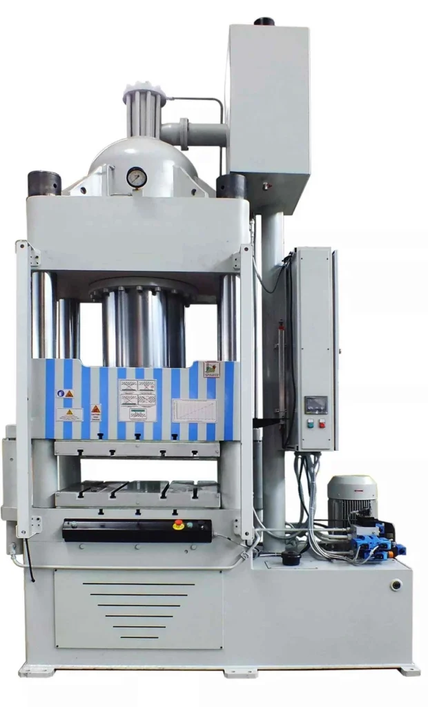
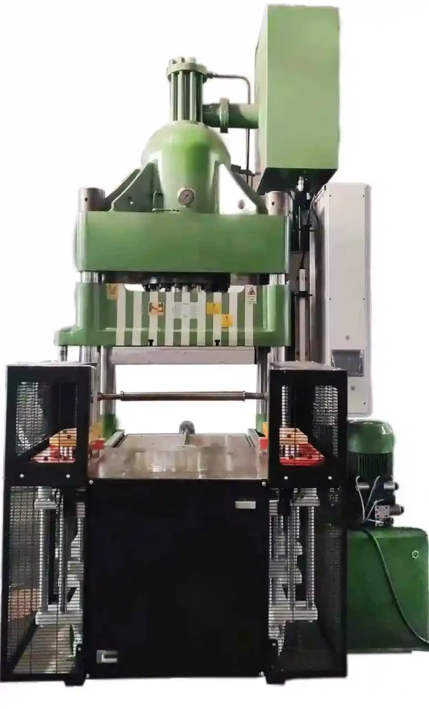
The high-pressure hydroform press is a critical piece of equipment in the hydroforming process, known for its ability to apply extreme fluid pressure to shape metal components. This type of press is typically used in applications where precise control over the forming process is required, particularly when dealing with complex geometries or materials that require careful handling to avoid defects.
High-pressure hydroform presses operate by filling a die with a hydraulic fluid, usually water or oil, and then applying pressure to the metal blank. The fluid pressure forces the metal to conform to the shape of the die, resulting in a precisely formed part. These presses are capable of generating pressures upwards of 60,000 psi (pounds per square inch), making them suitable for forming high-strength materials like stainless steel and titanium.
The use of a high-pressure hydroform press offers several advantages. First, it enables the production of parts with superior dimensional accuracy and surface finish, reducing the need for secondary machining operations. Second, the process minimizes material waste by utilizing the inherent strength of the metal, allowing for thinner walls and lighter components without compromising strength. Finally, the high-pressure capability allows for the forming of highly complex shapes that would be difficult or impossible to achieve with traditional stamping or pressing methods.
Tube Hydroforming Press
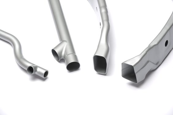
The tube hydroforming press is specifically designed for shaping tubular metal components, making it a cornerstone in industries like automotive and aerospace. Tube hydroforming involves placing a tubular metal blank into a die and then applying internal hydraulic pressure, combined with axial feeding, to expand the tube and conform it to the shape of the die.
Tube hydroforming presses are engineered to handle a wide variety of materials, including aluminum, steel, and stainless steel. These presses are capable of producing components with exceptional structural integrity and reduced weight, which is especially important in automotive applications where reducing vehicle weight is a key factor in improving fuel efficiency and performance.
One of the key advantages of tube hydroforming is its ability to create complex, hollow structures with varying cross-sections in a single step. This capability not only simplifies the manufacturing process but also results in stronger, more reliable components. Examples of parts produced by tube hydroforming include automotive chassis components, exhaust manifolds, and even bicycle frames.
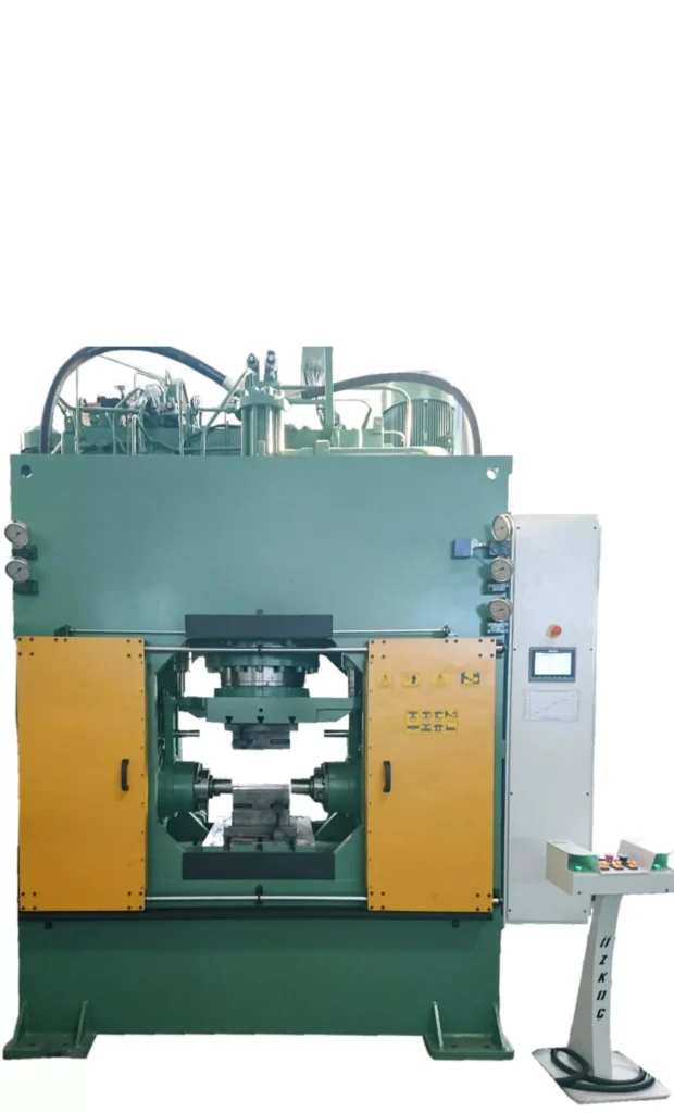
Sheet Hydroforming Machine
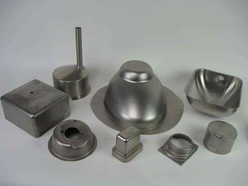
The sheet hydroforming machine is another specialized type of hydroforming equipment designed for shaping flat metal sheets into three-dimensional forms. Unlike traditional press forming, sheet hydroforming applies uniform pressure across the surface of the sheet, allowing for more intricate and precise shaping.
Sheet hydroforming machines are widely used in industries that require high precision and complex part geometries, such as aerospace, automotive, and electronics. The process involves placing a metal sheet over a die and then applying fluid pressure from above, forcing the sheet to conform to the shape of the die. This method is particularly advantageous for forming lightweight materials like aluminum and titanium, which are commonly used in aerospace applications.
The benefits of using a sheet hydroforming machine include the ability to produce parts with a high degree of accuracy, minimal material thinning, and excellent surface finishes. Additionally, the process allows for the production of large, complex parts in a single operation, reducing the need for multiple forming steps and lowering production costs.
Hydropress Forming Machine
A hydropress forming machine is a versatile piece of equipment that can be used for both tube and sheet hydroforming processes. These machines are designed to accommodate a wide range of materials and part geometries, making them a valuable asset in any manufacturing environment that requires flexibility and precision.
Hydropress forming machines operate by using a hydraulic fluid to exert pressure on the workpiece, whether it is a tube or a sheet, forcing it to take the shape of a pre-designed die. The machine’s versatility allows it to handle various materials, from softer metals like aluminum to harder ones like stainless steel, with equal efficiency.
The primary advantage of a hydropress forming machine is its ability to perform multiple types of forming operations with a single piece of equipment. This not only reduces the need for multiple machines but also streamlines the production process, leading to faster turnaround times and lower costs. Furthermore, the precision offered by hydropress forming machines ensures that each part meets strict quality standards, which is crucial in industries such as automotive and aerospace.
Core Keywords: High pressure hydroform press, Tube hydroforming press, Sheet hydroforming machine, Hydropress forming machine
Key Components and Equipment in Hydroforming
Hydroforming Equipment Overview
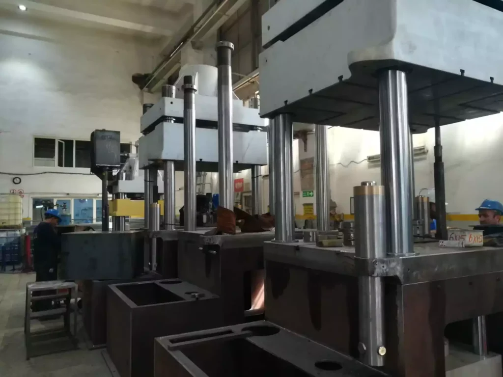
Hydroforming is a highly specialized manufacturing process that relies on sophisticated equipment to shape metals with precision and efficiency. The key components of hydroforming systems include the press itself, dies, hydraulic pumps, control systems, and supporting infrastructure. Each of these elements plays a critical role in ensuring the accuracy, repeatability, and quality of the hydroforming process.
The hydroforming press is the centerpiece of the system, where the actual forming of metal components takes place. These presses are designed to withstand the extreme pressures required to shape metals, often exceeding tens of thousands of psi. The press structure must be robust enough to handle these pressures while maintaining precise alignment of the dies to ensure consistent part quality.
Dies are another crucial component in the hydroforming process. They define the final shape of the metal component and are typically made from high-strength tool steels capable of withstanding the stresses of repeated high-pressure forming operations. The design and fabrication of dies require careful consideration of the material properties, desired part geometry, and the specifics of the hydroforming process being employed.
Hydraulic pumps generate the high-pressure fluid needed to form the metal. These pumps must be capable of delivering consistent pressure throughout the forming cycle to ensure uniform shaping of the metal blank. Depending on the specific requirements of the process, pumps may be powered by electric motors, pneumatic systems, or other energy sources.
Control systems are essential for managing the complex interactions between the press, dies, and hydraulic pumps. Modern hydroforming systems use advanced computer-based control systems that monitor and adjust pressure, positioning, and timing in real-time. This level of control is crucial for producing parts with tight tolerances and high repeatability.
Supporting infrastructure, including power supplies, cooling systems, and safety features, ensures that the hydroforming equipment operates reliably and safely. Given the high pressures involved, safety is a paramount concern in hydroforming operations, and systems are typically equipped with multiple layers of redundancy and fail-safes to protect operators and equipment.
Sheet Hydroforming Equipment
Sheet hydroforming equipment is specifically designed to handle the unique requirements of forming flat metal sheets into complex three-dimensional shapes. These machines are engineered to apply uniform pressure across the entire surface of the metal sheet, which is critical for avoiding wrinkles, tears, and other defects that can occur with uneven pressure distribution.
The equipment typically includes a pressure chamber, where the metal sheet is placed over the die, and a flexible membrane or punch that applies the fluid pressure to form the metal. The pressure chamber is often designed to accommodate various die shapes and sizes, allowing for flexibility in production.
One of the key advantages of sheet hydroforming equipment is its ability to form large, intricate parts in a single operation. This capability is particularly valuable in industries such as aerospace, where large panels with complex curves and features are common. The equipment is also designed to minimize material thinning, ensuring that the final product maintains consistent thickness and structural integrity.
Sheet hydroforming equipment often includes advanced features such as automated tool changing, which allows for rapid switching between different dies and materials, and integrated quality control systems, which monitor the forming process in real-time to detect and correct any issues that arise.
Core Keywords: Sheet hydroforming equipment, Hydroform sheet metal machine
Hydroforming Processes and Techniques
Understanding the Hydroforming Process
Hydroforming is a highly versatile and efficient forming process that uses high-pressure fluid to shape metals into complex geometries. This process is primarily employed in two forms: tube hydroforming and sheet hydroforming. Both methods offer unique advantages, making hydroforming a preferred choice in industries where precision, strength, and weight reduction are critical.
At its core, hydroforming involves placing a metal blank or tube into a die and then applying hydraulic pressure to the metal. The pressure forces the metal to conform to the shape of the die, creating a precisely formed part. The process can handle a wide range of materials, including aluminum, steel, stainless steel, and other alloys, each with its specific benefits and challenges.
The key to successful hydroforming lies in carefully controlling the pressure, material flow, and die design to achieve the desired shape without causing defects such as wrinkles, tears, or excessive thinning. This precision is achieved through the use of advanced hydraulic systems, computerized control systems, and meticulously designed dies.
Tube Hydroforming Process
The tube hydroforming process is a specialized technique used to form tubular metal components. This process is particularly valuable in the automotive and aerospace industries, where it is used to create lightweight, structurally sound parts with complex geometries.
In tube hydroforming, a tubular metal blank is placed inside a die, and then internal hydraulic pressure is applied to expand the tube outward until it conforms to the shape of the die. Axial feeding, where the tube is pushed into the die during the forming process, is often used in conjunction with hydraulic pressure to achieve more complex shapes.
The tube hydroforming process can be broken down into several key steps:
- Tube Preparation: The process begins with the selection and preparation of the metal tube, which may involve cutting it to length, cleaning, and lubricating the surface.
- Tube Insertion: The prepared tube is placed into the die, which is designed to match the desired final shape of the component.
- Pressure Application: Hydraulic pressure is applied inside the tube, causing it to expand and conform to the shape of the die. Axial force may also be applied to control the flow of material into the die and ensure uniform wall thickness.
- Forming Completion: Once the tube has fully conformed to the die, the pressure is released, and the formed part is removed from the die.
- Post-Processing: The formed part may undergo additional processes such as trimming, heat treatment, or surface finishing to meet final specifications.
Tube hydroforming offers several advantages, including the ability to create complex, seamless parts with uniform wall thickness and superior strength. The process is also highly efficient, often combining multiple forming steps into a single operation, which reduces production time and costs.
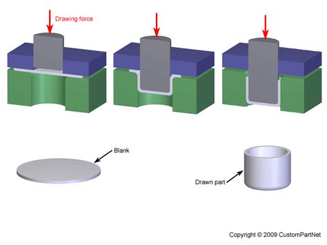
Sheet Hydroforming Process
The sheet hydroforming process is used to form flat metal sheets into three-dimensional shapes, making it ideal for creating intricate parts with smooth surfaces and fine details. This process is widely used in industries such as aerospace, where the ability to produce lightweight, high-strength components is essential.
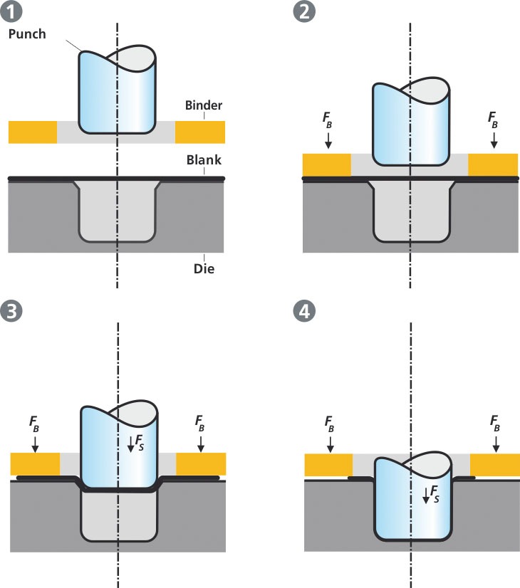
In sheet hydroforming, a metal sheet is placed over a die, and hydraulic pressure is applied from above, forcing the sheet to conform to the shape of the die. The pressure is typically applied through a flexible diaphragm or directly by a punch, depending on the specific equipment and application.
The sheet hydroforming process can be summarized in the following steps:
- Sheet Preparation: The metal sheet is selected, cut to size, and prepared with any necessary surface treatments such as cleaning or lubrication.
- Sheet Placement: The sheet is positioned over the die, which is mounted on the lower part of the press.
- Pressure Application: Hydraulic pressure is applied through a diaphragm or punch, forcing the sheet to conform to the shape of the die. The pressure is carefully controlled to ensure even forming and avoid defects.
- Forming Completion: Once the sheet has fully conformed to the die, the pressure is released, and the formed part is removed.
- Post-Processing: Like tube hydroforming, sheet hydroformed parts may require additional processes such as trimming, heat treatment, or surface finishing.
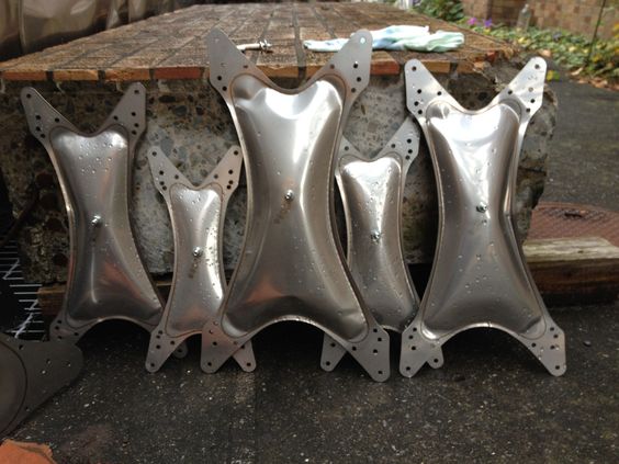
Sheet hydroforming offers several distinct advantages. The process allows for the creation of large, complex parts with minimal thinning and excellent surface finish. Additionally, sheet hydroforming can accommodate a wide range of materials, including lightweight alloys like aluminum and high-strength materials like titanium and stainless steel.
Innovations in Hydroforming Technology
Hydroforming technology continues to evolve, with ongoing innovations aimed at improving efficiency, precision, and material capabilities. Some of the latest advancements in hydroforming include:
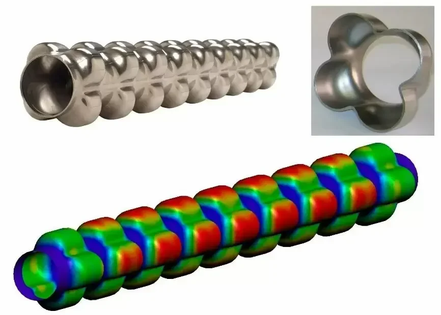
- Advanced Simulation and Modeling: Modern hydroforming processes benefit from sophisticated simulation software that allows engineers to model and optimize the forming process before actual production. This reduces trial-and-error and helps achieve better results with less material waste.
- Multi-Material Hydroforming: New techniques are being developed to enable the hydroforming of multi-material components, combining metals with different properties to create parts with enhanced performance characteristics.
- High-Speed Hydroforming: Advances in hydraulic systems and control technologies have led to the development of high-speed hydroforming processes, which significantly reduce cycle times and increase production rates.
- Hydroforming of Advanced Materials: Research is ongoing to expand the range of materials that can be effectively hydroformed, including high-strength steels, magnesium alloys, and composites.
- Adaptive Hydroforming: Adaptive control systems that adjust pressure, feed rates, and other parameters in real-time during the forming process are being developed to improve quality and reduce the occurrence of defects.
These innovations are driving the continued adoption of hydroforming in industries where precision, efficiency, and material performance are critical.
Core Keywords: Tube hydroforming machine, Sheet hydroforming machine, Hydroforming metal
Applications of Hydroforming in Various Industries
Automotive Industry
The automotive industry is one of the largest adopters of hydroforming technology, leveraging its unique capabilities to produce lightweight, durable, and complex components. As vehicle manufacturers continuously strive to improve fuel efficiency and meet stringent environmental regulations, hydroforming has become an essential process in automotive production.
Hydroforming is particularly valued for its ability to create high-strength components with complex geometries, often in a single forming step. This ability to consolidate parts not only reduces the overall weight of vehicles but also improves their structural integrity. For example, hydroformed components such as engine cradles, roof rails, and suspension parts are integral to modern automotive designs, contributing to enhanced safety and performance.
Tube hydroforming is widely used in the automotive industry to produce structural components that require both strength and lightness. By using hydroforming to shape tubes into complex forms, manufacturers can create parts that would be difficult or impossible to produce using traditional stamping or welding techniques. These parts often have better load-bearing capacity and can be made with fewer welds, which improves the overall safety of the vehicle.
Another advantage of hydroforming in automotive applications is the reduction in material usage. The process allows for the precise control of material thickness, enabling the production of thinner-walled components without compromising strength. This not only reduces the weight of the vehicle but also leads to material cost savings, making hydroforming an economically attractive option for manufacturers.
Sheet hydroforming is also employed in the automotive sector, particularly for producing body panels and other exterior components that require high precision and surface quality. The ability to form large, intricate shapes with minimal thinning and excellent surface finishes makes sheet hydroforming ideal for creating aesthetically pleasing and aerodynamically efficient vehicle designs.
Aerospace Industry
In the aerospace industry, hydroforming plays a critical role in the fabrication of lightweight, high-precision components that must withstand extreme conditions. The aerospace sector demands materials and processes that offer exceptional strength-to-weight ratios, and hydroforming meets these requirements by enabling the production of complex shapes from high-strength materials like titanium, aluminum, and stainless steel.
Tube hydroforming is used extensively in the aerospace industry to create components such as fuselage sections, engine nacelles, and landing gear parts. These components often require complex shapes and tight tolerances that can be difficult to achieve with conventional forming methods. Hydroforming allows for the creation of seamless, structurally sound parts with uniform wall thickness, which is crucial for maintaining the integrity and performance of aerospace components under high stress.
In addition to structural components, hydroforming is also used to produce intricate parts for aircraft engines, where precision and material integrity are paramount. The ability to form complex geometries with minimal secondary operations reduces the overall weight of the engine, contributing to improved fuel efficiency and performance.
Sheet hydroforming is particularly valuable in the production of large, contoured panels for aircraft bodies and wings. The process allows for the creation of smooth, continuous surfaces with precise curvature, which is essential for aerodynamic performance. The resulting panels are not only lighter but also exhibit superior structural integrity, which is critical for the safety and efficiency of modern aircraft.
Other Industries
Beyond automotive and aerospace, hydroforming is utilized in a variety of other industries where the ability to produce lightweight, durable, and complex components is essential. In the electronics industry, for instance, hydroforming is used to create enclosures and structural parts that require high precision and minimal material usage.
In the HVAC (Heating, Ventilation, and Air Conditioning) sector, hydroforming is employed to produce components such as heat exchangers and ductwork, where the ability to form intricate shapes with thin walls is highly advantageous. The process ensures that these components meet the required performance standards while minimizing material costs and waste.
The furniture industry also benefits from hydroforming, particularly in the production of metal frames and supports for modern furniture designs. The process allows for the creation of sleek, lightweight structures that are both aesthetically pleasing and structurally sound.
In the medical industry, hydroforming is used to produce components for medical devices and equipment, where precision and reliability are critical. The ability to form complex shapes from biocompatible materials like stainless steel and titanium makes hydroforming an ideal choice for medical applications.
Hydroforming’s versatility extends even further, with applications in the production of bicycle frames, exhaust systems, musical instruments, and artistic sculptures. The process’s ability to create strong, lightweight, and intricate components from a wide range of materials continues to open new possibilities across various industries.
Core Keywords: Hydroforming stainless steel, Hydroform sheet metal machine, Hydroforming metal
Advantages and Challenges of Hydroforming
Advantages
Hydroforming offers numerous advantages that make it a preferred manufacturing process in industries where precision, efficiency, and material utilization are critical. Below are some of the key benefits of hydroforming:
- Material Efficiency: Hydroforming allows for the production of parts with uniform wall thickness and complex shapes in a single forming step. This efficiency reduces material waste, as the process can precisely control material flow and thinning. The ability to use thinner sheets or tubes without sacrificing strength contributes to significant cost savings, particularly when working with expensive materials like titanium or stainless steel.
- Weight Reduction: One of the most significant advantages of hydroforming is its ability to create lightweight components without compromising structural integrity. By optimizing the strength-to-weight ratio of parts, hydroforming enables the production of components that are lighter than those made with traditional methods, making it ideal for applications in the automotive and aerospace industries, where weight reduction is paramount for fuel efficiency and performance.
- Enhanced Strength and Durability: The hydroforming process enhances the mechanical properties of the formed parts. The uniform distribution of material and the elimination of welds (common in multi-piece assemblies) result in components with superior strength and durability. This improved structural integrity is especially important in applications where parts are subjected to high stress or harsh operating conditions.
- Design Flexibility: Hydroforming offers unparalleled design flexibility, allowing for the creation of complex geometries that would be challenging or impossible to achieve with conventional stamping or machining processes. This flexibility enables manufacturers to design parts with integrated features, such as flanges, ribs, or holes, reducing the need for additional processing steps and assembly operations.
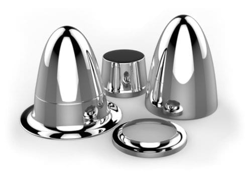
- Surface Finish Quality: The high-pressure forming process used in hydroforming ensures excellent surface finishes, which often require little to no post-processing. This is particularly beneficial for parts that require a high degree of aesthetic appeal or where smooth surfaces are essential for performance, such as in aerodynamic components.
- Cost-Effectiveness: Despite the initial investment in hydroforming equipment, the process can be highly cost-effective in the long run. The reduction in material waste, elimination of secondary operations, and the ability to produce complex parts in a single step contribute to lower overall production costs. Additionally, the durability of hydroformed parts reduces the need for frequent replacements, further driving down lifecycle costs.
Challenges
While hydroforming offers many advantages, it also presents certain challenges that must be carefully managed to ensure successful implementation:
- High Initial Investment: The cost of acquiring and setting up hydroforming equipment can be significant. This includes the cost of the press, dies, hydraulic systems, and control systems, as well as the infrastructure required to support these components. For smaller manufacturers or those producing lower volumes, the initial investment may be a barrier to entry.
- Complexity of Tooling: The design and fabrication of hydroforming dies are complex and require a high level of expertise. The dies must be precisely engineered to accommodate the specific material properties, desired part geometry, and the dynamics of the hydroforming process. Any errors in die design can result in defects in the final part, leading to costly rework or scrap.
- Material Limitations: While hydroforming is versatile and can handle a wide range of materials, there are limitations. Materials with low ductility or those prone to cracking under high pressure may not be suitable for hydroforming. Additionally, certain materials require specialized handling or processing conditions, which can complicate the hydroforming process.
- Process Control: Achieving consistent results in hydroforming requires precise control of process parameters such as pressure, material feed rates, and temperature. Variations in these parameters can lead to defects such as wrinkles, tears, or uneven wall thickness. Advanced control systems and real-time monitoring are essential to maintaining process stability and ensuring the quality of the final parts.
- Limited Material Flow: In some cases, the material may not flow sufficiently to fill the entire die cavity, leading to incomplete or malformed parts. This is particularly challenging when forming very complex shapes or when working with materials that have low elongation capabilities. To address this, careful consideration must be given to the design of the dies and the selection of process parameters.
Environmental Impact
Hydroforming has a favorable environmental profile compared to traditional manufacturing processes. The reduction in material waste, energy efficiency, and elimination of welding and other secondary operations contribute to a lower overall environmental impact. Additionally, the ability to produce lightweight components plays a significant role in reducing the fuel consumption and emissions of vehicles and aircraft, contributing to broader sustainability goals.
However, the use of hydraulic fluids and the disposal of used materials must be managed carefully to avoid environmental contamination. Advances in fluid recycling and the development of eco-friendly hydraulic fluids are helping to mitigate these concerns, making hydroforming an increasingly sustainable manufacturing option.
Core Keywords: Hydroforming metal, Hydroforming stainless steel
Hydroforming in Türkiye: A Growing Industry
Current State of Hydroforming in Türkiye
Türkiye has rapidly emerged as a significant player in the global hydroforming industry, leveraging its strategic location, growing industrial base, and skilled workforce. The country’s manufacturing sector, particularly in automotive and aerospace, has embraced hydroforming technology to meet the increasing demand for lightweight, high-strength components. This adoption is driven by both domestic manufacturers and international companies that have established operations in Türkiye to capitalize on its competitive advantages.
The hydroforming industry in Türkiye is characterized by a diverse range of applications, from the production of automotive parts to aerospace components. The automotive sector, in particular, has seen substantial growth, with Turkish manufacturers utilizing hydroforming to produce chassis components, exhaust systems, and structural elements. This growth is supported by Türkiye’s strong automotive industry, which is among the largest in Europe and continues to attract significant foreign investment.
In the aerospace sector, Turkish companies are increasingly adopting hydroforming to manufacture high-precision components such as fuselage panels, engine parts, and landing gear elements. The country’s growing role as a hub for aerospace manufacturing, coupled with its focus on innovation and quality, positions Türkiye as a key player in the global hydroforming landscape.
Key Players and Manufacturers
Several key players have emerged in the Turkish hydroforming industry, ranging from established manufacturers to innovative startups. These companies are driving the adoption of hydroforming technology and contributing to the industry’s growth through investments in advanced equipment, research and development, and workforce training.
Future Prospects
The future of hydroforming in Türkiye looks promising, with several factors contributing to the industry’s expected growth. The increasing demand for lightweight, high-strength components in automotive and aerospace applications is likely to drive further adoption of hydroforming technology. Additionally, Türkiye’s strategic location as a bridge between Europe and Asia makes it an attractive destination for foreign investment, which is expected to bolster the hydroforming industry.
Research and development will play a critical role in the future of hydroforming in Türkiye. Companies and academic institutions are increasingly collaborating on projects aimed at advancing hydroforming techniques, improving material capabilities, and developing more efficient processes. These efforts are expected to lead to innovations that will further enhance the competitiveness of Turkish manufacturers on the global stage.
Moreover, the Turkish government’s support for industrial growth, including incentives for technology adoption and export promotion, is likely to fuel the expansion of the hydroforming industry. As Türkiye continues to strengthen its position as a manufacturing hub, the demand for hydroforming equipment and expertise is expected to rise, creating new opportunities for both domestic and international companies.
In conclusion, Hydroforming in Türkiye is poised for significant growth, driven by the country’s robust industrial base, strategic investments in technology, and a focus on innovation. As the global demand for advanced manufacturing solutions continues to rise, Türkiye’s hydroforming industry is well-positioned to capitalize on these trends and contribute to the future of manufacturing.
Core Keywords: Hydroforming Türkiye, Hydroform sheet metal machine
Selecting the Right Hydroforming Equipment and Press
Factors to Consider
Selecting the right hydroforming equipment and press is a crucial decision that can significantly impact the efficiency, quality, and cost-effectiveness of your manufacturing operations. When choosing hydroforming equipment, several factors must be considered to ensure that the selected system meets the specific needs of your production environment.
- Material Type: The type of material you intend to form plays a significant role in determining the appropriate hydroforming equipment. Different materials, such as aluminum, stainless steel, titanium, and high-strength alloys, have varying properties that require specific handling. For example, materials like titanium and stainless steel require presses capable of generating higher pressures to achieve the desired shapes without compromising material integrity.
- Production Volume: The scale of production is another critical factor. High-volume production environments may require more robust, automated hydroforming presses that can handle continuous operation with minimal downtime. Conversely, for low-volume or specialized production, a more flexible, adaptable system might be more appropriate, allowing for quick tool changes and customization.
- Part Complexity: The complexity of the parts you need to produce will influence the choice of equipment. Highly intricate components with complex geometries may require advanced hydroforming presses with precise control over pressure, material flow, and tooling. Multi-axis control systems and sophisticated die designs are often necessary to achieve the high precision required for these parts.
- Tolerances and Precision: If your parts require tight tolerances and high precision, it’s essential to select equipment that offers fine control over the forming process. This includes the ability to adjust pressure and material feed rates in real-time, as well as advanced monitoring systems that can detect and correct any deviations from the desired specifications.
- Size and Shape of Parts: The physical size and shape of the parts being produced are also important considerations. Larger parts may require larger presses with greater tonnage capabilities, while smaller, more delicate parts may benefit from equipment designed for precision and gentle handling. The choice of die size and press capacity should align with the dimensions and weight of the components you plan to manufacture.
- Customization and Flexibility: Consider whether the hydroforming equipment offers the flexibility to accommodate different materials, part sizes, and geometries. This is particularly important in industries where product designs frequently change or where multiple products are produced using the same equipment. Equipment that allows for quick tool changes and process adjustments can be invaluable in such environments.
Customization and Vendor Selection
Customization is often necessary when selecting hydroforming equipment, as each manufacturing environment has unique requirements. Many equipment manufacturers offer custom solutions tailored to specific industry needs, whether it’s adapting the press for particular materials, integrating automation systems, or designing specialized dies.
When selecting a vendor, consider the following factors:
- Experience and Expertise: Choose a vendor with a proven track record in hydroforming technology, particularly in your specific industry. Experienced vendors can provide valuable insights into the best practices and innovations that can enhance your manufacturing process.
- Support and Service: Ensure that the vendor offers comprehensive support services, including installation, training, maintenance, and troubleshooting. Reliable after-sales support is critical to minimizing downtime and ensuring the smooth operation of your equipment.
- Technology and Innovation: Look for vendors that are at the forefront of hydroforming technology, offering the latest advancements in equipment design, control systems, and process optimization. Cutting-edge technology can provide a competitive advantage by improving efficiency, precision, and product quality.
- Customization Options: Assess the vendor’s ability to provide customized solutions that meet your specific needs. This could involve modifying existing equipment or designing entirely new systems to accommodate unique production requirements.
- Cost and Return on Investment (ROI): While cost is an important factor, it’s essential to consider the long-term ROI of the equipment. Investing in high-quality, reliable hydroforming equipment may have a higher upfront cost but can result in significant savings over time through improved efficiency, reduced waste, and lower maintenance costs.
By carefully evaluating these factors and selecting the right equipment and vendor, you can optimize your hydroforming operations for maximum efficiency and quality.
Core Keywords: Hydroforming Press, Sheet hydroforming equipment, Hydropress forming machine
Case Studies and Real-world Applications
Case Study 1: Automotive Industry
In the automotive industry, hydroforming has become a key technology for producing lightweight and durable vehicle components. A prime example of hydroforming’s application can be seen in the manufacturing of engine cradles and subframes for high-performance vehicles.
Background: A leading automotive manufacturer sought to reduce the weight of its vehicles to improve fuel efficiency and performance. The traditional method of assembling subframes involved multiple stamped steel parts welded together, resulting in a heavier structure with numerous potential points of failure.
Hydroforming Solution: The manufacturer adopted tube hydroforming to produce a one-piece engine cradle and subframe. By using hydroforming, the company was able to create complex, hollow structures that were both lighter and stronger than the multi-piece assemblies previously used. The hydroformed parts had fewer welds, which reduced the potential for failure and improved the overall strength and durability of the components.
Outcome: The switch to hydroforming resulted in a 20% reduction in the weight of the subframe, contributing to improved vehicle fuel efficiency and handling. Additionally, the simplified manufacturing process led to cost savings by reducing the number of components and assembly steps. The success of this application has led the manufacturer to expand the use of hydroforming across other vehicle components, further enhancing the performance and efficiency of their vehicles.
Case Study 2: Aerospace Industry
The aerospace industry demands components that are both lightweight and capable of withstanding extreme conditions. A notable case study involves the use of hydroforming in the production of aircraft fuselage panels.
Background: An aerospace manufacturer faced the challenge of producing large, curved fuselage panels that required precise shaping and a high strength-to-weight ratio. The traditional methods of forming these panels involved multiple stages of stamping and welding, which added weight and compromised the structural integrity of the final product.
Hydroforming Solution: The manufacturer implemented sheet hydroforming to produce the fuselage panels. This process allowed for the forming of large, complex shapes in a single operation, with precise control over material thickness and minimal residual stresses. The hydroforming press used was capable of applying uniform pressure across the entire surface of the metal sheet, ensuring a smooth and consistent finish.
Outcome: The hydroformed fuselage panels were significantly lighter than their traditionally manufactured counterparts, leading to an overall reduction in the aircraft’s weight. This reduction translated into improved fuel efficiency and payload capacity. Furthermore, the superior surface finish and dimensional accuracy achieved through hydroforming reduced the need for secondary machining operations, thereby lowering production costs and time.
Additional Real-world Applications
- Bicycle Frame Manufacturing: Hydroforming is widely used in the production of lightweight and strong bicycle frames. By using tube hydroforming, manufacturers can create frames with intricate geometries that optimize strength and stiffness while minimizing weight. This has led to the production of high-performance bicycles that are both durable and responsive.
- HVAC Systems: In the HVAC industry, hydroforming is used to produce components such as heat exchanger plates and ductwork. The ability to form complex shapes with precise dimensions ensures that these components meet the required performance standards for energy efficiency and durability.
- Medical Devices: Hydroforming is employed in the medical industry to manufacture components for medical devices, such as surgical instruments and implants. The process allows for the creation of intricate, biocompatible parts with high precision, which is critical for ensuring the safety and effectiveness of medical devices.
- Furniture and Home Appliances: Hydroforming is also used in the production of metal frames for furniture and structural components for home appliances. The process allows for the creation of sleek, modern designs that are both aesthetically pleasing and structurally sound.
These case studies and examples demonstrate the versatility and effectiveness of hydroforming across a wide range of industries. The ability to produce complex, lightweight, and durable components with high precision makes hydroforming an invaluable technology in modern manufacturing.
The sheet hydroforming machine is another specialized type of hydroforming equipment designed for shaping flat metal sheets into three-dimensional forms. Unlike traditional press forming, sheet hydroforming applies uniform pressure across the surface of the sheet, allowing for more intricate and precise shaping.
Sheet hydroforming machines are widely used in industries that require high precision and complex part geometries, such as aerospace, automotive, and electronics. The process involves placing a metal sheet over a die and then applying fluid pressure from above, forcing the sheet to conform to the shape of the die. This method is particularly advantageous for forming lightweight materials like aluminum and titanium, which are commonly used in aerospace applications.
The benefits of using a sheet hydroforming machine include the ability to produce parts with a high degree of accuracy, minimal material thinning, and excellent surface finishes. Additionally, the process allows for the production of large, complex parts in a single operation, reducing the need for multiple forming steps and lowering production costs.
Hydropress Forming Machine
A hydropress forming machine is a versatile piece of equipment that can be used for both tube and sheet hydroforming processes. These machines are designed to accommodate a wide range of materials and part geometries, making them a valuable asset in any manufacturing environment that requires flexibility and precision.
Hydropress forming machines operate by using a hydraulic fluid to exert pressure on the workpiece, whether it is a tube or a sheet, forcing it to take the shape of a pre-designed die. The machine’s versatility allows it to handle various materials, from softer metals like aluminum to harder ones like stainless steel, with equal efficiency.
The primary advantage of a hydropress forming machine is its ability to perform multiple types of forming operations with a single piece of equipment. This not only reduces the need for multiple machines but also streamlines the production process, leading to faster turnaround times and lower costs. Furthermore, the precision offered by hydropress forming machines ensures that each part meets strict quality standards, which is crucial in industries such as automotive and aerospace.
Core Keywords: High pressure hydroform press, Tube hydroforming press, Sheet hydroforming machine, Hydropress forming machine
Key Components and Equipment in Hydroforming
Hydroforming Equipment Overview
Hydroforming is a highly specialized manufacturing process that relies on sophisticated equipment to shape metals with precision and efficiency. The key components of hydroforming systems include the press itself, dies, hydraulic pumps, control systems, and supporting infrastructure. Each of these elements plays a critical role in ensuring the accuracy, repeatability, and quality of the hydroforming process.
The hydroforming press is the centerpiece of the system, where the actual forming of metal components takes place. These presses are designed to withstand the extreme pressures required to shape metals, often exceeding tens of thousands of psi. The press structure must be robust enough to handle these pressures while maintaining precise alignment of the dies to ensure consistent part quality.
Dies are another crucial component in the hydroforming process. They define the final shape of the metal component and are typically made from high-strength tool steels capable of withstanding the stresses of repeated high-pressure forming operations. The design and fabrication of dies require careful consideration of the material properties, desired part geometry, and the specifics of the hydroforming process being employed.
Hydraulic pumps generate the high-pressure fluid needed to form the metal. These pumps must be capable of delivering consistent pressure throughout the forming cycle to ensure uniform shaping of the metal blank. Depending on the specific requirements of the process, pumps may be powered by electric motors, pneumatic systems, or other energy sources.
Control systems are essential for managing the complex interactions between the press, dies, and hydraulic pumps. Modern hydroforming systems use advanced computer-based control systems that monitor and adjust pressure, positioning, and timing in real-time. This level of control is crucial for producing parts with tight tolerances and high repeatability.
Supporting infrastructure, including power supplies, cooling systems, and safety features, ensures that the hydroforming equipment operates reliably and safely. Given the high pressures involved, safety is a paramount concern in hydroforming operations, and systems are typically equipped with multiple layers of redundancy and fail-safes to protect operators and equipment.
Sheet Hydroforming Equipment
Sheet hydroforming equipment is specifically designed to handle the unique requirements of forming flat metal sheets into complex three-dimensional shapes. These machines are engineered to apply uniform pressure across the entire surface of the metal sheet, which is critical for avoiding wrinkles, tears, and other defects that can occur with uneven pressure distribution.
The equipment typically includes a pressure chamber, where the metal sheet is placed over the die, and a flexible membrane or punch that applies the fluid pressure to form the metal. The pressure chamber is often designed to accommodate various die shapes and sizes, allowing for flexibility in production.
One of the key advantages of sheet hydroforming equipment is its ability to form large, intricate parts in a single operation. This capability is particularly valuable in industries such as aerospace, where large panels with complex curves and features are common. The equipment is also designed to minimize material thinning, ensuring that the final product maintains consistent thickness and structural integrity.
Sheet hydroforming equipment often includes advanced features such as automated tool changing, which allows for rapid switching between different dies and materials, and integrated quality control systems, which monitor the forming process in real-time to detect and correct any issues that arise.
Core Keywords: Sheet hydroforming equipment, Hydroform sheet metal machine
Hydroforming Processes and Techniques
Understanding the Hydroforming Process
Hydroforming is a highly versatile and efficient forming process that uses high-pressure fluid to shape metals into complex geometries. This process is primarily employed in two forms: tube hydroforming and sheet hydroforming. Both methods offer unique advantages, making hydroforming a preferred choice in industries where precision, strength, and weight reduction are critical.
At its core, hydroforming involves placing a metal blank or tube into a die and then applying hydraulic pressure to the metal. The pressure forces the metal to conform to the shape of the die, creating a precisely formed part. The process can handle a wide range of materials, including aluminum, steel, stainless steel, and other alloys, each with its specific benefits and challenges.
The key to successful hydroforming lies in carefully controlling the pressure, material flow, and die design to achieve the desired shape without causing defects such as wrinkles, tears, or excessive thinning. This precision is achieved through the use of advanced hydraulic systems, computerized control systems, and meticulously designed dies.
Tube Hydroforming Process
The tube hydroforming process is a specialized technique used to form tubular metal components. This process is particularly valuable in the automotive and aerospace industries, where it is used to create lightweight, structurally sound parts with complex geometries.
In tube hydroforming, a tubular metal blank is placed inside a die, and then internal hydraulic pressure is applied to expand the tube outward until it conforms to the shape of the die. Axial feeding, where the tube is pushed into the die during the forming process, is often used in conjunction with hydraulic pressure to achieve more complex shapes.
The tube hydroforming process can be broken down into several key steps:
- Tube Preparation: The process begins with the selection and preparation of the metal tube, which may involve cutting it to length, cleaning, and lubricating the surface.
- Tube Insertion: The prepared tube is placed into the die, which is designed to match the desired final shape of the component.
- Pressure Application: Hydraulic pressure is applied inside the tube, causing it to expand and conform to the shape of the die. Axial force may also be applied to control the flow of material into the die and ensure uniform wall thickness.
- Forming Completion: Once the tube has fully conformed to the die, the pressure is released, and the formed part is removed from the die.
- Post-Processing: The formed part may undergo additional processes such as trimming, heat treatment, or surface finishing to meet final specifications.
Tube hydroforming offers several advantages, including the ability to create complex, seamless parts with uniform wall thickness and superior strength. The process is also highly efficient, often combining multiple forming steps into a single operation, which reduces production time and costs.
Sheet Hydroforming Process
The sheet hydroforming process is used to form flat metal sheets into three-dimensional shapes, making it ideal for creating intricate parts with smooth surfaces and fine details. This process is widely used in industries such as aerospace, where the ability to produce lightweight, high-strength components is essential.
In sheet hydroforming, a metal sheet is placed over a die, and hydraulic pressure is applied from above, forcing the sheet to conform to the shape of the die. The pressure is typically applied through a flexible diaphragm or directly by a punch, depending on the specific equipment and application.
The sheet hydroforming process can be summarized in the following steps:
- Sheet Preparation: The metal sheet is selected, cut to size, and prepared with any necessary surface treatments such as cleaning or lubrication.
- Sheet Placement: The sheet is positioned over the die, which is mounted on the lower part of the press.
- Pressure Application: Hydraulic pressure is applied through a diaphragm or punch, forcing the sheet to conform to the shape of the die. The pressure is carefully controlled to ensure even forming and avoid defects.
- Forming Completion: Once the sheet has fully conformed to the die, the pressure is released, and the formed part is removed.
- Post-Processing: Like tube hydroforming, sheet hydroformed parts may require additional processes such as trimming, heat treatment, or surface finishing.
Sheet hydroforming offers several distinct advantages. The process allows for the creation of large, complex parts with minimal thinning and excellent surface finish. Additionally, sheet hydroforming can accommodate a wide range of materials, including lightweight alloys like aluminum and high-strength materials like titanium and stainless steel.
Innovations in Hydroforming Technology
Hydroforming technology continues to evolve, with ongoing innovations aimed at improving efficiency, precision, and material capabilities. Some of the latest advancements in hydroforming include:
- Advanced Simulation and Modeling: Modern hydroforming processes benefit from sophisticated simulation software that allows engineers to model and optimize the forming process before actual production. This reduces trial-and-error and helps achieve better results with less material waste.
- Multi-Material Hydroforming: New techniques are being developed to enable the hydroforming of multi-material components, combining metals with different properties to create parts with enhanced performance characteristics.
- High-Speed Hydroforming: Advances in hydraulic systems and control technologies have led to the development of high-speed hydroforming processes, which significantly reduce cycle times and increase production rates.
- Hydroforming of Advanced Materials: Research is ongoing to expand the range of materials that can be effectively hydroformed, including high-strength steels, magnesium alloys, and composites.
- Adaptive Hydroforming: Adaptive control systems that adjust pressure, feed rates, and other parameters in real-time during the forming process are being developed to improve quality and reduce the occurrence of defects.
These innovations are driving the continued adoption of hydroforming in industries where precision, efficiency, and material performance are critical.
Core Keywords: Tube hydroforming machine, Sheet hydroforming machine, Hydroforming metal
Applications of Hydroforming in Various Industries
Automotive Industry
The automotive industry is one of the largest adopters of hydroforming technology, leveraging its unique capabilities to produce lightweight, durable, and complex components. As vehicle manufacturers continuously strive to improve fuel efficiency and meet stringent environmental regulations, hydroforming has become an essential process in automotive production.
Hydroforming is particularly valued for its ability to create high-strength components with complex geometries, often in a single forming step. This ability to consolidate parts not only reduces the overall weight of vehicles but also improves their structural integrity. For example, hydroformed components such as engine cradles, roof rails, and suspension parts are integral to modern automotive designs, contributing to enhanced safety and performance.
Tube hydroforming is widely used in the automotive industry to produce structural components that require both strength and lightness. By using hydroforming to shape tubes into complex forms, manufacturers can create parts that would be difficult or impossible to produce using traditional stamping or welding techniques. These parts often have better load-bearing capacity and can be made with fewer welds, which improves the overall safety of the vehicle.
Another advantage of hydroforming in automotive applications is the reduction in material usage. The process allows for the precise control of material thickness, enabling the production of thinner-walled components without compromising strength. This not only reduces the weight of the vehicle but also leads to material cost savings, making hydroforming an economically attractive option for manufacturers.
Sheet hydroforming is also employed in the automotive sector, particularly for producing body panels and other exterior components that require high precision and surface quality. The ability to form large, intricate shapes with minimal thinning and excellent surface finishes makes sheet hydroforming ideal for creating aesthetically pleasing and aerodynamically efficient vehicle designs.
Aerospace Industry
In the aerospace industry, hydroforming plays a critical role in the fabrication of lightweight, high-precision components that must withstand extreme conditions. The aerospace sector demands materials and processes that offer exceptional strength-to-weight ratios, and hydroforming meets these requirements by enabling the production of complex shapes from high-strength materials like titanium, aluminum, and stainless steel.
Tube hydroforming is used extensively in the aerospace industry to create components such as fuselage sections, engine nacelles, and landing gear parts. These components often require complex shapes and tight tolerances that can be difficult to achieve with conventional forming methods. Hydroforming allows for the creation of seamless, structurally sound parts with uniform wall thickness, which is crucial for maintaining the integrity and performance of aerospace components under high stress.
In addition to structural components, hydroforming is also used to produce intricate parts for aircraft engines, where precision and material integrity are paramount. The ability to form complex geometries with minimal secondary operations reduces the overall weight of the engine, contributing to improved fuel efficiency and performance.
Sheet hydroforming is particularly valuable in the production of large, contoured panels for aircraft bodies and wings. The process allows for the creation of smooth, continuous surfaces with precise curvature, which is essential for aerodynamic performance. The resulting panels are not only lighter but also exhibit superior structural integrity, which is critical for the safety and efficiency of modern aircraft.
Other Industries
Beyond automotive and aerospace, hydroforming is utilized in a variety of other industries where the ability to produce lightweight, durable, and complex components is essential. In the electronics industry, for instance, hydroforming is used to create enclosures and structural parts that require high precision and minimal material usage.
In the HVAC (Heating, Ventilation, and Air Conditioning) sector, hydroforming is employed to produce components such as heat exchangers and ductwork, where the ability to form intricate shapes with thin walls is highly advantageous. The process ensures that these components meet the required performance standards while minimizing material costs and waste.
The furniture industry also benefits from hydroforming, particularly in the production of metal frames and supports for modern furniture designs. The process allows for the creation of sleek, lightweight structures that are both aesthetically pleasing and structurally sound.
In the medical industry, hydroforming is used to produce components for medical devices and equipment, where precision and reliability are critical. The ability to form complex shapes from biocompatible materials like stainless steel and titanium makes hydroforming an ideal choice for medical applications.
Hydroforming’s versatility extends even further, with applications in the production of bicycle frames, exhaust systems, musical instruments, and artistic sculptures. The process’s ability to create strong, lightweight, and intricate components from a wide range of materials continues to open new possibilities across various industries.
Core Keywords: Hydroforming stainless steel, Hydroform sheet metal machine, Hydroforming metal
Advantages and Challenges of Hydroforming
Advantages
Hydroforming offers numerous advantages that make it a preferred manufacturing process in industries where precision, efficiency, and material utilization are critical. Below are some of the key benefits of hydroforming:
- Material Efficiency: Hydroforming allows for the production of parts with uniform wall thickness and complex shapes in a single forming step. This efficiency reduces material waste, as the process can precisely control material flow and thinning. The ability to use thinner sheets or tubes without sacrificing strength contributes to significant cost savings, particularly when working with expensive materials like titanium or stainless steel.
- Weight Reduction: One of the most significant advantages of hydroforming is its ability to create lightweight components without compromising structural integrity. By optimizing the strength-to-weight ratio of parts, hydroforming enables the production of components that are lighter than those made with traditional methods, making it ideal for applications in the automotive and aerospace industries, where weight reduction is paramount for fuel efficiency and performance.
- Enhanced Strength and Durability: The hydroforming process enhances the mechanical properties of the formed parts. The uniform distribution of material and the elimination of welds (common in multi-piece assemblies) result in components with superior strength and durability. This improved structural integrity is especially important in applications where parts are subjected to high stress or harsh operating conditions.
- Design Flexibility: Hydroforming offers unparalleled design flexibility, allowing for the creation of complex geometries that would be challenging or impossible to achieve with conventional stamping or machining processes. This flexibility enables manufacturers to design parts with integrated features, such as flanges, ribs, or holes, reducing the need for additional processing steps and assembly operations.
- Surface Finish Quality: The high-pressure forming process used in hydroforming ensures excellent surface finishes, which often require little to no post-processing. This is particularly beneficial for parts that require a high degree of aesthetic appeal or where smooth surfaces are essential for performance, such as in aerodynamic components.
- Cost-Effectiveness: Despite the initial investment in hydroforming equipment, the process can be highly cost-effective in the long run. The reduction in material waste, elimination of secondary operations, and the ability to produce complex parts in a single step contribute to lower overall production costs. Additionally, the durability of hydroformed parts reduces the need for frequent replacements, further driving down lifecycle costs.
Challenges
While hydroforming offers many advantages, it also presents certain challenges that must be carefully managed to ensure successful implementation:
- High Initial Investment: The cost of acquiring and setting up hydroforming equipment can be significant. This includes the cost of the press, dies, hydraulic systems, and control systems, as well as the infrastructure required to support these components. For smaller manufacturers or those producing lower volumes, the initial investment may be a barrier to entry.
- Complexity of Tooling: The design and fabrication of hydroforming dies are complex and require a high level of expertise. The dies must be precisely engineered to accommodate the specific material properties, desired part geometry, and the dynamics of the hydroforming process. Any errors in die design can result in defects in the final part, leading to costly rework or scrap.
- Material Limitations: While hydroforming is versatile and can handle a wide range of materials, there are limitations. Materials with low ductility or those prone to cracking under high pressure may not be suitable for hydroforming. Additionally, certain materials require specialized handling or processing conditions, which can complicate the hydroforming process.
- Process Control: Achieving consistent results in hydroforming requires precise control of process parameters such as pressure, material feed rates, and temperature. Variations in these parameters can lead to defects such as wrinkles, tears, or uneven wall thickness. Advanced control systems and real-time monitoring are essential to maintaining process stability and ensuring the quality of the final parts.
- Limited Material Flow: In some cases, the material may not flow sufficiently to fill the entire die cavity, leading to incomplete or malformed parts. This is particularly challenging when forming very complex shapes or when working with materials that have low elongation capabilities. To address this, careful consideration must be given to the design of the dies and the selection of process parameters.
Environmental Impact
Hydroforming has a favorable environmental profile compared to traditional manufacturing processes. The reduction in material waste, energy efficiency, and elimination of welding and other secondary operations contribute to a lower overall environmental impact. Additionally, the ability to produce lightweight components plays a significant role in reducing the fuel consumption and emissions of vehicles and aircraft, contributing to broader sustainability goals.
However, the use of hydraulic fluids and the disposal of used materials must be managed carefully to avoid environmental contamination. Advances in fluid recycling and the development of eco-friendly hydraulic fluids are helping to mitigate these concerns, making hydroforming an increasingly sustainable manufacturing option.
Core Keywords: Hydroforming metal, Hydroforming stainless steel
Hydroforming in Türkiye: A Growing Industry
Current State of Hydroforming in Türkiye
Türkiye has rapidly emerged as a significant player in the global hydroforming industry, leveraging its strategic location, growing industrial base, and skilled workforce. The country’s manufacturing sector, particularly in automotive and aerospace, has embraced hydroforming technology to meet the increasing demand for lightweight, high-strength components. This adoption is driven by both domestic manufacturers and international companies that have established operations in Türkiye to capitalize on its competitive advantages.
The hydroforming industry in Türkiye is characterized by a diverse range of applications, from the production of automotive parts to aerospace components. The automotive sector, in particular, has seen substantial growth, with Turkish manufacturers utilizing hydroforming to produce chassis components, exhaust systems, and structural elements. This growth is supported by Türkiye’s strong automotive industry, which is among the largest in Europe and continues to attract significant foreign investment.
In the aerospace sector, Turkish companies are increasingly adopting hydroforming to manufacture high-precision components such as fuselage panels, engine parts, and landing gear elements. The country’s growing role as a hub for aerospace manufacturing, coupled with its focus on innovation and quality, positions Türkiye as a key player in the global hydroforming landscape.
Key Players and Manufacturers
Several key players have emerged in the Turkish hydroforming industry, ranging from established manufacturers to innovative startups. These companies are driving the adoption of hydroforming technology and contributing to the industry’s growth through investments in advanced equipment, research and development, and workforce training.
Future Prospects
The future of hydroforming in Türkiye looks promising, with several factors contributing to the industry’s expected growth. The increasing demand for lightweight, high-strength components in automotive and aerospace applications is likely to drive further adoption of hydroforming technology. Additionally, Türkiye’s strategic location as a bridge between Europe and Asia makes it an attractive destination for foreign investment, which is expected to bolster the hydroforming industry.
Research and development will play a critical role in the future of hydroforming in Türkiye. Companies and academic institutions are increasingly collaborating on projects aimed at advancing hydroforming techniques, improving material capabilities, and developing more efficient processes. These efforts are expected to lead to innovations that will further enhance the competitiveness of Turkish manufacturers on the global stage.
Moreover, the Turkish government’s support for industrial growth, including incentives for technology adoption and export promotion, is likely to fuel the expansion of the hydroforming industry. As Türkiye continues to strengthen its position as a manufacturing hub, the demand for hydroforming equipment and expertise is expected to rise, creating new opportunities for both domestic and international companies.
In conclusion, Hydroforming in Türkiye is poised for significant growth, driven by the country’s robust industrial base, strategic investments in technology, and a focus on innovation. As the global demand for advanced manufacturing solutions continues to rise, Türkiye’s hydroforming industry is well-positioned to capitalize on these trends and contribute to the future of manufacturing.
Core Keywords: Hydroforming Türkiye, Hydroform sheet metal machine
Selecting the Right Hydroforming Equipment and Press
Factors to Consider
Selecting the right hydroforming equipment and press is a crucial decision that can significantly impact the efficiency, quality, and cost-effectiveness of your manufacturing operations. When choosing hydroforming equipment, several factors must be considered to ensure that the selected system meets the specific needs of your production environment.
- Material Type: The type of material you intend to form plays a significant role in determining the appropriate hydroforming equipment. Different materials, such as aluminum, stainless steel, titanium, and high-strength alloys, have varying properties that require specific handling. For example, materials like titanium and stainless steel require presses capable of generating higher pressures to achieve the desired shapes without compromising material integrity.
- Production Volume: The scale of production is another critical factor. High-volume production environments may require more robust, automated hydroforming presses that can handle continuous operation with minimal downtime. Conversely, for low-volume or specialized production, a more flexible, adaptable system might be more appropriate, allowing for quick tool changes and customization.
- Part Complexity: The complexity of the parts you need to produce will influence the choice of equipment. Highly intricate components with complex geometries may require advanced hydroforming presses with precise control over pressure, material flow, and tooling. Multi-axis control systems and sophisticated die designs are often necessary to achieve the high precision required for these parts.
- Tolerances and Precision: If your parts require tight tolerances and high precision, it’s essential to select equipment that offers fine control over the forming process. This includes the ability to adjust pressure and material feed rates in real-time, as well as advanced monitoring systems that can detect and correct any deviations from the desired specifications.
- Size and Shape of Parts: The physical size and shape of the parts being produced are also important considerations. Larger parts may require larger presses with greater tonnage capabilities, while smaller, more delicate parts may benefit from equipment designed for precision and gentle handling. The choice of die size and press capacity should align with the dimensions and weight of the components you plan to manufacture.
- Customization and Flexibility: Consider whether the hydroforming equipment offers the flexibility to accommodate different materials, part sizes, and geometries. This is particularly important in industries where product designs frequently change or where multiple products are produced using the same equipment. Equipment that allows for quick tool changes and process adjustments can be invaluable in such environments.
Customization and Vendor Selection
Customization is often necessary when selecting hydroforming equipment, as each manufacturing environment has unique requirements. Many equipment manufacturers offer custom solutions tailored to specific industry needs, whether it’s adapting the press for particular materials, integrating automation systems, or designing specialized dies.
When selecting a vendor, consider the following factors:
- Experience and Expertise: Choose a vendor with a proven track record in hydroforming technology, particularly in your specific industry. Experienced vendors can provide valuable insights into the best practices and innovations that can enhance your manufacturing process.
- Support and Service: Ensure that the vendor offers comprehensive support services, including installation, training, maintenance, and troubleshooting. Reliable after-sales support is critical to minimizing downtime and ensuring the smooth operation of your equipment.
- Technology and Innovation: Look for vendors that are at the forefront of hydroforming technology, offering the latest advancements in equipment design, control systems, and process optimization. Cutting-edge technology can provide a competitive advantage by improving efficiency, precision, and product quality.
- Customization Options: Assess the vendor’s ability to provide customized solutions that meet your specific needs. This could involve modifying existing equipment or designing entirely new systems to accommodate unique production requirements.
- Cost and Return on Investment (ROI): While cost is an important factor, it’s essential to consider the long-term ROI of the equipment. Investing in high-quality, reliable hydroforming equipment may have a higher upfront cost but can result in significant savings over time through improved efficiency, reduced waste, and lower maintenance costs.
By carefully evaluating these factors and selecting the right equipment and vendor, you can optimize your hydroforming operations for maximum efficiency and quality.
Core Keywords: Hydroforming Press, Sheet hydroforming equipment, Hydropress forming machine
Case Studies and Real-world Applications
Case Study 1: Automotive Industry
In the automotive industry, hydroforming has become a key technology for producing lightweight and durable vehicle components. A prime example of hydroforming’s application can be seen in the manufacturing of engine cradles and subframes for high-performance vehicles.
Background: A leading automotive manufacturer sought to reduce the weight of its vehicles to improve fuel efficiency and performance. The traditional method of assembling subframes involved multiple stamped steel parts welded together, resulting in a heavier structure with numerous potential points of failure.
Hydroforming Solution: The manufacturer adopted tube hydroforming to produce a one-piece engine cradle and subframe. By using hydroforming, the company was able to create complex, hollow structures that were both lighter and stronger than the multi-piece assemblies previously used. The hydroformed parts had fewer welds, which reduced the potential for failure and improved the overall strength and durability of the components.
Outcome: The switch to hydroforming resulted in a 20% reduction in the weight of the subframe, contributing to improved vehicle fuel efficiency and handling. Additionally, the simplified manufacturing process led to cost savings by reducing the number of components and assembly steps. The success of this application has led the manufacturer to expand the use of hydroforming across other vehicle components, further enhancing the performance and efficiency of their vehicles.
Case Study 2: Aerospace Industry
The aerospace industry demands components that are both lightweight and capable of withstanding extreme conditions. A notable case study involves the use of hydroforming in the production of aircraft fuselage panels.
Background: An aerospace manufacturer faced the challenge of producing large, curved fuselage panels that required precise shaping and a high strength-to-weight ratio. The traditional methods of forming these panels involved multiple stages of stamping and welding, which added weight and compromised the structural integrity of the final product.
Hydroforming Solution: The manufacturer implemented sheet hydroforming to produce the fuselage panels. This process allowed for the forming of large, complex shapes in a single operation, with precise control over material thickness and minimal residual stresses. The hydroforming press used was capable of applying uniform pressure across the entire surface of the metal sheet, ensuring a smooth and consistent finish.
Outcome: The hydroformed fuselage panels were significantly lighter than their traditionally manufactured counterparts, leading to an overall reduction in the aircraft’s weight. This reduction translated into improved fuel efficiency and payload capacity. Furthermore, the superior surface finish and dimensional accuracy achieved through hydroforming reduced the need for secondary machining operations, thereby lowering production costs and time.
Additional Real-world Applications
- Bicycle Frame Manufacturing: Hydroforming is widely used in the production of lightweight and strong bicycle frames. By using tube hydroforming, manufacturers can create frames with intricate geometries that optimize strength and stiffness while minimizing weight. This has led to the production of high-performance bicycles that are both durable and responsive.
- HVAC Systems: In the HVAC industry, hydroforming is used to produce components such as heat exchanger plates and ductwork. The ability to form complex shapes with precise dimensions ensures that these components meet the required performance standards for energy efficiency and durability.
- Medical Devices: Hydroforming is employed in the medical industry to manufacture components for medical devices, such as surgical instruments and implants. The process allows for the creation of intricate, biocompatible parts with high precision, which is critical for ensuring the safety and effectiveness of medical devices.
- Furniture and Home Appliances: Hydroforming is also used in the production of metal frames for furniture and structural components for home appliances. The process allows for the creation of sleek, modern designs that are both aesthetically pleasing and structurally sound.
These case studies and examples demonstrate the versatility and effectiveness of hydroforming across a wide range of industries. The ability to produce complex, lightweight, and durable components with high precision makes hydroforming an invaluable technology in modern manufacturing.
Hydroforming is a specialized manufacturing process that uses high-pressure hydraulic fluids to shape metals into specific, complex forms. The method is particularly valued for its ability to create lightweight, durable components with intricate shapes that would be difficult or impossible to achieve through traditional metalworking techniques.
A hydroforming press is the machine responsible for this process. These presses use a combination of hydraulic pressure and die molds to shape metals like aluminum, stainless steel, and brass into precise components. Industries that require high precision and strength in their products, such as automotive and aerospace, have widely adopted hydroforming for its ability to produce parts with enhanced structural integrity while maintaining a lighter weight.
The importance of hydroforming presses cannot be overstated in today’s manufacturing world. As industries strive for efficiency, sustainability, and cost-effectiveness, hydroforming presses offer a solution that reduces material waste, minimizes production time, and increases the versatility of product design. Companies focused on manufacturing components for cars, planes, and even home appliances rely on these machines for their ability to create custom, complex shapes that improve product performance and quality.
The hydroforming press has emerged as a critical tool in modern industries due to its ability to simplify the manufacturing process. The press not only helps in creating parts with greater precision but also reduces the need for additional processes such as welding or joining parts. By allowing manufacturers to form entire pieces in a single process, hydroforming technology is a game-changer, leading to improvements in product strength and performance.
History and Evolution of Hydroforming
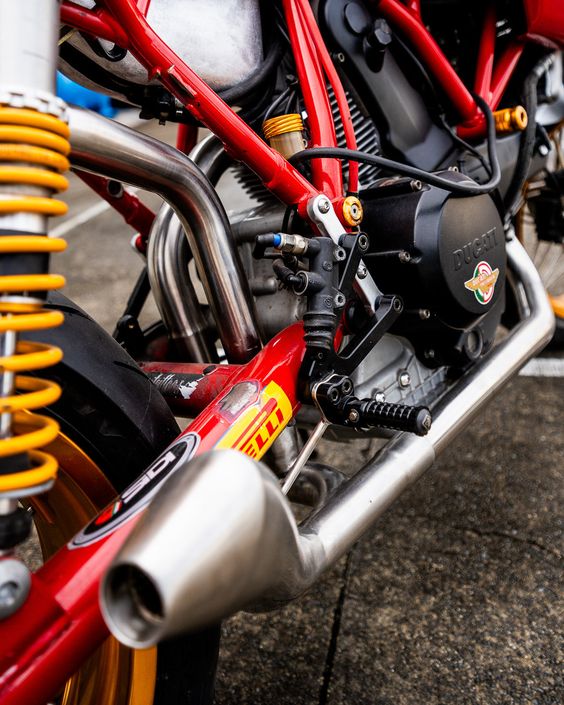
Hydroforming as a metal forming technology traces its origins back to the early 20th century. The method was initially developed for the production of complex and lightweight components in the automotive industry. As car manufacturers sought to create more aerodynamic and fuel-efficient vehicles, the need for lightweight metal parts with intricate shapes increased, giving rise to the hydroforming process.
The early stages of hydroforming technology were limited to tube hydroforming, where hollow metal tubes were shaped by hydraulic fluid pressure. This process allowed manufacturers to create lightweight yet strong frames for cars, which became especially important as the automotive industry began to focus on fuel economy and crash safety.
One of the major milestones in the evolution of hydroforming came in the 1950s when General Motors began utilizing the process for mass production of automotive parts. The introduction of the sheet hydroforming process further expanded the possibilities for the technology, allowing manufacturers to shape metal sheets into even more complex geometries. This marked the transition from tube hydroforming to sheet metal applications, broadening the use of the technology across industries such as aerospace and construction.
As materials and hydraulic technologies advanced, so did hydroforming techniques. By the 1990s, high-pressure hydroforming became a standard in automotive manufacturing, providing the precision and efficiency required to mass-produce complex parts such as engine cradles, exhaust systems, and chassis components.
In recent years, hydroforming technology has continued to evolve in response to the demand for more sustainable and efficient manufacturing processes. Today, hydroforming presses are highly automated, integrated with computerized controls and sensors that allow manufacturers to optimize production while reducing material waste. Advances in high-strength materials and digital technology have further enhanced the capabilities of hydroforming, making it one of the most important metal-forming techniques in modern manufacturing.
How Hydroforming Press Works
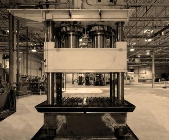
The hydroforming process, while innovative, is rooted in a simple principle: using hydraulic fluid pressure to mold metal into a die. The hydroforming press applies pressure uniformly, ensuring the metal conforms perfectly to the shape of the die, producing highly precise parts with a smooth surface finish.
Components of a Hydroforming Press
A typical hydroforming press consists of several key components:
- Hydraulic System: This is the core of the hydroforming press, responsible for generating the high-pressure fluid required to shape the metal.
- Die: The die is the mold into which the metal is shaped. Dies can be custom-designed to create specific geometries and contours.
- Blank Holder: This component holds the metal sheet or tube in place during the forming process.
- Control System: Modern hydroforming presses are equipped with advanced computerized control systems that monitor and adjust pressure, speed, and timing for optimal results.
The Hydroforming Process
The process typically involves the following steps:
- Material Preparation: A metal blank, either a sheet or tube, is placed into the hydroforming press.
- Die Closing: The die is closed around the metal, creating a sealed cavity.
- Pressurization: Hydraulic fluid is injected into the metal cavity at high pressure, causing the metal to expand and conform to the shape of the die.
- Shaping: The metal is held under pressure for a specified time to ensure the material forms to the desired shape.
- Release: Once the part is fully formed, the hydraulic pressure is released, and the die opens, allowing the part to be removed.
The precision offered by hydroforming presses is unparalleled. The press can apply uniform pressure across the entire surface of the metal, resulting in parts that are consistent in thickness, free from wrinkles or imperfections, and have a smooth finish. The ability to create complex shapes with minimal secondary processing gives hydroforming an edge over traditional forming methods such as stamping or forging.
Introduction to Hydroforming Press
Hydroforming is a highly specialized and advanced metal forming technique used in the manufacturing industry. The process involves shaping malleable metals into intricate, lightweight, and durable structures using high-pressure hydraulic fluids. By applying uniform pressure on the metal, it allows manufacturers to create precise and complex geometries that are difficult to achieve with traditional methods such as stamping, forging, or casting.
The hydroforming press is the central machine used in this process, employing hydraulic fluid to mold metal sheets or tubes into predefined shapes. The versatility of these presses makes them critical to industries that demand precision and high performance, such as the automotive, aerospace, and construction sectors. Whether it is the creation of lightweight car body panels, aircraft fuselage components, or architectural elements, hydroforming presses are essential for manufacturing parts that combine strength, lightweight properties, and complex design.
Hydroforming has revolutionized modern manufacturing. With a focus on efficiency and sustainability, industries across the globe are turning to hydroforming presses to create stronger, more aerodynamic parts, with fewer components, reduced material waste, and lower production costs. This process is particularly valued for its ability to form entire components from a single metal blank, minimizing the need for welding or joining multiple parts.
The rise in the popularity of hydroforming presses is also driven by the increasing demand for eco-friendly and energy-efficient manufacturing processes. With lighter, stronger components being key to reducing fuel consumption and improving vehicle safety, particularly in the automotive and aerospace industries, the role of the hydroforming press in helping manufacturers meet these goals is indispensable.
In summary, hydroforming presses have emerged as a critical tool in today’s manufacturing landscape. They offer high precision, versatility, and cost-effectiveness while reducing waste and simplifying the production process. As global industries continue to evolve and focus on sustainable practices, hydroforming technology will remain at the forefront of innovation in metal forming.
History and Evolution of Hydroforming
Hydroforming has its roots in the early 20th century when the need for more advanced metal forming techniques began to grow, particularly in the automotive industry. As car manufacturers sought to design vehicles with improved aerodynamics, fuel efficiency, and safety, they needed a metalworking process capable of creating lightweight yet strong components. The hydroforming process provided the ideal solution, enabling manufacturers to form complex shapes from metal sheets and tubes with reduced material waste.
The first significant use of hydroforming was in the automotive sector during the 1930s. Early developments in hydroforming focused on tube hydroforming, where metal tubes were placed inside a die and shaped by hydraulic fluid pressure. This method allowed manufacturers to create vehicle frame components that were both lighter and stronger than those produced through traditional metal forming techniques such as stamping or forging.
The technology evolved significantly in the 1950s when General Motors pioneered its use in mass production. GM used hydroforming presses to create complex automotive parts, such as structural frames and engine cradles, which required high strength and precision. The process proved to be a breakthrough in manufacturing, enabling mass production of lightweight components that were also more durable.
During the 1980s and 1990s, hydroforming technology expanded further into other industries, particularly aerospace, where the demand for lightweight and strong components grew exponentially. Advances in hydraulic systems and materials science allowed manufacturers to utilize hydroforming for sheet metal, enabling them to produce large, intricate structures like fuselage panels, bulkheads, and wing components for aircraft.
The development of high-pressure hydroforming in the 1990s marked another major milestone. This technique allowed manufacturers to use even higher pressures to shape metals like aluminum, titanium, and high-strength steels into more complex shapes. The ability to work with stronger, lighter materials opened new possibilities in industries such as aerospace and automotive, where weight reduction is crucial for improving fuel efficiency and performance.
The 21st century saw further advancements in hydroforming presses, particularly with the rise of Industry 4.0, where digital technologies such as computer-aided design (CAD), computer numerical control (CNC), and automation were integrated into manufacturing. Today, modern hydroforming presses are highly automated, enabling precise control of pressure, timing, and material properties during the forming process. These innovations have not only improved the quality of parts but also reduced production times and costs, making hydroforming an essential technology for mass production.
The evolution of hydroforming continues as researchers and manufacturers explore new materials, techniques, and applications. From its origins in the automotive industry to its current role in aerospace, construction, and other high-tech sectors, hydroforming has proven to be a versatile and sustainable solution for modern manufacturing needs.
How Hydroforming Press Works
Hydroforming is a sophisticated metal forming process that relies on hydraulic fluid pressure to shape malleable metals into complex forms. The process involves using a hydroforming press, a machine that generates the necessary pressure to mold metals such as aluminum, stainless steel, and copper. The ability to form intricate shapes with high precision makes hydroforming an invaluable process in industries that demand structural integrity, lightweight designs, and cost-effective production.
Key Components of a Hydroforming Press
A hydroforming press consists of several essential components that work together to execute the process:
- Hydraulic System: The hydraulic system generates the high-pressure fluid required for forming the metal. The hydraulic fluid is typically oil or water-based, depending on the specific application.
- Die: The die is a mold designed to shape the metal into the desired form. It consists of two halves—upper and lower—that close around the metal during the process.
- Blank Holder: The blank holder holds the metal sheet or tube in place while the hydraulic pressure is applied. It ensures that the metal remains stable throughout the forming process.
- Control System: Modern hydroforming presses are equipped with computerized control systems that monitor pressure, temperature, and other variables. These systems ensure precision and consistency during production.
The Hydroforming Process: Step-by-Step
The hydroforming process can be broken down into the following key steps:
- Material Preparation: A metal blank, which can either be a flat sheet or a tube, is placed inside the hydroforming press. This blank serves as the raw material that will be shaped into the final part.
- Die Closing: The two halves of the die are closed around the metal blank, creating a sealed chamber that defines the shape of the part being formed.
- Pressurization: Hydraulic fluid is pumped into the sealed chamber at very high pressure. For tube hydroforming, the fluid is injected inside the tube, causing it to expand outward against the die walls. For sheet hydroforming, the pressure is applied uniformly over the entire sheet, forcing it into the contours of the die.
- Shaping: The hydraulic pressure is maintained for a specific amount of time to ensure that the metal fully conforms to the shape of the die. This step requires precise control of pressure and timing to achieve optimal results.
- Release: Once the part is fully formed, the hydraulic pressure is released, and the die is opened. The finished part is removed from the press, and the process is repeated for the next blank.
Tube Hydroforming vs. Sheet Hydroforming
There are two main types of hydroforming: tube hydroforming and sheet hydroforming. While both processes rely on hydraulic pressure to shape metal, they differ in the type of material used and the specific applications.
- Tube Hydroforming: This process involves shaping hollow metal tubes by injecting hydraulic fluid inside the tube to expand it outward into the shape of the die. Tube hydroforming is widely used in the automotive industry to create components such as exhaust systems, chassis parts, and engine cradles. It is ideal for producing parts with complex cross-sections and varying diameters.
- Sheet Hydroforming: In this method, flat metal sheets are placed in the die and formed by applying uniform pressure over the entire sheet. Sheet hydroforming is often used in the aerospace and appliance industries to produce lightweight, high-strength components like aircraft panels, structural supports, and appliance housings.
Advantages of Hydroforming Press
One of the major advantages of hydroforming is its ability to create complex shapes with high precision and minimal waste. Traditional metal forming techniques like stamping or casting often result in uneven thickness, wrinkles, or imperfections, but hydroforming ensures uniform thickness and smooth surfaces. This precision reduces the need for secondary finishing processes, such as machining or welding.
In addition, hydroforming offers significant material savings. By forming parts from a single piece of metal, it eliminates the need for multiple components and reduces the amount of scrap material generated. This makes hydroforming an eco-friendly and cost-effective solution for manufacturers.
Moreover, the strength-to-weight ratio of hydroformed parts is superior to that of parts produced using conventional methods. This is especially important in industries like automotive and aerospace, where reducing weight without compromising strength can improve fuel efficiency and performance.
Types of Hydroforming Presses
Hydroforming presses come in several types, each designed for specific applications and industries. The two main categories are tube hydroforming and sheet hydroforming, but within these broad categories, different processes and press designs are used to meet various manufacturing requirements. Understanding the types of hydroforming presses available helps manufacturers select the most appropriate technology for their needs.
1. Tube Hydroforming Press
Tube hydroforming is the most commonly used form of hydroforming, particularly in industries such as automotive and aerospace, where hollow components with complex cross-sectional shapes are needed. Tube hydroforming presses are specifically designed to form tubular metal components by using internal hydraulic pressure to force the tube into the shape of the die.
- Low-Pressure Tube Hydroforming: In low-pressure tube hydroforming, moderate hydraulic pressures are used, typically under 100 MPa (mega pascals). This method is ideal for forming larger, more straightforward shapes, such as automotive exhaust systems and seat frames. Low-pressure hydroforming presses are less expensive and simpler to operate compared to high-pressure presses.
- High-Pressure Tube Hydroforming: High-pressure tube hydroforming involves the use of much higher hydraulic pressures (up to 400 MPa or more) to form intricate parts with tight tolerances and complex geometries. This method is ideal for creating vehicle chassis components, structural supports, and aerospace parts, where precision and strength are crucial. High-pressure presses are equipped with sophisticated control systems to ensure the metal expands uniformly, preventing wrinkling or thinning of the material.
2. Sheet Hydroforming Press
Sheet hydroforming is used to shape metal sheets into precise forms by applying uniform pressure over the entire surface. Sheet hydroforming presses are ideal for producing large, complex components with high strength and minimal weight.
- Hydro-mechanical Forming: In hydro-mechanical forming, a punch is used in combination with hydraulic fluid pressure. The punch shapes the sheet metal against a die, while the hydraulic fluid provides the force necessary to form the sheet without causing wrinkles or imperfections. This process is ideal for producing parts with deep draws or complex curves, commonly seen in the aerospace industry.
- Fluid-Cell Forming: This type of sheet hydroforming uses a flexible rubber diaphragm instead of a punch. The diaphragm, along with hydraulic fluid, pushes the sheet metal into the die to form the desired shape. Fluid-cell forming presses are often used for smaller-scale production runs or for prototyping new parts. This method is versatile and allows for rapid tool changes, making it ideal for industries that require frequent design adjustments.
3. High-Pressure Hydroforming
In addition to the standard tube and sheet hydroforming presses, some applications require high-pressure hydroforming presses. These presses are capable of exerting extreme hydraulic pressures to shape high-strength materials such as titanium, Inconel, and advanced aluminum alloys. High-pressure hydroforming is essential for industries like aerospace and defense, where lightweight and high-strength components are necessary for optimal performance.
4. Double Action Hydroforming Presses
Double-action presses are a type of hydroforming press equipped with two hydraulic systems, one for the initial shaping and another for applying pressure to fine-tune the component. This is especially useful in forming parts that require precise control over material flow, such as structural members with complex shapes.
Double-action presses offer a high level of control and versatility, making them ideal for applications that require parts with varying wall thicknesses or multiple curves. These presses are used in both tube and sheet hydroforming and are popular in industries that require parts with complex geometries, such as automotive chassis, aircraft fuselage components, and architectural elements.
5. Bladder Hydroforming
Bladder hydroforming is a specialized process where a rubber bladder filled with hydraulic fluid is used to form sheet metal. The bladder presses the sheet into the die, forming the part. Bladder hydroforming is commonly used for forming smaller, high-precision parts such as electronic components or medical devices. This type of press is highly accurate and reduces the risk of surface damage to delicate materials.
Applications of Hydroforming
Hydroforming is used in a wide range of industries, from automotive and aerospace to consumer products and electronics. Its ability to create lightweight, strong, and complex parts has made it a preferred manufacturing method across numerous sectors.
1. Automotive Industry
The automotive industry was one of the first adopters of hydroforming technology, and it remains one of the largest users of hydroforming presses today. Manufacturers use hydroforming to produce key components such as:
- Chassis and Structural Components: Hydroformed chassis parts, including engine cradles, subframes, and suspension systems, are designed to be lightweight yet strong. This contributes to better vehicle handling, improved crash safety, and reduced fuel consumption.
- Exhaust Systems: Tube hydroforming is extensively used to create exhaust manifolds, mufflers, and catalytic converter systems. The ability to form complex shapes without welding multiple parts reduces assembly time and improves the durability of these systems.
- Body Panels: Hydroforming also allows for the creation of aerodynamic body panels with intricate curves and shapes, such as fenders, hoods, and doors. These components are both lightweight and aesthetically pleasing.
The use of hydroformed parts in vehicles improves fuel efficiency by reducing the overall weight of the car. Additionally, hydroformed components offer greater crash protection due to their increased strength and rigidity, which are essential for meeting modern safety standards.
2. Aerospace Industry
In the aerospace sector, weight reduction is critical to improving fuel efficiency and overall performance. Hydroforming is used to create high-strength, lightweight components for aircraft, including:
- Fuselage Panels and Bulkheads: Hydroforming presses produce large, thin-walled components that are structurally sound yet light enough to reduce fuel consumption.
- Wing Components: Sheet hydroforming allows manufacturers to create complex wing shapes that improve aerodynamics.
- Engine Parts: Aerospace engines require components that can withstand extreme temperatures and pressures. High-pressure hydroforming is used to create intricate parts from high-strength materials such as titanium and Inconel.
The precision and strength of hydroformed parts are critical for aircraft performance, safety, and fuel economy. The process also reduces the number of parts needed, simplifying assembly and maintenance.
3. Construction and Architecture
Hydroforming is also used in the construction and architecture industries to create custom, aesthetically complex metal structures. Architectural components such as:
- Building Façades: Hydroformed metal panels are used to create unique building exteriors with smooth, flowing lines and curves.
- Structural Supports: Hydroforming enables the creation of strong yet lightweight support beams for large structures, reducing the need for heavy materials.
The ability to create customized, visually appealing metal components has made hydroforming a popular choice for architects looking to design modern, innovative buildings.
4. Other Applications
Beyond automotive, aerospace, and construction, hydroforming is also used in:
- Medical Devices: Bladder hydroforming is used to create precision components for medical devices, such as surgical instruments and implants, where high accuracy and smooth finishes are essential.
- Consumer Electronics: Small, complex metal casings and structural components for electronics are often formed using hydroforming presses. These components are lightweight, durable, and allow for sleek, compact designs.
- Sporting Goods: High-performance bicycles, golf clubs, and other sporting equipment often incorporate hydroformed parts that are both lightweight and strong, improving performance and durability.
Advantages of Hydroforming
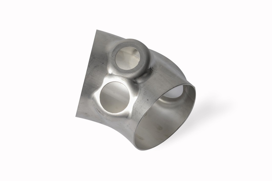
Hydroforming offers several key advantages over traditional metal forming methods, making it a preferred manufacturing process for industries that require precision, cost-efficiency, and high-performance components. The following are some of the primary benefits of using hydroforming presses.
1. Precision and Efficiency
One of the standout advantages of hydroforming is its ability to produce highly precise components with uniform thickness and minimal defects. The use of hydraulic fluid pressure ensures that the metal conforms perfectly to the die, resulting in parts with smooth surfaces and consistent dimensions. This level of precision reduces the need for secondary machining processes, such as trimming or welding, which in turn improves overall production efficiency.
The efficiency of hydroforming is further enhanced by its ability to form entire parts from a single piece of metal. Traditional metal forming methods often require multiple steps to achieve complex shapes, whereas hydroforming can produce intricate geometries in a single operation. This reduces production time and minimizes the need for assembly, leading to faster turnaround times and lower labor costs.
2. Cost-Effectiveness
Hydroforming is also a cost-effective manufacturing process. By reducing the number of parts required for assembly and eliminating the need for additional processes such as welding, hydroforming helps manufacturers save on materials and labor costs. Additionally, the high precision of the process reduces waste, as there is less need to discard defective parts or scrap material.
The material savings associated with hydroforming are significant, particularly for industries such as automotive and aerospace, where lightweight metals like aluminum and titanium are used extensively. Hydroforming allows manufacturers to use thinner materials while maintaining the necessary strength and structural integrity of the part, resulting in lower material costs.
Challenges and Limitations
Despite its numerous advantages, hydroforming is not without its challenges and limitations. While the process offers great precision, efficiency, and cost-effectiveness, there are technical and practical factors that manufacturers need to consider before choosing hydroforming presses for their production lines.
1. Material Constraints
Hydroforming works best with malleable materials, such as aluminum, stainless steel, brass, and titanium. However, not all metals respond well to the high-pressure process. For example, materials with low ductility or those that are prone to cracking or splitting under stress may not be suitable for hydroforming. High-strength steels and certain alloys can pose difficulties because they require higher pressures to deform, which may exceed the capacity of the available hydroforming presses.
Additionally, the thickness of the material plays a significant role in determining the feasibility of hydroforming. While hydroforming excels in shaping thin metal sheets and tubes, it is less effective with thicker materials, which may require more force and can lead to uneven shaping or defects such as tearing or thinning of the metal.
2. High Initial Investment
The upfront costs of hydroforming equipment can be substantial, especially for high-pressure or advanced presses equipped with automation and computerized control systems. For smaller manufacturers or those with limited budgets, the cost of purchasing and maintaining hydroforming presses may be a barrier to adopting the technology. Additionally, designing and manufacturing the custom dies required for hydroforming adds to the overall expense.
In many cases, the high initial investment is justified by long-term savings in material and production costs. However, for manufacturers who produce smaller volumes of parts or those with simpler design requirements, traditional metal forming methods such as stamping or forging may be more cost-effective.
3. Complex Tooling and Setup
The design and fabrication of hydroforming dies are complex and require high precision to ensure that the final part meets the desired specifications. The development of these dies can be time-consuming and costly, particularly for highly customized parts with intricate shapes. In some cases, multiple iterations of die design may be required to achieve optimal results, leading to longer lead times and increased costs.
Additionally, setting up and calibrating hydroforming presses requires a high level of expertise and precision. This setup process can be time-consuming, especially when transitioning between different part designs. For manufacturers who need to produce a wide range of parts in quick succession, the setup times for hydroforming may be a limiting factor compared to more straightforward forming processes.
4. Limited Application for Thick Materials
While hydroforming is highly effective for thin-walled materials, it is less suited for forming thick materials or very rigid metals. When working with thick materials, there is a risk of the part not forming evenly, leading to defects like thinning or cracking. Traditional methods such as stamping, casting, or forging may be more appropriate for these applications, where higher forces are needed to shape the material effectively.
Hydroforming vs. Traditional Press Methods
Hydroforming stands out as an advanced metal forming technique, but how does it compare with traditional press methods such as stamping, forging, and casting? While each method has its strengths, hydroforming offers distinct advantages in certain applications. Understanding these differences helps manufacturers decide when hydroforming is the best option.
1. Hydroforming vs. Stamping
Stamping is one of the most common metal forming processes used in manufacturing. It involves using a mechanical or hydraulic press to force a flat sheet of metal into a die to create the desired shape. Stamping is efficient for producing large quantities of simple parts quickly and is widely used in industries like automotive and appliance manufacturing.
- Material Usage: Stamping typically results in higher material waste than hydroforming. In stamping, excess material is often trimmed away, creating scrap that must be recycled or discarded. Hydroforming, on the other hand, uses the entire metal blank with minimal material loss, making it a more environmentally friendly process.
- Part Complexity: Hydroforming excels in creating parts with complex, three-dimensional shapes that are difficult to achieve with stamping. Stamping is limited to relatively simple geometries and may require additional steps, such as welding or machining, to create more intricate designs. Hydroforming produces these shapes in a single operation, reducing the need for secondary processes.
- Precision and Surface Finish: Hydroforming provides a superior surface finish and greater precision than stamping. The hydraulic pressure used in hydroforming evenly distributes forces across the metal, resulting in parts that have uniform thickness and smooth surfaces. Stamped parts often require additional finishing work to correct imperfections and remove rough edges.
2. Hydroforming vs. Forging
Forging involves shaping metal by applying compressive forces, usually by hammering or pressing the metal between dies. It is a process that produces very strong parts and is used extensively in the aerospace, automotive, and heavy machinery industries.
- Strength vs. Weight: Forging produces parts with exceptional strength because the metal is shaped under extreme pressure, which aligns its grain structure. However, forged parts are often heavier than those produced through hydroforming. In applications where reducing weight is a priority (such as in automotive and aerospace industries), hydroformed parts offer a better strength-to-weight ratio.
- Production Efficiency: Hydroforming is more efficient than forging for producing complex parts in high volumes. Forging may require multiple stages to achieve a final shape, whereas hydroforming can create intricate shapes in a single step. This reduces the number of processes needed, thus speeding up production times and reducing costs.
- Material Flexibility: Forging is more versatile in terms of the range of materials that can be used, especially for high-strength metals and alloys. Hydroforming is typically limited to more ductile metals, such as aluminum and stainless steel, which can be shaped without cracking or deforming.
3. Hydroforming vs. Casting
Casting is a process where molten metal is poured into a mold and allowed to solidify into the desired shape. This method is commonly used for creating large, complex parts and components in industries such as automotive, construction, and machinery.
- Surface Quality and Precision: Hydroforming provides superior surface quality and precision compared to casting. Cast parts often require extensive post-processing to remove surface defects and ensure dimensional accuracy. Hydroforming produces parts with a smooth finish and consistent thickness without the need for additional machining.
- Material Properties: While casting can produce strong and durable parts, hydroformed parts tend to have better mechanical properties, such as higher fatigue strength. The cold-forming process of hydroforming ensures that the material’s grain structure is not disrupted, leading to stronger and more resilient parts.
- Cost and Time Efficiency: Casting is a slower process compared to hydroforming and is typically more labor-intensive. While casting is ideal for low-volume production or for creating very large parts, hydroforming is more efficient for high-volume production runs and for parts that require tight tolerances and complex geometries.
In conclusion, while traditional methods like stamping, forging, and casting have their strengths, hydroforming offers distinct advantages when it comes to producing lightweight, complex, and high-precision parts. The choice between these methods ultimately depends on the specific requirements of the project, including material, design complexity, and production volume.
Hydroforming in Industry 4.0
Industry 4.0 represents the integration of digital technologies into manufacturing processes, leading to smarter, more efficient production lines. As manufacturers adopt automation, artificial intelligence (AI), and data analytics, hydroforming technology has also evolved to meet the demands of this new industrial era. The combination of hydroforming presses with advanced digital technologies has improved production efficiency, product quality, and flexibility.
1. Automation and Smart Hydroforming Presses
Modern hydroforming presses are increasingly equipped with automated systems that streamline production and reduce human error. Automated tool change systems allow for rapid transitions between different part designs, minimizing downtime and increasing overall production efficiency. Additionally, automation enhances consistency in the production process, ensuring that each part meets exact specifications.
Smart hydroforming presses are also integrated with sensors and monitoring systems that collect real-time data during the forming process. These sensors track variables such as pressure, temperature, and material flow, allowing manufacturers to make immediate adjustments to optimize performance. If a part shows signs of wrinkling or thinning, for example, the system can automatically adjust the pressure or cycle time to correct the issue.
2. AI and Machine Learning
Artificial intelligence and machine learning are transforming hydroforming by enabling predictive maintenance and process optimization. AI algorithms analyze data from previous production runs to predict potential equipment failures, allowing manufacturers to schedule maintenance before a breakdown occurs. This reduces unplanned downtime and extends the life of the hydroforming press.
Machine learning algorithms also help optimize the hydroforming process by analyzing patterns in production data. These algorithms can identify the most efficient settings for hydraulic pressure, die design, and cycle times, reducing trial and error and improving the quality of the final product.
3. Digital Twins
Digital twin technology is another key innovation in Industry 4.0. A digital twin is a virtual replica of a physical asset, in this case, a hydroforming press. By creating a digital twin of the press, manufacturers can simulate the entire hydroforming process in a virtual environment. This allows them to test different die designs, material properties, and process parameters before physically running the press.
Digital twins help reduce the costs and time associated with prototyping and process optimization. Manufacturers can fine-tune their processes digitally, making adjustments to ensure the best possible outcome without wasting materials or machine time. Once the optimal settings are identified, they can be applied to the physical press for real-world production.
The Future of Hydroforming in Industry 4.0
As Industry 4.0 technologies continue to advance, hydroforming will become even more integrated into smart manufacturing ecosystems. The use of robotic automation, AI-driven optimization, and real-time data analytics will make hydroforming presses more flexible, efficient, and capable of handling complex tasks. Manufacturers will be able to produce a wider range of parts, faster and with greater precision than ever before.
The future of hydroforming lies in its ability to adapt to changing industry needs, especially in sectors like automotive and aerospace, where demands for lightweight, strong, and eco-friendly components are growing. Industry 4.0 will enable hydroforming presses to operate in a more responsive and adaptive way, ensuring that manufacturers can meet the challenges of modern production with greater ease.
Conclusion
The hydroforming press is a pivotal piece of technology in modern manufacturing, offering the ability to create lightweight, strong, and complex components with high precision. Its advantages in terms of material efficiency, cost-effectiveness, and design flexibility make it an indispensable tool across industries such as automotive, aerospace, construction, and electronics.
From its origins in the automotive industry to its current applications in high-tech sectors, hydroforming has evolved to meet the needs of modern manufacturing. The integration of advanced technologies such as automation, AI, and digital twins has further enhanced its capabilities, making hydroforming a key process in the era of Industry 4.0.
As industries continue to focus on sustainability, fuel efficiency, and reducing waste, hydroforming will remain a vital technology in the creation of next-generation products. Its ability to form complex shapes with minimal material use positions it as a leader in environmentally friendly and cost-efficient manufacturing solutions.
In conclusion, the hydroforming press is not just a manufacturing tool, but a critical innovation that continues to shape the future of global production. Its adaptability, precision, and sustainability make it a cornerstone of modern industrial processes, ensuring its relevance for years to come.
Introduction to Hydroforming
Hydroforming is a specialized metal forming process that utilizes high-pressure hydraulic fluid to shape metals into complex geometries. The technique is widely used in industries such as automotive, aerospace, and electronics, where lightweight, strong, and intricate components are required. By using hydraulic pressure to form materials such as aluminum, steel, and brass, hydroforming offers several advantages, including the ability to produce lightweight components with uniform thickness and improved structural integrity.
The hydroforming process is a multi-stage procedure, involving precise control of pressure, material properties, and die design to achieve the desired shape. Whether it is sheet hydroforming, where metal sheets are shaped into parts, or tube hydroforming, where hollow tubes are expanded into complex geometries, the process relies on accurate coordination of hydraulic systems, dies, and control mechanisms. The result is a high-quality part that requires minimal secondary operations, such as welding or machining.
This guide will walk through the hydroforming process step by step, covering everything from material preparation and die design to fluid injection and post-processing. The aim is to provide a comprehensive understanding of how hydroforming works, the technology behind it, and the role of each stage in shaping metal components efficiently and precisely.
Material Preparation
The first step in any hydroforming process is material preparation. The choice of material and its initial condition are critical to the success of the process, as the metal must be capable of withstanding high hydraulic pressures while conforming to the complex shapes required by the die.
Material Selection
The materials typically used in hydroforming are metals that exhibit good ductility and malleability, allowing them to stretch or expand without cracking or tearing. Common materials include:
- Aluminum: Widely used in automotive and aerospace industries for its lightweight properties.
- Stainless Steel: Chosen for its strength and corrosion resistance, often used in medical devices and food-processing equipment.
- Brass and Copper: Used for their excellent formability and appearance, common in plumbing and decorative applications.
- High-strength Steel: Increasingly used in automotive applications to create parts that need both strength and low weight.
The choice of material depends on the application’s requirements, including factors such as strength, weight, corrosion resistance, and the complexity of the part being formed. Materials with higher ductility are preferred, as they can withstand the stresses imposed during the hydroforming process without failing.
Tube Hydroforming vs. Sheet Hydroforming Materials
- Tube Hydroforming: This method is typically used for forming hollow structures, such as automotive frames or exhaust systems. The tubes used in hydroforming must have uniform wall thickness to ensure that the expansion under hydraulic pressure is even across the length of the tube. Pre-cut tubes made of aluminum, steel, or titanium are commonly used, depending on the application.
- Sheet Hydroforming: Flat metal sheets are used for creating more complex shapes, such as body panels or enclosures. These sheets are often pre-cut to the required size and are checked for uniform thickness, surface finish, and mechanical properties.
Pre-Treatment of Metals
Before hydroforming can begin, the metal must be properly prepared. This involves cleaning the metal surfaces to remove any oils, contaminants, or debris that could interfere with the forming process or damage the dies. Surface treatment methods include:
- Degreasing: Removing any lubricants or oils that may have been applied during previous processes.
- Pickling: A chemical process used to remove oxides and scale from the metal’s surface.
- Surface Coating: In some cases, a thin layer of lubricant is applied to reduce friction during the forming process.
By ensuring that the metal is clean and properly conditioned, manufacturers can prevent defects and ensure that the material forms correctly during the hydroforming process.
Die Design and Setup
At the core of the hydroforming process is the die, the tool that defines the final shape of the part. The design and setup of the die are critical to ensuring that the part forms correctly and meets the required specifications.
Importance of Die Design in Hydroforming
The die is essentially a mold made of two halves (the upper and lower dies) that close around the metal to form it into the desired shape. During hydroforming, the hydraulic pressure forces the metal to conform to the contours of the die, creating a precise part. Therefore, the accuracy and quality of the die are paramount in determining the success of the process.
When designing a die, several factors need to be considered:
- Geometry: The die must accurately reflect the desired shape of the final part, including complex curves, holes, and varying thicknesses. Any imperfections in the die will translate directly into the part.
- Tolerances: High precision is required in the die design, especially for parts that will be used in industries like aerospace and automotive, where tight tolerances are essential for safety and performance.
- Flow Path: The die must be designed to ensure that the metal flows smoothly under hydraulic pressure, minimizing defects like wrinkles, tears, or thinning.
Types of Dies
There are two main types of dies used in hydroforming:
- Rigid Dies: These dies are made from hard materials such as tool steel and are used to create parts with complex, high-precision geometries. Rigid dies are durable and capable of withstanding the high pressures involved in hydroforming. They are commonly used in high-pressure tube hydroforming and sheet hydroforming processes.
- Flexible Dies: Also known as fluid dies or bladder dies, these are used in low-pressure hydroforming applications. The flexible die is often a rubber diaphragm or a liquid-filled bladder that presses the material into the shape of a rigid form or cavity. This type of die is useful for producing less complex parts or prototyping.
Die Materials and Manufacturing
Dies are typically manufactured from materials that are strong, wear-resistant, and capable of withstanding the high pressures of hydroforming. Common die materials include:
- Tool Steel: Known for its durability and hardness, tool steel is commonly used in dies for high-pressure hydroforming processes.
- Alloy Steel: Often used when toughness is required, alloy steel can resist both pressure and thermal stresses, making it suitable for forming tougher materials like high-strength steel.
- Carbide: For extremely high wear resistance, carbide-tipped dies are sometimes used, especially in industries like aerospace where precision is critical.
The die-making process involves several stages:
- CAD Design: The part is designed using computer-aided design (CAD) software to ensure accuracy and to simulate how the metal will behave during the hydroforming process.
- CNC Machining: Once the design is finalized, the die is fabricated using computer numerical control (CNC) machining to achieve the necessary precision and surface finish.
- Heat Treatment: Depending on the material, the die may undergo heat treatment to enhance its hardness and durability.
Die setup involves mounting the die into the hydroforming press and ensuring it is properly aligned and calibrated to ensure the metal forms correctly. Any misalignment or imperfections in the die setup can lead to defects in the final part.
Loading and Clamping
Once the material and die are ready, the next step in the hydroforming process is loading the material into the press and clamping it in place. This stage is critical to ensuring that the material remains stable and properly positioned throughout the process.
Loading the Material
- Tube Hydroforming: For tube hydroforming, a hollow metal tube is placed inside the die cavity. The tube must be pre-cut to the correct length, and its ends are often sealed to prevent hydraulic fluid from escaping during the forming process. This ensures that the internal pressure can expand the tube uniformly within the die.
- Sheet Hydroforming: In sheet hydroforming, a flat sheet of metal is placed on top of the die. The sheet must be positioned carefully to ensure that it aligns with the die’s contours, as even slight misalignment can lead to defects in the final part.
Clamping Mechanisms
Clamping is an essential step in both tube and sheet hydroforming. The purpose of clamping is to hold the material firmly in place, preventing it from moving or shifting as hydraulic pressure is applied. Effective clamping ensures that the metal conforms to the die shape uniformly.
- Blank Holders: In sheet hydroforming, a blank holder is used to press the metal sheet against the die. The blank holder applies pressure around the edges of the sheet, preventing it from wrinkling or slipping during the forming process. This ensures that the metal is forced evenly into the die’s contours.
- End Plugs: For tube hydroforming, end plugs are inserted into the ends of the tube to seal it and prevent the hydraulic fluid from escaping. These plugs may also apply additional axial pressure to the tube, assisting in the expansion process.
The clamping force must be carefully controlled to ensure that it is sufficient to hold the material in place without deforming or damaging it. If the clamping force is too low, the material may move during the process, resulting in defects. If the force is too high, it can lead to excessive thinning or tearing of the metal.
Fluid Injection
The defining characteristic of hydroforming is the use of hydraulic fluid to apply pressure to the metal. This stage, known as fluid injection, is where the metal is shaped into its final form by forcing it into the die under high pressure.
The Role of Hydraulic Fluid
Hydraulic fluid is the medium through which pressure is applied to the metal in hydroforming. The fluid is typically oil-based, although in some applications water or other specialized fluids are used. The fluid must be able to withstand extremely high pressures without compressing or losing its effectiveness.
- Tube Hydroforming: In tube hydroforming, the hydraulic fluid is injected into the hollow interior of the tube. The pressure causes the tube to expand outward until it conforms to the shape of the die. In some cases, additional axial pressure may be applied to the ends of the tube to help control the material flow and prevent thinning or wrinkling.
- Sheet Hydroforming: In sheet hydroforming, the hydraulic fluid is applied to the surface of the metal sheet. The fluid exerts uniform pressure over the entire surface, forcing the sheet into the die and forming it into the desired shape.
Pressure Control and Monitoring
The success of the hydroforming process depends on the precise control of hydraulic pressure. Too little pressure may result in incomplete forming, while too much pressure can cause the metal to crack or tear. Modern hydroforming presses are equipped with pressure sensors and control systems that monitor and adjust the pressure in real time to ensure optimal forming conditions.
- Initial Pressurization: The process begins with the slow injection of hydraulic fluid into the die or tube. As the pressure builds, the metal begins to deform and take the shape of the die. The rate of pressurization is carefully controlled to prevent sudden deformation, which could lead to defects.
- Peak Pressure: Once the metal has begun to conform to the die, the pressure is gradually increased to its peak value. This peak pressure varies depending on the material being formed, the thickness of the metal, and the complexity of the part’s shape. Typical pressures for hydroforming range from 100 MPa to 800 MPa (14,500 to 116,000 psi), with high-pressure hydroforming reaching even higher values.
- Pressure Maintenance: In some cases, the hydraulic pressure is maintained for a certain period to ensure that the metal fully conforms to the die and to allow the material’s grain structure to settle. This holding phase is important for achieving uniform thickness and avoiding defects such as spring-back, where the metal tries to return to its original shape.
High-Pressure vs. Low-Pressure Hydroforming Fluid Systems
- Low-Pressure Hydroforming: This method uses relatively low hydraulic pressures, typically below 100 MPa. Low-pressure hydroforming is suitable for simpler shapes and is often used for tube hydroforming in automotive applications, such as creating exhaust manifolds and suspension components. The lower pressures reduce the risk of material failure, making it a more cost-effective option for high-volume production.
- High-Pressure Hydroforming: High-pressure hydroforming involves pressures exceeding 100 MPa and is used for more complex parts, especially in industries like aerospace where precision is critical. High-pressure systems allow for the formation of more intricate geometries, tighter tolerances, and stronger materials. This method requires advanced control systems and robust dies to withstand the extreme forces involved.
Shaping Process
The shaping process is the most critical stage of hydroforming. It is where the hydraulic pressure applied to the material forces it to conform to the shape of the die, resulting in the desired part. This section provides a detailed look at how the shaping process occurs in sheet hydroforming and tube hydroforming, along with the dynamics of expansion and pressurization.
Sheet Hydroforming Step-by-Step
In sheet hydroforming, a flat sheet of metal is formed into a complex, three-dimensional shape using hydraulic pressure. The process can be broken down into the following steps:
- Loading the Metal Sheet: A pre-cut metal sheet is loaded into the hydroforming press, placed over the lower die cavity. The die is designed to represent the negative space of the final part.
- Clamping and Sealing: The sheet is clamped tightly around the edges by a blank holder, ensuring it remains in place during the pressurization process. The blank holder also helps control the flow of metal to prevent wrinkling or excessive thinning during forming.
- Pressurization Begins: Hydraulic fluid, typically oil, is introduced into the chamber above the sheet. As the fluid fills the chamber, it begins to exert pressure evenly across the entire surface of the sheet. This pressure is what forces the metal down into the contours of the die.
- Metal Deformation: As the pressure increases, the metal begins to deform. The sheet stretches and flows into the die cavity, taking on the shape of the mold. The uniform application of pressure ensures that the metal does not wrinkle or develop imperfections as it forms.
- Maintaining Pressure: Once the metal sheet has fully conformed to the die, the hydraulic pressure is held at a high level for a specific duration. This holding phase allows the material to settle into its final shape, ensuring that any spring-back (the tendency of the metal to return to its original shape) is minimized.
- Decompression and Die Opening: After the part has fully formed, the hydraulic pressure is slowly released. The die is then opened, and the formed part is removed. The final piece will have taken on the exact shape of the die with precise dimensional accuracy and surface quality.
Tube Hydroforming Step-by-Step
Tube hydroforming is slightly different from sheet hydroforming because it deals with hollow tubes instead of flat sheets. The following steps outline the tube hydroforming process:
- Inserting the Tube: A pre-cut hollow tube is inserted into the hydroforming press. The tube is placed inside the die, which is designed to mold the tube into the desired shape.
- End Sealing and Clamping: The ends of the tube are sealed with end plugs to prevent the hydraulic fluid from escaping. The tube is then clamped securely to ensure that it remains stationary during the forming process.
- Hydraulic Fluid Injection: Hydraulic fluid is injected into the sealed tube under high pressure. This fluid fills the interior of the tube, causing it to expand outward against the walls of the die.
- Controlled Expansion: As the internal pressure builds, the tube begins to expand. The expansion must be carefully controlled to ensure that the tube forms uniformly and does not develop weak spots or areas of excessive thinning. In many cases, axial pressure is also applied to the ends of the tube to help guide the metal into the die without causing wrinkling or tearing.
- Forming the Part: The hydraulic pressure is gradually increased to the point where the tube fully conforms to the shape of the die. In high-pressure tube hydroforming, the internal pressure can reach several hundred MPa, depending on the material and the complexity of the part.
- Pressure Holding Phase: Similar to sheet hydroforming, the pressure is maintained for a set period to ensure that the metal settles into its final shape. This phase helps to prevent defects such as spring-back or uneven thickness.
- Pressure Release and Part Removal: Once the part has been fully formed, the hydraulic pressure is gradually released. The die opens, and the finished tube is removed. The tube now possesses the complex cross-section or geometric features that were designed into the die.
Expansion and Forming Dynamics
The key dynamic in both sheet and tube hydroforming is the controlled expansion of the metal under hydraulic pressure. Several factors influence how the metal deforms during this process:
- Material Properties: The ductility and tensile strength of the metal determine how it will behave under pressure. More ductile materials, such as aluminum, are more likely to expand uniformly without cracking, while higher-strength materials like stainless steel may require more precise control of pressure to avoid defects.
- Thickness of the Material: Thinner metals are more likely to wrinkle or tear if not handled properly, while thicker materials can resist deformation but may require higher pressures to shape. The thickness of the metal must be uniform to avoid uneven expansion, which can lead to defects.
- Pressure Gradient: The rate at which hydraulic pressure is applied plays a critical role in shaping the part. A slow, controlled increase in pressure allows the metal to expand evenly into the die, while a rapid increase can cause the material to deform too quickly, leading to wrinkles, thinning, or cracking.
- Axial Forces in Tube Hydroforming: In tube hydroforming, axial forces are applied to the ends of the tube to control material flow. This helps to distribute the material more evenly and prevents defects such as buckling or wrinkling at the tube’s ends.
Pressurization Timelines and Adjustments
One of the key advantages of hydroforming is the ability to precisely control the pressurization timeline. By adjusting the speed and amount of pressure, manufacturers can control how the material behaves during the forming process. This is critical for achieving the desired shape without defects.
For complex parts, the pressurization timeline may involve multiple stages, where the pressure is increased incrementally and held for short periods at different stages of the forming process. These adjustments are often based on real-time feedback from sensors embedded in the hydroforming press, which monitor the material’s response and adjust the pressure accordingly.
Cooling and Solidification
After the material has been shaped under high pressure, the cooling phase is essential to lock the material into its final shape and ensure its structural integrity. The cooling process helps manage any heat generated during the shaping process, which could otherwise affect the material’s properties.
Role of Cooling in Hydroforming
During hydroforming, especially in high-pressure applications, the material can become heated due to the intense friction and pressure involved in the process. While hydroforming generally does not generate as much heat as processes like welding or forging, the localized heat in certain areas can affect the material’s mechanical properties if not controlled. Cooling ensures that the metal retains its desired characteristics, such as hardness and strength, after forming.
In some cases, manufacturers use active cooling systems within the hydroforming press. These systems circulate coolants through the die or the hydraulic fluid to dissipate heat and regulate the temperature during the process. This is particularly important for materials that are sensitive to heat, such as aluminum or certain high-strength alloys, which may lose their structural integrity if exposed to excessive heat.
Heat Management and Its Impact on Material Integrity
Effective heat management is critical in hydroforming, especially when forming high-strength metals. If the material cools unevenly or too quickly, it can lead to defects such as warping or cracking. On the other hand, cooling too slowly may allow the material to retain residual stresses, which can weaken the part over time.
By carefully controlling the cooling process, manufacturers can ensure that the material retains its desired properties, such as:
- Dimensional Stability: Proper cooling prevents the material from shrinking or expanding after the part has been formed, ensuring that it meets the required dimensions.
- Surface Finish: Cooling also affects the surface quality of the part. A controlled cooling process helps prevent surface defects, such as oxidation or discoloration, which can occur if the material is exposed to high temperatures for extended periods.
Cooling may be a passive process, where the part is simply allowed to return to room temperature after forming, or it may involve active cooling systems that regulate temperature throughout the process.
Opening the Die and Part Removal
After the shaping and cooling phases are complete, the next step is opening the die and removing the finished part. This step must be done carefully to avoid damaging the part, especially if it has complex geometries or delicate features.
Die Separation Process
In most hydroforming presses, the die consists of two halves: an upper die and a lower die. After the part has been shaped and cooled, the hydraulic pressure is released, and the two halves of the die are slowly separated. This step must be performed with precision, as any sudden movement could damage the part or cause it to become stuck in the die.
Modern hydroforming presses are equipped with sensors and control systems that ensure the die opens evenly and at the right speed. In some cases, the die opening process is automated, allowing for greater consistency and reducing the risk of errors.
Ejecting and Removing the Formed Part
Once the die has been opened, the part must be carefully removed. For simpler parts, this is a straightforward process, where the part is lifted out of the die manually or with the help of automated extraction systems. However, for more complex parts with intricate geometries or sharp angles, removing the part can be more challenging.
- Ejection Pins: In some hydroforming processes, ejection pins are used to push the part out of the die. These pins are strategically placed to ensure the part is ejected evenly and without distortion. The location and force of the ejection pins must be carefully controlled to avoid damaging the part.
- Robotic Assistance: In advanced hydroforming presses, robotic arms are sometimes used to extract the part from the die. These robotic systems are programmed to handle the part delicately, ensuring that it is removed without damage.
Challenges in Extracting Complex Geometries
For parts with complex geometries, removing the formed part from the die can be difficult. Sharp corners, deep recesses, or intricate curves may cause the part to become stuck in the die. In such cases, specialized tools or techniques, such as vacuum-assisted removal or mechanical extraction devices, may be used to safely remove the part without damaging it.
The die and part removal process must be carefully managed to prevent defects such as:
- Scratches or surface damage
- Deformation from improper handling
- Incomplete part ejection
After the part is removed, it is ready for the next stage of production, which may involve post-processing, finishing, or inspection.
Post-Processing and Inspection
Once the part has been successfully removed from the hydroforming press, it typically undergoes post-processing and inspection to ensure it meets the required specifications and quality standards.
Post-Hydroforming Treatments
Hydroformed parts often require some degree of post-processing to refine their shape, surface finish, or functionality. Common post-hydroforming treatments include:
- Trimming: After hydroforming, excess material, such as flash or trim, may remain around the edges of the part. This excess material is typically removed using laser cutting, water jet cutting, or mechanical trimming. Trimming ensures that the part meets the exact dimensions and tolerances required for its application.
- Surface Finishing: The surface quality of hydroformed parts is generally quite high, but in some cases, additional finishing may be required to improve the appearance or performance of the part. Surface treatments include:
- Polishing: Used to achieve a smooth, reflective surface finish, especially for aesthetic components.
- Coating: Parts may be coated with protective layers, such as paint, powder coating, or anodizing, to improve corrosion resistance or enhance appearance.
- Heat Treatment: In some cases, heat treatment is used to increase the strength or hardness of the part. This is especially common in parts made from high-strength alloys or materials that require additional hardening after forming.
- Welding and Assembly: For parts that require additional components or reinforcement, welding may be performed as part of the post-processing stage. Hydroforming is often used to produce complex subassemblies that are later welded together to create larger structures, such as vehicle frames or aircraft components.
Inspection Techniques
After post-processing, the part undergoes a thorough inspection to ensure it meets all required specifications. Inspection is crucial for maintaining quality control, especially in industries where precision and safety are paramount, such as automotive, aerospace, and medical device manufacturing.
- Dimensional Inspection: One of the primary goals of inspection is to ensure that the part meets its dimensional tolerances. This involves measuring the part’s geometry using tools such as calipers, coordinate measuring machines (CMM), or laser scanning systems. CMMs are often used for complex parts that require precise dimensional checks.
- Surface Inspection: The surface quality of the part is inspected for defects such as scratches, dents, or blemishes. Surface inspection can be performed visually or using specialized equipment such as optical scanners or microscopes.
- Non-Destructive Testing (NDT): For critical components, non-destructive testing (NDT) methods may be used to detect internal defects that are not visible to the naked eye. Common NDT techniques used in hydroforming include:
- Ultrasonic Testing: Ultrasonic waves are used to detect internal flaws, such as cracks or voids, within the part.
- X-ray or CT Scanning: X-rays or CT scans are used to create detailed images of the part’s internal structure, revealing any hidden defects or inconsistencies.
- Material Testing: In some cases, the mechanical properties of the part, such as its hardness, tensile strength, or ductility, may be tested to ensure that it meets the required performance criteria. This is particularly important for parts used in high-stress applications, such as aerospace or automotive components.
Addressing Defects and Process Refinement
If defects are detected during the inspection process, the part may be reworked or scrapped, depending on the severity of the issue. Common defects that can occur during hydroforming include:
- Wrinkles: Excessive material can cause wrinkles, especially in deep-drawn parts or parts with complex shapes.
- Thinning: Excessive thinning of the material can occur if the pressure is too high or if the material is not properly supported during forming.
- Cracks or Tearing: High-pressure hydroforming can sometimes lead to cracking or tearing of the material, particularly if the material is not ductile enough for the process.
To prevent defects, manufacturers continuously refine the hydroforming process, adjusting parameters such as pressure, material properties, and die design to optimize the final product.
Advanced Hydroforming Techniques
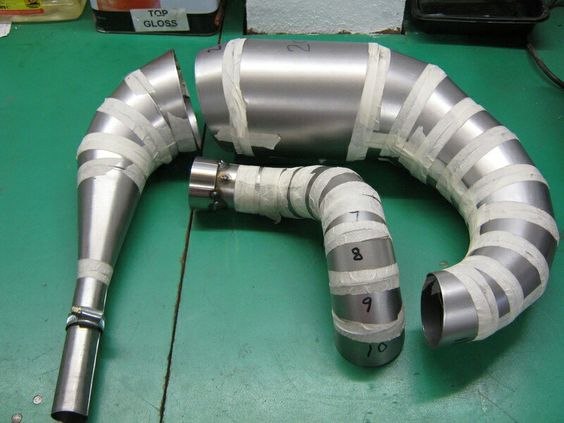
As hydroforming technology has advanced, new techniques have been developed to expand the capabilities of the process and allow for the forming of more complex parts and materials. These advanced techniques are particularly useful in industries where precision, strength, and weight reduction are critical.
Double-Action Hydroforming
One of the most significant advancements in hydroforming is the development of double-action hydroforming presses. These presses are equipped with two hydraulic systems: one that applies pressure to the material and another that controls the axial movement of the material during forming.
In double-action hydroforming, the metal is not only expanded outward by hydraulic pressure but also compressed axially. This allows for better control over the material’s flow, resulting in more uniform thickness and improved precision in complex shapes.
- Application: Double-action hydroforming is commonly used in the automotive industry to create complex chassis components, such as engine cradles and subframes, which require high strength and precision.
High-Pressure Hydroforming
High-pressure hydroforming is another advanced technique that involves using extremely high hydraulic pressures (often exceeding 800 MPa) to form complex parts from high-strength materials, such as titanium, Inconel, and advanced aluminum alloys.
- Benefits: High-pressure hydroforming allows for the creation of parts with tighter tolerances and more intricate geometries than traditional hydroforming methods. The process also enables the use of stronger, lighter materials, which is particularly important in industries like aerospace, where weight reduction is crucial for fuel efficiency and performance.
- Challenges: High-pressure hydroforming requires specialized equipment and robust dies to withstand the extreme forces involved. The process also requires precise control of pressure and material flow to prevent defects.
Hydroforming with Advanced Materials
As the demand for lighter, stronger materials has increased, manufacturers have begun experimenting with hydroforming processes that can accommodate advanced materials, such as high-strength steel, titanium alloys, and composites.
- Advanced Metals: Metals like titanium and Inconel offer exceptional strength-to-weight ratios but are notoriously difficult to form using traditional methods. Hydroforming provides a solution by allowing these materials to be shaped into complex parts without cracking or deforming.
- Composites: Although hydroforming is traditionally associated with metals, recent advancements have explored its use in shaping composite materials. These materials, which are made from a combination of fibers and resins, offer high strength and low weight, making them ideal for industries such as aerospace and automotive.
Conclusion: Advantages of Hydroforming
The hydroforming process, from material preparation to post-processing, offers manufacturers a highly efficient and versatile way to create complex, lightweight, and strong components. By utilizing hydraulic pressure to shape metal, hydroforming enables the production of parts that would be difficult or impossible to achieve using traditional methods such as stamping or forging.
The advantages of hydroforming include:
- Precision: Hydroforming allows for the creation of intricate geometries with high dimensional accuracy, reducing the need for secondary finishing operations.
- Material Efficiency: The process minimizes material waste by forming parts from a single piece of metal, reducing the need for welding or assembly.
- Cost-Effectiveness: While the initial investment in hydroforming equipment may be high, the long-term savings in material costs, labor, and production time make it an economical choice for mass production.
- Flexibility: Hydroforming is suitable for a wide range of materials, from lightweight aluminum to high-strength steel and titanium alloys. This flexibility makes it an ideal process for industries that require both strength and lightness in their products.
In conclusion, the hydroforming process has revolutionized modern manufacturing, offering a precise, efficient, and cost-effective solution for creating high-performance components across a range of industries. As technology continues to evolve, hydroforming will remain a critical tool for manufacturers looking to stay competitive in the era of advanced materials and complex designs.
Introduction to Hydroforming
Hydroforming is an advanced metal forming process that uses high-pressure hydraulic fluids to mold and shape malleable metals like aluminum, steel, and brass into complex geometries. It is a versatile and efficient method widely used in industries such as automotive, aerospace, and electronics, where components need to be lightweight yet strong. The ability of hydroforming to produce intricate, high-precision parts with minimal material waste has made it a preferred manufacturing technique in these industries.
At the heart of the hydroforming process is the hydroforming press, a machine that uses hydraulic pressure to shape metal into predefined dies. By applying uniform pressure across the metal surface, hydroforming produces components with a smoother finish, higher structural integrity, and more complex designs than those achieved through traditional metal forming techniques like stamping or forging.
Hydroforming can be broadly categorized into two types:
- Sheet Hydroforming: This involves forming flat metal sheets into three-dimensional shapes.
- Tube Hydroforming: This involves shaping hollow tubes into complex, often asymmetric, cross-sectional shapes.
The advantages of hydroforming lie in its ability to create strong, lightweight parts in fewer steps and with greater precision than other manufacturing methods. Unlike stamping or forging, which may require additional processes like welding or assembly, hydroforming allows for the production of seamless, one-piece components. This reduces production time, cost, and material waste while improving the overall quality of the finished product.
In this guide, we will walk through the hydroforming process step by step, starting from material preparation and die design to the final inspection and post-processing stages. Whether for simple or complex parts, the hydroforming process relies on precise control of pressure, timing, and material flow to achieve optimal results. By understanding the intricacies of each stage, manufacturers can harness the full potential of hydroforming technology to meet the demands of modern industrial applications.
Material Preparation
The success of the hydroforming process starts with the proper selection and preparation of the materials. The chosen material must have the right mechanical properties, including ductility, strength, and resistance to deformation under high pressure. Metals commonly used in hydroforming include:
- Aluminum: Valued for its lightweight properties and ease of forming, widely used in the automotive and aerospace industries.
- Stainless Steel: Known for its strength and corrosion resistance, stainless steel is commonly used in the manufacturing of medical devices, kitchen appliances, and structural components.
- Brass and Copper: These materials are used for applications requiring high formability and an attractive appearance, such as plumbing fixtures and decorative items.
- High-Strength Steel: Often used in automotive applications, high-strength steel offers a balance between formability and durability, making it ideal for safety-critical components like vehicle frames.
Tube Hydroforming vs. Sheet Hydroforming Materials
Tube hydroforming requires the use of pre-cut metal tubes. The tubes are selected based on the application’s requirements, including wall thickness, diameter, and the material’s ability to expand without cracking. Tubes made from materials like aluminum, steel, or titanium are commonly used for automotive and aerospace parts due to their strength-to-weight ratios.
Sheet hydroforming involves the use of flat metal sheets. These sheets are usually pre-cut to the required size and thickness, ensuring that they are uniform and free from defects. The metal sheets must have high formability and the ability to stretch into complex shapes without tearing or wrinkling.
Pre-Treatment of Metals
Before the metal can be formed in the hydroforming press, it must undergo pre-treatment to ensure it is free from contaminants and surface imperfections that could interfere with the forming process. The most common pre-treatments include:
- Cleaning: The metal sheets or tubes are thoroughly cleaned to remove any oils, dust, or dirt that may have accumulated during storage or handling. This step ensures that the metal will form evenly and without any surface defects.
- Surface Coating: In some cases, a thin layer of lubricant is applied to the surface of the metal. This reduces friction during the forming process and helps prevent damage to the die and the metal itself.
- Heat Treatment: For certain high-strength materials, heat treatment may be necessary to improve their ductility and make them easier to form. This step is particularly important when working with metals like titanium or high-strength steel, which can become brittle if not properly treated.
By carefully selecting and preparing the material, manufacturers can avoid common defects such as cracking, thinning, or uneven deformation during the hydroforming process. Proper material preparation is a critical step that sets the foundation for the rest of the process, ensuring that the metal will respond well to the high-pressure forces involved in hydroforming.
Die Design and Setup
The die plays a central role in the hydroforming process, serving as the mold into which the metal is pressed. Its design and setup are critical for ensuring that the final part meets the required dimensions, tolerances, and surface finish. A well-designed die enables the creation of intricate shapes with high precision, while a poor design can result in defects such as wrinkles, cracks, or uneven thickness.
Importance of Die Design in Hydroforming
The die is a tool made of two halves (upper and lower), between which the metal is placed. In both sheet and tube hydroforming, the hydraulic pressure forces the metal into the die, causing it to conform to the mold’s shape. The design of the die directly impacts the quality of the finished part, as it determines how the metal flows during forming and how the pressure is distributed.
- Part Geometry: The complexity of the part’s geometry is a key consideration in die design. Hydroforming excels at producing parts with complex curves, varying cross-sections, and intricate shapes that would be difficult to achieve through traditional forming methods. The die must be carefully designed to accommodate these shapes without causing the material to wrinkle or tear during forming.
- Tolerances: Hydroforming allows for tight tolerances, which are critical in industries such as aerospace and automotive. The die must be machined with high precision to ensure that the final part meets these strict dimensional requirements.
- Flow Control: The flow of the material during forming is affected by the die design. Features such as draft angles and radii must be optimized to allow the metal to stretch and expand uniformly without causing defects. Sharp edges or abrupt changes in geometry can result in stress concentrations, leading to cracks or thinning in the material.
Types of Dies
There are two main types of dies used in hydroforming: rigid dies and flexible dies, each of which is suited to different applications.
- Rigid Dies: These are the most commonly used dies in hydroforming. Made from hard materials such as tool steel, rigid dies are used for forming complex, high-precision parts. They are durable and capable of withstanding the high pressures involved in hydroforming. Rigid dies are typically used in high-pressure tube hydroforming and sheet hydroforming processes for automotive and aerospace components.
- Flexible Dies: Flexible dies, also known as bladder dies, use a rubber diaphragm or a fluid-filled bladder to press the metal into a mold. This technique is used in low-pressure hydroforming for less complex parts or in situations where surface finish is less critical. Flexible dies are often used in prototype development or small-batch production, where the ability to quickly change die designs is an advantage.
Die Materials and Manufacturing
The material used to manufacture the die must be strong enough to withstand repeated exposure to the high pressures involved in hydroforming, as well as the wear and tear from the metal’s movement. Common die materials include:
- Tool Steel: Known for its hardness and wear resistance, tool steel is often used in dies that will be subjected to high pressures and require long-term durability.
- Alloy Steel: Provides excellent toughness and is often used when strength and wear resistance are needed.
- Carbide: For extremely high wear resistance and precision, carbide-tipped dies may be used, especially for industries like aerospace, where precision is critical.
Die manufacturing involves several stages:
- Design and Simulation: The die is first designed using computer-aided design (CAD) software. Advanced simulations are performed to predict how the material will behave during the hydroforming process, allowing engineers to optimize the die design before manufacturing begins.
- CNC Machining: Once the design is finalized, the die is fabricated using computer numerical control (CNC) machines. CNC machining allows for high precision and consistency, ensuring that the die will produce parts with the required tolerances.
- Heat Treatment: In some cases, heat treatment is applied to the die to improve its hardness and resistance to wear.
Die Setup in the Press
Once the die has been manufactured, it must be properly installed in the hydroforming press. The setup process involves:
- Alignment: The die must be carefully aligned to ensure that the metal will be evenly formed. Even small misalignments can lead to defects in the final part.
- Calibration: Modern hydroforming presses are equipped with sensors and control systems that allow for precise calibration of the die setup. These systems ensure that the die closes evenly and that the hydraulic pressure is applied uniformly across the metal surface.
A properly designed and set up die is essential for achieving high-quality results in hydroforming. Careful attention to detail in this stage ensures that the material will flow correctly during forming, minimizing defects and improving the overall quality of the finished part.
Loading and Clamping
Once the material and die are prepared, the next step in the hydroforming process is to load the material into the press and secure it using clamping mechanisms. This stage is critical to ensuring that the material stays in place and is properly positioned throughout the forming process.
Loading the Material
- Tube Hydroforming: In tube hydroforming, a hollow metal tube is cut to the desired length and placed inside the die cavity. The tube must be positioned accurately within the die to ensure that it expands uniformly during the pressurization stage. The ends of the tube are typically sealed with end plugs, which prevent hydraulic fluid from escaping and allow pressure to build inside the tube.
- Sheet Hydroforming: In sheet hydroforming, a flat metal sheet is placed over the lower half of the die. The sheet must be aligned with the contours of the die to ensure that it forms correctly. Misalignment can result in defects such as wrinkles or tears during forming.
Clamping Mechanisms
Clamping is essential in both sheet and tube hydroforming to hold the material securely in place during the process. Proper clamping ensures that the material remains stationary and forms evenly without shifting or slipping.
- Blank Holders: In sheet hydroforming, blank holders are used to apply pressure around the edges of the metal sheet, securing it firmly to the die. The blank holder ensures that the sheet stays in place during the forming process, preventing it from slipping or wrinkling as the hydraulic pressure is applied. The amount of pressure applied by the blank holder is carefully controlled to avoid damaging the material while ensuring that it forms correctly.
- End Seals for Tube Hydroforming: In tube hydroforming, end plugs are inserted into the ends of the tube to seal them. These plugs prevent the hydraulic fluid from escaping and ensure that pressure is maintained inside the tube, allowing it to expand properly. The ends of the tube are also clamped securely to prevent any movement during the forming process.
Importance of Proper Clamping
Proper clamping is essential for ensuring that the material forms evenly and without defects. If the clamping force is too low, the material may move during the process, resulting in defects such as wrinkling, tearing, or uneven thickness. If the clamping force is too high, it can cause the material to thin excessively or even crack.
By carefully controlling the clamping process, manufacturers can ensure that the metal forms smoothly into the die, resulting in a high-quality finished part. Modern hydroforming presses are equipped with automated clamping systems that allow for precise control of clamping force and positioning, reducing the risk of defects and improving overall process efficiency.
Fluid Injection
Fluid injection is the key stage of the hydroforming process, where hydraulic fluid is introduced to create the pressure required to form the metal into the desired shape. This stage involves careful control of pressure and flow to ensure that the material expands evenly and fills the die without defects.
The Role of Hydraulic Fluid
Hydraulic fluid serves as the medium through which pressure is applied to the metal. The fluid is typically an oil-based or water-based liquid capable of withstanding high pressures without compressing. The hydraulic fluid’s primary function is to exert even, controlled pressure across the surface of the metal, forcing it into the contours of the die.
- Tube Hydroforming: In tube hydroforming, the hydraulic fluid is injected into the hollow tube. As pressure builds inside the tube, it expands outward against the walls of the die, taking on the shape of the mold. The fluid must be introduced at a controlled rate to ensure uniform expansion and avoid defects such as thinning or cracking.
- Sheet Hydroforming: In sheet hydroforming, the hydraulic fluid is applied above the metal sheet. As pressure is applied, the sheet is forced downward into the die, conforming to its shape. The uniform application of pressure ensures that the metal deforms evenly, producing a part with consistent thickness and a smooth surface finish.
Pressure Control and Monitoring
Precise control of hydraulic pressure is essential to the success of the hydroforming process. Modern hydroforming presses are equipped with pressure sensors and automated control systems that monitor and adjust the pressure in real time to ensure optimal results.
- Initial Pressurization: The hydraulic fluid is introduced gradually to avoid sudden deformation, which could lead to defects such as wrinkling or tearing. The pressure is slowly increased, allowing the material to stretch and flow into the die’s contours. For more complex shapes, a slow pressurization rate helps maintain control over the material’s behavior.
- Peak Pressure: Once the material begins to deform, the pressure is gradually increased to its peak value. The peak pressure depends on several factors, including the material being formed, the thickness of the metal, and the complexity of the part’s geometry. Pressures in hydroforming can range from 100 MPa (14,500 psi) to over 800 MPa (116,000 psi) for high-strength materials or complex shapes.
- Pressure Holding Phase: After the metal has conformed to the die, the pressure is often held at its peak level for a set period to ensure that the material settles into its final shape. This holding phase allows the material’s grain structure to adjust and helps prevent spring-back, where the metal tries to return to its original shape once the pressure is released.
High-Pressure vs. Low-Pressure Hydroforming
Hydroforming can be performed at both low pressures and high pressures, depending on the application and material.
- Low-Pressure Hydroforming: This method is used for simpler shapes and thinner materials. Pressures are typically under 100 MPa, and the process is less demanding on the equipment and the material. Low-pressure hydroforming is often used in automotive applications for parts like exhaust systems, where complex shapes are needed, but extreme precision is not required.
- High-Pressure Hydroforming: High-pressure hydroforming, with pressures exceeding 100 MPa, is used for more complex shapes and stronger materials, such as high-strength steel and titanium. This method is common in aerospace applications, where precision and material performance are critical. High-pressure hydroforming allows for the creation of intricate parts with tight tolerances and superior strength.
Shaping Process
The shaping process is the core of hydroforming, where hydraulic pressure forces the metal into the die, transforming it into the final part. This stage involves careful control over pressure, material flow, and timing to ensure that the metal forms uniformly and without defects.
Sheet Hydroforming Step-by-Step
In sheet hydroforming, a flat metal sheet is shaped into a three-dimensional part. The process involves the following steps:
- Placing the Sheet: A pre-cut metal sheet is placed into the press, lying flat over the lower half of the die. The die is designed to mirror the negative shape of the final part.
- Clamping: The sheet is securely clamped in place by blank holders around its edges. This prevents any movement during forming and ensures the material flows into the die uniformly.
- Pressurization Begins: Hydraulic fluid is injected into the chamber above the sheet, and pressure is applied evenly across its surface. As the pressure increases, the sheet is pushed downward into the die, taking on its shape. The pressurization must be carefully controlled to avoid sudden deformation, which could result in defects.
- Material Flow and Stretching: As the pressure increases, the metal begins to flow into the contours of the die, stretching and thinning as needed. The uniform application of pressure ensures that the metal conforms precisely to the die’s shape without wrinkling or tearing.
- Final Shaping: Once the metal has fully taken the shape of the die, the hydraulic pressure reaches its peak and is maintained for a short period to ensure the part has fully settled. This step is crucial to preventing spring-back, where the metal tries to revert to its original shape.
- Pressure Release and Die Opening: After the part has been fully formed, the hydraulic pressure is slowly released, and the die is opened. The formed sheet is then removed from the press. The final part has the exact shape and dimensions dictated by the die, with a smooth surface finish and consistent thickness.
Tube Hydroforming Step-by-Step
In tube hydroforming, a hollow tube is expanded into the desired shape using internal hydraulic pressure. The process differs from sheet hydroforming in that the hydraulic fluid is injected inside the tube, causing it to expand outward against the walls of the die.
- Tube Insertion: A pre-cut hollow tube is placed inside the die, positioned so that it will expand uniformly during forming. The tube must be positioned accurately to ensure even expansion during pressurization.
- Sealing and Clamping: The ends of the tube are sealed with end plugs to prevent hydraulic fluid from escaping. These plugs also help control the material flow and assist in maintaining uniform wall thickness. The tube is then clamped securely in place.
- Hydraulic Fluid Injection: Hydraulic fluid is injected into the tube, gradually increasing the internal pressure. As the pressure builds, the tube begins to expand outward, filling the contours of the die. The process must be carefully controlled to avoid excessive thinning or tearing of the material.
- Controlled Expansion: In tube hydroforming, controlling both internal pressure and axial forces (pressure applied to the ends of the tube) is critical to preventing defects. Axial forces ensure that the material flows evenly into the die and prevent the tube from buckling or wrinkling.
- Final Shaping: As with sheet hydroforming, the hydraulic pressure reaches a peak, ensuring that the tube fully conforms to the shape of the die. This step is maintained for a set period to allow the material to settle and prevent spring-back.
- Pressure Release and Part Removal: After the part has been fully formed, the hydraulic pressure is released, and the die opens. The newly shaped tube is then removed from the press. The final part has taken on the complex geometry of the die, with consistent wall thickness and structural integrity.
Expansion and Forming Dynamics
The key to successful hydroforming lies in the controlled expansion of the material. Several factors influence how the metal behaves during the shaping process:
- Material Properties: Ductile metals, such as aluminum, expand more easily under pressure, while high-strength materials, such as stainless steel or titanium, require more precise control to prevent cracking or tearing. The choice of material impacts the level of pressure needed and the behavior of the metal during forming.
- Metal Thickness: Thinner materials are more prone to wrinkling or tearing during forming, while thicker materials require higher pressures to shape. The goal is to achieve a balance where the material stretches evenly without losing structural integrity.
- Pressure Gradient: The rate at which hydraulic pressure is applied affects the final part’s quality. Gradual, controlled increases in pressure allow the metal to expand evenly, filling the die without creating weak spots or defects.
- Axial Forces (Tube Hydroforming): In tube hydroforming, axial forces are applied to the ends of the tube to help control material flow and ensure uniform wall thickness. Properly managed axial forces prevent buckling or wrinkling and contribute to achieving a well-formed part.
Pressurization Timelines and Adjustments
The hydroforming process is highly dependent on pressurization timelines. The pressure must be adjusted carefully throughout the process to control the rate of material flow, prevent defects, and ensure that the final part is formed correctly.
- Gradual Pressurization: In the initial stages, pressure is applied slowly to allow the material to stretch and flow into the die. Sudden pressure increases can cause the material to deform unevenly, resulting in defects such as cracks or thinning.
- Peak Pressure Holding: Once the material has fully expanded into the die, the pressure is held at its peak level for a specific amount of time. This allows the material to stabilize and ensures that the part maintains its shape once the pressure is released.
- Pressure Adjustments: Depending on the complexity of the part, pressure may need to be adjusted throughout the process. For example, higher pressures may be required for more intricate shapes or stronger materials, while lower pressures may be used for simpler geometries.
Cooling and Solidification
Once the shaping process is complete, the part enters the cooling phase, where it solidifies and retains its final form. The cooling process is critical for maintaining the structural integrity of the part and ensuring that it meets the required specifications.
Role of Cooling in Hydroforming
During the hydroforming process, especially under high pressures, some heat is generated due to friction and the stretching of the metal. Although hydroforming is not as heat-intensive as processes like welding or casting, localized heat can affect the material properties. Controlled cooling helps manage this heat and ensures the material’s final strength, hardness, and dimensional stability.
In some cases, active cooling systems are used in the hydroforming press to dissipate heat quickly and evenly. These systems may involve circulating coolants through the hydraulic fluid or around the die to regulate temperature during and after forming. For materials that are sensitive to heat, such as aluminum and high-strength alloys, proper cooling is essential to avoid defects such as warping or weakening of the material.
Heat Management and Its Impact on Material Integrity
Effective heat management is critical to ensuring that the hydroformed part retains its desired properties. If the part cools too quickly or unevenly, it can lead to defects such as:
- Warping or Distortion: Uneven cooling can cause the part to warp, altering its dimensions and potentially rendering it unusable.
- Residual Stress: Rapid cooling can trap residual stresses in the material, leading to cracks or failure when the part is subjected to load during its intended use.
- Surface Finish Defects: Excessive heat exposure during forming can cause surface defects, such as oxidation or discoloration, especially in metals like aluminum or stainless steel.
The cooling process can be passive, allowing the part to return to room temperature naturally, or active, where coolants are used to manage heat more precisely. For critical components, active cooling ensures that the part retains its shape, strength, and surface finish, meeting the necessary quality standards.
By carefully managing the cooling phase, manufacturers can ensure that the final part is dimensionally accurate, free from defects, and ready for use in its intended application.
Opening the Die and Part Removal
Once the part has been shaped and cooled, the next step is opening the die and carefully removing the formed part. This process must be done with precision to avoid damaging the part, especially when dealing with intricate geometries or delicate materials.
Die Separation Process
The hydroforming press typically consists of two die halves: an upper die and a lower die. After the hydraulic pressure is released and the part has cooled, the two halves of the die are slowly separated. This step must be controlled carefully, as sudden movements or misalignment during die opening can damage the newly formed part or cause it to become stuck in the die.
Modern hydroforming presses often use automated die separation systems, which ensure that the die opens at the right speed and in the correct sequence. These systems are designed to reduce the risk of part deformation or damage during the removal process, improving overall process reliability.
Ejecting and Removing the Formed Part
Once the die has been opened, the part must be safely removed. For simpler parts, this can be done manually or using automated extraction systems. However, for more complex parts with deep recesses, sharp corners, or intricate curves, removing the part can be more challenging.
- Ejection Pins: Many hydroforming presses are equipped with ejection pins that push the part out of the die. These pins are strategically placed to ensure that the part is ejected evenly and without distortion. The force and timing of the ejection must be carefully controlled to prevent damaging the part.
- Robotic Assistance: In advanced manufacturing settings, robotic arms are used to extract the part from the die. These robotic systems are programmed to handle the part with precision, reducing the risk of surface scratches or deformations that can occur with manual handling.
Challenges in Extracting Complex Geometries
For parts with complex geometries, removing the formed part from the die requires special care. Sharp corners, deep draws, or intricate shapes may cause the part to become stuck in the die, increasing the risk of damage during extraction. In such cases, additional tools or techniques, such as vacuum-assisted removal or mechanical extraction devices, may be employed to ensure safe part removal.
Proper part removal is critical to maintaining the dimensional accuracy and surface finish of the final product. Any damage during this stage could compromise the part’s performance or require costly rework.
EMS Metalworking Machines
We design, manufacture and assembly metalworking machinery such as:
- Hydraulic transfer press
- Glass mosaic press
- Hydraulic deep drawing press
- Casting press
- Hydraulic cold forming press
- Hydroforming press
- Composite press
- Silicone rubber moulding press
- Brake pad press
- Melamine press
- SMC & BMC Press
- Labrotaroy press
- Edge cutting trimming machine
- Edge curling machine
- Trimming beading machine
- Trimming joggling machine
- Cookware production line
- Pipe bending machine
- Profile bending machine
- Bandsaw for metal
- Cylindrical welding machine
- Horizontal pres and cookware
- Kitchenware, hotelware
- Bakeware and cuttlery production machinery
as a complete line as well as an individual machine such as:
- Edge cutting trimming beading machines
- Polishing and grinding machines for pot and pans
- Hydraulic drawing presses
- Circle blanking machines
- Riveting machine
- Hole punching machines
- Press feeding machine
You can check our machinery at work at: EMS Metalworking Machinery – YouTube
Applications:
Flange-punching
Beading and ribbing
Flanging
Trimming
Curling
Lock-seaming
Ribbing