
We manufacture a Small Sheet Bending Machine to bend sheet metal edges. Hydraulic Press Machines are used in metalworking industries
A small sheet bending machine, also known as a mini sheet metal bender or benchtop sheet metal brake, is a compact and portable machine used for bending small or thin sheet metal pieces. These machines are suitable for light-duty bending tasks and are commonly used in workshops, hobbyist projects, and small-scale fabrication operations. Here are some key features and considerations of small sheet bending machines:
- Size and Portability: Small sheet bending machines are designed to be compact and portable, allowing for easy transportation and storage. They are often lightweight and can be placed on a workbench or table.
- Manual Operation: Most small sheet bending machines are manually operated, requiring the user to apply force to bend the metal sheet. They typically feature a lever or handle mechanism that allows the operator to bend the sheet by hand.
- Bending Capacity: Small sheet bending machines are suitable for bending thin and small-sized sheet metal pieces. The bending capacity may vary depending on the machine model but is generally limited to a few millimeters in thickness and a small width.
- Adjustable Bending Angle: Small sheet bending machines often have an adjustable bending angle mechanism, allowing for the creation of different angles and bends. The angle adjustment can typically be made using a locking mechanism or a graduated scale.
- Material Compatibility: Small sheet bending machines can work with various types of sheet metal materials, including mild steel, aluminum, stainless steel, and copper. However, their bending capacity is generally limited to thinner gauges of these materials.
- Ease of Use: Small sheet bending machines are designed to be user-friendly and easy to operate. They often have simple controls and require minimal setup and adjustment.
- Safety Considerations: While small sheet bending machines may not have as many safety features as larger industrial machines, it is still important to follow safety precautions. Operators should wear appropriate personal protective equipment (PPE) and be cautious when applying force or handling sharp edges.
Small sheet bending machines are ideal for small-scale projects, hobbyists, and educational purposes. They provide a cost-effective solution for bending small sheet metal pieces without the need for larger and more complex machinery.
Small Sheet Bending Machine
A small sheet bending machine is a compact and versatile tool designed to bend sheet metal into various shapes and forms. It is commonly used in small workshops, prototyping environments, and DIY projects due to its portability, ease of use, and ability to handle a range of sheet metal thicknesses.
Key Components of a Small Sheet Bending Machine
A small sheet bending machine typically consists of the following components:
- Frame: The frame provides a sturdy base for the machine and supports the bending mechanism. It is typically made from heavy-duty steel or cast iron.
- Bending Mechanism: The bending mechanism is the heart of the machine, applying the force required to bend the sheet metal. It may consist of a lever, a hydraulic press, or an electric motor.
- Dies and Punches: Dies and punches are the tooling that shapes the sheet metal into the desired form. The die provides the desired shape, while the punch cuts or pierces the material.
- Work Table: The work table provides a stable surface for positioning and securing the sheet metal during bending. It may be adjustable to accommodate different workpiece sizes.
- Angle Indicator: The angle indicator allows the user to set the desired bending angle accurately.
- Handle or Lever: The handle or lever provides the user with the means to apply force and bend the sheet metal.
Common Applications of Small Sheet Bending Machines
Small sheet bending machines are suitable for various applications, including:
- Bending smaller sheet metal thicknesses (typically up to 1/8 inch or 3 mm)
- Creating prototype parts and small-scale production runs
- Forming ductwork, brackets, and other sheet metal components
- DIY projects and hobbyist applications
- Bending sheet metal for signage, lettering, and decorative elements
Safety Precautions for Using Small Sheet Bending Machines
When using small sheet bending machines, it is essential to follow safety precautions to prevent injuries and accidents:
- Wear appropriate personal protective equipment (PPE): This includes safety glasses, gloves, and hearing protection.
- Secure the sheet metal: The sheet metal should be firmly grasped and positioned correctly in the machine’s guides or rollers.
- Apply force gradually: Avoid applying excessive force abruptly, as this could cause the sheet metal to slip or break.
- Beware of pinch points: Use caution around pinch points where the sheet metal comes into contact with the bending mechanism.
- Maintain the machine in good condition: Regularly inspect the machine for loose or damaged parts and ensure proper lubrication.
Small sheet bending machines offer a convenient and cost-effective solution for bending smaller sheet metal thicknesses and handling small-scale projects. By following safety precautions and using the machine properly, individuals can effectively shape sheet metal and create various components.
Application Areas of the Small Sheet Bending Machines
Small sheet bending machines are versatile tools that offer a wide range of applications in various industries and settings. Their compact size, ease of use, and ability to handle various sheet metal thicknesses make them ideal for small workshops, prototyping environments, and DIY projects. Here’s a comprehensive overview of the application areas of small sheet bending machines:
- Prototype Development: Small sheet bending machines are extensively used in prototyping workshops to create physical models and test designs before mass production. They allow for quick and accurate bending of sheet metal parts, enabling designers to evaluate the form and functionality of their prototypes.
- Small-Scale Production: In small-scale manufacturing environments, small sheet bending machines are employed to produce limited quantities of sheet metal components. They are particularly useful for customized products, niche markets, or situations where large-scale production is not economically viable.
- Ductwork Fabrication: Small sheet bending machines are commonly used to create ductwork components, such as elbows, transitions, and offsets, for ventilation and air conditioning systems. Their precise bending capabilities ensure proper airflow and system performance.
- Bracket and Component Forming: Small sheet bending machines are utilized to form brackets, supports, and other sheet metal components used in various applications, including automotive, electronics, construction, and home appliances. They provide a cost-effective solution for producing these essential components.
- DIY Projects and Hobbyist Applications: Small sheet bending machines are popular among DIY enthusiasts and hobbyists for creating decorative elements, signage, lettering, and other custom sheet metal projects. Their ease of use and portability make them suitable for home workshops and craft studios.
- Sheet Metal Repairs: Small sheet bending machines can be used to make repairs on existing sheet metal components, such as metal furniture, household appliances, or automotive parts. Their precise bending capabilities allow for restoring the original shape and function of these components.
- Educational and Training Purposes: Small sheet bending machines are often used in educational institutions and vocational training programs to teach students about sheet metal bending techniques and safety protocols. They provide a hands-on learning experience for future professionals in various industries.
- Artistic and Decorative Applications: Small sheet bending machines can be employed for artistic expression and creating unique decorative pieces. They allow artists and designers to manipulate sheet metal into various shapes and forms, adding a touch of individuality to their creations.
- Metalworking Prototypes: Small sheet bending machines are used to create prototypes and test new designs for metalworking tools and machinery. They allow engineers and designers to evaluate the functionality and effectiveness of their prototypes before investing in large-scale production.
- Customized Metalwork Projects: Small sheet bending machines are ideal for creating customized metalwork pieces for individual use or small businesses. They allow for personalized designs and unique creations that cater to specific needs or preferences.
Overall, small sheet bending machines are versatile tools with a wide range of applications across various industries and settings. Their portability, ease of use, and ability to handle different sheet metal thicknesses make them suitable for both professional and personal use.
Bending Machine:
A bending machine, also known as a press brake or a brake press, is a versatile machine tool used in metalworking operations to bend and form sheet metal or other types of materials. It applies force to a workpiece to deform it along a predetermined axis, producing bends, curves, or angles according to the desired specifications.
Working Principle: Bending machines typically consist of a sturdy frame, a movable upper beam or ram, and a stationary lower die or bed. The workpiece is positioned between the upper beam and the lower die, and hydraulic or mechanical force is applied to the upper beam to press the workpiece against the lower die, causing it to bend.
Types of Bending Machines:
- Hydraulic Bending Machine: Utilizes hydraulic cylinders to apply force, offering precise control and high bending accuracy.
- CNC Bending Machine: Equipped with computer numerical control (CNC) systems for automated operation and programmable bending sequences.
- Manual Bending Machine: Operated manually by adjusting the position of the upper beam and applying force using hand levers or foot pedals.
- Electric Bending Machine: Utilizes electric motors or actuators to apply bending force, offering faster operation and energy efficiency.
- Automatic Bending Machine: Fully automated machines that can perform multiple bending operations without manual intervention, increasing productivity and efficiency.
Applications: Bending machines are widely used in various industries, including:
- Metal fabrication: for bending sheet metal components used in automotive, aerospace, and construction industries.
- Manufacturing: for producing structural components, enclosures, and machine parts with precise bending angles and dimensions.
- HVAC (heating, ventilation, and air conditioning): for bending ductwork and pipes used in HVAC systems.
- Electronics: for forming metal enclosures, chassis, and brackets for electronic devices.
- Furniture: for bending metal tubes and profiles used in furniture manufacturing.
- Art and sculpture: for creating artistic and decorative metalwork with intricate bends and curves.
Advantages:
- Versatility: Bending machines can produce a wide range of bends and shapes, making them suitable for various applications.
- Precision: Modern bending machines offer high precision and repeatability, ensuring consistent quality of bent components.
- Efficiency: Automated and CNC-controlled bending machines increase productivity and reduce setup time and material waste.
- Flexibility: Bending machines can handle different types of materials, including steel, aluminum, copper, and brass.
- Cost-effectiveness: Bending machines provide cost-effective solutions for producing complex bent components compared to traditional manual methods.
In summary, bending machines play a crucial role in metalworking operations, offering versatility, precision, and efficiency in bending and forming sheet metal and other materials for a wide range of industrial applications.
Sheet Metal Bending:
Sheet metal bending is a metalworking process used to deform flat sheets of metal into desired shapes by applying force to bend the material along a straight axis. It is a common fabrication technique used in various industries to produce a wide range of components, from simple brackets to complex enclosures and structural elements.
Working Principle: Sheet metal bending is typically performed using a bending machine, such as a press brake or a bending brake. The sheet metal workpiece is placed between a punch (mounted on the upper beam or ram) and a die (mounted on the lower bed), and force is applied to the punch to press the workpiece against the die, causing it to bend.
Types of Bends:
- V-Bend: Forms a V-shaped bend in the sheet metal, commonly used for forming corners and flanges.
- U-Bend: Forms a U-shaped bend, typically used for creating channels or enclosures with rounded edges.
- Box Bend: Forms a rectangular or square-shaped bend, often used for creating boxes, trays, and enclosures.
- Offset Bend: Forms a bend with one or more offsets or steps, allowing for complex shapes and angles.
- Hem Bend: Forms a closed hem along the edge of the sheet metal, providing reinforcement and safety against sharp edges.
Factors Affecting Bending:
- Material: Different types of metals, such as steel, aluminum, stainless steel, and copper, have varying degrees of ductility and require different bending techniques.
- Thickness: Thicker materials require higher bending forces and may require multiple bending operations or pre-bending to achieve the desired shape.
- Bend Radius: The radius of the bend determines the minimum achievable bend radius and affects the amount of springback (elastic recovery) after bending.
- Tooling: The selection of punch and die profiles, as well as the tooling setup, influences the bending process and the quality of the bent components.
- Bend Allowance: The calculated length of the flat pattern required for a given bend angle, taking into account material thickness, bend radius, and bend angle.
Applications: Sheet metal bending is widely used in various industries, including:
- Automotive: for manufacturing vehicle body panels, chassis components, and structural reinforcements.
- Aerospace: for fabricating aircraft fuselages, wings, and engine components.
- Electronics: for producing enclosures, cabinets, and mounting brackets for electronic devices.
- Construction: for fabricating structural components, architectural elements, and HVAC ductwork.
- Furniture: for creating metal frames, legs, and supports for furniture pieces.
- Signage and Displays: for forming lettering, logos, and shapes for signage and display applications.
Advantages:
- Versatility: Sheet metal bending allows for the production of a wide range of shapes and configurations, from simple bends to complex geometries.
- Cost-Effectiveness: Bending processes are generally more cost-effective than other fabrication methods, such as welding or machining.
- Precision: Modern bending machines offer high precision and repeatability, ensuring consistent quality of bent components.
- Efficiency: Automated bending processes increase productivity and reduce setup time, leading to faster production cycles.
- Design Freedom: Sheet metal bending enables designers to create custom shapes and profiles, providing flexibility in product design and innovation.
In summary, sheet metal bending is a fundamental metalworking process that offers versatility, precision, and efficiency in producing bent components for various industrial applications.
Plate Bending Machine:
A plate bending machine, also known as a plate roll or a roll bending machine, is a machine tool used to bend and shape metal plates into cylindrical, conical, or curved shapes. It is commonly used in industries such as metal fabrication, shipbuilding, aerospace, and construction for manufacturing cylindrical components such as tanks, pipes, and pressure vessels.
Working Principle: Plate bending machines utilize three or four rolls arranged in a pyramid or pyramid-type configuration. The top roll is the primary bending roll, while the bottom rolls (called pinch rolls) provide support and control the bending process. The plate is passed through the rolls, and the top roll exerts downward pressure on the plate, bending it into the desired shape.
Types of Plate Bending Machines:
- Initial Pinch Plate Bending Machine: Features three rolls, with the top roll adjustable in both horizontal and vertical planes. Suitable for bending thin and medium-thickness plates.
- Double Pinch Plate Bending Machine: Similar to the initial pinch machine but with all three rolls adjustable. Offers improved control and accuracy, making it suitable for bending thicker plates.
- Four-Roll Plate Bending Machine: Utilizes four rolls arranged in a pyramid-type configuration. Provides better control over the bending process and reduces the risk of material slipping during bending. Suitable for bending thicker plates and producing complex shapes.
Working Process:
- The plate is positioned between the top roll and the pinch rolls.
- The top roll applies downward pressure on the plate, causing it to bend as it passes through the rolls.
- The plate is gradually fed through the rolls while adjusting the position of the top roll to achieve the desired curvature.
- For cylindrical shapes, the plate is bent incrementally until it forms a complete cylinder. For conical shapes, the plate is bent asymmetrically to achieve the desired taper.
Applications: Plate bending machines are used in various industries for manufacturing a wide range of components, including:
- Tanks and vessels for the chemical, oil and gas, and food processing industries.
- Pipes and tubing for the automotive, aerospace, and construction industries.
- Pressure vessels and boilers for the power generation and petrochemical industries.
- Structural components for bridges, buildings, and infrastructure projects.
- Cylindrical and conical sections for shipbuilding and marine engineering.
Advantages:
- Versatility: Plate bending machines can produce cylindrical, conical, and curved shapes with a wide range of diameters and thicknesses.
- Precision: Modern plate bending machines offer high precision and repeatability, ensuring consistent quality of bent components.
- Efficiency: Plate bending machines increase productivity by bending large plates in a single pass, reducing the need for manual labor and secondary operations.
- Flexibility: Plate bending machines can handle various materials, including carbon steel, stainless steel, aluminum, and alloys.
- Cost-Effectiveness: Plate bending processes are generally more cost-effective than other fabrication methods, such as welding or machining, for producing curved components.
In summary, plate bending machines are essential tools in metal fabrication and manufacturing industries, offering versatility, precision, and efficiency in bending and shaping metal plates into cylindrical, conical, and curved components for a wide range of applications.
Hydraulic Bending Machine:
A hydraulic bending machine, also known as a hydraulic press brake, is a versatile machine tool used in metalworking operations to bend and form sheet metal or other types of materials. It employs hydraulic power to apply force to a workpiece, deforming it along a predetermined axis to create bends, curves, or angles according to the desired specifications.
Working Principle: Hydraulic bending machines utilize hydraulic cylinders to generate the force required for bending operations. The machine consists of a sturdy frame, a movable upper beam or ram, and a stationary lower die or bed. The workpiece is positioned between the upper beam and the lower die, and hydraulic pressure is applied to the upper beam, pressing the workpiece against the lower die and causing it to bend.
Types of Hydraulic Bending Machines:
- Conventional Hydraulic Press Brake: Operated manually or semi-automatically using foot pedals or hand levers to control the bending process.
- CNC Hydraulic Press Brake: Equipped with computer numerical control (CNC) systems for automated operation and programmable bending sequences, offering higher precision and productivity.
- Tandem Hydraulic Press Brake: Consists of multiple press brakes synchronized to work together, allowing for the bending of long or oversized workpieces.
Advantages:
- Precision: Hydraulic bending machines offer high precision and repeatability, ensuring consistent quality of bent components.
- Flexibility: Hydraulic press brakes can handle a wide range of materials, thicknesses, and bending angles, making them suitable for various applications.
- Efficiency: CNC hydraulic press brakes increase productivity and reduce setup time by automating bending sequences and tool changes.
- Versatility: Hydraulic bending machines can perform a wide range of bending operations, including air bending, bottoming, and coining.
- Safety: Hydraulic press brakes feature safety systems such as light curtains, interlocks, and emergency stop buttons to protect operators and prevent accidents.
Applications: Hydraulic bending machines are used in various industries for bending sheet metal and other materials to produce components such as:
- Automotive parts: chassis components, brackets, and panels
- Aerospace components: fuselage sections, wing ribs, and engine mounts
- Electrical enclosures: cabinets, control panels, and switchgear housings
- Architectural elements: handrails, balustrades, and decorative cladding
- Machinery components: frames, covers, and guards
- Consumer goods: furniture frames, appliance housings, and signage
Maintenance: Regular maintenance of hydraulic bending machines is essential to ensure optimal performance and prolong machine life. Maintenance tasks may include:
- Checking hydraulic fluid levels and replacing or topping up as needed
- Inspecting hydraulic hoses, fittings, and seals for signs of wear or damage
- Lubricating moving parts such as guide rails, bearings, and ball screws
- Inspecting and adjusting the hydraulic system for leaks, pressure fluctuations, or abnormal noises
- Calibrating and testing safety systems and emergency stop mechanisms
In summary, hydraulic bending machines are versatile and efficient tools used in metalworking operations to bend and form sheet metal and other materials for a wide range of applications. With proper maintenance and care, hydraulic press brakes can provide reliable and precise bending performance for many years.
CNC Bending Machine
A CNC (Computer Numerical Control) bending machine, also known as a CNC press brake, is a highly automated machine tool used in metalworking operations to bend and form sheet metal or other materials with precision and accuracy. It utilizes CNC technology to control the bending process, allowing for complex bending sequences and accurate positioning of the bending tooling.
Working Principle: CNC bending machines consist of a sturdy frame, a movable upper beam or ram, a stationary lower die or bed, and a backgauge system for positioning the workpiece. The machine is equipped with hydraulic or electric servo-driven actuators controlled by a CNC system. The CNC system interprets part programs generated from CAD (Computer-Aided Design) files and executes the bending sequences by controlling the movement of the upper beam, the backgauge, and other machine functions.
Features of CNC Bending Machines:
- Multi-Axis Control: CNC press brakes can control multiple axes, including the Y-axis (ram depth), X-axis (backgauge position), and optionally the R-axis (backgauge height) and Z-axis (side gauge position). This allows for complex bending operations and the production of intricate parts.
- Automatic Tool Changing: Some CNC bending machines are equipped with automatic tool changing systems that allow for quick and easy setup of different bending tooling configurations.
- Offline Programming: CNC press brakes typically support offline programming software that allows operators to create and simulate bending programs on a computer before transferring them to the machine, reducing setup time and minimizing errors.
- Safety Features: CNC bending machines are equipped with safety systems such as light curtains, interlocks, and emergency stop buttons to protect operators and prevent accidents during operation.
Advantages:
- Precision: CNC bending machines offer high precision and repeatability, ensuring consistent quality of bent components.
- Efficiency: CNC press brakes increase productivity by automating bending sequences, reducing setup time, and minimizing material waste.
- Flexibility: CNC bending machines can handle a wide range of materials, thicknesses, and bending angles, making them suitable for various applications.
- Versatility: CNC press brakes can perform a wide range of bending operations, including air bending, bottoming, coining, and radius bending.
- Accuracy: CNC control allows for accurate positioning of the bending tooling, ensuring precise bend angles and dimensions.
Applications: CNC bending machines are used in various industries for bending sheet metal and other materials to produce components such as:
- Automotive parts: chassis components, brackets, and panels
- Aerospace components: fuselage sections, wing ribs, and engine mounts
- Electrical enclosures: cabinets, control panels, and switchgear housings
- Architectural elements: handrails, balustrades, and decorative cladding
- Machinery components: frames, covers, and guards
- Consumer goods: furniture frames, appliance housings, and signage
In summary, CNC bending machines are highly automated and versatile machine tools used in metalworking operations to bend and form sheet metal and other materials with precision and accuracy. They offer numerous advantages, including increased productivity, flexibility, and accuracy, making them indispensable in modern manufacturing processes.
Press Brake
A press brake is a machine tool used in metalworking to bend sheet metal and other materials. It consists of a hydraulic or mechanical press that applies force to a workpiece, forcing it against a die to create bends, angles, or curves. Press brakes are essential in various industries, including automotive, aerospace, construction, and manufacturing.
Working Principle: Press brakes work on the principle of applying force to a workpiece between a punch (mounted on the upper beam) and a die (mounted on the lower bed). The workpiece is positioned between the punch and die, and the press brake’s ram descends to exert force on the workpiece, bending it to the desired angle. Press brakes can perform various bending operations, including air bending, bottoming, and coining, depending on the application requirements.
Types of Press Brakes:
- Hydraulic Press Brake: Utilizes hydraulic cylinders to apply force, offering precise control and high bending accuracy.
- Mechanical Press Brake: Utilizes mechanical linkages or gears to apply force, suitable for high-volume production but may lack the precision of hydraulic press brakes.
- CNC Press Brake: Equipped with computer numerical control (CNC) systems for automated operation and programmable bending sequences, offering higher precision and productivity.
- Tandem Press Brake: Consists of multiple press brakes synchronized to work together, allowing for the bending of long or oversized workpieces.
Features of Press Brakes:
- Backgauge System: Allows for precise positioning of the workpiece for accurate bending.
- Tooling: Press brakes can accommodate various types of tooling, including punches, dies, and tool holders, to create different bending profiles and shapes.
- Safety Systems: Press brakes are equipped with safety features such as light curtains, interlocks, and emergency stop buttons to protect operators and prevent accidents during operation.
- Offline Programming: CNC press brakes typically support offline programming software that allows operators to create and simulate bending programs on a computer before transferring them to the machine, reducing setup time and minimizing errors.
Applications: Press brakes are used in various industries for bending sheet metal and other materials to produce components such as:
- Automotive parts: chassis components, brackets, and panels
- Aerospace components: fuselage sections, wing ribs, and engine mounts
- Electrical enclosures: cabinets, control panels, and switchgear housings
- Architectural elements: handrails, balustrades, and decorative cladding
- Machinery components: frames, covers, and guards
- Consumer goods: furniture frames, appliance housings, and signage
Advantages:
- Precision: Press brakes offer high precision and repeatability, ensuring consistent quality of bent components.
- Efficiency: CNC press brakes increase productivity by automating bending sequences, reducing setup time, and minimizing material waste.
- Versatility: Press brakes can handle a wide range of materials, thicknesses, and bending angles, making them suitable for various applications.
- Flexibility: Press brakes can perform a wide range of bending operations, including air bending, bottoming, and coining.
- Accuracy: Press brakes allow for accurate positioning of the bending tooling, ensuring precise bend angles and dimensions.
In summary, press brakes are essential machine tools used in metalworking operations to bend sheet metal and other materials with precision and accuracy. They offer numerous advantages, including increased productivity, flexibility, and accuracy, making them indispensable in modern manufacturing processes.
Metal Bending Machine:
A metal bending machine is a versatile tool used in metalworking operations to deform metal sheets or bars into desired shapes. These machines apply force to the metal workpiece, causing it to bend or form according to predetermined specifications. Metal bending machines are crucial in various industries, including automotive, aerospace, construction, and manufacturing, for producing a wide range of components and structures.
Working Principle: Metal bending machines work by exerting force on metal workpieces to deform them into desired shapes. The machine typically consists of a sturdy frame, a bending mechanism (such as a press brake or roll bender), and tooling (such as dies, punches, or rolls) to shape the metal. The workpiece is positioned between the bending mechanism and the tooling, and force is applied to the workpiece, causing it to bend or form as required.
Types of Metal Bending Machines:
- Press Brake: A press brake utilizes a hydraulic or mechanical press to bend sheet metal or plates into various shapes, such as angles, curves, or channels.
- Roll Bender: Also known as a plate roll or rolling machine, a roll bender uses cylindrical rolls to bend metal plates or sheets into cylindrical or conical shapes.
- Tube Bender: Used specifically for bending metal tubes or pipes into various shapes, such as curves, angles, or spirals.
- Profile Bender: Designed for bending metal profiles, such as bars, beams, or channels, into specific shapes or curves.
- Bar Bender: Used for bending metal bars or rods into desired shapes, such as curves, angles, or loops.
- Angle Bender: Designed to bend metal angles or L-shaped profiles into specific angles or curves.
Features of Metal Bending Machines:
- Adjustable Tooling: Metal bending machines often feature interchangeable or adjustable tooling to accommodate different material sizes, thicknesses, and bending radii.
- Control Systems: Advanced metal bending machines may incorporate computer numerical control (CNC) systems for precise control over bending operations, allowing for automation and complex bending sequences.
- Safety Features: Metal bending machines are equipped with safety mechanisms such as guards, emergency stop buttons, and safety interlocks to protect operators and prevent accidents during operation.
- Versatility: Metal bending machines can handle a wide range of metals, including steel, aluminum, copper, and alloys, making them suitable for various applications.
- Efficiency: Metal bending machines increase productivity and reduce material waste by providing fast and accurate bending operations, minimizing the need for manual labor and secondary processing.
Applications: Metal bending machines are used in various industries for producing components and structures such as:
- Automotive: chassis components, brackets, frames, and exhaust systems.
- Aerospace: fuselage sections, wing ribs, and engine mounts.
- Construction: structural beams, columns, and trusses.
- Manufacturing: machinery frames, enclosures, and guards.
- Architectural: handrails, balustrades, and decorative elements.
- Furniture: metal frames, legs, and supports.
Advantages:
- Precision: Metal bending machines offer high precision and repeatability, ensuring consistent quality of bent components.
- Versatility: Metal bending machines can produce a wide range of shapes and configurations, offering flexibility in design and manufacturing.
- Efficiency: Metal bending machines increase productivity and reduce lead times by providing fast and accurate bending operations.
- Cost-Effectiveness: Metal bending machines offer cost-effective solutions for producing complex bent components compared to traditional manual methods.
- Automation: Advanced metal bending machines with CNC control allow for automation of bending sequences, reducing the need for manual intervention and improving efficiency.
In summary, metal bending machines are essential tools in metalworking operations, offering precision, versatility, and efficiency in bending metal sheets, bars, tubes, and profiles into desired shapes and configurations for various industrial applications.
Plate Rolling Machine:
A plate rolling machine, also known as a roll bending machine or a plate roll, is a machine tool used in metalworking operations to roll metal plates or sheets into cylindrical, conical, or curved shapes. Plate rolling machines are widely used in industries such as shipbuilding, aerospace, construction, and manufacturing for producing cylindrical components such as tanks, pipes, and pressure vessels.
Working Principle: Plate rolling machines work by passing metal plates or sheets between a series of rollers to gradually bend them into the desired shape. The machine typically consists of three or four rolls arranged in a pyramid or pyramid-type configuration: two bottom rolls and one or two top rolls. The top roll(s) apply downward pressure on the metal workpiece, while the bottom rolls provide support and control the bending process. By adjusting the position and angle of the rolls, plate rolling machines can produce cylindrical, conical, or curved shapes with precise dimensions.
Types of Plate Rolling Machines:
- Initial Pinch Plate Rolling Machine: Features three rolls, with the top roll adjustable in both horizontal and vertical planes. Suitable for bending thin and medium-thickness plates.
- Double Pinch Plate Rolling Machine: Similar to the initial pinch machine but with all three rolls adjustable. Offers improved control and accuracy, making it suitable for bending thicker plates.
- Four-Roll Plate Rolling Machine: Utilizes four rolls arranged in a pyramid-type configuration. Provides better control over the bending process and reduces the risk of material slipping during bending. Suitable for bending thicker plates and producing complex shapes.
Features of Plate Rolling Machines:
- Variable Geometry: Plate rolling machines often feature adjustable roll positions and angles, allowing for the bending of various shapes and profiles with different radii and dimensions.
- CNC Control: Advanced plate rolling machines may incorporate computer numerical control (CNC) systems for automated operation and precise control over bending sequences, ensuring consistent quality and accuracy.
- Safety Systems: Plate rolling machines are equipped with safety features such as emergency stop buttons, interlocks, and safety guards to protect operators and prevent accidents during operation.
- Offline Programming: CNC plate rolling machines typically support offline programming software that allows operators to create and simulate bending programs on a computer before transferring them to the machine, reducing setup time and minimizing errors.
Applications: Plate rolling machines are used in various industries for producing cylindrical, conical, or curved components such as:
- Pressure vessels: tanks, boilers, and storage containers for the chemical, oil and gas, and food processing industries.
- Pipes and tubing: for the automotive, aerospace, and construction industries.
- Structural components: for bridges, buildings, and infrastructure projects.
- Cylindrical and conical sections: for shipbuilding and marine engineering.
- Architectural elements: columns, arches, and decorative features for buildings and structures.
Advantages:
- Precision: Plate rolling machines offer high precision and repeatability, ensuring consistent quality of rolled components.
- Versatility: Plate rolling machines can produce a wide range of shapes and configurations, offering flexibility in design and manufacturing.
- Efficiency: Plate rolling machines increase productivity and reduce lead times by providing fast and accurate rolling operations.
- Cost-Effectiveness: Plate rolling machines offer cost-effective solutions for producing cylindrical and curved components compared to traditional fabrication methods.
- Automation: Advanced plate rolling machines with CNC control allow for automation of rolling sequences, reducing the need for manual intervention and improving efficiency.
In summary, plate rolling machines are essential tools in metalworking operations, offering precision, versatility, and efficiency in rolling metal plates and sheets into cylindrical, conical, or curved shapes for various industrial applications.
Angle Bending Machine:
An angle bending machine, also known as an angle roll or angle roller, is a specialized machine tool used in metalworking operations to bend metal angles or L-shaped profiles into desired shapes. These machines are commonly used in industries such as construction, structural engineering, and metal fabrication for producing components such as frames, supports, and structural elements.
Working Principle: Angle bending machines work by passing metal angles or L-shaped profiles between a series of rollers to gradually bend them into the desired shape. The machine typically consists of three rolls arranged in a pyramid or pyramid-type configuration: two bottom rolls and one top roll. The bottom rolls are fixed, while the top roll is adjustable in both horizontal and vertical planes. By adjusting the position and angle of the rolls, angle bending machines can produce bends with different radii and angles according to the specifications of the workpiece.
Types of Angle Bending Machines:
- Manual Angle Bending Machine: Operated manually using hand cranks or levers to adjust the position of the top roll and feed the workpiece through the machine.
- Hydraulic Angle Bending Machine: Utilizes hydraulic cylinders to apply force to the top roll, providing greater control and precision in bending operations.
- CNC Angle Bending Machine: Equipped with computer numerical control (CNC) systems for automated operation and precise control over bending sequences, ensuring consistent quality and accuracy.
Features of Angle Bending Machines:
- Adjustable Roll Positions: Angle bending machines often feature adjustable roll positions and angles, allowing for the bending of various angles and profiles with different dimensions and radii.
- Tooling Options: Angle bending machines may support various types of tooling, such as rolls with different profiles or dies for specific bending applications.
- Control Systems: Advanced angle bending machines may incorporate CNC systems for automated operation and precise control over bending sequences, ensuring consistent quality and accuracy.
- Safety Features: Angle bending machines are equipped with safety mechanisms such as emergency stop buttons, interlocks, and safety guards to protect operators and prevent accidents during operation.
Applications: Angle bending machines are used in various industries for producing bent components such as:
- Structural steel: beams, columns, trusses, and frames for buildings, bridges, and infrastructure projects.
- Architectural elements: handrails, balustrades, and decorative features for buildings and structures.
- Machinery frames: supports, brackets, and enclosures for industrial machinery and equipment.
- Automotive components: chassis components, roll cages, and frames for vehicles and trailers.
- Furniture: frames, legs, and supports for tables, chairs, and shelving units.
Advantages:
- Precision: Angle bending machines offer high precision and repeatability, ensuring consistent quality of bent components.
- Versatility: Angle bending machines can bend a wide range of angles and profiles, offering flexibility in design and manufacturing.
- Efficiency: Angle bending machines increase productivity and reduce lead times by providing fast and accurate bending operations.
- Cost-Effectiveness: Angle bending machines offer cost-effective solutions for producing bent components compared to traditional fabrication methods.
- Automation: Advanced angle bending machines with CNC control allow for automation of bending sequences, reducing the need for manual intervention and improving efficiency.
In summary, angle bending machines are essential tools in metalworking operations, offering precision, versatility, and efficiency in bending metal angles and L-shaped profiles into desired shapes for various industrial applications.
Tube Bending Machine
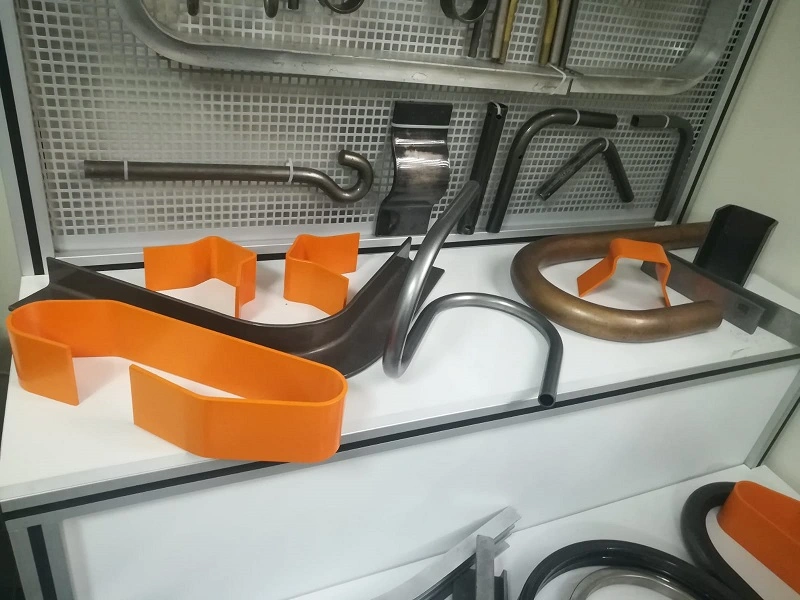
A tube bending machine is a specialized machine tool used in metalworking operations to bend metal tubes or pipes into desired shapes. These machines are commonly used in industries such as automotive, aerospace, construction, and manufacturing for producing components such as exhaust systems, handrails, and chassis frames.
Working Principle: Tube bending machines work by applying force to metal tubes or pipes to deform them into the desired shape. The machine typically consists of a bending die, a clamp die, and a mandrel (for some applications). The tube is clamped securely between the bending die and the clamp die, and a bending arm exerts force on the tube, causing it to bend around the bending die. The mandrel, if used, supports the inside of the tube to prevent wrinkling or collapsing during bending.
Types of Tube Bending Machines:
- Manual Tube Bending Machine: Operated manually using hand cranks or levers to adjust the position of the bending die and feed the tube through the machine.
- Hydraulic Tube Bending Machine: Utilizes hydraulic cylinders to apply force to the bending arm, providing greater control and precision in bending operations.
- CNC Tube Bending Machine: Equipped with computer numerical control (CNC) systems for automated operation and precise control over bending sequences, ensuring consistent quality and accuracy.
Features of Tube Bending Machines:
- Mandrel Support: Some tube bending machines feature a mandrel to support the inside of the tube during bending, preventing wrinkling or collapsing and ensuring smooth bends.
- Adjustable Bending Dies: Tube bending machines often feature interchangeable or adjustable bending dies to accommodate different tube sizes, thicknesses, and bending radii.
- Control Systems: Advanced tube bending machines may incorporate CNC systems for automated operation and precise control over bending sequences, ensuring consistent quality and accuracy.
- Safety Features: Tube bending machines are equipped with safety mechanisms such as emergency stop buttons, interlocks, and safety guards to protect operators and prevent accidents during operation.
Applications: Tube bending machines are used in various industries for producing bent components such as:
- Automotive exhaust systems: pipes, headers, and mufflers for cars, trucks, and motorcycles.
- Aerospace components: tubing for hydraulic systems, fuel lines, and pneumatic systems in aircraft and spacecraft.
- Construction: handrails, guardrails, and structural supports for buildings, bridges, and infrastructure projects.
- Furniture: frames, legs, and supports for chairs, tables, and shelving units.
- Plumbing: pipes and tubing for plumbing systems in residential, commercial, and industrial buildings.
Advantages:
- Precision: Tube bending machines offer high precision and repeatability, ensuring consistent quality of bent components.
- Versatility: Tube bending machines can bend a wide range of tube sizes, thicknesses, and materials, offering flexibility in design and manufacturing.
- Efficiency: Tube bending machines increase productivity and reduce lead times by providing fast and accurate bending operations.
- Cost-Effectiveness: Tube bending machines offer cost-effective solutions for producing bent components compared to traditional fabrication methods.
- Automation: Advanced tube bending machines with CNC control allow for automation of bending sequences, reducing the need for manual intervention and improving efficiency.
In summary, tube bending machines are essential tools in metalworking operations, offering precision, versatility, and efficiency in bending metal tubes and pipes into desired shapes for various industrial applications.
Profile Bending Machine:
A profile bending machine, also known as a section bending machine or profile roller, is a specialized machine tool used in metalworking operations to bend metal profiles such as bars, beams, channels, and angles into desired shapes. These machines are commonly used in industries such as construction, architecture, manufacturing, and metal fabrication for producing components such as frames, arches, and structural elements.
Working Principle: Profile bending machines work by passing metal profiles between a series of rollers to gradually bend them into the desired shape. The machine typically consists of three or four rolls arranged in a pyramid or pyramid-type configuration: two bottom rolls and one or two top rolls. The bottom rolls are fixed, while the top roll(s) are adjustable in both horizontal and vertical planes. By adjusting the position and angle of the rolls, profile bending machines can produce bends with different radii and dimensions according to the specifications of the workpiece.
Types of Profile Bending Machines:
- Manual Profile Bending Machine: Operated manually using hand cranks or levers to adjust the position of the top roll(s) and feed the profile through the machine.
- Hydraulic Profile Bending Machine: Utilizes hydraulic cylinders to apply force to the top roll(s), providing greater control and precision in bending operations.
- CNC Profile Bending Machine: Equipped with computer numerical control (CNC) systems for automated operation and precise control over bending sequences, ensuring consistent quality and accuracy.
Features of Profile Bending Machines:
- Adjustable Roll Positions: Profile bending machines often feature adjustable roll positions and angles, allowing for the bending of various profiles with different dimensions and radii.
- Tooling Options: Profile bending machines may support various types of tooling, such as rolls with different profiles or dies for specific bending applications.
- Control Systems: Advanced profile bending machines may incorporate CNC systems for automated operation and precise control over bending sequences, ensuring consistent quality and accuracy.
- Safety Features: Profile bending machines are equipped with safety mechanisms such as emergency stop buttons, interlocks, and safety guards to protect operators and prevent accidents during operation.
Applications: Profile bending machines are used in various industries for producing bent components such as:
- Architectural elements: handrails, balustrades, and decorative features for buildings and structures.
- Structural steel: beams, columns, trusses, and frames for construction and infrastructure projects.
- Machinery components: frames, supports, and enclosures for industrial machinery and equipment.
- Automotive components: chassis components, roll cages, and frames for vehicles and trailers.
- Furniture: frames, legs, and supports for tables, chairs, and shelving units.
Advantages:
- Precision: Profile bending machines offer high precision and repeatability, ensuring consistent quality of bent components.
- Versatility: Profile bending machines can bend a wide range of profiles, including bars, beams, channels, and angles, offering flexibility in design and manufacturing.
- Efficiency: Profile bending machines increase productivity and reduce lead times by providing fast and accurate bending operations.
- Cost-Effectiveness: Profile bending machines offer cost-effective solutions for producing bent components compared to traditional fabrication methods.
- Automation: Advanced profile bending machines with CNC control allow for automation of bending sequences, reducing the need for manual intervention and improving efficiency.
In summary, profile bending machines are essential tools in metalworking operations, offering precision, versatility, and efficiency in bending metal profiles into desired shapes for various industrial applications.
Sheet Metal Bending:
Sheet metal bending is a metalworking process used to deform a flat sheet of metal into a desired shape. It is a fundamental technique in manufacturing and fabrication industries, employed to create a wide range of products such as enclosures, brackets, panels, and structural components.
Working Principle: Sheet metal bending involves applying force to a flat metal sheet, causing it to deform and form a bend. The bending process typically takes place between a punch and a die, where the punch applies force to the metal sheet, forcing it into the shape of the die. The angle of the bend is determined by the shape and dimensions of the die, as well as the depth to which the punch penetrates into the die. Bending may occur along a straight line (known as a straight bend) or around a curved profile (known as a radius bend).
Types of Bending:
- Air Bending: In air bending, the punch does not fully penetrate the die, leaving a gap between the punch and the bottom of the die. The metal sheet is bent as it is forced into this gap, resulting in a bend angle that is greater than the die angle.
- Bottoming: In bottoming, the punch fully penetrates the die, forcing the metal sheet to conform closely to the shape of the die. This results in a bend angle that is equal to the die angle.
- Coining: Coining involves applying high pressure to the metal sheet between the punch and die to create a highly precise bend with minimal springback. This process is often used for producing precise angles and shapes in thin metal sheets.
Equipment Used:
- Press Brake: A press brake is the primary machine used for sheet metal bending. It consists of a hydraulic or mechanical press, a punch, and a die. The metal sheet is positioned between the punch and die, and the press applies force to bend the sheet into the desired shape.
- Roll Bending Machine: Roll bending machines, also known as plate rolls, can also be used for bending sheet metal into cylindrical or conical shapes. These machines use cylindrical rolls to gradually bend the sheet metal into the desired curvature.
Factors Affecting Bending:
- Material Type: Different types of metals, such as steel, aluminum, and stainless steel, have varying degrees of ductility and require different bending techniques.
- Material Thickness: Thicker materials require higher bending forces and may be subject to greater springback after bending.
- Bend Radius: The radius of the bend determines the minimum achievable bend angle and influences the amount of springback.
- Die Design: The shape and dimensions of the die determine the final shape of the bend and the achievable bend angle.
- Tooling: The selection of punch and die tooling, including the size and shape of the punch tip and die opening, affects the quality and accuracy of the bend.
Applications: Sheet metal bending is used in various industries and applications, including:
- Automotive: chassis components, brackets, panels, and body parts.
- Aerospace: structural components, panels, and enclosures.
- Electronics: housings, enclosures, and brackets for electronic devices.
- Construction: architectural elements, cladding, and structural supports.
- Machinery: frames, guards, and enclosures for industrial equipment.
Advantages:
- Versatility: Sheet metal bending allows for the creation of a wide range of complex shapes and forms.
- Precision: With the right equipment and tooling, sheet metal bending can achieve high levels of accuracy and repeatability.
- Cost-Effective: Sheet metal bending is a relatively quick and efficient process, making it cost-effective for producing large quantities of parts.
- Design Flexibility: Sheet metal bending offers designers flexibility in creating custom shapes and configurations to meet specific requirements.
In summary, sheet metal bending is a fundamental metalworking process that offers versatility, precision, and cost-effectiveness in creating a wide range of products for various industries and applications.
Sheet Metal Brake:
A sheet metal brake, also known as a press brake, is a machine tool used in metalworking to bend sheet metal into various shapes and angles. It is a vital piece of equipment in fabrication shops, automotive workshops, construction sites, and manufacturing facilities.
Working Principle: A sheet metal brake works by clamping the metal sheet between a matching set of upper and lower dies, then applying force to bend the sheet to the desired angle. The operator positions the sheet metal against a back gauge, which ensures consistent bending dimensions. The bending force is typically applied hydraulically or mechanically, using a lever or pedal mechanism.
Types of Sheet Metal Brakes:
- Manual Sheet Metal Brake: Operated by hand, a manual brake relies on the operator’s strength to bend the metal sheet. It is suitable for light-duty applications and smaller workshops.
- Hydraulic Sheet Metal Brake: Utilizes hydraulic pressure to exert force on the metal sheet, providing greater bending capacity and precision. Hydraulic brakes are suitable for heavy-duty applications and high-volume production.
- CNC Sheet Metal Brake: Equipped with computer numerical control (CNC) systems, CNC brakes offer automated operation and precise control over bending sequences. They are ideal for complex bending tasks and large-scale production runs.
Features of Sheet Metal Brakes:
- Adjustable Back Gauge: Allows the operator to set precise bending dimensions, ensuring consistency and accuracy in the finished parts.
- Removable Fingers: Fingers or clamping bars can be removed or repositioned to accommodate different bending setups and sheet sizes.
- Bending Capacity: Sheet metal brakes come in various sizes and capacities to handle different sheet thicknesses and lengths.
- Safety Guards: Safety features such as guards and interlocks protect the operator from injury during bending operations.
- Foot Pedal: Some brakes feature a foot pedal for hands-free operation, allowing the operator to keep both hands on the workpiece during bending.
Applications: Sheet metal brakes are used in a wide range of applications across various industries, including:
- Fabrication: Bending sheet metal to create enclosures, brackets, panels, and structural components.
- Automotive: Forming body panels, chassis components, brackets, and trim pieces.
- Construction: Manufacturing ductwork, flashing, gutters, and architectural elements.
- Aerospace: Producing aircraft components, panels, and structural assemblies.
- HVAC: Fabricating ducting, vents, and other HVAC system components.
Advantages:
- Versatility: Sheet metal brakes can bend a wide range of materials, including steel, aluminum, stainless steel, and copper.
- Precision: With proper setup and adjustment, sheet metal brakes can achieve precise bends with consistent angles and dimensions.
- Efficiency: Sheet metal brakes offer fast cycle times and high productivity, making them ideal for batch production and repetitive tasks.
- Cost-Effectiveness: Investing in a sheet metal brake can save money over time by reducing outsourcing costs and increasing in-house manufacturing capabilities.
In summary, sheet metal brakes are essential tools in metalworking operations, offering versatility, precision, and efficiency in bending sheet metal to create a wide range of parts and components for various industries and applications.
Bending Force:
Bending force refers to the amount of force required to bend a material, typically metal, into a desired shape or angle. It is a crucial parameter in metalworking processes such as bending, forming, and stamping, as it directly affects the quality and accuracy of the finished part.
Factors Affecting Bending Force:
- Material Type: Different materials have varying degrees of ductility and strength, affecting the amount of force required to bend them. For example, softer metals like aluminum require less force compared to harder metals like steel.
- Material Thickness: Thicker materials require more bending force to deform them, as they offer greater resistance to bending. Thinner materials, on the other hand, require less force but may be more prone to wrinkling or buckling.
- Bend Radius: The radius of the bend influences the amount of material deformation and, consequently, the bending force required. Smaller bend radii typically require higher bending forces.
- Bend Angle: The angle of the bend also affects the bending force, with sharper angles requiring more force to achieve.
- Tooling Design: The design and condition of the bending tooling, including the punch and die, can impact the distribution of force and the quality of the bend. Worn or improperly designed tooling may result in inconsistent bending forces and poor-quality bends.
- Machine Capacity: The capacity of the bending machine, including its tonnage rating and working length, determines its ability to apply the necessary force to bend the material effectively. Insufficient machine capacity may lead to incomplete or inaccurate bends.
Measuring Bending Force: Bending force is typically measured in units of force, such as pounds-force (lbf) or Newtons (N). It can be measured directly using load cells or force sensors integrated into the bending machine or indirectly calculated based on machine parameters such as hydraulic pressure, ram speed, and material properties.
Importance of Bending Force:
- Quality Assurance: Controlling bending force ensures that parts are bent accurately and consistently, meeting dimensional tolerances and quality standards.
- Preventing Material Damage: Applying excessive force can lead to material deformation, wrinkling, cracking, or springback, compromising the integrity and appearance of the finished part.
- Optimizing Production: Understanding bending force helps optimize production processes by selecting the appropriate tooling, machine settings, and material specifications to achieve efficient and cost-effective bending operations.
- Safety: Monitoring bending force helps ensure the safe operation of bending machines, preventing equipment damage and minimizing the risk of accidents or injuries to operators.
In summary, bending force is a critical parameter in metalworking processes, influencing the quality, accuracy, and efficiency of bending operations. By understanding the factors affecting bending force and implementing appropriate control measures, manufacturers can achieve optimal bending results while ensuring product quality and safety.
Springback in Bending:
Springback is a phenomenon that occurs in metal bending processes where the material partially returns to its original shape after the bending force is removed. It is a common challenge in metalworking operations such as bending, forming, and stamping, and it can impact the dimensional accuracy and quality of the finished part.
Causes of Springback:
- Elastic Deformation: When a metal material is bent, it undergoes elastic deformation, where it temporarily changes shape under the applied stress. Once the bending force is removed, the material attempts to return to its original shape due to its elastic properties, resulting in springback.
- Material Properties: The material’s composition, including its modulus of elasticity and yield strength, influences its tendency to spring back after bending. Softer materials exhibit greater springback compared to harder materials.
- Bend Radius: Smaller bend radii result in greater material deformation during bending, leading to higher levels of springback. Larger bend radii reduce the severity of springback but may require more force to achieve the bend.
- Bend Angle: Sharp bends or angles increase the likelihood of springback, as they induce higher levels of stress and strain in the material.
- Tooling and Machine Setup: Inadequate tooling design, improper die selection, or incorrect machine settings can contribute to uneven bending and excessive springback.
Effects of Springback:
- Dimensional Inaccuracy: Springback can lead to deviations from the desired bend angle or shape, resulting in parts that do not meet dimensional tolerances.
- Poor Surface Finish: Excessive springback may cause wrinkling, buckling, or surface defects in the bent part, compromising its appearance and quality.
- Assembly Issues: Parts with significant springback may not fit properly during assembly, leading to assembly difficulties or functional issues in the final product.
- Increased Scrap Rate: Parts that experience excessive springback may need to be reworked or scrapped, increasing production costs and reducing overall efficiency.
Mitigation Strategies:
- Overbending: Compensating for springback by bending the material slightly beyond the desired angle or shape to account for the anticipated springback.
- Material Selection: Choosing materials with lower levels of springback or higher ductility can help minimize the effects of springback.
- Tooling Design: Using proper tooling design, including selecting the appropriate punch and die profiles and radii, can reduce the severity of springback.
- Incremental Bending: Performing multiple small bends instead of a single large bend can help distribute stress more evenly, reducing springback.
- Post-Bending Processes: Applying secondary processes such as stress relieving, heat treatment, or shot peening can help stabilize the material and minimize springback.
In summary, springback is a common challenge in metal bending processes that can impact the dimensional accuracy, quality, and production efficiency of bent parts. By understanding the causes and effects of springback and implementing appropriate mitigation strategies, manufacturers can minimize its impact and achieve more consistent and accurate bending results.
Bend Allowance:
Bend allowance is a critical concept in sheet metal bending that represents the amount of material elongation or stretching required to achieve a desired bend angle. It accounts for the material’s thickness and the bend radius to calculate the flat pattern dimensions accurately before bending.
Calculation of Bend Allowance: The bend allowance is calculated based on the material thickness (T), bend angle (θ), and bend radius (R) using the following formula:
Bend Allowance (BA) = [(π/180) × θ × (R + (K × T))]
Where:
- θ is the bend angle in degrees.
- R is the bend radius.
- T is the material thickness.
- K is the K-factor, a coefficient that depends on the material type, bending method, and tooling used.
Key Points:
- Material Thickness: Thicker materials require more elongation during bending, resulting in a larger bend allowance.
- Bend Angle: Greater bend angles require more material elongation and, consequently, a larger bend allowance.
- Bend Radius: Smaller bend radii result in greater material stretching and a larger bend allowance.
- K-Factor: The K-factor accounts for the material’s behavior during bending and varies based on factors such as material type, bending method, and tooling geometry.
- Flat Pattern Dimensions: Adding the bend allowance to the flat pattern dimensions ensures that the bent part will achieve the desired dimensions after bending.
Importance of Bend Allowance:
- Accuracy: Calculating the bend allowance accurately ensures that the flat pattern dimensions are adjusted correctly to achieve the desired dimensions after bending.
- Quality: Properly accounting for the bend allowance helps minimize dimensional variations, springback, and surface distortions in the finished part.
- Efficiency: Understanding the bend allowance allows manufacturers to optimize material usage, reduce scrap, and improve production efficiency.
- Tooling Design: Incorporating the bend allowance into tooling design ensures that punch and die profiles are appropriately sized to achieve the desired bend dimensions.
- Cost Savings: By optimizing bend allowance calculations, manufacturers can reduce material waste, rework, and production costs associated with scrap and rejected parts.
Applications: Bend allowance calculations are essential in various sheet metal bending applications, including:
- Manufacturing of enclosures, brackets, panels, and structural components.
- Automotive body panels, chassis components, and trim parts.
- Aerospace structural assemblies, panels, and aircraft components.
- HVAC ducting, vents, and equipment enclosures.
- Architectural elements, cladding, and decorative features.
In summary, bend allowance is a fundamental concept in sheet metal bending that ensures accurate flat pattern dimensions and facilitates efficient and precise bending operations. By understanding and properly calculating the bend allowance, manufacturers can achieve consistent quality, minimize waste, and optimize production processes in sheet metal fabrication.
Die Opening:
In sheet metal bending processes, the die opening refers to the gap between the two halves of the die through which the metal sheet is bent. It is a critical parameter that directly influences the accuracy, quality, and dimensional characteristics of the bent part.
Key Aspects:
- Gap Width: The die opening width determines the inner radius of the bend and affects the final dimensions of the bent part. It is typically slightly larger than the thickness of the material being bent to accommodate material deformation and minimize surface imperfections.
- Bend Radius: The die opening, along with the punch radius and material thickness, determines the bend radius of the finished part. Smaller die openings result in tighter bend radii, while larger die openings produce more gradual bends.
- Material Thickness: The die opening must be carefully selected based on the material thickness to ensure proper material deformation during bending. Thicker materials may require wider die openings to prevent overloading and distortion.
- Material Type: Different materials exhibit varying degrees of ductility and elasticity, which can affect their behavior during bending. The die opening should be adjusted accordingly to accommodate the specific characteristics of the material being bent.
Importance:
- Dimensional Accuracy: The die opening directly influences the final dimensions and geometry of the bent part. Proper selection and adjustment of the die opening are essential to achieve accurate bend angles and bend radii.
- Surface Finish: The die opening width affects the surface quality of the bent part, with smaller die openings generally resulting in smoother, more uniform bends. Larger die openings may lead to surface imperfections such as wrinkles or ridges.
- Material Deformation: The die opening width must be carefully controlled to ensure optimal material deformation during bending. Insufficient die opening may cause material overloading and cracking, while excessive die opening may result in under bending and springback.
- Tooling Selection: Die openings are selected based on factors such as material thickness, bend radius, and desired bend angle. Proper tooling selection and setup are crucial for achieving consistent and high-quality bends.
- Production Efficiency: Optimizing die opening dimensions and tooling setups can improve production efficiency by minimizing scrap, reducing setup times, and enhancing overall process reliability.
Applications:
Die openings are used in various sheet metal bending applications across industries such as:
- Manufacturing of enclosures, cabinets, brackets, and structural components.
- Automotive body panels, chassis components, and interior trim parts.
- Aerospace structural assemblies, panels, and aircraft components.
- HVAC ducting, vents, and equipment enclosures.
- Architectural elements, cladding, and decorative features.
In summary, the die opening is a critical parameter in sheet metal bending processes, influencing the dimensional accuracy, surface finish, and material deformation characteristics of the bent part. Proper selection and adjustment of the die opening are essential for achieving high-quality bends and optimizing production efficiency in sheet metal fabrication.
Die Rollers:
Die rollers, also known as bending rollers or forming rollers, are components of bending machines used in sheet metal fabrication processes. They play a crucial role in guiding and shaping metal sheets as they pass through the bending machine, enabling the creation of precise bends and curves according to the desired specifications.
Functionality:
- Material Guidance: Die rollers guide the metal sheet as it passes through the bending machine, ensuring smooth and controlled movement during the bending process. They help prevent material misalignment or distortion, ensuring accurate and consistent bends.
- Bend Formation: Die rollers are designed with specific profiles to shape the metal sheet into the desired bend radius or curve. By adjusting the position and alignment of the rollers, operators can control the shape and dimensions of the bent parts.
- Material Support: Die rollers provide support to the metal sheet as it undergoes bending, reducing the risk of material buckling, wrinkling, or deformation. Properly aligned and calibrated rollers distribute the bending force evenly across the material, minimizing stress concentrations and improving bend quality.
- Springback Compensation: In some bending applications, die rollers may be equipped with features such as adjustable tension or pressure settings to compensate for springback, the tendency of metal to return to its original shape after bending. By applying controlled pressure to the metal sheet, die rollers can help minimize springback and achieve more accurate bend angles and dimensions.
Types of Die Rollers:
- Top Rollers: Top rollers are located above the metal sheet and exert downward pressure to shape the material as it passes through the bending machine. They are typically adjustable in both horizontal and vertical directions to accommodate different bending configurations and material thicknesses.
- Bottom Rollers: Bottom rollers are positioned below the metal sheet and provide support and stability during bending operations. They may be fixed or adjustable depending on the specific requirements of the bending process.
- Side Rollers: Side rollers are optional components that can be used to guide and support the edges of the metal sheet during bending, particularly in applications involving large or heavy materials. They help maintain proper alignment and prevent material distortion during bending.
Applications:
Die rollers are used in various sheet metal bending applications across industries such as:
- Manufacturing of cylindrical or conical parts, such as pipes, tubes, and cylinders.
- Fabrication of curved or arched components, including frames, brackets, and architectural elements.
- Production of complex shapes and profiles for automotive, aerospace, and industrial equipment.
Advantages:
- Precision: Die rollers enable precise control over bend angles, radii, and dimensions, ensuring accurate and consistent results in sheet metal bending operations.
- Versatility: With adjustable settings and interchangeable profiles, die rollers can accommodate a wide range of bending configurations and material types.
- Efficiency: By reducing material handling and setup times, die rollers contribute to increased productivity and cost-effectiveness in sheet metal fabrication processes.
- Quality: Properly maintained and calibrated die rollers help minimize defects such as wrinkling, buckling, or surface imperfections, resulting in high-quality finished parts.
In summary, die rollers are essential components of bending machines, providing guidance, support, and shaping capabilities to metal sheets during the bending process. Their precise functionality and versatility make them indispensable tools in sheet metal fabrication, enabling the production of complex and accurate bent parts for various industrial applications.
Bend Deduction:
Bend deduction is a critical concept in sheet metal bending that accounts for the dimensional changes that occur in the material during bending. It is used to calculate the flat pattern dimensions needed to achieve the desired dimensions in the finished bent part accurately.
Definition: Bend deduction refers to the difference between the total flat pattern length of the material and the sum of the lengths of the two flanges in the bent part. It represents the amount of material consumed or deducted during bending due to stretching and deformation.
Calculation of Bend Deduction: Bend deduction can be calculated using the following formula:
Bend Deduction (BD) = (K × π × R) + (T × (π/180) × θ)
Where:
- K is the K-factor, a coefficient that depends on the material type, thickness, bending method, and tooling used.
- R is the bend radius.
- T is the material thickness.
- θ is the bend angle in degrees.
Key Points:
- Material Stretching: During bending, the outer surface of the material stretches, while the inner surface compresses. This elongation and compression result in changes to the material’s dimensions, which must be accounted for in the flat pattern layout.
- K-Factor Influence: The K-factor accounts for the material’s behavior during bending and varies based on factors such as material type, thickness, bend radius, and bending method. It is used to adjust the flat pattern dimensions to compensate for material stretching and deformation.
- Material Thickness and Bend Angle: Thicker materials and sharper bend angles require larger bend deductions due to increased material stretching and deformation.
Importance of Bend Deduction:
- Dimensional Accuracy: Calculating the bend deduction accurately ensures that the flat pattern dimensions are adjusted correctly to compensate for material stretching and deformation. This results in bent parts that meet the desired dimensional tolerances and specifications.
- Quality Assurance: Properly accounting for bend deduction helps minimize dimensional variations, springback, and surface distortions in the finished part, ensuring high-quality and consistent bends.
- Tooling Design: Incorporating bend deduction into tooling design ensures that punch and die profiles are appropriately sized to achieve the desired bend dimensions. It helps optimize tooling setups and minimize scrap and rework.
- Efficiency: Understanding bend deduction allows manufacturers to optimize material usage, reduce scrap, and improve production efficiency by accurately predicting the material consumption during bending operations.
Applications: Bend deduction calculations are essential in various sheet metal bending applications across industries such as:
- Manufacturing of enclosures, cabinets, brackets, and structural components.
- Automotive body panels, chassis components, and interior trim parts.
- Aerospace structural assemblies, panels, and aircraft components.
- HVAC ducting, vents, and equipment enclosures.
- Architectural elements, cladding, and decorative features.
In summary, bend deduction is a fundamental concept in sheet metal bending that ensures accurate flat pattern dimensions and facilitates efficient and precise bending operations. By understanding and properly calculating bend deduction, manufacturers can achieve consistent quality, minimize waste, and optimize production processes in sheet metal fabrication.
Wipe Bending:
Wipe bending is a common sheet metal bending technique used to create bends with large bend radii and minimal material deformation. It is characterized by the use of a flexible pad or “wipe die” that contacts the metal sheet along the bend line to gradually form the desired angle.
Working Principle: In wipe bending, the metal sheet is placed over the bend line on the die, and a flexible pad or cushion is brought into contact with the sheet along the bend line. As the punch descends, the pad applies pressure evenly across the bend line, gradually forming the material around the die radius without causing excessive stretching or distortion. The result is a smooth, uniform bend with a large radius and minimal springback.
Key Features:
- Flexible Pad: The flexible pad, also known as the wipe die or cushion, is typically made of materials such as urethane or rubber and conforms to the shape of the die radius. It distributes pressure evenly along the bend line, preventing localized deformation and surface imperfections.
- Die Design: The die used in wipe bending has a large radius that matches the desired bend radius in the finished part. It supports the material during bending and helps maintain uniform pressure distribution to achieve consistent bend angles and dimensions.
- Punch Configuration: The punch used in wipe bending may have a matching radius to the die or a slightly smaller radius to prevent interference with the material during bending. It applies downward force to the material, working in conjunction with the flexible pad to form the bend.
- Material Considerations: Wipe bending is suitable for a wide range of sheet metal materials, including aluminum, steel, stainless steel, and copper. It is particularly effective for thin to medium-gauge materials that require large bend radii and precise control over bending angles.
- Bend Accuracy: Wipe bending offers high precision and repeatability, allowing for the creation of complex bends with tight dimensional tolerances. It produces bends with minimal surface imperfections, reducing the need for secondary finishing operations.
Advantages:
- Large Bend Radii: Wipe bending is ideal for creating bends with large radii, which are often difficult to achieve using other bending methods.
- Minimal Material Deformation: The gradual forming process and even pressure distribution in wipe bending minimize material stretching, distortion, and surface imperfections.
- Consistent Bend Quality: Wipe bending produces uniform bends with precise angles and dimensions, ensuring high-quality finished parts.
- Reduced Springback: The controlled bending process in wipe bending helps minimize springback, allowing for accurate bend angles and dimensions without the need for excessive overbending.
Applications: Wipe bending is used in various industries for applications such as:
- Manufacturing of curved or rounded components, including enclosures, brackets, and frames.
- Production of architectural elements, decorative features, and furniture components.
- Automotive body panels, trim parts, and structural components.
- Aerospace structural assemblies, panels, and aircraft components.
- HVAC ducting, piping, and equipment enclosures.
In summary, wipe bending is a versatile and precise sheet metal bending technique suitable for creating bends with large radii and minimal material deformation. Its ability to produce high-quality bends with tight dimensional tolerances makes it an essential process in various manufacturing industries.
Rotary Bending:
Rotary bending, also known as roll bending or pyramid rolling, is a sheet metal bending process that utilizes a set of rollers to gradually bend a metal sheet into a curved or cylindrical shape. It is commonly used to produce cylindrical, conical, or curved parts with consistent radii along their length.
Working Principle: In rotary bending, the metal sheet is fed between a set of rollers arranged in a pyramid or triangular configuration. As the sheet passes through the rollers, they gradually apply pressure to bend the material around the desired radius. The position and alignment of the rollers determine the shape and dimensions of the bent part, allowing for precise control over bend radii and curvature.
Key Features:
- Roller Configuration: The rollers used in rotary bending are typically arranged in a pyramid or triangular configuration, with each roller applying pressure to the material as it passes through. The number and alignment of the rollers can be adjusted to achieve different bend radii and shapes.
- Material Support: Rotary bending provides continuous support to the metal sheet as it undergoes bending, reducing the risk of material distortion, wrinkling, or buckling. The rollers distribute pressure evenly across the material, ensuring uniform bending along its length.
- Bend Radius Control: The radius of the bent part is determined by the distance between the rollers and the material thickness. By adjusting the position and spacing of the rollers, operators can control the bend radius and curvature of the finished part.
- Multiple Passes: In rotary bending, the metal sheet may undergo multiple passes through the rollers to achieve the desired bend radius or curvature gradually. Each pass incrementally bends the material, allowing for precise control over the bending process.
- Material Compatibility: Rotary bending is suitable for a wide range of sheet metal materials, including aluminum, steel, stainless steel, and copper. It is particularly effective for thin to medium-gauge materials that require smooth, consistent bends without material deformation.
- Versatility: Rotary bending can produce a variety of bent shapes, including cylindrical, conical, and curved profiles. It is widely used in applications where uniform curvature and precise bend radii are required, such as in the automotive, aerospace, and architectural industries.
Advantages:
- Consistent Bend Quality: Rotary bending produces uniform bends with consistent radii along the length of the material, ensuring high-quality finished parts.
- Versatility: Rotary bending can accommodate a wide range of material thicknesses and bend radii, making it suitable for diverse bending applications.
- Efficiency: Rotary bending can bend long lengths of material in a single pass, reducing production time and material waste compared to other bending methods.
- Complex Shapes: Rotary bending can produce complex shapes and profiles with multiple bends and contours, allowing for the creation of customized parts and components.
- Cost-Effectiveness: Rotary bending offers cost-effective bending solutions for both small-scale and large-scale production runs, making it a preferred choice for many manufacturers.
Applications: Rotary bending is used in various industries for applications such as:
- Manufacturing of cylindrical or conical parts, including pipes, tubes, and cylinders.
- Production of curved or arched components, such as frames, brackets, and structural members.
- Fabrication of structural assemblies, panels, and enclosures for automotive, aerospace, and industrial equipment.
- Architectural elements, including curved facades, handrails, and decorative features.
In summary, rotary bending is a versatile and efficient sheet metal bending process that offers precise control over bend radii and curvature. Its ability to produce consistent, high-quality bends makes it an essential process in various manufacturing industries for creating cylindrical, conical, and curved parts and components.
Air Bending:
Air bending is a common sheet metal bending process that uses a press brake and a punch and die set to bend the material into the desired shape. Unlike bottoming or coining, air bending does not require the punch to bottom out in the die, allowing for greater flexibility and versatility in bending operations.
Working Principle: In air bending, the metal sheet is placed between the punch and die of a press brake, and the punch descends to apply force to the material. The material is bent as it is forced into the die cavity, with the punch stopping short of fully bottoming out in the die. The amount of force applied determines the bend angle, while the distance between the punch and die sets the bend radius.
Key Features:
- Flexibility: Air bending allows for a wide range of bend angles and bend radii to be achieved with a single punch and die set. By adjusting the punch stroke and material thickness, operators can produce a variety of bend configurations without changing tooling.
- Material Support: Unlike bottoming or coining, air bending does not require the punch to fully bottom out in the die. This reduces the risk of material distortion, wrinkling, or cracking, as the material is supported by the die throughout the bending process.
- Bend Angle Control: Air bending offers precise control over bend angles, allowing for tight dimensional tolerances and consistent bend quality. The punch stroke and backgauge positioning can be adjusted to achieve the desired bend angle accurately.
- Material Thickness: Air bending is suitable for a wide range of sheet metal thicknesses, from thin gauges to thick plates. By adjusting the bending parameters, operators can bend a variety of materials, including aluminum, steel, stainless steel, and copper.
- Tooling Compatibility: Air bending can be performed using standard punch and die sets designed for press brakes. The same tooling can be used for a range of bend configurations, reducing setup time and tooling costs.
Advantages:
- Versatility: Air bending allows for a wide range of bend angles and radii to be achieved with a single set of tooling, making it suitable for a variety of bending applications.
- Efficiency: Air bending offers fast cycle times and high production rates, making it an efficient choice for both small-scale and large-scale production runs.
- Quality: Air bending produces uniform bends with precise angles and dimensions, ensuring high-quality finished parts.
- Material Conservation: Air bending minimizes material waste by allowing for tighter nesting of parts and reducing scrap compared to other bending methods.
- Safety: Air bending is a safe bending method that minimizes the risk of tooling damage, material distortion, and operator injury. The punch and die are less likely to be damaged due to the reduced force exerted during bending.
Applications: Air bending is used in various industries for applications such as:
- Manufacturing of enclosures, cabinets, brackets, and structural components.
- Automotive body panels, chassis components, and interior trim parts.
- Aerospace structural assemblies, panels, and aircraft components.
- HVAC ducting, vents, and equipment enclosures.
- Architectural elements, cladding, and decorative features.
In summary, air bending is a versatile and efficient sheet metal bending process that offers precise control over bend angles and dimensions. Its flexibility, efficiency, and quality make it a preferred choice for many manufacturers in a wide range of industries for producing high-quality bent parts and components.
Bottoming Bending:
Bottoming bending, also known as bottom bending or coining, is a sheet metal bending process that involves applying pressure to the metal sheet until it fully conforms to the shape of the die cavity. This method is commonly used to produce precise bends with tight dimensional tolerances and minimal springback.
Working Principle: In bottoming bending, the metal sheet is placed between the punch and die of a press brake, and the punch descends to apply force to the material. Unlike air bending, in which the punch stops short of fully bottoming out in the die, bottoming bending requires the punch to fully bottom out, compressing the material into the die cavity. The material is formed to the shape of the die, resulting in a bend with a sharp inside corner and minimal radius.
Key Features:
- Material Compression: Bottoming bending involves compressing the material between the punch and die until it fully conforms to the shape of the die cavity. This results in a bend with precise dimensions and sharp inside corners.
- Tight Tolerances: Bottoming bending allows for tight dimensional tolerances to be achieved, making it suitable for applications that require high precision and accuracy.
- Springback Reduction: By fully bottoming out the punch in the die, bottoming bending minimizes springback, the tendency of the material to return to its original shape after bending. This results in bent parts with more consistent bend angles and dimensions.
- Material Support: Bottoming bending provides continuous support to the material throughout the bending process, reducing the risk of material distortion, wrinkling, or buckling.
- Tooling Design: Bottoming bending requires specialized tooling with a precise die cavity and matching punch profile. The die cavity is typically designed with a sharp inside corner to produce bends with minimal radius.
Advantages:
- Precision: Bottoming bending produces bends with precise dimensions and sharp inside corners, making it ideal for applications that require tight tolerances.
- Springback Reduction: By fully compressing the material into the die cavity, bottoming bending minimizes springback, resulting in bent parts with more accurate bend angles and dimensions.
- Quality: Bottoming bending produces high-quality bends with uniform dimensions and minimal surface imperfections.
- Material Compatibility: Bottoming bending is suitable for a wide range of sheet metal materials, including aluminum, steel, stainless steel, and copper.
- Versatility: Bottoming bending can be used to produce a variety of bend configurations, including straight bends, offsets, and flanges.
Applications: Bottoming bending is used in various industries for applications such as:
- Manufacturing of enclosures, cabinets, brackets, and structural components.
- Automotive body panels, chassis components, and interior trim parts.
- Aerospace structural assemblies, panels, and aircraft components.
- HVAC ducting, vents, and equipment enclosures.
- Architectural elements, cladding, and decorative features.
In summary, bottoming bending is a precision sheet metal bending process that produces bends with tight dimensional tolerances and minimal springback. Its ability to achieve precise bends with sharp inside corners makes it a preferred choice for applications that require high precision and accuracy in bent parts and components.
Springback Compensation:
Springback compensation is a technique used in sheet metal bending to account for the elastic recovery of the material after bending. When a metal sheet is bent, it undergoes deformation, but upon release of the bending force, it tends to partially or fully return to its original shape due to its inherent elasticity. Springback compensation aims to anticipate and offset this elastic recovery to achieve the desired final shape accurately.
Working Principle: During the bending process, the material experiences plastic deformation, causing it to take on the shape of the die. However, once the bending force is removed, the material undergoes elastic recovery, leading to springback. To compensate for this, the bending parameters are adjusted to overbend the material slightly during the initial bending process. This overbending allows for the material to spring back to the desired final shape, effectively canceling out the effects of springback.
Key Aspects:
- Bend Angle Adjustment: Springback compensation involves adjusting the bend angle slightly beyond the desired final angle during the bending process. The degree of overbending depends on factors such as material type, thickness, and bend radius.
- Material Properties: The degree of springback varies depending on the material’s elasticity, ductility, and mechanical properties. Materials with higher elastic modulus and yield strength exhibit less springback, while those with lower modulus and higher ductility may experience more significant springback.
- Tooling Setup: Springback compensation requires precise control over the bending parameters, including punch stroke, die clearance, and backgauge positioning. Proper tooling setup ensures that the material is bent to the correct angle to account for springback.
- Trial and Error: Achieving optimal springback compensation often involves iterative adjustments and testing to fine-tune the bending parameters. Trial runs may be conducted to validate the effectiveness of the compensation technique and make necessary adjustments.
- Simulation Software: Advanced bending simulation software can be used to predict springback behavior and optimize bending parameters virtually. By simulating the bending process, manufacturers can anticipate springback and adjust the compensation accordingly before actual production runs.
Advantages:
- Accuracy: Springback compensation improves the accuracy of bent parts by anticipating and counteracting the effects of elastic recovery, resulting in parts with the desired final dimensions and angles.
- Consistency: By compensating for springback, manufacturers can achieve more consistent bend angles and dimensions across multiple parts, reducing variation and scrap rates.
- Quality: Springback compensation helps maintain bend quality by minimizing the need for rework or correction due to dimensional inaccuracies caused by springback.
- Efficiency: Optimizing springback compensation reduces the time and material wasted on trial and error adjustments, leading to more efficient bending operations and higher productivity.
- Cost Savings: Minimizing scrap and rework associated with springback issues can result in cost savings for manufacturers by maximizing material utilization and reducing production time.
Applications: Springback compensation is used in various sheet metal bending applications across industries such as:
- Manufacturing of enclosures, cabinets, brackets, and structural components.
- Automotive body panels, chassis components, and interior trim parts.
- Aerospace structural assemblies, panels, and aircraft components.
- HVAC ducting, vents, and equipment enclosures.
- Architectural elements, cladding, and decorative features.
In summary, springback compensation is a critical technique in sheet metal bending that improves the accuracy, consistency, and quality of bent parts by addressing the effects of elastic recovery. By anticipating and offsetting springback, manufacturers can achieve more precise bend angles and dimensions, leading to higher quality and efficiency in sheet metal fabrication.
Die Opening:
Die opening, also known as die clearance, is a crucial parameter in sheet metal bending that determines the gap between the punch and die during the bending process. It plays a significant role in controlling the bend radius, reducing material deformation, and ensuring accurate bend angles and dimensions.
Working Principle: During sheet metal bending, the material is placed between the punch and die of a press brake, and the punch descends to apply force, bending the material around the die. The die opening refers to the clearance or gap between the punch and die. The size of this gap affects the bend radius, material deformation, and overall bend quality.
Key Aspects:
- Bend Radius Control: Die opening influences the bend radius, with smaller clearances resulting in tighter bend radii and larger clearances producing larger radii. Controlling the die opening allows manufacturers to achieve the desired bend radius for specific applications.
- Material Thickness Consideration: The die opening must be selected based on the material thickness to prevent overbending or underbending. Thicker materials typically require larger die openings to accommodate greater material compression during bending.
- Die Material and Coating: The material and surface finish of the die affect the friction between the punch and die and influence the required die opening. Proper die selection and maintenance are essential to ensure consistent bend quality and prolong tool life.
- Springback Compensation: Die opening is adjusted to account for springback, the elastic recovery of the material after bending. By slightly increasing the die opening, manufacturers can compensate for springback and achieve the desired final bend angle and dimensions.
- Tooling Wear: Over time, wear and tear on the punch and die can affect the die opening and lead to variations in bend quality. Regular inspection and maintenance of tooling are necessary to ensure consistent performance and bend accuracy.
Importance:
- Bend Quality: Proper die opening selection is critical for achieving accurate bend angles and dimensions, minimizing material deformation, and reducing the risk of surface imperfections such as wrinkling or buckling.
- Material Utilization: Optimal die opening helps maximize material utilization by reducing scrap and minimizing material waste. By controlling the bend radius and minimizing excess material deformation, manufacturers can optimize material usage and reduce production costs.
- Tooling Life: Maintaining the appropriate die opening helps prolong the life of the punch and die by reducing wear and preventing premature tool failure. Consistent tooling performance ensures reliable bend quality and production efficiency over time.
- Productivity: Efficient die opening setup and adjustment contribute to overall productivity by reducing setup time, minimizing trial and error, and streamlining bending operations. Well-maintained tooling and precise die opening control enable faster, more accurate bending processes.
- Quality Assurance: Die opening plays a key role in quality assurance by ensuring that bent parts meet dimensional tolerances, surface finish requirements, and other quality specifications. Consistent die opening adjustment helps maintain bend consistency and overall part quality.
Applications: Die opening control is essential in various sheet metal bending applications across industries such as:
- Manufacturing of enclosures, cabinets, brackets, and structural components.
- Automotive body panels, chassis components, and interior trim parts.
- Aerospace structural assemblies, panels, and aircraft components.
- HVAC ducting, vents, and equipment enclosures.
- Architectural elements, cladding, and decorative features.
In summary, die opening is a critical parameter in sheet metal bending that influences bend quality, material utilization, tooling life, productivity, and quality assurance. Proper die opening selection and control are essential for achieving accurate bend angles and dimensions, minimizing material deformation, and ensuring consistent bend quality in sheet metal fabrication.
Sheet Metal Bend Allowance:
Sheet metal bend allowance refers to the amount of material required for a bend in a metal sheet, taking into account factors such as bend radius, material thickness, and bend angle. It is a critical consideration in sheet metal bending operations to ensure accurate dimensions and angles in the finished part.
Working Principle: When a metal sheet is bent, the material along the inside radius of the bend is compressed, while the material along the outside radius is stretched. The bend allowance compensates for these changes in material length to ensure that the final dimensions of the bent part match the desired specifications. It represents the additional material length required for the bend and is calculated based on the bend radius, material thickness, and bend angle.
Key Aspects:
- Bend Radius: The bend radius is the radius of the curvature formed during bending. A smaller bend radius requires more material compression and stretching, resulting in a larger bend allowance, while a larger bend radius requires less material deformation and a smaller bend allowance.
- Material Thickness: Thicker materials require more material for bending compared to thinner materials, leading to larger bend allowances. The thickness of the material directly affects the amount of material deformation and the resulting bend allowance.
- Bend Angle: The bend angle is the angle between the original and bent surfaces of the metal sheet. Larger bend angles require more material for bending, resulting in larger bend allowances, while smaller bend angles require less material and smaller bend allowances.
- Bend Allowance Calculation: The bend allowance is calculated using mathematical formulas or tables based on the specific bending parameters, including bend radius, material thickness, and bend angle. Various equations and empirical formulas are available to accurately determine the bend allowance for different bending scenarios.
- Accuracy: Accurate calculation of the bend allowance is essential for achieving precise dimensions and angles in the finished part. Proper allowance calculation ensures that the bent part meets dimensional tolerances and design requirements.
Importance:
- Dimensional Accuracy: The correct bend allowance ensures that the final dimensions of the bent part match the desired specifications, minimizing dimensional variations and ensuring part accuracy.
- Bend Quality: Proper allowance calculation helps prevent issues such as overbending or underbending, material wrinkling, and surface imperfections, resulting in high-quality bends with smooth surfaces and precise angles.
- Material Utilization: Optimizing the bend allowance helps maximize material utilization by minimizing scrap and reducing material waste. By accurately calculating the required material for bending, manufacturers can optimize material usage and reduce production costs.
- Tooling Optimization: Understanding the bend allowance allows manufacturers to optimize tooling design and setup for efficient bending operations. Proper tooling selection and adjustment help achieve consistent bend quality and improve overall productivity.
- Design Consideration: Bend allowance calculation is an essential consideration in sheet metal part design. Designers must account for the bend allowance to ensure that the final dimensions of the part meet functional requirements and manufacturing constraints.
Applications: Sheet metal bend allowance calculation is critical in various sheet metal bending applications across industries such as:
- Manufacturing of enclosures, cabinets, brackets, and structural components.
- Automotive body panels, chassis components, and interior trim parts.
- Aerospace structural assemblies, panels, and aircraft components.
- HVAC ducting, vents, and equipment enclosures.
- Architectural elements, cladding, and decorative features.
In summary, sheet metal bend allowance is a fundamental concept in sheet metal bending that ensures accurate dimensions, angles, and bend quality in finished parts. Proper allowance calculation is essential for achieving dimensional accuracy, minimizing material waste, optimizing tooling setup, and ensuring efficient bending operations in sheet metal fabrication.
Back Gauge:
A back gauge is an essential component of a press brake machine used in sheet metal bending operations. It serves as a reference point and positioning system to accurately position the metal sheet before bending, ensuring precise bend angles and dimensions.
Working Principle: The back gauge consists of a series of adjustable fingers or stops positioned behind the bending die of the press brake. Before bending, the metal sheet is placed against the back gauge, and the gauge fingers are adjusted to the desired position based on the required bend length. The back gauge holds the material in place during bending, ensuring consistent bend positioning and dimensional accuracy.
Key Aspects:
- Positioning Accuracy: The back gauge provides precise positioning of the metal sheet before bending, ensuring consistent bend angles and dimensions across multiple parts.
- Adjustability: Back gauge fingers can be adjusted horizontally to accommodate different bend lengths and part geometries. This allows for flexibility in bending operations and the production of a variety of part configurations.
- Multiple Stops: Some press brakes are equipped with multiple back gauge stops, allowing for sequential bending operations to produce complex parts with multiple bends.
- Automatic Control: Modern press brake machines feature CNC (Computer Numerical Control) back gauges that can be programmed to automatically adjust the back gauge position for different bending sequences and part specifications.
- Safety Features: Back gauges are often equipped with safety features such as light curtains or laser sensors to prevent accidents by detecting the presence of the operator’s hands or foreign objects in the bending area.
Importance:
- Dimensional Accuracy: The back gauge ensures precise positioning of the metal sheet, resulting in accurate bend angles and dimensions in the finished part.
- Consistency: By maintaining consistent bend positioning, the back gauge helps produce parts with uniform quality and dimensional repeatability.
- Efficiency: The use of a back gauge streamlines bending operations by reducing setup time and manual handling, leading to increased productivity and reduced production costs.
- Versatility: Adjustable back gauge fingers allow for the production of a wide range of part geometries and bend configurations, making the press brake machine suitable for diverse bending applications.
- Safety: The integration of safety features in the back gauge helps prevent accidents and ensures operator safety during bending operations.
Applications: Back gauges are used in various sheet metal bending applications across industries such as:
- Manufacturing of enclosures, cabinets, brackets, and structural components.
- Automotive body panels, chassis components, and interior trim parts.
- Aerospace structural assemblies, panels, and aircraft components.
- HVAC ducting, vents, and equipment enclosures.
- Architectural elements, cladding, and decorative features.
In summary, the back gauge is a critical component of a press brake machine that enables precise positioning of the metal sheet before bending. Its importance lies in ensuring dimensional accuracy, consistency, efficiency, versatility, and safety in sheet metal bending operations.
Ram Speed Control:
Ram speed control is a feature in press brake machines that allows operators to adjust the speed at which the ram descends during the bending process. This control mechanism influences the bending operation’s efficiency, accuracy, and safety, ensuring optimal performance and quality in sheet metal bending.
Working Principle: In press brake machines, the ram is the moving component that applies force to bend the metal sheet against the stationary die. Ram speed control regulates the rate at which the ram descends to make contact with the material and apply bending force. The speed can be adjusted based on factors such as material type, thickness, bend angle, and part geometry to achieve desired bend quality and production efficiency.
Key Aspects:
- Variable Speed Settings: Ram speed control systems offer adjustable speed settings, allowing operators to select different speeds for various bending requirements. Slower speeds may be used for precise bending operations, while faster speeds are suitable for high-volume production runs.
- Acceleration and Deceleration: Some press brake machines feature acceleration and deceleration control, which gradually increases or decreases the ram speed to prevent sudden impacts and minimize stress on the machine components and tooling.
- Pressure Sensing: Advanced ram speed control systems may incorporate pressure sensing technology to monitor the bending force applied to the material. By adjusting the ram speed based on real-time feedback, these systems ensure consistent bend quality and prevent material deformation or tooling damage.
- Programmable Speed Profiles: CNC (Computer Numerical Control) press brakes often feature programmable speed profiles that allow operators to define custom speed settings for different bending sequences and part geometries. This flexibility enables efficient production of complex parts with multiple bends.
- Safety Features: Ram speed control systems may include safety features such as emergency stop buttons, light curtains, or laser sensors to prevent accidents and ensure operator safety during bending operations.
Importance:
- Bend Quality: Proper control of ram speed ensures uniform bend quality by minimizing material deformation, surface imperfections, and tooling wear. Adjusting the speed based on material properties and bending requirements helps achieve accurate bend angles and dimensions.
- Production Efficiency: Optimizing ram speed enhances production efficiency by reducing cycle times and increasing throughput. Faster speeds can shorten overall production times for high-volume runs, while slower speeds improve accuracy and precision in complex bending operations.
- Machine Longevity: Controlled ram speeds help prolong the lifespan of press brake machines and tooling by minimizing wear and stress on mechanical components. Gradual acceleration and deceleration reduce mechanical shocks and vibrations, extending equipment durability and reliability.
- Operator Comfort: Adjustable ram speed settings provide operators with greater control over the bending process, enhancing comfort and reducing fatigue during extended production runs. Smooth and predictable ram movements contribute to a safer and more ergonomic working environment.
- Process Flexibility: Variable ram speed capabilities accommodate a wide range of bending applications and material types, from thin gauge sheets to thick plates. By adapting the speed to specific bending requirements, manufacturers can maintain flexibility in their production processes and respond effectively to changing customer demands.
Applications: Ram speed control is utilized in various sheet metal bending applications across industries such as:
- Manufacturing of enclosures, cabinets, brackets, and structural components.
- Automotive body panels, chassis components, and interior trim parts.
- Aerospace structural assemblies, panels, and aircraft components.
- HVAC ducting, vents, and equipment enclosures.
- Architectural elements, cladding, and decorative features.
In summary, ram speed control is a critical feature in press brake machines that influences bend quality, production efficiency, machine longevity, operator comfort, and process flexibility in sheet metal bending operations. Proper adjustment of ram speed ensures optimal performance and safety while meeting diverse bending requirements in sheet metal fabrication.
Die Materials in Sheet Metal Bending:
Die materials play a crucial role in sheet metal bending processes, influencing factors such as bend quality, tool longevity, and overall manufacturing efficiency. Various materials are used to construct bending dies, each offering unique properties and advantages suited to specific bending applications.
Working Principle: In sheet metal bending, the die is the stationary tool against which the metal sheet is formed. The die cavity determines the final shape and dimensions of the bend, while the punch applies force to bend the material around the die. Die materials must withstand the bending forces and friction generated during the bending process while maintaining dimensional accuracy and surface finish.
Key Aspects:
- Hardness: Die materials should possess sufficient hardness to resist wear and deformation caused by repeated bending cycles. Harder materials maintain dimensional accuracy and surface finish over extended use, resulting in high-quality bends and prolonged tool life.
- Toughness: While hardness is essential, die materials also require toughness to withstand impact and shock loads during bending operations. Tough materials are less prone to cracking or chipping, ensuring reliable performance and reducing the risk of premature tool failure.
- Wear Resistance: Die materials must exhibit excellent wear resistance to withstand the abrasive effects of metal-on-metal contact and friction during bending. Wear-resistant materials maintain sharp edges and surface finish, minimizing material deformation and surface imperfections in bent parts.
- Heat Resistance: During bending, die materials are subjected to elevated temperatures generated by friction between the metal sheet and the die surface. Heat-resistant materials maintain their mechanical properties at high temperatures, preventing thermal degradation and maintaining tool integrity.
- Surface Finish: The surface finish of the die cavity influences the quality of the bent part’s surface. Smooth and polished die surfaces reduce friction and minimize surface imperfections, resulting in bends with uniform finish and reduced risk of surface defects such as scratches or gouges.
Common Die Materials:
- Tool Steel: Tool steel is a popular die material known for its excellent combination of hardness, toughness, and wear resistance. It is available in various grades, such as D2, A2, and O1, with each offering specific properties suited to different bending applications.
- Carbide: Carbide dies, typically made from tungsten carbide or cemented carbide alloys, offer superior hardness and wear resistance compared to tool steel. Carbide dies are ideal for high-volume production runs and demanding bending applications.
- High-Speed Steel (HSS): HSS dies are capable of withstanding high temperatures and cutting speeds, making them suitable for applications involving elevated temperatures or high-speed bending operations.
- Chrome Plating: Some die materials, such as tool steel or HSS, may be coated with chrome to enhance their wear resistance and surface finish. Chrome plating improves die longevity and reduces friction, resulting in smoother bends and reduced material adhesion.
- Polyurethane: In certain specialized applications, polyurethane dies are used to form soft or delicate materials without causing surface damage. Polyurethane dies offer flexibility and cushioning properties, making them suitable for forming materials such as plastics or thin-gauge metals.
Selection Considerations:
- Material Compatibility: Die materials should be compatible with the types of metal being bent, considering factors such as material hardness, ductility, and surface finish requirements.
- Bending Application: The specific bending application, including material thickness, bend radius, and part geometry, influences the choice of die material. High-volume production runs may require wear-resistant carbide dies, while low-volume or prototype runs may utilize tool steel or HSS dies.
- Cost and Tooling Life: The cost of die materials must be weighed against their expected tooling life and performance characteristics. While carbide dies may have a higher initial cost, they offer longer tool life and reduced downtime, resulting in overall cost savings over time.
- Maintenance Requirements: Different die materials may require specific maintenance procedures to ensure optimal performance and longevity. Chrome-plated dies, for example, may require periodic reconditioning to maintain their surface finish and wear resistance.
- Environmental Factors: Environmental conditions such as temperature, humidity, and exposure to corrosive substances may influence die material selection. Materials with excellent corrosion resistance or heat resistance may be preferred for demanding operating environments.
Applications: Die materials are utilized in various sheet metal bending applications across industries such as:
- Manufacturing of enclosures, cabinets, brackets, and structural components.
- Automotive body panels, chassis components, and interior trim parts.
- Aerospace structural assemblies, panels, and aircraft components.
- HVAC ducting, vents, and equipment enclosures.
- Architectural elements, cladding, and decorative features.
In summary, die materials are critical components in sheet metal bending processes, influencing bend quality, tool longevity, and overall manufacturing efficiency. The selection of appropriate die materials based on hardness, toughness, wear resistance, and surface finish requirements is essential to achieve high-quality bends and optimize production performance in sheet metal fabrication.
Die Clearance in Sheet Metal Bending:
Die clearance, also known as die opening or die gap, is a crucial parameter in sheet metal bending that determines the gap between the punch and die during the bending process. It plays a significant role in controlling the bend radius, reducing material deformation, and ensuring accurate bend angles and dimensions.
Working Principle: During sheet metal bending, the material is placed between the punch and die of a press brake, and the punch descends to apply force, bending the material around the die. The die clearance refers to the clearance or gap between the punch and die. The size of this gap affects the bend radius, material deformation, and overall bend quality.
Key Aspects:
- Bend Radius Control: Die clearance influences the bend radius, with smaller clearances resulting in tighter bend radii and larger clearances producing larger radii. Controlling the die clearance allows manufacturers to achieve the desired bend radius for specific applications.
- Material Thickness Consideration: The die clearance must be selected based on the material thickness to prevent overbending or underbending. Thicker materials typically require larger die clearances to accommodate greater material compression during bending.
- Die Material and Coating: The material and surface finish of the die affect the friction between the punch and die and influence the required die clearance. Proper die selection and maintenance are essential to ensure consistent bend quality and prolong tool life.
- Springback Compensation: Die clearance is adjusted to account for springback, the elastic recovery of the material after bending. By slightly increasing the die clearance, manufacturers can compensate for springback and achieve the desired final bend angle and dimensions.
- Tooling Wear: Over time, wear and tear on the punch and die can affect the die clearance and lead to variations in bend quality. Regular inspection and maintenance of tooling are necessary to ensure consistent performance and bend accuracy.
Importance:
- Bend Quality: Proper die clearance selection is critical for achieving accurate bend angles and dimensions, minimizing material deformation, and reducing the risk of surface imperfections such as wrinkling or buckling.
- Material Utilization: Optimal die clearance helps maximize material utilization by reducing scrap and minimizing material waste. By controlling the bend radius and minimizing excess material deformation, manufacturers can optimize material usage and reduce production costs.
- Tooling Life: Maintaining the appropriate die clearance helps prolong the life of the punch and die by reducing wear and preventing premature tool failure. Consistent tooling performance ensures reliable bend quality and production efficiency over time.
- Productivity: Efficient die clearance setup and adjustment contribute to overall productivity by reducing setup time, minimizing trial and error, and streamlining bending operations. Well-maintained tooling and precise die clearance control enable faster, more accurate bending processes.
- Quality Assurance: Die clearance plays a key role in quality assurance by ensuring that bent parts meet dimensional tolerances, surface finish requirements, and other quality specifications. Consistent die clearance adjustment helps maintain bend consistency and overall part quality.
Applications: Die clearance control is essential in various sheet metal bending applications across industries such as:
- Manufacturing of enclosures, cabinets, brackets, and structural components.
- Automotive body panels, chassis components, and interior trim parts.
- Aerospace structural assemblies, panels, and aircraft components.
- HVAC ducting, vents, and equipment enclosures.
- Architectural elements, cladding, and decorative features.
In summary, die clearance is a critical parameter in sheet metal bending that influences bend quality, material utilization, tooling life, productivity, and quality assurance. Proper clearance selection and control are essential for achieving accurate bend angles and dimensions, minimizing material waste, optimizing tooling setup, and ensuring efficient bending operations in sheet metal fabrication.
Sheet Metal Bend Radius:
The bend radius in sheet metal bending refers to the radius of curvature formed when a metal sheet is bent around a specific die. It is a critical parameter that directly influences the structural integrity, appearance, and manufacturability of bent parts in sheet metal fabrication.
Working Principle: When a metal sheet undergoes bending, it is formed around a die, which imposes a curvature on the material. The inner surface of the bend experiences compression, while the outer surface undergoes tension. The bend radius defines the extent of curvature and determines how tightly the material can be bent without fracturing or deforming excessively.
Key Aspects:
- Material Thickness: Thicker materials typically require larger bend radii to prevent excessive material deformation, cracking, or fracturing during bending. Thin-gauge materials, on the other hand, can be bent around smaller radii without significant risk of failure.
- Material Type: The type of metal being bent influences the allowable bend radius. Ductile materials such as aluminum and mild steel can generally be bent around smaller radii compared to brittle materials like stainless steel or high-strength alloys.
- Die Geometry: The shape and size of the bending die directly affect the achievable bend radius. Dies with larger radii produce gentler bends, while smaller radii result in tighter bends. Manufacturers select dies with appropriate radii based on the desired bend angle and material properties.
- Springback: After bending, metal sheets tend to spring back slightly due to elastic deformation. The bend radius must account for this springback effect to achieve the desired final dimensions and angles in the bent part. Adjustments to the die geometry or bending process may be necessary to compensate for springback.
- Minimum Bend Radius: Each material has a minimum bend radius specified by its ductility and mechanical properties. Bending the material around a radius smaller than the minimum may lead to cracking, wrinkling, or other defects. Manufacturers adhere to minimum bend radius guidelines to ensure part quality and integrity.
Importance:
- Structural Integrity: Proper selection of the bend radius is essential for preserving the structural integrity of bent parts. Excessive bending around too small of a radius can weaken the material and lead to premature failure or fatigue.
- Appearance: The bend radius influences the appearance of bent parts, particularly visible edges and corners. Larger radii produce smoother bends with less distortion and surface imperfections, resulting in a more aesthetically pleasing finish.
- Manufacturability: The chosen bend radius must be compatible with the material’s mechanical properties and thickness to ensure successful bending without defects or material failure. Manufacturers consider bend radius limitations during part design and process planning to optimize manufacturability.
- Tooling Selection: The appropriate selection of bending dies with suitable radii is crucial for achieving accurate bend radii and dimensional tolerances. Proper tooling selection ensures consistent bend quality and minimizes the risk of tooling damage or wear.
- Cost and Efficiency: Optimal bend radius selection balances part requirements with manufacturing constraints to minimize material waste, tooling costs, and production time. Achieving the desired bend radii efficiently contributes to cost-effective and timely sheet metal fabrication processes.
Applications: Sheet metal bend radius considerations are integral to various bending applications across industries, including:
- Manufacturing of enclosures, cabinets, brackets, and structural components.
- Automotive body panels, chassis components, and interior trim parts.
- Aerospace structural assemblies, panels, and aircraft components.
- HVAC ducting, vents, and equipment enclosures.
- Architectural elements, cladding, and decorative features.
In summary, the bend radius is a critical parameter in sheet metal bending that influences structural integrity, appearance, manufacturability, and cost efficiency. Proper selection of the bend radius ensures high-quality bends, optimal part performance, and efficient production processes in sheet metal fabrication.
Sheet Metal Bend Allowance:
The bend allowance in sheet metal bending refers to the amount of material elongation or expansion required on the outside surface of a bend to accommodate the bending process. It is a crucial factor in determining the flat pattern dimensions and accurately predicting the final dimensions of bent parts in sheet metal fabrication.
Working Principle: When a metal sheet is bent, the material on the outer surface of the bend experiences stretching or elongation, while the material on the inner surface undergoes compression. The bend allowance compensates for this material deformation by adding extra material length to the outside surface of the bend, ensuring that the final bent part achieves the desired dimensions.
Key Aspects:
- Material Thickness: Thicker materials require larger bend allowances to accommodate the greater material elongation and compression during bending. Thin-gauge materials, on the other hand, may require smaller bend allowances due to their higher ductility and reduced resistance to bending.
- Bend Radius: The bend radius influences the magnitude of material stretching and compression during bending, affecting the required bend allowance. Larger bend radii typically require larger bend allowances to account for greater material deformation.
- Material Type and Properties: Different materials exhibit varying levels of ductility, elasticity, and springback behavior, which influence the amount of material elongation and compression during bending. The bend allowance must be tailored to the specific material properties to achieve accurate bend dimensions.
- Bending Method: The bending method, such as air bending, bottoming, or coining, affects the magnitude of material deformation and therefore the required bend allowance. Each bending method has its own characteristic bending behavior and may necessitate adjustments to the bend allowance calculation.
- Springback Compensation: After bending, metal sheets tend to spring back slightly due to elastic recovery. The bend allowance may need to be adjusted to compensate for springback and achieve the desired final dimensions in the bent part. Proper springback compensation ensures dimensional accuracy and part quality.
Importance:
- Dimensional Accuracy: Accurate calculation of the bend allowance is essential for achieving the desired final dimensions in bent parts. Proper allowance ensures that the flat pattern accurately reflects the bent part’s dimensions, minimizing rework and ensuring dimensional accuracy.
- Material Utilization: Optimizing the bend allowance helps maximize material utilization and minimize scrap in sheet metal fabrication. By accurately predicting the material elongation and compression during bending, manufacturers can optimize material usage and reduce waste.
- Tooling Selection: The bend allowance calculation influences the selection of bending dies and tooling, as well as the setup of the bending process. Proper tooling selection and setup ensure consistent bend quality and dimensional accuracy across multiple parts.
- Cost Efficiency: Efficient bend allowance calculation contributes to cost-effective sheet metal fabrication processes by minimizing material waste, tooling costs, and production time. Accurate prediction of bend dimensions helps streamline production and reduce overall manufacturing costs.
- Design Optimization: Bend allowance considerations influence part design and layout, particularly for complex geometries and multi-bend parts. Designers must account for the bend allowance in the design phase to ensure that the flat pattern accurately represents the final bent part dimensions.
Applications: Sheet metal bend allowance calculations are integral to various bending applications across industries, including:
- Manufacturing of enclosures, cabinets, brackets, and structural components.
- Automotive body panels, chassis components, and interior trim parts.
- Aerospace structural assemblies, panels, and aircraft components.
- HVAC ducting, vents, and equipment enclosures.
- Architectural elements, cladding, and decorative features.
In summary, the bend allowance is a critical parameter in sheet metal bending that influences dimensional accuracy, material utilization, tooling selection, cost efficiency, and design optimization. Accurate calculation and consideration of the bend allowance are essential for achieving high-quality bends and efficient production processes in sheet metal fabrication.
Press Brake Tooling:
Press brake tooling refers to the specialized tools and dies used in press brake machines to bend sheet metal into various shapes and configurations. These tools consist of punches and dies designed to work together to form precise bends with consistent quality and accuracy.
Working Principle: Press brake tooling operates on the principle of applying force to deform sheet metal between a punch (upper tool) and a die (lower tool). The punch applies downward force while the die provides support and defines the desired bend geometry. By selecting appropriate tooling and adjusting parameters such as tonnage, bend radius, and material thickness, operators can achieve precise bends with tight tolerances.
Key Aspects:
- Punches: Press brake punches come in various shapes and sizes to accommodate different bending requirements. They feature a profiled edge that contacts the metal sheet to initiate bending. Punch designs include straight, acute, gooseneck, and hemming punches, each suitable for specific bending applications.
- Dies: Press brake dies consist of a V-shaped groove or channel that supports the metal sheet during bending. They determine the final shape and angle of the bend and are available in different profiles, such as acute, acute relief, radius, and hemming dies. Adjustable dies allow for flexibility in bend angle and radius.
- Tool Holders: Tool holders secure the punches and dies in the press brake machine and provide alignment and stability during bending operations. They come in various configurations, including single, multiple, and segmented holders, depending on the complexity of the bending application and the desired level of precision.
- Backgauges: Backgauges are positioning devices that assist in accurately positioning the metal sheet relative to the press brake tooling. They ensure consistent bend locations and help operators achieve precise bend angles and dimensions. CNC press brakes often feature programmable backgauges for automated positioning.
- Tool Coatings: Some press brake tools are coated with wear-resistant materials such as chrome or carbide to prolong tool life and improve bending performance. Coatings reduce friction between the tooling and the metal sheet, resulting in smoother bends and reduced tool wear.
Importance:
- Precision Bending: High-quality press brake tooling is essential for achieving precise bends with tight tolerances and consistent quality. Proper tool selection and maintenance ensure accurate bend angles, dimensions, and surface finish in bent parts.
- Versatility: Press brake tooling offers versatility in bending applications, allowing manufacturers to produce a wide range of part geometries and configurations. Various punch and die profiles enable flexibility in bend angle, radius, and shape, accommodating diverse design requirements.
- Efficiency: Well-maintained press brake tooling contributes to efficient production processes by minimizing setup time, reducing downtime due to tool changes or adjustments, and optimizing bending performance. Consistent tooling performance ensures reliable and repeatable bending operations.
- Tool Longevity: Proper care and maintenance of press brake tooling prolong tool life and minimize the need for frequent replacements. Regular inspection, cleaning, and reconditioning help prevent premature tool wear and damage, ensuring sustained productivity and cost efficiency.
- Safety: High-quality press brake tooling enhances operator safety by providing stable and reliable support during bending operations. Secure tool holders, precise alignment, and well-designed safety features minimize the risk of accidents and injuries in the workplace.
Applications: Press brake tooling is used in various sheet metal bending applications across industries, including:
- Manufacturing of enclosures, cabinets, brackets, and structural components.
- Automotive body panels, chassis components, and interior trim parts.
- Aerospace structural assemblies, panels, and aircraft components.
- HVAC ducting, vents, and equipment enclosures.
- Architectural elements, cladding, and decorative features.
In summary, press brake tooling is a critical component in sheet metal bending processes, enabling precise, efficient, and versatile bending operations. Proper selection, maintenance, and use of press brake punches, dies, tool holders, and backgauges are essential for achieving high-quality bends, maximizing productivity, and ensuring operator safety in sheet metal fabrication.
Air Bending in Sheet Metal Fabrication:
Air bending is a common sheet metal bending technique used in press brake machines to create bends in metal sheets. It involves bending the material between a punch and die using only a fraction of the punch’s width to form the bend, resulting in a bend angle that is greater than the punch angle.
Working Principle: In air bending, the metal sheet is positioned between the punch and die of a press brake machine. The punch descends to contact the material, but instead of bottoming out against the die, it stops short, leaving a small gap (known as the “air bend”) between the bottom of the punch and the die surface. As a result, only a portion of the punch width comes into contact with the material, forming the bend.
Key Aspects:
- Bend Angle Control: The bend angle in air bending is primarily determined by the depth to which the punch descends into the material. By adjusting the punch stroke, operators can achieve precise bend angles without the need for specialized tooling.
- Material Thickness: Air bending is suitable for a wide range of material thicknesses, from thin-gauge sheets to thicker plates. However, thicker materials require higher tonnage and may exhibit greater springback, necessitating adjustments to the bending parameters.
- Tooling Selection: While air bending does not require specialized tooling, selecting the appropriate punch and die profiles is essential for achieving desired bend radii and minimizing material deformation. Standard V-dies are commonly used for air bending, but other profiles may be employed for specific applications.
- Springback Compensation: After bending, metal sheets tend to spring back slightly due to elastic recovery. Operators compensate for springback by overbending the material to achieve the desired final bend angle. Accurate springback compensation is crucial for achieving dimensional accuracy in bent parts.
- Tonnage Calculation: Air bending requires less tonnage compared to bottoming or coining, making it suitable for a wide range of bending applications. Calculating the required tonnage involves considering factors such as material type, thickness, bend angle, and bend radius.
Importance:
- Versatility: Air bending is highly versatile and can accommodate a wide range of bend angles, radii, and material thicknesses without the need for specialized tooling. It offers flexibility in bending operations and enables efficient production of diverse part geometries.
- Material Conservation: By using only a fraction of the punch width to form bends, air bending minimizes material wastage and reduces the risk of surface damage compared to bottoming or coining. This conserves material and improves overall material utilization in sheet metal fabrication.
- Setup Flexibility: Air bending setups are relatively simple and straightforward, requiring minimal tooling changes or adjustments. This results in faster setup times and increased production efficiency, particularly for small batch sizes or prototype runs.
- Dimensional Accuracy: Air bending allows for precise control over bend angles and dimensions, facilitating the production of parts with tight tolerances and consistent quality. Accurate setup and springback compensation ensure dimensional accuracy in bent parts.
- Cost Efficiency: Air bending offers cost-effective bending solutions by minimizing tooling requirements, reducing setup time, and optimizing material usage. It is well-suited for low to medium volume production runs where efficiency and flexibility are paramount.
Applications: Air bending is employed in various sheet metal bending applications across industries, including:
- Manufacturing of enclosures, cabinets, brackets, and structural components.
- Automotive body panels, chassis components, and interior trim parts.
- Aerospace structural assemblies, panels, and aircraft components.
- HVAC ducting, vents, and equipment enclosures.
- Architectural elements, cladding, and decorative features.
In summary, air bending is a versatile and cost-effective sheet metal bending technique that offers flexibility, efficiency, and precision in forming a wide range of part geometries. Proper setup, tooling selection, and springback compensation are essential for achieving accurate bends and optimal performance in air bending applications.
Bottoming in Sheet Metal Bending:
Bottoming, also known as bottom bending or bottoming out, is a sheet metal bending technique used in press brake machines to create bends with precise angles and dimensions. Unlike air bending, where a small gap (air bend) is left between the punch and die, bottoming involves fully closing the gap between the punch and die to achieve a sharp bend with minimal springback.
Working Principle: In bottoming, the metal sheet is positioned between the punch and die of a press brake machine, similar to air bending. However, in bottoming, the punch is brought down to fully contact the material against the die surface. This results in a sharp bend with minimal radius and little to no springback, as the material is forced to conform tightly to the die geometry.
Key Aspects:
- Bend Angle Control: Bottoming allows for precise control over bend angles, as the punch directly contacts the material and defines the bend angle based on the die geometry. This ensures accurate bend dimensions and tight tolerances in the final part.
- Material Thickness: Bottoming is suitable for a wide range of material thicknesses, from thin-gauge sheets to thicker plates. Thicker materials may require higher tonnage and greater force to achieve full penetration and sharp bends.
- Die Selection: Bottoming typically utilizes sharp-edged dies with minimal radius to produce sharp bends with crisp edges. V-dies, acute angle dies, and bottoming dies with acute relief angles are commonly used for bottoming applications, depending on the desired bend geometry and material properties.
- Tonnage Calculation: Bottoming requires higher tonnage compared to air bending, as it involves fully compressing the material between the punch and die. Calculating the required tonnage involves considering factors such as material type, thickness, bend angle, and die geometry.
- Tooling Maintenance: Maintaining sharp-edged dies and punches is crucial for achieving clean, precise bends in bottoming operations. Regular inspection, sharpening, and replacement of worn tooling help ensure consistent bend quality and minimize the risk of tooling damage.
Importance:
- Dimensional Accuracy: Bottoming enables precise control over bend angles and dimensions, resulting in accurate parts with tight tolerances. This is essential for applications requiring precise fitment and dimensional consistency.
- Edge Quality: Bottoming produces sharp bends with crisp edges, making it suitable for applications where edge quality is critical, such as architectural elements, decorative features, and parts with exposed edges.
- Springback Minimization: Bottoming minimizes springback compared to air bending, as the material is fully compressed against the die surface. This reduces the need for springback compensation and simplifies the bending process.
- High Tonnage Capability: Bottoming can accommodate high tonnage requirements, making it suitable for bending thick or high-strength materials that require significant force to deform.
- Tooling Compatibility: Bottoming can be performed using standard press brake tooling, although specialized sharp-edged dies may be required for specific bend geometries and material types.
Applications: Bottoming is utilized in various sheet metal bending applications across industries, including:
- Manufacturing of enclosures, cabinets, brackets, and structural components.
- Automotive body panels, chassis components, and frame members.
- Aerospace structural assemblies, panels, and aircraft components.
- Machinery and equipment housings, covers, and frames.
- Architectural elements, cladding, and decorative features.
In summary, bottoming is a sheet metal bending technique that produces sharp, precise bends with minimal springback, making it suitable for applications requiring tight tolerances, crisp edges, and dimensional accuracy. Proper die selection, tonnage calculation, and tooling maintenance are essential for achieving optimal results in bottoming operations.
Coining in Sheet Metal Bending:
Coining is an advanced sheet metal bending technique used in press brake machines to create highly precise bends with sharp corners and minimal springback. It involves compressing the material between the punch and die to form bends with extremely tight radii and crisp edges, making it ideal for applications requiring intricate geometries and high dimensional accuracy.
Working Principle: In coining, the metal sheet is positioned between the punch and die of a press brake machine, similar to bottoming. However, in coining, the punch applies maximum force to fully penetrate and deform the material against the die surface. This results in bends with sharp corners and minimal radius, as the material is forced to conform tightly to the die geometry.
Key Aspects:
- Bend Angle Control: Coining offers precise control over bend angles and dimensions, as the punch directly defines the bend geometry based on the die profile. This allows for accurate replication of complex part geometries and tight dimensional tolerances.
- Material Thickness: Coining is suitable for a wide range of material thicknesses, including thin-gauge sheets and thicker plates. Thicker materials may require higher tonnage and greater force to achieve full penetration and sharp bends.
- Die Selection: Coining dies feature sharp-edged profiles with extremely tight radii to produce bends with crisp corners and minimal radius. The die geometry directly influences the final bend shape and edge quality, making die selection critical for achieving desired part characteristics.
- Tonnage Calculation: Coining requires significant tonnage compared to air bending and bottoming, as it involves fully compressing the material to form bends with sharp corners and minimal radius. Calculating the required tonnage involves considering factors such as material type, thickness, bend angle, and die geometry.
- Tooling Maintenance: Maintaining sharp-edged dies and punches is crucial for achieving clean, precise bends in coining operations. Regular inspection, sharpening, and replacement of worn tooling help ensure consistent bend quality and minimize the risk of tooling damage.
Importance:
- Dimensional Accuracy: Coining enables the production of parts with extremely tight dimensional tolerances and high precision. This is essential for applications requiring intricate geometries, precise fitment, and dimensional consistency.
- Edge Quality: Coining produces bends with sharp corners and crisp edges, making it suitable for applications where edge quality is critical, such as precision components, electronic enclosures, and decorative features.
- Springback Minimization: Coining minimizes springback compared to other bending techniques, as the material is fully compressed against the die surface. This reduces the need for springback compensation and simplifies the bending process.
- Complex Geometries: Coining is capable of forming complex bend geometries and features, including flanges, tabs, reliefs, and embossed patterns. This versatility allows for the production of highly intricate parts with minimal secondary processing.
- High Tonnage Capability: Coining can accommodate high tonnage requirements, making it suitable for bending thick or high-strength materials that require significant force to deform.
Applications: Coining is utilized in various sheet metal bending applications across industries, including:
- Precision components and parts for electronics, medical devices, and instrumentation.
- Automotive body panels, chassis components, and frame members.
- Aerospace structural assemblies, panels, and aircraft components.
- Machinery and equipment housings, enclosures, and frames.
- Tooling and dies for stamping, forming, and molding operations.
In summary, coining is an advanced sheet metal bending technique that produces highly precise bends with sharp corners, minimal radius, and tight dimensional tolerances. Proper die selection, tonnage calculation, and tooling maintenance are essential for achieving optimal results in coining operations.
Press Brake Backgauge:
The press brake backgauge is a crucial component of a press brake machine used in sheet metal bending processes. It provides precise positioning and alignment of the metal sheet relative to the bending tooling, ensuring accurate and consistent bends across multiple parts.
Working Principle: The press brake backgauge consists of a set of adjustable fingers or stops positioned along the back of the machine’s bed. These fingers can be moved horizontally to set the desired distance between the bending tooling (punch and die) and the edge of the metal sheet. The backgauge is typically controlled electronically or manually, allowing operators to program specific bend locations and sequences.
Key Aspects:
- Positioning Accuracy: The primary function of the backgauge is to accurately position the metal sheet relative to the bending tooling, ensuring precise bend locations and dimensions. High-quality backgauges incorporate precision linear guides and encoders to achieve tight positioning tolerances.
- Adjustability: Press brake backgauges are adjustable to accommodate various part geometries, bend angles, and bending sequences. Operators can configure the backgauge fingers to set the desired bend locations and sequences for each part in a batch production run.
- Programming Capability: Modern press brake backgauges feature advanced CNC control systems that allow for programmable positioning and sequencing of the backgauge fingers. Operators can input part dimensions, bend angles, and sequences into the control interface to automate the bending process.
- Safety Features: Press brake backgauges are equipped with safety features to prevent collisions between the backgauge fingers and the bending tooling. Sensors and interlocks ensure that the backgauge remains clear of the bending zone during operation, minimizing the risk of accidents and injuries.
- Compatibility: Backgauges are compatible with various press brake tooling configurations, including standard punches and dies, segmented tooling, and specialized tooling for complex bending applications. They can be integrated into both manual and CNC-controlled press brake machines.
Importance:
- Precision Bending: The press brake backgauge plays a critical role in achieving precise bend locations and dimensions, ensuring dimensional accuracy and consistency across multiple parts. Accurate positioning minimizes scrap and rework, resulting in cost savings and improved part quality.
- Efficiency: Backgauges streamline the bending process by automating part positioning and sequencing, reducing setup time and operator intervention. This improves production efficiency and throughput, particularly for batch production runs with multiple bends and part configurations.
- Flexibility: The adjustable nature of press brake backgauges allows for flexibility in part design and layout. Operators can easily reconfigure the backgauge fingers to accommodate changes in part geometry, bend angles, and sequencing without the need for extensive retooling or setup.
- Safety: Built-in safety features ensure that the press brake backgauge operates safely and reliably, minimizing the risk of accidents and injuries in the workplace. Collision detection systems and safety interlocks prevent unintended contact between the backgauge and bending tooling, safeguarding operators and equipment.
- Quality Control: The precise positioning and alignment provided by the backgauge contribute to improved quality control in sheet metal bending operations. Consistent bend locations and dimensions facilitate dimensional verification and inspection, ensuring compliance with design specifications and quality standards.
Applications: Press brake backgauges are used in various sheet metal bending applications across industries, including:
- Manufacturing of enclosures, cabinets, brackets, and structural components.
- Automotive body panels, chassis components, and frame members.
- Aerospace structural assemblies, panels, and aircraft components.
- HVAC ducting, vents, and equipment enclosures.
- Architectural elements, cladding, and decorative features.
In summary, the press brake backgauge is an essential component of a press brake machine that provides precise positioning and alignment of the metal sheet during bending operations. Its role in achieving accurate and consistent bends, improving production efficiency, ensuring safety, and enhancing quality control makes it indispensable in modern sheet metal fabrication processes.
Sheet Metal Bending Radius:
The sheet metal bending radius refers to the curvature of the inner surface of a bent metal part. It is a critical parameter in sheet metal bending operations, as it determines the minimum achievable bend radius, bend angle, and overall part geometry.
Working Principle: When a metal sheet is bent using a press brake machine, the inner surface of the bend undergoes compression while the outer surface undergoes tension. The bending radius is the distance from the centerline of the material thickness to the neutral axis, where neither compression nor tension occurs. It is influenced by factors such as material type, thickness, bend angle, and bending method.
Key Aspects:
- Material Properties: The bending radius is influenced by the material’s mechanical properties, including its elasticity, ductility, and yield strength. Softer and more ductile materials tend to have smaller minimum bend radii compared to harder and less ductile materials.
- Material Thickness: Thinner materials can achieve tighter bend radii compared to thicker materials. However, bending thin materials beyond their minimum bend radius may lead to material deformation, wrinkling, or cracking, necessitating careful consideration of material thickness in bending operations.
- Bend Angle: The bend angle affects the minimum achievable bend radius, with tighter radii typically associated with smaller bend angles. Increasing the bend angle beyond a certain threshold may require larger bend radii to prevent material deformation and ensure bend quality.
- Tooling Selection: The selection of press brake tooling, including punches and dies, influences the achievable bend radius and part geometry. Sharp-edged tooling profiles result in tighter bend radii and sharper corners, while radiused tooling profiles produce larger bend radii and smoother bends.
- Bending Method: Different bending methods, such as air bending, bottoming, and coining, have varying effects on the achievable bend radius. Air bending allows for greater flexibility in bend radii due to the use of a partial punch stroke, while bottoming and coining produce sharper bends with smaller radii.
Importance:
- Part Geometry: The bend radius directly impacts the overall part geometry and appearance, influencing factors such as corner radii, fillet sizes, and part aesthetics. Achieving the desired bend radius is essential for meeting design specifications and aesthetic requirements.
- Material Integrity: Maintaining an appropriate bend radius is crucial for preserving the structural integrity and mechanical properties of the material. Bending beyond the material’s minimum bend radius can lead to material thinning, micro-cracking, or work hardening, compromising part performance and durability.
- Bend Quality: The bend radius affects the quality of the bent part, including factors such as surface finish, edge straightness, and dimensional accuracy. Proper selection of bend radius and bending method is essential for producing high-quality bends with tight tolerances and minimal defects.
- Tooling Considerations: Selecting the appropriate tooling profiles and configurations is critical for achieving the desired bend radius and part geometry. Proper tooling maintenance, including sharpening and inspection, ensures consistent bend quality and prolongs tool life in bending operations.
- Design Flexibility: Understanding the relationship between bend radius, material properties, and bending method allows designers to optimize part geometry and performance. Designing with appropriate bend radii and tolerances enhances manufacturability and facilitates efficient sheet metal bending processes.
Applications: Sheet metal bending radius considerations are applicable across various industries and applications, including:
- Automotive body panels, chassis components, and structural reinforcements.
- Aerospace structural assemblies, aircraft fuselages, and wing components.
- Electronics enclosures, cabinets, and housings.
- HVAC ducting, vents, and equipment enclosures.
- Architectural elements, cladding, and decorative features.
In summary, the sheet metal bending radius is a critical parameter in sheet metal bending operations, influencing part geometry, material integrity, bend quality, and design flexibility. Understanding the factors that influence bend radius and selecting appropriate bending methods and tooling configurations are essential for achieving desired bend radii and producing high-quality bent parts.
Springback in Sheet Metal Bending:
Springback is a common phenomenon in sheet metal bending processes where the material partially returns to its original shape after being bent, resulting in a deviation from the desired bend angle and dimension. Understanding and managing springback is crucial for achieving accurate and consistent bends in sheet metal fabrication.
Working Principle: When a metal sheet is bent using a press brake machine, it undergoes elastic deformation, where the material is stretched on the outer surface of the bend and compressed on the inner surface. After the bending force is removed, the material attempts to return to its original, undeformed shape due to its elastic properties, resulting in springback.
Key Aspects:
- Material Properties: The elastic modulus and yield strength of the material influence its tendency to spring back after bending. Materials with higher elastic modulus and yield strength exhibit greater resistance to deformation and tend to spring back less compared to softer and more ductile materials.
- Material Thickness: Thinner materials generally experience greater springback compared to thicker materials, as they undergo more significant elastic deformation during bending. Thicker materials have higher bending rigidity and are less prone to springback, but they may require higher bending forces to achieve desired bends.
- Bend Radius: The bend radius affects the magnitude of springback, with tighter radii typically associated with greater springback. Sharp bends with small radii experience more deformation during bending and are more likely to exhibit significant springback compared to bends with larger radii.
- Bend Angle: The bend angle influences springback behavior, with larger bend angles generally associated with greater springback. Higher bend angles require more material deformation and energy input during bending, increasing the likelihood of springback after the bending force is removed.
- Bending Method: Different bending methods, such as air bending, bottoming, and coining, have varying effects on springback behavior. Air bending, which involves partial penetration of the material, typically results in greater springback compared to bottoming or coining, where the material is fully compressed.
Importance:
- Dimensional Accuracy: Springback can lead to deviations from the desired bend angle and dimensions, affecting the dimensional accuracy and precision of bent parts. Proper springback compensation techniques, such as overbending or pre-bending, are essential for achieving accurate bends and dimensional consistency.
- Part Quality: Managing springback is crucial for maintaining part quality and ensuring that bent parts meet design specifications and tolerances. Minimizing springback reduces the risk of scrap, rework, and part rejection, resulting in cost savings and improved overall part quality.
- Tooling Optimization: Understanding springback behavior helps optimize press brake tooling configurations and bending parameters to minimize springback effects. Proper selection of tooling profiles, bending methods, and process parameters is essential for controlling springback and achieving desired bend characteristics.
- Process Efficiency: Effectively managing springback improves process efficiency and productivity by reducing the need for iterative adjustments and rework in bending operations. Minimizing springback allows for faster setup times, fewer part rejects, and increased throughput in sheet metal fabrication processes.
- Design Considerations: Designing parts with springback in mind allows for the incorporation of features and tolerances that accommodate springback effects. Designing with appropriate bend allowances, bend radii, and dimensional tolerances helps mitigate the impact of springback on part geometry and dimensional accuracy.
Applications: Springback considerations are applicable across various sheet metal bending applications in industries such as:
- Automotive body panels, chassis components, and structural reinforcements.
- Aerospace structural assemblies, aircraft fuselages, and wing components.
- Electronics enclosures, cabinets, and housings.
- HVAC ducting, vents, and equipment enclosures.
- Architectural elements, cladding, and decorative features.
In summary, springback is a common phenomenon in sheet metal bending processes that can affect dimensional accuracy, part quality, process efficiency, and design considerations. Understanding the factors that influence springback behavior and implementing appropriate springback compensation techniques are essential for achieving accurate and consistent bends in sheet metal fabrication.
Sheet Metal Bending Force
Sheet metal bending force refers to the amount of force required to deform a metal sheet into a desired shape during the bending process. It is a critical parameter in sheet metal fabrication, influencing tooling selection, machine capacity, and part quality.
Working Principle: When a metal sheet is placed between the punch and die of a press brake machine and subjected to bending force, it undergoes plastic deformation, where the material permanently changes shape. The bending force required depends on factors such as material type, thickness, bend angle, bend radius, and bending method.
Key Aspects:
- Material Properties: The mechanical properties of the material, including its yield strength, tensile strength, and ductility, influence the amount of force required for bending. Higher strength materials require greater bending force to achieve deformation, while more ductile materials may require less force.
- Material Thickness: Thicker materials generally require higher bending forces compared to thinner materials, as they offer greater resistance to deformation. However, excessively thin materials may require additional support or specialized tooling to prevent buckling or wrinkling during bending.
- Bend Angle: The bend angle affects the bending force required, with larger bend angles typically requiring greater force. Increasing the bend angle increases the amount of material deformation and energy input required to achieve the desired bend geometry.
- Bend Radius: The bend radius influences the bending force required, with tighter radii generally associated with higher bending forces. Sharp bends with small radii require more material deformation and energy input compared to bends with larger radii.
- Bending Method: Different bending methods, such as air bending, bottoming, and coining, have varying effects on the bending force required. Air bending typically requires less force compared to bottoming or coining, as it involves partial penetration of the material rather than full compression.
Importance:
- Machine Capacity: Understanding the bending force requirements is essential for selecting a press brake machine with adequate tonnage capacity. Matching the machine’s tonnage capacity to the bending force requirements of the application ensures efficient and safe operation without overloading the machine.
- Tooling Selection: Bending force considerations influence the selection of press brake tooling, including punches and dies. Properly sized and configured tooling ensures that the required bending force is evenly distributed across the material, minimizing tool wear and achieving consistent bend quality.
- Process Optimization: Optimizing bending force parameters, such as tooling configuration, bending method, and process parameters, improves process efficiency and part quality. Minimizing excessive bending force reduces energy consumption, tooling wear, and material deformation, resulting in cost savings and improved production throughput.
- Material Handling: Understanding the bending force requirements helps operators properly handle and support the material during bending operations. Providing adequate support, clamping, and backgauging ensures stable and consistent bending processes, reducing the risk of material slippage, distortion, or misalignment.
- Part Quality: Controlling bending force parameters is crucial for achieving high-quality bends with tight tolerances and minimal defects. Properly controlled bending forces result in uniform material deformation, accurate bend angles, and consistent part dimensions, ensuring part quality and dimensional accuracy.
Applications: Sheet metal bending force considerations are applicable across various industries and applications, including:
- Manufacturing of enclosures, cabinets, brackets, and structural components.
- Automotive body panels, chassis components, and frame members.
- Aerospace structural assemblies, panels, and aircraft components.
- Machinery and equipment housings, covers, and frames.
- Architectural elements, cladding, and decorative features.
In summary, sheet metal bending force is a critical parameter in sheet metal fabrication that influences machine capacity, tooling selection, process optimization, material handling, and part quality. Understanding the factors that influence bending force requirements and optimizing bending processes accordingly are essential for achieving efficient and high-quality sheet metal bending operations.
Sheet Metal Bend Allowance
Sheet metal bend allowance is a crucial concept in sheet metal fabrication that represents the amount of material required for a bend, considering factors such as material thickness, bend angle, bend radius, and bending method. It ensures accurate flat pattern development and proper dimensioning of bent parts.
Working Principle: When a metal sheet is bent, the outer surface of the bend undergoes elongation, while the inner surface undergoes compression. The bend allowance compensates for this material elongation and compression, ensuring that the final dimensions of the bent part match the design specifications.
Key Aspects:
- Material Thickness: Thicker materials require larger bend allowances to accommodate material elongation and compression during bending. The bend allowance increases proportionally with material thickness, ensuring consistent dimensional accuracy across different material gauges.
- Bend Angle: The bend angle influences the amount of material elongation and compression during bending. Larger bend angles require greater material deformation and, therefore, larger bend allowances to compensate for the additional material consumed in the bend region.
- Bend Radius: The bend radius affects the bend allowance, with tighter radii generally requiring larger bend allowances. Sharp bends with small radii undergo more severe material deformation and, consequently, require larger allowances to ensure proper material distribution and dimensional accuracy.
- Bending Method: Different bending methods, such as air bending, bottoming, and coining, have varying effects on the bend allowance. Air bending typically requires smaller bend allowances compared to bottoming or coining, as it involves partial penetration of the material rather than full compression.
- K-Factor: The K-factor is a coefficient used to calculate the bend allowance based on the material’s properties and bend geometry. It accounts for the material’s elasticity, thickness, and bend radius, providing a more accurate representation of the material’s behavior during bending.
Importance:
- Accuracy in Flat Pattern Development: Calculating the bend allowance accurately ensures that flat patterns are developed with precise dimensions and tolerances. Properly dimensioned flat patterns facilitate efficient material utilization and minimize waste in sheet metal fabrication processes.
- Dimensional Accuracy in Bent Parts: Adequate bend allowances result in bent parts with accurate dimensions and tight tolerances. Properly compensated bend allowances ensure that the final dimensions of the bent part match the design specifications, reducing the need for rework or adjustments.
- Cost Efficiency: Optimizing bend allowances minimizes material waste and scrap in sheet metal fabrication, leading to cost savings and improved production efficiency. Efficient material utilization reduces material costs and enhances overall process profitability.
- Tooling and Process Optimization: Understanding bend allowances helps optimize press brake tooling configurations and bending processes. Proper tooling selection, setup, and process parameters ensure consistent bend quality and dimensional accuracy in sheet metal bending operations.
- Design Flexibility: Knowledge of bend allowances allows designers to create parts with complex geometries and tight dimensional tolerances. Designing with appropriate bend allowances enables the fabrication of parts that meet performance requirements while minimizing manufacturing constraints and limitations.
Applications: Sheet metal bend allowance considerations are applicable across various industries and applications, including:
- Manufacturing of enclosures, cabinets, brackets, and structural components.
- Automotive body panels, chassis components, and frame members.
- Aerospace structural assemblies, panels, and aircraft components.
- Machinery and equipment housings, covers, and frames.
- Architectural elements, cladding, and decorative features.
In summary, sheet metal bend allowance is a critical parameter in sheet metal fabrication that ensures accurate flat pattern development, dimensional accuracy in bent parts, cost efficiency, tooling optimization, and design flexibility. Understanding and properly calculating bend allowances are essential for achieving high-quality and efficient sheet metal bending operations.
Press Brake Tooling
Press brake tooling refers to the components used in press brake machines to shape and bend sheet metal into desired forms. It consists of punches and dies that come in various shapes, sizes, and configurations to accommodate different bending applications and part geometries.
Working Principle: Press brake tooling operates by applying force to deform a metal sheet between a punch (mounted on the ram) and a die (mounted on the bed) of the press brake machine. The punch applies downward force to the material, while the die provides support and determines the final shape of the bend. By selecting the appropriate tooling profiles and configurations, operators can achieve precise bends with consistent quality and accuracy.
Key Aspects:
- Punches: Press brake punches are the upper tooling components that come into direct contact with the metal sheet during bending. They feature various profiles, including V-dies, straight punches, offset punches, and custom profiles, to accommodate different bend shapes and angles. Punches may also have special features such as radius shoulders, segmented designs, or custom coatings to enhance bending performance and tool life.
- Dies: Press brake dies are the lower tooling components that provide support and shape to the metal sheet during bending. They come in different configurations, including V-dies, hemming dies, radius dies, and custom profiles, to create specific bend shapes and angles. Dies may feature hardened surfaces, precision ground profiles, or replaceable inserts to ensure accurate and consistent bending results.
- Tooling Material: Press brake tooling is typically made from high-strength tool steels or carbide materials to withstand the high forces and wear encountered during bending operations. Tool steels such as D2, A2, and M2 offer excellent durability, toughness, and machinability, while carbide materials provide superior wear resistance and extended tool life in high-volume production environments.
- Tooling Configuration: Press brake tooling configurations vary based on the bending application and part geometry. Standard tooling sets include matching punches and dies with complementary profiles for common bend shapes. Specialized tooling configurations, such as segmented tooling, gooseneck punches, or radius tooling, are used for complex bend geometries or unique part requirements.
- Tooling Accessories: Press brake tooling may include accessories such as holders, adapters, clamps, and backgauges to enhance tooling performance and versatility. Tool holders provide secure mounting and alignment of punches and dies, while adapters allow for quick tooling changes and adjustments. Clamps and backgauges ensure proper material positioning and alignment during bending operations.
Importance:
- Bend Quality: Selecting the appropriate press brake tooling is crucial for achieving high-quality bends with precise dimensions and tight tolerances. Properly matched punches and dies ensure uniform material deformation, minimal springback, and consistent bend quality across multiple parts.
- Tooling Life: High-quality press brake tooling with durable materials and precision machining extends tool life and reduces tooling maintenance and replacement costs. Proper tool maintenance, including cleaning, lubrication, and sharpening, further enhances tooling longevity and performance.
- Process Efficiency: Optimal press brake tooling configurations and setups improve process efficiency and productivity by reducing setup times, tool changes, and adjustment cycles. Standardized tooling setups and quick-change systems enable rapid reconfiguration for different bending applications and part geometries.
- Versatility: Press brake tooling versatility allows for the fabrication of a wide range of parts with varying shapes, sizes, and complexities. By selecting the appropriate tooling profiles and configurations, operators can accommodate diverse bending requirements and production demands without the need for extensive retooling or setup.
- Safety: Properly maintained and secured press brake tooling enhances operator safety by minimizing the risk of tooling malfunctions, accidents, and injuries. Safety features such as guards, interlocks, and sensors further ensure safe operation and compliance with industry regulations and standards.
Applications: Press brake tooling is used across various industries and applications, including:
- Manufacturing of enclosures, cabinets, brackets, and structural components.
- Automotive body panels, chassis components, and frame members.
- Aerospace structural assemblies, panels, and aircraft components.
- Machinery and equipment housings, covers, and frames.
- Architectural elements, cladding, and decorative features.
In summary, press brake tooling is a critical component in sheet metal bending operations that influences bend quality, tooling life, process efficiency, versatility, and safety. Proper selection, maintenance, and utilization of press brake tooling are essential for achieving high-quality and efficient sheet metal bending processes.
Press Brake Backgauge:
A press brake backgauge is a positioning system used in press brake machines to accurately position and support the metal sheet during bending operations. It consists of adjustable fingers or stops that move along the machine’s bed to establish precise bend locations and part dimensions.
Working Principle: The press brake backgauge operates in conjunction with the bending ram and tooling to accurately position the metal sheet for bending. Before bending, the operator sets the backgauge fingers to the desired bend location, ensuring proper material alignment and dimensioning. During bending, the backgauge supports the material and prevents it from shifting or buckling under bending forces, resulting in accurate and consistent bends.
Key Aspects:
- Finger Design: Press brake backgauges feature adjustable fingers or stops that can be positioned along the machine’s bed to accommodate different part geometries and bending requirements. Fingers may have flat, pointed, or radiused profiles to support various material types and thicknesses without marring or damaging the surface.
- Adjustability: Backgauge fingers are typically adjustable in both height and depth to accommodate different material thicknesses and bending setups. Height adjustment allows for proper material support and clearance, while depth adjustment determines the bend location and part dimensioning.
- Control System: Press brake backgauges may be operated manually, semi-automatically, or automatically, depending on the machine’s capabilities and user preferences. Manual backgauges require operator intervention for positioning and adjustment, while semi-automatic and automatic systems feature motorized or hydraulic actuators for precise and programmable positioning.
- Accuracy: Backgauge systems are designed to provide accurate and repeatable positioning of the metal sheet, ensuring consistent part dimensions and bend angles across multiple parts. Precision components, such as linear guides, ball screws, and encoders, contribute to the backgauge’s accuracy and reliability.
- Integration: Press brake backgauges may be integrated with the machine’s control system for seamless operation and coordination with bending cycles. Advanced backgauge systems offer programmable features, such as multi-step positioning, sequential bending, and angle correction, to enhance productivity and versatility in bending operations.
Importance:
- Dimensional Accuracy: The press brake backgauge plays a crucial role in ensuring dimensional accuracy and consistency in bent parts. Properly positioned backgauge fingers establish precise bend locations and part dimensions, minimizing variations and deviations from design specifications.
- Bend Quality: Accurate material positioning and support provided by the backgauge contribute to high-quality bends with uniform material deformation and minimal distortion. Properly supported material reduces the risk of wrinkling, buckling, or misalignment during bending, resulting in clean and precise bend profiles.
- Process Efficiency: Utilizing a press brake backgauge improves process efficiency and productivity by reducing setup times, manual adjustments, and part rework. Automated backgauge systems enable rapid and repeatable positioning of the material, streamlining bending operations and increasing throughput.
- Versatility: Backgauge systems offer flexibility to accommodate a wide range of part geometries, bend sequences, and production requirements. Adjustable fingers and programmable control features allow operators to quickly adapt the backgauge setup for different bending applications without the need for extensive retooling or setup changes.
- Safety: Properly positioned backgauges enhance operator safety by preventing material slippage, misalignment, or ejection during bending operations. Integrated safety features, such as light curtains, interlocks, and emergency stops, further ensure safe operation and compliance with industry regulations.
Applications: Press brake backgauges are used across various industries and applications, including:
- Manufacturing of enclosures, cabinets, brackets, and structural components.
- Automotive body panels, chassis components, and frame members.
- Aerospace structural assemblies, panels, and aircraft components.
- Machinery and equipment housings, covers, and frames.
- Architectural elements, cladding, and decorative features.
In summary, the press brake backgauge is an essential component in sheet metal bending operations that ensures dimensional accuracy, bend quality, process efficiency, versatility, and safety. Proper selection, setup, and utilization of press brake backgauges are critical for achieving high-quality and efficient bending processes.
Press Brake Crowning System:
A press brake crowning system is a mechanical or hydraulic device used in press brake machines to compensate for deflection and achieve uniform bending across the length of the bending beam. It ensures consistent bend angles and dimensional accuracy, particularly in applications involving long or heavy workpieces.
Working Principle: Press brake crowning systems operate by applying upward or downward forces to the bending beam or bed, counteracting the natural deflection that occurs under bending loads. By adjusting the curvature of the beam or bed, the crowning system compensates for deflection-induced variations in bend angles and part dimensions, ensuring uniform bending along the entire length of the workpiece.
Key Aspects:
- Mechanical vs. Hydraulic: Press brake crowning systems may be mechanical or hydraulic, depending on the machine’s design and capabilities. Mechanical crowning systems typically use adjustable wedges or shims to apply localized forces to specific areas of the bending beam. Hydraulic crowning systems utilize hydraulic cylinders or actuators to apply controlled forces to the bending beam or bed, allowing for precise adjustments and dynamic compensation during bending operations.
- Crowning Profile: The crowning profile refers to the desired curvature or shape of the bending beam or bed. It is determined based on factors such as material type, thickness, and bending requirements. Common crowning profiles include parabolic, elliptical, or segmented shapes, designed to counteract deflection and achieve uniform bending across the workpiece.
- Adjustability: Press brake crowning systems are adjustable to accommodate different bending applications and workpiece geometries. Operators can manually or automatically adjust the crowning profile based on the specific requirements of each bending job, ensuring optimal bend quality and dimensional accuracy.
- Control System: Crowning systems may be integrated with the press brake’s control system for automated operation and real-time adjustment during bending cycles. Advanced control features, such as closed-loop feedback and predictive algorithms, enable dynamic compensation for variations in material properties, tooling wear, and bending conditions.
- Material Support: In addition to compensating for deflection, press brake crowning systems provide support and stability to the workpiece during bending operations. Properly supported material reduces the risk of distortion, wrinkling, or misalignment, resulting in clean and accurate bend profiles.
Importance:
- Uniform Bend Quality: Press brake crowning systems ensure consistent bend angles and dimensional accuracy across the entire length of the workpiece, even in applications involving long or heavy materials. By compensating for deflection-induced variations, crowning systems produce uniform bend profiles with minimal distortion or deviation from design specifications.
- Dimensional Accuracy: Properly adjusted crowning systems maintain precise alignment and positioning of the bending beam or bed, resulting in accurate part dimensions and tight tolerances. Consistent dimensional accuracy reduces the need for rework or adjustments and improves overall part quality and fitment.
- Tooling Protection: Crowning systems help distribute bending forces evenly across the length of the bending beam, reducing localized wear and stress on tooling components. By minimizing tooling deflection and fatigue, crowning systems extend tool life and reduce maintenance costs associated with tool replacement and refurbishment.
- Process Efficiency: Utilizing a press brake crowning system enhances process efficiency and productivity by reducing setup times, manual adjustments, and part rework. Automated crowning systems enable rapid and repeatable adjustments during bending cycles, streamlining production and increasing throughput.
- Versatility: Crowning systems offer flexibility to accommodate a wide range of bending applications, material types, and thicknesses. Adjustable crowning profiles allow operators to tailor the bending process to specific requirements, optimizing bend quality, and ensuring compatibility with diverse production needs.
Applications: Press brake crowning systems are used across various industries and applications, including:
- Manufacturing of enclosures, cabinets, brackets, and structural components.
- Automotive body panels, chassis components, and frame members.
- Aerospace structural assemblies, panels, and aircraft components.
- Machinery and equipment housings, covers, and frames.
- Architectural elements, cladding, and decorative features.
In summary, the press brake crowning system is an essential component in sheet metal bending operations that ensures uniform bend quality, dimensional accuracy, tooling protection, process efficiency, and versatility. Proper selection, adjustment, and utilization of press brake crowning systems are critical for achieving high-quality and efficient bending processes.
Press Brake Safety Systems:
Press brake safety systems are designed to protect operators, equipment, and workpieces during bending operations by minimizing the risk of accidents, injuries, and damage. These systems incorporate various features and devices to ensure safe operation, compliance with regulations, and industry standards.
Working Principle: Press brake safety systems utilize a combination of engineering controls, administrative controls, and personal protective equipment to mitigate hazards and safeguard personnel and equipment. These systems are integrated into the press brake machine’s design and operation to prevent accidents and injuries during bending operations.
Key Aspects:
- Light Curtains: Light curtains are optoelectronic devices installed along the front of the press brake machine to create an invisible safety barrier. They detect the presence of objects, such as hands or fingers, within the machine’s operating zone and automatically stop or prevent the bending cycle to avoid contact accidents.
- Two-Hand Control: Two-hand control systems require operators to simultaneously press two buttons or switches located at a safe distance from the bending area to initiate the bending cycle. This ensures that operators keep their hands away from the hazardous areas during machine operation, reducing the risk of accidental contact or injuries.
- Interlocks: Interlocks are mechanical or electrical devices that prevent the press brake machine from operating when certain safety conditions are not met. For example, interlocks may prevent the machine from cycling if the safety guards are not properly closed or if the workpiece is not securely positioned.
- Emergency Stop (E-Stop): Emergency stop buttons or switches are readily accessible controls that allow operators to quickly stop the machine’s operation in case of an emergency or hazardous situation. Activating the E-stop immediately halts all machine functions, providing a rapid response to potential accidents or hazards.
- Safety Guards: Safety guards are physical barriers or shields installed around the press brake machine’s hazardous areas to prevent access to moving parts, pinch points, and cutting edges. Guards protect operators from flying debris, ejected workpieces, and other hazards present during bending operations.
Importance:
- Operator Safety: Press brake safety systems protect operators from hazards such as crushing, shearing, entanglement, and impact injuries associated with machine operation. By preventing unauthorized access to hazardous areas and providing rapid emergency response capabilities, these systems help minimize the risk of accidents and injuries.
- Equipment Protection: Safety systems safeguard press brake machines from damage caused by misuse, overloading, or improper operation. By incorporating interlocks, emergency stops, and other protective features, these systems help prevent costly repairs, downtime, and production delays resulting from equipment malfunctions or accidents.
- Workpiece Integrity: Press brake safety systems ensure the integrity and quality of bent parts by preventing material slippage, misalignment, or damage during bending operations. By maintaining proper material support, alignment, and control, these systems minimize the risk of defects, rework, or scrap, resulting in higher part quality and production efficiency.
- Regulatory Compliance: Compliance with regulatory requirements and industry standards is essential for ensuring workplace safety and legal liability. Press brake safety systems help companies meet regulatory obligations by incorporating safety features and practices recommended by organizations such as OSHA, ANSI, and ISO.
- Employee Confidence: Providing a safe working environment enhances employee confidence, morale, and productivity. By demonstrating a commitment to workplace safety through the implementation of robust safety systems and practices, companies foster a culture of responsibility, trust, and engagement among employees.
Applications: Press brake safety systems are used across various industries and applications, including:
- Manufacturing of enclosures, cabinets, brackets, and structural components.
- Automotive body panels, chassis components, and frame members.
- Aerospace structural assemblies, panels, and aircraft components.
- Machinery and equipment housings, covers, and frames.
- Architectural elements, cladding, and decorative features.
In summary, press brake safety systems are essential components in sheet metal bending operations that protect operators, equipment, and workpieces from accidents, injuries, and damage. Proper selection, installation, and utilization of safety systems are critical for ensuring workplace safety, regulatory compliance, and operational efficiency in press brake operations.
Press Brake Control Systems:
Press brake control systems are electronic or computerized systems used to operate and automate press brake machines for bending sheet metal. These systems provide precise control over bending parameters, such as bend angle, bend length, and material positioning, to achieve accurate and repeatable bending results.
Working Principle: Press brake control systems utilize sensors, actuators, and programmable logic controllers (PLCs) to monitor and adjust bending parameters during the bending cycle. Operators input bending specifications into the control system, which then calculates and executes the necessary movements and adjustments to achieve the desired bend geometry and dimensions.
Key Aspects:
- PLC-Based Control: Many press brake control systems are based on PLC technology, which allows for programmable and customizable control over bending operations. PLCs can store and execute bending programs, perform calculations for bend allowance and tooling setup, and interface with other machine components such as backgauges, crowning systems, and safety devices.
- Human-Machine Interface (HMI): HMIs provide operators with a user-friendly interface for inputting bending parameters, monitoring machine status, and controlling machine functions. HMIs may include touchscreens, keypads, and graphical displays that allow operators to visualize bending sequences, tooling setups, and part dimensions.
- Automatic Bending Sequences: Press brake control systems can automate the bending sequence by programming multiple bends and tool changes into a single bending program. Automatic bending sequences improve productivity and efficiency by reducing setup times, minimizing operator intervention, and optimizing material utilization.
- Closed-Loop Feedback: Some press brake control systems incorporate closed-loop feedback systems to monitor bending parameters in real-time and make adjustments during the bending cycle. Feedback sensors, such as angle sensors, force sensors, or laser scanners, provide feedback to the control system, allowing for dynamic compensation and correction of deviations from the desired bend geometry.
- Integration with CAD/CAM Systems: Advanced press brake control systems can integrate with computer-aided design (CAD) and computer-aided manufacturing (CAM) systems to import part geometries, bend sequences, and tooling setups directly from digital design files. This seamless integration streamlines the programming process and ensures accuracy and consistency between the design and manufacturing stages.
Importance:
- Precision and Accuracy: Press brake control systems enable precise control over bending parameters, resulting in accurate bend angles, dimensions, and tolerances. By eliminating manual adjustments and minimizing human error, these systems ensure consistent bending results across multiple parts and production runs.
- Productivity and Efficiency: Automated bending sequences and programming capabilities improve productivity and efficiency by reducing setup times, cycle times, and material handling. Press brake control systems optimize machine utilization and throughput, allowing for faster turnaround times and increased production capacity.
- Flexibility and Versatility: Control systems provide flexibility to accommodate a wide range of part geometries, bending requirements, and material types. Operators can easily adjust bending parameters, tooling setups, and bending sequences to meet changing production demands and customer specifications.
- Quality Assurance: By incorporating closed-loop feedback and monitoring capabilities, press brake control systems ensure consistent part quality and adherence to design specifications. Real-time monitoring and adjustment of bending parameters minimize deviations, defects, and rework, resulting in higher overall part quality and customer satisfaction.
- Safety and Compliance: Press brake control systems may include safety features such as interlocks, light curtains, and emergency stops to ensure operator safety and compliance with regulatory standards. By incorporating safety protocols into machine operation, control systems help prevent accidents, injuries, and damage during bending operations.
Applications: Press brake control systems are used across various industries and applications, including:
- Manufacturing of enclosures, cabinets, brackets, and structural components.
- Automotive body panels, chassis components, and frame members.
- Aerospace structural assemblies, panels, and aircraft components.
- Machinery and equipment housings, covers, and frames.
- Architectural elements, cladding, and decorative features.
In summary, press brake control systems are essential components in sheet metal bending operations that provide precise control, automation, and optimization of bending processes. Proper selection, integration, and utilization of control systems are critical for achieving high-quality, efficient, and safe press brake operations.
Bend Allowance:
Bend allowance is a critical factor in sheet metal bending operations, representing the amount of material elongation or deformation required to accommodate a bend. It is essential for accurately predicting the final dimensions of bent parts and ensuring proper alignment and fitment in assemblies.
Working Principle: Bend allowance accounts for the stretching and compression of material that occurs during the bending process. When a metal sheet is bent, the outer surface of the bend stretches (elongates), while the inner surface compresses. Bend allowance compensates for these changes in material length and thickness, allowing for precise calculation of the unfolded (flat) length of the sheet before bending.
Key Aspects:
- Material Properties: Bend allowance depends on the material type, thickness, and bend radius. Different materials exhibit varying degrees of elasticity, plasticity, and springback, which affect the amount of elongation and compression during bending. Harder materials require larger bend allowances to accommodate bending without cracking or fracturing.
- Bend Angle: The angle of the bend also influences bend allowance. As the bend angle increases, the amount of material elongation and compression increases proportionally. Obtuse bends require larger bend allowances than acute bends due to the greater degree of material deformation.
- Bend Radius: The radius of the bend affects the degree of stretching and compression experienced by the material. Smaller bend radii result in greater material deformation and require larger bend allowances to compensate for the increased elongation and compression along the bend curve.
- Tooling Configuration: Press brake tooling configurations, such as punch and die profiles, also impact bend allowance. The shape and design of the tooling determine the distribution of bending forces and material deformation during bending. Properly matched tooling helps minimize material distortion and ensures accurate bend dimensions.
- Calculations: Bend allowance is calculated using mathematical formulas or empirical tables based on material properties, bend angle, bend radius, and other factors. Common calculation methods include the K-factor method, the neutral axis method, and the empirical method. Software programs and CAD/CAM systems can automate bend allowance calculations for greater accuracy and efficiency.
Importance:
- Dimensional Accuracy: Accurate bend allowance calculations are essential for predicting the final dimensions of bent parts and ensuring proper alignment and fitment in assemblies. Incorrect bend allowances can result in parts that are too long, too short, or improperly positioned, leading to rework, scrap, and production delays.
- Part Quality: Properly calculated bend allowances help maintain part quality by minimizing material distortion, wrinkling, or cracking during bending. By compensating for material elongation and compression, bend allowance ensures uniform bend profiles and smooth transitions between bent and unbent sections of the sheet.
- Tooling Selection: Bend allowance considerations influence the selection of press brake tooling, including punch and die profiles, bend radii, and tooling configurations. Matching the tooling to the specific bending application and material properties ensures optimal bending performance and part quality.
- Cost Efficiency: Accurate bend allowances contribute to cost efficiency by reducing material waste, rework, and production errors. By optimizing material utilization and minimizing scrap, proper bend allowance calculations help maximize yield and minimize production costs associated with material consumption and disposal.
- Design Optimization: Bend allowance considerations play a crucial role in the design of sheet metal parts and assemblies. Design engineers must account for bend allowances when specifying part dimensions, tolerances, and bend angles to ensure manufacturability and assembly compatibility.
Applications: Bend allowance calculations are used in various industries and applications, including:
- Manufacturing of enclosures, cabinets, brackets, and structural components.
- Automotive body panels, chassis components, and frame members.
- Aerospace structural assemblies, panels, and aircraft components.
- Machinery and equipment housings, covers, and frames.
- Architectural elements, cladding, and decorative features.
In summary, bend allowance is a critical factor in sheet metal bending operations that influences dimensional accuracy, part quality, tooling selection, cost efficiency, and design optimization. Proper calculation and consideration of bend allowance are essential for achieving high-quality and efficient bending processes.
Sheet Metal Bending Force:
Sheet metal bending force refers to the amount of force required to bend a metal sheet to a specified angle around a given bend radius. It is a critical parameter in press brake operations, influencing tooling selection, machine capacity, and bending process parameters.
Working Principle: Sheet metal bending force is primarily determined by the material properties of the metal being bent, including its thickness, yield strength, and elongation characteristics. As the metal sheet is formed around the bend radius, internal stresses develop within the material, requiring an external force to overcome resistance and induce plastic deformation.
Key Aspects:
- Material Thickness: Thicker metal sheets require higher bending forces due to their increased resistance to deformation. As material thickness increases, the amount of material that needs to be elongated and compressed during bending also increases, necessitating greater bending forces to achieve the desired bend angle.
- Material Properties: The yield strength and ductility of the metal sheet influence its response to bending forces. Higher yield strength materials require greater bending forces to induce plastic deformation, while more ductile materials may require lower forces but can exhibit greater springback after bending.
- Bend Radius: The radius of the bend also affects the bending force required. Smaller bend radii result in higher localized stresses and require higher bending forces to overcome material resistance. Larger bend radii distribute bending forces more evenly along the bend curve and may require less force for bending.
- Tooling Configuration: Press brake tooling, including punch and die profiles, also influences bending force requirements. The shape, size, and clearance of the tooling determine the distribution of bending forces and the degree of material deformation during bending. Properly matched tooling minimizes material distortion and reduces bending forces.
- Bend Angle: The angle of the bend affects the total bending force required. As the bend angle increases, the length of material being bent also increases, requiring higher forces to achieve the desired bend angle. Obtuse bends typically require more force than acute bends due to the increased material elongation.
Importance:
- Machine Capacity: Understanding the bending force requirements is essential for selecting a press brake machine with sufficient capacity to handle the desired bending operations. Machines with higher tonnage ratings can apply greater bending forces and accommodate thicker or stronger materials.
- Tooling Selection: Bending force considerations influence the selection of press brake tooling, including punch and die profiles, bend radii, and tooling configurations. Properly matched tooling helps minimize bending forces, reduce material distortion, and ensure accurate bend angles and dimensions.
- Process Optimization: By accurately predicting bending forces, operators can optimize bending process parameters such as tooling clearance, bending speed, and backgauge positioning. Optimizing these parameters helps minimize cycle times, reduce energy consumption, and improve overall process efficiency.
- Material Utilization: Understanding bending force requirements is crucial for optimizing material utilization and reducing material waste. By minimizing bending forces and material distortion, operators can maximize yield and reduce scrap, resulting in cost savings and improved profitability.
- Part Quality: Properly controlled bending forces contribute to part quality by minimizing material distortion, wrinkling, or cracking during bending. By applying uniform forces and ensuring proper material support, operators can achieve accurate bend angles, dimensions, and surface finishes.
Applications: Sheet metal bending force considerations are relevant in various industries and applications, including:
- Manufacturing of enclosures, cabinets, brackets, and structural components.
- Automotive body panels, chassis components, and frame members.
- Aerospace structural assemblies, panels, and aircraft components.
- Machinery and equipment housings, covers, and frames.
- Architectural elements, cladding, and decorative features.
In summary, sheet metal bending force is a critical parameter in press brake operations that influences machine capacity, tooling selection, process optimization, material utilization, and part quality. Proper understanding and control of bending forces are essential for achieving high-quality and efficient bending processes.
Springback in Sheet Metal Bending:
Springback in sheet metal bending refers to the tendency of a bent metal part to return partially toward its original shape after the bending force is removed. It is a common phenomenon in metal forming processes and can lead to dimensional inaccuracies and deviations from the desired bend angle.
Working Principle: Springback occurs due to the elastic deformation of the metal during bending. When a metal sheet is bent around a die or punch, it undergoes both elastic and plastic deformation. After the bending force is removed, the material attempts to return to its original, undeformed state, resulting in the springback effect.
Key Aspects:
- Material Properties: Springback is influenced by the material’s elastic modulus, yield strength, and elongation characteristics. Materials with higher elastic moduli and yield strengths exhibit greater resistance to deformation and tend to experience more pronounced springback. Conversely, more ductile materials may exhibit less springback but can still be affected, especially in complex bending geometries.
- Bend Radius: The bend radius plays a significant role in determining the magnitude of springback. Smaller bend radii result in higher levels of bending stress and strain concentration, leading to greater springback effects. Larger bend radii distribute bending stresses more evenly and may mitigate springback to some extent.
- Bend Angle: The bend angle also influences the degree of springback. As the bend angle increases, so does the amount of material elongation and compression, which can exacerbate springback effects. Obtuse bends typically exhibit more springback than acute bends due to the increased deformation.
- Tooling Design: Press brake tooling design can impact springback by affecting the distribution of bending stresses and strains. Properly matched tooling, including punch and die profiles, can help minimize springback by providing adequate support and control over material deformation during bending.
- Process Parameters: Bending process parameters such as bending speed, backgauge positioning, and tooling clearance can influence springback. Optimal process parameters can help reduce springback effects by controlling material flow and deformation during bending.
Importance:
- Dimensional Accuracy: Springback can lead to dimensional inaccuracies in bent parts, causing deviations from the desired bend angle and dimensions. Understanding and compensating for springback effects are essential for achieving accurate part geometries and tolerances.
- Tooling Selection: Proper selection of press brake tooling is crucial for minimizing springback effects. Matching the tooling to the specific material and bending application can help control material deformation and reduce springback tendencies.
- Process Optimization: Bending process parameters should be optimized to mitigate springback while maintaining production efficiency. By adjusting parameters such as bending speed, tooling clearance, and backgauge positioning, operators can minimize springback effects and improve part quality.
- Material Utilization: Springback can affect material utilization by causing dimensional variations in bent parts. Optimizing bend sequences, nesting strategies, and material handling processes can help minimize material waste and maximize yield.
- Quality Assurance: Understanding and controlling springback effects are essential for ensuring part quality and consistency in sheet metal bending operations. By implementing measures to mitigate springback, manufacturers can produce parts that meet design specifications and customer requirements.
Applications: Springback considerations are relevant in various industries and applications, including:
- Manufacturing of enclosures, cabinets, brackets, and structural components.
- Automotive body panels, chassis components, and frame members.
- Aerospace structural assemblies, panels, and aircraft components.
- Machinery and equipment housings, covers, and frames.
- Architectural elements, cladding, and decorative features.
In summary, springback is a common challenge in sheet metal bending operations that can impact dimensional accuracy, tooling selection, process optimization, material utilization, and part quality. Proper understanding and management of springback effects are essential for achieving high-quality and efficient bending processes.
Backgauge System in Sheet Metal Bending:
The backgauge system in sheet metal bending is a critical component of press brake machines, used to accurately position and support the workpiece during bending operations. It consists of a series of adjustable fingers or stops that ensure precise material alignment and control throughout the bending process.
Working Principle: The backgauge system works in conjunction with the press brake’s bending beam and tooling to accurately position the workpiece for bending. Before initiating the bending cycle, the operator adjusts the backgauge fingers or stops to the desired position based on the part dimensions, bend sequence, and tooling setup. During bending, the backgauge supports the workpiece from behind, preventing material distortion and ensuring consistent bend angles and dimensions.
Key Aspects:
- Adjustability: Backgauge systems feature adjustable fingers or stops that can be positioned along the backgauge bar to accommodate various part sizes, shapes, and bending requirements. Operators can quickly and easily adjust the backgauge position using manual handwheels or motorized controls to ensure precise material alignment.
- Material Support: The backgauge provides critical support to the workpiece during bending, preventing material sagging, slipping, or deformation. Proper material support ensures uniform bending forces and minimizes dimensional inaccuracies and defects in the bent parts.
- Multi-Axis Control: Advanced backgauge systems may incorporate multiple axes of control, allowing for simultaneous positioning of multiple backgauge fingers or stops. Multi-axis control enables complex bending sequences, such as flanging, hemming, and offset bending, by dynamically adjusting the backgauge position throughout the bending cycle.
- Programming Capabilities: Some backgauge systems are equipped with programmable controls that can store and execute bending programs for automated operation. Operators can input part dimensions, bend sequences, and tooling setups into the control system, which then calculates and adjusts the backgauge position accordingly during bending.
- Safety Features: Backgauge systems may include safety features such as light curtains, interlocks, and emergency stops to protect operators and equipment during bending operations. Safety sensors detect the presence of objects in the backgauge area and automatically stop or prevent machine cycling to avoid accidents and injuries.
Importance:
- Precision and Accuracy: The backgauge system ensures precise material alignment and control during bending, resulting in accurate bend angles, dimensions, and tolerances. Properly positioned backgauge fingers or stops minimize material deviation and ensure consistent part quality across multiple parts and production runs.
- Efficiency and Productivity: By providing reliable material support and positioning, the backgauge system helps optimize bending cycle times and throughput. Operators can quickly set up and execute bending operations, reducing setup times, manual adjustments, and idle time between bends.
- Versatility and Flexibility: Adjustable backgauge fingers or stops accommodate a wide range of part sizes, shapes, and bending requirements, enhancing the versatility and flexibility of press brake machines. Operators can easily switch between different bending setups and part geometries without the need for extensive retooling or manual adjustments.
- Safety and Operator Comfort: Proper material support and alignment provided by the backgauge system reduce the risk of accidents, injuries, and damage during bending operations. By ensuring stable and controlled material handling, the backgauge enhances operator comfort and confidence in machine operation.
- Quality Assurance: The backgauge system plays a critical role in maintaining part quality and consistency in sheet metal bending operations. By minimizing material distortion and ensuring proper material alignment, the backgauge contributes to the production of high-quality, dimensionally accurate parts.
Applications: Backgauge systems are used across various industries and applications, including:
- Manufacturing of enclosures, cabinets, brackets, and structural components.
- Automotive body panels, chassis components, and frame members.
- Aerospace structural assemblies, panels, and aircraft components.
- Machinery and equipment housings, covers, and frames.
- Architectural elements, cladding, and decorative features.
In summary, the backgauge system is a critical component of press brake machines that ensures precise material alignment and control during sheet metal bending operations. Proper selection, setup, and utilization of the backgauge system are essential for achieving high-quality, efficient, and safe bending processes.
History of Press Brake Machines
The origins of metal bending can be traced back to ancient civilizations, where blacksmiths used rudimentary tools to shape metal. As technology progressed, so did the methods of metal bending, leading to the development of more sophisticated machinery.
The first press brake machines emerged during the Industrial Revolution, driven by the need for more efficient and precise metalworking tools. Early press brake machines were manually operated, requiring significant physical effort and skill from the operator. Despite their limitations, these machines marked a significant advancement in the field of metal fabrication.
The 20th century witnessed substantial improvements in press brake technology. The introduction of hydraulic systems in the 1940s allowed for greater force and control, enabling the bending of thicker and tougher metals. This innovation revolutionized the industry, making hydraulic press brake machines the standard for many years.
In recent decades, the advent of computer numerical control (CNC) technology has transformed press brake machines once again. CNC press brake machines offer unparalleled precision and automation, allowing for complex bending operations to be performed with minimal human intervention. These machines are equipped with advanced software that can program and execute intricate bending sequences, ensuring consistency and accuracy.
Today, press brake machines continue to evolve, incorporating cutting-edge technologies such as robotics and artificial intelligence. These advancements are paving the way for even greater efficiency, flexibility, and precision in metal fabrication.
Types of Press Brake Machines

Press brake machines come in various types, each with its own features, advantages, and applications. Understanding the different types of press brake machines is essential for selecting the right equipment for specific metal bending tasks.
Manual Press Brake Machines
Features and Uses Manual press brake machines are the simplest type of press brakes, operated entirely by human effort. They are typically used for small-scale or low-volume production tasks, where high precision is not critical.
Advantages
- Cost-effective and affordable for small businesses
- Easy to operate and maintain
- Suitable for simple bending operations
Disadvantages
- Limited bending capacity and precision
- Labor-intensive and time-consuming
- Not suitable for high-volume production
Hydraulic Press Brake Machines
Features and Uses Hydraulic press brake machines use hydraulic fluid to generate the necessary force for bending metal sheets. They are widely used in various industries due to their versatility and reliability.
Advantages
- High bending capacity and precision
- Capable of handling thicker and tougher metals
- Smooth and consistent operation
Disadvantages
- Higher initial cost compared to manual machines
- Requires regular maintenance of hydraulic systems
- Potential for hydraulic fluid leaks
Electric Press Brake Machines
Features and Uses Electric press brake machines use electric motors to drive the bending process. They are known for their energy efficiency and precision.
Advantages
- Energy-efficient and environmentally friendly
- High precision and repeatability
- Lower operating costs compared to hydraulic machines
Disadvantages
- Limited force compared to hydraulic machines
- Higher initial cost than manual machines
- Requires skilled operators
CNC Press Brake Machines
Features and Uses CNC (Computer Numerical Control) press brake machines represent the pinnacle of press brake technology. They are equipped with advanced computer systems that control the bending process with exceptional precision.
Advantages
- Unmatched precision and accuracy
- Automated and programmable operations
- Suitable for complex and high-volume production
Disadvantages
- High initial cost and investment
- Requires skilled operators and programmers
- Complex maintenance and troubleshooting
Each type of press brake machine has its unique advantages and disadvantages, making it crucial to select the appropriate type based on specific production requirements and budget constraints.
Components of a Press Brake Machine
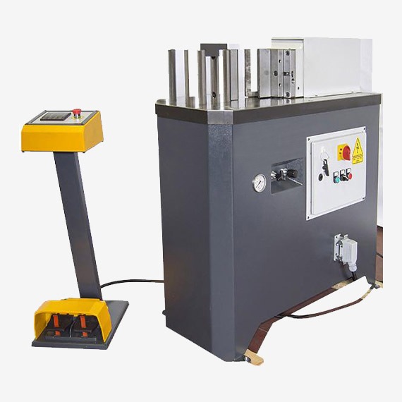
Press brake machines consist of several key components, each playing a vital role in the bending process. Understanding these components is essential for operating and maintaining the machine effectively.
Frame
The frame is the backbone of the press brake machine, providing structural support and stability. It is typically constructed from heavy-duty steel to withstand the forces exerted during the bending process.
Ram
The ram is a movable component that exerts force on the metal sheet, pressing it against the die to create the desired bend. The ram’s movement can be controlled manually, hydraulically, or electrically, depending on the type of press brake machine.
Die and Punch
The die and punch are the primary tools used in the bending process. The punch, attached to the ram, presses the metal sheet into the die, which is fixed to the machine’s bed. The shape and size of the die and punch determine the angle and radius of the bend.
Back Gauge
The back gauge is a positioning tool that helps in accurately aligning the metal sheet for bending. It ensures consistent bend angles and dimensions by providing a reference point for the sheet.
Control System
The control system manages the operation of the press brake machine. In manual machines, this may be a simple mechanical system, while hydraulic and electric machines use more advanced control systems. CNC press brake machines have sophisticated computer systems that program and control the entire bending process.
Safety Features
Press brake machines are equipped with various safety features to protect operators from accidents and injuries. These may include safety guards, emergency stop buttons, and light curtains that detect the presence of an operator’s hands near the bending area.
Working Principle
The basic working principle of a press brake machine involves applying a controlled force to bend metal sheets into specific shapes. Here are the key steps in the bending process:
- Sheet Positioning: The metal sheet is positioned on the machine’s bed, aligned against the back gauge to ensure precise placement.
- Tool Selection: The appropriate die and punch are selected based on the desired bend angle and radius. These tools are then installed on the machine.
- Bending Operation: The ram descends, pressing the punch into the metal sheet and forcing it into the die. This action creates the bend, with the angle and shape determined by the tools used and the force applied.
- Return Stroke: After the bend is completed, the ram ascends, releasing the pressure on the metal sheet. The sheet is then removed or repositioned for additional bends.
Precision and control are crucial in the bending process to ensure the accuracy and consistency of the bends. CNC press brake machines excel in this regard, as they use computer programming to control the ram’s movement and force, resulting in highly precise bends.
Applications of Press Brake Machines

Press brake machines are used across various industries due to their versatility and precision. Here are some common applications:
- Automotive Industry: Manufacturing car body panels, chassis components, and brackets.
- Aerospace Industry: Producing aircraft parts, including wing components and fuselage sections.
- Construction Industry: Fabricating structural components, such as beams, columns, and brackets.
- Electronics Industry: Creating enclosures, chassis, and brackets for electronic devices.
- Furniture Industry: Making metal frames and components for furniture.
- HVAC Industry: Producing ductwork and ventilation components.
These machines are also used in creating custom metal parts and prototypes, showcasing their adaptability to various production needs.
Advantages of Using Press Brake Machines
Press brake machines offer several advantages that make them indispensable in metal fabrication:
- Precision and Accuracy: These machines can produce highly precise bends, ensuring that components meet exact specifications.
- Efficiency and Productivity: Press brake machines can perform complex bending operations quickly, increasing production efficiency.
- Versatility: They can handle a wide range of materials and thicknesses, making them suitable for various applications.
- Cost-effectiveness: By reducing material waste and increasing production speed, press brake machines can lower manufacturing costs.
Maintenance and Safety Tips
Proper maintenance and safety practices are essential for the efficient and safe operation of press brake machines. Here are some tips:
Routine Maintenance
- Regularly inspect the machine for wear and tear.
- Keep the machine clean and free from debris.
- Lubricate moving parts as recommended by the manufacturer.
- Check hydraulic fluid levels and replace as necessary.
Common Issues and Troubleshooting
- Misalignment of the die and punch: Adjust the alignment to ensure precise bends.
- Inconsistent bending angles: Check for wear on the tools and replace if needed.
- Hydraulic system leaks: Inspect seals and hoses, and replace any damaged components.
Safety Guidelines for Operators
- Always wear appropriate personal protective equipment (PPE).
- Ensure that safety guards and emergency stop buttons are in place and functional.
- Follow the manufacturer’s guidelines for safe operation.
- Undergo proper training before operating the machine.
Future Trends in Press Brake Technology
The future of press brake technology is shaped by advancements in automation, materials, and environmental considerations:
- Automation and Industry 4.0: The integration of robotics and IoT (Internet of Things) is enhancing the automation of press brake machines, leading to increased efficiency and reduced human intervention.
- Advanced Materials and Designs: The development of new materials and innovative designs is expanding the capabilities of press brake machines, allowing for more complex and precise bends.
- Environmental Considerations: Efforts to reduce energy consumption and minimize environmental impact are driving the adoption of electric press brake machines and other eco-friendly technologies.
Conclusion
Press brake machines are a cornerstone of modern metal fabrication, offering unmatched precision, efficiency, and versatility. From their historical evolution to the latest technological advancements, these machines continue to play a vital role in various industries.
Understanding the different types of press brake machines, their components, and working principles is essential for selecting the right equipment and maximizing its potential. By following proper maintenance and safety practices, operators can ensure the longevity and safe operation of these machines.
As we look to the future, advancements in automation, materials, and environmental sustainability will further enhance the capabilities of press brake machines, solidifying their place in the ever-evolving landscape of manufacturing.
Whether you are a seasoned professional or new to the field, this comprehensive guide provides valuable insights into the world of sheet metal bending press brake machines, highlighting their importance and potential in modern industry.
Components of a Press Brake Machine
Press brake machines consist of several key components, each playing a vital role in the bending process. Understanding these components is essential for operating and maintaining the machine effectively.
Frame
The frame is the backbone of the press brake machine, providing structural support and stability. Constructed from heavy-duty steel, the frame must be robust enough to withstand the significant forces exerted during the bending process. The frame’s design can vary depending on the machine type, but its primary function remains to ensure rigidity and durability.
Ram
The ram is a movable component that exerts force on the metal sheet, pressing it against the die to create the desired bend. The ram’s movement can be controlled manually, hydraulically, or electrically, depending on the type of press brake machine. In CNC press brakes, the ram’s motion is precisely controlled by computer programming, allowing for highly accurate and repeatable bends.
Die and Punch
The die and punch are the primary tools used in the bending process. The punch, attached to the ram, presses the metal sheet into the die, which is fixed to the machine’s bed. The shape and size of the die and punch determine the angle and radius of the bend. There are various types of dies and punches, each suited for different bending operations, such as V-dies, U-dies, and hemming dies.
Back Gauge
The back gauge is a positioning tool that helps in accurately aligning the metal sheet for bending. It ensures consistent bend angles and dimensions by providing a reference point for the sheet. Modern press brake machines often feature CNC-controlled back gauges, which can be programmed to automatically adjust positions for complex bending sequences, enhancing precision and efficiency.
Control System
The control system manages the operation of the press brake machine. In manual machines, this may be a simple mechanical system, while hydraulic and electric machines use more advanced control systems. CNC press brake machines have sophisticated computer systems that program and control the entire bending process. These systems can store multiple bending programs, allowing for quick setup and reduced downtime between jobs.
Safety Features
Press brake machines are equipped with various safety features to protect operators from accidents and injuries. These may include safety guards, emergency stop buttons, and light curtains that detect the presence of an operator’s hands near the bending area. Modern machines also incorporate safety sensors that halt the machine’s operation if a potential hazard is detected, ensuring a safer working environment.
Working Principle
https://www.youtube.com/embed/l8quDXXNNEg?feature=oembedWorking Principle
The basic working principle of a press brake machine involves applying a controlled force to bend metal sheets into specific shapes. Here are the key steps in the bending process:
- Sheet Positioning: The metal sheet is positioned on the machine’s bed, aligned against the back gauge to ensure precise placement. Proper alignment is crucial for achieving accurate and consistent bends.
- Tool Selection: The appropriate die and punch are selected based on the desired bend angle and radius. These tools are then installed on the machine. The selection of the correct tools is essential for achieving the desired bend geometry and avoiding damage to the metal sheet.
- Bending Operation: The ram descends, pressing the punch into the metal sheet and forcing it into the die. This action creates the bend, with the angle and shape determined by the tools used and the force applied. The bending process requires careful control of the ram’s speed and pressure to ensure precise and consistent results.
- Return Stroke: After the bend is completed, the ram ascends, releasing the pressure on the metal sheet. The sheet is then removed or repositioned for additional bends. In CNC press brakes, the return stroke and repositioning of the sheet can be automated, increasing efficiency and reducing operator fatigue.
Precision and control are crucial in the bending process to ensure the accuracy and consistency of the bends. CNC press brake machines excel in this regard, as they use computer programming to control the ram’s movement and force, resulting in highly precise bends. The ability to program complex bending sequences also allows for the efficient production of intricate parts with minimal manual intervention.
Applications of Press Brake Machines
https://www.youtube.com/embed/o1dG-pIFkTk?feature=oembedApplications of Press Brake Machines
Press brake machines are used across various industries due to their versatility and precision. Here are some common applications:
- Automotive Industry: Press brake machines are integral to manufacturing car body panels, chassis components, and brackets. These machines can produce complex shapes and bends required for modern vehicle designs, ensuring high precision and repeatability.
- Aerospace Industry: The aerospace industry demands high precision and stringent quality standards. Press brake machines are used to produce aircraft parts, including wing components and fuselage sections, where accuracy and consistency are paramount.
- Construction Industry: Press brake machines are utilized to fabricate structural components such as beams, columns, and brackets. These components must meet specific strength and dimensional requirements to ensure the safety and stability of buildings and other structures.
- Electronics Industry: In the electronics industry, press brake machines are used to create enclosures, chassis, and brackets for electronic devices. These components often require intricate bends and precise dimensions to accommodate various electronic components and assemblies.
- Furniture Industry: The furniture industry employs press brake machines to make metal frames and components for furniture. These machines enable the production of aesthetically pleasing and structurally sound furniture parts, such as legs, supports, and brackets.
- HVAC Industry: The HVAC industry uses press brake machines to produce ductwork and ventilation components. These machines can create complex bends and shapes needed for efficient air distribution and ventilation systems.
These machines are also used in creating custom metal parts and prototypes, showcasing their adaptability to various production needs. The ability to quickly and accurately produce custom components makes press brake machines valuable tools for manufacturers and fabricators across different industries.
Advantages of Using Press Brake Machines
Press brake machines offer several advantages that make them indispensable in metal fabrication:
- Precision and Accuracy: Press brake machines are designed to produce highly precise bends, ensuring that components meet exact specifications. CNC press brakes, in particular, offer unmatched precision and repeatability, allowing for the production of intricate and complex parts with tight tolerances.
- Efficiency and Productivity: These machines can perform complex bending operations quickly, increasing production efficiency. The automation capabilities of CNC press brakes reduce the need for manual intervention, leading to faster setup times and higher throughput.
- Versatility: Press brake machines can handle a wide range of materials and thicknesses, making them suitable for various applications. From thin aluminum sheets to thick steel plates, these machines can accommodate different bending requirements, providing flexibility in manufacturing processes.
- Cost-effectiveness: By reducing material waste and increasing production speed, press brake machines can lower manufacturing costs. The precision and efficiency of these machines minimize errors and rework, resulting in significant cost savings over time.
- Consistency: Press brake machines ensure consistent bend quality across multiple parts, which is essential for mass production. The ability to produce uniform parts enhances the overall quality and reliability of the final products.
- Customizability: Modern press brake machines, especially CNC models, offer high levels of customizability. Operators can program specific bending sequences and parameters, allowing for the production of custom parts tailored to unique design requirements.
- Reduced Labor Costs: Automation in CNC press brake machines reduces the need for skilled labor, lowering labor costs. These machines can operate with minimal supervision, enabling manufacturers to allocate human resources more efficiently.
- Enhanced Safety: Press brake machines are equipped with advanced safety features that protect operators from accidents and injuries. Safety guards, emergency stop buttons, and sensors contribute to a safer working environment, reducing the risk of workplace incidents.
These advantages highlight the critical role of press brake machines in modern metal fabrication, underscoring their value in achieving high-quality, efficient, and cost-effective manufacturing processes.
Maintenance and Safety Tips
Proper maintenance and safety practices are essential for the efficient and safe operation of press brake machines. Here are some tips:
Routine Maintenance
- Regular Inspection: Regularly inspect the machine for wear and tear. Check for any signs of damage or misalignment in the components, especially the die and punch.
- Cleaning: Keep the machine clean and free from debris. Accumulated dust and metal shavings can affect the machine’s performance and lead to premature wear.
- Lubrication: Lubricate moving parts as recommended by the manufacturer. Proper lubrication reduces friction and prevents wear, extending the machine’s lifespan.
- Hydraulic Fluid: Check hydraulic fluid levels and replace as necessary. Ensure that the hydraulic system is free from leaks and that the fluid is clean and at the proper level.
- Tool Maintenance: Inspect the die and punch for wear and replace them if needed. Sharp and well-maintained tools are crucial for achieving precise bends.
Common Issues and Troubleshooting
- Misalignment: Misalignment of the die and punch can result in inaccurate bends. Adjust the alignment to ensure precise bending operations.
- Inconsistent Bending Angles: Inconsistent bending angles may be due to worn tools or incorrect settings. Check the tools for wear and verify the machine’s settings.
- Hydraulic System Leaks: Hydraulic system leaks can affect the machine’s performance. Inspect seals and hoses regularly and replace any damaged components.
- Control System Errors: Errors in the control system, particularly in CNC machines, can disrupt operations. Ensure that the control system software is up-to-date and that any programming issues are addressed promptly.
Safety Guidelines for Operators
- Personal Protective Equipment (PPE): Always wear appropriate PPE, including safety glasses, gloves, and protective clothing, to prevent injuries.
- Safety Guards and Emergency Stops: Ensure that safety guards are in place and functional. Familiarize yourself with the location and operation of emergency stop buttons.
- Manufacturer Guidelines: Follow the manufacturer’s guidelines for safe operation. These guidelines provide crucial information on operating the machine safely and efficiently.
- Training: Undergo proper training before operating the machine. Training should cover machine operation, maintenance, and safety procedures.
- Awareness: Stay alert and aware of your surroundings while operating the machine. Avoid distractions and ensure that the work area is free from hazards.
By adhering to these maintenance and safety tips, operators can ensure the longevity, efficiency, and safe operation of press brake machines, minimizing downtime and reducing the risk of accidents.
Future Trends in Press Brake Technology
The future of press brake technology is shaped by advancements in automation, materials, and environmental considerations. Here are some key trends to watch:
Automation and Industry 4.0
The integration of robotics and the Internet of Things (IoT) is enhancing the automation of press brake machines. Industry 4.0 technologies enable machines to communicate and coordinate with each other, leading to increased efficiency and reduced human intervention. Automated press brake machines can perform complex bending operations with minimal oversight, improving productivity and precision.
Advanced Materials and Designs
The development of new materials and innovative designs is expanding the capabilities of press brake machines. Advanced materials, such as high-strength alloys and composites, require precise and powerful bending techniques. Modern press brake machines are being designed to handle these materials, enabling the production of more durable and lightweight components.
Environmental Considerations
Efforts to reduce energy consumption and minimize environmental impact are driving the adoption of electric press brake machines and other eco-friendly technologies. Electric press brakes are more energy-efficient than their hydraulic counterparts, producing less noise and requiring less maintenance. Additionally, manufacturers are exploring sustainable materials and processes to further reduce the environmental footprint of metal fabrication.
Smart Manufacturing
Smart manufacturing technologies, including artificial intelligence (AI) and machine learning, are being integrated into press brake machines. These technologies enable predictive maintenance, real-time monitoring, and adaptive control, enhancing machine performance and reducing downtime. AI-powered systems can optimize bending operations by analyzing data and making adjustments in real-time.
User-Friendly Interfaces
Future press brake machines are likely to feature more user-friendly interfaces, making them easier to operate and program. Touchscreen controls, intuitive software, and augmented reality (AR) training tools will simplify the operation of these machines, reducing the learning curve for operators.
These trends highlight the ongoing evolution of press brake technology, promising greater efficiency, precision, and sustainability in metal fabrication.
Conclusion
Press brake machines are a cornerstone of modern metal fabrication, offering unmatched precision, efficiency, and versatility. From their historical evolution to the latest technological advancements, these machines continue to play a vital role in various industries.
Understanding the different types of press brake machines, their components, and working principles is essential for selecting the right equipment and maximizing its potential. By following proper maintenance and safety practices, operators can ensure the longevity and safe operation of these machines.
As we look to the future, advancements in automation, materials, and environmental sustainability will further enhance the capabilities of press brake machines, solidifying their place in the ever-evolving landscape of manufacturing.
Whether you are a seasoned professional or new to the field, this comprehensive guide provides valuable insights into the world of sheet metal bending press brake machines, highlighting their importance and potential in modern industry.
Press brake machines will undoubtedly continue to evolve, driven by technological innovations and industry demands. Staying informed about these advancements and adopting best practices will enable manufacturers to leverage the full potential of press brake machines, ensuring continued success in their metal fabrication endeavors.
Overview of Bending and Press Machines in Industrial Applications
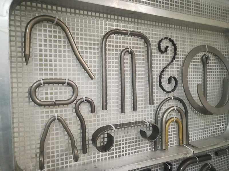
In the modern manufacturing and metalworking industries, bending and press machines are indispensable tools that shape, form, and modify metal and other materials with high precision. These machines are designed to handle various tasks, from simple bending operations to complex shaping processes, catering to a wide range of applications across multiple industries. The effectiveness and versatility of these machines make them critical in producing parts and components for automotive, aerospace, construction, and other heavy industries.
Bending and press machines are essential in transforming raw materials into finished products by applying force to alter the shape and properties of metals and other materials. The machines are designed to handle different materials, including steel, stainless steel (SS), aluminum, and more. These machines vary in size and capacity, from small, manual models used in workshops to large, automated systems in industrial manufacturing plants.
Types of Bending and Press Machines:
- Hydraulic Press Machines: Utilize hydraulic pressure to exert force, offering high precision and control in operations such as pressing, bending, and punching.
- Press Brake Machines: Specifically designed for bending sheet metal into various shapes by clamping the workpiece between a matching punch and die.
- Pipe Bending Machines: Used to bend pipes and tubes into desired angles and shapes, essential in plumbing, construction, and automotive industries.
- Sheet Metal Bending Machines: These machines focus on bending and shaping sheet metal, often used in fabrication shops and manufacturing lines.
Importance of Precision in Metalworking
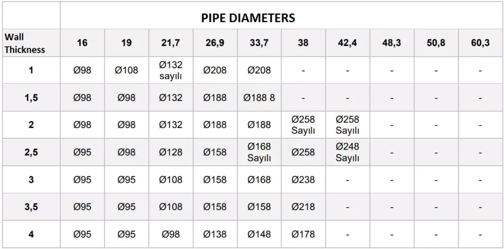
Precision is paramount in metalworking, as even minor deviations can lead to significant issues in the final product. Accurate bending and shaping are critical for ensuring that parts fit together correctly, maintain structural integrity, and meet the required specifications. The precision offered by modern bending and press machines allows manufacturers to produce complex components with tight tolerances, reducing the need for additional finishing processes and minimizing material waste.
Key Factors Influencing Precision:
- Machine Calibration: Proper calibration ensures the machine operates within the specified tolerances, providing consistent results.
- Tooling Quality: High-quality tools, such as dies and punches, are essential for achieving precise bends and shapes.
- Material Properties: Understanding the material’s properties, including its thickness, tensile strength, and ductility, is crucial for selecting the right machine settings.
- Operator Skill: Experienced operators can optimize machine settings and techniques to achieve the best results, even with challenging materials.
Overview of Bending and Press Machines
Bending and press machines are categorized based on their operating principles, applications, and the materials they handle. Below is a brief overview of some common types of bending and press machines:
1.3.1 Hydraulic Press Machines Hydraulic press machines operate by using a hydraulic cylinder to generate compressive force. They are highly versatile, allowing for various applications such as bending, forming, punching, and drawing. Hydraulic presses are known for their ability to exert high forces with great precision, making them ideal for heavy-duty applications. The introduction and working principles of hydraulic press machines will be discussed in more detail in the following sections.
1.3.2 Press Brake Machines Press brake machines are specialized machines used primarily for bending sheet metal. These machines utilize a combination of a punch and die to shape metal into specific angles and forms. Press brakes can be manual, hydraulic, or CNC-controlled, with each type offering different levels of automation and precision. The versatility of press brakes makes them a staple in metal fabrication shops.
1.3.3 Pipe Bending Machines Pipe bending machines are designed to bend pipes and tubes into various shapes and angles without compromising the material’s structural integrity. These machines are essential in industries such as plumbing, automotive, and construction, where precise pipe bends are required. Pipe bending machines can be hydraulic, pneumatic, mechanical, or electric, each offering different advantages depending on the application.
1.3.4 Sheet Metal Bending Machines Sheet metal bending machines focus on bending thin, flat sheets of metal into specific shapes. These machines are commonly used in the automotive and aerospace industries, where precision is critical. The machines can be manually operated, hydraulic, or CNC-controlled, offering various levels of control and automation.
Key Terminology and Concepts
Understanding the key terminology and concepts related to bending and press machines is essential for selecting the right equipment and optimizing its use. Below are some important terms that will be used throughout this document:
- Tonnage: The amount of force a machine can exert, usually measured in tons. For example, a 100-ton hydraulic press can exert 100 tons of force.
- Punch and Die: The tools used in press brake machines to shape metal. The punch presses into the die, which holds the workpiece.
- CNC (Computer Numerical Control): A method of automating machine tools using computers to control their movement and operation.
- Bend Radius: The radius of the inside curve of a bent section of metal. The bend radius is critical in determining the integrity and appearance of the bend.
- Ductility: The ability of a material to undergo deformation without breaking. Ductility is an important factor in bending operations.
Applications of Bending and Press Machines
Bending and press machines are used in a wide range of applications, from simple bending tasks to complex forming and shaping operations. Some common applications include:
- Automotive Industry: Producing car body parts, exhaust systems, and chassis components.
- Aerospace Industry: Manufacturing aircraft components, including fuselage panels and structural supports.
- Construction: Fabricating steel beams, columns, and other structural elements.
- Plumbing and HVAC: Bending pipes and tubes for plumbing, heating, and ventilation systems.
- Heavy Machinery: Forming and shaping parts for heavy equipment, such as cranes and bulldozers.
These applications highlight the versatility and importance of bending and press machines in modern manufacturing. The following sections will delve deeper into specific types of machines, their working principles, and the factors to consider when choosing the right equipment for your needs.
Hydraulic Press Machines: An Overview
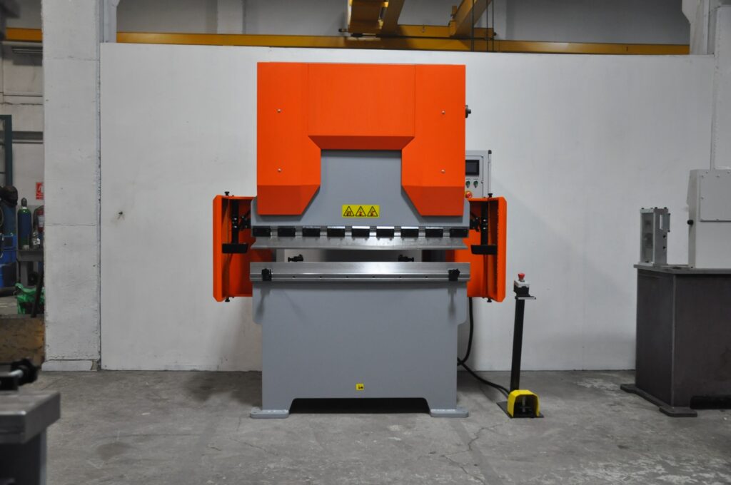
Hydraulic press machines are a cornerstone of modern manufacturing, offering unmatched power and precision in shaping, molding, and forming materials. These machines harness the power of hydraulics—a technology that uses fluid pressure to generate force—enabling them to perform tasks that require significant force with high accuracy. In this section, we will explore the fundamentals of hydraulic press machines, their working principles, various types, and key specifications that are critical for their selection and application in different industries.
2.1 Hydraulic Press Machine Introduction
Hydraulic press machines are used in a variety of industries for tasks that require compressive force. The concept behind hydraulic presses is based on Pascal’s law, which states that when pressure is applied to a confined fluid, the pressure is transmitted equally in all directions. This principle allows hydraulic presses to generate enormous amounts of force with relatively little input, making them highly efficient for industrial applications.
Key Characteristics:
- High Force Generation: Hydraulic presses can generate forces ranging from a few tons to several thousand tons, depending on the machine’s design and application.
- Versatility: These machines can perform a wide range of operations, including forging, stamping, bending, punching, and drawing.
- Precision: Hydraulic presses offer precise control over the applied force and movement, which is essential for tasks that require high accuracy.
- Customizability: Hydraulic presses can be customized with different types of tooling, making them adaptable to various tasks.
Hydraulic press machines are widely used in industries such as automotive manufacturing, aerospace, construction, and heavy machinery production. Their ability to handle large-scale operations with precision makes them a valuable asset in any industrial setting.
2.2 Hydraulic Press Machine Working Principles
The working of a hydraulic press machine is based on the simple but powerful principle of fluid mechanics. The machine typically consists of two cylinders: a smaller cylinder (called the slave cylinder) and a larger cylinder (called the master cylinder). These cylinders are connected by a pipe filled with hydraulic fluid, usually oil.
Working Process:
- Applying Force: When force is applied to the smaller cylinder (using a lever or a motor), it creates pressure in the hydraulic fluid.
- Pressure Transmission: According to Pascal’s law, the pressure in the fluid is transmitted equally throughout the system, causing the larger cylinder to move.
- Force Amplification: Because the larger cylinder has a greater surface area, the force exerted by it is much greater than the force applied to the smaller cylinder. This allows the machine to perform tasks that require significant force, such as pressing or bending metal.
Control Mechanisms:
- Pressure Control Valves: These valves regulate the amount of pressure applied to the hydraulic fluid, allowing the operator to control the force exerted by the machine.
- Flow Control Valves: These valves control the speed of the hydraulic fluid, which in turn controls the speed of the machine’s movement.
- Directional Control Valves: These valves direct the flow of hydraulic fluid to different parts of the system, enabling the machine to perform various operations.
Hydraulic press machines can be operated manually, semi-automatically, or fully automatically, depending on the level of control and automation required. Modern hydraulic presses often incorporate computerized control systems (CNC) for enhanced precision and efficiency.
2.3 Hydraulic Press Specifications
When selecting a hydraulic press machine, understanding its specifications is crucial to ensure that it meets the requirements of the intended application. Key specifications include:
2.3.1 Tonnage (Force Capacity)
- Definition: Tonnage refers to the maximum force that the hydraulic press can exert, usually measured in tons.
- Importance: The tonnage requirement depends on the material being processed and the operation being performed. For example, a higher tonnage is needed for tasks such as forging thick metal parts compared to bending thin sheets.
- Examples: A 100-ton hydraulic press is commonly used in medium-scale operations, while a 1000-ton hydraulic press is suitable for large-scale industrial applications.
2.3.2 Stroke Length
- Definition: Stroke length is the distance the press ram (the moving part of the machine that exerts force) can travel in one cycle.
- Importance: The stroke length determines the depth to which the material can be compressed or formed. It is particularly important in operations like deep drawing or molding.
- Adjustability: Many hydraulic presses allow the stroke length to be adjusted according to the specific requirements of the operation.
2.3.3 Bed Size
- Definition: The bed size is the working surface area of the press where the material is placed.
- Importance: The bed size must accommodate the dimensions of the workpiece being processed. A larger bed size is required for bigger workpieces.
- Customization: Some hydraulic presses offer interchangeable beds to handle different workpiece sizes.
2.3.4 Ram Speed
- Definition: Ram speed refers to the speed at which the press ram moves during operation.
- Importance: The speed of the ram can affect the quality of the operation. For example, slower speeds may be needed for precision tasks, while faster speeds are suitable for high-volume production.
- Control: Hydraulic presses often have adjustable ram speeds to suit different tasks.
2.3.5 Hydraulic System Pressure
- Definition: This is the pressure at which the hydraulic fluid operates within the system, usually measured in pounds per square inch (PSI) or bar.
- Importance: Higher system pressure allows for greater force generation but also requires more robust components to handle the increased stress.
- Safety: Hydraulic presses are equipped with safety mechanisms to prevent over-pressurization, which could lead to system failure.
2.4 100 Ton Hydraulic Press Specifications
A 100-ton hydraulic press is a versatile and commonly used machine in many industries, capable of handling a wide range of tasks from bending and forming to punching and drawing.
Key Specifications of a 100 Ton Hydraulic Press:
- Tonnage: 100 tons of maximum force, suitable for medium to large-scale operations.
- Stroke Length: Typically around 8 to 12 inches, with adjustability for different tasks.
- Bed Size: A standard bed size might be around 36 x 24 inches, but this can vary depending on the manufacturer.
- Ram Speed: Variable, often ranging from 10 to 30 mm/s, depending on the operation.
- System Pressure: Generally operates at around 3000 PSI, providing the necessary force without compromising safety.
Applications:
- Automotive Manufacturing: Used for pressing, forming, and shaping automotive parts.
- Metal Fabrication: Ideal for bending and shaping metal components in medium-scale production.
- Construction Equipment Manufacturing: Useful in the production of parts for heavy machinery and construction tools.
2.5 1000 Ton Hydraulic Press
The 1000-ton hydraulic press represents a significant leap in force capacity, making it suitable for the most demanding industrial applications. These machines are typically used in heavy industries where large-scale and high-force operations are required.
Key Specifications of a 1000 Ton Hydraulic Press:
- Tonnage: 1000 tons of maximum force, designed for heavy-duty tasks.
- Stroke Length: Can range from 12 to 24 inches, depending on the specific model and application.
- Bed Size: Large beds, often exceeding 72 x 48 inches, to accommodate massive workpieces.
- Ram Speed: Slower speeds, typically around 5 to 15 mm/s, due to the immense force being applied.
- System Pressure: Operates at high pressures, usually around 5000 PSI, to deliver the required force.
Applications:
- Shipbuilding: Used in the production of large metal components for ships and submarines.
- Aerospace: Essential for forming and shaping large aircraft components.
- Heavy Machinery Production: Involved in the manufacturing of parts for mining equipment, cranes, and other heavy-duty machinery.
2.6 Horizontal Hydraulic Press Machine
Horizontal hydraulic press machines differ from the more common vertical models in that the ram moves horizontally rather than vertically. This configuration is particularly useful for specific applications such as bending long pieces of metal or pressing components that are difficult to position vertically.
Advantages of Horizontal Hydraulic Press Machines:
- Versatility: Can handle a variety of tasks including bending, pressing, and straightening long workpieces.
- Ease of Operation: Easier to load and position large or awkwardly shaped workpieces.
- Space Efficiency: Horizontal presses can be more space-efficient in certain workshop layouts.
Applications:
- Railway Manufacturing: Used for bending and forming long steel rails.
- Pipeline Construction: Ideal for bending and forming large pipes used in oil, gas, and water pipelines.
- Structural Engineering: Employed in the production of long beams and structural components.
2.7 Small Horizontal Hydraulic Press
Small horizontal hydraulic presses are designed for applications that require less force and smaller workpieces. These machines are commonly used in workshops and smaller manufacturing facilities where space and budget constraints are factors.
Key Features:
- Compact Design: Takes up less space, making it ideal for small workshops.
- Lower Tonnage: Typically ranges from 10 to 50 tons, suitable for light to medium tasks.
- Ease of Use: Simple controls and operation, often with manual or semi-automatic settings.
Applications:
- Automotive Repair Shops: Used for pressing and straightening components like axles and shafts.
- Small Fabrication Shops: Ideal for bending and forming smaller metal parts.
- Maintenance Operations: Useful in on-site repairs and maintenance tasks where portability is required.
3. Press Brake Machines and Bending Applications
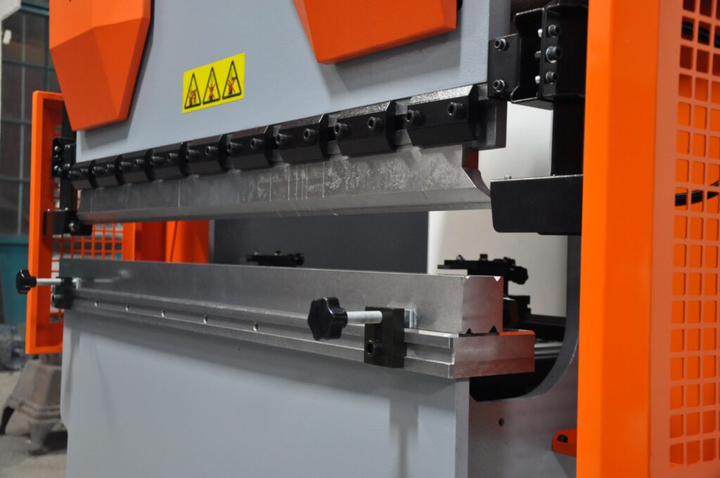
Press brake machines play a pivotal role in the metal fabrication industry, offering the precision and versatility required to transform flat metal sheets into complex shapes and structures. These machines are specifically designed for bending operations, making them indispensable in various manufacturing processes. This section delves into the functionality and applications of press brake machines, explores different bending techniques, and highlights the nuances of hydraulic press bending machines, including those tailored for sheet metal applications.
3.1 Press Brake Machine: Functionality and Applications
A press brake machine is a specialized tool used to bend and shape metal sheets and plates with high accuracy. Unlike general-purpose press machines, press brakes are specifically engineered to perform bending operations, making them essential in industries such as automotive, aerospace, construction, and manufacturing.
Key Functionalities:
- Bending: The primary function of a press brake is to bend metal sheets along a straight axis. This is achieved by clamping the metal between a punch and a die and applying force to create the desired angle.
- Forming: Beyond simple bends, press brakes can form complex shapes by combining multiple bending operations. This allows for the creation of intricate components required in various applications.
- Precision Cutting: Some advanced press brakes are equipped with features that allow for precise cutting or shearing of metal sheets during the bending process.
Applications:
- Automotive Industry: Manufacturing car body panels, chassis components, and exhaust systems.
- Aerospace Industry: Producing aircraft components, including fuselage sections and structural supports.
- Construction: Fabricating steel beams, columns, and other structural elements for buildings and infrastructure projects.
- Electronics: Creating enclosures and frames for electronic devices and appliances.
- Furniture Manufacturing: Designing and producing metal frames and supports for furniture pieces.
3.2 Press Brake Bending: Techniques and Precision
Bending is a fundamental operation in metalworking, and press brakes offer the precision and control necessary to achieve consistent and accurate results. Various bending techniques can be employed depending on the material, thickness, and desired outcome.
Bending Techniques:
- Air Bending: In this method, the punch presses the metal into the die without fully contacting it. This allows for greater flexibility in adjusting the bend angle and reduces stress on the material. Air bending is suitable for applications requiring variable angles and is widely used in sheet metal fabrication.Advantages:
- Versatility in bend angles.
- Reduced tooling wear.
- Lower force requirements compared to bottom bending.
- Bottom Bending (V-Die Bending): Here, the punch presses the metal all the way into the die, resulting in a more precise bend angle. This technique is ideal for applications where high accuracy and consistency are paramount.Advantages:
- Higher precision in bend angles.
- Better repeatability for mass production.
- Suitable for thicker materials.
- Coining: A specialized form of bottom bending where the metal is pressed into a highly precise shape within the die. Coining is used for intricate bends and is often employed in applications requiring fine details and superior surface finishes.
Precision Considerations:
- Tooling Quality: High-quality punches and dies are essential for achieving precise bends. The condition of the tooling directly impacts the accuracy and consistency of the bending process.
- Machine Calibration: Regular calibration ensures that the press brake operates within the specified tolerances, maintaining the precision of each bend.
- Material Properties: Understanding the ductility, tensile strength, and thickness of the material is crucial for selecting the appropriate bending parameters and avoiding defects such as cracking or warping.
- Operator Skill: Skilled operators can optimize machine settings and bending techniques to achieve the desired precision, especially when working with challenging materials or complex shapes.
3.3 Bend Press Machine: Overview
Bend press machines, often referred to interchangeably with press brake machines, are designed specifically for bending operations in metal fabrication. These machines vary in size, capacity, and control mechanisms, allowing them to cater to a wide range of applications from small workshops to large industrial facilities.
Types of Bend Press Machines:
- Manual Bend Press Machines: These are operated manually by the user, typically using a lever or hydraulic pump to apply force. They are suitable for small-scale operations and simple bending tasks.Advantages:
- Lower cost.
- Simplicity and ease of use.
- Ideal for light-duty applications.
- Hydraulic Bend Press Machines: Utilize hydraulic systems to apply force, offering greater control and higher tonnage capabilities compared to manual machines. They are widely used in medium to large-scale operations.Advantages:
- Higher force generation.
- Precise control over bending parameters.
- Suitable for a variety of materials and thicknesses.
- CNC Bend Press Machines: Equipped with computer numerical control (CNC) systems, these machines offer automated and programmable bending operations. They are ideal for high-precision and high-volume production environments.Advantages:
- Enhanced precision and repeatability.
- Ability to handle complex and intricate bends.
- Increased efficiency and reduced manual intervention.
Key Features:
- Adjustable Backgauges: Allow operators to set the precise location of the bend, ensuring consistency across multiple bends.
- Multiple Axes Control: Enables the machine to perform bends at various angles and positions without manual adjustments.
- Safety Features: Includes guards, emergency stop buttons, and sensors to ensure safe operation and protect operators from potential hazards.
3.4 Hydraulic Press Bending Machine
Hydraulic press bending machines combine the force-generating capabilities of hydraulic systems with the precision of press brakes to perform bending operations with high efficiency and accuracy. These machines are essential in applications where consistent and reliable bends are required, especially in medium to high-volume production settings.
Working Principles: Hydraulic press bending machines operate by using a hydraulic cylinder to exert force on the punch, which in turn bends the metal sheet against the die. The hydraulic system allows for smooth and controlled application of force, enabling precise bending angles and consistent results.
Advantages:
- High Force Capacity: Capable of handling thick and strong materials that require significant force to bend.
- Precision Control: Hydraulic systems offer fine control over the bending process, allowing for accurate and repeatable bends.
- Versatility: Suitable for a wide range of materials, including steel, aluminum, and stainless steel, making them adaptable to various industrial applications.
Applications:
- Automotive Manufacturing: Bending automotive body panels and structural components with high precision.
- Aerospace Industry: Forming aircraft parts that require exacting specifications and tight tolerances.
- Construction: Creating structural steel components for buildings and infrastructure projects.
- Heavy Machinery Production: Fabricating parts for construction equipment, mining machinery, and industrial tools.
3.5 Hydraulic Sheet Metal Bending Machine
Hydraulic sheet metal bending machines are specialized press brakes designed to handle the specific challenges associated with bending thin metal sheets. These machines leverage hydraulic systems to provide the necessary force and control for precise sheet metal fabrication.
Key Features:
- Enhanced Precision: Hydraulic systems ensure that each bend is executed with high accuracy, minimizing deviations and maintaining consistency.
- Adjustable Clamping Force: Allows for the secure holding of thin sheets without causing deformation or damage during the bending process.
- Integrated Control Systems: Modern hydraulic sheet metal bending machines often feature computerized controls for automated bending sequences, reducing manual intervention and increasing efficiency.
Benefits:
- Reduced Material Waste: Precise bending reduces the likelihood of errors and rework, leading to less material wastage and lower production costs.
- Increased Productivity: Automated and semi-automated systems enable faster production rates, meeting the demands of high-volume manufacturing.
- Versatility: Capable of handling a variety of sheet metal thicknesses and materials, making them suitable for diverse applications.
Applications:
- Appliance Manufacturing: Producing metal housings and components for household appliances such as refrigerators, washing machines, and ovens.
- Electronics Enclosures: Creating precise and compact metal enclosures for electronic devices and equipment.
- Furniture Manufacturing: Bending metal sheets for modern and ergonomic furniture designs.
- Signage and Displays: Forming metal panels used in signage, displays, and advertising materials.
3.6 Integration of CNC Technology in Press Brake Machines
The integration of Computer Numerical Control (CNC) technology into press brake machines has revolutionized the bending process, enhancing precision, efficiency, and flexibility. CNC press brakes are programmed with specific bending sequences, allowing for automated and repeatable operations that meet the stringent demands of modern manufacturing.
Advantages of CNC Press Brake Machines:
- Automation: Reduces the need for manual adjustments, minimizing human error and increasing production speed.
- Programmability: Allows for the storage and execution of complex bending programs, enabling the production of intricate shapes and multiple bends in a single setup.
- Consistency: Ensures that each bend is executed with the same precision, maintaining quality across large production runs.
- Ease of Use: User-friendly interfaces and software enable operators to input and modify bending programs with minimal training.
Applications:
- High-Precision Industries: Essential in industries such as aerospace and medical device manufacturing, where exacting standards must be met.
- Mass Production: Ideal for large-scale manufacturing where consistency and speed are critical.
- Customization: Facilitates the production of customized parts and components without significant downtime for setup changes.
3.7 Challenges and Considerations in Press Brake Bending
While press brake machines offer significant advantages in metal bending operations, several challenges and considerations must be addressed to ensure optimal performance and longevity of the equipment.
Common Challenges:
- Material Springback: After bending, materials tend to return partially to their original shape, known as springback. Proper compensation techniques and machine settings are required to achieve the desired final angle.
- Tooling Wear: Frequent bending operations can lead to wear and tear of punches and dies, affecting the quality of bends. Regular maintenance and timely replacement of tooling are essential.
- Setup Time: Adjusting machine settings and tooling for different bending tasks can be time-consuming, impacting overall productivity. CNC press brakes help mitigate this by enabling quick program changes.
- Operator Training: Skilled operators are necessary to manage machine settings, troubleshoot issues, and ensure consistent quality. Investing in training programs can enhance operational efficiency.
Key Considerations:
- Machine Selection: Choosing the right press brake machine involves assessing factors such as tonnage capacity, stroke length, bed size, and control systems based on the specific application requirements.
- Tooling Quality: High-quality punches and dies are crucial for achieving precise and consistent bends. Investing in durable tooling can reduce maintenance costs and improve overall performance.
- Maintenance Practices: Regular maintenance, including lubrication, inspection, and calibration, ensures that the press brake operates efficiently and extends its operational lifespan.
- Safety Measures: Implementing safety protocols, such as using protective guards and emergency stop mechanisms, protects operators and prevents accidents in the workplace.
3.8 Innovations in Press Brake Technology
Advancements in press brake technology continue to enhance the capabilities and efficiency of bending operations. Innovations such as servo-electric systems, advanced control software, and enhanced automation features are driving the evolution of press brake machines.
Servo-Electric Press Brakes: Servo-electric press brakes use electric motors to control the movement of the ram, offering precise positioning and energy-efficient operation. These machines provide faster cycle times and reduced maintenance compared to traditional hydraulic systems.
Advanced Control Software: Modern press brake machines are equipped with sophisticated software that enables real-time monitoring, automatic adjustments, and predictive maintenance. Features like automatic backgauges, bend allowance calculations, and integrated CAD/CAM systems streamline the bending process and improve accuracy.
Enhanced Automation: Automation features, including robotic loading and unloading, automated tool changes, and integrated quality control systems, increase productivity and reduce manual labor. These advancements are particularly beneficial in high-volume production environments where efficiency and consistency are paramount.
Sustainability Initiatives: Manufacturers are increasingly focusing on energy-efficient press brake machines that reduce power consumption and minimize environmental impact. Innovations such as regenerative braking systems and energy recovery mechanisms contribute to more sustainable manufacturing practices.
3.9 Case Studies: Press Brake Machines in Action
Automotive Manufacturing: In the automotive industry, press brake machines are used to fabricate various components such as door panels, chassis parts, and engine components. The precision offered by CNC press brakes ensures that each part meets the stringent quality standards required for vehicle assembly. For example, a major automotive manufacturer utilizes a fleet of 100-ton hydraulic press brakes to produce consistent and high-quality body panels, reducing production time and minimizing material waste.
Aerospace Industry: Aerospace manufacturers rely on hydraulic sheet metal bending machines to produce aircraft components with exacting specifications. The high precision and repeatability of CNC press brakes enable the production of complex parts such as fuselage sections and wing components. By integrating advanced control systems, aerospace companies can achieve the necessary tolerances and maintain the integrity of critical components.
Construction Sector: In the construction industry, press brake machines are used to fabricate structural steel elements like beams, columns, and trusses. Hydraulic press brakes with large bed sizes and high tonnage capacities are essential for handling the thick and heavy materials used in construction projects. For instance, a construction equipment manufacturer employs 1000-ton hydraulic press brakes to produce large steel beams, ensuring structural integrity and compliance with safety standards.
Electronics Manufacturing: Electronics manufacturers use small hydraulic sheet metal bending machines to create precise enclosures and frames for devices such as smartphones, laptops, and medical equipment. The ability to perform intricate bends with high accuracy ensures that the final products meet design specifications and fit seamlessly with other components.
3.10 Best Practices for Operating Press Brake Machines
To maximize the efficiency and lifespan of press brake machines, adhering to best practices is essential. These practices encompass proper machine setup, maintenance, and operational techniques that ensure consistent quality and safety.
Machine Setup:
- Accurate Alignment: Ensure that the punch and die are properly aligned to prevent uneven bends and reduce tooling wear.
- Proper Tooling Selection: Choose the appropriate punches and dies based on the material type, thickness, and desired bend angle.
- Parameter Optimization: Set the correct bending force, ram speed, and stroke length according to the material properties and bending requirements.
Maintenance:
- Regular Inspections: Conduct routine inspections of hydraulic systems, electrical components, and mechanical parts to identify and address potential issues early.
- Lubrication: Keep moving parts well-lubricated to reduce friction and prevent wear.
- Tooling Maintenance: Clean and maintain punches and dies to ensure optimal performance and extend their lifespan.
Operational Techniques:
- Consistent Feeding: Ensure that metal sheets are fed consistently into the press brake to maintain uniform bends.
- Monitoring and Adjustment: Continuously monitor the bending process and make necessary adjustments to maintain precision.
- Safety Protocols: Implement and enforce safety protocols, including the use of personal protective equipment (PPE) and adherence to operational guidelines.
Training and Education:
- Operator Training: Provide comprehensive training for operators to ensure they understand machine operation, safety procedures, and maintenance practices.
- Continuous Improvement: Encourage operators to stay updated with the latest techniques and technologies in press brake operations through ongoing education and training programs.
3.11 Conclusion
Press brake machines are integral to the metal fabrication industry, offering the precision and versatility required to produce a wide range of components and structures. Understanding the functionality, bending techniques, and specific applications of different press brake machines, including hydraulic and CNC models, is essential for optimizing their use in various industrial settings. By adhering to best practices and leveraging advancements in press brake technology, manufacturers can achieve high-quality results, enhance productivity, and maintain a competitive edge in the market.
In the following sections, we will explore other specialized bending machines, including pipe bending machines and sheet metal bending machines, to provide a comprehensive overview of the tools available for metal shaping and forming operations.
Pipe Bending Machines
Pipe bending machines are essential tools in industries where precise and efficient bending of pipes and tubes is required. These machines are used to create complex pipe shapes that are crucial in various applications, from plumbing and construction to automotive and aerospace industries. In this section, we will explore the different types of pipe bending machines, including pneumatic, mechanical, hydraulic, and specialized machines for bending stainless steel (SS) and heavy pipes. We’ll also discuss the benefits and considerations for choosing the right pipe bending machine for specific applications.
4.1 Pneumatic Pipe Bending Machine
Pneumatic pipe bending machines utilize compressed air to generate the force needed to bend pipes. These machines are commonly used in applications that require moderate force and precision, making them suitable for a variety of industries, including automotive and HVAC (Heating, Ventilation, and Air Conditioning).
Working Principles:
- Air Compression: The machine operates by compressing air in a cylinder, which then forces a piston to move. This movement is transferred to the bending tool, which applies the necessary force to bend the pipe.
- Controlled Force: The force applied can be adjusted by regulating the air pressure, allowing for precise control over the bending process.
Advantages:
- Simplicity: Pneumatic systems are generally simpler and easier to maintain than hydraulic systems, with fewer components and less potential for leaks.
- Cost-Effectiveness: Pneumatic machines are often more affordable than their hydraulic counterparts, making them a good option for smaller operations.
- Safety: Pneumatic systems are inherently safer in environments where fire hazards are a concern, as they do not involve flammable fluids.
Applications:
- Automotive Industry: Bending exhaust pipes and other components where moderate force and precision are required.
- HVAC Systems: Shaping pipes and ducts for heating, ventilation, and air conditioning installations.
- General Fabrication: Suitable for bending tasks in small to medium-sized fabrication shops.
4.2 Mechanical Pipe Bending Machine
Mechanical pipe bending machines rely on mechanical force generated by gears, levers, and other mechanical components to bend pipes. These machines are known for their durability and reliability, making them suitable for high-volume production environments.
Working Principles:
- Mechanical Leverage: The machine uses mechanical leverage to amplify the force applied by the operator, allowing it to bend pipes with precision.
- Gear Systems: Gears and cams are often used to control the movement and force applied to the bending tool, ensuring consistent results.
Advantages:
- Durability: Mechanical pipe bending machines are built to last, with robust components that can withstand the rigors of high-volume production.
- Consistency: The use of gears and mechanical systems ensures consistent and repeatable bends, which is crucial in mass production.
- Ease of Use: These machines are typically straightforward to operate, with manual or semi-automatic controls that allow for precise adjustments.
Applications:
- Construction Industry: Bending steel pipes for structural applications, such as scaffolding and frameworks.
- Manufacturing: Producing bent pipes for various industrial products, including furniture, machinery, and equipment.
- Shipbuilding: Shaping pipes used in marine applications, where durability and precision are critical.
4.3 SS Pipe Bending Machine
Stainless steel (SS) pipes are widely used in industries that require corrosion-resistant and durable materials, such as food processing, pharmaceuticals, and chemical processing. Bending stainless steel pipes requires specialized machines that can handle the unique properties of this material without causing damage or deformation.
Key Features:
- Enhanced Tooling: SS pipe bending machines are equipped with hardened tooling that can withstand the high tensile strength of stainless steel, preventing tool wear and ensuring clean bends.
- Precision Control: These machines offer precise control over the bending process, allowing for tight bend radii and complex shapes without compromising the material’s integrity.
- Cooling Systems: Some SS pipe bending machines are equipped with cooling systems to prevent the material from overheating during the bending process, which could lead to discoloration or weakening of the stainless steel.
Advantages:
- Corrosion Resistance: SS pipe bending machines are designed to maintain the corrosion-resistant properties of stainless steel, making them ideal for applications in harsh environments.
- High Precision: The machines can produce precise bends with minimal springback, ensuring that the final product meets exact specifications.
- Versatility: Suitable for a wide range of applications, from sanitary piping in food processing to chemical transport lines in industrial settings.
Applications:
- Food and Beverage Industry: Bending pipes for sanitary processing lines, where cleanliness and corrosion resistance are paramount.
- Pharmaceutical Industry: Shaping pipes for sterile environments, including drug manufacturing and medical device production.
- Chemical Processing: Creating corrosion-resistant piping systems for transporting aggressive chemicals and other hazardous materials.
4.4 Steel Pipe Bending Machine
Steel pipe bending machines are designed to handle the rigors of bending steel pipes, which are commonly used in construction, infrastructure, and heavy industry. These machines are built to provide the necessary force and control to bend steel pipes without compromising their structural integrity.
Key Features:
- High Tonnage Capacity: Steel pipe bending machines are equipped with powerful hydraulic or mechanical systems capable of exerting the high forces required to bend steel.
- Robust Construction: The machines are built with heavy-duty frames and components to handle the stress of bending thick and strong steel pipes.
- Advanced Control Systems: Many steel pipe bending machines feature CNC controls, allowing for precise and automated bending processes.
Advantages:
- Strength and Durability: Steel pipe bending machines are capable of bending thick-walled and large-diameter steel pipes with high precision, ensuring that the final product meets structural requirements.
- Versatility: These machines can handle a wide range of steel pipe sizes and thicknesses, making them suitable for various applications in construction and heavy industry.
- Efficiency: The use of advanced control systems and automated features allows for efficient production, reducing labor costs and increasing throughput.
Applications:
- Construction: Bending steel pipes for structural applications, such as beams, columns, and supports in buildings and infrastructure projects.
- Oil and Gas Industry: Shaping steel pipes for pipelines, drilling rigs, and other critical infrastructure in the energy sector.
- Heavy Machinery Manufacturing: Producing bent steel components for construction equipment, mining machinery, and industrial tools.
4.5 Heavy Pipe Bending Machine
Heavy pipe bending machines are specialized for handling large-diameter and thick-walled pipes that require significant force to bend. These machines are used in industries where large-scale infrastructure projects and heavy-duty applications are common.
Key Features:
- High Force Capability: Heavy pipe bending machines are equipped with hydraulic systems capable of generating extremely high forces, often exceeding 1000 tons, to bend large and thick pipes.
- Large Bed Size: These machines feature expansive working areas to accommodate the size of the pipes being bent, allowing for precise positioning and control.
- Reinforced Components: The machines are built with reinforced frames, tooling, and hydraulic systems to handle the stress of bending heavy pipes without deformation.
Advantages:
- Capability: Heavy pipe bending machines can handle pipes with large diameters and thick walls, which are typically used in major infrastructure projects.
- Precision: Despite their size, these machines offer precise control over the bending process, ensuring that large pipes meet exacting specifications.
- Durability: Built to withstand the demands of heavy industry, these machines offer long service life and reliable performance in challenging environments.
Applications:
- Pipeline Construction: Bending large-diameter pipes for oil, gas, and water pipelines that span long distances and require precise engineering.
- Shipbuilding: Shaping heavy steel pipes for marine vessels, where durability and structural integrity are crucial.
- Power Generation: Producing bent pipes for power plants and energy infrastructure, including those used in nuclear and fossil fuel power generation.
4.6 Hydraulic Pipe Bending Machine
Hydraulic pipe bending machines are among the most versatile and powerful options for bending pipes in various industries. These machines utilize hydraulic pressure to apply force, offering precise control and the ability to handle a wide range of pipe sizes and materials.
Working Principles:
- Hydraulic Force: The machine uses a hydraulic cylinder to apply force to the bending tool, which then bends the pipe to the desired angle.
- Adjustable Pressure: Operators can adjust the hydraulic pressure to control the force applied, allowing for precise bends even in challenging materials.
Advantages:
- Versatility: Hydraulic pipe bending machines can handle a variety of materials, including steel, aluminum, and stainless steel, making them suitable for diverse applications.
- Precision: The hydraulic system offers fine control over the bending process, ensuring consistent results with minimal springback.
- Power: These machines are capable of generating significant force, allowing them to bend thick and strong pipes with ease.
Applications:
- Automotive Manufacturing: Bending exhaust pipes, roll cages, and other components where precision and strength are required.
- Aerospace Industry: Shaping pipes used in aircraft hydraulic systems, fuel lines, and other critical applications.
- Construction: Bending steel pipes for structural applications, such as beams, columns, and support structures.
4.7 Electric Pipe Bending Machine
Electric pipe bending machines offer an alternative to hydraulic and pneumatic systems, using electric motors to generate the force needed for bending operations. These machines are known for their energy efficiency, precision, and ease of use.
Key Features:
- Electric Motor Drive: The machine uses an electric motor to drive the bending tool, providing precise control over the bending process.
- Programmable Controls: Many electric pipe bending machines feature CNC or digital controls, allowing for automated and repeatable bending sequences.
- Quiet Operation: Electric machines tend to operate more quietly than hydraulic or pneumatic systems, making them suitable for environments where noise is a concern.
Advantages:
- Energy Efficiency: Electric pipe bending machines consume less energy compared to hydraulic systems, making them more cost-effective in the long run.
- Precision and Consistency: The use of electric motors and digital controls ensures precise and repeatable bends, which is critical in high-volume production.
- Ease of Maintenance: Electric machines have fewer moving parts compared to hydraulic systems, resulting in lower maintenance requirements and longer service life.
Applications:
- Furniture Manufacturing: Bending metal pipes for furniture frames, including chairs, tables, and shelving units.
- Medical Equipment: Shaping pipes used in medical devices and equipment, where precision and cleanliness are essential.
- Automotive Aftermarket: Producing custom exhaust systems, roll cages, and other automotive components.
4.8 Small Pipe Bending Machine
Small pipe bending machines are designed for applications that involve smaller-diameter pipes and require less force. These machines are commonly used in workshops, small-scale manufacturing, and maintenance operations.
Key Features:
- Compact Design: Small pipe bending machines are portable and space-efficient, making them ideal for use in confined spaces or on job sites.
- Manual or Semi-Automatic Operation: These machines are typically operated manually or with semi-automatic controls, offering a balance between control and ease of use.
- Versatility: Despite their small size, these machines can handle a variety of materials and bending angles, making them suitable for diverse applications.
Advantages:
- Portability: Small pipe bending machines are easy to transport and set up, making them ideal for on-site work and maintenance tasks.
- Cost-Effectiveness: These machines are typically more affordable than larger models, making them accessible to small businesses and workshops.
- Ease of Use: Simple controls and operation make these machines user-friendly, even for operators with limited experience.
Applications:
- Plumbing: Bending pipes for plumbing installations and repairs, including copper, PVC, and other materials.
- HVAC: Shaping small-diameter pipes for heating, ventilation, and air conditioning systems.
- DIY and Home Workshops: Suitable for hobbyists and small-scale fabricators working on custom projects.
4.9 Pipe Bending Machine Price Considerations
When selecting a pipe bending machine, understanding the factors that influence price is crucial to making an informed investment. The price of a pipe bending machine can vary significantly based on several key factors, including machine type, capacity, features, and brand.
Factors Influencing Price:
- Machine Type: Hydraulic and electric pipe bending machines are generally more expensive than pneumatic or mechanical models due to their advanced features and higher force capabilities.
- Capacity: Machines capable of bending larger-diameter or thicker-walled pipes typically cost more due to the increased force requirements and more robust construction.
- Control Systems: CNC-controlled machines with programmable features and automated bending sequences are priced higher than manual or semi-automatic models.
- Brand and Quality: Established brands with a reputation for quality and reliability often command higher prices, but they also offer better performance, durability, and support.
Cost vs. Functionality:
- Entry-Level Machines: Suitable for small-scale operations, workshops, and maintenance tasks, these machines offer basic functionality at a lower cost.
- Mid-Range Machines: Ideal for medium-sized businesses and manufacturers, offering a balance between price and advanced features.
- High-End Machines: Designed for large-scale production and heavy industry, these machines offer the highest levels of precision, automation, and durability but come at a premium price.
Making the Right Investment:
- Assessing Needs: Consider the specific requirements of your operation, including the types of materials, pipe sizes, and production volume, to choose a machine that meets your needs without overspending.
- Long-Term Value: While higher-end machines may have a higher initial cost, their durability, efficiency, and advanced features can lead to lower operational costs and better ROI over time.
- Supplier Support: Look for suppliers that offer good after-sales support, including training, maintenance, and parts availability, as this can significantly impact the total cost of ownership.
4.10 Conclusion
Pipe bending machines are crucial tools in various industries, offering the ability to shape and form pipes to precise specifications. Understanding the different types of pipe bending machines, including pneumatic, mechanical, hydraulic, and specialized machines for stainless steel and heavy pipes, is essential for selecting the right equipment for your needs. By considering factors such as machine capacity, control systems, and price, manufacturers and operators can make informed decisions that optimize productivity and ensure the quality of their products.
Sheet Metal Bending Machines
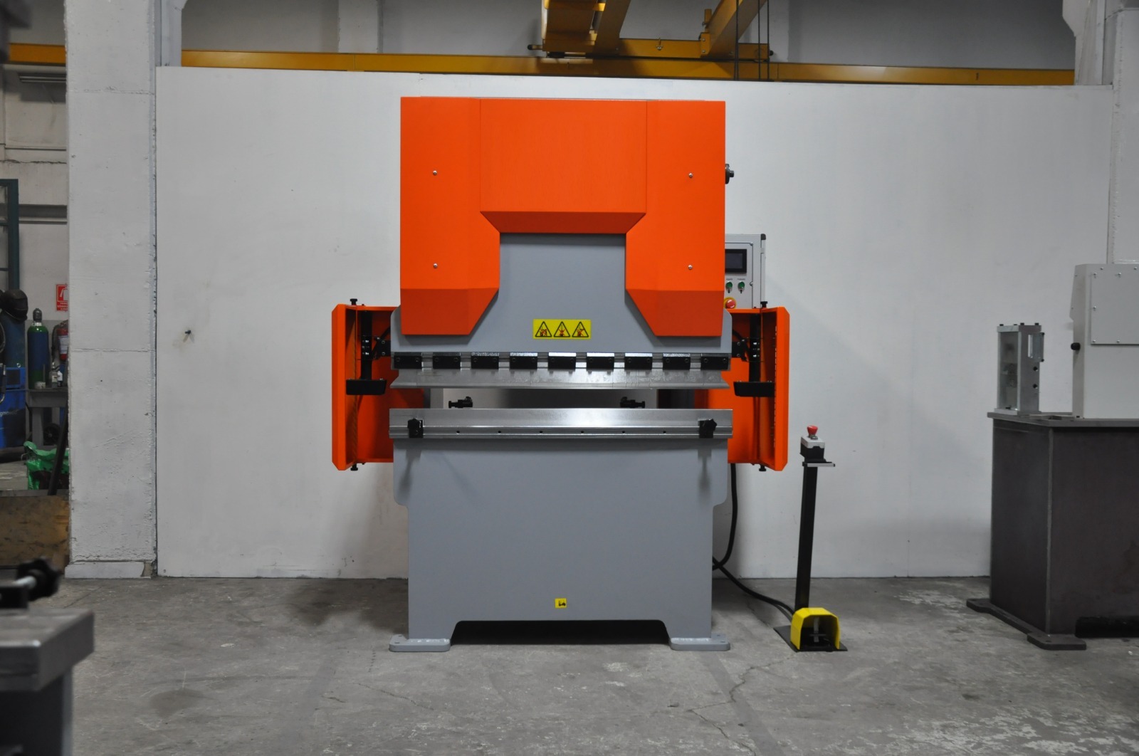
Sheet metal bending machines are essential in the fabrication of metal components, allowing manufacturers to create a wide range of shapes and structures from flat metal sheets. These machines are used across various industries, from automotive to aerospace, and play a critical role in producing everything from simple bends to complex geometries. In this section, we will explore the different types of sheet metal bending machines, including electric, hydraulic, automatic, and CNC-controlled machines. We will also discuss their applications, benefits, and factors to consider when selecting the right machine for specific tasks.
5.1 Electric Sheet Metal Bending Machine
Electric sheet metal bending machines use electric motors to generate the force needed to bend metal sheets. These machines are known for their energy efficiency, precision, and ease of use, making them a popular choice in many fabrication shops.
Key Features:
- Electric Motor Drive: These machines are driven by electric motors, which provide precise control over the bending process and allow for consistent and repeatable results.
- Programmable Controls: Many electric bending machines come with digital or CNC controls, enabling operators to program bending sequences and angles for automated operations.
- Quiet Operation: Electric machines tend to be quieter than hydraulic models, making them suitable for environments where noise reduction is important.
Advantages:
- Energy Efficiency: Electric machines are more energy-efficient than hydraulic machines, reducing operational costs over time.
- Precision: The electric motor provides consistent power, allowing for precise bends with minimal variability.
- Ease of Maintenance: With fewer moving parts and no hydraulic fluid, electric bending machines typically require less maintenance and have lower operating costs.
Applications:
- Light Fabrication: Suitable for bending thin sheets of metal, making them ideal for light fabrication tasks such as creating enclosures, brackets, and panels.
- Electronics Manufacturing: Used to bend metal components for electronic devices, where precision and consistency are critical.
- Custom Fabrication: Ideal for small workshops and custom fabrication businesses that require flexible and precise bending capabilities.
5.2 Small Sheet Bending Machine
Small sheet bending machines are designed for tasks that involve smaller pieces of sheet metal. These machines are typically more compact and easier to use, making them ideal for workshops and small-scale operations.
Key Features:
- Compact Design: Small sheet bending machines are designed to be portable and space-efficient, allowing them to be used in smaller workspaces.
- Manual or Semi-Automatic Operation: These machines often feature manual or semi-automatic controls, providing a balance between precision and ease of use.
- Versatile Tooling: Despite their size, small sheet bending machines can be equipped with a variety of tooling to handle different bending tasks.
Advantages:
- Portability: The compact size of these machines makes them easy to transport and set up, allowing for flexible use in different locations.
- Affordability: Small sheet bending machines are typically less expensive than larger models, making them accessible to small businesses and workshops.
- Ease of Use: Simple controls and operation make these machines user-friendly, even for operators with limited experience.
Applications:
- DIY and Custom Projects: Ideal for hobbyists and small-scale fabricators working on custom projects.
- Maintenance and Repair: Used in maintenance shops for bending small metal parts and components during repairs.
- Prototype Development: Suitable for creating prototypes and small production runs, where flexibility and quick setup are important.
5.3 Automatic Bending Machine
Automatic bending machines are designed to streamline the bending process by automating various aspects of the operation. These machines are equipped with advanced control systems that allow for precise and repeatable bending without the need for constant operator intervention.
Key Features:
- Automation: Automatic bending machines are capable of performing multiple bends in a single setup, reducing the need for manual adjustments and increasing productivity.
- CNC Controls: Many automatic bending machines are equipped with CNC (Computer Numerical Control) systems that allow for the programming of complex bending sequences.
- High Throughput: These machines are designed for high-volume production, making them ideal for industries that require large quantities of bent metal parts.
Advantages:
- Increased Efficiency: Automation reduces the time required for setup and bending, leading to higher production rates and lower labor costs.
- Consistency: Automatic machines ensure that each bend is executed with the same precision, reducing variability and improving product quality.
- Flexibility: The ability to program complex bending sequences allows for the production of intricate and custom shapes with minimal manual intervention.
Applications:
- Mass Production: Used in industries such as automotive and aerospace, where large quantities of parts with consistent quality are required.
- Complex Fabrication: Suitable for producing parts with multiple bends or intricate shapes that would be difficult to achieve manually.
- High-Precision Manufacturing: Ideal for applications where exacting tolerances and repeatability are essential, such as in the production of medical devices and electronics.
5.4 CNC Sheet Bending Machine
CNC sheet bending machines represent the pinnacle of precision and automation in sheet metal bending. These machines are controlled by computer numerical control (CNC) systems, which allow for highly accurate and repeatable bending operations.
Key Features:
- CNC Control: CNC sheet bending machines are equipped with computerized controls that allow operators to program and execute complex bending sequences with high precision.
- Automated Tooling: These machines often feature automated tooling systems that can change punches and dies as needed, further increasing efficiency and reducing setup time.
- Real-Time Monitoring: CNC systems provide real-time monitoring of the bending process, allowing operators to make adjustments on the fly and ensuring that each bend meets the required specifications.
Advantages:
- High Precision: CNC control ensures that each bend is performed with exacting accuracy, making these machines ideal for applications where precision is critical.
- Repeatability: The ability to store and recall bending programs allows for consistent results across multiple production runs, reducing variability and waste.
- Complexity: CNC sheet bending machines can perform intricate bends and form complex shapes that would be difficult or impossible to achieve with manual machines.
Applications:
- Aerospace Industry: Used to produce aircraft components with exacting tolerances and complex shapes.
- Automotive Manufacturing: Essential for the production of car body panels, chassis components, and other critical parts that require high precision.
- Electronics and Appliances: Ideal for creating metal enclosures, frames, and other components used in electronics and household appliances.
5.5 What is a CNC Bending Machine?
A CNC bending machine is a specialized type of bending machine that uses computer numerical control (CNC) to automate the bending process. CNC machines are programmed with specific instructions that control the movement of the machine’s bending tools, allowing for precise and repeatable operations.
How CNC Bending Machines Work:
- Programming: Operators program the CNC machine using specialized software, inputting parameters such as bend angles, material thickness, and sequence of operations.
- Tool Movement: The CNC system controls the movement of the bending tools, ensuring that each bend is executed according to the programmed instructions.
- Feedback Loops: CNC machines often include feedback systems that monitor the bending process in real-time, allowing for automatic adjustments to maintain precision.
Benefits of CNC Bending Machines:
- Precision: CNC bending machines offer unparalleled precision, with the ability to produce bends with tight tolerances and consistent quality.
- Efficiency: Automation reduces the time required for setup and bending, increasing throughput and reducing labor costs.
- Flexibility: The ability to program complex bending sequences allows for the production of custom and intricate shapes with minimal manual intervention.
Applications:
- Industrial Manufacturing: Used in high-volume production environments where consistency and precision are critical.
- Custom Fabrication: Ideal for producing custom parts and components, especially those with complex geometries.
- Prototyping: CNC bending machines are valuable in the development of prototypes, allowing for rapid iteration and precise adjustments.
5.6 Hydraulic Press Bending Machine
Hydraulic press bending machines combine the power of hydraulic systems with the precision of press brakes to perform bending operations with high efficiency and accuracy. These machines are widely used in industries that require consistent and reliable bends in a variety of materials, including steel, aluminum, and stainless steel.
Working Principles:
- Hydraulic Force: The machine uses a hydraulic cylinder to apply force to the bending tool, which then bends the metal sheet to the desired angle.
- Adjustable Pressure: Operators can adjust the hydraulic pressure to control the force applied, allowing for precise bends even in challenging materials.
Advantages:
- High Force Capacity: Hydraulic press bending machines are capable of exerting significant force, making them suitable for bending thick and strong materials.
- Precision: The hydraulic system provides fine control over the bending process, ensuring consistent results with minimal variability.
- Versatility: These machines can handle a wide range of materials and thicknesses, making them suitable for various industrial applications.
Applications:
- Automotive Manufacturing: Bending automotive body panels and structural components with high precision.
- Construction: Creating structural steel components for buildings and infrastructure projects.
- Heavy Machinery Production: Fabricating parts for construction equipment, mining machinery, and industrial tools.
5.7 Hydraulic Sheet Metal Bending Machine
Hydraulic sheet metal bending machines are specialized press brakes designed to handle the specific challenges associated with bending thin metal sheets. These machines leverage hydraulic systems to provide the necessary force and control for precise sheet metal fabrication.
Key Features:
- Enhanced Precision: Hydraulic systems ensure that each bend is executed with high accuracy, minimizing deviations and maintaining consistency.
- Adjustable Clamping Force: Allows for the secure holding of thin sheets without causing deformation or damage during the bending process.
- Integrated Control Systems: Modern hydraulic sheet metal bending machines often feature computerized controls for automated bending sequences, reducing manual intervention and increasing efficiency.
Benefits:
- Reduced Material Waste: Precise bending reduces the likelihood of errors and rework, leading to less material wastage and lower production costs.
- Increased Productivity: Automated and semi-automated systems enable faster production rates, meeting the demands of high-volume manufacturing.
- Versatility: Capable of handling a variety of sheet metal thicknesses and materials, making them suitable for diverse applications.
Applications:
- Appliance Manufacturing: Producing metal housings and components for household appliances such as refrigerators, washing machines, and ovens.
- Electronics Enclosures: Creating precise and compact metal enclosures for electronic devices and equipment.
- Furniture Manufacturing: Bending metal sheets for modern and ergonomic furniture designs.
5.8 Choosing the Right Sheet Metal Bending Machine
Selecting the right sheet metal bending machine involves considering several factors, including the material being bent, the required precision, production volume, and budget. Here are some key considerations to keep in mind:
Material Type and Thickness:
- Material: Different machines are better suited for specific materials. For example, hydraulic machines are ideal for thick steel sheets, while electric machines may be better for lighter materials.
- Thickness: The thickness of the material will determine the required force, with thicker materials needing more powerful machines.
Bending Precision:
- Tolerances: If your application requires tight tolerances, a CNC or hydraulic bending machine may be the best choice due to their precision and consistency.
- Complexity: For complex bending operations involving multiple bends or intricate shapes, a CNC machine will provide the necessary control and flexibility.
Production Volume:
- Low Volume: For small production runs or custom projects, a manual or small sheet bending machine may suffice.
- High Volume: For large-scale production, an automatic or CNC bending machine is more appropriate due to their higher efficiency and automation capabilities.
Budget Considerations:
- Initial Investment: CNC and hydraulic machines tend to have higher upfront costs but offer long-term benefits in precision, efficiency, and flexibility.
- Operating Costs: Consider the long-term costs of maintenance, energy consumption, and tooling when selecting a machine.
Supplier Support:
- After-Sales Service: Choose a supplier that offers good after-sales support, including maintenance, training, and access to spare parts.
- Warranty: Look for machines that come with a comprehensive warranty, which can protect your investment and reduce the risk of unexpected costs.
5.9 Future Trends in Sheet Metal Bending Machines
The field of sheet metal bending is constantly evolving, with new technologies and innovations improving the efficiency, precision, and versatility of bending machines. Here are some trends shaping the future of sheet metal bending:
Automation and Robotics:
- Increased Automation: Automation is becoming more prevalent in sheet metal bending, with robots and automated systems taking over tasks such as loading, unloading, and tool changes, leading to higher productivity and lower labor costs.
- Collaborative Robots: Also known as cobots, these robots work alongside human operators to assist with bending operations, enhancing efficiency while maintaining flexibility.
Advanced CNC Systems:
- Real-Time Monitoring: CNC systems are becoming more advanced, with features such as real-time monitoring, predictive maintenance, and automatic adjustments ensuring higher precision and reducing downtime.
- AI Integration: Artificial intelligence (AI) is being integrated into CNC systems to optimize bending processes, improve decision-making, and enhance overall efficiency.
Sustainability Initiatives:
- Energy Efficiency: Manufacturers are focusing on creating more energy-efficient bending machines that reduce power consumption without compromising performance.
- Material Waste Reduction: Innovations in tooling and process control are helping to reduce material waste, leading to more sustainable manufacturing practices.
Customization and Flexibility:
- Modular Machines: Modular designs allow for easy customization of bending machines, enabling manufacturers to adapt to different tasks and requirements without significant downtime.
- Flexible Tooling: Advances in tooling technology are allowing for more flexible and adaptable bending operations, making it easier to switch between different products and designs.
5.10 Conclusion
Sheet metal bending machines are vital tools in modern manufacturing, offering the precision, flexibility, and efficiency needed to produce high-quality metal components. Understanding the different types of machines—such as electric, hydraulic, automatic, and CNC models—and their specific applications is crucial for selecting the right equipment for your needs. By considering factors such as material type, bending precision, production volume, and budget, manufacturers can make informed decisions that enhance productivity and ensure the quality of their products.
Bending Press Machine Price Considerations
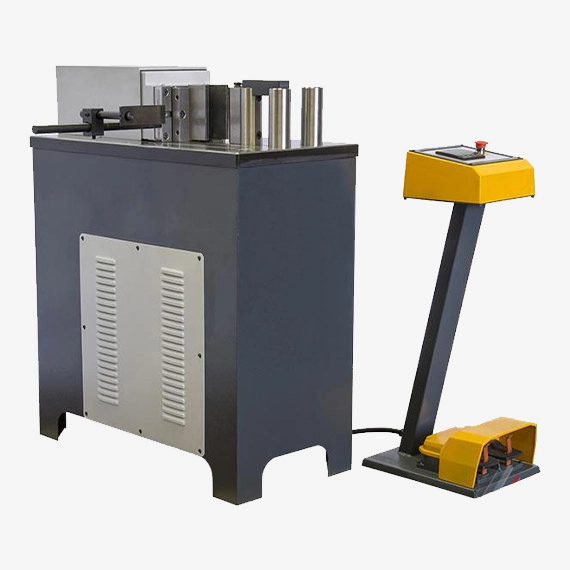
When investing in bending press machines, understanding the factors that influence pricing is essential for making an informed and cost-effective decision. Bending press machines come in various types and configurations, each with different features and capabilities that affect their overall cost. In this section, we will explore the key factors that determine the price of bending press machines, including specifications, features, brand reputation, and market demand. We will also discuss how to balance cost with functionality to ensure that you select the right machine for your specific needs.
6.1 Factors Affecting Bending Press Machine Price
The price of a bending press machine is influenced by several factors, including its type, specifications, features, brand, and market conditions. Understanding these factors can help you determine which machine offers the best value for your investment.
6.1.1 Machine Type
- Manual vs. Automated Machines: Manual bending press machines are generally less expensive than automated or CNC-controlled machines due to their simpler design and lower manufacturing costs. However, automated machines, while more expensive, offer greater efficiency, precision, and productivity, which can justify the higher initial investment.
- Hydraulic vs. Mechanical Presses: Hydraulic presses are typically more expensive than mechanical presses because of their complex hydraulic systems, which provide greater force and control. Mechanical presses, while less costly, may be more suitable for applications where speed is prioritized over precision.
6.1.2 Specifications and Capacity
- Tonnage: The tonnage, or force capacity, of a bending press machine is one of the primary factors influencing its price. Machines with higher tonnage are capable of bending thicker and stronger materials but come with a higher price tag due to the more robust construction and powerful hydraulic or mechanical systems required.
- Bed Size: The size of the machine’s bed, which determines the maximum size of the workpiece it can handle, also affects the price. Larger beds increase the machine’s versatility but require more material and engineering, leading to higher costs.
- Stroke Length: The stroke length, or the distance the press ram can travel, is another critical specification. Machines with longer stroke lengths can accommodate deeper bends, which adds to the complexity and cost of the machine.
6.1.3 Features and Technology
- CNC Controls: Bending press machines equipped with CNC (Computer Numerical Control) systems are significantly more expensive than those with manual or semi-automatic controls. CNC systems offer the ability to program and automate complex bending sequences, enhancing precision and productivity, which justifies their higher price.
- Automation and Robotics: Machines with advanced automation features, such as automatic tool changers, robotic loading and unloading, and real-time monitoring systems, command higher prices due to the added technology and the potential for increased production efficiency.
- Safety Features: Enhanced safety features, such as light curtains, safety guards, and emergency stop systems, can also contribute to the overall cost of the machine. These features are essential for protecting operators and ensuring compliance with safety regulations, particularly in high-volume production environments.
6.1.4 Brand and Quality
- Reputation: The reputation of the manufacturer or brand plays a significant role in the price of bending press machines. Established brands with a history of quality, reliability, and excellent after-sales support often charge a premium for their products. While these machines may be more expensive upfront, they often offer better performance, durability, and long-term value.
- Quality of Materials: The quality of the materials used in the construction of the machine, such as the steel for the frame and the components of the hydraulic system, affects both the machine’s durability and price. Higher-quality materials lead to longer-lasting machines but increase manufacturing costs.
6.1.5 Market Demand and Availability
- Supply and Demand: Market conditions, such as the balance between supply and demand, can also influence the price of bending press machines. During periods of high demand, prices may rise due to limited availability. Conversely, prices may decrease during periods of low demand or excess supply.
- Import and Export Costs: For machines that are imported, factors such as tariffs, shipping costs, and currency exchange rates can affect the final price. These costs can vary significantly depending on the country of origin and the location of the buyer.
6.2 Cost vs. Functionality: Making the Right Investment
When selecting a bending press machine, it is essential to balance cost with functionality to ensure that the machine meets your specific needs without exceeding your budget. Here are some strategies to help you make a cost-effective investment:
6.2.1 Assessing Your Needs
- Production Volume: Consider the volume of production when choosing a machine. If your operation involves high-volume production, investing in a more expensive, automated machine may be justified by the increased efficiency and reduced labor costs. For lower-volume operations, a less expensive manual or semi-automatic machine may be sufficient.
- Material Type and Thickness: The types of materials you work with, including their thickness and strength, will determine the necessary tonnage and capabilities of the machine. Ensure that the machine you choose can handle your specific material requirements without overpaying for unnecessary capacity.
- Complexity of Bends: If your applications involve complex bends or require high precision, investing in a CNC-controlled machine may be worth the higher cost. However, for simpler bends, a manual or mechanical machine may provide adequate functionality at a lower price.
6.2.2 Evaluating Long-Term Costs
- Operating Costs: Consider the long-term operating costs of the machine, including energy consumption, maintenance, and tooling. While a machine with advanced features may have a higher upfront cost, it could offer lower operating costs and higher efficiency, leading to savings over time.
- Durability and Reliability: Machines made with higher-quality materials and components tend to have longer service lives and require less maintenance. Investing in a durable, reliable machine can reduce downtime and maintenance costs, providing better long-term value.
- Resale Value: Some high-quality machines maintain their value well and can be resold at a good price if your needs change. This can offset some of the initial investment costs and provide flexibility in the future.
6.2.3 Exploring Financing and Leasing Options
- Financing: Many manufacturers and dealers offer financing options that allow you to spread the cost of the machine over time. This can make it easier to afford a higher-quality machine without straining your budget.
- Leasing: Leasing is another option that allows you to use a high-quality machine without the full upfront cost. Leasing can be particularly advantageous if you need the machine for a specific project or a limited time.
6.2.4 Considering Used or Refurbished Machines
- Used Machines: Purchasing a used bending press machine can be a cost-effective way to acquire high-quality equipment at a lower price. However, it is essential to thoroughly inspect the machine for wear and tear and ensure that it has been well-maintained.
- Refurbished Machines: Refurbished machines offer a middle ground between new and used equipment. These machines have been restored to good working condition and often come with warranties, providing reliability at a reduced cost.
6.2.5 Comparing Suppliers and Brands
- Supplier Reputation: Work with reputable suppliers who offer good after-sales support, including training, maintenance, and access to spare parts. A reliable supplier can significantly impact the total cost of ownership by helping you keep the machine in good working condition.
- Brand Comparison: Compare different brands and models to find the best balance between price and features. Look for reviews and case studies to understand how the machines perform in real-world applications and whether they meet industry standards.
6.3 Case Studies: Price Considerations in Real-World Scenarios
Case Study 1: Small Fabrication Shop A small metal fabrication shop required a bending press machine for custom projects involving light to medium-gauge steel. After evaluating their needs, they opted for a mid-range hydraulic press with manual controls. While they considered a CNC machine, the additional cost was not justified given their low production volume. The hydraulic press offered the necessary force and precision at a reasonable price, allowing the shop to handle a variety of projects without overextending their budget.
Case Study 2: High-Volume Automotive Manufacturer A large automotive manufacturer needed a new bending press machine to increase production efficiency for body panels. They chose a high-end CNC-controlled hydraulic press with automated tool changers and real-time monitoring. Although the machine was significantly more expensive than manual or semi-automatic models, the investment was justified by the increased throughput, reduced labor costs, and high precision required for automotive production. The machine’s advanced features also allowed for quicker setup times and reduced downtime, further enhancing productivity.
Case Study 3: Start-Up in the Aerospace Industry A start-up aerospace company needed a bending press machine capable of producing complex, high-precision components. Given their limited budget, they explored options for used and refurbished CNC machines. They found a reputable supplier offering a refurbished CNC press brake that met their specifications at a fraction of the cost of a new machine. The refurbished machine provided the precision and functionality needed for aerospace applications, allowing the start-up to meet industry standards without exceeding their budget.
6.4 Conclusion
When considering the purchase of a bending press machine, it is crucial to weigh the cost against the functionality and long-term value of the machine. Factors such as machine type, specifications, features, brand reputation, and market demand all play a significant role in determining the price. By carefully assessing your specific needs, evaluating long-term costs, exploring financing or leasing options, and comparing suppliers and brands, you can make a well-informed decision that balances cost with the required functionality. Whether you are a small shop or a large manufacturer, selecting the right bending press machine is an investment that can enhance productivity, improve product quality, and contribute to the overall success of your operation.
A Sheet Metal Brake Hydraulic Press is a machine tool used for bending, shaping, and forming sheet metal using hydraulic force. It combines the functionality of a sheet metal brake (which bends metal along a straight edge) with a hydraulic press (which uses hydraulic power for controlled force application).
Key Components:
- Frame – The rigid structure supporting the press.
- Hydraulic System – Includes a pump, cylinders, and valves to generate force.
- Upper and Lower Dies – Tools that form the sheet metal into the desired shape.
- Back Gauge – Helps position the metal accurately for repeatable bends.
- Control Panel – Allows operators to adjust pressure, angle, and speed.
- Safety Features – Guards, emergency stops, and light curtains for operator protection.
Advantages:
- High Precision – Provides accurate and repeatable bends.
- Powerful and Efficient – Can bend thicker metals with ease.
- Versatile – Can be used for various metals, including steel, aluminum, and copper.
- Automation Compatible – Can be integrated with CNC systems for complex bending sequences.
Applications:
- Metal fabrication shops
- Automotive industry (body panels)
- Aerospace (aircraft components)
- HVAC (ductwork manufacturing)
- Construction (structural components)
A sheet metal brake hydraulic press is a powerful machine used for bending and shaping metal sheets with precision. It combines the functionality of a sheet metal brake with the force of a hydraulic press, allowing for smooth and controlled bending. The machine consists of a rigid frame, a hydraulic system with cylinders and pumps, and upper and lower dies that shape the metal. It often includes a back gauge for positioning and a control panel for adjusting pressure and bend angles. These presses are widely used in industries like automotive, aerospace, HVAC, and construction due to their ability to handle thick metals and produce consistent, high-quality bends. Unlike mechanical or pneumatic press brakes, hydraulic presses offer greater force, improved control, and compatibility with CNC automation for complex bending tasks. Their safety features, such as emergency stops and light curtains, make them reliable for industrial operations.
A sheet metal brake hydraulic press is a specialized machine designed to bend and shape sheet metal with high precision and force. It operates using a hydraulic system that generates controlled pressure to manipulate metal sheets, making it ideal for industries that require consistent and accurate metal forming. This type of press is widely used in metal fabrication shops, automotive manufacturing, aerospace applications, and construction, where forming thick or high-strength materials is essential. Unlike traditional manual or mechanical sheet metal brakes, a hydraulic press brake offers superior power, repeatability, and versatility, making it a preferred choice for large-scale production and custom metalworking projects.
The main working principle of a hydraulic press brake involves a hydraulic pump that supplies fluid to cylinders, which then exert pressure on a movable ram. The metal sheet is placed between a top punch and a lower die, and as the ram moves downward, it forces the sheet into the die to create the desired bend. The pressure applied is carefully controlled to ensure precision and repeatability. Hydraulic press brakes come in various sizes and force capacities, ranging from small workshop models to heavy-duty industrial machines capable of handling thick steel plates. Many modern hydraulic presses are also integrated with CNC (Computer Numerical Control) systems, allowing for automated bending sequences, higher efficiency, and reduced human error.
One of the key advantages of a hydraulic sheet metal brake is its ability to provide smooth and controlled bending, even for complex or multiple-angle bends. The hydraulic system allows for variable force application, making it suitable for a wide range of materials, including stainless steel, aluminum, and copper. Unlike mechanical press brakes, which rely on flywheels and mechanical linkages, hydraulic presses can generate full pressing force at any point in the stroke, ensuring consistent results regardless of the material thickness. Additionally, hydraulic press brakes are known for their durability and lower maintenance needs, as they have fewer moving parts and less wear compared to mechanical alternatives.
Safety is another important aspect of hydraulic press brakes. Modern machines are equipped with advanced safety features such as light curtains, emergency stop buttons, and guarding systems that prevent accidental contact with moving parts. These safety measures are essential, as high-pressure bending operations pose significant risks if not properly controlled. Operators are also provided with user-friendly control panels that allow them to adjust bending parameters, monitor hydraulic pressure, and store bending programs for repeatable production runs.
The applications of hydraulic press brakes are diverse, ranging from simple right-angle bends to complex geometries required in industries such as shipbuilding, appliance manufacturing, and heavy equipment production. In the automotive industry, they are used to shape car body panels and structural components, while in aerospace, they help fabricate precision parts for aircraft frames. HVAC manufacturers use press brakes to create ducts and enclosures, and construction companies rely on them for fabricating structural steel components.
Overall, a sheet metal brake hydraulic press is an indispensable tool in modern metalworking, offering unmatched precision, efficiency, and versatility. Whether used for small-scale custom projects or mass production, its ability to handle a variety of materials and complex bending tasks makes it a crucial asset in any fabrication environment. With advancements in CNC automation and hydraulic technology, these machines continue to evolve, providing even greater levels of accuracy, productivity, and safety in industrial applications.
A sheet metal brake hydraulic press is a crucial piece of equipment in modern metal fabrication, offering unparalleled precision, power, and efficiency in bending and forming sheet metal. Unlike mechanical or pneumatic press brakes, hydraulic presses rely on a fluid-based system to generate force, allowing for smoother operation, better control, and the ability to handle a wide range of materials and thicknesses. These machines are widely used across various industries, including automotive, aerospace, shipbuilding, and construction, where accuracy and repeatability are essential. The hydraulic press brake’s ability to produce consistent, high-quality bends has made it an industry standard for both mass production and custom fabrication.
The construction of a hydraulic press brake consists of several essential components, each playing a vital role in its operation. The frame provides structural stability and must be designed to withstand immense forces without deformation. The hydraulic system, comprising cylinders, a hydraulic pump, and control valves, generates and regulates the pressing force. The ram, or upper beam, moves downward under hydraulic pressure, pressing the sheet metal into a die positioned on the lower beam. The shape of the die determines the final bend geometry. Advanced hydraulic press brakes are equipped with back gauges, which precisely position the sheet metal for accurate and repeatable bends, reducing the need for manual adjustments.
A key advantage of hydraulic press brakes over mechanical models is their ability to provide full tonnage throughout the bending stroke. This means that even at partial strokes, the machine can exert maximum pressure, making it highly effective for deep or complex bends. Furthermore, hydraulic systems allow for adjustable pressure settings, making the machine adaptable to different materials and thicknesses. Whether bending thin aluminum sheets or thick steel plates, a hydraulic press brake can handle the job with remarkable consistency. Additionally, modern press brakes incorporate proportional hydraulic controls, which allow for smooth, precise, and energy-efficient operation, reducing wear and tear on the machine.
With the integration of CNC (Computer Numerical Control) technology, hydraulic press brakes have become even more advanced, enabling automated and highly precise bending operations. CNC-controlled press brakes feature touch-screen interfaces where operators can input bending angles, material types, and desired part dimensions. The software then calculates the necessary force and position adjustments, ensuring flawless execution. This automation not only enhances precision but also significantly reduces setup times, making CNC hydraulic press brakes ideal for high-volume production environments. Moreover, these machines can store multiple bending programs, allowing for quick changeovers between different projects, which is especially beneficial for job shops handling a variety of orders.
Safety is a major consideration when working with hydraulic press brakes, as they involve high-pressure bending operations that can pose significant risks if not properly managed. To enhance operator safety, most modern hydraulic press brakes are equipped with light curtains, which create an invisible barrier around the bending area and stop the machine if an object or hand crosses into the danger zone. Other safety features include emergency stop buttons, two-hand operation controls, and safety interlocks that prevent unintended movements. Regular maintenance, including checking hydraulic fluid levels, inspecting seals and hoses, and calibrating the control system, ensures that the press operates safely and efficiently over time.
The applications of hydraulic press brakes extend far beyond simple right-angle bends. In the automotive industry, they are used to shape structural components, chassis parts, and body panels. The aerospace sector relies on them for manufacturing lightweight yet strong airframe components. Construction and structural engineering industries use press brakes to fabricate support beams, brackets, and enclosures. Even small-scale metal workshops and custom fabrication shops benefit from hydraulic press brakes, as they allow for precise, custom-made parts that meet specific client requirements.
In conclusion, the sheet metal brake hydraulic press is an indispensable tool in modern metalworking, offering unmatched versatility, precision, and efficiency. With advancements in hydraulic technology, CNC automation, and safety features, these machines continue to evolve, making them more reliable and user-friendly. Whether for large-scale industrial production or specialized custom projects, a hydraulic press brake remains a critical investment for any metal fabrication operation. As demand for complex and high-quality metal components grows, the role of hydraulic press brakes in shaping the future of manufacturing will only become more significant.
Hydraulic Press for Sheet Metal Bending
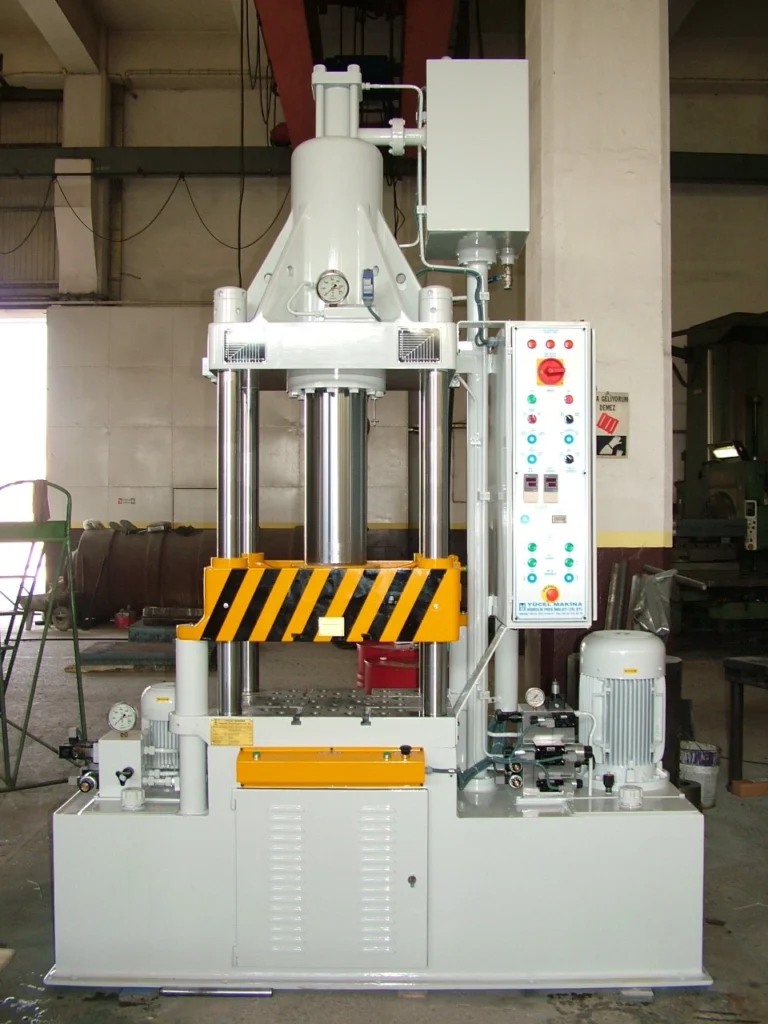
A hydraulic press for sheet metal bending is a powerful and versatile machine used to shape and form metal sheets by applying controlled hydraulic force. Unlike mechanical or pneumatic presses, which rely on gears or compressed air, hydraulic presses use a fluid-driven system to generate consistent pressure throughout the bending process. This allows for smooth, precise, and repeatable bends, making hydraulic presses an essential tool in metal fabrication, automotive manufacturing, aerospace engineering, and construction industries.
The operation of a hydraulic press involves a hydraulic pump that drives fluid into cylinders, generating force that moves a ram downward. The sheet metal is positioned between an upper punch and a lower die, and as the ram presses the metal into the die, it creates the desired bend angle and shape. The pressure applied can be precisely controlled, allowing for high levels of accuracy even when working with thick or high-strength materials like stainless steel or carbon steel. Hydraulic presses are available in various capacities, ranging from smaller workshop models to heavy-duty industrial machines capable of exerting thousands of tons of force.
One of the biggest advantages of hydraulic presses for sheet metal bending is their ability to provide full tonnage at any point in the stroke, ensuring consistent force application regardless of the material thickness. This makes them superior to mechanical presses, which require a full stroke to reach peak force. Additionally, hydraulic presses feature adjustable pressure and stroke length, allowing operators to customize the machine settings for different bending applications. This flexibility makes hydraulic presses ideal for a wide range of metalworking tasks, including V-bending, U-bending, coining, and deep drawing.
Modern hydraulic presses are often integrated with CNC (Computer Numerical Control) technology, enabling automated and precise bending operations. CNC-controlled hydraulic presses allow operators to program bending angles, material specifications, and force levels, ensuring uniformity and reducing manual errors. The ability to store multiple bending programs also improves efficiency in production environments that require high-volume or repetitive bending tasks. This automation reduces material waste, increases productivity, and lowers labor costs, making CNC hydraulic presses a valuable investment for industrial applications.
Safety is a crucial aspect of hydraulic press operations, as these machines generate immense pressure that can pose risks to operators if not properly managed. Most modern hydraulic presses are equipped with advanced safety features, such as light curtains, safety guards, and emergency stop mechanisms that prevent accidental injuries. Some models also feature two-hand operation controls and overload protection systems to ensure safe and controlled bending processes. Regular maintenance, including checking hydraulic fluid levels, inspecting seals and hoses, and calibrating control systems, helps keep the press in optimal working condition and extends its lifespan.
The applications of hydraulic presses for sheet metal bending are vast, spanning multiple industries. In the automotive sector, they are used to shape body panels, chassis components, and structural reinforcements. The aerospace industry relies on them to form lightweight yet strong metal parts for aircraft and spacecraft. In construction and heavy equipment manufacturing, hydraulic presses are used to create steel brackets, support beams, and architectural metal components. Additionally, HVAC (Heating, Ventilation, and Air Conditioning) manufacturers use these machines to fabricate ductwork and enclosures with precise bends and folds.
In summary, hydraulic presses for sheet metal bending are essential tools in modern manufacturing and metalworking, offering high precision, versatility, and efficiency. Their ability to apply controlled force, accommodate different materials, and integrate with CNC automation makes them an industry standard for both small-scale workshops and large-scale production facilities. With continuous advancements in hydraulic technology, including energy-efficient systems and smart automation, hydraulic presses will continue to play a crucial role in the future of metal fabrication and industrial manufacturing.
A hydraulic press for sheet metal bending is a highly efficient and powerful machine used in metal fabrication to shape and form metal sheets with precision. It operates using a hydraulic system that generates force by pressurizing a fluid within cylinders, allowing for controlled and consistent pressure throughout the bending process. Unlike mechanical or pneumatic presses, hydraulic presses provide full tonnage at any point in the stroke, ensuring that the force applied is uniform and effective regardless of the material thickness. This makes them particularly useful for bending high-strength metals such as stainless steel, aluminum, and carbon steel in various industries, including automotive, aerospace, construction, and heavy equipment manufacturing.
The working principle of a hydraulic press involves a hydraulic pump that drives fluid into one or more cylinders, moving a ram that applies pressure to the sheet metal placed between an upper punch and a lower die. As the ram descends, it forces the metal into the die, shaping it according to the desired angle and bend radius. The ability to adjust pressure, stroke length, and bending force allows operators to customize the machine settings based on material properties and design specifications. This level of control ensures high precision in metal bending applications, reducing errors and material waste while improving production efficiency.
One of the major advantages of hydraulic presses is their ability to handle a wide range of bending operations, including V-bending, U-bending, coining, and bottom bending. Their versatility allows manufacturers to produce complex metal components with multiple bends in a single operation. Modern hydraulic presses are often integrated with CNC (Computer Numerical Control) systems, which enable automation and precise control of the bending process. CNC technology allows operators to program bending angles, material types, and force settings, ensuring consistent and repeatable results across multiple production runs. The ability to store bending programs also reduces setup time, making CNC hydraulic presses ideal for high-volume manufacturing.
Safety is a critical consideration in hydraulic press operations due to the immense forces involved in the bending process. To protect operators and prevent workplace accidents, modern hydraulic presses are equipped with advanced safety features such as light curtains, which use infrared beams to detect any object or hand entering the danger zone, instantly stopping the machine. Emergency stop buttons, two-hand operation controls, and overload protection systems further enhance operator safety. Regular maintenance, including checking hydraulic fluid levels, inspecting seals and hoses, and calibrating the control system, is essential to ensure the machine’s longevity and optimal performance.
Hydraulic presses are widely used in various industrial applications where precision bending is required. In the automotive industry, they are essential for shaping body panels, chassis components, and reinforcements that contribute to vehicle safety and aerodynamics. Aerospace manufacturers rely on hydraulic presses to form lightweight yet structurally strong components for aircraft and spacecraft. In construction and heavy equipment manufacturing, hydraulic presses are used to create steel brackets, support beams, and other structural components. Additionally, the HVAC industry uses hydraulic presses to fabricate ducts, metal enclosures, and ventilation system components with high accuracy.
As technology continues to evolve, hydraulic presses are becoming more energy-efficient and intelligent, incorporating features such as servo-driven hydraulic systems and automated load sensing to optimize energy consumption. These advancements not only reduce operational costs but also improve the overall sustainability of manufacturing processes. The growing demand for precision metal forming, coupled with innovations in automation and hydraulic engineering, ensures that hydraulic presses will remain a fundamental tool in modern industrial production. Whether used for small-scale custom fabrication or mass production, hydraulic presses provide unmatched accuracy, efficiency, and reliability, making them indispensable in the field of metalworking.
Hydraulic presses for sheet metal bending have become essential tools in modern manufacturing, providing high precision, power, and adaptability for a wide range of metalworking tasks. The ability to apply consistent, controlled force throughout the bending process makes these presses ideal for handling thick, high-strength materials that would be challenging for mechanical or pneumatic presses. By using hydraulic force, the press can maintain full tonnage at any point during the stroke, which improves the consistency of the bends and eliminates the need for adjustments as the material is bent. This ensures a high degree of uniformity, which is especially important in industries that require parts to meet strict tolerances.
The versatility of hydraulic presses is another key factor in their widespread use. Operators can adjust the machine’s settings to accommodate different material types, thicknesses, and bend angles, making it suitable for a wide variety of bending operations. Whether it’s forming simple right-angle bends or more complex shapes, hydraulic presses provide the flexibility needed for a broad array of applications. For example, in the automotive sector, hydraulic presses are frequently used for shaping vehicle body panels, which require both precision and strength. The same technology is applied in aerospace manufacturing, where lightweight yet durable metal parts are essential for aircraft and spacecraft construction.
The integration of CNC (Computer Numerical Control) technology into hydraulic press brakes has revolutionized the industry, allowing for a level of automation and control that was once unattainable. CNC-controlled presses offer significant benefits, such as the ability to store bending programs, which speeds up setup times and reduces the likelihood of errors. Operators can program the press to perform multiple bends in a specific sequence, and the machine can automatically adjust for material variations, ensuring each part is made to precise specifications. This capability is particularly useful in high-volume manufacturing environments, where repeatability and efficiency are critical. With CNC control, operators can achieve highly complex bends and geometries that would be nearly impossible with manual or non-CNC systems.
Safety is a primary concern when operating hydraulic presses, as they involve significant amounts of force. To mitigate risks, modern hydraulic presses come equipped with a variety of safety features. For instance, light curtains are often used to create invisible safety zones around the machine’s moving parts. If the light curtain detects an obstruction or a person entering the danger zone, it automatically halts the press’s operation, preventing potential injuries. Other safety features include two-hand operation controls, which ensure that the operator’s hands are not in the danger zone when the press is active, and emergency stop buttons, which allow operators to quickly shut down the press in the event of a malfunction or emergency. These safety measures are designed to protect operators while maintaining high levels of productivity and efficiency.
The role of hydraulic presses is expanding as manufacturers seek ways to improve both productivity and sustainability. In addition to their established use in metal forming, hydraulic presses are becoming more energy-efficient. Modern systems often use servo-driven hydraulic pumps that adjust the pump’s speed according to the load, reducing energy consumption when full power isn’t necessary. This results in lower operational costs and a more sustainable manufacturing process, especially in large-scale production. The increased demand for energy-efficient machinery, combined with advancements in hydraulic technology, is driving the development of even more sophisticated press systems that combine precision, power, and sustainability.
Hydraulic presses are also invaluable for custom fabrication and prototype development. Small workshops and specialized manufacturers benefit from the flexibility and precision of hydraulic presses to produce unique parts for low-volume runs. In these environments, the ability to quickly change dies, adjust pressure settings, and program different bending sequences allows manufacturers to meet the specific needs of each project without long lead times. The versatility of hydraulic presses also means they can be used across a variety of industries, including HVAC, where they are used for bending and shaping ducts, enclosures, and other metal components for ventilation systems.
In conclusion, hydraulic presses for sheet metal bending are indispensable in today’s manufacturing landscape. Their ability to handle a wide range of materials, produce highly precise bends, and be adapted for both small-scale and large-scale operations makes them crucial for industries such as automotive, aerospace, construction, and HVAC. The integration of CNC technology, coupled with improved energy efficiency and safety features, ensures that hydraulic presses continue to evolve, remaining a reliable and vital tool in metalworking and fabrication. As the demand for more complex, higher-quality metal components increases, hydraulic presses will continue to play a central role in shaping the future of industrial manufacturing.
The role of hydraulic presses for sheet metal bending is continually evolving as industries push for more complex designs, higher production volumes, and greater efficiency. As technology advances, manufacturers are increasingly looking to optimize both the performance and environmental impact of their machinery, and hydraulic presses are no exception. Innovations in servo-hydraulic systems have made hydraulic presses more energy-efficient, reducing overall energy consumption by adapting the flow of hydraulic fluid to match the demand. This system allows for a more energy-efficient operation, as the press only consumes the energy required for each task, rather than running at full capacity all the time. These advances help companies lower their operating costs and align with growing sustainability demands, especially in industries focused on reducing their carbon footprint.
Another area of development is the automation of the sheet metal bending process. While traditional hydraulic presses require manual input for die adjustments and bending parameters, modern presses are often fully automated, with robotic arms or conveyor systems integrated into the machine. This automation allows for a higher degree of precision and speed, as the robots handle repetitive tasks like loading and unloading metal sheets, adjusting positions, and removing finished parts. Additionally, automation reduces human error and increases production rates, making it ideal for mass production environments. Furthermore, automation combined with CNC technology helps manufacturers achieve incredibly tight tolerances, which is essential in sectors such as aerospace and automotive, where even the smallest deviation in measurements can result in failure or defects.
The integration of smart technologies is another significant development in hydraulic press systems. Many modern machines are equipped with sensors that monitor variables such as hydraulic pressure, oil temperature, and stroke position. These sensors collect real-time data, which can be analyzed by integrated software to detect irregularities or potential issues before they result in failures or downtime. By continuously monitoring the system’s performance, manufacturers can optimize the press’s operation, predict maintenance needs, and ensure continuous production without the costly interruptions that can arise from unexpected breakdowns. These systems also help reduce material waste by adjusting the bending parameters automatically based on the material’s characteristics, ensuring that the correct amount of force is applied for each piece.
The customization of hydraulic presses has also expanded, with manufacturers offering a wider range of configurations tailored to specific applications. These presses can now be equipped with specialized tooling and accessories that allow for more intricate bends and complex geometries, such as those needed in the creation of curved or asymmetric shapes. Additionally, hydraulic presses are being used for a broader range of materials, from traditional metals like aluminum and steel to newer materials such as composite metals, high-strength alloys, and even certain types of plastics. This versatility ensures that hydraulic presses remain at the forefront of technology for industries requiring innovative material solutions, such as the medical device, electronics, and renewable energy sectors.
In terms of productivity, the speed of hydraulic presses is steadily increasing, with advancements in software algorithms allowing for faster processing of bending instructions and quicker execution of commands. Faster processing times not only improve productivity but also reduce the time between setup and production, which is crucial for meeting tight deadlines or handling high-mix, low-volume production runs. This increase in speed is complemented by enhanced precision, allowing manufacturers to maintain a high level of quality even as production speeds rise. In turn, this combination of speed and precision boosts the overall competitiveness of companies in industries with rapidly changing demands, such as consumer electronics, where faster turnarounds are critical.
Moreover, integrated design and simulation software has become more common in the hydraulic press industry. Manufacturers now have the ability to model and simulate the bending process virtually before any physical work is done. This allows engineers to optimize bending strategies, predict potential challenges, and improve die designs without the trial-and-error method that was once required. Through this process, companies can significantly reduce material waste and tooling costs, as well as minimize the need for costly rework during production. Such software is especially valuable in prototyping and custom fabrication, where flexibility and precision are key.
In addition to the hardware advancements, improved operator interfaces are making hydraulic presses more user-friendly. Many newer systems feature intuitive touch-screen interfaces with graphical representations of the bending process, real-time feedback on machine performance, and easier-to-understand diagnostic tools. This allows operators to quickly adjust settings, troubleshoot issues, and monitor performance without the need for extensive training or technical knowledge. The result is a more streamlined operation, with fewer errors and higher productivity.
As industries continue to demand more complex, durable, and cost-effective metal parts, the hydraulic press remains an indispensable tool for sheet metal bending. With advancements in automation, energy efficiency, smart technology, and customization, these presses are becoming increasingly capable of meeting the needs of modern manufacturing. Whether used for high-volume production runs or intricate custom jobs, hydraulic presses will continue to be integral to industries ranging from automotive to aerospace, medical to construction. Their ability to adapt to new materials, complex shapes, and ever-growing production demands ensures they will remain essential for metal fabrication for years to come.
Hydraulic Press Bender
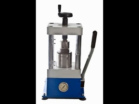
A hydraulic press bender is a type of machine used to bend and shape metal materials by applying controlled hydraulic force. It combines the principles of a hydraulic press with the functionality of a bender, making it an essential tool for fabricators, manufacturers, and metalworking professionals who require precise and powerful bending capabilities. Hydraulic press benders are versatile machines that are widely used across industries such as automotive, aerospace, construction, and heavy equipment manufacturing. These machines can bend a variety of metals, including steel, aluminum, and copper, offering flexibility for both simple and complex bending tasks.
The core operation of a hydraulic press bender is driven by hydraulic power, which provides a constant and adjustable force. The machine operates by using a hydraulic cylinder, which is activated by hydraulic fluid pressure from a pump. This fluid pressure is controlled by a system of valves and regulators to ensure that the bending force applied is precise and consistent. The sheet metal or metal workpiece is positioned between the upper die and lower die, and as the hydraulic cylinder moves the ram downwards, it presses the metal into the lower die to create the desired bend or curve.
One of the key benefits of hydraulic press benders over mechanical or pneumatic benders is their ability to maintain full force throughout the entire bending stroke. Hydraulic force is applied consistently, allowing the machine to bend thick and hard metals without the risk of uneven force application. This makes hydraulic press benders ideal for challenging materials such as high-strength steel or alloys, which may not be able to withstand the same pressure from other types of benders.
Hydraulic press benders are also highly customizable and can be configured for a wide range of bending operations. The bending dies can be adjusted or changed to accommodate different bend angles, radii, and part sizes. The flexibility of these machines makes them particularly valuable in situations where versatility is important, such as when manufacturers need to produce parts in small batches or with highly varied geometries. They are capable of performing tasks such as V-bending, U-bending, air bending, box bending, and even more complex operations such as hemming or flanging, depending on the tooling used.
Many modern hydraulic press benders are equipped with CNC (Computer Numerical Control) technology, enabling automated control over bending angles, pressure, and other parameters. CNC-controlled press benders offer precision and repeatability, allowing for highly accurate bends and reducing the risk of operator error. These advanced systems allow operators to enter specific bending instructions, and the machine automatically adjusts settings such as force, stroke length, and speed for optimal results. CNC hydraulic press benders can also store multiple bending programs, which allows for quick and easy setup changes when switching between different part designs.
Safety is a critical concern in the operation of hydraulic press benders due to the significant forces involved in the bending process. Most modern press benders are equipped with various safety features to protect operators from harm. Safety guards, light curtains, and two-hand operation controls are commonly incorporated to ensure that the operator’s hands or body are not exposed to the machine’s moving parts. Emergency stop buttons and overload protection systems are also standard to provide operators with quick access to halting the machine in the event of an issue.
Hydraulic press benders are used in a wide variety of industries where metal forming is required. For example, in the automotive industry, hydraulic press benders are employed to shape structural components, chassis parts, and body panels. In aerospace, they are used to form components for aircraft frames and fuselages, where precision and strength are paramount. HVAC manufacturers rely on hydraulic press benders to fabricate ducts, flanges, and other air conditioning and ventilation components. In construction, hydraulic press benders are used to bend structural steel elements, such as beams and columns, that are critical for building infrastructure.
In terms of maintenance, hydraulic press benders are generally easier to maintain than mechanical presses, as they have fewer moving parts. Regular maintenance includes checking hydraulic fluid levels, inspecting seals and hoses, and monitoring pressure settings to ensure that the system operates at peak performance. It is important to keep the hydraulic system clean and free from contaminants to prevent wear on the system and avoid costly repairs.
In summary, hydraulic press benders are powerful, versatile, and precise tools used for a wide range of metalworking tasks. Their ability to apply controlled hydraulic force makes them an ideal choice for bending thick or hard materials with consistent, accurate results. With advanced features such as CNC automation, adjustable tooling, and integrated safety systems, these machines offer a high level of productivity and efficiency for manufacturers across industries. Whether used for mass production, custom fabrication, or prototype development, hydraulic press benders are essential in shaping metal components with reliability and precision.
Hydraulic press benders are essential machines in the metalworking industry, providing the precision, power, and flexibility required for a wide range of bending applications. By utilizing hydraulic force, these machines can handle high levels of pressure, making them ideal for bending materials that are too thick or strong for mechanical presses. The hydraulic system, driven by fluid pressure, ensures that the force applied remains consistent throughout the entire bending process, providing uniform results and reducing the risk of defects or inaccuracies.
One of the key advantages of hydraulic press benders is their ability to work with different materials and thicknesses, offering unmatched versatility. The dies can be easily changed or adjusted to accommodate different bending requirements, which makes them perfect for both high-volume production and custom metalworking jobs. Whether bending sheet metal, plates, tubes, or even heavy structural components, hydraulic press benders offer the flexibility to achieve the desired shapes and angles with high accuracy.
Modern hydraulic press benders often come equipped with computer-controlled systems that enable precise adjustments to bending parameters such as force, stroke length, and speed. This automation allows for more complex bending operations and ensures that every part is consistently produced to the same high standard. CNC control systems are particularly beneficial in environments where production volume is high, and quick setup changes are required. The ability to store multiple bending programs means that operators can switch between different projects without wasting time recalibrating the machine, leading to faster turnarounds and increased efficiency.
Despite their power, hydraulic press benders are designed with safety in mind. With the potential for significant force during operation, manufacturers integrate safety features such as light curtains, safety shields, and emergency stop mechanisms to ensure that operators remain protected. The machines are also often equipped with overload protection to prevent damage to the hydraulic system in case of excessive force. These safety measures are critical in ensuring that the machine operates smoothly and that workers can perform their tasks without the risk of injury.
Another advantage of hydraulic press benders is their ability to handle complex bending tasks that require high levels of precision. This is particularly important in industries like aerospace, automotive, and construction, where components must meet exacting standards for strength, durability, and design. Hydraulic press benders can perform a variety of bends, such as air bending, V-bending, U-bending, and box bending, with exceptional accuracy. These types of bends are often required in the fabrication of structural components, chassis parts, brackets, and other critical pieces of machinery and infrastructure.
Maintenance of hydraulic press benders is generally straightforward, as they have fewer moving parts than mechanical presses. Routine maintenance typically involves checking hydraulic fluid levels, inspecting hoses and seals for leaks, and ensuring that the hydraulic system is free of contaminants. Regular maintenance helps extend the lifespan of the machine and ensures that it continues to perform at peak efficiency. Additionally, hydraulic press benders often feature easy-to-access components for quick repairs or adjustments, reducing downtime and increasing productivity.
In terms of applications, hydraulic press benders are used across a variety of industries. In the automotive industry, they are commonly used for bending sheet metal parts such as body panels, chassis components, and structural reinforcements. The aerospace industry relies on hydraulic press benders to form lightweight yet strong metal parts for aircraft, where precision and material strength are critical. In construction, hydraulic press benders are essential for bending steel beams and other structural elements used in buildings, bridges, and other infrastructure projects. The HVAC industry also uses hydraulic press benders for forming ducts, flanges, and other components necessary for ventilation and air conditioning systems.
Hydraulic press benders offer not only power and precision but also energy efficiency. Many modern machines are designed with energy-saving features such as servo-hydraulic systems, which adjust the hydraulic fluid flow to match the load demand. This reduces energy consumption compared to traditional hydraulic systems that constantly operate at full power. The result is a more sustainable operation that helps reduce manufacturing costs while improving overall efficiency.
In conclusion, hydraulic press benders are indispensable machines in modern metalworking, offering high precision, versatility, and safety for a wide range of bending applications. Their ability to handle thick, high-strength materials with consistent force and adjustability makes them ideal for industries that require both strength and accuracy. With advancements in automation and energy efficiency, hydraulic press benders are increasingly capable of meeting the demands of high-volume production while maintaining optimal performance. Whether for custom fabrication, mass production, or prototype development, hydraulic press benders continue to play a vital role in shaping the future of metalworking.
Hydraulic press benders continue to evolve, driven by technological advancements aimed at improving precision, efficiency, and adaptability in the metalworking industry. The integration of smart technology is one of the key trends shaping the future of hydraulic press benders. These machines are increasingly equipped with sensors that monitor and collect real-time data on various parameters such as hydraulic pressure, temperature, stroke position, and material thickness. This data is then analyzed by advanced software to optimize the bending process. By constantly monitoring the system, manufacturers can detect issues before they lead to costly downtime or defective parts. This predictive maintenance feature not only improves machine reliability but also helps reduce overall operational costs by identifying when repairs or adjustments are needed, rather than waiting for a breakdown to occur.
The use of advanced control systems is another significant development in hydraulic press benders. In addition to the standard CNC controls, many newer models incorporate features such as servo-driven pumps that adjust their speed and output according to the required force, further improving energy efficiency. These systems allow the press to automatically adjust its power consumption based on load conditions, reducing energy use during non-peak times. This can result in significant cost savings, particularly in industries where large-scale production runs demand high energy consumption.
Moreover, hydraulic press benders are becoming more user-friendly. The interface of modern systems typically features intuitive touchscreens that display detailed information about the machine’s status, performance, and diagnostics. These user-friendly interfaces make it easier for operators to control and monitor the machine, reducing the need for extensive training and improving overall productivity. Some systems even offer remote monitoring capabilities, enabling operators to access real-time performance data and make adjustments from a distance. This is particularly useful for large-scale operations with multiple machines, as it allows for centralized control and quick response times if issues arise.
The versatility of hydraulic press benders also continues to expand. Manufacturers now offer a wider variety of tooling options that allow for more complex and specialized bending tasks. Whether it’s creating intricate shapes, forming highly accurate angles, or producing custom parts, the variety of dies and tools available ensures that hydraulic press benders can meet the needs of even the most challenging projects. Additionally, these machines are now better equipped to handle non-metal materials, such as composites or plastics, broadening their applications even further.
Environmental considerations are also driving changes in hydraulic press bender design. With sustainability becoming a top priority in manufacturing, many companies are focusing on reducing their environmental footprint. In response, hydraulic press benders are being designed with more eco-friendly hydraulic fluids, better energy efficiency, and a reduced need for maintenance materials such as lubricants. Manufacturers are also looking at how to recycle or reuse waste materials from the bending process to minimize waste and contribute to a circular economy.
The ability to easily adjust settings and change dies allows hydraulic press benders to be adaptable to both high-volume production runs and low-volume custom jobs. In sectors where rapid prototyping or one-off jobs are common, this flexibility is invaluable. For example, in aerospace manufacturing, the demand for complex, precision-engineered parts is growing, and hydraulic press benders can be adapted to produce these parts with extreme accuracy. Similarly, in the automotive and construction industries, hydraulic press benders can efficiently produce components that require a high degree of customization, such as frame parts, body panels, and specialized brackets.
Training and skill development are also evolving alongside the technology. As CNC control and automation become more prevalent, operators are increasingly required to understand complex programming, troubleshooting, and optimization techniques. Many companies are investing in specialized training programs to ensure that workers have the necessary skills to maximize the potential of these advanced machines. This investment in training not only improves the quality of the final product but also contributes to the overall efficiency and productivity of the operation.
The applications of hydraulic press benders continue to grow across different industries. In industrial manufacturing, they are crucial for forming large-scale structural components used in machinery and infrastructure. In HVAC systems, they remain indispensable for shaping ducts and pipes, creating bends and connections that meet exacting industry standards. As renewable energy technologies continue to expand, hydraulic press benders are increasingly used to produce components for wind turbines, solar panels, and other green energy solutions, where strong yet lightweight parts are essential.
In summary, the evolution of hydraulic press benders has been marked by significant advancements in control, efficiency, versatility, and environmental sustainability. These machines are increasingly equipped with smart technology, automation, and energy-efficient systems, allowing manufacturers to meet the growing demands of precision and high-volume production. The combination of precision, power, and adaptability ensures that hydraulic press benders will remain a cornerstone of the metalworking industry for years to come, continuously shaping the future of manufacturing. Whether for custom fabrication, large-scale production, or prototyping, hydraulic press benders offer unparalleled capabilities that will continue to serve a broad range of industries.
The continual advancements in hydraulic press bender technology are enhancing their performance and expanding their application areas. One of the most notable trends in recent years has been the increased focus on automation and robotics integration. Modern hydraulic press benders can be paired with robotic systems that handle material loading, part unloading, and even automatic adjustments to the tooling setup. This level of automation reduces the need for manual labor, speeds up production, and enhances consistency by minimizing the potential for human error. For high-volume operations, robotic integration ensures that the machine is operating at peak efficiency throughout the day, reducing idle time and improving overall throughput.
The use of artificial intelligence (AI) and machine learning in hydraulic press benders is also gaining momentum. These technologies can help optimize the bending process by analyzing large datasets collected from the machine’s sensors. AI algorithms can predict the best parameters for bending based on real-time material properties, environmental factors, and past production data. Over time, as the system learns from each job, it becomes better at adjusting settings for ideal results, thereby improving productivity and part quality. For manufacturers producing highly customized or complex parts, this ability to adapt quickly and autonomously is a game-changer, allowing them to respond to varying production demands with ease.
One of the other advantages of modern hydraulic press benders is the use of advanced materials in their construction. The latest models are built with higher-strength materials that increase the durability and longevity of the machine while reducing weight and maintenance costs. These materials also allow hydraulic press benders to withstand the intense pressures involved in bending thick and high-strength metals without compromising on accuracy or reliability. The ability to withstand such stresses makes these machines increasingly capable of handling extreme bending operations, which is important for industries like aerospace and heavy manufacturing, where robust and high-performance parts are essential.
In addition to structural improvements, the dies used in hydraulic press benders have also seen significant innovation. Many modern machines feature customizable and modular die sets that can be quickly swapped out to accommodate different bending tasks. Some systems allow for automated die changeovers, which can be especially beneficial in environments where multiple types of bends are required, reducing setup times and increasing the flexibility of the machine. These advances in die technology are not only speeding up production but also enabling manufacturers to achieve highly complex and intricate bends that were previously difficult or impossible to perform on traditional press benders.
As manufacturers look to reduce their environmental footprint, the push for sustainable practices within hydraulic press bending has intensified. Hydraulic systems are becoming more energy-efficient, utilizing servo-driven pumps and other energy-saving features to reduce power consumption. These systems adjust fluid flow dynamically based on the load requirements, only using the necessary amount of energy for each specific task. As a result, energy consumption can be drastically reduced, leading to lower operational costs and a smaller carbon footprint. Additionally, manufacturers are opting for more sustainable hydraulic fluids that are less harmful to the environment, making it easier for companies to comply with environmental regulations and sustainability goals.
Furthermore, data integration and cloud connectivity are becoming more common in hydraulic press bender systems. These machines can now send real-time performance data to a central database or the cloud, allowing operators and managers to monitor the machine’s performance remotely. This remote access provides insight into machine health, production rates, and efficiency metrics, enabling managers to make data-driven decisions and perform predictive maintenance. The ability to track machine performance over time helps optimize the production process, identify trends, and reduce downtime due to unexpected failures. It also allows for better coordination between machines in a production line, enhancing overall system efficiency.
In terms of customization and flexibility, hydraulic press benders are increasingly being designed with the ability to perform a wider range of complex operations. Some machines can now be programmed to perform multi-axis bending, allowing for the creation of three-dimensional bends or complex contours that require precise multi-directional control. This feature is especially valuable in industries such as aerospace, where parts often require non-linear shapes or highly intricate geometries. Similarly, tube bending and profile bending are now more easily achieved with specialized tooling that allows hydraulic press benders to handle these specific applications with high precision and efficiency.
The increased use of virtual simulations and CAD (Computer-Aided Design) tools has further enhanced the capabilities of hydraulic press benders. Manufacturers can now use simulation software to model the bending process before actually performing the operation. This helps optimize tool selection, bending angles, and other variables to avoid errors and material waste. By accurately predicting how a piece will behave during the bending process, engineers can avoid costly mistakes and improve the design of parts before they go into production. This virtual modeling is especially important in the prototype development phase, where small-scale production or one-off parts need to meet exacting tolerances.
In high-mix, low-volume production environments, hydraulic press benders are particularly beneficial. The flexibility and programmability of these machines allow them to be used for small batches of unique parts without requiring the same level of setup time and cost associated with specialized equipment for each different design. This is particularly valuable for industries such as medical device manufacturing, where customized parts must often be fabricated to precise specifications in small quantities. The ability to quickly adjust the machine for different projects allows manufacturers to respond rapidly to changing customer demands and produce high-quality, customized products without significant delays.
In conclusion, hydraulic press benders are rapidly evolving, integrating advanced technologies such as AI, robotics, automation, and data-driven optimization to meet the needs of modern manufacturing. These developments are enhancing the machines’ capabilities, making them faster, more energy-efficient, and more precise. The continued innovations in hydraulic press bender technology are helping manufacturers stay competitive by improving flexibility, reducing waste, and increasing productivity. With the increasing demand for complex, high-precision parts across various industries, hydraulic press benders are set to remain an indispensable tool for shaping metal for years to come.
Manual Sheet Bending Machine
A manual sheet bending machine is a type of metalworking equipment designed for bending and shaping sheet metal without the need for electricity or hydraulic power. These machines are typically simpler in design compared to their hydraulic or mechanical counterparts, and they rely on manual force applied by the operator to perform bending tasks. They are especially useful for small-scale operations, hobbyists, workshops, and situations where precision is not as critical, but flexibility and ease of use are valued.
Manual sheet bending machines are designed to handle a variety of sheet metal thicknesses and materials, including steel, aluminum, brass, and copper. They can perform a wide range of bending operations, including V-bending, U-bending, and straight bending, depending on the type of machine and the tooling used. The bending process is relatively straightforward, but the operator must use physical force to manipulate the workpiece into the desired shape.
The core components of a manual sheet bending machine typically include:
- Frame: The frame of the machine is the primary structural component that supports the bending process. It is typically made from strong steel or cast iron to withstand the forces generated during bending.
- Upper Beam: The upper beam holds the bending punch, which applies the force to the sheet metal. The operator moves this beam manually, either using a hand lever, screw mechanism, or a crank system.
- Lower Bed: The lower bed is where the sheet metal is placed. It typically contains a die or set of dies that define the shape and angle of the bend. The metal is positioned on this bed, and the bending punch from the upper beam pushes it down into the die.
- Manual Controls: Manual sheet bending machines are operated by hand. Depending on the model, operators may use a lever, crank, or screw to raise or lower the upper beam, applying pressure to the sheet metal. These machines are often designed to be operated by one or two people, allowing for precise control over the bending process.
- Clamps or Hold-Downs: To ensure that the sheet metal remains in place during the bending process, manual sheet bending machines typically have clamps or hold-down mechanisms. These help secure the workpiece in the correct position and prevent it from shifting or moving as pressure is applied.
One of the significant advantages of manual sheet bending machines is their simplicity and cost-effectiveness. These machines are often more affordable than their hydraulic or mechanical counterparts, making them ideal for small workshops, prototype production, and environments where only occasional or light-duty bending is required. They are also relatively easy to operate, with no need for specialized training or knowledge of complex control systems.
Another benefit of manual sheet bending machines is their portability. Many models are compact and lightweight, allowing them to be easily moved or stored when not in use. This portability makes them particularly valuable for smaller shops or job sites that require flexible equipment that can be relocated as needed.
While manual sheet bending machines are highly useful for simpler tasks, they do have some limitations compared to automated or hydraulic systems. The most notable limitation is the force capacity. Manual machines rely on the operator to apply the necessary force to bend the metal, which can be challenging when working with thicker or harder materials. This makes manual sheet bending machines less suitable for high-volume production or heavy-duty applications. Additionally, achieving consistent, high-precision bends across multiple parts can be more difficult with manual machines, as the operator’s strength and control play a significant role in the outcome.
Despite these limitations, manual sheet bending machines remain popular in various industries, especially for prototype work, custom fabrication, hobbyist projects, and small-scale production. They are also well-suited for producing simple components such as brackets, panels, frames, and other small metal parts that require basic bends.
Overall, the manual sheet bending machine offers an accessible and efficient solution for bending metal sheets in small-scale or low-volume operations. It is a versatile and reliable tool that can help businesses and individuals achieve quality bends without the need for expensive equipment or complex automation. Whether for crafting prototypes, producing custom parts, or fulfilling specific metalworking needs, manual sheet bending machines continue to be a valuable asset in many metalworking shops.
Manual sheet bending machines are designed to provide a cost-effective and straightforward solution for bending sheet metal in various applications. They are ideal for small-scale or low-volume projects where simplicity, portability, and affordability are key considerations. These machines typically use a lever, crank, or screw mechanism to apply force, enabling the operator to manually bend the metal to the desired shape.
Despite their manual nature, these machines are capable of handling a variety of materials, including steel, aluminum, copper, and brass, across a range of thicknesses. While they are well-suited for basic bends, such as V-bending, U-bending, and simple straight bends, they may not be suitable for more complex, high-precision tasks. However, they excel in applications where accuracy is important, but the need for high-tech automation is not required.
One of the key advantages of manual sheet bending machines is their ease of use. The operator can control the bending process directly, adjusting the force applied to the sheet metal based on the material’s characteristics. This hands-on approach provides flexibility, allowing for adjustments during the bending process. This feature is particularly useful for custom or prototype work, where unique bends may be required for one-off parts or small batches.
Another advantage is the affordability and simplicity of manual sheet bending machines. They do not require specialized training to operate, making them accessible to small businesses, hobbyists, and craftsmen who may not have the resources for more complex or automated machinery. In addition to being easy to operate, these machines are often more budget-friendly compared to their hydraulic or mechanical counterparts, making them a practical choice for workshops that need a reliable bending solution without a large upfront investment.
Portability is also a key benefit of manual sheet bending machines. Many models are compact and lightweight, which makes them easy to move and store when not in use. This is particularly useful for small workshops or job sites where space is limited or when the machine needs to be relocated frequently. This portability makes manual sheet bending machines a convenient option for tasks that do not require a permanent setup but still demand consistent bending capability.
However, manual sheet bending machines are not without limitations. One of the primary drawbacks is the amount of physical force required by the operator, especially when working with thicker or harder metals. For applications that involve high-strength materials or large production volumes, the limitations of manual labor can become apparent. Achieving the required bending force can be difficult for the operator, and the process may not be as efficient as hydraulic or mechanical machines. This makes manual machines less ideal for high-volume manufacturing or applications requiring uniform precision across many parts.
Additionally, the consistency of bends can vary from part to part when using a manual sheet bending machine. Since the force applied relies on the operator’s physical effort and technique, achieving exact replication of bends across multiple pieces can be challenging, especially with more complex parts. The lack of automation means that manual sheet bending machines may not offer the same level of repeatability as automated machines, which can be a disadvantage when producing large quantities of the same part.
Despite these limitations, manual sheet bending machines remain valuable tools for a wide range of applications. They are particularly effective in industries or environments where low to medium-volume production is required, and when the ability to make quick adjustments during bending is important. They are often used in custom fabrication, small workshops, repair shops, hobbyist settings, and even for prototype development in industries like automotive, construction, and HVAC.
Manual sheet bending machines can be an excellent choice for bending smaller parts such as brackets, frames, and panels. They also serve well in metalworking education and training environments, where students can gain hands-on experience with metalworking tools without the complexity of automation. Additionally, these machines are often used for bending light-gauge metals or for making small custom metal components that do not require the high bending forces of larger, more powerful machines.
In conclusion, manual sheet bending machines provide an accessible, affordable, and flexible solution for bending sheet metal in small-scale operations. They offer a practical alternative for those needing basic metalworking capabilities without the need for more complex, costly machinery. While they may not be suitable for high-volume production or extremely precise bending tasks, they are reliable and efficient for a variety of applications, making them an essential tool in many metalworking environments.
Manual sheet bending machines continue to be a staple in workshops, small-scale metalworking operations, and custom fabrication environments due to their simplicity and affordability. Their ease of use makes them especially beneficial in situations where precision is required but doesn’t necessitate advanced technology or automation. These machines, although manual, offer versatility in handling a wide range of tasks, such as producing small metal parts, creating prototypes, or performing repairs.
The cost-effectiveness of manual sheet bending machines is a significant advantage, especially for small businesses or startups with limited budgets. Unlike their hydraulic or mechanical counterparts, manual machines do not require expensive components, complex control systems, or high maintenance costs. This makes them an attractive option for shops that need reliable equipment for occasional or low-volume bending without incurring large upfront expenses. Additionally, the simplicity of manual machines means there’s less risk of technical failure, which could disrupt production, as the fewer parts involved make them more durable and easy to maintain.
For tasks like bending light to medium-gauge sheet metal, manual sheet bending machines provide the required force and precision. Whether it’s for bending plates to create frames, brackets, or even intricate shapes, the operator can control the force and position during the bending process. This manual control allows the operator to adjust the machine quickly for various types of materials and bending angles, ensuring a high degree of flexibility. The setup for each job is straightforward, and changes can be made on the fly, which is ideal for industries or applications that involve frequent custom work or unique projects.
Moreover, manual sheet bending machines require minimal training to operate effectively. Most models have simple hand-operated levers or cranks that can be easily mastered by operators with basic skills. This simplicity also means that training new staff or even hobbyists is less time-consuming compared to learning to operate automated systems. For shops that may not have the resources to train employees on more sophisticated machinery, manual sheet bending machines offer a practical solution that provides the necessary functionality without requiring specialized expertise.
While manual sheet bending machines are great for smaller projects, they can still handle bending tasks across different industries. In HVAC manufacturing, for example, these machines are ideal for producing ducts, elbows, and other components that require basic bends. In construction, they’re often used to create frames, brackets, and reinforcements, particularly for smaller-scale building projects. In automotive customization or restoration, manual sheet benders are useful for fabricating custom parts or small, intricate components that may not be produced efficiently with larger machines.
However, as with any machine, there are limitations. One of the main challenges with manual sheet bending machines is the amount of physical exertion required, particularly when working with thicker or harder metals. While they can handle standard sheet metal thicknesses, as the material becomes thicker or the metal stronger, achieving the required bending force manually becomes increasingly difficult. The operator may struggle to produce consistent bends without the mechanical advantage provided by hydraulic or motorized systems, especially in high-strength materials like stainless steel or high-carbon steel.
Additionally, the force required for bending can create variability in the results. Since the machine relies on the operator’s input for the amount of force applied, variations in how much pressure is applied can result in inconsistent bends. This can be problematic if precision and repeatability are critical for a particular application. When multiple parts need to be bent to the exact same specifications, even small variations in force can lead to discrepancies in quality.
Despite these limitations, manual sheet bending machines are still an excellent option for many operations, especially when only limited quantities of metal parts need to be bent. They are also useful in environments where only basic bending operations are required, or where a large investment in automation is not feasible. Small job shops, metalworking enthusiasts, and DIY fabricators often find them to be indispensable tools, providing just the right amount of flexibility and functionality for custom projects.
One important factor to consider when using manual sheet bending machines is the type of metal and thickness being worked with. Operators can achieve better results when working with softer materials like aluminum, copper, or mild steel, particularly in gauges that are within the bending capacity of the machine. Thicker metals or stronger alloys may still be manageable, but they will require more effort and may be limited by the machine’s force capacity.
Despite their reliance on manual labor, there are ways to enhance the efficiency of a manual sheet bending machine. For instance, integrating simple tools like measuring guides, angle markers, or rulers can help improve the consistency of each bend. Some machines even come with adjustable stops, which can ensure that parts are bent to the correct angle repeatedly, adding a degree of precision to the manual process. These small improvements can make a big difference in the accuracy and quality of the bends, particularly when dealing with custom projects that require several parts to be shaped in similar ways.
Ultimately, the manual sheet bending machine’s value lies in its ability to provide a straightforward, efficient, and affordable solution for bending metal. While not as powerful or precise as fully automated systems, these machines continue to play a crucial role in metalworking, offering a practical tool for small businesses, repair shops, and hobbyists. Whether you’re fabricating a one-off part, developing a custom design, or creating low-volume metal components, manual sheet bending machines provide the flexibility, simplicity, and affordability necessary to get the job done effectively.
Manual sheet bending machines continue to play an essential role in metalworking shops, particularly for those that require flexibility, simplicity, and cost-effective equipment. While they are not intended for high-volume production or large-scale industrial tasks, these machines excel in low-volume, custom work, and small-scale fabrication. Their hands-on operation provides operators with the ability to make quick adjustments and produce unique parts with ease, making them indispensable for many smaller businesses or hobbyists.
In addition to basic bending tasks, some advanced manual sheet bending machines come with features that improve accuracy and precision. For example, adjustable stops can be used to ensure that each bend is made at the correct angle, allowing operators to replicate bends across multiple pieces consistently. This can be particularly useful in projects that require multiple parts with similar or identical bends. Angle indicators or rulers may also be incorporated into these machines, helping to ensure that bends are made to the desired specification. These enhancements can go a long way in improving the overall efficiency and quality of the bending process, making manual machines a viable option for applications that demand a higher level of precision than standard manual benders.
Another aspect that makes manual sheet bending machines valuable is their low maintenance requirements. With fewer components and a lack of complex automation, manual machines are easier to maintain and repair than their hydraulic or mechanical counterparts. Regular cleaning, lubrication of moving parts, and periodic inspection for wear are usually sufficient to keep the machine running smoothly. This simplicity also means that maintenance costs are lower, which is beneficial for businesses with limited resources or those operating in cost-sensitive environments. The durability of manual machines, coupled with their minimal need for upkeep, ensures that they can remain operational for many years, providing long-term value.
Manual sheet bending machines also have the advantage of being highly customizable. Many models offer interchangeable dies or tools, allowing operators to tailor the machine for specific bending tasks. Dies can be swapped out to accommodate different sheet metal thicknesses, bending angles, or material types. Some machines also allow for multiple bending stages, enabling the creation of more complex shapes. This versatility makes manual sheet bending machines useful in a variety of industries, from automotive repair to furniture fabrication and sign manufacturing, where customized metal components are often required.
While the manual operation of these machines may seem limiting compared to fully automated or hydraulic systems, the manual nature of the process can be an advantage in certain situations. For instance, the direct involvement of the operator provides a level of control that is difficult to achieve with automated machines. When working with small, delicate, or complex pieces, the operator can feel the metal’s resistance and make subtle adjustments, which allows for greater flexibility in bending. This level of tactile feedback is particularly useful when working with thin or intricate materials that might not respond well to automatic machines, which apply fixed force or pressure.
In addition to their widespread use in small-scale fabrication and prototyping, manual sheet bending machines are also well-suited for repair work. When parts need to be bent or shaped for repairs or modifications, manual machines provide a quick, efficient solution. The flexibility to make adjustments as needed means that even small adjustments or custom repairs can be done without the need for specialized tools or complex machinery. This versatility is especially beneficial in industries where repairs need to be completed on-site or in situations where the necessary parts are unavailable and need to be fabricated on demand.
Another noteworthy benefit of manual sheet bending machines is their portability. Due to their relatively small size and simple construction, these machines can often be moved from one location to another, making them a great option for temporary workspaces, job sites, or shops that have limited floor space. This portability is especially useful for smaller workshops or mobile fabrication services, where equipment needs to be compact and easy to transport. Many manual sheet bending machines are designed with portability in mind, with some even featuring a compact footprint that allows for easy storage when not in use.
Despite these benefits, manual sheet bending machines still have limitations. They are best suited for projects that involve relatively simple bending tasks and small quantities of metal. For large-scale, high-volume production, the manual process can become slow and labor-intensive, leading to reduced efficiency. Additionally, the manual effort required for thicker or more challenging materials can be a disadvantage in terms of physical strain on the operator, and achieving consistent results across large production runs may be more difficult.
To mitigate these challenges, some workshops may choose to combine manual sheet bending machines with other equipment, such as power-assisted bending tools or automated presses, for tasks that require more force or precision. This hybrid approach allows businesses to take advantage of the low-cost, hands-on nature of manual machines while ensuring that larger or more demanding projects can be handled by more powerful machines.
In conclusion, manual sheet bending machines are valuable tools for a variety of metalworking applications, providing a practical, affordable, and flexible solution for bending sheet metal. Their simplicity and versatility make them an ideal choice for small workshops, custom fabricators, hobbyists, and repair shops. While they may not be suitable for high-volume production or heavy-duty applications, their low cost, ease of use, and portability ensure that they remain an essential piece of equipment for many metalworking operations. The ability to adapt to various tasks and materials, combined with their durability and minimal maintenance needs, ensures that manual sheet bending machines will continue to serve a wide range of industries for years to come.
Bending Machine Hydraulic
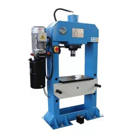
A hydraulic bending machine is a type of machine used to bend sheet metal and other materials by applying pressure through hydraulic force. These machines use hydraulic cylinders to generate the required bending force, allowing for precise and controlled shaping of the material. Hydraulic bending machines are widely used in manufacturing, fabrication, and construction for tasks that require heavy bending forces and high accuracy.
The key feature that sets hydraulic bending machines apart from manual or mechanical machines is their use of hydraulic power. The hydraulic system consists of a pump, valves, and cylinders that work together to create a force capable of bending thick or high-strength materials. This hydraulic force provides several advantages over other methods, such as the ability to bend thicker materials, achieve greater accuracy, and maintain consistent performance over long production runs.
The general components of a hydraulic bending machine include:
- Hydraulic Cylinder: The hydraulic cylinder is the primary component that provides the bending force. It is driven by hydraulic fluid under pressure, and when the fluid is forced into the cylinder, it pushes the punch (or ram) down onto the workpiece, bending the metal into the desired shape. The cylinder’s size and power determine the maximum bending capacity of the machine.
- Frame: The frame provides structural support to the machine and ensures stability during the bending process. It is typically made of high-strength steel or cast iron to withstand the forces generated by the hydraulic cylinders.
- Ram/Punch: The ram or punch is the part of the machine that directly applies the bending force to the metal sheet. It moves vertically, guided by the hydraulic system, to form the desired bend.
- Bed/Die: The bed is the surface where the sheet metal is placed. It usually includes a die or a set of dies that define the shape and angle of the bend. The workpiece is placed in the bed, and the ram pushes down to form the bend.
- Control System: Hydraulic bending machines typically come with an electronic control system that allows the operator to set the bending angle, pressure, and stroke length. Some machines offer advanced features such as programmable controls, which enable automation of the bending process, improving efficiency and consistency.
Hydraulic bending machines are capable of bending a variety of materials, including mild steel, stainless steel, aluminum, and other alloys, across a wide range of thicknesses. The hydraulic press ensures a consistent and high level of bending force, making it ideal for materials that would be too thick or tough for manual machines. The force provided by the hydraulic system allows for more precise bends, especially in thicker and more rigid materials.
The advantages of hydraulic bending machines include:
- High Bending Force: Hydraulic machines can generate a significant amount of force, making them suitable for bending thick and high-strength materials. This makes them ideal for heavy-duty applications such as in the construction of large metal components, vehicle frames, or machinery parts.
- Precision and Accuracy: The hydraulic system allows for precise control over the bending process, ensuring that the bend angles are consistent and accurate. This is particularly useful when producing parts that need to meet exact specifications.
- Flexibility: Hydraulic bending machines can be used to perform a variety of bends, including V-bending, U-bending, air bending, and edge bending. They can accommodate different materials and thicknesses, offering flexibility in the types of parts that can be fabricated.
- Ease of Operation: With a hydraulic system, operators do not need to exert physical effort, unlike manual machines. This makes hydraulic machines easier to operate and less physically demanding, which can improve operator efficiency and reduce fatigue.
- Safety: Hydraulic bending machines often have built-in safety features such as emergency stop buttons, safety shields, and overload protection. These features help to reduce the risk of accidents and ensure safe operation in a workshop environment.
- Automation Potential: Many modern hydraulic bending machines come with CNC (Computer Numerical Control) options, enabling full automation of the bending process. CNC controls allow the operator to input detailed specifications for the bend, and the machine automatically adjusts to produce precise bends consistently. This reduces the potential for human error and increases productivity.
However, hydraulic bending machines also come with some limitations and considerations:
- Cost: Hydraulic bending machines, particularly those with advanced features like CNC control, can be more expensive than manual or mechanical machines. The initial investment can be significant, making them a larger financial commitment for smaller businesses or operations with low-volume production.
- Space Requirements: These machines are generally larger than manual sheet bending machines, so they require more floor space. Workshops with limited space may need to plan accordingly when integrating a hydraulic bending machine into their operations.
- Energy Consumption: Hydraulic systems rely on pumps and motors to generate the necessary pressure, which can lead to higher energy consumption compared to mechanical or manual machines. Over time, this could increase operational costs.
- Maintenance: Although hydraulic systems are efficient, they do require regular maintenance to ensure proper operation. The hydraulic fluid needs to be checked and replaced periodically, and the system must be monitored for leaks, wear, and tear. Maintenance costs can add up over time.
In conclusion, hydraulic bending machines are an excellent choice for high-precision, high-force bending tasks. They are widely used in industries such as automotive, construction, aerospace, and general manufacturing where the need for bending thicker materials with precision is common. Despite their higher initial costs and space requirements, the efficiency, precision, and flexibility of hydraulic bending machines make them invaluable tools for businesses that require consistent, high-quality bends in a variety of materials. For companies involved in mass production or working with high-strength metals, the hydraulic bending machine is a powerful, reliable, and essential piece of equipment.
Hydraulic bending machines are essential tools in modern metalworking, offering the precision and force required for bending thick or strong materials that manual machines cannot handle. By utilizing hydraulic pressure, these machines generate the substantial force necessary to bend materials with high consistency and accuracy. This makes them ideal for industries where precise, high-quality bends are needed, such as aerospace, automotive, construction, and general manufacturing.
One of the key advantages of hydraulic bending machines is their ability to accommodate a wide variety of material types, thicknesses, and bending angles. Whether bending aluminum, steel, or more specialized alloys, the hydraulic system allows for consistent force application across various materials. This makes it possible to work with materials that would be difficult or impossible to bend with manual machines. Additionally, because the pressure is controlled, the bending process is highly repeatable, ensuring that parts produced in multiple batches maintain uniformity.
Hydraulic systems are also known for their ability to provide significant force with minimal effort from the operator. Unlike manual machines that rely on human strength to apply bending force, hydraulic machines require very little physical exertion, making them easier to operate and reducing fatigue. This is especially important when working with thicker materials, where the force required can be substantial. The ability to apply precise, controlled pressure allows for intricate bends without the risk of overloading or damaging the material, further enhancing the machine’s versatility.
Another major benefit of hydraulic bending machines is their ability to be fitted with CNC (Computer Numerical Control) systems, which significantly improve the machine’s capability and efficiency. With CNC integration, operators can input precise bending specifications into the machine’s control panel, allowing for automated bends with minimal manual intervention. This automation greatly increases productivity, reduces the chance for human error, and ensures that each part produced is consistent with the desired specifications. The ability to store multiple programs also allows the machine to switch between different bending tasks without requiring time-consuming reconfigurations.
Despite these advantages, there are some limitations to consider when using hydraulic bending machines. One of the primary considerations is the cost. These machines are generally more expensive than manual or mechanical bending machines, especially those equipped with advanced features like CNC controls. The initial investment may be prohibitive for smaller operations or businesses with low production volumes. Additionally, while hydraulic systems are efficient, they can be more costly to maintain over time due to the need for regular checks and fluid replacements. Proper maintenance is crucial to prevent leaks or other issues that could cause the machine to malfunction or operate inefficiently.
Another limitation is the size and weight of hydraulic bending machines. These machines can take up a significant amount of floor space, and their large footprint may be a challenge for smaller shops with limited space. Furthermore, their weight and complexity may require specialized installation and maintenance procedures. For companies with high mobility or who require machines that can be moved between job sites, the stationary nature of hydraulic bending machines might be a disadvantage.
Energy consumption is another aspect to consider. While hydraulic systems are powerful and efficient, they do require a consistent supply of power to operate the hydraulic pumps and motors. Over time, this can contribute to higher operational costs, particularly for businesses that use the machines extensively. However, these costs can often be offset by the machine’s ability to produce high volumes of parts with minimal human labor, resulting in long-term productivity gains.
In industries where large volumes of parts need to be produced with consistent bending angles and dimensions, hydraulic bending machines excel. Their ability to handle thick, high-strength materials with precision makes them indispensable for certain types of manufacturing, particularly in fields that require the fabrication of structural components or large, heavy-duty metal parts. Additionally, the flexibility of hydraulic machines means they can accommodate complex or multi-stage bends, which would be difficult to achieve with simpler machines.
While hydraulic bending machines are ideal for many types of industrial applications, they may not always be necessary for smaller-scale projects or less demanding tasks. For shops focused on low-volume or custom work, a manual or mechanical bending machine may be more appropriate due to its lower cost and simplicity. However, for businesses engaged in high-volume production or those needing to handle a wide range of materials and thicknesses, hydraulic bending machines provide a robust, efficient solution that significantly improves workflow and output.
In conclusion, hydraulic bending machines are a vital part of modern metalworking operations that demand precision, force, and flexibility. Their ability to bend materials with high strength, provide consistent results, and integrate with CNC controls makes them invaluable for industries involved in large-scale or complex fabrication. Although they come with a higher initial cost and require more space and energy than manual machines, their benefits in terms of productivity, precision, and versatility make them an excellent investment for businesses that need to handle demanding bending tasks.
Hydraulic bending machines, with their precision and power, have transformed the way metal fabrication and bending are done. They are particularly crucial in industries where accuracy and consistency are paramount, and where materials with greater thickness or strength are frequently handled. The versatility of these machines ensures they can perform a wide range of bending tasks, from basic, simple bends to intricate, multi-step forms. This makes hydraulic bending machines essential tools in high-demand environments, where both productivity and quality are critical.
The ability to work with a wide range of materials, including mild steel, stainless steel, aluminum, and specialized alloys, is another reason hydraulic bending machines are so widely used. The hydraulic system’s ability to apply controlled force makes it possible to bend materials of varying thicknesses and hardness, something that manual or mechanical machines might struggle with. This versatility is particularly valuable when working with high-strength materials, which require more force and precision than other metals. For example, in industries like automotive or aerospace, where metal parts need to meet strict performance and durability standards, hydraulic bending machines are indispensable for creating parts that fit those specifications.
The hydraulic system offers flexibility not only in terms of materials but also in the bending techniques it can support. One common technique is air bending, where the sheet metal is bent using a punch that doesn’t touch the die directly. Instead, the sheet is positioned above the die, and the punch applies force at a specific angle to achieve the desired bend. This method allows for a variety of bend angles and depths, providing greater flexibility when producing complex parts. Another bending method supported by hydraulic presses is V-bending, which uses a die to create a “V” shaped bend in the material. The pressure applied by the hydraulic system is crucial for achieving the necessary force to shape the material accurately.
In addition to these traditional methods, modern hydraulic bending machines are equipped with CNC (Computer Numerical Control) systems. CNC systems allow for the automation of the bending process, significantly improving efficiency and accuracy. Operators can program the machine to perform specific bends at exact angles and positions, which is especially useful when working with large quantities of parts. The ability to store and retrieve multiple programs enables quick changeovers between different tasks, reducing setup times and increasing throughput. This feature is especially beneficial in mass production settings where multiple batches of parts must be produced in quick succession, maintaining consistent quality across each batch.
The integration of CNC controls also contributes to reducing human error. While manual operation involves a certain level of skill and experience, CNC machines are able to follow programmed instructions with high precision. This eliminates variability in how each bend is performed, ensuring that every part meets the same standards, which is crucial for industries that require high-quality and uniform parts. The reduced need for constant operator adjustments or monitoring allows for more efficient production, especially when the same bending operation is being performed repeatedly.
Another benefit of hydraulic bending machines is their ability to apply force gradually. The hydraulic system’s smooth, controlled pressure allows for more delicate bends and reduces the risk of deforming or cracking the material. This is important when working with thin metals, where even slight variations in force can lead to issues like wrinkling or fracturing. The hydraulic process can apply the necessary force evenly, reducing the likelihood of such defects and ensuring that the final product is uniform and free from damage.
Furthermore, advanced safety features are commonly integrated into hydraulic bending machines. These include emergency stop buttons, safety shields, and automatic clamping systems that ensure the workpiece stays in place during the bending process. Many machines also include programmable safety settings, such as sensors that detect the position of the ram or the material, which helps prevent accidents or damage during operation. These safety measures provide peace of mind to operators and ensure that the machine can be used safely in a busy shop environment.
Despite all of these advantages, the size and complexity of hydraulic bending machines can make them more challenging to move or set up compared to smaller manual machines. While the larger machines are generally fixed in place due to their weight, some models are designed to be more compact, allowing for easier relocation or integration into smaller workshops. Even with their large size, many hydraulic machines are designed for optimal ergonomics, with user-friendly controls and easily accessible components that facilitate operator comfort and safety.
In terms of maintenance, hydraulic systems require regular attention to keep the machine running smoothly. This includes checking the hydraulic fluid for leaks or contamination, ensuring the pumps and valves are functioning properly, and inspecting the machine’s cylinders and rams for wear and tear. While these machines require more attention than manual counterparts, they are still considered relatively low-maintenance compared to fully automated or more complex machines. Scheduled preventive maintenance can help avoid costly repairs and ensure that the machine operates at peak efficiency, reducing downtime and increasing overall productivity.
Hydraulic bending machines also play a crucial role in custom metalworking. Many businesses, from sign shops to furniture makers, require one-off or small batch productions, where each part has unique bending specifications. These machines allow for quick adjustments, making it easy to modify the machine to handle different materials, thicknesses, and bending angles. The ability to change dies or adjust settings means these machines can be used for a wide variety of custom projects, adding to their appeal for small or specialized operations.
In conclusion, hydraulic bending machines offer significant advantages in terms of flexibility, precision, and force. They are particularly well-suited for industries and applications that require bending of thicker or stronger materials, complex shapes, or high-precision parts. The integration of hydraulic power with CNC technology has revolutionized bending operations, making them faster, more accurate, and more cost-effective over the long term. While they come with higher upfront costs and maintenance requirements than manual machines, their efficiency, safety features, and versatility make them an invaluable asset in any modern manufacturing operation. Whether for large-scale production or small-scale custom fabrication, hydraulic bending machines continue to be a core tool in the sheet metalworking industry.
Hydraulic bending machines continue to evolve with technological advancements, integrating more sophisticated features that enhance performance, productivity, and precision. As industries demand increasingly complex components and faster turnaround times, these machines have adapted to meet those challenges. From aerospace and automotive manufacturing to construction and metal fabrication, hydraulic bending machines are integral to producing parts that require both high strength and precise geometries.
One significant development is the increased automation of hydraulic bending machines. The combination of hydraulic force and computer-based controls allows these machines to perform complex tasks with minimal human intervention. In industries where the production of parts is high-volume and quality consistency is paramount, automation provides a major advantage. Automated loading and unloading systems are now common, allowing for parts to be moved quickly in and out of the machine, further reducing the time spent on each bending cycle. This seamless integration into automated workflows helps optimize overall production efficiency.
In addition to basic bending capabilities, modern hydraulic machines can perform multiple bending operations in one setup. This includes multi-axis bending, where the material is bent along several planes, enabling the creation of more complex geometries in a single pass. This capability is particularly useful in industries like aerospace, where parts often have intricate shapes and need to meet stringent specifications. Hydraulic bending machines can be equipped with specialized tooling to accommodate such complex tasks, allowing for rapid production of multi-dimensional shapes without the need for manual reorientation of the material.
To further enhance flexibility, manufacturers have developed machines with adjustable tooling systems. These systems allow for quick changes to the bending die, enabling operators to switch between different bend radii, material thicknesses, or bend angles. This adaptability ensures that hydraulic bending machines can handle a broad range of tasks, from simple to highly complex, with minimal downtime for tooling changes. This feature also reduces the need for multiple machines, which would otherwise be required for various bending operations. Instead, one hydraulic press can take on multiple functions, making it more cost-effective for businesses to expand their capabilities without purchasing additional equipment.
Another development in hydraulic bending machines is the integration of force sensors and feedback systems. These systems monitor the force being applied during the bending process in real time and adjust the machine’s settings to ensure that the force remains within the desired range. This closed-loop control system helps to prevent issues like overbending, material deformation, or damage, especially when working with materials that have varying thicknesses or tensile strengths. The real-time feedback ensures that each part is bent to the correct specifications, improving the overall quality of the finished products.
As sustainability becomes a more prominent focus in industrial practices, manufacturers are also implementing energy-saving technologies in hydraulic bending machines. Variable speed drives and energy-efficient pumps reduce the energy consumption of these machines, making them more environmentally friendly and cost-effective. Additionally, the hydraulic fluid used in these machines is now formulated with biodegradable options, reducing the environmental impact in the case of accidental leaks or spills.
Safety has also been a major focus in the design of hydraulic bending machines. The addition of safety guards, light curtains, and emergency stop buttons ensures that operators are protected during the bending process. Many modern hydraulic machines also come equipped with safety interlocks that automatically stop the machine if the operator’s hands or body come into the danger zone, providing an added layer of protection. These features, combined with ergonomic designs and user-friendly control panels, help minimize the risk of injury and improve the overall safety of the workplace.
The ability to simulate bending operations using advanced software is another innovation that has transformed hydraulic bending machines. Before performing any bending, operators can now use software simulations to model the bending process. This allows for the identification of potential issues, such as material deformation or incorrect angles, before the machine begins the actual bending operation. Simulation software can help fine-tune machine settings and predict the behavior of different materials under specific conditions, saving time and reducing the likelihood of costly errors during production.
In addition to technological improvements, hydraulic bending machines are also becoming more user-friendly. The introduction of intuitive touchscreens, advanced interface controls, and remote monitoring capabilities make it easier for operators to manage complex bending tasks. These user-friendly interfaces allow for easy adjustments, programming, and real-time monitoring of the machine’s performance, making it possible to optimize production without requiring a high level of expertise. For example, operators can monitor parameters such as bend angle, pressure, and stroke length, and make on-the-fly adjustments if needed.
Moreover, many hydraulic bending machines are now being designed with lean manufacturing principles in mind. This includes creating machines that are not only highly efficient but also easy to maintain. With modular designs, users can replace parts or perform maintenance without extensive downtime, ensuring that the machine remains operational with minimal interruptions. The increased ease of maintenance and reduced need for specialized parts contribute to the overall efficiency of hydraulic bending machines, keeping operating costs down.
Data collection and machine connectivity have also become more prevalent in modern hydraulic bending machines. The integration of Internet of Things (IoT) technology allows for real-time data collection, which can be used to monitor machine performance, track maintenance schedules, and optimize workflows. By connecting to a central database, manufacturers can use this data to predict maintenance needs, track production progress, and even adjust machine settings based on real-time performance metrics. This increased connectivity helps businesses remain competitive by maximizing uptime, reducing scrap rates, and improving product quality.
Despite the many advancements in hydraulic bending machines, there are still some challenges that manufacturers must address. The complexity of the machines means that training is essential to ensure operators are able to fully utilize their capabilities. Operators must be trained not only in how to operate the machine but also in how to troubleshoot issues and perform basic maintenance. Additionally, while the machines are more energy-efficient than ever before, their operational costs, especially for high-volume applications, can still be significant, particularly in terms of energy use, maintenance, and parts replacement.
In summary, hydraulic bending machines have undergone significant advancements that make them more efficient, versatile, and user-friendly. With the integration of CNC controls, automation, real-time force feedback, and safety features, these machines are capable of handling increasingly complex and precise bending tasks. They continue to play an essential role in industries that require high-quality metal parts, and the ongoing improvements in technology ensure that they will remain an invaluable asset in the metalworking sector. By incorporating cutting-edge software, improving energy efficiency, and enhancing safety protocols, modern hydraulic bending machines are helping businesses stay competitive while meeting the demands of a rapidly changing manufacturing environment.
Steel Bending Machine
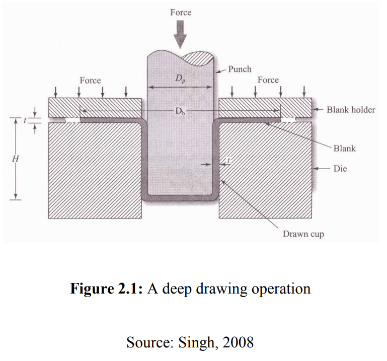
A steel bending machine is a specialized piece of equipment designed to bend steel and other metals into desired shapes and angles. These machines are widely used in industries such as construction, manufacturing, and metalworking, where steel is commonly shaped into various forms for structural, mechanical, and architectural purposes. Steel bending machines are capable of bending steel into precise angles and shapes, offering a high degree of control and accuracy, which is critical for producing parts that meet strict specifications.
Steel bending machines are designed to handle the challenging characteristics of steel, which include its high strength, rigidity, and resistance to deformation. The process of bending steel typically involves applying significant force to the material, which requires a machine that can generate the necessary pressure and control the bending process accurately.
There are several types of steel bending machines, including:
- Manual Steel Bending Machines: These machines require the operator to manually adjust settings and apply force to the steel. They are typically simpler machines with limited capabilities, ideal for small-scale operations or for tasks where only basic bends are needed. Manual machines are generally more affordable and require less maintenance compared to more automated options.
- Hydraulic Steel Bending Machines: These machines use hydraulic force to bend steel, providing more control and higher bending capacity than manual machines. Hydraulic steel bending machines are used for larger projects where precision and the ability to handle thicker steel sections are required. They can be operated either manually or with automated controls, with more advanced models offering programmable settings for more complex bending tasks. Hydraulic systems are particularly well-suited for heavy-duty bending tasks, such as bending thick steel plates or sections used in construction or machinery.
- CNC Steel Bending Machines: CNC (Computer Numerical Control) steel bending machines are equipped with computer systems that allow for automated and highly precise bending operations. CNC bending machines can handle a wide variety of bending tasks and are ideal for large-scale production environments where high precision and repeatability are crucial. With CNC technology, operators can program complex bend sequences and angles, enabling the machine to execute precise and consistent bends at high speeds. These machines are commonly used in industries like aerospace, automotive, and heavy equipment manufacturing, where high-performance parts are required.
- Roll Bending Machines: Roll bending machines use a set of rollers to gradually curve steel into the desired shape. These machines are typically used to create curved sections, such as pipes, tubes, or structural beams. The steel is passed through a series of rollers that apply even pressure to bend the material. Roll bending is often used in the production of large steel components like pipes or frames, which need to be bent in a continuous curve.
The core components of a steel bending machine typically include:
- Frame: The machine’s frame is designed to withstand the significant forces generated during the bending process. It is made from strong, durable materials such as high-strength steel or cast iron.
- Bending Mechanism: The bending mechanism consists of a die or set of dies that apply force to the steel to bend it. This mechanism may be powered by hydraulic cylinders, mechanical systems, or manual cranks, depending on the type of machine.
- Control System: Steel bending machines, especially hydraulic and CNC models, often have an advanced control system that regulates the speed, pressure, and angle of the bend. In manual machines, operators control the bend manually, while in CNC machines, the control system automates these tasks for precision.
- Bending Die: The die is the part of the machine that forms the steel into the desired shape. It may have different configurations depending on the type of bend required, such as a V-shaped die for sharp bends or a radius die for curves.
Advantages of Steel Bending Machines:
- Precision and Accuracy: Steel bending machines, particularly CNC-controlled models, offer high precision and can repeat complex bending tasks with minimal variation. This is important in industries where tight tolerances are required for each part.
- High Bending Capacity: Steel bending machines are designed to handle the high force required to bend steel, making them suitable for bending thick or high-strength materials that would be difficult to shape manually.
- Versatility: Depending on the type of machine, steel bending machines can handle a wide variety of tasks, from simple bends to complex, multi-dimensional shapes. This versatility makes them useful across multiple industries, from structural steel fabrication to custom metalworking.
- Automation: CNC and hydraulic models allow for greater automation, reducing manual labor and improving production efficiency. Operators can program the machine to automatically execute a series of bends, reducing setup times and the possibility of human error.
- Speed: Steel bending machines can execute multiple bends in a short period of time, increasing production speed and efficiency. This is particularly useful in high-volume production environments.
- Safety: Modern steel bending machines are equipped with safety features such as emergency stop buttons, safety guards, and automated clamping systems to reduce the risk of injury to operators.
While steel bending machines offer numerous benefits, there are some challenges and limitations to consider:
- Cost: High-end models, especially CNC-controlled machines, can be expensive, making them a significant investment for businesses. However, the increased automation and productivity they offer may help offset these costs in high-volume environments.
- Space Requirements: Larger machines, such as hydraulic and CNC models, often require a significant amount of floor space. This may be a consideration for smaller workshops with limited space.
- Maintenance: Steel bending machines, especially hydraulic and CNC models, require regular maintenance to ensure they operate at peak performance. This includes checking hydraulic fluid levels, inspecting the machine’s components for wear, and ensuring that the control systems are functioning correctly.
- Skill Requirements: Although modern steel bending machines have become more user-friendly, they still require operators with specialized knowledge to handle complex bending tasks, especially in CNC models.
Applications of Steel Bending Machines:
Steel bending machines are used in a wide variety of industries and applications. Some of the key uses include:
- Construction: In construction, steel bending machines are used to shape steel bars or rods for reinforcement in concrete structures. They are also used to create custom shapes and components for steel frames and other building elements.
- Automotive Manufacturing: Steel bending machines are employed in the production of automotive components, including frames, exhaust systems, and structural parts that require precise bending.
- Aerospace: The aerospace industry relies on steel bending machines to create intricate, high-performance parts for aircraft. These parts often need to meet strict safety standards and tolerances, making high-precision bending essential.
- Shipbuilding: Steel bending machines are used in the shipbuilding industry to create large steel plates and beams that form the structure of ships and boats.
- Furniture Manufacturing: Steel bending machines are also used in the production of furniture, particularly for creating bent metal frames, legs, and other components.
In conclusion, steel bending machines are an indispensable tool in metalworking, offering the necessary precision, strength, and versatility for bending steel and other metals. Whether for simple bends or more complex, multi-step shaping, these machines can help improve production speed, accuracy, and safety. The choice of machine depends on the specific needs of the project, including the thickness of the steel, the complexity of the bend, and the volume of production. From manual models to advanced CNC-controlled machines, steel bending machines provide the solutions necessary to meet the demands of modern manufacturing.
Steel bending machines have evolved significantly over the years, with advancements in technology making them more efficient, versatile, and user-friendly. These machines are now capable of handling a wide range of bending tasks, from simple, single-axis bends to more complex multi-axis bending operations. Their ability to process high-strength materials like steel has made them indispensable in industries ranging from construction and automotive to aerospace and manufacturing. As these machines have grown more advanced, their applications have expanded, making them essential tools in modern fabrication.
One of the most notable advancements in steel bending technology is the integration of computerized controls. With CNC (Computer Numerical Control) technology, steel bending machines can perform highly precise bends based on pre-programmed specifications. This automation significantly reduces the possibility of human error, improving the overall quality and consistency of each part produced. The ability to program complex sequences of bends allows manufacturers to streamline production and reduce setup times, which can increase output in high-volume environments. The precision offered by CNC systems also enables the production of parts that meet strict tolerances required in industries like aerospace and automotive manufacturing.
The use of hydraulic power has also revolutionized steel bending machines. Hydraulic systems provide an immense amount of force, which is crucial for bending thicker steel sections that would be difficult or impossible to shape using mechanical or manual methods. Hydraulic machines are equipped with high-pressure pumps and cylinders that allow them to apply uniform force over a larger area, ensuring that the steel is bent evenly and accurately. This feature is particularly important when working with high-strength or hardened steel, where inconsistent force application could lead to defects like cracking or warping. Hydraulic systems offer greater flexibility and precision, making them ideal for industries that require bending operations to be carried out under strict performance standards.
In addition to their bending capabilities, modern steel bending machines are also designed to be more energy-efficient and environmentally friendly. The introduction of variable speed drives and energy-saving pumps has reduced the energy consumption of these machines, making them more cost-effective to operate. With these improvements, manufacturers can maintain high productivity levels without significantly increasing operational costs. Furthermore, advancements in hydraulic fluid technology have led to the development of more eco-friendly fluids, reducing the environmental impact of any accidental leaks or spills.
Another key feature of modern steel bending machines is the integration of safety mechanisms. As steel bending involves the application of significant force, safety is a major concern. Modern machines are equipped with various safety features, such as emergency stop buttons, safety shields, light curtains, and automatic clamping systems that prevent the material from moving during the bending process. Many machines also include programmable safety settings, such as sensors that can detect the position of the ram or material, ensuring that the machine operates within safe parameters and reducing the risk of accidents. These features provide peace of mind to operators and ensure that the machine can be safely used in high-demand environments.
The versatility of modern steel bending machines also allows them to handle a wide variety of materials. While steel is the primary material these machines are designed to work with, they can also be used to bend other metals, including aluminum, stainless steel, and copper. This makes steel bending machines highly adaptable, allowing them to be used across various industries for a broad range of applications. For example, in the automotive industry, these machines are used to shape steel for vehicle frames, exhaust systems, and other structural components. In the construction industry, they are used to create reinforcement bars for concrete structures and form steel beams and columns for building frameworks. The ability to work with different metals increases the machine’s utility, making it a valuable asset in many manufacturing environments.
Steel bending machines also offer the advantage of reduced material waste. The precise nature of these machines allows for more efficient use of materials, which is particularly important when working with expensive metals like stainless steel or high-strength alloys. By minimizing material waste, businesses can reduce costs and increase profitability. In addition, many steel bending machines can be programmed to perform multiple bends in a single cycle, eliminating the need for multiple passes and reducing the time required for each part.
Despite their many advantages, steel bending machines come with certain challenges. Initial costs can be high, particularly for advanced models like CNC-controlled and hydraulic machines. However, these upfront costs are often justified by the increased efficiency, accuracy, and productivity they offer. Over time, the machine’s ability to handle large volumes of production with minimal downtime can result in significant cost savings. Another consideration is the maintenance required to keep the machine running at optimal performance. Hydraulic and CNC models often require regular maintenance to check the hydraulic fluid levels, inspect the pumps and valves, and ensure that the control systems are functioning properly. Regular maintenance is essential for ensuring that the machine remains in good working condition and avoids costly downtime due to malfunctions.
In terms of operator skills, while modern machines have become more user-friendly, they still require specialized training. Operators must be familiar with the machine’s settings, how to troubleshoot common issues, and how to ensure that the machine is running at peak efficiency. For CNC machines, this means understanding how to program the machine, input parameters, and adjust settings to accommodate different materials and bending requirements. Training is essential to prevent errors and ensure that the machine is used to its full potential.
Steel bending machines continue to evolve with the advancement of smart technologies. The integration of IoT (Internet of Things) capabilities has opened up new possibilities for monitoring and managing machine performance in real-time. Sensors and connectivity allow operators to monitor the status of the machine remotely, track production metrics, and predict maintenance needs. This data can be used to optimize machine performance, reduce downtime, and improve the overall efficiency of the manufacturing process. These technological advancements contribute to the ongoing trend of Industry 4.0, where machines are becoming more intelligent, connected, and autonomous, leading to more efficient and streamlined production environments.
As industries demand more complex, custom, and high-quality metal parts, the role of steel bending machines becomes even more critical. The ability to produce precise bends at high speeds, coupled with the versatility to handle a wide range of materials, ensures that these machines remain indispensable in the modern manufacturing process. As technological innovations continue to shape the future of metalworking, steel bending machines will remain at the forefront of shaping the next generation of high-performance parts used in construction, automotive, aerospace, and many other industries. Whether used for simple bends or highly complex, multi-step shaping operations, these machines are essential tools for creating the components that power industries around the world.
Steel bending machines are integral to the manufacturing process, and as technology continues to advance, the capabilities of these machines are expanding rapidly. One significant trend in the evolution of steel bending machines is the move toward increased automation. With the adoption of more sophisticated automation technologies, steel bending machines are becoming more capable of executing complex tasks with minimal human intervention. Automated loading and unloading systems, for example, are increasingly being integrated into steel bending machines, which help to further optimize production times and reduce the need for manual labor. These systems can quickly transfer materials into and out of the machine, allowing for smoother, faster workflows and minimizing downtime during the bending process.
Moreover, adaptive bending technology has made significant strides, enabling machines to automatically adjust bending parameters based on material type, thickness, and other variables. This means that the machine can be set to automatically calculate the optimal bending force and angle, ensuring that even with varying materials, each part is consistently bent to the highest precision. By reducing the need for manual adjustments, adaptive technology helps operators achieve more accurate bends while also improving overall production speed and efficiency.
One of the most exciting developments in steel bending machine technology is the introduction of collaborative robotics (cobots). These robots are designed to work safely alongside human operators, assisting with tasks such as material handling, loading, or even performing secondary operations on parts after bending. The collaboration between human workers and robots allows for a more efficient and flexible production environment. Cobots are particularly useful in situations where repetitive tasks are required, freeing up operators to focus on more complex aspects of production. In many cases, this type of automation leads to improved workplace safety, as the robots can handle heavy lifting and potentially dangerous tasks.
Another area where steel bending machines have seen significant advancement is in precision measurement and feedback systems. Many modern machines are equipped with advanced sensors that monitor the bending process in real-time, providing valuable feedback on parameters like force, angle, and material deformation. These sensors help ensure that each bend is executed correctly, preventing defects and minimizing scrap material. If a bend is found to be out of tolerance, the system can make immediate corrections, reducing the need for manual intervention and allowing the machine to continue working without stoppage. The ability to gather and analyze real-time data during the bending process has led to higher-quality, more consistent products, with greater efficiency in production.
Energy efficiency is another important consideration in the design of steel bending machines. As environmental concerns and sustainability continue to shape the manufacturing sector, many companies are opting for machines that consume less energy. Features such as variable frequency drives (VFDs) and energy-efficient hydraulic pumps have become common in modern machines, as they help reduce the amount of electricity required for operation. These energy-saving technologies lower operational costs while contributing to a more sustainable production process. Additionally, some machines are designed with regenerative energy systems, which capture energy during the bending process and reuse it, further reducing energy consumption and minimizing waste.
In addition to improved energy efficiency, manufacturers are also focusing on minimizing the environmental impact of steel bending machines. This includes using eco-friendly hydraulic fluids that are biodegradable and reducing the use of toxic chemicals in the machine’s operation. Moreover, many modern machines feature closed-loop hydraulic systems, which help reduce fluid leakage and contamination, contributing to a cleaner and more sustainable manufacturing environment.
The use of modular designs in steel bending machines has made them more versatile and easier to maintain. These modular machines can be customized with different tools, dies, and other components to meet specific production needs. This flexibility allows manufacturers to adapt the machine for different tasks without needing to invest in multiple pieces of equipment. Additionally, the modular approach makes it easier to replace or upgrade individual components of the machine, reducing maintenance costs and downtime. Operators can perform routine maintenance more quickly and efficiently, ensuring the machine remains in optimal condition and minimizing the chances of unexpected breakdowns.
As material science continues to advance, steel bending machines are being designed to handle new materials that require specific bending techniques. For instance, the development of advanced composites and high-strength alloys is driving the demand for machines that can bend materials with different mechanical properties. These materials may require specialized tools or bending processes, and manufacturers are designing machines that can handle these unique challenges. The ability to bend a wider variety of materials adds to the versatility of steel bending machines and makes them even more essential in industries that require cutting-edge materials for their products.
Moreover, the ongoing digitalization of manufacturing processes is leading to more integrated production systems. Steel bending machines are being connected to centralized monitoring systems that allow manufacturers to track machine performance, maintenance schedules, and production progress in real-time. These systems can provide valuable insights into machine utilization, helping to identify areas where performance can be improved or where downtime can be reduced. By integrating steel bending machines into broader digital manufacturing ecosystems, manufacturers are able to optimize their entire production process, from raw material handling to the final product.
The use of simulation software has also become a standard feature in many advanced steel bending machines. This software allows operators to simulate the entire bending process before executing it on the machine, ensuring that the bending operation will be successful and free from defects. The simulation software can predict potential issues, such as material distortion or tool wear, allowing for adjustments to be made before any actual bending takes place. This preemptive approach helps save time, reduce errors, and improve overall production quality.
In industries where high-volume production is required, steel bending machines equipped with multi-tool stations can perform several bending operations simultaneously. These multi-tool machines increase throughput and reduce the need for multiple setups or tool changes. By consolidating several steps into a single machine, manufacturers can significantly cut down on production time, allowing for faster delivery of parts and products. This is especially useful in industries such as automotive manufacturing, where parts must be produced quickly and in large quantities while maintaining strict quality standards.
Steel bending machines are increasingly equipped with remote monitoring capabilities, allowing operators and maintenance personnel to access machine data and diagnostics from anywhere in the facility. This remote monitoring helps identify issues before they become major problems, allowing for proactive maintenance and reducing downtime. By giving operators the ability to monitor the machine’s performance in real-time, remote access also helps improve production efficiency, as issues can be addressed quickly without requiring the operator to physically inspect the machine.
Overall, steel bending machines continue to play an essential role in modern manufacturing, with ongoing technological advancements improving their capabilities and efficiency. From enhanced automation and energy efficiency to precision control and smart features, these machines are helping industries meet the growing demand for high-quality, complex metal components. As industries evolve and new materials and processes emerge, steel bending machines will remain at the forefront of shaping the next generation of metal products. Their ability to adapt to changing requirements and handle a diverse range of materials ensures they will continue to be critical tools in manufacturing for years to come.
As steel bending machines continue to evolve, one of the most significant trends is the integration of artificial intelligence (AI) and machine learning into the manufacturing process. AI-enabled steel bending machines are capable of adapting in real-time to variables such as material properties, machine wear, and environmental factors. Through continuous learning from past operations, these machines can improve their performance over time, reducing errors and optimizing processes automatically. This technology allows the machine to “learn” the most efficient ways to handle different materials and bending tasks, resulting in more precise and consistent outputs. AI-driven systems also enable predictive maintenance, where the machine can alert operators to potential issues before they cause breakdowns, significantly reducing downtime and extending the lifespan of the equipment.
The customization of steel bending machines is also becoming increasingly sophisticated. Manufacturers can now integrate specific features into their machines to meet the unique needs of their production processes. For instance, some steel bending machines are designed with adjustable workpieces and flexible dies that can be altered quickly to accommodate different shapes, sizes, and types of bends. These machines are designed to handle a wider variety of part configurations without requiring significant reconfiguration, making them ideal for companies that produce small batches or custom orders. This flexibility is especially beneficial for industries that require specialized products, such as aerospace, where parts often need to meet highly specific and customized designs.
Furthermore, the integration of additive manufacturing (3D printing) technologies with traditional steel bending machines is opening up new possibilities in the production of complex metal components. By combining the two technologies, manufacturers can create intricate geometries that may not be achievable through conventional bending alone. This hybrid approach allows for faster prototyping and production of parts that are lightweight yet strong, such as lattice structures used in aerospace applications. The ability to print and then bend metal parts in a single, integrated system reduces production time and enhances design freedom.
The globalization of manufacturing has also influenced the design and use of steel bending machines. As businesses expand and require production on a global scale, steel bending machines have been designed to accommodate different market demands, standards, and material specifications. Manufacturers now need machines that can handle a variety of materials and meet local regulatory standards, while also ensuring that the machine can be maintained and serviced in different regions. This need for global standardization has led to more modular designs, where parts and components can be easily replaced or upgraded depending on regional requirements, making it easier for manufacturers to scale production internationally.
The cost-effectiveness of steel bending machines is another key focus as manufacturers look for ways to optimize their operations without sacrificing quality. Modern machines are designed to maximize productivity while minimizing operational expenses. This is achieved not only through advanced automation but also by reducing the overall footprint of the machines, making them more compact and easier to integrate into existing production lines. With smaller machines, manufacturers can achieve high throughput with less space required for operation. Additionally, the improved energy efficiency of these machines helps reduce utility costs, making them more affordable to run over long periods.
Customization also plays a vital role in the versatility of modern steel bending machines. The ability to easily adjust machines to accommodate different sizes, materials, and bending angles provides manufacturers with the flexibility to respond to a wide range of production needs. This is especially crucial in industries where production runs are short or where products must meet unique, non-standard designs. The development of multi-function bending machines capable of performing not only bending but also other operations such as cutting, punching, and shearing within a single machine further boosts efficiency and reduces the need for multiple machines. This multi-tasking capability is particularly beneficial for smaller workshops or companies looking to save space and reduce equipment costs while maintaining high productivity.
A significant development in steel bending machines is the use of hybrid drive systems that combine electric and hydraulic power. These hybrid systems are more energy-efficient than purely hydraulic systems and offer the speed and precision associated with electric drives. For example, hybrid systems can use electric motors for smaller, high-speed movements, while the hydraulic system handles heavier, forceful bending tasks. This combination allows for greater energy savings without compromising the machine’s performance, making it an attractive option for manufacturers who want to balance power and sustainability.
Remote diagnostics and troubleshooting have become a standard feature in many modern steel bending machines. Operators can now use mobile apps or cloud-based software to access machine performance data from anywhere, allowing for faster response times in the event of malfunctions. These systems can monitor a machine’s performance in real-time, flagging any issues before they turn into costly problems. By providing immediate access to maintenance logs and diagnostic data, manufacturers can reduce machine downtime and ensure a smoother operation. Moreover, manufacturers can track the productivity of multiple machines across different locations, providing valuable insights into their overall performance and helping to identify areas for improvement.
Another important feature in the evolution of steel bending machines is the enhancement of ergonomic design. As the industry places more emphasis on worker well-being and safety, modern machines are being designed to reduce operator strain and fatigue. Features such as adjustable work tables, improved control interfaces, and reduced vibration make these machines more comfortable and safer to operate. Some machines now come with user-friendly touch-screen interfaces that simplify machine setup and operation. The incorporation of visual aids and real-time feedback systems ensures that operators are always aware of the bending process, making it easier to detect potential errors and adjust settings accordingly.
In terms of maintenance, predictive and preventive technologies have further improved the longevity and efficiency of steel bending machines. With the use of sensor networks embedded within the machines, operators can now receive early alerts on potential issues related to hydraulic pressure, mechanical wear, or electronic malfunctions. This approach not only helps prevent costly repairs but also ensures that production continues smoothly with minimal disruptions. By scheduling maintenance tasks based on real-time machine health data, manufacturers can keep machines running at optimal performance without overloading the system or causing unnecessary downtime.
The sustainability of steel bending machines is becoming a more significant factor as environmental regulations become stricter across the globe. Manufacturers are being tasked with reducing their carbon footprint, and steel bending machines are evolving to meet these demands. Machines with closed-loop cooling systems reduce water usage, while eco-friendly lubrication systems help minimize environmental impact. Moreover, the ongoing trend towards lean manufacturing and zero-waste production has led to the development of machines that optimize material usage, further reducing scrap and minimizing waste. By producing less waste, companies can lower costs, save materials, and reduce their overall environmental impact.
Finally, as global competition increases, manufacturers are increasingly focused on achieving faster turnaround times without compromising quality. Steel bending machines are being equipped with faster processing speeds and faster tool-changing mechanisms to accommodate high-demand production schedules. The integration of robots with steel bending machines is also speeding up the overall process, as robots can perform certain repetitive tasks faster than human operators, reducing cycle times and improving production efficiency.
In conclusion, the development of steel bending machines is centered around achieving greater flexibility, precision, and efficiency, while also reducing energy consumption and environmental impact. As industries continue to demand faster, more precise, and more customized metal components, these machines will continue to evolve, incorporating cutting-edge technologies such as AI, robotics, and automation. Steel bending machines will remain an indispensable part of modern manufacturing, helping industries meet the growing challenges of quality, cost-efficiency, and sustainability.
Plate Bending Machine
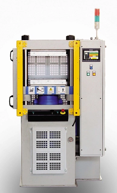
A plate bending machine, also known as a plate roll or rolling machine, is an essential piece of equipment in metalworking industries for shaping and bending thick metal plates. These machines are widely used in industries such as shipbuilding, construction, oil and gas, aerospace, and heavy machinery, where they are responsible for creating cylindrical or conical shapes from flat metal plates. Plate bending machines are particularly well-suited for working with materials such as steel, stainless steel, aluminum, and various alloys, allowing manufacturers to create curved or rolled sections that are essential in various structural applications.
Types of Plate Bending Machines
There are several types of plate bending machines, each designed for different applications and material thicknesses. The most common types include:
- Three-Roller Plate Bending Machines:
- These are the most common type of plate bending machines. They consist of three rollers: two lower rollers and one upper roller. The plate is fed between these rollers, with the upper roller applying pressure to form the metal plate into a desired curve.
- Mechanical and hydraulic versions of three-roller machines exist, with hydraulic versions offering greater control and force for bending thicker materials.
- Pre-bending capability: Hydraulic three-roll machines can pre-bend the edges of a plate before rolling it into a cylinder, which is particularly important for creating seamless cylinders without gaps.
- Four-Roller Plate Bending Machines:
- A four-roller machine is more advanced than the three-roller machine and offers better precision. It has two lower rollers and two upper rollers, and the upper rollers help to create a more accurate cylindrical shape.
- The four-roller configuration allows for more uniform bending, especially when working with thicker plates or achieving specific curvatures.
- Pre-bending is often more efficient in four-roller machines because of the additional upper roller that offers a greater range of motion and control.
- Plate Rollers with Variable Geometry:
- These machines have a more complex design where the rollers can change angles during the process to accommodate different shapes or specific geometries.
- This design allows for bending plates into conical shapes in addition to cylinders, offering greater versatility in creating custom shapes for industries that require more specialized bending.
Working Principle
The basic operation of a plate bending machine involves feeding a metal plate between rollers. The rollers apply force to the plate, causing it to bend gradually over several passes. The material is usually passed through the machine in stages, with each pass increasing the curvature of the plate until the desired shape is achieved. In a three-roller machine, one of the lower rollers is adjustable to control the curvature of the plate, while the upper roller applies force to shape the material.
In a four-roller machine, the material is supported more evenly, and the additional rollers ensure a more uniform and controlled bending process, especially for high-tensile-strength materials. Some advanced systems also feature automated controls for adjusting the position of the rollers to optimize the bending process for different material types and thicknesses.
Features of Modern Plate Bending Machines
- Hydraulic Systems:
- Many plate bending machines, particularly in industrial settings, utilize hydraulic systems to provide the power required for bending thick and strong materials. The hydraulic press ensures a consistent and powerful force that is essential for achieving precise bends.
- These systems also allow for adjustable bending force, providing the flexibility to work with different material thicknesses.
- CNC Controls:
- Advanced plate bending machines often incorporate CNC (Computer Numerical Control) systems, which allow for precise and automated control over the machine’s functions.
- With CNC controls, the bending parameters (such as roller positions, bending radius, and pressure) can be programmed into the machine, ensuring that each bend is made consistently and accurately.
- CNC controls can also be used to track and monitor production progress, enhancing efficiency and reducing human error.
- Digital Readouts and Feedback Systems:
- Many modern plate bending machines are equipped with digital readouts to provide operators with precise measurements of roller positions and bending angles.
- Feedback systems can automatically adjust the bending process in real-time, ensuring that the final product meets strict specifications. This feature is crucial when working with materials that require high precision or when producing large quantities of parts.
- Pre-bending Capability:
- As mentioned earlier, one of the important features of advanced plate bending machines is the ability to pre-bend the edges of a plate before rolling it into a cylinder. Pre-bending eliminates the need for additional operations to close the edges of the cylinder and ensures that the final shape has no gaps.
- Hydraulic systems in three-roller machines and four-roller machines are typically designed to perform pre-bending without requiring additional setups, making them highly efficient.
- Conical Bending:
- Some plate bending machines, particularly four-roller machines, are designed with special adjustments that allow them to produce conical shapes in addition to cylindrical ones.
- Conical bending is a specialized application used in industries such as pressure vessel manufacturing, where conical sections are often required for tanks and other equipment.
- Adjustable Speed and Force:
- Modern plate bending machines often allow operators to adjust the speed and force of the bending process. This is crucial for controlling the deformation rate of materials and ensuring that delicate or expensive materials are not damaged during bending.
- Adjustable speed also allows for more controlled bending of thicker plates, ensuring a smooth and even curve without excessive force that could damage the plate.
Applications of Plate Bending Machines
Plate bending machines are used across a variety of industries that require the creation of curved or cylindrical metal components. Some of the primary applications include:
- Shipbuilding: Plate bending machines are used extensively in shipyards to create the hulls and curved structures of ships.
- Pressure Vessels and Tanks: Many industries, including oil and gas, chemicals, and pharmaceuticals, require cylindrical and conical structures for storage tanks and pressure vessels. Plate bending machines are essential in forming these complex shapes from thick metal plates.
- Construction: Steel plates are often bent into cylindrical or curved beams for use in large construction projects, such as bridges and tunnels.
- Aerospace: Plate bending machines are used to manufacture components like fuselage skins and wing structures that require precise and uniform curvature.
- Heavy Equipment Manufacturing: Large metal components used in equipment like cranes, excavators, and industrial machinery often require precise bends that are made with plate bending machines.
Advantages of Plate Bending Machines
- High Precision: Modern plate bending machines, particularly those with CNC and hydraulic systems, offer high precision, making it easier to meet strict specifications for complex shapes and large production runs.
- Flexibility: These machines can handle a wide range of material types, thicknesses, and shapes, offering flexibility for manufacturers working with different specifications or custom orders.
- Increased Productivity: Plate bending machines allow manufacturers to quickly produce large volumes of parts with minimal manual labor, reducing production time and increasing throughput.
- Consistent Quality: Automated systems, feedback loops, and CNC controls ensure that each bend is uniform and within tolerance, improving the overall quality of the final product.
- Reduced Material Waste: Advanced plate bending machines optimize the bending process, helping to minimize material waste and reduce costs associated with scrap material.
Maintenance Considerations
Like all industrial machines, plate bending machines require regular maintenance to ensure optimal performance and longevity. Key areas of maintenance include:
- Hydraulic Fluid Checks: Ensuring that the hydraulic system has adequate fluid levels and that the fluid is in good condition is essential for maintaining consistent bending force and preventing machine malfunctions.
- Roller Alignment: Over time, the rollers can become misaligned, which can affect the machine’s ability to produce uniform bends. Regular checks and adjustments are needed to ensure that the rollers are properly aligned.
- Tool and Die Maintenance: The dies and tools used in the bending process can wear down, especially when working with thick, high-strength materials. Replacing or sharpening these components regularly ensures that the machine maintains its accuracy and efficiency.
- Electrical and CNC System Checks: CNC-controlled plate bending machines require regular checks of their electrical systems, including wiring, motors, and control panels, to ensure that the machine operates smoothly.
In conclusion, plate bending machines are critical tools in metalworking industries where large, curved metal plates are required. With advancements in hydraulic, CNC, and digital technologies, these machines have become more precise, efficient, and adaptable, meeting the demands of modern manufacturing. Their ability to handle a wide range of materials and thicknesses makes them indispensable in industries such as shipbuilding, construction, aerospace, and pressure vessel manufacturing.
Plate bending machines are highly specialized equipment that have revolutionized the process of shaping and bending large metal plates into curved, cylindrical, or conical shapes. These machines are vital in industries where structural integrity and precision are paramount, such as shipbuilding, construction, aerospace, and manufacturing of pressure vessels. The advancements in these machines, especially with the integration of automation and hydraulic technologies, have increased productivity, precision, and flexibility, making them indispensable for high-demand production environments.
One of the key features of plate bending machines is their ability to handle materials with varying thicknesses and strengths. Depending on the specific requirements of the project, these machines can adjust their bending force, speed, and roller configurations to ensure the material is formed correctly without causing damage. The hydraulic systems in modern machines, for example, provide the necessary force to handle heavy-duty plates that would be difficult to bend using manual methods. With the advent of CNC controls, operators can now program complex bending tasks into the machine, reducing the need for constant manual adjustments and increasing efficiency by allowing for automatic recalibration between batches.
The versatility of plate bending machines is also enhanced by their ability to perform conical bending in addition to cylindrical shapes. This is particularly valuable for industries that require custom-shaped parts, such as tanks, pipes, and cones used in construction and energy sectors. The ability to produce precise and uniform cones from flat plates without the need for additional operations is one of the significant advantages of using advanced bending machines.
Another notable development is the incorporation of digital controls that allow for real-time monitoring and feedback during the bending process. Operators can track parameters such as force, speed, and material strain, making it easier to adjust settings on the fly and prevent errors. This feedback system ensures that the machine stays within tolerances, helping to reduce material waste and improve the overall quality of the products being produced. For industries that require high precision, such as aerospace or pressure vessel manufacturing, this capability is essential.
Plate bending machines also cater to customization, which is essential when dealing with projects that require specific bending angles, curvature radii, or material types. The adaptability of modern machines means they can handle small batch production runs or even one-off projects where bespoke shapes are needed. The advanced roller configurations, especially in four-roller machines, allow for more even distribution of bending forces across the material, preventing deformation or uneven curvatures that might occur in simpler machines.
Maintenance of plate bending machines is crucial to ensure that they continue to operate at peak efficiency. Regular inspections of the hydraulic systems, roller alignment, and tool wear are necessary to prevent breakdowns that can result in production delays. Hydraulic fluid levels and the condition of the system also need periodic checks to maintain optimal pressure for bending. Additionally, CNC-controlled machines require software updates and diagnostic tests to ensure that the programming is running smoothly, reducing the chances of errors in complex tasks.
The energy efficiency of plate bending machines has also become a focus as industries strive for more sustainable operations. By optimizing hydraulic systems and incorporating energy recovery technologies, these machines can reduce their overall power consumption. Energy-efficient motors, variable speed drives, and regenerative systems that capture energy during the bending process contribute to lowering operational costs and minimizing the machine’s environmental footprint.
The growing demand for global standardization in manufacturing has led to the development of machines that can be easily adapted to meet local requirements. Plate bending machines are now built with modular components that can be swapped out or upgraded based on regional specifications or regulatory requirements, making them more adaptable for businesses operating in multiple markets. This flexibility is particularly useful for manufacturers who need to scale their operations and meet different production needs without investing in multiple pieces of equipment.
Ultimately, plate bending machines remain a cornerstone of modern metalworking, providing manufacturers with the tools necessary to produce complex, high-quality parts with efficiency and precision. The ongoing integration of automation, digitalization, and energy-saving technologies ensures that these machines will continue to evolve and play a crucial role in industries worldwide, making it possible to meet the increasing demand for customized and high-performance metal components.
As plate bending machines continue to evolve, further developments focus on improving automation and precision to cater to an even wider range of industries and production demands. One major shift is the integration of robotics with plate bending machines. In many manufacturing environments, automation is essential for maintaining high production speeds while reducing human error. By integrating robotic arms with bending machines, tasks such as feeding, rotating, or unloading metal plates can be done more efficiently, allowing for a higher throughput of parts with minimal human intervention. These systems can be programmed to handle multiple tasks simultaneously, including the loading of different material thicknesses, adjusting machine settings, and removing finished parts, all of which contribute to a significant reduction in cycle time.
Another key advancement is the growing use of 3D scanning and reverse engineering technologies to assist in the setup and operation of plate bending machines. By scanning the metal plates before they are fed into the machine, manufacturers can create a digital twin of the material, which helps to predict how it will behave during the bending process. This pre-bending analysis enables the operator to adjust the machine settings beforehand, ensuring the material is properly aligned and reducing the risk of defects. Furthermore, this technology can be used to detect material inconsistencies, such as thickness variations or surface imperfections, which could affect the quality of the final product. These digital tools also provide real-time feedback that allows operators to make immediate adjustments during the production process, ensuring accuracy in even the most complex designs.
The demand for smart manufacturing continues to grow, and plate bending machines are at the forefront of this shift. Modern machines are increasingly being equipped with IoT (Internet of Things) capabilities to enable real-time data collection, analysis, and remote monitoring. This allows manufacturers to track machine performance remotely and make informed decisions based on data-driven insights. For example, operators can receive instant notifications if there is an issue with the machine, such as hydraulic pressure drops or excessive wear on the rollers. These systems can also analyze production trends, helping to optimize operational efficiency and reduce downtime by providing predictive maintenance alerts. The ability to monitor machine health in real time allows businesses to schedule maintenance more effectively, preventing costly breakdowns and extending the lifespan of the equipment.
Additionally, the integration of advanced software solutions is making it easier for manufacturers to design and simulate bending operations before the physical process begins. Software programs can now predict how different materials will respond to bending forces and allow operators to visualize the final product before it is even produced. This minimizes the need for trial-and-error testing and speeds up the design-to-production cycle. These programs can also optimize bending paths, improving the efficiency of the process and ensuring the most economical use of material.
Another development is the increasing focus on sustainability in the design and operation of plate bending machines. Manufacturers are under growing pressure to reduce their environmental impact, and many modern bending machines are designed with energy-efficient systems that reduce electricity consumption. For example, some machines incorporate variable speed drives, which adjust the motor speed based on the load requirements, ensuring that power is used only when necessary. Additionally, innovations such as regenerative braking systems allow for the recovery of energy during certain phases of the operation, which is then used to power other aspects of the machine, further enhancing its energy efficiency. The trend towards sustainable practices also extends to the materials used in the construction of the machines, with manufacturers opting for recyclable and environmentally friendly components.
As industries increasingly prioritize customization, plate bending machines are adapting to accommodate even more specialized and complex shapes. Customization has become a central feature in many manufacturing sectors, especially in industries like automotive and aerospace, where parts often require non-standard, precise curvatures. To address this, plate bending machines are now capable of creating complex multi-radius bends and free-form shapes that were once difficult or impossible to achieve with older, more rigid machines. These advancements allow for the production of intricate components that meet highly specific design criteria, expanding the possibilities for manufacturers working on cutting-edge projects.
In terms of material innovation, plate bending machines are now being engineered to handle a wider variety of materials, from standard metals to high-strength alloys, composites, and even thin-gauge metals. Some machines are specifically designed for handling new, non-ferrous materials such as titanium or lightweight alloys, which are commonly used in industries like aerospace, where strength-to-weight ratios are critical. As manufacturers continue to work with materials that have unique properties—such as higher tensile strength or improved corrosion resistance—the machines are evolving to provide the force and precision needed to handle these materials without compromising the final product’s integrity.
The future of plate bending machines also includes a growing emphasis on user-friendly interfaces and training programs. As the complexity of machines increases, manufacturers are focusing on making machine controls more intuitive and easier to use, even for less experienced operators. Touchscreen interfaces, advanced software simulations, and augmented reality (AR) systems are being incorporated to help operators visualize the machine’s movements and make better decisions during production. Some manufacturers are developing virtual training environments where operators can practice machine setup and operation in a simulated setting, improving skill levels and reducing the risk of human error on the shop floor.
Furthermore, with the ongoing trend of globalization in manufacturing, plate bending machines are being designed with modular components that can be easily adapted to meet local market needs. This includes adjustments for different voltage standards, local materials, and regulatory requirements, as well as customizable roller configurations to accommodate different material sizes and shapes. Such adaptability is especially important for manufacturers who operate in multiple countries, as it reduces the need for multiple machine types and helps to standardize operations across diverse production environments.
The use of artificial intelligence (AI) is also finding its way into plate bending machines, especially in terms of predictive analytics. AI can predict how a material will behave during the bending process based on historical data and the physical properties of the metal. By continuously analyzing data from the machine, AI algorithms can identify trends and suggest optimizations to improve the efficiency of the process. Over time, these systems learn from each operation, improving the machine’s ability to make adjustments on the fly and providing suggestions for better results.
In conclusion, the evolution of plate bending machines is driven by the need for greater precision, efficiency, and flexibility in metalworking industries. With advances in automation, AI, IoT connectivity, and material technology, plate bending machines are more capable than ever before. These machines are not only improving the quality and speed of production but also supporting the trend toward more sustainable and customizable manufacturing practices. As industries continue to demand higher performance and more complex designs, plate bending machines will remain a critical component in producing high-quality metal components, with innovation paving the way for even more sophisticated and efficient solutions.
As the manufacturing landscape continues to evolve, the demand for greater automation and real-time data analysis in plate bending machines is expected to grow significantly. The integration of smart technologies will further transform the way manufacturers operate, making plate bending machines more versatile and efficient than ever. These advancements will not only streamline production processes but will also help to meet the increasing complexity of modern designs in industries such as aerospace, automotive, and energy.
One of the most significant changes on the horizon is the shift towards fully autonomous manufacturing cells, where plate bending machines operate in conjunction with other automated equipment like CNC machines, robotic arms, and material handling systems. These fully integrated systems will allow for end-to-end automation, from the initial material loading to the final part unloading and inspection, all without human intervention. Such systems can operate 24/7 with minimal supervision, increasing production capacity while reducing labor costs and the risk of human error. This level of automation is expected to be particularly beneficial in industries with high-volume, high-precision requirements, where consistency and efficiency are critical.
The role of artificial intelligence (AI) in these autonomous systems will be pivotal. AI-powered algorithms will continuously monitor machine performance, detect patterns, and suggest optimizations for each bending operation. For example, AI can analyze the thickness and material properties of each plate and adjust bending parameters in real-time, ensuring optimal results. The ability of AI to process vast amounts of data from sensors embedded in the machine will enable predictive maintenance, alerting operators to potential issues before they cause machine downtime. Additionally, AI can make decisions about tool wear, material selection, and machine settings based on historical data, leading to improved performance and reduced waste.
Predictive maintenance, powered by AI and IoT sensors, will become increasingly important in the future of plate bending machines. Traditional maintenance strategies are often reactive, waiting for parts to fail before they are replaced. In contrast, predictive maintenance uses real-time data to anticipate equipment failures and suggest preventive measures before breakdowns occur. By analyzing factors like machine vibrations, pressure levels, and temperature, the system can predict when certain components, such as rollers or hydraulic systems, will need maintenance or replacement. This approach not only minimizes machine downtime but also extends the lifespan of the equipment, reducing overall operational costs.
The concept of adaptive bending systems is also gaining traction. These systems adjust in real-time based on the specific material being processed, the desired curvature, and environmental factors like temperature. For example, metals behave differently depending on their temperature, and this can impact how they bend. Adaptive systems can automatically modify the bending force or speed to account for these variations, ensuring that the final product meets exact specifications. The ability to adapt to different materials and conditions without requiring manual adjustments will increase both flexibility and efficiency.
In terms of material handling, plate bending machines will increasingly integrate with advanced material tracking systems. These systems will use RFID tags or QR codes to track the movement and condition of materials throughout the manufacturing process. By linking the material’s unique identifier with the machine’s settings, operators can ensure that the correct material is used for each operation and that it is processed in the most efficient way. This integration will help eliminate errors caused by material misidentification and ensure the best possible results with minimal waste.
Moreover, advancements in sustainability will continue to influence the design of plate bending machines. Manufacturers will increasingly seek ways to reduce their environmental footprint, not only through energy-efficient operations but also by reducing the amount of scrap material produced during the bending process. New technologies such as precise laser cutting or plasma cutting will be integrated with plate bending machines to ensure cleaner edges, reducing the need for additional finishing processes and improving the overall efficiency of the production process.
In addition, the use of alternative materials such as composite metals or environmentally friendly alloys is becoming more widespread, especially in industries like automotive and aerospace, where lightweight yet strong materials are in high demand. These materials often require specific bending techniques, and plate bending machines will continue to evolve to handle these new materials effectively. The development of specialized rollers and adjustable bending parameters will allow manufacturers to produce parts from these materials without compromising on performance or strength.
As plate bending machines continue to become more advanced, they will also become more user-friendly. Touchscreen interfaces, enhanced visualization tools, and voice-command systems are all set to become standard features, making it easier for operators to interact with the machines. Augmented reality (AR) and virtual reality (VR) technologies could also be used for training purposes, allowing operators to practice machine operations in a simulated environment before working with the actual equipment. These technologies can help reduce training time and improve the overall safety of the workplace.
As more companies embrace industry 4.0, the interconnected nature of modern manufacturing will become more prevalent. Plate bending machines will not only be equipped with sensors that monitor their performance but also connected to a larger network of devices within the factory. This interconnectedness will allow for real-time tracking of production status, inventory, and machine performance across the entire factory floor. Data analytics platforms will collect this information and generate actionable insights that can help companies make more informed decisions about scheduling, inventory management, and production efficiency.
Cloud-based systems will also play a significant role in the future of plate bending machines. These systems will allow for the remote monitoring of machine performance, making it possible for operators, engineers, or managers to access real-time data from any location. Cloud technology will also enable better collaboration between teams, as machine data can be shared instantly with other departments or across different facilities. This level of connectivity will help to improve communication, reduce response times, and streamline operations in a globalized manufacturing environment.
In the coming years, modular designs for plate bending machines will become more common. Manufacturers will increasingly look for machines that can be easily adapted or upgraded to meet changing production needs. For example, a machine may be designed with interchangeable rollers or components that allow for quick reconfiguration based on different material types, thicknesses, or project requirements. This flexibility will be crucial as manufacturers are required to produce a wider variety of parts and respond to changing customer demands more rapidly.
As the demand for highly customized parts continues to grow, plate bending machines will become more adept at handling complex geometries and multi-step processes. For example, machines will be capable of performing multiple bending operations in a single pass, reducing the number of setups and minimizing handling time. Some advanced systems may even be capable of combining bending, cutting, and welding operations into one seamless process, streamlining the production of complex parts.
The future of plate bending machines is undoubtedly exciting, with new innovations continually emerging to improve the precision, efficiency, and flexibility of these essential manufacturing tools. As industries evolve and the demand for more complex and customized parts increases, plate bending machines will play a critical role in meeting these challenges, driving productivity, sustainability, and profitability in metalworking operations. The continued integration of cutting-edge technologies such as AI, robotics, IoT, and cloud computing will ensure that plate bending machines remain at the forefront of modern manufacturing.
Small Sheet Bending Machine
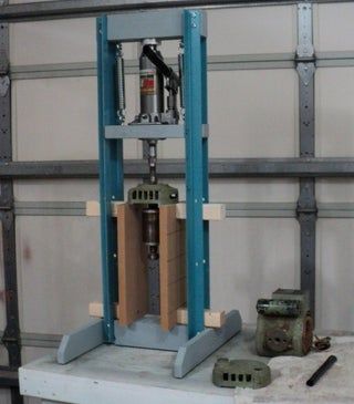
A small sheet bending machine is a compact version of the larger, industrial-grade bending machines designed specifically for bending metal sheets or plates into various shapes, typically in small-scale production or for light-duty applications. These machines are widely used in workshops, garages, or small manufacturing environments, where space constraints or lower production volumes require equipment that can provide high precision and versatility in bending metal sheets.
Here are some of the features and benefits that characterize small sheet bending machines:
Compact Design
Small sheet bending machines are designed to occupy minimal space while still providing sufficient bending power to work with a range of metal materials. Their compact size makes them ideal for use in smaller shops where floor space is limited but the need for precision and versatility remains high.
Types of Small Sheet Bending Machines
- Manual Sheet Benders: These machines are operated manually and are ideal for low-volume bending tasks. The operator adjusts the bend angle and the pressure through a hand lever, making them easy to use and economical for small-scale operations.
- Hydraulic Benders: Some small sheet bending machines come with hydraulic systems that provide more consistent bending power compared to manual machines. These are typically more suited for medium-duty tasks and can handle thicker materials than manual benders.
- CNC Sheet Benders: Small sheet bending machines can also come with computer numerical control (CNC) systems for higher precision. CNC machines automate the bending process, allowing for complex shapes and angles to be bent with high repeatability. These machines are typically used in operations that require consistent and intricate work, even on a smaller scale.
- Roll Benders: Small three-roller or four-roller benders are used to roll metal sheets into cylindrical or curved shapes. These are ideal for fabricating pipes, tubes, or curved metal parts and are available in small versions for lighter-duty tasks.
Materials Handled
Small sheet bending machines can handle a variety of metals, including:
- Mild steel: Commonly used for general sheet metal work.
- Stainless steel: Used in industries requiring corrosion-resistant materials.
- Aluminum: Light and easy to work with for applications that do not require heavy-duty materials.
- Copper: Often used in electrical and plumbing applications, where bending without cracking is essential.
Capacity and Thickness
Small sheet benders generally have a capacity for bending thin to medium-gauge sheets, often ranging from 0.5mm to 6mm thick, depending on the type of machine and its power. Some hydraulic or CNC machines can handle thicker material, but for the most part, these machines are built for relatively light-duty tasks.
Bending Accuracy and Quality
Small sheet bending machines are designed for high accuracy and precision. Even with manual benders, operators can achieve repeatable bends with the right tools and setup. Hydraulic and CNC versions offer even more precise bends, with some machines offering digital readouts or programmable control to ensure consistency from one part to the next.
Ease of Use
The smaller, manual machines are typically very user-friendly, making them ideal for operators who are less experienced with larger, more complex machines. Even for small shops, the simplicity of operation makes these machines an excellent choice for occasional or light production.
Applications
Small sheet bending machines are used in various industries, such as:
- HVAC (Heating, Ventilation, and Air Conditioning): Bending sheet metal for ductwork and components.
- Automotive: Manufacturing small parts, brackets, or panels.
- Electrical enclosures: Creating cases for electrical components or distribution boards.
- Sign-making: Bending metal sheets for creating custom signage or decorative elements.
- Prototype manufacturing: Bending metal for custom, one-off parts or prototypes.
Advantages
- Space-Saving: Small sheet bending machines are a great choice for smaller workshops where space is at a premium.
- Cost-Effective: These machines are typically less expensive than larger industrial machines, making them an attractive option for small businesses or hobbyists.
- Flexibility: Despite their size, small sheet benders can handle a variety of bending tasks and material types, making them versatile.
- User-Friendliness: Manual models are straightforward to use, while hydraulic and CNC options offer ease of programming and operation for those who need higher precision.
- Portability: Some small sheet bending machines are designed to be portable, allowing them to be moved easily between workstations or jobsites.
Maintenance
Although small sheet bending machines require less maintenance than larger machines, regular care is necessary to keep them in optimal condition. For manual machines, lubricating the moving parts, checking the alignment of the bending tools, and ensuring that there is no excessive wear on the surface is key. For hydraulic models, maintaining the fluid levels and checking for any leaks or performance issues is critical. CNC machines require periodic software updates, tool calibration, and checks on the hydraulic or mechanical components to ensure accurate operation.
Safety Features
Small sheet bending machines usually come with basic safety features such as:
- Guards or shields: To protect the operator from the bending area.
- Emergency stop buttons: To quickly halt operation in case of a malfunction.
- Pressure relief valves: On hydraulic models to prevent overloading.
- Foot pedals: For hands-free operation, especially on manual and hydraulic machines.
Conclusion
Small sheet bending machines are an essential tool for small-scale metalworking operations that require flexibility, precision, and efficiency. They provide a wide range of capabilities for bending sheet metal, whether for prototype creation, light manufacturing, or hobbyist work. With advances in hydraulic, manual, and CNC technologies, these machines are suitable for a variety of applications and can be a cost-effective solution for smaller shops that still need high-quality results. The right choice depends on the specific needs of the operation, from manual bending for basic shapes to high-precision CNC machines for complex and customized work.
Small sheet bending machines are highly versatile tools designed for bending metal sheets into precise angles and shapes. They offer a compact solution for small-scale workshops or businesses that do not have the space or budget for large industrial equipment. These machines are typically capable of handling a variety of materials, including mild steel, aluminum, stainless steel, and copper, and can be used for bending tasks in industries like HVAC, automotive, electrical, sign-making, and prototyping.
Despite their size, small sheet bending machines are designed for high accuracy. Even manual machines, when operated properly, can deliver consistent bends. Hydraulic and CNC versions take this a step further by offering even more precision, allowing operators to achieve complex shapes and high-quality bends without the need for constant adjustments. CNC machines, in particular, are ideal for environments where repeatability and consistency are critical, as they allow the operator to input exact bending specifications, minimizing human error.
One of the key advantages of these machines is their ease of use. Manual models are especially user-friendly, making them suitable for small workshops or hobbyists who may not have extensive experience with more complex equipment. Even for machines that feature hydraulic or CNC controls, the learning curve is generally not steep, and many machines come with intuitive interfaces that allow operators to quickly adapt to the system. This makes them accessible to a wide range of users, from beginners to experienced metalworkers.
Small sheet bending machines are also space-efficient. Their compact size makes them ideal for small shops or businesses that need to conserve floor space but still require reliable metalworking equipment. They can easily fit into smaller workshops or be moved between different workstations when necessary, making them a flexible option for shops with limited space.
Cost-effectiveness is another advantage of these machines. Small sheet benders are typically much less expensive than larger, industrial-grade machines, which makes them an attractive choice for smaller operations that may not require the capabilities of a full-sized machine. This affordability extends to their operation as well. They use less power and are less likely to incur high operational costs, making them economical over the long term, especially for low- to medium-volume production.
Maintenance requirements for small sheet bending machines are generally minimal compared to larger machines. Regular lubrication of moving parts and monitoring for wear and tear is typically all that’s needed to keep these machines running smoothly. Hydraulic models require periodic checks of fluid levels, and CNC models may require software updates or calibration adjustments, but overall, maintenance is straightforward and manageable.
The portability of some small sheet bending machines adds to their appeal. These machines can be easily relocated within a shop or even taken on-site for work on specific projects. This flexibility is especially useful for businesses that may need to transport equipment between locations or projects, further extending the utility of the machine.
Small sheet bending machines can handle a wide range of bending tasks. They are commonly used for bending simple shapes and angles in sheet metal but can also handle more intricate tasks like creating custom brackets, panels, or components for machinery. As technology advances, small sheet benders are becoming increasingly capable of handling more complex bends, with some machines now offering multi-step bending processes or the ability to bend multiple materials at once.
When it comes to safety, most small sheet bending machines are equipped with basic features like emergency stop buttons, safety guards, and pressure relief valves on hydraulic machines. These safety mechanisms are designed to protect the operator from potential injuries while also ensuring the machine operates smoothly. For example, foot pedals on manual and hydraulic machines allow operators to control the bending process hands-free, reducing the risk of accidents.
Small sheet bending machines are also environmentally friendly. With the growing emphasis on sustainability in manufacturing, these machines are designed to minimize waste and energy consumption. Many are built with energy-efficient components, and the reduced need for large quantities of material in small-scale production helps minimize waste. Additionally, the ability to control the bending process accurately means that scrap metal is kept to a minimum, further reducing material waste.
As industries continue to move towards more customized and complex products, small sheet bending machines are evolving to meet these demands. Innovations in CNC technology and automation are enabling these machines to handle increasingly complex geometries and multi-step processes. For example, some machines now have the ability to perform both bending and cutting operations in one pass, reducing setup time and improving production efficiency. This trend towards automation and higher precision will only continue to grow, making small sheet bending machines an indispensable tool in modern metalworking.
Overall, small sheet bending machines are invaluable assets for smaller shops and businesses that need precision, versatility, and efficiency in their metalworking operations. They provide the perfect balance of power, flexibility, and ease of use, enabling operators to produce high-quality results with minimal investment in space and resources. Whether for hobbyists, small-scale manufacturers, or prototype shops, these machines offer the necessary tools to create a wide range of metal components while keeping costs low and production times efficient.
Small sheet bending machines are crucial in industries that require precise bending of sheet metal in low to medium volumes. Their versatility allows them to handle a variety of metal materials, from mild steel to aluminum, copper, and stainless steel. Their compact size and user-friendly nature make them a go-to solution for small workshops, hobbyists, or small manufacturers. Unlike larger industrial machines, small sheet benders are designed to offer flexibility without requiring extensive space or a large investment.
A major advantage of small sheet bending machines is their ability to work with various gauges of sheet metal, typically ranging from thin to medium thickness. For example, they can handle sheets that range from 0.5mm up to around 6mm in thickness, depending on the model. This makes them ideal for industries such as HVAC, where sheet metal is regularly bent to create ducts, panels, or brackets. Additionally, industries such as automotive, electrical, and signage benefit from their ability to produce high-precision parts in smaller batches.
For those who don’t require high automation, manual sheet bending machines are often the first choice. These machines are simple, cost-effective, and easy to use. With manual operation, the user can adjust the bend angle by manipulating the machine’s mechanical components. While they may lack the automation and power of hydraulic or CNC models, they are sufficient for basic bending tasks and are ideal for small projects or smaller batches where precise, repetitive bends aren’t as critical.
Hydraulic small sheet bending machines offer a more powerful alternative to manual machines. These machines use hydraulic force to bend the material, providing more consistent bending pressure. This type of machine is particularly useful when working with materials that are difficult to bend manually or when more precise control over the bending process is needed. They are often chosen for medium-duty tasks where precision is important, but the need for full automation is not necessary. Hydraulic benders are also more efficient for thicker materials, capable of handling sheets that manual machines cannot.
For those seeking the highest level of accuracy and repeatability, CNC sheet bending machines are the most advanced option available. These machines are equipped with computer numerical control (CNC), which allows them to automatically adjust the bending process based on programmed specifications. The use of CNC technology provides higher precision and repeatability, making them ideal for production runs that require multiple identical parts or intricate geometries. CNC machines are programmed via software and can store different bending configurations for different materials, allowing quick switching between different tasks. They are commonly used for tasks that require complex and customized bends or for businesses that need to maintain tight tolerances over long production runs.
While small sheet bending machines may be simpler in terms of functionality compared to larger industrial equipment, their adaptability and ease of use make them indispensable for many applications. They are designed for small-scale production, prototyping, and repair tasks. Manufacturers in industries such as automotive, HVAC, sign-making, and sheet metal fabrication use small sheet bending machines to produce parts, create components, or carry out repairs on-site or in small batches.
Moreover, the development of more energy-efficient models and automation in small sheet benders is increasing their appeal. With the ability to integrate more advanced features such as digital controls or programmable bending sequences, these machines are now more capable of handling complex tasks that were once the domain of larger, more expensive machines. Additionally, as automation becomes more accessible, small businesses can see significant improvements in throughput and part consistency without needing to make significant investments in high-end industrial equipment.
In terms of maintenance, small sheet bending machines are relatively easy to care for. Most models require simple upkeep such as periodic lubrication of moving parts, checking for wear and tear, and inspecting hydraulic components (for hydraulic models). For CNC machines, calibration of the control system and ensuring the proper alignment of the bending tools is also essential. Fortunately, these machines are designed with ease of maintenance in mind, so they generally do not require specialized technicians to perform routine tasks.
As a whole, small sheet bending machines offer a great solution for small and medium-sized manufacturers looking to perform precise bending tasks without the high costs or space requirements associated with larger industrial machinery. Whether manual, hydraulic, or CNC, each type of machine provides different levels of control, power, and flexibility to meet the diverse needs of small businesses and workshops.
The ability to perform multiple operations on small sheet bending machines has seen improvements with the development of multi-functional models. These machines are now capable of combining bending with other processes such as cutting, punching, and shearing. By integrating these functions, manufacturers can streamline their production workflows, reduce setup time, and increase overall efficiency. For instance, some CNC sheet bending machines now include capabilities for cutting metal sheets to size before bending them, eliminating the need for a separate cutting process. This not only saves time but also reduces the risk of material handling errors and ensures that all processes are seamlessly integrated.
In industries like HVAC, where custom ductwork is frequently required, having a small sheet bending machine that can perform both bending and cutting operations in a single pass is particularly valuable. It reduces the need for multiple machines and operators, leading to cost savings and faster turnaround times. This trend toward integrated operations is also evident in industries like automotive manufacturing, where small but highly precise parts must be produced quickly and with minimal waste.
The material versatility of small sheet bending machines continues to expand, as these machines are increasingly designed to handle not just common metals like steel and aluminum but also more specialized materials. For example, small sheet bending machines are now used to work with copper alloys, titanium, and composite metals, which are common in industries such as aerospace, electronics, and medical device manufacturing. These materials often require more specialized bending techniques due to their specific properties like high strength-to-weight ratios or resistance to corrosion. As demand for such materials increases, small sheet benders are evolving to meet the needs of manufacturers working with these advanced materials.
The growing trend of customization in manufacturing is also driving the evolution of small sheet bending machines. Many industries are increasingly demanding custom components, which means that sheet metal work needs to be flexible and adaptable. CNC-controlled small sheet benders have become more adept at handling complex geometries, allowing operators to bend sheet metal into non-standard shapes and sizes. Whether it’s for prototype design, small-scale batch production, or even one-off custom projects, these machines are able to achieve the high precision required for such tasks.
To support the increasing demand for customized work, the development of programmable controls has made it easier for operators to quickly change bending configurations. Operators can store various bending programs in the machine’s memory and quickly switch between them, facilitating efficient transitions between different jobs. This makes small sheet bending machines highly versatile in environments where the product mix changes frequently, such as in job shops or repair shops.
Moreover, the integration of robotics and automation into small sheet bending systems is another area that is improving machine efficiency. While many small sheet bending machines have been traditionally operated by hand or with manual controls, robotic arms are now being used to automate material loading and unloading, reducing the physical strain on operators and speeding up the production process. These automated systems can be used in conjunction with CNC-controlled benders to achieve both high precision and high throughput. In addition to improving speed and reducing manual labor, robotic systems also allow for continuous production of parts, making it possible for small businesses to operate around the clock, even without a full-time operator present.
Another exciting development in the realm of small sheet bending machines is the increasing use of IoT (Internet of Things) technology. IoT-enabled machines can communicate with other devices on the shop floor, allowing for greater data sharing and real-time monitoring. These systems enable manufacturers to track the performance of their machines, monitor energy consumption, and even predict when maintenance is needed before a failure occurs. This predictive maintenance capability is particularly important in preventing downtime and ensuring continuous operations, which is vital for businesses that rely on high-output production. The data provided by IoT sensors can also be used to analyze production trends, identify areas for improvement, and optimize workflow efficiency.
The focus on energy efficiency in small sheet bending machines has also increased in recent years. As businesses seek to reduce their carbon footprints and operating costs, energy-efficient machines are becoming more sought after. Manufacturers are designing these machines to use less power without compromising performance, making them more cost-effective in the long run. Hydraulic machines, in particular, are seeing improvements in the design of their hydraulic systems, allowing them to operate at higher efficiencies and consume less energy compared to older models.
In terms of ergonomics, small sheet bending machines are also becoming more user-friendly. Modern machines are designed with adjustable working heights, easier-to-use controls, and reduced noise levels, all of which contribute to a safer and more comfortable work environment for operators. For manual models, enhancements in leverage mechanisms and bending angles ensure that operators can bend materials with minimal physical strain, while more sophisticated machines with CNC controls and hydraulic systems require less physical effort to achieve precise bends. These ergonomic considerations help to prevent workplace injuries and reduce operator fatigue, making small sheet bending machines more accessible and safer to operate for a wider range of workers.
One of the challenges manufacturers face with small sheet bending machines is ensuring consistent quality across different production runs. However, with the rise of automated quality control and inspection systems, this issue is becoming easier to manage. Some modern machines now incorporate laser scanning or vision systems that can assess the quality of a part after it has been bent, ensuring that it meets the required specifications. These inspection systems can check for things like material deformation, bend angles, and dimensional accuracy, allowing operators to identify defects early in the production process and reduce waste.
The trend towards digitalization in manufacturing also extends to the way small sheet bending machines are operated. Newer models come equipped with touchscreen interfaces or smart controls that simplify the programming and operation of the machine. These interfaces provide visual guides and step-by-step instructions, making it easier for operators to understand complex processes and troubleshoot any issues that arise. Furthermore, some machines now support remote monitoring, which allows managers and technicians to monitor the machine’s performance from a distance, providing real-time updates on production progress, machine health, and potential issues.
In conclusion, the future of small sheet bending machines is increasingly tied to innovations in automation, data analytics, energy efficiency, and advanced materials. As these machines evolve to meet the needs of industries requiring high precision, customization, and sustainable practices, they will continue to play a vital role in small-scale and medium-scale metalworking operations. Whether it’s through the integration of robotics, CNC technology, IoT, or energy-saving designs, small sheet bending machines are becoming more advanced, efficient, and versatile than ever before, enabling manufacturers to stay competitive in an ever-changing market.
Small sheet bending machines are evolving not only to meet the demands of precision and efficiency but also to adapt to the challenges posed by an increasingly globalized and fast-paced manufacturing environment. As industries strive for shorter lead times, higher customization, and lower production costs, small sheet bending machines are becoming more integral to achieving these objectives.
One significant trend is the increased focus on precision and tolerance control. As industries like aerospace, medical devices, and electronics demand tighter tolerances for metal parts, small sheet bending machines are incorporating advanced measurement and feedback systems. These systems ensure that each part meets the required specifications, minimizing the risk of defects and scrap. Technologies such as laser measurement systems, auto-calibration, and real-time adjustment controls are allowing operators to achieve extremely tight tolerances without requiring extensive manual intervention.
For instance, in aerospace manufacturing, where parts must meet stringent quality standards, small sheet bending machines are equipped with sensors that constantly monitor the bending process, ensuring parts are formed within precise dimensional limits. These automated systems can adjust parameters such as pressure, angle, or speed during the bending process, making real-time corrections as needed to guarantee accuracy.
In addition to precision, material handling automation is becoming a critical component of modern small sheet bending machines. As manufacturers are expected to work with a wider range of materials—including advanced composites, high-strength alloys, and multi-material constructions—small sheet bending machines must be able to accommodate the varying properties of these materials. Newer models incorporate systems that can automatically adjust the bending force based on the material’s characteristics, ensuring optimal performance and preventing material damage during the bending process.
For example, automated material feeders are now being integrated into small sheet bending systems. These feeders automatically load sheets onto the machine and align them for optimal bending, reducing human error and increasing throughput. Some systems even feature automated unloading mechanisms, where bent parts are automatically removed and placed into bins or other collection devices, eliminating the need for manual handling after the bending process. This automation reduces labor costs and minimizes the risk of part contamination or mishandling, ensuring higher quality and efficiency throughout the production process.
Data integration and Industry 4.0 technologies are also making their way into small sheet bending machines. By connecting machines to a network of other devices and systems, manufacturers can track machine performance, monitor material usage, and gather critical operational data. This data-driven approach allows manufacturers to better understand their production processes, identify inefficiencies, and make data-backed decisions to optimize operations. The integration of these technologies enables predictive maintenance, which can alert operators to potential equipment failures before they occur, minimizing downtime and extending the life of the equipment.
As small sheet bending machines become more integrated with broader manufacturing ecosystems, the capability for remote monitoring is becoming increasingly important. With the rise of cloud-based platforms, operators and managers can access machine data and monitor the status of their operations from virtually anywhere. This level of connectivity is particularly valuable for manufacturers with multiple locations or global supply chains. Remote monitoring allows for real-time troubleshooting, machine diagnostics, and production tracking, all of which help to streamline workflows and improve decision-making.
The rise of customization continues to drive innovation in small sheet bending machines. Customers are increasingly demanding products that are tailored to their specific needs, which requires bending machines to be flexible enough to handle complex, one-off designs or small-batch production runs. To meet these needs, small sheet bending machines are being equipped with multi-axis bending capabilities. These machines can perform bends in multiple directions, allowing manufacturers to create parts with complex, 3D geometries that would be difficult or impossible with traditional machines. The ability to create customized parts quickly and accurately has become a critical differentiator for manufacturers that want to compete in markets that demand uniqueness and originality.
For example, in the automotive industry, where customized parts for limited edition vehicles or prototypes are needed, small sheet bending machines equipped with multi-axis bending functionality can produce intricate metal parts with complex curves and angles. This makes the machines invaluable for industries that require bespoke manufacturing at a lower cost compared to large-scale industrial setups.
The environmental impact of small sheet bending machines is another area of focus as manufacturers continue to push for sustainability in their operations. Newer machines are designed to reduce energy consumption, minimize material waste, and lower the overall carbon footprint of manufacturing operations. This includes the use of energy-efficient motors, optimized hydraulic systems, and improved tooling that ensures minimal scrap during the bending process. Additionally, some machines are now designed to be recyclable at the end of their life cycle, contributing to the overall sustainability of the manufacturing process.
The adoption of eco-friendly lubricants and coolants in small sheet bending machines is another way to reduce environmental impact. These products are specifically designed to provide excellent cooling and lubrication while being less harmful to the environment compared to traditional lubricants. Furthermore, advances in tool design have made it possible to increase tool life, reducing the frequency of tool replacements and minimizing waste generated by worn-out components.
As manufacturers seek ways to improve their bottom line, they are also looking for machines that are not only cost-effective but also capable of increasing throughput without sacrificing quality. High-speed bending is becoming increasingly possible with newer machines that can perform rapid, repetitive bending operations with minimal downtime. The integration of high-speed servo motors and advanced drive systems enables these machines to achieve faster cycle times, reducing overall production time and improving efficiency.
The flexibility of small sheet bending machines also extends to their ability to handle varied part sizes and shapes. These machines are capable of processing sheets of varying lengths, widths, and thicknesses, which is ideal for manufacturers that need to produce parts in different configurations. Adjustments to machine settings can be made quickly, enabling operators to switch between different jobs without significant downtime or setup time. This makes small sheet bending machines perfect for small-batch or on-demand production, where the flexibility to handle different orders is essential.
Finally, operator training is a key consideration as technology continues to evolve. While small sheet bending machines are generally designed to be user-friendly, the introduction of more sophisticated features and control systems requires operators to undergo specialized training to fully harness the machine’s capabilities. Many manufacturers now offer online training modules, virtual tutorials, and augmented reality (AR)-based training programs to help operators quickly learn how to use new machines or upgrade their skills to keep up with technological advancements. As these technologies become more widespread, ongoing training will be crucial to ensuring that operators can effectively operate and maintain the machines.
In conclusion, small sheet bending machines are becoming increasingly advanced, incorporating cutting-edge technologies such as automation, real-time data analysis, IoT connectivity, and high-precision bending capabilities. These innovations not only improve operational efficiency but also enable manufacturers to meet the growing demands for customization, sustainability, and rapid production. The future of small sheet bending machines lies in their ability to offer more flexibility, precision, and automation, positioning them as essential tools in industries where high-quality, cost-effective, and customized sheet metal products are required. As manufacturers continue to adapt to changing market demands, small sheet bending machines will remain at the forefront of innovation in the metalworking industry.
Electric Sheet Metal Bending Machine
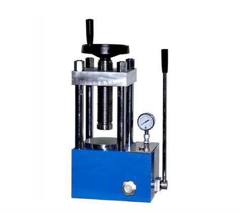
An electric sheet metal bending machine is a modern, versatile tool used to bend metal sheets with the precision and control needed for a wide range of applications. Unlike traditional hydraulic or manual bending machines, electric sheet metal bending machines use electric motors to provide the necessary force for bending, offering several distinct advantages such as energy efficiency, precision, and ease of use.
Advantages of Electric Sheet Metal Bending Machines:
- Energy Efficiency: One of the most significant benefits of electric sheet metal benders is their energy efficiency. Traditional hydraulic machines can consume a lot of energy, as they require pumps, motors, and hydraulic fluids to generate force. In contrast, electric machines use electric motors, which are generally more energy-efficient, reducing operational costs over time.
- Precision and Accuracy: Electric sheet metal benders are known for their high precision, making them ideal for applications that require tight tolerances. The ability to adjust bending parameters electronically allows for more consistent results, reducing the chance of human error. Additionally, the use of CNC (computer numerical control) technology in electric models enables automatic, programmable bending with repeatable accuracy.
- Low Maintenance: Electric machines generally require less maintenance than hydraulic machines. Since they do not have hydraulic pumps or fluid systems, there is less wear and tear, and maintenance is simpler. There is also no need for frequent fluid changes or dealing with leaks, which are common issues in hydraulic machines.
- Cleaner Operation: With no hydraulic fluids involved, electric sheet metal bending machines have a cleaner operation compared to their hydraulic counterparts. This can be particularly advantageous in industries where cleanliness is important, such as food processing, medical devices, or electronics manufacturing.
- Compact and Space-Saving: Electric machines are typically more compact than hydraulic machines, which makes them suitable for smaller workshops or facilities where space is limited. This also makes them more portable and easier to move around within a shop, allowing greater flexibility in production layouts.
- Environmentally Friendly: Since electric sheet metal benders do not use hydraulic fluids, there is less environmental impact, both in terms of the production and disposal of hydraulic fluids. This makes electric machines a more environmentally friendly option compared to hydraulic systems.
Key Features of Electric Sheet Metal Bending Machines:
- Servo Motors: Electric sheet metal benders often use servo motors, which are controlled via CNC systems. These motors can provide high precision while using less energy than traditional drive motors.
- CNC Control: CNC-controlled electric benders allow for automation of the bending process. The operator can program the machine to perform multiple bends with exact angles, reducing the need for manual adjustments and improving productivity.
- Touchscreen Interface: Many electric bending machines come with a user-friendly touchscreen interface, which allows operators to input specific parameters (such as bend angle, depth, and pressure) quickly and efficiently.
- Hydraulic Assist: Some electric bending machines combine electric and hydraulic power to provide the benefits of both technologies. This hybrid approach can offer enhanced force output for thicker materials while maintaining the energy savings and precision of electric operation.
- Energy-Saving Features: Modern electric sheet metal bending machines often come equipped with energy-saving features such as regenerative braking and variable frequency drives (VFDs), which help to optimize energy use based on the bending workload.
- Automatic Back Gauge: This feature allows the machine to adjust automatically to the correct position for each bend, improving the speed and accuracy of part production.
Applications of Electric Sheet Metal Bending Machines:
- Precision Bending: They are ideal for applications that require high precision and exact bends. These can include industries like aerospace, automotive, and electronics, where the quality of bent parts is critical.
- Small to Medium-Scale Production: Electric sheet metal benders are often used for smaller to medium-scale production runs, especially in job shops or for prototyping where quick setups and flexibility are key.
- Custom Part Fabrication: They are commonly used to produce custom parts or prototypes that require complex bends and shapes. The accuracy of electric machines makes them a good choice for small batches of custom metalwork.
- Enclosures and Panels: Electric benders are widely used in the fabrication of enclosures, panels, and casings for electronic, electrical, and industrial products.
- HVAC and Ductwork: In the HVAC industry, electric sheet metal bending machines are used to produce ducts, fittings, and other custom components that require precise bends.
- Signage and Display Products: The precision and energy efficiency of electric benders make them ideal for fabricating metal parts used in signage and display products, which often require complex bends.
Considerations When Choosing an Electric Sheet Metal Bending Machine:
- Material Thickness: Make sure the machine is capable of handling the thickness and type of material you intend to work with. While electric benders are well-suited for thin to medium gauge metals, very thick sheets may require hydraulic assistance.
- Bending Force: Ensure that the machine provides enough bending force for the required applications. The bending force is generally calculated based on the material’s thickness, type, and width.
- Machine Size and Footprint: Depending on your workshop space, you’ll want to select a machine that fits your needs without taking up unnecessary space. Electric benders are generally more compact than hydraulic models, but it’s still important to check dimensions.
- Automation Needs: If you require high-volume production or the ability to produce complex parts with minimal human input, you may want a machine with CNC control or additional automation features, such as robotic loading and unloading systems.
- Budget: While electric sheet metal benders can be more affordable than their hydraulic counterparts in terms of initial cost and maintenance, it’s important to balance the features with the budget. High-end CNC machines with advanced automation can be more expensive.
Conclusion:
Electric sheet metal bending machines offer a great combination of energy efficiency, precision, and ease of use, making them a popular choice for small- to medium-scale manufacturers, custom fabricators, and prototyping shops. With fewer maintenance requirements, cleaner operations, and the ability to handle a wide variety of materials with high accuracy, these machines are well-suited for industries that demand both flexibility and precision. As manufacturing continues to move towards more energy-efficient and environmentally friendly solutions, electric sheet metal bending machines will likely become even more prevalent in the years to come.
Electric sheet metal bending machines are transforming the metalworking industry with their advanced features, combining high precision, energy efficiency, and lower maintenance needs. As industries demand greater flexibility, customization, and faster production cycles, these machines are becoming an essential tool for fabricators. They offer significant advantages over traditional hydraulic machines, especially in terms of operational cost savings, because electric motors require less energy compared to hydraulic systems. In addition, the integration of CNC control allows for easy programming, which automates the bending process and ensures repeatability, accuracy, and consistency.
One of the key factors driving the adoption of electric sheet metal bending machines is their energy efficiency. Traditional hydraulic machines consume a considerable amount of energy due to their hydraulic pumps and fluid systems, which require constant power. In contrast, electric benders are powered by electric motors that can be more precisely controlled, leading to lower energy consumption, especially during idling or low-power stages of operation. For businesses aiming to reduce operational costs and carbon footprints, electric machines provide a clear advantage over more energy-intensive hydraulic systems.
The introduction of servo motors has also elevated the capabilities of electric sheet metal benders, offering increased control over bending force and speed. These servo motors provide smooth and responsive control, translating to faster cycle times, precise adjustments, and the ability to handle different material types with minimal setup time. The use of regenerative braking further enhances energy savings by capturing and reusing energy during braking phases, a feature commonly found in more advanced models.
Electric benders are especially suitable for applications where precision is critical. The CNC control systems in modern electric machines allow for intricate, complex bends to be achieved with high repeatability, making them ideal for industries like electronics, automotive, and aerospace. This precision is crucial when working with high-tolerance materials or for producing custom parts. The control systems also enable operators to program the machine for multiple bends, reducing human error and improving workflow efficiency.
Additionally, electric machines are becoming increasingly user-friendly. With touchscreen interfaces, operators can quickly input settings for various bending tasks. The machines often come with visual programming aids that make it easy to understand and adjust settings, even for operators who may not have extensive experience with CNC machinery. This ease of use reduces the learning curve, improving operational efficiency and reducing the chances of setup mistakes that could result in costly rework or material waste.
Another important benefit of electric sheet metal bending machines is their cleaner operation compared to hydraulic systems. With no hydraulic oil required, there is less risk of leaks, and the machines operate in a cleaner environment, reducing contamination risks—especially important in industries where precision and cleanliness are critical. Additionally, electric systems generally have fewer moving parts and are less prone to the wear and tear associated with traditional hydraulic pumps and fluid systems.
The integration of automation within electric sheet metal benders is also becoming increasingly common. Robotic arms or automated loading and unloading systems can be paired with these machines to further enhance productivity. These systems reduce the need for manual labor in tasks such as positioning the metal sheet, removing finished parts, and ensuring that the parts are properly aligned for each successive bend. Such automation not only saves time but also minimizes the potential for human error and increases production efficiency.
Electric benders are also versatile when it comes to handling different materials. They can be easily adjusted to work with a variety of metals, from stainless steel and aluminum to titanium and copper alloys, each requiring different bending forces and parameters. With the ability to fine-tune bending parameters for specific materials, manufacturers can produce high-quality, custom metal parts with little material waste. The added flexibility makes electric bending machines especially useful for prototype development and small-batch production, where varying material types and custom parts are the norm.
Furthermore, electric sheet metal bending machines are a practical choice for businesses that need to maintain high production rates without sacrificing quality. The combination of high-speed servo motors and CNC programming allows these machines to bend large quantities of metal sheets in a short amount of time, increasing overall throughput. These machines can be used for mass production of simple parts or for more complex, customized components, offering flexibility across various production scales. This scalability makes electric benders a reliable tool for both high-volume production and low-volume, high-precision applications.
The use of electric sheet metal bending machines is also aligned with industry trends toward sustainability. Many companies are focusing on reducing their environmental footprint, and switching to electric systems is one effective way to achieve this. With reduced energy consumption, cleaner operation, and longer machine life, these machines contribute to a more sustainable manufacturing process. Additionally, electric benders often come with features such as energy-efficient motors, programmable energy-saving modes, and smart power management systems, all of which work together to reduce operational costs and environmental impact.
Maintenance is another area where electric sheet metal bending machines shine. They require less maintenance compared to hydraulic machines because there are no hydraulic systems to monitor or maintain. This not only reduces downtime but also cuts maintenance costs, allowing businesses to allocate resources to other areas. Regular maintenance typically involves checking for wear and tear on parts like servo motors, ensuring that the electrical components are functioning properly, and keeping the machine clean. The reduction in maintenance requirements also leads to lower total cost of ownership, which is an attractive proposition for businesses looking to optimize their investments in equipment.
As the market for custom metal products continues to grow, the demand for flexible, high-precision machines that can handle both large-scale production and customized orders is rising. Electric sheet metal bending machines are well-suited for these tasks, as they offer a combination of efficiency, precision, and adaptability that is difficult to match with traditional bending methods. The ability to quickly reprogram these machines and adjust bending parameters for different materials and geometries makes them a valuable asset for manufacturers seeking to stay competitive in industries that require fast turnaround times and high-quality custom parts.
In conclusion, electric sheet metal bending machines represent the future of bending technology, offering superior energy efficiency, reduced maintenance, cleaner operation, and precise control over the bending process. As industries continue to demand more flexibility, customization, and sustainability, electric sheet metal bending machines will continue to evolve and play a critical role in helping manufacturers meet these challenges. The ongoing development of automation, CNC technology, and smart features will further enhance the capabilities of these machines, making them an even more indispensable tool in modern metalworking and fabrication.
As the demand for higher precision and faster turnaround times increases across a variety of industries, electric sheet metal bending machines are becoming indispensable in modern manufacturing environments. They offer unmatched repeatability and the ability to handle complex geometries with minimal error, which is essential for industries such as aerospace, automotive, and medical device manufacturing, where strict tolerance standards must be met. By offering CNC-controlled automation, these machines can achieve consistently high-quality results across high-volume production runs, making them ideal for batch production or custom orders.
A key advantage of electric sheet metal bending machines is their ability to maintain precision even with complex bends. In many manufacturing environments, the ability to bend metal sheets at multiple angles or in intricate shapes is crucial. Electric benders can be equipped with multiple-axis control systems that allow them to perform bends along different axes, enabling more complex forms to be created without requiring multiple machines or setups. This capability reduces the need for additional equipment, streamlining production and reducing lead times for customized parts.
The reduced environmental impact of electric sheet metal benders cannot be overstated. In addition to their energy-efficient operation, many models are designed with sustainability in mind. These machines often use eco-friendly lubricants, non-toxic coolants, and low-maintenance components that minimize the use of harmful substances. The absence of hydraulic fluids not only reduces the risk of spills and leaks, but also eliminates the need for disposal of used oils and chemicals, making them a more environmentally responsible option for manufacturers who prioritize eco-friendly production practices.
The rise of smart manufacturing is another area where electric sheet metal bending machines shine. With the integration of IoT (Internet of Things) technology, these machines can connect to cloud-based systems that allow for real-time monitoring and data collection. Operators and managers can remotely access machine performance data, track production metrics, and monitor material usage, all of which help to optimize production processes and reduce waste. Furthermore, the data generated by these machines can be used to predict maintenance needs, allowing for predictive maintenance. This minimizes the risk of unplanned downtime and helps companies extend the lifespan of their equipment, leading to even greater long-term cost savings.
The ability to integrate electric sheet metal bending machines with other automated systems in a production line enhances their utility. Many modern systems can be paired with automated material handling systems, such as robots or conveyors, that load and unload materials, further reducing the need for manual labor and increasing production efficiency. This level of automation enables manufacturers to streamline their operations and increase throughput while maintaining a high level of flexibility to accommodate varying production runs and customized part specifications.
Programming and customization are also much more user-friendly with electric machines, especially those with advanced CNC systems. Operators can easily modify settings to accommodate different materials, thicknesses, and bend types, all through an intuitive interface. Additionally, simulation software often accompanies these systems, allowing operators to visualize the bending process virtually before actual production begins. This feature minimizes errors by ensuring that all parameters are correctly set before material is physically worked on.
Electric sheet metal bending machines are also more adaptable to different material types and thicknesses. The ability to adjust the bending force, speed, and precision on the fly makes these machines suitable for working with a variety of materials, from thin sheets of aluminum to thicker, harder metals like steel and titanium. As a result, manufacturers are able to tackle a wide range of applications, from producing delicate, thin-walled components to handling heavier-duty parts used in industrial or construction settings.
The future of electric sheet metal bending machines looks promising as manufacturers continue to push for greater automation, smarter control systems, and faster production cycles. In the coming years, we can expect even more advanced features, such as artificial intelligence (AI) and machine learning (ML), to be integrated into these systems. These technologies will allow machines to learn from past operations, adapt to changing conditions, and make autonomous adjustments in real-time, optimizing both production efficiency and quality control. This could dramatically reduce human intervention and allow for more personalized, on-demand production without sacrificing speed or cost.
The cost-effectiveness of electric sheet metal bending machines is another driving factor behind their increasing adoption. While the initial investment might be higher compared to traditional manual or even some hydraulic machines, the long-term savings associated with lower operational costs and reduced maintenance requirements make them an attractive option for manufacturers looking to optimize their bottom line. As energy prices fluctuate and pressure to reduce manufacturing costs grows, electric bending machines present a viable solution for businesses aiming to balance productivity with environmental responsibility.
Moreover, the customization capabilities offered by these machines make them a preferred choice for industries that require low-volume production of highly specialized parts. The ability to easily change settings and reprogram the machine for different part specifications allows manufacturers to meet customer demands for small-batch runs or custom orders without compromising on quality or increasing costs. This level of adaptability is crucial for businesses that need to quickly respond to changing customer demands, seasonal fluctuations, or trends in design.
As manufacturers continue to embrace digital technologies, the integration of cloud-based systems and advanced data analytics into electric sheet metal bending machines will further enhance their capabilities. These systems will enable manufacturers to track the performance of their machines in real-time, providing insights into machine health, productivity levels, and material usage. Such data-driven approaches allow companies to identify inefficiencies, improve processes, and ultimately reduce waste and cost.
In conclusion, electric sheet metal bending machines are positioned to play a central role in the evolution of modern manufacturing. Their combination of precision, energy efficiency, flexibility, and advanced automation makes them an invaluable tool for a variety of industries. Whether producing large volumes of simple parts or small runs of complex, custom components, these machines offer the precision and reliability that modern manufacturers need to stay competitive. With continued advancements in technology, electric sheet metal bending machines will become even more integral to the future of manufacturing, driving innovations in customization, automation, and sustainability.
As electric sheet metal bending machines continue to evolve, the role they play in enhancing manufacturing capabilities becomes even more significant. These machines are not only central to precision manufacturing but also to ensuring that businesses can respond quickly to market demands. With industries increasingly focusing on lean manufacturing and just-in-time production, electric benders offer the flexibility needed to streamline production processes, minimize waste, and reduce the time between design and finished product.
One of the key advancements in electric sheet metal bending machines is the integration of predictive analytics. With the advent of smart technologies such as IoT sensors and AI-driven software, these machines can analyze real-time data and predict when certain components may need maintenance or adjustment. This predictive capability reduces the risk of unexpected downtime and allows for preventative maintenance, ensuring that production remains uninterrupted. By leveraging machine learning algorithms, these machines can even adjust their operations autonomously, fine-tuning parameters based on data collected during previous bends, optimizing for factors like material thickness, hardness, and environmental conditions. This kind of self-learning system not only improves machine efficiency but also extends the machine’s lifecycle, resulting in long-term cost savings.
The future of electric sheet metal bending machines is likely to be shaped by increased automation and robotic integration. As more businesses adopt fully automated production lines, the need for machines that can operate seamlessly alongside robots and other automated systems will continue to rise. For example, robotic arms may work in tandem with the bending machines to load and unload sheets of metal, while other robots could be used for quality control checks, such as inspecting the precision of the bends. This fully automated approach not only reduces labor costs but also increases throughput, especially in industries with high production demands, such as automotive and electronics.
Another promising direction is the use of additive manufacturing (3D printing) in combination with electric bending machines. In some cases, parts made from 3D printed metal may need to be bent or shaped after they have been printed. Electric benders can complement additive manufacturing processes by providing the necessary bending power for creating more complex or refined shapes. This fusion of additive and subtractive manufacturing processes could lead to entirely new possibilities in product design, allowing for the creation of intricate, custom parts that could not have been achieved with traditional methods.
Electric sheet metal bending machines also have a role in the development of sustainable manufacturing practices. In addition to being more energy-efficient than hydraulic systems, these machines are often designed to have a smaller environmental footprint in other areas. For example, many modern electric benders are built with closed-loop cooling systems that reduce the need for constant water or coolant replenishment. By reusing the same fluids, these systems not only reduce consumption but also minimize waste. Additionally, manufacturers are developing new materials and coatings that help to reduce the wear and tear on machine components, leading to longer machine lifecycles and less frequent need for replacements.
Advanced software integration is also enhancing the capabilities of electric sheet metal bending machines. Today’s software can simulate the bending process before a single sheet is worked on, allowing engineers and operators to visualize the final product virtually. This simulation software can identify potential problems such as material distortion or excessive stress at certain points, allowing adjustments to be made in advance to prevent mistakes. Moreover, software packages now offer greater integration with other CAD/CAM systems, enabling seamless communication between design, production, and quality control departments. By automating the transfer of design data directly to the machine, human errors are reduced, and the transition from digital design to physical production becomes smoother and more efficient.
As electric bending machines continue to advance, material innovation will also play a significant role in shaping their future. In industries like aerospace, medical, and automotive, the use of lightweight alloys, composite materials, and specialty metals is growing. Electric benders will need to be adaptable enough to handle these materials, which often have different properties from traditional metals like steel or aluminum. Future machines will likely include specialized tooling or sensors to better work with these advanced materials, ensuring the same level of precision and quality regardless of the metal used.
The ability to produce high-quality parts with minimal waste is another significant factor in the increasing adoption of electric sheet metal bending machines. In today’s market, there is a growing emphasis on sustainability, and companies are actively seeking ways to reduce scrap material during the manufacturing process. The precision of electric benders ensures that only the necessary amount of material is used for each bend, which helps to minimize waste. Furthermore, the automation and smart control systems allow for continuous optimization of the bending process, further improving material efficiency.
In terms of market demand, industries that require high levels of customization or one-off designs are increasingly turning to electric sheet metal bending machines. These industries, such as furniture manufacturing, architectural metalworking, and signage fabrication, need machines that can produce complex, custom metal parts at competitive prices. Electric sheet metal benders provide a cost-effective solution for these applications by offering rapid changeovers, flexible settings, and consistent quality, all while being more affordable than traditional hydraulic systems.
Looking ahead, the potential for cloud-based solutions for electric sheet metal bending machines is another exciting area of growth. By connecting machines to cloud platforms, manufacturers can take advantage of remote monitoring and real-time diagnostics, enabling them to identify issues before they become serious problems. In addition, cloud-based data storage allows for the collection and analysis of machine performance over time, helping businesses track their operational efficiency, identify bottlenecks, and improve overall productivity. Big data analytics could further enhance these capabilities, enabling predictive modeling that not only optimizes the bending process but also forecasts demand, inventory, and maintenance needs.
In conclusion, electric sheet metal bending machines represent the future of the metalworking industry, offering energy efficiency, precision, flexibility, and advanced automation. As the manufacturing sector continues to embrace digital technologies, sustainability, and customization, these machines will play an increasingly central role in driving innovation and meeting the evolving demands of modern production. With continued improvements in smart automation, advanced software integration, and materials technology, electric sheet metal bending machines will help manufacturers remain competitive and efficient in a rapidly changing global marketplace. Their ability to adapt to new materials, improve sustainability efforts, and produce high-quality parts with minimal waste positions them as a cornerstone of future manufacturing strategies.
Automatic Bending Machine Price
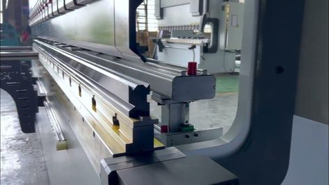
The price of an automatic bending machine can vary significantly based on factors such as the machine’s size, capabilities, brand, and the type of materials it is designed to handle. Below is a general breakdown of the pricing structure:
- Entry-Level Automatic Bending Machines:
- These machines are typically used for smaller-scale operations and lighter materials like aluminum and thin steel.
- Price Range: Around $10,000 to $30,000.
- These machines offer basic automation features, such as CNC controls, but may not have the advanced capabilities found in higher-end models.
- Mid-Range Automatic Bending Machines:
- These machines are suitable for medium-scale operations, capable of handling a variety of materials such as mild steel, stainless steel, and aluminum.
- They come with advanced CNC controls, servo motors, and more flexible configurations.
- Price Range: Around $30,000 to $70,000.
- These machines often feature higher precision, better control over bending parameters, and faster production speeds.
- High-End Automatic Bending Machines:
- These machines are designed for heavy-duty applications, including high-precision, high-speed bending of thick steel plates, titanium, and other demanding materials.
- They come with sophisticated features such as AI integration, robotic automation, advanced simulation software, and multi-axis control.
- Price Range: Around $70,000 to $150,000+.
- These machines are capable of handling complex geometries and high volumes, providing top-notch precision and efficiency for industrial-scale operations.
- Specialty and Custom Bending Machines:
- Custom-built machines designed for very specific bending needs, such as those for aerospace, automotive, or medical industries, can be significantly more expensive due to their tailored design and additional features.
- Price Range: $150,000 and above.
Additional Factors Affecting Price:
- Machine Capacity: Larger machines with higher tonnage and the ability to handle thicker materials tend to be more expensive.
- Automation Features: The level of automation, such as robotic loading/unloading, automated tool changing, or CNC integration, adds to the price.
- Brand and Warranty: Well-known, reputable brands with strong service networks may come at a premium.
- Customization and Special Tools: Custom machines or machines with specialized tooling (e.g., for specific types of bends or materials) will increase costs.
Operational Costs:
- In addition to the upfront price, there are ongoing operational costs such as maintenance, energy consumption, and tooling replacement.
If you’re considering purchasing an automatic bending machine, it’s important to assess your specific needs, including the types of materials you plan to work with, the scale of your production, and your desired level of automation. This will help determine the right model and price point for your business.
The price of an automatic bending machine can vary widely based on factors like machine size, capabilities, brand, and material compatibility. For entry-level automatic bending machines, which are typically used for smaller-scale operations and lighter materials like aluminum and thin steel, prices generally range from $10,000 to $30,000. These machines usually feature basic automation such as CNC controls but might lack the advanced features seen in more expensive models.
For mid-range automatic bending machines, which are suitable for medium-scale operations and a wider range of materials like mild steel, stainless steel, and aluminum, the price typically falls between $30,000 and $70,000. These models usually come equipped with more advanced CNC controls, servo motors, and enhanced flexibility, providing higher precision and faster production speeds.
High-end automatic bending machines, designed for heavy-duty applications and capable of handling thicker materials such as thick steel plates and titanium, are priced between $70,000 and $150,000 or more. These machines offer sophisticated features like AI integration, robotic automation, multi-axis control, and advanced simulation software, enabling them to handle complex geometries and high-volume production with top-tier precision.
Specialty and custom-built bending machines, which are tailored for specific industries like aerospace, automotive, or medical applications, can cost $150,000 or more. These machines are designed to meet the unique requirements of high-precision, high-demand tasks and often come with advanced, customized features.
Several factors influence the price beyond the machine’s base cost, including machine capacity, the level of automation (e.g., robotic loading/unloading, automated tool changing), and the reputation of the brand. Larger machines capable of handling thicker materials tend to be more expensive, as do models with high levels of automation and customization. Well-known brands with strong service networks may charge a premium for their reliability and after-sales support.
In addition to the purchase price, operational costs such as maintenance, energy consumption, and tooling replacement should also be considered. When purchasing an automatic bending machine, it’s essential to assess specific needs, such as material types, production scale, and desired automation level, to ensure the right machine is selected for the job. This will help in determining both the upfront investment and the ongoing operational costs for your business.
As the demand for customization and precision in sheet metal fabrication continues to grow, automatic bending machines are increasingly seen as essential tools for manufacturing industries. The increasing complexity of designs and the need for high-quality, consistent results at scale have driven many manufacturers to upgrade from manual or semi-automatic systems to fully automatic machines. These machines not only increase efficiency but also significantly reduce human error, improving the overall quality of the final product. For businesses that need to produce a high volume of parts with tight tolerances, automatic bending machines offer a considerable advantage.
Another key factor in the growing popularity of automatic bending machines is their ability to handle a wide range of materials. Today’s advanced systems are capable of bending not only common metals like steel, aluminum, and stainless steel, but also more specialized materials such as titanium and copper alloys. The flexibility to work with different material types and thicknesses makes these machines highly versatile and adaptable to various industries, from automotive and aerospace to electronics and construction.
The integration of advanced CNC technology and servo motors allows these machines to handle complex bends with high precision and at faster speeds than traditional bending methods. CNC controls offer the ability to automate the entire bending process, from programming to execution, which greatly improves both speed and repeatability. For industries that rely on large runs of identical parts, such as those producing components for mass-produced consumer goods or automotive parts, this high level of automation can help reduce production costs and labor requirements.
Automatic bending machines are also becoming more energy-efficient, as compared to their hydraulic counterparts. While hydraulic systems are known for their power, they can consume a lot of energy and require regular maintenance due to the need for hydraulic fluid. In contrast, electric-driven bending machines offer a more sustainable solution by consuming less energy and requiring minimal maintenance. This helps businesses reduce operational costs while simultaneously lowering their carbon footprint. The energy efficiency of electric machines makes them a more attractive choice for companies focused on green manufacturing practices and reducing overall energy consumption.
Another driving force behind the adoption of automatic bending machines is the trend toward smart manufacturing. These machines can be equipped with advanced IoT (Internet of Things) capabilities, allowing them to connect to cloud-based platforms. This enables real-time monitoring, data collection, and analysis, which can be used to improve machine performance, predict potential issues, and optimize production schedules. By collecting and analyzing operational data, manufacturers can identify inefficiencies in the process and make adjustments to improve throughput, reduce downtime, and maximize productivity.
With the integration of artificial intelligence (AI) and machine learning (ML), automatic bending machines can further enhance performance by learning from past production runs. These systems can make automatic adjustments to the machine settings based on variables such as material properties, machine wear, and environmental conditions. This level of automation allows businesses to streamline their operations even further, reducing the need for manual intervention and improving production consistency.
For manufacturers, particularly those in industries like aerospace or medical device manufacturing, where part quality and precision are critical, the ability to program specific bending sequences is a key advantage. The precision offered by automatic bending machines ensures that even highly complex components can be produced with exacting standards. For example, parts used in the aerospace industry often require multiple bends at varying angles, and these complex geometries can be achieved with ease through the advanced features found in automatic bending machines.
Customization remains a crucial element in many industries, and automatic bending machines excel in producing parts for low-volume, high-mix production runs. Their ability to be easily reprogrammed to accommodate different part designs and specifications allows manufacturers to offer highly customized products without the need for significant setup changes. This capability is particularly valuable in industries like furniture, architecture, and signage, where custom orders are frequent.
Beyond operational efficiency, automatic bending machines contribute to a more streamlined workflow in the production process. Automated material handling systems can be integrated with the bending machine to load and unload materials, significantly reducing manual labor and the time spent on each part. These machines can also be paired with quality control systems that automatically inspect the bent parts for defects or dimensional errors, ensuring that only accurately bent components make it to the next stage of production. This built-in quality assurance minimizes the need for rework, reducing material waste and improving overall productivity.
Despite the higher upfront investment compared to manual machines, the cost-effectiveness of automatic bending machines becomes clear over time due to the reduced labor costs, increased production speed, and lower material waste. Many businesses find that the long-term benefits of investing in an automatic bending machine far outweigh the initial purchase cost. By increasing production throughput, maintaining consistent quality, and reducing overall operational costs, these machines offer a solid return on investment for companies that rely on high-precision sheet metal bending.
In conclusion, automatic bending machines are a powerful tool for modern manufacturers looking to improve their production efficiency, accuracy, and flexibility. With advancements in automation, AI, IoT, and energy efficiency, these machines are increasingly capable of handling a wide range of materials, complex geometries, and varying production volumes. As industries continue to push for higher-quality, more customized products at faster production rates, automatic bending machines will remain central to achieving these goals, providing companies with the competitive edge they need in an increasingly demanding marketplace.
As industries move toward more advanced production capabilities and seek greater levels of automation, the future of automatic bending machines looks poised for significant innovation. One of the most exciting developments is the incorporation of robotic automation to further streamline the bending process. By integrating robotic arms with bending machines, manufacturers can achieve fully automated workflows, where robots handle the loading, unloading, and sometimes even the bending process itself. This integration can increase the overall speed and efficiency of operations, particularly in high-demand industries like automotive, electronics, and appliance manufacturing, where mass production often requires rapid turnaround times and high precision.
In these automated systems, robots can quickly adjust to handle different types of metal sheets and sizes, making them highly flexible. The synergy between robotics and automatic bending machines can also reduce labor costs and the risks associated with human errors, ensuring that the production line runs smoothly and consistently. Furthermore, automated systems with integrated robotics can work around the clock, increasing production capacity and helping companies meet stringent delivery deadlines.
A significant area of development for future bending machines is adaptive bending technology. This technology uses sensors and real-time feedback to adjust the machine’s settings on the fly based on the material being bent. For instance, if the machine detects that the material thickness or tensile strength has changed, it can immediately adjust the bending force or angle to accommodate the new material properties. This type of intelligent system ensures more accurate bends, especially when working with a variety of materials and thicknesses, thus reducing the need for manual adjustments and improving overall process reliability.
The integration of digital twins—virtual replicas of physical assets—into automatic bending machines is another key innovation on the horizon. By using real-time data from the machine, a digital twin can simulate the performance of the bending machine under various conditions. This virtual model allows manufacturers to conduct thorough testing and analysis without the need for physical trials, which helps to identify potential inefficiencies or failures before they occur on the production floor. Digital twins also enable predictive maintenance, helping operators anticipate when components are likely to fail, reducing downtime and increasing the machine’s operational lifespan.
Moreover, cloud-based systems will continue to play a crucial role in optimizing automatic bending machines. By connecting machines to the cloud, manufacturers can remotely monitor machine performance, track key metrics, and receive real-time alerts for maintenance needs or performance issues. This allows companies to streamline their maintenance schedules and optimize machine uptime, reducing operational interruptions and improving overall production efficiency. Cloud technology can also facilitate data sharing between different machines and locations, enabling better coordination in large-scale production environments and multi-factory operations.
Incorporating augmented reality (AR) and virtual reality (VR) into machine operation and training is another exciting possibility. AR can provide real-time guidance to machine operators by overlaying digital instructions or warnings onto the physical machine, helping operators troubleshoot or optimize machine settings without needing to refer to paper manuals or external sources. VR could be used for immersive training simulations, allowing new operators to learn the ropes of machine operation in a risk-free environment, which can improve safety and reduce training time.
Looking further into the future, advanced material processing capabilities will become a key differentiator in automatic bending machines. As new materials such as lightweight composites, advanced alloys, and carbon fiber continue to gain popularity in industries like aerospace and automotive, bending machines will need to adapt to handle these specialized materials. These materials often require different processing techniques and bending strategies due to their unique properties. Future automatic bending machines will likely come equipped with the flexibility to accommodate these advanced materials while still maintaining the high precision that modern manufacturing demands.
Customization will also continue to be a driving force in the evolution of automatic bending machines. With the increasing need for short-run production and bespoke parts, bending machines will need to become even more adaptable. Machines will likely be equipped with enhanced features for quick changeovers, allowing manufacturers to easily adjust tooling or settings to accommodate different part designs. Additionally, more advanced user interfaces could allow operators to intuitively create and modify bending programs on the fly, further reducing downtime and improving operational efficiency.
In terms of sustainability, automatic bending machines are expected to incorporate even more energy-saving features. As companies strive to meet stricter environmental regulations, machines with lower power consumption and reduced material waste will become increasingly desirable. Future models might include innovations like regenerative braking systems that capture energy during the bending process and reuse it, or intelligent power management systems that optimize energy use based on production demand. These sustainability features will not only help companies reduce their carbon footprint but also cut operational costs over time.
Moreover, laser-assisted bending technology, which utilizes lasers to heat the metal before bending, could be integrated into automatic bending machines. This technique can help reduce the required force to bend certain materials, improving accuracy and expanding the range of materials the machine can process. Laser-assisted bending can also minimize the risk of material deformation and reduce the wear on tooling, leading to improved part quality and lower maintenance costs.
Finally, the globalization of manufacturing will continue to influence the development of automatic bending machines. As companies strive to remain competitive in the global marketplace, they will increasingly demand machines that can be easily integrated into multinational supply chains. Future automatic bending machines may feature advanced networking capabilities, allowing them to communicate seamlessly with other machines, inventory systems, and production lines, regardless of location. This interconnectedness will enable companies to create more efficient supply chains and optimize production in real time, enhancing both responsiveness and scalability.
In conclusion, the future of automatic bending machines is marked by increased automation, intelligent feedback systems, integration with smart technologies like AI and IoT, and the development of new materials and techniques. These innovations will drive the efficiency, flexibility, and precision needed to meet the ever-growing demands of modern manufacturing. As industries push for faster production, higher-quality products, and greater sustainability, automatic bending machines will continue to evolve and remain an indispensable part of the manufacturing landscape. Their continued advancement will provide companies with the tools to remain competitive and innovative in a rapidly changing global marketplace.
CNC Sheet Bending Machine
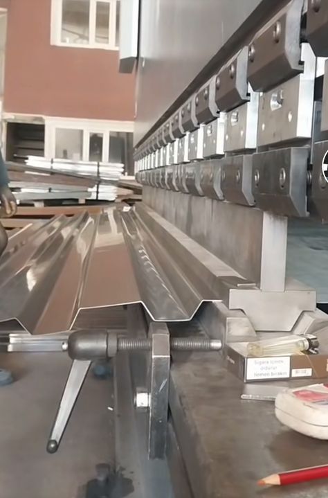
A CNC sheet bending machine is a highly automated, computer-controlled device used to bend sheet metal with precision and efficiency. CNC stands for Computer Numerical Control, which means the machine is operated by a computer program that controls the bending process based on specific parameters such as angle, length, and material type. These machines are ideal for industries that require high-precision bends on a variety of materials, such as stainless steel, aluminum, and mild steel.
The key advantage of using a CNC sheet bending machine is its ability to perform complex bends with high accuracy and repeatability, making it ideal for mass production or high-precision tasks. The machine is equipped with a CNC control system that allows the user to input bending programs, specifying parameters like bend angle, bend sequence, and material thickness. The machine then uses this information to execute the bending process automatically, minimizing human error and improving overall production efficiency.
CNC sheet bending machines can handle a variety of bends, including V-bends, U-bends, and radius bends. They are also capable of bending sheet metal to tight tolerances, which is crucial for industries such as automotive, aerospace, and electronics, where parts must meet strict quality standards. The ability to program the machine to perform precise bends at specific intervals without manual intervention is particularly beneficial for applications that require consistency across large production runs.
These machines come in a variety of sizes, with varying tonnage and bend length capabilities. Some CNC sheet bending machines are capable of bending thick materials with higher tonnage capacities, while others are designed for more delicate operations on thinner metals. The machine’s press brake—the tool that applies force to the material—is often equipped with a dies set that can be easily changed to accommodate different bending requirements.
In addition to basic bending, many CNC sheet bending machines are equipped with advanced features such as automatic backgauges, which help to position the material with high precision, and programmable clamping systems, which ensure that the material is held firmly during the bending process. These features enhance the machine’s ability to work efficiently and accurately across a wide range of parts.
Benefits of CNC Sheet Bending Machines include:
- Precision and Consistency: CNC machines provide highly accurate and repeatable bends, which ensures that parts meet the required specifications.
- Increased Productivity: Automated programming allows for faster production speeds, reducing cycle times and the need for manual intervention.
- Flexibility: CNC sheet bending machines can handle a variety of materials and part designs, making them versatile for different industries.
- Cost Efficiency: While the initial cost of a CNC sheet bending machine may be higher than manual machines, the savings in labor and improved production efficiency over time often make the investment worthwhile.
- Advanced Features: The integration of real-time monitoring systems, automated material handling, and data-driven adjustments ensures optimal machine performance and reduces the likelihood of errors.
These machines are commonly used in industries that demand high-quality, high-volume production, such as sheet metal fabrication, electronic enclosures, furniture manufacturing, construction, and signage production. In addition to bending sheet metal, some CNC sheet bending machines are also capable of performing additional functions, such as punching or cutting, to further streamline the production process.
As manufacturing demands evolve, modern CNC sheet bending machines are incorporating smart technology, allowing for greater automation and integration with industry 4.0 standards. Features such as predictive maintenance, real-time data collection, and cloud-based performance monitoring are becoming increasingly common. These technologies enhance the machine’s ability to optimize production processes, reduce downtime, and improve overall machine efficiency.
In conclusion, CNC sheet bending machines offer a highly automated, precise, and efficient solution for sheet metal bending, making them indispensable for industries that require high-quality and high-precision bent parts. As automation and technology continue to evolve, these machines will only become more advanced, further driving improvements in productivity, cost-effectiveness, and flexibility for manufacturers across a range of industries.
CNC sheet bending machines are pivotal in industries that require precision and efficiency in bending sheet metal. With their computer-controlled systems, these machines allow manufacturers to input detailed specifications like bend angles, material thickness, and length, ensuring that each part meets exact requirements. The computer programming eliminates much of the variability associated with manual bending, which can lead to errors, and ensures consistent, high-quality output even in large-scale production runs.
A CNC sheet bending machine typically operates using a press brake, which applies force to the material, bending it according to the programmed parameters. The press brake is equipped with a die set that can be easily swapped out to handle different types of bends, such as V-bends, U-bends, and others. These machines can handle materials of varying thickness and strength, from thin sheets of aluminum to thicker steel, making them versatile across different industries. Many machines include features like automatic backgauges, which help in positioning the material precisely, ensuring that every bend is exactly where it should be. The programmable clamping system further helps by securing the metal firmly in place while the bending process takes place, reducing the likelihood of deformation.
CNC sheet bending machines also offer the benefit of faster cycle times compared to manual systems. Once the program is set, the machine can continuously execute bending operations without the need for constant human oversight. This increases production efficiency, especially in environments where large volumes of parts need to be bent with uniformity. The machines can also be programmed for multiple bend sequences, which is particularly useful when working with complex geometries or intricate part designs.
While the initial investment in a CNC sheet bending machine can be higher than that of manual or semi-automatic machines, the long-term benefits often justify the cost. The precision, speed, and consistency these machines offer can significantly reduce labor costs and increase throughput. Additionally, the ability to produce high-precision parts with little to no rework required reduces material waste, making CNC machines a cost-effective solution for many manufacturing processes.
Another key advantage of CNC sheet bending machines is their ability to easily adapt to different projects and materials. This flexibility is essential in industries where production runs vary in size and design, and manufacturers need to be able to switch quickly between different tasks. Whether it’s for prototyping, short-run production, or mass manufacturing, these machines can be programmed to accommodate a wide variety of part designs, material types, and bending requirements, without the need for frequent tooling changes or lengthy setup times.
The trend toward smart manufacturing and Industry 4.0 has led to further advancements in CNC sheet bending machines. These machines are increasingly integrated with technologies like Internet of Things (IoT) and cloud-based monitoring systems. This allows manufacturers to remotely monitor machine performance, track real-time production data, and even adjust parameters to optimize the bending process. Predictive maintenance features are becoming more common as well, where the system can alert operators about potential issues before they lead to machine failure, helping to minimize downtime and extend the lifespan of the equipment.
As the demand for sustainability increases, newer models of CNC sheet bending machines are designed to be more energy-efficient. Electric-powered machines, as opposed to hydraulic ones, typically consume less energy and require less maintenance. They also offer a more environmentally friendly option for manufacturers concerned with reducing their carbon footprint. Additionally, some modern CNC sheet bending machines are equipped with technologies that help minimize material waste during the bending process. By precisely controlling the amount of force applied and optimizing the bending process, these machines ensure that materials are used efficiently, and parts are produced with minimal scrap.
The ability of CNC sheet bending machines to handle more complex and precise bending tasks also positions them well for industries that demand higher standards of quality, such as aerospace, automotive, and medical equipment manufacturing. These industries often require parts with very tight tolerances and specific material properties, and CNC machines provide the precision necessary to meet those demands. Parts for aircraft, for example, often require complex bends and high strength-to-weight ratios, making CNC bending machines an ideal solution. Similarly, medical devices often require metal parts with precise geometries that must adhere to strict regulatory standards, where CNC bending machines can provide the necessary accuracy.
CNC sheet bending machines can also be an essential tool for rapid prototyping. Their ability to quickly adjust to new designs and bend parts according to precise specifications allows manufacturers to produce prototypes in less time compared to traditional methods. This is especially important in industries where time to market is critical, such as in consumer electronics or fashion, where designs may need to be adjusted quickly based on feedback or market trends.
In conclusion, CNC sheet bending machines are indispensable in modern manufacturing for their precision, efficiency, and versatility. They cater to a wide range of industries by providing automated solutions for bending sheet metal with high accuracy, which not only improves product quality but also optimizes production processes. As technology advances and the manufacturing landscape continues to evolve, CNC sheet bending machines will play an increasingly important role in driving the future of industrial fabrication, contributing to improved productivity, reduced operational costs, and better quality control.
As CNC sheet bending machines continue to evolve, there are several trends and innovations that are shaping their future in the manufacturing landscape. One significant development is the integration of artificial intelligence (AI) and machine learning (ML) algorithms. These technologies allow the machines to learn from past production runs and make real-time adjustments to the bending process. For example, if a machine detects slight deviations in material properties or bending behavior during production, AI can analyze this data and modify the machine’s settings to maintain optimal performance. This makes the machines even more adaptable to changes in material quality or other factors, further reducing errors and enhancing the overall efficiency of the process.
Another area of growth for CNC sheet bending machines is the increased automation of ancillary processes, such as material handling and part inspection. Automated systems for loading and unloading sheet metal into the machine are becoming more common, which reduces the need for manual labor and speeds up production cycles. These systems can be integrated with the bending machines to create a fully automated production line, capable of handling everything from material loading to part inspection without human intervention. This level of automation can lead to substantial cost savings and improved throughput, especially in industries where high-volume production is a key requirement.
To enhance flexibility and improve efficiency further, some newer models of CNC sheet bending machines are being equipped with multi-tool stations. This allows the machine to switch between different types of tooling automatically during the bending process. For instance, the machine could use different dies for various bends, allowing it to perform multiple bending operations without needing to stop and change tooling manually. This is particularly advantageous for manufacturers that need to produce a variety of part designs quickly, without significant downtime between setups.
In addition, CNC sheet bending machines are increasingly becoming more user-friendly thanks to advancements in their interface systems. Modern CNC machines feature touchscreen displays with intuitive graphical interfaces, making it easier for operators to input and adjust bending parameters. Operators can visualize bending sequences in real-time, previewing how the material will bend before the process even starts. This can reduce setup times and errors, especially for less experienced operators, as the machine provides step-by-step guidance throughout the operation.
Another noteworthy development is the integration of real-time data analytics and cloud-based monitoring. This enables manufacturers to monitor their CNC sheet bending machines remotely, track machine performance, and gather data on machine usage. By analyzing this data, manufacturers can identify patterns that indicate areas for improvement, such as bottlenecks in production or underperforming machines. This information can be used to optimize production schedules, prevent downtime, and extend the life of the machine by scheduling preventive maintenance before breakdowns occur.
As smart technology continues to advance, CNC sheet bending machines will likely incorporate more sensor-based technologies. These sensors can detect factors like material temperature, humidity, or even vibration during the bending process, allowing the machine to make real-time adjustments based on these environmental conditions. This level of sensing and feedback could further enhance the precision and accuracy of the machine, especially when dealing with materials that are sensitive to environmental factors, like thin aluminum or high-tensile steels.
Sustainability is also a growing concern in the design of CNC sheet bending machines. As manufacturers increasingly focus on green manufacturing practices, there is a push for machines that not only offer energy efficiency but also minimize waste. Advanced CNC machines are now equipped with energy-saving features, such as variable frequency drives (VFDs), which adjust the motor speed based on the load to reduce energy consumption. Additionally, some machines incorporate recycling systems that capture heat generated during operation and convert it into usable energy, further reducing operational costs.
The rise of customized products and short-run manufacturing also contributes to the increased demand for CNC sheet bending machines. As industries move away from large, standardized production runs and focus on more personalized, small-batch production, CNC machines that can handle quick changeovers and flexible part designs are more in demand than ever. The ability to easily switch between part designs and material types without lengthy setups makes CNC sheet bending machines the ideal choice for companies that need to stay competitive in an environment where demand for customization is on the rise.
In the coming years, the incorporation of augmented reality (AR) and virtual reality (VR) technologies could also further enhance the functionality of CNC sheet bending machines. For instance, AR could be used to overlay real-time bending instructions onto the machine, guiding the operator through the process and ensuring accuracy. VR might be used for training purposes, allowing new operators to practice using the machine in a virtual environment before working with the actual equipment. This could help companies reduce training time and improve operator proficiency, resulting in better overall machine utilization.
With the increasing complexity of manufacturing processes and the demand for higher precision, CNC sheet bending machines will continue to evolve to meet these challenges. The future of these machines is closely tied to innovations in automation, AI, data analytics, and sustainability, all of which will contribute to improved performance, cost-effectiveness, and environmental responsibility. As these technologies become more integrated, CNC sheet bending machines will continue to play a central role in shaping the future of modern manufacturing, offering manufacturers the tools they need to stay ahead in a highly competitive global market.
Looking further ahead, robotic integration with CNC sheet bending machines is becoming an increasingly promising trend. Robotic arms can be used in conjunction with these machines for tasks like material handling, loading, unloading, and even positioning parts. This robotic synergy helps reduce manual labor, increases the speed of production, and improves safety by eliminating the need for human operators to interact directly with large, heavy sheets of metal. Automated material loading and unloading also ensure that production can continue without interruption, even during off-hours or overnight, maximizing machine uptime and throughput.
Another potential advancement is the development of advanced material handling systems. With the push toward more automated processes, future CNC sheet bending machines may incorporate intelligent material handling features that automatically adjust to different sheet sizes and weights. These systems could use vision systems to detect the dimensions and thickness of incoming materials, adjusting the machine settings accordingly, which would help avoid human error during setup and increase the overall flexibility of the machine. This intelligent handling of materials ensures that production can proceed with minimal intervention, reducing setup time and human labor while boosting overall efficiency.
The integration of multi-axis bending capabilities into CNC sheet bending machines is another exciting direction for future advancements. While many CNC machines today use two-axis systems (where the metal is bent using two linear motions), multi-axis systems would enable more complex, curved, and three-dimensional bending. This allows for even greater flexibility in manufacturing, as parts with intricate geometries can be bent with high precision and fewer steps. Such systems would be beneficial in industries like aerospace, automotive, and medical device manufacturing, where parts often have complex shapes and require multiple bends in different directions.
Moreover, laser bending technology is expected to become more prevalent in CNC machines in the future. Laser-assisted bending uses a laser to heat the material before bending it, making it easier to achieve complex shapes with minimal deformation or material stress. This method significantly reduces the need for high-force bending, which can be particularly beneficial when working with high-strength or sensitive materials. The incorporation of laser bending into CNC machines could extend the range of materials they can handle and increase the overall precision of the process, particularly for metals with high tensile strength, such as titanium or advanced alloys used in aerospace and medical industries.
The concept of intelligent machine learning will also further develop, with CNC machines becoming smarter and more capable of making adjustments on the fly based on real-time production data. This includes predictive analysis for material behavior during bending, adjusting for temperature variations, and adapting to material inconsistencies without requiring manual input. The machine’s control system could become so sophisticated that it predicts how certain materials will respond to different bending processes, adjusting parameters instantly to avoid defects such as warping or cracking. This self-learning capability could revolutionize the way sheet metal is bent and dramatically reduce trial and error during the production process.
In terms of sustainability, the future of CNC sheet bending machines may include a more aggressive focus on closed-loop manufacturing systems. These systems will be designed to reduce waste at every stage of production by automatically recycling scrap metal or using it in other processes. For instance, after the bending operation, any leftover material or scrap could be automatically fed into another machine that reuses the metal for different applications. Additionally, with increased emphasis on eco-friendly designs, more CNC sheet bending machines will be optimized for energy efficiency, using low-energy actuators, regenerative systems, and even solar-powered components, aligning with global trends toward sustainable manufacturing practices.
As digital technologies continue to evolve, the use of cloud-based systems will likely become even more widespread in the operation of CNC sheet bending machines. With cloud integration, machine operators can monitor and control the bending process remotely from any location, allowing for greater flexibility and centralized control across multiple machines or factories. This would also allow for better collaboration between design teams, production teams, and engineers by offering real-time data access to improve workflows, optimize machine settings, and streamline communication across departments.
Increased integration with enterprise resource planning (ERP) systems will help CNC machines better integrate into broader factory workflows. ERP software is designed to track and manage resources, production schedules, and inventory in real-time. By connecting CNC machines directly with ERP systems, manufacturers can have a more seamless operation, where data from the machine is automatically fed into inventory management, production planning, and even supply chain systems. This integration ensures that parts are produced on time and in the right quantities, with a clear picture of how each machine is performing in the context of overall production goals.
Another notable trend in the future of CNC sheet bending machines is the use of collaborative robots (cobots). Cobots are designed to work alongside human operators in a shared workspace, rather than replacing them entirely. These robots are particularly useful in small and medium-sized operations where automation might not have been cost-effective before. Cobots could work in tandem with CNC machines to assist with tasks such as holding sheets in place during the bending process, reducing the need for workers to manually handle heavy materials, and allowing operators to focus on other tasks. This collaboration between humans and machines can enhance efficiency and safety without requiring significant investment in large-scale robotic systems.
As manufacturing becomes more globalized, CNC sheet bending machines are also likely to become more standardized and adaptable across different regions and industries. Manufacturers may be able to program the same machine to accommodate a variety of materials and design standards, making it easier to shift production across different geographic locations while maintaining consistency in product quality. The ability to easily replicate a production setup in multiple locations also enhances flexibility for global supply chains, enabling manufacturers to meet demand fluctuations and regional requirements more efficiently.
In conclusion, the future of CNC sheet bending machines is marked by increased automation, advanced technologies, and smart manufacturing systems that provide manufacturers with greater efficiency, flexibility, and precision. These machines are evolving into highly intelligent systems capable of adapting to real-time changes in production, offering sustainability features that reduce waste, and providing greater integration with broader manufacturing processes. As technological advancements continue to emerge, CNC sheet bending machines will remain at the forefront of the manufacturing industry, driving innovation and helping companies meet the increasing demand for high-quality, customized products in a global market.
EMS Metalworking Machinery
We design, manufacture and assembly metalworking machinery such as:
- Hydraulic transfer press
- Glass mosaic press
- Hydraulic deep drawing press
- Casting press
- Hydraulic cold forming press
- Hydroforming press
- Composite press
- Silicone rubber moulding press
- Brake pad press
- Melamine press
- SMC & BMC Press
- Labrotaroy press
- Edge cutting trimming machine
- Edge curling machine
- Trimming beading machine
- Trimming joggling machine
- Cookware production line
- Pipe bending machine
- Profile bending machine
- Bandsaw for metal
- Cylindrical welding machine
- Horizontal pres and cookware
- Kitchenware, hotelware
- Bakeware and cuttlery production machinery
as a complete line as well as an individual machine such as:
- Edge cutting trimming beading machines
- Polishing and grinding machines for pot and pans
- Hydraulic drawing presses
- Circle blanking machines
- Riveting machine
- Hole punching machines
- Press feeding machine
You can check our machinery at work at: EMS Metalworking Machinery – YouTube
Applications:
- Beading and ribbing
- Flanging
- Trimming
- Curling
- Lock-seaming
- Ribbing
- Flange-punching