
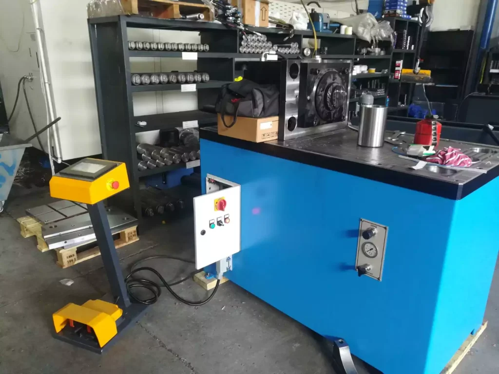
We manufacture the Small Horizontal Hydraulic Press for Sale to cut, trim, and curl the edges of round parts. The Circular End Head Joggling Machines are used in various metalworking industries.
Horizontal hydraulic presses are versatile and powerful machines that utilize hydraulic pressure to apply force horizontally to a workpiece. They are commonly used in a wide range of industries, including metalworking, manufacturing, and construction, for various applications such as bending, straightening, pressing, and forming.
Key Components of Horizontal Hydraulic Presses
- Frame: The sturdy frame provides the structural support for the press, ensuring stability and rigidity during operation.
- Hydraulic Cylinder: The hydraulic cylinder is the heart of the press, converting hydraulic pressure into mechanical force. It consists of a piston, cylinder barrel, and hydraulic seals.
- Hydraulic Pump and Power Unit: The hydraulic pump and power unit supply hydraulic fluid to the cylinder, generating the required pressure for operation.
- Control System: The control system regulates the hydraulic pressure, ram speed, and press operation, ensuring precise and controlled movement.
- Work Table or Bed: The work table or bed provides a stable surface for the workpiece and facilitates alignment during the pressing process.
- Tooling: Various tooling options are available, including dies, punches, and adapters, to accommodate different workpiece shapes and applications.
Types of Horizontal Hydraulic Presses
- Single-acting Presses: These presses have a single hydraulic cylinder that applies force in one direction. They are suitable for simple bending and straightening operations.
- Double-acting Presses: These presses have two hydraulic cylinders, allowing for force application in both directions. They are more versatile and can handle a wider range of pressing operations.
- Four-column Presses: These presses feature four columns that provide exceptional stability and rigidity, making them suitable for heavy-duty applications.
- C-frame Presses: These presses have a C-shaped frame, offering a more compact design and suitable for smaller workpieces.
Applications of Horizontal Hydraulic Presses
- Metalworking: Bending, straightening, forming, and coining of metal components for manufacturing.
- Construction: Pressing and forming of sheet metal components for construction applications, such as roofing, cladding, and structural elements.
- Automotive Industry: Forming of automotive components, such as body panels, brackets, and structural parts.
- Aerospace Industry: Precision forming of aerospace components, ensuring high strength, dimensional accuracy, and structural integrity.
- Industrial Applications: Pressing and forming of various components for industrial machinery, equipment, and tools.
Safety Considerations for Horizontal Hydraulic Press Operation
- Wear appropriate personal protective equipment (PPE), including safety glasses, gloves, and hearing protection.
- Ensure proper machine setup and maintenance, following the manufacturer’s instructions.
- Secure the workpiece firmly on the work table before operation.
- Avoid distractions while operating the press.
- Never operate the press with damaged components or under unsafe conditions.
- Receive proper training and supervision before operating the press.
- Be aware of potential hazards, such as pinch points, moving parts, and high-pressure hydraulic fluid.
- Never operate the press under the influence of alcohol or drugs.
- Report any malfunctions or safety concerns to the appropriate personnel immediately.
Horizontal hydraulic presses are versatile and powerful tools that play a significant role in various industries. By following safety guidelines and using appropriate techniques, operators can safely and effectively utilize these machines to produce high-quality components for a wide range of applications.
Horizontal Hydraulic Press
The horizontal hydraulic press machine can bend sheet metal parts up to 5 mm sheet thickness. The parts’ materials can be mild steel, stainless steel, aluminum, copper tin, and brass.
As sheet metal parts, you can bend metal pipes as well on our horizontal press machines
A horizontal hydraulic press is a versatile and powerful machine that utilizes hydraulic pressure to apply force horizontally to a workpiece. It is commonly used in various industries, including metalworking, manufacturing, and construction, for a wide range of applications such as bending, straightening, pressing, and forming.
Key Components of a Horizontal Hydraulic Press
- Frame: The sturdy frame provides the structural support for the press, ensuring stability and rigidity during operation.
- Hydraulic Cylinder: The hydraulic cylinder is the heart of the press, converting hydraulic pressure into mechanical force. It consists of a piston, cylinder barrel, and hydraulic seals.
- Hydraulic Pump and Power Unit: The hydraulic pump and power unit supply hydraulic fluid to the cylinder, generating the required pressure for operation.
- Control System: The control system regulates the hydraulic pressure, ram speed, and press operation, ensuring precise and controlled movement.
- Work Table or Bed: The work table or bed provides a stable surface for the workpiece and facilitates alignment during the pressing process.
- Tooling: Various tooling options are available, including dies, punches, and adapters, to accommodate different workpiece shapes and applications.
Types of Horizontal Hydraulic Presses
- Single-acting Presses: These presses have a single hydraulic cylinder that applies force in one direction. They are suitable for simple bending and straightening operations.
- Double-acting Presses: These presses have two hydraulic cylinders, allowing for force application in both directions. They are more versatile and can handle a wider range of pressing operations.
- Four-column Presses: These presses feature four columns that provide exceptional stability and rigidity, making them suitable for heavy-duty applications.
- C-frame Presses: These presses have a C-shaped frame, offering a more compact design and suitable for smaller workpieces.
Applications of Horizontal Hydraulic Presses
- Metalworking: Bending, straightening, forming, and coining of metal components for manufacturing.
- Construction: Pressing and forming of sheet metal components for construction applications, such as roofing, cladding, and structural elements.
- Automotive Industry: Forming of automotive components, such as body panels, brackets, and structural parts.
- Aerospace Industry: Precision forming of aerospace components, ensuring high strength, dimensional accuracy, and structural integrity.
- Industrial Applications: Pressing and forming of various components for industrial machinery, equipment, and tools.
Safety Considerations for Horizontal Hydraulic Press Operation
- Wear appropriate personal protective equipment (PPE), including safety glasses, gloves, and hearing protection.
- Ensure proper machine setup and maintenance, following the manufacturer’s instructions.
- Secure the workpiece firmly on the work table before operation.
- Avoid distractions while operating the press.
- Never operate the press with damaged components or under unsafe conditions.
- Receive proper training and supervision before operating the press.
- Be aware of potential hazards, such as pinch points, moving parts, and high-pressure hydraulic fluid.
- Never operate the press under the influence of alcohol or drugs.
- Report any malfunctions or safety concerns to the appropriate personnel immediately.
Horizontal hydraulic presses are versatile and powerful tools that play a significant role in various industries. By following safety guidelines and using appropriate techniques, operators can safely and effectively utilize these machines to produce high-quality components for a wide range of applications.
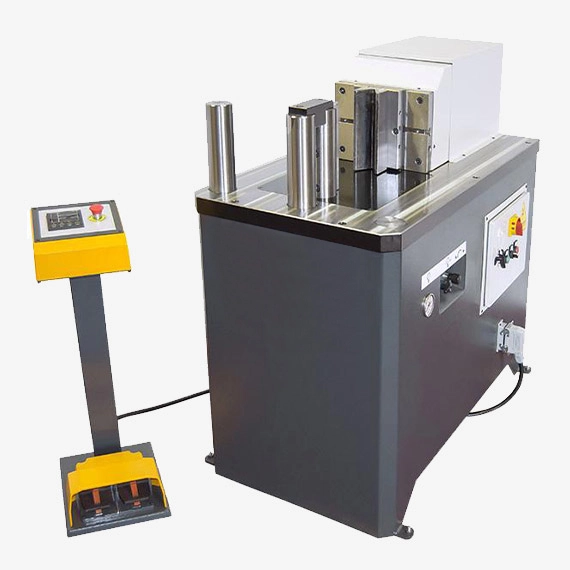
The horizontal hydraulic press is a small press brake machine. The difference between a horizontal press machine and a press brake is that the horizontal press bends the sheet metal parts horizontally and the press brake bends them vertically.
Our industrial horizontal hydraulic press models are as follows:
All the horizontal hydraulic press for sale models operate with a foot pedal. By pressing the foot pedal, the bending tool moves forward and starts to bend the sheet metal between the bending tools.
What is a Horizontal Hydraulic Press?
A horizontal hydraulic press is a powerful machine that utilizes hydraulic pressure to apply force horizontally to a workpiece. It is commonly used in various industries, including metalworking, manufacturing, and construction, for a wide range of applications such as bending, straightening, pressing, and forming.
Key Components of a Horizontal Hydraulic Press
Horizontal hydraulic presses consist of several key components that work together to achieve the desired pressing operation. These components include:
- Frame: The frame provides the structural backbone for the press, ensuring stability and rigidity during operation. It is typically constructed from heavy-duty steel plates or castings and is designed to withstand the high forces generated during pressing operations.
- Hydraulic Cylinder: The hydraulic cylinder is the heart of the press, converting hydraulic pressure into mechanical force. It consists of a piston, cylinder barrel, and hydraulic seals. The size of the cylinder determines the maximum force the press can exert.
- Hydraulic Pump and Power Unit: The hydraulic pump and power unit supply hydraulic fluid to the cylinder, generating the required pressure for operation. The pump draws fluid from a reservoir and forces it through a series of valves and filters into the cylinder. The power unit regulates the pressure and flow of hydraulic fluid.
- Control System: The control system manages the operation of the press, including ram movement, pressure control, and safety interlocks. It receives input from sensors, such as pressure transducers and position encoders, and controls the valves and actuators to regulate the press’s behavior.
- Ram: The ram is the movable part of the press that applies force directly to the workpiece. It is connected to the piston of the hydraulic cylinder and slides along guides within the frame. The ram can be equipped with various tooling, such as dies, punches, or adapters, depending on the specific application.
- Work Table or Bed: The work table or bed provides a stable surface for positioning and securing the workpiece during the pressing operation. It is typically adjustable to accommodate different workpiece sizes and heights.
- Tooling: Tooling is a crucial component of horizontal hydraulic presses, allowing the press to perform various forming operations. Common tooling options include dies, punches, adapters, and forming tools. Dies are used to shape the workpiece, while punches are used to cut or pierce material. Adapters are used to connect different tooling components, and forming tools are used for specific forming operations, such as bending or straightening.
- Safety Interlocks: Safety interlocks are essential components that prevent hazardous situations from occurring during press operation. They typically include sensors that detect the presence of an operator or workpiece, and they prevent the press from activating if safety conditions are not met.
- Gauges and Indicators: Gauges and indicators provide the operator with real-time information about the press’s operation, such as hydraulic pressure, ram position, and press force. This information is crucial for monitoring the press’s performance and ensuring safe operation.
- Electrical System: The electrical system powers the control system, hydraulic pump, and other electrical components of the press. It includes wiring, electrical panels, and various electrical components, such as motors, relays, and switches.
Applications of Horizontal Hydraulic Presses
Horizontal hydraulic presses are versatile machines used for a wide range of applications in various industries. Some common applications include:
- Metalworking: Bending, straightening, forming, and coining of metal components for manufacturing.
- Construction: Pressing and forming of sheet metal components for construction applications, such as roofing, cladding, and structural elements.
- Automotive Industry: Forming of automotive components, such as body panels, brackets, and structural parts.
- Aerospace Industry: Precision forming of aerospace components, ensuring high strength, dimensional accuracy, and structural integrity.
- Industrial Applications: Pressing and forming of various components for industrial machinery, equipment, and tools.
Safety Considerations for Horizontal Hydraulic Press Operation
Safety is paramount when operating horizontal hydraulic presses. Operators must follow strict safety guidelines to prevent accidents and injuries. These guidelines include:
- Wearing appropriate personal protective equipment (PPE), including safety glasses, gloves, and hearing protection.
- Ensuring proper machine setup and maintenance, following the manufacturer’s instructions.
- Securing the workpiece firmly on the work table before operation.
- Avoiding distractions while operating the press.
- Never operating the press with damaged components or under unsafe conditions.
- Receiving proper training and supervision before operating the press.
- Being aware of potential hazards, such as pinch points, moving parts, and high-pressure hydraulic fluid.
- Never operating the press under the influence of alcohol or drugs.
- Reporting any malfunctions or safety concerns to the appropriate personnel immediately.
Horizontal hydraulic presses play a vital role in various industries, enabling the production of high-quality components for a wide range of applications. By following safety guidelines and operating the press responsibly, operators can ensure safe and efficient
A hydraulic press is a device using a hydraulic cylinder to generate a compressive force. It is easy transmissibility of a large amount of energy with practically unlimited force amplification. It has also a very low inertia effect. It uses the hydraulic equivalent of a mechanical lever and was also known as a Bramah press after the inventor, Joseph Bramah, of England.
Press work is a method of mass production involving the cold working of metals, usually in the form of thin sheets or strips. Press working is one of the extensively employed methods of fabricating parts of intricate shapes with thin walls. Press working processes make use of large forces by press tools for a short time interval which results in cutting or shaping the sheet metal.
Since, press working does not involve heating the parts, close tolerances and a high surface finish can be obtained on the part. Since presses can produce components at fairly fast rates, the unit cost of labor for operating the press is fairly low.
Frame:
The frame of a horizontal press serves as the foundational structure that provides stability, support, and rigidity to the entire machine. Its design and construction are paramount to the press’s performance, accuracy, and longevity. Typically made from high-strength materials such as steel or cast iron, the frame undergoes rigorous engineering to withstand the forces generated during pressing operations without deflecting or deforming excessively.
Modern press frames are often fabricated using advanced manufacturing techniques such as welding, forging, or machining to achieve precise geometries and tolerances. They may feature intricate designs with reinforced sections, gussets, and bracing to enhance structural integrity and minimize vibrations. Additionally, the frame’s geometry and configuration are optimized to distribute loads evenly across its members, ensuring uniform stress distribution and preventing localized failures.
The frame houses various components of the press, including the hydraulic system, control panel, ram, and bed. It provides mounting points and interfaces for these components, allowing for easy assembly, maintenance, and servicing. Moreover, the frame’s design may incorporate provisions for adjustable components such as backgauges, tooling supports, and safety features to accommodate different workpiece sizes, shapes, and applications.
In high-performance presses, the frame undergoes thorough testing and validation processes to ensure compliance with industry standards and safety regulations. Finite element analysis (FEA) and other simulation techniques are often employed to optimize the frame’s design for maximum strength, stiffness, and durability while minimizing weight and material usage.
Overall, the frame is a critical component of a horizontal press, providing the structural backbone necessary for reliable and precise metalworking operations. Its robust construction, advanced engineering, and meticulous design contribute to the press’s performance, efficiency, and productivity in various industrial applications.
Bed:
In the realm of horizontal presses, the bed holds paramount significance as the foundational surface upon which the workpiece rests during bending or pressing operations. This flat, sturdy platform is meticulously engineered to provide stability, support, and alignment for the workpiece, ensuring precise and accurate results in metalworking processes.
Constructed from durable materials such as steel or cast iron, the bed undergoes rigorous machining processes to achieve flatness, parallelism, and surface finish within tight tolerances. Its design incorporates features such as T-slots, grooves, or mounting holes to facilitate the secure attachment of tooling, fixtures, and workpiece supports, enabling versatile and efficient operation across a wide range of applications.
The bed’s surface is often hardened, ground, or coated to enhance wear resistance, corrosion resistance, and longevity, particularly in demanding industrial environments. Additionally, it may feature provisions for coolant channels, drainage, or chip evacuation systems to maintain cleanliness and efficiency during metalworking operations.
A key aspect of the bed’s design is its ability to withstand the forces and stresses exerted by the workpiece and the pressing operation without deforming or yielding. To achieve this, the bed’s thickness, cross-section, and material composition are carefully selected and engineered to provide optimal strength, rigidity, and stability under load.
Furthermore, the bed is equipped with precision guides, stops, or backgauges to ensure accurate positioning and alignment of the workpiece during bending or pressing. These features enable repeatability, consistency, and dimensional accuracy in the manufactured parts, crucial for meeting stringent quality standards and specifications.
Safety is also a paramount consideration in bed design, with provisions for guarding, interlocking mechanisms, and emergency stop systems to protect operators from hazards associated with moving parts and high-pressure operations.
In summary, the bed of a horizontal press plays a fundamental role in the metalworking process, providing a stable and reliable foundation for bending, forming, and pressing operations. Its robust construction, precise engineering, and versatile features contribute to the efficiency, accuracy, and safety of the press in diverse industrial applications.
Ram:
At the heart of a horizontal press lies the ram, a pivotal component responsible for applying the necessary force to deform the metal sheet during bending or pressing operations. This dynamic element moves vertically under hydraulic pressure, exerting controlled force onto the workpiece to achieve desired shapes, angles, or configurations.
Constructed from heavy-duty materials such as high-strength steel or alloyed metals, the ram undergoes meticulous machining and surface treatment processes to ensure optimal strength, durability, and precision. Its design is engineered to withstand the immense forces encountered during pressing, bending, or forming tasks without yielding or deforming.
The ram’s movement is facilitated by hydraulic cylinders, which convert hydraulic pressure into linear motion, driving the ram downwards towards the workpiece. These hydraulic cylinders are meticulously calibrated and synchronized to ensure uniform force distribution and consistent results across the entire bending or pressing area.
The ram’s geometry and configuration are tailored to accommodate various tooling setups, including punches, dies, and attachments, enabling a wide range of bending profiles, angles, and shapes to be achieved. Quick-change systems or modular designs may be incorporated to facilitate rapid tooling changes and setup adjustments, enhancing productivity and versatility in metalworking applications.
To ensure precise control and accuracy, the ram is equipped with position feedback sensors or encoders, providing real-time feedback to the press control system. This enables closed-loop control of ram position and force, allowing for precise modulation and adjustment of bending parameters to meet specific part requirements.
Safety features such as overload protection, ram cushioning systems, and emergency stop mechanisms are integrated into the ram design to safeguard operators and equipment from potential hazards associated with high-pressure operations and unexpected events.
In summary, the ram is a critical component of a horizontal press, serving as the primary driver of metal deformation processes. Its robust construction, precise engineering, and advanced features contribute to the press’s efficiency, accuracy, and versatility in a wide range of metalworking applications.
Hydraulic Cylinder:
The hydraulic cylinder is a fundamental component of a horizontal press, serving as the powerhouse that converts hydraulic energy into linear motion to drive the press’s ram. This dynamic element is pivotal in exerting controlled force onto the workpiece during bending, forming, or pressing operations, enabling precise and efficient metalworking processes.
Constructed from high-strength materials such as steel or alloyed metals, hydraulic cylinders undergo rigorous machining, honing, and surface treatment processes to ensure optimal performance, durability, and reliability under high-pressure conditions. The cylinder’s design is engineered to withstand the immense forces encountered during pressing tasks without yielding or deforming, providing consistent and uniform force application across the entire workpiece.
Hydraulic cylinders operate on the principle of Pascal’s law, which states that pressure applied to a confined fluid is transmitted undiminished in all directions. When hydraulic fluid is pressurized and introduced into the cylinder’s chamber, it acts upon the piston, generating linear motion and driving the ram downwards towards the workpiece. The magnitude of force exerted by the hydraulic cylinder is determined by the pressure of the hydraulic fluid and the effective area of the piston.
The cylinder’s geometry, bore diameter, and stroke length are tailored to meet the specific force and displacement requirements of the press, ensuring optimal performance and efficiency in metalworking operations. Additionally, the cylinder may feature advanced sealing systems, such as piston seals, rod seals, and wiper seals, to prevent hydraulic fluid leakage and ensure long-term reliability.
To facilitate precise control and modulation of force and speed, hydraulic cylinders are often equipped with proportional or servo-controlled valves, allowing for accurate adjustment of hydraulic pressure and flow rates. This enables operators to fine-tune bending parameters, such as bend angle, bend radius, and material thickness, to achieve desired part specifications and quality standards.
Safety features such as pressure relief valves, overstroke protection, and cylinder position sensors are integrated into the hydraulic cylinder design to safeguard operators and equipment from potential hazards associated with high-pressure hydraulic systems and excessive loads.
In summary, the hydraulic cylinder is a critical component of a horizontal press, providing the motive force necessary for metalworking processes. Its robust construction, precise engineering, and advanced features contribute to the press’s efficiency, accuracy, and reliability in diverse industrial applications.
Hydraulic Pump:
The hydraulic pump is a vital component of a horizontal press, responsible for generating the hydraulic pressure required to drive the press’s hydraulic system and actuate the hydraulic cylinders. As the heart of the hydraulic system, the pump plays a crucial role in providing the motive force necessary for bending, forming, or pressing operations.
Operating on the principle of fluid mechanics, hydraulic pumps convert mechanical energy into hydraulic energy by displacing hydraulic fluid and increasing its pressure. There are several types of hydraulic pumps commonly used in horizontal presses, including gear pumps, vane pumps, piston pumps, and axial piston pumps. Each type has its unique design, construction, and performance characteristics, suited to specific application requirements.
Gear pumps consist of intermeshing gears housed within a casing, with one gear being the drive gear and the other the driven gear. As the gears rotate, they trap and transport hydraulic fluid from the pump inlet to the outlet, generating hydraulic pressure. Vane pumps utilize rotating vanes or blades mounted on a rotor within a cam ring to displace hydraulic fluid and create pressure. Piston pumps employ reciprocating pistons or plungers to pressurize hydraulic fluid by varying the volume of the pump chamber. Axial piston pumps feature pistons arranged parallel to the drive shaft, which reciprocate axially to displace hydraulic fluid and generate pressure.
The selection of a hydraulic pump depends on factors such as flow rate, pressure rating, efficiency, and cost-effectiveness. High-performance presses may utilize variable displacement pumps, which allow for precise control of hydraulic pressure and flow rates to optimize energy efficiency and productivity.
Hydraulic pumps may be driven by electric motors, internal combustion engines, or other power sources, depending on the application requirements and environmental considerations. Additionally, auxiliary components such as filters, reservoirs, and cooling systems are often integrated into the hydraulic pump assembly to ensure proper fluid filtration, storage, and temperature regulation.
Proper maintenance and servicing of hydraulic pumps are essential to ensure reliable and efficient operation of horizontal presses. This includes regular inspection, lubrication, and replacement of wear parts such as seals, bearings, and hydraulic fluid. Additionally, monitoring hydraulic fluid quality and cleanliness is crucial to prevent contamination and maintain system performance.
In summary, the hydraulic pump is a critical component of a horizontal press, providing the hydraulic pressure necessary for metalworking processes. Its selection, design, and maintenance significantly impact the press’s performance, efficiency, and reliability in various industrial applications.
Hydraulic Motor:
In the realm of horizontal presses, the hydraulic motor serves as a key component responsible for converting hydraulic energy into mechanical energy to drive the hydraulic pump, which in turn powers the press’s hydraulic system. This dynamic element plays a crucial role in providing the motive force necessary for bending, forming, or pressing operations.
Hydraulic motors operate on the principle of fluid dynamics, utilizing the flow of hydraulic fluid under pressure to drive a rotating shaft and generate mechanical power. There are several types of hydraulic motors commonly used in horizontal presses, including gear motors, vane motors, piston motors, and axial piston motors. Each type offers unique performance characteristics, such as speed, torque, efficiency, and control, suited to specific application requirements.
Gear motors consist of intermeshing gears housed within a casing, with one gear being the driving gear and the other the driven gear. As hydraulic fluid is directed into the motor, it imparts rotational motion to the gears, driving the output shaft and generating mechanical power. Vane motors utilize rotating vanes or blades mounted on a rotor within a cam ring to convert hydraulic pressure into rotational motion. Piston motors employ reciprocating pistons or plungers to drive a rotating shaft by expanding and contracting within a cylinder. Axial piston motors feature pistons arranged parallel to the drive shaft, which reciprocate axially to drive the output shaft.
The selection of a hydraulic motor depends on factors such as speed, torque, power, efficiency, and cost-effectiveness. High-performance presses may utilize variable displacement motors, which allow for precise control of rotational speed and torque to optimize energy efficiency and productivity.
Hydraulic motors may be directly coupled to the hydraulic pump or connected via a transmission system such as a gearbox or belt drive, depending on the application requirements and space constraints. Additionally, auxiliary components such as filters, reservoirs, and cooling systems are often integrated into the hydraulic motor assembly to ensure proper fluid filtration, storage, and temperature regulation.
Proper maintenance and servicing of hydraulic motors are essential to ensure reliable and efficient operation of horizontal presses. This includes regular inspection, lubrication, and replacement of wear parts such as seals, bearings, and hydraulic fluid. Additionally, monitoring hydraulic fluid quality and cleanliness is crucial to prevent contamination and maintain system performance.
In summary, the hydraulic motor is a critical component of a horizontal press, providing the mechanical power necessary for metalworking processes. Its selection, design, and maintenance significantly impact the press’s performance, efficiency, and reliability in various industrial applications.
Hydraulic Reservoir:
The hydraulic reservoir, often referred to as the hydraulic oil tank, is an essential component of a horizontal press’s hydraulic system, serving as a storage vessel for hydraulic fluid. This reservoir plays a critical role in maintaining the proper functioning of the hydraulic system by storing an adequate supply of hydraulic fluid, dissipating heat generated during operation, and allowing for the removal of contaminants from the fluid.
Constructed from materials such as steel, aluminum, or plastic, hydraulic reservoirs are designed to withstand the internal pressures and temperatures associated with hydraulic systems. They are available in various shapes and sizes, ranging from small, compact tanks for portable presses to large, integrated reservoirs for industrial-scale equipment.
The hydraulic reservoir is typically located within the press’s frame or mounted externally, depending on space constraints and design considerations. It is connected to the hydraulic system via hydraulic hoses or piping, allowing hydraulic fluid to be circulated between the reservoir, hydraulic pump, hydraulic cylinders, and other components.
One of the primary functions of the hydraulic reservoir is to provide a source of hydraulic fluid for the hydraulic pump to draw from during operation. This ensures that the hydraulic system remains adequately pressurized and lubricated, enabling smooth and efficient operation of the press’s hydraulic components.
Additionally, the hydraulic reservoir serves as a heat exchanger, dissipating heat generated by the hydraulic system during operation. Hydraulic fluid absorbs heat from the press’s hydraulic components and transfers it to the reservoir’s walls, where it is dissipated into the surrounding environment through natural or forced convection.
Furthermore, the hydraulic reservoir allows for the removal of contaminants from the hydraulic fluid, such as dirt, debris, and moisture, which can degrade the performance and longevity of the hydraulic system. Most reservoirs are equipped with filtration systems, breathers, and access ports for inspecting, draining, and refilling hydraulic fluid as needed.
Proper maintenance and servicing of the hydraulic reservoir are essential to ensure the reliable and efficient operation of the horizontal press’s hydraulic system. This includes regular inspection of fluid levels, cleanliness, and condition, as well as periodic replacement of hydraulic fluid and filtration elements to prevent system contamination and degradation.
In summary, the hydraulic reservoir is a critical component of a horizontal press, providing storage, cooling, and contamination control for the hydraulic system. Its design, construction, and maintenance significantly impact the press’s performance, efficiency, and longevity in various metalworking applications.
Control Panel:
The control panel of a horizontal press serves as the centralized interface for operating and controlling the press’s various functions, parameters, and settings. It plays a pivotal role in facilitating precise and efficient metalworking operations by providing operators with intuitive access to essential controls, indicators, and feedback mechanisms.
Constructed from durable materials such as steel or aluminum, the control panel is typically mounted on the press frame or positioned within easy reach of the operator for convenient access and visibility. Its design incorporates ergonomic principles to ensure operator comfort and safety during operation.
The control panel houses a wide array of components and features, including:
- Control Buttons and Switches: These are used to initiate, stop, and control the movement of the press’s hydraulic system, including the ram, backgauge, and auxiliary functions.
- Emergency Stop Button: This is a prominent, easily accessible button that allows operators to immediately halt the press’s operation in case of an emergency or safety hazard.
- Mode Selector Switch: This switch allows operators to select between different operating modes, such as manual, semi-automatic, or fully automatic, depending on the desired workflow and application requirements.
- Programmable Logic Controller (PLC): The PLC is the brain of the press, responsible for executing programmed sequences of operations, monitoring inputs and outputs, and controlling various system functions.
- Human-Machine Interface (HMI) Display: This display provides operators with real-time feedback on press parameters, such as ram position, pressure, speed, and cycle time, allowing for precise monitoring and adjustment of press operations.
- Digital Readouts: These display numerical values, such as bend angle, backgauge position, and tooling dimensions, enabling operators to accurately set up and adjust press parameters.
- Indicator Lights and Alarms: These provide visual and audible feedback to alert operators of system status, errors, or malfunctions, allowing for timely response and troubleshooting.
- Safety Interlocks: These are integrated into the control panel to ensure safe operation by preventing unauthorized access, activating safety features, and verifying the status of safety devices such as guards and sensors.
- Data Logging and Connectivity: Some advanced control panels feature data logging capabilities and connectivity options, allowing operators to store, retrieve, and analyze press data for quality control, process optimization, and predictive maintenance purposes.
- Peripheral Controls: These include auxiliary controls for ancillary equipment, such as tooling changers, material handling systems, and safety curtains, enabling integrated operation and automation of press-related processes.
Overall, the control panel is a critical component of a horizontal press, providing operators with intuitive and efficient control over press operations. Its design, features, and functionality significantly impact the press’s performance, productivity, and safety in various metalworking applications.
Control Pedestal:
The control pedestal of a horizontal press is a dedicated interface that houses essential controls and switches for operating the press. Positioned within easy reach of the operator, typically near the front of the press, the control pedestal provides convenient access to key functions and parameters, allowing operators to interact with the press safely and efficiently during metalworking operations.
Constructed from robust materials such as steel or aluminum, the control pedestal is designed to withstand the rigors of industrial environments while ensuring operator comfort and ergonomics. Its height and placement are carefully configured to accommodate operators of varying heights and preferences, promoting ease of use and reducing fatigue during prolonged operation.
The control pedestal typically features a range of controls and switches, including:
- Start and Stop Buttons: These buttons allow operators to initiate and halt press operations with ease, providing immediate control over the press’s movement and functionality.
- Cycle Selector Switch: This switch enables operators to select between different operating modes, such as manual, semi-automatic, or fully automatic, depending on the desired workflow and production requirements.
- Speed Control Knob: This knob allows operators to adjust the speed of the press’s hydraulic system, controlling the rate at which the ram moves during bending or pressing operations.
- Emergency Stop Button: Positioned prominently and marked with a distinctive color or symbol, the emergency stop button provides a quick and easy way for operators to halt press operations in case of an emergency or safety hazard.
- Mode Indicator Lights: These lights provide visual feedback to indicate the current operating mode of the press, ensuring operators are aware of the press’s status at all times.
- Cycle Counter: This digital or analog display keeps track of the number of cycles completed by the press, allowing operators to monitor production progress and plan maintenance activities accordingly.
- Foot Pedal Connector: In some setups, the control pedestal may include a connector for a foot pedal, allowing operators to control press movement using their feet, freeing up their hands for other tasks.
- Safety Interlocks: Integrated into the control pedestal, safety interlocks ensure safe operation by preventing unauthorized access to press controls and activating safety features such as guards and sensors.
The design and layout of the control pedestal are carefully optimized to promote intuitive operation and minimize the risk of operator error. Clear labeling, color-coding, and ergonomic positioning of controls contribute to ease of use and enhance operator efficiency and productivity during metalworking operations.
Overall, the control pedestal plays a crucial role in facilitating safe, efficient, and intuitive operation of a horizontal press, providing operators with convenient access to essential controls and functions. Its design, features, and placement significantly impact the press’s performance, productivity, and safety in various metalworking applications.
Hydraulic Valves:
Hydraulic valves are integral components of the hydraulic system in a horizontal press, responsible for controlling the flow, direction, and pressure of hydraulic fluid to various hydraulic actuators, including cylinders, motors, and pumps. These valves play a critical role in regulating the movement and force exerted by the press’s hydraulic components, enabling precise and efficient operation in metalworking processes.
There are several types of hydraulic valves commonly used in horizontal presses, each serving specific functions and applications:
- Directional Control Valves: These valves regulate the flow of hydraulic fluid to control the direction of movement of hydraulic actuators, such as cylinders or motors. They typically feature multiple ports and spools that direct fluid flow to different hydraulic circuits, allowing for forward, reverse, or stop motion of the press’s ram or other moving components.
- Pressure Control Valves: These valves maintain or regulate hydraulic pressure within specified limits to ensure safe and efficient operation of the hydraulic system. Pressure relief valves, for example, prevent excessive pressure buildup in the system by diverting excess fluid flow back to the reservoir, protecting hydraulic components from damage due to overpressure conditions.
- Flow Control Valves: Flow control valves regulate the rate of hydraulic fluid flow to hydraulic actuators, controlling the speed and acceleration of moving components such as the press’s ram. These valves may be adjustable to allow operators to fine-tune the speed of press operations according to specific requirements, such as material thickness or bending angle.
- Proportional Control Valves: Proportional valves provide precise control over hydraulic fluid flow, pressure, or direction by modulating the valve opening proportionally to an input signal, such as voltage or current. These valves are commonly used in closed-loop control systems to achieve accurate and dynamic control of press parameters, such as ram position, force, and speed.
- Check Valves: Check valves allow hydraulic fluid to flow in one direction while preventing reverse flow, ensuring proper operation and safety of hydraulic circuits. They are often used to maintain pressure in hydraulic actuators or to prevent fluid backflow and pressure loss in the system.
- Sequence Valves: Sequence valves control the sequence of operations in hydraulic circuits by opening or closing at predetermined pressure levels. They ensure proper timing and coordination of hydraulic actuators, such as clamping, bending, and releasing, in sequential press operations.
- Solenoid Valves: Solenoid valves are electrically operated valves that control hydraulic fluid flow by energizing a solenoid coil to actuate the valve mechanism. They are commonly used in automated press systems to enable remote or automatic control of press operations, such as part loading, unloading, and tooling changes.
The selection, configuration, and installation of hydraulic valves are crucial aspects of hydraulic system design in horizontal presses. Proper valve sizing, placement, and integration ensure optimal performance, efficiency, and safety of press operations, while minimizing energy consumption, wear, and maintenance requirements.
In summary, hydraulic valves are essential components of a horizontal press’s hydraulic system, providing precise control over fluid flow, pressure, and direction to enable efficient and accurate metalworking operations. Their selection, design, and integration significantly impact the performance, reliability, and safety of the press in various industrial applications.
Pressure Gauge:
A pressure gauge is a vital instrument used in horizontal presses to measure the hydraulic pressure applied to the press’s hydraulic system, particularly to the hydraulic cylinders that drive the press’s ram. This gauge provides operators with real-time feedback on the hydraulic pressure, enabling them to monitor and control the force exerted by the press during metalworking operations.
Pressure gauges come in various types and designs, but the most commonly used type in hydraulic systems is the Bourdon tube pressure gauge. This gauge consists of a curved, hollow metal tube (the Bourdon tube) connected to the hydraulic system via a pressure port. As hydraulic pressure increases, the Bourdon tube straightens slightly, causing the movement of a pointer on a calibrated dial to indicate the pressure reading.
The pressure gauge is typically mounted on the control panel or control pedestal of the horizontal press, within easy view of the operator. It is strategically positioned to provide immediate feedback on the hydraulic pressure during press operation, allowing operators to adjust press parameters as needed to achieve desired bending or pressing results.
The pressure gauge is essential for several reasons:
- Monitoring Press Performance: By continuously monitoring the hydraulic pressure, operators can assess the performance of the press and identify any abnormalities or deviations from expected operating conditions. Sudden fluctuations or drops in pressure may indicate issues such as hydraulic fluid leakage, pump malfunctions, or system overloads, which require immediate attention to prevent equipment damage and production downtime.
- Ensuring Press Safety: Maintaining the correct hydraulic pressure is crucial for safe press operation. The pressure gauge allows operators to ensure that the press is operating within safe pressure limits, preventing excessive forces that could lead to equipment failure, tooling damage, or workplace accidents.
- Optimizing Press Settings: Hydraulic pressure directly influences the force exerted by the press’s ram, affecting the bending or pressing process’s outcome. By monitoring the pressure gauge readings, operators can adjust press parameters such as ram speed, stroke length, and tooling selection to optimize the bending angle, bend radius, and material thickness for each specific workpiece.
- Quality Control: Consistent hydraulic pressure is essential for achieving consistent and high-quality bending or pressing results. The pressure gauge helps operators maintain uniform pressure levels throughout the production run, ensuring consistent part dimensions, surface finish, and material properties.
In summary, the pressure gauge is a critical instrument in a horizontal press, providing operators with essential feedback on hydraulic pressure levels during metalworking operations. Its role in monitoring press performance, ensuring safety, optimizing press settings, and maintaining quality control is indispensable for efficient and accurate press operation in various industrial applications.
Backgauge:
The backgauge in a horizontal press is a crucial component designed to provide accurate positioning and alignment of the workpiece during bending or pressing operations. It consists of a movable stop or fence located behind the press’s bending or forming area, which can be adjusted horizontally to the desired position based on the dimensions and specifications of the workpiece.
The backgauge serves several important functions in metalworking processes:
- Precision Positioning: By adjusting the backgauge to the required distance from the bending line or tooling, operators can ensure precise positioning of the workpiece, allowing for consistent and accurate bending angles and dimensions.
- Repeatable Setup: Once the backgauge position is set for a specific part or batch of parts, it can be locked in place to enable repeatable and consistent setup for subsequent production runs. This minimizes setup time and ensures uniformity in part dimensions and quality.
- Versatility: The backgauge can be adjusted to accommodate various workpiece sizes, shapes, and bending requirements. It may feature extendable fingers, multiple stops, or interchangeable tooling to support a wide range of bending configurations and applications.
- Safety: Proper positioning of the backgauge helps prevent interference between the workpiece and the press’s moving components, such as the ram or tooling. This reduces the risk of accidents, tooling damage, and workpiece misalignment during bending operations.
- Automation: In advanced horizontal presses, the backgauge may be motorized or programmable, allowing for automated positioning and adjustment based on pre-programmed part dimensions or bending sequences. This enhances productivity, accuracy, and efficiency in high-volume production environments.
- Integration with Control System: The backgauge is often integrated with the press’s control system, allowing operators to input part dimensions, bend angles, and other parameters directly into the control panel or HMI interface. This enables seamless coordination between backgauge positioning and press operation, reducing manual errors and improving workflow efficiency.
- Flexibility: Depending on the application requirements, the backgauge may be configured for simple manual adjustment or equipped with advanced features such as CNC control, motorized movement, and adaptive bending algorithms. This provides flexibility to adapt to changing production needs and technological advancements.
Overall, the backgauge is a critical component of a horizontal press, enabling precise and efficient positioning of workpieces for bending or pressing operations. Its role in ensuring accuracy, repeatability, and safety makes it indispensable for achieving high-quality results in metalworking applications.
Tooling:
In the realm of horizontal presses, tooling plays a pivotal role in shaping, bending, and forming metal workpieces with precision and efficiency. Tooling refers to a wide array of specialized components, including punches, dies, and fixtures, designed to impart specific shapes, angles, and configurations onto the workpiece during the pressing process.
- Punches: Punches are typically mounted on the ram of the press and are responsible for applying force to the workpiece to deform it. They come in various shapes and sizes, each tailored to achieve specific bending profiles, angles, and radii. Common punch configurations include straight, V-shaped, U-shaped, and radius punches, depending on the desired bend characteristics.
- Dies: Dies are complementary components mounted on the press’s bed or tooling support and are used to provide support and shape to the workpiece during bending. Like punches, dies come in a variety of configurations, including flat dies for straight bends, V-dies for sharp bends, and hemming dies for creating folded edges or seams. The selection of dies depends on factors such as material type, thickness, and bend radius.
- Fixtures: Fixtures are auxiliary components used to hold and support the workpiece in the correct position and orientation during bending operations. They may include clamps, supports, and backgauges to secure the workpiece firmly against the die and prevent movement or distortion during pressing. Fixtures are essential for achieving precise and repeatable bending results, particularly in high-volume production environments.
- Tooling Accessories: In addition to punches, dies, and fixtures, various accessories may be used to enhance the functionality and versatility of tooling setups. These include tooling adapters, holders, guides, and quick-change systems, allowing for rapid setup and adjustment of tooling configurations to accommodate different workpiece sizes, shapes, and bending requirements.
- Material Considerations: Tooling materials are selected based on factors such as material type, thickness, and production volume. Common materials used for tooling include tool steel, carbide, and hardened alloys, chosen for their durability, wear resistance, and machinability. Proper maintenance and sharpening of tooling are essential to ensure consistent performance and longevity.
- Customization: Tooling setups can be customized and optimized for specific bending applications and part geometries. This may involve designing custom punches and dies, modifying existing tooling configurations, or integrating specialized features such as forming pockets, embossing surfaces, or bend radius compensators to achieve desired part specifications and quality standards.
In summary, tooling is a critical aspect of horizontal press operation, directly impacting the accuracy, efficiency, and quality of metalworking processes. By selecting and configuring the appropriate punches, dies, fixtures, and accessories, operators can achieve precise and repeatable bending results, meeting the diverse needs of various industrial applications.
Hydraulic Fluid:
Hydraulic fluid is a vital component of the hydraulic system in a horizontal press, serving as the medium through which hydraulic power is transmitted to drive the press’s hydraulic components, including cylinders, motors, and valves. It plays a crucial role in facilitating smooth and efficient operation of the press by transmitting force, lubricating moving parts, dissipating heat, and sealing hydraulic circuits.
- Transmitting Force: Hydraulic fluid transmits force from the press’s hydraulic pump to the hydraulic cylinders or motors, converting mechanical energy into linear or rotational motion to drive the press’s ram or other moving components. This allows for precise and controlled movement of the press during bending or pressing operations, enabling accurate shaping of metal workpieces.
- Lubricating Moving Parts: Hydraulic fluid lubricates the moving parts within the press’s hydraulic system, reducing friction and wear between components such as pistons, cylinders, and valves. Proper lubrication ensures smooth operation and prolongs the lifespan of hydraulic components, minimizing maintenance requirements and downtime.
- Heat Dissipation: During press operation, hydraulic fluid absorbs heat generated by the press’s hydraulic components and dissipates it through the press’s reservoir and cooling system. This helps maintain optimal operating temperatures within the hydraulic system, preventing overheating and thermal damage to hydraulic components.
- Sealing Hydraulic Circuits: Hydraulic fluid acts as a sealing agent within the press’s hydraulic system, forming a tight seal between moving parts and sealing hydraulic circuits to prevent fluid leakage. Proper sealing ensures efficient transmission of hydraulic power and maintains system integrity, preventing contamination and loss of hydraulic fluid.
- Compatibility: Hydraulic fluid must be compatible with the materials used in the press’s hydraulic system, including seals, hoses, valves, and cylinders. Compatibility ensures proper sealing and lubrication, prevents degradation of hydraulic components, and minimizes the risk of fluid leakage or system failure.
- Viscosity and Fluid Properties: The viscosity and other properties of hydraulic fluid are critical factors in determining its performance and suitability for use in a horizontal press. Proper viscosity ensures smooth flow and operation of hydraulic components, while other properties such as temperature stability, oxidation resistance, and anti-wear additives contribute to fluid longevity and performance.
- Fluid Contamination: Hydraulic fluid must be kept clean and free from contaminants such as dirt, debris, water, and air bubbles, which can degrade fluid performance and damage hydraulic components. Regular maintenance, including fluid filtration, monitoring, and replacement, is essential to ensure the integrity and effectiveness of hydraulic fluid in the press’s hydraulic system.
In summary, hydraulic fluid is an essential component of a horizontal press, providing the necessary medium for transmitting hydraulic power and facilitating smooth, efficient, and reliable operation of hydraulic components. Proper selection, maintenance, and monitoring of hydraulic fluid are essential to ensure optimal press performance, longevity, and safety in metalworking applications.
Ram:
In a horizontal press, the ram is a critical component responsible for applying force to the workpiece during bending or pressing operations. It serves as the primary moving element of the press, exerting controlled pressure to shape the metal workpiece according to the desired specifications. The ram’s design, construction, and movement characteristics directly influence the accuracy, efficiency, and quality of the pressing process.
- Construction: The ram is typically a heavy-duty, solid steel or alloyed metal component, engineered to withstand the immense forces encountered during pressing operations. It may feature a machined surface or mounting interface for attaching tooling, such as punches and dies, to impart specific shapes and configurations onto the workpiece.
- Hydraulic Actuation: The ram is actuated by hydraulic cylinders, which apply hydraulic pressure to drive the ram downwards towards the workpiece. Hydraulic fluid is pressurized and directed into the cylinders, causing the pistons to extend and exert force on the ram, initiating the bending or pressing process. The ram’s movement is precisely controlled and regulated by the press’s hydraulic system to achieve accurate and consistent results.
- Stroke Length: The stroke length of the ram refers to the distance it travels vertically during each pressing cycle. The stroke length is adjustable and can be tailored to accommodate different workpiece sizes, thicknesses, and bending requirements. Longer stroke lengths enable the press to handle larger workpieces or perform deep bends, while shorter stroke lengths are suitable for smaller parts or shallow bends.
- Speed Control: The speed at which the ram moves during pressing operations is a critical parameter that affects bending accuracy, cycle time, and productivity. The press’s hydraulic system may feature speed control mechanisms, such as variable-speed pumps or proportional valves, to regulate the ram’s speed based on specific process requirements. This allows operators to achieve optimal bending results while minimizing cycle times and maximizing throughput.
- Force Application: The ram applies force to the workpiece through the tooling, such as punches and dies, to deform the material and create the desired bend or shape. The force exerted by the ram is carefully controlled and monitored to ensure uniformity and consistency across the entire workpiece, preventing defects such as wrinkles, tears, or uneven bending.
- Safety Features: Safety features are integrated into the ram design to protect operators and equipment during pressing operations. These may include safety guards, light curtains, and interlocks to prevent accidental contact with the moving ram and to ensure safe operation of the press.
- Maintenance: Regular inspection, lubrication, and maintenance of the ram are essential to ensure its proper functioning and longevity. This includes checking for wear, damage, or misalignment, as well as cleaning and greasing moving parts to reduce friction and prevent premature failure.
In summary, the ram is a critical component of a horizontal press, responsible for applying controlled force to the workpiece during bending or pressing operations. Its design, movement characteristics, and integration with the press’s hydraulic system are key factors that influence the accuracy, efficiency, and safety of metalworking processes.
Bed:
In a horizontal press, the bed is the stationary component of the press that provides support and stability for the workpiece during bending or pressing operations. It serves as the foundation upon which the workpiece rests, ensuring proper alignment and resistance to bending forces exerted by the press’s ram and tooling. The design and construction of the bed are critical factors that influence the accuracy, repeatability, and quality of metalworking processes.
- Construction: The bed is typically a robust, flat platform made of high-strength steel or alloyed metal, engineered to withstand the forces encountered during pressing operations. It is precision-machined to ensure a smooth and level surface for the workpiece to rest on, minimizing distortion or deformation during bending.
- Mounting Surface: The bed features a mounting surface where the tooling, such as dies and fixtures, is securely attached to shape and support the workpiece during pressing. The mounting surface may incorporate T-slots, threaded holes, or other fixtures for easy installation and adjustment of tooling configurations to accommodate different workpiece sizes and bending requirements.
- Support Structures: The bed is supported by heavy-duty frame structures, such as columns, beams, and cross members, which provide rigidity and stability to withstand the bending forces exerted by the press’s ram and tooling. These support structures are designed to minimize deflection and ensure uniform distribution of forces across the bed surface, preventing distortion or misalignment of the workpiece.
- Tooling Compatibility: The bed is designed to be compatible with various types of tooling used in metalworking processes, including punches, dies, and fixtures. It may feature standard mounting patterns or configurations that allow for easy integration and interchangeability of tooling setups to accommodate different bending applications and part geometries.
- Safety Features: Safety features are integrated into the bed design to protect operators and equipment during pressing operations. These may include safety guards, light curtains, and interlocks to prevent accidental contact with moving parts and to ensure safe operation of the press.
- Accessibility: The design of the bed should facilitate easy access for loading and unloading of workpieces, as well as for installation and adjustment of tooling setups. Accessibility features, such as open front or side access, removable panels, and ergonomic work heights, contribute to operator comfort, productivity, and safety.
- Maintenance: Regular inspection and maintenance of the bed are essential to ensure its proper functioning and longevity. This includes checking for wear, damage, or deformation of the bed surface, as well as cleaning and lubricating mounting surfaces and support structures to maintain smooth operation and prevent premature failure.
In summary, the bed is a critical component of a horizontal press, providing support and stability for the workpiece during bending or pressing operations. Its design, construction, and compatibility with tooling configurations are key factors that contribute to the accuracy, repeatability, and quality of metalworking processes.
Hydraulic Pump:
The hydraulic pump is a fundamental component of a horizontal press, responsible for generating the hydraulic pressure required to drive the press’s hydraulic system. It converts mechanical energy, typically from an electric motor or an engine, into hydraulic energy by pressurizing hydraulic fluid, which is then used to power the press’s hydraulic actuators, such as cylinders, motors, and valves.
- Types of Hydraulic Pumps: There are several types of hydraulic pumps commonly used in horizontal presses, including:
- Gear pumps: These pumps are simple in design, consisting of two meshing gears that create suction and discharge pressures to move hydraulic fluid.
- Vane pumps: Vane pumps utilize rotating vanes or blades to trap and pressurize hydraulic fluid, delivering smooth and consistent flow rates.
- Piston pumps: Piston pumps use reciprocating pistons to pressurize hydraulic fluid, offering high efficiency and precise control over flow rates and pressures.
- Operation: The hydraulic pump draws hydraulic fluid from the reservoir and pressurizes it to the required level before distributing it to the press’s hydraulic system. This pressurized fluid is then directed to hydraulic cylinders to actuate the press’s ram, providing the necessary force for bending or pressing operations.
- Flow Rate and Pressure: The hydraulic pump’s flow rate and pressure capabilities determine the speed and force at which the press’s hydraulic system operates. Higher flow rates and pressures enable faster cycle times and greater force exertion, allowing the press to handle heavier workpieces and perform more demanding bending tasks.
- Variable Displacement: Some hydraulic pumps feature variable displacement mechanisms that allow operators to adjust the pump’s output flow rate and pressure according to specific process requirements. This enables precise control over press operations and facilitates optimization of energy consumption and hydraulic system performance.
- Efficiency: Hydraulic pump efficiency is critical for minimizing energy consumption and maximizing system performance. Modern hydraulic pumps incorporate advanced design features, materials, and technologies, such as optimized internal clearances, variable-speed drives, and hydraulic circuitry, to improve efficiency and reduce operating costs.
- Maintenance: Regular maintenance and servicing of the hydraulic pump are essential to ensure its proper functioning and longevity. This includes checking for leaks, inspecting seals and bearings, monitoring fluid levels and quality, and replacing worn or damaged components as needed. Proper maintenance helps prevent downtime, costly repairs, and premature failure of the hydraulic system.
- Integration with Control System: The hydraulic pump is integrated with the press’s control system to facilitate coordinated operation and control of press parameters, such as ram speed, force, and positioning. The control system may include sensors, actuators, and feedback mechanisms to monitor pump performance and adjust operating parameters in real-time for optimal press operation.
In summary, the hydraulic pump is a critical component of a horizontal press, providing the hydraulic power necessary to drive the press’s hydraulic system and perform bending or pressing operations. Its type, operation, flow rate, pressure, efficiency, maintenance, and integration with the control system are key factors that influence the performance, reliability, and productivity of the press in various metalworking applications.
Hydraulic Cylinder:
The hydraulic cylinder is an essential component of a horizontal press, responsible for converting hydraulic pressure into linear motion to actuate the press’s ram or other moving components. It plays a critical role in applying force to the workpiece during bending or pressing operations, allowing for precise and controlled deformation of metal workpieces.
- Construction: Hydraulic cylinders are typically cylindrical in shape and consist of a piston, piston rod, cylinder barrel, and seals. The piston divides the cylinder into two chambers: the pressure chamber (where hydraulic fluid is pressurized) and the return chamber (where fluid returns to the reservoir). The piston rod extends from the piston and connects to the press’s ram or other moving components.
- Actuation: When hydraulic fluid is pressurized and directed into the pressure chamber of the cylinder, it exerts force on the piston, causing it to move linearly within the cylinder barrel. This linear motion is transmitted through the piston rod to actuate the press’s ram, driving it downwards towards the workpiece. By controlling the flow and pressure of hydraulic fluid, operators can regulate the speed, force, and stroke length of the hydraulic cylinder, enabling precise control over press operations.
- Stroke Length: The stroke length of the hydraulic cylinder refers to the distance the piston travels within the cylinder barrel during each pressing cycle. It can be adjusted to accommodate different bending requirements, workpiece sizes, and tooling setups. Longer stroke lengths enable the press to handle larger workpieces or perform deep bends, while shorter stroke lengths are suitable for smaller parts or shallow bends.
- Force Generation: The force exerted by the hydraulic cylinder is directly proportional to the hydraulic pressure applied to the piston and the effective area of the piston. By increasing or decreasing hydraulic pressure, operators can control the force exerted by the cylinder and, consequently, the force applied to the workpiece during pressing operations.
- Sealing: Seals are installed within the hydraulic cylinder to prevent leakage of hydraulic fluid and maintain pressure within the cylinder chambers. Common types of seals used in hydraulic cylinders include O-rings, piston seals, rod seals, and wiper seals. Proper sealing is essential to ensure the efficient and reliable operation of the hydraulic cylinder and prevent contamination of hydraulic fluid.
- Maintenance: Regular inspection and maintenance of hydraulic cylinders are essential to ensure their proper functioning and longevity. This includes checking for leaks, inspecting seals and piston rods for wear or damage, lubricating moving parts, and replacing worn components as needed. Proper maintenance helps prevent downtime, costly repairs, and premature failure of hydraulic cylinders.
- Integration with Control System: Hydraulic cylinders are integrated with the press’s control system to facilitate coordinated operation and control of press parameters, such as ram speed, force, and positioning. The control system may include sensors, actuators, and feedback mechanisms to monitor cylinder performance and adjust operating parameters in real-time for optimal press operation.
In summary, the hydraulic cylinder is a critical component of a horizontal press, responsible for converting hydraulic pressure into linear motion to actuate the press’s ram or other moving components. Its design, construction, stroke length, force generation, sealing, maintenance, and integration with the control system are key factors that influence the performance, reliability, and productivity of the press in various metalworking applications.
Reservoir:
The reservoir in a horizontal press is a crucial component of the hydraulic system, serving as a storage container for hydraulic fluid used to power the press’s hydraulic components, such as cylinders, motors, and valves. It plays a vital role in maintaining the proper level, cleanliness, and temperature of hydraulic fluid to ensure smooth and efficient press operation.
- Storage Capacity: The reservoir is sized to accommodate an adequate volume of hydraulic fluid to meet the press’s operational requirements. The reservoir capacity is determined based on factors such as the size of the hydraulic system, the volume of fluid circulation, and the duration of press operations between fluid replenishment or maintenance intervals.
- Fluid Level Monitoring: The reservoir features a fluid level indicator or sight glass that allows operators to monitor the hydraulic fluid level visually. Maintaining the proper fluid level is essential to ensure uninterrupted press operation and prevent damage to hydraulic components due to fluid starvation or cavitation.
- Fluid Filtration: The reservoir may incorporate filtration systems, such as suction strainers or filters, to remove contaminants and impurities from the hydraulic fluid. Filtration helps prevent damage to hydraulic components, such as pumps, valves, and cylinders, by reducing wear, friction, and fluid degradation caused by contaminants.
- Fluid Cooling: Hydraulic fluid absorbs heat generated by the press’s hydraulic components during operation. The reservoir may feature cooling mechanisms, such as heat exchangers or cooling fins, to dissipate excess heat and maintain optimal operating temperatures within the hydraulic system. Cooling helps prevent fluid degradation, component overheating, and loss of system efficiency.
- Fluid Reservoir: The reservoir is designed to contain hydraulic fluid securely, preventing leaks, spills, or contamination. It may feature sealed or vented construction, depending on environmental conditions and safety requirements. Proper sealing and venting ensure the integrity and cleanliness of the hydraulic fluid, minimizing the risk of fluid loss or contamination.
- Accessibility: The reservoir is accessible for fluid replenishment, inspection, and maintenance purposes. It may feature access panels, fill ports, drain plugs, and inspection covers to facilitate easy access for operators or maintenance personnel. Accessibility ensures timely fluid replenishment, inspection of fluid condition, and servicing of filtration or cooling systems.
- Fluid Quality Monitoring: The reservoir may be equipped with sensors or monitoring devices to measure fluid temperature, viscosity, and cleanliness. These devices provide real-time feedback on the condition of the hydraulic fluid, allowing operators to identify potential issues, such as overheating, fluid degradation, or contamination, and take corrective actions as needed.
- Maintenance: Regular maintenance of the reservoir is essential to ensure the proper functioning and longevity of the hydraulic system. This includes monitoring fluid levels, inspecting for leaks or damage, cleaning filtration systems, and replenishing fluid as needed. Proper maintenance helps preserve hydraulic fluid quality, extend component lifespan, and minimize downtime due to hydraulic system failures.
In summary, the reservoir is a critical component of a horizontal press’s hydraulic system, providing storage, filtration, cooling, and monitoring functions for hydraulic fluid. Its design, capacity, accessibility, and maintenance are essential factors that contribute to the reliability, efficiency, and longevity of press operations in various metalworking applications.
Control Panel:
The control panel of a horizontal press serves as the central interface for operators to monitor, control, and adjust various parameters and functions of the press’s operation. It plays a crucial role in facilitating efficient, safe, and precise metalworking processes by providing real-time feedback, control options, and diagnostic capabilities.
- Operator Interface: The control panel features a user-friendly interface, typically consisting of a touchscreen display, buttons, switches, and indicators, that allows operators to interact with the press’s control system. The interface provides access to various press parameters, such as ram speed, force, stroke length, and tooling configurations, enabling operators to set up and adjust press operations according to specific bending or pressing requirements.
- Process Monitoring: The control panel provides real-time monitoring of press parameters, such as hydraulic pressure, ram position, workpiece dimensions, and cycle times. Operators can monitor these parameters during press operation to ensure proper press performance, detect anomalies or deviations from desired conditions, and take corrective actions as needed to maintain quality and productivity.
- Control Options: The control panel offers a range of control options to operators, including manual, semi-automatic, and fully automatic modes. Manual control allows operators to manually adjust press parameters and perform press operations using intuitive controls on the panel. Semi-automatic and fully automatic modes enable automated press operation, where press parameters are pre-programmed or controlled by PLC (Programmable Logic Controller) systems to execute specific bending sequences or production routines.
- Safety Features: The control panel integrates safety features and interlocks to ensure safe press operation and protect operators from hazards. These may include emergency stop buttons, safety light curtains, door interlocks, and overload protection systems that automatically halt press operation or prevent unsafe conditions if detected.
- Diagnostic Functions: The control panel provides diagnostic functions and error reporting capabilities to assist operators in troubleshooting press malfunctions or issues. Diagnostic messages, alarms, and system status indicators alert operators to potential problems, such as hydraulic fluid leaks, sensor failures, or control system errors, allowing for timely intervention and corrective action.
- Data Logging and Analysis: The control panel may incorporate data logging and analysis capabilities to record press parameters, production statistics, and error events for analysis and optimization purposes. This data can be used to identify trends, optimize press settings, improve process efficiency, and enhance product quality over time.
- Integration with Other Systems: The control panel may be integrated with other systems, such as CAD/CAM software, ERP (Enterprise Resource Planning) systems, or production management systems, to enable seamless data exchange, scheduling, and workflow integration across the manufacturing environment. Integration with external systems streamlines production processes, reduces manual data entry errors, and enhances overall operational efficiency.
- Remote Access and Control: Some advanced control panels support remote access and control capabilities, allowing operators to monitor press operations, adjust parameters, and diagnose issues from remote locations via network connectivity. Remote access enables real-time supervision and control of press operations, facilitates troubleshooting, and reduces downtime by enabling timely intervention and support from off-site personnel.
In summary, the control panel is a critical component of a horizontal press, providing operators with intuitive interfaces, monitoring capabilities, control options, safety features, diagnostic functions, and integration capabilities to ensure efficient, safe, and productive metalworking operations. Its design, functionality, and usability significantly impact the performance, reliability, and versatility of press operations in various industrial applications.
Safety Guards:
Safety guards are essential components of a horizontal press designed to protect operators and prevent accidents during metalworking operations. They serve as physical barriers that enclose hazardous areas of the press, such as the ram, tooling, and moving parts, to prevent accidental contact and minimize the risk of injuries or equipment damage.
- Types of Safety Guards: Safety guards come in various forms, including fixed guards, movable guards, interlocking guards, light curtains, and presence-sensing devices. Each type of guard is designed to address specific safety requirements and operating conditions of the press.
- Fixed Guards: Fixed guards are permanent barriers installed around hazardous areas of the press to prevent access to moving parts and pinch points. They are typically made of sturdy materials, such as steel or polycarbonate, and securely attached to the press frame or bed to withstand impact and resist tampering.
- Movable Guards: Movable guards are adjustable barriers that can be opened or closed to provide access to the press’s working area while maintaining operator safety. They may feature hinged or sliding mechanisms that allow operators to move the guard aside for loading and unloading of workpieces or tooling setup, then close it during press operation to protect against accidental contact.
- Interlocking Guards: Interlocking guards are equipped with safety interlock switches or sensors that prevent press operation when the guard is open or improperly positioned. These switches detect the presence of the guard and interrupt the press’s control circuit, preventing the ram from cycling until the guard is securely closed and locked in place.
- Light Curtains: Light curtains are optical safety devices consisting of arrays of light beams projected across the press’s working area. They detect the presence of objects or operators within the protected zone and automatically stop the press if an obstruction is detected. Light curtains provide continuous protection without physical barriers, allowing for easy access and visibility of the workpiece.
- Presence-Sensing Devices: Presence-sensing devices, such as pressure-sensitive mats or safety mats, detect the presence of operators within the press’s working area. When pressure is applied to the mat, it sends a signal to the press control system to stop operation, preventing accidental activation or cycling of the press.
- Safety Compliance: Safety guards are designed and implemented in compliance with relevant safety standards and regulations, such as OSHA (Occupational Safety and Health Administration) standards or ANSI (American National Standards Institute) guidelines. Compliance ensures that the press meets minimum safety requirements and provides adequate protection for operators against hazards.
- Training and Awareness: Proper training and awareness programs are essential to ensure that operators understand the importance of safety guards and follow established safety procedures when operating the press. Training should cover topics such as guard operation, emergency procedures, hazard identification, and safe work practices to minimize the risk of accidents and injuries.
In summary, safety guards are critical safety features of a horizontal press, providing physical barriers and detection mechanisms to protect operators and prevent accidents during metalworking operations. Their design, functionality, compliance with safety standards, and operator training significantly contribute to the overall safety and productivity of press operations in various industrial settings.
Emergency Stop System:
The emergency stop system is a critical safety feature of a horizontal press designed to provide rapid and effective means for halting press operations in emergency situations. It serves as a fail-safe mechanism to prevent accidents, injuries, or damage to equipment by quickly stopping the press’s motion in response to hazardous conditions or operator intervention.
- Emergency Stop Button: The primary component of the emergency stop system is the emergency stop button, also known as an E-stop or mushroom button. The button is prominently located on the control panel or within easy reach of operators and is designed to be easily identifiable and operable in emergency situations.
- Immediate Action: In the event of an emergency, operators can press the emergency stop button to immediately halt all press operations, including the movement of the ram, tooling, and other moving parts. The emergency stop function overrides all other control inputs and interrupts the press’s control circuit to bring it to a safe and controlled stop.
- Mechanical Locking: The emergency stop button is typically equipped with a mechanical locking mechanism that latches into place when activated. Once pressed, the button remains locked in the activated position until manually reset by rotating or pulling it. This prevents accidental or unintended reactivation of the press and ensures that it remains safely stopped until the emergency condition is resolved.
- Visual Indication: The emergency stop button is often accompanied by visual indicators, such as illuminated lights or signs, to signal its status to operators. A brightly colored button and flashing lights draw attention to the location of the emergency stop and indicate when it has been activated. This helps operators quickly identify and respond to emergency situations.
- Integration with Control System: The emergency stop system is integrated with the press’s control system to provide coordinated and immediate response to emergency events. When the emergency stop button is pressed, it sends a signal to the control system to initiate emergency shutdown procedures, including stopping hydraulic pumps, releasing hydraulic pressure, and disabling press movement.
- Override Function: In some cases, the emergency stop system may include an override function that allows authorized personnel to reset the press and resume operations after addressing the emergency condition. The override function typically requires a deliberate and controlled sequence of actions, such as key-operated resets or password entry, to prevent accidental reactivation of the press.
- Testing and Maintenance: Regular testing and maintenance of the emergency stop system are essential to ensure its proper functioning and reliability. This includes conducting periodic functional tests of the emergency stop button, inspecting wiring and connections for damage or corrosion, and verifying proper operation of the mechanical locking mechanism.
- Operator Training: Proper training is essential to ensure that operators understand the function and importance of the emergency stop system and know how to use it effectively in emergency situations. Training should cover topics such as emergency procedures, hazard recognition, and the location and operation of the emergency stop button.
In summary, the emergency stop system is a critical safety feature of a horizontal press, providing operators with a rapid and effective means to halt press operations in emergency situations. Its design, functionality, integration with the control system, testing, maintenance, and operator training are essential factors that contribute to the overall safety and reliability of press operations in metalworking applications.
Die Set:
In metalworking processes, a die set is a collection of tooling components used in a horizontal press to shape, form, or cut workpieces during bending or pressing operations. It consists of various die blocks, punches, and other accessories designed to impart specific shapes, profiles, or features onto metal workpieces with precision and accuracy.
- Die Blocks: Die blocks are the main components of a die set and serve as the foundation for mounting punches, forming tools, and other accessories. They are typically made of hardened steel or alloyed metal to withstand the forces encountered during pressing operations and provide a rigid and stable platform for shaping workpieces.
- Punches: Punches are tooling components mounted on the die blocks that exert force on the workpiece to deform or shape it according to the desired specifications. They come in various shapes, sizes, and configurations, including flat, V-shaped, round, and custom profiles, to accommodate different bending requirements and part geometries.
- Forming Tools: Forming tools are specialized punches or inserts used to create specific features, such as bends, flanges, embosses, or holes, on the workpiece surface. They are designed to impart precise shapes and dimensions onto the workpiece while minimizing distortion or deformation during pressing.
- Cutting Tools: In addition to shaping and forming operations, die sets may include cutting tools or shearing blades for trimming or separating workpieces from the parent material. These cutting tools feature sharp edges or profiles that penetrate the workpiece material and produce clean, accurate cuts without causing excessive burrs or distortion.
- Alignment Features: Die sets may incorporate alignment features, such as guide pins, bushings, and alignment plates, to ensure precise positioning and alignment of tooling components during press operation. Proper alignment is critical for achieving consistent and accurate results, minimizing part rejections and scrap.
- Quick-Change Systems: Some die sets feature quick-change systems that allow operators to rapidly replace or interchange tooling components without the need for extensive setup or adjustment. Quick-change systems improve press versatility, reduce downtime between job changeovers, and enhance overall productivity in metalworking applications.
- Customization: Die sets can be customized to meet specific application requirements, such as part complexity, material type, and production volume. Customization may involve designing and fabricating specialized tooling components, incorporating automation or robotics, or integrating sensors and monitoring systems for process optimization.
- Maintenance and Care: Proper maintenance and care of die sets are essential to ensure their longevity and performance. This includes regular inspection for wear, damage, or misalignment of tooling components, cleaning and lubricating moving parts, and replacing worn or damaged components as needed. Proper maintenance helps prolong die set lifespan, maintain part quality, and minimize downtime in metalworking operations.
In summary, a die set is a vital component of a horizontal press, providing the necessary tooling and accessories for shaping, forming, and cutting metal workpieces with precision and accuracy. Its design, composition, customization, alignment features, and maintenance practices significantly impact the efficiency, versatility, and quality of press operations in various metalworking applications.
Tooling Setup:
In metalworking processes, the tooling setup refers to the configuration and arrangement of tooling components within a die set on a horizontal press to perform specific bending or pressing operations. It involves selecting, positioning, and adjusting punches, dies, and other accessories to achieve the desired shape, dimensions, and features on the workpiece with precision and accuracy.
- Selection of Tooling Components: The tooling setup begins with the selection of appropriate punches, dies, forming tools, and other accessories based on the specific bending requirements, part geometry, material type, and production volume. Different types of tooling components are chosen to achieve desired bends, angles, profiles, and features on the workpiece.
- Mounting and Fixturing: Once selected, tooling components are mounted and fixtured onto the die blocks of the press’s die set. This involves securely attaching punches, dies, and forming tools to the die blocks using clamps, bolts, or quick-change systems to ensure stability, alignment, and rigidity during press operation.
- Alignment and Positioning: Proper alignment and positioning of tooling components within the die set are critical for achieving accurate and consistent bending results. Alignment features such as guide pins, bushings, and alignment plates are used to ensure precise positioning of punches and dies relative to each other and to the workpiece.
- Adjustment and Calibration: Tooling components may require adjustment and calibration to accommodate variations in workpiece dimensions, material thickness, and bending angles. This may involve adjusting the height, depth, or angle of punches and dies, as well as fine-tuning pressure settings and stroke lengths to achieve optimal bending results.
- Trial Runs and Validation: Once the tooling setup is complete, operators conduct trial runs and validation tests to ensure that the press’s performance meets the desired specifications and quality standards. Trial runs involve bending sample workpieces and inspecting them for dimensional accuracy, surface finish, and consistency of bends.
- Fine-Tuning and Optimization: Based on the results of trial runs, operators may fine-tune and optimize the tooling setup to address any issues or deviations observed during testing. This may involve further adjustments to tooling components, press parameters, or material handling techniques to improve overall process efficiency and part quality.
- Documentation and Standardization: Documentation of the tooling setup, including tooling configurations, adjustment procedures, and validation results, is essential for maintaining consistency and repeatability in press operations. Standardization of tooling setups across similar parts or production runs helps streamline setup times, reduce errors, and ensure uniformity in part quality.
- Maintenance and Inspection: Regular maintenance and inspection of tooling components are essential to ensure their proper functioning and longevity. This includes checking for wear, damage, or misalignment of punches, dies, and forming tools, as well as cleaning and lubricating moving parts to prevent friction and premature failure.
In summary, the tooling setup is a critical aspect of horizontal press operations, involving the selection, mounting, alignment, adjustment, validation, and maintenance of tooling components to achieve accurate and consistent bending results. Proper setup practices, documentation, and maintenance procedures are essential for optimizing press performance, maximizing productivity, and ensuring quality in metalworking applications.
Ram:
In a horizontal press, the ram is a key component responsible for delivering the force required to bend or press the workpiece against the tooling. It is a movable part of the press that travels vertically or horizontally, depending on the press design, to exert pressure on the workpiece and perform metalworking operations with precision and accuracy.
- Construction: The ram is typically made of high-strength steel or alloyed metal to withstand the forces encountered during pressing operations. It may have a solid or hollow construction, depending on the press’s design requirements and the magnitude of forces exerted during bending.
- Guidance Mechanism: The ram is guided within the press frame or along a predetermined path to ensure smooth and accurate movement during press operation. Guiding mechanisms, such as linear bearings, slideways, or guide rails, help maintain alignment and prevent lateral deflection of the ram under load.
- Actuation: The ram is actuated by hydraulic, pneumatic, or mechanical means to apply force to the workpiece. Hydraulic presses use hydraulic cylinders to drive the ram, while pneumatic presses utilize pneumatic cylinders, and mechanical presses employ mechanical linkages or gears to transmit motion to the ram.
- Force Generation: The ram generates force through the application of hydraulic pressure, pneumatic pressure, or mechanical leverage, depending on the press’s power source and design. The magnitude of force exerted by the ram is determined by factors such as hydraulic pressure, cylinder size, and mechanical advantage.
- Stroke Length: The stroke length of the ram refers to the distance it travels during each pressing cycle. Longer stroke lengths enable the press to accommodate larger workpieces or perform deep bends, while shorter stroke lengths are suitable for smaller parts or shallow bends. The stroke length can be adjusted to meet specific bending requirements.
- Speed Control: The speed at which the ram travels during pressing operations can be controlled to optimize press performance and part quality. Hydraulic presses typically feature variable-speed hydraulic pumps or control valves to regulate ram speed, while pneumatic presses may incorporate flow control valves or regulators to adjust air flow rates.
- Tooling Compatibility: The ram is designed to accommodate various types of tooling used in metalworking processes, including punches, dies, forming tools, and cutting blades. It may feature standardized mounting interfaces, such as T-slots or bolt patterns, to facilitate easy installation and interchangeability of tooling setups.
- Safety Features: Safety features are integrated into the ram design to protect operators and equipment during press operations. These may include safety guards, presence-sensing devices, limit switches, and overload protection systems to prevent accidents, overloading, or damage to the press and tooling.
In summary, the ram is a critical component of a horizontal press, responsible for delivering the force necessary to bend or press the workpiece against the tooling. Its construction, guidance mechanism, actuation method, force generation, stroke length, speed control, tooling compatibility, and safety features are essential factors that contribute to the efficiency, accuracy, and safety of press operations in metalworking applications.
Bed:
The bed of a horizontal press is a sturdy, flat surface that provides support and stability for the workpiece during bending or pressing operations. It serves as the foundation upon which the die set, tooling components, and workpiece are positioned and secured, ensuring proper alignment, rigidity, and accuracy throughout the metalworking process.
- Construction: The bed is typically constructed from high-strength steel or cast iron to withstand the forces exerted during pressing operations. It is designed to be rigid and durable, providing a stable platform for the die set, tooling, and workpiece without deflection or deformation under load.
- Flatness and Parallelism: The bed surface is machined to high precision to ensure flatness and parallelism within tight tolerances. This ensures uniform contact between the workpiece and the tooling, minimizing distortion and achieving consistent bending results across the entire workpiece surface.
- Mounting Points: The bed features mounting points or fixtures for securing the die set and tooling components during press setup. These may include T-slots, threaded holes, or clamping mechanisms that allow for easy and secure attachment of the die set to the bed, ensuring proper alignment and stability during press operation.
- Alignment Guides: Alignment guides or reference marks are often provided on the bed surface to assist operators in positioning and aligning the workpiece and tooling components accurately. These guides help ensure that the workpiece is positioned correctly relative to the tooling, minimizing errors and improving part quality.
- T-Slots and Bolster Plates: Some horizontal presses feature T-slots or bolster plates on the bed surface to accommodate modular tooling setups and facilitate quick tooling changes. T-slots allow for easy attachment and adjustment of tooling components, while bolster plates provide additional support and rigidity for heavy-duty bending operations.
- Workpiece Support: The bed provides ample support for the workpiece throughout the bending or pressing process. It may feature additional support structures, such as adjustable supports, V-blocks, or auxiliary tables, to stabilize the workpiece and prevent distortion or movement during press operation.
- Safety Features: Safety features are integrated into the design of the bed to protect operators and equipment during press operations. These may include safety guards, interlocks, presence-sensing devices, and emergency stop systems to prevent accidents, injuries, or damage to the press and tooling.
- Maintenance: Regular inspection and maintenance of the bed are essential to ensure its proper functioning and longevity. This may include checking for wear, damage, or deformation of the bed surface, cleaning and lubricating moving parts, and inspecting mounting points and alignment guides for proper alignment and condition.
In summary, the bed is a critical component of a horizontal press, providing support, stability, and alignment for the workpiece and tooling during bending or pressing operations. Its construction, flatness, mounting points, alignment guides, workpiece support, safety features, and maintenance practices significantly impact the efficiency, accuracy, and safety of press operations in metalworking applications.
Hydraulic Power Unit (HPU):
The hydraulic power unit (HPU) is a vital component of a horizontal press, responsible for generating hydraulic pressure and supplying hydraulic fluid to the press’s hydraulic system. It plays a crucial role in powering hydraulic cylinders, actuators, valves, and other hydraulic components to perform bending, pressing, and other metalworking operations with precision and efficiency.
- Hydraulic Pump: The hydraulic power unit typically includes one or more hydraulic pumps that are responsible for pressurizing hydraulic fluid. These pumps may be of various types, such as gear pumps, vane pumps, or piston pumps, depending on the press’s power requirements, flow rate, and pressure capacity.
- Pressure Regulation: The hydraulic power unit regulates hydraulic pressure to meet the requirements of the press’s operation. Pressure control valves, relief valves, and pressure switches are commonly used to monitor and adjust hydraulic pressure within the system, ensuring consistent and accurate force application during pressing operations.
- Flow Control: Flow control valves and regulators are employed to control the flow rate of hydraulic fluid within the system. These devices regulate the speed of hydraulic cylinders, actuators, and other hydraulic components, allowing for precise control over press motion, speed, and cycle times.
- Reservoir and Filtration: The hydraulic power unit incorporates a reservoir or tank for storing hydraulic fluid and a filtration system to remove contaminants and impurities from the fluid. Clean hydraulic fluid is essential for maintaining the performance and longevity of hydraulic components, minimizing wear, and preventing damage to seals and valves.
- Cooling System: Hydraulic power units may include cooling systems, such as heat exchangers or cooling fans, to dissipate heat generated during press operation. Excessive heat can degrade hydraulic fluid and reduce system efficiency, so proper cooling is essential to maintain optimal operating temperatures and prolong component lifespan.
- Control and Monitoring: The hydraulic power unit is integrated with the press’s control system to facilitate monitoring and control of hydraulic parameters, such as pressure, flow, temperature, and fluid level. Sensors, transducers, and feedback mechanisms provide real-time data on hydraulic system performance, allowing operators to adjust operating parameters for optimal press operation.
- Energy Efficiency: Hydraulic power units are designed for energy efficiency to minimize power consumption and operating costs. Variable-speed pumps, load-sensing systems, and energy-efficient components help optimize hydraulic system performance and reduce energy waste during press operation.
- Maintenance and Service: Regular maintenance and service of the hydraulic power unit are essential to ensure its reliability and longevity. This includes inspecting hydraulic pumps, valves, and hoses for leaks or damage, checking fluid levels and cleanliness, and performing routine maintenance tasks, such as fluid changes, filter replacements, and lubrication.
In summary, the hydraulic power unit is a critical component of a horizontal press, providing the hydraulic pressure and fluid supply necessary to power hydraulic components and perform bending, pressing, and metalworking operations. Its design, pressure regulation, flow control, reservoir and filtration, cooling system, control and monitoring, energy efficiency, and maintenance practices significantly influence the efficiency, reliability, and performance of press operations in various industrial applications.
Hydraulic Cylinder:
The hydraulic cylinder is a fundamental component of a horizontal press, responsible for converting hydraulic pressure into linear motion to actuate the press’s ram or other movable components. It plays a crucial role in providing the force necessary to bend, shape, or press workpieces against the tooling with precision and accuracy.
- Construction: Hydraulic cylinders are typically constructed from high-strength steel or alloyed metal to withstand the forces encountered during pressing operations. They consist of a cylindrical barrel, piston, rod, seals, and end caps, assembled with precision to ensure leak-free operation and durability.
- Actuation: Hydraulic cylinders actuate the press’s ram or other movable components by converting hydraulic pressure into linear motion. When pressurized hydraulic fluid is directed into the cylinder’s chamber, it exerts force on the piston, causing it to move linearly along the cylinder barrel and extend or retract the rod accordingly.
- Force Generation: The force exerted by a hydraulic cylinder is determined by the hydraulic pressure applied to its chamber and the effective piston area. Higher pressure results in greater force output, allowing hydraulic cylinders to generate the significant forces required for bending thick or high-strength materials in horizontal presses.
- Stroke Length: The stroke length of a hydraulic cylinder refers to the maximum distance the piston can travel between its fully extended and fully retracted positions. Stroke length is a critical parameter that determines the press’s bending capacity and the maximum size of workpieces it can accommodate.
- Speed Control: Hydraulic cylinders may feature speed control mechanisms, such as flow control valves or adjustable pump settings, to regulate the speed of piston movement during press operation. This allows operators to control press speed, acceleration, and deceleration to achieve precise and consistent bending results.
- Sealing System: Hydraulic cylinders incorporate seals, such as piston seals, rod seals, and wiper seals, to prevent hydraulic fluid leakage and contamination. High-quality seals ensure reliable performance and longevity of the cylinder by maintaining hydraulic integrity and protecting internal components from wear and damage.
- Mounting and Connection: Hydraulic cylinders are mounted securely within the press’s frame and connected to the hydraulic power unit via hydraulic hoses or piping. Proper mounting and connection ensure alignment, stability, and efficient transfer of hydraulic pressure to the cylinder during press operation.
- Maintenance and Service: Regular maintenance and service of hydraulic cylinders are essential to ensure their proper functioning and longevity. This includes inspecting seals for wear or damage, checking piston and rod surfaces for scoring or corrosion, lubricating moving parts, and performing any necessary repairs or replacements to maintain cylinder performance.
In summary, the hydraulic cylinder is a critical component of a horizontal press, providing the force and motion necessary to perform bending, shaping, and pressing operations with precision and efficiency. Its construction, actuation, force generation, stroke length, speed control, sealing system, mounting and connection, and maintenance practices significantly impact the performance, reliability, and longevity of press operations in metalworking applications.
Die Shoe:
The die shoe is a foundational component of the die set in a horizontal press, providing support and stability for the lower portion of the die assembly. It serves as the base upon which lower dies, forming tools, and other accessories are mounted and secured, ensuring proper alignment, rigidity, and accuracy during metalworking operations.
- Construction: Die shoes are typically made from high-strength steel or alloyed metal to withstand the forces encountered during pressing operations. They are designed to be rigid and durable, providing a stable platform for mounting lower dies and forming tools without deflection or deformation under load.
- Flatness and Parallelism: Die shoes are precision-machined to ensure flatness and parallelism within tight tolerances. This ensures uniform contact between the lower dies and the workpiece, minimizing distortion and achieving consistent bending results across the entire workpiece surface.
- Mounting Points: Die shoes feature mounting points or fixtures for securely attaching lower dies, forming tools, and other accessories during press setup. These may include T-slots, threaded holes, or clamping mechanisms that allow for easy and secure attachment of tooling components, ensuring proper alignment and stability during press operation.
- Alignment Guides: Alignment guides or reference marks are often provided on the die shoe surface to assist operators in positioning and aligning lower dies and forming tools accurately. These guides help ensure that the lower dies are positioned correctly relative to the workpiece and upper dies, minimizing errors and improving part quality.
- Wear Plates: Wear plates or inserts may be incorporated into the die shoe design to protect the surface from wear and damage caused by repeated contact with the workpiece or tooling components. These plates are replaceable and help extend the lifespan of the die shoe by minimizing wear and maintaining flatness.
- Quick-Change Systems: Some die shoes feature quick-change systems that allow operators to rapidly replace or interchange lower dies and forming tools without the need for extensive setup or adjustment. Quick-change systems improve press versatility, reduce downtime between job changeovers, and enhance overall productivity in metalworking applications.
- Compatibility: Die shoes are designed to be compatible with a wide range of lower dies, forming tools, and accessories used in metalworking processes. Standardized mounting interfaces and dimensions ensure compatibility and interchangeability of tooling setups across different press models and applications.
- Maintenance: Regular inspection and maintenance of die shoes are essential to ensure their proper functioning and longevity. This may include checking for wear, damage, or deformation of the die shoe surface, cleaning and lubricating mounting points, and replacing wear plates or inserts as needed to maintain flatness and stability.
In summary, the die shoe is a critical component of the die set in a horizontal press, providing support, stability, and alignment for lower dies and forming tools during metalworking operations. Its construction, flatness, mounting points, alignment guides, wear plates, quick-change systems, compatibility, and maintenance practices significantly influence the efficiency, accuracy, and longevity of press operations in various industrial applications.
Pressure Gauge:
The pressure gauge is a vital instrument used in a horizontal press to measure and display the hydraulic pressure exerted within the hydraulic system. It provides operators with real-time feedback on the pressure levels during pressing operations, enabling them to monitor and control the force applied to the workpiece with precision and accuracy.
- Measurement Principle: Pressure gauges measure hydraulic pressure by sensing the force exerted by hydraulic fluid within the system. They typically utilize a Bourdon tube, diaphragm, or piston mechanism that responds to changes in pressure by deflecting or displacing, which is then translated into a readable pressure indication on the gauge dial.
- Pressure Range: Pressure gauges are available in a variety of pressure ranges to accommodate the specific requirements of the press’s hydraulic system. Common pressure ranges include psi (pounds per square inch), bar, MPa (megapascals), or kg/cm² (kilograms per square centimeter), depending on the press’s operating parameters and the force required for bending or pressing operations.
- Accuracy and Calibration: Pressure gauges are calibrated to provide accurate and reliable pressure readings within specified tolerances. Calibration ensures that the gauge accurately reflects the actual pressure within the hydraulic system, allowing operators to make informed decisions and adjustments based on precise pressure measurements.
- Mounting: Pressure gauges are mounted on the press’s control panel or hydraulic system using threaded connections, flanges, or mounting brackets. They are positioned in a visible and accessible location for easy monitoring by operators during press operation.
- Analog vs. Digital: Pressure gauges are available in both analog and digital formats. Analog gauges feature a dial face with a pointer that indicates pressure readings on a scale, while digital gauges display pressure values numerically on a digital screen. Both types offer advantages in terms of readability, durability, and accuracy, depending on the application requirements.
- Overpressure Protection: Some pressure gauges incorporate overpressure protection mechanisms, such as pressure relief valves or snubbers, to prevent damage or rupture in the event of sudden pressure spikes or surges within the hydraulic system. These safety features help safeguard the gauge and maintain its integrity under extreme operating conditions.
- Remote Monitoring: In modern press systems, pressure gauges may be equipped with remote monitoring capabilities, allowing operators to view pressure readings from a centralized control panel or interface. Remote monitoring enables real-time monitoring of press performance and troubleshooting of hydraulic issues without the need for direct access to the gauge.
- Maintenance and Calibration: Regular maintenance and calibration of pressure gauges are essential to ensure their accuracy and reliability over time. This includes periodic inspection for damage, wear, or leakage, as well as calibration checks using certified reference standards to verify pressure readings and recalibrate as needed.
In summary, the pressure gauge is a critical instrument in a horizontal press, providing operators with essential feedback on hydraulic pressure levels during bending or pressing operations. Its accuracy, range, mounting, analog/digital format, overpressure protection, remote monitoring capabilities, and maintenance practices significantly impact the efficiency, safety, and reliability of press operations in metalworking applications.
Tooling Holder:
The tooling holder is a component in a horizontal press that securely holds and positions various tooling elements, such as punches, dies, forming tools, and cutting blades, during metalworking operations. It plays a crucial role in maintaining alignment, stability, and rigidity of the tooling setup, ensuring accurate and consistent results in bending, forming, and cutting processes.
- Design and Construction: Tooling holders are typically designed to accommodate specific types of tooling components used in the press. They may feature standardized mounting interfaces, such as T-slots, bolt patterns, or quick-change systems, to facilitate easy installation and interchangeability of tooling setups. Constructed from high-strength steel or alloyed metal, tooling holders are engineered to withstand the forces encountered during pressing operations and provide a stable platform for tooling elements.
- Mounting Mechanism: Tooling holders employ various mounting mechanisms to secure tooling components firmly in place during press operation. These mechanisms may include clamps, bolts, screws, or quick-change systems that allow operators to attach and adjust tooling components quickly and securely. Proper mounting ensures proper alignment and prevents tooling from shifting or moving during bending or forming processes.
- Alignment Features: Alignment features, such as guide pins, bushings, or alignment plates, are often incorporated into tooling holders to assist operators in positioning and aligning tooling components accurately. These features help ensure that punches, dies, and forming tools are aligned correctly relative to each other and to the workpiece, minimizing errors and improving part quality.
- Compatibility: Tooling holders are designed to be compatible with a wide range of tooling components used in metalworking applications. They are engineered to accommodate various sizes, shapes, and configurations of punches, dies, and forming tools, allowing for flexibility and versatility in press setups.
- Quick-Change Systems: Some tooling holders feature quick-change systems that allow operators to rapidly replace or interchange tooling components without the need for extensive setup or adjustment. Quick-change systems streamline tooling changeovers, reduce downtime between job setups, and enhance overall productivity in metalworking applications.
- Adjustability: Tooling holders may offer adjustability features, such as height adjustment, angle adjustment, or lateral adjustment, to fine-tune tooling setups and accommodate variations in workpiece dimensions, material thickness, and bending requirements. Adjustable tooling holders enable operators to optimize press performance and achieve precise bending results.
- Safety Features: Safety features may be integrated into tooling holders to protect operators and equipment during press operations. These features may include safety guards, interlocks, presence-sensing devices, or overload protection systems to prevent accidents, overloading, or damage to the press and tooling.
- Maintenance and Inspection: Regular maintenance and inspection of tooling holders are essential to ensure their proper functioning and longevity. This includes checking for wear, damage, or deformation of mounting surfaces, alignment features, and adjustment mechanisms, as well as cleaning and lubricating moving parts to maintain smooth operation.
In summary, the tooling holder is a critical component in a horizontal press, providing the necessary support, alignment, and stability for tooling components during metalworking operations. Its design, mounting mechanism, alignment features, compatibility, quick-change systems, adjustability, safety features, and maintenance practices significantly impact the efficiency, accuracy, and safety of press operations in various industrial applications.
V-Block:
A V-block is a specialized tooling component used in a horizontal press to support cylindrical or round workpieces during bending, forming, or machining operations. It is designed with a V-shaped groove or channel that securely holds and aligns cylindrical workpieces, allowing for precise and stable positioning during press operation.
- Construction: V-blocks are typically made from hardened steel or alloyed metal to withstand the forces encountered during pressing operations. They are precision-machined to ensure accurate alignment and smooth contact surfaces that minimize workpiece deflection and distortion.
- V-Groove Design: The V-groove of a V-block features a precise angle and depth that matches the diameter of the workpiece being supported. The V-shaped design provides multiple contact points along the circumference of the workpiece, distributing the load evenly and preventing slippage or misalignment during pressing.
- Support and Stability: V-blocks provide stable support for cylindrical workpieces, preventing them from rolling or shifting during bending or forming operations. The V-groove securely cradles the workpiece, maintaining its position and alignment throughout the pressing process, which is crucial for achieving accurate and consistent results.
- Versatility: V-blocks are versatile tooling components that can accommodate a wide range of cylindrical workpieces, including shafts, rods, tubes, pipes, and other round objects. They are commonly used in metalworking, machining, and fabrication applications where precise alignment and support are required.
- Mounting: V-blocks are typically mounted onto the press’s bed or tooling holder using clamps, bolts, or quick-change systems. Proper mounting ensures stability and alignment of the V-block relative to the press’s ram and tooling, allowing for consistent and repeatable positioning of the workpiece.
- Adjustability: Some V-blocks feature adjustable components, such as movable jaws or sliding blocks, that allow for customization and fine-tuning to accommodate different workpiece sizes and shapes. Adjustable V-blocks offer versatility and flexibility in press setups, enabling operators to handle a variety of cylindrical workpieces with ease.
- Material Handling: V-blocks can also be used for material handling and positioning tasks in addition to supporting workpieces during pressing operations. They are often integrated into material handling systems or fixtures to facilitate loading, unloading, and manipulation of cylindrical parts within the press or work cell.
- Maintenance: Regular inspection and maintenance of V-blocks are essential to ensure their proper functioning and longevity. This includes checking for wear, damage, or deformation of the V-groove, cleaning and lubricating moving parts, and replacing worn components as needed to maintain alignment and stability.
In summary, V-blocks are essential tooling components in a horizontal press, providing stable support and precise alignment for cylindrical workpieces during bending, forming, and machining operations. Their durable construction, V-groove design, support and stability, versatility, mounting options, adjustability, material handling capabilities, and maintenance practices significantly impact the efficiency, accuracy, and reliability of press operations in various industrial applications.
Safety Light Curtain:
A safety light curtain is an advanced safety device used in horizontal presses to safeguard operators and prevent accidents during press operation. It consists of an array of light beams emitted across the press’s working area, which, when interrupted by an object or obstruction, triggers an immediate stoppage of press motion to ensure operator safety.
- Principle of Operation: Safety light curtains operate based on the principle of light beam interruption. They emit multiple parallel beams of infrared light across the press’s working area. When an operator or object enters the protected zone and interrupts one or more of these light beams, the light curtain detects the interruption and sends a signal to the press control system to stop the press motion instantly.
- Detection Zone: The detection zone of a safety light curtain covers the entire working area of the press where operators are at risk of injury from moving parts or pinch points. It typically extends horizontally across the front and sides of the press, ensuring comprehensive protection against potential hazards.
- Resolution and Response Time: Safety light curtains feature high resolution and fast response times to detect even the smallest objects or movements within the detection zone accurately. This ensures immediate detection and activation of the safety system to prevent accidents and minimize the risk of operator injury.
- Integration with Press Controls: Safety light curtains are integrated with the press’s control system to facilitate seamless operation and safety compliance. They communicate with the press controls via wired or wireless connections, enabling real-time monitoring of the detection zone and immediate response to safety breaches.
- Configuration and Setup: Safety light curtains can be configured and customized to meet the specific safety requirements of the press and the application. Operators can adjust parameters such as beam spacing, detection height, sensitivity, and response time to optimize safety performance while minimizing false alarms and interruptions to production.
- Flexibility and Adaptability: Safety light curtains offer flexibility and adaptability to accommodate various press configurations, tooling setups, and production scenarios. They can be easily integrated into new or existing press systems without significant modifications, providing scalable safety solutions for different manufacturing environments.
- Diagnostic and Monitoring Features: Advanced safety light curtains may incorporate diagnostic and monitoring features to enhance system reliability and performance. These features include self-check functions, fault diagnostics, status indicators, and remote monitoring capabilities, allowing operators to monitor system health and troubleshoot issues proactively.
- Compliance with Safety Standards: Safety light curtains are designed and manufactured in compliance with international safety standards and regulations, such as ISO 13849, ANSI B11.19, and EN 61496. Compliance ensures that safety light curtains meet stringent requirements for reliability, accuracy, and effectiveness in safeguarding press operators and preventing accidents.
In summary, safety light curtains are essential safety devices in horizontal presses, providing reliable protection against operator injuries and accidents. Their principle of operation, detection zone coverage, resolution, response time, integration with press controls, configuration flexibility, diagnostic features, and compliance with safety standards significantly contribute to the efficiency, safety, and compliance of press operations in industrial manufacturing environments.
Die Set Assembly:
The die set assembly is a crucial component of a horizontal press, comprising upper and lower dies, punches, tooling holders, and other accessories necessary for bending, forming, or cutting workpieces. It serves as the primary tooling system within the press, providing the means to shape, deform, or trim metal parts with precision and accuracy.
- Upper and Lower Dies: The die set assembly includes both upper and lower dies, which are precision-machined components designed to impart specific shapes or contours to the workpiece during pressing operations. Upper dies are mounted on the press’s ram, while lower dies are attached to the press’s bed or tooling holder, creating a matched set of tooling surfaces that interact to bend or form the workpiece.
- Punches and Forming Tools: In addition to upper and lower dies, the die set assembly may incorporate punches, forming tools, and other specialized tooling components to achieve specific bending or forming requirements. Punches are used to create holes, slots, or recesses in the workpiece, while forming tools shape or deform the material to produce complex geometries or features.
- Tooling Holders: Tooling holders are integral components of the die set assembly that securely hold and position punches, dies, and forming tools during press operation. They provide stability, alignment, and rigidity to the tooling setup, ensuring accurate and consistent results in bending, forming, or cutting processes.
- Mounting and Alignment: Proper mounting and alignment of the die set components are essential for achieving accurate and repeatable results in press operations. The upper and lower dies, punches, and forming tools must be securely attached to their respective mounting points on the press’s ram, bed, or tooling holder and aligned with precision to ensure uniform contact and minimal deflection during pressing.
- Adjustability and Flexibility: Die set assemblies may offer adjustability and flexibility to accommodate different workpiece sizes, shapes, and material thicknesses. Adjustable components, such as movable dies, adjustable tooling holders, or modular tooling systems, enable operators to fine-tune press setups and optimize bending or forming processes for various production requirements.
- Quick-Change Systems: Some die set assemblies feature quick-change systems that allow operators to rapidly replace or interchange tooling components without the need for extensive setup or adjustment. Quick-change systems streamline tooling changeovers, reduce downtime between job setups, and enhance overall productivity in metalworking applications.
- Material Handling and Support: The die set assembly may include features such as V-blocks, support arms, or material handling fixtures to facilitate the loading, positioning, and support of workpieces during press operation. These features help prevent workpiece deflection, minimize operator fatigue, and ensure consistent part quality throughout the production process.
- Safety Considerations: Safety is paramount in die set assembly design to protect operators and equipment from accidents or injuries during press operations. Safety features such as safety guards, interlocks, presence-sensing devices, and overload protection systems are integrated into the die set assembly to mitigate risks and ensure compliance with safety standards and regulations.
In summary, the die set assembly is a critical component of a horizontal press, providing the necessary tooling and support for bending, forming, or cutting metal parts with precision and efficiency. Its components, including upper and lower dies, punches, forming tools, tooling holders, mounting systems, adjustability features, quick-change systems, material handling and support features, and safety considerations, significantly impact the efficiency, accuracy, and safety of press operations in various industrial applications.
Back Gauge:
The back gauge is a key accessory in a horizontal press, used to precisely position and align workpieces during bending or forming operations. It consists of a movable gauge or fence positioned behind the press’s bending area, allowing operators to set the desired distance between the bend line and the edge of the workpiece accurately.
- Design and Construction: Back gauges are typically constructed from high-strength steel or alloyed metal to withstand the forces encountered during press operations. They feature a rigid frame or support structure with a movable gauge bar or fingers that can be adjusted horizontally to accommodate different workpiece sizes and bending requirements.
- Movement Mechanism: The back gauge is equipped with a movement mechanism that allows operators to adjust the position of the gauge bar or fingers with precision. Common movement mechanisms include manual handwheels, motorized actuators, ball screws, or linear guides, which enable smooth and accurate positioning of the back gauge along the press’s bed.
- Digital Readout: Many modern back gauges are equipped with digital readout systems that display the position of the gauge bar or fingers in real-time. Digital readouts provide operators with accurate measurements and feedback, allowing for precise positioning and alignment of workpieces according to predetermined dimensions or bend sequences.
- Adjustability and Flexibility: Back gauges offer adjustability and flexibility to accommodate various workpiece sizes, shapes, and bending requirements. Operators can adjust the position of the gauge bar or fingers horizontally and vertically, as well as tilt or angle them to facilitate complex bending geometries or multiple bend sequences.
- Programming Capabilities: Advanced back gauges may feature programmable controls and memory functions that allow operators to store and recall multiple bend sequences or setups. Programmable back gauges streamline production processes, reduce setup times, and ensure consistent accuracy and repeatability in bending operations.
- Safety Features: Safety is a critical consideration in back gauge design to protect operators and equipment during press operations. Back gauges may incorporate safety features such as safety guards, interlocks, presence-sensing devices, and emergency stop systems to prevent accidents, injuries, or damage to the press and tooling.
- Integration with Press Controls: Back gauges are integrated with the press’s control system to facilitate seamless operation and coordination with other press functions. They communicate with the press controls via wired or wireless connections, enabling synchronized movement and precise positioning of the back gauge during bending operations.
- Maintenance and Calibration: Regular maintenance and calibration of the back gauge are essential to ensure its proper functioning and accuracy over time. This includes inspecting for wear, damage, or misalignment of components, lubricating moving parts, and calibrating digital readout systems to maintain measurement accuracy within specified tolerances.
In summary, the back gauge is a critical accessory in a horizontal press, providing precise positioning and alignment of workpieces during bending or forming operations. Its design, movement mechanism, digital readout, adjustability, flexibility, programming capabilities, safety features, integration with press controls, and maintenance practices significantly impact the efficiency, accuracy, and safety of press operations in various industrial applications.
Ram:
The ram is a central component of a horizontal press, responsible for delivering force to the workpiece during bending, forming, or pressing operations. It serves as the upper movable part of the press, where tooling components such as upper dies, punches, and forming tools are mounted to apply pressure and shape the workpiece.
- Construction: Rams are typically constructed from high-strength steel or alloyed metal to withstand the forces encountered during press operations. They are designed with precision-machined surfaces and bearing surfaces to ensure smooth and accurate movement along the press’s frame.
- Mounting Interface: The ram features a mounting interface where tooling components such as upper dies, punches, and forming tools are securely attached. Mounting methods may include bolts, clamps, or quick-change systems, allowing for easy installation and interchangeability of tooling setups.
- Hydraulic Actuation: Rams are actuated using hydraulic systems that apply pressure to move the ram downward towards the workpiece. Hydraulic cylinders, pistons, and valves control the movement and force exerted by the ram, allowing for precise control over pressing operations and forming processes.
- Force Generation: Rams generate the force required to bend, form, or press the workpiece against the tooling components. The force exerted by the ram is determined by the hydraulic pressure applied to the hydraulic system and the effective area of the ram’s surface in contact with the workpiece.
- Stroke Length: The stroke length of the ram refers to the maximum distance it can travel vertically from its fully retracted to its fully extended position. Stroke length is a critical parameter that determines the press’s bending capacity and the maximum size of workpieces it can accommodate.
- Speed Control: Hydraulic systems control the speed of the ram’s movement during pressing operations to achieve precise and consistent bending results. Flow control valves, adjustable pump settings, and proportional control systems regulate the speed and acceleration of the ram, allowing operators to optimize press performance for different materials and bending requirements.
- Safety Features: Safety is a paramount consideration in ram design to protect operators and equipment during press operations. Rams may incorporate safety features such as overload protection systems, position sensors, and emergency stop mechanisms to prevent accidents, overloading, or damage to the press and tooling.
- Maintenance and Inspection: Regular maintenance and inspection of the ram are essential to ensure its proper functioning and longevity. This includes checking for wear, damage, or misalignment of components, lubricating moving parts, and performing any necessary repairs or replacements to maintain ram performance and safety.
In summary, the ram is a critical component of a horizontal press, providing the force and movement necessary to bend, form, or press workpieces with precision and accuracy. Its construction, mounting interface, hydraulic actuation, force generation, stroke length, speed control, safety features, and maintenance practices significantly impact the efficiency, accuracy, and safety of press operations in various industrial applications.
Press Brake Controller:
The press brake controller is the central control unit of a horizontal press brake, responsible for managing and coordinating various aspects of the bending process. It encompasses a range of features and functionalities designed to enhance precision, efficiency, and safety during press operation.
- User Interface: The press brake controller typically features a user-friendly interface, such as a touchscreen display or control panel, through which operators can input bending parameters, select bending programs, and monitor press operation. Intuitive user interfaces streamline setup and operation, reducing the risk of errors and improving productivity.
- Bending Programs: Press brake controllers allow operators to store and recall bending programs for different workpiece profiles, materials, and bending sequences. Bending programs specify parameters such as bend angle, bend radius, back gauge position, and tooling setup, enabling quick and accurate setup of press operations for repetitive tasks.
- Material Library: Advanced press brake controllers may include a material library that contains pre-programmed settings for various types of materials commonly used in sheet metal fabrication. Operators can select the appropriate material from the library, and the controller automatically adjusts bending parameters based on material properties such as thickness and tensile strength.
- Automatic Crowning: Press brake controllers may incorporate automatic crowning functionality to compensate for deflection in the press bed and ensure uniform bending along the entire length of the workpiece. Automatic crowning systems use sensors or feedback mechanisms to measure bed deflection and adjust the position of the lower die or bed support system accordingly.
- Angle Measurement: Some press brake controllers feature built-in angle measurement systems that accurately measure the bend angle during press operation. These systems use sensors or encoders to monitor the position of the ram and calculate the bend angle in real-time, providing operators with feedback on bend accuracy and repeatability.
- Safety Features: Safety is a primary consideration in press brake controller design, with built-in safety features to protect operators and equipment during press operation. Safety features may include light curtains, interlocks, two-hand controls, and emergency stop buttons to prevent accidents and ensure compliance with safety regulations.
- Diagnostic Tools: Press brake controllers often include diagnostic tools and self-check functions to monitor press performance, detect faults or errors, and provide troubleshooting guidance to operators. Diagnostic tools help identify issues quickly and minimize downtime by facilitating timely maintenance or repairs.
- Integration with Press Components: Press brake controllers integrate seamlessly with other press components, such as hydraulic systems, back gauges, and tooling holders, to ensure synchronized operation and optimal performance. Communication protocols such as CAN bus or Ethernet enable data exchange between the controller and press components, facilitating coordination and control of press operations.
In summary, the press brake controller is a critical component of a horizontal press brake, providing advanced functionality and control capabilities to optimize bending processes. Its user interface, bending programs, material library, automatic crowning, angle measurement, safety features, diagnostic tools, and integration with press components significantly contribute to the efficiency, accuracy, and safety of press operations in sheet metal fabrication applications.
Hydraulic System
The hydraulic system in a horizontal press is a key component responsible for generating and transmitting hydraulic power to actuate various press functions, such as ram movement, back gauge adjustment, and tooling clamping. It utilizes hydraulic fluid, pumps, valves, actuators, and control systems to deliver precise force and motion control essential for bending, forming, and pressing operations.
- Hydraulic Fluid: The hydraulic system relies on hydraulic fluid, typically oil-based, to transmit power and energy within the system. Hydraulic fluid is chosen for its lubricating properties, high viscosity index, and resistance to temperature changes, ensuring smooth operation and efficient power transmission in the hydraulic system.
- Hydraulic Pump: The hydraulic pump is the heart of the hydraulic system, responsible for generating hydraulic pressure by converting mechanical energy into fluid flow. Common types of hydraulic pumps include gear pumps, vane pumps, and piston pumps, each offering different flow rates, pressure capabilities, and efficiency levels to meet the requirements of the press application.
- Hydraulic Valves: Hydraulic valves control the direction, flow, and pressure of hydraulic fluid within the system. Directional control valves, pressure relief valves, flow control valves, and proportional valves are commonly used in hydraulic systems to regulate the movement of hydraulic actuators, adjust pressure levels, and maintain precise control over press functions.
- Hydraulic Actuators: Hydraulic actuators, such as hydraulic cylinders and pistons, convert hydraulic pressure into linear or rotary motion to actuate various press components, including the ram, back gauge, and tooling holders. Hydraulic actuators provide high force output, precise positioning, and smooth motion control essential for bending and forming operations.
- Hydraulic Reservoir: The hydraulic reservoir stores hydraulic fluid and helps regulate fluid temperature and pressure within the system. It also serves as a deaeration chamber, removing air bubbles and contaminants from the hydraulic fluid to maintain system efficiency and performance.
- Hydraulic Hoses and Fittings: Hydraulic hoses and fittings transport hydraulic fluid between hydraulic components, ensuring a leak-free and reliable fluid connection throughout the system. High-quality hoses and fittings are essential for maintaining system integrity, preventing fluid loss, and minimizing downtime due to hydraulic leaks.
- Hydraulic Filters: Hydraulic filters remove contaminants, such as dirt, debris, and metal particles, from the hydraulic fluid to protect hydraulic components from damage and maintain system cleanliness. Filters are located at various points within the hydraulic system, including the reservoir, pump, and valve assemblies, to ensure proper filtration and fluid purity.
- Hydraulic Control System: The hydraulic control system encompasses electronic and hydraulic components that regulate and coordinate press functions, such as ram movement, back gauge positioning, and tooling actuation. Control systems may include programmable logic controllers (PLCs), human-machine interfaces (HMIs), sensors, and feedback devices to provide precise control, monitoring, and feedback during press operation.
In summary, the hydraulic system is a critical component of a horizontal press, providing the power, control, and precision necessary for bending, forming, and pressing operations. Its hydraulic fluid, pump, valves, actuators, reservoir, hoses, fittings, filters, and control system work together to deliver reliable performance, efficient power transmission, and precise motion control in various industrial applications.
Emergency Stop System:
The emergency stop system is a critical safety feature in a horizontal press, designed to quickly and effectively stop press operations in emergency situations to prevent accidents, injuries, or damage to equipment. It comprises emergency stop buttons, safety circuits, and control systems that provide operators with a reliable means to halt press motion in case of emergencies.
- Emergency Stop Buttons: Emergency stop buttons are prominently located on the press’s control panel and within easy reach of operators. They are typically large, red buttons that can be pressed or pushed to activate the emergency stop function instantly. Pressing the emergency stop button immediately halts all press motion and initiates safety shutdown procedures.
- Safety Circuits: The emergency stop system is integrated with safety circuits that monitor press operation and detect emergency situations, such as personnel entrapment, equipment malfunction, or imminent hazards. Safety circuits continuously monitor inputs from sensors, limit switches, and other safety devices to detect abnormal conditions and trigger the emergency stop function when necessary.
- Control System Integration: The emergency stop system is integrated with the press’s control system, including programmable logic controllers (PLCs) or other control devices, to ensure coordinated response and immediate shutdown of press operations. Control system integration enables rapid communication and execution of emergency stop commands to stop hydraulic pumps, deactivate motor drives, and engage safety interlocks.
- Redundancy and Reliability: Emergency stop systems are designed with redundancy and reliability features to ensure fail-safe operation in critical situations. Redundant emergency stop buttons, dual-channel safety circuits, and self-monitoring mechanisms minimize the risk of system failure or malfunction, providing operators with confidence in the effectiveness of the emergency stop system.
- Reset and Restart Procedures: After activating the emergency stop function, operators must follow established reset and restart procedures to resume press operations safely. Resetting the emergency stop system typically requires manual intervention, such as twisting or pulling the emergency stop button, followed by verification of system status and clearance of any hazards before restarting the press.
- Training and Awareness: Proper training and awareness of emergency stop procedures are essential for press operators to respond quickly and effectively in emergency situations. Operators should be familiar with the location and operation of emergency stop buttons, as well as the steps to reset and restart the press following an emergency stop event.
- Testing and Maintenance: Regular testing and maintenance of the emergency stop system are essential to ensure its proper functioning and reliability. Periodic testing of emergency stop buttons, safety circuits, and control system integration helps identify potential issues and ensure compliance with safety standards and regulations.
- Documentation and Compliance: Documentation of emergency stop procedures, including emergency stop locations, reset procedures, and operator responsibilities, should be readily available to press operators and maintenance personnel. Compliance with relevant safety standards and regulations, such as OSHA (Occupational Safety and Health Administration) and ANSI (American National Standards Institute) standards, is essential to ensure the effectiveness and legality of the emergency stop system.
In summary, the emergency stop system is a critical safety feature in a horizontal press, providing operators with a reliable means to stop press operations quickly in emergency situations. Its emergency stop buttons, safety circuits, control system integration, redundancy features, reset procedures, training and awareness, testing and maintenance practices, and documentation and compliance measures significantly contribute to the safety and reliability of press operations in industrial environments.
Die Cushion System:
The die cushion system is a supplementary feature in some horizontal presses, primarily used for forming operations that require additional support and control of the workpiece during pressing. It consists of a hydraulic or pneumatic cushion located beneath the lower die or bed of the press, providing upward force to counteract the downward force exerted by the ram during pressing.
- Functionality: The die cushion system functions by exerting upward force against the workpiece, opposing the downward force applied by the ram during pressing. This counterforce helps control material flow, reduce springback, and prevent wrinkling or distortion of the workpiece, particularly in deep drawing or forming applications.
- Hydraulic or Pneumatic Actuation: Die cushion systems may be actuated hydraulically or pneumatically, depending on the specific requirements of the pressing application. Hydraulic die cushions utilize hydraulic cylinders, pistons, and valves to generate and control cushion force, while pneumatic die cushions use compressed air or gas to achieve similar functionality.
- Adjustability: Die cushion systems are often adjustable to accommodate different workpiece sizes, shapes, and forming requirements. Operators can adjust cushion force, stroke length, and timing to optimize press performance and achieve desired forming results for various materials and part geometries.
- Integration with Press Controls: Die cushion systems are integrated with the press’s control system to ensure synchronized operation and coordination with other press functions. Control systems regulate cushion force, stroke speed, and timing based on input parameters such as material type, thickness, and forming profile, enabling precise control and optimization of forming processes.
- Multiple Zones: Some die cushion systems feature multiple cushion zones that can be independently controlled to apply varying levels of force or pressure across different areas of the workpiece. Multi-zone cushion systems provide enhanced flexibility and control over material flow and part geometry, particularly in complex forming operations with irregular shapes or contours.
- Pressure Relief and Safety Features: Die cushion systems incorporate pressure relief valves, safety interlocks, and overload protection mechanisms to ensure safe and reliable operation during pressing. These features prevent excessive force or pressure buildup, mitigate the risk of equipment damage or operator injury, and ensure compliance with safety standards and regulations.
- Material Handling and Support: In addition to forming support, die cushion systems may also provide material handling and support functions, facilitating loading, positioning, and ejection of workpieces before and after pressing. Integration with material handling systems or fixtures further enhances press efficiency and productivity in forming applications.
- Maintenance and Inspection: Regular maintenance and inspection of the die cushion system are essential to ensure its proper functioning and longevity. This includes checking for leaks, wear, or damage to hydraulic or pneumatic components, lubricating moving parts, and performing any necessary repairs or replacements to maintain system performance and reliability.
In summary, the die cushion system is a valuable feature in horizontal presses, providing additional support and control for forming operations that require precise material flow and part geometry. Its functionality, hydraulic or pneumatic actuation, adjustability, integration with press controls, multi-zone capabilities, pressure relief and safety features, material handling support, and maintenance practices significantly contribute to the efficiency, accuracy, and safety of press operations in various industrial forming applications.
Material Feeding System:
The material feeding system in a horizontal press is a crucial component that facilitates the efficient and accurate positioning of raw material or workpieces for processing. It encompasses various mechanisms and devices designed to feed, position, and align the material with precision before it undergoes pressing, bending, or forming operations.
- Feeding Mechanisms: Material feeding systems may utilize different feeding mechanisms depending on the type of material and the specific requirements of the pressing application. Common feeding mechanisms include roller conveyors, belt conveyors, pneumatic or hydraulic pushers, grippers, and robotic arms, each offering unique advantages in terms of speed, accuracy, and flexibility.
- Positioning and Alignment: The material feeding system is responsible for accurately positioning and aligning the material or workpiece before it enters the press’s working area. Precision positioning ensures that the material is properly centered and oriented relative to the press’s tooling and dies, minimizing setup time and optimizing press performance.
- Feed Length Control: Some material feeding systems feature feed length control capabilities that allow operators to specify the desired length of material to be fed into the press. This is particularly useful for batch processing or when producing parts with specific dimensions, as it ensures consistent material feed and accurate part dimensions.
- Speed and Acceleration Control: Material feeding systems may incorporate speed and acceleration control features to optimize material handling and processing efficiency. Variable speed drives, servo motors, or frequency converters enable operators to adjust the feed rate and acceleration profile to match the press’s speed and production requirements.
- Sensor Integration: Sensors and proximity switches are often integrated into material feeding systems to provide feedback on material position, presence, and alignment. These sensors detect the presence of material, verify its position and orientation, and trigger automatic adjustments or corrective actions to ensure accurate feeding and processing.
- Safety Features: Safety is a primary consideration in material feeding system design to protect operators and equipment during material handling and processing. Safety features such as light curtains, interlocks, presence sensors, and emergency stop buttons are incorporated into feeding systems to prevent accidents, collisions, or injuries.
- Integration with Press Controls: Material feeding systems are integrated with the press’s control system to enable seamless operation and coordination between material feeding and pressing functions. Integration allows for synchronized movement, precise positioning, and automatic adjustment of feed parameters based on press operation and material characteristics.
- Maintenance and Inspection: Regular maintenance and inspection of the material feeding system are essential to ensure its proper functioning and reliability. This includes lubricating moving parts, inspecting sensors and actuators for wear or damage, and performing any necessary repairs or adjustments to maintain system performance and safety.
In summary, the material feeding system is a critical component of a horizontal press, providing the means to efficiently and accurately position raw material or workpieces for processing. Its feeding mechanisms, positioning and alignment capabilities, feed length control, speed and acceleration control, sensor integration, safety features, integration with press controls, and maintenance practices significantly contribute to the efficiency, accuracy, and safety of press operations in various industrial applications.
Tooling Storage and Management System:
The tooling storage and management system in a horizontal press is a vital component that organizes and maintains the various tooling components used for bending, forming, or cutting operations. It encompasses storage racks, cabinets, or systems designed to store, protect, and manage press tooling efficiently, ensuring quick access, proper organization, and optimal utilization of tooling resources.
- Storage Capacity: Tooling storage and management systems are designed to accommodate a wide range of tooling components, including upper and lower dies, punches, forming tools, clamps, and accessories. They feature multiple shelves, drawers, or compartments with sufficient capacity to store various types and sizes of tooling securely.
- Organization and Labeling: Tooling storage systems are organized and labeled to facilitate easy identification and retrieval of tooling components. Each storage location is labeled with the type, size, and specifications of the tooling, allowing operators to quickly locate the required tooling for specific bending or forming tasks.
- Tooling Protection: Tooling storage systems are designed to protect tooling components from damage, corrosion, and contamination during storage. They may feature padded compartments, protective coatings, or climate-controlled environments to prevent wear, rust, or degradation of tooling surfaces, ensuring extended tool life and consistent performance.
- Accessibility: Tooling storage systems prioritize accessibility, allowing operators to retrieve and replace tooling components quickly and safely. Storage racks or cabinets are positioned within easy reach of the press operator, with ergonomic designs and safety features to facilitate smooth and efficient tooling exchange during press setup and operation.
- Tooling Management Software: Advanced tooling storage and management systems may incorporate software solutions to track, organize, and manage tooling inventory and usage. Tooling management software provides real-time visibility into tooling availability, usage history, maintenance schedules, and replacement requirements, enabling proactive maintenance and optimization of tooling resources.
- Tooling Identification and Tracking: Tooling storage systems utilize identification and tracking systems, such as barcodes, RFID tags, or QR codes, to uniquely identify and track individual tooling components. This allows operators to scan tooling items using handheld devices or integrated scanners to record usage, location, and maintenance history automatically.
- Tooling Maintenance and Inspection: Tooling storage systems include provisions for tooling maintenance and inspection to ensure optimal performance and longevity. Maintenance tasks such as cleaning, lubrication, and sharpening are performed regularly to keep tooling components in optimal condition, while inspection procedures identify and address any issues or defects promptly.
- Integration with Press Controls: Tooling storage and management systems may integrate with the press’s control system to streamline tooling setup and changeover processes. Integration allows for automatic retrieval of tooling data, setup parameters, and press configurations, minimizing manual input and reducing setup time during press operation.
In summary, the tooling storage and management system is a critical component of a horizontal press, ensuring efficient organization, protection, and utilization of press tooling resources. Its features, including storage capacity, organization and labeling, tooling protection, accessibility, tooling management software, identification and tracking, maintenance and inspection, and integration with press controls, significantly contribute to the efficiency, accuracy, and reliability of press operations in various industrial applications.
Safety Guards and Enclosures:
Safety guards and enclosures are essential components of a horizontal press, designed to protect operators and bystanders from hazards associated with press operation. They form physical barriers around the press area, preventing access to moving parts, pinch points, and other dangerous areas during press setup, operation, and maintenance.
- Physical Barriers: Safety guards and enclosures create physical barriers around the press area to prevent unauthorized access and keep operators and bystanders at a safe distance from moving parts, tooling, and workpieces. They typically consist of sturdy metal or polycarbonate panels mounted around the press perimeter, enclosing the working area and restricting access to authorized personnel only.
- Interlocking Systems: Many safety guards and enclosures are equipped with interlocking systems that automatically disable press operation when the guards are opened or removed. Interlocks ensure that the press cannot be operated while the guards are open, preventing accidental contact with moving parts and minimizing the risk of injury or damage.
- Transparent Panels: Safety guards and enclosures often incorporate transparent panels made of polycarbonate or safety glass to provide visibility into the press area while still protecting operators from hazards. Transparent panels allow operators to monitor press operation and observe tooling and workpiece positioning without compromising safety.
- Adjustability: Some safety guards and enclosures are adjustable to accommodate different press setups, tooling configurations, and workpiece sizes. Adjustable panels, doors, or curtains allow operators to customize the enclosure to fit specific press applications while maintaining adequate protection and accessibility.
- Accessibility Features: Safety guards and enclosures include accessibility features such as hinged doors, sliding panels, or quick-release mechanisms to facilitate easy access for press setup, tooling changeover, and maintenance tasks. Accessibility features ensure that authorized personnel can safely access the press area when necessary without compromising safety.
- Emergency Stop Integration: Safety guards and enclosures are often integrated with the press’s emergency stop system to provide additional safety in emergency situations. Opening the guards or enclosures may trigger automatic activation of the emergency stop function, immediately halting press operation and preventing accidents or injuries.
- Compliance with Safety Standards: Safety guards and enclosures are designed and manufactured to comply with relevant safety standards and regulations, such as OSHA (Occupational Safety and Health Administration) and ANSI (American National Standards Institute) standards. Compliance ensures that safety guards and enclosures meet minimum requirements for protecting operators and bystanders from press-related hazards.
- Maintenance and Inspection: Regular maintenance and inspection of safety guards and enclosures are essential to ensure their proper functioning and effectiveness. This includes inspecting for damage, wear, or misalignment of panels and components, lubricating hinges and moving parts, and performing any necessary repairs or replacements to maintain safety compliance.
In summary, safety guards and enclosures are critical components of a horizontal press, providing essential protection for operators and bystanders during press operation. Their features, including physical barriers, interlocking systems, transparent panels, adjustability, accessibility features, emergency stop integration, compliance with safety standards, and maintenance practices, significantly contribute to the safety, efficiency, and reliability of press operations in various industrial applications.
Laser Safety System:
The laser safety system is a specialized safety feature in some advanced horizontal presses, designed to protect operators and personnel from potential hazards associated with laser-based operations, such as laser cutting or engraving. It comprises a combination of sensors, barriers, interlocks, and warning devices to ensure safe operation and compliance with laser safety standards and regulations.
- Safety Sensors: Laser safety systems incorporate sensors that detect the presence of laser radiation within the press’s working area. These sensors may include photodiodes, photodetectors, or laser power meters capable of measuring laser intensity and monitoring radiation levels to ensure they remain within safe limits.
- Safety Barriers: Physical barriers or enclosures are installed around the laser cutting or engraving area to prevent direct exposure to laser radiation. Safety barriers may consist of transparent panels made of laser-safe materials, such as polycarbonate or glass, that allow operators to observe the laser process while providing protection from accidental contact with the laser beam.
- Interlock Systems: Interlock systems are integrated into the laser safety system to automatically disable laser operation when safety barriers or enclosures are opened or breached. Interlocks ensure that laser cutting or engraving operations cannot proceed unless all safety precautions are in place, preventing accidental exposure to laser radiation.
- Warning Devices: Laser safety systems include audible and visual warning devices, such as alarms, lights, or signage, to alert operators and personnel to potential laser hazards. Warning devices provide clear and immediate notification of unsafe conditions or operation, prompting operators to take appropriate action to mitigate risks and ensure safety.
- Emergency Stop Integration: Laser safety systems are integrated with the press’s emergency stop system to provide additional safety in emergency situations. Activation of the emergency stop function immediately halts laser operation and disables laser power to prevent accidents, injuries, or damage to equipment.
- Safety Training and Procedures: Proper safety training and adherence to established safety procedures are essential for personnel working with laser-based operations. Operators should receive comprehensive training on laser safety practices, including proper use of personal protective equipment (PPE), safe handling of laser equipment, and emergency response protocols in case of accidents or incidents.
- Compliance with Safety Standards: Laser safety systems are designed and implemented in compliance with applicable laser safety standards and regulations, such as ANSI (American National Standards Institute) Z136.1 and OSHA (Occupational Safety and Health Administration) regulations. Compliance ensures that laser operations meet minimum safety requirements and protect operators and personnel from potential laser hazards.
- Regular Maintenance and Inspection: Regular maintenance and inspection of the laser safety system are essential to ensure its proper functioning and effectiveness. This includes checking sensors, barriers, interlocks, warning devices, and emergency stop systems for proper operation, cleanliness, and alignment, as well as performing any necessary repairs or replacements to maintain safety compliance.
In summary, the laser safety system is a critical component of advanced horizontal presses equipped with laser-based operations, providing essential protection for operators and personnel working with laser equipment. Its features, including safety sensors, barriers, interlocks, warning devices, emergency stop integration, safety training and procedures, compliance with safety standards, and regular maintenance practices, significantly contribute to the safety, efficiency, and compliance of laser operations in industrial applications.
Automatic Tool Changer (ATC) System:
An Automatic Tool Changer (ATC) system is a sophisticated component integrated into some horizontal presses, particularly those used in CNC machining or milling operations. It facilitates automatic tool changes during machining processes, enhancing efficiency, productivity, and versatility in manufacturing operations.
- Tool Magazine: The ATC system features a tool magazine or carousel that stores a variety of cutting tools, drills, or other machining implements. The magazine is typically equipped with multiple slots or compartments to accommodate different types and sizes of tools, allowing for a wide range of machining capabilities without manual intervention.
- Tool Selection Mechanism: The ATC system utilizes a tool selection mechanism, such as a robotic arm or tool changer mechanism, to automatically retrieve and exchange tools from the tool magazine. The selection mechanism is controlled by the press’s CNC system, which executes tool change commands based on the machining program’s requirements.
- Tool Holder: Each tool in the ATC system is mounted on a dedicated tool holder that interfaces with the press’s spindle or machining head. Tool holders are designed to securely hold and position the tools during machining operations, ensuring precise tool alignment and repeatability.
- Tool Changing Process: During machining operations, the CNC system commands the ATC system to execute tool changes based on the machining program’s tool path requirements. The tool selection mechanism retrieves the required tool from the magazine and inserts it into the press’s spindle or machining head, replacing the previous tool. This process is typically completed within seconds, minimizing downtime and maximizing machining efficiency.
- Tool Length Measurement: Some ATC systems incorporate tool length measurement features to ensure accurate tool positioning and machining results. Tool length probes or sensors measure the length of each tool before insertion into the spindle, allowing the CNC system to compensate for any variations in tool length and adjust machining parameters accordingly.
- Tool Calibration: ATC systems may include tool calibration capabilities to calibrate tool offsets and alignments automatically. Tool calibration procedures ensure that each tool is accurately positioned and aligned relative to the workpiece and machining coordinates, optimizing machining accuracy and surface finish.
- Integration with CNC System: The ATC system is seamlessly integrated with the press’s CNC system, allowing for synchronized control of machining operations and tool changes. The CNC system manages tool selection, tool path optimization, tool change commands, and tool offset adjustments, ensuring efficient and precise machining performance.
- Maintenance and Troubleshooting: Regular maintenance and troubleshooting of the ATC system are essential to ensure its reliable performance and longevity. This includes cleaning and lubricating moving parts, inspecting tool holders and magazine components for wear or damage, and performing any necessary repairs or adjustments to maintain optimal functionality.
In summary, the Automatic Tool Changer (ATC) system is a valuable component of horizontal presses used in CNC machining or milling operations, offering automatic tool changes, tool selection flexibility, and machining efficiency. Its features, including the tool magazine, tool selection mechanism, tool holder, tool changing process, tool length measurement, tool calibration, integration with the CNC system, and maintenance practices, significantly contribute to the productivity, versatility, and accuracy of machining processes in various manufacturing applications.
Pressure Sensors:
Pressure sensors are essential components integrated into horizontal presses to monitor and control the hydraulic or pneumatic pressure applied during pressing operations. These sensors play a crucial role in ensuring precise force control, safeguarding equipment, and maintaining consistent product quality.
- Force Measurement: Pressure sensors measure the force exerted by hydraulic or pneumatic systems during pressing operations. They convert the applied pressure into an electrical signal proportional to the force, allowing operators to monitor and adjust the force exerted on the workpiece accurately.
- Hydraulic and Pneumatic Applications: Pressure sensors are utilized in both hydraulic and pneumatic systems of horizontal presses. In hydraulic systems, they measure the pressure of hydraulic fluid in the system, while in pneumatic systems, they measure the pressure of compressed air or gas used to actuate press components.
- Feedback Control: Pressure sensors provide feedback to the press’s control system, enabling closed-loop control of force during pressing operations. The control system adjusts hydraulic or pneumatic pressure based on the feedback from pressure sensors to maintain the desired force level, ensuring consistent part quality and preventing damage to tooling or workpieces.
- Safety Monitoring: Pressure sensors also serve as safety devices by monitoring pressure levels and detecting abnormalities or malfunctions in hydraulic or pneumatic systems. They can trigger alarms or shutdown procedures when pressure exceeds safe limits, preventing overloading, leaks, or equipment failure that could pose safety hazards to operators or damage press components.
- Pressure Regulation: Pressure sensors contribute to precise pressure regulation in hydraulic and pneumatic systems, ensuring optimal performance and energy efficiency. By monitoring pressure levels in real-time, they help adjust system parameters, such as pump speed, valve openings, or air supply, to maintain consistent pressure levels and minimize energy consumption.
- Fault Diagnosis: Pressure sensors play a role in diagnosing faults or malfunctions in hydraulic or pneumatic systems by detecting deviations from normal pressure levels. Sudden drops or fluctuations in pressure may indicate leaks, blockages, or component failures, prompting operators to perform troubleshooting and maintenance to restore system functionality.
- Integration with Control Systems: Pressure sensors are integrated with the press’s control system, such as programmable logic controllers (PLCs) or computer numerical control (CNC) systems, to enable real-time monitoring and control of pressure levels. Integration allows for seamless communication between pressure sensors and control systems, facilitating automatic adjustments and optimization of pressing parameters.
- Calibration and Maintenance: Regular calibration and maintenance of pressure sensors are essential to ensure their accuracy and reliability. Calibration procedures verify the accuracy of pressure measurements and may be performed periodically or in response to changes in operating conditions. Additionally, maintenance tasks such as cleaning, inspection, and replacement of sensors help prevent sensor drift or degradation over time, ensuring consistent performance.
In summary, pressure sensors are critical components of horizontal presses, providing accurate force measurement, feedback control, safety monitoring, pressure regulation, fault diagnosis, integration with control systems, and calibration and maintenance capabilities. Their role in monitoring and controlling hydraulic or pneumatic pressure ensures efficient and reliable pressing operations while safeguarding equipment and maintaining product quality in various industrial applications.
Lubrication System:
The lubrication system in a horizontal press is a vital component responsible for ensuring smooth and efficient operation of mechanical components, reducing friction, wear, and heat generation. It delivers lubricants to key parts of the press, such as bearings, gears, and slides, to minimize frictional losses and prolong equipment lifespan.
- Types of Lubricants: The lubrication system delivers various types of lubricants, including oils, greases, and lubricating fluids, depending on the specific lubrication requirements of the press components. Each lubricant type has unique properties suited for different operating conditions and environmental factors.
- Oil Circulation System: In hydraulic presses, the lubrication system often includes an oil circulation system that pumps hydraulic oil to critical components, such as hydraulic cylinders, valves, and seals. The circulating oil lubricates moving parts, dissipates heat generated during operation, and maintains hydraulic system integrity.
- Grease Lubrication: Certain press components, such as bearings and gears, may require grease lubrication to reduce friction and wear. The lubrication system delivers grease to these components through centralized lubrication points or grease fittings, ensuring adequate lubricant supply and distribution.
- Automatic Lubrication: Many modern horizontal presses are equipped with automatic lubrication systems that deliver lubricants at predetermined intervals or based on operating conditions. Automatic lubrication systems eliminate the need for manual lubrication tasks, improve lubrication consistency, and reduce the risk of equipment damage due to insufficient lubrication.
- Centralized Lubrication Points: The lubrication system is designed with centralized lubrication points strategically located throughout the press structure. These lubrication points include bearings, shafts, slides, gears, and other moving components that require lubrication to reduce friction and wear.
- Lubricant Monitoring and Management: Some lubrication systems incorporate monitoring and management features to track lubricant levels, quality, and usage. Sensors, indicators, or monitoring devices may be installed to alert operators when lubricant levels are low or when maintenance is required, ensuring continuous equipment lubrication and performance.
- Cooling and Heat Dissipation: In addition to reducing friction, the lubrication system also helps dissipate heat generated during press operation. Lubricants absorb and carry away heat from frictional surfaces, preventing overheating and thermal damage to press components, particularly in high-speed or heavy-duty applications.
- Maintenance and Inspection: Regular maintenance and inspection of the lubrication system are essential to ensure its proper functioning and effectiveness. This includes monitoring lubricant levels, checking for leaks or contamination, replacing filters, and performing periodic lubricant analysis to assess lubricant quality and condition.
In summary, the lubrication system is a critical component of horizontal presses, providing essential lubrication to reduce friction, wear, and heat generation in mechanical components. Its features, including oil circulation systems, grease lubrication, automatic lubrication, centralized lubrication points, lubricant monitoring and management, cooling and heat dissipation, and maintenance practices, significantly contribute to the efficiency, reliability, and longevity of press operations in various industrial applications.
Die Clamping System:
The die clamping system in a horizontal press is a fundamental component responsible for securely holding and positioning the upper and lower dies during pressing operations. It ensures precise alignment and stability of the dies to achieve accurate bending, forming, or stamping of workpieces. The die clamping system comprises various mechanisms and devices designed to clamp, release, and adjust dies quickly and safely.
- Die Clamping Mechanisms: The die clamping system employs various clamping mechanisms to secure the upper and lower dies in place during pressing operations. Common clamping mechanisms include hydraulic clamps, pneumatic clamps, manual clamps, and mechanical locking systems, each offering different levels of clamping force, speed, and control.
- Hydraulic Clamping: Hydraulic clamping systems utilize hydraulic cylinders and actuators to apply clamping force to the dies. Hydraulic pressure is controlled by the press’s hydraulic system, allowing for precise adjustment of clamping force and rapid die changes. Hydraulic clamping systems are suitable for heavy-duty applications requiring high clamping forces and fast response times.
- Pneumatic Clamping: Pneumatic clamping systems use compressed air or gas to actuate clamping mechanisms and secure the dies in place. Pneumatic clamps are often lightweight, compact, and easy to operate, making them suitable for smaller presses or applications where rapid die changes are required. However, they may have lower clamping forces compared to hydraulic clamping systems.
- Manual Clamping: Manual clamping systems rely on hand-operated mechanisms, such as levers, knobs, or screws, to clamp and release the dies manually. While manual clamps are simple and cost-effective, they require more time and effort to operate compared to hydraulic or pneumatic clamping systems. Manual clamping is typically used in smaller presses or applications with infrequent die changes.
- Quick-Change Die Systems: Some horizontal presses feature quick-change die systems that allow for rapid and tool-less die changes. These systems utilize specialized die holders, adapters, or quick-release mechanisms to streamline the die changeover process, minimizing downtime and improving productivity. Quick-change die systems are particularly beneficial in high-volume production environments with frequent setup changes.
- Die Alignment and Registration: The die clamping system ensures precise alignment and registration of the upper and lower dies to achieve accurate and repeatable part dimensions. Alignment features, such as alignment pins, dowel holes, and precision machined surfaces, facilitate proper positioning of the dies relative to each other and the workpiece, minimizing setup errors and ensuring consistent part quality.
- Safety Interlocks: Die clamping systems may incorporate safety interlocks to prevent accidental or unauthorized die changes during press operation. Interlocks detect the presence of dies, verify proper clamping engagement, and disable press operation if clamping conditions are not met, reducing the risk of equipment damage or operator injury.
- Maintenance and Inspection: Regular maintenance and inspection of the die clamping system are essential to ensure its proper functioning and reliability. This includes checking for wear or damage to clamping components, lubricating moving parts, verifying clamping force and alignment, and performing any necessary repairs or adjustments to maintain optimal performance.
In summary, the die clamping system is a critical component of horizontal presses, providing essential support for securing and positioning dies during pressing operations. Its features, including die clamping mechanisms, hydraulic and pneumatic clamping, manual clamping, quick-change die systems, die alignment and registration, safety interlocks, and maintenance practices, significantly contribute to the efficiency, accuracy, and safety of press operations in various industrial applications.
Safety Light Curtains:
Safety light curtains are advanced safety devices integrated into horizontal presses to safeguard operators and personnel from potential hazards associated with press operation. They utilize beams of light to create a sensing field around the press area, detecting the presence of objects or personnel and triggering safety measures to prevent accidents or injuries.
- Principle of Operation: Safety light curtains operate based on the principle of light beam interruption. They consist of an array of transmitter and receiver units mounted on opposite sides of the press’s working area. The transmitter emits beams of infrared light, which are detected by the receiver units. When an object or person enters the sensing field and interrupts the light beams, the light curtain sends a signal to the press control system to stop or prevent hazardous operations.
- Detection Field: Safety light curtains create a detection field that covers the entire press area where hazardous operations occur. The height and width of the detection field can be adjusted to suit the specific requirements of the press application, ensuring comprehensive coverage and protection against potential hazards.
- Object Detection: Safety light curtains are capable of detecting objects of various shapes, sizes, and materials within the sensing field. They can distinguish between solid objects and transparent materials, ensuring reliable detection and triggering of safety measures regardless of the object’s properties.
- Personnel Detection: In addition to object detection, safety light curtains are sensitive to the presence of personnel within the sensing field. They can detect operators, maintenance personnel, or bystanders who enter the press area and trigger safety measures to prevent accidental contact with moving parts or hazardous zones.
- Safety Zones: Safety light curtains divide the press area into distinct safety zones, each associated with specific safety requirements or operating conditions. By defining safety zones within the sensing field, operators can implement tailored safety measures and control strategies to mitigate risks and ensure safe press operation.
- Configurable Parameters: Safety light curtains are configurable to meet the specific safety requirements of the press application. Operators can adjust parameters such as detection range, response time, beam resolution, and sensitivity levels to optimize performance and minimize false triggers or interruptions during press operation.
- Integration with Press Controls: Safety light curtains are integrated with the press’s control system to provide real-time monitoring and control of safety functions. Integration allows for seamless communication between the light curtains and press controls, enabling automatic activation of safety measures, such as emergency stop or press halt, in response to detected hazards.
- Maintenance and Testing: Regular maintenance and testing of safety light curtains are essential to ensure their proper functioning and reliability. This includes cleaning optical surfaces, inspecting cables and connections, verifying alignment and calibration, and performing functional tests to confirm compliance with safety standards and regulations.
In summary, safety light curtains are critical safety devices in horizontal presses, providing reliable detection and protection against potential hazards during press operation. Their principle of operation, detection field, object and personnel detection capabilities, safety zones, configurable parameters, integration with press controls, and maintenance practices contribute to the safety, efficiency, and compliance of press operations in various industrial applications.
Emergency Stop System:
The emergency stop system is a crucial safety feature integrated into horizontal presses to provide rapid and effective means of halting press operations in emergency situations. It is designed to protect operators, personnel, and equipment from accidents, injuries, and damage by immediately stopping press motion when activated.
- Emergency Stop Button: The primary component of the emergency stop system is the emergency stop button, also known as the E-stop button or mushroom button. It is typically large, prominently located, and easily accessible to operators in the press’s control panel or within reach of the press area. Pressing the emergency stop button triggers immediate cessation of press motion and activation of safety measures.
- Immediate Response: The emergency stop system is engineered to provide an immediate response to emergency situations, stopping press motion within milliseconds of activation. This rapid response helps prevent accidents, injuries, or damage to equipment by halting hazardous operations promptly.
- Redundant Design: To ensure reliability and fail-safe operation, the emergency stop system often features a redundant design with multiple emergency stop buttons located at different points around the press area. Redundancy minimizes the risk of failure due to component malfunction or obstruction, allowing operators to activate the emergency stop system quickly from any location.
- Integration with Press Controls: The emergency stop system is seamlessly integrated with the press’s control system, such as programmable logic controllers (PLCs) or computer numerical control (CNC) systems. Integration enables automatic deactivation of press functions, such as motor drives, hydraulic actuators, or pneumatic systems, upon activation of the emergency stop button.
- Lockout/Tagout Capability: Some emergency stop systems incorporate lockout/tagout (LOTO) capability to prevent unauthorized restart of press operations after an emergency stop event. Lockout devices or procedures are applied to isolate energy sources and secure press components in a deactivated state, ensuring safety during maintenance or troubleshooting activities.
- Visual and Audible Indicators: Emergency stop systems may include visual and audible indicators to provide feedback on the system’s status. Visual indicators, such as indicator lights or illuminated buttons, signal when the emergency stop system is activated or deactivated. Audible alarms or sirens may accompany visual indicators to alert operators and personnel to the emergency stop event.
- Reset Mechanism: After an emergency stop event, the emergency stop system typically requires manual reset before press operations can resume. This prevents accidental or unintended restart of press motion and ensures that operators assess the situation and address any safety concerns before continuing operations.
- Testing and Maintenance: Regular testing and maintenance of the emergency stop system are essential to ensure its proper functioning and reliability. This includes periodic inspection of emergency stop buttons, verification of system response times, functional testing of integration with press controls, and training for operators on emergency stop procedures.
In summary, the emergency stop system is a critical safety feature of horizontal presses, providing immediate and effective means of halting press operations in emergency situations. Its features, including the emergency stop button, immediate response, redundant design, integration with press controls, lockout/tagout capability, visual and audible indicators, reset mechanism, and testing and maintenance practices, contribute to the safety, reliability, and compliance of press operations in various industrial applications.
Overview of Bending and Press Machines in Industrial Applications
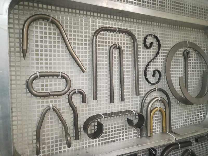
In the modern manufacturing and metalworking industries, bending and press machines are indispensable tools that shape, form, and modify metal and other materials with high precision. These machines are designed to handle various tasks, from simple bending operations to complex shaping processes, catering to a wide range of applications across multiple industries. The effectiveness and versatility of these machines make them critical in producing parts and components for automotive, aerospace, construction, and other heavy industries.
Bending and press machines are essential in transforming raw materials into finished products by applying force to alter the shape and properties of metals and other materials. The machines are designed to handle different materials, including steel, stainless steel (SS), aluminum, and more. These machines vary in size and capacity, from small, manual models used in workshops to large, automated systems in industrial manufacturing plants.
Types of Bending and Press Machines:
- Hydraulic Press Machines: Utilize hydraulic pressure to exert force, offering high precision and control in operations such as pressing, bending, and punching.
- Press Brake Machines: Specifically designed for bending sheet metal into various shapes by clamping the workpiece between a matching punch and die.
- Pipe Bending Machines: Used to bend pipes and tubes into desired angles and shapes, essential in plumbing, construction, and automotive industries.
- Sheet Metal Bending Machines: These machines focus on bending and shaping sheet metal, often used in fabrication shops and manufacturing lines.
Importance of Precision in Metalworking
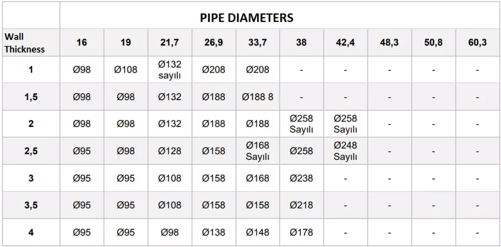
Precision is paramount in metalworking, as even minor deviations can lead to significant issues in the final product. Accurate bending and shaping are critical for ensuring that parts fit together correctly, maintain structural integrity, and meet the required specifications. The precision offered by modern bending and press machines allows manufacturers to produce complex components with tight tolerances, reducing the need for additional finishing processes and minimizing material waste.
Key Factors Influencing Precision:
- Machine Calibration: Proper calibration ensures the machine operates within the specified tolerances, providing consistent results.
- Tooling Quality: High-quality tools, such as dies and punches, are essential for achieving precise bends and shapes.
- Material Properties: Understanding the material’s properties, including its thickness, tensile strength, and ductility, is crucial for selecting the right machine settings.
- Operator Skill: Experienced operators can optimize machine settings and techniques to achieve the best results, even with challenging materials.
Overview of Bending and Press Machines
Bending and press machines are categorized based on their operating principles, applications, and the materials they handle. Below is a brief overview of some common types of bending and press machines:
1.3.1 Hydraulic Press Machines Hydraulic press machines operate by using a hydraulic cylinder to generate compressive force. They are highly versatile, allowing for various applications such as bending, forming, punching, and drawing. Hydraulic presses are known for their ability to exert high forces with great precision, making them ideal for heavy-duty applications. The introduction and working principles of hydraulic press machines will be discussed in more detail in the following sections.
1.3.2 Press Brake Machines Press brake machines are specialized machines used primarily for bending sheet metal. These machines utilize a combination of a punch and die to shape metal into specific angles and forms. Press brakes can be manual, hydraulic, or CNC-controlled, with each type offering different levels of automation and precision. The versatility of press brakes makes them a staple in metal fabrication shops.
1.3.3 Pipe Bending Machines Pipe bending machines are designed to bend pipes and tubes into various shapes and angles without compromising the material’s structural integrity. These machines are essential in industries such as plumbing, automotive, and construction, where precise pipe bends are required. Pipe bending machines can be hydraulic, pneumatic, mechanical, or electric, each offering different advantages depending on the application.
1.3.4 Sheet Metal Bending Machines Sheet metal bending machines focus on bending thin, flat sheets of metal into specific shapes. These machines are commonly used in the automotive and aerospace industries, where precision is critical. The machines can be manually operated, hydraulic, or CNC-controlled, offering various levels of control and automation.
Key Terminology and Concepts
Understanding the key terminology and concepts related to bending and press machines is essential for selecting the right equipment and optimizing its use. Below are some important terms that will be used throughout this document:
- Tonnage: The amount of force a machine can exert, usually measured in tons. For example, a 100-ton hydraulic press can exert 100 tons of force.
- Punch and Die: The tools used in press brake machines to shape metal. The punch presses into the die, which holds the workpiece.
- CNC (Computer Numerical Control): A method of automating machine tools using computers to control their movement and operation.
- Bend Radius: The radius of the inside curve of a bent section of metal. The bend radius is critical in determining the integrity and appearance of the bend.
- Ductility: The ability of a material to undergo deformation without breaking. Ductility is an important factor in bending operations.
Applications of Bending and Press Machines
Bending and press machines are used in a wide range of applications, from simple bending tasks to complex forming and shaping operations. Some common applications include:
- Automotive Industry: Producing car body parts, exhaust systems, and chassis components.
- Aerospace Industry: Manufacturing aircraft components, including fuselage panels and structural supports.
- Construction: Fabricating steel beams, columns, and other structural elements.
- Plumbing and HVAC: Bending pipes and tubes for plumbing, heating, and ventilation systems.
- Heavy Machinery: Forming and shaping parts for heavy equipment, such as cranes and bulldozers.
These applications highlight the versatility and importance of bending and press machines in modern manufacturing. The following sections will delve deeper into specific types of machines, their working principles, and the factors to consider when choosing the right equipment for your needs.
Hydraulic Press Machines: An Overview
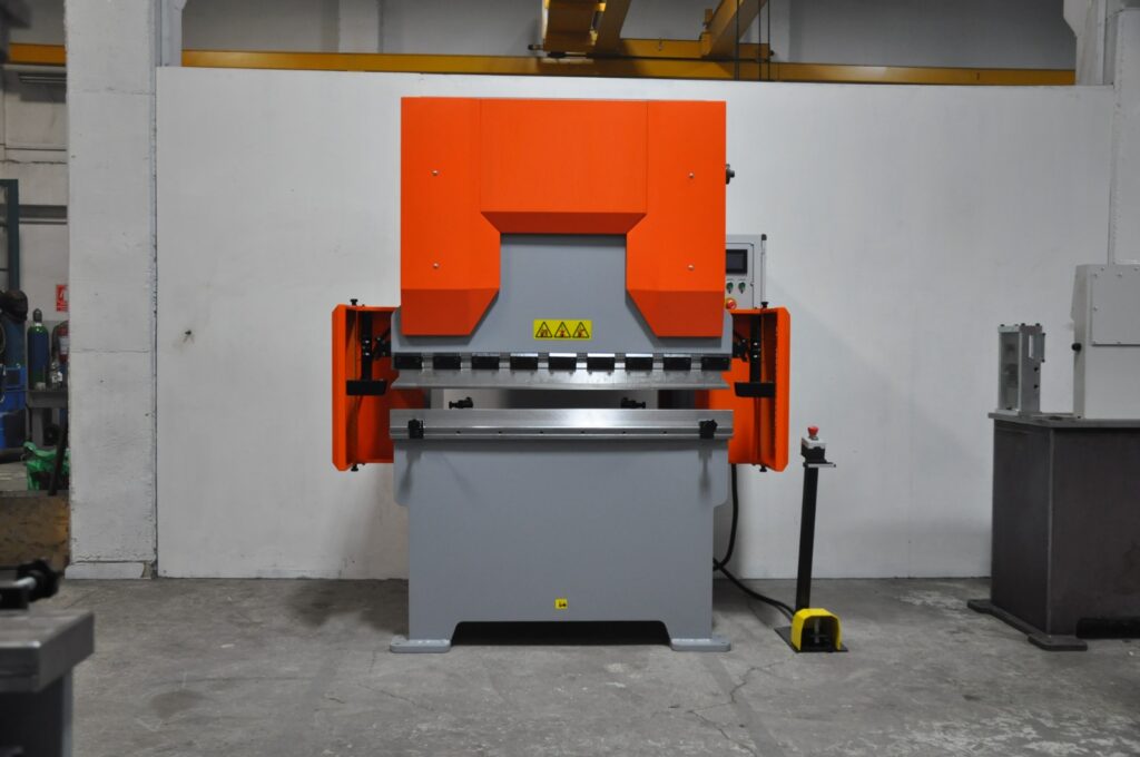
Hydraulic press machines are a cornerstone of modern manufacturing, offering unmatched power and precision in shaping, molding, and forming materials. These machines harness the power of hydraulics—a technology that uses fluid pressure to generate force—enabling them to perform tasks that require significant force with high accuracy. In this section, we will explore the fundamentals of hydraulic press machines, their working principles, various types, and key specifications that are critical for their selection and application in different industries.
2.1 Hydraulic Press Machine Introduction
Hydraulic press machines are used in a variety of industries for tasks that require compressive force. The concept behind hydraulic presses is based on Pascal’s law, which states that when pressure is applied to a confined fluid, the pressure is transmitted equally in all directions. This principle allows hydraulic presses to generate enormous amounts of force with relatively little input, making them highly efficient for industrial applications.
Key Characteristics:
- High Force Generation: Hydraulic presses can generate forces ranging from a few tons to several thousand tons, depending on the machine’s design and application.
- Versatility: These machines can perform a wide range of operations, including forging, stamping, bending, punching, and drawing.
- Precision: Hydraulic presses offer precise control over the applied force and movement, which is essential for tasks that require high accuracy.
- Customizability: Hydraulic presses can be customized with different types of tooling, making them adaptable to various tasks.
Hydraulic press machines are widely used in industries such as automotive manufacturing, aerospace, construction, and heavy machinery production. Their ability to handle large-scale operations with precision makes them a valuable asset in any industrial setting.
2.2 Hydraulic Press Machine Working Principles
The working of a hydraulic press machine is based on the simple but powerful principle of fluid mechanics. The machine typically consists of two cylinders: a smaller cylinder (called the slave cylinder) and a larger cylinder (called the master cylinder). These cylinders are connected by a pipe filled with hydraulic fluid, usually oil.
Working Process:
- Applying Force: When force is applied to the smaller cylinder (using a lever or a motor), it creates pressure in the hydraulic fluid.
- Pressure Transmission: According to Pascal’s law, the pressure in the fluid is transmitted equally throughout the system, causing the larger cylinder to move.
- Force Amplification: Because the larger cylinder has a greater surface area, the force exerted by it is much greater than the force applied to the smaller cylinder. This allows the machine to perform tasks that require significant force, such as pressing or bending metal.
Control Mechanisms:
- Pressure Control Valves: These valves regulate the amount of pressure applied to the hydraulic fluid, allowing the operator to control the force exerted by the machine.
- Flow Control Valves: These valves control the speed of the hydraulic fluid, which in turn controls the speed of the machine’s movement.
- Directional Control Valves: These valves direct the flow of hydraulic fluid to different parts of the system, enabling the machine to perform various operations.
Hydraulic press machines can be operated manually, semi-automatically, or fully automatically, depending on the level of control and automation required. Modern hydraulic presses often incorporate computerized control systems (CNC) for enhanced precision and efficiency.
2.3 Hydraulic Press Specifications
When selecting a hydraulic press machine, understanding its specifications is crucial to ensure that it meets the requirements of the intended application. Key specifications include:
2.3.1 Tonnage (Force Capacity)
- Definition: Tonnage refers to the maximum force that the hydraulic press can exert, usually measured in tons.
- Importance: The tonnage requirement depends on the material being processed and the operation being performed. For example, a higher tonnage is needed for tasks such as forging thick metal parts compared to bending thin sheets.
- Examples: A 100-ton hydraulic press is commonly used in medium-scale operations, while a 1000-ton hydraulic press is suitable for large-scale industrial applications.
2.3.2 Stroke Length
- Definition: Stroke length is the distance the press ram (the moving part of the machine that exerts force) can travel in one cycle.
- Importance: The stroke length determines the depth to which the material can be compressed or formed. It is particularly important in operations like deep drawing or molding.
- Adjustability: Many hydraulic presses allow the stroke length to be adjusted according to the specific requirements of the operation.
2.3.3 Bed Size
- Definition: The bed size is the working surface area of the press where the material is placed.
- Importance: The bed size must accommodate the dimensions of the workpiece being processed. A larger bed size is required for bigger workpieces.
- Customization: Some hydraulic presses offer interchangeable beds to handle different workpiece sizes.
2.3.4 Ram Speed
- Definition: Ram speed refers to the speed at which the press ram moves during operation.
- Importance: The speed of the ram can affect the quality of the operation. For example, slower speeds may be needed for precision tasks, while faster speeds are suitable for high-volume production.
- Control: Hydraulic presses often have adjustable ram speeds to suit different tasks.
2.3.5 Hydraulic System Pressure
- Definition: This is the pressure at which the hydraulic fluid operates within the system, usually measured in pounds per square inch (PSI) or bar.
- Importance: Higher system pressure allows for greater force generation but also requires more robust components to handle the increased stress.
- Safety: Hydraulic presses are equipped with safety mechanisms to prevent over-pressurization, which could lead to system failure.
2.4 100 Ton Hydraulic Press Specifications
A 100-ton hydraulic press is a versatile and commonly used machine in many industries, capable of handling a wide range of tasks from bending and forming to punching and drawing.
Key Specifications of a 100 Ton Hydraulic Press:
- Tonnage: 100 tons of maximum force, suitable for medium to large-scale operations.
- Stroke Length: Typically around 8 to 12 inches, with adjustability for different tasks.
- Bed Size: A standard bed size might be around 36 x 24 inches, but this can vary depending on the manufacturer.
- Ram Speed: Variable, often ranging from 10 to 30 mm/s, depending on the operation.
- System Pressure: Generally operates at around 3000 PSI, providing the necessary force without compromising safety.
Applications:
- Automotive Manufacturing: Used for pressing, forming, and shaping automotive parts.
- Metal Fabrication: Ideal for bending and shaping metal components in medium-scale production.
- Construction Equipment Manufacturing: Useful in the production of parts for heavy machinery and construction tools.
2.5 1000 Ton Hydraulic Press
The 1000-ton hydraulic press represents a significant leap in force capacity, making it suitable for the most demanding industrial applications. These machines are typically used in heavy industries where large-scale and high-force operations are required.
Key Specifications of a 1000 Ton Hydraulic Press:
- Tonnage: 1000 tons of maximum force, designed for heavy-duty tasks.
- Stroke Length: Can range from 12 to 24 inches, depending on the specific model and application.
- Bed Size: Large beds, often exceeding 72 x 48 inches, to accommodate massive workpieces.
- Ram Speed: Slower speeds, typically around 5 to 15 mm/s, due to the immense force being applied.
- System Pressure: Operates at high pressures, usually around 5000 PSI, to deliver the required force.
Applications:
- Shipbuilding: Used in the production of large metal components for ships and submarines.
- Aerospace: Essential for forming and shaping large aircraft components.
- Heavy Machinery Production: Involved in the manufacturing of parts for mining equipment, cranes, and other heavy-duty machinery.
2.6 Horizontal Hydraulic Press Machine
Horizontal hydraulic press machines differ from the more common vertical models in that the ram moves horizontally rather than vertically. This configuration is particularly useful for specific applications such as bending long pieces of metal or pressing components that are difficult to position vertically.
Advantages of Horizontal Hydraulic Press Machines:
- Versatility: Can handle a variety of tasks including bending, pressing, and straightening long workpieces.
- Ease of Operation: Easier to load and position large or awkwardly shaped workpieces.
- Space Efficiency: Horizontal presses can be more space-efficient in certain workshop layouts.
Applications:
- Railway Manufacturing: Used for bending and forming long steel rails.
- Pipeline Construction: Ideal for bending and forming large pipes used in oil, gas, and water pipelines.
- Structural Engineering: Employed in the production of long beams and structural components.
2.7 Small Horizontal Hydraulic Press
Small horizontal hydraulic presses are designed for applications that require less force and smaller workpieces. These machines are commonly used in workshops and smaller manufacturing facilities where space and budget constraints are factors.
Key Features:
- Compact Design: Takes up less space, making it ideal for small workshops.
- Lower Tonnage: Typically ranges from 10 to 50 tons, suitable for light to medium tasks.
- Ease of Use: Simple controls and operation, often with manual or semi-automatic settings.
Applications:
- Automotive Repair Shops: Used for pressing and straightening components like axles and shafts.
- Small Fabrication Shops: Ideal for bending and forming smaller metal parts.
- Maintenance Operations: Useful in on-site repairs and maintenance tasks where portability is required.
3. Press Brake Machines and Bending Applications
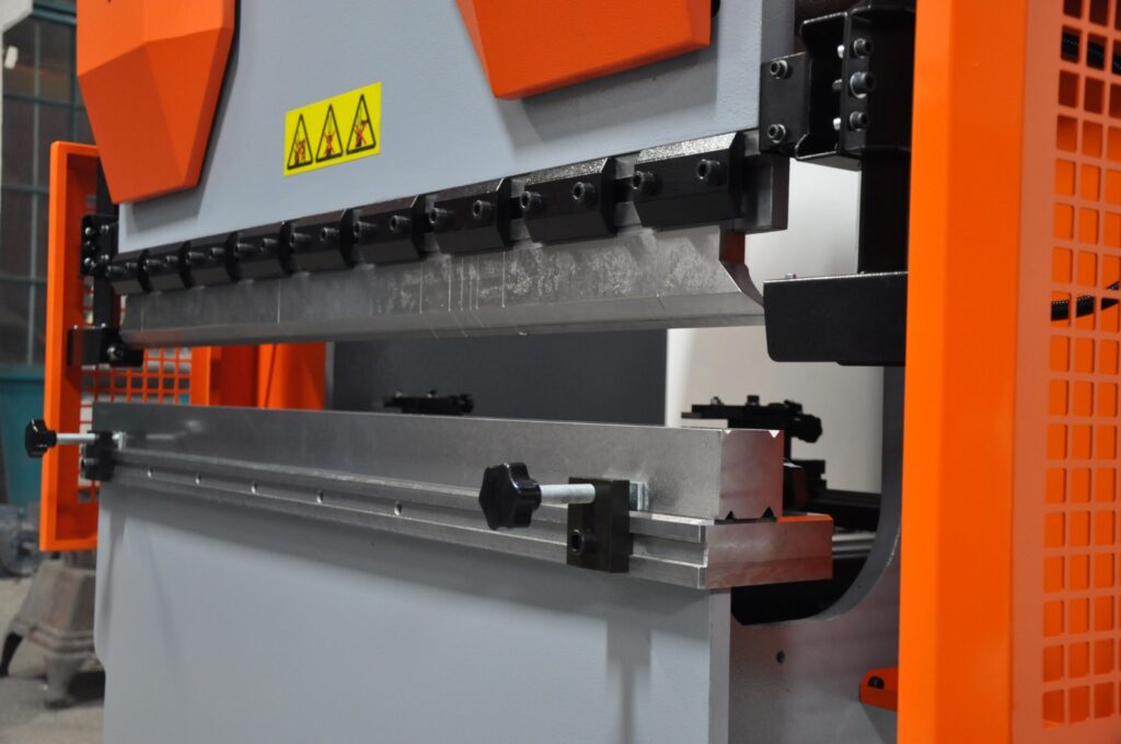
Press brake machines play a pivotal role in the metal fabrication industry, offering the precision and versatility required to transform flat metal sheets into complex shapes and structures. These machines are specifically designed for bending operations, making them indispensable in various manufacturing processes. This section delves into the functionality and applications of press brake machines, explores different bending techniques, and highlights the nuances of hydraulic press bending machines, including those tailored for sheet metal applications.
3.1 Press Brake Machine: Functionality and Applications
A press brake machine is a specialized tool used to bend and shape metal sheets and plates with high accuracy. Unlike general-purpose press machines, press brakes are specifically engineered to perform bending operations, making them essential in industries such as automotive, aerospace, construction, and manufacturing.
Key Functionalities:
- Bending: The primary function of a press brake is to bend metal sheets along a straight axis. This is achieved by clamping the metal between a punch and a die and applying force to create the desired angle.
- Forming: Beyond simple bends, press brakes can form complex shapes by combining multiple bending operations. This allows for the creation of intricate components required in various applications.
- Precision Cutting: Some advanced press brakes are equipped with features that allow for precise cutting or shearing of metal sheets during the bending process.
Applications:
- Automotive Industry: Manufacturing car body panels, chassis components, and exhaust systems.
- Aerospace Industry: Producing aircraft components, including fuselage sections and structural supports.
- Construction: Fabricating steel beams, columns, and other structural elements for buildings and infrastructure projects.
- Electronics: Creating enclosures and frames for electronic devices and appliances.
- Furniture Manufacturing: Designing and producing metal frames and supports for furniture pieces.
3.2 Press Brake Bending: Techniques and Precision
Bending is a fundamental operation in metalworking, and press brakes offer the precision and control necessary to achieve consistent and accurate results. Various bending techniques can be employed depending on the material, thickness, and desired outcome.
Bending Techniques:
- Air Bending: In this method, the punch presses the metal into the die without fully contacting it. This allows for greater flexibility in adjusting the bend angle and reduces stress on the material. Air bending is suitable for applications requiring variable angles and is widely used in sheet metal fabrication.Advantages:
- Versatility in bend angles.
- Reduced tooling wear.
- Lower force requirements compared to bottom bending.
- Bottom Bending (V-Die Bending): Here, the punch presses the metal all the way into the die, resulting in a more precise bend angle. This technique is ideal for applications where high accuracy and consistency are paramount.Advantages:
- Higher precision in bend angles.
- Better repeatability for mass production.
- Suitable for thicker materials.
- Coining: A specialized form of bottom bending where the metal is pressed into a highly precise shape within the die. Coining is used for intricate bends and is often employed in applications requiring fine details and superior surface finishes.
Precision Considerations:
- Tooling Quality: High-quality punches and dies are essential for achieving precise bends. The condition of the tooling directly impacts the accuracy and consistency of the bending process.
- Machine Calibration: Regular calibration ensures that the press brake operates within the specified tolerances, maintaining the precision of each bend.
- Material Properties: Understanding the ductility, tensile strength, and thickness of the material is crucial for selecting the appropriate bending parameters and avoiding defects such as cracking or warping.
- Operator Skill: Skilled operators can optimize machine settings and bending techniques to achieve the desired precision, especially when working with challenging materials or complex shapes.
3.3 Bend Press Machine: Overview
Bend press machines, often referred to interchangeably with press brake machines, are designed specifically for bending operations in metal fabrication. These machines vary in size, capacity, and control mechanisms, allowing them to cater to a wide range of applications from small workshops to large industrial facilities.
Types of Bend Press Machines:
- Manual Bend Press Machines: These are operated manually by the user, typically using a lever or hydraulic pump to apply force. They are suitable for small-scale operations and simple bending tasks.Advantages:
- Lower cost.
- Simplicity and ease of use.
- Ideal for light-duty applications.
- Hydraulic Bend Press Machines: Utilize hydraulic systems to apply force, offering greater control and higher tonnage capabilities compared to manual machines. They are widely used in medium to large-scale operations.Advantages:
- Higher force generation.
- Precise control over bending parameters.
- Suitable for a variety of materials and thicknesses.
- CNC Bend Press Machines: Equipped with computer numerical control (CNC) systems, these machines offer automated and programmable bending operations. They are ideal for high-precision and high-volume production environments.Advantages:
- Enhanced precision and repeatability.
- Ability to handle complex and intricate bends.
- Increased efficiency and reduced manual intervention.
Key Features:
- Adjustable Backgauges: Allow operators to set the precise location of the bend, ensuring consistency across multiple bends.
- Multiple Axes Control: Enables the machine to perform bends at various angles and positions without manual adjustments.
- Safety Features: Includes guards, emergency stop buttons, and sensors to ensure safe operation and protect operators from potential hazards.
3.4 Hydraulic Press Bending Machine
Hydraulic press bending machines combine the force-generating capabilities of hydraulic systems with the precision of press brakes to perform bending operations with high efficiency and accuracy. These machines are essential in applications where consistent and reliable bends are required, especially in medium to high-volume production settings.
Working Principles: Hydraulic press bending machines operate by using a hydraulic cylinder to exert force on the punch, which in turn bends the metal sheet against the die. The hydraulic system allows for smooth and controlled application of force, enabling precise bending angles and consistent results.
Advantages:
- High Force Capacity: Capable of handling thick and strong materials that require significant force to bend.
- Precision Control: Hydraulic systems offer fine control over the bending process, allowing for accurate and repeatable bends.
- Versatility: Suitable for a wide range of materials, including steel, aluminum, and stainless steel, making them adaptable to various industrial applications.
Applications:
- Automotive Manufacturing: Bending automotive body panels and structural components with high precision.
- Aerospace Industry: Forming aircraft parts that require exacting specifications and tight tolerances.
- Construction: Creating structural steel components for buildings and infrastructure projects.
- Heavy Machinery Production: Fabricating parts for construction equipment, mining machinery, and industrial tools.
3.5 Hydraulic Sheet Metal Bending Machine
Hydraulic sheet metal bending machines are specialized press brakes designed to handle the specific challenges associated with bending thin metal sheets. These machines leverage hydraulic systems to provide the necessary force and control for precise sheet metal fabrication.
Key Features:
- Enhanced Precision: Hydraulic systems ensure that each bend is executed with high accuracy, minimizing deviations and maintaining consistency.
- Adjustable Clamping Force: Allows for the secure holding of thin sheets without causing deformation or damage during the bending process.
- Integrated Control Systems: Modern hydraulic sheet metal bending machines often feature computerized controls for automated bending sequences, reducing manual intervention and increasing efficiency.
Benefits:
- Reduced Material Waste: Precise bending reduces the likelihood of errors and rework, leading to less material wastage and lower production costs.
- Increased Productivity: Automated and semi-automated systems enable faster production rates, meeting the demands of high-volume manufacturing.
- Versatility: Capable of handling a variety of sheet metal thicknesses and materials, making them suitable for diverse applications.
Applications:
- Appliance Manufacturing: Producing metal housings and components for household appliances such as refrigerators, washing machines, and ovens.
- Electronics Enclosures: Creating precise and compact metal enclosures for electronic devices and equipment.
- Furniture Manufacturing: Bending metal sheets for modern and ergonomic furniture designs.
- Signage and Displays: Forming metal panels used in signage, displays, and advertising materials.
3.6 Integration of CNC Technology in Press Brake Machines
The integration of Computer Numerical Control (CNC) technology into press brake machines has revolutionized the bending process, enhancing precision, efficiency, and flexibility. CNC press brakes are programmed with specific bending sequences, allowing for automated and repeatable operations that meet the stringent demands of modern manufacturing.
Advantages of CNC Press Brake Machines:
- Automation: Reduces the need for manual adjustments, minimizing human error and increasing production speed.
- Programmability: Allows for the storage and execution of complex bending programs, enabling the production of intricate shapes and multiple bends in a single setup.
- Consistency: Ensures that each bend is executed with the same precision, maintaining quality across large production runs.
- Ease of Use: User-friendly interfaces and software enable operators to input and modify bending programs with minimal training.
Applications:
- High-Precision Industries: Essential in industries such as aerospace and medical device manufacturing, where exacting standards must be met.
- Mass Production: Ideal for large-scale manufacturing where consistency and speed are critical.
- Customization: Facilitates the production of customized parts and components without significant downtime for setup changes.
3.7 Challenges and Considerations in Press Brake Bending
While press brake machines offer significant advantages in metal bending operations, several challenges and considerations must be addressed to ensure optimal performance and longevity of the equipment.
Common Challenges:
- Material Springback: After bending, materials tend to return partially to their original shape, known as springback. Proper compensation techniques and machine settings are required to achieve the desired final angle.
- Tooling Wear: Frequent bending operations can lead to wear and tear of punches and dies, affecting the quality of bends. Regular maintenance and timely replacement of tooling are essential.
- Setup Time: Adjusting machine settings and tooling for different bending tasks can be time-consuming, impacting overall productivity. CNC press brakes help mitigate this by enabling quick program changes.
- Operator Training: Skilled operators are necessary to manage machine settings, troubleshoot issues, and ensure consistent quality. Investing in training programs can enhance operational efficiency.
Key Considerations:
- Machine Selection: Choosing the right press brake machine involves assessing factors such as tonnage capacity, stroke length, bed size, and control systems based on the specific application requirements.
- Tooling Quality: High-quality punches and dies are crucial for achieving precise and consistent bends. Investing in durable tooling can reduce maintenance costs and improve overall performance.
- Maintenance Practices: Regular maintenance, including lubrication, inspection, and calibration, ensures that the press brake operates efficiently and extends its operational lifespan.
- Safety Measures: Implementing safety protocols, such as using protective guards and emergency stop mechanisms, protects operators and prevents accidents in the workplace.
3.8 Innovations in Press Brake Technology
Advancements in press brake technology continue to enhance the capabilities and efficiency of bending operations. Innovations such as servo-electric systems, advanced control software, and enhanced automation features are driving the evolution of press brake machines.
Servo-Electric Press Brakes: Servo-electric press brakes use electric motors to control the movement of the ram, offering precise positioning and energy-efficient operation. These machines provide faster cycle times and reduced maintenance compared to traditional hydraulic systems.
Advanced Control Software: Modern press brake machines are equipped with sophisticated software that enables real-time monitoring, automatic adjustments, and predictive maintenance. Features like automatic backgauges, bend allowance calculations, and integrated CAD/CAM systems streamline the bending process and improve accuracy.
Enhanced Automation: Automation features, including robotic loading and unloading, automated tool changes, and integrated quality control systems, increase productivity and reduce manual labor. These advancements are particularly beneficial in high-volume production environments where efficiency and consistency are paramount.
Sustainability Initiatives: Manufacturers are increasingly focusing on energy-efficient press brake machines that reduce power consumption and minimize environmental impact. Innovations such as regenerative braking systems and energy recovery mechanisms contribute to more sustainable manufacturing practices.
3.9 Case Studies: Press Brake Machines in Action
Automotive Manufacturing: In the automotive industry, press brake machines are used to fabricate various components such as door panels, chassis parts, and engine components. The precision offered by CNC press brakes ensures that each part meets the stringent quality standards required for vehicle assembly. For example, a major automotive manufacturer utilizes a fleet of 100-ton hydraulic press brakes to produce consistent and high-quality body panels, reducing production time and minimizing material waste.
Aerospace Industry: Aerospace manufacturers rely on hydraulic sheet metal bending machines to produce aircraft components with exacting specifications. The high precision and repeatability of CNC press brakes enable the production of complex parts such as fuselage sections and wing components. By integrating advanced control systems, aerospace companies can achieve the necessary tolerances and maintain the integrity of critical components.
Construction Sector: In the construction industry, press brake machines are used to fabricate structural steel elements like beams, columns, and trusses. Hydraulic press brakes with large bed sizes and high tonnage capacities are essential for handling the thick and heavy materials used in construction projects. For instance, a construction equipment manufacturer employs 1000-ton hydraulic press brakes to produce large steel beams, ensuring structural integrity and compliance with safety standards.
Electronics Manufacturing: Electronics manufacturers use small hydraulic sheet metal bending machines to create precise enclosures and frames for devices such as smartphones, laptops, and medical equipment. The ability to perform intricate bends with high accuracy ensures that the final products meet design specifications and fit seamlessly with other components.
3.10 Best Practices for Operating Press Brake Machines
To maximize the efficiency and lifespan of press brake machines, adhering to best practices is essential. These practices encompass proper machine setup, maintenance, and operational techniques that ensure consistent quality and safety.
Machine Setup:
- Accurate Alignment: Ensure that the punch and die are properly aligned to prevent uneven bends and reduce tooling wear.
- Proper Tooling Selection: Choose the appropriate punches and dies based on the material type, thickness, and desired bend angle.
- Parameter Optimization: Set the correct bending force, ram speed, and stroke length according to the material properties and bending requirements.
Maintenance:
- Regular Inspections: Conduct routine inspections of hydraulic systems, electrical components, and mechanical parts to identify and address potential issues early.
- Lubrication: Keep moving parts well-lubricated to reduce friction and prevent wear.
- Tooling Maintenance: Clean and maintain punches and dies to ensure optimal performance and extend their lifespan.
Operational Techniques:
- Consistent Feeding: Ensure that metal sheets are fed consistently into the press brake to maintain uniform bends.
- Monitoring and Adjustment: Continuously monitor the bending process and make necessary adjustments to maintain precision.
- Safety Protocols: Implement and enforce safety protocols, including the use of personal protective equipment (PPE) and adherence to operational guidelines.
Training and Education:
- Operator Training: Provide comprehensive training for operators to ensure they understand machine operation, safety procedures, and maintenance practices.
- Continuous Improvement: Encourage operators to stay updated with the latest techniques and technologies in press brake operations through ongoing education and training programs.
3.11 Conclusion
Press brake machines are integral to the metal fabrication industry, offering the precision and versatility required to produce a wide range of components and structures. Understanding the functionality, bending techniques, and specific applications of different press brake machines, including hydraulic and CNC models, is essential for optimizing their use in various industrial settings. By adhering to best practices and leveraging advancements in press brake technology, manufacturers can achieve high-quality results, enhance productivity, and maintain a competitive edge in the market.
In the following sections, we will explore other specialized bending machines, including pipe bending machines and sheet metal bending machines, to provide a comprehensive overview of the tools available for metal shaping and forming operations.
Pipe Bending Machines
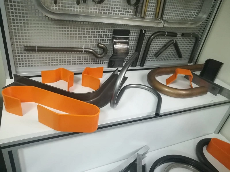
Pipe bending machines are essential tools in industries where precise and efficient bending of pipes and tubes is required. These machines are used to create complex pipe shapes that are crucial in various applications, from plumbing and construction to automotive and aerospace industries. In this section, we will explore the different types of pipe bending machines, including pneumatic, mechanical, hydraulic, and specialized machines for bending stainless steel (SS) and heavy pipes. We’ll also discuss the benefits and considerations for choosing the right pipe bending machine for specific applications.
4.1 Pneumatic Pipe Bending Machine
Pneumatic pipe bending machines utilize compressed air to generate the force needed to bend pipes. These machines are commonly used in applications that require moderate force and precision, making them suitable for a variety of industries, including automotive and HVAC (Heating, Ventilation, and Air Conditioning).
Working Principles:
- Air Compression: The machine operates by compressing air in a cylinder, which then forces a piston to move. This movement is transferred to the bending tool, which applies the necessary force to bend the pipe.
- Controlled Force: The force applied can be adjusted by regulating the air pressure, allowing for precise control over the bending process.
Advantages:
- Simplicity: Pneumatic systems are generally simpler and easier to maintain than hydraulic systems, with fewer components and less potential for leaks.
- Cost-Effectiveness: Pneumatic machines are often more affordable than their hydraulic counterparts, making them a good option for smaller operations.
- Safety: Pneumatic systems are inherently safer in environments where fire hazards are a concern, as they do not involve flammable fluids.
Applications:
- Automotive Industry: Bending exhaust pipes and other components where moderate force and precision are required.
- HVAC Systems: Shaping pipes and ducts for heating, ventilation, and air conditioning installations.
- General Fabrication: Suitable for bending tasks in small to medium-sized fabrication shops.
4.2 Mechanical Pipe Bending Machine
Mechanical pipe bending machines rely on mechanical force generated by gears, levers, and other mechanical components to bend pipes. These machines are known for their durability and reliability, making them suitable for high-volume production environments.
Working Principles:
- Mechanical Leverage: The machine uses mechanical leverage to amplify the force applied by the operator, allowing it to bend pipes with precision.
- Gear Systems: Gears and cams are often used to control the movement and force applied to the bending tool, ensuring consistent results.
Advantages:
- Durability: Mechanical pipe bending machines are built to last, with robust components that can withstand the rigors of high-volume production.
- Consistency: The use of gears and mechanical systems ensures consistent and repeatable bends, which is crucial in mass production.
- Ease of Use: These machines are typically straightforward to operate, with manual or semi-automatic controls that allow for precise adjustments.
Applications:
- Construction Industry: Bending steel pipes for structural applications, such as scaffolding and frameworks.
- Manufacturing: Producing bent pipes for various industrial products, including furniture, machinery, and equipment.
- Shipbuilding: Shaping pipes used in marine applications, where durability and precision are critical.
4.3 SS Pipe Bending Machine
Stainless steel (SS) pipes are widely used in industries that require corrosion-resistant and durable materials, such as food processing, pharmaceuticals, and chemical processing. Bending stainless steel pipes requires specialized machines that can handle the unique properties of this material without causing damage or deformation.
Key Features:
- Enhanced Tooling: SS pipe bending machines are equipped with hardened tooling that can withstand the high tensile strength of stainless steel, preventing tool wear and ensuring clean bends.
- Precision Control: These machines offer precise control over the bending process, allowing for tight bend radii and complex shapes without compromising the material’s integrity.
- Cooling Systems: Some SS pipe bending machines are equipped with cooling systems to prevent the material from overheating during the bending process, which could lead to discoloration or weakening of the stainless steel.
Advantages:
- Corrosion Resistance: SS pipe bending machines are designed to maintain the corrosion-resistant properties of stainless steel, making them ideal for applications in harsh environments.
- High Precision: The machines can produce precise bends with minimal springback, ensuring that the final product meets exact specifications.
- Versatility: Suitable for a wide range of applications, from sanitary piping in food processing to chemical transport lines in industrial settings.
Applications:
- Food and Beverage Industry: Bending pipes for sanitary processing lines, where cleanliness and corrosion resistance are paramount.
- Pharmaceutical Industry: Shaping pipes for sterile environments, including drug manufacturing and medical device production.
- Chemical Processing: Creating corrosion-resistant piping systems for transporting aggressive chemicals and other hazardous materials.
4.4 Steel Pipe Bending Machine
Steel pipe bending machines are designed to handle the rigors of bending steel pipes, which are commonly used in construction, infrastructure, and heavy industry. These machines are built to provide the necessary force and control to bend steel pipes without compromising their structural integrity.
Key Features:
- High Tonnage Capacity: Steel pipe bending machines are equipped with powerful hydraulic or mechanical systems capable of exerting the high forces required to bend steel.
- Robust Construction: The machines are built with heavy-duty frames and components to handle the stress of bending thick and strong steel pipes.
- Advanced Control Systems: Many steel pipe bending machines feature CNC controls, allowing for precise and automated bending processes.
Advantages:
- Strength and Durability: Steel pipe bending machines are capable of bending thick-walled and large-diameter steel pipes with high precision, ensuring that the final product meets structural requirements.
- Versatility: These machines can handle a wide range of steel pipe sizes and thicknesses, making them suitable for various applications in construction and heavy industry.
- Efficiency: The use of advanced control systems and automated features allows for efficient production, reducing labor costs and increasing throughput.
Applications:
- Construction: Bending steel pipes for structural applications, such as beams, columns, and supports in buildings and infrastructure projects.
- Oil and Gas Industry: Shaping steel pipes for pipelines, drilling rigs, and other critical infrastructure in the energy sector.
- Heavy Machinery Manufacturing: Producing bent steel components for construction equipment, mining machinery, and industrial tools.
4.5 Heavy Pipe Bending Machine
Heavy pipe bending machines are specialized for handling large-diameter and thick-walled pipes that require significant force to bend. These machines are used in industries where large-scale infrastructure projects and heavy-duty applications are common.
Key Features:
- High Force Capability: Heavy pipe bending machines are equipped with hydraulic systems capable of generating extremely high forces, often exceeding 1000 tons, to bend large and thick pipes.
- Large Bed Size: These machines feature expansive working areas to accommodate the size of the pipes being bent, allowing for precise positioning and control.
- Reinforced Components: The machines are built with reinforced frames, tooling, and hydraulic systems to handle the stress of bending heavy pipes without deformation.
Advantages:
- Capability: Heavy pipe bending machines can handle pipes with large diameters and thick walls, which are typically used in major infrastructure projects.
- Precision: Despite their size, these machines offer precise control over the bending process, ensuring that large pipes meet exacting specifications.
- Durability: Built to withstand the demands of heavy industry, these machines offer long service life and reliable performance in challenging environments.
Applications:
- Pipeline Construction: Bending large-diameter pipes for oil, gas, and water pipelines that span long distances and require precise engineering.
- Shipbuilding: Shaping heavy steel pipes for marine vessels, where durability and structural integrity are crucial.
- Power Generation: Producing bent pipes for power plants and energy infrastructure, including those used in nuclear and fossil fuel power generation.
4.6 Hydraulic Pipe Bending Machine
Hydraulic pipe bending machines are among the most versatile and powerful options for bending pipes in various industries. These machines utilize hydraulic pressure to apply force, offering precise control and the ability to handle a wide range of pipe sizes and materials.
Working Principles:
- Hydraulic Force: The machine uses a hydraulic cylinder to apply force to the bending tool, which then bends the pipe to the desired angle.
- Adjustable Pressure: Operators can adjust the hydraulic pressure to control the force applied, allowing for precise bends even in challenging materials.
Advantages:
- Versatility: Hydraulic pipe bending machines can handle a variety of materials, including steel, aluminum, and stainless steel, making them suitable for diverse applications.
- Precision: The hydraulic system offers fine control over the bending process, ensuring consistent results with minimal springback.
- Power: These machines are capable of generating significant force, allowing them to bend thick and strong pipes with ease.
Applications:
- Automotive Manufacturing: Bending exhaust pipes, roll cages, and other components where precision and strength are required.
- Aerospace Industry: Shaping pipes used in aircraft hydraulic systems, fuel lines, and other critical applications.
- Construction: Bending steel pipes for structural applications, such as beams, columns, and support structures.
4.7 Electric Pipe Bending Machine
Electric pipe bending machines offer an alternative to hydraulic and pneumatic systems, using electric motors to generate the force needed for bending operations. These machines are known for their energy efficiency, precision, and ease of use.
Key Features:
- Electric Motor Drive: The machine uses an electric motor to drive the bending tool, providing precise control over the bending process.
- Programmable Controls: Many electric pipe bending machines feature CNC or digital controls, allowing for automated and repeatable bending sequences.
- Quiet Operation: Electric machines tend to operate more quietly than hydraulic or pneumatic systems, making them suitable for environments where noise is a concern.
Advantages:
- Energy Efficiency: Electric pipe bending machines consume less energy compared to hydraulic systems, making them more cost-effective in the long run.
- Precision and Consistency: The use of electric motors and digital controls ensures precise and repeatable bends, which is critical in high-volume production.
- Ease of Maintenance: Electric machines have fewer moving parts compared to hydraulic systems, resulting in lower maintenance requirements and longer service life.
Applications:
- Furniture Manufacturing: Bending metal pipes for furniture frames, including chairs, tables, and shelving units.
- Medical Equipment: Shaping pipes used in medical devices and equipment, where precision and cleanliness are essential.
- Automotive Aftermarket: Producing custom exhaust systems, roll cages, and other automotive components.
4.8 Small Pipe Bending Machine
Small pipe bending machines are designed for applications that involve smaller-diameter pipes and require less force. These machines are commonly used in workshops, small-scale manufacturing, and maintenance operations.
Key Features:
- Compact Design: Small pipe bending machines are portable and space-efficient, making them ideal for use in confined spaces or on job sites.
- Manual or Semi-Automatic Operation: These machines are typically operated manually or with semi-automatic controls, offering a balance between control and ease of use.
- Versatility: Despite their small size, these machines can handle a variety of materials and bending angles, making them suitable for diverse applications.
Advantages:
- Portability: Small pipe bending machines are easy to transport and set up, making them ideal for on-site work and maintenance tasks.
- Cost-Effectiveness: These machines are typically more affordable than larger models, making them accessible to small businesses and workshops.
- Ease of Use: Simple controls and operation make these machines user-friendly, even for operators with limited experience.
Applications:
- Plumbing: Bending pipes for plumbing installations and repairs, including copper, PVC, and other materials.
- HVAC: Shaping small-diameter pipes for heating, ventilation, and air conditioning systems.
- DIY and Home Workshops: Suitable for hobbyists and small-scale fabricators working on custom projects.
4.9 Pipe Bending Machine Price Considerations
When selecting a pipe bending machine, understanding the factors that influence price is crucial to making an informed investment. The price of a pipe bending machine can vary significantly based on several key factors, including machine type, capacity, features, and brand.
Factors Influencing Price:
- Machine Type: Hydraulic and electric pipe bending machines are generally more expensive than pneumatic or mechanical models due to their advanced features and higher force capabilities.
- Capacity: Machines capable of bending larger-diameter or thicker-walled pipes typically cost more due to the increased force requirements and more robust construction.
- Control Systems: CNC-controlled machines with programmable features and automated bending sequences are priced higher than manual or semi-automatic models.
- Brand and Quality: Established brands with a reputation for quality and reliability often command higher prices, but they also offer better performance, durability, and support.
Cost vs. Functionality:
- Entry-Level Machines: Suitable for small-scale operations, workshops, and maintenance tasks, these machines offer basic functionality at a lower cost.
- Mid-Range Machines: Ideal for medium-sized businesses and manufacturers, offering a balance between price and advanced features.
- High-End Machines: Designed for large-scale production and heavy industry, these machines offer the highest levels of precision, automation, and durability but come at a premium price.
Making the Right Investment:
- Assessing Needs: Consider the specific requirements of your operation, including the types of materials, pipe sizes, and production volume, to choose a machine that meets your needs without overspending.
- Long-Term Value: While higher-end machines may have a higher initial cost, their durability, efficiency, and advanced features can lead to lower operational costs and better ROI over time.
- Supplier Support: Look for suppliers that offer good after-sales support, including training, maintenance, and parts availability, as this can significantly impact the total cost of ownership.
4.10 Conclusion
Pipe bending machines are crucial tools in various industries, offering the ability to shape and form pipes to precise specifications. Understanding the different types of pipe bending machines, including pneumatic, mechanical, hydraulic, and specialized machines for stainless steel and heavy pipes, is essential for selecting the right equipment for your needs. By considering factors such as machine capacity, control systems, and price, manufacturers and operators can make informed decisions that optimize productivity and ensure the quality of their products.
Sheet Metal Bending Machines
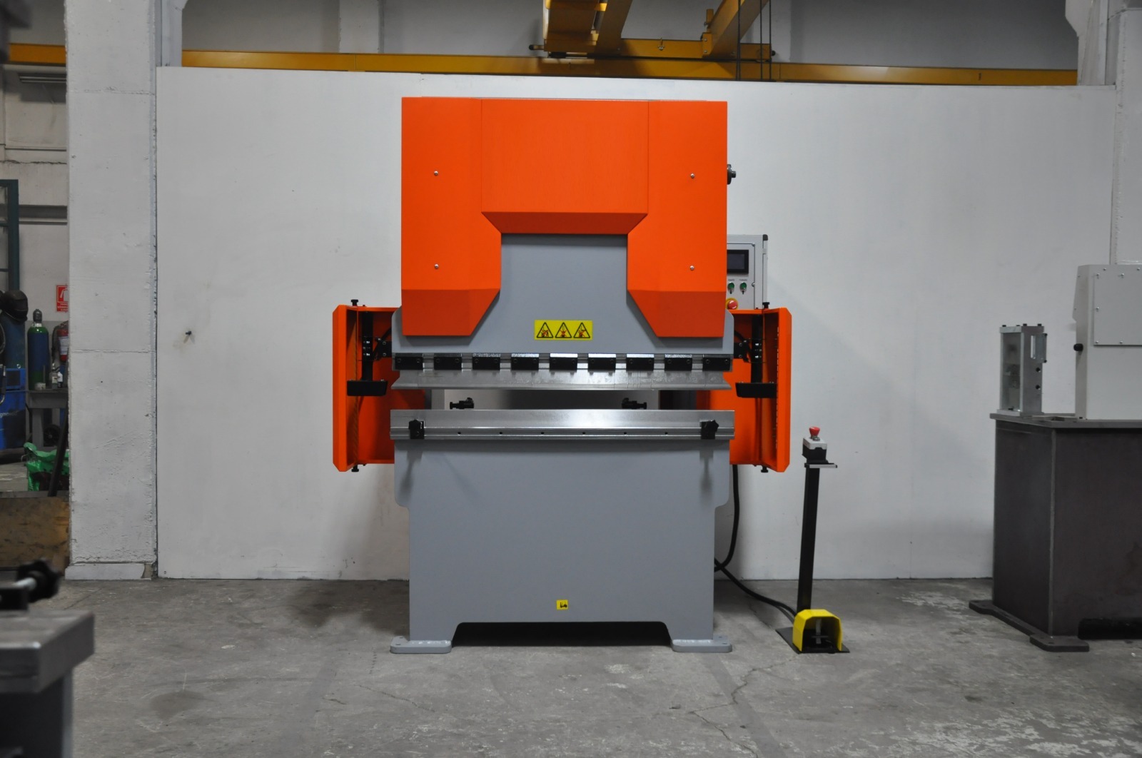
Sheet metal bending machines are essential in the fabrication of metal components, allowing manufacturers to create a wide range of shapes and structures from flat metal sheets. These machines are used across various industries, from automotive to aerospace, and play a critical role in producing everything from simple bends to complex geometries. In this section, we will explore the different types of sheet metal bending machines, including electric, hydraulic, automatic, and CNC-controlled machines. We will also discuss their applications, benefits, and factors to consider when selecting the right machine for specific tasks.
5.1 Electric Sheet Metal Bending Machine
Electric sheet metal bending machines use electric motors to generate the force needed to bend metal sheets. These machines are known for their energy efficiency, precision, and ease of use, making them a popular choice in many fabrication shops.
Key Features:
- Electric Motor Drive: These machines are driven by electric motors, which provide precise control over the bending process and allow for consistent and repeatable results.
- Programmable Controls: Many electric bending machines come with digital or CNC controls, enabling operators to program bending sequences and angles for automated operations.
- Quiet Operation: Electric machines tend to be quieter than hydraulic models, making them suitable for environments where noise reduction is important.
Advantages:
- Energy Efficiency: Electric machines are more energy-efficient than hydraulic machines, reducing operational costs over time.
- Precision: The electric motor provides consistent power, allowing for precise bends with minimal variability.
- Ease of Maintenance: With fewer moving parts and no hydraulic fluid, electric bending machines typically require less maintenance and have lower operating costs.
Applications:
- Light Fabrication: Suitable for bending thin sheets of metal, making them ideal for light fabrication tasks such as creating enclosures, brackets, and panels.
- Electronics Manufacturing: Used to bend metal components for electronic devices, where precision and consistency are critical.
- Custom Fabrication: Ideal for small workshops and custom fabrication businesses that require flexible and precise bending capabilities.
5.2 Small Sheet Bending Machine
Small sheet bending machines are designed for tasks that involve smaller pieces of sheet metal. These machines are typically more compact and easier to use, making them ideal for workshops and small-scale operations.
Key Features:
- Compact Design: Small sheet bending machines are designed to be portable and space-efficient, allowing them to be used in smaller workspaces.
- Manual or Semi-Automatic Operation: These machines often feature manual or semi-automatic controls, providing a balance between precision and ease of use.
- Versatile Tooling: Despite their size, small sheet bending machines can be equipped with a variety of tooling to handle different bending tasks.
Advantages:
- Portability: The compact size of these machines makes them easy to transport and set up, allowing for flexible use in different locations.
- Affordability: Small sheet bending machines are typically less expensive than larger models, making them accessible to small businesses and workshops.
- Ease of Use: Simple controls and operation make these machines user-friendly, even for operators with limited experience.
Applications:
- DIY and Custom Projects: Ideal for hobbyists and small-scale fabricators working on custom projects.
- Maintenance and Repair: Used in maintenance shops for bending small metal parts and components during repairs.
- Prototype Development: Suitable for creating prototypes and small production runs, where flexibility and quick setup are important.
5.3 Automatic Bending Machine
Automatic bending machines are designed to streamline the bending process by automating various aspects of the operation. These machines are equipped with advanced control systems that allow for precise and repeatable bending without the need for constant operator intervention.
Key Features:
- Automation: Automatic bending machines are capable of performing multiple bends in a single setup, reducing the need for manual adjustments and increasing productivity.
- CNC Controls: Many automatic bending machines are equipped with CNC (Computer Numerical Control) systems that allow for the programming of complex bending sequences.
- High Throughput: These machines are designed for high-volume production, making them ideal for industries that require large quantities of bent metal parts.
Advantages:
- Increased Efficiency: Automation reduces the time required for setup and bending, leading to higher production rates and lower labor costs.
- Consistency: Automatic machines ensure that each bend is executed with the same precision, reducing variability and improving product quality.
- Flexibility: The ability to program complex bending sequences allows for the production of intricate and custom shapes with minimal manual intervention.
Applications:
- Mass Production: Used in industries such as automotive and aerospace, where large quantities of parts with consistent quality are required.
- Complex Fabrication: Suitable for producing parts with multiple bends or intricate shapes that would be difficult to achieve manually.
- High-Precision Manufacturing: Ideal for applications where exacting tolerances and repeatability are essential, such as in the production of medical devices and electronics.
5.4 CNC Sheet Bending Machine
CNC sheet bending machines represent the pinnacle of precision and automation in sheet metal bending. These machines are controlled by computer numerical control (CNC) systems, which allow for highly accurate and repeatable bending operations.
Key Features:
- CNC Control: CNC sheet bending machines are equipped with computerized controls that allow operators to program and execute complex bending sequences with high precision.
- Automated Tooling: These machines often feature automated tooling systems that can change punches and dies as needed, further increasing efficiency and reducing setup time.
- Real-Time Monitoring: CNC systems provide real-time monitoring of the bending process, allowing operators to make adjustments on the fly and ensuring that each bend meets the required specifications.
Advantages:
- High Precision: CNC control ensures that each bend is performed with exacting accuracy, making these machines ideal for applications where precision is critical.
- Repeatability: The ability to store and recall bending programs allows for consistent results across multiple production runs, reducing variability and waste.
- Complexity: CNC sheet bending machines can perform intricate bends and form complex shapes that would be difficult or impossible to achieve with manual machines.
Applications:
- Aerospace Industry: Used to produce aircraft components with exacting tolerances and complex shapes.
- Automotive Manufacturing: Essential for the production of car body panels, chassis components, and other critical parts that require high precision.
- Electronics and Appliances: Ideal for creating metal enclosures, frames, and other components used in electronics and household appliances.
5.5 What is a CNC Bending Machine?
A CNC bending machine is a specialized type of bending machine that uses computer numerical control (CNC) to automate the bending process. CNC machines are programmed with specific instructions that control the movement of the machine’s bending tools, allowing for precise and repeatable operations.
How CNC Bending Machines Work:
- Programming: Operators program the CNC machine using specialized software, inputting parameters such as bend angles, material thickness, and sequence of operations.
- Tool Movement: The CNC system controls the movement of the bending tools, ensuring that each bend is executed according to the programmed instructions.
- Feedback Loops: CNC machines often include feedback systems that monitor the bending process in real-time, allowing for automatic adjustments to maintain precision.
Benefits of CNC Bending Machines:
- Precision: CNC bending machines offer unparalleled precision, with the ability to produce bends with tight tolerances and consistent quality.
- Efficiency: Automation reduces the time required for setup and bending, increasing throughput and reducing labor costs.
- Flexibility: The ability to program complex bending sequences allows for the production of custom and intricate shapes with minimal manual intervention.
Applications:
- Industrial Manufacturing: Used in high-volume production environments where consistency and precision are critical.
- Custom Fabrication: Ideal for producing custom parts and components, especially those with complex geometries.
- Prototyping: CNC bending machines are valuable in the development of prototypes, allowing for rapid iteration and precise adjustments.
5.6 Hydraulic Press Bending Machine
Hydraulic press bending machines combine the power of hydraulic systems with the precision of press brakes to perform bending operations with high efficiency and accuracy. These machines are widely used in industries that require consistent and reliable bends in a variety of materials, including steel, aluminum, and stainless steel.
Working Principles:
- Hydraulic Force: The machine uses a hydraulic cylinder to apply force to the bending tool, which then bends the metal sheet to the desired angle.
- Adjustable Pressure: Operators can adjust the hydraulic pressure to control the force applied, allowing for precise bends even in challenging materials.
Advantages:
- High Force Capacity: Hydraulic press bending machines are capable of exerting significant force, making them suitable for bending thick and strong materials.
- Precision: The hydraulic system provides fine control over the bending process, ensuring consistent results with minimal variability.
- Versatility: These machines can handle a wide range of materials and thicknesses, making them suitable for various industrial applications.
Applications:
- Automotive Manufacturing: Bending automotive body panels and structural components with high precision.
- Construction: Creating structural steel components for buildings and infrastructure projects.
- Heavy Machinery Production: Fabricating parts for construction equipment, mining machinery, and industrial tools.
5.7 Hydraulic Sheet Metal Bending Machine
Hydraulic sheet metal bending machines are specialized press brakes designed to handle the specific challenges associated with bending thin metal sheets. These machines leverage hydraulic systems to provide the necessary force and control for precise sheet metal fabrication.
Key Features:
- Enhanced Precision: Hydraulic systems ensure that each bend is executed with high accuracy, minimizing deviations and maintaining consistency.
- Adjustable Clamping Force: Allows for the secure holding of thin sheets without causing deformation or damage during the bending process.
- Integrated Control Systems: Modern hydraulic sheet metal bending machines often feature computerized controls for automated bending sequences, reducing manual intervention and increasing efficiency.
Benefits:
- Reduced Material Waste: Precise bending reduces the likelihood of errors and rework, leading to less material wastage and lower production costs.
- Increased Productivity: Automated and semi-automated systems enable faster production rates, meeting the demands of high-volume manufacturing.
- Versatility: Capable of handling a variety of sheet metal thicknesses and materials, making them suitable for diverse applications.
Applications:
- Appliance Manufacturing: Producing metal housings and components for household appliances such as refrigerators, washing machines, and ovens.
- Electronics Enclosures: Creating precise and compact metal enclosures for electronic devices and equipment.
- Furniture Manufacturing: Bending metal sheets for modern and ergonomic furniture designs.
5.8 Choosing the Right Sheet Metal Bending Machine
Selecting the right sheet metal bending machine involves considering several factors, including the material being bent, the required precision, production volume, and budget. Here are some key considerations to keep in mind:
Material Type and Thickness:
- Material: Different machines are better suited for specific materials. For example, hydraulic machines are ideal for thick steel sheets, while electric machines may be better for lighter materials.
- Thickness: The thickness of the material will determine the required force, with thicker materials needing more powerful machines.
Bending Precision:
- Tolerances: If your application requires tight tolerances, a CNC or hydraulic bending machine may be the best choice due to their precision and consistency.
- Complexity: For complex bending operations involving multiple bends or intricate shapes, a CNC machine will provide the necessary control and flexibility.
Production Volume:
- Low Volume: For small production runs or custom projects, a manual or small sheet bending machine may suffice.
- High Volume: For large-scale production, an automatic or CNC bending machine is more appropriate due to their higher efficiency and automation capabilities.
Budget Considerations:
- Initial Investment: CNC and hydraulic machines tend to have higher upfront costs but offer long-term benefits in precision, efficiency, and flexibility.
- Operating Costs: Consider the long-term costs of maintenance, energy consumption, and tooling when selecting a machine.
Supplier Support:
- After-Sales Service: Choose a supplier that offers good after-sales support, including maintenance, training, and access to spare parts.
- Warranty: Look for machines that come with a comprehensive warranty, which can protect your investment and reduce the risk of unexpected costs.
5.9 Future Trends in Sheet Metal Bending Machines
The field of sheet metal bending is constantly evolving, with new technologies and innovations improving the efficiency, precision, and versatility of bending machines. Here are some trends shaping the future of sheet metal bending:
Automation and Robotics:
- Increased Automation: Automation is becoming more prevalent in sheet metal bending, with robots and automated systems taking over tasks such as loading, unloading, and tool changes, leading to higher productivity and lower labor costs.
- Collaborative Robots: Also known as cobots, these robots work alongside human operators to assist with bending operations, enhancing efficiency while maintaining flexibility.
Advanced CNC Systems:
- Real-Time Monitoring: CNC systems are becoming more advanced, with features such as real-time monitoring, predictive maintenance, and automatic adjustments ensuring higher precision and reducing downtime.
- AI Integration: Artificial intelligence (AI) is being integrated into CNC systems to optimize bending processes, improve decision-making, and enhance overall efficiency.
Sustainability Initiatives:
- Energy Efficiency: Manufacturers are focusing on creating more energy-efficient bending machines that reduce power consumption without compromising performance.
- Material Waste Reduction: Innovations in tooling and process control are helping to reduce material waste, leading to more sustainable manufacturing practices.
Customization and Flexibility:
- Modular Machines: Modular designs allow for easy customization of bending machines, enabling manufacturers to adapt to different tasks and requirements without significant downtime.
- Flexible Tooling: Advances in tooling technology are allowing for more flexible and adaptable bending operations, making it easier to switch between different products and designs.
5.10 Conclusion
Sheet metal bending machines are vital tools in modern manufacturing, offering the precision, flexibility, and efficiency needed to produce high-quality metal components. Understanding the different types of machines—such as electric, hydraulic, automatic, and CNC models—and their specific applications is crucial for selecting the right equipment for your needs. By considering factors such as material type, bending precision, production volume, and budget, manufacturers can make informed decisions that enhance productivity and ensure the quality of their products.
Bending Press Machine Price Considerations
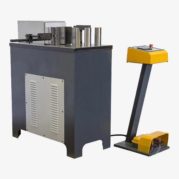
When investing in bending press machines, understanding the factors that influence pricing is essential for making an informed and cost-effective decision. Bending press machines come in various types and configurations, each with different features and capabilities that affect their overall cost. In this section, we will explore the key factors that determine the price of bending press machines, including specifications, features, brand reputation, and market demand. We will also discuss how to balance cost with functionality to ensure that you select the right machine for your specific needs.
6.1 Factors Affecting Bending Press Machine Price
The price of a bending press machine is influenced by several factors, including its type, specifications, features, brand, and market conditions. Understanding these factors can help you determine which machine offers the best value for your investment.
6.1.1 Machine Type
- Manual vs. Automated Machines: Manual bending press machines are generally less expensive than automated or CNC-controlled machines due to their simpler design and lower manufacturing costs. However, automated machines, while more expensive, offer greater efficiency, precision, and productivity, which can justify the higher initial investment.
- Hydraulic vs. Mechanical Presses: Hydraulic presses are typically more expensive than mechanical presses because of their complex hydraulic systems, which provide greater force and control. Mechanical presses, while less costly, may be more suitable for applications where speed is prioritized over precision.
6.1.2 Specifications and Capacity
- Tonnage: The tonnage, or force capacity, of a bending press machine is one of the primary factors influencing its price. Machines with higher tonnage are capable of bending thicker and stronger materials but come with a higher price tag due to the more robust construction and powerful hydraulic or mechanical systems required.
- Bed Size: The size of the machine’s bed, which determines the maximum size of the workpiece it can handle, also affects the price. Larger beds increase the machine’s versatility but require more material and engineering, leading to higher costs.
- Stroke Length: The stroke length, or the distance the press ram can travel, is another critical specification. Machines with longer stroke lengths can accommodate deeper bends, which adds to the complexity and cost of the machine.
6.1.3 Features and Technology
- CNC Controls: Bending press machines equipped with CNC (Computer Numerical Control) systems are significantly more expensive than those with manual or semi-automatic controls. CNC systems offer the ability to program and automate complex bending sequences, enhancing precision and productivity, which justifies their higher price.
- Automation and Robotics: Machines with advanced automation features, such as automatic tool changers, robotic loading and unloading, and real-time monitoring systems, command higher prices due to the added technology and the potential for increased production efficiency.
- Safety Features: Enhanced safety features, such as light curtains, safety guards, and emergency stop systems, can also contribute to the overall cost of the machine. These features are essential for protecting operators and ensuring compliance with safety regulations, particularly in high-volume production environments.
6.1.4 Brand and Quality
- Reputation: The reputation of the manufacturer or brand plays a significant role in the price of bending press machines. Established brands with a history of quality, reliability, and excellent after-sales support often charge a premium for their products. While these machines may be more expensive upfront, they often offer better performance, durability, and long-term value.
- Quality of Materials: The quality of the materials used in the construction of the machine, such as the steel for the frame and the components of the hydraulic system, affects both the machine’s durability and price. Higher-quality materials lead to longer-lasting machines but increase manufacturing costs.
6.1.5 Market Demand and Availability
- Supply and Demand: Market conditions, such as the balance between supply and demand, can also influence the price of bending press machines. During periods of high demand, prices may rise due to limited availability. Conversely, prices may decrease during periods of low demand or excess supply.
- Import and Export Costs: For machines that are imported, factors such as tariffs, shipping costs, and currency exchange rates can affect the final price. These costs can vary significantly depending on the country of origin and the location of the buyer.
6.2 Cost vs. Functionality: Making the Right Investment
When selecting a bending press machine, it is essential to balance cost with functionality to ensure that the machine meets your specific needs without exceeding your budget. Here are some strategies to help you make a cost-effective investment:
6.2.1 Assessing Your Needs
- Production Volume: Consider the volume of production when choosing a machine. If your operation involves high-volume production, investing in a more expensive, automated machine may be justified by the increased efficiency and reduced labor costs. For lower-volume operations, a less expensive manual or semi-automatic machine may be sufficient.
- Material Type and Thickness: The types of materials you work with, including their thickness and strength, will determine the necessary tonnage and capabilities of the machine. Ensure that the machine you choose can handle your specific material requirements without overpaying for unnecessary capacity.
- Complexity of Bends: If your applications involve complex bends or require high precision, investing in a CNC-controlled machine may be worth the higher cost. However, for simpler bends, a manual or mechanical machine may provide adequate functionality at a lower price.
6.2.2 Evaluating Long-Term Costs
- Operating Costs: Consider the long-term operating costs of the machine, including energy consumption, maintenance, and tooling. While a machine with advanced features may have a higher upfront cost, it could offer lower operating costs and higher efficiency, leading to savings over time.
- Durability and Reliability: Machines made with higher-quality materials and components tend to have longer service lives and require less maintenance. Investing in a durable, reliable machine can reduce downtime and maintenance costs, providing better long-term value.
- Resale Value: Some high-quality machines maintain their value well and can be resold at a good price if your needs change. This can offset some of the initial investment costs and provide flexibility in the future.
6.2.3 Exploring Financing and Leasing Options
- Financing: Many manufacturers and dealers offer financing options that allow you to spread the cost of the machine over time. This can make it easier to afford a higher-quality machine without straining your budget.
- Leasing: Leasing is another option that allows you to use a high-quality machine without the full upfront cost. Leasing can be particularly advantageous if you need the machine for a specific project or a limited time.
6.2.4 Considering Used or Refurbished Machines
- Used Machines: Purchasing a used bending press machine can be a cost-effective way to acquire high-quality equipment at a lower price. However, it is essential to thoroughly inspect the machine for wear and tear and ensure that it has been well-maintained.
- Refurbished Machines: Refurbished machines offer a middle ground between new and used equipment. These machines have been restored to good working condition and often come with warranties, providing reliability at a reduced cost.
6.2.5 Comparing Suppliers and Brands
- Supplier Reputation: Work with reputable suppliers who offer good after-sales support, including training, maintenance, and access to spare parts. A reliable supplier can significantly impact the total cost of ownership by helping you keep the machine in good working condition.
- Brand Comparison: Compare different brands and models to find the best balance between price and features. Look for reviews and case studies to understand how the machines perform in real-world applications and whether they meet industry standards.
6.3 Case Studies: Price Considerations in Real-World Scenarios
Case Study 1: Small Fabrication Shop A small metal fabrication shop required a bending press machine for custom projects involving light to medium-gauge steel. After evaluating their needs, they opted for a mid-range hydraulic press with manual controls. While they considered a CNC machine, the additional cost was not justified given their low production volume. The hydraulic press offered the necessary force and precision at a reasonable price, allowing the shop to handle a variety of projects without overextending their budget.
Case Study 2: High-Volume Automotive Manufacturer A large automotive manufacturer needed a new bending press machine to increase production efficiency for body panels. They chose a high-end CNC-controlled hydraulic press with automated tool changers and real-time monitoring. Although the machine was significantly more expensive than manual or semi-automatic models, the investment was justified by the increased throughput, reduced labor costs, and high precision required for automotive production. The machine’s advanced features also allowed for quicker setup times and reduced downtime, further enhancing productivity.
Case Study 3: Start-Up in the Aerospace Industry A start-up aerospace company needed a bending press machine capable of producing complex, high-precision components. Given their limited budget, they explored options for used and refurbished CNC machines. They found a reputable supplier offering a refurbished CNC press brake that met their specifications at a fraction of the cost of a new machine. The refurbished machine provided the precision and functionality needed for aerospace applications, allowing the start-up to meet industry standards without exceeding their budget.
6.4 Conclusion
When considering the purchase of a bending press machine, it is crucial to weigh the cost against the functionality and long-term value of the machine. Factors such as machine type, specifications, features, brand reputation, and market demand all play a significant role in determining the price. By carefully assessing your specific needs, evaluating long-term costs, exploring financing or leasing options, and comparing suppliers and brands, you can make a well-informed decision that balances cost with the required functionality. Whether you are a small shop or a large manufacturer, selecting the right bending press machine is an investment that can enhance productivity, improve product quality, and contribute to the overall success of your operation.
Hydraulic presses are machines used to exert a high amount of pressure on a material or object. They are widely used in manufacturing, metalworking, and other industries for tasks like shaping, molding, punching, and testing materials. The specifications of a hydraulic press vary depending on its intended use and size, but the key specifications usually include the following:
1. Pressing Force (Capacity)
- This is the maximum force the hydraulic press can exert. It’s usually measured in tons (tonnage) or kilonewtons (kN).
- Common capacities range from 10 tons to over 1,000 tons, depending on the machine size and application.
2. Working Pressure
- The operating pressure of the hydraulic system, usually expressed in megapascals (MPa) or pounds per square inch (psi).
- Hydraulic presses typically operate at pressures between 10 and 35 MPa, depending on the design.
3. Stroke Length
- The maximum distance the ram (the pressing part) can travel.
- The stroke length affects the size of the material that can be processed.
- Typically ranges from a few inches to several feet, depending on the press design.
4. Table Size
- The dimensions of the table or bed where the workpiece is placed.
- Varies depending on the press size and application but is essential for determining the maximum size of parts that can be processed.
5. Speed of Ram (Advance, Return)
- The speed at which the ram moves during its advance and return strokes.
- Often has multiple speed stages: rapid approach, pressing, and return.
- Speed is usually measured in millimeters per second (mm/s) or inches per minute (IPM).
6. Pump Type
- Gear Pumps: Most common, cost-effective, and suitable for lower-pressure applications.
- Piston Pumps: Provide higher pressure and are more efficient for heavy-duty presses.
- Vane Pumps: Often used for medium-duty applications with moderate pressures.
7. Hydraulic Fluid
- The type of fluid used in the hydraulic system, which can be mineral oil, water-based fluids, or synthetic oils.
- The viscosity, pressure tolerance, and cooling properties of the fluid are essential for proper press operation.
8. Electrical Requirements
- Includes the motor power required to run the hydraulic system, typically measured in horsepower (HP) or kilowatts (kW).
- Electrical input specifications (voltage, phase, and frequency) are also critical.
9. Frame Construction
- Hydraulic presses typically have a heavy-duty frame made from steel or cast iron to support the high forces.
- Frame design varies depending on whether the press is a C-frame, H-frame, or other types, with each offering different advantages in terms of rigidity, accessibility, and ease of use.
10. Control System
- Many modern hydraulic presses have programmable logic controllers (PLCs) that automate the operation, adjust parameters, and improve precision.
- Some presses include digital pressure gauges, load cells, and automated press cycles.
11. Safety Features
- Includes overload protection, emergency stop functions, pressure relief valves, and safety interlocks to ensure operator safety during operation.
12. Options and Accessories
- Cushioning: For extra pressing power.
- Heat Exchangers: To prevent overheating of the hydraulic fluid.
- Tooling: Custom dies or molds for specific applications.
Hydraulic presses are designed to exert significant pressure on materials for shaping, molding, and other tasks. The key specifications include pressing force, which is typically measured in tons or kilonewtons and determines the maximum pressure the press can exert. This varies widely, with capacities ranging from 10 tons to over 1,000 tons. The working pressure, expressed in megapascals (MPa) or pounds per square inch (psi), indicates the pressure at which the hydraulic system operates, generally between 10 and 35 MPa for most presses.
Another crucial specification is the stroke length, which determines how far the ram can travel during each cycle. This will influence the size of the materials that can be processed. The table size is equally important because it dictates the maximum size of workpieces that the press can handle, and it varies with the design of the press. The speed of the ram’s movement during advance, press, and return cycles is another factor, typically measured in millimeters per second (mm/s) or inches per minute (IPM), with multiple speed stages for different operations.
Hydraulic presses use different types of pumps, such as gear, piston, or vane pumps, depending on the required pressure and efficiency. The type of hydraulic fluid used also plays a role in press operation, with mineral oils, water-based fluids, and synthetic oils commonly used. The electrical requirements of the press include the motor power, typically measured in horsepower or kilowatts, and the voltage and frequency specifications necessary for operation.
The frame of a hydraulic press is usually made of heavy-duty materials like steel or cast iron to withstand the forces generated. The design can vary depending on the type of press, such as C-frame or H-frame. Many modern presses include automated control systems like programmable logic controllers (PLCs) for adjusting operational parameters and improving precision. Additional features such as overload protection, emergency stop functions, pressure relief valves, and safety interlocks are essential for operator safety.
Options and accessories, such as cushioning for extra pressing power, heat exchangers to prevent overheating, and custom tooling for specific applications, can also be included depending on the requirements of the operation.
In addition to the core specifications, there are several other features that can impact the performance and versatility of a hydraulic press. One important aspect is the type of control system employed. Hydraulic presses may have manual, semi-automatic, or fully automatic systems that allow for different levels of operator involvement. In more advanced presses, digital controls and touchscreen interfaces provide precise adjustments for parameters such as pressure, stroke, and speed, while also enabling programmable cycles for more efficient production.
The accuracy and repeatability of a hydraulic press are critical for applications that require precision. Many presses are equipped with load cells, digital pressure gauges, and displacement sensors to ensure consistent results. These sensors can monitor pressure fluctuations, and stroke movement, and provide real-time feedback, allowing the operator to adjust settings as needed to maintain the desired force or position.
The maintenance requirements of a hydraulic press are an essential consideration for long-term operation. Regular maintenance tasks include checking and replacing hydraulic fluid, inspecting seals and hoses for leaks, and ensuring that the hydraulic pumps and valves are functioning properly. Some presses include automated diagnostic systems that alert operators to potential issues, reducing the risk of breakdowns and minimizing downtime.
Customization options can also vary, allowing presses to be tailored for specific tasks. For example, specialized tooling, such as molds, dies, or punches, can be designed for unique applications in industries like automotive manufacturing, metalworking, or plastics. The press may also come with options for additional power sources, such as electric motors or hybrid systems, to optimize energy efficiency.
Lastly, the overall footprint of the hydraulic press and its integration with other machinery in a production line should be considered, particularly in automated manufacturing environments. Many modern hydraulic presses are designed with compact frames to save space without sacrificing performance, making them suitable for smaller factory floors or tight production environments.
Each of these features, from automation to customization, contributes to the overall efficiency, versatility, and operational costs of a hydraulic press, making them adaptable to a wide range of industrial applications.
Hydraulic Press Manufacturing
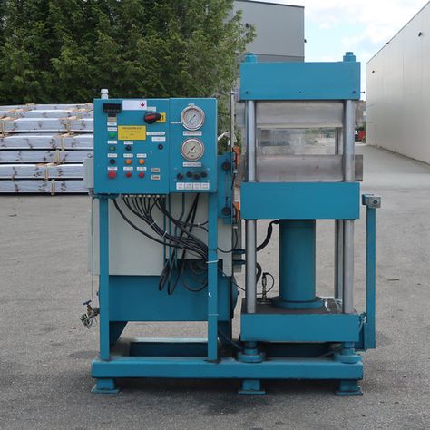
The manufacturing of hydraulic presses involves several key stages, from design and material selection to assembly and testing. The process is highly specialized and requires precise engineering to ensure the press meets performance, safety, and durability standards. Below are the general steps involved in hydraulic press manufacturing:
- Design and Engineering
- Initial Design: The first step in manufacturing a hydraulic press is designing it to meet the specific requirements of the customer or application. Engineers create detailed technical drawings, CAD models, and simulations to determine the size, force, stroke length, and other operational parameters of the press.
- Component Selection: Critical components like the hydraulic pump, valves, cylinder, frame, and control systems are selected based on the desired specifications. Material selection is crucial for ensuring the press’s strength and longevity. Typically, high-strength steel or cast iron is used for the frame and major structural components, while hardened steel may be used for components subjected to high wear.
- Customization: Depending on the intended application, hydraulic presses may be customized with specialized tooling, specific control systems, or additional features such as automated cycles or heat exchangers.
- Manufacturing of Components
- Frame and Structural Parts: The main structural components of the press are fabricated, typically using methods such as casting, forging, or machining. The frame of the press needs to be extremely rigid to withstand the high forces involved in pressing operations. Large frames are usually cast in molds, while smaller or more intricate parts may be machined from solid blocks of metal.
- Hydraulic Cylinder and Ram: The hydraulic cylinder and ram, which are responsible for applying pressure, are fabricated using precision machining to ensure smooth operation. The cylinder is typically made from high-strength steel, and the ram is often hardened to resist wear from constant pressure.
- Pump and Hydraulic System: The hydraulic pump is an essential component that determines the press’s ability to generate force. The pump may be a gear, piston, or vane type, depending on the application. Hydraulic hoses, valves, and fittings are also manufactured or sourced to ensure proper fluid flow and pressure regulation.
- Assembly
- Frame Assembly: The frame is assembled first, often involving welding or bolting together the main sections. If the press is large, it may be assembled in multiple stages.
- Hydraulic System Assembly: The hydraulic components, including the pump, valves, hydraulic cylinder, and pipes, are integrated into the frame. Careful attention is given to ensuring that the hydraulic system is sealed properly to avoid leaks and maintain pressure consistency.
- Ram and Pressing Mechanism: The ram, which is the moving part that applies pressure to the material, is installed. This component is connected to the hydraulic cylinder, and the entire pressing mechanism is calibrated to ensure smooth operation.
- Control and Electrical Systems: The electrical control panel, sensors, and automation systems are installed. These systems control the hydraulic press’s functions, including pressure, speed, and stroke length. In advanced models, programmable logic controllers (PLCs) are integrated to automate the press cycle.
- Testing and Quality Control
- Pressure Testing: One of the most important aspects of manufacturing a hydraulic press is testing its hydraulic system. The system is pressurized to ensure that the components can withstand the required loads without leaks or failures.
- Functionality Testing: After assembly, the press undergoes thorough functionality testing to verify that all movements, speeds, and pressures are within the required specifications. The control system is also tested for accuracy and reliability.
- Load Testing: The press is subjected to load testing to ensure it can handle the maximum intended force. This may include using test materials to simulate real-world operations and checking for stability, performance, and safety.
- Safety Checks: Hydraulic presses are equipped with various safety mechanisms, such as overload protection, emergency stop buttons, and safety interlocks. These features are rigorously tested to ensure they function correctly under all conditions.
- Final Adjustments and Calibration
- Fine-Tuning: After initial testing, any necessary adjustments are made to improve performance, such as fine-tuning the speed, pressure, or stroke length. The press is calibrated to meet the exact needs of the application, ensuring precision.
- Finishing: The hydraulic press is cleaned and inspected for any surface imperfections. Protective coatings may be applied to prevent rust and wear, and any cosmetic finishing is done.
- Packaging and Shipping
- Once the hydraulic press passes all tests, it is disassembled for shipping, if necessary, or fully assembled for delivery, depending on size and customer requirements.
- It is carefully packaged to prevent damage during transport. Large presses may be shipped in parts and require assembly at the customer’s facility.
- Installation and Training
- After delivery, the hydraulic press is installed at the customer’s site, where it is reassembled and connected to power, hydraulic, and control systems.
- Operators are trained on how to use the press, including how to operate the controls, maintain the equipment, and troubleshoot basic issues.
The manufacturing of hydraulic presses involves high precision, quality control, and careful attention to safety standards. It is essential that manufacturers adhere to international standards (such as ISO and ANSI) to ensure the machines perform safely and reliably over their service life.
The manufacturing of hydraulic presses starts with careful design and engineering to meet the specific requirements of the intended application. Engineers create detailed technical drawings and CAD models, determining the necessary specifications such as force, stroke length, and frame size. Material selection plays a crucial role, with components like the frame, cylinder, and ram often made from high-strength steel or cast iron to ensure durability and resistance to wear.
Once the design is finalized, the manufacturing of the various components begins. The frame and other structural parts are typically fabricated through processes like casting, forging, or machining. Large frames are often cast, while smaller or more intricate parts are machined from solid metal. The hydraulic cylinder and ram, responsible for generating and applying the pressure, are also machined with precision to ensure smooth movement and durability.
The next phase is the assembly of the press. The frame is first constructed, often involving welding or bolting. Afterward, the hydraulic system, including pumps, valves, and cylinders, is integrated into the frame. Careful attention is paid to seal the hydraulic components to prevent leaks and ensure pressure stability. The pressing mechanism, including the ram and cylinder, is connected, and the entire assembly is tested for correct operation.
Control systems, including electrical panels, sensors, and automation components, are installed to monitor and regulate the press’s functions. In advanced models, programmable logic controllers (PLCs) are used to automate the press cycle, providing precision and repeatability. The system is then tested to ensure it performs according to the required specifications. Pressure tests check for leaks, and functionality tests ensure the system responds properly to inputs.
Once the initial testing is complete, the press undergoes load testing to ensure it can handle the maximum force it’s rated for. Safety features, such as emergency stop buttons and overload protection, are thoroughly tested to ensure they function correctly under all conditions. After this, any necessary adjustments or fine-tuning are made to ensure optimal performance.
The hydraulic press is then cleaned, finished, and inspected for any surface imperfections. Protective coatings are applied to prevent rust, and any cosmetic finishing is completed. Once everything is ready, the press is carefully packaged for shipping. Depending on the size and design, the press may be shipped fully assembled or in parts that require on-site assembly.
Finally, once the hydraulic press arrives at the customer’s location, it’s reassembled if necessary, connected to the power and hydraulic systems, and calibrated for operation. Operators are trained on its use and maintenance, ensuring the press runs smoothly and safely throughout its lifecycle.
Once the hydraulic press is set up and running, ongoing maintenance and periodic inspections are critical to ensuring its long-term reliability and performance. Routine maintenance tasks include checking and replacing the hydraulic fluid, inspecting seals and hoses for signs of wear or leaks, and verifying that the pumps and valves are functioning correctly. The control systems should also be regularly checked to ensure sensors, actuators, and PLCs are performing as expected.
It is also essential to monitor the performance of the hydraulic system during regular operations. Over time, components like pumps, valves, and cylinders may experience wear and tear due to the high forces and pressures exerted during each press cycle. A preventative maintenance schedule can help identify potential issues before they lead to downtime or costly repairs. This includes cleaning the hydraulic reservoir, changing the oil and filters, and making sure all parts are well-lubricated.
For companies operating large-scale production facilities, a monitoring system might be implemented to track the performance of the hydraulic press in real-time. Sensors embedded in the machine can provide data on temperature, pressure, stroke length, and other critical parameters. This data can be analyzed to predict when certain components may need to be replaced or serviced, allowing for more efficient maintenance planning and reducing unexpected failures.
In addition to maintenance, operators should be trained to recognize early signs of malfunction or inefficiency. They should be familiar with troubleshooting procedures, such as identifying abnormal noises, vibrations, or pressure drops that could signal problems with the hydraulic system. Regular calibration of the press, especially in industries where precise tolerances are required, ensures that the press continues to operate within the specified parameters.
Advancements in hydraulic press technology also allow for integration with automated production systems. Some presses are designed with robotics or automated material handling systems to improve throughput, reduce human error, and streamline operations. In such systems, the press becomes a part of a larger automated assembly line, with the ability to change tooling and adjust parameters on the fly without requiring manual intervention.
As hydraulic press technology evolves, manufacturers may also adopt energy-efficient designs, including hydraulic systems that use less fluid and power or presses with energy recovery systems. These improvements can lead to reduced operational costs and less environmental impact, contributing to more sustainable manufacturing practices.
In the event of a malfunction or breakdown, having spare parts on hand and a strong support network for troubleshooting can minimize downtime. Manufacturers of hydraulic presses often provide maintenance manuals, training programs, and remote support options, allowing operators and maintenance personnel to address issues swiftly and effectively.
Ultimately, the longevity and efficiency of a hydraulic press depend on both the quality of its manufacturing and the care taken throughout its lifecycle. By following manufacturer-recommended maintenance procedures, operators can ensure that the press continues to deliver high performance and reliability for years to come.
Horizontal Hydraulic Press Machine
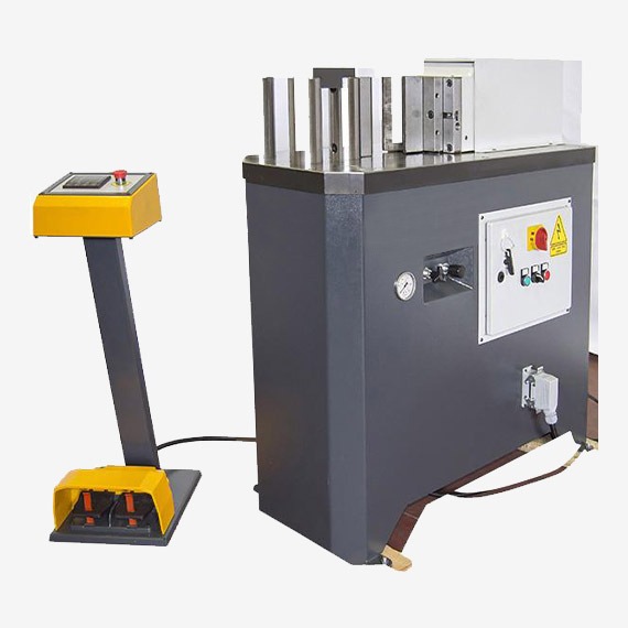
A horizontal hydraulic press machine is a type of hydraulic press where the primary press mechanism is oriented horizontally rather than vertically, as seen in conventional hydraulic presses. This configuration provides several advantages, especially when dealing with large, heavy, or awkwardly shaped workpieces. Horizontal presses are typically used in industries like metal forming, automotive, plastic molding, and in applications that require high precision and large capacities.
The main working principle of a horizontal hydraulic press machine is similar to other hydraulic presses. A hydraulic fluid is pressurized in a cylinder, creating force that moves a ram to apply pressure to the material placed between the press and a die or mold. The key difference lies in the positioning of the cylinder and ram, which are arranged horizontally, allowing for easier material handling, especially for larger or heavier workpieces.
Key Characteristics of a Horizontal Hydraulic Press Machine:
- Configuration: The horizontal orientation allows for better ergonomics, as the material to be processed is positioned on the horizontal surface. This setup makes it easier to load and unload parts, especially large and heavy components.
- Large Bed Size: Horizontal presses often feature a larger bed or table to accommodate bigger or bulkier workpieces. The wider bed makes it suitable for shaping, bending, or molding large components like automotive parts, structural elements, or large plastic molds.
- Higher Precision: Horizontal hydraulic presses can offer high precision in shaping and cutting operations, especially when paired with advanced controls and custom tooling.
- Increased Force Capacity: Horizontal presses often have a higher force capacity compared to their vertical counterparts, making them ideal for applications that require substantial pressure, such as deep drawing or heavy forging.
- Material Handling: The horizontal design allows for easier automation of material handling. It’s common to pair horizontal hydraulic presses with robotic arms, conveyors, or other material handling systems, enhancing the press’s throughput and efficiency.
- Safety Features: Horizontal presses are equipped with various safety features, such as pressure relief valves, overload protection, and emergency stop functions. These are critical to preventing accidents during the press operation, especially when dealing with large and heavy materials.
- Versatility: Horizontal presses are versatile and can be used for a wide variety of tasks, including punching, bending, embossing, molding, and forging. They are often custom-built to handle specific industrial applications.
Applications of Horizontal Hydraulic Press Machines:
- Metalworking: They are used for stamping, bending, punching, and deep drawing metal sheets and plates. The horizontal layout makes it easier to work with large metal parts, often found in the automotive and aerospace industries.
- Plastic Molding: Horizontal hydraulic presses are widely used in injection molding for plastic parts, where large molds are applied under high pressure.
- Forging: Heavy-duty horizontal presses are ideal for forging operations, where high force is required to shape and form metal parts.
- Assembly and Testing: Horizontal presses are also used for assembly operations and component testing, where consistent and precise force is needed.
Advantages:
- Easy Material Loading and Unloading: The horizontal configuration allows for more efficient loading and unloading of parts, particularly when large or heavy workpieces are involved.
- Improved Precision: Horizontal presses often provide better control over the material and tooling alignment, offering higher precision in various manufacturing processes.
- Reduced Maintenance: The horizontal orientation tends to reduce stress on the press components, which may result in lower wear and tear, leading to reduced maintenance costs over time.
Disadvantages:
- Space Requirements: Horizontal presses typically require more floor space than vertical presses, which could be a limitation in smaller facilities or production lines.
- Cost: Horizontal presses tend to be more expensive to manufacture and maintain than vertical presses, especially if they are customized for specific tasks.
Overall, horizontal hydraulic press machines are an excellent choice for applications that require high force, large workpieces, and precise material handling, providing versatility and efficiency across a wide range of industries.
A horizontal hydraulic press machine operates on the same principle as traditional hydraulic presses, using hydraulic fluid to generate force that moves a ram to apply pressure on a material. The key difference lies in the horizontal orientation of the press, which makes it particularly suitable for handling large, heavy, or cumbersome materials. This design enables more efficient material loading and unloading, especially for large workpieces, which can be positioned on the horizontal bed or table. As the ram moves horizontally across the press, it can apply consistent pressure across a larger surface area, which is ideal for certain types of operations such as molding, shaping, or punching.
These presses typically have a larger bed size compared to vertical models, providing more room for bigger workpieces. This added space is beneficial for industries that work with larger components like automotive parts, structural elements, or large plastic molds. In addition to the larger bed, horizontal presses often have higher force capacities, which makes them suitable for tasks that require substantial pressure, like deep drawing or heavy forging.
The horizontal orientation also improves material handling, as the workpieces are easily accessible from the side rather than being fed vertically into the press. This feature enhances ergonomics, particularly in applications where operators need to load and unload large or heavy materials. The design also allows for greater automation, with robotic arms, conveyors, or other handling systems being integrated into the process, which helps to increase efficiency and reduce manual labor.
In terms of precision, horizontal hydraulic presses offer excellent control over the movement of the ram and alignment of materials. When equipped with advanced control systems and custom tooling, they can achieve high precision in shaping, cutting, and molding, which is essential for industries like aerospace and automotive manufacturing. Furthermore, horizontal presses are versatile, able to perform various operations such as punching, bending, embossing, forging, and injection molding.
Safety features are also critical in these machines. They are equipped with pressure relief valves, overload protection, and emergency stop functions to ensure safe operation, particularly given the high forces involved in pressing large materials. While the horizontal design offers many advantages in terms of usability, ease of material handling, and precision, it does require more space on the shop floor compared to vertical presses. This larger footprint can be a consideration in smaller production environments. Additionally, the cost of manufacturing and maintaining a horizontal press tends to be higher, especially if the machine is customized for specific applications.
Despite these challenges, horizontal hydraulic presses are widely used across various industries, including metalworking, plastic molding, and forging, where high pressure and large workpieces are common. Their ability to handle complex tasks efficiently makes them an essential part of many modern manufacturing processes.
In addition to the advantages and challenges, horizontal hydraulic presses are designed with features that contribute to their efficiency, longevity, and adaptability. These presses often have a robust frame and structure to handle the immense pressure exerted during operations. The hydraulic cylinders and ram are precision-engineered to ensure smooth, controlled movement. With the horizontal design, the press is more stable under load, allowing for better force distribution, especially when processing large or uneven materials.
The hydraulic system of a horizontal press is also critical to its functionality. It typically includes a high-capacity pump, precision valves, and robust hoses to manage the pressure required for pressing tasks. The press is usually equipped with an efficient cooling system to prevent the hydraulic fluid from overheating during extended operations. Some advanced models use energy-saving systems, such as variable-speed pumps or energy recovery mechanisms, to reduce power consumption, making them more cost-effective and environmentally friendly over time.
As technology progresses, many horizontal hydraulic presses are now incorporating automation and smart control systems. These presses are often integrated with programmable logic controllers (PLCs) and touchscreen interfaces, allowing operators to control and monitor various parameters such as pressure, stroke speed, and cycle times. These advancements enhance precision and consistency, reduce human error, and make it easier to optimize the press for different tasks. The integration of sensors also allows for real-time feedback, enabling the press to adjust its parameters automatically to maintain optimal performance.
Furthermore, horizontal presses are designed with maintenance in mind. Easy access to critical components, such as the hydraulic fluid reservoir, pumps, and valves, makes routine maintenance and servicing more straightforward. Regular maintenance checks, including the inspection of seals, hoses, and hydraulic fluid levels, are essential to ensure the longevity and efficiency of the press. The modular design of some horizontal presses allows for easier upgrades or replacements of parts, which can help reduce downtime and extend the machine’s operational life.
Horizontal hydraulic presses are also ideal for industries that require a high level of precision and customization. For example, in metalworking or automotive manufacturing, custom dies and molds can be incorporated into the press for specialized parts, ensuring that the press can handle a wide range of materials and designs. The ability to swap tooling quickly and easily allows for greater flexibility in production, especially for high-mix, low-volume manufacturing.
Overall, horizontal hydraulic presses are highly versatile and capable of performing a wide variety of manufacturing tasks. Their ability to handle large workpieces, high pressure, and precise operations, combined with ease of material handling and automation options, makes them indispensable in many industrial sectors. Although they require a larger footprint and higher investment, the benefits they provide in terms of efficiency, safety, and precision often outweigh the drawbacks, making them a valuable asset for businesses seeking to optimize their production capabilities.
Small Horizontal Hydraulic Press

A small horizontal hydraulic press functions similarly to larger models but is designed for more compact, lighter, and often less demanding applications. While the basic principles of operation—using hydraulic pressure to move a ram or piston that applies force to materials—remain unchanged, the small horizontal hydraulic press is more suitable for smaller-scale tasks, limited spaces, and lower production volumes. These presses are commonly used in smaller workshops, laboratories, or small-scale manufacturing settings.
Small horizontal hydraulic presses are highly versatile machines, often used in tasks such as bending, shaping, embossing, punching, or even light-duty forging. They are ideal for applications that require moderate force but still need the benefits of a horizontal design, like better ergonomics and ease of material handling. Their smaller size makes them easier to integrate into existing production lines or workshops where space is limited.
These presses still maintain the essential features of their larger counterparts, such as a horizontal orientation that facilitates easy loading and unloading of workpieces, especially for larger materials that may not fit well in vertical presses. Even though they are smaller, these presses can still apply significant pressure, with force capacities typically ranging from 10 to 100 tons, depending on the model and application. This makes them suitable for light metalworking, plastic molding, or small-scale assembly and testing tasks.
The hydraulic system in a small horizontal press typically includes a pump, cylinder, and ram, but scaled down to meet the smaller size and force requirements. The hydraulic fluid is pressurized and directed to the cylinder, which moves the ram across the bed of the press to apply force. Smaller pumps and valves are used to ensure smooth and efficient operation, and some models feature energy-saving technologies such as reduced pump capacity or automatic pressure adjustments for optimized performance.
Compact and lightweight, small horizontal hydraulic presses can be equipped with manual, semi-automatic, or fully automatic controls, depending on the complexity of the application. In some cases, advanced features like programmable logic controllers (PLCs) and digital interfaces may be incorporated, allowing for precision control over the pressing process, such as stroke length, pressure, and cycle time. These controls are especially useful for ensuring consistency and precision in repeated tasks.
Safety features in smaller presses are just as critical as in larger models. These presses are equipped with safety guards, emergency stop buttons, pressure relief valves, and overload protection to prevent accidents. Some models may also include safety interlocks that stop the press if the operator’s hands are detected in the pressing area.
A key advantage of small horizontal hydraulic presses is their ability to operate in smaller spaces while providing efficient and consistent performance for a variety of tasks. They are generally more affordable than their larger counterparts, making them an attractive option for small businesses, startups, or research and development labs that require precision pressing but have limited space or budget. Additionally, their smaller size makes them easier to move and set up, adding to their versatility.
Despite their smaller size, these presses can still handle a wide range of materials, including metals, plastics, rubber, and composites, depending on the specific press configuration. Small horizontal hydraulic presses are especially useful in industries like automotive prototyping, electronics manufacturing, or jewelry making, where small, precise parts need to be formed, stamped, or assembled with relatively low force. They also find applications in educational settings, where they serve as a hands-on tool for learning about hydraulics and material processing.
In summary, small horizontal hydraulic presses offer a balance of compact design, ease of use, and versatility, making them suitable for applications in small-scale manufacturing, prototyping, or research. They retain the efficiency and ergonomic benefits of larger horizontal presses but in a more accessible package for smaller operations.
Small horizontal hydraulic presses are designed to offer many of the same benefits as their larger counterparts but in a more compact and cost-effective form. They operate on the same fundamental principle, using hydraulic pressure to generate force that moves a ram across a workpiece, applying pressure to shape or mold materials. The horizontal orientation is particularly useful in these smaller models because it allows for easier loading and unloading of parts, providing more ergonomic benefits compared to vertical presses. Even though these machines are smaller in size, they still deliver precision and power that can handle a range of tasks.
One of the main advantages of a small horizontal hydraulic press is its ability to work in smaller, confined spaces. Unlike larger presses, which can be cumbersome and require significant floor space, the compact design of a small press makes it ideal for workshops or manufacturing environments where space is at a premium. These presses can be easily integrated into existing production lines or used for small-scale operations without taking up too much room.
Despite their size, small horizontal hydraulic presses can still apply substantial force, typically ranging from 10 to 100 tons, making them capable of handling tasks like bending, embossing, punching, and light forging. They can also be used for precise work such as molding plastics, testing parts, or assembling components. The press’s design allows for easy positioning of materials, which is crucial for ensuring uniform pressure and accurate results.
Hydraulic pumps, cylinders, and rams are all scaled down in smaller presses, ensuring that the machine can perform its tasks efficiently without requiring excessive hydraulic fluid or energy. Some models even incorporate energy-saving features, such as adjustable pumps or systems that reduce power consumption when the press is not operating at full capacity. These features help keep operating costs low, which is a major benefit for smaller businesses.
Although compact, small horizontal presses still come equipped with safety mechanisms to protect operators. These include emergency stop buttons, pressure relief valves, safety guards, and overload protection. Some machines may even include additional safety interlocks to prevent the press from operating if it detects potential hazards, further ensuring safe operation. This makes them suitable for environments where safety is a priority, such as in educational settings or small-scale production facilities.
Another important consideration is the flexibility these presses offer. Many models allow for adjustments in parameters like stroke length, pressure, and cycle time, which can be controlled through manual, semi-automatic, or fully automatic systems. This adaptability ensures that the press can be used for a wide range of applications and different materials, including metals, plastics, rubber, and composites.
Small horizontal hydraulic presses are especially popular in industries like automotive prototyping, electronics manufacturing, jewelry making, and small-scale metalworking. In these industries, precision is often critical, and the ability to customize the press for specific tasks makes these machines invaluable. Whether it’s forming small parts, stamping intricate designs, or testing materials, these presses are versatile enough to handle a variety of projects while maintaining high levels of accuracy.
Overall, small horizontal hydraulic presses offer an excellent solution for companies or individuals who need a reliable, versatile, and cost-effective machine for precision pressing, molding, or shaping. Their compact design, ease of use, and ability to handle different materials make them indispensable tools for small businesses or research and development labs. Despite their smaller size, they provide much of the power and precision of larger models, offering an affordable and efficient option for smaller-scale operations.
Small horizontal hydraulic presses are particularly useful in industries where space is limited but precise and consistent pressing is essential. Their compact nature doesn’t compromise their ability to perform critical tasks, making them ideal for smaller workshops, R&D labs, or prototyping environments. These presses are well-suited for handling small to medium-sized workpieces, offering high precision in applications such as metal forming, plastic molding, and even certain forms of testing and assembly.
The hydraulic system in a small horizontal press is typically designed to be energy-efficient while providing the required force for operations. Smaller pumps and cylinders are used to ensure the machine operates within its specific pressure range, which also helps reduce wear on components and lower the operational cost. This makes small horizontal presses an excellent choice for businesses or workshops with limited resources, as the cost of running and maintaining the machine is relatively low compared to larger, more industrial hydraulic presses.
In addition to their cost-efficiency, small horizontal hydraulic presses are often designed for ease of use. Many are equipped with intuitive control systems that allow operators to adjust parameters such as pressure, stroke length, and cycle times. Even if the press is manual, operators can quickly learn to use the machine, making it accessible even to less experienced personnel. For more advanced applications, some models come with digital controls or programmable logic controllers (PLCs), providing a higher level of automation and control.
The maintenance of small horizontal hydraulic presses is also simplified by their compact design. Many components are easily accessible, reducing the time and effort required for routine maintenance or troubleshooting. Whether it’s changing the hydraulic fluid, inspecting seals, or replacing a pump, small presses often require less time for upkeep, which minimizes downtime and increases productivity. Regular checks on key components, such as the cylinder and hydraulic system, help ensure that the machine continues to perform at its best without any significant issues.
Customization options for small horizontal hydraulic presses are available as well, allowing users to tailor the press for specific applications. Whether it’s designing specialized tooling or integrating a specific automation system, many manufacturers offer solutions that ensure the press meets the needs of the particular task at hand. This versatility makes them adaptable across a wide variety of industries, from automotive prototyping to smaller-scale plastic molding and even custom fabrication projects.
For industries that focus on high-precision work, like jewelry or electronics, small horizontal hydraulic presses can achieve tight tolerances that are critical in producing parts with exact specifications. The horizontal design of the press allows for better material positioning, reducing the risk of errors and ensuring more consistent results across multiple cycles. Operators can also easily monitor the pressing process to ensure the quality of the output is maintained throughout production.
The flexibility and compactness of small horizontal hydraulic presses make them a valuable asset for businesses that need reliable and consistent performance but lack the space or resources for larger machines. Their ability to handle a variety of tasks—ranging from simple pressing to more intricate molding or forming operations—while occupying a relatively small footprint, makes them ideal for smaller operations that still require the precision and power of hydraulic systems.
Overall, small horizontal hydraulic presses offer an excellent combination of efficiency, versatility, and affordability, making them an attractive choice for businesses looking to streamline their production processes, reduce costs, and maintain a high level of quality in their manufacturing operations.
Small horizontal hydraulic presses also provide advantages in terms of ease of integration into automated production lines. While larger presses are often too bulky or complex to be easily integrated, the compact design of small presses makes them much easier to pair with robotic arms, conveyors, or other automated material handling systems. This integration can significantly improve throughput by reducing manual labor and increasing production efficiency. For example, a robotic arm can load and unload workpieces quickly, while the press operates autonomously, making it ideal for tasks that require repetitive, high-precision operations such as stamping, cutting, or assembling components.
In addition to automation, the ability to quickly change tooling on small horizontal hydraulic presses makes them versatile for businesses that need to perform a wide variety of tasks. Tooling such as dies, molds, and punches can be swapped easily, which is particularly useful in industries like automotive or aerospace, where prototyping or small-batch production of different parts is common. The press can be reconfigured to perform different functions, making it a more flexible asset in fast-paced production environments.
Another factor that contributes to the utility of small horizontal hydraulic presses is their ability to work with a wide range of materials. Whether it’s metal, plastic, rubber, or composite materials, these presses are capable of applying the necessary force to mold, shape, or test the materials for a variety of applications. They are often used in the fabrication of metal parts, such as stamping and bending thin metal sheets, or in plastic molding, where high pressure is used to shape plastic into specific forms. The horizontal configuration allows for better control over the material, reducing the likelihood of defects or inconsistencies during the pressing process.
For businesses that require high-precision results, small horizontal hydraulic presses provide a stable platform that ensures accuracy. The horizontal orientation keeps the workpiece flat, which is important for applications where uniform pressure across the entire surface is required. This consistency in pressure helps to maintain the quality of the finished parts, especially when small, delicate, or complex components are being produced. The precise control over the force applied by the press also allows operators to ensure that parts meet exact specifications, which is critical in industries like electronics manufacturing or medical device production.
Environmental considerations are also important when evaluating small hydraulic presses. With rising energy costs and increasing environmental awareness, manufacturers have begun incorporating more energy-efficient features into small presses. These might include variable-speed pumps that adjust the flow of hydraulic fluid based on the load, energy recovery systems that capture and reuse energy from the press’s operations, and designs that minimize hydraulic fluid consumption. These improvements not only reduce the environmental impact of operating the press but also lower operating costs, making small horizontal hydraulic presses even more cost-effective over time.
Small horizontal hydraulic presses are often equipped with a variety of user-friendly features that make them accessible to operators at different experience levels. Many presses have simple interfaces with basic controls for adjusting pressure, stroke length, and cycle times. More advanced models may include digital displays or touch-screen interfaces that allow for precise input of settings and real-time monitoring of the press’s operation. These features make the presses easier to use, which helps reduce training time and the potential for errors during operation.
Maintenance of small horizontal hydraulic presses is generally straightforward, thanks to their user-friendly design. Access to key components like the hydraulic fluid reservoir, pumps, and cylinders is typically easy, allowing for quick inspections, fluid changes, and other routine maintenance tasks. This reduces the overall maintenance burden and helps ensure that the press continues to function at its optimal level throughout its lifecycle.
Small horizontal hydraulic presses are also valuable tools for research and development (R&D) purposes. Engineers and designers use these presses for testing and prototyping new products, allowing them to refine designs and experiment with different materials or processes without committing to large-scale production equipment. The ability to conduct R&D on a smaller, more affordable machine allows companies to innovate more rapidly and cost-effectively.
In conclusion, small horizontal hydraulic presses offer businesses a cost-effective, flexible, and efficient solution for a variety of manufacturing and prototyping tasks. With their compact size, ease of integration into automated systems, and ability to handle a wide range of materials, these presses serve as valuable assets for companies of all sizes. Whether for small-scale production, prototyping, or research and development, small horizontal hydraulic presses provide consistent performance, high precision, and versatility while maintaining relatively low operational costs.
Horizontal Hydraulic Press Manufacturing
The manufacturing process of horizontal hydraulic presses involves several stages, from initial design and material selection to assembly and testing. The goal is to produce a machine that offers precision, reliability, and high performance under heavy loads. Manufacturers focus on ensuring that the press can withstand high forces while maintaining a smooth and controlled operation. Below is an overview of the key steps involved in the manufacturing process of a horizontal hydraulic press.
The first step in the manufacturing process is designing the horizontal hydraulic press. Engineers and designers collaborate to create a blueprint that specifies the size, force capacity, material requirements, and other key features of the machine. This stage involves determining the dimensions of the bed, the configuration of the hydraulic cylinder, the maximum pressure the system will need to handle, and other operational parameters such as stroke length, speed, and control systems. The design must also account for safety features, such as overload protection, emergency stop functions, and guards to prevent operator injury.
Once the design is finalized, the manufacturing process moves to material selection. Key components of the hydraulic press, such as the frame, bed, and hydraulic cylinders, must be made from high-strength steel or other durable materials capable of withstanding high forces without warping or cracking. The quality of the materials used is critical to ensuring the long-term performance and durability of the press. For example, high-tensile steel is commonly used for the frame to ensure the press remains stable under heavy load conditions. The hydraulic components, including the pump, valves, and hoses, are made of materials that resist wear and corrosion under high pressure.
The next step is machining the components. This involves cutting, shaping, and refining the parts that make up the press. For example, the frame of the horizontal hydraulic press is fabricated and welded together to form a sturdy structure capable of bearing the forces exerted during the pressing process. CNC (Computer Numerical Control) machines are often used to ensure that each part is produced to precise specifications. Hydraulic cylinders are machined and polished to ensure smooth movement and minimal friction during operation. The bed and table are also machined to provide a flat and stable surface for positioning workpieces.
After machining, the hydraulic components are assembled. The hydraulic pump, valves, pressure relief systems, and other critical elements are integrated into the press’s hydraulic circuit. The pump must be designed to provide the required pressure and flow rate to move the ram or piston across the bed and apply the necessary force. The hydraulic fluid used in the system must be carefully selected to ensure optimal performance under varying temperatures and pressures. The press is also equipped with hoses, filters, and accumulators to maintain fluid flow and prevent contamination.
Once the hydraulic system is fully assembled, the press components are brought together for final assembly. The frame, hydraulic cylinder, bed, and table are connected, and the various electrical and control systems are installed. For small horizontal hydraulic presses, the electrical systems may include basic controls for manual operation, while more advanced models may include programmable logic controllers (PLCs) or digital touchscreens to allow for automated operation and precise adjustments of pressure, stroke, and cycle time. The operator interface is designed to be user-friendly and easy to navigate.
At this stage, safety features are integrated into the press. These may include safety guards, pressure sensors, emergency stop buttons, and overload protection devices. These features ensure that the press can operate safely in a production environment and protect the operator from potential hazards. For example, safety interlocks prevent the press from operating if the protective covers are removed, while pressure relief valves prevent the system from operating beyond its maximum pressure rating.
Once the press is fully assembled, the machine undergoes a series of tests to ensure that it meets all operational specifications and safety standards. This includes checking the hydraulic system for leaks, testing the press under load to verify that it applies the correct force, and calibrating the controls to ensure precise operation. The press may also undergo endurance testing to ensure that it can perform reliably over an extended period. Any necessary adjustments are made during this testing phase to fine-tune the machine’s performance.
Finally, the horizontal hydraulic press is thoroughly inspected and cleaned before being shipped to the customer. A quality control team checks the final product for defects, ensuring that all components function as expected and meet industry standards. Once approved, the press is packaged and delivered to the customer, ready for installation and operation.
The manufacturing process of a horizontal hydraulic press requires careful planning, precision engineering, and attention to detail. It involves several stages, including design, material selection, machining, assembly, and testing, all of which ensure that the final product is capable of withstanding the heavy loads and rigorous demands of industrial applications. Each component must be made to exacting standards to ensure the press operates efficiently, reliably, and safely. With advancements in technology, manufacturers are now able to produce hydraulic presses with more advanced controls, energy-saving features, and increased automation, making them more efficient and cost-effective in the long run.
The process of manufacturing a horizontal hydraulic press is complex and requires precise engineering, attention to detail, and the integration of several systems to ensure that the machine delivers the required force and reliability. The first step is to ensure that the press is designed for the specific application it will be used for. Engineers develop a detailed blueprint that incorporates the size, force requirements, and other operational specifications. Factors such as stroke length, speed, pressure settings, and the desired type of material to be processed are carefully considered. The press design must account for structural integrity and stability, as it needs to withstand substantial forces during operation.
After the design is finalized, materials are selected. High-quality, durable materials are necessary to ensure that the press can handle the stresses associated with pressing operations. Strong steels and alloys are typically chosen for the frame and structural components, as these materials can handle the pressures exerted during use without deforming. The hydraulic system also requires specific materials, such as corrosion-resistant metals for the pump, valves, and piping, to ensure longevity and reliability in high-pressure environments.
Machining is the next critical step in the manufacturing process. Components such as the press frame, bed, ram, and hydraulic cylinders must be precisely cut, shaped, and finished to meet the design specifications. This typically involves using advanced CNC machines to achieve tight tolerances and high-quality finishes. The precision of the machining process ensures that the parts fit together perfectly during assembly and that the hydraulic components, particularly the cylinders, operate smoothly without excessive friction.
After machining, the press components are assembled. The hydraulic pump and other fluid control systems are integrated, ensuring that the hydraulic fluid circulates properly through the system to move the ram. The hydraulic cylinders must be properly aligned, and the fluid system must be tested for leaks to prevent any operational issues during use. At this stage, it’s also essential to verify that all connections are secure, and any seals are in place to prevent fluid loss.
With the main components assembled, attention shifts to incorporating the press’s electrical and control systems. For manual presses, this might involve basic switchgear to control the hydraulic system. More advanced models, however, incorporate sophisticated control systems, such as PLCs, which allow for automated operations. These systems allow operators to set and monitor parameters like pressure, stroke length, and cycle time, improving the press’s efficiency and precision. The control panel is designed for ease of use, ensuring that operators can easily adjust settings as needed.
Next, safety features are integrated into the machine. Horizontal hydraulic presses often include emergency stop buttons, pressure relief valves, and overload protection systems to ensure safe operation. The press must have mechanisms to prevent accidents, such as automatic shutdown in case of an overload or malfunction. Safety guards are also incorporated to protect the operator from potential hazards, such as moving parts or hot surfaces. These safety measures are critical to meeting regulatory standards and ensuring the press operates in a safe environment.
Once assembly is complete, the press undergoes rigorous testing. The hydraulic system is checked for leaks, and the machine is tested under load to ensure it can generate the required force. Calibration is performed to ensure that the press applies consistent and accurate pressure during operation. The press may also undergo endurance testing to verify that it can maintain performance over long periods of continuous use. Any adjustments or refinements are made during this testing phase to ensure that the press is fully functional and reliable.
Finally, before the machine is shipped to the customer, it is subjected to a thorough inspection and cleaning. A quality control team carefully examines the press to ensure it meets all specifications and safety standards. This inspection includes checking the overall construction, hydraulic system, electrical components, and safety features. The press is then cleaned and prepared for shipping, ensuring that it arrives in optimal condition.
Manufacturing a horizontal hydraulic press requires a combination of engineering expertise, precise manufacturing techniques, and a commitment to safety and quality. Each stage of production, from design and material selection to assembly and testing, must be carefully executed to ensure that the press will deliver reliable performance under heavy load conditions. With advancements in automation, energy efficiency, and control systems, modern hydraulic presses are more capable and versatile than ever, making them essential tools for a wide range of industrial applications.
Once the manufacturing process is completed and the horizontal hydraulic press is assembled, the final quality assurance steps are critical. These processes ensure that the press will perform optimally in real-world applications. Engineers conduct a series of functional tests to simulate actual operating conditions, checking for proper hydraulic fluid flow, load capacity, and overall performance. The press is often subjected to extended testing cycles, running through various stages of operation to verify that it maintains stable pressure and consistent results.
During this phase, the machine is monitored closely for any signs of malfunction or inefficiency. Any issues discovered are addressed immediately, whether it be fine-tuning the hydraulic system, recalibrating pressure settings, or adjusting the alignment of moving parts. The press is then subjected to load testing, where it is gradually brought up to its maximum capacity to ensure it can handle the intended workload without issues. These tests help identify potential problems that might not be apparent during initial assembly but could emerge during regular usage.
Once the press passes all functional tests, a comprehensive inspection of all components is conducted. Every part of the hydraulic press, including mechanical, electrical, and hydraulic systems, is thoroughly inspected to ensure that it adheres to both industry standards and the customer’s specific requirements. The safety features are tested again to ensure they function correctly in various emergency situations, ensuring that the press will stop if a safety hazard is detected, protecting operators and reducing the risk of injury.
After passing all tests and inspections, the horizontal hydraulic press is carefully cleaned to remove any residues from the manufacturing process. Any hydraulic fluid remnants are drained, and all surfaces are wiped down to prevent contaminants from affecting the press during its first operation. At this stage, all components are lubricated, and seals are checked to ensure that they are properly in place and functioning to prevent hydraulic fluid leaks.
The press is then packaged for shipping. Proper packaging is essential to prevent any damage during transport. Typically, the press is carefully disassembled into major sections (such as the frame, bed, hydraulic components, and controls) and packed using high-quality materials to cushion and protect each component. Detailed assembly instructions and user manuals are also included to assist in setting up the press at its final destination.
Once the press arrives at its destination, it is carefully reassembled and tested one more time on-site. If the press has been shipped in parts, a trained team of technicians will handle the assembly and integration. After reassembly, the press undergoes a final round of operational tests to ensure it is functioning properly and meets all performance requirements. This step is crucial, as it ensures that the press is ready for immediate use and operates as expected in its intended environment.
Training may also be provided to the customer or end users. This training typically includes instructions on the proper setup, maintenance, and operation of the press. Operators are educated on how to adjust settings like pressure, stroke length, and cycle time, as well as how to troubleshoot common issues. Training also covers safety protocols, such as proper use of safety guards, emergency stop mechanisms, and maintenance practices.
Overall, the entire process, from initial design to delivery and training, requires significant expertise and coordination. Manufacturers ensure that the horizontal hydraulic press is built to last and perform efficiently for years, even under heavy loads. The attention to detail throughout the manufacturing process, combined with thorough testing and quality control measures, guarantees that the machine can handle the pressures of industrial environments. The final result is a machine that offers reliability, precision, and safety, making it an invaluable tool for a variety of industries, including automotive, metalworking, plastics, and many more.
Stainless Steel Cookware Manufacturing Process
The manufacturing process for stainless steel cookware involves several stages, from material selection to shaping, finishing, and quality control. Stainless steel cookware is prized for its durability, resistance to corrosion, and ability to retain heat evenly. The process of making high-quality stainless steel cookware requires precise control over materials, forming techniques, and finishing processes to ensure the final product meets both functional and aesthetic standards.
The first step in manufacturing stainless steel cookware is selecting the appropriate material. Stainless steel comes in various grades, and the most common grades for cookware are 18/8 (18% chromium, 8% nickel) and 18/10 (18% chromium, 10% nickel), which offer a good balance of strength, resistance to rust, and durability. Higher-quality cookware may include additional elements such as molybdenum to increase corrosion resistance. The selected stainless steel is sourced in large sheets or coils, depending on the size and design of the cookware to be produced.
Next, the stainless steel sheets or coils are cut to the required size and shape. This is typically done using high-precision cutting tools like laser cutters, water jets, or shears. The sheets are carefully measured to ensure uniformity, as the final shape and size of the cookware will depend on this initial cutting process. The cutting process is critical in determining the cookware’s form, so accuracy is key to ensuring proper fit during assembly.
Once the stainless steel is cut to size, the cookware is formed into its desired shape. For pots and pans, this is typically done using deep drawing or stamping. Deep drawing is a process in which a flat sheet of stainless steel is placed into a die, and a punch is used to force the metal into the mold, creating the desired shape. This process is used to form the body of the cookware, including the sides and bottom. The metal is stretched and shaped under high pressure to create a smooth and consistent surface. After forming, the cookware may undergo a process called “trimming” to remove any excess metal around the edges.
For cookware that requires a handle, this step also involves the attachment of the handle. Stainless steel handles are often welded or riveted to the cookware body, depending on the design. Welding provides a strong bond and is preferred for certain designs, while riveting may be used for aesthetic or functional reasons. The handles are usually made from the same high-quality stainless steel to ensure the cookware is durable and retains its high-end appearance.
In many cases, cookware manufacturers incorporate an additional layer of material, such as an aluminum or copper core, to improve heat distribution. This is especially common in high-end cookware, as it helps to ensure that heat is evenly distributed across the cooking surface, preventing hot spots. The aluminum or copper core is inserted between layers of stainless steel, and the cookware is bonded under high pressure and heat. This process is known as “clad” cookware, where multiple layers of metal are fused together to create a composite material.
After the cookware is formed and any additional layers are bonded, the surface is polished to achieve a smooth, reflective finish. Polishing is an important step, as it not only enhances the appearance of the cookware but also provides a smooth surface that is resistant to food sticking. Several types of finishes are used in stainless steel cookware, including mirror polishing, satin finishes, or brushed finishes. Mirror polishing gives the cookware a highly reflective, shiny surface, while satin and brushed finishes provide a more matte or textured look, which some consumers prefer for aesthetic or practical reasons.
The next step is to clean the cookware. Stainless steel cookware is thoroughly cleaned to remove any manufacturing oils, residues, or contaminants from the surface. This is typically done using a combination of mechanical cleaning, such as brushing or abrasive cleaning, and chemical cleaning processes, such as acid washing or passivation. The passivation process is crucial because it helps to enhance the stainless steel’s corrosion resistance by removing iron particles from the surface and creating a protective oxide layer.
Once the cookware is cleaned, any necessary finishing touches are applied. This can include adding engraved logos, branding, or other decorative elements. Some cookware may also undergo heat treatments to strengthen the metal or improve its heat conductivity. For example, in some cookware, the bottom may be reinforced with a thicker layer of metal or a non-stick coating may be applied. Non-stick coatings are often applied to frying pans or sauté pans, providing an easy-to-clean surface and preventing food from sticking. These coatings are typically made from Teflon or ceramic-based materials, and the cookware is heated to bond the coating to the surface.
Before the cookware is packaged and shipped, it undergoes rigorous quality control checks. These checks ensure that the cookware meets both safety standards and performance expectations. Common quality control measures include checking the integrity of welded or riveted handles, ensuring the cookware is free from defects such as cracks or dents, and verifying that the non-stick coating adheres properly. The cookware is also tested for heat distribution, durability, and overall functionality. This ensures that the cookware can withstand everyday use and maintain its performance over time.
Finally, the cookware is carefully packaged to prevent damage during transit. Packaging typically includes protective materials, such as foam or bubble wrap, to safeguard the cookware. Manufacturers may also include user manuals and care instructions to help customers maintain the cookware’s longevity. The packaging is designed to be both protective and visually appealing, as the cookware is often sold in retail stores or online.
The manufacturing of stainless steel cookware requires high precision at each step, from material selection to forming, finishing, and quality control. By combining high-quality stainless steel with advanced manufacturing techniques and attention to detail, manufacturers produce cookware that is durable, resistant to corrosion, and capable of delivering optimal cooking performance. Whether the cookware is designed for home use or professional kitchens, the end result is a product that combines functionality with aesthetic appeal.
The stainless steel cookware manufacturing process continues with various precision steps to ensure the product is not only functional but also aesthetically pleasing. After the cookware is assembled, it undergoes heat treatment in some cases to further enhance its durability and performance. This heat treatment may include processes like annealing, which involves heating the metal to a specific temperature to improve its hardness and resistance to corrosion. This step ensures the cookware can endure prolonged exposure to high temperatures without warping or losing its structural integrity.
Once heat treatment is completed, the cookware may undergo a final round of polishing or brushing to refine its surface. This gives the cookware its final texture and sheen. The surface can be mirror-polished for a highly reflective look or brushed to create a more muted, matte finish. Both finishes offer different aesthetic qualities and functional benefits. Mirror finishes are typically easier to clean and give a shiny, elegant look, while brushed finishes tend to hide fingerprints and stains better, making them popular for everyday use. Each piece is carefully inspected to ensure uniformity in finish, as well as to verify that there are no imperfections in the surface, such as scratches, discoloration, or irregularities.
After polishing, the cookware is cleaned again to remove any residual polishing compounds or other contaminants. This is usually done through ultrasonic cleaning or another method to ensure the surface is pristine. This cleaning process is crucial, as any leftover materials can affect the cookware’s performance and appearance.
The final stages of manufacturing include quality control and packaging. Each piece of cookware is subjected to rigorous quality control checks to ensure it meets high standards. These checks include verifying the functionality of the cookware, such as ensuring the handle is securely attached and that there are no defects in the welds or rivets. If non-stick coatings have been applied, tests are conducted to ensure the coating is evenly distributed and adheres correctly. Additionally, some manufacturers may conduct tests on the cookware’s ability to withstand extreme temperatures and ensure that it performs as expected on various stovetops, whether gas, electric, or induction. The cookware is also checked for heat distribution and how evenly it cooks food, ensuring that the end product will perform well in the kitchen.
Once quality control is complete, the cookware is packaged for shipment. The packaging process involves placing the cookware into protective materials like bubble wrap, foam, or custom-fit inserts to ensure that it arrives undamaged. The packaging also includes care instructions and sometimes a warranty, which are essential for customers to maintain the cookware over time. Some brands may also include informational leaflets or booklets with recipes or tips on how to care for stainless steel cookware to prolong its life and keep it looking new.
Packaging is also designed with branding in mind, as it plays an important role in marketing. High-end cookware brands often use premium, visually appealing packaging to convey the quality of the product. The cookware is then labeled and shipped to distributors or retailers, where it will be available for purchase. In some cases, cookware may also be sold directly to consumers through e-commerce platforms, with additional care taken to ensure the product reaches the customer in excellent condition.
Stainless steel cookware manufacturing is a multi-step, highly detailed process that combines advanced technology with craftsmanship. From selecting the right material to forming, finishing, testing, and packaging, each stage plays a crucial role in ensuring the cookware is durable, functional, and visually appealing. The result is a high-quality product that meets the demands of consumers, whether they’re professional chefs or home cooks. With the right combination of material quality, precision manufacturing, and quality control, stainless steel cookware continues to be a popular choice in kitchens worldwide for its longevity, performance, and versatility.
As the manufacturing process of stainless steel cookware progresses, the attention to detail at each stage remains paramount to delivering a product that performs well in real-world cooking environments. After the cookware is packaged and sent to retail or directly to customers, the final responsibility for its quality lies with the consumer’s usage and care. However, manufacturers ensure that the cookware’s longevity is maximized through continuous innovations in material science, design improvements, and enhancements to functionality.
One of the key developments in recent years has been the advancement in induction-ready cookware. Stainless steel alone does not conduct heat as well as some other metals, such as copper or aluminum. To address this, many manufacturers integrate a layer of magnetic material in the base of the cookware to make it compatible with induction stoves. Induction cooking requires cookware with a magnetic base, as the heat is generated directly through electromagnetic induction. As a result, manufacturers have created cookware that incorporates this technology, allowing users to benefit from the efficiency and speed of induction cooking.
In addition to induction compatibility, many stainless steel cookware brands have invested in incorporating ergonomic handle designs for enhanced comfort and safety. The handles are engineered to remain cool during cooking, even when the pot or pan is heated, and they are designed to provide a secure grip, reducing the risk of slipping or accidents. Some manufacturers even incorporate handles that are riveted with an additional layer of stainless steel to ensure strength and durability over time. The handle attachment is a critical part of the manufacturing process because it directly affects the safety and functionality of the cookware.
Another area of development in the manufacturing of stainless steel cookware involves the integration of non-stick coatings, especially on frying pans or sauté pans. While stainless steel itself is known for its durability and resistance to staining, many consumers seek the ease of cleaning that non-stick surfaces offer. Manufacturers have responded by combining stainless steel with non-stick coatings, such as Teflon or ceramic-based materials, which provide easy food release and simple cleanup. However, there is an ongoing effort to improve these coatings to ensure they are safe, long-lasting, and free of harmful chemicals like PTFE (polytetrafluoroethylene) or PFOA (perfluorooctanoic acid).
Furthermore, stainless steel cookware is being designed with energy efficiency in mind. With rising energy costs and increasing environmental concerns, manufacturers are now focused on improving heat retention and distribution across cookware surfaces. Clad stainless steel cookware—where layers of aluminum or copper are bonded between layers of stainless steel—provides superior heat conduction compared to traditional single-layer stainless steel. This ensures that the cookware heats up quickly and distributes heat evenly, reducing cooking times and improving energy efficiency.
Manufacturers also strive to incorporate eco-friendly practices into the production of stainless steel cookware. Sustainable practices include reducing waste in the manufacturing process, using recyclable materials for packaging, and minimizing the carbon footprint associated with production. Some companies also focus on reducing the environmental impact of the raw materials they use by sourcing steel from certified, sustainable suppliers. This shift toward more environmentally friendly practices aligns with consumer preferences for eco-conscious products and can influence a brand’s reputation in the market.
Beyond the technical innovations, the aesthetic aspects of stainless steel cookware have continued to evolve. Manufacturers often offer a variety of styles, finishes, and designs to cater to different consumer tastes. While the polished, mirror-like finish remains popular for its elegant appearance, brushed or matte finishes are often chosen for their more contemporary look and practicality. These finishes also help to minimize the appearance of fingerprints, which is important for cookware used regularly in home kitchens or professional settings.
Quality assurance continues to play a vital role throughout the entire process, from initial design to final shipment. As competition in the cookware industry grows, manufacturers have developed more stringent testing protocols to ensure that each piece of cookware not only meets the expected standards for durability and performance but also adheres to regulatory safety standards. This ensures that consumers receive a product they can trust for both safety and cooking efficiency.
The final product that reaches consumers is the result of a sophisticated manufacturing process, combining cutting-edge technology, craftsmanship, and ongoing innovation. Stainless steel cookware continues to be a staple in kitchens worldwide due to its unmatched combination of durability, versatility, and ease of maintenance. As trends in cooking and environmental responsibility evolve, so too does the manufacturing of cookware, ensuring that stainless steel remains at the forefront of kitchen technology.
Hydraulic presses are machines used to exert a high amount of pressure on a material or object. They are widely used in manufacturing, metalworking, and other industries for tasks like shaping, molding, punching, and testing materials. The specifications of a hydraulic press vary depending on its intended use and size, but the key specifications usually include the following:
1. Pressing Force (Capacity)
- This is the maximum force the hydraulic press can exert. It’s usually measured in tons (tonnage) or kilonewtons (kN).
- Common capacities range from 10 tons to over 1,000 tons, depending on the machine size and application.
2. Working Pressure
- The operating pressure of the hydraulic system, usually expressed in megapascals (MPa) or pounds per square inch (psi).
- Hydraulic presses typically operate at pressures between 10 and 35 MPa, depending on the design.
3. Stroke Length
- The maximum distance the ram (the pressing part) can travel.
- The stroke length affects the size of the material that can be processed.
- Typically ranges from a few inches to several feet, depending on the press design.
4. Table Size
- The dimensions of the table or bed where the workpiece is placed.
- Varies depending on the press size and application but is essential for determining the maximum size of parts that can be processed.
5. Speed of Ram (Advance, Return)
- The speed at which the ram moves during its advance and return strokes.
- Often has multiple speed stages: rapid approach, pressing, and return.
- Speed is usually measured in millimeters per second (mm/s) or inches per minute (IPM).
6. Pump Type
- Gear Pumps: Most common, cost-effective, and suitable for lower-pressure applications.
- Piston Pumps: Provide higher pressure and are more efficient for heavy-duty presses.
- Vane Pumps: Often used for medium-duty applications with moderate pressures.
7. Hydraulic Fluid
- The type of fluid used in the hydraulic system, which can be mineral oil, water-based fluids, or synthetic oils.
- The viscosity, pressure tolerance, and cooling properties of the fluid are essential for proper press operation.
8. Electrical Requirements
- Includes the motor power required to run the hydraulic system, typically measured in horsepower (HP) or kilowatts (kW).
- Electrical input specifications (voltage, phase, and frequency) are also critical.
9. Frame Construction
- Hydraulic presses typically have a heavy-duty frame made from steel or cast iron to support the high forces.
- Frame design varies depending on whether the press is a C-frame, H-frame, or other types, with each offering different advantages in terms of rigidity, accessibility, and ease of use.
10. Control System
- Many modern hydraulic presses have programmable logic controllers (PLCs) that automate the operation, adjust parameters, and improve precision.
- Some presses include digital pressure gauges, load cells, and automated press cycles.
11. Safety Features
- Includes overload protection, emergency stop functions, pressure relief valves, and safety interlocks to ensure operator safety during operation.
12. Options and Accessories
- Cushioning: For extra pressing power.
- Heat Exchangers: To prevent overheating of the hydraulic fluid.
- Tooling: Custom dies or molds for specific applications.
Hydraulic presses are designed to exert significant pressure on materials for shaping, molding, and other tasks. The key specifications include pressing force, which is typically measured in tons or kilonewtons and determines the maximum pressure the press can exert. This varies widely, with capacities ranging from 10 tons to over 1,000 tons. The working pressure, expressed in megapascals (MPa) or pounds per square inch (psi), indicates the pressure at which the hydraulic system operates, generally between 10 and 35 MPa for most presses.
Another crucial specification is the stroke length, which determines how far the ram can travel during each cycle. This will influence the size of the materials that can be processed. The table size is equally important because it dictates the maximum size of workpieces that the press can handle, and it varies with the design of the press. The speed of the ram’s movement during advance, press, and return cycles is another factor, typically measured in millimeters per second (mm/s) or inches per minute (IPM), with multiple speed stages for different operations.
Hydraulic presses use different types of pumps, such as gear, piston, or vane pumps, depending on the required pressure and efficiency. The type of hydraulic fluid used also plays a role in press operation, with mineral oils, water-based fluids, and synthetic oils commonly used. The electrical requirements of the press include the motor power, typically measured in horsepower or kilowatts, and the voltage and frequency specifications necessary for operation.
The frame of a hydraulic press is usually made of heavy-duty materials like steel or cast iron to withstand the forces generated. The design can vary depending on the type of press, such as C-frame or H-frame. Many modern presses include automated control systems like programmable logic controllers (PLCs) for adjusting operational parameters and improving precision. Additional features such as overload protection, emergency stop functions, pressure relief valves, and safety interlocks are essential for operator safety.
Options and accessories, such as cushioning for extra pressing power, heat exchangers to prevent overheating, and custom tooling for specific applications, can also be included depending on the requirements of the operation.
In addition to the core specifications, there are several other features that can impact the performance and versatility of a hydraulic press. One important aspect is the type of control system employed. Hydraulic presses may have manual, semi-automatic, or fully automatic systems that allow for different levels of operator involvement. In more advanced presses, digital controls and touchscreen interfaces provide precise adjustments for parameters such as pressure, stroke, and speed, while also enabling programmable cycles for more efficient production.
The accuracy and repeatability of a hydraulic press are critical for applications that require precision. Many presses are equipped with load cells, digital pressure gauges, and displacement sensors to ensure consistent results. These sensors can monitor pressure fluctuations, and stroke movement, and provide real-time feedback, allowing the operator to adjust settings as needed to maintain the desired force or position.
The maintenance requirements of a hydraulic press are an essential consideration for long-term operation. Regular maintenance tasks include checking and replacing hydraulic fluid, inspecting seals and hoses for leaks, and ensuring that the hydraulic pumps and valves are functioning properly. Some presses include automated diagnostic systems that alert operators to potential issues, reducing the risk of breakdowns and minimizing downtime.
Customization options can also vary, allowing presses to be tailored for specific tasks. For example, specialized tooling, such as molds, dies, or punches, can be designed for unique applications in industries like automotive manufacturing, metalworking, or plastics. The press may also come with options for additional power sources, such as electric motors or hybrid systems, to optimize energy efficiency.
Lastly, the overall footprint of the hydraulic press and its integration with other machinery in a production line should be considered, particularly in automated manufacturing environments. Many modern hydraulic presses are designed with compact frames to save space without sacrificing performance, making them suitable for smaller factory floors or tight production environments.
Each of these features, from automation to customization, contributes to the overall efficiency, versatility, and operational costs of a hydraulic press, making them adaptable to a wide range of industrial applications.
Hydraulic Press Manufacturing
The manufacturing of hydraulic presses involves several key stages, from design and material selection to assembly and testing. The process is highly specialized and requires precise engineering to ensure the press meets performance, safety, and durability standards. Below are the general steps involved in hydraulic press manufacturing:
- Design and Engineering
- Initial Design: The first step in manufacturing a hydraulic press is designing it to meet the specific requirements of the customer or application. Engineers create detailed technical drawings, CAD models, and simulations to determine the size, force, stroke length, and other operational parameters of the press.
- Component Selection: Critical components like the hydraulic pump, valves, cylinder, frame, and control systems are selected based on the desired specifications. Material selection is crucial for ensuring the press’s strength and longevity. Typically, high-strength steel or cast iron is used for the frame and major structural components, while hardened steel may be used for components subjected to high wear.
- Customization: Depending on the intended application, hydraulic presses may be customized with specialized tooling, specific control systems, or additional features such as automated cycles or heat exchangers.
- Manufacturing of Components
- Frame and Structural Parts: The main structural components of the press are fabricated, typically using methods such as casting, forging, or machining. The frame of the press needs to be extremely rigid to withstand the high forces involved in pressing operations. Large frames are usually cast in molds, while smaller or more intricate parts may be machined from solid blocks of metal.
- Hydraulic Cylinder and Ram: The hydraulic cylinder and ram, which are responsible for applying pressure, are fabricated using precision machining to ensure smooth operation. The cylinder is typically made from high-strength steel, and the ram is often hardened to resist wear from constant pressure.
- Pump and Hydraulic System: The hydraulic pump is an essential component that determines the press’s ability to generate force. The pump may be a gear, piston, or vane type, depending on the application. Hydraulic hoses, valves, and fittings are also manufactured or sourced to ensure proper fluid flow and pressure regulation.
- Assembly
- Frame Assembly: The frame is assembled first, often involving welding or bolting together the main sections. If the press is large, it may be assembled in multiple stages.
- Hydraulic System Assembly: The hydraulic components, including the pump, valves, hydraulic cylinder, and pipes, are integrated into the frame. Careful attention is given to ensuring that the hydraulic system is sealed properly to avoid leaks and maintain pressure consistency.
- Ram and Pressing Mechanism: The ram, which is the moving part that applies pressure to the material, is installed. This component is connected to the hydraulic cylinder, and the entire pressing mechanism is calibrated to ensure smooth operation.
- Control and Electrical Systems: The electrical control panel, sensors, and automation systems are installed. These systems control the hydraulic press’s functions, including pressure, speed, and stroke length. In advanced models, programmable logic controllers (PLCs) are integrated to automate the press cycle.
- Testing and Quality Control
- Pressure Testing: One of the most important aspects of manufacturing a hydraulic press is testing its hydraulic system. The system is pressurized to ensure that the components can withstand the required loads without leaks or failures.
- Functionality Testing: After assembly, the press undergoes thorough functionality testing to verify that all movements, speeds, and pressures are within the required specifications. The control system is also tested for accuracy and reliability.
- Load Testing: The press is subjected to load testing to ensure it can handle the maximum intended force. This may include using test materials to simulate real-world operations and checking for stability, performance, and safety.
- Safety Checks: Hydraulic presses are equipped with various safety mechanisms, such as overload protection, emergency stop buttons, and safety interlocks. These features are rigorously tested to ensure they function correctly under all conditions.
- Final Adjustments and Calibration
- Fine-Tuning: After initial testing, any necessary adjustments are made to improve performance, such as fine-tuning the speed, pressure, or stroke length. The press is calibrated to meet the exact needs of the application, ensuring precision.
- Finishing: The hydraulic press is cleaned and inspected for any surface imperfections. Protective coatings may be applied to prevent rust and wear, and any cosmetic finishing is done.
- Packaging and Shipping
- Once the hydraulic press passes all tests, it is disassembled for shipping, if necessary, or fully assembled for delivery, depending on size and customer requirements.
- It is carefully packaged to prevent damage during transport. Large presses may be shipped in parts and require assembly at the customer’s facility.
- Installation and Training
- After delivery, the hydraulic press is installed at the customer’s site, where it is reassembled and connected to power, hydraulic, and control systems.
- Operators are trained on how to use the press, including how to operate the controls, maintain the equipment, and troubleshoot basic issues.
The manufacturing of hydraulic presses involves high precision, quality control, and careful attention to safety standards. It is essential that manufacturers adhere to international standards (such as ISO and ANSI) to ensure the machines perform safely and reliably over their service life.
The manufacturing of hydraulic presses starts with careful design and engineering to meet the specific requirements of the intended application. Engineers create detailed technical drawings and CAD models, determining the necessary specifications such as force, stroke length, and frame size. Material selection plays a crucial role, with components like the frame, cylinder, and ram often made from high-strength steel or cast iron to ensure durability and resistance to wear.
Once the design is finalized, the manufacturing of the various components begins. The frame and other structural parts are typically fabricated through processes like casting, forging, or machining. Large frames are often cast, while smaller or more intricate parts are machined from solid metal. The hydraulic cylinder and ram, responsible for generating and applying the pressure, are also machined with precision to ensure smooth movement and durability.
The next phase is the assembly of the press. The frame is first constructed, often involving welding or bolting. Afterward, the hydraulic system, including pumps, valves, and cylinders, is integrated into the frame. Careful attention is paid to seal the hydraulic components to prevent leaks and ensure pressure stability. The pressing mechanism, including the ram and cylinder, is connected, and the entire assembly is tested for correct operation.
Control systems, including electrical panels, sensors, and automation components, are installed to monitor and regulate the press’s functions. In advanced models, programmable logic controllers (PLCs) are used to automate the press cycle, providing precision and repeatability. The system is then tested to ensure it performs according to the required specifications. Pressure tests check for leaks, and functionality tests ensure the system responds properly to inputs.
Once the initial testing is complete, the press undergoes load testing to ensure it can handle the maximum force it’s rated for. Safety features, such as emergency stop buttons and overload protection, are thoroughly tested to ensure they function correctly under all conditions. After this, any necessary adjustments or fine-tuning are made to ensure optimal performance.
The hydraulic press is then cleaned, finished, and inspected for any surface imperfections. Protective coatings are applied to prevent rust, and any cosmetic finishing is completed. Once everything is ready, the press is carefully packaged for shipping. Depending on the size and design, the press may be shipped fully assembled or in parts that require on-site assembly.
Finally, once the hydraulic press arrives at the customer’s location, it’s reassembled if necessary, connected to the power and hydraulic systems, and calibrated for operation. Operators are trained on its use and maintenance, ensuring the press runs smoothly and safely throughout its lifecycle.
Once the hydraulic press is set up and running, ongoing maintenance and periodic inspections are critical to ensuring its long-term reliability and performance. Routine maintenance tasks include checking and replacing the hydraulic fluid, inspecting seals and hoses for signs of wear or leaks, and verifying that the pumps and valves are functioning correctly. The control systems should also be regularly checked to ensure sensors, actuators, and PLCs are performing as expected.
It is also essential to monitor the performance of the hydraulic system during regular operations. Over time, components like pumps, valves, and cylinders may experience wear and tear due to the high forces and pressures exerted during each press cycle. A preventative maintenance schedule can help identify potential issues before they lead to downtime or costly repairs. This includes cleaning the hydraulic reservoir, changing the oil and filters, and making sure all parts are well-lubricated.
For companies operating large-scale production facilities, a monitoring system might be implemented to track the performance of the hydraulic press in real-time. Sensors embedded in the machine can provide data on temperature, pressure, stroke length, and other critical parameters. This data can be analyzed to predict when certain components may need to be replaced or serviced, allowing for more efficient maintenance planning and reducing unexpected failures.
In addition to maintenance, operators should be trained to recognize early signs of malfunction or inefficiency. They should be familiar with troubleshooting procedures, such as identifying abnormal noises, vibrations, or pressure drops that could signal problems with the hydraulic system. Regular calibration of the press, especially in industries where precise tolerances are required, ensures that the press continues to operate within the specified parameters.
Advancements in hydraulic press technology also allow for integration with automated production systems. Some presses are designed with robotics or automated material handling systems to improve throughput, reduce human error, and streamline operations. In such systems, the press becomes a part of a larger automated assembly line, with the ability to change tooling and adjust parameters on the fly without requiring manual intervention.
As hydraulic press technology evolves, manufacturers may also adopt energy-efficient designs, including hydraulic systems that use less fluid and power or presses with energy recovery systems. These improvements can lead to reduced operational costs and less environmental impact, contributing to more sustainable manufacturing practices.
In the event of a malfunction or breakdown, having spare parts on hand and a strong support network for troubleshooting can minimize downtime. Manufacturers of hydraulic presses often provide maintenance manuals, training programs, and remote support options, allowing operators and maintenance personnel to address issues swiftly and effectively.
Ultimately, the longevity and efficiency of a hydraulic press depend on both the quality of its manufacturing and the care taken throughout its lifecycle. By following manufacturer-recommended maintenance procedures, operators can ensure that the press continues to deliver high performance and reliability for years to come.
Horizontal Hydraulic Press Machine
A horizontal hydraulic press machine is a type of hydraulic press where the primary press mechanism is oriented horizontally rather than vertically, as seen in conventional hydraulic presses. This configuration provides several advantages, especially when dealing with large, heavy, or awkwardly shaped workpieces. Horizontal presses are typically used in industries like metal forming, automotive, plastic molding, and in applications that require high precision and large capacities.
The main working principle of a horizontal hydraulic press machine is similar to other hydraulic presses. A hydraulic fluid is pressurized in a cylinder, creating force that moves a ram to apply pressure to the material placed between the press and a die or mold. The key difference lies in the positioning of the cylinder and ram, which are arranged horizontally, allowing for easier material handling, especially for larger or heavier workpieces.
Key Characteristics of a Horizontal Hydraulic Press Machine:
- Configuration: The horizontal orientation allows for better ergonomics, as the material to be processed is positioned on the horizontal surface. This setup makes it easier to load and unload parts, especially large and heavy components.
- Large Bed Size: Horizontal presses often feature a larger bed or table to accommodate bigger or bulkier workpieces. The wider bed makes it suitable for shaping, bending, or molding large components like automotive parts, structural elements, or large plastic molds.
- Higher Precision: Horizontal hydraulic presses can offer high precision in shaping and cutting operations, especially when paired with advanced controls and custom tooling.
- Increased Force Capacity: Horizontal presses often have a higher force capacity compared to their vertical counterparts, making them ideal for applications that require substantial pressure, such as deep drawing or heavy forging.
- Material Handling: The horizontal design allows for easier automation of material handling. It’s common to pair horizontal hydraulic presses with robotic arms, conveyors, or other material handling systems, enhancing the press’s throughput and efficiency.
- Safety Features: Horizontal presses are equipped with various safety features, such as pressure relief valves, overload protection, and emergency stop functions. These are critical to preventing accidents during the press operation, especially when dealing with large and heavy materials.
- Versatility: Horizontal presses are versatile and can be used for a wide variety of tasks, including punching, bending, embossing, molding, and forging. They are often custom-built to handle specific industrial applications.
Applications of Horizontal Hydraulic Press Machines:
- Metalworking: They are used for stamping, bending, punching, and deep drawing metal sheets and plates. The horizontal layout makes it easier to work with large metal parts, often found in the automotive and aerospace industries.
- Plastic Molding: Horizontal hydraulic presses are widely used in injection molding for plastic parts, where large molds are applied under high pressure.
- Forging: Heavy-duty horizontal presses are ideal for forging operations, where high force is required to shape and form metal parts.
- Assembly and Testing: Horizontal presses are also used for assembly operations and component testing, where consistent and precise force is needed.
Advantages:
- Easy Material Loading and Unloading: The horizontal configuration allows for more efficient loading and unloading of parts, particularly when large or heavy workpieces are involved.
- Improved Precision: Horizontal presses often provide better control over the material and tooling alignment, offering higher precision in various manufacturing processes.
- Reduced Maintenance: The horizontal orientation tends to reduce stress on the press components, which may result in lower wear and tear, leading to reduced maintenance costs over time.
Disadvantages:
- Space Requirements: Horizontal presses typically require more floor space than vertical presses, which could be a limitation in smaller facilities or production lines.
- Cost: Horizontal presses tend to be more expensive to manufacture and maintain than vertical presses, especially if they are customized for specific tasks.
Overall, horizontal hydraulic press machines are an excellent choice for applications that require high force, large workpieces, and precise material handling, providing versatility and efficiency across a wide range of industries.
A horizontal hydraulic press machine operates on the same principle as traditional hydraulic presses, using hydraulic fluid to generate force that moves a ram to apply pressure on a material. The key difference lies in the horizontal orientation of the press, which makes it particularly suitable for handling large, heavy, or cumbersome materials. This design enables more efficient material loading and unloading, especially for large workpieces, which can be positioned on the horizontal bed or table. As the ram moves horizontally across the press, it can apply consistent pressure across a larger surface area, which is ideal for certain types of operations such as molding, shaping, or punching.
These presses typically have a larger bed size compared to vertical models, providing more room for bigger workpieces. This added space is beneficial for industries that work with larger components like automotive parts, structural elements, or large plastic molds. In addition to the larger bed, horizontal presses often have higher force capacities, which makes them suitable for tasks that require substantial pressure, like deep drawing or heavy forging.
The horizontal orientation also improves material handling, as the workpieces are easily accessible from the side rather than being fed vertically into the press. This feature enhances ergonomics, particularly in applications where operators need to load and unload large or heavy materials. The design also allows for greater automation, with robotic arms, conveyors, or other handling systems being integrated into the process, which helps to increase efficiency and reduce manual labor.
In terms of precision, horizontal hydraulic presses offer excellent control over the movement of the ram and alignment of materials. When equipped with advanced control systems and custom tooling, they can achieve high precision in shaping, cutting, and molding, which is essential for industries like aerospace and automotive manufacturing. Furthermore, horizontal presses are versatile, able to perform various operations such as punching, bending, embossing, forging, and injection molding.
Safety features are also critical in these machines. They are equipped with pressure relief valves, overload protection, and emergency stop functions to ensure safe operation, particularly given the high forces involved in pressing large materials. While the horizontal design offers many advantages in terms of usability, ease of material handling, and precision, it does require more space on the shop floor compared to vertical presses. This larger footprint can be a consideration in smaller production environments. Additionally, the cost of manufacturing and maintaining a horizontal press tends to be higher, especially if the machine is customized for specific applications.
Despite these challenges, horizontal hydraulic presses are widely used across various industries, including metalworking, plastic molding, and forging, where high pressure and large workpieces are common. Their ability to handle complex tasks efficiently makes them an essential part of many modern manufacturing processes.
In addition to the advantages and challenges, horizontal hydraulic presses are designed with features that contribute to their efficiency, longevity, and adaptability. These presses often have a robust frame and structure to handle the immense pressure exerted during operations. The hydraulic cylinders and ram are precision-engineered to ensure smooth, controlled movement. With the horizontal design, the press is more stable under load, allowing for better force distribution, especially when processing large or uneven materials.
The hydraulic system of a horizontal press is also critical to its functionality. It typically includes a high-capacity pump, precision valves, and robust hoses to manage the pressure required for pressing tasks. The press is usually equipped with an efficient cooling system to prevent the hydraulic fluid from overheating during extended operations. Some advanced models use energy-saving systems, such as variable-speed pumps or energy recovery mechanisms, to reduce power consumption, making them more cost-effective and environmentally friendly over time.
As technology progresses, many horizontal hydraulic presses are now incorporating automation and smart control systems. These presses are often integrated with programmable logic controllers (PLCs) and touchscreen interfaces, allowing operators to control and monitor various parameters such as pressure, stroke speed, and cycle times. These advancements enhance precision and consistency, reduce human error, and make it easier to optimize the press for different tasks. The integration of sensors also allows for real-time feedback, enabling the press to adjust its parameters automatically to maintain optimal performance.
Furthermore, horizontal presses are designed with maintenance in mind. Easy access to critical components, such as the hydraulic fluid reservoir, pumps, and valves, makes routine maintenance and servicing more straightforward. Regular maintenance checks, including the inspection of seals, hoses, and hydraulic fluid levels, are essential to ensure the longevity and efficiency of the press. The modular design of some horizontal presses allows for easier upgrades or replacements of parts, which can help reduce downtime and extend the machine’s operational life.
Horizontal hydraulic presses are also ideal for industries that require a high level of precision and customization. For example, in metalworking or automotive manufacturing, custom dies and molds can be incorporated into the press for specialized parts, ensuring that the press can handle a wide range of materials and designs. The ability to swap tooling quickly and easily allows for greater flexibility in production, especially for high-mix, low-volume manufacturing.
Overall, horizontal hydraulic presses are highly versatile and capable of performing a wide variety of manufacturing tasks. Their ability to handle large workpieces, high pressure, and precise operations, combined with ease of material handling and automation options, makes them indispensable in many industrial sectors. Although they require a larger footprint and higher investment, the benefits they provide in terms of efficiency, safety, and precision often outweigh the drawbacks, making them a valuable asset for businesses seeking to optimize their production capabilities.
Small Horizontal Hydraulic Press
A small horizontal hydraulic press functions similarly to larger models but is designed for more compact, lighter, and often less demanding applications. While the basic principles of operation—using hydraulic pressure to move a ram or piston that applies force to materials—remain unchanged, the small horizontal hydraulic press is more suitable for smaller-scale tasks, limited spaces, and lower production volumes. These presses are commonly used in smaller workshops, laboratories, or small-scale manufacturing settings.
Small horizontal hydraulic presses are highly versatile machines, often used in tasks such as bending, shaping, embossing, punching, or even light-duty forging. They are ideal for applications that require moderate force but still need the benefits of a horizontal design, like better ergonomics and ease of material handling. Their smaller size makes them easier to integrate into existing production lines or workshops where space is limited.
These presses still maintain the essential features of their larger counterparts, such as a horizontal orientation that facilitates easy loading and unloading of workpieces, especially for larger materials that may not fit well in vertical presses. Even though they are smaller, these presses can still apply significant pressure, with force capacities typically ranging from 10 to 100 tons, depending on the model and application. This makes them suitable for light metalworking, plastic molding, or small-scale assembly and testing tasks.
The hydraulic system in a small horizontal press typically includes a pump, cylinder, and ram, but scaled down to meet the smaller size and force requirements. The hydraulic fluid is pressurized and directed to the cylinder, which moves the ram across the bed of the press to apply force. Smaller pumps and valves are used to ensure smooth and efficient operation, and some models feature energy-saving technologies such as reduced pump capacity or automatic pressure adjustments for optimized performance.
Compact and lightweight, small horizontal hydraulic presses can be equipped with manual, semi-automatic, or fully automatic controls, depending on the complexity of the application. In some cases, advanced features like programmable logic controllers (PLCs) and digital interfaces may be incorporated, allowing for precision control over the pressing process, such as stroke length, pressure, and cycle time. These controls are especially useful for ensuring consistency and precision in repeated tasks.
Safety features in smaller presses are just as critical as in larger models. These presses are equipped with safety guards, emergency stop buttons, pressure relief valves, and overload protection to prevent accidents. Some models may also include safety interlocks that stop the press if the operator’s hands are detected in the pressing area.
A key advantage of small horizontal hydraulic presses is their ability to operate in smaller spaces while providing efficient and consistent performance for a variety of tasks. They are generally more affordable than their larger counterparts, making them an attractive option for small businesses, startups, or research and development labs that require precision pressing but have limited space or budget. Additionally, their smaller size makes them easier to move and set up, adding to their versatility.
Despite their smaller size, these presses can still handle a wide range of materials, including metals, plastics, rubber, and composites, depending on the specific press configuration. Small horizontal hydraulic presses are especially useful in industries like automotive prototyping, electronics manufacturing, or jewelry making, where small, precise parts need to be formed, stamped, or assembled with relatively low force. They also find applications in educational settings, where they serve as a hands-on tool for learning about hydraulics and material processing.
In summary, small horizontal hydraulic presses offer a balance of compact design, ease of use, and versatility, making them suitable for applications in small-scale manufacturing, prototyping, or research. They retain the efficiency and ergonomic benefits of larger horizontal presses but in a more accessible package for smaller operations.
Small horizontal hydraulic presses are designed to offer many of the same benefits as their larger counterparts but in a more compact and cost-effective form. They operate on the same fundamental principle, using hydraulic pressure to generate force that moves a ram across a workpiece, applying pressure to shape or mold materials. The horizontal orientation is particularly useful in these smaller models because it allows for easier loading and unloading of parts, providing more ergonomic benefits compared to vertical presses. Even though these machines are smaller in size, they still deliver precision and power that can handle a range of tasks.
One of the main advantages of a small horizontal hydraulic press is its ability to work in smaller, confined spaces. Unlike larger presses, which can be cumbersome and require significant floor space, the compact design of a small press makes it ideal for workshops or manufacturing environments where space is at a premium. These presses can be easily integrated into existing production lines or used for small-scale operations without taking up too much room.
Despite their size, small horizontal hydraulic presses can still apply substantial force, typically ranging from 10 to 100 tons, making them capable of handling tasks like bending, embossing, punching, and light forging. They can also be used for precise work such as molding plastics, testing parts, or assembling components. The press’s design allows for easy positioning of materials, which is crucial for ensuring uniform pressure and accurate results.
Hydraulic pumps, cylinders, and rams are all scaled down in smaller presses, ensuring that the machine can perform its tasks efficiently without requiring excessive hydraulic fluid or energy. Some models even incorporate energy-saving features, such as adjustable pumps or systems that reduce power consumption when the press is not operating at full capacity. These features help keep operating costs low, which is a major benefit for smaller businesses.
Although compact, small horizontal presses still come equipped with safety mechanisms to protect operators. These include emergency stop buttons, pressure relief valves, safety guards, and overload protection. Some machines may even include additional safety interlocks to prevent the press from operating if it detects potential hazards, further ensuring safe operation. This makes them suitable for environments where safety is a priority, such as in educational settings or small-scale production facilities.
Another important consideration is the flexibility these presses offer. Many models allow for adjustments in parameters like stroke length, pressure, and cycle time, which can be controlled through manual, semi-automatic, or fully automatic systems. This adaptability ensures that the press can be used for a wide range of applications and different materials, including metals, plastics, rubber, and composites.
Small horizontal hydraulic presses are especially popular in industries like automotive prototyping, electronics manufacturing, jewelry making, and small-scale metalworking. In these industries, precision is often critical, and the ability to customize the press for specific tasks makes these machines invaluable. Whether it’s forming small parts, stamping intricate designs, or testing materials, these presses are versatile enough to handle a variety of projects while maintaining high levels of accuracy.
Overall, small horizontal hydraulic presses offer an excellent solution for companies or individuals who need a reliable, versatile, and cost-effective machine for precision pressing, molding, or shaping. Their compact design, ease of use, and ability to handle different materials make them indispensable tools for small businesses or research and development labs. Despite their smaller size, they provide much of the power and precision of larger models, offering an affordable and efficient option for smaller-scale operations.
Small horizontal hydraulic presses are particularly useful in industries where space is limited but precise and consistent pressing is essential. Their compact nature doesn’t compromise their ability to perform critical tasks, making them ideal for smaller workshops, R&D labs, or prototyping environments. These presses are well-suited for handling small to medium-sized workpieces, offering high precision in applications such as metal forming, plastic molding, and even certain forms of testing and assembly.
The hydraulic system in a small horizontal press is typically designed to be energy-efficient while providing the required force for operations. Smaller pumps and cylinders are used to ensure the machine operates within its specific pressure range, which also helps reduce wear on components and lower the operational cost. This makes small horizontal presses an excellent choice for businesses or workshops with limited resources, as the cost of running and maintaining the machine is relatively low compared to larger, more industrial hydraulic presses.
In addition to their cost-efficiency, small horizontal hydraulic presses are often designed for ease of use. Many are equipped with intuitive control systems that allow operators to adjust parameters such as pressure, stroke length, and cycle times. Even if the press is manual, operators can quickly learn to use the machine, making it accessible even to less experienced personnel. For more advanced applications, some models come with digital controls or programmable logic controllers (PLCs), providing a higher level of automation and control.
The maintenance of small horizontal hydraulic presses is also simplified by their compact design. Many components are easily accessible, reducing the time and effort required for routine maintenance or troubleshooting. Whether it’s changing the hydraulic fluid, inspecting seals, or replacing a pump, small presses often require less time for upkeep, which minimizes downtime and increases productivity. Regular checks on key components, such as the cylinder and hydraulic system, help ensure that the machine continues to perform at its best without any significant issues.
Customization options for small horizontal hydraulic presses are available as well, allowing users to tailor the press for specific applications. Whether it’s designing specialized tooling or integrating a specific automation system, many manufacturers offer solutions that ensure the press meets the needs of the particular task at hand. This versatility makes them adaptable across a wide variety of industries, from automotive prototyping to smaller-scale plastic molding and even custom fabrication projects.
For industries that focus on high-precision work, like jewelry or electronics, small horizontal hydraulic presses can achieve tight tolerances that are critical in producing parts with exact specifications. The horizontal design of the press allows for better material positioning, reducing the risk of errors and ensuring more consistent results across multiple cycles. Operators can also easily monitor the pressing process to ensure the quality of the output is maintained throughout production.
The flexibility and compactness of small horizontal hydraulic presses make them a valuable asset for businesses that need reliable and consistent performance but lack the space or resources for larger machines. Their ability to handle a variety of tasks—ranging from simple pressing to more intricate molding or forming operations—while occupying a relatively small footprint, makes them ideal for smaller operations that still require the precision and power of hydraulic systems.
Overall, small horizontal hydraulic presses offer an excellent combination of efficiency, versatility, and affordability, making them an attractive choice for businesses looking to streamline their production processes, reduce costs, and maintain a high level of quality in their manufacturing operations.
Small horizontal hydraulic presses also provide advantages in terms of ease of integration into automated production lines. While larger presses are often too bulky or complex to be easily integrated, the compact design of small presses makes them much easier to pair with robotic arms, conveyors, or other automated material handling systems. This integration can significantly improve throughput by reducing manual labor and increasing production efficiency. For example, a robotic arm can load and unload workpieces quickly, while the press operates autonomously, making it ideal for tasks that require repetitive, high-precision operations such as stamping, cutting, or assembling components.
In addition to automation, the ability to quickly change tooling on small horizontal hydraulic presses makes them versatile for businesses that need to perform a wide variety of tasks. Tooling such as dies, molds, and punches can be swapped easily, which is particularly useful in industries like automotive or aerospace, where prototyping or small-batch production of different parts is common. The press can be reconfigured to perform different functions, making it a more flexible asset in fast-paced production environments.
Another factor that contributes to the utility of small horizontal hydraulic presses is their ability to work with a wide range of materials. Whether it’s metal, plastic, rubber, or composite materials, these presses are capable of applying the necessary force to mold, shape, or test the materials for a variety of applications. They are often used in the fabrication of metal parts, such as stamping and bending thin metal sheets, or in plastic molding, where high pressure is used to shape plastic into specific forms. The horizontal configuration allows for better control over the material, reducing the likelihood of defects or inconsistencies during the pressing process.
For businesses that require high-precision results, small horizontal hydraulic presses provide a stable platform that ensures accuracy. The horizontal orientation keeps the workpiece flat, which is important for applications where uniform pressure across the entire surface is required. This consistency in pressure helps to maintain the quality of the finished parts, especially when small, delicate, or complex components are being produced. The precise control over the force applied by the press also allows operators to ensure that parts meet exact specifications, which is critical in industries like electronics manufacturing or medical device production.
Environmental considerations are also important when evaluating small hydraulic presses. With rising energy costs and increasing environmental awareness, manufacturers have begun incorporating more energy-efficient features into small presses. These might include variable-speed pumps that adjust the flow of hydraulic fluid based on the load, energy recovery systems that capture and reuse energy from the press’s operations, and designs that minimize hydraulic fluid consumption. These improvements not only reduce the environmental impact of operating the press but also lower operating costs, making small horizontal hydraulic presses even more cost-effective over time.
Small horizontal hydraulic presses are often equipped with a variety of user-friendly features that make them accessible to operators at different experience levels. Many presses have simple interfaces with basic controls for adjusting pressure, stroke length, and cycle times. More advanced models may include digital displays or touch-screen interfaces that allow for precise input of settings and real-time monitoring of the press’s operation. These features make the presses easier to use, which helps reduce training time and the potential for errors during operation.
Maintenance of small horizontal hydraulic presses is generally straightforward, thanks to their user-friendly design. Access to key components like the hydraulic fluid reservoir, pumps, and cylinders is typically easy, allowing for quick inspections, fluid changes, and other routine maintenance tasks. This reduces the overall maintenance burden and helps ensure that the press continues to function at its optimal level throughout its lifecycle.
Small horizontal hydraulic presses are also valuable tools for research and development (R&D) purposes. Engineers and designers use these presses for testing and prototyping new products, allowing them to refine designs and experiment with different materials or processes without committing to large-scale production equipment. The ability to conduct R&D on a smaller, more affordable machine allows companies to innovate more rapidly and cost-effectively.
In conclusion, small horizontal hydraulic presses offer businesses a cost-effective, flexible, and efficient solution for a variety of manufacturing and prototyping tasks. With their compact size, ease of integration into automated systems, and ability to handle a wide range of materials, these presses serve as valuable assets for companies of all sizes. Whether for small-scale production, prototyping, or research and development, small horizontal hydraulic presses provide consistent performance, high precision, and versatility while maintaining relatively low operational costs.
Horizontal Hydraulic Press Manufacturing
The manufacturing process of horizontal hydraulic presses involves several stages, from initial design and material selection to assembly and testing. The goal is to produce a machine that offers precision, reliability, and high performance under heavy loads. Manufacturers focus on ensuring that the press can withstand high forces while maintaining a smooth and controlled operation. Below is an overview of the key steps involved in the manufacturing process of a horizontal hydraulic press.
The first step in the manufacturing process is designing the horizontal hydraulic press. Engineers and designers collaborate to create a blueprint that specifies the size, force capacity, material requirements, and other key features of the machine. This stage involves determining the dimensions of the bed, the configuration of the hydraulic cylinder, the maximum pressure the system will need to handle, and other operational parameters such as stroke length, speed, and control systems. The design must also account for safety features, such as overload protection, emergency stop functions, and guards to prevent operator injury.
Once the design is finalized, the manufacturing process moves to material selection. Key components of the hydraulic press, such as the frame, bed, and hydraulic cylinders, must be made from high-strength steel or other durable materials capable of withstanding high forces without warping or cracking. The quality of the materials used is critical to ensuring the long-term performance and durability of the press. For example, high-tensile steel is commonly used for the frame to ensure the press remains stable under heavy load conditions. The hydraulic components, including the pump, valves, and hoses, are made of materials that resist wear and corrosion under high pressure.
The next step is machining the components. This involves cutting, shaping, and refining the parts that make up the press. For example, the frame of the horizontal hydraulic press is fabricated and welded together to form a sturdy structure capable of bearing the forces exerted during the pressing process. CNC (Computer Numerical Control) machines are often used to ensure that each part is produced to precise specifications. Hydraulic cylinders are machined and polished to ensure smooth movement and minimal friction during operation. The bed and table are also machined to provide a flat and stable surface for positioning workpieces.
After machining, the hydraulic components are assembled. The hydraulic pump, valves, pressure relief systems, and other critical elements are integrated into the press’s hydraulic circuit. The pump must be designed to provide the required pressure and flow rate to move the ram or piston across the bed and apply the necessary force. The hydraulic fluid used in the system must be carefully selected to ensure optimal performance under varying temperatures and pressures. The press is also equipped with hoses, filters, and accumulators to maintain fluid flow and prevent contamination.
Once the hydraulic system is fully assembled, the press components are brought together for final assembly. The frame, hydraulic cylinder, bed, and table are connected, and the various electrical and control systems are installed. For small horizontal hydraulic presses, the electrical systems may include basic controls for manual operation, while more advanced models may include programmable logic controllers (PLCs) or digital touchscreens to allow for automated operation and precise adjustments of pressure, stroke, and cycle time. The operator interface is designed to be user-friendly and easy to navigate.
At this stage, safety features are integrated into the press. These may include safety guards, pressure sensors, emergency stop buttons, and overload protection devices. These features ensure that the press can operate safely in a production environment and protect the operator from potential hazards. For example, safety interlocks prevent the press from operating if the protective covers are removed, while pressure relief valves prevent the system from operating beyond its maximum pressure rating.
Once the press is fully assembled, the machine undergoes a series of tests to ensure that it meets all operational specifications and safety standards. This includes checking the hydraulic system for leaks, testing the press under load to verify that it applies the correct force, and calibrating the controls to ensure precise operation. The press may also undergo endurance testing to ensure that it can perform reliably over an extended period. Any necessary adjustments are made during this testing phase to fine-tune the machine’s performance.
Finally, the horizontal hydraulic press is thoroughly inspected and cleaned before being shipped to the customer. A quality control team checks the final product for defects, ensuring that all components function as expected and meet industry standards. Once approved, the press is packaged and delivered to the customer, ready for installation and operation.
The manufacturing process of a horizontal hydraulic press requires careful planning, precision engineering, and attention to detail. It involves several stages, including design, material selection, machining, assembly, and testing, all of which ensure that the final product is capable of withstanding the heavy loads and rigorous demands of industrial applications. Each component must be made to exacting standards to ensure the press operates efficiently, reliably, and safely. With advancements in technology, manufacturers are now able to produce hydraulic presses with more advanced controls, energy-saving features, and increased automation, making them more efficient and cost-effective in the long run.
The process of manufacturing a horizontal hydraulic press is complex and requires precise engineering, attention to detail, and the integration of several systems to ensure that the machine delivers the required force and reliability. The first step is to ensure that the press is designed for the specific application it will be used for. Engineers develop a detailed blueprint that incorporates the size, force requirements, and other operational specifications. Factors such as stroke length, speed, pressure settings, and the desired type of material to be processed are carefully considered. The press design must account for structural integrity and stability, as it needs to withstand substantial forces during operation.
After the design is finalized, materials are selected. High-quality, durable materials are necessary to ensure that the press can handle the stresses associated with pressing operations. Strong steels and alloys are typically chosen for the frame and structural components, as these materials can handle the pressures exerted during use without deforming. The hydraulic system also requires specific materials, such as corrosion-resistant metals for the pump, valves, and piping, to ensure longevity and reliability in high-pressure environments.
Machining is the next critical step in the manufacturing process. Components such as the press frame, bed, ram, and hydraulic cylinders must be precisely cut, shaped, and finished to meet the design specifications. This typically involves using advanced CNC machines to achieve tight tolerances and high-quality finishes. The precision of the machining process ensures that the parts fit together perfectly during assembly and that the hydraulic components, particularly the cylinders, operate smoothly without excessive friction.
After machining, the press components are assembled. The hydraulic pump and other fluid control systems are integrated, ensuring that the hydraulic fluid circulates properly through the system to move the ram. The hydraulic cylinders must be properly aligned, and the fluid system must be tested for leaks to prevent any operational issues during use. At this stage, it’s also essential to verify that all connections are secure, and any seals are in place to prevent fluid loss.
With the main components assembled, attention shifts to incorporating the press’s electrical and control systems. For manual presses, this might involve basic switchgear to control the hydraulic system. More advanced models, however, incorporate sophisticated control systems, such as PLCs, which allow for automated operations. These systems allow operators to set and monitor parameters like pressure, stroke length, and cycle time, improving the press’s efficiency and precision. The control panel is designed for ease of use, ensuring that operators can easily adjust settings as needed.
Next, safety features are integrated into the machine. Horizontal hydraulic presses often include emergency stop buttons, pressure relief valves, and overload protection systems to ensure safe operation. The press must have mechanisms to prevent accidents, such as automatic shutdown in case of an overload or malfunction. Safety guards are also incorporated to protect the operator from potential hazards, such as moving parts or hot surfaces. These safety measures are critical to meeting regulatory standards and ensuring the press operates in a safe environment.
Once assembly is complete, the press undergoes rigorous testing. The hydraulic system is checked for leaks, and the machine is tested under load to ensure it can generate the required force. Calibration is performed to ensure that the press applies consistent and accurate pressure during operation. The press may also undergo endurance testing to verify that it can maintain performance over long periods of continuous use. Any adjustments or refinements are made during this testing phase to ensure that the press is fully functional and reliable.
Finally, before the machine is shipped to the customer, it is subjected to a thorough inspection and cleaning. A quality control team carefully examines the press to ensure it meets all specifications and safety standards. This inspection includes checking the overall construction, hydraulic system, electrical components, and safety features. The press is then cleaned and prepared for shipping, ensuring that it arrives in optimal condition.
Manufacturing a horizontal hydraulic press requires a combination of engineering expertise, precise manufacturing techniques, and a commitment to safety and quality. Each stage of production, from design and material selection to assembly and testing, must be carefully executed to ensure that the press will deliver reliable performance under heavy load conditions. With advancements in automation, energy efficiency, and control systems, modern hydraulic presses are more capable and versatile than ever, making them essential tools for a wide range of industrial applications.
Once the manufacturing process is completed and the horizontal hydraulic press is assembled, the final quality assurance steps are critical. These processes ensure that the press will perform optimally in real-world applications. Engineers conduct a series of functional tests to simulate actual operating conditions, checking for proper hydraulic fluid flow, load capacity, and overall performance. The press is often subjected to extended testing cycles, running through various stages of operation to verify that it maintains stable pressure and consistent results.
During this phase, the machine is monitored closely for any signs of malfunction or inefficiency. Any issues discovered are addressed immediately, whether it be fine-tuning the hydraulic system, recalibrating pressure settings, or adjusting the alignment of moving parts. The press is then subjected to load testing, where it is gradually brought up to its maximum capacity to ensure it can handle the intended workload without issues. These tests help identify potential problems that might not be apparent during initial assembly but could emerge during regular usage.
Once the press passes all functional tests, a comprehensive inspection of all components is conducted. Every part of the hydraulic press, including mechanical, electrical, and hydraulic systems, is thoroughly inspected to ensure that it adheres to both industry standards and the customer’s specific requirements. The safety features are tested again to ensure they function correctly in various emergency situations, ensuring that the press will stop if a safety hazard is detected, protecting operators and reducing the risk of injury.
After passing all tests and inspections, the horizontal hydraulic press is carefully cleaned to remove any residues from the manufacturing process. Any hydraulic fluid remnants are drained, and all surfaces are wiped down to prevent contaminants from affecting the press during its first operation. At this stage, all components are lubricated, and seals are checked to ensure that they are properly in place and functioning to prevent hydraulic fluid leaks.
The press is then packaged for shipping. Proper packaging is essential to prevent any damage during transport. Typically, the press is carefully disassembled into major sections (such as the frame, bed, hydraulic components, and controls) and packed using high-quality materials to cushion and protect each component. Detailed assembly instructions and user manuals are also included to assist in setting up the press at its final destination.
Once the press arrives at its destination, it is carefully reassembled and tested one more time on-site. If the press has been shipped in parts, a trained team of technicians will handle the assembly and integration. After reassembly, the press undergoes a final round of operational tests to ensure it is functioning properly and meets all performance requirements. This step is crucial, as it ensures that the press is ready for immediate use and operates as expected in its intended environment.
Training may also be provided to the customer or end users. This training typically includes instructions on the proper setup, maintenance, and operation of the press. Operators are educated on how to adjust settings like pressure, stroke length, and cycle time, as well as how to troubleshoot common issues. Training also covers safety protocols, such as proper use of safety guards, emergency stop mechanisms, and maintenance practices.
Overall, the entire process, from initial design to delivery and training, requires significant expertise and coordination. Manufacturers ensure that the horizontal hydraulic press is built to last and perform efficiently for years, even under heavy loads. The attention to detail throughout the manufacturing process, combined with thorough testing and quality control measures, guarantees that the machine can handle the pressures of industrial environments. The final result is a machine that offers reliability, precision, and safety, making it an invaluable tool for a variety of industries, including automotive, metalworking, plastics, and many more.
Stainless Steel Cookware Manufacturing Process
The manufacturing process for stainless steel cookware involves several stages, from material selection to shaping, finishing, and quality control. Stainless steel cookware is prized for its durability, resistance to corrosion, and ability to retain heat evenly. The process of making high-quality stainless steel cookware requires precise control over materials, forming techniques, and finishing processes to ensure the final product meets both functional and aesthetic standards.
The first step in manufacturing stainless steel cookware is selecting the appropriate material. Stainless steel comes in various grades, and the most common grades for cookware are 18/8 (18% chromium, 8% nickel) and 18/10 (18% chromium, 10% nickel), which offer a good balance of strength, resistance to rust, and durability. Higher-quality cookware may include additional elements such as molybdenum to increase corrosion resistance. The selected stainless steel is sourced in large sheets or coils, depending on the size and design of the cookware to be produced.
Next, the stainless steel sheets or coils are cut to the required size and shape. This is typically done using high-precision cutting tools like laser cutters, water jets, or shears. The sheets are carefully measured to ensure uniformity, as the final shape and size of the cookware will depend on this initial cutting process. The cutting process is critical in determining the cookware’s form, so accuracy is key to ensuring proper fit during assembly.
Once the stainless steel is cut to size, the cookware is formed into its desired shape. For pots and pans, this is typically done using deep drawing or stamping. Deep drawing is a process in which a flat sheet of stainless steel is placed into a die, and a punch is used to force the metal into the mold, creating the desired shape. This process is used to form the body of the cookware, including the sides and bottom. The metal is stretched and shaped under high pressure to create a smooth and consistent surface. After forming, the cookware may undergo a process called “trimming” to remove any excess metal around the edges.
For cookware that requires a handle, this step also involves the attachment of the handle. Stainless steel handles are often welded or riveted to the cookware body, depending on the design. Welding provides a strong bond and is preferred for certain designs, while riveting may be used for aesthetic or functional reasons. The handles are usually made from the same high-quality stainless steel to ensure the cookware is durable and retains its high-end appearance.
In many cases, cookware manufacturers incorporate an additional layer of material, such as an aluminum or copper core, to improve heat distribution. This is especially common in high-end cookware, as it helps to ensure that heat is evenly distributed across the cooking surface, preventing hot spots. The aluminum or copper core is inserted between layers of stainless steel, and the cookware is bonded under high pressure and heat. This process is known as “clad” cookware, where multiple layers of metal are fused together to create a composite material.
After the cookware is formed and any additional layers are bonded, the surface is polished to achieve a smooth, reflective finish. Polishing is an important step, as it not only enhances the appearance of the cookware but also provides a smooth surface that is resistant to food sticking. Several types of finishes are used in stainless steel cookware, including mirror polishing, satin finishes, or brushed finishes. Mirror polishing gives the cookware a highly reflective, shiny surface, while satin and brushed finishes provide a more matte or textured look, which some consumers prefer for aesthetic or practical reasons.
The next step is to clean the cookware. Stainless steel cookware is thoroughly cleaned to remove any manufacturing oils, residues, or contaminants from the surface. This is typically done using a combination of mechanical cleaning, such as brushing or abrasive cleaning, and chemical cleaning processes, such as acid washing or passivation. The passivation process is crucial because it helps to enhance the stainless steel’s corrosion resistance by removing iron particles from the surface and creating a protective oxide layer.
Once the cookware is cleaned, any necessary finishing touches are applied. This can include adding engraved logos, branding, or other decorative elements. Some cookware may also undergo heat treatments to strengthen the metal or improve its heat conductivity. For example, in some cookware, the bottom may be reinforced with a thicker layer of metal or a non-stick coating may be applied. Non-stick coatings are often applied to frying pans or sauté pans, providing an easy-to-clean surface and preventing food from sticking. These coatings are typically made from Teflon or ceramic-based materials, and the cookware is heated to bond the coating to the surface.
Before the cookware is packaged and shipped, it undergoes rigorous quality control checks. These checks ensure that the cookware meets both safety standards and performance expectations. Common quality control measures include checking the integrity of welded or riveted handles, ensuring the cookware is free from defects such as cracks or dents, and verifying that the non-stick coating adheres properly. The cookware is also tested for heat distribution, durability, and overall functionality. This ensures that the cookware can withstand everyday use and maintain its performance over time.
Finally, the cookware is carefully packaged to prevent damage during transit. Packaging typically includes protective materials, such as foam or bubble wrap, to safeguard the cookware. Manufacturers may also include user manuals and care instructions to help customers maintain the cookware’s longevity. The packaging is designed to be both protective and visually appealing, as the cookware is often sold in retail stores or online.
The manufacturing of stainless steel cookware requires high precision at each step, from material selection to forming, finishing, and quality control. By combining high-quality stainless steel with advanced manufacturing techniques and attention to detail, manufacturers produce cookware that is durable, resistant to corrosion, and capable of delivering optimal cooking performance. Whether the cookware is designed for home use or professional kitchens, the end result is a product that combines functionality with aesthetic appeal.
The stainless steel cookware manufacturing process continues with various precision steps to ensure the product is not only functional but also aesthetically pleasing. After the cookware is assembled, it undergoes heat treatment in some cases to further enhance its durability and performance. This heat treatment may include processes like annealing, which involves heating the metal to a specific temperature to improve its hardness and resistance to corrosion. This step ensures the cookware can endure prolonged exposure to high temperatures without warping or losing its structural integrity.
Once heat treatment is completed, the cookware may undergo a final round of polishing or brushing to refine its surface. This gives the cookware its final texture and sheen. The surface can be mirror-polished for a highly reflective look or brushed to create a more muted, matte finish. Both finishes offer different aesthetic qualities and functional benefits. Mirror finishes are typically easier to clean and give a shiny, elegant look, while brushed finishes tend to hide fingerprints and stains better, making them popular for everyday use. Each piece is carefully inspected to ensure uniformity in finish, as well as to verify that there are no imperfections in the surface, such as scratches, discoloration, or irregularities.
After polishing, the cookware is cleaned again to remove any residual polishing compounds or other contaminants. This is usually done through ultrasonic cleaning or another method to ensure the surface is pristine. This cleaning process is crucial, as any leftover materials can affect the cookware’s performance and appearance.
The final stages of manufacturing include quality control and packaging. Each piece of cookware is subjected to rigorous quality control checks to ensure it meets high standards. These checks include verifying the functionality of the cookware, such as ensuring the handle is securely attached and that there are no defects in the welds or rivets. If non-stick coatings have been applied, tests are conducted to ensure the coating is evenly distributed and adheres correctly. Additionally, some manufacturers may conduct tests on the cookware’s ability to withstand extreme temperatures and ensure that it performs as expected on various stovetops, whether gas, electric, or induction. The cookware is also checked for heat distribution and how evenly it cooks food, ensuring that the end product will perform well in the kitchen.
Once quality control is complete, the cookware is packaged for shipment. The packaging process involves placing the cookware into protective materials like bubble wrap, foam, or custom-fit inserts to ensure that it arrives undamaged. The packaging also includes care instructions and sometimes a warranty, which are essential for customers to maintain the cookware over time. Some brands may also include informational leaflets or booklets with recipes or tips on how to care for stainless steel cookware to prolong its life and keep it looking new.
Packaging is also designed with branding in mind, as it plays an important role in marketing. High-end cookware brands often use premium, visually appealing packaging to convey the quality of the product. The cookware is then labeled and shipped to distributors or retailers, where it will be available for purchase. In some cases, cookware may also be sold directly to consumers through e-commerce platforms, with additional care taken to ensure the product reaches the customer in excellent condition.
Stainless steel cookware manufacturing is a multi-step, highly detailed process that combines advanced technology with craftsmanship. From selecting the right material to forming, finishing, testing, and packaging, each stage plays a crucial role in ensuring the cookware is durable, functional, and visually appealing. The result is a high-quality product that meets the demands of consumers, whether they’re professional chefs or home cooks. With the right combination of material quality, precision manufacturing, and quality control, stainless steel cookware continues to be a popular choice in kitchens worldwide for its longevity, performance, and versatility.
As the manufacturing process of stainless steel cookware progresses, the attention to detail at each stage remains paramount to delivering a product that performs well in real-world cooking environments. After the cookware is packaged and sent to retail or directly to customers, the final responsibility for its quality lies with the consumer’s usage and care. However, manufacturers ensure that the cookware’s longevity is maximized through continuous innovations in material science, design improvements, and enhancements to functionality.
One of the key developments in recent years has been the advancement in induction-ready cookware. Stainless steel alone does not conduct heat as well as some other metals, such as copper or aluminum. To address this, many manufacturers integrate a layer of magnetic material in the base of the cookware to make it compatible with induction stoves. Induction cooking requires cookware with a magnetic base, as the heat is generated directly through electromagnetic induction. As a result, manufacturers have created cookware that incorporates this technology, allowing users to benefit from the efficiency and speed of induction cooking.
In addition to induction compatibility, many stainless steel cookware brands have invested in incorporating ergonomic handle designs for enhanced comfort and safety. The handles are engineered to remain cool during cooking, even when the pot or pan is heated, and they are designed to provide a secure grip, reducing the risk of slipping or accidents. Some manufacturers even incorporate handles that are riveted with an additional layer of stainless steel to ensure strength and durability over time. The handle attachment is a critical part of the manufacturing process because it directly affects the safety and functionality of the cookware.
Another area of development in the manufacturing of stainless steel cookware involves the integration of non-stick coatings, especially on frying pans or sauté pans. While stainless steel itself is known for its durability and resistance to staining, many consumers seek the ease of cleaning that non-stick surfaces offer. Manufacturers have responded by combining stainless steel with non-stick coatings, such as Teflon or ceramic-based materials, which provide easy food release and simple cleanup. However, there is an ongoing effort to improve these coatings to ensure they are safe, long-lasting, and free of harmful chemicals like PTFE (polytetrafluoroethylene) or PFOA (perfluorooctanoic acid).
Furthermore, stainless steel cookware is being designed with energy efficiency in mind. With rising energy costs and increasing environmental concerns, manufacturers are now focused on improving heat retention and distribution across cookware surfaces. Clad stainless steel cookware—where layers of aluminum or copper are bonded between layers of stainless steel—provides superior heat conduction compared to traditional single-layer stainless steel. This ensures that the cookware heats up quickly and distributes heat evenly, reducing cooking times and improving energy efficiency.
Manufacturers also strive to incorporate eco-friendly practices into the production of stainless steel cookware. Sustainable practices include reducing waste in the manufacturing process, using recyclable materials for packaging, and minimizing the carbon footprint associated with production. Some companies also focus on reducing the environmental impact of the raw materials they use by sourcing steel from certified, sustainable suppliers. This shift toward more environmentally friendly practices aligns with consumer preferences for eco-conscious products and can influence a brand’s reputation in the market.
Beyond the technical innovations, the aesthetic aspects of stainless steel cookware have continued to evolve. Manufacturers often offer a variety of styles, finishes, and designs to cater to different consumer tastes. While the polished, mirror-like finish remains popular for its elegant appearance, brushed or matte finishes are often chosen for their more contemporary look and practicality. These finishes also help to minimize the appearance of fingerprints, which is important for cookware used regularly in home kitchens or professional settings.
Quality assurance continues to play a vital role throughout the entire process, from initial design to final shipment. As competition in the cookware industry grows, manufacturers have developed more stringent testing protocols to ensure that each piece of cookware not only meets the expected standards for durability and performance but also adheres to regulatory safety standards. This ensures that consumers receive a product they can trust for both safety and cooking efficiency.
The final product that reaches consumers is the result of a sophisticated manufacturing process, combining cutting-edge technology, craftsmanship, and ongoing innovation. Stainless steel cookware continues to be a staple in kitchens worldwide due to its unmatched combination of durability, versatility, and ease of maintenance. As trends in cooking and environmental responsibility evolve, so too does the manufacturing of cookware, ensuring that stainless steel remains at the forefront of kitchen technology.
1000 ton Hydraulic Press
A 1000-ton hydraulic press is a powerful industrial machine used for heavy-duty applications such as metal forming, forging, deep drawing, stamping, and composite molding. These presses utilize hydraulic force to generate immense pressure, enabling them to shape, compress, or assemble materials with high precision and consistency. The construction and operation of a 1000-ton hydraulic press involve several key components and advanced engineering techniques to ensure efficiency, durability, and safety.
The frame of a 1000-ton hydraulic press is typically made from high-strength steel to withstand the extreme forces exerted during operation. There are various frame configurations, including H-frame, C-frame, and four-column designs, each tailored to specific applications. The choice of frame design impacts the press’s stability, load distribution, and accessibility for operators. The base and support structures are reinforced to prevent deformation or misalignment, ensuring long-term reliability and consistent performance under heavy loads.
The hydraulic system is the core of the press, comprising a hydraulic cylinder, pump, valves, and control unit. The hydraulic cylinder is designed to handle extreme pressures, with a precision-engineered piston that moves within the cylinder bore to generate force. Hydraulic fluid, typically oil, is pressurized by a high-capacity pump and directed into the cylinder, causing the piston to move and exert force on the workpiece. Advanced hydraulic systems use proportional valves and servo-controlled mechanisms to regulate pressure, speed, and force, ensuring precise control over pressing operations.
The press bed and ram are designed to accommodate large and heavy workpieces. The ram, which moves downward to apply force, is engineered with high precision to ensure uniform pressure distribution across the entire surface. The bed is often equipped with T-slots or die holders to securely position molds, tooling, or workpieces. Depending on the application, additional features such as heated platens for composite molding or cushioning mechanisms for deep drawing may be integrated into the press design.
Control systems play a crucial role in the operation of a 1000-ton hydraulic press. Modern presses incorporate programmable logic controllers (PLCs) or computer numerical control (CNC) systems that allow operators to program specific force, speed, and stroke parameters. These systems improve efficiency by enabling automated operation, real-time monitoring, and data logging. Advanced control interfaces include touchscreen panels with user-friendly navigation, allowing operators to adjust settings, troubleshoot issues, and optimize performance for different applications.
The safety of a 1000-ton hydraulic press is paramount due to the immense forces involved. Safety features include pressure relief valves to prevent overloading, light curtains or safety interlocks to protect operators, and emergency stop buttons for instant shutdown in case of malfunction. Structural reinforcements, overload protection mechanisms, and fail-safe hydraulic circuits further enhance operational safety. Regular maintenance and inspection of hydraulic components, seals, and lubrication systems ensure the press operates smoothly and safely over extended periods.
Applications of a 1000-ton hydraulic press span across various industries, including automotive, aerospace, shipbuilding, construction, and heavy machinery manufacturing. In the automotive sector, these presses are used for metal stamping and body panel forming. The aerospace industry utilizes them for shaping high-strength alloys and composite materials. Heavy industries rely on them for forging large components, such as gears, beams, and structural parts. Additionally, these presses are widely used in the production of laminated materials, thermoset composites, and rubber molding.
Energy efficiency and sustainability are important considerations in modern hydraulic press design. Advanced systems incorporate energy-efficient hydraulic pumps, variable-speed drives, and energy recovery mechanisms to reduce power consumption and operational costs. Some presses use hybrid hydraulic-electric systems that optimize energy usage while maintaining high performance. The integration of smart sensors and IoT connectivity allows remote monitoring and predictive maintenance, reducing downtime and improving productivity.
Overall, a 1000-ton hydraulic press represents a fusion of high-strength engineering, precision hydraulic control, and advanced automation. Its ability to apply massive force with accuracy makes it an essential tool for manufacturing industries requiring heavy-duty metalworking and material processing. With continuous advancements in hydraulic technology and control systems, these presses continue to evolve, offering greater efficiency, safety, and versatility to meet the demands of modern industrial applications.
A 1000-ton hydraulic press is designed to handle extreme pressures and heavy-duty applications with precision and efficiency. The sheer force exerted by such a machine allows for the processing of materials that require significant deformation, compression, or shaping. The hydraulic system is the driving force behind its operation, consisting of a high-pressure pump, hydraulic fluid reservoirs, valves, and a precisely engineered cylinder that translates hydraulic pressure into mechanical force. The system operates by directing hydraulic fluid into the cylinder, which pushes a piston downward, applying immense force onto the workpiece. To maintain efficiency and accuracy, advanced hydraulic presses incorporate servo-controlled systems, proportional valves, and load-sensing pumps that adjust force and speed dynamically based on the specific application.
The structural integrity of a 1000-ton hydraulic press is critical, as the immense forces involved require a highly durable frame made of reinforced steel or cast iron. The frame must resist deformation under load while ensuring precision alignment between the ram and the worktable. The ram is designed to apply even pressure across the surface, minimizing material stress and ensuring uniform forming. The bed of the press, where the workpiece is positioned, is engineered to handle the substantial loads involved, often reinforced with T-slots or customized tooling fixtures to accommodate various molds, dies, or materials. In cases where deep drawing or metal forming is involved, additional features such as blank holders and hydraulic cushions are integrated to enhance forming precision and reduce defects.
Control systems play a pivotal role in the performance of a 1000-ton hydraulic press. With the advancement of digital technology, modern presses are equipped with computer numerical control (CNC) or programmable logic controllers (PLC) that provide operators with precise control over pressing parameters, such as force, stroke length, and speed. These systems enhance repeatability and reduce waste by ensuring that each pressing cycle adheres to strict tolerances. User-friendly interfaces, such as touchscreen panels, allow operators to program multiple stages of pressing, monitor real-time performance, and adjust settings to accommodate different materials and production requirements. Safety mechanisms, including emergency stop buttons, light curtains, pressure relief valves, and interlocks, are incorporated to protect operators and prevent machine overload.
Applications of a 1000-ton hydraulic press span a wide range of industries, from metal fabrication and automotive manufacturing to aerospace, shipbuilding, and heavy machinery production. In the automotive sector, these presses are commonly used for metal stamping, chassis component forming, and structural reinforcements. Aerospace manufacturers utilize them for shaping high-strength alloys and composite materials that require controlled compression. Heavy industry applications include the forging of large metal components, the production of railway and shipbuilding parts, and the forming of thick steel plates. Additionally, these presses are utilized in specialized manufacturing processes such as thermoset composite molding, high-density plastic forming, and rubber vulcanization.
Energy efficiency and sustainability have become increasingly important in hydraulic press design. Traditional hydraulic systems consume significant energy, but newer designs incorporate energy-efficient pumps, variable-speed drives, and energy recovery mechanisms to reduce power consumption. Some presses integrate hybrid hydraulic-electric systems that optimize force application while minimizing hydraulic fluid usage, resulting in lower operating costs and environmental impact. The adoption of smart technology, including IoT-enabled sensors, enables remote monitoring and predictive maintenance, allowing manufacturers to optimize uptime, reduce unexpected breakdowns, and extend the lifespan of critical components.
Manufacturing and maintenance of a 1000-ton hydraulic press require expertise in engineering, hydraulics, and material science. The press must undergo regular inspections to ensure that hydraulic seals, fluid levels, and structural components remain in optimal condition. Preventive maintenance programs are essential for avoiding costly downtime and ensuring consistent performance. Over time, components such as hydraulic cylinders, pumps, and control valves may require replacement or recalibration to maintain accuracy and efficiency. Innovations in hydraulic press technology continue to drive improvements in cycle times, automation, and integration with robotic systems, enabling manufacturers to increase productivity while maintaining high-quality standards.
As industrial demands grow, 1000-ton hydraulic presses remain indispensable tools in modern manufacturing, offering unparalleled power, precision, and versatility. The continuous evolution of hydraulic technology, automation, and energy-efficient design ensures that these machines will continue to play a crucial role in industries that require heavy-duty metalworking, forming, and material processing. The ability to apply massive force with accuracy makes these presses essential for shaping the future of industrial production, meeting the increasing demands of efficiency, durability, and environmental responsibility.
The evolution of 1000-ton hydraulic presses continues to redefine industrial production by incorporating advanced engineering, automation, and precision control. As industries demand faster production cycles, greater accuracy, and improved efficiency, manufacturers are integrating state-of-the-art hydraulic and electronic control systems to optimize performance. The development of servo-hydraulic technology has significantly enhanced the responsiveness and energy efficiency of these machines, allowing them to adapt to different pressure requirements dynamically. With closed-loop control systems, operators can achieve highly accurate force application, stroke positioning, and speed adjustments, reducing material waste and improving product consistency.
Structural advancements in 1000-ton hydraulic presses ensure their longevity and ability to withstand high stress over repeated operations. Modern designs incorporate finite element analysis (FEA) in the development phase to optimize frame strength and weight distribution. High-strength steel alloys and reinforced welds enhance durability while minimizing frame deflection under extreme loads. The precision of the ram movement is further improved with high-performance linear guides and hydraulic cylinders designed for minimal wear, reducing maintenance needs and increasing the lifespan of the press. Some models also feature modular construction, allowing for easier transportation, installation, and future upgrades, making them adaptable to evolving production requirements.
Automation and robotics integration have further enhanced the efficiency of 1000-ton hydraulic presses. Industrial robotic arms and automated feeding systems are increasingly being used to load and unload workpieces, improving safety and reducing manual labor costs. This automation is particularly valuable in high-volume manufacturing environments, such as automotive stamping plants and aerospace component production facilities, where consistency and precision are critical. Robotic systems also enable seamless coordination between multiple presses, allowing manufacturers to implement synchronized multi-stage forming processes that streamline production lines and improve overall productivity.
In addition to mechanical improvements, digital connectivity and data analytics are playing a growing role in hydraulic press technology. Many modern presses are equipped with Industrial Internet of Things (IIoT) capabilities, enabling real-time data monitoring, predictive maintenance, and remote diagnostics. Sensors embedded in critical components track variables such as hydraulic pressure, temperature, fluid levels, and component wear, sending this data to cloud-based monitoring platforms. With machine learning algorithms analyzing performance trends, operators can detect potential failures before they occur, minimizing unplanned downtime and optimizing operational efficiency.
Environmental sustainability is another focus in the development of 1000-ton hydraulic presses. Traditionally, hydraulic systems have been associated with high energy consumption and significant oil usage. However, modern presses utilize variable-speed pumps and energy recovery systems that minimize power consumption while maintaining high performance. Some models incorporate hybrid drive systems that combine hydraulic and electric power, further reducing energy costs and emissions. Additionally, advancements in eco-friendly hydraulic fluids, such as biodegradable oils, help reduce environmental impact and improve workplace safety.
The diverse applications of 1000-ton hydraulic presses continue to expand as industries innovate and develop new manufacturing techniques. In the automotive industry, these presses are essential for forming high-strength steel and aluminum components used in lightweight vehicle construction. Aerospace manufacturers rely on their power and precision to shape titanium and composite materials for aircraft structures. The shipbuilding and heavy machinery industries use them to form large structural components, ensuring strength and durability under extreme operating conditions. Emerging applications, such as the production of advanced composite materials for electric vehicle battery enclosures and renewable energy components, highlight the ongoing relevance of hydraulic press technology.
As manufacturers push the boundaries of performance and efficiency, the role of 1000-ton hydraulic presses in industrial production will continue to grow. By integrating intelligent automation, energy-efficient systems, and digital connectivity, these machines are becoming more versatile, reliable, and sustainable. The combination of raw power with cutting-edge technology ensures that hydraulic presses remain indispensable tools for modern manufacturing, enabling the production of high-quality, precision-engineered components that meet the demands of an ever-evolving industrial landscape.
The continuous advancement of 1000-ton hydraulic press technology is shaping the future of heavy-duty manufacturing by improving precision, efficiency, and sustainability. As industries demand faster production speeds, tighter tolerances, and lower operating costs, manufacturers are responding by integrating smarter hydraulic systems, automated controls, and more durable machine components. The transition to digitally controlled hydraulic presses has enabled real-time monitoring and adaptive force adjustments, ensuring that even the most complex forming, forging, or stamping operations are performed with minimal material waste and maximum accuracy.
One of the most significant developments in hydraulic press design is the integration of electro-hydraulic hybrid systems, which combine the power of hydraulic actuation with the precision and efficiency of electric servo motors. These systems significantly reduce energy consumption by delivering power on demand rather than running hydraulic pumps continuously. This not only lowers operational costs but also minimizes heat generation and hydraulic fluid degradation, leading to reduced maintenance requirements and extended machine lifespan. In addition, noise reduction is a notable benefit, making these machines more suitable for modern manufacturing environments where operator comfort and workplace safety are priorities.
The increasing role of artificial intelligence (AI) and machine learning in hydraulic press operation is also transforming industrial processes. AI-driven control systems can analyze vast amounts of sensor data to optimize cycle times, detect wear on machine components, and predict potential failures before they lead to downtime. These predictive maintenance systems allow manufacturers to reduce unexpected breakdowns, improve overall equipment efficiency (OEE), and extend the longevity of critical components such as hydraulic cylinders, seals, and pressure valves. The implementation of automated self-calibration features ensures that each press cycle operates within optimal parameters, further enhancing consistency and reducing material defects.
In the realm of material innovation, 1000-ton hydraulic presses are playing an increasingly important role in the development of high-performance components for next-generation industries. The growing use of advanced composite materials, such as carbon fiber-reinforced plastics (CFRP) and thermoplastic composites, requires precise control over pressure, temperature, and forming speed. Hydraulic presses equipped with heated platens and intelligent pressure regulation systems enable the efficient molding of these lightweight, high-strength materials, which are critical for the aerospace, automotive, and renewable energy sectors. The ability to precisely control temperature profiles and press force ensures that complex composite structures maintain their mechanical properties while reducing production waste.
Another emerging application of 1000-ton hydraulic presses is in the manufacturing of electric vehicle (EV) battery components and structural enclosures. As the automotive industry shifts toward electrification, there is an increasing demand for lightweight yet strong enclosures to house lithium-ion battery cells. These components must be formed with extreme precision to ensure structural integrity, thermal management, and safety. Hydraulic presses are used to shape aluminum and other high-strength alloys into intricate geometries while maintaining uniform thickness and strength. The integration of automation in the material handling and quality inspection stages further enhances the efficiency and reliability of battery enclosure production.
Hydraulic press technology is also evolving in response to stricter environmental regulations and sustainability initiatives. Traditional hydraulic presses rely on large volumes of oil-based fluids, which pose potential environmental risks if not properly managed. In response, manufacturers are developing closed-loop hydraulic systems that minimize fluid loss and contamination. Additionally, the use of eco-friendly hydraulic fluids, such as biodegradable or water-based alternatives, is gaining traction in industries looking to reduce their carbon footprint. Energy recovery systems that capture and reuse hydraulic energy further contribute to sustainability efforts by improving overall system efficiency.
As 1000-ton hydraulic presses become more advanced, their role in industrial automation is expanding. Robotic integration has streamlined material handling, die changes, and post-processing operations, reducing the reliance on manual labor and increasing production consistency. Presses equipped with automatic tool-changing systems allow manufacturers to switch between different forming operations quickly, enabling greater production flexibility and responsiveness to market demands. Smart factory integration, where hydraulic presses communicate with other machines in a networked production line, is further optimizing workflow and enhancing productivity across industries.
The future of hydraulic press technology lies in continuous innovation, driven by the need for greater efficiency, precision, and environmental responsibility. As manufacturers invest in digitalization, AI-driven automation, and hybrid hydraulic-electric systems, 1000-ton presses will continue to push the boundaries of what is possible in metal forming, composite molding, and high-strength material processing. These advancements ensure that hydraulic presses remain essential tools in the evolving landscape of industrial manufacturing, meeting the challenges of modern production while paving the way for more sustainable and intelligent manufacturing practices.
EMS Metalworking Machinery
We design, manufacture and assembly metalworking machinery such as:
- Hydraulic transfer press
- Glass mosaic press
- Hydraulic deep drawing press
- Casting press
- Hydraulic cold forming press
- Hydroforming press
- Composite press
- Silicone rubber moulding press
- Brake pad press
- Melamine press
- SMC & BMC Press
- Labrotaroy press
- Edge cutting trimming machine
- Edge curling machine
- Trimming beading machine
- Trimming joggling machine
- Cookware production line
- Pipe bending machine
- Profile bending machine
- Bandsaw for metal
- Cylindrical welding machine
- Horizontal pres and cookware
- Kitchenware, hotelware
- Bakeware and cuttlery production machinery
as a complete line as well as an individual machine such as:
- Edge cutting trimming beading machines
- Polishing and grinding machines for pot and pans
- Hydraulic drawing presses
- Circle blanking machines
- Riveting machine
- Hole punching machines
- Press feeding machine
You can check our machinery at work at: EMS Metalworking Machinery – YouTube
Applications:
- Beading and ribbing
- Flanging
- Trimming
- Curling
- Lock-seaming
- Ribbing
- Flange-punching