
CNC Metal Spinning Machine: In the modern landscape of advanced manufacturing, CNC metal spinning machines have emerged as a cornerstone technology for producing complex, symmetric, and high-performance metal parts. Leveraging computer numerical control (CNC), these machines offer an unmatched combination of automated precision, repeatability, and efficiency, making them indispensable across industries such as aerospace, automotive, medical devices, energy, cookware, and defense.
Automated precision has revolutionized numerous manufacturing processes, and CNC metal spinning machines stand as a prime example of this transformative technology. Combining the ancient craft of metal spinning with the cutting-edge accuracy of computer numerical control (CNC), these machines offer unparalleled efficiency, repeatability, and intricate design capabilities in the production of symmetrical, hollow metal parts.
The Evolution of Metal Spinning: From Manual Artistry to Automated Excellence
Metal spinning, in its essence, is a chipless forming process where a flat metal disc, known as a blank, is rotated at high speed while a roller tool progressively presses it against a rotating mandrel (a form or mold). This forces the metal to flow and take the shape of the mandrel. Historically, this was a highly skilled manual operation, relying on the artisan’s strength, dexterity, and keen eye to achieve the desired form. While capable of producing beautiful and functional pieces, manual spinning was limited by human endurance, potential for inconsistency, and the complexity of shapes that could be economically produced.
The advent of hydraulic and pneumatic systems brought semi-automation, reducing the physical strain on the operator. However, true revolution came with the integration of CNC technology. CNC machines replace human control with computer programs that precisely dictate the movement of the spinning roller, mandrel, and other machine components. This leap from manual control to digital precision is what defines the modern era of metal spinning.
How CNC Metal Spinning Machines Work: A Symphony of Precision
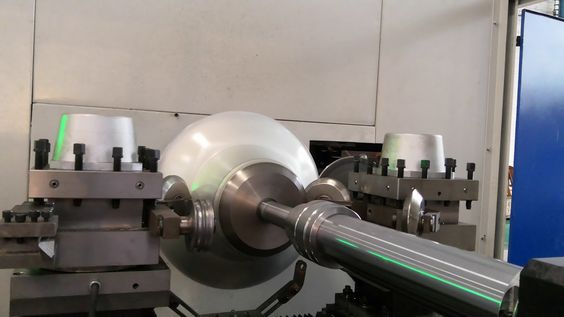
At the heart of a CNC metal spinning machine is its ability to translate digital design data into precise physical movements. Here’s a breakdown of the key components and their functions:
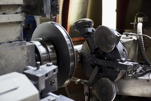
- Machine Frame and Spindle: A robust frame provides stability, while a powerful spindle rotates the metal blank at high speeds. The spindle’s speed is precisely controlled by the CNC program, allowing for optimal forming conditions based on the material and part geometry.
- Mandrel (Form): This is the core against which the metal is formed. In CNC spinning, mandrels are typically made from hardened steel or other durable materials and are precisely machined to the exact internal dimensions of the desired part.
- Roller Tooling: Unlike manual spinning where a single hand-held tool might be used, CNC machines employ a variety of precisely shaped roller tools. These rollers, often made from hardened steel or carbide, are mounted on a turret or tool changer, allowing the machine to automatically select the appropriate tool for different stages of the forming process.
- CNC Control System: This is the brain of the operation. The CNC system reads G-code and M-code programming instructions, which define the path of the roller, spindle speed, feed rates, and other machine parameters. Modern CNC systems feature sophisticated software for tool path generation, simulation, and real-time process monitoring.
- Axis Control: CNC spinning machines typically feature multiple axes of motion (e.g., X and Z axes for linear movement of the roller, sometimes additional axes for complex geometries or automated loading/unloading). High-precision servomotors and ball screws ensure accurate and repeatable positioning.
- Tailstock: A tailstock supports the center of the blank during rotation, preventing deflection and ensuring stability, especially for larger or thinner workpieces.
- Hydraulic/Pneumatic Systems: These systems provide the force for the spinning rollers to press against the blank and mandrel, as well as for clamping mechanisms and other automated functions.
- Automated Loading/Unloading Systems (Optional): For high-volume production, robotic arms or other automated systems can be integrated to load raw blanks and unload finished parts, significantly reducing cycle times and labor costs.
The process begins with a CAD (Computer-Aided Design) model of the desired part. This model is then used to generate a CAM (Computer-Aided Manufacturing) program, which translates the design into G-code instructions for the CNC machine. The operator loads a metal blank onto the machine, and the CNC program takes over. The spindle rotates the blank, and the roller tool, under precise computer control, incrementally deforms the metal against the mandrel, layer by layer, until the final shape is achieved.
Advantages of Automated Precision with CNC Metal Spinning
The transition to CNC technology has brought a multitude of benefits to metal spinning:
- Exceptional Precision and Accuracy: CNC machines can achieve tolerances far beyond what is possible with manual spinning, often within thousandths of an inch. This precision is critical for applications requiring tight fits, consistent wall thickness, and complex geometries.
- Unrivaled Repeatability: Once a program is established, CNC machines can produce identical parts consistently, run after run, batch after batch. This eliminates human error and ensures uniform product quality.
- Increased Production Efficiency: Automated operations, faster forming speeds, and reduced setup times lead to significantly higher production rates compared to manual or semi-automated methods. Lights-out manufacturing is often possible.
- Complex Geometries and Intricate Designs: The ability to precisely control the roller’s path allows for the creation of highly complex and non-linear shapes that would be impossible or economically unfeasible with traditional methods. This includes parts with varying wall thicknesses, internal features, and multi-radius contours.
- Material Versatility: CNC metal spinning machines can effectively work with a wide range of materials, including:
- Aluminum and its alloys
- Stainless steel
- Carbon steel
- Copper and brass
- Titanium
- High-temperature alloys
- Precious metals
- Reduced Material Waste: The chipless forming process of metal spinning inherently minimizes material waste compared to machining processes that remove material. CNC control further optimizes material usage by ensuring precise blank sizing and efficient forming.
- Lower Labor Costs: While initial investment in CNC machines can be higher, the reduced need for highly skilled manual operators and the ability to run machines with minimal supervision lead to lower per-part labor costs in the long run.
- Enhanced Safety: Automation reduces the need for human interaction with moving parts and high-speed machinery, improving workplace safety.
- Rapid Prototyping and Tooling Development: CNC programming allows for quick iterations and modifications to designs, making it ideal for rapid prototyping and developing new tooling without extensive manual adjustments.
- Surface Finish Quality: The spinning process inherently creates a smooth, often work-hardened, surface finish, reducing or eliminating the need for secondary finishing operations.
Applications of CNC Metal Spinning
The versatility and precision of CNC metal spinning machines make them indispensable in a vast array of industries for producing a diverse range of parts:
- Aerospace: Nose cones, engine components, fuel tanks, venturis, and other lightweight, high-strength parts.
- Automotive: Wheel covers, filter housings, air intake components, exhaust system parts, and decorative trim.
- HVAC & Lighting: Reflectors, diffusers, fan housings, ventilation components, and lamp shades.
- Medical & Pharmaceutical: Instrument housings, sterilization trays, and specialized containers.
- Defense: Projectile casings, missile components, and specialized enclosures.
- Pressure Vessels: Tanks, cylinders, and dished ends for various industries.
- Cookware: Pots, pans, and bowls, often with integrated features.
- Art and Architecture: Custom decorative elements, sculptures, and architectural features.
- Industrial Equipment: Machine guards, covers, and various components for manufacturing machinery.
- Consumer Goods: Speaker cones, fire pits, and various other household items.
Challenges and Considerations
Despite its numerous advantages, CNC metal spinning also presents certain considerations:
- Initial Investment: CNC metal spinning machines represent a significant capital investment compared to manual spinning equipment.
- Programming Expertise: While user-friendly software is evolving, creating efficient and error-free CNC programs still requires specialized knowledge and experience.
- Tooling Costs: Developing specialized mandrels and roller tooling can add to the overall cost, especially for low-volume or highly custom parts.
- Material Limits: While versatile, certain materials or extremely thick gauges may still pose challenges for the spinning process.
- Part Geometry Limitations: While capable of complex shapes, metal spinning is primarily suited for symmetrical, hollow parts. Parts with square corners or extreme non-symmetrical features are generally not suitable.
- Springback: As with other forming processes, material springback needs to be accounted for in the tooling and programming to achieve the desired final dimensions.
The Future of Automated Precision in Metal Spinning
The field of CNC metal spinning is continuously evolving. Future advancements are likely to focus on:
- Smarter Automation: Further integration of artificial intelligence (AI) and machine learning (ML) for optimized tool path generation, predictive maintenance, and real-time process adjustments.
- Adaptive Control Systems: Systems that can automatically compensate for material variations or process anomalies during spinning.
- Multi-Material Capabilities: Development of techniques to spin exotic or composite materials more effectively.
- Additive Manufacturing Integration: Combining metal spinning with additive manufacturing for creating complex mandrels or hybrid parts.
- Enhanced Simulation and Virtual Prototyping: More sophisticated simulation software that can accurately predict material flow, stresses, and potential defects, reducing the need for physical prototypes.
- Industry 4.0 Connectivity: Seamless integration of CNC spinning machines into broader smart factory ecosystems for data exchange, remote monitoring, and autonomous production.
In conclusion, CNC metal spinning machines embody the pinnacle of automated precision in metal forming. By merging the time-honored principles of metal spinning with the unparalleled accuracy and control of computer numerical control, these machines empower manufacturers to produce complex, high-quality, and cost-effective symmetrical hollow metal parts with consistency and efficiency that were once unimaginable. As technology continues to advance, the capabilities of automated precision in metal spinning will only continue to grow, opening up new possibilities for design and manufacturing across countless industries.
Automated Precision with CNC Metal Spinning Machines – Detailed Expansion
1. The Evolution of Metal Spinning: From Manual Artistry to Automated Excellence (Detailed)
This section highlights the journey from a craft-based skill to a high-tech manufacturing process.
- Manual Metal Spinning (Historical Context & Artistry):
- Process: A skilled artisan would position a flat metal blank on a rotating chuck (mandrel). Using a specialized, long-handled tool (spinning stick or lever), the spinner would apply pressure against the rotating blank, progressively bending and stretching the metal over the mandrel’s form. Lubricants (like wax or grease) were often applied to reduce friction and heat.
- Skill Demands: This required immense physical strength, exceptional hand-eye coordination, an intuitive understanding of metal properties (ductility, work hardening), and a highly developed sense of touch to feel the metal flow. The spinner had to constantly adjust pressure and leverage to avoid tearing or wrinkling the material.
- Limitations:
- Physical Fatigue: Extremely labor-intensive, limiting batch sizes and production rates.
- Inconsistency: Part-to-part variation was inherent due to human factors, even with highly skilled operators. Achieving precise tolerances was difficult.
- Complexity: Limited to simpler, more straightforward geometric shapes. Complex contours or multiple radii were exceptionally challenging.
- Material Thickness: Thicker materials were very difficult to spin manually due to the force required.
- Safety: Manual spinning could be hazardous due to rotating parts and flying debris.
- Semi-Automated Metal Spinning (Transition Phase):
- Introduction: The late 19th and early 20th centuries saw the introduction of mechanical aids. Hydraulic or pneumatic cylinders replaced some of the manual force application.
- Process: The operator would still guide the spinning tool, but the power to press the tool against the blank came from the machine. This significantly reduced physical strain.
- Improvements: Allowed for spinning of slightly thicker materials and larger diameters. Improved consistency somewhat.
- Remaining Limitations: Still relied heavily on operator skill for tool path and pressure control, meaning inconsistencies and human limitations persisted, though lessened. Setup times were still significant.
- CNC Metal Spinning (The Revolution):
- Core Principle: Replacing human control with digital instructions. The “brain” is the Computer Numerical Control system.
- Genesis: Evolved from the development of CNC machining, where precise tool paths could be programmed. The application of this concept to the forming process of spinning was a natural progression.
- Key Enablers:
- Powerful Servomotors: For precise and rapid movement of axes.
- High-Resolution Encoders: For accurate feedback on axis positions.
- Robust Machine Structures: To handle the significant forces involved in metal forming without deflection.
- Advanced Software: For CAD/CAM integration, simulation, and post-processing (generating machine code).
- Impact: This shift fundamentally changed metal spinning from a craft to an engineered manufacturing process, opening doors to new levels of precision, complexity, and productivity.
2. How CNC Metal Spinning Machines Work: A Symphony of Precision (Detailed)
This section describes the mechanical and digital collaboration that defines CNC spinning.
- Machine Frame and Spindle:
- Frame: Constructed from heavy, often cast, steel or welded structures, designed for extreme rigidity and vibration dampening. This ensures the precise relative positioning of the mandrel and the spinning roller during high-force operations.
- Spindle: A robust, precision-ground spindle houses the chuck that holds the metal blank. It’s driven by powerful, variable-speed electric motors (often AC servo motors) that allow for precise RPM control. Spindle speed is critical and can be adjusted during the spinning process based on material, diameter, and desired deformation. High-quality bearings ensure minimal runout.
- Mandrel (Form):
- Function: The internal form that dictates the shape of the spun part.
- Material: Typically high-strength tool steels (e.g., D2, H13) hardened and ground for durability and surface finish. For softer materials or short runs, mandrels can be made from aluminum or even wood.
- Design Considerations: Mandrel design is crucial. It must account for material springback, tool clearances, and ejecting the finished part. Sometimes, multi-piece or collapsible mandrels are required for parts with undercuts.
- Mounting: Precisely mounted to the machine spindle, ensuring concentricity and rigidity.
- Roller Tooling:
- Diversity: CNC machines utilize a wide array of roller shapes and sizes:
- Radius Rollers: Most common, with a specific radius to form the metal smoothly.
- Bead Rollers: For creating external or internal beads.
- Trimming Rollers: For cutting off excess material.
- Curling Rollers: For creating rolled edges.
- Shearing Rollers: For specialized cutting operations.
- Material: Typically hardened tool steel (e.g., A2, D2) or carbide for abrasive materials and long life. The surface finish of the roller is critical to avoid marking the part.
- Mounting: Mounted on a robust tool post or a multi-station turret. The turret allows the machine to automatically switch between different rollers during a single part cycle, enabling complex multi-stage operations without manual intervention.
- Path Generation: The most significant aspect of CNC. The software generates a continuous tool path (G-code) that guides the roller in multiple axes (typically X and Z, sometimes more for complex or off-axis movements) with extreme precision, dictating pressure points and metal flow.
- Diversity: CNC machines utilize a wide array of roller shapes and sizes:
- CNC Control System:
- Hardware: Industrial computer, specialized motion control cards, HMI (Human Machine Interface) screen.
- Software:
- Operating System: Real-time operating system for deterministic control.
- User Interface: Intuitive graphical interface for program loading, setup, monitoring, and diagnostics.
- G-Code/M-Code Interpreter: Translates the programming language into machine movements and functions.
- Path Generation Software (CAM): Often integrated or interfaced with separate CAM software (e.g., SolidWorks CAM, Inventor CAM, dedicated spinning CAM packages) to take a 3D CAD model and generate the optimal tool paths. This accounts for material properties, springback, and forming strategies.
- Simulation Software: Crucial for verifying tool paths before actual production, identifying potential collisions, material tearing, or wrinkling. This saves significant time and material.
- Process Monitoring: Real-time display of spindle speed, axis positions, motor loads, and alarms.
- Axis Control:
- Axes: Most commonly X (radial movement of the roller relative to the spindle axis) and Z (axial movement along the spindle axis). More advanced machines may have additional axes (e.g., Y for off-center movements, A/B/C for tool orientation) to accommodate even more complex geometries or for integrated secondary operations.
- Mechanism: High-precision ball screws and linear guides ensure smooth, low-friction, and highly accurate linear motion.
- Drive System: High-torque, closed-loop servo motors drive each axis. Encoders on the motors provide feedback to the CNC controller, ensuring the actual position matches the commanded position with extreme accuracy (nanometer or micron level resolution).
- Tailstock:
- Purpose: To provide axial support to the center of the metal blank, preventing it from bowing or deflecting under the pressure of the spinning roller.
- Mechanism: Typically hydraulically or pneumatically actuated, with a live center (rotating point) to minimize friction.
- Importance: Crucial for stability, especially when spinning large diameter, thin-gauge, or deep parts, ensuring concentricity and preventing deformation.
- Hydraulic/Pneumatic Systems:
- Power Source: Provide the significant force required to press the spinning roller against the blank (forming force).
- Other Uses: Clamping mechanisms for the blank, tailstock actuation, tool changer operation, and part ejection systems.
- Control: Integrated with the CNC system for precise control of pressure and timing.
- Automated Loading/Unloading Systems (Optional but common in production):
- Benefits: Reduces cycle time, allows for “lights-out” operation, and improves operator safety.
- Types:
- Robotic Arms: Highly flexible, can pick and place blanks from stacks, load them onto the chuck, and unload finished parts onto conveyors or bins.
- Gantry Systems: Overhead systems for automated material handling.
- Bowl Feeders/Magazines: For feeding smaller blanks in high volumes.
- Integration: Requires seamless communication and synchronization with the CNC machine’s control system.
3. Advantages of Automated Precision with CNC Metal Spinning (Detailed)
Expanding on the benefits, with more specific examples.
- Exceptional Precision and Accuracy:
- Tolerance Levels: Achieves tolerances typically in the range of ±0.05 mm to ±0.1 mm ($ \pm 0.002 \text{ inches}$ to ±0.004 inches), depending on part size, material, and machine capability. This is critical for parts that need to mate precisely with others (e.g., aerospace components, medical devices).
- Wall Thickness Control: CNC enables highly consistent and controllable wall thickness, even in complex parts where the thickness might vary intentionally (e.g., a part that is thicker at the base and thinner at the rim).
- Concentricity and Roundness: Superior concentricity and roundness compared to manual methods, important for rotating parts or sealed enclosures.
- Unrivaled Repeatability:
- Zero Human Error: Eliminates variability introduced by human operators. Once a program is proven, every part produced will be virtually identical.
- Process Stability: Consistent quality over long production runs, crucial for industries with strict quality control (e.g., automotive, defense).
- Reduced Inspection: With high repeatability, sampling inspection can often replace 100% inspection, saving time and cost.
- Increased Production Efficiency:
- Faster Cycle Times: Optimized tool paths, rapid axis movements, and automated features (tool changes, loading/unloading) dramatically reduce the time to produce each part.
- 24/7 Operation: With automation, machines can run continuously with minimal human intervention, maximizing throughput.
- Reduced Setup Time: Programs can be quickly loaded, and tool offsets applied, reducing changeover time between different parts compared to manual setups.
- Complex Geometries and Intricate Designs:
- Multi-Radius Contours: Easily creates parts with multiple, smoothly transitioning radii, and even parabolic or hyperbolic shapes.
- Internal Features: Capable of forming internal flanges, beads, or other features using specialized tooling and multi-stage spinning.
- Varying Wall Thickness: Through precise control of the roller’s path and pressure, the machine can intentionally thin or thicken specific areas of the part.
- Deep Draws: Excels at forming very deep parts from a flat blank, often achieving greater depth-to-diameter ratios than traditional deep drawing methods without material thinning concerns in the walls.
- Material Versatility:
- Formability: Metal spinning generally benefits from highly ductile materials, but CNC control allows for better handling of less ductile or high-strength alloys.
- Examples:
- Aerospace Alloys: Inconel, Hastelloy, Titanium alloys (often spun hot).
- Food Grade: 304/316 Stainless Steel.
- Conductive: Copper, Brass.
- Lightweight: Aluminum alloys (1100, 3003, 5052, 6061).
- Structural: Mild Steel, High-Strength Low-Alloy (HSLA) steels.
- Reduced Material Waste:
- Chipless Process: No chips or swarf are produced, unlike machining. The material is merely reshaped.
- Near-Net Shape: Spinning typically produces parts closer to the final shape, minimizing the need for subsequent machining operations that generate waste.
- Optimized Blank Sizing: CNC programming can precisely calculate the optimal blank diameter and thickness to minimize edge trim waste.
- Lower Labor Costs:
- Reduced Direct Labor: Fewer operators are needed to oversee multiple machines.
- Skilled Labor Shift: The need shifts from manual spinning artisans to CNC programmers and machine maintenance technicians.
- Overall Cost Reduction: Despite higher machine cost, the significantly higher throughput and reduced direct labor often result in a lower per-part manufacturing cost.
- Enhanced Safety:
- Operator Isolation: Operators are typically outside the safety enclosure during machine operation, separated from rotating parts, high forces, and potential projectiles.
- Automated Features: Automated loading/unloading further reduces human interaction with dangerous areas.
- Interlocks and Sensors: Machines are equipped with safety interlocks, light curtains, and emergency stops to prevent accidents.
- Rapid Prototyping and Tooling Development:
- Digital Prototyping: Changes to part geometry can be made in the CAD model, new tool paths generated, and simulations run quickly, drastically reducing the time and cost of physical prototyping.
- Flexible Tooling: While mandrels are specific, the spinning rollers are versatile. A range of standardized rollers can be used for many different parts, and custom rollers can be quickly machined based on digital designs.
- Surface Finish Quality:
- Work Hardening: The spinning process inherently work hardens the material, which can improve strength and fatigue resistance.
- Smooth Finish: The continuous contact with the smooth, polished roller and mandrel results in a very fine surface finish, often eliminating the need for grinding, polishing, or other secondary finishing operations, especially on the spun surface.
4. Applications of CNC Metal Spinning (Detailed)
More specific examples and industry roles.
- Aerospace:
- Nose Cones & Domes: For missiles, rockets, and aircraft. The lightweight, strong, and precise forms are critical.
- Engine Components: Inlet bells, exhaust nozzles, combustion liners – often made from high-temp alloys due to their superior forming characteristics.
- Fuel Tanks & Pressure Vessels: Seamless construction and controlled wall thickness are vital for integrity.
- Venturis & Ducts: For airflow control, requiring smooth internal surfaces.
- Challenges: Extremely tight tolerances, exotic materials, and critical safety requirements.
- Automotive:
- Wheel Covers & Decorative Trim: High-volume production with consistent aesthetics.
- Filter Housings & Air Intake Components: Often complex internal geometries.
- Exhaust System Components: Cones, diffusers, catalytic converter shells – often stainless steel.
- Lightweight Components: As the industry moves towards electric vehicles and fuel efficiency, lightweight spun parts are increasingly valuable.
- HVAC & Lighting:
- Reflectors: Highly precise parabolic or elliptical shapes for optimal light distribution. Often aluminum.
- Diffusers & Shades: Aesthetic and functional components.
- Fan Housings & Ventilation Components: Often large diameter, deep draws.
- Medical & Pharmaceutical:
- Instrument Housings: Smooth, seamless designs for hygiene and aesthetics.
- Sterilization Trays & Basins: Corrosion-resistant materials like stainless steel.
- Specialized Containers & Vessels: For processing, mixing, or storage where seamless, cleanable surfaces are crucial.
- Bioreactor Components: Precision-spun vessels for biological processes.
- Defense:
- Projectile Casings & Missile Components: High-strength, precise forms critical for performance and safety.
- Specialized Enclosures: Rugged, sealed components for harsh environments.
- Armor Components: In some cases, for lightweight and strong protective layers.
- Pressure Vessels:
- Dished Ends: For cylindrical tanks (e.g., chemical, food processing).
- Cryogenic Tanks: Insulated and sealed vessels requiring high integrity.
- Gas Cylinders: For various industrial and medical gases.
- Challenges: Requiring strict adherence to pressure codes and standards.
- Cookware:
- Pots, Pans, Bowls: Common household items, often with specific features like flared rims or integrated handles (formed by spinning, then potentially secondary operations).
- Material: Aluminum, stainless steel, copper.
- Benefits: Cost-effective for mass production, good surface finish.
- Art and Architecture:
- Custom Decorative Elements: Unique light fixtures, sculptures, fountains.
- Architectural Cladding: Large, shaped panels.
- Benefits: Ability to create large, seamless, complex forms that are visually appealing and structurally sound.
- Industrial Equipment:
- Machine Guards & Covers: For safety and aesthetics.
- Pulleys & Flywheels: Requiring balance and concentricity.
- Fluid Flow Components: Cones, reducers, and expansion joints.
- Consumer Goods:
- Speaker Cones: Precisely spun for acoustic properties.
- Fire Pits & Outdoor Furniture Components: Durable and aesthetically pleasing.
- Home Appliances: Components for blenders, mixers, vacuum cleaners.
5. Challenges and Considerations (Detailed)
A deeper look at the hurdles and factors to account for.
- Initial Investment:
- Cost: A high-end, multi-axis CNC metal spinning machine with automation can cost from several hundred thousand to well over a million USD.
- Justification: Requires a clear business case based on projected production volumes, cost savings, and the value of enhanced capabilities. It’s often viable for medium to high-volume production or for parts requiring extreme precision.
- Programming Expertise:
- Complexity: While basic programs are straightforward, optimizing tool paths for complex geometries, minimizing thinning, preventing wrinkling, and managing springback requires significant expertise.
- Software Skills: Proficiency in CAD/CAM software (e.g., SolidWorks, Inventor, Fusion 360 with spinning modules, or dedicated spinning CAM software) is essential.
- Material Knowledge: Programmers need to understand how different metals deform and react during spinning.
- Training: Investment in training for programmers and operators is crucial.
- Tooling Costs:
- Mandrel Specificity: Each unique part shape generally requires a custom mandrel. For complex parts, these can be expensive to design and machine, especially from hardened tool steel.
- Roller Tool Variety: While some rollers are standard, specialized forms require custom grinding.
- Wear and Tear: Tooling (especially rollers and mandrels) wears over time and needs to be replaced or refurbished, adding to operational costs.
- Material Limits:
- Ductility: Materials with low ductility (e.g., some cast irons or brittle alloys) are generally not suitable as they will crack or tear.
- Thickness: While CNC machines can spin thicker materials than manual methods, there are still practical limits based on machine power and material properties. Very thick materials might require multiple annealing steps.
- Work Hardening: While often beneficial, excessive work hardening can make a material brittle, requiring inter-stage annealing (heating and cooling to soften the metal).
- Part Geometry Limitations:
- Symmetry: Primarily suited for parts with rotational symmetry around a central axis. While some non-symmetrical features can be added through secondary operations or advanced multi-axis spinning, the core process is rotational.
- Sharp Corners: Difficult to achieve perfectly sharp internal or external corners due to the nature of metal flow and the roller’s radius. A minimum radius will always be present.
- Flats/Squares: Cannot produce truly square or rectangular cross-sections in the spun portion.
- Springback:
- Definition: The elastic recovery of a material after forming forces are removed. The spun part will slightly spring back from the mandrel’s exact shape.
- Compensation: The CNC program and mandrel design must strategically “over-form” the material to compensate for springback. This requires empirical data for each material and geometry, often refined through trial and error or advanced simulation.
- Variability: Springback can vary slightly with material batches and temperature, requiring robust process control.
6. The Future of Automated Precision in Metal Spinning (Detailed)
Gazing into future advancements and trends.
- Smarter Automation with AI & Machine Learning:
- Optimized Tool Paths: AI algorithms could analyze part geometry, material properties, and machine capabilities to automatically generate the most efficient and effective tool paths, minimizing forming time and defects.
- Predictive Maintenance: ML models can analyze sensor data (vibration, temperature, motor current) to predict machine component failures before they occur, enabling proactive maintenance and reducing downtime.
- Real-time Process Adjustment: AI could monitor the spinning process in real-time, detecting deviations (e.g., slight material variations, unexpected thinning) and making instantaneous micro-adjustments to roller pressure or speed to maintain quality.
- Adaptive Control Systems:
- In-Situ Sensing: Integration of laser displacement sensors, force transducers, or acoustic emission sensors to monitor the metal flow and deformation during spinning.
- Feedback Loops: These sensors would provide real-time data to the CNC controller, allowing it to adapt the forming parameters (e.g., roller speed, feed rate, pressure) dynamically to compensate for material inconsistencies or unexpected behavior, ensuring consistent quality even with varying material batches.
- Multi-Material Capabilities & Hybrid Manufacturing:
- Exotic Alloys: Continued development of spinning techniques for even more challenging high-strength, high-temperature, or superplastic alloys, potentially involving advanced heating systems (induction, laser).
- Composite Spinning: Exploring the spinning of layered metal composites or even metal-polymer composites.
- Hybrid Additive/Subtractive/Forming: Combining processes. For instance, additive manufacturing could be used to create complex, lightweight mandrels or to build up sections of a part that are then finished by spinning. Or, spinning could be followed by precision machining on the same machine (multi-tasking).
- Enhanced Simulation and Virtual Prototyping:
- Advanced FEA (Finite Element Analysis): More sophisticated simulation software (e.g., ABAQUS, ANSYS, specialized forming simulation packages) that can accurately model the complex, non-linear deformation of metal during spinning.
- Predictive Capabilities: Predicting residual stresses, springback, material thinning, and potential defects (wrinkles, tears) with higher accuracy, significantly reducing the need for costly physical prototypes and trial-and-error.
- Digital Twin: Creating a digital replica of the physical machine and process, allowing for virtual testing, optimization, and monitoring.
- Industry 4.0 Connectivity:
- IoT (Internet of Things) Integration: CNC spinning machines connected to a factory-wide network, sharing data on production rates, machine status, energy consumption, and quality metrics.
- Cloud-Based Analytics: Data uploaded to cloud platforms for big data analysis, leading to insights for process improvement, efficiency gains, and predictive maintenance across an entire fleet of machines.
- Remote Monitoring and Control: Operators and managers could monitor machine performance and even control aspects of the process remotely, improving flexibility and responsiveness.
- Automated Scheduling: Integration with MES (Manufacturing Execution Systems) and ERP (Enterprise Resource Planning) for optimized production scheduling and resource allocation.
The continuous evolution of CNC metal spinning machines is driven by the relentless demand for higher precision, greater efficiency, and the ability to produce increasingly complex and functional parts across a multitude of industries. This blend of traditional forming principles with cutting-edge digital control ensures that metal spinning remains a vital and innovative manufacturing process.
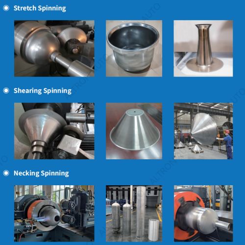
7. Advanced Metal Spinning Techniques and Capabilities
Beyond the basic principles, CNC machines enable sophisticated forming strategies:
- Multi-Pass Spinning: Instead of forming a part in one go, the roller makes multiple passes, gradually deforming the material. Each pass prepares the material for the next, reducing stress, preventing cracks, and allowing for deeper or more complex shapes. The CNC precisely controls the reduction per pass.
- Shear Spinning (Flow Forming): A specialized technique where the roller exerts immense pressure, significantly thinning the material’s wall thickness while maintaining the original outer diameter. This is often used for high-strength, lightweight cylindrical or conical parts (e.g., rocket motor casings, pressure vessels, precision shafts). CNC control is absolutely critical for maintaining the precise flow and thinning.
- Necking In/Out: Creating a reduction (necking in) or expansion (necking out) in the diameter of a tube or cylindrical part. This is achieved by specific roller tool paths that push the material inward or outward.
- Reverse Spinning: Forming a part by spinning from the larger diameter towards the smaller diameter, or even inverting the part during the process. This can be useful for complex internal features or to manage material flow.
- Hot Spinning: For materials that are difficult to form at room temperature (e.g., titanium, certain stainless steels, high-nickel alloys), the blank or the forming area is heated. CNC machines can be equipped with induction heaters or other heating elements. Precise temperature control is crucial for consistent results and material integrity.
- Flanging and Beading: Creating precise flanges (outward or inward lips) or beads (rounded reinforcing ridges) on the edge or body of a spun part. These add rigidity, provide mating surfaces, or serve as decorative elements.
- Spinning on Air (Internal Support): For very thin-walled or complex parts where a traditional mandrel might be difficult to remove or would cause too much friction, some advanced techniques use internal air pressure or a temporary, dissolvable core for support during spinning. This is less common but highlights the flexibility.
8. Tooling Design and Material Considerations in Depth
The choice and design of tooling are paramount to successful CNC metal spinning:
- Roller Tool Materials:
- High Carbon, High Chromium Steels (e.g., D2, A2): Excellent wear resistance and hardness, suitable for most materials.
- Carbides (Tungsten Carbide): Superior wear resistance and hardness, preferred for abrasive materials (e.g., some stainless steels, high-nickel alloys) or for very long production runs. More expensive and brittle.
- Ceramics: Emerging for specialized applications due to extreme hardness and wear resistance, though also brittle.
- Surface Treatment: Rollers are often polished to a mirror finish to prevent marking the workpiece. Coatings (e.g., PVD, CVD coatings like TiN, TiAlN) can further enhance wear resistance and reduce friction.
- Mandrel Materials:
- Hardened Tool Steels (e.g., H13, 4140, 4340): Standard for high-volume production due to durability and resistance to wear and deformation.
- Cast Iron: For less demanding applications or prototyping due to lower cost and machinability.
- Aluminum Alloys: For short runs, prototyping, or when a lighter mandrel is required.
- Wood/Plastics: For very short runs, prototyping with soft metals, or extremely large, complex, and low-pressure applications.
- Lubrication: Proper lubrication is critical to reduce friction, dissipate heat, and prevent galling between the roller/mandrel and the workpiece. CNC machines can have automated lubrication systems that apply oils, greases, or synthetic compounds. The type of lubricant depends on the material, spinning speed, and desired surface finish.
- Tooling Rigidity: Both the roller tool and the mandrel must be extremely rigid to withstand the immense forming forces without deflecting. Any deflection will lead to inaccuracies in the final part.
9. Programming and Software Ecosystem for CNC Metal Spinning
The digital backbone that makes automated precision possible:
- CAD/CAM Integration (Detailed Workflow):
- Part Design (CAD): The desired part is designed in a 3D CAD software (e.g., SolidWorks, Inventor, CATIA).
- Blank Calculation: Software assists in calculating the optimal flat blank diameter required to form the part, minimizing waste and ensuring sufficient material. This can be complex, often using iterative calculations or experience-based factors.
- Mandrel Design: The mandrel geometry is derived from the part’s internal shape, compensating for material springback.
- Tool Path Generation (CAM): This is the core of the programming.
- Strategy Selection: Choosing the spinning strategy (e.g., single-pass, multi-pass, shear spinning).
- Roller Selection: Assigning specific roller tools for different stages.
- Pass Definition: Defining the sequence of roller passes, the reduction per pass, and the precise path (X-Z coordinates) of the roller for each pass. This is often done graphically within the CAM software.
- Process Parameters: Defining spindle speed, feed rates (how fast the roller moves), and pressure for each segment of the tool path. These are critical and often determined through material databases, simulations, or trial and error.
- G-Code Generation (Post-processing): The CAM software translates the visual tool path into G-code (geometric code) and M-code (miscellaneous functions like spindle start/stop, coolant on/off) specific to the target CNC machine.
- Simulation Software: More than just collision detection, advanced simulation software can perform:
- Material Flow Analysis: Visualizing how the material deforms and flows during spinning, identifying areas of potential thinning, wrinkling, or tearing.
- Stress and Strain Analysis: Predicting stress concentrations and strain distribution, which can influence material properties and part integrity.
- Springback Prediction: Highly accurate prediction of elastic recovery, allowing for precise compensation in mandrel and tool path design.
- Optimization: Running simulations with different parameters to find the most efficient and robust spinning process.
- Operator Interface (HMI): Modern HMIs are highly intuitive, featuring touchscreens, graphical representations of the part and tool path, real-time feedback on machine status, and diagnostic tools. They allow operators to load programs, monitor progress, make minor adjustments, and troubleshoot issues.
10. Quality Control and Inspection in CNC Metal Spinning
Ensuring that the automated precision translates into perfect parts:
- In-Process Monitoring:
- Force Sensors: Measuring the force exerted by the roller to ensure consistent pressure and detect anomalies.
- Spindle Load Monitoring: Tracking motor current to identify excessive load, which can indicate material inconsistencies or tool wear.
- Acoustic Emission Sensors: Detecting high-frequency sound waves that can indicate micro-cracks or material tearing during forming.
- Post-Process Inspection:
- CMM (Coordinate Measuring Machines): Highly accurate, automated inspection using touch probes or laser scanners to verify dimensional accuracy, concentricity, roundness, and form.
- Laser Scanners/3D Imaging: For rapid, non-contact inspection of complex geometries, comparing the as-spun part to the original CAD model.
- Ultrasonic Testing: For detecting internal defects or verifying wall thickness.
- Visual Inspection: For surface finish, defects, and overall appearance.
- Statistical Process Control (SPC): Using statistical methods to monitor and control the production process. Data from inspection is collected and analyzed to identify trends, predict potential issues, and ensure that the process remains within acceptable limits. This helps in maintaining consistent quality over long production runs.
- Material Traceability: Essential in regulated industries (aerospace, medical). Ensuring that the raw material (blank) can be traced throughout the production process to the final part.
11. Economic and Environmental Impact
Beyond just part production, the broader implications:
- Cost Efficiency: While the initial investment is high, the long-term cost benefits are significant:
- Lower Per-Part Cost: Due to higher production rates, reduced labor, and minimized material waste.
- Reduced Scrap Rates: Precision and repeatability lead to fewer defective parts.
- Energy Efficiency: Modern CNC machines are designed for energy efficiency, with optimized motor control and idle modes.
- Environmental Benefits:
- Reduced Material Waste: The chipless forming process is inherently more material-efficient than machining.
- Lower Energy Consumption: Compared to processes requiring extensive heating and cooling cycles.
- Reduced Hazardous Waste: Less lubricant use compared to machining, and simpler waste disposal (metal scrap is usually recyclable).
- Supply Chain Resilience: In-house CNC metal spinning capabilities can reduce reliance on external suppliers, shorten lead times, and improve responsiveness to market demands.
12. Essential Skill Sets in the Era of CNC Metal Spinning
While automation reduces the need for manual dexterity in spinning the metal, it increases the demand for highly specialized technical skills. The workforce for CNC metal spinning is multidisciplinary:
- CNC Programmers (CAD/CAM Specialists):
- Core Role: Translate part designs into precise machine instructions.
- Key Skills:
- Advanced CAD Proficiency: Ability to create and manipulate complex 3D models.
- CAM Software Mastery: In-depth knowledge of specialized spinning CAM software (e.g., those from machines builders like Leifeld, Eckold, or general CAM packages with spinning modules). This includes understanding tool path generation, material deformation algorithms, and post-processing for specific machine controls.
- G-Code/M-Code Understanding: Ability to read, understand, and debug machine code, even if not writing it from scratch.
- Material Science Knowledge: A strong grasp of how different metals behave under stress, their ductility, work-hardening characteristics, and springback. This is crucial for optimizing forming parameters and preventing defects.
- Process Optimization: Understanding how to select the right spinning strategy (e.g., number of passes, roller geometry, pressure profiles) to achieve desired part quality and efficiency.
- Problem-Solving: Diagnosing issues like wrinkling, tearing, or inconsistent wall thickness and adjusting programs accordingly.
- Machine Operators/Technicians:
- Core Role: Set up, run, and monitor the CNC spinning machines.
- Key Skills:
- Machine Setup: Accurately mounting blanks, mandrels, and roller tools.
- HMI Proficiency: Navigating the machine’s Human-Machine Interface, loading programs, monitoring machine status, and understanding alarms.
- Troubleshooting: Identifying and resolving minor machine issues (e.g., sensor errors, tool misalignment).
- Preventive Maintenance: Performing routine checks, lubrication, and minor adjustments to keep the machine running optimally.
- Quality Inspection: Performing in-process and post-process checks using measurement tools (calipers, micrometers, possibly CMM basics).
- Safety Adherence: Strict observance of all safety protocols for operating high-speed, high-force machinery.
- Maintenance Engineers (Mechanical, Electrical, Controls):
- Core Role: Ensure machine uptime and optimal performance.
- Key Skills:
- Mechanical Expertise: Understanding hydraulics, pneumatics, ball screws, linear guides, bearings, and structural integrity.
- Electrical/Electronics Knowledge: Diagnosing issues with motors, drives, sensors, and wiring.
- Control Systems: Understanding the logic of the CNC controller, PLCs (Programmable Logic Controllers), and communication protocols.
- Software Diagnostics: Using manufacturer-specific diagnostic tools to identify and resolve software or control issues.
- Robotics (if applicable): For machines with integrated automated loading/unloading.
- Quality Assurance Specialists:
- Core Role: Verify that parts meet all specifications.
- Key Skills:
- Metrology: Expert use of advanced measuring equipment (CMMs, laser scanners, optical comparators).
- Statistical Process Control (SPC): Implementing and interpreting SPC charts to monitor process stability and identify trends.
- Blue-Print Reading: Thorough understanding of engineering drawings, GD&T (Geometric Dimensioning and Tolerancing).
- Root Cause Analysis: Investigating quality deviations and contributing to corrective actions.
13. Future-Proofing Strategies for Manufacturers Utilizing CNC Metal Spinning
Investing in CNC metal spinning is a significant commitment. Companies need strategies to maximize their return and stay competitive:
- Continuous Workforce Training & Development:
- Upskilling: Regularly training existing staff on new software versions, machine features, and advanced techniques.
- Cross-Training: Encouraging operators to learn basic programming, and programmers to understand machine mechanics.
- Talent Acquisition: Attracting new talent with strong foundational skills in engineering, automation, and manufacturing.
- Embrace Digital Integration (Industry 4.0):
- Data Collection & Analytics: Implementing sensors and software to collect real-time data from machines (e.g., cycle times, energy consumption, error codes). Using this data to identify bottlenecks, optimize processes, and predict maintenance needs.
- MES/ERP Integration: Connecting CNC spinning machines to broader manufacturing execution and enterprise resource planning systems for seamless scheduling, inventory management, and order fulfillment.
- Cloud Connectivity: Utilizing cloud platforms for remote monitoring, collaborative problem-solving, and leveraging big data analytics for process improvement across multiple facilities.
- Modular and Scalable Machine Investments:
- Flexibility: Choosing machines that can be easily upgraded or reconfigured to handle different part sizes, materials, or integrate new automation modules (e.g., robotics).
- Phased Automation: Starting with semi-automated solutions and gradually adding full automation as production volumes and needs grow.
- Focus on Niche Markets & Complex Geometries:
- High-Value Parts: Leveraging the precision and complexity capabilities of CNC spinning to produce parts that are difficult or impossible with other methods, thus commanding higher prices or securing specialized contracts (e.g., aerospace, medical implants).
- Material Expertise: Developing deep expertise in spinning challenging materials (e.g., high-temperature alloys, very thin gauges).
- Sustainable Manufacturing Practices:
- Energy Efficiency: Optimizing machine parameters to reduce energy consumption during operation.
- Waste Reduction: Continuing to refine blank calculation and process control to minimize scrap material.
- Recycling Programs: Ensuring all metal scrap is efficiently collected and recycled.
- Strategic Partnerships:
- OEM Relationships: Building strong relationships with machine manufacturers for technical support, training, and early access to new technologies.
- Tooling Suppliers: Partnering with expert tooling designers and manufacturers to ensure optimal and durable tooling solutions.
- R&D Collaborations: Collaborating with universities or research institutions on advanced spinning techniques or new material applications.
14. Vendor Landscape and Machine Types
The market for CNC metal spinning machines is dominated by a few key players, alongside specialized regional manufacturers. Machines can be categorized by their capabilities:
- Leading Global Manufacturers:
- Leifeld Metal Spinning (Germany): A global leader, known for a wide range of highly advanced machines from entry-level to heavy-duty, multi-axis systems for various industries (automotive, aerospace, energy).
- Eckold (Switzerland/Germany): Also a prominent player, offering robust machines and a focus on specialized forming technologies.
- Denn Industries (USA): A well-established manufacturer, offering a range of spinning machines including CNC models.
- Forming World (Italy/Germany): Known for innovative solutions and often customized machines.
- Other Regional Players: Various manufacturers exist in countries like China, India, and other parts of Europe, offering machines tailored to specific market needs and budgets.
- Machine Types (Categorized by Application & Capability):
- Vertical vs. Horizontal Spindles:
- Horizontal: Most common configuration, with the spindle axis parallel to the floor. Good for general-purpose spinning.
- Vertical: The spindle axis is perpendicular to the floor. Often used for very large, heavy blanks (where gravity helps with loading) or for very small, high-precision parts where vertical orientation can improve access or material flow.
- Single-Slide vs. Multi-Slide/Multi-Axis:
- Single-Slide: A single spinning roller on a two-axis (X-Z) slide. Suitable for simpler parts.
- Multi-Slide: Two or more independent slides, each with a roller tool, working simultaneously or sequentially. This significantly reduces cycle times and enables more complex operations (e.g., spinning both sides of a part simultaneously, creating complex internal and external features).
- Multi-Axis (beyond X-Z): Machines with additional axes (Y-axis for off-center movements, rotary axes for tool orientation) allow for even more intricate shapes, non-axisymmetric features (though the blank itself remains rotational), or integrated trimming/finishing operations.
- Heavy-Duty vs. Light-Gauge Machines:
- Heavy-Duty: Built with massive frames, powerful spindles, and high-force hydraulics to spin thick plates (e.g., up to 25mm steel, 50mm aluminum) for large pressure vessels, missile domes, etc.
- Light-Gauge: Smaller, faster machines optimized for thin materials and high-volume production of smaller parts (e.g., lighting reflectors, cookware).
- Specialized Machines:
- Shear Spinning Machines: Designed specifically for flow forming, with extremely high force capabilities and precise control over material thinning.
- Tube Spinning Machines: For spinning pre-formed tubes rather than flat blanks, often for very long, thin-walled cylinders.
- Vertical vs. Horizontal Spindles:
By understanding these advanced aspects, the intricate ecosystem surrounding CNC metal spinning becomes clearer, high lighting not just the technology itself, but also the human expertise and strategic planning required to leverage its full potential in modern manufacturing.
Understanding CNC Metal Spinning
Metal spinning, also known as spin forming or spinning lathe, is a cold-forming process in which a rotating metal blank is shaped over a mandrel using rollers or tools. Traditional manual spinning required considerable operator skill and was limited by variability and complexity. With CNC integration, metal spinning has evolved into a highly precise, programmable, and automated process, offering tighter tolerances and consistent quality in both prototyping and mass production environments.
CNC spinning machines control multiple axes — typically X (radial), Z (axial), and occasionally Y or B (tool rotation or tilt) — using pre-programmed G-code instructions. These instructions control every movement of the roller and spindle, allowing for high-speed precision forming of both simple and intricate profiles.
Key Advantages of CNC Metal Spinning Automation
- Exceptional Dimensional Accuracy
CNC systems deliver consistent wall thickness, diameter control, and geometry, often within ±0.05 mm or better. This precision is especially critical for components like aerospace domes, turbine disks, and pressure vessel end caps. - Repeatability and Consistency
Once a program is developed and validated, the machine can repeat the exact process indefinitely, ensuring uniform quality in every unit—ideal for large batch runs. - Material Efficiency
CNC spinning involves negligible material waste compared to stamping or deep drawing. Thin walls and seamless contours are formed with minimal trimming, improving raw material utilization. - Reduced Labor Dependency
Automation reduces reliance on skilled labor, enabling operators to oversee multiple machines. This lowers production costs and enhances overall throughput. - Design Flexibility
CNC programming allows manufacturers to switch between part geometries quickly, even for complex contours such as parabolic, toroidal, or ogive shapes, making it highly adaptable for custom or short-run orders. - Improved Surface Finish
Controlled roller paths, constant surface contact, and proper lubrication provide excellent surface finishes, often eliminating the need for post-processing like grinding or polishing. - In-Process Adjustments and Monitoring
Many CNC systems incorporate sensors for real-time feedback on parameters such as force, temperature, and vibration. These data help in dynamically adjusting process variables for optimal quality.
Critical Components Enabling CNC Precision
- Servo Motors and Ball Screws
High-torque servo motors and precision ball screws drive tool positioning with accuracy and responsiveness, enabling micro-adjustments during forming. - Programmable Controllers
CNC controllers from companies like Siemens, Fanuc, or Heidenhain offer advanced programming capabilities, simulation, and fault detection features to optimize every spinning cycle. - CAD/CAM Integration
Most CNC metal spinning workflows begin with 3D CAD models, which are translated into CNC-compatible tool paths via CAM software. This reduces design-to-production time and ensures geometrical fidelity. - Tooling and Mandrels
Mandrels are custom-shaped to match internal part geometry and are typically made of hardened steel or aluminum. CNC allows automatic changeover between tooling setups with minimal manual intervention.
Types of CNC Spinning Machines
- Single-Head CNC Spinners
Suitable for low- to mid-complexity parts, these machines are ideal for applications requiring only one roller and lower cycle times. - Dual-Head or Opposed Roller Spinners
Allow for simultaneous forming from both sides, enabling the production of thicker parts or those with complex geometries. - CNC Flow Forming Machines
These advanced systems stretch and elongate the workpiece while spinning, ideal for making parts like rocket motor cases or automotive wheels. - Multitasking CNC Spinning Centers
Some systems combine spinning, trimming, beading, and even laser measurement systems into a single automated cell.
Applications Across Industries
- Aerospace: Nose cones, jet engine parts, oxygen tank domes.
- Automotive: Alloy wheels, hubcaps, pulleys, housings.
- Lighting: Reflectors, architectural domes, lamp housings.
- Medical Devices: Surgical bowls, centrifuge components.
- Cookware: Pots, pans, and metal kitchen utensils.
- Industrial: Pressure vessel ends, pipe reducers, fan housings.
The technology supports a wide variety of metals, including aluminum, stainless steel, titanium, copper, brass, and Inconel, each responding differently to deformation and requiring careful parameter control.
Challenges and Mitigation Strategies
While CNC metal spinning is highly efficient, challenges remain:
- Tool Wear: Continuous contact leads to roller and mandrel wear. High-speed steels and carbide coatings mitigate this.
- Material Springback: Especially in high-strength alloys. Compensation strategies in CNC programming or post-spinning heat treatment can help.
- Vibration and Chatter: At higher speeds or with thin blanks. These are addressed via damped tooling or adaptive feed-rate control.
- Setup Time for Custom Jobs: Tooling design and CAM programming can be time-intensive. Modular tooling and digital twins help reduce lead time.
Industry Trends and Innovations
- Hybrid Machines: Incorporating additive manufacturing (metal deposition) with spinning for near-net-shape production.
- AI-Driven Predictive Maintenance: Using sensors to forecast machine issues before failure.
- Digital Twins and Simulation: Virtual models of the spinning process to optimize force application and reduce trial runs.
- Green Manufacturing: Reduced energy consumption and waste, aligning CNC spinning with sustainability goals.
Conclusion
CNC metal spinning machines represent the evolution of a centuries-old forming process into a digitally driven, high-precision, and adaptive manufacturing technology. Their ability to produce high-strength, symmetric, and aesthetically refined components—while minimizing waste and manual intervention—positions them as an essential asset in modern production ecosystems. As CNC control systems continue to advance, metal spinning is poised to meet the increasing demands of custom manufacturing, lightweighting, and global supply chain flexibility with both speed and accuracy.
1000 mm CNC Metal Spinning Machine: Detailed Overview
A 1000 mm CNC metal spinning machine refers to a numerically controlled spinning lathe capable of forming metal blanks up to 1000 mm (1 meter) in diameter. This class of machine is widely used in the mid- to large-scale production of rotationally symmetric components in a variety of sectors such as lighting, cookware, aerospace, HVAC, and industrial fabrication.
Key Specifications
| Feature | Typical Value |
|---|---|
| Max Blank Diameter | 1000 mm |
| Max Blank Thickness | Up to 6–8 mm (Aluminum), 3–5 mm (Stainless Steel) |
| Max Workpiece Length | ~500–1000 mm (depending on model) |
| Spindle Motor Power | 15–30 kW |
| Main Spindle Speed | 0–2000 RPM (variable) |
| Tool Axis Travel (X/Z) | ~600 mm (X), 1000 mm (Z) |
| Roller Force | 5–15 tons (depending on frame and hydraulics) |
| Control System | Siemens / Fanuc / Mitsubishi CNC |
| Hydraulics | For tailstock pressure and tool support |
| Weight | 5–10 tons |
| Footprint | ~3.5 m × 2.5 m × 2.2 m (varies by model) |
Main Components
1. CNC Control Unit
A dedicated CNC controller precisely governs tool positioning and spindle speed. Programming can be done via:
- G-code
- Conversational mode (for spinning paths)
- Integrated CAD/CAM software
2. Spindle Drive
Robust motorized spindle capable of:
- Variable speed
- High torque for thicker metals
- Reversal and stop-on-position features
3. Tool Slides (X and Z Axes)
These control radial and axial motion of the roller:
- Servo or ball-screw driven
- Capable of interpolated movement for complex profiles
4. Tailstock or Hydraulic Center
Supports the workpiece against forming forces. Some models include:
- Hydraulic cushion or programmable thrust
- Quick-change mandrel clamps
5. Forming Tools and Rollers
Hardened steel or carbide rollers shaped according to the desired part profile. Tool change systems may be manual, semi-automatic, or fully automatic.
Material Compatibility
A 1000 mm CNC spinning machine can process a wide variety of materials, including:
- Aluminum alloys (1050, 6061, 5083, etc.)
- Stainless steel (304, 316, 430)
- Mild steel / Carbon steel
- Copper and brass
- Titanium (with heat-assisted spinning)
- Inconel and other high-performance alloys (with upgraded frames and rollers)
Common Products Formed
- Pressure vessel heads (hemispherical, torispherical)
- Parabolic and conical reflectors
- Air conditioning duct hoods
- Large cookware (industrial pans, stock pots)
- Tank ends and gas cylinder tops
- Architectural metal domes and decorative forms
- Satellite dish or antenna parts
Automation and Add-ons
Depending on the machine model, the following automation features may be included or added:
- Automatic lubrication systems
- Roller tool changer (ATC)
- Laser or camera-based profile checking
- Integrated trimming/beading stations
- Automatic loading/unloading with robot arms
- Data acquisition and Industry 4.0 integration
Advantages of the 1000 mm Class CNC Spinner
- Versatile Production: From small batches to continuous series
- Flexible Forming: Supports flanges, grooves, necking, and more
- Minimal Setup Time: Compared to traditional spinning lathes
- Low Waste: Highly efficient use of raw blanks
- Repeatable Accuracy: ±0.1 mm or better with proper tooling
- Scalability: Can be upgraded to dual-head or flow-forming versions
Maintenance and Operation Notes
- Regular lubrication of linear guides, ball screws, and tailstock pistons is crucial.
- Roller inspection and polishing should be done periodically to ensure surface quality.
- CNC controller backups and firmware updates help avoid production downtime.
- Operators should be trained in spinning force management, tool path simulation, and material behavior under deformation.
Who Uses 1000 mm CNC Metal Spinning Machines?
This class of machines is commonly found in:
- OEM factories making ventilation or lighting components
- Job shops offering contract forming services
- Aerospace suppliers forming engine and fuselage components
- Cookware manufacturers of premium industrial-scale pots and woks
- Architectural fabricators of domed structures and art installations
Conclusion
A 1000 mm CNC metal spinning machine is a powerful and adaptable solution for mid-to-large-scale metal forming needs. With the precision of CNC and the strength of rigid mechanical frames, these machines can handle complex shapes, various materials, and high-volume production runs with minimal operator input. For industries aiming to enhance product quality while reducing material waste and labor dependency, CNC spinning machines of this size represent a robust and future-ready investment.
A 1000 mm CNC metal spinning machine represents a crucial bridge between medium and large-scale production in modern metal forming applications. It is designed to process circular metal blanks up to 1000 millimeters in diameter, offering high precision, automated control, and repeatable results. Using servo-driven axes and advanced CNC controllers, this class of machine allows the forming of complex rotationally symmetric geometries with exceptional accuracy, often within ±0.1 mm tolerances. These machines are particularly valued in industries where smooth surface finishes, structural strength, and seamless geometry are critical. The operation begins with clamping a flat or pre-cut metal disc against a mandrel that defines the inner profile of the desired part. The spinning roller or forming tool, driven by CNC-controlled linear axes, applies localized pressure as the blank rotates at high speed. This pressure causes the metal to stretch and conform to the shape of the mandrel without the need for cutting, making the process highly material-efficient.
The CNC aspect allows for highly programmable paths, enabling the forming of straight, conical, spherical, parabolic, toroidal, or custom contoured parts. In contrast to manual spinning, CNC control eliminates operator variability, reduces human error, and allows high-volume production with consistent quality. The machines can work with a wide range of metals such as aluminum, stainless steel, mild steel, copper, and even high-performance alloys like titanium and Inconel, depending on machine rigidity and roller selection. A typical 1000 mm CNC spinner includes a powerful spindle motor ranging from 15 to 30 kW to maintain torque during forming, and programmable tailstock pressure to support the workpiece during high-force operations. Roller toolpaths are controlled by servo motors with closed-loop feedback, which ensures that the roller travels along precise profiles with optimal feed rates and force application.
Common applications include forming end caps for pressure vessels, tank domes, reflectors for lighting, cookware like woks and stockpots, vent hoods, ductwork transitions, and aerospace components. In many cases, additional attachments such as trimming heads, beading tools, and robot arms for automated handling are integrated into the system to complete multiple processes in a single cycle. Tooling is typically customized based on part geometry and material thickness, with hardened steel or carbide rollers providing wear resistance and durability over long production runs. For advanced applications, some machines come equipped with real-time sensors that monitor force, torque, and temperature, feeding data back into the controller for adaptive path adjustment and process optimization.
One of the key benefits of the 1000 mm class is its versatility. It is suitable for both prototyping and batch production, allowing manufacturers to switch between part designs by simply loading new CNC programs and swapping mandrels. CAM software integrated with CAD models enables fast path generation, simulation, and virtual collision checking. This not only shortens setup times but also improves first-pass yield and reduces scrap. The overall machine footprint is moderate, typically around 3.5 by 2.5 meters, making it suitable for mid-sized workshops as well as fully automated production cells. Maintenance is relatively straightforward, involving routine lubrication of linear rails and ball screws, periodic inspection of rollers and mandrels, and software updates or backups of the CNC controller.
The growing demand for lightweight, strong, and seamless metal components across many sectors has led to increased adoption of CNC metal spinning technology. In addition to offering material savings, the process supports green manufacturing by minimizing waste and enabling the use of recycled metals. Machines in this range often include energy-saving spindle drives and optional regenerative braking systems. With the integration of Industry 4.0 features, manufacturers can monitor machine health, track production metrics, and perform remote diagnostics, making the 1000 mm CNC spinning machine a future-ready solution for precision metal forming. Whether producing aerospace nose cones, industrial cooking pots, or architectural domes, this machine class provides the flexibility, speed, and accuracy that modern production demands.
The ability of a 1000 mm CNC metal spinning machine to handle a broad spectrum of geometries also opens opportunities for manufacturers involved in bespoke or low-volume, high-precision production. For instance, manufacturers of architectural lighting systems frequently utilize such machines to form large-diameter reflectors or decorative domes that require not only dimensional accuracy but also aesthetic consistency. In these applications, surface finish is critical, and CNC spinning machines can produce smooth, uniform surfaces that often eliminate the need for secondary polishing. Furthermore, CNC parameters can be fine-tuned to reduce surface marks or waviness, which is especially important when working with soft metals like aluminum or copper.
In cookware manufacturing, especially for premium or commercial kitchenware, 1000 mm CNC spinners allow the creation of large pans and pots with perfectly symmetrical bases, uniform wall thickness, and high structural strength, all without welding or joining. This improves thermal conductivity, aesthetics, and durability. The seamless nature of spun parts also eliminates potential points of failure under high heat or pressure. For industrial and utility-grade applications, such as forming end caps for pressurized tanks or HVAC duct transitions, this spinning technology delivers parts that can withstand internal forces, vacuum conditions, or corrosive environments, depending on the material used.
When paired with modern automation, such machines become part of a highly efficient production line. Automatic blank feeding, robotic loading/unloading, and programmable inspection stations reduce cycle time and labor involvement. For manufacturers running multiple product types, the CNC system enables rapid retooling—changing from one part to another in under an hour in many cases. This agility is crucial in contract manufacturing and just-in-time production environments. In terms of return on investment, the efficiency, repeatability, and material savings offered by CNC spinning can quickly offset the initial machine cost, especially when considering the reduced need for skilled manual spinners and lower scrap rates.
From a design standpoint, engineers benefit from the design freedoms allowed by CNC spinning. Internal ribs, tapered walls, flared ends, and integrated collars or steps can all be achieved with proper tool path programming. For parts requiring both spinning and secondary forming operations such as trimming, flanging, curling, or beading, many 1000 mm CNC machines can be equipped with multipurpose heads or adjacent stations. This consolidation of processes further enhances productivity and quality control.
In terms of mechanical design, most 1000 mm spinners feature a heavy-duty steel frame designed to absorb high radial and axial forming forces. The machine bed is typically thermally stabilized and precisely machined to prevent deformation over long operating hours. Vibration damping is integrated to maintain part surface quality, especially during long tool paths at high spindle speeds. Safety features such as protective enclosures, light curtains, interlock doors, and emergency braking systems are standard, especially for CE-certified machines used in the EU.
With increasing emphasis on traceability and quality assurance, many CNC spinning machines include production data logging features. Parameters such as force applied, roller position, spindle load, and real-time diagnostics are stored and can be linked to each part ID. This data can be reviewed for quality audits, customer records, or process optimization. Integration with ERP or MES systems allows seamless data flow between design, production, and logistics, reducing paperwork and enabling live production tracking.
CNC spinning is also environmentally friendly compared to forging, deep drawing, or stamping. It typically consumes less energy, requires fewer material handling steps, and generates significantly less waste. The forming process itself is quiet and clean, often requiring only minimal lubrication, which can be applied automatically and recycled within the system. This aligns well with sustainable manufacturing initiatives.
As global competition and demands for custom solutions increase, the flexibility and capabilities of 1000 mm CNC metal spinning machines give manufacturers a competitive edge. With the right tooling and programming support, even complex or asymmetrical profiles can be approximated through controlled deformation. While the core principle of spinning remains centuries old, CNC automation has transformed it into a precision-driven, software-defined process compatible with the demands of Industry 4.0. Whether integrated into a high-volume cookware factory or a precision aerospace facility, these machines continue to prove their value by enabling faster turnarounds, tighter tolerances, and greater product innovation.
In high-value manufacturing sectors such as aerospace and defense, the 1000 mm CNC metal spinning machine plays a vital role in fabricating components that must meet strict mechanical and safety standards. Components like satellite dish structures, nose cones, fuel tank ends, and jet engine casings benefit from the seamless and stress-distributed profiles achieved through precision spinning. Because the process does not rely on welding, stamping, or joining, the finished parts exhibit uniform grain structure and reduced points of mechanical weakness. This is particularly important in high-pressure or high-speed environments where structural integrity is non-negotiable. Moreover, the ability to process high-performance alloys like Inconel or titanium—when equipped with the appropriate tooling and machine rigidity—further extends the application range of this machine class into mission-critical systems.
In the realm of research and development or prototyping, the 1000 mm CNC spinning machine’s programmability enables fast iterations. Engineers and designers can simulate a part, generate CNC code, and produce a physical prototype in a fraction of the time required by casting or forging. This is advantageous for projects involving customized geometries, experimental forms, or small production runs where tooling costs for traditional processes would be prohibitive. For example, in laboratory or pilot-scale energy systems, components like heat exchanger shells, thin-walled reactor covers, or custom bell-shaped parts can be prototyped and tested quickly using CNC spinning.
Another benefit lies in the process control and tooling optimization made possible by modern CNC interfaces. Advanced control panels often include touchscreen operation, part libraries, built-in simulation environments, and smart diagnostics. Operators can visually track toolpaths, verify spindle loads, and make on-the-fly adjustments to forming speeds, dwell times, or roller pressures. As a result, even challenging materials or new part shapes can be successfully spun after only a few cycles. This sharply reduces the traditional reliance on trial-and-error development. For complex parts, multi-pass spinning strategies can be programmed to gradually form the part with reduced stress accumulation, improving final geometry accuracy and material properties.
Thermal management is another area where precision matters. While most spinning is performed at room temperature (cold spinning), some materials or geometries benefit from warm or hot spinning. Many 1000 mm CNC spinning machines can be equipped with induction or gas heating systems to preheat the blank or maintain it at a controlled temperature during forming. This helps prevent cracking in hard alloys or allows thicker sections to be formed with reduced force. In such cases, the CNC controller may include temperature feedback loops and tool path synchronization with thermal zones, ensuring both mechanical precision and metallurgical consistency.
From a production standpoint, many manufacturers are turning to cell-based layouts where the CNC metal spinning machine is paired with robots, conveyors, or gantry systems to handle input blanks, apply lubricants, and transfer finished parts to post-processing stations. In this environment, a single operator may supervise multiple machines, with most adjustments and quality control tasks performed digitally. The result is a highly productive, flexible cell that can shift from one product type to another with minimal downtime. Combined with remote monitoring, cloud-based data storage, and predictive maintenance tools, the machine becomes part of a larger smart factory ecosystem capable of autonomous decision-making and real-time optimization.
In the long term, the durability of the machine’s mechanical components plays a crucial role in operational efficiency. The spindle bearing systems are typically oversized to handle repeated loads at high RPMs, with precision-ground shafts and heavy-duty housings. Roller arms and turrets are engineered for low deflection under load, often reinforced with box-frame cross-sections or cast structures. Drive systems use direct-coupled servo motors to minimize backlash and reduce maintenance, while enclosed ball screw assemblies with automatic lubrication ensure consistent axis movement over years of service.
Because the 1000 mm size range is a midpoint between small part spinners and massive vessel-end spinners, it offers an excellent balance of footprint, cost, and capability. Many shops use it as their primary forming platform, especially when dealing with customer-driven variability or medium-sized standard parts. When configured with dual-head forming (spinning from both sides), even thicker and more complex shapes can be tackled, such as flanged cylinders, double-contoured shells, or parts with deep draw depths. Combined with modular tooling systems, this flexibility allows a single machine to fulfill a wide range of contracts or in-house production needs.
In terms of cost efficiency, the initial capital expense of a 1000 mm CNC spinning machine is offset over time by reductions in material waste, labor, and tooling redundancy. Because the same mandrel can often be used for multiple similar parts, and because tool changes are rapid, the per-unit cost of production decreases significantly as volumes rise. In many cases, manufacturers report break-even points within the first year of operation, particularly when the machine replaces slower or less flexible legacy equipment. For companies expanding into new markets or attempting to localize supply chains, acquiring such a machine opens doors to producing high-value, custom-engineered components without relying on imports or outside vendors.
As global manufacturing standards continue to evolve, CNC spinning will likely play an even greater role in ensuring product performance, cost control, and design innovation. The 1000 mm class, in particular, sits at the heart of this evolution, offering scalability without the heavy infrastructure demands of ultra-large spinning systems. It represents a perfect convergence of mechanical engineering, software intelligence, and operational agility.
Beyond the technical and operational strengths of a 1000 mm CNC metal spinning machine, one of its most strategic advantages is how well it supports mass customization. As market demands shift toward personalized, low-volume, high-mix production—especially in industries like industrial design, boutique cookware, aerospace R&D, and custom lighting—this machine class allows manufacturers to respond quickly without sacrificing efficiency or accuracy. By simply loading a different CNC program and changing the mandrel or roller tooling, entirely different parts can be produced on the same platform. This rapid adaptability reduces downtime and inventory costs, and enables just-in-time manufacturing where end products are tailored to specific orders or specifications.
This capability is particularly important in markets with frequent product redesigns or short product life cycles. For example, in the lighting industry, architectural projects often require large-scale, aesthetically distinct reflectors, domes, or light housings. The 1000 mm CNC spinner is perfectly suited to producing one-off or short-run components with high finish quality and geometric precision. Likewise, in the defense industry, evolving design requirements or limited production runs of specialized equipment make flexible manufacturing essential. In such environments, CNC spinning offers the geometric control and rapid prototyping capabilities needed to meet contract demands on short notice.
The machine’s digital interface and connectivity also align it with modern quality assurance frameworks. Tolerances, surface finish targets, and roller paths can be pre-validated in CAM simulation environments, and then logged during production for traceability. This not only supports ISO-compliant quality documentation but also gives operators and supervisors real-time insights into production performance. For manufacturers working with strict regulatory requirements—like those producing pressure vessel components or parts for the energy sector—this capability reduces compliance risk while increasing customer trust.
Energy efficiency is another key consideration. Compared to stamping or forging, CNC spinning requires less overall energy per part. There is minimal heating unless required for special materials, and most of the machine’s energy is used only during active forming operations. Many newer machines feature regenerative braking on their spindles and servo motors, converting kinetic energy back into usable electrical power during deceleration. Combined with precise material usage (due to minimal trimming or scrap), this leads to a lower environmental footprint and operating cost per unit. Such qualities are increasingly important for manufacturers participating in green procurement programs or aiming to meet carbon reduction goals.
Ergonomics and safety have also evolved significantly in modern 1000 mm CNC spinning systems. Machines now come equipped with full enclosures, interlocked access doors, safety light curtains, and sound-dampened panels. Control panels are mounted on swiveling arms or touchscreen consoles that can be positioned for operator comfort. Tool changes are increasingly assisted by hydraulics or quick-release mechanisms, minimizing the need for heavy lifting or manual adjustment. In multi-shift operations or environments where operators rotate between machines, these features improve both productivity and workplace safety.
Another important dimension is how the 1000 mm spinner integrates with digital manufacturing platforms. Through Ethernet or wireless connections, the CNC control system can be linked to manufacturing execution systems (MES), enterprise resource planning (ERP), and quality monitoring tools. This allows real-time production data to flow directly into dashboards used by plant managers, logistics planners, and maintenance staff. Alerts can be set for tool wear thresholds, cycle time deviations, or unexpected spindle load increases—allowing preemptive action before quality or productivity suffers. Additionally, the accumulation of this production data allows long-term trend analysis, helping engineers optimize forming strategies and tooling life based on historical patterns.
Tooling strategy is another area where the capabilities of the 1000 mm machine shine. With careful roller design and well-structured CNC paths, a wide range of wall thicknesses can be achieved even from similar starting blanks. Multi-pass forming strategies, which gradually deform the material in stages, are easily executed via CNC code, preventing material failure while maintaining geometric precision. For even more complex shapes—such as internal ribs, stepped contours, or integrated flanges—machines can be fitted with secondary forming arms or multi-axis heads. This enables intricate part geometries that would be difficult or impossible with traditional pressing or machining methods.
Finally, from a business development perspective, owning a 1000 mm CNC spinning machine opens doors to contract manufacturing opportunities. Many industries are looking for reliable partners who can produce small- to mid-sized batches of custom, precision-formed metal components. A shop equipped with such a machine gains the flexibility to serve sectors as diverse as food processing, renewable energy, marine, HVAC, and transportation—all of which use components that fall within the 1000 mm spinning envelope. The ability to prototype, iterate, and scale quickly becomes a competitive differentiator in markets that value speed, customization, and technical proficiency.
In essence, the 1000 mm CNC metal spinning machine is not merely a piece of equipment—it’s a flexible manufacturing platform that supports modern engineering, sustainable production, and rapid market response. It brings together the strengths of traditional metalworking craftsmanship with the precision, speed, and scalability of digital automation. As the demand for high-quality, cost-effective, and custom metal components continues to rise, the value of such a machine becomes increasingly clear—not only as a productive asset, but as a strategic tool for growth and innovation.
CNC Metal Spinning Lathes
CNC Metal Spinning Lathes are advanced, computer-controlled machines specifically designed for shaping metal discs or tubes into rotationally symmetrical parts through the metal spinning process. These lathes combine traditional spinning mechanics with modern automation and digital precision, making them a crucial tool in industries such as aerospace, lighting, cookware, HVAC, defense, and general metal fabrication.
Unlike conventional lathes that primarily perform cutting, metal spinning lathes operate by forming a rotating blank over a mandrel using rollers or forming tools. The key innovation in CNC spinning lathes lies in their servo-driven multi-axis control systems, which allow precise and repeatable shaping of complex profiles. CNC (Computer Numerical Control) systems guide the movement of rollers along programmed paths in the X (radial), Z (axial), and sometimes additional axes (like Y or B for tool tilt or rotation). This allows the machine to execute exact forming sequences with consistent force, speed, and path alignment, even for complex shapes such as parabolic domes, conical shells, torispherical ends, or cylindrical vessels with flanges and ribs.
A CNC metal spinning lathe consists of several key components: the main spindle, which rotates the metal blank; the tailstock, which clamps the blank against a mandrel; and the roller carriage, which holds one or more forming rollers on precision slides controlled by ball screws and servo motors. The CNC controller (such as Fanuc, Siemens, or Mitsubishi) interprets G-code or custom spinning language to control every movement, speed, and force parameter. Tooling setups can often be changed quickly, enabling rapid shifts from one part type to another with minimal downtime.
These machines handle a broad range of metals including aluminum, stainless steel, carbon steel, copper, brass, titanium, and Inconel. Thickness capacity depends on the material and machine size but generally ranges from 1 mm to 10 mm. Larger industrial-grade models may also incorporate hot spinning capabilities using gas torches or induction heaters to soften high-strength alloys during forming.
Common applications include making cookware (pots, pans, woks), lighting fixtures (reflectors, lamp housings), pressure vessel heads, ventilation components, aerospace cones and cylinders, decorative metal domes, automotive parts (pulleys, wheel hubs), and even satellite parts. CNC lathes bring repeatability and scalability to the spinning process, allowing manufacturers to produce consistent parts with minimal waste, excellent surface finish, and tight dimensional tolerances—typically ±0.1 mm or better.
Compared to manual spinning lathes, CNC models significantly reduce labor intensity and operator skill requirements. With integrated CAD/CAM interfaces and simulation tools, operators can pre-program roller paths, simulate forming, and make precise adjustments before production begins. Automation features such as tool changers, automatic lubrication, robotic loading/unloading, force sensors, and real-time monitoring enhance productivity and reduce wear on both machines and tools.
In production environments, CNC metal spinning lathes are often integrated into automated cells or linked to ERP and MES systems for Industry 4.0 compatibility. Their ability to log production data, enable remote diagnostics, and provide feedback on forming forces and spindle loads makes them highly suitable for modern, connected manufacturing facilities.
Overall, CNC metal spinning lathes are a critical tool for achieving high-performance forming with speed, precision, and flexibility. Whether in prototyping, short-run production, or large-scale manufacturing, they offer a unique balance of strength, accuracy, and versatility that makes them indispensable in advanced metalworking operations.
CNC metal spinning lathes represent a sophisticated evolution of traditional metal spinning, where precision, speed, and automation converge into a single machine platform. These machines are designed to process round metal blanks or tubes into symmetrical components by pressing them over a shaped mandrel while rotating at controlled speeds. Unlike manual spinning, which relies heavily on operator skill and muscle memory, CNC spinning lathes use servo-driven motors and computer-controlled axes to execute forming operations with extraordinary accuracy and consistency. The rollers follow programmed paths with defined forces, feeds, and speeds, resulting in parts that are nearly identical from one unit to the next, regardless of batch size. This automation not only enhances productivity but also reduces material waste and minimizes the need for skilled labor, which is increasingly difficult to source in specialized trades.
The forming process itself involves gradually deforming the metal as it is pressed against the mandrel. The CNC program can dictate a single-pass or multi-pass strategy depending on the material thickness and shape complexity. These machines are capable of forming a wide variety of geometries, from simple conical or hemispherical shapes to more complex stepped, flanged, or parabolic forms. Because the forming is done through controlled plastic deformation without cutting, the resulting parts maintain their structural integrity, grain alignment, and surface finish. This is particularly advantageous in high-performance applications where mechanical strength, fatigue resistance, or pressure containment are critical, such as in aerospace fuel systems, HVAC ducting, and pressure vessels.
CNC metal spinning lathes come in various sizes, with smaller models handling blanks of 300 to 600 mm in diameter, and larger industrial machines capable of forming parts up to 2000 mm or more. The machine frame is typically heavy-duty welded steel, designed to withstand high radial and axial forces during the spinning process. The main spindle, powered by a high-torque motor, rotates the workpiece, while the roller carriage moves precisely along the X and Z axes, guided by ball screws and linear bearings. Some machines also include additional servo axes for more complex forming operations, such as tool tilting or secondary rollers for simultaneous multi-point forming. The CNC control unit integrates all these movements and provides an interface for programming, diagnostics, simulation, and real-time monitoring.
One of the key strengths of CNC spinning lathes is their compatibility with modern CAD/CAM systems. Engineers can design parts using 3D CAD software, export the profiles, and then generate CNC tool paths through CAM software specifically designed for spinning. These programs allow simulation of the forming process, prediction of stress points, and optimization of tool motion to avoid wrinkles, thinning, or cracking. Once verified, the G-code is uploaded to the machine’s controller, which executes the commands with exact precision. This reduces the need for physical prototyping, shortens development cycles, and ensures first-run success, especially for complex or high-value parts.
In modern production environments, CNC metal spinning lathes are often part of integrated manufacturing cells. They may be equipped with automatic blank loading systems, hydraulic or pneumatic clamping, automated lubrication, and even in-process inspection systems using lasers or cameras. These features reduce downtime, increase throughput, and enhance process reliability. For high-volume production, machines can be fitted with tool changers that allow different roller profiles to be swapped in automatically, further minimizing manual intervention. This level of automation enables a single operator to oversee multiple machines or run a line unattended during night shifts, thereby maximizing equipment utilization.
Materials processed on CNC spinning lathes range from soft metals like aluminum and copper to harder materials like stainless steel, titanium, and superalloys. Material thickness and forming speed are carefully controlled to match each material’s ductility and work-hardening behavior. In some cases, heat is applied using gas torches or induction heating coils to soften the metal during forming, a process known as hot spinning. This is common when working with high-strength alloys or when deep, sharp contours are required. The machine’s controller may include feedback loops to regulate temperature and synchronize it with roller movement, ensuring uniform material behavior throughout the forming cycle.
Maintenance and longevity are also strong points of modern CNC metal spinning lathes. Because there are fewer high-speed cutting operations and little to no material removal, wear on the machine is relatively low. Most machines feature sealed linear guides, centralized lubrication systems, and robust cooling for motors and controllers. With regular maintenance and software updates, a well-built CNC spinning lathe can operate continuously in industrial settings for decades. Many manufacturers also offer remote diagnostics, over-the-air firmware updates, and predictive maintenance features that detect signs of bearing wear, motor load imbalance, or vibration anomalies before they cause unplanned downtime.
Economically, CNC spinning lathes deliver strong returns on investment. They reduce tooling costs compared to stamping or hydroforming, especially for low- to medium-volume runs. The same mandrel and roller set can often be reused for different part sizes or shapes with minor adjustments in the CNC program, making the machine extremely versatile. When factoring in reduced scrap rates, faster setup times, and minimal post-processing requirements, the total cost per part becomes highly competitive. For companies looking to expand their in-house capabilities, enter new markets, or replace aging manual processes with automated precision, CNC spinning lathes represent a powerful and future-ready solution.
The versatility of CNC metal spinning lathes makes them an appealing choice not only for established manufacturers but also for startups and job shops looking to diversify their capabilities. With a single machine, it’s possible to handle a broad range of product types and industry sectors without the need for frequent retooling or major capital expansion. For instance, a shop producing architectural lighting fixtures can quickly switch from shallow aluminum reflectors to deep stainless steel domes by loading a new CNC program and changing out the mandrel, often in under an hour. This adaptability reduces inventory requirements, shortens lead times, and allows companies to respond quickly to custom orders or design changes from clients.
In terms of labor efficiency, CNC spinning lathes help bridge the growing gap between traditional metalworking craftsmanship and the modern industrial workforce. Manual spinning is a highly skilled trade that takes years to master, and trained spinners are increasingly rare. By contrast, CNC-operated machines require minimal manual dexterity, relying instead on the operator’s ability to manage programs, monitor performance, and handle basic maintenance. Most machines feature user-friendly touchscreen interfaces with intuitive visual controls, making it easier to train new operators and scale production across multiple shifts or sites. For companies aiming to standardize quality across different production teams, the consistency of CNC programming ensures that every part is formed to the same specification, regardless of who’s operating the machine.
Another major benefit is the ability to form parts with superior mechanical properties. Because the metal is worked gradually and without severing fibers, spun components often exhibit improved tensile strength and fatigue resistance compared to cast or welded alternatives. This makes them ideal for pressurized systems, rotating machinery, or structural elements that must endure vibration or mechanical shock. The controlled grain flow and absence of seams or welds also make these parts less susceptible to leaks, cracking, or corrosion—critical advantages in industries such as petrochemicals, food processing, and marine engineering.
Environmental factors also favor the adoption of CNC metal spinning. As sustainability becomes a core priority across industries, the efficiency of the spinning process aligns with green manufacturing principles. Spinning typically uses flat blanks or trimmed disks with minimal excess material, generating very little scrap. Lubrication is limited and can be recycled, and energy usage is moderate compared to more aggressive processes like forging or stamping. Machines that include regenerative drive systems can reclaim energy during deceleration, further improving efficiency. When implemented as part of a lean manufacturing strategy, CNC spinning lathes help reduce waste, conserve resources, and lower overall production emissions, supporting corporate ESG goals and compliance with international standards.
From a design and engineering perspective, CNC spinning opens the door to forms that would be difficult or impossible to produce with other methods. Deep draw ratios, compound curves, and tight-radius transitions can be achieved through multi-pass programs and customized roller profiles. Unlike die stamping, which requires massive tooling and presses for each shape, spinning allows complex profiles to be formed with relatively simple tooling. This gives designers more freedom to create functional and aesthetic shapes without being constrained by tooling costs or process limitations. The result is greater innovation, faster iteration, and the ability to bring new products to market more quickly.
Globally, the demand for CNC spinning solutions is growing in parallel with the expansion of decentralized manufacturing and custom production. As markets shift away from mass production toward flexible, high-mix manufacturing, machines that can adapt quickly and produce low- to mid-volume parts economically are in high demand. CNC metal spinning lathes fulfill this need precisely. Whether located in a high-volume production plant or a custom fabrication workshop, they offer a combination of precision, repeatability, and agility that few other metal forming technologies can match.
In terms of future developments, manufacturers are integrating more smart technologies into spinning machines. Advanced sensors now monitor real-time forming pressures, roller temperatures, part thickness, and spindle torque. AI-based algorithms can analyze this data to detect anomalies, optimize paths, and adapt forming speeds automatically to different materials or shapes. Some systems use machine learning to refine tool paths based on historical forming behavior, reducing trial runs and improving yield over time. Cloud connectivity enables remote diagnostics, firmware updates, and performance monitoring from anywhere in the world. These advancements are pushing CNC metal spinning into the realm of fully autonomous, intelligent manufacturing.
As the industry continues to evolve, CNC spinning lathes will remain an essential part of the metalworking ecosystem. They fill a unique niche between high-volume stamping and low-volume manual fabrication, providing the precision and scalability that modern production demands. Whether producing hundreds of pressure vessel ends per day or crafting a single architectural centerpiece, these machines offer a level of control, efficiency, and versatility that is hard to beat. For any company looking to enhance its forming capabilities, reduce production costs, and increase responsiveness to market needs, CNC metal spinning lathes are a forward-looking investment with lasting value.
The integration of CNC metal spinning lathes into modern manufacturing also encourages tighter process control and streamlined production flow. In many facilities, these machines are positioned as a central element within a digital production ecosystem, interfacing seamlessly with ERP (Enterprise Resource Planning) and MES (Manufacturing Execution System) platforms. This integration enables live tracking of job orders, tooling usage, cycle times, and quality data, all of which feed into dashboards for real-time decision-making. Operators and managers alike can monitor the performance of the entire system from a single interface, reducing human error and improving responsiveness to disruptions or urgent changes in production priorities.
Safety, too, has seen major advancements in CNC spinning machine design. Enclosures with interlocked doors, automatic shut-off sensors, and programmable safe zones ensure the machine cannot operate if a risk is detected. Light curtains and emergency-stop systems are standard in many models, particularly those operating at high speeds or using thermal assistance. Because the operator’s role is largely observational and supervisory, physical exposure to moving parts or hot surfaces is minimal. For hazardous environments or high-temperature spinning applications, remote operation features can be employed to allow control from a safe distance.
One of the often-overlooked advantages of CNC spinning is its ability to reduce or eliminate secondary operations. Parts that traditionally required welding, machining, or assembling multiple sections can often be spun as a single seamless component. This not only reduces labor and inspection time but also improves product reliability by eliminating joints and weld lines—points that typically represent mechanical weaknesses or potential failure modes. In cases where tolerances are extremely tight, spun parts can be finished with minimal machining to achieve precise mating dimensions. This hybrid approach—near-net spinning followed by fine CNC turning—offers a cost-effective and time-efficient route to producing complex parts with exacting requirements.
Customization of CNC metal spinning lathes is also widely available to suit specific industrial needs. Some manufacturers offer modular designs where features like tailstocks, heating units, or dual-head rollers can be added post-purchase as requirements evolve. Others provide application-specific options such as automatic trimming, beading, or flanging units that perform finishing operations inline with the spinning process. For example, in cookware production, spinning, beading, and hole punching might be performed in a single setup, drastically reducing production time per unit. These tailored solutions allow manufacturers to optimize for volume, variety, or part complexity based on their unique business model.
Another trend reshaping the CNC spinning landscape is the growing use of simulation and digital twins. Prior to actual production, engineers can create a virtual model of the spinning process using finite element analysis (FEA) to simulate material flow, roller forces, heat distribution, and part deformation. This simulation helps predict potential forming issues like wrinkling, tearing, or excessive thinning. Corrections can then be made to the tooling design or CNC path before a single blank is ever loaded into the machine. This predictive capability saves time and material, especially in high-cost metals like Inconel or titanium where experimentation is expensive. Digital twins—virtual replicas of actual machines—can also be used to train operators, test control software, and monitor machine health, making them valuable tools for continuous improvement and risk management.
From a logistical perspective, CNC spinning machines reduce the dependency on complex and costly tooling inventories. Compared to deep-draw stamping, which often requires unique die sets for each size and shape, CNC spinning relies on a universal spinning roller and a relatively low-cost mandrel. Adjustments for different part dimensions can often be made by simply modifying the G-code and using mandrels of similar geometry. This drastically reduces the lead time and cost of launching new products, which is particularly important in sectors like defense, aerospace, or custom fabrication where low-volume, high-spec parts are common.
Customer-driven design flexibility is another major benefit. CNC spinning allows clients to request custom shapes, transitions, or profiles without incurring exorbitant tooling costs. Manufacturers can accommodate small-batch or prototype orders profitably, making spinning ideal for R&D, pilot production, or legacy part reproduction. When combined with 3D scanning, it’s even possible to reverse-engineer obsolete components and reproduce them via CNC spinning with minimal dimensional deviation. This capability is highly valued in industries like energy, where aged infrastructure often requires parts that are no longer in production but must be replaced with extreme accuracy.
In summary, CNC metal spinning lathes embody the convergence of tradition and innovation—preserving the fundamentals of a centuries-old forming process while enhancing them with the latest in digital automation, material science, and process engineering. They empower manufacturers to produce strong, lightweight, geometrically complex parts at a lower cost and with greater repeatability than ever before. Whether applied in high-precision industries like aerospace and medical, or in artistic and architectural applications demanding aesthetic finesse, these machines deliver unmatched versatility and reliability. As global manufacturing continues to evolve toward smarter, cleaner, and more responsive systems, CNC metal spinning stands out as a transformative technology with enduring relevance.
CNC Metal Spinning Machine Manufacturing
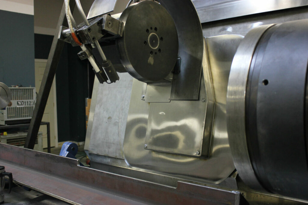
CNC metal spinning machine manufacturing is a specialized and technologically advanced field that blends mechanical engineering, control systems, materials science, and software integration. Producing a CNC metal spinning machine requires a deep understanding of both the traditional principles of metal forming and the modern demands of automation, precision, and flexibility. These machines are engineered to perform metal spinning—also known as flow forming or spin forming—at high speed with computer-controlled accuracy, enabling the shaping of symmetrical, hollow components from metal blanks without compromising structural integrity.
The manufacturing process begins with the machine’s structural framework, which is typically fabricated from high-grade steel or cast iron to ensure rigidity, vibration dampening, and long-term stability. The machine bed and columns are machined with high precision using large-format CNC milling and grinding machines to guarantee flatness and parallelism, which are crucial for maintaining tight tolerances during high-force spinning operations. Thermal stress relief treatments are often applied to the welded frames before machining to prevent distortion during long production cycles.
Next comes the spindle assembly, which is the heart of the CNC spinning machine. The spindle must rotate at variable speeds, often exceeding 3000 RPM, while sustaining axial loads of several tons. It is typically powered by a high-torque servo or induction motor, with precision bearings and cooling systems to ensure smooth, reliable rotation. The spindle also requires a robust chuck or fixture system to securely hold the forming mandrel—the tool over which the metal is spun. High-end machines may use automatic tool changers or quick-lock mandrels to minimize setup time between different production runs.
Equally important are the roller heads—these are the arms equipped with hardened forming rollers that press the metal blank against the mandrel while following a predefined CNC path. Each roller assembly is mounted on servo-driven axes (typically X, Z, and sometimes Y or U) that control radial and axial pressure as well as feed rates. These axes must deliver micron-level positioning accuracy under dynamic loads, which is why precision linear guides, ball screws, and digital feedback systems are used. The forming rollers themselves are manufactured from hardened tool steel or carbide and may be custom profiled depending on the part geometry and material type.
At the core of the system lies the CNC control unit, which coordinates all machine movements and processes in real-time. Most manufacturers use Siemens, Fanuc, or Beckhoff platforms, integrating custom software developed specifically for metal spinning. These control units manage not only axis motion and spindle speed but also auxiliary functions such as lubrication, thermal forming cycles, hydraulic tailstock engagement, and safety interlocks. Operators interface with the machine through touchscreen panels that allow for G-code programming, simulation, and monitoring of production data.
Heating systems are often integrated into the machine, especially for spinning harder or thicker materials like stainless steel or titanium. These may include induction heaters, gas burners, or infrared lamps positioned around the forming area to soften the blank prior to deformation. Precise thermal control is essential to avoid cracking or tearing during spinning. Advanced machines may use temperature sensors or pyrometers to provide closed-loop feedback to the heating system.
During assembly, every subsystem is tested individually before full integration. Spindle alignment, axis synchronization, backlash compensation, and load testing are performed to ensure that the machine will meet specified performance standards. Once assembled, machines undergo test runs with sample materials, where parameters such as repeatability, surface finish, and forming force are verified. Acceptance trials may include running customer-specific parts to validate cycle times and production feasibility.
In terms of manufacturing philosophy, many CNC spinning machine producers follow lean production methodologies, emphasizing modularity and standardization of components. This approach facilitates easier maintenance, faster delivery times, and simplified upgrades. For example, modular designs may allow a single base machine to be configured for single-roller or dual-roller operation, or to accommodate automation options such as robotic loading, trimming stations, or quality inspection modules.
To support global markets, many manufacturers offer customization based on the application sector. Aerospace models might include precision coolant systems and tool wear detection, while cookware industry machines may emphasize speed and integrated trimming. Medical device manufacturers may require machines that support titanium spinning under sterile conditions. This level of customization is made possible through close collaboration between the machine builder and the end user, often starting at the design stage with 3D modeling, FEA simulations, and virtual factory layouts.
After production, CNC metal spinning machines are shipped with comprehensive documentation, operator training modules, and remote diagnostics capabilities. On-site commissioning is typically handled by the manufacturer’s technical team, who calibrate the machine, provide safety training, and assist in the initial production runs. With the growing importance of digital integration, many manufacturers now offer IoT-ready machines that can connect to cloud platforms for predictive maintenance, software updates, and data analytics.
In conclusion, CNC metal spinning machine manufacturing is a multidisciplinary endeavor that produces one of the most flexible and efficient tools in modern metalworking. These machines are engineered to deliver high repeatability, reduced setup time, minimal material waste, and broad compatibility with a wide range of metals and part geometries. Whether for prototyping, mass production, or custom fabrication, CNC spinning machines continue to evolve—offering unmatched precision, adaptability, and performance in the age of smart manufacturing.
The manufacturing process of CNC metal spinning machines also involves rigorous quality control and testing protocols to ensure reliability and precision. Each mechanical component—from the spindle bearings to the linear guides and ball screws—is sourced from reputable suppliers and subjected to inspection for dimensional accuracy and material integrity. Subassemblies are often tested independently on specialized rigs to measure parameters such as vibration, load capacity, and thermal stability before being integrated into the final machine. This meticulous attention to detail minimizes potential downtime caused by mechanical failure and contributes to the machine’s long operational lifespan.
Software development plays an equally critical role in machine manufacturing. Beyond standard CNC control, manufacturers develop proprietary spinning modules or add-ons that optimize the toolpaths for metal forming operations. These software packages incorporate algorithms to calculate optimal roller pressure, feed rates, and spindle speeds based on material type, thickness, and part geometry. Simulation tools are frequently included to allow offline programming and virtual testing, which significantly reduces trial-and-error on the shop floor. Some manufacturers also provide interfaces for CAD/CAM integration, allowing engineers to directly translate 3D models into spinning programs, thus streamlining the workflow from design to production.
Safety engineering is another fundamental aspect during the design and manufacturing of CNC spinning machines. Given the high rotational speeds and heavy forming forces involved, machines must comply with international safety standards such as CE, OSHA, or ISO regulations. This includes the incorporation of emergency stop buttons, light curtains, interlocked access doors, protective enclosures, and overload sensors. Ergonomics are carefully considered to reduce operator fatigue and risk of injury during tool changes or maintenance tasks. Modern machines often incorporate software-controlled safety zones to prevent collisions between the roller heads, tailstock, and workpiece.
Manufacturers also focus on modularity and scalability in their machine designs. This allows customers to start with a basic configuration and add features such as dual roller heads, automatic tool changers, or integrated heating systems as their production needs evolve. Modular electrical cabinets and standardized interfaces make it easier to upgrade or repair machines without extensive downtime. Additionally, manufacturers may design their machines to be compatible with automation peripherals like robotic arms, conveyor systems, and in-line inspection devices, facilitating seamless integration into larger production cells or smart factories.
Supply chain management is a vital part of CNC metal spinning machine production. High-quality components—motors, sensors, CNC controllers, precision bearings—must be procured reliably and on time to meet customer delivery schedules. Many manufacturers maintain partnerships with global suppliers and implement just-in-time inventory systems to reduce costs and avoid production delays. Concurrently, they invest in in-house manufacturing capabilities for critical parts such as mandrels, rollers, and machine frames to maintain quality control and customization flexibility.
After assembly, the factory acceptance testing phase ensures that the machine performs according to its specifications under simulated operating conditions. Tests include verifying positional accuracy, repeatability, spindle speed range, torque delivery, and axis synchronization. Manufacturers may also conduct forming trials on standard materials to demonstrate the machine’s capability to achieve target part geometries and surface finishes. These tests often form the basis for customer acceptance and warranty agreements.
Installation and commissioning at the customer’s site are typically supported by the manufacturer’s service engineers. This process involves machine leveling, electrical and pneumatic hookups, CNC calibration, safety verification, and operator training. Some manufacturers provide remote support options that use IoT connectivity to monitor machine health, troubleshoot issues, and perform software updates, ensuring minimal disruption to production.
The after-sales service network is critical to maintaining machine uptime and maximizing return on investment. Leading manufacturers offer preventive maintenance contracts, spare parts supply, and technical support tailored to customer requirements. Training programs for operators and maintenance personnel help maximize the benefits of CNC metal spinning technology while minimizing errors and equipment wear.
As customer demands and technology advance, manufacturers continuously innovate by incorporating features like AI-driven process optimization, adaptive control, real-time force and temperature monitoring, and advanced materials handling. The drive toward Industry 4.0 compatibility encourages the integration of these machines into interconnected production environments, where data analytics and machine learning enhance efficiency, predict maintenance needs, and enable dynamic production scheduling.
Ultimately, CNC metal spinning machine manufacturing is a complex, interdisciplinary process that combines precision mechanical engineering, advanced electronics, software innovation, and robust quality assurance. These machines empower manufacturers worldwide to produce strong, precise, and complex metal components efficiently and sustainably, meeting the evolving needs of modern industry.
Advancing further into the manufacturing of CNC metal spinning machines, innovation continues to push the boundaries of what these machines can achieve. Emerging technologies such as additive manufacturing (3D printing) are beginning to influence the production of certain machine components, especially complex geometries in tooling, cooling channels, or lightweight structural parts. This approach allows manufacturers to reduce weight, enhance thermal management, and optimize part strength, leading to improved machine performance and energy efficiency. Additionally, rapid prototyping with additive manufacturing accelerates the development cycle for new roller designs or mandrels tailored to specific applications, reducing lead times and costs.
Another significant trend is the integration of advanced sensor technology and Internet of Things (IoT) connectivity. Smart sensors embedded in critical components continuously monitor parameters such as vibration, temperature, spindle load, and axis position with high precision. This real-time data is transmitted to centralized control systems or cloud platforms where it is analyzed using machine learning algorithms to predict maintenance needs, detect anomalies, and optimize operational parameters dynamically. Predictive maintenance enabled by these capabilities reduces unplanned downtime and extends the service life of mechanical and electronic components, offering a substantial cost-saving advantage to end users.
The move toward more user-centric interfaces is also reshaping CNC metal spinning machine manufacturing. Touchscreen displays, augmented reality (AR) support, and customizable dashboards allow operators to visualize toolpaths in 3D, access troubleshooting guides, and receive interactive training directly on the machine. Voice commands and gesture controls, although still emerging, show promise for enhancing operator efficiency and safety by enabling hands-free interaction during setup or operation. Furthermore, remote operation capabilities allow experts to support or control machines offsite, which is especially valuable in geographically dispersed manufacturing facilities or during situations where on-site presence is limited.
In parallel, manufacturers are emphasizing sustainability throughout the lifecycle of CNC metal spinning machines. From selecting environmentally responsible materials and components to designing for energy efficiency and recyclability, green manufacturing principles are being integrated into machine production. Energy recovery systems, low-friction coatings, and optimized hydraulic circuits reduce power consumption during operation. Additionally, companies are developing end-of-life programs that facilitate recycling or refurbishing of machines, supporting circular economy goals.
Customization and modularity remain core pillars in machine manufacturing strategy. Customers increasingly demand machines tailored to their specific processes, material choices, and production volumes. Machine builders respond by offering modular components such as interchangeable roller heads, adaptive clamping systems, and scalable axis configurations that can be configured or upgraded post-sale. This modularity enables manufacturers to adapt quickly to new market demands, reduce initial capital expenditure, and extend the functional lifespan of their equipment through incremental enhancements.
Training and knowledge transfer are also prioritized by leading CNC spinning machine manufacturers. Comprehensive programs include virtual simulations, hands-on workshops, and digital manuals that ensure operators and maintenance personnel can fully exploit the capabilities of their machines. Online platforms and communities provide ongoing support and a knowledge base for troubleshooting, programming tips, and best practices, fostering continuous improvement and innovation.
Looking ahead, the convergence of CNC metal spinning machines with other advanced manufacturing processes, such as hybrid machining or laser-assisted forming, is anticipated to further expand their capabilities. Hybrid machines combining spinning with cutting, welding, or additive processes enable the production of multi-functional components in fewer steps, enhancing efficiency and opening new design possibilities. Similarly, laser-assisted metal spinning, which applies controlled heat via laser sources, is being researched to form ultra-hard or heat-sensitive alloys with improved precision and surface quality.
In conclusion, CNC metal spinning machine manufacturing stands at the intersection of traditional craftsmanship and cutting-edge technology. Manufacturers continue to innovate in mechanical design, control systems, software integration, and connectivity to deliver machines that are faster, smarter, more reliable, and more adaptable than ever before. These advancements empower industries worldwide to produce high-quality, complex metal parts efficiently while meeting growing demands for sustainability, customization, and digital integration. The future of CNC metal spinning machines promises even greater versatility and intelligence, cementing their role as indispensable tools in modern metal forming.
Building on these advancements, the future of CNC metal spinning machine manufacturing is increasingly tied to the broader trends in Industry 4.0 and smart factories. Manufacturers are investing in machine designs that support seamless integration with digital twins—virtual replicas of the physical machine and its processes—which enable real-time simulation, predictive analytics, and remote troubleshooting. This allows not only for enhanced process optimization and quality control but also for more efficient training and rapid response to maintenance needs without requiring physical presence.
Furthermore, the adoption of edge computing technologies within CNC controllers is gaining traction. By processing data locally on or near the machine, latency is reduced and critical decisions—such as adjusting forming forces or detecting anomalies—can be made instantaneously. This enhances process stability, particularly in high-speed or precision-critical spinning operations, where milliseconds matter. Combined with cloud-based analytics, this hybrid approach balances responsiveness with the advantages of centralized data aggregation and long-term trend analysis.
Material science developments also influence machine manufacturing. As new alloys and composite materials become standard in aerospace, automotive, and medical fields, CNC spinning machines are being engineered to handle these more challenging substrates. This includes enhanced rigidity, improved spindle torque, and advanced roller materials/coatings to resist wear from abrasive or high-strength metals. Additionally, machines capable of multi-temperature processing—switching seamlessly between cold, warm, and hot spinning modes—are emerging to meet diverse material requirements without sacrificing throughput or quality.
Another emerging area is the application of artificial intelligence (AI) and machine learning to CNC metal spinning. AI algorithms are being developed to automatically optimize spinning parameters based on continuous feedback, learning from each part produced to reduce defects and improve cycle times. These systems can predict tool wear before failure, adjust spindle speed to compensate for material variability, or recommend maintenance schedules, thereby reducing downtime and improving overall equipment effectiveness (OEE).
Sustainability remains a guiding principle in the design and manufacture of new CNC spinning machines. Beyond energy-efficient components and regenerative systems, manufacturers are exploring biodegradable lubricants, recyclable machine components, and eco-friendly packaging for shipment. These efforts are often coupled with certifications and environmental reporting that help manufacturers and users meet increasingly stringent regulatory and corporate social responsibility (CSR) requirements.
From a global perspective, CNC metal spinning machine manufacturing is also becoming more decentralized. With the rise of additive manufacturing and modular assembly techniques, components can be produced closer to end-users, reducing supply chain complexity and shipping costs. Regional manufacturing hubs equipped with advanced quality assurance and customization capabilities are appearing, enabling faster delivery and tailored machine configurations that reflect local market demands and industry sectors.
Finally, collaboration between machine manufacturers, material suppliers, software developers, and end-users is fostering innovation ecosystems where new spinning technologies and processes are rapidly developed and commercialized. Industry consortia, research partnerships, and user forums promote the sharing of best practices, joint development of standards, and co-creation of specialized solutions that push the boundaries of what CNC metal spinning can achieve.
In essence, the manufacturing of CNC metal spinning machines is evolving from purely mechanical engineering into a multidisciplinary domain integrating digital technologies, advanced materials, and sustainable practices. This transformation equips manufacturers to deliver smarter, more adaptable, and environmentally responsible machines that will meet the complex and evolving needs of tomorrow’s metal forming industries.
CNC Metal Spinning Machine
CNC Metal Spinning Machines, Flow Forming Machines, and Spinforming Lathes are closely related metal forming technologies that share the fundamental principle of shaping metal blanks into hollow, symmetrical parts by applying pressure while the workpiece rotates. Although the terms are sometimes used interchangeably, there are subtle differences in their processes, applications, and machine configurations.
CNC Metal Spinning Machines specifically refer to computer-controlled equipment that performs traditional metal spinning. In this process, a flat metal disc or tube is clamped to a mandrel and rotated at high speed while one or more rollers apply pressure to plastically deform the metal over the mandrel’s shape. CNC controls guide the roller’s axial and radial movement with precision, allowing the production of complex geometries with excellent surface finish and dimensional accuracy. This method is particularly suited for producing parts such as cookware, lighting reflectors, domes, and pressure vessel heads.
Flow Forming Machines are a type of metal forming equipment that focuses on reducing the wall thickness and extending the length of cylindrical or conical metal blanks by applying high pressure with rollers while the blank spins on a mandrel. Unlike metal spinning, flow forming often involves multiple passes with incremental deformation to achieve significant elongation and thinning of the metal. Flow forming is widely used in manufacturing high-performance components like aerospace rings, automotive wheels, and rocket motor casings, where superior mechanical properties and weight reduction are critical. These machines generally feature robust frames, powerful spindles, and multiple rollers that operate simultaneously or sequentially.
Spinforming Lathes is a broader term that encompasses manual and CNC-controlled machines designed to perform spinning operations. Traditional spinforming lathes rely on skilled operators to manually control the roller position and force, shaping the metal by hand guidance. Modern CNC spinforming lathes automate this process, using precise servo motors and programmed toolpaths to replicate and scale complex shapes consistently. Spinforming is valued for its ability to produce seamless, structurally sound parts with minimal tooling costs and quick turnaround.
All these machines typically consist of a rotating spindle to hold the blank and mandrel, one or more roller assemblies mounted on servo-driven axes, and a CNC controller that manages spindle speed, roller feed, and forming pressure. The machines may also include tailstocks or back supports to secure the workpiece, heating systems for hot forming, and safety enclosures to protect operators.
The choice between CNC metal spinning, flow forming, or spinforming lathes depends on factors like part geometry, material type, mechanical requirements, and production volume. For parts requiring significant wall thinning and elongation with high strength, flow forming is preferred. For more intricate shapes or shorter runs, CNC metal spinning offers greater flexibility and lower tooling costs. Manual or CNC spinforming lathes excel in producing medium complexity parts with excellent surface finishes and dimensional control.
Together, these technologies form an essential suite of metal forming methods used across aerospace, automotive, defense, cookware, lighting, and energy industries. Their ability to produce seamless, lightweight, and high-strength components efficiently makes them invaluable in modern manufacturing environments where precision, adaptability, and cost-effectiveness are paramount.
The integration and evolution of CNC metal spinning machines, flow forming machines, and spinforming lathes reflect the growing demand for precision, efficiency, and versatility in metal forming processes. CNC metal spinning machines bring automation and digital precision to the age-old craft of spinning, enabling manufacturers to produce complex shapes with consistent quality and minimal waste. Flow forming machines complement this by specializing in controlled thinning and elongation of cylindrical components, delivering parts with enhanced mechanical properties essential for critical applications like aerospace engine components and structural rings. Spinforming lathes, whether manual or CNC-controlled, offer flexibility for a range of part sizes and shapes, balancing the need for craftsmanship and automation.
Modern CNC systems have revolutionized these machines by providing multi-axis control, programmable roller trajectories, and integration with CAD/CAM software. This allows engineers to design intricate profiles and simulate the forming process virtually before actual production, reducing trial-and-error and material waste. The ability to rapidly switch between part designs by loading different CNC programs enhances responsiveness to market changes and customization demands. Furthermore, advanced sensors and feedback loops monitor forming forces, spindle torque, and part dimensions in real time, ensuring that each component meets stringent quality standards.
Material versatility is another hallmark of these technologies. From soft metals like aluminum and copper to high-strength alloys such as titanium and Inconel, CNC metal spinning and flow forming machines are engineered to accommodate a wide spectrum of materials. The machines can be equipped with heating systems to enable hot forming of difficult-to-shape alloys, improving ductility and preventing cracks or wrinkles during deformation. This adaptability makes them indispensable in industries where material performance and reliability are critical, including medical device manufacturing, defense, and renewable energy.
Production efficiency is further enhanced through automation features such as robotic loading and unloading, automated tool changers, and integrated trimming stations. These additions reduce cycle times and operator intervention, making it feasible to economically produce both small prototype batches and larger production runs. The modular design of many machines allows customization to specific production needs, enabling manufacturers to optimize their investment and scale capabilities as demand grows.
Safety and ergonomics have been prioritized in the design of modern spinning and flow forming machines. Enclosures, interlocks, emergency stops, and noise reduction features protect operators, while intuitive touchscreen interfaces and assistive controls simplify operation and maintenance. Training tools, including virtual reality simulations and remote diagnostics, further support workforce development and machine uptime.
The sustainability aspect cannot be overlooked. These forming processes generally consume less energy than traditional forging or stamping, generate minimal scrap, and often require fewer secondary machining operations. Advances such as regenerative braking systems and environmentally friendly lubricants contribute to reducing the carbon footprint of metal forming operations.
Looking forward, the convergence of CNC metal spinning, flow forming, and spinforming with emerging technologies like artificial intelligence, machine learning, and IoT connectivity promises even greater capabilities. Machines will increasingly self-optimize, predict maintenance needs, and integrate seamlessly into smart factory ecosystems. This evolution will empower manufacturers to meet the growing demands for complex, high-quality metal components while maintaining agility, efficiency, and environmental responsibility.
In summary, CNC metal spinning machines, flow forming machines, and spinforming lathes represent a continuum of highly adaptable, precise, and efficient metal forming technologies. Their complementary capabilities address a broad range of industrial challenges, enabling the production of seamless, strong, and lightweight components essential to modern engineering and manufacturing. As these machines continue to evolve, they will remain at the forefront of metal forming innovation, driving quality and productivity across countless sectors worldwide.
Beyond their core forming functions, CNC metal spinning machines, flow forming machines, and spinforming lathes are increasingly integrated with auxiliary technologies to enhance their capabilities and streamline manufacturing workflows. For example, in-line inspection systems using laser scanners or optical measurement tools can verify part dimensions immediately after forming, ensuring quality control without interrupting production. This real-time feedback can automatically trigger adjustments to the CNC program or signal operators when tolerances deviate, reducing scrap and rework.
Another key development is the coupling of these machines with automated material handling solutions such as robotic arms, conveyors, and pallet changers. These systems facilitate continuous operation with minimal human intervention, enabling lights-out manufacturing environments where machines run unattended for extended periods. Such automation is especially valuable for high-volume production or hazardous environments where safety concerns restrict human presence.
The evolution of tooling for metal spinning and flow forming also plays a crucial role. Advanced materials like carbide, ceramic coatings, and engineered composites are used to manufacture rollers and mandrels that withstand higher pressures, reduce wear, and improve surface finishes. Some machines employ quick-change tooling systems to minimize downtime during tool swaps or part changeovers. Additionally, modular mandrel systems allow easy adaptation to different part profiles, increasing machine flexibility and reducing lead times.
Materials processing innovations complement machine capabilities. Cold spinning remains popular for many alloys, but warm and hot spinning techniques are gaining traction, particularly for difficult-to-form materials. Induction heating, gas torches, and infrared heaters are integrated into CNC machines to soften metals precisely where needed, reducing forming forces and improving final part properties. These thermal methods expand the range of feasible materials and geometries while preserving dimensional accuracy and surface integrity.
Industry-specific adaptations further illustrate the versatility of these technologies. In aerospace, CNC spinning and flow forming produce lightweight structural components with high strength-to-weight ratios, such as engine casings, ducting, and fairings. The automotive sector leverages these machines for wheels, drive shafts, and decorative trim parts requiring high durability and aesthetic appeal. In the cookware industry, rapid-changeover CNC spinners enable efficient production of various pot and pan shapes with excellent finish quality. Renewable energy companies use flow forming to manufacture turbine components and pressure vessels that withstand harsh operating conditions.
From a business perspective, the capital investment in CNC metal spinning and flow forming equipment is justified by their ability to reduce tooling costs, shorten lead times, and increase part quality. These machines lower the barrier to entry for complex metal forming by minimizing reliance on large stamping presses or expensive dies. Small to medium enterprises benefit from the flexibility to produce diverse part runs without the high upfront costs associated with traditional forming methods.
Looking ahead, the integration of artificial intelligence, machine learning, and predictive analytics will continue to transform metal spinning and flow forming operations. Smart machines will adapt in real-time to material variability, optimize cycle times dynamically, and provide operators with actionable insights through intuitive dashboards. Collaborative robots (cobots) may work alongside operators to handle loading, inspection, and finishing tasks, enhancing productivity and safety.
Furthermore, the growing emphasis on sustainability will drive innovations such as energy-efficient motors, biodegradable lubricants, and machine designs that facilitate easy recycling at end-of-life. The ability to form near-net-shape parts reduces material waste and downstream machining, contributing to greener manufacturing processes.
In essence, CNC metal spinning machines, flow forming machines, and spinforming lathes are not static tools but evolving platforms that integrate mechanical precision, digital intelligence, and sustainable practices. They empower manufacturers to meet complex design requirements with speed, accuracy, and cost-effectiveness while adapting to the challenges of modern production environments. As these technologies advance, their role in shaping the future of metal forming and manufacturing will only become more significant, enabling innovations across industries worldwide.
In addition to technological advancements, the adoption of standardized protocols and interoperability in CNC metal spinning and flow forming machines is gaining momentum. Manufacturers increasingly design machines to communicate seamlessly with other equipment and software in the production line using industry-standard protocols such as OPC UA, MTConnect, or MQTT. This connectivity enables real-time data exchange between machines, enterprise resource planning (ERP) systems, and manufacturing execution systems (MES), facilitating coordinated workflows, just-in-time production, and enhanced traceability. Such integration supports agile manufacturing environments where production schedules and processes can be adjusted dynamically in response to demand fluctuations or supply chain constraints.
The role of digital twins in CNC spinning and flow forming is expanding as well. Digital twins serve as comprehensive virtual models of physical machines and processes, allowing engineers to simulate different operating scenarios, predict maintenance needs, and optimize parameters before actual production. These virtual replicas also support operator training, enabling personnel to practice machine operation and troubleshoot potential issues in a risk-free environment. The result is improved machine utilization, fewer unplanned stoppages, and faster ramp-up times for new production runs.
Customization remains a key differentiator in the market for CNC metal spinning and flow forming machines. End users frequently require machines tailored to their specific part geometries, materials, and production volumes. To meet these demands, manufacturers offer modular platforms with interchangeable components, expandable axis configurations, and optional features such as integrated heating, automatic trimming, or in-line inspection. This modularity allows manufacturers to deliver solutions that balance upfront cost with long-term flexibility and upgrade potential.
Training and workforce development continue to be critical factors as well. The increasing complexity of CNC metal spinning and flow forming machines necessitates skilled operators, programmers, and maintenance personnel. Manufacturers and industry organizations invest in comprehensive training programs, combining classroom instruction, hands-on workshops, and digital learning platforms. Virtual and augmented reality tools enhance training effectiveness by providing immersive experiences that simulate real-world machine operation and maintenance tasks.
Supply chain resilience has come into sharper focus in recent years, influencing how CNC metal spinning and flow forming machines are manufactured and deployed. Manufacturers emphasize local sourcing of critical components where possible, dual sourcing strategies, and the use of standardized parts to reduce vulnerability to disruptions. Additionally, modular machine designs enable easier replacement or upgrading of subsystems without requiring entire machine replacements, supporting longer equipment lifecycles and sustainability goals.
From a research and development perspective, ongoing efforts focus on expanding the capabilities of CNC metal spinning and flow forming machines through multi-material forming, hybrid processes, and enhanced automation. Combining spinning or flow forming with additive manufacturing techniques, laser-assisted forming, or friction stir welding holds promise for producing parts with novel properties or integrated functions. Advances in sensors and artificial intelligence are also enabling machines to self-correct in real time, improving quality and reducing operator intervention.
In conclusion, CNC metal spinning machines, flow forming machines, and spinforming lathes are evolving rapidly, driven by advances in digitalization, materials science, automation, and sustainability. Their ability to deliver precision, repeatability, and adaptability makes them indispensable in modern manufacturing across aerospace, automotive, energy, medical, and consumer goods sectors. As these technologies continue to mature and integrate with smart factory ecosystems, they will play a pivotal role in enabling innovative product designs, flexible production strategies, and responsible resource management, shaping the future of metal forming worldwide.
Single Roller CNC Spinning Machines
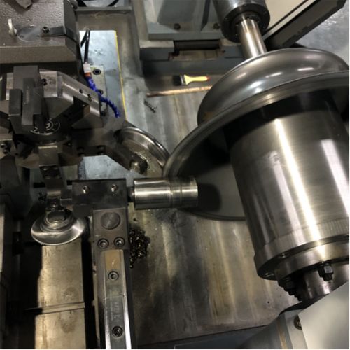
Single roller CNC spinning machines are a specialized category of metal spinning equipment designed to produce rotationally symmetrical parts by applying force through a single forming roller onto a rotating metal blank. These machines combine the traditional metal spinning process with modern CNC (Computer Numerical Control) technology, offering precision, repeatability, and automation advantages while maintaining the flexibility to form complex shapes.
The core feature of a single roller CNC spinning machine is its single forming roller mounted on a servo-controlled arm or slide, which moves along programmed paths to shape the metal blank over a mandrel. The metal blank, typically a flat disc or tube, is clamped securely to the mandrel, which rotates at variable speeds. The single roller then applies pressure, gradually deforming the metal into the desired profile. This process allows for continuous, smooth metal flow, maintaining the material’s grain structure and strength without cutting or joining.
One of the main advantages of single roller machines is their relative mechanical simplicity compared to multi-roller systems. With fewer moving parts and axes to control, they tend to have lower maintenance requirements and reduced initial costs. Their compact design also makes them well-suited for smaller workshops or applications where floor space is limited. Despite the simpler setup, single roller CNC spinners can produce a wide variety of part shapes, including cones, cylinders, hemispheres, and custom profiles with varying wall thicknesses.
The CNC control system is crucial for maximizing the machine’s capabilities. It precisely governs roller position, feed rate, spindle speed, and forming pressure according to programmed toolpaths. Operators can input detailed part geometries via CAD/CAM software, generating CNC code that guides the roller’s motion with micron-level accuracy. This ensures consistent part quality, reduces cycle times, and minimizes material waste. Advanced systems may include closed-loop feedback from force sensors or position encoders to adapt forming parameters dynamically during operation.
Single roller CNC spinning machines excel in applications where moderate complexity parts are needed, often with tight tolerances and good surface finishes. They are commonly used in industries such as lighting, cookware, HVAC components, musical instruments, and small pressure vessels. Their ability to quickly switch between part designs by changing CNC programs makes them ideal for short to medium production runs and prototyping.
While multi-roller CNC spinning machines can offer faster forming and better control over certain complex shapes or thicker materials, single roller machines remain popular due to their cost-effectiveness, ease of operation, and versatility. Some manufacturers offer modular designs where a single roller machine can be upgraded with additional rollers or automation features as production demands increase.
Additional features often integrated into single roller CNC spinning machines include hydraulic or pneumatic tailstocks to firmly support the mandrel, heating systems for warm or hot spinning processes, and automated tool changers for forming rollers. Safety enclosures with interlocks and emergency stops are standard to protect operators during high-speed operation.
In summary, single roller CNC spinning machines represent a balanced solution that combines precision automation with mechanical simplicity. They enable manufacturers to produce high-quality spun metal components efficiently and flexibly, making them valuable tools in a wide range of industrial and artisanal applications.
Single roller CNC spinning machines continue to gain popularity due to their adaptability and user-friendly operation, making them accessible to both experienced metal spinners and those transitioning from manual processes. Their straightforward design translates into faster setup times and easier maintenance, allowing shops to focus on production rather than complex machine management. This accessibility supports smaller manufacturers and custom fabricators who benefit from the automation and repeatability of CNC without the higher costs and complexity of multi-roller systems.
The precision afforded by CNC control on single roller machines also enables the production of parts with tighter dimensional tolerances and superior surface finishes compared to manual spinning. This accuracy is particularly important in industries where component fit and function are critical, such as aerospace, automotive, and medical device manufacturing. Additionally, the CNC system allows for the replication of intricate shapes that would be difficult or time-consuming to achieve by hand, expanding design possibilities while maintaining consistent quality across batches.
In terms of materials, single roller CNC spinning machines are compatible with a broad range of metals, including aluminum, copper, brass, stainless steel, and some titanium alloys. When paired with integrated heating systems, these machines can handle more challenging materials by increasing ductility during forming, thereby reducing the risk of cracking or wrinkling. This expands the applicability of single roller CNC spinners to sectors that demand high-performance materials and components.
Automation options further enhance the capabilities of single roller CNC spinning machines. Features such as robotic loading and unloading, automatic mandrel changes, and in-line trimming stations can be incorporated to improve throughput and reduce manual labor. Software advancements enable quick program switching and adaptive control strategies that adjust forming parameters in real-time based on sensor feedback, ensuring optimal forming conditions for varying batch sizes and materials.
Moreover, single roller machines often serve as excellent training platforms within manufacturing environments. Their relative simplicity allows operators to develop CNC programming and spinning skills before progressing to more complex multi-roller systems. This staged learning approach improves workforce competency while minimizing costly mistakes during the learning curve.
The economic benefits of single roller CNC spinning machines also contribute to their appeal. Lower acquisition costs, reduced maintenance expenses, and shorter lead times for part changeover translate into a favorable return on investment, especially for small and medium-sized enterprises. The machines enable profitable production of low to medium volume runs, prototypes, and custom parts without requiring significant tooling investment.
Looking forward, technological developments continue to improve single roller CNC spinning machines. Integration of artificial intelligence and machine learning is beginning to provide self-optimizing capabilities that enhance forming quality and process efficiency. Connectivity with factory automation systems facilitates data-driven decision making, predictive maintenance, and remote support, aligning these machines with Industry 4.0 principles.
In summary, single roller CNC spinning machines combine the simplicity of traditional metal spinning with the precision and efficiency of modern CNC automation. They offer a versatile, cost-effective solution for producing a wide variety of spun metal components across many industries. Their balance of ease of use, flexibility, and advanced control makes them a valuable asset for manufacturers seeking to improve productivity while maintaining high quality and adaptability.
Single roller CNC spinning machines also play a critical role in fostering innovation within product development cycles. Their ability to rapidly switch between different programs and mandrels allows designers and engineers to test new shapes, materials, and thicknesses with minimal downtime and tooling costs. This agility supports iterative prototyping and customization, which is especially valuable in industries where bespoke or limited-run components are common, such as custom lighting, architectural elements, and specialized industrial equipment.
From a manufacturing workflow perspective, these machines often integrate smoothly into lean production environments. Their compact footprint and straightforward operation reduce the complexity of factory layouts and help optimize space utilization. With the addition of automated material handling and quality inspection systems, single roller CNC spinning machines can contribute to highly efficient, continuous production lines with minimal bottlenecks.
Material savings inherent in single roller spinning processes also contribute to cost and environmental benefits. Unlike stamping or deep drawing, spinning typically generates little to no scrap since the metal is plastically deformed rather than cut away. This near-net-shape forming reduces raw material consumption and the energy required for downstream machining, aligning with sustainable manufacturing initiatives and cost reduction goals.
In maintenance terms, the simpler mechanical design means that common issues such as roller wear, ball screw backlash, or spindle bearing degradation are easier to diagnose and address. This reduces machine downtime and maintenance costs, enhancing overall equipment effectiveness. Manufacturers often provide comprehensive support packages including remote diagnostics, spare parts kits, and preventative maintenance schedules tailored to single roller CNC spinning machines, ensuring reliability in demanding production settings.
Operator safety is another important consideration. Single roller CNC machines typically incorporate safety enclosures, interlocked doors, and emergency stop systems to protect users from high-speed rotating components and moving rollers. The reduced number of moving parts also means fewer pinch points and hazards compared to multi-roller systems, contributing to a safer working environment.
As demand for lightweight, high-strength components continues to grow in sectors like aerospace, automotive, and medical devices, the role of single roller CNC spinning machines in producing such parts is set to expand. Their capability to handle advanced materials and complex geometries efficiently positions them as indispensable tools in modern manufacturing portfolios.
The future of single roller CNC spinning machines lies in deeper integration with digital manufacturing ecosystems. Enhanced connectivity will allow these machines to exchange data seamlessly with enterprise systems, robotics, and inspection technologies, enabling fully automated, traceable, and adaptive production processes. Continuous advancements in control algorithms, sensor technologies, and machine learning will drive improvements in precision, speed, and material utilization, ensuring these machines remain competitive and relevant.
In conclusion, single roller CNC spinning machines offer a compelling blend of simplicity, precision, flexibility, and efficiency. Their adaptability to various materials and part designs, combined with automation and digital integration possibilities, make them powerful assets for manufacturers aiming to optimize metal forming operations. Whether used for prototyping, small batch production, or specialized manufacturing, these machines continue to evolve and meet the challenges of modern industry with innovation and reliability.
Expanding further, single roller CNC spinning machines increasingly incorporate advanced monitoring and diagnostic technologies to enhance process control and machine health management. Real-time data collection from sensors measuring spindle load, roller force, vibration, temperature, and axis position allows for detailed analysis of forming conditions. This continuous monitoring helps identify deviations from optimal parameters early, enabling corrective actions before defects occur or machine components experience excessive wear. Over time, accumulated data supports predictive maintenance strategies, reducing unexpected downtime and extending the life of critical parts like bearings and ball screws.
The integration of augmented reality (AR) and virtual reality (VR) tools is also gaining traction in supporting the operation and maintenance of single roller CNC spinning machines. AR headsets or tablets can overlay step-by-step guidance, machine status information, and troubleshooting tips directly onto the operator’s field of view, simplifying complex tasks and reducing human error. VR simulators provide immersive training environments where operators can practice programming, setup, and emergency response without risking damage to actual equipment, thus accelerating skill development and safety awareness.
Software ecosystems surrounding these machines continue to evolve, offering more intuitive user interfaces, advanced CAD/CAM integration, and cloud connectivity. Operators benefit from graphical programming tools that allow the import and editing of 3D part models, automatic generation of optimized toolpaths, and simulation of forming processes before actual production. Cloud-based platforms enable remote monitoring, program management, and collaborative troubleshooting between on-site teams and manufacturer experts, facilitating faster issue resolution and continuous process improvement.
Energy efficiency is another focus area in the design of modern single roller CNC spinning machines. Manufacturers are incorporating high-efficiency servo motors, regenerative braking systems that recover energy during deceleration, and optimized hydraulic and pneumatic components to minimize power consumption. Such improvements not only reduce operational costs but also align with global efforts to lower industrial energy footprints and comply with environmental regulations.
Customization options continue to expand, with machines tailored to specific industry needs. For example, food-grade models include stainless steel components and easy-to-clean surfaces for hygienic manufacturing environments. Aerospace-grade machines emphasize ultra-precise controls and enhanced stiffness to handle exotic alloys and tight tolerances. Some machines are designed with modular frames and quick-change tooling to support rapid product changeovers in contract manufacturing or job shop settings.
Looking toward the future, advancements in materials science—such as the development of high-entropy alloys and metal matrix composites—will present new challenges and opportunities for single roller CNC spinning machines. Their forming capabilities will need to adapt to these emerging materials, potentially requiring innovations in heating methods, roller design, and process control to maintain quality and efficiency.
Collaborative robots (cobots) are expected to play a growing role in assisting single roller CNC spinning operations. Cobots can handle repetitive, ergonomically challenging tasks like loading/unloading blanks, mandrel changes, or part inspection, working safely alongside human operators. This collaboration enhances productivity while allowing skilled personnel to focus on programming, quality control, and process optimization.
In sum, the trajectory of single roller CNC spinning machines points toward greater intelligence, connectivity, and versatility. Through continuous integration of cutting-edge technologies and customer-driven customization, these machines are positioned to remain essential tools for manufacturers seeking precision metal forming solutions that balance efficiency, quality, and adaptability in an increasingly complex industrial landscape.
Double Roller CNC Spinning Machines (Symmetrical)
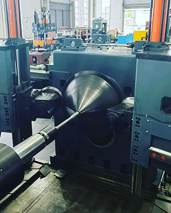
Double roller CNC spinning machines with symmetrical roller arrangements are an advanced solution for high-precision and high-efficiency metal forming operations, particularly in applications requiring symmetric force distribution and superior surface finishes. These machines utilize two synchronized spinning rollers, typically positioned on opposite sides of the forming zone, working in unison to apply uniform pressure on the rotating metal blank. This dual-sided force application results in reduced radial stress, minimized deformation imbalances, and faster cycle times, especially beneficial for large-diameter or heavy-gauge components.
Symmetrical double roller CNC spinning machines excel in forming deep, uniform shapes with high repeatability. The symmetrical roller setup ensures consistent material flow and better wall thickness control, which is critical in aerospace, defense, high-performance automotive, and industrial applications where structural integrity and dimensional accuracy are paramount. Compared to single roller systems, double roller configurations significantly reduce the chances of wrinkling, tearing, or thinning at complex geometries or transitions, especially in parts with long axial lengths.
One of the defining advantages of double roller machines is their enhanced forming efficiency. With pressure applied from both sides, metal deformation is more evenly distributed, requiring less forming time and fewer tool passes. This results in shorter production cycles and increased throughput. Additionally, the symmetrical design contributes to longer tool life by balancing load on the rollers and reducing wear caused by uneven stress distribution. This not only decreases tooling costs but also minimizes machine downtime associated with roller replacement or reconditioning.
From a structural perspective, these machines are built with reinforced frames and high-rigidity components to withstand the intense forces generated during dual-sided spinning. The synchronized control system is engineered to ensure precise coordination between the rollers, typically powered by high-torque servo motors and managed through advanced CNC software. This software enables complex motion programming, real-time adjustments, and seamless transitions between forming phases. Operators can control roller depth, feed rate, contact angle, and forming speed with high precision, tailoring the process to specific material and geometry requirements.
Double roller CNC spinning machines are particularly well-suited for forming non-ferrous and high-strength metals such as aluminum, titanium, stainless steel, and even Inconel. In heated spinning applications, the symmetrical roller setup ensures more efficient thermal distribution, reducing the risk of localized overheating or cracking. Some configurations also include integrated induction or gas heating systems for hot spinning of thick or hard-to-form blanks.
Automation is deeply integrated into modern double roller CNC systems. Robotic arms, gantry loaders, and conveyor-based material handling systems can be added to automate blank loading, unloading, mandrel changes, and part transfer. In-line trimming, beading, or hole punching can also be incorporated to create a complete spinning cell that minimizes manual intervention. These machines are often embedded into MES (Manufacturing Execution Systems) and ERP platforms for full production traceability, quality tracking, and efficiency analysis.
In industries such as aerospace and defense, double roller CNC spinning machines are indispensable for manufacturing rocket motor cases, jet engine components, missile housings, and large pressure vessels. Their ability to form large and structurally critical parts with superior mechanical properties makes them a preferred choice. Similarly, in automotive and commercial vehicle sectors, these machines are used to produce clutch housings, flywheel covers, and heavy-duty suspension components.
The rise of digital manufacturing has further expanded the capabilities of these machines. IoT integration allows real-time monitoring of machine performance, predictive maintenance alerts, and remote diagnostics. Cloud-based data storage supports quality documentation and facilitates collaboration between engineers and operators across different locations. With AI-driven analytics, some systems can now optimize forming parameters autonomously to improve product quality and reduce waste.
In conclusion, double roller CNC spinning machines (symmetrical type) represent a pinnacle of precision metal forming technology, combining high productivity, exceptional part quality, and operational flexibility. They are ideally suited for demanding applications where material performance and geometry consistency are non-negotiable. As manufacturing trends move toward greater automation, digitalization, and material complexity, symmetrical double roller spinning machines will remain at the forefront of advanced metalworking solutions.
The symmetrical configuration of double roller CNC spinning machines also enables smoother force distribution, which is particularly important when working with difficult-to-form materials or when producing parts with large diameters and deep draw ratios. This balanced pressure application minimizes distortion and allows for more aggressive forming without compromising structural integrity or surface quality. In many cases, these machines can achieve tight tolerances without the need for secondary operations, contributing to both cost and time savings in the overall production process.
Another key benefit of symmetrical double roller machines lies in their ability to handle both forward and reverse spinning operations with equal efficiency. This bidirectional capability allows for the production of complex geometries, including stepped cones, curved contours, and components with reverse curves, which are challenging to form on single roller systems. The coordinated movement of the rollers ensures material flow is controlled with precision, reducing the occurrence of common defects such as folds, uneven wall thickness, or eccentricity.
These machines are often equipped with advanced HMI (Human-Machine Interface) panels, featuring intuitive touchscreens, graphical program editors, and real-time process visualization. Operators can simulate forming processes before actual production, allowing them to optimize toolpaths, set forming parameters, and preview part deformation in a virtual environment. This reduces trial-and-error, shortens setup times, and improves first-pass yield. For high-mix, low-volume production environments, these programming features make symmetrical double roller machines extremely adaptable and user-friendly.
Tooling for double roller machines is specially designed to withstand symmetrical loading, with mandrels and rollers often fabricated from hardened tool steels or coated with wear-resistant materials like tungsten carbide. Quick-change tool systems and hydraulic or pneumatic clamping mechanisms further reduce downtime during changeovers. The rollers themselves may be designed with modular geometry, allowing operators to configure the contact profile according to part specifications, whether it involves a gentle curve or a sharp angle.
Process consistency is a hallmark of symmetrical double roller systems, aided by precision CNC control and servo-driven axes. Closed-loop feedback systems, including load cells and position encoders, constantly monitor roller force and position, making real-time corrections to compensate for material variability or tool wear. This ensures uniform wall thickness, concentricity, and surface finish across the entire batch of parts, meeting the stringent quality demands of aerospace and medical industries.
Sound and vibration insulation are often integrated into the design of modern double roller spinning machines, especially those installed in production facilities where noise and mechanical resonance could impact neighboring equipment or worker comfort. Cast iron or steel-reinforced frames, isolated machine bases, and enclosed working chambers contribute to a stable, low-vibration environment, which further enhances forming accuracy and tool longevity.
For manufacturers concerned with sustainability, double roller CNC spinning machines align well with energy-efficient and waste-reduction goals. Because the spinning process involves plastic deformation without cutting away excess material, there is minimal scrap. Combined with efficient motor drives, variable frequency control, and smart power management systems, these machines consume less energy per part compared to many other forming technologies, particularly in the case of medium to large batch runs.
Training and workforce adaptation are also simplified thanks to the digital capabilities of these machines. Digital twin technology, virtual commissioning, and cloud-based simulation tools allow technicians and engineers to understand machine behavior and optimize processes before physical deployment. Training modules integrated into the HMI or delivered via remote support make onboarding of new staff faster and more effective.
In terms of safety, symmetrical double roller spinning machines are typically equipped with advanced protective features such as full enclosure doors with interlocks, emergency stop buttons, thermal overload protection, and anti-collision sensors. Light curtains and area scanners can be added to ensure operator safety even in semi-automated or robotic environments. As machines become more connected and intelligent, safety protocols are increasingly monitored and enforced through software, ensuring compliance with global safety standards.
In a rapidly evolving manufacturing landscape, symmetrical double roller CNC spinning machines provide a powerful combination of mechanical precision, digital intelligence, and operational flexibility. Their ability to handle complex shapes, tough materials, and tight tolerances make them indispensable for industries pushing the limits of performance and reliability. Whether forming parts for satellites, electric vehicles, or industrial machinery, these machines deliver consistent, repeatable results that support innovation and productivity on the factory floor.
The advancement of symmetrical double roller CNC spinning machines has also opened up opportunities for forming hybrid materials and multi-layered metal blanks, which are increasingly used in high-performance applications. These materials often combine metals with distinct properties—such as corrosion resistance, thermal conductivity, or weight reduction—into a single composite blank. The precise control and uniform pressure of double rollers are ideal for maintaining layer integrity and preventing delamination during the spinning process. This capability allows manufacturers to produce functionally graded components or clad parts that meet strict mechanical and environmental specifications.
In terms of size capacity, symmetrical double roller CNC spinning machines can be designed for both small and extremely large parts. For instance, compact models are ideal for forming small aluminum cones, reflectors, or cookware at high speeds with minimal material waste, while large-frame models—sometimes exceeding several meters in length and swing diameter—are capable of forming large satellite fuel tanks, heavy-duty bellows, wind turbine hubs, and industrial domes. The flexibility in design scale enables suppliers to serve a wide range of industries from consumer goods to heavy industry and defense sectors.
The use of sensors and AI-assisted process optimization is another growing area. These machines can be integrated with strain gauges, acoustic sensors, and thermal cameras that collect real-time process feedback. When paired with AI algorithms, the system can self-optimize forming sequences, detect subtle variations that may lead to defects, and suggest or automatically apply corrections. This level of intelligence not only improves quality but also enables lights-out manufacturing, where machines operate autonomously during off-hours, significantly improving facility throughput.
One of the technical challenges traditionally associated with metal spinning—tool deflection—has been largely mitigated in symmetrical double roller machines. Because forces are counterbalanced, bending moments on the mandrel and spindle are reduced, allowing for higher forming pressures and more complex geometries without compromising accuracy. This stability is particularly important when forming long, thin-walled parts, where even slight tooling deflections can result in unacceptable tapering or dimensional variation.
Manufacturers can also take advantage of post-forming integration, where operations such as heat treatment, polishing, or surface coating are performed immediately after spinning without removing the part from the fixture. In some configurations, these secondary processes are integrated directly onto the machine bed or mounted alongside the spinning station. This inline approach streamlines production and reduces the need for part repositioning, which can introduce alignment errors or increase handling time.
On the customization front, OEMs offer a wide range of optional accessories and configurations to suit different production needs. Examples include turret-style roller holders for rapid tool switching, automatic mandrel positioning systems, programmable tailstocks for dynamic support, and dual-spindle designs for increased forming speed. Machine builders often work closely with end users to develop turnkey systems tailored to their parts, materials, and workflow—this collaborative approach ensures the equipment performs optimally from day one.
Training and service support are crucial to the adoption and sustained use of these machines. Many CNC spinning machine manufacturers now offer remote diagnostics, real-time monitoring dashboards, and over-the-air software updates. This reduces machine downtime and helps customers continuously improve their processes. Some vendors provide operator training packages, including virtual simulators, to accelerate operator proficiency and ensure that personnel are capable of leveraging the full capabilities of the equipment.
As metal spinning gains broader recognition for its sustainability and material efficiency, symmetrical double roller CNC spinning machines are likely to see increased adoption across sectors aiming to reduce carbon footprint and manufacturing waste. Unlike machining processes that remove material, spinning reshapes it, typically with a material utilization rate near 100%. This not only conserves raw materials but also reduces costs associated with scrap handling, recycling, and environmental compliance.
In conclusion, symmetrical double roller CNC spinning machines embody a fusion of traditional metal forming principles and modern digital manufacturing technologies. Their unmatched ability to produce high-precision, structurally sound, and geometrically complex components—across a vast array of materials and sizes—positions them as critical assets in the future of metal fabrication. With continued innovations in software, materials, and automation, these machines will remain at the core of advanced forming operations in the aerospace, automotive, energy, and industrial manufacturing sectors.
Multi-Roller CNC Flow Forming Machines (3-roller, 4-roller, etc.)
Multi-roller CNC flow forming machines—typically configured with 3 or 4 forming rollers—represent the pinnacle of precision rotary forming technology. These machines are engineered for high-strength, thin-walled, and dimensionally critical components, especially in sectors such as aerospace, defense, automotive, and energy. Unlike conventional spinning, flow forming involves the plastic deformation of a preform (often a thick-walled tube or disc) by compressing it against a mandrel using synchronized rollers. The material is forced to elongate axially while reducing in wall thickness, resulting in superior strength properties due to grain alignment and work hardening.
The key advantage of using three or more rollers in CNC flow forming machines lies in their ability to distribute forming forces symmetrically around the workpiece. This balanced configuration minimizes radial runout, mandrel deflection, and tool wear, allowing for tighter dimensional tolerances and improved roundness—even over long axial lengths. In high-speed production of items like missile cases, pressure vessels, or drive shafts, multi-roller systems offer unmatched consistency and forming efficiency.
Each roller is independently controlled via high-precision CNC servo axes, which makes it possible to execute highly complex forming profiles. These machines can form stepped, tapered, or variable-wall-thickness components in a single pass, dramatically reducing the need for secondary machining or welding. Multi-axis interpolation ensures that roller contact pressure, feed rate, and angle of attack are dynamically adjusted throughout the cycle, maximizing material flow without inducing defects such as buckling, folding, or cracking.
Flow forming inherently enhances mechanical properties. The cold-working effect introduces compressive residual stresses and refines grain structure along the axial direction, making the final component significantly stronger and more fatigue-resistant than parts formed by forging or machining alone. This allows for thinner walls with the same or greater load-bearing capacity—an advantage particularly valued in aerospace and military applications where every gram matters.
Multi-roller CNC flow forming machines are also equipped with robust spindle and tailstock systems capable of withstanding immense axial loads. Mandrels are typically water-cooled and can be made from hardened steel or tool-grade alloys, depending on the material being formed. Commonly processed metals include high-strength steels, titanium alloys, Inconel, aluminum, and stainless steels. The equipment’s ability to maintain tight tolerances despite high-strength material resistance is a direct result of the symmetrical multi-roller approach, which spreads deformation evenly and suppresses tool deflection.
The control systems behind these machines are equally advanced. Operators work with intuitive HMIs that integrate CAD/CAM software, allowing for offline programming, virtual simulation, and automated cycle generation. Real-time monitoring of roller force, torque, spindle speed, and temperature ensures safe and stable operation, even in aggressive forming scenarios. In production environments, this data is often logged and analyzed for quality assurance, traceability, and continuous process improvement.
Tooling flexibility is another strength of multi-roller CNC flow forming systems. Quick-change roller heads, programmable forming profiles, and adjustable support modules make these machines adaptable for both low- and high-volume production. For instance, a manufacturer producing aerospace parts may need to change from forming a conical fuel tank to a cylindrical motor casing with minimal downtime. With multi-roller machines, this switch is fast and repeatable, thanks to CNC-controlled tooling setups and stored program recipes.
In automation-centric facilities, multi-roller flow formers are often integrated with robotic material handling systems, automatic loading arms, and inline inspection stations. These integrations reduce labor dependency, enhance consistency, and increase throughput. For high-volume automotive applications—such as forming CVT pulleys, drive shafts, or aluminum wheels—these machines deliver unmatched speed and repeatability, often running continuously across multiple shifts.
Safety and enclosure systems on modern multi-roller flow forming machines are also designed to meet global standards. Fully enclosed cabinets, light curtains, emergency stop circuits, and software-based interlocks protect operators from high-speed rotating components and hydraulic or servo-actuated arms. Additionally, vibration isolation and sound-dampening designs reduce the physical impact of the process on surrounding equipment and personnel.
The environmental footprint of flow forming is also lower compared to subtractive manufacturing methods. Since the process displaces rather than removes material, there’s virtually no scrap. Combined with lower energy requirements—particularly in cold flow forming operations—these machines align with the goals of sustainable manufacturing while offering unmatched mechanical performance.
Overall, multi-roller CNC flow forming machines represent a technological leap in precision metal forming. Their ability to produce high-performance, lightweight, structurally optimized parts at scale makes them indispensable for forward-looking industries. As demand grows for stronger, lighter, and more cost-effective components, especially in electric vehicles, defense, and space systems, these machines will continue to evolve, incorporating AI-driven process control, digital twin modeling, and even additive-subtractive hybrid capabilities to push the limits of what flow forming can achieve.
In recent years, the evolution of digital control systems and integrated manufacturing platforms has further amplified the capabilities of multi-roller CNC flow forming machines. With advancements in closed-loop control, these machines can now respond in milliseconds to variations in material resistance or minor inconsistencies in preform geometry. This real-time feedback ensures that the forming process remains stable throughout even the most demanding operations, such as working with ultra-high-strength steels or forming parts with extreme aspect ratios. Adaptive control not only improves part quality but also prolongs tool life by reducing unnecessary loading on rollers and mandrels.
Material science also plays a pivotal role in unlocking new applications for these machines. As industries develop specialized alloys—such as titanium aluminides or dual-phase steels—the ability of flow forming machines to accommodate varying strain rates and thermal properties becomes critical. Multi-roller systems are uniquely suited to handle these challenges due to their evenly distributed forces and advanced thermal compensation techniques. For instance, preheating the workpiece or using temperature-monitored mandrels allows even difficult-to-form alloys to be shaped accurately without cracking or residual stress buildup.
In the defense sector, multi-roller flow forming is routinely used for producing thin-walled rocket casings, artillery shell bodies, and launch canisters. The need for strength, balance, and reliability under high dynamic stress makes flow-formed parts ideal in such applications. The concentricity and straightness achievable with three or four rollers are essential in ensuring ballistic precision. Furthermore, these machines enable the production of long seamless components that would otherwise require welding, which is often a structural weak point.
Space exploration initiatives also depend on flow forming for creating lightweight and structurally stable components. Pressure vessels, oxidizer tanks, and propulsion system housings are frequently flow formed due to the process’s ability to reduce wall thickness while enhancing material integrity. In these applications, even minute imperfections are unacceptable. CNC-controlled multi-roller machines, combined with non-destructive testing like ultrasonic or eddy current inspection during or after forming, help ensure component integrity at every stage.
One of the more recent trends in flow forming is hybridizing it with other forming technologies such as shear forming, spinning, and deep drawing. Multi-roller machines are increasingly being designed to support multi-stage operations where a part is initially deep drawn and then transferred to the flow forming section, or where the same machine can toggle between forming modes via software commands and interchangeable heads. This not only saves space and cost but also improves workflow by reducing inter-process transport and re-clamping errors.
The rise of digital twin technology further enhances the performance of multi-roller machines. By creating a virtual replica of the entire forming system—including roller paths, material flow, thermal profiles, and tooling wear—engineers can predict outcomes, optimize forming parameters, and prevent potential issues before they occur. This predictive modeling capability is increasingly becoming a standard feature in high-end machines, particularly those used in regulated industries where certification and repeatability are paramount.
In terms of machine architecture, manufacturers now offer modular designs that can be scaled based on the size and complexity of the parts being produced. Machines can be configured with extended beds for longer components, high-torque spindles for tougher materials, or multi-roller carriages that allow for forming asymmetrical or non-cylindrical parts. Innovations such as servo-hydraulic hybrids combine the force capacity of hydraulic drives with the precision and responsiveness of servo motors, offering the best of both worlds for high-performance forming.
Maintenance and diagnostics have also become more streamlined. Smart sensors monitor bearing loads, motor temperatures, lubricant levels, and vibration patterns to predict wear or failure before it affects production. This predictive maintenance reduces unplanned downtime and allows for better lifecycle management of the machine. In highly automated factories, these diagnostics are tied into plant-wide MES or ERP systems for centralized monitoring and control.
As sustainability becomes a global priority, multi-roller CNC flow forming machines offer unique environmental benefits. By minimizing scrap, reducing material usage, and often eliminating the need for post-forming machining or welding, they contribute to greener manufacturing. Additionally, innovations in energy-efficient drives, regenerative braking systems, and closed-loop hydraulic systems help reduce power consumption, making them even more attractive in energy-conscious industries.
Ultimately, multi-roller CNC flow forming machines are at the forefront of precision forming technology. Their unmatched ability to produce strong, lightweight, and geometrically complex components with high repeatability and minimal waste ensures their continued relevance across critical industries. Whether for forming structural aerospace components, automotive transmission parts, or high-pressure energy vessels, these machines offer a combination of strength, speed, and intelligence that few other forming processes can match. As material demands grow more complex and tolerance expectations become more stringent, multi-roller systems will continue to evolve, setting new standards in the world of advanced metal forming.
The future trajectory of multi-roller CNC flow forming machines is tightly linked with innovations in automation, process intelligence, and material engineering. As factories move toward Industry 4.0 and beyond, these machines are becoming integral components of fully connected digital production environments. Through OPC-UA and similar industrial communication protocols, flow forming machines can now communicate directly with enterprise systems, sharing data on tool wear, cycle efficiency, part traceability, and even energy consumption in real time.
One of the most significant developments is the integration of AI-driven process optimization. Using historical process data, machine learning algorithms are able to predict the ideal forming paths, roller speeds, and force profiles for a given material and geometry. Instead of relying solely on operator expertise, the system can auto-tune itself for new jobs, drastically reducing setup times. AI can also identify subtle process anomalies—such as tool chatter, micro-cracking, or heat build-up—far earlier than human operators, ensuring greater quality assurance and less waste.
Virtual commissioning is also becoming increasingly common. Before a new production run begins, the entire forming cycle can be simulated using digital twins. This helps engineers test and validate tooling strategies, deformation behavior, and thermal gradients without ever touching the actual hardware. By minimizing trial-and-error at the shop floor, this approach shortens time-to-market, especially for complex parts with stringent dimensional and metallurgical requirements.
Additive manufacturing is starting to intersect with flow forming in exciting ways. For example, hybrid production cells now exist where metal preforms are 3D printed to near-net shape and then transferred directly to a flow forming machine for final dimensional tuning and property enhancement. This synergy allows for more efficient use of exotic materials like titanium or Inconel, which are costly to machine or forge in traditional ways. In such hybrid setups, flow forming acts as the final precision enhancement stage, delivering uniform grain structure and improved surface finishes without adding weight or creating scrap.
Tooling materials and coatings have also advanced significantly. Forming rollers are now commonly made from ultra-hard tungsten carbide composites or surface-treated H13 steels, providing not just hardness, but also resistance to thermal cycling and galling. Sophisticated coatings like TiAlN or CrN are applied via PVD to reduce friction and extend roller life even under high-pressure forming. This is particularly critical in automotive applications, where hundreds of thousands of parts may be formed using the same roller profile.
Another trend is the emergence of fully servo-electric flow forming machines. Traditional machines have relied on hydraulics for high force delivery, but recent advancements in servo motors and drive technology now allow even multi-roller systems to be powered entirely by electric actuators. These all-electric machines offer better responsiveness, lower maintenance, and improved energy efficiency, making them especially attractive in clean manufacturing environments such as aerospace or biomedical sectors.
In terms of safety and ergonomics, newer machines are designed with improved accessibility, faster tooling changeovers, and operator-friendly control panels. Touchscreen HMIs with visualized roller paths, 3D forming simulations, and error diagnostics help reduce the skill barrier, enabling semi-skilled personnel to operate complex flow forming cycles. Meanwhile, integrated cooling systems, chip-free forming, and reduced noise levels contribute to safer, cleaner, and more sustainable production environments.
Global demand for lightweight but strong metal components is surging, particularly in the fields of electric mobility and hydrogen energy. Flow forming plays a critical role in producing thin-walled storage cylinders for compressed hydrogen or battery cell enclosures where structural integrity is vital. These parts must withstand internal pressures exceeding 700 bar while remaining as light as possible, a combination perfectly suited to the capabilities of multi-roller CNC flow forming machines.
Customization and modularity are also becoming a priority for machine builders. Instead of offering monolithic machines, many manufacturers now provide modular platforms where users can choose roller count, bed length, motor power, control systems, and auxiliary features based on their production profile. This flexibility is especially useful for contract manufacturers or R&D centers that must handle a wide range of parts across different industries.
Training and support ecosystems are evolving alongside the hardware. Manufacturers often bundle their machines with VR-based training modules, online diagnostic portals, and cloud-linked maintenance systems. This ensures that users not only operate the machines efficiently but can also resolve minor issues in-house without waiting for service teams. Such self-sufficiency becomes critical in high-throughput environments where every minute of downtime can translate to lost revenue.
Looking forward, the convergence of multi-roller CNC flow forming with technologies like in-line metrology, robotic automation, and data analytics is paving the way for lights-out manufacturing—automated facilities that can run 24/7 with minimal human supervision. In these facilities, raw preforms are loaded robotically, formed into precision parts, inspected, and offloaded—all under digital oversight. This level of efficiency is no longer speculative; it’s being implemented today in sectors like automotive EV battery cases, aerospace turbine shells, and defense-grade projectile bodies.
In conclusion, multi-roller CNC flow forming machines are not merely forming equipment; they are intelligent production platforms designed for the next generation of industrial manufacturing. Their unique ability to reduce weight while enhancing strength, improve material properties without heat treatment, and deliver complex geometries with high precision makes them irreplaceable in any forward-looking factory. As materials, machines, and data continue to converge, these systems will serve as the backbone of efficient, scalable, and sustainable production in the age of advanced manufacturing.
As demand increases for zero-defect production and traceability in critical components, the role of inline monitoring and inspection technologies within multi-roller CNC flow forming machines is growing rapidly. Advanced optical systems and laser-based profilometers can now be integrated directly into the forming cell, allowing each part to be scanned for dimensional accuracy, surface defects, and concentricity while still clamped in the machine. Deviations can trigger automatic corrections in the following cycle or flag the component for further evaluation. This closed-loop feedback dramatically increases consistency and lowers the rejection rate—especially crucial in industries like aerospace, nuclear, and medical where part integrity is non-negotiable.
Emerging applications are also reshaping the use cases for flow forming. The rise of urban air mobility (UAM) vehicles, such as drones and electric vertical takeoff and landing (eVTOL) aircraft, calls for ultra-lightweight but high-strength structural and propulsion components. Flow forming is ideal for producing seamless cylindrical structures and housings with optimized mechanical properties—often eliminating the need for welds, rivets, or reinforcement ribs. These advantages not only improve flight efficiency but reduce maintenance intervals, which is critical for fleet-scale operations in future urban skies.
In the renewable energy sector, flow forming is gaining traction for producing structural parts of wind turbines, high-pressure hydrogen storage tanks, and structural components of concentrated solar power (CSP) systems. As the world transitions to greener energy sources, the scalability and repeatability of CNC flow forming ensure that manufacturers can keep pace with growing demands while maintaining low lifecycle emissions. Flow-formed components also tend to exhibit superior fatigue resistance—an essential characteristic in renewable systems that undergo prolonged stress cycles in variable environments.
From a research and development standpoint, national laboratories and university research centers are investing in multi-roller CNC flow forming machines to explore new materials and process models. These environments often require machines with high configurability—such as adjustable roller spacing, swappable mandrels, multi-axis roller arms, and force-torque sensors on each axis—to allow experimentation with nontraditional shapes or dual-material preforms. This experimentation fuels the next wave of industrial breakthroughs, including composite-metal hybrid structures, graded-thickness components, and asymmetric geometries with tailored stress paths.
Another key development is the role of software in optimizing not just machine control but also part design. CAD/CAM packages for flow forming now include advanced modules for simulating plastic deformation, wall thinning, strain hardening, and residual stress development. These tools allow engineers to design parts specifically for flow forming from the outset—rather than adapting designs meant for machining or forging. This design-for-manufacturing approach leads to parts that are lighter, stronger, and more cost-effective, while also speeding up development cycles.
Cybersecurity has become increasingly important as these machines are tied into digital manufacturing networks. Flow forming machines, like all industrial equipment connected to cloud or network infrastructure, can be vulnerable to cyberattacks if not properly protected. Secure access protocols, encrypted data transmission, and firmware integrity checks are now built into many high-end control systems, ensuring that the forming process cannot be maliciously altered or interrupted. This is particularly crucial for industries under regulatory oversight, such as defense and nuclear energy, where data confidentiality and process integrity are mission-critical.
As sustainability reporting becomes a standard business practice, manufacturers are also turning to CNC flow forming as a means to improve their environmental, social, and governance (ESG) metrics. Flow forming naturally uses less raw material and energy than machining from solid billets or casting, thanks to its near-net-shape capabilities and material consolidation efficiency. Additionally, scrap generated from trimming or cutoff is often clean and recyclable without complex reprocessing, further closing the loop in sustainable metalworking.
On the manufacturing floor, the human-machine interface continues to evolve. Operators today benefit from intuitive dashboards, real-time data visualizations, and AI-driven process assistance. Smart alerts notify users of tooling wear, material inconsistencies, or deviations from target dimensions. Some systems even include voice-guided instructions or AR overlays via tablets or glasses, enabling faster training and greater process understanding. These enhancements improve not only productivity but also operator confidence and engagement.
As a final outlook, the convergence of data science, material innovation, precision engineering, and digital control is transforming multi-roller CNC flow forming from a specialized niche into a central player in the global movement toward intelligent, sustainable manufacturing. The technology is now mature enough for mass production, flexible enough for prototyping, and advanced enough to meet the demands of tomorrow’s most ambitious industrial applications.
Whether building the next generation of electric mobility, launching reusable rockets, constructing clean energy infrastructure, or crafting high-performance defense systems, the industries of the future will rely on the silent precision, speed, and strength offered by these formidable machines. In this light, multi-roller CNC flow forming stands not just as a method of shaping metal—but as a foundational process shaping the future of engineering itself.
Expanding further, the adaptability of multi-roller CNC flow forming machines continues to unlock manufacturing solutions for highly complex geometries once deemed unachievable with conventional forming or machining. Innovations in mandrel design, such as segmented or expandable mandrels, now allow for variable internal support during the forming process. This enables the production of tapered cylinders, stepped wall profiles, or parts with internal features—without compromising surface finish or dimensional accuracy. These advancements are especially relevant in applications like aerospace structural shells, long-length fuel system liners, and intricate motor casings.
The increasing demand for high-performance alloys has also prompted a wave of metallurgical research centered around flow forming. Alloys like Inconel 718, Hastelloy, titanium, and aluminum-lithium, which are notoriously difficult to machine, respond favorably to flow forming under controlled conditions. When properly executed, the process enhances fatigue resistance, aligns the grain structure along the stress axis, and can even induce beneficial compressive stresses. This makes formed parts suitable for extreme conditions—high temperature, pressure, vibration, or corrosive environments—without resorting to multiple costly post-processing steps.
The integration of real-time acoustic emission (AE) monitoring systems in modern machines adds a new layer of process intelligence. These systems detect and classify the sounds generated during forming—such as microcracking, roller chatter, or mandrel stress—and translate them into actionable insights. For example, a spike in a particular frequency band may indicate an impending fracture or tool overloading. The system can then alert the operator or automatically adjust process parameters to prevent failure. This type of sensory feedback loop enhances preventive maintenance strategies and ensures long-term operational reliability.
Additionally, the development of modular tooling systems has simplified the reconfiguration of machines for different part sizes or material types. Quick-change roller heads, universal clamping systems, and automated alignment tools minimize downtime between batches and reduce human error during setup. For contract manufacturers who deal with varied part geometries and short production runs, this flexibility can drastically increase throughput and profit margins.
In defense and aerospace industries, national and international standards—such as AS9100 or MIL-STD compliance—place heavy emphasis on documentation and repeatability. CNC flow forming machines are now equipped with built-in traceability protocols: every input (operator ID, material batch, temperature, roller position, etc.) and every output (final dimensions, force curves, inspection data) is logged and time-stamped. This digital paper trail ensures that each component’s full lifecycle—from raw material to finished product—is transparent and auditable. In industries where failure is unacceptable, this level of control is not just beneficial but mandatory.
Looking at energy efficiency, many next-generation machines are designed with regenerative drive systems that capture kinetic energy during roller deceleration and reuse it within the system. Combined with predictive control algorithms, energy usage can be minimized without sacrificing process stability. Such advances help manufacturers meet increasingly stringent energy regulations and sustainability benchmarks, especially in Europe and East Asia, where green compliance is often tied to subsidies or tax incentives.
From a global competitiveness standpoint, nations that invest in high-precision flow forming capabilities are positioning themselves at the forefront of strategic manufacturing. Unlike legacy forging or casting lines that require extensive capital and long lead times, CNC flow forming systems can be set up relatively quickly, scaled modularly, and operated with a smaller skilled workforce thanks to digital automation. This makes them ideal for countries seeking to strengthen domestic production of aerospace components, energy systems, advanced vehicles, and even space hardware without total reliance on imports.
Educational institutions and vocational training centers are beginning to include flow forming in their core curricula to close the skill gap. Partnerships between machine builders and technical universities offer real-world training on actual production equipment, supported by digital twins and process simulation software. This prepares the next generation of engineers not only to operate the machines but to innovate with them, ensuring that the full potential of CNC flow forming is harnessed across industries.
In summary, multi-roller CNC flow forming machines are evolving into cornerstone technologies of modern metal forming. They offer a perfect blend of material efficiency, structural performance, and production scalability—all while aligning with the digital, automated, and sustainable ethos of 21st-century manufacturing. As industries demand more strength with less weight, more performance with less energy, and more complexity with less waste, CNC flow forming stands uniquely positioned to deliver on all fronts. Its precision is not only measured in microns, but in the very future of industrial progress.
Necking CNC Metal Spinning Machines
Necking CNC metal spinning machines are specialized variants of standard CNC spinning systems, designed specifically for the precise and controlled reduction of a cylindrical metal part’s diameter along its axis—commonly referred to as “necking down.” This process is essential in manufacturing components such as pressurized gas cylinders, fire extinguishers, aerosol cans, automotive shock absorber tubes, and aerospace structural elements. The necking process not only reshapes the material but also enhances its mechanical strength by work hardening the region, improving burst resistance and structural integrity.
These machines operate by clamping a pre-formed or deep-drawn cylindrical shell over a mandrel. As the CNC-controlled spinning roller approaches, it applies force tangentially along a programmed path, progressively decreasing the diameter over a specific length. The forming path, reduction rate, material flow, and frictional heat are all digitally monitored and adjusted in real time to prevent wrinkling, tearing, or wall thinning. CNC control allows for multiple necking stages in one clamping setup—gradually reducing the diameter in smooth transitions, or even forming complex step-necked geometries where needed.
The advantages of CNC necking over conventional methods like forging or press-reduction are substantial. With CNC spinning, the process offers superior surface finishes, higher material utilization, tighter tolerances, and minimal need for post-machining. It can also achieve seamless transitions without weld lines, critical in applications where internal pressure or fatigue resistance is a concern. The axial elongation caused by necking also contributes to material savings, especially when forming elongated vessels.
Materials commonly processed include aluminum alloys, stainless steel, carbon steels, copper, and titanium. Modern necking machines are often equipped with servo-controlled tailstocks, hydraulic back-pressure systems, and automatic lubrication. Some configurations include induction or resistance heating modules to improve formability, especially when working with harder materials like stainless steel or inconel. These heated necking machines allow deeper reductions per pass and help prevent cracking in high-strength alloys.
Tooling is a key factor in the performance of a necking CNC spinning machine. Rollers must be custom-shaped to the desired neck profile, and mandrels are often hardened and precision-ground to prevent deflection. Some high-end machines use modular mandrel systems or segmented dies that can expand and contract, allowing for complex geometries and quick changeovers between product types. This is especially valuable in contract manufacturing or low-volume/high-mix production environments.
In advanced production setups, inline inspection systems are integrated into the necking process. Laser sensors, cameras, or ultrasonic gauges inspect the finished neck region for concentricity, wall thickness, and surface integrity—ensuring consistent quality and adherence to regulatory standards such as DOT, ISO 11119, or UN pressure vessel codes. Defects such as ovality, eccentricity, or localized thinning are automatically flagged, and machines can compensate for tool wear or material variation in subsequent parts.
Necking CNC metal spinning machines are increasingly adopted in fully automated production cells where robots handle loading, unloading, trimming, and sometimes welding of the necked part. This integration allows for lights-out manufacturing and reduces operator dependency, further enhancing productivity and reducing labor costs. In some facilities, multiple necking machines are configured in series to produce parts with double-ended necks or deep drawn tapering suitable for highly specialized containers.
The future of necking machines lies in even greater digitalization. Machine learning algorithms are being developed to predict optimal forming strategies based on material input properties, historical performance, and in-process data. Virtual simulation of necking processes using finite element analysis (FEA) software is helping engineers refine roller paths, determine safe reduction ratios, and predict deformation behaviors before production even begins. These technologies reduce tooling development time, shorten commissioning periods, and ensure first-time-right part production.
In conclusion, necking CNC metal spinning machines represent a critical technology for industries requiring precise, high-strength, pressure-resistant cylindrical components. They combine the benefits of digital control, advanced forming mechanics, and high material efficiency to produce components that meet modern demands for safety, lightweighting, and geometric precision. As engineering pushes further into performance-critical fields like energy storage, aerospace, and high-pressure transport, the role of necking in advanced metal spinning continues to grow in relevance and capability.
The evolution of necking CNC metal spinning machines continues to push the boundaries of precision forming and component optimization. One of the defining aspects of these machines is their ability to produce seamless, concentric reductions without introducing structural weak points, making them indispensable in the production of gas storage vessels and safety-critical pressurized containers. Unlike traditional methods that require welding or multi-stage pressing, necking with CNC spinning offers a single-flow, continuous metal structure, preserving the integrity of the material’s grain and eliminating weld seams, which are often the first point of failure under fatigue or high pressure.
Advanced machine models today utilize dual-axis servo-driven roller systems, allowing for the formation of highly complex neck profiles with variable wall thickness control. The rollers are programmed to apply force in calculated sequences, gradually thinning and compressing the metal into the desired profile while minimizing residual stresses. This level of control results in extremely uniform material deformation, a key factor in meeting regulatory strength and burst criteria. In addition to diameter reduction, the machines can simultaneously apply axial or radial forming pressure to compensate for material springback and ensure consistent dimensional outcomes.
In terms of automation, necking machines are now frequently equipped with fully enclosed safety cells, robotic part transfer systems, and automatic mandrel cleaning or lubrication units. These integrations help achieve full-cycle manufacturing from blank loading to finished part ejection without human intervention. Automated trimming systems downstream of the necking operation remove excess material with CNC-guided circular knives or laser cutters, delivering a fully shaped, ready-to-use product. These closed-loop systems are commonly used in the manufacturing of SCBA tanks, fire suppression containers, and aerospace fluid vessels.
Another major development is the application of AI-powered adaptive control systems. These systems learn from previous runs by analyzing parameters like forming force, roller position, temperature gradient, and forming time. Based on deviations detected through in-line sensors, the system can auto-tune the next part’s profile path or roller pressure dynamically. This helps mitigate issues related to material variability across batches, especially when working with recycled aluminum or exotic alloys with less predictable behavior. Real-time compensation not only ensures part uniformity but also increases the usable yield of raw material, further reducing production costs.
Thermal management during the necking process has also seen innovations. In many cases, localized heat is required to soften the neck region for better formability. Traditional induction heating has been improved with closed-loop pyrometric controls that maintain precise temperatures during forming. Newer technologies such as infrared pulse heating or conduction-controlled heated mandrels allow for tighter temperature windows and shorter heating cycles. These approaches are particularly useful when forming stainless steel, titanium, or other high-tensile alloys that would otherwise crack under cold forming pressure.
Tooling has progressed toward modularity and longer service life. Interchangeable roller heads and segmented mandrels can be swapped in minutes, allowing manufacturers to switch between part geometries without prolonged downtime. Advanced coatings on rollers—such as DLC (diamond-like carbon), TiAlN (titanium aluminum nitride), or ceramic composites—extend tool life by reducing wear and galling, especially when spinning abrasive materials or alloys with high friction coefficients. In high-throughput environments, predictive tool monitoring systems track wear patterns and signal when regrinding or replacement is due, reducing unscheduled machine stops.
On the software side, digital twin technology is now being leveraged to simulate and validate necking processes in virtual environments before physical trials begin. Engineers can input the material properties, mandrel shape, roller configuration, and neck geometry to simulate stress flow, wall thinning, and deformation zones in detail. These simulations help predict potential failures and optimize forming sequences, which drastically reduces prototyping costs and ensures faster time-to-market. Some manufacturers even use these simulations for customer validation and regulatory documentation, providing an extra layer of technical assurance.
In markets where regulatory compliance is stringent—such as aerospace, defense, and medical gas cylinders—CNC necking machines offer the traceability and repeatability required to meet ISO, DOT, and EN standards. Each part’s process data is logged with timestamps, machine identifiers, and real-time sensor data. This information can be accessed remotely or stored for years, enabling full audit trails and quick diagnostics in case of recalls or quality reviews. The ability to match each product to its unique forming cycle is a major selling point for manufacturers serving critical sectors.
As the demand for lightweight, high-pressure storage solutions grows—especially with the rise of hydrogen fuel systems and electric mobility—necking CNC spinning machines are playing a pivotal role in enabling next-generation energy systems. The forming of thin-walled aluminum or composite-overwrapped metal liners with precisely necked ends is essential for ensuring both safety and efficiency in high-pressure fuel tanks. As hydrogen fuel cell vehicles and aerospace propulsion systems move toward commercial viability, the scalability and accuracy of CNC necking technology become key differentiators.
In the broader manufacturing landscape, necking CNC metal spinning machines are increasingly being designed with sustainability in mind. Machines are built with energy-efficient drives, regenerative braking systems, and smart standby modes to reduce power consumption during idle periods. Eco-friendly hydraulic systems with biodegradable oils and centralized lubrication systems reduce environmental impact and improve workplace safety. Combined with lean production methodologies, these technologies contribute to greener and more responsible metal forming operations.
Ultimately, necking CNC metal spinning machines represent a convergence of material science, mechanical engineering, and digital intelligence. Their ability to reshape metal with micron-level precision, while enhancing structural performance and reducing material waste, makes them indispensable in the manufacture of modern cylindrical components. As industries continue to demand higher strength-to-weight ratios, tighter dimensional tolerances, and better lifecycle sustainability, the capabilities and applications of necking CNC systems will only continue to expand.
Building on the growing sophistication of necking CNC metal spinning machines, the trend toward integrating these systems into flexible manufacturing cells is becoming more pronounced. In these advanced production setups, necking machines work in concert with complementary forming, finishing, and inspection equipment within a highly automated, digitally interconnected ecosystem. For example, a blank may be deep drawn in one station, then transferred via robotic arms to a necking machine, followed by precision trimming and automated surface finishing—all coordinated by a central Manufacturing Execution System (MES). This level of integration reduces cycle times, eliminates handling errors, and maintains consistent product quality across varied production runs.
Furthermore, the use of multi-material necking is gaining traction, where composite or clad metal tubes with differing material layers are formed seamlessly. Necking machines equipped with advanced force and temperature controls can handle these complex blanks, maintaining layer integrity and preventing delamination. This is particularly important in aerospace and energy sectors where components often require corrosion-resistant outer layers combined with high-strength core materials. The ability to neck such hybrid parts without compromising mechanical properties opens new avenues for design innovation and weight reduction.
Emerging research in ultrasonic-assisted necking processes is also promising. By applying high-frequency vibrations to the forming rollers or mandrels during necking, the metal’s yield strength temporarily decreases, allowing for easier deformation and reducing forming forces. This technology enhances formability, especially in high-strength alloys and difficult-to-form metals, enabling deeper neck reductions and more complex shapes with less risk of cracking. Although still largely in experimental phases, ultrasonic-assisted necking may become a commercial standard as equipment designs mature.
Digital transformation extends to operator training and maintenance as well. Augmented reality (AR) and virtual reality (VR) tools now offer immersive training modules that allow operators and engineers to practice machine setup, tool changes, and troubleshooting in a risk-free virtual environment. This accelerates workforce readiness and ensures that knowledge is retained and transferred effectively, particularly in regions facing skilled labor shortages. Combined with remote monitoring and predictive maintenance systems, these digital tools minimize downtime and optimize machine uptime.
On the materials front, the expanding palette of alloys suited for necking includes not only traditional steels and aluminum but also novel high-entropy alloys (HEAs) and lightweight magnesium alloys. These advanced materials often present unique challenges in forming due to anisotropy, limited ductility, or susceptibility to cracking. Necking CNC machines, with their precise force application and controlled deformation paths, offer a viable manufacturing route to harness the benefits of these next-generation metals while maintaining tight tolerances and surface quality.
Environmental sustainability continues to be a core consideration. Modern necking machines are engineered with low-noise operation, minimal hydraulic fluid usage, and energy recovery systems. Some manufacturers are exploring fully electric servo-driven necking units that eliminate hydraulic oil altogether, reducing maintenance burdens and environmental hazards. Additionally, the high material efficiency intrinsic to spinning and necking aligns with circular economy principles by minimizing scrap and facilitating easier recycling of end-of-life parts.
In highly regulated industries, the increasing emphasis on digital traceability is leading to tighter integration between necking machines and quality management software. Real-time data capture includes not just machine parameters but also ambient conditions, operator inputs, and even raw material batch certificates. This holistic approach allows manufacturers to deliver components with verifiable provenance and documented compliance, enhancing customer confidence and facilitating certification processes.
Looking ahead, the convergence of necking CNC metal spinning with additive manufacturing (AM) is an exciting frontier. Hybrid manufacturing cells are emerging where near-net-shape parts produced via AM are subsequently necked to final dimensions, combining the geometric freedom of 3D printing with the material and surface advantages of spinning. This hybrid approach is particularly promising for complex aerospace components, medical devices, and bespoke industrial parts requiring both intricate internal features and smooth, thin-walled necks.
Finally, as digital twins become more mainstream, necking processes will be further optimized through predictive analytics and closed-loop control. Virtual replicas of the machine and part will simulate the entire forming process, allowing engineers to experiment with tooling designs, process parameters, and material selections before actual production. Coupled with machine learning, this enables continuous process improvement, reduces prototyping cycles, and helps manufacturers respond swiftly to changing market demands.
In essence, necking CNC metal spinning machines are evolving from stand-alone forming tools into intelligent, interconnected components of smart factories. Their ability to deliver precise, high-strength, lightweight, and complex cylindrical parts makes them indispensable for industries striving for innovation, efficiency, and sustainability. As technologies converge and manufacturing paradigms shift, necking will remain a vital process shaping the future of advanced metal forming.
Continuing this trajectory, the adoption of Industry 5.0 principles is poised to further transform necking CNC metal spinning machines by fostering closer collaboration between human operators and intelligent machines. Unlike purely automated setups, Industry 5.0 emphasizes the augmentation of human skills through advanced robotics, AI, and intuitive interfaces. In necking operations, this means operators can oversee multiple machines simultaneously, assisted by AI-driven decision support systems that highlight anomalies, suggest corrective actions, and optimize process parameters in real time. This synergy improves not only productivity but also innovation, as skilled workers are empowered to focus on complex tasks rather than routine monitoring.
In parallel, advances in sensor technology are enriching process visibility. Multi-sensor fusion techniques combine data from force transducers, high-speed cameras, temperature sensors, and acoustic emission detectors to build comprehensive profiles of the necking operation. This holistic sensing enables predictive maintenance models that foresee roller wear, mandrel fatigue, or lubrication issues well before failures occur. By scheduling maintenance proactively, manufacturers avoid costly downtime and extend machine lifespans, all while maintaining stringent quality standards.
Another emerging focus is on miniaturization and customization of necked parts. Industries such as medical device manufacturing, micro-electromechanical systems (MEMS), and precision instrumentation require extremely small, thin-walled cylindrical components with necked features for connectors, housings, or fluid channels. Specialized micro-CNC necking machines with ultra-fine roller controls and nanometer-scale positional accuracy are being developed to meet these demands. These systems must also incorporate cleanroom-compatible designs and contamination controls, reflecting the stringent environments these parts often serve.
The role of simulation-driven design is becoming increasingly integral throughout the product lifecycle. Designers are now able to use integrated CAD/CAM/CAE platforms to generate necking-compatible geometries from the conceptual phase, taking into account material behavior, process limitations, and final application requirements. This approach leads to optimized part designs that minimize forming complexity while maximizing performance. Additionally, iterative feedback from production and inspection data enables continuous refinement of both machine parameters and part designs, establishing a closed-loop development ecosystem.
Sustainability goals are further influencing material selection and process strategies in necking. There is growing interest in bio-based metal matrix composites, recycled alloys, and materials designed for circularity. Necking CNC machines, with their precise control over deformation and strain rates, facilitate the forming of these novel materials without compromising structural integrity. This aligns with global efforts to reduce carbon footprints and promote responsible manufacturing, particularly in sectors like automotive and consumer goods.
On the frontier of digital integration, blockchain technology is being explored as a method for secure and immutable recording of process data, ensuring transparency and trust in supply chains that include necked components. Such systems can verify provenance, certify compliance, and protect intellectual property, addressing growing concerns around counterfeit parts and regulatory scrutiny.
Finally, the geographic democratization of advanced necking CNC technologies is noteworthy. As machine builders develop more compact, cost-effective, and user-friendly models, smaller manufacturers and startups worldwide gain access to high-precision forming capabilities previously limited to large industrial players. This democratization fosters innovation at the grassroots level and enables localized production of critical components, enhancing supply chain resilience.
In summary, the future of necking CNC metal spinning machines lies in their seamless integration with digital intelligence, human expertise, and sustainable practices. As they evolve, these machines will not only form metal but will shape the very fabric of advanced manufacturing—driving innovation, efficiency, and quality in a rapidly changing industrial landscape.
Inner Forming CNC Metal Spinning Machines
Inner forming CNC metal spinning machines are a specialized class of CNC metal spinning equipment designed to shape the internal surfaces of cylindrical or conical metal parts with high precision. Unlike traditional metal spinning, which typically forms the external contours of a workpiece by pressing it against a mandrel from the outside, inner forming machines manipulate the internal geometry using tools and rollers that act from inside the part, enabling the creation of complex internal features such as grooves, tapers, necks, or intricate cavities.
These machines are essential in manufacturing components where internal dimensional accuracy, surface finish, and structural integrity are critical—such as aerospace engine components, precision fluid control valves, medical implants, and high-performance automotive parts. Inner forming allows for seamless, one-piece construction of parts that would otherwise require welding, machining, or assembly of multiple components, thereby improving strength, reducing weight, and enhancing reliability.
The core of an inner forming CNC machine includes a rotatable spindle that holds and spins the metal blank, a CNC-controlled tooling system capable of precise axial and radial movements, and an internal forming tool or roller mounted on a programmable arm or turret. The forming tool moves in close coordination with the spinning blank, gradually shaping the internal surface by applying controlled pressure, often while the blank is supported by a robust mandrel or internal fixture. This process can include expanding, necking, beading, or profiling the inner diameter to exact specifications.
One of the primary advantages of inner forming CNC machines is their ability to achieve tight tolerances and superior surface finishes on internal surfaces, which are often challenging or impossible to machine with conventional tools. The spinning action promotes favorable grain flow and work hardening inside the metal, enhancing mechanical properties such as fatigue resistance and pressure containment. Furthermore, inner forming minimizes scrap and material waste by reshaping existing blanks instead of cutting away material.
Materials processed in these machines span a wide range, including aluminum alloys, stainless steels, titanium, copper, and various high-strength alloys. The CNC control system allows for precise adjustment of parameters such as spindle speed, tool feed rate, axial pressure, and roller angle, tailored to the material’s forming characteristics and the part’s geometry. Some inner forming machines integrate heating elements or induction coils to preheat the blank, improving ductility and reducing the risk of cracking in tougher alloys.
Tooling design is critical in inner forming applications. Forming rollers and expanding tools must be carefully engineered to follow the desired internal profile without causing deformation defects like wrinkling or thinning. Advanced tooling often incorporates modular, interchangeable heads with coatings or surface treatments—such as tungsten carbide or diamond-like carbon—to withstand high pressures and reduce friction. Some machines use multi-axis tool heads capable of complex motion patterns, allowing the formation of non-cylindrical internal shapes or variable taper angles within a single cycle.
Inner forming CNC metal spinning machines find widespread use in producing hollow shafts, fluid flow restrictors, pressure vessel liners, nozzle inserts, and medical components like orthopedic joint shells or implant casings. Their ability to form seamless internal geometries with excellent dimensional control reduces the need for secondary machining, assembly, or welding, thereby lowering production costs and improving part reliability.
Integration with automated systems is increasingly common, enabling robotic loading/unloading, inline dimensional inspection via laser scanning or ultrasonic testing, and real-time process monitoring. Advanced software suites provide simulation and programming tools that allow engineers to model the internal forming process virtually, optimizing roller paths and forces before physical production. This reduces setup time and accelerates the ramp-up of new part programs.
Looking ahead, inner forming CNC metal spinning machines are expected to incorporate more intelligent controls driven by AI and machine learning, which will enable adaptive forming strategies responsive to subtle variations in material properties or environmental conditions. The continued development of hybrid manufacturing cells—combining additive manufacturing for near-net-shape preforms with inner forming for final dimensional refinement—is also poised to revolutionize how complex internal metal components are produced.
In summary, inner forming CNC metal spinning machines represent a highly precise and efficient method for creating complex internal metal geometries with enhanced mechanical properties and reduced manufacturing costs. Their growing adoption across aerospace, medical, automotive, and energy sectors underscores their importance in meeting modern engineering challenges where internal part quality is just as critical as external form.
Inner forming CNC metal spinning machines continue to evolve as key enablers for producing complex, high-precision internal geometries that meet the exacting demands of modern industries. Their unique ability to shape internal surfaces with minimal material waste and superior metallurgical properties sets them apart from conventional internal machining or casting methods. By gradually applying controlled pressure from inside the part while it spins, these machines enhance grain flow and induce work hardening in critical regions, resulting in components with improved strength, fatigue resistance, and durability.
Modern inner forming machines utilize multi-axis CNC control systems that coordinate spindle rotation, tool feed, radial pressure, and sometimes axial positioning with micron-level precision. This allows operators to program complex internal contours, including stepped diameters, variable tapers, grooves, and internal flanges, all formed seamlessly in a single setup. The flexibility of CNC programming also means that batch sizes can range from one-offs and prototypes to high-volume production runs without extensive tooling changes or setup times.
Material versatility remains a hallmark of these machines. From lightweight aluminum alloys used in aerospace structural parts to corrosion-resistant stainless steels in medical implants, inner forming machines adapt their process parameters to accommodate varying ductility, strength, and thermal properties. Integration of induction or resistance heating within the machine facilitates forming of difficult materials by locally increasing ductility, allowing deeper reductions or more complex profiles without cracking or surface defects.
Advanced tooling innovations further expand the capabilities of inner forming. Tool heads equipped with sensor arrays provide real-time feedback on forming forces and surface contact quality, enabling adaptive control to avoid defects such as wrinkling or localized thinning. Surface coatings on tooling components minimize friction and wear, which is particularly critical when working with abrasive or hard-to-form alloys. Quick-change tooling systems allow rapid swapping between different internal geometries, improving machine uptime and production flexibility.
In industries like aerospace and energy, where internal component integrity is paramount, inner forming CNC machines often integrate nondestructive testing (NDT) technologies directly into the production line. Inline ultrasonic thickness gauges, eddy current sensors, or laser profilometers inspect internal dimensions and surface quality immediately after forming, ensuring that every part meets stringent specifications. This inline quality assurance reduces scrap rates and accelerates certification processes.
Automation integration plays an increasingly vital role. Robotic arms load raw blanks and unload finished parts, while automated inspection systems validate geometry and surface finish. Data from sensors and quality checks feed into centralized manufacturing execution systems (MES) for traceability and process optimization. This interconnected ecosystem supports lean manufacturing principles and enables lights-out operation, reducing labor costs and human error.
Simulation tools leveraging finite element analysis (FEA) and digital twins allow engineers to virtually test and optimize internal forming processes before physical production. These tools model material flow, stress distributions, and thermal effects, helping predict potential issues such as excessive thinning or springback. By refining tool paths and process parameters in software, manufacturers minimize trial-and-error on the shop floor, reducing time-to-market and tooling costs.
Emerging trends point toward the integration of inner forming with additive manufacturing (AM). Near-net-shape parts produced by AM can be post-processed with inner forming to achieve precise internal dimensions and improved surface finishes. This hybrid approach combines the design freedom of 3D printing with the mechanical benefits of work-hardened, smoothly formed internal surfaces. Such synergy is particularly promising in producing lightweight aerospace components, complex medical implants, and high-performance automotive parts.
Sustainability considerations are also influencing machine design. Newer inner forming CNC systems incorporate energy-efficient drives, regenerative braking, and eco-friendly hydraulic fluids to reduce environmental impact. Material efficiency inherent in spinning reduces scrap and enables easier recycling of offcuts, aligning with circular economy goals. Additionally, longer-lasting tooling and predictive maintenance reduce resource consumption over the machine’s lifecycle.
As manufacturing moves toward greater digitalization, inner forming CNC metal spinning machines are becoming intelligent, connected assets within smart factories. Advanced process monitoring, AI-driven optimization, and integration with enterprise systems enable continuous improvement, rapid response to material variability, and enhanced quality control. This digital maturity ensures that inner forming remains a critical technology for producing high-value, precision internal metal components in an increasingly competitive and innovation-driven market.
In essence, inner forming CNC metal spinning machines offer unparalleled capability to create complex, seamless internal geometries with exceptional mechanical properties and manufacturing efficiency. Their expanding applications across aerospace, medical, automotive, energy, and precision engineering sectors highlight their essential role in advancing modern metal forming technologies. As innovations in automation, materials, and digital controls continue to emerge, these machines will play an ever more central role in shaping the future of precision manufacturing.
Building further on their evolving capabilities, inner forming CNC metal spinning machines are increasingly incorporating smart sensor networks and advanced data analytics to enhance process stability and product quality. Embedded sensors continuously monitor parameters such as forming force, vibration, temperature, and spindle torque, generating large volumes of real-time data. This data is processed using machine learning algorithms to detect subtle signs of tool wear, material inconsistencies, or process deviations that might otherwise go unnoticed. Early detection enables predictive maintenance and adaptive control, reducing downtime and ensuring consistent part quality throughout production runs.
Another critical advancement lies in the ergonomic and safety design of these machines. Manufacturers are integrating intuitive touchscreen interfaces, augmented reality (AR) guidance, and voice command capabilities to simplify machine setup and operation. Operators can visualize internal forming processes in 3D, simulate tool paths, and receive step-by-step instructions, significantly lowering the skill barrier and speeding up training. Enclosed safety guards with interlocks and real-time monitoring of machine conditions protect operators while supporting uninterrupted automated operation.
In terms of materials, ongoing research into novel metal alloys and composites pushes the boundaries of what inner forming machines can handle. High-entropy alloys (HEAs), magnesium-lithium alloys, and advanced titanium composites—valued for their exceptional strength-to-weight ratios—are increasingly tested in inner forming applications. These materials pose unique challenges such as anisotropic deformation behavior and limited ductility. Inner forming CNC machines with precise force control and localized heating capabilities help unlock these materials’ potential, producing components with tailor-made internal geometries and enhanced mechanical properties.
Customization and modularity are key trends in modern inner forming machines. Manufacturers offer modular platforms where the number of axes, tooling configurations, spindle speeds, and automation options can be tailored to specific application needs. This modular approach reduces capital expenditure and facilitates upgrades as production demands evolve. Furthermore, quick-change tooling systems and flexible clamping mechanisms reduce setup times and support high-mix, low-volume manufacturing environments common in aerospace and medical sectors.
Integration with broader Industry 4.0 ecosystems is transforming inner forming into a digitally native process. Machine data interfaces seamlessly with enterprise resource planning (ERP), supply chain management (SCM), and quality management systems (QMS), enabling end-to-end traceability and process transparency. Cloud-based platforms allow remote monitoring, diagnostics, and software updates, ensuring machines operate at peak efficiency regardless of location. This connectivity also supports collaborative product development cycles, where feedback from manufacturing informs iterative design improvements.
From a sustainability perspective, inner forming CNC metal spinning machines contribute significantly by maximizing material utilization and minimizing energy consumption. Their near-net-shape forming reduces the need for machining waste, and many systems now employ energy recovery technologies and electric drives to lower their carbon footprint. Enhanced lubrication systems and optimized process parameters reduce tooling wear and maintenance requirements, extending machine life and decreasing environmental impact.
Looking ahead, the fusion of inner forming with advanced manufacturing paradigms such as digital twins, artificial intelligence, and hybrid fabrication methods will continue to redefine what is achievable. Virtual process optimization, real-time adaptive control, and integration with additive manufacturing will allow the production of ever more complex, high-performance components with unprecedented speed and reliability. The capability to manufacture seamless internal geometries tailored precisely to application needs will open new frontiers in aerospace propulsion, biomedical implants, energy systems, and precision instrumentation.
In conclusion, inner forming CNC metal spinning machines stand at the forefront of precision metal forming technology. Their combination of mechanical sophistication, digital intelligence, and material versatility makes them indispensable tools for producing intricate, high-quality internal features that meet the stringent demands of today’s advanced engineering applications. As technology advances and industries seek ever greater efficiency, quality, and sustainability, inner forming CNC machines will continue to play a vital role in shaping the future of manufacturing.
Continuing this exploration, the role of inner forming CNC metal spinning machines in emerging industries is becoming increasingly prominent. For example, in the aerospace sector, the demand for lightweight, high-strength components with complex internal passages—such as fuel nozzles, cooling ducts, and structural supports—is driving innovation in inner forming technologies. These machines enable the production of seamless, integrally formed parts that improve aerodynamic efficiency and reduce assembly complexity, which in turn enhances overall aircraft performance and lowers maintenance costs.
In the medical field, the ability of inner forming machines to create precise internal geometries with exceptional surface finishes is critical for manufacturing implants, prosthetics, and surgical instruments. Customized, patient-specific components require tight tolerances and biocompatible surface conditions, both of which can be achieved with inner forming processes. The seamless nature of these parts reduces the risk of contamination and improves durability, which are vital for implant longevity and patient safety.
The automotive industry is also leveraging inner forming CNC metal spinning for manufacturing lightweight, high-performance engine components, exhaust parts, and structural elements. The process’s ability to form complex internal profiles without welds or joints enhances fatigue resistance and allows for innovative design features such as variable wall thicknesses and integrated cooling channels. These improvements contribute to better fuel efficiency, reduced emissions, and improved vehicle safety.
Energy generation and storage sectors benefit from inner forming machines as well. Components like turbine shafts, pressure vessel liners, and battery casings require exacting internal dimensions to withstand high pressures and temperatures. Inner forming delivers these critical geometries with improved metallurgical properties and minimal defects, supporting the development of more efficient and reliable energy systems. The growing focus on renewable energy technologies, including hydrogen fuel cells and advanced battery designs, underscores the increasing relevance of precision internal forming.
From a technological standpoint, hybrid manufacturing cells that combine inner forming with additive manufacturing and subtractive machining are gaining traction. This integrated approach allows manufacturers to exploit the strengths of each process: additive manufacturing for complex, near-net-shape forms; inner forming for enhanced internal surface quality and mechanical properties; and precision machining for final finishing and tolerances. Such synergy reduces lead times, cuts costs, and expands design possibilities.
Training and workforce development are critical to maximizing the potential of inner forming CNC metal spinning machines. Industry partnerships with educational institutions are establishing specialized programs that blend theoretical knowledge with hands-on experience using advanced forming equipment and simulation software. Virtual reality (VR) and augmented reality (AR) training modules are increasingly used to accelerate skill acquisition and improve safety awareness, preparing operators and engineers to effectively manage sophisticated forming processes.
As sustainability becomes a global imperative, the efficient use of materials and energy offered by inner forming processes aligns well with corporate environmental goals. Reduced scrap rates, longer tool life, and lower energy consumption contribute to greener manufacturing footprints. Moreover, the recyclability of formed components and clean production methods support circular economy initiatives, further enhancing the environmental credentials of parts produced with inner forming technologies.
In regulatory environments, the comprehensive data capture and traceability inherent in modern inner forming machines support compliance with industry standards and quality assurance protocols. Detailed records of process parameters, material batches, and inspection results provide transparency and accountability, which are essential for certification in aerospace, medical, and energy applications.
Looking ahead, ongoing research into smart materials, adaptive tooling, and artificial intelligence promises to make inner forming CNC metal spinning machines even more capable and responsive. Innovations such as self-adjusting roller systems, in-situ process monitoring with real-time feedback loops, and predictive maintenance algorithms will drive higher productivity and reliability. These advances will empower manufacturers to meet increasingly complex engineering challenges with greater agility and precision.
In summary, inner forming CNC metal spinning machines are pivotal in advancing manufacturing capabilities across diverse sectors. Their unique ability to produce seamless, high-quality internal features with exceptional mechanical properties makes them indispensable for modern engineering solutions. As technology continues to evolve, these machines will remain central to driving innovation, efficiency, and sustainability in precision metal forming.
Square Blank Inner Spinning Machines
Square blank inner spinning machines are specialized CNC metal spinning systems designed to transform square or rectangular metal blanks into precisely formed cylindrical or complex curved components through an inner forming process. Unlike conventional metal spinning—which typically starts with round blanks—these machines enable manufacturers to work directly from square or flat sheet stock, expanding material utilization options and allowing for innovative part designs without the need for initial blank shaping or cutting.
The fundamental challenge addressed by square blank inner spinning machines lies in efficiently and accurately reshaping a non-cylindrical blank into a smooth, seamless, and dimensionally precise cylindrical or near-cylindrical part. This transformation requires sophisticated control over material flow and deformation, as the metal must stretch, compress, and redistribute evenly from corners to curves without wrinkling, cracking, or uneven thickness. Advanced CNC control combined with carefully engineered mandrels and tooling ensures this complex forming process can be reliably performed.
In operation, the square blank is first clamped securely onto a robust mandrel or internal support fixture capable of accommodating the initial flat geometry. The CNC-controlled inner forming rollers then engage the blank, applying controlled pressure from within the part as it spins. These rollers follow meticulously programmed paths that guide the metal inward, smoothing corners and gradually reshaping the blank into the desired internal profile. Multiple forming passes are often required, with parameters adjusted dynamically to maintain uniform wall thickness and optimal mechanical properties throughout the transformation.
These machines are particularly valuable in industries requiring seamless, high-strength cylindrical parts derived from commonly available flat or square sheet stock—such as HVAC ducting, pressure vessels, aerospace structural components, and certain types of piping and tubing assemblies. By eliminating the need to first cut round blanks from sheet metal, manufacturers benefit from material savings, reduced preparation time, and lower tooling costs.
Material versatility is a key advantage of square blank inner spinning machines. They can handle a range of metals including aluminum alloys, stainless steel, copper, and carbon steel sheets of varying thicknesses. To accommodate differences in ductility and forming behavior, machines often integrate adaptive control features—such as variable roller pressure, feed rate modulation, and optional localized heating—to prevent defects and improve formability, especially when working with harder or less ductile alloys.
The tooling systems in these machines are engineered to handle the complex stresses of reshaping corners and flat sections. Mandrels may be designed with segmented or expandable elements to support the blank evenly as it transforms, minimizing distortion or wrinkling. Rollers are custom shaped and coated with wear-resistant materials to maintain precision and durability over many cycles. Additionally, the machines often include real-time sensor arrays monitoring force, thickness, and surface quality, enabling closed-loop adjustments during forming.
Automation and integration with robotic loading/unloading systems further enhance the efficiency of square blank inner spinning processes, allowing for high-volume, repeatable production with minimal operator intervention. Inline inspection systems employing laser scanning or ultrasonic thickness measurement ensure that formed parts meet tight tolerances and surface finish requirements, critical for applications in aerospace, automotive, and industrial manufacturing.
Simulation tools play a vital role in developing forming programs for square blank inner spinning machines. Finite element analysis (FEA) software models the complex material flow and strain distribution as the flat blank is reshaped, helping engineers optimize tool paths, roller pressures, and mandrel designs before actual production. This reduces setup time, tooling trial costs, and scrap rates, accelerating time-to-market for new parts.
Looking forward, innovations in square blank inner spinning technology include multi-axis CNC control for forming parts with more complex internal geometries, integration with additive manufacturing for near-net-shape preforms, and the use of AI-driven adaptive forming strategies that respond dynamically to material variability. These advances will expand the range of feasible part geometries, improve quality, and reduce lead times.
In summary, square blank inner spinning machines provide a highly versatile and efficient solution for transforming flat or square metal sheets into precision cylindrical parts through controlled inner forming. Their ability to maximize material utilization, reduce preparation steps, and produce seamless, high-quality components makes them valuable assets in advanced manufacturing environments spanning aerospace, automotive, energy, and industrial sectors.
Square blank inner spinning machines continue to revolutionize metal forming by enabling manufacturers to bypass traditional blank preparation processes, thus streamlining production workflows and reducing material waste. By starting directly with square or rectangular sheet stock, these machines open up new possibilities for flexible manufacturing, especially in environments where material availability or cost constraints make the use of standard round blanks impractical. This capability supports just-in-time manufacturing and small-batch production runs, where rapid changeovers and minimal setup are critical.
The process of reshaping a square blank into a cylindrical or near-cylindrical form involves complex metal flow patterns that require precise control of strain rates and deformation paths. CNC control systems with multi-axis capabilities allow the forming rollers to follow intricate trajectories, gradually rounding the corners and smoothing flat surfaces while maintaining uniform wall thickness. This controlled deformation minimizes common defects such as wrinkling at corners, uneven thinning, or cracking, which could compromise the mechanical integrity of the final component.
Material characteristics heavily influence process parameters; for example, aluminum alloys typically offer higher ductility, allowing more aggressive forming in fewer passes, while stainless steels or high-strength alloys require gentler pressure applications and sometimes localized heating to prevent cracking. Advanced square blank inner spinning machines incorporate induction heating coils or resistance heaters integrated near the forming zone, which can be precisely controlled to soften the metal just enough for improved formability without affecting overall part properties.
Tooling design remains a pivotal factor in achieving successful transformations from square blanks. Mandrels are often segmented or expandable to provide consistent internal support during the gradual reshaping of corners. This segmentation permits the mandrel to adjust dynamically as the blank transitions from flat to curved geometry, preventing unsupported areas that could cause wrinkles or buckling. Rollers themselves may be specially contoured to match the evolving profile and are frequently coated with low-friction, wear-resistant materials such as diamond-like carbon or tungsten carbide to extend tool life and maintain forming consistency.
Automation is increasingly integrated into square blank inner spinning operations to boost throughput and consistency. Robotic arms can feed raw sheet metal blanks onto mandrels and remove finished parts, while inline sensors continuously monitor critical forming parameters such as wall thickness, surface finish, and forming forces. These sensors feed data into adaptive control algorithms, enabling real-time adjustments that compensate for material variability or tool wear, thus ensuring consistent product quality over long production runs.
The combination of real-time monitoring and CNC precision also facilitates the manufacture of complex part geometries. Beyond simple cylinders, square blank inner spinning machines can create components with variable diameters, stepped features, internal grooves, or flanges, all within a single clamping operation. This versatility reduces the need for secondary machining or assembly processes, lowering manufacturing costs and shortening production cycles.
Simulation and virtual prototyping tools are integral in the design and optimization phases. By modeling the forming process in finite element analysis (FEA) environments, engineers can predict potential defects such as thinning zones or excessive strains, allowing them to refine tool paths and forming sequences before cutting metal. This virtual validation reduces scrap rates and accelerates development, enabling manufacturers to bring new parts to market faster and with higher confidence in quality.
Looking toward future developments, the integration of artificial intelligence (AI) and machine learning into square blank inner spinning systems promises even greater process optimization. AI algorithms can analyze vast datasets from prior forming cycles to predict optimal roller trajectories, pressure profiles, and heating patterns tailored to specific material batches or part geometries. Such adaptive forming strategies enhance machine efficiency, extend tool life, and improve overall product quality.
Environmental considerations are also driving innovation. The process inherently reduces material waste by eliminating the need to first cut round blanks from sheet stock, maximizing yield from expensive metals. Energy-efficient machine designs, regenerative drives, and eco-friendly lubricants further reduce the environmental footprint of square blank inner spinning operations, aligning manufacturing with broader sustainability goals.
In addition, the expanding application of square blank inner spinning machines spans multiple sectors. Aerospace benefits from the ability to form lightweight, seamless cylindrical components from commonly stocked flat sheets, supporting complex structural parts and fuel system components. The automotive industry utilizes these machines to produce exhaust components, structural tubing, and fluid conduits with enhanced strength and reduced weight. Industrial equipment manufacturers appreciate the cost-effectiveness and flexibility of forming pressure vessels, ducting, and piping from square sheet stock. Medical device producers employ the precision and surface finish advantages for implant casings and surgical instrument components.
In conclusion, square blank inner spinning machines represent a significant advancement in metal forming technology, enabling the efficient transformation of flat or square sheet metal blanks into precise, seamless cylindrical parts. Their combination of advanced CNC control, adaptive tooling, process monitoring, and automation delivers superior product quality, enhanced material utilization, and greater manufacturing flexibility. As industries demand more complex, high-performance metal components with shorter lead times and lower environmental impact, these machines will continue to play an essential role in shaping the future of precision metal forming.
Expanding on the capabilities of square blank inner spinning machines, ongoing research and development efforts focus on enhancing process flexibility to accommodate increasingly complex part geometries and advanced materials. Manufacturers are exploring hybrid machine architectures that combine traditional inner spinning with complementary forming processes such as hydroforming, stretch forming, or incremental sheet forming. By integrating these techniques, it becomes possible to produce intricate shapes with tight tolerances and tailored mechanical properties from square blanks, further broadening the application range.
Material science innovations also drive evolution in this field. New aluminum-lithium alloys, high-strength stainless steels, and titanium composites present both challenges and opportunities for square blank inner spinning. Their unique mechanical behaviors—such as anisotropy, limited ductility, or sensitivity to strain rates—necessitate sophisticated process controls. Advanced machines equipped with real-time adaptive feedback systems can adjust roller forces, feed rates, and heating dynamically to accommodate these properties, ensuring defect-free forming even with demanding materials.
From an automation perspective, the future points toward fully integrated smart manufacturing cells. In such environments, square blank inner spinning machines are interconnected with upstream sheet metal preparation units, robotic handling systems, and downstream inspection and finishing stations. This level of integration allows for seamless data flow and coordination, enabling just-in-time production, rapid product changeovers, and minimized human intervention. Digital twin models replicate the entire forming process, providing predictive insights and facilitating rapid troubleshooting.
Moreover, additive manufacturing technologies are increasingly being leveraged alongside square blank inner spinning. Near-net-shape parts created by 3D printing can be post-processed through inner spinning to refine internal geometries, improve surface finishes, and enhance mechanical properties via work hardening. This hybrid manufacturing approach combines the design freedom of additive techniques with the material efficiency and precision of inner spinning, opening new frontiers for lightweight, high-performance components.
Sustainability remains a key focus, with machine builders striving to reduce energy consumption through servo-electric drives, regenerative braking, and optimized process sequences. The efficient material utilization intrinsic to square blank inner spinning supports waste reduction goals, and innovations in tooling longevity and maintenance further contribute to environmentally responsible manufacturing practices.
Workforce development is also adapting to these technological advances. Training programs increasingly incorporate virtual and augmented reality tools, providing immersive environments for operators and engineers to master complex machine setups and troubleshooting without impacting production. This approach accelerates skills acquisition, reduces training costs, and enhances overall operational safety.
In the realm of quality assurance, inline non-destructive testing methods—such as laser profilometry, ultrasonic thickness gauging, and acoustic emission monitoring—are being integrated directly into forming lines. These technologies enable immediate detection of dimensional deviations or material defects, ensuring that only parts meeting stringent specifications proceed to subsequent stages, thereby reducing scrap and rework.
Industries such as aerospace, automotive, energy, medical, and industrial manufacturing are rapidly adopting square blank inner spinning technologies due to their ability to produce lightweight, high-strength, and precision parts efficiently. The process supports innovative designs with complex internal features that enhance component performance, reliability, and lifecycle.
In summary, square blank inner spinning machines are at the forefront of modern metal forming innovation. Their unique capacity to efficiently transform flat sheet metal into seamless, precision-formed cylindrical components addresses critical industry needs for quality, flexibility, and sustainability. Continued advancements in automation, materials, hybrid manufacturing, and digital integration will ensure these machines remain essential tools for meeting the evolving demands of high-performance metal part production.
Advancing further, the role of software in square blank inner spinning machines is becoming increasingly sophisticated, with integrated CAD/CAM systems enabling seamless transition from part design to machine programming. These software solutions allow engineers to import complex geometries directly, automatically generate optimized tool paths, and simulate the forming process virtually. This digital approach helps identify potential issues such as material thinning or springback before production, reducing trial-and-error cycles and expediting product development.
Artificial intelligence (AI) and machine learning algorithms are being embedded within these software suites to analyze historical and real-time process data. By learning from previous runs, AI can predict optimal forming parameters for new parts or adapt operations dynamically to compensate for variations in material batches or environmental conditions. This results in enhanced product consistency, reduced setup times, and extended tool life, all contributing to lower operational costs.
The integration of Internet of Things (IoT) connectivity transforms square blank inner spinning machines into smart devices within Industry 4.0 frameworks. Continuous data streams from sensors monitoring force, temperature, vibration, and wear are collected and analyzed centrally. This connectivity supports predictive maintenance, reducing unexpected downtime, and enables remote monitoring and control, allowing experts to assist or intervene without being physically present on the factory floor.
Safety advancements are also a critical focus, with modern machines featuring comprehensive guarding, light curtains, and emergency stop systems compliant with international standards. Operator interfaces are designed to be intuitive and ergonomically optimized, reducing the risk of user error and fatigue. Virtual and augmented reality tools assist in training and setup, allowing operators to visualize machine operations and detect potential hazards before actual engagement.
Customization remains key for meeting diverse industry requirements. Manufacturers offer modular machine designs where spindle sizes, axis configurations, and tooling options can be tailored to specific applications. This modularity not only optimizes capital investment but also facilitates upgrades as production demands evolve or new materials are introduced.
The environmental impact of manufacturing processes is under scrutiny globally, prompting ongoing efforts to make square blank inner spinning more sustainable. Innovations include energy-efficient electric drives, recovery of kinetic energy during deceleration, and use of biodegradable lubricants. The process’s inherent efficiency in material usage reduces scrap rates and raw material consumption, aligning with circular economy principles.
From a materials perspective, research continues into expanding the range of alloys and composites that can be effectively formed from square blanks. Developments in high-performance alloys with enhanced corrosion resistance, heat tolerance, and strength-to-weight ratios require precise control over forming parameters to avoid defects. Square blank inner spinning machines equipped with real-time feedback and adaptive controls are ideally suited to meet these challenges.
Industries such as aerospace benefit significantly by using these machines to fabricate lightweight structural components with complex internal channels for cooling or weight reduction. Automotive manufacturers leverage the technology for exhaust systems, structural tubes, and fluid conduits that demand seamless construction and precise internal profiles. The medical sector uses square blank inner spun parts for implant housings and surgical instruments where biocompatibility and surface finish are paramount.
Looking ahead, the fusion of square blank inner spinning with emerging manufacturing technologies like additive manufacturing and advanced robotics is poised to revolutionize part production. Hybrid cells combining 3D printed preforms with subsequent inner spinning post-processing can achieve unprecedented design complexity and material performance. Robotics enable automated handling, quality inspection, and machine servicing, increasing throughput and reducing labor costs.
In summary, square blank inner spinning machines represent a convergence of mechanical innovation, digital intelligence, and material science. Their ability to efficiently convert flat or square metal blanks into high-quality, seamless cylindrical components meets critical demands across multiple high-tech industries. Continuous advancements in software, automation, materials, and sustainability will ensure their central role in the future landscape of precision metal forming and manufacturing excellence.
Continuing this exploration, the expansion of collaborative robotics—or “cobots”—within square blank inner spinning operations is a significant trend. Cobots can safely work alongside human operators to assist with tasks such as loading heavy or awkward square blanks onto mandrels, changing tooling, or performing quality inspections. This human-machine collaboration enhances flexibility, reduces physical strain on workers, and improves overall productivity without requiring extensive safety barriers or dedicated robotic cells.
Another emerging area is the development of real-time adaptive forming techniques enabled by advanced sensor fusion. By integrating data from force sensors, high-speed cameras, acoustic emission detectors, and temperature monitors, inner spinning machines can dynamically adjust roller pressure, feed rate, and spindle speed in response to subtle material behavior changes during forming. This closed-loop control minimizes defects such as wrinkling, tearing, or uneven thickness and improves repeatability—especially important when processing new or variable-grade materials.
The adoption of edge computing and on-machine AI accelerates these adaptive capabilities by processing sensor data locally with minimal latency. This reduces reliance on cloud connectivity and enhances data security, which is critical in industries with stringent confidentiality requirements like aerospace and defense. It also enables faster decision-making for process adjustments, maximizing machine uptime and yield.
In terms of tooling advancements, smart tooling equipped with embedded sensors is gaining traction. These “intelligent” rollers and mandrels monitor wear, contact forces, temperature, and vibrations during operation. Data collected can predict tool degradation before failure, allowing scheduled maintenance that prevents unplanned downtime. Furthermore, smart tooling facilitates more precise forming by providing direct feedback to the CNC control system, enabling fine-tuning of the forming parameters on the fly.
The move toward electrification of machine actuation systems is another important development. Servo-electric drives replace traditional hydraulic systems, offering higher precision, cleaner operation, and lower energy consumption. Electric systems simplify machine maintenance, reduce environmental hazards associated with hydraulic fluids, and enable advanced motion profiles that improve forming quality and cycle times.
Manufacturers are also exploring modular and portable square blank inner spinning machine designs to serve niche applications or remote locations. Compact, transportable units can be deployed closer to end-users or assembly sites, reducing logistics costs and enabling on-demand, localized production. This approach supports just-in-time manufacturing and supply chain resilience, particularly for industries with complex, time-sensitive component requirements.
On the software front, digital twin technology is maturing rapidly. Virtual replicas of the spinning machine and workpiece simulate the entire forming process, allowing engineers to experiment with tooling, process parameters, and material behavior without physical trials. These simulations help optimize setups, anticipate quality issues, and shorten product development cycles. When linked with live machine data, digital twins enable predictive analytics and continuous process improvement.
In environmental terms, square blank inner spinning machines contribute to sustainable manufacturing by reducing raw material usage, minimizing machining scrap, and supporting lightweight component production that lowers end-use energy consumption—for example, through lighter vehicles or aircraft. The ability to form complex internal geometries without assembly or welding also eliminates joining materials and processes that could introduce environmental impacts.
Training and workforce development evolve alongside technological advancements. Interactive training platforms use virtual and augmented reality to immerse operators in realistic machine scenarios, improving safety awareness and proficiency without risking production downtime. Remote support and expert systems help troubleshoot complex issues, democratizing access to specialized knowledge and maintaining high operational standards across dispersed facilities.
Industries leveraging square blank inner spinning machines increasingly demand stringent traceability and certification. Integrated data capture systems log every aspect of the forming process, material batch, tooling usage, and inspection results. This comprehensive documentation supports regulatory compliance and quality audits, which are particularly vital in aerospace, medical, and energy sectors.
In summary, square blank inner spinning machines are rapidly evolving into intelligent, adaptive, and sustainable manufacturing solutions. The integration of advanced robotics, sensor fusion, electrification, digital twins, and smart tooling equips these machines to meet the complex, high-precision demands of today’s manufacturing landscape. Their growing versatility and efficiency will ensure they remain indispensable for producing seamless, high-quality cylindrical components from flat sheet metal blanks across a wide range of industries well into the future.
Heavy-Duty CNC Metal Spinning Machines
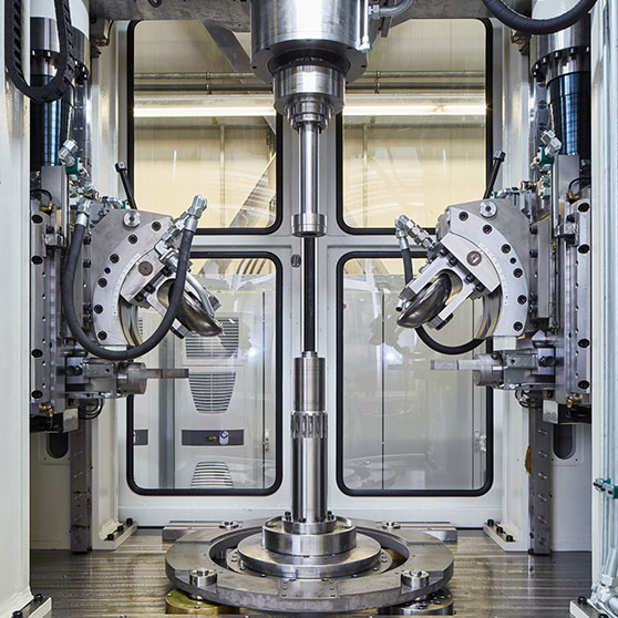
Heavy-duty CNC metal spinning machines are robust, high-capacity industrial systems engineered to perform precision metal spinning on large, thick, or hard-to-form metal blanks. These machines are designed to handle demanding manufacturing applications that require significant forming forces, extended cycle times, and the ability to shape large-diameter or heavy-gauge workpieces with consistent quality and repeatability. Built for durability and strength, heavy-duty CNC metal spinning machines are essential in sectors such as aerospace, energy, automotive, shipbuilding, and heavy machinery manufacturing, where large and complex spun components are critical.
The core of a heavy-duty CNC metal spinning machine consists of a powerful spindle motor capable of high torque output to rotate large or dense metal blanks at controlled speeds. This spindle is often supported by precision heavy-load bearings engineered to withstand continuous, high-radial and axial loads without compromising rotational accuracy. The machine frame and bed are constructed from reinforced materials like cast iron or steel to resist deformation under heavy forming pressures, ensuring long-term rigidity and alignment.
CNC control systems in heavy-duty metal spinning machines manage multiple axes of motion with precision, including spindle speed, axial feed, radial tool positioning, and roller pressure. The CNC allows complex tool paths to be programmed and executed repeatedly, enabling intricate contouring of large parts such as turbine casings, pressure vessels, large lighting reflectors, or industrial drum shells. Advanced control algorithms optimize forming forces and speeds to balance production efficiency with material integrity.
Tooling on heavy-duty machines includes oversized mandrels, heavy-gauge rollers, and specialized forming heads capable of exerting substantial forces necessary to plastically deform thick metals or high-strength alloys. Tooling components are often custom-designed for each application, with enhanced wear resistance achieved through heat treatment, surface coatings (such as tungsten carbide), or the use of advanced materials to extend service life and maintain dimensional accuracy.
These machines accommodate a wide range of materials, from conventional steels and aluminum alloys to stainless steel, titanium, and exotic superalloys. The ability to work with thick or difficult-to-form materials makes heavy-duty CNC metal spinning machines indispensable in producing components that must endure harsh operating environments, such as jet engine parts, large-diameter pipe fittings, and heavy industrial machinery housings.
Heavy-duty CNC spinning machines may incorporate features like hydraulic or servo-electric drives for precise control of tooling pressure and movement. Hydraulic systems provide high force output necessary for thick materials, while servo-electric systems offer energy efficiency, cleaner operation, and improved motion control. Many modern machines combine both technologies to optimize performance and reliability.
Cooling and lubrication systems are critical components, especially during prolonged forming cycles of heavy blanks. Advanced coolant delivery ensures consistent temperature control at the tooling interface, reducing thermal distortion, minimizing tool wear, and improving surface finish quality. Some machines integrate mist or flood cooling systems depending on the material and process requirements.
Automation and safety features in heavy-duty CNC metal spinning machines are increasingly sophisticated. Enclosed work areas with interlocks protect operators from flying debris or accidental contact with moving parts. Robotic loaders and unloaders handle heavy blanks, reducing manual labor risks and increasing throughput. Integrated monitoring systems track spindle torque, vibration, and temperature to detect anomalies early and prevent catastrophic failures.
From a process standpoint, heavy-duty metal spinning requires careful planning and sequencing to avoid defects such as cracking, wrinkling, or uneven thickness, especially with thick or hard materials. CNC programming takes into account material properties, blank geometry, and final part requirements to optimize forming parameters like roller feed rate, spindle speed, and forming force. Simulation software is often employed prior to production to model metal flow and stress distribution, minimizing trial and error.
In heavy industry applications, spun parts produced on heavy-duty CNC metal spinning machines often replace welded or cast components, offering advantages in strength, uniformity, and reduced post-processing requirements. The seamless nature of spun components enhances mechanical properties by aligning metal grain flow with part geometry, improving fatigue resistance and structural integrity.
Industries such as aerospace rely on these machines to fabricate large engine casings, turbine shells, and ductwork that must meet stringent certification standards. Energy sectors use them to manufacture pressure vessels, large pipes, and containment structures for oil, gas, and power generation. Automotive and transportation industries utilize heavy-duty spinning for components like wheel rims, large hub caps, and structural tubes. Shipbuilding and heavy equipment manufacturers depend on these machines for durable, precisely formed parts critical to safety and performance.
Advancements in heavy-duty CNC metal spinning machines continue to push the limits of size, material hardness, and complexity. Developments include multi-axis CNC control for more intricate shapes, integration of in-process monitoring sensors for real-time quality control, and hybrid manufacturing approaches that combine spinning with machining or additive processes. Enhanced user interfaces and programming tools reduce setup times and allow operators to manage complex jobs more effectively.
Sustainability efforts focus on energy-efficient motors, regenerative braking systems, and optimized forming strategies that minimize cycle times and material waste. Improved tooling materials and coatings extend service life, reducing downtime and environmental impact. Additionally, remote diagnostics and predictive maintenance systems help ensure machines operate at peak efficiency while minimizing unexpected breakdowns.
In summary, heavy-duty CNC metal spinning machines are vital assets in industrial manufacturing, enabling the production of large, robust, and precision-formed metal components across demanding sectors. Their combination of mechanical strength, CNC precision, material versatility, and advanced automation allows manufacturers to meet rigorous quality standards while improving efficiency and reducing costs. As technology advances, these machines will continue to be indispensable for shaping the backbone of modern heavy industry.
Heavy-duty CNC metal spinning machines play a critical role in producing large-scale components that demand both precision and durability. Their capacity to handle thick or heavy-gauge metal blanks allows manufacturers to form parts that would be difficult or impossible to fabricate using conventional machining or casting methods alone. This capability results in components with superior mechanical properties, such as improved grain flow and structural integrity, which are essential for applications subjected to high stresses and harsh environments.
The design of these machines emphasizes structural rigidity to maintain accuracy during heavy forming operations. Reinforced frames and beds minimize deflection, while high-tolerance spindle assemblies ensure consistent rotation even under significant loads. This rigidity is vital to achieve tight tolerances on large-diameter parts, which can span several meters depending on the industry requirements. Additionally, vibration dampening technologies are incorporated to enhance surface finish quality and prolong tool life during prolonged forming cycles.
CNC programming sophistication is paramount in heavy-duty metal spinning. Complex part geometries often require multi-pass forming strategies with variable feed rates, spindle speeds, and roller pressures tailored to different stages of deformation. Advanced CAM software assists programmers in developing optimized tool paths that minimize stress concentrations and material thinning, ensuring that even the thickest blanks deform uniformly without defects. Simulation tools provide virtual previews, allowing engineers to fine-tune process parameters and tooling designs before actual production.
Material handling systems integrated into heavy-duty CNC metal spinning machines facilitate the movement of bulky and heavy blanks safely and efficiently. Overhead cranes, robotic arms, or automated guided vehicles (AGVs) often assist in loading and unloading operations, reducing manual labor and mitigating safety risks. This automation supports high-throughput production environments while maintaining consistent cycle times and quality.
The versatility of these machines extends to their adaptability for specialized processes. Some models are equipped to perform multi-stage forming, combining spinning with metal flow forming, stretch forming, or necking within a single setup. This integration reduces the need for multiple machines and secondary operations, streamlining production workflows and reducing overall lead times.
In terms of tooling, heavy-duty machines employ robust mandrels and rollers made from high-strength materials capable of withstanding extreme forming forces. Tooling is frequently customized to the part geometry and material properties, incorporating features such as adjustable diameters or segmented components to accommodate complex shapes and facilitate quick changeovers. Maintenance and inspection protocols are essential to preserve tooling accuracy and prevent defects caused by wear or damage.
Quality control in heavy-duty CNC metal spinning is increasingly integrated into the production process. Inline inspection techniques, including laser scanning, ultrasonic testing, and coordinate measuring machines (CMMs), enable real-time verification of critical dimensions and surface conditions. These systems provide immediate feedback to the CNC controller, allowing for adaptive adjustments that maintain part conformity and reduce scrap rates.
Energy efficiency is a growing priority, with manufacturers adopting servo-electric drives that offer precise motion control with lower power consumption compared to hydraulic systems. Regenerative braking and energy recovery features help reduce operational costs and environmental impact. Additionally, optimized process planning minimizes idle times and unnecessary tool movements, further conserving energy.
Safety remains a top concern due to the large forces and moving parts involved in heavy-duty metal spinning. Machines are equipped with comprehensive guarding, emergency stop systems, and sensors that monitor machine status and halt operations if unsafe conditions are detected. Operator training programs emphasize safe handling of heavy blanks, proper machine operation, and maintenance procedures to minimize workplace accidents.
Heavy-duty CNC metal spinning machines contribute significantly to supply chain efficiency by enabling local manufacturing of large components that might otherwise be sourced through costly imports. Their flexibility allows for rapid reconfiguration to accommodate new part designs or production volumes, supporting just-in-time manufacturing and reducing inventory costs.
The integration of Industry 4.0 technologies transforms heavy-duty metal spinning into a connected, data-driven process. Remote monitoring, predictive maintenance, and advanced analytics improve machine uptime and product quality. Digital twins simulate machine behavior and process outcomes, enabling continuous optimization and rapid troubleshooting.
Looking forward, developments in materials science, such as the use of high-performance alloys and composites, challenge machine capabilities but also drive innovation in machine design and control strategies. Heavy-duty CNC metal spinning machines must evolve to handle these materials’ unique forming characteristics while maintaining productivity and precision.
In conclusion, heavy-duty CNC metal spinning machines are indispensable for manufacturing large, complex, and high-strength metal components across critical industries. Their robust construction, advanced CNC control, versatile tooling, and integration with automation and digital technologies enable efficient, high-quality production that meets stringent performance and safety standards. As industrial demands grow, these machines will continue to advance, ensuring their vital role in shaping the future of heavy industry manufacturing.
Heavy-duty CNC metal spinning machines are also increasingly pivotal in supporting advanced manufacturing techniques such as hybrid fabrication and additive-subtractive integration. By combining traditional spinning with machining, welding, or even additive manufacturing processes within a single production cell, manufacturers can achieve complex part geometries and enhanced material properties that meet the most stringent specifications. This integration reduces the number of handling steps, decreases lead times, and improves overall process efficiency.
One of the key challenges addressed by these machines is the management of residual stresses that develop during heavy forming. Large, thick blanks subjected to intense plastic deformation can experience internal stresses that affect dimensional stability and mechanical performance. Heavy-duty CNC spinning machines utilize carefully programmed forming sequences, gradual deformation passes, and controlled cooling to minimize these stresses. Additionally, post-forming heat treatments may be integrated to relieve residual stress and optimize metallurgical characteristics.
The scalability of heavy-duty CNC metal spinning machines enables manufacturers to serve a wide spectrum of industries, from producing massive aerospace engine casings several meters in diameter to crafting smaller yet thick-walled pressure vessels for chemical plants. This scalability is supported by modular machine designs that can be tailored with variable spindle sizes, motor capacities, and tooling configurations to meet specific production needs without excessive capital investment.
Furthermore, customization in control software allows for the implementation of specialized cycles tailored to unique part requirements. For example, multi-step spin forming with variable feed rates can be programmed to accommodate sections with varying wall thickness or complex internal contours. Advanced user interfaces provide operators and engineers with real-time visualization of forming parameters, process alarms, and maintenance indicators, enhancing operational control and reducing errors.
In response to growing global emphasis on sustainability, manufacturers of heavy-duty CNC metal spinning machines are focusing on green manufacturing principles. This includes designing machines with energy-efficient components, enabling the reuse of scrap metal generated during forming, and promoting processes that minimize waste. The capability to form near-net-shape parts also reduces the need for extensive machining, further conserving resources.
Material versatility remains a hallmark of heavy-duty machines, with ongoing efforts to expand the range of alloys and composites that can be effectively spun. Innovations in forming technology, such as localized induction heating and cryogenic processing, are being explored to improve formability of difficult-to-work materials. These technologies allow for better control over microstructure and mechanical properties, expanding the applicability of spinning to cutting-edge materials used in aerospace, defense, and medical fields.
The human-machine interface continues to evolve with touchscreen controls, voice command capabilities, and augmented reality support. These features simplify programming, diagnostics, and maintenance procedures, reducing operator workload and enabling faster response to production issues. Remote support and cloud-based platforms facilitate expert assistance and software updates, ensuring machines remain current with the latest technological advancements.
Heavy-duty CNC metal spinning machines are also benefiting from improved supply chain integration. Real-time data sharing with suppliers and customers enhances transparency, accelerates order processing, and supports quality assurance. Traceability systems record detailed information about material batches, forming parameters, and inspection results, which is crucial for regulated industries where compliance and certification are mandatory.
Training and workforce development are aligned with these technological advancements. Specialized programs incorporate virtual reality simulations, interactive tutorials, and hands-on experience with modern machines, preparing operators for complex tasks while emphasizing safety and efficiency. Continuous learning platforms keep staff updated on new features, software upgrades, and best practices.
In the face of increasing global competition, the adoption of heavy-duty CNC metal spinning machines offers manufacturers a competitive edge through improved precision, productivity, and flexibility. Their ability to produce large, complex parts with reduced lead times and lower costs positions companies to respond rapidly to market demands and customer specifications.
In conclusion, heavy-duty CNC metal spinning machines represent a critical nexus of mechanical engineering, materials science, and digital innovation. Their ongoing development addresses the challenges of forming large, high-strength metal components with exacting tolerances and complex geometries. As industries push for greater efficiency, sustainability, and product performance, these machines will remain at the forefront of advanced manufacturing solutions, shaping the future of heavy industry worldwide.
Building further on these advancements, heavy-duty CNC metal spinning machines are increasingly incorporating artificial intelligence (AI) and machine learning to enhance process optimization and predictive maintenance. By analyzing large volumes of operational data—including spindle loads, vibration patterns, and temperature fluctuations—AI systems can identify subtle trends that precede tool wear or machine faults. This predictive capability enables maintenance to be scheduled proactively, minimizing unexpected downtime and extending the life of critical components.
The integration of AI also improves forming quality by enabling adaptive control systems that automatically adjust process parameters in real time. For example, if sensors detect an anomaly such as uneven material flow or emerging surface defects, the CNC controller can modify roller pressure, spindle speed, or feed rates instantly to correct the issue. Such closed-loop control enhances part consistency and reduces scrap rates, which is especially valuable when working with expensive or difficult-to-form materials.
Collaborative robotics (cobots) are becoming common partners in heavy-duty spinning operations, augmenting human capabilities rather than replacing them. Cobots assist with loading heavy blanks, tool changes, and in-process inspection, working safely alongside operators thanks to advanced sensors and force-limiting technologies. This collaboration improves workflow efficiency, reduces worker fatigue and injury risks, and increases overall production throughput.
Digital twin technology plays a growing role in design and manufacturing integration. Virtual replicas of heavy-duty spinning machines simulate forming processes under various conditions, enabling engineers to experiment with tool paths, speeds, and forces before committing to physical trials. When linked with live machine data, digital twins support continuous process optimization and troubleshooting, reducing setup times and improving first-pass yields.
Sustainability considerations are shaping the development of next-generation heavy-duty CNC spinning machines. Manufacturers focus on reducing energy consumption by employing servo-electric drives with regenerative braking and energy recovery systems. Additionally, machine designs prioritize recyclable materials, minimized waste, and the use of environmentally friendly lubricants. These efforts align with industry-wide goals to reduce carbon footprints and comply with increasingly stringent environmental regulations.
Material advancements such as high-strength aluminum alloys, titanium, and nickel-based superalloys challenge machine capabilities but also drive innovation. Heavy-duty CNC metal spinning machines equipped with precise temperature control, including localized induction heating and cryogenic cooling, can manage these materials’ unique forming behaviors. This enables the production of critical components for aerospace engines, medical implants, and energy systems with exceptional strength-to-weight ratios and durability.
The human-machine interface continues to evolve toward greater intuitiveness and accessibility. Touchscreen controls, voice command systems, and augmented reality (AR) guidance simplify machine operation, diagnostics, and maintenance. AR systems can overlay instructions, highlight machine components, and provide real-time troubleshooting assistance, reducing errors and accelerating operator training.
Global supply chain integration enhances responsiveness and quality assurance. Real-time tracking of raw materials, machine status, and production metrics allows manufacturers to meet customer demands more rapidly and transparently. Detailed process documentation supports regulatory compliance and traceability in safety-critical industries.
Workforce development adapts alongside these technologies, incorporating virtual reality (VR) training modules that simulate complex operating scenarios in a risk-free environment. Continuous education programs ensure operators stay current with evolving machine capabilities, software updates, and industry best practices.
Heavy-duty CNC metal spinning machines empower manufacturers to meet escalating demands for large, complex, and high-performance metal components with increased precision, efficiency, and sustainability. Their continued evolution through AI integration, robotics collaboration, advanced materials handling, and digital transformation ensures these machines remain central to the future of heavy industry manufacturing worldwide.
High-Precision CNC Spinning Machines
High-precision CNC spinning machines are advanced metal forming systems designed to produce components with exceptionally tight tolerances, intricate geometries, and superior surface finishes. These machines leverage computer numerical control (CNC) technology to precisely manipulate tooling and workpieces, allowing for repeatable, complex metal spinning operations that meet the stringent demands of industries such as aerospace, medical devices, electronics, and luxury automotive manufacturing.
At the heart of high-precision CNC spinning machines is a multi-axis CNC control system that governs spindle rotation, axial feed, radial tool positioning, and roller pressure with micron-level accuracy. This control allows for the formation of complex contours, variable wall thicknesses, and detailed features that are difficult or impossible to achieve through conventional manual spinning or less sophisticated machinery. The precision is maintained consistently across production runs, ensuring uniformity and reducing the need for extensive post-processing.
These machines are constructed with high-rigidity frames and precision spindle assemblies to minimize vibration and deflection during forming. Precision linear guides, ball screws, and servo motors with high-resolution encoders facilitate smooth, accurate tool movements. The use of thermally stable materials and environmental controls in machine design further enhances dimensional stability, critical for maintaining tight tolerances over long production cycles.
Tooling for high-precision CNC spinning machines is equally specialized. Rollers and mandrels are engineered to exact specifications and often feature fine surface finishes or coatings such as diamond-like carbon (DLC) to reduce friction and wear. Custom tooling can be fabricated to accommodate intricate part geometries or specialized materials. Some machines also integrate quick-change tooling systems to enable rapid transitions between part designs without sacrificing accuracy.
Material versatility is a key feature, with high-precision CNC spinning machines capable of forming a wide range of metals including aluminum alloys, stainless steel, titanium, copper, and specialty alloys. The precise control of forming parameters—such as roller force, feed rate, and spindle speed—enables the processing of delicate or high-strength materials without inducing defects like cracking, wrinkling, or unwanted thinning.
Incorporation of advanced sensor systems allows real-time monitoring of forming forces, thickness distribution, surface quality, and temperature. This data feeds into adaptive control algorithms that adjust process parameters dynamically, maintaining optimal forming conditions and ensuring consistent part quality. Inline inspection tools, such as laser scanners and optical profilometers, provide immediate feedback on dimensional accuracy and surface finish, facilitating just-in-time quality control.
High-precision CNC spinning machines are often integrated into automated production cells featuring robotic loading and unloading, robotic inspection, and in-line finishing operations. This integration enhances throughput, reduces human error, and ensures cleanroom compatibility for sensitive applications like medical devices or electronics enclosures.
Software plays a critical role in the operation of high-precision CNC spinning machines. CAD/CAM programs generate optimized tool paths based on detailed 3D part models, simulating material flow and predicting potential forming issues. Post-processing software assists in fine-tuning programs based on feedback from actual runs, accelerating setup times and minimizing scrap. Artificial intelligence and machine learning are increasingly incorporated to refine forming strategies and predict maintenance needs.
Industries reliant on high-precision spinning include aerospace, where components like fuel nozzles, ducting, and structural housings require exacting specifications; medical devices, which demand flawless surface finishes and biocompatibility for implants and surgical instruments; and luxury automotive, where aesthetic quality and mechanical performance are both paramount.
In addition to forming capabilities, high-precision CNC spinning machines often support secondary operations such as internal necking, flanging, or grooving within the same setup, reducing the need for additional machining or assembly. This multi-functionality enhances manufacturing efficiency and reduces lead times.
Sustainability considerations are addressed through efficient material usage, minimal waste generation, and energy-efficient drive systems. The ability to form near-net-shape parts reduces downstream machining requirements and associated environmental impact. Additionally, advanced lubrication and cooling systems optimize resource use and extend tooling life.
Operator interfaces are designed for ease of use, featuring high-resolution touchscreens, customizable control panels, and interactive diagnostics. Augmented reality (AR) and virtual reality (VR) training tools help operators master complex machine functions and safety procedures without disrupting production.
In summary, high-precision CNC spinning machines represent the pinnacle of metal spinning technology, delivering exceptional accuracy, repeatability, and versatility. Their integration of advanced mechanical design, precise CNC control, sophisticated tooling, and real-time process monitoring equips manufacturers to meet the highest quality standards across demanding industries, enabling the production of complex, high-performance metal components with efficiency and reliability.
High-precision CNC spinning machines continue to evolve through the integration of cutting-edge technologies that push the boundaries of accuracy and process control. One significant advancement is the use of multi-axis CNC systems, often incorporating five or more controlled axes. This expanded control capability allows for the creation of complex three-dimensional geometries, including tapered profiles, stepped diameters, and intricate internal features that previously required multiple machines or secondary machining operations. The ability to perform these sophisticated forming actions within a single setup improves manufacturing efficiency and reduces cumulative tolerance stack-up.
Thermal management is another critical factor in maintaining precision during metal spinning. High-precision machines often include environmental controls such as temperature-regulated enclosures or active cooling systems that mitigate thermal expansion of machine components. This stability is essential for maintaining micron-level tolerances during long production cycles, especially when working with materials that are sensitive to temperature changes or when forming thin-walled parts prone to distortion.
The development of advanced sensor arrays embedded in tooling and machine structures enhances process visibility. Force sensors monitor roller pressure with exceptional sensitivity, while displacement sensors track tool position and workpiece deformation in real time. High-speed cameras and laser profilometers can capture surface finish and dimensional changes instantaneously. These data streams feed into closed-loop control systems that adjust parameters dynamically, compensating for variations in material properties, tool wear, or environmental conditions, thereby ensuring consistent quality.
Software innovation complements hardware advancements by providing intuitive interfaces and powerful simulation capabilities. Modern CAD/CAM platforms enable engineers to import complex part models and automatically generate optimized tool paths that minimize strain concentrations and material thinning. Simulation tools predict outcomes such as springback and residual stresses, allowing programmers to refine operations before actual machining, reducing scrap and setup time. Additionally, AI-powered analytics evaluate production data to recommend process improvements and anticipate maintenance requirements.
Automation and integration within smart manufacturing environments amplify the capabilities of high-precision CNC spinning machines. Robotic systems handle loading, unloading, and tool changes, reducing cycle times and human error. Inline metrology tools provide continuous inspection, feeding quality data directly to manufacturing execution systems (MES) for traceability and compliance documentation. Connectivity through Industrial Internet of Things (IIoT) protocols enables remote monitoring and diagnostics, allowing manufacturers to optimize machine utilization and quickly respond to issues.
Material versatility remains a hallmark of high-precision spinning machines, with the ability to form a broad spectrum of metals including high-strength aluminum alloys, titanium, stainless steel, copper, and specialty alloys used in aerospace and medical fields. Precise control over forming conditions reduces risks of cracking, wrinkling, or surface defects, even when processing difficult-to-form materials or thin sections.
Sustainability considerations drive efforts to enhance energy efficiency and minimize waste. Servo-electric drives replace traditional hydraulic systems, providing cleaner, more precise motion control with lower power consumption. Near-net-shape forming reduces machining allowances, conserving material and reducing scrap. Advanced cooling and lubrication systems optimize resource use and extend tooling life, supporting environmentally responsible manufacturing.
Operator experience is improved through ergonomic designs, customizable control layouts, and advanced training tools. Augmented reality (AR) assists operators with setup and maintenance by overlaying visual instructions and alerts, reducing errors and downtime. Virtual reality (VR) environments offer immersive training scenarios that accelerate skill acquisition and enhance safety awareness without interrupting production.
Industries relying on high-precision CNC spinning machines benefit from their ability to produce complex, high-quality components with repeatable accuracy and efficient throughput. Aerospace applications include precision ducting, fuel system components, and structural housings requiring tight tolerances and impeccable surface finishes. Medical device manufacturers utilize these machines for implants and surgical tools where biocompatibility and exact dimensions are critical. Luxury automotive producers leverage high-precision spinning for components demanding both aesthetic appeal and mechanical performance.
In addition to forming, high-precision CNC spinning machines often incorporate multifunctional capabilities such as internal spinning, necking, flanging, or grooving within a single setup. This consolidation reduces production steps and enables the manufacture of intricate parts without secondary operations, shortening lead times and lowering costs.
Overall, high-precision CNC spinning machines embody the fusion of mechanical excellence, digital innovation, and materials science. Their continual advancement ensures manufacturers can meet increasingly stringent quality standards, produce complex geometries, and achieve efficient, sustainable operations. As technology progresses, these machines will remain indispensable in industries where precision, reliability, and performance are paramount.
Building on their foundational strengths, high-precision CNC spinning machines are increasingly incorporating real-time data analytics and machine learning to further enhance process reliability and part quality. By continuously collecting and analyzing vast amounts of operational data—such as spindle torque, roller force, feed rate, and vibration signatures—these systems can detect subtle deviations from optimal forming conditions. Machine learning algorithms interpret these patterns to predict potential defects before they occur, enabling proactive adjustments that reduce scrap rates and improve overall efficiency.
The trend toward customization and rapid product changeovers drives the development of modular machine architectures. Components such as spindles, tooling mounts, and control units are designed for quick replacement or reconfiguration, allowing manufacturers to switch between different part geometries or materials with minimal downtime. This flexibility is critical in industries with short product life cycles or highly specialized components.
Advancements in additive manufacturing complement high-precision spinning by enabling the production of complex mandrels, rollers, or tooling inserts with optimized internal structures for weight reduction and improved thermal management. Such hybrid approaches combine the precision and repeatability of CNC spinning with the design freedom of 3D printing, expanding the possibilities for complex part fabrication.
Thermomechanical process control is becoming more sophisticated, with integrated heating or cooling systems applied locally to the workpiece or tooling. Precise temperature management helps improve material formability, particularly for alloys with narrow processing windows or materials prone to work hardening. These capabilities enable the spinning of advanced high-strength alloys and exotic materials while maintaining tight tolerances and surface quality.
The integration of digital twins provides a virtual platform for comprehensive process simulation, training, and troubleshooting. Digital twins mirror the real-time state of the spinning machine and workpiece, allowing engineers to test modifications, optimize forming parameters, and predict maintenance needs without interrupting production. This virtual feedback loop accelerates innovation cycles and enhances machine uptime.
Collaborative robotics (cobots) are increasingly employed alongside high-precision spinning machines to assist with material handling, inspection, and tool changes. Equipped with advanced sensors and safety features, cobots work in close proximity to human operators, augmenting productivity while reducing ergonomic risks and workplace injuries.
Environmental sustainability remains a key focus, with machine builders innovating energy-efficient drive systems, regenerative braking, and eco-friendly lubrication. The ability of high-precision spinning machines to produce near-net-shape parts minimizes raw material consumption and waste, aligning with circular economy principles. Enhanced tooling longevity and predictive maintenance also contribute to resource conservation.
Operator interfaces continue to evolve with user-centric designs incorporating touchscreen controls, customizable dashboards, and augmented reality (AR) overlays. AR assists in setup, diagnostics, and maintenance by providing real-time, context-sensitive guidance, reducing errors and training time. Remote monitoring and cloud connectivity allow experts to support operations globally, facilitating faster resolution of issues and continuous improvement.
Industries such as aerospace, medical devices, electronics, and luxury automotive benefit immensely from these advancements, gaining the ability to manufacture highly complex, lightweight, and reliable components. The precision and repeatability of CNC spinning enable the production of parts with strict certification requirements and exceptional surface quality, often eliminating the need for secondary finishing.
In summary, high-precision CNC spinning machines represent a convergence of mechanical engineering, digital technology, and advanced materials processing. Their ongoing development enhances manufacturing agility, quality, and sustainability, positioning them as indispensable tools in the production of sophisticated metal components. As industries demand ever greater complexity and precision, these machines will continue to innovate, driving the future of high-performance metal forming.
Expanding further, the role of cybersecurity in high-precision CNC spinning machines is becoming increasingly important as these systems become more interconnected within smart factories and Industry 4.0 ecosystems. Protecting sensitive design data, process parameters, and machine control networks from cyber threats is critical to ensure production integrity, prevent intellectual property theft, and avoid costly operational disruptions. Manufacturers are implementing robust cybersecurity protocols, including encrypted communication, user authentication, and regular software updates, to safeguard their CNC spinning assets.
The integration of advanced robotics and automation continues to redefine workflow efficiency. Collaborative robots (cobots) equipped with force sensors and vision systems can perform complex tasks such as precision loading of delicate blanks, intricate tool changes, and in-process inspection with minimal supervision. This human-robot collaboration not only boosts throughput but also enhances workplace safety by reducing operator exposure to repetitive or hazardous tasks.
High-precision CNC spinning machines are increasingly compatible with hybrid manufacturing approaches that combine subtractive, additive, and forming processes within a single workflow. For example, 3D-printed metal preforms can be post-processed by CNC spinning to refine geometries, improve surface finish, and enhance mechanical properties through work hardening. Such hybrid strategies offer unparalleled design freedom and material efficiency, enabling production of components with optimized performance characteristics.
The advent of edge computing in CNC machine control allows for faster data processing and decision-making at the machine level, reducing latency and dependence on centralized servers. Edge-enabled machines can execute real-time adaptive controls, manage local data storage, and maintain continuous operation even if network connectivity is interrupted. This autonomy is vital for maintaining precision and consistency, particularly in critical manufacturing environments.
Material innovations continue to challenge and inspire enhancements in high-precision spinning technology. The increasing use of composite materials, metal matrix composites, and functionally graded materials necessitates specialized tooling and forming strategies. Machines equipped with advanced sensing and adaptive control can tailor forming parameters dynamically to accommodate these complex materials’ unique behaviors, ensuring defect-free parts.
Sustainability goals drive innovations such as energy recovery systems that capture and reuse kinetic energy during deceleration phases, reducing overall power consumption. Water-based and biodegradable lubricants are replacing traditional oils, lowering environmental impact and improving workplace health. Moreover, the precision and near-net-shape capabilities of CNC spinning contribute to waste minimization and resource-efficient manufacturing.
Operator training and knowledge transfer benefit from immersive technologies like virtual reality (VR) and augmented reality (AR). VR simulators provide safe, realistic environments for mastering machine operation, setup, and troubleshooting without interrupting production lines. AR overlays guide operators through maintenance tasks and complex procedures in real time, reducing errors and downtime.
Advanced analytics platforms aggregate machine, process, and quality data across multiple high-precision spinning systems to deliver actionable insights. Manufacturers leverage these analytics to optimize production scheduling, predict maintenance windows, and continuously improve process parameters, enhancing competitiveness and responsiveness to market demands.
In highly regulated sectors such as aerospace and medical devices, traceability and compliance are paramount. High-precision CNC spinning machines integrate comprehensive data logging, capturing detailed records of raw materials, process conditions, tooling usage, and inspection results. This documentation supports rigorous certification requirements and facilitates rapid audits.
In conclusion, high-precision CNC spinning machines are at the forefront of modern metal forming, embodying the integration of mechanical engineering, digital technologies, and advanced materials science. Their continuous evolution enables manufacturers to achieve unprecedented levels of accuracy, efficiency, and sustainability. As industries push toward more complex, lightweight, and high-performance components, these machines will remain essential enablers of innovation and quality in precision manufacturing.
CNC Metal Spinning Centers
CNC metal spinning centers are advanced, highly automated machining platforms designed specifically for the metal spinning process, enabling the precise and efficient production of rotationally symmetrical components. These centers integrate CNC technology with robust mechanical systems to control multiple axes of movement, delivering superior accuracy, repeatability, and versatility in shaping metal blanks into complex, seamless parts. CNC metal spinning centers are widely used across industries such as aerospace, automotive, lighting, cookware, and industrial equipment manufacturing, where precision-formed metal parts are essential.
At their core, CNC metal spinning centers feature a powerful, variable-speed spindle that securely holds and rotates the metal blank while various tools—including rollers, mandrels, and forming heads—are precisely manipulated around the workpiece. The CNC controller governs the synchronized movement of the spindle and tooling axes, often including axial feed, radial positioning, and in some advanced models, angular and vertical tool orientation. This multi-axis control enables the creation of complex shapes with consistent wall thickness and smooth surface finishes.
The construction of CNC metal spinning centers emphasizes rigidity and stability to withstand the high forming forces involved. Heavy-duty cast or welded steel frames minimize vibration and deflection, ensuring dimensional accuracy during high-speed spinning operations. Precision ball screws, linear guides, and servo motors facilitate smooth and precise tool movements, while advanced bearing systems in the spindle support high torque and rotational speeds with minimal runout.
CNC metal spinning centers accommodate a wide variety of materials including aluminum, stainless steel, copper, brass, titanium, and specialty alloys. Their flexible control systems allow operators to tailor spinning parameters such as spindle speed, tool feed rate, and roller pressure to suit the specific characteristics of each material, optimizing formability and minimizing defects like wrinkling or cracking.
Modern CNC metal spinning centers incorporate comprehensive software suites featuring CAD/CAM integration, simulation capabilities, and process optimization tools. Engineers can import 3D part models and generate CNC tool paths that precisely control forming sequences, roller trajectories, and feed rates. Simulations predict material flow and potential forming issues, reducing trial-and-error and accelerating production startup. Some systems employ adaptive control algorithms that adjust parameters in real time based on sensor feedback, ensuring consistent part quality.
Automation is a key feature of CNC metal spinning centers. Many models include robotic loading and unloading systems to handle heavy or delicate blanks safely and efficiently. Automated tool changers facilitate rapid transitions between different forming tools or operations, increasing flexibility and reducing downtime. Inline inspection devices such as laser scanners and thickness gauges provide continuous quality monitoring, enabling immediate correction of deviations.
The versatility of CNC metal spinning centers extends to their ability to perform multiple forming operations in a single setup. Besides conventional spinning, these machines can execute internal and external necking, flanging, beading, and grooving, reducing the need for secondary processing. This multi-functionality streamlines manufacturing workflows and shortens lead times.
Energy efficiency is an increasing focus in the design of CNC metal spinning centers. Servo-electric drives replace traditional hydraulic systems to provide precise, responsive motion control with lower energy consumption and reduced maintenance requirements. Regenerative braking systems capture and recycle energy during deceleration phases, further enhancing sustainability.
Safety systems in CNC metal spinning centers include fully enclosed work areas with interlocked doors, emergency stop buttons, and light curtains to protect operators from moving parts and flying debris. Ergonomic control panels and user interfaces promote ease of operation while reducing fatigue and the likelihood of human error.
Industries benefiting from CNC metal spinning centers include aerospace, which demands precision-formed ducts, cones, and housings with tight tolerances and superior surface finishes. Automotive manufacturers utilize these centers for components like wheel rims, exhaust parts, and decorative trim. The lighting industry employs CNC spinning for reflectors and housings, while cookware producers rely on the technology to create seamless pots and pans with consistent wall thickness.
Maintenance of CNC metal spinning centers involves regular lubrication of mechanical components, calibration of CNC systems, and inspection of tooling for wear or damage. Predictive maintenance programs, enabled by embedded sensors and IoT connectivity, help prevent unplanned downtime and optimize machine availability.
Training operators and programmers on CNC metal spinning centers is facilitated by advanced simulation software, virtual reality environments, and interactive tutorials, enhancing workforce skills and reducing setup times. Remote diagnostics and support allow manufacturers to access expert assistance quickly, minimizing production interruptions.
In summary, CNC metal spinning centers are sophisticated, versatile manufacturing systems that combine precision mechanical engineering with advanced digital controls. Their ability to produce complex, high-quality spun metal parts efficiently and consistently makes them indispensable tools across diverse industrial sectors. Continuous advancements in automation, software integration, and sustainability will ensure CNC metal spinning centers remain at the forefront of modern metal forming technology.
CNC metal spinning centers have revolutionized traditional metal spinning by providing highly automated, precise, and flexible manufacturing capabilities. Their advanced control systems enable operators to reproduce complex part geometries with exceptional repeatability, significantly reducing human error and improving overall product quality. The use of CNC programming allows for quick adaptation to design changes, facilitating rapid prototyping and small-batch production alongside high-volume manufacturing.
The mechanical design of these centers incorporates robust frames and precision components to handle the significant forces and stresses involved in spinning operations. This durability ensures consistent performance over long production runs, minimizing downtime and maintenance costs. High-quality spindle assemblies with precision bearings reduce runout and vibration, which is essential for achieving smooth surface finishes and tight dimensional tolerances.
Material versatility is a hallmark of CNC metal spinning centers. They can handle a broad spectrum of metals, from soft, highly ductile materials like aluminum and copper to harder alloys such as stainless steel and titanium. By adjusting spindle speeds, tool feeds, and forming forces through CNC controls, manufacturers can optimize the spinning process to accommodate material-specific behaviors, reducing defects such as cracking or wrinkling.
Software integration plays a critical role in maximizing the efficiency and capabilities of CNC metal spinning centers. CAD/CAM programs streamline the transition from design to production by enabling seamless import of 3D models and automatic generation of optimized tool paths. Process simulation helps predict potential issues and allows for adjustments before physical forming begins, saving time and reducing waste. Adaptive control systems continuously monitor process variables, automatically fine-tuning parameters to maintain consistent quality throughout production.
Automation enhancements, including robotic handling and tool changers, contribute to improved safety and productivity. Robots manage the loading and unloading of heavy or delicate blanks, minimizing manual labor risks and ensuring precise positioning. Automated tool changers allow rapid switching between different forming tools or operations without manual intervention, supporting flexible manufacturing environments and quick changeovers.
Quality assurance is embedded within CNC metal spinning centers through inline metrology and inspection systems. Laser scanners, thickness gauges, and vision systems provide real-time data on dimensional accuracy and surface integrity. This immediate feedback enables corrective actions to be taken during the forming process, reducing scrap and ensuring parts meet stringent specifications.
Energy efficiency and sustainability are integral to the design of modern CNC metal spinning centers. The adoption of servo-electric drives enhances motion control precision while reducing power consumption and maintenance needs compared to hydraulic systems. Regenerative braking systems capture energy during deceleration phases, feeding it back into the power grid or machine systems. Optimized forming strategies reduce cycle times and material waste, contributing to environmentally responsible manufacturing practices.
Safety features in CNC metal spinning centers are comprehensive, with fully enclosed work areas, emergency stop functions, and advanced sensor systems that detect operator presence and potential hazards. Ergonomic control panels and intuitive user interfaces reduce operator fatigue and minimize the risk of errors, supporting a safer working environment.
Industries across the spectrum leverage CNC metal spinning centers for their ability to produce high-quality, complex parts efficiently. Aerospace manufacturers rely on them for producing precision engine components, structural parts, and ducting. Automotive companies use them for lightweight, durable parts like wheel rims and exhaust components. Lighting manufacturers benefit from their ability to form reflectors and housings with consistent optical properties, while cookware producers achieve seamless, uniform pots and pans that meet consumer quality expectations.
Maintenance strategies for CNC metal spinning centers focus on proactive approaches, utilizing embedded sensors and IoT connectivity to monitor machine health and predict component wear. Regular calibration and tooling inspection maintain precision and prolong machine lifespan, ensuring consistent production quality.
Training and workforce development are enhanced through advanced digital tools, including virtual reality simulations and augmented reality-assisted maintenance, enabling operators and technicians to gain experience and troubleshoot effectively without disrupting production schedules. Remote support capabilities facilitate expert assistance globally, minimizing downtime and optimizing machine utilization.
In conclusion, CNC metal spinning centers represent the convergence of mechanical robustness, advanced control technology, and automation to deliver unparalleled precision, efficiency, and flexibility in metal spinning. Their ongoing evolution and integration with digital manufacturing platforms position them as critical assets in modern industrial production, enabling manufacturers to meet complex design requirements and market demands with speed and reliability.
CNC metal spinning centers continue to advance through integration with Industry 4.0 technologies, enabling greater connectivity, data-driven decision-making, and enhanced process control. These machines are often equipped with sensors and communication modules that allow them to interface with manufacturing execution systems (MES) and enterprise resource planning (ERP) software. This connectivity facilitates real-time monitoring of production status, machine health, and quality metrics, allowing manufacturers to optimize workflows, reduce downtime, and improve overall equipment effectiveness (OEE).
Predictive maintenance strategies powered by machine learning analyze historical and real-time data to forecast component wear or potential failures before they occur. This proactive approach helps prevent unexpected breakdowns, reduces maintenance costs, and maximizes machine availability. In some advanced setups, the CNC metal spinning center can automatically adjust operating parameters or alert maintenance personnel when anomalies are detected, further enhancing reliability and productivity.
Customization and flexibility remain key drivers in CNC metal spinning center development. Modular machine designs allow manufacturers to scale capabilities by adding or removing components such as additional axes, tooling stations, or automation modules. This modularity supports diverse production requirements, from small precision parts to large-scale, heavy-gauge components, without necessitating entirely new equipment investments.
The combination of CNC spinning with complementary processes like flow forming, stretch forming, or incremental forming in integrated manufacturing cells is becoming more prevalent. These hybrid cells enable the production of complex parts with superior mechanical properties, reduced material waste, and fewer secondary operations. The seamless handoff between processes improves throughput and part quality while minimizing handling and potential damage.
Material innovation continues to influence the evolution of CNC metal spinning centers. As manufacturers increasingly work with advanced alloys, composites, and lightweight materials, machines are being equipped with enhanced control systems and specialized tooling to accommodate varying formability characteristics. Techniques such as localized heating, cryogenic cooling, or ultrasonic vibration assistance are being integrated to expand material capabilities and improve surface quality.
Sustainability initiatives drive design improvements focused on reducing energy consumption and environmental impact. Energy-efficient motors, regenerative braking, and optimized process planning contribute to greener operations. Additionally, advancements in lubrication systems reduce fluid use and enable recycling, supporting eco-friendly manufacturing practices.
Operator interfaces are evolving toward greater intuitiveness and ease of use. Touchscreen controls with customizable layouts, voice command integration, and augmented reality (AR) guidance help operators manage complex setups and troubleshooting more effectively. Remote operation and monitoring capabilities enable experts to support production from anywhere, ensuring quick response times and minimizing downtime.
Quality assurance is increasingly automated and integrated within CNC metal spinning centers. Inline metrology tools continuously verify part dimensions, surface finish, and structural integrity, feeding data into statistical process control systems. This closed-loop quality management helps maintain tight tolerances, ensures compliance with industry standards, and reduces scrap and rework costs.
Training programs leverage virtual reality (VR) and simulation technologies to provide immersive, hands-on learning experiences without disrupting production. These tools enable operators and engineers to practice programming, setup, and maintenance tasks safely and efficiently, accelerating skill development and reducing errors.
In industries such as aerospace, automotive, medical devices, and electronics, CNC metal spinning centers enable manufacturers to meet increasingly stringent requirements for precision, performance, and traceability. Their ability to produce complex, lightweight, and high-strength components with repeatable quality positions them as indispensable assets in modern manufacturing ecosystems.
Looking ahead, continued advancements in artificial intelligence, robotics, materials science, and digital manufacturing will further enhance the capabilities of CNC metal spinning centers. Their role in enabling flexible, efficient, and sustainable production will remain central as industries evolve to meet future challenges and opportunities.
Building on these trends, CNC metal spinning centers are poised to become even more intelligent and autonomous. Integration of advanced AI algorithms will enable machines to self-optimize forming parameters based on continuous feedback, learning from each part produced to refine tool paths, forces, and speeds dynamically. This self-learning capability will reduce reliance on operator expertise, shorten setup times, and improve yield, especially when working with new materials or complex geometries.
Further adoption of collaborative robotics will enhance flexibility and safety. Cobots will not only handle material loading and unloading but also assist with in-process adjustments, quality inspections, and minor maintenance tasks. Their ability to safely interact with human operators will create more ergonomic and efficient production environments, lowering physical strain and minimizing human error.
Augmented reality (AR) and mixed reality (MR) technologies will become standard tools for operator assistance and remote support. Operators wearing AR glasses will receive real-time guidance overlaid onto the machine, highlighting components for adjustment or alerting to potential issues. Remote experts can virtually “see” the machine’s status and guide on-site personnel through troubleshooting or complex setups, reducing downtime and travel costs.
Digital twins of CNC metal spinning centers will evolve into comprehensive virtual production environments, simulating not only machine behavior but also entire manufacturing lines. These digital twins will facilitate end-to-end process optimization, from material input to finished part inspection, enabling manufacturers to predict bottlenecks, test process changes virtually, and train operators in realistic scenarios without impacting live production.
Materials science advancements will push the capabilities of CNC metal spinning centers further. The ability to spin-form advanced composites, metal matrix composites, and functionally graded materials will open new applications in aerospace, defense, and medical industries. Specialized tooling and process controls will be developed to accommodate these materials’ unique properties, ensuring defect-free components with tailored performance characteristics.
Sustainability will remain a core focus. Machines will incorporate energy harvesting systems, such as piezoelectric devices that convert vibration into electrical energy to power sensors or auxiliary functions. Closed-loop lubrication and cooling systems will minimize resource use and environmental impact. Circular manufacturing concepts, where scrap and end-of-life components are efficiently recycled back into the process, will become integral to production planning.
The human element will evolve alongside technology. Training programs will increasingly leverage immersive VR and AR platforms to build operator skills and safety awareness before machine interaction. Gamification elements may be introduced to enhance learning engagement and retention. Workforce development initiatives will emphasize digital literacy and adaptability, preparing operators for increasingly automated and data-rich manufacturing environments.
Cybersecurity will be paramount as CNC metal spinning centers become more connected. Robust protocols for data encryption, access control, and threat detection will protect intellectual property and prevent operational disruptions. Manufacturers will adopt comprehensive cybersecurity frameworks aligned with industry standards to safeguard their digital assets.
In summary, the future of CNC metal spinning centers lies in their transformation into smart, connected, and highly autonomous systems capable of producing ever more complex, precise, and high-performance metal components sustainably and efficiently. This evolution will empower manufacturers to meet growing market demands, accelerate innovation, and maintain competitive advantage in a rapidly changing industrial landscape.
Hot Spinning Machines
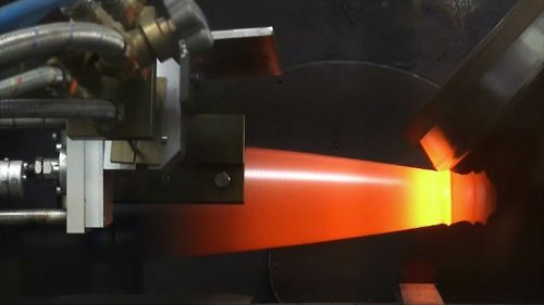
Hot spinning machines are specialized metal forming systems designed to shape heated metal blanks into precise, rotationally symmetrical components through a controlled spinning process. Unlike cold or room-temperature spinning, hot spinning involves heating the workpiece—typically metals like steel, stainless steel, aluminum, or titanium—to elevated temperatures that increase ductility and reduce the force required for deformation. This enables the forming of thicker, harder, or less ductile materials that would be difficult or impossible to shape cold, expanding the range of parts and materials manufacturers can produce.
These machines consist of a robust frame, a high-torque spindle to rotate the heated blank, and a set of forming tools such as rollers or mandrels that apply pressure and guide metal flow as the workpiece spins. The heating process is typically achieved through induction coils, gas or electric furnaces, or localized heating methods, ensuring uniform temperature distribution critical to maintaining consistent material properties and preventing thermal stresses or cracking.
The design of hot spinning machines emphasizes thermal insulation and temperature control to manage heat loss and protect machine components from excessive temperatures. Cooling systems for critical parts like bearings and spindles help maintain operational stability. Integrated temperature monitoring and feedback loops ensure the metal blank remains within precise thermal ranges throughout the forming cycle, optimizing material flow and final part quality.
Hot spinning is especially suited for manufacturing large-diameter components with variable wall thicknesses and complex geometries, such as aerospace engine parts, pressure vessels, turbine casings, cookware, and decorative metalwork. The process can produce parts with superior mechanical properties due to dynamic recrystallization and grain refinement occurring during hot deformation.
CNC controls increasingly govern hot spinning machines, enabling precise coordination of spindle speed, axial feed, roller pressure, and tool paths. This automation improves repeatability, reduces operator dependency, and allows for complex part profiles to be formed accurately. Programmable cycles enable customization for different materials and designs, enhancing production flexibility.
Safety is a key consideration due to the high temperatures involved. Hot spinning machines often feature protective enclosures, emergency shutoffs, and heat shields to safeguard operators. Automated handling systems may be employed to load and unload hot blanks, minimizing human exposure.
The integration of real-time sensors monitoring temperature, force, and deformation enables adaptive process control, ensuring optimal forming conditions and reducing defects like cracking, warping, or surface oxidation. Post-forming heat treatments may be incorporated to relieve residual stresses and achieve desired microstructures.
Energy efficiency is addressed by using induction heating, which provides rapid, localized heating with lower energy consumption compared to traditional furnace methods. Waste heat recovery systems may also be implemented to improve overall process sustainability.
Maintenance of hot spinning machines involves regular inspection of heating elements, cooling systems, spindle bearings, and tooling wear due to the combined effects of heat and mechanical stress. Predictive maintenance programs leverage sensor data to schedule service proactively, enhancing machine uptime.
Training operators for hot spinning machines requires emphasis on thermal safety, precise process control, and understanding material behavior at elevated temperatures. Simulation software assists in planning forming sequences and predicting material flow, reducing trial-and-error and improving first-pass success rates.
In summary, hot spinning machines enable the efficient and precise shaping of heated metal blanks into complex, high-performance parts that are difficult to form by cold spinning. Their combination of thermal management, robust mechanical design, and CNC control makes them essential tools in industries demanding large, high-strength, and intricately shaped metal components.
Hot spinning machines continue to evolve with advancements in automation, materials science, and thermal management, enhancing their capabilities and expanding their application scope. Modern hot spinning machines increasingly incorporate CNC controls that allow for multi-axis tool movement and precise synchronization between spindle rotation, tool feed, and pressure application. This integration improves accuracy, repeatability, and the ability to produce complex shapes with consistent wall thicknesses, even in challenging materials like titanium or nickel-based superalloys used in aerospace and power generation.
Thermal control technologies have advanced significantly, with induction heating becoming the preferred method for many applications due to its rapid, energy-efficient, and localized heating capabilities. Induction coils can be designed to focus heat precisely on the spinning area, reducing thermal exposure to machine components and minimizing oxidation or scale formation on the workpiece. Some systems incorporate in-process temperature sensors that provide real-time data, enabling adaptive control to maintain optimal forming temperatures throughout the cycle.
To protect machine elements from high temperatures, hot spinning machines often use advanced cooling systems, including liquid-cooled spindle housings, heat shields, and thermally resistant materials in critical areas. These measures extend machine life and maintain precision under thermal stress. Additionally, tooling materials and coatings have improved to withstand elevated temperatures and mechanical loads, with carbides, ceramics, and advanced surface treatments enhancing durability and reducing wear.
Automation and robotics integration facilitate safer and more efficient handling of hot blanks. Automated loading, unloading, and positioning systems reduce operator exposure to heat and improve cycle times. Safety enclosures and interlocks ensure that the high-temperature environment is well contained, protecting personnel and preventing accidents.
Material processing benefits from hot spinning by enabling deformation beyond the limits of cold spinning, allowing thicker, harder, or less ductile metals to be shaped without cracking or excessive thinning. The elevated temperature also promotes dynamic recrystallization, refining grain structure and improving mechanical properties such as toughness and fatigue resistance. This makes hot-spun parts suitable for critical applications in aerospace engine components, pressure vessels, and high-performance cookware.
Process monitoring technologies, including force sensors, thermal imaging, and laser profilometry, provide comprehensive data during spinning operations. This feedback supports adaptive control algorithms that adjust roller pressure, feed rates, and spindle speed in real time to optimize material flow and surface quality. Such closed-loop control minimizes defects, reduces scrap, and enhances overall production efficiency.
Energy efficiency remains a priority, with many hot spinning systems incorporating regenerative energy capture and heat recovery technologies. Waste heat from induction coils or exhaust gases can be recycled for preheating incoming blanks or other plant operations, contributing to sustainability goals. Servo-electric drives further reduce power consumption compared to traditional hydraulic systems, offering precise control with lower environmental impact.
Maintenance strategies for hot spinning machines focus on managing the dual challenges of mechanical wear and thermal stress. Predictive maintenance utilizing sensor data helps identify tooling degradation, bearing wear, or heating system faults before they lead to failures. Scheduled inspections and timely replacements ensure consistent machine performance and avoid costly downtime.
Training for hot spinning machine operators encompasses understanding material behavior at elevated temperatures, safe handling practices, and proficiency with CNC programming and adaptive controls. Virtual simulation tools and augmented reality aids support skill development and process optimization without interrupting live production.
In essence, hot spinning machines are indispensable for producing complex, high-strength metal parts that demand precise control over shape and microstructure. Their ongoing development in thermal management, automation, and process control enables manufacturers to tackle increasingly challenging materials and geometries while maintaining efficiency, quality, and safety. As industries continue to push the limits of metal forming technology, hot spinning machines will play a vital role in meeting those demands.
Building further upon these advancements, hot spinning machines are increasingly being integrated into comprehensive manufacturing ecosystems that emphasize digitalization and smart factory principles. By connecting hot spinning equipment with factory-wide networks, operators and engineers gain real-time visibility into machine status, production metrics, and quality data. This connectivity facilitates coordinated workflows, predictive maintenance scheduling, and rapid response to process deviations, thereby improving overall operational efficiency.
The adoption of advanced materials in industries such as aerospace, defense, and medical devices is driving the development of specialized hot spinning processes tailored to the unique properties of these alloys. For instance, spinning titanium and nickel-based superalloys at elevated temperatures requires precise thermal profiles and forming speeds to avoid defects like cracking or undesirable microstructural changes. Customized CNC programs, coupled with adaptive control systems, allow these challenging materials to be formed reliably into complex shapes with excellent mechanical performance.
Hybrid manufacturing approaches are also emerging, combining hot spinning with additive manufacturing, machining, or heat treatment processes. For example, additive techniques can produce near-net-shape preforms that are subsequently refined and strengthened through hot spinning. This integration reduces material waste, shortens lead times, and enables the fabrication of parts with intricate geometries and tailored material properties.
Robotics and automation continue to enhance safety and productivity in hot spinning operations. Automated loading and unloading systems reduce the risk of operator injury from handling heated blanks. Collaborative robots (cobots) assist in inspection, tool changes, and minor maintenance tasks, working alongside humans to increase throughput without compromising safety.
Environmental sustainability remains a focal point in the evolution of hot spinning machines. Innovations such as advanced insulation materials reduce heat loss, lowering energy consumption during forming cycles. Integration of waste heat recovery systems captures residual thermal energy, which can be redirected to other plant processes or preheating operations. Use of eco-friendly lubricants and coatings minimizes environmental impact and improves workplace conditions.
Training and workforce development leverage immersive technologies, including virtual and augmented reality, to simulate hot spinning processes safely. These tools help operators understand thermal dynamics, material behavior, and machine controls without exposure to hazardous environments. Enhanced training reduces setup times, improves process consistency, and fosters continuous learning.
Safety systems in hot spinning machines continue to advance, incorporating multisensor arrays that monitor temperature, force, and operator presence. Intelligent interlocks and emergency shutdown protocols ensure rapid response to abnormal conditions, protecting both personnel and equipment.
Quality control benefits from in-process metrology solutions that measure dimensional accuracy, surface finish, and temperature distribution during forming. High-resolution sensors enable immediate corrective actions, ensuring that final parts meet stringent specifications required in critical applications.
In summary, hot spinning machines are evolving into highly integrated, intelligent manufacturing systems that blend mechanical robustness with digital innovation. Their ability to form complex, high-performance metal components at elevated temperatures makes them indispensable across advanced industries. Continuous improvements in automation, thermal management, material processing, and sustainability will further expand the capabilities and applications of hot spinning technology in the future.
Continuing this progression, the future of hot spinning machines is tightly linked with advances in artificial intelligence (AI) and machine learning (ML), which promise to revolutionize process optimization and predictive maintenance. AI-driven systems can analyze extensive datasets collected from sensors monitoring temperature, force, spindle torque, and vibration to identify subtle patterns indicating process drift or tooling wear. These insights enable automated adjustments to forming parameters in real time, enhancing part quality while minimizing waste and downtime.
Machine learning models trained on historical production data can predict the lifespan of critical components, such as rollers and mandrels, allowing maintenance to be scheduled proactively before failures occur. This shift from reactive to predictive maintenance not only reduces unexpected stoppages but also extends the overall service life of machinery, lowering operational costs.
The incorporation of edge computing brings powerful data processing capabilities directly to the machine, reducing latency and enabling real-time control decisions independent of centralized networks. This local intelligence ensures that critical adjustments happen instantly, maintaining precision even in environments with unstable connectivity.
Emerging sensor technologies will further deepen process insight. For example, high-speed thermal imaging cameras can capture detailed temperature gradients across the spinning blank, enabling more precise thermal management and early detection of hotspots that may cause defects. Ultrasonic sensors can assess material thickness and structural integrity during forming, providing non-destructive quality assurance inline.
Advanced materials and coatings for tooling will continue to evolve, incorporating nanocomposite layers and self-healing surfaces to resist wear and thermal degradation. These innovations will reduce tooling downtime and improve surface finish quality, particularly when spinning hard or abrasive alloys.
Integration with broader smart factory systems will facilitate end-to-end digital threads, linking design, manufacturing, quality control, and supply chain management. Digital twins of hot spinning machines and production lines will simulate and optimize processes holistically, allowing manufacturers to experiment with new part designs, process parameters, or production schedules virtually before implementation.
Collaborative robotics will play an expanding role beyond material handling, participating in complex assembly, in-process inspection, and even minor on-machine repairs. These flexible robotic systems will adapt to varied tasks, enhancing efficiency without extensive reprogramming.
Sustainability efforts will intensify, with hot spinning machines featuring energy harvesting technologies, such as capturing vibrational energy to power sensors, and adopting circular economy principles by facilitating the recycling of scrap material directly within production workflows.
Operator interaction will be transformed by intuitive interfaces powered by natural language processing, voice commands, and gesture controls, reducing cognitive load and allowing hands-free machine operation. Personalized dashboards will provide operators with real-time insights tailored to their specific roles and expertise.
Training will leverage AI-driven adaptive learning platforms that customize educational content based on individual progress and skill gaps, enhancing workforce readiness for increasingly sophisticated hot spinning operations.
In highly regulated sectors like aerospace and medical devices, traceability will be enhanced through blockchain technology, securely recording every step of the manufacturing process to ensure compliance and provenance.
Overall, hot spinning machines are on a trajectory toward becoming fully integrated, intelligent manufacturing hubs capable of autonomously producing complex, high-quality metal components with minimal human intervention. This evolution will empower manufacturers to meet the escalating demands of precision, customization, and sustainability in a competitive global marketplace.
CNC Metal Spinning Lathes (General Purpose)
CNC metal spinning lathes (general purpose) are versatile, computer-controlled machines designed to form rotationally symmetric metal components through the spinning process. These lathes combine the traditional principles of metal spinning with modern CNC technology, allowing for precise, repeatable, and efficient fabrication of parts ranging from simple shapes to moderately complex geometries. They serve a broad range of industries including automotive, lighting, cookware, HVAC, and decorative metalworking.
At their core, general-purpose CNC metal spinning lathes consist of a rigid bed and frame supporting a high-precision spindle that holds and rotates the metal blank. A set of tooling, typically rollers or forming heads, is moved precisely along multiple axes under CNC control to shape the spinning metal blank against a mandrel or form. The CNC system governs spindle speed, tool feed rate, radial and axial positioning, ensuring smooth and accurate metal flow during forming.
These lathes are engineered to handle a variety of materials such as aluminum, stainless steel, copper, brass, and mild steel, typically in thicknesses suitable for cold or warm spinning operations. Their general-purpose design balances sufficient power and rigidity with flexibility, making them suitable for small- to medium-sized production runs and prototyping.
The CNC control interface on these machines allows operators to program and store spinning cycles, adjusting parameters like spindle speed, feed rate, and roller pressure to accommodate different materials and part geometries. This capability reduces setup times and operator dependency, improving productivity and consistency across batches.
Mechanical components of general-purpose CNC metal spinning lathes include precision ball screws and linear guides that provide smooth, accurate tool movement, along with robust spindle assemblies capable of delivering high torque with minimal runout. Machine frames are designed to minimize vibration and deflection, critical for maintaining dimensional accuracy and surface finish quality.
Software integration with CAD/CAM systems enables the import of part designs and automatic generation of optimized tool paths, reducing programming effort and facilitating quick transitions between different jobs. Some systems offer simulation features to predict material behavior and potential defects, allowing pre-production adjustments.
Safety features on general-purpose CNC metal spinning lathes typically include emergency stops, protective guards, and interlocks to shield operators from moving parts. Ergonomic controls and user-friendly interfaces help reduce operator fatigue and errors.
Applications for these lathes include manufacturing cookware like pots and pans, lighting reflectors, automotive parts such as wheel rims and exhaust components, HVAC ducts, and decorative metal pieces. Their capability to produce seamless, strong, and smooth components makes them valuable in industries where both functionality and aesthetics matter.
Maintenance involves regular lubrication, inspection of tooling and spindle components, and calibration of CNC systems to ensure continued precision. Training operators in CNC programming and machine operation improves machine utilization and product quality.
In summary, general-purpose CNC metal spinning lathes offer a balanced solution combining flexibility, precision, and efficiency for a wide range of metal spinning applications. Their integration of CNC technology streamlines production, enhances repeatability, and enables manufacturers to meet diverse part requirements with consistent quality.
General-purpose CNC metal spinning lathes continue to evolve with advancements in control technology, machine design, and software integration. Modern versions often feature multi-axis capabilities, allowing not only radial and axial movements but also slight angular adjustments of the tooling, which enable more complex shapes and improved surface finishes. This flexibility broadens the range of parts that can be produced efficiently, reducing the need for secondary operations.
The use of high-precision encoders and servo motors enhances the accuracy and responsiveness of tool positioning, ensuring smooth metal flow and tight dimensional tolerances. These improvements contribute to better consistency across production batches and higher overall part quality. Additionally, some machines incorporate adaptive control algorithms that adjust forming parameters in real time based on sensor feedback, compensating for material inconsistencies or tooling wear.
Software advancements facilitate seamless integration between CAD/CAM platforms and the CNC control system. Engineers can design parts using 3D modeling software and directly translate these designs into spinning programs with minimal manual intervention. Simulation modules allow virtual testing of spinning sequences to detect potential issues such as material thinning or wrinkling, enabling process optimization before physical production begins.
Automation features like robotic loading and unloading systems reduce manual handling, improving workplace safety and increasing throughput. Tool changers and quick-release tooling systems minimize downtime during product changeovers, making small batch production and prototyping more cost-effective.
General-purpose CNC spinning lathes are designed with ergonomic considerations to reduce operator fatigue. Intuitive touch-screen interfaces, customizable control panels, and real-time process monitoring displays allow operators to manage production efficiently and respond promptly to alerts or adjustments.
Maintenance strategies focus on predictive approaches, utilizing built-in sensors to monitor key components such as spindle bearings, ball screws, and lubrication systems. Data analytics help schedule service before failures occur, extending machine lifespan and reducing costly downtime.
Applications span many industries due to the machines’ adaptability. In cookware manufacturing, they enable production of seamless pots and pans with consistent thickness and attractive finishes. Automotive industries use these lathes to fabricate lightweight, durable components like wheel rims and trim parts. HVAC manufacturers rely on them for forming ducts and fittings, while lighting companies produce reflectors and housings.
Training and skill development are enhanced through digital resources and virtual simulators, helping operators become proficient in programming and machine operation without risking production delays. Remote diagnostics and software updates allow technical support teams to assist users promptly, maintaining optimal machine performance.
Energy efficiency is addressed by employing servo-electric drives and optimized motor control, reducing power consumption compared to older hydraulic systems. Some machines incorporate regenerative energy features that recover power during deceleration phases, contributing to sustainable manufacturing practices.
Safety systems include fully enclosed work areas, emergency stop buttons, and sensors that detect operator presence or abnormal conditions, ensuring compliance with industry safety standards and protecting personnel.
In conclusion, general-purpose CNC metal spinning lathes offer a flexible and reliable platform for producing a wide variety of spun metal components. Their blend of precision mechanics, advanced CNC controls, and integrated software solutions empowers manufacturers to meet diverse production needs efficiently while maintaining high quality and safety standards. As technology progresses, these machines will continue to adapt, providing even greater capabilities for modern metal spinning applications.
Building further on their capabilities, general-purpose CNC metal spinning lathes are increasingly being designed with modular architectures that allow manufacturers to customize and scale their equipment according to specific production requirements. This modularity enables the addition of features such as extra tooling axes, enhanced spindle capacities, or integrated automation units without replacing the entire machine, providing greater investment flexibility and adaptability.
The incorporation of smart sensors and IoT connectivity into these lathes facilitates real-time data collection on machine performance, environmental conditions, and part quality. This data is invaluable for implementing Industry 4.0 strategies, allowing manufacturers to monitor production remotely, perform predictive maintenance, and analyze process trends for continuous improvement. Cloud-based analytics platforms aggregate data from multiple machines, supporting decision-making and operational optimization at the factory or enterprise level.
Another growing trend is the integration of environmental controls within the spinning area to manage temperature, humidity, and particulate contamination. Maintaining stable environmental conditions helps preserve material properties during spinning, reduces oxidation, and improves surface finish quality, especially for sensitive alloys.
Advanced tooling materials and designs continue to enhance the performance and longevity of spinning tools used in general-purpose CNC lathes. Carbide-tipped rollers, coated mandrels, and vibration-damping tool holders reduce wear and improve forming accuracy, enabling longer production runs and minimizing downtime.
Automation beyond material handling is expanding to include in-process inspection and quality assurance. Inline measurement systems such as laser scanners, contact probes, and vision cameras verify dimensions and surface integrity during or immediately after spinning, enabling real-time adjustments and reducing scrap rates.
Operator training increasingly leverages augmented reality (AR) and virtual reality (VR) technologies to simulate machine operation, programming, and troubleshooting in a risk-free virtual environment. This approach accelerates skill acquisition, enhances safety awareness, and reduces onboarding time for new personnel.
Energy-saving features such as variable frequency drives (VFDs), regenerative braking, and energy-efficient motors are becoming standard, aligning general-purpose CNC metal spinning lathes with sustainability goals. Optimized process control reduces cycle times and power consumption while maintaining precision.
Safety remains paramount with ongoing improvements in machine guarding, emergency stop responsiveness, and ergonomic design. User-friendly interfaces provide clear visual and audio feedback to alert operators to potential issues promptly.
In diverse sectors including automotive, aerospace, consumer goods, and industrial equipment, these versatile lathes continue to meet the demand for high-quality, cost-effective spun metal components. Their ability to quickly switch between different part programs and materials makes them ideal for job shops and manufacturers requiring flexibility.
Looking ahead, further integration of AI-driven process optimization, enhanced automation, and digital twin simulations will deepen the capabilities of general-purpose CNC metal spinning lathes. These developments will support manufacturers in achieving higher productivity, improved quality, and greater responsiveness to evolving market needs.
Overall, general-purpose CNC metal spinning lathes remain foundational tools in modern metal forming, combining mechanical precision with intelligent control systems to deliver reliable, flexible, and efficient production solutions.
Fully Automatic CNC Metal Spinning Machines
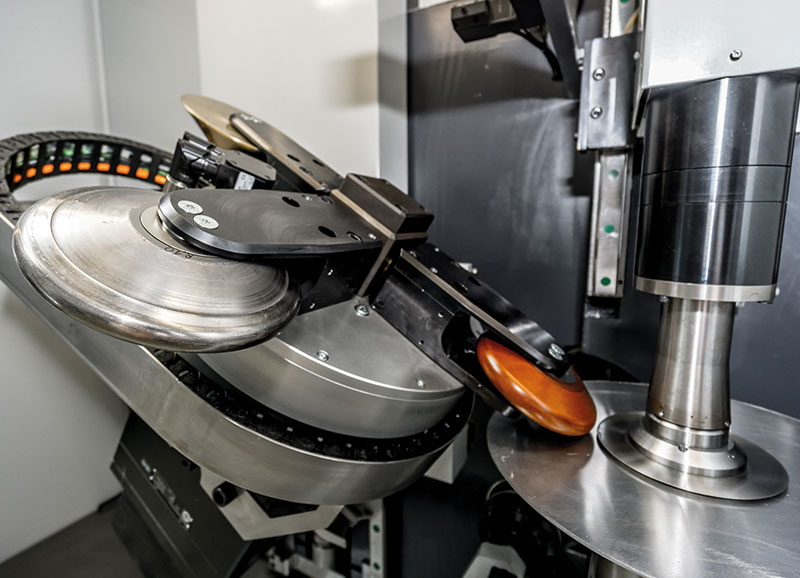
Fully automatic CNC metal spinning machines represent the pinnacle of metal spinning technology, combining advanced CNC control with comprehensive automation to deliver unparalleled precision, speed, and consistency in the production of rotationally symmetric metal components. These machines are engineered to perform the entire spinning process—from loading raw blanks to finishing the formed parts—with minimal human intervention, making them ideal for high-volume manufacturing environments where quality and efficiency are paramount.
At the heart of these machines is a robust CNC system capable of controlling multiple axes simultaneously, including spindle rotation, axial and radial tool feeds, and often additional movements such as tool tilt or mandrel positioning. This multi-axis control enables the formation of complex geometries with precise wall thickness and surface finish, consistently reproducing intricate designs that might be challenging or impossible with manual or semi-automatic spinning.
Fully automatic CNC metal spinning machines incorporate integrated robotic systems for material handling, such as automated loading and unloading of metal blanks and finished parts. This reduces operator workload, minimizes handling errors, and significantly speeds up production cycles. Tool changers and automated tooling systems allow rapid switching between different forming tools or operations, supporting flexible manufacturing of multiple part types without lengthy downtime.
These machines are designed with heavy-duty frames and precision components to withstand the high forces involved in spinning, ensuring dimensional accuracy and repeatability throughout extended production runs. High-torque, variable-speed spindles provide the necessary power and control for forming a wide range of materials, including aluminum, stainless steel, copper, brass, and advanced alloys.
Sophisticated software suites accompany fully automatic CNC metal spinning machines, offering seamless CAD/CAM integration, process simulation, and adaptive control. Engineers can import 3D part models and automatically generate optimized spinning programs that account for material properties and desired part characteristics. Real-time process monitoring with feedback loops adjusts forming parameters on the fly to maintain optimal conditions and reduce defects such as wrinkling, cracking, or uneven thickness.
Safety is rigorously addressed through fully enclosed work cells, interlocked doors, emergency stop systems, and sensors that detect operator presence or abnormal operating conditions. The automation minimizes human exposure to moving parts and high-force operations, fostering a safer work environment.
Energy-efficient servo-electric drives and regenerative braking systems contribute to reduced power consumption and lower operational costs. Some machines incorporate waste heat recovery or optimized heating systems when integrated with hot spinning processes, enhancing overall sustainability.
Maintenance strategies leverage embedded sensors and IoT connectivity to monitor machine health continuously, enabling predictive maintenance and minimizing unplanned downtime. Remote diagnostics and software updates facilitate rapid troubleshooting and performance optimization.
Applications for fully automatic CNC metal spinning machines span aerospace, automotive, lighting, cookware, HVAC, and industrial equipment manufacturing. Their ability to deliver high-quality, complex, and consistent parts at high throughput makes them essential for competitive production environments.
Operator training focuses on programming, process optimization, and system monitoring, supported by advanced simulation and virtual training tools that reduce learning curves and improve productivity.
In summary, fully automatic CNC metal spinning machines embody the integration of precision mechanics, advanced automation, and intelligent control systems. They enable manufacturers to achieve superior product quality, maximize efficiency, and maintain flexibility in demanding industrial applications, positioning them as critical assets in modern metal spinning operations.
Fully automatic CNC metal spinning machines continue to evolve with ongoing advancements in automation, artificial intelligence, and digital integration, further enhancing their capabilities and production efficiency. The integration of AI-driven process optimization allows these machines to analyze real-time data and autonomously adjust parameters such as spindle speed, feed rate, and roller pressure, improving product consistency and reducing scrap rates. This level of intelligence minimizes human intervention and accelerates setup times, especially when switching between different part designs or materials.
Robotic systems integrated into these machines not only handle loading and unloading but also perform tool changes, in-process inspections, and quality assurance tasks. Vision systems and laser scanners provide immediate feedback on dimensional accuracy and surface finish, enabling closed-loop control that corrects deviations during the spinning process. Such automation ensures that parts consistently meet tight tolerances and industry standards.
Connectivity with factory-wide networks and cloud platforms allows fully automatic CNC metal spinning machines to participate in smart manufacturing ecosystems. Real-time monitoring of machine health, production metrics, and maintenance needs supports predictive maintenance strategies that prevent unexpected downtime and optimize machine utilization. Data analytics help identify bottlenecks, streamline workflows, and enable informed decision-making at both the shop floor and management levels.
Energy efficiency improvements remain a focus, with servo-electric drives and regenerative braking reducing power consumption. Advanced thermal management and insulation techniques lower energy waste in machines incorporating hot spinning capabilities. Sustainable manufacturing practices are further supported by minimizing material waste through precise control and by recycling scrap metal generated during the spinning process.
Safety enhancements include multi-layered protective enclosures, sensor-based operator detection, and emergency stop mechanisms, creating secure environments that comply with the strictest occupational health standards. Automation reduces manual interaction with moving parts and heated materials, decreasing the risk of workplace injuries.
Operator interfaces are becoming increasingly intuitive, utilizing touchscreen controls, voice commands, and augmented reality (AR) overlays that guide technicians through setup, troubleshooting, and maintenance. Remote access capabilities enable experts to assist operators worldwide, ensuring quick resolution of technical issues and minimizing production interruptions.
Training programs leverage virtual reality (VR) and simulation technologies to immerse operators in realistic scenarios, allowing them to gain proficiency without risking damage to equipment or materials. These digital tools accelerate learning curves and promote safer, more efficient machine operation.
Industries ranging from aerospace and automotive to consumer goods and heavy machinery benefit from the speed, precision, and repeatability of fully automatic CNC metal spinning machines. Their ability to manufacture complex parts with high throughput and minimal labor makes them essential in meeting the growing demand for customized, high-quality metal components.
Looking ahead, advances in machine learning, robotics, and materials science will further enhance the flexibility, intelligence, and sustainability of these machines. Fully automatic CNC metal spinning systems will continue to play a vital role in the modernization of metal forming processes, driving innovation and competitiveness across manufacturing sectors.
Expanding further, fully automatic CNC metal spinning machines are increasingly embracing the concept of digital twins—virtual replicas of the physical machine and its processes. Digital twins enable manufacturers to simulate and optimize spinning operations in a virtual environment before actual production begins. This capability helps identify potential issues, reduce trial-and-error, and accelerate time-to-market for new parts. By continuously syncing with real-time machine data, digital twins also support ongoing process refinement and predictive maintenance.
Advanced sensor technologies embedded within these machines provide detailed insights into every aspect of the spinning process. High-resolution force sensors monitor roller pressures and spindle torque, while thermal sensors track temperature variations critical for hot spinning operations. Vibration sensors detect imbalances or bearing wear early, allowing for timely interventions that prevent costly breakdowns. Combined with AI analytics, these sensors empower machines to self-correct and maintain peak performance autonomously.
The evolution of tooling systems contributes significantly to machine versatility and efficiency. Automated tool changers equipped with precision actuators allow rapid swapping of different rollers, mandrels, or forming heads, enabling complex multi-step forming sequences without manual intervention. Tooling materials now incorporate advanced coatings and composites that resist wear, thermal degradation, and corrosion, extending service life and reducing maintenance frequency.
Integration with upstream and downstream manufacturing processes is becoming seamless, with fully automatic CNC metal spinning machines serving as critical nodes in flexible production lines. For example, spun components can be automatically transferred to machining centers, inspection stations, or assembly lines via robotic conveyors, enabling continuous, unattended workflows that maximize throughput.
Sustainability efforts are increasingly reflected in machine design and operation. Energy-efficient drives, optimized motion profiles, and intelligent standby modes minimize electricity consumption. Waste heat recovery systems capture and reuse thermal energy from hot spinning cycles. Scrap reduction is achieved through precision forming and inline quality control, while process planning software helps optimize material usage and recycling.
Human-machine interaction is being transformed by augmented reality (AR) and mixed reality (MR) technologies that overlay digital information onto the physical machine. Operators receive step-by-step guidance for setup, maintenance, and troubleshooting, enhancing accuracy and reducing errors. Remote experts can collaborate through these platforms, providing real-time assistance regardless of location.
Safety continues to advance with multisensor monitoring, predictive hazard detection, and adaptive machine behavior that can slow or stop operations in response to unexpected events. Enclosures with transparent, impact-resistant materials maintain visibility while protecting personnel, and ergonomic designs reduce operator fatigue during necessary manual interactions.
Training increasingly incorporates immersive virtual environments replicating real-world machine behavior and failure modes. This approach allows safe experimentation and rapid skill acquisition, crucial as machines grow more complex and automated.
Industries adopting fully automatic CNC metal spinning machines benefit from accelerated production cycles, enhanced product quality, and greater adaptability to changing design requirements. The combination of mechanical precision, intelligent control, and robust automation makes these machines indispensable in sectors demanding high reliability and tight tolerances.
Looking forward, the integration of edge AI, 5G connectivity, and collaborative robotics will further enhance responsiveness and flexibility. Fully automatic CNC metal spinning machines will continue evolving as smart, connected manufacturing hubs that empower factories to meet the challenges of Industry 5.0, blending human creativity with machine intelligence to achieve new levels of productivity and innovation.
Building even further, the role of fully automatic CNC metal spinning machines in Industry 5.0 emphasizes not only smart automation but also enhanced human–machine collaboration. Future developments aim to create environments where operators and intelligent machines work synergistically, combining human creativity and decision-making with the precision and speed of automated spinning systems. This collaboration will be facilitated by intuitive interfaces, augmented reality tools, and adaptive machine learning algorithms that respond to operator input and feedback in real time.
Artificial intelligence will increasingly handle complex process optimization by analyzing vast datasets from production runs, material behavior, and machine health to recommend or autonomously execute adjustments. This will allow machines to adapt instantly to variations in material batches, tool wear, or design modifications without extensive reprogramming, significantly reducing downtime and waste.
Robotics integrated with fully automatic CNC spinning machines will evolve to support not only material handling but also in-process quality inspection, minor tool maintenance, and environmental control tasks such as adjusting cooling systems or clearing debris. These robots will feature enhanced perception and dexterity, enabling flexible responses to dynamic manufacturing scenarios.
Sustainability will be further embedded through closed-loop systems that monitor resource consumption in real time, optimize energy use, and recycle scrap metal directly back into the production cycle. Smart scheduling algorithms will minimize idle machine time and balance energy demand with grid availability, contributing to greener manufacturing footprints.
Advanced materials, including high-performance alloys and composites, will be more routinely processed by fully automatic CNC spinning machines thanks to innovations in thermal control, tooling, and adaptive forming strategies. This will open new applications in aerospace, medical implants, and electric vehicle components where lightweight and high-strength properties are critical.
The digital thread will extend across the entire product lifecycle, linking design, manufacturing, inspection, and service data. This seamless integration ensures traceability, quality assurance, and facilitates rapid redesign or customization, meeting the growing market demand for personalized products.
Cybersecurity will become a foundational aspect of these interconnected systems, protecting intellectual property and ensuring uninterrupted operation. Multi-layered security protocols, blockchain for data integrity, and real-time threat detection will safeguard the smart spinning environment against cyber threats.
Training and workforce development will harness AI-driven personalized learning platforms, continuously updating operator skills to keep pace with evolving machine capabilities. Virtual and augmented reality environments will simulate complex scenarios and emergency responses, fostering resilience and adaptability.
In essence, fully automatic CNC metal spinning machines are poised to become the nerve centers of future smart factories—intelligent, adaptable, and collaborative systems that deliver superior metal forming performance while promoting sustainability and human empowerment. Their continued evolution will be instrumental in shaping the next generation of advanced manufacturing worldwide.
CNC Metal Spinning Machines with Playback/Replay Programming
CNC metal spinning machines equipped with playback or replay programming combine the precision of CNC control with an intuitive method of program creation, allowing operators to record and replicate manual spinning operations. This hybrid approach bridges traditional skilled craftsmanship with modern automation, enabling manufacturers to quickly generate CNC programs without extensive coding or CAD expertise.
In such machines, an experienced operator performs the spinning process manually or semi-automatically while the system records the tool paths, spindle speeds, feed rates, and roller pressures in real time. This recorded sequence becomes the “playback” program that the machine can execute repeatedly with high accuracy and consistency. Replay programming is especially useful for parts with complex geometries or those requiring subtle, skill-dependent forming techniques that are difficult to define purely through conventional programming.
These CNC spinning machines typically feature multi-axis control systems that capture the operator’s precise tool movements, including radial, axial, and sometimes angular motions. The recorded data is stored digitally and can be edited or fine-tuned using the machine’s interface or dedicated software, allowing adjustments to optimize forming conditions or accommodate different materials.
Playback programming accelerates the setup phase by reducing the time and expertise required to develop CNC code from scratch. It also preserves specialized forming knowledge within the digital program, enabling less experienced operators to replicate skilled craftsmanship consistently. This capability is invaluable in industries where custom or low-volume production demands flexible yet precise metal spinning solutions.
The user interface usually provides visualization tools to review the recorded tool paths and simulated forming process before actual production, minimizing trial runs and material waste. Some systems integrate sensors that monitor force, torque, and temperature during playback, enabling adaptive adjustments to maintain quality and prevent defects.
Safety features remain paramount, with the machines designed to pause or stop automatically if unusual forces or conditions are detected during playback, protecting both operators and equipment.
Applications of CNC metal spinning machines with playback programming span aerospace, automotive, cookware, and decorative metalworking sectors, where precision, repeatability, and skilled forming techniques are critical. They support rapid prototyping, small batch manufacturing, and customized production with reduced programming overhead.
Maintenance involves regular calibration of sensors and controls to ensure accurate recording and playback fidelity. Operators benefit from training in both manual spinning techniques and the use of playback programming features to maximize machine potential.
Overall, CNC metal spinning machines with playback or replay programming offer a powerful blend of human skill and automation. They streamline program development, enhance production consistency, and preserve specialized knowledge, making them valuable assets in modern metal spinning operations.
CNC metal spinning machines with playback or replay programming continue to gain popularity due to their ability to seamlessly combine traditional craftsmanship with modern automation technology. This approach not only speeds up the programming process but also preserves valuable artisanal techniques by capturing the nuanced tool paths and pressures applied by skilled operators. This is particularly beneficial in industries where subtle variations in forming technique significantly impact final product quality.
The replay feature allows for quick iteration and refinement. After an initial recording, engineers and operators can analyze the recorded data, identify any inefficiencies or potential defects, and modify the program accordingly. This iterative process enhances both the quality and efficiency of production runs, reducing material waste and machine wear.
Advanced versions of these machines incorporate real-time monitoring systems that compare live process data against the recorded playback parameters. If deviations occur—such as unexpected changes in force or speed—the control system can automatically compensate by adjusting tool positions or spindle speeds, ensuring consistent forming quality. This closed-loop control elevates the reliability of replay programming beyond simple repetition.
Integration with CAD/CAM software further expands the flexibility of playback programming. Recorded tool paths can be imported into design software for detailed editing, simulation, or combination with digitally generated programs. This hybrid workflow enables manufacturers to leverage both manual expertise and digital precision in developing complex part geometries.
These machines often feature user-friendly touchscreens with visual playback controls, allowing operators to start, pause, rewind, or slow down the execution of recorded programs. Such interfaces improve accessibility, making it easier for less experienced staff to operate complex spinning sequences safely and effectively.
Automated tool changers and multi-axis tool heads are frequently paired with playback programming capabilities, permitting complex multi-step forming operations within a single setup. The machine can seamlessly switch between different tools or angles as dictated by the recorded sequence, increasing production efficiency and reducing setup time.
Safety remains a critical aspect, with sensors and software safeguards ensuring that playback does not exceed machine limits or cause collisions. Emergency stop functions and operator alerts are integrated to maintain safe operation throughout automated runs.
In manufacturing environments where small batch sizes, rapid prototyping, or custom designs are common, CNC metal spinning machines with playback programming offer a compelling advantage. They reduce the barrier to entry for automation by minimizing the need for specialized programming skills and accelerate time-to-market by shortening development cycles.
Maintenance and calibration routines are essential to preserve the accuracy of recorded programs and the responsiveness of sensors. Regular updates to software and firmware ensure compatibility with evolving control features and enable ongoing improvements in process control.
Training programs emphasize both traditional spinning skills and familiarity with playback programming tools, fostering a workforce capable of maximizing the benefits of this hybrid approach. Virtual and augmented reality training aids are increasingly used to simulate the recording and playback process in a controlled environment.
In conclusion, CNC metal spinning machines with playback or replay programming represent a harmonious fusion of human expertise and digital automation. They empower manufacturers to capture and replicate complex forming techniques efficiently, enhance production consistency, and adapt quickly to changing product requirements, making them invaluable in today’s dynamic manufacturing landscape.
Building further, CNC metal spinning machines with playback or replay programming are increasingly being integrated with advanced data analytics and machine learning to enhance process optimization and quality control. By collecting detailed information from each spinning cycle—including force application, spindle speed, and tool position—these machines develop rich datasets that can be analyzed to identify subtle trends or deviations over time. Machine learning algorithms use this data to predict potential defects or tool wear before they become critical, allowing for proactive adjustments or maintenance that reduce downtime and improve yield.
The combination of playback programming with adaptive control systems means the machines can autonomously modify forming parameters mid-cycle in response to real-time sensor feedback. For example, if the system detects excessive thinning or unexpected changes in material behavior, it can adjust roller pressure or feed rate dynamically to maintain optimal forming conditions. This blend of recorded operator expertise and autonomous correction enhances reliability and part quality, even with challenging materials or complex shapes.
Interoperability with enterprise resource planning (ERP) and manufacturing execution systems (MES) is becoming standard, linking spinning operations directly with production scheduling, inventory management, and quality assurance workflows. This connectivity facilitates traceability and compliance with industry standards, especially in regulated sectors like aerospace and medical devices where documentation of every production step is critical.
User interfaces continue to evolve, with augmented reality (AR) tools overlaying playback data and machine diagnostics onto the operator’s field of view. These tools guide operators during setup, maintenance, or troubleshooting, making complex tasks more intuitive and reducing the potential for human error. Voice recognition and gesture controls may further simplify interactions, especially in environments requiring hands-free operation.
Automation of peripheral tasks complements playback programming, with robotic arms handling blank loading, part removal, and even inspection using machine vision. This integration minimizes manual intervention, enhances safety, and supports continuous operation.
Material science advances also influence playback-enabled spinning. The ability to capture and replicate expert forming techniques allows processing of newer, advanced alloys and composites that demand precise control to avoid defects. The recorded programs serve as valuable knowledge repositories for manufacturing these challenging materials consistently.
Sustainability efforts benefit as well, since precise replay programming reduces scrap and rework. Coupled with energy-efficient drives and optimized cycle times, fully integrated spinning systems contribute to lower environmental impact and improved resource utilization.
Training environments increasingly incorporate virtual and mixed reality platforms that simulate the playback programming process, enabling operators to practice recording, editing, and executing programs in safe, controlled conditions. This immersive training fosters deeper understanding and skill development, accelerating workforce readiness.
In summary, CNC metal spinning machines with playback and replay programming are evolving beyond simple automation tools into intelligent, connected systems that preserve human expertise while leveraging data-driven process control and factory integration. This evolution enhances manufacturing flexibility, product quality, and operational efficiency, positioning these machines at the forefront of modern metal forming technology.
Further expanding on this topic, CNC metal spinning machines with playback or replay programming are increasingly becoming integral components of fully digitalized smart factories. These machines not only record and replicate skilled manual operations but also connect seamlessly with a broader ecosystem of manufacturing equipment, sensors, and software platforms. This connectivity enables end-to-end traceability, process transparency, and data-driven decision-making that align with Industry 4.0 principles.
One key advancement is the use of digital twins for playback-enabled spinning processes. A digital twin creates a dynamic virtual model of the machine and the spinning operation, synchronized with live data from sensors and controls. This allows engineers to simulate the recorded tool paths, evaluate the potential impact of process changes, and predict part outcomes without interrupting production. Continuous feedback between the physical machine and its digital twin supports ongoing optimization and rapid troubleshooting.
Playback programming is also benefiting from enhanced AI-powered editing tools that can automatically smooth tool paths, optimize feed rates, and detect anomalies in recorded data. These tools reduce the manual effort required to refine programs and improve repeatability. By leveraging machine learning, the system can recommend process improvements based on historical production data, material behavior, and quality metrics.
User experience enhancements include voice-guided programming and contextual help systems that assist operators during recording and playback. Real-time visualizations on high-resolution displays show 3D representations of the spinning process alongside sensor data, helping operators understand and control complex forming sequences with greater confidence.
The integration of multisensory feedback—combining force, torque, vibration, temperature, and acoustic emissions—enables deeper insight into the material deformation during spinning. This holistic sensing allows for more sophisticated adaptive control strategies during playback, ensuring superior part quality even under varying material conditions or external disturbances.
Robotic automation around playback-enabled CNC spinning machines is becoming more advanced, featuring collaborative robots that work safely alongside human operators to handle material loading, tool changes, and quality inspections. Such automation minimizes production bottlenecks and supports flexible manufacturing setups that can quickly respond to changing product demands.
From a maintenance perspective, predictive analytics monitor the health of key components like spindles, ball screws, and servo motors, correlating deviations in performance with changes in playback behavior. Early warning systems alert maintenance teams to potential issues, allowing proactive interventions that reduce downtime and extend machine lifespan.
In sectors where regulatory compliance is critical, detailed process records generated by playback programming support rigorous documentation requirements. Blockchain technology is beginning to be explored as a means to securely and immutably log production data, enhancing traceability and trust in the manufacturing process.
Training programs continue to evolve with virtual and augmented reality environments that simulate playback programming scenarios, enabling operators to experiment and learn without impacting live production. These immersive tools accelerate skill development and support knowledge retention, ensuring that valuable artisanal expertise is effectively transferred and preserved.
Looking ahead, advances in edge computing and 5G connectivity will further reduce latency in data processing, allowing playback-enabled CNC metal spinning machines to operate with greater autonomy and responsiveness. This will facilitate real-time collaboration between machines and human operators, enhancing flexibility and resilience in smart manufacturing environments.
In conclusion, CNC metal spinning machines with playback or replay programming are transforming from standalone automation tools into intelligent, networked systems that embody the convergence of craftsmanship and digital innovation. Their continued evolution will empower manufacturers to achieve unprecedented levels of precision, efficiency, and adaptability in metal spinning production.
CNC Metal Spinning Machines with CAD-CAM Integration
CNC metal spinning machines with CAD-CAM integration represent a significant advancement in the metal forming industry, combining precise computer-aided design (CAD) and computer-aided manufacturing (CAM) software with sophisticated CNC control systems. This integration streamlines the transition from part design to production, enabling manufacturers to produce complex, high-quality spun components efficiently and with minimal manual intervention.
The core advantage of CAD-CAM integrated metal spinning machines lies in their ability to import detailed 3D models directly from CAD software into the CAM environment, where manufacturing processes are planned and optimized. Designers create intricate part geometries using CAD tools, specifying dimensions, tolerances, and material properties. These digital models are then used by CAM software to generate precise tool paths, spindle speeds, feed rates, and forming sequences tailored specifically for the spinning process.
Once the CAM program is generated, it is seamlessly transferred to the CNC metal spinning machine’s controller, which executes the detailed instructions with high accuracy. This direct digital workflow minimizes errors associated with manual programming, reduces setup times, and ensures that the finished parts conform closely to the original design intent.
The integration of CAD-CAM also enables simulation and verification of the spinning process before actual production begins. Virtual machining environments model the metal flow, tool interactions, and potential material stresses, allowing engineers to identify and correct issues such as thinning, wrinkling, or tool collisions in advance. This reduces scrap rates and enhances process reliability.
CAD-CAM systems often provide options for customizing spinning parameters based on material type, thickness, and part complexity, optimizing cycle times and tool life. Adaptive control features adjust forming variables dynamically during operation, improving surface finish and dimensional accuracy.
In addition to facilitating complex part fabrication, CAD-CAM integration supports rapid prototyping and small batch production by simplifying program modifications and repeatability. This flexibility is critical in industries such as aerospace, automotive, lighting, cookware, and decorative arts, where customized or intricate metal spun components are frequently required.
User-friendly interfaces allow programmers and operators to visualize tool paths and part geometry interactively, aiding in setup and troubleshooting. The ability to archive and retrieve programs linked directly to CAD models enhances documentation, quality control, and regulatory compliance.
Maintenance and updates to CAD-CAM software ensure compatibility with the latest machine controllers and industry standards, while ongoing training helps personnel maximize the benefits of integrated design-to-manufacturing workflows.
Overall, CNC metal spinning machines with CAD-CAM integration deliver a powerful combination of design freedom, manufacturing precision, and operational efficiency, enabling manufacturers to meet increasingly complex and demanding production requirements with confidence and speed.
CNC metal spinning machines with CAD-CAM integration continue to transform manufacturing by enabling a fully digital workflow from design to production. This seamless connection allows engineers and designers to iterate quickly on product concepts, testing different shapes, thicknesses, and materials virtually before committing to physical trials. The ability to simulate metal flow and tool engagement within the CAM software helps optimize forming strategies, reducing costly trial-and-error on the shop floor.
The integration also facilitates automation of complex multi-step processes. For example, CAD-CAM systems can generate coordinated tool paths for multiple spinning passes, variable feed rates, and pressure adjustments tailored to specific areas of the part. This level of control improves the precision of wall thickness distribution and surface finish, which is particularly important for high-performance applications in aerospace and medical device manufacturing.
By linking CAD data directly to machine programs, manufacturers reduce the risk of errors caused by manual data entry or misinterpretation of design drawings. This enhances consistency across production batches and shortens lead times. Additionally, the digital archive of designs and associated CNC programs supports traceability and quality management, essential for compliance with industry standards and regulations.
Advanced CAD-CAM packages often include libraries of standard spinning tools, materials, and process templates, enabling rapid program generation even for less experienced operators. Customizable post-processing features ensure generated CNC code is fully compatible with specific machine controllers, further streamlining production readiness.
The ability to easily modify CAD models and regenerate CNC programs supports agile manufacturing, allowing quick adaptation to customer requests, design changes, or new product introductions. This flexibility is invaluable in competitive markets where responsiveness can differentiate manufacturers.
Visualization tools within the integrated software provide detailed previews of tool paths and material deformation, helping operators verify setups and anticipate potential issues before starting production. Some systems incorporate augmented reality overlays that assist with machine setup and real-time monitoring, enhancing operator confidence and reducing errors.
Energy-efficient machining is supported by optimized tool paths and cycle times generated through CAD-CAM, minimizing unnecessary tool movements and machine idling. This contributes to sustainable manufacturing practices by reducing energy consumption and material waste.
Maintenance and troubleshooting benefit from diagnostic data linked to CAD-CAM programs, enabling technicians to correlate machine performance with specific process steps and identify root causes quickly. Regular software updates keep systems current with evolving machine capabilities and manufacturing techniques.
Training programs increasingly emphasize proficiency with CAD-CAM systems alongside traditional spinning skills, ensuring operators can fully leverage integrated workflows. Virtual simulations and interactive tutorials provide safe environments to develop expertise in both design and machine programming.
In summary, CNC metal spinning machines with CAD-CAM integration empower manufacturers with a comprehensive digital manufacturing ecosystem. This integration enhances precision, efficiency, and flexibility, enabling the production of complex spun metal parts that meet stringent quality requirements while adapting swiftly to evolving market demands.
Building further, CNC metal spinning machines with CAD-CAM integration are playing a critical role in advancing Industry 4.0 and smart manufacturing initiatives. Their ability to communicate with other digital systems through standardized protocols enables centralized monitoring, data collection, and coordination across the entire production line. This connectivity supports real-time process optimization, predictive maintenance, and adaptive scheduling that maximize machine uptime and throughput.
Cloud-based CAD-CAM platforms are becoming more prevalent, allowing design teams to collaborate globally and instantly share updated part models and manufacturing instructions with shop floor operators. This eliminates delays caused by physical document transfers and reduces version control errors. Remote access to CAD-CAM environments also enables experts to assist with programming, troubleshooting, and process improvements regardless of location.
Machine learning algorithms integrated with CAD-CAM data analyze historical production trends to recommend process parameter adjustments that improve cycle times, surface quality, and material usage. This continuous improvement loop enhances overall manufacturing efficiency and product performance.
Hybrid manufacturing techniques combining CNC metal spinning with complementary processes such as CNC machining, laser cutting, or additive manufacturing are facilitated through CAD-CAM integration. Multi-process workflows can be planned and simulated digitally, ensuring seamless transitions between operations and reducing total production time.
Advanced simulation capabilities within CAD-CAM software model complex material behaviors under spinning forces, including elastic and plastic deformation, heat generation, and strain hardening. These insights help engineers design tooling and processes that minimize defects and extend tool life, contributing to cost savings.
Customization and personalization of spun metal parts are streamlined by parametric CAD models linked directly to CAM tool paths. Customers can request modifications that are quickly implemented and validated digitally before production, supporting mass customization trends.
Environmental sustainability is supported by CAD-CAM optimized processes that reduce energy consumption and material waste. Digital planning helps identify opportunities for scrap recycling and efficient raw material usage, aligning manufacturing with green initiatives.
Enhanced user interfaces combine graphical programming, drag-and-drop features, and interactive 3D modeling, lowering barriers to entry for operators and programmers. This democratization of advanced manufacturing technology fosters a more skilled and versatile workforce.
Safety is improved through simulation of machine movements and collision detection in the CAD-CAM environment, allowing hazards to be identified and mitigated prior to actual machining. Integration with machine safety systems ensures programmed limits are enforced during operation.
Maintenance is facilitated by digital logs correlating machine activity with specific CAD-CAM programs, aiding in diagnostics and lifecycle management of tooling and components. Scheduled software updates keep systems aligned with evolving industry standards and emerging manufacturing innovations.
In conclusion, CNC metal spinning machines with CAD-CAM integration form a cornerstone of modern, agile, and intelligent manufacturing systems. Their comprehensive digital workflows enable precise, efficient, and flexible production of high-quality spun metal components, empowering manufacturers to meet complex design demands while optimizing operational performance and sustainability.
Continuing, the future trajectory of CNC metal spinning machines with CAD-CAM integration points toward even deeper convergence with emerging technologies such as artificial intelligence, augmented reality, and advanced robotics. AI-powered generative design tools will enable engineers to automatically create optimized spinning part geometries and tooling configurations based on performance requirements and manufacturing constraints. These designs can be directly fed into CAD-CAM systems for rapid program generation and production, drastically shortening development cycles.
Augmented reality (AR) will become an essential aid for operators working with CAD-CAM integrated spinning machines. AR headsets and smart glasses will overlay critical information such as tool path previews, machine status, and real-time sensor data directly onto the operator’s field of view. This immersive guidance will improve setup accuracy, reduce errors, and enable faster troubleshooting without interrupting machine operation.
Collaborative robots (cobots) integrated with CNC spinning centers will handle material loading, tool changes, and quality inspections while working safely alongside human operators. The synergy between automated manipulation and CAD-CAM programmed precision will maximize throughput and flexibility, allowing production lines to switch quickly between diverse part types with minimal downtime.
Edge computing will empower CNC metal spinning machines to process large volumes of sensor data locally, facilitating real-time adaptive control that responds instantly to changes in material behavior or tooling conditions. This reduces latency compared to cloud-based analytics and enhances process stability and product consistency.
Integration with digital manufacturing platforms will provide comprehensive visibility into production performance, enabling operators, engineers, and management to monitor key metrics such as cycle time, energy consumption, and quality indicators. Data-driven insights support continuous improvement initiatives and facilitate compliance with environmental and safety regulations.
Additive manufacturing techniques will complement metal spinning by producing complex mandrels, tooling, or prototype parts that can be directly incorporated into spinning processes programmed via CAD-CAM. This hybrid approach expands design possibilities and accelerates innovation.
As materials science progresses, CAD-CAM integrated spinning machines will adapt to process novel alloys, composites, and functionally graded materials. Advanced simulation and control algorithms will ensure these challenging materials are formed without defects, opening new application areas in aerospace, medical implants, and energy sectors.
Training and workforce development will increasingly rely on virtual and mixed reality environments that replicate the CAD-CAM programming and spinning operations. These immersive tools will enable safer, more effective learning experiences, helping manufacturers maintain skilled personnel capable of leveraging the full potential of integrated systems.
In summary, CNC metal spinning machines with CAD-CAM integration are evolving into intelligent, connected, and highly flexible manufacturing hubs. Their continual advancement will drive innovation, efficiency, and sustainability in metal forming industries, enabling manufacturers to meet the growing demand for complex, high-quality spun components in a rapidly changing global market.
Multi-Axis CNC Metal Spinning Machines
Multi-axis CNC metal spinning machines represent an advanced evolution in metal spinning technology, featuring multiple coordinated axes of motion that provide unparalleled control over the spinning process. Unlike traditional two-axis lathes, which typically control spindle rotation and one linear tool feed, multi-axis machines incorporate additional movements—such as radial, axial, vertical, and angular tool positioning—enabling complex forming operations with greater precision and flexibility.
These machines commonly feature three, four, or even five controlled axes, including simultaneous multi-directional tool paths. This capability allows for the creation of highly intricate and asymmetrical parts that would be difficult or impossible to produce on simpler machines. The added axes enable operators to manipulate the roller or forming tool with a combination of linear and rotary motions, which helps control metal flow more precisely, reduce material thinning, and achieve desired surface finishes.
Multi-axis CNC metal spinning machines often use advanced servo motors and precision ball screws or linear motors to provide smooth, rapid, and accurate axis movements. Sophisticated CNC controllers coordinate all axes in real time, executing complex tool paths generated from CAD-CAM software or specialized spinning programming systems.
One major advantage of multi-axis spinning is the ability to perform complex forming sequences, such as necking, flange forming, undercutting, or contouring, within a single machine setup. This reduces the need for secondary operations, tooling changes, or multiple machine transfers, thus improving production efficiency and reducing costs.
These machines also support multi-tool configurations, allowing simultaneous or sequential use of different rollers or forming heads controlled across various axes. This capability facilitates advanced spinning processes, such as flow forming or incremental forming, where multiple tools work together to shape the metal progressively.
Applications of multi-axis CNC spinning machines span aerospace, automotive, lighting, cookware, and specialty manufacturing sectors where precision, complexity, and repeatability are critical. They excel at producing parts with complex geometries, varying wall thicknesses, and tight tolerances, including turbine components, cookware lids, lighting reflectors, and decorative metalwork.
The programming of multi-axis CNC metal spinning machines benefits greatly from CAD-CAM integration, enabling engineers to create detailed 3D tool paths that exploit the full range of machine motion. Simulation software helps verify and optimize these paths before production, minimizing the risk of collisions or material defects.
Advanced sensor systems monitor force, position, and vibration on multiple axes during operation, enabling real-time adaptive control that maintains forming quality and protects equipment from overload. Feedback from these sensors can also feed predictive maintenance systems that reduce downtime and extend machine life.
The complexity of multi-axis systems necessitates robust safety features, including collision detection, emergency stops, and enclosed work areas to protect operators from moving parts and flying debris. User-friendly interfaces with graphical programming and visual feedback facilitate operator training and reduce errors.
In conclusion, multi-axis CNC metal spinning machines offer enhanced flexibility, precision, and productivity by leveraging coordinated multi-directional tool control. Their ability to produce complex, high-quality spun metal parts efficiently makes them indispensable in modern manufacturing environments requiring advanced metal forming capabilities.
Multi-axis CNC metal spinning machines continue to push the boundaries of metal forming by enabling highly sophisticated and customizable manufacturing processes. The increased degrees of freedom afforded by additional axes allow for the creation of complex part geometries with minimal manual intervention, making these machines essential for producing components that demand both aesthetic precision and structural integrity.
The expanded motion control enables not only traditional spinning operations but also hybrid processes such as flow forming and incremental forming, where the metal is gradually shaped through carefully coordinated tool movements. This results in superior material properties, including improved grain structure and strength, due to controlled deformation patterns.
With multi-axis capability, manufacturers can achieve tighter tolerances and more uniform wall thicknesses across parts, reducing material waste and enhancing performance. This precision is particularly critical in industries like aerospace and medical devices, where component reliability and safety are paramount.
The integration of advanced CNC controllers allows synchronization of multiple axes with high-speed responsiveness, supporting complex tool paths generated through CAD-CAM software. This ensures smooth transitions between different forming stages and prevents abrupt movements that could damage the workpiece or tooling.
Multi-axis spinning machines also facilitate faster production cycles by minimizing the need for repositioning or manual adjustments. The ability to complete intricate forming sequences in a single setup decreases downtime and boosts overall throughput, offering significant cost savings.
In addition to improved mechanical capabilities, these machines incorporate comprehensive sensor arrays that monitor critical process variables in real time. This data enables adaptive control systems to make instantaneous corrections, maintaining consistent quality even when faced with variations in material properties or environmental conditions.
The machines’ design often includes modular tooling systems compatible with a variety of roller shapes and sizes, enhancing versatility for different part designs. Quick-change tooling reduces setup times further and supports agile manufacturing environments where product runs may vary frequently.
Safety remains a top priority, with multi-layered protective enclosures, automatic shutdown protocols, and operator presence sensors ensuring a secure working environment. Ergonomic designs facilitate easier operator interaction with the machine, even during complex programming and maintenance tasks.
Training programs for multi-axis CNC metal spinning machines focus on equipping operators and programmers with skills in multi-dimensional tool path creation, machine dynamics understanding, and troubleshooting multi-axis coordination challenges. Simulators and virtual reality tools are increasingly used to provide hands-on experience without risking damage to expensive equipment.
Looking ahead, multi-axis CNC spinning machines are expected to integrate more deeply with smart factory systems, leveraging IoT connectivity for predictive maintenance, process analytics, and seamless workflow coordination. Enhanced AI-driven control algorithms will further optimize multi-axis movements, improving efficiency and enabling the processing of increasingly challenging materials and designs.
In essence, multi-axis CNC metal spinning machines embody the fusion of mechanical sophistication and digital intelligence, empowering manufacturers to meet evolving demands for precision, complexity, and efficiency in metal spinning production. Their continued innovation will remain vital to advancing capabilities in high-value manufacturing sectors worldwide.
Building further, multi-axis CNC metal spinning machines are increasingly incorporating real-time process monitoring and closed-loop control systems that leverage data from multiple sensors across all axes. These systems track parameters such as spindle torque, roller force, tool position, and vibration, enabling the machine to adjust motions dynamically to compensate for material inconsistencies or tool wear. This adaptive control helps maintain tight dimensional tolerances and consistent surface finishes even in high-speed production environments.
The ability to precisely coordinate multiple axes also facilitates the manufacture of parts with complex asymmetrical features and non-uniform thickness profiles. For example, components with variable flanges, deep draws, or intricate undercuts can be formed in a single continuous operation without the need for secondary machining or assembly. This reduces lead times and eliminates errors associated with multiple handling steps.
Advances in servo motor and drive technology contribute to smoother, more accurate multi-axis movements, allowing machines to operate at higher speeds without sacrificing quality. This boosts productivity while maintaining the structural integrity of spun components.
The integration of CAD-CAM software with multi-axis CNC controllers enables the development of highly optimized tool paths that minimize machine vibrations and reduce stress concentrations in the material. Simulation tools provide visualization of each axis’s movement, collision detection, and predicted material flow, allowing engineers to fine-tune processes before running the actual machine.
Multi-axis machines also support sophisticated tool changers and automated material handling systems that reduce manual labor and enable unattended or lights-out operation. Robotic arms can load blanks, swap tooling, and unload finished parts in synchronization with multi-axis machining cycles, maximizing throughput and operational efficiency.
Environmental controls, such as coolant delivery and temperature monitoring, are increasingly integrated with multi-axis systems to protect tooling and workpieces from thermal distortion. Maintaining optimal thermal conditions is essential for precision spinning, especially when working with heat-sensitive alloys or during hot spinning operations.
User interfaces are evolving to provide intuitive 3D programming environments that display multi-axis tool paths and machine status in real time. Touchscreen controls, augmented reality overlays, and customizable dashboards empower operators to monitor complex multi-axis processes easily and respond promptly to alerts or deviations.
Training remains crucial, with manufacturers offering comprehensive programs that combine theoretical instruction on multi-axis kinematics and material behavior with hands-on experience in programming and operating these advanced machines. Virtual reality simulators and digital twins allow operators to practice complex sequences safely and gain confidence before production.
As multi-axis CNC metal spinning technology advances, its applications continue to expand into new markets requiring high precision and complex geometries, such as aerospace turbine components, medical implants, automotive structural parts, and artistic metalwork.
In conclusion, the synergy of enhanced multi-axis motion control, intelligent software integration, real-time adaptive systems, and automation makes multi-axis CNC metal spinning machines a cornerstone of modern, flexible, and efficient metal forming manufacturing. Their continued development is critical to meeting the ever-increasing demands for precision, complexity, and productivity in contemporary industry.
CNC Metal Spinning Machines with Gap and Electronic Pressure Control
CNC metal spinning machines equipped with gap and electronic pressure control systems represent a sophisticated advancement in precision metal forming technology. These features allow operators and automated control systems to finely regulate the distance between the spinning roller and the workpiece surface (the gap) as well as the force (pressure) applied by the roller during the spinning process. Together, gap and electronic pressure control significantly enhance process consistency, part quality, and machine responsiveness.
Gap control is critical because the precise spacing between the spinning tool and the metal blank directly affects material flow, thickness distribution, and surface finish. CNC machines with electronic gap control use high-resolution sensors and servo-actuated positioning systems to maintain exact spacing in real time, compensating for tool wear, thermal expansion, or part deformation during spinning. This prevents unwanted contact or excessive clearance that could lead to defects such as wrinkling, cracking, or uneven thickness.
Electronic pressure control enables the machine to apply and maintain a consistent force through the spinning roller, which is essential for controlled plastic deformation of the metal. Using load cells or force sensors integrated with servo drives, the CNC system dynamically adjusts roller pressure based on programmed values or feedback from the spinning process. Maintaining optimal pressure ensures smooth metal flow, reduces the risk of work hardening or tearing, and enhances dimensional accuracy.
The combination of gap and electronic pressure control allows for closed-loop feedback operation, where continuous sensor data informs real-time adjustments to spindle position, roller feed, and pressure. This dynamic control adapts to variations in material properties, thickness, and part geometry, resulting in high repeatability and improved surface quality across production runs.
These advanced control systems are especially valuable when working with difficult-to-form materials such as high-strength alloys, thin gauges, or complex shapes that require delicate balance between tool contact and force. They also facilitate processes like incremental spinning and flow forming, where gradual and precise deformation is key.
Integration with CAD-CAM programming further enhances these machines’ capabilities. Designers can specify exact gap distances and pressure profiles throughout the forming sequence, and the CNC controller executes these parameters precisely, ensuring the finished parts match the intended design specifications.
Real-time monitoring dashboards display gap and pressure data, allowing operators to track process stability and intervene if deviations occur. Alarms and automatic shutdown features protect the machine and workpiece from damage in case of excessive pressure or gap anomalies.
Maintenance of gap and pressure control systems involves calibration of sensors and actuators to ensure accuracy, as well as periodic inspection of mechanical components subject to wear. Software updates improve control algorithms and expand functionality over time.
In summary, CNC metal spinning machines with gap and electronic pressure control offer superior process precision, adaptability, and quality assurance. These features are essential for modern metal spinning applications demanding consistent high performance, efficient material usage, and the ability to handle complex, high-value components with tight tolerances.
CNC metal spinning machines with gap and electronic pressure control continue to revolutionize metal forming by enabling highly responsive and adaptive operations. The real-time adjustment of the gap ensures that the roller maintains optimal proximity to the workpiece surface throughout the spinning cycle, accounting for changes such as thermal expansion or elastic springback in the material. This responsiveness reduces the risk of surface defects, improves thickness uniformity, and helps maintain tight dimensional tolerances across complex geometries.
Electronic pressure control complements this by continuously regulating the force applied by the roller, preventing excessive stress that could cause material failure or tool damage. The precise control over pressure also enables more efficient metal flow, reducing work hardening and minimizing the number of passes required to achieve the desired shape. This not only improves throughput but also extends tool life and lowers energy consumption.
The closed-loop feedback mechanisms used in these systems leverage high-precision sensors, such as laser distance sensors or capacitive gap sensors, combined with force transducers embedded in the roller assemblies. The CNC controller processes this data instantaneously, adjusting actuator commands to maintain target parameters seamlessly. This dynamic control is especially beneficial when processing advanced materials with varying mechanical properties, such as aluminum alloys, stainless steel, or titanium.
Integration with sophisticated CAD-CAM systems allows engineers to program detailed gap and pressure profiles along the length of the part or at specific forming stages. This programmable variability enables the creation of parts with controlled thickness gradients, complex contours, or intricate features that would be difficult to achieve with fixed mechanical setups.
Operators benefit from intuitive user interfaces that display real-time pressure and gap metrics, alongside alerts if parameters deviate beyond safe thresholds. This visibility supports proactive intervention and ensures consistent part quality. Safety systems automatically halt operations if abnormal conditions are detected, protecting both the machine and the workpiece.
Maintenance routines focus on regular calibration of sensors and verification of actuator responsiveness to preserve control accuracy. Software updates often introduce improved control algorithms, enhanced sensor fusion techniques, and user interface refinements, keeping the machines at the cutting edge of precision manufacturing.
In applications ranging from aerospace components and automotive parts to cookware and decorative metalwork, the combination of gap and electronic pressure control empowers manufacturers to push the limits of design complexity while ensuring reproducibility and efficiency. By precisely managing the interaction between tool and material, these CNC metal spinning machines minimize scrap, reduce rework, and contribute to sustainable manufacturing practices.
Overall, CNC metal spinning machines with gap and electronic pressure control embody the integration of advanced sensing, real-time control, and digital programming to deliver unparalleled forming precision and operational flexibility. Their continued adoption is a testament to their vital role in meeting the evolving demands of modern metal spinning industries.
Expanding further, CNC metal spinning machines with gap and electronic pressure control are increasingly integrated into smart manufacturing ecosystems where data from these control systems feed into broader factory analytics platforms. This integration enables comprehensive monitoring of machine health, process efficiency, and quality trends across production batches. By analyzing variations in gap and pressure data over time, manufacturers can detect early signs of tooling wear, misalignment, or material inconsistencies, facilitating predictive maintenance strategies that minimize unplanned downtime.
The precise control enabled by these systems also supports advanced manufacturing techniques such as incremental spinning, where controlled, gradual deformation is crucial. Fine-tuning the gap and pressure at each step allows for the creation of parts with complex shapes and variable wall thicknesses that meet stringent engineering specifications. This capability expands the range of applications and materials suitable for CNC spinning, including lightweight alloys and exotic metals used in aerospace, medical, and energy sectors.
In addition, real-time feedback loops using gap and pressure sensors contribute to process robustness by compensating for external disturbances such as vibration, temperature fluctuations, or material batch variations. This adaptability enhances consistency, reduces scrap rates, and improves overall yield.
User interfaces on modern machines often feature graphical representations of gap and pressure profiles mapped along the part’s surface, providing operators and engineers with intuitive insights into process dynamics. Advanced visualization tools, sometimes augmented with virtual or augmented reality, help diagnose issues and optimize process parameters more efficiently.
Furthermore, these machines are increasingly designed with modular sensor and actuator architectures, allowing customization of gap and pressure control setups to suit specific application requirements. This flexibility supports a wide range of part sizes, shapes, and materials while maintaining high control fidelity.
Safety remains integral, with multi-level fail-safes that immediately reduce pressure or retract rollers if sensor readings exceed predefined limits. These protective measures not only safeguard equipment and workpieces but also ensure operator safety.
From a training perspective, incorporating gap and electronic pressure control concepts into operator education enhances understanding of the interplay between machine settings and part quality. Simulation tools that model how variations in gap and pressure affect metal flow provide valuable hands-on experience without consuming material.
Looking to the future, developments in sensor technology—such as non-contact gap measurement and high-speed force sensing—promise even greater control resolution and faster response times. Coupled with advances in machine learning, CNC metal spinning machines will increasingly anticipate and adjust process parameters proactively, further elevating product quality and manufacturing efficiency.
In essence, gap and electronic pressure control systems transform CNC metal spinning machines into highly intelligent, adaptive tools capable of producing complex, high-precision metal components consistently. Their continued evolution is central to advancing metal spinning technology and meeting the rigorous demands of modern manufacturing industries.
Building even further, the evolution of CNC metal spinning machines with gap and electronic pressure control is fostering deeper integration with digital twins and virtual commissioning tools. Digital twins—precise virtual replicas of the physical machine and spinning process—leverage real-time gap and pressure data to simulate ongoing operations and predict outcomes under varying conditions. This powerful synergy allows engineers to test process changes, troubleshoot issues, and optimize parameters virtually before applying them to the actual machine, reducing downtime and material waste.
Incorporating artificial intelligence (AI) and machine learning algorithms, these systems analyze historical and live data streams to recognize patterns indicating optimal or suboptimal forming conditions. Over time, the CNC controller can autonomously adjust gap distances and roller pressures for improved accuracy and efficiency, adapting to subtle shifts in material batch properties or tooling wear without manual intervention.
The combination of precise gap and pressure control with AI-driven predictive adjustments enhances the ability to spin advanced materials—such as titanium alloys, high-strength steels, and specialized composites—by managing their unique deformation behaviors delicately. This capability expands the applicability of CNC metal spinning in aerospace, medical devices, and high-performance automotive components, where material integrity is paramount.
Manufacturers also benefit from enhanced traceability and quality assurance as every adjustment to gap and pressure parameters during a production run is logged and correlated with final part measurements and inspection results. This comprehensive data capture supports regulatory compliance, failure analysis, and continuous improvement initiatives.
From a user experience perspective, modern CNC interfaces present operators with adaptive dashboards that contextualize gap and pressure data relative to part geometry, material properties, and production targets. Augmented reality (AR) overlays can guide machine setup and maintenance by visualizing sensor locations and ideal parameter zones directly on the equipment, reducing setup times and human error.
Environmental and energy efficiency improvements are realized as optimal gap and pressure settings minimize excessive forming forces and unnecessary machine movements, leading to lower power consumption and reduced tool wear. This contributes to greener manufacturing practices aligned with sustainability goals.
Modular and scalable system designs allow gap and pressure control features to be tailored for a broad range of spinning machines, from small bench-top units to large industrial centers. This flexibility ensures that manufacturers across diverse sectors can leverage these advancements regardless of production scale.
Training programs increasingly incorporate simulation of gap and electronic pressure control dynamics, helping operators develop a nuanced understanding of how these variables affect metal flow and final part quality. Virtual reality (VR) modules provide immersive learning environments, enabling safe experimentation and skill refinement.
In summary, CNC metal spinning machines with gap and electronic pressure control are rapidly advancing toward fully autonomous, self-optimizing manufacturing platforms. By blending precise mechanical control with intelligent software, sensor fusion, and virtual modeling, these machines deliver unparalleled forming accuracy, efficiency, and adaptability, positioning them at the forefront of modern metal spinning technology and industry 4.0 manufacturing strategies.
Vertical CNC Metal Spinning Machines
Vertical CNC metal spinning machines are a distinctive category within metal spinning technology, characterized primarily by the vertical orientation of the spindle and workpiece axis. Unlike traditional horizontal spinning machines, where the workpiece rotates on a horizontal axis, vertical machines position the spinning blank upright, enabling specific advantages in process control, part handling, and operator ergonomics.
The vertical configuration allows gravity to assist in material flow and positioning during the spinning operation, often reducing the risk of slippage or misalignment. This orientation is particularly beneficial for deeper or taller parts, such as cylindrical vessels, cones, or complex hollow shapes, where maintaining concentricity and even wall thickness is critical.
Vertical CNC spinning machines typically feature a vertically mounted spindle powered by high-precision servo motors, offering variable speed control and stable rotation. The forming tools or rollers are mounted on programmable axes that move radially, axially, and sometimes vertically to shape the metal progressively against a mandrel or form.
One of the key advantages of vertical CNC metal spinning machines is enhanced accessibility to the workpiece and tooling area. This facilitates easier setup, inspection, and manual intervention if necessary, improving operator safety and efficiency. The vertical arrangement also allows for simpler loading and unloading of blanks and finished parts, often utilizing overhead cranes or automated handling systems.
These machines are well suited for spinning large-diameter but relatively shallow parts, as well as components with pronounced vertical profiles. Applications include manufacturing of lighting reflectors, satellite dishes, cookware, automotive parts, and aerospace components where precise vertical symmetry and surface finish are essential.
Vertical CNC spinning machines often incorporate advanced control systems with multi-axis motion capability, allowing complex tool paths and forming sequences. Integration with CAD-CAM software enables precise programming and simulation, ensuring consistency and high quality across production runs.
Sensors for force, position, and vibration monitoring can be integrated to support closed-loop control, enhancing accuracy and preventing defects. Gap and pressure control systems are commonly employed to maintain optimal tool-to-workpiece contact throughout the spinning cycle.
Ergonomics and safety features are emphasized in vertical machine designs, with protective guarding, emergency stops, and intuitive user interfaces. Operator consoles are positioned to provide clear visibility and convenient access to machine controls.
Maintenance considerations for vertical CNC metal spinning machines include regular calibration of servo drives and sensors, lubrication of moving parts, and inspection of spindle bearings to ensure smooth operation.
In summary, vertical CNC metal spinning machines offer unique advantages in processing specific part geometries and sizes, combining precise control with improved accessibility and operator interaction. Their design and capabilities make them an essential choice for manufacturers seeking efficient and accurate production of vertically oriented spun metal components.
Vertical CNC metal spinning machines continue to gain prominence due to their adaptability and efficiency in handling a wide range of part geometries that benefit from gravity-assisted forming. The vertical orientation helps maintain the stability of large or awkwardly shaped blanks during rotation, reducing the likelihood of vibrations or runout that could affect dimensional accuracy. This stability is particularly valuable when working with thinner materials or lightweight alloys prone to deformation.
The design of vertical machines often includes robust, high-torque motors and rigid frames to accommodate the stresses associated with spinning larger parts. The spindle’s vertical axis aligns naturally with mandrels or tooling that require precise axial alignment, facilitating better control over wall thickness and taper angles.
Integration of advanced CNC controls allows simultaneous multi-axis movements, including radial, axial, and sometimes angular adjustments of the forming tools. This multi-dimensional control enables intricate shaping operations such as necking, flanging, or undercutting without repositioning the workpiece, improving cycle times and reducing errors.
Many vertical CNC metal spinning machines are equipped with automatic tool changers and robotic material handling systems that load blanks from overhead or adjacent stations, further streamlining production and enabling unattended or lights-out operation. These automation features increase throughput while maintaining consistent quality.
The ergonomic benefits of vertical machines also contribute to safer working conditions. Operators can access tooling areas more easily for setup and inspection without awkward positioning or lifting, reducing fatigue and the risk of injury. The vertical layout simplifies the implementation of safety enclosures and sensors, creating a controlled environment that meets stringent workplace safety standards.
In terms of process monitoring, vertical machines commonly utilize gap and electronic pressure control technologies to precisely regulate tool contact and force application. Combined with sensors that measure torque, vibration, and temperature, these controls help maintain process stability and high-quality surface finishes throughout the spinning cycle.
Maintenance for vertical CNC spinning machines focuses on preserving spindle alignment, servo motor performance, and sensor calibration. The vertical orientation facilitates gravity-assisted drainage of lubricants and coolants, potentially reducing contamination and wear compared to horizontal counterparts.
Industries such as aerospace, automotive, lighting, and cookware manufacturing leverage vertical CNC metal spinning machines to produce components that demand tight tolerances, repeatability, and superior surface finishes. These machines support both prototype development and high-volume production runs with equal effectiveness.
Software integration plays a crucial role, with CAD-CAM platforms enabling detailed simulation and programming of vertical spinning operations. Digital twins and virtual commissioning tools allow engineers to optimize process parameters virtually, reducing setup times and scrap rates.
Overall, vertical CNC metal spinning machines offer a compelling combination of mechanical robustness, precision control, ergonomic design, and automation potential. Their unique capabilities position them as vital assets in modern metal spinning operations focused on quality, efficiency, and flexibility.
Vertical CNC metal spinning machines are also evolving to incorporate cutting-edge sensor technologies and data analytics to further enhance process control and efficiency. Real-time monitoring systems capture detailed metrics such as spindle load, tool displacement, and vibration frequencies during spinning operations. By analyzing this data, advanced control algorithms can detect early signs of tool wear, part deformation, or process instabilities, allowing for immediate adjustments or preventative maintenance.
These machines increasingly support integration with Industry 4.0 frameworks, enabling seamless communication with factory-wide manufacturing execution systems (MES) and enterprise resource planning (ERP) software. This connectivity provides production planners and quality managers with real-time visibility into machine status, process parameters, and output quality, facilitating data-driven decision-making and continuous improvement.
The vertical design is particularly conducive to incorporating automated inspection systems that use laser scanners, machine vision, or coordinate measuring machines (CMMs) to verify part geometry immediately after spinning. Automated quality checks reduce reliance on manual inspection, speeding up throughput and ensuring consistent adherence to specifications.
Energy efficiency is another area of focus for modern vertical CNC spinning machines. Servo motor drives and advanced power management systems optimize energy consumption by adjusting motor loads dynamically according to process demands. Regenerative braking and energy recovery features may also be integrated to capture and reuse energy during deceleration phases, contributing to greener manufacturing operations.
Material versatility is enhanced in vertical machines through the use of adaptive control systems that tailor spinning parameters to the specific properties of metals such as aluminum, copper, stainless steel, and exotic alloys. This adaptability allows manufacturers to expand their product portfolios without extensive machine reconfiguration.
Training and simulation tools specific to vertical CNC metal spinning are becoming more sophisticated, incorporating virtual reality (VR) and augmented reality (AR) platforms. These immersive technologies enable operators and programmers to practice machine setup, programming, and troubleshooting in a risk-free environment, accelerating skill acquisition and reducing onboarding time.
Furthermore, modular machine architectures allow vertical CNC spinning centers to be customized or upgraded with additional axes, tooling options, or automation features as production requirements evolve. This scalability protects capital investment and supports flexible manufacturing strategies.
In conclusion, vertical CNC metal spinning machines combine mechanical innovation with digital intelligence to deliver precise, efficient, and flexible metal forming solutions. Their continued development aligns with the demands of modern manufacturing environments that prioritize quality, sustainability, and responsiveness to changing market needs.
Building further, vertical CNC metal spinning machines are increasingly embracing hybrid manufacturing approaches by integrating complementary technologies such as additive manufacturing (AM) and subtractive machining within the same production cell. This convergence enables complex parts to be partially 3D printed—often intricate mandrels or tooling inserts—and then finished through precise spinning operations, leveraging the strengths of both processes for enhanced design freedom and material utilization.
The vertical configuration proves advantageous in such hybrid setups, as it provides easier access for multi-process tooling changes and robotic handling. Combining additive manufacturing with CNC spinning also reduces lead times for prototyping and small batch production, enabling rapid iteration and customization while maintaining high quality and repeatability.
Advanced materials science is driving the use of vertical CNC spinning machines for processing novel alloys and metal matrix composites that require specialized forming conditions. The precise control over spindle speed, tool path, gap, and pressure in vertical machines ensures these challenging materials can be formed without cracking or delamination, expanding applications in aerospace, medical implants, and high-performance engineering components.
Environmental sustainability is further supported through vertical machine designs that optimize coolant delivery and recycling systems. Sophisticated sensors monitor coolant flow and temperature, ensuring efficient use while preventing thermal distortion during spinning. This attention to thermal management helps maintain dimensional accuracy and surface quality, especially for heat-sensitive materials.
In terms of software innovation, vertical CNC spinning machines increasingly utilize cloud-based platforms for remote monitoring, diagnostics, and programming. This connectivity allows manufacturers to leverage expert support and software updates without interrupting production, facilitating continuous process optimization and faster response to issues.
Moreover, vertical machines are well-suited to incorporate multi-functional tooling heads that combine spinning, trimming, embossing, or piercing operations in a single setup. This multi-tasking capability reduces handling, minimizes setup changes, and streamlines production workflows, boosting efficiency and flexibility.
Safety technologies continue to advance, with vertical CNC machines integrating smart sensors, light curtains, and automated shutdown protocols that react instantly to operator presence or abnormal operating conditions. The ergonomic layout of vertical machines complements these safety features by reducing operator fatigue and enhancing visibility during operation.
Training programs for vertical CNC spinning increasingly focus on multidisciplinary skills that cover mechanical setup, CNC programming, process monitoring, and digital troubleshooting. Virtual and augmented reality simulations provide immersive environments where trainees can explore machine dynamics and process effects without risking costly errors.
Finally, the modular and scalable nature of vertical CNC metal spinning machines ensures they remain adaptable to emerging industry trends, such as miniaturization, complex surface textures, and integrated smart component fabrication. Their role in flexible, high-precision metal forming continues to grow as manufacturers seek to meet stringent quality standards while reducing time-to-market and environmental impact.
In summary, vertical CNC metal spinning machines stand at the forefront of modern manufacturing innovation, blending mechanical excellence, digital integration, and sustainable design to deliver versatile, precise, and efficient metal forming solutions for a wide array of industrial applications.
Horizontal CNC Metal Spinning Machines
Horizontal CNC metal spinning machines are the most widely used configuration in metal spinning and flow forming applications due to their structural simplicity, ease of automation, and ability to accommodate long or large-diameter workpieces. In these machines, the spindle and tailstock are aligned horizontally, allowing parts to be mounted between centers or on mandrels with robust axial support. This makes them ideal for forming cylindrical, conical, and parabolic parts, including pressure vessels, lighting components, cookware, HVAC parts, and aerospace cones.
The horizontal design allows for better distribution of forming forces, especially when using long mandrels or handling large-diameter blanks. The structure of the machine bed and carriage system ensures high rigidity and resistance to deflection under load, which is critical for precision spinning of thick or high-strength materials. CNC control systems, typically running on Fanuc, Siemens, or proprietary platforms, enable tight control over roller path, feed rates, tool pressure, and rotational speed, delivering consistent wall thickness, high surface finish, and dimensional accuracy across parts.
Horizontal CNC spinning machines are highly adaptable. Depending on the configuration, they can be equipped with single, double, or multi-roller heads to perform roughing and finishing passes in a single setup. Machines with two synchronized roller arms—especially in symmetrical designs—are used to apply balanced forming forces, reducing stress on the workpiece and enabling spinning of high-strength metals without inducing asymmetrical deformation.
Automation is a key strength of horizontal spinning systems. These machines can be integrated with automatic loading/unloading arms, robotic material feeders, and tool changers for high-volume production with minimal human intervention. When paired with barcode or RFID systems, the machine can load part-specific spinning programs automatically, reducing setup time and preventing operator error.
Advanced horizontal CNC spinning machines now include servo-driven tailstocks and roller slides, enabling dynamic adjustment of forming pressure and position during operation. This is especially useful in complex shapes where material thinning, buckling, or wrinkling risks must be managed dynamically. Gap control sensors and force-feedback systems are also increasingly common, allowing real-time corrections based on material resistance.
In high-temperature spinning (hot spinning), horizontal machines can be fitted with integrated heating systems—such as flame torches, induction heaters, or resistance coils—that heat the workpiece during forming. This expands the range of spinformable materials and allows forming of thicker or more complex parts without cracking.
Many horizontal spinning machines are built with modular platforms that can be extended or upgraded to include trimming, beading, flanging, or curling operations. This integration enables the full forming cycle to be performed in one station, reducing handling and cycle time. Machines designed for flow forming or shear forming can also be derived from the same base, with upgrades to roller control, tool force, and torque capacity.
Horizontal CNC metal spinning machines are also often the first choice for playback or replay-based systems, where a skilled operator performs the spin manually, and the CNC records every move. These machines can then repeat the operation precisely, making them well-suited for custom or low-volume production of complex geometries without the need for extensive programming.
Their flexibility also makes them a preferred platform for integration with CAD-CAM systems. CAM-generated tool paths can be imported directly into the CNC controller, allowing rapid transition from 3D model to production. Simulation and collision-avoidance features ensure safe operation, while virtual twin environments can be used to optimize cycles offline before physical production.
The wide acceptance of horizontal CNC metal spinning machines across industries is a result of their balance between cost, performance, accessibility, and adaptability. Whether in small workshops or fully automated production lines, they serve as foundational equipment for precision rotary forming. With continuous innovations in software, sensors, automation, and drive systems, horizontal CNC spinning machines continue to evolve—offering higher speeds, greater force, and unmatched repeatability in demanding applications.
Horizontal CNC metal spinning machines are highly compatible with advanced forming techniques such as shear forming, necking, and expanding. These machines can handle various material types including aluminum, stainless steel, copper, titanium, and superalloys. Their versatility is enhanced by their ability to perform operations like inner forming, contour spinning, and precision thickness control. When coupled with rigid mandrel support and real-time feedback control systems, horizontal machines maintain concentricity and wall uniformity even during aggressive forming cycles. For industries like aerospace, automotive, and defense, this precision is critical for meeting strict dimensional tolerances and material integrity standards. Tooling changes are simplified through quick-change tool holders and automatic roller changers, reducing downtime and increasing throughput. CNC programs can include interpolation of axes for complex profiles, allowing smooth, multi-radius transitions that are difficult to achieve with manual or semi-automatic machines. Integrated HMI panels and touchscreen interfaces allow operators to monitor forming pressures, torque, and thermal data in real time, enabling better quality assurance and traceability. Data from the spinning process can be logged and exported for process optimization or ISO compliance. For long parts, steady rests and programmable tailstocks prevent deflection and vibration, ensuring geometric precision throughout the part length. The design also allows for through-spindle coolant or lubricant delivery, improving tool life and surface finish. Many horizontal machines feature safety enclosures with interlocked doors, light curtains, and emergency stop zones to comply with international safety regulations like CE or OSHA. Their structure allows for better access to the spinning area during maintenance or manual adjustments, making them user-friendly for operators and technicians. As the demand for energy-efficient manufacturing grows, many horizontal spinning machines now feature regenerative braking systems, high-efficiency servo motors, and optimized drive trains that reduce power consumption without compromising torque or speed. In terms of part diversity, horizontal CNC spinning machines can handle components ranging from small high-speed fan cones to large pressure tanks and artillery shells. Their horizontal layout accommodates longer mandrels and deeper draws, which are often impractical on vertical machines. Toolpath simulation software allows manufacturers to pre-validate the spinning cycle for collisions or overforming, reducing trial-and-error during prototyping. Advanced users can also integrate these machines into smart factory networks via OPC-UA or MQTT protocols, enabling centralized monitoring and predictive maintenance through IoT platforms. The consistent performance of horizontal CNC metal spinning machines makes them ideal for batch production as well as just-in-time manufacturing models. Their ability to quickly switch between product types while maintaining quality ensures minimal downtime and maximized equipment utilization. From forming cookware and lighting reflectors to precision military casings and aerospace nozzles, horizontal CNC spinning machines offer unmatched reliability and adaptability in both conventional and high-tech manufacturing environments.
Horizontal CNC metal spinning machines can be customized to suit highly specific production requirements. Manufacturers often request tailored configurations such as extended beds for longer parts, increased tailstock force for thicker materials, or enhanced roller travel ranges for deeper forms. These machines can also incorporate hydraulic or servo-actuated roller arms, allowing real-time adjustment of forming pressure based on feedback from force sensors. This dynamic forming capability reduces stress concentrations and material thinning, which is especially important when working with high-value materials or complex geometries.
Advanced spindle designs allow high torque at low RPMs for heavy-duty spinning, while also offering high-speed operation for thinner, more ductile materials. Many machines now feature backlash-free ball screw drives and linear guideways, which contribute to exceptional precision and repeatability. These components, combined with closed-loop CNC control, allow forming cycles to run with minimal deviation across thousands of parts, making them ideal for aerospace and defense contracts where tolerances are extremely tight.
Horizontal machines are often favored for integrating post-spinning processes. For example, in-line trimming stations can remove excess flange material immediately after forming, and beading or curling stations can shape the part’s edge while it remains on the mandrel. Some systems also include in-situ measuring arms or laser scanning devices that verify part dimensions without needing to remove the workpiece, reducing rework and quality control delays.
Material handling automation has also evolved. Gantry loaders, robotic arms, and conveyor integration allow seamless transfer of blanks and finished parts. Machine vision systems can verify blank orientation, diameter, and thickness before loading, further enhancing automation reliability. With these features, a horizontal CNC metal spinning machine can be embedded into fully unmanned production cells, capable of 24/7 operation with remote monitoring.
Lubrication systems can be centralized or fully automated, delivering mists or sprays at precise intervals to prolong tool life and ensure consistent surface quality. For hot spinning, some horizontal models incorporate automatic torch alignment systems that follow the roller path to deliver uniform heat across the forming zone, improving material flow and reducing the chance of cracking.
Operators can interact with the machine through intuitive software environments. Tool paths can be imported from CAD drawings, adjusted with drag-and-drop features, and simulated before execution. Real-time data such as forming force, temperature, roller position, and spindle load are displayed graphically, allowing immediate adjustments and deeper insight into the process.
Horizontal CNC spinning machines are particularly suited for multi-layer material applications, such as clad metals or composite blanks. With precise control over forming parameters, delamination can be avoided, and the interface between layers can be preserved throughout the spinforming cycle. This is important for applications in pressure vessels, corrosion-resistant containers, and dual-function aerospace components.
As demand grows for sustainable manufacturing, newer horizontal CNC metal spinning machines are being built with modular energy management systems, regenerative braking, and smart power distribution. These systems monitor usage and adjust motor activity in real-time to reduce energy consumption, improving overall plant efficiency.
Finally, the scalability of horizontal spinning machines makes them suitable for both entry-level operations and large industrial complexes. A small workshop can use a basic 2-axis system for cookware production, while a large defense contractor might employ a multi-axis, fully automated line with 4-roller flow forming capability. This adaptability ensures the horizontal CNC metal spinning machine remains the backbone of precision rotary forming across diverse industries.
The adaptability of horizontal CNC metal spinning machines extends to tooling compatibility and process versatility. Interchangeable mandrels, quick-release roller holders, and programmable tool turrets allow users to switch between product types rapidly, making the equipment ideal for low-volume prototyping as well as high-volume production. The machine’s horizontal orientation ensures better chip and lubricant evacuation during integrated processes like trimming or hole piercing, reducing contamination and improving surface finish.
One of the standout features in advanced horizontal models is the integration of hybrid forming methods. Some machines combine spinning with rolling, deep drawing, or ironing—allowing complex, high-aspect-ratio parts to be produced in fewer steps. This hybridization reduces total cycle time, tooling costs, and material waste while maintaining mechanical properties and concentricity.
In terms of precision, horizontal CNC spinning machines can achieve tolerances within microns depending on the spindle encoder resolution, rigidity of the machine frame, and control algorithm sophistication. Vibration-damping materials such as polymer concrete or hybrid steel bases are increasingly used in machine beds to enhance stability, especially under high forming loads. This ensures dimensional consistency even when operating continuously under full load.
The software interface typically includes not only CAD/CAM import but also support for playback and teach-in programming, which is especially useful for forming complex profiles where manual adjustments during a dry run are recorded and refined into a repeatable cycle. These recorded paths can be analyzed for pressure, force, and strain, allowing operators to fine-tune their processes for optimal outcomes.
Data connectivity is another area where horizontal CNC spinning machines excel. They are often equipped with Ethernet/IP, OPC-UA, or Profinet communication protocols, enabling seamless integration with MES (Manufacturing Execution Systems), SCADA, or ERP platforms. This digital integration allows for real-time KPI tracking, such as OEE (Overall Equipment Effectiveness), cycle counts, downtime reasons, and predictive maintenance alerts.
Machine safety and ergonomics are also advanced in horizontal configurations. The layout allows operators to load heavy blanks with less vertical strain, and front-access designs make maintenance more straightforward. Many models also feature automatic alignment and clamping systems to reduce operator involvement and enhance safety.
For temperature-sensitive or stress-sensitive metals like titanium or high-nickel alloys, horizontal CNC metal spinning machines can be equipped with cryogenic cooling systems or inert gas environments, preserving material properties while ensuring accurate forming. These systems are essential in industries such as medical equipment manufacturing, aerospace shielding, and satellite component production.
Horizontal machines are also highly effective in forming thick-walled components, such as steel domes for pressure vessels or artillery rounds. With the right tooling and hydraulic assistance, wall thicknesses of several millimeters can be maintained uniformly even in deep-drawn or complex contours. The ability to achieve such uniformity without secondary machining processes adds substantial value by reducing cost, weight, and lead time.
Training and usability are also evolving. Some horizontal CNC spinning machines now include AR (Augmented Reality) guided maintenance and setup procedures, helping new operators understand complex systems with visual overlays. Meanwhile, simulation environments allow virtual trials of tool paths and forming scenarios, minimizing the risk of tool or material damage before actual production begins.
In essence, horizontal CNC metal spinning machines are no longer limited to traditional symmetric shaping—they have become high-precision, multi-process platforms capable of integrating seamlessly into advanced manufacturing systems. Their robust construction, intelligent control systems, and wide application range make them indispensable for industries aiming for high productivity, flexible manufacturing, and superior part quality in rotary metal forming.
Flatbed CNC Metal Spinning Machines
Flatbed CNC metal spinning machines are uniquely designed to provide high accessibility, enhanced rigidity, and broad configuration possibilities for complex spinning operations. Unlike conventional horizontal machines with elevated beds or enclosed frames, flatbed configurations feature an open, level base structure that allows easier loading, better visual access during operation, and greater modular expansion for automation and tooling systems.
The flatbed architecture supports a robust and heavy-duty frame that is less prone to torsional deflection, which is critical when spinning large or thick-walled blanks that require substantial forming forces. Because the bed is wide and flat, it enables precise alignment of tailstocks, support rollers, and tool arms across extended distances—ideal for spinning long or large-diameter parts like gas cylinders, industrial bellows, aerospace nose cones, and satellite domes.
CNC flatbed spinning machines often come equipped with multi-axis servo control systems that drive the rollers along linear and radial paths with high accuracy. This allows real-time adjustments to forming angles, depth, and pressure based on the material’s resistance and forming progress. The open layout makes it easier to accommodate large roller arms or dual roller systems, which can spin and finish components simultaneously, saving cycle time.
Tooling on flatbed systems is highly customizable. They can support oversized mandrels with complex profiles and quick-change chucks to allow fast part transitions. The bed can house built-in rail systems for auxiliary operations like automated trimming, hole piercing, or beading after the main spinning pass. Some machines even include integrated hydraulic or pneumatic side-press units to support challenging geometries like steep wall angles or compound curves.
Due to their geometry, flatbed CNC spinning machines are commonly used in research and development, where frequent tool changes, varied part profiles, and clear visual observation of the process are important. In production settings, their open design enables seamless integration with robotic arms or linear transfer systems. For example, robotic loaders can easily deposit blanks onto the spindle and remove finished parts without complex manipulation, making these machines ideal for high-throughput cells.
Precision is also a hallmark of flatbed designs. Their lower center of gravity contributes to enhanced vibration damping, which, combined with high-resolution servo drives and backlash-free mechanics, enables forming tolerances within fractions of a millimeter. This is essential in sectors such as defense, aerospace, and cryogenics, where even minor deviations can compromise functionality or safety.
In terms of software, flatbed CNC metal spinning machines often feature CAD/CAM compatibility, teach-in modes, and real-time forming diagnostics. Operators can simulate tool paths based on part geometry, preview stress concentrations, and adjust speed or pressure parameters accordingly. Advanced HMI systems display spindle torque, roller force, and temperature data, making the process more transparent and controlled.
Another benefit of the flatbed format is easier maintenance and adaptability. The open structure allows technicians to access hydraulic, electrical, and mechanical components without disassembling enclosures, reducing downtime. The base can also be extended or reconfigured to accommodate longer mandrels or additional processing modules over time.
Flatbed CNC spinning machines can also be adapted for hot spinning. Gas torches or induction heaters can be mounted on adjustable rails to move in sync with the forming roller. This synchronized heating ensures uniform temperature distribution along the forming zone, which is critical when spinning high-strength alloys or stainless steels that are prone to cracking or springback at ambient temperatures.
Some flatbed machines are capable of dual-mode operation—serving both as metal spinning lathes and as flow forming platforms with minimal reconfiguration. This versatility allows manufacturers to use a single machine for different forming processes, maximizing floor space efficiency and reducing capital investment.
In summary, flatbed CNC metal spinning machines represent the convergence of accessibility, structural rigidity, and high-performance forming capabilities. They are especially suited for large parts, complex profiles, and high-precision applications where conventional layouts might fall short. Whether for industrial-scale production or specialized prototyping, their flexible configuration and open design continue to make them a vital asset in advanced rotary forming technology.
The flatbed CNC metal spinning machine continues to be a cornerstone of modern forming technology, particularly where versatility and access are critical. Its design offers a lower profile and expansive workspace, allowing engineers and operators to modify tooling setups quickly, perform inspections, or adapt the system for non-standard part geometries. This becomes especially useful when handling asymmetric or custom-formed components that demand unique tool movement and support arrangements. Many flatbed models include programmable tailstocks and center supports that can adapt to various workpiece lengths and materials, enhancing control during long-forming cycles or when working with flexible metals that require support against wrinkling or distortion. The robust mechanical design of flatbed machines supports high torque delivery from powerful servo or hybrid drive systems, providing the necessary force to deform thick blanks while maintaining precision and repeatability. This is crucial in industries that form components with high aspect ratios or require deep drawing, such as fire extinguishers, food-grade vessels, aerospace bulkheads, and even large-diameter lighting reflectors.
Flatbed machines are also often used in forming double-walled or multi-layer parts, where internal mandrels and synchronized roller systems must be deployed along a long axis. The flat structure offers the clearance and modular space to mount auxiliary forming equipment, post-forming inspection arms, or even in-process laser measurement devices for real-time thickness verification. High-end models may incorporate adaptive forming algorithms that automatically modify pressure, feed rate, or roller angle based on sensor feedback during the forming process, reducing scrap and improving part consistency across batches.
Integration with modern industrial software is another key strength. Flatbed CNC spinning machines can be programmed via CAM software with full kinematic simulation, and their control systems often support open protocols for Industry 4.0 connectivity. This allows them to be fully embedded into digital production lines where job queues, quality data, and maintenance logs are centrally managed. For long parts, the flatbed structure helps maintain axis alignment over extended distances, minimizing deflection or runout even under asymmetric loads. That makes them uniquely suited for forming long cones, tubes, and transitional geometries that would otherwise sag or flex in vertical machines. Their scalability also extends to customization; users can add additional tool arms, longer beds, or synchronized mandrel drives, making the flatbed a future-proof solution for evolving product requirements.
Safety and ergonomics are also improved due to the open layout. Operators can easily observe the roller-material interaction, which aids in manual teach-in modes or for prototype runs where immediate visual feedback is essential. Maintenance crews benefit from side-access panels and unobstructed component layout, which speeds up diagnostics and reduces downtime. In heated applications, the open platform dissipates radiant heat more effectively and allows better positioning of thermal shielding or active cooling systems. Lastly, the inherent modularity of flatbed CNC spinning machines means they can evolve with the user’s needs—whether adding robot loaders, camera-based inspection systems, or adapting them for entirely new product lines. In summary, flatbed CNC metal spinning machines combine structural integrity, open accessibility, and digital sophistication to serve both traditional forming needs and advanced manufacturing applications with unmatched flexibility and precision.
As flatbed CNC metal spinning machines evolve, their adaptability for custom tooling and hybrid processes becomes even more significant. Users can now integrate high-speed trimming heads, hole punching units, or even friction welding attachments directly onto the flatbed, allowing multiple operations in a single setup. This reduces the need for separate downstream equipment, streamlining the production flow and drastically lowering both cycle time and labor costs.
One standout advantage is the machine’s capacity to handle both cold and hot spinning operations. With optional induction heating coils, gas burners, or resistance heating elements mounted alongside the forming area, flatbed systems can be transformed into hot-spinning platforms capable of shaping high-strength alloys like Inconel, titanium, and duplex stainless steels. The thermal compatibility of the bed and carriage structure ensures expansion is managed evenly, maintaining part accuracy even at elevated temperatures.
Advanced drive systems—typically AC servo motors with high-torque gearing—allow for finely controlled roller paths, ensuring exact geometry replication across thousands of parts. Positioning feedback systems, often using high-resolution linear and rotary encoders, make sub-millimeter tolerance holding a routine achievement. Coupled with dynamic load sensors and servo-hydraulic pressure control on the tailstock and tool arms, forming pressure is no longer static but intelligently adjusted in real time to compensate for material variability, blank misalignment, or wear on forming tools.
These machines also excel in forming large-diameter or unusually shaped components that would not physically fit into enclosed or vertical systems. Industrial chimneys, large decorative lighting, gas cylinder domes, automotive exhaust bells, satellite dishes, and aerospace nozzles are all examples of parts more efficiently formed on a flatbed system due to the clearance and accessibility it offers. Some variants even support the spinning of non-circular geometries by employing adjustable follower rests and programmable axis trajectories, enabling elliptical, conical, or scalloped profiles.
Noise, vibration, and thermal dissipation are also addressed in newer flatbed designs. Anti-vibration mounts, acoustic shielding panels, and integrated mist collection systems help make the work environment safer and more compliant with international safety standards like CE and OSHA. Operator interface terminals—often touchscreen HMIs with real-time visual feedback—allow intuitive process control, recipe selection, manual jogging, and data logging for traceability. In larger production environments, machines can be linked in clusters via centralized control systems, facilitating simultaneous production and centralized quality assurance.
Training modes are another modern feature: many flatbed CNC metal spinning machines now come equipped with offline simulation software that mirrors the control panel interface. This allows operators and engineers to experiment with tool paths, detect collisions, and optimize forming pressure schedules without physically running the machine. These digital twins accelerate onboarding and reduce the learning curve for new staff.
Looking toward the future, integration with AI-driven process control is beginning to emerge. Some machines can now self-optimize forming paths based on scanned data from previous runs, adjusting roller velocity, tailstock pressure, and tool engagement to reduce thinning, wrinkling, or ovality in real time. Predictive maintenance tools are also commonplace, with onboard diagnostic systems monitoring spindle vibration, oil pressure, tool wear, and cycle load history to notify operators before failures occur.
In short, the flatbed CNC metal spinning machine is not just a mechanically robust forming device—it is becoming a highly intelligent, multifunctional production asset. Whether for rapid prototyping or large-scale manufacturing of precision-formed metal components, its open architecture, adaptability, and cutting-edge control systems make it one of the most capable and future-proof forming solutions in the modern fabrication environment.
As the demand for customized, high-performance metal components rises across industries—from aerospace and defense to energy, architecture, and consumer products—flatbed CNC metal spinning machines are being adapted for an even broader range of technical challenges. One such adaptation includes hybrid forming, where spinning is combined with other processes like shear forming, flow forming, or ironing in a single machine cycle. This not only streamlines production but also allows tighter control over wall thickness variation, grain flow orientation, and surface finish—all critical in structural or pressure-retaining applications.
Another noteworthy innovation is the use of interchangeable modular tool arms. These arms, mounted on servo-controlled carriages, can be quickly swapped out or reconfigured for entirely different forming styles or part geometries. A single flatbed unit can therefore support low-volume, highly diverse manufacturing without extended retooling times. Additionally, servo synchronization between the roller head and the tailstock has reached a point where both ends of a long blank can be worked simultaneously, enabling symmetrical forming or step-wise shaping from both directions. This is especially valuable in the production of turbine casings, large vessel necks, or aerospace nacelles, where uniformity along the length is crucial.
Precision lubrication systems have also been introduced to flatbed systems to manage friction and tool wear during aggressive forming tasks. These systems automatically apply coolant or lubricant to the tool path based on temperature or roller load, extending tool life while minimizing contamination or overspray. Paired with automated tool changers, flatbed CNC machines can now operate for extended periods without manual intervention, improving uptime and ROI.
Flatbed machines are also being increasingly tailored for automation. Robotic integration is common—both for material handling and for inline quality inspection. Industrial robots with vision systems can load metal blanks, align them with micrometric accuracy, and even assist in secondary operations like deburring or brushing. Meanwhile, overhead scanners or laser profilometers measure formed parts for defects or dimensional variance, feeding data back to the CNC system for immediate correction or logging. This kind of closed-loop control brings spinning technology up to par with the tight tolerances expected in CNC milling or turning.
From an environmental and efficiency standpoint, flatbed CNC metal spinning machines are well-positioned. Their forming method is inherently material-efficient—often achieving near-net shape with minimal scrap. Compared to stamping or forging, spinning consumes less raw material and energy, and produces parts with better mechanical properties due to work hardening and grain flow alignment. As manufacturers seek to reduce environmental impact and maximize resource use, spinning becomes an increasingly strategic process.
Additionally, remote machine diagnostics and process support have expanded significantly. Many manufacturers now equip their flatbed machines with remote access modules for troubleshooting, software updates, and performance monitoring via cloud platforms. This enables centralized maintenance teams to support multiple facilities worldwide and allows data scientists to optimize performance trends across a fleet of machines.
Flatbed CNC machines are also entering specialized sectors. In medical manufacturing, they are being used to produce surgical gas canisters, implants, and surgical lighting components. In renewable energy, they are forming parts for wind turbine housings, solar reflectors, and hydrogen containment vessels. Their ability to form complex, compound curves makes them ideal for advanced reflector designs in lighting and solar thermal applications.
To ensure long-term competitiveness, manufacturers are now designing flatbed CNC spinning systems with open software platforms that support future upgrades. Whether integrating AI algorithms, connecting to digital twins, or incorporating augmented reality for operator training, these machines are increasingly becoming intelligent forming hubs in smart factories.
In conclusion, flatbed CNC metal spinning machines are no longer just precision-forming tools—they’re evolving into comprehensive, adaptable manufacturing cells capable of meeting the most demanding production, quality, and digital integration requirements across modern industry. Their unique combination of structural robustness, process flexibility, and cutting-edge automation ensures they will remain essential assets in high-precision fabrication for decades to come.
CNC Metal Spinning Machines with Integrated Trimming and Beading
CNC metal spinning machines with integrated trimming and beading represent a highly efficient and multifunctional solution for manufacturers seeking to streamline post-forming operations. Traditionally, metal spinning was followed by manual or separate-machine processes such as trimming excess material from the edge of the spun part or forming a bead (a rolled edge) for structural reinforcement, safety, or sealing purposes. By integrating these functions directly into the CNC spinning machine, manufacturers can dramatically reduce cycle time, improve repeatability, and lower labor and handling costs.
The integrated trimming system typically features a servo-driven or pneumatically actuated knife or cutting tool, mounted either on a dedicated turret or sharing the same tool post as the spinning roller. This cutter is precisely controlled by the CNC system and can execute straight or contoured trims based on the geometry of the part. Since the trimming tool is programmed in the same coordinate system as the forming tools, there’s no need to reposition or re-align the part between forming and trimming. This not only improves dimensional accuracy but also prevents deformation that might occur during part transfer. The trimming operation can be synchronized with part rotation and tool feed rates to ensure a clean, burr-free edge, even on high-strength materials.
Integrated beading tools, on the other hand, use specially shaped rollers that press the edge of the spun blank against a forming mandrel or support die, gradually rolling it into a bead shape—either inward, outward, or as a safety bead. In advanced configurations, the machine can switch between forming and beading tools automatically via a tool turret or quick-change mechanism. Beading adds rigidity to thin-walled parts, enhances mechanical strength, and eliminates sharp edges. This is critical for parts used in HVAC ducts, cookware, lighting housings, fire extinguishers, and pressurized containers.
Advanced CNC machines with trimming and beading capabilities often include load sensing, servo torque monitoring, and force-feedback systems to adaptively control forming pressure and ensure consistent results, even with variable material properties or batch differences. These features reduce the need for operator intervention and minimize part rejection rates. The software interface allows users to predefine trimming and beading cycles as part of the forming program, enabling true one-pass production.
In some models, laser or vision systems monitor the edge geometry during and after trimming and beading to verify tolerances and ensure process stability. Waste material from trimming can be automatically ejected and collected, keeping the work area clean and ready for continuous production.
Machines equipped with these functions are highly sought after in sectors requiring high-volume, precision-finished components. For example, in the automotive industry, integrated trimming and beading CNC spinners are used to manufacture parts like turbocharger housings, air intake bells, or fuel system components where edge quality and repeatability are non-negotiable. In aerospace, similar systems are used to create lightweight yet structurally sound parts with reinforced edges.
In summary, CNC metal spinning machines with integrated trimming and beading deliver a fully automated, closed-loop manufacturing process. By combining multiple forming operations into a single machine cycle, they reduce floor space requirements, minimize handling errors, and significantly enhance overall production efficiency. As automation and lean manufacturing become more vital, such multifunctional machines stand out as a smart investment for high-performance metal forming applications.
These advanced CNC metal spinning machines with integrated trimming and beading are designed to handle both simple and complex geometries without sacrificing precision or speed. Their rigid machine frames support high dynamic loads, enabling them to process thicker materials or more challenging profiles with consistent output. The ability to transition from spinning to trimming and then to beading within a single clamping cycle is one of their most notable advantages, especially in high-throughput environments where time savings translate directly to increased productivity and profitability. These machines reduce the need for skilled manual labor and post-processing stations, helping manufacturers overcome labor shortages and skill gaps in metal forming industries.
Because the trimming and beading tools are coordinated with the same CNC controller that manages the spinning process, the transitions between operations are seamless and precise. This ensures consistent radial alignment and accurate dimensional results across entire production batches. Moreover, since all forming actions occur in the same datum setup, cumulative error is eliminated—something that’s often an issue when transferring parts between multiple stations. This integrated approach is especially beneficial when forming components with tight concentricity or when working on assemblies where the final edge geometry is critical to downstream fitting or sealing.
More advanced versions of these machines may feature tool wear compensation algorithms, which automatically adjust tool positions based on expected or measured tool degradation. This feature extends tooling life and maintains product quality over long production runs. The controller may also allow the operator to program edge profiles using standard templates or CAD-imported shapes, which adds significant flexibility and speeds up new product development. Some systems are equipped with programmable chamfering or radiusing capabilities, which go beyond basic trimming to deliver refined edge finishes suitable for precision mechanical interfaces or consumer-facing applications.
Another significant benefit is that these machines often support adaptive process control. During trimming or beading, sensors embedded in the tool arms or carriage detect load changes or resistance variances and feed this data back to the controller in real time. The CNC then dynamically adjusts feed rates, force, or tool paths to avoid tool breakage or part defects. This kind of closed-loop control is particularly useful when dealing with alloys that have variable hardness, or when forming parts from recycled metal blanks with unpredictable material properties.
In industries such as fire safety equipment manufacturing, where the bottom and top domes of pressure cylinders must be spun, trimmed, and beaded to exact specifications, these machines significantly simplify production and guarantee better consistency. Similarly, in kitchenware production, such as spinning pots, kettles, and bowls, integrating trimming and beading eliminates the need for secondary polishing or edge refinement operations, allowing manufacturers to move directly to surface treatment or assembly. In lighting fixture production, where both aesthetics and mechanical fit are crucial, the precision achieved in integrated trimming and beading leads to better final assembly tolerance and reduced cosmetic defects.
Additionally, the user interface on modern machines is intuitive and built for speed, often featuring touchscreen control panels, real-time simulation displays, and simplified programming environments. This lowers the training threshold for new operators and enhances operational reliability. Tool changeover systems can be semi-automated or fully servo-actuated, reducing downtime between different product runs.
Environmental sustainability also benefits from this integration. Since excess material is trimmed in-line, scrap can be sorted and collected immediately, facilitating recycling. Reduced handling also means less energy is used in moving parts between operations, and the chances of part rejection due to mishandling are greatly minimized.
Ultimately, CNC metal spinning machines with integrated trimming and beading redefine efficiency in precision metal forming. They embody the convergence of mechanical robustness, digital intelligence, and multifunctional capability, offering manufacturers a future-proof platform that adapts to changing product demands and rising quality standards without requiring additional investment in standalone systems.
These CNC metal spinning machines with integrated trimming and beading continue to push the boundaries of precision and automation by incorporating advanced monitoring and quality assurance features. Real-time process monitoring often includes force sensors, acoustic emission detectors, and high-resolution cameras that detect anomalies such as tool chatter, material cracking, or dimensional deviations during both spinning and secondary operations. By analyzing this data instantaneously, the CNC controller can pause or adjust the process, preventing defective parts from progressing further down the production line and reducing waste.
The integration of trimming and beading tools also facilitates complex edge geometries that would be difficult or impossible to achieve through spinning alone. For example, multi-step beads, rolled hems, or reinforced flanges can be created in a single cycle, enhancing the structural integrity and functional performance of the part without additional manual labor. This capability is especially beneficial in applications requiring pressure containment, such as gas cylinders, fuel tanks, and hydraulic components, where edge strength directly influences safety and compliance.
Moreover, these machines are adaptable to a wide range of materials, from soft aluminum and copper alloys to high-strength steels, stainless steels, and even exotic aerospace alloys like titanium and Inconel. The CNC system’s ability to fine-tune forming parameters and adjust tool pressures dynamically means that manufacturers can switch between materials or product types with minimal downtime, further increasing production flexibility.
In terms of software, many integrated machines offer comprehensive CAD/CAM compatibility, allowing engineers to design complex part geometries and edge treatments digitally, then translate these designs directly into CNC programs. Coupled with simulation modules, this enables virtual testing of forming sequences, identifying potential issues such as material thinning, wrinkle formation, or tool collisions before physical production begins. The reduction in trial-and-error programming accelerates product development and ensures higher first-pass yield rates.
From an operational standpoint, integrated trimming and beading reduce the footprint of manufacturing cells by combining multiple process steps into one machine. This not only frees up valuable factory floor space but also simplifies material handling and logistics. Operators benefit from simplified workflows, as the number of setups and manual handling steps is minimized, lowering the risk of damage or contamination.
Further advancements include automatic tool wear detection and predictive maintenance alerts. These features monitor the condition of trimming blades and beading rollers, scheduling preventive replacements or maintenance to avoid unexpected downtime. Additionally, some machines come equipped with smart tool changers that can handle a variety of tool geometries and sizes, supporting rapid transitions between product variants.
Safety remains paramount in these integrated machines. Enclosed work areas with interlocked doors, emergency stop systems, and light curtains ensure operator protection during high-speed spinning and cutting operations. Ergonomic design elements reduce operator fatigue, while intuitive user interfaces streamline training and reduce the likelihood of operational errors.
The ability to produce finished parts straight off the machine with minimal secondary operations translates into significant cost savings. By delivering parts that meet or exceed dimensional tolerances and surface quality requirements, manufacturers can shorten lead times and improve responsiveness to market demands. This efficiency is particularly advantageous in industries where customization, small batch production, or rapid prototyping are critical.
In summary, CNC metal spinning machines with integrated trimming and beading epitomize modern manufacturing excellence. Their combination of precise mechanical design, advanced control systems, and multifunctional capabilities enables manufacturers to achieve higher productivity, superior part quality, and greater process reliability—all within a compact, user-friendly platform that adapts seamlessly to evolving industrial needs.
Building further on their advanced capabilities, CNC metal spinning machines with integrated trimming and beading increasingly incorporate modular automation and smart factory compatibility to maximize efficiency and traceability. These machines can be equipped with robotic loaders and unloaders, automated part handling conveyors, and even automated scrap collection systems. Such automation reduces manual labor, shortens cycle times, and ensures consistent part orientation and positioning for each cycle, enhancing repeatability and quality.
Integration with Manufacturing Execution Systems (MES) and Enterprise Resource Planning (ERP) software allows real-time tracking of production data, machine utilization, and part genealogy. This connectivity supports lean manufacturing principles by providing immediate feedback on process efficiency, downtime causes, and quality metrics. Operators and engineers can analyze this data to continuously improve forming parameters, maintenance schedules, and material usage.
Energy efficiency is another focus area. Many machines are built with high-efficiency servo motors, regenerative braking systems, and smart power management to reduce electricity consumption while maintaining high torque and speed capabilities. Such features align with sustainability goals and lower operating costs over the machine’s lifecycle.
The modular design of integrated trimming and beading systems allows manufacturers to customize machines for specific production needs. For example, additional tool stations can be installed for secondary edge treatments like flanging or embossing, further expanding the machine’s capabilities without needing separate equipment. This flexibility supports rapid product changeovers and short production runs common in industries such as aerospace, medical devices, and specialty consumer goods.
User experience enhancements include advanced graphical user interfaces with drag-and-drop programming, augmented reality (AR) support for setup and maintenance, and voice-command options for hands-free operation. Training modules embedded within the control software help new operators learn machine functions safely and efficiently, reducing the learning curve and minimizing errors.
Material science advancements are also influencing the capabilities of these machines. As new high-strength, corrosion-resistant, and lightweight alloys become standard in critical industries, CNC metal spinning machines with integrated trimming and beading adapt by employing advanced tool materials and coatings, optimized lubrication systems, and finely tuned process control to handle these challenging materials without compromising cycle time or quality.
Quality assurance is further enhanced through integration of inline inspection systems such as laser scanners, machine vision cameras, and ultrasonic thickness gauges. These tools provide immediate feedback on part geometry, surface defects, and wall thickness, allowing corrective actions during the manufacturing cycle rather than post-production. This in-process inspection capability reduces scrap, rework, and customer complaints, driving higher overall product reliability.
In highly regulated sectors like aerospace, automotive, and medical manufacturing, the ability to maintain detailed process documentation and traceability is crucial. CNC metal spinning machines with integrated trimming and beading typically support comprehensive data logging, digital signatures, and audit trails, ensuring compliance with industry standards such as AS9100, ISO 9001, and FDA requirements.
Looking ahead, the evolution of these machines is moving toward greater intelligence and autonomy. Artificial intelligence (AI) and machine learning algorithms are being integrated to analyze process data, predict tool wear, optimize forming parameters dynamically, and even detect early signs of machine faults. This predictive capability minimizes downtime, enhances machine lifespan, and improves product quality.
In conclusion, CNC metal spinning machines with integrated trimming and beading stand at the forefront of precision metal forming technology. By combining multiple critical forming processes into a single automated platform equipped with smart controls, advanced monitoring, and digital connectivity, these machines empower manufacturers to meet increasing demands for quality, flexibility, and efficiency in an ever-competitive global market.
CNC Machines with Automated Tool Changers
CNC machines with automated tool changers (ATCs) revolutionize manufacturing by drastically improving productivity, precision, and operational efficiency. These systems allow CNC machines to automatically switch between different cutting, forming, or measuring tools during a production cycle without operator intervention. This capability minimizes downtime, enables complex multi-step machining or forming processes, and supports high-mix, low-volume production as well as large-scale manufacturing.
Automated tool changers come in various configurations depending on the machine type and application. Common types include drum-style tool magazines, chain-type carousels, linear racks, and robotic arm tool changers. Each system is designed to store a specific number of tools—ranging from a handful in small shops to hundreds in large industrial CNC centers. The tool changer mechanism precisely selects and exchanges tools, guided by the CNC program’s instructions, ensuring rapid and accurate tool swaps.
Integration of ATCs into CNC metal spinning machines enhances their versatility. Since spinning often requires multiple tools for forming, trimming, beading, polishing, or drilling, an ATC enables seamless transitions between these operations in one setup. This eliminates manual tool changes that consume time and introduce alignment errors. Operators can program complex forming cycles that automatically sequence through various tools, optimizing the production flow and ensuring consistent part quality.
In machining centers, ATCs allow milling, drilling, tapping, and finishing operations to be completed sequentially without human intervention. The CNC controller coordinates spindle speed, feed rate, and tool change commands, reducing cycle time and improving throughput. Tool holders and grippers in ATCs are designed for high repeatability and rigidity to maintain tight tolerances during tool swaps. Many systems also feature automatic tool recognition, inventory management, and wear tracking to assist preventive maintenance and tooling cost control.
Modern CNC machines with ATCs often incorporate sophisticated collision avoidance and verification systems. Sensors confirm successful tool pickup and proper seating, while machine vision or probe systems verify tool integrity before machining. These safety measures prevent machine crashes and reduce scrap due to incorrect tool usage.
Tool changers are engineered to operate reliably under harsh industrial environments, with robust construction resistant to dust, coolant, and vibration. Maintenance is simplified by modular designs that allow quick access and replacement of tool magazine components. Some advanced ATCs utilize servo-driven motors for smooth, precise tool indexing and faster changeover cycles compared to pneumatic or hydraulic systems.
The benefits of CNC machines with automated tool changers extend beyond speed. They enable greater process flexibility, allowing a single machine to handle diverse part geometries and materials without costly setup changes. This adaptability supports just-in-time manufacturing and rapid prototyping, reducing inventory and lead times.
In addition, ATCs improve operator safety by minimizing manual intervention in potentially hazardous environments. Operators spend less time near moving machine components and sharp tools, reducing the risk of injury.
When combined with networked manufacturing systems, CNC machines with ATCs contribute to smart factory initiatives. Tool usage data can be collected and analyzed to optimize tooling strategies, predict tool life, and schedule maintenance, ensuring high machine availability and reducing unexpected downtime.
Overall, CNC machines equipped with automated tool changers represent a vital advancement in modern manufacturing, delivering higher productivity, consistent quality, and operational efficiency across a wide range of industries from aerospace and automotive to medical device production and precision engineering.
CNC machines with automated tool changers (ATCs) continue to evolve by integrating more intelligent features and expanding their capabilities to meet the demands of increasingly complex manufacturing environments. One significant advancement is the development of larger and more versatile tool magazines that can store and manage hundreds of tools, enabling machines to undertake highly diverse machining or forming tasks without human intervention. These expanded tool capacities are particularly valuable in aerospace and automotive industries, where parts often require dozens of different tools and operations.
The precision of automated tool changers has also improved significantly. Modern ATCs use servo motors and advanced sensor systems to achieve sub-millimeter accuracy in tool placement and retention. This precision ensures that each tool is seated firmly in the spindle or turret, reducing runout and vibration during machining, which directly impacts surface finish and dimensional tolerances. Many systems incorporate real-time monitoring to detect tool slippage or improper engagement, immediately alerting operators or pausing operations to prevent damage.
Integration with CNC control software allows for dynamic tool management, where the system can optimize tool paths and change sequences on-the-fly based on production conditions, tool wear, or material inconsistencies. This adaptability reduces cycle times and extends tool life by avoiding unnecessary tool changes or adjusting feed rates according to real-time feedback. Predictive maintenance is often built into these systems, analyzing data from tool sensors to forecast when tools will require replacement or recalibration, minimizing unplanned downtime.
Furthermore, automated tool changers contribute to the growing trend of lights-out manufacturing, where CNC machines operate unattended for extended periods, including overnight or weekends. With ATCs, a machine can automatically switch to backup tools or new toolsets, allowing continuous operation without operator presence. This capability maximizes machine utilization and return on investment.
Safety enhancements are also a focus area. Modern ATCs include multiple interlocks, collision detection sensors, and emergency stop features to protect operators and equipment during tool changes. Enclosed tool magazines and automated doors prevent accidental contact with moving parts, while ergonomic designs facilitate safe maintenance access.
The physical designs of ATCs have diversified to suit different machine configurations. For example, chain-type carousels are compact and ideal for machines with limited space, while drum-style magazines allow rapid tool indexing. Robotic tool changers provide the most flexibility, capable of handling a wide variety of tool shapes and sizes, and are increasingly common in multi-tasking machines that combine milling, turning, and grinding operations.
Maintenance of automated tool changers has become more straightforward with modular components and diagnostic software that can alert technicians to worn or malfunctioning parts before failures occur. Remote monitoring capabilities allow service teams to perform diagnostics and software updates without onsite visits, reducing downtime and service costs.
ATCs also enhance the sustainability of manufacturing processes by enabling efficient use of tooling. By automating tool selection and sequencing, machines reduce unnecessary tool changes and optimize cutting parameters, which lowers energy consumption and extends tool life. This efficiency aligns with broader industry goals for greener manufacturing and resource conservation.
In production settings where high-mix, low-volume manufacturing is common, CNC machines with automated tool changers provide the flexibility to switch rapidly between different part types and tooling requirements. This agility supports just-in-time production, reduces inventory holding costs, and enables rapid response to market demands.
The future of CNC machines with automated tool changers is closely linked to advances in artificial intelligence and machine learning. These technologies will enable even smarter tool management, with machines learning optimal tool change strategies, predicting tool wear with greater accuracy, and autonomously adjusting machining parameters to maintain quality and productivity.
In summary, CNC machines equipped with automated tool changers are indispensable components of modern manufacturing systems. Their combination of speed, precision, flexibility, and intelligence not only boosts productivity but also enhances product quality, reduces operational costs, and supports the transition toward fully automated, smart factories across diverse industrial sectors.
Looking ahead, the integration of automated tool changers (ATCs) within CNC machines is increasingly synergizing with broader Industry 4.0 initiatives, driving toward fully connected, intelligent manufacturing ecosystems. These machines are being equipped with Internet of Things (IoT) sensors that continuously transmit data on tool status, machine health, and process metrics to centralized cloud platforms. This connectivity facilitates real-time decision-making, enabling manufacturers to optimize tool usage, schedule predictive maintenance, and swiftly adjust production workflows in response to changing demands or detected anomalies.
Moreover, advancements in robotic automation are enhancing ATC capabilities by enabling collaborative robots (cobots) to assist or even fully handle complex tool change sequences, especially for oversized or heavy tooling beyond the reach of traditional changers. This hybrid approach increases flexibility, allowing CNC machines to expand their operational envelope to more intricate or large-scale manufacturing tasks without compromising cycle times.
The rise of adaptive machining processes, empowered by machine learning algorithms integrated with ATCs, is another transformative trend. Machines can now analyze historical tool wear patterns, cutting forces, and vibration signatures to autonomously modify tool change intervals and machining parameters. This results in optimal tool utilization, reduced scrap rates, and improved surface finishes, even when machining difficult materials or complex geometries.
In multi-tasking CNC centers, automated tool changers serve as critical enablers for rapid switching between turning, milling, drilling, and grinding operations within a single setup. This consolidation reduces the need for multiple machines and eliminates the delays and errors associated with part transfer between different equipment. The ability of ATCs to handle a diverse tool inventory seamlessly supports these hybrid machining strategies, making them essential for producing complex aerospace components, medical implants, and precision automotive parts.
Environmental sustainability is also enhanced by ATC-equipped CNC machines. By optimizing tool usage and reducing unnecessary tool changes, these systems minimize waste and energy consumption. Additionally, integrated chip management systems work in tandem with ATCs to ensure efficient collection and recycling of metal swarf, contributing to greener manufacturing practices.
User experience improvements continue to evolve, with graphical user interfaces becoming more intuitive and integrating augmented reality (AR) for tool change visualization and training. Operators can now simulate tool change sequences, diagnose issues remotely, and receive step-by-step AR guidance during maintenance procedures, improving uptime and reducing errors.
Lastly, the modularity of modern ATC systems facilitates easy upgrades and customization. Manufacturers can scale tool magazine capacities, add specialty tool holders, or integrate custom grippers to meet evolving production needs without replacing entire machines. This scalability extends machine lifespans and protects capital investments.
In essence, CNC machines with automated tool changers are central pillars in the future of smart manufacturing. Their ongoing advancements in connectivity, intelligence, flexibility, and sustainability position them as indispensable tools for industries aiming to achieve higher productivity, superior quality, and operational excellence in a rapidly changing global marketplace.
As CNC machines with automated tool changers (ATCs) continue to advance, their role in flexible manufacturing systems becomes even more pronounced. These machines are increasingly integrated into fully automated production cells, where robotic material handling, automated inspection, and intelligent scheduling work in concert to maximize throughput and minimize human intervention. In such environments, ATCs enable rapid switching between diverse tooling sets required for complex, multi-stage part fabrication, drastically reducing cycle times and enhancing process reliability.
The expanding variety of tooling supported by ATCs now includes not only traditional cutting and forming tools but also specialized attachments such as probing devices, laser heads, and additive manufacturing nozzles. This multi-functionality allows a single CNC machine to perform hybrid manufacturing operations—combining subtractive, additive, and inspection steps—without manual tool changes, thereby accelerating innovation and product development.
Enhanced tool management software integrated with ATCs supports real-time inventory tracking, usage-based tool lifecycle assessment, and automated ordering processes, ensuring that tooling resources are optimally allocated and maintained. This reduces downtime caused by unexpected tool wear or shortages and streamlines supply chain logistics.
Emerging trends in ATC technology also focus on miniaturization and precision for micro-machining applications. Compact, high-accuracy tool changers are being developed to support ultra-fine tools used in electronics, medical devices, and watchmaking, where tight tolerances and delicate handling are critical.
In addition, cybersecurity measures are increasingly incorporated into CNC control and ATC systems to safeguard against cyber threats that could disrupt manufacturing operations or compromise intellectual property. Secure communication protocols, user authentication, and encrypted data transfers protect tool change commands and machine parameters within connected production networks.
Finally, the continuous feedback loops established by ATC-enabled machines facilitate advanced analytics and machine learning applications. By capturing detailed data on tool performance, change frequency, and machining conditions, manufacturers can refine process parameters, predict maintenance needs with greater accuracy, and optimize overall equipment effectiveness (OEE).
Overall, CNC machines equipped with automated tool changers are evolving from simple tool-swapping mechanisms into sophisticated components of intelligent, interconnected manufacturing systems. Their expanding capabilities empower manufacturers to achieve unprecedented levels of efficiency, flexibility, and product quality, positioning them at the forefront of Industry 4.0 transformation.
CNC Machines with In-process Gauging/Measurement
CNC machines with in-process gauging and measurement represent a significant advancement in manufacturing technology by integrating real-time quality control directly into the machining process. These systems use a variety of sensors, probes, and measurement devices mounted on the machine tool or spindle to monitor dimensions, surface finishes, and geometric features as the part is being produced. This integration allows immediate detection and correction of deviations, minimizing scrap, reducing rework, and improving overall production efficiency.
In-process gauging can include contact probes that physically touch the part to measure dimensions like diameter, depth, or position, as well as non-contact methods such as laser scanners, optical sensors, and eddy current devices. These tools capture precise data without interrupting the machining cycle, enabling continuous quality assurance without the delays associated with manual inspection.
By feeding measurement data directly into the CNC control system, machines can automatically adjust tool paths, cutting parameters, or tool offsets on the fly. This closed-loop control ensures that parts remain within tight tolerances even when tool wear, thermal expansion, or material variability would otherwise cause defects. For example, if a diameter measurement reveals a slight undersize condition, the machine can compensate by adjusting tool position or feed rate before completing the cycle.
In-process measurement is especially valuable in high-precision industries such as aerospace, automotive, medical device manufacturing, and electronics, where dimensional accuracy and surface integrity are critical. It reduces dependence on downstream inspection, shortens lead times, and supports just-in-time production by providing immediate verification of part quality.
These systems often include software that records measurement data for traceability, statistical process control, and compliance with industry standards like ISO 9001 or AS9100. The collected data can be analyzed to identify trends, predict tool wear, and optimize machining strategies.
Advanced CNC machines may integrate multi-sensor measurement platforms combining tactile probes, lasers, and vision systems to inspect complex geometries in a single setup. This comprehensive approach reduces the need for multiple fixtures and transfer between machines, cutting costs and improving repeatability.
User interfaces for in-process gauging systems are designed for intuitive operation, allowing programmers and operators to easily define measurement routines, set tolerance limits, and interpret results. Many systems support CAD model-based inspection, where measurement paths and criteria are generated automatically from the digital part design.
In summary, CNC machines with in-process gauging and measurement bring manufacturing quality control into the heart of the machining process. Their ability to detect and correct deviations in real time enhances product accuracy, reduces waste, and supports lean, flexible manufacturing strategies essential for today’s competitive industries.
CNC machines equipped with in-process gauging and measurement technologies offer a transformative approach to manufacturing by seamlessly integrating inspection within the production cycle. This capability eliminates the traditional pause between machining and quality control, significantly reducing cycle times and enabling immediate corrective actions that enhance first-pass yield rates. The direct communication between measurement sensors and CNC controllers facilitates adaptive machining processes where deviations caused by tool wear, thermal drift, or material inconsistencies are dynamically compensated for without operator intervention.
These in-process systems utilize a wide range of sensor technologies tailored to specific measurement needs. Contact probes, often mounted on the spindle or dedicated measurement arms, provide precise tactile feedback on dimensions such as diameters, depths, and flatness. Non-contact methods, including laser triangulation, white light scanning, and chromatic confocal sensors, enable rapid capture of complex surface profiles and contours, often at micron-level accuracy. Some advanced machines incorporate multisensor heads combining tactile and optical measurement to achieve comprehensive inspection in a single automated cycle.
Integration of in-process gauging enhances the machining of complex geometries and tight-tolerance components, where traditional off-machine inspection might introduce errors due to part repositioning or handling. It also supports the machining of hard-to-access features by enabling measurement directly within the machine’s working envelope. This capability is invaluable in industries like aerospace, medical, and precision engineering, where quality requirements are stringent and rework costly.
Data collected from in-process measurement is automatically logged and analyzed, supporting statistical process control (SPC) and providing traceability critical for regulatory compliance and customer audits. By monitoring trends in dimensional variation and surface finish, manufacturers can proactively schedule maintenance, adjust tooling, or refine machining parameters, thereby enhancing machine uptime and product consistency.
User-friendly software interfaces allow operators and programmers to create, simulate, and optimize measurement routines alongside machining programs. Many systems offer CAD-based inspection programming, reducing the need for manual measurement path creation and minimizing programming errors. Real-time graphical feedback and alerts guide users through measurement processes, ensuring clarity and reducing the learning curve.
The ability of in-process gauging to detect and respond to process variations also supports the shift toward lights-out manufacturing, where machines operate autonomously with minimal human supervision. Automated measurement and correction reduce the risk of producing defective parts during unattended shifts, boosting overall productivity and cost-effectiveness.
Furthermore, some CNC machines with in-process measurement integrate machine vision systems capable of inspecting surface defects, verifying features like hole presence or thread quality, and performing complex geometric analyses. This expands quality assurance beyond dimensional checks to include surface integrity and functional verification.
As manufacturing moves toward more complex materials and multi-functional components, in-process gauging becomes critical to maintaining quality without sacrificing efficiency. It enables the production of intricate parts with tight tolerances in fewer setups, reducing fixturing requirements and lowering overall production costs.
In summary, CNC machines with integrated in-process gauging and measurement embody a paradigm shift in manufacturing quality control. By embedding inspection within the machining process, they enhance accuracy, reduce waste, and enable smarter, more responsive production systems essential for competitive, high-precision industries.
Building on these capabilities, CNC machines with in-process gauging and measurement are increasingly integrated with advanced data analytics and artificial intelligence to further enhance manufacturing outcomes. The continuous stream of measurement data collected during machining cycles feeds into machine learning algorithms that identify subtle patterns and correlations, enabling predictive quality control. This means the system can anticipate potential deviations or tool failures before they occur and recommend preventive actions, thereby minimizing downtime and scrap rates.
Real-time feedback from in-process measurement also allows adaptive control strategies where cutting conditions such as spindle speed, feed rate, and depth of cut are automatically adjusted to compensate for observed variances. For example, if a dimensional drift is detected due to tool wear or thermal expansion, the CNC controller recalibrates tool offsets or modifies tool paths mid-cycle to maintain nominal tolerances. This closed-loop control significantly improves first-pass yield and reduces the need for secondary finishing operations.
Integration with digital twin technology further amplifies the benefits of in-process gauging. Digital twins are virtual replicas of the physical machining environment that simulate and predict machine behavior under various conditions. By synchronizing real-time measurement data with the digital twin, manufacturers gain a powerful tool for process optimization, troubleshooting, and training. Operators can virtually test new machining strategies or tooling setups and foresee their impact on part quality without risking actual production.
These systems also support increasingly complex geometries enabled by advanced manufacturing techniques such as 5-axis machining and multi-tasking CNC centers. In-process measurement ensures that the precision required for intricate contours, deep cavities, or compound angles is maintained throughout the process. This reduces reliance on multiple setups or manual inspections that traditionally increase cost and lead time.
In sectors like aerospace, medical devices, and automotive safety components, traceability is critical. CNC machines with integrated gauging capture detailed inspection data for every part, automatically associating it with batch numbers, operator IDs, and machine conditions. This comprehensive record-keeping supports compliance with strict regulatory standards and facilitates root cause analysis in case of quality issues.
Furthermore, advances in sensor miniaturization and robustness now allow in-process gauging even in harsh machining environments involving coolant, chips, and vibrations. Sensors and probes are designed with protective housings and materials resistant to wear and contamination, ensuring reliable performance over extended production runs.
User experience continues to improve with interactive graphical user interfaces, 3D visualization of measurement data, and automated report generation. Operators receive instant feedback on part quality, enabling quicker decisions and reducing reliance on specialized metrology staff. Remote monitoring and diagnostics are also becoming standard, allowing expert technicians to assist or troubleshoot without being physically present, further minimizing downtime.
The integration of in-process gauging contributes to lean manufacturing principles by reducing overproduction, defects, and excessive inventory through tighter process control. By enabling “right first time” production, these CNC machines help manufacturers reduce costs and improve customer satisfaction.
In conclusion, CNC machines equipped with in-process gauging and measurement are at the forefront of intelligent manufacturing. Their ability to embed precision inspection within machining processes transforms quality control from a post-production bottleneck into a dynamic, integrated function that enhances efficiency, accuracy, and agility in modern industrial production.
Another key benefit of in-process gauging in CNC metal spinning and machining environments is the ability to support lights-out or unattended manufacturing. Because the machine is equipped to inspect its own work as it progresses, it can operate for extended hours—overnight or during weekends—without the constant presence of an operator. The automated feedback loop ensures that part quality is continuously maintained, and if an out-of-spec condition arises, the machine can automatically pause, alert the operator remotely, or reject the faulty part. This increases machine utilization, reduces labor costs, and maximizes return on investment.
For manufacturers working with high-mix, low-volume production, such as in aerospace or custom fabrication industries, in-process measurement allows for rapid setup changes and flexible quality control without the need to reprogram extensive external measurement routines. Once the digital model is loaded and the machining sequence initiated, the integrated system verifies each dimension and feature as it’s created, drastically reducing setup time and error potential.
Additionally, the use of in-process gauging in CNC machines ensures tighter tolerance stacking across multi-step processes. For components requiring several sequential operations—such as turning, boring, facing, and threading—the ability to measure after each operation and compensate in real time helps maintain overall dimensional consistency throughout the entire production chain. This reduces cumulative error and prevents compounding defects, especially important when producing components that must fit or seal precisely in assemblies.
In the context of metal spinning, especially CNC-based spinning of complex or deep-drawn shapes, in-process monitoring becomes even more critical. Variations in material properties like thickness or ductility can lead to deviations in wall thickness or final contour. With gauging systems monitoring each forming pass, the machine can adapt forming pressure or roller path dynamically to ensure consistent output, regardless of batch-to-batch material variation. This is crucial in industries where metal spinning is used to produce high-performance parts such as gas turbine components, pressure vessels, or automotive wheels.
Emerging innovations in this area include real-time 3D scanning during spinning operations, enabling full-surface profile checks even as the component is forming. These systems, often based on laser triangulation or structured light, reconstruct the exact geometry of the part as it spins, comparing it to the CAD model in milliseconds. Any deviation is not only detected instantly but can be visualized as a heat map or overlay, giving engineers deep insights into process behavior and material flow.
Modern CNC machines with in-process gauging also contribute to environmental and material sustainability goals. By catching errors early and minimizing rework, they reduce scrap rates significantly. Moreover, by precisely controlling forming parameters based on measurement feedback, material thinning or overworking is minimized, which extends the life of tools and raw materials. This directly contributes to more efficient use of energy and resources on the shop floor.
Interoperability is another strength. In-process gauging systems can be networked across production lines, integrated with ERP and MES systems, and used for centralized quality monitoring. This connectivity allows managers to observe trends across multiple machines, compare productivity and quality metrics, and schedule maintenance or recalibration proactively. In the context of Industry 4.0 and Smart Manufacturing, these machines become intelligent nodes in a data-driven, fully optimized factory.
As automation continues to evolve, we can expect future CNC machines to feature even more advanced self-diagnosis and self-correction capabilities. For example, next-generation control systems may use AI-powered analytics to identify subtle changes in machine behavior—such as vibration signatures, thermal patterns, or spindle load profiles—and relate them to product quality outcomes. When combined with in-process gauging, such systems won’t just measure what’s happening—they’ll understand why, and act accordingly.
Ultimately, in-process gauging transforms CNC machining from a static, open-loop process into a dynamic, intelligent system. It allows manufacturers to meet rising demands for customization, precision, and speed without compromising on quality. Whether producing aerospace rings, cookware, automotive discs, or architectural metalwork, CNC machines with built-in measurement are redefining what’s possible in modern forming and subtractive manufacturing.
CNC Metal Spinning Machines for Preform Forming
CNC metal spinning machines tailored for preform forming represent a highly specialized subset of the broader spinning technology landscape. These machines are engineered to precisely shape raw metal blanks—often discs or pre-cut shapes—into intermediate forms, known as preforms, which are subsequently subjected to additional forming, welding, or machining processes. The preform serves as a foundational geometry, purposefully crafted to reduce material waste, facilitate downstream processes, and improve mechanical properties in the final product. CNC-controlled preform forming enhances the repeatability, dimensional accuracy, and cycle-time efficiency of this critical initial step.
Preform forming is particularly crucial in industries where complex, multi-stage metalworking is employed—such as in aerospace (jet engine components), automotive (gear cones, wheel hubs), pressure vessel fabrication, cookware manufacturing, and energy sectors. The CNC system enables high-resolution programming of roller paths, feed rates, and forming pressures, ensuring that each preform adheres to extremely tight tolerances. This consistency is vital for ensuring that subsequent operations like deep drawing, necking, flow forming, or hydroforming can proceed without risk of defect propagation or geometrical misalignment.
These machines often incorporate heavy-duty spindles and reinforced tool holders to handle the substantial forming forces required in the preform stage. Depending on the workpiece size and material—such as stainless steel, aluminum, copper, or titanium—the forming strategy may involve single-pass or multi-pass techniques. CNC programming allows for stepwise deformation, distributing strain more uniformly and reducing risks of cracking or wrinkling, especially when working with hard-to-form alloys.
CNC preform spinning machines may feature servo-hydraulic or fully electric actuators, offering real-time force feedback and positional control. Advanced systems can automatically adjust forming parameters based on real-time sensor data, compensating for variations in material thickness or hardness. This not only protects the workpiece but extends tool life and reduces the need for manual intervention. Some models include integrated heating systems—induction or gas torches—to aid in hot spinning of high-strength or brittle metals during the preform stage.
Another distinguishing feature is the option to work with asymmetrical or non-circular blanks. In such cases, CNC control ensures the forming rollers trace customized paths to gradually and uniformly shape the irregular blank into a symmetrical preform. This opens up possibilities for manufacturing non-standard components or integrating complex design geometries from the very first forming step.
Automation compatibility is also a hallmark of these systems. Robotic blank loading, optical centering systems, and automated unloading arms can be added to minimize manual handling and maximize throughput. For factories aiming for Industry 4.0 integration, these CNC machines can transmit process data, dimensional measurements, and performance metrics directly to cloud-based monitoring systems or MES platforms.
In summary, CNC metal spinning machines for preform forming are an essential tool in modern forming lines where precision, repeatability, and material efficiency are critical from the outset. They enable manufacturers to standardize the base geometry of parts in a way that streamlines subsequent processes, reduces material costs, and ensures superior quality and structural performance in the finished product.
These CNC metal spinning machines designed for preform forming also offer an adaptable production platform that supports both high-mix and high-volume manufacturing strategies. Thanks to the CNC’s programmability, operators can quickly switch between different preform geometries without the need for extensive mechanical changeovers. Toolpaths, pressure settings, spindle speeds, and roller movements are stored digitally and can be recalled instantly, which reduces downtime and boosts responsiveness in dynamic production environments. This makes them especially valuable in contract manufacturing operations or facilities producing components for multiple industries.
Preform-specific spinning machines often feature enhanced rigidity in the headstock and tailstock assembly, which is critical for maintaining concentricity and axial alignment during heavy forming cycles. The use of precision-ground guideways or linear rails with automated lubrication systems further minimizes backlash and mechanical wear, contributing to long-term machine stability. In addition, modern drive systems employ high-torque servo motors coupled with planetary gearboxes or direct-drive mechanisms to provide the force necessary for forming thick blanks without compromising motion resolution or acceleration.
To ensure that the preforms meet tight geometric tolerances, many machines include in-process sensors and digital encoders that continuously track spindle rotation, tool position, and forming depth. These inputs are fed into the CNC controller, which can apply real-time corrections or pause the cycle if anomalies are detected. Some systems also utilize laser line sensors or optical cameras to monitor the contour of the evolving preform and compare it against CAD-defined tolerances, thereby facilitating adaptive control based on actual part geometry rather than just programmed motion.
Moreover, tool setup is made more efficient through automatic roller calibration routines. When a new roller is installed or a forming program is changed, the CNC system can initiate a guided calibration sequence that measures tool offsets and stores them as digital references. This reduces trial-and-error setup, minimizes scrap during the first article production, and simplifies maintenance procedures. Additionally, intelligent software modules embedded in the control system often guide operators through material-specific parameters based on known behavior of the alloy, thickness, and blank diameter, assisting even less experienced users in producing accurate preforms.
For applications requiring hot spinning, these machines can be integrated with programmable heating systems that synchronize flame or induction heat with roller position. This coordination ensures that the metal reaches optimal formability temperature precisely when and where it is needed, improving surface finish and preventing localized over-thinning or tearing. Temperature feedback can be incorporated via infrared sensors or thermocouples, and thermal profiles can be stored and retrieved like any other CNC program.
Machine frames are typically constructed from heavy-duty welded steel and stress-relieved to avoid distortion under load. They are designed to dampen vibrations and resist the torsional forces exerted during high-speed spinning. Enclosures with safety interlocks and protective shields ensure compliance with international safety standards, making them suitable for deployment in certified aerospace or medical device manufacturing facilities.
The ability to spin a wide variety of preforms—including cones, domes, flanges, and stepped geometries—also makes these machines ideal for hybrid forming lines, where the preformed blank may go through further processes such as hydroforming, CNC machining, welding, or heat treatment. The close control over wall thickness and roundness achieved during preform forming lays a foundation for consistency in these downstream operations, reducing the likelihood of defects and improving overall throughput.
From a business standpoint, manufacturers benefit from lower per-part costs due to reduced material waste, minimized post-processing, and shortened production cycles. The consistency and traceability offered by CNC automation also support certification and compliance in highly regulated industries, where full documentation of each process step is essential. These systems can generate digital records of every forming operation, including timestamps, material specs, operator credentials, and dimensional outputs—forming a comprehensive digital thread from raw blank to finished part.
In conclusion, CNC metal spinning machines for preform forming are not just shaping metal—they are shaping the modern production ecosystem with intelligence, precision, and adaptability. By combining mechanical robustness with advanced control capabilities and real-time monitoring, they deliver the repeatable accuracy, material efficiency, and operational flexibility required to meet the demands of today’s competitive and evolving manufacturing landscape.
These CNC metal spinning machines are further enhanced by their integration with manufacturing execution systems (MES) and enterprise resource planning (ERP) platforms, allowing for complete synchronization between shop floor operations and upper-level planning. Through such integration, job orders can be automatically loaded into the CNC system, while feedback about part completion, cycle time, tool wear, and quality control outcomes is transmitted back to central databases in real-time. This closed-loop communication not only supports lean manufacturing principles but also enables predictive analytics and OEE (Overall Equipment Effectiveness) monitoring.
The machines’ ability to execute complex preform shapes with multi-pass forming cycles is another defining strength. CNC-controlled multi-pass routines can gradually shape thicker or more rigid materials without inducing stress cracks, improving the mechanical integrity of the final part. Toolpaths can be optimized using material-specific algorithms that calculate optimal angles, radii, and roller engagement depths for each stage of forming. These routines help maintain material continuity, prevent wrinkling, and ensure uniform wall distribution—an essential factor in structural components like gas cylinders, aerospace nose cones, and pressure vessel domes.
Noise reduction and environmental control are also addressed through engineering innovations such as servo-hydraulic systems (instead of conventional hydraulic drives), soundproof enclosures, and energy recovery units that convert kinetic energy into electrical feedback during deceleration. These features reduce energy consumption, make the machines more suitable for indoor and urban factory environments, and align with sustainability targets in modern production.
In terms of adaptability, many preform-forming CNC spinning machines are designed with modular tooling interfaces that can accommodate different mandrel sizes, roller shapes, and auxiliary attachments. This modularity means that a single base machine can be reconfigured quickly for vastly different production tasks—ranging from shallow spun lids to deep cylindrical forms—without requiring an entirely new setup. Optional attachments such as beading heads, trimming knives, flanging rollers, or inner forming tools can be added via quick-change toolholders, further expanding capability.
Advancements in CNC software now allow for simulation of spinning operations prior to production. These digital twins can simulate material flow, predict potential failure points, and estimate wall thickness distribution under different forming paths and roller pressures. This not only aids in process validation but also drastically reduces time-to-production, as potential defects can be addressed virtually before any physical trials begin. These simulation environments also support operator training and new product introduction by providing an intuitive, visual interface to understand how forming parameters affect the final geometry.
Training and usability are additionally enhanced through touchscreen HMIs (Human-Machine Interfaces), multi-language software environments, and guided setup wizards. Diagnostic functions are integrated directly into the control interface, enabling users to run performance checks, calibrate axes, and troubleshoot alarms with minimal disruption. Smart diagnostics can alert maintenance teams about tool wear, lubrication needs, or drive anomalies before they lead to machine failure, reducing unscheduled downtime.
These machines also benefit from rigid compliance with global industry standards, including CE marking for Europe, UL listing for North America, and ISO 23125/EN12417 conformity for machine tool safety. For companies working in aerospace, defense, or nuclear sectors, such certifications are often mandatory, and the CNC spinning machine’s built-in safety architecture—emergency stops, redundant limit switches, torque monitoring, and guarded work zones—ensures safe and compliant operation even in demanding regulatory contexts.
Another transformative feature is the support for multi-axis synchronized motion. Beyond simple Z-axis (in/out) and X-axis (up/down) tool movement, high-end CNC preform spinning machines offer Y-axis positioning, live tooling, and even dual-spindle configurations. This makes them capable of forming eccentric geometries, off-axis features, or integrated pre-bending operations, which are particularly useful in advanced hollow shaft, missile casing, or pressure dome production.
In conclusion, CNC metal spinning machines dedicated to preform forming offer much more than just forming capability—they provide a scalable, flexible, and intelligent platform that supports the complete digital manufacturing workflow. By incorporating innovations in motion control, data integration, predictive diagnostics, and material science, these machines are at the forefront of modern forming technology, enabling manufacturers to create complex geometries with tight tolerances, high repeatability, and optimal efficiency. Whether producing components for aerospace, renewable energy, automotive, or medical sectors, these machines stand as an essential tool in the digital transformation of metal forming.
These preform-focused CNC metal spinning machines are also proving vital in the evolution of hybrid manufacturing environments, where traditional subtractive methods (like milling or turning) are combined with forming processes to reduce material waste and improve structural integrity. By shaping the metal rather than cutting it away, preform spinning drastically limits scrap rates, especially in high-cost materials such as titanium, Inconel, or aerospace-grade aluminum. This makes the process not only more sustainable but also more economically viable for low- and mid-volume production, where material costs can dominate the overall part price.
In terms of automation, many modern CNC preform spinning machines are offered with robotic integration or linear gantry systems that load and unload blanks, align tooling, or even inspect the part geometry post-forming. These robotic systems can be synchronized with the machine cycle time to ensure that no human intervention is required once the initial batch is programmed, thereby enabling 24/7 lights-out manufacturing. Combined with automated tool changers and adaptive roller positioning systems, the machine can switch between different part profiles with little or no downtime.
The machine frames themselves are engineered with finite element analysis (FEA) to reduce vibration, increase torsional rigidity, and maintain geometric alignment even under heavy forming forces. The use of mineral casting or polymer concrete beds in some high-end models offers superior damping characteristics compared to traditional cast iron, which not only enhances surface finish quality but also extends tool life and reduces maintenance cycles.
Servo-electric roller drives have become another hallmark of high-precision CNC spinning machines. These allow for controlled pressure application based on feedback from force sensors located near the tool mount. As the tool advances into the workpiece, the system dynamically adjusts feed rate, roller pressure, and engagement depth based on real-time resistance, material elasticity, and temperature—leading to more consistent wall thickness and significantly reduced defect rates.
Heat-assisted spinning, or thermally controlled preform forming, is also becoming more common. In this configuration, the spinning zone is heated either through direct contact elements, induction heating, or integrated infrared systems. This softens the material prior to forming, allowing for more aggressive deformation or for spinning alloys that would otherwise crack under cold working conditions. These heated machines often include temperature monitoring systems that ensure precise thermal control, enabling repeatable results even on demanding materials like duplex stainless steels or magnesium alloys.
Noise levels and environmental emissions have also seen improvements. Modern machines come enclosed in sound-dampening cabinets, complete with mist extractors and filtration systems for lubricants or coolant vapors. While metal spinning typically involves minimal coolant use compared to machining, when it’s needed (such as in heated or deep forming processes), systems with recirculation, filtration, and automated coolant dosage ensure environmental compliance and consistent lubrication quality.
In terms of digital transformation, CNC spinning machines are increasingly deployed with IIoT (Industrial Internet of Things) capabilities. Embedded sensors capture spindle loads, thermal drift, vibration signatures, tool life cycles, and part conformity, transmitting these to cloud-based dashboards or MES systems. These data sets are used for predictive maintenance, statistical process control (SPC), and continuous improvement initiatives across global manufacturing operations. For companies running smart factories, this data visibility is a key enabler of traceability and ISO-compliant process documentation.
Training and support infrastructure for these machines have also evolved. Many manufacturers offer digital twins and virtual reality (VR) training modules that simulate machine behavior, operator interactions, and troubleshooting scenarios. Technicians can now train without using real materials or occupying the actual machine, accelerating skill development while eliminating the risk of damaging expensive tools or parts during the learning phase.
Finally, preform spinning machines with CNC control are becoming more user-customizable, with APIs and PLC programming interfaces that allow the integration of additional sensors, inspection cameras, barcode readers, or ERP connectors. This customization makes it possible to tailor each machine for specific workflows—such as sequential forming, in-process metrology, or post-forming stress relief—making them indispensable in both high-mix low-volume (HMLV) and serial production settings.
As global industries move toward more complex geometries, lighter-weight materials, and energy-efficient forming processes, CNC metal spinning machines designed for preform shaping are positioned at the intersection of performance, precision, and digital connectivity. They’re not only tools for shaping metal—they’re the embodiment of smart forming, bringing the future of metal manufacturing into today’s production floor.
CNC Metal Spinning Machine for Cookware (Pots, Pans, Bowls)
CNC metal spinning machines designed specifically for cookware production—such as pots, pans, and bowls—play a vital role in modern kitchenware manufacturing by combining formability, repeatability, and high-speed automation. These machines are engineered to handle non-ferrous metals commonly used in cookware, such as aluminum, stainless steel, and copper, ensuring not only precision forming but also cosmetic surface quality critical for consumer-facing products.
The cookware industry relies heavily on CNC metal spinning for several reasons. First, the process enables the rapid forming of deep-drawn shapes without the need for complex multi-stage stamping dies, making it ideal for flexible production. Whether the part is a frying pan, saucepan, mixing bowl, or stockpot, a single programmable setup can handle a wide variety of diameters, depths, and profiles. This versatility significantly reduces tooling costs and changeover times.
Most cookware-focused CNC spinning machines are equipped with servo-controlled spindles and forming rollers that allow highly repeatable and consistent wall thickness control across batches. The spinning action gradually shapes a rotating blank against a mandrel using one or more rollers. These rollers are often coated with materials such as carbide or ceramic to prevent surface marring—especially important when spinning polished stainless steel or brushed aluminum intended for visible consumer use.
In cookware applications, the machines are typically built with automatic blank centering and clamping systems. These mechanisms ensure that the raw metal disc is perfectly aligned before spinning begins, reducing material waste and ensuring symmetrical forming. Some models also include automatic lubrication dispensers that apply precise amounts of forming oil or wax, improving flow and finish without overapplying fluids that could interfere with subsequent finishing steps.
To accommodate different cookware sizes and shapes, the machines often feature quick-change tooling systems. An operator can switch between mandrels and roller profiles within minutes, thanks to modular tool mounts and pre-programmed CNC recipes. This feature is especially valuable in facilities that produce a wide array of products on the same machine, such as frying pans, woks, lids, and even specialty items like tagines or pressure cooker bases.
Heating systems are sometimes integrated for spinning harder metals like stainless steel or copper. These can include localized induction heating or external gas torches to bring the blank to an optimal forming temperature. Heat-assisted spinning reduces forming resistance, minimizes springback, and allows for deeper draws without cracking—essential when manufacturing high-capacity pots or thick-walled cookware.
Advanced machines may also incorporate trimming, beading, and curling units inline with the spinning head. For example, once the bowl or pot is formed, the CNC system can immediately trim excess material from the rim, roll a bead for edge strength and safety, or prepare the lip for subsequent welding (as with handles). In some configurations, bottom-thickening attachments are included to reinforce pan bases for better thermal distribution or for induction-compatible sandwich bottoms.
In cookware production, aesthetic quality is as important as mechanical performance. High-speed polishing spindles and brushing stations are often attached after spinning to refine the part’s surface finish. Some systems also offer light buffing or embossing options, allowing logos or decorative textures to be added directly after forming, without removing the part from the automated work cell.
The software control interface on cookware-specific machines is usually tailored for ease of use, enabling technicians to select a product type from a library and automatically load corresponding tool paths, roller pressures, and forming speeds. Some models include “playback” features that allow users to manually guide the tool on a master part and have the machine replicate the motion automatically on future parts, which is particularly useful during prototyping or small production runs.
In terms of productivity, these machines are often capable of forming a standard 240–300 mm frying pan in under 30 seconds, depending on the material and complexity. This level of throughput allows cookware manufacturers to scale up quickly, whether they’re supplying mass-market products or high-end culinary equipment.
In conclusion, CNC metal spinning machines built for cookware combine formability, aesthetics, and speed in one robust platform. They streamline the production of pots, pans, bowls, and kitchen vessels with minimal waste, rapid changeovers, and consistent high quality, making them a cornerstone technology for competitive cookware manufacturing operations around the world.
These machines are further enhanced by the use of precision servo motors and high-resolution encoders, allowing for tight control over tool paths, roller pressure, and spindle synchronization. This high level of coordination is crucial when forming cookware items that require not only functional precision but also perfect geometric symmetry. For example, in high-end non-stick pans or clad cookware, even minor deviations in wall thickness or contour can lead to hot spots, poor heat distribution, or consumer rejection due to cosmetic flaws. CNC control eliminates these risks by executing every movement with sub-millimeter repeatability, cycle after cycle.
Tool wear is another area that CNC systems manage effectively. Many advanced cookware spinning machines are equipped with real-time monitoring systems that assess forming loads, tool deflection, and roller vibration. This data allows predictive maintenance and automatic compensation for wear or thermal expansion, which is especially valuable during long production runs of aluminum cookware where rapid heat buildup could affect dimensions. Sensors can detect if a forming roller begins to drift out of alignment or apply uneven pressure and automatically correct the deviation or halt the cycle for inspection, thereby avoiding scrap or damaged tooling.
Many cookware manufacturers also benefit from the integration of robotic loading and unloading systems into their CNC spinning setups. A robotic arm can load a blank disc, center it on the spindle, and remove the finished part with high-speed reliability, reducing labor costs and human error. This approach is particularly effective in high-throughput cookware factories where different shapes and sizes are run back-to-back, as robots can switch grippers and tasks in tandem with CNC tool changes. Automation extends beyond part handling—automated quality checks like vision systems or laser scanners can be added downstream to inspect for concentricity, wall uniformity, or surface defects before parts proceed to anodizing, painting, or packaging.
Another major advantage of CNC metal spinning in cookware is its sustainability profile. Unlike stamping or deep drawing processes that require large dies and often generate significant scrap, spinning uses close-to-net shape forming, which conserves raw material and reduces waste. For manufacturers focused on environmentally friendly operations, this aspect aligns well with green certifications or carbon-neutral production goals. Additionally, the relatively low energy usage of servo-driven machines compared to hydraulic presses makes CNC spinning more efficient in terms of power consumption per finished unit.
Cookware designs are also evolving with consumer tastes, and CNC spinning technology keeps pace by supporting rapid prototyping and design flexibility. New forms such as hybrid flat-wok profiles, multi-radius pots, or cookware with contoured bases for ergonomic stacking can all be programmed and formed without extensive retooling. This agility allows manufacturers to respond quickly to market trends or create OEM lines for private-label brands with minimal investment.
The ability to integrate CAD/CAM systems further elevates design-to-production speed. Engineers can design a cookware profile in 3D modeling software and simulate the forming path digitally, adjusting for roller contact, material thinning, and stress zones before a single blank is loaded. This not only shortens development cycles but ensures manufacturability and quality before physical trials, saving time and resources. Some high-end spinning systems even allow direct G-code import or feature digital twins for machine simulation, allowing the full forming process to be validated virtually.
CNC metal spinning machines tailored for cookware are also increasingly designed with ergonomic and safety considerations. Features such as light curtains, emergency brakes, and programmable safety interlocks protect operators, while user-friendly touchscreens reduce the skill level required to run the machine efficiently. This democratizes access to advanced forming processes, enabling even small cookware workshops or contract manufacturers to produce complex shapes with professional precision.
Over time, the return on investment from CNC cookware spinning machines becomes clear. Their ability to produce large quantities with minimal waste, short cycle times, reduced manual labor, and consistent high quality translates into lower per-unit costs and higher customer satisfaction. Whether a manufacturer specializes in budget cookware for mass retail or luxury kitchenware for gourmet chefs, the flexibility, reliability, and efficiency of CNC spinning systems make them a key technological asset in modern cookware manufacturing.
In cookware production, especially for items like frying pans, saucepans, and bowls, CNC metal spinning machines also support composite material integration. This includes bonded-layer cookware—where aluminum and stainless steel are layered for thermal performance. CNC machines allow precise control over material flow and pressure during spinning, ensuring the bonding integrity remains intact throughout forming. This is especially important for multi-layer blanks, where uneven pressure could lead to delamination or internal stresses. CNC-controlled roller movements minimize these risks, delivering cookware that meets both culinary and mechanical performance standards.
CNC spinning is also critical for forming specialty cookware, such as tagines, double-walled vessels, or pressure cooker bodies. These forms often include non-linear geometries and varying wall thicknesses, which traditional forming techniques struggle to achieve with accuracy or efficiency. CNC machines, however, can follow complex, multi-radii contours while dynamically adjusting pressure and feed rate. For example, a double-walled cooking vessel can be pre-formed with internal cavities or recesses, all spun from a single piece of material or via controlled forming steps using inner mandrels and synchronized rollers.
For manufacturers producing induction-compatible cookware, CNC spinning machines allow precise thickness control at the base, where ferromagnetic layers must be embedded or formed. The tight tolerances enabled by CNC allow for base thickness consistency across hundreds of units, ensuring efficient heat transfer and uniform performance on induction stovetops. Additionally, integrating post-forming features like trimming, base flattening, and embossing can be done inline, with CNC tooling changes or secondary stations positioned along the production cell.
Many cookware manufacturers now also rely on CNC machines with quick-change tooling systems. These allow for a rapid swap of mandrels and rollers to accommodate different cookware sizes and shapes without lengthy setup times. This is especially valuable in short-batch, high-mix manufacturing environments, such as customized cookware lines or seasonal product shifts. Quick-change setups can be paired with automated calibration and roller position memory, so operators can resume production with minimal trial pieces, further reducing material waste.
The surface finish achieved with CNC metal spinning is also a major asset in cookware applications. A smooth, uniform surface directly from forming reduces the need for secondary polishing or grinding, which are time-consuming and costly. This is particularly important for anodized cookware or non-stick coated surfaces, where surface consistency is essential for coating adhesion and long-term durability. CNC parameters can be adjusted to optimize surface texture depending on the downstream finish required, from brushed aesthetics to mirror polishing.
Furthermore, CNC metal spinning supports traceability and data logging—important for quality assurance and regulatory compliance. Each part produced can be tracked with a digital fingerprint, recording spindle speed, roller force, material lot, and operator ID. This allows manufacturers to implement total quality management systems and respond swiftly to any defects or customer feedback. For cookware brands focused on export, especially to markets like the EU or North America, this level of documentation can be crucial for passing audits and maintaining customer trust.
Finally, ongoing advances in software and IoT integration (though not overly reliant on buzzwords) are making CNC spinning machines even more intelligent. Predictive analytics based on historical forming data can suggest process improvements, energy optimization, or tool life extension. Remote diagnostics and firmware updates allow manufacturers to keep machines running at peak efficiency without frequent technician visits. This reduces downtime and increases overall equipment effectiveness (OEE), which directly supports profitability.
In essence, CNC metal spinning machines for cookware are no longer just forming tools—they’re intelligent, versatile production platforms. Whether for artisanal pots or industrial-scale pan production, these machines deliver unmatched control, repeatability, and adaptability. They empower manufacturers to respond to market trends, reduce waste, ensure consistency, and maintain competitiveness in a global cookware market that demands both innovation and quality.
Additionally, CNC metal spinning machines for cookware are increasingly integrated into fully automated production lines, often including robotic material handling, stacking, and packaging. For instance, once a pan is spun and trimmed, a robotic arm can transfer it to a punching or embossing station, or directly to a washing unit. These robots communicate seamlessly with the CNC controller, creating a synchronized workflow that eliminates idle time and maximizes throughput. This level of automation is especially advantageous in high-volume cookware production, where consistency and uptime directly impact margins.
Some manufacturers are now integrating camera-based inspection systems into their CNC spinning setups. These systems can scan each spun piece for defects such as wrinkles, surface flaws, or out-of-tolerance profiles. Instead of relying on manual inspection post-process, these vision systems allow in-line quality control, where defective parts can be automatically diverted for rework or recycling. This reduces labor needs and ensures a higher percentage of first-pass yield, which is critical in competitive markets.
In terms of tooling, the development of modular mandrel and roller designs has simplified production changeovers and tooling maintenance. Cookware shapes can vary widely—even within the same product family—so being able to swap out just the front insert of a mandrel, or a contoured roller, without replacing the entire tool assembly, saves both time and cost. These modular systems are CNC-calibrated and digitally indexed, ensuring perfect repeatability and alignment without the need for skilled manual setup each time.
For thicker or harder materials—such as stainless steel, copper, or clad aluminum—the machines can be outfitted with reinforced frames, servo-controlled roller heads, and hydraulic assistance. These features increase forming pressure and maintain tool rigidity, preventing chatter or distortion even under heavy loads. As a result, cookware made from premium materials can be formed just as efficiently as basic aluminum pots, allowing manufacturers to diversify their product range without separate machinery.
Environmental considerations are also influencing machine design. Modern CNC spinning systems use energy-efficient motors, regenerative braking systems, and lubrication-reducing technologies. These contribute to lower operational costs and a smaller carbon footprint. Water-based cooling systems and dust extraction units can be integrated as well, particularly when forming generates heat or fine particulates. These additions not only make the work environment safer but also ensure compliance with increasingly strict environmental regulations.
For cookware companies focused on custom branding, CNC metal spinning allows incorporation of logos, text, or design details directly into the metal during forming. With proper die design and CNC path control, embossing can be seamlessly integrated without secondary steps. This feature is highly sought after by boutique or premium cookware brands looking to differentiate through unique finishes or functional design elements that aren’t possible with stamped or cast methods.
Global cookware demand continues to evolve, with increased emphasis on induction-ready bases, ergonomic design, lightweight construction, and sustainable manufacturing. CNC spinning machines are uniquely equipped to adapt to these demands due to their digital programmability, scalability, and versatility. Whether adjusting for new base diameters, wall profiles, or decorative patterns, a software update or parameter change is often all that’s required—without the need for completely new tooling or processes.
In summary, CNC metal spinning for cookware represents the intersection of craftsmanship and automation. It provides unmatched forming precision while supporting high-throughput manufacturing. The combination of CNC control, advanced tooling, and intelligent integration allows manufacturers to push the boundaries of what’s possible in cookware design and production. As consumer preferences shift and manufacturing technology advances, CNC spinning machines will remain central to meeting the evolving challenges of the cookware industry.
CNC Metal Spinning Machine for Lighting Reflectors and Housings
CNC metal spinning machines are widely used in the production of lighting reflectors and housings due to their ability to form complex, symmetrical, and highly reflective surfaces with excellent dimensional precision. These machines are particularly effective in shaping aluminum, stainless steel, and other non-ferrous metals into parabolic, conical, spherical, or cylindrical geometries that are commonly required in lighting applications. Reflectors, for example, must often maintain tight tolerances to ensure proper light distribution, whether for industrial luminaires, automotive headlights, architectural fixtures, or consumer lighting products. CNC control ensures that each piece conforms exactly to the design profile, with consistent wall thickness, depth, and curvature.
The surface quality requirements for lighting reflectors are especially demanding, as even minor imperfections can scatter light and reduce optical efficiency. To address this, CNC spinning machines can be equipped with fine-feed servo motors and specialized roller materials—such as mirror-finish carbide or Teflon-coated tooling—that allow smooth, scratch-free forming. In some configurations, the spinning cycle includes a final polishing pass, which slightly reforms the metal at lower pressure to burnish the surface. This technique enhances reflectivity and often eliminates the need for additional mechanical or chemical polishing.
For lighting housings, which may be larger and deeper than reflectors, heavy-duty or extended-bed CNC spinning machines are used. These machines offer increased torque and tailstock force to support long components and prevent deformation. In some applications—especially those using anodized or coated aluminum sheet—the machines are configured to maintain low friction and avoid damage to the protective surface during forming. Anti-scratch rollers, soft clamping jaws, and air-based sheet alignment systems help preserve the appearance of decorative or finished materials.
Tooling flexibility is also critical for lighting manufacturers who deal with a wide variety of sizes and shapes. Modern CNC spinning machines often support quick-change tooling systems with automatic calibration. A lighting company may produce a small batch of compact reflectors in the morning, then switch to forming large commercial housings by afternoon, with minimal downtime. This flexibility reduces tooling costs and inventory requirements while supporting just-in-time production strategies.
Some CNC metal spinning machines used for lighting also incorporate integrated trimming and beading systems, which allow the edge of the spun part to be finalized in a single cycle. Trimming ensures a smooth, burr-free opening on the reflector or housing, which is essential for parts that will be inserted into lamp sockets or covered with lenses. Beading can be used to add structural rigidity or to prepare the rim for a press-fit or locking feature. These operations are often controlled through the same CNC interface, streamlining the overall process and reducing reliance on secondary finishing machinery.
In high-volume production environments, CNC metal spinning machines for lighting can be paired with automated loading and unloading systems, robotic arms, or even material feeding reels. For example, a coil-fed CNC spinning cell can automatically feed aluminum discs onto the spindle, form them into reflectors, trim the edges, and stack the finished parts—all without operator intervention. This setup dramatically improves production rates, repeatability, and labor efficiency.
Finally, the integration of CAD-CAM software allows lighting designers and engineers to import complex reflector geometries directly into the machine’s control system. This direct translation of design data to machine code eliminates the guesswork of manual path programming and ensures that even custom or proprietary reflector profiles are formed exactly as intended. Such integration is especially valuable in the development of advanced optical systems, such as LED-focused reflectors or precision floodlight housings, where minor geometric deviations can affect beam angles and light intensity.
In summary, CNC metal spinning machines offer the lighting industry a high-speed, high-precision, and cost-effective method for manufacturing both reflectors and housings. With features such as scratch-free tooling, multi-axis control, trimming integration, and automation compatibility, these machines deliver superior form accuracy and surface quality. As the demand for energy-efficient, high-performance lighting continues to grow across sectors, CNC metal spinning remains a cornerstone technology for producing the critical optical and structural components that make modern lighting systems possible.
These CNC metal spinning machines are adaptable to a wide range of reflector and housing designs, allowing manufacturers to produce shallow, deep, wide, or narrow components without the need for expensive molds or dies. Unlike stamping or casting, the metal spinning process is inherently more economical for medium to low production volumes, making it particularly attractive for custom lighting applications or niche market designs where frequent product changes are required. The forming process retains the strength and grain orientation of the base material, resulting in finished parts that are not only lighter but also stronger and more durable compared to those made by alternative methods.
In addition to shape-forming advantages, CNC metal spinning machines can incorporate variable pressure and speed profiles during the forming cycle, allowing sensitive materials to be processed without wrinkling, tearing, or heat damage. This is especially important when working with high-purity aluminum for reflectors, where even slight surface disruption can compromise the reflectivity and aesthetic finish. By programming the toolpath and pressure zones with exacting control, operators can achieve optimal material flow and strain distribution. This level of sophistication supports complex features such as compound curves, ribs, or flanges directly within the spinning cycle.
CNC metal spinning machines used in lighting reflector production often support hot spinning capabilities when working with harder materials or thicker stock. In these cases, localized heating is applied—either through induction, gas torches, or radiant heat systems—while the metal is being formed. This reduces forming force requirements and enables the creation of deeper or more intricate geometries that would otherwise be difficult to achieve in cold-forming conditions. The integration of real-time thermal control with CNC movement ensures repeatable results without excessive deformation or uneven thinning.
Another critical aspect of these machines is the use of intelligent feedback systems. Advanced CNC spinning systems may include sensors that monitor forming force, torque, spindle vibration, or even acoustic signals to detect anomalies during production. If irregularities are detected—such as misalignment, tool wear, or metal cracking—the machine can automatically adjust forming parameters or halt the operation to prevent part rejection. This predictive behavior not only improves product quality but also enhances safety and reduces waste, which is crucial in high-precision lighting manufacturing environments.
Tooling materials used in lighting-oriented CNC spinning operations are selected based on the desired part finish and required cycle life. Hardened steel, tungsten carbide, and special non-marking polymers are commonly used, depending on whether the focus is on tool longevity, surface smoothness, or scratch-free contact. In certain reflector applications, where the metal part must later undergo vacuum metallization or anodizing, maintaining a pristine surface during forming is essential. The CNC spinning machine’s ability to consistently replicate toolpaths ensures that each reflector or housing meets these downstream process requirements without rework.
The evolving demand for sustainability and energy efficiency in lighting has also influenced the role of CNC metal spinning machines. As LED technology becomes more compact and thermally demanding, housings must often serve dual functions—both as optical reflectors and as heat sinks. CNC spinning machines can form complex rear or base geometries that assist with heat dissipation, using aluminum alloys or copper-based materials to enhance thermal conductivity. This integrated approach helps streamline the design and manufacturing process, enabling multifunctional lighting components to be produced with fewer assembly steps and greater structural integrity.
Manufacturers using CNC metal spinning for lighting components also benefit from the digital connectivity of modern equipment. Through remote monitoring, machine data logging, and IoT-based maintenance alerts, production lines can operate with higher uptime and traceability. Engineers can track tool wear rates, part counts, material performance, and even environmental conditions surrounding the forming process. This level of transparency allows for continuous process improvement and compliance with international quality standards required in automotive, architectural, and industrial lighting markets.
Because of their versatility, precision, and cost-efficiency, CNC metal spinning machines remain a core element of the lighting industry’s manufacturing toolkit. From decorative wall sconces to large-scale streetlight housings and high-efficiency commercial reflectors, these machines can be tailored to meet nearly any design and production requirement. Their ability to work with a wide range of metals, maintain tight tolerances, and scale from prototyping to full-scale production makes them indispensable to both traditional and modern lighting manufacturers. Whether used as standalone forming units or integrated into fully automated lines, CNC metal spinning machines continue to redefine how lighting components are shaped, refined, and brought to market.
CNC metal spinning machines for lighting reflectors and housings also support the fabrication of highly specialized components, such as elliptical or asymmetric reflectors used in automotive or theatrical lighting, where precise light directionality is critical. The multi-axis CNC control enables the creation of complex curvatures and profiles that optimize beam focus and distribution, enhancing the performance of LED arrays or traditional bulbs. These sophisticated shapes often require coordinated tool movements beyond simple radial forming, which CNC technology delivers with high repeatability and accuracy.
Another benefit of CNC metal spinning in this sector is the capacity to incorporate functional features directly during the forming process. For instance, mounting brackets, ventilation slots, or cable channels can be integrated by combining spinning with secondary operations like CNC milling or laser cutting, often performed on the same or adjacent machinery within a manufacturing cell. This integration reduces assembly complexity and improves overall product robustness by minimizing the number of separate components and fasteners.
In high-volume lighting production, CNC spinning machines can be equipped with pallet changers or rotary indexing tables that allow continuous machining while parts are loaded and unloaded. This automation minimizes cycle times and supports just-in-time manufacturing principles, reducing inventory and accelerating time-to-market for new lighting designs. Operators can program multiple recipes for different reflector or housing types, switching seamlessly as demand shifts.
Material versatility is another hallmark of CNC spinning for lighting. While aluminum remains the dominant material due to its light weight and reflectivity, manufacturers increasingly work with copper alloys for improved thermal management, stainless steel for corrosion resistance in outdoor fixtures, or even titanium for aerospace-grade lighting housings. CNC spinning machines with adaptable tooling and power configurations can handle these diverse alloys without compromising forming quality or speed.
To meet the demanding aesthetic standards of architectural or decorative lighting, CNC machines often incorporate fine surface finishing stages, such as micro-polishing passes or light sanding, programmed into the spinning cycle. This reduces the need for manual polishing, saving labor and improving consistency. Reflective coatings applied after spinning—like vacuum metallization or anodizing—adhere better to smooth, uniformly formed surfaces, extending product lifespan and visual appeal.
In recent years, sustainability concerns have driven lighting manufacturers to favor CNC spinning over stamping or casting, as spinning generates less scrap and often avoids the need for chemical treatments or molds. This reduces environmental impact and lowers production costs. Additionally, the inherent flexibility of CNC spinning supports rapid prototyping and small-batch production runs, helping companies test new reflector designs or limited-edition housings without heavy upfront investment.
Finally, CNC metal spinning machines for lighting are evolving alongside digital manufacturing trends. Integration with advanced software platforms allows seamless transfer of CAD models to machine code, virtual simulation of forming processes, and real-time monitoring of production metrics. Cloud connectivity enables remote troubleshooting, firmware updates, and data analytics, empowering manufacturers to optimize performance, predict maintenance needs, and respond swiftly to quality issues.
Together, these capabilities ensure that CNC metal spinning remains a vital and forward-looking technology for producing lighting reflectors and housings. Its combination of precision, adaptability, surface quality, and automation readiness makes it the preferred method for meeting the complex demands of modern lighting design and manufacturing—delivering components that not only function optimally but also enhance the aesthetic and environmental goals of the lighting industry.
Beyond traditional applications, CNC metal spinning machines are increasingly utilized to create innovative lighting components featuring integrated cooling fins or heat sinks. These additions are critical in modern LED fixtures where heat dissipation directly impacts performance and lifespan. By incorporating these features into the spinning process—either through multi-pass forming or the use of specialized roller attachments—manufacturers can produce lightweight, thermally efficient housings without the need for separate assembly steps. This integration reduces part count, lowers costs, and enhances reliability by eliminating potential weak points at joints or fasteners.
Customization is another area where CNC metal spinning excels for lighting reflectors and housings. With flexible programming, manufacturers can quickly adapt to bespoke design requests, producing unique reflector profiles or housing shapes tailored to specific luminaire designs or brand aesthetics. This responsiveness is particularly valuable in architectural lighting, stage and entertainment sectors, or automotive lighting, where style and function must align precisely with project specifications.
The machines’ ability to handle a range of metal gauges and alloys allows manufacturers to optimize each component for weight, strength, and cost. For example, thinner aluminum alloys may be used for indoor decorative fixtures, while thicker, corrosion-resistant stainless steels are reserved for outdoor or industrial luminaires. CNC control ensures consistent forming quality regardless of material variation, maintaining tight tolerances across the entire production run.
In addition, CNC spinning machines can be equipped with in-line nondestructive testing (NDT) tools, such as ultrasonic thickness gauges or laser scanners, that verify dimensional accuracy and detect internal defects immediately after forming. This capability enhances quality assurance processes and reduces reliance on manual inspection, speeding up production and minimizing scrap rates.
The evolution of Industry 4.0 technologies also supports the adoption of smart CNC spinning machines in lighting manufacturing. Sensors embedded in the machine monitor parameters such as spindle load, vibration, temperature, and roller force, feeding data to centralized monitoring systems. Advanced analytics can predict tool wear or potential failure points, prompting preventive maintenance and avoiding costly downtime. Remote access enables expert technicians to troubleshoot issues quickly, even from different geographical locations, ensuring machines remain operational with minimal interruptions.
Environmental considerations have driven innovations in coolant and lubrication management on CNC spinning machines. Modern systems use minimal or no oil-based lubricants, favoring synthetic or biodegradable fluids that reduce environmental impact. In many cases, dry or near-dry forming processes are employed, which not only align with green manufacturing goals but also reduce post-processing cleaning requirements, enhancing throughput.
Safety features are integral to modern CNC metal spinning machines for lighting components. Protective enclosures, light curtains, emergency stop systems, and interlocks ensure operator safety even during high-speed operation. Ergonomic designs minimize operator fatigue during setup or maintenance, facilitating a safer and more productive work environment.
Ultimately, CNC metal spinning machines provide lighting manufacturers with a powerful combination of precision, flexibility, and automation potential. They enable the efficient production of complex reflectors and housings that meet stringent optical, thermal, and aesthetic requirements while supporting sustainable, cost-effective, and adaptable manufacturing strategies. As lighting technologies continue to advance, CNC metal spinning remains a cornerstone process, driving innovation and quality in the fabrication of essential lighting components.
Aerospace Engine Component Spinning Machines (Extreme Precision)
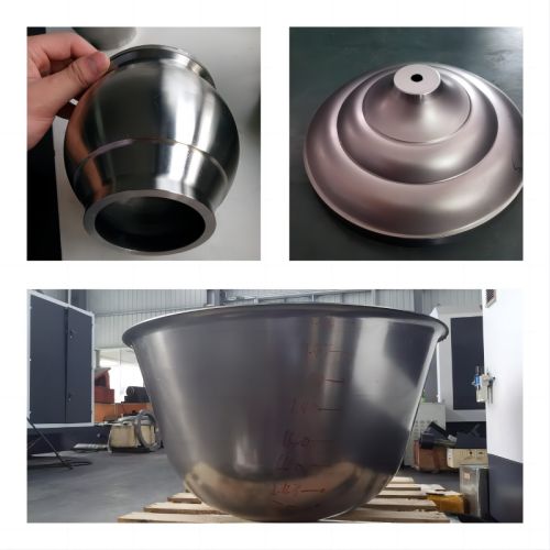
Aerospace engine component spinning machines are specialized CNC metal spinning systems engineered to meet the extraordinary precision, material, and performance demands of the aerospace industry. These machines are designed to form critical engine parts such as turbine shrouds, compressor cases, combustion chambers, and nozzles, where exacting tolerances, surface finishes, and material integrity are paramount for safety, efficiency, and reliability.
Extreme precision in aerospace spinning machines is achieved through several key technological features. High-rigidity machine frames—often constructed from polymer concrete or mineral-cast bases—minimize vibration and thermal distortion during forming. This stability is critical when working with superalloys like Inconel, titanium, or titanium aluminides that exhibit complex deformation behaviors and require precise control to avoid microstructural damage or cracks. The machines employ high-torque servo motors with ultra-fine resolution encoders that synchronize spindle rotation and roller feed movements to sub-micron accuracy, ensuring repeatable part geometry and surface conformity.
Advanced force feedback and adaptive control systems are integral to aerospace CNC spinning. Real-time sensors monitor forming pressures, roller deflection, spindle torque, and vibration signatures. This data feeds into closed-loop control algorithms that dynamically adjust roller position, feed rates, and forming forces to maintain uniform wall thickness and prevent defects. These adaptive systems compensate for tool wear, material inconsistencies, or thermal expansion, which is especially critical during multi-pass forming of thick or heat-treated aerospace alloys.
Thermal management is another vital aspect. Some aerospace spinning machines integrate localized induction heating or controlled environmental chambers to maintain optimal metal temperatures throughout forming. This reduces residual stresses and improves ductility, allowing intricate shapes to be formed without compromising the high-strength properties essential in turbine and compressor components. Precise temperature control also prevents undesirable phase transformations that could affect material performance at high operating temperatures in jet engines.
Tooling materials and design in aerospace machines are optimized for durability and surface integrity. Roller tools are made from super-hard carbides, ceramics, or coated with wear-resistant layers to withstand the extreme forces and abrasive superalloy surfaces. Mandrels and forming supports are custom-engineered for each part geometry, often featuring cooling channels or flexible segments to maintain dimensional stability while minimizing stress concentrations.
In-line metrology and inspection systems are frequently incorporated into aerospace spinning setups. Laser scanners, coordinate measuring machines (CMM), or ultrasonic thickness gauges verify part dimensions, surface finish, and wall thickness immediately after forming, enabling rapid detection of deviations and rejection of non-conforming parts before costly downstream processes like machining or coating. Some facilities also employ digital twin simulations linked with CNC programs, allowing virtual process validation and optimization prior to actual spinning.
Automation and integration with manufacturing execution systems (MES) are common in aerospace environments to ensure traceability and compliance with stringent quality standards such as AS9100 or NADCAP. Each component’s forming history—including machine parameters, operator data, and inspection results—is digitally recorded, facilitating full lifecycle traceability vital for certification and maintenance.
Because aerospace components often require complex multi-stage forming, aerospace CNC spinning machines support multi-axis control—beyond traditional two-axis setups—to accommodate compound curves, flanges, or integral cooling passages. Some machines also combine spinning with secondary operations like machining or laser welding in integrated production cells, reducing handling and improving overall precision.
Given the critical nature of aerospace engine parts, CNC spinning machines are engineered with extensive safety and reliability features, including redundant sensors, automatic shutdown protocols on fault detection, and cleanroom-compatible enclosures to maintain contaminant-free environments during forming.
In summary, aerospace engine component spinning machines represent the pinnacle of precision forming technology. Their sophisticated controls, robust construction, advanced thermal and force management, and integrated inspection systems enable the production of complex, high-performance engine parts that meet the demanding standards of the aerospace sector. These machines are essential in delivering components that can withstand extreme operating conditions while ensuring safety, efficiency, and longevity in modern aircraft engines.
These aerospace CNC metal spinning machines also prioritize material conservation, as many superalloys and titanium alloys used in engine components are costly and difficult to machine. By precisely controlling the forming process, these machines minimize scrap and reduce the need for extensive machining, which not only saves material but also shortens production cycles. The near-net-shape parts produced require less post-processing, lowering overall manufacturing costs and lead times while maintaining the high dimensional accuracy essential for aerodynamic performance.
In addition, these machines are capable of handling extremely thin wall sections without compromising structural integrity, which is critical for components like turbine blades and combustor liners that must endure high temperatures and mechanical stresses while maintaining minimal weight. The CNC systems achieve this through meticulous control of roller pressure and feed rate, often utilizing multi-pass spinning strategies that gradually form the metal to the final geometry, reducing the risk of cracking or distortion.
To meet the tight tolerances required, many aerospace spinning machines employ environmental controls such as temperature and humidity regulation within the machine enclosure. This minimizes thermal expansion effects on both the machine structure and the workpiece, ensuring consistency between production runs. Some advanced facilities even incorporate vibration isolation systems to shield the machine from external disturbances that could affect micrometer-level accuracy.
The software driving these machines is highly sophisticated, offering simulation capabilities that predict material behavior, strain distribution, and potential failure points before physical forming begins. By integrating material property databases and finite element analysis, engineers can optimize process parameters to achieve the desired final part characteristics while avoiding defects. This virtual process design reduces costly trial-and-error and speeds up the qualification of new aerospace components.
Another critical feature is the traceability and documentation capability integrated into aerospace CNC spinning machines. Every step of the forming process is logged, including machine settings, sensor readings, and operator actions. This comprehensive data trail supports stringent regulatory compliance and enables root-cause analysis in case of any component failure or nonconformance. It also facilitates continuous improvement by providing detailed insights into process stability and variability.
The machines are often equipped with multi-function tooling setups, enabling the execution of additional forming operations such as necking, flanging, or beading without removing the part from the spindle. This multi-operation capability enhances process efficiency and ensures dimensional consistency across complex geometries by maintaining precise positioning throughout all stages of forming.
Maintenance and reliability are critical in aerospace manufacturing environments, so these CNC metal spinning machines are designed for ease of upkeep with modular components, automated lubrication systems, and diagnostic software that monitors system health. Predictive maintenance alerts minimize unexpected downtime, ensuring high availability in production schedules where delays can be costly.
Safety systems in aerospace spinning machines go beyond standard industrial norms due to the high-value nature of parts and the criticality of precision. These include redundant safety interlocks, machine status monitoring, and emergency stop systems integrated into factory-wide safety networks. Operators often undergo specialized training to handle these complex systems and to respond effectively to alarms or deviations.
In essence, aerospace engine component spinning machines combine state-of-the-art mechanical design, advanced CNC control, and comprehensive quality assurance to produce parts that meet the stringent demands of modern aviation. Their capability to handle exotic materials, execute complex geometries with micron-level precision, and integrate seamlessly into digital manufacturing ecosystems makes them indispensable assets for aerospace manufacturers focused on performance, safety, and innovation.
To further enhance precision and repeatability, aerospace CNC metal spinning machines often incorporate advanced thermal compensation algorithms. These algorithms adjust for any dimensional changes caused by temperature fluctuations within the machine or the workpiece itself, ensuring that every component remains within micron-level tolerances throughout the production cycle. Such compensation is crucial when spinning alloys that exhibit significant thermal expansion or when machines operate continuously in variable factory environments.
In some cases, these machines employ hybrid forming techniques that combine metal spinning with stretch forming or flow forming within a single setup. This hybrid approach enables the production of complex aerospace components that require both axial and radial deformation, such as contoured compressor cases or aerodynamic fairings. The integration of multiple forming methods reduces the number of separate processes, improving throughput and maintaining tighter dimensional control.
The use of real-time process monitoring systems is widespread in aerospace spinning machines. Sensors continuously capture data on forming forces, spindle speed, roller position, and vibration. Machine learning algorithms analyze this data to predict tool wear, material fatigue, and potential defects before they manifest, allowing proactive adjustments or maintenance. This predictive capability significantly reduces scrap rates and helps maintain the high reliability standards demanded by aerospace applications.
Because aerospace components often require certification for flight safety, CNC metal spinning machines are frequently integrated into highly controlled production environments that comply with cleanroom standards. Dust and particulate control measures, air filtration systems, and controlled access ensure that components are free from contamination, which could compromise engine performance or safety. Machine designs incorporate sealed enclosures and materials that minimize particulate generation during forming.
Another key aspect is the capability to handle exotic materials such as gamma titanium aluminide (γ-TiAl), which is prized for its high temperature resistance and low density but is challenging to form due to its brittleness. Aerospace CNC spinning machines tailored for such materials use specialized tooling, reduced forming speeds, and controlled heating to carefully manipulate the metal without inducing cracks or structural defects.
Post-forming treatments such as heat treatment, surface finishing, or coating application are often planned in concert with the spinning process. Some CNC spinning setups allow for integration with inline laser texturing or surface preparation systems that improve coating adhesion or enhance aerodynamic properties. Coordinating these steps within a single production cell minimizes handling and improves process consistency.
In terms of software, aerospace CNC spinning machines benefit from integrated PLM (Product Lifecycle Management) systems that facilitate version control of part designs, process recipes, and quality documentation. This integration ensures traceability from design through production to inspection and delivery, which is critical for meeting the stringent regulatory requirements of the aerospace industry.
Finally, the continuous evolution of aerospace engine designs drives the need for flexible and highly programmable spinning machines. Manufacturers must adapt rapidly to new materials, changing aerodynamic profiles, and tighter environmental regulations. CNC metal spinning technology, with its combination of precision, adaptability, and digital integration, provides the foundation to meet these challenges, supporting the production of next-generation engine components that deliver higher efficiency, lower emissions, and superior performance.
In conclusion, aerospace engine component spinning machines represent the cutting edge of metal forming technology. Their advanced mechanical design, intelligent control systems, and integration with digital manufacturing platforms enable the precise, reliable, and efficient production of some of the most demanding parts in modern aviation. These machines are essential enablers of innovation, safety, and quality in the aerospace sector, powering the engines that fly today’s aircraft and those of the future.
Building on these advanced capabilities, aerospace CNC metal spinning machines increasingly incorporate modular designs that allow manufacturers to customize and upgrade systems as technology evolves or production requirements change. Modular spindles, interchangeable roller assemblies, and adaptable control hardware enable rapid reconfiguration for different part sizes, materials, or process complexities without extensive downtime. This flexibility supports lean manufacturing principles and helps aerospace suppliers respond swiftly to new engine programs or design revisions.
Furthermore, collaboration between machine manufacturers, aerospace engineers, and material scientists has led to innovations in hybrid machine-tool cells, where CNC metal spinning is combined with additive manufacturing techniques. For example, components can be spun into near-net shapes and then have complex internal features or cooling channels added via metal 3D printing. This integration allows for lighter, more efficient engine parts with geometries impossible to achieve through conventional forming alone.
Data security and intellectual property protection have also become priorities as aerospace CNC spinning machines become more connected. Secure communication protocols, encrypted data storage, and controlled access to CNC programs safeguard proprietary designs and process knowledge from cyber threats or unauthorized use. This is critical given the strategic importance of aerospace technologies and the competitive nature of the industry.
The human-machine interface (HMI) on these systems is designed for intuitive operation by skilled technicians, with graphical displays that provide real-time visualization of tool paths, process parameters, and part status. Advanced simulation tools integrated into the control software allow operators to preview forming cycles, detect potential collisions or errors, and optimize cycle times before actual production. This user-centric design reduces setup errors and training time, increasing overall productivity.
Environmental sustainability is increasingly integrated into machine design and operation. Energy-efficient motors, regenerative braking systems, and optimized cycle parameters reduce power consumption, while environmentally friendly lubricants and coolant systems minimize ecological impact. Some facilities incorporate closed-loop recycling of scrap material generated during forming, supporting circular economy goals and reducing waste.
Finally, aerospace CNC metal spinning machines are vital contributors to additive manufacturing’s growing role in aerospace. By combining precise metal spinning with post-forming additive enhancements or repair processes, manufacturers can produce complex, high-performance engine components that meet evolving industry standards. This synergy between traditional and emerging technologies underscores CNC spinning’s continued relevance and potential as a foundational manufacturing method for aerospace innovation.
In summary, aerospace engine component CNC spinning machines embody a fusion of mechanical precision, digital intelligence, and manufacturing flexibility. They enable the production of critical, high-value parts with exceptional quality and efficiency while supporting ongoing innovation in materials and design. As aerospace engines become more advanced and demanding, these spinning machines will remain indispensable tools in delivering the performance, safety, and sustainability that define modern aviation.
CNC Metal Spinning Machine with Integrated Machining (Milling/Drilling)
CNC metal spinning machines with integrated machining capabilities—such as milling and drilling—represent a sophisticated evolution in metal forming technology, combining multiple manufacturing processes into a single, seamless operation. This integration enables the production of complex, high-precision parts with minimal handling, improved dimensional accuracy, and significantly reduced cycle times compared to traditional sequential methods where spinning and machining are performed separately.
The core advantage of CNC spinning machines with integrated machining is their ability to complete both the forming and finishing operations in one setup. After a metal blank is spun to the desired shape, the same machine uses CNC-controlled milling heads or drilling spindles to perform features such as holes, slots, threads, or surface contours directly on the spun part without removal. This approach eliminates repositioning errors, reduces fixturing complexity, and maintains tight tolerances, which is especially beneficial for parts with critical alignment or concentricity requirements.
Mechanically, these hybrid machines are designed with multi-axis CNC control systems that coordinate the spinning spindle and the machining tool simultaneously or sequentially. Typically, the spinning axis is combined with additional linear and rotary axes to position and move milling or drilling heads around the workpiece. High-precision rotary tables or B-axis heads allow complex tool paths on curved surfaces, enabling intricate machining on spun cylinders, cones, or domes.
The integration demands robust machine frames and precision bearings to handle the dynamic forces from both spinning and cutting operations. Vibration damping and thermal stability are critical to preserve surface finish quality and dimensional accuracy throughout the multi-process cycle. Advanced servo drives synchronize spindle speeds and feed rates, ensuring smooth transitions between forming and machining tasks.
From a tooling perspective, quick-change systems facilitate switching between forming rollers and machining cutters, enabling flexible production of diverse parts with minimal downtime. Tool monitoring and automatic wear compensation further enhance process reliability, while collision detection systems protect both machine and workpiece from accidental damage during complex multi-axis operations.
Software plays a pivotal role in these integrated CNC machines. CAD-CAM platforms generate unified programs that combine spinning toolpaths with machining operations, allowing full process simulation and optimization before actual production. This digital continuity ensures that forming-induced material deformations are accounted for in machining tool paths, improving final part quality. Some systems offer real-time adaptive control, adjusting machining parameters based on feedback from force sensors or tool condition monitoring.
Industries such as aerospace, automotive, lighting, and cookware benefit greatly from CNC spinning machines with integrated machining. For example, aerospace components like compressor casings may be spun into near-net shapes and then precisely milled to achieve required mounting features or cooling hole patterns. Lighting reflectors can be spun and then drilled or milled for mounting brackets or wiring channels without additional setups. Cookware bodies benefit from integrated trimming and hole drilling for handles or lids, streamlining assembly.
In high-volume manufacturing, these hybrid machines can be coupled with automated material handling, pallet systems, and in-process inspection equipment, creating fully automated production cells. This integration enhances throughput, consistency, and traceability while reducing labor costs and human error.
Environmental and economic benefits are notable as well. Reducing part handling lowers contamination risks and material damage. Combining processes minimizes energy consumption and floor space requirements. The ability to produce complex parts in fewer steps accelerates time to market and increases overall equipment effectiveness (OEE).
In conclusion, CNC metal spinning machines with integrated milling and drilling combine the best of forming and machining technologies. They deliver high-precision, multifunctional manufacturing capabilities that meet modern industrial demands for complexity, efficiency, and quality. By uniting spinning and machining into one flexible platform, these machines empower manufacturers to innovate and excel across a broad range of applications.
These integrated CNC metal spinning machines also excel in maintaining tight tolerances across complex geometries, which is often challenging when forming and machining are done separately. Because the part remains fixed on the spindle throughout both operations, issues like repositioning errors, misalignment, or deformation caused by multiple setups are eliminated. This leads to superior concentricity and dimensional consistency, crucial for components in aerospace, automotive, and lighting applications where precision impacts performance and assembly fit.
Moreover, the synchronization of spinning and machining operations enables innovative hybrid manufacturing strategies. For instance, while the metal is being spun and stretched to the final shape, the machine can intermittently pause or slow the forming process to perform milling of specific areas such as flanges, grooves, or mounting faces. This overlapping capability reduces overall cycle times and allows for more intricate designs that combine smooth spun surfaces with machined features, all without moving the workpiece.
The versatility of tooling in these machines is another significant advantage. Multi-functional tool holders can accommodate not only spinning rollers but also milling cutters, drills, reamers, or even tapping heads. This flexibility means manufacturers can adapt quickly to different product requirements or custom orders by simply programming tool changes and paths, without the need for multiple dedicated machines or manual intervention.
Advanced control systems incorporate real-time monitoring of forces, spindle load, and tool wear, allowing the CNC to adjust cutting speeds and feeds dynamically. This ensures optimal machining conditions even as tool conditions change or as material properties vary within the spun part due to strain hardening or thickness variation. Such adaptability prolongs tool life, improves surface finish, and reduces the risk of defects like chatter marks or burrs.
From a software perspective, the seamless integration between CAD/CAM systems and the machine controller allows engineers to simulate the entire forming and machining process virtually. Potential collisions, toolpath errors, or material flow issues can be identified and corrected before production begins, saving time and reducing scrap. Additionally, data from in-process sensors can be fed back into the software for closed-loop process optimization, improving quality and productivity over time.
In production environments, CNC spinning machines with integrated machining contribute to significant workflow simplification. By consolidating multiple manufacturing steps into a single machine, floor space requirements are reduced, logistics and material handling are minimized, and operator skill requirements are streamlined. This consolidation also supports lean manufacturing principles and helps achieve higher overall equipment effectiveness (OEE).
Environmental benefits include reduced energy consumption, as fewer machines run and less idle time occurs between separate forming and machining stations. Material waste is also minimized since near-net-shape spinning combined with precision machining requires less excess stock removal. Additionally, with fewer setups and transfers, there is less risk of contamination or surface damage, enhancing product quality.
Industries that demand complex parts with high accuracy and repeatability, such as aerospace engine components, lighting housings, cookware, and automotive body parts, increasingly rely on CNC metal spinning machines with integrated machining to meet their rigorous standards. These machines empower manufacturers to produce parts that would otherwise require multiple machines and labor-intensive setups, enabling faster turnaround times and more competitive pricing.
In summary, the fusion of CNC metal spinning with integrated milling and drilling creates a powerful manufacturing platform that enhances precision, efficiency, and flexibility. By uniting forming and machining in a single, controlled environment, these machines redefine what’s possible in metal component production, supporting innovation and excellence across diverse industrial sectors.
Building further on these capabilities, CNC metal spinning machines with integrated machining are increasingly being equipped with multi-axis tool heads—such as 5-axis milling spindles—that allow complex machining operations on curved and irregular spun surfaces. This capability enables the creation of intricate features like contoured grooves, angled holes, or threaded inserts that conform precisely to the part’s geometry. The multi-axis movement ensures tools approach the surface at optimal angles, improving cutting quality and extending tool life.
The integration of in-process inspection systems within these machines adds another layer of precision assurance. Laser scanners, contact probes, or optical measurement devices can be mounted on the machining head or nearby, enabling real-time dimensional verification immediately after forming or machining steps. This immediate feedback allows for automatic corrections during the same cycle, reducing scrap rates and improving yield for high-value components.
Material handling automation often accompanies these hybrid machines to further streamline production. Robotic arms or automated pallet changers can load raw blanks, unload finished parts, and prepare the machine for the next cycle without manual intervention. When combined with integrated machining, this level of automation supports lights-out manufacturing, reducing labor costs and enabling continuous 24/7 operation—vital for meeting high-volume production demands.
In addition, the machines’ CNC controls are often networked with enterprise resource planning (ERP) and manufacturing execution systems (MES). This connectivity provides full traceability from raw material to finished product, including process parameters, tooling usage, and inspection data. Such traceability is crucial for quality certifications in industries like aerospace and medical device manufacturing, where regulatory compliance is stringent.
Thermal management within these machines is carefully engineered to maintain dimensional stability throughout extended cycles that combine spinning and machining. Precision coolant delivery systems, temperature-controlled enclosures, and thermal compensation algorithms ensure that both the machine and the workpiece maintain consistent conditions, preventing warping or tolerance drift that could degrade part quality.
Furthermore, hybrid CNC metal spinning and machining machines are contributing to sustainability goals by enabling near-net-shape manufacturing that drastically reduces machining allowances and scrap. This efficiency conserves raw materials and lowers energy consumption, aligning production practices with environmental responsibility initiatives.
The user interfaces on these advanced machines are designed to be intuitive yet powerful, often incorporating touchscreen displays, graphical programming aids, and augmented reality (AR) tools to assist operators in setup, troubleshooting, and training. These human-machine interfaces help reduce errors and accelerate production ramp-up for new parts.
Finally, continuous innovation in this field is expanding the potential of integrated CNC metal spinning and machining. Emerging technologies such as machine learning for predictive maintenance, adaptive process control based on sensor fusion, and even the integration of additive manufacturing steps are being explored. This convergence of technologies promises to further enhance precision, efficiency, and flexibility, positioning these hybrid machines at the forefront of modern metal component manufacturing.
In conclusion, CNC metal spinning machines with integrated milling and drilling offer a comprehensive solution for producing complex, high-precision metal parts in a streamlined, efficient manner. Their advanced mechanical design, intelligent control systems, and automation readiness make them indispensable tools across diverse industries, enabling manufacturers to meet ever-evolving demands for quality, speed, and innovation.
Expanding on the future trends, CNC metal spinning machines with integrated machining are increasingly incorporating artificial intelligence (AI) and machine learning algorithms to enhance process optimization and predictive maintenance. By analyzing vast amounts of sensor data collected during forming and machining, AI systems can identify subtle patterns indicating tool wear, material anomalies, or process drift. This enables machines to autonomously adjust parameters in real time or schedule maintenance proactively, minimizing downtime and ensuring consistent part quality.
The fusion of augmented reality (AR) and virtual reality (VR) technologies with CNC control interfaces is transforming operator training and machine setup. Technicians can visualize tool paths, machine kinematics, and potential collision zones in immersive 3D environments before running production. This reduces setup errors, accelerates learning curves, and improves overall operational safety and efficiency.
Moreover, the integration of additive manufacturing processes with CNC spinning and machining is paving the way for hybrid manufacturing cells. For instance, near-net-shape components produced by metal spinning can have complex internal geometries or lattice structures added via directed energy deposition (DED) or powder bed fusion methods. This approach combines the strength and surface finish advantages of spinning with the geometric freedom of 3D printing, enabling the creation of lightweight, high-performance aerospace or medical components that were previously impossible to manufacture.
Energy efficiency is another critical focus area. Advanced CNC metal spinning machines use regenerative drives that capture and recycle kinetic energy during deceleration phases. Combined with optimized cycle programming and energy-conscious cooling systems, these machines reduce electricity consumption, lowering operating costs and carbon footprint.
Cybersecurity also gains prominence as these machines become more interconnected within smart factories. Manufacturers implement robust encryption, multi-factor authentication, and secure network architectures to protect intellectual property and prevent unauthorized access or tampering with CNC programs.
Material science advancements complement machine capabilities. The ability to process new alloys with enhanced strength-to-weight ratios, corrosion resistance, or thermal properties drives demand for machines with adaptable tooling, heating, and forming parameters. CNC metal spinning machines evolve alongside to accommodate these materials without sacrificing precision or efficiency.
Collaborative robotics (cobots) are increasingly integrated around spinning and machining centers to assist with tasks like material loading, part unloading, and quality inspection. These robots work safely alongside human operators, enhancing productivity while reducing ergonomic strain and workplace injuries.
Finally, the modular design philosophy is extended to software platforms, allowing manufacturers to customize control software with plug-in modules for specific materials, part geometries, or production strategies. This modularity ensures that machines remain future-proof and adaptable as manufacturing needs evolve.
In essence, CNC metal spinning machines with integrated machining are not static tools but dynamic platforms that continually incorporate cutting-edge technologies. Their ongoing evolution ensures they remain central to precision metal forming and finishing, empowering manufacturers across industries to meet the ever-growing demands of quality, complexity, and sustainability in modern production.
CNC Spinning Metal Machines with Integrated Surface Finishing
CNC spinning metal machines with integrated surface finishing combine the precision forming capabilities of metal spinning with automated surface treatment processes to produce parts that meet exacting standards for both geometry and surface quality in a single, streamlined operation. This integration eliminates the need for separate finishing stations, reducing handling, cycle times, and the risk of surface damage while ensuring consistent, high-quality finishes critical for industries such as aerospace, automotive, lighting, and cookware.
These advanced machines incorporate surface finishing tools—such as polishing heads, abrasive brushes, buffing wheels, or ultrasonic cleaning systems—directly into the CNC-controlled spinning setup. After the metal blank is spun into the desired shape, the machine seamlessly transitions to applying surface finishing processes under precise computer control. This ensures uniform application of finishing treatments across complex curved surfaces, enhancing aesthetics, improving corrosion resistance, and preparing parts for subsequent coating or assembly steps.
Mechanically, integrating surface finishing within a spinning machine requires robust, vibration-damped tool mounts and adaptable tool changers that can switch between forming rollers and finishing heads. Multi-axis CNC control coordinates the motion of both spinning and finishing tools to maintain correct pressure, speed, and contact angle with the workpiece. This precise control prevents defects such as over-polishing, uneven abrasion, or surface chatter.
Common finishing processes integrated into these machines include mechanical polishing for mirror-like surfaces, fine sanding to remove minor imperfections, bead blasting for matte finishes, and ultrasonic cleaning to eliminate residues and prepare surfaces for coating. Some setups also incorporate laser surface texturing capabilities to create controlled micro-patterns that enhance paint adhesion, reduce glare, or improve aerodynamic properties.
The software controlling these hybrid machines allows operators to program finishing cycles with detailed parameters—such as polishing pressure, brush speed, and dwell time—tailored to specific materials and surface finish requirements. Real-time feedback from force and vibration sensors enables adaptive adjustments during finishing to maintain consistent quality despite variations in material hardness or geometry.
Benefits of CNC spinning machines with integrated surface finishing extend beyond quality improvements. By consolidating forming and finishing into a single machine, manufacturers reduce floor space requirements, simplify logistics, and lower labor costs. The reduction in part handling also minimizes the risk of scratches, dents, or contamination, which is especially important for high-value components or those requiring cleanroom-compatible environments.
Industries with stringent surface quality demands, such as aerospace turbine components needing aerodynamic smoothness or decorative cookware requiring flawless aesthetics, benefit significantly from these integrated systems. Additionally, lighting manufacturers gain the ability to produce reflectors with both precise shapes and optimal surface finishes in one operation, improving optical performance.
Automation can be further enhanced by coupling these machines with robotic loading/unloading systems and in-process inspection tools, such as laser profilometers or surface roughness gauges. This enables closed-loop quality control, where finishing parameters are adjusted dynamically based on measured surface characteristics, ensuring each part meets specifications without manual intervention.
Environmentally, integrated surface finishing reduces the use of consumables like polishing compounds or abrasive media by optimizing application and recycling process fluids where applicable. This aligns with sustainability goals while maintaining high-quality output.
In summary, CNC spinning metal machines with integrated surface finishing represent a powerful convergence of forming and finishing technologies. They deliver parts with superior dimensional accuracy and surface quality in a streamlined, efficient process that meets the exacting standards of modern manufacturing across a wide range of industries.
These CNC spinning metal machines with integrated surface finishing also enable greater flexibility in handling a wide variety of materials, from soft aluminum and copper alloys to harder stainless steels and titanium. The finishing tools and process parameters can be precisely adjusted to accommodate different hardness levels and surface sensitivities, ensuring optimal results without damaging or deforming the spun part. This adaptability is especially important for industries where multiple alloys or specialized coatings are used to meet performance or regulatory requirements.
The integration of finishing processes within the spinning cycle also allows for immediate correction of surface imperfections that may arise during forming, such as tool marks, minor scratches, or micro-deformations. Rather than removing the part for external polishing or buffing, these machines can target and treat these areas in real time, significantly improving throughput and reducing scrap or rework rates.
In advanced configurations, these machines can incorporate multiple finishing techniques in sequence. For example, a spun part might first undergo abrasive polishing to smooth out roughness, followed by a fine buffing stage to achieve mirror-like reflectivity, and finally an ultrasonic cleaning to remove any residual debris or oils. This comprehensive approach produces surfaces ready for direct coating, anodizing, or assembly without additional manual preparation.
The machines often include automated tool condition monitoring systems that track brush wear, polishing pad integrity, or abrasive media consumption. By alerting operators or triggering automatic tool changes, these features help maintain consistent surface quality and reduce downtime. Coupled with predictive maintenance software, manufacturers can optimize consumable usage and machine availability.
From a process control perspective, integrating surface finishing within CNC spinning enables highly repeatable and reproducible results. The closed-loop control systems monitor key variables such as finishing pressure, spindle speed, and tool position, compensating dynamically for any variations in part geometry or material behavior. This ensures each part meets tight surface roughness specifications and visual quality standards, critical for premium products or safety-critical applications.
In terms of production efficiency, combining forming and finishing reduces cycle times by eliminating transport, staging, and setup between separate machines. This consolidation lowers energy consumption and labor costs, contributing to a smaller environmental footprint and higher overall equipment effectiveness (OEE).
Moreover, these integrated machines support rapid prototyping and small-batch production runs by simplifying process workflows. Designers can quickly iterate on part geometry and surface finish parameters in a single setup, accelerating development timelines and reducing tooling costs.
The adoption of CNC spinning machines with integrated surface finishing is also driven by the increasing demand for high-quality finishes in consumer products, where tactile feel and visual appeal strongly influence brand perception. This technology enables manufacturers to consistently deliver aesthetically superior components that meet or exceed customer expectations.
Finally, as Industry 4.0 and smart manufacturing principles become widespread, these machines are being equipped with sensors and connectivity features that enable remote monitoring, process data analytics, and integration with factory automation systems. This digitalization facilitates continuous improvement, quality traceability, and predictive process adjustments, further enhancing surface finish quality and production reliability.
Overall, CNC spinning metal machines with integrated surface finishing represent a significant advancement in metal forming technology. By uniting precision shaping and surface treatment in one automated platform, they empower manufacturers to achieve exceptional part quality, operational efficiency, and production flexibility across diverse industrial sectors.
Building further on these capabilities, CNC spinning metal machines with integrated surface finishing increasingly leverage adaptive process control driven by real-time sensor feedback. Force sensors, acoustic emission detectors, and optical scanners monitor finishing effectiveness as it happens, enabling the machine to fine-tune polishing pressure, brush speed, or abrasive intensity dynamically. This adaptive control ensures consistent surface quality even when part geometry varies slightly or material hardness fluctuates due to forming-induced strain hardening.
The incorporation of automated cleaning stages within these integrated systems further enhances surface quality and readiness for downstream processing. Ultrasonic cleaning or spray rinsing units can be programmed to operate immediately after polishing, removing fine particulate matter and polishing residues without manual handling. This is particularly important in sectors like aerospace or medical device manufacturing, where surface cleanliness directly affects component performance and certification.
To accommodate increasingly complex part geometries, some CNC spinning machines employ multi-axis finishing heads capable of tilting and rotating independently from the spinning axis. This multi-degree-of-freedom movement allows finishing tools to maintain optimal contact angles on compound curves, flanges, or recessed areas that would be difficult or impossible to treat effectively with fixed finishing setups.
Energy efficiency is also a priority in modern integrated spinning and finishing machines. Regenerative braking in servo drives, optimized cycle sequencing to minimize idle times, and efficient coolant and lubricant management systems reduce overall energy consumption. These eco-friendly design features align with manufacturers’ sustainability goals and help lower operating costs over the machine’s lifecycle.
Furthermore, modular tooling systems enable quick interchangeability between different finishing tools—such as polishing pads, abrasive brushes, or blasting nozzles—supporting rapid changeovers between production runs with varying surface finish requirements. This modularity increases machine utilization and makes it feasible to produce diverse product lines without investing in separate finishing equipment.
The user interface and control software for these machines often include advanced visualization tools that display finishing tool paths, contact pressure maps, and live surface finish metrics. Operators can monitor and adjust finishing cycles on the fly, improving process transparency and empowering quick responses to quality deviations.
Integration with factory-wide quality management systems provides seamless documentation of surface finish parameters, inspection data, and process conditions for each part produced. This traceability supports compliance with industry standards such as ISO 9001, AS9100, or ISO 13485, which are crucial for aerospace, automotive, and medical device sectors.
In summary, CNC spinning metal machines with integrated surface finishing continue to evolve as highly intelligent, flexible, and efficient manufacturing platforms. Their ability to deliver precise, defect-free part geometries coupled with superior surface quality in a single automated operation makes them indispensable for modern manufacturers seeking to improve product performance, reduce costs, and accelerate time to market.
Moreover, the integration of artificial intelligence (AI) and machine learning into CNC spinning machines with surface finishing capabilities is revolutionizing the way finishing processes are controlled and optimized. By continuously analyzing data from sensors—such as force feedback, vibration, acoustic signals, and surface imaging—AI algorithms can detect subtle anomalies or trends that indicate wear, process drift, or material inconsistencies. This enables predictive adjustments to finishing parameters in real time, minimizing defects and extending tool life without human intervention.
These smart systems also facilitate self-learning, where the machine improves its finishing strategies based on accumulated production data, adapting to new materials or complex geometries with greater ease. This results in shorter setup times and more consistent quality, particularly beneficial in industries with frequent design changes or custom production requirements.
Additionally, the incorporation of augmented reality (AR) interfaces is enhancing operator training and maintenance for these integrated machines. Through AR glasses or tablets, operators can visualize internal machine components, finishing tool paths, or sensor readouts overlaid directly on the physical equipment. This interactive visualization helps technicians quickly identify issues, perform adjustments, or learn complex procedures with reduced downtime and error rates.
On the materials front, advances in surface finishing within CNC spinning systems now accommodate emerging alloys and composite-metal hybrids, which often present unique challenges due to varying hardness, surface chemistry, or thermal sensitivity. Tailored finishing cycles using specially designed abrasives or polishing compounds ensure that these advanced materials retain their functional properties while achieving the required surface aesthetics and texture.
From a sustainability perspective, integrated finishing reduces waste not only by minimizing scrap but also by enabling closed-loop recycling of polishing media and process fluids. Innovative filtration and regeneration systems recover abrasives and solvents, lowering environmental impact and operational costs.
Collaboration between machine manufacturers and end-users is driving the development of customizable finishing modules that can be tailored to specific industry needs—whether ultra-smooth finishes for optical components, textured surfaces for improved paint adhesion, or specialized coatings applied inline after finishing. This modularity empowers manufacturers to keep pace with evolving market demands and regulatory requirements.
Finally, as Industry 4.0 concepts become standard, these CNC spinning machines with integrated surface finishing are increasingly connected within digital manufacturing ecosystems. Real-time data exchange with enterprise systems, predictive maintenance platforms, and supply chain management software ensures optimal resource utilization, production planning, and quality assurance, positioning these machines as cornerstones of smart factories.
In conclusion, the fusion of advanced control, AI-driven optimization, operator-assistive technologies, and environmental stewardship in CNC spinning metal machines with integrated surface finishing is transforming metal component manufacturing. These systems deliver unprecedented precision, efficiency, and adaptability—enabling manufacturers across sectors to produce superior parts faster, more sustainably, and with greater confidence than ever before.
CNC Metal Spinning Machine with Integrated Welding
CNC metal spinning machines with integrated welding combine precision metal forming with automated welding processes in a single, unified system. This integration enables the efficient production of complex, high-quality components that require both spinning and welding operations without the need for multiple machines or manual transfers. By uniting these processes, manufacturers benefit from reduced cycle times, improved dimensional accuracy, and enhanced structural integrity.
Mechanically, these hybrid machines feature CNC-controlled spinning spindles alongside integrated welding heads—such as TIG (Tungsten Inert Gas), MIG (Metal Inert Gas), laser, or plasma welding systems—mounted on multi-axis arms capable of precise positioning relative to the spinning workpiece. The synchronization of spinning rotation with welding torch movement allows continuous or intermittent weld application on cylindrical, conical, or irregularly shaped spun parts.
The combination is particularly advantageous for producing components that require welded joints as part of their final geometry—such as spun shells with flanges that must be welded to structural rings, or multi-section assemblies where spun elements are joined in-line. Performing welding immediately after or during forming reduces distortion caused by multiple handling and heat cycles, ensuring better dimensional stability and joint quality.
CNC control systems coordinate the spinning parameters—like spindle speed and roller feed—with welding parameters such as current, voltage, wire feed rate, and shielding gas flow. Real-time feedback from sensors monitoring weld pool temperature, arc stability, and joint fit-up enables adaptive control to maintain optimal weld quality throughout the process.
Advanced welding technologies, like laser welding integrated into spinning machines, offer high precision, minimal heat-affected zones, and the ability to weld thin sections with minimal distortion. This is critical for aerospace, automotive, and medical components where weld quality directly impacts safety and performance.
Integrated welding also allows for automated seam tracking and adaptive torch positioning, compensating for slight variations in spun part geometry or surface irregularities. This flexibility ensures consistent weld bead placement and penetration, reducing the need for manual rework or inspection.
In manufacturing environments, these hybrid machines streamline workflows by eliminating the need to transfer parts between forming and welding stations, minimizing handling damage and reducing lead times. The integrated approach supports lean manufacturing principles and increases overall equipment utilization.
Safety systems within these machines are designed to manage the combined hazards of spinning and welding operations, including protective enclosures, ventilation for welding fumes, arc flash detection, and emergency stop functions that coordinate across both processes.
The software platforms driving these integrated machines typically offer unified programming environments where forming and welding operations are programmed together. Simulation tools allow operators and engineers to visualize combined spinning and welding sequences, optimize parameters, and detect potential collisions or defects before production starts.
Industries such as aerospace, energy, and heavy equipment benefit from CNC metal spinning machines with integrated welding when producing pressure vessels, turbine components, exhaust systems, or structural parts that require both precise shaping and high-quality weld joints. This combination enables the manufacture of complex, high-performance assemblies with improved reliability and reduced production costs.
In summary, CNC metal spinning machines with integrated welding represent a powerful convergence of forming and joining technologies. They deliver enhanced process efficiency, superior part quality, and manufacturing flexibility, making them essential tools for modern metal component production where both precision spinning and robust welding are required in a streamlined, automated workflow.
These CNC metal spinning machines with integrated welding further enhance production efficiency by enabling simultaneous or sequential forming and welding operations within a single machine cycle. This capability reduces overall cycle times by minimizing idle periods between spinning and welding, allowing manufacturers to meet tight production schedules and increase throughput without compromising quality.
The integration also facilitates the production of complex assemblies that combine multiple spun sections welded together with high precision. By maintaining the part on the spinning spindle throughout forming and welding, the system preserves accurate alignment and concentricity, which is critical for components subjected to high mechanical or thermal stresses.
Advanced sensor systems monitor weld quality in real time, using technologies such as infrared thermal imaging, ultrasonic testing, or arc voltage analysis. These sensors feed data back to the CNC controller, enabling automatic adjustments to welding parameters or triggering alerts for operator intervention. This closed-loop control minimizes defects like porosity, incomplete fusion, or cracking, ensuring the structural integrity and longevity of the finished parts.
Safety considerations are paramount in machines combining high-speed rotation and welding arcs. Integrated shielding, interlocked enclosures, fume extraction systems, and arc flash protection are carefully designed to protect operators and maintain regulatory compliance. The machine’s control software manages coordinated emergency stop functions, ensuring immediate cessation of spinning and welding if unsafe conditions are detected.
Programming complexity is addressed through sophisticated CAM software that unifies spinning toolpaths and welding sequences. This integrated software environment allows engineers to simulate combined processes, optimize weld bead placement relative to spun geometry, and generate CNC programs that synchronize multi-axis motions of spinning rollers and welding torches.
These hybrid machines also support quick-change tooling systems for both spinning rollers and welding heads, facilitating rapid adaptation to different part designs or welding processes. This flexibility is essential in industries where production runs vary widely in size and complexity, such as aerospace prototypes or customized industrial equipment.
Energy efficiency gains are realized by reducing material handling and machine idle time. Regenerative drives capture energy during deceleration phases, and optimized process scheduling minimizes overlapping energy peaks between spinning and welding operations, contributing to lower operational costs and environmental impact.
In sectors like aerospace, energy, and heavy machinery, where components must withstand demanding service conditions, CNC metal spinning with integrated welding ensures that both the form and the weld meet stringent performance and safety standards. The ability to produce these parts in a single automated system enhances reliability and traceability, supporting rigorous quality management and certification requirements.
Overall, CNC metal spinning machines with integrated welding represent a cutting-edge manufacturing solution that merges precise metal forming and robust joining into a streamlined process. By eliminating separate handling and aligning these operations within a coordinated, computer-controlled system, they deliver superior part quality, higher productivity, and greater manufacturing agility to meet the evolving needs of modern industry.
Building further, the development of CNC metal spinning machines with integrated welding is driving innovation in multi-material and multi-layer component manufacturing. By precisely controlling the forming and welding of dissimilar metals or layered materials, these machines enable the production of components with tailored properties—such as corrosion resistance combined with structural strength—that are difficult or costly to achieve through conventional methods.
The ability to perform in-process welding during spinning also supports repair and refurbishment applications. Damaged or worn spun parts can be reshaped and welded with minimal disassembly, extending component life and reducing waste. This capability is particularly valuable in industries like power generation, oil and gas, and aerospace, where costly parts benefit from efficient maintenance solutions.
Machine builders are increasingly incorporating advanced robotics and automation systems alongside these hybrid machines to handle material loading, unloading, and part transfer. Collaborative robots (cobots) work safely with human operators, further enhancing flexibility and productivity while maintaining safety standards. Automated inspection systems integrated within the machine can perform dimensional and weld quality checks in real time, ensuring that only parts meeting strict specifications proceed down the production line.
Moreover, integration with digital manufacturing platforms enables full traceability and quality documentation for each part produced. Data on forming forces, welding parameters, sensor readings, and inspection results are logged and linked to specific batches or serial numbers, supporting compliance with industry regulations and customer requirements.
Thermal management remains a critical aspect in these integrated machines. Since welding introduces localized heat, controlling thermal distortion during and after welding is essential to maintaining dimensional accuracy. Advanced cooling systems, preheating capabilities, and process sequencing strategies are implemented to mitigate residual stresses and avoid warping.
From a programming standpoint, the complexity of coordinating spinning and welding has led to the development of specialized simulation and offline programming tools. These allow engineers to model material flow during spinning, predict weld pool behavior, and optimize combined toolpaths before physical production begins, reducing trial-and-error and accelerating time-to-market.
Future advancements may include adaptive welding techniques that respond dynamically to variations in spun part thickness or geometry, further improving joint quality and reducing scrap. The integration of real-time imaging and machine vision could enable automatic recognition of weld seams and defects, facilitating autonomous corrections or operator alerts.
In conclusion, CNC metal spinning machines with integrated welding are transforming metal fabrication by merging shaping and joining into a cohesive, automated process. This synergy enhances manufacturing efficiency, improves product quality, and opens new possibilities for complex, high-performance component designs across diverse industrial sectors. As technology continues to evolve, these hybrid machines will play an increasingly vital role in meeting the challenges of modern manufacturing.
Continuing onward, the evolution of CNC metal spinning machines with integrated welding is fostering the emergence of highly customized, on-demand manufacturing. With the ability to rapidly switch between different spinning profiles and welding programs, these machines support low-volume production and bespoke part fabrication without sacrificing efficiency or quality. This flexibility aligns well with the growing trend toward mass customization in industries like automotive, aerospace, and industrial equipment.
Additionally, the integration enables improved material utilization. By combining near-net-shape spinning with precise welding, manufacturers can minimize excess material usage and machining allowances. This leads to cost savings, reduced scrap, and a smaller environmental footprint—key factors as industries strive for sustainable production practices.
The machines’ ability to perform welding during or immediately after spinning also reduces thermal cycles on the workpiece, which is crucial for maintaining the metallurgical properties of heat-sensitive alloys. This results in improved mechanical performance and longevity of the finished components, critical for applications subject to fatigue, corrosion, or high temperature.
In terms of workforce impact, integrated CNC spinning and welding machines reduce the reliance on multiple specialized operators, consolidating tasks into a more streamlined workflow. Operators can focus on overseeing the entire process, supported by advanced diagnostics, remote monitoring, and user-friendly interfaces. This enhances productivity while lowering training requirements and human error.
From a maintenance perspective, predictive analytics powered by embedded sensors monitor machine health, welding torch wear, and spindle condition. Early detection of potential failures or quality issues allows planned maintenance, avoiding costly downtime and ensuring consistent production output.
Furthermore, as additive manufacturing continues to integrate with traditional processes, CNC spinning machines with welding capabilities may incorporate hybrid workflows that combine forming, joining, and metal deposition. This expands design freedom, enabling complex internal structures or repair overlays that improve component performance and reduce weight.
The continuous advancement of control software and hardware platforms also supports increasingly complex geometries and multi-material assemblies. Enhanced simulation accuracy, combined with AI-driven optimization, allows for faster development cycles and higher confidence in first-piece quality.
In summary, CNC metal spinning machines with integrated welding are not only enhancing traditional manufacturing methods but also enabling new production paradigms that emphasize customization, sustainability, and operational excellence. Their capacity to combine precise shaping and reliable joining within a single, automated system positions them as pivotal technologies for the future of advanced metal fabrication across diverse industries.
Dual-Head / Opposed Metal Spinning Machines (for Tube Closure/Necking)
Dual-head or opposed metal spinning machines are specialized CNC metal spinning systems equipped with two spinning heads positioned opposite each other on a shared spindle axis. These machines are designed to perform simultaneous spinning operations from both ends of a workpiece, enabling highly efficient processing of cylindrical components such as tubes, cans, or vessels, especially for applications like tube closure, necking, and complex end forming.
In dual-head configurations, one head typically performs a spinning or necking operation on one end of the tube blank, while the opposite head simultaneously spins or forms the other end. This synchronized action drastically reduces cycle times by eliminating the need to reposition or flip the workpiece between sequential forming steps. The simultaneous opposing motions also balance the forces exerted on the workpiece, reducing deformation or wobble and improving dimensional accuracy and concentricity.
These machines are especially valuable in manufacturing tube closures or necked ends for products such as aerosol cans, pressure vessels, hydraulic cylinders, or storage tanks. The necking process reduces the diameter of one or both tube ends to allow for fittings, closures, or welding, and the dual-head system ensures symmetrical forming with precise wall thickness control.
CNC control systems govern the precise coordination of both spinning heads, controlling spindle speeds, roller feeds, and forming forces in real time. Advanced software algorithms synchronize movements to maintain exact timing and pressure balance, which is critical for preventing material thinning, wrinkling, or cracking during the necking or closure process.
Dual-head metal spinning machines often incorporate servo-driven roller arms with multi-axis freedom, enabling complex profiles such as tapered necks, flanges, or stepped reductions to be formed efficiently. The opposing heads can also be configured to perform different forming operations concurrently, such as one side necking while the other applies a flange or bead.
Because the workpiece remains held securely between the two heads throughout the operation, the system delivers exceptional concentricity and surface finish quality. This is vital for components requiring tight tolerances and smooth surfaces, often mandated in the packaging, automotive, or aerospace industries.
Safety features are integral to these machines due to the high forces and rotating components involved. Enclosures, interlocks, and emergency stop systems protect operators while allowing for high-speed, continuous operation.
From a productivity standpoint, dual-head spinning machines increase throughput by halving the processing time compared to traditional single-head setups. The reduction in handling steps also minimizes the risk of surface damage and improves overall process repeatability.
Integration options may include automated material loading/unloading, robotic handling, and in-line inspection systems to further enhance manufacturing efficiency and quality assurance. Some models also allow quick changeovers between different tube diameters or lengths via adjustable head positioning and tooling.
In summary, dual-head or opposed CNC metal spinning machines represent a powerful solution for efficiently producing high-precision tube closures, necked ends, and related components. Their simultaneous, balanced forming approach ensures superior dimensional control, surface quality, and throughput, making them indispensable in industries demanding reliable and cost-effective tubular part fabrication.
These dual-head or opposed metal spinning machines continue to gain popularity because they effectively address many challenges inherent in tube closure and necking processes. By spinning from both ends simultaneously, the system naturally counterbalances the forces applied to the workpiece, significantly reducing the risk of distortion, vibration, or runout, which are common issues in single-head spinning. This force equilibrium results in parts with superior roundness, concentricity, and structural integrity, crucial for pressure-containing components or those that must fit precisely with mating parts.
The dual-head design also offers flexibility in handling a wide range of tube sizes and materials, from thin-walled aluminum and stainless steel to more robust alloys used in industrial applications. Adjustments to spindle distance, roller pressure, and tool geometry allow manufacturers to tailor the process to specific product requirements, maintaining wall thickness uniformity and preventing material thinning or wrinkling during necking.
In addition to necking and tube closure, these machines can perform complex end forming operations such as flange creation, beading, or shoulder forming, which are often required for sealing or assembly purposes. The CNC controls enable precise multi-step forming sequences without manual intervention, supporting consistent quality across high-volume production runs.
Another advantage of dual-head machines is their ability to improve cycle efficiency through optimized programming and synchronization. The simultaneous spinning operations reduce the total processing time per part, increasing throughput and lowering unit production costs. This efficiency is further enhanced when integrated with automated material handling systems, allowing continuous production with minimal operator involvement.
The software supporting these machines often features advanced simulation and process optimization tools. Engineers can model material flow, predict potential thinning or wrinkling zones, and fine-tune roller paths and speeds before production, reducing trial-and-error and material waste. Real-time monitoring systems track forming forces and spindle loads, enabling adaptive control that maintains process stability even when material properties vary or tool wear occurs.
Maintenance considerations are addressed by designing accessible roller arms, quick-change tooling systems, and robust spindle bearings capable of handling the dynamic loads generated by opposed spinning. Preventative maintenance programs, supported by sensor data analytics, help ensure high machine availability and consistent part quality over long production cycles.
Industries such as automotive, aerospace, packaging, and energy increasingly rely on dual-head CNC metal spinning machines for producing components like fuel tank necks, hydraulic cylinder ends, aerosol can closures, and pressure vessel fittings. The machines’ ability to deliver precision, repeatability, and speed makes them essential for meeting stringent industry standards and production targets.
Environmental benefits also arise from the dual-head approach. By reducing cycle times and eliminating intermediate handling, energy consumption per part decreases, and material scrap is minimized due to better process control. This contributes to greener manufacturing practices and aligns with sustainability goals many companies prioritize today.
In conclusion, dual-head or opposed CNC metal spinning machines represent an advanced, highly efficient technology for tubular component forming. Their synchronized, balanced spinning actions deliver superior product quality, operational speed, and flexibility, addressing the evolving demands of modern manufacturing environments where precision and productivity are paramount.
Additionally, as digitalization in manufacturing accelerates, dual-head CNC metal spinning machines are increasingly integrated into smart factory ecosystems. Through Industrial Ethernet or fieldbus protocols, these machines can connect to factory networks, enabling centralized control, production scheduling, and data logging. Real-time performance analytics — including spindle torque trends, roller forces, and machine temperature — can be collected and processed to ensure optimal machine utilization and early detection of anomalies or wear.
Advanced models also feature automatic alignment systems for the dual heads. This ensures perfect synchronization between the opposing spindles, crucial when spinning components with tight tolerances or complex geometries. Adaptive servo algorithms allow each spindle to dynamically compensate for minor variances, maintaining symmetrical forming pressure and consistent wall thickness, which is critical in industries like medical devices, military equipment, or aircraft systems where any deviation could lead to functional failure.
When equipped with robotic arms or gantry loaders, these machines can become part of a fully automated cell. Raw tubing or blanks can be fed directly into the spinning zone, processed, and ejected or transferred for secondary operations like trimming, welding, or inspection — all without human intervention. This drastically reduces labor costs and eliminates human error, particularly valuable for night-shift or lights-out production strategies.
Custom tooling is another area where dual-head machines excel. Spinning tools can be tailored to generate unique profiles or integrate multiple forming stages into a single cycle. For example, a necking, beading, and calibration operation can be completed in one setup, enhancing part precision and reducing handling. Furthermore, the modular tool interface supports quick changeovers, ideal for job shops or manufacturers producing a variety of part numbers in short batches.
From a design perspective, the machines are often built on heavy-duty welded steel frames to withstand the enormous forming forces. Vibration-dampening systems and precision-ground slideways contribute to machine longevity and quiet, stable operation — a critical factor when operating at high RPMs with hard materials like Inconel or titanium.
Safety systems are robust as well, with interlocked enclosures, emergency stop systems, light curtains, and overload protection. In hazardous applications (such as flammable materials or high-temperature spinning), optional features like thermal shielding, fire suppression, or explosion-proof controls can be incorporated.
In educational and prototyping environments, scaled-down versions of dual-head spinning machines are also available. These compact systems offer the same control philosophy and toolpath logic as their full-scale counterparts, enabling engineers and students to develop forming recipes, conduct material studies, or create custom prototypes without occupying full-production machines.
As material science progresses, especially with the growing use of advanced composites, metal matrix materials, and functionally graded materials, dual-head CNC spinning machines are expected to evolve to handle new challenges in flow behavior, temperature sensitivity, and elasticity. Hybrid systems combining forming with localized induction heating or laser assistance are already under exploration to push the boundaries of what can be spun efficiently and accurately.
In sum, dual-head CNC metal spinning machines stand as a pinnacle of modern forming technology, merging precision mechanics, real-time control, and adaptive automation. They support not only current industrial demands but are also well-positioned for future manufacturing trends, from mass customization to aerospace-grade complexity — all while upholding high standards for reliability, repeatability, and sustainability.
With the rapid evolution of materials, production standards, and end-user requirements, dual-head CNC metal spinning machines continue to find broader applications beyond traditional industries. One such growing area is the renewable energy sector, particularly in fabricating large, high-strength components for wind turbines, hydrogen storage tanks, and high-pressure vessels. These applications often require spun parts with perfect axial symmetry, long lengths, and uniform wall thickness — parameters ideally suited to dual-head or opposed spinning systems.
Integration of AI-driven process monitoring further enhances the adaptability of these machines. By leveraging machine learning algorithms trained on thousands of spinning cycles, modern systems can auto-adjust roller speed, feed rate, and pressure in real-time to compensate for material inconsistency or unplanned deformation. This ensures every part remains within tolerance — especially crucial in safety-critical industries like aerospace, defense, and nuclear energy.
In terms of software, many dual-head spinning systems now support fully parametric programming. Engineers can input dimensional targets such as neck diameter, shoulder angle, and wall thickness, and the system automatically generates the toolpath. Some software platforms offer built-in simulation tools to visualize material flow, thickness distribution, and roller stress before running the actual part, greatly reducing the risk of trial-and-error prototyping.
Servo-hydraulic hybrid drive systems are also being introduced to combine the responsiveness of electric actuators with the raw forming force of hydraulics. These systems offer better energy efficiency, more precise force application, and quieter operation. The result is a smoother forming cycle, reduced mechanical stress on the workpiece, and extended tool life — especially important when spinning expensive or difficult-to-machine alloys.
Customization remains a major advantage of CNC spinning technology. Machine builders can tailor everything from bed length to spindle clearance to roller layout depending on whether the customer is spinning long tubes, short bowls, flared ends, or stepped profiles. The dual-head design allows simultaneous operations from both ends — such as spinning one side while trimming the other — effectively halving cycle times and increasing throughput for symmetrical or tubular parts.
Dual-head machines are also increasingly employed in medical and laboratory equipment manufacturing. These sectors demand ultra-clean forming environments, often necessitating sealed enclosures, oil-free actuators, and compliance with GMP (Good Manufacturing Practice) standards. Some installations even incorporate HEPA-filtered airflow and low-vibration foundations to meet sterile or low-particulate specifications.
Another trend is the incorporation of real-time dimensional feedback via integrated laser scanners or high-speed cameras. These sensors measure the profile of the part as it’s being formed and compare it to a CAD reference. If deviations are detected, corrections are applied instantly — reducing scrap, enhancing repeatability, and enabling true closed-loop manufacturing.
From an operator’s standpoint, modern interfaces are becoming increasingly user-friendly. Touchscreen HMIs with graphical overlays, smart alarm systems, and multi-language support reduce training time and improve daily usability. Remote support modules allow manufacturers to diagnose and service the machines via secure internet connections, minimizing downtime and eliminating the need for costly on-site visits.
In the context of Industry 4.0, data from dual-head CNC spinning machines can feed into plant-wide analytics systems, allowing factory managers to optimize batch sizes, track machine utilization, schedule predictive maintenance, and even forecast material consumption based on historical trends. This level of connectivity transforms the machine from a standalone forming tool into an integrated, data-rich node within the digital factory.
Whether producing jet engine sleeves, high-pressure gas bottles, long-distance pipeline end caps, or symmetrical architectural elements, dual-head CNC metal spinning machines offer unmatched balance, force distribution, and geometric control. As demand for high-integrity formed metal parts grows across industries, these machines will remain a cornerstone of advanced manufacturing — combining legacy metalworking principles with next-generation automation, sensing, and AI-based control.
Multi-Roller CNC Synchronized Metal Spinning Machines
Multi-roller CNC synchronized metal spinning machines represent the pinnacle of modern spinning technology, particularly when dealing with complex geometries, hard metals, and high-volume production. These machines use three, four, or more rollers working in coordinated motion to distribute forming forces more evenly across the workpiece, reduce localized stress, and enable the forming of intricate or high-strength profiles with greater control and surface quality.
Unlike single-roller systems, where forming stress is concentrated on one contact point, multi-roller synchronized setups allow simultaneous shaping across multiple zones of the metal blank. This synchronization not only enhances symmetry but also significantly reduces the number of passes needed to achieve the final shape, improving productivity and extending the life of both tools and machine components.
One of the major advantages is their ability to form highly complex parts such as gas bottle necks, aerospace domes, or pressure vessel closures in a single cycle with precise wall thickness control. The rollers can be independently controlled along multiple axes, with real-time coordination managed by the CNC system. This enables progressive or staged forming, where different rollers contribute differently at various steps of the cycle — for instance, one roller may preform the shoulder, another may finalize the contour, and a third may smooth the surface.
Material flow is more uniform in multi-roller synchronized machines, making them ideal for working with titanium, stainless steel, and Inconel — materials known for work hardening and poor formability in single-roller setups. Heat-assisted spinning or induction heating can also be integrated when forming extremely tough materials, with each roller contributing to continuous deformation under controlled thermal conditions.
These machines often feature adaptive servo axes with torque and displacement sensors on each roller arm, enabling dynamic pressure feedback and ultra-precise control. Combined with advanced software, they can compensate for minor imperfections in the blank, changes in temperature, or tool deflection. The result is improved consistency across long production runs and higher first-pass yield, even on critical components.
Multi-roller synchronized spinning is especially valued in industries where form accuracy and repeatability are essential, such as:
- Aerospace: fuel tanks, engine components, nose cones
- Defense: mortar shells, missile casings
- Energy: hydrogen storage domes, turbine parts, nuclear containment ends
- Automotive: heavy-duty axle housings, truck wheel components
- Industrial: pressure-rated pipe fittings, pump housings, high-strength dish heads
Some machines are equipped with modular roller heads, allowing users to switch between 3, 4, or even 5 rollers depending on part geometry. Others integrate CNC tool changers or programmable roller paths to allow a single setup to produce a wide variety of parts with minimal manual intervention.
Additionally, machine stiffness and vibration damping are optimized in these systems due to their symmetrical loading, allowing higher forming speeds and smoother finishes. Because multiple rollers divide the forming effort, the risk of wrinkling, tearing, or thinning is minimized, particularly on large-diameter or deep-drawn parts.
Many multi-roller synchronized systems also incorporate intelligent thermal management, remote diagnostics, and cloud-based performance monitoring. This allows engineers to track forming cycles, predict maintenance needs, and fine-tune performance for specific material-lot variations or part batches.
Ultimately, multi-roller CNC synchronized metal spinning machines combine brute forming capability with surgical precision. They are indispensable where quality, efficiency, and high material strength are non-negotiable — offering a reliable platform for the most demanding applications in modern metal forming.
Multi-roller CNC synchronized metal spinning machines offer a high degree of control, efficiency, and precision, making them ideal for complex, large-diameter, or high-strength metal forming tasks. These machines employ multiple rollers—commonly three, four, or more—that work in perfect coordination to apply forming forces uniformly over the surface of the rotating workpiece. By synchronizing the movement of each roller, they reduce localized deformation, improve material flow, and prevent defects like wrinkling or tearing. Unlike single-roller machines that must perform forming in multiple passes with significant tool pressure on one point, synchronized multi-roller systems distribute the workload, enabling deeper draws and more consistent wall thickness in fewer passes. Each roller is controlled by its own servo axis and pressure feedback loop, which allows precise adjustments in real-time during the forming cycle. This capability ensures higher repeatability and better surface finish, especially critical in aerospace, defense, and energy sectors where dimensional tolerances and material properties are tightly controlled. These machines are commonly used to form tank ends, domes, pressure vessels, missile casings, and turbine covers. Their adaptive CNC platforms often support CAD/CAM integration, simulation, and process optimization for new part designs. Heated forming can also be integrated, using gas torches, induction, or resistance elements to soften hard materials like titanium, Inconel, or duplex stainless steel before and during spinning. With reduced tool wear, faster production cycles, and higher forming stability, multi-roller CNC spinning machines dramatically improve the economics of precision metal forming.
Multi-roller CNC synchronized metal spinning machines are also highly advantageous for working with exotic or hard-to-form alloys, such as titanium, Hastelloy, or high-strength stainless steels. Their synchronized pressure application helps maintain metallurgical integrity by minimizing internal stress concentrations, strain hardening, or microcracking. This is especially important in industries like aerospace and nuclear, where the structural reliability of each component is paramount. The simultaneous and balanced pressure from each roller ensures uniform plastic flow, reducing the need for intermediate annealing steps and extending tool life. The synchronization system can be programmed for both symmetrical and asymmetrical geometries, enabling the production of conical, parabolic, or highly contoured shapes that are difficult or impossible to form using conventional single or double roller configurations.
These systems often feature advanced feedback mechanisms using real-time sensors to monitor force, torque, material thickness, temperature, and roller position, enabling adaptive control. This makes it possible to dynamically adjust forming parameters during the process to compensate for material inconsistencies or geometric deviations. Additionally, the integration of digital twin models or forming simulation software allows engineers to preview material flow and stress distribution virtually, thereby reducing trial-and-error and increasing first-pass yield rates. Modern multi-roller CNC spinning systems can also integrate peripheral automation, such as robotic part loading/unloading, integrated trimming, laser measuring systems, and surface finishing heads, creating a seamless and continuous production environment.
Thanks to their rigidity and modularity, these machines can be scaled for components with diameters from a few hundred millimeters to several meters, supporting production for automotive gas bottles, industrial fan housings, satellite domes, LNG tank heads, and heavy-duty industrial diaphragms. In highly regulated sectors, the traceability of production parameters and integration with factory MES/ERP systems is also achievable, ensuring compliance with ISO, AS9100, or API standards. Overall, synchronized multi-roller CNC spinning machines represent the peak of high-volume, high-precision metal forming, combining brute force, intelligent control, and adaptive flexibility in a single platform.
These synchronized multi-roller CNC spinning machines are increasingly being adopted not only for their forming power and precision but also for their versatility in hybrid applications. They can be configured for conventional spinning, flow forming, shear forming, or necking—sometimes even all within the same cycle—making them ideal for complex parts that transition across varying wall thicknesses, diameters, or profiles. This is particularly advantageous in defense applications, such as the production of rocket motor cases, artillery shell bodies, or high-performance pressure vessels, where material performance and dimensional tolerances are mission-critical.
Further advancement in synchronization technology involves the use of servo-driven independent axes for each roller, allowing real-time positional corrections without interrupting the process. These systems can detect minute deflections or forming resistance changes and compensate through coordinated motion adjustments—something traditional hydraulic or mechanically coupled systems cannot achieve. This capability drastically reduces waste and tool wear, especially during the forming of high-strength alloys or multilayered composite blanks.
In terms of machine architecture, multi-roller spinning centers now offer modular expansions—additional roller arms can be integrated into the system depending on the forming complexity. For example, a 4-roller system can be upgraded to a 6-roller arrangement for ultra-deep draw or full-contour shaping tasks. Cooling systems, tool preheating modules, and high-frequency induction heating units can also be integrated to manage material temperature during hot or warm spinning operations, further broadening the material spectrum and improving formability.
Automation integration is another domain where these machines excel. With Industry 4.0 compatibility, they can be networked with SCADA systems and cloud-based analytics platforms, enabling predictive maintenance, cycle optimization, and remote diagnostics. Vision systems with AI-assisted quality control can inspect dimensional conformity and surface finish immediately after forming, ensuring zero-defect production in mission-critical industries.
From a design-to-manufacturing standpoint, multi-roller CNC synchronized spinning machines support a fully digital workflow. CAD-CAM environments allow engineers to import part geometries, assign material characteristics, simulate forming steps, and export optimized tool paths to the CNC controller. This drastically shortens lead times for prototype development and small-batch manufacturing, making these machines ideal for R&D departments, aerospace prototype labs, and advanced manufacturing institutes.
In essence, these machines are redefining the boundaries of what’s possible in metal forming, offering a level of control, repeatability, and part complexity that was unthinkable with traditional lathes or manual spinning setups. Whether forming long aluminum cones for space applications, deep stainless pressure domes for cryogenic storage, or ultra-thin titanium shapes for aviation, synchronized multi-roller CNC spinning machines deliver unmatched efficiency, accuracy, and versatility.
Internal Flow Forming Machines
Internal flow forming machines are specialized CNC metal forming systems designed to reduce wall thickness and elongate tubular or cylindrical parts from the inside-out. Unlike conventional flow forming, which shapes the workpiece by pressing rollers against its outer diameter, internal flow forming applies force from the inside using a mandrel or tooling system that expands or supports the inner wall while the outer surface remains fixed or is supported by a die. This allows for precise internal geometry control, making it ideal for applications requiring tight tolerances and enhanced mechanical properties in hollow, high-performance components.
These machines typically operate with a fixed or rotating mandrel inside the tube and multiple rollers applying axial and radial pressure externally. However, in true internal flow forming systems, the mandrel may itself be dynamic—heated, expandable, or segmented—to conform to complex internal profiles during forming. The blank, often a preform or deep-drawn shell, is clamped and rotated while the internal tooling pushes material longitudinally, thereby thinning the wall and extending the tube with controlled grain flow and no seams.
Internal flow forming is commonly employed in aerospace, defense, and high-end automotive sectors for producing parts like jet engine liners, rocket casings, gun barrels, and reinforced tubing. One of the main advantages of this method is its ability to create extremely precise internal diameters and surface finishes without additional boring or machining. This not only reduces material waste but also shortens production times and enhances structural integrity through work hardening and fiber alignment.
Advanced internal flow forming machines are CNC-controlled, allowing for multi-pass forming sequences, variable wall thicknesses along the tube length, and automatic tool retraction and positioning. They often integrate in-process sensors such as load cells, temperature monitors, and laser gauges to maintain dimensional accuracy and repeatability. Additionally, software simulation and CAM modules help optimize tooling paths and forming speeds to prevent defects like wrinkling, tearing, or non-uniform thinning.
In some configurations, internal flow forming can be combined with other operations such as internal profiling, ID grooving, or heat-assisted forming. This hybrid capability is especially valuable in components where both the internal and external shapes are functionally critical—such as hydraulic cylinders, missile tubes, or telescopic casings.
Overall, internal flow forming machines represent a pinnacle of controlled deformation technology, offering unmatched accuracy and strength in critical hollow components, where weight reduction, performance under pressure, and dimensional consistency are essential.
Modern internal flow forming machines are increasingly adopting servo-hydraulic or fully electric actuation systems, allowing for finer control over roller pressures and mandrel dynamics. These advanced actuation methods not only enhance energy efficiency but also enable dynamic adjustments during forming, which is crucial when dealing with materials like titanium alloys, high-strength steels, or superalloys that are sensitive to thermal and strain conditions. Additionally, many of these machines are integrated into digital production environments, featuring full compatibility with Industry 4.0 protocols. This allows for real-time monitoring, data logging, predictive maintenance, and adaptive forming sequences based on sensor feedback and historical performance data.
One of the primary engineering challenges in internal flow forming is controlling the interface between the mandrel and the workpiece, especially in long components. To mitigate issues such as mandrel deflection, frictional heating, and uneven pressure distribution, some machines employ active mandrel supports or floating mandrels with embedded sensors. These help maintain concentricity and dimensional consistency even under varying load conditions. Cooling systems are often integrated directly into the mandrel or tool carriers to manage thermal expansion and ensure repeatable forming behavior. For very large or thick-walled parts, induction preheating or localized laser heating may be used to soften the material just before contact with the forming tools, reducing required forces and improving surface finish.
Internal flow forming is distinct from tube drawing or hydroforming in that it emphasizes plastic deformation through mechanical rolling rather than fluid pressure or tensile pulling. The grains in the material are typically elongated along the forming direction, producing superior mechanical characteristics such as increased tensile strength, yield strength, and fatigue resistance. Because of this, internally flow-formed tubes often outperform forged or extruded counterparts in structural performance, even when made from the same alloy.
The tooling for these machines must be carefully engineered, not only for geometric precision but also for material compatibility. Carbide-tipped or ceramic-coated rollers are commonly used for abrasive or high-temperature alloys. Modular mandrel designs are favored when multiple product sizes must be produced with minimal changeover time. These modular systems often feature quick-lock or automated mandrel swapping mechanisms that can be programmed directly through the machine’s control interface.
Applications continue to expand into sectors such as nuclear fuel cladding, submarine pressure hull segments, satellite propulsion tanks, and high-precision industrial actuators. In these contexts, the ability to form extremely long, seamless, concentric tubes with consistent wall thickness and exact internal diameters is mission-critical. With growing demand for weight reduction and performance optimization, especially in aerospace and defense sectors, internal flow forming is emerging as a cornerstone technology in advanced manufacturing.
Looking forward, the combination of machine learning algorithms and in-process metrology systems will further enhance the capabilities of internal flow forming systems. By analyzing real-time forming data such as force signatures, surface strain distribution, and material springback behavior, smart machines can autonomously adapt forming strategies to maintain part quality even with incoming material variability. Such intelligent forming platforms not only reduce scrap rates and human intervention but also pave the way for digital twins—virtual models that replicate and predict the performance of physical forming systems, enabling simulation-driven process optimization before a single part is made.
To further enhance precision and repeatability in internal flow forming machines, advanced closed-loop control systems are being widely implemented. These systems continuously monitor critical forming parameters—such as roller force, mandrel torque, radial displacement, and axial feed—and adjust them in real time using feedback from high-resolution sensors. This is especially critical when forming complex geometries like stepped wall thicknesses or conical interiors, where a minor deviation in process control can lead to significant geometric inaccuracies or material thinning.
In terms of mechanical configuration, most high-end internal flow forming machines now use numerically synchronized multi-axis systems, where each roller axis, mandrel rotation, and carriage feed is governed by a coordinated motion controller. This allows not only for conventional cylindrical forming but also the shaping of elliptical, parabolic, or even helical internal profiles—features increasingly demanded in aerospace propulsion and turbomachinery applications.
Noise, vibration, and harshness (NVH) control is another important design consideration, especially in environments where tight tolerances and smooth surfaces are mandatory. Vibration-dampened bed frames, precision-ground guideways, and low-friction roller assemblies reduce harmonic disturbances during forming. Additionally, acoustic sensors are sometimes integrated to monitor process anomalies, such as material tearing or roller chatter, which may not be visible through force readings alone but could compromise part integrity.
On the materials front, internal flow forming has expanded into exotic alloys that were previously considered unformable with conventional techniques. Inconel 718, Maraging steels, and even MMCs (metal matrix composites) can now be internally formed thanks to hybrid forming techniques that include simultaneous axial heating or ultrasonic vibration assistance. These methods temporarily reduce yield stress and improve plastic flow without overloading the mechanical system.
Inspection and quality control are also evolving. Inline ultrasonic wall thickness gauges, laser triangulation sensors, and eddy current probes are now commonly embedded in the forming stations. These enable instant feedback on dimensional conformity and help detect flaws like internal voids, surface cracking, or eccentric growth. Machine operators or automated systems can then halt or adjust the operation based on live diagnostic data, which is a critical component of zero-defect manufacturing protocols.
Automation has reached the point where entire forming cells can operate unmanned, integrating robotic handling, automatic part centering, adaptive tool change, and post-forming deburring or surface finishing. This not only boosts throughput but also ensures consistent product quality across large production runs. Data from each forming operation is logged and indexed against part serial numbers, creating a full traceability chain—a necessity for aerospace, nuclear, and medical sectors.
With additive manufacturing gaining traction, hybrid machines are now emerging that can deposit near-net shape preforms via Directed Energy Deposition (DED) or Wire Arc Additive Manufacturing (WAAM) and subsequently refine them internally via flow forming. This combination of additive and subtractive forming opens up the possibility of producing highly complex, weight-optimized structures that were previously impractical or too costly to machine or forge conventionally.
In essence, internal flow forming machines are transitioning from being merely precision metalworking tools into intelligent, adaptive, and fully integrated systems within advanced digital factories. As industries continue to demand lighter, stronger, and more complex tubular components, these machines will play an increasingly vital role in reshaping the way high-performance cylindrical parts are designed and produced.
Looking ahead, internal flow forming technology is expected to integrate more deeply with Industry 4.0 principles. This includes predictive maintenance powered by AI-driven analytics, where machine learning algorithms monitor sensor data for signs of wear or misalignment in rollers, mandrels, bearings, or servo systems. By identifying potential failures before they happen, downtime is reduced, and overall equipment effectiveness (OEE) is significantly improved.
Another promising development is the digital twin of the forming process. In this setup, a real-time virtual model mirrors the physical operation, simulating stresses, deformations, thermal behavior, and material flow during the actual forming cycle. Engineers can observe and modify parameters in the digital space before applying them in the real machine, minimizing trial-and-error and enabling faster prototyping for custom parts.
Tooling in internal flow forming machines is also evolving. Advanced coatings like TiAlN or diamond-like carbon (DLC) are being applied to rollers and mandrels to reduce wear, improve surface finish, and allow dry forming of stainless steels or titanium alloys. In some cases, modular tooling sets are used that allow quick adaptation to different part geometries, enhancing machine versatility.
Cooling and lubrication systems are another area of advancement. High-pressure, directed coolant jets or minimum quantity lubrication (MQL) systems are being used to control localized heating, prevent galling, and flush away debris during the forming process. For heat-sensitive alloys or multi-pass operations, zone-based cooling around the mandrel helps maintain dimensional accuracy by controlling thermal expansion effects.
Human-machine interfaces (HMI) in modern internal flow forming machines have become more intuitive. Large touchscreen panels with 3D simulation previews, voice-guided setup procedures, and even augmented reality overlays assist operators in setup, monitoring, and maintenance. This reduces the need for highly specialized labor and shortens the learning curve, particularly in environments with frequent job changes.
Energy efficiency is being addressed through regenerative servo drives and optimized hydraulic units that only activate on demand. This not only reduces power consumption but also contributes to quieter operation and less heat generation within the facility.
Sustainability is another emerging consideration. Flow forming produces far less scrap compared to machining from solid billets. Some manufacturers are even working with recycled metals, using flow forming to bring secondary raw materials up to aerospace-grade specifications. Combined with the reduction in post-processing needs (like welding or grinding), this makes internal flow forming one of the most material-efficient metal forming processes available.
Lastly, collaboration between machine tool builders, material scientists, and end users is accelerating innovation. Aerospace and defense customers are driving requirements for forming complex missile canisters, fuel system liners, or jet engine sleeves with unprecedented precision and strength-to-weight ratios. These demands push the limits of what flow forming machines can achieve, leading to custom machine architectures, real-time adaptive forming logic, and entirely new roller kinematics.
In summary, internal flow forming machines are not only keeping pace with the future of advanced manufacturing—they are actively shaping it. With ever-expanding capabilities in geometry, precision, material range, automation, and digital integration, they will remain essential assets in high-performance, high-specification production landscapes for decades to come.
Conical/Parabolic Specific CNC Metal Spinning Machines
Conical and parabolic specific CNC metal spinning machines are highly specialized forming systems designed to precisely produce parts with tapered or curved profiles such as cones, paraboloids, and other complex rotational shapes. Unlike standard cylindrical spinning machines, these systems are engineered to handle the geometric challenges involved in shaping metal blanks into non-uniform cross sections where the diameter changes continuously along the axis, and the wall thickness varies predictably to maintain structural integrity.
These machines utilize advanced CNC control systems with multi-axis capabilities to coordinate spindle rotation, tool movement, and pressure application dynamically throughout the forming process. The programming allows the roller or forming tool to follow complex 3D toolpaths that correspond to the exact conical or parabolic shape specified by the CAD model. This precise synchronization is critical because conical and parabolic shapes involve continuous taper angles and curvature that require varying forming forces and tool engagement depths at different positions along the workpiece.
Typically, these machines have servo-driven axes controlling radial displacement, axial feed, and roller pressure, often enhanced by synchronized tilt or swivel mechanisms on the tooling to maintain optimal contact angles. This capability allows the machine to adapt continuously to changing diameters and surface curvature, preventing common defects such as wrinkling, thinning, or tool slip. For example, when forming a parabolic satellite dish reflector or a conical nozzle, the tool must smoothly transition between different radii while controlling metal flow to avoid distortion.
Materials commonly processed on conical/parabolic CNC spinning machines include aluminum alloys, stainless steel, titanium, and copper, often selected for their strength-to-weight ratios and corrosion resistance—key properties in aerospace, defense, and telecommunications applications. These machines are instrumental in producing components like rocket engine cones, satellite reflectors, lighting reflectors, acoustic horns, and aerodynamic fairings.
Some advanced machines incorporate heating systems such as induction coils or resistance elements to perform hot spinning, enhancing formability for hard-to-spin alloys or thicker blanks. Integration with CAD/CAM software is standard, enabling users to import complex 3D profiles, simulate forming processes, and optimize tool paths before actual production. This reduces setup times, material waste, and trial iterations.
In addition, these machines often support automatic tool changers and multi-roller configurations to handle different forming stages within a single setup—such as rough shaping with a larger roller followed by fine finishing with smaller, precision tools. Some models include in-process measurement systems like laser scanners or contact probes to monitor geometry in real time and adjust forming parameters dynamically, ensuring tight tolerances.
Overall, conical and parabolic specific CNC metal spinning machines combine mechanical precision, adaptive control, and software intelligence to produce highly complex rotational shapes efficiently and consistently. They serve critical roles in industries demanding aerodynamic efficiency, optical accuracy, and structural performance from tapered or curved metal components.
Conical and parabolic CNC metal spinning machines have evolved to meet the increasing demand for precision and complexity in modern manufacturing. Their multi-axis control systems enable seamless transitions between varying diameters and curvatures, which is essential when forming parts like aerodynamic nozzles, satellite reflectors, or sound horns that require exact contour fidelity. The continuous adjustment of roller pressure and position prevents common spinning defects such as wrinkling, tearing, or uneven wall thickness, ensuring each part meets stringent quality standards. These machines often incorporate real-time feedback from sensors monitoring force, position, and surface finish, enabling closed-loop control to adapt to variations in material properties or thickness during the forming cycle.
The ability to work with a range of materials, including lightweight aluminum alloys and high-strength titanium or stainless steel, makes these machines highly versatile. Hot spinning options integrated into these systems allow the forming of difficult alloys by heating the blank to optimal temperatures, reducing forming forces, and improving metal ductility. The thermal control is often managed by induction coils or infrared heaters with precise temperature monitoring to avoid overheating or damaging the workpiece.
Advanced CAM software plays a critical role in programming these machines, allowing engineers to input detailed 3D models and simulate the spinning process to optimize tool paths and forming sequences. This reduces trial and error, minimizes scrap, and shortens production cycles. Automation features such as automatic tool changers and multi-roller setups enable complex parts to be formed in fewer passes, boosting productivity while maintaining precision.
Industries such as aerospace, defense, telecommunications, and automotive rely heavily on conical and parabolic CNC spinning machines for components requiring aerodynamic or optical performance. For example, parabolic satellite reflectors demand extremely smooth surfaces and precise focal geometries to ensure signal accuracy, while aerospace engine nozzles need conical profiles with consistent wall thickness to withstand high thermal and mechanical stresses.
Furthermore, some machines offer integrated in-process inspection using laser scanning or contact probes, which detect deviations from design specifications during forming. This immediate feedback allows for corrective adjustments in real-time, enhancing part consistency and reducing the need for secondary quality checks. The use of digital twins—virtual replicas of the forming process—also enables simulation-driven optimization and predictive maintenance, further improving operational efficiency.
Mechanically, these machines are built on rigid frames with vibration damping features to maintain stability during high-speed or high-force spinning. Tooling is often customized with specialized coatings or materials to endure the specific demands of conical or parabolic forming, such as carbide or ceramic tips to reduce wear and prevent workpiece damage.
Overall, conical and parabolic CNC metal spinning machines combine sophisticated motion control, adaptable tooling, thermal management, and software intelligence to produce high-precision, complex shapes that meet the exacting requirements of advanced engineering fields. Their ability to efficiently create tapered and curved rotational parts with exceptional surface quality and dimensional accuracy makes them indispensable in cutting-edge manufacturing environments.
In addition to their core capabilities, conical and parabolic CNC metal spinning machines increasingly incorporate features that support flexible manufacturing and rapid changeovers. Modular tooling systems allow quick swapping of rollers, mandrels, and forming heads tailored to specific part geometries or materials. This flexibility is crucial for industries producing diverse product lines with varying conical or parabolic profiles, enabling shorter setup times and higher machine utilization.
The integration of multi-axis CNC control with servo-driven actuators enables dynamic adjustments during spinning, such as varying roller tilt angles or feed rates in response to in-process measurements. This adaptability is essential when working with complex curvature transitions or stepped wall thicknesses, where a fixed toolpath could cause defects or material failure. Machines equipped with multi-roller configurations can perform simultaneous forming operations on different sections of the part, accelerating production and enhancing geometric control.
Thermal management continues to be a focal point. By combining precise heating zones with localized cooling, manufacturers can tailor temperature profiles to optimize formability while minimizing residual stresses and distortion. Some systems use infrared cameras or thermocouples embedded near the forming area to continuously monitor temperatures, allowing closed-loop control of heating elements. This is particularly important when spinning alloys prone to phase changes or heat sensitivity.
Surface finish quality is another critical aspect addressed by advanced conical and parabolic spinning machines. They often feature integrated surface finishing tools such as burnishing rollers, polishing attachments, or ultrasonic vibration modules. These help achieve mirror-like finishes directly on the spinning line, reducing or eliminating secondary finishing operations like grinding or electro-polishing. The ultrasonic modules can also assist in forming by lowering forming forces and preventing surface defects through high-frequency vibrations.
On the software side, AI and machine learning are making their way into programming and process optimization. By analyzing historical data from previous runs, these intelligent systems can predict optimal forming parameters for new parts, detect anomalies during production, and suggest corrective actions. This leads to improved first-pass yield, reduced scrap, and better overall equipment effectiveness.
Industrially, these machines serve a variety of demanding applications such as parabolic antenna dishes for telecommunications, conical rocket nozzles and thrust cones in aerospace, sound-reflecting horns in acoustic engineering, and precision lighting reflectors in automotive and architectural lighting. Their ability to form complex three-dimensional profiles with consistent material properties and tight tolerances underpins product performance in these sectors.
Ergonomics and operator interface design also receive attention. Touchscreen controls with intuitive graphical interfaces simplify setup and operation, while remote monitoring capabilities allow experts to support and troubleshoot machines without being physically present. Augmented reality (AR) tools are sometimes employed to assist operators in tooling changes or maintenance, overlaying instructions directly onto the machine components.
Finally, sustainability considerations are integrated through energy-efficient drives, reduced scrap due to precise control, and the ability to work with recycled or lower-grade feedstock by optimizing forming parameters. The high material utilization typical of metal spinning combined with these efficiencies makes conical and parabolic CNC metal spinning machines attractive choices for manufacturers seeking both quality and environmental responsibility.
In summary, conical and parabolic specific CNC metal spinning machines represent a convergence of advanced mechanical design, precise multi-axis control, adaptive thermal management, and intelligent software integration. Together, these features enable the efficient production of complex tapered and curved rotational components with superior accuracy, surface finish, and structural integrity—fulfilling the stringent requirements of cutting-edge industries worldwide.
Building on these advancements, conical and parabolic CNC metal spinning machines are increasingly designed for full integration into smart manufacturing ecosystems. They are equipped with IoT (Internet of Things) connectivity, enabling continuous data exchange with factory management systems for real-time production monitoring, predictive maintenance, and quality assurance. This connectivity allows manufacturers to track machine health, production rates, and part quality metrics remotely, facilitating proactive interventions that minimize downtime and optimize throughput.
The machines often feature advanced safety systems including light curtains, automatic shutdowns, and enclosed work areas to protect operators during high-speed spinning operations. Automated loading and unloading systems using robotic arms or conveyors are also integrated in high-volume environments to reduce manual handling, improve cycle times, and enhance workplace ergonomics.
For prototyping and small batch production, some conical and parabolic CNC spinning machines offer flexible programming modes including manual override, replay functionality, and rapid tool path editing. This flexibility allows engineers to quickly iterate part designs and make real-time adjustments without lengthy CNC programming, shortening development cycles and accelerating time-to-market.
Material handling systems are optimized to work with a variety of blank forms—round discs, pre-cut cones, or spun shells—and support automated centering and clamping to ensure precision alignment before spinning begins. This reduces setup variability and contributes to consistent part quality.
Advanced thermal forming options enable hot spinning processes where blanks are heated uniformly or in targeted zones to enhance formability of difficult alloys or thick sections. Integration with induction heating coils, resistance heaters, or infrared lamps allows precise temperature control synchronized with forming cycles. Cooling systems using air jets, water sprays, or liquid cooling channels manage part temperature post-forming to minimize distortion and residual stresses.
To maintain geometric accuracy during spinning, some machines utilize real-time shape measurement technologies such as laser scanners or structured light systems. These tools measure the part profile as it spins, feeding data back to the CNC controller to adjust roller position or speed dynamically. This closed-loop correction capability ensures parts consistently meet tight dimensional tolerances without the need for secondary machining.
From a tooling perspective, modular design enables quick adaptation to different part geometries and materials. Tooling materials range from hardened steels to carbide or ceramic composites, chosen based on wear resistance, heat tolerance, and friction characteristics. Tooling changeovers are increasingly automated, often supported by machine vision systems to verify correct installation and alignment.
In sectors like aerospace, telecommunications, and lighting, these machines contribute to producing components with critical aerodynamic, optical, or acoustic performance requirements. For example, the smooth, precisely curved surfaces of parabolic reflectors maximize signal focus, while conical exhaust nozzles must endure extreme thermal and mechanical loads while maintaining precise flow characteristics.
Looking forward, further integration of artificial intelligence for adaptive process control, augmented reality for operator training and troubleshooting, and digital twins for virtual commissioning and optimization will continue to push the capabilities of conical and parabolic CNC metal spinning machines. These technologies will enable manufacturers to achieve unparalleled levels of quality, efficiency, and flexibility while responding rapidly to evolving market demands.
In conclusion, conical and parabolic specific CNC metal spinning machines stand at the forefront of precision metal forming technology. Their blend of mechanical innovation, digital intelligence, and versatile operation empowers industries to produce complex, high-performance rotational components with exceptional speed, accuracy, and repeatability, driving advances across aerospace, defense, communications, and beyond.
Miniature / Micro- CNC Metal Spinning Machines
Miniature and micro CNC metal spinning machines are specialized precision systems designed to form extremely small and intricate metal components with high accuracy and surface finish. These machines cater to applications requiring tiny rotationally symmetric parts, often measuring just a few millimeters or even less in diameter, such as components for medical devices, microelectronics, aerospace instrumentation, and miniature optical assemblies.
Due to the diminutive scale, these CNC spinning machines are engineered with ultra-precise motion control, often incorporating high-resolution linear and rotary encoders, nanometer-level positioning accuracy, and low-friction bearings to minimize vibration and backlash. Spindle speeds are typically higher than conventional spinning machines, sometimes reaching tens of thousands of RPM, to accommodate the small diameter blanks and ensure smooth forming.
The tooling for miniature and micro metal spinning is correspondingly specialized. Rollers and mandrels are fabricated with micrometer tolerances, often using super-finished tool steels or carbide tips to maintain form accuracy and surface quality at small scales. Custom tooling designs may include micro-profiled rollers or precision-ground mandrels that conform to complex shapes such as miniature cones, domes, or curved surfaces.
Material handling in micro spinning machines requires delicate fixtures and automated micro-clamping systems to securely hold tiny blanks without distortion. Loading and unloading are often performed with micro-robotic arms or vacuum grippers integrated into the machine to avoid damaging fragile parts or altering their geometry.
These machines support multi-axis CNC control, allowing synchronized adjustment of spindle speed, axial feed, radial roller displacement, and sometimes tilt or swivel angles for advanced shaping. Closed-loop feedback systems use laser interferometry, capacitance probes, or high-precision encoders to monitor tool position and part deformation in real time, enabling adaptive corrections during the spinning process.
Typical materials formed include thin foils and sheets of stainless steel, aluminum alloys, titanium, copper, and specialized medical-grade alloys such as Nitinol. In some cases, ultra-thin metal foils are spun into miniature cups, tubes, or lens housings with wall thicknesses measured in microns.
Applications for miniature and micro CNC metal spinning machines are diverse and growing. In the medical field, they produce components for surgical tools, implantable devices, and diagnostic instruments. In aerospace, they manufacture micro-scale nozzles, sensor housings, and optical mounts. In electronics, they form precision connectors, shielding cans, and micro-coils. The optical industry benefits from highly accurate miniature reflectors, diaphragms, and housings formed through micro spinning.
Programming these machines often involves highly detailed CAD models and CAM routines optimized for micro-forming, including compensation for springback and material anisotropy common at small scales. Simulation tools help predict deformation and optimize tool paths, minimizing scrap and setup time.
To maintain consistent quality, miniature CNC spinning machines incorporate environmental controls such as temperature stabilization and vibration isolation to prevent external disturbances from affecting the delicate forming process. Some advanced systems also use in-process metrology with optical or electron microscopy-based inspection to verify dimensional and surface finish parameters in real time.
Overall, miniature and micro CNC metal spinning machines push the boundaries of precision metal forming, enabling manufacturers to create intricate, high-quality components at scales previously unattainable with conventional equipment. Their combination of ultra-fine control, specialized tooling, and adaptive feedback systems makes them essential for cutting-edge industries demanding miniaturization and exceptional part integrity.
Miniature and micro CNC metal spinning machines also emphasize automation and integration due to the challenges of handling tiny, delicate parts. Robotic loading systems with precision vision guidance are often employed to place blanks accurately on the spindle and retrieve finished components without damage. Automated tool changers equipped with micro-scale tooling sets enable quick transitions between different part geometries or batch sizes, improving productivity in small-scale manufacturing environments.
The control software for these machines is typically customized to handle the unique dynamics of micro forming, including compensation algorithms for thermal expansion, tool wear, and material springback that are more pronounced at small scales. Advanced motion controllers use high-frequency feedback loops and predictive models to maintain nanometer-level accuracy despite potential sources of error such as machine frame vibration or servo lag.
Because the forces involved in miniature spinning are much lower than in conventional metal spinning, the machines feature highly sensitive force and torque sensors to monitor and adjust forming pressure continuously. This prevents overloading or deformation that could ruin the delicate workpieces. Some systems integrate ultrasonic vibration assistance or micro-heating elements to enhance material ductility and reduce forming forces for difficult-to-shape alloys.
Surface finish quality is paramount in miniature parts, often impacting optical clarity, electrical conductivity, or biocompatibility. Thus, micro spinning machines may incorporate in-situ polishing tools or ultrasonic-assisted finishing modules to produce mirror-like surfaces directly during the forming cycle. These integrated finishing steps reduce the need for secondary processing, saving time and preserving dimensional accuracy.
Due to their specialized nature, miniature and micro CNC metal spinning machines are often found in research institutions, medical device manufacturers, aerospace component suppliers, and precision engineering workshops. Their ability to produce repeatable, high-quality parts in batch sizes ranging from prototypes to medium production runs makes them valuable assets in industries where miniaturization and precision are critical competitive factors.
Looking toward future developments, the field is moving toward greater integration of artificial intelligence and machine learning. These technologies will analyze vast amounts of process data to optimize forming parameters autonomously, predict maintenance needs, and detect anomalies before defects occur. Coupled with enhanced sensor arrays and adaptive control, this will further improve yield, reduce scrap, and enable even more complex micro-component geometries.
Environmental controls also play a significant role; cleanroom-compatible micro spinning machines are designed to operate within contamination-controlled environments to meet the strict standards of semiconductor, medical, and aerospace industries. Vibration isolation tables, temperature-controlled enclosures, and filtered air systems help maintain stable forming conditions essential for the smallest and most sensitive parts.
In summary, miniature and micro CNC metal spinning machines embody the convergence of ultra-precision mechanics, sophisticated control systems, and advanced automation to enable the reliable production of extremely small, complex, and high-quality metal components. Their continual evolution supports the ongoing trend toward miniaturization and functional integration in high-tech industries worldwide.
Miniature and micro CNC metal spinning machines are also evolving to support multi-material and hybrid component production. Advances in tooling and process control enable these machines to spin composite-metal laminates or coated metal foils, combining the mechanical benefits of metal with functional surface layers such as corrosion resistance, conductivity, or biocompatibility. This opens up new possibilities for micro-scale devices requiring multifunctional surfaces without additional assembly steps.
Moreover, these machines are increasingly paired with additive manufacturing (AM) technologies. For example, near-net-shape micro preforms created via micro 3D printing or micro powder bed fusion can be subsequently spun to refine surface finish, enhance mechanical properties through work hardening, and achieve tight dimensional tolerances. This hybrid approach combines the geometric freedom of AM with the precision and material integrity of metal spinning, expanding the design space for miniaturized components.
In terms of hardware, the trend is toward ultra-compact, modular spinning centers with integrated metrology, robotics, and environmental controls that fit within limited cleanroom or lab spaces. Compact footprint machines are also designed with energy efficiency in mind, utilizing brushless servo motors, regenerative drives, and optimized mechanical linkages to reduce power consumption while maintaining precision.
Operator interfaces emphasize ease of use and remote monitoring capabilities. Touchscreen panels with intuitive graphics guide users through micro-scale setup and diagnostics. Remote connectivity and cloud-based data analytics enable specialists to oversee multiple machines from centralized locations, troubleshoot issues, and update control algorithms without disrupting production.
Material versatility continues to grow, with machines adapted to handle everything from ductile precious metals like gold and platinum—used in microelectronics and medical implants—to ultra-hard alloys and exotic metals for aerospace and defense micro-components. This is supported by advancements in micro tooling materials and coatings that extend tool life and maintain dimensional accuracy over extended production runs.
Quality assurance is further enhanced by integration with automated optical inspection (AOI), scanning electron microscopy (SEM), or even atomic force microscopy (AFM) for surface characterization, ensuring that micro parts meet stringent surface roughness, dimensional, and structural criteria. Feedback from these inspection systems can be directly linked to machine controls for adaptive process correction.
Training and knowledge transfer are supported through augmented reality (AR) and virtual reality (VR) tools that allow technicians to simulate machine setup, maintenance, and troubleshooting in immersive environments. This reduces downtime and enhances skill development, critical in the highly specialized field of micro metal spinning.
As industries push the boundaries of miniaturization, from implantable medical devices to compact aerospace sensors, miniature and micro CNC metal spinning machines will play an increasingly vital role. Their unique combination of precision, adaptability, and integration with emerging technologies ensures they remain at the forefront of advanced manufacturing for the tiniest yet most critical metal components.
Continuing the evolution of miniature and micro CNC metal spinning machines, researchers and manufacturers are exploring the integration of advanced sensor fusion techniques to further enhance process control and part quality. By combining data from multiple sensor types—such as laser displacement sensors, acoustic emission detectors, and thermal cameras—machines gain a comprehensive understanding of forming conditions in real time. This multi-modal monitoring enables earlier detection of defects like micro-cracks, delamination in composite materials, or subtle deviations in surface texture that single-sensor setups might miss.
Another emerging area is the incorporation of micro-actuation technologies, such as piezoelectric or magnetostrictive actuators, to provide ultra-fine, rapid adjustments to tooling position or pressure during spinning. These actuators supplement traditional servo systems by enabling vibrations or micro-movements at frequencies and amplitudes that improve material flow, reduce forming forces, and enhance surface finish quality on a microscopic scale.
From a materials science perspective, the capability to spin new classes of advanced alloys, metal matrix composites (MMCs), and even nano-engineered metals at miniature scales is gaining momentum. These materials often exhibit complex behavior during deformation, requiring sophisticated modeling and control strategies to avoid cracking or uneven thickness. High-fidelity finite element analysis (FEA) combined with machine learning-based predictive models assist in optimizing spinning parameters tailored to these novel materials.
Miniature CNC spinning machines are also being integrated into multi-step micro-manufacturing lines, where spinning is one operation among many—such as micro-machining, laser processing, coating, or assembly. Seamless integration with robotics and automated material handling facilitates high-throughput production of complex assemblies while maintaining traceability and quality control.
The growing emphasis on sustainability drives efforts to minimize material waste and energy consumption in micro spinning. Precise control reduces scrap rates, while process optimizations lower power use. Additionally, recycling initiatives encourage the use of recovered metals and reduce reliance on virgin raw materials, contributing to greener manufacturing practices.
On the user experience front, advances in artificial intelligence assist in adaptive learning of machine behavior. Over time, the machine “learns” the characteristics of different materials, tooling wear patterns, and environmental factors, autonomously adjusting process parameters to maintain consistent output quality with minimal operator intervention.
Finally, collaboration between academia, industry, and equipment manufacturers accelerates innovation in micro CNC metal spinning. Joint research initiatives focus on expanding the boundaries of achievable geometries, materials, and functional integration—enabling next-generation micro components with unprecedented performance for fields such as biomedical implants, micro-electromechanical systems (MEMS), and miniaturized aerospace devices.
In essence, miniature and micro CNC metal spinning machines represent a nexus of precision engineering, advanced materials science, and intelligent automation. Their continued advancement will unlock new frontiers in manufacturing the smallest, most complex metal parts that form the backbone of modern technology.
Large Diameter / Heavy Gauge CNC Metal Spinning Machines
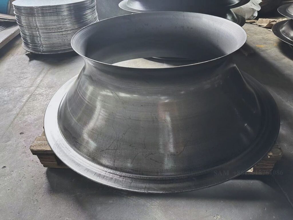
Large diameter and heavy gauge CNC metal spinning machines are robust, high-capacity systems engineered to handle sizable metal blanks and thick materials while maintaining precision and repeatability. These machines are essential in industries requiring large, structurally demanding components such as aerospace, energy, transportation, shipbuilding, and industrial equipment manufacturing.
Due to the scale and mass of the blanks—often exceeding diameters of one meter and material thicknesses from several millimeters up to multiple centimeters—these machines feature reinforced frames and heavy-duty spindle assemblies to withstand immense forming forces. The beds and columns are constructed from high-strength cast iron or welded steel to minimize deflection and vibration during operation, ensuring dimensional accuracy even under heavy loads.
The spindle motors are high-torque, often utilizing direct-drive technology or geared systems capable of delivering consistent rotational speeds with controlled acceleration and deceleration. This is critical for spinning thick sections where controlling strain rates can affect material flow and final properties.
CNC control on large diameter and heavy gauge machines typically involves multi-axis synchronization, enabling coordinated movement of the spindle, rollers, and sometimes the tooling turret or mandrel. This coordination allows for complex shapes such as deep cones, large domes, or stepped cylinders to be formed with precise control over wall thickness and surface finish.
Tooling systems are designed with substantial contact areas and often employ multiple rollers—single, double, or multi-roller configurations—to distribute forming forces evenly and reduce localized stress concentrations. Tool materials include hardened steels and tungsten carbide coatings to withstand abrasion and high pressures associated with thick metal deformation.
Thermal management is a significant consideration. While many large parts are formed cold, some applications require hot spinning or warm spinning to improve formability, especially with alloys like stainless steel, titanium, or high-strength steels. Induction heating, resistance heaters, or localized heating blankets are integrated into the machine to preheat blanks or specific areas, facilitating smoother metal flow and reducing the risk of cracking.
Material handling solutions, including overhead cranes, vacuum lifters, or hydraulic arms, are incorporated to load and unload heavy blanks safely and accurately. Automated clamping and centering systems ensure proper alignment before spinning begins, reducing setup times and minimizing errors.
Large diameter heavy gauge CNC spinning machines are used to manufacture critical components such as aerospace engine casings, ship propeller hubs, large-diameter pressure vessels, turbine shrouds, and structural elements for industrial machinery. These components demand not only dimensional precision but also exceptional mechanical properties and surface quality.
To maintain quality, advanced machines often feature in-process monitoring technologies like laser scanning, force sensors, and temperature probes. These sensors provide real-time feedback to the CNC system, allowing dynamic adjustments of forming parameters to compensate for material inconsistencies or thermal expansion.
Safety systems are paramount due to the mass and energy involved. Enclosed guarding, emergency stops, vibration dampening mounts, and operator safety interlocks are standard features to protect personnel during operation.
Modern large diameter spinning machines integrate with factory automation systems and Industry 4.0 platforms, providing remote monitoring, predictive maintenance, and production analytics. This connectivity helps optimize machine utilization, reduce downtime, and ensure consistent part quality over extended production runs.
In summary, large diameter and heavy gauge CNC metal spinning machines combine mechanical robustness, precise multi-axis control, advanced tooling, and integrated process monitoring to shape thick, sizable metal components reliably. Their capability to deliver high-quality, structurally sound parts makes them indispensable in heavy industries requiring large-scale metal forming solutions.
Large diameter and heavy gauge CNC metal spinning machines continue to advance with innovations aimed at improving efficiency, precision, and adaptability for complex part geometries. One key development is the use of adaptive control algorithms that automatically adjust roller feed rates, spindle speed, and forming pressure based on live sensor feedback. This adaptive approach compensates for variations in material thickness, hardness, or temperature, reducing scrap and ensuring consistent wall thickness throughout large components.
Another important trend is the integration of multi-roller configurations that enable simultaneous forming operations. By using two or more rollers working in concert, the machines can better distribute forming forces, reduce cycle times, and achieve more uniform metal flow, which is critical when working with heavy gauge materials. Some machines also feature motorized roller tilt and swivel axes, allowing dynamic adjustment of roller contact angles to accommodate complex shapes such as stepped diameters, flanges, or contoured profiles.
Thermal management systems have grown more sophisticated, with zoned heating and cooling capabilities that allow selective temperature control of different blank areas. This is particularly useful for large, thick parts where temperature gradients can cause distortion or residual stress. Precise thermal control combined with real-time temperature monitoring helps maintain dimensional accuracy and metallurgical integrity throughout the forming process.
Material handling automation is evolving to handle ever-larger and heavier blanks with improved safety and ergonomics. Integrated cranes, robotic arms, or automated guided vehicles (AGVs) are employed to move blanks from storage to the machine and then to subsequent processing stations. This automation not only reduces manual labor and injury risk but also enables just-in-time manufacturing practices that optimize factory floor space and inventory.
To support the increased complexity of large parts, CNC programming software has become more advanced, incorporating 3D simulation, collision detection, and process optimization features. Engineers can virtually validate tool paths, identify potential forming issues, and fine-tune process parameters before physical production begins, minimizing trial-and-error and reducing lead times.
Quality assurance is enhanced through in-process metrology using laser scanners or contact probes that measure part geometry during spinning. This feedback loop allows the CNC controller to make minute adjustments on the fly, maintaining tight tolerances without the need for extensive secondary machining or inspection.
The structural design of these machines also incorporates vibration isolation techniques, such as damped foundations and frame reinforcements, to minimize chatter and surface defects that could compromise part quality. This is especially important in spinning operations involving thick materials, where higher forces can induce harmful vibrations.
Safety systems continue to improve with integrated monitoring that can detect abnormal machine behavior, such as excessive torque or unexpected vibrations, and automatically halt operations to prevent damage or injury. Enclosed work areas, light curtains, and emergency stop systems are standard, ensuring operator protection in demanding heavy-duty environments.
Energy efficiency initiatives are gaining traction, with regenerative braking on spindle drives and energy-saving servo motors reducing power consumption during slowdowns or idle periods. These improvements contribute to lower operational costs and support sustainability goals.
In heavy industries such as aerospace, power generation, and maritime, large diameter heavy gauge CNC spinning machines enable the production of critical, high-performance components with unmatched precision and repeatability. Their ability to handle challenging materials and geometries while maintaining consistent quality makes them vital assets in modern manufacturing operations.
Overall, the ongoing advancements in mechanical design, automation, thermal management, and intelligent control continue to expand the capabilities of large diameter and heavy gauge CNC metal spinning machines, positioning them as indispensable tools for shaping the next generation of large, high-strength metal parts.
Large diameter and heavy gauge CNC metal spinning machines are also evolving toward greater modularity and customization to meet the specific demands of diverse industries. Manufacturers increasingly offer configurable machine platforms that allow users to select spindle sizes, roller arrangements, control systems, and thermal management options tailored to their unique production needs. This modularity facilitates upgrades and adaptation as production requirements change, enhancing machine lifespan and return on investment.
Advanced process simulation tools integrated into the machine’s CNC software are becoming essential for planning the forming of large, thick parts. These simulations use finite element analysis (FEA) to predict metal flow, stress distribution, and potential defect formation during spinning, allowing engineers to optimize process parameters in a virtual environment. By identifying challenges early, manufacturers reduce costly physical trials and improve first-pass yield rates.
The rise of hybrid manufacturing approaches combines CNC metal spinning with complementary processes such as machining, welding, and additive manufacturing within a single cell or production line. For example, after spinning a large-diameter component, integrated milling heads or welding stations can perform secondary operations without removing the part from the machine, saving time and improving alignment accuracy. This multi-function integration supports just-in-time production and reduces handling-related errors or damage.
Real-time digital monitoring and analytics play an increasingly important role in heavy gauge metal spinning operations. Sensors embedded throughout the machine collect data on vibrations, forces, temperatures, and cycle times, which are analyzed using machine learning algorithms to detect anomalies, predict maintenance needs, and optimize throughput. This data-driven approach enhances machine reliability and reduces unplanned downtime, critical when working with expensive large blanks and complex parts.
Material science advancements also influence machine capabilities. New high-strength alloys and composite-metal materials with enhanced mechanical or thermal properties require precise control of forming forces and temperatures to avoid cracking or distortion. Heavy gauge CNC spinning machines are adapting to handle these materials through improved thermal management systems, enhanced roller materials, and refined control algorithms that accommodate unique deformation behaviors.
In addition, environmental and safety regulations are shaping machine design, prompting manufacturers to incorporate noise reduction technologies, dust and fume extraction systems, and energy-efficient components. Ergonomic improvements such as improved operator access, automated safety interlocks, and user-friendly interfaces contribute to safer, more productive work environments.
The industrial sectors benefiting from these large diameter heavy gauge CNC spinning machines include aerospace for large engine casings and structural parts, energy for turbine components and pressure vessels, maritime for ship propellers and hull sections, and heavy machinery manufacturing for rollers, drums, and large housings. The ability to form complex, thick-walled, and large-diameter metal parts with consistent quality enables manufacturers to meet stringent performance and reliability standards required in these demanding fields.
As manufacturing moves toward Industry 4.0, these machines will increasingly integrate with factory-wide digital ecosystems, enabling seamless communication with other equipment, supply chain management systems, and quality control platforms. This connectivity supports flexible production schedules, rapid response to design changes, and continuous process improvement.
In conclusion, large diameter and heavy gauge CNC metal spinning machines represent a pinnacle of mechanical robustness, precise control, and technological integration. Their continued innovation is essential for producing the next generation of large, high-performance metal components that drive progress in critical industrial sectors worldwide.
Large diameter and heavy gauge CNC metal spinning machines are increasingly embracing automation and robotics to enhance productivity and safety in heavy manufacturing environments. Automated loading and unloading systems, often utilizing robotic arms with force-feedback control, reduce manual labor and the risk of injury when handling bulky, heavy blanks and finished parts. These systems ensure precise placement and alignment, which is crucial for maintaining dimensional accuracy in large components.
The adoption of advanced human-machine interfaces (HMIs) and augmented reality (AR) tools is also transforming operator interaction with these machines. AR-assisted maintenance and setup procedures allow technicians to visualize internal machine components, follow step-by-step instructions overlaid onto physical equipment, and quickly diagnose issues without extensive downtime. Touchscreen controls with customizable dashboards provide operators with intuitive access to machine status, error diagnostics, and process parameters, streamlining workflow and reducing human error.
Thermal imaging and infrared sensing technologies integrated into the machine provide real-time temperature mapping of the blank and tooling during spinning. This information helps prevent thermal hotspots that can cause material defects or tool wear, especially when working with alloys sensitive to temperature fluctuations. Combined with precise heating and cooling control systems, these sensors contribute to maintaining optimal material properties and extending tool life.
Material handling innovations also include the use of smart pallets and fixtures embedded with RFID tags or sensors, enabling traceability of each blank through the manufacturing process. This digital tracking supports quality assurance and compliance with regulatory standards by providing a detailed history of forming conditions, machine settings, and inspection results for every part produced.
To meet the demand for increasingly complex geometries, large diameter CNC spinning machines are integrating multi-axis tooling systems capable of simultaneous movements in five or more axes. This capability allows the formation of compound curves, non-linear profiles, and intricate features without manual intervention, expanding the range of producible parts while maintaining tight tolerances.
In sectors such as aerospace and energy, where component failure is not an option, these machines undergo rigorous validation and certification processes. Manufacturers implement strict quality control protocols including statistical process control (SPC), automated non-destructive testing (NDT) methods, and comprehensive documentation to ensure every part meets exacting industry standards.
Energy efficiency remains a key focus, with many machines incorporating regenerative drives that capture and reuse energy during deceleration phases, as well as variable frequency drives (VFDs) to optimize motor performance according to load requirements. These features contribute to reduced operational costs and support corporate sustainability goals.
Looking ahead, the integration of artificial intelligence (AI) and digital twin technology will enable predictive process optimization and virtual commissioning. Digital twins—virtual replicas of the physical machine and process—allow engineers to simulate and refine spinning operations, predict wear and maintenance needs, and train operators in a risk-free environment. AI algorithms can analyze historical and real-time data to recommend optimal machine settings, detect early signs of tool degradation, and minimize defects.
The development of large diameter and heavy gauge CNC metal spinning machines continues to push the boundaries of what is possible in metal forming. By combining mechanical strength, precise control, intelligent automation, and advanced materials handling, these machines are vital enablers of modern manufacturing, producing the robust, complex parts essential for critical infrastructure, transportation, and energy systems worldwide.
Hybrid Forming CNC Machines (Spinning + Other Processes)
Hybrid forming CNC machines that combine metal spinning with other manufacturing processes represent a cutting-edge evolution in precision metalworking technology. By integrating spinning with complementary operations such as machining, welding, forging, or additive manufacturing within a single, versatile platform, these hybrid systems deliver enhanced efficiency, accuracy, and design flexibility that conventional standalone machines cannot match.
The primary advantage of hybrid forming CNC machines is their ability to complete multiple sequential or simultaneous operations without removing the part from the machine. For example, a spinning operation can form the basic rotational shape of a component, after which integrated milling or drilling heads can machine precise features like holes, slots, or complex contours directly on the spun part. This reduces setup times, improves alignment accuracy, and shortens the overall production cycle, which is especially valuable for high-value or complex parts.
Many hybrid systems incorporate advanced multi-axis CNC control, often exceeding five axes, to coordinate the movement of spinning rollers, machining tools, welding torches, or additive heads with the rotating workpiece. This synchronized control enables intricate shaping and finishing operations to be performed in a tightly controlled sequence, preserving dimensional tolerances and surface quality throughout.
The combination of spinning and welding, for instance, allows the fabrication of large hollow components that would be difficult or impossible to produce via spinning alone. The machine can spin individual sections of a part and then weld them together seamlessly, eliminating the need for separate assembly steps and reducing the risk of misalignment or weak joints.
In hybrid CNC spinning and additive manufacturing machines, metal powder or wire can be deposited onto the spinning blank in targeted areas to build up features, repair defects, or create complex geometries unattainable by spinning alone. Following additive deposition, the part can undergo finishing operations like machining or further spinning to refine surface quality and dimensions, resulting in fully integrated manufacturing workflows.
Thermal management in hybrid machines is critical due to the varying heat inputs from spinning, welding, or additive processes. Advanced temperature control systems with real-time monitoring help maintain optimal forming conditions and prevent distortion or material degradation, ensuring consistent mechanical properties and surface integrity.
Tooling in hybrid machines is typically modular and adaptable, allowing quick changeovers between spinning rollers, cutting tools, welding heads, or additive nozzles. Automated tool changers and robotic arms may be integrated to further enhance flexibility and reduce manual intervention.
These machines often include comprehensive in-process inspection technologies such as laser scanners, ultrasonic sensors, or machine vision systems to verify part geometry and detect defects at each stage. Data from these sensors feeds into closed-loop control systems that can adjust process parameters dynamically, maintaining tight tolerances and reducing scrap rates.
Industries benefiting from hybrid forming CNC machines include aerospace, where complex engine components demand combined forming and machining; automotive, for structural parts requiring high strength and intricate features; energy, for large pressure vessels with weldments and machined interfaces; and medical device manufacturing, where custom, multi-material components are common.
The integration of digital twins and AI-driven process optimization is accelerating the adoption of hybrid machines. Virtual simulations allow engineers to design and test complex multi-process sequences before production, minimizing trial-and-error and expediting product development. AI algorithms analyze production data to optimize cycle times, predict maintenance needs, and ensure consistent quality across diverse part geometries and materials.
In summary, hybrid forming CNC machines combining spinning with machining, welding, additive manufacturing, or other processes represent a transformative advancement in metal fabrication. By consolidating multiple operations into a single automated platform, these systems deliver unparalleled productivity, precision, and design freedom—enabling manufacturers to meet the increasingly complex demands of modern industry with efficiency and agility.
Hybrid forming CNC machines continue to evolve by incorporating increasingly sophisticated automation and connectivity features that enhance their operational efficiency and adaptability. Automated material handling systems, such as robotic arms and conveyor integrations, facilitate seamless transitions between different processing stages within the hybrid machine, minimizing manual intervention and reducing cycle times. This level of automation is particularly valuable when handling complex parts or high-mix production environments where frequent tool changes and process adjustments are required.
The control architecture of hybrid machines leverages advanced multi-tasking CNC platforms capable of managing concurrent processes with high precision. Real-time synchronization between spinning, machining, welding, or additive heads ensures smooth transitions and avoids conflicts or collisions, even when working on intricate geometries. These CNC platforms often support open architecture and standardized communication protocols, enabling integration with factory automation systems, supervisory control, and data acquisition (SCADA), and enterprise resource planning (ERP) software to facilitate Industry 4.0 connectivity.
Process monitoring and quality assurance are enhanced through the integration of multi-sensor arrays that combine visual inspection, dimensional metrology, thermal imaging, and acoustic emission analysis. The collected data feeds into intelligent control loops where machine learning algorithms identify trends, predict tool wear, and adjust process parameters dynamically to maintain optimal forming and finishing conditions. This adaptive control significantly reduces defects and material waste while maximizing throughput.
Thermal management remains a critical challenge in hybrid forming machines due to the varying heat sources from welding, additive deposition, and forming. Modern machines incorporate zoned cooling systems, thermal shields, and active heat dissipation technologies to protect tooling and maintain dimensional stability of the workpiece. In some designs, closed-loop temperature feedback enables precise modulation of heating elements and coolant flow rates to achieve consistent metallurgical properties.
The versatility of hybrid machines is further extended by modular tooling platforms that support rapid changeover between different process heads and tooling configurations. Tooling modules are often equipped with embedded sensors to monitor wear, temperature, and force, allowing predictive maintenance and reducing unplanned downtime. Quick-change systems facilitate flexibility in handling diverse part designs and materials without compromising setup times.
Hybrid forming CNC machines also support the fabrication of multi-material components by combining metal spinning with additive manufacturing techniques such as directed energy deposition or laser cladding. This capability enables localized reinforcement, surface functionalization, or graded material transitions within a single component, expanding design possibilities and performance characteristics.
From an operator perspective, user-friendly interfaces featuring augmented reality (AR) overlays and virtual commissioning tools simplify machine setup, programming, and troubleshooting. These technologies enable remote assistance, training, and diagnostics, reducing the learning curve and enhancing operational uptime.
Industries that require rapid prototyping and small-batch production benefit from the flexibility and precision of hybrid machines. The ability to quickly switch between forming, machining, and additive processes accelerates product development cycles and allows for efficient customization without extensive tooling investment.
Environmental considerations are addressed through energy-efficient drive systems, regenerative braking, and optimized process sequencing to minimize power consumption. Additionally, integrated filtration and extraction systems manage fumes, dust, and particulates generated during welding or additive operations, ensuring compliance with workplace safety regulations.
Looking forward, the integration of digital twin technology with hybrid forming CNC machines will allow virtual simulation of multi-process workflows, enabling predictive optimization and real-time process control adjustments. Artificial intelligence will play a growing role in autonomous process planning, defect detection, and adaptive maintenance scheduling, further enhancing machine productivity and part quality.
In conclusion, hybrid forming CNC machines that blend metal spinning with other advanced manufacturing processes represent a significant leap forward in flexible, high-precision production capabilities. Their multi-process integration, intelligent automation, and connectivity enable manufacturers to meet complex part requirements efficiently while reducing lead times and operational costs, driving innovation across aerospace, automotive, energy, medical, and other high-tech industries.
These machines are also playing a crucial role in reducing tooling costs and inventory. Since hybrid forming CNC machines can perform multiple operations—such as spinning, trimming, milling, and even welding—on a single setup, the need for multiple dedicated machines and tools is greatly diminished. This consolidation minimizes floor space requirements and streamlines inventory management, especially in high-mix, low-volume production environments.
The structural rigidity of hybrid CNC machines is another key area of focus. Because these systems must endure the combined forces of spinning and subtractive or additive operations, their frames are engineered using high-strength alloys and precision-ground linear guides to resist vibration and deflection. This stability directly contributes to better surface finishes, tighter tolerances, and repeatable forming outcomes across different material types, from aluminum to high-nickel alloys.
Software continues to be a major enabler in hybrid spinning systems. Modern CAM software allows seamless toolpath generation for multi-process operations within a single programming environment. Operators can simulate complex workflows—including transitions between spinning and drilling or additive layering—before actual execution. This reduces trial-and-error on the shop floor and helps avoid costly mistakes.
A key benefit of hybrid machines is their contribution to sustainability. By consolidating forming and finishing operations into a single work cell, energy consumption per part is reduced. Likewise, the minimization of rework, scrap, and overproduction aligns with lean manufacturing and circular economy principles. Some systems are now being outfitted with closed-loop lubrication and chip recovery systems to further reduce environmental impact.
Hybrid CNC metal spinning machines are especially advantageous in sectors requiring structural integrity with complex geometries. For instance, in aerospace and defense, these machines are used to create parts like nose cones, fuel tanks, and engine components that require both spinning precision and additional features like stiffening ribs, internal channels, or mounting flanges machined in-situ.
In medical manufacturing, hybrid systems are used for forming surgical components and implant-grade hardware, where a combination of formed contours and machined surfaces is essential. The integration of polishing or ultrasonic cleaning modules is also being explored for these machines to further reduce post-processing needs.
In the field of research and development, hybrid machines allow engineers to experiment with novel geometries, wall thicknesses, and material layering strategies. For instance, combining spinning with laser-assisted additive manufacturing enables production of reinforced structures with internal lattices or varied wall compositions that are not achievable with conventional spinning or machining alone.
The ability to monitor axial and radial forces during spinning while simultaneously tracking tool paths and process feedback from additive or subtractive modules leads to enhanced understanding of part behavior. This data can be used for process validation, traceability, and further refinement in part modeling for digital twin applications.
In terms of machine ergonomics and accessibility, many hybrid systems now feature automated doors, adjustable workholding stations, and integrated camera systems for live monitoring. Combined with IoT connectivity, users can control and supervise multiple operations remotely, increasing flexibility in smart factory environments.
As these machines become more widely adopted, manufacturers are increasingly offering customizable modules. This allows buyers to specify a base spinning machine and then choose add-ons like robotic welding heads, laser cutters, or vision-guided inspection systems. This modularity ensures that manufacturers can scale up capabilities as their product complexity or volumes increase.
Ultimately, hybrid forming CNC machines are redefining what is possible in metal forming. They are empowering engineers to design without traditional process constraints, enabling more efficient, compact, and multifunctional products. Whether for prototyping or full-scale production, their fusion of forming, machining, and intelligent automation is setting a new standard in advanced manufacturing.
These hybrid CNC metal spinning machines are also paving the way for mass customization. Manufacturers can now create unique, customer-specific parts with minimal retooling. Since forming parameters, machining paths, and post-processing routines are digitally programmable, each part in a batch can be slightly different without incurring additional setup costs—perfect for industries like luxury lighting, high-end cookware, custom aerospace hardware, and even artistic installations.
A major innovation in this space is the use of adaptive control systems. These systems continuously monitor spindle load, material deformation behavior, temperature, and vibration levels, and automatically adjust feed rates, tool paths, or spinning pressure in real time. This level of autonomy improves consistency and prevents tool or part failure during complex hybrid operations.
Tooling advancements are also keeping pace. Hybrid-compatible rollers and tools now come in modular, quick-change formats with integrated sensors. This reduces tool change time dramatically and allows tools to relay usage, wear level, and even calibration data back to the machine’s controller, further reinforcing predictive maintenance strategies.
Some hybrid machines are incorporating ultrasonic vibration-assisted tooling for both spinning and machining phases. This not only improves material flow and surface finish, particularly on hard-to-form metals like titanium, but also significantly reduces tool wear and work hardening effects. In turn, this leads to longer machine uptime and lower operational cost per part.
For operations involving composite or clad materials, hybrid spinning machines with laser-assisted heating or induction systems are being adopted. These heating mechanisms allow for local softening of difficult layers, which improves formability without compromising the structural properties of the base material—important for aerospace-grade layered structures or armor applications.
Integration with MES (Manufacturing Execution Systems) and ERP (Enterprise Resource Planning) software is another growing trend. Hybrid machines feed back cycle times, material usage, process deviations, and quality metrics to higher-level management systems. This helps plant managers optimize production schedules, track batch genealogy, and reduce waste across the board.
Some hybrid CNC metal spinning systems are even moving toward full automation cells—complete with robotic loading/unloading, in-line inspection, and smart part orientation modules. These systems can operate unattended for long hours, often overnight, improving productivity and reducing labor dependency, especially in high-cost regions.
In research institutions and innovation hubs, these machines are being used to explore new material behaviors under combined force and thermal gradients. They’re helping metallurgists and process engineers understand how novel alloys react to hybrid forming, which informs future alloy development for better strength-to-weight ratios or corrosion resistance.
From a design standpoint, the use of generative design software is gaining traction. Engineers input performance targets, space constraints, and material choices, and the software generates complex geometries that traditional forming methods cannot produce. Hybrid spinning machines, however, can often fabricate these designs thanks to their multiprocess flexibility.
In industries like rail, automotive, and shipbuilding, hybrid systems are beginning to tackle larger and more robust components such as structural joints, housings, and fluid vessels. The ability to form, trim, machine, and inspect large-diameter or thick-walled parts on a single machine is drastically improving throughput and reducing part logistics between departments.
Overall, hybrid CNC metal spinning machines are transforming not just how parts are made, but how engineers think about manufacturability. They’re collapsing traditional process silos and enabling a more holistic, efficient, and creative approach to modern metalworking.
Multi-Station/Cellular CNC Spinning Systems
Multi-station and cellular CNC spinning systems represent a leap toward high-throughput, continuous metal forming environments where multiple operations are integrated and executed in parallel or in sequence, drastically reducing cycle times and manual intervention. These systems typically involve several coordinated CNC spinning units arranged in a linear, rotary, or modular cell layout, each responsible for a distinct stage such as preforming, necking, trimming, beading, or surface finishing.
Designed for mass production environments like automotive, cookware, HVAC, and lighting industries, multi-station systems enable part handoff between machines via robotic arms, servo-driven transfer shuttles, or turntables. Each station is synchronized through a master control system, allowing for seamless transition between forming stages while maintaining dimensional consistency and production rhythm.
A key benefit of these systems is that they eliminate work-in-progress storage and reduce floor space usage. Since all forming, machining, and auxiliary operations are consolidated into a single automated cell, the need for transporting parts between separate machines and operators is minimized, which increases efficiency and decreases risk of handling-related deformation or contamination.
Tooling in multi-station setups is highly engineered to allow fast changeovers. Many systems use quick-lock dies, universal spinning rollers, and modular fixtures that accommodate a variety of part families with minimal downtime. Some stations feature adaptive clamping or intelligent positioning systems that auto-correct alignment issues on the fly.
Advanced systems include in-line quality control such as laser profilometry, vision systems, or eddy current inspection, allowing real-time rejection of out-of-spec parts without stopping the entire cell. Statistical process control (SPC) data is collected across stations, enabling predictive adjustments and long-term process optimization.
Some installations are purpose-built as flexible manufacturing cells (FMC), where each spinning station can operate independently or in tandem, allowing for quick adaptation to different product variants or batch sizes. This is especially valuable for Tier 1 suppliers catering to diverse OEM requirements.
The integration of auxiliary processes—like in-cell annealing, brushing, cooling, or laser marking—further expands the capabilities of these systems. Operators can thus receive a fully finished, traceable part at the cell output without further post-processing.
In highly advanced implementations, machine learning algorithms optimize station loading order, forming force profiles, and tool wear patterns based on previous production runs. This not only improves repeatability but also extends the life of tooling and mechanical components.
Multi-station CNC spinning systems are increasingly available with remote diagnostics, performance dashboards, and digital twins, allowing maintenance teams and plant managers to monitor uptime, throughput, and energy usage in real-time, even across multiple plants.
Their modular nature also supports phased investment. A manufacturer might start with two or three stations and expand capacity by adding more modules to the same control backbone without reengineering the entire line. This scalability is particularly beneficial for growing operations in export-driven or seasonal industries.
In summary, multi-station/cellular CNC spinning systems are high-efficiency, high-consistency production platforms. They combine precision forming with integrated automation to meet the demand for rapid, repeatable, and cost-effective metal part manufacturing at industrial scale.
These systems are often tailored to specific product types and volumes. For example, in cookware production, a multi-station line may start with a blank loading robot, followed by spinning stations for shaping pots or pans, then necking and trimming stations, and finally automated polishing or surface texturing. In HVAC or automotive applications, the system might include integrated bead forming, flanging, and port piercing operations. Such process consolidation reduces production bottlenecks and operator dependency.
Cycle synchronization between stations is managed by a central PLC or industrial PC, coordinating servo motors, hydraulic systems, and robotic transfers with millisecond precision. This ensures each forming stage completes just in time to hand off to the next, keeping the cell continuously occupied and output steady. Error handling is built-in, so if a station faults, the system can either pause upstream operations or reroute parts to bypass the issue temporarily.
Tool wear monitoring is another crucial feature. Using torque sensors, strain gauges, or motor current feedback, the system identifies increasing resistance that may indicate tool degradation. This allows predictive maintenance scheduling and reduces unexpected downtime. In some cells, tooling modules are equipped with RFID tags for usage tracking and automated calibration prompts.
Some multi-station spinning systems are configured for left-hand and right-hand operations simultaneously. For symmetrical parts or paired components, mirrored stations work in sync to double productivity per cycle. This is common in dual-wall vessels, muffler cones, and symmetrical aerospace parts.
Because of the number of integrated systems, user interfaces are typically advanced HMIs with multi-layered diagnostics, graphical tool setup guides, and recipe-driven part programming. Experienced operators can set up and change over a new product batch in under 30 minutes, while less experienced staff can rely on guided workflows and real-time alerts.
With the rise of Industry 4.0, cellular spinning systems are increasingly equipped with edge computing nodes and IoT connectivity. This enables centralized data aggregation for performance analytics, traceability logging, and integration with ERP or MES systems for inventory and scheduling.
Overall, these machines support continuous operation with minimal manual input, making them ideal for 24/7 manufacturing. By reducing operator variability, tool setup time, and inter-process transport, multi-station spinning systems deliver unmatched consistency, part quality, and production economy.
Many advanced multi-station CNC spinning systems now incorporate AI-driven adaptive control, allowing the machine to adjust forming speeds, force limits, and tool paths in real time based on metal flow characteristics and part behavior. This is particularly useful in high-tolerance applications like aerospace or medical components, where material springback or subtle geometric deviations must be corrected mid-process without stopping production.
For high-volume operations, automatic blank feeding systems with stack alignment and deburring modules are often added at the line’s front end. These systems use pneumatic or servo-driven lifters, vision-guided pickers, or magnetic feeders for rapid, accurate material handling. At the backend, finished parts may enter cooling zones, automated inspection stations, or robotic packing units. When configured this way, the entire spinning cell becomes a closed-loop production island requiring minimal operator supervision.
To further increase part complexity capabilities, some cells integrate rotary tool heads or turret spindles that allow the same station to perform spinning, trimming, punching, and light machining without tool change. Modular headstocks or tailstocks with auto-retraction features can accommodate various part lengths and diameters without requiring extensive mechanical reconfiguration.
In terms of structure, machine bases are usually constructed from stress-relieved cast iron or welded steel to maintain dimensional accuracy over long operation periods. Vibration damping components and linear rail slide systems are used to maintain precision at high cycle rates. Cooling systems are integrated to manage the thermal expansion of components during extended use, especially in high-power forming operations involving stainless steel or titanium.
Programming and simulation are usually performed offline using CAD-CAM integration software tailored for metal spinning, which includes material flow modeling, roller contact path generation, and part unwrapping. This allows engineers to optimize cycle time and minimize scrap even before the actual prototype is made. Virtual commissioning of multi-station systems is now standard practice to verify sequence logic, interlocks, and safety systems prior to physical installation.
These systems are customizable not only in tooling but also in station layout. U-shape, linear, or circular arrangements are possible depending on floor space and required throughput. Some installations use mobile modular stations mounted on tracks or automated transfer carts to enable flexible reconfiguration for different product lines.
Ultimately, multi-station and cellular CNC spinning systems represent the highest level of automation and precision in rotational forming, making them indispensable for manufacturers aiming to scale production of complex spun metal parts with repeatability, low scrap rates, and reduced labor costs.
Tool wear monitoring in multi-station CNC spinning systems is often integrated directly into the machine’s control logic. Sensors track force feedback, acoustic emissions, and torque fluctuations to detect when a roller, forming mandrel, or trimming blade has degraded beyond acceptable limits. When anomalies are detected, the system can automatically trigger tool change sequences or alert maintenance staff, thereby reducing unplanned downtime and preserving part quality.
Advanced versions of these systems feature centralized HMI control panels that manage all stations simultaneously. Operators can monitor forming pressures, roller positions, spindle loads, and thermal profiles from a single interface. Touchscreen-based diagnostic menus allow for rapid troubleshooting, while remote access functions enable supervisors or OEM technicians to access live machine data from anywhere in the world for support or software updates.
Many manufacturers now demand traceability features within their CNC spinning cells. This is achieved through part marking (laser, dot-peen, or RFID tagging), which is often integrated as an inline process. Once a part is marked, all forming data—temperatures, roller paths, spindle speeds, tool usage—is logged and stored in a database tied to that serial number. This is essential in regulated industries like aerospace, medical, and defense where every component must be audit-traceable to its raw material batch and process parameters.
Multi-station systems also increasingly incorporate collaborative robotics (cobots) between stations. These robots can handle semi-finished parts, apply lubrication, clean mandrels, or perform dimensional checks using vision systems. Since cobots are inherently safe for close human interaction, they are well-suited for compact spinning cells where human access is still required for certain operations.
Another rising trend is the deployment of these systems within digital twin environments. Here, the complete cell—including all stations, tooling, control software, and product flow—is replicated virtually to test layout scenarios, simulate wear-and-tear cycles, and even predict machine behavior under different production loads. This not only shortens the commissioning time but also helps optimize long-term performance and reduce total cost of ownership.
In summary, multi-station and cellular CNC spinning systems have evolved into intelligent, modular manufacturing ecosystems. They combine traditional spinning accuracy with the speed of automation, the adaptability of modern control software, and the traceability required for high-stakes production—making them a strategic asset for any metal forming operation aiming at Industry 4.0 standards.
High-Speed CNC Metal Shear Spinning Machines
High-speed CNC metal shear spinning machines are designed for rapid, precise, and high-volume production of axisymmetric components with significant wall thinning. Unlike conventional spinning, shear spinning involves forcing a flat or preformed metal blank over a mandrel using rollers while intentionally reducing the wall thickness. This process allows for dramatic elongation of the material while preserving volume, making it ideal for conical, cylindrical, or parabolic shapes used in industries such as aerospace, lighting, defense, and cookware.
These machines are equipped with robust CNC control systems capable of managing high rotational speeds—often exceeding 3,000 RPM depending on the material and part diameter. The machines employ heavy-duty servo-driven slideways and hydrostatic or linear guide systems to maintain accuracy and repeatability at high feed rates. Tooling systems typically use hardened rollers shaped specifically for shear forming angles, with programmable pressure and force control to adjust thinning ratios during the cycle.
One of the key advantages of shear spinning is the ability to create strong, seamless parts with grain flow oriented along the final shape. This results in significantly improved mechanical properties compared to deep-drawn or stamped equivalents. The process also enables reduced material consumption, as it eliminates the need for trimming off excess stock.
High-speed shear spinning machines are often integrated with automated blank feeding, chip extraction systems, and active cooling units to manage the heat generated from severe plastic deformation. They may also feature vibration damping systems and real-time feedback loops for force and temperature, allowing consistent thinning control and part quality, especially in critical applications like missile cones or high-pressure vessel heads.
Modern variants support adaptive control functions and CAD-to-part conversion, allowing engineers to simulate tool paths and stress loads before production. In advanced configurations, these machines are also capable of hybrid forming, where spinning is followed by integrated trimming, beading, or even heat treatment in a single cycle.
In summary, high-speed CNC shear spinning machines represent the cutting edge in metal forming for complex, high-strength, and high-precision parts. Their ability to maintain accuracy at high production rates while tailoring wall thickness profiles makes them indispensable in demanding industrial sectors.
These machines are particularly suitable for forming materials like aluminum alloys, stainless steel, Inconel, and titanium, which are commonly used in aerospace and defense applications. Due to their capability to create parts with reduced weight and increased strength, they are widely used in the production of satellite components, missile bodies, and jet engine parts. High-speed CNC shear spinning machines can form parts up to several meters in diameter, depending on the model, and can maintain tight tolerances over the entire surface of the workpiece.
The integration of closed-loop servo controls ensures precise synchronization between mandrel rotation and roller movement, which is critical to avoid tearing or buckling in the material during the shear forming process. Advanced CNC models may include multi-axis control (up to 5 axes), allowing for complex contour forming without the need for additional secondary operations. These machines often operate in tandem with robotic arms for loading and unloading, especially in high-throughput production cells.
Tool change systems are typically automated and capable of switching rollers and mandrels within minutes, which minimizes downtime and enables flexible production for varying part geometries. Some setups also include sensor-based wear monitoring systems for predictive maintenance, ensuring optimal roller surface condition and consistent part quality.
To handle the significant forces and vibrations involved, the machine base is usually made from heavy-duty cast iron or composite damping structures. Cooling systems are either integrated in the mandrel and rollers or provided externally, using either liquid or air-based cooling to maintain process stability.
Noise and heat generated by high-speed spinning are mitigated by using enclosed safety housings and thermal shielding. Operators interface with the machine through touch-screen panels with visual simulation tools, which assist in adjusting forming speeds, roller pressures, and forming depth profiles.
These machines are also utilized in commercial cookware production for items such as frying pans, pressure cookers, and large bowls. In these applications, their high productivity and repeatability significantly reduce cycle times and production costs. Furthermore, energy efficiency features such as regenerative braking and smart standby modes are increasingly incorporated to reduce the environmental footprint of continuous production.
In addition to standard configurations, custom high-speed shear spinning systems can be designed for niche applications, such as producing high-pressure gas cylinder domes, radar housings, or aerodynamic structures. When integrated with Industry 4.0 architecture, data from these machines can be monitored remotely to ensure quality assurance, production traceability, and overall equipment effectiveness (OEE) analysis.
Advanced high-speed CNC metal shear spinning machines often utilize dynamic pressure control systems to automatically adjust roller force in real-time, depending on material thickness, hardness, and forming depth. This adaptive pressure control ensures that the material is evenly deformed without introducing defects like thinning, cracking, or surface waviness, even at very high forming speeds.
Another significant feature in high-end models is tool path optimization software, which calculates the most efficient and safest trajectory for the roller to follow. This not only reduces wear on tooling but also shortens cycle times and minimizes energy consumption. These software systems often come with libraries of pre-set forming parameters for different materials and part geometries, making it easier for operators to switch between product types without extensive reprogramming.
Shear spinning machines also employ high-torque, direct-drive spindle motors that provide consistent rotational force even under extreme forming loads. These motors eliminate the need for belts or gearboxes, which increases reliability and reduces maintenance requirements. The rigid spindle structure also helps to reduce vibration, which is critical for maintaining surface quality in the final part.
In applications requiring extreme wall thinning—such as pressure vessels, deep-drawn aerospace shells, or automotive bell housings—these machines can reduce material thickness by up to 90% while maintaining structural integrity. This makes shear spinning a preferred process when both weight reduction and strength are essential.
To enhance quality control, many systems include in-process measurement technologies such as laser profilometers, ultrasonic thickness gauges, or machine vision cameras. These systems continuously monitor the dimensions and surface finish of the workpiece and can provide automatic feedback to the CNC control system for instant corrections.
Environmentally, these machines are designed with chipless forming in mind, reducing material waste compared to conventional subtractive processes. Additionally, since many parts formed via shear spinning are structurally stronger and require less raw material, manufacturers benefit from both economic and sustainability standpoints.
For integration into automated production environments, high-speed CNC shear spinning machines can be outfitted with robotic handling systems, part conveyors, and even automated stacking units. These setups enable continuous 24/7 operation with minimal human intervention, ideal for high-volume production in industries such as cookware manufacturing, HVAC systems, gas cylinders, and defense.
Many manufacturers now offer digital twins of the spinning machines, allowing engineers to simulate the forming process offline before production begins. This reduces trial-and-error during setup, shortens development time, and prevents costly material waste. Combined with cloud connectivity, performance analytics, and predictive maintenance alerts, modern shear spinning machines are evolving into smart manufacturing platforms aligned with modern factory requirements.
Some high-speed CNC shear spinning machines also come with dual-head configurations that allow simultaneous forming from both ends of a workpiece. This setup significantly reduces cycle time and ensures symmetrical pressure distribution—especially useful in the production of long, cylindrical components such as compressed gas tanks, missile housings, or elongated reflectors.
To further refine forming precision, manufacturers integrate high-resolution servo axes with micron-level repeatability. These axes are crucial in handling thin-walled or high-strength alloys such as titanium, Inconel, or duplex stainless steel, which demand controlled deformation to avoid defects. Machines with six or more servo-controlled axes can even perform asymmetric or compound curvature shear spinning—something previously only possible via multi-stage operations or deep drawing.
The lubrication systems on these machines are also engineered for efficiency. Many use micro-lubrication (MQL) or dry forming technologies, eliminating the need for excess coolant. This reduces contamination, lowers operating costs, and facilitates easier recycling of scrap. For customers in food-grade or medical sectors, this clean operation is essential.
Advanced HMI (Human-Machine Interface) panels now include touchscreen-based dashboards with multi-language support, forming simulation previews, maintenance prompts, and parameter auto-tuning. Operators can store and recall hundreds of forming programs, and even troubleshoot remotely via secure remote diagnostics offered by the manufacturer.
Noise and vibration damping systems are also key design priorities. Enclosures lined with acoustic insulation and vibration-absorbing foundations reduce operational noise, making the machines more suitable for indoor production floors. Combined with automatic chip collection and dust filtering systems, these features also contribute to better workplace safety and cleanliness.
In many heavy-duty versions of these machines, forming pressure can exceed 30 tons, enabling the use of thicker blanks up to 15 mm in stainless steel or 20 mm in aluminum alloys. Despite this force, modern frames are compact and modular, allowing them to be installed in smaller production cells or integrated into existing lines.
Finally, the tooling design for shear spinning is becoming increasingly modular. Quick-change roller heads, adaptive die holders, and standardized tool interfaces mean that downtime for retooling is minimized. This flexibility empowers manufacturers to shift between small-batch custom parts and high-volume mass production within the same shift, without sacrificing quality or speed.
As industries move toward digital manufacturing ecosystems, CNC shear spinning machines are evolving not just as forming tools but as data-driven production hubs—communicating with upstream and downstream systems for material inventory, quality tracking, and production scheduling.
CNC Metal Spinning Machines with Simulation Software Integration
CNC metal spinning machines with simulation software integration represent a major advancement in precision manufacturing, combining the power of real-time process visualization with advanced control to optimize metal forming operations. This integration allows manufacturers to virtually model and predict the behavior of metal blanks and tools before actual production, reducing trial-and-error, minimizing material waste, and accelerating product development cycles.
Simulation software tailored for CNC metal spinning typically incorporates finite element analysis (FEA) and material deformation modeling to simulate complex phenomena such as strain distribution, thinning, springback, and stress concentration during the spinning process. By inputting parameters such as blank geometry, material properties, roller path, spindle speed, and feed rate, engineers can generate detailed predictions of how the metal will flow, identify potential defects, and adjust tool trajectories or process conditions accordingly.
The integration of these simulation tools directly with CNC controllers allows for a seamless workflow. Once an optimized spinning program is validated virtually, it can be automatically translated into CNC code and uploaded to the machine, eliminating manual programming errors and reducing setup time. Some systems also enable iterative “what-if” scenarios, where process parameters are adjusted in the simulation environment and immediately tested on the machine via live updates, supporting adaptive manufacturing.
By leveraging simulation, manufacturers can achieve tighter tolerances, improved surface finish, and consistent mechanical properties, especially in challenging materials like titanium, high-strength steels, and aluminum alloys. Simulation-driven optimization also extends tool life by identifying excessive load areas and preventing over-stressing of rollers or mandrels.
In addition to process optimization, integrated simulation platforms provide enhanced training capabilities. Operators and programmers can use virtual machining environments to practice setups, understand machine dynamics, and troubleshoot potential issues without tying up physical equipment or risking scrap. This results in a steeper learning curve and faster onboarding of new staff.
Some CNC metal spinning simulation suites include multi-physics modeling, which accounts for thermal effects, lubrication, and frictional forces. This holistic approach allows for more accurate prediction of formability and part quality, particularly when forming thick-walled components or using hot spinning processes.
Simulation integration also facilitates rapid prototyping and small batch production by allowing quick adjustments and verification of new part designs without extensive physical trials. It supports complex geometries and multi-stage spinning processes, such as necking or beading, enabling precise control over each phase.
Furthermore, these systems often connect with CAD/CAM software, allowing direct import of part models and exporting optimized tool paths back to the CNC machine. This digital thread enhances design-for-manufacturing (DFM) efforts and shortens time-to-market.
Real-time process monitoring data can be fed back into simulation models to continuously refine predictive accuracy, creating a closed-loop system. This capability is especially valuable for high-value aerospace or medical components where traceability and quality assurance are paramount.
In summary, CNC metal spinning machines with integrated simulation software provide a powerful platform for intelligent manufacturing. They empower engineers and operators with predictive insights, reduce costs associated with trial production, and improve overall part quality and process reliability—making them indispensable in today’s competitive precision metal forming industry.
These integrated simulation systems also enhance the ability to handle new materials and complex alloys by enabling virtual testing of formability and process parameters before physical trials. This reduces the risk of costly scrap when working with expensive or difficult-to-form metals like titanium alloys or high-strength aluminum grades. Simulation can predict issues such as cracking, wrinkling, or excessive thinning, allowing engineers to optimize roller paths, spindle speeds, and feed rates to mitigate these risks.
By coupling simulation data with machine learning algorithms, modern CNC metal spinning systems can progressively improve process efficiency and part quality. Over time, the system learns from each production cycle, refining parameter recommendations and anticipating potential defects. This adaptive learning reduces dependency on operator expertise and supports consistent manufacturing even with shifts in material batches or environmental conditions.
The integration of simulation with CNC controllers also enables what is known as “digital twins” — real-time virtual replicas of the spinning machine and process. Digital twins allow continuous monitoring and prediction of part quality by comparing live sensor data with simulation models. Deviations can trigger automated adjustments or alerts to operators, preventing defective parts before they occur and minimizing downtime.
Simulation-assisted CNC spinning machines often incorporate advanced visualization tools such as 3D animations, cross-sectional views, and stress maps. These tools help engineers and operators better understand complex material flow and deformation behavior. They can visually identify critical points where design or process changes are necessary, facilitating faster problem-solving and innovation.
Training operators on simulated CNC spinning processes reduces learning curves and improves workforce flexibility. Trainees can experiment with different parameters and toolpaths in a risk-free virtual environment, gaining confidence before working on physical machines. This approach enhances safety and reduces training costs.
Some simulation platforms offer multi-stage process modeling, where users can simulate sequential operations like spinning, necking, trimming, and beading in one continuous workflow. This holistic simulation ensures compatibility between stages and helps optimize overall cycle times and tooling strategies.
Integration with enterprise resource planning (ERP) and manufacturing execution systems (MES) enables seamless data flow from simulation and production to quality control and inventory management. This connectivity supports traceability requirements and helps manufacturers meet stringent industry standards, particularly in aerospace, medical, and automotive sectors.
Simulation also facilitates rapid prototyping and customization, allowing engineers to quickly assess feasibility and adjust designs for unique or low-volume parts without physical trials. This capability is increasingly important as markets demand shorter product lifecycles and more personalized products.
In the broader context of Industry 4.0, CNC metal spinning machines with simulation integration contribute to smart factories by providing data-driven insights, enabling predictive maintenance, and supporting autonomous production cells. They help manufacturers optimize resource use, reduce waste, and improve overall operational efficiency.
Overall, the synergy between CNC metal spinning machines and simulation software creates a transformative manufacturing environment. It empowers manufacturers to innovate faster, produce higher-quality parts consistently, and respond agilely to changing production demands while minimizing costs and risks.
The combination of CNC metal spinning machines with simulation software also enhances collaboration across engineering, production, and quality teams. By sharing simulation models and results digitally, design engineers can communicate forming challenges and potential improvements to manufacturing specialists early in the product development cycle. This collaborative approach reduces costly redesigns and accelerates time-to-market.
Simulation tools integrated with CNC systems support the evaluation of alternative tooling designs virtually, enabling engineers to test different roller shapes, mandrel geometries, or tool materials before committing to expensive physical prototypes. This experimentation leads to better tool longevity and improved part consistency.
In high-mix, low-volume production environments, simulation integration enables rapid program generation and verification for each new part variant. This flexibility helps manufacturers meet customer demands for customized or specialized components without sacrificing delivery times or quality.
Moreover, these systems support sustainability goals by minimizing material scrap and energy consumption. Virtual optimization of forming parameters reduces trial runs and rejects, conserving raw materials and lowering carbon footprints. Some simulation packages also estimate energy usage for different forming scenarios, helping plants choose more environmentally friendly process routes.
Integration with real-time sensor data allows closed-loop control systems to adjust forming parameters dynamically based on actual process feedback. For example, if the system detects unexpected material hardening or temperature variations, it can modify roller pressure or feed rate to maintain consistent quality. This responsiveness is crucial for maintaining tight tolerances in aerospace, medical, and precision engineering applications.
Furthermore, simulation-enabled CNC spinning machines facilitate compliance with stringent industry standards by generating detailed process documentation and quality reports automatically. Traceability from raw material input through final forming parameters ensures audit readiness and supports certification requirements.
As additive manufacturing technologies evolve, some CNC metal spinning systems are beginning to incorporate hybrid workflows where simulation also models combined forming and additive steps. This integration expands the range of achievable geometries and material properties, opening new possibilities for innovative product designs.
In summary, CNC metal spinning machines with simulation software integration are central to modern, intelligent manufacturing strategies. They provide predictive insights, enhance process control, support collaboration, and contribute to sustainable, efficient production—making them indispensable tools for competitive metal forming operations.
Beyond process optimization and quality control, simulation integration in CNC metal spinning machines also enables advanced customization and rapid innovation. Designers can quickly iterate on complex geometries by simulating how different shapes respond to spinning forces, identifying feasible designs that maximize performance while minimizing material usage. This capability accelerates product development cycles, allowing companies to bring new products to market faster and respond to changing customer demands with agility.
The ability to simulate multi-material spinning is another emerging advantage. Some advanced simulation software can model how layered or composite blanks behave during spinning, predicting interactions between dissimilar metals or coatings. This opens pathways to manufacturing functionally graded components or parts with enhanced surface properties without resorting to costly secondary operations.
Real-time simulation feedback also aids in troubleshooting and continuous improvement. If production anomalies occur—such as unexpected thinning, wrinkling, or surface defects—engineers can replicate the conditions virtually to diagnose root causes. This reduces machine downtime and prevents repeated errors by enabling targeted process adjustments or tooling modifications.
Integrated simulation supports the training and certification of machine operators by providing realistic virtual environments where personnel can practice programming, setup, and emergency procedures safely. Such immersive training tools improve operator competence and confidence, which translates into better productivity and fewer operational errors on the shop floor.
In high-stakes industries like aerospace, defense, and medical devices, the combination of CNC metal spinning and simulation software enables robust risk management. Manufacturers can conduct virtual process validation and failure mode analyses, demonstrating compliance with regulatory requirements while ensuring part reliability and safety.
Looking forward, as artificial intelligence and machine learning techniques mature, their integration with spinning process simulation will enable increasingly autonomous manufacturing. Machines will self-optimize forming parameters based on historical and real-time data, minimizing human intervention while maximizing quality and throughput.
In conclusion, CNC metal spinning machines integrated with simulation software are not merely manufacturing tools—they represent a digital transformation in metal forming. They deliver predictive precision, process transparency, and adaptive flexibility essential for meeting the demands of today’s complex, fast-paced, and quality-driven manufacturing landscape.
CNC Metal Spinning Machines with Multi-Spindle Capabilities
CNC metal spinning machines with multi-spindle capabilities are designed to significantly increase productivity by enabling simultaneous or sequential processing of multiple parts or multiple operations on a single part within one machine setup. By incorporating two or more spindles—each capable of independent rotation and control—these machines maximize throughput, reduce cycle times, and optimize floor space utilization in high-volume manufacturing environments.
Multi-spindle CNC spinning machines can be configured in several ways. In one common arrangement, multiple spindles are aligned on a single bed, allowing the machine to load and spin several blanks concurrently. This is especially advantageous for producing small to medium-sized components in large quantities, such as lighting reflectors, cookware parts, or automotive components, where repetitive accuracy and speed are paramount.
Another configuration involves a single part being transferred between different spindles or stations within the machine for sequential forming operations without manual intervention. For example, one spindle may perform initial rough spinning, while another completes necking or beading, thus integrating multiple forming stages in one compact system.
The multi-spindle design enhances operational flexibility by allowing different spindles to operate at varying speeds and feeds tailored to specific process steps or materials. This independent control supports complex part geometries and reduces the risk of material damage or deformation during sensitive forming phases.
Integration with automated loading/unloading systems further boosts efficiency. Robotic arms or gantries can load blanks onto one spindle while another spindle is actively forming a part, ensuring continuous operation without idle time. Some machines also use rotary or linear transfer mechanisms to shuttle parts between spindles seamlessly.
To maintain precision, these machines are equipped with advanced synchronization controls and high-resolution encoders that ensure spindle alignment and coordinated tool movement. This coordination is critical when multiple spindles work in tandem on the same part to maintain dimensional tolerances and surface finish quality.
Tooling for multi-spindle machines is designed for rapid changeover and modularity, enabling manufacturers to switch production between different parts or batches swiftly. Quick-change mandrels, rollers, and clamping fixtures reduce downtime and support just-in-time manufacturing strategies.
Multi-spindle CNC spinning machines often incorporate comprehensive monitoring systems, including force sensors, vibration analysis, and thermal tracking on each spindle. These systems provide real-time feedback to the CNC controller, allowing adaptive adjustments to maintain consistent forming conditions across all spindles.
Applications of multi-spindle CNC metal spinning machines span industries demanding high throughput and precision, such as aerospace (for producing engine components), automotive (wheel rims and housings), cookware manufacturing, lighting fixtures, and HVAC ducting parts. The ability to run multiple processes simultaneously also supports lower per-part costs and improves overall plant efficiency.
Furthermore, multi-spindle machines are increasingly integrated into smart factory environments, where their operation is monitored and coordinated through central manufacturing execution systems (MES). This integration enables predictive maintenance scheduling, production tracking, and quality assurance across the entire manufacturing line.
In summary, CNC metal spinning machines with multi-spindle capabilities deliver enhanced productivity, flexibility, and precision. By enabling concurrent or sequential processing within a single system, they are ideal for manufacturers seeking to optimize output while maintaining tight quality standards in competitive markets.
Multi-spindle CNC metal spinning machines also facilitate complex part production by allowing different spindles to be equipped with specialized tooling tailored to various forming operations. For example, one spindle may be fitted with rollers optimized for deep spinning, while another uses tools designed for necking or beading. This specialization within a single machine eliminates the need to move parts between separate machines, reducing handling errors and improving overall process consistency.
The architecture of multi-spindle machines often incorporates synchronized servo drives that coordinate spindle speeds and tool paths, ensuring smooth transitions when parts move from one spindle to another or when multiple spindles operate simultaneously on similar or related tasks. This synchronization is essential to prevent mechanical interference and to maintain precision, especially for parts requiring tight geometric tolerances.
To support high-speed production, these machines typically include robust structural frames made from vibration-dampening materials such as cast iron or specialized composites. The rigidity of the frame minimizes deflection under load, ensuring that each spindle maintains exact positioning even under heavy forming forces.
Automation integration is a key advantage of multi-spindle CNC metal spinning systems. Automated loading and unloading stations, often equipped with robotic arms or gantry systems, work in concert with the machine’s controller to maintain a continuous production flow. This reduces operator fatigue and human error while allowing the system to run unattended for extended periods.
Advanced diagnostic and monitoring features track the performance of each spindle independently. Sensors measure torque, spindle load, temperature, and vibration to detect early signs of wear or imbalance. This data is fed back into the machine’s control system, which can adjust operating parameters or schedule maintenance proactively, minimizing unexpected downtime.
These machines also support flexible manufacturing systems (FMS) where different part programs can be queued and executed across spindles without manual reprogramming. Such flexibility is invaluable in job shops or manufacturing environments that require quick changeovers between different product runs.
In industries where traceability and quality control are critical, multi-spindle CNC spinning machines can embed identification marks, barcodes, or RFID tags into parts during or immediately after spinning. This enables full tracking of each component through the production process and downstream supply chains.
Energy efficiency is another consideration in multi-spindle designs. Regenerative drives recover braking energy when spindles decelerate, feeding it back into the system to reduce overall power consumption. Intelligent power management systems also optimize motor usage based on load requirements, lowering operational costs and environmental impact.
Maintenance access is carefully engineered in multi-spindle machines, with modular components and easy-to-reach service points. This design minimizes the time required for routine inspections, lubrication, and repairs, further enhancing machine uptime.
The adaptability of multi-spindle CNC metal spinning machines makes them suitable for a wide range of materials, including aluminum, stainless steel, copper, titanium, and specialty alloys. This versatility supports diverse manufacturing needs from lightweight aerospace parts to durable industrial components.
In conclusion, the multi-spindle capability in CNC metal spinning machines represents a powerful evolution in metal forming technology. By combining simultaneous operation, advanced automation, precise control, and flexible tooling, these systems enable manufacturers to achieve high throughput, exceptional quality, and operational efficiency in a compact footprint.
Multi-spindle CNC metal spinning machines also excel in scalability, making them ideal for both small batch production and large-scale manufacturing. Because multiple spindles operate either simultaneously or in carefully orchestrated sequences, manufacturers can easily adjust production volumes by activating additional spindles or altering cycle times without investing in new machines. This scalability provides cost-effective solutions for companies experiencing fluctuating demand or entering new markets.
Customization options on multi-spindle machines extend beyond tooling and layout. Manufacturers often incorporate modular automation cells that can be configured with different numbers of spindles, robotic material handlers, and quality inspection stations to meet specific production goals. This modularity facilitates future upgrades or reconfiguration without major downtime or capital expenditure, protecting the investment over the machine’s lifecycle.
Data connectivity is another crucial feature of modern multi-spindle CNC metal spinning machines. They commonly support industry-standard communication protocols such as OPC-UA, MTConnect, or MQTT, allowing integration with plant-wide monitoring systems, production dashboards, and cloud-based analytics platforms. Real-time data streams from each spindle provide detailed insights into machine health, cycle times, and part quality, empowering management with actionable intelligence for process optimization.
In terms of user experience, multi-spindle machines feature centralized control panels that provide operators with comprehensive oversight of all spindles. Intuitive touchscreens display individual spindle status, alarms, and diagnostics, while allowing easy selection and adjustment of operating parameters. This centralized interface simplifies machine management and reduces the potential for operator error.
The design of multi-spindle CNC metal spinning machines also considers ergonomics and safety. Guarding systems and interlocks protect operators from moving parts, while automated loading and unloading reduce manual handling risks. Many systems include safety-rated sensors and emergency stop functions that comply with international safety standards.
Multi-spindle machines are increasingly being paired with complementary technologies such as integrated inspection systems, including laser scanners or vision systems that verify part dimensions immediately after spinning. This in-process inspection supports zero-defect manufacturing by enabling quick rejection or rework of defective parts before they proceed to downstream processes.
In addition, these machines support hybrid manufacturing processes by combining spinning with other metal forming or finishing operations within the same cell. For instance, a spindle can be equipped to perform spinning followed by automated trimming or surface finishing, further streamlining production and reducing handling.
Sustainability considerations are becoming integral to multi-spindle CNC machine design. Energy-efficient drives, reduced material waste through precise forming, and automated lubrication systems that minimize fluid use all contribute to lowering the environmental footprint of spinning operations. Some manufacturers also provide end-of-life recycling programs for worn tooling and machine components.
Ultimately, CNC metal spinning machines with multi-spindle capabilities represent a convergence of speed, precision, automation, and flexibility. They are well-suited to meet the evolving needs of industries ranging from aerospace and automotive to consumer goods and industrial manufacturing, enabling companies to deliver high-quality spun metal parts at competitive costs and with exceptional consistency.
These multi-spindle CNC metal spinning machines also play a pivotal role in lean manufacturing environments. By consolidating multiple forming operations into a single, high-throughput setup, they help minimize work-in-progress (WIP), reduce floor space usage, and eliminate unnecessary material transfers. This streamlining of operations results in faster lead times and more predictable production flows, aligning with just-in-time (JIT) and continuous improvement strategies.
In terms of tooling design, multi-spindle machines often require custom fixtures and dies capable of withstanding high repetition rates across synchronized axes. These tools are engineered for thermal stability and mechanical durability, ensuring they maintain dimensional accuracy even after thousands of cycles. Quick-change tooling systems further improve uptime by allowing operators to swap tools without extensive realignment, contributing to reduced setup times and increased daily output.
For industries requiring traceability and part serialization, these machines can be equipped with marking systems—laser or dot peen—that engrave unique identifiers on each finished piece. This feature supports quality assurance and regulatory compliance in sectors like aerospace, medical devices, and defense, where every part must be accounted for and performance-certified.
Thermal management in multi-spindle machines is another engineering focus. Given the intense mechanical forces and friction involved, advanced cooling systems are integrated to maintain stable temperatures within the spindles, drives, and forming tools. These cooling systems may include oil-air mist lubricators, closed-loop coolant circulation, or even chilled air nozzles that target specific tool contact zones.
The machines’ ability to handle various materials—including aluminum, stainless steel, titanium, and high-strength alloys—makes them extremely versatile. Parameters like feed rate, rotational speed, and roller pressure can be independently adjusted per spindle, allowing the machine to accommodate mixed-material production runs without compromising product quality.
From a mechanical standpoint, each spindle is supported by precision-grade bearings and servo-driven actuation systems, which offer repeatable positioning and forming accuracy within micrometer tolerances. Linear guides and heavy-duty welded bases provide rigidity and vibration damping, ensuring long-term stability and consistency even in 24/7 industrial environments.
Finally, manufacturers offering multi-spindle CNC metal spinning machines typically provide extensive training, remote diagnostics, and post-installation support. Many systems are equipped with remote access modules for software updates, troubleshooting, and real-time support from the OEM. This ensures that even complex operations can be sustained with minimal downtime and in-house technical effort.
By combining these features, multi-spindle CNC metal spinning machines embody the future of automated, high-precision metal forming. They offer manufacturers a competitive edge by reducing cycle times, improving product quality, and enabling flexible responses to market demands—all within a robust and technologically advanced platform.
CNC Metal Spinning Machines for Venturi Tube Production
CNC metal spinning machines for Venturi tube production are highly specialized systems engineered to form the smooth, converging-diverging profiles that are essential to Venturi geometries. These tubes are used in applications requiring precise fluid dynamics—such as flow meters, carburetors, gas pipelines, air intake systems, and industrial vacuum systems—so dimensional accuracy and surface finish are critical.
The machines are equipped with advanced contour-following capabilities that allow for the seamless forming of the inner taper, throat, and diffuser zones in one continuous spinning process. The CNC control synchronizes roller pressure, feed rate, and spindle speed to maintain the required shape with minimal material springback or deviation. The result is a perfectly symmetrical Venturi profile, which is essential for ensuring laminar flow and pressure differentials.
Due to the aerodynamic and hydrodynamic function of Venturi tubes, the forming process demands extremely smooth inner surfaces. CNC spinning machines used for this application often include polishing attachments or can be integrated with post-processing systems like burnishing tools or internal sanding heads to achieve mirror-like finishes directly on the forming line.
Tooling for Venturi spinning is typically custom-engineered, using hardened steel or tool steel mandrels with compound tapers to match the unique profile. These mandrels are mounted on precision-aligned headstocks to eliminate runout and maintain concentricity throughout the forming cycle. Many systems also include tailstock support with hydraulic pressure control to keep the workpiece stable during high-tension spinning.
Material selection is another crucial factor. CNC spinning machines for Venturi production must accommodate stainless steel, aluminum, brass, or titanium, depending on the industry. The machines use servo-controlled roller arms that adjust forming pressure dynamically to adapt to material thickness and ductility while preventing wrinkling or tearing near the narrow throat section of the tube.
For large-scale or repetitive production, these machines can be integrated into automated cells with robotic loading/unloading systems and inline inspection tools like laser profilometers or 3D scanners. This allows for continuous monitoring of profile geometry, throat diameter, and wall thickness, all without manual intervention.
Some advanced setups include real-time forming simulation software. These systems predict material flow and thinning during spinning, ensuring that the final Venturi tube meets both aerodynamic performance and mechanical strength requirements. This digital twin functionality is invaluable when producing Venturi shapes with critical tolerances in aviation or energy applications.
Overall, CNC metal spinning machines for Venturi tube production combine high-speed forming, tight-tolerance precision, and process automation. They enable manufacturers to produce flow-critical components at scale with consistency, structural integrity, and aerodynamic performance that meet the stringent demands of modern engineering systems.
These CNC metal spinning machines for Venturi tube production operate with continuous rotation and controlled radial roller advancement, shaping the metal blank over a custom mandrel designed to replicate the Venturi profile. The forming process begins by securing a flat or tubular metal blank against the mandrel using a hydraulic tailstock. As the spindle rotates, the CNC-controlled rollers progressively press the material along the contour of the mandrel, ensuring precise wall thickness and profile geometry. This is especially important for the throat section, where a consistent internal diameter is critical for achieving the desired flow characteristics. The machines are typically equipped with high-torque drives and rigid bed structures to handle the axial forces generated during spinning, especially when working with high-strength materials like stainless steel or Inconel. Precision feedback systems monitor position and force in real-time, making adjustments on the fly to counteract material elasticity or unevenness. Integrated lubrication systems are often employed to reduce friction and tool wear, especially when working with sticky or work-hardening metals. In some models, dual-head or opposed-head configurations are used to simultaneously form both ends of the tube, which is beneficial for symmetric Venturi designs. The machines can be programmed to compensate for springback, especially in the divergent cone section, by slightly over-forming the metal and allowing it to elastically return to the desired shape upon release. The forming cycle can be further optimized using adaptive algorithms that learn from previous spins and adjust process parameters for improved efficiency and repeatability. Venturi tube production also benefits from optional trimming and flaring stations integrated into the spinning cell, enabling end preparation in the same cycle. Some systems include in-situ wall thickness measurement using eddy current or ultrasonic sensors, feeding data back into the CNC controller for dynamic control of roller pressure and feed rate. For high-volume production environments, these machines are often enclosed within safety cabins and equipped with automatic part ejectors and conveyors, allowing seamless integration with downstream operations such as welding, pressure testing, or coating. Because Venturi applications often involve harsh environments, machines are designed to handle specialty alloys and are built with anti-corrosion and vibration-damping features to extend machine life and maintain dimensional accuracy. Overall, CNC metal spinning machines for Venturi tube production represent a blend of mechanical precision, software intelligence, and process flexibility, enabling manufacturers to produce flow-optimized components at scale without compromising on quality or efficiency.
To further enhance performance and productivity in CNC metal spinning machines for Venturi tube production, some systems incorporate multi-axis roller heads, allowing not only axial but also tangential and radial forming motions. This is crucial for crafting complex, non-linear profiles where traditional two-axis systems would struggle. These advanced machines often utilize servo-driven rollers instead of hydraulics, which offer faster response times, better energy efficiency, and finer control over force application. Additionally, machines designed for aerospace or precision instrumentation industries may come equipped with temperature control systems that preheat the blank or mandrel to reduce work hardening and improve flow during forming. In high-performance applications, a fully closed-loop control system governs pressure, feed rate, roller position, and rotational speed, minimizing human intervention and ensuring tight tolerances—often within ±0.05 mm over the entire tube length.
Modern setups can integrate offline CAD/CAM software, allowing engineers to model complex Venturi geometries in 3D, simulate the forming process digitally, and send optimized tool paths directly to the machine controller. This not only reduces setup times but also prevents costly trial-and-error adjustments. Furthermore, some production lines are equipped with vision systems or laser scanning heads to inspect the geometry of each formed tube post-spin. Any deviations from the programmed tolerances can trigger corrective adjustments in subsequent parts, contributing to a self-correcting process loop.
For safety and repeatability, these machines may be outfitted with intelligent tool changers capable of swapping out forming rollers based on the geometry being spun. This is particularly useful for manufacturers producing different Venturi models for HVAC, flow metering, or propulsion applications. Machines may also include retractable mandrels or collapsible tooling to facilitate easy removal of complex internal geometries without damaging the part. Anti-backlash gearboxes, high-resolution encoders, and vibration isolation mounts are also common in high-end models, allowing for sustained high-speed operation while maintaining accuracy.
Additionally, hybrid forming techniques—such as combining shear spinning for initial thickness control with flow forming for contour refinement—are increasingly being used in Venturi tube production. These techniques make it possible to optimize both structural strength and aerodynamic performance without requiring secondary machining operations. Altogether, these machines represent the cutting edge of forming technology tailored to precision fluid dynamics components.
Some advanced CNC metal spinning machines for Venturi tube production are also equipped with adaptive forming algorithms that use real-time sensor feedback to dynamically adjust roller pressure and feed rate based on the material’s resistance. This ensures consistent wall thickness and dimensional accuracy even when using materials with batch-to-batch variability, such as certain stainless steel or titanium alloys.
To maintain process stability, the machines can feature mandrel temperature monitoring and control, especially important when forming high-nickel alloys or duplex stainless steels that are sensitive to thermal conditions. Thermal expansion compensation is also built into the control software, allowing the machine to adapt its forming path based on real-time expansion data, ensuring final dimensions are met precisely.
In terms of automation, full robotic integration is common in modern Venturi tube lines. Robotic arms load blanks, transfer semi-finished parts between stations (e.g., spinning, trimming, hole punching), and handle unloading—creating a lights-out manufacturing environment. Some systems even coordinate multiple CNC spinning machines in a single cell, managed by a central control system that balances the workload, tracks tool wear, and logs production data for traceability.
From a sustainability perspective, regenerative drives are increasingly employed. These recover braking energy during deceleration of the spinning chuck and feed it back into the power system, significantly reducing energy consumption over time. For materials like aluminum and copper alloys, which are softer and more prone to thermal distortion, air or liquid-based cooling systems are used on both the roller heads and the spun part itself to maintain surface integrity and geometric consistency.
Finally, as Venturi tubes are used in applications ranging from industrial flow meters to aircraft fuel systems and gas burner assemblies, the forming machines are often built with modular tooling systems. This allows users to quickly change over between tube diameters, taper angles, or diffuser/convergent profiles, without extensive reprogramming or mechanical realignment. The result is a highly flexible, precision-driven platform optimized for high-mix, low-to-medium volume production scenarios.
CNC Metal Spinning Machines for Tube Spinning
CNC metal spinning machines for tube spinning are specialized systems designed to form seamless, symmetrical tubular components from cylindrical blanks or preforms. Unlike general-purpose spinning machines, tube spinning systems focus on reducing wall thickness and elongating the tube length with high axial precision while maintaining roundness and structural integrity. These machines are widely used in aerospace, automotive, defense, and energy industries where precision-formed tubes are critical.
Tube spinning is generally categorized into two types: forward spinning (where the tube length increases as the rollers push the material forward over a mandrel) and backward spinning (where material flows backward relative to the tool motion). CNC tube spinning machines can handle both processes depending on part design.
Key characteristics of CNC tube spinning machines include:
- Multiple Synchronized Rollers: Typically, 2–4 forming rollers are mounted on CNC-controlled tool slides. These rollers move precisely in radial and axial directions, applying high forming pressure to incrementally shape the tube.
- Mandrel Support System: A hardened steel or heat-treated alloy mandrel supports the inner surface of the tube during spinning. The mandrel may be static or rotating, and is often cooled internally to counteract thermal buildup.
- Servo-Controlled Tailstock and Chuck: The tube is gripped securely and rotated at controlled speeds, while the tailstock applies axial force to keep the part stable and eliminate wobble during forming.
- Closed-Loop Process Control: Integrated sensors monitor parameters such as roller force, spindle torque, mandrel temperature, and vibration. These signals feed into the CNC controller, which adjusts forming variables in real time to ensure dimensional accuracy.
- Material Handling and Lubrication: Automated feeding systems can insert tube blanks into the machine, and precise spray or flood lubrication units reduce friction and prevent surface damage, especially when working with stainless steel, Inconel, or titanium.
- Typical Applications:
- Gas and hydraulic cylinders
- Rocket motor casings
- Aerospace ducts
- Driveshaft components
- Pressure vessels
- Deep-drawn shells with extended tubular profiles
Modern CNC tube spinning machines may also include CAD/CAM-based programming for path generation, simulation software to visualize deformation and thinning before production, and high-speed data acquisition for quality assurance.
Overall, these machines offer superior control over wall thinning, lengthening, and tube-end geometries, making them ideal for precision manufacturing of long, tapered, or stepped tubes from preforms or extruded cylinders.
CNC metal spinning machines for tube spinning operate with a high degree of automation and precision, focusing on forming cylindrical blanks into extended tubes with uniform wall thickness and accurate dimensional tolerances. These machines typically employ hardened steel mandrels and synchronized forming rollers, driven by servo motors through CNC control, allowing complex tapering or stepped profiles to be formed in a single continuous motion. The spinning process reduces wall thickness while increasing tube length, and it does so without compromising concentricity, roundness, or surface quality, even under high-stress forming conditions. Tooling configurations often include axial supports, hydraulic tailstocks, and programmable roller paths, which together ensure stability during forming and reduce chatter or deformation errors. Lubrication systems are precisely targeted to minimize frictional heat and avoid scoring or material tearing. With support for both hot and cold spinning operations, these machines can handle high-strength alloys like titanium, Inconel, and stainless steel commonly used in aerospace, defense, and power applications. Integration with CAD/CAM systems and finite element simulation software enhances accuracy and reduces trial-and-error cycles. Data acquisition systems continuously monitor key metrics such as roller force, mandrel torque, forming speed, and part temperature, allowing immediate corrective feedback and real-time quality control. End-use applications include the production of rocket motor housings, artillery shell bodies, energy storage canisters, long fluid transport tubes, and complex custom shafts where seamless construction and tight tolerances are essential.
Advanced CNC metal spinning machines for tube spinning often incorporate multi-axis control—typically 2 to 5 axes—to handle asymmetric features or varied thickness profiles along the tube length. Servo-hydraulic or electric actuators provide controlled force feedback, allowing real-time adjustment of roller pressure depending on material flow behavior. This is particularly useful for thinning operations where material elongation must be controlled to avoid localized tearing or ovality. Precision indexing of both the spinning head and roller carriage enables segmented forming, useful for manufacturing stepped or flared tubes without tool changes.
The machines are frequently equipped with mandrel heating units for warm spinning of high-hardness materials, as well as active cooling systems to stabilize the dimensional accuracy of long parts during continuous forming cycles. The use of hardened carbide-tipped rollers enhances longevity and permits higher-speed forming on exotic materials. High-speed spindle capabilities—sometimes exceeding 3000 RPM—facilitate faster production cycles for thinner wall sections, while maintaining roundness within microns.
Material feeding systems are designed to accommodate long-length blanks, and some setups offer automatic loading and unloading using gantry arms or robotic pick-and-place units, improving throughput for large batch production. Integration with statistical process control (SPC) software enables trend analysis and defect prediction, while in-line ultrasonic or laser-based wall thickness gauging ensures 100% inspection coverage for safety-critical components.
These machines are ideal for sectors demanding structurally sound, pressure-tight, seamless tubular components, such as fuel lines, hydraulic cylinders, launch vehicle airframes, jet engine liners, or even advanced HVAC ductwork. Thanks to their flexibility and precision, they outperform traditional drawing or extrusion processes in applications requiring custom geometry and reduced post-processing.
Many CNC metal spinning machines for tube applications now include real-time process mapping that digitally reconstructs the tube’s evolving geometry during spinning. This allows dynamic control of spinning parameters such as roller path, depth of penetration, feed rate, and spindle torque. It’s especially crucial for forming parts with non-linear wall thickness transitions, pressure-resistant ends, or internal collars.
To maintain concentricity and avoid warping in long tubular parts, dual-head configurations are often used—one head spins the tube while the other supports or counter-forms. These can be synchronized to close both ends of a long tube simultaneously or to apply opposite forming forces for balanced shaping, useful in necking or thickening operations.
Tool path simulation software integrated into the CNC control enables pre-run virtual forming, predicting material flow, wrinkling risk, or thinning beyond tolerance. This simulation is often tied to CAD/CAM environments, allowing easy import of part geometry and output of optimized tool paths without manual programming.
Machines for high-volume production often support quick-change tooling systems, enabling the roller heads and mandrels to be swapped out in minutes, minimizing downtime between production runs. Additionally, closed-loop servo control on pressure and position ensures repeatability, even when switching between different alloys or wall thicknesses.
Applications range from automotive drive shafts, missile canisters, and compressed air tanks, to high-precision aerospace ducts and medical gas delivery tubes. Spinning offers a cost-effective alternative to hydroforming or deep drawing for medium-to-long tubular components, especially when structural integrity, surface finish, and geometry complexity are key.
CNC Metal Spinning Machines with Advanced Material Handling Systems
CNC metal spinning machines with advanced material handling systems are designed to automate the loading, unloading, alignment, and transfer of blanks or preforms with minimal human intervention. These systems are essential for high-throughput production, safety, precision, and reducing cycle time—particularly when working with heavy, large, or delicate parts.
Integrated robotic arms or gantry loaders pick and place metal blanks (discs, cones, or tubes) from pallets or conveyors into the spinning lathe with exact positioning. These systems often include vision-guided controls to recognize orientation, detect defects, and verify dimensions before processing.
For line integration, automatic conveyors and transfer tracks move workpieces between spinning stations, trimming machines, annealing units, or inspection points. In cellular manufacturing environments, these material handling systems enable seamless workflow between operations with minimal bottlenecking.
Rotary loaders or turntables may be employed for rapid changeover and simultaneous loading/unloading. While one blank is being formed, the next can be loaded onto a standby spindle. This parallel processing capability significantly increases overall efficiency.
Systems working with heavy-gauge blanks or large-diameter discs may include powered lift-assist arms, suction-based pickers, or magnetic lifters to reduce operator fatigue and ensure safe, damage-free handling. For delicate or mirror-finished parts (e.g., lighting reflectors or cookware), soft gripping tools and non-marking surfaces are used.
Many machines also feature automated centering and clamping systems with sensors that correct slight misalignments before spinning begins. This minimizes scrap and reduces tool wear caused by eccentric loads.
Advanced systems can log every handling event via a manufacturing execution system (MES) or integrate into a smart factory environment for traceability, maintenance planning, and optimization.
Ultimately, these enhancements transform CNC metal spinning machines into fully automated production cells, supporting lean manufacturing goals, improving quality, and dramatically reducing labor dependency.
Advanced material handling systems in CNC metal spinning machines often incorporate intelligent sensors and feedback loops to ensure precise placement and orientation of metal blanks before forming begins. These systems utilize vision cameras, laser scanners, and proximity sensors to detect part position and automatically adjust robotic arms or grippers for optimal alignment. This level of automation reduces the risk of misfeeds or part damage, which is particularly important when working with expensive or delicate materials such as titanium or polished stainless steel. Additionally, some setups feature adaptive gripping mechanisms that adjust grip force dynamically based on the blank’s shape and weight, preventing deformation during handling. To facilitate continuous production, automated loading and unloading stations operate in tandem with the spinning cycle, allowing parts to be loaded while previous ones are still being formed, effectively minimizing idle time. The integration of conveyor belts, robotic transfer systems, and programmable logic controllers (PLCs) enables seamless coordination across multiple machines or process stages, creating an efficient manufacturing cell. These systems also incorporate safety features such as light curtains, emergency stops, and collision detection to protect operators and equipment during automated movements. For larger or heavier workpieces, material handling equipment may include overhead cranes, vacuum lifters, or powered assist devices integrated directly into the CNC spinning machine’s workflow. Real-time data from the handling systems is often fed back into the central CNC controller or plant management software, supporting process optimization, traceability, and predictive maintenance. In high-mix, low-volume manufacturing environments, flexible tooling and quick-change end effectors on robotic handlers allow rapid switching between different part types without lengthy setup times. Overall, advanced material handling systems complement CNC metal spinning machines by increasing throughput, enhancing part quality, reducing labor costs, and improving workplace ergonomics and safety.
These sophisticated material handling systems also support integration with upstream and downstream processes, enabling fully automated production lines. For example, blanks can be automatically sourced from coil-fed straightening lines or sheet metal stamping presses and delivered directly to the spinning machine, reducing manual material transport and handling risks. After spinning, finished or semi-finished parts can be conveyed automatically to inspection stations equipped with laser scanners, ultrasonic thickness gauges, or vision systems, ensuring quality control without interrupting the production flow. Some setups incorporate robotic deburring, trimming, or cleaning stations immediately after spinning, streamlining the entire manufacturing sequence into a single, cohesive workflow.
Furthermore, advanced scheduling and synchronization algorithms coordinate the timing of robotic handlers, machine cycles, and auxiliary equipment, maximizing equipment utilization and minimizing bottlenecks. This level of coordination is critical when multiple CNC spinning machines operate in parallel within a cellular manufacturing environment, allowing dynamic load balancing based on production demands.
In terms of customization, material handling systems can be tailored to accommodate a wide range of part sizes, shapes, and materials, from small reflective cones for lighting fixtures to large aerospace-grade titanium tubes. This flexibility is achieved through modular end effectors, adjustable grippers, and configurable conveyor layouts.
Energy efficiency is also a key design consideration. Many systems employ regenerative drives and energy-saving modes, reducing power consumption during idle or low-load periods. Additionally, material handling equipment is designed for minimal maintenance with easily accessible components, contributing to overall system reliability and uptime.
Ultimately, the integration of advanced material handling within CNC metal spinning machines transforms traditional metal forming into a smart, automated manufacturing process. This synergy enables manufacturers to achieve higher throughput, better quality, and lower operational costs while meeting the increasing complexity and precision requirements of modern metal spinning applications.
In addition to enhancing productivity and precision, advanced material handling systems in CNC metal spinning environments significantly improve workplace safety. By automating the movement of heavy or awkward blanks and finished parts, these systems reduce operator exposure to repetitive strain injuries and accidents caused by manual lifting or handling. Safety interlocks and real-time monitoring ensure that robotic arms and conveyors halt instantly if an obstacle or human presence is detected within the working zone, minimizing the risk of collisions.
These handling systems also support traceability and quality assurance by integrating barcode scanners, RFID readers, or vision-based identification tools. Each blank or finished part can be tracked throughout the entire production cycle, linking material batches, machine settings, and inspection results to individual components. This data-driven approach facilitates compliance with industry standards and regulatory requirements, especially important in aerospace, medical, and automotive sectors.
Moreover, many systems are designed with scalability in mind. As production demands grow or diversify, additional robotic stations, conveyors, or automated storage solutions can be added with minimal disruption. The modular nature of these handling systems means that manufacturers can start with a basic setup and expand capabilities as needed, optimizing capital investment.
Integration with factory-wide manufacturing execution systems (MES) and enterprise resource planning (ERP) software allows centralized monitoring and control. Production managers can access real-time dashboards showing machine status, part flow, and maintenance schedules, enabling proactive decision-making and continuous process improvement.
In summary, CNC metal spinning machines equipped with advanced material handling systems offer a holistic manufacturing solution. They combine precision forming with intelligent automation to deliver higher throughput, consistent quality, safer working conditions, and flexible scalability—empowering manufacturers to meet the evolving challenges of modern metal spinning production.
CNC Metal Spinning Machine for Hydraulic Cylinders/Drive Shafts
CNC metal spinning machines for hydraulic cylinders and drive shafts are engineered to handle thick-walled, high-strength tubular components requiring precise dimensional control and exceptional material integrity. These machines are optimized for forming operations such as necking, flanging, and tapering on seamless or welded tubes used in high-pressure hydraulic systems or rotating mechanical assemblies.
For hydraulic cylinders, the CNC spinning process ensures consistent wall thickness and surface finish across the tube length, improving seal reliability and pressure resistance. The machine typically incorporates long-bed configurations with high-torque, servo-controlled tailstocks and synchronized roller arms capable of exerting the necessary forming forces without inducing cracking or material distortion. This is especially important when working with hardened steels or alloy materials.
When used for drive shafts, CNC metal spinning machines allow the gradual forming of shaft tapers or flanges with perfect concentricity, ensuring balance and rotational stability. This is critical for high-speed or torque-transmitting applications in automotive, aerospace, or industrial drive systems. Machines may feature multi-pass forming strategies with programmable step depths and automated lubrication systems to reduce tool wear and ensure repeatable quality.
Advanced models often integrate automated loading/unloading systems, length measurement sensors, and inline inspection tools such as laser scanners or eddy current probes to verify dimensional and structural integrity after forming. These enhancements not only improve cycle time but also support closed-loop quality control.
Overall, CNC metal spinning machines tailored for hydraulic cylinders and drive shafts offer a cost-effective and technically robust alternative to traditional machining or forging methods, reducing material waste while achieving the high mechanical performance required by pressure and rotational components.
These CNC metal spinning machines typically support tube diameters ranging from 50 mm up to over 500 mm and lengths exceeding 2 meters, depending on the configuration. The frame is often constructed from rigid cast iron or welded steel to absorb forming forces and maintain tight tolerances. The headstock motor is usually servo or spindle-driven, offering precise rotational control at variable speeds to accommodate a wide range of materials like carbon steel, stainless steel, alloy steels, or even aluminum alloys for lighter applications. Tailstocks are hydraulically or pneumatically actuated and may include live centers or hydraulic chucks to securely hold the workpiece during high-force operations. Tooling is modular and often quick-change, with forming rollers made from hardened tool steels or carbide for extended life. Control is handled through an industrial CNC platform with customized spinning macros or user-defined forming paths, allowing for complex profile generation and multi-pass forming with feedback loops. Some systems come with pre-form recognition, automatic compensation for material springback, and adaptive force control to prevent material thinning or surface wrinkling. Depending on production needs, these machines can be incorporated into a full production cell including pre-cutting, chamfering, forming, trimming, deburring, and inspection in a single flow. This makes them ideal not just for large batch production but also for flexible, mixed-part manufacturing scenarios in demanding sectors like mobile hydraulics, railcar braking systems, oil & gas actuators, or construction equipment.
Advanced CNC metal spinning machines used for hydraulic cylinders and drive shafts also often include real-time thickness monitoring systems, using ultrasonic or laser-based sensors to ensure wall uniformity along the length of the formed tube. Integrated servo-hydraulic control systems enable precise force modulation during forming to accommodate variations in material properties, which is especially important for high-strength steels or heat-treated alloys.
The machines may include automatic mandrel repositioning and synchronized tailstock movement, which allow complex stepped or tapered internal geometries without removing the workpiece. For drive shaft production, axial elongation and diameter control are key—these are managed through multi-axis interpolation and closed-loop feedback systems. Forming parameters, such as roller angle, contact pressure, and rotation speed, are all programmable and can be optimized using digital twins or simulation-based pre-validation before actual forming.
Toolpath programming is often assisted by CAD/CAM interfaces, enabling the import of 3D part models directly into the CNC controller. Once a model is uploaded, the system generates a proposed spinning sequence, estimates forming loads, and recommends tooling and process settings. Post-processing modules can include automated straightening, non-destructive testing (NDT), and robotic part transfer.
To minimize downtime, many systems are equipped with predictive maintenance analytics and integrated diagnostics. Connectivity options such as OPC-UA, EtherCAT, or MTConnect allow seamless integration into smart factory or Industry 4.0 environments. These machines are frequently used by OEMs in sectors like aerospace hydraulics, commercial vehicles, high-performance suspension systems, and energy infrastructure, where durability and dimensional precision are mission-critical.
CNC metal spinning machines specifically designed for hydraulic cylinder and drive shaft production are among the most advanced in the field, combining high-precision forming capabilities with automation, material handling, and real-time feedback systems. These machines are engineered to work with thick-walled tubular materials, typically ranging from 50 mm to over 600 mm in diameter and several meters in length, often made from high-strength steels, chrome-moly alloys, or seamless carbon steel tubes.
Machine Design and Construction
The mechanical structure of these machines is typically box-frame or reinforced bed type, ensuring rigidity and vibration damping during heavy forming. They feature servo-hydraulic or direct-drive spindle systems with torque outputs of several thousand Nm to ensure the forming of thick-walled tubes. The spindle’s speed and acceleration are finely controlled, crucial for processes such as tube necking, wall thickening, or stepped transitions.
A heavy-duty tailstock supports the free end of the tube and is synchronized with the mandrel movement. It is often equipped with servo-hydraulic clamping systems to ensure concentricity and axial alignment during spinning. This is particularly important for multi-step parts like telescoping hydraulic cylinders or long automotive propeller shafts, where even a slight misalignment can lead to unbalanced parts and functional failure.
Forming Capabilities and Processes
The forming process is highly automated and typically includes:
- Outer diameter reduction / necking: for drive shaft ends.
- Wall thickness control: via roller pressure modulation.
- Internal profiling: stepped bores for piston/cylinder matching.
- Closed-end forming: in cases where the shaft is also acting as a pressure vessel.
To enable these, the machine may have multi-axis roller arms (X, Z, Y axes with optional B-axis tilting), which allow forming from various angles and complex contours. These rollers are often programmable in pressure and path, adapting their pressure in real-time depending on resistance—this is especially important for variable-thickness spinning.
Sensors and Measurement
State-of-the-art machines include:
- Laser triangulation or laser micrometers: for monitoring outer diameter during spinning.
- Ultrasonic or eddy-current probes: to check wall thickness and detect internal defects.
- Thermal cameras or pyrometers: when hot spinning or frictional heat buildup is involved.
Data from these sensors is fed back into the closed-loop CNC controller, which adjusts speed, pressure, or roller paths on the fly. The use of adaptive control ensures consistent part quality across different batches of material, even with minor hardness or ductility variations.
Software and Digital Twin Integration
Most modern spinning systems are paired with CAM software that imports 3D CAD models of the desired component and simulates the spinning path virtually. These digital twins can predict stresses, wall thickness changes, and possible wrinkling or tearing points before production begins. This reduces setup time and improves process reliability.
Some high-end systems feature process libraries where forming recipes for common parts—e.g., a standard 120 mm hydraulic cylinder—can be stored and reused. Operators can make modifications with minimal training, thanks to intuitive HMIs and graphical process editors.
Automation and Handling Systems
Given the large and heavy nature of these parts, the machines are often integrated into automated production lines with:
- Robotic arms or gantry loaders: for tube loading/unloading.
- Rotary or inline inspection stations: for non-destructive testing.
- Integrated deburring, trimming, or welding heads: especially useful when the spinning machine is combined with other processes like friction welding or flange forming.
Material handling is often augmented with roller beds, hydraulic lifts, and safety enclosures to ensure both operator safety and alignment accuracy.
Applications and Industry Usage
These machines are used in:
- Hydraulic cylinder production: for construction, mining, and forestry equipment.
- Automotive and truck drive shafts: including splined and flanged ends.
- Oil & gas equipment: such as pressure housings and actuators.
- Heavy-duty aerospace landing gear components: involving thick-walled, high-strength alloy tubes.
The end customers often require strict compliance with standards such as ISO 9001, IATF 16949, and AS9100, so machine builders ensure their spinning systems have full traceability, part serial logging, and network connectivity via OPC-UA, Profinet, or EtherCAT.
In summary, CNC metal spinning machines for hydraulic cylinders and drive shafts are not just forming machines—they are digitally integrated, sensor-rich production cells designed to meet the extreme demands of modern manufacturing with repeatability, flexibility, and material-efficiency at their core.
CNC Metal Spinning Machine for Filtration Housings
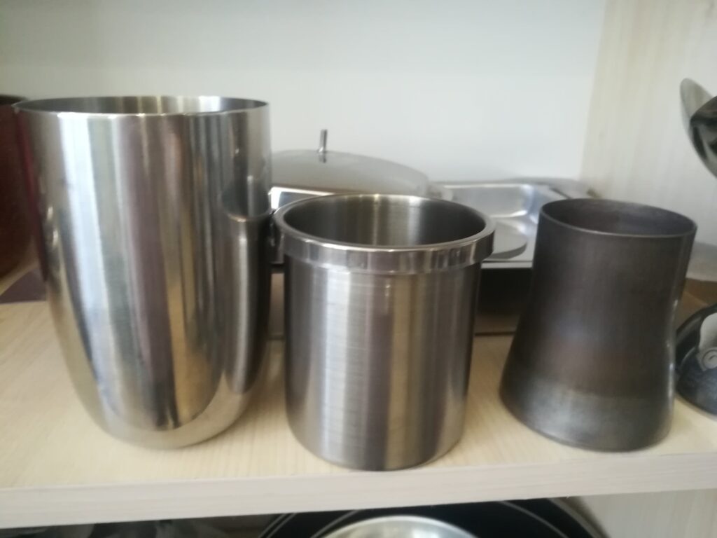
CNC metal spinning machines designed for filtration housings serve a specialized and growing sector that includes applications in air, oil, hydraulic, water, and industrial gas filtration systems. These machines are tailored for cylindrical, conical, and multi-stepped housings made from materials like stainless steel, aluminum, titanium, or coated carbon steels. The emphasis is on precision, surface quality, and structural integrity, as many filtration housings must meet high-pressure resistance and sealing standards.
These CNC systems are typically flatbed or vertical in layout, depending on the housing size and complexity. A flatbed CNC configuration is ideal for long and tubular filter bodies, especially where multiple diameters or wall transitions are needed along the length of the housing. Vertical designs are used for shorter, bell-shaped, or canister-type filters.
The spinning head is equipped with servo-driven roller arms, offering programmable movement across multiple axes (typically X and Z, with optional Y/B axes for advanced profiles). These allow the formation of complex geometries such as inward necking, flaring, flanging, or stepped reductions, often required at the inlet/outlet sections of filtration housings. Some machines also integrate trimming knives and beading tools to form sealing lips or gasket retention rings, common in filter end caps.
For thin-walled or highly polished stainless steel housings, the machines feature low-inertia spindles and high-resolution encoders to prevent vibration and ensure smooth tool paths. When mirror-like finishes are required inside or outside the housing, roller polishing heads or integrated burnishing tools are deployed within the same CNC cycle.
Many models offer tool changers or hybrid forming stations, enabling operations like:
- Spinning followed by trimming
- Forming + hole punching for inlet/outlet ports
- Final curling or closure forming
Machines designed for pressure filter housings may include hot spinning capability, where localized heating via induction or gas torches softens the metal during forming. This is particularly important when shaping thicker duplex stainless steels or Inconel alloys used in high-pressure filtration environments such as petrochemical or aerospace systems.
CNC control systems offer parametric programming, enabling fast changeover between different housing sizes and designs. Operators can switch between recipes stored in the machine’s memory or upload CAD-generated paths from offline CAM software. Simulation features show predicted stress points and thinning areas, helping to validate production before the actual spin.
Many filtration housing machines are also designed with automated loading/unloading arms, tube feeders, and clamping devices that prevent axial shifting during spin, which is critical for maintaining uniform wall thickness.
In terms of size, these machines typically handle diameters from 60 mm to 450 mm, though custom solutions can go well beyond that. Lengths vary from shallow canister types (100–300 mm) to long filter bodies (up to 1500 mm or more). The final products are used in:
- Industrial hydraulic filters
- Compressed air system housings
- Oil and fuel filtration canisters
- Water treatment pressure vessels
- HVAC and HEPA filter body tubes
Ultimately, these CNC spinning systems enable single-setup forming, reducing welding steps, improving part strength (via grain elongation), and offering faster cycle times than conventional fabrication methods like deep drawing and welding, especially for medium-volume and custom-sized filtration housings.
CNC metal spinning machines for filtration housings are engineered to produce highly cylindrical or conical shapes used in pressurized or high-flow systems. These machines are especially optimized for forming housings that require tight dimensional tolerances, high surface integrity, and durable geometry, suitable for downstream sealing, welding, or threading. Typically using stainless steel, aluminum alloys, or coated low-carbon steel, the machines are designed to shape materials with varying ductility and hardness levels while maintaining concentricity and wall uniformity. Filtration housings often feature complex transitions in diameter, beaded edges for gasket retention, and integrated sealing flanges or reinforced rims, all of which are achievable in a single CNC spinning sequence. The roller systems are servo-actuated with programmable motion paths, capable of accurately reproducing contour geometries for a wide range of filter sizes, whether for compact cartridges or elongated cylindrical casings. The spinning cycle may include inward or outward flaring, necking, bulging, or radius transitions, especially in areas intended for pipe connections or coupling ports. Some models incorporate in-process trimming and cut-off tools, allowing finished ends to be processed immediately after forming. Others may include roller burnishing or controlled cooling steps to minimize springback and ensure dimensional retention. For applications requiring internal features such as threaded grooves, notching, or pressure test flanges, CNC machines can be equipped with auxiliary forming heads or indexed turret tools. Hot spinning capabilities may be integrated for tough alloys or thicker walls, where formability is limited at room temperature. The system controls are typically touchscreen-based with real-time load monitoring, thickness control predictions, and digital feedback loops to adjust roller speed and pressure based on live material response. Filtration housing spinning cells may be automated with feeding conveyors, robotic tube loaders, and discharge platforms, especially in continuous or high-volume environments. Parts produced on these machines serve critical industries including hydraulic systems, air and gas filtration, high-purity water systems, pharmaceutical fluid handling, fuel and lubricant filtration in automotive or aerospace, and municipal or industrial filtration units. Compared to deep drawing or welding-based fabrication, CNC metal spinning for housings offers superior grain flow, fewer welded seams, reduced tooling costs for short and medium production runs, and faster changeovers between housing sizes or variants.
These CNC metal spinning machines for filtration housings are also configured to support modular design adaptations, meaning tooling and spindle setups can be rapidly reconfigured for different product dimensions or filter types without major downtime. The spindle systems are generally driven by high-torque servo motors that can maintain constant rotational speed even under variable forming resistance—crucial for deep or multi-stage draws common in industrial-grade housings.
When producing housings that must withstand high internal pressures (such as those used in oil filtration or hydraulic circuits), the machines can execute multiple forming passes to gradually reduce wall thickness in controlled zones, enhancing mechanical strength without risking material rupture or thinning inconsistencies. Wall thickness control can be integrated via laser or ultrasonic measurement sensors mounted near the forming area, feeding back real-time data to ensure tolerances are maintained throughout the process.
Advanced filtration housing spinning machines also support simulation-based toolpath programming using CAD-CAM integration. This allows engineers to predefine shape profiles, simulate stress and flow patterns, and anticipate deformation behavior during spinning, especially for alloys like Inconel, Hastelloy, or duplex stainless steel used in corrosive environments.
Optional features may include:
- Pre-heating ovens or induction heaters for pre-softening workpieces.
- Water or air-cooled mandrels to manage heat during hot spinning cycles.
- Integrated marking systems (laser or punch-based) for serial numbering or traceability.
- Pressure-testing modules at the end of the spinning cycle for inline quality checks.
The machines also meet international standards for safety and reliability, with full guarding, interlocked access doors, and overload protection systems. CNC programs often store hundreds of part recipes, allowing quick switching between housing formats such as inline cylindrical filters, domed-end pressure vessels, or conical intake separators.
End users of this machinery range from OEM filtration system producers to subcontract manufacturers specializing in high-purity industrial applications. Whether used in water purification plants, oil & gas pipelines, food-grade filtration, or chemical handling systems, these machines provide a cost-effective and highly repeatable forming method with minimal material waste and excellent part-to-part consistency.
In addition to forming filtration housings with high structural integrity and dimensional accuracy, these CNC metal spinning machines are often equipped with automated part unloading systems—such as robotic arms or conveyor-based extraction units—to increase throughput in continuous production environments. These systems are particularly beneficial when producing large quantities of identical parts, such as industrial air filters or hydraulic canisters.
Another key advancement in these machines is the integration of closed-loop process control. This system uses real-time feedback from torque sensors, axial pressure sensors, and displacement transducers to dynamically adjust the forming force and roller path as the material deforms. This ensures uniform wall thickness and roundness, which are critical for pressure-tight filter housings that must pass rigorous burst or fatigue testing.
For manufacturers dealing with high-mix, low-volume production (e.g., custom filtration units or prototyping), the CNC systems are often equipped with quick-change tooling mechanisms. This allows operators to switch between different mandrels and roller profiles within minutes, minimizing machine idle time.
Additional optional features may include:
- Integrated deburring and edge-trimming stations, reducing post-processing needs.
- Beading and flange-forming modules, used to create seal-ready edges compatible with O-rings or gaskets.
- Automated lubrication systems, extending tool life during high-friction operations.
- Remote diagnostics and predictive maintenance modules, which alert operators of wear on rollers or mandrels before part quality is affected.
Some manufacturers further customize the machines with custom-tailored roller geometries designed specifically for complex shapes, such as filtration housings with external ribs, internal flow diverters, or compound curvature.
Industries that rely on these CNC spinning machines for filtration housings include:
- Power generation (gas turbines, steam condensate filters)
- Aerospace and defense (fuel and hydraulic filters)
- Food and beverage (sanitary filters and strainer housings)
- Pharmaceuticals (ultra-clean processing equipment)
- Petrochemical (high-pressure filtration skids)
Because the spinning process inherently improves grain flow alignment, the resulting parts often exhibit enhanced mechanical properties compared to those made by stamping or welding, especially in terms of fatigue resistance and pressure tolerance. This makes CNC spinning an ideal forming process for high-demand applications where reliability and safety are paramount.
CNC Metal Spinning Machine for Milk/Food Processing Tanks
CNC metal spinning machines for milk and food processing tanks are precision-engineered to fabricate hygienic, seamless, and high-strength vessels that meet stringent sanitary and regulatory standards such as 3-A Sanitary Standards, EHEDG, or FDA requirements. These tanks are typically made from austenitic stainless steels like AISI 304 or 316L, chosen for their corrosion resistance, ease of cleaning, and food safety compliance.
These CNC spinning machines are configured to produce a wide range of geometries used in food and dairy industries, including:
- Tank bottoms (dished ends, torispherical, or hemispherical)
- Domed or conical tops for mixing vessels
- Rounded corner sections for CIP-friendly interiors
Key capabilities and features of these systems include:
- Precision Roller Control with Multi-Axis Movement: Enables complex curvature forming without thinning the material excessively, essential for food-grade pressure tanks and jacketed vessels.
- High-Speed Spinning with Servo-Controlled Pressure Application: Ensures smooth, work-hardened surfaces without wrinkling or surface tearing, resulting in vessels with mirror-like finishes that prevent bacterial adhesion.
- Surface Finish Optimization: The machines can integrate in-situ polishing heads or fine-roller passes to reduce the need for post-polishing, achieving Ra values below 0.8 μm, compliant with hygienic surface criteria.
- Cleanable, Lubrication-Free Zones: To meet food safety demands, many components near the forming area are designed for dry operation or sealed to prevent lubricant contamination.
- Tooling Quick-Change Systems: Facilitates rapid switching between different tank geometries (e.g., from a milk silo bottom to a yogurt mixer dome), improving uptime in multi-product environments.
- Integration with Robotic Handling: For large tank components (up to 2,000 mm or more in diameter), robotic arms or gantry loaders manage the feeding, aligning, and unloading of heavy blanks.
- Thermally Assisted Spinning (Hot Spinning): In thicker materials (e.g., >4 mm), some models incorporate localized induction or resistance heating during spinning to reduce forming loads and extend tool life, without compromising food safety.
Typical applications of these CNC metal spinning machines in milk and food processing include:
- Milk storage silos and tank ends
- Cream separator bowl shells
- Conical fermenters and yogurt mixers
- Hygienic pressure vessels for pasteurization
- Double-jacketed cooking and mixing tanks
By using CNC metal spinning instead of conventional welding and pressing, manufacturers benefit from reduced weld seams, enhanced mechanical strength, and improved cleaning characteristics, which are essential in food-grade environments. These machines often become part of integrated tank production cells, working alongside CNC trimming, orbital welding, and polishing units to produce fully finished vessels ready for sanitary inspection and deployment.
These CNC metal spinning machines for milk and food processing tanks operate with extreme precision to meet hygiene-critical requirements. The machine architecture is typically based on heavy-duty cast-iron or welded steel beds that minimize vibration and ensure stable operation even during high-pressure spinning. Their drives are usually servo-electric or servo-hydraulic, delivering exact control over speed and torque, essential for achieving accurate thickness distribution across the formed surfaces. For food-grade tank manufacturing, a major concern is ensuring the interior surface is smooth, crevice-free, and without micro-deformations that could harbor bacteria. CNC spinning makes this possible by eliminating the welds, folds, and rough areas that are common in traditional pressing or segment welding techniques. The rollers used in these systems are manufactured from hardened tool steel or tungsten carbide, and their profiles are optimized specifically for common food vessel radii, such as the radiused transitions at the bottom or top of milk tanks. Some machines can accommodate spinning of large-diameter blanks, up to 2.5 meters, with blank thicknesses up to 6 mm in 304 or 316L stainless steel, which is critical for pressure-rated processing tanks. A further enhancement is servo-controlled tailstocks that apply axial force to keep the blank firmly seated against the mandrel, preventing slippage, which is essential for achieving uniform shape and surface finish. Another aspect is the use of integrated thermal control where the blank can be preheated, either in a chamber or directly with controlled heaters, before spinning. This reduces work-hardening in the stainless steel, minimizes springback, and allows deeper draws without cracking. These machines often work in conjunction with inline brushing or Scotch-Brite buffing units that can polish the internal surface to pharmaceutical-grade finishes. To reduce operator intervention and contamination risk, many models offer fully enclosed working areas with transparent doors and HEPA-filtered airflow, keeping both the machine and the formed part free from dust and contaminants. For serial production of food-grade tanks, automated part loading systems—such as suction lifters or magnetic blank feeders—are often integrated to handle the large sheet metal discs. The machine’s CNC controller may support recipe storage for common tank geometries and adaptive feedback loops where in-process measurements (using laser profilometers or tactile gauges) adjust roller positions automatically to maintain tolerance even with variations in blank thickness or hardness. The ability to create seamless, polished tank ends, cones, and domes in a repeatable and sanitary manner makes these machines a key element in modern dairy and food processing equipment manufacturing lines.
Beyond the forming process itself, CNC metal spinning machines for milk and food processing tanks are often integrated into fully automated manufacturing cells that encompass material handling, in-process inspection, and finishing operations. Automated loading systems utilize vacuum suction cups or magnetic grippers to precisely position large stainless steel blanks onto the spindle, minimizing manual handling and contamination risk. Once spinning is complete, robotic arms or conveyor systems transfer the formed parts to trimming stations where CNC-controlled knives remove excess flange material or prepare the edges for welding or assembly. Some production lines incorporate in-line surface finishing units, such as automated polishing brushes or electropolishing baths, ensuring that the interior surfaces meet the stringent hygienic standards required by food safety regulations.
To guarantee dimensional accuracy and structural integrity, many of these machines feature integrated non-contact laser scanners or tactile probes that measure wall thickness, diameter, and surface finish during and after the spinning process. This real-time feedback enables adaptive control of roller pressure and feed rates, maintaining consistent quality even when dealing with material variances like thickness tolerances or batch-to-batch differences in stainless steel.
Advanced CNC controllers support recipe-based programming, allowing operators to store multiple tank designs with all process parameters—including roller paths, speeds, pressures, and temperature profiles—simplifying changeovers between different product models. CAD/CAM integration facilitates the import of 3D tank designs directly into the machine control, enabling simulation of the spinning process and verification of toolpaths prior to production. This virtual validation reduces trial-and-error on the shop floor and shortens setup times.
Many manufacturers also incorporate thermal management systems into their CNC spinning machines to accommodate the forming of thicker or more challenging stainless steels. Pre-heating the blanks via induction or resistance heaters softens the material locally, reducing the forming forces and extending tool life. Meanwhile, water-cooled mandrels and rollers prevent overheating, ensuring consistent surface finishes and dimensional stability.
Safety is a key consideration in these machines, with fully enclosed work zones equipped with interlocked doors, emergency stop buttons, and light curtains to protect operators while allowing visibility of the process. The enclosures often include ventilation and filtration systems to handle any airborne particles or lubricant mist generated during spinning.
Industries served by CNC metal spinning machines for milk and food processing tanks include dairy production, beverage manufacturing, pharmaceutical processing, and specialty food equipment fabrication. These machines enable manufacturers to produce seamless, corrosion-resistant tanks with superior mechanical strength and hygienic surfaces, reducing the risk of contamination and simplifying cleaning and maintenance. Compared to traditional fabrication methods like welding or deep drawing, CNC spinning offers greater flexibility, reduced lead times, and lower tooling costs—especially beneficial for small to medium batch sizes and custom tank designs.
In essence, CNC metal spinning machines for milk and food processing tanks represent a synthesis of precision engineering, automation, and food-grade manufacturing standards, delivering products that uphold safety, quality, and efficiency demands of modern food processing industries.
CNC Metal Spinning Machine for Fire Extinguisher Bodies
CNC metal spinning machines for fire extinguisher bodies are specialized systems designed to manufacture the cylindrical shells and domed ends of fire extinguishers with high precision, structural integrity, and consistent wall thickness. These machines handle materials such as cold-rolled steel, aluminum alloys, and sometimes stainless steel, selected for their strength, corrosion resistance, and compatibility with fire suppression chemicals.
The manufacturing process for fire extinguisher bodies requires exacting tolerances to ensure the cylinders can safely withstand high internal pressures, often exceeding 15–30 MPa, depending on the extinguisher rating. CNC spinning machines achieve this by carefully controlling the wall thickness reduction and material flow during forming, avoiding weak points that could lead to failure.
These machines are typically configured with:
- Heavy-duty, rigid frames to absorb the high forming forces necessary for thick-walled tubes.
- High-torque servo-driven spindles capable of spinning large-diameter blanks at controlled speeds.
- Multi-axis roller arms that can perform necking, beading, flanging, and tapering operations with precise control.
- Hydraulically actuated tailstocks to firmly hold the workpiece, ensuring concentricity and alignment throughout the process.
The CNC control system enables multi-pass forming programs that gradually reduce diameter or thickness, preventing cracks or wrinkles. Integrated sensors, such as laser micrometers or ultrasonic thickness gauges, provide real-time feedback to maintain uniformity and detect defects during forming. This data feeds into closed-loop control systems that adjust roller pressure and feed rates dynamically.
For fire extinguisher domed ends and closures, the machines can perform complex spinning sequences that create hemispherical or torispherical shapes essential for pressure containment. Some setups include integrated trimming and beading tools that form the critical sealing edges and attachment points in the same production cycle, reducing secondary operations.
Automated loading and unloading systems improve throughput and safety, minimizing manual handling of heavy blanks. In high-volume production, these machines can be linked to robotic cell systems, incorporating pre-forming, spinning, inspection, and finishing stations.
Quality standards for fire extinguisher bodies are stringent, requiring compliance with ISO 9001, EN3, DOT, or other regional certifications. CNC metal spinning provides the repeatability and precision needed to meet these standards, ensuring every cylinder can pass hydrostatic and burst testing.
In summary, CNC metal spinning machines for fire extinguisher bodies combine robust mechanical design, advanced CNC controls, and integrated measurement systems to produce safe, durable, and precisely formed pressure vessels critical for life safety equipment.
CNC metal spinning machines for fire extinguisher bodies are engineered to deliver exceptional consistency and reliability, vital for pressure vessels where failure is not an option. The forming process starts with flat blanks or tubes which are spun at high speeds while rollers gradually shape the metal into seamless cylindrical bodies and domed ends. These machines often feature servo-controlled multi-axis roller arms that precisely manipulate the metal flow to avoid thinning or stress concentrations that could compromise safety. The tailstock and mandrel systems are designed to securely hold the part under high forming forces, ensuring perfect concentricity and dimensional accuracy.
Real-time monitoring through laser micrometers and ultrasonic thickness gauges continuously measures wall thickness and diameter, feeding data back to the CNC controller for closed-loop adjustments to roller pressure and speed. This adaptive control reduces scrap rates and maintains tight tolerances throughout production runs. For complex features like necked sections, flanges for valve attachments, or rolled rims, integrated tool heads perform multi-functional forming within the same cycle, streamlining manufacturing and reducing secondary machining. Machines dedicated to fire extinguisher production often incorporate automated loading systems using robotic arms or conveyors to handle heavy metal blanks safely and efficiently, enhancing throughput and operator safety. The entire spinning cell can be linked with post-forming processes such as trimming, heat treatment, and pressure testing to create a seamless production line.
Materials commonly used include mild steel for standard extinguishers and aluminum alloys for lightweight or specialty applications, with machine parameters optimized for each to ensure ductility and formability without cracks. Compliance with industry standards such as EN3 in Europe, DOT in the USA, and ISO 9001 quality management systems requires consistent process validation and traceability, which these CNC systems facilitate through integrated data logging and part serialization.
The use of CNC metal spinning over traditional welding or stamping methods offers superior mechanical properties by preserving metal grain structure and minimizing weld-related weaknesses, critical for the high-pressure demands of fire extinguisher bodies. In essence, these CNC machines provide a robust, flexible, and highly automated solution for manufacturing safe, reliable, and cost-effective fire extinguisher cylinders that meet rigorous safety and quality standards worldwide.
Beyond forming the main body and domed ends, CNC metal spinning machines for fire extinguisher production often include specialized stations for creating critical features such as necking for valve mounting, beading for structural reinforcement, and flange rolling for attachment points. These features require precise control over roller position and pressure to ensure uniformity and strength, as they are subjected to high mechanical stresses during operation. Some advanced machines offer dual-head or multi-roller configurations that allow simultaneous spinning and feature forming, greatly improving cycle times and reducing labor.
The machines are designed to handle a variety of materials, including high-strength low-alloy steels and aluminum-magnesium alloys, which may require preheating or controlled forming speeds to prevent cracking. Thermal management systems, including induction heaters or infrared preheating, can be integrated to maintain optimal material temperatures during spinning. Additionally, cooled mandrels and rollers help manage heat buildup, preserving tool life and part quality.
Incorporation of in-process non-destructive testing equipment, such as ultrasonic flaw detectors, ensures early detection of defects like cracks, inclusions, or thinning, enabling immediate rejection or process correction without halting production. The CNC control systems store extensive process parameters and can automatically adjust forming strategies based on sensor feedback, promoting consistent quality across batches.
Automated part handling is critical for safety and efficiency, especially given the weight and size of blanks used for extinguisher bodies. Robotic loading systems equipped with vacuum or magnetic grippers precisely position blanks on the spindle, while finished parts are transferred to subsequent inspection or finishing stations. This automation minimizes operator exposure to heavy lifting and reduces cycle times.
Final finishing steps may include CNC trimming of excess flange material, edge rounding to remove sharp burrs, and surface treatments like passivation or powder coating, which can be integrated into the overall production line. Many manufacturers also employ digital tracking systems linking each spun component to its production data, ensuring traceability and compliance with safety certifications.
By combining precise mechanical design, advanced CNC controls, integrated sensing, and automation, CNC metal spinning machines for fire extinguisher bodies enable manufacturers to produce reliable, high-quality pressure vessels that meet strict international standards while optimizing production efficiency and reducing waste.
Additionally, CNC metal spinning machines for fire extinguisher bodies often feature modular tooling systems that allow quick changeovers between different extinguisher sizes and designs. This flexibility is essential for manufacturers producing a variety of extinguisher types, from small portable units to large wheeled models, without incurring extensive downtime or tooling costs. The modular tooling typically includes interchangeable mandrels, roller heads, and tailstock fixtures tailored to specific diameters, lengths, and contour profiles.
Advanced CNC controllers offer multi-stage process programming capabilities, enabling complex forming sequences that gradually shape the blank through multiple passes. This stepwise approach minimizes material stress and enhances dimensional accuracy, particularly important for maintaining uniform wall thickness in thick or high-strength steel blanks. Real-time process data collection and analysis help operators identify trends or deviations, facilitating proactive maintenance and quality assurance.
Environmental and safety considerations are also integrated into machine design. Enclosed work areas with dust extraction and filtration systems protect operators from airborne particles generated during spinning, while coolant and lubricant delivery systems are optimized to reduce contamination risks, especially critical when producing parts destined for fire safety applications. Noise reduction features further improve the workplace environment.
The seamless, spin-formed fire extinguisher bodies produced by these CNC machines exhibit superior mechanical properties compared to welded or stamped counterparts. Grain flow alignment along the cylindrical axis improves fatigue resistance and pressure tolerance, which is vital for extinguishers subjected to repeated handling, transport, and pressurization cycles. The absence of weld seams also eliminates common failure points, enhancing overall reliability.
In high-volume manufacturing settings, these machines can be integrated into fully automated production lines with synchronized material handling, quality inspection, and finishing stations. This level of automation reduces human error, increases throughput, and ensures consistent product quality, meeting the rigorous demands of global fire safety regulations.
In summary, CNC metal spinning machines dedicated to fire extinguisher body production combine precision engineering, adaptive control, and automation to deliver safe, durable, and cost-effective pressure vessels. Their ability to produce complex, seamless components efficiently makes them an indispensable technology in the fire protection equipment industry.
CNC Metal Spinning Machine for Musical Instrument Bells
CNC metal spinning machines for musical instrument bells are precision-engineered to produce the complex, curved shapes characteristic of brass, copper, or bronze bells used in instruments such as trumpets, trombones, saxophones, French horns, and tubas. These bells require exceptional surface finish quality, consistent thickness, and accurate contour profiles to ensure optimal acoustic performance and tonal quality.
The machines typically handle thin-gauge metal blanks, often in brass or specialized copper alloys, spinning them over precision mandrels to gradually form the bell flare and bell throat. The CNC control allows multi-axis movement of the roller tools, enabling the creation of intricate curves and smooth transitions that define the bell’s acoustic properties.
High-resolution servo motors control roller pressure and feed rates to prevent material thinning or wrinkling, which could adversely affect sound resonance or structural integrity. The spinning process also preserves the metal’s grain structure, enhancing vibration response and tonal clarity. Many CNC spinning machines for musical bells integrate polishing and burnishing stations, providing near-final surface finishes directly on the machine, reducing manual labor and ensuring uniformity across production runs.
These machines support rapid tooling changes and program storage to accommodate various bell sizes and shapes, from small trumpet bells to large tuba bells. Integration with CAD-CAM software enables precise design replication and process simulation, essential for custom or limited-run instruments.
Operators benefit from automated blank feeding and unloading systems, minimizing handling of delicate materials and maintaining high cleanliness standards. Some advanced systems incorporate in-process thickness measurement and surface inspection to ensure every bell meets strict quality criteria for professional-grade musical instruments.
Overall, CNC metal spinning machines for musical instrument bells combine precise forming, high surface quality, and repeatability, enabling manufacturers to produce acoustically optimized bells that meet the demanding standards of musicians and instrument makers worldwide.
CNC metal spinning machines for musical instrument bells excel at delivering the precise contours and smooth finishes that directly influence sound quality. The forming process involves gradually shaping thin metal blanks into flared bell profiles while maintaining uniform wall thickness to avoid dead spots or tonal inconsistencies. These machines are equipped with highly sensitive servo-driven rollers that apply controlled pressure, ensuring the metal flows evenly without wrinkling or cracking, which is especially important for delicate brass and copper alloys commonly used in instrument making.
The multi-axis CNC control allows for intricate shaping, including gradual tapers and compound curves that define the bell’s acoustic resonance. Many machines integrate polishing or burnishing tools within the same production cycle, producing mirror-like surface finishes that enhance both appearance and sound reflection. Automated loading and unloading systems handle fragile blanks with care, reducing the risk of damage and improving production efficiency. The CNC controllers store multiple programs for different bell designs, allowing quick changeovers between models like trumpet, trombone, or French horn bells. CAD/CAM integration enables manufacturers to import complex bell geometries and simulate spinning processes beforehand, optimizing toolpaths and minimizing trial runs.
Real-time thickness measurement and feedback loops help maintain tight tolerances essential for consistent acoustic performance across batches. These machines also facilitate customization for boutique or artist-specific bells, supporting small batch production without sacrificing precision. Compared to traditional manual spinning or stamping, CNC metal spinning offers superior repeatability, surface quality, and mechanical properties by preserving grain structure and reducing residual stresses. The result is a finely crafted bell with enhanced tonal richness, projection, and durability, meeting the high standards of professional musicians and instrument manufacturers worldwide.
In addition to shaping and finishing, CNC metal spinning machines for musical instrument bells often incorporate features to support complex design elements such as flared edges, rolled rims, and decorative beadings that contribute both to aesthetics and acoustic tuning. The machines can perform multi-stage forming sequences, gradually refining the bell’s flare angle and thickness distribution to achieve the precise sound characteristics desired by instrument designers. For premium instruments, where every subtle variation affects tone, the ability to program and replicate exact toolpaths ensures consistent production of bells with uniform acoustic properties.
Advanced systems may include in-process quality inspection tools such as laser scanners or contact probes to monitor surface smoothness, thickness uniformity, and dimensional accuracy. This feedback allows for immediate adjustments during spinning, reducing scrap rates and ensuring that each bell conforms tightly to the required specifications. Some manufacturers integrate post-spinning polishing and buffing stations directly adjacent to the CNC spinning machine, streamlining workflow and maintaining a controlled environment that prevents contamination or surface defects.
The materials processed typically include high-quality brass alloys like yellow brass (CuZn37), red brass, and sometimes nickel silver, each chosen for specific tonal qualities. These alloys require careful handling during spinning to avoid work hardening or cracking, making the precise control of speed, pressure, and temperature critical. Some CNC machines support mild thermal assistance, such as localized heating, to improve formability without affecting metallurgical properties adversely.
Automation extends to material handling as well, with robotic arms or vacuum-based systems loading delicate blanks and unloading finished bells, minimizing manual contact and reducing the potential for damage or fingerprints that would require additional cleaning. This automation also increases production rates, supporting both small-scale artisan workshops and large manufacturers alike.
Ultimately, CNC metal spinning machines empower musical instrument makers to produce bells that are acoustically superior, visually flawless, and mechanically reliable. The combination of advanced control, automation, and integrated finishing capabilities allows manufacturers to meet the exacting demands of professional musicians while maintaining cost efficiency and production flexibility.
Further enhancing the production capabilities, CNC metal spinning machines for musical instrument bells can be integrated with advanced software that simulates the acoustic impact of design changes in real time. This allows instrument makers to iterate on bell shapes digitally before committing to physical prototypes, drastically reducing development time and material waste. By adjusting parameters such as flare angle, wall thickness, and curvature in the software, designers can predict sound projection, timbre, and resonance, ensuring that the spun bells meet specific tonal goals.
The machines also support hybrid manufacturing processes, where spinning is combined with other metalworking techniques such as CNC milling or laser engraving. This enables the incorporation of intricate engravings, logos, or structural reinforcements directly onto the bell surface without manual intervention. Some manufacturers utilize multi-axis CNC spinning centers that can simultaneously perform forming, trimming, and surface finishing operations, streamlining production and ensuring repeatability.
Material traceability is often embedded within these modern CNC systems, linking each spun bell to batch data, alloy certifications, and process parameters. This traceability is especially important for high-end instruments where provenance and quality assurance are critical selling points. Additionally, many machines include environmentally conscious features like coolant recycling, low-energy servo motors, and optimized cycle times to reduce their ecological footprint.
The ability to produce custom bells with consistent quality makes CNC metal spinning machines invaluable to boutique instrument makers who cater to niche markets or artist endorsements. Smaller production runs can be economically viable due to reduced setup times and flexible programming. Moreover, the machines’ fine control over material flow preserves the integrity of sound-enhancing grain structures within the metal, something traditional manufacturing methods struggle to achieve consistently.
In conclusion, CNC metal spinning machines tailored for musical instrument bell production combine precision engineering, sophisticated automation, and integrated finishing to produce bells with superior acoustic qualities, aesthetic beauty, and manufacturing efficiency. They have become essential tools for modern instrument makers seeking to blend traditional craftsmanship with cutting-edge technology.
CNC Metal Spinning Machine for Architectural Elements
CNC metal spinning machines for architectural elements are specialized systems designed to produce intricately shaped, high-quality metal components commonly used in building and design projects. These elements include decorative domes, finials, columns, balustrades, light fixtures, signage, and custom metal cladding panels. The machines are capable of forming a wide variety of metals such as aluminum, copper, brass, stainless steel, and even some mild steels, depending on the desired aesthetic and structural requirements.
The primary advantage of CNC metal spinning in architectural fabrication is the ability to create seamless, complex curved shapes with smooth surfaces and consistent wall thickness, which are difficult or costly to achieve through traditional stamping, welding, or casting methods. These machines use computer-controlled rollers and mandrels to spin metal blanks at precise speeds while shaping them against custom tooling, allowing for exact replication of design geometries with minimal material waste.
Architectural CNC spinning machines often feature multi-axis control, enabling the formation of conical, domed, flared, or tapered shapes with tight tolerances essential for fitting and assembly in construction. They also support variable wall thickness control, allowing designers to optimize structural strength without unnecessary weight. This is particularly important in façade elements and roofing components where load-bearing capacity and wind resistance are critical.
Many CNC spinning machines for architecture incorporate integrated surface finishing options, such as in-line polishing or texturing, to meet aesthetic standards required for visible exterior or interior features. Advanced models may also be equipped with automated trimming, beading, or flange rolling stations to prepare edges for mounting or joining without additional manual labor.
Material handling systems, including robotic loaders and unloaders, enhance efficiency in high-volume production or when working with large-diameter blanks often required for domes or large light fixtures. The CNC controllers allow for recipe storage and quick changeovers between different architectural designs, supporting customization and short production runs typical in architectural projects.
The use of CNC metal spinning for architectural elements reduces production time, improves quality, and allows greater design flexibility compared to conventional fabrication techniques. It enables architects and fabricators to realize complex, custom metal components that combine functionality, durability, and visual appeal, elevating the overall architectural experience.
CNC metal spinning machines for architectural elements enable the creation of seamless, curved metal parts that are both structurally sound and visually striking. The spinning process shapes flat metal blanks into domes, cones, cylinders, or flared forms by rotating the workpiece at high speeds while rollers apply controlled pressure. This technique allows for uniform wall thickness and smooth surface finishes, critical for weather-resistant building components like roofing domes, decorative cornices, and ornate finials. The precision of CNC control ensures that complex curves and profiles are replicated consistently, which is essential when multiple identical parts are required for large-scale architectural projects or modular installations.
These machines typically accommodate a wide range of materials, from lightweight aluminum alloys that resist corrosion and reduce structural loads, to copper and brass that develop attractive patinas over time, adding aesthetic value. Stainless steel options are also common for modern or industrial designs demanding durability and minimal maintenance. CNC metal spinning allows fabricators to customize thickness and shape precisely, optimizing components to meet both engineering requirements and artistic vision.
In addition to forming, many CNC spinning systems integrate secondary operations such as trimming, flanging, beading, or embossing, which prepare parts for installation or enhance decorative features without needing separate manual processes. Automated tool changers and programmable roller paths facilitate quick transitions between different architectural designs, making the machines suitable for bespoke pieces and small batch runs as well as larger production volumes.
Material handling is streamlined through robotic arms, conveyors, or suction lifters, especially important when working with large or heavy metal blanks. These systems improve operator safety and increase throughput, enabling fabricators to meet tight project deadlines. CNC controllers often feature CAD/CAM integration, allowing architectural designers to import digital models directly into the spinning machine’s control software. This capability accelerates the prototyping phase, reduces errors, and ensures the final product matches the intended design precisely.
Moreover, the spinning process naturally enhances the metal’s mechanical properties by aligning grain flow along the contours, resulting in parts that are both lightweight and strong—ideal for exposed architectural elements that must withstand wind loads, thermal expansion, and environmental wear. The smooth, seamless nature of spun components also minimizes points where moisture can penetrate, contributing to long-term durability.
Overall, CNC metal spinning machines provide architects and metal fabricators with a versatile, efficient, and high-quality method for producing complex, elegant metal elements that elevate the aesthetic and functional quality of buildings and structures. By combining advanced automation, precision engineering, and flexible design capabilities, these machines support the evolving demands of contemporary architecture and custom metalwork.
Beyond basic forming and finishing, CNC metal spinning machines for architectural elements increasingly incorporate advanced technologies that expand creative possibilities and production efficiency. For example, some systems offer multi-axis capabilities that allow simultaneous shaping and texturing, enabling architects and designers to add intricate surface patterns or embossed details directly during the spinning process. This eliminates the need for costly post-forming embellishments and reduces overall lead times.
Integration with digital design workflows through CAD/CAM software allows rapid iteration of complex geometries, enabling fabrication of unique, site-specific components such as large-scale domes or custom light fixtures that conform precisely to architectural plans. Virtual simulations predict material behavior during spinning, helping optimize toolpaths and minimize defects before production starts. This capability is especially valuable when working with challenging materials like high-strength alloys or composites used in cutting-edge architectural applications.
CNC metal spinning machines for architecture also increasingly feature modular tooling systems that simplify changeovers between different shapes and sizes, supporting both one-off custom projects and higher-volume manufacturing without extensive downtime. Automated loading and unloading systems, including robotic arms with vacuum or magnetic grippers, streamline handling of large or heavy blanks, improving safety and throughput while reducing labor costs.
Thermal control options such as localized heating or cooling are sometimes integrated to assist in forming difficult materials or achieving specific surface finishes, maintaining metal integrity and appearance. Additionally, enclosed work zones with dust extraction and filtration protect operators and ensure clean processing environments, which is especially important when working with decorative metals prone to oxidation or contamination.
Environmental sustainability is gaining emphasis in architectural fabrication, and modern CNC spinning machines contribute by optimizing material usage through precise forming, reducing scrap, and enabling recycling of offcuts. Energy-efficient servo motors and smart cycle management further reduce power consumption during production.
Overall, CNC metal spinning machines empower architects, fabricators, and artisans to realize complex, durable, and visually stunning metal architectural elements with unprecedented precision, flexibility, and efficiency. They bridge traditional craftsmanship and modern technology, supporting innovative design while meeting the practical demands of construction, installation, and long-term performance.
For high-profile architectural applications such as facades, domes, columns, cladding panels, balustrades, or decorative installations in public buildings, CNC metal spinning machines provide unmatched control over material flow and wall thickness distribution. This enables the production of seamless, symmetrical elements with consistent visual and structural quality—ideal for exposed installations where aesthetic and strength are equally critical.
Manufacturers often use metals like stainless steel, aluminum, copper, brass, or even titanium for these projects, chosen for their corrosion resistance, sheen, and longevity. CNC spinning allows these materials to be formed into both classical curves and ultra-modern geometric shapes, supporting a wide range of design languages from neoclassical to parametric.
To facilitate integration with large-scale architectural builds, some CNC spinning systems come with expandable bed lengths or rotating chucks that can accommodate oversized blanks, sometimes exceeding 2 or even 3 meters in diameter. These features are critical for forming large hemispheres, bell shapes, spires, or other dramatic architectural volumes from a single piece of metal—eliminating weld seams, which enhances both durability and aesthetics.
Advanced HMI (Human Machine Interface) systems allow architects and metal artisans to fine-tune forming parameters in real-time, whether adjusting pressure zones, roller speed, forming sequence, or rotation rate. For heritage or restoration work, CNC spinning machines can replicate historic metalwork with modern efficiency and consistency. Digitized scans of legacy pieces can be imported into the machine’s software to reproduce the exact curves and dimensions of traditional metal forms with precision.
In some cases, CNC spinning is combined with post-processes like anodizing, powder coating, or patination directly within integrated production lines. This results in end-to-end workflows where a raw blank is transformed into a ready-to-install, fully finished architectural piece without intermediate transfers—saving time and reducing handling risks.
Architectural firms and fabricators now often rely on spinning machines as part of a vertically integrated system that includes 3D modeling, finite element analysis (FEA), CNC spinning, robotic trimming, and automated assembly. This digital ecosystem ensures that every piece—whether a single public sculpture or a thousand facade components—meets the same standards for form, fit, and finish.
In summary, CNC metal spinning machines tailored for architectural element production offer not just mechanical forming capabilities, but also artistic flexibility and industrial reliability—bridging the gap between creative vision and structural execution in modern architecture.
CNC Metal Spinning Machine for Funnels and Hoppers
CNC metal spinning machines designed for the production of funnels and hoppers are essential for industries requiring efficient material handling, such as agriculture, food processing, pharmaceuticals, chemicals, mining, and bulk solids transport. These machines enable seamless, conical or bell-shaped components to be formed from flat or preformed blanks with high dimensional accuracy and minimal material waste.
Funnels and hoppers often require smooth, uninterrupted surfaces to ensure efficient flow of materials—whether powders, grains, liquids, or pellets. CNC spinning offers this advantage by producing seamless forms that do not require welding or joining, which reduces contamination risks and improves structural integrity, particularly for hygienic applications such as dairy, food, or pharmaceutical production.
The forming process begins by clamping a circular blank onto a rotating mandrel, typically shaped to match the internal geometry of the desired funnel or hopper. A programmable roller then presses the metal over the mandrel with precise force and path control, gradually shaping it into the target form. The machine can accommodate conical, stepped, parabolic, or eccentric funnel shapes, allowing for both standard and custom product geometries.
Materials commonly spun for these applications include stainless steel (especially grades like 304 and 316), aluminum, mild steel, and, in certain cases, high-nickel or corrosion-resistant alloys. CNC control ensures that critical dimensions—such as outlet diameter, wall thickness, and cone angle—remain consistent throughout batches, which is vital for ensuring compatibility with piping systems, valves, or feeders.
Advanced CNC spinning machines used in funnel and hopper production often feature:
- Servo-driven rollers for better surface control and repeatability.
- Automatic toolpath optimization to prevent wrinkling or tearing in the forming zone.
- Variable wall thickness adjustment to produce heavy-duty inlet rims and lightweight outlet zones.
- Gap and pressure control systems to manage material strain rates for thick or work-hardened metals.
- In-machine trimming to create sharp, burr-free outlet lips or mounting flanges.
For large hoppers, extended-bed or vertical CNC spinning machines are used. These can handle blanks up to several meters in diameter and support forming of deep-draw geometries in a single setup. Some are integrated into robotic cells with automatic blank feeding and unloading systems, enabling high-volume or lights-out production.
CNC-spun funnels and hoppers are commonly used in:
- Silo inlets/outlets and agricultural augers
- Pharmaceutical powder dosing systems
- Industrial mixers and feeders
- Food-grade ingredient hoppers
- Dust collection and air handling funnels
Ultimately, CNC spinning offers a cost-effective, high-speed, and highly flexible solution for funnel and hopper production, delivering the combination of hygiene, flow efficiency, and structural performance required across demanding industrial sectors.
CNC metal spinning machines used for producing funnels and hoppers provide precise, seamless shaping of conical or flared parts essential in many bulk material handling systems. These machines rotate a flat metal blank against a mandrel that mirrors the inner profile of the desired funnel or hopper while a roller tool, under CNC control, gradually presses and flows the material into shape. The resulting part has no welded seams, improving structural strength, sanitation, and visual appearance.
CNC control allows for repeatable, complex geometries including deep draws, narrow outlets, steep angles, and compound curves with tight dimensional tolerances. This is especially important in industries like agriculture, food processing, chemical dosing, and pneumatic conveying, where smooth transitions are needed to prevent material sticking, bridging, or contamination. Material thickness can be maintained or reduced during spinning depending on the application—thicker flanges can be retained at the entry edge for mounting strength, while lighter walls can be formed near the discharge end to reduce weight. Machines can work with various metals including stainless steel, aluminum, and carbon steel, often in large diameters or deep profiles.
CNC programming ensures that the roller path adapts to different cone angles, reducing tool wear and material stress. Some systems feature integrated trimming to remove excess metal and finish the lip of the hopper, and pressure control feedback prevents over-thinning or cracking in critical zones. For higher output, automated systems include robotic loading/unloading, blank centering, and spindle tooling changes. These machines are ideal for hopper outlets in silos, feeders in pharmaceutical or food lines, filling stations, mixers, and other systems that require clean, strong, geometrically accurate transitions. Their ability to form long, symmetrical tapers in one pass makes CNC metal spinning machines a preferred solution over welded or pressed alternatives when quality and consistency are vital.
Advanced CNC metal spinning machines for funnels and hoppers can be configured with servo-driven tailstocks, programmable pressure settings, and real-time monitoring to ensure forming consistency even when working with variable sheet thicknesses or multi-layered metal blanks. These features are especially critical for fabricating hoppers subjected to pressure, vacuum, or high vibration environments—such as those used in vacuum conveying or vibratory feeders.
The flexibility of CNC controls allows the operator to switch between different funnel or hopper profiles without changing mechanical cams or gears; only a change in the program is needed. This significantly reduces downtime and setup costs for manufacturers that produce a range of funnel sizes or taper angles. For example, food packaging facilities that handle different granular or powdered products can rapidly switch hopper geometries to suit each line.
Many of these CNC spinning systems can also accommodate asymmetrical flanges, reinforcing collars, or stiffening ribs as part of the same process. This is done by modifying the tool path and pressure profile at strategic points, offering stronger end products without requiring welding or secondary forming steps. Furthermore, integrated trimming and beading heads can shape the funnel rim or hopper lip immediately after the spinning operation, ensuring precise edge finishes that match assembly requirements (like bolt-on flanges or clamp-fit systems).
In industries like agriculture or chemicals, where hoppers are exposed to abrasive materials, high-speed CNC spinning can be combined with post-process hardening treatments or in-line polishing systems. Some machines even support heating during spinning for heavy-duty stainless steel or alloy materials, which improves formability and reduces tool wear.
Lastly, modern CNC spinning machines often include simulation software and digital twin capability, enabling offline programming, cycle time optimization, and virtual defect prediction. This reduces material waste and allows prototypes to be perfected digitally before actual production, making it an essential solution for modern, just-in-time manufacturing environments.
These CNC metal spinning machines can also be equipped with multi-axis control systems, which allow for complex geometries in hoppers and funnels—such as eccentric or offset cone shapes that are not symmetrical along the central axis. This is especially useful for equipment where space constraints or fluid dynamics require unusual taper profiles, like in high-efficiency cyclone separators or customized discharge chutes.
Material flexibility is another key advantage. These machines can handle not only traditional stainless steel or aluminum, but also more challenging materials like Inconel, titanium, or duplex steels, which are common in corrosive or high-temperature processing environments. The CNC parameters—such as feed rate, pressure application, and tool dwell time—can be finely tuned per material type, enabling repeatable, crack-free forming.
For high-volume production, especially in sectors like paint manufacturing or bulk food handling, these CNC systems can be integrated into fully automated cells with robotic part loading and unloading. Such automation eliminates manual handling of heavy blanks, improves safety, and maintains uniform cycle times. Parts are often barcode-scanned or RFID-tagged before forming, triggering the correct CNC program automatically—ideal for job shops or contract manufacturers serving multiple customers.
Noise and vibration control are also taken into account in these machines. Damping systems and precision-ground linear guides reduce chatter and resonance during high-speed spinning, ensuring a smoother finish and less tool wear. Some units even monitor machine acoustics to detect early signs of tool failure or material inconsistency.
Energy-efficient drives and smart spindle motors now allow energy recovery and reduced consumption, making the system more sustainable—an increasingly important feature in eco-conscious industries.
Lastly, all production data—force curves, rotational speeds, tool paths, cycle times—can be logged and exported for traceability and quality control. This makes the system compliant with ISO 9001 or FDA/GMP documentation requirements, which is essential for food-grade or pharmaceutical processing funnel and hopper production.
CNC Metal Spinning Machine for Fan and Blower Housings
CNC metal spinning machines designed specifically for fan and blower housings are engineered to handle the production of rotationally symmetrical components with precision, repeatability, and high structural integrity. These housings often require specific aerodynamic shapes, durable finishes, and balanced construction—especially critical for high-speed rotating systems.
The machines used for this application typically feature a robust frame and high-torque servo-driven spindles capable of handling thicker gauge metals like carbon steel, stainless steel, or aluminum alloys. Blower housings often range in size from small HVAC units to large industrial ventilation systems, so CNC systems are scalable—offering swing diameters from 300 mm up to 2000 mm or more, depending on the use case.
Forming is often done using hardened rollers synchronized through multi-axis servo control. The programmable nature of CNC allows the forming tools to precisely create scroll-type volutes or stepped cylindrical contours used in multi-stage blower housings. Pre-punched blanks with alignment notches or pilot holes can be accommodated with automatic centering systems, ensuring concentricity for dynamically balanced parts.
Integrated systems can also support beading, flanging, and edge-folding operations without removing the part from the spindle—minimizing handling time and error risk. For double-inlet centrifugal fans or squirrel-cage blower bodies, dual-head configurations or opposed roller systems allow for forming on both sides in a single setup.
Some advanced setups include:
- Laser projection alignment systems to guide operators for blank loading.
- Real-time force monitoring to detect thin-wall buckling or work-hardening limits.
- Automated trimming stations for post-spin edge cleanup.
- Dynamic balancing checks using in-line sensors, particularly in aerospace or clean-room ventilation applications.
Industries served by such machines include:
- Industrial HVAC and air handling
- Vehicle cooling systems and radiator fans
- Dust collection and fume extraction systems
- High-pressure blowers in pneumatic transport systems
- Aerospace cabin ventilation and environmental control units
CNC metal spinning for fan housings ensures excellent part-to-part consistency, reduced material waste compared to traditional stamping or deep drawing, and flexibility for rapid design changes—making it ideal for both OEMs and custom ventilation component manufacturers.
The CNC metal spinning machines used for fan and blower housings are engineered to accommodate a wide range of geometries, from simple cylindrical forms to complex volute contours, allowing for tailored airflow designs. These machines use servo-controlled axes to maintain tight tolerances, ensuring the resulting housings are perfectly concentric and structurally sound even at high operating speeds. Because fan housings often undergo dynamic stress during operation, particularly in industrial HVAC systems or high-speed blowers, the CNC forming process guarantees uniform material distribution and fiber alignment, improving fatigue resistance and dimensional stability. Many of these machines are equipped with high-stiffness spindles and tool slides capable of maintaining forming pressure across heavy gauge material, often up to 6 mm thick in carbon steel or 4 mm in stainless.
To handle high production volumes, these systems can include automatic blank loading arms, hydraulic clamping chucks, and integrated trimming heads for edge conditioning immediately after spinning. Some versions offer dual-opposed rollers for inner and outer forming passes without repositioning, while others integrate in-situ beading or stiffening ribs along the housing diameter. With tooling libraries stored in the CNC control interface, users can quickly switch between models—ideal for job shops serving both industrial and commercial fan manufacturers. CNC code can be derived directly from CAD drawings using simulation software, reducing trial cycles and scrap material. For special applications like clean room fans or turbine cooling systems, spinning operations may be done in controlled environments or with pre-treated, coated blanks to preserve cleanliness and corrosion resistance.
In applications requiring acoustic dampening or precision air balancing, the repeatability of the CNC machine ensures each housing meets design specifications exactly, preventing resonance issues or inefficiencies in airflow. Advanced variants may include harmonic dampers or automated in-process balancing modules that check and adjust the mass distribution during forming. Post-forming processes like hole punching, collar forming for motor mounts, and laser engraving for identification can be included in a single-cycle robotic cell. Whether producing axial fan shells, backward-curved centrifugal blower scrolls, or conical exhaust outlets, CNC metal spinning remains one of the most flexible, cost-effective, and high-performance methods for forming robust, aerodynamic fan housings from metal blanks.
In more advanced configurations, CNC metal spinning machines for fan and blower housings can be integrated into full production lines with robotic part transfer, non-contact laser measurement, and even automatic pass/fail sorting. These features drastically reduce manual labor while maintaining high throughput and consistent product quality. Many systems are equipped with Industry 4.0-ready interfaces, enabling remote monitoring of machine parameters, predictive maintenance, and integration with enterprise production management software.
Thermal expansion and material springback—often critical issues in the production of blower housings—are mitigated by precise thermal compensation algorithms built into modern CNC controllers. For materials like aluminum alloys, which are common in HVAC and automotive fan applications, the spinning machines utilize adaptive forming force control to avoid cracking or thinning at the lip and shoulder regions of the housing. This is particularly important when forming deeper draws or reentrant shapes, where constant surface contact and controlled roller trajectory are necessary.
In terms of tooling, quick-change modular dies and roller holders are now common, allowing operators to reconfigure the machine for a different housing diameter or depth in under 30 minutes. Some tooling setups also include inflatable mandrels for forming complex geometries or facilitating easy demolding of nested parts. Cooling systems, including air blast and mist cooling, are used during the spinning of thermally sensitive metals to ensure part integrity and extend tool life.
Noise reduction, a crucial concern in many fan designs, is addressed by the ability of CNC spinning to produce seamless, one-piece housings with fewer welds and joints, which can otherwise create turbulence or vibrational hotspots. This manufacturing precision also allows for thinner walls without sacrificing mechanical strength, leading to lower material costs and lighter final products—especially valuable in aerospace and vehicle HVAC applications.
CNC spun fan housings are also increasingly being used in renewable energy systems, such as wind turbine cooling units or solar thermal air handling systems, where longevity, aerodynamic efficiency, and environmental corrosion resistance are essential. Machines can be outfitted to handle exotic metals like titanium, Inconel, or duplex stainless steel where high performance is demanded. Some manufacturers go further and include real-time feedback loops in their CNC controls that measure forming forces, adjust roller speed dynamically, and ensure exact wall thickness profiles through every stage of the spinning process.
This level of precision and automation makes CNC metal spinning one of the most trusted forming technologies for mission-critical blower housings in defense, nuclear power, semiconductor cooling, and high-speed train systems, where failure is not an option and performance must be guaranteed over decades of service.
For fan and blower housing production, CNC metal spinning machines are also engineered to accommodate a wide variety of diameters and shapes—ranging from small axial fan housings used in electronics cooling to large centrifugal blower shells used in industrial ventilation systems. Machines can be equipped with programmable backstops and tailstock positioning systems to ensure repeatable depth control, especially when forming stepped or flanged housings. Servo-driven pressure control allows precise tuning of the forming force throughout the operation, which helps prevent wrinkling or deformation at the outer edges or intake lips of the housing.
Some systems utilize synchronized dual-axis spinning, where both the roller and mandrel can move in precise coordination. This is critical for forming multi-radius geometries or internal flow features like aerodynamic vanes. These high-end machines can replicate complex CAD profiles directly into the metal part with tolerances often within ±0.1 mm—suitable for precision airflow systems in laboratory equipment, cleanrooms, or sensitive electronic enclosures.
To ensure excellent surface finish—which is often critical for reducing turbulence in high-performance fans—the roller surface hardness and finish can be tailored to the material being spun. Tungsten carbide-tipped rollers or polished nitrided tool steel rollers are commonly used. For stainless steel or coated aluminum, roller lubrication and surface cooling play a major role in maintaining finish quality, minimizing galling, and reducing tool wear.
From an energy efficiency standpoint, modern CNC spinning systems are built with low-inertia servo drives and regenerative braking systems, recovering energy during deceleration phases of the spinning cycle. For sustainability-focused manufacturers, some systems even come with production waste tracking software that calculates and logs material usage, offcuts, and forming efficiency across shifts.
In addition, machine enclosures are often designed with integrated safety features including light curtains, automatic part ejection arms, and interlock guards to protect operators without sacrificing visibility or accessibility. These enclosures may also include built-in mist extraction systems to comply with indoor air quality standards, especially when lubricants or coolants are in use.
Lastly, training and simulation tools are now a common part of many CNC spinning packages. Operators can practice forming cycles in a virtual environment with real machine response data before running actual metal—this significantly reduces material waste during setup and makes operator training safer and more efficient. These simulation systems are frequently paired with machine health diagnostics that monitor spindle vibration, load fluctuations, and thermal drift, giving early warnings before any defect or failure impacts production.
Such advances collectively position CNC metal spinning as a cost-effective, high-precision, and flexible solution for fan and blower housing production across industries such as automotive, rail, industrial HVAC, clean energy, and military-grade systems.
CNC Metal Spinning Machine for HVAC Ducting Components
CNC metal spinning machines for HVAC ducting components are specially engineered to produce round and conical air-handling parts such as reducers, end caps, cones, collars, transition sections, and airflow connectors. These machines are optimized for forming thin to medium gauge sheet metals—typically galvanized steel, aluminum, and stainless steel—commonly used in heating, ventilation, and air conditioning systems.
The core advantage of CNC metal spinning in this sector lies in its ability to produce lightweight, high-strength, and seamless duct elements without requiring welding or joining. This results in improved airflow efficiency and reduced leakage risks compared to fabricated or segmented parts.
These CNC spinning machines often feature:
- Wide-Diameter Range Capacity: Machines are available with forming diameters ranging from as small as 100 mm to over 1500 mm, accommodating everything from residential duct collars to large industrial duct reducers and bellmouths.
- Servo-Controlled Axes: High-precision servo motors allow full control of roller pressure, mandrel speed, tailstock positioning, and tool path, enabling repeatable production of geometrically complex duct transitions or bell shapes.
- Integrated Trimming Stations: For duct components that require clean-cut edges or precise flange lengths, integrated trimming tools or post-spinning cutting heads eliminate the need for secondary operations.
- Programmable Forming Paths: CNC systems are equipped with libraries for common HVAC geometries (reducers, offset cones, etc.), or allow import of CAD profiles to automate customized duct fittings production.
- Support for Perforated and Coated Materials: Machines are designed to handle pre-perforated sheets or coated materials (e.g., zinc, paint, or PVC-coated metal) while minimizing coating damage during the spinning process.
- Short Setup Times and Batch Flexibility: The CNC platform offers rapid changeovers between part types, making it ideal for both small-batch custom ducting and medium-scale production runs. This flexibility is critical in HVAC projects where ducting systems are often bespoke to building layouts.
- Optional Beading, Grooving, and Flanging Units: These secondary forming functions can be integrated into the same machine cell, allowing formation of stiffening beads, sealing grooves, or connection flanges required for ductwork assembly.
- Automation Compatibility: Many systems support robotic loading/unloading or are part of a production line connected to coil-fed blanking stations, helping improve throughput in commercial HVAC part manufacturing.
- Software Integration for Duct Design: Advanced models can interface directly with HVAC ducting design software (like Autodesk Fabrication CADmep or Revit MEP), translating digital ductwork layouts into machine-ready programs with minimal operator input.
CNC metal spinning machines for HVAC duct components offer a durable, cost-efficient, and scalable method for producing smooth, aerodynamic parts with minimal waste. They are especially beneficial in meeting the growing demand for energy-efficient and air-leakage-minimized ducting solutions in modern buildings and industrial environments.
CNC metal spinning machines for HVAC ducting components provide a highly efficient way to produce smooth, consistent, and precise parts that fit tightly within duct networks, reducing airflow turbulence and energy losses. The seamless nature of spun components eliminates joints and welds, which are common leakage points in traditional duct fabrication. This enhances the overall airtightness of HVAC systems, helping buildings meet increasingly stringent energy codes and environmental standards.
These machines can handle a wide range of thicknesses, from very thin sheets used in lightweight residential ducting to thicker gauge metals for industrial or commercial applications where durability is paramount. The CNC control systems adjust the roller pressure and spindle speed dynamically to accommodate changes in material thickness or hardness, ensuring uniform wall thickness and minimizing the risk of cracking or wrinkling.
Additionally, CNC metal spinning for HVAC often incorporates specialized tooling to create flanges, collars, or locking seams integral to duct assembly. The precision control ensures these features align perfectly, facilitating quick and secure connections on-site. Some machines also feature multi-station configurations allowing operators to perform spinning, trimming, and beading in a single automated cycle, significantly reducing cycle times and labor costs.
Automation capabilities extend further with robotic arms for loading heavy blanks and unloading finished duct parts, integrated conveyors for material flow, and vision systems to verify part dimensions and surface quality. This level of automation supports high production volumes and consistent quality, critical for large commercial HVAC projects.
Material versatility is another strength, as these machines can form galvanized steel, aluminum alloys, stainless steel, and coated metals without damaging protective layers. This is particularly important to maintain corrosion resistance and longevity in HVAC components exposed to varying environmental conditions.
Software integration plays a vital role, enabling seamless transitions from building information modeling (BIM) or CAD layouts directly into the CNC programming environment. This eliminates manual programming errors and speeds up customization for complex duct shapes, transitions, or offsets often required in retrofit projects or irregular architectural spaces.
Furthermore, real-time process monitoring and adaptive feedback loops help maintain forming precision by compensating for material variations or tool wear. This ensures tight tolerances are met consistently across production batches, essential for modular duct systems that require interchangeable parts.
In essence, CNC metal spinning machines for HVAC ducting components combine precision engineering, flexible automation, and material adaptability to deliver high-quality, airtight, and durable parts efficiently. They address the growing demand for sustainable building systems while reducing production costs and improving installation speed in HVAC manufacturing and contracting industries.
Advanced CNC metal spinning machines for HVAC ducting components often incorporate real-time data analytics and machine learning algorithms to further optimize production efficiency and part quality. Sensors embedded in the machine monitor parameters such as spindle torque, roller force, vibration, and temperature. This data is continuously analyzed to predict tool wear, detect anomalies in material behavior, and adjust forming parameters on-the-fly. Such adaptive control reduces scrap rates and extends tool life, leading to cost savings and more sustainable operations.
These machines are also designed to easily integrate with Industry 4.0 manufacturing ecosystems. Through IoT connectivity, production data from spinning operations can be shared with enterprise resource planning (ERP) systems, enabling better scheduling, inventory management, and supply chain visibility. Remote diagnostics and maintenance alerts minimize downtime by allowing service teams to address issues proactively.
In terms of ergonomics and safety, modern CNC spinning machines feature enclosed work zones with automatic guarding, light curtains, and emergency stop systems. These features protect operators from moving parts and metal chips while maintaining visibility and accessibility for setup and maintenance tasks. Additionally, dust and fume extraction systems maintain clean air quality in the workspace, essential when working with coated or galvanized sheets.
Material handling innovations such as vacuum or magnetic grippers, automated coil feeders, and robotic part manipulators further streamline the production flow. By reducing manual material handling, these systems lower the risk of damage to delicate duct components and improve overall throughput.
Customization options for HVAC duct spinning machines include multi-axis tool heads capable of producing complex transition pieces with elliptical or non-cylindrical cross-sections, which are increasingly required in modern HVAC designs to optimize airflow in constrained architectural spaces. Some machines also offer in-process laser measurement systems that verify dimensional accuracy immediately after spinning, allowing for rapid correction or rejection of out-of-spec parts before they proceed to assembly or finishing.
Together, these capabilities position CNC metal spinning as a cutting-edge, reliable, and versatile technology for manufacturing high-quality HVAC ducting components. It meets industry demands for precision, efficiency, and sustainability while enabling manufacturers to rapidly adapt to changing design requirements and production volumes.
Further enhancing CNC metal spinning machines for HVAC ducting components, manufacturers have developed modular system architectures that allow users to customize machine configurations to their specific production needs. These modular designs enable the addition or removal of processing stations such as spinning, trimming, beading, flanging, and even welding, allowing manufacturers to build integrated production lines tailored for particular product types or batch sizes. This flexibility supports both small custom runs and large-scale continuous production with minimal retooling.
In addition, advanced simulation software is now commonly integrated into the CNC control environment. These tools enable engineers and operators to virtually prototype ducting components, optimizing roller paths, tool pressures, and spindle speeds before physical production begins. Simulation reduces trial-and-error iterations, saving time and raw materials, and helps predict potential defects such as wrinkling, thinning, or cracking. Virtual testing is especially valuable when working with new materials or complex duct geometries.
To meet the increasing demand for environmentally friendly manufacturing, CNC metal spinning machines for HVAC applications often feature energy-saving technologies. Regenerative drives capture kinetic energy during deceleration phases and feed it back into the power grid, lowering electricity consumption. Machines are also designed to minimize lubricant and coolant use by employing advanced tool coatings and optimized forming parameters, reducing waste and the need for post-process cleaning.
Material traceability and quality control are emphasized in many systems, with integrated barcode or RFID readers tracking each blank from input through forming to final inspection. This data is logged for compliance with industry standards and customer requirements, providing full process transparency and enabling root-cause analysis in the event of defects.
Lastly, user interfaces have evolved to become more intuitive and accessible. Touchscreen panels with graphical programming environments, guided setup wizards, and multi-language support reduce the learning curve for new operators and increase uptime. Remote access capabilities allow experts to provide real-time assistance, troubleshooting, or software updates, helping maintain peak machine performance and production continuity.
Overall, these developments make CNC metal spinning machines for HVAC ducting components an essential tool for manufacturers aiming to deliver high-quality, cost-effective, and sustainable air handling parts in today’s fast-paced, quality-driven construction and industrial markets.
CNC Metal Spinning Machine for Automotive Components
CNC metal spinning machines for automotive components are specialized systems designed to manufacture a wide variety of precision, rotationally symmetrical metal parts used in vehicles. These components range from small to large sizes and include items such as wheel rims, hubcaps, exhaust system parts, brake drums, pulleys, bearing housings, engine components, and decorative trim pieces. The automotive industry demands high-volume production with consistent quality, tight tolerances, and often complex geometries—all of which CNC metal spinning excels at delivering.
These machines are engineered to handle a diverse array of materials commonly found in automotive manufacturing, including aluminum alloys for lightweight parts, stainless steel and mild steel for structural and exhaust components, and occasionally specialty alloys for performance or high-temperature applications. The CNC control enables precise adjustments to forming parameters such as roller pressure, spindle speed, and tool path, allowing the machine to adapt seamlessly to different metals and thicknesses without manual recalibration.
One of the key advantages in automotive applications is the ability of CNC metal spinning machines to produce seamless parts. This eliminates the need for welding or joining, resulting in improved mechanical strength, reduced weight, and better corrosion resistance—critical factors for components subjected to stress, vibration, and environmental exposure. Additionally, seamless spun parts often provide superior surface finishes and dimensional accuracy, enhancing both performance and aesthetic appeal.
High-volume automotive manufacturing benefits from CNC metal spinning’s repeatability and rapid cycle times. Many machines feature automated loading and unloading systems, robotic handling, and quick-change tooling to minimize downtime between runs. Multi-spindle or multi-roller configurations allow simultaneous forming of complex features or double-sided spinning, boosting productivity further.
Advanced CNC metal spinning centers incorporate integrated trimming, beading, and flanging tools to complete secondary operations inline, reducing the need for separate machining or fabrication steps. Some systems also include in-process gauging and inspection equipment to ensure each part meets stringent automotive quality standards, often with real-time feedback to adjust forming parameters dynamically and prevent defects.
Integration with CAD/CAM software streamlines production workflows, allowing designers and engineers to translate digital models directly into CNC programs, facilitating rapid prototyping and iterative design changes. This flexibility is particularly valuable as automotive manufacturers increasingly adopt lightweighting and custom component designs to meet performance, safety, and environmental regulations.
In summary, CNC metal spinning machines for automotive components offer a combination of high precision, speed, material versatility, and automation that aligns perfectly with the automotive industry’s needs for quality, efficiency, and scalability. They enable manufacturers to produce strong, lightweight, and aesthetically refined parts that contribute to vehicle performance, safety, and style.
CNC metal spinning machines used in automotive component manufacturing are built for both flexibility and durability to handle the demanding production environments of the automotive sector. These machines can spin a wide range of component sizes, from small intricate parts like bearing housings and pulleys to large diameter wheel rims and brake drums. The robust machine frames and high-torque servo motors ensure stable operation even when working with thick gauge metals or high-strength alloys required for structural parts.
Precision control over roller position, feed rates, and spindle speed enables the formation of complex contours, such as the flared edges of wheel rims or the stepped profiles of exhaust flanges. Seamless spinning reduces the need for secondary welding or machining, cutting down both production time and costs while enhancing the structural integrity of critical safety components. For example, brake drums and wheel hubs spun on CNC machines exhibit superior concentricity and balance, which translates to smoother vehicle operation and reduced wear on tires and suspension systems.
Automotive manufacturers benefit from the rapid changeover capabilities of CNC metal spinning machines. Tooling libraries allow operators to switch between different component programs quickly, supporting just-in-time production and customization demands without long setup times. This adaptability is essential as the automotive industry moves toward increased model variety and smaller batch sizes while maintaining lean manufacturing principles.
Many modern CNC spinning centers include automation features such as robotic part handling, automated blank feeding, and integrated inline inspection systems using laser scanners or optical sensors. These technologies ensure consistent quality, reduce human error, and improve throughput—factors critical for meeting tight automotive production schedules and quality certifications such as IATF 16949.
Furthermore, these machines often have integrated software platforms capable of simulating the entire spinning process. This virtual prototyping allows engineers to optimize material usage, minimize forming defects like wrinkling or cracking, and reduce tooling wear. It also enables quick adjustments when switching between materials or designs, supporting the use of advanced lightweight alloys or multi-material constructions increasingly common in modern vehicles.
Surface finish quality is another important factor for automotive spun components, especially decorative parts like hubcaps or trim rings. CNC metal spinning machines can be equipped with precision-ground tooling and controlled lubrication systems to achieve smooth, uniform finishes that require minimal post-processing. For high-volume applications, inline polishing or coating stations can be integrated to provide ready-to-install parts straight from the production line.
Environmental sustainability is becoming a key consideration in automotive manufacturing. CNC metal spinning’s ability to produce near-net-shape components with minimal scrap aligns well with green manufacturing goals. Regenerative braking on servo motors and energy-efficient drives further reduce the carbon footprint of spinning operations.
In summary, CNC metal spinning machines for automotive components combine precision, speed, flexibility, and automation to meet the complex and evolving demands of the automotive industry. They enable manufacturers to produce structurally sound, lightweight, and high-quality parts efficiently, supporting vehicle performance, safety, and design innovation.
To further enhance the manufacturing process, CNC metal spinning machines for automotive components often integrate advanced monitoring and feedback systems that continuously track forming parameters such as spindle load, roller force, and material deformation. This real-time data enables adaptive control adjustments to compensate for variations in material thickness, alloy composition, or tool wear, thereby ensuring consistent part quality throughout long production runs. Such precision is particularly critical for safety-related components like brake drums or bearing housings, where dimensional accuracy and structural integrity directly impact vehicle reliability.
These machines are also increasingly equipped with multi-axis CNC capabilities, allowing for simultaneous control over complex tool paths and mandrel movements. This feature enables the production of more intricate automotive parts, including tapered or contoured sections that improve airflow in engine components or enhance aesthetic appeal in trim pieces. The ability to program and replicate these complex shapes with minimal operator intervention reduces cycle times and boosts throughput.
Moreover, the integration of CAD/CAM software directly with CNC metal spinning controls facilitates seamless transitions from design to production. Automotive engineers can rapidly prototype new part designs, run virtual simulations to predict forming stresses, and generate optimized CNC programs that minimize material waste and reduce tool wear. This digital workflow supports agile development cycles and helps manufacturers respond swiftly to market trends or regulatory changes.
Automation plays a vital role in scaling production. Robotic arms for loading and unloading heavy blanks and finished parts, automated tool changers, and inline quality inspection systems using laser scanners or vision systems ensure that each component meets stringent industry standards without sacrificing speed. This automation also contributes to improved workplace safety by reducing manual handling of large or sharp metal blanks.
Material versatility is another hallmark of CNC metal spinning machines tailored for automotive use. Beyond standard aluminum and steel alloys, these machines can process advanced materials such as magnesium alloys or titanium, which are increasingly used to reduce vehicle weight and improve fuel efficiency. The precise control over forming parameters ensures these often more challenging materials are spun without cracking or distortion.
Sustainability considerations are reflected in machine designs that minimize energy consumption through regenerative braking on motors, optimized cycle programming, and reduced lubricant usage. Additionally, the near-net-shape forming capability of CNC spinning minimizes scrap generation compared to stamping or machining processes, contributing to greener manufacturing practices.
In applications where surface finish is paramount—such as decorative wheel covers or polished trim rings—CNC metal spinning machines can be fitted with specialized tooling and cooling systems to achieve high-quality finishes that reduce or eliminate the need for additional polishing. For structural parts, integrated post-spinning processes like beading, flanging, or trimming can be completed in the same machine cycle, streamlining production and reducing handling.
Overall, CNC metal spinning machines for automotive components combine precision engineering, digital integration, automation, and material flexibility to deliver parts that meet the rigorous demands of modern vehicles. They help manufacturers improve product quality, increase production efficiency, and adapt quickly to evolving design and regulatory requirements, ultimately supporting innovation and competitiveness in the automotive sector.
In addition to their core capabilities, CNC metal spinning machines for automotive components increasingly support hybrid manufacturing processes, combining spinning with complementary operations such as milling, drilling, or welding within a single integrated cell. This consolidation reduces the need for multiple handling steps and separate machines, shortening production cycles and improving dimensional accuracy by maintaining part alignment throughout the process. For example, wheel hubs spun to near-net shape can have bolt holes precisely drilled or countersunk in the same setup, enhancing assembly speed and part consistency.
Customization options have expanded, allowing manufacturers to tailor machine configurations based on specific automotive component requirements. Modular tooling systems enable quick swaps between different roller types, mandrels, or cutting heads, supporting a wide variety of shapes and sizes without extensive downtime. Some advanced CNC machines offer adaptive tool path programming that can automatically adjust roller trajectories based on sensor feedback, further reducing trial runs and scrap.
To meet the stringent quality standards of the automotive industry, many CNC spinning centers are equipped with in-line non-contact measurement technologies such as laser scanners or structured light systems. These devices verify dimensions, surface finish, and roundness immediately after forming, enabling rapid quality control and early detection of defects. Data from these measurements can be fed back into the CNC control system to refine subsequent forming passes, creating a closed-loop quality assurance process.
The machines also support integration with Industry 4.0 frameworks, providing manufacturers with connectivity options for real-time monitoring, predictive maintenance, and production analytics. Remote access features allow technical support teams to troubleshoot issues quickly, minimizing downtime and ensuring consistent uptime in high-volume automotive manufacturing environments.
Material handling innovations such as automated blank feeders, robotic part manipulators, and conveyor systems have been incorporated to streamline workflow and reduce labor costs. These systems handle everything from loading raw material blanks to transferring finished components to downstream processes, creating seamless production lines capable of running unattended for extended periods.
Environmental concerns are addressed through energy-efficient servo drives, regenerative braking, and optimized cycle programming that reduces power consumption. Lubrication and cooling systems are designed to minimize waste, and many setups employ environmentally friendly fluids that comply with workplace safety and disposal regulations.
Finally, operator training and support have evolved alongside these machines. Interactive touchscreen interfaces, virtual training modules, and augmented reality overlays assist operators in machine setup, troubleshooting, and maintenance. This comprehensive approach ensures that manufacturers can maximize machine productivity while maintaining a skilled workforce capable of adapting to new technologies and production demands.
Together, these advances make CNC metal spinning machines indispensable tools in automotive component manufacturing, enabling the production of high-quality, durable, and precisely formed parts essential to modern vehicle performance, safety, and aesthetics.
CNC Metal Spinning Machine for Aerospace Components (e.g., Rocket Nose Cones, Turbine Casings, Satellite Dishes)
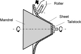
CNC metal spinning machines designed for aerospace components are engineered to meet the sector’s extremely high standards for precision, material integrity, and complex geometries. Aerospace parts such as rocket nose cones, turbine casings, satellite dishes, and other aerodynamic structures demand tight dimensional tolerances, flawless surface finishes, and the use of advanced materials capable of withstanding harsh operating conditions including high temperatures, extreme pressures, and corrosive environments.
These CNC metal spinning systems typically feature highly rigid machine frames and ultra-precision servo drives to ensure minimal vibration and maximum control during the spinning process. This stability is crucial when forming large diameter or very thin-walled aerospace components where even slight deviations can compromise aerodynamic performance or structural integrity.
Materials commonly processed on these machines include high-grade aluminum alloys, titanium, Inconel, stainless steels, and other specialty superalloys. The CNC controls allow precise modulation of roller pressure, spindle speed, and tool path to avoid material cracking or work hardening while achieving the required wall thickness and shape accuracy. Many aerospace parts also require spinning at elevated temperatures or with specialized lubrication to facilitate forming of these challenging materials.
Advanced multi-axis CNC capabilities enable the production of complex, contoured parts like turbine casings that include intricate internal cooling channels or aerodynamic features. Integration with CAD/CAM software allows engineers to import detailed 3D models directly into the CNC control system, enabling exact replication of aerodynamic profiles critical to performance.
In-line non-contact metrology systems—such as laser scanners or structured light sensors—are commonly incorporated to measure surface geometry and thickness during forming. These real-time measurements feed back into the CNC system to adjust tool paths dynamically and maintain strict tolerances, essential for aerospace quality standards such as AS9100.
To support the manufacture of large or delicate components like satellite dishes or rocket nose cones, these machines often include specialized tooling such as inflatable mandrels or segmented formers that provide support without damaging the material. Additionally, modular tooling systems facilitate quick changeovers between part designs, improving production flexibility in aerospace environments where bespoke or small batch manufacturing is common.
Automation features such as robotic loading/unloading, integrated trimming, flanging, and surface finishing modules help minimize handling and reduce cycle times, ensuring high throughput without sacrificing quality. Advanced CNC metal spinning centers may also integrate environmental controls like cleanroom enclosures to prevent contamination during the manufacturing of sensitive aerospace parts.
Energy-efficient servo drives and regenerative braking systems help manage power consumption, which is especially important given the extended cycle times typical in precision aerospace manufacturing. Additionally, many machines are equipped with remote monitoring and diagnostics capabilities to enable predictive maintenance, reducing downtime in mission-critical production lines.
Ultimately, CNC metal spinning machines for aerospace components deliver the precision, material adaptability, and process control required to produce high-performance, reliable parts that meet the demanding specifications of the aerospace industry. Their ability to form complex, seamless, and lightweight metal components contributes significantly to advances in aerospace engineering, from propulsion systems to satellite communications and beyond.
CNC metal spinning machines for aerospace components are designed to accommodate the unique challenges of working with advanced, often difficult-to-form materials such as titanium alloys and nickel-based superalloys. These materials require precise control of forming forces and thermal management to prevent cracking, delamination, or unwanted residual stresses that could compromise part integrity during operation. Machines are often equipped with advanced cooling systems and, in some cases, heated mandrels or localized heating elements to facilitate spinning at controlled temperatures, optimizing ductility and material flow.
The complexity of aerospace component geometries—like the tapered profile of rocket nose cones or the curved contours of satellite dishes—demands multi-axis control with sub-micron positioning accuracy. This level of precision ensures aerodynamic efficiency and structural performance, which are critical for components exposed to extreme aerodynamic loads or high-velocity airflow. Multi-axis CNC systems synchronize roller, mandrel, and tailstock movements, enabling intricate shapes to be spun without the need for welding or assembling multiple parts, thus reducing weight and potential failure points.
Because aerospace parts often have stringent certification and traceability requirements, CNC spinning machines are integrated with comprehensive data logging and quality assurance systems. Every process parameter—spindle speed, roller force, material temperature, and tool wear—is recorded and linked to individual part IDs. This traceability supports compliance with aerospace standards and provides valuable data for lifecycle analysis and maintenance planning.
Moreover, these machines frequently incorporate advanced simulation software that models the metal spinning process before actual production. This virtual prototyping predicts material behavior, identifies potential defects, and helps optimize tool paths and process parameters. By reducing trial runs and material waste, simulation saves time and resources, which is crucial given the high cost of aerospace-grade materials.
Handling large aerospace components also requires specialized fixtures and support systems to prevent deformation under gravity during spinning. Some machines use modular mandrels with adjustable support points or inflatable bladders that conform to complex internal geometries, ensuring even pressure distribution and preventing part distortion.
Surface finish quality is paramount for aerospace applications to minimize drag and improve thermal and electromagnetic properties. CNC metal spinning machines are equipped with finely polished tooling surfaces and controlled lubrication systems to produce mirror-like finishes that often meet or exceed aerospace standards without additional polishing. For parts requiring special coatings—such as radar-absorbing materials or thermal barriers—spinning processes are carefully managed to maintain surface integrity and coating adhesion.
Automation enhances throughput and reduces operator intervention. Robotic arms handle heavy blanks and finished parts, while integrated vision and laser measurement systems perform in-line inspections for defects such as surface irregularities, dimensional deviations, or micro-cracks. This real-time quality control prevents defective parts from progressing further, ensuring only components meeting rigorous standards move to final assembly or shipment.
Energy efficiency is addressed through the use of high-performance servo motors with regenerative braking, which recaptures energy during deceleration phases, reducing overall power consumption. These features are especially important given the extended cycle times often required to spin thin, high-strength aerospace materials.
In summary, CNC metal spinning machines for aerospace components represent the pinnacle of precision manufacturing technology. They combine robust mechanical design, multi-axis control, advanced materials processing, and integrated quality systems to produce lightweight, seamless, and high-performance parts essential for aerospace innovation. Their ability to reliably form complex geometries from challenging materials supports critical applications ranging from propulsion systems and airframe structures to satellite communication devices, helping drive progress in aerospace engineering and exploration.
Beyond their fundamental capabilities, CNC metal spinning machines for aerospace components continue to evolve with the integration of cutting-edge technologies such as artificial intelligence (AI) and machine learning (ML). These advanced algorithms analyze vast amounts of process data in real-time, identifying subtle patterns and correlations that human operators might miss. AI-driven predictive maintenance schedules help avoid unexpected downtime by anticipating component wear or machine failures before they occur, ensuring uninterrupted production of mission-critical aerospace parts.
Machine learning models also optimize spinning parameters dynamically. By continuously learning from each part spun, the system fine-tunes roller pressure, spindle speeds, and feed rates to enhance part quality, reduce cycle time, and extend tool life. This adaptive control is especially valuable when processing new or exotic materials where baseline forming data is limited.
In response to the aerospace industry’s increasing demand for customization and rapid prototyping, flexible CNC metal spinning cells are being developed that combine spinning with additive manufacturing (3D printing) and subtractive machining operations. These hybrid manufacturing platforms enable the creation of complex, multi-material components that integrate spun metal structures with printed lattice reinforcements or precisely machined interfaces, pushing the boundaries of lightweight design and structural performance.
Furthermore, advancements in digital twin technology allow manufacturers to create virtual replicas of spinning machines and production lines. These digital twins simulate entire manufacturing processes under various conditions, enabling engineers to optimize machine settings, predict production outcomes, and conduct “what-if” analyses without halting physical operations. This not only reduces costly trial-and-error but also supports continuous improvement initiatives aligned with aerospace quality standards.
Collaboration between CNC metal spinning machines and advanced inspection technologies, such as computed tomography (CT) scanning and ultrasonic testing, provides comprehensive non-destructive evaluation of spun aerospace parts. Integrating these inspection methods into the production workflow helps detect internal flaws, inclusions, or residual stresses that could compromise performance, thereby elevating safety and reliability.
Environmental sustainability remains a priority in aerospace manufacturing. CNC metal spinning machines incorporate energy recovery systems, low-waste tooling strategies, and environmentally friendly lubricants to minimize ecological impact. The near-net-shape forming capability reduces raw material consumption and machining scrap, aligning with the aerospace sector’s goals of reducing carbon footprint and resource usage.
Lastly, workforce development is supported through augmented reality (AR) and virtual reality (VR) training programs that allow operators and engineers to simulate machine setup, maintenance, and troubleshooting in immersive, risk-free environments. This enhances skill retention and accelerates onboarding, ensuring personnel can effectively operate and optimize increasingly sophisticated CNC metal spinning equipment.
In totality, the convergence of AI, digital twin simulation, hybrid manufacturing, advanced inspection, and sustainable design principles is transforming CNC metal spinning machines into intelligent, adaptive, and eco-conscious tools that empower aerospace manufacturers to meet the ever-escalating demands for innovation, quality, and efficiency in one of the most challenging industrial sectors.
Building on these advancements, CNC metal spinning machines for aerospace components are also embracing enhanced connectivity through Industrial Internet of Things (IIoT) frameworks. This connectivity allows machines to communicate seamlessly with other equipment, production management systems, and supply chains, creating an interconnected ecosystem that facilitates real-time monitoring, predictive analytics, and agile decision-making. Data collected from spinning operations—such as machine health, process metrics, and production throughput—can be aggregated and analyzed across multiple facilities, enabling global aerospace manufacturers to standardize quality and optimize resource allocation.
The integration of edge computing technologies further empowers CNC metal spinning machines to process critical data locally, reducing latency and enhancing response times for adaptive control and fault detection. This means that adjustments to forming parameters or alerts for potential defects can occur instantly, minimizing scrap and preventing costly downtime.
In terms of material innovation, CNC spinning machines are increasingly compatible with emerging aerospace alloys and metal matrix composites (MMCs), which combine metals with ceramic or polymer reinforcements to achieve superior strength-to-weight ratios and thermal resistance. The ability to precisely spin these advanced materials opens new possibilities for lightweight structural parts that meet the stringent demands of next-generation aircraft and spacecraft designs.
To address the need for extreme accuracy in components like turbine casings and antenna reflectors, some CNC metal spinning systems employ laser-assisted forming techniques. This approach uses focused laser energy to locally heat and soften the metal just ahead of the roller, enabling greater deformation with less force and reducing residual stresses. The result is improved dimensional accuracy and surface finish, especially in hard-to-form high-performance alloys.
Moreover, the trend toward miniaturization in aerospace electronics and instrumentation is driving the development of micro-CNC metal spinning machines capable of producing tiny, highly precise components such as sensor housings and micro-antennas. These compact systems maintain the same level of control and quality assurance found in larger machines but are optimized for small-scale, intricate parts.
Safety enhancements remain a focus as well, with CNC spinning centers equipped with advanced monitoring systems that detect abnormal vibrations, temperature spikes, or unexpected tool deflections. These features trigger automatic shutdowns or slowdowns, protecting both operators and valuable aerospace parts.
Finally, collaboration between aerospace manufacturers, machine builders, and software developers is fostering continuous innovation through open platforms and standardization initiatives. This collaborative ecosystem accelerates the adoption of best practices, enables rapid integration of new technologies, and supports compliance with evolving aerospace regulations.
Altogether, these emerging technologies and collaborative approaches position CNC metal spinning machines at the forefront of aerospace manufacturing, empowering producers to fabricate lighter, stronger, and more complex components with unprecedented precision, efficiency, and reliability—fueling progress in aviation, space exploration, and satellite communications well into the future.
CNC Metal Spinning Machine for Gas Cylinders (Necking/Forming)
CNC metal spinning machines designed for gas cylinder manufacturing—particularly for necking and forming operations—play a critical role in producing high-strength, precision-shaped components that meet rigorous safety and performance standards. Gas cylinders, used for storing compressed gases like oxygen, propane, and industrial gases, require necks and valve seats that are dimensionally accurate and structurally sound to ensure safe containment under high pressure.
These CNC spinning machines are engineered to handle thick-walled steel or aluminum blanks, applying controlled radial and axial forces to progressively reduce the diameter and shape the neck area without causing material cracking or thinning beyond allowable limits. The CNC control system precisely regulates spindle speed, roller pressure, and feed rate to accommodate variations in material properties and cylinder sizes, enabling consistent neck profiles across large production batches.
The necking process is often multi-stage, with initial rough forming passes followed by fine finishing operations to achieve the exact geometry required for valve attachment and sealing surfaces. CNC metal spinning machines can integrate automated tool changers and multiple rollers to perform these stages sequentially without manual intervention, improving throughput and reducing labor costs.
To ensure safety compliance, these machines incorporate in-process measurement systems that verify critical neck dimensions and wall thickness in real time. Non-contact sensors, such as laser micrometers or ultrasonic thickness gauges, detect deviations immediately, allowing the CNC controller to adjust forming parameters dynamically or reject out-of-tolerance parts before final processing.
Material handling automation is essential given the heavy and bulky nature of gas cylinder blanks and finished parts. Robotic loading/unloading systems, along with ergonomic fixtures, reduce operator fatigue and the risk of handling damage. Some CNC spinning cells include integrated deburring and surface finishing stations to prepare necked cylinders for downstream welding or assembly operations.
Given the high safety standards governing gas cylinders—such as those from ISO, DOT, or EN—traceability is a key feature in CNC metal spinning setups. Each part’s process data, including forming forces, temperature, and inspection results, is logged and linked to unique serial numbers, facilitating certification and quality audits.
Energy efficiency measures, including servo motor regenerative drives and optimized cycle programming, help minimize power consumption during heavy forming cycles. Lubrication systems are designed to use minimal amounts of environmentally friendly fluids, reducing waste and post-process cleaning requirements.
In summary, CNC metal spinning machines for gas cylinder necking provide precise, repeatable, and safe forming capabilities essential to producing high-quality gas cylinders. Their automation, process control, and integrated quality assurance features ensure that each cylinder neck meets stringent regulatory and safety standards, supporting the reliable and secure storage of compressed gases across industrial, medical, and consumer applications.
CNC metal spinning machines for gas cylinder necking are designed to handle the demanding physical stresses involved in forming thick-walled cylinders, which typically require substantial force to reshape without compromising material integrity. The machines often feature heavy-duty frames and high-torque servo motors capable of maintaining consistent pressure during the necking operation, preventing deformation irregularities that could lead to weak spots or leaks under pressure.
Precision is vital because the neck region must fit perfectly with valves, regulators, and safety devices. CNC control allows for micron-level accuracy in controlling roller positioning and feed rates, ensuring uniform neck thickness and concentricity. This precision reduces the need for costly post-processing adjustments and helps achieve tighter sealing surfaces, improving overall cylinder safety.
Many CNC spinning machines for gas cylinders support multi-stage forming sequences, where initial passes reduce the diameter gradually to avoid excessive strain on the material. Subsequent finishing passes refine the neck geometry and surface quality. These stages can be programmed to automatically switch between different roller tools, enabling seamless transitions without manual intervention and maximizing production efficiency.
In-process inspection is frequently integrated into the machine setup to measure wall thickness, diameter, and surface finish during forming. This data is fed back to the CNC controller in real time, allowing immediate corrections to roller pressure or feed speed. Such closed-loop control minimizes scrap rates and ensures every neck meets strict safety certifications.
Material handling automation plays a crucial role in managing the heavy blanks and finished necked cylinders, improving workplace ergonomics and safety. Robotic arms or automated conveyors load raw cylinders into the spinning machine and transfer finished parts to subsequent welding or testing stations, reducing human error and cycle times.
Given the critical safety nature of gas cylinders, manufacturers often implement full traceability systems that record every production parameter alongside part identifiers. This documentation supports compliance with international regulations and aids in quality control audits or failure investigations.
Environmentally conscious designs have led to machines that minimize lubricant use and optimize power consumption, often incorporating regenerative braking systems that capture energy during deceleration. These features help reduce operational costs and environmental impact in high-volume production settings.
Furthermore, advanced CNC spinning machines may include adaptive forming algorithms that adjust process parameters on-the-fly based on real-time sensor input, compensating for slight variations in material batches or ambient conditions. This adaptability enhances consistency and reliability in cylinder neck production.
Overall, CNC metal spinning machines for gas cylinder necking combine robust mechanical design, precise digital control, and comprehensive automation to deliver safe, high-quality, and cost-effective components critical to the storage and handling of compressed gases across diverse industries.
These CNC metal spinning machines are often equipped with specialized tooling designed to accommodate the variety of gas cylinder sizes and materials encountered in production. Custom mandrels and rollers can be quickly swapped to adjust for different neck diameters, wall thicknesses, and taper angles, allowing manufacturers to maintain flexibility in their product range without extensive machine downtime. This modular tooling system supports rapid changeovers, which is especially important for manufacturers serving multiple markets or producing cylinders with varying specifications.
Thermal management is another critical aspect in gas cylinder necking operations. The forming process can generate significant heat due to friction and metal deformation, particularly when working with high-strength steel alloys. To mitigate the risk of overheating and maintain material properties, CNC metal spinning machines may incorporate cooling systems that circulate coolant around tooling and mandrels or use controlled lubrication to dissipate heat efficiently. These features extend tool life and help maintain the metallurgical integrity of the necked areas.
In high-capacity manufacturing environments, CNC metal spinning machines can be integrated into fully automated production lines, linking spinning cells with upstream blank preparation and downstream welding, heat treatment, and testing stations. This integration streamlines workflow, reduces manual handling, and ensures consistent quality across the entire production process. Real-time data exchange between stations enables synchronized operations, improving throughput and enabling rapid response to production bottlenecks or quality issues.
Safety systems on these machines are engineered to protect operators from the risks associated with handling heavy blanks and high forces. Enclosures with interlocked doors, emergency stop functions, and light curtains prevent access during operation. Additionally, vibration and overload sensors monitor machine status, halting the process if abnormal conditions arise, thereby preventing damage to both equipment and parts.
From a quality assurance perspective, CNC metal spinning machines for gas cylinder necking often include advanced statistical process control (SPC) software that tracks key parameters and trends over time. This data supports proactive maintenance, process optimization, and compliance with industry standards such as ISO 9809 or DOT regulations. By analyzing process variability, manufacturers can identify potential defects early and implement corrective actions to maintain consistent product quality.
As sustainability becomes increasingly important, manufacturers are adopting greener practices supported by these CNC machines. Energy-efficient servo motors, reduced lubricant consumption, and waste minimization through near-net-shape forming contribute to lower environmental impact. Additionally, the precise forming reduces material waste compared to traditional machining or forging methods, aligning with circular economy principles.
Operator interfaces have become more user-friendly with the incorporation of touchscreen controls, graphical programming, and diagnostic tools that simplify setup and maintenance. Some systems offer remote monitoring capabilities, enabling technicians to troubleshoot or update CNC programs without being physically present, reducing downtime and improving support responsiveness.
In conclusion, CNC metal spinning machines for gas cylinder necking combine robust mechanical engineering, precision digital controls, advanced automation, and comprehensive quality systems to produce critical safety components with high reliability and efficiency. Their adaptability, process consistency, and integration capabilities make them indispensable in modern gas cylinder manufacturing, supporting industry demands for safety, performance, and sustainability.
Expanding further, the role of CNC metal spinning machines in gas cylinder necking is increasingly influenced by advancements in materials science, especially as manufacturers seek lighter yet stronger cylinders to improve portability and reduce environmental impact. The ability of these machines to precisely control forming parameters enables the successful spinning of advanced high-strength alloys and composite-metal hybrids, which often have more stringent forming requirements due to their increased strength and reduced ductility compared to traditional steels.
Moreover, the integration of digital twins—a virtual, real-time model of the spinning machine and process—allows manufacturers to simulate necking operations before physically running production. This simulation aids in optimizing tool paths, anticipating potential forming defects such as wrinkling or thinning, and refining process parameters to maximize throughput while maintaining safety margins. By validating these simulations against live process data, manufacturers can continuously improve their forming strategies, reduce trial-and-error, and shorten product development cycles.
In terms of industry compliance, CNC metal spinning machines incorporate comprehensive data logging and audit trail capabilities that support certifications like ISO 9001 and those specific to pressure vessel manufacturing. This traceability ensures that every gas cylinder neck produced is backed by a full record of its manufacturing conditions, facilitating recalls or failure analyses if needed and enhancing customer confidence in product safety.
The rise of Industry 4.0 has accelerated the deployment of interconnected CNC spinning systems where multiple machines communicate within a smart factory ecosystem. Predictive maintenance algorithms analyze vibration, temperature, and power consumption data across spinning lines to schedule service proactively, avoiding unexpected breakdowns. Additionally, production scheduling software uses real-time machine status and order priorities to dynamically allocate workloads, improving efficiency and responsiveness to market demands.
Ergonomics and operator safety continue to advance with machine designs that minimize manual handling of heavy components, utilize collaborative robots (cobots) for loading/unloading tasks, and provide intuitive user interfaces that reduce setup errors. Training programs often leverage augmented reality (AR) tools that overlay step-by-step instructions and diagnostics onto the machine environment, facilitating faster learning curves and reducing downtime.
Environmental sustainability initiatives benefit from the efficient metal utilization characteristic of spinning processes, which generate minimal scrap compared to cutting or forging. Coupled with energy-saving features such as regenerative drives and optimized cycle times, CNC metal spinning machines contribute to greener manufacturing footprints. Recycling programs for used lubricants and worn tooling materials further enhance environmental stewardship.
Looking ahead, the continued convergence of advanced materials, smart manufacturing technologies, and process automation is poised to make CNC metal spinning machines for gas cylinder necking even more capable and versatile. These machines will support increasingly complex cylinder designs, including integrated safety features and sensor housings, while delivering the precision, reliability, and traceability essential for safe, efficient, and sustainable compressed gas storage solutions worldwide.
EMS Metalworking Machines
We design, manufacture and assembly metalworking machinery such as:
- Hydraulic transfer press
- Glass mosaic press
- Hydraulic deep drawing press
- Casting press
- Hydraulic cold forming press
- Hydroforming press
- Composite press
- Silicone rubber moulding press
- Brake pad press
- Melamine press
- SMC & BMC Press
- Labrotaroy press
- Edge cutting trimming machine
- Edge curling machine
- Trimming beading machine
- Trimming joggling machine
- Cookware production line
- Pipe bending machine
- Profile bending machine
- Bandsaw for metal
- Cylindrical welding machine
- Horizontal pres and cookware
- Kitchenware, hotelware
- Bakeware and cuttlery production machinery
as a complete line as well as an individual machine such as:
- Edge cutting trimming beading machines
- Polishing and grinding machines for pot and pans
- Hydraulic drawing presses
- Circle blanking machines
- Riveting machine
- Hole punching machines
- Press feeding machine
You can check our machinery at work at: EMS Metalworking Machinery – YouTube
Applications:
- Beading and ribbing
- Flanging
- Trimming
- Curling
- Lock-seaming
- Ribbing
- Flange-punching