
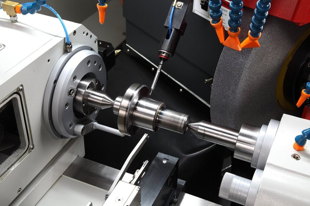
Precision Grinding Machines: Precision grinding machines are essential equipment in modern manufacturing industries where high dimensional accuracy, excellent surface quality, tight tolerances, and consistent production results are required. These machines are designed to remove very small amounts of material from workpieces through controlled abrasive machining processes, achieving levels of precision and surface finish that are difficult or impossible to obtain through conventional machining operations such as turning, milling, drilling, or general-purpose grinding. Precision grinding is widely used in the production of mechanical components, automotive parts, aerospace equipment, hydraulic systems, machine tools, bearings, shafts, gears, dies, molds, cutting tools, medical equipment, and numerous other industrial products. As manufacturing technologies continue to advance, the demand for precision grinding machines capable of producing increasingly complex geometries with high repeatability and dimensional stability continues to grow.
The fundamental principle of precision grinding is based on the controlled interaction between an abrasive grinding wheel and the workpiece surface. The grinding wheel consists of numerous abrasive grains that act as microscopic cutting edges, removing small particles of material during contact with the workpiece. The grinding process can be precisely controlled through the adjustment of wheel speed, workpiece speed, feed rate, grinding depth, dressing parameters, and cooling conditions. By optimizing these parameters according to the material characteristics and required machining specifications, manufacturers can achieve extremely accurate dimensions, controlled surface roughness, and excellent geometrical quality. The selection of suitable abrasive materials, grinding wheel specifications, bonding systems, and machine configurations plays a critical role in determining the final machining performance.
The mechanical construction of a precision grinding machine is particularly important because even minor structural deformations or vibrations can negatively affect machining accuracy. The machine bed is generally manufactured from high-quality cast iron or specially designed welded structures, providing the necessary rigidity, vibration absorption, and thermal stability. Precision-ground guideways, linear roller guides, hydrostatic guideways, and other advanced guiding systems are used to ensure smooth and accurate movement of the machine axes. The grinding spindle is one of the most critical components, as it must maintain high rotational accuracy, low vibration levels, and stable operating temperatures. Depending on the machine design and application, grinding spindles may operate with precision rolling bearings, hydrostatic bearings, or other specialized bearing arrangements. The spindle assembly must provide sufficient rigidity to maintain consistent grinding conditions even during demanding machining operations.
Modern precision grinding machines are equipped with advanced drive systems that provide accurate control over the movement of the grinding wheel, workpiece, and machine axes. Servo motors, high-resolution encoders, precision ball screws, and direct-drive systems allow controlled positioning and feed movements with excellent repeatability. CNC-controlled grinding machines offer significant advantages in the production of complex components because they can execute programmed grinding cycles, automatically compensate for wheel wear, control dressing operations, and maintain consistent machining parameters throughout production. Depending on the application, machines may include automatic workpiece loading, measuring systems, automatic wheel changing, in-process dimensional inspection, and integrated temperature monitoring. These technologies reduce operator dependency, improve production consistency, and make it possible to manufacture high-precision components with demanding geometrical tolerances.
Precision grinding machines are available in several configurations, each developed for specific machining requirements. Precision cylindrical grinding machines are primarily used for machining external cylindrical surfaces, internal cylindrical surfaces, shoulders, tapers, and other rotational geometries. They are widely employed in the production of shafts, bearing components, hydraulic piston rods, precision spindles, rollers, and similar mechanical parts. Precision surface grinding machines are designed to produce flat surfaces with excellent dimensional accuracy and surface finish. They are commonly used for machining machine components, tooling plates, dies, molds, guide surfaces, and precision mechanical assemblies. Centerless grinding machines provide highly efficient machining of cylindrical components without requiring the workpiece to be held between centers or in a conventional chuck. This configuration is particularly advantageous for high-volume production of pins, rollers, shafts, bushes, and other rotational components. Tool and cutter grinding machines are developed for manufacturing, sharpening, and reconditioning cutting tools such as drills, milling cutters, reamers, and specialized industrial tooling. Coordinate grinding machines are used for producing extremely accurate holes, profiles, internal contours, and complex geometrical features, particularly in dies, molds, and precision tooling applications.
One of the most important factors in precision grinding is the selection of the appropriate grinding wheel. Different workpiece materials require different abrasive characteristics and wheel specifications. Aluminium oxide grinding wheels are commonly used for grinding various steels, while silicon carbide abrasives are suitable for many non-ferrous materials and certain hard or brittle materials. Cubic boron nitride grinding wheels are particularly effective for hardened steels and other difficult-to-grind ferrous materials. Diamond grinding wheels are widely used for carbide, ceramics, glass, and other extremely hard materials. In addition to abrasive type, grain size, wheel hardness, structure, and bonding material must be selected according to the required material removal rate, surface finish, and dimensional accuracy. Proper grinding wheel dressing is equally important because it restores the cutting characteristics of the wheel, maintains its geometrical profile, and prevents excessive grinding forces and thermal damage.
Thermal management is another critical aspect of precision grinding. Although the amount of material removed during grinding is relatively small compared with conventional machining operations, the localized heat generated in the grinding zone can be significant. Excessive temperatures may cause grinding burns, microstructural changes, residual stresses, dimensional instability, and surface cracks, particularly when machining hardened steels and other heat-sensitive materials. Precision grinding machines therefore incorporate suitable coolant delivery systems designed to provide effective lubrication, cooling, and removal of grinding debris. Depending on the machining application, conventional flood cooling, high-pressure coolant delivery, minimum quantity lubrication, or specialized filtration systems may be used. Coolant filtration is especially important because fine abrasive particles and metallic contaminants can negatively affect surface quality, grinding wheel performance, and the reliability of machine components.
Dimensional accuracy in precision grinding depends on the combined performance of the machine structure, spindle system, guideways, drive mechanisms, measuring equipment, grinding wheel, and environmental conditions. Thermal expansion is particularly important when machining components with very tight tolerances. Temperature variations in the machine structure, workpiece, grinding wheel, and measuring equipment can introduce dimensional deviations even when the machine itself has excellent mechanical accuracy. For this reason, high-precision grinding operations are often performed in temperature-controlled environments. Modern machines may also incorporate thermal compensation systems, automatic measurement probes, laser measurement equipment, and in-process gauging systems to maintain dimensional consistency and reduce the need for repeated manual inspection.
The use of precision grinding machines is not limited to producing simple cylindrical or flat surfaces. Advanced CNC grinding technologies make it possible to manufacture complicated profiles, non-circular geometries, precision tapers, stepped surfaces, internal contours, and specially designed cutting edges. Multi-axis grinding machines can perform several machining operations within a single setup, reducing repositioning errors and improving production efficiency. With the integration of CAD/CAM software, digital machine controls, and advanced measurement technologies, manufacturers can develop grinding processes for increasingly complex components while maintaining high levels of accuracy and repeatability. Five-axis grinding technology is particularly valuable in the production of advanced cutting tools, turbine components, aerospace parts, and specialized industrial tooling.
Precision grinding machines are widely used in the automotive industry for manufacturing crankshafts, camshafts, transmission components, bearing races, valve components, and precision shafts. In the aerospace sector, they are employed for machining turbine components, high-strength alloy parts, precision hydraulic elements, and components requiring extremely accurate geometrical characteristics. The machine tool industry relies on precision grinding for manufacturing spindles, guideways, linear motion components, ball screws, and precision mechanical assemblies. In the hydraulic and pneumatic industries, precision grinding is essential for producing piston rods, valve spools, cylinder components, and sealing surfaces where dimensional accuracy and surface quality directly influence leakage performance, friction, and service life. The medical equipment industry also uses precision grinding technologies for producing surgical instruments, implants, and specialized components manufactured from stainless steel, titanium, ceramics, and other advanced materials.
Machine calibration and regular maintenance are necessary to preserve the accuracy and reliability of precision grinding equipment throughout its service life. Spindle runout, axis positioning accuracy, guideway condition, geometric alignment, wheel balancing, and vibration characteristics should be inspected periodically. Grinding wheels must be balanced correctly to minimize vibration and ensure uniform material removal. Dressing tools should be maintained in good condition to produce consistent wheel profiles and cutting characteristics. Lubrication systems, coolant filtration units, hydraulic circuits, pneumatic systems, and electrical components must also be inspected and serviced according to the manufacturer’s maintenance recommendations. Proper machine installation, foundation design, leveling, and environmental control are equally important because external vibration, unstable foundations, and temperature fluctuations can significantly influence grinding accuracy.
The development of modern precision grinding machines is increasingly focused on automation, digitalization, energy efficiency, and advanced process control. CNC technology, intelligent measuring systems, automatic dressing compensation, adaptive grinding cycles, and real-time process monitoring are becoming standard features in advanced manufacturing environments. Sensors can monitor spindle vibration, temperature, grinding forces, and other operating parameters, allowing the control system to identify process deviations and maintain stable machining conditions. Automated production cells can integrate grinding machines with robotic loading systems, washing units, measuring stations, and material handling equipment, creating highly efficient manufacturing processes with reduced manual intervention.
Choosing the appropriate precision grinding machine requires a detailed evaluation of the workpiece geometry, material characteristics, dimensional tolerances, required surface roughness, production volume, and machining operations. The maximum workpiece dimensions, grinding length, spindle power, wheel diameter, axis configuration, positioning resolution, and measuring capabilities must be considered during machine selection and engineering design. A machine intended for high-precision single-part production may require a different mechanical configuration and control system compared with a machine designed for continuous mass production. Similarly, grinding hardened steel shafts, carbide cutting tools, ceramic components, or precision flat surfaces requires different spindle arrangements, grinding wheel specifications, cooling systems, and process parameters.
Precision grinding machines represent a fundamental part of advanced industrial manufacturing because they provide the dimensional accuracy, surface integrity, and repeatability required for high-performance mechanical components. Their importance continues to increase as industrial products become more sophisticated and manufacturing tolerances become tighter. Through the combination of rigid machine structures, precision spindle systems, advanced motion controls, carefully selected abrasive technologies, effective cooling systems, and modern CNC automation, precision grinding machines enable manufacturers to achieve exceptional machining quality and consistent production performance. Continued developments in machine engineering, grinding technology, measurement systems, and intelligent process control will further expand their capabilities and strengthen their role in modern precision manufacturing.
Precision Grinding Machines
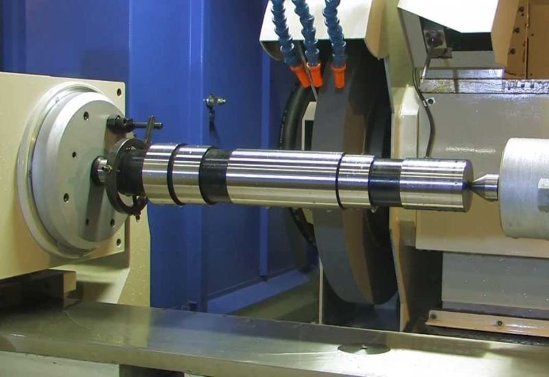
The continuous development of precision grinding technology has created new possibilities for manufacturers seeking to improve machining accuracy, production efficiency, component reliability, and manufacturing quality. Precision grinding machines are no longer considered only finishing equipment used to correct dimensions after conventional machining. In modern industrial production, they are increasingly integrated into the complete manufacturing process and are often responsible for establishing the final geometrical characteristics of critical mechanical components. Their ability to produce extremely accurate dimensions, maintain consistent surface characteristics, and machine difficult materials makes them indispensable in industries where component performance depends on precise manufacturing tolerances.
An important characteristic of precision grinding is the relationship between material removal, cutting forces, machine rigidity, and dimensional stability. Unlike conventional cutting operations, grinding involves a large number of abrasive grains simultaneously interacting with the workpiece. Each abrasive grain acts as a microscopic cutting edge, although not all grains remove material under identical conditions. Some grains perform actual cutting, while others contribute to ploughing and friction. The resulting machining forces are influenced by abrasive grain geometry, wheel structure, wheel speed, workpiece speed, feed rate, grinding depth, and the mechanical properties of the material being processed. Understanding these interactions is essential for developing stable grinding processes capable of maintaining dimensional accuracy and achieving the required surface quality.
The grinding wheel is one of the most influential elements in the machining process. Its abrasive composition, grain distribution, bonding characteristics, porosity, and geometrical dimensions determine how effectively material can be removed. A properly selected grinding wheel must provide an appropriate balance between cutting ability, dimensional stability, heat generation, and resistance to wear. Wheels that are too hard for a particular application may retain worn abrasive grains for too long, resulting in increased grinding forces and excessive heat generation. Conversely, wheels that are too soft may wear rapidly and lose their geometrical profile, increasing production costs and reducing dimensional consistency. The selection of grinding wheel hardness and structure must therefore consider the workpiece material, hardness, contact area, machine power, and required surface finish.
Abrasive grain size also has a direct influence on the final machining characteristics. Coarse abrasive grains generally provide higher material removal rates and are suitable for rough grinding operations where a significant amount of stock must be removed. Fine abrasive grains produce smoother surfaces and are commonly used during finishing operations where dimensional accuracy and surface quality are the primary objectives. However, finer grain sizes may increase grinding forces and require careful control of dressing and coolant conditions. In high-precision applications, manufacturers frequently employ several grinding stages, beginning with controlled stock removal and continuing with intermediate and finishing operations. This approach provides better control over the final dimensions while reducing the risk of excessive thermal loading.
Grinding wheel bonding technology is equally important. Vitrified bonds are widely used because they provide good dimensional stability, predictable dressing characteristics, and effective chip clearance. Resin bonds offer different mechanical characteristics and are frequently used in applications requiring improved impact resistance or particular surface finishing properties. Metal bonds are commonly associated with superabrasive wheels, especially diamond and cubic boron nitride applications, where long service life and profile retention are important. Electroplated abrasive wheels can provide high abrasive concentration and are particularly useful for certain specialized profiles and applications. The selection of the bonding system must be coordinated with the abrasive material and the operating conditions of the grinding machine.
The grinding spindle requires particular engineering attention because its rotational accuracy directly influences the geometrical quality of the finished component. A high-performance grinding spindle must operate with minimal radial and axial runout, sufficient stiffness, controlled thermal expansion, and excellent dynamic balance. Even relatively small spindle errors can create periodic surface deviations, dimensional variations, and unwanted vibration patterns. Spindle design must consider the operating speed, grinding wheel dimensions, grinding forces, bearing arrangement, lubrication method, cooling requirements, and expected operating duty. Depending on the application, precision angular contact ball bearings, cylindrical roller bearings, hydrostatic bearings, or specialized high-speed spindle systems may be employed.
Bearing selection is particularly important in applications where grinding forces are relatively high or where exceptionally low vibration levels are required. Angular contact ball bearings can provide combined radial and axial load capacity and are commonly used in precision spindle arrangements. Their preload must be selected carefully because excessive preload increases friction and operating temperature, while insufficient preload can reduce stiffness and negatively affect rotational accuracy. Hydrostatic spindle systems operate on a pressurized lubricant film that separates the moving surfaces, providing excellent damping characteristics and very low friction under suitable operating conditions. Such systems are particularly valuable in specialized high-precision grinding machines, although their additional hydraulic and lubrication requirements increase system complexity.
The machine bed and supporting structure form the mechanical foundation of precision grinding equipment. Machine structures must resist deformation under static and dynamic loads while maintaining geometric alignment throughout the machining process. Cast iron remains a widely used material because of its favourable damping characteristics, machinability, and dimensional stability when properly manufactured and stress relieved. Polymer concrete is also used in certain high-precision machine structures because of its vibration-damping characteristics and ability to absorb dynamic energy. Welded steel structures can provide high structural strength and design flexibility, provided that appropriate welding procedures, stress-relieving treatments, machining allowances, and final precision machining are applied.
The structural design of a precision grinding machine must also account for the position and movement of its major assemblies. The grinding spindle, workpiece support, table, wheelhead, and measuring systems must maintain their relative positions under varying operating conditions. A poorly designed structural arrangement can produce deflection that changes according to the grinding wheel position, workpiece location, or direction of applied forces. These errors may become particularly noticeable when machining long shafts, large flat components, or workpieces with varying cross-sections. Finite element analysis can be used during machine development to evaluate structural deformation, natural frequencies, and the distribution of mechanical stresses. Such analysis helps engineers identify weak areas and optimize the geometry of the machine structure before manufacturing.
Precision guideway systems are another essential part of machine construction. The guideways determine the movement characteristics of the machine axes and directly influence straightness, positioning accuracy, and repeatability. Conventional box guideways provide high load capacity and good damping characteristics when manufactured and lubricated correctly. Linear rolling guides offer low friction, high positioning accuracy, and convenient integration with CNC-controlled axes. Hydrostatic guideways provide exceptionally smooth movement and excellent damping under suitable conditions, making them suitable for certain demanding precision applications. The choice of guideway system depends on machine size, required accuracy, operating speed, load distribution, maintenance requirements, and overall machine design.
The drive system must provide controlled and repeatable movement throughout the machining cycle. Servo motors combined with precision ball screws are widely used for CNC axis control. The mechanical transmission must be sufficiently rigid to minimize backlash, elastic deformation, and positioning errors. Direct-drive linear motors can provide high dynamic response and eliminate certain mechanical transmission elements, although their thermal behaviour and control requirements must be considered carefully. In conventional precision grinding machines, hydraulic systems may also be used for table reciprocation, wheelhead movement, or specialized feed mechanisms. Hydraulic drives can provide smooth movement and high force capacity, but oil temperature, fluid cleanliness, pressure stability, and system vibration must be controlled to maintain consistent performance.
Modern CNC precision grinding machines provide extensive control over machining parameters. Operators can define grinding wheel speeds, workpiece rotational speeds, axial feed rates, radial infeed, spark-out periods, dressing cycles, and automatic dimensional compensation. The CNC system coordinates the movement of individual axes and manages the machining sequence according to the programmed component geometry. In more advanced systems, the control unit can communicate with measuring equipment and automatically adjust the grinding cycle according to the actual workpiece dimensions. This is particularly important in production environments where small variations in incoming material dimensions or grinding wheel wear can influence the final component size.
In-process measurement is one of the most important technologies used to improve precision grinding performance. Conventional grinding processes often require the workpiece to be removed from the machine and inspected using external measuring equipment. Although this method remains appropriate for many applications, it increases production time and introduces additional handling operations. In-process gauging allows the machine to measure workpiece dimensions during grinding without interrupting the complete production sequence. Depending on the application, contact measuring systems, air gauges, displacement sensors, and specialized electronic measuring devices can be integrated into the machine. The measurement data can be used to control the final grinding dimension and compensate for wheel wear or thermal changes.
Automatic wheel dressing is another important function in advanced precision grinding machines. During operation, abrasive grains gradually become worn, loaded with workpiece material, or displaced from their original positions. These changes influence cutting efficiency, grinding forces, and surface finish. Dressing restores the wheel’s cutting ability by removing a controlled amount of abrasive material and exposing fresh cutting edges. Dressing systems may use single-point diamond dressers, rotary diamond dressers, multi-point dressing tools, or specialized CNC-controlled profiling systems. In complex grinding operations, the dressing unit must reproduce the required wheel geometry with high accuracy because any profile error can be transferred directly to the workpiece.
The relationship between wheel dressing and machine accuracy is particularly important when grinding complicated profiles. A grinding wheel used for producing grooves, radii, shoulders, or specially shaped surfaces must maintain its intended geometry throughout the machining cycle. If the wheel profile changes excessively during operation, the resulting component geometry may deviate from the required specifications. CNC-controlled dressing systems allow the wheel profile to be generated and corrected according to programmed geometrical data. This is particularly useful in the production of precision dies, molds, cutting tools, gear components, and specialized mechanical profiles.
Another significant factor is grinding wheel balancing. An unbalanced grinding wheel generates centrifugal forces during rotation, and these forces increase with rotational speed. Even a small imbalance can cause vibration that affects surface roughness, dimensional accuracy, bearing life, and machine reliability. Precision grinding machines therefore require correctly balanced wheels, suitable mounting systems, and periodic inspection of wheel condition. Depending on the machine configuration and application, balancing can be performed manually, using external balancing equipment, or through automatic balancing systems integrated into the spindle assembly. Automatic balancing systems are especially useful in demanding production environments where the grinding wheel operates at high rotational speeds or where very fine surface finishes are required.
Coolant technology has a direct influence on the quality and efficiency of precision grinding. The coolant must reach the grinding contact zone effectively, remove heat, reduce friction, and transport abrasive and metallic particles away from the machining area. Conventional flood coolant systems remain widely used, but the effectiveness of cooling depends not only on the coolant quantity but also on its delivery pressure, velocity, direction, and filtration quality. A poorly directed coolant stream may fail to penetrate the air barrier surrounding a rapidly rotating grinding wheel. Specialized nozzles and high-pressure delivery systems can improve coolant penetration and stabilize the grinding process.
Coolant filtration is particularly important because grinding produces extremely fine particles that can remain suspended in the fluid. These particles may be recirculated into the grinding zone if the filtration system is insufficient. Contaminated coolant can reduce surface quality, accelerate wheel loading, and damage sensitive machine components. Depending on the application, filtration systems may include magnetic separators, paper filtration units, cartridge filters, hydrocyclones, or combinations of several filtration technologies. High-precision applications may require very fine filtration and temperature-controlled coolant circulation to maintain stable machining conditions.
Temperature control must be considered at the complete machine-system level. The grinding spindle, bearings, hydraulic systems, coolant, workpiece, and machine structure all generate or absorb heat during operation. Changes in temperature can alter component dimensions and affect the relative position of machine assemblies. For this reason, advanced precision grinding machines may incorporate spindle cooling circuits, temperature-controlled coolant tanks, hydraulic oil cooling, and thermal compensation software. In particularly demanding applications, the machine is installed in a temperature-controlled production environment where ambient temperature variations are minimized.
Surface integrity is an important consideration in precision grinding, particularly when machining hardened materials. A component may meet its dimensional requirements while still containing undesirable surface damage caused by excessive grinding temperatures, high mechanical forces, or unsuitable process parameters. Grinding burns, tensile residual stresses, microcracks, and metallurgical transformations can negatively influence fatigue strength and component service life. The risk of these problems increases when grinding hardened steels, high-strength alloys, and components subjected to repeated mechanical loading. Process development must therefore consider not only dimensional accuracy and roughness but also the metallurgical condition of the finished surface.
Grinding burn detection is particularly relevant in the production of automotive transmission components, bearing races, shafts, and other safety-critical mechanical parts. Various inspection techniques can be used to identify thermal damage, including visual examination, etching methods, Barkhausen noise analysis, hardness testing, and metallographic inspection. The appropriate inspection method depends on the material, component geometry, production requirements, and applicable quality standards. Preventing grinding burns through correct wheel selection, dressing, coolant delivery, and machining parameters is generally more effective than relying exclusively on final inspection.
The selection of a precision grinding machine begins with a detailed analysis of the component to be manufactured. The geometry of the workpiece determines whether cylindrical, surface, internal, centerless, profile, tool, or coordinate grinding technology is required. Material characteristics influence abrasive selection, grinding forces, coolant requirements, and achievable material removal rates. Dimensional tolerances determine the necessary mechanical accuracy of the machine, while surface roughness requirements influence wheel specification, finishing strategy, and process stability. Production quantity also has a major influence on machine configuration because high-volume manufacturing may require automatic loading, gauging, dressing, and integrated material handling systems.
The maximum workpiece diameter, length, width, height, and weight must be considered during machine sizing. In cylindrical grinding, the distance between centers, maximum grinding diameter, grinding length, and workhead configuration determine the range of components that can be manufactured. In surface grinding, table dimensions, longitudinal travel, cross travel, and vertical movement define the available machining envelope. Internal grinding machines require sufficient spindle accessibility, suitable wheel dimensions, and adequate clearance for the internal geometry of the workpiece. Centerless machines require carefully designed grinding wheel, regulating wheel, and work-rest arrangements to accommodate the component diameter and required production cycle.
Precision cylindrical grinding machines are particularly important in the manufacturing of rotational components. These machines are designed to grind external cylindrical surfaces, shoulders, tapers, and other rotational features with high dimensional accuracy. Depending on the configuration, the workpiece may be mounted between centers, supported by a chuck, or held using specialized fixtures. The grinding wheel rotates at a controlled speed while the workpiece is rotated and fed relative to the wheel. Longitudinal grinding is commonly used for components with relatively long cylindrical surfaces, while plunge grinding is appropriate for shorter surfaces, shoulders, and defined profile regions. CNC cylindrical grinding machines can combine several grinding operations within one setup and automatically manage complex machining sequences.
The precision of cylindrical grinding depends heavily on the alignment of the workhead, tailstock, grinding spindle, and machine guideways. Any angular misalignment between the workpiece axis and the grinding wheel movement can produce taper errors along the component length. Long and slender workpieces may also experience elastic deflection under grinding forces, requiring the use of steady rests or optimized machining parameters. The design of the workholding system must provide sufficient support without introducing unwanted deformation. Precision centers, specialized chucks, and suitable clamping arrangements are therefore essential when machining components with demanding dimensional and geometrical tolerances.
Internal cylindrical grinding machines are used for producing accurate internal diameters, bearing seats, bores, sleeves, hydraulic components, and other internal geometries. Internal grinding presents particular mechanical challenges because the grinding wheel must operate inside the workpiece while maintaining sufficient stiffness and accessibility. The grinding spindle is often relatively slender, and its stiffness can become a limiting factor, particularly when machining deep bores or small internal diameters. Wheel diameter, spindle overhang, operating speed, coolant delivery, and workpiece clamping must be carefully coordinated. In many applications, high spindle speeds are required to maintain an appropriate grinding wheel peripheral speed despite the small wheel diameter.
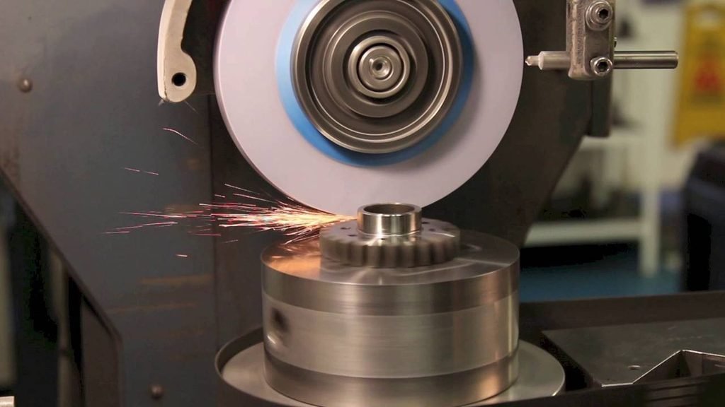
Precision surface grinding machines are developed for producing flat and parallel surfaces with high geometrical accuracy. The workpiece is commonly mounted on a magnetic chuck or a specialized mechanical fixture, while the grinding wheel moves across the surface according to the selected machining cycle. Horizontal spindle machines with reciprocating tables are widely used for general precision surface grinding. Vertical spindle machines are also employed where different wheel configurations and larger contact areas are advantageous. Surface grinding machines are essential in the production of precision plates, machine components, tooling elements, dies, molds, guideways, and accurately dimensioned mechanical parts.
Flatness, parallelism, perpendicularity, and surface roughness are among the principal quality requirements in precision surface grinding. Achieving these characteristics requires a stable machine structure, accurate table movement, correct magnetic chuck installation, suitable wheel selection, and controlled grinding parameters. Workpiece deformation caused by magnetic clamping, residual stresses, or temperature changes must also be considered. Thin components are particularly sensitive because clamping forces and thermal gradients may cause temporary deformation during machining. For such applications, specialized fixtures and carefully controlled grinding sequences may be required.
Centerless grinding machines offer a different approach to cylindrical component production. Unlike conventional cylindrical grinding, the workpiece is not normally held between centers or in a chuck. Instead, it is supported between a grinding wheel, a regulating wheel, and a work-rest blade. The grinding wheel performs material removal, while the regulating wheel controls the rotational speed and axial movement of the workpiece. This arrangement provides excellent production efficiency for components with suitable geometries and is particularly valuable in high-volume manufacturing. Centerless grinding is widely used for pins, rollers, shafts, bushes, precision rods, bearing components, and similar products.
There are several centerless grinding methods, including through-feed, in-feed, and end-feed grinding. Through-feed grinding is particularly suitable for long cylindrical components that can pass continuously through the grinding zone. In-feed grinding is used for components with shoulders, grooves, or specific profile characteristics that prevent continuous axial movement. End-feed grinding is suitable for certain tapered components where the workpiece enters the grinding zone from one side and moves until it reaches a defined position. The choice of method depends on the workpiece geometry, production quantity, dimensional requirements, and machine configuration.
The adjustment of the regulating wheel and work-rest blade is essential for successful centerless grinding. Small changes in the position or inclination of these components can influence workpiece rotation, axial movement, and final geometry. The workpiece center height relative to the grinding wheel centerline is another important process parameter. Incorrect center height may cause roundness errors, lobing, or unstable machining behaviour. Centerless grinding therefore requires careful setup and a detailed understanding of the relationship between grinding wheel speed, regulating wheel speed, workpiece diameter, and support geometry.
Precision tool and cutter grinding machines are designed for manufacturing and reconditioning cutting tools. These machines are used to grind drills, end mills, milling cutters, reamers, taps, form tools, and other specialized cutting equipment. Modern CNC tool grinding machines can control several axes simultaneously to generate complex cutting geometries and flute profiles. Their performance depends on accurate spindle positioning, stable toolholding, suitable grinding wheel configurations, and advanced CNC software. In addition to producing new tools, these machines are used for resharpening worn tools and restoring their cutting characteristics.
The production of cutting tools requires close control over rake angles, clearance angles, helix angles, cutting-edge geometry, and concentricity. Small geometrical deviations can influence cutting forces, chip formation, tool temperature, and machining performance. Five-axis CNC grinding machines are particularly useful because they can generate complex geometries through coordinated movement of the grinding wheel and workpiece. Automatic tool measurement and wheel dressing systems improve repeatability and reduce setup time. Such machines are widely used by specialist cutting-tool manufacturers and industrial tooling departments.
Coordinate grinding machines are used when extremely accurate internal and external geometrical features must be produced, particularly in dies, molds, precision tooling, and components containing accurately positioned holes. These machines combine precision spindle systems with accurate coordinate positioning and specialized grinding attachments. They are capable of machining cylindrical holes, tapered bores, profiles, radii, slots, and other complex geometrical features. Their applications frequently involve components where the relative position of several geometrical features is just as important as the individual dimensions themselves.
Coordinate grinding is particularly valuable in toolmaking because the manufacturing of dies and molds often requires precise control of hole positions, cavity profiles, clearances, and geometrical relationships. Advanced machines may use CNC control, automatic measuring systems, and specialized wheel dressing equipment to generate complex internal contours. The machine structure, spindle stiffness, positioning accuracy, and thermal stability must be carefully engineered to achieve the required machining quality.
Profile grinding is another specialized category of precision grinding technology. It is used to produce components with defined geometrical contours that cannot be machined efficiently through conventional cylindrical or surface grinding. The grinding wheel may be dressed to reproduce a specific profile, or the machine may use coordinated CNC movements to generate the required contour. Profile grinding is commonly used for gear components, camshafts, cutting tools, dies, molds, and specialized mechanical parts. The accuracy of the wheel profile and the stability of the dressing system are especially important because errors in the grinding wheel geometry can directly affect the finished component.
Gear grinding is an important specialized application of precision grinding. It is used to improve tooth geometry, surface finish, and dimensional accuracy after previous manufacturing operations such as hobbing, shaping, or heat treatment. Gear grinding is particularly important for hardened gears used in automotive transmissions, industrial gearboxes, aerospace drives, and precision machinery. Depending on the gear geometry and production requirements, generating grinding and form grinding technologies may be employed. Modern CNC gear grinding machines coordinate the movement of the grinding wheel and gear workpiece to produce accurate tooth profiles and controlled surface characteristics.
Thread grinding is another specialized precision grinding process used to manufacture highly accurate external and internal threads. It is particularly important in the production of precision lead screws, ball screws, thread gauges, precision spindles, and specialized mechanical transmission components. Thread grinding can produce accurate thread profiles with excellent surface finish, particularly in hardened materials where conventional thread cutting becomes difficult. The grinding wheel must be dressed to the required thread profile, and the machine must maintain accurate synchronization between the workpiece rotation and grinding wheel movement.
Camshaft and crankshaft grinding machines are specialized forms of cylindrical grinding equipment developed for automotive and industrial engine components. Camshaft grinding requires accurate reproduction of the cam profile, including base circle, lift, opening and closing ramps, and other functional geometrical characteristics. Crankshaft grinding requires control over main journal and connecting rod journal diameters, concentricity, and surface finish. Modern CNC systems allow the grinding wheel movement to follow complex programmed profiles, improving machining consistency and reducing setup requirements.
The grinding of advanced materials is becoming increasingly important in modern manufacturing. Hardened tool steels, stainless steels, nickel-based superalloys, titanium alloys, cemented carbides, technical ceramics, and composite materials present different challenges during grinding. Some materials generate high cutting forces, while others are sensitive to thermal damage or abrasive wear. Nickel-based superalloys, for example, may exhibit significant work hardening and poor thermal conductivity, requiring careful selection of abrasive materials and coolant delivery conditions. Titanium alloys require particular attention to heat generation and chemical interaction with the grinding environment. Ceramics and glass require controlled grinding conditions to minimize cracking and subsurface damage.
Cubic boron nitride abrasives are particularly useful when machining hardened ferrous materials because of their high hardness and thermal characteristics. Diamond abrasives are widely used for carbide, ceramics, glass, and other hard non-ferrous materials. However, the suitability of a particular abrasive depends on the workpiece material, grinding temperature, chemical compatibility, wheel construction, and required machining performance. Abrasive selection should therefore be based on the complete grinding application rather than hardness alone.
Production efficiency is another major consideration in the engineering of precision grinding machines. Reducing non-productive time can significantly improve the economic performance of a grinding operation. Automatic workpiece loading, rapid positioning, automatic wheel dressing, in-process measurement, and programmable grinding cycles can reduce manual intervention and improve machine utilization. In high-volume production, grinding machines may be integrated into automated manufacturing lines where workpieces move between machining, washing, measuring, and inspection stations without manual handling.
Robotic loading systems can be used to transfer workpieces between storage units, machine fixtures, and inspection equipment. The design of such systems must consider workpiece dimensions, weight, orientation, gripping requirements, and the necessary positioning accuracy. Machine interfaces must coordinate the robot movements with the grinding cycle and ensure that the grinding zone is accessible only under safe operating conditions. Automatic part identification and recipe selection can also be incorporated to prevent incorrect machining parameters from being applied to different component types.
Digital monitoring is becoming an increasingly important element of advanced grinding technology. Sensors installed in the spindle, machine structure, coolant system, and drive assemblies can provide information about vibration, temperature, operating load, and process stability. This information can be used to identify changes in machine behaviour before they develop into serious mechanical problems. Predictive maintenance systems can analyze operating data and help determine when bearings, lubrication components, filters, or other machine elements require inspection or replacement.
The integration of grinding machines into digital manufacturing environments also allows production data to be collected and analyzed. Cycle times, machine utilization, wheel consumption, dimensional measurement results, and maintenance information can be monitored over extended production periods. This information helps manufacturers identify recurring process deviations, optimize machining parameters, and improve production planning. Digital connectivity can also support remote diagnostics and technical assistance, provided that appropriate cybersecurity and access-control measures are implemented.
Machine safety must remain a fundamental part of precision grinding machine design. Grinding wheels operate at high rotational speeds and can store considerable kinetic energy. Incorrect wheel selection, improper mounting, excessive operating speed, mechanical damage, or inadequate guarding can create serious hazards. Machines must incorporate suitable wheel guards, interlocking safety systems, emergency stops, protective enclosures, and appropriate coolant containment arrangements. The maximum permissible wheel speed must never be exceeded, and grinding wheels must be inspected and mounted according to the applicable manufacturer instructions and safety standards.
The electrical and control systems must also comply with the relevant machinery safety requirements. Emergency stopping, protective interlocks, access monitoring, safe operating modes, and controlled restart functions must be considered during machine development. Where automatic loading systems are used, the safety design must include the robot working area, material transfer mechanisms, and interaction between the operator and automated equipment. A comprehensive risk assessment should be performed during the machine design process to identify mechanical, electrical, hydraulic, pneumatic, and operational hazards.
Precision grinding machine manufacturing requires a combination of mechanical engineering, precision machining, metrology, electrical engineering, CNC programming, and process development. Manufacturing tolerances for the machine components must be established according to the required final machine performance. Spindle housings, bearing seats, guideway mounting surfaces, precision shafts, wheelhead assemblies, and workpiece support elements require appropriate machining and inspection procedures. Assembly operations must be carried out under controlled conditions to ensure correct alignment, preload, lubrication, and mechanical positioning.
The final machine accuracy should be verified through systematic geometric and functional testing. Depending on the machine type, this may include axis positioning accuracy, positioning repeatability, straightness, parallelism, perpendicularity, spindle radial and axial runout, spindle vibration, table movement characteristics, and thermal stability. Machine acceptance tests should also include actual grinding trials using representative workpieces. Measuring only the unloaded machine geometry is insufficient to establish its complete machining capability because actual grinding performance also depends on dynamic behaviour, thermal conditions, grinding wheel characteristics, and process parameters.
Metrology is therefore closely connected to precision grinding technology. Coordinate measuring machines, roundness measuring instruments, cylindrical form testers, surface roughness measuring equipment, laser interferometers, electronic comparators, and precision gauges are used to verify different aspects of machining accuracy. The measurement method must be appropriate for the geometrical feature being inspected. For example, diameter measurement alone cannot establish roundness, cylindricity, or concentricity. Similarly, a surface roughness measurement cannot independently determine whether a component has acceptable waviness or geometrical form.
Roundness is particularly important in precision cylindrical grinding because a component may have the correct nominal diameter while exhibiting unacceptable deviations around its circumference. Cylindricity evaluates the complete three-dimensional cylindrical form and includes variations along the component length. Coaxiality and concentricity are important where multiple rotational features must share a common axis. These characteristics are particularly relevant in the production of precision shafts, bearing seats, hydraulic spools, spindle components, and rotating mechanical assemblies.
Surface roughness is generally evaluated through parameters such as Ra, Rz, and other profile-based measurements. The appropriate roughness requirement depends on the functional purpose of the surface. A bearing seat, sealing surface, sliding guide, and general locating surface may require different surface characteristics. Extremely low roughness is not necessarily the best solution for every application because certain mechanical interfaces require controlled surface texture to retain lubricant or achieve proper functional contact. Grinding parameters must therefore be selected according to the actual engineering function of the finished surface.
One of the major challenges in precision grinding is maintaining consistent quality throughout long production runs. Grinding wheels gradually wear, machine components experience temperature changes, and workpiece material characteristics may vary between batches. These changes can produce dimensional drift if they are not properly controlled. Automatic gauging, adaptive compensation, controlled dressing intervals, coolant temperature management, and statistical process monitoring can significantly improve production stability. The objective is not simply to produce one component within tolerance but to maintain the required quality across hundreds or thousands of components.
Statistical process control can be applied to grinding operations to monitor dimensional variation and identify trends before components exceed their permitted tolerances. Measurements collected during production can be analyzed to determine process capability and evaluate whether the machine is operating consistently. This approach is particularly valuable in automotive, aerospace, bearing, and other industries where traceability and production repeatability are essential. Measurement data can also help distinguish between gradual wheel wear, thermal drift, machine positioning errors, and variations in incoming material.
The economic performance of precision grinding machines depends on more than their initial purchase price. Machine productivity, achievable accuracy, wheel consumption, coolant requirements, maintenance costs, energy consumption, operator requirements, and production flexibility all influence the total cost of ownership. A highly specialized machine may provide excellent performance for one particular component but offer limited flexibility for other applications. A more versatile CNC grinding machine may require a higher initial investment but provide advantages when manufacturing different component families. Machine selection should therefore consider both current production requirements and anticipated future manufacturing needs.
Energy efficiency is also receiving increasing attention in modern grinding machine design. Grinding spindle motors, hydraulic pumps, coolant pumps, extraction systems, and auxiliary equipment can contribute significantly to total energy consumption. High-efficiency motors, variable-speed drives, optimized hydraulic circuits, intelligent coolant management, and automatic standby functions can reduce unnecessary energy use. Machine structures and thermal systems should also be designed to minimize heat generation and reduce the energy required for temperature stabilization.
Environmental considerations extend beyond electricity consumption. Grinding operations generate abrasive particles, metallic sludge, used coolant, and other industrial waste products. Proper filtration, coolant maintenance, waste separation, and responsible disposal are necessary to maintain a clean and safe production environment. Modern coolant systems can extend fluid service life and reduce disposal frequency through effective filtration and contamination control. Enclosed grinding areas and suitable extraction systems can also help control mist and airborne particles.
The development of precision grinding machines is closely connected to advances in CNC control technology. Modern controllers can coordinate multiple axes, execute complex interpolation movements, manage dressing cycles, and communicate with external measurement systems. The integration of digital component models and machining simulation allows grinding processes to be developed and optimized before actual production begins. This can reduce setup time, improve programming reliability, and minimize the risk of tool collisions or incorrect machining sequences.
Grinding simulation is particularly useful for complex profiles and multi-axis machining operations. By modeling the relationship between the grinding wheel and workpiece, engineers can evaluate potential interference, wheel accessibility, material removal, and geometrical accuracy. Simulation can also support the selection of wheel dimensions and machining strategies. However, the accuracy of a simulation depends on the quality of the underlying machine, wheel, workpiece, and process models. Actual machining trials and metrological verification remain necessary before a process can be considered fully validated.
The future of precision grinding technology will increasingly involve the integration of machine design, advanced materials, intelligent sensors, automated inspection, and adaptive process control. New spindle technologies, improved abrasive materials, high-performance CNC systems, and advanced coolant delivery methods will continue to expand the range of achievable machining operations. Manufacturers will increasingly seek machines that can perform multiple operations within a single setup while maintaining the accuracy required for sophisticated mechanical components.
The importance of precision grinding will remain particularly high in industries where surface quality and geometrical accuracy directly influence safety, efficiency, and product service life. Bearings, turbine components, precision hydraulic systems, automotive transmissions, aerospace mechanisms, machine tool spindles, cutting tools, and advanced industrial equipment all depend on accurately manufactured surfaces and geometrical features. As tolerances become tighter and materials become more demanding, the engineering requirements placed on precision grinding machines will continue to increase.
Ultimately, a precision grinding machine must be considered as a complete engineering system rather than simply a machine equipped with a rotating abrasive wheel. Its performance is determined by the interaction of structural rigidity, spindle accuracy, bearing technology, guideway design, drive mechanisms, CNC control, wheel characteristics, coolant delivery, thermal stability, measuring systems, and operator expertise. Successful precision grinding requires all these elements to function together under stable and repeatable conditions. A well-designed machine provides not only excellent dimensional accuracy and surface finish but also long-term reliability, predictable production performance, and the flexibility required by modern industrial manufacturing.
Precision Grinding Machines – Advanced Engineering, Manufacturing Technologies and Industrial Applications
The engineering of precision grinding machines requires a comprehensive understanding of mechanical systems, material science, tribology, vibration analysis, thermal behaviour, machining dynamics, and industrial automation. As manufacturing tolerances become increasingly demanding, the design of grinding equipment must address not only the nominal positioning accuracy of individual machine components but also the stability of the complete system under actual operating conditions. A grinding machine may incorporate high-resolution measuring devices, advanced CNC controls, and precision spindle bearings, but its practical machining capability will still be limited if the supporting structure, drive mechanisms, workholding arrangements, or thermal management systems cannot maintain the necessary stability. For this reason, precision grinding machine development involves the optimization of numerous interacting engineering parameters rather than concentrating on a single high-accuracy component.
One of the most important engineering considerations is the static and dynamic stiffness of the machine. Static stiffness determines how much the machine structure deforms under an applied force, while dynamic stiffness describes its response to forces that vary with time. During grinding, forces are generated continuously as abrasive grains interact with the workpiece. These forces are not perfectly constant because abrasive grain geometry, wheel runout, material hardness, and the distribution of active cutting edges vary throughout the grinding cycle. The resulting excitation can produce vibrations in the grinding spindle, wheelhead, machine bed, workpiece support, and other structural assemblies. If the machine has insufficient dynamic stiffness or an unfavourable natural frequency, these vibrations may become visible on the finished surface as periodic patterns, waviness, or other geometrical deviations.
The structural design must therefore consider the complete force transmission path from the grinding contact zone through the wheelhead, spindle housing, machine bed, guideways, and foundation. Every mechanical connection along this path contributes to the overall stiffness and damping characteristics. Bolted joints, bearing housings, guideway mounting surfaces, and structural interfaces must be designed to minimize unwanted relative movement. The location of major assemblies also influences the distribution of forces and the machine’s response to dynamic loading. A compact structural arrangement can reduce unnecessary overhangs and improve stiffness, while an optimized bed geometry can help distribute machining forces without creating excessive local deformation.
Finite element analysis is widely used during the development of advanced grinding machines to evaluate structural deformation, stress distribution, modal characteristics, and thermal behaviour. Engineers can use these models to investigate the effects of different bed geometries, material selections, rib arrangements, spindle positions, and support configurations. Modal analysis helps identify the natural frequencies of the machine structure and determine whether operating frequencies or their harmonics may excite undesirable vibration modes. Harmonic response analysis can provide further information about the dynamic behaviour of the machine under periodic excitation. Although numerical analysis is an important design tool, physical measurements are still required to validate the structural model and confirm actual machine behaviour.
Vibration control is particularly important in high-speed grinding applications. The grinding wheel, spindle assembly, workpiece, and rotating workholding components must be balanced and mechanically stable. Even small eccentricities can generate centrifugal forces that increase with the square of rotational speed. Bearing defects, incorrect spindle preload, damaged wheel flanges, and unsuitable mounting arrangements may also contribute to vibration. Advanced grinding machines may incorporate vibration sensors that continuously monitor spindle behaviour and identify changes in operating conditions. These measurements can be used for preventive maintenance, process optimization, and early detection of mechanical problems.
Regenerative chatter is another phenomenon that can affect grinding stability. It occurs when surface irregularities produced during one revolution or pass influence the cutting conditions during subsequent contact. Under certain combinations of machine stiffness, damping, wheel speed, workpiece speed, and grinding depth, these interactions can amplify vibration. Chatter may cause visible surface patterns, increased noise, accelerated wheel wear, and dimensional inaccuracies. Preventing it requires a suitable combination of structural design, spindle dynamics, grinding parameters, wheel selection, and process monitoring. In particularly demanding applications, engineers may use experimental modal analysis and operational vibration measurements to identify problematic frequency ranges and optimize the machine configuration.
The design of precision grinding spindles involves a detailed evaluation of rotational speed, bearing arrangement, load capacity, stiffness, lubrication, cooling, and service life. The spindle must support the grinding wheel without introducing unacceptable radial or axial displacement. The bearing arrangement must also accommodate the loads generated by grinding and the centrifugal forces associated with wheel rotation. Precision angular contact ball bearings are frequently used because they provide high rotational accuracy and can support combined radial and axial loads. Their contact angle, internal geometry, preload, lubrication method, and mounting arrangement must be selected according to the intended operating conditions.
Bearing preload is an especially important parameter in precision spindle design. Applying preload removes internal clearance and increases the rigidity of the bearing arrangement. However, excessive preload increases friction, heat generation, and contact stress, potentially reducing bearing life. Insufficient preload can allow unwanted displacement and reduce spindle stiffness. The appropriate preload therefore depends on bearing dimensions, operating speed, applied loads, thermal conditions, and the required rotational accuracy. In high-speed applications, preload changes caused by temperature differences between the inner and outer bearing rings must also be considered.
Lubrication systems must provide a stable supply of lubricant without generating excessive heat or causing unnecessary fluid resistance. Grease lubrication is used in many precision spindles because of its relatively simple construction and low maintenance requirements. Oil-air lubrication can provide controlled lubricant delivery and is frequently employed in high-speed spindle systems. Oil circulation systems offer additional cooling capabilities and can be used where bearing temperature control is particularly important. The lubrication system must be compatible with the bearing arrangement, spindle speed, operating duty, and environmental conditions. Incorrect lubrication can cause premature bearing failure even when the mechanical design is otherwise satisfactory.
Hydrostatic and hydrodynamic spindle technologies provide alternative solutions for applications requiring particular combinations of stiffness, damping, and rotational accuracy. Hydrostatic bearings use an externally pressurized fluid film to separate the bearing surfaces. This arrangement can provide excellent damping and very low friction, including at relatively low rotational speeds. Hydrodynamic bearings generate their supporting film through relative motion between the bearing surfaces and lubricant. Both technologies require careful engineering of clearances, pressure distribution, fluid viscosity, temperature, and supply conditions. Their application is particularly relevant in specialized precision grinding machines where conventional rolling bearings may not provide the desired performance characteristics.
Thermal deformation of the spindle is a major source of dimensional error in precision grinding. Heat generated by bearings, motor windings, seals, and grinding operations can change the temperature distribution along the spindle assembly. Even small temperature differences can produce measurable axial or radial displacement. Direct-drive motor spindles require particular attention because the motor is integrated into or closely coupled with the spindle assembly, potentially introducing additional heat. Cooling channels, temperature sensors, controlled coolant circulation, and thermal compensation algorithms can be used to minimize the influence of these effects. The cooling arrangement must be designed so that it does not introduce excessive temperature gradients or mechanical distortion into the spindle housing.
Direct-drive spindle technology is increasingly used in advanced grinding machines because it eliminates certain transmission elements and can provide accurate speed control. Conventional belt-driven systems remain appropriate for many applications because they are relatively simple, economical, and easy to maintain. However, belt elasticity, pulley balance, transmission losses, and vibration can influence high-precision performance. Direct-drive systems avoid belt-related disturbances but require suitable motor design, cooling, electronic control, and electromagnetic compatibility. The choice between direct drive and belt drive must therefore be based on spindle speed, required torque, machine configuration, operating duty, maintenance strategy, and overall cost.
The grinding wheel flange and mounting system also deserve careful consideration. The flange must support the wheel securely while maintaining concentricity and correct alignment with the spindle axis. Incorrect mounting can produce eccentric rotation, uneven contact pressure, vibration, or even wheel damage. The contact surfaces must be clean and properly manufactured, and the mounting arrangement must follow the grinding wheel manufacturer’s specifications. The wheel diameter, width, bore, maximum permitted speed, and mounting requirements must be verified before operation. For machines intended to use several wheel types, standardized mounting systems can simplify wheel replacement and improve setup consistency.
The design of grinding wheel dressing systems has become increasingly sophisticated as manufacturers demand more complex component profiles and improved process consistency. Traditional dressing tools can generate conventional cylindrical, flat, and profile wheel geometries, while CNC-controlled rotary dressing systems allow more complicated forms to be produced. Rotary diamond dressing tools are particularly useful for generating precise profiles and maintaining repeatable wheel geometry during production. Their rotational speed, direction, contact ratio, dressing depth, and traverse movement influence the resulting abrasive surface characteristics.
The relationship between dressing conditions and grinding performance is not always straightforward. Aggressive dressing can produce a sharper and more open wheel surface, improving cutting ability but potentially increasing wheel wear. Fine dressing can produce a smoother wheel surface and improve surface finish, although it may also increase grinding forces and heat generation if the wheel becomes excessively closed. The correct dressing strategy depends on the workpiece material, wheel specification, machining operation, and required final quality. Advanced grinding machines can store several dressing programs for different operations and automatically compensate for wheel diameter reduction.
The development of high-precision machine axes requires particular attention to positioning accuracy, repeatability, straightness, and thermal stability. Precision ball screws are widely used in CNC grinding machines because they provide efficient mechanical transmission and relatively high positioning accuracy. Their performance depends on screw lead accuracy, preload, bearing arrangement, support rigidity, lubrication, and temperature. Ball screw expansion can introduce positioning errors during long production cycles, particularly when the screw is exposed to heat generated by rapid movement. Temperature monitoring and compensation can help reduce these effects.
Linear motor technology provides an alternative to conventional screw-driven axes. Because the motor produces linear movement directly, there is no need for a rotary-to-linear transmission mechanism. This arrangement can provide high acceleration, smooth movement, and reduced mechanical backlash. However, linear motors require careful management of heat generation, magnetic forces, encoder installation, and control-system tuning. They may be particularly advantageous in machines requiring fast and precise movement, although their cost and technical complexity must be evaluated against the intended production requirements.
Position feedback is essential for accurate CNC axis control. Linear optical scales can measure actual axis displacement independently of certain mechanical transmission errors, while rotary encoders generally measure motor or screw rotation. The use of direct linear measurement can improve positioning accuracy because it reduces the influence of ball screw lead errors, transmission deformation, and certain thermal effects. The measuring resolution, installation geometry, contamination protection, signal processing, and machine control architecture must all be considered when selecting a feedback system.
The geometric calibration of a precision grinding machine is a complex process involving several independent error sources. These include linear positioning errors, straightness deviations, angular errors, squareness errors, spindle alignment, and rotary-axis errors. Individual errors can interact and produce more complicated deviations at the workpiece. Laser interferometers, electronic levels, autocollimators, precision squares, straightedges, and other calibration instruments can be used to measure different aspects of machine geometry. The resulting data can be used to adjust mechanical assemblies or generate CNC compensation tables.
Volumetric accuracy is an important consideration in multi-axis grinding machines. A machine may exhibit acceptable positioning accuracy along each individual axis but still produce significant errors when several axes move simultaneously. These errors can result from geometric misalignment, angular deviations, structural deformation, and thermal effects. Volumetric calibration evaluates the combined positioning performance of the machine throughout its working envelope. This is particularly important for five-axis tool grinding machines, profile grinding systems, and specialized CNC machines producing complex geometrical components.
The workholding system is another major factor in precision grinding. A component must be supported securely without introducing excessive deformation or restricting the required machining movements. Magnetic chucks are widely used in surface grinding for suitable ferromagnetic materials. Mechanical fixtures, precision vises, vacuum systems, collets, chucks, and specialized clamping arrangements are employed according to workpiece geometry and material characteristics. In cylindrical grinding, the use of centers and suitable workholding devices helps establish the rotational axis and maintain concentricity.
Magnetic workholding systems require particular attention when machining thin or flexible components. Excessive magnetic clamping force can cause a workpiece to deform during grinding. After releasing the magnetic field, the component may return toward its original shape, resulting in unacceptable flatness or thickness variations. Residual magnetism can also affect subsequent manufacturing or inspection operations. Suitable magnetic chuck design, controlled clamping, demagnetization, and alternative fixture arrangements may be necessary for sensitive components.
Vacuum workholding is useful for certain non-ferrous, non-magnetic, and thin workpieces. The workpiece is held through a pressure differential generated by a vacuum system. Its effectiveness depends on the available contact area, sealing characteristics, surface condition, and applied grinding forces. Specialized mechanical support may be required where the component geometry does not provide sufficient sealing or stiffness. For precision grinding, the fixture must be sufficiently rigid to prevent vibration and displacement during machining.
The grinding of long and slender components requires special attention because workpiece deflection can become a major source of dimensional error. Long shafts, hydraulic piston rods, precision rollers, and similar components may bend under their own weight or under the forces generated during grinding. Steady rests and support systems can reduce this deformation by providing additional radial support. However, their position, contact force, alignment, and lubrication must be controlled to avoid introducing new geometrical errors. The grinding sequence may also be optimized to distribute material removal and minimize the effect of changing workpiece stiffness.
In the production of precision shafts, several operations may be combined within a single cylindrical grinding machine. These can include external diameter grinding, shoulder grinding, taper grinding, end-face grinding, and profile grinding. CNC-controlled wheelhead movement allows the machine to perform multiple operations according to a programmed sequence. Automatic workpiece measurement can be used to verify critical diameters and compensate for wheel wear. The ability to complete several features in one setup reduces handling time and helps maintain the geometrical relationship between different surfaces.
Precision grinding is also essential in the manufacture of hydraulic valve components. Hydraulic spools, valve sleeves, precision plungers, and piston elements require carefully controlled diameters, roundness, cylindricity, and surface characteristics. The clearances between moving components influence leakage, friction, response time, and operating efficiency. Excessive clearance can increase internal leakage, while insufficient clearance may cause sticking or seizure under operating conditions. Grinding machines used for these components must provide stable dimensional control and consistent surface quality across production batches.
The grinding of hydraulic piston rods requires particular attention to surface finish, straightness, and dimensional stability. These components operate in contact with sealing systems, and surface characteristics directly influence seal wear and leakage performance. Excessively rough surfaces can damage seals, while unsuitable surface texture may reduce lubricant retention. The required surface quality depends on the sealing arrangement, material, coating, operating pressure, and movement speed. Cylindrical grinding is frequently combined with subsequent polishing or superfinishing operations when the application requires additional control over the surface characteristics.
Bearing manufacturing is another major field of precision grinding. Bearing rings, rollers, and balls require highly accurate geometrical characteristics because even small deviations can influence load distribution, vibration, noise, friction, and service life. Outer and inner raceways are ground to controlled profiles, while rolling elements are processed to achieve the required diameter, roundness, and surface finish. Modern bearing production uses specialized grinding machines with automatic loading, measuring, dressing, and compensation systems. High production rates must be achieved without sacrificing the geometrical consistency of individual components.
Superfinishing is often used after precision grinding when an even finer surface texture or improved functional contact is required. The process generally uses fine abrasive stones or specialized abrasive materials operating under controlled contact conditions. It removes a very small amount of material and modifies the surface texture without significantly changing the nominal geometry when properly applied. Superfinishing is widely used in bearing raceways, crankshaft journals, camshaft surfaces, and other components where friction, lubrication, and contact behaviour are important.
The relationship between grinding and subsequent finishing operations must be considered during process planning. If the grinding process leaves excessive waviness, subsurface damage, or geometrical errors, a light finishing operation may not be sufficient to correct them. The preceding grinding operation must therefore establish a suitable geometrical foundation for the final process. In high-precision manufacturing, every machining stage should be designed according to the requirements of the following operation and the final functional characteristics of the component.
Precision grinding machines are also important in the production of machine tool components. Linear guideways, spindle shafts, bearing housings, precision rails, and mounting surfaces require accurate geometrical relationships to ensure the performance of the complete machine. Surface grinding is used to produce flat and parallel reference surfaces, while cylindrical grinding is used for shafts and rotational components. The final accuracy of a machine tool depends partly on the precision of these individual elements and the quality of their assembly.
The manufacturing of precision dies and molds involves a wide range of grinding operations. Flat surfaces, internal bores, profiles, cavities, radii, and narrow slots must often be produced with high dimensional accuracy. Tool steels may be hardened before final grinding, creating additional challenges related to material removal, thermal damage, and abrasive wear. Coordinate grinding, profile grinding, surface grinding, and specialized internal grinding technologies are frequently combined to manufacture complex tooling components. CNC-controlled machines provide greater flexibility when generating complicated geometries and maintaining the relative positions of different features.
The use of precision grinding in the aerospace industry requires particularly strict process control. Turbine shafts, compressor components, landing gear elements, hydraulic parts, and other critical components may be manufactured from materials with high strength and demanding mechanical properties. Nickel-based superalloys and titanium alloys can be difficult to grind because of their thermal and mechanical characteristics. Grinding processes must be developed to prevent excessive heat generation, surface damage, and undesirable residual stresses. Inspection and traceability requirements are also important because the finished components may operate under high mechanical loads and demanding environmental conditions.
In the energy sector, precision grinding is used for manufacturing turbine components, generator shafts, pump elements, compressor parts, and industrial transmission systems. Large rotating components may require specialized machines with considerable workpiece capacity and high structural stiffness. The grinding of long shafts and large diameters presents particular challenges because workpiece weight, thermal expansion, and support conditions can influence the final geometry. Machine design must therefore account for the complete workpiece mass, support arrangement, loading method, and required dimensional tolerances.
The production of precision optical and ceramic components introduces a different range of grinding requirements. Glass, optical ceramics, technical ceramics, and other brittle materials can be sensitive to subsurface cracking and localized mechanical stress. Diamond abrasives are frequently used because of their high hardness and suitability for these materials. The grinding process must be carefully controlled to minimize fracture, chipping, and unwanted surface damage. Depending on the required optical or functional characteristics, grinding may be followed by lapping, polishing, or other specialized finishing processes.
The growing use of advanced ceramics in industrial machinery has increased the importance of specialized grinding technologies. Ceramic components can provide excellent wear resistance, hardness, thermal stability, and corrosion resistance, but they are often difficult to machine after sintering. Diamond grinding wheels, controlled feed rates, rigid machine structures, and effective coolant systems are commonly required. The choice of abrasive concentration, wheel bond, and grinding parameters must be based on the particular ceramic composition and the required surface integrity.
Precision grinding machines are also used in the production of medical and dental components. Surgical instruments, implant components, dental tools, and specialized medical equipment may require complex geometries and very fine surface finishes. Stainless steels, titanium alloys, cobalt-chromium alloys, and ceramics are among the materials processed in this field. The machine configuration must provide the necessary precision while supporting clean and controlled production conditions. Where components have complex geometries, CNC grinding and specialized workholding arrangements can improve repeatability and manufacturing flexibility.
Another developing area is the grinding of additive-manufactured components. Metal additive manufacturing processes can produce geometries that are difficult to manufacture using conventional methods, but the resulting surfaces and dimensional characteristics may require additional machining. Precision grinding can be used to finish selected surfaces, correct critical dimensions, and improve functional contact areas. However, additive-manufactured materials may exhibit variations in microstructure, residual stress, and hardness depending on the manufacturing process. Grinding parameters must therefore be developed according to the actual material condition and component geometry.
The integration of grinding with other manufacturing technologies is becoming increasingly important. A precision grinding machine may operate as part of a production cell that includes turning, milling, heat treatment, washing, inspection, and assembly. The objective is to minimize unnecessary handling and establish a consistent flow of components through the manufacturing process. Automated transfer systems and centralized production management software can coordinate different machines while maintaining traceability and quality information. Such integration is particularly valuable for manufacturers producing complex mechanical components in medium- and high-volume production environments.
Machine acceptance procedures should reflect the actual intended application rather than relying exclusively on general machine specifications. A manufacturer may specify spindle runout, axis positioning accuracy, and geometric tolerances, but the customer also needs evidence that the machine can produce the required components under realistic operating conditions. Acceptance trials should therefore include representative workpieces, appropriate grinding wheels, specified coolant conditions, and agreed machining parameters. The finished components should be inspected using suitable measuring instruments, and the results should be documented against the required dimensional and geometrical specifications.
Long-term machine capability is another important consideration. A machine that produces acceptable results during initial commissioning must also maintain those results during continuous operation. Spindle bearing temperature, machine bed temperature, axis repeatability, coolant stability, and wheel wear should be monitored during extended production trials. Maintenance accessibility, spare-part availability, service procedures, and technical documentation also influence the practical reliability of the equipment throughout its operating life.
The engineering of precision grinding machines continues to evolve through improvements in mechanical design, bearing technology, CNC control, abrasive materials, measurement systems, and industrial automation. The objective is to achieve higher accuracy while improving productivity, reliability, energy efficiency, and operational flexibility. Modern grinding machines must be capable of handling increasingly diverse workpiece materials and geometries while maintaining consistent performance over long production periods.
Ultimately, the successful development of a precision grinding machine requires a balanced approach to every element of the mechanical and technological system. The spindle, bearings, machine bed, guideways, drive mechanisms, workholding system, grinding wheel, dressing equipment, coolant system, CNC control, and measurement technology must be designed to operate together. The machine’s actual performance is determined by the combined behaviour of these systems under real machining conditions. Through careful engineering, accurate manufacturing, systematic calibration, and continuous process optimization, precision grinding machines can deliver the dimensional accuracy, surface integrity, repeatability, and production reliability required by the most demanding areas of modern industrial manufacturing.
Precision Cylindrical Grinding Machines
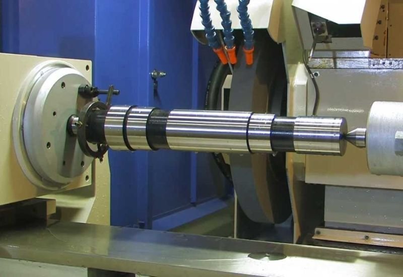
Precision cylindrical grinding machines are essential industrial machine tools designed to produce highly accurate cylindrical, conical, stepped, and profile-shaped surfaces on metallic and other machinable materials. These machines are widely used in manufacturing environments where dimensional accuracy, geometrical consistency, surface quality, and repeatability are critical requirements. They are particularly important for producing precision shafts, spindles, bearing components, hydraulic piston rods, rollers, transmission elements, machine tool components, automotive parts, and various mechanical assemblies. By using controlled abrasive machining processes, cylindrical grinding machines can achieve extremely fine dimensional tolerances and surface finishes that are difficult to obtain through conventional turning or milling operations.
The fundamental principle of cylindrical grinding is based on the controlled removal of material from a rotating workpiece through contact with a high-speed abrasive grinding wheel. The workpiece rotates around its longitudinal axis while the grinding wheel rotates at a much higher peripheral speed. Depending on the machine configuration and machining requirements, the grinding wheel may move longitudinally along the workpiece or penetrate radially into a specific section. The relative movement between the grinding wheel and workpiece determines the material removal rate, final diameter, surface characteristics, and geometrical accuracy. The process can be used for external cylindrical surfaces, internal bores, tapers, shoulders, grooves, radii, and complex rotational profiles.
One of the most important advantages of precision cylindrical grinding is its ability to machine hardened materials with excellent dimensional control. Components that have undergone heat treatment often develop dimensional changes, distortion, and surface irregularities. Cylindrical grinding provides an effective method of correcting these deviations and producing the final dimensions required for assembly and operation. Hardened steels, alloy steels, stainless steels, tool steels, and various specialized engineering materials can be processed using appropriately selected abrasive wheels and machining parameters. Depending on the material and application, aluminium oxide, silicon carbide, cubic boron nitride, or diamond abrasive technologies may be employed.
The mechanical structure of a precision cylindrical grinding machine must provide exceptional rigidity and vibration stability. The machine bed is generally manufactured from high-quality cast iron or another engineered structural material selected for its strength, damping characteristics, and dimensional stability. Its geometry is designed to support the grinding wheelhead, workhead, tailstock, longitudinal table, and other machine assemblies while maintaining their relative alignment. Internal ribs and structural reinforcement are used to improve stiffness and distribute mechanical loads. The machine bed must resist deformation caused by grinding forces, component weight, drive mechanisms, and temperature variations during continuous operation.
The grinding wheelhead is one of the most important assemblies of a cylindrical grinding machine. It contains the grinding spindle, bearings, drive system, wheel mounting arrangement, and associated protective components. The spindle must maintain high rotational accuracy while supporting the grinding wheel under the radial and axial forces generated during machining. Any excessive spindle runout, bearing vibration, or thermal displacement can directly influence the final workpiece geometry and surface quality. For this reason, precision cylindrical grinding machines use carefully engineered spindle assemblies with suitable bearing arrangements, lubrication systems, cooling provisions, and dynamic balancing procedures.
Spindle bearing selection depends on the intended grinding wheel speed, wheel dimensions, applied forces, required stiffness, and operating duty. Precision angular contact ball bearings are commonly used because they can support combined radial and axial loads while maintaining accurate rotational guidance. Their preload must be selected carefully to achieve the required stiffness without generating excessive friction or heat. In specialized machines, hydrostatic spindle systems may be used to provide excellent damping characteristics and very low friction. The spindle housing must also be designed to minimize thermal distortion and maintain stable alignment throughout the machining cycle.
The workhead is responsible for rotating the workpiece at a controlled speed during grinding. It generally incorporates a spindle, bearings, drive motor, transmission system, and suitable workholding arrangements. Depending on the component geometry, the workpiece may be held between centers, mounted in a chuck, supported by a collet, or secured using a specialized fixture. The workhead must provide stable rotation with minimal runout and sufficient torque to overcome friction and other mechanical resistance during machining. The rotational speed is selected according to the workpiece diameter, material, grinding wheel characteristics, and required surface finish.
Grinding between centers is one of the most widely used workholding methods for precision cylindrical grinding. The workpiece is supported at both ends by precision centers, allowing it to rotate around an established axis. A driving dog or other drive arrangement transmits rotational movement to the workpiece. This configuration is particularly useful for long shafts, precision spindles, rollers, and components requiring accurate relationships between several cylindrical surfaces. The condition and alignment of the centers are critical because any deviation can produce runout or geometrical errors in the finished component.
The tailstock provides support for the opposite end of the workpiece and allows components of different lengths to be accommodated. Its axial positioning must be accurate, and the applied center pressure must be sufficient to support the workpiece without causing excessive axial loading or deformation. Hydraulic, pneumatic, mechanical, and manually operated tailstock systems can be used depending on machine size and automation requirements. In CNC cylindrical grinding machines, programmable tailstock positioning and controlled center pressure can improve setup consistency and reduce operator intervention.
The longitudinal table is responsible for moving the workpiece relative to the grinding wheel during traverse grinding operations. Its movement must be smooth, accurate, and repeatable throughout the machining stroke. Traditional machines may use hydraulic table drives, while modern CNC machines generally employ servo-driven axes with precision ball screws or other advanced transmission systems. The guiding arrangement may incorporate precision-ground box guideways, linear rolling guides, or hydrostatic guideways according to the required machine performance. The table must maintain accurate alignment with the grinding spindle and minimize angular and linear deviations during movement.
The quality of cylindrical grinding depends strongly on the relationship between grinding wheel speed, workpiece speed, longitudinal feed, and radial infeed. These parameters must be selected according to the workpiece material, initial machining allowance, grinding wheel specification, and final dimensional requirements. Higher material removal rates may be suitable for rough grinding, while finishing operations require smaller infeed values and carefully controlled feed movements. Spark-out operations, in which the grinding wheel continues contacting the workpiece with little or no additional radial infeed, can help reduce elastic deformation effects and improve dimensional consistency.
Cylindrical grinding machines can perform several different grinding methods depending on the component geometry and production requirements. Traverse grinding is used for machining relatively long cylindrical surfaces. During this process, the grinding wheel moves longitudinally across the workpiece while removing material from its surface. The wheel may perform multiple passes until the required diameter is achieved. This method is particularly suitable for shafts, rollers, hydraulic piston rods, and other elongated components.
Plunge grinding is used when a specific cylindrical section, shoulder, or defined profile must be machined without a longitudinal traverse across the entire workpiece length. The grinding wheel moves radially toward the rotating workpiece and removes material over the required contact width. Plunge grinding is particularly useful for short cylindrical surfaces, bearing seats, stepped shafts, and components with localized grinding requirements. It can also provide high production efficiency when the wheel width is suitable for the machining area.
Angular plunge grinding is another important cylindrical grinding method. In this configuration, the grinding wheel axis is inclined relative to the workpiece axis, allowing several surfaces or geometrical features to be ground in a coordinated operation. This arrangement can be used for machining shoulders, end faces, tapers, and cylindrical surfaces within a single setup. It reduces the need for repositioning and can improve the relative accuracy of different workpiece features.
Taper grinding is used to produce conical surfaces with accurately controlled angles and diameters. Depending on the machine design, taper grinding can be performed by swivelling the workhead, adjusting the tailstock, swivelling the grinding wheelhead, or using CNC-controlled axis movements. The appropriate method depends on the taper angle, component length, required accuracy, and machine configuration. CNC cylindrical grinding machines offer particular advantages for components containing several different taper geometries because the required movements can be programmed and repeated automatically.
Profile grinding allows cylindrical grinding machines to produce more complicated rotational geometries. Specially dressed grinding wheels or coordinated CNC movements can be used to generate radii, grooves, curved surfaces, shoulders, and other profiles. This capability is important in the production of camshaft components, transmission elements, precision rollers, tooling parts, and specialized mechanical components. The wheel dressing system must maintain the required profile throughout the machining process to ensure dimensional consistency.
Internal cylindrical grinding machines are designed for machining accurate internal diameters and cylindrical bores. Although they share the basic abrasive machining principle of external cylindrical grinding, their mechanical configuration is different because the grinding wheel must operate inside the workpiece. Internal grinding spindles are generally smaller in diameter and may require higher rotational speeds to achieve the appropriate grinding wheel peripheral speed. Their stiffness is particularly important because excessive spindle deflection can produce bore geometry errors and poor surface quality. Internal grinding is widely used for bearing rings, sleeves, bushes, hydraulic valve components, precision housings, and other parts requiring accurately machined internal surfaces.
Universal cylindrical grinding machines provide greater flexibility by combining different grinding operations within a single machine platform. Depending on the design, they may be equipped with external grinding spindles, internal grinding attachments, swivelling wheelheads, programmable workheads, and specialized measuring systems. This flexibility makes them suitable for manufacturing environments where a wide variety of components must be processed. Universal grinding machines are particularly useful in toolrooms, precision engineering workshops, prototype production, and specialized component manufacturing.
CNC cylindrical grinding machines have significantly expanded the capabilities of conventional cylindrical grinding technology. Computer numerical control allows the machine to execute programmed movements with high repeatability and coordinate several axes during complex grinding operations. Operators can define the workpiece geometry, grinding sequence, wheel dimensions, dressing parameters, and machining conditions through the control system. CNC technology also enables automatic compensation for grinding wheel wear, controlled spark-out cycles, automatic measurement, and repeatable production programs. These capabilities are particularly valuable when producing components with multiple diameters, shoulders, grooves, and tapered sections.
The selection of the grinding wheel is one of the most important factors in cylindrical grinding. The abrasive material must be compatible with the workpiece material and the required machining conditions. Aluminium oxide wheels are commonly used for grinding conventional and hardened steels. Different aluminium oxide formulations are available to suit various grinding conditions, including applications requiring improved friability, cutting performance, or wheel life. Silicon carbide wheels are generally used for non-ferrous metals, certain hard materials, and specialized applications. Cubic boron nitride wheels are particularly suitable for grinding hardened steels and other difficult-to-machine ferrous alloys. Diamond wheels are commonly used for cemented carbides, ceramics, and other extremely hard non-ferrous materials.
Grinding wheel grain size influences material removal behaviour and surface quality. Coarser grains generally provide higher cutting capacity and are used for rough grinding or applications involving larger machining allowances. Finer grains are more suitable for finishing operations where a smoother surface and controlled material removal are required. Wheel hardness determines how strongly the bond retains abrasive grains during operation, while wheel structure influences the spacing between grains and the available chip clearance. Bond type, abrasive concentration, wheel diameter, and wheel width must also be selected according to the application.
Grinding wheel dressing is essential for maintaining consistent machining performance. During operation, the abrasive grains gradually wear and the wheel may become loaded with workpiece material. Dressing removes worn or loaded abrasive material and restores the wheel’s cutting characteristics. It can also correct the wheel profile and maintain the required geometrical accuracy. Diamond dressing tools are widely used in cylindrical grinding machines, while rotary diamond dressing systems are employed for more complex profiles and automated production operations.
Wheel balancing is equally important because unbalanced grinding wheels can generate vibrations that negatively influence surface quality and machine life. The wheel and flange assembly must be balanced according to the operating speed and machine requirements. High-speed grinding operations require particular attention because centrifugal forces increase rapidly with rotational speed. Modern cylindrical grinding machines may incorporate automatic balancing systems that detect and compensate for wheel imbalance during operation.
Cooling and lubrication play a critical role in cylindrical grinding. The grinding zone can generate significant localized heat, particularly when machining hardened materials or performing operations with large contact areas. Excessive heat may cause grinding burns, microcracks, residual stresses, and dimensional instability. Coolant systems are therefore designed to deliver sufficient fluid directly into the grinding zone while removing heat and transporting grinding debris away from the contact area. The coolant delivery arrangement must consider wheel speed, nozzle geometry, flow rate, pressure, and the accessibility of the grinding zone.
Coolant filtration is particularly important in precision cylindrical grinding because fine abrasive particles and metallic contaminants can affect surface quality and machine reliability. Magnetic separators, paper filters, cartridge filtration systems, and other industrial filtration technologies can be used depending on the workpiece material and required fluid cleanliness. Temperature-controlled coolant circulation can further improve dimensional consistency by reducing thermal variations during long production cycles.
The geometrical accuracy of a precision cylindrical grinding machine is determined by several interacting parameters. These include spindle runout, workhead alignment, tailstock alignment, table straightness, guideway accuracy, wheelhead positioning, and workholding stability. The machine must maintain the correct relationship between the workpiece rotational axis and the grinding wheel movement. Even relatively small angular deviations can create taper errors, while spindle eccentricity may produce roundness and surface quality problems.
Roundness is one of the most important inspection parameters in cylindrical grinding. It evaluates the deviation of the workpiece cross-section from a theoretically perfect circle. A component may have an acceptable average diameter while still containing unacceptable roundness deviations. Cylindricity evaluates the complete three-dimensional cylindrical surface and considers variations along the workpiece length. Straightness, concentricity, coaxiality, and total indicated runout are also important depending on the component’s functional requirements.
Surface roughness is another critical characteristic. Parameters such as Ra and Rz are commonly used to evaluate the surface texture produced by cylindrical grinding. The required roughness depends on the component application, contact conditions, lubrication requirements, sealing arrangement, and assembly tolerances. Bearing seats, hydraulic piston rods, precision shafts, and sliding surfaces may require different surface characteristics. The grinding process must therefore be developed according to the functional requirements of the component rather than targeting the lowest possible roughness value in every application.
Thermal stability is particularly important when grinding long components or producing parts with very tight dimensional tolerances. The workpiece, machine bed, spindle housing, coolant, and surrounding environment may experience temperature variations during operation. These changes can influence the measured diameter and geometrical relationships between different surfaces. Precision cylindrical grinding machines may incorporate spindle cooling, controlled coolant temperature, thermal compensation, and in-process gauging to reduce the influence of thermal effects.
In-process measuring systems provide an important advantage in modern cylindrical grinding machines. Contact gauges can measure workpiece diameter while the component remains mounted in the machine. The CNC control system can use this information to adjust the radial infeed, compensate for wheel wear, and control the final machining dimension. This reduces the need for repeated manual measurement and improves production consistency. Automatic measurement is especially useful in mass production of shafts, bearing components, and hydraulic parts.
The applications of precision cylindrical grinding machines cover almost every major industrial manufacturing sector. In the automotive industry, they are used for crankshafts, camshafts, transmission shafts, gear shafts, bearing seats, valve components, and precision engine parts. In aerospace manufacturing, they are employed for turbine shafts, hydraulic components, landing gear parts, and high-strength alloy components. The machine tool industry uses cylindrical grinding for spindles, precision shafts, rollers, and other rotational assemblies. Hydraulic equipment manufacturers rely on cylindrical grinding for piston rods, valve spools, precision plungers, and cylinder components.
Bearing manufacturers use precision cylindrical grinding to produce accurate bearing rings, rollers, and other rotational elements. The dimensional accuracy and surface quality of these components directly influence bearing friction, operating noise, load distribution, and service life. In the energy sector, cylindrical grinding is used for turbine shafts, generator components, pump shafts, and large industrial rotating equipment. The medical equipment industry also employs precision cylindrical grinding for surgical instruments, implant components, and specialized medical devices.
The manufacturing requirements of modern cylindrical grinding machines increasingly include automation and intelligent process control. Automatic loading and unloading systems can reduce handling time and improve production efficiency. Robotic systems may transfer workpieces between storage stations, grinding machines, washing units, and measuring equipment. CNC control systems coordinate these operations and maintain the correct machining sequence. Automatic wheel dressing and in-process gauging further reduce operator dependency and help maintain stable production conditions.
Advanced cylindrical grinding machines may also incorporate vibration sensors, spindle temperature monitoring, power measurement, and process monitoring systems. These technologies provide information about the condition of the machine and the grinding operation. Changes in vibration levels may indicate wheel imbalance, bearing deterioration, or unstable machining conditions. Increased spindle power may indicate wheel loading or excessive grinding forces. Temperature monitoring can help identify abnormal operating conditions before they cause serious damage.
Machine maintenance is essential for preserving cylindrical grinding accuracy throughout the equipment’s service life. Spindle bearings, guideways, lubrication systems, hydraulic circuits, coolant filtration units, and measuring systems must be inspected periodically. Grinding wheel flanges and mounting surfaces must remain clean and accurately maintained. The machine should also be checked for geometric alignment and spindle runout according to the manufacturer’s maintenance schedule. Proper foundation installation and environmental control contribute significantly to long-term machine stability.
The selection of a precision cylindrical grinding machine should be based on the workpiece dimensions, material characteristics, machining allowance, required tolerances, surface finish, production quantity, and expected operating conditions. Maximum grinding diameter, distance between centers, grinding length, wheel dimensions, spindle power, workhead speed range, and available CNC axes are among the principal technical specifications. Machines intended for large shafts require different structural configurations and drive capacities compared with machines designed for small precision pins or bearing components.
Production requirements must also be evaluated carefully. A machine designed for flexible manufacturing may require universal wheelhead arrangements, programmable workholding, and multiple grinding capabilities. A machine intended for high-volume production may prioritize automatic loading, rapid cycle times, automatic dressing, and integrated measuring systems. The most suitable machine configuration is determined by balancing technical capability, production flexibility, investment cost, and long-term operating efficiency.
Precision cylindrical grinding machines represent a fundamental technology in modern mechanical engineering. Their ability to produce accurate rotational surfaces, controlled geometrical characteristics, and excellent surface quality makes them indispensable in the production of high-performance industrial components. Through the integration of rigid machine structures, precision spindle systems, advanced bearing technology, accurate motion control, optimized grinding wheels, effective coolant systems, and intelligent measuring technologies, modern cylindrical grinding machines provide the manufacturing accuracy and reliability required by demanding industrial applications. As mechanical components become increasingly sophisticated and production tolerances continue to tighten, precision cylindrical grinding technology will remain one of the most important processes in advanced manufacturing.
Precision surface grinding machines are essential machine tools used to produce flat, parallel, and dimensionally accurate surfaces on metallic and non-metallic components. They are widely employed in toolmaking, die manufacturing, mold production, automotive engineering, aerospace manufacturing, hydraulic equipment production, precision mechanical engineering, and general industrial machining. Their primary function is to remove small amounts of material from a workpiece using a rotating abrasive grinding wheel, producing a controlled surface geometry with a high degree of dimensional accuracy and surface finish. Compared with conventional milling or turning operations, surface grinding provides considerably finer control over surface flatness, parallelism, thickness, and roughness, making it an important finishing process for components that require precise contact surfaces, accurate assembly dimensions, and consistent geometric characteristics.
The fundamental principle of surface grinding is based on the interaction between the abrasive grains of a rotating grinding wheel and the surface of a workpiece. Each abrasive grain acts as a small cutting edge, removing microscopic particles of material as the wheel passes across the workpiece. The grinding wheel rotates at a high peripheral speed while the workpiece is moved relative to the wheel through controlled table movements. The depth of cut is generally very small, allowing material to be removed progressively until the required dimensions and surface characteristics are achieved. Depending on the machine configuration, the grinding wheel may operate with its peripheral surface or its end face. Peripheral grinding is the most widely used arrangement for precision surface grinding because it provides stable contact conditions and is suitable for producing highly accurate flat surfaces.
A conventional horizontal-spindle surface grinding machine consists of a grinding wheel mounted on a horizontal spindle, a reciprocating worktable, a saddle, a cross-feed mechanism, a vertical grinding head adjustment system, and a rigid machine base. The workpiece is normally positioned on a magnetic chuck or an alternative mechanical clamping fixture mounted on the machine table. During operation, the table moves longitudinally beneath the grinding wheel, allowing the wheel to grind the entire working surface. After each longitudinal pass, the machine can apply a controlled transverse movement to cover the required width of the workpiece. The grinding head is lowered by a small amount after each grinding cycle or series of passes until the final dimension is reached.
The mechanical construction of a precision surface grinding machine has a direct influence on its machining accuracy, stability, and long-term performance. The machine base must provide sufficient stiffness to resist cutting forces, vibration, and deformation during operation. Although grinding forces are generally lower than those encountered in heavy milling or turning, the process is particularly sensitive to small movements and vibrations. Even minor variations in machine geometry can influence flatness, surface finish, and dimensional consistency. For this reason, precision surface grinding machines are designed with carefully proportioned structural components, accurately machined mounting surfaces, and stable guideway arrangements.
The machine column supports the vertical grinding head and provides the structural connection between the grinding spindle assembly and the machine base. It must maintain accurate alignment throughout the full vertical movement of the grinding head. Any angular deviation or deformation can produce variations in the grinding depth across the workpiece surface. In high-precision machines, the column and grinding head are designed to minimize deflection under operating loads, while the spindle mounting arrangement is manufactured to maintain precise geometric relationships between the grinding wheel and the machine table.
The grinding spindle is one of the most important components of a precision surface grinding machine. It must rotate the grinding wheel at a stable speed with minimal radial and axial runout. Spindle accuracy directly affects the surface quality produced by the machine. Excessive runout can cause periodic variations in grinding depth, wheel vibration, and visible surface marks. High-quality surface grinding machines therefore use precision spindle assemblies supported by accurately selected bearings. Depending on the machine design, these may include precision angular contact ball bearings, cylindrical roller bearings, or specialized hydrostatic or hydrodynamic bearing arrangements.
The bearing arrangement must be selected according to spindle speed, wheel dimensions, operating loads, required stiffness, lubrication method, and expected service life. Angular contact ball bearings are commonly used in precision grinding spindles because they can support combined radial and axial loads while providing good rotational accuracy. The preload must be controlled carefully. Insufficient preload can result in unwanted spindle movement, while excessive preload can increase friction, operating temperature, and bearing wear. In machines intended for continuous industrial production, the spindle lubrication and cooling systems must maintain stable operating conditions even during extended grinding cycles.
The grinding wheel itself is a critical process component and must be selected according to the workpiece material, grinding operation, required material removal rate, surface finish, and machine characteristics. Conventional grinding wheels generally consist of abrasive grains held together by a bonding material. Common abrasive types include aluminium oxide, silicon carbide, ceramic abrasives, and other specialized abrasive materials. Aluminium oxide wheels are widely used for grinding steels and many ferrous alloys, while silicon carbide is frequently selected for cast iron, non-ferrous metals, and certain non-metallic materials. Advanced ceramic abrasive grains can provide improved cutting performance and wheel life in demanding industrial applications.
The selection of abrasive grain size influences the surface finish and material removal characteristics. Coarse abrasive grains generally provide higher material removal rates and are suitable for preliminary grinding operations. Fine abrasive grains produce smoother surfaces and are commonly used during finishing operations. However, grain size cannot be considered independently of wheel hardness, structure, bond type, grinding speed, and coolant conditions. A wheel that is too fine or too hard for a particular application may become loaded or glazed, increasing grinding forces and heat generation. Conversely, a wheel that is too soft may wear excessively and require frequent dressing.
Grinding wheel hardness refers to the strength with which the bond retains the abrasive grains rather than the hardness of the abrasive material itself. A softer wheel releases worn abrasive grains more easily, exposing new cutting edges and maintaining cutting efficiency. A harder wheel retains the grains for a longer period and may provide improved wheel life under suitable operating conditions. The correct wheel hardness depends on workpiece material, contact area, grinding pressure, wheel speed, and the thermal characteristics of the operation. For hardened steels, wheel selection must provide sufficient cutting ability while limiting thermal damage and maintaining dimensional stability.
Wheel structure describes the spacing between abrasive grains within the wheel. An open structure provides larger spaces for chip clearance and coolant access, which can be advantageous when grinding materials that tend to produce long or adhesive chips. A denser structure can provide a larger number of cutting points and may be useful for achieving fine surface finishes under suitable operating conditions. The bond system holds the abrasive grains together and determines important mechanical and thermal characteristics of the wheel. Vitrified bonds are widely used in precision surface grinding because they provide good dimensional stability, controlled porosity, and reliable cutting characteristics. Resin bonds are also used where different impact resistance, flexibility, or surface-finish characteristics are required.
Wheel dressing is necessary to maintain the grinding wheel’s cutting ability and geometric accuracy. During operation, abrasive grains gradually become worn, while material particles can accumulate between the grains. This can reduce cutting efficiency, increase grinding forces, and generate excessive heat. Dressing removes worn abrasive material and exposes fresh cutting edges. It can also restore the required wheel profile and correct geometric deviations. Depending on the machine and application, dressing may be performed using single-point diamond dressers, rotary diamond dressers, multi-point diamond tools, or specialized dressing systems.
The dressing operation has a significant influence on the resulting surface finish. More aggressive dressing conditions generally produce a sharper and more open wheel structure, which can improve cutting efficiency and reduce grinding forces. Fine dressing conditions may produce a smoother wheel surface and improve the finish under appropriate operating conditions. The dressing depth, traverse speed, overlap ratio, dresser geometry, and relationship between the dresser and grinding wheel must be controlled carefully. In automated precision grinding machines, dressing cycles can be integrated into the machining program, allowing the machine to compensate for wheel wear and maintain consistent grinding conditions throughout production.
Wheel balancing is another essential requirement for precision surface grinding. An unbalanced grinding wheel generates centrifugal forces during rotation, creating vibration that can be transmitted through the spindle, grinding head, column, and machine structure. These vibrations can produce periodic surface marks, reduce dimensional accuracy, accelerate bearing wear, and affect the service life of machine components. Grinding wheels should therefore be balanced using suitable static or dynamic balancing methods according to their dimensions, operating speed, and application. In high-precision machines, the complete wheel assembly, including the wheel, flange, and mounting components, must be considered during balancing.
The worktable provides the controlled movement required to carry the workpiece beneath the grinding wheel. Traditional surface grinding machines commonly use reciprocating tables driven by hydraulic systems. Hydraulic table movement provides smooth longitudinal travel and allows the machine to operate with adjustable feed rates and controlled acceleration and deceleration. The hydraulic system must maintain stable pressure and flow to prevent irregular table movement. Variations in table speed can influence the grinding process, particularly when the machine is operating with very small depths of cut or producing highly finished surfaces.
Modern precision surface grinding machines may also use servo-driven ball screws or linear motor systems for table movement. These arrangements provide accurate electronic control over feed speed, positioning, acceleration, and reciprocating motion. Servo-driven systems can be integrated with CNC controls, allowing the operator to define grinding cycles and machining parameters through a programmed interface. The choice between hydraulic and servo-driven table systems depends on the machine size, required accuracy, production volume, desired automation level, and maintenance requirements.
The cross-feed mechanism moves the table or grinding head transversely to the direction of the main table movement. This movement allows the grinding wheel to cover the complete width of the workpiece. Cross-feed increments must be controlled carefully because excessive overlap or insufficient coverage can affect surface quality and machining time. In manual machines, cross-feed may be controlled by a handwheel, while automatic machines use mechanical, hydraulic, or servo-driven feed systems. CNC surface grinding machines provide programmable cross-feed movements that can be adjusted according to the workpiece geometry and grinding requirements.
Vertical feed controls the distance between the grinding wheel and the workpiece. This movement determines the depth of material removed during each grinding pass. Because precision surface grinding generally involves very small material removal depths, the vertical feed mechanism must provide accurate and repeatable positioning. Manual machines commonly use graduated handwheels and precision screw mechanisms. Automatic and CNC machines use controlled feed systems with electronic positioning and, in advanced configurations, closed-loop feedback. The vertical feed mechanism must also minimize backlash and provide sufficient stiffness to prevent unwanted movement during grinding.
The relationship between the longitudinal, transverse, and vertical movements determines the final surface geometry. Accurate coordination of these axes is essential when grinding large surfaces, narrow components, precision tooling, and parts with demanding flatness or parallelism tolerances. In CNC machines, the control system can coordinate these movements according to predefined grinding strategies. This makes it possible to optimize the grinding cycle for different workpiece dimensions and materials while reducing dependence on manual operator adjustments.
One of the most common workholding arrangements in precision surface grinding is the electromagnetic chuck. Magnetic chucks are particularly useful for holding ferromagnetic workpieces with flat contact surfaces. They distribute the holding force over a relatively large area and allow components to be positioned quickly without complex mechanical clamping arrangements. The magnetic force must be sufficient to resist the forces generated during grinding, while the workpiece must have adequate contact with the chuck surface. Incorrect positioning, insufficient magnetic force, contamination, or uneven contact can allow the workpiece to move during machining and cause serious dimensional errors.
Permanent magnetic chucks are also used in surface grinding applications. These systems do not require a continuous electrical supply to maintain their magnetic holding force and can be suitable for applications where simple operation and reliable workholding are required. Electromagnetic systems provide electrical control of the magnetic field and can be integrated with machine control systems. Some precision applications require specialized magnetic chucks with fine pole spacing to improve the holding of small or thin components. In cases where the workpiece is non-magnetic or has an irregular geometry, mechanical fixtures, vacuum fixtures, or custom workholding devices may be necessary.
The condition of the workpiece contact surface is important when using magnetic workholding. A component with significant distortion, burrs, or an uneven underside may not sit correctly on the chuck. This can lead to unstable clamping and inaccurate grinding results. Before grinding, the workpiece should be inspected and prepared to ensure that it can be held securely. For thin components, the magnetic force and grinding sequence must be controlled to minimize distortion. When necessary, suitable support plates or specialized fixtures can be used to distribute the holding forces more evenly.
Thermal management is a major consideration in precision surface grinding. Although the amount of material removed during each pass is generally small, grinding can generate considerable heat within the contact zone because many abrasive grains engage the workpiece simultaneously. A large proportion of the mechanical energy consumed during grinding is converted into heat. If this heat is not controlled, it can cause thermal expansion, dimensional variation, surface burning, residual stresses, microcracks, and changes in the metallurgical properties of the workpiece.
Grinding burn is particularly important when machining hardened steels and other heat-sensitive materials. Excessive local temperature can alter the microstructure of the surface layer, potentially causing tempering effects, rehardening, or undesirable residual stresses. Such damage may not always be visible during a normal visual inspection. It can nevertheless reduce fatigue strength, wear resistance, and component service life. The grinding process must therefore be designed to maintain an appropriate balance between material removal rate, wheel condition, feed speed, depth of cut, and coolant performance.
Coolant systems are widely used in precision surface grinding to reduce temperature, lubricate the grinding contact zone, and remove abrasive particles and workpiece chips. Water-based emulsions and synthetic grinding fluids are common choices for many industrial applications. Straight oils may be used in specialized operations where lubrication characteristics are particularly important. The coolant must be compatible with the workpiece material, grinding wheel bond, machine components, and filtration equipment. Its concentration, temperature, cleanliness, and delivery pressure should be monitored during operation.
The coolant delivery arrangement must provide effective access to the grinding contact zone. A poorly positioned nozzle may fail to penetrate the air barrier created by the rotating grinding wheel, reducing the cooling effect even when the coolant flow rate is high. Nozzle geometry, flow direction, pressure, and distance from the contact zone all influence performance. In high-performance grinding applications, specially designed nozzles can direct a coherent coolant stream toward the grinding interface. The coolant system should also include suitable filtration to remove abrasive particles and metallic contamination before the fluid is recirculated.
Filtration is especially important in precision surface grinding because small abrasive particles and metal chips can affect both machining quality and machine reliability. Contaminated coolant may cause surface scratches, accelerate component wear, and reduce the effectiveness of the lubrication system. Depending on production requirements, filtration can be performed using paper filters, magnetic separators, hydrocyclones, centrifugal systems, or combinations of these technologies. High-precision production environments may require more advanced filtration arrangements to maintain consistent coolant cleanliness.
The machine guideways are another important element of surface grinding machine construction. They determine the accuracy and smoothness of the relative movement between the table, saddle, and machine base. Traditional precision machines often use hardened and accurately ground sliding guideways. These can provide high stiffness and good damping characteristics when properly designed and lubricated. The guideway surfaces must maintain their geometric accuracy over long periods of operation. Wear, contamination, inadequate lubrication, and improper adjustment can cause changes in table movement and influence the geometry of the finished workpiece.
Hydrostatic guideways are used in certain high-precision grinding machines where extremely smooth movement and high stiffness are required. In a hydrostatic arrangement, a pressurized lubricant film separates the moving surfaces, reducing direct mechanical contact. This can minimize friction and wear while providing excellent motion characteristics. However, hydrostatic systems require a dedicated hydraulic supply, accurate flow control, filtration, and careful maintenance. Their use is generally justified in machines designed for particularly demanding accuracy and surface-finish requirements.
The geometric accuracy of a precision surface grinding machine is determined by several interacting factors. These include the flatness and alignment of the table, the squareness of the grinding head relative to the table, the parallelism of the guideways, spindle runout, thermal stability, and the stiffness of the machine structure. During machine assembly, these relationships must be checked using appropriate precision measurement instruments. The accuracy of the machine cannot be evaluated only by examining the nominal positioning resolution of its feed systems. Mechanical geometry, thermal behavior, dynamic stability, and repeatability are equally important.
Flatness is one of the principal geometric characteristics produced by surface grinding. It describes how closely a finished surface approaches an ideal plane. Parallelism describes the relationship between two surfaces or planes, while perpendicularity describes the angular relationship between surfaces. Surface grinding machines are frequently used to manufacture components that require accurate parallel faces, controlled thickness, and precise mounting surfaces. These characteristics are particularly important in machine tool construction, hydraulic equipment, precision fixtures, molds, dies, and mechanical assemblies.
The accuracy achievable in practice depends on the machine condition, workpiece material, grinding wheel specification, process parameters, workholding method, temperature, and measurement procedure. A machine capable of producing very accurate surfaces under controlled conditions may deliver different results when grinding a thin component that is sensitive to clamping forces or thermal distortion. For this reason, process development should include consideration of the actual workpiece geometry and material condition rather than relying only on machine catalogue specifications.
Precision surface grinding is commonly divided into rough grinding, intermediate grinding, and finishing operations. Rough grinding removes relatively larger amounts of material and establishes the basic geometry of the component. Intermediate grinding reduces dimensional deviations and prepares the surface for the finishing operation. Finishing grinding uses smaller material removal depths and carefully selected wheel and feed conditions to achieve the final dimensions and surface finish. This staged approach is especially useful when manufacturing hardened components, precision plates, tooling elements, and parts that require strict dimensional consistency.
The grinding strategy must also consider the initial condition of the workpiece. Components produced by casting, forging, heat treatment, milling, or welding may contain residual stresses and geometric deviations. If a large amount of material is removed from only one side of a component, the redistribution of residual stresses can cause distortion. In such cases, a balanced machining sequence may be necessary. Grinding both sides progressively, allowing the component to stabilize between operations, or using an appropriate stress-relief treatment can improve dimensional stability.
Thin workpieces present additional challenges. Their low stiffness makes them sensitive to magnetic clamping forces, grinding pressure, and temperature variations. A thin plate may appear flat while held against the magnetic chuck but become distorted after release. This can produce a difference between the measured geometry on the machine and the final free-state geometry. Specialized fixtures, reduced magnetic force, controlled grinding depths, and alternating grinding sequences can help minimize this effect. In particularly demanding applications, the workpiece may require additional stabilization procedures before final grinding.
Precision surface grinding machines are available in several configurations. Horizontal-spindle reciprocating-table machines are among the most common types. They use the peripheral surface of a horizontally mounted grinding wheel and are suitable for a wide range of flat-surface machining operations. Their reciprocating table arrangement provides a straightforward grinding process and is particularly effective for rectangular workpieces, precision plates, machine components, and tooling elements.
Vertical-spindle surface grinding machines use the face of a vertically mounted grinding wheel. They are often equipped with rotary tables or reciprocating tables and can provide high material removal rates when machining relatively large surfaces. The vertical spindle arrangement allows a broad contact area between the wheel and workpiece, depending on the wheel geometry. These machines are used in applications involving large plates, heavy components, and production work where high surface coverage is important. However, the grinding process must be carefully controlled to manage heat generation and wheel contact conditions.
Rotary-table surface grinding machines use a circular worktable that rotates beneath the grinding wheel. The workpiece can be mounted directly on the table or held using a magnetic chuck or dedicated fixture. Rotary-table machines are particularly suitable for grinding circular components, rings, discs, and multiple small workpieces arranged around the table. Their continuous rotary motion can provide efficient production cycles and consistent machining conditions when the workpieces are positioned correctly.
Double-disc grinding machines are related to surface grinding technology but use two opposing grinding wheels to process both sides of a component simultaneously. This arrangement is useful for producing accurate thickness, parallelism, and surface finish in high-volume manufacturing. Components such as bearing races, washers, valve plates, spacer elements, and precision discs can be processed using double-disc grinding. Depending on the machine design, the workpieces may be transported through the grinding zone using a carrier system or processed through other controlled feeding arrangements.
CNC precision surface grinding machines provide a higher degree of automation and process control. They allow operators to program longitudinal movement, transverse feed, vertical infeed, dressing cycles, and other machining parameters. The control system can store different grinding programs for different workpiece types and retrieve them when required. This is particularly useful in manufacturing environments where multiple component families are produced and process repeatability is important.
Modern CNC machines may include automatic wheel dressing, automatic wheel balancing, workpiece measurement systems, and in-process dimensional compensation. These functions reduce the need for manual intervention and help maintain consistent results during long production runs. In-process measurement can detect dimensional changes and provide information for automatic correction. However, the reliability of such systems depends on correct calibration, sensor condition, thermal stability, and the quality of the machine’s mechanical structure.
Automation can also be extended to workpiece loading and unloading. Robotic handling systems, automatic pallet changers, conveyor systems, and dedicated loading mechanisms can be integrated into surface grinding cells. These arrangements are especially useful for repetitive production operations involving large quantities of similar components. Automatic workpiece handling can reduce manual labor, improve production consistency, and allow the grinding machine to operate for longer periods without interruption.
The application of precision surface grinding extends across many industrial sectors. In tool and die manufacturing, it is used to produce accurate mounting surfaces, guide plates, punches, die components, and mold inserts. These components often require precise thickness and parallelism because even small dimensional deviations can affect the operation of the complete tool. Surface grinding is also used to finish hardened tool steels after heat treatment, removing distortion and restoring the required dimensions.
In automotive manufacturing, precision surface grinding is used for engine components, transmission elements, hydraulic parts, precision plates, and specialized tooling. Flatness and surface finish are important where components must form sealing interfaces or maintain accurate alignment during assembly. Hydraulic valve plates, pump components, bearing-related parts, and precision spacers are examples of components that may require controlled surface grinding operations.
In aerospace manufacturing, surface grinding is used to finish components made from alloy steels, stainless steels, nickel-based alloys, and other engineering materials. The requirements can be demanding because component geometry, surface integrity, and dimensional consistency influence the performance and reliability of the finished assembly. Grinding processes for aerospace components must be developed carefully to prevent thermal damage and maintain the specified surface condition.
Machine tool manufacturing is another major application area. Precision surface grinding is used to finish machine beds, guideway elements, mounting plates, support surfaces, and precision mechanical components. The accuracy of these surfaces influences the alignment and performance of the complete machine. Components used in CNC machining centers, cylindrical grinding machines, coordinate measuring systems, and precision assembly equipment may require surface grinding during manufacturing.
The production of hydraulic and pneumatic equipment also depends on precision ground surfaces. Valve plates, cylinder components, mounting blocks, distribution elements, and other parts may require flat surfaces to ensure accurate assembly and reliable sealing. Surface grinding can provide the dimensional consistency needed for these components, particularly when the workpiece material has undergone heat treatment or other processes that create dimensional changes.
In bearing manufacturing, surface grinding is used for selected bearing components and associated precision parts. Flatness, parallelism, and surface finish can influence the contact conditions and assembly characteristics of bearing-related elements. Depending on the component geometry, specialized grinding processes may be used in addition to conventional surface grinding to achieve the required functional surfaces.
Precision surface grinding is also important in the manufacture of measuring instruments, inspection equipment, precision fixtures, and laboratory machinery. Reference surfaces and mounting interfaces must often maintain stable geometry over extended periods. In these applications, the quality of the grinding operation contributes directly to measurement reliability and mechanical alignment.
The maintenance of precision surface grinding machines is essential for preserving accuracy and operational reliability. Daily maintenance should include checking lubrication levels, coolant condition, hydraulic system performance, magnetic chuck condition, and the general cleanliness of the machine. Grinding debris should be removed from areas where it can accumulate and affect guideway movement or measurement accuracy. The machine should be operated with suitable coolant and lubrication conditions according to the manufacturer’s recommendations.
Spindle condition should be monitored through vibration, temperature, noise, and surface-quality observations. A change in spindle noise or operating temperature may indicate bearing wear, lubrication problems, imbalance, or other mechanical issues. The grinding wheel and its mounting components should be inspected regularly for damage, contamination, and signs of incorrect installation. Wheels must be handled and mounted according to the applicable safety procedures because a damaged or incorrectly mounted grinding wheel can create a serious hazard during operation.
Guideway lubrication must be maintained to prevent excessive friction and wear. Hydraulic systems should be checked for leaks, contamination, pressure stability, and filter condition. Coolant tanks and filtration systems should be cleaned at suitable intervals to prevent the accumulation of grinding sludge and metallic particles. Electrical cabinets, servo systems, sensors, and control components should also be inspected periodically, particularly on CNC machines operating in continuous production environments.
Geometric inspection should be performed at intervals appropriate to the machine’s accuracy requirements and operating conditions. Measurements may include table flatness, spindle alignment, table movement accuracy, grinding head squareness, and the repeatability of the feed systems. If the machine is used for high-precision work, inspection should also consider thermal stabilization and the influence of the surrounding environment. Temperature variations within the workshop can affect both machine geometry and workpiece dimensions.
Environmental conditions are particularly important in precision grinding. Large temperature differences between the machine, workpiece, coolant, and measuring instruments can produce dimensional variations. A component measured immediately after grinding may have a different dimension once it reaches room temperature. For high-accuracy production, the machine and workpieces should be allowed to stabilize under controlled conditions before final measurement. The measuring instruments must also be suitable for the required tolerance range and calibrated according to an appropriate procedure.
Selecting a precision surface grinding machine requires a detailed evaluation of the intended workpieces and production requirements. The maximum workpiece length, width, and height determine the required table dimensions and machine capacity. The largest expected grinding area influences the wheel diameter, spindle power, and machine configuration. Workpiece material and hardness determine the appropriate wheel specification and the expected grinding forces. Required flatness, parallelism, thickness tolerance, and surface roughness determine the necessary machine accuracy and process capability.
Production volume is another important selection factor. A manually operated machine may be suitable for small batches, maintenance workshops, toolrooms, and applications involving frequent changes in workpiece geometry. A semi-automatic machine can reduce operator intervention while retaining flexibility. CNC machines are generally more suitable when repeatable production cycles, automatic dressing, programmable feeds, and integrated measurement functions are required. For large production volumes, dedicated automation and automatic loading systems may provide significant productivity advantages.
The required spindle power must be evaluated according to the grinding wheel dimensions, operating speed, material removal rate, and type of operation. A larger spindle motor does not automatically guarantee better grinding performance. Spindle stiffness, bearing quality, wheel selection, machine structure, and thermal stability are equally important. The machine must provide sufficient power without introducing excessive vibration or heat into the spindle assembly. Its operating speed range should also be compatible with the grinding wheels intended for use.
The machine’s working envelope should provide sufficient clearance for the workpiece, magnetic chuck, fixtures, grinding wheel, and dressing equipment. The maximum grinding height must be considered together with the thickness of the workholding device and the required wheel diameter. In some applications, the machine may need additional clearance for special fixtures or tall components. The ability to accommodate different wheel dimensions and workholding arrangements can improve the machine’s versatility.
Measurement and inspection capabilities should also be considered during machine selection. Precision surface grinding is often the final operation before a component enters assembly or inspection. The machine should therefore be capable of producing surfaces that can be measured reliably using appropriate equipment. Depending on the application, inspection may involve precision height gauges, dial indicators, electronic comparators, surface plates, coordinate measuring machines, or specialized flatness measurement systems.
A complete surface grinding production process should be evaluated as a system rather than as an isolated machine operation. Grinding wheels, dressing equipment, coolant systems, filtration, workholding devices, measurement instruments, and operator procedures all influence the final result. A technically advanced machine may fail to achieve its expected performance if the wheel specification is unsuitable, the magnetic chuck is not properly maintained, or the coolant delivery system is inadequate. Consistent production quality requires coordination between the machine design and all supporting process elements.
The development of modern precision surface grinding machines continues to focus on improved thermal stability, higher positioning accuracy, advanced spindle technology, automated dressing, intelligent process monitoring, and reduced operator intervention. Machine manufacturers are increasingly integrating sensors and control algorithms to monitor spindle vibration, grinding forces, temperature, wheel wear, and dimensional variation. These technologies can help identify process instability before it produces defective components and can improve the consistency of long production runs.
Digital control systems also make it possible to store and reproduce machining parameters for different component types. This improves process documentation and reduces the time required to establish production conditions when returning to a previously manufactured part. In advanced manufacturing environments, surface grinding machines can be connected to production management systems and integrated with upstream and downstream machining operations. This allows process data to be collected and evaluated as part of a wider manufacturing system.
Despite developments in CNC technology and automation, the mechanical fundamentals of precision surface grinding remain unchanged. Accurate surfaces depend on a rigid machine structure, a stable spindle, correctly selected abrasive tools, controlled workpiece movement, effective thermal management, and reliable measurement. Automation can improve repeatability and reduce operator dependence, but it cannot compensate fully for fundamental mechanical inaccuracies or an incorrectly developed grinding process.
Precision surface grinding machines therefore remain indispensable in modern manufacturing, particularly where components require accurate flatness, parallelism, controlled thickness, and high-quality surface finishes. Their ability to remove small amounts of material with a high degree of geometric control makes them suitable for finishing both simple and complex industrial components. From small precision tooling elements to large machine components, surface grinding provides a reliable method for achieving functional surfaces that cannot always be produced economically or accurately through conventional machining operations.
The selection of the correct machine configuration, spindle system, grinding wheel, workholding arrangement, and coolant technology must be based on the actual engineering requirements of the component. When these elements are properly coordinated, a precision surface grinding machine can provide stable machining performance, consistent dimensional accuracy, excellent surface quality, and reliable production over long operating periods.
Precision Centerless Grinding Machines
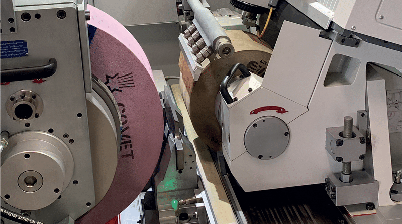
Precision centerless grinding machines are specialized grinding systems designed to produce cylindrical components with high dimensional accuracy, excellent surface finish, and consistent geometric characteristics without requiring the workpiece to be held between centers or secured in a conventional chuck. Unlike traditional cylindrical grinding machines, which support and rotate the workpiece through a headstock, tailstock, or dedicated workholding arrangement, centerless grinding machines control the workpiece through the combined action of a grinding wheel, a regulating wheel, and a work-rest blade. This arrangement allows the workpiece to rotate and move through the grinding zone while remaining supported externally. The absence of conventional workholding requirements makes centerless grinding particularly suitable for manufacturing long, slender, small-diameter, and high-volume cylindrical components.
Centerless grinding is widely used in automotive manufacturing, bearing production, hydraulic and pneumatic equipment manufacturing, medical device production, precision mechanical engineering, aerospace manufacturing, toolmaking, and general industrial production. Typical applications include shafts, pins, rollers, bushings, valve components, piston rods, bearing elements, precision bars, guide rods, dowel pins, and other cylindrical components requiring controlled diameter, roundness, cylindricity, and surface roughness. Depending on the machine configuration and production requirements, centerless grinding can be used for external diameter finishing, through-feed grinding, in-feed grinding, and specialized profile grinding operations.
The fundamental operating principle of a centerless grinding machine is based on the interaction of three principal elements: the grinding wheel, the regulating wheel, and the work-rest blade. The grinding wheel performs the actual material removal, while the regulating wheel controls the rotational speed and longitudinal movement of the workpiece. The work-rest blade supports the component between the two wheels and maintains its position within the grinding zone. The relative positions, diameters, rotational speeds, and contact conditions of these elements determine the grinding behavior and the final geometry of the component.
The grinding wheel is generally the larger and faster rotating wheel in the system. It is responsible for removing material from the external cylindrical surface of the workpiece. Its abrasive characteristics, diameter, width, peripheral speed, and dressing condition have a direct influence on cutting performance and surface quality. The regulating wheel usually rotates at a much lower peripheral speed and is manufactured with a different surface structure and bond specification. Its main function is to control the workpiece rotation and, in through-feed applications, generate the axial movement that carries the component through the grinding zone.
The work-rest blade is positioned between the grinding wheel and the regulating wheel, providing support for the workpiece during machining. It is generally manufactured from hardened steel, carbide, or another wear-resistant material suitable for the operating conditions. The upper surface of the blade must be accurately finished and positioned because even small variations in blade height, inclination, or straightness can influence the stability of the grinding process. The blade must also provide sufficient support without creating excessive friction or heat at the workpiece contact point.
One of the main advantages of centerless grinding is that the workpiece does not require center holes or dedicated chucking arrangements. This makes the process particularly useful for components that are difficult to support using conventional cylindrical grinding methods. Long, slender shafts can be processed without the bending forces that may occur when they are held between centers or in a chuck. Small components can also be ground efficiently because they do not need individual positioning and clamping operations. In automated production lines, large quantities of parts can pass continuously through the grinding zone, resulting in high productivity and consistent machining conditions.
Centerless grinding machines are generally classified according to their operating method. The most common configurations are through-feed centerless grinding machines, in-feed centerless grinding machines, and end-feed centerless grinding machines. Each configuration is designed for particular workpiece geometries and production requirements. The selection depends primarily on the component length, diameter, surface profile, shoulder geometry, required tolerance, and production volume.
Through-feed centerless grinding is one of the most widely used centerless grinding methods. In this process, the workpiece enters the grinding zone from one side of the machine and moves continuously between the grinding wheel and regulating wheel until it exits from the opposite side. The regulating wheel is inclined relative to the grinding wheel axis, creating an axial component of motion that advances the workpiece through the grinding zone. The grinding wheel removes material from the external diameter as the component rotates and moves longitudinally.
The regulating wheel inclination is an important parameter in through-feed grinding. A greater inclination generally increases the axial feed rate, while a smaller inclination reduces it. However, the relationship is influenced by the regulating wheel diameter, rotational speed, contact conditions, workpiece geometry, and friction between the regulating wheel and component. Excessive axial feed can reduce the effective grinding time and result in dimensional variation or poor surface finish. Insufficient feed may reduce production capacity and increase the risk of unwanted process effects. The inclination must therefore be selected according to the required balance between productivity and machining accuracy.
Through-feed grinding is particularly suitable for cylindrical components with a constant external diameter along their working length. Examples include straight shafts, precision pins, cylindrical rollers, bearing-related components, and ground bar stock. Because the workpiece passes continuously through the machine, this method is especially efficient for large production quantities. Multiple components can be processed in sequence without stopping the machine for individual loading and unloading operations. When combined with automatic feeding systems, through-feed grinding can operate as part of a highly productive manufacturing cell.
However, through-feed grinding has limitations when components contain shoulders, flanges, grooves, or other geometric features that prevent continuous axial movement through the grinding zone. Since the workpiece must pass completely between the wheels, its external geometry must allow the required feeding movement. Components with complex profiles or localized grinding requirements generally require in-feed grinding or another specialized configuration.
In-feed centerless grinding is used when the workpiece contains shoulders, steps, grooves, tapered sections, or other features that prevent it from moving continuously through the grinding zone. In this method, the component is positioned between the grinding wheel and regulating wheel and remains in a fixed axial position during machining. The grinding wheel is fed radially toward the workpiece until the required diameter or profile is achieved. The regulating wheel rotates the component, while the work-rest blade supports it throughout the grinding operation.
In-feed grinding allows a wider range of component geometries to be processed compared with through-feed grinding. Components with different diameter sections can be ground using appropriately dressed grinding wheels and carefully controlled radial feed movements. The grinding wheel may be dressed to reproduce a specific profile, allowing the machine to generate shoulders, recesses, radii, and other external shapes. The workpiece must be positioned accurately because the axial location determines the relationship between the grinding wheel profile and the component geometry.
In-feed centerless grinding is widely used for precision pins, stepped shafts, valve components, bearing elements, automotive parts, and components with localized cylindrical surfaces. It can also be used for grinding short workpieces that cannot be processed reliably through a conventional through-feed arrangement. Depending on the machine design, the grinding wheel may be moved radially while the regulating wheel maintains the workpiece rotation. Some machines use specialized loading mechanisms to position the component accurately and remove it after the grinding cycle.
End-feed centerless grinding is a specialized method used for components with tapered or stepped geometries where the workpiece enters the grinding zone from one side and moves axially until it reaches a defined stopping position. The grinding operation is performed while the component advances between the wheels, and the final geometry is established as it reaches the intended grinding position. This method can be useful for components that cannot be processed through the complete grinding zone because of their shape.
The choice between through-feed, in-feed, and end-feed grinding must be based on the workpiece geometry and the required production sequence. A machine designed for continuous through-feed production may not be suitable for complex in-feed components without substantial modifications. Similarly, a machine optimized for in-feed grinding may not provide the same productivity when processing long cylindrical bars continuously. Modern centerless grinding machines are available in configurations designed for specific operations, while some advanced machines provide sufficient adjustment and CNC control to accommodate several different grinding methods.
The mechanical structure of a precision centerless grinding machine must provide high stiffness and stable geometric relationships between the grinding wheel, regulating wheel, and work-rest system. The machine bed supports the principal assemblies and must resist deformation caused by grinding forces, wheel rotation, feed mechanisms, and thermal changes. Because centerless grinding depends on the precise relative positioning of several rotating and supporting elements, small mechanical deviations can produce significant variations in the finished workpiece.
The machine bed is commonly manufactured from cast iron, fabricated steel, or specialized structural materials selected according to the machine size and performance requirements. Cast iron is widely used because of its damping characteristics and suitability for machine tool construction. A properly designed cast iron bed can absorb a significant proportion of vibration generated during grinding and wheel rotation. Fabricated steel structures may provide advantages in manufacturing flexibility and structural design, but they require careful engineering to achieve adequate stiffness and vibration control.
The grinding wheel spindle assembly is one of the most critical components of a centerless grinding machine. It must support the grinding wheel with high rotational accuracy, maintain stable operating speed, and resist the mechanical and thermal loads generated during continuous operation. The spindle bearings must be selected according to the wheel dimensions, operating speed, radial loads, axial loads, and required service life. Precision angular contact ball bearings and cylindrical roller bearings are commonly used, depending on the spindle arrangement and machine design.
The spindle housing must provide sufficient rigidity and accurate alignment. Any displacement or angular deviation can alter the relationship between the grinding wheel and workpiece, affecting the resulting diameter, roundness, and surface finish. The spindle assembly should also provide an appropriate lubrication and cooling arrangement to maintain stable bearing operating temperatures. In high-speed machines, thermal expansion must be considered during the design stage because changes in spindle dimensions can influence wheel position and machining accuracy.
The regulating wheel spindle has a different operating function from the grinding wheel spindle. It generally operates at a much lower rotational speed and must provide precise control over the workpiece rotation and axial feed. The regulating wheel surface must maintain sufficient friction to rotate the component without unwanted slipping. Its spindle assembly must provide stable speed control and accurate positioning relative to the grinding wheel. Depending on the machine configuration, the regulating wheel may be driven by a variable-speed motor, servo motor, or specialized transmission system.
The regulating wheel is commonly manufactured with a rubber, resin, or other suitable bonding system that provides the required frictional characteristics. Its surface condition is extremely important because the workpiece receives its rotational movement through contact with this wheel. If the regulating wheel becomes glazed, worn, contaminated, or incorrectly dressed, the workpiece may slip or rotate irregularly. This can result in unstable grinding conditions, dimensional variation, and reduced surface quality.
Regulating wheel speed is generally controlled according to the required workpiece rotational speed and axial feed rate. In through-feed grinding, both the speed and inclination of the regulating wheel influence the longitudinal movement of the component. In in-feed grinding, the regulating wheel primarily controls workpiece rotation, while the grinding wheel provides the radial material removal movement. The speed relationship must be established carefully to avoid excessive friction, irregular rotation, and unnecessary heating.
The work-rest blade is another component that has a major influence on the accuracy of centerless grinding. It supports the workpiece at a position between the grinding wheel and regulating wheel, preventing the component from falling into the gap and maintaining a controlled contact geometry. The blade must be sufficiently rigid to resist deformation under the operating forces. Its upper surface should be accurately ground and maintained in good condition throughout the machine’s service life.
Blade height is particularly important because it determines the position of the workpiece relative to the centers of the grinding and regulating wheels. The workpiece is generally positioned above the line connecting the wheel centers by a controlled amount. This arrangement helps establish the correct geometric contact conditions and supports stable workpiece rotation. If the workpiece is positioned too low or too high, its contact conditions change and the grinding process may become unstable.
The correct workpiece height depends on the wheel diameters, workpiece diameter, grinding gap, blade geometry, and machine configuration. It cannot be selected independently of the other machine settings. In precision applications, blade height must be established according to the machine manufacturer’s recommendations and verified through practical grinding trials. Changes in workpiece diameter may require corresponding adjustments to the blade position.
The work-rest blade material must also be selected according to the component material, grinding speed, and production requirements. Hardened tool steel blades are common in general-purpose machines. Carbide blades may provide improved wear resistance in high-volume production or when processing hard materials. Specialized low-friction coatings or surface treatments can also be used in certain applications. Regardless of the material, the blade must maintain a stable support surface and resist wear during continuous contact with the workpiece.
Grinding wheel selection in centerless grinding is similar in principle to other abrasive machining processes, but the specific operating conditions must be considered. The wheel must provide sufficient cutting ability, dimensional stability, and resistance to loading. Aluminium oxide abrasives are widely used for steel components, while silicon carbide and specialized abrasive materials are selected for other workpiece materials. Ceramic abrasive grains can provide high cutting performance and may be advantageous in demanding production applications.
The abrasive grain size determines the relationship between material removal rate and surface finish. Coarser grains can provide higher material removal rates, while finer grains are generally used to achieve smoother surfaces. However, the correct grain size also depends on the contact length, wheel specification, workpiece hardness, and dressing conditions. A grinding wheel that is too fine may generate excessive heat or become loaded, while a wheel that is too coarse may produce an unacceptable surface finish.
Wheel hardness and structure must be selected according to the workpiece material and grinding conditions. Softer wheels can release worn abrasive grains more easily and expose new cutting edges, while harder wheels retain their abrasive grains for longer periods. Open wheel structures provide additional space for chip clearance and coolant access. Dense structures can provide a larger number of abrasive cutting points and may be useful in certain finishing applications. The optimum combination must be established through engineering evaluation and process testing.
Wheel dressing is essential for maintaining the cutting performance and geometry of the grinding wheel. During operation, abrasive grains become worn and the wheel surface may become loaded with workpiece material. This reduces the effectiveness of the cutting process and can increase grinding forces and heat generation. Dressing removes worn abrasive material and restores the wheel surface. It can also correct the wheel profile and ensure that the grinding zone maintains the required geometry.
In centerless grinding, dressing must be considered for both the grinding wheel and regulating wheel. The grinding wheel dresser must maintain the required cylindrical profile and cutting characteristics. The regulating wheel dresser must establish the correct surface condition and geometry to provide stable workpiece rotation. In through-feed applications, the regulating wheel profile and inclination are particularly important because they influence the axial feeding behavior of the component.
Diamond dressing tools are widely used in precision centerless grinding. Single-point diamond dressers, multi-point dressers, and rotary diamond dressing systems can be selected according to the wheel dimensions, profile complexity, and production requirements. CNC centerless grinding machines may include automatic dressing cycles that restore the wheel geometry after a predefined number of workpieces or according to measured wheel wear. Automatic dressing improves process consistency and reduces the need for frequent manual adjustment.
The dressing parameters must be coordinated with the grinding operation. Dressing depth, traverse speed, overlap ratio, dresser geometry, and wheel speed all influence the resulting wheel surface. An aggressive dressing operation can create a sharper wheel surface with greater cutting ability, while a finer dressing operation may produce a smoother wheel surface. The appropriate dressing strategy depends on the required surface roughness, material removal rate, and dimensional accuracy.
Thermal management is an important aspect of centerless grinding, particularly during high-volume production. The grinding contact zone generates heat as abrasive grains remove material from the workpiece. If this heat is not controlled, it can cause thermal expansion, surface burning, residual stresses, microcracks, and dimensional instability. Hardened steel components are particularly sensitive to excessive grinding temperatures because their surface properties can be affected by local thermal changes.
Coolant systems are used to reduce heat generation, improve lubrication, and remove grinding debris from the contact zone. Water-based emulsions and synthetic grinding fluids are common in industrial centerless grinding. Straight oils may be used in specialized applications where lubrication requirements justify their use. The coolant must be delivered consistently and at a suitable flow rate to reach the grinding interface.
The arrangement of coolant nozzles must account for the geometry of the grinding zone and the rotation of both wheels. Coolant must reach the actual contact area rather than being deflected by the air movement around the rotating grinding wheel. Correct nozzle positioning, flow direction, pressure, and delivery volume can significantly improve cooling performance. In high-production machines, coolant delivery systems may be designed specifically for the wheel dimensions and grinding operation.
Coolant filtration is particularly important in centerless grinding because abrasive particles and metallic debris continuously enter the fluid during operation. Contaminated coolant can cause scratches, surface defects, accelerated wheel wear, and damage to pumps or other machine components. Filtration systems may use paper filters, magnetic separators, hydrocyclones, centrifugal separators, or combinations of these methods. The required filtration level depends on the workpiece material, grinding wheel specification, surface-finish requirements, and coolant system design.
The geometric accuracy of centerless grinding depends on the interaction between the grinding wheel, regulating wheel, work-rest blade, and workpiece. The machine must maintain accurate wheel alignment, stable spindle rotation, controlled wheel gaps, and consistent support conditions. Workpiece roundness is influenced by the contact geometry and the stability of the grinding process. Cylindricity depends on maintaining consistent grinding conditions along the component length, while diameter accuracy depends on wheel positioning, feed control, dressing condition, and process compensation.
One of the characteristic challenges of centerless grinding is the development of lobing or polygonal roundness errors. These errors occur when the workpiece does not rotate in a sufficiently stable manner relative to the grinding wheel and regulating wheel. Instead of maintaining a uniform circular motion, the component may develop a repeating pattern of small geometric deviations. The number and magnitude of these lobes depend on the grinding geometry, workpiece support position, wheel speeds, friction conditions, and dynamic behavior of the system.
The position of the workpiece center relative to the wheel centers is therefore a critical process parameter. The center height must be selected to provide stable rotation and suitable geometric contact conditions. Incorrect center height can encourage roundness errors and make the grinding process sensitive to small changes in wheel condition or workpiece diameter. Adjustments to the work-rest blade height and wheel positions are commonly used to establish the correct operating geometry.
The relationship between the grinding wheel speed and regulating wheel speed also influences roundness. The grinding wheel must provide the required cutting speed, while the regulating wheel controls the component rotation. If the regulating wheel does not provide stable frictional contact, the workpiece may slip or experience irregular rotational movement. This can produce inconsistent material removal and surface defects. The regulating wheel surface condition, contact pressure, and speed must therefore be controlled carefully.
Workpiece material is another important factor in centerless grinding performance. Hardened steels are commonly processed because centerless grinding provides an effective method for achieving accurate diameters after heat treatment. Stainless steels may require specialized wheel specifications and coolant conditions because of their tendency to generate heat and adhere to abrasive surfaces. Alloy steels, tool steels, and bearing steels can also be ground using appropriate abrasive systems and process parameters.
Non-ferrous materials such as aluminium, copper alloys, and certain brass grades may require different grinding wheel structures and bonding systems. These materials can be more susceptible to wheel loading, smearing, and heat generation. The grinding process must provide adequate chip clearance and prevent material accumulation on the abrasive surface. In some cases, specialized abrasive wheels or alternative finishing processes may be more appropriate depending on the component material and required surface quality.
Centerless grinding is especially useful for long and slender components because the workpiece is supported continuously along the grinding zone rather than being held at its ends. In conventional cylindrical grinding, a slender shaft may deflect under the forces associated with workholding or grinding. This can produce taper, diameter variation, or geometric errors. Centerless grinding reduces the need for end support and can therefore provide advantages when processing long, small-diameter components.
However, long components require careful control of their support and feeding conditions. If the workpiece is not sufficiently straight before grinding, it may enter the machine with irregular contact conditions. Excessive initial bending can cause unstable rotation and uneven material removal. In such cases, straightening or preliminary machining may be required before centerless grinding. The component must also be supported properly during loading and unloading to prevent bending or damage.
Short components present a different set of challenges. They may not remain stable within the grinding zone if their length is insufficient relative to their diameter and the machine geometry. Special loading devices, support arrangements, and in-feed grinding configurations may be required. Small pins and precision dowels can be processed efficiently when the machine is designed specifically for their dimensions and production volume.
Automatic feeding systems are commonly integrated into centerless grinding machines to improve productivity. Through-feed machines may use inclined magazines, vibratory feeders, linear feeding systems, or conveyor arrangements to deliver components continuously to the grinding zone. Finished components can be collected using receiving conveyors or automated sorting systems. The feeding mechanism must prevent components from colliding, overlapping, or entering the grinding zone in an incorrect orientation.
For in-feed grinding, automatic loading systems must position each workpiece accurately between the grinding wheel and regulating wheel. Mechanical fingers, pneumatic actuators, servo-driven loaders, and robotic systems can be used depending on the component geometry and required cycle time. The loading mechanism must coordinate with the grinding cycle and ensure that the workpiece is securely positioned before material removal begins.
CNC control systems have significantly expanded the capabilities of modern centerless grinding machines. They provide programmable control over wheel positioning, regulating wheel speed, feed movements, dressing cycles, and other operating parameters. CNC systems can store machining programs for different component types and allow repeatable production conditions to be established. This is particularly valuable in manufacturing environments where several workpiece families must be processed using the same machine.
Advanced centerless grinding machines may include automatic wheel compensation, electronic measuring systems, in-process diameter gauges, and automated loading equipment. Measuring systems can monitor the component diameter during or after grinding and provide information for adjusting the grinding wheel position. This allows the machine to compensate for gradual wheel wear and maintain the required diameter over extended production runs.
In-process measurement is particularly important in high-volume production because small changes in grinding conditions can affect thousands of components if they are not detected promptly. Measurement systems must be calibrated and protected against coolant, abrasive particles, vibration, and temperature variations. Their measurement accuracy must be appropriate for the required component tolerance. Automatic compensation should also be configured carefully to avoid unstable correction behavior or excessive adjustments.
Centerless grinding is widely used in automotive manufacturing. Precision shafts, valve components, fuel system parts, transmission elements, piston pins, bearing components, and other cylindrical parts may require centerless grinding to achieve accurate external diameters. In these applications, dimensional consistency and surface integrity are important for assembly, sealing, friction, and wear performance. High production rates make centerless grinding particularly attractive for automotive manufacturing lines.
Bearing manufacturing is another major application area. Bearing-related cylindrical components often require controlled diameters, roundness, surface finish, and geometric consistency. Centerless grinding can be used for selected rollers, pins, cylindrical elements, and other components depending on their design. The process is particularly useful when large quantities of similar cylindrical parts must be finished economically and consistently.
Hydraulic and pneumatic equipment manufacturers use centerless grinding for piston rods, valve spools, guide shafts, precision pins, and other components with accurately controlled cylindrical surfaces. Surface finish and dimensional accuracy can influence sealing performance, friction, leakage, and wear. Components that operate within close-fitting bores may require particularly consistent diameter and cylindricity to maintain their intended functional clearances.
Medical device manufacturing can also benefit from precision centerless grinding. Small stainless steel shafts, surgical instrument components, guide pins, and other cylindrical elements may require high surface quality and controlled dimensions. The grinding process must be developed according to the material, component geometry, and applicable cleanliness and quality requirements. In such applications, burr control, surface integrity, and repeatability are important considerations.
Aerospace manufacturing uses centerless grinding for selected cylindrical components that require accurate dimensions and reliable surface characteristics. Materials may include high-strength alloy steels, stainless steels, and specialized engineering alloys. The grinding process must be controlled to prevent thermal damage and maintain the required mechanical properties of the surface layer. Inspection procedures may include dimensional measurement, roundness evaluation, surface roughness testing, and additional material integrity checks.
Precision toolmaking is another important field for centerless grinding. Hardened pins, guide elements, punches, ejector pins, dowels, and other cylindrical tooling components may require accurate diameters and surface finishes. Centerless grinding is especially useful for producing large quantities of straight cylindrical tooling elements with consistent dimensions. When the components have special profiles or stepped sections, in-feed grinding can provide additional flexibility.
Centerless grinding is also widely used in the production of precision bar stock. Long bars can be passed continuously through the grinding machine to improve diameter accuracy, straightness, and surface finish. This process is often used to prepare material for subsequent machining operations such as turning, automatic screw machining, and precision component production. The resulting ground bar can provide a more consistent starting diameter and improved surface condition than untreated or conventionally drawn material.
Maintenance is essential for maintaining the accuracy and reliability of a centerless grinding machine. The grinding and regulating wheel spindles must be monitored for vibration, temperature, noise, and signs of bearing deterioration. Lubrication systems should be maintained according to the manufacturer’s specifications. Wheel mounting components must be inspected regularly, and grinding wheels must be checked for damage and correct installation.
The condition of the work-rest blade should be inspected frequently because wear can alter the workpiece support position. Even small changes in blade height or surface geometry can affect the grinding result. The blade should be cleaned and inspected for damage, wear marks, and contamination. If its supporting surface becomes uneven, it may require regrinding or replacement.
The regulating wheel must also be maintained carefully. Its surface should provide consistent frictional contact with the workpiece. Glazing, wear, contamination, and incorrect dressing can reduce its ability to control workpiece rotation and feed. Regular dressing and inspection are necessary to maintain stable operation. The grinding wheel should be dressed at appropriate intervals to restore its cutting ability and geometric condition.
Machine alignment should be checked periodically. The relative positions of the grinding wheel, regulating wheel, and work-rest system must remain within the required geometric limits. Guideways, adjustment mechanisms, and positioning systems should be inspected for wear and backlash. The machine bed and spindle housings must remain rigid and properly aligned to ensure consistent machining results.
Coolant systems require regular maintenance because contaminated fluid can affect surface quality and machine reliability. Filters should be cleaned or replaced at suitable intervals, while coolant concentration and condition should be monitored. Pumps, pipes, nozzles, and tanks should be inspected for leaks, blockage, and accumulation of grinding sludge. Effective filtration also reduces the risk of abrasive particles returning to the grinding zone.
The selection of a precision centerless grinding machine should begin with an evaluation of the workpiece geometry. The maximum and minimum diameters, component length, material, hardness, and required surface characteristics determine the appropriate machine configuration. A machine intended for long cylindrical bars may not be suitable for short precision pins or complex stepped components. The required grinding method must therefore be established before selecting the machine.
Production volume is another major consideration. Through-feed machines are generally suitable for high-volume production of straight cylindrical components. In-feed machines are more appropriate for components with shoulders, grooves, or localized grinding requirements. If the production range includes several different component geometries, a CNC machine with flexible adjustment and automated dressing may provide greater versatility.
The required diameter tolerance must be considered together with roundness, cylindricity, straightness, and surface roughness. These characteristics are related but are not interchangeable. A component may meet its nominal diameter requirement while still containing unacceptable roundness or cylindricity deviations. Machine selection and process development must therefore address the complete geometric specification rather than focusing only on diameter accuracy.
The grinding wheel dimensions and machine capacity should also be evaluated according to the expected workpiece size and material removal requirements. Larger wheels can provide greater grinding contact length and may support certain production strategies, while smaller wheels can be advantageous in compact machines or specialized applications. The machine must provide sufficient spindle power, wheel speed, structural stiffness, and adjustment range for the intended operation.
The regulating wheel drive should provide the speed range and control accuracy required by the production process. Variable-speed systems allow the operator to adjust workpiece rotation and axial feed conditions. Servo-driven regulating wheel systems can provide more precise control and can be integrated with CNC programs. The appropriate drive system depends on the required production flexibility and the complexity of the workpiece geometry.
Workpiece handling and automation should be considered as part of the overall machine specification. For high-volume production, automatic feeding and unloading can significantly reduce cycle time and operator involvement. For small batches or specialized components, manual loading may provide sufficient flexibility and lower initial investment. The loading system must be matched to the workpiece dimensions and should prevent damage, incorrect orientation, or unstable positioning.
A complete centerless grinding installation includes more than the grinding machine itself. It may require grinding wheels, regulating wheels, dressing equipment, work-rest blades, coolant filtration, automatic feeding systems, measuring equipment, and component handling devices. The performance of the production system depends on the correct coordination of these elements. A high-precision machine cannot consistently produce accurate components if the regulating wheel is unsuitable, the work-rest blade is worn, or the coolant system cannot maintain stable operating conditions.
Modern centerless grinding technology continues to develop through improvements in spindle design, CNC control, wheel materials, dressing systems, measurement technology, and automation. Advanced machines can monitor process conditions and compensate for gradual changes in wheel diameter or component dimensions. More sophisticated systems can use vibration monitoring, temperature sensors, and measurement feedback to identify deviations before they result in unacceptable production quality.
The increasing use of automation also allows centerless grinding machines to operate as integrated manufacturing cells. Raw material feeding, grinding, dimensional inspection, sorting, and finished component collection can be coordinated through a single production system. This can improve manufacturing consistency and reduce manual handling. For manufacturers producing large quantities of precision cylindrical components, such integration can provide substantial advantages in productivity and process control.
Despite these developments, the fundamental success of centerless grinding still depends on accurate mechanical geometry and stable contact conditions. The grinding wheel must remove material consistently, the regulating wheel must control workpiece rotation and feed, and the work-rest blade must support the component at the correct height and position. These elements must operate together as a precisely coordinated system.
Precision centerless grinding machines provide an effective solution for manufacturing cylindrical components that require high dimensional accuracy, excellent surface finish, and consistent production quality. Their ability to grind components without conventional center support or individual chucking makes them particularly suitable for long shafts, small pins, precision bars, rollers, and high-volume industrial components. When the machine configuration, abrasive tools, workpiece support, wheel speeds, dressing conditions, and coolant system are correctly selected, centerless grinding can provide highly repeatable results with excellent production efficiency.
The choice of a centerless grinding machine should ultimately be based on the complete engineering requirements of the component, including its geometry, material, tolerance, surface finish, production volume, and downstream functional requirements. A properly engineered machine and process can provide reliable cylindrical finishing, reduce dependence on conventional workholding systems, and support efficient production of precision components across a wide range of industrial applications.
Precision Surface Grinding Machines
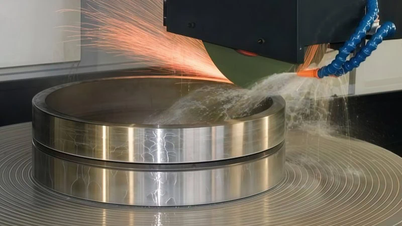
Precision surface grinding machines are advanced machine tools designed to manufacture flat, parallel, and dimensionally accurate surfaces on metallic components and other engineering materials. They are widely used in precision mechanical engineering, tool and die manufacturing, mold production, automotive manufacturing, aerospace engineering, hydraulic equipment production, machine tool manufacturing, and industrial component finishing. Their primary purpose is to remove controlled amounts of material from a workpiece using a rotating abrasive grinding wheel, producing a surface with precisely defined dimensions, geometric accuracy, and surface roughness.
Surface grinding is generally considered a finishing operation, although it can also be used for relatively high material removal rates when the machine, grinding wheel, and workpiece are suitable for the operation. It is particularly valuable when components require a degree of flatness, parallelism, or dimensional consistency that cannot be achieved economically through conventional milling or other machining processes. Hardened components, precision plates, machine elements, tooling components, and reference surfaces are among the most common applications.
The basic operating principle involves the relative movement between a rotating grinding wheel and a workpiece supported on a machine table. The abrasive grains on the wheel act as numerous microscopic cutting edges. As the wheel passes across the workpiece, these cutting edges remove small particles of material, gradually reducing the workpiece dimensions and improving the surface condition. The grinding wheel rotates at a high peripheral speed, while the workpiece is moved longitudinally and transversely beneath it. The vertical position of the grinding head determines the depth of cut.
The material removal process is controlled through a combination of wheel speed, workpiece feed rate, cross-feed increment, depth of cut, abrasive specification, and coolant conditions. These parameters must be selected according to the workpiece material, hardness, initial surface condition, required dimensional tolerance, and final surface roughness. A correctly developed grinding process provides consistent material removal while minimizing thermal deformation, vibration, wheel wear, and geometric errors.
Precision surface grinding machines are available in several mechanical configurations. The most common arrangement is the horizontal-spindle reciprocating-table surface grinder, which uses the peripheral surface of a horizontally mounted grinding wheel. Other configurations include vertical-spindle machines, rotary-table surface grinders, CNC surface grinding machines, double-disc grinding systems, and specialized machines designed for particular workpiece geometries or production requirements.
The horizontal-spindle reciprocating-table machine is widely used because of its versatility and ability to produce highly accurate flat surfaces. The workpiece is normally mounted on a magnetic chuck or a dedicated fixture attached to the machine table. The table moves longitudinally beneath the grinding wheel, allowing the abrasive wheel to cover the required working length. After each longitudinal movement, the machine applies a controlled transverse feed to grind the adjacent section of the surface. The grinding head is lowered incrementally until the required material removal and final dimension are achieved.
The machine base provides the structural foundation for all principal assemblies. It must have sufficient stiffness and damping capacity to maintain accurate relative positioning between the grinding wheel and workpiece. Although grinding forces are generally lower than those encountered in heavy milling operations, surface grinding is highly sensitive to vibration and small structural movements. Even minor changes in the relative position of the spindle and worktable can affect flatness, surface finish, and dimensional accuracy.
Cast iron is commonly used for machine bases because of its vibration-damping properties, dimensional stability, and suitability for machine tool construction. Properly designed cast iron structures can absorb a significant proportion of the vibration generated by the rotating grinding wheel and moving machine components. Fabricated steel structures are also used, particularly where manufacturing flexibility or specific structural arrangements are required. In such designs, the stiffness, weld distortion, stress relief, and vibration characteristics must be considered carefully.
The machine column supports the grinding head and maintains its position relative to the machine base and worktable. It must provide sufficient rigidity throughout the vertical travel of the grinding spindle. Any angular deviation or deformation can cause the grinding wheel to remove different amounts of material across the workpiece width. For this reason, the column geometry, mounting surfaces, guideways, and spindle head assembly must be manufactured and aligned accurately.
The grinding head contains the spindle assembly, motor, wheel mounting arrangement, and associated protective components. Its design directly influences the rotational accuracy, stiffness, and thermal behavior of the grinding wheel. A precision grinding spindle must operate with minimal radial and axial runout while maintaining stable rotational speed under varying grinding loads. The spindle bearings must be selected according to the wheel dimensions, operating speed, radial and axial loads, required stiffness, and expected operating life.
Angular contact ball bearings are frequently used in precision grinding spindles because they can support combined radial and axial loads while providing good rotational accuracy. Cylindrical roller bearings may be used in arrangements requiring high radial stiffness and load capacity. Specialized hydrostatic or hydrodynamic spindle systems can also be used in high-end machines where exceptional rotational stability and damping characteristics are required.
Bearing preload is an important design parameter. Insufficient preload can allow unwanted spindle movement and reduce rotational accuracy. Excessive preload can increase friction, operating temperature, and bearing wear. The bearing arrangement must therefore be designed to provide the necessary stiffness without generating excessive internal loading. Lubrication and cooling must also be selected according to the bearing type, spindle speed, and operating conditions.
The spindle housing must maintain accurate alignment and provide sufficient thermal stability. Heat generated by the motor, bearings, and grinding operation can influence spindle dimensions and wheel position. In precision machines, thermal expansion must be considered during the design and assembly stages. Advanced machines may include temperature monitoring and controlled cooling arrangements to maintain stable operating conditions.
Grinding wheel selection is one of the most important factors influencing surface grinding performance. The wheel must provide suitable cutting characteristics for the workpiece material while maintaining the required dimensional accuracy and surface finish. Grinding wheels are manufactured from abrasive grains held together by a bonding system. Common abrasive materials include aluminium oxide, silicon carbide, ceramic abrasives, and specialized abrasive materials developed for demanding industrial applications.
Aluminium oxide grinding wheels are widely used for grinding carbon steels, alloy steels, hardened steels, and many other ferrous materials. Different grades are available according to the hardness and grinding characteristics of the workpiece. Silicon carbide wheels are commonly used for cast iron, non-ferrous metals, and certain non-metallic materials. Ceramic abrasive grains can provide high cutting efficiency and may be advantageous in demanding precision grinding applications where wheel life and productivity are important.
The abrasive grain size determines the relationship between cutting efficiency and surface finish. Coarse grains provide relatively large cutting edges and allow higher material removal rates. They are generally used for preliminary grinding or operations where substantial stock must be removed. Fine grains produce a smoother surface and are commonly used for finishing operations. The selection must also consider wheel structure, bond type, workpiece hardness, contact area, and coolant conditions.
Grinding wheel hardness refers to the strength with which the bond retains the abrasive grains. It does not describe the hardness of the abrasive material itself. A soft wheel releases worn abrasive grains more readily, exposing fresh cutting edges and maintaining cutting ability. A hard wheel retains abrasive grains for a longer period and may provide improved wheel life under suitable conditions. The correct hardness depends on the material being ground, the contact area, the grinding pressure, wheel speed, and the thermal characteristics of the operation.
Wheel structure describes the spacing between abrasive grains. Open structures provide more space for chip clearance and coolant penetration, which can be beneficial when grinding materials that tend to load the wheel. Denser structures provide a greater concentration of abrasive grains and may be suitable for certain finishing applications. The bond system holds the abrasive grains together and determines the mechanical and thermal characteristics of the wheel. Vitrified bonds are widely used in precision surface grinding because they provide dimensional stability, controlled porosity, and reliable cutting performance.
Resin-bonded wheels are also used in applications requiring different mechanical characteristics, including improved impact resistance or particular surface-finish behavior. Specialized bonds may be selected according to the required grinding speed, material removal rate, and workpiece material. The wheel specification must always be compatible with the machine’s operating speed and the manufacturer’s safety requirements.
Wheel dressing is necessary to maintain the cutting ability and geometric accuracy of the grinding wheel. During operation, abrasive grains gradually become worn or blunt. Material particles may also accumulate between the grains, reducing the wheel’s cutting efficiency. This condition is commonly described as wheel loading or glazing, depending on the mechanism involved. As the wheel becomes less effective, grinding forces and heat generation can increase, potentially causing surface defects and dimensional variation.
Dressing removes worn abrasive material and exposes fresh cutting edges. It can also restore the required wheel profile and correct geometric deviations. Single-point diamond dressers, multi-point diamond dressers, rotary diamond dressers, and specialized dressing tools are commonly used in precision surface grinding. The dressing method depends on wheel dimensions, abrasive specification, required surface finish, and machine configuration.
Dressing parameters include dressing depth, traverse speed, overlap ratio, dresser geometry, and the relative movement between the dresser and grinding wheel. These parameters determine the resulting wheel surface and cutting characteristics. More aggressive dressing generally creates a sharper and more open wheel surface, while finer dressing can produce a smoother wheel condition. The correct dressing strategy must be established according to the grinding operation and required finish.
Wheel balancing is equally important in precision surface grinding. An unbalanced wheel generates centrifugal forces during rotation, producing vibration that can be transmitted through the spindle and machine structure. This vibration may create periodic surface marks, reduce dimensional accuracy, increase bearing loads, and shorten the service life of machine components. Grinding wheels should therefore be balanced using suitable static or dynamic methods according to their dimensions, operating speed, and application.
The complete wheel assembly must be considered during balancing. This includes the grinding wheel, mounting flanges, adapters, and other rotating components. The mounting surfaces must be clean and accurately manufactured. The wheel must be installed according to the manufacturer’s instructions, and the assembly should be inspected before operation. In high-precision machines, wheel balancing is an important part of the process preparation procedure rather than an occasional corrective activity.
The worktable provides the controlled movement required to carry the workpiece beneath the grinding wheel. Traditional surface grinding machines commonly use reciprocating tables driven by hydraulic systems. Hydraulic table drives provide smooth longitudinal movement and allow the operator to adjust table speed and stroke characteristics. The hydraulic system must maintain stable pressure and flow to prevent irregular movement and variations in grinding conditions.
The hydraulic table drive generally includes a pump, hydraulic motor or cylinder arrangement, directional control valves, flow-control elements, filters, and associated piping. The system must be designed to provide consistent movement under the changing friction and operating conditions of the table. Pressure fluctuations, contamination, air in the hydraulic circuit, and incorrect flow adjustment can affect the smoothness of the reciprocating movement.
Modern surface grinding machines may use servo-driven ball screws or linear motor systems instead of conventional hydraulic table drives. These systems provide electronic control over positioning, feed speed, acceleration, deceleration, and reciprocating movement. They can be integrated with CNC systems to execute complex grinding cycles automatically. The selection between hydraulic and servo-driven arrangements depends on machine size, production requirements, desired control characteristics, maintenance considerations, and the required accuracy.
The cross-feed mechanism moves the worktable or grinding head transversely to the main longitudinal direction. This movement allows the grinding wheel to cover the complete width of the workpiece. Cross-feed increments must be selected according to the wheel width, required surface finish, grinding strategy, and material removal rate. Excessive cross-feed may leave insufficient overlap between adjacent grinding paths, while unnecessarily small increments can increase cycle time.
In manual machines, cross-feed is usually controlled by a precision handwheel and screw mechanism. Automatic machines use mechanical, hydraulic, or servo-driven systems. CNC machines provide programmable cross-feed movements that can be adjusted according to workpiece dimensions and grinding requirements. The cross-feed mechanism must provide accurate positioning, repeatability, and minimal backlash.
Vertical feed determines the distance between the grinding wheel and workpiece and therefore controls the depth of material removal. Precision surface grinding commonly involves very small infeed increments, particularly during finishing operations. The vertical movement system must provide accurate and repeatable positioning while maintaining sufficient stiffness under grinding loads. Manual machines commonly use precision screws and graduated handwheels, while automatic and CNC machines use controlled feed systems with electronic positioning.
The accuracy of the vertical feed depends not only on the resolution of the positioning system but also on mechanical backlash, structural stiffness, guideway condition, thermal expansion, and spindle alignment. A machine with a high-resolution digital display may still produce inaccurate results if the mechanical structure is unstable or the feed mechanism contains excessive clearance. Mechanical accuracy and process stability must therefore be evaluated together.
The workholding arrangement is another major factor in surface grinding performance. Electromagnetic chucks are widely used because they can hold ferromagnetic workpieces securely while providing convenient access to the surface being ground. The magnetic force is distributed over the contact area, reducing the need for individual mechanical clamping devices. This makes the arrangement particularly suitable for flat plates, blocks, machine components, and tooling elements.
Permanent magnetic chucks are also used in precision grinding applications. They maintain their holding force without requiring continuous electrical power and can be suitable for applications where simple and reliable workholding is required. Electromagnetic systems provide electrical control of the magnetic field and can be integrated with machine control systems. Some designs allow the operator to adjust the magnetic holding force according to workpiece size and geometry.
Magnetic chuck pole spacing is an important consideration. Fine-pole arrangements can improve the holding of small or relatively thin components, while other configurations may be more suitable for larger workpieces. The magnetic force must be sufficient to resist grinding forces without creating unnecessary distortion. Thin components can deform under excessive magnetic attraction, particularly when their thickness is low relative to their unsupported dimensions.
The workpiece contact surface must be clean and sufficiently flat to ensure proper seating on the magnetic chuck. Burrs, contamination, chips, and surface irregularities can prevent full contact and reduce holding stability. A workpiece that is not properly seated may move during grinding, causing dimensional errors or damage. Before machining, the operator should verify that the component is positioned correctly and that the magnetic holding force is appropriate for the operation.
Non-magnetic materials require alternative workholding methods. Mechanical fixtures, vacuum chucks, special clamping plates, and dedicated support arrangements may be used depending on the component geometry. Aluminium, copper alloys, certain stainless steels, ceramics, and engineering plastics cannot always be held directly by conventional magnetic chucks. The workholding system must provide adequate stability while avoiding deformation or damage to the component.
Thermal management is one of the most important engineering considerations in precision surface grinding. Although the depth of cut is generally small, the grinding contact zone can generate significant heat because many abrasive grains interact with the workpiece simultaneously. A large proportion of the mechanical energy consumed during grinding is converted into heat. If this heat is not controlled, it can cause thermal expansion, dimensional variation, residual stresses, surface burning, microcracks, and changes in the metallurgical condition of the workpiece.
Grinding burn is particularly important when processing hardened steels and other heat-sensitive materials. Excessive local temperature can alter the microstructure of the surface layer, producing tempering effects, rehardening, or undesirable residual stresses. Such damage may not always be visible during a normal visual inspection, but it can reduce fatigue strength, wear resistance, and component service life. The grinding process must therefore be developed to control heat generation and maintain the required surface integrity.
Coolant systems are widely used to reduce temperature, lubricate the grinding contact zone, and remove abrasive particles and metallic debris. Water-based emulsions and synthetic grinding fluids are common choices for industrial surface grinding. Straight oils may be used in specialized applications where their lubrication characteristics provide a particular advantage. The coolant must be compatible with the workpiece material, grinding wheel, machine components, filtration system, and operating conditions.
Coolant delivery must be designed to reach the actual grinding contact zone. The rotating grinding wheel creates an air barrier that can deflect a poorly directed coolant stream. Even a high coolant flow rate may be ineffective if the fluid does not penetrate the contact region. Nozzle position, geometry, pressure, flow direction, and distance from the wheel must therefore be considered together.
Specialized coolant nozzles can direct a coherent stream toward the grinding interface. Their design may be adapted to the wheel diameter, width, rotational speed, and grinding arrangement. In high-performance applications, the coolant flow should be sufficient to remove heat and grinding debris without creating unnecessary turbulence or excessive fluid consumption.
Coolant filtration is essential because abrasive particles and workpiece chips continuously enter the fluid during grinding. Contaminated coolant can cause scratches, surface defects, accelerated wear, and damage to pumps or other system components. Filtration systems may include paper filters, magnetic separators, hydrocyclones, centrifugal separators, or combinations of these technologies. The required filtration level depends on the workpiece material, grinding wheel specification, surface-finish requirements, and coolant system design.
The machine guideways determine the accuracy and smoothness of the relative movement between the worktable, saddle, and machine base. Traditional precision surface grinders often use hardened and accurately ground sliding guideways. These provide high stiffness and good damping characteristics when correctly designed and maintained. The guideway surfaces must remain clean and properly lubricated to prevent wear, friction variations, and unwanted movement.
Linear roller guides are used in certain modern machines where low friction, high positioning accuracy, and controlled movement are required. Their selection depends on the machine structure and operating loads. Hydrostatic guideways may be used in high-precision grinding machines where extremely smooth movement and high stiffness are important. In hydrostatic systems, pressurized lubricant separates the moving surfaces, reducing direct mechanical contact and minimizing wear.
Hydrostatic systems require a dedicated hydraulic supply, accurate flow control, effective filtration, and reliable temperature management. Their design is more complex than conventional sliding guideways, but they can provide excellent motion characteristics under suitable conditions. The choice of guideway technology must be based on the required accuracy, machine size, dynamic loads, and long-term operating requirements.
The geometric accuracy of a precision surface grinding machine is determined by several interacting factors. These include table flatness, guideway alignment, spindle runout, grinding head squareness, machine stiffness, thermal stability, and feed system repeatability. During machine assembly, these characteristics must be checked using appropriate precision measurement instruments. The nominal resolution of the control system alone cannot establish the actual accuracy of the machine.
Flatness is one of the principal geometric characteristics produced by surface grinding. It describes how closely a finished surface approaches an ideal plane. Parallelism describes the relationship between two surfaces or planes, while perpendicularity describes their angular relationship. Precision surface grinding machines are frequently used to manufacture components requiring accurately parallel faces, controlled thickness, and precise mounting surfaces.
The achievable accuracy depends on the machine condition, workpiece material, grinding wheel specification, workholding arrangement, process parameters, and measurement method. A machine capable of producing highly accurate surfaces under controlled conditions may produce different results when grinding a thin component that is sensitive to clamping forces or temperature variations. Process development must therefore consider the actual geometry and material behavior of the component.
Precision surface grinding is commonly divided into rough grinding, intermediate grinding, and finishing operations. Rough grinding removes the larger portion of the material allowance and establishes the basic geometry. Intermediate grinding reduces dimensional deviations and prepares the surface for the finishing stage. Finishing grinding uses smaller infeed increments, carefully selected wheel specifications, and controlled feed conditions to achieve the final dimensions and surface roughness.
The initial condition of the workpiece has a significant influence on the grinding strategy. Components produced by casting, forging, welding, heat treatment, or heavy machining may contain residual stresses and geometric deviations. Removing material from only one side of a component can redistribute these stresses and cause distortion. A balanced machining sequence may therefore be necessary, particularly for large plates, thin components, and precision machine elements.
Grinding both sides progressively, alternating the machining sequence, or allowing the component to stabilize between operations can help reduce distortion. In some cases, stress-relief treatment may be necessary before final grinding. The appropriate procedure depends on the material, component dimensions, manufacturing history, and required final geometry.
Thin workpieces require particular attention because their low stiffness makes them sensitive to magnetic clamping forces, grinding pressure, and temperature. A thin plate may appear flat while held against a magnetic chuck but become distorted after removal. This can result in a difference between the geometry measured on the machine and the final free-state geometry. Reduced magnetic force, specialized fixtures, smaller grinding depths, and alternating grinding sequences can help minimize these effects.
Large workpieces present different challenges. Their mass and dimensions can influence table loading, machine deflection, handling, and thermal stability. The machine must provide sufficient working capacity and structural stiffness to support the component without compromising accuracy. Workpiece support should be distributed appropriately, particularly when the component has a large unsupported area or an irregular underside.
Horizontal-spindle surface grinding machines are widely used for general precision grinding. They use the peripheral surface of the grinding wheel and a reciprocating table. This arrangement is suitable for rectangular components, precision plates, tooling elements, machine components, and many other flat surfaces. The relatively narrow contact zone allows the grinding process to be controlled through longitudinal and transverse movements.
Vertical-spindle surface grinding machines use the face of a vertically mounted grinding wheel. They are often equipped with rotary tables or reciprocating tables and can provide high material removal rates when machining large surfaces. The vertical spindle arrangement creates a broad contact area between the wheel and workpiece, depending on the wheel geometry. These machines are used for large plates, heavy components, and production operations where extensive surface coverage is required.
Rotary-table surface grinding machines use a circular worktable that rotates beneath the grinding wheel. Workpieces can be mounted directly on the table or held using magnetic chucks and specialized fixtures. Rotary-table machines are particularly suitable for circular components, rings, discs, and multiple small workpieces arranged around the table. Their continuous rotary movement can provide efficient production cycles and consistent machining conditions.
Double-disc grinding machines are designed to process both sides of a component simultaneously using two opposing grinding wheels. They are particularly useful for producing accurate thickness, parallelism, and surface finish in high-volume manufacturing. Typical applications include washers, bearing-related components, valve plates, spacer elements, precision discs, and other parts requiring parallel faces.
Depending on the machine design, workpieces may be transported through the grinding zone using a carrier system or processed through a specialized feeding arrangement. Double-disc grinding can provide high productivity because both faces are machined during the same operation. However, the process requires careful control of wheel alignment, material removal distribution, workpiece feeding, and thermal conditions.
CNC precision surface grinding machines provide a high level of process automation and control. The operator can program longitudinal movement, transverse feed, vertical infeed, wheel dressing, and other machining parameters. The control system can store different grinding programs for different workpiece types and retrieve them when required. This is particularly useful in production environments where several component families are manufactured on the same machine.
Modern CNC machines may include automatic wheel dressing, automatic wheel balancing, in-process measurement systems, and dimensional compensation. These functions reduce manual intervention and help maintain consistent grinding conditions during long production runs. In-process measurement can detect dimensional changes and provide information for automatic correction. The effectiveness of these systems depends on correct calibration, sensor condition, machine stability, and appropriate control parameters.
Automation can also include automatic workpiece loading and unloading. Robotic handling systems, automatic pallet changers, conveyor systems, and dedicated loading mechanisms can be integrated into surface grinding cells. Such arrangements are particularly useful for repetitive production operations involving large quantities of similar components. Automatic handling can reduce manual labor, improve production consistency, and increase machine utilization.
Precision surface grinding machines are widely used in tool and die manufacturing. Punches, die plates, guide plates, mold inserts, support blocks, and other tooling components frequently require accurately ground surfaces. These components may undergo heat treatment before final grinding, making dimensional correction necessary. Surface grinding restores the required dimensions and provides accurate contact surfaces for assembly.
In automotive manufacturing, surface grinding is used for engine components, transmission elements, hydraulic parts, precision plates, and specialized tooling. Flatness and surface finish are particularly important where components must form sealing interfaces or maintain accurate alignment during assembly. Hydraulic valve plates, pump components, bearing-related parts, and precision spacers are examples of components that may require controlled surface grinding operations.
Aerospace manufacturing uses precision surface grinding for selected components made from alloy steels, stainless steels, nickel-based alloys, and other engineering materials. The process must maintain dimensional accuracy and surface integrity because geometric deviations and thermal damage can influence component reliability. Grinding parameters must be developed according to the material characteristics and the requirements of the finished component.
Machine tool manufacturing is another important application area. Surface grinding is used to finish machine beds, guideway elements, mounting plates, support surfaces, and precision mechanical components. The geometry of these surfaces influences the alignment and performance of the complete machine. Components used in CNC machining centers, cylindrical grinding machines, coordinate measuring equipment, and precision assembly systems may require surface grinding during manufacturing.
Hydraulic and pneumatic equipment manufacturers use precision ground surfaces for valve plates, cylinder components, mounting blocks, distribution elements, and other parts. Flatness and surface finish may influence sealing performance, leakage, friction, and assembly accuracy. Surface grinding is particularly useful when components have undergone heat treatment or other manufacturing processes that can produce dimensional changes.
Bearing manufacturing also involves surface grinding for selected components and associated precision parts. Flatness, parallelism, and surface finish can influence contact conditions and assembly characteristics. Depending on the component geometry, specialized grinding operations may be used in addition to conventional surface grinding to produce the required functional surfaces.
Precision surface grinding is also important in the production of measuring instruments, inspection equipment, precision fixtures, and laboratory machinery. Reference surfaces and mounting interfaces must maintain stable geometry over extended periods. In these applications, the quality of the grinding operation contributes directly to measurement reliability and mechanical alignment.
The maintenance of precision surface grinding machines is essential for preserving their accuracy and operational reliability. Daily maintenance should include checking lubrication levels, coolant condition, hydraulic system performance, magnetic chuck condition, and general machine cleanliness. Grinding debris should be removed from areas where it could accumulate and interfere with guideway movement or measurement accuracy.
Spindle condition should be monitored through vibration, temperature, noise, and surface-quality observations. Changes in spindle noise or operating temperature may indicate bearing wear, lubrication problems, wheel imbalance, or other mechanical issues. Grinding wheels and mounting components should be inspected regularly for damage, contamination, and incorrect installation.
Guideway lubrication must be maintained to prevent excessive friction and wear. Hydraulic systems should be checked for leakage, contamination, pressure stability, and filter condition. Coolant tanks and filtration systems should be cleaned at suitable intervals to prevent the accumulation of grinding sludge and metallic particles. Electrical cabinets, servo drives, sensors, and CNC components should also be inspected periodically.
Geometric inspection should be performed at intervals appropriate to the machine’s accuracy requirements and operating conditions. Measurements may include table flatness, spindle alignment, table movement accuracy, grinding head squareness, and feed system repeatability. High-precision machines may require more detailed geometric inspection and periodic recalibration.
Environmental conditions are particularly important in precision grinding. Temperature variations between the machine, workpiece, coolant, and measuring instruments can produce dimensional changes. A component measured immediately after grinding may have a different dimension after reaching thermal equilibrium. For high-accuracy production, the machine and workpieces should be stabilized under controlled conditions before final inspection.
The measuring instruments must also be suitable for the required tolerance range. Precision height gauges, dial indicators, electronic comparators, surface plates, coordinate measuring machines, and specialized flatness measurement systems may be used depending on the component geometry and inspection requirements. Measurement procedures should account for temperature, workpiece support, surface cleanliness, and instrument calibration.
Selecting a precision surface grinding machine requires a detailed evaluation of the intended workpieces and production requirements. Maximum workpiece length, width, and height determine the necessary table dimensions and machine capacity. The largest grinding area influences the required wheel dimensions, spindle power, and machine configuration. Workpiece material and hardness determine the appropriate wheel specification and expected grinding conditions.
The required flatness, parallelism, thickness tolerance, and surface roughness determine the necessary machine accuracy and process capability. These requirements should be considered together rather than independently. For example, a component may require a particular thickness while also maintaining parallel faces and a controlled surface finish. The machine must be capable of achieving all these characteristics consistently.
Production volume is another important selection factor. A manually operated machine may be suitable for small batches, maintenance workshops, toolrooms, and applications involving frequent changes in workpiece geometry. Semi-automatic machines reduce operator intervention while retaining flexibility. CNC machines are generally more suitable when repeatable production cycles, automatic dressing, programmable feeds, and integrated measurement functions are required.
For large production volumes, dedicated automation and automatic loading systems can provide significant productivity advantages. However, the initial investment must be evaluated against expected production quantities, cycle times, labor requirements, setup time, and maintenance costs. The most appropriate machine is not necessarily the one with the highest automation level, but the one that provides the required accuracy and productivity for the intended manufacturing process.
Spindle power must be evaluated according to grinding wheel dimensions, operating speed, material removal rate, and type of operation. A larger spindle motor does not automatically guarantee better grinding performance. Spindle stiffness, bearing quality, wheel selection, machine structure, and thermal stability are equally important. The machine must provide sufficient power without introducing excessive vibration or heat into the spindle assembly.
The working envelope should provide sufficient clearance for the workpiece, magnetic chuck, fixtures, grinding wheel, and dressing equipment. Maximum grinding height must be considered together with the thickness of the workholding device and the required wheel diameter. Some applications may require additional clearance for special fixtures or tall components. The ability to accommodate different wheel dimensions and workholding arrangements can improve the machine’s versatility.
A complete surface grinding production process should be evaluated as a system rather than as an isolated machine operation. Grinding wheels, dressing equipment, coolant systems, filtration, workholding devices, measurement instruments, and operator procedures all influence the final result. A technically advanced machine may fail to achieve its expected performance if the wheel specification is unsuitable, the magnetic chuck is not properly maintained, or the coolant delivery system is inadequate.
Modern precision surface grinding machines are increasingly equipped with intelligent monitoring systems and advanced control functions. Sensors can monitor spindle vibration, temperature, grinding forces, wheel wear, and dimensional variation. This information can be used to identify process instability before it produces defective components. Automatic compensation systems can adjust machining parameters to account for gradual changes in wheel diameter or other process characteristics.
Digital control systems also allow grinding programs and process parameters to be stored for different component types. This improves production documentation and reduces the time required to establish machining conditions when manufacturing a previously processed part. In advanced manufacturing environments, surface grinding machines can be connected to production management systems and integrated with upstream and downstream machining operations.
The development of grinding wheel materials and bonding technologies continues to improve cutting performance and process efficiency. Advanced ceramic abrasives, engineered grain structures, specialized bonds, and improved dressing technologies allow manufacturers to optimize the relationship between material removal rate, wheel life, surface quality, and energy consumption. These developments are particularly important when grinding hardened steels, difficult-to-machine alloys, and components with demanding surface integrity requirements.
Despite advances in CNC technology, automation, and abrasive materials, the fundamental principles of precision surface grinding remain based on mechanical accuracy, stable spindle rotation, controlled workpiece movement, appropriate abrasive selection, and effective thermal management. Automation can improve repeatability and reduce operator dependence, but it cannot fully compensate for fundamental mechanical inaccuracies or an incorrectly developed grinding process.
Precision surface grinding machines therefore remain indispensable in modern manufacturing. Their ability to produce flat surfaces with high dimensional accuracy, controlled parallelism, and excellent surface finish makes them suitable for a broad range of industrial components. From small hardened tooling elements to large machine structures, surface grinding provides a reliable method for producing functional surfaces that may be difficult or uneconomical to achieve through conventional machining operations.
The correct selection of machine configuration, spindle system, grinding wheel, workholding arrangement, feed mechanism, coolant technology, and measurement equipment must be based on the actual engineering requirements of the component. When these elements are properly coordinated, a precision surface grinding machine can provide stable machining performance, consistent dimensional accuracy, excellent surface quality, and reliable production over extended operating periods.
Precision Tool and Cutter Grinding Machines
Precision tool and cutter grinding machines are specialized machine tools designed for manufacturing, sharpening, reconditioning, and finishing cutting tools with accurately controlled geometries. They are essential in modern machining industries because the performance of a cutting tool depends directly on the accuracy of its cutting edges, rake angles, clearance angles, helix geometry, relief surfaces, and dimensional characteristics. A properly manufactured or reground tool can significantly influence machining productivity, surface quality, dimensional accuracy, tool life, and production costs.
These machines are widely used in toolmaking workshops, cutting tool manufacturers, mold and die production facilities, automotive manufacturing, aerospace engineering, precision mechanical engineering, and industrial machining centers. Their applications include the production and regrinding of end mills, drills, reamers, taps, countersinks, milling cutters, form tools, broaches, countersinking tools, and specialized cutting instruments. Depending on their configuration, tool and cutter grinding machines can process both simple tools with conventional cutting geometries and complex multi-flute tools requiring accurately coordinated movements across several axes.
The fundamental purpose of a tool and cutter grinding machine is to remove material from a cutting tool in a controlled manner to create or restore its functional geometry. The grinding wheel acts as an abrasive cutting tool, removing microscopic particles from the workpiece while the machine controls the relative movement between the wheel and the component. Unlike ordinary surface grinding, tool grinding frequently involves complex three-dimensional geometries. The grinding wheel must approach the workpiece at precisely defined angles and follow controlled paths to generate the required cutting edge and relief surfaces.
A conventional tool and cutter grinding machine generally consists of a rigid machine base, a grinding head, a spindle assembly, a workholding system, a tool support arrangement, longitudinal and transverse feed mechanisms, vertical adjustment systems, and angular positioning elements. Depending on the machine design, the workpiece may be held between centers, in a precision collet, in a specialized fixture, or on a rotary dividing head. The grinding head and workholding system must provide accurate relative positioning to maintain the required tool geometry.
Modern CNC tool and cutter grinding machines use coordinated multi-axis motion to manufacture complex cutting tools automatically. These machines commonly provide four, five, or more controlled axes, depending on their intended applications. Simultaneous movement of the grinding wheel and workpiece allows the machine to generate complex flute profiles, variable helix angles, multiple relief surfaces, and specialized cutting geometries. CNC systems also allow machining programs to be stored and reproduced, improving consistency between production batches.
The mechanical structure of a precision tool and cutter grinding machine must provide high stiffness and geometric stability. Cutting tool geometries are often defined by small angular and dimensional differences, and even minor mechanical deviations can affect cutting performance. The machine base must resist vibration and deformation while maintaining accurate alignment between the grinding spindle and workpiece axes. Cast iron is frequently used because of its damping characteristics and dimensional stability. Modern machines may also use fabricated steel structures, mineral casting, or composite structural arrangements according to their design objectives.
The grinding head is one of the most important assemblies. It supports the grinding spindle and provides the angular and positional adjustments required for different grinding operations. Depending on the machine configuration, the grinding head may rotate around horizontal or vertical axes, allowing the grinding wheel to approach the cutting tool from different directions. In CNC machines, these movements are controlled through rotary axes and precision positioning systems.
The grinding spindle must provide high rotational accuracy, sufficient stiffness, and stable operating speed. Tool grinding frequently uses relatively small grinding wheels and requires accurate control of their position relative to the cutting edge. Spindle runout can produce variations in grinding depth and affect the symmetry of the cutting geometry. For this reason, precision bearings, accurately manufactured spindle components, and carefully balanced wheel assemblies are essential.
Angular contact ball bearings are commonly used in precision grinding spindles because they can support combined radial and axial loads while providing good rotational accuracy. Depending on the required stiffness, spindle speed, and operating conditions, specialized bearing arrangements may be selected. High-speed tool grinding machines may use spindle systems designed for elevated rotational speeds and controlled thermal behavior. The bearing preload and lubrication system must be selected according to the spindle design and expected operating conditions.
The spindle motor must provide sufficient power and torque for the intended grinding operations. Small-diameter grinding wheels often require high rotational speeds to achieve the appropriate peripheral velocity. Larger wheels may operate at lower rotational speeds while maintaining similar peripheral speeds. The spindle drive must therefore provide an operating range compatible with the wheel dimensions and abrasive specifications. Variable-speed systems allow the operator or CNC program to adjust the rotational speed according to the grinding operation.
Tool and cutter grinding machines use a wide range of abrasive wheels. Aluminium oxide wheels are commonly used for grinding high-speed steel tools, while silicon carbide wheels may be suitable for certain carbide-related applications and non-ferrous materials. Diamond and cubic boron nitride wheels are particularly important for grinding hard cutting tool materials. The selection of abrasive material depends on the hardness of the tool, its chemical characteristics, the required grinding operation, and the expected surface finish.
High-speed steel remains widely used in cutting tool manufacturing because of its toughness, wear resistance, and ability to retain cutting properties at elevated temperatures. Aluminium oxide grinding wheels are commonly selected for high-speed steel tools. Different abrasive grades and bond systems are available according to the tool geometry and grinding requirements. Grinding conditions must be controlled to prevent excessive heat generation and preserve the metallurgical properties of the cutting edge.
Cemented carbide cutting tools require different grinding technologies because of their high hardness and wear resistance. Diamond grinding wheels are commonly used for grinding carbide tools because diamond provides suitable abrasive characteristics for removing this material. The wheel specification must be selected according to carbide grain size, cobalt binder content, grinding conditions, and required surface quality. Inadequate wheel selection can increase grinding forces, generate excessive heat, and produce undesirable surface conditions.
CBN grinding wheels are used for selected hard ferrous materials and specialized tool grinding applications. CBN provides excellent hardness and thermal stability and can be advantageous when grinding hardened steels. Its use depends on the workpiece material and the chemical compatibility of the abrasive with the material being ground. Diamond and CBN wheels are not interchangeable in every application, and their selection must be based on the actual grinding requirements.
The bond system is an important factor in grinding wheel performance. Vitrified bonds are widely used because they provide dimensional stability, controlled porosity, and reliable cutting characteristics. Resin bonds can provide different mechanical properties and may be suitable for particular finishing operations. Metal bonds are used in certain specialized abrasive tools where strong grain retention and wheel profile stability are required. The bond must provide the appropriate balance between abrasive grain retention, cutting efficiency, wheel wear, and dressing requirements.
Grinding wheel geometry is particularly important in tool and cutter grinding. Different wheel profiles are required to generate different tool features. Straight wheels can be used for cylindrical and surface grinding operations, while cup wheels, dish wheels, tapered wheels, and specially profiled wheels are used for more complex geometries. The wheel profile must be selected according to the cutting edge, flute geometry, clearance surface, and accessibility of the grinding zone.
Wheel dressing is necessary to maintain the cutting ability and geometric accuracy of the abrasive tool. During grinding, abrasive grains become worn, and the wheel profile may gradually change. Dressing restores the cutting surface and can reproduce the required wheel geometry. Depending on the wheel type, dressing may be performed using diamond tools, rotary dressing systems, or specialized dressing equipment.
For conventional abrasive wheels, dressing can expose fresh abrasive grains and remove loading material. For superabrasive wheels, the dressing procedure may involve both conditioning and sharpening operations, depending on the bond system. Vitrified and resin-bonded diamond wheels require different dressing approaches. The correct procedure must be selected according to the abrasive material, bond type, wheel construction, and manufacturer’s recommendations.
The workholding system must position the cutting tool accurately throughout the grinding operation. Collets are commonly used for holding cylindrical tools such as drills, end mills, reamers, and taps. Precision collets provide concentric clamping and allow tools of different diameters to be held securely. The collet must have suitable accuracy and gripping force to prevent movement during grinding without causing unwanted deformation.
Between-centers workholding is also used for certain cylindrical tools and components. This arrangement allows the workpiece to rotate accurately around its axis while providing support at both ends. It can be useful for grinding long tools, cylindrical shanks, and components requiring concentricity between different sections. The centers, drive mechanism, and support arrangements must be aligned accurately to avoid introducing runout or angular errors.
Dividing heads and rotary workholding systems are important in tool grinding because many cutting tools contain multiple flutes or equally spaced cutting edges. A dividing head allows the workpiece to be indexed through controlled angular increments. For example, a four-flute tool requires four equally spaced cutting positions around its circumference, while a six-flute tool requires six. Accurate indexing is essential to ensure consistent flute spacing and balanced cutting behavior.
CNC tool and cutter grinding machines frequently use direct-drive rotary axes or precision servo-driven rotary tables. These systems can position the workpiece continuously during simultaneous grinding operations. High-resolution encoders provide feedback to the control system, allowing accurate angular positioning and coordinated movement with the linear axes. The rotary axis must provide sufficient stiffness and repeatability to maintain the required tool geometry.
One of the most important operations in tool and cutter grinding is flute grinding. Flutes are the helical or straight channels formed along the cutting portion of a tool. They provide space for chip evacuation and define important aspects of the cutting edge geometry. The flute geometry influences cutting forces, chip formation, tool stiffness, heat generation, and machining performance.
Flute grinding requires accurate control of the relationship between the grinding wheel, workpiece rotation, and axial movement. In helical tools, the workpiece rotates while moving longitudinally relative to the grinding wheel, creating a spiral flute. The helix angle is determined by the relationship between the axial feed and rotational movement. CNC machines can coordinate these movements to produce different helix angles and specialized flute configurations.
The flute depth and profile must be controlled according to the intended cutting application. Deep flutes provide greater chip space but can reduce the core diameter and therefore decrease tool stiffness. Shallow flutes can improve tool strength but may limit chip evacuation. The appropriate geometry depends on tool diameter, material, number of flutes, cutting conditions, and workpiece material to be machined.
The number of flutes also influences the performance of a cutting tool. Tools with fewer flutes generally provide greater chip space and may be suitable for materials that produce large chips. Tools with more flutes can provide additional cutting edges and may improve productivity in suitable finishing applications. However, increasing the number of flutes reduces the available space for chip evacuation and can affect tool strength. The grinding machine must therefore be capable of producing the required flute geometry with accurate angular spacing.
The cutting edge is formed where the rake face and clearance face intersect. Its geometry determines how the tool engages the workpiece material and influences cutting forces, heat generation, chip formation, and tool life. The cutting edge must be sharp enough to cut effectively while maintaining sufficient strength to resist mechanical loading. Depending on the tool application, the cutting edge may be prepared with a controlled hone or edge radius.
Rake angle is one of the principal geometric characteristics of a cutting tool. It influences the direction of chip flow, cutting forces, and the strength of the cutting edge. Positive rake angles can reduce cutting forces and improve cutting action in certain materials, while negative or less positive rake angles can provide stronger cutting edges for demanding applications. The required rake geometry depends on the tool material, workpiece material, cutting speed, and machining operation.
Clearance angle provides the necessary space between the tool flank and the machined surface. Without adequate clearance, friction increases and the tool may rub against the workpiece rather than cutting efficiently. Excessive clearance, however, can weaken the cutting edge and reduce tool rigidity. Precision tool grinding machines must therefore produce the specified clearance geometry consistently.
Primary and secondary relief surfaces are commonly used in milling cutters and other rotating tools. The primary relief surface provides clearance immediately behind the cutting edge, while the secondary relief provides additional clearance farther behind the edge. This arrangement can improve cutting edge strength while reducing unnecessary contact with the workpiece. The geometry must be generated accurately because variations between flutes can create uneven cutting loads.
End mills are among the most common tools manufactured and reground using precision tool and cutter grinding machines. They are used for milling slots, pockets, shoulders, profiles, and complex surfaces. End mills can have two or more flutes, different helix angles, square or radiused corners, and specialized cutting geometries. Tool grinding machines must be capable of generating the required peripheral flutes, end-face cutting edges, and clearance surfaces.
Square end mills require accurately ground peripheral cutting edges and end cutting geometries that produce a nominally sharp corner. Corner-radius end mills have a controlled radius between the peripheral and end cutting edges, while ball-nose end mills have a hemispherical cutting end used for machining three-dimensional surfaces. These tools require more complex grinding paths and precise coordination between the grinding wheel and workpiece axes.
Drill grinding is another important application. Twist drills contain two helical flutes, cutting lips, and a point geometry that must be accurately formed to ensure stable drilling performance. The cutting lips should have appropriate symmetry, and the chisel edge must be correctly positioned. Unequal cutting lip lengths or angles can cause the drill to wander, produce an oversized hole, or generate uneven cutting forces.
Precision tool and cutter grinding machines can manufacture drill point geometries with different point angles, web thinning arrangements, and specialized cutting edge preparations. The point angle is selected according to the workpiece material and drilling application. Different geometries may be required for general-purpose drilling, stainless steels, hardened materials, aluminium alloys, and specialized industrial applications.
Web thinning reduces the size of the chisel edge and can improve drilling performance by reducing the force required to penetrate the workpiece material. Different web thinning geometries can be produced depending on the drill design. The grinding machine must control the position and shape of the thinning surfaces to maintain symmetry and avoid weakening the cutting edges excessively.
Reamers are precision cutting tools used to improve the dimensional accuracy and surface finish of previously produced holes. They may have straight or helical flutes and several cutting edges arranged around the tool circumference. The grinding machine must maintain accurate flute spacing, cutting edge geometry, and diameter. Small variations in reamer geometry can influence the final hole size, roundness, and surface quality.
Taps are used to produce internal threads and require accurately formed cutting teeth, flutes, and relief geometry. Grinding operations are used to manufacture their thread profiles, cutting chamfers, and flute configurations. Depending on the tap type, the grinding process may involve complex thread grinding and specialized flute grinding operations. The tool and cutter grinding machine must maintain the correct relationship between the thread geometry and flute position.
Countersinks, counterbores, form cutters, and specialized profile tools also require precision grinding. These tools often contain multiple cutting edges with specific angular relationships and profile requirements. Their grinding operations may involve the use of specially shaped wheels or CNC-generated tool paths. The accuracy of the finished tool geometry directly influences the dimensional quality and surface finish of the machined component.
Tool grinding is not limited to the manufacture of new cutting tools. Regrinding and resharpening are important industrial activities because cutting tools can often be restored after their cutting edges become worn. Regrinding removes a controlled amount of material from the worn region and restores the original or modified cutting geometry. This can significantly reduce tooling costs, particularly when processing expensive solid carbide or high-performance tools.
A regrinding process must begin with an evaluation of the tool condition. The operator should inspect the cutting edges, flutes, shank, and overall geometry to determine whether the tool can be restored economically. Excessive wear, cracks, chipping, severe thermal damage, or deformation may make regrinding unsuitable. If the tool is suitable, the grinding sequence must be selected according to the original geometry and the amount of material that must be removed.
Repeated regrinding reduces the tool diameter and may change the relationship between the cutting portion and the shank. The machine must be capable of compensating for these dimensional changes while maintaining the required cutting geometry. Tool manufacturers and regrinding facilities often maintain standardized programs and process data for different tool families to ensure consistency between reconditioning cycles.
CNC tool and cutter grinding machines have transformed the production of complex cutting tools. They allow several linear and rotary axes to move in a coordinated manner, enabling the grinding wheel to follow precisely calculated paths. This is particularly important for tools with variable helix angles, variable pitch, unequal flute spacing, complex end geometries, and specialized relief surfaces.
A typical CNC tool grinding machine may include X, Y, and Z linear axes together with rotary axes for workpiece orientation and grinding head positioning. The exact axis arrangement varies according to machine design. Some machines use a five-axis configuration, while advanced systems may provide additional controlled axes for more complex grinding operations. The number of axes alone does not determine the machine’s capability; axis stiffness, positioning accuracy, interpolation performance, spindle arrangement, and software functionality are equally important.
The CNC control system coordinates the movements according to the programmed tool geometry. Specialized tool grinding software can calculate grinding paths based on parameters such as tool diameter, flute number, helix angle, rake angle, clearance angle, point geometry, and cutting length. The software can also generate different grinding sequences and compensate for wheel geometry and dressing conditions.
Tool design software and grinding machine programming are closely related. The finished tool must first be defined through its geometry and functional requirements. The grinding software then converts this information into machine movements and wheel contact paths. The accuracy of the final tool depends on the correctness of the geometry model, the machine calibration, the wheel specification, and the grinding process.
Tool measurement systems are important for verifying the finished geometry. Optical measuring machines can evaluate cutting edge positions, flute geometry, helix angles, rake angles, and clearance surfaces. Specialized tool measuring systems may also inspect runout, diameter, concentricity, and cutting edge preparation. These measurements provide information that can be used to correct the grinding program and improve subsequent production.
In-process measurement is increasingly used in advanced tool grinding machines. Sensors and measurement systems can monitor tool dimensions during production and compensate for changes caused by wheel wear or thermal effects. Automatic probing may be used to determine the initial position of the workpiece and reduce setup errors. Such systems can improve repeatability, particularly when manufacturing several tools with similar geometries.
Thermal management is an important consideration in tool and cutter grinding. Grinding operations can generate high local temperatures, particularly when processing carbide, hardened steels, and tools with small cutting edge dimensions. Excessive heat can alter the metallurgical condition of the tool, produce grinding cracks, cause residual stresses, and reduce cutting performance.
Grinding cracks are particularly undesirable because they can lead to premature tool failure during machining. In carbide tools, excessive thermal gradients can create stresses between the carbide grains and binder phase. In high-speed steel tools, uncontrolled heating may alter the heat-treated condition of the cutting edge. The grinding process must therefore control wheel specification, material removal rate, coolant delivery, and feed conditions.
Coolant systems are commonly used to remove heat and grinding debris from the contact zone. Water-based grinding fluids and specialized synthetic fluids are widely used in industrial tool grinding. The coolant must be delivered directly to the grinding interface at an appropriate flow rate and pressure. In high-speed grinding operations, the coolant system must also account for the air movement around the rotating wheel.
High-pressure coolant delivery may be used in demanding applications to improve penetration into the grinding zone and remove chips from complex flute geometries. The nozzle position and direction must be selected according to the wheel and workpiece arrangement. Inadequate coolant delivery can cause excessive temperature, wheel loading, and poor surface quality even when the total coolant volume appears sufficient.
Coolant filtration is also essential because abrasive particles, carbide debris, and metallic contaminants can accumulate during grinding. Contaminated fluid may damage the workpiece surface, accelerate wheel wear, and affect machine components. Filtration systems may include magnetic separators, paper filters, centrifugal separators, and specialized fine-filtration equipment. The required filtration level depends on the abrasive material, coolant type, tool material, and surface-finish requirements.
The rigidity of the workholding and positioning systems is particularly important when grinding small tools. Cutting tools may have long slender shanks and relatively small diameters, making them sensitive to vibration and clamping forces. Collet systems must hold the tool securely and concentrically without introducing excessive deformation. The machine must also provide sufficient support and controlled movement to prevent vibration during grinding.
Vibration can produce surface marks, irregular cutting edge geometry, and variations in flute depth. It may also accelerate wheel wear and reduce spindle bearing life. The machine structure, spindle assembly, wheel balancing, workholding system, and grinding parameters must therefore be coordinated to maintain stable operating conditions. Small-diameter tools are particularly sensitive to dynamic disturbances because their cutting geometry can be affected by very small positional deviations.
The grinding wheel must be selected not only according to the workpiece material but also according to the geometry being produced. A wheel suitable for grinding the outside diameter of a tool may not be appropriate for grinding a deep flute or a complex relief surface. Wheel diameter, thickness, profile, abrasive type, bond, and dressing characteristics all influence accessibility and cutting performance.
Small grinding wheels are frequently used for detailed tool geometries, particularly where the grinding wheel must enter narrow flutes or reach complex cutting edge locations. However, smaller wheels may require higher rotational speeds to maintain the desired peripheral velocity. The machine spindle must be designed to operate safely and accurately at the required speed. Wheel diameter reduction through dressing must also be considered because it changes the peripheral speed at a given spindle rpm.
The grinding sequence is important in tool manufacturing. The order in which flutes, relief surfaces, cutting edges, end geometries, and finishing operations are performed can influence dimensional stability and production efficiency. Some tools require preliminary grinding to establish the basic geometry, followed by finishing operations that refine the cutting edges. The sequence must avoid unnecessary removal of material from previously finished surfaces.
For multi-flute tools, equal spacing and consistent geometry are essential. If the flutes are not equally spaced or their cutting edges are not ground to the same radial position, the tool may experience uneven cutting loads. This can produce vibration, poor surface finish, and premature tool wear during machining. CNC indexing and accurate rotary positioning help maintain consistent flute spacing.
Tool and cutter grinding machines are widely used in the manufacture of solid carbide tools. Solid carbide end mills, drills, reamers, and specialized cutting tools are commonly produced through a combination of cylindrical grinding, flute grinding, end grinding, and relief grinding operations. The high hardness of carbide requires suitable diamond abrasive systems and carefully controlled grinding parameters.
High-speed steel tools remain important in applications where toughness, impact resistance, and flexibility are required. Tool grinding machines can manufacture and recondition these tools using appropriate aluminium oxide wheels and controlled grinding procedures. The process must preserve the heat-treated properties of the cutting edges while producing the required geometry.
Specialized cutting tools made from polycrystalline diamond and cubic boron nitride may also require advanced grinding and finishing processes. These materials are used in demanding machining applications where wear resistance and cutting performance are particularly important. Their manufacture may involve specialized abrasive wheels, precision bonding arrangements, and carefully controlled thermal conditions.
The maintenance of precision tool and cutter grinding machines is essential for preserving their accuracy and productivity. Spindle bearings, guideways, rotary axes, linear positioning systems, lubrication circuits, and coolant systems must be maintained according to the machine manufacturer’s requirements. Regular inspection helps identify wear, vibration, and alignment changes before they affect tool quality.
Grinding wheel mounting components should be inspected for damage and contamination. Wheel flanges and adapters must provide accurate seating and concentricity. Grinding wheels must be handled and installed according to their specified operating limits and safety procedures. Wheel balancing should be performed when required, particularly for high-speed and high-precision grinding operations.
The condition of the collets, centers, dividing heads, and workholding fixtures must also be checked regularly. Worn or contaminated clamping components can introduce runout and positioning errors. Rotary axes should be inspected for backlash, positioning repeatability, and mechanical stiffness. CNC machines may require periodic calibration of linear and rotary axes to maintain their specified accuracy.
Coolant systems should be checked for fluid condition, concentration, filtration performance, and delivery pressure. The machine enclosure should be cleaned to remove abrasive particles and grinding debris. Guideways and moving components must be protected against contamination. Electrical cabinets, servo drives, sensors, and CNC control systems should be inspected periodically to ensure reliable operation.
The selection of a precision tool and cutter grinding machine should begin with an evaluation of the intended tool range. The types of cutting tools, maximum and minimum diameters, tool lengths, flute configurations, material specifications, and required production volumes determine the necessary machine configuration. A machine designed for sharpening simple drills may not provide the flexibility required for manufacturing complex five-axis carbide end mills.
The required geometric accuracy must also be established. Tool diameter, flute spacing, helix angle, rake angle, clearance angle, cutting edge position, runout, and surface finish are all important characteristics. The machine must provide sufficient axis accuracy and stiffness to achieve these specifications consistently. The capabilities of the CNC software and tool design system should be considered together with the mechanical performance of the machine.
Production volume and flexibility influence the choice between manual, universal, and CNC machines. Manual tool and cutter grinders can be suitable for maintenance workshops, toolrooms, and specialized regrinding operations. Universal machines provide a wider range of mechanical adjustments and can process different tool geometries with suitable fixtures. CNC machines are generally preferred for repeatable production of complex cutting tools and automated regrinding operations.
The spindle configuration and wheel arrangement should be evaluated according to the intended grinding operations. Some tools require several different wheel profiles or wheel types, while others can be processed using a more limited selection. Automatic wheel changers can improve productivity when multiple grinding operations require different wheel geometries. Automatic dressing and wheel measurement systems can further reduce setup time and improve consistency.
Machine software is another important selection factor. A capable CNC tool grinding system should allow the operator to define the required tool geometry and generate suitable grinding paths. It should support the relevant tool types, flute configurations, and grinding operations. The software should also provide appropriate simulation, collision checking, wheel compensation, and process documentation functions.
Measurement capability should be considered as part of the complete production system. Precision tool manufacturing often requires optical or specialized measuring equipment to verify complex cutting geometries. The measuring system should be compatible with the tool dimensions and required tolerances. For high-volume production, automated measurement and feedback can improve consistency and reduce the risk of defective tools reaching subsequent machining operations.
A complete tool manufacturing facility may include CNC tool grinding machines, cylindrical grinding machines, wheel dressing equipment, tool measuring systems, balancing equipment, coolant filtration, workholding accessories, and dedicated software. The performance of the facility depends on the coordination of these elements. A high-precision grinding machine alone cannot guarantee tool quality if the workholding system is inaccurate, the wheel specification is unsuitable, or the measurement procedure is inadequate.
Modern precision tool and cutter grinding machines continue to develop through improvements in multi-axis control, high-speed spindle technology, advanced abrasive materials, automatic wheel management, and integrated measurement systems. These developments allow manufacturers to produce increasingly complex cutting geometries with higher repeatability and reduced manual intervention. Simultaneous multi-axis grinding makes it possible to manufacture tools with variable helix angles, variable pitch, special end geometries, and application-specific cutting edge preparations.
Digital manufacturing technologies are also becoming increasingly important in tool grinding. Tool geometry data can be transferred from design software to the grinding machine, reducing manual programming and improving consistency. Machine monitoring systems can collect information about spindle load, vibration, temperature, wheel wear, and production performance. This information can support process optimization and preventive maintenance.
Despite these developments, the fundamental quality of a precision-ground cutting tool still depends on accurate geometry, suitable abrasive selection, stable machine mechanics, effective cooling, and reliable measurement. The machine must reproduce the intended tool geometry while maintaining the required cutting edge condition and dimensional relationships. Advanced software and automation improve productivity, but they must be supported by a mechanically accurate and properly maintained grinding system.
Precision tool and cutter grinding machines are therefore essential for manufacturing and maintaining the cutting tools used throughout modern industrial production. Their ability to produce complex cutting edges, flutes, relief surfaces, and controlled tool profiles makes them indispensable in industries where machining accuracy, productivity, and tool performance are critical. From standard drills and end mills to specialized carbide cutting tools and application-specific machining instruments, precision tool grinding provides the manufacturing capability required to achieve consistent cutting geometry and reliable tool performance.
The correct selection of machine configuration, spindle technology, abrasive wheels, workholding systems, CNC control, coolant equipment, and measurement technology must be based on the intended tool geometries and production requirements. When these elements are properly coordinated, a precision tool and cutter grinding machine can provide high manufacturing accuracy, repeatable tool geometry, efficient regrinding, and reliable long-term performance in demanding industrial environments.
Precision Centerless Grinding Machines
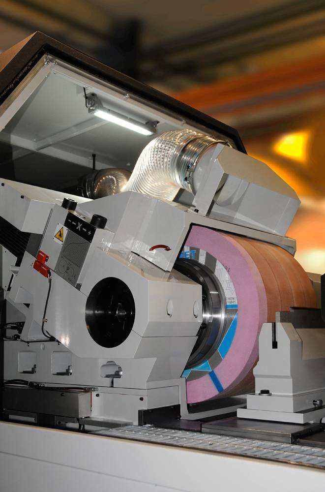
Precision centerless grinding machines are specialized grinding machines designed to produce highly accurate cylindrical components without holding the workpiece between centers or securing it in a conventional chuck. Unlike traditional cylindrical grinding machines, which support and rotate the workpiece using a headstock and tailstock arrangement, centerless grinding machines control the workpiece through the interaction of a grinding wheel, a regulating wheel, and a work-rest blade. This arrangement allows cylindrical components to be ground continuously or in rapid production cycles while maintaining excellent dimensional consistency, roundness, surface finish, and production efficiency.
Centerless grinding is widely used in automotive manufacturing, bearing production, hydraulic and pneumatic equipment manufacturing, medical device production, aerospace engineering, precision mechanical engineering, fastener manufacturing, and general industrial component production. It is particularly suitable for cylindrical parts that require accurate outside diameters, consistent roundness, controlled surface roughness, and high production volumes. Typical applications include shafts, pins, rollers, bearing components, guide rods, piston rods, valve elements, needles, precision tubes, dowel pins, and numerous other cylindrical components.
One of the most important advantages of centerless grinding is that the workpiece does not require conventional end support or individual chucking. The grinding operation is performed while the component is supported externally between the grinding wheel and regulating wheel, with the work-rest blade providing the necessary support from below. This arrangement simplifies workpiece handling and makes it possible to process long and slender components that may be difficult to grind using conventional cylindrical grinding methods.
The basic operating principle of a centerless grinding machine involves two rotating wheels positioned opposite each other. The grinding wheel performs the actual material removal, while the regulating wheel controls the rotational speed and movement of the workpiece. The work-rest blade supports the component and maintains its position within the grinding zone. The three elements work together to establish a stable grinding condition.
The grinding wheel generally rotates at a relatively high peripheral speed and removes material from the workpiece surface. The regulating wheel rotates at a lower peripheral speed and is normally made with a bond and abrasive specification that provide the necessary frictional contact with the workpiece. By controlling the regulating wheel speed and inclination, the machine determines the workpiece rotational speed and, in through-feed grinding, its axial movement through the grinding zone.
The work-rest blade is positioned between the two wheels and supports the workpiece during grinding. Its upper surface is normally inclined at a specific angle, depending on the workpiece diameter, grinding geometry, and machine configuration. The height and angle of the blade influence the position of the workpiece relative to the grinding and regulating wheel centers. Small changes in blade position can significantly affect the roundness and dimensional accuracy of the finished component.
A precision centerless grinding machine generally consists of a rigid machine bed, grinding wheel spindle assembly, regulating wheel spindle assembly, work-rest blade, wheel dressing mechanisms, feed adjustment systems, coolant equipment, hydraulic or servo-driven positioning systems, and an appropriate control system. Depending on the machine design, additional components may include automatic loading systems, workpiece guides, dimensional measurement devices, and automatic compensation mechanisms.
The machine bed must provide high structural stiffness and excellent vibration-damping characteristics. Centerless grinding is sensitive to small changes in the relative position of the grinding wheel, regulating wheel, and workpiece. Any structural movement or vibration can influence the finished diameter, roundness, and surface finish. The machine structure must therefore maintain accurate alignment under operating loads and throughout changes in temperature.
Cast iron is widely used for centerless grinding machine beds because of its vibration-damping properties and dimensional stability. Large machines may use heavily ribbed cast structures to improve stiffness while controlling weight and material consumption. Fabricated steel structures are also possible, but their design must account for welding distortion, residual stresses, and long-term dimensional stability. In high-precision machines, the machine bed and supporting structures must be manufactured and assembled with particular attention to geometric accuracy.
The grinding wheel spindle is one of the most important assemblies because it determines the rotational accuracy and stability of the main material-removal tool. The spindle must maintain low radial and axial runout while operating at the required rotational speed. It must also resist the radial forces generated during grinding without excessive deflection. Spindle stiffness, bearing quality, housing rigidity, and thermal stability all influence the final machining accuracy.
Precision rolling bearings are commonly used in centerless grinding spindles. Angular contact ball bearings can support combined radial and axial loads and provide high rotational accuracy. Cylindrical roller bearings may be used where high radial stiffness and load capacity are required. Depending on the machine performance level, hydrostatic or hydrodynamic spindle arrangements may also be considered.
Bearing selection must account for spindle speed, grinding wheel dimensions, wheel mass, operating forces, preload, lubrication, and thermal conditions. Excessive bearing preload can increase friction and temperature, while insufficient preload may reduce spindle stiffness and permit unwanted movement. The bearing arrangement must therefore provide the required rigidity without creating excessive internal loading.
The spindle housing must maintain accurate bearing alignment and provide sufficient thermal stability. Heat generated by the bearings and motor can change the spindle position relative to the workpiece. In high-precision grinding operations, even small thermal changes may influence dimensional consistency. Cooling systems, temperature monitoring, and suitable structural design can help maintain stable operating conditions.
The regulating wheel spindle requires equally careful engineering because it controls the movement and rotational behavior of the workpiece. Its speed must be adjustable over a suitable operating range, and its rotational movement must remain smooth and stable. Any irregularity in regulating wheel rotation can produce variations in workpiece speed, feed rate, and grinding conditions.
Regulating wheel drives may use variable-speed electric motors, belt drives, or direct-drive systems. Modern centerless grinding machines frequently use servo-controlled or variable-frequency drives to provide accurate speed adjustment. CNC systems can coordinate regulating wheel speed with other machine movements, allowing different workpiece materials and diameters to be processed using stored machining programs.
The grinding wheel and regulating wheel have different functions and therefore require different mechanical and abrasive characteristics. The grinding wheel must provide efficient material removal, maintain its profile, and produce the required surface finish. The regulating wheel must provide controlled frictional contact with the workpiece while maintaining dimensional and geometric stability.
Grinding wheels used in centerless grinding are commonly manufactured from aluminium oxide, silicon carbide, ceramic abrasives, and specialized abrasive materials. Aluminium oxide wheels are widely used for grinding carbon steels, alloy steels, and hardened steel components. Silicon carbide may be used for certain non-ferrous materials and specialized applications. Advanced ceramic abrasives can provide improved cutting performance and wheel life under suitable grinding conditions.
The abrasive grain size determines the cutting characteristics and achievable surface finish. Coarser grains generally provide higher material removal capacity and improved chip clearance, while finer grains are commonly selected for finishing operations requiring smoother surfaces. The correct grain size depends on workpiece material, hardness, wheel dimensions, contact conditions, and required surface quality.
Wheel hardness describes the strength with which the bond retains abrasive grains. A softer wheel releases worn grains more easily and exposes fresh cutting edges, while a harder wheel retains the grains for a longer period. The appropriate wheel hardness depends on the material being ground, grinding pressure, contact area, and thermal conditions. Incorrect wheel hardness can cause excessive wear, glazing, loading, or unstable grinding performance.
The wheel structure determines the spacing between abrasive grains. Open structures provide greater chip clearance and may improve coolant penetration, while denser structures provide a higher concentration of abrasive grains. The bond system holds the abrasive grains together and determines the mechanical characteristics of the wheel. Vitrified bonds are widely used in precision centerless grinding because they provide dimensional stability and controlled cutting behavior.
The regulating wheel is generally made using abrasive materials and bonding systems selected to provide suitable frictional contact. Its peripheral speed is lower than that of the grinding wheel, and it must transmit the necessary rotational and feeding forces to the workpiece without causing excessive wear or surface damage. The regulating wheel specification depends on workpiece material, diameter, required feed rate, and grinding configuration.
Regulating wheels may be manufactured from rubber-bonded, resin-bonded, or other specialized abrasive structures. The wheel surface must provide sufficient traction while maintaining stable contact with the workpiece. If the regulating wheel becomes glazed or excessively worn, the workpiece may not rotate or advance consistently. This can lead to dimensional variation, irregular surface finish, and reduced process stability.
Wheel dressing is essential for maintaining the geometric accuracy and cutting performance of centerless grinding wheels. During operation, abrasive grains become worn and the wheel profile may gradually change. Dressing removes worn abrasive material and restores the required wheel surface. It can also correct geometrical deviations and maintain the intended grinding wheel profile.
Diamond dressing tools are widely used in centerless grinding machines. Single-point diamond dressers, multi-point dressers, and rotary diamond dressing systems may be selected according to wheel dimensions and application requirements. The dressing system must provide controlled movement across the wheel surface and maintain the required profile accuracy.
The grinding wheel dressing mechanism must be sufficiently rigid to prevent unwanted movement during the dressing process. The dresser position, traverse speed, dressing depth, and overlap ratio influence the resulting wheel surface. A more aggressive dressing operation may produce a sharper and more open cutting surface, while finer dressing conditions can produce a smoother wheel profile.
The regulating wheel must also be dressed to maintain its contact geometry and surface characteristics. Because it controls workpiece rotation and axial movement, changes in its profile can directly affect the grinding process. The regulating wheel dressing system must restore the required shape and provide a consistent frictional surface. The dressing procedure should be coordinated with the grinding wheel condition to maintain stable operating relationships.
One of the defining characteristics of centerless grinding is the ability to process workpieces using different grinding methods. The three principal methods are through-feed grinding, in-feed grinding, and end-feed grinding. Each method is suitable for different workpiece geometries and production requirements.
Through-feed grinding is the most common method for processing cylindrical components with a continuous external profile. The workpiece enters one side of the machine, passes through the grinding zone, and exits from the opposite side. The regulating wheel is inclined at a small angle relative to the grinding wheel, causing the workpiece to move axially through the machine while rotating.
The inclination of the regulating wheel creates an axial component of movement. This allows the workpiece to advance continuously without requiring an individual feeding mechanism for each component. The axial feed rate depends on regulating wheel speed, inclination angle, workpiece diameter, and contact conditions. Adjusting the regulating wheel angle allows the operator to control the feed rate and machining cycle.
Through-feed grinding is particularly suitable for straight cylindrical components such as rods, pins, shafts, and rollers. It is highly productive because multiple workpieces can be processed continuously. The method is especially advantageous when large quantities of similar components must be manufactured with consistent diameters and surface finishes.
The geometry of the workpiece is an important limitation in through-feed grinding. Components must generally have a continuous cylindrical profile without shoulders or significant diameter changes that prevent them from passing through the grinding zone. Parts with steps, flanges, grooves, or complex external profiles may require in-feed grinding or another specialized method.
In-feed grinding, also called plunge grinding, is used when the workpiece cannot move axially through the grinding zone. The regulating wheel and grinding wheel are positioned around the required grinding section, and the grinding wheel moves radially toward the workpiece to remove material. The workpiece rotates in place while the grinding operation is performed.
In-feed grinding is suitable for components with shoulders, steps, grooves, formed diameters, and other geometries that cannot pass continuously through the machine. The grinding wheel may be dressed with a profile corresponding to the required workpiece shape. This allows several external features to be ground during a single setup, depending on the machine configuration and wheel width.
The in-feed method requires accurate positioning of the workpiece and precise control of the radial grinding movement. The regulating wheel must maintain stable rotational contact while the grinding wheel advances toward the component. The machine must provide sufficient stiffness to resist grinding forces and maintain the required profile during material removal.
End-feed grinding is used for certain tapered or geometrically defined cylindrical components. The workpiece is introduced into the grinding zone from one end and moves axially until it reaches a mechanical stop or the intended grinding position. The grinding wheel and regulating wheel are arranged to generate the required surface geometry. This method can be suitable for parts with a tapered profile or a specific axial configuration.
The choice between through-feed, in-feed, and end-feed grinding depends on workpiece geometry, production quantity, dimensional tolerance, and required surface characteristics. A component with a constant cylindrical diameter may be processed efficiently through-feed, while a stepped shaft may require in-feed grinding. Tapered parts may require end-feed or specialized arrangements.
The work-rest blade is a critical component in all centerless grinding operations. It supports the workpiece and determines its vertical position relative to the grinding and regulating wheels. The blade must have sufficient stiffness and wear resistance to maintain a stable support surface. It is commonly manufactured from hardened tool steel or other wear-resistant materials, depending on the machine and application.
The blade height influences the location of the workpiece center relative to the wheel centers. This position has a significant effect on roundness generation. If the workpiece center is positioned incorrectly, the grinding process may produce lobing, out-of-roundness, or unstable contact conditions. Correct blade height must therefore be established according to workpiece diameter, wheel geometry, and the required machining accuracy.
The blade angle is also important because it influences the support and contact conditions. A suitable blade geometry must prevent the workpiece from rolling or moving unpredictably while maintaining enough clearance for grinding wheel contact. The blade surface should be smooth and accurately manufactured to avoid damaging the workpiece or creating unwanted vibration.
Blade wear can affect the stability of the grinding process. As the contact surface gradually wears, the workpiece position may change, causing dimensional and roundness variations. Regular inspection and replacement or reconditioning are therefore necessary. In high-precision production, blade condition should be included in the machine maintenance and process control program.
One of the most important technical challenges in centerless grinding is controlling workpiece roundness. Unlike conventional cylindrical grinding, the workpiece is not held rigidly between centers. Its rotational position is determined by the geometry of the grinding wheel, regulating wheel, and work-rest blade. This creates a geometric relationship that must be carefully controlled to avoid the generation of lobing.
Lobing refers to a condition in which the workpiece cross-section contains repeated deviations from a perfect circle. A component may appear cylindrical when measured at certain positions but contain multiple high and low points around its circumference. This condition can be difficult to identify using simple two-point diameter measurements. Roundness inspection therefore requires suitable measuring equipment and measurement procedures.
The number and amplitude of lobes can be influenced by workpiece center height, wheel geometry, regulating wheel speed, blade position, and grinding conditions. Certain geometric arrangements may encourage the formation of specific lobing patterns. Machine setup must therefore be developed according to the workpiece diameter and required roundness tolerance.
The relationship between the wheel centers and the workpiece center is particularly important. If the workpiece center is too low or too high, the contact geometry changes and the stability of the grinding process may be affected. The appropriate center height depends on the machine design and component dimensions. It should be established using the manufacturer’s setup recommendations and verified through actual grinding trials.
Workpiece diameter is another important parameter. Different component diameters change the relative contact positions between the grinding wheel, regulating wheel, and work-rest blade. A machine intended to process a wide diameter range must provide sufficient adjustment capability to maintain correct geometry. This includes wheel center positioning, blade height adjustment, and regulating wheel inclination.
The regulating wheel angle influences both axial feed and workpiece rotational speed. A larger inclination generally increases the axial feeding component, although the actual relationship depends on the machine geometry and contact conditions. Excessive inclination may reduce contact stability or produce undesirable surface characteristics. The correct angle must be selected according to the workpiece dimensions and required production rate.
Grinding wheel speed and regulating wheel speed must be coordinated to provide stable material removal. The grinding wheel normally operates at a higher peripheral speed, while the regulating wheel controls the slower rotation of the workpiece. Changes in either speed influence grinding forces, workpiece movement, and surface finish. Modern machines provide adjustable drive systems that allow these parameters to be optimized for different materials and workpiece sizes.
The grinding force in centerless grinding is influenced by the material removal rate, wheel specification, workpiece hardness, contact length, and grinding parameters. Although the forces are generally lower than those found in heavy cutting operations, they can cause deflection in slender workpieces. Long, thin shafts are particularly sensitive to bending because they are supported externally rather than held along their complete length.
For long and slender components, workpiece support must be carefully designed. Additional support systems or specialized machine arrangements may be required to prevent deflection and vibration. The grinding wheel and regulating wheel must maintain stable contact along the required working length. In some applications, the workpiece may require intermediate support or specialized guide arrangements.
Thermal management is another major consideration in precision centerless grinding. Grinding involves numerous abrasive cutting points operating simultaneously, and a significant amount of mechanical energy is converted into heat. If this heat is not controlled, the workpiece may experience thermal expansion, grinding burn, residual stresses, microcracks, and dimensional variation.
Grinding burn is particularly problematic when processing hardened steels and precision components. Excessive surface temperature can alter the microstructure and mechanical properties of the material. In some cases, the damage may not be visible during a normal visual inspection. It may nevertheless reduce fatigue resistance, wear resistance, and the long-term reliability of the component.
Coolant systems are therefore essential in many precision centerless grinding applications. Water-based emulsions and synthetic grinding fluids are widely used to remove heat, lubricate the contact zone, and carry away abrasive and metallic particles. The coolant must be compatible with the workpiece material, wheel specification, machine components, and filtration system.
Coolant delivery must be directed accurately toward the grinding contact zone. The high rotational speed of the grinding wheel creates airflow that can prevent coolant from entering the grinding interface. The nozzle design and position should therefore be selected to deliver a stable fluid stream at the required location. Adequate coolant flow alone does not guarantee effective cooling if the fluid does not reach the actual contact area.
Coolant filtration is important because centerless grinding produces fine abrasive particles and metallic debris. These contaminants can accumulate in the fluid and cause scratches, surface defects, and premature wear of machine components. Magnetic separators can remove ferrous particles, while paper filters, centrifugal separators, and other filtration systems can remove finer contaminants.
The required filtration level depends on the surface-finish requirements, material being processed, grinding wheel type, and coolant system design. High-precision components may require more effective filtration because small particles can become trapped between the workpiece and grinding wheel. Coolant cleanliness should therefore be treated as an essential process parameter.
Centerless grinding is particularly effective for producing high volumes of precision cylindrical components. Because the workpiece does not need to be individually clamped between centers, loading and unloading can be simplified. Through-feed grinding allows continuous processing, and automatic feeding systems can supply components to the machine without requiring manual handling of every part.
Automatic loading systems may include vibratory bowl feeders, linear conveyors, robotic loading systems, magazine feeders, and specialized component handling mechanisms. The appropriate arrangement depends on workpiece size, geometry, surface condition, and production volume. The feeding system must prevent components from colliding or becoming damaged before entering the grinding zone.
Automatic unloading and sorting systems can be integrated with dimensional inspection equipment. Finished components may be measured automatically and separated according to dimensional limits. Parts that do not meet the required tolerances can be rejected or directed to a corrective operation. Such systems are particularly useful in high-volume automotive and bearing manufacturing environments.
CNC centerless grinding machines provide advanced control over wheel positioning, regulating wheel speed, dressing movements, and grinding cycles. Servo-driven adjustment systems can position the regulating wheel and grinding wheel with high repeatability. CNC control can also store different setup parameters for different workpiece types, reducing setup time and improving process consistency.
Some modern machines incorporate automatic compensation for grinding wheel wear. As the wheel diameter changes due to dressing and normal operation, the machine can adjust the relevant positions to maintain the required grinding geometry. Automatic measurement systems can also provide feedback for dimensional correction. These functions are particularly valuable in production environments where long machining runs require stable dimensional results.
In-process measurement systems can monitor workpiece diameter during grinding. Contact measuring devices, air gauges, laser systems, and other non-contact measurement technologies may be used depending on the machine configuration and workpiece characteristics. The measurement system can provide information for automatic correction or process monitoring.
Post-process measurement is also important because it verifies the final dimensions after the workpiece has left the grinding zone and reached a stable temperature. Air gauging is widely used for measuring small and medium cylindrical components in production environments. Laser micrometers can provide non-contact diameter measurement, while roundness measuring instruments are used to evaluate geometric deviations in greater detail.
Diameter measurement alone is not sufficient to establish complete cylindrical accuracy. A workpiece may meet its nominal diameter while still containing excessive roundness, cylindricity, or straightness deviations. Precision inspection should therefore consider the functional geometric characteristics required by the component drawing.
Roundness describes how closely a cross-section approaches a perfect circle. Cylindricity evaluates the complete cylindrical surface in three dimensions, considering variations in diameter, roundness, and axis alignment along the component length. Straightness is particularly important for long cylindrical components such as guide rods and precision shafts. Surface roughness describes the microscopic texture of the ground surface and must be evaluated using an appropriate surface measurement method.
Precision centerless grinding is widely used in bearing manufacturing. Bearing rollers, cylindrical components, needle rollers, and other precision elements require accurate diameters, roundness, and surface finish. Centerless grinding can provide high production rates while maintaining consistent dimensions. Depending on the bearing design, additional grinding and superfinishing operations may be used to achieve the final functional surface characteristics.
Automotive manufacturing is another major application area. Components such as transmission shafts, hydraulic elements, fuel system parts, valve components, piston pins, and precision guide elements may require centerless grinding. These parts often operate under repeated mechanical loading, sliding contact, or rotational movement. Their dimensional and surface characteristics can influence friction, wear, leakage, and service life.
Hydraulic and pneumatic equipment manufacturers use centerless grinding for piston rods, valve stems, guide rods, precision pins, and cylindrical sealing components. Surface quality and dimensional accuracy are important because these components interact with seals, bushings, bearings, and other precision elements. A properly ground surface can improve sealing performance and reduce friction during operation.
In medical device manufacturing, centerless grinding is used for selected precision shafts, pins, needles, and cylindrical instruments. These applications may involve stainless steels, specialized alloys, and other materials requiring controlled surface conditions. Depending on the component, additional cleaning, passivation, polishing, or finishing operations may be necessary after grinding.
Aerospace engineering uses centerless grinding for selected cylindrical components that require high dimensional accuracy and surface integrity. Materials may include alloy steels, stainless steels, titanium alloys, and other engineering materials. The grinding process must be developed according to the material characteristics and component requirements, particularly where fatigue resistance and reliability are critical.
Precision centerless grinding is also used in the production of small mechanical components. Pins, dowels, rollers, miniature shafts, and guide elements can be manufactured with accurate diameters and surface finishes. The ability to process slender and small-diameter components without conventional end clamping makes centerless grinding particularly advantageous for these applications.
The maintenance of centerless grinding machines is essential for preserving dimensional accuracy and operational reliability. Regular inspection should include grinding wheel condition, regulating wheel condition, blade wear, spindle vibration, coolant system performance, lubrication, hydraulic components, and positioning mechanisms. Small mechanical changes can have a significant effect on the grinding process.
Grinding and regulating wheel mounting systems must be inspected for contamination, damage, and incorrect seating. Wheel assemblies must be installed according to the manufacturer’s safety instructions and operating limits. Balancing should be performed where required to minimize vibration. The dressing system should also be checked to ensure that the dresser moves accurately and restores the intended wheel geometry.
The regulating wheel drive must be maintained to ensure smooth speed control. Irregular motor operation, belt wear, transmission backlash, or unstable electronic control can produce variations in workpiece movement. The regulating wheel spindle bearings should be monitored for noise, temperature, and vibration. Any change in these characteristics may indicate a developing mechanical problem.
The work-rest blade should be inspected regularly for wear, damage, and surface irregularities. Its mounting arrangement must remain rigid and accurately positioned. Blade height and angle should be checked after setup changes and when dimensional or roundness deviations appear. A worn or incorrectly positioned blade can cause instability even when the grinding wheel and spindle assemblies are in good condition.
Hydraulic and lubrication systems should be inspected for pressure stability, fluid cleanliness, leakage, and filter condition. Guideways and adjustment mechanisms must remain properly lubricated to prevent wear and inconsistent movement. Coolant tanks and filtration systems should be cleaned periodically to prevent the accumulation of grinding sludge and metallic particles.
Geometric inspection should include wheel spindle runout, regulating wheel alignment, machine guideway accuracy, wheel center positioning, and adjustment system repeatability. Depending on the machine design, additional checks may be necessary for blade mounting surfaces and dressing mechanism alignment. Precision measuring instruments should be used to verify the mechanical condition of the machine.
The selection of a precision centerless grinding machine begins with the dimensions and geometry of the components to be processed. Maximum and minimum workpiece diameters, component lengths, material specifications, and required dimensional tolerances determine the necessary machine capacity. The machine must provide sufficient adjustment range to accommodate the intended component family while maintaining the correct grinding geometry.
The required production volume is another important consideration. Through-feed grinding is particularly suitable for large quantities of straight cylindrical components, while in-feed machines are better suited to stepped and formed parts. A production facility manufacturing several different component geometries may require a machine with flexible wheel dressing and positioning capabilities.
The required dimensional accuracy, roundness, cylindricity, and surface roughness must be established before machine selection. These characteristics determine the necessary machine stiffness, spindle accuracy, dressing system, workholding arrangement, and measurement equipment. The machine specification should be evaluated against the actual component drawings and expected process conditions rather than relying solely on general accuracy claims.
Grinding wheel dimensions and spindle power must also be selected according to the required material removal rate and workpiece material. Larger wheels may provide greater contact length and higher grinding capacity, while smaller wheels can be suitable for specialized applications. The spindle must provide the required rotational speed and power without excessive vibration or thermal instability.
The regulating wheel drive must provide sufficient speed range and control resolution for the intended workpiece diameters and feed rates. Servo-controlled systems can provide accurate speed adjustment and integration with CNC programs. Conventional variable-speed drives may be suitable for many standard applications. The correct choice depends on the required process flexibility, production volume, and automation level.
Machine automation should be evaluated according to the expected production cycle. Manual loading may be suitable for low-volume or specialized manufacturing, while automatic feeding and unloading can provide significant advantages in high-volume production. Automatic measurement, dressing, and dimensional compensation can further improve process consistency, although they increase system complexity and initial investment.
A complete centerless grinding installation may include the grinding machine, grinding and regulating wheels, wheel dressing equipment, work-rest blades, coolant filtration, automatic loading and unloading, dimensional measurement systems, and dedicated process monitoring equipment. These elements must be selected as a coordinated system to achieve the intended production performance.
The development of a centerless grinding process should begin with an evaluation of the component material, geometry, initial condition, and final dimensional requirements. The grinding wheel and regulating wheel specifications must be selected according to the workpiece characteristics. The work-rest blade height, regulating wheel angle, wheel speeds, and grinding allowance must then be established through suitable setup procedures and process trials.
Initial grinding trials should evaluate dimensional consistency, roundness, surface finish, thermal effects, and production stability. If the component exhibits lobing, the workpiece center position, blade geometry, and wheel relationship should be reviewed. If the surface finish is poor, wheel condition, dressing parameters, coolant delivery, and feed rate should be examined. If dimensional variation occurs during longer production runs, thermal changes, wheel wear, and automatic compensation should be investigated.
The process should be optimized through controlled adjustments rather than changing several parameters simultaneously. This allows the influence of each parameter to be understood and makes it easier to identify the actual cause of dimensional or surface-quality problems. Once a stable process has been established, the relevant machine settings should be documented and stored for repeat production.
Modern centerless grinding machines continue to develop through improvements in spindle technology, servo drives, CNC control, wheel materials, automatic dressing, and in-process measurement. Advanced monitoring systems can evaluate spindle vibration, drive loads, coolant conditions, and dimensional changes. This information can support preventive maintenance and process optimization, reducing unexpected downtime and improving production consistency.
Digital manufacturing systems can also connect centerless grinding machines with upstream and downstream production equipment. Workpiece identification, stored grinding programs, automatic inspection results, and production data can be integrated into manufacturing management systems. Such integration helps manufacturers monitor process performance and maintain traceability in demanding production environments.
Despite these technological developments, the fundamental success of centerless grinding still depends on the correct relationship between the grinding wheel, regulating wheel, work-rest blade, and workpiece. The machine must maintain accurate mechanical positioning, stable rotation, controlled feed movement, and effective thermal management. Wheel condition, blade geometry, and process parameters must remain consistent throughout production.
Precision centerless grinding machines therefore provide an essential manufacturing solution for producing accurate cylindrical components at high production rates. Their ability to process workpieces without conventional end clamping makes them particularly suitable for long, slender, small-diameter, and high-volume components. When correctly configured, they can achieve excellent dimensional consistency, roundness, surface finish, and production efficiency.
The selection of the machine configuration, spindle systems, grinding and regulating wheels, dressing mechanisms, work-rest blade, coolant technology, automation equipment, and measurement systems must be based on the actual engineering requirements of the components. When these elements are properly coordinated, a precision centerless grinding machine can provide reliable long-term performance, repeatable cylindrical accuracy, and efficient production in demanding industrial manufacturing environments.
EMS Metalworking Machines
We design, manufacture and assembly metalworking machinery such as:
- Hydraulic transfer press
- Glass mosaic press
- Hydraulic deep drawing press
- Casting press
- Hydraulic cold forming press
- Hydroforming press
- Composite press
- Silicone rubber moulding press
- Brake pad press
- Melamine press
- SMC & BMC Press
- Labrotaroy press
- Edge cutting trimming machine
- Edge curling machine
- Trimming beading machine
- Trimming joggling machine
- Cookware production line
- Pipe bending machine
- Profile bending machine
- Bandsaw for metal
- Cylindrical welding machine
- Horizontal pres and cookware
- Kitchenware, hotelware
- Bakeware and cuttlery production machinery
as a complete line as well as an individual machine such as:
- Edge cutting trimming beading machines
- Polishing and grinding machines for pot and pans
- Hydraulic drawing presses
- Circle blanking machines
- Riveting machine
- Hole punching machines
- Press feeding machine
You can check our machinery at work at: EMS Metalworking Machinery – YouTube
Applications:
- Beading and ribbing
- Flanging
- Trimming
- Curling
- Lock-seaming
- Ribbing
- Flange-punching