
Hydraulic Deep Drawing Press Machine Price from the manufacturer. High quality & low price with free consultation. Deep Drawing Press Price
A hydraulic deep drawing press machine is a type of machine used in metal forming and fabrication that uses hydraulic pressure to force a metal sheet into a die to create a specific shape or form. The process is called deep drawing because the metal is formed into a three-dimensional shape by drawing it into a die cavity with a punch.
Hydraulic Deep Drawing Press
Hydraulic deep drawing press machines are used to produce a variety of metal parts for industries such as automotive, aerospace, and construction. The machines are available in various sizes and capacities, ranging from small tabletop models to large, industrial-scale machines that can produce parts up to several meters in size.
The process of deep drawing with a hydraulic press machine involves several steps. First, a flat sheet of metal is placed on the die surface. Next, the hydraulic press applies force to the punch, which pushes the sheet into the die cavity. The force and pressure applied by the hydraulic press causes the metal to flow and stretch to the shape of the die cavity. The final shape is achieved when the punch is retracted from the die and the formed metal part is removed.
One of the main advantages of using hydraulic deep drawing press machines is the high precision and accuracy they provide. The hydraulic system ensures that the force applied to the metal sheet is consistent throughout the process, resulting in a uniform and accurate shape. Additionally, the use of hydraulic systems allows for greater control over the speed and force of the forming process, which can result in fewer defects and lower scrap rates.
However, there are also some disadvantages associated with hydraulic deep drawing press machines. The machines can be expensive to purchase and maintain, and the process can be slow compared to other metal forming methods. Additionally, the use of hydraulic systems can result in environmental concerns related to hydraulic fluid leakage and disposal.
Overall, hydraulic deep drawing press machines are an important tool for metal fabrication and can provide high precision and accuracy in the production of complex metal parts.
A hydraulic press is a mechanical device that uses a hydraulic cylinder to generate a compressive force. It operates based on Pascal’s Law, which states that pressure applied to a confined fluid is transmitted equally in all directions. This principle allows hydraulic presses to exert significant force with minimal input, making them essential tools in industries requiring high-pressure applications.
A single-acting hydraulic press uses hydraulic pressure to move the piston in one direction, typically the downward or compressive stroke. After the press completes this action, the piston returns to its original position using an external force such as a spring or the weight of the cylinder. This differs from a double-acting hydraulic press, where hydraulic pressure is applied in both the forward and return strokes.
The simplicity and cost-effectiveness of single-acting hydraulic presses make them ideal for a variety of applications, including small to medium-scale production, metal fabrication, and mechanical testing. These presses are widely used in industries such as automotive, aerospace, manufacturing, and even laboratories for precision tasks.
The core advantage of a single-acting hydraulic press lies in its simplicity. Fewer moving parts and a straightforward design reduce both the initial cost and ongoing maintenance requirements. However, the trade-off is that the press lacks the stroke control and power range of more complex systems, limiting its effectiveness in higher-end or more precise applications.
How Single-Acting Hydraulic Presses Work
The fundamental operation of a single-acting hydraulic press relies on Pascal’s Law, which underpins all hydraulic systems. According to this principle, when a force is applied to a fluid inside a closed system, the pressure is transmitted evenly throughout the fluid. In a hydraulic press, this means that the force generated by a pump acting on a small volume of hydraulic fluid can be magnified to create a much larger output force.
Key Components of a Single-Acting Hydraulic Press:
- Cylinder and Piston: The hydraulic cylinder contains a piston that moves up and down. In a single-acting press, hydraulic fluid forces the piston downwards, creating the press action.
- Hydraulic Pump: The pump generates pressure within the hydraulic system, pushing the fluid into the cylinder to drive the piston.
- Reservoir: This stores hydraulic fluid, which is pumped into the cylinder during operation.
- Valves: Control the flow of hydraulic fluid, directing it into the cylinder for the pressing stroke.
- Return Mechanism: In single-acting systems, this is usually a spring or gravitational force that returns the piston to its original position after the pressing action.
Pressing and Return Process:
- Pressing: When the press operator activates the system, hydraulic fluid is pumped into the cylinder. The increase in pressure forces the piston downward, applying force to the material placed under the press head. The force can range from several tons to hundreds of tons, depending on the press’s specifications.
- Return Stroke: Once the pressing action is complete, the external force—usually a spring or gravity—returns the piston to its starting position. Unlike double-acting presses, where hydraulic pressure can control both strokes, single-acting presses rely on this mechanical or natural return.
Advantages and Limitations:
- Advantages: Single-acting presses are simple, affordable, and easy to maintain. They are ideal for tasks that do not require precise control over the return stroke or where the pressing force is the primary concern.
- Limitations: The primary limitation is the lack of control over the piston’s return stroke, which can make single-acting presses less suited to precision applications. Additionally, since only one stroke is powered, these presses are less efficient in tasks requiring continuous motion or high-speed operation.
Types of Single-Acting Hydraulic Presses
Single-acting hydraulic presses come in several varieties, each suited to different applications and operational needs.
1. Manually Operated Hydraulic Presses:
These presses are powered by a hand-operated pump, which provides the hydraulic pressure needed to move the piston. They are ideal for small-scale applications or environments where electricity is not available. These presses are portable and commonly used in repair shops, garages, or remote field locations. Their affordability and ease of use make them popular for light-duty tasks like pressing bearings or removing shafts.
2. Electric-Powered Hydraulic Presses:
Electric-powered hydraulic presses use an electric motor to drive the hydraulic pump, offering greater efficiency and consistency compared to manual models. These presses are suitable for more intensive industrial applications where higher force or faster operation is required. They are commonly found in manufacturing plants, where they can be integrated into production lines for repetitive tasks such as stamping, forging, or cutting.
3. Air-Driven Hydraulic Presses:
In these systems, compressed air is used to generate hydraulic pressure. They are commonly used in industrial environments where compressed air is readily available. Air-driven hydraulic presses are often employed in applications where speed and convenience are critical, and they offer a middle ground between manually operated and electric-powered presses in terms of power and cost.
Applications of Each Type:
- Manually Operated: Ideal for low-volume tasks, repair work, or environments lacking electrical infrastructure.
- Electric-Powered: Suitable for continuous, heavy-duty applications in factories and production environments.
- Air-Driven: Often used in automotive workshops and for lighter industrial tasks where compressed air is available.
Applications of Single-Acting Hydraulic Presses
Single-acting hydraulic presses are versatile tools used across a wide range of industries for different applications.
1. Metal Forming and Fabrication:
In the metalworking industry, hydraulic presses are used to shape, bend, punch, and cut metal sheets and components. Single-acting presses are especially useful in tasks where the return stroke is less critical, such as metal stamping or bending. These presses are commonly used in fabrication shops, tool and die manufacturing, and custom metalwork projects.
2. Press Fitting and Assembly Tasks:
Single-acting presses are commonly employed in press fitting, where parts are mechanically forced together using high pressure. This includes tasks such as pressing bushings, bearings, gears, and other components into place. These presses are widely used in the automotive industry for assembly operations, as well as in machinery and equipment manufacturing.
3. Material Testing and Laboratory Uses:
In laboratories, single-acting hydraulic presses are often used for testing materials under compressive force. For example, engineers and scientists may use hydraulic presses to measure the compressive strength of materials like concrete, metals, or plastics. The simplicity of single-acting presses makes them ideal for controlled experiments where large forces are required without complex control systems.
4. Automotive and Aerospace Industries:
In the automotive sector, single-acting hydraulic presses play a crucial role in various assembly and maintenance tasks, such as pressing in bushings, removing bearings, and straightening parts. Their use extends to aerospace industries for tasks such as forming lightweight components, shaping metal parts, or assembling intricate systems that require precise force application.
Examples of Practical Applications:
- Metal Stamping: Single-acting presses are used to punch or stamp metal parts for various industries, including automotive and electronics.
- Bearing Installation: Presses ensure that bearings are seated correctly without causing damage to delicate components.
- Cutting and Trimming: Hydraulic presses can be used to cut metal, plastic, or composite materials, making them essential in production environments.
Advantages of Single-Acting Hydraulic Presses
Single-acting hydraulic presses have several advantages, making them a popular choice in a variety of applications.
1. Simplicity and Cost-Effectiveness:
Due to their basic design, single-acting hydraulic presses are more affordable than their double-acting counterparts. They have fewer moving parts and require less complex control systems, reducing both the upfront cost and the likelihood of mechanical failure. This makes them ideal for smaller operations or businesses looking for cost-effective solutions.
2. Efficiency in Force Delivery:
Despite their simplicity, single-acting hydraulic presses can deliver tremendous force, making them suitable for heavy-duty tasks like metal forming or assembly. They can generate forces ranging from a few tons to several hundred tons, depending on the size and type of the press, enabling them to handle a wide range of materials and tasks.
3. Reduced Maintenance:
With fewer components, single-acting presses are easier and less costly to maintain. Routine maintenance is generally limited to inspecting seals, checking hydraulic fluid levels, and ensuring that the return mechanism (spring or gravity) is functioning properly.
4. Portability and Space Efficiency:
Single-acting presses are typically more compact than double-acting presses, making them easier to move and install in smaller workspaces. This portability is especially valuable in environments where space is limited, such as small workshops or laboratories.
Challenges and Limitations of Single-Acting Hydraulic Presses
While single-acting hydraulic presses offer many benefits, they also have certain limitations that can affect their performance in specific applications.
1. Limited Stroke Control and Precision:
Because the return stroke is not powered by hydraulics, single-acting presses lack the precise control over the piston’s movement during the return phase. This makes them less suitable for applications requiring fine control of both the forward and return strokes.
2. External Force Required for Return Stroke:
The reliance on springs or gravity for the return stroke introduces limitations. Springs can wear out over time, reducing the efficiency of the press, and gravitational return may be too slow for certain high-speed applications.
3. Power Limitations:
Single-acting presses typically have less power and speed compared to double-acting systems. For tasks requiring high force or rapid cycling, a double-acting press may be more appropriate.
4. Environmental Considerations:
Hydraulic systems, including single-acting presses, can pose environmental risks if not properly maintained. Leaking hydraulic fluid, for instance, can cause environmental contamination, making proper maintenance and disposal of used fluids critical.
Maintenance and Safety Considerations
Proper maintenance and adherence to safety protocols are essential to ensure the safe and efficient operation of single-acting hydraulic presses.
Maintenance Procedures:
- Hydraulic Fluid Levels: Regularly check and maintain the hydraulic fluid to ensure smooth operation. Low fluid levels can reduce press efficiency and lead to mechanical wear.
- Seals and Hoses: Inspect seals and hoses for wear and tear, as leaks can cause pressure loss and reduce the effectiveness of the press.
- Return Mechanism: Check the spring or gravity-based return system for signs of fatigue or failure. Over time, springs may lose tension, reducing the effectiveness of the return stroke.
Safety Protocols:
- Personal Protective Equipment (PPE): Operators should wear appropriate PPE, including safety goggles, gloves, and hearing protection.
- Proper Training: Ensure that all operators are trained in the correct use of the press and are aware of potential hazards.
- Emergency Stops: Hydraulic presses should be equipped with emergency stop buttons to allow operators to quickly halt the machine in case of malfunction or danger.
Future of Single-Acting Hydraulic Presses
Advancements in technology are opening new possibilities for single-acting hydraulic presses. As industries evolve, the demand for more efficient and eco-friendly machinery is growing.
1. Advancements in Hydraulic Technology:
Innovations in hydraulic systems are leading to more efficient and powerful single-acting presses. For instance, new hydraulic fluids with better thermal stability and lower environmental impact are being developed, reducing the ecological footprint of hydraulic systems.
2. Energy Efficiency Improvements:
Modern hydraulic presses are being designed with energy efficiency in mind. Enhanced pump designs, variable speed motors, and more efficient control systems are reducing energy consumption and operational costs.
3. Integration with Automation:
The future of hydraulic presses lies in their integration with automated and smart systems. Automated single-acting presses equipped with sensors and computer control systems can adjust force, speed, and stroke in real time, enhancing precision and adaptability.
4. Future Applications and Innovations:
As industries continue to demand more from hydraulic systems, single-acting presses are likely to be used in new applications such as additive manufacturing (3D printing) and precision engineering. The increasing focus on sustainability may also drive the development of greener, more energy-efficient presses.
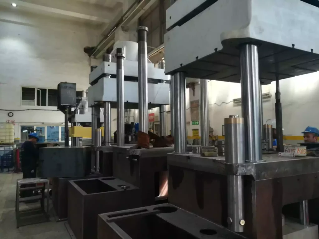
Introduction to Double-Acting Hydraulic Presses
Hydraulic presses are mechanical devices that use fluid pressure to generate significant force, commonly employed in industries where large-scale pressing, forming, or molding is required. They operate on Pascal’s Law, which states that pressure applied to a fluid in a confined space is transmitted equally in all directions. This principle allows hydraulic presses to amplify force, making them crucial in metalworking, manufacturing, automotive industries, and beyond.
A double-acting hydraulic press differs from its single-acting counterpart in that it applies hydraulic pressure in both directions—both for the pressing stroke and the return stroke. In contrast, a single-acting press relies on external forces, like springs or gravity, for the return motion, which limits control and precision.
The use of double-acting hydraulic presses has revolutionized several industrial processes due to the enhanced control and precision they offer. With powered movement in both directions, these presses are capable of handling more complex and demanding tasks, such as deep drawing, forging, or any process where high precision and consistent force are essential. These presses are widely used in automotive production, aerospace manufacturing, and large-scale industrial operations.
How Double-Acting Hydraulic Presses Work
Double-acting hydraulic presses function based on hydraulic principles, which utilize fluid power to amplify force. The critical difference from single-acting presses is that double-acting presses can apply hydraulic pressure in both the pressing and return strokes. This provides enhanced control and versatility.
Core Components of a Double-Acting Hydraulic Press:
- Cylinder and Piston: A double-acting press has a hydraulic cylinder with a piston that moves in two directions. Hydraulic fluid is directed into the cylinder on either side of the piston to control both the downward and upward strokes.
- Hydraulic Pump: The hydraulic pump provides pressure by moving hydraulic fluid into the cylinder. In double-acting presses, the pump must be capable of routing the fluid to either side of the piston, depending on whether it is the pressing or return stroke.
- Valves and Control Systems: Double-acting presses require more sophisticated valve systems to control the flow of hydraulic fluid. These valves direct fluid pressure to either side of the piston, enabling the precise control of both strokes.
- Power Source: These presses can be powered by manual pumps, electric motors, or pneumatic systems, depending on the scale and application of the press.
The Pressing and Return Strokes:
- Pressing Stroke: The hydraulic pump directs fluid into the top of the cylinder, pushing the piston downward. This downward force can range from a few tons to hundreds of tons, depending on the press’s size and design. The press head applies this force to the material being processed, whether it’s for stamping, molding, or cutting.
- Return Stroke: After the pressing operation, hydraulic pressure is redirected to the bottom of the piston. This lifts the piston back to its starting position, ensuring precise and controlled movement. The ability to hydraulically control both strokes eliminates the reliance on gravity or springs, allowing for faster cycle times and more complex tasks.
Precision and Control:
The ability to control both strokes of the piston provides greater accuracy in industrial processes. Unlike single-acting presses, where the return stroke can vary in speed and efficiency, double-acting presses offer consistent performance across all movements. This precision makes them ideal for complex forming processes, deep drawing, and precision cutting operations, where both the force and the return timing must be tightly controlled.
Types of Double-Acting Hydraulic Presses
Double-acting hydraulic presses come in various forms, each tailored for specific industrial applications. Here are some of the main types:
1. Manual Double-Acting Hydraulic Presses:
Manual versions of double-acting presses are powered by hand-operated hydraulic pumps. These are typically used in small workshops or repair facilities where tasks like pressing, bending, or assembling components do not require extensive automation. These presses are portable, cost-effective, and often used in low-production environments.
2. Electric-Powered Double-Acting Hydraulic Presses:
Electric-powered double-acting presses are more common in industrial settings where high force and consistent operation are required. The hydraulic pump is driven by an electric motor, allowing for automated control of both strokes. These presses are essential for high-volume operations, such as metal stamping, die forming, and precision cutting. The electric-powered system allows for greater precision, repeatability, and faster cycle times.
3. Pneumatic Double-Acting Hydraulic Presses:
Pneumatic-powered double-acting presses use compressed air to drive the hydraulic fluid in both strokes. These presses are favored in industries where pneumatic systems are already integrated into the production environment, such as in automotive assembly lines. Pneumatic systems provide rapid action, and the integration with hydraulics ensures the generation of high forces, making them suitable for mid-sized industrial applications.
4. Specialized Double-Acting Presses:
Some double-acting hydraulic presses are designed for specific applications, such as hydraulic press brakes used in bending and shaping metal sheets. These presses provide precise control over the angle and force applied, making them ideal for custom metal fabrication. Another example includes forging presses, where high tonnage and precise control are required to shape metal components.
Applications of Double-Acting Hydraulic Presses
Double-acting hydraulic presses are widely employed across a variety of industries due to their versatility and ability to handle complex tasks with precision. Here are some of the key applications:
1. Metal Forming and Deep Drawing:
One of the primary uses of double-acting hydraulic presses is in metal forming, particularly deep drawing. Deep drawing is a manufacturing process where a sheet metal blank is radially drawn into a forming die by the mechanical action of a punch. Double-acting presses provide the precise control necessary to form complex shapes in metals like aluminum, steel, and copper without cracking or deforming the material.
2. Punching, Forging, and Die Forming:
In punching and forging operations, double-acting presses apply controlled force to deform or cut metal parts. This is commonly used in the automotive and aerospace industries, where high-strength materials are forged into critical components like gears, axles, and structural parts. The ability to control both the pressing and return strokes ensures consistent quality and reduces the risk of material damage.
3. Composite Material Molding:
As industries increasingly adopt composite materials, double-acting hydraulic presses have become essential for forming and molding these materials. Composites, such as carbon fiber or fiberglass, require careful handling during the molding process to maintain their strength and durability. Double-acting presses allow for precise pressure application during both the pressing and release phases, making them indispensable in industries like aerospace and automotive, where lightweight, high-strength components are essential.
4. Automotive and Aerospace Industries:
The automotive industry relies heavily on double-acting hydraulic presses for the production of body panels, frames, and engine components. The precision and repeatability of these presses ensure that every part is manufactured to exact specifications. In the aerospace industry, where weight, strength, and safety are critical, double-acting presses are used to form lightweight components like aircraft skin panels, structural parts, and engine elements.
5. Examples of Industrial Applications:
- Automotive: Deep drawing for body panels, stamping parts like hoods, doors, and roofs.
- Aerospace: Forming of lightweight metal and composite parts for aircraft and spacecraft.
- Heavy Machinery: Forging of large components for construction equipment and industrial machinery.
- Consumer Electronics: Precision forming of metal casings and components.
Advantages of Double-Acting Hydraulic Presses
Double-acting hydraulic presses offer several significant advantages that make them indispensable in many industries.
1. Precise Control Over Both Strokes:
The ability to apply hydraulic force in both the pressing and return strokes gives double-acting presses greater control over the entire operation. This precision is particularly valuable in tasks that require consistent force and motion, such as deep drawing, forging, and punching. Both strokes can be finely adjusted to meet the exact requirements of the material and application, leading to superior product quality.
2. Higher Efficiency in Repetitive Operations:
In manufacturing environments where tasks must be repeated at high speed, double-acting presses outperform single-acting models. Since both the press and return strokes are powered, cycle times are faster, and operators have more control over the movement of the piston, which boosts productivity in high-volume production lines.
3. Versatility in Complex Tasks:
Double-acting presses are incredibly versatile, able to handle a wide variety of materials and tasks. They can be used for pressing, forming, bending, cutting, and molding, which makes them highly adaptable to different industries and processes. Whether the task requires the shaping of metals, molding of composites, or assembly of mechanical components, these presses can be fine-tuned to meet the needs of the job.
4. Suitability for Heavy-Duty and Continuous Use:
Double-acting hydraulic presses are built for heavy-duty applications and continuous use in industrial settings. The ability to power both strokes ensures that even the toughest materials, such as steel and titanium, can be shaped and formed without compromising on speed or accuracy. Their robust design and advanced control systems make them ideal for industries where durability and long-term performance are critical.
Challenges and Limitations of Double-Acting Hydraulic Presses
Despite their advantages, double-acting hydraulic presses also come with challenges and limitations that must be considered before implementation.
1. Higher Cost and Complexity:
Double-acting hydraulic presses are generally more expensive than single-acting presses due to their more complex design and the additional control systems required to power both strokes. This can make them less appealing for small-scale operations or businesses with tight budgets.
2. Increased Maintenance Requirements:
With more moving parts and components to manage, double-acting presses require more frequent and thorough maintenance than their single-acting counterparts. Components like seals, valves, and hydraulic lines must be regularly inspected and serviced to prevent leaks and ensure optimal performance. This adds to the operational costs over the lifespan of the machine.
3. Space and Energy Requirements:
Double-acting hydraulic presses tend to be larger and consume more energy than simpler presses. This means they require more space and have higher energy costs, which can be a limiting factor in smaller workshops or facilities with limited energy resources.
4. Specialized Training and Safety Considerations:
Operators of double-acting hydraulic presses must be thoroughly trained to handle the complex control systems and high pressures involved. The increased force and speed of these presses mean that strict safety protocols must be followed to prevent accidents and equipment damage.
Maintenance and Safety Considerations
Proper maintenance and safety protocols are crucial for ensuring the long-term operation and safety of double-acting hydraulic presses.
Maintenance Procedures:
- Hydraulic Fluid Levels: Maintaining appropriate hydraulic fluid levels is essential for the proper operation of both strokes. Low fluid levels can result in uneven pressure distribution and lead to damage.
- Seal and Hose Inspections: Double-acting presses have more seals and hoses than single-acting models, which makes regular inspections critical. Leaks in these components can cause a loss of pressure, reduced efficiency, and safety hazards.
- System Pressure Checks: Monitoring and adjusting the system’s pressure levels ensures that the press operates within its designed parameters, preventing over-pressurization and component failure.
Safety Protocols:
- Operator Training: Given the complexity of double-acting presses, operators must be trained in their safe use. They should understand the machine’s control systems, emergency stop features, and troubleshooting procedures.
- Regular Inspections: Presses should be inspected regularly for signs of wear or malfunction. Safety devices like pressure relief valves and emergency stops should be tested to ensure they are functioning properly.
- Personal Protective Equipment (PPE): Operators should always wear appropriate PPE, including gloves, goggles, and ear protection, especially in high-noise environments.
Future Trends in Double-Acting Hydraulic Press Technology
As technology evolves, double-acting hydraulic presses are expected to undergo several advancements that will enhance their performance and broaden their applications.
1. Technological Advancements:
Innovations in hydraulic control systems, such as the integration of proportional valves and servo-driven pumps, are improving the precision and efficiency of double-acting presses. These systems allow for finer control of pressure and movement, resulting in higher-quality output and reduced material waste.
2. Energy Efficiency:
One of the key areas of development is the push for more energy-efficient hydraulic systems. With the increasing focus on sustainability, new technologies are emerging that reduce energy consumption, such as variable-speed pumps that adjust output based on demand. These advancements not only lower operational costs but also reduce the environmental impact of hydraulic presses.
3. Automation and Industry 4.0:
The integration of double-acting hydraulic presses with automation and smart manufacturing systems is another significant trend. By connecting presses to factory networks, manufacturers can monitor machine performance in real-time, predict maintenance needs, and optimize press cycles. This leads to increased productivity and minimizes downtime due to unexpected equipment failure.
4. Future Innovations:
Looking ahead, double-acting presses may see further improvements in force capacity, miniaturization for precise applications, and modular designs that allow presses to be easily reconfigured for different tasks. Additionally, advancements in green hydraulic fluids will reduce the environmental risks associated with hydraulic systems.
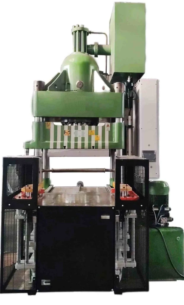
Triple Action Deep Drawing Press
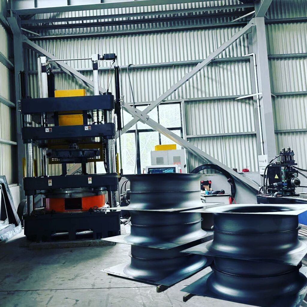
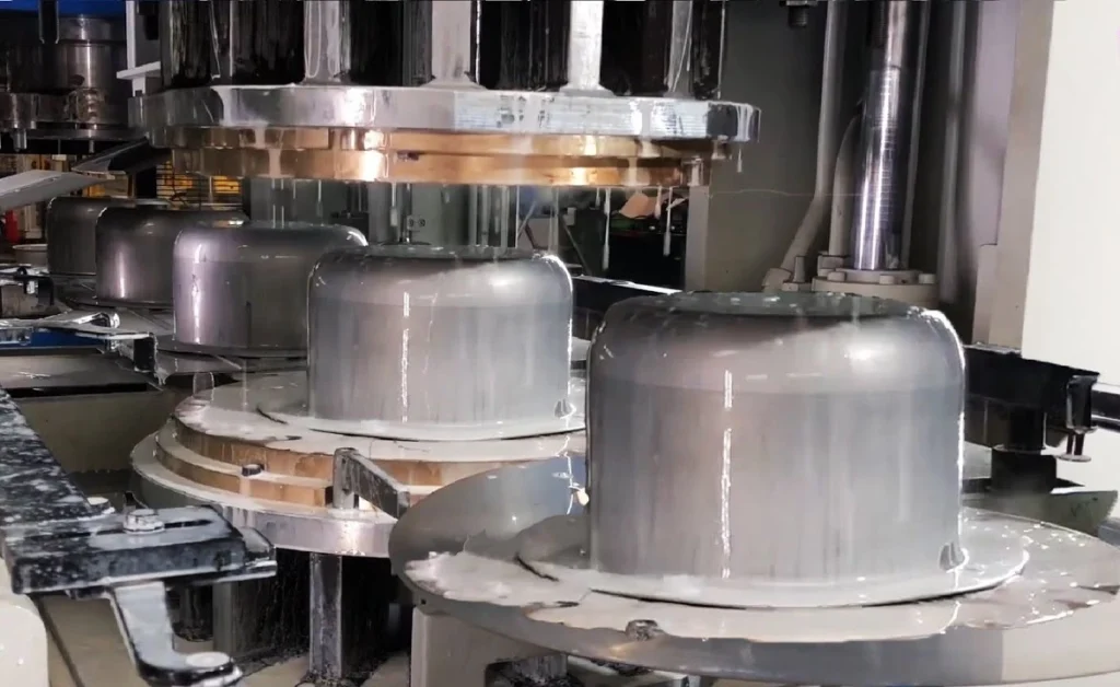
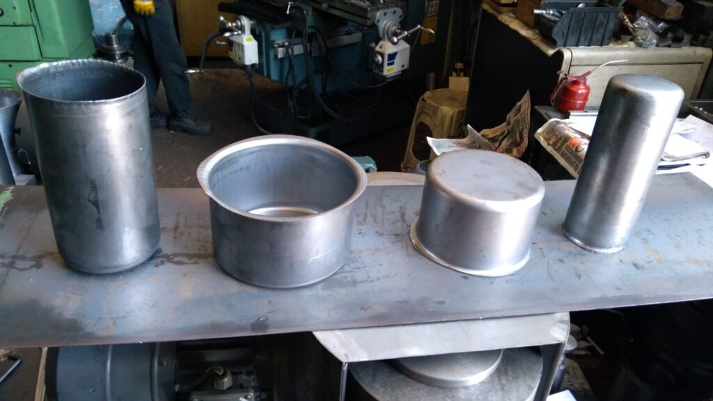
Deep drawing is a popular metal forming process used to shape flat sheet metal into cylindrical or box-like shapes. The process involves placing a metal blank over a die and pressing it into the die cavity with a punch. This transforms the flat blank into a three-dimensional shape, making it essential for producing components like automotive body panels, kitchen sinks, and various enclosures. The process can be repeated to achieve more complex shapes with greater depth, but the challenges increase as the material undergoes severe deformation.
A Triple Action Deep Drawing Press is a specialized machine designed to address the complexity of the deep drawing process. Unlike conventional single-acting or double-acting presses, a triple action press incorporates three independent force mechanisms:
- Blank Holder Action: Keeps the metal blank firmly in place, controlling material flow and preventing wrinkling.
- Punch Action: The primary force that shapes the blank by pushing it into the die.
- Ejector Action: Removes the finished part from the die after the drawing process is complete.
This triple-action mechanism provides greater control over the deep drawing process, allowing for the production of more complex shapes, with fewer defects, and better efficiency. The ability to control all three forces independently is particularly important in producing deep-drawn components for industries like automotive, aerospace, and consumer goods, where precision and quality are critical.
How Triple Action Deep Drawing Presses Work (500 words)
To understand how triple action deep drawing presses function, it’s essential to break down the mechanics of the deep drawing process and how each action contributes to shaping the material.
The Deep Drawing Process:
The deep drawing process transforms a flat metal blank into a three-dimensional component. The key stages include:
- Blank Placement: A flat metal blank is placed over the die cavity.
- Blank Holder Engagement: The blank holder clamps the blank around its edges, preventing movement or wrinkling during drawing.
- Punch Stroke: The punch moves downward, pressing the blank into the die cavity, forming the desired shape. This action stretches and deforms the material, thinning it in certain areas.
- Ejection: Once the part is formed, the ejector mechanism releases the part from the die, ready for the next cycle.
Components of a Triple Action Deep Drawing Press:
- Blank Holder: The blank holder is crucial in controlling material flow. Its force must be precisely regulated to avoid wrinkling, which can occur if the material is allowed to move too freely. At the same time, too much force from the blank holder can result in tearing.
- Punch: The punch is the main shaping tool. In triple-action presses, the punch force is adjustable, allowing for greater flexibility in handling different materials or thicknesses. As the punch presses the blank into the die, it forms the desired shape.
- Ejector: The ejector action ensures the formed part is smoothly removed from the die without causing damage to the component or slowing down the production process. The ejector often uses hydraulic or mechanical systems to push the part upward, releasing it from the die.
Key Advantages of the Triple Action System:
- Independent Control of Forces: One of the main benefits of triple action presses is that each force (blank holder, punch, ejector) can be independently controlled. This ensures optimal pressure at each stage, reducing the risk of defects such as wrinkling, tearing, or excessive thinning.
- Complex Shapes: By using all three actions in a coordinated manner, triple action presses can produce complex, deep-drawn components that would be difficult or impossible with a standard press.
- Minimized Defects: The precise control over material flow, punch pressure, and ejection force allows manufacturers to achieve higher-quality products with fewer defects, making triple-action presses ideal for high-precision industries.
Types of Triple Action Deep Drawing Presses
Triple action deep drawing presses come in various types, each suited to different applications and production environments. The main types include mechanical, hydraulic, and servo-electric presses.
1. Mechanical Triple Action Presses:
Mechanical triple action presses use mechanical linkages, cams, and gears to generate and control the forces required for the blank holder, punch, and ejector. These presses are known for their high speed and are commonly used in high-volume production environments, such as automotive manufacturing. However, they tend to offer less precision than hydraulic presses, making them less suitable for complex or precision deep drawing applications.
2. Hydraulic Triple Action Presses:
Hydraulic presses are the most common type of triple action deep drawing presses. These machines use hydraulic cylinders to apply force independently to the blank holder, punch, and ejector. Hydraulic presses are favored for their precision and the ability to control force and speed at every stage of the process. This makes them ideal for deep drawing applications that require complex shapes, deep draws, or challenging materials. Additionally, hydraulic systems can apply constant force throughout the entire stroke, providing a smooth and consistent draw.
3. Servo-Electric Triple Action Presses:
Servo-electric presses use electric motors to control the movement of the blank holder, punch, and ejector. These presses offer the highest level of precision and flexibility, allowing manufacturers to program specific force and speed profiles for different stages of the drawing process. Servo-electric presses are energy-efficient and offer precise control, making them ideal for applications requiring high precision, such as aerospace components and medical devices.
Comparison of Press Types:
- Mechanical: Best for high-speed, large-volume production; less precise.
- Hydraulic: Ideal for precision deep drawing, complex shapes, and variable materials; slower but more controlled.
- Servo-Electric: Offers the highest precision and flexibility, with energy efficiency; often used in highly specialized applications.
Applications of Triple Action Deep Drawing Presses
The versatility and precision of triple action deep drawing presses make them indispensable across a wide range of industries. Their ability to form complex, deep-drawn parts with minimal defects and high repeatability is a key reason for their widespread use.
1. Automotive Industry:
In the automotive sector, deep drawing presses are essential for producing a wide array of components, including body panels, fuel tanks, and engine components. Triple action presses are particularly well-suited for forming large, complex parts such as car doors, hoods, and trunk lids, which require high precision to ensure they meet the industry’s stringent safety and performance standards.
For example, the ability to control the blank holder force ensures that body panels are formed without wrinkling, a common defect in deep drawing. Additionally, the precision of triple-action presses allows for tight tolerances in the production of complex components like fuel tanks, which must be leak-proof and structurally sound.
2. Aerospace Industry:
In the aerospace industry, the demand for lightweight yet strong components is paramount. Triple action deep drawing presses are used to form aircraft skin panels, engine housings, and other structural components. The ability to control every aspect of the drawing process, including the exact force applied by the blank holder and punch, ensures that aerospace parts meet the high standards required for safety and performance.
Additionally, the triple action mechanism is crucial for working with materials like titanium, aluminum, and composites, which are commonly used in the aerospace industry but can be difficult to form due to their strength and tendency to crack under stress.
3. Consumer Goods:
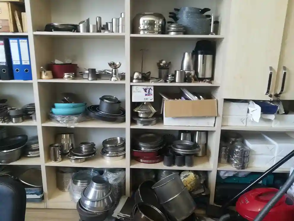
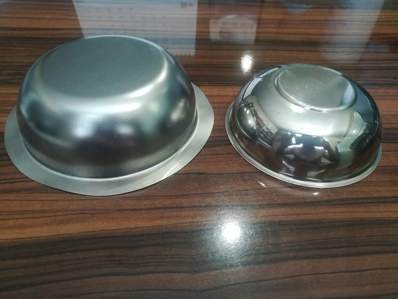
Triple action deep drawing presses are widely used to manufacture various consumer goods, particularly in the production of kitchenware (e.g., stainless steel sinks, pots, and pans) and household appliances (e.g., washing machine drums, microwave enclosures). The ability to form deep, complex shapes in materials like stainless steel or aluminum with smooth surfaces and minimal defects is essential for consumer products where aesthetics and durability are key selling points.
4. Industrial Containers and Enclosures:
Industries requiring industrial containers, cylindrical tanks, or enclosures for sensitive equipment often rely on triple action deep drawing presses. These presses allow for the formation of durable, uniform containers with precise dimensions, ensuring that they meet stringent industry standards for storage and protection.
Case Studies and Real-World Examples:
- Automotive: A major automotive manufacturer uses triple action presses to produce seamless body panels for luxury vehicles, ensuring high quality and eliminating the need for secondary finishing processes.
- Aerospace: Leading aerospace companies utilize triple action deep drawing presses for the production of lightweight, high-strength structural components, ensuring aircraft performance while reducing weight.
- Consumer Goods: A well-known kitchenware brand uses triple action presses to manufacture stainless steel cookware with flawless surfaces and uniform thickness, enhancing both performance and aesthetics.
Advantages of Triple Action Deep Drawing Presses
Triple action deep drawing presses offer numerous advantages that make them essential in industries requiring precision metal forming.
1. Enhanced Control Over the Deep Drawing Process:
One of the most significant advantages of a triple action press is the ability to independently control the blank holder, punch, and ejector forces. This precision control allows for adjustments throughout the deep drawing process, ensuring consistent material flow and reducing the risk of defects such as wrinkling, tearing, or excessive thinning.
2. Ability to Form Complex, Precise Shapes:
The precise control offered by triple action presses enables the formation of intricate shapes and deep-drawn components. The ability to fine-tune the force applied at each stage ensures that even challenging materials can be drawn without damage. This is especially important in industries like aerospace and automotive, where components must meet exacting standards for performance and safety.
3. Minimization of Defects:
Triple action presses significantly reduce common defects in the deep drawing process, such as wrinkling, cracking, and material thinning. The blank holder’s independent force ensures that the material is held securely, while the punch and ejector forces can be adjusted to optimize material flow. This results in higher-quality parts and reduced scrap, making triple action presses more efficient and cost-effective in large-scale production.
4. High Efficiency for Large-Scale Production:
Triple action presses are ideal for high-volume production, offering fast cycle times and repeatable precision. The automation of these presses allows for continuous operation, reducing downtime and increasing throughput. This efficiency is critical in industries where large quantities of parts must be produced quickly and to tight tolerances, such as automotive manufacturing.
Challenges and Limitations of Triple Action Deep Drawing Presses
Despite their numerous advantages, triple action deep drawing presses also present certain challenges and limitations.
1. High Initial Investment and Complexity:
Triple action deep drawing presses are more expensive than single or double-action presses due to their complexity and advanced control systems. The cost of purchasing and setting up a triple action press can be prohibitive for smaller operations or manufacturers with limited budgets. Additionally, these presses require more sophisticated control systems and software, which can increase the initial investment.
2. Greater Maintenance Requirements:
The complexity of triple action presses means that they require more frequent and thorough maintenance compared to simpler presses. The hydraulic systems, punch, blank holder, and ejector mechanisms all need regular inspection and servicing to prevent breakdowns and ensure the press operates at peak efficiency. Maintenance costs and downtime can be a challenge, especially in high-production environments.
3. Limitations in Smaller-Scale Operations:
For smaller-scale manufacturers or those producing limited quantities of deep-drawn parts, the high cost and complexity of triple action presses may not be justified. These presses are best suited to large-scale operations where the benefits of increased precision, efficiency, and reduced scrap outweigh the higher costs.
4. Energy and Space Requirements:
Triple action presses require significant amounts of energy to operate, especially hydraulic models, which need continuous power to maintain pressure. They are also large machines that require a substantial amount of floor space, limiting their use in smaller production facilities or workshops.
Maintenance and Safety Considerations
Proper maintenance and safety protocols are essential to ensure the longevity and safe operation of triple action deep drawing presses.
Maintenance Procedures:
- Hydraulic System Maintenance: Hydraulic presses rely on clean, properly pressurized fluid systems to function efficiently. Regular checks of hydraulic fluid levels, cleanliness, and pressure are necessary. Dirty or low fluid can cause increased wear on components or lead to system failure.
- Lubrication: Proper lubrication of moving parts, including the punch, blank holder, and ejector, is critical to reduce friction and wear. Over time, insufficient lubrication can lead to damage and expensive repairs.
- Seal and Hose Inspections: Hydraulic seals and hoses should be regularly inspected for wear and leaks. Any signs of leakage must be addressed immediately to prevent pressure loss, damage to components, or safety hazards.
- Alignment Checks: Regular alignment checks for the punch, die, and blank holder ensure that parts are being formed accurately and uniformly. Misalignment can lead to defective parts and increased machine wear.
Safety Protocols:
- Operator Training: Operators should be thoroughly trained in the use of triple action presses, including how to safely load blanks, adjust controls, and handle finished parts. Understanding how to safely manage the hydraulic systems and high forces involved is critical for preventing accidents.
- Emergency Stops and Safety Guards: Triple action presses should be equipped with emergency stop systems and safety guards to protect operators. These features ensure that the machine can be immediately stopped in the event of a malfunction or danger.
- Personal Protective Equipment (PPE): Operators must wear appropriate PPE, including gloves, goggles, and protective clothing, to reduce the risk of injury from moving parts, flying debris, or hydraulic fluid leaks.
Future Trends in Triple Action Deep Drawing Press Technology
The future of triple action deep drawing presses is being shaped by advancements in technology, materials, and manufacturing processes.
1. Innovations in Press Control Systems:
As manufacturing becomes more automated and digital, the control systems used in triple action presses are becoming more sophisticated. Proportional hydraulic control valves and servo-driven systems are allowing for even more precise control over the forces applied during the deep drawing process. This enhanced control not only improves part quality but also reduces waste and increases efficiency.
2. Material Advancements:
As industries increasingly demand stronger, lighter, and more durable materials, triple action presses are evolving to handle these new challenges. Advances in high-strength steel, aluminum alloys, and composites are pushing the limits of what deep drawing presses can do. Modern presses are being designed with enhanced force capabilities and precision to work with these advanced materials, enabling the production of lightweight, high-strength components for the automotive, aerospace, and electronics industries.
3. Integration with Industry 4.0:
The integration of Industry 4.0 technologies, such as sensors, real-time data monitoring, and predictive maintenance systems, is helping manufacturers optimize the performance of their triple action presses. Smart systems can monitor machine performance in real-time, automatically adjust press settings, and even predict when maintenance is needed, reducing downtime and improving overall productivity.
4. Environmental Sustainability and Energy Efficiency:
Energy efficiency is becoming a priority for manufacturers using triple action presses. New designs are focusing on reducing energy consumption through variable-speed hydraulic pumps, energy recovery systems, and servo-electric technologies. These advancements not only reduce operational costs but also help companies meet their environmental sustainability goals by reducing the energy footprint of their manufacturing processes.
Double-Acting Hydraulic Presses
Double-acting hydraulic presses provide more control and flexibility during the deep drawing process, particularly for applications that require more complex or deeper shapes. In a double-acting press, two separate hydraulic systems work in tandem—one controls the downward motion of the punch, while the other operates the blank holder, applying force independently to hold the material in place.
- Structure: The press has two rams or cylinders—one for the punch and another for the blank holder. This setup allows for precise control of both the drawing force and the holding force, preventing material slippage or wrinkling during the drawing process.
- Applications: Double-acting presses are commonly used in automotive, aerospace, and household appliance manufacturing, where complex shapes and deeper draws are required. For instance, components like fuel tanks, car body panels, and aircraft parts are often made using double-acting hydraulic presses.
- Advantages: The independent control over the punch and blank holder forces allows for more precise and uniform drawing, reducing the risk of defects such as tearing or wrinkling. These presses are suitable for larger and more intricate parts and offer greater flexibility in handling a variety of materials and shapes.
Triple-Action Hydraulic Presses
For the most demanding and complex deep drawing applications, triple-action hydraulic presses provide unparalleled performance. These presses add a third hydraulic system to control additional movements or processes during the drawing operation.
- Structure: In addition to the punch and blank holder, triple-action presses feature a third force, often applied from the bottom of the press. This additional motion allows for processes like reverse drawing or extrusion, enabling the machine to handle extremely deep or complex shapes that require multiple stages of forming.
- Applications: Triple-action presses are typically used in highly specialized industries such as aerospace and defense, where precision and complexity are paramount. Components like deep drawn fuel cells, engine components, and structural parts for aircraft or heavy machinery are ideal for these machines.
- Advantages: These presses provide maximum control and precision, allowing manufacturers to produce parts with extreme depth or complexity without compromising on quality. They also offer higher productivity by enabling multiple forming operations in a single press cycle.
Automated vs. Manual Hydraulic Presses
Automation is an important factor in modern manufacturing, and hydraulic deep drawing presses are no exception. Buyers can choose between manual presses, which require human intervention for loading, unloading, and controlling the operation, or automated presses, which integrate robotic systems and computerized controls to manage the entire process.
- Manual Hydraulic Presses: These presses are operated by technicians who manually load the blank, initiate the drawing process, and remove the formed part. While manual presses are typically less expensive and easier to maintain, they are best suited for low-volume production runs or applications where flexibility is required.
- Automated Hydraulic Presses: Automated presses use Programmable Logic Controllers (PLCs) or Computer Numerical Control (CNC) systems to control the drawing process. Automation allows for higher precision, increased production speed, and greater consistency in the final product. Automated presses are ideal for high-volume production environments where efficiency and accuracy are critical.
Specialized Hydraulic Presses for Tailor-Made Applications
In addition to the standard configurations, there are specialized hydraulic presses designed for specific industries or applications. These machines are often custom-built to meet unique production requirements, such as forming particular shapes, materials, or sizes. For example:
- Automotive Industry: Hydraulic presses tailored for producing large, complex automotive parts, such as chassis components, doors, and structural parts.
- Aerospace Industry: Presses designed for handling high-strength alloys and lightweight materials, where the precision and complexity of the shapes are critical.
- Consumer Goods: Smaller, more compact hydraulic presses used to produce kitchenware, metal containers, and packaging components.
Operation
The operation of a hydraulic deep drawing press machine typically involves several steps:
- Preparation of the sheet metal: The metal sheet to be formed is prepared by cutting it to the desired size and shape. It may also be cleaned and coated with lubricant to facilitate the forming process.
- Loading the sheet metal onto the machine: The prepared sheet metal is loaded onto the machine, and the die and punch are positioned according to the desired shape.
- Closing the machine: The hydraulic press is closed, and the punch begins to apply force to the metal sheet, pushing it into the die cavity. The force applied by the hydraulic system is carefully controlled to ensure that the metal flows evenly and does not tear or wrinkle.
- Forming the metal: As the punch continues to apply force, the metal sheet is stretched and formed into the shape of the die cavity. The forming process may take several cycles to achieve the desired shape and depth.
- Ejecting the formed part: Once the forming process is complete, the hydraulic press is opened, and the formed part is ejected from the die cavity. The part may be further trimmed or finished as needed.
- Cleaning the machine: After use, the machine must be thoroughly cleaned and maintained to ensure proper operation and prevent damage or wear.
Overall, the operation of a hydraulic deep drawing press machine requires careful control and monitoring of the hydraulic pressure, punch speed, and forming process to achieve the desired shape and quality of the formed part. Proper training and maintenance are also essential for safe and efficient operation of the machine.
Advantages and Disadvantages
Advantages:
- High precision and accuracy: Hydraulic deep drawing press machines provide high precision and accuracy in the production of complex metal parts. The hydraulic system ensures that the force applied to the metal sheet is consistent throughout the process, resulting in a uniform and accurate shape.
- Greater control over the forming process: The use of hydraulic systems allows for greater control over the speed and force of the forming process. This can result in fewer defects and lower scrap rates, as well as the ability to form complex shapes.
- Versatility: Hydraulic deep drawing press machines can be used for a wide range of applications, from small-scale tabletop models to large industrial machines capable of producing parts up to several meters in size.
- Durability and longevity: Hydraulic deep drawing press machines are built to be durable and long-lasting, with high-quality components and materials that can withstand the rigors of heavy use.
Disadvantages:
- Cost: Hydraulic deep drawing press machines can be expensive to purchase and maintain. This can be a significant investment for smaller businesses or those with limited budgets.
- Environmental concerns: The use of hydraulic systems can result in environmental concerns related to hydraulic fluid leakage and disposal. This can require additional maintenance and cleanup efforts, as well as the use of environmentally-friendly hydraulic fluids.
- Slow speed: The process of hydraulic deep drawing can be slower compared to other metal forming methods. This can limit the rate of production and increase lead times for customers.
- Complex operation: Hydraulic deep drawing press machines require specialized training and knowledge to operate effectively. This can limit the pool of available operators and require additional time and resources for training.
Metal Fabrication:
Metal fabrication is a multifaceted process involving the shaping, cutting, and assembling of metal components to create a wide range of products. It encompasses various techniques and methodologies to transform raw metal materials into finished parts or structures suitable for diverse applications across industries.
Working Principle: Metal fabrication begins with the selection of appropriate raw materials, which may include sheet metal, plate metal, bars, tubes, or castings, depending on the desired end product. The fabrication process typically involves several key steps, including cutting, forming, welding, machining, and finishing.
Cutting: The cutting stage involves the removal of excess material from the raw metal stock to achieve the desired shape and dimensions. Common cutting methods include shearing, sawing, laser cutting, plasma cutting, and water jet cutting, each offering unique advantages in terms of precision, speed, and material compatibility.
Forming: Forming operations shape the metal into the desired geometry through bending, rolling, stamping, or pressing. Press brakes, roll forming machines, stamping presses, and hydraulic presses are commonly used to bend, fold, or shape metal components according to precise specifications.
Welding: Welding is a fundamental process in metal fabrication, used to join metal components together permanently. Various welding techniques, such as arc welding, MIG welding, TIG welding, and spot welding, are employed based on factors such as material type, thickness, joint design, and application requirements.
Machining: Machining operations involve the removal of material from metal workpieces to achieve tight tolerances and surface finishes. CNC machining centers, lathes, milling machines, and drilling machines are utilized to perform tasks such as drilling, milling, turning, and threading with exceptional precision and accuracy.
Assembling: Assembling entails the joining of individual metal components to form larger assemblies or structures. Fastening methods such as bolting, riveting, adhesive bonding, and mechanical joining techniques are employed to securely assemble fabricated parts into functional units or systems.
Finishing: The finishing stage involves surface treatments and coatings to enhance the appearance, durability, and corrosion resistance of fabricated metal products. Processes such as painting, powder coating, plating, anodizing, and chemical conversion coatings are applied to achieve desired aesthetic and functional properties.
Quality Control: Throughout the fabrication process, stringent quality control measures are implemented to ensure the dimensional accuracy, structural integrity, and performance of fabricated metal products. Inspection techniques such as dimensional measurement, visual inspection, non-destructive testing, and mechanical testing are employed to verify compliance with specified standards and customer requirements.
Applications: Metal fabrication finds extensive applications across industries such as automotive, aerospace, construction, manufacturing, electronics, energy, and consumer goods. Common products produced through metal fabrication include structural components, machine parts, enclosures, chassis, frames, fittings, hardware, and architectural elements.
In summary, metal fabrication is a comprehensive process that encompasses cutting, forming, welding, machining, assembling, and finishing of metal components to create a diverse array of products. With advancements in technology and manufacturing techniques, metal fabrication continues to play a vital role in shaping the modern industrial landscape.
Welding:
Welding is a fundamental process in metalworking that involves the permanent joining of two or more metal pieces through the application of heat and pressure. It is widely used across industries for fabricating structures, machinery, vehicles, and various other metal components, offering versatility, strength, and efficiency in joining different materials and shapes.
Working Principle: Welding works on the principle of melting the base metals and adding a filler material, if necessary, to create a strong and continuous bond between the parts being joined. The heat source used in welding can be generated through various methods, including electric arcs, gas flames, laser beams, and friction. The choice of welding method depends on factors such as material type, thickness, joint configuration, and application requirements.
Key Processes:
- Arc Welding: Arc welding is one of the most common welding processes, utilizing an electric arc to generate heat between the welding electrode and the workpiece. Shielded metal arc welding (SMAW), gas metal arc welding (GMAW), and gas tungsten arc welding (GTAW) are popular variations of arc welding, each offering unique advantages in terms of efficiency, versatility, and weld quality.
- Gas Welding: Gas welding utilizes a flame generated by burning a mixture of fuel gas and oxygen to melt the base metals and create a fusion weld. Oxy-fuel welding (OFW) and oxy-acetylene welding (OAW) are common gas welding techniques employed for joining thin metals, brazing, and soldering applications.
- Resistance Welding: Resistance welding relies on the application of electric current and pressure to create a weld between two metal surfaces. Spot welding, seam welding, and projection welding are examples of resistance welding processes widely used in automotive, aerospace, and manufacturing industries for high-speed, automated joining of sheet metal components.
- Laser Welding: Laser welding utilizes a concentrated beam of coherent light energy to melt and fuse metal surfaces together. It offers high precision, speed, and control, making it suitable for welding intricate and heat-sensitive materials in industries such as electronics, medical devices, and jewelry manufacturing.
- Friction Welding: Friction welding involves the rotation or oscillation of one metal component against another under pressure, generating heat through friction to create a solid-state bond between the parts. Friction welding techniques, such as friction stir welding (FSW) and rotary friction welding, are used for joining dissimilar materials, including metals with different melting points and compositions.
Applications: Welding is used in a wide range of industries and applications, including:
- Automotive and transportation: chassis, body panels, exhaust systems.
- Aerospace and aviation: aircraft structures, engine components.
- Construction: structural steel, bridges, pipelines.
- Manufacturing: machinery, equipment, tools.
- Electronics: soldering, micro-welding.
- Energy: pipelines, power plants, renewable energy systems.
In summary, welding is a versatile and indispensable process in metalworking, enabling the fabrication of complex structures and components through the permanent joining of metal materials. With continuous advancements in welding technology and techniques, it continues to play a vital role in various industries, driving innovation and progress in manufacturing and engineering.
Machining:
Machining is a subtractive manufacturing process that involves the removal of material from a workpiece to achieve the desired shape, dimensions, and surface finish. It encompasses a wide range of operations, from simple drilling and milling to complex turning and grinding, and is utilized across industries for the production of precision components and parts.
Working Principle: The basic principle of machining involves the use of cutting tools to remove material from a workpiece, resulting in the formation of chips or swarf. The cutting tool is brought into contact with the workpiece, and relative motion is established between them, causing the material to be sheared, shaved, or scraped away. The choice of cutting tool, machining operation, and cutting parameters depends on factors such as material type, workpiece geometry, tolerance requirements, and surface finish specifications.
Key Processes:
- Turning: Turning is a machining process in which a cylindrical workpiece is rotated against a stationary cutting tool to remove material and create a cylindrical surface. It is commonly used for producing cylindrical components such as shafts, bolts, and bushings on a lathe machine.
- Milling: Milling involves the use of rotary cutting tools to remove material from the surface of a workpiece, producing flat, contoured, or irregular shapes. Milling machines can perform a variety of operations, including face milling, end milling, slotting, and profiling, making them versatile tools for producing complex parts with tight tolerances.
- Drilling: Drilling is a machining operation used to create cylindrical holes in a workpiece using a rotating cutting tool called a drill bit. Drill presses, CNC drilling machines, and hand drills are commonly used for drilling operations in metalworking, woodworking, and construction applications.
- Grinding: Grinding is a precision machining process that uses abrasive particles to remove material from the surface of a workpiece, achieving tight tolerances and surface finish requirements. It is commonly used for producing high-precision components such as gears, bearings, and tooling inserts.
- Milling: Milling involves the use of rotary cutting tools to remove material from the surface of a workpiece, producing flat, contoured, or irregular shapes. Milling machines can perform a variety of operations, including face milling, end milling, slotting, and profiling, making them versatile tools for producing complex parts with tight tolerances.
Applications: Machining is used in a wide range of industries and applications, including:
- Aerospace and aviation: engine components, structural parts, landing gear.
- Automotive: engine blocks, cylinder heads, transmission components.
- Manufacturing: prototypes, tooling, molds, dies.
- Medical: orthopedic implants, surgical instruments, prosthetic devices.
- Electronics: printed circuit boards, connectors, housings.
- Energy: turbine blades, power generation components, oil and gas equipment.
In summary, machining is a versatile and essential process in manufacturing, enabling the production of precision components and parts with tight tolerances and complex geometries. With advancements in machining technology and techniques, it continues to play a vital role in driving innovation and progress across industries.
Casting:
Casting is a manufacturing process that involves pouring molten metal or other materials into a mold cavity, where it solidifies to form a desired shape. It is one of the oldest and most versatile methods of metalworking, allowing for the production of complex parts with intricate details and precise dimensions.
Working Principle: The casting process begins with the creation of a mold, which can be made from various materials such as sand, metal, ceramic, or plaster. The mold is designed to replicate the desired shape of the final part, with additional features such as runners, gates, and vents to facilitate the flow of molten metal and the escape of gases during casting.
Once the mold is prepared, the molten metal is poured into the mold cavity through a sprue, or pouring system, and allowed to solidify. The cooling rate and solidification process can be controlled to achieve the desired properties and microstructure in the final casting. After solidification, the casting is removed from the mold, cleaned, and finished as necessary to meet the required specifications.
Key Processes:
- Sand Casting: Sand casting is one of the most common and widely used casting processes, suitable for producing both ferrous and non-ferrous metal parts of various sizes and complexities. It involves the creation of a mold from compacted sand, which is then filled with molten metal to create the final casting.
- Investment Casting: Investment casting, also known as lost-wax casting, is a precision casting process used to produce intricate and highly detailed parts with tight tolerances. It involves the creation of a wax pattern, which is coated with a refractory material to form a mold. The wax is then melted out, leaving behind a hollow cavity that is filled with molten metal to produce the final casting.
- Die Casting: Die casting is a high-pressure casting process used to produce geometrically complex parts with excellent surface finish and dimensional accuracy. It involves forcing molten metal into a reusable steel mold cavity under high pressure, followed by rapid cooling and ejection of the casting from the mold.
- Centrifugal Casting: Centrifugal casting utilizes centrifugal force to distribute molten metal evenly within a rotating mold cavity, resulting in cylindrical or symmetrical castings with uniform properties. It is often used for producing pipes, tubes, and cylindrical components such as wheels and rings.
- Continuous Casting: Continuous casting is a continuous process used to produce long lengths of metal with a constant cross-section, such as billets, slabs, and rods. It involves pouring molten metal into a water-cooled mold, where it solidifies and is continuously drawn out as a solidified strand.
Applications: Casting is used in a wide range of industries and applications, including:
- Automotive: engine blocks, cylinder heads, transmission housings.
- Aerospace: turbine blades, airframe components, landing gear.
- Construction: architectural elements, decorative fixtures, structural components.
- Industrial machinery: pump casings, valve bodies, gears.
- Consumer goods: kitchenware, jewelry, ornamental pieces.
- Energy: turbine components, heat exchangers, pipe fittings.
In summary, casting is a versatile and widely used manufacturing process that allows for the production of complex metal parts with excellent dimensional accuracy and surface finish. With various casting methods available, manufacturers can choose the most suitable technique for their specific application requirements, resulting in efficient and cost-effective production of high-quality castings.
Forging:
Forging is a metalworking process that involves shaping metal by applying compressive forces to deform it into the desired shape. It is one of the oldest and most traditional methods of metal forming, dating back thousands of years, and remains a fundamental process in modern manufacturing for producing high-strength, durable components.
Working Principle: The forging process typically begins with the heating of a metal billet or ingot to a temperature above its recrystallization point, allowing for easier deformation without risk of fracture. The heated metal is then placed in a forging die or tooling set and subjected to compressive forces, usually applied through a hammer, press, or hydraulic press, to reshape it into the desired form.
Depending on the complexity of the part and the required precision, forging can be performed using various techniques, including open-die forging, closed-die forging, impression-die forging, and roll forging. Each method offers unique advantages in terms of efficiency, material utilization, and part complexity.
Key Processes:
- Open-Die Forging: Open-die forging, also known as smith forging or hand forging, involves shaping metal between flat or contoured dies without completely enclosing the workpiece. It allows for greater flexibility in part design and is often used for producing large, simple shapes such as bars, shafts, and blocks.
- Closed-Die Forging: Closed-die forging, also called impression-die forging, utilizes shaped dies that fully enclose the workpiece, allowing for precise control over the final shape and dimensions of the forged part. It is commonly used for producing complex components with tight tolerances, such as automotive crankshafts, connecting rods, and gears.
- Roll Forging: Roll forging, also known as rotary forging or cross-wedge rolling, involves shaping metal between two rotating cylindrical rolls to reduce its cross-sectional area and increase its length. It is often used for producing long, cylindrical parts such as shafts, axles, and pins, offering high productivity and material utilization.
- Cold Forging: Cold forging, or cold forming, is a forging process performed at or near room temperature, eliminating the need for heating the metal to high temperatures. It is used for producing small to medium-sized parts with high dimensional accuracy and surface finish, such as fasteners, bolts, and screws.
- Hot Forging: Hot forging is a forging process performed at elevated temperatures, typically above the recrystallization point of the metal, to facilitate plastic deformation and reduce the force required for shaping. It is commonly used for producing large, heavy-duty components such as crankshafts, turbine blades, and aerospace structural parts.
Applications: Forging is used in a wide range of industries and applications, including:
- Automotive: engine and transmission components, suspension parts, steering components.
- Aerospace: landing gear, turbine discs, structural frames.
- Construction: structural steel components, fasteners, hand tools.
- Oil and gas: valves, fittings, flanges, drilling equipment.
- Power generation: turbine shafts, generator rotors, boiler parts.
- Defense: artillery shells, missile components, armor plating.
In summary, forging is a versatile and essential process in metalworking, offering superior strength, durability, and reliability in producing critical components for various industries. With its ability to produce parts with excellent mechanical properties and dimensional accuracy, forging continues to be a preferred manufacturing method for high-performance applications where quality and performance are paramount.
Sheet Metal Work:
Sheet metal work is a specialized form of metalworking that focuses on the fabrication of thin, flat pieces of metal into various shapes and structures. It encompasses a wide range of processes, including cutting, bending, forming, joining, and finishing, and is widely used across industries for producing lightweight, durable, and versatile components.
Working Principle: Sheet metal work begins with the selection of a suitable sheet metal material, such as steel, aluminum, stainless steel, or copper, based on factors such as strength, corrosion resistance, and cost. The sheet metal is then processed through a series of operations to transform it into the desired shape and size.
Key Processes:
- Cutting: Cutting is the first step in sheet metal work and involves the removal of excess material from the sheet to create the desired profile or shape. Common cutting methods include shearing, laser cutting, plasma cutting, water jet cutting, and punching, each offering unique advantages in terms of speed, precision, and material compatibility.
- Bending: Bending is the process of deforming the sheet metal along a straight axis to create angular or curved shapes. It is typically performed using a press brake or bending machine, which applies pressure to the workpiece to bend it to a specific angle or radius. Bending operations can be simple, such as straight-line bends, or complex, such as multiple-bend configurations and three-dimensional shapes.
- Forming: Forming operations involve shaping the sheet metal into three-dimensional structures, such as enclosures, housings, and structural components. Forming processes include deep drawing, roll forming, stretch forming, and hydroforming, each tailored to achieve specific geometric requirements and material properties.
- Joining: Joining is the process of connecting multiple sheet metal components to create larger assemblies or structures. Common joining methods in sheet metal work include welding, brazing, soldering, riveting, and adhesive bonding, each selected based on factors such as joint design, material compatibility, and assembly requirements.
- Finishing: Finishing operations are performed to enhance the appearance, corrosion resistance, and durability of the sheet metal components. Surface treatments such as painting, powder coating, anodizing, plating, and polishing are applied to protect the metal surface and provide aesthetic appeal.
Applications: Sheet metal work finds widespread applications across industries and sectors, including:
- Automotive: body panels, chassis components, interior trim.
- Aerospace: aircraft fuselage, wings, engine components.
- Electronics: enclosures, racks, cabinets, heat sinks.
- Construction: roofing, cladding, gutters, flashing.
- HVAC (Heating, Ventilation, and Air Conditioning): ductwork, ventilation systems, air handling units.
- Appliances: kitchen appliances, HVAC units, consumer electronics.
In summary, sheet metal work is a versatile and indispensable process in metalworking, offering flexibility, efficiency, and cost-effectiveness in producing a wide range of components and structures. With advancements in technology and manufacturing techniques, sheet metal work continues to play a vital role in shaping the modern industrial landscape, driving innovation and progress across industries.
Metal Forming
Metal forming is a manufacturing process that involves shaping metal workpieces into desired shapes and sizes through plastic deformation. It encompasses a wide range of techniques, including bending, stretching, drawing, and extrusion, and is used to produce a variety of components and products across industries.
Working Principle: Metal forming relies on the ability of metals to undergo plastic deformation when subjected to external forces, such as compression, tension, or shear. The process typically begins with the selection of a suitable metal workpiece, which can be in the form of sheet, plate, bar, tube, or wire. The workpiece is then subjected to mechanical or hydraulic forces to change its shape and dimensions, resulting in the desired final product.
Key Processes:
- Bending: Bending is a metal forming process that involves the deformation of a workpiece along a straight axis to create angular or curved shapes. It is commonly performed using press brakes, roll bending machines, or specialized bending tools, which apply bending forces to the workpiece to achieve the desired bend radius and angle.
- Stretching: Stretching, also known as deep drawing or forming, involves the elongation of a metal workpiece to create shallow or deep recesses, cups, or shells. It is commonly used in the production of automotive body panels, kitchen sinks, and beverage cans, where complex shapes and contours are required.
- Drawing: Drawing is a metal forming process used to reduce the cross-sectional area of a workpiece by pulling it through a die or forming tool. It is commonly used to produce long, cylindrical parts such as tubes, rods, wires, and shafts, with precise dimensions and surface finish.
- Extrusion: Extrusion is a metal forming process that involves forcing a metal workpiece through a shaped die to create a continuous profile with a constant cross-section. It is commonly used in the production of structural shapes, tubing, and complex profiles such as window frames, door frames, and automotive trim.
- Stamping: Stamping is a metal forming process that uses a press and a die set to cut, bend, or shape metal workpieces into desired configurations. It is commonly used in the mass production of sheet metal components such as automotive body panels, appliance parts, and electrical enclosures.
Applications: Metal forming is used in a wide range of industries and applications, including:
- Automotive: body panels, chassis components, engine parts.
- Aerospace: structural components, fuselage panels, wing skins.
- Construction: structural steel, architectural elements, roofing materials.
- Electronics: enclosures, heat sinks, connectors.
- Appliances: kitchen appliances, HVAC components, white goods.
- Manufacturing: machine components, tooling, fixtures.
In summary, metal forming is a versatile and essential process in manufacturing, offering the ability to produce complex shapes and structures with high precision and efficiency. With advancements in technology and materials, metal forming continues to drive innovation and progress across industries, enabling the production of lightweight, durable, and cost-effective components and products.
Metal Cutting:
Metal cutting is a fundamental process in metalworking that involves removing material from a workpiece to create the desired shape, size, and surface finish. It is a versatile and widely used technique in various industries, ranging from automotive and aerospace to construction and manufacturing.
Working Principle: Metal cutting works on the principle of shearing or removing material from a workpiece using a cutting tool. The cutting tool is brought into contact with the workpiece, and relative motion is established between them to generate the cutting action. The cutting tool applies forces to the workpiece, causing the material to be sheared, shaved, or chipped away, resulting in the desired shape or profile.
Key Processes:
- Turning: Turning is a metal cutting process used to create cylindrical shapes by removing material from the rotating workpiece using a single-point cutting tool. It is commonly performed on lathes and is used to produce components such as shafts, bolts, and bushings.
- Milling: Milling is a metal cutting process that utilizes rotating multi-point cutting tools to remove material from the surface of a workpiece to create flat, contoured, or irregular shapes. It is performed on milling machines and is used for producing components such as gears, molds, and engine blocks.
- Drilling: Drilling is a metal cutting process used to create cylindrical holes in a workpiece using a rotating cutting tool called a drill bit. It is commonly performed on drilling machines and is used for producing components such as bolts, screws, and dowel pins.
- Sawing: Sawing is a metal cutting process that uses a reciprocating or rotating blade to remove material from a workpiece. It is commonly performed on bandsaws, circular saws, and hacksaws and is used for cutting metal stock into smaller pieces or creating complex shapes.
- Grinding: Grinding is a metal cutting process that uses abrasive particles to remove material from the surface of a workpiece to achieve tight tolerances and surface finish requirements. It is commonly performed on grinding machines and is used for producing components such as gears, bearings, and tooling inserts.
Applications: Metal cutting is used in a wide range of industries and applications, including:
- Automotive: engine components, transmission parts, brake rotors.
- Aerospace: aircraft structures, engine components, landing gear.
- Construction: structural steel, beams, columns, fasteners.
- Manufacturing: machine components, tooling, dies.
- Electronics: printed circuit boards, connectors, housings.
- Energy: turbine blades, power generation components, pipelines.
In summary, metal cutting is a versatile and essential process in metalworking, enabling the production of a wide range of components and parts with high precision and accuracy. With advancements in cutting tool technology and machining techniques, metal cutting continues to play a vital role in driving innovation and progress across industries, contributing to the development of advanced materials and manufacturing processes.
Metal Joining:
Metal joining is a crucial process in metalworking that involves the joining together of two or more metal components to create a single integrated structure. It enables the assembly of complex products and structures by providing strength, stability, and functionality to the final assembly. Metal joining techniques vary depending on the materials being joined, the application requirements, and the desired properties of the joint.
Working Principle: Metal joining processes rely on the principle of creating a bond between two or more metal surfaces to form a secure and durable connection. This bond can be achieved through various mechanisms, including mechanical interlocking, chemical bonding, and metallurgical fusion. The choice of joining method depends on factors such as the type of metals being joined, the geometry of the parts, and the service conditions of the final assembly.
Key Processes:
- Welding: Welding is a metal joining process that involves the fusion of two or more metal components by applying heat and pressure to the joint interface. The heat generated melts the base metal and filler material (if used), forming a molten pool that solidifies to create a strong bond between the parts. Welding methods include arc welding, gas welding, resistance welding, and laser welding, each offering unique advantages in terms of speed, precision, and applicability to different materials and thicknesses.
- Brazing: Brazing is a metal joining process similar to welding but differs in that it uses a filler material with a lower melting point than the base metals being joined. The filler material, typically a metal alloy or brazing paste, is heated above its melting point and drawn into the joint by capillary action. Upon cooling, the filler material solidifies, forming a strong bond between the parts. Brazing is commonly used for joining dissimilar metals, thin-walled components, and parts with complex geometries.
- Soldering: Soldering is a metal joining process that uses a filler material called solder, typically an alloy of tin and lead, to create a bond between metal surfaces. Unlike welding and brazing, soldering does not involve melting the base metals; instead, the solder is heated to its melting point and allowed to flow into the joint by capillary action. Soldering is commonly used for joining electronic components, plumbing fixtures, and jewelry.
- Adhesive Bonding: Adhesive bonding is a metal joining process that uses adhesive materials, such as epoxy, cyanoacrylate, or polyurethane, to create a bond between metal surfaces. The adhesive is applied to the mating surfaces, and the parts are pressed together until the adhesive cures, forming a strong and durable bond. Adhesive bonding is commonly used for joining dissimilar materials, thin-walled components, and parts with irregular shapes.
- Mechanical Fastening: Mechanical fastening is a metal joining process that uses mechanical devices, such as screws, bolts, nuts, rivets, and clips, to create a secure connection between metal components. The fasteners are inserted through pre-drilled or punched holes in the parts and tightened to clamp them together. Mechanical fastening is commonly used for assembling structures, machinery, vehicles, and consumer products.
Applications: Metal joining is used in a wide range of industries and applications, including:
- Automotive: vehicle chassis, body panels, engine components.
- Aerospace: aircraft structures, engine assemblies, avionics.
- Construction: steel structures, bridges, building facades.
- Electronics: printed circuit boards, connectors, housings.
- Appliances: kitchen appliances, HVAC systems, white goods.
- Manufacturing: machinery, equipment, tooling.
In summary, metal joining is a critical process in metalworking that enables the assembly of complex products and structures by providing secure and durable connections between metal components. With advancements in joining technology and materials science, manufacturers can achieve stronger, lighter, and more cost-effective assemblies, driving innovation and progress across industries.
Metal Forming Dies:
Metal forming dies are specialized tools used in metalworking processes to shape, bend, cut, or stamp sheet metal or other metal components into desired shapes and configurations. They play a crucial role in the manufacturing industry, enabling the production of a wide range of products and components with high precision and accuracy.
Working Principle: Metal forming dies work on the principle of applying compressive forces to deform metal workpieces into specific shapes or profiles. The dies consist of two main components: the punch and the die. The punch is the tool that applies the force to the workpiece, while the die provides the desired shape or contour to the finished part. When the punch and die come into contact with the workpiece, they exert pressure to shape or cut the metal, resulting in the desired form.
Key Components:
- Punch: The punch is the component of the die set that applies the compressive force to the metal workpiece. It is typically made of hardened tool steel or carbide and is designed to withstand the high pressures and wear associated with metal forming operations. The punch may have various shapes, sizes, and configurations depending on the specific application requirements.
- Die: The die is the counterpart to the punch and provides the desired shape or contour to the finished part. It is usually made of tool steel and is precisely machined to the required dimensions and tolerances. The die may consist of multiple components, including the die block, stripper plate, and backing plate, to support and guide the workpiece during forming operations.
- Guide Components: Guide components are used to align and support the punch and die during the metal forming process. They ensure proper alignment and movement of the punch and die to achieve accurate and consistent results. Guide components may include guide pins, guide bushings, and guide posts, which are installed in the die set to control the movement of the punch and die.
- Backing Plate: The backing plate provides support to the die and helps distribute the forces evenly during metal forming operations. It is typically made of hardened tool steel and is mounted behind the die to prevent deflection and distortion of the workpiece during forming. The backing plate may also serve as a mounting surface for other die components and accessories.
- Stripper Plate: The stripper plate is used to eject the finished part from the die after forming operations are complete. It applies a stripping force to the workpiece, separating it from the punch and die and allowing for easy removal. The stripper plate may be spring-loaded or actuated by hydraulic or pneumatic mechanisms to ensure efficient part ejection.
Applications: Metal forming dies are used in a wide range of industries and applications, including:
- Automotive: body panels, chassis components, engine parts.
- Aerospace: aircraft structures, engine assemblies, landing gear.
- Electronics: enclosures, brackets, heat sinks.
- Appliances: kitchen appliances, HVAC components, consumer electronics.
- Manufacturing: machinery, equipment, tooling.
In summary, metal forming dies are essential tools in the metalworking industry, enabling the production of complex and precise components with high efficiency and accuracy. With advancements in die design, materials, and manufacturing techniques, manufacturers can achieve greater productivity, quality, and versatility in metal forming operations, driving innovation and progress across industries.
Metal Stamping:
Metal stamping is a metalworking process that involves forming, cutting, or shaping metal sheets or coils using a stamping press and dies. It is a versatile and cost-effective method for producing high-volume, precision metal components with tight tolerances and complex geometries. Metal stamping finds widespread applications across industries, including automotive, aerospace, electronics, and appliances.
Working Principle: Metal stamping works by feeding metal sheets or coils into a stamping press, which applies mechanical force to deform the metal into the desired shape using a die set. The die set consists of a punch and a die, which are mounted on the upper and lower halves of the press, respectively. When the press is activated, the punch descends and applies force to the metal sheet, causing it to deform and take the shape of the die cavity. Depending on the design of the die set, metal stamping can be used to create various shapes, including bends, holes, slots, and embossed features.
Key Processes:
- Blanking: Blanking is a metal stamping process that involves cutting a flat metal sheet or coil into smaller pieces, known as blanks, using a punch and die. The blanks are typically used as starting materials for subsequent forming or assembly operations. Blanking is commonly used to produce components such as washers, brackets, and automotive body panels.
- Piercing: Piercing is a metal stamping process that involves cutting holes or openings in a metal sheet or coil using a punch and die. The punch penetrates the metal sheet, while the die provides support and guidance to ensure precise hole geometry. Piercing is commonly used to create holes for fasteners, electrical connectors, and ventilation openings in sheet metal components.
- Forming: Forming is a metal stamping process that involves bending, stretching, or shaping a metal sheet or coil to create complex three-dimensional shapes. Forming operations may include bending, drawing, embossing, and coining, depending on the desired geometry and functionality of the final part. Forming is commonly used to produce automotive body panels, appliance enclosures, and structural components.
- Coining: Coining is a metal stamping process that involves compressing a metal sheet or coil between two dies to create precise features or patterns on the surface. Coining operations typically produce shallow indentations, textures, or engravings on the metal surface for decorative or functional purposes. Coining is commonly used in jewelry making, coin minting, and decorative metalwork.
- Progressive Stamping: Progressive stamping is a metal stamping process that combines multiple forming and cutting operations into a single continuous process. The metal sheet or coil is fed through a series of dies mounted on a progressive stamping press, with each die performing a specific operation on the workpiece. Progressive stamping is highly automated and is used to produce high-volume parts with minimal setup time and labor costs.
Applications: Metal stamping is used in a wide range of industries and applications, including:
- Automotive: body panels, chassis components, engine parts.
- Aerospace: aircraft structures, interior fittings, avionics.
- Electronics: connectors, brackets, heat sinks.
- Appliances: kitchen appliances, HVAC components, white goods.
- Construction: structural components, fasteners, hardware.
- Manufacturing: machinery, equipment, tooling.
In summary, metal stamping is a versatile and efficient metalworking process that enables the production of high-quality, precision components for a wide range of applications. With advancements in stamping technology, materials, and tooling, manufacturers can achieve greater productivity, flexibility, and cost-effectiveness in metal stamping operations, driving innovation and progress across industries.
Metal Bending:
Metal bending is a metalworking process that involves deforming a metal workpiece along a straight axis to create angular or curved shapes. It is a fundamental technique used in various industries for producing components with desired geometries, such as brackets, frames, enclosures, and structural members. Metal bending can be performed using a variety of methods and equipment, depending on the material thickness, bend radius, and complexity of the part.
Working Principle: Metal bending works on the principle of applying external forces to deform the metal workpiece along a specific axis, causing it to bend or curve to the desired shape. The bending process typically involves securing the workpiece between a stationary tool, such as a die or V-block, and a movable tool, such as a punch or press brake, which applies the bending force. As the movable tool moves toward the stationary tool, it exerts pressure on the workpiece, causing it to bend or deform to the desired angle or radius.
Key Processes:
- Press Brake Bending: Press brake bending is a common method used for bending sheet metal and plate materials. It involves clamping the workpiece between a punch, mounted on the ram of a press brake, and a die, mounted on the bed of the press brake. The press brake applies hydraulic or mechanical force to the workpiece, causing it to bend around the die and form the desired angle or radius. Press brake bending offers high precision and versatility, allowing for the production of complex shapes and multiple bends in a single operation.
- Roll Bending: Roll bending, also known as plate rolling or section bending, is a method used for bending long, flat metal sheets or plates into cylindrical or curved shapes. It involves passing the workpiece between a series of rollers, which apply pressure to the material and gradually bend it into the desired curvature. Roll bending is commonly used in the production of pipes, tubes, cylinders, and structural beams, where a uniform curvature is required along the length of the workpiece.
- Tube and Pipe Bending: Tube and pipe bending is a specialized method used for bending hollow metal tubes and pipes into various shapes and configurations. It involves using a mandrel, or form die, inserted into the interior of the tube to prevent collapse and maintain the shape of the bend. Tube and pipe bending can be performed using manual, hydraulic, or CNC bending machines, depending on the material thickness, bend radius, and production volume.
- Hot Bending: Hot bending is a metal bending process that involves heating the workpiece to a high temperature before bending to reduce the material’s resistance to deformation. It is commonly used for bending thick or hard-to-form materials, such as stainless steel, alloy steel, and high-strength alloys. Hot bending can be performed using induction heating, flame heating, or furnace heating methods, followed by rapid cooling to set the desired shape.
- Cold Bending: Cold bending is a metal bending process that is performed at or near room temperature without heating the workpiece. It is commonly used for bending thin-gauge sheet metal and soft metals, such as aluminum, copper, and mild steel. Cold bending offers greater precision and control over bend angles and radii compared to hot bending and is suitable for producing sharp bends and intricate shapes.
Applications: Metal bending is used in a wide range of industries and applications, including:
- Construction: structural steel beams, columns, trusses.
- Manufacturing: machinery frames, enclosures, brackets.
- Automotive: chassis components, roll cages, exhaust systems.
- Aerospace: aircraft frames, engine mounts, control surfaces.
- Electronics: chassis, racks, cabinets, heat sinks.
- Architecture: metal cladding, façade elements, decorative features.
In summary, metal bending is a versatile and essential metalworking process that enables the production of a wide range of components and structures with desired shapes and configurations. With advancements in bending technology, equipment, and tooling, manufacturers can achieve greater precision, efficiency, and cost-effectiveness in metal bending operations, driving innovation and progress across industries.
Sheet Metal Fabrication:
Sheet metal fabrication is a versatile metalworking process that involves forming, cutting, and assembling thin metal sheets into various shapes and structures. It is widely used across industries for manufacturing a diverse range of products, from simple brackets and enclosures to complex machinery and equipment. Sheet metal fabrication offers several advantages, including high strength-to-weight ratio, design flexibility, and cost-effectiveness, making it a preferred choice for many applications.
Working Principle: Sheet metal fabrication involves several key steps, including design, cutting, bending, forming, welding, and finishing. The process begins with the design of the desired part or product, followed by the selection of suitable sheet metal material, thickness, and fabrication techniques. The sheet metal is then cut into the required size and shape using various cutting methods, such as shearing, laser cutting, or plasma cutting. Next, the metal is formed and shaped using bending, rolling, or stamping processes to create the desired geometry. The formed parts are then assembled using welding, fasteners, or adhesives, and finally, the assembled components are finished with surface treatments such as painting, powder coating, or plating to enhance appearance and durability.
Key Processes:
- Cutting: Cutting is the first step in sheet metal fabrication and involves separating the metal sheet into smaller pieces or blanks. Common cutting methods include:
- Shearing: Using a shear to cut straight lines in the sheet metal.
- Laser Cutting: Using a laser beam to cut intricate shapes and patterns with high precision.
- Plasma Cutting: Using a plasma torch to cut through metal sheets using high-velocity ionized gas.
- Waterjet Cutting: Using a high-pressure stream of water mixed with abrasive particles to cut through various materials.
- Bending: Bending is a process used to deform the metal sheet along a straight axis to create angular or curved shapes. Common bending methods include:
- Press Brake Bending: Using a press brake machine to apply force to the metal sheet and bend it around a die to achieve the desired angle.
- Roll Bending: Using a set of rollers to gradually bend the metal sheet into cylindrical or curved shapes.
- Tube Bending: Using specialized machinery to bend hollow metal tubes into various configurations.
- Forming: Forming involves shaping the metal sheet into complex three-dimensional shapes using techniques such as stamping, deep drawing, and hydroforming. Forming operations are commonly used to create parts with intricate contours and details.
- Welding: Welding is a joining process used to fuse metal parts together using heat and pressure. Common welding methods in sheet metal fabrication include:
- MIG (Metal Inert Gas) Welding
- TIG (Tungsten Inert Gas) Welding
- Spot Welding
- Seam Welding
- Assembly: Assembly involves joining individual sheet metal components together to create larger structures or assemblies. This can be done using welding, mechanical fasteners (such as screws or rivets), or adhesives.
Applications: Sheet metal fabrication is used in a wide range of industries and applications, including:
- Automotive: body panels, chassis components, exhaust systems.
- Aerospace: aircraft structures, engine components, interior fittings.
- Electronics: enclosures, racks, cabinets, heat sinks.
- Construction: roofing, cladding, structural components.
- Manufacturing: machinery frames, equipment enclosures, tooling.
In summary, sheet metal fabrication is a versatile and essential process in manufacturing, offering a cost-effective solution for producing a wide range of metal components and structures with high precision and quality. With advancements in technology and automation, sheet metal fabrication continues to drive innovation and progress across industries, enabling the production of lightweight, durable, and complex products to meet the demands of modern applications.
Sheet Metal Rolling:
Sheet metal rolling, also known as plate rolling or roll bending, is a metalworking process used to bend flat metal sheets or plates into cylindrical or curved shapes. It is a versatile technique that enables the production of various components and structures with different diameters, radii, and lengths. Sheet metal rolling is widely used across industries for manufacturing pipes, tubes, cylinders, cones, and other curved parts required in construction, manufacturing, and engineering applications.
Working Principle: Sheet metal rolling works on the principle of passing a flat metal sheet or plate through a series of rollers to gradually bend it into the desired curvature. The rollers exert pressure on the metal workpiece, causing it to deform and conform to the shape of the rollers. Depending on the complexity of the desired shape, sheet metal rolling may involve different types of rollers, such as pyramid rollers, three-roll benders, or four-roll benders, each offering unique advantages in terms of precision, flexibility, and efficiency.
Key Processes:
- Initial Setup: The sheet metal rolling process begins with the setup of the rolling machine, which involves adjusting the position and alignment of the rollers according to the desired curvature and dimensions of the final part. The rollers are typically mounted on adjustable shafts or frames that allow for precise control over the bending process.
- Feeding the Workpiece: The flat metal sheet or plate, known as the workpiece, is fed into the rolling machine between the rollers. The initial position of the workpiece relative to the rollers determines the starting point of the bending operation and influences the final shape of the curved part.
- Rolling Operation: As the workpiece passes through the rollers, the rollers apply pressure to the metal sheet, causing it to bend gradually into the desired curvature. The bending process may involve multiple passes through the rollers, with adjustments made to the roller positions between passes to achieve the desired radius and length of the curved part.
- Final Inspection: Once the bending operation is complete, the curved part is inspected for dimensional accuracy, surface finish, and overall quality. Any defects or imperfections are corrected, and adjustments may be made to the rolling machine settings to achieve the desired results.
Applications: Sheet metal rolling is used in a wide range of industries and applications, including:
- Construction: manufacturing pipes, tubes, cylinders, and structural components for buildings, bridges, and infrastructure projects.
- Manufacturing: producing curved parts for machinery, equipment, vehicles, and consumer products.
- Aerospace: fabricating aircraft fuselages, wings, engine components, and fuel tanks.
- Automotive: forming exhaust systems, chassis components, and body panels.
- Energy: manufacturing pipelines, tanks, and pressure vessels for oil, gas, and renewable energy applications.
In summary, sheet metal rolling is a versatile and efficient metalworking process that enables the production of curved parts and components with precise dimensions and complex geometries. With advancements in rolling technology, equipment, and materials, manufacturers can achieve greater productivity, flexibility, and cost-effectiveness in sheet metal rolling operations, driving innovation and progress across industries.
Metal Stamping Press:
A metal stamping press is a specialized machine used in the metalworking industry to perform stamping operations on metal sheets or coils. It is a versatile and high-capacity equipment designed to form, cut, or shape metal parts with precision and efficiency. Metal stamping presses are essential for manufacturing a wide range of products across industries, including automotive, aerospace, electronics, and appliances.
Working Principle: A metal stamping press works by applying mechanical force to deform or cut metal sheets or coils using a combination of dies and punches. The press consists of a sturdy frame or housing that supports the moving parts and provides rigidity and stability during operation. The key components of a metal stamping press include the following:
- Ram: The ram is the main moving component of the press and is responsible for applying the downward force required for stamping operations. It is typically powered by hydraulic, mechanical, or pneumatic systems and can move vertically or horizontally depending on the press design.
- Die Set: The die set consists of upper and lower dies mounted on the ram and the press bed, respectively. The upper die, also known as the punch, contains the desired shape or contour of the finished part, while the lower die, known as the die block, provides support and guidance for the workpiece during forming or cutting operations.
- Feed System: The feed system is responsible for supplying metal sheets or coils to the stamping press for processing. It may consist of rollers, conveyors, or other feeding mechanisms that ensure smooth and consistent material flow into the press.
- Clamping System: The clamping system holds the workpiece securely in place during stamping operations to prevent movement or shifting. It may consist of clamps, vices, or pneumatic cylinders that apply pressure to the workpiece to keep it stable and aligned with the dies.
- Controls and Safety Features: Metal stamping presses are equipped with controls and safety features to ensure safe and efficient operation. These may include electronic or hydraulic control systems, safety interlocks, emergency stop buttons, and overload protection devices to prevent accidents and damage to the equipment or operators.
Key Processes: Metal stamping presses can perform a variety of stamping operations, including:
- Blanking: Cutting flat metal sheets or coils into smaller blanks or pieces.
- Piercing: Creating holes or openings in metal sheets or coils.
- Forming: Shaping metal sheets or coils into three-dimensional parts or components.
- Embossing: Impressing raised or recessed patterns or designs onto metal surfaces.
- Coining: Applying high pressure to deform metal surfaces and create precise features or details.
Applications: Metal stamping presses are used in various industries and applications, including:
- Automotive: manufacturing body panels, chassis components, engine parts.
- Aerospace: fabricating aircraft structures, interior fittings, avionics.
- Electronics: producing connectors, brackets, enclosures, and heat sinks.
- Appliances: forming components for kitchen appliances, HVAC systems, and consumer electronics.
- Manufacturing: creating machinery, equipment, tooling, and hardware components.
In summary, metal stamping presses are essential tools in the metalworking industry, enabling the production of a wide range of metal parts and components with high precision, speed, and repeatability. With advancements in press technology, automation, and tooling, manufacturers can achieve greater productivity, efficiency, and quality in stamping operations, driving innovation and progress across industries.
Sheet Metal Cutting:
Sheet metal cutting is a fundamental process in metalworking that involves separating or removing material from a metal sheet to create smaller pieces, blanks, or specific shapes. It is a critical step in the manufacturing of various products across industries, including automotive, aerospace, construction, and electronics. Sheet metal cutting can be performed using a variety of techniques and equipment, each offering unique advantages in terms of speed, precision, and versatility.
Working Principle: Sheet metal cutting works by applying mechanical force, heat, or energy to the metal sheet to induce deformation, fracture, or melting, resulting in the separation of material along a defined path or contour. The choice of cutting method depends on factors such as the material type, thickness, complexity of the cut, and desired edge quality. Common sheet metal cutting techniques include:
- Shearing: Shearing is a mechanical cutting process that involves applying a shearing force to the metal sheet using a sharp blade or cutting edge. The blade penetrates the material, causing it to fracture along a straight line or contour. Shearing is suitable for cutting straight lines and simple shapes in thin to medium thickness metal sheets.
- Laser Cutting: Laser cutting is a thermal cutting process that uses a high-power laser beam to melt, vaporize, or burn through the metal sheet along a predefined path. Laser cutting offers high precision, speed, and versatility, allowing for the cutting of intricate shapes, patterns, and contours with minimal distortion or heat-affected zones.
- Plasma Cutting: Plasma cutting is a thermal cutting process that uses a high-velocity jet of ionized gas, known as plasma, to melt and remove material from the metal sheet. Plasma cutting is suitable for cutting a wide range of metal materials, including stainless steel, aluminum, and mild steel, and is commonly used in heavy-duty industrial applications.
- Waterjet Cutting: Waterjet cutting is a non-thermal cutting process that uses a high-pressure stream of water mixed with abrasive particles to erode and cut through the metal sheet. Waterjet cutting is suitable for cutting a wide range of materials, including metals, plastics, composites, and ceramics, and offers high precision and minimal heat-affected zones.
Key Processes: Sheet metal cutting processes can be categorized into:
- Straight Cutting: Cutting along a straight line or contour to separate the metal sheet into smaller pieces or blanks.
- Contour Cutting: Cutting along complex shapes, curves, or patterns to create specific geometries or profiles in the metal sheet.
- Hole Cutting: Cutting circular or irregular-shaped holes in the metal sheet for fasteners, electrical connectors, or ventilation openings.
Applications: Sheet metal cutting is used in various industries and applications, including:
- Automotive: cutting body panels, chassis components, and engine parts.
- Aerospace: cutting aircraft structures, interior fittings, and avionics.
- Electronics: cutting enclosures, brackets, and heat sinks.
- Construction: cutting roofing, cladding, and structural components.
- Manufacturing: cutting machinery, equipment, and tooling components.
In summary, sheet metal cutting is a critical process in metalworking that enables the fabrication of complex parts and components with high precision and efficiency. With advancements in cutting technology, equipment, and automation, manufacturers can achieve greater productivity, flexibility, and cost-effectiveness in sheet metal cutting operations, driving innovation and progress across industries.
Sheet Metal Forming:
Sheet metal forming is a metalworking process that involves shaping metal sheets or strips into desired geometries, such as curves, angles, or three-dimensional parts. It is a versatile and widely used technique in manufacturing industries for producing a variety of components and products with different shapes, sizes, and functionalities. Sheet metal forming processes can be categorized into two main types: cold forming and hot forming, each offering unique advantages and applications.
Working Principle: Sheet metal forming works by applying external forces, such as bending, stretching, or compressing, to deform the metal sheet or strip to conform to the shape of a die or mold. The forming process may involve one or more operations, including bending, drawing, stretching, deep drawing, and stamping, depending on the complexity of the desired part and the material properties. The choice of forming method and equipment depends on factors such as material type, thickness, and required geometries.
Key Processes:
- Bending: Bending is a common sheet metal forming process that involves deforming the metal sheet along a straight axis to create angular or curved shapes. It can be performed using various methods, including press brake bending, roll bending, and tube bending, depending on the material thickness and bend radius requirements.
- Drawing: Drawing is a forming process that involves stretching a flat metal sheet or strip over a die cavity to create three-dimensional shapes, such as cups, shells, or enclosures. It is commonly used in the production of automotive body panels, kitchen sinks, and household appliances.
- Stretch Forming: Stretch forming is a forming process that involves stretching the metal sheet or strip over a die cavity using tensile forces to create elongated or contoured shapes. It is commonly used in the aerospace industry for forming aircraft skins, fuselage panels, and wing ribs.
- Deep Drawing: Deep drawing is a specialized forming process used to create complex, deep-drawn parts with uniform wall thicknesses and tight tolerances. It involves placing a blank metal sheet or strip over a die cavity and drawing it into the cavity using a punch to form the desired shape.
- Stamping: Stamping is a high-speed forming process that involves pressing a metal sheet or strip between a punch and a die to cut, pierce, or form the material into specific shapes or profiles. It is commonly used in mass production applications for producing automotive components, electronic enclosures, and appliance parts.
Applications: Sheet metal forming is used in various industries and applications, including:
- Automotive: producing body panels, chassis components, and structural reinforcements.
- Aerospace: manufacturing aircraft structures, fuselage panels, and engine components.
- Electronics: fabricating enclosures, brackets, and heat sinks for electronic devices.
- Appliances: forming kitchen appliances, HVAC components, and consumer electronics.
- Construction: creating roofing, cladding, and architectural features for buildings and structures.
In summary, sheet metal forming is a versatile and essential process in manufacturing, enabling the production of a wide range of parts and components with complex geometries and tight tolerances. With advancements in forming technology, equipment, and materials, manufacturers can achieve greater productivity, efficiency, and quality in sheet metal forming operations, driving innovation and progress across industries.
Sheet Metal Welding
Sheet metal welding is a joining process used to fuse metal sheets or components together to create strong and durable assemblies. It plays a critical role in various industries, including automotive, aerospace, construction, and manufacturing, where welded structures are essential for structural integrity, functionality, and performance. Sheet metal welding encompasses a range of techniques and methods, each suited to different materials, thicknesses, and applications.
Working Principle: Sheet metal welding works by melting and fusing the edges or surfaces of metal sheets or components using heat, pressure, or both. The welding process typically involves the following steps:
- Preparation: Before welding, the metal surfaces to be joined are cleaned, degreased, and prepared to ensure proper fusion and adhesion. This may involve removing oxides, coatings, or contaminants using chemical cleaning, mechanical abrasion, or solvent wiping.
- Alignment: The metal sheets or components are aligned and positioned relative to each other to achieve the desired joint configuration and fit-up. Proper alignment is crucial to ensure uniform heat distribution and penetration during welding.
- Heat Application: Heat is applied to the joint area using a welding heat source, such as an arc, flame, laser, or resistance. The heat source melts the base metal and filler material (if used), creating a molten pool that solidifies to form a strong metallurgical bond upon cooling.
- Filler Material (if applicable): In some welding processes, filler material is added to the joint to enhance strength, improve weldability, or fill gaps between the metal surfaces. The filler material is typically selected based on compatibility with the base metal and desired mechanical properties of the weld.
- Cooling and Solidification: After welding, the welded joint is allowed to cool and solidify, forming a continuous and homogeneous bond between the metal sheets or components. Proper cooling is essential to prevent distortion, cracking, or metallurgical defects in the welded structure.
Key Processes: Sheet metal welding encompasses various welding processes, including:
- Gas Metal Arc Welding (GMAW/MIG): A semi-automatic or automatic welding process that uses a consumable electrode wire and shielding gas to create a weld.
- Gas Tungsten Arc Welding (GTAW/TIG): A manual or automatic welding process that uses a non-consumable tungsten electrode and shielding gas to create a weld.
- Resistance Spot Welding (RSW): A welding process that uses resistance heat and pressure to join metal sheets or components at discrete spots.
- Projection Welding: A welding process similar to spot welding but with specially designed electrodes that create localized heat at predefined points on the metal surfaces.
- Laser Welding: A welding process that uses a high-energy laser beam to melt and fuse metal sheets or components together with minimal heat-affected zones.
Applications: Sheet metal welding is used in various industries and applications, including:
- Automotive: welding body panels, chassis components, exhaust systems, and structural reinforcements.
- Aerospace: welding aircraft structures, engine components, fuel tanks, and aerospace alloys.
- Construction: welding structural steel, architectural features, and building components.
- Manufacturing: welding machinery, equipment, tooling, and fabricated metal products.
- Electronics: welding enclosures, cabinets, racks, and heat sinks for electronic devices.
In summary, sheet metal welding is a versatile and essential process in manufacturing, enabling the fabrication of complex and durable assemblies from metal sheets or components. With advancements in welding technology, equipment, and materials, manufacturers can achieve greater productivity, efficiency, and quality in sheet metal welding operations, driving innovation and progress across industries.
Sheet Metal Bending
Sheet metal bending is a metalworking process used to deform flat metal sheets or strips into predetermined shapes or angles. It is a versatile and widely used technique in manufacturing industries for producing a variety of components and products with different geometries and functionalities. Sheet metal bending can be performed using various methods and equipment, each offering unique advantages in terms of precision, flexibility, and efficiency.
Working Principle: Sheet metal bending works by applying external forces to the metal sheet to induce plastic deformation and reshape it into the desired geometry. The bending process typically involves clamping the metal sheet between a punch and a die and applying mechanical force to bend it around a bending axis. The choice of bending method and equipment depends on factors such as material type, thickness, bend radius, and required accuracy.
Key Processes:
- Press Brake Bending: Press brake bending is a common method used to bend metal sheets or strips using a press brake machine. The machine consists of a punch, which applies downward force to the metal sheet, and a die, which supports and guides the workpiece during bending. Press brake bending offers high precision, repeatability, and versatility, allowing for the production of a wide range of bent parts with complex shapes and angles.
- Roll Bending: Roll bending, also known as plate rolling or roll forming, is a method used to bend metal sheets or strips into cylindrical or curved shapes using a set of rollers. The metal sheet is passed through the rollers, which gradually deform it into the desired curvature. Roll bending is commonly used in the production of pipes, tubes, cylinders, and curved structural components.
- Tube Bending: Tube bending is a specialized bending process used to bend hollow metal tubes or pipes into various configurations, including bends, twists, and coils. It is commonly used in industries such as automotive, aerospace, and furniture manufacturing for producing exhaust systems, chassis components, and furniture frames.
- Incremental Bending: Incremental bending is a bending technique that involves making multiple small bends along the length of the metal sheet to achieve a desired curvature or shape. It is commonly used in applications where precise control over bend angles and dimensions is required, such as in the production of architectural features, signage, and decorative elements.
Applications: Sheet metal bending is used in various industries and applications, including:
- Automotive: manufacturing body panels, chassis components, and structural reinforcements.
- Aerospace: fabricating aircraft structures, interior fittings, and engine components.
- Construction: creating roofing, cladding, and architectural features for buildings and structures.
- Electronics: producing enclosures, brackets, and heat sinks for electronic devices.
- Manufacturing: forming machinery, equipment, and tooling components.
In summary, sheet metal bending is a versatile and essential process in metalworking, enabling the production of a wide range of parts and components with complex geometries and precise dimensions. With advancements in bending technology, equipment, and tooling, manufacturers can achieve greater productivity, efficiency, and quality in sheet metal bending operations, driving innovation and progress across industries.
Sheet Metal Cutting Tools
Sheet metal cutting tools are essential equipment used in metalworking to cut, trim, or shape metal sheets or strips into desired sizes and configurations. These tools are designed to provide precision, efficiency, and versatility in various cutting applications, ranging from simple straight cuts to intricate shapes and contours. There are numerous types of sheet metal cutting tools available, each suited to specific materials, thicknesses, and cutting requirements.
Working Principle: Sheet metal cutting tools work by applying mechanical force, thermal energy, or abrasive action to the metal surface, causing deformation, shearing, or removal of material along a defined path or contour. The choice of cutting tool and method depends on factors such as material type, thickness, complexity of the cut, and required edge quality. Common types of sheet metal cutting tools include:
- Shears: Shears are mechanical cutting tools that use a sharp blade or cutting edge to shear or trim metal sheets along a straight line. They are available in manual, electric, and pneumatic versions, offering different levels of cutting capacity and precision. Shears are suitable for cutting thin to medium thickness metal sheets and are commonly used in fabrication shops, construction sites, and maintenance workshops.
- Nibblers: Nibblers are cutting tools that use a punch-and-die mechanism to remove small, irregular-shaped pieces of metal from the edge of a sheet. They are particularly useful for cutting complex shapes, curves, or patterns in metal sheets without the need for pre-drilling or notching. Nibblers are available in handheld and bench-mounted versions, offering varying cutting capacities and speeds.
- Snips: Snips, also known as aviation snips or tin snips, are handheld cutting tools with serrated blades designed to cut straight, curved, or irregular shapes in metal sheets. They are commonly used in HVAC, roofing, and automotive applications for cutting sheet metal, aluminum, and other thin materials. Snips are available in different blade configurations, including straight, left-cut, and right-cut, to suit various cutting requirements.
- Plasma Cutters: Plasma cutters are thermal cutting tools that use a high-velocity jet of ionized gas, known as plasma, to melt and remove metal from the workpiece. They are capable of cutting a wide range of metals, including steel, stainless steel, aluminum, and copper, with high precision and speed. Plasma cutters are commonly used in fabrication shops, metalworking industries, and construction sites for cutting thick metal sheets and structural components.
- Laser Cutters: Laser cutters are precision cutting tools that use a high-energy laser beam to melt, vaporize, or burn through metal sheets along a predefined path. They offer high accuracy, speed, and versatility, allowing for the cutting of intricate shapes, patterns, and contours in various metals. Laser cutters are widely used in industries such as aerospace, automotive, electronics, and jewelry manufacturing for producing precision parts and components.
Applications: Sheet metal cutting tools are used in various industries and applications, including:
- Fabrication: cutting metal sheets for manufacturing parts, components, and assemblies.
- Construction: trimming roofing, cladding, and structural components on construction sites.
- Automotive: shaping body panels, chassis components, and exhaust systems in automotive workshops.
- HVAC: fabricating ductwork, vents, and fittings for heating, ventilation, and air conditioning systems.
- Artistic: creating sculptures, artworks, and decorative elements from metal sheets in artistic workshops and studios.
In summary, sheet metal cutting tools are essential equipment in metalworking, enabling the fabrication of parts and components with precision, efficiency, and versatility. With advancements in cutting technology, equipment, and materials, manufacturers can achieve greater productivity, quality, and innovation in sheet metal cutting operations, driving progress and competitiveness across industries.
Sheet Metal Bending Tools:
Sheet metal bending tools are essential equipment used in metalworking to deform metal sheets or strips into predetermined shapes or angles. These tools provide precision, flexibility, and efficiency in bending operations, allowing manufacturers to produce a wide range of components and products with different geometries and functionalities. There are various types of sheet metal bending tools available, each suited to specific bending requirements and material characteristics.
Working Principle: Sheet metal bending tools work by applying mechanical force to the metal sheet to induce plastic deformation and reshape it into the desired geometry. The bending process typically involves clamping the metal sheet between a punch and a die and applying pressure to bend it around a bending axis. The choice of bending tool and method depends on factors such as material type, thickness, bend radius, and required accuracy. Common types of sheet metal bending tools include:
- Press Brake: A press brake is a versatile machine used for precision bending of metal sheets or strips. It consists of a punch, which applies downward force to the metal sheet, and a die, which supports and guides the workpiece during bending. Press brakes are available in manual, hydraulic, and CNC-controlled versions, offering different levels of bending capacity, accuracy, and automation.
- Bending Brake: A bending brake, also known as a box and pan brake or finger brake, is a manual or powered tool used for bending metal sheets into simple shapes, such as boxes, pans, or trays. It consists of a flat surface with adjustable fingers or clamps that hold the metal sheet in place while bending. Bending brakes are commonly used in sheet metal fabrication shops, HVAC workshops, and maintenance facilities.
- Roll Bender: A roll bender, also known as a three-roll bender or pyramid roll bender, is a machine used for bending metal sheets into cylindrical or curved shapes. It consists of three rollers, two of which are adjustable and exert pressure on the metal sheet to bend it around a central axis. Roll benders are commonly used in industries such as construction, automotive, and aerospace for producing pipes, tubes, and curved structural components.
- Tube Bender: A tube bender is a specialized tool used for bending hollow metal tubes or pipes into various configurations, including bends, curves, and coils. It consists of a bending die, which supports the tube during bending, and a bending arm or lever, which applies force to deform the tube. Tube benders are commonly used in industries such as plumbing, HVAC, and automotive for fabricating exhaust systems, roll cages, and hydraulic lines.
Applications: Sheet metal bending tools are used in various industries and applications, including:
- Manufacturing: producing parts, components, and assemblies for automotive, aerospace, and electronics industries.
- Construction: fabricating roofing, cladding, and architectural features for buildings and structures.
- HVAC: shaping ductwork, vents, and fittings for heating, ventilation, and air conditioning systems.
- Metalworking: bending pipes, tubes, and structural components for machinery, equipment, and tooling.
- Artistic: creating sculptures, artworks, and decorative elements from metal sheets in artistic workshops and studios.
In summary, sheet metal bending tools are essential equipment in metalworking, enabling the fabrication of parts and components with precision, efficiency, and versatility. With advancements in bending technology, equipment, and tooling, manufacturers can achieve greater productivity, quality, and innovation in sheet metal bending operations, driving progress and competitiveness across industries.
Sheet Metal Forming
Sheet metal forming is a versatile metalworking process used to shape flat metal sheets or strips into desired geometries, such as curves, angles, or three-dimensional parts. It is a fundamental manufacturing technique employed across various industries for producing a wide range of components and products with diverse shapes, sizes, and functionalities. Sheet metal forming encompasses a variety of processes and techniques, each offering unique advantages and applications depending on the material properties, thickness, and complexity of the part.
Working Principle: Sheet metal forming works by applying external forces, such as bending, stretching, or compressing, to deform the metal sheet or strip to conform to the shape of a die or mold. The forming process may involve one or more operations, including bending, drawing, stretching, deep drawing, and stamping, depending on the desired part geometry and material characteristics. The choice of forming method and equipment depends on factors such as material type, thickness, required tolerances, and production volume.
Key Processes:
- Bending: Bending is a common sheet metal forming process that involves deforming the metal sheet along a straight axis to create angular or curved shapes. It is typically achieved using equipment such as press brakes, roll benders, or tube benders, depending on the material thickness and bend radius requirements.
- Drawing: Drawing is a forming process used to stretch a flat metal sheet or strip over a die cavity to create three-dimensional shapes, such as cups, shells, or enclosures. It is commonly used in the production of automotive body panels, kitchen sinks, and household appliances.
- Stretch Forming: Stretch forming is a forming process that involves stretching the metal sheet or strip over a die cavity using tensile forces to create elongated or contoured shapes. It is commonly used in the aerospace industry for forming aircraft skins, fuselage panels, and wing ribs.
- Deep Drawing: Deep drawing is a specialized forming process used to create complex, deep-drawn parts with uniform wall thicknesses and tight tolerances. It involves placing a blank metal sheet or strip over a die cavity and drawing it into the cavity using a punch to form the desired shape.
- Stamping: Stamping is a high-speed forming process used to press a metal sheet or strip between a punch and a die to cut, pierce, or form the material into specific shapes or profiles. It is commonly used in mass production applications for producing automotive components, electronic enclosures, and appliance parts.
Applications: Sheet metal forming is used in various industries and applications, including:
- Automotive: producing body panels, chassis components, and structural reinforcements.
- Aerospace: manufacturing aircraft structures, fuselage panels, and engine components.
- Electronics: fabricating enclosures, brackets, and heat sinks for electronic devices.
- Appliances: forming kitchen appliances, HVAC components, and consumer electronics.
- Construction: creating roofing, cladding, and architectural features for buildings and structures.
In summary, sheet metal forming is a versatile and essential process in manufacturing, enabling the production of a wide range of parts and components with complex geometries and tight tolerances. With advancements in forming technology, equipment, and materials, manufacturers can achieve greater productivity, efficiency, and quality in sheet metal forming operations, driving innovation and progress across industries.
Sheet Metal Stamping
Sheet metal stamping is a high-speed manufacturing process used to form metal sheets or strips into specific shapes, profiles, or patterns using a stamping press and dies. It is a versatile and widely used technique in various industries, including automotive, aerospace, electronics, and appliance manufacturing, for producing complex and precision parts with tight tolerances. Sheet metal stamping encompasses a range of operations, including cutting, bending, forming, drawing, and embossing, each tailored to the desired part geometry and material properties.
Working Principle: Sheet metal stamping works by pressing a metal sheet or strip between a punch and a die to deform it into the desired shape or profile. The stamping process typically involves the following steps:
- Blanking: Blanking is the process of cutting the metal sheet into a blank or flat shape using a punch and die. This step creates the starting material for subsequent forming operations.
- Piercing: Piercing involves cutting holes or openings in the metal sheet using a punch and die. This step may occur before or after forming operations to create features such as mounting holes, slots, or openings in the part.
- Forming: Forming is the process of deforming the metal sheet or blank into the desired shape or profile using a punch and die. This may involve bending, drawing, stretching, or embossing the material to achieve the desired geometry.
- Drawing: Drawing is a forming operation used to stretch a flat metal blank over a die cavity to create three-dimensional shapes, such as cups, shells, or enclosures. It is commonly used in the production of automotive body panels, kitchen sinks, and household appliances.
- Embossing: Embossing is a decorative forming operation used to create raised or recessed patterns, logos, or text on the surface of the metal sheet. It adds aesthetic appeal and branding to the finished part.
Key Processes: Sheet metal stamping encompasses various processes and techniques, including:
- Progressive Stamping: A continuous stamping process where multiple operations, such as cutting, bending, and forming, are performed sequentially in a single press line.
- Transfer Stamping: A stamping process where the workpiece is transferred between multiple dies or stations to complete complex forming operations.
- Deep Drawing: A specialized stamping process used to create deep-drawn parts with uniform wall thicknesses and tight tolerances.
- Coining: A precision stamping process used to create precise features, such as coined edges or surfaces, on the metal part.
Applications: Sheet metal stamping is used in various industries and applications, including:
- Automotive: producing body panels, chassis components, and structural reinforcements.
- Aerospace: manufacturing aircraft structures, fuselage panels, and engine components.
- Electronics: fabricating enclosures, brackets, and heat sinks for electronic devices.
- Appliances: forming kitchen appliances, HVAC components, and consumer electronics.
- Packaging: producing metal cans, containers, and closures for food and beverage packaging.
In summary, sheet metal stamping is a versatile and efficient manufacturing process for producing complex and precise parts from metal sheets or strips. With advancements in stamping technology, equipment, and tooling, manufacturers can achieve greater productivity, efficiency, and quality in sheet metal stamping operations, driving innovation and progress across industries.
Hydraulic Press:
A hydraulic press is a powerful machine used in various industrial applications for pressing, forming, and shaping metal, plastic, rubber, and other materials. It utilizes hydraulic pressure to generate a compressive force, allowing it to perform a wide range of tasks, including stamping, forging, punching, bending, and deep drawing. Hydraulic presses are available in different sizes, capacities, and configurations to suit specific manufacturing requirements, ranging from small benchtop models to large industrial presses used in heavy-duty applications.
Working Principle: The working principle of a hydraulic press involves the conversion of hydraulic energy into mechanical force to exert pressure on the workpiece. The press consists of a hydraulic system, which includes a hydraulic pump, cylinders, valves, and actuators, and a frame or structure to support the pressurized components. When the hydraulic pump is activated, it pressurizes hydraulic fluid, which is then transmitted to the cylinders. The hydraulic cylinders, typically arranged in a vertical or horizontal configuration, actuate the press ram or platen to apply force to the workpiece. The pressure exerted by the hydraulic cylinders can be precisely controlled and adjusted to suit the specific requirements of the forming or pressing operation.
Key Components:
- Hydraulic Pump: The hydraulic pump is responsible for pressurizing hydraulic fluid, usually oil or water-glycol, to generate hydraulic pressure for the press. It may be driven by an electric motor, internal combustion engine, or hydraulic power unit.
- Hydraulic Cylinders: Hydraulic cylinders are the primary actuators responsible for transferring hydraulic pressure to the press ram or platen. They consist of a cylindrical barrel, piston, and rod, with hydraulic fluid on one side of the piston generating force to move the piston and apply pressure to the workpiece.
- Press Ram or Platen: The press ram or platen is the component that directly applies force to the workpiece during pressing or forming operations. It may be equipped with specialized tooling, such as dies, molds, or punches, to shape or manipulate the workpiece as desired.
- Hydraulic Valves: Hydraulic valves control the flow and direction of hydraulic fluid within the hydraulic system, allowing for precise regulation of pressure, speed, and direction of movement of the press ram or platen.
Applications: Hydraulic presses are used in a wide range of industries and applications, including:
- Metalworking: forming, stamping, punching, bending, and deep drawing of metal sheets, plates, and profiles.
- Plastic and Rubber Processing: molding, compression molding, injection molding, and extrusion of plastic and rubber components.
- Forging and Die Casting: hot and cold forging of metal components, die casting of metal alloys, and forging of automotive and aerospace parts.
- Compression Testing: testing the strength, durability, and performance of materials through compression testing.
- Assembly and Joining: pressing, riveting, and joining of components in automotive, aerospace, and manufacturing assembly lines.
In summary, hydraulic presses are versatile and essential machines in manufacturing and metalworking industries, offering high precision, efficiency, and flexibility in a wide range of pressing and forming applications. With advancements in hydraulic technology, controls, and automation, hydraulic presses continue to play a crucial role in driving innovation and progress in industrial manufacturing processes.
Mechanical Press:
A mechanical press is a type of machine used in metalworking and manufacturing processes to shape, form, and manipulate metal sheets, plates, or components. It operates on mechanical principles, such as leverage, gears, and cams, to generate force and motion for various forming operations, including stamping, punching, bending, and blanking. Mechanical presses are available in a variety of configurations, ranging from small benchtop models to large industrial presses, each designed to meet specific application requirements and production needs.
Working Principle: The working principle of a mechanical press involves the conversion of mechanical energy into force and motion through the use of mechanical components such as flywheels, crankshafts, gears, and linkages. When the press is activated, the mechanical energy is transferred from a motor or power source to the press ram or slide through a series of mechanical components. The motion of the ram or slide, typically vertical or horizontal, applies force to the workpiece to perform the desired forming or cutting operation. The force and motion of the press can be adjusted by controlling parameters such as motor speed, gear ratios, and press stroke.
Key Components:
- Frame: The frame provides the structural support and rigidity for the mechanical press, housing the various mechanical components and guiding the motion of the press ram or slide.
- Flywheel: The flywheel is a rotating mass connected to the press motor or power source, storing and releasing energy to drive the press during the forming operation. It helps to smooth out the motion of the press and maintain consistent force and speed.
- Crankshaft: The crankshaft converts the rotational motion of the flywheel into linear motion, driving the press ram or slide up and down (or back and forth) to perform the forming operation.
- Ram or Slide: The ram or slide is the component that applies force to the workpiece during the forming operation. It may be equipped with specialized tooling, such as dies, punches, or molds, to shape or manipulate the workpiece as desired.
- Clutch and Brake: The clutch and brake are mechanical components used to engage and disengage the press motor or power source, controlling the start, stop, and speed of the press motion.
Applications: Mechanical presses are used in various industries and applications, including:
- Metal Stamping: producing parts, components, and assemblies for automotive, aerospace, and appliance industries.
- Fabrication: forming, punching, and bending metal sheets, plates, and profiles in fabrication shops and manufacturing facilities.
- Coining and Embossing: creating precise features, patterns, or textures on metal surfaces for decorative or functional purposes.
- Blanking and Piercing: cutting, shearing, and punching holes or shapes in metal sheets for subsequent forming or assembly processes.
- Forging and Swaging: shaping and deforming metal billets, bars, or rods into desired shapes or profiles through forging or swaging processes.
In summary, mechanical presses are versatile and robust machines widely used in metalworking and manufacturing industries for a variety of forming and cutting operations. With advancements in mechanical design, automation, and controls, mechanical presses continue to play a crucial role in driving efficiency, productivity, and innovation in industrial manufacturing processes.
Die Design:
Die design is a crucial aspect of metalworking and manufacturing processes, particularly in stamping, forming, and cutting operations. A die is a specialized tool used to shape, cut, or form metal sheets, plates, or components into specific geometries or profiles. Die design involves the creation and optimization of die components, such as punches, dies, and tooling, to ensure accurate, efficient, and cost-effective production of parts and components. Effective die design considers factors such as material properties, part geometry, production volume, and tooling requirements to achieve desired outcomes in terms of quality, precision, and productivity.
Key Considerations in Die Design:
- Material Selection: The choice of die material is critical to ensure durability, wear resistance, and dimensional stability under operating conditions. Common die materials include tool steel, carbide, and ceramics, selected based on factors such as material hardness, abrasion resistance, and thermal conductivity.
- Part Geometry: Understanding the desired part geometry and tolerances is essential for designing dies that can accurately shape or form the workpiece. Die designers must consider factors such as bend radii, fillet sizes, draft angles, and surface finish requirements to achieve the desired part specifications.
- Die Components: Die design involves the selection and configuration of various components, including punches, dies, strippers, and inserts, to perform specific forming or cutting operations. Each component must be carefully designed and engineered to ensure proper alignment, clearance, and functionality within the die assembly.
- Die Layout: The layout of the die assembly, including the arrangement of components and the sequence of forming or cutting operations, plays a crucial role in optimizing production efficiency and minimizing material waste. Die designers must consider factors such as material flow, part orientation, and parting line design to maximize die performance and throughput.
- Tooling Design: Tooling design encompasses the design and fabrication of specialized tooling, such as cutting inserts, forming punches, and bending blocks, to achieve specific forming or cutting requirements. Tooling design considerations include tool material selection, surface coatings, and heat treatment processes to enhance tool life and performance.
- Die Maintenance: Designing dies for ease of maintenance and repair is essential to minimize downtime and ensure consistent production quality. Die designers may incorporate features such as replaceable wear plates, quick-change tooling, and access ports for lubrication and inspection to facilitate routine maintenance and troubleshooting.
Benefits of Effective Die Design:
- Improved Product Quality: Well-designed dies can produce parts with tighter tolerances, smoother surface finishes, and more consistent dimensions, leading to higher product quality and performance.
- Enhanced Production Efficiency: Optimized die designs can increase production throughput, reduce cycle times, and minimize material waste, resulting in improved efficiency and cost-effectiveness.
- Extended Tool Life: Proper die design and maintenance practices can prolong the service life of dies and tooling, reducing tooling costs and downtime associated with frequent replacements or repairs.
- Flexibility and Versatility: Well-designed dies can accommodate a wide range of part geometries, materials, and production volumes, providing greater flexibility and versatility in manufacturing operations.
- Cost Savings: Effective die design can result in cost savings through reduced scrap rates, lower tooling costs, and improved production yields, contributing to overall profitability and competitiveness.
In summary, die design is a critical aspect of metalworking and manufacturing processes, influencing product quality, production efficiency, and cost-effectiveness. By considering key factors such as material selection, part geometry, die components, tooling design, and maintenance practices, die designers can optimize die performance and achieve desired outcomes in terms of quality, precision, and productivity.
Progressive Die:
A progressive die is a specialized tooling system used in metal stamping and forming operations to efficiently produce complex parts and components with multiple features in a single operation. It is a versatile and high-speed manufacturing solution commonly employed in industries such as automotive, electronics, and appliance manufacturing for mass production of parts with tight tolerances and intricate geometries. Progressive dies consist of a series of stations or stages, each performing a specific forming, cutting, or punching operation as the workpiece progresses through the die assembly.
Working Principle:
The working principle of a progressive die involves the sequential movement of the workpiece through multiple stations or stages within the die assembly. Each station performs a specific forming or cutting operation, such as blanking, piercing, bending, or drawing, on the workpiece as it advances through the die. The progressive die operates in a continuous, step-by-step manner, with each station synchronized to the movement of the press ram or slide. As the workpiece moves through the die, it undergoes successive forming operations, gradually taking shape and acquiring the desired features until the final part is produced at the end of the die.
Key Components:
- Feeding System: The feeding system delivers the metal coil or strip into the progressive die, ensuring precise positioning and feeding of the material into each station. Common feeding mechanisms include roll feeds, gripper feeds, and servo feeds, depending on the material type, thickness, and production requirements.
- Stripper Plate: The stripper plate assists in removing the formed part from the punch or tooling after each operation, preventing it from sticking to the tooling or interfering with subsequent operations. It may include springs, air cylinders, or mechanical mechanisms to facilitate part ejection.
- Die Stations: The die assembly consists of multiple stations or stages, each equipped with specialized tooling, such as punches, dies, and forms, to perform specific forming, cutting, or punching operations on the workpiece. The die stations are arranged in sequential order along the progression path of the workpiece through the die.
- Punches and Dies: Punches and dies are the primary tooling components used to shape, cut, or form the workpiece at each station within the progressive die. They are precision-engineered to produce accurate and repeatable features on the workpiece, such as holes, slots, bends, or embossed patterns.
- Guide Pins and Bushings: Guide pins and bushings ensure precise alignment and registration of the workpiece as it moves through the die, minimizing tooling wear and maintaining dimensional accuracy throughout the forming process.
Applications:
Progressive dies are used in various industries and applications for producing a wide range of parts and components, including:
- Automotive: manufacturing automotive body panels, brackets, clips, and structural reinforcements.
- Electronics: producing connectors, terminals, lead frames, and stamped components for electronic devices.
- Appliance: forming appliance panels, housings, brackets, and hardware components for household appliances.
- Hardware: fabricating hardware fittings, fasteners, hinges, and brackets for construction and furniture applications.
- Consumer Goods: manufacturing stamped components for toys, sporting goods, packaging, and other consumer products.
In summary, progressive dies are versatile and efficient tooling systems used in metal stamping and forming operations to produce complex parts and components with high precision and productivity. By integrating multiple forming and cutting operations into a single die assembly, progressive dies offer significant advantages in terms of cost-effectiveness, production throughput, and part quality, making them indispensable in modern manufacturing processes.
Blanking:
Blanking is a metal forming process used to cut flat shapes or profiles from sheet metal or strip material. It involves the shearing or punching of the material to create a blank, which is the desired shape or outline of the final part. Blanking is a fundamental operation in sheet metal fabrication and stamping processes, serving as the initial step in the production of various components and parts used in automotive, aerospace, electronics, and appliance industries.
Working Principle:
The working principle of blanking involves the use of a specialized tool, called a blanking die, to cut or punch the desired shape from the sheet metal or strip material. The blanking die consists of two main components: the punch, which is the upper part, and the die, which is the lower part. The punch is shaped to match the desired outline or profile of the blank, while the die provides support and clearance for the material being cut.
During the blanking process, the sheet metal or strip material is placed between the punch and die, and a downward force is applied to the punch. As the punch descends, it penetrates the material and shears or punches out the desired shape, leaving behind the blank. The blank falls through the die opening or is ejected from the die, depending on the design of the blanking die and the specific application.
Key Components:
- Punch: The punch is the upper component of the blanking die and is designed to match the desired shape or outline of the blank being produced. It is typically made of hardened tool steel to withstand the cutting forces and maintain dimensional accuracy.
- Die: The die is the lower component of the blanking die and provides support and clearance for the material being cut. It has a cutout or cavity that allows the punch to penetrate the material and create the desired shape. The die may include features such as strippers, guides, and ejectors to facilitate the blanking process and ensure proper part ejection.
- Stripper: The stripper is a component of the blanking die that helps to remove the blank from the punch after the cutting operation. It prevents the blank from sticking to the punch or die and ensures smooth ejection of the finished part.
- Press: The press is the machine tool used to apply the downward force to the punch during the blanking process. It may be a mechanical press, hydraulic press, or servo press, depending on the material thickness, part complexity, and production volume.
Applications:
Blanking is used in various industries and applications for producing a wide range of components and parts, including:
- Stamped metal parts for automotive body panels, chassis components, and structural reinforcements.
- Electronic components such as connectors, terminals, and lead frames for electronic devices and circuit boards.
- Appliance parts such as panels, covers, and brackets for household appliances like refrigerators, ovens, and washing machines.
- Precision metal components for hardware fittings, fasteners, hinges, and brackets used in construction, furniture, and industrial applications.
In summary, blanking is a versatile and essential metal forming process used in sheet metal fabrication and stamping operations to create flat shapes or profiles from sheet metal or strip material. By using specialized blanking dies and press equipment, manufacturers can efficiently produce high-quality components and parts with precise dimensions and tolerances, contributing to the success and competitiveness of various industries.
Punch Press
A punch press, also known as a punch machine or punching machine, is a versatile machine tool used in metalworking and manufacturing processes for punching, blanking, and forming operations on sheet metal or plate material. It consists of a stationary frame or structure, a ram or slide mechanism, and specialized tooling, including punches and dies, to perform specific punching or forming tasks. Punch presses are available in various configurations and capacities, ranging from small benchtop models to large industrial machines, and are widely used in industries such as automotive, aerospace, electronics, and appliance manufacturing.
Working Principle:
The working principle of a punch press involves the application of mechanical force to a punch tool, which penetrates the workpiece material to create holes, shapes, or profiles. The punch press utilizes a mechanical or hydraulic mechanism to drive the ram or slide, which carries the punch tool, downward toward the workpiece. As the punch descends, it engages with the workpiece and applies sufficient force to shear or deform the material, forming the desired feature.
The punch tool is typically mounted on the ram or slide and aligned with a corresponding die or support structure mounted on the bed or bolster of the punch press. The die provides clearance and support for the workpiece during the punching operation, ensuring accurate and repeatable results. Depending on the specific application, the punch tool may be shaped to create holes, slots, notches, or other features in the workpiece material.
Key Components:
- Ram or Slide: The ram or slide is the moving component of the punch press that carries the punch tool and applies force to the workpiece. It may be driven by mechanical linkages, hydraulic cylinders, or servo motors, depending on the press design and application requirements.
- Punch Tool: The punch tool is the cutting or forming element mounted on the ram or slide of the punch press. It is designed to penetrate the workpiece material and create the desired feature, such as holes, shapes, or profiles. Punch tools are available in various shapes, sizes, and configurations to suit different punching applications.
- Die: The die is the stationary component of the punch press that provides clearance and support for the workpiece during the punching operation. It is typically mounted on the bed or bolster of the press and aligned with the punch tool to ensure accurate and consistent results. Dies may include features such as guides, strippers, and ejectors to facilitate part ejection and improve productivity.
- Press Frame: The press frame is the rigid structure or frame that supports the ram, slide, and tooling components of the punch press. It provides stability and rigidity during the punching operation, ensuring precision and repeatability in the forming process. Press frames are constructed from heavy-duty materials such as cast iron, steel, or welded steel plates to withstand the forces generated during punching operations.
Applications:
Punch presses are used in a wide range of applications and industries for various punching, blanking, and forming operations, including:
- Hole punching and piercing in sheet metal panels, plates, and profiles for automotive body panels, enclosures, and structural components.
- Blanking and shearing of metal sheets or strips to create flat shapes or profiles for appliance panels, electronic enclosures, and hardware components.
- Forming and embossing operations to create decorative or functional features on metal parts, such as logos, patterns, or textures.
- Notching and slotting for creating openings or recesses in metal components for assembly, fastening, or ventilation purposes.
In summary, punch presses are essential machine tools in metalworking and manufacturing industries, offering high precision, versatility, and efficiency in punching, blanking, and forming operations. By utilizing specialized tooling and press configurations, manufacturers can produce a wide range of components and parts with precise dimensions, tolerances, and surface finishes, contributing to the success and competitiveness of various industries.
Hydraulic Press
A hydraulic press is a machine tool used in metalworking and manufacturing processes to apply controlled force through the use of hydraulic cylinders. It utilizes hydraulic fluid pressure to generate force, allowing for a wide range of forming, shaping, and assembly operations on sheet metal, plate material, and components. Hydraulic presses are known for their versatility, power, and precision, making them suitable for various industries such as automotive, aerospace, construction, and appliance manufacturing.
Working Principle:
The working principle of a hydraulic press revolves around the use of hydraulic fluid, typically oil, to transmit force from a hydraulic pump to one or more hydraulic cylinders. When the hydraulic pump is activated, it pressurizes the hydraulic fluid, which is then directed to the hydraulic cylinders. As the fluid enters the cylinders, it exerts pressure on a piston, causing it to move linearly and apply force to the workpiece or tooling.
Hydraulic presses are equipped with a ram or platen, which is connected to the piston in the hydraulic cylinder. The ram applies force to the workpiece or tooling, performing various forming, shaping, or assembly operations. The force applied by the hydraulic press can be precisely controlled by adjusting parameters such as hydraulic pressure, cylinder size, and piston speed, allowing for accurate and repeatable results.
Key Components:
- Hydraulic Pump: The hydraulic pump is responsible for pressurizing the hydraulic fluid and generating the force required for the hydraulic press operation. It may be driven by an electric motor, internal combustion engine, or hydraulic power unit, depending on the press design and application requirements.
- Hydraulic Cylinder: Hydraulic cylinders are the primary actuating components of the hydraulic press, converting hydraulic fluid pressure into linear motion. They consist of a cylindrical housing, piston, and rod, with the piston connected to the ram or platen of the press. Hydraulic cylinders are available in various sizes, types, and configurations to accommodate different force and stroke requirements.
- Ram or Platen: The ram or platen is the component of the hydraulic press that applies force to the workpiece or tooling. It may be equipped with specialized tooling, such as dies, punches, or forming tools, to perform specific forming, bending, or pressing operations. The ram can move vertically, horizontally, or at an angle, depending on the press design and application needs.
- Control System: The control system of a hydraulic press includes components such as valves, actuators, sensors, and PLCs (Programmable Logic Controllers) to regulate hydraulic fluid flow, pressure, and motion. It allows operators to adjust parameters such as press speed, force, and dwell time to optimize the forming process and achieve desired outcomes.
Applications:
Hydraulic presses are used in a wide range of applications and industries for various forming, shaping, and assembly operations, including:
- Forming and bending of sheet metal and plate material for automotive body panels, aerospace components, and structural parts.
- Deep drawing and stamping operations to produce complex geometries and contours in metal parts and enclosures.
- Compression molding of composite materials, rubber, plastics, and ceramics for manufacturing components such as automotive parts, appliance housings, and electrical insulators.
- Assembly and joining operations such as riveting, crimping, and pressing for assembling components and subassemblies in automotive, appliance, and manufacturing industries.
In summary, hydraulic presses are versatile and powerful machine tools used in metalworking and manufacturing processes to perform a wide range of forming, shaping, and assembly operations. With their ability to apply controlled force and motion, hydraulic presses offer precision, flexibility, and efficiency in producing high-quality parts and components for various industries and applications.
Stamping Press:
A stamping press, also known as a metal stamping machine or stamping press machine, is a versatile machine tool used in metalworking and manufacturing processes for shaping, cutting, and forming metal parts and components. It operates by applying force through specialized tooling, such as dies and punches, to deform or cut sheet metal or plate material into desired shapes, profiles, or patterns. Stamping presses are widely used in industries such as automotive, aerospace, electronics, and appliance manufacturing for mass production of parts with high precision and consistency.
Working Principle:
The working principle of a stamping press involves the use of mechanical or hydraulic force to apply pressure to a workpiece placed between a punch and die set. The punch is the upper tooling component, while the die is the lower tooling component, with the workpiece positioned between them. When the press is activated, the punch descends and penetrates the workpiece, deforming it according to the shape of the die cavity.
Stamping presses are available in various configurations, including mechanical, hydraulic, and servo-driven models, each with its own operating principles and advantages. Mechanical presses utilize a mechanical linkage system to generate force, while hydraulic presses use hydraulic cylinders and fluid pressure. Servo-driven presses combine the precision of hydraulic systems with the speed and efficiency of electric servo motors.
Key Components:
- Punch: The punch is the upper tooling component of the stamping press and is designed to shape, cut, or form the workpiece material. It may have various configurations, such as flat, round, or shaped profiles, depending on the desired part geometry and forming requirements.
- Die: The die is the lower tooling component of the stamping press and provides support and clearance for the workpiece during the forming process. It has a cavity or recess that matches the desired shape or profile of the finished part and ensures accurate and repeatable results.
- Press Frame: The press frame is the rigid structure or frame that supports the punch, die, and other tooling components of the stamping press. It provides stability and rigidity during the forming operation, ensuring precision and repeatability in part production.
- Feeding System: The feeding system delivers the workpiece material into the stamping press and ensures precise positioning and feeding for accurate forming and cutting operations. Feeding mechanisms may include roll feeds, gripper feeds, or coil feeds, depending on the material type and production requirements.
Applications:
Stamping presses are used in a wide range of applications and industries for various forming, cutting, and shaping operations, including:
- Automotive: producing automotive body panels, chassis components, brackets, and structural reinforcements.
- Electronics: manufacturing connectors, terminals, lead frames, and stamped components for electronic devices and circuit boards.
- Appliance: forming appliance panels, housings, brackets, and hardware components for household appliances like refrigerators, ovens, and washing machines.
- Aerospace: fabricating aircraft components, structural parts, and engine components from sheet metal and plate material.
In summary, stamping presses are versatile and efficient machine tools used in metalworking and manufacturing processes to shape, cut, and form metal parts and components. By utilizing specialized tooling and press configurations, manufacturers can produce high-quality parts with precise dimensions, tolerances, and surface finishes, contributing to the success and competitiveness of various industries.
Sheet Metal Forming
Sheet metal forming is a manufacturing process used to shape flat sheet metal into a desired geometry through plastic deformation. This process involves applying force to the sheet metal, causing it to bend, stretch, or compress, resulting in the formation of complex shapes and structures. Sheet metal forming techniques are widely used in industries such as automotive, aerospace, construction, and electronics for producing a variety of components and products with different sizes, shapes, and functionalities.
Working Principle:
The working principle of sheet metal forming relies on the plastic deformation of the material under applied force. When force is applied to a flat sheet metal blank, the material undergoes plastic deformation, meaning it permanently changes shape without springing back to its original form when the force is removed. This deformation can occur through various processes, including bending, stretching, drawing, and deep drawing, each of which produces different shapes and geometries.
In bending, the sheet metal is bent along a straight axis, creating a bend or fold in the material. This process is typically performed using a press brake or similar equipment, which applies force to the sheet metal, causing it to bend around a die or forming tool.
Stretching involves elongating the sheet metal along one or more axes, increasing its length or width while reducing its thickness. Stretch forming processes include stretching, bulging, and ironing, each of which produces specific shapes and features.
Drawing and deep drawing processes involve pulling a flat sheet metal blank into a die cavity using a punch, resulting in the formation of a three-dimensional shape. Deep drawing is used to create components with significant depth, such as cups, cans, and automotive body panels.
Key Components:
- Press Brake: A press brake is a machine tool used for bending sheet metal. It consists of a punch and die set mounted on a press, with the sheet metal placed between them. When force is applied, the punch descends and bends the sheet metal around the die to the desired angle.
- Die Set: The die set consists of a die and punch, which are matched to produce specific bend angles and geometries in the sheet metal. Dies are typically made from hardened steel and may have various profiles and configurations to accommodate different bending requirements.
- Blank Holder: In deep drawing and stretching processes, a blank holder is used to hold the edges of the sheet metal blank in place while the punch pulls it into the die cavity. This prevents wrinkles and ensures uniform deformation of the material.
- Tooling: Various tooling components, such as punches, dies, mandrels, and pressure pads, are used in sheet metal forming processes to shape, bend, and stretch the material. Tooling is selected based on the desired part geometry, material properties, and production requirements.
Applications:
Sheet metal forming processes are used in a wide range of applications and industries, including:
- Automotive: producing body panels, chassis components, brackets, and structural reinforcements.
- Aerospace: fabricating aircraft fuselage sections, wing skins, engine nacelles, and structural components.
- Electronics: manufacturing enclosures, housings, heat sinks, and mounting brackets for electronic devices and equipment.
- Construction: fabricating architectural elements, roofing panels, cladding systems, and structural components for buildings and infrastructure.
In summary, sheet metal forming is a versatile and essential manufacturing process used to produce a wide variety of components and products with complex shapes and structures. By utilizing different forming techniques and tooling configurations, manufacturers can achieve precise dimensional accuracy, tight tolerances, and high-quality finishes in sheet metal parts, contributing to the success and competitiveness of various industries.
Metal Stamping:
Metal stamping is a manufacturing process that involves forming, cutting, or shaping metal sheets or coils using stamping presses and specialized tooling. It is a highly versatile and efficient process commonly used in industries such as automotive, aerospace, electronics, and appliances for producing large volumes of high-quality metal components with tight tolerances and precise geometries.
Working Principle:
The working principle of metal stamping revolves around the use of stamping presses equipped with dies and punches to deform or cut metal sheets or coils into desired shapes and configurations. The process typically involves the following steps:
- Feeding: Metal sheets or coils are fed into the stamping press using feeding mechanisms such as roll feeds, gripper feeds, or coil feeds. The feeding system ensures precise positioning and feeding of the material for accurate stamping operations.
- Tooling Setup: Specialized tooling, including dies and punches, is installed in the stamping press to perform specific forming, cutting, or shaping operations. Dies are mounted on the press bed, while punches are attached to the press ram or slide.
- Stamping Operation: When the stamping press is activated, the press ram descends, and the punch engages with the metal sheet or coil, applying force to deform or cut the material according to the shape of the die cavity. The metal undergoes plastic deformation, permanently changing shape to form the desired part.
- Ejection: After the stamping operation is complete, the finished part is ejected from the die cavity using ejector pins, strippers, or other ejection mechanisms. The stamped parts are then collected, inspected, and prepared for further processing or assembly.
Key Components:
- Stamping Press: The stamping press is the primary machine tool used in metal stamping operations. It consists of a rigid frame or structure, a press bed, a ram or slide mechanism, and a control system. Stamping presses may be mechanical, hydraulic, or servo-driven, depending on the application requirements.
- Dies: Dies are specialized tooling components used to shape, cut, or form metal sheets or coils in stamping operations. They consist of a punch and a die cavity, with the punch mounted on the press ram and the die cavity mounted on the press bed. Dies may be designed for blanking, piercing, forming, or progressive stamping operations.
- Punches: Punches are tooling components attached to the press ram or slide and used to apply force to the metal sheet or coil during stamping operations. They come in various shapes, sizes, and configurations to accommodate different part geometries and forming requirements.
- Feeding Systems: Feeding systems deliver metal sheets or coils into the stamping press and ensure precise positioning and feeding for accurate stamping operations. Common feeding mechanisms include roll feeds, gripper feeds, and coil feeds, each suited to different material types and thicknesses.
Applications:
Metal stamping is used in various industries and applications for producing a wide range of metal components and parts, including:
- Automotive: manufacturing body panels, chassis components, brackets, and fasteners.
- Aerospace: fabricating aircraft structural components, engine parts, and interior fittings.
- Electronics: producing enclosures, connectors, terminals, and lead frames for electronic devices.
- Appliances: forming panels, housings, and hardware components for household appliances.
In summary, metal stamping is a versatile and efficient manufacturing process used to produce high-quality metal components and parts with complex geometries and tight tolerances. By utilizing stamping presses and specialized tooling, manufacturers can achieve cost-effective production of large volumes of parts, contributing to the success and competitiveness of various industries.
Metal Fabrication:
Metal fabrication is a broad term that encompasses various processes involved in shaping, cutting, and assembling metal materials to create finished products or components. It includes a wide range of techniques and technologies used in industries such as construction, automotive, aerospace, and manufacturing to produce structural elements, machinery, equipment, and consumer goods.
Working Principle:
The working principle of metal fabrication involves transforming raw metal materials into finished products or components through a series of processes, including cutting, bending, welding, machining, and assembly. Each process plays a crucial role in shaping and forming metal materials to meet specific design requirements and functional needs.
- Cutting: Metal cutting is the process of separating metal materials into desired shapes and sizes using various cutting techniques, such as sawing, shearing, laser cutting, plasma cutting, or water jet cutting. This process may involve cutting flat sheets, bars, tubes, or structural shapes to create blanks or components for further processing.
- Bending: Metal bending is the process of deforming metal materials to create curved or angular shapes. It is commonly performed using bending machines, press brakes, or roll forming equipment, which apply force to the metal material to bend it along a straight axis or form complex contours and profiles.
- Welding: Welding is the process of joining metal materials together by melting and fusing them with heat, pressure, or both. Various welding techniques, such as arc welding, MIG welding, TIG welding, and spot welding, are used to create strong and durable welds between metal components, assemblies, or structural elements.
- Machining: Metal machining involves removing material from metal workpieces using cutting tools, such as drills, lathes, milling machines, and CNC machining centers. This process is used to achieve precise dimensions, surface finishes, and geometries in metal parts and components, such as holes, threads, slots, and grooves.
- Assembly: Metal assembly involves joining individual metal components or parts together to create larger assemblies, subassemblies, or finished products. It may include mechanical fastening methods, such as screws, bolts, rivets, or adhesive bonding, as well as welding, soldering, or brazing techniques to create permanent joints between metal parts.
Key Processes:
- Sheet Metal Fabrication: Sheet metal fabrication involves cutting, bending, and forming flat metal sheets into finished parts or components. It is used in various industries for producing enclosures, panels, brackets, and structural elements with precise dimensions and complex shapes.
- Structural Fabrication: Structural fabrication involves cutting, welding, and assembling metal structural components, such as beams, columns, trusses, and frames, to create building structures, bridges, platforms, and machinery supports. It requires high precision and adherence to structural engineering standards and codes.
- Precision Machining: Precision machining involves using advanced machining techniques and equipment to achieve tight tolerances, fine surface finishes, and complex geometries in metal parts and components. It is commonly used in aerospace, medical, and automotive industries for producing critical components with high accuracy and reliability.
- Welding and Fabrication: Welding and fabrication shops specialize in joining metal components and assemblies using various welding techniques and fabrication processes. They provide custom fabrication services for a wide range of industries, including construction, manufacturing, and infrastructure development.
Applications:
Metal fabrication is used in a wide range of applications and industries, including:
- Construction: fabricating structural steel components, building frameworks, and architectural elements for buildings, bridges, and infrastructure projects.
- Automotive: manufacturing chassis components, body panels, engine parts, and exhaust systems for automobiles, trucks, and motorcycles.
- Aerospace: producing aircraft structures, engine components, landing gear, and interior fittings for commercial, military, and space vehicles.
- Manufacturing: fabricating machinery, equipment, tools, and consumer goods for various industrial sectors, including electronics, appliances, furniture, and signage.
In summary, metal fabrication encompasses a diverse range of processes and techniques used to transform raw metal materials into finished products or components for various applications and industries. By leveraging cutting-edge technologies and skilled craftsmanship, metal fabricators can produce high-quality, custom-made solutions to meet the needs and requirements of their customers, contributing to the advancement and development of modern society.
CNC Machining:
CNC machining, or Computer Numerical Control machining, is a manufacturing process that utilizes computerized controls and automated machinery to remove material from a workpiece to create a desired shape or part. It is widely used in industries such as aerospace, automotive, medical, and electronics for producing high-precision components with tight tolerances and complex geometries.
Working Principle:
The working principle of CNC machining involves the use of computer-controlled machine tools, such as mills, lathes, routers, and grinders, to perform various machining operations on a workpiece. The process typically includes the following steps:
- Design: A CAD (Computer-Aided Design) model of the part is created using specialized software. The CAD model defines the geometry, dimensions, and features of the part to be machined.
- Programming: The CAD model is converted into machine-readable instructions using CAM (Computer-Aided Manufacturing) software. These instructions, known as G-code, contain commands that control the movements and operations of the CNC machine.
- Setup: The workpiece is securely mounted on the CNC machine, and the cutting tools, fixtures, and tooling necessary for the machining operation are installed and aligned. The CNC machine is then programmed with the appropriate G-code instructions.
- Machining: The CNC machine executes the programmed instructions, guiding the cutting tools to remove material from the workpiece according to the specified geometry and dimensions. Machining operations may include milling, turning, drilling, boring, threading, and grinding, depending on the part requirements.
- Quality Control: Throughout the machining process, quality control measures, such as in-process inspections, dimensional measurements, and surface finish checks, are performed to ensure that the finished parts meet the required specifications and tolerances.
Key Components:
- CNC Machine: The CNC machine is the central component of CNC machining systems. It consists of a machine tool (e.g., mill, lathe) equipped with servo motors, ball screws, linear guides, and other mechanical components controlled by a CNC controller.
- Cutting Tools: Cutting tools, such as end mills, drills, inserts, and taps, are used to remove material from the workpiece during machining operations. These tools come in various shapes, sizes, and materials to accommodate different materials and machining requirements.
- Tool Holders: Tool holders securely hold cutting tools in place and provide a connection between the tool and the CNC machine spindle. They come in different types, including collets, end mill holders, and toolholder chucks, to accommodate different tooling configurations and sizes.
- Workpiece: The workpiece is the material being machined. It can be made from various metals, plastics, composites, or other materials and may be in the form of a solid block, sheet, bar, or casting.
Applications:
CNC machining is used in a wide range of applications and industries, including:
- Aerospace: producing aircraft components, engine parts, structural assemblies, and landing gear.
- Automotive: manufacturing engine blocks, cylinder heads, transmission components, and suspension parts.
- Medical: fabricating surgical instruments, implants, prosthetics, and medical devices.
- Electronics: machining circuit boards, connectors, housings, and enclosures for electronic devices.
In summary, CNC machining is a versatile and precise manufacturing process that enables the production of complex parts and components with high accuracy and repeatability. By leveraging advanced CNC technology and automation, manufacturers can achieve greater efficiency, flexibility, and quality in their production processes, contributing to the advancement and innovation of various industries.
Laser Cutting:
Laser cutting is a high-precision manufacturing process that utilizes a focused laser beam to cut through various materials, including metals, plastics, and composites. It is widely used in industries such as automotive, aerospace, electronics, and signage for producing intricate parts, components, and prototypes with smooth edges and precise dimensions.
Working Principle:
The working principle of laser cutting involves the use of a focused laser beam to melt, vaporize, or burn through material along a predetermined path. The process typically includes the following steps:
- Material Preparation: The workpiece, usually a flat sheet or plate, is prepared for laser cutting by cleaning, positioning, and securing it on the cutting bed of the laser cutting machine. The material may be clamped, taped, or held in place using a vacuum table or magnetic fixtures to prevent movement during cutting.
- Laser Setup: The laser cutting machine is configured with the appropriate laser source, optics, and cutting parameters based on the material type, thickness, and cutting requirements. The laser beam is focused to a small diameter using focusing lenses or mirrors to achieve high energy density at the cutting point.
- Cutting Operation: When the laser cutting process begins, the focused laser beam is directed onto the surface of the material, where it rapidly heats and melts or vaporizes the material along the cutting path. The high-intensity laser energy creates a kerf, or cut, in the material as it penetrates through the thickness.
- Motion Control: The laser cutting machine moves the laser beam along the programmed cutting path using computer-controlled motion systems, such as galvanometer scanners, linear stages, or gantry systems. Precise positioning and speed control are essential to maintain accuracy and achieve smooth, consistent cuts.
- Gas Assist: In some laser cutting applications, assist gases, such as oxygen, nitrogen, or air, are used to enhance cutting efficiency and quality. Assist gases help to remove molten material from the kerf, prevent re-solidification, and reduce heat-affected zone (HAZ) effects.
- Quality Control: Throughout the cutting process, quality control measures, such as monitoring cutting parameters, inspecting cut edges, and measuring dimensional accuracy, are performed to ensure that the finished parts meet the required specifications and tolerances.
Key Components:
- Laser Source: The laser source generates the high-energy laser beam used for cutting. Common types of lasers used in laser cutting include CO2 lasers, fiber lasers, and solid-state lasers, each with different wavelengths, power levels, and cutting capabilities.
- Optics: Optics, such as focusing lenses, mirrors, and beam delivery systems, are used to control and direct the laser beam onto the workpiece. They help to focus the beam to a small spot size and maintain beam quality and intensity over long distances.
- Cutting Head: The cutting head contains the focusing optics and nozzle assembly that deliver the laser beam to the workpiece. It may also include sensors, cameras, or other devices for monitoring and controlling the cutting process.
- Control System: The control system consists of computerized hardware and software that program and regulate the laser cutting process. It coordinates motion, laser power, gas flow, and other parameters to achieve accurate and efficient cutting operations.
Applications:
Laser cutting is used in a wide range of applications and industries, including:
- Automotive: cutting sheet metal parts, chassis components, brackets, and exhaust systems.
- Aerospace: fabricating aircraft panels, frames, brackets, and engine components.
- Electronics: machining circuit boards, housings, enclosures, and connectors.
- Signage and Advertising: cutting letters, logos, and shapes from metal, acrylic, and wood for signs and displays.
In summary, laser cutting is a versatile and precise manufacturing process that offers high-speed, high-quality cutting capabilities for a wide range of materials and applications. By leveraging advanced laser technology and automation, manufacturers can achieve greater efficiency, flexibility, and precision in their production processes, enabling innovation and competitiveness in the global marketplace.
Plasma Cutting:
Plasma cutting is a thermal cutting process that utilizes a high-velocity jet of ionized gas, known as plasma, to cut through electrically conductive materials such as metals. It is widely used in industries such as metal fabrication, construction, automotive, and shipbuilding for cutting thick and thin metal sheets, plates, and pipes with high speed and precision.
Working Principle:
The working principle of plasma cutting involves the use of a plasma torch to create a controlled plasma arc that melts and blows away material from the workpiece, resulting in a clean and precise cut. The process typically includes the following steps:
- Plasma Generation: Plasma is created by passing a high-velocity gas, typically air, nitrogen, or a mixture of gases, through a constricted nozzle at high pressure. The gas is then ionized using a high-frequency electrical arc generated between the torch electrode and the workpiece.
- Arc Initiation: An electrical arc is initiated between the electrode and the workpiece by applying a high-voltage, high-frequency current to ionize the gas passing through the torch nozzle. This creates a stable plasma arc that generates intense heat, reaching temperatures of up to 30,000°C (54,000°F).
- Material Melting: The intense heat of the plasma arc melts the metal material along the cutting path, forming a molten pool or kerf. The kinetic energy of the plasma jet blows away the molten material, creating a narrow, clean-cut edge with minimal heat-affected zone (HAZ) and distortion.
- Motion Control: The plasma cutting machine moves the plasma torch along the programmed cutting path using computer-controlled motion systems, such as CNC (Computer Numerical Control) gantry systems or robotic arms. Precise positioning and speed control are essential to maintain cutting accuracy and quality.
- Gas Flow: In addition to the plasma gas, auxiliary gases, such as oxygen, nitrogen, or argon, may be used to enhance cutting performance and efficiency. These gases may be injected into the plasma arc or around the cutting area to improve cut quality, reduce dross formation, and increase cutting speed.
- Quality Control: Throughout the cutting process, quality control measures, such as monitoring cutting parameters, inspecting cut edges, and measuring dimensional accuracy, are performed to ensure that the finished parts meet the required specifications and tolerances.
Key Components:
- Plasma Torch: The plasma torch is the primary tool used for generating and controlling the plasma arc. It consists of a torch body, electrode, nozzle, swirl ring, and shield cap, each designed to optimize plasma flow, stability, and cutting performance.
- Power Supply: The power supply provides the electrical energy needed to generate and sustain the plasma arc. It delivers a high-voltage, high-frequency current to ionize the plasma gas and maintain arc stability throughout the cutting process.
- Gas Supply: Gas supplies provide the plasma gas and auxiliary gases required for the cutting operation. These gases are typically stored in compressed gas cylinders or supplied from on-site gas distribution systems and are regulated and controlled to achieve optimal cutting results.
- CNC Controller: The CNC controller is a computerized system that programs and regulates the plasma cutting process. It coordinates motion, plasma power, gas flow, and other parameters to execute precise and efficient cutting operations based on the programmed cutting path.
Applications:
Plasma cutting is used in a wide range of applications and industries, including:
- Metal Fabrication: cutting sheet metal, plates, tubes, and profiles for various structural and decorative applications.
- Construction: fabricating steel beams, columns, and plates for building construction and infrastructure projects.
- Automotive: cutting chassis components, body panels, brackets, and exhaust systems for vehicles and trucks.
- Shipbuilding: producing ship hulls, bulkheads, decks, and
Metal Bending Machine:
A metal bending machine, also known as a press brake or bending press, is a versatile industrial machine used to bend and shape metal sheets or plates into desired angles, curves, or profiles. It is an essential tool in metal fabrication and manufacturing processes, allowing for the creation of a wide range of components and structures with precise bending accuracy and repeatability.
Working Principle:
The working principle of a metal bending machine involves clamping a metal workpiece between a punch and a die, then applying mechanical force to deform the material and bend it into a desired shape. The process typically includes the following steps:
- Setup: The metal bending machine is set up with the appropriate tooling, including a punch and a die, based on the desired bending angle, material thickness, and part geometry. The tooling is installed and aligned with the machine’s ram or beam to ensure accurate bending.
- Material Preparation: The metal workpiece, typically a flat sheet or plate, is prepared for bending by cleaning, deburring, and marking the bending lines or reference points. The workpiece is then positioned and clamped between the punch and die using the machine’s back gauge or manual positioning systems.
- Bending Operation: When the bending process begins, the machine’s hydraulic or mechanical system applies force to the punch, which presses against the workpiece and forces it into the die cavity. As the material is pushed into the die, it undergoes plastic deformation and forms a bend along the bending line.
- Bend Adjustment: The bending angle and depth are controlled and adjusted using the machine’s control system, which regulates the position and movement of the machine’s ram or beam. Operators can fine-tune the bending parameters to achieve precise angles and dimensions according to the part specifications.
- Unloading: After the bending operation is complete, the clamping force is released, and the bent part is removed from the machine. Depending on the bending complexity and part size, additional forming or secondary operations may be required to complete the part.
Key Components:
- Frame: The frame provides the structural support and rigidity for the metal bending machine. It is typically made of heavy-duty steel or cast iron to withstand the high bending forces and maintain stability during operation.
- Ram or Beam: The ram or beam is the moving part of the bending machine that applies force to the punch to bend the metal workpiece. It may be powered by hydraulic cylinders, mechanical linkages, or servo motors, depending on the machine type and capacity.
- Punch and Die: The punch and die are the tooling components used to form the metal workpiece during the bending process. The punch applies pressure to the workpiece, while the die supports and shapes the material to achieve the desired bend angle and radius.
- Back Gauge: The back gauge is a positioning device located behind the bending area that helps align the workpiece and control the bending length. It can be manually adjusted or motorized for precise positioning of the workpiece relative to the bending tooling.
- Control System: The control system regulates and monitors the bending process, including the machine’s operation, position, speed, and bending parameters. It may feature manual controls, digital displays, and programmable settings for efficient and accurate bending operations.
Applications:
Metal bending machines are used in various industries and applications for bending sheet metal, plates, tubes, and profiles to create a wide range of components and structures, including:
- Architectural: fabricating metal panels, trims, and profiles for building facades, cladding, and architectural features.
- Automotive: manufacturing chassis components, brackets, frames, and body panels for vehicles and trucks.
- Aerospace: producing structural components, brackets, and enclosures for aircraft and aerospace applications.
- Industrial: forming machine guards, enclosures, brackets, and frames for industrial machinery and equipment.
In summary, metal bending machines are essential tools in metal fabrication and manufacturing processes, allowing for the precise and efficient bending of metal materials to create complex components and structures. By leveraging advanced bending technology and tooling, manufacturers can achieve greater flexibility, accuracy, and productivity in their production processes, contributing to the success and competitiveness of various industries.
Sheet Metal Forming:
Sheet metal forming is a manufacturing process used to shape flat metal sheets into desired parts and components through plastic deformation. It encompasses a variety of techniques, including bending, stretching, deep drawing, and roll forming, and is widely used in industries such as automotive, aerospace, electronics, and construction for producing a wide range of products with complex shapes and configurations.
Working Principle:
The working principle of sheet metal forming involves applying mechanical force to deform a flat metal sheet into a desired shape without causing fracture or failure. The process typically includes the following steps:
- Material Selection: The sheet metal material is selected based on factors such as thickness, strength, ductility, and corrosion resistance. Common materials used in sheet metal forming include steel, aluminum, stainless steel, and copper alloys.
- Tooling Preparation: Tooling, including dies, punches, and forming dies, is prepared for the specific forming operation. The tooling is designed to match the desired part geometry and features and is typically made of hardened steel or carbide to withstand the high forces and wear associated with forming processes.
- Workpiece Setup: The sheet metal workpiece is prepared for forming by cleaning, lubricating, and positioning it in the forming press or machine. Lubrication helps reduce friction between the metal and the tooling and prevents surface defects during forming.
- Forming Operation: The forming process begins with the application of mechanical force to the workpiece using hydraulic presses, mechanical presses, or specialized forming machines. Depending on the desired part geometry and complexity, different forming techniques, such as bending, stretching, deep drawing, or roll forming, may be employed.
- Deformation and Strain: As the mechanical force is applied, the metal undergoes plastic deformation, causing it to stretch, bend, or compress to conform to the shape of the forming tooling. The deformation induces strain in the material, resulting in changes in thickness, length, and curvature.
- Springback and Tolerance Control: After the forming operation is complete, the formed part may exhibit springback, where it partially returns to its original shape due to elastic recovery. Tolerance control measures, such as dimensional inspection and adjustment, may be necessary to ensure that the formed part meets the required specifications and tolerances.
Key Forming Techniques:
- Bending: Bending involves deforming a sheet metal workpiece along a straight axis to create angular bends or curves. It is commonly used in the fabrication of brackets, enclosures, panels, and structural components.
- Stretching: Stretching stretches a sheet metal workpiece over a die cavity to increase its surface area and elongate it in one or more directions. It is often used to form shallow or complex shapes, such as automotive body panels and aircraft skins.
- Deep Drawing: Deep drawing involves forming a sheet metal blank into a three-dimensional shape by drawing it into a die cavity with a punch. It is commonly used in the production of cups, cans, containers, and automotive body parts.
- Roll Forming: Roll forming passes a sheet metal strip through a series of rollers to gradually bend and form it into a continuous profile or shape. It is used to produce long, uniform parts with complex cross-sectional geometries, such as roofing panels, tubing, and structural members.
Applications:
Sheet metal forming is used in a wide range of applications and industries for producing parts and components with complex shapes and configurations, including:
- Automotive: manufacturing body panels, chassis components, brackets, and structural reinforcements.
- Aerospace: producing aircraft fuselage sections, wings, engine components, and interior fittings.
- Electronics: fabricating enclosures, housings, heat sinks, and connectors for electronic devices and equipment.
- Construction: forming roofing panels, cladding, flashings, and architectural components for buildings and structures.
In summary, sheet metal forming is a versatile and essential manufacturing process that enables the production of a wide range of parts and components with complex shapes and configurations. By leveraging advanced forming techniques and tooling, manufacturers can achieve greater flexibility, efficiency, and precision in their production processes, contributing to innovation and competitiveness in various industries.
Metal Stamping:
Metal stamping, also known as pressworking or pressing, is a manufacturing process used to shape flat sheet metal into desired parts and components through the application of mechanical force and dies. It is a versatile and efficient method for producing high-volume, precision parts with complex geometries, tight tolerances, and consistent quality. Metal stamping is widely used in industries such as automotive, electronics, aerospace, and appliance manufacturing for producing a wide range of components and products.
Working Principle:
The working principle of metal stamping involves feeding a flat metal sheet or strip into a stamping press, where it is subjected to mechanical force between a punch and a die to deform and shape the material into the desired form. The process typically includes the following steps:
- Material Selection: The sheet metal material is selected based on factors such as thickness, strength, ductility, and surface finish. Common materials used in metal stamping include steel, aluminum, stainless steel, copper, and brass alloys.
- Die Design and Tooling: Dies, which consist of a punch and a die cavity, are designed to match the desired part geometry and features. The punch applies force to the sheet metal, while the die provides support and defines the shape of the formed part. Tooling components, such as blanking dies, forming dies, and trimming dies, are used to perform specific operations in the stamping process.
- Material Feeding: The sheet metal material is fed into the stamping press using a feeder or coil handling equipment. The material may be fed manually or automatically, depending on the complexity and volume of the stamping operation. Precision feeding mechanisms ensure accurate positioning of the material for each stamping cycle.
- Stamping Operation: In the stamping press, the sheet metal is clamped between the punch and die, and mechanical force is applied to deform the material into the shape of the die cavity. The punch descends into the die cavity, exerting pressure on the metal and causing it to bend, stretch, or shear to form the desired features.
- Stripping and Ejection: After the stamping operation is complete, the formed part is stripped from the punch and ejected from the die cavity. The stripping mechanism may use spring-loaded pins, air blasts, or mechanical arms to remove the part from the die and transfer it to a conveyor or collection bin.
- Quality Control: Throughout the stamping process, quality control measures, such as dimensional inspection, surface inspection, and material testing, are performed to ensure that the formed parts meet the required specifications and tolerances. Statistical process control (SPC) techniques may be used to monitor and maintain process stability and consistency.
Key Advantages:
- High Productivity: Metal stamping allows for high-speed, high-volume production of parts, making it ideal for mass production applications.
- Precision and Consistency: Metal stamping offers excellent dimensional accuracy and repeatability, ensuring consistent quality and fitment of parts.
- Complex Geometries: Metal stamping can produce parts with complex shapes, intricate features, and tight tolerances, allowing for design flexibility and innovation.
- Cost Efficiency: Metal stamping is a cost-effective manufacturing process for producing large quantities of parts, with lower per-piece costs compared to other fabrication methods.
- Material Utilization: Metal stamping minimizes material waste by optimizing nesting and blanking layouts, maximizing the use of sheet metal stock.
- Versatility: Metal stamping can be used to form a wide range of materials, including ferrous and non-ferrous metals, as well as plastics and composites.
Applications:
Metal stamping is used in various industries and applications for producing a wide range of parts and components, including:
- Automotive: manufacturing body panels, brackets, chassis components, and engine parts.
- Electronics: producing enclosures, connectors, heat sinks, and shielding components.
- Appliances: fabricating housings, panels, and structural components for household appliances.
- Aerospace: forming aircraft structural components, interior fittings, and engine mounts.
- Medical devices: stamping surgical instruments, implantable devices, and medical equipment components.
- Consumer goods: producing hardware, fixtures, fittings, and decorative items.
In summary, metal stamping is a versatile and efficient manufacturing process that offers numerous advantages in terms of productivity, precision, versatility, and cost efficiency. By leveraging advanced stamping technology and tooling, manufacturers can achieve greater flexibility, innovation, and competitiveness in their production processes, driving progress and growth in various industries.
Hydraulic Press:
A hydraulic press is a machine tool that uses hydraulic cylinders to generate a compressive force to perform various metalworking operations such as pressing, forming, punching, blanking, and stamping. It is widely used in industries such as automotive, aerospace, construction, and manufacturing for shaping and processing metal parts and components with high precision and efficiency.
Working Principle:
The working principle of a hydraulic press involves the conversion of hydraulic pressure into mechanical force to perform metalworking operations. The press typically consists of the following components:
- Hydraulic System: The hydraulic system comprises a hydraulic pump, hydraulic cylinders, valves, hoses, and reservoirs filled with hydraulic fluid (usually oil). When the pump is activated, it pressurizes the hydraulic fluid, which is then transmitted through the hydraulic lines to the cylinders.
- Cylinder Assembly: The hydraulic press contains one or more hydraulic cylinders that act as actuators to apply force to the workpiece. The cylinders consist of a piston connected to a rod, which extends and retracts under hydraulic pressure. The size and number of cylinders determine the maximum force that the press can exert.
- Ram or Platen: The ram or platen is the moving part of the hydraulic press that applies force to the workpiece. It is attached to the piston rod of the hydraulic cylinder and moves vertically or horizontally, depending on the press configuration and application.
- Tooling: Various tooling, such as dies, punches, molds, and fixtures, is used in conjunction with the hydraulic press to perform specific metalworking operations. The tooling is securely mounted on the ram or the press bed and is designed to shape, cut, or form the workpiece according to the desired specifications.
- Control System: The hydraulic press is equipped with a control system that regulates the operation of the press, including the activation of the hydraulic pump, cylinder movement, pressure control, and safety interlocks. Modern hydraulic presses may feature programmable logic controllers (PLCs) and human-machine interfaces (HMIs) for advanced control and monitoring.
Operating Process:
- Setup: The workpiece is positioned on the press bed or placed between the tooling components, such as dies or molds, in preparation for the pressing operation. The press is adjusted and configured based on the desired part geometry, material type, and production requirements.
- Pressing Operation: When the hydraulic pump is activated, hydraulic fluid is pumped into the hydraulic cylinders, causing the pistons to extend and exert force on the workpiece through the ram or platen. The force applied by the press is carefully controlled and monitored to ensure consistent and accurate forming or shaping of the workpiece.
- Forming or Shaping: The hydraulic press applies pressure to the workpiece, causing it to deform, bend, stretch, or shape according to the contours of the tooling. The forming or shaping process may involve single or multiple press strokes, depending on the complexity and dimensions of the part being produced.
- Release and Unloading: After the pressing operation is complete, the hydraulic pressure is released, and the ram or platen retracts to its original position. The formed part is then removed from the press, either manually or with the aid of material handling equipment, and transferred to the next stage of the manufacturing process.
Applications:
Hydraulic presses are used in a wide range of metalworking applications and industries for various forming, shaping, and processing operations, including:
- Sheet metal forming: bending, stretching, deep drawing, and embossing of metal sheets and plates.
- Cold and hot forging: shaping metal blanks into finished parts and components through controlled deformation.
- Stamping and punching: cutting, blanking, and perforating metal sheets to produce intricate shapes and profiles.
- Composite molding: forming and consolidating composite materials such as carbon fiber, fiberglass, and plastics.
- Powder compaction: compressing powdered metals and ceramics into solid parts for manufacturing components such as gears, bushings, and bearings.
- Assembly and joining: pressing, riveting, and bonding metal parts and components to assemble finished products.
In summary, hydraulic presses are essential tools in metalworking and manufacturing processes, offering versatility, precision, and efficiency in shaping and processing metal parts and components. By leveraging advanced hydraulic technology and tooling, manufacturers can achieve greater flexibility, productivity, and quality in their production operations, contributing to innovation and competitiveness in various industries.
Sheet Metal Bending:
Sheet metal bending is a metalworking process used to deform a flat sheet or plate of metal into a desired shape or angle along a straight axis. It is a fundamental and versatile forming operation widely used in industries such as automotive, aerospace, construction, and manufacturing for producing various components and structures with different geometries and configurations.
Working Principle:
The working principle of sheet metal bending involves applying mechanical force to a flat metal workpiece to deform it along a straight axis and create a bend or angle. The process typically involves the following steps:
- Material Selection: The sheet metal material is selected based on factors such as thickness, strength, ductility, and corrosion resistance. Common materials used in sheet metal bending include steel, aluminum, stainless steel, copper, and brass alloys.
- Tooling Preparation: Tooling, including a punch and a die, is prepared for the specific bending operation. The punch applies force to the workpiece, while the die supports and defines the shape of the bend. The tooling is selected based on the desired bend angle, material thickness, and part geometry.
- Workpiece Setup: The sheet metal workpiece is prepared for bending by cleaning, deburring, and marking the bending lines or reference points. The workpiece is then positioned and clamped between the punch and die using the bending machine’s back gauge or manual positioning systems.
- Bending Operation: When the bending process begins, the bending machine’s hydraulic or mechanical system applies force to the punch, which presses against the workpiece and forces it into the die cavity. As the material is pushed into the die, it undergoes plastic deformation and forms a bend along the bending line.
- Bend Adjustment: The bending angle and depth are controlled and adjusted using the bending machine’s control system, which regulates the position and movement of the machine’s ram or beam. Operators can fine-tune the bending parameters to achieve precise angles and dimensions according to the part specifications.
- Unloading: After the bending operation is complete, the clamping force is released, and the bent part is removed from the machine. Depending on the bending complexity and part size, additional forming or secondary operations may be required to complete the part.
Key Considerations:
- Bend Radius: The bend radius refers to the curvature of the bend and is determined by factors such as material thickness, tensile strength, and tooling geometry. Smaller bend radii result in tighter bends, while larger bend radii produce more gradual curves.
- Springback: Springback is the tendency of the material to partially return to its original shape after bending due to elastic deformation. It is influenced by factors such as material type, thickness, bend radius, and tooling condition. Compensation techniques, such as overbending or pre-bending, may be used to account for springback and achieve the desired final shape.
- Bending Methods: Sheet metal bending can be performed using various methods, including air bending, bottoming bending, coining, and edge bending. Each method has its advantages and limitations in terms of bend accuracy, tooling complexity, and material suitability.
- Tooling Design: The design of the bending tooling, including the punch and die profiles, determines the final shape and quality of the bent part. Factors such as die opening width, punch radius, and relief angle affect the bend accuracy, surface finish, and tool life.
- Material Handling: Proper material handling and support are critical during the bending process to prevent wrinkling, distortion, or damage to the workpiece. Back gauges, support arms, and adjustable fingers are used to hold the workpiece securely and maintain proper alignment during bending.
Applications:
Sheet metal bending is used in various industries and applications for producing a wide range of components and structures, including:
- Enclosures and housings for electronics, appliances, and machinery.
- Brackets, frames, and supports for automotive, aerospace, and construction.
- Architectural components such as panels, trims, and facades.
- Furniture, fixtures, and fittings for interior design and fabrication.
- Metal signage, displays, and decorative elements.
In summary, sheet metal bending is a versatile and essential metalworking process that enables the fabrication of complex parts and components with precise geometries and dimensions. By understanding the principles, considerations, and applications of sheet metal bending, manufacturers can achieve greater efficiency, accuracy, and quality in their production processes, driving innovation and competitiveness in various industries.
Roll Bending:
Roll bending, also known as plate rolling or section bending, is a metalworking process used to bend flat or curved metal plates, sheets, or profiles into cylindrical, conical, or curved shapes. It is a versatile forming technique widely used in industries such as aerospace, automotive, construction, and manufacturing for producing pipes, cylinders, tanks, and structural components with varying diameters and lengths.
Working Principle:
The working principle of roll bending involves passing a metal workpiece between a series of rollers to gradually bend and form it into the desired shape. The process typically includes the following steps:
- Material Preparation: The flat or curved metal workpiece, known as the blank, is prepared for roll bending by cleaning, deburring, and marking the bending lines or reference points. The material thickness, width, and length are determined based on the final part specifications and bending requirements.
- Rolling Machine Setup: The roll bending machine, also known as a plate rolling machine or section bender, is configured and adjusted for the specific bending operation. The machine consists of three or more rollers arranged in a triangular configuration, with the top and bottom rollers serving as the driving rollers and the middle roller as the idler or forming roller.
- Workpiece Feeding: The workpiece is positioned and aligned between the top and bottom rollers of the roll bending machine using guide rolls, alignment marks, or manual adjustment. The material is fed into the machine with the aid of a feeding mechanism or by manual manipulation, ensuring proper contact and alignment with the forming rollers.
- Rolling Operation: As the workpiece passes through the roll bending machine, the top and bottom rollers rotate in opposite directions, gripping and bending the material between them. The forming roller applies pressure to the workpiece, causing it to deform and gradually take on the curvature of the rollers. The bending process is carefully controlled and monitored to achieve the desired bend radius, curvature, and dimensional accuracy.
- Multiple Passes: Depending on the complexity and dimensions of the part being formed, multiple passes may be required to achieve the desired shape and curvature. The workpiece is incrementally fed through the machine, with adjustments made to the roller positions and bending parameters as needed to achieve uniform bending along the entire length of the part.
- Quality Control: Throughout the roll bending process, quality control measures such as dimensional inspection, surface inspection, and material testing are performed to ensure that the formed part meets the required specifications and tolerances. Any deviations or defects are identified and addressed to maintain part quality and integrity.
Key Considerations:
- Material Selection: Roll bending can be performed on a wide range of materials, including carbon steel, stainless steel, aluminum, copper, and alloys. The material properties, such as strength, ductility, and elongation, influence the bending process parameters and tooling selection.
- Roller Configuration: Roll bending machines may feature different roller configurations, such as pyramid, three-roll, four-roll, or variable geometry rolls, depending on the application and part geometry. The roller diameter, profile, and spacing are selected based on the material thickness, bend radius, and bending forces.
- Pre-bending and Post-bending: Pre-bending and post-bending operations may be used to achieve tighter radii, eliminate flat spots, or correct springback in the formed part. Pre-bending involves bending the material slightly before the main bending operation, while post-bending applies additional pressure or passes after the main bending to refine the shape.
- Roll Positioning and Adjustment: Roll bending machines may be equipped with manual or motorized roll positioning systems to adjust the roller positions and bending parameters accurately. The roller alignment, parallelism, and gap settings are critical for achieving uniform bending and avoiding distortion or wrinkling of the material.
- Support and Alignment: Proper support and alignment of the workpiece during roll bending are essential to prevent deflection, distortion, or misalignment of the material. Support rolls, backup rolls, and lateral guides are used to maintain the stability and alignment of the workpiece throughout the bending process.
Applications:
Roll bending is used in various industries and applications for producing a wide range of cylindrical, conical, or curved parts and components, including:
- Pipes, tubes, and cylinders for plumbing, HVAC, and fluid transportation systems.
- Pressure vessels, tanks, and storage containers for chemical, oil and gas, and manufacturing industries.
- Structural components such as beams, columns, and trusses for construction and infrastructure projects.
- Aerospace components such as fuselage sections, engine nacelles, and wing ribs.
- Architectural elements such as curved panels, facades, and balustrades for buildings and structures.
In summary, roll bending is a versatile and efficient metalworking process that offers flexibility, precision, and scalability in forming cylindrical and curved parts from flat or curved metal plates, sheets, or profiles. By understanding the principles, considerations, and applications of roll bending, manufacturers can achieve greater efficiency, accuracy, and quality in their production processes, driving innovation and competitiveness in various industries.
Tube Bending:
Tube bending is a metalworking process used to bend and shape hollow cylindrical tubes or pipes into various configurations and angles. It is a versatile forming technique widely used in industries such as automotive, aerospace, construction, and manufacturing for producing components such as exhaust systems, roll cages, handrails, and structural frames with complex geometries and curves.
Working Principle:
The working principle of tube bending involves applying mechanical force to a hollow cylindrical tube or pipe to deform it into the desired shape or angle. The process typically includes the following steps:
- Material Selection: The tube material is selected based on factors such as diameter, wall thickness, material type, and desired mechanical properties. Common materials used in tube bending include steel, stainless steel, aluminum, copper, brass, and titanium alloys.
- Tooling Preparation: Tube bending tooling, including mandrels, dies, and wiper shoes, is prepared for the specific bending operation. Mandrels are inserted into the tube to support the inner wall and prevent collapsing or wrinkling during bending, while dies and wiper shoes define the shape and radius of the bend.
- Tube Setup: The tube is prepared for bending by cleaning, deburring, and marking the bending lines or reference points. The tube is then clamped securely in the bending machine’s collet or clamp assembly, with the mandrel inserted inside the tube to provide internal support and maintain roundness.
- Bending Operation: When the bending process begins, the tube is fed into the bending machine, where it is positioned between the bending die and the forming mandrel. The machine’s hydraulic or mechanical system applies force to the tube, causing it to deform and bend around the die profile while maintaining contact with the mandrel.
- Bend Adjustment: The bending angle, radius, and dimensions are controlled and adjusted using the bending machine’s control system, which regulates the position and movement of the bending die and mandrel. Operators can fine-tune the bending parameters to achieve precise angles and dimensions according to the part specifications.
- Unloading: After the bending operation is complete, the tube is released from the bending machine and removed from the mandrel. Any excess material or burrs may be trimmed or deburred, and the bent tube is inspected for quality and dimensional accuracy before further processing or assembly.
Key Considerations:
- Bend Radius and Wall Thickness: The bend radius and wall thickness of the tube influence the bending process parameters, such as mandrel diameter, die profile, and bending force. Larger bend radii and thinner wall thicknesses result in smoother bends with reduced risk of distortion or wrinkling.
- Tube Orientation and Direction: Tube bending machines may be configured for bending tubes in different orientations and directions, including horizontal, vertical, or compound bends. The machine setup and tooling selection depend on the desired bend orientation and part geometry.
- Mandrel Design and Lubrication: The design and material of the mandrel play a crucial role in supporting the tube during bending and preventing collapse or ovalization. Lubrication and surface coatings may be applied to the mandrel to reduce friction and wear and ensure smooth bending without scratching or marking the tube surface.
- Springback Compensation: Like sheet metal bending, tube bending may exhibit springback, where the bent tube partially returns to its original shape after bending. Compensation techniques, such as overbending or springback calculations, may be used to achieve the desired final bend angle and compensate for material elastic recovery.
- Tooling Alignment and Maintenance: Proper alignment and maintenance of the bending machine’s tooling, including dies, mandrels, and clamps, are essential for achieving accurate and repeatable bends. Regular inspection, cleaning, and replacement of worn or damaged tooling components help ensure consistent bending quality and performance.
Applications:
Tube bending is used in various industries and applications for producing a wide range of tubular components and structures, including:
- Automotive exhaust systems, roll cages, and chassis components.
- Aerospace structural components such as fuselage frames, engine mounts, and landing gear.
- HVAC ductwork, piping systems, and heat exchangers for residential, commercial, and industrial applications.
- Handrails, guardrails, and balustrades for architectural and construction projects.
- Medical equipment, furniture, and recreational vehicles requiring curved and bent tubing.
In summary, tube bending is a versatile and essential metalworking process that enables the fabrication of tubular components with complex geometries and configurations. By understanding the principles, considerations, and applications of tube bending, manufacturers can achieve greater efficiency, accuracy, and versatility in their production processes, driving innovation and competitiveness in various industries.
Press Brake:
A press brake is a machine tool used in metalworking to bend and form sheet metal into various shapes and configurations. It employs a mechanical or hydraulic mechanism to apply force to a workpiece, causing it to deform and bend along a straight axis. Press brakes are essential equipment in industries such as automotive, aerospace, construction, and manufacturing for producing components such as brackets, panels, enclosures, and chassis with precise angles and dimensions.
Working Principle:
The working principle of a press brake involves the use of a punch and die set to exert force on a flat sheet metal workpiece, causing it to bend along a straight axis. The process typically includes the following steps:
- Material Selection: The sheet metal material is selected based on factors such as thickness, strength, ductility, and surface finish. Common materials used in press brake operations include steel, aluminum, stainless steel, copper, and brass alloys.
- Tooling Setup: The press brake is equipped with a punch and die set, which determines the shape and dimensions of the bend. The punch, attached to the ram or upper beam of the press brake, applies force to the workpiece, while the die, mounted on the bed or lower beam, supports the material and defines the bend radius.
- Workpiece Positioning: The sheet metal workpiece is positioned and aligned between the punch and die using manual or automatic back gauges, stops, and clamps. Proper alignment and clearance are essential to ensure accurate and consistent bending along the entire length of the part.
- Bending Operation: When the bending process begins, the press brake’s mechanical or hydraulic system activates, driving the ram downward and pressing the punch against the workpiece. The force applied by the punch causes the sheet metal to deform and bend around the die profile, forming the desired angle or shape.
- Bend Adjustment: The bending angle, depth, and dimensions are controlled and adjusted using the press brake’s control system, which regulates the ram position, speed, and pressure. Operators can fine-tune the bending parameters to achieve precise angles and dimensions according to the part specifications.
- Unloading: After the bending operation is complete, the press brake’s ram retracts, and the bent part is removed from the machine. Additional operations such as trimming, deburring, and secondary forming may be performed to complete the part before further processing or assembly.
Key Considerations:
- Bending Force and Capacity: Press brakes are available in various tonnage capacities, ranging from small manual machines to large CNC-controlled systems. The bending force required depends on factors such as material thickness, bend angle, bend radius, and part geometry.
- Tooling Selection: Press brake tooling, including punches and dies, is selected based on the desired bend radius, angle, and part geometry. Tooling options include V-dies, U-dies, hemming dies, and custom profiles to accommodate different material types and bending requirements.
- Back Gauge System: Press brakes may be equipped with manual or CNC-controlled back gauge systems to accurately position and align the workpiece during bending. The back gauge ensures consistent bending along the entire length of the part and reduces setup time for complex bending sequences.
- Material Handling and Support: Proper material handling and support are critical during the bending process to prevent deflection, distortion, or damage to the workpiece. Back gauges, support arms, and adjustable fingers are used to hold the workpiece securely and maintain proper alignment during bending.
- Safety Features: Press brakes are equipped with safety features such as light curtains, safety interlocks, and emergency stop buttons to protect operators from hazards such as crushing, shearing, and entanglement. Operators are trained to follow safe work practices and procedures when operating press brakes.
Applications:
Press brakes are used in various industries and applications for producing a wide range of sheet metal components and structures, including:
- Enclosures, cabinets, and panels for electronics, appliances, and machinery.
- Automotive body panels, chassis components, and interior trim parts.
- Aerospace structural components such as fuselage skins, wing ribs, and engine mounts.
- Architectural elements such as facades, cladding, and decorative features for buildings and structures.
- Furniture, fixtures, and fittings for residential, commercial, and industrial applications.
In summary, press brakes are essential metalworking machines that offer versatility, precision, and efficiency in bending and forming sheet metal parts and components. By understanding the principles, considerations, and applications of press brake operations, manufacturers can achieve greater productivity, accuracy, and quality in their production processes, driving innovation and competitiveness in various industries.
Hydraulic Press:
A hydraulic press is a machine tool that uses hydraulic cylinders to generate compressive force and perform various metalworking operations such as pressing, punching, forming, and shaping. It utilizes the principle of Pascal’s law, which states that pressure applied to a confined fluid is transmitted uniformly in all directions, to exert force on a workpiece and deform it according to the desired shape or configuration. Hydraulic presses are widely used in industries such as automotive, aerospace, manufacturing, and construction for producing components with precise dimensions and characteristics.
Working Principle:
The working principle of a hydraulic press involves the use of hydraulic fluid, typically oil, to transmit force from a pump to a piston or ram, which applies pressure to the workpiece. The process typically includes the following steps:
- Hydraulic System Setup: The hydraulic press is equipped with a hydraulic power unit, which consists of a pump, reservoir, valves, and actuators. The pump generates hydraulic pressure by forcing oil into the system, while the valves control the flow and direction of the fluid.
- Workpiece Setup: The workpiece, typically a metal blank or component, is positioned and aligned on the press bed or bolster. Fixtures, tooling, and alignment guides may be used to secure the workpiece and ensure proper positioning during the pressing operation.
- Pressing Operation: When the pressing operation begins, hydraulic pressure is applied to the piston or ram, causing it to move downward and exert force on the workpiece. The force applied depends on factors such as the size of the hydraulic cylinder, the pressure of the hydraulic fluid, and the mechanical advantage of the press design.
- Material Deformation: As the piston or ram presses against the workpiece, the material undergoes plastic deformation, changing shape or dimension according to the applied force and the die or tooling profile. The pressing operation may involve straight compression, drawing, punching, bending, or forming, depending on the specific requirements of the application.
- Pressure Control: Hydraulic presses are equipped with pressure control mechanisms, such as relief valves and pressure gauges, to regulate the amount of force applied during the pressing operation. Operators can adjust the pressure settings to achieve the desired deformation, prevent overloading, and ensure consistent part quality.
- Unloading: After the pressing operation is complete, the hydraulic pressure is released, and the piston or ram returns to its initial position. The formed part is removed from the press bed, and any excess material or burrs may be trimmed or deburred to meet the required specifications.
Key Considerations:
- Press Capacity: Hydraulic presses are available in various tonnage capacities, ranging from small benchtop units to large industrial machines. The press capacity depends on factors such as the size of the workpiece, the material type, and the required force for deformation.
- Tooling and Die Design: The selection of tooling and die sets is crucial for achieving the desired shape, dimensions, and surface finish of the formed part. Tooling options include punches, dies, molds, and fixtures designed to match the specific requirements of the pressing operation.
- Material Compatibility: Hydraulic presses can work with a wide range of materials, including metals, plastics, composites, and rubber. The material properties, such as hardness, ductility, and thickness, influence the pressing parameters, tooling selection, and deformation characteristics.
- Speed and Stroke Control: Hydraulic presses may feature adjustable speed and stroke control mechanisms to optimize the pressing operation for different materials and applications. Operators can adjust the press cycle time, dwell time, and ram velocity to achieve precise forming and minimize production time.
- Safety Features: Hydraulic presses are equipped with safety features such as interlocks, guards, and emergency stop buttons to protect operators from hazards such as crushing, shearing, and hydraulic fluid leakage. Regular maintenance, inspection, and training are essential to ensure safe operation and compliance with safety standards.
Applications:
Hydraulic presses are used in various industries and applications for performing a wide range of metalworking operations, including:
- Metal forming processes such as stamping, drawing, bending, and deep drawing.
- Punching, blanking, and piercing operations for cutting and shaping sheet metal and plate.
- Coining, embossing, and extruding operations for producing intricate patterns and textures.
- Compression molding, injection molding, and transfer molding processes for manufacturing plastic and composite parts.
- Assembly, riveting, and joining operations for bonding, fastening, and assembling components.
In summary, hydraulic presses are versatile and essential metalworking machines that offer flexibility, precision, and efficiency in performing various forming and shaping operations. By understanding the principles, considerations, and applications of hydraulic press operations, manufacturers can achieve greater productivity, quality, and cost-effectiveness in their production processes, driving innovation and competitiveness in various industries.
Sheet Metal Forming:
Sheet metal forming is a metalworking process that involves shaping and bending flat sheet metal into desired configurations and geometries. It is a versatile manufacturing technique widely used in industries such as automotive, aerospace, construction, and electronics for producing a wide range of components and structures with complex shapes and precise dimensions.
Working Principle:
The working principle of sheet metal forming involves applying mechanical force to a flat sheet metal workpiece to deform it into the desired shape or configuration. The process typically includes the following steps:
- Material Selection: The sheet metal material is selected based on factors such as thickness, strength, ductility, and surface finish. Common materials used in sheet metal forming include steel, aluminum, stainless steel, copper, brass, and titanium alloys.
- Tooling Preparation: Sheet metal forming tooling, including dies, punches, and press brake tooling, is prepared for the specific forming operation. The die defines the shape and dimensions of the formed part, while the punch applies force to the workpiece to deform it according to the die profile.
- Workpiece Setup: The sheet metal workpiece is positioned and aligned on the forming tooling using fixtures, clamps, or magnetic plates. Proper alignment and clearance are essential to ensure accurate and consistent forming along the entire length of the part.
- Forming Operation: When the forming process begins, mechanical force is applied to the sheet metal workpiece using a press, stamping machine, or roll forming equipment. The force may be applied gradually or in a single stroke, depending on the specific requirements of the application.
- Deformation and Shaping: As the forming force is applied, the sheet metal undergoes plastic deformation, changing shape or dimension according to the die profile and applied force. The forming operation may involve bending, stretching, drawing, deep drawing, or incremental forming, depending on the complexity of the part geometry.
- Dimensional Control: The forming operation is carefully monitored and controlled to ensure that the formed part meets the required dimensional tolerances and specifications. Pressures, temperatures, speeds, and feed rates may be adjusted to achieve the desired forming characteristics and surface finish.
- Quality Inspection: After the forming process is complete, the formed part is inspected for dimensional accuracy, surface finish, and structural integrity. Any defects or imperfections may be corrected through additional forming, trimming, or finishing operations to meet the required quality standards.
Key Considerations:
- Material Properties: The material properties of the sheet metal, such as hardness, ductility, and elasticity, influence the forming process parameters, tooling selection, and deformation characteristics. Different materials may require specific forming techniques and tooling designs to achieve optimal results.
- Tooling Design: The design and construction of forming tooling, including dies, punches, and press brake tooling, are critical for achieving accurate and repeatable forming operations. Tooling options include V-dies, U-dies, hemming dies, and custom profiles to accommodate different part geometries and material types.
- Forming Techniques: Sheet metal forming techniques vary depending on the desired part geometry and complexity. Common techniques include bending, stretching, drawing, deep drawing, hydroforming, and roll forming, each with its advantages and limitations in terms of material utilization, tooling complexity, and production speed.
- Surface Finish Requirements: The surface finish of the formed part is influenced by factors such as tooling design, material type, lubrication, and forming parameters. Proper lubrication and tool surface coatings help reduce friction and wear, resulting in smoother surfaces and improved part quality.
- Springback Compensation: Like other metal forming processes, sheet metal forming may exhibit springback, where the formed part partially returns to its original shape after forming. Compensation techniques, such as overbending or springback calculations, may be used to achieve the desired final dimensions and compensate for material elastic recovery.
Applications:
Sheet metal forming is used in various industries and applications for producing a wide range of components and structures, including:
- Automotive body panels, chassis components, and structural reinforcements.
- Aerospace structural components such as fuselage skins, wing ribs, and engine enclosures.
- Consumer electronics housings, enclosures, and heat sinks.
- HVAC ductwork, piping systems, and heat exchangers for heating, ventilation, and air conditioning.
- Architectural elements such as facades, cladding, and decorative features for buildings and structures.
In summary, sheet metal forming is a versatile and essential metalworking process that offers flexibility, precision, and efficiency in producing complex parts and components from flat sheet metal. By understanding the principles, considerations, and applications of sheet metal forming, manufacturers can achieve greater productivity, quality, and innovation in their production processes, driving competitiveness and success in various industries.
Deep Drawing:
Deep drawing is a metal forming process used to produce hollow, seamless components with complex shapes and high dimensional accuracy from sheet metal blanks. It is commonly employed in industries such as automotive, aerospace, appliance manufacturing, and packaging for producing parts such as cans, enclosures, casings, and containers.
Working Principle:
The working principle of deep drawing involves the gradual deformation of a flat sheet metal blank into a three-dimensional shape using a punch and die set. The process typically includes the following steps:
- Material Selection: The sheet metal material is selected based on factors such as thickness, strength, ductility, and surface finish. Common materials used in deep drawing include aluminum, steel, stainless steel, copper, and brass alloys.
- Blank Preparation: The sheet metal blank is cut or sheared to the required size and shape, typically in the form of a circular or rectangular disc. The blank may undergo surface preparation, such as cleaning or lubrication, to reduce friction and improve formability during the deep drawing process.
- Tooling Setup: The deep drawing tooling consists of a punch, die, and blank holder, which are mounted on a press or deep drawing machine. The punch applies force to the center of the blank, while the die supports the outer edges and defines the final shape of the drawn part.
- Blank Placement: The sheet metal blank is placed on the die cavity or draw ring, with the blank holder holding it in position. The clearance between the punch and die determines the depth of the drawn part, while the blank holder prevents wrinkling and maintains material tension during forming.
- Drawing Operation: When the drawing operation begins, the punch descends into the die cavity, applying force to the center of the blank and causing it to stretch and flow into the die cavity. The material undergoes plastic deformation, thinning, and elongation, gradually assuming the shape of the die cavity.
- Redrawing and Ironing: In multiple drawing operations, the partially formed part may undergo redrawing or ironing to achieve the desired dimensions, thickness uniformity, and surface finish. Redrawing involves drawing the part through multiple stages to increase its length or reduce its diameter, while ironing reduces wall thickness and improves surface smoothness.
- Trimming and Piercing: After the deep drawing process is complete, excess material may be trimmed or pierced from the formed part to remove flash, burrs, and excess metal. Trimming operations may be performed using shearing, punching, or laser cutting techniques to achieve the final part dimensions and geometry.
Key Considerations:
- Material Formability: Deep drawing requires sheet metal materials with high ductility and uniform mechanical properties to facilitate stretching and deformation without cracking or tearing. Material properties such as elongation, strain hardening, and grain structure influence the formability and quality of the drawn part.
- Tooling Design: The design and construction of deep drawing tooling, including punches, dies, and blank holders, are critical for achieving accurate and repeatable forming operations. Tooling features such as radii, fillets, and draft angles help minimize stress concentration, reduce friction, and improve material flow during drawing.
- Lubrication and Surface Treatment: Proper lubrication of the sheet metal blank and tooling surfaces is essential to reduce friction, wear, and galling during the deep drawing process. Lubricants such as oils, greases, and dry films help improve material flow, surface finish, and tool life, enhancing the quality and efficiency of the drawing operation.
- Springback and Residual Stresses: Like other metal forming processes, deep drawing may exhibit springback, where the formed part partially returns to its original shape after forming. Compensation techniques, such as overbending or springback calculations, may be used to achieve the desired final dimensions and compensate for material elastic recovery.
- Quality Control: Deep drawing operations require careful monitoring and control of process parameters such as punch force, blank holder pressure, and lubricant application to ensure consistent part quality and dimensional accuracy. Inspection techniques such as dimensional measurement, surface profilometry, and non-destructive testing may be used to verify part integrity and compliance with specifications.
Applications:
Deep drawing is used in various industries and applications for producing a wide range of hollow, seamless components and structures, including:
- Automotive body panels, fuel tanks, exhaust systems, and structural reinforcements.
- Appliance components such as cookware, sinks, washing machine drums, and refrigerator doors.
- Packaging containers, cans, bottles, and caps for food, beverages, pharmaceuticals, and cosmetics.
- Aerospace components such as aircraft fuselage sections, engine housings, and missile casings.
- Medical devices, implants, and surgical instruments for healthcare and biomedical applications.
In summary, deep drawing is a versatile and efficient metal forming process that offers flexibility, precision, and scalability in producing complex, seamless parts from sheet metal blanks. By understanding the principles, considerations, and applications of deep drawing, manufacturers can achieve greater productivity, quality, and innovation in their production processes, driving competitiveness and success in various industries.
Metal Spinning:
Metal spinning, also known as spin forming or spin turning, is a metalworking process used to produce axially symmetric components such as cylindrical, conical, or hemispherical shapes from flat sheet metal or preformed blanks. It is a versatile forming technique widely employed in industries such as aerospace, automotive, lighting, and architectural for producing components such as lampshades, rocket nose cones, cookware, and decorative elements.
Working Principle:
The working principle of metal spinning involves rotating a metal blank on a spinning lathe or spinning machine while applying pressure using forming tools to shape the metal around a mandrel or form block. The process typically includes the following steps:
- Material Selection: The material for metal spinning is selected based on factors such as thickness, ductility, strength, and surface finish requirements. Common materials used include aluminum, stainless steel, copper, brass, and alloys such as titanium and Inconel.
- Blank Preparation: The sheet metal blank or preformed disc is cut or sheared to the required size and shape, typically in the form of a circular or rectangular disc. The blank may undergo surface preparation, such as cleaning or annealing, to improve formability and surface finish.
- Tooling Setup: The metal spinning lathe or machine is set up with the required tooling, including a chuck or collet to hold the blank, a mandrel or form block to support the workpiece, and forming tools such as rollers, followers, or pressure pads to shape the metal.
- Blank Mounting: The metal blank is mounted securely onto the spinning lathe or machine using the chuck or collet, ensuring proper alignment and clearance. The mandrel or form block is positioned beneath the blank to provide support and define the desired shape of the spun part.
- Spinning Operation: When the spinning operation begins, the spinning lathe rotates the metal blank at high speed while the forming tools apply pressure to the outer surface of the blank. The metal gradually flows and stretches over the mandrel or form block, conforming to its shape and creating the desired profile.
- Controlled Deformation: The spinning process involves controlled deformation of the metal blank through a combination of axial compression, radial expansion, and circumferential flow. The forming tools may be adjusted or repositioned as needed to achieve the desired thickness distribution, surface finish, and dimensional accuracy.
- Finishing Operations: After the spinning process is complete, the formed part may undergo additional finishing operations such as trimming, machining, or polishing to remove excess material, refine surface features, and improve dimensional accuracy. Any burrs, wrinkles, or defects may be removed through secondary operations to achieve the final part specifications.
Key Considerations:
- Tooling Design: The design and selection of spinning tooling, including mandrels, form blocks, and forming tools, are critical for achieving accurate and repeatable forming operations. Tooling features such as profile geometry, surface finish, and material hardness influence the formability, surface finish, and dimensional accuracy of the spun part.
- Material Formability: Metal spinning requires sheet metal materials with high ductility and uniform mechanical properties to facilitate stretching and deformation without cracking or tearing. Material properties such as elongation, strain hardening, and grain structure influence the formability and quality of the spun part.
- Process Control: The spinning process parameters, including spindle speed, feed rate, pressure, and lubrication, are carefully controlled and optimized to achieve the desired forming characteristics and part quality. Process monitoring techniques such as force sensing, vibration analysis, and temperature measurement may be used to ensure consistent performance and detect any deviations or defects during spinning.
- Surface Finish Requirements: Metal spinning can achieve a wide range of surface finishes, from rough to mirror-like, depending on factors such as tooling condition, material type, lubrication, and spinning parameters. Proper lubrication and tool surface coatings help reduce friction and wear, resulting in smoother surfaces and improved part quality.
- Part Size and Complexity: Metal spinning is suitable for producing parts ranging from small, intricate components to large, geometrically complex structures. The process can accommodate various part geometries, including cylinders, cones, domes, and hemispheres, with minimal tooling changes or setup adjustments.
Applications:
Metal spinning is used in various industries and applications for producing a wide range of components and structures, including:
- Lighting fixtures, lampshades, reflectors, and chandeliers for residential, commercial, and industrial lighting applications.
- Aerospace components such as rocket nose cones, satellite dishes, engine housings, and missile casings for aerospace and defense applications.
- Cookware, kitchen utensils, bowls, pots, and pans for household and commercial cooking and food preparation.
- Architectural elements such as columns, domes, spires, and decorative features for buildings, monuments, and public spaces.
- Automotive parts such as wheel covers, hubcaps, fuel tanks, and exhaust tips for automotive styling and performance enhancement.
In summary, metal spinning is a versatile and efficient metal forming process that offers flexibility, precision, and scalability in producing axially symmetric components from sheet metal blanks. By understanding the principles, considerations, and applications of metal spinning, manufacturers can achieve greater productivity, quality, and innovation in their production processes, driving competitiveness and success in various industries.
Metal Extrusion:
Metal extrusion is a metalworking process used to create long, continuous shapes by forcing metal billets or blanks through a die under high pressure. It is a versatile manufacturing technique widely used in industries such as automotive, construction, aerospace, and electronics for producing components such as rods, bars, tubes, profiles, and structural shapes with complex cross-sectional geometries.
Working Principle:
The working principle of metal extrusion involves the application of compressive force to a heated metal billet or blank placed within a chamber or container, forcing it through a shaped die to produce a continuous length of extruded metal. The process typically includes the following steps:
- Material Selection: The material for metal extrusion is selected based on factors such as strength, ductility, temperature resistance, and surface finish requirements. Common materials used include aluminum, steel, copper, brass, titanium, and alloys such as stainless steel and nickel-based superalloys.
- Billet Preparation: The metal billet or blank is cut or sheared to the required length and loaded into a container or chamber of the extrusion press. The billet may undergo surface cleaning, preheating, or surface treatment to improve formability and surface finish during extrusion.
- Container Heating: The container or chamber containing the metal billet is heated to a controlled temperature, typically above the recrystallization temperature of the material, to facilitate plastic deformation and reduce forming forces during extrusion. Heating methods may include induction heating, resistance heating, or radiant heating.
- Die Design and Setup: The extrusion die is designed to define the shape and dimensions of the extruded profile or cross-section. The die assembly includes a stationary die (or die holder) and a moving ram or plunger, which applies force to the metal billet to extrude it through the die opening. The die may have a single or multiple cavities to produce multiple profiles simultaneously.
- Extrusion Operation: When the extrusion operation begins, the hydraulic or mechanical press applies force to the metal billet, forcing it through the die opening. The metal undergoes plastic deformation as it flows through the die cavity, taking on the shape and dimensions of the die profile. The extruded metal emerges from the die as a continuous length of profiled material.
- Cooling and Quenching: After extrusion, the extruded metal profile may undergo cooling and quenching to control its microstructure, mechanical properties, and dimensional stability. Cooling methods may include air cooling, water quenching, or controlled cooling in a temperature-controlled chamber.
- Cutting and Finishing: The extruded metal profile is cut to the desired length using sawing, shearing, or machining techniques. Additional finishing operations such as surface treatment, machining, anodizing, or coating may be performed to improve surface finish, corrosion resistance, or aesthetic appearance of the extruded part.
Key Considerations:
- Die Design and Tooling: The design and construction of extrusion dies are critical for achieving accurate and repeatable extrusion operations. Die geometry, surface finish, and material hardness influence the extruded profile’s dimensional accuracy, surface finish, and mechanical properties.
- Temperature Control: Proper temperature control of the metal billet and extrusion die is essential to ensure uniform plastic deformation, reduce forming forces, and prevent surface defects such as cracking or tearing. Heating and cooling systems are used to control the temperature of the billet, container, and die during extrusion.
- Material Flow and Formability: Metal extrusion requires materials with good ductility, uniform mechanical properties, and low strain hardening to facilitate deformation and flow through the die cavity. Material properties such as elongation, strain rate sensitivity, and recrystallization behavior influence the formability and quality of the extruded part.
- Process Parameters: Extrusion process parameters such as ram speed, extrusion ratio, billet temperature, and lubrication affect the extrusion process’s efficiency, productivity, and part quality. Process monitoring techniques such as force sensing, temperature measurement, and die profile inspection may be used to optimize process parameters and detect any deviations or defects during extrusion.
- Surface Finish and Tolerance: Metal extrusion can achieve a wide range of surface finishes and dimensional tolerances, depending on factors such as die design, material type, lubrication, and extrusion parameters. Proper die polishing, lubrication, and material handling help reduce friction and surface defects, resulting in smoother surfaces and tighter tolerances in the extruded part.
Applications:
Metal extrusion is used in various industries and applications for producing a wide range of components and structures, including:
- Architectural elements such as window frames, door frames, curtain walls, and structural profiles for buildings, bridges, and infrastructure projects.
- Automotive components such as body panels, chassis components, heat exchangers, and structural reinforcements for vehicles and transportation systems.
- Electrical and electronic enclosures, heat sinks, connectors, and busbars for power distribution, telecommunications, and electronic equipment.
- Aerospace structural components such as aircraft fuselage sections, wing spars, landing gear components, and structural supports for aircraft and spacecraft.
- Industrial machinery components such as conveyor frames, machine bases, frames, and structural members for manufacturing equipment and automation systems.
In summary, metal extrusion is a versatile and efficient metal forming process that offers flexibility, precision, and scalability in producing long, continuous profiles with complex cross-sectional geometries. By understanding the principles, considerations, and applications of metal extrusion, manufacturers can achieve greater productivity, quality, and innovation in their production processes, driving competitiveness and success in various industries.