
We manufacture the deep drawing press machine. Discount Price from the Manufacturer. Get more information about deep drawing defects.
Common Deep Drawing Defects
The three major common defects which occur during DD are fracture, wrinkling, and tearing. A fracture occurs when the sheet metal is subjected to strains exceeding the safe strain limits of the material. For ductile sheets, this fracture usually occurs near the punch corner. It is because the maximum forming load appears in the material in this region and also stress concentration lines are converging in this section. Once this necking exceeds a certain value, a fracture appears in the drawn cup.
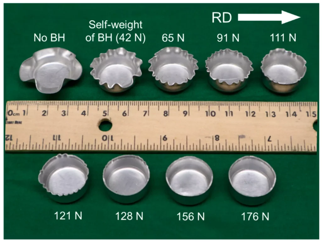
Wrinkling occurs in the flange when compressive stresses in the circumferential direction reach a critical point of instability.
It can occur in regions where the workpiece is unsupported or when the blank holding force is insufficient.
Deep drawing of anisotropic sheets results in a drawn cup with an uneven top edge i.e. some kind of ears are formed at the top as shown in Fig.
Conventional Deep Drawing
In the conventional deep drawing (CDD) process, the sheet metal is formed into a cup-shaped component. In this process, a flat circular
sheet of metal called blank is placed over the opening in the die and then pushed through and deformed by a moving punch. As the punch
moves downward, the outer annulus of the blank(flange) moves radially inward. The tendency of the flange to fold upward(wrinkling) is restricted by the blank holder force. In CDD, the majority of the deformation occurs in the flange of the cup. The metal is subjected to three different types of stress systems.
Problems encountered in conventional deep drawing
Some of the problems encountered during the conventional deep drawing operation are:
- Difficulty in finding the metal flow precisely.
- Difficulty in setting the criteria for the stability of the metal forming process.
- The complexity involved in the selection of precise process parameters and proper press tool design parameters.
- Large deformation during a deep drawing at room temperature causes problems in forming high-strength, low-formability materials like magnesium, aluminum alloys etc
- Deformation-induced transformation of microstructure as in the case of austenitic stainless steels.
- Number of tools required to produce the desired defect-free component
Limitations of Conventional Deep
Drawing
The main limitations of conventional deep drawing are:
A very high limiting draw ratio cannot be obtained due to excessive thinning and fracture in the cup wall, associated with large draw ratios. For most of the common sheet materials, an LDR of more than 2.2-2.3 is extremely difficult to achieve.
These stresses have an influence on the thickness variation in the drawn cup. The primary deformation occurs in the flange of the deforming which undergoes radial tension and circumferential compression. Because of this, the thickness increases in the flange portion. The second deformation zone is the bending around the die radius while the third deformation zone is the uni-axial stretching (plane strain) in the cup wall, which causes thinning of the metal. Very sharp corners of the punch and the dying lead to fracture. High friction between the die and the sheet puts a limit on the LDR and increases the punch force required for drawing
The surface finish of the component obtained usually is of low quality due to the friction between the sheet and the punch and between the die and the sheet Beyond a certain extent enhancement in formability is not possible because of the inherent limitations of conventional sheet-forming processes. But it was shown that higher forming limits than in conventional forming processes would be possible with the modification of the process itself.
Non-Conventional Deep Drawing
Non-conventional deep drawing is one in which other than the usual mechanical punch like hydraulic, pneumatic, gas, etc., is used to provide the required force or some additional means are used along with the conventional method to improve the forming characteristics of a
material. Some of the nonconventional deep drawing operations are hydro-forming (HF), hydro-mechanical forming (HMDD), warm deep drawing (WDD), superplastic forming (SPF) electromagnetic forming (EMF), incremental forming (IF), etc.
Advantages of non-conventional deep drawing
Metals can be deep drawn which, otherwise, cannot be made at room temperature due to their poor forming characteristics.
- Possibility of deep drawing high strength low formability metals and alloys.
- Components of the very thin sheets (less than 0.5 mm) can be drawn successfully.
- Lesser forming force to form the component.Reduction in the number of tools required for producing the desired part and hence the reduction in production cost.
- Decrease in the probability of defect formation on the product surface.
Limitations of non-conventional deep drawing
The higher capital cost of the additional equipment in some of the processes like hydroforming, and electromagnetic forming. These processes are justifiable only when the production quantities are larger.
- In some processes like electromagnetic forming, gas forming, and operational safety is the primary concern.
- Considerable operational time, as in superplastic forming, etc., and hence the productivity is lower and the cost of the part is higher.
- Numerous process parameters need to be optimized in order to achieve a defect-free component
Deep Drawing Defects
Ironing
Iron consists principally in reducing the wall thickness of the cup by restricting the clearance between the punch and the die to a value less than the blank thickness. The punch load is of primary importance in ironing because it determines the tension in the cup walls and hence the maximum reduction possible for a given punch load. A theoretical study of ironing has been reported in reference and an experimental investigation was carried out using hemispherical head punches for the different conditions of wall thinning, die profile, and lubrication
Galling
It is the transfer of some particles from the cup wall into the part of the die in contact with it. It causes damage to the die surface. It depends on the hardness o the blank and the lubricant’s effectiveness. It can be avoided by keeping the die surface in very good surface quality and using efficient lubricants to reduce friction between the cup and the die surface in contact with it.
Orange Peeling
It occurs at the outer surface of the cup when the grain size of its material is large it can be avoided by reducing the grain size prior to drawing either by heat treatment or by adding grain refining the grains with the addition of the appropriate refiners.
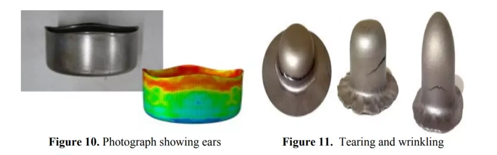
Earing
Earing is one of the defects which is commonly observed in the deep drawing process. By definition, earing is the uneven height at the edge of a drawn product, forming a series of peaks and valleys along its circumference. Kishor and Kumar (2002) defined earing as the formation of waviness on the top of the drawn cup.
The number of ears formed is commonly four (Hosford and Caddell, 2007), but might also be two, six, or eight, depending on the thermo-mechanical processing and microstructure of the sheet. During deep drawing, the sheet metal is subjected to a different amount of plastic strain for each angle relative to the rolling direction, which causes a different amount of elongation resulting in the formation or ears. The difference in the number of elongations results in the formation of ears.
The difference in the amount of plastic deformation at different angles is due to the anisotropic properties of the material. Earing in the deep drawing is usually not desirable as the ears serve no purpose and will have to be cut off, resulting in loss of material, production rate, and increase in production costs
It is caused by planar anisotropy which is due to variations in the mechanical behavior of the sheet from its plane to any other direction inclined or perpendicular to it they are normally even in number 2
or 4 or 6. The worst number is 8 in the case of the brass blank. They appear on the upper part of the drawn cup and are treated by trimming. The photograph in Figure 10 clearly shows the ears on the steel specimen.
Tearing
It might take place at the inner region of the annular part of the rim near the die profile if the holding down pressure is high which stops the blank from sliding and bending over the die profile radius, or it might take place in the maximum thinning region in the clearance region near the punch profile which is subjected to bending and stretching as clearly indicated in Figure 11.
Wrinkling
Wrinkling is one of the major defects that occur in sheet metal forming by the conventional deep drawing process. Wrinkling may be a serious obstacle to a successful forming process and to the assembly of parts, and may also play a significant role in the wear of tools. In order to improve productivity and the quality of products, wrinkling must be avoided. Wrinkling is a kind of buckling phenomenon that prevents from forming of the sheet.
If the buckling takes place in a flange area it is well known as well as it is called puckering if takes place on the wall of the cup. The schematic diagram in Figure 2.12 shows the mechanism of wrinkling initiation and growth in the cylindrical cup deep drawing process and Figure 2.13 shows an example of wrinkling after the deep drawing test.
During the deep drawing process, the sheet under the blank holder is drawn into the deformation zone by the punch. As a result, compressive hoop stress and thus wrinkling can be developed in the sheet metal under the holder (flange wrinkling) as well as those in the side wall, as wrinkling is a phenomenon of compressive instability.
The magnitude of the compressive stress necessary to initiate the side-wall wrinkling is usually smaller than that for the flange wrinkling since the wall is relatively unsupported. Hence, the formation of side-wall wrinkles is relatively easier especially when the ratio of the unsupported dimension to sheet thickness is large.
There are several factors that lead to the wrinkling formation like the retaining force of the blank, the geometrical parameters of the die, the frictions that appear during deep-drawing between the blank and the work elements of the die, the material characteristics and anisotropy, the contact conditions, the part geometry, the mechanical properties of the material, the imperfections in the structure and the initial state of internal tensions of the material, etc.
The wrinkling which occurs in the deep drawing process can be divided into two types that is corrugation which is flange instability and bending over that is the instability in the body of the piece. The phenomenon of wrinkling is specific to the process of deep drawing and also depends on the position in the piece in which it occurs.
Usually, the retaining force has to increase along with the increase of the deep drawing depth but it has to take note that if its value is too big it can lead to cracks and even a break of the material. The main geometric parameter of the die which influences the wrinkling is the diameter of the punch. In the case of friction between the piece and the tool, the increase of the coefficient of friction determines the wrinkling to reduce but the high value of the coefficient can cause cracks and material breakage.
This defect starts in the rim region of the blank and travels towards the middle region, the clearance zone between the punch and die profiles, by the continuation of the deep drawing process, as indicated in Figure 11. Examination of the available literature reveals that experimental research work on this important defect is relatively little compared to the analytical and theoretical work.
The critical dimensions of the rim at the onset of wrinkling were given in reference where it was stated that wrinkling depends on the properties of the blank thickness and its mechanical properties in addition to the shape and dimensions of the die set and the method by which the holding down pressure is applied. The experimental work of reference revealed that the resistance to wrinkling increases with the increase of strain percentage; which explains the use of the draw-beads in the deep drawing process to reduce the liability to wrinkling.
The authors of reference found the critical values of stress and punch displacement at which wrinkling starts to occur. They also agree with the authors of reference that both the critical stress and displacement increase with the increase of strain in the process.
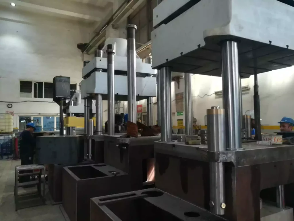
Hydraulic presses are powerful machines used to apply a significant amount of force to an object through hydraulic fluid pressure. They are essential in various industrial applications, providing the necessary force for processes such as metal forming, stamping, bending, and molding. The versatility and efficiency of hydraulic presses make them indispensable tools in manufacturing and production lines. This document will explore the different types of hydraulic presses, their application areas, components, operational principles, manufacturing process, and the challenges and advancements in the industry.
A hydraulic press is a mechanical device that uses a hydraulic cylinder to generate a compressive force. It operates based on Pascal’s Law, which states that pressure applied to a confined fluid is transmitted equally in all directions. This principle allows hydraulic presses to exert significant force with minimal input, making them essential tools in industries requiring high-pressure applications.
A single-acting hydraulic press uses hydraulic pressure to move the piston in one direction, typically the downward or compressive stroke. After the press completes this action, the piston returns to its original position using an external force such as a spring or the weight of the cylinder. This differs from a double-acting hydraulic press, where hydraulic pressure is applied in both the forward and return strokes.
The simplicity and cost-effectiveness of single-acting hydraulic presses make them ideal for a variety of applications, including small to medium-scale production, metal fabrication, and mechanical testing. These presses are widely used in industries such as automotive, aerospace, manufacturing, and even laboratories for precision tasks.
The core advantage of a single-acting hydraulic press lies in its simplicity. Fewer moving parts and a straightforward design reduce both the initial cost and ongoing maintenance requirements. However, the trade-off is that the press lacks the stroke control and power range of more complex systems, limiting its effectiveness in higher-end or more precise applications.
How Single-Acting Hydraulic Presses Work
The fundamental operation of a single-acting hydraulic press relies on Pascal’s Law, which underpins all hydraulic systems. According to this principle, when a force is applied to a fluid inside a closed system, the pressure is transmitted evenly throughout the fluid. In a hydraulic press, this means that the force generated by a pump acting on a small volume of hydraulic fluid can be magnified to create a much larger output force.
Key Components of a Single-Acting Hydraulic Press:
- Cylinder and Piston: The hydraulic cylinder contains a piston that moves up and down. In a single-acting press, hydraulic fluid forces the piston downwards, creating the press action.
- Hydraulic Pump: The pump generates pressure within the hydraulic system, pushing the fluid into the cylinder to drive the piston.
- Reservoir: This stores hydraulic fluid, which is pumped into the cylinder during operation.
- Valves: Control the flow of hydraulic fluid, directing it into the cylinder for the pressing stroke.
- Return Mechanism: In single-acting systems, this is usually a spring or gravitational force that returns the piston to its original position after the pressing action.
Pressing and Return Process:
- Pressing: When the press operator activates the system, hydraulic fluid is pumped into the cylinder. The increase in pressure forces the piston downward, applying force to the material placed under the press head. The force can range from several tons to hundreds of tons, depending on the press’s specifications.
- Return Stroke: Once the pressing action is complete, the external force—usually a spring or gravity—returns the piston to its starting position. Unlike double-acting presses, where hydraulic pressure can control both strokes, single-acting presses rely on this mechanical or natural return.
Advantages and Limitations:
- Advantages: Single-acting presses are simple, affordable, and easy to maintain. They are ideal for tasks that do not require precise control over the return stroke or where the pressing force is the primary concern.
- Limitations: The primary limitation is the lack of control over the piston’s return stroke, which can make single-acting presses less suited to precision applications. Additionally, since only one stroke is powered, these presses are less efficient in tasks requiring continuous motion or high-speed operation.
Types of Single-Acting Hydraulic Presses
Single-acting hydraulic presses come in several varieties, each suited to different applications and operational needs.
1. Manually Operated Hydraulic Presses:
These presses are powered by a hand-operated pump, which provides the hydraulic pressure needed to move the piston. They are ideal for small-scale applications or environments where electricity is not available. These presses are portable and commonly used in repair shops, garages, or remote field locations. Their affordability and ease of use make them popular for light-duty tasks like pressing bearings or removing shafts.
2. Electric-Powered Hydraulic Presses:
Electric-powered hydraulic presses use an electric motor to drive the hydraulic pump, offering greater efficiency and consistency compared to manual models. These presses are suitable for more intensive industrial applications where higher force or faster operation is required. They are commonly found in manufacturing plants, where they can be integrated into production lines for repetitive tasks such as stamping, forging, or cutting.
3. Air-Driven Hydraulic Presses:
In these systems, compressed air is used to generate hydraulic pressure. They are commonly used in industrial environments where compressed air is readily available. Air-driven hydraulic presses are often employed in applications where speed and convenience are critical, and they offer a middle ground between manually operated and electric-powered presses in terms of power and cost.
Applications of Each Type:
- Manually Operated: Ideal for low-volume tasks, repair work, or environments lacking electrical infrastructure.
- Electric-Powered: Suitable for continuous, heavy-duty applications in factories and production environments.
- Air-Driven: Often used in automotive workshops and for lighter industrial tasks where compressed air is available.
Applications of Single-Acting Hydraulic Presses
Single-acting hydraulic presses are versatile tools used across a wide range of industries for different applications.
1. Metal Forming and Fabrication:
In the metalworking industry, hydraulic presses are used to shape, bend, punch, and cut metal sheets and components. Single-acting presses are especially useful in tasks where the return stroke is less critical, such as metal stamping or bending. These presses are commonly used in fabrication shops, tool and die manufacturing, and custom metalwork projects.
2. Press Fitting and Assembly Tasks:
Single-acting presses are commonly employed in press fitting, where parts are mechanically forced together using high pressure. This includes tasks such as pressing bushings, bearings, gears, and other components into place. These presses are widely used in the automotive industry for assembly operations, as well as in machinery and equipment manufacturing.
3. Material Testing and Laboratory Uses:
In laboratories, single-acting hydraulic presses are often used for testing materials under compressive force. For example, engineers and scientists may use hydraulic presses to measure the compressive strength of materials like concrete, metals, or plastics. The simplicity of single-acting presses makes them ideal for controlled experiments where large forces are required without complex control systems.
4. Automotive and Aerospace Industries:
In the automotive sector, single-acting hydraulic presses play a crucial role in various assembly and maintenance tasks, such as pressing in bushings, removing bearings, and straightening parts. Their use extends to aerospace industries for tasks such as forming lightweight components, shaping metal parts, or assembling intricate systems that require precise force application.
Examples of Practical Applications:
- Metal Stamping: Single-acting presses are used to punch or stamp metal parts for various industries, including automotive and electronics.
- Bearing Installation: Presses ensure that bearings are seated correctly without causing damage to delicate components.
- Cutting and Trimming: Hydraulic presses can be used to cut metal, plastic, or composite materials, making them essential in production environments.
Advantages of Single-Acting Hydraulic Presses
Single-acting hydraulic presses have several advantages, making them a popular choice in a variety of applications.
1. Simplicity and Cost-Effectiveness:
Due to their basic design, single-acting hydraulic presses are more affordable than their double-acting counterparts. They have fewer moving parts and require less complex control systems, reducing both the upfront cost and the likelihood of mechanical failure. This makes them ideal for smaller operations or businesses looking for cost-effective solutions.
2. Efficiency in Force Delivery:
Despite their simplicity, single-acting hydraulic presses can deliver tremendous force, making them suitable for heavy-duty tasks like metal forming or assembly. They can generate forces ranging from a few tons to several hundred tons, depending on the size and type of the press, enabling them to handle a wide range of materials and tasks.
3. Reduced Maintenance:
With fewer components, single-acting presses are easier and less costly to maintain. Routine maintenance is generally limited to inspecting seals, checking hydraulic fluid levels, and ensuring that the return mechanism (spring or gravity) is functioning properly.
4. Portability and Space Efficiency:
Single-acting presses are typically more compact than double-acting presses, making them easier to move and install in smaller workspaces. This portability is especially valuable in environments where space is limited, such as small workshops or laboratories.
Challenges and Limitations of Single-Acting Hydraulic Presses
While single-acting hydraulic presses offer many benefits, they also have certain limitations that can affect their performance in specific applications.
1. Limited Stroke Control and Precision:
Because the return stroke is not powered by hydraulics, single-acting presses lack the precise control over the piston’s movement during the return phase. This makes them less suitable for applications requiring fine control of both the forward and return strokes.
2. External Force Required for Return Stroke:
The reliance on springs or gravity for the return stroke introduces limitations. Springs can wear out over time, reducing the efficiency of the press, and gravitational return may be too slow for certain high-speed applications.
3. Power Limitations:
Single-acting presses typically have less power and speed compared to double-acting systems. For tasks requiring high force or rapid cycling, a double-acting press may be more appropriate.
4. Environmental Considerations:
Hydraulic systems, including single-acting presses, can pose environmental risks if not properly maintained. Leaking hydraulic fluid, for instance, can cause environmental contamination, making proper maintenance and disposal of used fluids critical.
Maintenance and Safety Considerations
Proper maintenance and adherence to safety protocols are essential to ensure the safe and efficient operation of single-acting hydraulic presses.
Maintenance Procedures:
- Hydraulic Fluid Levels: Regularly check and maintain the hydraulic fluid to ensure smooth operation. Low fluid levels can reduce press efficiency and lead to mechanical wear.
- Seals and Hoses: Inspect seals and hoses for wear and tear, as leaks can cause pressure loss and reduce the effectiveness of the press.
- Return Mechanism: Check the spring or gravity-based return system for signs of fatigue or failure. Over time, springs may lose tension, reducing the effectiveness of the return stroke.
Safety Protocols:
- Personal Protective Equipment (PPE): Operators should wear appropriate PPE, including safety goggles, gloves, and hearing protection.
- Proper Training: Ensure that all operators are trained in the correct use of the press and are aware of potential hazards.
- Emergency Stops: Hydraulic presses should be equipped with emergency stop buttons to allow operators to quickly halt the machine in case of malfunction or danger.
Future of Single-Acting Hydraulic Presses
Advancements in technology are opening new possibilities for single-acting hydraulic presses. As industries evolve, the demand for more efficient and eco-friendly machinery is growing.
1. Advancements in Hydraulic Technology:
Innovations in hydraulic systems are leading to more efficient and powerful single-acting presses. For instance, new hydraulic fluids with better thermal stability and lower environmental impact are being developed, reducing the ecological footprint of hydraulic systems.
2. Energy Efficiency Improvements:
Modern hydraulic presses are being designed with energy efficiency in mind. Enhanced pump designs, variable speed motors, and more efficient control systems are reducing energy consumption and operational costs.
3. Integration with Automation:
The future of hydraulic presses lies in their integration with automated and smart systems. Automated single-acting presses equipped with sensors and computer control systems can adjust force, speed, and stroke in real time, enhancing precision and adaptability.
4. Future Applications and Innovations:
As industries continue to demand more from hydraulic systems, single-acting presses are likely to be used in new applications such as additive manufacturing (3D printing) and precision engineering. The increasing focus on sustainability may also drive the development of greener, more energy-efficient presses.
Introduction to Double-Acting Hydraulic Presses
Hydraulic presses are mechanical devices that use fluid pressure to generate significant force, commonly employed in industries where large-scale pressing, forming, or molding is required. They operate on Pascal’s Law, which states that pressure applied to a fluid in a confined space is transmitted equally in all directions. This principle allows hydraulic presses to amplify force, making them crucial in metalworking, manufacturing, automotive industries, and beyond.
A double-acting hydraulic press differs from its single-acting counterpart in that it applies hydraulic pressure in both directions—both for the pressing stroke and the return stroke. In contrast, a single-acting press relies on external forces, like springs or gravity, for the return motion, which limits control and precision.
The use of double-acting hydraulic presses has revolutionized several industrial processes due to the enhanced control and precision they offer. With powered movement in both directions, these presses are capable of handling more complex and demanding tasks, such as deep drawing, forging, or any process where high precision and consistent force are essential. These presses are widely used in automotive production, aerospace manufacturing, and large-scale industrial operations.
How Double-Acting Hydraulic Presses Work
Double-acting hydraulic presses function based on hydraulic principles, which utilize fluid power to amplify force. The critical difference from single-acting presses is that double-acting presses can apply hydraulic pressure in both the pressing and return strokes. This provides enhanced control and versatility.
Core Components of a Double-Acting Hydraulic Press:
- Cylinder and Piston: A double-acting press has a hydraulic cylinder with a piston that moves in two directions. Hydraulic fluid is directed into the cylinder on either side of the piston to control both the downward and upward strokes.
- Hydraulic Pump: The hydraulic pump provides pressure by moving hydraulic fluid into the cylinder. In double-acting presses, the pump must be capable of routing the fluid to either side of the piston, depending on whether it is the pressing or return stroke.
- Valves and Control Systems: Double-acting presses require more sophisticated valve systems to control the flow of hydraulic fluid. These valves direct fluid pressure to either side of the piston, enabling the precise control of both strokes.
- Power Source: These presses can be powered by manual pumps, electric motors, or pneumatic systems, depending on the scale and application of the press.
The Pressing and Return Strokes:
- Pressing Stroke: The hydraulic pump directs fluid into the top of the cylinder, pushing the piston downward. This downward force can range from a few tons to hundreds of tons, depending on the press’s size and design. The press head applies this force to the material being processed, whether it’s for stamping, molding, or cutting.
- Return Stroke: After the pressing operation, hydraulic pressure is redirected to the bottom of the piston. This lifts the piston back to its starting position, ensuring precise and controlled movement. The ability to hydraulically control both strokes eliminates the reliance on gravity or springs, allowing for faster cycle times and more complex tasks.
Precision and Control:
The ability to control both strokes of the piston provides greater accuracy in industrial processes. Unlike single-acting presses, where the return stroke can vary in speed and efficiency, double-acting presses offer consistent performance across all movements. This precision makes them ideal for complex forming processes, deep drawing, and precision cutting operations, where both the force and the return timing must be tightly controlled.
Types of Double-Acting Hydraulic Presses
Double-acting hydraulic presses come in various forms, each tailored for specific industrial applications. Here are some of the main types:
1. Manual Double-Acting Hydraulic Presses:
Manual versions of double-acting presses are powered by hand-operated hydraulic pumps. These are typically used in small workshops or repair facilities where tasks like pressing, bending, or assembling components do not require extensive automation. These presses are portable, cost-effective, and often used in low-production environments.
2. Electric-Powered Double-Acting Hydraulic Presses:
Electric-powered double-acting presses are more common in industrial settings where high force and consistent operation are required. The hydraulic pump is driven by an electric motor, allowing for automated control of both strokes. These presses are essential for high-volume operations, such as metal stamping, die forming, and precision cutting. The electric-powered system allows for greater precision, repeatability, and faster cycle times.
3. Pneumatic Double-Acting Hydraulic Presses:
Pneumatic-powered double-acting presses use compressed air to drive the hydraulic fluid in both strokes. These presses are favored in industries where pneumatic systems are already integrated into the production environment, such as in automotive assembly lines. Pneumatic systems provide rapid action, and the integration with hydraulics ensures the generation of high forces, making them suitable for mid-sized industrial applications.
4. Specialized Double-Acting Presses:
Some double-acting hydraulic presses are designed for specific applications, such as hydraulic press brakes used in bending and shaping metal sheets. These presses provide precise control over the angle and force applied, making them ideal for custom metal fabrication. Another example includes forging presses, where high tonnage and precise control are required to shape metal components.
Applications of Double-Acting Hydraulic Presses
Double-acting hydraulic presses are widely employed across a variety of industries due to their versatility and ability to handle complex tasks with precision. Here are some of the key applications:
1. Metal Forming and Deep Drawing:
One of the primary uses of double-acting hydraulic presses is in metal forming, particularly deep drawing. Deep drawing is a manufacturing process where a sheet metal blank is radially drawn into a forming die by the mechanical action of a punch. Double-acting presses provide the precise control necessary to form complex shapes in metals like aluminum, steel, and copper without cracking or deforming the material.
2. Punching, Forging, and Die Forming:
In punching and forging operations, double-acting presses apply controlled force to deform or cut metal parts. This is commonly used in the automotive and aerospace industries, where high-strength materials are forged into critical components like gears, axles, and structural parts. The ability to control both the pressing and return strokes ensures consistent quality and reduces the risk of material damage.
3. Composite Material Molding:
As industries increasingly adopt composite materials, double-acting hydraulic presses have become essential for forming and molding these materials. Composites, such as carbon fiber or fiberglass, require careful handling during the molding process to maintain their strength and durability. Double-acting presses allow for precise pressure application during both the pressing and release phases, making them indispensable in industries like aerospace and automotive, where lightweight, high-strength components are essential.
4. Automotive and Aerospace Industries:
The automotive industry relies heavily on double-acting hydraulic presses for the production of body panels, frames, and engine components. The precision and repeatability of these presses ensure that every part is manufactured to exact specifications. In the aerospace industry, where weight, strength, and safety are critical, double-acting presses are used to form lightweight components like aircraft skin panels, structural parts, and engine elements.
5. Examples of Industrial Applications:
- Automotive: Deep drawing for body panels, stamping parts like hoods, doors, and roofs.
- Aerospace: Forming of lightweight metal and composite parts for aircraft and spacecraft.
- Heavy Machinery: Forging of large components for construction equipment and industrial machinery.
- Consumer Electronics: Precision forming of metal casings and components.
Advantages of Double-Acting Hydraulic Presses
Double-acting hydraulic presses offer several significant advantages that make them indispensable in many industries.
1. Precise Control Over Both Strokes:
The ability to apply hydraulic force in both the pressing and return strokes gives double-acting presses greater control over the entire operation. This precision is particularly valuable in tasks that require consistent force and motion, such as deep drawing, forging, and punching. Both strokes can be finely adjusted to meet the exact requirements of the material and application, leading to superior product quality.
2. Higher Efficiency in Repetitive Operations:
In manufacturing environments where tasks must be repeated at high speed, double-acting presses outperform single-acting models. Since both the press and return strokes are powered, cycle times are faster, and operators have more control over the movement of the piston, which boosts productivity in high-volume production lines.
3. Versatility in Complex Tasks:
Double-acting presses are incredibly versatile, able to handle a wide variety of materials and tasks. They can be used for pressing, forming, bending, cutting, and molding, which makes them highly adaptable to different industries and processes. Whether the task requires the shaping of metals, molding of composites, or assembly of mechanical components, these presses can be fine-tuned to meet the needs of the job.
4. Suitability for Heavy-Duty and Continuous Use:
Double-acting hydraulic presses are built for heavy-duty applications and continuous use in industrial settings. The ability to power both strokes ensures that even the toughest materials, such as steel and titanium, can be shaped and formed without compromising on speed or accuracy. Their robust design and advanced control systems make them ideal for industries where durability and long-term performance are critical.
Challenges and Limitations of Double-Acting Hydraulic Presses
Despite their advantages, double-acting hydraulic presses also come with challenges and limitations that must be considered before implementation.
1. Higher Cost and Complexity:
Double-acting hydraulic presses are generally more expensive than single-acting presses due to their more complex design and the additional control systems required to power both strokes. This can make them less appealing for small-scale operations or businesses with tight budgets.
2. Increased Maintenance Requirements:
With more moving parts and components to manage, double-acting presses require more frequent and thorough maintenance than their single-acting counterparts. Components like seals, valves, and hydraulic lines must be regularly inspected and serviced to prevent leaks and ensure optimal performance. This adds to the operational costs over the lifespan of the machine.
3. Space and Energy Requirements:
Double-acting hydraulic presses tend to be larger and consume more energy than simpler presses. This means they require more space and have higher energy costs, which can be a limiting factor in smaller workshops or facilities with limited energy resources.
4. Specialized Training and Safety Considerations:
Operators of double-acting hydraulic presses must be thoroughly trained to handle the complex control systems and high pressures involved. The increased force and speed of these presses mean that strict safety protocols must be followed to prevent accidents and equipment damage.
Maintenance and Safety Considerations
Proper maintenance and safety protocols are crucial for ensuring the long-term operation and safety of double-acting hydraulic presses.
Maintenance Procedures:
- Hydraulic Fluid Levels: Maintaining appropriate hydraulic fluid levels is essential for the proper operation of both strokes. Low fluid levels can result in uneven pressure distribution and lead to damage.
- Seal and Hose Inspections: Double-acting presses have more seals and hoses than single-acting models, which makes regular inspections critical. Leaks in these components can cause a loss of pressure, reduced efficiency, and safety hazards.
- System Pressure Checks: Monitoring and adjusting the system’s pressure levels ensures that the press operates within its designed parameters, preventing over-pressurization and component failure.
Safety Protocols:
- Operator Training: Given the complexity of double-acting presses, operators must be trained in their safe use. They should understand the machine’s control systems, emergency stop features, and troubleshooting procedures.
- Regular Inspections: Presses should be inspected regularly for signs of wear or malfunction. Safety devices like pressure relief valves and emergency stops should be tested to ensure they are functioning properly.
- Personal Protective Equipment (PPE): Operators should always wear appropriate PPE, including gloves, goggles, and ear protection, especially in high-noise environments.
Future Trends in Double-Acting Hydraulic Press Technology
As technology evolves, double-acting hydraulic presses are expected to undergo several advancements that will enhance their performance and broaden their applications.
1. Technological Advancements:
Innovations in hydraulic control systems, such as the integration of proportional valves and servo-driven pumps, are improving the precision and efficiency of double-acting presses. These systems allow for finer control of pressure and movement, resulting in higher-quality output and reduced material waste.
2. Energy Efficiency:
One of the key areas of development is the push for more energy-efficient hydraulic systems. With the increasing focus on sustainability, new technologies are emerging that reduce energy consumption, such as variable-speed pumps that adjust output based on demand. These advancements not only lower operational costs but also reduce the environmental impact of hydraulic presses.
3. Automation and Industry 4.0:
The integration of double-acting hydraulic presses with automation and smart manufacturing systems is another significant trend. By connecting presses to factory networks, manufacturers can monitor machine performance in real-time, predict maintenance needs, and optimize press cycles. This leads to increased productivity and minimizes downtime due to unexpected equipment failure.
4. Future Innovations:
Looking ahead, double-acting presses may see further improvements in force capacity, miniaturization for precise applications, and modular designs that allow presses to be easily reconfigured for different tasks. Additionally, advancements in green hydraulic fluids will reduce the environmental risks associated with hydraulic systems.
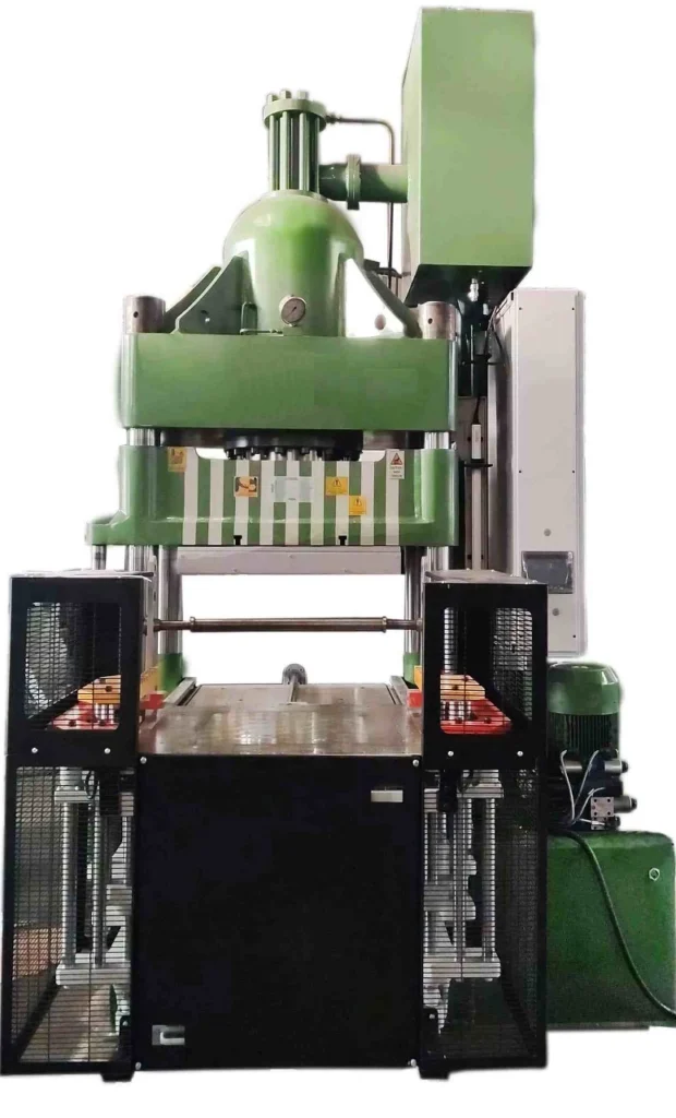
Triple Action Deep Drawing Press
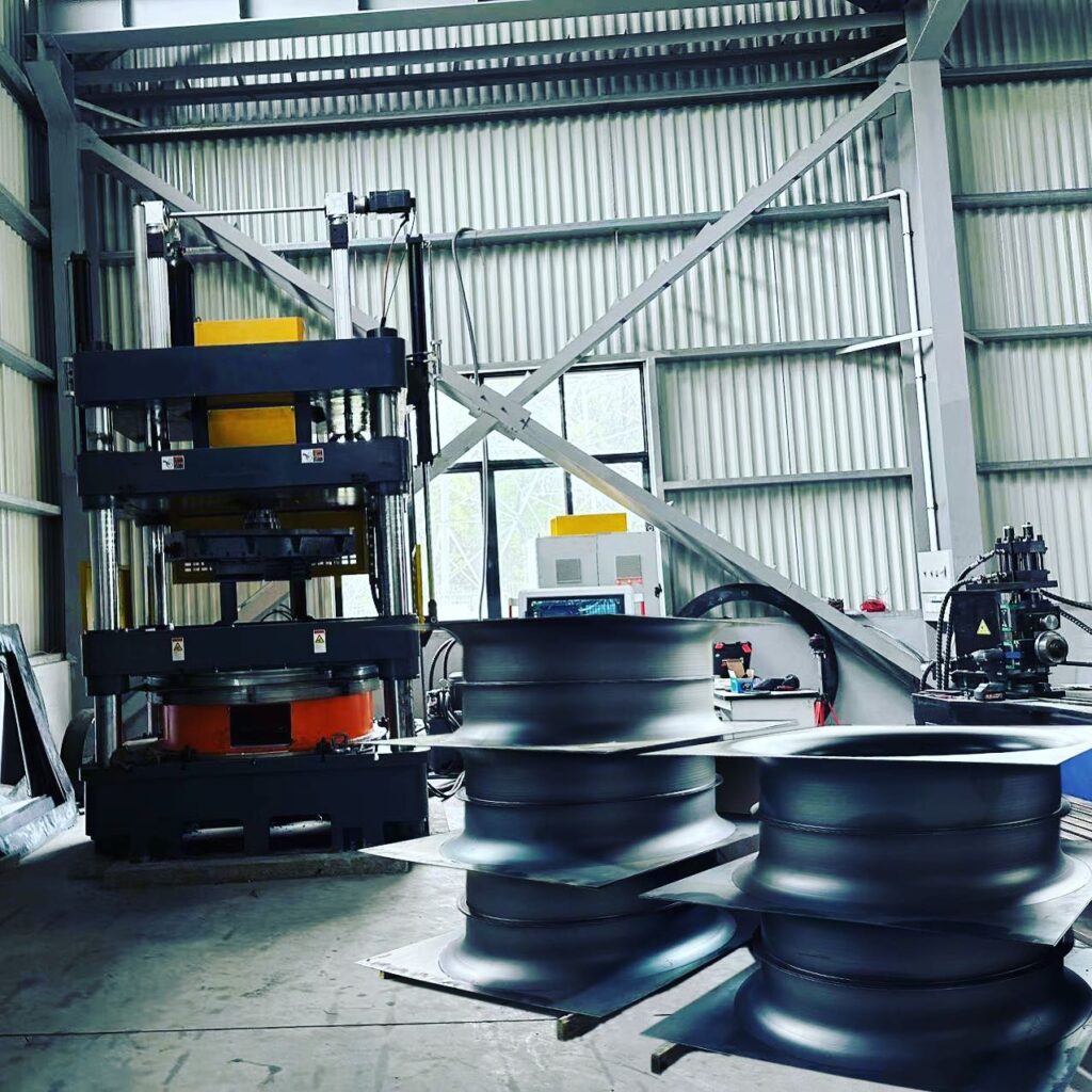
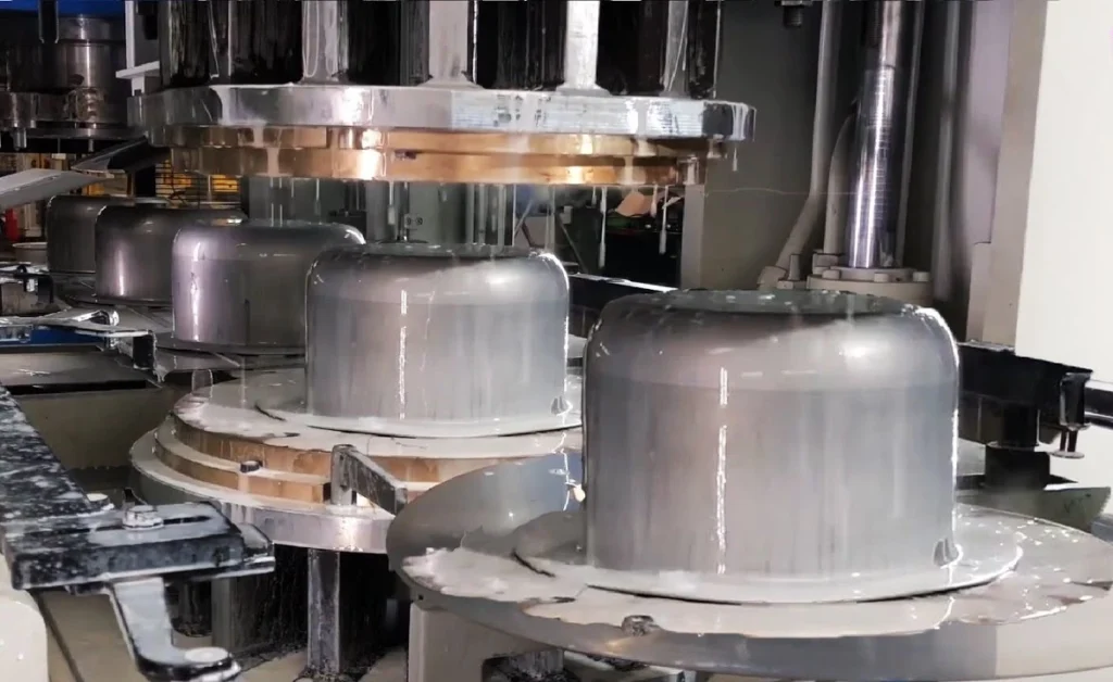
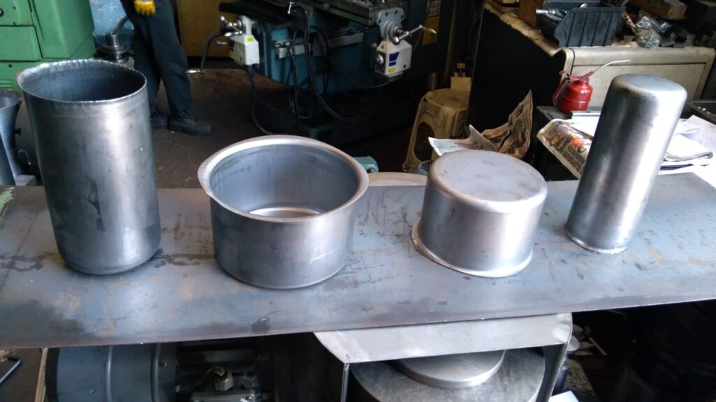
Deep drawing is a popular metal forming process used to shape flat sheet metal into cylindrical or box-like shapes. The process involves placing a metal blank over a die and pressing it into the die cavity with a punch. This transforms the flat blank into a three-dimensional shape, making it essential for producing components like automotive body panels, kitchen sinks, and various enclosures. The process can be repeated to achieve more complex shapes with greater depth, but the challenges increase as the material undergoes severe deformation.
A Triple Action Deep Drawing Press is a specialized machine designed to address the complexity of the deep drawing process. Unlike conventional single-acting or double-acting presses, a triple action press incorporates three independent force mechanisms:
- Blank Holder Action: Keeps the metal blank firmly in place, controlling material flow and preventing wrinkling.
- Punch Action: The primary force that shapes the blank by pushing it into the die.
- Ejector Action: Removes the finished part from the die after the drawing process is complete.
This triple-action mechanism provides greater control over the deep drawing process, allowing for the production of more complex shapes, with fewer defects, and better efficiency. The ability to control all three forces independently is particularly important in producing deep-drawn components for industries like automotive, aerospace, and consumer goods, where precision and quality are critical.
How Triple Action Deep Drawing Presses Work (500 words)
To understand how triple action deep drawing presses function, it’s essential to break down the mechanics of the deep drawing process and how each action contributes to shaping the material.
The Deep Drawing Process:
The deep drawing process transforms a flat metal blank into a three-dimensional component. The key stages include:
- Blank Placement: A flat metal blank is placed over the die cavity.
- Blank Holder Engagement: The blank holder clamps the blank around its edges, preventing movement or wrinkling during drawing.
- Punch Stroke: The punch moves downward, pressing the blank into the die cavity, forming the desired shape. This action stretches and deforms the material, thinning it in certain areas.
- Ejection: Once the part is formed, the ejector mechanism releases the part from the die, ready for the next cycle.
Components of a Triple Action Deep Drawing Press:
- Blank Holder: The blank holder is crucial in controlling material flow. Its force must be precisely regulated to avoid wrinkling, which can occur if the material is allowed to move too freely. At the same time, too much force from the blank holder can result in tearing.
- Punch: The punch is the main shaping tool. In triple-action presses, the punch force is adjustable, allowing for greater flexibility in handling different materials or thicknesses. As the punch presses the blank into the die, it forms the desired shape.
- Ejector: The ejector action ensures the formed part is smoothly removed from the die without causing damage to the component or slowing down the production process. The ejector often uses hydraulic or mechanical systems to push the part upward, releasing it from the die.
Key Advantages of the Triple Action System:
- Independent Control of Forces: One of the main benefits of triple action presses is that each force (blank holder, punch, ejector) can be independently controlled. This ensures optimal pressure at each stage, reducing the risk of defects such as wrinkling, tearing, or excessive thinning.
- Complex Shapes: By using all three actions in a coordinated manner, triple action presses can produce complex, deep-drawn components that would be difficult or impossible with a standard press.
- Minimized Defects: The precise control over material flow, punch pressure, and ejection force allows manufacturers to achieve higher-quality products with fewer defects, making triple-action presses ideal for high-precision industries.
Types of Triple Action Deep Drawing Presses
Triple action deep drawing presses come in various types, each suited to different applications and production environments. The main types include mechanical, hydraulic, and servo-electric presses.
1. Mechanical Triple Action Presses:
Mechanical triple action presses use mechanical linkages, cams, and gears to generate and control the forces required for the blank holder, punch, and ejector. These presses are known for their high speed and are commonly used in high-volume production environments, such as automotive manufacturing. However, they tend to offer less precision than hydraulic presses, making them less suitable for complex or precision deep drawing applications.
2. Hydraulic Triple Action Presses:
Hydraulic presses are the most common type of triple action deep drawing presses. These machines use hydraulic cylinders to apply force independently to the blank holder, punch, and ejector. Hydraulic presses are favored for their precision and the ability to control force and speed at every stage of the process. This makes them ideal for deep drawing applications that require complex shapes, deep draws, or challenging materials. Additionally, hydraulic systems can apply constant force throughout the entire stroke, providing a smooth and consistent draw.
3. Servo-Electric Triple Action Presses:
Servo-electric presses use electric motors to control the movement of the blank holder, punch, and ejector. These presses offer the highest level of precision and flexibility, allowing manufacturers to program specific force and speed profiles for different stages of the drawing process. Servo-electric presses are energy-efficient and offer precise control, making them ideal for applications requiring high precision, such as aerospace components and medical devices.
Comparison of Press Types:
- Mechanical: Best for high-speed, large-volume production; less precise.
- Hydraulic: Ideal for precision deep drawing, complex shapes, and variable materials; slower but more controlled.
- Servo-Electric: Offers the highest precision and flexibility, with energy efficiency; often used in highly specialized applications.
Applications of Triple Action Deep Drawing Presses
The versatility and precision of triple action deep drawing presses make them indispensable across a wide range of industries. Their ability to form complex, deep-drawn parts with minimal defects and high repeatability is a key reason for their widespread use.
1. Automotive Industry:
In the automotive sector, deep drawing presses are essential for producing a wide array of components, including body panels, fuel tanks, and engine components. Triple action presses are particularly well-suited for forming large, complex parts such as car doors, hoods, and trunk lids, which require high precision to ensure they meet the industry’s stringent safety and performance standards.
For example, the ability to control the blank holder force ensures that body panels are formed without wrinkling, a common defect in deep drawing. Additionally, the precision of triple-action presses allows for tight tolerances in the production of complex components like fuel tanks, which must be leak-proof and structurally sound.
2. Aerospace Industry:
In the aerospace industry, the demand for lightweight yet strong components is paramount. Triple action deep drawing presses are used to form aircraft skin panels, engine housings, and other structural components. The ability to control every aspect of the drawing process, including the exact force applied by the blank holder and punch, ensures that aerospace parts meet the high standards required for safety and performance.
Additionally, the triple action mechanism is crucial for working with materials like titanium, aluminum, and composites, which are commonly used in the aerospace industry but can be difficult to form due to their strength and tendency to crack under stress.
3. Consumer Goods:
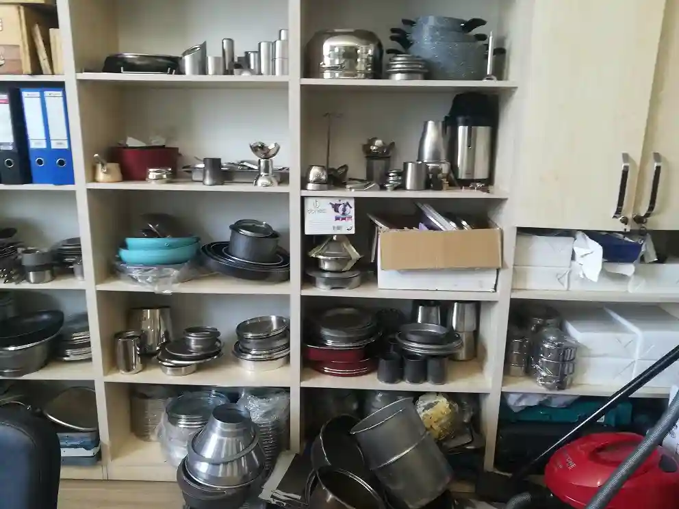
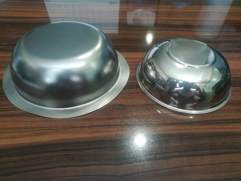
Triple action deep drawing presses are widely used to manufacture various consumer goods, particularly in the production of kitchenware (e.g., stainless steel sinks, pots, and pans) and household appliances (e.g., washing machine drums, microwave enclosures). The ability to form deep, complex shapes in materials like stainless steel or aluminum with smooth surfaces and minimal defects is essential for consumer products where aesthetics and durability are key selling points.
4. Industrial Containers and Enclosures:
Industries requiring industrial containers, cylindrical tanks, or enclosures for sensitive equipment often rely on triple action deep drawing presses. These presses allow for the formation of durable, uniform containers with precise dimensions, ensuring that they meet stringent industry standards for storage and protection.
Case Studies and Real-World Examples:
- Automotive: A major automotive manufacturer uses triple action presses to produce seamless body panels for luxury vehicles, ensuring high quality and eliminating the need for secondary finishing processes.
- Aerospace: Leading aerospace companies utilize triple action deep drawing presses for the production of lightweight, high-strength structural components, ensuring aircraft performance while reducing weight.
- Consumer Goods: A well-known kitchenware brand uses triple action presses to manufacture stainless steel cookware with flawless surfaces and uniform thickness, enhancing both performance and aesthetics.
Advantages of Triple Action Deep Drawing Presses
Triple action deep drawing presses offer numerous advantages that make them essential in industries requiring precision metal forming.
1. Enhanced Control Over the Deep Drawing Process:
One of the most significant advantages of a triple action press is the ability to independently control the blank holder, punch, and ejector forces. This precision control allows for adjustments throughout the deep drawing process, ensuring consistent material flow and reducing the risk of defects such as wrinkling, tearing, or excessive thinning.
2. Ability to Form Complex, Precise Shapes:
The precise control offered by triple action presses enables the formation of intricate shapes and deep-drawn components. The ability to fine-tune the force applied at each stage ensures that even challenging materials can be drawn without damage. This is especially important in industries like aerospace and automotive, where components must meet exacting standards for performance and safety.
3. Minimization of Defects:
Triple action presses significantly reduce common defects in the deep drawing process, such as wrinkling, cracking, and material thinning. The blank holder’s independent force ensures that the material is held securely, while the punch and ejector forces can be adjusted to optimize material flow. This results in higher-quality parts and reduced scrap, making triple action presses more efficient and cost-effective in large-scale production.
4. High Efficiency for Large-Scale Production:
Triple action presses are ideal for high-volume production, offering fast cycle times and repeatable precision. The automation of these presses allows for continuous operation, reducing downtime and increasing throughput. This efficiency is critical in industries where large quantities of parts must be produced quickly and to tight tolerances, such as automotive manufacturing.
Challenges and Limitations of Triple Action Deep Drawing Presses
Despite their numerous advantages, triple action deep drawing presses also present certain challenges and limitations.
1. High Initial Investment and Complexity:
Triple action deep drawing presses are more expensive than single or double-action presses due to their complexity and advanced control systems. The cost of purchasing and setting up a triple action press can be prohibitive for smaller operations or manufacturers with limited budgets. Additionally, these presses require more sophisticated control systems and software, which can increase the initial investment.
2. Greater Maintenance Requirements:
The complexity of triple action presses means that they require more frequent and thorough maintenance compared to simpler presses. The hydraulic systems, punch, blank holder, and ejector mechanisms all need regular inspection and servicing to prevent breakdowns and ensure the press operates at peak efficiency. Maintenance costs and downtime can be a challenge, especially in high-production environments.
3. Limitations in Smaller-Scale Operations:
For smaller-scale manufacturers or those producing limited quantities of deep-drawn parts, the high cost and complexity of triple action presses may not be justified. These presses are best suited to large-scale operations where the benefits of increased precision, efficiency, and reduced scrap outweigh the higher costs.
4. Energy and Space Requirements:
Triple action presses require significant amounts of energy to operate, especially hydraulic models, which need continuous power to maintain pressure. They are also large machines that require a substantial amount of floor space, limiting their use in smaller production facilities or workshops.
Maintenance and Safety Considerations
Proper maintenance and safety protocols are essential to ensure the longevity and safe operation of triple action deep drawing presses.
Maintenance Procedures:
- Hydraulic System Maintenance: Hydraulic presses rely on clean, properly pressurized fluid systems to function efficiently. Regular checks of hydraulic fluid levels, cleanliness, and pressure are necessary. Dirty or low fluid can cause increased wear on components or lead to system failure.
- Lubrication: Proper lubrication of moving parts, including the punch, blank holder, and ejector, is critical to reduce friction and wear. Over time, insufficient lubrication can lead to damage and expensive repairs.
- Seal and Hose Inspections: Hydraulic seals and hoses should be regularly inspected for wear and leaks. Any signs of leakage must be addressed immediately to prevent pressure loss, damage to components, or safety hazards.
- Alignment Checks: Regular alignment checks for the punch, die, and blank holder ensure that parts are being formed accurately and uniformly. Misalignment can lead to defective parts and increased machine wear.
Safety Protocols:
- Operator Training: Operators should be thoroughly trained in the use of triple action presses, including how to safely load blanks, adjust controls, and handle finished parts. Understanding how to safely manage the hydraulic systems and high forces involved is critical for preventing accidents.
- Emergency Stops and Safety Guards: Triple action presses should be equipped with emergency stop systems and safety guards to protect operators. These features ensure that the machine can be immediately stopped in the event of a malfunction or danger.
- Personal Protective Equipment (PPE): Operators must wear appropriate PPE, including gloves, goggles, and protective clothing, to reduce the risk of injury from moving parts, flying debris, or hydraulic fluid leaks.
Future Trends in Triple Action Deep Drawing Press Technology
The future of triple action deep drawing presses is being shaped by advancements in technology, materials, and manufacturing processes.
1. Innovations in Press Control Systems:
As manufacturing becomes more automated and digital, the control systems used in triple action presses are becoming more sophisticated. Proportional hydraulic control valves and servo-driven systems are allowing for even more precise control over the forces applied during the deep drawing process. This enhanced control not only improves part quality but also reduces waste and increases efficiency.
2. Material Advancements:
As industries increasingly demand stronger, lighter, and more durable materials, triple action presses are evolving to handle these new challenges. Advances in high-strength steel, aluminum alloys, and composites are pushing the limits of what deep drawing presses can do. Modern presses are being designed with enhanced force capabilities and precision to work with these advanced materials, enabling the production of lightweight, high-strength components for the automotive, aerospace, and electronics industries.
3. Integration with Industry 4.0:
The integration of Industry 4.0 technologies, such as sensors, real-time data monitoring, and predictive maintenance systems, is helping manufacturers optimize the performance of their triple action presses. Smart systems can monitor machine performance in real-time, automatically adjust press settings, and even predict when maintenance is needed, reducing downtime and improving overall productivity.
4. Environmental Sustainability and Energy Efficiency:
Energy efficiency is becoming a priority for manufacturers using triple action presses. New designs are focusing on reducing energy consumption through variable-speed hydraulic pumps, energy recovery systems, and servo-electric technologies. These advancements not only reduce operational costs but also help companies meet their environmental sustainability goals by reducing the energy footprint of their manufacturing processes.
Double-Acting Hydraulic Presses
Double-acting hydraulic presses provide more control and flexibility during the deep drawing process, particularly for applications that require more complex or deeper shapes. In a double-acting press, two separate hydraulic systems work in tandem—one controls the downward motion of the punch, while the other operates the blank holder, applying force independently to hold the material in place.
- Structure: The press has two rams or cylinders—one for the punch and another for the blank holder. This setup allows for precise control of both the drawing force and the holding force, preventing material slippage or wrinkling during the drawing process.
- Applications: Double-acting presses are commonly used in automotive, aerospace, and household appliance manufacturing, where complex shapes and deeper draws are required. For instance, components like fuel tanks, car body panels, and aircraft parts are often made using double-acting hydraulic presses.
- Advantages: The independent control over the punch and blank holder forces allows for more precise and uniform drawing, reducing the risk of defects such as tearing or wrinkling. These presses are suitable for larger and more intricate parts and offer greater flexibility in handling a variety of materials and shapes.
Triple-Action Hydraulic Presses
For the most demanding and complex deep drawing applications, triple-action hydraulic presses provide unparalleled performance. These presses add a third hydraulic system to control additional movements or processes during the drawing operation.
- Structure: In addition to the punch and blank holder, triple-action presses feature a third force, often applied from the bottom of the press. This additional motion allows for processes like reverse drawing or extrusion, enabling the machine to handle extremely deep or complex shapes that require multiple stages of forming.
- Applications: Triple-action presses are typically used in highly specialized industries such as aerospace and defense, where precision and complexity are paramount. Components like deep drawn fuel cells, engine components, and structural parts for aircraft or heavy machinery are ideal for these machines.
- Advantages: These presses provide maximum control and precision, allowing manufacturers to produce parts with extreme depth or complexity without compromising on quality. They also offer higher productivity by enabling multiple forming operations in a single press cycle.
Automated vs. Manual Hydraulic Presses
Automation is an important factor in modern manufacturing, and hydraulic deep drawing presses are no exception. Buyers can choose between manual presses, which require human intervention for loading, unloading, and controlling the operation, or automated presses, which integrate robotic systems and computerized controls to manage the entire process.
- Manual Hydraulic Presses: These presses are operated by technicians who manually load the blank, initiate the drawing process, and remove the formed part. While manual presses are typically less expensive and easier to maintain, they are best suited for low-volume production runs or applications where flexibility is required.
- Automated Hydraulic Presses: Automated presses use Programmable Logic Controllers (PLCs) or Computer Numerical Control (CNC) systems to control the drawing process. Automation allows for higher precision, increased production speed, and greater consistency in the final product. Automated presses are ideal for high-volume production environments where efficiency and accuracy are critical.
Specialized Hydraulic Presses for Tailor-Made Applications
In addition to the standard configurations, there are specialized hydraulic presses designed for specific industries or applications. These machines are often custom-built to meet unique production requirements, such as forming particular shapes, materials, or sizes. For example:
- Automotive Industry: Hydraulic presses tailored for producing large, complex automotive parts, such as chassis components, doors, and structural parts.
- Aerospace Industry: Presses designed for handling high-strength alloys and lightweight materials, where the precision and complexity of the shapes are critical.
- Consumer Goods: Smaller, more compact hydraulic presses used to produce kitchenware, metal containers, and packaging components.
Types of Hydraulic Presses
Hydraulic presses come in various designs, each suited to specific applications and requirements. The primary types of hydraulic presses include C-frame presses, H-frame presses, four-column presses, straightening presses, arbor presses, laminating presses, and transfer presses.
C-frame presses, also known as gap-frame presses, have a C-shaped frame that provides three-sided access to the work area. This design is ideal for applications requiring easy loading and unloading of materials.
H-frame presses, or two-post presses, have a robust H-shaped frame that offers excellent stability and strength. They are commonly used for heavy-duty tasks such as metal forming and straightening.
Four-column presses, or four-post presses, have four vertical columns that provide superior support and uniform force distribution. These presses are suitable for large-scale applications requiring high precision and repeatability.
Straightening presses are specialized hydraulic presses used to straighten bent or distorted metal components. They are widely used in the automotive and construction industries.
Arbor presses are smaller, manually operated hydraulic presses used for light-duty tasks such as assembly, riveting, and broaching. They are commonly found in workshops and small manufacturing facilities.
Laminating presses are used to bond multiple layers of material together under heat and pressure. These presses are essential in industries such as electronics, where laminated components are common.
Transfer presses are automated hydraulic presses that move the workpiece through multiple stations for different operations. They are highly efficient and used in high-volume production environments.
Application Areas
Hydraulic presses are employed in various industries, thanks to their ability to deliver consistent and precise force. Key application areas include:
Metal forming and forging: Hydraulic presses are crucial in shaping and forming metal parts through processes such as stamping, bending, and deep drawing. They are essential in the production of automotive parts, machinery components, and structural elements.
Automotive industry: In the automotive sector, hydraulic presses are used for manufacturing various parts, including body panels, chassis components, and engine parts. They play a critical role in ensuring the structural integrity and performance of vehicles.
Aerospace industry: The aerospace industry relies on hydraulic presses for forming and shaping high-strength materials used in aircraft components. Precision and reliability are paramount in this industry, making hydraulic presses indispensable.
Plastic and rubber molding: Hydraulic presses are used in the molding of plastic and rubber components, including automotive parts, household goods, and medical devices. They ensure consistent product quality and precision.
Electrical and electronics industry: In the electronics sector, hydraulic presses are used for laminating circuit boards, forming connectors, and assembling electronic components. They provide the necessary force and precision for delicate operations.
Medical device manufacturing: Hydraulic presses are used in the production of medical devices, including surgical instruments, implants, and diagnostic equipment. They ensure the high precision and quality required in the medical field.
Packaging industry: Hydraulic presses are employed in the packaging industry for forming and shaping packaging materials, such as cardboard, plastic, and metal. They help produce packaging solutions that are strong, durable, and aesthetically pleasing.
Components of a Hydraulic Press
A hydraulic press comprises several key components that work together to generate and control the applied force. The main components include the frame, hydraulic cylinder, hydraulic pump, control valves, hydraulic fluid, pressure gauges and sensors, and die and tooling.
The frame is the main structure of the hydraulic press, providing stability and support for all other components. It is typically made of high-strength steel to withstand the significant forces generated during operation.
The hydraulic cylinder is the core component that generates the pressing force. It consists of a cylindrical chamber, a piston, and a piston rod. When hydraulic fluid is pumped into the cylinder, it moves the piston, which in turn applies force to the workpiece.
The hydraulic pump is responsible for generating the hydraulic fluid pressure needed to move the piston. It draws hydraulic fluid from a reservoir and delivers it to the cylinder under high pressure.
Control valves regulate the flow of hydraulic fluid to and from the cylinder, controlling the movement and force of the press. These valves can be manually operated or automated, depending on the press design.
Hydraulic fluid, typically oil, is the medium through which force is transmitted in the hydraulic system. It must have suitable properties, such as viscosity and lubricity, to ensure efficient operation and protect system components.
Pressure gauges and sensors monitor the hydraulic fluid pressure within the system. They provide real-time feedback to the operator or control system, ensuring safe and accurate press operation.
Die and tooling are the interchangeable components that come into direct contact with the workpiece. They are designed to shape, form, or cut the material as required by the specific application.
How Hydraulic Presses Work
Hydraulic presses operate based on Pascal’s principle, which states that pressure applied to a confined fluid is transmitted equally in all directions. This principle allows hydraulic presses to generate significant force with relatively small input pressure.
The operation of a hydraulic press begins with the hydraulic pump drawing fluid from the reservoir and delivering it to the cylinder. The control valves regulate the flow of fluid, directing it into the cylinder to move the piston. As the piston moves, it applies force to the workpiece placed between the die and tooling.
The hydraulic fluid plays a crucial role in this process, as it transmits the applied pressure and lubricates the system components. The pressure gauges and sensors continuously monitor the fluid pressure, providing feedback to ensure the press operates within safe limits.
The force generated by the hydraulic press can be precisely controlled by adjusting the hydraulic fluid pressure and the position of the control valves. This allows for accurate and repeatable operations, essential for high-quality manufacturing.
Manufacturing of Hydraulic Presses
The manufacturing of hydraulic presses involves several stages, from design and engineering to assembly and quality control. Each stage is critical to ensuring the press’s performance, reliability, and safety.
Design and engineering: The process begins with the design and engineering phase, where specifications for the press are developed based on the intended application. This includes selecting suitable materials, determining the required force and stroke, and designing the frame and hydraulic system.
Material selection: High-quality materials, such as high-strength steel for the frame and durable alloys for the hydraulic components, are selected to ensure the press’s longevity and performance.
Fabrication of components: The individual components of the hydraulic press, including the frame, cylinder, and pump, are fabricated using precision machining and manufacturing techniques. This ensures that each component meets the required tolerances and specifications.
Assembly process: The fabricated components are then assembled into the complete hydraulic press. This involves mounting the cylinder, pump, and control valves onto the frame, connecting the hydraulic lines, and installing the die and tooling.
Quality control and testing: Rigorous quality control measures are implemented throughout the manufacturing process to ensure the press meets all specifications and standards. This includes pressure testing the hydraulic system, verifying the accuracy of the control valves, and performing operational tests to ensure the press functions correctly.
Advancements and Innovations
The hydraulic press industry is continually evolving, driven by advancements in technology and increasing demands for efficiency and precision. Key innovations include automation and control systems, energy efficiency improvements, and smart hydraulic presses.
Automation and control systems: Modern hydraulic presses are often equipped with advanced control systems that automate the pressing process. This includes programmable logic controllers (PLCs), human-machine interfaces (HMIs), and sensors that monitor and adjust the press’s operation in real time. Automation improves efficiency, reduces the risk of human error, and enhances the consistency of the finished products.
Energy efficiency improvements: Manufacturers are focusing on developing hydraulic presses that consume less energy and have a smaller environmental footprint. This includes using variable displacement pumps, energy recovery systems, and optimizing the hydraulic system’s design to minimize energy losses.
Smart hydraulic presses: The integration of IoT (Internet of Things) technology into hydraulic presses has led to the development of smart presses. These presses can communicate with other machines and systems, providing real-time data on their status, performance, and maintenance needs. This connectivity allows for predictive maintenance, reducing downtime and extending the press’s lifespan.
Challenges in Hydraulic Press Manufacturing
The manufacturing of hydraulic presses presents several challenges, including precision and quality requirements, cost management, technological advancements, and environmental considerations.
Precision and quality requirements: Hydraulic presses must deliver consistent and precise force, which requires high levels of accuracy in the manufacturing process. Ensuring each component meets the required tolerances and specifications is critical to the press’s performance and reliability.
Cost management: The cost of materials, labor, and energy can significantly impact the overall cost of manufacturing hydraulic presses. Manufacturers must balance quality and cost to remain competitive in the market.
Technological advancements: Keeping up with technological advancements is essential for manufacturers to meet the evolving demands of the industry. This requires continuous investment in research and development to incorporate new technologies and improve existing designs.
Environmental considerations: Environmental regulations and sustainability concerns are increasingly important in hydraulic press manufacturing. Manufacturers must develop eco-friendly presses that consume less energy, use recyclable materials, and minimize their environmental impact.
Conclusion
Hydraulic presses are essential machines in various industries, providing the necessary force for processes such as metal forming, stamping, and molding. Understanding the different types of hydraulic presses, their components, and how they work is crucial for effective application and operation.
The manufacturing process of hydraulic presses involves careful design and engineering, material selection, precision fabrication, and rigorous quality control. Despite the challenges, advancements in technology and innovations are driving the industry forward, leading to more efficient, precise, and environmentally friendly hydraulic presses.
As industries continue to evolve, the hydraulic press industry must adapt and innovate to meet the demands of efficiency, precision, and sustainability. Through continuous research and development, manufacturers can enhance the performance and reliability of hydraulic presses, contributing to the success of various industrial applications.