A circular welding machine can weld parts that have a round form. The purpose of the operation here is to have a proper welding seam on a round surface. As the area, that needs to be welded has a greater surface than the welding torch point, the welding machine makes small movements around the area to be welded. This determines the seam width.
A circular welding machine, also known as a girth welding machine or tank welding machine, is a specialized machine designed for welding cylindrical workpieces along their circumferential axis. It is commonly used in the manufacturing industry to produce continuous welds on pipes, tanks, pressure vessels, and other cylindrical components.
Principle of Operation:
Circular welding machines typically employ one of two main welding processes:
- Submerged Arc Welding (SAW): SAW utilizes a consumable electrode and a layer of granular flux to create a protective shielding gas and provide additional heat input. The electrode feeds continuously into the weld pool, while the flux melts and forms a slag layer that prevents atmospheric contamination and promotes clean weld penetration.
- Gas Metal Arc Welding (GMAW): GMAW uses a consumable wire electrode and shielding gas to protect the weld puddle from atmospheric contaminants. The wire electrode is fed continuously into the weld pool, and the shielding gas, typically argon or a mixture of argon and carbon dioxide, flows around the arc to prevent oxidation and ensure a clean weld.
Components of a Circular Welding Machine:
- Traveling Carriage: The traveling carriage houses the welding head, filler metal feed mechanism, and control systems. It moves along the circumference of the workpiece, ensuring consistent weld positioning and alignment.
- Welding Head: The welding head consists of the welding torch, electrode or wire feed mechanism, and shielding gas nozzle. It directs the welding energy and filler metal into the weld joint.
- Control System: The control system regulates the welding parameters, such as welding current, voltage, travel speed, and filler metal feed rate. It ensures consistent weld quality and optimizes the welding process.
- Workpiece Rotator: The workpiece rotator rotates the workpiece at a controlled speed, allowing the welding head to travel along the circumferential axis and produce a continuous weld.
Applications of Circular Welding Machines:
Circular welding machines are widely used in various industries, including:
- Pipe Fabrication: Circular welding machines are essential for welding pipes of various diameters and thicknesses, used in oil and gas pipelines, water distribution systems, and industrial piping.
- Pressure Vessel Manufacturing: Circular welding machines are crucial for producing pressure vessels, such as storage tanks, boilers, and reactors, which require high-quality welds to withstand pressure and maintain structural integrity.
- Tank and Silo Production: Circular welding machines are employed in the fabrication of tanks and silos used for storing liquids, grains, and other materials.
- Aerospace and Automotive Industries: Circular welding machines are used in the aerospace industry to weld fuel tanks, engine components, and structural assemblies. In the automotive industry, they are used to weld exhaust systems, chassis components, and vehicle frames.
Advantages of Circular Welding Machines:
- High Production Rates: Circular welding machines can achieve high welding speeds, enabling efficient production of continuous welds on cylindrical workpieces.
- Consistent Weld Quality: Circular welding machines produce consistent and high-quality welds with minimal defects, ensuring the integrity and reliability of welded components.
- Automation and Versatility: Circular welding machines can be automated and integrated into production lines, reducing labor requirements and improving process consistency. They can weld a wide range of materials and workpiece diameters.
- Safety and Ergonomics: Circular welding machines help minimize operator exposure to hazardous fumes and repetitive motions, enhancing safety and ergonomics.
Safety Considerations:
- Proper Shielding Gas Flow: Ensure adequate shielding gas flow to protect the weld puddle from atmospheric contamination and prevent weld defects.
- Fume Extraction: Employ appropriate fume extraction systems to remove welding fumes and gases from the work area.
- Protective Equipment: Always wear personal protective equipment (PPE), including a welding helmet, gloves, safety glasses, and a welding jacket, to protect yourself from sparks, fumes, and arc rays.
- Electrical Safety: Follow proper electrical safety practices to prevent electric shock hazards.
- Workpiece Handling: Handle workpieces carefully to prevent injuries from sharp edges or hot surfaces.
Circular Welding Machine
Circular welding machines are specialized welding machines designed for welding circular or cylindrical workpieces around their circumference. They are commonly used in the manufacturing industry to produce continuous welds on pipes, tanks, pressure vessels, and other cylindrical structures.
Types of Circular Welding Machines
There are several different types of circular welding machines available, each with its own unique advantages and limitations. Some of the most common types include:
- Submerged arc welding (SAW) machines: These machines utilize a consumable electrode and a layer of granular flux to weld along the circular axis. They are suitable for welding thick workpieces and offer high deposition rates.
- Gas metal arc welding (GMAW) machines: These machines use a consumable wire electrode and shielding gas to weld along the circular axis. They are versatile and can weld a wide range of materials.
- Friction stir welding (FSW) machines: These machines employ a rotating tool to generate frictional heat and plastic deformation in the weld joint, joining two or more metal pieces without melting the base material. They are particularly suitable for welding dissimilar metals.
Applications of Circular Welding Machines
Circular welding machines are used in a wide variety of applications in the manufacturing industry. Some of the most common applications include:
- Welding of pipes and tubes
- Welding of cylindrical tanks and vessels
- Welding of pressure vessels
- Welding of storage tanks
- Welding of offshore structures
Benefits of Using Circular Welding Machines
Circular welding machines offer several benefits over other welding methods, including:
- High production rates: Circular welding machines can achieve high welding speeds, allowing for efficient production of continuous welds.
- Consistent weld quality: Circular welding machines produce consistent and high-quality welds with minimal defects.
- Versatility: Circular welding machines can weld a wide range of materials and workpiece thicknesses.
- Automation: Circular welding machines can be automated, reducing labor costs and improving process consistency.
Installation and Operation of Circular Welding Machines
The installation and operation of circular welding machines should be carried out by trained and experienced personnel. Here’s a general overview of the steps involved:
Installation
- Site Preparation: Ensure adequate clearance and a level, stable installation surface.
- Machine Positioning: Position the machine and align it with the workpiece.
- Electrical and Control Connections: Connect power supply and control systems.
- Safety Interlocks and Grounding: Verify proper grounding and safety interlocks.
Operation
- Welding Parameter Setup: Set welding parameters based on workpiece material, thickness, and desired weld quality.
- Welding Torch Positioning: Position the welding torch or carriage precisely along the weld path.
- Welding Process Initiation: Initiate the welding process, monitoring and adjusting parameters as needed.
- Weld Quality Inspection: Upon completion, inspect the weld for defects and verify its integrity.
Maintenance
- Regular Inspection: Regularly inspect the machine for wear, damage, or malfunction.
- Component Cleaning: Clean welding components, including the torch, carriage, and power supply.
- Preventive Maintenance: Perform scheduled maintenance tasks as per the manufacturer’s recommendations.
Safety Precautions
- Personal Protective Equipment (PPE): Always wear appropriate PPE, including a welding helmet, gloves, safety glasses, and a welding jacket.
- Proper Ventilation: Ensure adequate ventilation to remove welding fumes and gases.
- Electrical Safety: Follow electrical safety protocols to prevent electric shock hazards.
- Machine Guarding: Use safety guards to protect operators from moving parts and potential pinch points.
- Workpiece Handling: Handle workpieces carefully to prevent injuries from sharp edges or hot surfaces.
Circular welding machines are valuable tools for the manufacturing industry, enabling the production of high-quality, continuous welds on cylindrical workpieces. Their versatility, automation capabilities, and consistent weld quality make them essential in various manufacturing processes.
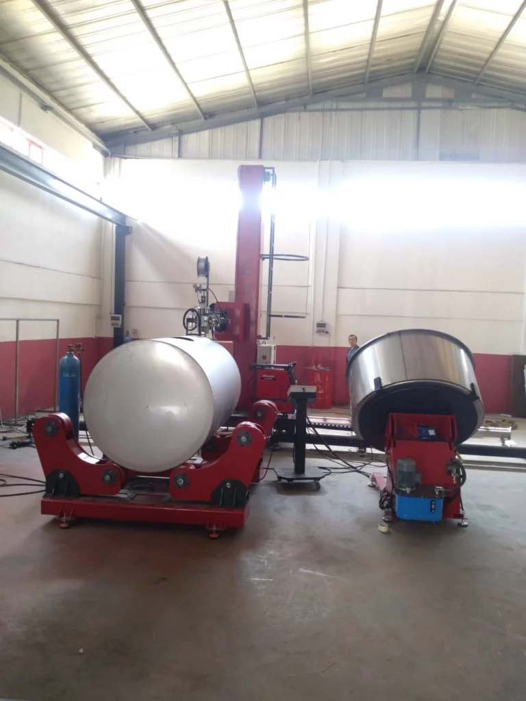
One or two welding positioners carry out the circular welding. The welding positioner is a device that keeps the part tight and rotates it with a required rotational speed. This rotational movement can in 3 Axis.
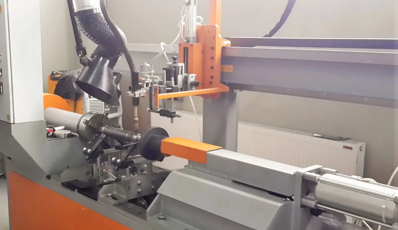
In circular welding, the round part is positioned under the welding torch. The MIG or TIG welding machine starts the welding. A MIG welder is a welding machine that uses a metal feed wire to weld the parts. In a MIG welding machine (Metal Inert Gas) the application can be made on different metals such as aluminum, stainless steel, and steel, and on every thickness from 26-gauge sheet metal to heavy-duty structural plates.
The MIG welding feed wire also acts not only as an electrode but also as a filler. So the thickness of the sheet metal doesn’t play a role here as the feed wire of the MIG welding torch can fill the space easily. Conversely, TIG welding (Tungsten Inert Gas) has a better finishing effect and higher quality.
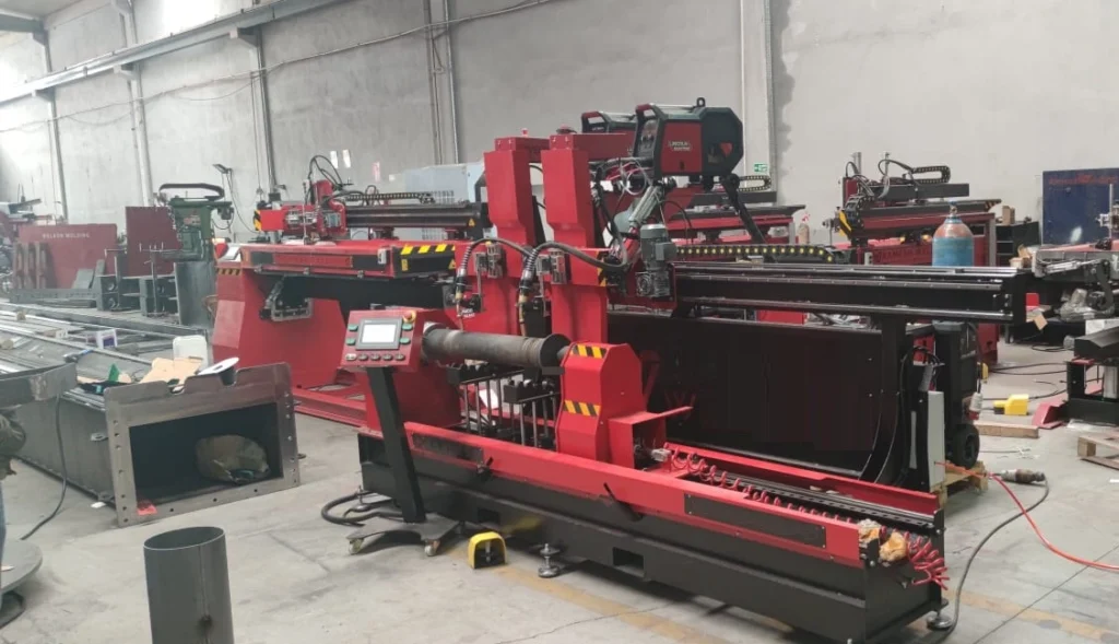
A circular welding machine can be horizontal or vertical. A horizontal circular welding machine can also be called an automatic pipe welding machine. Here the round part is laid horizontally and is rotated by the pipe rotators. A pipe rotator is a tool that keeps the part fixed and rotates it around its own axis and meanwhile the welding torch contacts the part surface and starts to weld. The turning machine here can be located on the tips of the pipe or down on the welding bed.
Welding Machine Types
- Longitudinal Welding Machine
- Circular Welding System
- Collar and Sleeve Welding Machine
- Boom Welding Machine
- Pipe Welding Machine
- Welding Rotator
Longitudinal Welding Machine
The longitudinal welding machine is used to weld cylinders and pipes in a horizontal way. The pipe is placed on the positioners to rotate it. The positioner is energized by an electric motor. The operator can arrange the turning speed via the control screen. The cylinder turns around while the welding torch contacts the part and starts the welding process.
A longitudinal welding machine is a specialized machine designed for welding cylindrical or rectangular workpieces along their longitudinal axis. It is commonly used in the manufacturing industry to produce long, continuous welds on various materials, including metals, plastics, and composites.
How does a longitudinal welding machine work?
The specific working principle of a longitudinal welding machine depends on the type of welding process being used. However, all longitudinal welding machines share the common goal of joining two or more workpieces together along their length. This is typically achieved by applying heat and pressure to the weld joint, causing the materials to fuse together.
What are the different types of longitudinal welding machines?
There are several different types of longitudinal welding machines available, each with its own unique advantages and limitations. Some of the most common types include:
- Resistance seam welding (RSW) machines: These machines use electrical resistance to generate heat and fuse overlapping metal pieces together. They are commonly used for welding thin sheet metals, particularly in the automotive industry.
- Laser seam welding (LSW) machines: These machines employ a highly focused laser beam to melt and fuse overlapping metal pieces. They are known for their precision and ability to produce clean, narrow welds.
- Submerged arc welding (SAW) machines: These machines utilize a consumable electrode and a layer of granular flux to weld along the longitudinal axis. They are suitable for welding thick workpieces and offer high deposition rates.
- Gas metal arc welding (GMAW) machines: These machines use a consumable wire electrode and shielding gas to weld along the longitudinal axis. They are versatile and can weld a wide range of materials.
- Friction stir welding (FSW) machines: These machines employ a rotating tool to generate frictional heat and plastic deformation in the weld joint, joining two or more metal pieces without melting the base material. They are particularly suitable for welding dissimilar metals.
What are the applications of longitudinal welding machines?
Longitudinal welding machines are used in a wide variety of applications in the manufacturing industry. Some of the most common applications include:
- Welding of pipes and tubes
- Welding of cylindrical tanks and vessels
- Welding of rectangular beams and frames
- Welding of sheet metal assemblies
- Welding of plastic and composite components
What are the benefits of using a longitudinal welding machine?
Longitudinal welding machines offer several benefits over other welding methods, including:
- High production rates: Longitudinal welding machines can achieve high welding speeds, allowing for efficient production of long welds.
- Consistent weld quality: Longitudinal welding machines produce consistent and high-quality welds with minimal defects.
- Versatility: Longitudinal welding machines can weld a wide range of materials and workpiece thicknesses.
- Automation: Longitudinal welding machines can be automated, reducing labor costs and improving process consistency.
Circular Welding System
Circular welding systems, also known as circumferential welding systems, are specialized machines designed to weld cylindrical components in a continuous rotation. They are commonly used in the manufacturing and construction industries to join pipes, tanks, pressure vessels, and other cylindrical structures.
Key Features of Circular Welding Systems:
- Continuous Rotation: The workpiece is rotated continuously during the welding process, ensuring uniform heat distribution and consistent weld quality along the entire circumference.
- Precise Torch Positioning: The welding torch is precisely positioned and controlled to maintain proper alignment with the weld seam, ensuring accurate weld penetration and fusion.
- Automation Integration: Circular welding systems can be integrated with robotic arms or other automated systems, enabling high-volume production and reducing labor costs.
- Versatility: These systems can handle a wide range of workpiece sizes, materials, and welding processes, making them adaptable to various applications.
- Safety Features: Circular welding systems incorporate safety features, such as interlocks, guards, and emergency stop buttons, to protect operators from hazards.
Applications of Circular Welding Systems:
Circular welding systems are widely used in various industries, including:
- Oil and Gas: Welding pipelines, pressure vessels, and storage tanks in the oil and gas industry.
- Power Generation: Welding power plant components, such as boilers, turbines, and heat exchangers.
- Chemical Industry: Welding flanges, pipes, and other components in chemical processing equipment.
- Shipbuilding: Welding ship hulls, decks, and piping systems.
- Construction Industry: Welding pipes, tanks, and other cylindrical structures in construction projects.
- Water and Wastewater Treatment Industry: Welding pipes, tanks, and other components in water supply and wastewater treatment systems.
- Food and Beverage Industry: Welding pipes, tanks, and other components in food and beverage processing equipment.
- Pharmaceutical and Medical Device Manufacturing: Welding components for medical devices, such as implants, catheters, and other medical equipment.
- Aerospace Industry: Welding components for aircraft structures, such as fuselages, pressure vessels, and landing gear.
Advantages of Circular Welding Systems:
- Consistent Weld Quality: The continuous rotation and precise torch positioning ensure consistent weld quality along the entire circumference of the workpiece.
- Increased Productivity: Automation and continuous operation significantly reduce welding time and enhance productivity, especially for large-volume production.
- Reduced Labor Costs: Automated welding systems minimize the need for manual labor, reducing labor costs associated with traditional welding methods.
- Enhanced Safety: Safety features and automated operation protect operators from hazards, such as sparks, fumes, and potential injuries.
Future Trends in Circular Welding Systems:
- Advanced Automation: Integration of more sophisticated robotics, sensors, and control systems for greater automation and precision.
- Real-Time Monitoring: Integration of monitoring systems to track welding parameters, weld quality, and potential defects in real-time.
- Adaptive Welding Control: Development of adaptive welding control systems to adjust welding parameters based on workpiece material, geometry, and environmental factors.
- Remote Operation: Implementation of remote operation capabilities to allow for control and monitoring of welding processes from a distance.
- Data-Driven Optimization: Utilization of welding data and analytics to optimize welding parameters, improve weld quality, and predict potential issues.
Circular welding systems play a crucial role in various industries, ensuring efficient, precise, and reliable methods for joining cylindrical components. Their versatility, advanced automation capabilities, and safety features make them indispensable tools for manufacturing and construction applications. As technology advances, circular welding systems are expected to become even more sophisticated, enabling further automation, enhanced control, and improved weld quality across diverse industries.
Collar and Sleeve Welding Machine
A collar and sleeve welding machine, also known as a pipe coupling welding machine or a fitting welding machine, is a specialized welding machine designed for welding collars and sleeves onto pipes and tubes. Collars and sleeves are used to connect pipes and tubes of different diameters or to create branches or connections in piping systems.
Types of Collar and Sleeve Welding Machines
There are two main types of collar and sleeve welding machines:
- Butt Welding Machines: These machines use electrical resistance or gas metal arc welding (GMAW) to join the collar or sleeve to the pipe or tube end-to-end.
- Socket Welding Machines: These machines use GMAW or friction stir welding (FSW) to join the collar or sleeve to the pipe or tube by inserting the collar or sleeve into a pre-formed socket on the pipe or tube.
Applications of Collar and Sleeve Welding Machines
Collar and sleeve welding machines are used in a wide variety of applications, including:
- Pipeline Construction: These machines are used to weld collars and sleeves onto pipes and tubes in oil and gas, water, and wastewater pipelines.
- HVAC Systems: These machines are used to weld collars and sleeves onto pipes and tubes in heating, ventilation, and air conditioning (HVAC) systems.
- Process Piping: These machines are used to weld collars and sleeves onto pipes and tubes in chemical, pharmaceutical, and food processing plants.
- Structural Steelwork: These machines are used to weld collars and sleeves onto pipes and tubes in structural steelwork applications.
Benefits of Using Collar and Sleeve Welding Machines
Collar and sleeve welding machines offer several benefits over other welding methods, including:
- High Production Rates: Collar and sleeve welding machines can achieve high welding speeds, allowing for efficient production of welds.
- Consistent Weld Quality: Collar and sleeve welding machines produce consistent and high-quality welds with minimal defects.
- Versatility: Collar and sleeve welding machines can weld a wide range of materials and workpiece thicknesses.
- Automation: Collar and sleeve welding machines can be automated, reducing labor costs and improving process consistency.
Installation and Operation of Collar and Sleeve Welding Machines
The installation and operation of collar and sleeve welding machines should be carried out by trained and experienced personnel. Here’s a general overview of the steps involved:
Installation
- Site Preparation: Ensure adequate clearance and a level, stable installation surface.
- Machine Positioning: Position the machine and align it with the workpiece.
- Electrical and Control Connections: Connect power supply and control systems.
- Safety Interlocks and Grounding: Verify proper grounding and safety interlocks.
Operation
- Workpiece Preparation: Prepare the pipe or tube and collar or sleeve for welding, including cleaning and surface preparation.
- Welding Parameter Setup: Set welding parameters based on workpiece material, thickness, and desired weld quality.
- Welding Torch Positioning: Position the welding torch precisely along the weld path.
- Welding Process Initiation: Initiate the welding process, monitoring and adjusting parameters as needed.
- Weld Quality Inspection: Upon completion, inspect the weld for defects and verify its integrity.
Maintenance
- Regular Inspection: Regularly inspect the machine for wear, damage, or malfunction.
- Component Cleaning: Clean welding components, including the torch, carriage, and power supply.
- Preventive Maintenance: Perform scheduled maintenance tasks as per the manufacturer’s recommendations.
Safety Precautions
- Personal Protective Equipment (PPE): Always wear appropriate PPE, including a welding helmet, gloves, safety glasses, and a welding jacket.
- Proper Ventilation: Ensure adequate ventilation to remove welding fumes and gases.
- Electrical Safety: Follow electrical safety protocols to prevent electric shock hazards.
- Machine Guarding: Use safety guards to protect operators from moving parts and potential pinch points.
- Workpiece Handling: Handle workpieces carefully to prevent injuries from sharp edges or hot surfaces.
Collar and sleeve welding machines are valuable tools for the piping and structural steel industries, enabling the production of high-quality, consistent welds on pipes, tubes, and fittings. Their versatility, automation capabilities, and consistent weld quality make them essential in various piping and structural applications.
Boom Welding Machine
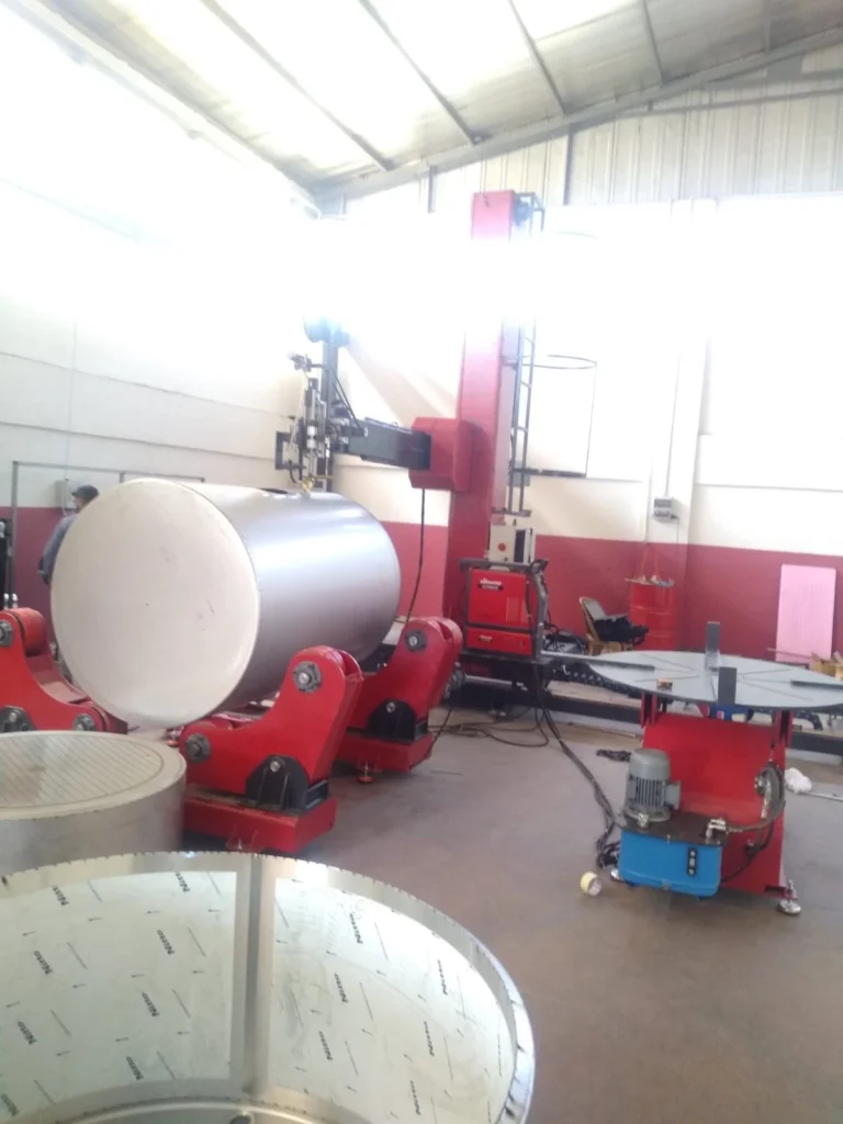
A boom welding machine, also known as a column and boom welding machine, is a specialized piece of equipment designed to weld pipes and other cylindrical components in elevated positions. These machines typically consist of a stable column that houses the welding equipment and a boom that extends from the column to reach the workpiece. The boom can be maneuvered to position the welding torch precisely along the weld seam, ensuring consistent weld quality and accessibility in challenging work environments.
Key Features of Boom Welding Machines:
- Stable Column: A sturdy column provides a solid base for the welding equipment, ensuring stability and preventing movement during welding operations.
- Movable Boom: An extendable boom that can be maneuvered to reach various heights and positions, enabling welding in elevated or inaccessible areas.
- Precision Positioning: The boom can be precisely positioned using various controls, allowing the welding torch to be accurately aligned with the weld seam.
- Compatible Welding Processes: Compatible with various welding processes, such as gas metal arc welding (GMAW), gas tungsten arc welding (GTAW), and submerged arc welding (SAW), providing flexibility in material handling.
- Welding Torch Positioning: Adjustable welding torch holders ensure the welding torch can be positioned to the desired location for optimal weld penetration and fusion.
- Automation Integration: Can be integrated with robotic arms or other controlled systems for automated welding operations, enhancing productivity and reducing labor costs.
- Safety Features: Interlocks, guards, and emergency stop buttons to prevent accidents and hazards, ensuring operator safety during welding operations.
- Data Logging: Advanced boom welding machines may have data logging capabilities to record welding parameters and weld quality information for process control, quality assurance, and traceability purposes.
- Adaptability: Boom welding machines can be adapted to handle a wide range of pipe diameters and configurations, making them versatile tools for various applications.
- Durability: Boom welding machines are built to withstand the rigors of industrial environments, making them a reliable and long-lasting investment for welding operations.
Applications of Boom Welding Machines:
Boom welding machines are widely used in various industries to weld pipes and other cylindrical components:
- Construction Industry: Welding pipes and other structural components in construction projects, such as scaffolding, towers, and pipelines.
- Power Generation Industry: Welding pressure vessels, pipes, and other components for power plants in elevated or hard-to-reach areas.
- Manufacturing Industry: Welding cylindrical components in various manufacturing processes, such as water tanks, vessels, and storage containers.
- Shipbuilding: Welding pipes and tubes used in the construction and maintenance of ships in shipyards and other marine environments.
- Oil and Gas Industry: Welding pipelines, storage tanks, and other infrastructure in offshore and onshore oil and gas operations.
- Aerospace Industry: Welding components for aircraft fuselages, pressure vessels, and other structures in aircraft manufacturing.
- Medical Device Manufacturing: Welding implantable devices, catheters, and other medical components that require precise and controlled welding operations.
Conclusion:
Boom welding machines are essential tools in various industries, providing efficient, precise, and reliable methods for joining cylindrical components in elevated or challenging work environments. Their adaptability, versatility, and ability to handle a wide range of applications make them indispensable tools for manufacturing, construction, and various industrial processes. As technology advances, boom welding machines are expected to become even more sophisticated, enhancing their efficiency, precision, and safety, further expanding their applications in diverse industries.
Pipe Welding Machine
An automatic pipe welding machine can easily weld pipes on a device called a pipe rotator. For fast and effective work, we designed and manufactured a brand new automatic tig pipe welding machine. For this reason, we use pipe position for welding. A pipe positioner or pipe rotator is a device used to rotate pipes around their own axis.
Pipe welding machines, also known as rotating welding machines or turning rolls, are specialized equipment used to join cylindrical and curved components, commonly pipes. These machines rotate the workpiece during the welding process, ensuring consistent access to all weld seams and enabling efficient, high-quality welds.
Types of Pipe Welding Machines:
1. Rotary Welding Machine:
This type of machine rotates the workpiece along its longitudinal axis, providing access to the entire weld seam. It is suitable for welding pipes of various diameters, from small-diameter tubing to large-diameter pipelines.
2. Orbital Welding Machine:
This machine moves the welding torch in an orbital motion around the weld joint, ensuring precise control over weld depth and penetration. It is particularly useful for joining pipes with complex geometries or where limited access is a concern.
3. Head-to-End Welding Machine:
This machine is designed specifically for welding pipes end-to-end, forming a continuous weld seam without any gaps or discontinuities. It is commonly used in oil and gas pipelines and similar applications.
4. Automatic Welding Machine:
This type of machine is integrated with robotic arms or other controlled systems to automate the welding process. This enables high-speed, consistent welding operations with minimal operator intervention, reducing labor costs and improving productivity.
Technical Specifications of Pipe Welding Machines:
Pipe welding machines are equipped with various technical specifications to ensure efficient and reliable welding operations. These include:
Load Capacity:
The maximum weight of the workpiece that the machine can handle. This is important to ensure the machine can support heavy pipes without compromising stability or precision.
Pipe Diameter Range:
The range of pipe diameters that the machine can weld. Pipe welding machines are typically designed to handle a variety of pipe sizes, from small-diameter tubing to large-diameter pipelines.
Rotation Speed:
The speed at which the machine rotates the workpiece or travels along the weld seam. This is crucial for ensuring consistent weld quality and controlling the deposition rate of the weld material.
Welding Process Compatibility:
The ability to weld using various welding processes, such as gas metal arc welding (GMAW), gas tungsten arc welding (GTAW), or submerged arc welding (SAW). This flexibility allows the machine to handle different pipe materials and applications.
Automation Capabilities:
The ability to integrate with automation systems for automated welding operations. This feature is essential for high-volume production and reduces labor costs.
Safety Features:
Interlocks, guards, and emergency stop buttons to prevent accidents and hazards. These safety features protect operators from exposure to sparks, flying debris, and electrical hazards.
Applications of Pipe Welding Machines:
Pipe welding machines are used extensively in various industries to weld a wide range of pipes and components:
Oil and Gas Industry:
Welding pipelines for oil and gas transportation is a critical application where pipe welding machines are essential for ensuring the integrity of pipelines under high pressure and harsh conditions.
Power Generation Industry:
Welding pressure vessels, pipes, and other components for power plants is another major application where pipe welding machines are used to create strong and durable welds that withstand the rigors of power generation environments.
Chemical Industry:
Welding reactor vessels, piping systems, and storage tanks in the chemical industry is crucial for ensuring the safety and integrity of chemical processing equipment.
Construction Industry:
Welding pipe structures, scaffolding, and other steel components in construction projects is essential for building strong and stable structures that can withstand various loads and conditions.
Manufacturing Industry:
Welding pipes for various applications, such as water supply, irrigation, and manufacturing equipment, is essential in various manufacturing processes.
Shipbuilding:
Pipe welding machines are crucial in shipbuilding for welding pipes and tubes used in the construction and maintenance of ships. These welds must withstand the harsh marine environment and the stresses of ship operation.
Food and Beverage Industry:
Pipe welding machines are used in the food and beverage industry to manufacture containers and equipment, such as cans, bottles, and tanks. These welds must meet food safety standards and prevent contamination.
Medical Device Industry:
Pipe welding machines are employed in the medical device industry for producing implantable devices, such as surgical stents, catheters, and prosthetic components. These welds must be precise, durable, and biocompatible to ensure the safety and effectiveness of medical devices.
Appliance Manufacturing:
Pipe welding machines are used in appliance manufacturing for welding cookware, water heaters, and other cylindrical components. These welds must withstand the heat and pressure of appliance operation.
General Manufacturing:
Pipe welding machines are used in various general manufacturing industries to weld cylindrical and curved components in a
Here’s a comprehensive overview of pipe welding machines:
Overview of Pipe Welding Machines
Pipe welding machines are specialized welding equipment designed to join cylindrical and curved components, commonly pipes. They are indispensable in various industries, including oil and gas, power generation, chemical, construction, and manufacturing, for creating strong and durable welds that ensure the integrity of critical structures and systems.
Types of Pipe Welding Machines
There are four main types of pipe welding machines:
1. Rotary Welding Machines:
These machines rotate the workpiece during welding, providing consistent access to all weld seams and ensuring uniform weld quality. They are suitable for welding a wide range of pipe diameters, from small-diameter pipes to large-diameter pipelines.
2. Orbital Welding Machines:
Orbital welding machines utilize an orbital motion to weld the joint, precisely controlling weld depth and penetration. This type of machine is particularly advantageous for joining pipes with complex geometries or where limited access is a concern.
3. Head-to-End Welding Machines:
Head-to-end welding machines are specifically designed for welding pipes end-to-end, forming a continuous weld seam without any gaps or discontinuities. They are commonly used in oil and gas pipelines and similar applications.
4. Automatic Welding Machines:
Automatic welding machines are integrated with robotic arms or other controlled systems to automate the welding process. This enables high-speed, consistent welding operations with minimal operator intervention, reducing labor costs and improving productivity.
Key Features of Pipe Welding Machines
Pipe welding machines are equipped with several essential features to ensure efficient and reliable welding operations:
Load Capacity:
The maximum weight of the workpiece that the machine can handle. This is important to ensure the machine can support heavy pipes without compromising stability or precision.
Pipe Diameter Range:
The range of pipe diameters that the machine can weld. Pipe welding machines are typically designed to handle a variety of pipe sizes, from small-diameter tubing to large-diameter pipelines.
Rotation Speed:
The speed at which the machine rotates the workpiece or travels along the weld seam. This is crucial for ensuring consistent weld quality and controlling the deposition rate of the weld material.
Welding Process Compatibility:
The ability to weld using various welding processes, such as gas metal arc welding (GMAW), gas tungsten arc welding (GTAW), or submerged arc welding (SAW). This flexibility allows the machine to handle different pipe materials and applications.
Automation Capabilities:
The ability to integrate with automation systems for automated welding operations. This feature is essential for high-volume production and reduces labor costs.
Safety Features:
Interlocks, guards, and emergency stop buttons to prevent accidents and hazards. These safety features protect operators from exposure to sparks, flying debris, and electrical hazards.
Applications of Pipe Welding Machines
Pipe welding machines are used extensively in various industries to weld a wide range of pipes and components:
1. Oil and Gas Industry:
Welding pipelines for oil and gas transportation is a critical application where pipe welding machines are essential for ensuring the integrity of pipelines under high pressure and harsh conditions.
2. Power Generation Industry:
Welding pressure vessels, pipes, and other components for power plants is another major application where pipe welding machines are used to create strong and durable welds that withstand the rigors of power generation environments.
3. Chemical Industry:
Welding reactor vessels, piping systems, and storage tanks in the chemical industry is crucial for ensuring the safety and integrity of chemical processing equipment.
4. Construction Industry:
Welding pipe structures, scaffolding, and other steel components in construction projects is essential for building strong and stable structures that can withstand various loads and conditions.
5. Manufacturing Industry:
Welding pipes for various applications, such as water supply, irrigation, and manufacturing equipment, is essential in various manufacturing processes.
Conclusion
Pipe welding machines are indispensable tools for joining cylindrical and curved components in various industries, providing efficient, high-quality welds that ensure the integrity of critical structures and systems. Their adaptability, automation capabilities, and wide range of applications make them valuable assets in various sectors, from infrastructure and manufacturing to oil and gas production. As technology advances, pipe welding machines are expected to become even more sophisticated, enhancing their efficiency, precision, and safety, further expanding their applications in various industries.
Pipe welding machines are specialized welding equipment designed to join cylindrical and curved components, commonly pipes. They utilize various welding processes, such as gas metal arc welding (GMAW), gas tungsten arc welding (GTAW), and submerged arc welding (SAW), to create strong and durable welds.
Types of Pipe Welding Machines:
- Rotary Welding Machines: These machines rotate the workpiece during welding, ensuring consistent weld quality and access to all weld seams.
- Orbital Welding Machines: These machines utilize an orbital motion to weld the joint, providing precise control over weld depth and penetration.
- Head-to-End Welding Machines: These machines are designed for welding pipes end-to-end, forming a continuous seam.
- Automatic Welding Machines: These machines are automated using robotic arms or other controlled systems, enabling high-speed and consistent welding operations.
Key Features of Pipe Welding Machines:
- Load Capacity: The maximum weight of the workpiece that the machine can handle.
- Pipe Diameter Range: The range of pipe diameters that the machine can weld.
- Rotation Speed: The speed at which the machine rotates the workpiece or travels along the weld seam.
- Welding Process Compatibility: The ability to weld using various welding processes, such as GMAW, GTAW, or SAW.
- Automation Capabilities: The ability to integrate with automation systems for automated welding operations.
- Safety Features: Interlocks, guards, and emergency stop buttons to prevent accidents and hazards.
Applications of Pipe Welding Machines:
- Oil and Gas Industry: Welding pipelines for oil and gas transportation.
- Power Generation Industry: Welding pressure vessels, pipes, and other components for power plants.
- Chemical Industry: Welding reactor vessels, piping systems, and storage tanks.
- Construction Industry: Welding pipe structures, scaffolding, and other steel components.
- Manufacturing Industry: Welding pipes for various applications, such as water supply, irrigation, and manufacturing equipment.
Pipe welding machines are essential tools for joining cylindrical and curved components in various industries. They provide efficient, high-quality welds and contribute to the infrastructure, manufacturing, and energy sectors.
For robotic welding automation, we design and manufacture complete automatic welding equipment, including a welding column (column and boom welding machine), welding rotator machine, welding robot, and welding machine.
Automation of Circular Welding Machine
Automating a circular welding machine can significantly enhance its capabilities and productivity, enabling the production of high-quality welds with minimal human intervention. Here are some key aspects of automating a circular welding machine:
- Robotic Integration: Integrating a robotic arm with the circular welding machine provides precise control over the welding torch’s movement, ensuring consistent weld paths and angles. The robot can handle complex geometries and variations in workpiece positioning, maintaining weld quality.
- Sensor Integration: Incorporating sensors into the system allows for real-time monitoring of various parameters, such as workpiece position, weld bead width, and arc voltage. This data can be used to adjust welding parameters dynamically, ensuring consistent weld quality and minimizing defects.
- Machine Vision Integration: Integrating machine vision systems enables the robot to identify and position itself accurately relative to the workpiece. This visual feedback ensures precise alignment and eliminates the need for manual adjustments.
- Programming and Control Systems: Developing sophisticated programming and control systems is crucial for automating the welding process. These systems should be able to handle complex weld paths, manage welding parameters, and incorporate sensor data for adaptive control.
- Safety Interlocks and Monitoring: Implementing robust safety interlocks and monitoring systems is essential to prevent accidents and ensure operator safety. This includes sensors for detecting obstructions, emergency stop mechanisms, and access control measures.
- Human-Machine Interface (HMI): Designing a user-friendly HMI allows operators to monitor the welding process, adjust parameters, and intervene if necessary. The HMI should provide clear visualizations and intuitive controls for efficient operation.
- Integration with Manufacturing Processes: Automating the circular welding machine should be integrated into the overall manufacturing process, ensuring seamless data exchange and synchronization with other machines and systems. This integration can optimize production flow and minimize downtime.
- Maintenance and Troubleshooting: Establishing comprehensive maintenance procedures and troubleshooting protocols is crucial for maintaining the performance and reliability of the automated welding system. Regular inspections, preventive maintenance, and prompt error resolution are essential for continuous operation.
- Training and Skill Development: Providing adequate training to operators and maintenance personnel is essential for ensuring the safe and effective operation of the automated welding system. Training should cover all aspects of the system, including operation, maintenance, and troubleshooting procedures.
- Continuous Improvement and Optimization: Continuously evaluating and optimizing the automated welding system can further enhance its performance and efficiency. This includes identifying areas for improvement, implementing new technologies, and adapting to changing production requirements.
By implementing these automation strategies, manufacturers can significantly enhance the capabilities of their circular welding machines, achieving higher productivity, consistent weld quality, and improved safety in their manufacturing processes.
Development of a portable rotary MIG arc welding machine, the rotary MIG ARC welding is one of the several techniques developed for narrow gap welding. It has been found that the fusion characteristics of the HAZ is improved because of the nature of the ARC physics. The process can be effectively used for different materials, particularly those sensitive to
heat input including high-strength low alloy, stainless steel, heat-resistant steels, aluminum, and titanium alloys.
Based on this result, it has been identified that this type of welding is more suitable for fillet and butt welding. The principle of the process is that the welding wire is fed into the electrode nozzle with eccentricity at the contact tip. In this project, we will be doing Design, Analysis & Manufacturing for automation for circular parts welding with uniform weld structure. We will be designing & manufacturing the turntable which will be rotating at a specifically required speed depending upon the requirement of fillet material to be added.
Further, the electrode nozzle is kept stationary, which will be in contact with the surface of the component to be welded. Hence in this project, a detailed design for converting the conventional MIG welding (ARC) machine into an automated circular component welding machine has been proposed. Along with this main modification the existing MIG welding machine – (a stationary downward ARG – HEAD that has provisions for horizontal and upward movements) is to be modified into a portable welding machine.
Robotic Welding Automation with a Circular Welding Machine
Robotic welding automation with a circular welding machine offers significant advantages in terms of productivity, consistency, and safety. By combining the precision and flexibility of robotics with the specialized capabilities of a circular welding machine, manufacturers can achieve high-quality welds on cylindrical workpieces with minimal human intervention.
Here are some of the key benefits of robotic welding automation with a circular welding machine:
- Increased Productivity: Robotic welding automation can significantly improve welding speeds and reduce cycle times, leading to increased production output. Robots can operate continuously and consistently, eliminating the need for operator breaks and reducing downtime.
- Enhanced Weld Quality: Robotic welding systems can precisely control welding parameters, ensuring consistent and high-quality welds with minimal defects. Robots can maintain precise positioning and torch angles, reducing the risk of weld inconsistencies.
- Improved Safety: Robotic welding automation removes human operators from the hazardous environment of the welding arc, reducing the risk of burns, eye injuries, and exposure to fumes. Robots can work in confined spaces or around hazardous materials without putting workers at risk.
- Reduced Labor Costs: Robotic welding automation can significantly reduce labor costs associated with manual welding processes. Robots can operate 24/7, eliminating the need for multiple shifts and reducing overtime expenses.
- Data-Driven Optimization: Robotic welding systems can collect and analyze welding data, providing valuable insights into process performance and weld quality. This data can be used to optimize welding parameters, improve weld consistency, and identify potential issues early on.
- Adaptability to Complex Geometries: Robotic welding systems can be programmed to handle complex weld paths and geometries, making them suitable for a wide range of applications. Robots can adapt to variations in workpiece size and position, ensuring consistent weld quality.
- Integration with Automation Systems: Robotic welding systems can be integrated with various automation systems, including CNC machines and production lines, enabling seamless integration into manufacturing processes. This integration can further enhance productivity and efficiency.
- Reduced Material Waste: Robotic welding systems can minimize material waste by precisely controlling weld bead size and deposition. This precision reduces the risk of weld defects and overconsumption of welding filler material.
- Improved Ergonomics: Robotic welding automation eliminates the physical strain and repetitive motions associated with manual welding, reducing the risk of work-related musculoskeletal disorders. Operators can focus on monitoring and maintaining the robotic system, minimizing fatigue and discomfort.
- Enhanced Scalability: Robotic welding systems can be easily scaled up or down to meet changing production demands. Additional robots can be added to increase capacity, while the system can be reconfigured for different product lines.
Overall, robotic welding automation with a circular welding machine offers a comprehensive solution for achieving high-quality, consistent welds on cylindrical workpieces while improving productivity, safety, and cost-effectiveness. The combination of robotic precision and specialized welding capabilities makes it an invaluable asset for various manufacturing industries.
Automatic Pipe Roller for Welding
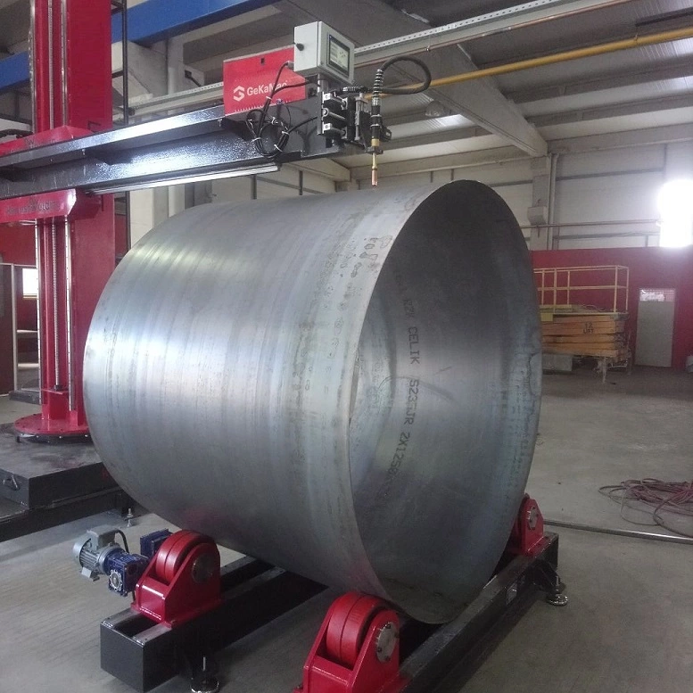
An automatic pipe roller for welding, also known as a welding rotator or a pipe turning roll, is a specialized machine designed to rotate cylindrical workpieces, such as pipes and tubes, during the welding process. This rotation ensures that the weld seam is evenly heated and fused, resulting in a strong and consistent weld. Automatic pipe rollers are commonly used in various industries, including oil and gas, pipeline construction, shipbuilding, and structural steelwork.
Types of Automatic Pipe Rollers
Automatic pipe rollers can be categorized into two main types based on their rotation mechanism:
- Driven Rollers: These rollers use a motor or drive system to mechanically rotate the workpiece. Driven rollers offer precise control over rotation speed and provide consistent rotation even for heavy workpieces.
- Idler Rollers: These rollers rely on friction between the rollers and the workpiece to induce rotation. Idler rollers are often used in conjunction with driven rollers to support the workpiece and prevent slippage.
Features of Automatic Pipe Rollers
Automatic pipe rollers typically incorporate several key features to enhance their functionality and effectiveness:
- Adjustable Workpiece Support: The rollers can be adjusted to accommodate various workpiece diameters and lengths, ensuring proper support and alignment.
- Variable Rotation Speed Control: The rotation speed can be controlled to match the welding parameters, ensuring optimal weld quality and minimizing heat buildup.
- Integrated Welding Seam Tracking: Some advanced rollers incorporate seam tracking systems that automatically adjust the rotation speed and angle based on the welding torch’s position, ensuring even weld coverage.
- Remote Control and Monitoring: Many automatic pipe rollers can be operated and monitored remotely, allowing operators to control the welding process from a safe distance.
- Safety Interlocks and Guards: Safety interlocks and guards are incorporated to prevent accidents and protect operators from rotating parts and potential pinch points.
Applications of Automatic Pipe Rollers
Automatic pipe rollers are widely used in various applications, including:
- Welding of Pipes and Tubes: Automatic pipe rollers are essential for welding pipes and tubes in oil and gas pipelines, water and wastewater pipelines, and structural steelwork.
- Welding of Cylindrical Tanks and Vessels: Automatic pipe rollers are used to weld cylindrical tanks and vessels in chemical, pharmaceutical, and food processing plants.
- Welding of Pressure Vessels: Automatic pipe rollers are employed to weld pressure vessels in various industries, including oil and gas, power generation, and aerospace.
- Welding of Offshore Structures: Automatic pipe rollers are used to weld offshore structures, such as platforms and pipelines, in the marine and oil and gas industries.
Benefits of Using Automatic Pipe Rollers
Automatic pipe rollers offer several benefits over manual welding methods, including:
- Improved Weld Quality: Automatic pipe rollers ensure consistent and high-quality welds by providing precise rotation and control of welding parameters.
- Increased Productivity: Automatic pipe rollers can significantly reduce welding time and increase production output by automating the rotation process.
- Reduced Labor Costs: Automatic pipe rollers minimize the need for manual labor, reducing labor costs and improving efficiency.
- Enhanced Safety: Automatic pipe rollers eliminate the need for operators to work in close proximity to the welding arc, reducing the risk of burns, eye injuries, and exposure to fumes.
- Versatility: Automatic pipe rollers can handle a wide range of pipe diameters, lengths, and materials, making them suitable for various applications.
Overall, automatic pipe rollers play a crucial role in the welding industry, enabling the production of high-quality, consistent welds on cylindrical workpieces with increased productivity, safety, and cost-effectiveness.
Nowadays mass production is often required to automate the manufacturing processes that were conventionally done manually. At present, various welding technique is used for the welding processes such as CO2 welding, Electric arc welding, and TIG (tungsten inert gas welding), in that various fixture is used for various welding, but in many application, we use some technique which does not work efficiently & accurately.
Moving the electrode along the welding line is a skill full work and especially for circular component become much more difficult. To avoid such a problem we implement a welding rotator. The need of a special device that can rotate the job at a fixed rate to assist the welding process for circular components and ensure good profile and homogeneous welding. Many different energy sources can be used for welding, including a gas flame, an electric arc, a laser, an electron beam, friction, and ultrasound.
Industrial Welding Machine
Industrial welding machines are essential tools for joining metal parts in a wide variety of industries, including automotive, construction, shipbuilding, and aerospace. They are used to create strong, durable bonds that can withstand the stresses and forces encountered in these applications.
Types of Industrial Welding Machines
There are many different types of industrial welding machines, each with its own strengths and applications. Some of the most common types include:
- Gas metal arc welding (GMAW) (MIG): This is a versatile process that is well-suited for welding a variety of metals, including steel, aluminum, and stainless steel. It uses a consumable wire electrode and shielding gas to create a stable arc and weld pool.
- Shielded metal arc welding (SMAW) (Stick): This is a widely used process that is relatively simple to operate. It uses a consumable wire electrode that is coated with flux. The flux melts and creates a protective gas shield around the arc and weld pool.
- Gas tungsten arc welding (GTAW) (TIG): This process is known for producing high-quality welds with a narrow weld bead. It uses a non-consumable tungsten electrode and shielding gas to create a clean, stable arc.
- Submerged arc welding (SAW): This process is used for welding thick plates. It uses a consumable wire electrode and granular flux that is fed into the weld joint. The flux melts and surrounds the arc, creating a protective environment and shielding the weld pool from contamination.
- Flux cored arc welding (FCAW) (Gasless MIG): This is a variation of GMAW that does not require a separate shielding gas. It uses a tubular electrode that contains flux, which provides both shielding and deoxidizing properties.
Applications of Industrial Welding Machines
Industrial welding machines are used in a wide variety of applications, including:
- Joining steel beams in construction
- Welding together pipes and tubes in the oil and gas industry
- Repairing damaged metal parts in manufacturing
- Creating strong, lightweight structures in the aerospace industry
- Fabricating parts for automobiles and other vehicles
Benefits of Using Industrial Welding Machines
Industrial welding machines offer several benefits over traditional joining methods, such as riveting, bolting, and adhesive bonding:
- Strength: Welded joints are typically stronger than riveted or bolted joints.
- Durability: Welded joints are more resistant to corrosion and fatigue than other joining methods.
- Versatility: Welding machines can be used to join a wide variety of metals and materials.
- Cost-effectiveness: Welding is often a more cost-effective way to join metals than other methods.
- Automation: Industrial welding machines can be automated, which can improve productivity and quality.
Safety Precautions for Industrial Welding Machines
Working with industrial welding machines can be dangerous if safety precautions are not taken. Some of the most important safety precautions include:
- Wear personal protective equipment (PPE), such as gloves, safety glasses, and a welding helmet.
- Work in a well-ventilated area to avoid inhaling fumes.
- Keep flammable materials away from the welding area.
- Never touch the electrode or any part of the welding circuit while it is energized.
- Be aware of the arc flash hazard, which can cause severe burns.
While often an industrial process, welding can be done in many different environments, including open air, underwater, and in outer space. Regardless of location, welding remains dangerous, and
precautions are taken to avoid burns, electric shock, eye damage, poisonous fumes, and overexposure to ultraviolet light.
In CO2 welding or sometimes electric arc welding, the need often arises for the welding of circular shape components, where the welding is carried out on the entire periphery or a partial arc length of the job. The electrode is thus moved along this circular path in the conventional method. But the movement of the electrode is much more difficult and it is much easier to index the job.
For welding, the current workpiece Cycle time is higher i.e 45-
60 sec. So we need to develop such a system for easy workpiece loading and & auto-welding gun positioning. Auto ON/OFF the switches of the welding machine to achieve smooth working.
Objectives of Project
- Develop a system using AutoCAD 2014 & CATIA V5R20
- Check frame safety using analytical methods (Student
Version ANSYS 15.0) - Implementation of concepts to increase the productivity of
welding. Need For Project Robotic welding systems offer three main advantages: - Consistent weld quality, increased output, and decreased
variable labor costs. Consistent weld quality The welding task associated with the magnet coils are extremely labor intensive. With most labor-intensive tasks, quality tends to decrease the longer the activity is continued. Unlike a manual welder, a robotic system is not subject to fatigue and is able to sustain high-quality welding for prolonged periods of time. Well-designed robotic systems have the capability to repeat any taught action with the same quality results. This attribute is important since there are several different magnet configurations and each configuration is used
multiple times
Circular Welding Machine Characteristics
Circular welding machines, also known as circumferential welding machines, are specialized pieces of equipment designed to weld cylindrical components in a continuous rotation. They are commonly used in the manufacturing and construction industries to join pipes, tanks, pressure vessels, and other cylindrical structures.
Key Characteristics of Circular Welding Machines:
- Continuous Rotation: The workpiece is rotated continuously during the welding process, ensuring uniform heat distribution and consistent weld quality along the entire circumference. This continuous rotation eliminates uneven heat distribution and prevents weld defects such as undercut and overlap.
- Precise Torch Positioning: The welding torch is precisely positioned and controlled to maintain proper alignment with the weld seam, ensuring accurate weld penetration and fusion. This precise positioning ensures that the weld metal is properly deposited and fused along the entire weld joint, resulting in a strong and durable weld.
- Automation Integration: Circular welding machines can be integrated with robotic arms or other automated systems, enabling high-volume production and reducing labor costs. Automation in circular welding machines allows for consistent and repeatable welding operations, reducing the risk of human error and ensuring consistent weld quality.
- Versatility: These systems can handle a wide range of workpiece sizes, materials, and welding processes, making them adaptable to various applications. Circular welding machines can accommodate various workpiece diameters and lengths, and they can be used with different welding processes such as gas metal arc welding (GMAW), gas tungsten arc welding (GTAW), and submerged arc welding (SAW).
- Safety Features: Circular welding systems incorporate safety features, such as interlocks, guards, and emergency stop buttons, to protect operators from hazards. These safety features prevent unauthorized access to the welding area, protect operators from flying sparks and debris, and allow for immediate shutdown of the machine in case of an emergency.
- Welding Parameter Control: Circular welding machines provide precise control over welding parameters, such as welding current, voltage, travel speed, and filler metal type. This control allows for optimization of welding parameters based on the specific workpiece material, thickness, and welding requirements, ensuring consistent weld quality and preventing defects.
- Non-Destructive Testing (NDT) Compatibility: Circular welding machines are compatible with non-destructive testing (NDT) methods, such as ultrasonic testing, radiographic testing, and magnetic particle inspection. NDT allows for inspection of the weld joint to identify any internal defects or discontinuities, ensuring the integrity and safety of the welded component.
- Data Monitoring and Recording: Advanced circular welding machines can monitor and record welding parameters and weld quality data. This data can be used for process control, quality assurance, and traceability purposes. Data monitoring and recording allow for identification of potential issues, optimization of welding parameters, and documentation of weld quality for traceability purposes.
- Ease of Operation and Maintenance: Circular welding machines are designed for user-friendly operation and maintenance. Clear controls, intuitive interfaces, and readily accessible components make them easy to operate and maintain. This ease of operation and maintenance minimizes training time and reduces downtime for maintenance tasks.
In summary, circular welding machines offer a combination of precision, efficiency, and safety that is essential for manufacturing and construction applications. Their ability to weld cylindrical components in a continuous rotation ensures consistent weld quality, and their automation capabilities enable high-volume production and reduced labor costs. As technology advances, these machines are expected to become even more sophisticated, incorporating advanced automation, monitoring, and control systems to further enhance their capabilities and contribute to the production of safe, durable, and efficient cylindrical structures.
Increased output Industrial experience suggests that the average robot can weld at least twice as fast as a skilled manual welder. The increased speed helps avoid potential delay due to the welding operation, and a quicker turnover of magnet coils can be realized. Decreased variable labor costs Due to the increased output, overall labor time is shortened and labor costs are reduced. The limited availability of skilled, certified welders may pose a challenge. Conversely, general machine operators are more
readily available and more affordable than skilled, certified labor.
- Study of different research papers
- Line diagram of the project
- Deciding dimensions and specifications
- Assembling components
- Results and discussion about errors
Components
- Mounting table.
- Rotating disc to place the job.
- Job holding stand.
- Rpm controlled gear motor.
- Gear motor to control the auto feed of filler material.
- Torch holding stand.
Gas Testing for the Circular Welding Machine
Gas testing is an essential procedure for ensuring the safe operation of a circular welding machine. It involves checking for the presence of hazardous gases, such as carbon monoxide, nitrogen dioxide, and argon, which can accumulate in the welding area and pose a risk to the health of operators.
Reasons for Gas Testing
Gas testing is crucial for several reasons:
- Safety: Hazardous gases can cause serious health problems, including respiratory distress, dizziness, unconsciousness, and even death. Regular gas testing helps identify and address potential gas leaks or buildup, preventing these health hazards.
- Compliance with Regulations: Many industries and workplaces have strict regulations regarding gas exposure limits and safety procedures for welding operations. Gas testing ensures compliance with these regulations and protects workers from potential legal repercussions.
- Prevention of Welding Defects: Certain gases, such as argon, are used as shielding gases in welding processes to protect the weld from contamination. Gas testing ensures that the shielding gas is present at the appropriate level and quality, preventing weld defects and maintaining weld integrity.
Types of Gas Testing
There are two main types of gas testing for circular welding machines:
- Continuous Gas Monitoring: This method involves using gas detectors that continuously monitor the air around the welding area for the presence of hazardous gases. These detectors can alarm if gas levels reach a predetermined threshold, alerting operators to take immediate action.
- Periodic Gas Sampling: This method involves taking air samples from the welding area at regular intervals and analyzing them for the presence of hazardous gases. This method is less costly than continuous monitoring but may not be as effective in detecting short-term gas leaks or fluctuations.
Gas Testing Procedures
The specific gas testing procedures may vary depending on the type of gas testing equipment and the regulations in place. However, some general guidelines include:
- Identification of Hazardous Gases: Identify the hazardous gases that are likely to be present in the welding area based on the type of welding process and the materials being welded.
- Selection of Gas Testing Equipment: Choose the appropriate gas detectors or sampling equipment based on the identified hazardous gases and the desired sensitivity and accuracy of the measurements.
- Preparation of the Welding Area: Ventilate the welding area adequately to ensure proper airflow and minimize the risk of gas buildup.
- Calibration of Gas Testing Equipment: Calibrate the gas detectors or sampling equipment regularly to ensure the accuracy of the readings.
- Conduction of Gas Testing: Perform gas testing according to the recommended procedures, including continuous monitoring or periodic sampling.
- Interpretation of Gas Testing Results: Analyze the gas testing results to identify any hazardous gas levels that exceed acceptable limits.
- Implementation of Corrective Actions: If hazardous gas levels are detected, take immediate corrective actions to address the source of the gas leak or buildup. This may involve ventilation improvements, equipment repairs, or changes in welding procedures.
- Documentation of Gas Testing Results: Document the gas testing results, including dates, times, gas levels detected, and any corrective actions taken. This documentation can be used to demonstrate compliance with regulations and track the effectiveness of gas testing procedures over time.
Gas testing is an essential safety measure for the operation of circular welding machines. By regularly testing for hazardous gases, manufacturers and operators can protect workers from health risks, prevent welding defects, and ensure compliance with safety regulations.
Changing Drive Roll Sets
Changing drive roll sets for a circular welding machine is a necessary procedure to accommodate different workpiece diameters and ensure proper rotation during the welding process. The specific steps involved may vary depending on the machine model and manufacturer’s instructions. However, here’s a general overview of the process:
Preparation:
- Power Down and Disconnect: Ensure the machine is completely powered down and disconnected from the electrical supply to prevent electrical hazards.
- Clearance and Access: Clear the work area around the machine to provide ample space for removing and replacing the drive roll sets.
- Gather Tools: Gather the necessary tools, such as wrenches, screwdrivers, and lifting equipment, as per the manufacturer’s instructions.
Removing Existing Drive Roll Sets:
- Loosen Fasteners: Locate and loosen the fasteners securing the existing drive roll sets to the machine frame or support structure.
- Disconnect Power Cables: Disconnect any power cables or electrical connections associated with the drive rolls.
- Careful Handling: Carefully remove the existing drive roll sets, using appropriate lifting techniques and avoiding damage to the components.
Installing New Drive Roll Sets:
- Align and Position: Align the new drive roll sets with the machine mounting points and position them properly.
- Secure Fasteners: Secure the new drive roll sets to the machine frame or support structure using appropriate fasteners and tightening torque.
- Connect Power Cables: Reconnect any power cables or electrical connections associated with the new drive rolls.
Verification and Testing:
- Manual Rotation: Manually rotate the new drive rolls to ensure smooth movement and proper alignment.
- Power Up and Test: Power up the machine and perform a test weld to verify the proper operation of the drive rolls and the quality of the weld.
- Final Inspection: Conduct a final inspection of the drive roll installation, ensuring all fasteners are securely tightened and no loose parts or potential hazards are present.
- Turn off the power source.
- Release the pressure on the idle rolls by swinging the adjustable
pressure arm down. Lift the cast idle roll assembly and allow it to
sit in an upright position. - Unscrew the plastic knob retaining the lower grooved drive roll and side off the drive roller
- Ensure the wire size marked on the side of the feed roller matches the wire size to be used.
- Replace the drive rolls in reverse of the above procedure ensuring the wire size to be used is marked on the outward-facing side of the roller as it is refitted.
- Note:- Be sure that the torch liner and contact tip are also sized to match the selected wire size.
Welding Wire Installation
Welding wire installation is a crucial step in preparing a welding machine for operation. The proper installation of welding wire ensures smooth wire feeding, consistent weld quality, and prevents damage to the welding equipment. Here’s a step-by-step guide to installing welding wire:
Preparation:
- Power Down and Disconnect: Always ensure the welding machine is completely powered down and disconnected from the electrical supply to prevent electrical hazards.
- Identify Wire Type: Determine the type of welding wire required for the specific welding process and material being welded.
- Gather Tools: Gather the necessary tools, such as a wire cutter, wire spool, and wire feeder, as per the manufacturer’s instructions.
Installing Welding Wire:
- Access Wire Feed Mechanism: Open the access panel or cover that provides access to the wire feed mechanism.
- Remove Old Wire (if applicable): If there is an existing spool of wire, carefully remove it from the wire feed mechanism and discard it properly.
- Load Wire Spool: Place the new spool of welding wire onto the wire feed spool holder or spindle. Ensure the wire spool is properly aligned and secured.
- Unwind and Thread Wire: Unwind a few feet of wire from the spool and guide it through the wire feed channel or guide tubes.
- Connect Wire to Contact Tip: Connect the end of the wire to the contact tip or nozzle of the welding torch. Ensure the wire is securely connected and properly aligned.
- Adjust Wire Tension: Adjust the wire feed tension according to the manufacturer’s recommendations and the specific welding process. Proper wire tension ensures smooth feeding and consistent welding results.
Testing and Verification:
- Manual Wire Feed: Manually feed the wire through the wire feeder to ensure smooth movement and proper tension.
- Test Weld: Perform a test weld to verify the proper flow and operation of the welding wire. Check the weld quality and ensure the wire is feeding smoothly without any interruptions or tangles.
- Final Inspection: Conduct a final inspection of the wire installation, ensuring the wire is properly threaded, secured, and tension is adjusted correctly.
Additional Tips:
- Always consult the manufacturer’s instructions for specific wire installation procedures and recommended wire types and sizes.
- Handle welding wire with care to avoid kinks or damage that could affect wire feeding and weld quality.
- Store welding wire in a dry and dust-free environment to prevent contamination and ensure optimal performance.
- Regularly inspect and clean the wire feed mechanism to maintain smooth wire feeding and prevent wire jams or malfunctions.
- Always wear appropriate personal protective equipment (PPE), including gloves, safety glasses, and a welding helmet, when handling welding wire.
Torch Installation
Installing a welding torch involves connecting the torch to the welding machine and ensuring proper alignment and gas flow. Here’s a step-by-step guide to installing a welding torch:
Preparation:
- Power Down and Disconnect: Ensure the welding machine is completely powered down and disconnected from the electrical supply to prevent electrical hazards.
- Gather Tools: Gather the necessary tools, such as wrenches, screwdrivers, and any adapters or fittings specific to the torch and welding machine.
- Identify Torch Connections: Locate the connection points on the welding machine and the torch that correspond to the gas lines (gas supply hose, shielding gas hose) and electrical cables (torch control cable).
Connecting the Gas Lines:
- Gas Supply Hose: Connect the gas supply hose to the gas regulator and the corresponding gas connection point on the torch. Ensure the hose is properly tightened and there are no leaks.
- Shielding Gas Hose: Connect the shielding gas hose to the shielding gas regulator and the corresponding gas connection point on the torch. Ensure the hose is properly tightened and there are no leaks.
Connecting the Electrical Cables:
- Torch Control Cable: Connect the torch control cable to the corresponding electrical connection point on the torch and the welding machine. Ensure the cable is properly secured and the connectors are firmly attached.
Aligning the Torch:
- Torch Angle: Adjust the torch angle to the recommended angle for the specific welding process and material being welded.
- Torch Height: Adjust the torch height to the recommended distance from the workpiece to ensure proper weld penetration and coverage.
- Torch Nozzle Position: Position the torch nozzle at the correct distance from the weld joint to ensure optimal heat distribution and weld quality.
Testing and Verification:
- Gas Flow Check: Check the gas flow by opening the gas valves and observing the flow of gas through the torch. Ensure there are no leaks or obstructions.
- Torch Trigger Test: Test the torch trigger to ensure it activates the welding process and controls the flow of shielding gas.
- Test Weld: Perform a test weld to verify the proper operation of the torch, gas flow, and electrical connections. Check the weld quality and ensure the torch is functioning correctly.
Additional Tips:
- Always consult the manufacturer’s instructions for specific torch installation procedures and recommended connections.
- Handle the torch with care to avoid damage to the cables, gas lines, or torch head.
- Store the torch in a protective case or cover when not in use to prevent damage and contamination.
- Regularly inspect and maintain the torch, including cleaning the nozzle and checking for gas leaks or electrical faults.
- Always wear appropriate personal protective equipment (PPE), including gloves, safety glasses, and a welding helmet, when handling and operating a welding torch.
MIG Welding Operation
MIG welding, also known as gas metal arc welding (GMAW), is a versatile welding process that can be used to join a wide variety of metals, including steel, aluminum, and stainless steel. It is a semi-automatic process that uses a consumable wire electrode and shielding gas to create a stable arc and weld pool.
MIG Welding Equipment
The basic equipment required for MIG welding includes:
- Welding machine: The welding machine provides the electrical power and shielding gas for the welding process.
- Welding torch: The welding torch holds the wire electrode and directs the shielding gas to the weld joint.
- Wire feeder: The wire feeder feeds the wire electrode through the welding torch at a controlled rate.
- Shielding gas cylinder and regulator: The shielding gas cylinder provides the shielding gas for the welding process. The shielding gas regulator controls the flow of shielding gas to the welding torch.
- Personal protective equipment (PPE): Appropriate PPE is essential for protecting the welder from the hazards associated with welding, including arc flash, fumes, and heat.
MIG Welding Procedure
The basic steps involved in MIG welding are:
- Prepare the weld joint: Clean the weld joint to remove any dirt, oil, or other contaminants.
- Adjust the welding machine: Adjust the welding machine settings to match the type of metal being welded and the desired weld quality.
- Install the welding torch: Connect the welding torch to the welding machine and the shielding gas cylinder.
- Start the arc: Touch the wire electrode to the weld joint and pull it away to create an arc.
- Weld the joint: Move the welding torch along the weld joint, feeding the wire electrode through the torch at a controlled rate.
- End the weld: Allow the arc to extinguish and remove the welding torch from the weld joint.
MIG Welding Techniques
There are several different MIG welding techniques that can be used to achieve different weld qualities and appearances. Some of the most common MIG welding techniques include:
- Straight polarity: This technique is the most common MIG welding technique. It uses the wire electrode as the negative (cathode) and the workpiece as the positive (anode).
- Reverse polarity: This technique is less common than straight polarity. It uses the wire electrode as the positive (anode) and the workpiece as the negative (cathode).
- Short-circuit transfer: This technique is used for welding thin materials. It uses a low welding current and short arc length to create a smooth, bead-free weld.
- Globular transfer: This technique is used for welding thicker materials. It uses a higher welding current and longer arc length to create a larger, more globular weld bead.
- Pulsed transfer: This technique combines the characteristics of short-circuit transfer and globular transfer. It uses a pulsing welding current to create a smooth, bead-free weld with good penetration.
MIG Welding Safety
MIG welding can be a dangerous process if safety precautions are not taken. Some of the most important safety precautions for MIG welding include:
- Always wear appropriate personal protective equipment (PPE), including gloves, safety glasses, and a welding helmet.
- Work in a well-ventilated area to avoid inhaling fumes.
- Keep flammable materials away from the welding area.
- Never touch the electrode or any part of the welding circuit while it is energized.
- Be aware of the arc flash hazard, which can cause severe burns.
MIG Welding Tips
Here are some tips for improving MIG welding skills:
- Practice regularly to develop your skills and techniques.
- Watch experienced welders to learn from their techniques.
- Read the manufacturer’s instructions for your welding machine and equipment.
- Use the correct welding settings for the type of metal being welded and the desired weld quality.
- Clean the weld joint thoroughly to ensure good weld quality.
- Weld slowly and carefully to avoid defects.
By following these safety precautions and tips, you can safely and effectively weld a variety of metals using the MIG welding process.
Advantages of Welding
Welding is a versatile and essential manufacturing process that offers numerous advantages for joining metals and creating strong, durable structures. Here are some of the key benefits of welding:
- Strength and Durability: Welded joints are typically stronger than other joining methods, such as riveting, bolting, or adhesive bonding. This makes welding particularly suitable for applications where high strength and durability are crucial, such as in construction, shipbuilding, and automotive manufacturing.
- Versatility: Welding can be used to join a wide variety of metals, including steel, aluminum, stainless steel, and even different metals together. This versatility makes welding adaptable to a diverse range of applications and industries.
- Precision and Control: Welding allows for precise control over the heat and material deposition during the joining process. This precision enables welders to create welds with specific characteristics and geometries, ensuring the integrity and performance of the welded structure.
- Efficiency and Productivity: Welding can be a relatively fast and efficient method for joining metals, especially when compared to other joining methods that may require more preparation, drilling, or fastening. This efficiency translates into increased productivity and cost savings.
- Automation Potential: Welding processes can be automated to a high degree, allowing for consistent, high-quality welds with minimal human intervention. This automation is particularly beneficial for repetitive tasks and high-volume production environments.
- Repairability: Welded joints can be repaired or modified if necessary, making welding a versatile and adaptable joining method for maintenance and repair applications.
- Wide Range of Applications: Welding is used in a vast array of industries and applications, including construction, shipbuilding, automotive manufacturing, aerospace, energy production, and infrastructure development.
- Environmental Benefits: Welding can contribute to environmental sustainability by reducing the need for adhesives, solvents, and other materials associated with less efficient joining methods.
- Aesthetics: Welding can produce aesthetically pleasing joints that are smooth, continuous, and can be blended to match the surrounding material, enhancing the overall appearance of the welded structure.
- Cost-Effectiveness: In many cases, welding is a cost-effective joining method, particularly for high-strength applications where other methods may be more expensive or less reliable.
Overall, welding offers a combination of strength, versatility, precision, and efficiency that makes it an indispensable tool in manufacturing and construction. Its ability to create strong, durable joints that can withstand various stresses and conditions makes welding a crucial process in building and maintaining critical structures across various industries.
Applications of Welding Processes
Welding processes are used in a wide variety of applications, including:
Construction
- Joining steel beams and columns in buildings and bridges
- Assembling piping and ductwork for plumbing and HVAC systems
- Fabricating metal stairs, railings, and other structural components
- Repairing and renovating existing structures made of metal
Shipbuilding
- Welding the hull and deck of ships and boats
- Joining metal plates, pipes, and other components of marine vessels
- Fabricating offshore structures, such as oil rigs and platforms
- Repairing and maintaining ships and boats
Automotive Manufacturing
- Assembling car bodies and frames
- Joining metal parts in engines, transmissions, and other components
- Fabricating exhaust systems, suspension parts, and other automotive components
- Repairing and restoring damaged automotive parts
Aerospace
- Joining metal parts in aircraft fuselages, wings, and landing gear
- Fabricating spacecraft components, such as rockets and satellites
- Repairing and maintaining aircraft and spacecraft
Energy Production
- Welding pipes and tanks for oil and gas pipelines
- Fabricating components for power plants and refineries
- Repairing and maintaining energy infrastructure
Infrastructure Development
- Welding steel beams and columns for bridges and other structures
- Joining metal pipes for water and sewer systems
- Fabricating railway tracks and other transportation infrastructure components
- Repairing and maintaining existing infrastructure
A circular welding machine is a type of automated welding equipment used primarily for welding circular or cylindrical objects. These machines are often used in industries such as pipe manufacturing, tank construction, or any process where round objects need to be welded efficiently and consistently.
Here are some key features and uses of circular welding machines:
- Application: Circular welding machines are designed for welding pipes, tanks, tubes, and similar cylindrical items. They ensure uniformity in weld quality by controlling the welding process around the entire circumference of the object.
- Types: There are different types of circular welding machines, such as:
- Orbital Welding Machines: These are used for high-precision welding, especially in industries like pharmaceuticals, food processing, and aerospace.
- Rotary Welding Machines: These machines use a rotating workpiece and a fixed welding torch to create the weld around the circumference.
- Mechanism: These machines often feature a rotating fixture or turntable that holds the part being welded. The welding head moves along the circumference of the part, ensuring a continuous weld. The rotation helps achieve uniformity.
- Automation: Many circular welding machines are fully automated, with the ability to adjust parameters like speed, voltage, and amperage based on the part size and material. This reduces human error and increases production efficiency.
- Materials: These machines can be used for a variety of metals such as stainless steel, carbon steel, and alloys, depending on the material properties required for the finished product.
- Advantages:
- Precision: Circular welding machines are known for their precise and uniform welds, which are crucial in high-quality industrial applications.
- Speed: Automation reduces welding time significantly, which improves production rates.
- Consistency: These machines are excellent for repetitive tasks, ensuring consistent weld quality for mass production.
A circular welding machine is an automated system designed to weld circular or cylindrical objects, commonly used in industries like pipe manufacturing, tank construction, and any other process involving round materials. The machine typically works by rotating the workpiece while the welding head stays fixed or moves along the circumference, ensuring a continuous weld all around the piece. These machines are essential in achieving uniform welds, especially in high-precision applications like pharmaceuticals, aerospace, and food processing.
Circular welding machines can be orbital, where the workpiece rotates and the welding head moves in a specific pattern, or rotary, where a rotating fixture holds the part and the welding torch remains fixed. The main advantage of using such machines is the high consistency and quality of the welds, along with the efficiency they bring to the production process. Automation in these systems reduces human error and allows for faster welding, making them ideal for mass production.
Circular welding machines can weld a variety of materials such as stainless steel, carbon steel, and alloys. The precision, speed, and consistency offered by these machines make them invaluable for industries that require high-quality, repeatable welds on cylindrical items.
Circular welding machines are specialized automated systems designed to handle the welding of cylindrical or circular workpieces, such as pipes, tubes, tanks, and other round objects. These machines are used in industries where precise, uniform welds are essential, including manufacturing, construction, aerospace, automotive, and energy sectors. The primary function of a circular welding machine is to deliver a consistent and high-quality weld around the entire circumference of a circular part, ensuring strength and durability.
One of the most common types of circular welding machines is the orbital welding machine. In this system, the workpiece itself rotates, while a stationary welding head moves in a specific path to create a uniform weld. Orbital welding is often used for high-precision applications, especially where cleanliness and structural integrity are crucial, such as in the pharmaceutical or food industries. This type of machine is highly valued for its ability to create consistent, repeatable welds with minimal operator intervention.
Another type is the rotary welding machine, where the workpiece is rotated, and the welding torch or head remains in a fixed position. The rotating workpiece moves through the welding zone, allowing the machine to make continuous welds along the circumference of the material. Rotary welding machines are commonly used for applications where the workpiece is large or needs to be rotated around a central axis, like in the manufacturing of large tanks, pipes, and pressure vessels.
Circular welding machines offer a range of advantages, especially when it comes to mass production or high-demand environments. Their ability to provide precise, consistent welds significantly reduces the risk of errors, which can be costly and time-consuming. With automation, these machines are not only faster but also more efficient than manual welding, cutting down on labor costs and improving throughput.
Moreover, these machines are capable of working with various materials, such as stainless steel, carbon steel, alloys, and other metals that require precise control over heat input, which is crucial to avoid warping or distortion. In industries where high-pressure or high-temperature components are needed, such as in the oil and gas industry or aerospace, the use of circular welding machines ensures the structural integrity and reliability of the final product.
Automation is a key feature in these systems. Circular welding machines are often programmed with sensors and controls that allow for real-time adjustments to welding parameters like speed, voltage, and amperage, depending on the material being welded, the thickness of the workpiece, and other factors. This level of control ensures that each weld is consistent and meets the required specifications without the need for manual intervention, making these machines ideal for environments where precision and repeatability are critical.
The integration of advanced technologies such as digital control systems and robotics into circular welding machines has also expanded their capabilities. These machines can now handle more complex geometries, different types of welds (e.g., butt welds, fillet welds), and a broader range of materials. Additionally, the use of automated inspection systems allows for real-time monitoring of the weld quality, enabling immediate adjustments to maintain high standards.
Circular welding machines are not just limited to large-scale industries; they are also highly beneficial in small-scale or specialized applications. For instance, industries that require small diameter pipes or intricate cylindrical parts can also rely on circular welding machines for high-quality welds without compromising on time or material efficiency.
In summary, circular welding machines are indispensable tools in modern manufacturing, offering significant advantages in terms of precision, speed, and consistency. Their automated nature allows for high-volume production while maintaining the highest quality of welds. Whether used for small-scale custom fabrication or large-scale industrial production, these machines are essential for producing reliable, durable welded parts, especially in industries that require high performance and structural integrity in their products.
Automatic Circular Welding Machine
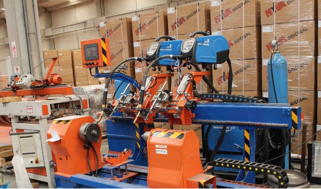
An Automatic Circular Welding Machine is a highly specialized type of welding equipment designed to automatically perform welding operations on circular or cylindrical parts. These machines are essential in industries that require precision welding on pipes, tubes, tanks, and other round workpieces. The automation of these machines eliminates the need for manual intervention, which not only increases production speed but also ensures consistency and high-quality welds across all parts.
The working principle behind an automatic circular welding machine involves rotating the workpiece around its axis while a welding torch or head moves along its circumference. This allows for a continuous, uniform weld to be created around the entire circumference of the material. The process is typically automated with pre-programmed settings to control welding parameters such as speed, heat input, and welding path.
These machines come in several configurations, including orbital welding machines and rotary welding machines. Orbital machines are particularly known for their precision, where the workpiece rotates and the welding head follows a controlled orbital path. These are often used in industries requiring high-precision welding, such as aerospace, pharmaceutical, and food processing industries. On the other hand, rotary welding machines have a rotating fixture that holds the workpiece, while the welding torch remains stationary. The workpiece continuously rotates through the welding zone, making the process ideal for larger or cylindrical parts.
Key features of Automatic Circular Welding Machines include:
- Automation and Control: Automatic circular welding machines often come with advanced digital control systems that allow for precise adjustments to welding parameters. These can include weld speed, heat settings, voltage, and amperage. Automation ensures that the machine can run without continuous operator input, reducing human error and increasing production efficiency.
- High Precision: The automated nature of these machines ensures that each weld is precise and uniform, which is critical for industries where structural integrity and quality are non-negotiable. For example, in the aerospace and pharmaceutical sectors, the welds must be flawless to avoid defects that could compromise the safety or performance of the product.
- Speed and Efficiency: By automating the welding process, these machines reduce the time it takes to weld each part, which increases overall production rates. This is especially important in industries with high-volume manufacturing where time is a critical factor.
- Adaptability to Various Materials: Automatic circular welding machines are designed to weld a wide range of materials, such as stainless steel, carbon steel, alloys, and other metals. The machine can be set up to handle different material thicknesses and diameters, making it highly versatile for various applications.
- Consistent Quality: The automation and control features ensure that each weld is of the same high quality, with uniform heat input and minimal defects. This is especially important in industries like energy, where welded components must withstand extreme conditions, or in industries like food processing, where hygiene and safety are paramount.
- Inspection and Monitoring: Many modern automatic circular welding machines are equipped with real-time monitoring and inspection systems. These systems use sensors and cameras to detect weld quality, including potential defects such as porosity or cracks, during the welding process. This feedback allows for immediate adjustments, ensuring that any issues are addressed without affecting the final product.
- Customization: Automatic circular welding machines can be customized to suit specific manufacturing needs. Features such as adjustable welding heads, rotary tables, and various welding techniques (e.g., TIG, MIG, or laser welding) can be integrated into the machine depending on the application requirements.
Applications of Automatic Circular Welding Machines:
- Pipe and Tube Manufacturing: These machines are ideal for the continuous welding of pipes and tubes in industries such as oil and gas, water treatment, and construction.
- Tank Production: Automatic circular welding machines are often used to weld large, cylindrical tanks used in industries like chemical storage, water tanks, and pressure vessels.
- Automotive Industry: In automotive manufacturing, these machines are used for welding exhaust pipes, fuel tanks, and other cylindrical parts that require high-quality, durable welds.
- Aerospace and Defense: In aerospace applications, circular welding machines ensure the integrity of critical components that must withstand extreme conditions, such as fuel tanks and pressure vessels.
- Food and Beverage: For applications requiring strict hygiene standards, such as the production of tanks and pipelines for the food and beverage industry, automatic circular welding machines ensure clean, safe welds that meet industry standards.
- Pharmaceutical Industry: The high precision of these machines is particularly important in the pharmaceutical industry, where welded parts must meet stringent cleanliness and structural integrity standards.
In conclusion, automatic circular welding machines are essential tools for industries that require high-precision, consistent, and efficient welding of cylindrical parts. With their advanced automation, control systems, and versatility, these machines improve productivity, reduce operational costs, and maintain high weld quality, making them indispensable in modern manufacturing environments.
Automatic circular welding machines are an indispensable part of modern manufacturing, providing significant advantages over manual or semi-automated welding processes. These machines integrate advanced technologies to ensure that welding tasks are executed quickly, accurately, and with minimal human intervention, making them ideal for high-volume production environments where precision and efficiency are critical.
At the core of an automatic circular welding machine is its ability to rotate the workpiece around its axis, while the welding head, typically a stationary or orbiting torch, moves along the circular path to create a continuous and uniform weld. This rotation allows for the even distribution of heat around the entire circumference of the part, ensuring a strong, consistent weld without the risk of uneven heat distribution, which could lead to warping or structural weaknesses.
The automation aspect of these machines allows them to operate with minimal supervision, relying on pre-programmed settings and digital control systems to manage parameters such as welding speed, voltage, amperage, and even the type of welding process used (e.g., MIG, TIG, or laser welding). Once the parameters are set, the machine can run independently, making it possible to achieve the same high-quality welds across thousands of parts, reducing the need for manual adjustments and inspections during the welding process.
One of the standout benefits of automatic circular welding machines is their versatility. These machines can handle a wide range of materials, from lightweight metals like aluminum to more robust materials like stainless steel and titanium. They can also accommodate different material thicknesses, which makes them highly adaptable for various industries, including automotive, aerospace, food and beverage, pharmaceutical, and more.
In addition to their precision and adaptability, these machines also incorporate advanced safety features. Sensors and feedback loops continuously monitor the welding process, identifying issues like undercuts, porosity, or misalignment before they become problems. In some cases, these machines can even adjust the welding process in real-time, ensuring the final product meets the required specifications.
Another advantage of automatic circular welding machines is their ability to significantly improve productivity. With automated processes that can run continuously with minimal downtime, these machines increase the throughput of a factory or workshop, allowing manufacturers to meet higher production demands while reducing the need for additional labor. Furthermore, the consistent weld quality reduces the likelihood of rework, saving both time and materials.
As industries continue to push for greater automation and efficiency, the role of automatic circular welding machines will only expand. Their ability to provide precision, speed, and scalability makes them essential in the production of high-quality cylindrical and circular components. Whether in the creation of pipelines, tanks, automotive parts, or aerospace components, these machines ensure that manufacturers can meet the growing demands for high-performance, durable products.
As automatic circular welding machines continue to evolve, their integration with cutting-edge technologies opens up new possibilities for industries that rely on high-quality, consistent welding. One of the most significant advancements is the incorporation of robotics and AI (Artificial Intelligence) into these systems. With robotic arms or automated welding heads, these machines can now perform welding tasks with even more precision and flexibility, including the ability to weld complex geometries or intricate shapes. AI systems can analyze welding parameters in real time and optimize the process dynamically, further improving efficiency and reducing the chance of defects.
Another technological advancement is the use of advanced sensors and monitoring systems. These sensors can detect variations in material properties, temperature fluctuations, and even microscopic defects during the welding process. The data gathered is continuously analyzed by the machine’s control system, which can make real-time adjustments to ensure the highest possible quality for each weld. This level of continuous feedback is particularly beneficial for industries where weld integrity is critical, such as aerospace or nuclear energy, where even the smallest flaw can have catastrophic consequences.
Additionally, the integration of Internet of Things (IoT) capabilities in automatic circular welding machines allows for real-time remote monitoring and maintenance. Operators can access machine data from anywhere, providing them with the ability to monitor performance, track welding quality, and perform diagnostic checks remotely. This capability reduces downtime and enhances the ability to perform predictive maintenance, minimizing the risk of machine failure and extending the lifespan of the equipment.
Customization options have also improved in modern automatic circular welding machines. With software that can be tailored to specific applications, manufacturers can create customized welding patterns and parameters for different types of materials, thicknesses, and geometries. This flexibility ensures that the machine can meet a broad range of welding needs, from simple cylindrical parts to more complex, multi-functional components that require intricate weld designs.
In terms of energy efficiency, newer models of automatic circular welding machines are designed to minimize power consumption without sacrificing performance. With features like variable speed drives and efficient cooling systems, these machines are becoming more sustainable and cost-effective, offering savings on energy costs while maintaining optimal performance.
Another trend is the use of wireless technology to simplify the connection between the welding equipment and other systems, such as control panels or inspection devices. Wireless systems reduce the need for physical connections and cables, which can be cumbersome in complex setups, and improve the machine’s mobility and flexibility within the workspace.
The growing trend of sustainability in manufacturing also plays a role in the design of modern circular welding machines. Manufacturers are increasingly focused on reducing material waste, optimizing energy use, and producing fewer harmful emissions during the welding process. Machines are now more efficient in terms of material handling, which results in less scrap and wasted energy, contributing to environmentally friendly practices in manufacturing.
As industries continue to push for higher production rates, lower costs, and better product quality, automatic circular welding machines are becoming more integrated into production lines. Their ability to handle large volumes of work, provide high-quality welds, and minimize human intervention has made them an essential tool in a variety of manufacturing sectors.
The future of automatic circular welding machines looks even more promising with continuous improvements in artificial intelligence, sensor technology, robotics, and data analytics. These innovations will help further refine welding quality, enhance productivity, and reduce costs, enabling manufacturers to meet the demands of increasingly complex, high-precision applications in a wide range of industries.
In conclusion, automatic circular welding machines are transforming modern manufacturing. With the combination of robotics, AI, advanced sensors, and connectivity, these machines are pushing the boundaries of what is possible in welding technology. As automation continues to evolve, these systems will not only improve efficiency and product quality but will also make manufacturing processes more flexible, adaptable, and sustainable, offering significant advantages in the highly competitive global market.
Longitudinal Welding Machine
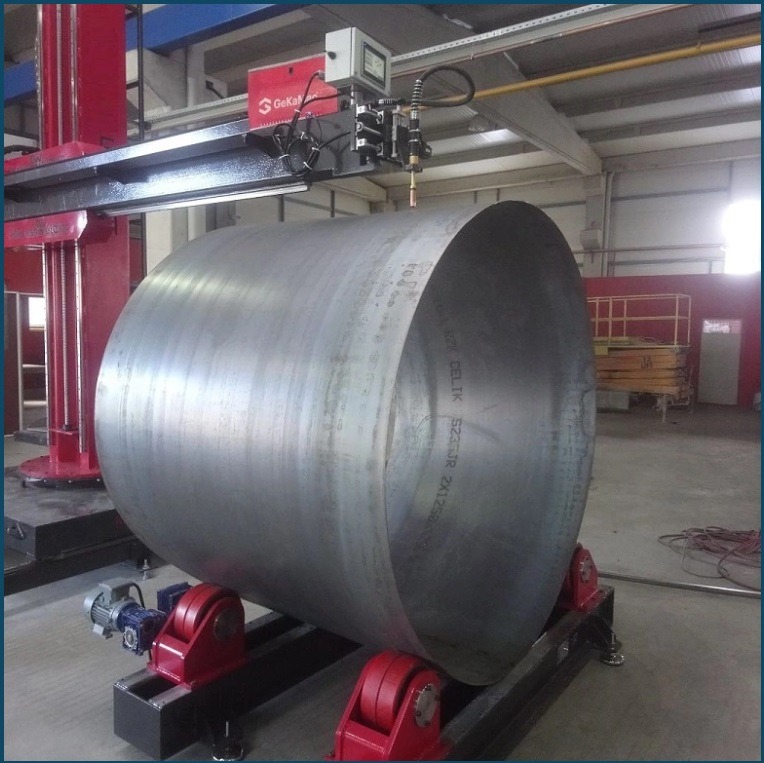
A Longitudinal Welding Machine is a specialized piece of equipment used for welding along the length of a workpiece, particularly for long, straight materials such as pipes, tubes, and plates. The main function of a longitudinal welding machine is to create continuous, high-quality welds along the longitudinal axis (the length) of cylindrical or flat parts, ensuring uniformity and structural integrity across the entire welded seam. This type of welding is essential in various industries, including pipe manufacturing, tank production, automotive, and shipbuilding, where long, linear welds are required for joining metal parts.
These machines are typically designed to automate the welding process, reducing human error, increasing production speed, and ensuring consistent weld quality. They are used in a variety of applications, from manufacturing pipelines and tanks to welding automotive chassis and structural components. By using longitudinal welding machines, manufacturers can achieve high production rates while maintaining the integrity and durability of the welded parts.
How It Works:
The operation of a longitudinal welding machine typically involves the workpiece being moved along a fixed path while a welding head or torch follows the length of the material. The workpiece can be a flat plate, a pipe, or a tube, and the welding machine ensures that the entire seam along the length is welded, often in a continuous motion.
There are various welding methods that can be used on a longitudinal welding machine, including:
- Tungsten Inert Gas (TIG) Welding: Known for producing high-quality welds with precise control, TIG welding is often used for thin materials or when a clean, strong weld is required.
- Metal Inert Gas (MIG) Welding: This process uses a consumable wire electrode and is typically faster than TIG welding, making it more suitable for higher volume production.
- Submerged Arc Welding (SAW): In submerged arc welding, the arc is shielded by a blanket of flux, making it ideal for thicker materials and producing high-quality welds with minimal spatter.
- High-Frequency Induction (HFI) Welding: This method is commonly used in pipe manufacturing, where high-frequency electrical currents are used to heat and weld the edges of the material.
Key Components:
- Welding Head: The head contains the welding torch or electrode and moves along the length of the workpiece to create the weld. It is often adjustable to ensure precision in weld placement.
- Feed Mechanism: The workpiece is fed into the welding machine, and the speed at which it moves can be adjusted depending on the material, thickness, and welding process used.
- Cooling System: High heat generated during the welding process can affect both the machine and the workpiece. A cooling system is typically integrated to maintain optimal temperature conditions and prevent warping or damage.
- Control Systems: Modern longitudinal welding machines are equipped with advanced control systems that monitor and adjust parameters like welding speed, voltage, amperage, and gas flow to ensure consistent weld quality. These systems may also include sensors for real-time feedback, allowing adjustments during the process to address any issues immediately.
Advantages of Longitudinal Welding Machines:
- Efficiency: By automating the welding process, longitudinal welding machines can handle high-volume production, significantly improving the efficiency of the manufacturing process.
- Consistency: Automated systems ensure uniformity across all welded parts, reducing the likelihood of defects and ensuring high-quality welds.
- Reduced Labor: These machines require less manual intervention, which reduces labor costs and minimizes human error during the welding process.
- Versatility: Longitudinal welding machines can be adapted to different materials, thicknesses, and types of welds, making them highly versatile for a wide range of industrial applications.
- Speed: With continuous feeding and automated welding, these machines can operate at high speeds, making them ideal for mass production.
- Quality Control: Automated welding allows for precise control over welding parameters, which helps maintain high-quality standards across all parts being welded.
Applications of Longitudinal Welding Machines:
- Pipe Manufacturing: One of the most common applications for longitudinal welding machines is in the production of welded pipes and tubes, especially in industries like oil and gas, water treatment, and construction. These machines are used to weld the longitudinal seam of the pipe, which is critical for its strength and reliability.
- Tank Production: In industries that produce large tanks, such as for chemical or fuel storage, longitudinal welding machines are used to weld the seams along the length of the tank’s cylindrical walls.
- Automotive Industry: These machines are used to weld parts like chassis, exhaust systems, and other long metal components found in automotive manufacturing.
- Shipbuilding: Longitudinal welding is crucial for welding the hulls of ships, as these long seams are essential for maintaining the structural integrity of the vessel.
- Steel Fabrication: In structural steel fabrication, longitudinal welding machines are used to create strong, durable welds on beams, plates, and other large metal components used in construction projects.
Advanced Features:
In modern longitudinal welding machines, technological advancements such as robotics, vision systems, and automated inspection play an increasingly important role. Robots can handle the welding head with high precision, while vision systems are used to inspect the welds in real time, ensuring that any defects can be addressed immediately. Some machines are also equipped with adaptive control systems that automatically adjust the welding parameters based on changes in material thickness, composition, or alignment during the welding process.
Conclusion:
Longitudinal welding machines are vital for industries that require high-quality, high-efficiency, and high-volume welding of long, straight seams. By automating the welding process, these machines reduce labor costs, improve the quality of the weld, and ensure faster production times. Their versatility and ability to adapt to various materials and welding processes make them indispensable in applications ranging from pipeline manufacturing to automotive production and shipbuilding. As technologies continue to improve, longitudinal welding machines are likely to become even more precise, faster, and energy-efficient, further enhancing their role in modern manufacturing.
Longitudinal welding machines are integral to many industries due to their capacity to provide high-quality, efficient welding for long, straight seams. The automation provided by these machines ensures consistency, reducing the likelihood of defects and allowing manufacturers to produce large quantities of welded products quickly and reliably. By eliminating manual processes and human error, these machines can increase the overall production output, especially in industries that deal with high volumes of welded materials.
One of the primary benefits of using longitudinal welding machines is the improved weld quality. Automated systems can precisely control parameters such as welding speed, current, voltage, and heat input, leading to cleaner, stronger, and more consistent welds. This level of control is particularly important in industries that require high structural integrity, such as in the aerospace, energy, and automotive sectors. For example, in the manufacturing of fuel tanks, pressure vessels, and pipelines, the strength and durability of the weld are critical to the safety and reliability of the finished product.
Additionally, speed is another significant advantage. Since the process is automated and designed for continuous operation, longitudinal welding machines can achieve much faster welding rates compared to manual methods. For industries like pipe manufacturing, where large quantities of material need to be welded in a relatively short time, this speed is vital for meeting production targets. The high throughput and low downtime also contribute to a cost-effective manufacturing process, making it an ideal choice for mass production.
Another area where longitudinal welding machines excel is flexibility. While these machines are primarily designed for welding long, linear seams, they can often be adapted to different welding processes or configurations, depending on the needs of the manufacturer. For example, switching between different welding methods like MIG, TIG, or submerged arc welding is possible in some advanced machines, making them suitable for a wide range of materials, from thin sheets to thicker, high-strength alloys. This versatility allows manufacturers to use a single machine for various products, reducing the need for multiple machines and minimizing space requirements in the production facility.
In terms of maintenance and operational efficiency, modern longitudinal welding machines are designed with user-friendly control systems that allow operators to monitor performance and make adjustments as needed. Some machines include diagnostic tools that can predict when maintenance is required, helping to avoid unexpected downtimes. This predictive maintenance reduces the overall cost of repairs and ensures the machine operates at peak efficiency.
The integration of real-time monitoring and feedback systems further enhances the capabilities of longitudinal welding machines. Through the use of sensors and cameras, these systems can detect issues such as poor weld penetration, misalignment, or inadequate heat distribution during the welding process. When a potential issue is identified, the system can automatically adjust parameters or alert the operator to address the problem before it results in a defect. This constant monitoring ensures that the quality of the weld remains consistently high, even in long production runs.
Energy efficiency is another growing concern in modern manufacturing, and longitudinal welding machines have evolved to become more energy-efficient. With advanced features like variable-speed motors and optimized cooling systems, these machines reduce unnecessary energy consumption, lowering operational costs and environmental impact. The efficient use of energy in these systems not only contributes to lower operational costs but also supports sustainability efforts in the manufacturing industry.
Moreover, the integration of Industry 4.0 technologies is transforming longitudinal welding machines into smarter systems. With data analytics and machine learning algorithms, manufacturers can gain deeper insights into their welding processes. This allows them to identify trends, predict issues, and optimize workflows for greater efficiency. For instance, by analyzing historical data, operators can adjust machine settings based on past performance to improve the quality and speed of future welds.
Longitudinal welding machines are also becoming more customizable. Manufacturers can adjust the machine’s settings to accommodate different sizes, materials, and welding processes, making it easier to handle a wide variety of parts and production requirements. Whether it’s adjusting the feed rate for a thicker workpiece or configuring the system for a specific type of weld, the machine can be tailored to meet specific needs.
Conclusion:
In summary, longitudinal welding machines are pivotal in modern manufacturing, offering unparalleled precision, speed, and versatility in welding long seams. Their ability to automate the process enhances consistency, reduces labor costs, and improves overall efficiency, making them indispensable in industries ranging from pipeline construction to automotive manufacturing. As technology continues to advance, these machines will only become more efficient, smarter, and capable of handling increasingly complex and diverse welding tasks, solidifying their role as a cornerstone of automated production systems.
As longitudinal welding machines continue to evolve, their role in improving manufacturing processes becomes increasingly significant. The integration of cutting-edge technologies like robotics, artificial intelligence (AI), and data analytics has led to even higher levels of efficiency, quality, and adaptability. These advancements are transforming longitudinal welding machines into highly intelligent systems capable of continuous self-optimization, enabling manufacturers to meet the growing demand for high-quality, high-volume production.
One of the key developments is the integration of robotic arms in longitudinal welding machines. These robotic systems bring greater flexibility and precision to the welding process. By using multi-axis robotic arms, manufacturers can weld complex geometries or achieve extremely precise welds along irregular or curved surfaces, in addition to the traditional straight seams. This allows manufacturers to produce a wider range of products without the need to switch to different machines or systems, resulting in greater overall production efficiency.
The inclusion of artificial intelligence (AI) and machine learning in modern longitudinal welding machines further enhances their capabilities. AI algorithms can analyze vast amounts of data collected from sensors and cameras during the welding process, allowing the system to automatically adjust welding parameters like speed, voltage, and heat. This real-time feedback loop ensures that the welding process is continuously optimized, minimizing defects and improving the overall quality of the weld. Additionally, AI-based systems can detect anomalies, such as poor fusion or porosity, during the welding process and make immediate corrective adjustments, reducing the need for manual intervention.
Furthermore, these AI systems can analyze trends over time, learning from past welds to make predictive adjustments for future welding operations. This predictive maintenance capability is particularly valuable because it allows operators to address potential issues before they cause any downtime or defects. By predicting wear and tear on critical components, such as welding torches or motors, the system can schedule maintenance proactively, reducing the risk of unplanned stoppages.
Data analytics is another powerful tool being integrated into longitudinal welding machines. With the increasing volume of data being collected by sensors, cameras, and monitoring systems, manufacturers can now use advanced data analysis tools to gain actionable insights into the entire welding process. These insights can be used to optimize welding parameters, reduce material waste, and improve production rates. For example, analyzing the temperature profiles of a weld during the process can help adjust the cooling rates to prevent overheating or distortion of the material.
The integration of real-time monitoring and smart sensors is also enhancing the capabilities of longitudinal welding machines. These sensors can continuously track variables like arc stability, welding speed, and material flow, providing immediate feedback that allows for automatic adjustments in the welding process. This capability ensures the consistency and quality of every weld, even during long production runs. If any deviation from the desired welding parameters is detected, the system can alert the operator or automatically adjust the process to maintain the quality standards.
Another emerging trend is the use of advanced welding processes in longitudinal welding machines. For instance, the integration of laser welding technology into these systems enables high-precision welding with minimal heat input, reducing the likelihood of material distortion and improving the overall quality of the weld. Laser welding is particularly useful in applications requiring very fine, clean, and precise welds, such as in the electronics and medical device industries. Longitudinal welding machines equipped with laser welding technology can perform these delicate welds at a much faster rate than traditional welding methods.
Moreover, cobot integration—where collaborative robots (cobots) work alongside human operators—has further expanded the scope of longitudinal welding machines. Cobots can assist in loading and unloading workpieces, adjusting welding parameters, or performing secondary operations like grinding or polishing. The use of cobots not only reduces operator fatigue but also increases safety and efficiency on the production floor by reducing manual handling of heavy or dangerous parts.
Energy efficiency remains a major focus in the development of modern longitudinal welding machines. Newer machines are designed with optimized energy usage, reducing both operational costs and environmental impact. Features like variable frequency drives (VFDs) help control motor speeds more precisely, allowing for energy savings during the welding process. Additionally, improved cooling systems and heat recovery technologies contribute to maintaining the machine’s efficiency while minimizing energy consumption.
Sustainability is also becoming increasingly important in the context of longitudinal welding. Manufacturers are focusing on reducing the environmental impact of welding processes by minimizing material waste and improving resource efficiency. Some longitudinal welding machines are equipped with technologies that reduce fumes and harmful emissions, such as integrated fume extraction systems, which not only protect the environment but also improve the working conditions for operators. Moreover, the precise nature of modern welding machines leads to less material waste, as the welds are more consistent, requiring less rework or scrap.
Longitudinal welding machines are also evolving to become more user-friendly and easier to operate. With the integration of advanced human-machine interfaces (HMIs), operators can monitor the welding process more effectively, adjust settings intuitively, and gain access to real-time performance data. These intuitive interfaces reduce the learning curve for new operators and allow experienced workers to focus on overseeing the machine’s operations rather than troubleshooting issues. Moreover, remote diagnostics and cloud-based support enable manufacturers to troubleshoot and resolve issues without needing on-site visits, minimizing downtime and improving overall equipment efficiency.
Conclusion:
In conclusion, the evolution of longitudinal welding machines is driven by advancements in automation, artificial intelligence, robotics, and data analytics, all of which contribute to higher efficiency, quality, and flexibility in the welding process. These machines are becoming increasingly intelligent, adaptable, and energy-efficient, making them indispensable in industries that rely on high-precision, high-volume welding. Whether it’s incorporating predictive maintenance, laser welding, or cobot collaboration, longitudinal welding machines are poised to continue shaping the future of manufacturing by enhancing productivity and ensuring consistently high-quality results.
Circular Welding System
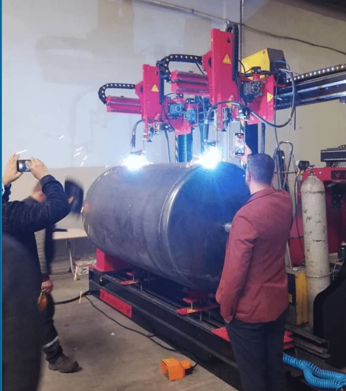
A circular welding system is a specialized type of automated welding equipment designed to weld around the circumference of cylindrical or circular workpieces. This system is particularly important in industries that require precise and continuous welds on parts with a circular shape, such as pipes, tanks, reactors, and other cylindrical structures. The circular welding system ensures consistent, high-quality welds along the circumference of the workpiece, making it essential for a range of applications in the automotive, aerospace, chemical, energy, and construction industries.
How It Works:
The fundamental concept behind a circular welding system is to rotate the workpiece around its axis while the welding torch or head moves along the circular path, creating a continuous and uniform weld. There are two main configurations for circular welding systems:
- Rotary Welding Systems: In this configuration, the workpiece is held stationary, while a rotating welding head or torch moves along the circumference. This type of system is often used for large cylindrical parts, such as tanks or pressure vessels, where the part rotates during the welding process.
- Rotating Workpiece Systems: In this design, the workpiece itself rotates while the welding head or torch stays stationary. The workpiece’s rotation allows the welding system to create a continuous seam around the entire circumference. This configuration is commonly used for smaller cylindrical parts, such as pipes and tubes.
The system usually operates in a fully automated manner, allowing for a continuous, high-speed welding process that can be programmed for specific parameters such as welding speed, amperage, and voltage. These settings ensure a uniform, high-quality weld along the entire circumference of the piece.
Key Components:
- Rotational Mechanism: This component is responsible for rotating the workpiece. The rotational speed is carefully controlled to ensure that the welding head maintains the correct pace to produce a uniform and high-quality weld.
- Welding Head/Torch: The welding head is typically positioned either stationary or on a moving carriage, depending on the system design. The torch is the part that applies the heat to the material to create the weld bead. It can be equipped for different welding processes such as Tungsten Inert Gas (TIG), Metal Inert Gas (MIG), Submerged Arc Welding (SAW), or Laser Welding.
- Control System: Modern circular welding systems are equipped with programmable logic controllers (PLCs) or digital control systems that allow operators to input and adjust welding parameters. These controls manage important factors such as speed, heat input, and weld pattern, ensuring that the weld is performed consistently and within specified tolerances.
- Feed Mechanism: In some circular welding systems, especially those using wire-fed processes (like MIG or SAW), a wire feed mechanism is included to supply the welding material into the weld pool. The feed rate is typically controlled to match the welding speed.
- Cooling System: Welding generates significant heat, and a cooling system is necessary to prevent overheating of both the workpiece and the machine itself. Cooling is especially important in high-heat welding processes like TIG or MIG, where maintaining an optimal temperature is critical for high-quality welds.
- Safety and Inspection Features: Modern circular welding systems often include various safety features such as automatic shutoffs in case of malfunction, protective shielding to contain the welding arc, and fume extraction systems to maintain a safe work environment. Additionally, some systems include vision systems or in-process inspection technologies to detect defects like porosity or misalignment during the welding process.
Types of Welding Processes Used in Circular Welding Systems:
- Tungsten Inert Gas (TIG) Welding: Known for its high precision, TIG welding is often used in applications that require clean and strong welds, such as aerospace and medical devices. The use of a non-consumable tungsten electrode allows for a high degree of control over the welding process.
- Metal Inert Gas (MIG) Welding: This is a faster, more cost-effective process compared to TIG welding and is commonly used for welding thicker materials. MIG welding is more automated and is ideal for high-volume production.
- Submerged Arc Welding (SAW): This process is used for heavy-duty applications where thicker materials are involved. The weld is shielded by a layer of flux, allowing for deep penetration and a high-quality finish.
- Laser Welding: Laser welding is a highly precise and efficient process that uses a focused laser beam to melt and join the material. It is used for high-speed welding with minimal heat-affected zones, making it suitable for thin materials and high-precision applications.
- Electroslag Welding: This process is used for welding thick materials and is often seen in heavy industries like shipbuilding and pressure vessel manufacturing. It provides high penetration and strength for large, thick-walled components.
Advantages of Circular Welding Systems:
- Consistency and Quality: Automated circular welding systems ensure uniform heat distribution, which results in consistent welds with minimal defects. The precise control of welding parameters eliminates the risk of human error, making the system ideal for high-quality production.
- Increased Production Speed: Automated welding systems work much faster than manual processes, significantly increasing throughput and production rates. The ability to rotate the workpiece continuously allows for faster welding of long seams, which is essential for large-scale manufacturing.
- Reduced Labor Costs: Circular welding systems reduce the need for skilled labor since the process is highly automated. This results in cost savings, as fewer operators are needed to manage the system.
- Flexibility: Many circular welding systems can be configured for a variety of materials and welding processes. This flexibility is essential for manufacturers that produce a wide range of products with different material types, thicknesses, and weld requirements.
- Energy Efficiency: Modern circular welding machines are designed with energy efficiency in mind, using variable speed drives, advanced cooling systems, and optimized welding techniques that minimize energy consumption.
- Safety: The fully automated nature of the circular welding system reduces the exposure of operators to hazardous conditions like the high temperatures, ultraviolet radiation, and fumes produced during the welding process.
- Reduced Material Waste: With precise control over the weld bead and heat input, circular welding systems can minimize material waste, leading to a more efficient use of raw materials and reduced production costs.
Applications:
- Pipe and Tube Manufacturing: Circular welding systems are frequently used in the production of pipes and tubes, particularly in industries like oil and gas, petrochemical, and water treatment, where pipes are welded continuously along their circumferences.
- Tank and Pressure Vessel Production: Many industries, including chemical, pharmaceutical, and food processing, require tanks and pressure vessels with welded seams along their circumference. Circular welding machines can efficiently handle these large, cylindrical components.
- Automotive and Aerospace: Circular welding systems are used in automotive and aerospace applications, where precise and strong welds are required for exhaust systems, fuel tanks, and structural components.
- Shipbuilding: The shipbuilding industry also relies on circular welding systems for welding cylindrical sections of ships, submarines, and other maritime vessels.
- Storage Tanks and Silos: Circular welding machines are commonly used to weld large storage tanks, silos, and other cylindrical containers, ensuring structural integrity and leak-tight welds.
Conclusion:
In summary, circular welding systems are critical for industries that require high-quality, efficient welding of cylindrical or circular parts. Their automated nature, combined with advanced welding techniques like TIG, MIG, and laser welding, ensures that manufacturers can produce strong, consistent welds at a high rate of speed and with minimal material waste. As technology continues to advance, these systems will only become more precise, versatile, and energy-efficient, further expanding their role in modern manufacturing.
As circular welding systems continue to evolve, several emerging trends and technologies are enhancing their capabilities and further expanding their range of applications. The integration of advanced automation, AI-driven process control, and industry-specific customization is driving the next generation of circular welding systems, enabling even greater precision, efficiency, and adaptability.
Emerging Technologies in Circular Welding Systems:
- Industry 4.0 Integration: The rise of Industry 4.0 technologies is transforming circular welding systems into smarter, connected machines. By integrating Internet of Things (IoT) sensors and devices, circular welding systems can continuously monitor and collect real-time data during the welding process. This data is transmitted to cloud-based systems or central control hubs, allowing manufacturers to remotely track performance, adjust settings, and perform diagnostics. Industry 4.0-enabled welding systems not only improve operational efficiency but also enhance predictive maintenance, reducing downtime and avoiding unexpected equipment failures.
- AI and Machine Learning for Process Optimization: With the integration of artificial intelligence (AI) and machine learning, modern circular welding systems can autonomously adjust welding parameters based on real-time data analysis. By continuously analyzing data from sensors (such as heat, voltage, and current) during the welding process, AI algorithms can identify patterns and predict potential issues like weld defects, misalignment, or material inconsistencies. The system can then make on-the-fly adjustments to correct these issues, ensuring optimal weld quality with minimal manual intervention. This level of process optimization can lead to faster production cycles, less material waste, and improved weld consistency over time.
- Advanced Weld Inspection Systems: As the demand for higher-quality and defect-free welds increases, so does the importance of in-process weld inspection. Circular welding systems are increasingly equipped with advanced visual and thermal inspection systems, such as ultrasonic testing, X-ray imaging, and infrared sensors. These systems continuously monitor the weld during the process, allowing for real-time detection of defects like cracks, porosity, or undercutting. By automatically detecting potential flaws, these inspection technologies provide early warnings, enabling operators to take corrective action before defective parts are produced. This reduces the need for costly post-production inspections and rework, improving overall productivity.
- Robot-Assisted Welding and Automation: The growing use of robot-assisted welding in circular welding systems allows for greater flexibility and precision. Robotic arms, equipped with advanced sensors and vision systems, can move around the workpiece or adjust the welding parameters during the process. This technology is particularly valuable for handling complex geometries or specialized welding tasks that require high accuracy. Robots can also be programmed to perform secondary operations, such as cleaning, grinding, or inspecting the welds, further reducing the need for manual labor.
- Multi-Process Welding: Many modern circular welding systems are designed to support multi-process welding, which allows operators to switch between different welding techniques depending on the material, thickness, and desired weld characteristics. For example, a system may be capable of switching from TIG welding to MIG welding or laser welding, all within the same setup. This flexibility helps manufacturers save time and costs by using one system to meet various welding needs, especially when working with a diverse range of materials, such as steel, stainless steel, or aluminum.
- Additive Manufacturing and Hybrid Welding: The fusion of traditional welding techniques with additive manufacturing (3D printing) technologies is also gaining traction in circular welding systems. In hybrid welding, traditional welding methods are combined with additive manufacturing techniques to build up material layers in areas that require additional reinforcement. This capability is especially useful in industries that require complex geometries or repairs to high-value components. Hybrid systems also enable the creation of multi-material welds, where different materials are combined to optimize the final part’s strength, weight, or other properties.
- Enhanced Energy Efficiency: As manufacturers look for ways to lower their environmental footprint and reduce operational costs, energy-efficient circular welding systems are becoming increasingly important. Innovations like energy recovery systems, high-efficiency welding power sources, and improved cooling systems contribute to the reduced energy consumption of circular welding processes. By optimizing the energy used during the welding process, manufacturers can lower costs, improve their sustainability, and increase the overall efficiency of their operations.
- Advanced Cooling Systems: Effective cooling is critical in circular welding, especially when dealing with high-heat welding processes like laser welding or submerged arc welding. To address this, manufacturers are developing more efficient cooling systems, such as closed-loop coolant systems, which are better at maintaining the welding head and workpiece at optimal temperatures. These cooling systems not only increase the lifespan of the machine components but also help maintain the quality of the weld by preventing overheating or material distortion.
Benefits of Advancements in Circular Welding Systems:
- Higher Precision and Consistency: With the integration of advanced sensors, AI, and robotic technologies, modern circular welding systems offer higher precision and consistency than ever before. This is especially important in industries such as aerospace and automotive manufacturing, where even minor defects in welds can lead to product failures.
- Reduced Operational Costs: The adoption of automation, predictive maintenance, and energy-efficient systems significantly reduces operational costs. These advancements minimize downtime, reduce scrap rates, and lower energy consumption, contributing to more cost-effective production.
- Greater Flexibility and Customization: The ability to switch between multiple welding processes, utilize robotic arms, and integrate advanced inspection technologies makes modern circular welding systems more flexible and customizable. Manufacturers can adapt to a wider range of materials, part sizes, and welding requirements, enhancing their ability to serve diverse industries and production demands.
- Improved Safety: Automation reduces the need for human involvement in hazardous aspects of the welding process, such as exposure to high heat, intense light, and fumes. Additionally, AI-based inspection systems can detect potential hazards before they escalate, further improving workplace safety.
- Faster Turnaround Times: By automating the welding process and incorporating real-time adjustments, modern circular welding systems can significantly reduce production time. The ability to weld large, complex parts continuously without the need for frequent manual intervention accelerates production, which is crucial for industries with high demand or tight deadlines.
- Sustainability: Energy-efficient technologies, coupled with waste-reducing welding practices, help reduce the environmental impact of circular welding processes. By optimizing energy use, reducing waste materials, and improving process accuracy, manufacturers contribute to sustainability while enhancing their bottom line.
Applications in Emerging Markets:
- Renewable Energy: Circular welding systems are increasingly used in the production of components for the renewable energy industry, such as wind turbines, solar panel frames, and storage tanks for biogas and other renewable energy sources. The ability to produce strong, leak-proof welds is crucial in these applications to ensure long-lasting, reliable performance.
- Electric Vehicles (EVs): As the demand for electric vehicles continues to grow, circular welding systems are playing a pivotal role in the production of components like battery casings, electric motor housings, and charging stations. The precise, high-quality welds required in these applications are perfectly suited for automation using circular welding technologies.
- Medical Device Manufacturing: The medical device industry, especially in the production of surgical instruments, diagnostic equipment, and implants, requires highly precise and clean welding processes. Circular welding systems, particularly those that use TIG or laser welding, are ideal for ensuring the integrity and sterility of these critical components.
- Oil and Gas Industry: Circular welding systems are essential in the oil and gas sector for manufacturing high-strength pipelines, pressure vessels, and storage tanks. The ability to produce strong, durable welds that can withstand extreme conditions, such as high pressure and corrosive environments, makes circular welding systems indispensable for these applications.
Conclusion:
As circular welding systems continue to advance with the integration of automation, AI, robotics, and data analytics, their capabilities are expanding beyond traditional applications to meet the demands of emerging industries. These innovations provide manufacturers with the tools they need to increase precision, efficiency, and sustainability in their welding operations. With their versatility, speed, and quality, circular welding systems will remain a key component in the manufacturing processes of a wide variety of industries, from renewable energy to aerospace.
The continuous development and refinement of circular welding systems hold the potential for even greater advancements in efficiency, quality, and versatility, all of which will play an increasingly important role in industries ranging from construction and automotive to aerospace and energy. The evolution of these systems is closely tied to broader technological trends, including automation, smart manufacturing, and sustainability. These trends are not only optimizing the welding process but also contributing to new applications that were previously not possible or economically feasible.
Further Technological Innovations in Circular Welding:
- Hybrid and Advanced Welding Techniques:
- As the demand for higher-performance materials grows, hybrid welding techniques are gaining traction. In a hybrid welding system, multiple processes are combined in one machine to take advantage of their individual strengths. For example, laser welding combined with MIG welding or laser welding combined with TIG welding allows manufacturers to achieve deep penetration with high welding speeds while minimizing heat distortion and achieving cleaner, more precise welds.
- The combination of additive manufacturing with traditional welding methods, known as hybrid additive-subtractive manufacturing, is also making significant strides. This approach allows for the deposition of material while simultaneously using welding methods to create structures that were previously difficult or time-consuming to build, such as intricate geometries and custom components.
- Advanced Materials for Welding:
- The use of new, high-strength, lightweight materials in industries like automotive and aerospace is pushing the boundaries of what circular welding systems can achieve. Materials like titanium alloys, high-strength steels, and advanced composites often require specialized welding techniques. Circular welding systems are evolving to handle these materials, utilizing advanced power sources and precision controls that ensure the integrity of the welds without compromising the material properties.
- Stainless steel, aluminum, and copper alloys are becoming more common in many industrial applications. As a result, circular welding systems must be equipped with specialized torches and wire feeds to ensure optimal compatibility with these materials, which often require different parameters for welding.
- Real-Time Process Control and Adaptive Feedback Loops:
- Smart sensors and adaptive feedback systems in circular welding systems are enabling even greater precision. These sensors monitor factors such as temperature, arc behavior, and material deformation in real-time, sending data to the system’s control unit. Based on the sensor inputs, the system automatically adjusts parameters like welding speed, heat input, and voltage. This real-time process control not only ensures weld quality but also reduces the likelihood of defects and minimizes the need for post-welding inspections.
- For example, adaptive welding systems can detect slight variations in the material surface, such as thickness changes or surface contamination, and adjust the welding parameters to compensate for these inconsistencies. This results in a more robust and flexible welding process that can adapt to real-world variations in materials and environmental conditions.
- Integration with Digital Twins:
- The concept of digital twins, which involves creating a virtual replica of a physical system, is starting to be applied to welding systems. By integrating a digital twin into a circular welding machine, manufacturers can simulate the entire welding process before it takes place. This helps identify potential issues in the design, process parameters, or materials before they arise in the real world. Using simulations, manufacturers can optimize welding strategies, reduce trial-and-error, and predict the outcomes of complex welds, ensuring higher-quality results right from the start.
- A digital twin can also enable predictive analytics, forecasting when a machine will require maintenance or when components may wear out, allowing manufacturers to schedule downtime more effectively and minimize unexpected interruptions.
The Role of Automation and Robotics:
- Collaborative Robots (Cobots):
- Cobots are increasingly being integrated into circular welding systems, particularly for tasks like loading and unloading workpieces, changing consumables, or performing secondary operations such as grinding, polishing, or inspecting welds. Cobots work alongside human operators, assisting them in tasks that require precision and dexterity. By reducing the amount of manual labor, these cobots not only increase productivity but also reduce the risk of operator fatigue and injury.
- The integration of cobots with vision systems and AI algorithms allows the robots to perform tasks with high accuracy. For example, a cobot can automatically adjust the positioning of a workpiece during the welding process, ensuring the alignment remains perfect throughout the cycle. This reduces human error and increases the consistency of the welds.
- Automated Workpiece Handling:
- Advanced automated workpiece handling systems are designed to move large or heavy cylindrical components into position for welding. These systems utilize conveyors, automated clamps, and rotating tables to position the workpieces accurately and securely during the welding process. By automating this part of the operation, circular welding systems can improve throughput and reduce human labor requirements, while also enhancing safety by minimizing the risk of manual handling accidents.
- Automated Welding Heads:
- Modern circular welding systems often use automated welding heads that can move in all directions along the workpiece. These welding heads are capable of adjusting to changes in the workpiece’s geometry or material characteristics, ensuring that each weld is uniform and defect-free. Articulated robotic arms or linear slides enable the welding head to follow intricate or irregular contours along the cylinder or tube.
Environmental Impact and Sustainability:
- Energy-Efficient Systems:
- As industries become more focused on sustainability, there is a growing emphasis on reducing energy consumption in welding processes. New innovations in power source design, such as inverter-based power supplies, have led to more energy-efficient circular welding machines. These power sources use less electricity and produce lower heat, which reduces operational costs and the overall carbon footprint of manufacturing processes.
- Additionally, energy recovery systems are becoming more common in circular welding systems. These systems capture excess heat generated during welding and use it to preheat materials or support other parts of the production process, further enhancing energy efficiency.
- Fume Extraction and Pollution Control:
- The fume extraction systems in modern circular welding machines are also advancing to improve air quality in welding environments. These systems use high-efficiency filters to capture harmful fumes and particulate matter generated during the welding process, ensuring that the working environment remains safe for operators. Some advanced systems also incorporate carbon capture technologies to mitigate the release of pollutants into the atmosphere, aligning with the growing need for environmentally responsible manufacturing practices.
- Reduction in Material Waste:
- As circular welding systems continue to improve, they are contributing to a reduction in material waste. The precision of modern welding processes ensures that less filler material is required, and the risk of material defects is minimized, reducing the amount of scrap material. The exact control over the welding process also allows for better material use, which is particularly important when working with costly or specialized materials.
- Eco-Friendly Consumables:
- The development of eco-friendly consumables, such as welding wires and fluxes, has also played a role in reducing the environmental impact of welding operations. These consumables are designed to minimize harmful by-products and to work effectively in conjunction with the latest circular welding systems.
Conclusion:
As circular welding systems continue to evolve, they are becoming more advanced, adaptable, and environmentally conscious. The integration of technologies like AI, robotics, advanced sensors, and predictive maintenance is enhancing the quality, speed, and precision of welding processes, enabling manufacturers to meet the growing demands for complex, high-performance products. These systems are also becoming more sustainable, with innovations in energy efficiency, material waste reduction, and pollution control helping manufacturers reduce their environmental footprint.
Circular welding systems will continue to be at the forefront of manufacturing innovation, providing solutions for industries as diverse as aerospace, automotive, renewable energy, and medical devices. By embracing new technologies and trends, manufacturers can not only improve their production capabilities but also position themselves for long-term success in an increasingly competitive global market.
Rotary Pipe Flange Welding Machine
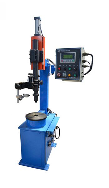
A Rotary Pipe Flange Welding Machine is a specialized piece of equipment designed for the welding of flanges onto pipes. This machine is widely used in industries where pipe flanges need to be welded to pipelines, such as in the oil and gas, chemical, power generation, and construction sectors. These systems provide efficient and precise welding of flanges, ensuring secure and leak-proof connections between pipes in various applications.
Here’s an overview of a Rotary Pipe Flange Welding Machine:
Key Components of the Machine:
- Rotary Table:
- The core feature of the machine is a rotary table or rotating fixture that holds the pipe while the welding process occurs. This table is motorized and can rotate the pipe flange at a consistent speed to ensure uniform welds. The rotation eliminates the need for manual movement and ensures consistent weld bead formation as the weld head moves around the flange.
- Welding Head/ Torch:
- The welding head or torch is an essential part of the rotary welding machine. It holds the welding electrode (in the case of TIG welding or MIG welding) or the wire feed for processes such as submerged arc welding. This head is mounted on an adjustable arm and is positioned in relation to the rotating pipe flange to ensure an even, high-quality weld.
- Welding Power Source:
- The power source supplies the necessary electrical energy to the welding process. In a rotary pipe flange welding machine, the power source can be adjusted to control the voltage, current, and other parameters needed for specific welding techniques like TIG, MIG, or Stick welding.
- Clamping Mechanism:
- A set of clamps or a chuck is used to hold the pipe securely in place. These mechanisms ensure that the pipe does not move during the welding process, preventing alignment errors or distortion. The clamping system may vary based on the diameter and material of the pipe being welded.
- Torch Oscillation Mechanism:
- In some systems, an additional mechanism for torch oscillation may be included to improve the uniformity of the weld. This feature is particularly useful when welding larger diameter flanges to pipes, where a wider area needs to be covered by the weld.
- Cooling and Fume Extraction:
- Cooling systems are used to prevent overheating of the welding torch and the workpiece. These systems ensure that the welding process is stable, and the machine components remain at optimal temperatures.
- Fume extraction systems are often incorporated into rotary pipe flange welding machines to eliminate harmful fumes and gases produced during welding, ensuring a safer working environment.
Types of Welding Techniques Used:
- TIG (Tungsten Inert Gas) Welding:
- Often used for high-quality welds on pipes and flanges, especially when dealing with thin materials or when a clean, smooth finish is required. The TIG welding process provides excellent precision and control over the welding arc, making it ideal for critical applications.
- MIG (Metal Inert Gas) Welding:
- MIG welding is a faster process than TIG welding and is often used for welding thicker materials. It is less sensitive to contamination and is typically employed for larger, industrial applications.
- Stick Welding (SMAW):
- Stick welding is an older, simpler technique that uses an electrode to create the weld. While it is less common in modern pipe welding systems, it may still be used in certain environments or for repairs.
- Submerged Arc Welding (SAW):
- Submerged arc welding is ideal for heavy-duty pipe welding, particularly when welding thicker pipes and flanges. In this process, the arc is submerged under a layer of flux, providing deep penetration and excellent weld strength.
Features of a Rotary Pipe Flange Welding Machine:
- Precise Welding Control:
- Rotary machines offer excellent control over welding speed, angle, and heat input, which ensures high-quality welds, reducing the risk of defects like porosity, undercutting, or incomplete fusion.
- Automation and Consistency:
- These machines provide a high degree of automation, minimizing human intervention and reducing the potential for error. This leads to more consistent and reliable welds, which is critical for maintaining pressure integrity in pipelines.
- Versatility in Pipe Sizes:
- Many rotary pipe flange welding machines are designed to accommodate a range of pipe sizes, allowing for versatile use in various projects. Adjustable clamps, rotary tables, and positioning arms enable the machine to work with both small and large-diameter pipes and flanges.
- Increased Productivity:
- By automating the welding process and eliminating the need for manual movement of the pipe, rotary pipe flange welding machines reduce the overall time required to weld flanges, thus increasing the efficiency and throughput of production.
- Operator Safety:
- The machine can be designed to keep the operator at a safe distance from the heat and fumes produced during the welding process. Automated features such as remote controls and robotic arms further reduce operator exposure to potentially hazardous conditions.
- Improved Quality and Strength of Welds:
- Rotary pipe flange welding machines provide uniform heat distribution and consistent weld bead formation, which results in stronger, more durable welds. This is particularly important for industries such as oil and gas and nuclear power, where the integrity of the welds must meet stringent standards.
Applications of Rotary Pipe Flange Welding Machines:
- Oil and Gas Industry:
- In the oil and gas sector, rotary pipe flange welding machines are crucial for welding flanges onto pipelines and equipment, ensuring a leak-proof seal and structural integrity of the entire system. The ability to produce high-quality, reliable welds is essential in this sector, where failures can lead to costly downtime and environmental hazards.
- Chemical and Petrochemical Plants:
- Chemical and petrochemical facilities require precise and leak-proof pipe connections for the transport of hazardous fluids and gases. Rotary pipe flange welding machines are used to ensure the safe and efficient operation of piping systems in these industries.
- Power Generation:
- In power plants, rotary pipe flange welding machines are used to weld flanges onto steam, gas, and water pipes that carry critical fluids. These welds need to withstand high pressure and temperature conditions, and the automated process ensures high-quality welds with minimal risk of defects.
- Shipbuilding and Marine Industry:
- In shipbuilding, particularly for large vessels or submarines, rotary pipe flange welding machines are used to weld pipe flanges in systems such as fuel, hydraulic, and cooling pipes. The precision and automation offered by these machines are critical in maintaining the structural integrity of the vessel.
- Construction Industry:
- Construction of large industrial facilities often requires extensive piping systems that require reliable and efficient flange welding. The use of rotary machines helps streamline these processes, ensuring that flanges are welded correctly and securely to pipes during the construction phase.
Conclusion:
A Rotary Pipe Flange Welding Machine is an essential tool for industries that require precise and high-quality welds between pipes and flanges. By automating the welding process, these machines improve weld quality, increase productivity, and ensure the safety and integrity of welded joints. The use of advanced welding techniques, coupled with automation and customization, makes rotary welding machines indispensable in fields like oil and gas, power generation, and chemical processing. With the growing demand for reliable piping systems, rotary pipe flange welding machines will continue to play a crucial role in ensuring the success of large-scale industrial projects.
Continuing from the previous explanation, let’s explore further developments and considerations for Rotary Pipe Flange Welding Machines, focusing on their evolving capabilities, enhancements in technology, and their impact on the industries that use them.
Evolving Technology in Rotary Pipe Flange Welding Machines:
- Advanced Control Systems:
- Modern rotary pipe flange welding machines are equipped with advanced digital control systems that allow operators to fine-tune welding parameters with great precision. These systems often include touch-screen interfaces, programmable controls, and pre-set welding profiles tailored for different materials and welding techniques. Operators can quickly select the correct settings for different projects, ensuring minimal downtime and greater flexibility.
- Data logging and monitoring features are now available, allowing real-time tracking of welding parameters such as voltage, current, speed, and temperature. These logs can be stored for future reference and quality assurance purposes, making it easier to monitor and maintain welding standards over time.
- Integration with CAD/CAM Systems:
- The integration of Computer-Aided Design (CAD) and Computer-Aided Manufacturing (CAM) software with rotary pipe flange welding machines has led to more accurate and optimized weld paths. Through this integration, machine operators can import 3D models directly from design software, ensuring that the flange and pipe are correctly aligned, and the welding path is precise from the very start.
- CAD/CAM systems enable the automation of custom flanges by generating precise welding paths that can be used with robotic arms or welding heads. This means that even highly customized or complex flange configurations can be welded with greater speed and accuracy.
- Artificial Intelligence (AI) and Machine Learning:
- AI and machine learning algorithms are increasingly being incorporated into rotary welding machines. These algorithms can analyze welding performance data in real-time and adjust welding parameters for optimal results. Over time, the machine “learns” from past welds and can make predictive adjustments, such as anticipating heat distortion or material inconsistencies before they happen.
- AI-powered vision systems are being integrated to ensure that the alignment between the pipe and the flange is perfect. These systems use high-resolution cameras and machine vision software to scan the joint and provide instant feedback, correcting the position of the pipe if necessary. This reduces human error and ensures that the finished welds are flawless.
- Remote Monitoring and Control:
- The rise of Industry 4.0 technologies has led to the development of remote monitoring and control systems for rotary welding machines. These systems allow operators to monitor the machine’s performance from a distance via cloud-based software. In addition, operators can remotely adjust welding parameters or even troubleshoot minor issues without having to be physically present at the machine.
- Remote diagnostics tools are also becoming more common, where sensors on the machine can send data to a cloud platform or local network. These tools analyze the data and provide recommendations on adjustments, maintenance schedules, or potential system issues. This ensures continuous performance and allows for predictive maintenance to minimize downtime.
Operational Benefits and Economic Impact:
- Reduced Material Costs:
- The precision of rotary pipe flange welding machines helps reduce material waste by ensuring that the correct amount of welding material is used. The high control over the heat input and weld bead formation reduces the need for excessive filler material, leading to cost savings.
- In addition, the improved quality of welds leads to fewer defective or reworked pieces, reducing material losses and the need for repairs.
- Labor Efficiency:
- Automation in rotary welding machines has significantly reduced the need for manual labor, especially in heavy industries. The automated welding process minimizes the need for workers to handle heavy pipes or perform repetitive tasks, which reduces the risk of injury and fatigue.
- Automation also leads to higher production rates. The rotating system, combined with automated welding heads, enables faster welds with fewer errors, increasing throughput and reducing production time. This makes rotary pipe flange welding machines highly efficient in large-scale manufacturing environments.
- Improved Quality Control:
- With features like real-time monitoring, welding parameter logging, and automated alignment systems, rotary welding machines ensure that each flange weld meets strict quality standards. This is critical in industries like oil and gas, where the integrity of welded joints can directly impact the safety and performance of the entire pipeline system.
- High-quality welds produced by these machines ensure strong, leak-proof connections, minimizing the risk of failure in harsh environments. This quality assurance also reduces the need for extensive post-welding inspections and testing, which can be costly and time-consuming.
- Reduction in Downtime:
- Automated troubleshooting and predictive maintenance features ensure that potential issues are detected early, reducing unexpected downtimes. For instance, sensors may detect wear on key components such as welding electrodes, and the system can alert operators before a failure occurs. This proactive approach to maintenance keeps production lines running smoothly and minimizes unscheduled downtime.
- Customization and Flexibility:
- Rotary welding machines can be configured to handle different pipe diameters, flange sizes, and materials. By offering customizable features, these machines can be adapted to various production needs. For example, some models include adjustable clamping systems or interchangeable welding heads that make them suitable for different project specifications.
- Modular systems are increasingly popular, where individual components of the machine can be upgraded or replaced as needed. This modular approach ensures that the machine can grow with evolving industry demands, such as the need to work with more exotic materials or thicker pipes.
Challenges and Considerations:
- Initial Investment Costs:
- While rotary pipe flange welding machines offer significant long-term benefits, their initial cost can be high. The complexity of the technology, including advanced controls, automation, and robotics, means that these machines can require a substantial investment upfront. However, the reduction in labor costs, improved weld quality, and increased productivity can lead to a return on investment (ROI) within a few years.
- Skilled Operators and Maintenance:
- Despite the automation, skilled operators are still required to manage the machine and ensure that the settings are optimal. Operators need to be familiar with the machine’s control systems and welding processes to get the best results.
- Additionally, regular maintenance and calibration are necessary to keep the machine functioning properly. Even though the system is largely automated, routine inspections and care are essential for maintaining high performance.
- Training Requirements:
- Due to the complexity of rotary welding machines and their advanced control systems, operators and maintenance personnel often require specialized training. Proper training programs ensure that workers can troubleshoot problems, optimize settings, and maintain high-quality production.
- Furthermore, as technologies like AI and machine vision continue to be integrated into these systems, operators will need to stay updated with the latest trends and features, which may require ongoing training and support.
Conclusion:
The Rotary Pipe Flange Welding Machine is an indispensable tool in modern industrial manufacturing, offering significant benefits in terms of quality, productivity, and efficiency. Through the use of automation, advanced control systems, and integration with cutting-edge technologies like AI and machine vision, these machines are improving the consistency and precision of welded pipe and flange connections across various industries.
While the initial investment and operational complexity may pose challenges for some manufacturers, the long-term advantages—such as reduced labor costs, material waste, and downtime—make rotary welding machines an essential part of large-scale production operations. As technology continues to evolve, these systems will only become more capable, efficient, and integral to the manufacturing process, helping industries meet the growing demand for strong, reliable, and cost-effective piping systems.
Continuing further, we will look at how Rotary Pipe Flange Welding Machines are evolving in terms of technological integration, future trends, and their continued importance across industries.
Future Trends in Rotary Pipe Flange Welding Machines:
- Robotic Integration:
- Robots are increasingly being integrated into rotary pipe flange welding systems to further automate the process. In many cases, robotic arms can be used to handle, position, and weld pipe flanges, reducing human intervention and increasing efficiency. These robots are equipped with advanced vision systems and sensors to ensure precise positioning of the pipe and flange, resulting in accurate welds even in difficult-to-reach areas.
- Robotic arms also improve flexibility in handling irregularly shaped or heavy flanges, offering more versatility in welding different configurations. Furthermore, the robots can work continuously, providing greater uptime and more consistent results.
- Advanced Welding Processes:
- Laser welding and electron beam welding are gaining traction as alternative welding methods in high-precision industries. Laser welding is a non-contact process that offers minimal heat input, resulting in finer welds with reduced distortion, ideal for thin-walled pipes or materials prone to heat damage.
- In addition to laser welding, electron beam welding provides deep penetration with minimal heat-affected zones, making it suitable for highly demanding applications where maximum strength and integrity are required.
- These methods are being incorporated into rotary pipe flange welding machines to provide additional options for manufacturers, further enhancing welding capabilities for a wide range of materials and pipe sizes.
- Additive Manufacturing (3D Printing) for Pipe Flanges:
- The incorporation of 3D printing technology into the welding process could revolutionize the production of pipe flanges. Additive manufacturing allows for the creation of custom flanges with unique geometries, reducing the need for traditional machining processes and reducing material waste.
- In the future, 3D printing could be used to create both the flanges and the welds in a single step. Rotary pipe flange welding machines may be adapted to work in conjunction with 3D printers to offer a more streamlined production process.
- Advanced Materials:
- As industries evolve and new materials are introduced, rotary pipe flange welding machines will need to be able to handle a variety of specialized materials such as composite pipes, high-strength alloys, or corrosion-resistant coatings. These materials often require specialized welding techniques and settings.
- Future machines will be equipped with more advanced sensors and control systems that can automatically adjust the welding parameters based on the material being welded. This will further improve the efficiency and precision of the welding process.
- Increased Customization and Flexibility:
- As demand grows for more customizable pipe and flange systems, rotary welding machines will evolve to provide even greater flexibility. Modular systems that allow for quick adjustments to accommodate various pipe sizes, flange geometries, and welding techniques will become more common.
- Furthermore, machines may include multi-functional heads that can perform different welding processes (e.g., TIG, MIG, laser) within the same system. This will allow operators to tailor the welding approach based on the project’s specific requirements, reducing the need for multiple machines.
- Sustainability and Energy Efficiency:
- In response to growing environmental concerns, manufacturers are focusing on making rotary pipe flange welding machines more energy-efficient and sustainable. These machines are being designed to minimize energy consumption during the welding process, reducing both costs and the carbon footprint of manufacturing operations.
- Additionally, green welding technologies such as using low-emission gases, recycling welding materials, and reducing waste in the welding process are becoming more popular. Manufacturers are also focusing on reducing the amount of heat generated during welding to minimize energy consumption and reduce cooling requirements.
- Smart Features and IoT Integration:
- The Internet of Things (IoT) is making its way into welding machines, including rotary pipe flange welding systems. Through IoT, machines can be connected to a central database or cloud platform, allowing for real-time data collection and monitoring.
- Operators can track welding performance, machine diagnostics, and maintenance schedules remotely, improving the predictive maintenance capabilities. IoT-enabled systems can send alerts about potential issues before they become critical, allowing for faster troubleshooting and minimal downtime.
- The smart capabilities of these machines will also enable manufacturers to better manage production schedules, ensuring that the machines are running at peak efficiency.
- Artificial Intelligence in Quality Control:
- AI-powered vision systems and machine learning algorithms are being integrated into rotary pipe flange welding machines to improve quality control. These AI systems analyze the welds in real-time, detecting issues such as porosity, undercuts, and improper bead formations.
- AI can also predict the optimal welding conditions, automatically adjusting settings based on data gathered from previous welds. Over time, the system learns from a vast dataset of welding jobs, helping to ensure that each weld is as perfect as possible.
- Wearable Technology for Operators:
- Future advancements in wearable technology could provide operators with augmented reality (AR) or virtual reality (VR) devices that give real-time feedback and troubleshooting information. For example, AR glasses could overlay information about the welding process directly onto the operator’s field of view, helping them make adjustments without needing to leave the work area.
- Additionally, wearable exoskeletons could assist operators by supporting heavy lifting or maintaining posture, reducing physical strain during manual tasks. These innovations would help increase the comfort and safety of operators working with rotary pipe flange welding machines.
Impact on Industry Sectors:
- Oil and Gas Industry:
- The oil and gas industry heavily relies on the safe, efficient, and reliable transportation of oil and gas through pipelines. With increasing demands for higher quality and pressure-resistant pipelines, rotary pipe flange welding machines will play an even more critical role in maintaining the integrity of pipeline systems.
- Offshore drilling operations, in particular, will benefit from more automated welding solutions, where difficult working conditions can often hinder the welding process. Robotic arms and remotely operated welding systems will help perform precise welds even in extreme conditions.
- Chemical and Petrochemical Industries:
- In the chemical industry, pipes carry highly corrosive substances that require robust, leak-proof welds. Rotary welding machines, integrated with advanced materials handling and AI-driven monitoring systems, will ensure that the welded flanges can withstand harsh chemicals and extreme pressures.
- Petrochemical plants will use these advanced welding machines to maintain their extensive piping networks, which carry flammable and toxic materials. The ability to automate the welding process also reduces the risk of human error and enhances the safety of these critical infrastructure systems.
- Nuclear and Power Generation:
- In the nuclear industry, welding plays a crucial role in ensuring that pipes and flanges are sealed perfectly to avoid any leaks in systems that handle radioactive fluids or gases. Rotary pipe flange welding machines will continue to play a key role in maintaining the integrity and safety of these highly sensitive systems.
- Power generation plants also use these machines to weld flanges onto piping systems that carry steam, gas, and water. The ability to achieve precise welds ensures the plant’s efficient operation and reduces the chances of leaks or failures that could disrupt power generation.
- Shipbuilding and Aerospace:
- The shipbuilding industry, particularly for large vessels like tankers and cargo ships, will continue to rely on rotary pipe flange welding machines for the installation of piping systems that must operate under extreme conditions (e.g., high pressure, temperature, and corrosive environments).
- Similarly, aerospace companies are beginning to explore the use of advanced welding systems for the construction of pipelines and fuel systems within spacecraft. The precision and reliability of rotary welding machines are critical for these high-tech applications.
- Construction Industry:
- In the construction of large-scale industrial facilities, commercial buildings, and infrastructure, rotary pipe flange welding machines are essential for ensuring the quick and reliable installation of piping systems. The versatility of these machines allows them to be used in a variety of construction environments, improving project timelines and reducing the need for rework.
- As smart buildings and green construction projects become more popular, the demand for reliable piping systems that are safe, durable, and energy-efficient will increase, further highlighting the importance of efficient rotary pipe flange welding solutions.
Conclusion:
Rotary Pipe Flange Welding Machines are at the forefront of revolutionizing welding processes across multiple industries. As they continue to evolve with technological advancements, such as robotics, AI, and 3D printing, their ability to automate complex tasks, improve weld quality, and ensure safety will make them even more valuable to the manufacturing process.
These machines are an integral part of ensuring the strength and reliability of critical infrastructure, including pipelines, power plants, chemical facilities, and even space exploration technologies. The ongoing innovation in these systems will not only make welding more efficient but also provide more sustainable, customizable, and smarter solutions that can meet the growing demands of industries worldwide. With automation, better control systems, and the integration of AI, the future of rotary welding machines looks promising, promising even greater precision, efficiency, and productivity across industrial applications.
Boom Welding Machine
A Boom Welding Machine is a specialized type of welding equipment designed for large-scale, industrial applications. It is primarily used in environments where long or large components need to be welded with high precision and efficiency. The machine features a boom arm that holds the welding torch or head and can move along a designated path to provide automated welding for various types of joints, such as longitudinal or circumferential welds.
Key Features and Components of a Boom Welding Machine:
- Boom Arm:
- The boom arm is the central element of the machine. It is a long, extendable arm that allows the welding torch or head to reach and weld long sections of metal. The arm can often be adjusted or extended to accommodate various sizes of components or structures.
- The arm is usually mounted on a track or rail system to ensure smooth, accurate movement, and it can also pivot or rotate for flexible operation in different positions.
- Welding Head:
- The welding head is attached to the boom arm and holds the welding torch or electrode. The welding head is often equipped with advanced control systems that enable automatic adjustment of the welding parameters, including speed, heat input, and electrode feed rate.
- Some advanced welding heads are also equipped with vision systems or sensors to automatically monitor and adjust the welding process, ensuring consistent quality.
- Track or Rail System:
- A track or rail system supports the boom and guides its movement along the surface of the workpiece. This allows the machine to maintain a precise welding path, which is essential when working with long pipes, vessels, or other large structures.
- These systems can be configured in various ways, such as straight tracks for linear welding or curved tracks for welding around cylindrical components.
- Control System:
- Modern boom welding machines come equipped with advanced digital control systems. These systems allow operators to program and control the welding parameters, including the speed, position, and motion of the welding torch. Operators can store welding profiles for different materials or components, ensuring consistent results.
- Some machines include automated programs for specific tasks (e.g., pipe welding, tank welding) to simplify operation and reduce the need for manual adjustments.
- Drive Mechanism:
- The boom arm is typically moved using an electric or hydraulic drive system. These systems provide smooth, controlled movement to position the welding head accurately along the length of the workpiece.
- The drive system often includes a servo motor or gear system to enable fine adjustments and high precision during welding.
- Cooling and Protection Systems:
- Welding can generate significant heat, so boom welding machines are often equipped with cooling systems to prevent overheating of components like the torch or welding head. Water-cooled torches or fan cooling systems are commonly used.
- The machine may also include protective enclosures or fume extraction systems to ensure a safe working environment by removing harmful welding fumes and providing protection against splatter and heat.
Types of Welding Processes Used:
- MIG (Metal Inert Gas) Welding: Frequently used in boom welding machines for its ability to provide high-speed, high-quality welds, especially for non-ferrous metals like aluminum and steel.
- TIG (Tungsten Inert Gas) Welding: Common for more precise, high-quality welds in industries like aerospace and automotive.
- Stick Welding (SMAW): In certain applications, stick welding may be used, particularly in more rugged environments where portability and ease of use are important.
- Submerged Arc Welding (SAW): This process is sometimes used in boom welding machines, particularly for welding large components like thick steel plates or pipes.
Applications of Boom Welding Machines:
- Pipe Welding:
- Boom welding machines are widely used in the oil and gas industry for welding pipelines. They can quickly weld long, continuous joints on large-diameter pipes, especially in fields like pipeline construction and offshore operations.
- The precise movement of the boom allows for high-quality circumferential and longitudinal welds, even in remote locations or harsh environments.
- Shipbuilding:
- In the shipbuilding industry, boom welding machines are used for welding large sections of ships and marine vessels. They help automate the welding process for critical components like hulls, tanks, and decks.
- The flexibility and reach of the boom allow for effective welding of hard-to-reach areas, contributing to faster and more accurate production.
- Tank Welding:
- For the storage tank manufacturing industry, boom welding machines are used to weld large cylindrical tanks. The machine’s ability to follow the circumference of the tank ensures uniform, high-quality welds, which are crucial for tank integrity, especially in industries such as chemical storage, oil refineries, and water treatment plants.
- Heavy Machinery and Structural Fabrication:
- In the heavy equipment manufacturing and structural steel fabrication industries, boom welding machines can be used to weld large beams, frames, and other components used in machinery, buildings, or bridges.
- The ability to weld long seams quickly and accurately contributes to enhanced productivity and ensures that welds meet strict engineering and safety standards.
- Pressure Vessel Manufacturing:
- Boom welding machines are commonly used to weld pressure vessels and reactor components in industries like nuclear, chemical, and petrochemical. These vessels require precise, high-strength welds to maintain their integrity under pressure, making boom welding an ideal solution.
Advantages of Boom Welding Machines:
- Increased Productivity:
- With automated movements and pre-programmed settings, boom welding machines can complete large welds much faster than manual welding processes, significantly increasing production throughput.
- The machine’s precision ensures consistent results, reducing the need for rework and reducing overall production time.
- Improved Weld Quality:
- The automated and controlled movement of the welding torch ensures high-quality, uniform welds with minimal defects. This is especially important in industries where structural integrity is critical, such as in the aerospace, automotive, and shipbuilding sectors.
- The machine’s ability to apply consistent heat and filler material leads to strong, durable welds, which are essential for safety and performance.
- Reduced Labor Costs:
- With the automation provided by boom welding machines, manufacturers can reduce the number of skilled workers required for welding tasks. This helps to lower labor costs and allows workers to focus on more complex tasks that require manual intervention.
- Automation also reduces the risk of human error, ensuring that the welds meet high-quality standards and minimizing the need for costly rework.
- Enhanced Safety:
- The automation of the welding process allows workers to be positioned at a safe distance from the welding area, reducing the risk of exposure to welding fumes, intense heat, and UV radiation.
- Many boom welding machines are equipped with built-in safety features, such as automatic shutdown in case of malfunction, protective shields to prevent accidents, and advanced cooling systems to prevent overheating.
- Flexibility and Customization:
- Boom welding machines can be adapted to various types of welding processes and workpieces, making them suitable for different industries and applications. With modular attachments and configurable settings, these machines can handle a wide range of welding tasks, from small components to large, complex structures.
- Machines can also be customized to fit specific operational needs, whether it’s for pipe welding, tank welding, or shipbuilding.
Conclusion:
Boom Welding Machines offer a powerful and efficient solution for industrial welding tasks, especially in sectors that require large-scale, high-quality welds. Their flexibility, speed, and precision make them indispensable in industries such as pipeline construction, shipbuilding, and pressure vessel manufacturing.
By automating the welding process, boom welding machines not only improve productivity and weld quality but also reduce labor costs and enhance safety for operators. As technology continues to advance, these machines will likely become even more automated, incorporating features such as robotic arms, AI-based control systems, and IoT integration, further enhancing their capabilities and the industries they serve.
Technological Advancements in Boom Welding Machines:
- Automation and Adaptive Welding Systems:
- Adaptive welding systems are a major development in boom welding machines. These systems automatically adjust welding parameters like speed, voltage, and wire feed rate in real time, depending on the material being welded. The ability to adapt to changes in the material or welding conditions increases the overall quality and efficiency of the welding process.
- Automatic path tracking systems are integrated into boom welding machines to follow pre-programmed paths on complex geometries. These systems are typically coupled with vision sensors or laser scanners that constantly monitor the welding area to ensure the welding head stays on track, regardless of any small shifts or misalignments.
- Advanced Welding Power Sources:
- Modern boom welding machines can be paired with advanced welding power sources that deliver more precise and stable arcs. These systems are equipped with inverter technology, which provides high-quality welds at reduced energy consumption.
- Some machines now integrate multi-process welding capabilities, allowing operators to switch seamlessly between welding methods like MIG, TIG, or Stick welding, depending on the specific application and material requirements.
- Real-Time Data Monitoring and Feedback Systems:
- Many newer boom welding machines are equipped with real-time monitoring systems that continuously track parameters like arc stability, heat input, and weld penetration. These systems alert operators if any parameters deviate from the desired range, allowing immediate corrective actions before defects occur.
- Integration with cloud-based platforms can allow for remote monitoring and diagnostics, enabling service teams to analyze machine performance and address potential issues without being physically on-site.
- Use of Artificial Intelligence (AI) for Quality Control:
- AI-powered algorithms are being employed to inspect and ensure the quality of the weld during the process. Using machine learning, these systems can compare the actual weld with an ideal weld profile, identifying defects like cracks, porosity, or lack of fusion in real-time.
- This integration helps ensure that the final weld quality meets industry standards and eliminates the need for time-consuming manual inspections.
- Energy-Efficient and Eco-Friendly Systems:
- As with many modern industrial machines, energy efficiency is becoming a significant focus in boom welding machines. Manufacturers are designing machines that require less energy while maintaining high welding performance. This includes using low-voltage, high-efficiency power sources, as well as integrating energy recovery systems that capture and reuse heat during the welding process.
- Additionally, some systems have been designed with environmental sustainability in mind. For example, advanced exhaust and fume extraction systems ensure that welding fumes and gases are captured and filtered, reducing the environmental impact of the operation.
Operational Benefits of Boom Welding Machines:
- High Precision and Consistency:
- One of the primary benefits of a boom welding machine is its ability to maintain high precision across long, continuous welds. The automation ensures that the welding head follows a consistent path, creating uniform bead patterns and high-quality welds throughout the entire joint.
- This is especially important in industries like aerospace, shipbuilding, and pressure vessel manufacturing, where even the smallest deviation in a weld can lead to structural failure.
- Improved Weld Penetration and Heat Control:
- The automated control systems in boom welding machines allow for better control over the heat input, helping to optimize weld penetration. This reduces the risk of undercutting, burn-through, or distortion of thin-walled materials, ensuring a stronger bond without damaging the workpiece.
- This level of heat control is particularly beneficial in welding high-strength materials or sensitive alloys, where precision is critical for both performance and safety.
- Reduced Downtime and Enhanced Productivity:
- Automation reduces the reliance on manual labor, which in turn minimizes downtime caused by human error or fatigue. Once programmed, the machine can operate continuously, producing welds at a faster rate compared to manual processes, increasing overall productivity.
- This constant, high-speed operation is ideal for industries with high-volume production needs, such as pipeline construction, tank manufacturing, and industrial equipment fabrication.
- Versatility for Large and Complex Projects:
- Boom welding machines are often used for projects that involve large, heavy components that are difficult to weld manually. Their ability to move along tracks or rails and reach difficult positions allows them to handle a variety of complex projects that would otherwise require multiple machines or manual labor.
- Whether it’s welding cylindrical tanks, pipes, or large plates, the boom welding machine provides a versatile solution for welding in confined spaces, high locations, or other challenging environments.
- Enhanced Safety:
- By automating the welding process, boom welding machines help reduce worker exposure to welding hazards such as UV radiation, molten metal, and harmful fumes. Workers are often positioned in more secure areas, reducing the risk of burns, eye injuries, or inhalation of toxic fumes.
- Additionally, many machines feature safety mechanisms like automatic shutoffs if a malfunction is detected, preventing damage to both the operator and the machine.
Challenges of Boom Welding Machines:
- Initial Investment Cost:
- One of the most significant challenges when acquiring a boom welding machine is the high initial cost. These machines require substantial capital investment, particularly when integrating advanced features like robotics, adaptive welding systems, and AI-powered monitoring. However, this cost is often offset by the long-term savings in labor, energy, and time.
- Maintenance and Technical Expertise:
- Like any industrial machine, boom welding machines require regular maintenance and servicing to ensure that they continue to operate efficiently. The complexity of the machinery, especially when incorporating automated and robotic elements, may require specialized technicians for maintenance and repairs, which can be costly and time-consuming.
- Regular calibration and troubleshooting are essential for ensuring that the machine is operating within the required parameters and producing high-quality welds.
- Limited Mobility:
- While the boom arm provides reach and flexibility for certain applications, mobility can sometimes be a limitation. In cases where the workpieces are irregularly shaped or need to be moved frequently, the machine’s fixed nature or reliance on tracks may present challenges. Some systems are portable, but they are often limited in size and capability compared to larger, fixed units.
- Material Compatibility:
- While modern boom welding machines are adaptable to various materials, there may still be challenges in welding certain materials or combinations of metals. For example, welding dissimilar materials (e.g., steel to aluminum) or highly reflective metals may require specialized equipment or settings that can add complexity to the welding process.
- Operator Training:
- The advanced technology in boom welding machines means that operators must undergo specialized training to effectively use the system. Operators need to understand complex control systems, interpret feedback from monitoring systems, and make adjustments as needed to ensure high-quality welds. Lack of proper training can lead to inefficiencies or mistakes, impacting weld quality and project timelines.
Conclusion:
Boom welding machines offer tremendous advantages for industries that require high-precision, high-efficiency welding of large components. With automation, advanced control systems, and improved safety features, these machines are capable of delivering high-quality welds with minimal human intervention, significantly improving productivity, reducing costs, and enhancing overall weld integrity.
However, the high initial cost, maintenance needs, and operator expertise requirements should be carefully considered when investing in boom welding machines. As technology continues to advance, innovations in automation, robotics, and AI integration are likely to make these machines even more effective, versatile, and accessible for a broader range of industries.
In summary, boom welding machines are essential for modern industries that require large-scale, high-quality welding solutions, and their continued development will further enhance their ability to meet the demands of an increasingly automated and precision-driven manufacturing world.
Future Trends in Boom Welding Machines:
- Integration with Robotic Welding Systems:
- Robotic arms integrated with boom welding machines will continue to enhance their functionality. By combining the precision of robotics with the flexibility of the boom arm, manufacturers can achieve multi-axis movement for even more complex welds and geometries. This would expand the range of applications from industrial manufacturing to research and development of highly specialized products.
- Robots can handle the welding torch while also incorporating additional functions such as part positioning or post-weld inspections. The integration of robots allows for improved speed, accuracy, and consistency in complex or repetitive tasks.
- Additive Manufacturing and Welding Fusion:
- The field of additive manufacturing (3D printing) is increasingly converging with traditional welding processes. In the future, boom welding machines might integrate additive manufacturing capabilities, allowing for the creation of complex structures directly from a CAD model by depositing material layer by layer during the welding process.
- This hybrid approach could enable manufacturers to build large parts or make repairs directly on-site without the need for expensive molds or casting. It’s a perfect synergy for industries like aerospace, automotive, or oil & gas, where lightweight, durable, and complex components are in demand.
- IoT and Data-Driven Welding:
- Internet of Things (IoT) technologies are likely to play a pivotal role in future boom welding machines. These machines will be able to collect data during welding processes and communicate it to cloud platforms for real-time analysis.
- Predictive maintenance can be achieved by analyzing this data to foresee potential failures, reducing unplanned downtime. Operators could receive notifications about equipment performance and suggested adjustments to improve weld quality or efficiency.
- Additionally, machine learning algorithms could help continuously optimize welding parameters based on historical data, improving weld quality over time.
- Increased Automation with AI:
- The role of Artificial Intelligence (AI) in boom welding will continue to grow. AI-driven vision systems could be used to inspect the quality of each weld in real time, comparing the weld to pre-programmed standards. This would allow the machine to make corrections instantly, significantly reducing errors and improving productivity.
- AI will also facilitate self-learning systems where machines improve their welding capabilities by analyzing past operations. This self-optimization can further enhance consistency and speed, leading to fewer defects, better-quality welds, and more cost-effective operations.
- Increased Use of Augmented Reality (AR):
- Augmented Reality (AR) can be used to enhance operator interaction with the welding machine. By superimposing digital information onto the operator’s field of view, AR can assist operators in identifying key parameters such as welding temperature, speed, and material thickness in real-time. This ensures greater accuracy in the welding process.
- For training purposes, AR could be used to simulate different welding scenarios, allowing operators to familiarize themselves with machine settings and troubleshooting techniques without the need for physical machines.
- Robust Materials and Energy Efficiency:
- Future boom welding machines may use more energy-efficient components, such as advanced inverter-based power supplies. These systems provide higher efficiency by reducing energy consumption while maintaining consistent weld quality, which is crucial for reducing operational costs.
- The trend towards environmentally friendly materials could see a shift in the types of welding wires and consumables used in boom welding machines. Companies may look for low-emission or recyclable materials to meet environmental standards and improve sustainability.
Integration with Other Systems:
- MES (Manufacturing Execution Systems):
- Boom welding machines are increasingly being integrated with Manufacturing Execution Systems (MES). MES is responsible for tracking and controlling the entire production process, from raw materials to finished goods. By connecting boom welding machines to MES, manufacturers can achieve better production planning, resource allocation, and workflow management.
- This integration allows for real-time monitoring of each weld, ensuring it meets quality standards and enabling manufacturers to quickly identify any deviations in the process. This also allows for better tracking of inventory, machine usage, and work orders.
- CAD/CAM Systems:
- Computer-Aided Design (CAD) and Computer-Aided Manufacturing (CAM) systems can be seamlessly integrated with boom welding machines. These systems help design the weld path, material requirements, and process parameters before the welding begins.
- The integration allows for a direct link between design and manufacturing, ensuring that the machine can automatically adjust to the specific requirements of each part, even if the designs are modified or updated in real-time.
- ERP (Enterprise Resource Planning) Systems:
- ERP systems will be crucial in integrating boom welding machines with broader business operations. These systems help streamline everything from inventory management to order fulfillment and workforce scheduling.
- By integrating ERP systems, manufacturers can ensure that the welding process is synchronized with other stages of production, reducing lead times and improving overall production efficiency.
- Automated Material Handling Systems:
- Many industries that utilize boom welding machines are implementing automated material handling systems like robotic arms or conveyor belts to transport workpieces to and from the welding stations. Integrating boom welding machines with these systems enhances the overall speed of the production line by minimizing manual labor and improving material flow.
- Automated systems can transport large components that would be difficult or dangerous for human workers to handle manually, providing an added layer of safety and efficiency.
Long-Term Impact on Industries:
- Manufacturing Efficiency:
- Boom welding machines will continue to improve manufacturing efficiency by reducing cycle times and minimizing waste. The automation of repetitive tasks allows human workers to focus on higher-level tasks such as quality control, system maintenance, and design innovation.
- As automation increases, manufacturers can scale up production without a corresponding increase in labor costs, which is critical in industries where demand fluctuates or where tight margins exist.
- Global Supply Chain Optimization:
- With advanced technologies like remote diagnostics, cloud-based monitoring, and real-time data sharing, boom welding machines can play a role in global supply chain optimization. Manufacturers can monitor operations across different geographies, troubleshoot remotely, and ensure that projects are completed on time, regardless of location.
- For industries like aerospace and oil and gas, where projects often require a global workforce and international collaboration, the ability to control welding processes from a distance can significantly improve operational efficiency and reduce logistical complexity.
- Quality Assurance and Compliance:
- With increasing demands for high-quality welds in industries like nuclear power, shipbuilding, and automotive manufacturing, the precision offered by boom welding machines will ensure compliance with industry standards and regulations.
- Automated inspection features like in-line ultrasonic testing or visual inspection using AI will be able to detect defects during the welding process, ensuring that the final product meets all necessary standards and reduces the likelihood of failures down the line.
- Labor Market Shift:
- While automation with boom welding machines reduces the need for manual labor, it also creates opportunities for skilled technicians and automation specialists. These workers will need advanced training in operating, programming, and maintaining these highly sophisticated machines.
- The shift toward automation will require a re-skilling of the labor force, with a focus on technical expertise and problem-solving. Additionally, it may lead to a reduction in demand for certain traditional welding roles while increasing demand for roles focused on machine operation and maintenance.
- Cost Reduction and Competitive Advantage:
- Manufacturers that adopt boom welding machines can gain a competitive advantage by reducing their production costs, improving weld quality, and speeding up their time to market. This can be especially valuable in industries that deal with large-scale projects or that operate in highly competitive markets.
- The ability to automate complex welding tasks will allow companies to offer products with improved durability and performance at competitive prices, making them more attractive to customers.
Conclusion:
The future of boom welding machines is closely tied to advancements in automation, robotics, AI, and IoT technologies. These machines are evolving from simple welding tools to integrated manufacturing solutions that enable industries to improve efficiency, quality, and safety while reducing costs.
Boom welding machines are already crucial in sectors like pipe welding, shipbuilding, and heavy machinery manufacturing, and their role will continue to expand. The integration of these machines with other systems, coupled with advances in machine learning and real-time data analytics, will provide manufacturers with powerful tools to streamline operations and stay competitive.
While there are challenges such as high initial investment and the need for specialized expertise, the long-term benefits—such as improved productivity, consistent weld quality, and operational flexibility—make boom welding machines an essential investment for industries looking to meet the growing demands of the global market. With continued advancements, these machines will play an even more critical role in shaping the future of modern manufacturing.
EMS Metalworking Machinery: Your Trusted Partner in Precision Metalworking

EMS Metalworking Machinery is a leading manufacturer of high-quality metalworking equipment, dedicated to providing innovative solutions that meet the evolving needs of industries worldwide. With a rich history of excellence and a commitment to technological advancement, we have earned a reputation for delivering cutting-edge machinery that ensures precision, efficiency, and durability.
Our Product Range:
- CNC Spinning Lathes: From precision bench lathes to heavy-duty industrial models, our lathes offer unmatched accuracy and performance for a wide range of applications, including machining shafts, gears, and other cylindrical components.
- Trimming Beading Machine: Our trimming beading machines are designed to provide exceptional cutting capabilities and versatility, enabling you to create complex shapes and intricate details with ease. Whether you need a horizontal or vertical trimming machine, we have the perfect solution for your needs.
- Hydraulic Deep Drawing Press Machines: Our hydraulic deep drawing press machines are built to deliver precise and powerful drawing operations, ensuring clean holes and exceptional surface finishes. We offer a comprehensive range to suit various applications.
- Grinding Machines: Our grinding machines are engineered for precision and efficiency, allowing you to achieve the highest levels of surface finish and dimensional accuracy. Whether you need a surface grinder, cylindrical grinder, or tool grinder, we have the equipment to meet your specific requirements.
- Sawing Machines: Our sawing machines are designed for fast and accurate cutting of metals, providing clean cuts and minimal burrs. From band saws to circular saws, we offer a variety of options to suit different materials and cutting needs.
- Custom Machinery: In addition to our standard product line, we also specialize in custom machinery fabrication. Our experienced engineers can work with you to design and build tailored solutions that meet your unique requirements and optimize your production processes.
Why Choose EMS Metalworking Machinery:
- Quality: Our machines are crafted with the highest quality materials and components, ensuring long-lasting performance and reliability.
- Precision: We are committed to delivering machinery that meets the most stringent tolerances and standards, ensuring exceptional accuracy in your metalworking operations.
- Innovation: We continuously invest in research and development to stay at the forefront of technological advancements, offering innovative solutions that enhance your productivity and efficiency.
- Customer Support: Our dedicated team of experts is always available to provide comprehensive support, from machine selection and installation to maintenance and troubleshooting.
- Customization: We understand that every business has unique needs, and we offer flexible customization options to tailor our machines to your specific requirements.
At EMS Metalworking Machinery, we are more than just a supplier of equipment; we are your trusted partner in metalworking success. By choosing EMS, you can be confident in the quality, reliability, and performance of your machinery, enabling you to achieve your business goals and stay ahead of the competition.
EMS Metalworking Machinery
We design, manufacture and assembly metalworking machinery such as:
- Hydraulic transfer press
- Glass mosaic press
- Hydraulic deep drawing press
- Casting press
- Hydraulic cold forming press
- Hydroforming press
- Composite press
- Silicone rubber moulding press
- Brake pad press
- Melamine press
- SMC & BMC Press
- Labrotaroy press
- Edge cutting trimming machine
- Edge curling machine
- Trimming beading machine
- Trimming joggling machine
- Cookware production line
- Pipe bending machine
- Profile bending machine
- Bandsaw for metal
- Cylindrical welding machine
- Horizontal pres and cookware
- Kitchenware, hotelware
- Bakeware and cuttlery production machinery
as a complete line as well as an individual machine such as:
- Edge cutting trimming beading machines
- Polishing and grinding machines for pot and pans
- Hydraulic drawing presses
- Circle blanking machines
- Riveting machine
- Hole punching machines
- Press feeding machine
You can check our machinery at work at: EMS Metalworking Machinery – YouTube
Applications:
- Beading and ribbing
- Flanging
- Trimming
- Curling
- Lock-seaming
- Ribbing
- Flange-punching