
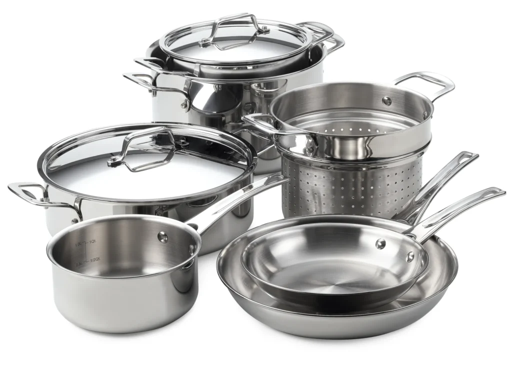
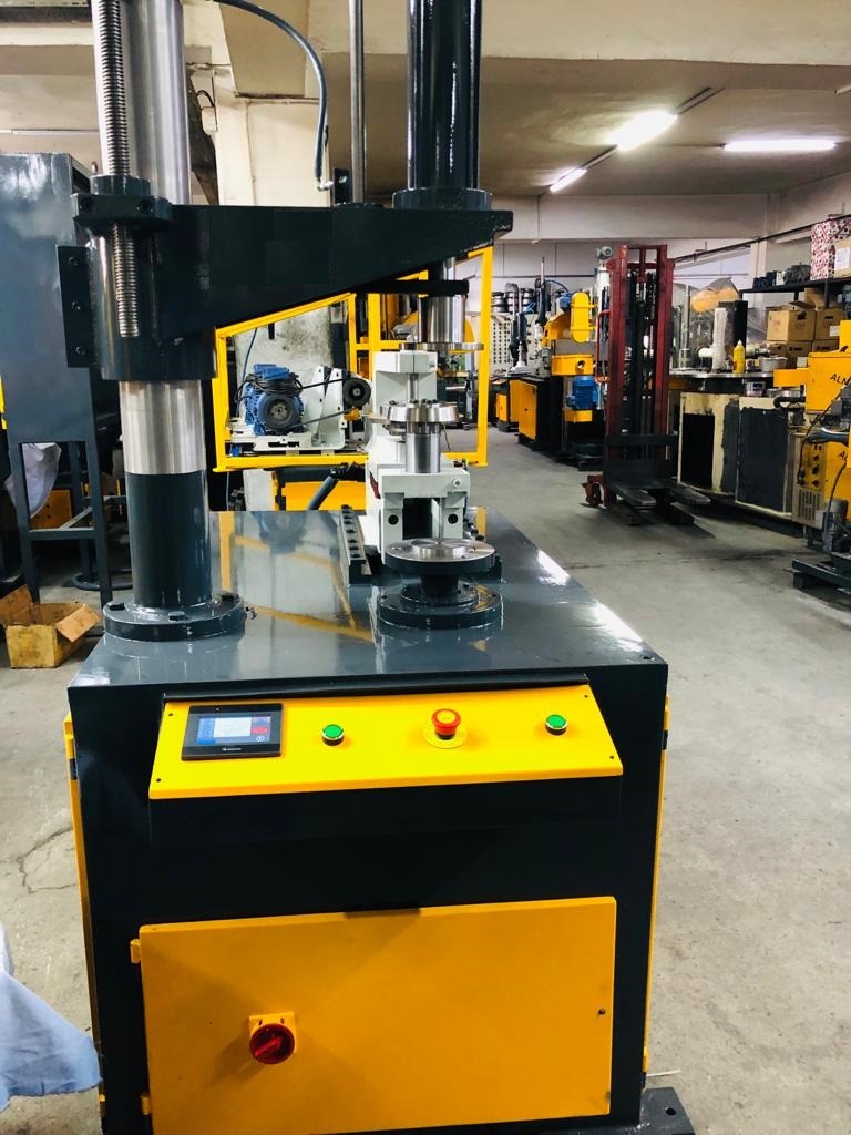
We manufacture the Stainless Steel Cookware Manufacturing Process to cut, trim and curl the edges of round parts. The Circular End Head Joggling Machines are used in various metalworking industries.
Stainless steel cookware is a popular choice for many home cooks because it is durable, easy to clean, and versatile. It is also relatively inexpensive, especially when compared to other types of cookware, such as copper or cast iron.
Types of Stainless Steel Cookware
There are two main types of stainless steel cookware: 18/0 and 18/10. The numbers refer to the percentage of chromium and nickel in the steel, respectively. 18/0 stainless steel has 18% chromium and no nickel, while 18/10 stainless steel has 18% chromium and 10% nickel. Nickel is added to stainless steel to make it more resistant to corrosion and to give it a brighter finish.
Benefits of Stainless Steel Cookware
There are many benefits to using stainless steel cookware. Here are a few of the most important:
- Durability: Stainless steel is a very durable material that can withstand years of use. It is also resistant to scratches and dents.
- Easy to clean: Stainless steel cookware is very easy to clean. It can be washed in the dishwasher or by hand with soap and water.
- Versatility: Stainless steel cookware can be used to cook a wide variety of foods, from searing meats to simmering sauces.
- Induction compatible: Most stainless steel cookware is induction compatible, which means that it can be used on induction cooktops.
Considerations When Choosing Stainless Steel Cookware
When choosing stainless steel cookware, there are a few things to consider. Here are a few tips:
- Thickness: The thicker the stainless steel, the more durable it will be. Look for cookware that is at least 2mm thick.
- Cladding: Some stainless steel cookware is clad with other metals, such as aluminum or copper. Cladding can help to distribute heat evenly and prevent hot spots.
- Handle: The handle should be comfortable to grip and stay cool during cooking.
Care and Maintenance for Stainless Steel Cookware
To keep your stainless steel cookware looking its best, follow these care and maintenance tips:
- Hand wash: Hand washing is the best way to clean stainless steel cookware. However, if you do use the dishwasher, use a mild detergent and avoid using the high heat setting.
- Avoid abrasive cleaners: Do not use abrasive cleaners on stainless steel cookware. This can scratch the surface and make it more susceptible to corrosion.
- Dry thoroughly: Always dry stainless steel cookware thoroughly after washing. This will help to prevent water spots.
- Season: If your stainless steel cookware starts to look dull, you can season it with a light coating of oil. This will help to protect the surface and give it a shine.
Overall, stainless steel cookware is a great choice for home cooks who are looking for durable, easy-to-clean, and versatile cookware.
This review comprises a critical evaluation of available data concerning the health effects associated with stainless steels, from manufacture through to processing and end-use. The review has been divided into the following three sections to reflect the qualitative variations in exposure that occur:
• Metallic stainless steel
• Stainless steel manufacture
• Stainless steel processing
The information contained in this review is intended to provide the basis for an assessment of the hazards associated with metallic stainless steel and those substances which occur during the manufacture and processing of stainless steel.
Stainless Steel Cookware Manufacturing Process
Cookware manufacturing involves a series of intricate processes that transform raw materials into durable, functional, and aesthetically pleasing kitchenware. Specialized machinery plays a pivotal role in each stage of production, ensuring precision, efficiency, and consistent quality. Here’s a comprehensive overview of the key machinery employed in cookware manufacturing:
- Sheet Metal Cutting Machines:
Sheet metal cutting machines are essential for shaping and sizing flat metal sheets into the desired dimensions for cookware components. These machines utilize various cutting techniques, such as laser cutting, plasma cutting, and shearing, to achieve precise cuts with minimal material waste.
- Deep Drawing Machines:
Deep drawing machines transform flat metal sheets into three-dimensional shapes, such as pots, pans, and bowls. They utilize a powerful hydraulic press to push a sheet metal blank into a die, forcing the material to conform to the desired shape.
- Forming Machines:
Forming machines are used to create specific shapes and features in cookware components, such as handles, rims, and decorative elements. They employ various forming techniques, such as roll forming, press forming, and stamping, to manipulate the metal into the desired shape.
- Welding Machines:
Welding machines are crucial for joining different cookware components together, creating a seamless and durable structure. They utilize various welding techniques, such as arc welding, spot welding, and laser welding, to achieve a strong and reliable bond.
- Polishing Machines:
Polishing machines provide the final touch, giving cookware its gleaming finish. They utilize abrasive belts, buffing wheels, and polishing compounds to remove imperfections, smooth out surfaces, and enhance the cookware’s aesthetic appeal.
- Quality Control Machines:
Quality control machines ensure that cookware meets the highest standards of quality and consistency. They utilize various inspection techniques, such as dimensional measurement, surface flaw detection, and material testing, to identify and rectify any defects.
- Packaging and Labeling Machines:
Packaging and labeling machines are essential for preparing cookware for distribution. They automate the process of wrapping, labeling, and boxing cookware, ensuring efficient and consistent packaging for retail presentation.
These specialized machines, along with the expertise of skilled operators, contribute to the production of high-quality cookware that meets the demands of modern kitchens. From shaping raw materials to creating intricate designs and ensuring impeccable finishes, cookware manufacturing machinery plays a vital role in bringing culinary creations to life.
Currently, stainless steel is classified in the European Union according to the Preparations Directive (88/379/EEC). Consequently, by using the conventional method specified in the Directive, stainless steels which contain nickel at a concentration of 1% or more are classified as category 3 carcinogens (R40) and skin sensitizers (R43). In this review, identifiable hazards associated with metallic stainless steel are evaluated against the criteria for classification, as contained in Annex VI of European Council Directive 92/32/EEC, amending Directive 67/548/EEC.
The purpose of this evaluation is to establish how, based on currently available data, metallic stainless steels would be classified if they were substances. Identifiable hazards associated with the materials occurring during the processing of stainless steel, for example, welding fume or grinding dust, are also evaluated against the same classification criteria.
The purpose of this evaluation is to determine how the toxicological properties of the materials concerned correlate with the classification criteria for substances and thus enable an objective judgment of whether the materials should be considered hazardous. The review is also intended to provide the basis of a risk assessment for those hazards which have been identified.
Cookware manufacturing is a vital industry that produces a wide range of kitchen utensils and tools essential for food preparation. Cookware includes items such as pots, pans, skillets, and baking dishes, each designed for specific cooking methods and techniques. The manufacturing process of cookware is complex, involving various materials, techniques, and machinery to ensure the final products are durable, efficient, and safe for cooking.
Cookware is indispensable in both domestic and commercial kitchens. High-quality cookware can significantly impact cooking performance, influencing heat distribution, cooking times, and food safety. As a result, manufacturers strive to produce cookware that meets rigorous standards for performance, durability, and user safety. The evolution of cookware manufacturing has led to the development of innovative materials and processes that enhance the functionality and aesthetics of kitchen tools.
In this comprehensive guide, we will explore the materials used in cookware manufacturing, the detailed manufacturing process, the machinery involved, and the latest innovations and trends in the industry. Understanding these aspects provides insight into how everyday kitchen items are crafted and the technological advancements driving the cookware industry forward.
Materials Used in Cookware Manufacturing
The choice of materials in cookware manufacturing is critical as it affects the performance, durability, and safety of the cookware. Different materials offer unique properties that make them suitable for specific types of cookware and cooking techniques. Here are the primary materials used in the manufacturing of cookware:
Metals
- Aluminum
- Properties: Aluminum is lightweight, has excellent thermal conductivity, and is relatively inexpensive. It heats up quickly and distributes heat evenly, making it ideal for cookware.
- Uses: Commonly used in the production of frying pans, saucepans, and stockpots. It is often anodized or coated to prevent reactions with acidic foods and enhance durability.
- Types: Includes regular aluminum, hard-anodized aluminum, and cast aluminum.
- Stainless Steel
- Properties: Stainless steel is highly durable, resistant to rust and corrosion, and has a sleek appearance. It is less conductive than aluminum but can be combined with other materials for better performance.
- Uses: Frequently used for pots, pans, and kitchen utensils. It is often layered with other metals like aluminum or copper to improve heat distribution.
- Types: Includes 18/10 stainless steel, which indicates the ratio of chromium to nickel, enhancing its resistance to rust and corrosion.
- Cast Iron
- Properties: Cast iron retains heat exceptionally well and provides even heating. It is very durable but requires regular seasoning to maintain its non-stick surface and prevent rust.
- Uses: Ideal for skillets, Dutch ovens, and griddles. Often used for slow-cooking and baking.
- Types: Includes traditional cast iron and enameled cast iron, which offers a protective coating and eliminates the need for seasoning.
- Copper
- Properties: Copper has superior thermal conductivity, providing precise temperature control. However, it is reactive with certain foods and requires regular polishing to maintain its appearance.
- Uses: Often used in high-end cookware like sauté pans and saucepans. Typically lined with stainless steel or tin to prevent food reactions.
- Types: Includes pure copper and copper-core cookware, which has a layer of copper sandwiched between layers of other metals for better performance.
Non-Metal Materials
- Ceramic
- Properties: Ceramic cookware is non-reactive, providing a safe cooking surface. It offers even heating and retains heat well. Ceramic coatings can be applied to metal bases for enhanced performance.
- Uses: Common in baking dishes, casseroles, and coated frying pans.
- Types: Includes pure ceramic cookware and ceramic-coated metal cookware.
- Glass
- Properties: Glass is non-reactive and can be used for both cooking and serving. It allows for even heating and provides a clear view of the cooking process.
- Uses: Often used for baking dishes, storage containers, and microwave-safe cookware.
- Types: Includes borosilicate glass, known for its durability and resistance to thermal shock.
- Non-Stick Coatings
- Properties: Non-stick coatings, such as Teflon, provide a slick surface that prevents food from sticking, making cleanup easier. These coatings are applied to metal bases, usually aluminum or stainless steel.
- Uses: Widely used in frying pans, griddles, and baking sheets.
- Types: Includes PTFE (Teflon) and newer ceramic-based non-stick coatings.
The selection of materials is based on the desired properties of the cookware, including heat conductivity, durability, ease of maintenance, and compatibility with various cooking methods. Manufacturers often combine materials to create cookware that maximizes performance and user satisfaction.
Manufacturing Process of Cookware
The manufacturing process of cookware involves several key stages, from raw material preparation to final finishing and quality control. Each step requires precision and attention to detail to ensure that the final product meets the high standards required for safe and efficient cooking. Here is a detailed look at the typical steps involved in the manufacturing process of cookware:
1. Raw Material Preparation
- Material Sourcing:
- High-quality raw materials, such as aluminum, stainless steel, cast iron, copper, and non-metal materials like ceramics and glass, are sourced from reputable suppliers. Ensuring the purity and quality of these materials is crucial for the performance and durability of the cookware.
- Material Inspection:
- The raw materials undergo rigorous inspection to verify their chemical composition, mechanical properties, and overall quality. This step ensures that the materials meet the necessary standards and specifications for cookware production.
2. Forming and Shaping
- Cutting and Stamping:
- Metal sheets or blanks are cut and stamped into the desired shapes and sizes using cutting and stamping machines. This process forms the basic shape of the cookware, such as the body of a pot or pan.
- Deep Drawing:
- For certain types of cookware, such as deep pots and pans, a process called deep drawing is used. In this process, metal blanks are placed in a die and subjected to high pressure to form deep, hollow shapes.
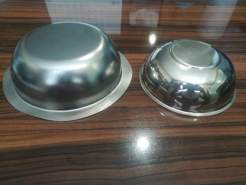
- Spinning:
- Spinning is a technique used to form round cookware items like bowls and woks. The metal blank is rotated at high speed while a tool shapes it into the desired form. This process is particularly useful for creating seamless and uniform shapes.
- Forging and Casting:
- For cookware like cast iron skillets and Dutch ovens, forging and casting processes are employed. Molten metal is poured into molds to create the desired shapes, which are then cooled and solidified. Forging involves heating the metal and hammering it into shape, enhancing its strength and durability.
3. Surface Treatment and Coating
- Surface Preparation:
- The formed cookware undergoes surface preparation to remove any impurities, rough edges, or oxidation. This is achieved through processes like sanding, grinding, and polishing. The goal is to create a smooth surface that is ready for coating.
- Coating Application:
- Various coatings are applied to enhance the performance and appearance of the cookware. Common coatings include non-stick surfaces, enamel, and protective layers to prevent corrosion. The coating process may involve spraying, dipping, or electrostatic application, followed by curing at high temperatures to ensure adhesion and durability.
- Anodizing:
- For aluminum cookware, anodizing is a surface treatment that increases the metal’s hardness and corrosion resistance. The cookware is immersed in an electrolytic solution, where an electric current is applied to create a protective oxide layer on the surface.
4. Assembly and Finishing
- Handle Attachment:
- Handles and other components, such as lids and knobs, are attached to the cookware. This may involve welding, riveting, or screwing, depending on the design and material of the cookware. The attachment process ensures that the handles are securely fastened and can withstand regular use.
- Polishing and Buffing:
- The cookware undergoes final polishing and buffing to achieve a smooth, shiny finish. This step enhances the appearance of the cookware and ensures that any remaining rough edges or imperfections are removed.
- Final Inspection:
- Each piece of cookware is inspected for defects, such as scratches, dents, or coating imperfections. This rigorous quality control step ensures that only cookware meeting the highest standards is packaged and shipped to customers.
5. Quality Control and Testing
- Dimensional Verification:
- The dimensions of the cookware are checked to ensure they meet the specified tolerances. This includes verifying the thickness, diameter, and depth of the cookware to ensure uniformity and consistency.
- Performance Testing:
- Cookware undergoes performance testing to evaluate its heat conductivity, durability, and non-stick properties. This may involve cooking tests, abrasion resistance tests, and impact tests to ensure the cookware performs as expected in real-world conditions.
- Safety and Compliance:
- The cookware is tested for safety and compliance with industry standards and regulations. This includes checking for harmful substances, such as lead or cadmium, and ensuring that the cookware is safe for food contact.
Machinery Used in Cookware Manufacturing
The manufacturing of cookware requires specialized machinery to ensure precision, efficiency, and high-quality production. Here are some of the key types of machinery used in the process:
1. Cutting and Stamping Machines
- Laser Cutters: Used for precise cutting of metal sheets into specific shapes and sizes. Laser cutting ensures clean edges and accurate dimensions.
- Stamping Presses: These machines stamp metal blanks into the desired shapes. They use dies and punches to form complex shapes and patterns.
2. Hydraulic Presses
- Deep Drawing Presses: Used for forming deep, hollow cookware items. These presses apply high pressure to metal blanks, shaping them into pots, pans, and other deep items.
- Forming Presses: Employed for shaping metal into various cookware forms. They provide the necessary force to bend, stretch, and shape the metal.
3. Spinning Machines
- CNC Spinning Lathes: These computer-controlled machines are used for spinning metal blanks into round cookware items. They offer high precision and repeatability, ensuring uniform shapes.
4. Welding and Assembly Equipment
- Spot Welders: Used for attaching handles and other components to the cookware. Spot welding provides strong, durable joints.
- Riveting Machines: Employed for securing handles and lids to cookware. Riveting ensures a firm attachment that can withstand regular use.
5. Surface Treatment and Coating Machines
- Anodizing Tanks: Used for anodizing aluminum cookware. The tanks hold the electrolytic solution and apply the electric current to create the protective oxide layer.
- Spray Coating Systems: These systems apply non-stick coatings, enamel, or other protective layers to the cookware. They ensure even coverage and adhesion.
- Curing Ovens: After coating, the cookware is placed in curing ovens to set and harden the coatings. This step ensures the coatings are durable and long-lasting.
6. Inspection and Testing Equipment
- Coordinate Measuring Machines (CMMs): Used for dimensional verification, ensuring the cookware meets specified tolerances.
- Abrasion Testers: These machines test the durability of non-stick coatings by simulating regular use and wear.
- Heat Conductivity Testers: Used to measure the heat distribution properties of the cookware, ensuring even cooking performance.
Innovations and Trends in Cookware Manufacturing
The cookware manufacturing industry is continually evolving, driven by innovations and trends that enhance performance, sustainability, and user experience. Here are some of the latest developments:
1. Sustainable and Eco-Friendly Materials
- Recycled Metals: Manufacturers are increasingly using recycled aluminum and stainless steel to reduce environmental impact. This approach minimizes resource consumption and energy use.
- Eco-Friendly Coatings: Advances in coating technology have led to the development of non-stick coatings that are free from harmful chemicals like PFOA and PFOS. These coatings are safer for both users and the environment.
2. Advanced Coating Technologies
- Ceramic Coatings: Ceramic-based non-stick coatings are gaining popularity due to their durability and heat resistance. They offer a safer alternative to traditional non-stick coatings.
- Titanium Reinforcement: Some non-stick coatings are reinforced with titanium particles, enhancing their durability and scratch resistance.
3. Automation and Smart Manufacturing
- Robotic Automation: The use of robots in manufacturing processes increases efficiency, precision, and consistency. Robots handle tasks such as material handling, welding, and coating application.
- Smart Cookware: Integration of smart technology in cookware, such as temperature sensors and connectivity features, allows users to monitor and control cooking processes through mobile apps.
Conclusion
The manufacturing process of cookware is a complex and detailed operation involving the selection of high-quality materials, precise forming and shaping techniques, advanced surface treatments, and rigorous quality control measures. The use of specialized machinery ensures that each piece of cookware meets the highest standards for performance, durability, and safety.
Innovations in materials and manufacturing processes continue to drive the industry forward, offering consumers cookware that is not only functional and efficient but also environmentally friendly and technologically advanced. As the demand for high-quality cookware grows, manufacturers will continue to refine and enhance their production methods, contributing to the evolution of culinary tools that enhance the cooking experience.
Cookware Manufacture Machines
The final part of each section focuses on “future research needs”. Gaps in the database, which have been identified during the preparation of this document, are reviewed and suggestions are put forward regarding future research needs where it is thought appropriate
Within the review, each section is divided into the following sub-sections: general information; information on exposure; toxicokinetics; toxicity; hazard assessment; risk assessment; gaps in knowledge. The review was prepared using primary sources of data.
In each toxicity sub-section, the review of the epidemiological literature relating to occupational cancers is limited to original publications of cohort studies. Population-based case-control studies were considered to be too problematic to include reliable analyses of detailed occupational exposures and were not evaluated.
Cookware Buffing and Finishing Machine
Cookware buffing and finishing machines play a crucial role in the cookware manufacturing process, transforming raw materials into gleaming, aesthetically pleasing, and durable kitchenware. These machines employ a variety of polishing techniques to remove imperfections, smooth out surfaces, and impart a high-gloss shine on cookware components.
Key Types of Cookware Buffing and Finishing Machines
- Abrasive Belt Polishing Machines: These versatile machines utilize abrasive belts of varying grit levels to progressively remove imperfections and create a smooth finish. They are suitable for polishing various materials, including stainless steel, aluminum, and cast iron.
- Buffing Wheel Polishing Machines: These machines employ buffing wheels made of natural or synthetic materials to polish and shine cookware surfaces. They are particularly effective for achieving a high-gloss finish and removing fine scratches.
- Polishing Compounds: Polishing compounds, also known as buffing compounds, are applied to buffing wheels to enhance their polishing action. They contain abrasive particles and lubricants that effectively remove imperfections and create a desired level of shine.
Safety Guidelines for Cookware Buffing and Finishing Machines
- Personal Protective Equipment (PPE): Always wear appropriate PPE, including safety glasses, gloves, and sturdy footwear, to protect yourself from flying debris, sparks, and potential injuries.
- Machine Guarding: Ensure all machine guards are properly installed and in place to prevent accidental contact with moving parts.
- Training and Authorization: Only trained and authorized personnel should operate cookware buffing and finishing machines.
- Machine Inspection: Before each operation, thoroughly inspect the machine for any signs of damage, leaks, or loose components.
- Secure Work Area: Keep the work area clean, well-lit, and free from clutter to minimize tripping hazards and ensure safe operation.
- Emergency Stop Switch: Familiarize yourself with the location and function of the emergency stop switch. Be prepared to use it immediately in case of a malfunction or hazardous situation.
- Avoid Overloading: Do not exceed the machine’s rated capacity. Overloading can strain the machine, leading to potential failures and safety hazards.
- Maintenance Routine: Follow the manufacturer’s recommended maintenance schedule to keep the machine in good working condition. Regular maintenance reduces the risk of breakdowns and ensures optimal safety performance.
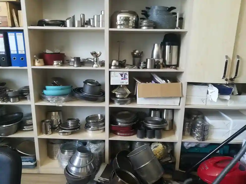
Applications of Cookware Buffing and Finishing Machines
Cookware buffing and finishing machines are widely used in the production of various cookware items, including:
- Pots and Pans: They create a smooth, shiny finish on the exterior and interior surfaces of pots and pans, enhancing their appearance and durability.
- Lids: They polish the exterior and interior surfaces of lids, ensuring a perfect fit and airtight seal.
- Inserts: They polish the surfaces of inserts for multi-cooker pots, enhancing their aesthetic appeal and functionality.
- Bowls: They create a gleaming finish on bowls of various sizes and shapes, adding elegance and visual appeal to kitchenware.
- Cookware Handles: They polish handles for pots and pans, ensuring a comfortable grip and aesthetic coherence with the cookware design.
Conclusion
Cookware buffing and finishing machines are indispensable tools in the cookware manufacturing industry, contributing to the creation of high-quality, aesthetically pleasing, and durable kitchenware. By carefully selecting, operating, and maintaining these machines, manufacturers can ensure the production of cookware that meets the demands of modern kitchens and enhances the culinary experience for consumers.
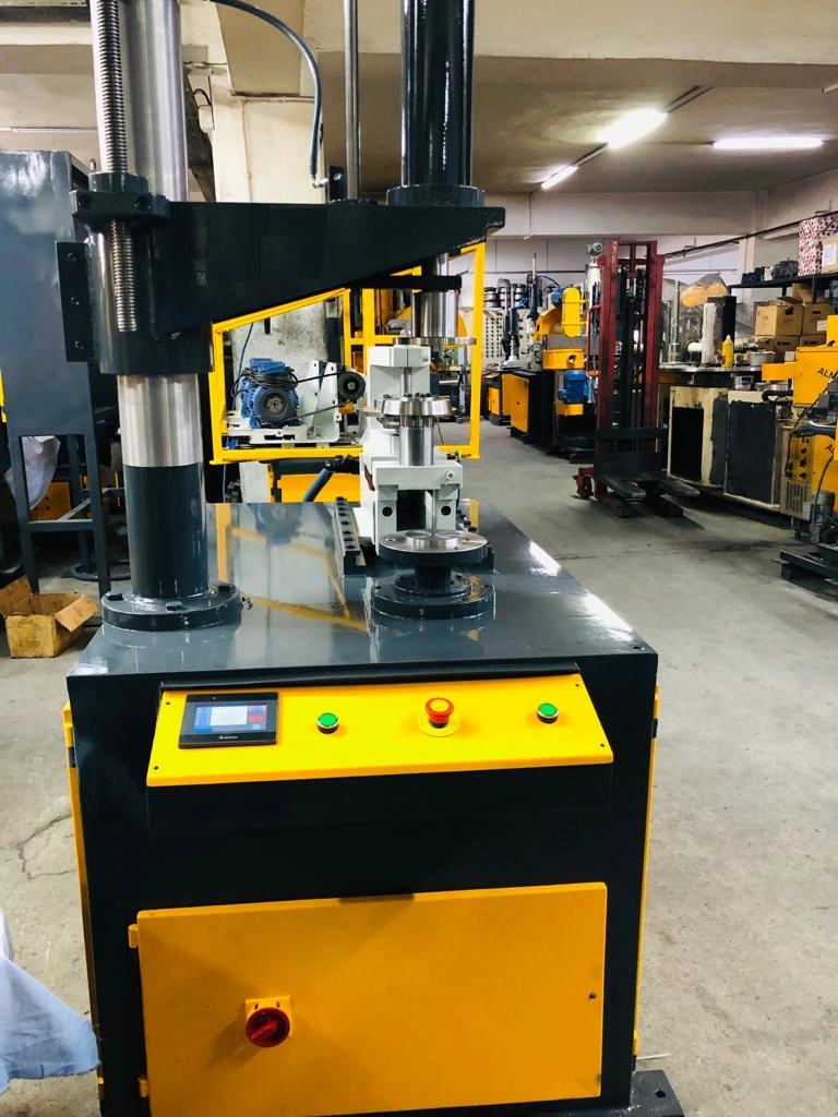
Hydraulic Drawing Press as a Steel Cookware Making Machine
Hydraulic drawing presses play a crucial role in the production of steel cookware, particularly in the deep drawing process. These powerful machines utilize hydraulic pressure to transform flat metal sheets into three-dimensional shapes, such as pots, pans, and bowls. Their versatility and precision make them indispensable tools in the cookware manufacturing industry.
Deep Drawing Process with Hydraulic Drawing Presses
- Blanking: The first step involves cutting a flat metal sheet into a blank, the initial shape of the desired cookware component.
- Lubrication: The blank is lubricated to reduce friction and ensure smooth movement during the deep drawing process.
- Positioning: The blank is carefully positioned on the die, the metal mold that will shape the component during deep drawing.
- Punch Movement: The punch, a descending metal tool, presses the blank into the die, forcing the material to conform to the desired shape.
- Hydraulic Pressure: Hydraulic pressure is applied to the punch, gradually increasing the force until the desired shape is achieved.
- Ejection: Once the deep drawing process is complete, the punch retracts, and the formed component is ejected from the die.
Benefits of Hydraulic Drawing Presses for Steel Cookware Making
- Precision Shaping: Hydraulic drawing presses ensure precise and consistent shaping of cookware components, maintaining accurate dimensions and consistent wall thickness.
- Complex Shapes: They can handle complex shapes, including rounded contours, tapered walls, and intricate details, catering to a wide range of cookware designs.
- Durability: Hydraulic drawing presses are robust and durable, capable of withstanding the high pressures and repeated cycling required for deep drawing operations.
- Versatility: They can handle a wide range of materials, including various grades of stainless steel, aluminum, and other metals, catering to diverse cookware production needs.
- Automation: Automated hydraulic drawing presses can significantly increase production speed and efficiency, particularly for high-volume manufacturing.
Applications of Hydraulic Drawing Presses in Steel Cookware Making
Hydraulic drawing presses are widely used in the production of various steel cookware items, including:
- Pots and Pans: They form the main body of pots and pans, creating the desired depth, curvature, and shape.
- Lids: They shape the lids of cookware, ensuring a perfect fit and airtight seal.
- Inserts: They form inserts for multi-cooker pots, ensuring consistent dimensions and proper fit within the main pot.
- Bowls: They create bowls of various sizes and shapes for mixing, preparing, and serving food.
- Cookware Handles: They shape and form cookware handles, ensuring a comfortable grip and structural integrity.
Conclusion
Hydraulic drawing presses are essential equipment in the production of steel cookware, providing precision, versatility, and efficiency for deep drawing operations. Their ability to transform flat metal sheets into complex shapes with consistent accuracy makes them indispensable tools for creating durable, functional, and aesthetically pleasing cookware. As technology advances, hydraulic drawing presses continue to evolve, incorporating innovative features and control systems that enhance their capabilities and expand their applications in the cookware manufacturing industry.
Steel Cookware Making Machine
Steel cookware making machines play a crucial role in the production of high-quality cookware, transforming raw materials into durable, functional, and aesthetically pleasing kitchenware. These machines employ various techniques to shape, trim, polish, and finish stainless steel and other metals into the desired forms and designs.
Key Steel Cookware Making Machines
- Sheet Metal Cutting Machines: These machines precisely cut flat metal sheets into the desired dimensions for cookware components. They utilize various cutting techniques, such as laser cutting, plasma cutting, and shearing, to achieve precise cuts with minimal material waste.
- Deep Drawing Machines: These machines transform flat metal sheets into three-dimensional shapes, such as pots, pans, and bowls. They utilize a powerful hydraulic press to push a sheet metal blank into a die, forcing the material to conform to the desired shape.
- Trimming and Beading Machines: These machines perform multiple tasks, including trimming excess material from edges, creating decorative beads along the rim, and curling the edges for a smooth finish. They ensure consistent and accurate shaping of cookware components.
- Polishing Machines: These machines remove imperfections, smooth out surfaces, and create a gleaming finish on cookware components. They utilize abrasive belts, buffing wheels, and polishing compounds to achieve the desired finish, enhancing the cookware’s aesthetic appeal and durability.
- Quality Control Machines: These machines ensure that cookware meets the highest standards of quality and consistency. They utilize various inspection techniques, such as dimensional measurement, surface flaw detection, and material testing, to identify and rectify any defects.
Production Process with Steel Cookware Making Machines
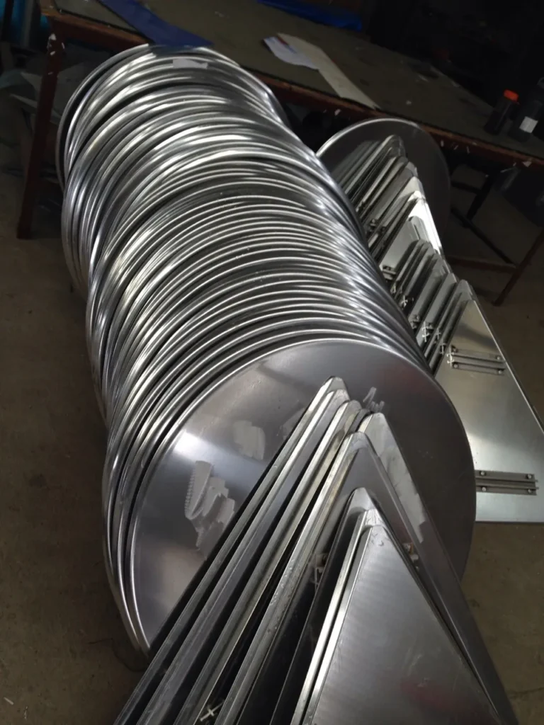
- Material Preparation: Stainless steel sheets or coils are prepared according to the desired thickness and specifications.
- Cutting and Shaping: Sheet metal cutting machines precisely cut the metal into shapes for various cookware components.
- Deep Drawing: Deep drawing machines transform flat metal sheets into three-dimensional shapes, such as pots and pans.
- Trimming and Beading: Trimming and beading machines remove excess material, create decorative beads, and curl the edges for a smooth finish on cookware components.
- Welding: Welding machines join different cookware components together, creating a seamless and durable structure.
- Polishing: Polishing machines remove imperfections and create a gleaming finish on cookware components.
- Quality Control: Quality control machines inspect the cookware for any defects, ensuring it meets the highest standards.
- Packaging and Labeling: Packaging and labeling machines prepare the cookware for distribution, ensuring consistent and attractive packaging.
Factors Affecting Steel Cookware Making Machine Selection
- Cookware Type: The type of cookware being manufactured, such as pots, pans, lids, or handles, influences the choice of machines.
- Production Volume: High-volume production may require faster, more automated machines, while smaller-scale operations may utilize manual or semi-automated machines.
- Material Thickness: The thickness of the stainless steel being used affects the power and capabilities of the required machines.
- Cookware Design: The complexity of the cookware design, such as intricate shapes or decorative elements, influences the machine selection.
- Cost and ROI: The initial investment in machines should be balanced against their capabilities, production requirements, and expected lifespan.
Conclusion
Steel cookware making machines are essential tools that transform raw materials into durable, functional, and aesthetically pleasing cookware. By carefully selecting and operating these machines, manufacturers can maintain high production quality, enhance the appeal of their products, and meet the demands of modern kitchens.
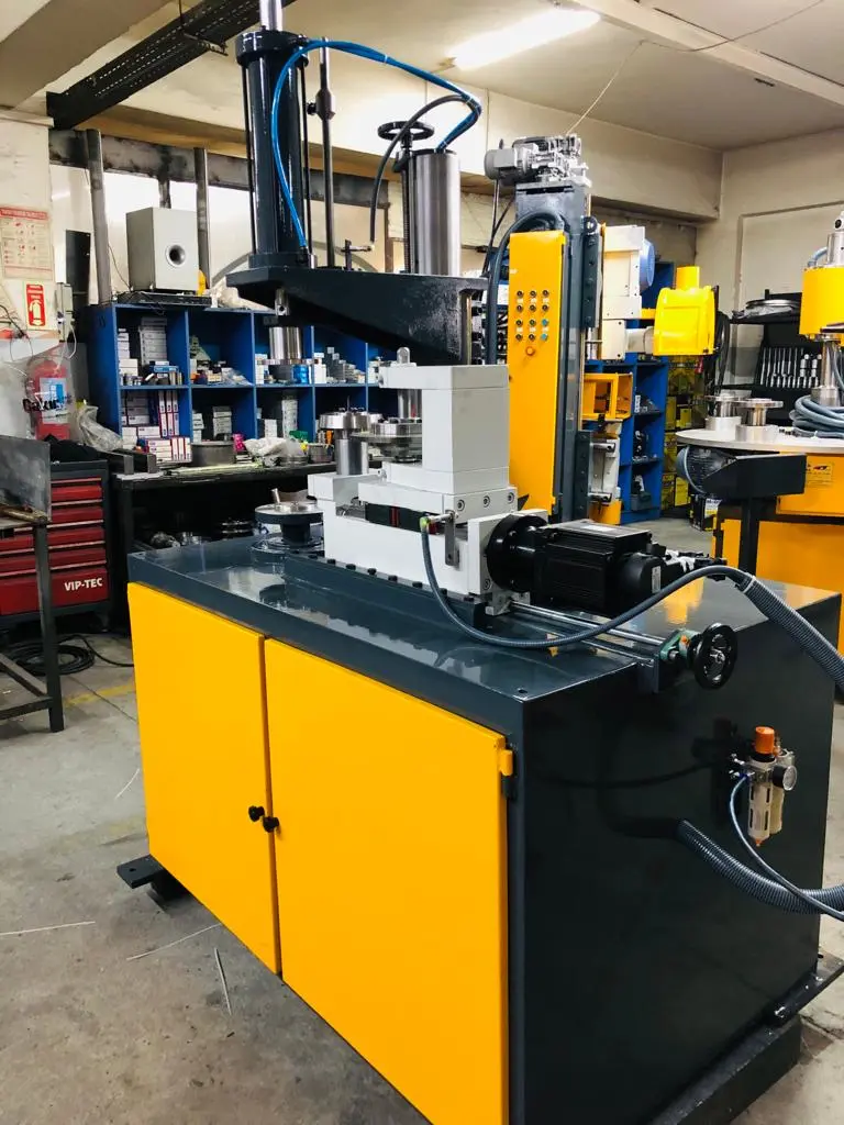
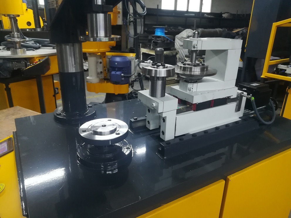
Automatic edge cutting trimming beading machine for cookware manufacturing
Automatic edge cutting trimming beading machines are essential equipment in the cookware manufacturing industry, streamlining production and ensuring precise shaping of cookware components. These versatile machines perform multiple tasks, including edge cutting, trimming, beading, and curling, eliminating the need for separate machines and enhancing overall efficiency.
Benefits of Using Automatic Edge Cutting Trimming Beading Machines
- Enhanced Efficiency: These machines automate multiple processes, significantly reducing production time and labor costs compared to manual methods.
- Precision Shaping: They ensure consistent and accurate shaping of edges, trims, beads, and curls, contributing to high-quality cookware products.
- Reduced Material Waste: By utilizing precise cutting and trimming techniques, these machines minimize material waste, optimizing resource utilization.
- Versatility: They can handle a wide range of cookware materials, including stainless steel, aluminum, and titanium, making them adaptable to various production needs.
- Improved Work Safety: By automating tasks, these machines reduce the risk of injuries associated with manual edge cutting, trimming, and beading operations.
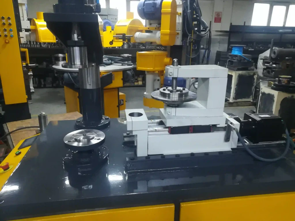
Key Components of Automatic Edge Cutting Trimming Beading Machines
- Cutting Blades: Precision cutting blades are designed to cut cleanly through various cookware materials, ensuring smooth and accurate edges.
- Trimming Tools: Adjustable trimming tools precisely remove excess material from the edges, creating clean and even finishes.
- Beading Forms: Specialized beading forms create decorative beads along the rim of cookware components, enhancing aesthetics and functionality.
- Curling Mechanism: A curling mechanism precisely rolls the edges of cookware components, creating smooth, rounded rims that prevent sharp edges and enhance user safety.
- Control System: A sophisticated control system coordinates the movement of the cutting blades, trimming tools, beading forms, and curling mechanism, ensuring precise shaping and consistent results.
Applications of Automatic Edge Cutting Trimming Beading Machines
These machines are widely used in the production of various cookware items, including:
- Pots and Pans: They shape the edges, trims excess material, and create beads on pots and pans, enhancing their appearance and durability.
- Lids: They precisely cut circular shapes for lids, ensuring a perfect fit and airtight seal.
- Inserts: They trim and shape inserts for multi-cooker pots, ensuring consistent dimensions and proper fit.
- Cookware Handles: They bead and curl cookware handles, creating a comfortable grip and preventing sharp edges.
Conclusion
Automatic edge cutting trimming beading machines play a crucial role in cookware manufacturing, streamlining production, ensuring precise shaping, and enhancing product quality. Their versatility, efficiency, and safety benefits make them indispensable equipment for cookware manufacturers.
Industries working with our machinery
Trimming and beading machines are versatile tools that are used in a wide range of industries. Here are some of the most common industries that use trimming and beading machines:
Automotive Industry
The automotive industry is one of the largest users of trimming and beading machines. These machines are used to trim and bead car body panels, fenders, doors, and other sheet metal components. Trimming ensures precise dimensions and eliminates rough edges, while beading strengthens the sheet metal and provides reference points for alignment during assembly and welding.
Aerospace Industry
The aerospace industry also relies heavily on trimming and beading machines. These machines are used to fabricate lightweight and high-strength components for aircraft and spacecraft. The precise and consistent trimming and beading operations ensure the structural integrity of these critical components.
Appliance Manufacturing
Appliance manufacturing is another major user of trimming and beading machines. These machines are used to trim and bead the sheet metal components of refrigerators, washing machines, and other household appliances. Trimming and beading help to strengthen the appliances, improve their appearance, and facilitate assembly.
HVAC Industry
The HVAC industry uses trimming and beading machines to fabricate ductwork, fans, and other sheet metal components. Trimming ensures that the components fit together properly, while beading strengthens the components and provides rigidity.
Construction Industry
The construction industry uses trimming and beading machines to fabricate roofing panels, siding, and other sheet metal components for buildings. Trimming and beading help to ensure that the components are weatherproof and durable.
Metal Fabrication Industries
Trimming and beading machines are widely used in various metal fabrication industries, including electrical equipment manufacturing, medical device manufacturing, and industrial machinery manufacturing. These machines are used to trim and bead a wide range of sheet metal components for various applications.
In addition to these specific industries, trimming and beading machines are also used in a variety of other applications, including:
- Sign Manufacturing
- Furniture Manufacturing
- Toy Manufacturing
- Food and Beverage Processing Equipment Manufacturing
- Medical Device Manufacturing
The versatility and effectiveness of trimming and beading machines make them essential tools for a wide range of industries. These machines play a crucial role in producing high-quality, durable, and precisely dimensioned sheet metal components for a variety of applications.
- Cookware Kitchenware
- Defense
- Water Tank Manufacturing
- Solar Power Generator Manufacturing
- Electrical Motor Fan Cover Manufacturing
- Fire Extinguisher Manufacturing
- Exhaust Pipe Manufacturing
- LPG & LNG Tank Manufacturing
Trimming beading machines are specialized pieces of equipment used in various manufacturing industries to cut, shape, and form beads along the edges of metal sheets and other materials. These machines serve the critical function of enhancing the structural integrity and aesthetic appeal of products by creating precise and consistent beading.
Trimming beading machines are essential in processes where the appearance and durability of the edges are paramount. They are commonly employed in industries such as automotive, aerospace, HVAC, and consumer goods manufacturing, where precision and efficiency are crucial.
Importance in Industrial Applications
The primary importance of trimming beading machines lies in their ability to streamline manufacturing processes by automating edge-forming tasks that would otherwise be labor-intensive and prone to human error. By improving consistency and reducing waste, these machines contribute significantly to the overall productivity and cost-effectiveness of production lines.
Furthermore, trimming beading machines enhance the quality of finished products, ensuring they meet stringent industry standards and customer expectations. Their ability to produce uniform edges and beads also plays a vital role in the assembly and functionality of components, particularly in high-stakes industries like aerospace and automotive manufacturing.
Overview of the Content
This comprehensive guide aims to provide an in-depth exploration of trimming beading machines, covering their components, working principles, types, applications, technical specifications, maintenance, and emerging trends. By understanding these aspects, industry professionals can make informed decisions about implementing and optimizing trimming beading machines within their operations.
Components of Trimming Beading Machines
Base and Frame
The base and frame of a trimming beading machine form its structural backbone, providing stability and support for all other components. Typically constructed from robust materials such as steel or cast iron, the frame ensures the machine can withstand the stresses of operation and maintain precision over time.
Materials Used
- Steel: Known for its durability and resistance to deformation, steel is commonly used in high-performance trimming beading machines. It offers excellent rigidity and longevity.
- Cast Iron: Preferred for its vibration-damping properties, cast iron frames help minimize noise and improve accuracy during operation.
Structural Design
- The structural design of trimming beading machines varies based on the specific model and intended application. Key considerations include the machine’s footprint, ease of access for maintenance, and adaptability to different manufacturing environments.
Cutting and Beading Tools
The cutting and beading tools are critical to the machine’s functionality, responsible for shaping and forming the edges of materials. These tools come in various shapes and sizes, tailored to the specific beading patterns and material thicknesses required.
Types and Materials
- High-Speed Steel (HSS): Known for its hardness and heat resistance, HSS is commonly used for cutting tools that need to maintain sharpness under demanding conditions.
- Carbide: Offering superior wear resistance and durability, carbide tools are ideal for high-volume production runs and materials that are difficult to machine.
Maintenance and Replacement
- Regular maintenance of cutting and beading tools is essential to ensure consistent performance. This includes sharpening or replacing worn tools and adjusting alignment to prevent defects in the finished products.
Drive Mechanism
The drive mechanism powers the machine’s operations, converting electrical energy into mechanical motion. It is a crucial component that directly influences the machine’s efficiency and performance.
Motor Types
- AC Motors: Widely used in trimming beading machines for their reliability and simplicity. AC motors offer consistent performance and are suitable for applications where speed control is not critical.
- Servo Motors: Preferred for applications requiring precise control and variable speeds. Servo motors enable dynamic adjustments to the machine’s operations, enhancing versatility and efficiency.
Energy Efficiency Considerations
- Modern trimming beading machines are designed with energy efficiency in mind, incorporating features like variable frequency drives (VFDs) to optimize power consumption and reduce operational costs.
Control Systems
Control systems govern the operation of trimming beading machines, allowing operators to configure settings, monitor performance, and ensure safety. These systems range from basic manual controls to sophisticated automated interfaces.
Manual vs. Automated Systems
- Manual Systems: Suitable for smaller operations or applications requiring frequent adjustments. Manual controls offer simplicity and direct operator oversight.
- Automated Systems: Essential for large-scale production environments, automated systems provide consistent performance, reduce human error, and enable integration with other machinery.
Integration with Industry 4.0 Technologies
- Trimming beading machines are increasingly adopting Industry 4.0 technologies, such as IoT sensors and data analytics, to enhance operational efficiency and enable predictive maintenance.
Working Principles
Detailed Description of the Trimming Process
The trimming process involves cutting away excess material from the edges of a workpiece to achieve a desired shape or size. Trimming beading machines utilize specialized tools to perform this task with high precision and consistency.
- Material Feeding: The workpiece is fed into the machine, either manually or automatically, and positioned for trimming.
- Tool Engagement: Cutting tools engage the workpiece, removing excess material while following the predefined path and pattern.
- Material Removal: The machine’s cutting tools execute the trimming operation, guided by precise control systems to ensure uniformity.
- Quality Inspection: The trimmed edges are inspected for accuracy and quality, with adjustments made as necessary.
Beading Techniques and Variations
Beading is the process of forming beads along the edges of a workpiece, enhancing both its structural integrity and aesthetic appeal. Different techniques and variations are employed based on the material and intended application.
- Single Bead Formation: The simplest form of beading, involving a single continuous bead along the edge.
- Double Bead Formation: Utilized when additional strength or a decorative effect is desired, double beads consist of two parallel beads along the edge.
- Custom Bead Patterns: Some machines allow for custom bead patterns, tailored to specific design requirements or functional needs.
Workflow and Operational Steps
The workflow of a trimming beading machine is designed to maximize efficiency and ensure consistent output. Key operational steps include:
- Setup and Calibration: Operators configure the machine settings, such as tool alignment and material thickness, to match the requirements of the production run.
- Material Loading: Workpieces are loaded onto the machine, either manually or through automated systems, and positioned for processing.
- Trimming and Beading: The machine executes the trimming and beading operations, following the specified parameters and patterns.
- Quality Control: Finished pieces undergo quality control checks to verify dimensional accuracy and bead integrity.
- Adjustment and Maintenance: Regular adjustments and maintenance are performed to ensure optimal performance and address any issues that arise during operation.
Common Challenges and Solutions
Trimming beading machines can encounter various challenges during operation, which can impact performance and product quality. Common issues and their solutions include:
- Tool Wear and Dullness: Regular tool maintenance, including sharpening and replacement, is essential to maintain cutting precision and prevent defects.
- Material Deformation: Proper machine calibration and tool alignment help prevent material deformation during trimming and beading processes.
- Machine Downtime: Implementing predictive maintenance and monitoring systems can reduce downtime and improve overall equipment efficiency.
- Quality Variability: Consistent quality control checks and process adjustments help ensure uniformity and adherence to specifications.
Types of Trimming Beading Machines
Trimming beading machines are available in various types, each suited to specific applications and production needs. Understanding the differences between these machines is crucial for selecting the right equipment for a given operation.
Manual Trimming Beading Machines
Features and Use Cases
- Manual trimming beading machines are operated entirely by human intervention, making them suitable for small-scale production or applications requiring frequent adjustments. These machines offer simplicity and ease of use, often utilized in workshops or small manufacturing facilities.
Advantages and Disadvantages
- Advantages:
- Cost-effective for low-volume production
- Flexibility to handle various materials and bead patterns
- Simple operation and maintenance
- Disadvantages:
- Limited throughput and productivity
- Higher labor costs due to manual operation
- Inconsistent quality due to human error
Semi-Automatic Trimming Beading Machines
Features and Use Cases
- Semi-automatic trimming beading machines combine manual input with automated processes, offering a balance between flexibility and efficiency. These machines are ideal for medium-scale production environments where speed and precision are important.
Advantages and Disadvantages
- Advantages:
- Improved productivity compared to manual machines
- Enhanced consistency and accuracy
- Reduced operator fatigue and error
- Disadvantages:
- Higher initial investment compared to manual machines
- Requires skilled operators for setup and adjustment
- Limited scalability for large-scale production
Fully Automatic Trimming Beading Machines
Features and Use Cases
- Fully automatic trimming beading machines offer the highest level of automation and efficiency, designed for large-scale production environments. These machines are equipped with advanced control systems and automation features, enabling continuous and consistent operation.
Advantages and Disadvantages
- Advantages:
- Maximum productivity and throughput
- Consistent quality and precision
- Integration with other automated systems and Industry 4.0 technologies
- Disadvantages:
- High initial cost and complexity
- Requires skilled technicians for maintenance and troubleshooting
- Limited flexibility for custom or small-batch production
Applications in Various Industries
Trimming beading machines play a vital role in a wide range of industries, each benefiting from the precision and efficiency these machines offer. Here, we explore some of the key industries and their specific applications.
Automotive Industry
Specific Use Cases
- In the automotive industry, trimming beading machines are used for forming edges on components such as fenders, doors, hoods, and other body panels. These machines ensure that parts meet the strict dimensional tolerances required for assembly and safety.
Benefits in Automotive Manufacturing
- Improved part quality and consistency, reducing rework and waste
- Enhanced structural integrity of components, contributing to vehicle safety
- Increased production speed and efficiency, supporting high-volume manufacturing
Aerospace Industry
Specific Use Cases
- Aerospace manufacturing demands precision and reliability, making trimming beading machines essential for producing parts such as fuselage panels, wing components, and engine casings. These machines contribute to the stringent quality standards of the aerospace industry.
Benefits in Aerospace Manufacturing
- High precision and repeatability, ensuring compliance with aerospace standards
- Reduction in material waste and production costs
- Support for complex geometries and advanced materials
HVAC Industry
Specific Use Cases
- In the HVAC industry, trimming beading machines are used to form edges and beads on ductwork, vents, and other components. These machines help produce parts that are essential for efficient heating, ventilation, and air conditioning systems.
Benefits in HVAC Manufacturing
- Consistent part quality and fit, reducing installation time and costs
- Enhanced durability and performance of HVAC components
- Support for custom designs and specifications
Consumer Goods Industry
Specific Use Cases
- The consumer goods industry utilizes trimming beading machines for a variety of products, including appliances, electronics, and packaging. These machines help create aesthetically pleasing and functional components.
Benefits in Consumer Goods Manufacturing
- Improved product appearance and appeal
- Increased manufacturing efficiency and speed
- Support for diverse materials and product designs
Technical Specifications and Standards
Understanding the technical specifications and standards of trimming beading machines is crucial for selecting the right equipment and ensuring compliance with industry requirements.
International Standards and Compliance
Trimming beading machines must adhere to international standards to ensure safety, quality, and interoperability. Key standards include:
- ISO 9001: Quality management systems standard that ensures consistent product quality and customer satisfaction.
- ISO 12100: Safety of machinery – General principles for design, providing guidelines for reducing risks associated with machine operation.
- CE Marking: Conformity with European health, safety, and environmental protection standards.
Key Technical Specifications
Trimming beading machines have various technical specifications that influence their performance and suitability for specific applications. Key specifications include:
- Maximum Material Thickness: The thickest material the machine can handle, typically measured in millimeters or inches.
- Beading Speed: The rate at which the machine can form beads, often measured in meters per minute.
- Cutting Force: The amount of force exerted by the machine’s cutting tools, affecting its ability to handle different materials.
- Power Requirements: The electrical power needed for operation, influencing energy consumption and infrastructure needs.
Customization Options
Manufacturers often offer customization options to tailor trimming beading machines to specific requirements. Common customization options include:
- Tooling Variations: Custom tools and dies to accommodate unique bead patterns and material specifications.
- Automation Features: Integration of advanced control systems and automation technologies for enhanced performance.
- Material Handling Systems: Customized feeding and handling systems to improve workflow and reduce manual intervention.
Maintenance and Troubleshooting
Proper maintenance and troubleshooting are essential to ensuring the longevity and performance of trimming beading machines. Here, we outline key maintenance practices and common issues that operators may encounter.
Routine Maintenance Procedures
Regular maintenance helps prevent unexpected downtime and ensures consistent machine performance. Key maintenance procedures include:
- Tool Inspection and Replacement: Regularly inspect cutting and beading tools for wear and damage. Sharpen or replace tools as needed to maintain cutting precision.
- Lubrication: Ensure all moving parts are properly lubricated to reduce friction and wear.
- Alignment Checks: Verify tool alignment and calibration to prevent defects and ensure uniformity.
- Electrical System Inspection: Check electrical connections and components for signs of wear or damage, addressing issues promptly to prevent malfunctions.
Common Issues and Solutions
Trimming beading machines may encounter various issues during operation. Understanding these problems and their solutions is crucial for maintaining productivity and quality.
- Tool Wear and Dullness: Dull or worn tools can lead to poor cutting performance and defects. Regularly sharpen or replace tools to maintain quality.
- Material Jams: Misalignment or improper feeding can cause material jams, leading to downtime and damage. Ensure proper setup and alignment to prevent jams.
- Machine Vibration: Excessive vibration can impact precision and tool life. Check for loose components and ensure the machine is properly anchored to reduce vibration.
- Inconsistent Quality: Variability in bead quality and dimensions can arise from improper calibration or tool wear. Regularly inspect and adjust settings to maintain consistency.
Safety Considerations
Safety is paramount when operating trimming beading machines. Key safety considerations include:
- Personal Protective Equipment (PPE): Operators should wear appropriate PPE, such as gloves, safety glasses, and hearing protection, to minimize injury risk.
- Machine Guarding: Ensure all machine guards and safety features are in place and functional to prevent accidental contact with moving parts.
- Emergency Stops: Verify that emergency stop mechanisms are operational and accessible in case of emergencies.
- Training and Education: Provide thorough training to operators and maintenance personnel on safe machine operation and emergency procedures.
Latest Innovations and Trends
The field of trimming beading machines is continually evolving, with new technologies and trends shaping the future of manufacturing. Here, we explore some of the latest innovations and emerging trends in the industry.
Technological Advances
Advancements in technology are driving significant improvements in trimming beading machines, enhancing their capabilities and performance.
- Smart Sensors and IoT Integration: Trimming beading machines are increasingly incorporating smart sensors and IoT connectivity to monitor performance, predict maintenance needs, and optimize operations.
- Advanced Control Systems: New control systems offer greater precision and flexibility, enabling operators to achieve complex bead patterns and adapt to changing production requirements.
- Automation and Robotics: The integration of automation and robotics is transforming trimming beading machines, reducing manual labor, and increasing throughput.
Future Trends in Trimming Beading Machines
Several trends are shaping the future of trimming beading machines, influencing how they are designed and utilized.
- Sustainability and Energy Efficiency: Manufacturers are focusing on sustainability, developing machines with lower energy consumption and reduced environmental impact.
- Customization and Flexibility: As demand for custom products grows, trimming beading machines are becoming more adaptable, with features that support rapid reconfiguration and customization.
- Digitalization and Industry 4.0: The digital transformation of manufacturing is driving the adoption of Industry 4.0 technologies, enabling data-driven decision-making and enhanced machine performance.
Case Studies and Examples
Real-world examples and case studies demonstrate the impact of trimming beading machines in various industries, highlighting their benefits and applications.
- Automotive Manufacturing: A leading automotive manufacturer implemented advanced trimming beading machines to improve production efficiency and reduce defects, achieving significant cost savings and quality improvements.
- Aerospace Industry: An aerospace supplier adopted IoT-enabled trimming beading machines to enhance traceability and optimize maintenance, resulting in reduced downtime and improved compliance with industry standards.
- HVAC Production: A major HVAC manufacturer integrated automated trimming beading machines to increase production capacity and reduce manual labor, leading to faster lead times and higher product quality.
Choosing the Right Trimming Beading Machine
Selecting the right trimming beading machine is crucial for achieving optimal performance and meeting specific production needs. Here, we outline key factors to consider and offer guidance on the selection process.
Factors to Consider
When choosing a trimming beading machine, several factors should be considered to ensure the equipment meets operational requirements.
- Production Volume: Assess the production volume and throughput requirements to determine the appropriate machine type and capacity.
- Material Specifications: Consider the types of materials and thicknesses the machine will handle, ensuring compatibility with the equipment’s capabilities.
- Beading Patterns: Evaluate the complexity and variety of bead patterns needed, selecting machines that offer the necessary tooling and flexibility.
- Automation Needs: Determine the level of automation required, balancing productivity gains with cost considerations and operator expertise.
Cost vs. Benefit Analysis
Conducting a cost vs. benefit analysis helps evaluate the financial implications of investing in a trimming beading machine.
- Initial Investment: Assess the upfront cost of the machine, including installation and setup expenses.
- Operational Costs: Consider ongoing operational costs, such as energy consumption, maintenance, and labor.
- Return on Investment (ROI): Calculate the expected ROI by evaluating the machine’s impact on productivity, quality, and cost savings.
Vendor Selection and Partnerships
Choosing the right vendor and establishing strong partnerships are essential for acquiring quality equipment and support.
- Reputation and Experience: Evaluate potential vendors based on their reputation, experience, and track record in the industry.
- Technical Support and Service: Ensure the vendor offers comprehensive technical support, training, and maintenance services to maximize machine performance and uptime.
- Customization and Flexibility: Consider vendors that offer customization options and flexible solutions tailored to specific production needs.
Conclusion
Recap of Key Points
Trimming beading machines are essential tools in modern manufacturing, offering precision, efficiency, and versatility across a range of industries. Understanding their components, working principles, and applications is crucial for making informed decisions and optimizing production processes.
Final Thoughts on Trimming Beading Machines
As technology continues to advance, trimming beading machines are poised to play an increasingly important role in the manufacturing landscape. By embracing innovation and adopting best practices, manufacturers can leverage these machines to enhance quality, productivity, and competitiveness in their respective industries.
Components of Trimming Beading Machines
To provide a detailed exploration of the components of a trimming beading machine, we’ll delve deeper into each part, discussing their functions, materials, and importance. Here’s an expanded version of the Components of Trimming Beading Machines section:
Trimming beading machines consist of several integral components, each playing a crucial role in ensuring precise operation and high-quality output. Understanding these components can aid in the proper selection, operation, and maintenance of the machines.
Base and Frame
Functionality and Importance
The base and frame of a trimming beading machine serve as the foundation, providing structural support and stability. A well-designed frame is essential to withstand operational stresses and vibrations, ensuring accurate and consistent performance.
Materials Used
- Steel: Often used for its high tensile strength and durability. Steel frames provide rigidity, helping to maintain precision even under heavy loads.
- Cast Iron: Valued for its excellent vibration-damping properties. Cast iron is commonly used in applications where reducing machine noise and vibration is critical to maintaining accuracy.
- Aluminum Alloys: Used in some lightweight machines, aluminum alloys offer corrosion resistance and ease of handling, though they may lack the rigidity of steel or cast iron.
Structural Design
- Box-Type Frames: Provide superior rigidity and support. Box-type frames are designed to minimize deformation and ensure precise alignment of components.
- Open-Type Frames: Offer ease of access for maintenance and adjustments. Open frames are suitable for applications where quick changes and flexibility are required.
- Welded vs. Bolted Structures: Welded structures provide a solid and seamless frame, while bolted structures offer flexibility in assembly and disassembly for maintenance.
Cutting and Beading Tools
Role in Operation
Cutting and beading tools are at the heart of the trimming beading machine’s functionality. They are responsible for removing excess material and forming beads along the edges of workpieces.
Types of Tools
- Rotary Cutters: Used for continuous cutting operations, rotary cutters offer high speed and precision, ideal for long production runs.
- Punch and Die Sets: Employed for stamping and forming operations, punch and die sets provide versatility in creating complex bead patterns and shapes.
- Roller Dies: Utilized in forming continuous beads along the length of a workpiece. Roller dies offer consistent pressure and control, ensuring uniform bead formation.
Materials for Cutting Tools
- High-Speed Steel (HSS): Known for its hardness and ability to maintain a sharp edge at high temperatures. HSS is suitable for a wide range of cutting applications.
- Carbide: Offers superior wear resistance and durability, making it ideal for high-volume production and difficult-to-machine materials.
- Ceramic and Diamond Coatings: Used for specialized applications requiring extreme hardness and wear resistance. These coatings can extend the life of cutting tools and improve performance.
Maintenance and Replacement
Regular maintenance of cutting and beading tools is essential to ensure optimal performance. This includes:
- Tool Inspection: Conduct routine inspections to identify signs of wear or damage. Replace tools that have become dull or chipped.
- Sharpening: Maintain sharp edges on cutting tools to ensure precise cuts and prevent material deformation.
- Alignment and Calibration: Regularly check tool alignment and calibration to prevent defects and ensure uniformity in bead formation.
Drive Mechanism
Functionality and Importance
The drive mechanism powers the operation of trimming beading machines, converting electrical energy into mechanical motion. It directly influences the machine’s efficiency and performance.
Motor Types
- AC Motors: Commonly used for their reliability and low maintenance requirements. AC motors provide consistent performance and are suitable for applications where speed control is not critical.
- DC Motors: Offer precise speed control and are used in applications requiring variable speeds. DC motors can be paired with controllers to fine-tune performance.
- Servo Motors: Provide high precision and dynamic control, enabling rapid adjustments to speed and position. Servo motors are ideal for applications requiring complex bead patterns and high-speed operations.
- Stepper Motors: Offer precise positioning and repeatability. Stepper motors are used in applications where incremental movements and accuracy are essential.
Energy Efficiency Considerations
- Variable Frequency Drives (VFDs): Used to optimize energy consumption by adjusting the motor’s speed and torque to match the operational needs. VFDs can significantly reduce energy costs and extend the life of the drive system.
- Regenerative Drives: Capture and reuse energy generated during deceleration, further improving energy efficiency and reducing operational costs.
Control Systems
Role in Operation
Control systems govern the operation of trimming beading machines, allowing operators to configure settings, monitor performance, and ensure safety. These systems range from basic manual controls to sophisticated automated interfaces.
Types of Control Systems
- Manual Controls: Suitable for smaller operations or applications requiring frequent adjustments. Manual controls offer simplicity and direct operator oversight.
- Programmable Logic Controllers (PLCs): Provide automation and flexibility, enabling operators to program complex operations and adjust settings on the fly. PLCs are widely used in industrial applications for their reliability and ease of use.
- Computer Numerical Control (CNC): Offers high precision and control, allowing for complex and repeatable operations. CNC systems are ideal for high-volume production and applications requiring intricate bead patterns.
- Human-Machine Interfaces (HMIs): Facilitate interaction between operators and machines, providing real-time data and control over machine settings. HMIs enhance usability and improve operational efficiency.
Integration with Industry 4.0 Technologies
Trimming beading machines are increasingly adopting Industry 4.0 technologies to enhance operational efficiency and enable predictive maintenance. Key advancements include:
- IoT Connectivity: Sensors and IoT devices provide real-time monitoring and data collection, enabling operators to track performance, detect anomalies, and predict maintenance needs.
- Data Analytics and Machine Learning: Advanced analytics and machine learning algorithms optimize machine performance by analyzing operational data and identifying trends or inefficiencies.
- Remote Monitoring and Control: Operators can access and control machines remotely, improving flexibility and enabling rapid response to issues.
Conclusion
The components of trimming beading machines play vital roles in ensuring precision, efficiency, and durability. By understanding these components, manufacturers can optimize their machines for specific applications, improve operational efficiency, and reduce downtime. Proper selection, maintenance, and integration of these components are essential for maximizing the performance and lifespan of trimming beading machines.
Tool Maintenance Tips for Trimming Beading Machines
Maintaining the tools of a trimming beading machine is essential for ensuring long-term efficiency, precision, and reliability. Regular maintenance not only prolongs the lifespan of the tools but also ensures consistent quality of the finished products. Here are some detailed tool maintenance tips:
1. Regular Inspection and Assessment
Visual Inspection
- Daily Checks: Conduct visual inspections of cutting and beading tools at the start and end of each shift to identify any visible signs of wear, damage, or misalignment.
- Surface Examination: Look for chips, cracks, or signs of wear on the cutting edges and surfaces, as these can affect the tool’s performance and the quality of the beading.
Performance Monitoring
- Quality Checks: Routinely check the quality of the finished products for any signs of tool-related issues, such as burrs, uneven edges, or inconsistent beading.
- Operational Sounds: Listen for unusual noises during operation, which may indicate tool misalignment or wear.
2. Proper Cleaning and Lubrication
Cleaning Procedures
- Remove Debris: Regularly clean tools to remove metal shavings, dust, and other debris that can accumulate and affect performance.
- Use Appropriate Solvents: Employ non-corrosive cleaning solvents to remove stubborn residues without damaging the tool’s surface.
Lubrication
- Lubricant Selection: Use the correct type of lubricant for the specific tool material, such as oil-based lubricants for steel tools or dry lubricants for carbide tools.
- Regular Application: Apply lubricants at regular intervals to reduce friction, prevent overheating, and protect against corrosion.
3. Sharpening and Reconditioning
Sharpening Techniques
- Proper Tools: Use appropriate sharpening tools, such as diamond stones or grinding wheels, to maintain the cutting edge.
- Sharpening Angles: Follow the manufacturer’s recommendations for sharpening angles to ensure optimal cutting performance.
- Frequency: Establish a regular sharpening schedule based on tool usage and material hardness to maintain sharp edges.
Reconditioning Services
- Professional Reconditioning: Consider professional reconditioning services for heavily worn or damaged tools to restore them to their original specifications.
- Tool Replacement: Replace tools that have reached the end of their usable life to maintain performance and quality.
4. Alignment and Calibration
Tool Alignment
- Proper Setup: Ensure that tools are correctly aligned before each operation to prevent uneven wear and ensure accurate cuts and beads.
- Alignment Tools: Use precision alignment tools and gauges to verify proper tool positioning and alignment.
Calibration
- Regular Calibration: Regularly calibrate the machine and its components to ensure that tools operate within specified tolerances.
- Documentation: Keep detailed records of calibration activities and adjustments for quality control and maintenance purposes.
5. Storage and Handling
Tool Storage
- Protective Cases: Store tools in protective cases or racks to prevent damage when not in use.
- Controlled Environment: Maintain a clean, dry, and temperature-controlled environment to prevent corrosion and material degradation.
Handling Practices
- Proper Handling: Use appropriate handling techniques to prevent dropping or mishandling tools, which can lead to damage.
- Training: Train operators and maintenance personnel on proper handling and storage procedures to minimize accidental damage.
6. Documentation and Training
Maintenance Records
- Detailed Logs: Keep detailed records of all maintenance activities, including inspections, cleaning, sharpening, and replacements. This information can help track tool performance and identify patterns or issues.
- Tool Usage Records: Document tool usage, including hours of operation and materials processed, to anticipate maintenance needs and schedule downtime effectively.
Training and Education
- Operator Training: Provide comprehensive training for operators and maintenance personnel on proper tool care and maintenance procedures.
- Continuous Education: Stay updated on the latest tool maintenance techniques and technologies to improve maintenance practices and enhance tool longevity.
Conclusion
Effective tool maintenance is crucial for maximizing the performance and lifespan of trimming beading machines. By implementing these maintenance tips, manufacturers can ensure consistent product quality, reduce downtime, and extend the life of their tools. Regular inspections, proper cleaning and lubrication, alignment, and training are essential components of a comprehensive maintenance strategy.
Application Areas of Trimming Beading Machines
Trimming beading machines play a crucial role across various industries due to their ability to efficiently trim and bead the edges of metal and other materials. They are essential for achieving precision, consistency, and quality in manufacturing processes. Below, we delve into the primary application areas where these machines are indispensable:
1. Automotive Industry
Role and Importance
The automotive industry relies heavily on trimming beading machines to ensure the structural integrity and aesthetic quality of vehicle components. These machines are used to trim and form beads on various parts, contributing to the overall safety and appearance of vehicles.
Specific Applications
- Body Panels: Trimming beading machines are used to trim and bead the edges of doors, hoods, fenders, and trunk lids. This ensures a smooth fit and finish, reducing the risk of sharp edges and improving the vehicle’s aesthetic appeal.
- Exhaust Systems: Beading is essential for exhaust system components to ensure proper sealing and assembly. Trimming beading machines create precise beads that help maintain joint integrity under varying temperatures and pressures.
- Interior Components: These machines are used to create beaded edges on interior panels and trim pieces, enhancing the aesthetic quality and durability of the interior components.
Benefits
- Improved Safety: Proper beading enhances the strength and stability of components, contributing to vehicle safety.
- Aesthetic Appeal: Beading provides a polished and professional appearance, enhancing the overall look of the vehicle.
- Cost Efficiency: Automated trimming and beading reduce labor costs and increase production efficiency, enabling manufacturers to meet high-volume demands.
2. Aerospace Industry
Role and Importance
The aerospace industry demands the highest precision and quality standards, making trimming beading machines essential for manufacturing components that must withstand extreme conditions and stresses.
Specific Applications
- Fuselage Panels: Trimming beading machines are used to trim and bead the edges of fuselage panels, ensuring a precise fit and alignment during assembly. Beading enhances the panels’ structural integrity and resistance to aerodynamic forces.
- Wing Components: Beading is applied to wing components, such as flaps and ailerons, to improve their strength and performance. The precision of trimming beading machines ensures the components meet strict aerospace standards.
- Engine Components: In engine manufacturing, trimming beading machines are used to create precise beads on engine casings and ducts, improving thermal and mechanical performance.
Benefits
- Precision and Accuracy: Trimming beading machines provide the precision necessary to meet the stringent requirements of the aerospace industry.
- Enhanced Performance: Beaded components offer improved strength and aerodynamic performance, contributing to the overall efficiency of aircraft.
- Reliability: The consistent quality of beaded components ensures reliability and safety in critical aerospace applications.
3. HVAC Industry
Role and Importance
The HVAC (Heating, Ventilation, and Air Conditioning) industry utilizes trimming beading machines to manufacture components that require precise sealing and structural integrity.
Specific Applications
- Ductwork: Trimming beading machines are used to bead the edges of ductwork components, ensuring a tight seal and preventing air leaks. Proper beading also enhances the structural stability of ducts.
- Vents and Grilles: Beading is applied to vents and grilles to improve their strength and appearance. Trimming beading machines ensure a consistent fit and finish, contributing to the overall quality of HVAC systems.
- Heat Exchangers: In heat exchanger manufacturing, trimming beading machines create beads that enhance the thermal performance and durability of components.
Benefits
- Energy Efficiency: Beaded components improve sealing and reduce air leakage, enhancing the energy efficiency of HVAC systems.
- Durability: The structural integrity provided by beading ensures the long-term durability of HVAC components.
- Quality Assurance: Trimming beading machines deliver consistent quality, enabling manufacturers to meet industry standards and customer expectations.
4. Consumer Goods Industry
Role and Importance
In the consumer goods industry, trimming beading machines are employed to enhance the quality and appearance of a wide range of products, from household appliances to electronics.
Specific Applications
- Appliances: Trimming beading machines are used to create beaded edges on appliances such as refrigerators, ovens, and washing machines. This improves the aesthetic appeal and durability of the products.
- Electronics Enclosures: Beading is applied to electronic enclosures and casings to enhance their strength and provide a polished appearance. Trimming beading machines ensure a precise fit and finish, critical for protecting sensitive electronic components.
- Packaging: In packaging manufacturing, trimming beading machines create beads that improve the strength and sealing of containers, ensuring the protection and integrity of packaged goods.
Benefits
- Aesthetic Enhancement: Beading enhances the visual appeal of consumer products, contributing to customer satisfaction and brand image.
- Structural Integrity: Beaded edges provide added strength and resistance to wear and tear, extending the lifespan of consumer goods.
- Manufacturing Efficiency: Trimming beading machines increase production efficiency, allowing manufacturers to meet high demand while maintaining quality.
5. Metalworking Industry
Role and Importance
The metalworking industry utilizes trimming beading machines for a variety of applications where precision and consistency are paramount.
Specific Applications
- Sheet Metal Fabrication: Trimming beading machines are used to trim and bead sheet metal components for a range of applications, from construction to transportation.
- Custom Metal Components: Beading is applied to custom metal parts to enhance their strength and performance. Trimming beading machines enable the production of intricate and precise designs.
- Architectural Metalwork: In architectural metalwork, trimming beading machines create beaded edges on decorative elements, ensuring a high-quality finish.
Benefits
- Precision and Consistency: Trimming beading machines provide the accuracy required for complex metalworking applications.
- Versatility: These machines can handle a wide range of materials and thicknesses, accommodating diverse metalworking needs.
- Quality Assurance: The consistent quality of beaded metal components ensures they meet industry standards and project specifications.
6. Food and Beverage Industry
Role and Importance
In the food and beverage industry, trimming beading machines are used to manufacture components that require precise sealing and hygiene standards.
Specific Applications
- Food Containers: Trimming beading machines are used to create beaded edges on food containers, ensuring a tight seal and preventing contamination.
- Beverage Cans: Beading is applied to beverage cans to enhance their strength and resistance to pressure changes. Trimming beading machines ensure a uniform and reliable seal.
- Processing Equipment: In food processing equipment manufacturing, trimming beading machines create beads that improve the structural integrity and hygiene of components.
Benefits
- Food Safety: Beaded components provide secure sealing, preventing contamination and ensuring food safety.
- Durability: The added strength provided by beading ensures the longevity and reliability of food and beverage packaging.
- Efficiency: Trimming beading machines increase production efficiency, enabling manufacturers to meet high demand while maintaining quality and safety standards.
7. Medical Device Manufacturing
Role and Importance
The medical device manufacturing industry requires precision and reliability, making trimming beading machines essential for producing components that must meet strict standards.
Specific Applications
- Surgical Instruments: Trimming beading machines are used to create beaded edges on surgical instruments, enhancing their strength and safety.
- Medical Equipment Casings: Beading is applied to medical equipment casings to improve their structural integrity and provide a polished appearance.
- Implantable Devices: In the manufacturing of implantable devices, trimming beading machines create beads that ensure precision and compatibility with human tissue.
Benefits
- Precision and Accuracy: Trimming beading machines provide the precision necessary to meet the stringent requirements of medical device manufacturing.
- Reliability: Beaded components ensure reliability and safety in critical medical applications.
- Quality Assurance: The consistent quality of beaded medical components ensures they meet industry standards and regulatory requirements.
Conclusion
Trimming beading machines are versatile tools that play a vital role in various industries, from automotive to medical device manufacturing. Their ability to enhance the precision, consistency, and quality of components makes them indispensable for modern manufacturing processes. By understanding the specific applications and benefits of trimming beading machines, manufacturers can optimize their operations, improve product quality, and meet the demands of their respective industries.
Trimming Beading Tools

Trimming beading tools are critical components of trimming beading machines, directly responsible for cutting and forming beads on workpieces. Their design, material, and maintenance play a crucial role in determining the quality and efficiency of the trimming and beading process. Here’s an in-depth look at trimming beading tools, including their types, materials, maintenance, and considerations for selection:
Types of Trimming Beading Tools
Trimming beading tools come in various shapes and forms, each designed for specific tasks and applications. The choice of tools depends on the material being processed, the desired bead pattern, and the machine’s capabilities.
1. Rotary Cutters
Functionality
- Rotary cutters are used for continuous cutting operations and are ideal for long production runs.
- They provide high-speed cutting and precision, making them suitable for trimming operations that require clean and straight edges.
Applications
- Automotive body panels
- Sheet metal fabrication
- Packaging components
2. Punch and Die Sets
Functionality
- Punch and die sets are used for stamping and forming operations, allowing for the creation of complex bead patterns and shapes.
- They offer versatility and can be customized to meet specific design requirements.
Applications
- Complex bead patterns in aerospace components
- Decorative metalwork
- Custom metal parts
3. Roller Dies
Functionality
- Roller dies are utilized in forming continuous beads along the length of a workpiece.
- They apply consistent pressure and control, ensuring uniform bead formation.
Applications
- HVAC ductwork
- Metal enclosures
- Architectural metalwork
4. Serrated Cutters
Functionality
- Serrated cutters feature a toothed edge that is designed for gripping and cutting through tougher materials.
- They are often used in applications where a smooth finish is not critical but where material grip and precision are required.
Applications
- Heavy-duty metal cutting
- Thicker materials such as steel or titanium
5. Profile Tools
Functionality
- Profile tools are used to create specific bead profiles and shapes, including U-beads, V-beads, and more complex designs.
- These tools are customized to match the desired profile and are critical for applications requiring specific geometric shapes.
Applications
- Automotive trim components
- Custom metal profiles
- Precision sheet metal work
Materials for Trimming Beading Tools
The choice of material for trimming beading tools affects their performance, durability, and suitability for different applications. Key materials include:
1. High-Speed Steel (HSS)
Characteristics
- Known for its hardness and ability to maintain a sharp edge at high temperatures.
- Offers good wear resistance and is suitable for a wide range of cutting applications.
Advantages
- Cost-effective for general-purpose trimming and beading.
- Easy to sharpen and recondition.
Limitations
- May wear quickly in high-volume production or with abrasive materials.
2. Carbide
Characteristics
- Carbide tools offer superior wear resistance and durability, making them ideal for high-volume production and difficult-to-machine materials.
- Maintains sharpness and precision over extended periods.
Advantages
- Long tool life and reduced downtime for tool changes.
- Suitable for hard and abrasive materials.
Limitations
- Higher initial cost compared to HSS tools.
- More challenging to recondition and sharpen.
3. Ceramic and Diamond Coatings
Characteristics
- Ceramic and diamond coatings provide extreme hardness and wear resistance.
- Used for specialized applications requiring the highest levels of durability and precision.
Advantages
- Exceptional tool life and performance in demanding applications.
- Resistance to heat and wear, reducing tool degradation.
Limitations
- Very high cost, typically reserved for critical applications.
- Requires specialized equipment for sharpening and maintenance.
4. Tool Steel
Characteristics
- Tool steel is a versatile material that offers a good balance of strength, toughness, and wear resistance.
- Suitable for a variety of tool types and applications.
Advantages
- Cost-effective and easy to machine and customize.
- Provides a good balance between durability and flexibility.
Limitations
- May not perform as well as carbide or ceramic in highly abrasive conditions.
Maintenance of Trimming Beading Tools
Proper maintenance of trimming beading tools is essential for ensuring consistent performance and longevity. Here are some key maintenance practices:
1. Regular Inspection and Assessment
- Visual Inspections: Conduct regular visual inspections to identify signs of wear, damage, or misalignment.
- Performance Monitoring: Monitor tool performance by checking the quality of the finished products for any signs of tool-related issues, such as burrs or uneven edges.
2. Cleaning and Lubrication
- Cleaning Procedures: Regularly clean tools to remove metal shavings, dust, and debris that can accumulate and affect performance.
- Lubrication: Apply appropriate lubricants to reduce friction, prevent overheating, and protect against corrosion. Ensure that the correct type of lubricant is used for the specific tool material.
3. Sharpening and Reconditioning
- Sharpening Techniques: Use the appropriate sharpening tools, such as diamond stones or grinding wheels, to maintain the cutting edge. Follow manufacturer recommendations for sharpening angles.
- Reconditioning Services: Consider professional reconditioning services for heavily worn or damaged tools to restore them to their original specifications.
4. Alignment and Calibration
- Tool Alignment: Ensure that tools are correctly aligned before each operation to prevent uneven wear and ensure accurate cuts and beads.
- Calibration: Regularly calibrate the machine and its components to ensure that tools operate within specified tolerances.
5. Storage and Handling
- Proper Storage: Store tools in protective cases or racks to prevent damage when not in use. Maintain a clean, dry, and temperature-controlled environment.
- Handling Practices: Use appropriate handling techniques to prevent dropping or mishandling tools. Train operators on proper handling and storage procedures.
Considerations for Selecting Trimming Beading Tools
Selecting the right trimming beading tools requires careful consideration of several factors to ensure optimal performance and quality:
1. Material Compatibility
- Choose tools made from materials that are compatible with the workpiece material to ensure effective cutting and beading.
- Consider the hardness, abrasiveness, and thickness of the material when selecting tool materials and coatings.
2. Tool Geometry
- Select tools with the appropriate geometry for the desired bead profile and cutting requirements.
- Consider factors such as tool angle, shape, and size when choosing tools for specific applications.
3. Production Volume
- Consider the production volume and frequency of tool changes when selecting tools. High-volume production may require more durable materials such as carbide or ceramic.
4. Quality Requirements
- Evaluate the quality requirements of the finished product, including precision, surface finish, and consistency.
- Select tools that can meet the desired quality standards, taking into account the required tolerances and specifications.
5. Cost Considerations
- Balance the cost of tools with their expected performance and longevity. Consider the total cost of ownership, including maintenance and replacement costs.
6. Machine Compatibility
- Ensure that the selected tools are compatible with the specific trimming beading machine being used, including tool holders, spindles, and drive mechanisms.
Conclusion
Trimming beading tools are essential components of trimming beading machines, directly influencing the quality and efficiency of the manufacturing process. By understanding the different types of tools, their materials, and maintenance requirements, manufacturers can optimize their operations and ensure consistent, high-quality results. Proper tool selection, maintenance, and handling are key to maximizing performance and extending the lifespan of trimming beading tools.
Beading Machine Efficiency
Improving the efficiency of a beading machine is crucial for manufacturers seeking to enhance productivity, reduce costs, and maintain high-quality output. A beading machine’s efficiency is influenced by multiple factors, including machine design, tool selection, operational practices, and maintenance strategies. This guide will explore these factors in detail, providing insights into how efficiency can be optimized.
1. Machine Design and Configuration
The design and configuration of a beading machine have a significant impact on its efficiency. Considerations include the machine’s mechanical setup, automation capabilities, and adaptability to various production requirements.
Key Design Factors
- Automation Level: Automated beading machines can significantly improve efficiency by reducing manual intervention, minimizing errors, and increasing throughput. Machines with advanced control systems, such as CNC (Computer Numerical Control) or PLC (Programmable Logic Controllers), offer precise control over operations.
- Modular Design: Machines with modular components allow for quick changes and customization to accommodate different product specifications. This flexibility can lead to reduced downtime and faster setup times.
- Ergonomic Design: An ergonomic design reduces operator fatigue and error rates. Features such as user-friendly interfaces and adjustable components enhance operator comfort and efficiency.
Technological Integration
- Industry 4.0: Incorporating Industry 4.0 technologies, such as IoT (Internet of Things) sensors and data analytics, enables real-time monitoring of machine performance and predictive maintenance. This integration helps identify potential issues before they lead to downtime, ensuring continuous operation.
- Adaptive Controls: Machines equipped with adaptive control systems can automatically adjust settings based on real-time data, optimizing performance for varying materials and production requirements.
2. Tool Selection and Maintenance
The selection and maintenance of tools are critical to maximizing the efficiency of a beading machine. High-quality tools, combined with regular maintenance, ensure precision and longevity.
Tool Selection
- Material Compatibility: Choose tools that are compatible with the materials being processed. This minimizes wear and tear and ensures efficient operation. For example, carbide tools are ideal for high-volume production due to their durability and resistance to wear.
- Tool Geometry: Select tools with the appropriate geometry for the desired bead profile and cutting requirements. Proper tool geometry can reduce material waste and improve cycle times.
Tool Maintenance
- Routine Sharpening: Regularly sharpen tools to maintain their cutting efficiency. Dull tools increase cycle times and reduce product quality.
- Alignment and Calibration: Ensure tools are properly aligned and calibrated to prevent defects and ensure consistent bead formation.
- Inventory Management: Maintain an inventory of spare tools to prevent downtime in the event of tool failure or wear.
3. Operational Practices
Operational practices, including setup procedures, quality control, and process optimization, play a crucial role in enhancing beading machine efficiency.
Setup and Calibration
- Efficient Setup Procedures: Streamline setup procedures to reduce downtime between production runs. This includes using quick-change tooling systems and pre-configured settings.
- Calibration Checks: Regularly perform calibration checks to ensure the machine operates within specified tolerances. This prevents defects and reduces the need for rework.
Process Optimization
- Cycle Time Reduction: Analyze and optimize cycle times by identifying bottlenecks and implementing process improvements. This can include adjustments to machine speed, tool changes, and material handling.
- Lean Manufacturing Principles: Implement lean manufacturing principles to eliminate waste and improve process flow. Techniques such as 5S and value stream mapping can enhance efficiency.
- Continuous Improvement: Foster a culture of continuous improvement by encouraging operators and engineers to identify inefficiencies and propose solutions.
4. Quality Control and Inspection
Implementing robust quality control and inspection processes ensures that beading machines produce consistent and high-quality output, reducing waste and rework.
In-Line Inspection
- Automated Inspection Systems: Use automated inspection systems to monitor product quality in real-time. This allows for immediate identification and correction of defects.
- Statistical Process Control (SPC): Implement SPC techniques to track and analyze production data. This helps identify trends and deviations, enabling proactive adjustments.
Feedback Loops
- Operator Feedback: Encourage operators to provide feedback on machine performance and quality issues. This insight can be invaluable for identifying areas for improvement.
- Customer Feedback: Collect and analyze customer feedback to identify quality issues and adjust processes accordingly.
5. Maintenance Strategies
A proactive maintenance strategy is essential for minimizing downtime and ensuring the long-term efficiency of beading machines.
Preventive Maintenance
- Scheduled Maintenance: Implement a regular maintenance schedule to address wear and tear before it leads to machine failure. This includes lubrication, alignment checks, and part replacements.
- Maintenance Logs: Maintain detailed logs of maintenance activities to track machine performance and identify recurring issues.
Predictive Maintenance
- Condition Monitoring: Use condition monitoring tools, such as vibration analysis and thermal imaging, to detect signs of impending failure.
- Data Analytics: Analyze maintenance and operational data to predict future maintenance needs, reducing unplanned downtime.
6. Training and Workforce Development
Investing in operator training and workforce development can enhance the efficiency of beading machines by ensuring proper machine operation and fostering a culture of continuous improvement.
Operator Training
- Skill Development: Provide comprehensive training on machine operation, maintenance procedures, and quality control. This ensures operators are equipped to maximize machine performance.
- Cross-Training: Implement cross-training programs to develop a versatile workforce capable of operating multiple machines and handling various tasks.
Continuous Learning
- Workshops and Seminars: Encourage participation in workshops and seminars to stay updated on the latest industry trends and technologies.
- Knowledge Sharing: Foster a culture of knowledge sharing among employees to disseminate best practices and innovations.
Conclusion
Enhancing the efficiency of a beading machine involves a multifaceted approach that encompasses machine design, tool selection, operational practices, quality control, maintenance strategies, and workforce development. By focusing on these areas, manufacturers can optimize machine performance, reduce costs, and maintain high-quality output. A commitment to continuous improvement and technological integration will ensure long-term efficiency and competitiveness in the industry.
Installation Requirements for Trimming Beading Machines
The installation of a trimming beading machine requires careful planning and consideration of various factors to ensure optimal performance and safety. Proper installation is crucial for maximizing efficiency, reducing downtime, and maintaining consistent product quality. Below, we explore the key installation requirements for trimming beading machines, covering site preparation, utility requirements, machine setup, safety considerations, and training.
1. Site Preparation
Preparing the installation site is a critical first step to ensure that the beading machine can be set up and operated efficiently. This involves selecting the appropriate location, ensuring structural support, and planning for space requirements.
Location Selection
- Proximity to Production Lines: The machine should be located near the relevant production lines to minimize material handling time and improve workflow efficiency.
- Access for Maintenance: Ensure that there is sufficient space around the machine for maintenance and repairs. Consider the accessibility of components that require frequent servicing.
Structural Support
- Floor Load Capacity: Verify that the floor can support the weight of the machine and any additional equipment. Reinforce the floor if necessary to prevent vibrations and ensure stability.
- Vibration Isolation: Implement vibration isolation measures, such as mounting the machine on anti-vibration pads, to reduce noise and prevent damage to nearby equipment.
Space Requirements
- Working Area: Allocate sufficient space for operators to work safely and efficiently, including room for tool changes, adjustments, and inspections.
- Material Handling: Plan for adequate space for the storage and handling of raw materials and finished products, including conveyors or material handling systems if necessary.
2. Utility Requirements
Ensuring that the necessary utilities are in place is essential for the proper operation of a trimming beading machine. This includes power supply, compressed air, and ventilation.
Power Supply
- Voltage and Amperage: Confirm that the power supply meets the machine’s voltage and amperage requirements. Most industrial beading machines require a three-phase power supply with specific voltage levels (e.g., 220V, 380V, or 440V).
- Electrical Connections: Ensure that electrical connections are made by a qualified electrician, adhering to local electrical codes and standards. Install circuit breakers and fuses as necessary to protect the machine and operators.
Compressed Air
- Air Supply: Some beading machines require compressed air for certain operations, such as clamping or pneumatic controls. Verify the machine’s air pressure and flow requirements and ensure a reliable supply.
- Air Quality: Install air filters and dryers to maintain air quality and prevent contaminants from affecting the machine’s performance.
Ventilation
- Dust and Fume Extraction: Provide adequate ventilation to remove dust, fumes, and other airborne contaminants generated during the beading process. Consider installing dust extraction systems or local exhaust ventilation to maintain air quality.
- Climate Control: Ensure that the installation area is climate-controlled to prevent temperature and humidity fluctuations that could affect machine performance and material quality.
3. Machine Setup and Alignment
Proper setup and alignment of the beading machine are critical to ensure precision and efficiency. This involves machine assembly, calibration, and testing.
Machine Assembly
- Component Installation: Assemble the machine according to the manufacturer’s instructions, ensuring that all components are correctly installed and secured.
- Tooling Installation: Install and configure the necessary cutting and beading tools, ensuring they are compatible with the materials and bead profiles required.
Alignment and Calibration
- Tool Alignment: Align tools with the workpiece to ensure accurate trimming and beading. Use precision alignment tools and gauges to verify correct positioning.
- Calibration: Calibrate the machine’s control systems to ensure that operations are performed within specified tolerances. This includes setting tool angles, cutting speeds, and beading pressures.
Testing and Verification
- Trial Runs: Conduct trial runs with sample materials to verify that the machine is operating correctly and producing the desired results. Adjust settings as needed to achieve optimal performance.
- Quality Inspection: Inspect finished samples for quality and consistency, checking for defects such as burrs, uneven edges, or incomplete beads.
4. Safety Considerations
Safety is a paramount concern during the installation and operation of a trimming beading machine. Implementing proper safety measures protects operators and equipment.
Machine Safety Features
- Emergency Stops: Ensure that emergency stop buttons are accessible and functioning correctly. Test the emergency stop system to verify its effectiveness.
- Safety Guards: Install safety guards and barriers to prevent accidental contact with moving parts. Ensure that guards are securely fastened and meet relevant safety standards.
Operator Safety
- Personal Protective Equipment (PPE): Provide operators with appropriate PPE, such as gloves, safety glasses, and hearing protection, to minimize injury risks.
- Safety Signage: Install safety signage to warn operators of potential hazards and remind them of safe operating procedures.
Compliance and Regulations
- Regulatory Compliance: Ensure that the installation complies with all relevant safety and environmental regulations. This may include OSHA standards in the United States or similar regulations in other countries.
- Risk Assessment: Conduct a risk assessment to identify potential hazards and implement mitigation measures.
5. Training and Workforce Development
Training operators and maintenance personnel is essential for ensuring safe and efficient machine operation.
Operator Training
- Machine Operation: Provide comprehensive training on machine operation, including setup, tool changes, and adjustments. Ensure that operators understand the machine’s control systems and safety features.
- Quality Control: Train operators on quality control procedures, including inspecting finished products for defects and making necessary adjustments.
Maintenance Training
- Routine Maintenance: Train maintenance personnel on routine maintenance tasks, such as lubrication, tool sharpening, and alignment checks.
- Troubleshooting: Provide training on troubleshooting common issues and performing repairs to minimize downtime.
Continuous Improvement
- Feedback Mechanisms: Encourage operators and maintenance personnel to provide feedback on machine performance and suggest improvements.
- Ongoing Training: Offer ongoing training opportunities to keep employees updated on the latest technologies and best practices.
Conclusion
Proper installation of a trimming beading machine involves careful consideration of site preparation, utility requirements, machine setup, safety considerations, and training. By addressing these factors, manufacturers can ensure that their machines operate efficiently, safely, and effectively, leading to improved productivity and product quality. A well-planned installation process lays the foundation for long-term success and competitiveness in the manufacturing industry.
Installation Time Estimate for a Trimming Beading Machine
Estimating the installation time for a trimming beading machine involves considering various factors, such as the complexity of the machine, site preparation, the availability of resources, and the experience of the installation team. While the specific time required can vary widely depending on these factors, I can provide a general breakdown of the installation steps and estimated time frames for each phase.
Here’s a detailed look at the various steps involved in the installation process and the estimated time required for each phase:
1. Pre-Installation Planning and Preparation
Estimated Time: 1-3 Days
- Site Inspection and Preparation: Conduct a thorough inspection of the installation site to ensure it meets the necessary requirements, such as floor strength, ventilation, and space availability. Prepare the site by clearing any obstructions and ensuring utilities are accessible.
- Utility Setup: Arrange for electrical connections, compressed air supply, and other necessary utilities. This might require coordination with electricians and other contractors to ensure compliance with safety standards.
- Logistics and Equipment Handling: Plan the delivery and handling of the machine and its components. This includes scheduling transportation and ensuring equipment like cranes or forklifts is available for moving heavy parts.
2. Machine Assembly
Estimated Time: 2-5 Days
- Unpacking and Inspection: Unpack the machine components and inspect them for any damage incurred during transportation. Verify that all components and accessories are present according to the packing list.
- Base and Frame Setup: Assemble the base and frame of the machine. This involves positioning and securing the machine to the floor, ensuring it is level and stable. Vibration pads or anchors may need to be installed, depending on the machine’s design and site requirements.
- Component Assembly: Assemble the various components of the machine, such as drive systems, control panels, cutting and beading tools, and other peripherals. This step can vary significantly depending on the complexity of the machine.
3. Electrical and Utility Connections
Estimated Time: 1-2 Days
- Electrical Wiring: Connect the machine to the power supply, ensuring that wiring is done by a certified electrician. Test the connections to verify proper voltage and amperage levels.
- Compressed Air and Pneumatics: Connect the compressed air supply if required by the machine. Verify that air pressure and flow meet the manufacturer’s specifications.
- Ventilation Systems: Install any necessary ventilation systems or dust extraction equipment to ensure a safe working environment.
4. Calibration and Testing
Estimated Time: 1-3 Days
- Tool Installation and Alignment: Install and align the cutting and beading tools. Use precision instruments to ensure correct alignment and positioning.
- System Calibration: Calibrate the machine’s control systems, including CNC or PLC settings, to ensure operations are within specified tolerances. This may involve setting up parameters for speed, pressure, and bead patterns.
- Trial Runs and Testing: Conduct trial runs using sample materials to verify machine operation. Inspect the finished products for quality and consistency, making necessary adjustments to settings.
5. Safety Checks and Final Adjustments
Estimated Time: 1 Day
- Safety Inspections: Conduct a thorough safety inspection to ensure all guards, emergency stops, and safety features are operational. Address any potential hazards identified during this inspection.
- Final Adjustments: Make final adjustments to optimize machine performance and address any remaining issues detected during testing.
6. Operator Training and Handover
Estimated Time: 1-3 Days
- Operator Training: Provide comprehensive training to operators and maintenance personnel on machine operation, maintenance procedures, and safety protocols.
- Handover: Conduct a formal handover process, providing documentation, manuals, and support contacts. Ensure that operators and technicians are comfortable with the machine’s operation and troubleshooting procedures.
Total Estimated Installation Time
Overall Time Estimate: 7-17 Days
This estimate assumes that all resources are available, and the installation team is experienced. The time required can vary based on the complexity of the machine, the readiness of the site, and the efficiency of the installation team.
Factors Influencing Installation Time
- Machine Complexity: More complex machines with advanced automation and control systems may require additional time for assembly, calibration, and testing.
- Site Readiness: Delays in site preparation, such as electrical work or structural modifications, can extend the installation timeline.
- Team Experience: Experienced installation teams can complete the process more quickly and efficiently, reducing potential delays.
- Logistical Challenges: Issues with transportation, equipment handling, or supply chain disruptions can affect the installation schedule.
- Customizations: Custom or modified machines may require additional time for assembly and configuration to meet specific requirements.
Hydraulic presses are machines used to exert a high amount of pressure on a material or object. They are widely used in manufacturing, metalworking, and other industries for tasks like shaping, molding, punching, and testing materials. The specifications of a hydraulic press vary depending on its intended use and size, but the key specifications usually include the following:
1. Pressing Force (Capacity)
- This is the maximum force the hydraulic press can exert. It’s usually measured in tons (tonnage) or kilonewtons (kN).
- Common capacities range from 10 tons to over 1,000 tons, depending on the machine size and application.
2. Working Pressure
- The operating pressure of the hydraulic system, usually expressed in megapascals (MPa) or pounds per square inch (psi).
- Hydraulic presses typically operate at pressures between 10 and 35 MPa, depending on the design.
3. Stroke Length
- The maximum distance the ram (the pressing part) can travel.
- The stroke length affects the size of the material that can be processed.
- Typically ranges from a few inches to several feet, depending on the press design.
4. Table Size
- The dimensions of the table or bed where the workpiece is placed.
- Varies depending on the press size and application but is essential for determining the maximum size of parts that can be processed.
5. Speed of Ram (Advance, Return)
- The speed at which the ram moves during its advance and return strokes.
- Often has multiple speed stages: rapid approach, pressing, and return.
- Speed is usually measured in millimeters per second (mm/s) or inches per minute (IPM).
6. Pump Type
- Gear Pumps: Most common, cost-effective, and suitable for lower-pressure applications.
- Piston Pumps: Provide higher pressure and are more efficient for heavy-duty presses.
- Vane Pumps: Often used for medium-duty applications with moderate pressures.
7. Hydraulic Fluid
- The type of fluid used in the hydraulic system, which can be mineral oil, water-based fluids, or synthetic oils.
- The viscosity, pressure tolerance, and cooling properties of the fluid are essential for proper press operation.
8. Electrical Requirements
- Includes the motor power required to run the hydraulic system, typically measured in horsepower (HP) or kilowatts (kW).
- Electrical input specifications (voltage, phase, and frequency) are also critical.
9. Frame Construction
- Hydraulic presses typically have a heavy-duty frame made from steel or cast iron to support the high forces.
- Frame design varies depending on whether the press is a C-frame, H-frame, or other types, with each offering different advantages in terms of rigidity, accessibility, and ease of use.
10. Control System
- Many modern hydraulic presses have programmable logic controllers (PLCs) that automate the operation, adjust parameters, and improve precision.
- Some presses include digital pressure gauges, load cells, and automated press cycles.
11. Safety Features
- Includes overload protection, emergency stop functions, pressure relief valves, and safety interlocks to ensure operator safety during operation.
12. Options and Accessories
- Cushioning: For extra pressing power.
- Heat Exchangers: To prevent overheating of the hydraulic fluid.
- Tooling: Custom dies or molds for specific applications.
Hydraulic presses are designed to exert significant pressure on materials for shaping, molding, and other tasks. The key specifications include pressing force, which is typically measured in tons or kilonewtons and determines the maximum pressure the press can exert. This varies widely, with capacities ranging from 10 tons to over 1,000 tons. The working pressure, expressed in megapascals (MPa) or pounds per square inch (psi), indicates the pressure at which the hydraulic system operates, generally between 10 and 35 MPa for most presses.
Another crucial specification is the stroke length, which determines how far the ram can travel during each cycle. This will influence the size of the materials that can be processed. The table size is equally important because it dictates the maximum size of workpieces that the press can handle, and it varies with the design of the press. The speed of the ram’s movement during advance, press, and return cycles is another factor, typically measured in millimeters per second (mm/s) or inches per minute (IPM), with multiple speed stages for different operations.
Hydraulic presses use different types of pumps, such as gear, piston, or vane pumps, depending on the required pressure and efficiency. The type of hydraulic fluid used also plays a role in press operation, with mineral oils, water-based fluids, and synthetic oils commonly used. The electrical requirements of the press include the motor power, typically measured in horsepower or kilowatts, and the voltage and frequency specifications necessary for operation.
The frame of a hydraulic press is usually made of heavy-duty materials like steel or cast iron to withstand the forces generated. The design can vary depending on the type of press, such as C-frame or H-frame. Many modern presses include automated control systems like programmable logic controllers (PLCs) for adjusting operational parameters and improving precision. Additional features such as overload protection, emergency stop functions, pressure relief valves, and safety interlocks are essential for operator safety.
Options and accessories, such as cushioning for extra pressing power, heat exchangers to prevent overheating, and custom tooling for specific applications, can also be included depending on the requirements of the operation.
In addition to the core specifications, there are several other features that can impact the performance and versatility of a hydraulic press. One important aspect is the type of control system employed. Hydraulic presses may have manual, semi-automatic, or fully automatic systems that allow for different levels of operator involvement. In more advanced presses, digital controls and touchscreen interfaces provide precise adjustments for parameters such as pressure, stroke, and speed, while also enabling programmable cycles for more efficient production.
The accuracy and repeatability of a hydraulic press are critical for applications that require precision. Many presses are equipped with load cells, digital pressure gauges, and displacement sensors to ensure consistent results. These sensors can monitor pressure fluctuations, and stroke movement, and provide real-time feedback, allowing the operator to adjust settings as needed to maintain the desired force or position.
The maintenance requirements of a hydraulic press are an essential consideration for long-term operation. Regular maintenance tasks include checking and replacing hydraulic fluid, inspecting seals and hoses for leaks, and ensuring that the hydraulic pumps and valves are functioning properly. Some presses include automated diagnostic systems that alert operators to potential issues, reducing the risk of breakdowns and minimizing downtime.
Customization options can also vary, allowing presses to be tailored for specific tasks. For example, specialized tooling, such as molds, dies, or punches, can be designed for unique applications in industries like automotive manufacturing, metalworking, or plastics. The press may also come with options for additional power sources, such as electric motors or hybrid systems, to optimize energy efficiency.
Lastly, the overall footprint of the hydraulic press and its integration with other machinery in a production line should be considered, particularly in automated manufacturing environments. Many modern hydraulic presses are designed with compact frames to save space without sacrificing performance, making them suitable for smaller factory floors or tight production environments.
Each of these features, from automation to customization, contributes to the overall efficiency, versatility, and operational costs of a hydraulic press, making them adaptable to a wide range of industrial applications.
Hydraulic Press Manufacturing
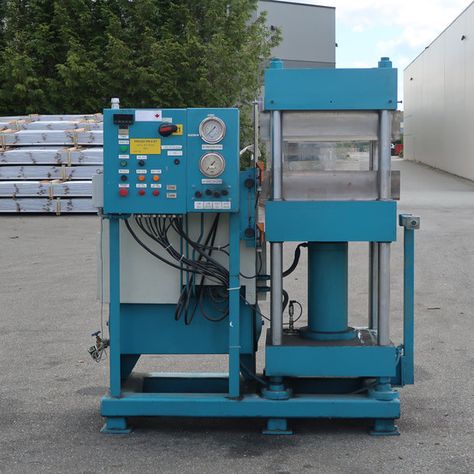
The manufacturing of hydraulic presses involves several key stages, from design and material selection to assembly and testing. The process is highly specialized and requires precise engineering to ensure the press meets performance, safety, and durability standards. Below are the general steps involved in hydraulic press manufacturing:
- Design and Engineering
- Initial Design: The first step in manufacturing a hydraulic press is designing it to meet the specific requirements of the customer or application. Engineers create detailed technical drawings, CAD models, and simulations to determine the size, force, stroke length, and other operational parameters of the press.
- Component Selection: Critical components like the hydraulic pump, valves, cylinder, frame, and control systems are selected based on the desired specifications. Material selection is crucial for ensuring the press’s strength and longevity. Typically, high-strength steel or cast iron is used for the frame and major structural components, while hardened steel may be used for components subjected to high wear.
- Customization: Depending on the intended application, hydraulic presses may be customized with specialized tooling, specific control systems, or additional features such as automated cycles or heat exchangers.
- Manufacturing of Components
- Frame and Structural Parts: The main structural components of the press are fabricated, typically using methods such as casting, forging, or machining. The frame of the press needs to be extremely rigid to withstand the high forces involved in pressing operations. Large frames are usually cast in molds, while smaller or more intricate parts may be machined from solid blocks of metal.
- Hydraulic Cylinder and Ram: The hydraulic cylinder and ram, which are responsible for applying pressure, are fabricated using precision machining to ensure smooth operation. The cylinder is typically made from high-strength steel, and the ram is often hardened to resist wear from constant pressure.
- Pump and Hydraulic System: The hydraulic pump is an essential component that determines the press’s ability to generate force. The pump may be a gear, piston, or vane type, depending on the application. Hydraulic hoses, valves, and fittings are also manufactured or sourced to ensure proper fluid flow and pressure regulation.
- Assembly
- Frame Assembly: The frame is assembled first, often involving welding or bolting together the main sections. If the press is large, it may be assembled in multiple stages.
- Hydraulic System Assembly: The hydraulic components, including the pump, valves, hydraulic cylinder, and pipes, are integrated into the frame. Careful attention is given to ensuring that the hydraulic system is sealed properly to avoid leaks and maintain pressure consistency.
- Ram and Pressing Mechanism: The ram, which is the moving part that applies pressure to the material, is installed. This component is connected to the hydraulic cylinder, and the entire pressing mechanism is calibrated to ensure smooth operation.
- Control and Electrical Systems: The electrical control panel, sensors, and automation systems are installed. These systems control the hydraulic press’s functions, including pressure, speed, and stroke length. In advanced models, programmable logic controllers (PLCs) are integrated to automate the press cycle.
- Testing and Quality Control
- Pressure Testing: One of the most important aspects of manufacturing a hydraulic press is testing its hydraulic system. The system is pressurized to ensure that the components can withstand the required loads without leaks or failures.
- Functionality Testing: After assembly, the press undergoes thorough functionality testing to verify that all movements, speeds, and pressures are within the required specifications. The control system is also tested for accuracy and reliability.
- Load Testing: The press is subjected to load testing to ensure it can handle the maximum intended force. This may include using test materials to simulate real-world operations and checking for stability, performance, and safety.
- Safety Checks: Hydraulic presses are equipped with various safety mechanisms, such as overload protection, emergency stop buttons, and safety interlocks. These features are rigorously tested to ensure they function correctly under all conditions.
- Final Adjustments and Calibration
- Fine-Tuning: After initial testing, any necessary adjustments are made to improve performance, such as fine-tuning the speed, pressure, or stroke length. The press is calibrated to meet the exact needs of the application, ensuring precision.
- Finishing: The hydraulic press is cleaned and inspected for any surface imperfections. Protective coatings may be applied to prevent rust and wear, and any cosmetic finishing is done.
- Packaging and Shipping
- Once the hydraulic press passes all tests, it is disassembled for shipping, if necessary, or fully assembled for delivery, depending on size and customer requirements.
- It is carefully packaged to prevent damage during transport. Large presses may be shipped in parts and require assembly at the customer’s facility.
- Installation and Training
- After delivery, the hydraulic press is installed at the customer’s site, where it is reassembled and connected to power, hydraulic, and control systems.
- Operators are trained on how to use the press, including how to operate the controls, maintain the equipment, and troubleshoot basic issues.
The manufacturing of hydraulic presses involves high precision, quality control, and careful attention to safety standards. It is essential that manufacturers adhere to international standards (such as ISO and ANSI) to ensure the machines perform safely and reliably over their service life.
The manufacturing of hydraulic presses starts with careful design and engineering to meet the specific requirements of the intended application. Engineers create detailed technical drawings and CAD models, determining the necessary specifications such as force, stroke length, and frame size. Material selection plays a crucial role, with components like the frame, cylinder, and ram often made from high-strength steel or cast iron to ensure durability and resistance to wear.
Once the design is finalized, the manufacturing of the various components begins. The frame and other structural parts are typically fabricated through processes like casting, forging, or machining. Large frames are often cast, while smaller or more intricate parts are machined from solid metal. The hydraulic cylinder and ram, responsible for generating and applying the pressure, are also machined with precision to ensure smooth movement and durability.
The next phase is the assembly of the press. The frame is first constructed, often involving welding or bolting. Afterward, the hydraulic system, including pumps, valves, and cylinders, is integrated into the frame. Careful attention is paid to seal the hydraulic components to prevent leaks and ensure pressure stability. The pressing mechanism, including the ram and cylinder, is connected, and the entire assembly is tested for correct operation.
Control systems, including electrical panels, sensors, and automation components, are installed to monitor and regulate the press’s functions. In advanced models, programmable logic controllers (PLCs) are used to automate the press cycle, providing precision and repeatability. The system is then tested to ensure it performs according to the required specifications. Pressure tests check for leaks, and functionality tests ensure the system responds properly to inputs.
Once the initial testing is complete, the press undergoes load testing to ensure it can handle the maximum force it’s rated for. Safety features, such as emergency stop buttons and overload protection, are thoroughly tested to ensure they function correctly under all conditions. After this, any necessary adjustments or fine-tuning are made to ensure optimal performance.
The hydraulic press is then cleaned, finished, and inspected for any surface imperfections. Protective coatings are applied to prevent rust, and any cosmetic finishing is completed. Once everything is ready, the press is carefully packaged for shipping. Depending on the size and design, the press may be shipped fully assembled or in parts that require on-site assembly.
Finally, once the hydraulic press arrives at the customer’s location, it’s reassembled if necessary, connected to the power and hydraulic systems, and calibrated for operation. Operators are trained on its use and maintenance, ensuring the press runs smoothly and safely throughout its lifecycle.
Once the hydraulic press is set up and running, ongoing maintenance and periodic inspections are critical to ensuring its long-term reliability and performance. Routine maintenance tasks include checking and replacing the hydraulic fluid, inspecting seals and hoses for signs of wear or leaks, and verifying that the pumps and valves are functioning correctly. The control systems should also be regularly checked to ensure sensors, actuators, and PLCs are performing as expected.
It is also essential to monitor the performance of the hydraulic system during regular operations. Over time, components like pumps, valves, and cylinders may experience wear and tear due to the high forces and pressures exerted during each press cycle. A preventative maintenance schedule can help identify potential issues before they lead to downtime or costly repairs. This includes cleaning the hydraulic reservoir, changing the oil and filters, and making sure all parts are well-lubricated.
For companies operating large-scale production facilities, a monitoring system might be implemented to track the performance of the hydraulic press in real-time. Sensors embedded in the machine can provide data on temperature, pressure, stroke length, and other critical parameters. This data can be analyzed to predict when certain components may need to be replaced or serviced, allowing for more efficient maintenance planning and reducing unexpected failures.
In addition to maintenance, operators should be trained to recognize early signs of malfunction or inefficiency. They should be familiar with troubleshooting procedures, such as identifying abnormal noises, vibrations, or pressure drops that could signal problems with the hydraulic system. Regular calibration of the press, especially in industries where precise tolerances are required, ensures that the press continues to operate within the specified parameters.
Advancements in hydraulic press technology also allow for integration with automated production systems. Some presses are designed with robotics or automated material handling systems to improve throughput, reduce human error, and streamline operations. In such systems, the press becomes a part of a larger automated assembly line, with the ability to change tooling and adjust parameters on the fly without requiring manual intervention.
As hydraulic press technology evolves, manufacturers may also adopt energy-efficient designs, including hydraulic systems that use less fluid and power or presses with energy recovery systems. These improvements can lead to reduced operational costs and less environmental impact, contributing to more sustainable manufacturing practices.
In the event of a malfunction or breakdown, having spare parts on hand and a strong support network for troubleshooting can minimize downtime. Manufacturers of hydraulic presses often provide maintenance manuals, training programs, and remote support options, allowing operators and maintenance personnel to address issues swiftly and effectively.
Ultimately, the longevity and efficiency of a hydraulic press depend on both the quality of its manufacturing and the care taken throughout its lifecycle. By following manufacturer-recommended maintenance procedures, operators can ensure that the press continues to deliver high performance and reliability for years to come.
Horizontal Hydraulic Press Machine
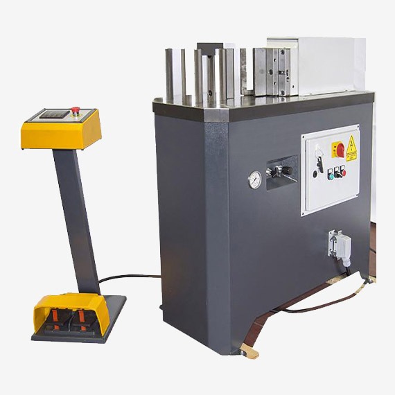
A horizontal hydraulic press machine is a type of hydraulic press where the primary press mechanism is oriented horizontally rather than vertically, as seen in conventional hydraulic presses. This configuration provides several advantages, especially when dealing with large, heavy, or awkwardly shaped workpieces. Horizontal presses are typically used in industries like metal forming, automotive, plastic molding, and in applications that require high precision and large capacities.
The main working principle of a horizontal hydraulic press machine is similar to other hydraulic presses. A hydraulic fluid is pressurized in a cylinder, creating force that moves a ram to apply pressure to the material placed between the press and a die or mold. The key difference lies in the positioning of the cylinder and ram, which are arranged horizontally, allowing for easier material handling, especially for larger or heavier workpieces.
Key Characteristics of a Horizontal Hydraulic Press Machine:
- Configuration: The horizontal orientation allows for better ergonomics, as the material to be processed is positioned on the horizontal surface. This setup makes it easier to load and unload parts, especially large and heavy components.
- Large Bed Size: Horizontal presses often feature a larger bed or table to accommodate bigger or bulkier workpieces. The wider bed makes it suitable for shaping, bending, or molding large components like automotive parts, structural elements, or large plastic molds.
- Higher Precision: Horizontal hydraulic presses can offer high precision in shaping and cutting operations, especially when paired with advanced controls and custom tooling.
- Increased Force Capacity: Horizontal presses often have a higher force capacity compared to their vertical counterparts, making them ideal for applications that require substantial pressure, such as deep drawing or heavy forging.
- Material Handling: The horizontal design allows for easier automation of material handling. It’s common to pair horizontal hydraulic presses with robotic arms, conveyors, or other material handling systems, enhancing the press’s throughput and efficiency.
- Safety Features: Horizontal presses are equipped with various safety features, such as pressure relief valves, overload protection, and emergency stop functions. These are critical to preventing accidents during the press operation, especially when dealing with large and heavy materials.
- Versatility: Horizontal presses are versatile and can be used for a wide variety of tasks, including punching, bending, embossing, molding, and forging. They are often custom-built to handle specific industrial applications.
Applications of Horizontal Hydraulic Press Machines:
- Metalworking: They are used for stamping, bending, punching, and deep drawing metal sheets and plates. The horizontal layout makes it easier to work with large metal parts, often found in the automotive and aerospace industries.
- Plastic Molding: Horizontal hydraulic presses are widely used in injection molding for plastic parts, where large molds are applied under high pressure.
- Forging: Heavy-duty horizontal presses are ideal for forging operations, where high force is required to shape and form metal parts.
- Assembly and Testing: Horizontal presses are also used for assembly operations and component testing, where consistent and precise force is needed.
Advantages:
- Easy Material Loading and Unloading: The horizontal configuration allows for more efficient loading and unloading of parts, particularly when large or heavy workpieces are involved.
- Improved Precision: Horizontal presses often provide better control over the material and tooling alignment, offering higher precision in various manufacturing processes.
- Reduced Maintenance: The horizontal orientation tends to reduce stress on the press components, which may result in lower wear and tear, leading to reduced maintenance costs over time.
Disadvantages:
- Space Requirements: Horizontal presses typically require more floor space than vertical presses, which could be a limitation in smaller facilities or production lines.
- Cost: Horizontal presses tend to be more expensive to manufacture and maintain than vertical presses, especially if they are customized for specific tasks.
Overall, horizontal hydraulic press machines are an excellent choice for applications that require high force, large workpieces, and precise material handling, providing versatility and efficiency across a wide range of industries.
A horizontal hydraulic press machine operates on the same principle as traditional hydraulic presses, using hydraulic fluid to generate force that moves a ram to apply pressure on a material. The key difference lies in the horizontal orientation of the press, which makes it particularly suitable for handling large, heavy, or cumbersome materials. This design enables more efficient material loading and unloading, especially for large workpieces, which can be positioned on the horizontal bed or table. As the ram moves horizontally across the press, it can apply consistent pressure across a larger surface area, which is ideal for certain types of operations such as molding, shaping, or punching.
These presses typically have a larger bed size compared to vertical models, providing more room for bigger workpieces. This added space is beneficial for industries that work with larger components like automotive parts, structural elements, or large plastic molds. In addition to the larger bed, horizontal presses often have higher force capacities, which makes them suitable for tasks that require substantial pressure, like deep drawing or heavy forging.
The horizontal orientation also improves material handling, as the workpieces are easily accessible from the side rather than being fed vertically into the press. This feature enhances ergonomics, particularly in applications where operators need to load and unload large or heavy materials. The design also allows for greater automation, with robotic arms, conveyors, or other handling systems being integrated into the process, which helps to increase efficiency and reduce manual labor.
In terms of precision, horizontal hydraulic presses offer excellent control over the movement of the ram and alignment of materials. When equipped with advanced control systems and custom tooling, they can achieve high precision in shaping, cutting, and molding, which is essential for industries like aerospace and automotive manufacturing. Furthermore, horizontal presses are versatile, able to perform various operations such as punching, bending, embossing, forging, and injection molding.
Safety features are also critical in these machines. They are equipped with pressure relief valves, overload protection, and emergency stop functions to ensure safe operation, particularly given the high forces involved in pressing large materials. While the horizontal design offers many advantages in terms of usability, ease of material handling, and precision, it does require more space on the shop floor compared to vertical presses. This larger footprint can be a consideration in smaller production environments. Additionally, the cost of manufacturing and maintaining a horizontal press tends to be higher, especially if the machine is customized for specific applications.
Despite these challenges, horizontal hydraulic presses are widely used across various industries, including metalworking, plastic molding, and forging, where high pressure and large workpieces are common. Their ability to handle complex tasks efficiently makes them an essential part of many modern manufacturing processes.
In addition to the advantages and challenges, horizontal hydraulic presses are designed with features that contribute to their efficiency, longevity, and adaptability. These presses often have a robust frame and structure to handle the immense pressure exerted during operations. The hydraulic cylinders and ram are precision-engineered to ensure smooth, controlled movement. With the horizontal design, the press is more stable under load, allowing for better force distribution, especially when processing large or uneven materials.
The hydraulic system of a horizontal press is also critical to its functionality. It typically includes a high-capacity pump, precision valves, and robust hoses to manage the pressure required for pressing tasks. The press is usually equipped with an efficient cooling system to prevent the hydraulic fluid from overheating during extended operations. Some advanced models use energy-saving systems, such as variable-speed pumps or energy recovery mechanisms, to reduce power consumption, making them more cost-effective and environmentally friendly over time.
As technology progresses, many horizontal hydraulic presses are now incorporating automation and smart control systems. These presses are often integrated with programmable logic controllers (PLCs) and touchscreen interfaces, allowing operators to control and monitor various parameters such as pressure, stroke speed, and cycle times. These advancements enhance precision and consistency, reduce human error, and make it easier to optimize the press for different tasks. The integration of sensors also allows for real-time feedback, enabling the press to adjust its parameters automatically to maintain optimal performance.
Furthermore, horizontal presses are designed with maintenance in mind. Easy access to critical components, such as the hydraulic fluid reservoir, pumps, and valves, makes routine maintenance and servicing more straightforward. Regular maintenance checks, including the inspection of seals, hoses, and hydraulic fluid levels, are essential to ensure the longevity and efficiency of the press. The modular design of some horizontal presses allows for easier upgrades or replacements of parts, which can help reduce downtime and extend the machine’s operational life.
Horizontal hydraulic presses are also ideal for industries that require a high level of precision and customization. For example, in metalworking or automotive manufacturing, custom dies and molds can be incorporated into the press for specialized parts, ensuring that the press can handle a wide range of materials and designs. The ability to swap tooling quickly and easily allows for greater flexibility in production, especially for high-mix, low-volume manufacturing.
Overall, horizontal hydraulic presses are highly versatile and capable of performing a wide variety of manufacturing tasks. Their ability to handle large workpieces, high pressure, and precise operations, combined with ease of material handling and automation options, makes them indispensable in many industrial sectors. Although they require a larger footprint and higher investment, the benefits they provide in terms of efficiency, safety, and precision often outweigh the drawbacks, making them a valuable asset for businesses seeking to optimize their production capabilities.
Small Horizontal Hydraulic Press
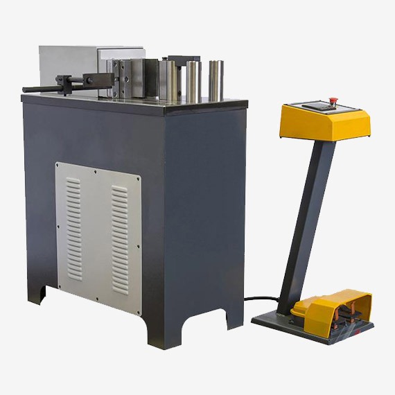
A small horizontal hydraulic press functions similarly to larger models but is designed for more compact, lighter, and often less demanding applications. While the basic principles of operation—using hydraulic pressure to move a ram or piston that applies force to materials—remain unchanged, the small horizontal hydraulic press is more suitable for smaller-scale tasks, limited spaces, and lower production volumes. These presses are commonly used in smaller workshops, laboratories, or small-scale manufacturing settings.
Small horizontal hydraulic presses are highly versatile machines, often used in tasks such as bending, shaping, embossing, punching, or even light-duty forging. They are ideal for applications that require moderate force but still need the benefits of a horizontal design, like better ergonomics and ease of material handling. Their smaller size makes them easier to integrate into existing production lines or workshops where space is limited.
These presses still maintain the essential features of their larger counterparts, such as a horizontal orientation that facilitates easy loading and unloading of workpieces, especially for larger materials that may not fit well in vertical presses. Even though they are smaller, these presses can still apply significant pressure, with force capacities typically ranging from 10 to 100 tons, depending on the model and application. This makes them suitable for light metalworking, plastic molding, or small-scale assembly and testing tasks.
The hydraulic system in a small horizontal press typically includes a pump, cylinder, and ram, but scaled down to meet the smaller size and force requirements. The hydraulic fluid is pressurized and directed to the cylinder, which moves the ram across the bed of the press to apply force. Smaller pumps and valves are used to ensure smooth and efficient operation, and some models feature energy-saving technologies such as reduced pump capacity or automatic pressure adjustments for optimized performance.
Compact and lightweight, small horizontal hydraulic presses can be equipped with manual, semi-automatic, or fully automatic controls, depending on the complexity of the application. In some cases, advanced features like programmable logic controllers (PLCs) and digital interfaces may be incorporated, allowing for precision control over the pressing process, such as stroke length, pressure, and cycle time. These controls are especially useful for ensuring consistency and precision in repeated tasks.
Safety features in smaller presses are just as critical as in larger models. These presses are equipped with safety guards, emergency stop buttons, pressure relief valves, and overload protection to prevent accidents. Some models may also include safety interlocks that stop the press if the operator’s hands are detected in the pressing area.
A key advantage of small horizontal hydraulic presses is their ability to operate in smaller spaces while providing efficient and consistent performance for a variety of tasks. They are generally more affordable than their larger counterparts, making them an attractive option for small businesses, startups, or research and development labs that require precision pressing but have limited space or budget. Additionally, their smaller size makes them easier to move and set up, adding to their versatility.
Despite their smaller size, these presses can still handle a wide range of materials, including metals, plastics, rubber, and composites, depending on the specific press configuration. Small horizontal hydraulic presses are especially useful in industries like automotive prototyping, electronics manufacturing, or jewelry making, where small, precise parts need to be formed, stamped, or assembled with relatively low force. They also find applications in educational settings, where they serve as a hands-on tool for learning about hydraulics and material processing.
In summary, small horizontal hydraulic presses offer a balance of compact design, ease of use, and versatility, making them suitable for applications in small-scale manufacturing, prototyping, or research. They retain the efficiency and ergonomic benefits of larger horizontal presses but in a more accessible package for smaller operations.
Small horizontal hydraulic presses are designed to offer many of the same benefits as their larger counterparts but in a more compact and cost-effective form. They operate on the same fundamental principle, using hydraulic pressure to generate force that moves a ram across a workpiece, applying pressure to shape or mold materials. The horizontal orientation is particularly useful in these smaller models because it allows for easier loading and unloading of parts, providing more ergonomic benefits compared to vertical presses. Even though these machines are smaller in size, they still deliver precision and power that can handle a range of tasks.
One of the main advantages of a small horizontal hydraulic press is its ability to work in smaller, confined spaces. Unlike larger presses, which can be cumbersome and require significant floor space, the compact design of a small press makes it ideal for workshops or manufacturing environments where space is at a premium. These presses can be easily integrated into existing production lines or used for small-scale operations without taking up too much room.
Despite their size, small horizontal hydraulic presses can still apply substantial force, typically ranging from 10 to 100 tons, making them capable of handling tasks like bending, embossing, punching, and light forging. They can also be used for precise work such as molding plastics, testing parts, or assembling components. The press’s design allows for easy positioning of materials, which is crucial for ensuring uniform pressure and accurate results.
Hydraulic pumps, cylinders, and rams are all scaled down in smaller presses, ensuring that the machine can perform its tasks efficiently without requiring excessive hydraulic fluid or energy. Some models even incorporate energy-saving features, such as adjustable pumps or systems that reduce power consumption when the press is not operating at full capacity. These features help keep operating costs low, which is a major benefit for smaller businesses.
Although compact, small horizontal presses still come equipped with safety mechanisms to protect operators. These include emergency stop buttons, pressure relief valves, safety guards, and overload protection. Some machines may even include additional safety interlocks to prevent the press from operating if it detects potential hazards, further ensuring safe operation. This makes them suitable for environments where safety is a priority, such as in educational settings or small-scale production facilities.
Another important consideration is the flexibility these presses offer. Many models allow for adjustments in parameters like stroke length, pressure, and cycle time, which can be controlled through manual, semi-automatic, or fully automatic systems. This adaptability ensures that the press can be used for a wide range of applications and different materials, including metals, plastics, rubber, and composites.
Small horizontal hydraulic presses are especially popular in industries like automotive prototyping, electronics manufacturing, jewelry making, and small-scale metalworking. In these industries, precision is often critical, and the ability to customize the press for specific tasks makes these machines invaluable. Whether it’s forming small parts, stamping intricate designs, or testing materials, these presses are versatile enough to handle a variety of projects while maintaining high levels of accuracy.
Overall, small horizontal hydraulic presses offer an excellent solution for companies or individuals who need a reliable, versatile, and cost-effective machine for precision pressing, molding, or shaping. Their compact design, ease of use, and ability to handle different materials make them indispensable tools for small businesses or research and development labs. Despite their smaller size, they provide much of the power and precision of larger models, offering an affordable and efficient option for smaller-scale operations.
Small horizontal hydraulic presses are particularly useful in industries where space is limited but precise and consistent pressing is essential. Their compact nature doesn’t compromise their ability to perform critical tasks, making them ideal for smaller workshops, R&D labs, or prototyping environments. These presses are well-suited for handling small to medium-sized workpieces, offering high precision in applications such as metal forming, plastic molding, and even certain forms of testing and assembly.
The hydraulic system in a small horizontal press is typically designed to be energy-efficient while providing the required force for operations. Smaller pumps and cylinders are used to ensure the machine operates within its specific pressure range, which also helps reduce wear on components and lower the operational cost. This makes small horizontal presses an excellent choice for businesses or workshops with limited resources, as the cost of running and maintaining the machine is relatively low compared to larger, more industrial hydraulic presses.
In addition to their cost-efficiency, small horizontal hydraulic presses are often designed for ease of use. Many are equipped with intuitive control systems that allow operators to adjust parameters such as pressure, stroke length, and cycle times. Even if the press is manual, operators can quickly learn to use the machine, making it accessible even to less experienced personnel. For more advanced applications, some models come with digital controls or programmable logic controllers (PLCs), providing a higher level of automation and control.
The maintenance of small horizontal hydraulic presses is also simplified by their compact design. Many components are easily accessible, reducing the time and effort required for routine maintenance or troubleshooting. Whether it’s changing the hydraulic fluid, inspecting seals, or replacing a pump, small presses often require less time for upkeep, which minimizes downtime and increases productivity. Regular checks on key components, such as the cylinder and hydraulic system, help ensure that the machine continues to perform at its best without any significant issues.
Customization options for small horizontal hydraulic presses are available as well, allowing users to tailor the press for specific applications. Whether it’s designing specialized tooling or integrating a specific automation system, many manufacturers offer solutions that ensure the press meets the needs of the particular task at hand. This versatility makes them adaptable across a wide variety of industries, from automotive prototyping to smaller-scale plastic molding and even custom fabrication projects.
For industries that focus on high-precision work, like jewelry or electronics, small horizontal hydraulic presses can achieve tight tolerances that are critical in producing parts with exact specifications. The horizontal design of the press allows for better material positioning, reducing the risk of errors and ensuring more consistent results across multiple cycles. Operators can also easily monitor the pressing process to ensure the quality of the output is maintained throughout production.
The flexibility and compactness of small horizontal hydraulic presses make them a valuable asset for businesses that need reliable and consistent performance but lack the space or resources for larger machines. Their ability to handle a variety of tasks—ranging from simple pressing to more intricate molding or forming operations—while occupying a relatively small footprint, makes them ideal for smaller operations that still require the precision and power of hydraulic systems.
Overall, small horizontal hydraulic presses offer an excellent combination of efficiency, versatility, and affordability, making them an attractive choice for businesses looking to streamline their production processes, reduce costs, and maintain a high level of quality in their manufacturing operations.
Small horizontal hydraulic presses also provide advantages in terms of ease of integration into automated production lines. While larger presses are often too bulky or complex to be easily integrated, the compact design of small presses makes them much easier to pair with robotic arms, conveyors, or other automated material handling systems. This integration can significantly improve throughput by reducing manual labor and increasing production efficiency. For example, a robotic arm can load and unload workpieces quickly, while the press operates autonomously, making it ideal for tasks that require repetitive, high-precision operations such as stamping, cutting, or assembling components.
In addition to automation, the ability to quickly change tooling on small horizontal hydraulic presses makes them versatile for businesses that need to perform a wide variety of tasks. Tooling such as dies, molds, and punches can be swapped easily, which is particularly useful in industries like automotive or aerospace, where prototyping or small-batch production of different parts is common. The press can be reconfigured to perform different functions, making it a more flexible asset in fast-paced production environments.
Another factor that contributes to the utility of small horizontal hydraulic presses is their ability to work with a wide range of materials. Whether it’s metal, plastic, rubber, or composite materials, these presses are capable of applying the necessary force to mold, shape, or test the materials for a variety of applications. They are often used in the fabrication of metal parts, such as stamping and bending thin metal sheets, or in plastic molding, where high pressure is used to shape plastic into specific forms. The horizontal configuration allows for better control over the material, reducing the likelihood of defects or inconsistencies during the pressing process.
For businesses that require high-precision results, small horizontal hydraulic presses provide a stable platform that ensures accuracy. The horizontal orientation keeps the workpiece flat, which is important for applications where uniform pressure across the entire surface is required. This consistency in pressure helps to maintain the quality of the finished parts, especially when small, delicate, or complex components are being produced. The precise control over the force applied by the press also allows operators to ensure that parts meet exact specifications, which is critical in industries like electronics manufacturing or medical device production.
Environmental considerations are also important when evaluating small hydraulic presses. With rising energy costs and increasing environmental awareness, manufacturers have begun incorporating more energy-efficient features into small presses. These might include variable-speed pumps that adjust the flow of hydraulic fluid based on the load, energy recovery systems that capture and reuse energy from the press’s operations, and designs that minimize hydraulic fluid consumption. These improvements not only reduce the environmental impact of operating the press but also lower operating costs, making small horizontal hydraulic presses even more cost-effective over time.
Small horizontal hydraulic presses are often equipped with a variety of user-friendly features that make them accessible to operators at different experience levels. Many presses have simple interfaces with basic controls for adjusting pressure, stroke length, and cycle times. More advanced models may include digital displays or touch-screen interfaces that allow for precise input of settings and real-time monitoring of the press’s operation. These features make the presses easier to use, which helps reduce training time and the potential for errors during operation.
Maintenance of small horizontal hydraulic presses is generally straightforward, thanks to their user-friendly design. Access to key components like the hydraulic fluid reservoir, pumps, and cylinders is typically easy, allowing for quick inspections, fluid changes, and other routine maintenance tasks. This reduces the overall maintenance burden and helps ensure that the press continues to function at its optimal level throughout its lifecycle.
Small horizontal hydraulic presses are also valuable tools for research and development (R&D) purposes. Engineers and designers use these presses for testing and prototyping new products, allowing them to refine designs and experiment with different materials or processes without committing to large-scale production equipment. The ability to conduct R&D on a smaller, more affordable machine allows companies to innovate more rapidly and cost-effectively.
In conclusion, small horizontal hydraulic presses offer businesses a cost-effective, flexible, and efficient solution for a variety of manufacturing and prototyping tasks. With their compact size, ease of integration into automated systems, and ability to handle a wide range of materials, these presses serve as valuable assets for companies of all sizes. Whether for small-scale production, prototyping, or research and development, small horizontal hydraulic presses provide consistent performance, high precision, and versatility while maintaining relatively low operational costs.
Horizontal Hydraulic Press Manufacturing
The manufacturing process of horizontal hydraulic presses involves several stages, from initial design and material selection to assembly and testing. The goal is to produce a machine that offers precision, reliability, and high performance under heavy loads. Manufacturers focus on ensuring that the press can withstand high forces while maintaining a smooth and controlled operation. Below is an overview of the key steps involved in the manufacturing process of a horizontal hydraulic press.
The first step in the manufacturing process is designing the horizontal hydraulic press. Engineers and designers collaborate to create a blueprint that specifies the size, force capacity, material requirements, and other key features of the machine. This stage involves determining the dimensions of the bed, the configuration of the hydraulic cylinder, the maximum pressure the system will need to handle, and other operational parameters such as stroke length, speed, and control systems. The design must also account for safety features, such as overload protection, emergency stop functions, and guards to prevent operator injury.
Once the design is finalized, the manufacturing process moves to material selection. Key components of the hydraulic press, such as the frame, bed, and hydraulic cylinders, must be made from high-strength steel or other durable materials capable of withstanding high forces without warping or cracking. The quality of the materials used is critical to ensuring the long-term performance and durability of the press. For example, high-tensile steel is commonly used for the frame to ensure the press remains stable under heavy load conditions. The hydraulic components, including the pump, valves, and hoses, are made of materials that resist wear and corrosion under high pressure.
The next step is machining the components. This involves cutting, shaping, and refining the parts that make up the press. For example, the frame of the horizontal hydraulic press is fabricated and welded together to form a sturdy structure capable of bearing the forces exerted during the pressing process. CNC (Computer Numerical Control) machines are often used to ensure that each part is produced to precise specifications. Hydraulic cylinders are machined and polished to ensure smooth movement and minimal friction during operation. The bed and table are also machined to provide a flat and stable surface for positioning workpieces.
After machining, the hydraulic components are assembled. The hydraulic pump, valves, pressure relief systems, and other critical elements are integrated into the press’s hydraulic circuit. The pump must be designed to provide the required pressure and flow rate to move the ram or piston across the bed and apply the necessary force. The hydraulic fluid used in the system must be carefully selected to ensure optimal performance under varying temperatures and pressures. The press is also equipped with hoses, filters, and accumulators to maintain fluid flow and prevent contamination.
Once the hydraulic system is fully assembled, the press components are brought together for final assembly. The frame, hydraulic cylinder, bed, and table are connected, and the various electrical and control systems are installed. For small horizontal hydraulic presses, the electrical systems may include basic controls for manual operation, while more advanced models may include programmable logic controllers (PLCs) or digital touchscreens to allow for automated operation and precise adjustments of pressure, stroke, and cycle time. The operator interface is designed to be user-friendly and easy to navigate.
At this stage, safety features are integrated into the press. These may include safety guards, pressure sensors, emergency stop buttons, and overload protection devices. These features ensure that the press can operate safely in a production environment and protect the operator from potential hazards. For example, safety interlocks prevent the press from operating if the protective covers are removed, while pressure relief valves prevent the system from operating beyond its maximum pressure rating.
Once the press is fully assembled, the machine undergoes a series of tests to ensure that it meets all operational specifications and safety standards. This includes checking the hydraulic system for leaks, testing the press under load to verify that it applies the correct force, and calibrating the controls to ensure precise operation. The press may also undergo endurance testing to ensure that it can perform reliably over an extended period. Any necessary adjustments are made during this testing phase to fine-tune the machine’s performance.
Finally, the horizontal hydraulic press is thoroughly inspected and cleaned before being shipped to the customer. A quality control team checks the final product for defects, ensuring that all components function as expected and meet industry standards. Once approved, the press is packaged and delivered to the customer, ready for installation and operation.
The manufacturing process of a horizontal hydraulic press requires careful planning, precision engineering, and attention to detail. It involves several stages, including design, material selection, machining, assembly, and testing, all of which ensure that the final product is capable of withstanding the heavy loads and rigorous demands of industrial applications. Each component must be made to exacting standards to ensure the press operates efficiently, reliably, and safely. With advancements in technology, manufacturers are now able to produce hydraulic presses with more advanced controls, energy-saving features, and increased automation, making them more efficient and cost-effective in the long run.
The process of manufacturing a horizontal hydraulic press is complex and requires precise engineering, attention to detail, and the integration of several systems to ensure that the machine delivers the required force and reliability. The first step is to ensure that the press is designed for the specific application it will be used for. Engineers develop a detailed blueprint that incorporates the size, force requirements, and other operational specifications. Factors such as stroke length, speed, pressure settings, and the desired type of material to be processed are carefully considered. The press design must account for structural integrity and stability, as it needs to withstand substantial forces during operation.
After the design is finalized, materials are selected. High-quality, durable materials are necessary to ensure that the press can handle the stresses associated with pressing operations. Strong steels and alloys are typically chosen for the frame and structural components, as these materials can handle the pressures exerted during use without deforming. The hydraulic system also requires specific materials, such as corrosion-resistant metals for the pump, valves, and piping, to ensure longevity and reliability in high-pressure environments.
Machining is the next critical step in the manufacturing process. Components such as the press frame, bed, ram, and hydraulic cylinders must be precisely cut, shaped, and finished to meet the design specifications. This typically involves using advanced CNC machines to achieve tight tolerances and high-quality finishes. The precision of the machining process ensures that the parts fit together perfectly during assembly and that the hydraulic components, particularly the cylinders, operate smoothly without excessive friction.
After machining, the press components are assembled. The hydraulic pump and other fluid control systems are integrated, ensuring that the hydraulic fluid circulates properly through the system to move the ram. The hydraulic cylinders must be properly aligned, and the fluid system must be tested for leaks to prevent any operational issues during use. At this stage, it’s also essential to verify that all connections are secure, and any seals are in place to prevent fluid loss.
With the main components assembled, attention shifts to incorporating the press’s electrical and control systems. For manual presses, this might involve basic switchgear to control the hydraulic system. More advanced models, however, incorporate sophisticated control systems, such as PLCs, which allow for automated operations. These systems allow operators to set and monitor parameters like pressure, stroke length, and cycle time, improving the press’s efficiency and precision. The control panel is designed for ease of use, ensuring that operators can easily adjust settings as needed.
Next, safety features are integrated into the machine. Horizontal hydraulic presses often include emergency stop buttons, pressure relief valves, and overload protection systems to ensure safe operation. The press must have mechanisms to prevent accidents, such as automatic shutdown in case of an overload or malfunction. Safety guards are also incorporated to protect the operator from potential hazards, such as moving parts or hot surfaces. These safety measures are critical to meeting regulatory standards and ensuring the press operates in a safe environment.
Once assembly is complete, the press undergoes rigorous testing. The hydraulic system is checked for leaks, and the machine is tested under load to ensure it can generate the required force. Calibration is performed to ensure that the press applies consistent and accurate pressure during operation. The press may also undergo endurance testing to verify that it can maintain performance over long periods of continuous use. Any adjustments or refinements are made during this testing phase to ensure that the press is fully functional and reliable.
Finally, before the machine is shipped to the customer, it is subjected to a thorough inspection and cleaning. A quality control team carefully examines the press to ensure it meets all specifications and safety standards. This inspection includes checking the overall construction, hydraulic system, electrical components, and safety features. The press is then cleaned and prepared for shipping, ensuring that it arrives in optimal condition.
Manufacturing a horizontal hydraulic press requires a combination of engineering expertise, precise manufacturing techniques, and a commitment to safety and quality. Each stage of production, from design and material selection to assembly and testing, must be carefully executed to ensure that the press will deliver reliable performance under heavy load conditions. With advancements in automation, energy efficiency, and control systems, modern hydraulic presses are more capable and versatile than ever, making them essential tools for a wide range of industrial applications.
Once the manufacturing process is completed and the horizontal hydraulic press is assembled, the final quality assurance steps are critical. These processes ensure that the press will perform optimally in real-world applications. Engineers conduct a series of functional tests to simulate actual operating conditions, checking for proper hydraulic fluid flow, load capacity, and overall performance. The press is often subjected to extended testing cycles, running through various stages of operation to verify that it maintains stable pressure and consistent results.
During this phase, the machine is monitored closely for any signs of malfunction or inefficiency. Any issues discovered are addressed immediately, whether it be fine-tuning the hydraulic system, recalibrating pressure settings, or adjusting the alignment of moving parts. The press is then subjected to load testing, where it is gradually brought up to its maximum capacity to ensure it can handle the intended workload without issues. These tests help identify potential problems that might not be apparent during initial assembly but could emerge during regular usage.
Once the press passes all functional tests, a comprehensive inspection of all components is conducted. Every part of the hydraulic press, including mechanical, electrical, and hydraulic systems, is thoroughly inspected to ensure that it adheres to both industry standards and the customer’s specific requirements. The safety features are tested again to ensure they function correctly in various emergency situations, ensuring that the press will stop if a safety hazard is detected, protecting operators and reducing the risk of injury.
After passing all tests and inspections, the horizontal hydraulic press is carefully cleaned to remove any residues from the manufacturing process. Any hydraulic fluid remnants are drained, and all surfaces are wiped down to prevent contaminants from affecting the press during its first operation. At this stage, all components are lubricated, and seals are checked to ensure that they are properly in place and functioning to prevent hydraulic fluid leaks.
The press is then packaged for shipping. Proper packaging is essential to prevent any damage during transport. Typically, the press is carefully disassembled into major sections (such as the frame, bed, hydraulic components, and controls) and packed using high-quality materials to cushion and protect each component. Detailed assembly instructions and user manuals are also included to assist in setting up the press at its final destination.
Once the press arrives at its destination, it is carefully reassembled and tested one more time on-site. If the press has been shipped in parts, a trained team of technicians will handle the assembly and integration. After reassembly, the press undergoes a final round of operational tests to ensure it is functioning properly and meets all performance requirements. This step is crucial, as it ensures that the press is ready for immediate use and operates as expected in its intended environment.
Training may also be provided to the customer or end users. This training typically includes instructions on the proper setup, maintenance, and operation of the press. Operators are educated on how to adjust settings like pressure, stroke length, and cycle time, as well as how to troubleshoot common issues. Training also covers safety protocols, such as proper use of safety guards, emergency stop mechanisms, and maintenance practices.
Overall, the entire process, from initial design to delivery and training, requires significant expertise and coordination. Manufacturers ensure that the horizontal hydraulic press is built to last and perform efficiently for years, even under heavy loads. The attention to detail throughout the manufacturing process, combined with thorough testing and quality control measures, guarantees that the machine can handle the pressures of industrial environments. The final result is a machine that offers reliability, precision, and safety, making it an invaluable tool for a variety of industries, including automotive, metalworking, plastics, and many more.
Stainless Steel Cookware Manufacturing Process
The manufacturing process for stainless steel cookware involves several stages, from material selection to shaping, finishing, and quality control. Stainless steel cookware is prized for its durability, resistance to corrosion, and ability to retain heat evenly. The process of making high-quality stainless steel cookware requires precise control over materials, forming techniques, and finishing processes to ensure the final product meets both functional and aesthetic standards.
The first step in manufacturing stainless steel cookware is selecting the appropriate material. Stainless steel comes in various grades, and the most common grades for cookware are 18/8 (18% chromium, 8% nickel) and 18/10 (18% chromium, 10% nickel), which offer a good balance of strength, resistance to rust, and durability. Higher-quality cookware may include additional elements such as molybdenum to increase corrosion resistance. The selected stainless steel is sourced in large sheets or coils, depending on the size and design of the cookware to be produced.
Next, the stainless steel sheets or coils are cut to the required size and shape. This is typically done using high-precision cutting tools like laser cutters, water jets, or shears. The sheets are carefully measured to ensure uniformity, as the final shape and size of the cookware will depend on this initial cutting process. The cutting process is critical in determining the cookware’s form, so accuracy is key to ensuring proper fit during assembly.
Once the stainless steel is cut to size, the cookware is formed into its desired shape. For pots and pans, this is typically done using deep drawing or stamping. Deep drawing is a process in which a flat sheet of stainless steel is placed into a die, and a punch is used to force the metal into the mold, creating the desired shape. This process is used to form the body of the cookware, including the sides and bottom. The metal is stretched and shaped under high pressure to create a smooth and consistent surface. After forming, the cookware may undergo a process called “trimming” to remove any excess metal around the edges.
For cookware that requires a handle, this step also involves the attachment of the handle. Stainless steel handles are often welded or riveted to the cookware body, depending on the design. Welding provides a strong bond and is preferred for certain designs, while riveting may be used for aesthetic or functional reasons. The handles are usually made from the same high-quality stainless steel to ensure the cookware is durable and retains its high-end appearance.
In many cases, cookware manufacturers incorporate an additional layer of material, such as an aluminum or copper core, to improve heat distribution. This is especially common in high-end cookware, as it helps to ensure that heat is evenly distributed across the cooking surface, preventing hot spots. The aluminum or copper core is inserted between layers of stainless steel, and the cookware is bonded under high pressure and heat. This process is known as “clad” cookware, where multiple layers of metal are fused together to create a composite material.
After the cookware is formed and any additional layers are bonded, the surface is polished to achieve a smooth, reflective finish. Polishing is an important step, as it not only enhances the appearance of the cookware but also provides a smooth surface that is resistant to food sticking. Several types of finishes are used in stainless steel cookware, including mirror polishing, satin finishes, or brushed finishes. Mirror polishing gives the cookware a highly reflective, shiny surface, while satin and brushed finishes provide a more matte or textured look, which some consumers prefer for aesthetic or practical reasons.
The next step is to clean the cookware. Stainless steel cookware is thoroughly cleaned to remove any manufacturing oils, residues, or contaminants from the surface. This is typically done using a combination of mechanical cleaning, such as brushing or abrasive cleaning, and chemical cleaning processes, such as acid washing or passivation. The passivation process is crucial because it helps to enhance the stainless steel’s corrosion resistance by removing iron particles from the surface and creating a protective oxide layer.
Once the cookware is cleaned, any necessary finishing touches are applied. This can include adding engraved logos, branding, or other decorative elements. Some cookware may also undergo heat treatments to strengthen the metal or improve its heat conductivity. For example, in some cookware, the bottom may be reinforced with a thicker layer of metal or a non-stick coating may be applied. Non-stick coatings are often applied to frying pans or sauté pans, providing an easy-to-clean surface and preventing food from sticking. These coatings are typically made from Teflon or ceramic-based materials, and the cookware is heated to bond the coating to the surface.
Before the cookware is packaged and shipped, it undergoes rigorous quality control checks. These checks ensure that the cookware meets both safety standards and performance expectations. Common quality control measures include checking the integrity of welded or riveted handles, ensuring the cookware is free from defects such as cracks or dents, and verifying that the non-stick coating adheres properly. The cookware is also tested for heat distribution, durability, and overall functionality. This ensures that the cookware can withstand everyday use and maintain its performance over time.
Finally, the cookware is carefully packaged to prevent damage during transit. Packaging typically includes protective materials, such as foam or bubble wrap, to safeguard the cookware. Manufacturers may also include user manuals and care instructions to help customers maintain the cookware’s longevity. The packaging is designed to be both protective and visually appealing, as the cookware is often sold in retail stores or online.
The manufacturing of stainless steel cookware requires high precision at each step, from material selection to forming, finishing, and quality control. By combining high-quality stainless steel with advanced manufacturing techniques and attention to detail, manufacturers produce cookware that is durable, resistant to corrosion, and capable of delivering optimal cooking performance. Whether the cookware is designed for home use or professional kitchens, the end result is a product that combines functionality with aesthetic appeal.
The stainless steel cookware manufacturing process continues with various precision steps to ensure the product is not only functional but also aesthetically pleasing. After the cookware is assembled, it undergoes heat treatment in some cases to further enhance its durability and performance. This heat treatment may include processes like annealing, which involves heating the metal to a specific temperature to improve its hardness and resistance to corrosion. This step ensures the cookware can endure prolonged exposure to high temperatures without warping or losing its structural integrity.
Once heat treatment is completed, the cookware may undergo a final round of polishing or brushing to refine its surface. This gives the cookware its final texture and sheen. The surface can be mirror-polished for a highly reflective look or brushed to create a more muted, matte finish. Both finishes offer different aesthetic qualities and functional benefits. Mirror finishes are typically easier to clean and give a shiny, elegant look, while brushed finishes tend to hide fingerprints and stains better, making them popular for everyday use. Each piece is carefully inspected to ensure uniformity in finish, as well as to verify that there are no imperfections in the surface, such as scratches, discoloration, or irregularities.
After polishing, the cookware is cleaned again to remove any residual polishing compounds or other contaminants. This is usually done through ultrasonic cleaning or another method to ensure the surface is pristine. This cleaning process is crucial, as any leftover materials can affect the cookware’s performance and appearance.
The final stages of manufacturing include quality control and packaging. Each piece of cookware is subjected to rigorous quality control checks to ensure it meets high standards. These checks include verifying the functionality of the cookware, such as ensuring the handle is securely attached and that there are no defects in the welds or rivets. If non-stick coatings have been applied, tests are conducted to ensure the coating is evenly distributed and adheres correctly. Additionally, some manufacturers may conduct tests on the cookware’s ability to withstand extreme temperatures and ensure that it performs as expected on various stovetops, whether gas, electric, or induction. The cookware is also checked for heat distribution and how evenly it cooks food, ensuring that the end product will perform well in the kitchen.
Once quality control is complete, the cookware is packaged for shipment. The packaging process involves placing the cookware into protective materials like bubble wrap, foam, or custom-fit inserts to ensure that it arrives undamaged. The packaging also includes care instructions and sometimes a warranty, which are essential for customers to maintain the cookware over time. Some brands may also include informational leaflets or booklets with recipes or tips on how to care for stainless steel cookware to prolong its life and keep it looking new.
Packaging is also designed with branding in mind, as it plays an important role in marketing. High-end cookware brands often use premium, visually appealing packaging to convey the quality of the product. The cookware is then labeled and shipped to distributors or retailers, where it will be available for purchase. In some cases, cookware may also be sold directly to consumers through e-commerce platforms, with additional care taken to ensure the product reaches the customer in excellent condition.
Stainless steel cookware manufacturing is a multi-step, highly detailed process that combines advanced technology with craftsmanship. From selecting the right material to forming, finishing, testing, and packaging, each stage plays a crucial role in ensuring the cookware is durable, functional, and visually appealing. The result is a high-quality product that meets the demands of consumers, whether they’re professional chefs or home cooks. With the right combination of material quality, precision manufacturing, and quality control, stainless steel cookware continues to be a popular choice in kitchens worldwide for its longevity, performance, and versatility.
As the manufacturing process of stainless steel cookware progresses, the attention to detail at each stage remains paramount to delivering a product that performs well in real-world cooking environments. After the cookware is packaged and sent to retail or directly to customers, the final responsibility for its quality lies with the consumer’s usage and care. However, manufacturers ensure that the cookware’s longevity is maximized through continuous innovations in material science, design improvements, and enhancements to functionality.
One of the key developments in recent years has been the advancement in induction-ready cookware. Stainless steel alone does not conduct heat as well as some other metals, such as copper or aluminum. To address this, many manufacturers integrate a layer of magnetic material in the base of the cookware to make it compatible with induction stoves. Induction cooking requires cookware with a magnetic base, as the heat is generated directly through electromagnetic induction. As a result, manufacturers have created cookware that incorporates this technology, allowing users to benefit from the efficiency and speed of induction cooking.
In addition to induction compatibility, many stainless steel cookware brands have invested in incorporating ergonomic handle designs for enhanced comfort and safety. The handles are engineered to remain cool during cooking, even when the pot or pan is heated, and they are designed to provide a secure grip, reducing the risk of slipping or accidents. Some manufacturers even incorporate handles that are riveted with an additional layer of stainless steel to ensure strength and durability over time. The handle attachment is a critical part of the manufacturing process because it directly affects the safety and functionality of the cookware.
Another area of development in the manufacturing of stainless steel cookware involves the integration of non-stick coatings, especially on frying pans or sauté pans. While stainless steel itself is known for its durability and resistance to staining, many consumers seek the ease of cleaning that non-stick surfaces offer. Manufacturers have responded by combining stainless steel with non-stick coatings, such as Teflon or ceramic-based materials, which provide easy food release and simple cleanup. However, there is an ongoing effort to improve these coatings to ensure they are safe, long-lasting, and free of harmful chemicals like PTFE (polytetrafluoroethylene) or PFOA (perfluorooctanoic acid).
Furthermore, stainless steel cookware is being designed with energy efficiency in mind. With rising energy costs and increasing environmental concerns, manufacturers are now focused on improving heat retention and distribution across cookware surfaces. Clad stainless steel cookware—where layers of aluminum or copper are bonded between layers of stainless steel—provides superior heat conduction compared to traditional single-layer stainless steel. This ensures that the cookware heats up quickly and distributes heat evenly, reducing cooking times and improving energy efficiency.
Manufacturers also strive to incorporate eco-friendly practices into the production of stainless steel cookware. Sustainable practices include reducing waste in the manufacturing process, using recyclable materials for packaging, and minimizing the carbon footprint associated with production. Some companies also focus on reducing the environmental impact of the raw materials they use by sourcing steel from certified, sustainable suppliers. This shift toward more environmentally friendly practices aligns with consumer preferences for eco-conscious products and can influence a brand’s reputation in the market.
Beyond the technical innovations, the aesthetic aspects of stainless steel cookware have continued to evolve. Manufacturers often offer a variety of styles, finishes, and designs to cater to different consumer tastes. While the polished, mirror-like finish remains popular for its elegant appearance, brushed or matte finishes are often chosen for their more contemporary look and practicality. These finishes also help to minimize the appearance of fingerprints, which is important for cookware used regularly in home kitchens or professional settings.
Quality assurance continues to play a vital role throughout the entire process, from initial design to final shipment. As competition in the cookware industry grows, manufacturers have developed more stringent testing protocols to ensure that each piece of cookware not only meets the expected standards for durability and performance but also adheres to regulatory safety standards. This ensures that consumers receive a product they can trust for both safety and cooking efficiency.
The final product that reaches consumers is the result of a sophisticated manufacturing process, combining cutting-edge technology, craftsmanship, and ongoing innovation. Stainless steel cookware continues to be a staple in kitchens worldwide due to its unmatched combination of durability, versatility, and ease of maintenance. As trends in cooking and environmental responsibility evolve, so too does the manufacturing of cookware, ensuring that stainless steel remains at the forefront of kitchen technology.
Conclusion
The installation of a trimming beading machine involves several phases, each with its own set of tasks and time requirements. By planning effectively, coordinating resources, and ensuring that the installation team is well-prepared, manufacturers can optimize the installation process, minimizing downtime and ensuring that the machine is up and running efficiently. Proper installation not only ensures immediate productivity but also lays the foundation for long-term machine performance and reliability.
Hydraulic presses are machines used to exert a high amount of pressure on a material or object. They are widely used in manufacturing, metalworking, and other industries for tasks like shaping, molding, punching, and testing materials. The specifications of a hydraulic press vary depending on its intended use and size, but the key specifications usually include the following:
1. Pressing Force (Capacity)
- This is the maximum force the hydraulic press can exert. It’s usually measured in tons (tonnage) or kilonewtons (kN).
- Common capacities range from 10 tons to over 1,000 tons, depending on the machine size and application.
2. Working Pressure
- The operating pressure of the hydraulic system, usually expressed in megapascals (MPa) or pounds per square inch (psi).
- Hydraulic presses typically operate at pressures between 10 and 35 MPa, depending on the design.
3. Stroke Length
- The maximum distance the ram (the pressing part) can travel.
- The stroke length affects the size of the material that can be processed.
- Typically ranges from a few inches to several feet, depending on the press design.
4. Table Size
- The dimensions of the table or bed where the workpiece is placed.
- Varies depending on the press size and application but is essential for determining the maximum size of parts that can be processed.
5. Speed of Ram (Advance, Return)
- The speed at which the ram moves during its advance and return strokes.
- Often has multiple speed stages: rapid approach, pressing, and return.
- Speed is usually measured in millimeters per second (mm/s) or inches per minute (IPM).
6. Pump Type
- Gear Pumps: Most common, cost-effective, and suitable for lower-pressure applications.
- Piston Pumps: Provide higher pressure and are more efficient for heavy-duty presses.
- Vane Pumps: Often used for medium-duty applications with moderate pressures.
7. Hydraulic Fluid
- The type of fluid used in the hydraulic system, which can be mineral oil, water-based fluids, or synthetic oils.
- The viscosity, pressure tolerance, and cooling properties of the fluid are essential for proper press operation.
8. Electrical Requirements
- Includes the motor power required to run the hydraulic system, typically measured in horsepower (HP) or kilowatts (kW).
- Electrical input specifications (voltage, phase, and frequency) are also critical.
9. Frame Construction
- Hydraulic presses typically have a heavy-duty frame made from steel or cast iron to support the high forces.
- Frame design varies depending on whether the press is a C-frame, H-frame, or other types, with each offering different advantages in terms of rigidity, accessibility, and ease of use.
10. Control System
- Many modern hydraulic presses have programmable logic controllers (PLCs) that automate the operation, adjust parameters, and improve precision.
- Some presses include digital pressure gauges, load cells, and automated press cycles.
11. Safety Features
- Includes overload protection, emergency stop functions, pressure relief valves, and safety interlocks to ensure operator safety during operation.
12. Options and Accessories
- Cushioning: For extra pressing power.
- Heat Exchangers: To prevent overheating of the hydraulic fluid.
- Tooling: Custom dies or molds for specific applications.
Hydraulic presses are designed to exert significant pressure on materials for shaping, molding, and other tasks. The key specifications include pressing force, which is typically measured in tons or kilonewtons and determines the maximum pressure the press can exert. This varies widely, with capacities ranging from 10 tons to over 1,000 tons. The working pressure, expressed in megapascals (MPa) or pounds per square inch (psi), indicates the pressure at which the hydraulic system operates, generally between 10 and 35 MPa for most presses.
Another crucial specification is the stroke length, which determines how far the ram can travel during each cycle. This will influence the size of the materials that can be processed. The table size is equally important because it dictates the maximum size of workpieces that the press can handle, and it varies with the design of the press. The speed of the ram’s movement during advance, press, and return cycles is another factor, typically measured in millimeters per second (mm/s) or inches per minute (IPM), with multiple speed stages for different operations.
Hydraulic presses use different types of pumps, such as gear, piston, or vane pumps, depending on the required pressure and efficiency. The type of hydraulic fluid used also plays a role in press operation, with mineral oils, water-based fluids, and synthetic oils commonly used. The electrical requirements of the press include the motor power, typically measured in horsepower or kilowatts, and the voltage and frequency specifications necessary for operation.
The frame of a hydraulic press is usually made of heavy-duty materials like steel or cast iron to withstand the forces generated. The design can vary depending on the type of press, such as C-frame or H-frame. Many modern presses include automated control systems like programmable logic controllers (PLCs) for adjusting operational parameters and improving precision. Additional features such as overload protection, emergency stop functions, pressure relief valves, and safety interlocks are essential for operator safety.
Options and accessories, such as cushioning for extra pressing power, heat exchangers to prevent overheating, and custom tooling for specific applications, can also be included depending on the requirements of the operation.
In addition to the core specifications, there are several other features that can impact the performance and versatility of a hydraulic press. One important aspect is the type of control system employed. Hydraulic presses may have manual, semi-automatic, or fully automatic systems that allow for different levels of operator involvement. In more advanced presses, digital controls and touchscreen interfaces provide precise adjustments for parameters such as pressure, stroke, and speed, while also enabling programmable cycles for more efficient production.
The accuracy and repeatability of a hydraulic press are critical for applications that require precision. Many presses are equipped with load cells, digital pressure gauges, and displacement sensors to ensure consistent results. These sensors can monitor pressure fluctuations, and stroke movement, and provide real-time feedback, allowing the operator to adjust settings as needed to maintain the desired force or position.
The maintenance requirements of a hydraulic press are an essential consideration for long-term operation. Regular maintenance tasks include checking and replacing hydraulic fluid, inspecting seals and hoses for leaks, and ensuring that the hydraulic pumps and valves are functioning properly. Some presses include automated diagnostic systems that alert operators to potential issues, reducing the risk of breakdowns and minimizing downtime.
Customization options can also vary, allowing presses to be tailored for specific tasks. For example, specialized tooling, such as molds, dies, or punches, can be designed for unique applications in industries like automotive manufacturing, metalworking, or plastics. The press may also come with options for additional power sources, such as electric motors or hybrid systems, to optimize energy efficiency.
Lastly, the overall footprint of the hydraulic press and its integration with other machinery in a production line should be considered, particularly in automated manufacturing environments. Many modern hydraulic presses are designed with compact frames to save space without sacrificing performance, making them suitable for smaller factory floors or tight production environments.
Each of these features, from automation to customization, contributes to the overall efficiency, versatility, and operational costs of a hydraulic press, making them adaptable to a wide range of industrial applications.
Hydraulic Press Manufacturing
The manufacturing of hydraulic presses involves several key stages, from design and material selection to assembly and testing. The process is highly specialized and requires precise engineering to ensure the press meets performance, safety, and durability standards. Below are the general steps involved in hydraulic press manufacturing:
- Design and Engineering
- Initial Design: The first step in manufacturing a hydraulic press is designing it to meet the specific requirements of the customer or application. Engineers create detailed technical drawings, CAD models, and simulations to determine the size, force, stroke length, and other operational parameters of the press.
- Component Selection: Critical components like the hydraulic pump, valves, cylinder, frame, and control systems are selected based on the desired specifications. Material selection is crucial for ensuring the press’s strength and longevity. Typically, high-strength steel or cast iron is used for the frame and major structural components, while hardened steel may be used for components subjected to high wear.
- Customization: Depending on the intended application, hydraulic presses may be customized with specialized tooling, specific control systems, or additional features such as automated cycles or heat exchangers.
- Manufacturing of Components
- Frame and Structural Parts: The main structural components of the press are fabricated, typically using methods such as casting, forging, or machining. The frame of the press needs to be extremely rigid to withstand the high forces involved in pressing operations. Large frames are usually cast in molds, while smaller or more intricate parts may be machined from solid blocks of metal.
- Hydraulic Cylinder and Ram: The hydraulic cylinder and ram, which are responsible for applying pressure, are fabricated using precision machining to ensure smooth operation. The cylinder is typically made from high-strength steel, and the ram is often hardened to resist wear from constant pressure.
- Pump and Hydraulic System: The hydraulic pump is an essential component that determines the press’s ability to generate force. The pump may be a gear, piston, or vane type, depending on the application. Hydraulic hoses, valves, and fittings are also manufactured or sourced to ensure proper fluid flow and pressure regulation.
- Assembly
- Frame Assembly: The frame is assembled first, often involving welding or bolting together the main sections. If the press is large, it may be assembled in multiple stages.
- Hydraulic System Assembly: The hydraulic components, including the pump, valves, hydraulic cylinder, and pipes, are integrated into the frame. Careful attention is given to ensuring that the hydraulic system is sealed properly to avoid leaks and maintain pressure consistency.
- Ram and Pressing Mechanism: The ram, which is the moving part that applies pressure to the material, is installed. This component is connected to the hydraulic cylinder, and the entire pressing mechanism is calibrated to ensure smooth operation.
- Control and Electrical Systems: The electrical control panel, sensors, and automation systems are installed. These systems control the hydraulic press’s functions, including pressure, speed, and stroke length. In advanced models, programmable logic controllers (PLCs) are integrated to automate the press cycle.
- Testing and Quality Control
- Pressure Testing: One of the most important aspects of manufacturing a hydraulic press is testing its hydraulic system. The system is pressurized to ensure that the components can withstand the required loads without leaks or failures.
- Functionality Testing: After assembly, the press undergoes thorough functionality testing to verify that all movements, speeds, and pressures are within the required specifications. The control system is also tested for accuracy and reliability.
- Load Testing: The press is subjected to load testing to ensure it can handle the maximum intended force. This may include using test materials to simulate real-world operations and checking for stability, performance, and safety.
- Safety Checks: Hydraulic presses are equipped with various safety mechanisms, such as overload protection, emergency stop buttons, and safety interlocks. These features are rigorously tested to ensure they function correctly under all conditions.
- Final Adjustments and Calibration
- Fine-Tuning: After initial testing, any necessary adjustments are made to improve performance, such as fine-tuning the speed, pressure, or stroke length. The press is calibrated to meet the exact needs of the application, ensuring precision.
- Finishing: The hydraulic press is cleaned and inspected for any surface imperfections. Protective coatings may be applied to prevent rust and wear, and any cosmetic finishing is done.
- Packaging and Shipping
- Once the hydraulic press passes all tests, it is disassembled for shipping, if necessary, or fully assembled for delivery, depending on size and customer requirements.
- It is carefully packaged to prevent damage during transport. Large presses may be shipped in parts and require assembly at the customer’s facility.
- Installation and Training
- After delivery, the hydraulic press is installed at the customer’s site, where it is reassembled and connected to power, hydraulic, and control systems.
- Operators are trained on how to use the press, including how to operate the controls, maintain the equipment, and troubleshoot basic issues.
The manufacturing of hydraulic presses involves high precision, quality control, and careful attention to safety standards. It is essential that manufacturers adhere to international standards (such as ISO and ANSI) to ensure the machines perform safely and reliably over their service life.
The manufacturing of hydraulic presses starts with careful design and engineering to meet the specific requirements of the intended application. Engineers create detailed technical drawings and CAD models, determining the necessary specifications such as force, stroke length, and frame size. Material selection plays a crucial role, with components like the frame, cylinder, and ram often made from high-strength steel or cast iron to ensure durability and resistance to wear.
Once the design is finalized, the manufacturing of the various components begins. The frame and other structural parts are typically fabricated through processes like casting, forging, or machining. Large frames are often cast, while smaller or more intricate parts are machined from solid metal. The hydraulic cylinder and ram, responsible for generating and applying the pressure, are also machined with precision to ensure smooth movement and durability.
The next phase is the assembly of the press. The frame is first constructed, often involving welding or bolting. Afterward, the hydraulic system, including pumps, valves, and cylinders, is integrated into the frame. Careful attention is paid to seal the hydraulic components to prevent leaks and ensure pressure stability. The pressing mechanism, including the ram and cylinder, is connected, and the entire assembly is tested for correct operation.
Control systems, including electrical panels, sensors, and automation components, are installed to monitor and regulate the press’s functions. In advanced models, programmable logic controllers (PLCs) are used to automate the press cycle, providing precision and repeatability. The system is then tested to ensure it performs according to the required specifications. Pressure tests check for leaks, and functionality tests ensure the system responds properly to inputs.
Once the initial testing is complete, the press undergoes load testing to ensure it can handle the maximum force it’s rated for. Safety features, such as emergency stop buttons and overload protection, are thoroughly tested to ensure they function correctly under all conditions. After this, any necessary adjustments or fine-tuning are made to ensure optimal performance.
The hydraulic press is then cleaned, finished, and inspected for any surface imperfections. Protective coatings are applied to prevent rust, and any cosmetic finishing is completed. Once everything is ready, the press is carefully packaged for shipping. Depending on the size and design, the press may be shipped fully assembled or in parts that require on-site assembly.
Finally, once the hydraulic press arrives at the customer’s location, it’s reassembled if necessary, connected to the power and hydraulic systems, and calibrated for operation. Operators are trained on its use and maintenance, ensuring the press runs smoothly and safely throughout its lifecycle.
Once the hydraulic press is set up and running, ongoing maintenance and periodic inspections are critical to ensuring its long-term reliability and performance. Routine maintenance tasks include checking and replacing the hydraulic fluid, inspecting seals and hoses for signs of wear or leaks, and verifying that the pumps and valves are functioning correctly. The control systems should also be regularly checked to ensure sensors, actuators, and PLCs are performing as expected.
It is also essential to monitor the performance of the hydraulic system during regular operations. Over time, components like pumps, valves, and cylinders may experience wear and tear due to the high forces and pressures exerted during each press cycle. A preventative maintenance schedule can help identify potential issues before they lead to downtime or costly repairs. This includes cleaning the hydraulic reservoir, changing the oil and filters, and making sure all parts are well-lubricated.
For companies operating large-scale production facilities, a monitoring system might be implemented to track the performance of the hydraulic press in real-time. Sensors embedded in the machine can provide data on temperature, pressure, stroke length, and other critical parameters. This data can be analyzed to predict when certain components may need to be replaced or serviced, allowing for more efficient maintenance planning and reducing unexpected failures.
In addition to maintenance, operators should be trained to recognize early signs of malfunction or inefficiency. They should be familiar with troubleshooting procedures, such as identifying abnormal noises, vibrations, or pressure drops that could signal problems with the hydraulic system. Regular calibration of the press, especially in industries where precise tolerances are required, ensures that the press continues to operate within the specified parameters.
Advancements in hydraulic press technology also allow for integration with automated production systems. Some presses are designed with robotics or automated material handling systems to improve throughput, reduce human error, and streamline operations. In such systems, the press becomes a part of a larger automated assembly line, with the ability to change tooling and adjust parameters on the fly without requiring manual intervention.
As hydraulic press technology evolves, manufacturers may also adopt energy-efficient designs, including hydraulic systems that use less fluid and power or presses with energy recovery systems. These improvements can lead to reduced operational costs and less environmental impact, contributing to more sustainable manufacturing practices.
In the event of a malfunction or breakdown, having spare parts on hand and a strong support network for troubleshooting can minimize downtime. Manufacturers of hydraulic presses often provide maintenance manuals, training programs, and remote support options, allowing operators and maintenance personnel to address issues swiftly and effectively.
Ultimately, the longevity and efficiency of a hydraulic press depend on both the quality of its manufacturing and the care taken throughout its lifecycle. By following manufacturer-recommended maintenance procedures, operators can ensure that the press continues to deliver high performance and reliability for years to come.
Horizontal Hydraulic Press Machine
A horizontal hydraulic press machine is a type of hydraulic press where the primary press mechanism is oriented horizontally rather than vertically, as seen in conventional hydraulic presses. This configuration provides several advantages, especially when dealing with large, heavy, or awkwardly shaped workpieces. Horizontal presses are typically used in industries like metal forming, automotive, plastic molding, and in applications that require high precision and large capacities.
The main working principle of a horizontal hydraulic press machine is similar to other hydraulic presses. A hydraulic fluid is pressurized in a cylinder, creating force that moves a ram to apply pressure to the material placed between the press and a die or mold. The key difference lies in the positioning of the cylinder and ram, which are arranged horizontally, allowing for easier material handling, especially for larger or heavier workpieces.
Key Characteristics of a Horizontal Hydraulic Press Machine:
- Configuration: The horizontal orientation allows for better ergonomics, as the material to be processed is positioned on the horizontal surface. This setup makes it easier to load and unload parts, especially large and heavy components.
- Large Bed Size: Horizontal presses often feature a larger bed or table to accommodate bigger or bulkier workpieces. The wider bed makes it suitable for shaping, bending, or molding large components like automotive parts, structural elements, or large plastic molds.
- Higher Precision: Horizontal hydraulic presses can offer high precision in shaping and cutting operations, especially when paired with advanced controls and custom tooling.
- Increased Force Capacity: Horizontal presses often have a higher force capacity compared to their vertical counterparts, making them ideal for applications that require substantial pressure, such as deep drawing or heavy forging.
- Material Handling: The horizontal design allows for easier automation of material handling. It’s common to pair horizontal hydraulic presses with robotic arms, conveyors, or other material handling systems, enhancing the press’s throughput and efficiency.
- Safety Features: Horizontal presses are equipped with various safety features, such as pressure relief valves, overload protection, and emergency stop functions. These are critical to preventing accidents during the press operation, especially when dealing with large and heavy materials.
- Versatility: Horizontal presses are versatile and can be used for a wide variety of tasks, including punching, bending, embossing, molding, and forging. They are often custom-built to handle specific industrial applications.
Applications of Horizontal Hydraulic Press Machines:
- Metalworking: They are used for stamping, bending, punching, and deep drawing metal sheets and plates. The horizontal layout makes it easier to work with large metal parts, often found in the automotive and aerospace industries.
- Plastic Molding: Horizontal hydraulic presses are widely used in injection molding for plastic parts, where large molds are applied under high pressure.
- Forging: Heavy-duty horizontal presses are ideal for forging operations, where high force is required to shape and form metal parts.
- Assembly and Testing: Horizontal presses are also used for assembly operations and component testing, where consistent and precise force is needed.
Advantages:
- Easy Material Loading and Unloading: The horizontal configuration allows for more efficient loading and unloading of parts, particularly when large or heavy workpieces are involved.
- Improved Precision: Horizontal presses often provide better control over the material and tooling alignment, offering higher precision in various manufacturing processes.
- Reduced Maintenance: The horizontal orientation tends to reduce stress on the press components, which may result in lower wear and tear, leading to reduced maintenance costs over time.
Disadvantages:
- Space Requirements: Horizontal presses typically require more floor space than vertical presses, which could be a limitation in smaller facilities or production lines.
- Cost: Horizontal presses tend to be more expensive to manufacture and maintain than vertical presses, especially if they are customized for specific tasks.
Overall, horizontal hydraulic press machines are an excellent choice for applications that require high force, large workpieces, and precise material handling, providing versatility and efficiency across a wide range of industries.
A horizontal hydraulic press machine operates on the same principle as traditional hydraulic presses, using hydraulic fluid to generate force that moves a ram to apply pressure on a material. The key difference lies in the horizontal orientation of the press, which makes it particularly suitable for handling large, heavy, or cumbersome materials. This design enables more efficient material loading and unloading, especially for large workpieces, which can be positioned on the horizontal bed or table. As the ram moves horizontally across the press, it can apply consistent pressure across a larger surface area, which is ideal for certain types of operations such as molding, shaping, or punching.
These presses typically have a larger bed size compared to vertical models, providing more room for bigger workpieces. This added space is beneficial for industries that work with larger components like automotive parts, structural elements, or large plastic molds. In addition to the larger bed, horizontal presses often have higher force capacities, which makes them suitable for tasks that require substantial pressure, like deep drawing or heavy forging.
The horizontal orientation also improves material handling, as the workpieces are easily accessible from the side rather than being fed vertically into the press. This feature enhances ergonomics, particularly in applications where operators need to load and unload large or heavy materials. The design also allows for greater automation, with robotic arms, conveyors, or other handling systems being integrated into the process, which helps to increase efficiency and reduce manual labor.
In terms of precision, horizontal hydraulic presses offer excellent control over the movement of the ram and alignment of materials. When equipped with advanced control systems and custom tooling, they can achieve high precision in shaping, cutting, and molding, which is essential for industries like aerospace and automotive manufacturing. Furthermore, horizontal presses are versatile, able to perform various operations such as punching, bending, embossing, forging, and injection molding.
Safety features are also critical in these machines. They are equipped with pressure relief valves, overload protection, and emergency stop functions to ensure safe operation, particularly given the high forces involved in pressing large materials. While the horizontal design offers many advantages in terms of usability, ease of material handling, and precision, it does require more space on the shop floor compared to vertical presses. This larger footprint can be a consideration in smaller production environments. Additionally, the cost of manufacturing and maintaining a horizontal press tends to be higher, especially if the machine is customized for specific applications.
Despite these challenges, horizontal hydraulic presses are widely used across various industries, including metalworking, plastic molding, and forging, where high pressure and large workpieces are common. Their ability to handle complex tasks efficiently makes them an essential part of many modern manufacturing processes.
In addition to the advantages and challenges, horizontal hydraulic presses are designed with features that contribute to their efficiency, longevity, and adaptability. These presses often have a robust frame and structure to handle the immense pressure exerted during operations. The hydraulic cylinders and ram are precision-engineered to ensure smooth, controlled movement. With the horizontal design, the press is more stable under load, allowing for better force distribution, especially when processing large or uneven materials.
The hydraulic system of a horizontal press is also critical to its functionality. It typically includes a high-capacity pump, precision valves, and robust hoses to manage the pressure required for pressing tasks. The press is usually equipped with an efficient cooling system to prevent the hydraulic fluid from overheating during extended operations. Some advanced models use energy-saving systems, such as variable-speed pumps or energy recovery mechanisms, to reduce power consumption, making them more cost-effective and environmentally friendly over time.
As technology progresses, many horizontal hydraulic presses are now incorporating automation and smart control systems. These presses are often integrated with programmable logic controllers (PLCs) and touchscreen interfaces, allowing operators to control and monitor various parameters such as pressure, stroke speed, and cycle times. These advancements enhance precision and consistency, reduce human error, and make it easier to optimize the press for different tasks. The integration of sensors also allows for real-time feedback, enabling the press to adjust its parameters automatically to maintain optimal performance.
Furthermore, horizontal presses are designed with maintenance in mind. Easy access to critical components, such as the hydraulic fluid reservoir, pumps, and valves, makes routine maintenance and servicing more straightforward. Regular maintenance checks, including the inspection of seals, hoses, and hydraulic fluid levels, are essential to ensure the longevity and efficiency of the press. The modular design of some horizontal presses allows for easier upgrades or replacements of parts, which can help reduce downtime and extend the machine’s operational life.
Horizontal hydraulic presses are also ideal for industries that require a high level of precision and customization. For example, in metalworking or automotive manufacturing, custom dies and molds can be incorporated into the press for specialized parts, ensuring that the press can handle a wide range of materials and designs. The ability to swap tooling quickly and easily allows for greater flexibility in production, especially for high-mix, low-volume manufacturing.
Overall, horizontal hydraulic presses are highly versatile and capable of performing a wide variety of manufacturing tasks. Their ability to handle large workpieces, high pressure, and precise operations, combined with ease of material handling and automation options, makes them indispensable in many industrial sectors. Although they require a larger footprint and higher investment, the benefits they provide in terms of efficiency, safety, and precision often outweigh the drawbacks, making them a valuable asset for businesses seeking to optimize their production capabilities.
Small Horizontal Hydraulic Press
A small horizontal hydraulic press functions similarly to larger models but is designed for more compact, lighter, and often less demanding applications. While the basic principles of operation—using hydraulic pressure to move a ram or piston that applies force to materials—remain unchanged, the small horizontal hydraulic press is more suitable for smaller-scale tasks, limited spaces, and lower production volumes. These presses are commonly used in smaller workshops, laboratories, or small-scale manufacturing settings.
Small horizontal hydraulic presses are highly versatile machines, often used in tasks such as bending, shaping, embossing, punching, or even light-duty forging. They are ideal for applications that require moderate force but still need the benefits of a horizontal design, like better ergonomics and ease of material handling. Their smaller size makes them easier to integrate into existing production lines or workshops where space is limited.
These presses still maintain the essential features of their larger counterparts, such as a horizontal orientation that facilitates easy loading and unloading of workpieces, especially for larger materials that may not fit well in vertical presses. Even though they are smaller, these presses can still apply significant pressure, with force capacities typically ranging from 10 to 100 tons, depending on the model and application. This makes them suitable for light metalworking, plastic molding, or small-scale assembly and testing tasks.
The hydraulic system in a small horizontal press typically includes a pump, cylinder, and ram, but scaled down to meet the smaller size and force requirements. The hydraulic fluid is pressurized and directed to the cylinder, which moves the ram across the bed of the press to apply force. Smaller pumps and valves are used to ensure smooth and efficient operation, and some models feature energy-saving technologies such as reduced pump capacity or automatic pressure adjustments for optimized performance.
Compact and lightweight, small horizontal hydraulic presses can be equipped with manual, semi-automatic, or fully automatic controls, depending on the complexity of the application. In some cases, advanced features like programmable logic controllers (PLCs) and digital interfaces may be incorporated, allowing for precision control over the pressing process, such as stroke length, pressure, and cycle time. These controls are especially useful for ensuring consistency and precision in repeated tasks.
Safety features in smaller presses are just as critical as in larger models. These presses are equipped with safety guards, emergency stop buttons, pressure relief valves, and overload protection to prevent accidents. Some models may also include safety interlocks that stop the press if the operator’s hands are detected in the pressing area.
A key advantage of small horizontal hydraulic presses is their ability to operate in smaller spaces while providing efficient and consistent performance for a variety of tasks. They are generally more affordable than their larger counterparts, making them an attractive option for small businesses, startups, or research and development labs that require precision pressing but have limited space or budget. Additionally, their smaller size makes them easier to move and set up, adding to their versatility.
Despite their smaller size, these presses can still handle a wide range of materials, including metals, plastics, rubber, and composites, depending on the specific press configuration. Small horizontal hydraulic presses are especially useful in industries like automotive prototyping, electronics manufacturing, or jewelry making, where small, precise parts need to be formed, stamped, or assembled with relatively low force. They also find applications in educational settings, where they serve as a hands-on tool for learning about hydraulics and material processing.
In summary, small horizontal hydraulic presses offer a balance of compact design, ease of use, and versatility, making them suitable for applications in small-scale manufacturing, prototyping, or research. They retain the efficiency and ergonomic benefits of larger horizontal presses but in a more accessible package for smaller operations.
Small horizontal hydraulic presses are designed to offer many of the same benefits as their larger counterparts but in a more compact and cost-effective form. They operate on the same fundamental principle, using hydraulic pressure to generate force that moves a ram across a workpiece, applying pressure to shape or mold materials. The horizontal orientation is particularly useful in these smaller models because it allows for easier loading and unloading of parts, providing more ergonomic benefits compared to vertical presses. Even though these machines are smaller in size, they still deliver precision and power that can handle a range of tasks.
One of the main advantages of a small horizontal hydraulic press is its ability to work in smaller, confined spaces. Unlike larger presses, which can be cumbersome and require significant floor space, the compact design of a small press makes it ideal for workshops or manufacturing environments where space is at a premium. These presses can be easily integrated into existing production lines or used for small-scale operations without taking up too much room.
Despite their size, small horizontal hydraulic presses can still apply substantial force, typically ranging from 10 to 100 tons, making them capable of handling tasks like bending, embossing, punching, and light forging. They can also be used for precise work such as molding plastics, testing parts, or assembling components. The press’s design allows for easy positioning of materials, which is crucial for ensuring uniform pressure and accurate results.
Hydraulic pumps, cylinders, and rams are all scaled down in smaller presses, ensuring that the machine can perform its tasks efficiently without requiring excessive hydraulic fluid or energy. Some models even incorporate energy-saving features, such as adjustable pumps or systems that reduce power consumption when the press is not operating at full capacity. These features help keep operating costs low, which is a major benefit for smaller businesses.
Although compact, small horizontal presses still come equipped with safety mechanisms to protect operators. These include emergency stop buttons, pressure relief valves, safety guards, and overload protection. Some machines may even include additional safety interlocks to prevent the press from operating if it detects potential hazards, further ensuring safe operation. This makes them suitable for environments where safety is a priority, such as in educational settings or small-scale production facilities.
Another important consideration is the flexibility these presses offer. Many models allow for adjustments in parameters like stroke length, pressure, and cycle time, which can be controlled through manual, semi-automatic, or fully automatic systems. This adaptability ensures that the press can be used for a wide range of applications and different materials, including metals, plastics, rubber, and composites.
Small horizontal hydraulic presses are especially popular in industries like automotive prototyping, electronics manufacturing, jewelry making, and small-scale metalworking. In these industries, precision is often critical, and the ability to customize the press for specific tasks makes these machines invaluable. Whether it’s forming small parts, stamping intricate designs, or testing materials, these presses are versatile enough to handle a variety of projects while maintaining high levels of accuracy.
Overall, small horizontal hydraulic presses offer an excellent solution for companies or individuals who need a reliable, versatile, and cost-effective machine for precision pressing, molding, or shaping. Their compact design, ease of use, and ability to handle different materials make them indispensable tools for small businesses or research and development labs. Despite their smaller size, they provide much of the power and precision of larger models, offering an affordable and efficient option for smaller-scale operations.
Small horizontal hydraulic presses are particularly useful in industries where space is limited but precise and consistent pressing is essential. Their compact nature doesn’t compromise their ability to perform critical tasks, making them ideal for smaller workshops, R&D labs, or prototyping environments. These presses are well-suited for handling small to medium-sized workpieces, offering high precision in applications such as metal forming, plastic molding, and even certain forms of testing and assembly.
The hydraulic system in a small horizontal press is typically designed to be energy-efficient while providing the required force for operations. Smaller pumps and cylinders are used to ensure the machine operates within its specific pressure range, which also helps reduce wear on components and lower the operational cost. This makes small horizontal presses an excellent choice for businesses or workshops with limited resources, as the cost of running and maintaining the machine is relatively low compared to larger, more industrial hydraulic presses.
In addition to their cost-efficiency, small horizontal hydraulic presses are often designed for ease of use. Many are equipped with intuitive control systems that allow operators to adjust parameters such as pressure, stroke length, and cycle times. Even if the press is manual, operators can quickly learn to use the machine, making it accessible even to less experienced personnel. For more advanced applications, some models come with digital controls or programmable logic controllers (PLCs), providing a higher level of automation and control.
The maintenance of small horizontal hydraulic presses is also simplified by their compact design. Many components are easily accessible, reducing the time and effort required for routine maintenance or troubleshooting. Whether it’s changing the hydraulic fluid, inspecting seals, or replacing a pump, small presses often require less time for upkeep, which minimizes downtime and increases productivity. Regular checks on key components, such as the cylinder and hydraulic system, help ensure that the machine continues to perform at its best without any significant issues.
Customization options for small horizontal hydraulic presses are available as well, allowing users to tailor the press for specific applications. Whether it’s designing specialized tooling or integrating a specific automation system, many manufacturers offer solutions that ensure the press meets the needs of the particular task at hand. This versatility makes them adaptable across a wide variety of industries, from automotive prototyping to smaller-scale plastic molding and even custom fabrication projects.
For industries that focus on high-precision work, like jewelry or electronics, small horizontal hydraulic presses can achieve tight tolerances that are critical in producing parts with exact specifications. The horizontal design of the press allows for better material positioning, reducing the risk of errors and ensuring more consistent results across multiple cycles. Operators can also easily monitor the pressing process to ensure the quality of the output is maintained throughout production.
The flexibility and compactness of small horizontal hydraulic presses make them a valuable asset for businesses that need reliable and consistent performance but lack the space or resources for larger machines. Their ability to handle a variety of tasks—ranging from simple pressing to more intricate molding or forming operations—while occupying a relatively small footprint, makes them ideal for smaller operations that still require the precision and power of hydraulic systems.
Overall, small horizontal hydraulic presses offer an excellent combination of efficiency, versatility, and affordability, making them an attractive choice for businesses looking to streamline their production processes, reduce costs, and maintain a high level of quality in their manufacturing operations.
Small horizontal hydraulic presses also provide advantages in terms of ease of integration into automated production lines. While larger presses are often too bulky or complex to be easily integrated, the compact design of small presses makes them much easier to pair with robotic arms, conveyors, or other automated material handling systems. This integration can significantly improve throughput by reducing manual labor and increasing production efficiency. For example, a robotic arm can load and unload workpieces quickly, while the press operates autonomously, making it ideal for tasks that require repetitive, high-precision operations such as stamping, cutting, or assembling components.
In addition to automation, the ability to quickly change tooling on small horizontal hydraulic presses makes them versatile for businesses that need to perform a wide variety of tasks. Tooling such as dies, molds, and punches can be swapped easily, which is particularly useful in industries like automotive or aerospace, where prototyping or small-batch production of different parts is common. The press can be reconfigured to perform different functions, making it a more flexible asset in fast-paced production environments.
Another factor that contributes to the utility of small horizontal hydraulic presses is their ability to work with a wide range of materials. Whether it’s metal, plastic, rubber, or composite materials, these presses are capable of applying the necessary force to mold, shape, or test the materials for a variety of applications. They are often used in the fabrication of metal parts, such as stamping and bending thin metal sheets, or in plastic molding, where high pressure is used to shape plastic into specific forms. The horizontal configuration allows for better control over the material, reducing the likelihood of defects or inconsistencies during the pressing process.
For businesses that require high-precision results, small horizontal hydraulic presses provide a stable platform that ensures accuracy. The horizontal orientation keeps the workpiece flat, which is important for applications where uniform pressure across the entire surface is required. This consistency in pressure helps to maintain the quality of the finished parts, especially when small, delicate, or complex components are being produced. The precise control over the force applied by the press also allows operators to ensure that parts meet exact specifications, which is critical in industries like electronics manufacturing or medical device production.
Environmental considerations are also important when evaluating small hydraulic presses. With rising energy costs and increasing environmental awareness, manufacturers have begun incorporating more energy-efficient features into small presses. These might include variable-speed pumps that adjust the flow of hydraulic fluid based on the load, energy recovery systems that capture and reuse energy from the press’s operations, and designs that minimize hydraulic fluid consumption. These improvements not only reduce the environmental impact of operating the press but also lower operating costs, making small horizontal hydraulic presses even more cost-effective over time.
Small horizontal hydraulic presses are often equipped with a variety of user-friendly features that make them accessible to operators at different experience levels. Many presses have simple interfaces with basic controls for adjusting pressure, stroke length, and cycle times. More advanced models may include digital displays or touch-screen interfaces that allow for precise input of settings and real-time monitoring of the press’s operation. These features make the presses easier to use, which helps reduce training time and the potential for errors during operation.
Maintenance of small horizontal hydraulic presses is generally straightforward, thanks to their user-friendly design. Access to key components like the hydraulic fluid reservoir, pumps, and cylinders is typically easy, allowing for quick inspections, fluid changes, and other routine maintenance tasks. This reduces the overall maintenance burden and helps ensure that the press continues to function at its optimal level throughout its lifecycle.
Small horizontal hydraulic presses are also valuable tools for research and development (R&D) purposes. Engineers and designers use these presses for testing and prototyping new products, allowing them to refine designs and experiment with different materials or processes without committing to large-scale production equipment. The ability to conduct R&D on a smaller, more affordable machine allows companies to innovate more rapidly and cost-effectively.
In conclusion, small horizontal hydraulic presses offer businesses a cost-effective, flexible, and efficient solution for a variety of manufacturing and prototyping tasks. With their compact size, ease of integration into automated systems, and ability to handle a wide range of materials, these presses serve as valuable assets for companies of all sizes. Whether for small-scale production, prototyping, or research and development, small horizontal hydraulic presses provide consistent performance, high precision, and versatility while maintaining relatively low operational costs.
Horizontal Hydraulic Press Manufacturing
The manufacturing process of horizontal hydraulic presses involves several stages, from initial design and material selection to assembly and testing. The goal is to produce a machine that offers precision, reliability, and high performance under heavy loads. Manufacturers focus on ensuring that the press can withstand high forces while maintaining a smooth and controlled operation. Below is an overview of the key steps involved in the manufacturing process of a horizontal hydraulic press.
The first step in the manufacturing process is designing the horizontal hydraulic press. Engineers and designers collaborate to create a blueprint that specifies the size, force capacity, material requirements, and other key features of the machine. This stage involves determining the dimensions of the bed, the configuration of the hydraulic cylinder, the maximum pressure the system will need to handle, and other operational parameters such as stroke length, speed, and control systems. The design must also account for safety features, such as overload protection, emergency stop functions, and guards to prevent operator injury.
Once the design is finalized, the manufacturing process moves to material selection. Key components of the hydraulic press, such as the frame, bed, and hydraulic cylinders, must be made from high-strength steel or other durable materials capable of withstanding high forces without warping or cracking. The quality of the materials used is critical to ensuring the long-term performance and durability of the press. For example, high-tensile steel is commonly used for the frame to ensure the press remains stable under heavy load conditions. The hydraulic components, including the pump, valves, and hoses, are made of materials that resist wear and corrosion under high pressure.
The next step is machining the components. This involves cutting, shaping, and refining the parts that make up the press. For example, the frame of the horizontal hydraulic press is fabricated and welded together to form a sturdy structure capable of bearing the forces exerted during the pressing process. CNC (Computer Numerical Control) machines are often used to ensure that each part is produced to precise specifications. Hydraulic cylinders are machined and polished to ensure smooth movement and minimal friction during operation. The bed and table are also machined to provide a flat and stable surface for positioning workpieces.
After machining, the hydraulic components are assembled. The hydraulic pump, valves, pressure relief systems, and other critical elements are integrated into the press’s hydraulic circuit. The pump must be designed to provide the required pressure and flow rate to move the ram or piston across the bed and apply the necessary force. The hydraulic fluid used in the system must be carefully selected to ensure optimal performance under varying temperatures and pressures. The press is also equipped with hoses, filters, and accumulators to maintain fluid flow and prevent contamination.
Once the hydraulic system is fully assembled, the press components are brought together for final assembly. The frame, hydraulic cylinder, bed, and table are connected, and the various electrical and control systems are installed. For small horizontal hydraulic presses, the electrical systems may include basic controls for manual operation, while more advanced models may include programmable logic controllers (PLCs) or digital touchscreens to allow for automated operation and precise adjustments of pressure, stroke, and cycle time. The operator interface is designed to be user-friendly and easy to navigate.
At this stage, safety features are integrated into the press. These may include safety guards, pressure sensors, emergency stop buttons, and overload protection devices. These features ensure that the press can operate safely in a production environment and protect the operator from potential hazards. For example, safety interlocks prevent the press from operating if the protective covers are removed, while pressure relief valves prevent the system from operating beyond its maximum pressure rating.
Once the press is fully assembled, the machine undergoes a series of tests to ensure that it meets all operational specifications and safety standards. This includes checking the hydraulic system for leaks, testing the press under load to verify that it applies the correct force, and calibrating the controls to ensure precise operation. The press may also undergo endurance testing to ensure that it can perform reliably over an extended period. Any necessary adjustments are made during this testing phase to fine-tune the machine’s performance.
Finally, the horizontal hydraulic press is thoroughly inspected and cleaned before being shipped to the customer. A quality control team checks the final product for defects, ensuring that all components function as expected and meet industry standards. Once approved, the press is packaged and delivered to the customer, ready for installation and operation.
The manufacturing process of a horizontal hydraulic press requires careful planning, precision engineering, and attention to detail. It involves several stages, including design, material selection, machining, assembly, and testing, all of which ensure that the final product is capable of withstanding the heavy loads and rigorous demands of industrial applications. Each component must be made to exacting standards to ensure the press operates efficiently, reliably, and safely. With advancements in technology, manufacturers are now able to produce hydraulic presses with more advanced controls, energy-saving features, and increased automation, making them more efficient and cost-effective in the long run.
The process of manufacturing a horizontal hydraulic press is complex and requires precise engineering, attention to detail, and the integration of several systems to ensure that the machine delivers the required force and reliability. The first step is to ensure that the press is designed for the specific application it will be used for. Engineers develop a detailed blueprint that incorporates the size, force requirements, and other operational specifications. Factors such as stroke length, speed, pressure settings, and the desired type of material to be processed are carefully considered. The press design must account for structural integrity and stability, as it needs to withstand substantial forces during operation.
After the design is finalized, materials are selected. High-quality, durable materials are necessary to ensure that the press can handle the stresses associated with pressing operations. Strong steels and alloys are typically chosen for the frame and structural components, as these materials can handle the pressures exerted during use without deforming. The hydraulic system also requires specific materials, such as corrosion-resistant metals for the pump, valves, and piping, to ensure longevity and reliability in high-pressure environments.
Machining is the next critical step in the manufacturing process. Components such as the press frame, bed, ram, and hydraulic cylinders must be precisely cut, shaped, and finished to meet the design specifications. This typically involves using advanced CNC machines to achieve tight tolerances and high-quality finishes. The precision of the machining process ensures that the parts fit together perfectly during assembly and that the hydraulic components, particularly the cylinders, operate smoothly without excessive friction.
After machining, the press components are assembled. The hydraulic pump and other fluid control systems are integrated, ensuring that the hydraulic fluid circulates properly through the system to move the ram. The hydraulic cylinders must be properly aligned, and the fluid system must be tested for leaks to prevent any operational issues during use. At this stage, it’s also essential to verify that all connections are secure, and any seals are in place to prevent fluid loss.
With the main components assembled, attention shifts to incorporating the press’s electrical and control systems. For manual presses, this might involve basic switchgear to control the hydraulic system. More advanced models, however, incorporate sophisticated control systems, such as PLCs, which allow for automated operations. These systems allow operators to set and monitor parameters like pressure, stroke length, and cycle time, improving the press’s efficiency and precision. The control panel is designed for ease of use, ensuring that operators can easily adjust settings as needed.
Next, safety features are integrated into the machine. Horizontal hydraulic presses often include emergency stop buttons, pressure relief valves, and overload protection systems to ensure safe operation. The press must have mechanisms to prevent accidents, such as automatic shutdown in case of an overload or malfunction. Safety guards are also incorporated to protect the operator from potential hazards, such as moving parts or hot surfaces. These safety measures are critical to meeting regulatory standards and ensuring the press operates in a safe environment.
Once assembly is complete, the press undergoes rigorous testing. The hydraulic system is checked for leaks, and the machine is tested under load to ensure it can generate the required force. Calibration is performed to ensure that the press applies consistent and accurate pressure during operation. The press may also undergo endurance testing to verify that it can maintain performance over long periods of continuous use. Any adjustments or refinements are made during this testing phase to ensure that the press is fully functional and reliable.
Finally, before the machine is shipped to the customer, it is subjected to a thorough inspection and cleaning. A quality control team carefully examines the press to ensure it meets all specifications and safety standards. This inspection includes checking the overall construction, hydraulic system, electrical components, and safety features. The press is then cleaned and prepared for shipping, ensuring that it arrives in optimal condition.
Manufacturing a horizontal hydraulic press requires a combination of engineering expertise, precise manufacturing techniques, and a commitment to safety and quality. Each stage of production, from design and material selection to assembly and testing, must be carefully executed to ensure that the press will deliver reliable performance under heavy load conditions. With advancements in automation, energy efficiency, and control systems, modern hydraulic presses are more capable and versatile than ever, making them essential tools for a wide range of industrial applications.
Once the manufacturing process is completed and the horizontal hydraulic press is assembled, the final quality assurance steps are critical. These processes ensure that the press will perform optimally in real-world applications. Engineers conduct a series of functional tests to simulate actual operating conditions, checking for proper hydraulic fluid flow, load capacity, and overall performance. The press is often subjected to extended testing cycles, running through various stages of operation to verify that it maintains stable pressure and consistent results.
During this phase, the machine is monitored closely for any signs of malfunction or inefficiency. Any issues discovered are addressed immediately, whether it be fine-tuning the hydraulic system, recalibrating pressure settings, or adjusting the alignment of moving parts. The press is then subjected to load testing, where it is gradually brought up to its maximum capacity to ensure it can handle the intended workload without issues. These tests help identify potential problems that might not be apparent during initial assembly but could emerge during regular usage.
Once the press passes all functional tests, a comprehensive inspection of all components is conducted. Every part of the hydraulic press, including mechanical, electrical, and hydraulic systems, is thoroughly inspected to ensure that it adheres to both industry standards and the customer’s specific requirements. The safety features are tested again to ensure they function correctly in various emergency situations, ensuring that the press will stop if a safety hazard is detected, protecting operators and reducing the risk of injury.
After passing all tests and inspections, the horizontal hydraulic press is carefully cleaned to remove any residues from the manufacturing process. Any hydraulic fluid remnants are drained, and all surfaces are wiped down to prevent contaminants from affecting the press during its first operation. At this stage, all components are lubricated, and seals are checked to ensure that they are properly in place and functioning to prevent hydraulic fluid leaks.
The press is then packaged for shipping. Proper packaging is essential to prevent any damage during transport. Typically, the press is carefully disassembled into major sections (such as the frame, bed, hydraulic components, and controls) and packed using high-quality materials to cushion and protect each component. Detailed assembly instructions and user manuals are also included to assist in setting up the press at its final destination.
Once the press arrives at its destination, it is carefully reassembled and tested one more time on-site. If the press has been shipped in parts, a trained team of technicians will handle the assembly and integration. After reassembly, the press undergoes a final round of operational tests to ensure it is functioning properly and meets all performance requirements. This step is crucial, as it ensures that the press is ready for immediate use and operates as expected in its intended environment.
Training may also be provided to the customer or end users. This training typically includes instructions on the proper setup, maintenance, and operation of the press. Operators are educated on how to adjust settings like pressure, stroke length, and cycle time, as well as how to troubleshoot common issues. Training also covers safety protocols, such as proper use of safety guards, emergency stop mechanisms, and maintenance practices.
Overall, the entire process, from initial design to delivery and training, requires significant expertise and coordination. Manufacturers ensure that the horizontal hydraulic press is built to last and perform efficiently for years, even under heavy loads. The attention to detail throughout the manufacturing process, combined with thorough testing and quality control measures, guarantees that the machine can handle the pressures of industrial environments. The final result is a machine that offers reliability, precision, and safety, making it an invaluable tool for a variety of industries, including automotive, metalworking, plastics, and many more.
Stainless Steel Cookware Manufacturing Process
The manufacturing process for stainless steel cookware involves several stages, from material selection to shaping, finishing, and quality control. Stainless steel cookware is prized for its durability, resistance to corrosion, and ability to retain heat evenly. The process of making high-quality stainless steel cookware requires precise control over materials, forming techniques, and finishing processes to ensure the final product meets both functional and aesthetic standards.
The first step in manufacturing stainless steel cookware is selecting the appropriate material. Stainless steel comes in various grades, and the most common grades for cookware are 18/8 (18% chromium, 8% nickel) and 18/10 (18% chromium, 10% nickel), which offer a good balance of strength, resistance to rust, and durability. Higher-quality cookware may include additional elements such as molybdenum to increase corrosion resistance. The selected stainless steel is sourced in large sheets or coils, depending on the size and design of the cookware to be produced.
Next, the stainless steel sheets or coils are cut to the required size and shape. This is typically done using high-precision cutting tools like laser cutters, water jets, or shears. The sheets are carefully measured to ensure uniformity, as the final shape and size of the cookware will depend on this initial cutting process. The cutting process is critical in determining the cookware’s form, so accuracy is key to ensuring proper fit during assembly.
Once the stainless steel is cut to size, the cookware is formed into its desired shape. For pots and pans, this is typically done using deep drawing or stamping. Deep drawing is a process in which a flat sheet of stainless steel is placed into a die, and a punch is used to force the metal into the mold, creating the desired shape. This process is used to form the body of the cookware, including the sides and bottom. The metal is stretched and shaped under high pressure to create a smooth and consistent surface. After forming, the cookware may undergo a process called “trimming” to remove any excess metal around the edges.
For cookware that requires a handle, this step also involves the attachment of the handle. Stainless steel handles are often welded or riveted to the cookware body, depending on the design. Welding provides a strong bond and is preferred for certain designs, while riveting may be used for aesthetic or functional reasons. The handles are usually made from the same high-quality stainless steel to ensure the cookware is durable and retains its high-end appearance.
In many cases, cookware manufacturers incorporate an additional layer of material, such as an aluminum or copper core, to improve heat distribution. This is especially common in high-end cookware, as it helps to ensure that heat is evenly distributed across the cooking surface, preventing hot spots. The aluminum or copper core is inserted between layers of stainless steel, and the cookware is bonded under high pressure and heat. This process is known as “clad” cookware, where multiple layers of metal are fused together to create a composite material.
After the cookware is formed and any additional layers are bonded, the surface is polished to achieve a smooth, reflective finish. Polishing is an important step, as it not only enhances the appearance of the cookware but also provides a smooth surface that is resistant to food sticking. Several types of finishes are used in stainless steel cookware, including mirror polishing, satin finishes, or brushed finishes. Mirror polishing gives the cookware a highly reflective, shiny surface, while satin and brushed finishes provide a more matte or textured look, which some consumers prefer for aesthetic or practical reasons.
The next step is to clean the cookware. Stainless steel cookware is thoroughly cleaned to remove any manufacturing oils, residues, or contaminants from the surface. This is typically done using a combination of mechanical cleaning, such as brushing or abrasive cleaning, and chemical cleaning processes, such as acid washing or passivation. The passivation process is crucial because it helps to enhance the stainless steel’s corrosion resistance by removing iron particles from the surface and creating a protective oxide layer.
Once the cookware is cleaned, any necessary finishing touches are applied. This can include adding engraved logos, branding, or other decorative elements. Some cookware may also undergo heat treatments to strengthen the metal or improve its heat conductivity. For example, in some cookware, the bottom may be reinforced with a thicker layer of metal or a non-stick coating may be applied. Non-stick coatings are often applied to frying pans or sauté pans, providing an easy-to-clean surface and preventing food from sticking. These coatings are typically made from Teflon or ceramic-based materials, and the cookware is heated to bond the coating to the surface.
Before the cookware is packaged and shipped, it undergoes rigorous quality control checks. These checks ensure that the cookware meets both safety standards and performance expectations. Common quality control measures include checking the integrity of welded or riveted handles, ensuring the cookware is free from defects such as cracks or dents, and verifying that the non-stick coating adheres properly. The cookware is also tested for heat distribution, durability, and overall functionality. This ensures that the cookware can withstand everyday use and maintain its performance over time.
Finally, the cookware is carefully packaged to prevent damage during transit. Packaging typically includes protective materials, such as foam or bubble wrap, to safeguard the cookware. Manufacturers may also include user manuals and care instructions to help customers maintain the cookware’s longevity. The packaging is designed to be both protective and visually appealing, as the cookware is often sold in retail stores or online.
The manufacturing of stainless steel cookware requires high precision at each step, from material selection to forming, finishing, and quality control. By combining high-quality stainless steel with advanced manufacturing techniques and attention to detail, manufacturers produce cookware that is durable, resistant to corrosion, and capable of delivering optimal cooking performance. Whether the cookware is designed for home use or professional kitchens, the end result is a product that combines functionality with aesthetic appeal.
The stainless steel cookware manufacturing process continues with various precision steps to ensure the product is not only functional but also aesthetically pleasing. After the cookware is assembled, it undergoes heat treatment in some cases to further enhance its durability and performance. This heat treatment may include processes like annealing, which involves heating the metal to a specific temperature to improve its hardness and resistance to corrosion. This step ensures the cookware can endure prolonged exposure to high temperatures without warping or losing its structural integrity.
Once heat treatment is completed, the cookware may undergo a final round of polishing or brushing to refine its surface. This gives the cookware its final texture and sheen. The surface can be mirror-polished for a highly reflective look or brushed to create a more muted, matte finish. Both finishes offer different aesthetic qualities and functional benefits. Mirror finishes are typically easier to clean and give a shiny, elegant look, while brushed finishes tend to hide fingerprints and stains better, making them popular for everyday use. Each piece is carefully inspected to ensure uniformity in finish, as well as to verify that there are no imperfections in the surface, such as scratches, discoloration, or irregularities.
After polishing, the cookware is cleaned again to remove any residual polishing compounds or other contaminants. This is usually done through ultrasonic cleaning or another method to ensure the surface is pristine. This cleaning process is crucial, as any leftover materials can affect the cookware’s performance and appearance.
The final stages of manufacturing include quality control and packaging. Each piece of cookware is subjected to rigorous quality control checks to ensure it meets high standards. These checks include verifying the functionality of the cookware, such as ensuring the handle is securely attached and that there are no defects in the welds or rivets. If non-stick coatings have been applied, tests are conducted to ensure the coating is evenly distributed and adheres correctly. Additionally, some manufacturers may conduct tests on the cookware’s ability to withstand extreme temperatures and ensure that it performs as expected on various stovetops, whether gas, electric, or induction. The cookware is also checked for heat distribution and how evenly it cooks food, ensuring that the end product will perform well in the kitchen.
Once quality control is complete, the cookware is packaged for shipment. The packaging process involves placing the cookware into protective materials like bubble wrap, foam, or custom-fit inserts to ensure that it arrives undamaged. The packaging also includes care instructions and sometimes a warranty, which are essential for customers to maintain the cookware over time. Some brands may also include informational leaflets or booklets with recipes or tips on how to care for stainless steel cookware to prolong its life and keep it looking new.
Packaging is also designed with branding in mind, as it plays an important role in marketing. High-end cookware brands often use premium, visually appealing packaging to convey the quality of the product. The cookware is then labeled and shipped to distributors or retailers, where it will be available for purchase. In some cases, cookware may also be sold directly to consumers through e-commerce platforms, with additional care taken to ensure the product reaches the customer in excellent condition.
Stainless steel cookware manufacturing is a multi-step, highly detailed process that combines advanced technology with craftsmanship. From selecting the right material to forming, finishing, testing, and packaging, each stage plays a crucial role in ensuring the cookware is durable, functional, and visually appealing. The result is a high-quality product that meets the demands of consumers, whether they’re professional chefs or home cooks. With the right combination of material quality, precision manufacturing, and quality control, stainless steel cookware continues to be a popular choice in kitchens worldwide for its longevity, performance, and versatility.
As the manufacturing process of stainless steel cookware progresses, the attention to detail at each stage remains paramount to delivering a product that performs well in real-world cooking environments. After the cookware is packaged and sent to retail or directly to customers, the final responsibility for its quality lies with the consumer’s usage and care. However, manufacturers ensure that the cookware’s longevity is maximized through continuous innovations in material science, design improvements, and enhancements to functionality.
One of the key developments in recent years has been the advancement in induction-ready cookware. Stainless steel alone does not conduct heat as well as some other metals, such as copper or aluminum. To address this, many manufacturers integrate a layer of magnetic material in the base of the cookware to make it compatible with induction stoves. Induction cooking requires cookware with a magnetic base, as the heat is generated directly through electromagnetic induction. As a result, manufacturers have created cookware that incorporates this technology, allowing users to benefit from the efficiency and speed of induction cooking.
In addition to induction compatibility, many stainless steel cookware brands have invested in incorporating ergonomic handle designs for enhanced comfort and safety. The handles are engineered to remain cool during cooking, even when the pot or pan is heated, and they are designed to provide a secure grip, reducing the risk of slipping or accidents. Some manufacturers even incorporate handles that are riveted with an additional layer of stainless steel to ensure strength and durability over time. The handle attachment is a critical part of the manufacturing process because it directly affects the safety and functionality of the cookware.
Another area of development in the manufacturing of stainless steel cookware involves the integration of non-stick coatings, especially on frying pans or sauté pans. While stainless steel itself is known for its durability and resistance to staining, many consumers seek the ease of cleaning that non-stick surfaces offer. Manufacturers have responded by combining stainless steel with non-stick coatings, such as Teflon or ceramic-based materials, which provide easy food release and simple cleanup. However, there is an ongoing effort to improve these coatings to ensure they are safe, long-lasting, and free of harmful chemicals like PTFE (polytetrafluoroethylene) or PFOA (perfluorooctanoic acid).
Furthermore, stainless steel cookware is being designed with energy efficiency in mind. With rising energy costs and increasing environmental concerns, manufacturers are now focused on improving heat retention and distribution across cookware surfaces. Clad stainless steel cookware—where layers of aluminum or copper are bonded between layers of stainless steel—provides superior heat conduction compared to traditional single-layer stainless steel. This ensures that the cookware heats up quickly and distributes heat evenly, reducing cooking times and improving energy efficiency.
Manufacturers also strive to incorporate eco-friendly practices into the production of stainless steel cookware. Sustainable practices include reducing waste in the manufacturing process, using recyclable materials for packaging, and minimizing the carbon footprint associated with production. Some companies also focus on reducing the environmental impact of the raw materials they use by sourcing steel from certified, sustainable suppliers. This shift toward more environmentally friendly practices aligns with consumer preferences for eco-conscious products and can influence a brand’s reputation in the market.
Beyond the technical innovations, the aesthetic aspects of stainless steel cookware have continued to evolve. Manufacturers often offer a variety of styles, finishes, and designs to cater to different consumer tastes. While the polished, mirror-like finish remains popular for its elegant appearance, brushed or matte finishes are often chosen for their more contemporary look and practicality. These finishes also help to minimize the appearance of fingerprints, which is important for cookware used regularly in home kitchens or professional settings.
Quality assurance continues to play a vital role throughout the entire process, from initial design to final shipment. As competition in the cookware industry grows, manufacturers have developed more stringent testing protocols to ensure that each piece of cookware not only meets the expected standards for durability and performance but also adheres to regulatory safety standards. This ensures that consumers receive a product they can trust for both safety and cooking efficiency.
The final product that reaches consumers is the result of a sophisticated manufacturing process, combining cutting-edge technology, craftsmanship, and ongoing innovation. Stainless steel cookware continues to be a staple in kitchens worldwide due to its unmatched combination of durability, versatility, and ease of maintenance. As trends in cooking and environmental responsibility evolve, so too does the manufacturing of cookware, ensuring that stainless steel remains at the forefront of kitchen technology.
1000 ton Hydraulic Press
A 1000-ton hydraulic press is a powerful industrial machine used for heavy-duty applications such as metal forming, forging, deep drawing, stamping, and composite molding. These presses utilize hydraulic force to generate immense pressure, enabling them to shape, compress, or assemble materials with high precision and consistency. The construction and operation of a 1000-ton hydraulic press involve several key components and advanced engineering techniques to ensure efficiency, durability, and safety.
The frame of a 1000-ton hydraulic press is typically made from high-strength steel to withstand the extreme forces exerted during operation. There are various frame configurations, including H-frame, C-frame, and four-column designs, each tailored to specific applications. The choice of frame design impacts the press’s stability, load distribution, and accessibility for operators. The base and support structures are reinforced to prevent deformation or misalignment, ensuring long-term reliability and consistent performance under heavy loads.
The hydraulic system is the core of the press, comprising a hydraulic cylinder, pump, valves, and control unit. The hydraulic cylinder is designed to handle extreme pressures, with a precision-engineered piston that moves within the cylinder bore to generate force. Hydraulic fluid, typically oil, is pressurized by a high-capacity pump and directed into the cylinder, causing the piston to move and exert force on the workpiece. Advanced hydraulic systems use proportional valves and servo-controlled mechanisms to regulate pressure, speed, and force, ensuring precise control over pressing operations.
The press bed and ram are designed to accommodate large and heavy workpieces. The ram, which moves downward to apply force, is engineered with high precision to ensure uniform pressure distribution across the entire surface. The bed is often equipped with T-slots or die holders to securely position molds, tooling, or workpieces. Depending on the application, additional features such as heated platens for composite molding or cushioning mechanisms for deep drawing may be integrated into the press design.
Control systems play a crucial role in the operation of a 1000-ton hydraulic press. Modern presses incorporate programmable logic controllers (PLCs) or computer numerical control (CNC) systems that allow operators to program specific force, speed, and stroke parameters. These systems improve efficiency by enabling automated operation, real-time monitoring, and data logging. Advanced control interfaces include touchscreen panels with user-friendly navigation, allowing operators to adjust settings, troubleshoot issues, and optimize performance for different applications.
The safety of a 1000-ton hydraulic press is paramount due to the immense forces involved. Safety features include pressure relief valves to prevent overloading, light curtains or safety interlocks to protect operators, and emergency stop buttons for instant shutdown in case of malfunction. Structural reinforcements, overload protection mechanisms, and fail-safe hydraulic circuits further enhance operational safety. Regular maintenance and inspection of hydraulic components, seals, and lubrication systems ensure the press operates smoothly and safely over extended periods.
Applications of a 1000-ton hydraulic press span across various industries, including automotive, aerospace, shipbuilding, construction, and heavy machinery manufacturing. In the automotive sector, these presses are used for metal stamping and body panel forming. The aerospace industry utilizes them for shaping high-strength alloys and composite materials. Heavy industries rely on them for forging large components, such as gears, beams, and structural parts. Additionally, these presses are widely used in the production of laminated materials, thermoset composites, and rubber molding.
Energy efficiency and sustainability are important considerations in modern hydraulic press design. Advanced systems incorporate energy-efficient hydraulic pumps, variable-speed drives, and energy recovery mechanisms to reduce power consumption and operational costs. Some presses use hybrid hydraulic-electric systems that optimize energy usage while maintaining high performance. The integration of smart sensors and IoT connectivity allows remote monitoring and predictive maintenance, reducing downtime and improving productivity.
Overall, a 1000-ton hydraulic press represents a fusion of high-strength engineering, precision hydraulic control, and advanced automation. Its ability to apply massive force with accuracy makes it an essential tool for manufacturing industries requiring heavy-duty metalworking and material processing. With continuous advancements in hydraulic technology and control systems, these presses continue to evolve, offering greater efficiency, safety, and versatility to meet the demands of modern industrial applications.
A 1000-ton hydraulic press is designed to handle extreme pressures and heavy-duty applications with precision and efficiency. The sheer force exerted by such a machine allows for the processing of materials that require significant deformation, compression, or shaping. The hydraulic system is the driving force behind its operation, consisting of a high-pressure pump, hydraulic fluid reservoirs, valves, and a precisely engineered cylinder that translates hydraulic pressure into mechanical force. The system operates by directing hydraulic fluid into the cylinder, which pushes a piston downward, applying immense force onto the workpiece. To maintain efficiency and accuracy, advanced hydraulic presses incorporate servo-controlled systems, proportional valves, and load-sensing pumps that adjust force and speed dynamically based on the specific application.
The structural integrity of a 1000-ton hydraulic press is critical, as the immense forces involved require a highly durable frame made of reinforced steel or cast iron. The frame must resist deformation under load while ensuring precision alignment between the ram and the worktable. The ram is designed to apply even pressure across the surface, minimizing material stress and ensuring uniform forming. The bed of the press, where the workpiece is positioned, is engineered to handle the substantial loads involved, often reinforced with T-slots or customized tooling fixtures to accommodate various molds, dies, or materials. In cases where deep drawing or metal forming is involved, additional features such as blank holders and hydraulic cushions are integrated to enhance forming precision and reduce defects.
Control systems play a pivotal role in the performance of a 1000-ton hydraulic press. With the advancement of digital technology, modern presses are equipped with computer numerical control (CNC) or programmable logic controllers (PLC) that provide operators with precise control over pressing parameters, such as force, stroke length, and speed. These systems enhance repeatability and reduce waste by ensuring that each pressing cycle adheres to strict tolerances. User-friendly interfaces, such as touchscreen panels, allow operators to program multiple stages of pressing, monitor real-time performance, and adjust settings to accommodate different materials and production requirements. Safety mechanisms, including emergency stop buttons, light curtains, pressure relief valves, and interlocks, are incorporated to protect operators and prevent machine overload.
Applications of a 1000-ton hydraulic press span a wide range of industries, from metal fabrication and automotive manufacturing to aerospace, shipbuilding, and heavy machinery production. In the automotive sector, these presses are commonly used for metal stamping, chassis component forming, and structural reinforcements. Aerospace manufacturers utilize them for shaping high-strength alloys and composite materials that require controlled compression. Heavy industry applications include the forging of large metal components, the production of railway and shipbuilding parts, and the forming of thick steel plates. Additionally, these presses are utilized in specialized manufacturing processes such as thermoset composite molding, high-density plastic forming, and rubber vulcanization.
Energy efficiency and sustainability have become increasingly important in hydraulic press design. Traditional hydraulic systems consume significant energy, but newer designs incorporate energy-efficient pumps, variable-speed drives, and energy recovery mechanisms to reduce power consumption. Some presses integrate hybrid hydraulic-electric systems that optimize force application while minimizing hydraulic fluid usage, resulting in lower operating costs and environmental impact. The adoption of smart technology, including IoT-enabled sensors, enables remote monitoring and predictive maintenance, allowing manufacturers to optimize uptime, reduce unexpected breakdowns, and extend the lifespan of critical components.
Manufacturing and maintenance of a 1000-ton hydraulic press require expertise in engineering, hydraulics, and material science. The press must undergo regular inspections to ensure that hydraulic seals, fluid levels, and structural components remain in optimal condition. Preventive maintenance programs are essential for avoiding costly downtime and ensuring consistent performance. Over time, components such as hydraulic cylinders, pumps, and control valves may require replacement or recalibration to maintain accuracy and efficiency. Innovations in hydraulic press technology continue to drive improvements in cycle times, automation, and integration with robotic systems, enabling manufacturers to increase productivity while maintaining high-quality standards.
As industrial demands grow, 1000-ton hydraulic presses remain indispensable tools in modern manufacturing, offering unparalleled power, precision, and versatility. The continuous evolution of hydraulic technology, automation, and energy-efficient design ensures that these machines will continue to play a crucial role in industries that require heavy-duty metalworking, forming, and material processing. The ability to apply massive force with accuracy makes these presses essential for shaping the future of industrial production, meeting the increasing demands of efficiency, durability, and environmental responsibility.
The evolution of 1000-ton hydraulic presses continues to redefine industrial production by incorporating advanced engineering, automation, and precision control. As industries demand faster production cycles, greater accuracy, and improved efficiency, manufacturers are integrating state-of-the-art hydraulic and electronic control systems to optimize performance. The development of servo-hydraulic technology has significantly enhanced the responsiveness and energy efficiency of these machines, allowing them to adapt to different pressure requirements dynamically. With closed-loop control systems, operators can achieve highly accurate force application, stroke positioning, and speed adjustments, reducing material waste and improving product consistency.
Structural advancements in 1000-ton hydraulic presses ensure their longevity and ability to withstand high stress over repeated operations. Modern designs incorporate finite element analysis (FEA) in the development phase to optimize frame strength and weight distribution. High-strength steel alloys and reinforced welds enhance durability while minimizing frame deflection under extreme loads. The precision of the ram movement is further improved with high-performance linear guides and hydraulic cylinders designed for minimal wear, reducing maintenance needs and increasing the lifespan of the press. Some models also feature modular construction, allowing for easier transportation, installation, and future upgrades, making them adaptable to evolving production requirements.
Automation and robotics integration have further enhanced the efficiency of 1000-ton hydraulic presses. Industrial robotic arms and automated feeding systems are increasingly being used to load and unload workpieces, improving safety and reducing manual labor costs. This automation is particularly valuable in high-volume manufacturing environments, such as automotive stamping plants and aerospace component production facilities, where consistency and precision are critical. Robotic systems also enable seamless coordination between multiple presses, allowing manufacturers to implement synchronized multi-stage forming processes that streamline production lines and improve overall productivity.
In addition to mechanical improvements, digital connectivity and data analytics are playing a growing role in hydraulic press technology. Many modern presses are equipped with Industrial Internet of Things (IIoT) capabilities, enabling real-time data monitoring, predictive maintenance, and remote diagnostics. Sensors embedded in critical components track variables such as hydraulic pressure, temperature, fluid levels, and component wear, sending this data to cloud-based monitoring platforms. With machine learning algorithms analyzing performance trends, operators can detect potential failures before they occur, minimizing unplanned downtime and optimizing operational efficiency.
Environmental sustainability is another focus in the development of 1000-ton hydraulic presses. Traditionally, hydraulic systems have been associated with high energy consumption and significant oil usage. However, modern presses utilize variable-speed pumps and energy recovery systems that minimize power consumption while maintaining high performance. Some models incorporate hybrid drive systems that combine hydraulic and electric power, further reducing energy costs and emissions. Additionally, advancements in eco-friendly hydraulic fluids, such as biodegradable oils, help reduce environmental impact and improve workplace safety.
The diverse applications of 1000-ton hydraulic presses continue to expand as industries innovate and develop new manufacturing techniques. In the automotive industry, these presses are essential for forming high-strength steel and aluminum components used in lightweight vehicle construction. Aerospace manufacturers rely on their power and precision to shape titanium and composite materials for aircraft structures. The shipbuilding and heavy machinery industries use them to form large structural components, ensuring strength and durability under extreme operating conditions. Emerging applications, such as the production of advanced composite materials for electric vehicle battery enclosures and renewable energy components, highlight the ongoing relevance of hydraulic press technology.
As manufacturers push the boundaries of performance and efficiency, the role of 1000-ton hydraulic presses in industrial production will continue to grow. By integrating intelligent automation, energy-efficient systems, and digital connectivity, these machines are becoming more versatile, reliable, and sustainable. The combination of raw power with cutting-edge technology ensures that hydraulic presses remain indispensable tools for modern manufacturing, enabling the production of high-quality, precision-engineered components that meet the demands of an ever-evolving industrial landscape.
The continuous advancement of 1000-ton hydraulic press technology is shaping the future of heavy-duty manufacturing by improving precision, efficiency, and sustainability. As industries demand faster production speeds, tighter tolerances, and lower operating costs, manufacturers are responding by integrating smarter hydraulic systems, automated controls, and more durable machine components. The transition to digitally controlled hydraulic presses has enabled real-time monitoring and adaptive force adjustments, ensuring that even the most complex forming, forging, or stamping operations are performed with minimal material waste and maximum accuracy.
One of the most significant developments in hydraulic press design is the integration of electro-hydraulic hybrid systems, which combine the power of hydraulic actuation with the precision and efficiency of electric servo motors. These systems significantly reduce energy consumption by delivering power on demand rather than running hydraulic pumps continuously. This not only lowers operational costs but also minimizes heat generation and hydraulic fluid degradation, leading to reduced maintenance requirements and extended machine lifespan. In addition, noise reduction is a notable benefit, making these machines more suitable for modern manufacturing environments where operator comfort and workplace safety are priorities.
The increasing role of artificial intelligence (AI) and machine learning in hydraulic press operation is also transforming industrial processes. AI-driven control systems can analyze vast amounts of sensor data to optimize cycle times, detect wear on machine components, and predict potential failures before they lead to downtime. These predictive maintenance systems allow manufacturers to reduce unexpected breakdowns, improve overall equipment efficiency (OEE), and extend the longevity of critical components such as hydraulic cylinders, seals, and pressure valves. The implementation of automated self-calibration features ensures that each press cycle operates within optimal parameters, further enhancing consistency and reducing material defects.
In the realm of material innovation, 1000-ton hydraulic presses are playing an increasingly important role in the development of high-performance components for next-generation industries. The growing use of advanced composite materials, such as carbon fiber-reinforced plastics (CFRP) and thermoplastic composites, requires precise control over pressure, temperature, and forming speed. Hydraulic presses equipped with heated platens and intelligent pressure regulation systems enable the efficient molding of these lightweight, high-strength materials, which are critical for the aerospace, automotive, and renewable energy sectors. The ability to precisely control temperature profiles and press force ensures that complex composite structures maintain their mechanical properties while reducing production waste.
Another emerging application of 1000-ton hydraulic presses is in the manufacturing of electric vehicle (EV) battery components and structural enclosures. As the automotive industry shifts toward electrification, there is an increasing demand for lightweight yet strong enclosures to house lithium-ion battery cells. These components must be formed with extreme precision to ensure structural integrity, thermal management, and safety. Hydraulic presses are used to shape aluminum and other high-strength alloys into intricate geometries while maintaining uniform thickness and strength. The integration of automation in the material handling and quality inspection stages further enhances the efficiency and reliability of battery enclosure production.
Hydraulic press technology is also evolving in response to stricter environmental regulations and sustainability initiatives. Traditional hydraulic presses rely on large volumes of oil-based fluids, which pose potential environmental risks if not properly managed. In response, manufacturers are developing closed-loop hydraulic systems that minimize fluid loss and contamination. Additionally, the use of eco-friendly hydraulic fluids, such as biodegradable or water-based alternatives, is gaining traction in industries looking to reduce their carbon footprint. Energy recovery systems that capture and reuse hydraulic energy further contribute to sustainability efforts by improving overall system efficiency.
As 1000-ton hydraulic presses become more advanced, their role in industrial automation is expanding. Robotic integration has streamlined material handling, die changes, and post-processing operations, reducing the reliance on manual labor and increasing production consistency. Presses equipped with automatic tool-changing systems allow manufacturers to switch between different forming operations quickly, enabling greater production flexibility and responsiveness to market demands. Smart factory integration, where hydraulic presses communicate with other machines in a networked production line, is further optimizing workflow and enhancing productivity across industries.
The future of hydraulic press technology lies in continuous innovation, driven by the need for greater efficiency, precision, and environmental responsibility. As manufacturers invest in digitalization, AI-driven automation, and hybrid hydraulic-electric systems, 1000-ton presses will continue to push the boundaries of what is possible in metal forming, composite molding, and high-strength material processing. These advancements ensure that hydraulic presses remain essential tools in the evolving landscape of industrial manufacturing, meeting the challenges of modern production while paving the way for more sustainable and intelligent manufacturing practices.