
Metal Surface Polishing Grinding Machine: Surface finishing for sheet metals involves various processes designed to alter the surface of metal products for functional or aesthetic improvements. These treatments can enhance corrosion resistance, improve appearance, reduce surface roughness, aid in paint or coating adhesion, and improve wear resistance. The choice of finishing process depends on the metal type, desired properties, production cost, and end-use application.
1. Mechanical Finishing
Mechanical methods remove imperfections and smooth the surface through physical means:
- Grinding: Uses abrasive wheels or belts to remove material and shape surfaces, typically before finer finishes.
- Polishing: Involves fine abrasives or polishing compounds to create a smooth, reflective surface.
- Buffing: A higher-grade polishing process that gives a glossy or mirror-like finish.
- Brushing: Uses abrasive belts or brushes to create a uniform satin or grain finish, common in stainless steel appliances.
2. Chemical Finishing
Chemical treatments are used to clean, etch, or passivate the metal surface:
- Pickling: Removes oxides and scale using acidic solutions, especially after heat treatment or welding.
- Passivation: Enhances corrosion resistance by removing free iron from stainless steel surfaces using nitric or citric acid.
- Etching: Uses acids or alkalis to roughen the surface or produce decorative patterns.
3. Electrochemical Finishing
These processes use electrical current in combination with chemical solutions:
- Electropolishing: The reverse of electroplating; it removes a thin layer of metal to improve smoothness and corrosion resistance.
- Anodizing (mainly for aluminum): Increases surface hardness and corrosion resistance by forming an oxide layer.
4. Coating and Plating
To protect the surface or add specific properties, various coatings are applied:
- Powder Coating: Dry powder is electrostatically applied and then cured under heat, forming a hard, protective film.
- Electroplating: Deposits a metal coating (like chrome, nickel, or zinc) on the surface for enhanced durability or appearance.
- Hot-Dip Galvanizing: Dips steel into molten zinc for strong corrosion resistance, common in outdoor structures.
5. Specialized Finishes
Some advanced or decorative finishes include:
- Bead Blasting: Propels small beads at high pressure to clean and texture the surface.
- Laser Texturing: Uses focused laser beams to create precise surface patterns for functionality or branding.
- PVD Coating (Physical Vapor Deposition): Applies thin metallic coatings for hardness, wear resistance, and aesthetic colors (e.g., gold or black titanium finishes).
Applications
Surface finishing is crucial in industries such as automotive (for body panels), construction (architectural facades), kitchen equipment (sanitary and aesthetic reasons), electronics (reflective and conductive layers), and aerospace (precision and corrosion protection).
Ultimately, surface finishing is both a science and an art, combining material knowledge, surface engineering, and aesthetic considerations to produce durable, functional, and visually appealing metal products.
Surface finishing for sheet metals is an essential stage in manufacturing that determines both the functionality and the visual appeal of the final product. The surface of raw sheet metal often contains imperfections such as scratches, oxidation, scale, or uneven texture, which can interfere with subsequent processes like painting, welding, or assembly, and may reduce corrosion resistance or structural integrity. To address these issues, a wide range of surface finishing techniques are employed, depending on the type of metal, the intended use of the component, and the desired surface characteristics. Mechanical finishing processes such as grinding, polishing, buffing, and brushing physically alter the surface to achieve smoothness, shine, or a textured appearance. Grinding removes large imperfections and is often used as a preparatory step, while polishing and buffing refine the surface to achieve a high-gloss or mirror-like effect, frequently used for decorative parts or stainless steel applications. Brushing, on the other hand, provides a uniform directional texture, often seen in consumer electronics, appliances, and architectural panels.
Chemical finishing treatments are equally vital, particularly for cleaning, corrosion resistance, and adhesion improvement. Pickling removes oxide layers and heat scale through acidic solutions, making it essential for steels after welding or hot forming. Passivation involves applying a mild acid solution to stainless steel to remove free iron from the surface and enhance its corrosion resistance by promoting the formation of a stable oxide layer. Chemical etching is also used to add decorative or functional patterns, create micro-textures for bonding, or prepare surfaces for further coatings.
Electrochemical processes like electropolishing and anodizing further enhance surface performance. Electropolishing removes a thin layer from the metal surface using an electrical current in an electrolyte bath, smoothing microscopic roughness and improving corrosion resistance, especially in medical and food processing equipment. Anodizing, primarily used on aluminum, thickens the natural oxide layer to improve wear resistance, corrosion protection, and allow for dyeing in various colors, making it popular in architectural panels, bicycles, and consumer electronics.
Surface coatings and plating play a protective and aesthetic role. Electroplating deposits a thin layer of metal such as zinc, nickel, or chromium on the surface to enhance hardness, conductivity, or corrosion resistance. Hot-dip galvanizing involves immersing steel in molten zinc to create a thick, durable protective layer, commonly used in structural applications like poles, guardrails, and outdoor construction components. Powder coating, widely adopted for its durability and environmental advantages, applies a dry powder via electrostatic charge and cures it into a smooth, protective film, often seen on furniture, appliances, and automotive parts.
Advanced finishing methods include bead blasting, which gives the surface a matte texture and removes minor imperfections, and PVD (physical vapor deposition), which deposits ultra-thin films for enhanced hardness, low friction, and decorative coloring. Laser texturing is another precision method that allows intricate micro-patterns or branding elements to be applied without chemicals or abrasives. These high-end techniques are used in specialized sectors such as aerospace, luxury goods, and high-performance tools.
Ultimately, the selection of surface finishing processes is guided by the interplay of functional requirements—such as corrosion resistance, conductivity, hygiene, or paint adhesion—and visual demands like color, gloss, or texture. A carefully chosen and executed surface finish not only extends the service life of a product but also significantly enhances its perceived quality and performance, making it an indispensable part of sheet metal fabrication in both industrial and consumer-oriented sectors.
In modern manufacturing environments, surface finishing is often integrated into automated production lines to ensure consistency, repeatability, and efficiency. Robotic systems equipped with abrasive heads or polishing tools can handle large volumes of sheet metal components with uniform quality, reducing human error and improving cycle times. Similarly, automated chemical treatment lines allow precise control over immersion times, temperature, and chemical concentrations, ensuring optimal results across different batches and material types. These advancements are crucial in industries like automotive manufacturing, where large numbers of panels, brackets, and components must meet tight aesthetic and structural standards.
The role of surface finishing extends beyond just protection and appearance—it can also influence the mechanical behavior of sheet metals. For instance, a roughened surface may enhance bonding in adhesive applications, while a polished surface may reduce friction in moving components. Surface micro-texturing, achieved through controlled finishing techniques, can affect light reflection, fluid flow, and thermal performance, which is particularly important in fields such as aerospace and electronics. Even in food processing or pharmaceutical equipment, the smoothness of stainless steel surfaces achieved through electropolishing or fine mechanical polishing directly affects cleanliness and bacterial resistance.
Environmental considerations are also shaping the future of surface finishing. Traditional processes involving acids, heavy metals, and volatile organic compounds are increasingly being replaced or modified to comply with strict environmental regulations. Water-based coatings, eco-friendly pickling agents, and closed-loop systems for chemical recycling are becoming more common. Moreover, dry processes like powder coating and laser-based treatments are gaining popularity due to their minimal environmental impact and reduced waste. These innovations are not only driven by sustainability goals but also by economic pressures to minimize disposal costs and energy consumption.
In design and architecture, surface finishing is a defining element. Sheet metal facades, interior panels, and decorative elements often undergo custom finishing to match aesthetic preferences. Whether it’s a brushed stainless steel elevator panel, an anodized aluminum cladding system, or a colored titanium fixture, the surface treatment contributes significantly to the identity and visual impact of the structure. Designers work closely with metal fabricators to explore textures, reflectivity, and coloration, pushing the boundaries of what metal surfaces can achieve both visually and functionally.
Finally, the development of smart and multifunctional coatings is opening new possibilities in sheet metal finishing. Coatings that respond to temperature, light, or mechanical stress are being explored for self-healing, anti-fingerprint, anti-graffiti, and even energy-harvesting capabilities. While these technologies are still emerging, their integration into standard finishing processes represents the next step in turning metal surfaces into active participants in product performance rather than passive protective layers.
Thus, surface finishing for sheet metals stands at the intersection of engineering, materials science, design, and sustainability. It is a dynamic field that continues to evolve, supporting the growing demands for performance, precision, durability, and beauty in metal products used across every major industrial sector.
Surface Finishing Process Automation
Surface finishing process automation refers to the integration of advanced machinery, robotics, and control systems to perform finishing operations on metal surfaces with minimal human intervention. This approach enhances consistency, repeatability, speed, and overall product quality, while also reducing labor costs, workplace hazards, and material waste. Automation in surface finishing is increasingly adopted in industries like automotive, aerospace, consumer electronics, appliances, and architectural metalwork, where high-volume production and strict quality standards are essential.
Automated mechanical finishing includes robotic grinding, sanding, polishing, and buffing systems equipped with programmable arms and sensor-based feedback mechanisms. These systems can adapt to complex geometries, detect surface irregularities, and apply just the right amount of pressure or speed to ensure a uniform finish. Robotic arms can be fitted with interchangeable tools and abrasives to switch between operations without stopping the line. In brushed or satin finishes, CNC-controlled brushing machines allow precise direction, texture depth, and stroke control, producing identical results across hundreds or thousands of parts.
In chemical and electrochemical finishing, automation typically involves conveyorized immersion systems or spray chambers. Sheet metal parts are automatically loaded onto carriers or racks and moved through a sequence of cleaning, pickling, passivation, and rinsing stations under tightly controlled conditions. Parameters like temperature, immersion time, chemical concentration, and agitation are monitored and regulated using PLCs (programmable logic controllers) and SCADA (supervisory control and data acquisition) systems. Automated electropolishing or anodizing setups can handle delicate workpieces while ensuring consistent current density and electrolyte composition for optimal surface integrity.
Powder coating automation features electrostatic spray guns mounted on robotic arms or gantry systems that scan the part profile and adjust spraying angles in real time. Automated powder booths include reclaim systems that collect and reuse excess powder, improving material efficiency. Curing ovens downstream are synchronized with the coating line to ensure precise heating cycles. For electroplating, automatic rack plating and barrel plating lines use robotic loading and unloading, computer-controlled bath conditions, and agitation systems to ensure even metal deposition and reduced cycle times.
Automation also includes in-line inspection systems that use machine vision and laser scanning to detect defects such as surface scratches, roughness variations, or coating inconsistencies. These systems can provide immediate feedback to upstream equipment, allowing for real-time correction or rejection. Integrating AI and data analytics into the control systems further optimizes process parameters over time by learning from production data, wear patterns, and material response.
Safety and environmental management are enhanced by automation, especially in processes involving hazardous chemicals or dust generation. Enclosed automated systems reduce operator exposure, while automated ventilation, filtration, and chemical handling systems ensure compliance with environmental standards. Energy-efficient drives, process sequencing, and smart shutdown routines reduce power consumption and chemical usage.
Overall, automated surface finishing systems provide unmatched precision, throughput, and flexibility. They enable manufacturers to produce superior-quality parts at scale while meeting rigorous technical and aesthetic specifications. As technology continues to evolve, surface finishing automation will further expand to include predictive maintenance, AI-driven process tuning, and integration with broader smart factory frameworks, making it an indispensable component of modern metal manufacturing.
Surface finishing process automation continues to evolve as a critical aspect of modern manufacturing systems, transforming how industries approach efficiency, precision, and consistency. The core of automated finishing lies in its ability to standardize operations that traditionally relied heavily on manual skill, which can vary between operators and lead to inconsistencies in quality. In an automated setup, every variable—pressure, speed, angle, duration, temperature, chemical concentration—is programmed and controlled with precision, eliminating human error and enabling continuous production with minimal downtime. This is especially beneficial in industries with stringent surface quality requirements, such as aerospace, where even minute surface imperfections can affect performance or safety.
Another significant advantage of automation in surface finishing is its adaptability to complex and custom-shaped sheet metal components. With the help of CAD/CAM integration and advanced path-planning algorithms, robotic arms can be programmed to follow exact contours of parts, adjusting their approach dynamically based on sensor inputs or pre-scanned surface data. This ability allows manufacturers to achieve high-quality finishes on intricate geometries that would be nearly impossible or too time-consuming to complete manually. The combination of robotics, computer vision, and machine learning enables automated systems to detect anomalies, learn optimal paths, and improve process efficiency over time through real-time data feedback.
Digital twins and simulation environments are also becoming instrumental in surface finishing automation. These virtual models allow engineers to simulate the finishing process in a digital environment before implementing it on the shop floor, helping to anticipate potential issues, optimize parameters, and reduce trial-and-error runs. Such digital validation is particularly useful when switching between product lines or introducing new materials, as it shortens setup times and prevents costly rework. Alongside, process traceability is greatly enhanced in automated systems. Every parameter and adjustment can be logged and traced back to a specific batch or component, a feature that is highly valued in regulated industries such as medical device manufacturing or defense.
The integration of surface finishing automation with broader manufacturing ecosystems, such as Industry 4.0 frameworks, allows seamless communication between machines, production lines, and enterprise resource planning (ERP) systems. For example, if an upstream cutting process produces a part slightly out of tolerance, the finishing cell can automatically adapt its settings to compensate or alert for corrective action. This interconnectedness ensures greater agility in manufacturing operations, allowing facilities to respond quickly to changing demands, custom orders, or production anomalies.
Despite the significant advantages, implementing automated surface finishing requires careful planning and investment. The initial cost of robotic cells, sensors, control systems, and training can be high, especially for small or medium enterprises. However, the return on investment is realized through increased throughput, reduced scrap, improved quality, and lower long-term operational costs. Moreover, as collaborative robots, or cobots, become more prevalent, even smaller manufacturers can benefit from automation. Cobots can work safely alongside human operators, assisting in repetitive or hazardous tasks like sanding or spraying, without the need for large-scale safety enclosures or extensive floor space.
Future trends in automated surface finishing are geared toward smarter, more autonomous systems capable of self-calibration, predictive diagnostics, and adaptive decision-making. As sensors become more compact and powerful, and software becomes more intuitive, the barriers to entry will continue to decrease. New materials such as composite metals and lightweight alloys also drive the development of new finishing techniques that can be automated. These advancements ensure that automation in surface finishing is not only a pathway to greater productivity and quality but also a fundamental part of the evolving landscape of intelligent and sustainable manufacturing.
As surface finishing process automation advances, it continues to reshape workforce dynamics within manufacturing environments. While automation reduces the need for manual labor in physically demanding or repetitive finishing tasks, it increases the demand for skilled technicians and engineers who can program, operate, maintain, and optimize these automated systems. Workers transition from hands-on polishing or spraying to overseeing robotic cells, adjusting process parameters, analyzing performance data, and performing maintenance or troubleshooting when needed. This shift elevates job profiles and necessitates specialized training programs focused on robotics, control systems, materials behavior, and safety in automated environments.
Another critical aspect influenced by automation is quality assurance. Traditional methods of surface inspection often rely on visual checks or manual gauges, which can be subjective and inconsistent. Automated finishing lines, however, incorporate real-time inspection technologies such as laser profilometry, 3D scanning, and high-resolution cameras that can detect even microscopic surface anomalies or deviations from desired texture or gloss levels. These inspection systems not only identify defective parts but also provide feedback to upstream processes, enabling closed-loop quality control where corrections can be applied automatically or flagged before defects propagate through the system. This results in significantly reduced waste and rework, enhancing both product consistency and production efficiency.
In high-volume industries like automotive or consumer electronics, automation also enables rapid changeovers between different product models or finishes. Robotic arms equipped with quick-change tooling systems, along with programmable logic and recipe-based control, allow a production line to switch from processing brushed aluminum panels to glossy black-coated parts in a matter of minutes. This flexibility is essential in today’s market where customization, small-batch production, and just-in-time delivery are increasingly demanded. Automation ensures that high mix, low volume production remains feasible without sacrificing cost-efficiency or quality standards.
Sustainability and environmental performance also benefit greatly from surface finishing automation. Automated systems are designed to optimize material usage—applying coatings with minimal overspray, managing chemical bath lifecycles efficiently, and recycling abrasive materials or rinse water wherever possible. Exhaust and filtration systems are integrated to capture dust, fumes, or vapors during sanding, spraying, or chemical treatment, reducing air pollution and improving workplace safety. By minimizing resource consumption and hazardous exposure, automation supports manufacturers’ efforts to comply with environmental regulations and meet sustainability targets while also reducing operational risks.
In sectors such as aerospace and medical device manufacturing, where certification and compliance are paramount, automated surface finishing ensures traceability and repeatability at a level impossible to achieve through manual processes. Every part can be tagged with digital records of its surface treatment history—process duration, temperatures, chemical exposure, pressure, toolpath, and inspection data—creating a digital audit trail that supports regulatory audits, failure analysis, and continuous improvement initiatives. This transparency not only builds trust with clients and authorities but also fosters a culture of accountability and precision.
Looking forward, as technologies like AI, machine learning, and edge computing continue to integrate with industrial automation, the surface finishing process will become increasingly autonomous. Systems will be capable of learning from accumulated data, predicting tool wear, optimizing energy consumption, and even recommending design changes to improve manufacturability and finish quality. Autonomous robots will adjust finishing techniques in real time based on surface feedback or process variables, creating intelligent systems that require less human oversight and deliver superior outcomes. These smart finishing systems will redefine industry standards, making the entire production chain more intelligent, agile, and capable of delivering exceptional performance in an increasingly competitive and quality-driven marketplace.
Surface Finishing Polishing Machines
Surface finishing polishing machines are specialized equipment designed to smooth, refine, and enhance the appearance and functionality of metal surfaces by removing imperfections, oxidation, or machining marks. These machines use various abrasive tools and polishing compounds to achieve the desired surface quality, ranging from matte finishes to mirror-like reflections. They are essential in industries such as automotive, aerospace, cookware, medical devices, and architectural fabrication, where surface aesthetics and performance are critical.
Polishing machines can be manual, semi-automatic, or fully automatic, and their configurations vary depending on the type of part, production volume, material, and required finish. The most common types include rotary polishing machines, belt polishing machines, vibratory polishing systems, planetary polishers, and robotic polishing cells. Rotary polishing machines typically use a motor-driven spindle or wheel that rotates polishing mops or buffs made of cloth, felt, or sisal, which are loaded with abrasive compounds to smooth the metal surface. These machines are suitable for flat surfaces, round components, or edges and are common in general metalworking shops and finishing lines.
Belt polishing machines use continuous abrasive belts to polish surfaces through linear contact and are particularly effective for long, flat, or curved sheet metal components such as panels, doors, or housings. The belt’s grit can be selected according to the required coarseness or fineness of the finish, and the machine may be configured for dry or wet polishing, depending on the material and desired quality. Wet belt polishing is favored when dealing with stainless steel or aluminum to avoid heat buildup and surface burning. These machines can operate horizontally or vertically and may be equipped with multiple heads for successive polishing stages.
Vibratory polishing machines, also known as vibratory finishers, are used for mass finishing of small or medium-sized components. Parts are placed in a bowl or trough filled with abrasive media and subjected to high-frequency vibration, which causes the parts and media to rub against each other, resulting in uniform edge smoothing and surface refinement. This method is ideal for deburring, descaling, or polishing batches of components with complex geometries or internal surfaces that are hard to reach with manual tools.
Planetary polishing machines are often used for circular or symmetrical parts like discs, tubes, or domes. They feature multiple rotating polishing heads that orbit around a central axis, allowing consistent coverage and finish on all sides of the component. These machines offer high throughput and are widely used in the production of cookware, kitchen sinks, and decorative metal items. Depending on the setup, the polishing media can be solid wheels, abrasive pads, or compound-dispensing buffing heads.
Robotic polishing systems represent the most advanced and flexible category of polishing machines. Equipped with multi-axis robotic arms, force control sensors, and automated tool changers, these systems can polish complex and asymmetrical components with high precision. Robotic polishing allows real-time adaptation to part geometry and material variations, ensuring consistent results even in high-mix production environments. These systems are increasingly used in industries requiring repeatable finishes on high-value parts, such as aerospace turbine blades, automotive trim, or surgical instruments.
In all types of polishing machines, the choice of abrasives, polishing wheels, speed, pressure, and cooling method significantly influences the final result. Machines often feature adjustable parameters and safety features such as enclosed work areas, dust extraction systems, and temperature monitoring to ensure operator safety and product integrity. With growing demand for efficiency, consistency, and quality, polishing machines are increasingly integrated into automated finishing lines and connected to digital controls that monitor performance and track quality metrics.
The continuous advancement of surface finishing polishing machines ensures their expanding role in modern manufacturing, where visual appeal, corrosion resistance, and functional surface properties are inseparable from overall product value.
Surface finishing polishing machines are not only diverse in type but also highly adaptable to a wide range of materials and applications, making them indispensable in both heavy-duty industrial contexts and precision manufacturing environments. Their effectiveness relies heavily on process parameters such as polishing speed, tool-path accuracy, abrasive composition, and the type of polishing compound or slurry used. These variables are carefully adjusted to match the requirements of the material being polished, whether it’s stainless steel, aluminum, brass, copper, titanium, or even specialized alloys used in aerospace and medical technologies. For instance, stainless steel components might require a multi-stage polishing process that begins with coarse grit to remove surface defects and ends with fine buffing wheels and polishing pastes to achieve a mirror finish. On the other hand, aluminum, which is softer and more prone to scratches, demands gentler polishing with controlled pressure and non-aggressive compounds to avoid deformation or surface dulling.
In mass production settings, polishing machines are often integrated into continuous or semi-continuous production lines where automation and repeatability are critical. Polishing cells may include automatic feeding systems, part positioning fixtures, and programmable logic controllers that sequence the process from part loading to final inspection. CNC-based polishing machines offer additional flexibility, allowing manufacturers to program specific polishing paths for different part geometries, enabling batch production of varied components without the need for extensive mechanical adjustments. These machines often incorporate sensors and feedback loops to monitor torque, pressure, and speed in real time, ensuring uniformity across all processed parts and reducing the chances of defects such as under-polished areas, burns, or uneven gloss levels.
For applications requiring extremely fine finishes, such as optical components, surgical tools, or high-end decorative items, superfinishing techniques may be employed using high-speed spindles, diamond abrasives, or even magnetic polishing technologies. In magnetic polishing, ferromagnetic abrasives are suspended in a magnetic field, creating a flexible abrasive brush that conforms to intricate surfaces without mechanical contact, resulting in extremely smooth finishes with minimal material removal. This method is particularly useful for polishing internal surfaces or parts with delicate geometries where conventional tools may cause damage.
The environmental and health aspects of polishing operations are also significant concerns, particularly when dealing with metal dust, abrasive particles, and chemical residues from polishing compounds. Advanced polishing machines are equipped with integrated dust extraction systems, mist collectors, and liquid filtration units that capture and recycle waste materials, contributing to cleaner production environments and compliance with occupational safety standards. Moreover, the development of water-based and biodegradable polishing compounds is gaining traction as manufacturers seek to minimize their environmental impact and reduce disposal costs associated with hazardous waste.
Surface finishing polishing machines also play a key role in the preparation of parts for coating or painting, where surface cleanliness and texture uniformity are critical for adhesion and long-term durability. Even subtle imperfections left by prior machining operations can compromise the performance of high-end coatings, so precision polishing is often a prerequisite in high-value applications. In industries like consumer electronics or luxury goods, where visual quality is paramount, polishing is often the final step that determines a product’s market appeal. The reflective sheen of a smartphone casing, the brushed texture of a premium appliance panel, or the flawless curves of a luxury car trim are all achieved through meticulous polishing processes that combine mechanical precision with material-specific expertise.
As the demand for better finishes, tighter tolerances, and faster production continues to grow, polishing machines are increasingly being integrated into smart factory environments. These setups use real-time monitoring, data logging, and cloud connectivity to track machine performance, predict maintenance needs, and enable remote diagnostics. Such integration ensures minimal downtime, optimized throughput, and consistent product quality, all of which are essential in competitive manufacturing sectors. As part of the broader movement toward digitalization and automation in industrial production, surface finishing polishing machines are evolving into intelligent systems capable of not just refining metal surfaces but also contributing to overall production intelligence and operational efficiency.
The evolution of surface finishing polishing machines is closely aligned with the increasing complexity of modern product designs, which often involve multi-curved, asymmetrical, or micro-featured surfaces that cannot be effectively processed using traditional manual methods. Advanced polishing machines now incorporate multi-axis kinematics and dynamic compensation systems that allow the polishing tool to maintain constant pressure and optimal contact angle across challenging geometries. These machines can adapt in real-time to surface contours using force sensors and feedback loops, ensuring uniform polishing regardless of surface complexity. This capability is especially important in aerospace and automotive components such as turbine blades, engine parts, or exterior trim pieces where dimensional precision and surface integrity are directly linked to performance and durability.
One of the most transformative innovations in recent years has been the integration of artificial intelligence and machine learning into polishing processes. AI-driven polishing machines can analyze surface quality data collected by vision systems or tactile sensors and adjust operating parameters on the fly to achieve the target finish. Over time, the system learns the optimal conditions for each part type or material, reducing the need for manual intervention and enhancing process repeatability. Machine learning models can also predict tool wear, schedule preventive maintenance, and minimize downtime by analyzing historical performance data. This smart polishing approach transforms what was once a highly manual and variable operation into a predictable, optimized, and scalable process that meets the high demands of precision manufacturing.
Customization is another area where modern polishing machines excel. In industries like interior design, consumer electronics, and luxury goods, the ability to offer custom surface finishes—such as patterned textures, directional grain, or color-reflective polishing—is a significant value driver. Advanced polishing equipment allows for the use of different abrasive patterns, polishing agents, and motion paths to create distinctive surface appearances that contribute to a brand’s identity and perceived quality. These finishes not only enhance visual appeal but also serve functional purposes such as glare reduction, improved grip, or fingerprint resistance. Manufacturers can switch between these finishes efficiently through programmable settings, enabling a high degree of design flexibility without compromising production speed.
Furthermore, polishing machines are playing an increasingly important role in hybrid finishing systems where multiple surface treatments are combined into a single workflow. For example, a component may undergo initial polishing followed by coating, laser marking, or even micro-engraving—all performed in-line using integrated systems. This approach shortens production cycles, reduces handling time, and ensures better process consistency across finishing stages. In such setups, the polishing machine must not only deliver the required surface smoothness but also prepare the part for subsequent treatments by achieving the correct surface roughness, cleanliness, or chemical compatibility.
The global expansion of electric vehicles, medical implants, and renewable energy systems is also driving demand for ultra-clean, high-specification polished surfaces that support performance under extreme conditions. In battery housings, heat sinks, or biomedical implants, surface polishing contributes not just to appearance but to critical functional aspects like thermal conductivity, biocompatibility, and corrosion resistance. In these contexts, even microscopic flaws or contaminants introduced during polishing can lead to premature failure or regulatory non-compliance. As a result, manufacturers rely heavily on polishing machines equipped with advanced process control, clean-room compatibility, and contamination-free materials to meet rigorous standards.
In the context of Industry 4.0 and the digital transformation of manufacturing, polishing machines are no longer isolated pieces of hardware—they are data-producing nodes within a larger intelligent ecosystem. They communicate with upstream and downstream equipment, share data with quality control systems, and participate in enterprise-wide optimization strategies. This connectivity allows manufacturers to trace every aspect of the polishing process, from tool usage and cycle times to part-specific surface quality records, enabling traceability, compliance, and continuous improvement.
As global manufacturing trends push toward higher quality, customization, environmental sustainability, and digital integration, surface finishing polishing machines are becoming more than just tools for smoothing surfaces—they are strategic enablers of competitiveness, innovation, and operational excellence across virtually every metal-processing industry.
Surface Finishing Deburring Machine
A surface finishing deburring machine is a specialized piece of equipment designed to remove unwanted material such as burrs, sharp edges, or surface imperfections that form during cutting, stamping, laser machining, or other metalworking processes. Deburring is essential not only for improving the appearance and feel of metal parts but also for ensuring safety, proper fit, assembly accuracy, and long-term performance. Without effective deburring, parts can cause injuries during handling, lead to premature wear in assemblies, or interfere with coatings and surface treatments.
Deburring machines come in a wide variety of designs and mechanisms depending on the size, geometry, material, and application of the parts being processed. Some of the most common types include rotary deburring machines, belt deburring machines, vibratory deburring systems, brush deburring machines, and robotic deburring cells. Rotary deburring machines use rotating abrasive tools or wheels to grind off burrs and polish the surface, typically employed for round or symmetrical parts like discs, gears, or shafts. These machines offer precise control and are ideal for applications where tight tolerances and clean edges are crucial.
Belt deburring machines operate using continuous abrasive belts that contact the surface in a linear motion, effectively removing burrs from flat or contoured sheet metal components. These are often part of larger sheet metal processing lines in industries such as appliance manufacturing, furniture production, or automotive panel fabrication. Multi-head versions of these machines can combine deburring, edge rounding, and surface finishing in one pass, improving productivity and consistency. The belt’s grit can be adjusted according to the desired aggressiveness of the cut or the fineness of the surface finish.
Vibratory deburring machines are commonly used for batch processing of small or medium-sized components. In these systems, parts are loaded into a vibratory bowl or trough filled with abrasive media, which can be ceramic, plastic, or steel depending on the desired finish. As the bowl vibrates, the media and parts rub against each other, gradually removing sharp edges and producing a uniform finish. These machines are excellent for parts with complex geometries, internal features, or large surface areas that would be difficult to deburr by hand.
Brush deburring machines use rotating wire or abrasive brushes to gently remove burrs from surfaces and edges. These machines are especially effective for fine deburring and edge rounding on softer metals or thin sheet components. The brushes can be adjusted for pressure, angle, and speed, offering a great deal of control over the process. They are widely used in electronics, tooling, and decorative metal parts where surface integrity and appearance are important.
Robotic deburring machines represent the most advanced and flexible form of deburring automation. These systems use programmable robotic arms equipped with deburring tools, sensors, and vision systems to follow the contours of complex parts and apply the appropriate amount of pressure in real time. Ideal for high-mix, low-volume production, robotic deburring offers unmatched precision, adaptability, and repeatability. They are increasingly used in aerospace, medical devices, and custom automotive applications where every part may have unique geometries or surface specifications.
The effectiveness of any deburring machine depends on factors such as tool selection, material type, part geometry, and desired finish quality. Modern machines offer programmable settings and sensor-based feedback to maintain process consistency and minimize operator involvement. Many systems include automatic part loading, tool wear monitoring, and integration with inspection stations to streamline the workflow. Deburring machines are often paired with surface finishing operations such as polishing or coating preparation, making them a critical link in the broader production chain.
Environmental and safety considerations are also important in deburring operations. Machines are designed with dust extraction, noise reduction, and coolant management systems to protect operators and reduce workplace hazards. In wet deburring applications, water or coolant is used to control heat and carry away debris, requiring filtration and waste management systems to maintain environmental compliance.
As manufacturing continues to demand higher quality, tighter tolerances, and more efficient production, surface finishing deburring machines have become essential tools for ensuring parts are not only functional but also meet the aesthetic and safety expectations of the final user. With advances in automation, digital control, and material science, these machines are continuously evolving to handle more complex parts, reduce cycle times, and integrate seamlessly into smart manufacturing environments.
Surface finishing deburring machines play a vital role in enhancing the overall quality and functionality of metal parts by efficiently removing burrs that result from machining, stamping, or cutting operations. Burrs are tiny, often sharp protrusions of material that can cause assembly problems, damage other components, or pose safety risks to handlers. Automating the deburring process not only improves consistency and precision but also significantly reduces labor costs and turnaround times compared to manual deburring methods, which are time-consuming and prone to variability.
The design and operation of deburring machines vary widely to accommodate different part sizes, shapes, and production volumes. Some machines are designed for inline integration with other metal processing equipment, allowing parts to move seamlessly from cutting or stamping into deburring without manual handling. This continuous flow reduces cycle times and minimizes the risk of damage or contamination. Other deburring machines are configured for batch processing, where large quantities of parts can be loaded and processed simultaneously, making them ideal for smaller components such as fasteners, brackets, or precision machined parts.
One of the key challenges in deburring is managing the trade-off between removing burrs effectively while preserving critical dimensions and surface finishes. Over-aggressive deburring can lead to excessive material removal, altering tolerances and potentially compromising the part’s function. Modern deburring machines address this through sophisticated control systems, including force feedback sensors and adaptive programming, which adjust tool speed, pressure, and motion to ensure burr removal without damaging the part. This level of control is especially important for high-precision industries like aerospace and medical device manufacturing, where every micron of material can affect performance or regulatory compliance.
The choice of abrasive media and tooling in deburring machines is crucial for optimizing results. Ceramic or plastic media are often used in vibratory deburring for gentle but effective material removal, while steel brushes or abrasive belts may be chosen for tougher burrs on harder metals. Advances in tool materials, such as diamond-coated cutters or engineered abrasive compounds, have expanded the capabilities of deburring machines, enabling them to handle exotic alloys and hardened steels that were once difficult to process efficiently.
Environmental and safety aspects are increasingly influencing the design and operation of deburring machines. Because deburring can generate metal dust, sharp particles, and noise, machines are equipped with dust extraction and filtration systems to maintain air quality and protect worker health. Enclosed work areas, soundproofing, and coolant systems help reduce noise and prevent heat buildup, enhancing operator comfort and machine longevity. Additionally, the use of water-based coolants or environmentally friendly lubricants is becoming standard practice to reduce hazardous waste and improve sustainability.
Integration with inspection and quality control systems is another growing trend in surface finishing deburring machines. Inline vision systems, laser scanners, or tactile probes can inspect parts immediately after deburring to verify burr removal and dimensional accuracy. If defects or residual burrs are detected, the machine can automatically initiate corrective actions, such as repeating the deburring cycle or adjusting parameters for subsequent parts. This closed-loop quality control helps manufacturers meet strict quality standards and reduce scrap or rework.
Deburring machines are also increasingly part of larger automated production cells that include other surface finishing operations such as polishing, grinding, or coating preparation. This integrated approach streamlines workflows, reduces handling and manual intervention, and enables manufacturers to deliver finished parts that meet all functional and aesthetic requirements in a single, efficient process. With the rise of Industry 4.0 and smart manufacturing, deburring machines are often networked to central control systems, providing real-time data on machine status, production throughput, and maintenance needs, which supports predictive maintenance and minimizes downtime.
As manufacturing continues to advance toward greater complexity and customization, surface finishing deburring machines will play an essential role in ensuring that parts are safe, precise, and ready for assembly or further finishing. Their evolution toward smarter, more flexible, and environmentally responsible solutions reflects the broader trends in manufacturing technology, where efficiency, quality, and sustainability are paramount. By automating what was once a tedious and inconsistent manual task, deburring machines contribute significantly to improving product reliability, worker safety, and overall manufacturing competitiveness.
Advancements in surface finishing deburring machines continue to focus on increasing versatility and adaptability to accommodate a wide variety of part geometries and materials. Modern deburring machines often feature modular designs, allowing manufacturers to easily swap or customize tooling and abrasive media to match specific job requirements. This modularity is essential in facilities producing a diverse range of products or working with multiple metals such as aluminum, steel, copper alloys, or titanium, each of which responds differently to deburring processes.
Another important development is the integration of robotics and automation for enhanced precision and repeatability. Robotic deburring systems equipped with force sensors and vision-guided navigation can detect burr locations and adjust the tool path dynamically, ensuring burr removal even on complex or irregularly shaped parts. These systems can also accommodate low-volume or custom parts, offering flexibility that traditional fixed-path machines cannot. Robotics reduce human exposure to hazardous dust and repetitive strain, improving workplace safety while maintaining high throughput.
In high-precision industries like aerospace, automotive, and medical device manufacturing, deburring machines are now designed to comply with strict regulatory standards. Machines incorporate traceability features that record every step of the deburring process for each part, including machine settings, tool conditions, and inspection results. This data supports quality audits and helps manufacturers demonstrate compliance with industry regulations and customer specifications. Moreover, traceability enables continuous process improvement by identifying trends or recurring issues related to specific batches or tooling.
Sustainability concerns are also driving innovation in deburring technologies. Manufacturers are adopting water-based deburring fluids and environmentally friendly abrasives to reduce the environmental impact of the finishing process. Closed-loop filtration and recycling systems help minimize waste and conserve resources. Additionally, energy-efficient machine components and optimized process cycles reduce overall energy consumption. These eco-conscious approaches not only comply with tightening environmental regulations but also appeal to customers increasingly focused on sustainable sourcing and production practices.
Maintenance and ease of operation are critical considerations in the design of modern deburring machines. Automated tool wear monitoring, predictive maintenance alerts, and easy-access components help reduce downtime and extend machine life. User-friendly interfaces with touchscreen controls and guided setup procedures allow operators to quickly switch between jobs and adjust parameters without extensive technical expertise. These features enable manufacturers to maintain consistent quality and productivity even with frequent changes in production demands.
The combination of advanced sensor technology, robotics, modular tooling, and digital connectivity positions surface finishing deburring machines at the forefront of smart manufacturing. As part of interconnected production lines, these machines not only perform precise burr removal but also contribute valuable process data that enhances overall factory efficiency and product quality. In an era where product complexity and quality expectations are rapidly rising, automated and intelligent deburring systems will continue to be indispensable tools for manufacturers aiming to compete on precision, speed, and cost-effectiveness.
Looking forward, emerging technologies such as additive manufacturing and new composite materials will present fresh challenges and opportunities for deburring. Machines will need to evolve further to handle non-traditional materials and hybrid structures, requiring novel abrasive techniques and adaptive control algorithms. Research into non-contact deburring methods, including laser or ultrasonic-assisted systems, is underway to offer burr removal solutions that minimize mechanical stress and material distortion. These innovations promise to expand the capabilities of surface finishing deburring machines beyond conventional metalworking, reinforcing their critical role in the future of manufacturing.
Surface Finishing Machine with Abrasive Belts
A surface finishing machine with abrasive belts is a versatile and widely used piece of equipment designed to smooth, polish, deburr, or clean metal and other materials by employing continuous abrasive belts that move over rollers or drums. These machines are integral to many manufacturing and metalworking processes because they combine material removal and surface refinement efficiently, especially for flat or contoured surfaces. The abrasive belts come in various grit sizes and materials, allowing the machine to be adapted for coarse grinding to fine polishing tasks, making them suitable for applications across automotive, aerospace, appliance, furniture, and general metal fabrication industries.
The core operating principle of these machines is the movement of the abrasive belt at high speed, which contacts the workpiece surface under controlled pressure. The belt’s abrasive grains wear away imperfections such as burrs, weld spatter, scratches, and oxidation, producing a more uniform and aesthetically pleasing surface. Depending on the machine design, belts can run horizontally, vertically, or at an angle, with some machines featuring multiple belts arranged sequentially to perform multi-stage finishing in one pass. This setup enables efficient progression from rough sanding to fine finishing without manual intervention between steps.
Surface finishing machines with abrasive belts vary widely in size and configuration to handle everything from small parts to large panels or structural components. Bench-top models are suitable for small workshop tasks, while large industrial machines can process wide sheets or long metal profiles continuously. Some machines are equipped with adjustable tables or fixtures to hold parts at precise angles, improving contact consistency and finish quality. Additionally, variable speed controls allow operators to tailor the belt speed to the material type and desired finish, optimizing performance and belt life.
One of the major advantages of abrasive belt finishing machines is their adaptability. Operators can select belts with different abrasive materials—such as aluminum oxide, zirconia alumina, ceramic, or silicon carbide—depending on the workpiece metal and required surface condition. Belt backing materials, like cloth or polyester, and belt construction (e.g., resin-bonded or fiber-reinforced) influence durability and flexibility, further customizing the finishing process. For example, ceramic belts offer superior cutting ability and longer life for heavy stock removal on hard metals, while finer-grit belts made of aluminum oxide or silicon carbide are ideal for polishing softer metals or delicate finishes.
In many industrial setups, these machines are integrated with dust collection and extraction systems that capture abrasive particles and metal dust generated during finishing. This not only ensures a cleaner and safer working environment but also helps prolong belt life and maintain consistent finishing results. Some machines also incorporate coolant or lubrication systems to reduce heat buildup during high-speed sanding or polishing, which can otherwise damage both the belt and the workpiece.
Automation and control have become key features in modern abrasive belt surface finishing machines. CNC and PLC-controlled machines enable precise control over belt speed, pressure, feed rate, and workpiece positioning. This precision reduces operator variability, improves repeatability, and enhances overall quality. In fully automated lines, belt finishing machines can be part of continuous processing systems where parts move through multiple finishing stages, from coarse grinding to final polishing, without manual handling. Robotic loading and unloading further streamline the workflow, making abrasive belt machines highly efficient for large-scale production.
Applications of abrasive belt finishing machines include deburring sharp edges, smoothing weld seams, preparing surfaces for painting or coating, blending scratches or tool marks, and achieving specific textures or finishes such as satin, brushed, or mirror polish. They are indispensable in sheet metal fabrication shops, automotive body repair, metal furniture manufacturing, and many other sectors where surface quality directly impacts product performance and aesthetics.
Overall, surface finishing machines equipped with abrasive belts offer a reliable, flexible, and cost-effective solution for achieving a wide range of surface conditions. Their capacity to handle diverse materials, part geometries, and finishing stages makes them a fundamental tool in modern manufacturing environments focused on quality, productivity, and safety.
Surface finishing machines with abrasive belts continue to evolve, driven by advancements in materials science, automation, and process control technologies. One significant development is the introduction of wider and longer abrasive belts that enable processing of larger parts or continuous profiles without seams or interruptions. This is particularly valuable in industries such as aerospace, construction, and automotive manufacturing, where large panels or structural elements require consistent finishing across extensive surfaces. The ability to maintain uniform pressure and speed over such large areas minimizes variations in finish quality, which is crucial for both aesthetic appeal and functional performance.
Another key improvement is the refinement of belt materials and abrasive coatings. Modern abrasive belts often use engineered ceramic grains or hybrid blends that provide faster material removal rates, longer belt life, and improved heat resistance. These belts reduce downtime caused by frequent belt changes and lower overall operating costs. Additionally, advancements in backing materials, such as more flexible and tear-resistant fabrics, allow belts to better conform to contoured surfaces without compromising abrasive efficiency. This flexibility makes abrasive belt machines more effective for finishing complex shapes, curved edges, and 3D-formed parts.
The integration of computer numerical control (CNC) and programmable logic controllers (PLC) has transformed abrasive belt finishing from a largely manual or semi-automated operation into a precise, repeatable, and highly customizable process. CNC systems can control belt speed, feed rate, oscillation frequency, and part positioning with high accuracy, enabling multi-axis finishing on complex geometries. This level of control allows manufacturers to program finishing sequences that transition seamlessly from rough grinding to fine polishing within a single setup, significantly reducing cycle times and improving part consistency.
Safety and environmental considerations are increasingly incorporated into abrasive belt finishing machines. Effective dust extraction and filtration systems are standard features, protecting operators from inhaling metal particles and maintaining clean workspaces. Noise reduction technologies and vibration dampening also contribute to healthier working environments. Some machines include closed-loop coolant delivery systems that recycle fluids and minimize waste, aligning with growing environmental regulations and sustainability goals in manufacturing.
In automated production lines, abrasive belt finishing machines often work in tandem with other surface treatment equipment such as grinding wheels, vibratory finishers, polishing stations, and coating lines. This interconnectedness is facilitated by robotics and conveyor systems that transfer parts seamlessly between stations, reducing manual handling and potential damage. The use of sensors and real-time monitoring enables immediate adjustments to process parameters, ensuring that each part meets quality standards without the need for post-process inspection or rework.
Customizable tooling and fixtures enhance the versatility of abrasive belt machines, allowing manufacturers to secure parts of varying shapes and sizes firmly and precisely. Quick-change systems for belts and accessories reduce setup times and enable rapid switching between different finishing operations or part batches. This flexibility is particularly important in industries with high product mix and frequent design changes, where responsiveness and adaptability are key competitive factors.
Applications for abrasive belt finishing machines extend beyond metalworking. They are also used for finishing composite materials, plastics, wood, and other engineered substrates where surface texture and quality are critical. For example, in the furniture and cabinetry industries, abrasive belts provide efficient sanding and smoothing of veneers and laminates. In the production of fiberglass components or carbon fiber parts, these machines prepare surfaces for painting or bonding by removing surface imperfections without damaging underlying layers.
Looking ahead, the incorporation of smart technologies such as artificial intelligence (AI) and machine learning promises to further optimize abrasive belt finishing. These systems can analyze sensor data to predict belt wear, adjust process parameters in real time, and even recommend preventive maintenance. AI-driven vision systems can inspect surfaces immediately after finishing, identifying defects or inconsistencies that may not be visible to the human eye. Such advancements will enhance quality assurance, reduce waste, and improve overall operational efficiency.
In summary, surface finishing machines equipped with abrasive belts remain a cornerstone technology in modern manufacturing, valued for their efficiency, adaptability, and ability to deliver consistent, high-quality finishes across a broad spectrum of materials and applications. Their continuous evolution ensures they will meet the increasing demands for precision, speed, sustainability, and integration within smart factory environments.
Further innovations in surface finishing machines with abrasive belts are focusing on enhancing energy efficiency and reducing operational costs. Manufacturers are increasingly adopting variable frequency drives (VFDs) and servo motors to precisely control belt speed and tension, which not only improves finish quality but also reduces energy consumption by matching machine performance to the specific demands of each job. Energy-saving modes and automatic shut-off features help minimize power usage during idle times, aligning with the global push toward greener manufacturing practices.
The development of modular and compact abrasive belt finishing systems is another trend responding to space constraints in modern factories. These smaller footprint machines offer high performance while allowing flexible integration into existing production lines or cells. Their modular design enables manufacturers to scale capacity by adding or reconfiguring units as production needs evolve, supporting lean manufacturing principles and just-in-time workflows.
In terms of user interaction, advanced human-machine interfaces (HMIs) with touchscreens, intuitive software, and graphical programming simplify machine operation and reduce training requirements. Operators can easily select pre-set finishing programs or customize parameters for new parts, enabling faster job changeovers and minimizing errors. Some systems also provide remote monitoring and diagnostics via IoT connectivity, allowing maintenance teams to respond proactively to potential issues, thus reducing unplanned downtime.
Material handling innovations complement abrasive belt finishing machines by automating part loading, positioning, and unloading. Robotic arms, conveyors, and automated guided vehicles (AGVs) can transport parts efficiently, improving workflow continuity and reducing manual labor. This automation is particularly valuable in hazardous environments or when handling heavy or delicate components, enhancing workplace safety and part integrity.
Hybrid abrasive belts, combining different abrasive grains or layered structures, are being introduced to optimize cutting speed and finish quality within a single belt. Such belts can start with aggressive stock removal and gradually transition to finer polishing without changing belts, streamlining the finishing process. This reduces downtime, belt inventory, and operator intervention, boosting overall productivity.
Customization of abrasive belt finishing machines to meet industry-specific requirements is gaining prominence. For instance, food processing and pharmaceutical equipment manufacturers demand machines constructed with hygienic design principles, including stainless steel frames, sealed components, and easy-to-clean surfaces to comply with strict sanitary standards. Similarly, manufacturers of aerospace or medical components prioritize machines with ultra-precise controls and cleanroom compatibility to meet regulatory and quality assurance demands.
In the realm of quality control, inline surface measurement technologies such as laser profilometers or optical coherence tomography are increasingly integrated with abrasive belt machines. These tools provide immediate feedback on surface roughness, texture, and dimensional accuracy, enabling real-time process adjustments and ensuring parts conform to tight specifications. This capability supports zero-defect manufacturing strategies and reduces reliance on offline inspection methods.
As additive manufacturing (3D printing) grows, abrasive belt finishing machines are adapting to post-process the rough surfaces typical of many printed metal parts. The ability to blend support material remnants, smooth layer lines, and prepare parts for coating or assembly extends the applicability of abrasive belt machines into this emerging production domain, bridging the gap between additive fabrication and traditional manufacturing finishing standards.
Lastly, as the industry embraces Industry 4.0, abrasive belt finishing machines are becoming key nodes in interconnected manufacturing networks. Data collected from machine sensors and process controls feed into centralized systems for analytics, predictive maintenance, and supply chain optimization. This connectivity enhances transparency, traceability, and agility, enabling manufacturers to respond quickly to market changes, reduce waste, and improve overall operational efficiency.
Overall, the ongoing evolution of surface finishing machines with abrasive belts reflects the convergence of mechanical innovation, digital technology, and sustainable practices. These machines continue to offer a versatile, efficient, and precise solution for achieving high-quality finishes across diverse industries, positioning them as indispensable assets in the future of advanced manufacturing.
Surface Finishing Machine with Polishing Pads
Surface finishing machines with polishing pads are specialized equipment designed to achieve high-quality, smooth, and glossy finishes on metal, plastic, and other materials. Unlike abrasive belts, polishing pad machines use soft, often cushioned pads made from materials such as foam, wool, microfiber, or felt, combined with polishing compounds or liquids to gently refine surfaces. These machines are essential in industries where a fine, mirror-like finish is required, such as automotive, aerospace, electronics, jewelry, and medical device manufacturing.
The polishing pads are mounted on rotating or oscillating spindles that apply controlled pressure and motion to the workpiece. The pads, impregnated with abrasives or used in conjunction with polishing compounds, remove micro-scratches, oxidation, and surface irregularities left by previous grinding or sanding operations. This process not only enhances the visual appeal of parts but also improves corrosion resistance and prepares surfaces for subsequent coating or plating.
Surface finishing machines with polishing pads come in various configurations, ranging from handheld or bench-top polishers for small parts and precision work, to large industrial machines capable of handling sizable panels, sheets, or complex components. Some machines feature single or multiple heads, allowing simultaneous polishing of different areas or stages of finishing. Multi-axis robotic polishing systems equipped with polishing pads are increasingly common for complex or high-volume applications, offering automation, repeatability, and adaptability.
Speed control and pressure regulation are critical features in polishing pad machines. Adjustable spindle speeds allow operators to match rotational velocity to material type and finish requirements, while pressure controls prevent damage to delicate surfaces. Many modern machines include sensor feedback systems to maintain consistent pressure and optimize polishing paths, ensuring uniform finish quality. Cooling or lubrication systems are often integrated to prevent overheating, which can degrade polishing compounds and damage the workpiece.
Polishing pads vary widely in composition and texture to suit different materials and finish stages. Coarser pads may be used for initial polishing or defect removal, while softer, finer pads achieve high gloss and smoothness in the final stages. Some pads incorporate advanced materials like nano-fiber composites or hybrid structures to enhance polishing efficiency and pad durability. The choice of polishing compound—ranging from abrasive pastes to chemical polishing liquids—also significantly affects finish quality and process speed.
In automated production environments, polishing pad machines are often integrated into finishing lines with loading/unloading stations, quality inspection systems, and data monitoring software. Such integration enables high throughput and consistent quality, reducing reliance on skilled manual labor. Automated polishing systems can be programmed for complex polishing trajectories, adapting to varied part geometries and surface conditions, which is particularly valuable for aerospace turbine blades, medical implants, or automotive body parts.
Safety and environmental considerations are important in polishing pad operations. Machines are equipped with dust and fume extraction systems to manage particles and chemical vapors generated during polishing. Ergonomic designs, noise reduction features, and user-friendly controls improve operator comfort and reduce workplace hazards. Environmentally friendly polishing compounds and water-based lubricants are increasingly used to minimize health risks and environmental impact.
Surface finishing machines with polishing pads are fundamental tools for achieving premium surface quality and finish consistency. Their ability to delicately refine surfaces while adapting to diverse materials and geometries makes them indispensable in industries where appearance, functionality, and durability are paramount. As technology advances, these machines continue to integrate smart controls, automation, and sustainable practices to meet the evolving demands of modern manufacturing.
Surface finishing machines with polishing pads have grown increasingly sophisticated, responding to the demand for higher precision, efficiency, and automation in finishing processes. Modern machines often incorporate multi-axis movement systems that enable polishing pads to follow complex contours and surface geometries with great accuracy. This capability is essential for parts with intricate shapes, such as medical implants, aerospace components, or high-end automotive body panels, where uniform surface finish impacts both function and aesthetics. The precise control of pad orientation, pressure, and speed ensures that even the most challenging surfaces receive consistent and defect-free polishing.
Automation plays a major role in enhancing the capabilities of polishing pad machines. Robotic polishing systems equipped with force sensors and vision-guided feedback can dynamically adjust polishing parameters based on real-time surface conditions. This adaptability reduces over-polishing or under-polishing, minimizes material waste, and improves overall process reliability. Additionally, automated machines can handle a high mix of parts with varying sizes and geometries by simply loading different programs, thereby supporting flexible manufacturing and reducing setup times.
The selection and design of polishing pads are critical factors in achieving optimal finishes. Pads are engineered to provide the right balance between firmness and compliance—firm enough to effectively polish but compliant enough to conform to surface irregularities without causing damage. Materials such as microfiber or foam with controlled porosity allow better compound retention and heat dissipation, enhancing polishing efficiency and pad lifespan. Some pads incorporate layered or segmented designs that improve surface contact and reduce vibration, leading to smoother finishes and less operator fatigue in manual or semi-automatic systems.
Polishing compounds used in conjunction with pads have also advanced, with formulations tailored for specific materials and finish requirements. These compounds contain abrasive particles of varying sizes and types, chemical additives to aid surface smoothing, and lubricants to reduce friction and heat generation. Water-based and environmentally friendly compounds are increasingly favored to reduce toxicity and disposal concerns. Proper compound selection is essential for achieving desired surface properties such as gloss, reflectivity, and texture, while minimizing surface defects like swirl marks or haze.
Integration with surface inspection technologies is becoming standard in polishing pad machines, especially in high-precision industries. Inline optical scanners, laser profilometers, or interferometers provide detailed surface topography data, enabling real-time process adjustments and quality verification. This closed-loop feedback enhances consistency, reduces scrap rates, and supports compliance with stringent industry standards. Data collected during polishing also feeds into digital manufacturing systems, facilitating traceability, process optimization, and predictive maintenance.
Ergonomics and operator safety remain important considerations in polishing pad machine design. Machines often feature adjustable workstations, vibration dampening, and noise reduction to improve operator comfort during manual or semi-automated operations. Enclosed polishing stations with effective dust and fume extraction protect workers from airborne particles and chemical exposure. User-friendly interfaces with clear controls and safety interlocks ensure ease of operation and reduce the risk of accidents.
Environmental sustainability drives ongoing innovation in polishing pad machines. Efforts to minimize water and compound consumption, recycle polishing wastes, and use biodegradable materials align with broader manufacturing goals to reduce environmental footprints. Energy-efficient motors, smart power management, and optimized cycle times contribute to lowering overall resource consumption. Manufacturers are increasingly adopting green certifications and standards, making eco-friendly polishing solutions a competitive advantage.
In summary, surface finishing machines equipped with polishing pads are vital assets in modern manufacturing, delivering the fine surface quality required for both functional and aesthetic excellence. Their evolution toward intelligent automation, adaptable tooling, and sustainable operation ensures they remain central to industries demanding consistent, high-precision finishes on a wide variety of materials and part geometries. As manufacturing technologies advance, polishing pad machines will continue to integrate seamlessly into smart factories, driving improvements in quality, efficiency, and environmental responsibility.
Building on these advancements, surface finishing machines with polishing pads are increasingly designed with modular architectures that allow for easy upgrading and customization. This flexibility lets manufacturers adapt to changing production needs or incorporate new technologies without replacing entire machines, reducing capital expenditure and downtime. Modules can include different polishing heads, additional axes of movement, or enhanced control systems, enabling seamless integration into existing manufacturing lines or the creation of new, specialized finishing cells.
The rise of digital twin technology is also influencing polishing pad machine development. Digital twins—virtual replicas of physical machines and processes—allow engineers to simulate polishing operations, optimize parameters, and predict machine behavior before actual production. This reduces trial-and-error on the shop floor, speeds up process development, and improves product quality. Real-time synchronization between the digital twin and the physical machine enables continuous monitoring and rapid response to deviations, enhancing reliability and reducing scrap.
Collaboration between polishing pad machines and other manufacturing systems is another area of focus. Polishing operations are often one step in complex workflows involving machining, coating, inspection, and assembly. Integrated communication protocols and standardized interfaces enable polishing machines to share data with upstream and downstream equipment, facilitating coordinated scheduling, quality tracking, and inventory management. This holistic approach supports lean manufacturing and just-in-time production, reducing lead times and inventory costs.
Advanced materials used in polishing pads and compounds continue to expand machine capabilities. Nanotechnology is applied to create abrasives with superior cutting efficiency and longer life spans, while smart materials can respond to changes in pressure or temperature to optimize polishing conditions dynamically. These innovations allow machines to handle delicate or high-value materials—such as thin films, precision optics, or bio-compatible surfaces—with minimal risk of damage.
Emerging non-contact polishing technologies, such as plasma polishing or laser-assisted finishing, may eventually complement or integrate with traditional polishing pad machines. While still largely experimental, these methods offer the promise of polishing without mechanical abrasion, reducing tool wear and enabling finishing of extremely complex or sensitive surfaces. As these technologies mature, they may be incorporated into hybrid finishing systems alongside polishing pad machines, further broadening the scope of surface finishing solutions.
Workforce development and training also play a critical role in maximizing the benefits of advanced polishing pad machines. User-friendly interfaces, virtual reality (VR) training simulators, and augmented reality (AR) guidance systems help operators and maintenance personnel quickly gain proficiency, reducing errors and downtime. Continuous learning programs supported by machine data analytics empower teams to optimize processes and innovate in finishing techniques.
Looking forward, as manufacturing increasingly prioritizes customization and shorter product lifecycles, polishing pad machines will need to offer even greater flexibility and speed. Rapid changeover capabilities, adaptive controls, and intelligent process monitoring will enable manufacturers to meet diverse customer demands without sacrificing quality or efficiency. This evolution will position surface finishing machines with polishing pads not only as essential tools for producing flawless surfaces but also as enablers of agile, responsive manufacturing in the digital age.
Automatic Surface Finishing Machine with Brushes
An automatic surface finishing machine with brushes is a specialized industrial device designed to clean, deburr, polish, or texture the surfaces of various workpieces using rotary or oscillating brushes. These machines utilize abrasive or non-abrasive brushes made from materials such as steel wire, nylon, abrasive-impregnated fibers, or synthetic blends, depending on the application and the type of finish required. The brushing action removes surface contaminants, burrs, oxidation, or rough edges, preparing parts for subsequent processing steps like coating, painting, or assembly.
Automatic brushing machines come in diverse configurations tailored to different production needs and part geometries. Common designs include horizontal or vertical brush wheels, multiple brush heads arranged sequentially or simultaneously, and enclosed brush chambers with conveyor systems for continuous processing. Some machines incorporate flexible brush heads that adjust to irregular surfaces, ensuring consistent contact and finish quality. The automated nature of these machines allows for high throughput, repeatability, and reduced labor costs compared to manual brushing.
Brush selection is critical to machine effectiveness. Steel wire brushes are ideal for aggressive cleaning, rust removal, or heavy deburring on hard metals, while nylon or abrasive-impregnated brushes are suited for gentler polishing, surface conditioning, or delicate finishing on softer materials. Brushes vary in stiffness, diameter, and filament arrangement, allowing customization of surface impact and finish texture. Some machines use combination brushes with mixed materials to perform multiple surface treatments in one operation.
Automatic surface finishing machines with brushes feature adjustable parameters such as brush speed, pressure, and feed rate, enabling operators to fine-tune the process according to material type and finish requirements. Many systems include programmable controls and sensors to maintain consistent operating conditions, ensuring uniform results across large production runs. Integration with loading/unloading automation and conveyors enhances workflow efficiency and supports continuous manufacturing.
Safety and environmental controls are integral to these machines. Enclosures, dust extraction systems, and sound dampening reduce operator exposure to debris, dust, and noise. In wet brushing applications, coolant or lubricant delivery systems minimize heat and particulate generation, extending brush life and improving surface quality. Machines often include maintenance-friendly designs for easy brush replacement and cleaning.
Applications of automatic brushing machines span numerous industries, including automotive, aerospace, metal fabrication, electronics, and consumer goods. They are employed for surface preparation before coating, blending weld seams, deburring stamped parts, restoring finishes on castings, and producing decorative textures. Their versatility and efficiency make them essential in processes demanding consistent surface quality and high productivity.
In summary, automatic surface finishing machines with brushes offer a reliable, adaptable, and efficient solution for achieving a wide range of surface treatments. By automating brushing operations, they improve product quality, reduce manual labor, and streamline manufacturing workflows across diverse industrial sectors.
Automatic surface finishing machines with brushes continue to evolve as manufacturing industries demand higher precision, faster processing, and greater adaptability. These machines are increasingly engineered with modular systems that allow quick reconfiguration for different part sizes, shapes, and surface requirements. Multiple brush heads can be arranged in tandem or around the workpiece to target all critical surfaces simultaneously, ensuring consistent coverage and eliminating the need for repositioning. Rotary tables, oscillating platforms, or linear tracks are often used to control the movement of parts through the machine, enabling a high degree of automation and accuracy while reducing operator intervention.
Brush durability and selection remain critical to process success. Brushes are now available in a wide range of grit levels, filament diameters, and composite materials. Abrasive nylon brushes embedded with ceramic, silicon carbide, or aluminum oxide particles are particularly useful for controlled surface refinement and edge rounding. These brushes can deburr without altering part dimensions, making them ideal for parts that require high tolerances. Additionally, soft fiber or synthetic brushes are used for cosmetic applications where preserving the base material’s finish is critical, such as on anodized aluminum or polished stainless steel.
To meet the needs of high-mix production environments, modern machines often feature programmable logic controllers (PLCs) and touchscreens with recipe management systems. Operators can select pre-configured brush settings for specific parts or program new sequences that control brush speed, contact pressure, dwell time, and part feed rate. This flexibility allows manufacturers to switch between jobs quickly while ensuring repeatability and minimizing human error. Advanced models are equipped with real-time monitoring tools that track brush wear, part throughput, and surface condition metrics, feeding this data into quality control systems for analysis and optimization.
The integration of vision systems and sensors further enhances the performance of automatic brushing machines. Cameras and laser sensors can inspect each part before and after brushing to detect burrs, surface inconsistencies, or missed areas, triggering automatic adjustments or reprocessing as needed. This inline inspection ensures high-quality results and reduces scrap rates, particularly in industries like aerospace or medical where traceability and consistency are paramount. These systems also provide valuable data for predictive maintenance, identifying when brushes need replacement or when mechanical adjustments are required, minimizing unplanned downtime.
In large-scale production lines, brushing machines are connected with robotic arms or automated handling systems to create fully autonomous finishing cells. Robots load and unload parts, rotate them for complete surface coverage, or transfer them between different brushing stations for multi-step processes. For example, a robotic system might first present a part to a coarse wire brush for scale removal, then shift it to a softer brush for polishing, all without manual intervention. This level of automation increases throughput, reduces labor costs, and improves safety by removing operators from potentially hazardous environments.
Another emerging trend is the development of environmentally friendly brushing processes. Dry brushing is increasingly favored over wet methods to reduce water usage and eliminate the need for chemical coolants or cleaners. When wet brushing is necessary, machines are designed with closed-loop filtration and fluid recovery systems that minimize waste and contamination. Many manufacturers are also shifting to biodegradable or low-emission brush materials and lubricants to align with sustainability goals and regulatory requirements.
Surface finishing with brushes is especially valuable for components with irregular or delicate geometries. Unlike abrasive belts or rigid grinding tools, brushes conform to the contours of the part, providing even contact and reducing the risk of gouging or over-finishing. This makes them ideal for die-cast parts, stamped sheet metal, laser-cut profiles, or formed tubes that require consistent edge rounding or surface cleaning without dimensional alteration. Additionally, brushing can impart a controlled surface texture that improves adhesion for coatings or creates decorative finishes, such as linear or satin patterns on visible components.
The adoption of Industry 4.0 principles is also transforming brushing machines into intelligent, connected systems. Machine data, including usage statistics, performance metrics, and maintenance logs, are transmitted to centralized platforms where they can be analyzed to optimize scheduling, reduce energy consumption, and improve overall equipment effectiveness (OEE). Manufacturers gain greater visibility into production, enabling proactive decision-making and continuous process improvement. With cloud-based interfaces, operators and engineers can monitor machine status remotely, troubleshoot issues, and apply software updates without interrupting production.
As a result of these technological advancements, automatic surface finishing machines with brushes have become essential for delivering consistent, high-quality surface treatment at scale. Their flexibility, efficiency, and ability to handle complex or sensitive components make them indispensable in competitive industries where product appearance, precision, and durability are closely linked to market success. With continued development in automation, materials, and digital integration, these machines will remain a cornerstone of modern surface finishing operations well into the future.
Continuing the evolution of automatic surface finishing machines with brushes, manufacturers are focusing more on hybrid systems that combine brushing with other surface treatment methods within a single integrated unit. These may include belt grinding, polishing pads, or even ultrasonic or plasma cleaning technologies, all configured around a central brushing module. Such hybrid systems allow for compound finishing strategies—such as deburring followed by polishing or oxide removal followed by micro-texturing—without the need for additional machines or manual part transfers. This not only saves space and time but ensures process continuity, repeatability, and traceability.
Another emerging enhancement is the use of adaptive brushing technology. These systems employ servo-controlled brush heads that automatically adjust pressure and angle in real time based on feedback from force sensors, ensuring uniform surface engagement despite variations in part thickness, shape, or orientation. This capability is especially important when dealing with components that are not perfectly flat or that have been slightly distorted during earlier production stages. Adaptive brushing systems also protect parts from over-brushing or under-processing by reacting to surface irregularities dynamically, helping to extend the life of both parts and brushes.
Brush design itself is undergoing innovation. New generations of filament materials offer improved heat resistance, self-sharpening properties, and embedded abrasives that maintain cutting efficiency over longer periods. Brush cores are also being designed for faster tool changes, with quick-lock or magnetic mounting systems enabling rapid replacement without tools or downtime. These user-centric features improve machine uptime and reduce the operational burden, especially in facilities running multiple shifts or operating under high-volume conditions.
Customization is also becoming a standard capability in brushing machines. In industries like aerospace and medical, where each part may have unique dimensions and tolerances, machines are being designed to accommodate individual recipes per part model. Barcode or RFID scanning systems at the machine entry point identify the part and automatically load the corresponding brushing parameters, eliminating the risk of operator error and allowing true batch-size-one processing. This level of customization is further enhanced with AI-driven systems that learn from historical brushing data to optimize process settings and reduce variability over time.
Brushing machines are also playing a larger role in improving product functionality beyond cosmetic improvements. For example, controlled brushing can be used to induce micro-textures that enhance paint or adhesive bonding, increase surface energy, or improve frictional properties in components like seals, gaskets, or sliding surfaces. The ability to impart functional textures with precision and consistency is opening new application areas for brushing technology in the fields of advanced materials, electronics, and renewable energy systems.
In terms of global application, the expansion of electric vehicle (EV) manufacturing is presenting new use cases for automatic brushing machines. EV battery housings, busbars, connectors, and aluminum enclosures all require high-purity, burr-free, and conductive surface finishes that brushing is well-suited to provide. Machines are being adapted to operate in cleanroom or semi-cleanroom environments, with specialized enclosures and air handling systems to meet the stringent contamination controls of the electronics and battery industries.
Digital twin integration is becoming more advanced in brushing systems as well. Operators can now simulate brushing operations virtually, testing different brush types, speeds, and pressures on 3D models of the part before actual production begins. These simulations help optimize machine setup, reduce development time for new products, and ensure that parts are finished within specification on the first attempt. In high-value production environments, such as aerospace or medical implants, this capability significantly reduces waste and accelerates time-to-market.
Even the maintenance of these machines is being transformed through connectivity and predictive algorithms. Brushes have finite lifespans, and worn or improperly maintained tools can degrade finish quality or damage parts. By tracking tool usage in real time and correlating it with finish outcomes, machines can alert operators when it’s time to replace or recondition a brush—before quality issues arise. This predictive maintenance, combined with detailed usage analytics, allows production planners to anticipate downtime and optimize brush inventory.
In conclusion, automatic surface finishing machines with brushes are no longer just static tools for cleaning or deburring—they have become dynamic, intelligent, and multifunctional systems that play a critical role in advanced manufacturing. Their adaptability to various materials, parts, and finishing goals—combined with seamless integration into digital factory environments—makes them essential for maintaining competitiveness, quality, and throughput. As manufacturing becomes more connected, precise, and sustainable, these machines will remain at the core of surface engineering solutions across a growing number of industries.
Automatic Belt Grinding Machines
Automatic belt grinding machines are advanced industrial systems designed to automate the grinding, deburring, and surface finishing of metal or composite parts using abrasive belts. These machines use one or more continuously moving belts coated with abrasive grains to remove material from the workpiece surface, offering a reliable and efficient alternative to manual grinding. Belt grinding machines are widely used across industries such as automotive, aerospace, metal fabrication, tool manufacturing, shipbuilding, and appliance production—anywhere consistent surface quality, dimensional accuracy, and high productivity are essential.
The key advantage of automatic belt grinding machines lies in their ability to perform uniform grinding across flat, contoured, or irregular surfaces without the inconsistencies of manual operation. They are typically equipped with programmable logic controllers (PLCs) or CNC systems that allow precise control over grinding parameters such as belt speed, pressure, feed rate, and contact angle. This level of automation ensures repeatability, accuracy, and a significant reduction in operator fatigue and error. Machines can be configured with one or multiple grinding stations, allowing for progressive processing from coarse stock removal to fine finishing in a single pass.
The machines are available in various configurations depending on application requirements. Horizontal and vertical belt arrangements are common, with contact wheels, platens, or free-running belt sections enabling grinding of different surfaces, contours, and edge profiles. Some systems integrate oscillating or pivoting heads to improve belt coverage on complex geometries. Additionally, automatic part handling systems—such as rollers, clamps, or robotic arms—feed the parts through the grinding zones, further enhancing throughput and consistency.
Abrasive belts used in these machines come in a wide range of grit sizes and materials, including aluminum oxide, zirconia, silicon carbide, and ceramic abrasives. Coarser grits are used for heavy material removal, weld seam leveling, and descaling, while finer grits are applied for surface smoothing and pre-polishing. The backing material and bonding agents of the belts are also selected based on the type of part, surface finish requirements, and grinding temperature. Quick-change mechanisms and belt tracking systems ensure minimal downtime and easy maintenance during production shifts.
Automatic belt grinding machines often feature intelligent systems to monitor tool wear, belt condition, part quality, and machine status in real time. Sensors detect deviations in belt alignment, pressure, or speed, allowing automatic correction or triggering alarms to prevent part damage. More advanced machines include adaptive grinding technology that adjusts parameters on the fly based on feedback from force sensors or surface inspection systems, guaranteeing optimal contact and finish regardless of part variability.
Dust and spark containment systems are essential components of these machines due to the nature of grinding operations. Integrated vacuum extraction units, spark arrestors, and coolant delivery systems ensure operator safety, maintain part quality, and extend machine life. In applications involving stainless steel or titanium, wet grinding systems are used to prevent material contamination and reduce heat buildup. Water or oil-based coolants can be recirculated through closed-loop systems to reduce environmental impact and operating costs.
These machines are frequently deployed in high-throughput environments for tasks such as deburring laser- or plasma-cut components, removing weld spatter, surface leveling of fabricated panels, or achieving specific textures like satin or brushed finishes. In industries such as aerospace or medical device manufacturing, belt grinding machines are used for precision surface preparation, ensuring that parts meet strict dimensional and surface roughness tolerances.
Automation and robotics are increasingly integrated into belt grinding systems, particularly in environments requiring flexible processing of parts with varying shapes and sizes. Robotic arms equipped with force-controlled belt grinding heads can grind complex 3D components, adjusting automatically to variations in curvature and contour. Such systems enable batch-size-one production and reduce setup times, making them ideal for short runs or customized parts. Vision-guided robotic grinding systems also allow for intelligent positioning and defect detection, further increasing accuracy and minimizing scrap.
In the context of Industry 4.0, automatic belt grinding machines are becoming fully connected elements of smart factories. They collect and transmit data on machine usage, cycle time, tool wear, surface quality, and energy consumption, enabling predictive maintenance and process optimization. Cloud-based analytics platforms allow remote monitoring and real-time decision-making, further improving operational efficiency and enabling better integration with ERP and MES systems.
Ultimately, automatic belt grinding machines offer a powerful combination of speed, precision, and adaptability, enabling manufacturers to produce parts with high surface quality at scale while reducing labor, waste, and production variability. As industries demand increasingly complex parts with tighter tolerances and better finishes, these machines will continue to play a central role in modern surface engineering and finishing operations.
Automatic belt grinding machines are also becoming more compact and modular in design, allowing manufacturers to incorporate them into flexible production lines without requiring excessive floor space. These machines can be tailored with interchangeable grinding heads, multiple belt stations, or adjustable contact arms to accommodate a wide range of part geometries and finishing needs. This modularity is crucial in environments that produce a mix of parts or require frequent retooling, such as contract manufacturing facilities or job shops. The ability to reconfigure a grinding cell for different materials and shapes without extensive downtime increases overall equipment utilization and productivity.
The control systems in modern belt grinding machines offer highly intuitive human-machine interfaces (HMIs), enabling operators to adjust parameters, monitor performance, and load part-specific programs with minimal training. Many systems support recipe management, which allows pre-programmed setups to be recalled instantly for different workpieces, reducing changeover times and ensuring process consistency. In high-volume operations, the user interface often includes graphical displays of pressure, speed, and grinding progress, giving real-time feedback and helping operators make on-the-fly corrections or switch seamlessly between production tasks.
Belt grinding is particularly advantageous for finishing sheet metal parts with sharp edges, weld seams, or oxide layers. The abrasive belt conforms to slight deviations in part flatness or contour, removing imperfections without distorting the workpiece. This makes belt grinding especially effective for preparing stainless steel components for architectural finishes, food equipment, elevator panels, and other applications where surface quality is both functional and aesthetic. The grinding process not only removes surface flaws but can also be tuned to deliver a consistent surface texture, such as satin, linear brushed, or matte finishes.
In heavy industries such as shipbuilding, structural fabrication, and steel service centers, automatic belt grinding machines are used to remove mill scale, bevel edges for welding, and clean up large plates or structural members. These machines are built to withstand extreme duty cycles, often with reinforced frames, powerful motors, and heavy-duty belt drive systems. Conveyor-fed systems can handle plates several meters in length, grinding both sides of the material if needed. The automation reduces the need for manual grinding, which is labor-intensive, inconsistent, and poses safety risks.
As surface quality becomes increasingly linked to downstream processes like coating, painting, bonding, or welding, automatic belt grinding serves as a critical preparatory step. A uniform, properly textured surface ensures optimal adhesion of paints or coatings and improves the reliability of welds by removing contaminants and oxidation. For components intended for powder coating or electroplating, belt grinding provides the necessary surface profile to promote even coverage and long-term adhesion, helping reduce defects and rework.
In the context of sustainability, many automatic belt grinding machines are designed with energy-efficient motors, regenerative braking systems, and intelligent power management software. Belt materials are being optimized to last longer and perform more consistently, reducing the frequency of replacement and waste. Machines with wet grinding systems are being upgraded to include filtration, separation, and recirculation modules, minimizing water usage and controlling environmental impact. Dry grinding systems, when used, often include integrated spark and dust suppression technologies to meet increasingly strict health and safety regulations.
For high-precision applications such as aerospace parts or surgical instruments, automatic belt grinding can be combined with measurement and inspection technologies to meet exacting specifications. Laser sensors, profilometers, or surface roughness analyzers may be mounted inline or immediately downstream from the grinding station, providing closed-loop feedback for real-time adjustments. This is especially important in scenarios where dimensional tolerances are tight and where even minor surface deviations can affect component performance, such as in turbine blades or orthopedic implants.
In advanced robotic grinding systems, the belts are mounted on force-controlled end-effectors that maintain consistent pressure even as the tool follows irregular paths. These robots can be programmed with CAD-based toolpaths that align precisely with the geometry of the workpiece, enabling uniform surface treatment across complex 3D forms. The combination of robotics and automatic belt grinding opens the door to previously difficult or labor-intensive finishing operations, especially for components with deep grooves, compound curves, or hard-to-reach features.
With the continued evolution of digital manufacturing, automatic belt grinding machines are expected to become increasingly intelligent and interconnected. Future machines will likely incorporate more AI-driven adaptive controls that can learn from previous operations, predict process outcomes, and automatically adjust grinding parameters to optimize both finish quality and machine longevity. Integrated vision systems may identify surface defects before or after grinding, ensuring that corrective steps are taken without manual inspection. Over time, such capabilities will reduce the gap between finishing and quality control, creating a closed-loop system that constantly improves itself.
In essence, automatic belt grinding machines are no longer just tools for material removal—they are comprehensive surface engineering systems capable of delivering repeatable, high-quality results across a wide variety of materials, parts, and industrial settings. Their ability to combine speed, flexibility, and automation with advanced controls and safety features positions them as essential assets in modern manufacturing environments that demand precision, efficiency, and adaptability at every stage of production.
The integration of automatic belt grinding machines into smart factory ecosystems is further enhanced by the development of communication standards and protocols such as OPC UA, MQTT, and Ethernet/IP. These protocols enable seamless data exchange between the grinding machine and other equipment, such as CNC machines, robotic arms, ERP systems, and quality control stations. Through this connectivity, manufacturers gain full visibility into the grinding process, including tool usage, part count, energy consumption, and surface quality metrics. This information can be used to create detailed production dashboards, optimize workflows, and improve decision-making in real time, supporting goals such as just-in-time manufacturing and predictive maintenance.
Custom tooling and workholding systems are also an essential part of expanding the applications of automatic belt grinding machines. Fixtures designed to accommodate specific part geometries allow multiple parts to be processed in batches while ensuring precise positioning for each grinding pass. These fixtures can be mounted on indexing tables, rotary axes, or tilting platforms, giving the machine the flexibility to access different part surfaces from multiple angles. In many cases, quick-change fixture systems are used to reduce downtime between part types, which is especially useful in operations with frequent changeovers or low-volume, high-mix production environments.
In high-tolerance industries such as die and mold making or precision stamping, belt grinding is used not only for deburring but also for correcting minor dimensional errors and enhancing the surface texture before final machining or hardening. By carefully selecting belt grit, backing material, and machine settings, operators can remove microns of material uniformly, smoothing out tool marks or EDM recast layers without affecting the part geometry. This fine control of surface condition improves tool life, facilitates subsequent polishing, and enhances mold release performance.
Another critical advantage of belt grinding is its ability to perform edge rounding and radius formation consistently. Sharp edges can be a source of stress concentration, coating defects, or safety risks. Automatic belt grinding systems can round edges to predefined radii—typically between 0.2 mm and 2 mm—across a large batch of parts with high uniformity. This is particularly beneficial in the aerospace, defense, and electronics industries, where edge quality impacts both performance and regulatory compliance. Specialized belt heads with profiling wheels or oscillating contact arms are used to ensure even edge treatment on parts with complex contours or internal features.
New advancements in machine software now allow for digital modeling of the grinding envelope, enabling collision detection and offline simulation of toolpaths before actual operation. Engineers can simulate belt contact, surface interaction, and pressure patterns within CAD/CAM environments, identifying potential issues and optimizing settings for both safety and finish quality. This capability significantly reduces trial-and-error on the factory floor and supports quicker setup of new parts or prototypes.
Noise and vibration control is another aspect that has seen significant improvement in newer generations of automatic belt grinding machines. With the incorporation of vibration-isolated frames, acoustic enclosures, and dynamically balanced belt drives, these machines operate more quietly and smoothly, even during aggressive material removal. This improves operator comfort, protects delicate components, and allows the machines to be installed in closer proximity to other sensitive processes, such as measurement stations or cleanroom manufacturing areas.
In terms of operator training and usability, virtual and augmented reality tools are starting to be used for machine commissioning, diagnostics, and instruction. Augmented reality glasses or screens can overlay information such as belt wear, part orientation, and maintenance alerts onto the operator’s field of view. These systems help new operators become proficient more quickly and reduce the likelihood of setup errors or maintenance oversights. For global operations, remote assistance tools allow equipment manufacturers to provide support, diagnostics, and software updates directly, without sending personnel onsite.
Finally, the use of automatic belt grinding machines is expanding beyond traditional metalworking industries into sectors such as renewable energy, where components like wind turbine blades, solar panel frames, and battery enclosures require smooth, burr-free edges and surfaces. Belt grinding machines configured for aluminum, composite materials, and other non-ferrous substrates are being adopted for these applications, often with modifications such as anti-static features, specialized dust extraction systems, and temperature-sensitive process controls.
In total, automatic belt grinding machines have grown from simple material removal tools into high-precision, digitally integrated, and highly adaptive surface finishing systems. Their ability to deliver consistent surface quality, perform complex finishing operations, and integrate with advanced manufacturing workflows makes them indispensable in today’s industrial landscape. As production demands continue to grow for tighter tolerances, better surface finishes, and increased automation, belt grinding machines will remain a vital cornerstone of modern manufacturing technology.
Surface Finishing Belt Sanding Machines
Surface finishing belt sanding machines are versatile and highly efficient tools used in industrial and manufacturing settings to refine, smooth, and finish surfaces through the use of continuous abrasive belts. These machines operate by pressing a moving abrasive belt against the workpiece under controlled pressure and speed, effectively removing surface imperfections, scratches, burrs, or scale, while also shaping and texturing the surface to meet specific quality requirements. Belt sanding machines are essential in industries such as metal fabrication, woodworking, automotive, aerospace, appliance manufacturing, and construction equipment production, where consistent surface quality is a prerequisite.
Unlike handheld or manual sanders, industrial belt sanding machines are built for continuous operation, high throughput, and repeatable performance. They are available in a wide range of designs, including wide-belt sanders for flat surfaces, narrow-belt machines for profiling or edge sanding, and multi-head units capable of sequential sanding using different grit belts. Machines may be fitted with fixed worktables for manual feeding, or automated conveyors for processing sheet metal, panels, or long parts. Some systems are also equipped with oscillating belt heads or rotating platens to improve contact uniformity and reduce belt wear, especially on large or contoured parts.
The key component in belt sanding machines is the abrasive belt itself, which comes in various widths, lengths, grits, and abrasive materials—such as aluminum oxide, zirconia alumina, ceramic, or silicon carbide. The belt is mounted on tensioned rollers and runs at high speed, typically supported by a contact wheel or platen that ensures even pressure across the workpiece. Coarser grits are used for heavy material removal, deburring, or weld seam flattening, while finer grits provide smooth surface finishes suitable for painting, powder coating, or decorative texturing. Some machines also include finishing heads for polishing or buffing, extending their capability beyond just sanding.
Automatic surface finishing belt sanding machines offer a range of adjustable settings including belt speed, feed rate, contact pressure, and head positioning, all controlled through digital or PLC-based interfaces. These parameters can be optimized for different materials such as stainless steel, aluminum, mild steel, wood, or composites. In high-precision applications, sensors and control systems maintain consistent sanding performance by monitoring belt wear, pressure fluctuation, and part thickness, ensuring a uniform finish and minimizing rework or scrap.
Safety and dust control are crucial aspects of belt sanding operations. Machines are usually enclosed and equipped with integrated dust collection systems, spark suppression units, and fire safety features to handle the large volume of fine particles and debris generated during sanding. In wet sanding applications, where coolant is applied to reduce heat and improve finish quality, filtration and recirculation systems manage fluid use and disposal. These features help protect operators, extend machine life, and support compliance with occupational safety and environmental regulations.
Modern surface finishing belt sanding machines also support smart manufacturing concepts. Connected to factory networks via IoT systems, they can collect performance data, monitor energy consumption, predict maintenance needs, and interface with ERP or MES platforms. These capabilities enable more efficient production planning, real-time quality tracking, and reduced unplanned downtime, all of which contribute to higher productivity and cost savings.
In practice, belt sanding machines are used for a wide range of finishing tasks—flattening metal plates, smoothing weld joints, rounding edges, removing oxides or scale, preparing surfaces for coating, and even creating uniform surface patterns like brushed or matte textures. They offer unmatched consistency and speed, particularly in applications where appearance, adhesion, or fit are critical. Their ability to handle both rough and fine finishing in a single integrated system makes them indispensable for achieving high-quality, production-ready surfaces across countless applications.
As surface finishing belt sanding machines continue to evolve, manufacturers are incorporating more flexible and intelligent features to meet the growing demands of diverse industries. These machines are now commonly equipped with multiple sanding heads positioned in series, each loaded with different grit belts. This arrangement allows parts to pass through progressively finer abrasives in a single cycle, eliminating the need for intermediate handling and significantly improving throughput. In addition to grit variation, the inclusion of contact rollers, soft or hard platens, and vacuum hold-down tables allows for tailored sanding operations suited to different part geometries and finish specifications, from aggressive stock removal to ultra-fine surface preparation.
The adaptability of belt sanding machines makes them suitable not only for flat sheet metal but also for shaped components such as extrusions, tubes, frames, and even three-dimensional parts with complex contours. Specialized machines with floating or articulating heads are capable of adjusting in real time to irregularities in part surfaces, maintaining consistent contact and finish across varying dimensions. This adaptability is particularly valuable in industries like aerospace or shipbuilding, where large, contoured parts require precision finishing that manual processes can’t achieve efficiently or consistently.
In robotic belt sanding systems, sanding heads are mounted on articulated robotic arms that trace programmed toolpaths across complex surfaces. These systems can be equipped with force sensors that ensure optimal contact pressure, enabling the robot to adjust dynamically as it encounters curves, angles, or material transitions. Robotic belt sanding is especially useful for components like turbine blades, aircraft skins, or automotive body panels, where uniformity, repeatability, and surface integrity are non-negotiable. Vision systems further enhance these capabilities by guiding the robot’s movement or inspecting surfaces before and after sanding, allowing automatic compensation for defects or inconsistencies.
Another important aspect of belt sanding machine development is noise, vibration, and thermal management. High-speed sanding generates heat, which can affect part properties or belt performance. Advanced machines use liquid cooling systems, integrated misting units, or specially designed airflow channels to dissipate heat without contaminating the surface. At the same time, belt tracking and tensioning systems are engineered to operate smoothly and quietly, using electronically controlled actuators to maintain optimal belt alignment and pressure without introducing vibration that could affect surface quality.
The software side of modern belt sanding machines is becoming increasingly powerful. Machines often include digital job libraries, touchscreen interfaces, remote diagnostics, and the ability to simulate sanding paths using 3D CAD models. This enables faster setup, more accurate process planning, and less downtime when transitioning between different parts or product lines. Some machines automatically detect workpiece dimensions and adjust sanding parameters accordingly, further reducing setup time and human error.
Materials such as titanium, aluminum alloys, carbon fiber composites, and high-strength steels—often used in aerospace, energy, and automotive sectors—each present unique challenges in surface finishing. Belt sanding machines are configured with the appropriate belt composition, contact surfaces, and sanding speeds to address these material-specific issues, such as clogging, galling, or delamination. For example, in carbon fiber or plastic composite sanding, machines are designed to minimize heat buildup and fiber tearing, ensuring that the structural integrity of the component is preserved during the finishing process.
Environmental considerations are becoming more central to machine design as well. Dust collection systems are built to meet strict air quality standards, and many machines now incorporate energy-saving features like automatic power-down modes, smart motors, and regenerative drives. Wet sanding systems are designed with closed-loop coolant recycling to minimize water usage and disposal costs. Additionally, sustainable abrasives and recyclable belt materials are being adopted more widely, contributing to the overall environmental performance of the production line.
In decorative finishing applications, belt sanding machines are used to impart specific surface textures, such as linear brushed finishes on stainless steel for kitchen equipment, signage, or elevator panels. These finishes are not only aesthetic but also functional, providing directional grain patterns that can help mask minor scratches and wear. Belt sanding machines equipped with programmable feed paths and multiple grit options can produce highly consistent visual finishes across large panels, matching exact customer or design specifications with minimal variability.
Ultimately, surface finishing belt sanding machines have become indispensable tools for achieving high-volume, high-quality, and highly repeatable surface treatments. Their ability to remove imperfections, improve surface adhesion, enhance appearance, and prepare materials for downstream processes makes them essential in nearly every manufacturing sector. As industrial requirements continue to evolve toward more automation, precision, and sustainability, these machines are poised to remain at the core of modern surface finishing technology, delivering performance, flexibility, and reliability with every production cycle.
These machines are also playing an increasingly critical role in lean manufacturing and continuous improvement environments, where the emphasis is placed on minimizing waste, maximizing efficiency, and standardizing quality across every stage of production. With their precision control and automation capabilities, belt sanding machines contribute directly to takt time adherence and quality assurance by eliminating manual variation and rework. Real-time monitoring of sanding operations provides immediate feedback on belt wear, pressure deviations, and surface finish uniformity, enabling operators or automated systems to intervene proactively before any quality issues propagate through the production line.
In manufacturing facilities that operate across multiple shifts or handle a high variety of part types, the reliability and endurance of surface finishing belt sanding machines are especially important. To meet these demands, modern machines are constructed with reinforced frames, vibration-resistant mounts, and maintenance-free drives designed for long service life. Heavy-duty components, from precision-ground rollers to wear-resistant belt platens and high-performance bearings, allow these machines to run continuously with minimal intervention. Downtime is further reduced through predictive maintenance systems that track motor load, belt condition, and usage cycles, scheduling service only when necessary instead of relying on fixed intervals.
Ergonomics and user safety also remain at the forefront of belt sanding machine design. Touch-free material feeding, emergency shut-off systems, enclosed grinding heads, and low-noise enclosures create a safer and more comfortable work environment. For manual or semi-automatic models, user-centric designs ensure that operator fatigue is minimized even during repetitive sanding operations. Adjustability of table height, intuitive control panels, and integrated lighting enhance usability, while smart interlocks prevent operation unless all safety guards are in place.
Custom-engineered belt sanding systems are increasingly common in specialized industries, such as turbine manufacturing, where blade surfaces require high-precision edge rounding and contour smoothing; or in architectural metalwork, where long, seamless brushed finishes are demanded on stainless steel sheets and aluminum profiles. These applications often involve sanding units tailored to the exact profile of the part, sometimes using curved platens or shaped contact wheels to maintain uniform finish pressure across complex geometries. These systems can be designed to handle everything from lightweight aluminum fins to heavy structural panels, all while delivering a consistent finish from edge to edge.
Digitalization is further advancing the role of belt sanding machines in connected factory ecosystems. These machines are now routinely equipped with networked sensors, cloud data logging, and machine learning capabilities. Collected data is analyzed to identify trends such as abnormal torque loads, surface temperature deviations, or pattern irregularities. With AI-based optimization, machines can automatically tune belt speed, platen pressure, or sanding duration to achieve better surface results or accommodate part variability. These innovations not only reduce reliance on operator experience but also provide a measurable competitive advantage in maintaining high and consistent quality.
In automated production cells, belt sanding machines often work alongside robotic welders, press brakes, and CNC machining centers, forming part of a fully integrated workflow. Material flows seamlessly between machines via conveyors, robotic arms, or pallet systems, and each machine contributes digital data to a central system for traceability and performance tracking. In these environments, sanding becomes more than a finishing step—it becomes an integral quality gate that ensures upstream processes are aligned and downstream processes are not burdened by surface inconsistencies.
Applications outside traditional heavy industry are also benefiting from belt sanding machines. In the consumer electronics and appliance industries, brushed metal finishes on aluminum or stainless steel are achieved using narrow-belt or micro-finish sanding machines that can create visually flawless textures on casings, bezels, or panels. Similarly, in furniture and lighting design, belt sanding is used not just for defect removal but to create artistic finishes and controlled matte effects that enhance the visual and tactile appeal of the product.
As the technology continues to evolve, next-generation belt sanding machines are expected to become even more adaptive, capable of handling a wider range of materials and geometries without requiring physical adjustments. With ongoing research into smart abrasives, real-time surface feedback, and autonomous process control, the future of surface finishing points toward fully closed-loop systems where sanding results are automatically measured, evaluated, and optimized without operator intervention. These advances are set to redefine what’s possible in automated finishing, pushing the boundaries of precision, aesthetics, and production speed.
In essence, surface finishing belt sanding machines are no longer just tools for smoothing surfaces—they are highly intelligent, deeply integrated systems that support the entire manufacturing value chain. Their influence stretches from raw material processing to final product aesthetics, and their precision and reliability have become foundational to quality manufacturing in the modern industrial world.
Industrial Polishing Machine with Wheels For Metal
An industrial polishing machine with wheels for metal is a powerful and specialized tool used in manufacturing and metalworking facilities to achieve smooth, reflective, or textured finishes on metal components. These machines use rotating polishing wheels—often made of cloth, felt, sisal, or other abrasive-laden materials—to remove fine scratches, oxidation, tool marks, or surface irregularities, resulting in a desired surface finish ranging from satin matte to mirror-like gloss. They are widely used across industries such as automotive, aerospace, appliance manufacturing, construction hardware, medical devices, and decorative metal fabrication.
The core of a polishing machine consists of one or more motor-driven spindles that rotate polishing wheels at high speeds. Depending on the application, machines may be equipped with buffing wheels for high-gloss finishes, abrasive wheels for initial surface leveling, or compound-applied wheels for enhanced cutting and shine. Industrial models are typically floor-mounted, featuring robust frames, high-torque motors, and adjustable arms or platforms that support heavy-duty, continuous-use operations. Some machines are designed for manual operation where an operator holds the workpiece against the rotating wheel, while others are fully automated with robotic arms or conveyors to guide parts through the polishing process.
The polishing process often involves multiple stages, starting with coarser wheels and compounds to remove deeper imperfections, followed by progressively finer wheels to refine and brighten the surface. Polishing wheels can be impregnated with various polishing compounds such as tripoli, rouge, aluminum oxide, or diamond paste, each selected based on the base material and finish requirements. The wheels are available in different diameters, densities, and textures, offering flexibility to accommodate everything from large flat panels to intricate or contoured shapes like handles, frames, or pipes.
Modern industrial polishing machines are designed for precision and efficiency. Variable speed control allows operators or automated systems to adjust wheel rotation based on material type, part geometry, or desired finish. Machines may feature multiple polishing heads arranged in sequence, allowing a single part to pass through several finishing stages in one automated cycle. Integrated part holding fixtures or programmable robotic arms ensure repeatable positioning and pressure, enabling consistent results with minimal operator involvement.
Safety and cleanliness are key considerations in polishing operations. High-speed polishing generates fine dust, heat, and sometimes sparks, especially when working with ferrous metals or aggressive compounds. Machines are equipped with protective guards, spark arrestors, fume extraction systems, and cooling fans to maintain a safe working environment. In wet polishing applications, where water or coolant is applied to reduce heat and improve finish, fluid management systems ensure proper flow, filtration, and recirculation.
Polishing machines with wheels are used for a wide range of purposes: preparing parts for electroplating, improving corrosion resistance, enhancing aesthetic appeal, removing weld discoloration, or producing final cosmetic finishes. Stainless steel, brass, aluminum, copper, and titanium are all commonly polished materials. In automotive manufacturing, these machines are used to polish trim, bumpers, wheels, and interior components. In architectural fabrication, they create reflective or brushed finishes on cladding, railings, and decorative hardware.
Automation is increasingly integrated into wheel-based polishing machines, especially in high-volume production environments. Robotic polishing cells equipped with force sensors and vision systems can handle complex parts with variable geometries, applying uniform pressure and adjusting for part inconsistencies in real time. These systems reduce labor costs, eliminate operator fatigue, and improve finish uniformity across large batches.
In summary, industrial polishing machines with wheels for metal are essential for achieving high-quality, consistent surface finishes across a wide range of applications. Whether used for functional surface preparation or final cosmetic detailing, these machines combine speed, power, and precision to meet the rigorous demands of modern manufacturing, making them indispensable tools in the pursuit of product excellence and visual perfection.
Industrial polishing machines with wheels for metal continue to evolve as industries demand higher finish quality, greater automation, and more energy-efficient systems. These machines are often designed with modularity in mind, allowing manufacturers to configure polishing stations according to their specific part sizes, production volumes, and finish requirements. Machines can include multiple polishing spindles arranged in parallel or series, each with a different wheel composition or compound. This enables multi-stage polishing in a single pass, where a part progresses from initial surface conditioning to final gloss polishing without the need for manual intervention or part repositioning.
The types of wheels used in these machines are selected carefully based on the target finish and material properties. Sisal wheels, which are firm and coarse, are typically used in the initial stages to cut through oxidation, weld discoloration, or machining marks. Cotton and flannel wheels are softer and used in the final stages for producing mirror finishes. Some wheels are stitched to increase rigidity, while others are ventilated to allow heat dissipation during extended polishing runs. Impregnated wheels, preloaded with abrasive or polishing compound, can be used to simplify maintenance and improve consistency over long production cycles. In high-volume operations, wheels are often mounted on quick-change hubs to minimize downtime during replacement or grit transitions.
Advanced polishing machines now incorporate force-feedback control systems that adjust wheel pressure automatically as the part shape changes or as the wheel wears down. This ensures uniform contact and prevents under-polishing or surface overheating. Polishing force can be controlled either through pneumatic or servo-driven actuators, which apply a precise and adjustable load to the wheel against the part. These systems are particularly useful for parts with varying contours or surface elevations, such as turbine blades, mold cavities, cookware, or decorative trims with stamped or embossed details.
For parts that cannot be easily rotated or manipulated, machines may be equipped with movable arms or articulated platens that bring the wheels to the part in a controlled manner. Some polishing systems use CNC programming or robotic control to execute complex paths over large or irregular surfaces. For example, a robotic arm might be equipped with a rotating polishing wheel and programmed to follow a 3D path along a vehicle grille or stainless steel appliance panel. Such systems allow batch-size-one production without sacrificing consistency or quality.
Dust management is a major consideration in polishing environments, especially when working with materials like aluminum, brass, or titanium that generate fine, flammable particulates. Machines are typically enclosed and integrated with high-efficiency dust collection systems that use multi-stage filtration, spark arrestors, and sometimes wet collectors to prevent dust buildup and explosion risks. In wet polishing setups, which are preferred for achieving very fine finishes or reducing airborne dust, machines include water flow systems, filtration units, and corrosion-resistant construction to ensure long-term reliability.
In operations where appearance is critical—such as for jewelry, luxury appliances, kitchenware, or architectural hardware—the polishing machine must be able to deliver a finish that is flawless to the eye and smooth to the touch. These finishes may include satin, brushed, semi-gloss, or high-gloss mirror effects. Mirror polishing in particular requires a carefully sequenced process with controlled speed, low-pressure application, and fine polishing compounds like rouge or diamond paste. High-speed wheels are essential for bringing out the deepest shine, but they must be balanced with cooling systems to prevent the surface from overheating or warping.
Automation also plays a critical role in the repeatability of finishes. Machines can be equipped with sensors that measure gloss level, surface roughness (Ra), or part reflectivity, feeding that data back into the system for real-time adjustments. This closed-loop feedback allows the machine to detect when a surface has reached the desired finish and either move to the next polishing stage or reject the part for additional processing. Such systems are vital in industries where strict visual and functional tolerances must be maintained across thousands of identical parts.
The versatility of wheel-based polishing machines allows them to serve both heavy-duty industrial applications and precision finishing needs. In foundries and metal casting facilities, large machines are used to polish rough, irregular castings such as engine blocks, valve bodies, or pump housings. In contrast, compact precision polishers are used in the medical and dental sectors to finish surgical instruments, implants, and tools where smooth surfaces are required for hygiene and biocompatibility. Each machine is optimized not just for the part size and finish, but also for the material type and processing conditions.
Environmental efficiency is also being addressed in new designs. Variable frequency drives (VFDs) are used to regulate motor speed and reduce power consumption during idle or low-load periods. Polishing compound delivery systems are being improved to reduce waste, with controlled drip, mist, or paste application methods that ensure compound is used efficiently and does not contaminate the workspace. Used compound and dust can be collected, filtered, and in some cases recycled, minimizing environmental impact and aligning with regulatory standards.
In conclusion, the industrial polishing machine with wheels for metal has become a cornerstone of modern finishing operations, offering unmatched flexibility, finish quality, and productivity. Whether the goal is to achieve a decorative surface, prepare for coating, remove defects, or meet precision engineering tolerances, these machines provide scalable solutions that can be tailored to almost any application. As automation, digital control, and environmental demands increase, polishing systems will continue to integrate smarter, cleaner, and more adaptive technologies to meet the ever-rising expectations of advanced manufacturing.
Building further on the capabilities of industrial polishing machines with wheels for metal, integration with digital manufacturing platforms is accelerating the transformation of these machines from standalone equipment into fully networked components of smart factories. By connecting polishing machines to centralized manufacturing execution systems (MES) and enterprise resource planning (ERP) software, manufacturers gain real-time insight into production progress, machine health, and quality metrics. This integration enables better scheduling, traceability, and compliance with industry standards, while also facilitating data-driven continuous improvement initiatives.
Another growing trend is the use of simulation and digital twin technology in polishing operations. Before physical processing begins, engineers can create virtual models of both the polishing machine and the workpiece, simulating polishing paths, wheel engagement, force application, and expected surface finish outcomes. This pre-production validation helps optimize process parameters, reduce trial-and-error, and shorten development cycles, especially for complex or high-value components such as aerospace fittings, medical implants, or luxury consumer goods.
Ergonomics and operator experience remain key areas of focus, particularly in semi-automatic polishing machines where human involvement is necessary. Modern machines feature adjustable working heights, vibration-dampening mounts, and intuitive control panels designed to reduce operator fatigue and improve productivity. Visual and audio alerts guide operators during the polishing cycle, while safety interlocks and emergency stop features help prevent accidents. In robotic or fully automated cells, remote monitoring and control further minimize the need for direct human interaction, improving workplace safety.
Material science advances have also influenced polishing wheel design. Wheels with hybrid fiber blends, embedded abrasives, or specialized coatings improve cutting rates, reduce wheel wear, and deliver superior finishes with less heat generation. Such wheels can be tailored for specific metal types, whether hard stainless steel, soft aluminum alloys, or exotic materials like titanium and nickel-based superalloys. Additionally, eco-friendly polishing compounds with reduced volatile organic compounds (VOCs) and biodegradable bases are increasingly preferred in environmentally conscious manufacturing facilities.
For highly reflective or mirror finishes, multi-stage polishing processes sometimes incorporate not only wheels but also buffing pads, diamond pastes, or cerium oxide slurries applied manually or via automated dispensers. Industrial polishing machines may include integrated dispensing systems that apply precise amounts of compound directly to the wheel or workpiece, optimizing usage and ensuring uniform coverage. This level of control helps maintain finish consistency while minimizing waste and cleanup requirements.
Customization and modularity extend to machine footprints and installation. Depending on factory layout and production volume, polishing systems can range from compact benchtop units to large-scale floor-mounted cells integrated with conveyors, robotic loaders, and automated inspection stations. Some facilities deploy mobile polishing units for on-site maintenance or repair tasks, especially in shipbuilding, heavy machinery, or construction equipment industries.
Finally, as manufacturing moves toward more sustainable and circular economy models, polishing machines are being designed to minimize resource consumption and maximize component lifespan. Extended wheel life, reduced energy use, closed-loop compound and coolant recycling, and improved dust capture systems all contribute to greener polishing operations. Furthermore, these machines help extend the usable life of metal parts by restoring surface integrity and aesthetics, delaying replacement and reducing overall material consumption.
In summary, industrial polishing machines with wheels for metal continue to advance through innovation in automation, materials, connectivity, and environmental design. They remain essential for producing parts that meet exacting surface quality standards, enabling manufacturers to compete effectively in diverse and demanding markets. As polishing technology integrates ever more deeply with digital manufacturing ecosystems, it will play a pivotal role in shaping the future of high-precision, high-efficiency metal finishing worldwide.
Automatic metal grinding machines are highly efficient industrial systems designed to perform precise material removal, surface finishing, and shaping of metal components with minimal human intervention. These machines use abrasive wheels, belts, or discs to grind metal parts, achieving accurate dimensions, smooth surfaces, and tight tolerances essential in automotive, aerospace, tool manufacturing, heavy machinery, and metal fabrication industries. By automating grinding processes, manufacturers can significantly improve consistency, throughput, and safety while reducing labor costs and operator fatigue.
These machines are equipped with advanced CNC or PLC control systems that manage grinding parameters such as wheel speed, feed rate, depth of cut, and workpiece positioning. This automation enables complex grinding operations, including surface grinding, cylindrical grinding, centerless grinding, and profile grinding, to be performed with high precision and repeatability. Automatic loading and unloading systems—such as robotic arms, conveyors, or part feeders—further streamline the workflow, enabling continuous operation and integration into larger manufacturing cells.
In automatic surface grinding machines, a rotating grinding wheel removes material from a flat workpiece secured on a reciprocating table. The machine precisely controls the depth of cut and table movement to achieve flatness and surface finish requirements. For cylindrical grinding, either the workpiece or the grinding wheel rotates while the other moves linearly, allowing for external or internal surface grinding of shafts, pins, or rollers. Centerless grinding eliminates the need for centers or chucks by supporting the workpiece on a blade while grinding between a regulating wheel and a grinding wheel, ideal for high-volume, small-diameter parts like bearings or pins.
Automatic metal grinding machines incorporate features such as in-process measurement, adaptive controls, and tool condition monitoring to optimize performance and prevent defects. Sensors detect changes in force, vibration, or temperature during grinding, allowing the machine to adjust parameters dynamically to maintain consistent material removal and surface finish. Tool wear monitoring helps schedule wheel dressing or replacement proactively, reducing downtime and maintaining quality.
Safety features in these machines include fully enclosed grinding zones, interlocked doors, coolant and dust extraction systems, and emergency stop functions. The use of coolant not only reduces heat and friction during grinding but also helps flush away metal chips and abrasive particles, protecting both the workpiece and the machine components.
Automatic metal grinding machines are essential in high-volume production environments where speed, precision, and reliability are critical. Their ability to handle complex geometries and deliver uniform finishes makes them indispensable for producing components like engine parts, hydraulic cylinders, valve seats, cutting tools, and structural components. As automation and digital manufacturing evolve, these machines increasingly integrate with robotics, machine vision, and Industry 4.0 platforms to deliver smarter, more efficient, and adaptable grinding solutions tailored to modern industrial needs.
Automatic metal grinding machines further enhance manufacturing efficiency by incorporating multi-axis motion control, enabling complex geometries and contours to be ground with precision. These machines can perform sequential grinding operations—such as rough grinding followed by fine finishing—in a single setup, reducing part handling and improving accuracy. Integration with robotic loading and unloading systems allows for unattended operation over extended shifts, maximizing throughput and reducing labor costs. Advanced CNC controls facilitate the programming of intricate tool paths, enabling consistent production of parts with tight dimensional and surface finish tolerances.
Many automatic grinding machines are equipped with in-process measurement systems, such as laser scanners or touch probes, which provide real-time feedback on part dimensions and surface quality. This data enables adaptive control systems to automatically adjust grinding parameters, compensating for tool wear, part variability, or thermal expansion. Such closed-loop control improves first-pass yield, reduces scrap rates, and ensures consistent quality across production batches. Additionally, machine monitoring technologies collect performance data on spindle loads, vibration, and cycle times, supporting predictive maintenance and minimizing unplanned downtime.
The machines often feature advanced coolant delivery systems that optimize fluid flow to the grinding interface, enhancing heat dissipation and chip removal while minimizing coolant consumption and environmental impact. Dust extraction and filtration systems are integrated to maintain operator safety and comply with workplace regulations by controlling airborne particles generated during grinding. Enclosures and noise reduction technologies further improve the working environment.
Automatic metal grinding machines are versatile and customizable to accommodate a wide range of workpieces, from small precision components like bearings and cutting tools to larger parts such as automotive shafts or aerospace fittings. They support various grinding techniques, including surface, cylindrical (external and internal), centerless, and creep-feed grinding, making them adaptable for many applications. Tooling and fixtures are designed for quick changeover and secure part holding, facilitating high-mix, low-volume production as well as mass manufacturing.
With the rise of Industry 4.0, these machines are increasingly networked, allowing integration with factory automation systems and remote monitoring platforms. Operators and maintenance personnel can access machine status, diagnostics, and production data in real time via desktop or mobile devices, enabling faster response to issues and better resource planning. The ability to capture and analyze operational data also supports continuous process improvement initiatives and compliance with quality standards such as ISO and AS9100.
In summary, automatic metal grinding machines combine precise mechanical engineering, advanced control systems, and automation technologies to deliver high-quality, consistent, and efficient grinding solutions. They play a critical role in modern manufacturing by enabling complex, high-precision components to be produced at scale with minimal human intervention, while supporting safety, sustainability, and digital transformation goals across diverse industrial sectors.
Automatic metal grinding machines continue to evolve with the integration of artificial intelligence (AI) and machine learning algorithms that further enhance process optimization. These smart systems analyze historical and real-time data to predict optimal grinding parameters, adjust for variations in material hardness or surface condition, and even anticipate tool wear before it impacts quality. This proactive approach reduces the need for manual adjustments and minimizes downtime, making grinding operations more consistent and cost-effective.
The rise of collaborative robots (cobots) working alongside automatic grinding machines is also transforming production environments. Cobots assist in tasks such as loading, unloading, part inspection, or minor adjustments, all while ensuring operator safety through force-sensing and speed-limiting technologies. This collaboration reduces repetitive strain on workers and improves overall workflow flexibility, particularly in facilities managing small batch sizes or frequent product changes.
In addition, environmental sustainability is becoming a key design consideration. Modern machines employ energy-efficient motors, variable frequency drives, and regenerative braking to reduce power consumption. Coolant and lubricant management systems are optimized to minimize waste and environmental impact, with closed-loop filtration and recycling systems becoming standard. Dust and particulate control technologies not only protect workers but also contribute to cleaner production lines and compliance with increasingly strict environmental regulations.
Customization and modularity allow manufacturers to tailor automatic grinding machines to specific applications. Options include multi-spindle configurations for simultaneous grinding of multiple features, in-line integration with other machining or finishing operations, and specialized fixtures for complex or delicate parts. This flexibility supports a broad range of industries, from automotive and aerospace to medical device manufacturing and toolmaking.
Advanced user interfaces with touchscreen controls, graphical programming, and remote access simplify operation and maintenance. Training requirements are reduced as operators receive guided setup instructions, real-time diagnostics, and troubleshooting support. Machine learning also enables the system to “learn” from operator inputs and past cycles to continually refine grinding strategies and improve performance.
Ultimately, automatic metal grinding machines represent a convergence of mechanical precision, automation, digital intelligence, and sustainable engineering. They are essential components of modern, high-performance manufacturing, delivering the accuracy, efficiency, and adaptability needed to meet today’s complex and demanding production challenges. As technology progresses, these machines will become even more autonomous, interconnected, and capable of producing ever higher-quality components at greater speeds with reduced environmental footprint.
Automatic Metal Surface Finishing Lines
Automatic metal surface finishing lines are integrated production systems designed to perform multiple finishing operations—such as grinding, sanding, polishing, deburring, cleaning, and coating preparation—in a continuous, automated workflow. These lines are widely used in industries like automotive, aerospace, appliance manufacturing, metal furniture, and construction, where large volumes of metal parts require consistent, high-quality surface finishes to meet aesthetic, functional, and regulatory standards.
Such finishing lines typically combine several automated machines arranged sequentially, with conveyor systems or robotic handling equipment moving parts smoothly from one operation to the next. Each station is optimized for a specific task—for example, an initial abrasive grinding unit to remove weld seams or scale, followed by sanding or polishing stations that refine surface texture and gloss. Integrated cleaning or washing modules may be included to remove debris or residues, and final inspection stations ensure finished parts meet quality criteria.
The automation of surface finishing lines enhances production efficiency by minimizing manual handling, reducing cycle times, and ensuring process consistency. Programmable logic controllers (PLCs) and industrial computers coordinate the operation of conveyors, finishing machines, and robots, allowing for precise timing, speed control, and adaptation to different part sizes or shapes. Sensors and cameras provide real-time monitoring of part presence, surface condition, and process parameters, enabling dynamic adjustments and quality assurance.
In addition to improving throughput and quality, automatic finishing lines enhance workplace safety by enclosing abrasive or polishing operations, controlling dust and fumes with integrated extraction systems, and reducing operator exposure to repetitive, strenuous, or hazardous tasks. Environmental controls manage coolant or cleaning fluid use, filter waste, and ensure compliance with emissions regulations.
Advanced finishing lines incorporate flexible manufacturing principles to handle mixed product batches and frequent changeovers. Modular machine designs, quick-change tooling, and programmable recipes allow operators to switch between different finishing sequences with minimal downtime. Integration with factory automation systems and Industry 4.0 platforms enables comprehensive data collection, production tracking, and predictive maintenance, optimizing line performance and reducing unplanned stops.
These lines can be tailored to a wide variety of metals—including stainless steel, aluminum, brass, titanium, and coated substrates—and to parts ranging from small stamped components to large fabricated assemblies. By automating surface finishing processes, manufacturers achieve consistent, high-quality results that improve product durability, appearance, and readiness for downstream operations such as painting, coating, or assembly, all while lowering labor costs and increasing operational flexibility.
Automatic metal surface finishing lines have become essential for meeting the increasing demands of modern manufacturing, where speed, consistency, and quality are critical. By integrating multiple finishing operations into a single continuous process, these lines eliminate manual transfer and handling between steps, reducing the risk of damage, contamination, or inconsistent results. Conveyors equipped with precise positioning and adjustable speeds ensure parts move smoothly and maintain optimal contact time with each finishing station, whether grinding, sanding, polishing, or cleaning.
Robotics and automation play a vital role in these lines by handling parts with high precision and repeatability. Robotic arms or gantries can load and unload components, orient them correctly for each finishing process, and even perform in-process inspections using vision systems. This reduces operator intervention, minimizes human error, and allows for 24/7 operation in many facilities. Automated tool changers and adjustable machine settings enable quick transitions between part types or finish requirements, supporting high-mix, low-volume production without sacrificing efficiency.
Quality control is tightly integrated into automatic surface finishing lines. Sensors monitor parameters such as surface roughness, gloss, and thickness throughout the process, providing real-time feedback that can trigger adjustments or halt production if specifications are not met. Machine learning algorithms analyze production data to predict maintenance needs, optimize process parameters, and continually improve finish quality. These smart features help maintain tight tolerances required in industries such as aerospace, automotive, and medical device manufacturing.
Dust extraction, filtration, and environmental management systems are key components of finishing lines to ensure compliance with workplace safety and environmental regulations. Enclosed finishing stations minimize airborne particulates and fumes, while high-efficiency filtration systems capture contaminants before they enter the facility air. Many lines use water or synthetic fluids in wet finishing processes, incorporating closed-loop recycling and treatment systems to reduce water consumption and chemical discharge.
Flexibility in design allows these finishing lines to accommodate a wide range of metal materials and part geometries. For example, modular sanding and polishing stations can be added or removed depending on the finishing requirements, and adjustable fixtures or adaptable conveyors accommodate varying sizes and shapes. This adaptability is especially valuable for contract manufacturers or facilities producing multiple product lines with differing finish standards.
Integration with enterprise-level software platforms allows operators and managers to oversee the entire finishing line remotely, accessing performance metrics, maintenance schedules, and production statistics in real time. This visibility facilitates proactive decision-making, rapid troubleshooting, and streamlined communication between production, quality, and maintenance teams.
In summary, automatic metal surface finishing lines represent a sophisticated blend of mechanical engineering, automation, and digital technologies that enable manufacturers to achieve high-quality finishes at scale. By automating and integrating multiple finishing processes, these lines increase throughput, reduce labor intensity, improve consistency, and support sustainable manufacturing practices. As industries continue to demand higher precision and tighter quality control, these finishing lines will remain critical assets in delivering superior metal products efficiently and reliably.
Automatic metal surface finishing lines continue to advance with innovations that further improve efficiency, quality, and adaptability. One key development is the incorporation of adaptive process controls that use sensor data and machine learning to continuously optimize each finishing stage. For example, real-time feedback on surface roughness or reflectivity allows the system to adjust belt speeds, polishing pressures, or abrasive grit sizes dynamically, ensuring consistent finishes despite variations in incoming material or part geometry. This reduces scrap and rework, lowering costs and increasing customer satisfaction.
Another significant trend is the increased use of robotics beyond simple part handling. Collaborative robots equipped with force sensors and vision systems can now perform complex finishing tasks such as selective polishing of intricate features, edge rounding, or seam blending with high precision. This level of automation enables finishing lines to handle parts with complex shapes or delicate surfaces that were previously difficult to process automatically, expanding the range of applications served.
Environmental sustainability is increasingly prioritized in finishing line design. Closed-loop water and coolant recycling systems minimize waste and water consumption, while advanced dust and fume extraction units improve air quality and worker safety. Energy-efficient drives, lighting, and heating reduce the environmental footprint of the line. Additionally, many manufacturers are adopting eco-friendly abrasive materials and polishing compounds to further reduce chemical impact.
Integration with smart factory infrastructure continues to deepen. Finishing lines are often connected to manufacturing execution systems (MES), quality management systems (QMS), and enterprise resource planning (ERP) software, providing comprehensive data visibility. Operators and managers can monitor production rates, energy consumption, maintenance needs, and quality metrics from centralized dashboards, enabling data-driven decision-making and predictive maintenance that reduces downtime.
The modularity of automatic finishing lines also allows for rapid reconfiguration or expansion as production needs evolve. Adding or removing stations, changing tooling, or adjusting process sequences can be done with minimal disruption, supporting agile manufacturing strategies and shorter product lifecycles. This flexibility is especially valuable in industries such as automotive and electronics, where frequent design updates and customization are common.
Furthermore, finishing lines increasingly incorporate integrated inspection and quality assurance technologies, such as high-resolution cameras, laser scanners, and surface profilometers, to detect defects or deviations automatically. Inline quality checks help ensure only parts meeting stringent specifications proceed to packaging or assembly, enhancing overall product reliability and brand reputation.
In summary, automatic metal surface finishing lines have become highly sophisticated systems combining automation, intelligent control, environmental stewardship, and digital connectivity. They play a vital role in modern manufacturing by delivering superior surface quality at scale, improving operational efficiency, and enabling manufacturers to respond rapidly to changing market demands. Continued innovation in this area promises even greater levels of performance, flexibility, and sustainability in the years ahead.
Surface Finishing Automation Machines
Surface finishing automation machines are advanced industrial systems designed to perform various finishing processes—such as grinding, sanding, polishing, deburring, and cleaning—automatically, with minimal human intervention. These machines integrate robotics, precise control systems, and sensor technologies to enhance efficiency, repeatability, and quality in metal and other material surface treatments. By automating finishing operations, manufacturers achieve consistent surface quality, higher throughput, improved safety, and reduced labor costs, which are critical in industries like automotive, aerospace, electronics, appliance production, and metal fabrication.
At the heart of surface finishing automation machines are programmable controllers (PLCs or CNC systems) that manage all machine movements, tool speeds, feed rates, and process sequences. These controllers enable complex, multi-step finishing tasks to be performed with precision and flexibility, adapting easily to different part geometries and material types. Operators can select from pre-programmed finishing recipes or customize parameters for new products, facilitating rapid changeovers and minimizing downtime.
Robotic arms or gantry systems are often integrated to load, position, and manipulate parts during finishing, ensuring optimal contact between the finishing tool and workpiece. Force sensors, vision systems, and laser scanners provide real-time feedback on surface condition, tool pressure, and part positioning, enabling adaptive control. This closed-loop feedback helps maintain consistent finish quality even as abrasive tools wear or part variability occurs.
Automation machines are designed to handle a wide range of finishing processes. For example, automated grinding or sanding stations use abrasive belts, discs, or wheels to remove burrs, weld seams, or surface imperfections. Polishing units employ rotating brushes, pads, or buffing wheels with compound application systems to achieve mirror-like finishes or specific textures. Deburring machines may use tumbling, brushing, or high-pressure fluid jets to clean edges and internal features efficiently. Cleaning stations typically involve ultrasonic baths, spray washers, or chemical treatments integrated into the finishing line.
Safety and environmental controls are integral to these automated systems. Enclosures with interlocks protect operators from moving parts, sparks, and airborne dust or fumes. Dust extraction, filtration, and coolant management systems maintain clean air quality and comply with regulatory standards. Water or fluid recycling systems reduce waste and environmental impact.
Modern surface finishing automation machines also connect to factory networks and Industry 4.0 platforms, providing detailed production data, machine diagnostics, and maintenance alerts. This connectivity supports predictive maintenance, quality traceability, and process optimization, helping manufacturers reduce downtime and improve overall equipment effectiveness (OEE).
Overall, surface finishing automation machines represent a crucial evolution in manufacturing technology. They enable high-precision, repeatable surface treatments at scale, reduce manual labor and associated risks, and offer the flexibility needed to meet diverse product requirements. As automation, robotics, and digital technologies continue to advance, these machines will become even more intelligent, adaptable, and integral to efficient, sustainable production processes.
Surface finishing automation machines continue to transform manufacturing by enabling faster, more consistent, and higher-quality finishing processes that meet increasingly stringent industry standards. These machines reduce human variability by applying precise control over variables such as tool speed, contact pressure, feed rate, and dwell time, which are critical to achieving uniform surface textures and finishes. By integrating sensors that monitor parameters like vibration, temperature, and surface roughness in real time, the machines adjust operations dynamically to maintain optimal performance and prevent defects, resulting in higher first-pass yield and less rework.
Robotics play a vital role in these automated finishing systems, especially for handling complex or delicate parts. Robotic manipulators equipped with force-feedback sensors can adapt polishing or grinding motions to follow intricate contours, ensuring consistent contact and pressure across varying surface geometries. Vision systems enable automated inspection and alignment, allowing machines to identify defects or part variations and compensate accordingly. This level of adaptability is crucial in sectors like aerospace, automotive, and medical device manufacturing, where precision and surface quality are paramount.
Automation extends to multi-stage finishing lines where different surface treatments—such as grinding, sanding, polishing, and cleaning—are seamlessly integrated. Conveyor systems and robotic transfer units move parts efficiently between stations, minimizing handling and cycle times. Programmable logic controllers coordinate these sequences, allowing manufacturers to switch quickly between products or finishing recipes, supporting flexible production and just-in-time manufacturing models.
Safety and environmental sustainability are integral considerations in the design of surface finishing automation machines. Enclosed work cells, dust and fume extraction systems, and noise reduction features protect operators and reduce workplace hazards. Water and coolant management systems recycle fluids to minimize waste and environmental impact, while energy-efficient motors and drives contribute to lower power consumption. Many machines incorporate automated cleaning cycles and maintenance alerts to ensure long-term reliability and minimize downtime.
Connectivity with factory-wide information systems enables continuous monitoring and data collection, supporting predictive maintenance and process optimization. Operators and maintenance teams can remotely access machine status, performance metrics, and diagnostic information via centralized dashboards, improving responsiveness and resource allocation. This data-driven approach helps manufacturers maintain high productivity while ensuring consistent finish quality.
In addition to traditional metal finishing, automation machines are increasingly applied to new materials such as composites, plastics, and coated surfaces, requiring adaptable tool sets and process controls. Advances in abrasive materials, polishing compounds, and robotic dexterity expand the capabilities of automated finishing systems to meet these evolving needs.
In summary, surface finishing automation machines are vital components of modern manufacturing, delivering enhanced precision, efficiency, and flexibility. Their continued development—driven by advances in robotics, sensor technology, and digital integration—will further elevate surface finishing processes, enabling manufacturers to meet the challenges of complex part geometries, diverse materials, and stringent quality demands in a competitive global market.
Building further on the capabilities of surface finishing automation machines, recent innovations focus heavily on integrating artificial intelligence (AI) and machine learning to enable predictive and self-optimizing finishing processes. These systems analyze vast amounts of sensor data—covering vibration patterns, surface roughness, temperature fluctuations, and tool wear—to identify subtle trends and deviations that may indicate impending quality issues or equipment faults. By learning from historical and real-time data, AI algorithms can recommend or automatically implement adjustments to machine parameters, such as polishing speed or abrasive pressure, ensuring optimal finishes while minimizing scrap and downtime.
Another significant advancement is the development of multi-functional finishing cells where a single robotic system performs multiple finishing tasks sequentially or simultaneously. For example, one robot arm equipped with interchangeable end-effectors can carry out grinding, polishing, and deburring on complex parts without needing to transfer the workpiece to different machines. This consolidation reduces footprint, shortens cycle times, and increases flexibility, particularly beneficial for manufacturers dealing with low to medium production volumes or highly customized parts.
Robotic systems now also increasingly use advanced sensing modalities, including 3D laser scanners, structured light systems, and hyperspectral cameras, to capture detailed surface topography and material characteristics in real time. This high-resolution data allows for precise defect detection, adaptive tool path correction, and surface finish verification during the finishing process rather than post-process inspection. Such inline quality control accelerates production and ensures that only parts meeting stringent finish requirements proceed to downstream operations.
Sustainability remains a critical driver of innovation in surface finishing automation. Manufacturers are adopting eco-friendly abrasives and polishing compounds with reduced chemical impact, while fluid management systems recycle and purify water and lubricants to minimize consumption and waste. Energy-efficient motors combined with smart power management reduce electricity use, contributing to greener production environments. Furthermore, improved dust collection and filtration systems ensure that airborne particulates and contaminants are effectively captured, enhancing workplace safety and environmental compliance.
Customization and modular design continue to expand the applicability of automated finishing machines across diverse industries and part types. Configurable platforms enable quick adaptation to different materials—such as aluminum, stainless steel, titanium, and coated metals—and finishing requirements ranging from matte textures to mirror-like gloss. Tooling and fixtures can be rapidly swapped or adjusted, supporting agile manufacturing and reducing changeover times.
Integration with broader Industry 4.0 ecosystems is becoming standard, where surface finishing machines communicate seamlessly with upstream and downstream equipment. This connectivity supports synchronized production flows, comprehensive data analytics, and remote monitoring or control, empowering manufacturers to optimize operations, respond swiftly to process variations, and maintain traceability throughout the product lifecycle.
Ultimately, surface finishing automation machines are evolving into intelligent, versatile, and sustainable systems that not only improve finish quality and productivity but also enable manufacturers to meet complex design specifications and regulatory demands efficiently. As these technologies mature, they will play an increasingly central role in driving innovation and competitiveness in the manufacturing sector worldwide.
CNC Surface Finishing Machine
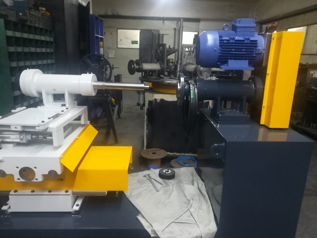
A CNC surface finishing machine is a computer-controlled system designed to perform precise and automated surface finishing operations on metal or other materials. These machines use computer numerical control (CNC) technology to direct the movement of finishing tools—such as grinding wheels, abrasive belts, polishing pads, or brushes—across complex part geometries with high accuracy and repeatability. By programming exact tool paths, speeds, pressures, and sequences, CNC surface finishing machines deliver consistent surface quality, tight tolerances, and complex finishes that manual methods cannot reliably achieve.
CNC surface finishing machines are widely used in industries like aerospace, automotive, medical device manufacturing, mold making, and precision engineering, where parts often feature intricate shapes, tight dimensional requirements, and demanding surface finish standards. These machines can perform a range of finishing tasks, including grinding, sanding, polishing, deburring, and edge rounding, often in multi-axis configurations (3-axis, 5-axis, or more) to access complex surfaces from multiple angles.
The core advantage of CNC surface finishing machines lies in their ability to automate labor-intensive finishing processes with programmable precision. Operators program finishing paths using CAD/CAM software or import digital part models to generate optimized tool trajectories. The CNC controller executes these instructions with precise coordination of tool position, rotation, and feed rate, ensuring uniform material removal and finish consistency across all parts. This automation reduces operator fatigue, minimizes variability, and significantly improves throughput.
Many CNC finishing machines incorporate advanced sensors and feedback systems that monitor tool condition, force, vibration, and surface quality during operation. This real-time data enables adaptive control strategies where the machine adjusts parameters dynamically to maintain optimal finishing conditions, compensate for tool wear, or respond to part geometry variations. Such closed-loop control enhances quality, reduces scrap, and extends tool life.
CNC surface finishing machines come in various configurations—from benchtop models for small parts and prototypes to large-scale industrial systems for heavy or oversized components. Multi-station machines can perform several finishing steps in sequence without manual part transfer, while robotic integration enables automated loading, unloading, and in-process inspection for high-volume production.
Coolant and dust extraction systems are integral to CNC finishing machines, managing heat and debris generated during abrasive processes to protect the workpiece, tooling, and operators. Enclosures and safety interlocks ensure safe operation while maintaining visibility and accessibility for setup and maintenance.
Overall, CNC surface finishing machines represent a critical technology for achieving precise, repeatable, and efficient surface treatments in modern manufacturing. Their combination of automation, flexibility, and digital control enables manufacturers to meet increasingly stringent quality standards while reducing costs and cycle times.
CNC surface finishing machines continue to advance with enhancements in control software, hardware precision, and integration capabilities. Modern machines often feature multi-axis CNC systems, such as 5-axis or even 7-axis configurations, enabling complex tool orientations and movements to reach intricate part geometries without manual repositioning. This flexibility allows for consistent finishing of contoured surfaces, undercuts, and complex molds or dies that would be difficult or impossible to finish accurately by hand.
The programming of CNC finishing operations has become more streamlined through improvements in CAD/CAM software, which can automatically generate optimized tool paths based on 3D part models. These programs factor in tool geometry, material properties, and desired surface finish to create efficient and collision-free finishing cycles. Simulation tools enable operators to verify the process virtually before machining, reducing trial-and-error, minimizing scrap, and speeding up setup times.
Sensor integration plays a crucial role in ensuring process reliability and quality. Force sensors, acoustic emission detectors, and vibration monitors feed real-time data back to the CNC controller, which can adjust feed rates, spindle speeds, or tool pressures dynamically to maintain ideal finishing conditions. This adaptive control helps compensate for tool wear, part inconsistencies, or changes in material hardness, ensuring a uniform surface finish and extending tooling life.
Many CNC surface finishing machines also support automation beyond the machining process itself. Robotic arms or automated material handling systems can load and unload parts, change tools, or perform in-process inspections using laser scanners or vision systems. Such automation reduces operator intervention, boosts throughput, and maintains tight process control in high-volume or complex production environments.
Dust extraction and coolant management systems integrated with CNC finishing machines help maintain a clean, safe workspace while protecting sensitive machine components and finished surfaces. Coolants or lubricants reduce heat and friction during abrasive or polishing operations, enhancing finish quality and preventing thermal damage or warping.
Customization and modularity allow manufacturers to tailor CNC surface finishing machines to specific application requirements. Machines can be configured with different spindle types, abrasive tools, workholding fixtures, and enclosure sizes to accommodate various materials, part sizes, and finish standards. This flexibility supports a wide range of industries, from aerospace and medical device production to automotive and precision tooling.
In addition to traditional metal finishing, CNC surface finishing machines are increasingly applied to advanced materials such as composites, ceramics, and coated surfaces, requiring specialized tooling and process parameters. The ability to precisely control finishing operations on these challenging materials expands the scope of CNC finishing technology.
The connectivity of CNC surface finishing machines to factory networks and Industry 4.0 platforms enables real-time monitoring, predictive maintenance, and data analytics. Manufacturers can track machine utilization, quality trends, and maintenance needs remotely, optimizing production schedules and reducing unplanned downtime. This digital integration supports continuous improvement and lean manufacturing initiatives.
In summary, CNC surface finishing machines combine the precision and repeatability of computer control with the flexibility to handle complex parts and materials. Their ongoing evolution in automation, sensing, and connectivity continues to enhance manufacturing efficiency and surface quality, making them indispensable tools in modern production environments where consistency, speed, and quality are paramount.
Further developments in CNC surface finishing machines emphasize enhanced intelligence, flexibility, and environmental sustainability. Artificial intelligence (AI) and machine learning algorithms are being incorporated to analyze vast amounts of process data, allowing machines to predict tool wear, optimize finishing parameters dynamically, and even detect surface defects automatically. This level of autonomy reduces the need for manual adjustments, shortens setup times, and improves overall process robustness, particularly in complex or high-precision applications.
The integration of collaborative robots (cobots) with CNC finishing machines is also gaining traction. Cobots assist in tasks such as loading and unloading parts, changing tools, or performing supplementary finishing operations, all while ensuring operator safety through advanced sensing and compliance features. This collaboration not only enhances workflow efficiency but also helps address ergonomic challenges and reduce operator fatigue.
Environmental considerations are driving innovations in coolant and waste management within CNC surface finishing operations. Closed-loop coolant filtration and recycling systems minimize fluid consumption and waste discharge, while environmentally friendly coolants and abrasives are increasingly adopted to reduce chemical impact. Energy-efficient motors and drives further lower the machines’ carbon footprint, aligning with manufacturers’ sustainability goals.
Modular machine designs enable rapid reconfiguration and scalability to accommodate varying production volumes and part complexities. Quick-change tooling systems and adjustable workholding fixtures support agile manufacturing environments where multiple part types and finishes are required. This flexibility is vital for industries with fast product cycles or customization demands, such as aerospace, medical, and automotive sectors.
Advanced inspection technologies integrated into CNC finishing cells, including high-resolution 3D scanning and optical measurement systems, provide inline quality assurance by detecting surface anomalies and verifying dimensional accuracy without halting production. This immediate feedback loop allows for real-time corrections, improving yield and reducing post-process inspection costs.
Connectivity with digital factory platforms facilitates comprehensive data analysis, remote monitoring, and predictive maintenance scheduling. Operators and maintenance teams can access real-time machine performance metrics and alerts via mobile devices or centralized control rooms, enabling rapid response to issues and minimizing downtime.
In conclusion, CNC surface finishing machines are evolving into highly intelligent, versatile, and sustainable systems that integrate advanced automation, sensing, and digital connectivity. These capabilities empower manufacturers to achieve superior surface finishes consistently while optimizing productivity, reducing environmental impact, and maintaining agility in dynamic production environments. As technology continues to advance, CNC finishing machines will remain pivotal in meeting the growing demands for precision, quality, and efficiency in modern manufacturing.
Automated Finishing Systems for Industry
Automated finishing systems for industry are comprehensive, integrated solutions designed to perform surface finishing processes—such as grinding, sanding, polishing, deburring, cleaning, and coating preparation—without manual intervention. These systems combine advanced machinery, robotics, control software, and material handling to deliver consistent, high-quality finishes at scale, improving productivity and reducing labor costs in sectors including automotive, aerospace, electronics, metal fabrication, and consumer goods manufacturing.
These finishing systems typically consist of multiple interconnected workstations arranged in sequence, where parts are automatically transported via conveyors or robotic handlers from one operation to the next. Each station is specialized for specific tasks—such as abrasive removal of surface imperfections, precision polishing for gloss finishes, or cleaning to remove residues—allowing a streamlined, continuous workflow that minimizes part handling and cycle times. Automated systems are programmed to adjust finishing parameters for different materials, shapes, and finish requirements, enabling flexible production of diverse product lines.
Key technologies integrated into industrial automated finishing systems include robotic arms with force and vision sensors for precise tool positioning and adaptive finishing, CNC-controlled grinding and polishing machines for repeatable surface treatments, and advanced inspection units employing laser scanning or optical cameras for inline quality assurance. These systems employ real-time monitoring and feedback loops to dynamically control finishing conditions, ensuring consistent surface quality and reducing scrap.
Environmental controls such as dust extraction, coolant filtration, and waste recycling are essential components of automated finishing systems, ensuring operator safety, regulatory compliance, and sustainability. Enclosed finishing cells minimize exposure to airborne particulates and fumes, while fluid management systems reduce resource consumption and environmental impact.
Connectivity and integration with Industry 4.0 frameworks allow automated finishing systems to communicate with enterprise resource planning (ERP), manufacturing execution systems (MES), and quality management systems (QMS). This connectivity enables comprehensive data collection, predictive maintenance, production analytics, and seamless coordination with upstream and downstream manufacturing processes.
Modular design principles enable manufacturers to customize and scale automated finishing systems according to production volume, part complexity, and facility layout. Quick-change tooling, flexible conveyors, and programmable finishing sequences support rapid changeovers and high-mix manufacturing, enhancing operational agility.
In summary, automated finishing systems for industry represent sophisticated, technology-driven platforms that optimize surface finishing operations by combining automation, precision control, environmental management, and digital connectivity. They empower manufacturers to meet increasing demands for quality, efficiency, and sustainability in competitive global markets.
Automated finishing systems continue to evolve by incorporating advanced robotics, intelligent controls, and flexible process architectures that enhance manufacturing efficiency and product quality. Robotics play a central role in these systems, with multi-axis robotic arms equipped with force sensors and vision systems enabling precise, adaptive finishing on complex geometries. These robots can adjust pressure, speed, and tool path dynamically based on real-time feedback, allowing for consistent surface quality across varying part shapes and materials without the need for constant human oversight.
The integration of CNC-controlled finishing equipment within automated lines allows for highly repeatable grinding, sanding, and polishing operations, which are coordinated through sophisticated control software to optimize cycle times and minimize tool wear. Real-time monitoring systems track parameters such as surface roughness, vibration, and tool condition, feeding data into adaptive control loops that fine-tune process variables on the fly to maintain target finishes and extend tool life. This reduces scrap rates, lowers maintenance costs, and enhances throughput.
Environmental and safety considerations are deeply embedded in automated finishing systems. Enclosures and dust extraction units control airborne particles and fumes, protecting operators and the workplace environment. Advanced filtration and coolant recycling systems minimize waste and resource consumption, supporting manufacturers’ sustainability goals. Noise reduction technologies and ergonomic system designs further contribute to a safer and more comfortable working environment.
Connectivity to Industry 4.0 and IoT platforms enables these systems to communicate seamlessly with other manufacturing equipment and enterprise software. This facilitates centralized monitoring, predictive maintenance, and data-driven decision-making, ensuring consistent production quality and minimizing unplanned downtime. Operators and managers can access system status and analytics remotely, enhancing responsiveness and operational transparency.
Automated finishing systems are designed for modularity and scalability, allowing manufacturers to tailor configurations to specific production needs. This flexibility supports a broad range of applications—from high-volume, standardized parts to customized, low-volume runs—by enabling rapid reconfiguration of tooling, finishing sequences, and handling methods. Quick-change fixtures and adaptive conveyors facilitate efficient changeovers, maximizing uptime.
Inline inspection and quality assurance technologies, such as laser scanners and machine vision, are increasingly integrated to detect surface defects and dimensional deviations during processing. This immediate feedback loop allows for corrective actions before parts proceed downstream, improving first-pass yield and reducing costly rework or rejects.
Overall, automated finishing systems represent a convergence of advanced automation, precision engineering, and digital intelligence that empowers manufacturers to meet growing demands for high-quality surface finishes with greater speed, consistency, and sustainability. As these technologies continue to mature, they will play an ever more critical role in optimizing manufacturing workflows and enhancing competitiveness across diverse industrial sectors.
Building further, automated finishing systems are increasingly incorporating artificial intelligence (AI) and machine learning (ML) algorithms to enhance process optimization and decision-making. By analyzing large datasets generated from sensors monitoring vibration, force, temperature, and surface characteristics, these systems can predict tool wear, detect anomalies, and recommend adjustments to finishing parameters in real time. This predictive capability helps prevent defects, reduce downtime, and extend equipment lifespan, leading to lower operational costs and improved product quality.
Collaborative robots (cobots) are becoming integral to automated finishing cells, working safely alongside human operators to handle tasks such as loading and unloading parts, tool changes, or performing detailed finishing operations that require nuanced control. Cobots enhance flexibility and efficiency while reducing ergonomic risks associated with repetitive or physically demanding finishing tasks.
Sustainability is a key driver in the evolution of automated finishing systems. Innovations in fluid management include closed-loop coolant recycling, biodegradable abrasives, and environmentally friendly polishing compounds, all aimed at minimizing waste and chemical usage. Energy-efficient motors, smart power management, and optimized cycle scheduling contribute to reducing overall energy consumption.
Modular design principles allow manufacturers to customize finishing systems quickly and scale capacity up or down in response to production demands. This adaptability is crucial in industries with rapidly changing product designs or small batch sizes, such as aerospace or medical device manufacturing. Systems can be reconfigured by adding or removing stations, changing tooling, or adjusting control software without extensive downtime.
Advanced inspection technologies embedded within finishing lines provide in-process quality assurance, utilizing high-resolution 3D scanning, hyperspectral imaging, or optical profilometry to identify surface defects or dimensional deviations. Immediate feedback from these systems allows for dynamic process adjustments or rejection of non-conforming parts, improving yield and customer satisfaction.
Integration with factory-wide digital ecosystems enables seamless communication between finishing systems and upstream/downstream manufacturing processes, facilitating synchronized production flows, comprehensive traceability, and real-time performance monitoring. This connectivity supports continuous improvement initiatives and aligns finishing operations with broader organizational goals.
In conclusion, automated finishing systems are rapidly advancing toward intelligent, flexible, and sustainable solutions that optimize surface finishing processes. By combining robotics, AI-driven control, modularity, and comprehensive digital integration, these systems empower manufacturers to meet increasingly stringent quality standards while improving productivity and environmental stewardship. As such, they are pivotal to the future of efficient and competitive industrial manufacturing.
Industrial Metal Brushing Machines
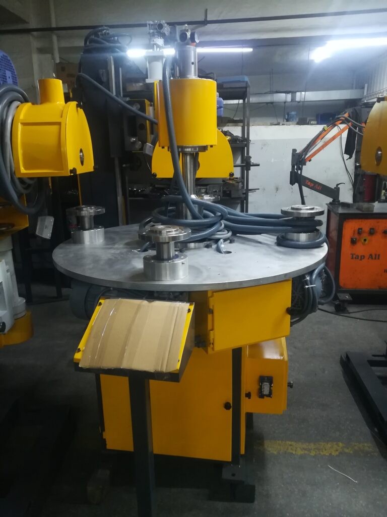
Industrial metal brushing machines are specialized equipment designed to clean, deburr, polish, or texture metal surfaces using rotating brushes made from various materials such as steel wire, stainless steel, nylon, or abrasive filaments. These machines are widely used across manufacturing sectors—including automotive, aerospace, metal fabrication, and construction—to prepare metal parts for further processing, improve surface appearance, or enhance functional properties like corrosion resistance.
The core operation involves brushes rotating at controlled speeds and pressures against the metal workpiece, removing surface contaminants like rust, scale, weld slag, or paint residues. Depending on the brush type and machine setup, brushing can also create specific surface finishes such as satin textures, matte looks, or decorative patterns. Brushing helps deburr sharp edges or weld seams, improving safety and assembly fit while reducing post-processing labor.
Industrial metal brushing machines come in various configurations tailored to specific applications. Bench-top or handheld models provide portability and flexibility for small parts or touch-up tasks, while larger automated or conveyor-fed brushing systems enable continuous processing of high-volume production batches. Multi-head machines with adjustable brush angles and pressures can simultaneously treat complex geometries or multiple surfaces, increasing throughput and uniformity.
Brush materials and designs vary to suit different metals and finishing goals. Steel wire brushes offer aggressive cleaning and deburring for hard metals like carbon steel, while stainless steel brushes prevent contamination on stainless steel parts. Nylon or abrasive filament brushes provide gentler finishes or fine polishing effects, ideal for aluminum or softer alloys. Brush size, stiffness, and rotation speed are carefully selected to optimize material removal without damaging the workpiece.
Automation is increasingly integrated into metal brushing machines, incorporating programmable controls, robotic handling, and in-line quality monitoring. These features enable precise adjustment of brushing parameters—such as speed, pressure, feed rate—and consistent, repeatable results with minimal operator intervention. Safety enclosures, dust extraction, and noise reduction systems are standard to protect workers and maintain clean working environments.
Applications of industrial metal brushing machines include surface preparation before painting or coating, removal of machining marks, weld cleaning, edge blending, and texturing for aesthetic or functional purposes. They are essential in workflows aiming to enhance product durability, appearance, and performance.
Overall, industrial metal brushing machines offer versatile, efficient, and controllable solutions for surface finishing challenges in metal manufacturing. Their ability to deliver tailored finishes with consistent quality makes them indispensable tools in modern industrial production environments.
Industrial metal brushing machines continue to evolve with advancements in automation, brush technology, and control systems that improve efficiency, precision, and versatility. Modern machines often feature programmable logic controllers (PLCs) or CNC interfaces that allow operators to set and adjust parameters such as brush speed, pressure, dwell time, and feed rate to match specific material types and finishing requirements. This programmability ensures consistent surface quality across large production runs and simplifies changeovers between different parts or finishes.
Robotic integration is increasingly common in industrial brushing applications, with robotic arms or gantry systems handling part positioning, orientation, and movement relative to the brushes. This automation enables complex geometries to be brushed uniformly, reduces manual labor, and enhances safety by limiting operator exposure to moving parts and airborne debris. Vision systems and sensors can be incorporated to guide brushing paths, detect surface conditions, and verify finish quality in real time, supporting adaptive process control.
Brush materials and designs continue to advance, with innovations such as abrasive-embedded filaments, variable stiffness bristles, and hybrid brush configurations that combine different filament types for optimized cleaning and finishing performance. These developments expand the range of applications, allowing brushing machines to work effectively on diverse metals including steel, aluminum, copper, and exotic alloys, while minimizing surface damage or contamination.
Industrial brushing machines also incorporate robust dust extraction and filtration systems to capture metallic particles, debris, and dust generated during brushing operations, ensuring compliance with workplace safety regulations and maintaining clean production environments. Enclosures and noise dampening features further contribute to operator safety and comfort.
Many machines are designed with modularity in mind, enabling manufacturers to add or remove brushing stations, change brush types quickly, and integrate supplementary finishing processes such as grinding, polishing, or washing within a single production line. This flexibility supports high-mix, low-volume production as well as large-scale manufacturing, adapting efficiently to changing product demands.
Applications of industrial metal brushing machines extend beyond surface cleaning to include weld seam blending, edge rounding, surface texturing for aesthetic or functional purposes, and preparation for coating or painting. The controlled brushing process enhances adhesion of subsequent layers and improves corrosion resistance, contributing to the durability and longevity of finished products.
Overall, industrial metal brushing machines are essential tools that combine mechanical robustness, technological sophistication, and operational flexibility to meet diverse finishing needs. Their continuous development ensures they remain vital components in achieving high-quality metal surface finishes while optimizing productivity and workplace safety in modern manufacturing environments.
As industrial metal brushing machines continue to integrate more intelligent features, manufacturers are increasingly equipping them with real-time diagnostics and remote monitoring capabilities. These smart systems allow operators and maintenance teams to track brush wear, motor loads, vibration levels, and production throughput from centralized dashboards or mobile devices. By analyzing this data, predictive maintenance strategies can be employed to schedule servicing before breakdowns occur, thus minimizing downtime and ensuring continuous operation.
In high-precision industries such as aerospace or medical device manufacturing, where even minor surface imperfections can affect performance, brushing machines are being fine-tuned for micron-level surface consistency. This is achieved through adaptive control loops and servo-driven brush positioning systems that adjust in real time to maintain a uniform finish, even when brushing parts with complex geometries or varying surface conditions. These systems ensure that the brushing process conforms precisely to specifications while reducing the need for post-process inspection and correction.
To support lean manufacturing and just-in-time production strategies, many brushing machines are designed for rapid setup and tool change. Quick-release brush hubs, programmable brush positioning, and automated fixture adjustment allow for fast transitions between product types or batches, increasing machine availability and reducing waste. This capability is particularly valuable in contract manufacturing or facilities producing a diverse array of components with differing finishing requirements.
Additionally, energy efficiency and environmental sustainability are becoming integral considerations. Variable-speed brush motors, energy-efficient drives, and optimized airflow systems reduce power consumption during idle or light-load operation. Coolant-less or dry brushing systems are also available for applications where minimal environmental impact is critical. Where fluids are used, closed-loop filtration and recycling systems help conserve resources and ensure safe disposal of particulates and residues.
Industries using brushing machines also benefit from their role in enhancing downstream processes. For example, a brushed surface provides better adhesion for paint, powder coating, adhesives, or thermal sprays by creating a clean, uniform profile that increases surface energy. This not only improves final product quality but also reduces the frequency of defects in coating or bonding stages. In welding applications, pre-brushing removes oxidation or mill scale, improving weld integrity, while post-brushing removes slag or discoloration for a cleaner appearance and improved corrosion resistance.
In sectors such as architectural metalwork, consumer appliances, or stainless steel products, brushing is often used not just for technical reasons but for visual appeal. Uniform brushed finishes offer a matte, anti-reflective look that resists fingerprints and scratches, contributing to both aesthetic quality and durability. Brushing machines with fine control over texture and directionality can replicate or create decorative finishes across different product lines, supporting brand consistency and design flexibility.
In conclusion, industrial metal brushing machines represent a mature yet continually evolving category of finishing equipment that blends mechanical simplicity with advanced automation, sensing, and control technologies. They provide manufacturers with a powerful means to clean, deburr, texture, and refine metal parts with consistency, efficiency, and safety. As production demands grow more complex and quality standards rise, these machines will remain central to surface treatment strategies in modern industrial operations.
Industrial Metal Finishing Techniques
Industrial metal finishing techniques encompass a broad range of processes used to alter the surface of metal parts for improved appearance, performance, durability, or manufacturability. These techniques are essential in nearly every manufacturing sector—including automotive, aerospace, electronics, construction, medical devices, and consumer goods—where they enhance corrosion resistance, wear resistance, conductivity, adhesion, or aesthetic value. The choice of technique depends on the type of metal, the functional requirements, production scale, and cost considerations.
Mechanical finishing is one of the most widely used categories, involving physical abrasion or modification of the metal surface through processes like grinding, sanding, brushing, polishing, lapping, and buffing. These techniques remove burrs, scale, weld slag, or oxidation while producing smooth or textured finishes. Mechanical methods are highly flexible and can be adapted to both manual and automated production systems. Depending on the abrasives or tools used, they can create anything from a matte industrial texture to a high-gloss mirror finish.
Chemical and electrochemical finishing processes involve the use of acids, alkalis, or electric current to clean, etch, or deposit materials on metal surfaces. Common techniques include pickling (to remove oxides and scale), electroplating (to apply a thin coating of another metal such as nickel, chromium, or zinc), anodizing (especially for aluminum), and electropolishing (to smooth and brighten surfaces while removing microscopic defects). These methods improve corrosion resistance, electrical conductivity, or decorative appearance and are especially suited for complex or internal geometries that are difficult to finish mechanically.
Thermal finishing techniques use heat to alter the surface properties of metals. Examples include flame polishing, laser surface treatment, and thermal spraying. Thermal spray processes deposit materials like ceramics or alloys onto a base metal using heat and velocity, providing coatings with high wear and corrosion resistance. Heat-based methods are often employed where high durability or specific surface chemistry is required.
Coating-based finishing involves the application of protective or functional layers to the metal surface. This includes painting, powder coating, electrophoretic deposition (e-coating), and various conversion coatings like phosphating and chromating. These coatings serve purposes ranging from UV protection and corrosion resistance to aesthetic enhancement and electrical insulation. The uniformity, adhesion, and longevity of coatings often depend on pre-finishing treatments like blasting or chemical cleaning.
Shot peening and bead blasting are impact-based mechanical finishing processes that bombard the surface with high-velocity media to improve fatigue strength, clean the surface, or produce specific textures. These techniques are especially useful in aerospace and automotive applications, where they induce compressive stress that helps prevent crack formation in components subjected to cyclic loading.
Deburring is a critical finishing step in precision manufacturing, ensuring that sharp edges and protrusions left from machining or cutting are removed. This can be achieved mechanically through tumbling, vibratory finishing, or brushing, or chemically through specialized deburring fluids or electrochemical processes. Proper deburring improves safety, assembly fit, and the effectiveness of coatings and seals.
Hybrid and advanced techniques are increasingly common in modern manufacturing. These include laser-assisted polishing, plasma surface modification, and automated robotic finishing systems that combine vision, force feedback, and AI-driven controls to achieve complex, high-tolerance finishes on intricate parts. Additive manufacturing has also introduced new challenges and opportunities for finishing, as printed metal parts often require support removal, surface smoothing, and sealing of porous structures.
In summary, industrial metal finishing techniques are vital to ensuring product functionality, aesthetics, and longevity. As manufacturing continues to advance, metal finishing technologies evolve in parallel—becoming more precise, efficient, and environmentally responsible—to meet the rigorous demands of contemporary industrial applications.
The continued advancement of industrial metal finishing techniques is driven by the need for higher precision, faster production cycles, greater durability, and enhanced sustainability. As industries demand tighter tolerances and more complex designs, finishing processes are becoming increasingly integrated with digital technologies and automated systems. Robotic finishing arms equipped with force sensors, vision systems, and AI-driven software can now adapt in real time to changing part geometries, surface conditions, and finishing requirements, ensuring consistent outcomes with minimal operator input. These systems are used extensively in automotive and aerospace sectors, where the margin for surface imperfection is extremely low.
In terms of process selection, the rise of high-performance alloys and composite-metal hybrid materials has expanded the role of non-traditional and specialized finishing methods. Techniques like cryogenic polishing, where liquid nitrogen is used to make brittle contaminants easier to remove, and abrasive flow machining, which pushes abrasive-laden fluid through internal channels, are gaining traction in high-precision applications such as aerospace fuel systems, biomedical implants, and semiconductor tooling. These techniques are especially valuable for internal surfaces or delicate structures where traditional methods cannot reach or might cause damage.
Environmental considerations are shaping the development and adoption of newer finishing technologies. Traditional methods such as electroplating and chromating are being replaced or re-engineered to reduce hazardous byproducts and comply with increasingly strict environmental regulations. Water-based coatings, closed-loop rinsing systems, and zero-discharge chemical baths are now standard in many finishing facilities, helping to eliminate toxic waste and reduce water and energy consumption. Dry finishing techniques like plasma treatment or laser texturing offer surface modification capabilities without the use of chemicals or large volumes of consumables.
Another significant trend is the use of surface texturing for functional purposes beyond appearance. Controlled roughness at the microscopic or even nanoscopic scale can improve lubrication retention, reduce friction, control fluid flow, or promote bonding and adhesion in both mechanical and biomedical applications. For example, laser ablation or micro-etching can be used to create hydrophobic or hydrophilic surfaces, which is critical in industries like electronics cooling, fluid management, and implant design.
Surface metrology, or the precise measurement of surface features, is now deeply integrated into the finishing process itself. In-line surface analysis using laser profilometers, white light interferometers, or confocal microscopes allows manufacturers to monitor roughness, gloss, and topography in real time. This tight process feedback loop ensures that deviations are detected early and corrected before defective parts move forward in the production line, thereby minimizing waste and enhancing overall production quality.
Digital twins and simulation tools are increasingly used to model and optimize finishing processes before they are implemented physically. By simulating how different surface treatments will affect stress concentrations, coating adhesion, or heat dissipation, engineers can choose the most effective finishing method and parameters without the time and cost of physical trials. This is particularly valuable for highly engineered products where surface integrity directly affects performance, such as turbine blades, engine components, or high-voltage connectors.
Ultimately, industrial metal finishing has transitioned from a secondary or cosmetic operation to a critical functional process that determines how well a component will perform in real-world conditions. Whether the goal is to ensure perfect cosmetic appeal for consumer goods, improve corrosion resistance for marine applications, or meet the microscopic smoothness required in semiconductor manufacturing, finishing techniques are indispensable. Their ongoing evolution continues to shape the capabilities of modern industry, supporting innovation, product reliability, and competitiveness on a global scale.
In the broader context of smart manufacturing, metal finishing is increasingly becoming an interconnected part of the digital production ecosystem. Through the use of industrial internet of things (IIoT) devices, finishing systems can transmit real-time operational data—such as temperature, humidity, tool wear, surface integrity, and chemical concentrations—to centralized platforms. This data is then analyzed to optimize line performance, predict failures before they happen, and ensure traceability for quality audits. The result is a closed-loop finishing environment where machine learning algorithms continuously improve outcomes based on feedback and historical data, reducing costs and improving consistency across large production volumes.
Hybrid manufacturing processes that combine additive manufacturing with subtractive or finishing techniques are also changing the role of surface treatment. Metal parts produced by 3D printing often exhibit rough or porous surfaces that require extensive post-processing to achieve functional integrity or aesthetic appeal. Finishing techniques like laser polishing, abrasive jet machining, or chemical smoothing are being adapted specifically for the unique characteristics of additively manufactured components, making it possible to take advantage of the design freedom of 3D printing without compromising surface performance.
Meanwhile, the rise in demand for lightweight components and alternative materials such as titanium, magnesium, and aluminum alloys has led to refinements in finishing techniques that can handle softer or chemically reactive surfaces without causing deformation, discoloration, or contamination. Specialized processes like non-abrasive vibratory finishing, dry electropolishing, and ultrasonic cleaning are being tailored to suit these materials, particularly in applications like electric vehicles, aerospace structures, and medical instruments, where material selection is often dictated by weight, biocompatibility, or corrosion resistance.
Automation in finishing now extends beyond just equipment control. Automated part tracking using RFID tags or vision-based systems allows finishing machines to recognize individual components, retrieve their finishing specifications, and adjust process parameters accordingly. This is critical in high-mix production environments where different parts move down the same line, and each requires unique surface treatments. Such flexibility significantly reduces setup time and eliminates the risk of human error during parameter configuration.
Advanced finishing is also used to enhance not just durability or aesthetics, but performance characteristics such as electrical conductivity, magnetic properties, or reflectivity. In electronics manufacturing, for instance, extremely fine polishing and coating processes are used to ensure reliable connections, reduce signal loss, or prevent corrosion under micro-scale solder joints. In optics and solar technology, precision finishing is used to shape light paths, improve efficiency, and minimize energy loss. These applications demand an unprecedented level of control over surface texture and composition, pushing the boundaries of what finishing technologies can achieve.
As industries prioritize sustainability, regulatory compliance, and long-term reliability, surface finishing is increasingly viewed as a strategic stage of manufacturing rather than a secondary or cosmetic step. The most advanced facilities are now designing parts, production lines, and finishing processes simultaneously to ensure that surfaces are not only functional but also manufacturable and sustainable from the outset. This shift in mindset reflects the central role that finishing plays in determining product performance, cost, and lifecycle durability.
In essence, industrial metal finishing techniques are evolving to meet the complex challenges of 21st-century manufacturing. They are becoming more precise, more automated, more intelligent, and more environmentally responsible. With continued innovation in materials science, robotics, data analytics, and process engineering, metal finishing will remain a critical enabler of industrial excellence—transforming raw and machined metal into components that meet the highest standards of quality, function, and appearance in every field of application.
Industrial Metal Band Sanding Equipment
Industrial metal band sanding equipment refers to heavy-duty machines designed for surface finishing, deburring, descaling, and smoothing of metal parts using continuous abrasive belts. These machines are essential in industries like automotive, aerospace, shipbuilding, metal fabrication, and steel processing, where precise, consistent, and high-throughput surface treatment is required for flat sheets, profiles, tubes, or fabricated parts. The core principle involves pressing a rotating abrasive belt against the metal surface under controlled speed, pressure, and feed rate to remove material, improve surface texture, or prepare for painting, welding, or coating.
These machines typically consist of a robust steel frame, powerful drive motors, tensioning systems, and adjustable contact rollers or platens that ensure optimal contact between the abrasive belt and the workpiece. Most are equipped with variable-speed control for both the sanding belt and the conveyor or table feed, allowing operators to tailor the process to different materials, such as stainless steel, aluminum, carbon steel, or titanium. The abrasive belts themselves come in various grits and compositions—ceramic, zirconia, aluminum oxide—chosen based on the desired surface finish and removal rate.
There are several configurations of industrial band sanding equipment, including wide belt sanders for large sheet or plate processing, edge sanders for treating sides or borders, and vertical or horizontal machines for handling specific component shapes. Automated systems often include multiple sanding heads in sequence, with progressively finer abrasives to achieve both rough removal and final finishing in one pass. Some advanced models feature oscillating belt motion, which reduces heat buildup, improves sanding uniformity, and extends belt life.
Dust extraction systems are a crucial part of these machines, capturing metal particles, sanding debris, and fine dust to maintain a clean work environment and comply with safety and air quality regulations. Many machines also include cooling systems or lubrication devices to prevent overheating, particularly when sanding soft metals or high-alloy steels that are sensitive to temperature changes.
Modern industrial band sanders can be integrated into fully automated production lines, equipped with sensors, programmable logic controllers (PLCs), and touch-screen HMIs for real-time parameter control, diagnostics, and quick recipe changes. These systems enhance efficiency, reduce operator dependency, and ensure consistency across high-volume runs. In combination with conveyors or robotic handling systems, metal parts can be fed, aligned, sanded, and transferred downstream without manual intervention.
In addition to flat part finishing, some machines are designed for 3D parts, welded structures, or cylindrical items, using flexible contact rollers or inflatable tension wheels that conform to surface contours. These machines are particularly useful in industries producing enclosures, tanks, tools, or custom-fabricated assemblies requiring uniform surface aesthetics or weld seam blending.
Overall, industrial metal band sanding equipment is a versatile and indispensable asset for achieving controlled, repeatable, and high-quality metal surface finishes. Its ability to combine power, precision, and automation makes it critical for modern metalworking operations that prioritize productivity, quality assurance, and operational safety.
Industrial metal band sanding equipment continues to evolve with the integration of advanced automation, smart controls, and enhanced mechanical features that improve both performance and adaptability. These machines are no longer limited to simple sanding tasks; they now operate as intelligent surface treatment systems capable of handling complex finishing routines with minimal operator involvement. With the development of servo-driven systems and programmable multi-axis adjustments, modern sanding equipment can automatically adapt to different workpiece shapes, thicknesses, and surface conditions in real time, ensuring a consistent finish regardless of part variability.
Multi-head band sanding machines are commonly used for sequential processing, where each station performs a specific function—such as coarse grinding, intermediate leveling, or fine finishing—without the need for manual part repositioning. These systems are highly beneficial in high-throughput production environments, allowing manufacturers to combine heavy stock removal and precise surface refinement in a single pass. The modularity of these machines also means that new sanding heads, brushing stations, or cleaning modules can be added as needed, giving manufacturers the flexibility to adapt to future finishing requirements or different product lines.
Advancements in belt tensioning and tracking mechanisms have also improved sanding precision and belt life. Automatic tensioners maintain optimal pressure, preventing belt slippage or excessive stretching, while sensor-guided tracking systems ensure the belt remains perfectly aligned during operation. These innovations reduce wear on both the abrasive belts and the machine’s mechanical components, leading to less downtime, fewer maintenance interventions, and a more stable finishing process over time.
Digital user interfaces, including touchscreens and programmable logic controllers (PLCs), are standard in modern equipment, giving operators full control over process parameters such as belt speed, sanding pressure, contact roller height, and feed rate. These systems often include recipe memory and diagnostic tools, which allow quick switching between different finishing setups and early detection of component wear or system faults. This digital control capability enhances consistency, reduces human error, and supports traceability—especially important in regulated industries or ISO-certified production facilities.
Dust management systems in industrial band sanding equipment have become more sophisticated and efficient, with high-capacity extraction units, multi-stage filtration, and automated bagging or collection systems that minimize cleanup and protect both operators and sensitive equipment. In addition to ensuring compliance with environmental and occupational health standards, effective dust control helps maintain surface quality by preventing fine particles from re-depositing on freshly sanded parts.
Energy efficiency is another area where improvements have been made. Frequency-controlled drives, idle-mode energy management, and optimized motor designs contribute to lower power consumption and reduced operational costs. These savings are particularly valuable in large-scale operations where machines may run continuously across multiple shifts. Some equipment also includes sensors that detect when parts are present, activating sanding and conveying only when needed to further minimize unnecessary energy use.
In sectors such as stainless steel fabrication, architectural metalwork, appliance manufacturing, and heavy machinery production, the quality of surface finish is a key differentiator. Band sanding machines are essential in creating finishes that meet both functional and aesthetic standards, whether it be a consistent brushed texture, a smooth weld-free appearance, or a preparation for coating or anodizing. Precision belt sanding can also improve downstream processes such as painting, powder coating, or adhesive bonding by enhancing surface cleanliness and texture uniformity.
Ultimately, industrial metal band sanding equipment serves as a cornerstone of modern surface preparation, offering manufacturers the ability to scale their operations, improve product quality, and meet increasingly stringent market expectations. As automation, sensing technology, and digital integration continue to evolve, these machines are becoming more intelligent, adaptive, and efficient—ensuring they remain vital tools in the production of finished metal components across a wide range of industries.
Another important advancement in industrial metal band sanding equipment is its growing compatibility with flexible manufacturing systems and Industry 4.0 environments. These sanding machines can now be seamlessly integrated into fully automated production cells, where robots handle material loading and unloading, sensors monitor part orientation and dimensions, and networked controllers adjust sanding parameters in response to upstream or downstream operations. Through this level of digital interconnectivity, sanding becomes an intelligent and reactive process that contributes to overall production efficiency and traceability.
In high-mix, low-volume manufacturing settings—common in custom metal fabrication or contract manufacturing—band sanding machines are being designed with quick-change features that drastically reduce downtime during part transitions. Automatic adjustment of contact pressure, conveyor height, and abrasive belt type or grit allows the system to accommodate different materials and surface requirements without extensive manual reconfiguration. This adaptability supports just-in-time workflows and helps meet tight deadlines without sacrificing finish quality.
Safety has also been significantly improved through the use of light curtains, interlocking guards, emergency stop systems, and overload detection. Operators are protected from rotating components and abrasive surfaces, while the machine itself is safeguarded against damage caused by incorrect loading, excessive part thickness, or belt misalignment. Safety PLCs can shut down the system instantly when anomalies are detected, ensuring protection of both human operators and machinery.
As the demand for environmentally responsible manufacturing grows, band sanding systems are increasingly designed to operate with minimal ecological impact. This includes not only energy-efficient motors and smart dust collection, but also dry sanding technologies that eliminate the need for water or chemical coolants. For applications where wet sanding is necessary—such as aluminum or magnesium components prone to dust ignition—closed-loop water filtration systems ensure that waste is properly treated and reused, reducing environmental risk and operational cost.
There is also a growing emphasis on hybrid machines that combine band sanding with other finishing technologies such as brushing, Scotch-Brite heads, planetary heads, or buffing wheels in a single system. These all-in-one solutions provide comprehensive surface treatment in a compact footprint, streamlining the finishing process and minimizing the need for additional downstream operations. Such combinations are ideal for achieving specific layered finishes or multitexture requirements often demanded in architectural or decorative metal applications.
In heavy-duty applications such as shipbuilding or structural steel fabrication, oversized band sanding equipment is used to process large plates and beams. These machines are built for extreme durability, with reinforced frames, hydraulic pressure control, and extra-wide belts that can handle high removal rates and long production cycles. Automation here plays a role in handling massive workpieces using rollers, lifters, and clamps that ensure proper alignment and safety while minimizing the need for overhead cranes or manual lifting.
From a quality control perspective, integration of real-time surface monitoring technologies is becoming standard in higher-end machines. Optical sensors, surface profilometers, and gloss meters can be mounted near the sanding head or exit conveyor to continuously evaluate surface condition. When deviation from target parameters is detected—whether it’s excessive roughness, under-sanding, or surface blemishes—the system can adjust in real time or flag the part for further inspection or reprocessing.
In conclusion, industrial metal band sanding equipment has grown far beyond a simple abrasive mechanism into a highly automated, intelligent, and adaptable part of the metal manufacturing process. Whether used for heavy stock removal, precise aesthetic finishing, or preparation for downstream treatments, these machines play a vital role in delivering products that meet modern performance and visual expectations. Their continued evolution reflects broader industry trends toward automation, precision, flexibility, and sustainability—making them essential to both traditional and advanced manufacturing operations.
Industrial Metal Buffing Machines
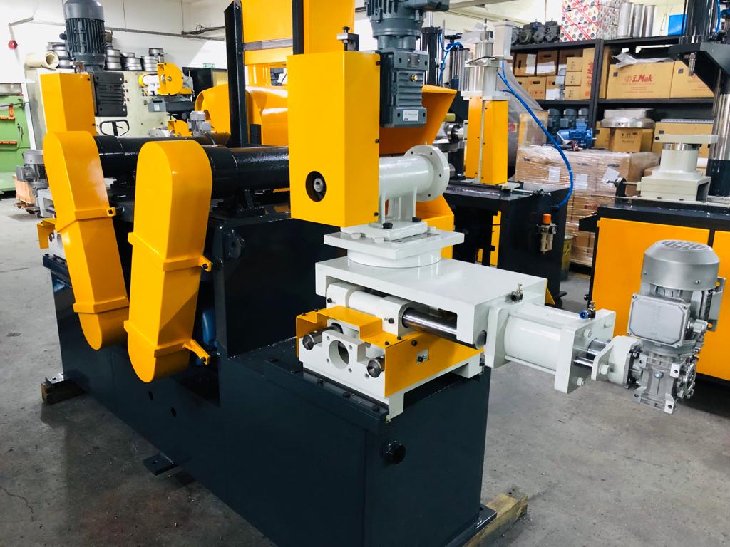
Industrial metal buffing machines are specialized finishing systems designed to produce smooth, high-gloss, or mirror-like surfaces on metal components by using rotating cloth wheels, buffing compounds, and controlled pressure. These machines are critical in industries where surface aesthetics, corrosion resistance, hygiene, or precision are vital—such as automotive, aerospace, cookware, plumbing fixtures, jewelry, architecture, and medical device manufacturing. Buffing not only enhances visual appeal but also improves surface performance by reducing microscopic defects and sealing pores that could harbor contaminants or promote corrosion.
At the heart of a buffing machine is a high-speed rotating spindle that drives soft, flexible wheels made of materials such as cotton, muslin, flannel, or sisal. These wheels are impregnated or coated with buffing compounds—abrasive pastes or bars made from aluminum oxide, chromium oxide, or diamond grit—that provide varying levels of cut and polish. The process is often divided into two or more stages: a cutting stage using coarser compounds to smooth the surface, and a coloring stage using finer abrasives to produce a lustrous finish. Operators or automated systems press the workpiece against the wheel, which conforms to the part geometry and gradually enhances the surface quality.
Industrial buffing machines come in a variety of configurations, including manual pedestal models, semi-automatic bench units, and fully automated robotic buffing cells. Manual machines are suited for skilled labor and custom finishing, while automatic and CNC-controlled models are preferred for high-volume, consistent production. Multi-head machines with programmable tool paths are used for sequential polishing, allowing for complex part shapes and multiple surface treatments in a single setup. These systems often incorporate part-holding jigs, robotic arms, and vision guidance for precise control over contact pressure, angle, and coverage area.
One of the major advantages of buffing over other metal finishing techniques is its ability to produce extremely fine surface finishes—down to submicron roughness levels—without significant material removal. This makes it ideal for components that require both tight dimensional tolerances and visual perfection, such as automotive trim, turbine blades, surgical instruments, and luxury hardware. Unlike sanding or grinding, buffing can bring out the natural luster of metals such as stainless steel, aluminum, brass, and copper, making it the finish of choice where reflectivity and smoothness are critical.
Dust and compound management is a key consideration in industrial buffing environments. High-speed rotating wheels generate airborne particles and residue that can pose safety and quality risks. Advanced machines include fully enclosed housings, downdraft dust collection systems, and automatic compound dispensing units to control the work environment and reduce operator exposure. Noise suppression features, emergency shutoffs, and programmable safety zones further enhance the safety of modern buffing operations.
Automation in buffing has expanded rapidly due to increasing demand for consistency, labor savings, and integration into broader finishing lines. Robotic buffing systems can handle highly repetitive tasks, learn complex movements, and adapt to variations in part shape or position using force-feedback sensors. These machines are particularly effective for parts with compound curves, recessed features, or large surface areas where manual polishing would be time-consuming or inconsistent. Custom end-effectors and compliant tools allow robots to replicate the skilled touch of a human operator with greater endurance and precision.
In today’s manufacturing landscape, buffing is often integrated as part of a hybrid finishing sequence that includes pre-buff grinding, sanding, brushing, or chemical cleaning. This multi-stage approach ensures the surface is properly prepared before polishing, maximizing gloss and minimizing compound usage. Some systems combine buffing with automated inspection, using vision or laser systems to verify reflectivity and surface uniformity in-line, eliminating the need for off-line quality checks.
Overall, industrial metal buffing machines provide a critical capability for enhancing both the form and function of metal components. Their ability to achieve ultra-smooth, high-shine finishes while supporting automation, customization, and precision makes them indispensable in a wide array of industrial applications. As technologies continue to evolve, buffing machines will remain central to advanced surface finishing strategies that demand performance, consistency, and superior visual quality.
Industrial metal buffing machines continue to be refined for greater efficiency, precision, and adaptability across a growing number of manufacturing applications. Modern buffing systems are increasingly equipped with advanced digital interfaces and programmable logic controllers (PLCs), allowing operators to input specific finishing parameters—such as spindle speed, feed rate, dwell time, and compound application timing—for repeatable, high-quality results. These digital controls not only improve consistency across production batches but also drastically reduce setup time when switching between part types or finish grades, which is particularly valuable in short-run or custom production environments.
One of the most significant developments in recent years is the integration of servo motors and force-feedback technology, which enables precise control of contact pressure between the buffing wheel and the workpiece. This adaptive pressure control is crucial when working with parts of varying thickness, shape complexity, or material hardness. In automated or robotic buffing systems, force sensors allow the machine to respond dynamically to surface contours, preventing over-polishing, burn marks, or uneven finishes. As a result, the system can deliver consistent results even on complex geometries or multi-surface components without operator intervention.
Buffing compounds themselves have evolved to meet different industry needs, offering a range of formulations optimized for speed, gloss level, surface hardness, or environmental compliance. Water-based and low-VOC compounds are now widely used to meet stricter environmental regulations and improve worker safety by minimizing fumes and residue. Specialized compounds are also developed for different metals—such as iron-free compounds for stainless steel to prevent contamination or fine diamond pastes for ultra-fine finishes on precision components. The controlled and automated application of these compounds, either via solid bars, liquid sprayers, or paste dispensers, ensures uniform distribution and minimal waste.
The physical design of buffing machines is also more ergonomic and modular, allowing for easy maintenance, quick-change spindle tools, and accessible component replacements. Machines are often built with multiple buffing stations arranged in sequence or parallel to accommodate different process steps, such as initial cut buffing, intermediate blending, and final coloring. Modular tool heads, each with its own motor and control system, can be swapped or adjusted quickly to maintain high productivity and uptime even in demanding production environments.
In industries like food processing, pharmaceuticals, and medical device manufacturing, where surface smoothness is essential for hygiene and sterility, buffing machines are critical for meeting surface roughness targets such as Ra ≤ 0.2 µm. In these applications, buffing not only serves aesthetic purposes but also functional requirements by eliminating micro-crevices that could harbor bacteria or compromise cleanliness. In these environments, polishing is often the final validation step before inspection, and automated buffing systems equipped with in-line surface profilometers ensure that each part meets strict regulatory standards before leaving the production line.
The role of buffing in post-processing 3D-printed metal components is also expanding. Additive manufacturing often leaves behind a rough or layered surface texture that can hinder part performance or appearance. Industrial buffing machines are being customized to remove the inherent roughness of metal printed parts, especially those made from aluminum, titanium, or stainless steel. By combining robotic motion planning with variable-speed buffing heads and adaptive pressure systems, manufacturers can efficiently refine the surface of complex geometries created by additive manufacturing, including internal channels and curved profiles.
Noise and vibration control is another aspect receiving attention in modern buffing machine design. Machines are now equipped with vibration-dampening frames, noise-isolating enclosures, and precision-balanced spindles that reduce mechanical stress, increase operator comfort, and extend equipment lifespan. These enhancements are particularly important in high-duty-cycle environments where machines operate for long shifts or across multiple lines simultaneously.
As manufacturers demand more responsive and flexible finishing solutions, buffing machines are increasingly integrated into fully automated smart manufacturing ecosystems. Through IIoT connectivity and centralized software platforms, real-time data on spindle loads, wheel wear, compound consumption, and surface quality can be monitored and used for predictive maintenance, quality control, and workflow optimization. In addition, digital twins of buffing cells can simulate process changes and test finish variations before implementation, reducing trial-and-error in production settings.
Ultimately, industrial metal buffing machines are evolving from standalone finishing tools into intelligent systems that enhance productivity, surface quality, and production flexibility. Their ability to meet both high-performance standards and strict visual requirements makes them indispensable across a wide spectrum of applications—from mass-produced stainless steel appliances to precision-machined aerospace components. As materials, technologies, and customer expectations continue to advance, buffing machines will remain central to surface finishing strategies where quality, consistency, and aesthetics are non-negotiable.
As industrial requirements grow more complex and competitive, metal buffing machines are also being reengineered to better integrate into lean manufacturing and continuous improvement systems. Manufacturers are focusing not just on the final finish, but on reducing cycle times, minimizing waste, and ensuring that every unit that passes through a buffing station meets exacting standards without the need for rework. This has led to the development of closed-loop feedback systems where surface quality metrics—such as gloss level, light reflectivity, or roughness average (Ra)—are measured in-line and used to dynamically adjust process parameters like buffing time, wheel pressure, or compound feed rate. These closed-loop systems minimize material waste, eliminate overprocessing, and ensure that energy and compound use are optimized per part.
In high-end consumer products like stainless steel appliances, luxury hardware, or decorative architectural metals, surface uniformity and consistency across multiple units are critical. Buffing machines designed for these industries incorporate multiple synchronized spindles that process wide surfaces in a single pass, ensuring that the visual grain direction and luster remain consistent from one component to the next. High-precision motor control systems manage rotational speed with minimal variance, which is vital to avoid streaking or inconsistent reflection, especially when panels will be installed side-by-side.
Another growing trend is the use of automated compound metering systems that precisely regulate the amount and type of buffing compound applied to each wheel or part. These systems reduce operator variability and compound overuse while also enabling quick changeovers between different formulations. This is particularly beneficial in multiproduct facilities or contract manufacturing operations where the same equipment is used for different customer specifications.
For industries where surface integrity affects functionality—such as aerospace or medical—buffing is often performed in conjunction with non-destructive testing (NDT) or high-resolution inspection. Automated buffing cells can be paired with in-line visual inspection cameras, laser scanners, or eddy current probes to identify any surface anomalies like pits, inclusions, or heat tinting. If a defect is detected, the system can either re-buff the part automatically or mark it for operator review, ensuring that only flawless components move to final assembly or shipping.
Some of the latest robotic buffing systems also include compliance mechanisms—like torque-limiting spindles or air-suspension tool mounts—that provide just the right amount of flexibility for conforming to curved or inconsistent surfaces. These systems can “float” over the part, maintaining optimal pressure without distorting thin-walled components or over-polishing delicate areas. This kind of tactile sensitivity is essential in industries producing components with mixed geometries, such as formed metal housings, castings, or fabricated enclosures.
From a maintenance and operational standpoint, newer buffing systems are being designed with intelligent alerting and maintenance forecasting. Machines log hours of use, detect changes in motor load or vibration levels, and notify technicians when bearings, belts, or wheels need attention—preventing breakdowns and reducing unplanned downtime. Tool-free access panels, modular drive units, and plug-and-play electronics further reduce maintenance time, allowing production lines to stay operational with fewer disruptions.
Environmental performance continues to be a key consideration. Manufacturers are now selecting machines that support dry or semi-dry buffing processes to eliminate water or coolant waste. Where wet buffing is required, machines are equipped with recycling systems that reclaim and filter used water or compound. Additionally, dust collection systems are being upgraded with HEPA filtration, spark arrestors, and automatic cleaning cycles, especially for operations involving fine particles from aluminum or titanium that pose a combustion risk.
In total, the role of the industrial metal buffing machine has grown from a basic aesthetic tool into a high-precision, intelligent, and essential element of the production line. These machines no longer simply polish parts—they monitor process health, interact with upstream and downstream operations, support rapid product changes, and uphold the most demanding standards of surface integrity and cosmetic finish. With continuing advancements in automation, sensor technology, and material science, buffing machines will keep evolving to meet the future challenges of global manufacturing while supporting both performance-critical and design-focused applications.
Automatic Surface Grinding Machines
Automatic surface grinding machines are precision machining tools designed to produce highly accurate and smooth flat surfaces on metal or other rigid materials with minimal manual intervention. These machines use an abrasive grinding wheel that rotates at high speed to remove small amounts of material from the workpiece surface, achieving tight dimensional tolerances and superior surface finishes. The automatic operation enables consistent, repeatable grinding cycles, improved productivity, and reduced operator fatigue, making them indispensable in industries like automotive, aerospace, mold and die manufacturing, toolmaking, and precision engineering.
The key components of an automatic surface grinding machine include a grinding wheel mounted on a spindle, a worktable that holds and moves the workpiece, and a control system that automates feed rates, grinding passes, wheel dressing, and coolant application. The worktable typically moves longitudinally or reciprocally beneath the grinding wheel, which can also move vertically to control the depth of cut. Advanced machines feature programmable controls, including CNC or PLC systems, that manage precise grinding parameters such as wheel speed, feed rate, infeed depth, and stroke length to meet exacting surface finish and dimensional requirements.
Automatic surface grinders come in various configurations, such as horizontal spindle and vertical spindle models, depending on the application. Horizontal spindle grinders are commonly used for general purpose flat surface grinding, while vertical spindle (or rotary) grinders excel in grinding complex profiles, tool faces, or small components with intricate features. Some machines include rotary tables or indexing heads to enable grinding of multiple faces or complex geometries in one setup, increasing accuracy and reducing handling time.
One of the critical features in automatic surface grinding machines is the wheel dressing system, which maintains the grinding wheel’s shape and sharpness during the grinding process. Automated wheel dressing units use diamond-tipped tools or rotary dressers controlled by the machine’s CNC system to precisely restore the wheel profile and remove clogged abrasive particles, ensuring consistent cutting performance and surface finish quality. Some systems include in-process dressing, allowing the wheel to be dressed during grinding cycles without stopping the machine.
Coolant delivery is integral to automatic surface grinding machines to reduce heat buildup, prevent thermal damage to the workpiece, and prolong wheel life. Sophisticated coolant systems provide controlled flow rates and spray patterns, often with filtration and recirculation features to maintain coolant cleanliness. Proper coolant management improves grinding efficiency and ensures the final surface integrity of the workpiece.
Automation in surface grinding also extends to part loading and unloading through robotic arms, conveyors, or pallet changers, allowing integration into fully automated production lines. These features reduce manual labor, enhance operator safety, and increase machine utilization rates. Modern surface grinders may also be equipped with in-line quality monitoring tools such as laser measurement systems or contact probes that verify flatness, thickness, and surface roughness immediately after grinding, enabling real-time process adjustments.
Surface grinding machines are used for finishing hardened or soft metals, ceramics, composites, and glass. They achieve surface finishes ranging from a rough ground texture to mirror-like finishes, with flatness tolerances often within microns. Typical applications include finishing precision machine components, die and mold plates, hydraulic valve faces, and sealing surfaces where smoothness and accuracy are critical for performance and longevity.
In summary, automatic surface grinding machines are essential tools in modern manufacturing, combining precision abrasive technology with advanced automation and control systems. They enable high-quality, consistent surface finishes on a variety of materials with enhanced productivity and minimal operator intervention, supporting stringent industrial standards and complex production demands.
Automatic surface grinding machines have advanced significantly with the integration of CNC controls and smart technologies, allowing for greater precision, repeatability, and efficiency in surface finishing operations. CNC automation enables the programming of complex grinding cycles, including variable feed rates, multiple passes, and precise wheel infeed depths, all optimized to achieve target surface finishes and tolerances consistently across large production runs. This automation reduces reliance on highly skilled operators, minimizes human error, and shortens setup times, making these machines ideal for both high-volume manufacturing and small batch production.
The machines often feature multi-axis control, allowing not only linear table movement but also fine vertical and sometimes lateral adjustments. This capability permits grinding of parts with varying thicknesses or subtle surface contours without requiring manual repositioning. Some advanced grinders include rotary tables or tilting fixtures, expanding their versatility to handle angular surfaces, complex geometries, or simultaneous multi-surface finishing. This flexibility reduces the need for multiple setups and improves overall workflow efficiency.
Wheel dressing technology has also seen major improvements, with automatic dressers precisely reshaping the abrasive wheel to maintain sharpness and profile throughout the grinding process. In-process dressing minimizes downtime by enabling dressing without stopping the machine, ensuring consistent material removal rates and surface finish quality. The diamond-tipped dressing tools are capable of producing intricate wheel profiles for specialized grinding tasks, such as form grinding or producing specific surface textures.
Coolant management systems in modern automatic surface grinders have become more sophisticated, incorporating filtration, temperature control, and targeted delivery to critical contact zones. Proper coolant application prevents thermal damage and grinding burns, improves wheel performance, and extends both wheel and machine component life. Some systems employ environmentally friendly coolants or advanced misting techniques to reduce fluid consumption and improve workplace safety.
Integration with robotic part handling systems allows automatic loading and unloading of workpieces, enabling continuous unattended operation and increasing throughput. Pallet changers, conveyors, and robotic arms can be synchronized with the grinding cycle to optimize production flow, reduce cycle times, and minimize manual handling risks. These automation features also enhance worker safety by reducing direct interaction with sharp or heavy workpieces.
Quality assurance is increasingly integrated into automatic surface grinding machines through the use of in-line measurement and inspection tools. Contact probes, laser scanners, and optical sensors measure surface flatness, roughness, and dimensional accuracy immediately after grinding, providing real-time feedback for process adjustments. This closed-loop control helps maintain tight tolerances and reduces scrap rates by catching deviations early in the production process.
The versatility of automatic surface grinding machines extends to a wide range of materials, including hardened steels, tool steels, stainless steel, carbide, ceramics, and composites. Their ability to produce finishes ranging from rough ground surfaces to mirror-like finishes makes them suitable for finishing critical components like dies, molds, bearing surfaces, valve seats, and precision machine parts.
In industrial settings where efficiency, precision, and surface quality are paramount, automatic surface grinding machines deliver significant benefits. They combine abrasive grinding technology with advanced automation, sensor feedback, and intelligent control systems to optimize material removal, ensure consistent quality, and maximize productivity. As manufacturing demands evolve, these machines continue to incorporate new technologies—such as AI-driven process optimization and predictive maintenance—to further enhance performance and reliability in complex finishing operations.
Automatic surface grinding machines are increasingly designed with modular architectures that allow manufacturers to customize configurations based on specific production needs. This modularity enables the addition or removal of components such as multiple grinding spindles, rotary tables, or robotic interfaces, allowing a single machine to adapt to various product lines or part sizes without requiring entirely new equipment. Such flexibility is especially valuable in industries with diverse product portfolios or frequent design changes, as it reduces capital expenditures and accelerates changeover times.
The adoption of Industry 4.0 principles has further transformed surface grinding operations by enabling machines to communicate seamlessly with factory-wide digital ecosystems. Real-time data collected from sensors monitoring spindle load, vibration, temperature, and surface finish quality feed into centralized manufacturing execution systems (MES) or enterprise resource planning (ERP) software. This connectivity supports predictive maintenance, where machine components are serviced proactively based on usage patterns, minimizing unplanned downtime. It also facilitates adaptive process control, where grinding parameters are dynamically adjusted based on incoming data to optimize quality and throughput.
Energy efficiency has become a priority in modern automatic surface grinders. Variable frequency drives (VFDs) regulate motor speeds and reduce energy consumption during idle or low-demand periods. Optimized hydraulic and pneumatic systems reduce power waste, and regenerative braking systems capture and reuse energy during deceleration phases. These energy-saving features contribute to lower operational costs and support sustainability initiatives in manufacturing plants.
Safety features in automatic surface grinding machines have advanced in parallel with performance improvements. Machines now incorporate comprehensive guarding systems, interlocked access doors, emergency stop buttons, and light curtains to protect operators from moving parts and flying debris. Advanced diagnostics can detect abnormal operating conditions such as spindle imbalance or overheating and safely shut down the machine before damage or injury occurs. Ergonomic design considerations reduce operator fatigue and facilitate easier machine interaction during setup and maintenance.
To support the trend toward miniaturization and ultra-precision manufacturing, some automatic surface grinders offer ultra-fine grinding capabilities using specialized abrasive wheels and high-precision motion control. These machines achieve surface finishes with sub-micron roughness and flatness tolerances in the nanometer range, essential for components in the semiconductor, optics, and medical device industries. The precise control of wheel speed, feed rate, and cooling enables the grinding of extremely thin or delicate parts without inducing cracks, warping, or thermal damage.
Furthermore, automatic surface grinding machines increasingly incorporate hybrid process capabilities, combining grinding with complementary operations such as polishing, lapping, or honing within a single machine platform. These hybrid systems reduce handling and setup time, improve alignment between finishing stages, and deliver superior surface finishes while maintaining tight dimensional control.
Overall, the evolution of automatic surface grinding machines reflects the growing complexity and precision required in modern manufacturing. By integrating advanced automation, digital connectivity, energy efficiency, and multi-process capabilities, these machines enable manufacturers to meet stringent quality standards, optimize production efficiency, and maintain competitiveness in rapidly changing industrial landscapes. As technology continues to advance, automatic surface grinders will play a pivotal role in shaping the future of precision surface finishing across diverse sectors.
Industrial Metal Deburring Machines
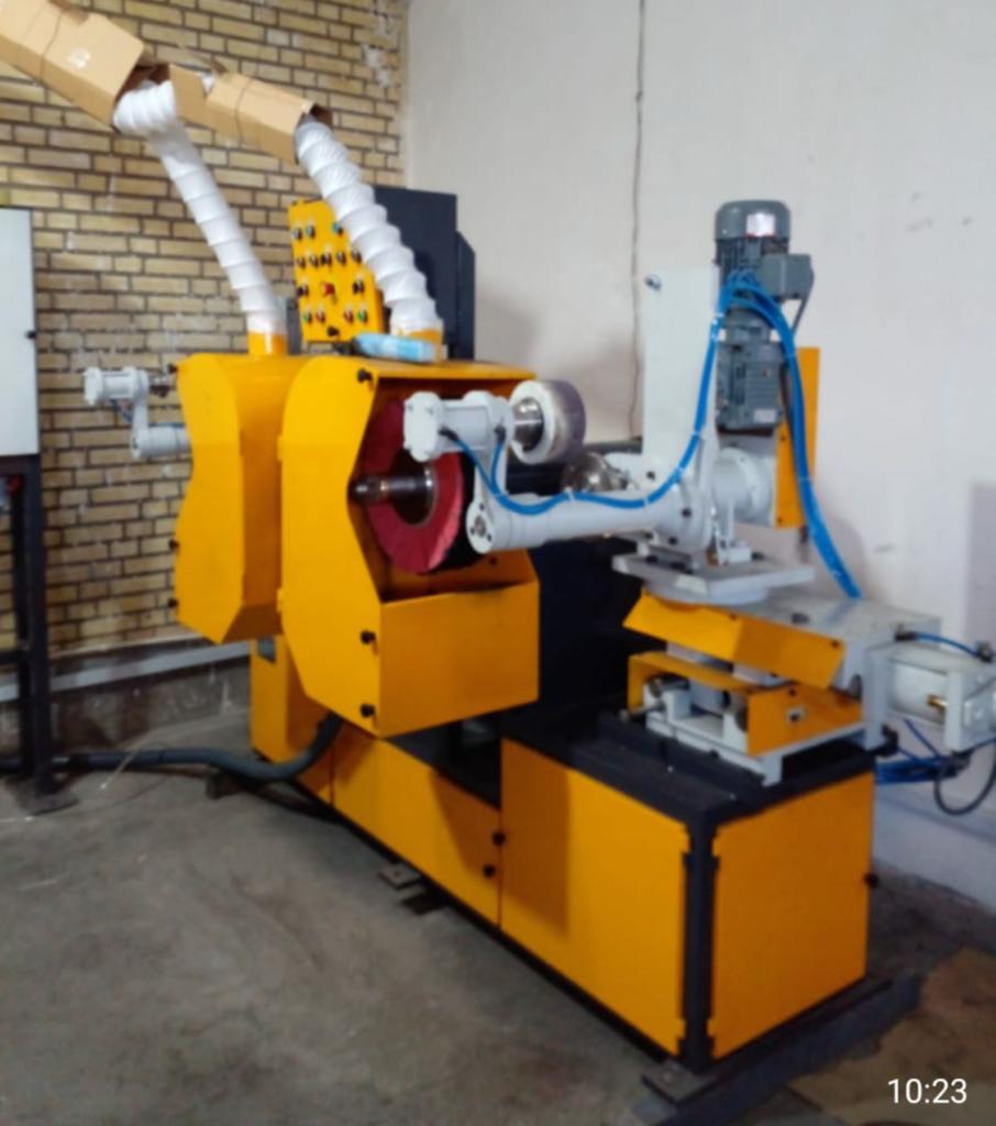
Industrial metal deburring machines are specialized equipment designed to remove burrs, sharp edges, flash, and other unwanted material from metal parts following machining, stamping, casting, or welding processes. Burrs are small, often microscopic, raised imperfections that can affect part functionality, assembly, safety, and aesthetics. Deburring machines improve product quality, ensure proper fit and function, reduce wear on mating parts, and enhance operator safety by eliminating hazardous sharp edges. These machines are widely used in automotive, aerospace, electronics, appliance manufacturing, metal fabrication, and precision engineering industries.
The core principle of industrial metal deburring involves controlled abrasion, cutting, or grinding of the burrs without damaging the main geometry or surface finish of the part. Various types of deburring machines exist, each tailored to specific applications, part sizes, shapes, and production volumes. Common types include vibratory finishing machines, abrasive belt or belt grinding deburring systems, brushing machines, tumblers, centrifugal disc finishers, and robotic or automated deburring cells.
Vibratory finishing machines use media—ceramic, plastic, or steel shapes—combined with water and compounds to create a scrubbing action that smooths edges and removes burrs. These machines are effective for batch processing of small to medium parts and provide uniform finishing on complex geometries. They are especially popular in high-volume applications where parts can be processed in bulk.
Abrasive belt deburring machines use powered sanding belts or grinding wheels to target burrs on flat or shaped surfaces. These systems offer precision control and can handle large or heavy components. Automated belt deburring systems often incorporate programmable controls, allowing precise adjustment of belt speed, pressure, and feed rates to optimize burr removal while preserving part integrity.
Brushing machines use abrasive nylon or wire brushes to remove burrs and polish edges. These machines are suitable for delicate parts or materials where aggressive grinding might cause damage. Wire brushing is particularly effective for removing weld spatter and cleaning surface contaminants as part of the deburring process.
Centrifugal disc finishers and rotary tumblers provide high-energy finishing by rotating parts in a chamber filled with abrasive media. These machines efficiently remove burrs and polish surfaces in a single operation and are commonly used for small parts such as fasteners, valves, and precision components.
Robotic and automated deburring cells are increasingly employed for complex or high-precision parts. Equipped with multi-axis robots, force sensors, and vision systems, these cells can adapt to part variability and execute burr removal on intricate shapes with minimal human intervention. Robots can use end-effectors such as grinding wheels, brushes, or abrasive pads, applying consistent pressure and path control to ensure uniform burr removal without damaging critical features.
Key features of industrial deburring machines include adjustable speed and pressure settings, programmable cycle times, quick-change tooling or media, and integrated dust and debris extraction systems. Dust collection is essential for maintaining a safe working environment, preventing contamination, and complying with health regulations, especially when processing metals that produce hazardous particles.
Deburring machines also vary in their capacity and throughput capabilities, from small bench-top units suitable for low-volume or prototype work to large-scale continuous flow machines designed for mass production. Integration with upstream and downstream processes such as washing, drying, inspection, and assembly lines is common in automated manufacturing environments to streamline workflow and reduce handling.
The choice of deburring method depends on factors including the material type (steel, aluminum, brass, titanium, plastics), part geometry, burr size and location, required surface finish, production volume, and cost considerations. Often, a combination of deburring techniques is used to achieve optimal results, such as initial heavy burr removal with belt grinding followed by fine edge finishing with brushing or vibratory polishing.
In summary, industrial metal deburring machines play a crucial role in improving the safety, functionality, and aesthetics of finished metal parts. Their range of technologies and automation levels allows manufacturers to tailor burr removal processes to diverse applications, ensuring efficient production and high-quality outcomes while minimizing labor and rework costs.
Industrial metal deburring machines have evolved to meet the increasing demands for higher precision, faster cycle times, and integration within automated production lines. Modern deburring systems often incorporate advanced control technologies that allow precise adjustment of process parameters such as speed, pressure, angle, and duration, enabling operators to tailor the deburring action to specific part geometries and materials. This adaptability is crucial for maintaining part integrity while ensuring complete burr removal, especially in industries like aerospace and medical devices where surface quality and dimensional accuracy are paramount.
Automation plays a significant role in contemporary deburring operations, with robotic deburring cells becoming more common in manufacturing environments focused on repeatability and consistency. These robotic systems are equipped with multi-axis arms capable of complex tool paths and force feedback control, allowing them to handle parts with intricate shapes or difficult-to-reach burrs. Vision systems and sensors guide the robot’s movement and verify burr presence, reducing the risk of missed spots or over-processing. Integration with programmable logic controllers (PLCs) and manufacturing execution systems (MES) enables seamless coordination with upstream machining centers and downstream inspection or assembly stations.
Material-specific deburring solutions have also become a focus area. For example, aluminum parts, which are prone to smearing and clogging abrasives, require deburring methods that minimize heat generation and tool wear. Similarly, titanium and high-strength alloys demand precise, low-impact techniques to avoid surface damage or distortion. To address these challenges, manufacturers employ specialized abrasive media, low-pressure brushing, or ultrasonic deburring methods that use cavitation effects to remove burrs without mechanical contact.
Environmental and safety considerations have driven innovations in dust extraction and waste management within deburring equipment. High-efficiency filtration systems capture fine particulate matter generated during abrasive processes, preventing operator exposure and ensuring compliance with occupational health standards. Additionally, some deburring machines use water-based or semi-dry processes to suppress dust, reducing airborne contaminants and facilitating easier waste collection. These advancements contribute to cleaner, safer, and more sustainable manufacturing environments.
Cycle time reduction remains a priority, especially in high-volume production. Multi-station deburring machines enable simultaneous processing of several parts or multiple faces of a single part, dramatically increasing throughput. Continuous flow belt or brush deburring systems allow parts to move through the machine on conveyors, receiving burr removal without stopping, thus minimizing handling and downtime. Quick-change tooling and media systems facilitate rapid adaptation to different part batches or finishing requirements, supporting flexible manufacturing strategies.
Deburring quality is often enhanced through hybrid finishing approaches, where machines combine deburring with additional surface treatments such as polishing, grinding, or passivation within a single system. This integration reduces the number of separate processing steps, lowers labor costs, and improves overall surface consistency. Automated inspection systems embedded in deburring lines can perform real-time surface analysis, ensuring burrs are fully removed and surface finishes meet specified standards before parts proceed further in the production process.
In summary, industrial metal deburring machines have transformed from simple manual or semi-automatic tools into sophisticated, automated systems capable of precise, efficient, and consistent burr removal across diverse materials and part complexities. By leveraging robotics, advanced control systems, specialized tooling, and integrated safety features, these machines enable manufacturers to meet stringent quality demands while optimizing productivity and workplace safety. As manufacturing technologies continue to evolve, deburring equipment will remain an essential component of the metal finishing landscape, supporting the production of high-performance, defect-free metal components across a wide range of industries.
Advancements in sensor technology have further enhanced industrial metal deburring machines by enabling real-time monitoring and adaptive process control. Sensors can detect variables such as tool wear, vibration, acoustic emissions, and burr size, providing feedback that allows machines to adjust parameters like feed speed, tool pressure, or abrasive intensity dynamically. This smart capability minimizes over-processing and tool damage while ensuring consistent burr removal, leading to improved part quality and extended equipment lifespan.
Collaborative robots (cobots) are increasingly being employed in deburring applications, working safely alongside human operators to combine the dexterity and judgment of skilled workers with the precision and endurance of automated systems. Cobots can be programmed to handle complex, low-volume, or customized parts, offering flexible solutions for deburring operations that traditional fixed automation cannot efficiently address. Their ease of programming and re-deployment makes them ideal for small batch production or prototyping environments.
The use of ultrasonic deburring technology is gaining traction for applications requiring delicate or hard-to-reach burr removal. Ultrasonic systems utilize high-frequency vibrations transmitted through a liquid medium, creating microscopic cavitation bubbles that collapse and gently remove burrs without mechanical abrasion. This method is especially effective for intricate parts, thin-walled components, and materials sensitive to heat or mechanical stress, such as thin aluminum or precision medical instruments.
Integration of deburring machines with upstream and downstream processes is becoming more sophisticated, enabling seamless material flow and data exchange throughout manufacturing lines. Automated part handling systems feed workpieces into deburring cells and transfer them to inspection, cleaning, or assembly stations, reducing manual intervention and increasing throughput. Data collected during deburring can be linked with quality management systems to ensure traceability and compliance with industry standards such as ISO or aerospace-specific requirements.
Energy efficiency and sustainability have become important design considerations for modern deburring equipment. Manufacturers focus on reducing power consumption through variable speed drives, optimized motor controls, and energy recovery systems. Additionally, innovations in abrasive media and coolant management reduce waste and environmental impact. Some deburring machines incorporate water recycling and filtration systems to minimize water usage, while others utilize dry or semi-dry processes to eliminate the need for coolants altogether.
Maintenance and uptime are critical factors in the selection and operation of industrial metal deburring machines. Predictive maintenance systems use machine learning algorithms to analyze operational data, anticipate component failures, and schedule maintenance proactively. This approach reduces unexpected downtime and maintenance costs, ensuring continuous production flow. Modular machine designs facilitate quick replacement of wear parts and tooling, enabling rapid turnaround during scheduled servicing.
Overall, industrial metal deburring machines are becoming increasingly intelligent, flexible, and environmentally friendly, enabling manufacturers to deliver high-quality, burr-free parts efficiently and safely. Their continued development integrates cutting-edge technologies from robotics, sensing, materials science, and digital manufacturing to meet the evolving demands of modern industry. As part complexity and quality standards rise, these machines will remain essential in optimizing metal finishing processes and enhancing product performance across a wide array of sectors.
Industrial Metal Grinders
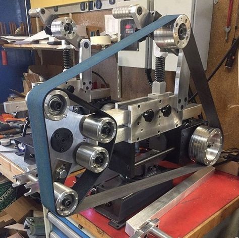
Industrial metal grinders are powerful machines designed to remove excess material, shape, smooth, or finish metal parts through abrasive cutting, grinding, or polishing actions. These grinders play a vital role in metalworking industries by enabling precision shaping, surface preparation, deburring, and finishing of components made from a variety of metals including steel, aluminum, brass, and cast iron. They are used extensively in manufacturing sectors such as automotive, aerospace, shipbuilding, toolmaking, and heavy machinery production.
There are several types of industrial metal grinders tailored to specific applications and part geometries. Bench grinders are versatile, compact machines typically equipped with abrasive wheels used for sharpening, rough grinding, or light deburring. Larger pedestal grinders provide more power and stability for heavier duty applications. Surface grinders focus on producing flat, smooth surfaces by grinding workpieces fixed to a magnetic or mechanical table under a rotating abrasive wheel. Cylindrical grinders specialize in grinding round or cylindrical parts to precise dimensions and finishes.
Industrial grinders may be manual, semi-automatic, or fully automated with CNC control for high precision and repeatability. CNC grinding machines enable programmable control of grinding wheel speed, feed rates, and depth of cut, making them ideal for complex shapes and tight tolerances. Automated grinders are integrated into production lines with robotic loading and unloading systems, enhancing throughput and reducing labor.
Grinding wheels are the primary abrasive tools used in metal grinders. They come in various compositions, including aluminum oxide, silicon carbide, cubic boron nitride (CBN), and diamond, selected based on the material to be ground and the desired surface finish. Wheel selection and dressing are critical for maintaining grinding performance, precision, and wheel life. Automated wheel dressing systems restore the wheel’s shape and sharpness during operation, minimizing downtime.
Grinders employ different grinding techniques depending on the application. Rough grinding removes significant material to shape or size a part, while finish grinding produces smooth surfaces and precise dimensions. Centerless grinding eliminates the need for workpiece mounting by supporting the part between a grinding wheel and a regulating wheel, allowing rapid processing of cylindrical components. Belt grinding machines use abrasive belts for flexible surface finishing, blending, and deburring.
Effective dust and coolant management systems are essential in industrial grinding to control heat generation, improve surface quality, and maintain a safe working environment. Coolant systems deliver fluids to reduce friction and carry away heat, preventing thermal damage to parts and abrasives. Dust extraction systems remove fine particles generated during grinding, reducing airborne contaminants and preventing accumulation that could impair machine function or operator health.
Safety features in industrial metal grinders include guards around abrasive wheels, emergency stop controls, vibration dampening, and automatic shutoffs triggered by abnormal operating conditions. These measures protect operators from sparks, debris, and mechanical hazards associated with high-speed abrasive machining.
Industrial metal grinders serve a wide range of functions—from rough shaping and deburring to precision finishing and polishing—making them indispensable tools in metal fabrication and manufacturing. Their adaptability, power, and precision help ensure components meet stringent dimensional and surface quality requirements, supporting the production of reliable, high-performance metal products across various industries.
Industrial metal grinders have continued to evolve with advances in automation, precision control, and material science, making them more versatile, efficient, and safer. Modern grinders often feature CNC systems that enable highly accurate control of grinding parameters such as wheel speed, feed rate, and depth of cut. This precision allows the production of complex shapes and tight tolerances while reducing scrap and rework. CNC grinding machines can store multiple programs, facilitating rapid changeovers between different part designs and boosting production flexibility.
Robotic integration is becoming increasingly common in grinding operations, where robots handle loading, unloading, and positioning of parts, allowing grinders to operate continuously with minimal human intervention. This automation not only enhances throughput but also improves operator safety by reducing exposure to abrasive dust and moving parts. Collaborative robots (cobots) are sometimes employed for grinding tasks that require a combination of automated precision and human oversight, especially in small-batch or custom manufacturing environments.
Material-specific grinding techniques have been developed to optimize performance across various metals and alloys. For instance, grinding hardened steels demands abrasive wheels with cubic boron nitride (CBN) or diamond grit to maintain sharpness and avoid rapid wear. Softer metals like aluminum or brass require different abrasive compositions and coolant strategies to prevent material smearing or clogging of the grinding wheel. These tailored approaches ensure consistent surface finishes and dimensional accuracy while extending tool life.
Dust and coolant management remain critical components of industrial grinding systems. Advanced filtration units capture fine particulates and prevent contamination of the workplace air, complying with increasingly stringent occupational health regulations. Coolant systems often feature recirculation, filtration, and temperature control to optimize grinding conditions, reduce fluid waste, and extend coolant lifespan. Some facilities are moving toward dry or minimum quantity lubrication (MQL) grinding processes to reduce environmental impact and simplify waste disposal.
The physical design of industrial grinders has also improved, focusing on operator ergonomics, machine accessibility, and ease of maintenance. Adjustable work supports, intuitive control panels, and modular components facilitate quicker setups, reduce operator fatigue, and minimize downtime for repairs or tool changes. Vibration isolation and noise reduction technologies enhance workplace comfort and equipment longevity.
Hybrid grinding machines combine grinding with complementary processes such as polishing, honing, or lapping in a single unit. These multifunctional systems reduce handling and improve alignment between finishing steps, leading to better overall surface quality and dimensional control. Hybrid machines are particularly valuable in industries like aerospace and medical device manufacturing, where ultra-precision finishes are essential.
Quality control is increasingly integrated into grinding workflows through in-process measurement technologies such as laser scanners, contact probes, and surface profilometers. These systems enable real-time monitoring of part dimensions and surface finishes, allowing automatic adjustments to grinding parameters to maintain strict tolerances. Closed-loop control systems reduce scrap rates and improve first-pass yield, contributing to cost savings and faster production cycles.
In summary, industrial metal grinders have become highly sophisticated machines that combine abrasive technology with automation, precision control, and environmental considerations. They are essential in shaping, finishing, and preparing metal components to meet demanding specifications in diverse manufacturing sectors. Ongoing technological advancements continue to enhance their performance, flexibility, and safety, ensuring they remain foundational tools in modern metalworking operations.
Industrial metal grinders also play a crucial role in emerging manufacturing technologies, such as additive manufacturing and advanced composite machining. As 3D-printed metal parts become more prevalent, grinders are used to finish and refine surfaces that are often rough or layered from the printing process. Specialized grinding techniques are developed to carefully remove support structures, smooth out surface irregularities, and achieve the required tolerances without compromising the part’s structural integrity. This adaptation extends the utility of grinding technology into cutting-edge production methods.
Furthermore, advancements in abrasive materials have led to the development of superabrasives like polycrystalline diamond (PCD) and cubic boron nitride (CBN) wheels, which offer superior hardness, thermal stability, and wear resistance compared to traditional abrasives. These wheels enable faster material removal rates, longer tool life, and the ability to grind hard-to-machine materials such as hardened steels, carbides, and ceramics. The use of superabrasives has transformed grinding processes, allowing for greater precision and efficiency in high-performance industries.
Customization and modularity in industrial grinders allow manufacturers to tailor machines for specific tasks, including multi-axis grinding, form grinding, and internal grinding. Multi-axis CNC grinders can handle complex geometries and contoured surfaces by moving the grinding wheel and workpiece along several coordinated axes. Form grinders use specially shaped wheels to grind profiles or contours in a single pass, reducing cycle time and improving consistency. Internal grinders focus on finishing bores, holes, or cylindrical cavities with high precision.
The integration of data analytics and artificial intelligence (AI) in industrial grinding machines is an emerging trend. AI algorithms analyze sensor data such as spindle load, vibration, acoustic signals, and temperature to optimize grinding parameters dynamically and predict maintenance needs. This approach enhances machine uptime, reduces tool wear, and maintains consistent quality without constant human monitoring. Predictive analytics also enable smarter scheduling of maintenance activities, avoiding unexpected breakdowns and improving overall equipment effectiveness (OEE).
Sustainability is increasingly emphasized in grinding operations, with efforts to minimize energy consumption, reduce waste, and improve resource efficiency. Manufacturers are adopting energy-efficient motors, regenerative braking, and optimized grinding cycles to lower power usage. Advances in coolant technology and recycling systems reduce fluid consumption and environmental impact. Additionally, dry grinding and minimum quantity lubrication (MQL) techniques are gaining traction as eco-friendly alternatives that also improve workplace conditions by minimizing fluid mist and disposal challenges.
Safety innovations continue to be paramount in industrial grinder design. Enhanced guarding systems, automatic shutoffs triggered by abnormal conditions, and ergonomic controls help prevent accidents and protect operators. Vibration isolation and noise reduction technologies contribute to a safer and more comfortable work environment. Training programs and digital interfaces that guide operators through safe machine operation further reduce the risk of human error.
In conclusion, industrial metal grinders remain indispensable in modern manufacturing due to their versatility, precision, and efficiency in shaping and finishing metal parts. Continuous advancements in automation, abrasive technology, machine intelligence, and sustainability are expanding their capabilities and applications. These innovations ensure that grinders will continue to meet the evolving demands of diverse industries, supporting the production of high-quality, complex metal components essential for today’s advanced engineering challenges.
Industrial Metal Polishing Equipment
Industrial metal polishing equipment encompasses a broad range of machines and systems designed to enhance the surface finish, appearance, and performance of metal parts through controlled abrasion, buffing, and smoothing processes. Polishing removes surface imperfections such as scratches, oxidation, and roughness, resulting in a bright, reflective, and often mirror-like finish that can also improve corrosion resistance and ease of cleaning. These machines are essential in industries like automotive, aerospace, electronics, jewelry manufacturing, household appliances, and architectural metalwork, where aesthetics and surface integrity are critical.
The core types of industrial metal polishing equipment include belt polishers, rotary polishing machines, vibratory finishing systems, centrifugal barrel finishers, and robotic polishing cells. Belt polishers use abrasive belts that move at high speeds to grind and polish flat or contoured metal surfaces efficiently. These machines are versatile and can handle large, heavy parts as well as delicate components by adjusting belt speed and abrasive grade. Rotary polishing machines feature rotating buffing wheels or pads that apply polishing compounds to achieve fine finishes, often used in applications requiring high gloss or mirror-quality surfaces.
Vibratory finishing equipment processes batches of parts simultaneously by using abrasive media in a vibrating container that induces friction and polishing action on metal surfaces. This method is well-suited for small to medium-sized parts with complex shapes, providing uniform polishing and deburring. Centrifugal barrel finishers operate on a similar principle but use centrifugal force to accelerate media and parts against each other, delivering faster and more aggressive polishing for tougher applications.
Robotic polishing cells are gaining popularity for their ability to automate complex polishing tasks that require consistent pressure, speed, and tool path control. These systems integrate multi-axis robots equipped with polishing tools such as abrasive pads, brushes, or buffing wheels and use sensors and vision systems to adapt to part geometry and surface conditions. Robotic polishing enhances repeatability, reduces labor intensity, and can be programmed for both rough and fine polishing steps, making them ideal for high-volume production or intricate components.
Polishing abrasives and compounds vary widely depending on the material being polished and the desired finish. Common abrasives include aluminum oxide, silicon carbide, and diamond pastes, while polishing compounds may contain rouge, chromium oxide, or cerium oxide. Proper selection and application of abrasives and compounds are crucial for achieving consistent results and minimizing surface defects like swirl marks or haze. Many polishing machines feature automated compound application systems to ensure even distribution and reduce waste.
Coolant and dust management are integral to industrial polishing processes. Water or specialized polishing fluids cool the surface and abrasives, prevent heat buildup, and flush away debris, preserving surface quality and extending tool life. Efficient dust extraction systems remove fine particles generated during polishing, maintaining a clean work environment and protecting operator health.
Ergonomic design and safety features are also priorities in polishing equipment. Adjustable work rests, user-friendly controls, and protective guards minimize operator fatigue and injury risk. Emergency stops, interlocks, and noise reduction measures contribute to a safer workplace.
In summary, industrial metal polishing equipment plays a vital role in producing high-quality, visually appealing, and functional metal surfaces. Through a combination of abrasive technology, automation, and precision control, these machines meet diverse polishing requirements across many industries, ensuring metal components achieve their intended performance and aesthetic standards.
Industrial metal polishing equipment continues to advance through the integration of automation, precision control, and environmentally conscious design. Automated polishing systems reduce the reliance on manual labor, which can be physically demanding and inconsistent. CNC-controlled polishing machines and robotic polishing cells deliver repeatable, high-quality finishes by precisely regulating tool speed, pressure, and motion paths. These automated solutions enable manufacturers to maintain tight tolerances and surface finish specifications, especially important in industries like aerospace and medical device manufacturing where surface integrity is critical.
Material-specific polishing processes have been developed to address the unique challenges posed by different metals and alloys. For example, stainless steel often requires polishing sequences that remove surface contaminants while enhancing corrosion resistance and creating a smooth, hygienic finish suitable for food or pharmaceutical applications. Aluminum polishing focuses on minimizing surface scratching and oxidation, frequently involving multi-step processes with progressively finer abrasives. Hard metals like titanium and superalloys demand durable polishing tools and carefully controlled parameters to avoid heat damage and preserve material properties.
Environmental and safety considerations shape the design of modern polishing equipment. Water-based coolants and polishing fluids are commonly used to reduce dust and control heat, but they require filtration and recycling systems to minimize waste and environmental impact. Advances in dust collection technologies, including high-efficiency particulate air (HEPA) filters and automated extraction systems, improve air quality and operator safety by capturing fine particles generated during polishing. Some polishing processes have transitioned to dry or minimal-lubricant methods to reduce fluid consumption and simplify waste management.
The modularity of polishing equipment allows manufacturers to configure systems tailored to specific applications, ranging from small batch workstations to fully automated production lines. Quick-change tooling, adjustable fixtures, and flexible control software enable rapid adaptation to different part sizes, shapes, and finish requirements. This versatility supports lean manufacturing principles by reducing setup times and enhancing production responsiveness.
Hybrid polishing machines combine polishing with related finishing operations such as buffing, grinding, or cleaning in a single integrated system. These hybrid systems streamline workflows, reduce handling, and improve the consistency of final surface quality. In-line inspection technologies, including laser scanners and surface profilometers, are increasingly incorporated into polishing lines to provide real-time feedback and ensure that parts meet exacting surface finish criteria before moving to subsequent stages.
Ergonomic considerations in polishing equipment design help reduce operator fatigue and risk of injury. Features such as adjustable worktables, intuitive user interfaces, vibration dampening, and noise reduction contribute to a safer and more comfortable working environment. Enhanced training programs and digital guidance systems assist operators in optimizing polishing techniques and machine settings, further improving quality and productivity.
Overall, industrial metal polishing equipment continues to evolve by combining advanced abrasive technologies, automation, environmental stewardship, and ergonomic design. These innovations enable manufacturers to achieve superior surface finishes with higher efficiency and lower operational costs, meeting the growing demands for quality and sustainability across diverse industries. As surface finishing requirements become increasingly complex, polishing equipment will remain an essential component in delivering flawless, high-performance metal parts.
The role of industrial metal polishing equipment is also expanding with the rise of digital manufacturing and smart factory concepts. Integration of Internet of Things (IoT) sensors and connectivity allows polishing machines to collect and transmit data on parameters such as motor load, spindle speed, temperature, vibration, and abrasive wear. This data is analyzed in real time to optimize polishing processes, predict maintenance needs, and reduce downtime. Such smart polishing systems support predictive maintenance strategies that minimize unexpected breakdowns and extend machine service life, improving overall operational efficiency.
Another important trend is the use of adaptive polishing technologies, where machines dynamically adjust polishing pressure, speed, and tool paths based on continuous feedback from force sensors or surface quality measurements. This adaptive control ensures consistent surface finishes across batches despite variations in part geometry, material hardness, or abrasive condition. It reduces the need for operator intervention and trial-and-error adjustments, leading to more stable processes and higher first-pass yield.
The development of new polishing consumables and compounds enhances the capability of polishing equipment. Nanotechnology-based polishing pastes and slurries provide finer abrasive particles that deliver ultra-smooth finishes without damaging sensitive surfaces. Environmentally friendly and biodegradable compounds are also gaining popularity as industries seek to reduce their ecological footprint. Automated compound dispensing systems integrated with polishing machines help maintain consistent application rates, reduce waste, and lower operational costs.
Hybrid polishing solutions increasingly incorporate multifunctional tools combining abrasive, buffing, and cleaning actions, enabling simultaneous polishing and surface conditioning. This approach shortens cycle times, improves surface uniformity, and reduces the number of separate processing steps required. Additionally, modular robotic polishing cells equipped with tool changers can switch between different polishing heads or brushes automatically, adapting to complex parts or varied surface finishing requirements within a single production run.
Training and skill development remain vital as polishing technologies become more sophisticated. Digital simulation and virtual reality (VR) training tools allow operators to practice polishing sequences and machine operation in safe, controlled environments before working on actual parts. Such training improves operator competence, reduces errors, and enhances safety. Furthermore, user-friendly machine interfaces with touchscreen controls, guided workflows, and real-time diagnostics simplify operation and troubleshooting, making advanced polishing technology accessible to a broader range of users.
Sustainability is also influencing polishing equipment design and use. Manufacturers prioritize machines that minimize energy consumption, utilize recyclable fluids, and reduce waste generation. Some polishing systems employ dry or near-dry processes to cut down on fluid use, while closed-loop coolant recycling systems reclaim and purify polishing liquids for extended use. Waste polishing compounds and debris are being collected and processed for reuse or safe disposal, supporting circular economy principles.
In conclusion, industrial metal polishing equipment is becoming increasingly intelligent, adaptable, and sustainable, driven by advances in automation, materials science, and digital connectivity. These developments enable manufacturers to achieve high-quality surface finishes consistently and efficiently, while reducing environmental impact and operational costs. As industries demand ever-higher surface quality and process reliability, polishing equipment will continue to evolve as a critical enabler of precision metal finishing across a wide range of applications.
Surface Finishing Machines
Surface finishing machines are specialized industrial equipment designed to modify the surface properties of materials—primarily metals—to improve appearance, functionality, durability, and cleanliness. These machines perform processes such as grinding, polishing, deburring, sanding, brushing, and coating removal to achieve desired surface textures, smoothness, gloss, or matte finishes. Surface finishing is critical in various manufacturing sectors including automotive, aerospace, electronics, medical devices, construction, and consumer goods, where surface quality directly affects product performance, corrosion resistance, wear characteristics, and aesthetic appeal.
Surface finishing machines come in many types and configurations to address diverse materials and part geometries. Common categories include vibratory finishing machines, abrasive belt grinders, polishing and buffing machines, shot blasting and bead blasting equipment, brushing machines, tumblers, and automated robotic finishing cells. Each machine type uses different mechanisms—mechanical abrasion, impact, chemical action, or a combination—to remove surface defects, smooth rough edges, or apply protective finishes.
Vibratory finishing machines operate by placing parts and abrasive media inside a vibrating tub or bowl, where the media scrubs and polishes surfaces through controlled friction. This process is effective for mass finishing of small parts with complex geometries, delivering consistent edge rounding, deburring, and surface smoothing. Abrasive belt grinders utilize continuous sanding belts driven over rollers to grind or polish flat or contoured surfaces rapidly. These grinders offer precision control over finish quality and are widely used for both heavy material removal and fine surface finishing.
Polishing and buffing machines employ rotating wheels, pads, or brushes combined with abrasive compounds to produce high-gloss, mirror-like finishes. These machines range from manual bench-top units to fully automated lines capable of handling large volumes with minimal operator involvement. Shot blasting and bead blasting equipment propel abrasive particles at high velocity to clean, strengthen, or texture surfaces, making them ideal for rust removal, surface preparation before painting, or achieving uniform matte finishes.
Brushing machines use abrasive or wire brushes to remove burrs, clean welds, or create specific surface textures. Tumblers and centrifugal finishers provide high-energy mass finishing by tumbling parts with abrasive media, often combining deburring and polishing in one step. Advanced robotic finishing cells incorporate multi-axis manipulators, vision systems, and force sensors to automate complex surface finishing tasks with high precision and repeatability.
Many surface finishing machines integrate features such as automated part handling, programmable controls, in-process measurement, and environmental management systems for dust and coolant. These capabilities enhance efficiency, consistency, and workplace safety, supporting lean manufacturing and high-quality standards.
In summary, surface finishing machines are essential tools in metalworking and manufacturing industries, enabling the transformation of raw or machined parts into finished components with optimized surface properties. Their wide variety of types and automation levels allow manufacturers to tailor finishing processes to specific materials, geometries, and quality requirements, ensuring performance, durability, and aesthetic appeal in final products.
Surface finishing machines have evolved significantly with advances in automation, precision control, and integration into modern manufacturing systems. Today’s machines often feature CNC programming or robotic automation to deliver consistent, repeatable finishes with minimal operator intervention. Automated surface finishing allows manufacturers to maintain tight tolerances on surface roughness, flatness, and edge quality, which is critical for industries such as aerospace, medical devices, and electronics where surface integrity impacts functionality and longevity.
Material versatility is a key strength of modern surface finishing equipment. Machines can be configured or adapted to work with a broad range of metals including steel, aluminum, titanium, copper alloys, and specialty superalloys, as well as non-metallic materials like composites and plastics. Specialized abrasive media, polishing compounds, and tooling ensure optimal finishing results without damaging or altering the base material properties. For example, delicate parts may be processed using fine polishing pads and low-pressure brush systems, while heavy-duty deburring may require robust belt grinding or vibratory tumbling.
Environmental and workplace safety considerations are integral to surface finishing machine design. Dust extraction and filtration systems capture fine particulate matter generated during grinding, polishing, or blasting, protecting worker health and maintaining clean production areas. Coolant and polishing fluid management systems recycle or filter fluids to reduce waste and prevent contamination. Machines also incorporate guarding, interlocks, and ergonomic controls to minimize operator risk and fatigue during operation.
Surface finishing processes are frequently combined or sequenced within single systems to optimize efficiency and quality. For instance, a machine might perform initial deburring via abrasive belts, followed by fine polishing with buffing wheels or brush heads, all within a continuous automated cycle. Hybrid finishing machines that integrate grinding, polishing, and cleaning stages reduce handling, setup times, and overall cycle durations. Integration with inline inspection technologies such as laser scanners and surface profilometers enables real-time quality control and process adjustments.
Scalability and modularity enable surface finishing equipment to meet diverse production volumes—from small batch and prototype runs to high-volume mass manufacturing. Quick-change tooling, adjustable process parameters, and flexible automation systems allow rapid adaptation to varying part designs and finish specifications. This flexibility supports just-in-time manufacturing and customized product variants without significant downtime or capital investment.
Digital connectivity and Industry 4.0 integration are enhancing surface finishing operations. Machines equipped with sensors and network interfaces provide continuous monitoring of parameters such as spindle load, vibration, temperature, and abrasive wear. Data analytics and predictive maintenance algorithms help reduce unplanned downtime and optimize consumable usage. Remote diagnostics and software updates improve machine uptime and responsiveness to changing production demands.
In conclusion, surface finishing machines are sophisticated, adaptable tools vital to producing metal and other material parts with precise, high-quality surface characteristics. Advances in automation, materials, and digital technologies continue to push the boundaries of what these machines can achieve, enabling manufacturers to meet increasingly stringent industry standards while improving productivity, safety, and sustainability. As manufacturing evolves, surface finishing machines will remain essential for delivering functional, durable, and visually appealing components across countless applications.
Emerging trends in surface finishing machines emphasize greater automation combined with artificial intelligence (AI) and machine learning (ML) to optimize finishing processes. AI-driven systems analyze real-time sensor data—including force feedback, surface roughness measurements, and tool wear indicators—to automatically adjust parameters such as polishing speed, pressure, and abrasive selection. This dynamic optimization reduces manual trial-and-error, minimizes material waste, and enhances consistency across production batches.
Robotic surface finishing cells are increasingly used for complex parts requiring multi-axis tool movement and variable contact pressures. These cells often incorporate vision systems and tactile sensors that guide the robot’s polishing or grinding tools to precisely follow intricate contours and identify areas needing more attention. Such adaptive capabilities improve finish uniformity, reduce operator intervention, and enable the processing of delicate or irregularly shaped components.
Sustainability considerations are driving innovations in surface finishing equipment design and operation. Water-based and biodegradable polishing compounds are replacing traditional chemical agents to lower environmental impact. Advanced filtration and recycling systems capture and reuse fluids and abrasive media, reducing consumption and waste. Dry finishing technologies and minimum quantity lubrication (MQL) methods are gaining popularity, cutting down on fluid use and associated disposal challenges while maintaining or improving finish quality.
Hybrid finishing systems that combine multiple surface treatment techniques into one machine are becoming standard in advanced manufacturing. For example, machines may integrate abrasive grinding, polishing, and ultrasonic cleaning stages to provide complete surface preparation and finishing without moving parts between different equipment. These integrated workflows reduce cycle times, handling risks, and potential damage to delicate surfaces.
Customization and modularity allow surface finishing machines to be rapidly reconfigured for different products, materials, or finishing standards. Quick-change tooling, adjustable fixtures, and software-based recipe management enable manufacturers to switch between production runs efficiently, supporting lean manufacturing and just-in-time delivery models.
Ergonomic design and operator support tools enhance productivity and safety. Adjustable workstations, vibration isolation, noise reduction, and intuitive control interfaces reduce operator fatigue and improve accuracy. Training simulators and augmented reality (AR) guidance systems help operators learn complex finishing techniques and machine operations faster and with fewer errors.
Looking ahead, integration of surface finishing machines into fully digital smart factories will allow seamless coordination with upstream and downstream production steps. Real-time quality data will feed into enterprise resource planning (ERP) and manufacturing execution systems (MES), enabling closed-loop process control and continuous improvement. This connectivity will also facilitate remote monitoring, diagnostics, and maintenance, ensuring optimal machine performance and rapid response to production issues.
In essence, surface finishing machines are at the forefront of industrial innovation, blending mechanical engineering, automation, materials science, and digital technologies. Their evolution supports manufacturing’s push toward higher precision, greater efficiency, enhanced sustainability, and improved product quality—making them indispensable in the production of modern metal and composite components across virtually all industries.
Metal Surface Finishing Machine
A metal surface finishing machine is an industrial device specifically engineered to modify and enhance the surface properties of metal components through processes such as polishing, grinding, deburring, sanding, brushing, and blasting. These machines improve the metal’s appearance, corrosion resistance, smoothness, and overall functionality by removing imperfections like burrs, oxidation, roughness, and scratches. Metal surface finishing machines are vital across many industries, including automotive, aerospace, electronics, construction, medical device manufacturing, and consumer goods production.
These machines come in a variety of types to accommodate different metal materials, part sizes, and surface finish requirements. Common varieties include vibratory finishing machines, abrasive belt grinders, rotary polishers, brushing machines, shot and bead blasting systems, centrifugal finishers, and robotic polishing cells. Each machine type utilizes unique mechanisms—mechanical abrasion, impact, chemical action, or combinations thereof—to achieve specific surface finishes, from coarse deburring to mirror-like polishing.
Modern metal surface finishing machines often incorporate automation and CNC controls, enabling precise, repeatable processing with minimal operator intervention. Automated systems can adjust parameters such as tool speed, pressure, and feed rate dynamically to suit various metals like steel, aluminum, titanium, and copper alloys. Integration with robotic arms and vision sensors allows handling of complex geometries and delicate parts, ensuring consistent finish quality even on intricate surfaces.
Environmental control features are integral to metal surface finishing machines, with advanced dust extraction, coolant filtration, and fluid recycling systems maintaining safe working conditions and reducing waste. Ergonomic design considerations enhance operator comfort and safety through adjustable workstations, noise reduction, and protective guarding.
Overall, metal surface finishing machines are essential tools that transform raw or machined metal parts into finished components meeting stringent aesthetic and functional standards. Their versatility, precision, and evolving technological sophistication enable manufacturers to deliver high-quality, durable metal products efficiently and sustainably across diverse industrial applications.
Metal surface finishing machines have steadily advanced to meet the growing demands for higher precision, efficiency, and adaptability in modern manufacturing. Many machines now feature programmable controls that allow operators to set and monitor key parameters such as abrasive type, pressure, speed, and cycle duration, ensuring consistent results regardless of part complexity or batch size. These capabilities reduce operator dependency and minimize variability, which is crucial for industries requiring strict adherence to surface quality standards.
Automation and robotic integration are increasingly prevalent, with robots handling part loading, positioning, and finishing tool manipulation. Robotic polishing and grinding cells equipped with multi-axis arms and sensors enable precise control over tool contact and motion paths, allowing complex geometries to be finished uniformly. Vision systems and tactile sensors guide these robots to detect surface irregularities or burrs in real time, enabling adaptive finishing that improves overall quality and reduces scrap.
Material-specific finishing processes are optimized through careful selection of abrasives, polishing compounds, and machine settings. For instance, stainless steel finishing often requires polishing sequences that enhance corrosion resistance and achieve sanitary surface finishes, while aluminum finishing focuses on preventing smearing and oxidation. Hard alloys like titanium or superalloys demand robust abrasives and precise process control to avoid overheating and maintain material properties. Machines are designed to accommodate these varied needs through modular tooling and adjustable process parameters.
Environmental and safety concerns play a major role in machine design. Efficient dust extraction and filtration systems capture fine particulate matter, protecting worker health and preventing equipment contamination. Coolant and polishing fluid management systems recycle and purify liquids to minimize environmental impact and operating costs. Many machines incorporate guarding, emergency stops, and ergonomic features to reduce operator risk and fatigue during extended operations.
Hybrid finishing machines that combine multiple processes—such as grinding, polishing, and cleaning—within a single system improve throughput and surface consistency by reducing handling and process transitions. Integration with in-line inspection tools like laser scanners and surface roughness testers allows real-time monitoring and quality assurance, enabling immediate adjustments and minimizing rework.
Flexibility and scalability are key attributes of contemporary metal surface finishing machines. Modular designs and quick-change tooling allow rapid adaptation to different part sizes, shapes, and finish requirements, supporting lean manufacturing and just-in-time production. Small batch and prototype runs benefit from easy reconfiguration, while high-volume production lines rely on continuous operation and automation to maintain efficiency.
The advent of Industry 4.0 technologies is transforming metal surface finishing by enabling connectivity between machines, sensors, and enterprise systems. Data collected during finishing processes feed into analytics platforms for process optimization, predictive maintenance, and production planning. Remote monitoring and diagnostics improve uptime and responsiveness, while digital twins and simulation tools help manufacturers develop and validate finishing processes virtually before physical implementation.
In summary, metal surface finishing machines are increasingly sophisticated, blending mechanical engineering, automation, materials science, and digital technology to meet diverse industrial finishing needs. Their evolution enhances manufacturing flexibility, product quality, operational safety, and environmental sustainability, solidifying their role as essential equipment in producing high-performance, visually appealing metal components across a wide spectrum of industries.
Advances in sensor technology have further elevated metal surface finishing machines by enabling real-time process monitoring and adaptive control. Sensors measuring vibration, temperature, force, and acoustic emissions provide continuous feedback, allowing machines to dynamically adjust parameters such as polishing pressure, abrasive speed, or feed rate to maintain optimal finishing conditions. This closed-loop control minimizes surface defects, reduces tool wear, and improves consistency across production batches, even when part geometries or material properties vary.
The rise of collaborative robots (cobots) in metal finishing has opened new possibilities for flexible automation. Cobots can safely work alongside human operators, assisting with complex or variable finishing tasks that require a combination of robotic precision and human judgment. Their ease of programming and redeployment makes them ideal for small-batch production, prototyping, or custom finishing operations where fully automated cells may be impractical.
Innovations in abrasive materials and polishing compounds continue to improve finishing performance and sustainability. Superabrasive wheels and belts embedded with diamond or cubic boron nitride particles offer exceptional hardness and longevity, enabling efficient finishing of hard alloys and minimizing downtime for tool changes. Environmentally friendly polishing pastes and fluids, including water-based and biodegradable formulations, reduce environmental impact while maintaining or enhancing finish quality.
Maintenance and uptime are supported by predictive analytics and machine learning applied to finishing equipment. By analyzing sensor data trends, manufacturers can anticipate wear or component failure before it occurs, scheduling maintenance proactively to avoid unexpected downtime. Modular machine architectures facilitate rapid replacement of wear parts and tooling, reducing servicing time and maintaining continuous production.
Emerging finishing methods such as ultrasonic polishing and laser-assisted surface finishing are beginning to complement traditional mechanical processes. Ultrasonic polishing uses high-frequency vibrations transmitted through a fluid medium to remove micro-burrs and achieve ultra-smooth finishes without mechanical abrasion, beneficial for delicate or intricate components. Laser-assisted finishing can precisely modify surface texture or hardness, providing functional enhancements in addition to cosmetic improvements.
Ergonomics and operator training remain critical as machines grow more complex. User interfaces increasingly incorporate touchscreens, guided workflows, and real-time diagnostics to simplify operation and troubleshooting. Virtual reality (VR) and augmented reality (AR) training tools help operators learn machine functions and polishing techniques safely and effectively, reducing errors and improving quality.
In essence, metal surface finishing machines are evolving into highly intelligent, adaptable systems that combine advanced mechanics, automation, sensor feedback, and digital connectivity. These advances empower manufacturers to deliver superior surface quality efficiently and sustainably, meeting the escalating demands of modern industries for precision, reliability, and environmental responsibility. As technology progresses, these machines will continue to play a pivotal role in producing the finely finished metal components essential to countless products and applications worldwide.
Sphere Polishing Equipment Machine
Sphere polishing equipment machines are specialized industrial devices designed to produce precise, high-quality polished spherical surfaces on metal or other hard materials. These machines are crucial in industries such as optics, aerospace, ball bearing manufacturing, precision instruments, and medical devices, where perfectly smooth and accurate spherical surfaces are essential for proper function and performance.
The core function of a sphere polishing machine is to remove surface irregularities and imperfections from spherical components, achieving tight dimensional tolerances and superior surface finishes, often measured in nanometers of roughness. These machines typically employ abrasive polishing techniques using fine grit polishing pads, wheels, or slurry-based abrasives, carefully controlled to maintain the geometry of the sphere while enhancing surface quality.
Sphere polishing machines may operate using different principles: some use rotating or oscillating polishing heads that conform to the sphere’s curvature, while others employ automated fixtures that hold and rotate the sphere itself against a stationary polishing medium. Multi-axis CNC-controlled machines provide precise movements in several coordinated directions, ensuring uniform polishing coverage and enabling customization of polishing parameters such as pressure, speed, and polishing time.
Advanced sphere polishing equipment often integrates sensors and feedback systems to monitor surface finish, force applied, and part position in real time. This data enables adaptive control of the polishing process, ensuring consistent quality and minimizing operator intervention. Some systems also incorporate in-process metrology tools like laser profilometers or interferometers to measure surface roughness and shape accuracy during polishing.
Automation is a significant trend in sphere polishing, with robotic handling and multi-part processing capabilities improving throughput and reducing labor intensity. Automated loading and unloading systems, combined with programmable polishing cycles, allow these machines to handle small batches or mass production efficiently while maintaining high precision.
Abrasive materials used in sphere polishing include diamond pastes, cerium oxide, aluminum oxide, and colloidal silica, selected based on the workpiece material and required finish. Polishing slurries or pads deliver these abrasives evenly and gently to avoid introducing new surface defects.
Environmental controls such as coolant delivery systems help manage heat generation and wash away debris, preserving surface integrity and extending tool life. Dust extraction and filtration maintain a clean work environment, protecting operators and equipment.
In summary, sphere polishing equipment machines are sophisticated tools that combine precision mechanics, advanced abrasives, automation, and real-time monitoring to achieve flawless spherical surfaces essential for high-performance applications. Their specialized design ensures that spherical components meet stringent dimensional and surface quality requirements, supporting critical functions in a wide range of technical fields.
Sphere polishing equipment machines have evolved to incorporate high levels of automation and precision control, enabling manufacturers to meet increasingly stringent requirements for spherical component quality and consistency. Modern machines often utilize multi-axis CNC systems that provide synchronized movements of both the polishing tool and the workpiece, allowing for uniform material removal across the entire spherical surface. This precise control minimizes geometric distortion and ensures tight dimensional tolerances essential for applications like optical lenses, precision ball bearings, and surgical implants.
Advanced sphere polishing systems integrate real-time monitoring technologies such as laser interferometry, tactile sensors, or acoustic emission detectors to track surface roughness, curvature, and polishing forces throughout the process. Feedback from these sensors allows the machine’s control system to dynamically adjust parameters like pressure, speed, and polishing duration, optimizing finish quality while reducing cycle times and consumable usage. Such adaptive control improves yield and reduces the need for manual inspection or rework.
Automation features include robotic part handling, automated polishing media dispensing, and programmable polishing sequences. Robotic arms can load and unload spheres with minimal human intervention, enabling continuous operation and higher throughput. Automated slurry or polishing compound delivery systems ensure consistent abrasive application, preventing uneven finishes or excessive material removal. Programmable cycles allow operators to customize polishing protocols for different materials, sizes, and finish specifications, enhancing flexibility and repeatability.
The choice of abrasive media and polishing methods depends on the material of the spheres and the finish requirements. Diamond and cubic boron nitride abrasives are commonly used for hard metals and ceramics, while softer materials may require aluminum oxide or cerium oxide compounds. Polishing may be performed with soft pads, polishing cloths, or slurry-based techniques to achieve mirror-like finishes with minimal subsurface damage.
Thermal management and debris removal are critical in sphere polishing to avoid overheating or embedding abrasive particles, which can degrade surface quality. Coolant systems circulate fluids to dissipate heat and flush away swarf and contaminants. Dust extraction systems capture fine particulate matter generated during polishing, ensuring a safe working environment and preventing equipment fouling.
Ergonomic design and operator safety are integral to modern sphere polishing equipment. Machines are often enclosed with transparent safety shields, and emergency stop features are standard. User-friendly interfaces provide easy access to machine controls, diagnostics, and maintenance procedures, reducing training time and minimizing operational errors.
Emerging trends in sphere polishing include the use of ultrasonic-assisted polishing and laser polishing techniques, which offer the potential for faster processing and improved surface finishes on challenging materials. Ultrasonic vibration can enhance abrasive action at a microscopic level, while laser polishing uses controlled energy pulses to smooth surfaces without mechanical contact.
In conclusion, sphere polishing equipment machines represent a sophisticated blend of mechanical engineering, materials science, and automation technology. They play a vital role in producing high-precision spherical components with superior surface finishes required by demanding industries. Continuous innovation in polishing methods, automation, and process monitoring ensures these machines remain essential for achieving the quality and performance standards of modern spherical parts.
Sphere polishing equipment is increasingly being integrated into comprehensive manufacturing workflows, where the polished spherical components must meet stringent specifications not only in surface finish but also in geometric accuracy and functional performance. To achieve this, many polishing machines are now part of automated production lines that include upstream and downstream processes such as precision grinding, heat treatment, coating, and final inspection.
One significant advancement is the use of closed-loop feedback systems where data from in-line metrology instruments—such as coordinate measuring machines (CMMs), optical profilometers, or interferometers—is fed directly into the polishing machine’s control software. This integration enables real-time corrections to be made during polishing, ensuring that each sphere adheres closely to dimensional tolerances and finish criteria without requiring repeated manual measurement or adjustment.
The versatility of sphere polishing equipment has expanded to accommodate a wide range of materials, from traditional metals like stainless steel, carbon steel, and brass to advanced ceramics, glass, and composite materials. This adaptability is critical as industries explore lightweight and high-strength materials for improved performance in sectors such as aerospace and medical devices.
Energy efficiency and sustainability have become key design considerations. Modern machines are engineered to minimize energy consumption through optimized motor drives, regenerative braking, and efficient cooling systems. Polishing compounds and abrasives are selected not only for effectiveness but also for environmental impact, with biodegradable and non-toxic formulations increasingly favored. Waste management systems for spent abrasives and polishing fluids are integrated to support responsible disposal or recycling.
Maintenance and serviceability are streamlined in contemporary sphere polishing machines. Modular component designs allow quick replacement of wear parts such as polishing pads, abrasives, and fixtures, reducing downtime. Predictive maintenance, enabled by IoT sensors monitoring machine health parameters like motor temperature, vibration, and spindle condition, alerts operators to potential issues before failures occur, enhancing machine uptime and reliability.
The user experience has been enhanced through intuitive interfaces featuring touchscreen controls, graphical programming, and remote diagnostics. Operators can access detailed process data, troubleshooting guides, and software updates via network connections, facilitating faster problem resolution and process optimization. Training modules often incorporate virtual or augmented reality to help operators master complex polishing routines safely and efficiently.
Looking forward, research into hybrid polishing methods that combine mechanical abrasion with chemical or laser-assisted finishing aims to further improve surface quality, reduce cycle times, and expand the range of polishable materials. Integration with artificial intelligence for predictive process control and adaptive parameter adjustment promises even greater consistency and resource efficiency.
In essence, sphere polishing equipment continues to advance as a cornerstone technology for producing flawless spherical components essential in high-precision applications. By combining precision mechanics, smart automation, advanced materials, and sustainable practices, these machines enable manufacturers to meet the demanding quality, efficiency, and environmental standards of today and the future.
Sphere Metal Finishing Machine
A sphere metal finishing machine is a specialized industrial device designed to perform precise surface finishing processes—such as polishing, grinding, deburring, and smoothing—on spherical metal components. These machines are essential for producing metal spheres with high dimensional accuracy and superior surface quality, which are critical in applications like ball bearings, precision instruments, aerospace components, optical devices, and medical implants.
The primary goal of a sphere metal finishing machine is to enhance the sphere’s surface by removing machining marks, burrs, oxidation, and other imperfections while maintaining or improving the exact spherical geometry. To achieve this, the machine employs controlled abrasive action using polishing pads, grinding wheels, or slurry abrasives, often combined with rotating or oscillating motions that conform precisely to the sphere’s curved surface.
Many modern sphere finishing machines utilize CNC or multi-axis robotic systems that enable synchronized movement of both the polishing tool and the sphere itself. This coordinated motion ensures uniform material removal and consistent surface finish across the entire spherical area. Programmable controls allow operators to customize parameters such as abrasive grit size, polishing speed, applied pressure, and processing time based on the metal type and finish requirements.
Advanced sphere metal finishing machines integrate real-time monitoring systems that track critical variables like surface roughness, polishing force, temperature, and part positioning. Feedback from these sensors allows adaptive adjustments to the polishing process, optimizing quality and reducing manual intervention. Some machines also incorporate in-process metrology tools, such as laser profilometers or interferometers, to measure surface texture and roundness during finishing.
Automation features, including robotic loading/unloading and automated abrasive or compound dispensing, improve throughput and reduce labor costs. The machines are designed with environmental controls like coolant delivery systems and dust extraction to manage heat and debris, ensuring operator safety and prolonging machine life.
Abrasive media selection depends on the sphere’s metal composition and desired finish. Common abrasives include diamond paste and cubic boron nitride for hard metals, and aluminum oxide or cerium oxide for softer alloys. Polishing compounds and fluids aid in achieving smooth, reflective surfaces while preventing surface damage.
Ergonomic and safety considerations are integral, with protective enclosures, emergency stops, and user-friendly interfaces enhancing operator comfort and machine usability. Maintenance is facilitated by modular components and predictive diagnostics to minimize downtime.
In summary, sphere metal finishing machines are sophisticated tools combining precision mechanics, advanced abrasives, automation, and process monitoring to produce high-quality spherical metal components. Their specialized design and technological features ensure consistent, efficient finishing that meets the demanding standards of industries requiring flawless spherical parts.
Sphere metal finishing machines continue to evolve with advancements in automation, materials science, and process control to meet the rising demands for precision and efficiency in manufacturing. Modern machines often feature multi-axis CNC systems or robotic polishing cells that allow synchronized movement of the sphere and polishing tools, ensuring even material removal and uniform surface quality. This precise control is essential for maintaining tight tolerances on roundness and surface roughness, particularly in high-performance applications like aerospace, medical devices, and precision bearings.
Integration of real-time sensor feedback and adaptive control algorithms is increasingly common in sphere finishing equipment. Sensors monitor parameters such as polishing pressure, surface texture, temperature, and vibration, enabling the machine to dynamically adjust polishing speed, force, or abrasive application to optimize finish quality and reduce the risk of defects. This closed-loop control reduces operator intervention and improves process consistency, which is vital for batch production or complex geometries.
Automation is extended beyond the polishing process itself through robotic handling systems for loading and unloading spheres, automated abrasive and polishing compound delivery, and programmable process sequencing. These features boost throughput and reduce labor costs while maintaining repeatability. The modular design of many sphere finishing machines allows quick changes of polishing tools, fixtures, or abrasives to accommodate different sphere sizes, materials, or finish requirements, enhancing manufacturing flexibility.
Environmental considerations influence the design and operation of sphere metal finishing machines. Cooling systems manage heat generated during polishing to prevent thermal distortion or damage to sensitive materials. Efficient dust extraction and filtration systems maintain clean work environments and protect operators from fine particulate matter. The use of eco-friendly polishing compounds and recycling systems for fluids and abrasives supports sustainable manufacturing practices.
Maintenance and uptime are supported by predictive analytics and remote diagnostics integrated into modern finishing equipment. Sensors track machine health indicators like spindle vibration, motor temperature, and wear of consumables, allowing timely maintenance to avoid unexpected breakdowns. Modular construction enables rapid replacement of wear parts and reduces downtime.
User experience improvements include intuitive graphical interfaces, touchscreen controls, and guided workflows that simplify machine setup and operation. Training tools employing augmented reality (AR) or virtual reality (VR) help operators develop skills safely and efficiently. Safety features such as enclosures, emergency stops, and ergonomic designs minimize operator fatigue and risk.
Emerging technologies like ultrasonic-assisted polishing and laser finishing are being explored to complement mechanical polishing, offering the potential for faster processing and ultra-smooth surfaces without mechanical abrasion. Such innovations may broaden the range of materials and geometries that sphere metal finishing machines can handle effectively.
In essence, sphere metal finishing machines are highly specialized, integrating precision mechanics, automation, real-time control, and sustainability to deliver flawless spherical metal components. Their continual advancement ensures they remain indispensable tools for industries demanding the highest standards of dimensional accuracy and surface quality.
Sphere metal finishing machines are increasingly being incorporated into fully integrated production lines, where their operation is synchronized with preceding and subsequent manufacturing steps such as precision grinding, heat treatment, coating, and final inspection. This integration enables seamless workflow, reduces handling risks, and improves overall manufacturing efficiency.
Real-time data connectivity plays a critical role in modern sphere finishing operations. Machines equipped with IoT-enabled sensors continuously transmit process parameters and machine health data to centralized monitoring platforms. Advanced analytics and machine learning algorithms analyze this information to optimize polishing cycles, predict maintenance needs, and identify process deviations early, minimizing scrap and downtime.
Material diversity is expanding, with sphere finishing machines now capable of handling not only traditional metals like stainless steel, brass, and carbon steel, but also advanced ceramics, glass, and composite materials used in cutting-edge applications. This capability requires versatile tooling, abrasives, and process controls tailored to the unique physical and chemical properties of these materials.
Sustainability initiatives are influencing machine design and operation. Energy-efficient motors, optimized drive systems, and regenerative technologies reduce power consumption. Polishing compounds with low environmental impact, water recycling systems, and dust collection methods that facilitate responsible waste management support eco-friendly manufacturing practices.
Maintenance is streamlined through modular designs allowing rapid replacement of wear components such as polishing pads, abrasives, and fixtures. Remote diagnostics and predictive maintenance alerts, enabled by continuous sensor monitoring, allow service personnel to address issues proactively, maximizing machine uptime and extending equipment lifespan.
Operator interaction is enhanced via user-friendly touchscreens, customizable interfaces, and step-by-step process guidance. Remote access capabilities facilitate troubleshooting and software updates, reducing on-site service requirements. Training programs incorporating augmented and virtual reality help operators develop proficiency and confidence in machine use, improving quality and safety.
Research into hybrid finishing methods—combining mechanical polishing with chemical or laser-assisted processes—is ongoing, aiming to achieve superior surface finishes with reduced cycle times and broader material compatibility. These innovations hold promise for future sphere finishing machines to meet evolving industry demands.
In conclusion, sphere metal finishing machines represent a convergence of precise mechanical engineering, automation, intelligent control, and sustainable practices. They are pivotal in producing high-quality spherical components that meet the exacting standards of modern industries, and their continuous advancement ensures they remain at the forefront of precision manufacturing technology.
Spherical Shell Forming Machine
A spherical shell forming machine is specialized industrial equipment designed to manufacture hollow, curved structures with spherical geometry, commonly known as spherical shells. These shells are widely used in applications such as pressure vessels, storage tanks, domes, aerospace components, submarine hulls, and architectural structures. The machine’s primary function is to shape metal plates or sheets into precise, smooth spherical segments with controlled thickness and dimensional accuracy.
Spherical shell forming machines typically use processes like hydraulic or mechanical pressing, spinning, stretch forming, or incremental forming to achieve the desired curvature. The choice of forming method depends on factors such as material type, shell size, thickness, and required tolerances. For large-scale spherical shells, hydraulic press machines with custom-designed dies can exert immense force to gradually shape thick metal plates into curved segments without cracking or excessive thinning.
Some machines employ metal spinning techniques where a flat metal disc or blank is rotated at high speed against a forming tool or roller, progressively shaping the metal into a spherical shell. This process is suitable for smaller shells and allows excellent control over wall thickness and surface finish. Incremental forming machines use a controlled tool path to deform the metal sheet locally, enabling complex curvature with minimal tooling and flexible shape adaptation.
Advanced spherical shell forming machines often incorporate CNC controls to precisely regulate tool movement, pressure, and feed rates, ensuring consistent shell geometry and surface quality. These machines may feature multi-axis capabilities to handle complex forming sequences and accommodate variable shell sizes and thicknesses.
Material handling systems, including automated loading/unloading and positioning fixtures, are integrated to improve efficiency and reduce manual labor. Sensors monitor process parameters such as force, displacement, and metal strain to optimize forming conditions and avoid defects like wrinkling, cracking, or uneven thickness distribution.
Post-forming processes such as trimming, welding of shell segments, heat treatment, and surface finishing are often combined with forming operations in integrated production lines to produce finished spherical shells ready for assembly or application.
Spherical shell forming machines are engineered to work with various metals, including carbon steel, stainless steel, aluminum alloys, and titanium, depending on application requirements. The machine design ensures uniform deformation, maintaining structural integrity and dimensional accuracy essential for pressure containment or load-bearing applications.
In summary, spherical shell forming machines are critical tools that transform flat metal materials into precisely curved, durable spherical shells. Their combination of mechanical power, precision control, and adaptable tooling makes them indispensable in industries requiring high-quality spherical components for structural and functional uses.
Spherical shell forming machines continue to evolve with advancements in automation, materials engineering, and process control to meet the increasing demands for precision, efficiency, and material performance in manufacturing. Modern machines often incorporate CNC or computer-controlled hydraulic systems that enable precise regulation of forming forces, tool trajectories, and deformation rates, ensuring consistent shell geometry and minimizing defects such as wrinkling, springback, or uneven thickness.
Automation plays a key role in improving throughput and reducing labor intensity. Automated loading and unloading systems, combined with robotic positioning and clamping, streamline handling of heavy or large metal blanks. Sensors embedded in forming tools and fixtures monitor real-time parameters such as strain, force, and displacement, providing feedback to control systems that dynamically adjust forming conditions for optimal results. This closed-loop control enhances repeatability and reduces scrap rates.
Material versatility is expanded by advances in forming technology and tooling design. Machines are capable of processing a wide range of metals, from conventional carbon and stainless steels to lightweight aluminum alloys and high-strength titanium, enabling production of spherical shells for diverse applications from industrial storage tanks to aerospace pressure vessels. Tooling materials and surface coatings are optimized to withstand high pressures and abrasive wear, extending tool life and maintaining forming precision.
Energy efficiency and sustainability are increasingly emphasized in machine design. Hydraulic systems utilize energy-saving pumps and accumulator technologies to reduce power consumption. Some forming machines employ servo-electric drives that offer precise control with lower energy use compared to traditional hydraulic presses. Waste reduction is supported through process optimization and integration with downstream finishing operations that minimize post-forming corrections.
Modular and flexible machine architectures facilitate rapid reconfiguration for different shell sizes, thicknesses, and batch quantities. Quick-change tooling and adjustable forming parameters enable manufacturers to switch production runs efficiently, supporting just-in-time manufacturing and customization. This adaptability is critical in industries requiring varied spherical shell designs without extensive setup times.
Maintenance and reliability are enhanced by predictive analytics and remote diagnostics. Continuous monitoring of machine health indicators such as hydraulic pressure stability, actuator condition, and sensor calibration alerts operators to potential issues before failures occur. Modular components allow rapid replacement of wear parts, minimizing downtime and maintaining production continuity.
Operator safety and usability are prioritized through ergonomic designs, protective enclosures, and intuitive control interfaces. Touchscreen panels with graphical process visualization guide operators through setup and operation, while safety interlocks and emergency stops mitigate risks during high-force forming processes. Training programs utilizing virtual and augmented reality tools help operators master complex forming sequences and machine maintenance safely.
Integration with digital manufacturing environments enables spherical shell forming machines to be part of smart factories, where process data is linked to enterprise resource planning (ERP) and quality management systems. This connectivity facilitates real-time production monitoring, traceability, and continuous process improvement, ensuring consistent quality and efficiency.
In conclusion, spherical shell forming machines represent a sophisticated blend of mechanical power, automation, sensor technology, and materials expertise. Their continuous development ensures they remain vital equipment for producing high-quality, reliable spherical shells essential in demanding structural, industrial, and aerospace applications worldwide.
Emerging technologies are further transforming spherical shell forming machines by introducing novel processes and materials handling methods. Incremental sheet forming (ISF) is gaining attention as a flexible technique that uses a CNC-controlled tool to deform metal sheets gradually into complex spherical shapes without dedicated dies. This process reduces tooling costs and is well-suited for small batch production or prototyping of custom shell geometries.
Additive manufacturing techniques are also beginning to complement traditional forming processes by enabling the fabrication of near-net-shape spherical shell components that require minimal post-processing. Hybrid systems combining 3D printing with forming or machining steps offer new possibilities for producing lightweight, high-strength shells with intricate internal features.
Material advances, such as high-strength alloys and composites, challenge spherical shell forming machines to adapt their tooling, force application, and process parameters. To accommodate these materials, machines are being equipped with enhanced force control, temperature monitoring, and flexible tooling systems designed to prevent cracking, delamination, or excessive thinning during forming.
Simulation and digital twin technologies play a crucial role in modern spherical shell forming. Finite element analysis (FEA) models allow engineers to predict material behavior, optimize tool paths, and identify potential defects before physical forming begins. Digital twins—virtual replicas of forming machines and processes—enable real-time monitoring, predictive maintenance, and process optimization by synchronizing data from sensors with simulation models.
Sustainability efforts continue to shape the development of spherical shell forming machines. Manufacturers seek to reduce energy consumption, minimize material waste, and improve recycling of scrap metal generated during forming. Water-based and environmentally friendly lubricants replace traditional oils to reduce environmental impact and improve workplace safety.
The growing complexity of spherical shell designs, especially in aerospace and defense sectors, demands tighter tolerances and enhanced surface finishes. To meet these challenges, forming machines are often integrated with downstream finishing equipment such as automated polishing, machining, and inspection systems, forming comprehensive production cells that ensure final component quality.
In parallel, advancements in control software improve user experience, offering graphical interfaces, customizable process recipes, and seamless integration with factory automation networks. Remote monitoring and cloud connectivity allow experts to assist operators from afar, speeding troubleshooting and continuous improvement.
In summary, spherical shell forming machines are at the forefront of manufacturing innovation, evolving to handle advanced materials, complex geometries, and stringent quality demands. Through the integration of new forming methods, digital technologies, and sustainable practices, these machines enable the efficient production of critical spherical components that underpin many high-tech and industrial applications globally.
A cylindrical roller grinding machine is a specialized industrial device designed to perform precision grinding on cylindrical rollers, which are critical components in various types of rolling-element bearings and heavy machinery. These rollers must meet stringent dimensional tolerances and surface finish requirements to ensure proper load distribution, reduce friction, and extend bearing life. The grinding machine’s primary function is to accurately shape and finish the rollers’ cylindrical surfaces, including their contours and end faces.
These machines typically employ high-precision grinding wheels made from abrasives like aluminum oxide, silicon carbide, or diamond, depending on the roller material and grinding requirements. The rollers are mounted between centers or in specialized fixtures that allow rotation while maintaining precise alignment. The grinding wheel rotates at high speed and is fed into the roller surface with controlled pressure and movement, removing material to achieve the desired diameter, roundness, and surface finish.
Modern cylindrical roller grinding machines often feature CNC or computer numerical control systems, enabling automated, repeatable grinding cycles with programmable parameters such as wheel speed, feed rate, grinding depth, and wheel dressing cycles. This automation improves consistency, reduces cycle times, and minimizes operator dependency.
Precision measurement systems, such as laser sensors, probe gauges, or in-process measurement devices, are integrated to monitor roller dimensions and surface quality in real time. Feedback from these sensors allows adaptive control of grinding parameters to maintain tolerances and avoid defects like taper, out-of-roundness, or surface irregularities.
Grinding machines for cylindrical rollers come in various configurations, including through-feed, plunge, or swing grinding, chosen based on roller size, geometry, and production volume. Some machines incorporate multiple grinding wheels or heads to perform roughing and finishing operations sequentially within a single setup.
To ensure operator safety and machine longevity, cylindrical roller grinding machines include coolant delivery systems to manage heat generated during grinding and flush away debris. Enclosures, dust extraction, and vibration isolation systems help maintain a safe and stable operating environment.
Overall, cylindrical roller grinding machines are critical for producing high-quality rollers that meet demanding industrial standards. Their combination of precision mechanics, abrasive technology, automation, and real-time monitoring ensures efficient manufacturing of components essential for reliable bearing performance and heavy machinery operation.
Cylindrical roller grinding machines have progressively incorporated advanced technologies to enhance precision, efficiency, and adaptability in manufacturing. The integration of CNC controls allows for the precise programming of grinding cycles, including wheel speed, feed rates, and dressing intervals, enabling repeatable production of rollers with tight tolerances and superior surface finishes. This automation reduces human error and improves throughput, making it suitable for both small-batch and high-volume manufacturing.
Modern machines often feature multi-axis capabilities, allowing simultaneous control of roller rotation, grinding wheel movement, and in some cases, roller axial positioning. This coordinated motion supports complex grinding profiles, such as crowned or tapered rollers, which are essential for specific bearing designs requiring optimized load distribution. The ability to handle diverse geometries enhances the machine’s versatility across various roller types and sizes.
Real-time monitoring systems play a critical role in maintaining grinding quality. Sensors measuring parameters like grinding force, vibration, acoustic emissions, and temperature provide continuous feedback to control systems. Adaptive algorithms analyze this data to adjust grinding parameters dynamically, preventing defects such as chatter marks, thermal damage, or excessive wheel wear. This closed-loop control improves product consistency and extends consumable life.
Advanced in-process measurement technologies, including laser scanners and touch probes, enable immediate verification of roller dimensions and surface quality during grinding. These systems reduce the need for offline inspection and rework, accelerating production cycles and ensuring adherence to stringent specifications. Data collected can be logged for traceability and process optimization.
The grinding wheels themselves have evolved, with superabrasive materials like diamond and cubic boron nitride (CBN) replacing conventional abrasives in many applications. These materials offer longer life, higher cutting efficiency, and better heat resistance, contributing to improved surface finish and dimensional accuracy. Dressing tools and automated wheel conditioning maintain optimal wheel profiles throughout production runs.
Thermal management is essential to prevent overheating that can cause metallurgical changes or dimensional distortion in rollers. Coolant delivery systems provide consistent fluid flow to the grinding zone, flushing away debris and dissipating heat. Some machines utilize minimum quantity lubrication (MQL) to reduce fluid consumption and environmental impact while maintaining effective cooling.
Operator safety and ergonomics are addressed through fully enclosed grinding areas, dust extraction systems, and vibration isolation. User-friendly interfaces with touchscreen controls and graphical programming simplify machine setup, operation, and diagnostics. Remote monitoring and predictive maintenance capabilities help reduce downtime by alerting operators to potential issues before failures occur.
Flexibility in machine design supports rapid changeover between different roller sizes and geometries. Modular fixtures, quick-change tooling, and programmable process recipes enable manufacturers to switch production with minimal downtime, catering to varied customer requirements and just-in-time manufacturing demands.
In summary, cylindrical roller grinding machines represent a sophisticated blend of mechanical precision, advanced abrasives, automation, and intelligent process control. Their continuous advancement supports the production of high-quality rollers essential for reliable bearing performance and heavy machinery operation across multiple industries, ensuring efficiency, accuracy, and consistency in manufacturing.
Further advancements in cylindrical roller grinding machines are focused on integrating Industry 4.0 concepts, where machines become part of interconnected smart manufacturing ecosystems. Real-time data collected from sensors during grinding processes are transmitted to centralized monitoring systems for analytics and process optimization. This connectivity enables predictive maintenance, where machine components are serviced based on condition rather than fixed schedules, reducing unexpected downtime and extending equipment lifespan.
The adoption of artificial intelligence (AI) and machine learning algorithms enhances process control by analyzing vast amounts of operational data to detect subtle patterns indicating tool wear, vibration anomalies, or deviations in surface quality. These insights allow automatic adjustments to grinding parameters, optimizing performance and minimizing scrap.
Hybrid grinding technologies that combine conventional abrasive grinding with other finishing methods, such as electrochemical grinding or laser-assisted processes, are being explored to improve material removal rates and surface integrity, especially on hard-to-machine or heat-sensitive materials. These hybrid approaches can reduce cycle times and improve surface finishes while mitigating thermal damage.
Robotic automation complements grinding machines by handling loading, unloading, and part transfer, enabling continuous operation with minimal human intervention. Collaborative robots (cobots) are particularly useful for smaller batch sizes or complex workflows where flexibility and safety are paramount.
Energy efficiency remains a priority in new machine designs, with features like regenerative drives, optimized hydraulic systems, and efficient cooling solutions reducing power consumption. Environmentally friendly coolants and lubricant management systems reduce waste and improve workplace safety.
The grinding wheels themselves continue to advance, with engineered superabrasive composites designed for specific applications, balancing cutting aggressiveness with longevity. Automated wheel dressing and balancing maintain grinding precision over long production runs.
Operator training and safety benefit from virtual reality (VR) simulators that replicate grinding machine operation, allowing personnel to develop skills without risk to equipment or product quality. Enhanced machine interfaces provide real-time feedback, alarms, and troubleshooting assistance, improving response times and reducing errors.
In conclusion, cylindrical roller grinding machines are evolving into intelligent, connected systems that blend mechanical precision with advanced automation, sensor technologies, and data analytics. These developments enable manufacturers to produce high-quality rollers with greater efficiency, consistency, and sustainability, meeting the growing demands of modern industries such as automotive, aerospace, and heavy machinery.
Spherical Part Polishing Machine
A spherical part polishing machine is a specialized industrial device designed to refine and perfect the surface finish of spherical components made from metals, ceramics, or other materials. These machines play a critical role in manufacturing where precision spheres—such as ball bearings, optical lenses, valve balls, or precision instruments—require exceptionally smooth, uniform surfaces to meet stringent functional and aesthetic standards.
The machine’s primary function is to remove surface irregularities, machining marks, burrs, or oxidation from spherical parts while preserving their geometric accuracy. This is typically achieved through controlled abrasive polishing techniques, which may involve rotating polishing pads, polishing wheels, or slurry-based abrasive compounds applied in a manner that conforms to the curved surface of the sphere.
Modern spherical part polishing machines often utilize multi-axis CNC or robotic systems that synchronize the rotation of the part with the motion of the polishing tool. This precise coordination ensures even material removal across the entire surface, preventing distortions or uneven finishes. Programmable parameters such as polishing speed, pressure, tool path, and duration allow customization for different materials and finish requirements.
Advanced machines integrate real-time monitoring systems, including sensors to measure surface roughness, polishing force, temperature, or vibration. These data inputs enable adaptive control of the polishing process, dynamically adjusting conditions to optimize surface quality and reduce cycle times. Some systems include in-process metrology, such as laser profilometers or optical scanners, to verify surface finish and roundness during polishing.
Automation is a key feature in many spherical part polishing machines. Robotic handling systems facilitate automated loading, positioning, and unloading of parts, increasing throughput and reducing manual labor. Automated abrasive or polishing compound delivery ensures consistent application, enhancing finish uniformity and process repeatability.
Abrasive materials used vary depending on the part’s material and desired finish. Common abrasives include diamond paste for hard metals and ceramics, aluminum oxide for softer alloys, and cerium oxide for glass or optical components. Polishing fluids or slurries help in lubrication and debris removal, preventing surface damage.
Thermal management and debris extraction systems maintain optimal operating conditions, preventing heat buildup that could deform parts or degrade abrasives, and keeping the working environment clean and safe. Machines often feature enclosures, dust collection, and coolant circulation to support these functions.
Ergonomic design and safety measures, such as transparent protective shields, emergency stops, and intuitive user interfaces, enhance operator comfort and minimize risk during operation. Maintenance is simplified through modular components and diagnostic tools that facilitate quick troubleshooting and part replacement.
In summary, spherical part polishing machines combine precision mechanics, automation, sensor feedback, and advanced abrasives to deliver flawless surface finishes on spherical components. Their role is essential in producing high-quality parts that meet the demanding specifications of industries ranging from aerospace and automotive to optics and medical devices.
Spherical part polishing machines have become increasingly sophisticated, incorporating multi-axis CNC control and robotic automation to achieve high precision and repeatability in polishing processes. The synchronization between the sphere’s rotation and the polishing tool’s movement ensures uniform material removal, preventing localized wear or geometric distortion. This level of control is essential when working with components that require extremely tight tolerances in both shape and surface finish.
Real-time monitoring plays a critical role in optimizing polishing operations. Sensors measure key parameters such as polishing force, surface roughness, temperature, and vibration, providing continuous feedback to the control system. This data enables adaptive adjustments to polishing speed, pressure, and abrasive application, improving surface quality while minimizing cycle times and consumable use. In some advanced setups, in-process metrology tools like laser scanners or interferometers are integrated to assess roundness and finish without interrupting production.
Automation extends beyond the polishing action itself. Robotic arms or automated fixtures handle loading, positioning, and unloading of spherical parts, increasing throughput and reducing manual labor. Automated abrasive delivery systems maintain consistent application of polishing compounds, which is crucial for achieving uniform finishes and reducing operator variability. These systems can be programmed with multiple polishing recipes, allowing quick changeovers between different part materials and specifications.
The choice of abrasives and polishing media is tailored to the specific material and desired finish. Diamond pastes and slurries are commonly used for hard metals and ceramics, providing efficient abrasion with minimal subsurface damage. Softer materials may require aluminum oxide or cerium oxide compounds to achieve the necessary smoothness without excessive material removal. Polishing fluids serve both as lubricants and cooling agents, helping to dissipate heat and wash away debris.
Thermal and environmental controls are integral to machine design. Coolant systems prevent heat buildup that could distort parts or degrade abrasives, while dust extraction and filtration maintain a clean, safe working environment. Enclosures and safety shields protect operators from moving parts and airborne particulates, ensuring compliance with workplace safety standards.
Maintenance and operational ease are enhanced through modular machine components and diagnostic tools that facilitate quick troubleshooting and part replacement. User-friendly interfaces with touchscreen controls and graphical process visualization simplify programming and monitoring, reducing training time and operator errors.
Emerging technologies such as ultrasonic-assisted polishing and laser finishing are beginning to complement traditional abrasive methods, offering the potential for faster processing and ultra-smooth surfaces, particularly on delicate or complex spherical parts. Virtual and augmented reality tools are also being used to train operators and optimize machine settings in simulated environments.
Overall, spherical part polishing machines represent a convergence of advanced mechanical design, precise automation, real-time sensing, and material science. These capabilities enable manufacturers to produce spherical components that meet the highest standards of surface quality and dimensional accuracy demanded by cutting-edge applications in aerospace, automotive, medical devices, and optics industries.
Advancements in spherical part polishing machines are increasingly focused on integrating digital manufacturing and Industry 4.0 capabilities. Connectivity features enable machines to communicate with factory-wide systems, allowing centralized monitoring of performance, maintenance schedules, and quality metrics. This connectivity facilitates predictive maintenance by analyzing machine data trends to anticipate wear or faults before they lead to downtime, thereby improving overall equipment effectiveness.
The use of artificial intelligence (AI) and machine learning algorithms is expanding, helping to optimize polishing parameters based on historical data and real-time feedback. These intelligent systems can recommend adjustments or even autonomously modify polishing cycles to achieve consistent surface finishes while reducing cycle times and consumable usage. AI-driven quality inspection tools can detect subtle surface defects that might be missed by traditional methods, enabling immediate corrective actions.
Robotic integration is further enhancing flexibility and efficiency. Collaborative robots (cobots) can work alongside human operators to handle complex loading and unloading tasks, adapt to variable part sizes, and assist in quality inspections. This combination of automation and human oversight allows for higher throughput without sacrificing precision or safety.
Material science innovations also influence polishing machine development. New abrasive materials and polishing compounds, such as nanodiamond suspensions or eco-friendly lubricants, provide improved finish quality while reducing environmental impact. Machines are designed to accommodate these advanced consumables, optimizing delivery and recovery systems to minimize waste.
Thermal management remains a critical area, with cooling technologies evolving to maintain stable processing temperatures, preventing thermal distortion or surface damage. Advanced coolant filtration and recycling systems improve sustainability and reduce operating costs.
Operator training and safety benefit from virtual reality (VR) and augmented reality (AR) applications, providing immersive simulations for skill development, machine setup, and maintenance procedures. These tools accelerate learning curves and improve adherence to safety protocols.
Looking ahead, hybrid polishing techniques that combine mechanical abrasion with chemical or laser-assisted processes promise to further enhance surface finish quality and process speed. Research into adaptive polishing strategies—where machine behavior evolves in response to varying material conditions—continues to push the boundaries of what spherical part polishing machines can achieve.
In essence, spherical part polishing machines are becoming increasingly intelligent, connected, and versatile, ensuring they remain indispensable for producing flawless spherical components across diverse high-tech industries. Their ongoing evolution aligns with broader trends toward smarter manufacturing, environmental responsibility, and ever-higher precision standards.
Machine for Surface Finish of Cylinders
A machine for surface finishing of cylinders is specialized industrial equipment designed to improve the surface quality, dimensional accuracy, and functional performance of cylindrical components. These cylinders can be parts such as engine cylinders, hydraulic cylinders, rollers, shafts, or pipes used in various industries including automotive, aerospace, manufacturing, and heavy machinery.
The primary goal of these machines is to produce a smooth, uniform surface finish on the outer or inner cylindrical surfaces to reduce friction, wear, and improve sealing and performance characteristics. Common surface finishing processes include grinding, honing, polishing, lapping, and sometimes superfinishing.
Grinding machines for cylinders typically use precision grinding wheels that rotate at high speeds while the cylindrical workpiece rotates or moves longitudinally. This controlled abrasive action removes surface irregularities, improves roundness, and achieves tight dimensional tolerances. Machines can be configured for external or internal grinding depending on the surface to be finished.
Honing machines employ abrasive stones or sticks that oscillate and rotate inside the cylinder bore, creating a cross-hatch pattern crucial for oil retention and sealing in engine cylinders or hydraulic components. The honing process refines surface texture and improves bore geometry.
Polishing machines for cylinders use abrasive pads, belts, or wheels to achieve mirror-like finishes, often applied after grinding or honing to enhance corrosion resistance or aesthetic appearance. Polishing can be manual, semi-automated, or fully automated with CNC control.
Lapping machines use loose abrasive slurry between the cylinder surface and a lapping tool to achieve ultra-fine finishes and extremely precise dimensional control, often required for high-performance or specialty cylinders.
Advanced machines combine multiple finishing methods in integrated setups, offering automated transitions between grinding, honing, polishing, and inspection to optimize quality and throughput.
Modern surface finishing machines for cylinders frequently incorporate CNC or programmable logic controllers (PLCs) to precisely control parameters like rotational speed, feed rate, pressure, and stroke length. Sensors and in-process measurement systems monitor surface roughness, roundness, and diameter in real time, enabling adaptive process control to maintain consistent quality and reduce scrap.
Coolant delivery systems help dissipate heat, flush debris, and prolong tool life during abrasive finishing processes. Dust extraction and filtration maintain a clean work environment.
Ergonomic designs, safety features like enclosures and emergency stops, and intuitive operator interfaces contribute to safe and efficient machine operation.
In summary, machines for surface finishing of cylinders are critical tools that employ various abrasive and mechanical techniques, often enhanced by automation and precision controls, to produce cylindrical components with optimal surface quality and dimensional accuracy for reliable performance in demanding applications.
Machines for surface finishing of cylinders have evolved significantly to meet the demands of modern manufacturing, emphasizing precision, efficiency, and automation. Many contemporary systems integrate CNC controls or programmable logic controllers to allow precise adjustment of key parameters such as rotational speed, feed rate, abrasive pressure, and stroke length. This automation enables consistent, repeatable finishing processes that reduce operator dependency and improve throughput.
Advanced surface finishing machines often combine multiple processes like grinding, honing, polishing, and lapping within a single automated setup. This integration minimizes handling between steps, reducing cycle times and the risk of damage or contamination. Some machines feature tool changers or multi-spindle arrangements to handle different finishing stages seamlessly.
Real-time monitoring and feedback systems are increasingly incorporated to ensure quality and process control. Sensors measuring surface roughness, diameter, roundness, and vibration provide continuous data to adaptive control algorithms. These systems can dynamically adjust finishing parameters to compensate for tool wear, material inconsistencies, or thermal expansion, maintaining tight tolerances and superior surface finishes.
Coolant and lubrication management is vital for surface finishing machines. Effective delivery systems help dissipate heat generated during abrasive operations, preventing thermal damage to the cylinder and tools. Coolants also flush away debris and abrasive particles, maintaining a clean interface between the tool and workpiece. Environmentally friendly coolant formulations and recycling systems are becoming more common, reflecting industry moves toward sustainable manufacturing.
Ergonomics and safety are integral to machine design. Enclosed work zones with transparent shields protect operators from flying debris and coolant splashes while allowing visibility. Emergency stops, interlocks, and automated fault detection enhance safety. User-friendly interfaces with touchscreen controls and graphical programming simplify operation and reduce training time.
Material versatility is a key feature, with machines capable of finishing a wide range of metals and alloys, including cast iron, steel, aluminum, and specialty materials. Tooling and abrasives are selected and configured accordingly to optimize finish quality and cycle times.
Maintenance considerations include modular component design for quick replacement of wear parts such as grinding wheels, honing stones, or polishing pads. Predictive maintenance technologies, enabled by sensor data and connectivity, help schedule service proactively, minimizing unplanned downtime.
Some machines integrate automated part handling with robotic arms or conveyors for loading and unloading, further boosting productivity and enabling lights-out manufacturing.
In addition to traditional abrasive methods, emerging finishing technologies such as laser polishing, ultrasonic-assisted honing, or electrochemical polishing are being explored and, in some cases, integrated into surface finishing machines to achieve enhanced surface qualities or to handle challenging materials.
Overall, machines for surface finishing of cylinders represent a sophisticated combination of mechanical precision, abrasive technology, automation, and intelligent control. They play a critical role in producing cylinders that meet stringent dimensional and surface quality requirements essential for reliable performance in industries ranging from automotive and aerospace to hydraulics and heavy equipment.
Spherical Part Grinding Machine
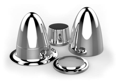
A spherical part grinding machine is a precision industrial machine designed specifically to grind spherical components with high accuracy and superior surface quality. These spherical parts, such as ball bearings, valve balls, optical spheres, and precision balls, require exact spherical geometry and smooth surfaces to perform reliably in demanding applications.
The machine’s main function is to remove material from the spherical workpiece to achieve precise dimensions, roundness, and surface finish. This is typically accomplished through abrasive grinding processes using specialized grinding wheels or tools shaped and controlled to conform to the sphere’s curved surface. The grinding process eliminates surface imperfections, machining marks, and any dimensional inconsistencies.
Modern spherical part grinding machines often employ multi-axis CNC or robotic systems that coordinate the rotation of the spherical part with the movement of the grinding wheel or tool. This synchronized motion ensures uniform material removal and consistent spherical geometry. Operators can program variables such as grinding speed, feed rate, depth of cut, and grinding path to optimize performance for different materials and part sizes.
Advanced machines integrate in-process measurement systems, including laser scanners or touch probes, to monitor roundness, diameter, and surface finish in real time. This feedback enables adaptive control, automatically adjusting grinding parameters to maintain tight tolerances and reduce the need for manual intervention or rework.
Grinding wheels used in spherical grinding are typically made of high-quality abrasives like diamond or cubic boron nitride (CBN) to handle a variety of materials, including hardened steels, ceramics, and other difficult-to-machine substances. Automated dressing systems keep the grinding wheel in optimal condition, preserving its profile and cutting efficiency throughout production.
Thermal management is critical during grinding to avoid heat-induced distortions or damage to the workpiece. Cooling systems deliver lubricating fluids precisely to the grinding zone, dissipating heat and flushing away debris. Enclosures and extraction systems ensure a clean and safe working environment by controlling dust and particles generated during grinding.
Automation extends beyond grinding with robotic loading/unloading and part handling systems to enhance productivity and reduce manual labor. Machine interfaces often feature user-friendly touchscreens with graphical programming, diagnostics, and remote monitoring capabilities, simplifying operation and maintenance.
Safety features include protective guards, emergency stop mechanisms, and vibration isolation to protect operators and improve machine stability. Modular machine designs facilitate quick maintenance and changeovers for different part sizes or grinding requirements.
In summary, spherical part grinding machines combine precise mechanical control, advanced abrasives, automation, and real-time monitoring to deliver high-precision spherical components. Their capability to produce consistently accurate and smooth spheres is vital for industries such as aerospace, automotive, medical devices, and precision instrumentation.
Spherical part grinding machines have advanced significantly with the integration of multi-axis CNC systems and robotic automation, allowing for highly precise and repeatable grinding operations. These machines coordinate the rotation of the spherical workpiece with the movement of the grinding tool to ensure uniform material removal and maintain tight tolerances on roundness and surface finish. This synchronization is essential for preventing geometric distortions and achieving the high quality demanded in applications like ball bearings, optical components, and aerospace parts.
Real-time monitoring systems have become standard features, incorporating sensors and measurement devices such as laser scanners, touch probes, and surface profilometers. These instruments continuously assess parameters like diameter, roundness, surface roughness, and temperature during grinding. The feedback is used to adapt grinding conditions dynamically, optimizing process efficiency, minimizing scrap rates, and reducing the need for manual adjustments.
Grinding wheels made from superabrasive materials like diamond and cubic boron nitride (CBN) provide superior cutting performance and longer tool life, especially when machining hard or wear-resistant materials. Automated wheel dressing systems maintain the grinding wheel’s precise profile, ensuring consistent contact with the spherical surface and reducing downtime associated with manual maintenance.
Thermal management is critical to avoid heat-induced defects such as thermal cracking or dimensional changes in the workpiece. Cooling systems deliver lubricating fluids directly to the grinding zone, helping to dissipate heat and flush away debris. Enclosures and dust extraction units maintain a clean working environment, protecting operators and equipment from abrasive particles.
Automation extends beyond the grinding process itself, with robotic or automated handling systems facilitating loading, unloading, and positioning of spherical parts. This reduces labor requirements, enhances safety, and enables continuous, unattended operation, boosting productivity.
User interfaces have evolved to feature intuitive touchscreen controls with graphical programming environments, real-time diagnostics, and remote monitoring capabilities. These interfaces simplify machine setup, operation, and maintenance, reducing training time and operator errors.
Safety features such as protective guarding, emergency stop functions, vibration isolation, and ergonomic designs contribute to operator protection and machine stability. Modular machine architectures enable quick changeovers between different part sizes or grinding processes, enhancing flexibility.
Emerging technologies like ultrasonic-assisted grinding and hybrid finishing methods are being explored to improve grinding efficiency and surface quality further, especially for challenging materials or complex spherical geometries. Integration with digital manufacturing and Industry 4.0 systems allows for data-driven process optimization and predictive maintenance.
In essence, spherical part grinding machines represent a highly specialized fusion of precision mechanics, advanced abrasives, intelligent automation, and sensor-based control. Their continual development ensures they meet the stringent requirements of industries relying on flawlessly finished spherical components for critical applications.
Further innovations in spherical part grinding machines are focused on enhancing precision, efficiency, and integration within smart manufacturing environments. The incorporation of artificial intelligence (AI) and machine learning algorithms is enabling these machines to analyze vast amounts of process data, predict tool wear, and optimize grinding parameters in real time. This intelligent adaptation minimizes cycle times, improves surface finish quality, and extends consumable life, ultimately reducing production costs.
The rise of collaborative robotics (cobots) allows for flexible, safe automation of material handling tasks around grinding machines. Cobots assist with loading and unloading spheres, quality inspection, and part transfer, working safely alongside human operators to boost throughput without compromising workplace safety.
Hybrid grinding technologies combining conventional abrasive methods with processes like laser-assisted grinding or electrochemical machining are being explored to tackle materials that are difficult to machine or prone to thermal damage. These hybrid approaches can improve material removal rates and surface integrity while preserving dimensional accuracy.
Enhanced thermal management systems using advanced coolant formulations, ultrasonic vibration cooling, or cryogenic cooling techniques help maintain stable grinding temperatures, which is critical for maintaining the metallurgical properties and geometric precision of spherical parts.
Digital twin technology is increasingly used to create virtual models of the grinding machine and process, allowing simulation and optimization before actual machining. This reduces trial-and-error cycles, accelerates process development, and enables real-time synchronization between the physical machine and its virtual counterpart for predictive maintenance and process control.
Environmental sustainability considerations are driving the adoption of eco-friendly abrasives, optimized coolant use, and energy-efficient drives within spherical grinding machines. Recycling and waste minimization strategies are integrated to reduce the ecological footprint of finishing operations.
Operator experience is enhanced through immersive training programs using augmented reality (AR) and virtual reality (VR), which help technicians learn machine operation, programming, and maintenance in a risk-free virtual environment. Intuitive human-machine interfaces with voice control and gesture recognition are being developed to further streamline interaction.
In summary, spherical part grinding machines are evolving into intelligent, connected, and versatile systems that leverage advanced automation, real-time sensing, and digital technologies. These developments ensure that manufacturers can consistently produce high-precision spherical components with optimal surface finishes to meet the ever-increasing demands of aerospace, medical, automotive, and precision engineering sectors worldwide.
Belt Type Cookware Surface Sander
A belt type cookware surface sander is an industrial machine designed specifically for finishing the surfaces of cookware items—such as pots, pans, and baking trays—made from metals like stainless steel, aluminum, or copper. This machine uses abrasive sanding belts to smooth, polish, or prepare the cookware’s exterior or interior surfaces, enhancing their appearance, removing imperfections, and improving functional properties such as corrosion resistance or coating adhesion.
The core component of the machine is a continuous abrasive sanding belt mounted on rotating drums or rollers. The belt moves at controlled speeds to abrade the cookware surface uniformly. Operators or automated systems position the cookware so that its surface contacts the moving belt with consistent pressure, enabling efficient removal of surface defects like scratches, scale, welding marks, or uneven textures.
Belt speed, belt grit size, contact pressure, and feed rate are adjustable to accommodate different cookware materials, shapes, and desired surface finishes—from coarse sanding for heavy material removal to fine polishing for a smooth, mirror-like appearance. The machine may be equipped with multiple sanding stations in series to progressively refine the surface finish.
Automation features often include conveyor systems to transport cookware through the sanding zones, robotic arms or positioning fixtures for precise and repeatable handling, and sensors to monitor belt tension, surface quality, and machine performance. These elements enhance productivity, reduce labor intensity, and improve consistency across production batches.
Dust collection and filtration systems are integral, capturing metal particles and abrasive dust generated during sanding to maintain a clean working environment and comply with safety standards. Coolant or lubricant application may be incorporated to reduce heat buildup, prevent abrasive clogging, and extend belt life.
Machine construction emphasizes durability and ease of maintenance, with quick-change sanding belts, modular components, and accessible service points. Safety features include emergency stops, protective guards, and ergonomic controls to protect operators.
In summary, a belt type cookware surface sander is a specialized finishing machine that leverages abrasive belt technology and automation to deliver high-quality surface finishes on cookware products. Its adjustable parameters and integrated handling systems make it essential for efficient, consistent, and scalable cookware manufacturing and finishing operations.
Belt type cookware surface sanders are engineered for high-volume production environments where consistent surface quality and efficiency are critical. These machines can be customized to handle various cookware sizes and shapes, including flat pans, curved pots, and complex handles or rims, by incorporating adjustable fixtures or adaptable conveyor systems. This flexibility ensures that each piece receives uniform sanding coverage regardless of its geometry.
The abrasive belts used in these machines come in a wide range of grit sizes and materials, from coarse aluminum oxide for heavy material removal to fine zirconia or ceramic abrasives for polishing and finishing. Belt selection is tailored to the specific metal type and desired surface texture, optimizing the balance between material removal rate and finish quality. Additionally, some systems utilize multi-layer belts or hybrid abrasive technologies to extend belt life and improve performance.
Advanced machines often integrate real-time monitoring systems that track belt wear, tension, and temperature, alerting operators or triggering automatic belt changes to maintain optimal sanding conditions. Surface inspection technologies such as optical sensors or cameras may be incorporated downstream to verify finish quality, enabling immediate adjustments or sorting to ensure only parts meeting specifications proceed to packaging or further processing.
Dust extraction and filtration units play a vital role in maintaining workplace safety and equipment longevity by efficiently capturing fine metal dust and abrasive particles. Many setups use high-efficiency particulate air (HEPA) filters or cyclonic separators to manage airborne contaminants and facilitate compliance with environmental and occupational health regulations.
Automation enhances throughput and reduces manual labor by incorporating robotic arms or automated conveyors for loading, unloading, and part orientation. Some systems use programmable logic controllers (PLCs) or CNC interfaces to coordinate sanding speed, belt pressure, and feed rates dynamically based on real-time feedback, allowing for consistent quality even with variations in part geometry or material properties.
Ergonomic design considerations ensure operator safety and comfort, with features such as adjustable workstations, easy-access control panels, and protective guarding. Emergency stop functions and safety interlocks are standard to quickly halt operations if necessary.
Maintenance-friendly construction includes quick-release mechanisms for sanding belts, modular components for rapid replacement, and clear diagnostics to identify issues promptly, minimizing downtime and maximizing productivity.
Belt type cookware surface sanders are indispensable in modern cookware manufacturing, providing the means to achieve high-quality, uniform surface finishes that meet both aesthetic and functional requirements. Their adaptability, automation capabilities, and robust design make them well-suited to meet the rigorous demands of mass production while ensuring operator safety and environmental compliance.
Recent developments in belt type cookware surface sanders focus heavily on increasing automation, process control, and sustainability. Integration with smart factory systems allows these machines to communicate with upstream and downstream equipment, enabling seamless production flow and real-time quality tracking. Data from sensors monitoring belt wear, motor load, and surface finish can be analyzed to optimize maintenance schedules and reduce unplanned downtime.
Energy-efficient motor drives and variable frequency controllers help minimize power consumption by adjusting belt speed and torque based on workload, contributing to greener manufacturing operations. Some machines incorporate regenerative braking systems that recover energy during deceleration phases.
The abrasive belts themselves are evolving, with manufacturers developing longer-lasting, more environmentally friendly options that reduce waste and improve sanding consistency. Water-based or biodegradable lubricants are replacing traditional solvents and oils, lessening environmental impact and improving workplace safety.
Flexible machine designs now accommodate rapid changeovers between different cookware types and sizes, supporting just-in-time production and customized finishing options. Quick-adjust fixtures, programmable process parameters, and modular components allow manufacturers to respond swiftly to changing market demands without sacrificing quality.
Operator interfaces are becoming more intuitive, featuring touchscreen displays with graphical process visualization, remote monitoring capabilities, and integration with mobile devices. This connectivity allows supervisors to oversee multiple machines simultaneously and respond quickly to alerts or production issues.
Safety features continue to advance, with enhanced guarding, light curtains, and presence sensors that automatically stop sanding belts if operators enter hazardous zones. Noise reduction technologies and improved dust containment systems contribute to healthier working environments.
In sum, belt type cookware surface sanders are evolving into highly automated, efficient, and environmentally conscious machines. Their ability to deliver consistent, high-quality surface finishes on a wide range of cookware products makes them essential assets in modern manufacturing facilities striving for excellence in product quality, operational efficiency, and sustainability.
Cylindrical Vessel Surface Grinding Machine
A cylindrical vessel surface grinding machine is a specialized industrial machine designed to perform precise surface grinding on the outer or inner cylindrical surfaces of pressure vessels, tanks, pipes, and similar large cylindrical components. These vessels are commonly used in industries such as chemical processing, oil and gas, pharmaceuticals, and food production, where surface finish and dimensional accuracy are critical for sealing, pressure containment, and corrosion resistance.
The primary function of this machine is to remove surface irregularities, welding marks, scale, and machining imperfections from cylindrical vessel surfaces to achieve a smooth, uniform finish that meets strict engineering specifications. Surface grinding improves the vessel’s performance by ensuring proper fitment of flanges, gaskets, or insulation and by enhancing corrosion resistance through better surface preparation.
Typically, the machine consists of a rotating workpiece fixture that holds and rotates the cylindrical vessel or its components steadily, and a grinding head equipped with abrasive wheels or belts that traverse along the surface. The grinding head moves linearly or follows programmed paths to cover the entire cylindrical area evenly.
Machines are often designed with heavy-duty structural frames and precision guideways to support the large size and weight of vessels while maintaining grinding accuracy. The grinding wheels or belts are selected based on the vessel material—commonly carbon steel, stainless steel, or alloys—and the desired surface finish, ranging from rough material removal to fine polishing.
Advanced cylindrical vessel grinding machines incorporate CNC or PLC controls, allowing operators to program grinding parameters such as rotational speed, feed rate, grinding depth, and wheel speed. Automation enhances repeatability, reduces cycle times, and enables complex grinding profiles if required.
Cooling and lubrication systems deliver coolant fluids directly to the grinding interface to dissipate heat, prevent thermal damage, and wash away debris. Dust extraction systems collect metal particles and abrasive dust to maintain a clean and safe environment.
Safety features include protective guards, emergency stop functions, and interlocks to protect operators from moving parts and abrasive materials. The machine design often facilitates easy loading and unloading of large cylindrical vessels, sometimes integrating with cranes, rollers, or automated handling systems.
In-process measurement and inspection tools, such as laser scanners or contact probes, may be integrated to monitor surface finish and dimensional tolerances in real time, allowing adaptive process control and ensuring that components meet stringent quality standards.
Overall, cylindrical vessel surface grinding machines are vital equipment for finishing large cylindrical components with precision and efficiency. Their combination of robust mechanical design, abrasive technology, automation, and safety features ensures the production of vessels that comply with demanding industrial requirements for functionality, safety, and longevity.
Cylindrical vessel surface grinding machines have advanced to accommodate the increasing size and complexity of modern industrial vessels. Their robust construction ensures stability and precision when handling heavy and often bulky components, while precision linear guides and servo-driven axes allow smooth and accurate grinding motions. Many machines now feature multi-axis control, enabling the grinding head to adjust angles or apply variable pressure to achieve uniform surface quality across complex geometries or tapered sections.
Automation plays a significant role in improving productivity and consistency. CNC programming allows operators to define grinding sequences, speeds, and depths tailored to specific vessel dimensions and materials. This reduces manual setup time and ensures repeatability across production runs. Some systems incorporate robotic loaders or conveyor integration to facilitate the safe and efficient handling of heavy cylindrical parts, minimizing operator intervention and improving workplace safety.
Real-time monitoring systems are increasingly common, employing laser profilometers, contact probes, or optical sensors to measure surface roughness, roundness, and dimensional accuracy during grinding. Data from these sensors feed into closed-loop control systems that adapt grinding parameters on the fly, compensating for tool wear, thermal expansion, or material inconsistencies. This adaptive control enhances surface finish quality and reduces the need for secondary finishing operations.
Thermal management is critical in grinding large vessels to avoid distortions or metallurgical damage. Advanced coolant delivery systems provide targeted cooling and lubrication, using high-pressure jets or misting to effectively manage heat at the grinding interface. Efficient debris removal through integrated vacuum extraction or chip conveyors maintains clear visibility and prevents abrasive contamination.
Safety considerations include fully enclosed grinding zones, interlocked access doors, and emergency stop circuits. Vibration isolation mounts and heavy-duty foundations reduce machine-induced vibrations, preserving grinding accuracy and prolonging component life. Operator ergonomics are addressed with adjustable control panels, remote monitoring capabilities, and diagnostic displays that simplify troubleshooting.
Maintenance is facilitated through modular components such as quick-change grinding wheels, accessible lubrication points, and condition monitoring sensors that predict wear or failure before issues arise. This approach minimizes downtime and keeps production on schedule.
The versatility of these machines allows for finishing a range of vessel types, from small pressure cylinders to large storage tanks. They support various surface finish requirements, whether preparing surfaces for welding, painting, or applying specialized coatings. Some models offer options for internal and external grinding within the same setup, increasing operational flexibility.
Emerging technologies like laser-assisted grinding and ultrasonic vibration help enhance material removal rates and surface quality, especially for tough alloys or heat-sensitive materials. Integration with digital factory systems enables data collection for quality assurance, traceability, and continuous process improvement.
In summary, cylindrical vessel surface grinding machines combine mechanical strength, precision engineering, automation, and smart controls to meet the demanding finishing needs of industrial cylindrical components. Their ongoing evolution supports safer, faster, and higher-quality production processes essential for industries requiring reliable, durable vessels and tanks.
Further developments in cylindrical vessel surface grinding machines emphasize connectivity and smart manufacturing integration. These machines are increasingly equipped with IoT (Internet of Things) capabilities, allowing real-time data exchange with factory management systems. Such connectivity enables predictive maintenance by analyzing vibration patterns, motor loads, and temperature trends to forecast component wear or potential failures, reducing unexpected downtime and maintenance costs.
Adaptive process control is enhanced through machine learning algorithms that interpret sensor data to optimize grinding parameters continuously. This ensures consistent surface quality despite variations in vessel material properties or machine tool condition. Automated reporting and quality documentation streamline compliance with industry standards and facilitate traceability throughout production.
The push for sustainability influences machine design as well. Energy-efficient motors, regenerative braking systems, and optimized coolant usage minimize environmental impact. Closed-loop coolant recycling and filtration systems reduce water and chemical consumption, aligning with stricter environmental regulations and corporate responsibility goals.
Advanced safety features now include augmented reality (AR) support for operators, providing real-time overlays of machine status, maintenance instructions, and hazard alerts through smart glasses or tablets. Remote operation and monitoring capabilities enable specialists to assist or troubleshoot machines off-site, increasing responsiveness and reducing the need for on-site interventions.
Modular machine architectures are becoming more prevalent, allowing manufacturers to customize and upgrade equipment easily to accommodate new vessel sizes, materials, or finishing technologies without replacing entire systems. This adaptability extends machine service life and protects capital investment.
Robotics and automated material handling continue to evolve, with intelligent robotic arms capable of handling heavy cylindrical vessels, performing precise positioning, and even conducting basic inspections. Collaborative robots (cobots) facilitate safe human-machine interaction, increasing flexibility in production environments.
Emerging finishing techniques such as cryogenic grinding or hybrid mechanical-chemical polishing are being explored to improve grinding efficiency and surface integrity for specialized vessel applications, particularly in aerospace or pharmaceutical industries where contamination control is critical.
Overall, cylindrical vessel surface grinding machines are becoming more intelligent, connected, and versatile. These advancements support manufacturers in achieving higher productivity, superior quality, and enhanced operational safety while aligning with the broader trends of Industry 4.0 and sustainable manufacturing practices.
EMS Metalworking Machines
We design, manufacture and assembly metalworking machinery such as:
- Hydraulic transfer press
- Glass mosaic press
- Hydraulic deep drawing press
- Casting press
- Hydraulic cold forming press
- Hydroforming press
- Composite press
- Silicone rubber moulding press
- Brake pad press
- Melamine press
- SMC & BMC Press
- Labrotaroy press
- Edge cutting trimming machine
- Edge curling machine
- Trimming beading machine
- Trimming joggling machine
- Cookware production line
- Pipe bending machine
- Profile bending machine
- Bandsaw for metal
- Cylindrical welding machine
- Horizontal pres and cookware
- Kitchenware, hotelware
- Bakeware and cuttlery production machinery
as a complete line as well as an individual machine such as:
- Edge cutting trimming beading machines
- Polishing and grinding machines for pot and pans
- Hydraulic drawing presses
- Circle blanking machines
- Riveting machine
- Hole punching machines
- Press feeding machine
You can check our machinery at work at: EMS Metalworking Machinery – YouTube
Applications:
Flange-punching
Beading and ribbing
Flanging
Trimming
Curling
Lock-seaming
Ribbing