Spin Forming Machines: Metalworking is an age-old craft that has evolved significantly with advancements in technology and machinery. It involves various processes to shape and fabricate metal components, ranging from cutting, bending, and assembling to finishing and polishing. The success of these processes largely depends on the quality and efficiency of the equipment used, making metalworking machines indispensable to the industry.
1.1 Overview of the Metalworking Industry
The metalworking industry is a cornerstone of modern manufacturing, encompassing a vast array of processes and technologies. These processes are vital in producing components used in automotive, aerospace, construction, and consumer goods. The industry relies heavily on precision, and thus, the machinery involved must be state-of-the-art, providing accurate and repeatable results.
1.2 Importance of High-Quality Equipment in Metalworking
High-quality metalworking equipment ensures not only precision and efficiency but also safety and longevity of the products. Machines such as burr removal machines, metal polishing machines, and deep drawing presses play a crucial role in achieving the desired surface finish and dimensional accuracy. For instance, burr removal is essential in preventing defects that could compromise the structural integrity of the product or even cause safety hazards in its application.
Investing in advanced metalworking equipment is therefore not just about improving production speed but also about ensuring the reliability and quality of the final product. As the demand for intricate and precise metal components continues to rise, so does the need for equipment that can meet these challenges.
1.3 Brief Introduction to Different Types of Metalworking Machines
Metalworking machines come in various forms, each designed for specific tasks within the metalworking process. Some of the key types include:
- Burr Removal Machines: These are specialized machines used to remove burrs—small, rough edges or protrusions that form on metal surfaces after cutting or machining. Burr removal is critical for ensuring a smooth finish and preventing potential issues during assembly or use.
- Metal Polishing Machines: These machines are used to achieve a fine, smooth finish on metal surfaces. They are essential in industries where appearance and surface quality are paramount, such as in the production of automotive parts, appliances, and consumer electronics.
- Deep Drawing Presses: These are used in processes that involve shaping sheet metal into complex shapes, such as automotive body panels and kitchen sinks. Deep drawing presses must be highly precise to maintain the integrity of the metal during the forming process.
- Moulding Presses: Moulding presses are crucial in the production of various components, particularly those made from composite materials. They are widely used in industries such as automotive, aerospace, and electronics.
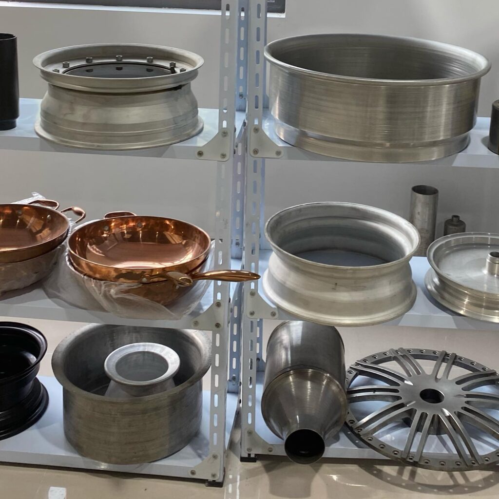
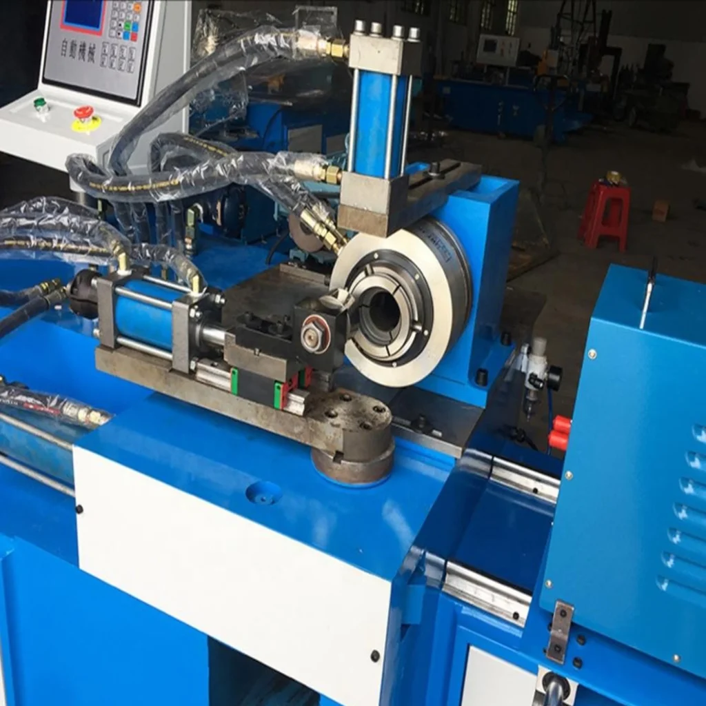
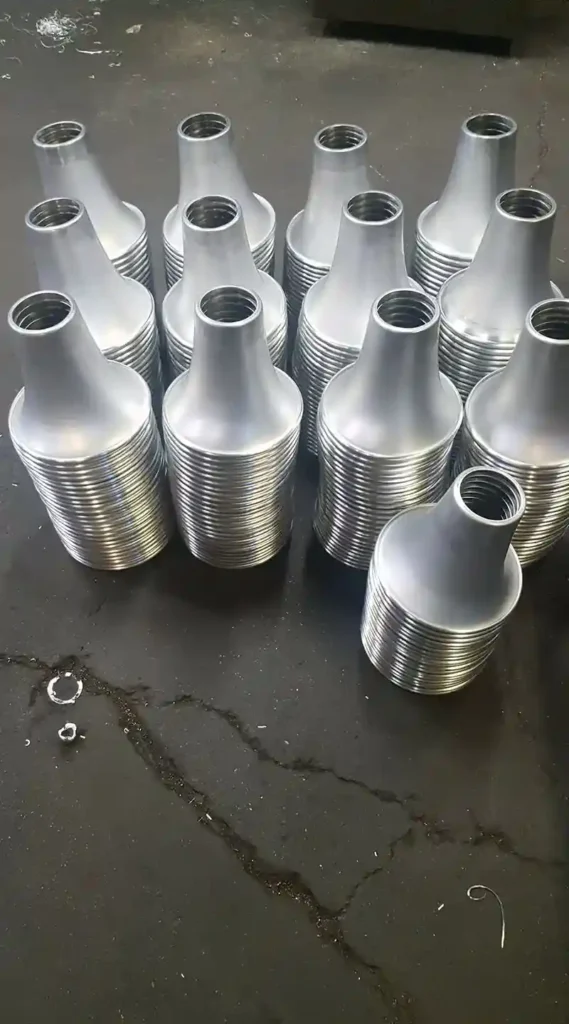
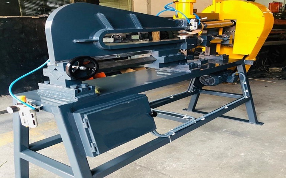
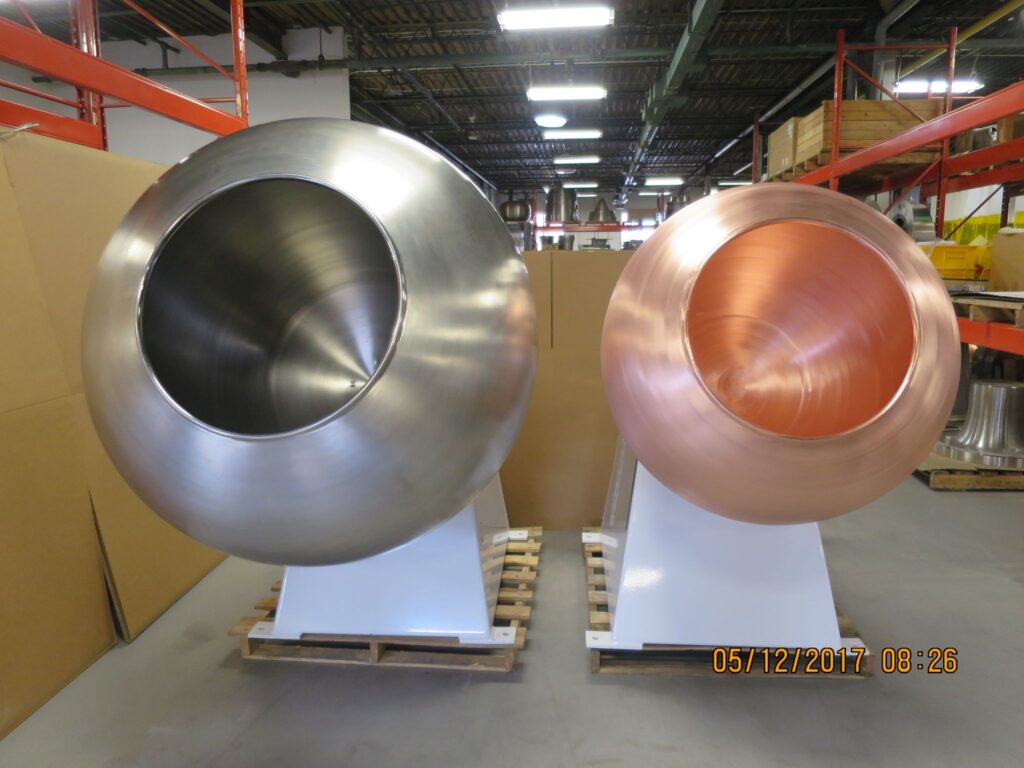
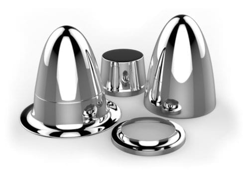
- Spin Forming Machines: These machines are used to form metal into cylindrical shapes, such as rims, cones, and tubes. Spin forming is a versatile process that allows for the creation of seamless, strong, and lightweight components.
Each type of machine plays a specific role in the metalworking process, and their combined use ensures the production of high-quality metal components that meet industry standards.
2. The Critical Role of Burr Removal in Metalworking
Burr removal is a fundamental aspect of metalworking, often regarded as a critical finishing process that directly impacts the quality, safety, and functionality of the final product. Burrs, the unwanted rough edges or protrusions left on metal surfaces after machining, cutting, or stamping, can lead to various issues if not properly managed. These include compromised product integrity, assembly difficulties, and even safety hazards during usage. Understanding the significance of burr removal and employing effective methods to achieve it is essential for any manufacturer striving for excellence.
2.1 Understanding Burrs and Their Impact
In the metalworking industry, burrs are an inevitable byproduct of machining and manufacturing processes. They can form on almost any metal part during operations like drilling, milling, turning, or shearing. While burrs might seem insignificant, their presence can have detrimental effects on both the manufacturing process and the end product.
- Quality Compromise: Burrs can lead to dimensional inaccuracies, which might result in parts that do not fit together correctly. This is particularly problematic in industries like aerospace or automotive, where precision is critical.
- Safety Concerns: Sharp burrs pose a risk of injury to workers handling the parts. In addition, burrs can cause issues in the functionality of the product, such as electrical shorts in electronic components or leaks in fluid systems.
- Assembly Challenges: Burrs can interfere with the assembly process by causing parts to snag or fit improperly. This can lead to increased production time, higher costs, and potential delays in delivery.
Given these potential issues, burr removal is not just a matter of finishing; it is a critical step in ensuring the overall quality and functionality of metal parts.
2.2 Burr Removal Techniques
There are various techniques for removing burrs from metal parts, ranging from manual methods to advanced automated systems. The choice of technique depends on factors such as the material, part geometry, production volume, and desired finish quality.
- Manual Deburring: This traditional method involves using hand tools such as files, scrapers, or abrasive stones to remove burrs. While manual deburring is suitable for small-scale operations or intricate parts, it is labor-intensive and can be inconsistent in terms of finish quality.
- Mechanical Deburring: Mechanical methods involve the use of machines such as tumblers, vibratory finishers, or abrasive belts to remove burrs. These methods are more consistent and efficient than manual deburring, making them suitable for larger production runs.
- Thermal Deburring: Also known as “thermal energy method” (TEM), this technique uses controlled explosions of gas in a chamber to burn away burrs. Thermal deburring is highly effective for complex parts with internal burrs, as the gas can reach areas that are difficult to access with other methods.
- Electrochemical Deburring: This process uses an electrolyte solution and an electric current to dissolve burrs. It is ideal for parts with hard-to-reach burrs and provides a smooth, precise finish.
- Cryogenic Deburring: In this method, parts are cooled to extremely low temperatures using liquid nitrogen, making the burrs brittle. The parts are then agitated in a tumbler, causing the burrs to break off. Cryogenic deburring is particularly effective for plastic and rubber parts.
2.3 The Role of Burr Removal Machines
Burr removal machines are specialized equipment designed to automate and streamline the deburring process, ensuring consistent and high-quality results. These machines are essential for industries where precision and repeatability are paramount. Some of the key benefits of using burr removal machines include:
- Increased Efficiency: Automated burr removal machines can process multiple parts simultaneously, significantly reducing the time and labor required for deburring.
- Consistent Quality: Unlike manual deburring, which can vary depending on the operator’s skill, burr removal machines provide uniform results, ensuring that all parts meet the required specifications.
- Cost-effectiveness: While the initial investment in burr removal machines may be high, the long-term savings in labor costs and improved production efficiency make them a cost-effective solution for many manufacturers.
- Enhanced Safety: Automated machines reduce the risk of injury associated with manual deburring, as workers are not required to handle sharp parts directly.
2.4 Specialized Burr Removal Machines
There are various types of burr removal machines, each tailored to specific applications and industries. These include:
- Aluminium Deburring Machines: These machines are specifically designed to handle aluminum parts, which require a delicate touch to avoid damaging the material. They are commonly used in the automotive and aerospace industries, where aluminum is widely used.
- Deburring Machines for Sheet Metal Edges: These machines are designed to remove burrs from the edges of sheet metal, ensuring smooth, clean edges that are safe to handle and meet the required tolerances.
- Metal Edge Finishing Machines: These machines are used to finish the edges of metal parts, providing a smooth, rounded edge that improves both the appearance and functionality of the part.
- Automatic Burr Removal Machines: These machines are designed for high-volume production environments, where speed and efficiency are critical. They are capable of processing large quantities of parts quickly, with minimal operator intervention.
2.5 Advancements in Burr Removal Technology
The field of burr removal is continuously evolving, with new technologies being developed to improve the efficiency and effectiveness of the process. Some of the latest advancements include:
- CNC-controlled Deburring Machines: These machines use computer numerical control (CNC) technology to precisely control the deburring process, ensuring consistent, high-quality results. CNC deburring machines are ideal for complex parts with tight tolerances.
- Robotic Deburring: Robotic systems are increasingly being used for deburring, particularly in industries where precision and repeatability are critical. These systems can be programmed to perform complex deburring tasks with a high degree of accuracy.
- Laser Deburring: Laser technology is being used to remove burrs with high precision, particularly on small, intricate parts. Laser deburring is contactless, which reduces the risk of damaging delicate components.
- Hybrid Deburring Systems: These systems combine multiple deburring techniques, such as mechanical and thermal deburring, to achieve optimal results for complex parts. Hybrid systems are particularly useful for parts with varied geometries and materials.
2.6 The Importance of Proper Burr Removal in Quality Assurance
In today’s competitive manufacturing environment, maintaining high-quality standards is essential for success. Proper burr removal is a key component of quality assurance, as it directly impacts the functionality, safety, and appearance of the final product. Manufacturers that invest in advanced burr removal technologies and processes are better equipped to meet the demanding requirements of their customers and stay ahead of the competition.
Quality assurance in burr removal involves not only the selection of the right techniques and machines but also continuous monitoring and testing to ensure that the process consistently meets the required standards. This can include:
- Regular Inspection: Parts should be inspected after deburring to ensure that all burrs have been effectively removed and that the surface finish meets the required specifications.
- Testing: In some cases, additional testing, such as pressure testing for fluid systems or electrical testing for electronic components, may be necessary to confirm that the burr removal process has not compromised the integrity of the part.
- Documentation: Proper documentation of the burr removal process, including machine settings, inspection results, and corrective actions, is essential for traceability and quality control.
2.7 Conclusion
Burr removal is a critical step in the metalworking process that should not be overlooked. By understanding the impact of burrs on product quality and safety, and by investing in the right burr removal techniques and machines, manufacturers can ensure that their products meet the highest standards. As technology continues to advance, new burr removal methods and machines will further enhance the efficiency and effectiveness of this essential process.
3. Exploring Metalworking Machines and Their Functions
The metalworking industry relies on a diverse array of machines to transform raw materials into finished products. These machines are integral to the manufacturing process, offering precision, efficiency, and versatility across various applications. Each type of metalworking machine serves a specific function, from shaping and forming metal to finishing and polishing it. Understanding the capabilities and applications of these machines is crucial for selecting the right equipment for any given project.
3.1 Overview of Metalworking Machines
Metalworking machines encompass a wide range of equipment designed to perform tasks such as cutting, bending, forming, and finishing metal components. These machines are categorized based on the specific operations they perform, such as pressing, deburring, polishing, and forming. Here’s a broad classification of metalworking machines:
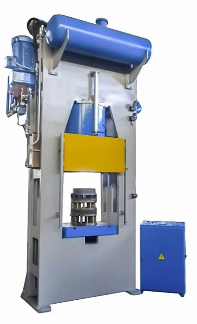
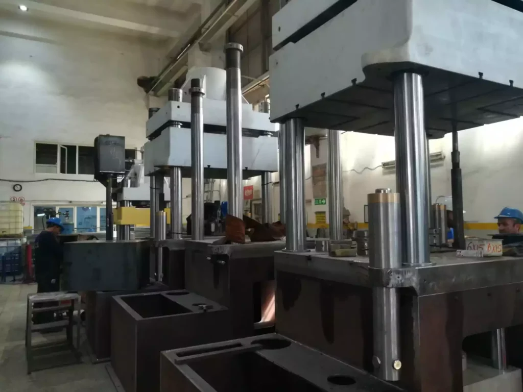
- Press Machines: These include various types of presses such as hydraulic presses, deep drawing presses, and moulding presses. Press machines are used to shape metal by applying force to it, typically using a die to form the metal into the desired shape.
- Deburring and Finishing Machines: These machines are designed to remove burrs, polish, and finish metal surfaces. Burr removal machines, metal polishing machines, and edge rounding machines fall into this category.
- Forming Machines: Machines like spin forming machines, CNC profile bending machines, and cold forming presses are used to bend or shape metal into specific profiles or forms.
- Grinding and Cutting Machines: These include centerless grinding machines, which provide a high-quality surface finish by removing material from the outer surface of a metal part.
3.2 Specific Machines and Their Functions
Each type of metalworking machine plays a vital role in the production process, contributing to the creation of precise, high-quality metal components. Let’s delve into the functions and applications of some of the most essential metalworking machines.
3.2.1 Moulding Presses
Moulding presses are pivotal in the manufacturing of components that require precise shapes and forms, especially in industries like automotive and aerospace. These presses are used to shape materials by applying pressure to a mold, which can be made of metal or other durable materials. The types of moulding presses include:
- Compression Moulding Presses: These presses are used to shape materials like rubber, plastic, and composites. The material is placed in a heated mold, and the press applies pressure to shape it. Compression molding presses are widely used in the production of automotive parts, electronic components, and industrial equipment.
- Rubber Compression Molding Presses: Specifically designed for molding rubber products, these presses are used in the production of items like seals, gaskets, and other rubber components. They offer precise control over temperature and pressure, ensuring high-quality results.
- SMC Presses (Sheet Moulding Compound Presses): SMC presses are used to mold composite materials, which are commonly used in the automotive and aerospace industries for their strength and lightweight properties.
3.2.2 SMC Presses
SMC presses are specialized machines designed to mold sheet molding compounds, which are a type of composite material made of a thermosetting resin, glass fibers, and fillers. These presses are widely used in the automotive and aerospace industries to produce lightweight, durable components such as car body panels, aircraft parts, and electrical enclosures.
The advantages of SMC presses include:
- High Strength-to-Weight Ratio: SMC components offer excellent strength while remaining lightweight, making them ideal for applications where weight savings are critical.
- Complex Shapes: SMC presses can produce complex shapes with high precision, reducing the need for additional machining or finishing.
- Corrosion Resistance: SMC materials are inherently resistant to corrosion, making them suitable for use in harsh environments.
3.2.3 Hot Press Systems
Hot press systems are used in various metalworking processes to apply heat and pressure simultaneously to a material, shaping it or bonding it to another material. These systems are commonly used in the production of laminated components, metal bonding, and the forming of composite materials.
- Application Areas: Hot press systems are extensively used in the electronics industry for the lamination of circuit boards, in the automotive industry for bonding metal components, and in the aerospace industry for forming composite materials.
- Benefits: Hot press systems offer high precision, uniform pressure application, and controlled heating, resulting in consistent and high-quality products.
3.2.4 Cold Forming Presses
Cold forming presses are used to shape metal at room temperature, relying on mechanical force to deform the metal into the desired shape. Unlike hot forming, cold forming does not involve heating the material, which helps maintain the material’s inherent properties and produces a high-quality finish.
- Advantages of Cold Forming:
- Improved Material Properties: Cold forming strengthens the metal by refining its grain structure, enhancing its mechanical properties.
- Cost Efficiency: Cold forming processes typically require less energy and are faster than hot forming processes, reducing overall production costs.
- Precision and Surface Finish: Cold forming produces parts with excellent dimensional accuracy and a smooth surface finish, reducing the need for further processing.
3.2.5 Silicone Presses
Silicone presses are used to mold silicone rubber into various shapes and forms, typically in the production of seals, gaskets, medical devices, and other silicone products. These presses operate under controlled temperature and pressure to ensure the silicone material cures properly and achieves the desired properties.
- Key Applications:
- Medical Devices: Silicone presses are used to produce components such as tubing, seals, and gaskets for medical devices, where biocompatibility and precision are critical.
- Automotive Industry: Silicone seals and gaskets produced by silicone presses are widely used in the automotive industry for their durability and resistance to extreme temperatures.
3.3 Advanced Metalworking Machines
As technology advances, the metalworking industry has seen the development of more sophisticated machines designed to enhance precision, efficiency, and flexibility. Some of these advanced machines include:
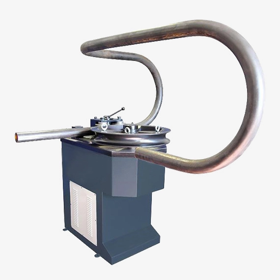
3.3.1 CNC Profile Bending Machines
CNC (Computer Numerical Control) profile bending machines are advanced systems used to bend metal profiles with a high degree of precision and consistency. These machines are essential in industries where complex shapes and tight tolerances are required, such as in the construction of architectural elements, automotive components, and aerospace structures.
- Benefits of CNC Profile Bending:
- Precision: CNC control allows for precise bending angles and repeatability, ensuring uniformity across all parts.
- Complex Bends: CNC machines can perform complex bends that would be difficult or impossible to achieve with manual methods.
- Efficiency: CNC profile bending machines can handle high volumes of work with minimal setup time, making them ideal for mass production.
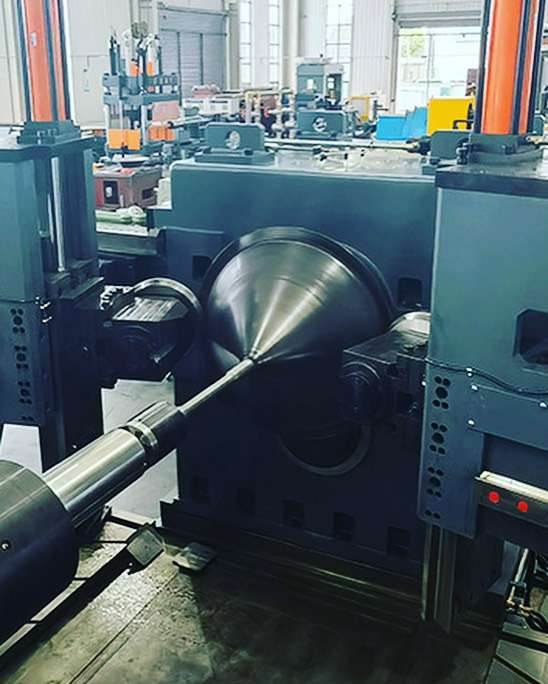
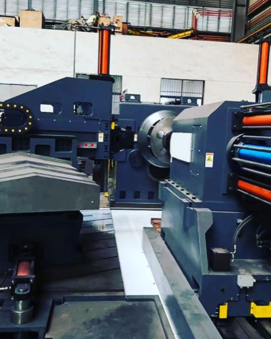
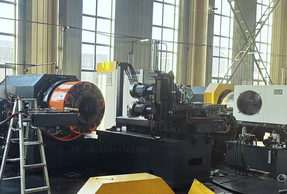
3.3.2 Spin Forming Machines
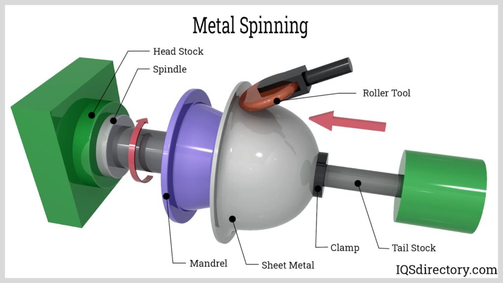
Spin forming, also known as metal spinning, is a process where a metal disc or tube is rotated at high speed and formed into a symmetrical shape using a combination of pressure and heat. Spin forming machines are used to produce components like metal cones, cylinders, and domes.
- Applications of Spin Forming:
- Aerospace: Spin forming is used to create components such as nose cones, rocket fairings, and other aerodynamic parts.
- Automotive: In the automotive industry, spin forming is used to produce parts like wheel rims and exhaust components.
- Industrial Equipment: Spin forming is also employed in the production of industrial equipment such as pressure vessels and fluid tanks.
3.3.3 Flow Forming Lathes
Flow forming lathes are specialized machines used to produce high-precision cylindrical components by gradually deforming a metal blank under controlled conditions. This process is particularly useful for producing components with thin walls and high strength, such as automotive drive shafts, aerospace components, and military hardware.
- Advantages of Flow Forming:
- Precision: Flow forming lathes provide excellent control over wall thickness and dimensions, resulting in highly accurate parts.
- Material Efficiency: The process minimizes material waste, making it a cost-effective option for producing high-strength components.
- Strength: Flow forming enhances the mechanical properties of the material, producing parts with superior strength and durability.
3.3.4 Hydroforming Presses
Hydroforming is a versatile metal forming process that uses high-pressure hydraulic fluid to shape metal into complex forms. Hydroforming presses are particularly useful for creating lightweight, high-strength components with intricate geometries, making them a popular choice in the automotive and aerospace industries.
- Key Features:
- Complex Shapes: Hydroforming can produce parts with complex shapes and fine details that would be difficult to achieve with traditional forming methods.
- Weight Reduction: The process allows for the creation of lightweight components without sacrificing strength, making it ideal for applications where weight savings are critical.
- Material Flexibility: Hydroforming can be used with various metals, including aluminum, steel, and titanium.
3.4 Choosing the Right Metalworking Machine
Selecting the right metalworking machine depends on several factors, including the material being worked on, the complexity of the part, the required precision, and the production volume. For instance:
- For Precision Work: CNC profile bending machines and flow forming lathes offer unparalleled precision, making them ideal for aerospace and automotive applications.
- For High-Volume Production: Automatic burr removal machines and transfer press stamping systems provide the efficiency needed for mass production environments.
- For Complex Geometries: Hydroforming presses and spin forming machines are excellent choices for producing parts with complex shapes and fine details.
Investing in the appropriate metalworking machinery is crucial for optimizing production processes, reducing costs, and ensuring the highest quality of the final product.
4. Metal Polishing and Finishing Machines
Polishing and finishing are critical steps in the metalworking process, ensuring that metal parts not only meet functional requirements but also achieve the desired aesthetic appeal. These processes involve the removal of surface imperfections, the enhancement of surface smoothness, and the creation of a polished or matte finish, depending on the application. Metal polishing and finishing machines are designed to automate these tasks, providing consistent and high-quality results that are essential for industries like automotive, aerospace, and consumer goods.
4.1 Importance of Metal Polishing and Finishing
Polishing and finishing metal components serve multiple purposes, from improving the appearance to enhancing the durability and performance of the final product. The importance of these processes can be summarized as follows:
- Surface Quality: A polished surface reduces friction, which is particularly important for moving parts. It also enhances the appearance of the product, making it more appealing to consumers.
- Corrosion Resistance: Polishing helps to close surface pores, reducing the likelihood of corrosion, especially in metals like stainless steel and aluminum.
- Improved Functionality: Polished surfaces can improve the performance of parts in applications where smooth surfaces are critical, such as in hydraulic systems or sealing surfaces.
- Ease of Cleaning: Polished surfaces are easier to clean and maintain, making them ideal for applications in the food, medical, and pharmaceutical industries.
4.2 Types of Metal Polishing Machines
Metal polishing machines are designed to achieve different levels of finish, from a basic smooth surface to a mirror-like polish. Depending on the application and the desired finish, various types of polishing machines are used:
4.2.1 Fine Polishing Machines
Fine polishing machines are used to achieve a high level of smoothness on metal surfaces. These machines are essential in industries where surface quality is paramount, such as in the production of surgical instruments, high-end consumer goods, and precision components.
- Applications: Fine polishing machines are commonly used in the medical device industry, the jewelry industry, and the production of luxury items where a flawless finish is required.
- Capabilities: These machines can handle a variety of materials, including stainless steel, aluminum, brass, and other non-ferrous metals. They are capable of producing a mirror-like finish that enhances both the appearance and performance of the component.
4.2.2 Automatic Metal Polishing Machines
Automatic metal polishing machines are designed for high-volume production environments where speed and consistency are crucial. These machines can polish multiple parts simultaneously, ensuring uniformity across all pieces.
- Efficiency: Automatic polishing machines reduce manual labor, increasing production efficiency and throughput. They are ideal for industries like automotive manufacturing, where large quantities of metal parts need to be polished quickly and consistently.
- Customization: Many automatic polishing machines offer customizable settings, allowing manufacturers to adjust the polishing process according to the specific requirements of different parts.
4.2.3 CNC-controlled Polishing Machines
CNC (Computer Numerical Control) polishing machines use advanced technology to control the polishing process with high precision. These machines are essential for applications where tight tolerances and consistent finishes are required.
- Precision: CNC polishing machines can follow complex contours and geometries with precision, making them ideal for polishing intricate parts or components with complex shapes.
- Repeatability: Once programmed, CNC polishing machines can replicate the same polishing process across multiple parts, ensuring consistency and reducing the likelihood of human error.
4.3 Edge Rounding and Deburring Machines
In addition to polishing, edge rounding and deburring are essential processes in metal finishing. These processes remove sharp edges and burrs that can result from machining, cutting, or stamping, improving the safety, appearance, and functionality of the final product.
4.3.1 Deburring Sheet Metal Edges
Deburring sheet metal edges is a crucial step in preparing metal parts for assembly or final finishing. Burrs, which are unwanted material projections, can compromise the quality of the final product and pose safety risks.
- Methods: Deburring sheet metal edges can be done using various methods, including mechanical deburring, abrasive belts, and tumbling. The choice of method depends on the material, part geometry, and production volume.
- Benefits: Proper deburring ensures that parts fit together correctly during assembly and reduces the risk of injury from sharp edges. It also improves the aesthetic appeal and prepares the parts for subsequent finishing processes.
4.3.2 Edge Rounding Stainless Steel
Stainless steel, widely used in industries like food processing, medical equipment, and construction, requires careful finishing to ensure both functionality and appearance. Edge rounding is an essential process for stainless steel parts, particularly in applications where sharp edges could cause damage or injury.
- Process: Edge rounding involves removing sharp edges from stainless steel parts, either through mechanical means or using specialized edge rounding machines. This process not only enhances safety but also improves the durability and resistance to corrosion.
- Applications: Edge rounding is commonly used in the production of stainless steel kitchen appliances, medical instruments, and architectural components where smooth, safe edges are crucial.
4.4 Aluminum Deburring and Finishing Machines
Aluminum is a versatile material used across various industries, including automotive, aerospace, and construction. However, due to its relatively soft nature, aluminum is prone to burrs and surface imperfections during machining. Aluminum deburring and finishing machines are designed to address these issues, ensuring a smooth, clean finish.
4.4.1 Aluminum Deburring Machines
Aluminum deburring machines are specialized to handle the unique properties of aluminum, which can be easily scratched or damaged if not properly deburred. These machines are designed to remove burrs and other imperfections without compromising the material’s integrity.
- Applications: Aluminum deburring machines are used in the production of automotive components, aircraft parts, and consumer electronics, where precision and surface quality are critical.
- Techniques: These machines use various techniques, such as abrasive belts, brushes, or chemical processes, to achieve a smooth, burr-free surface.
4.4.2 Aluminum Polishing and Finishing
Polishing aluminum requires a delicate balance between removing surface imperfections and achieving a high-quality finish. Aluminum polishing machines are designed to enhance the appearance and functionality of aluminum parts by providing a smooth, reflective surface.
- Challenges: Aluminum is prone to oxidation, which can dull the surface if not properly polished and protected. Polishing machines for aluminum often include features to minimize oxidation and maintain the metal’s shine.
- End Use: Polished aluminum is commonly used in automotive trim, aircraft interiors, and consumer products like smartphones and laptops, where both appearance and performance are important.
4.5 Industrial Metal Polishing Equipment
For large-scale operations, industrial metal polishing equipment is essential for handling high volumes of work with consistency and precision. This equipment is used in industries ranging from automotive manufacturing to aerospace production, where the quality of the surface finish can significantly impact the performance and longevity of the final product.
4.5.1 Large-Scale Polishing Systems
Industrial polishing systems are designed to handle large components or high volumes of smaller parts. These systems often include multiple polishing stations, automated handling, and integrated quality control to ensure that every part meets the required standards.
- Automation: Many industrial polishing systems are fully automated, reducing the need for manual intervention and increasing production speed. This automation also ensures that the polishing process is consistent across all parts.
- Customization: Industrial systems can be customized to suit specific applications, with adjustable settings for different materials, finishes, and part geometries.
4.5.2 Safety and Efficiency in Industrial Polishing
Safety is a key concern in industrial polishing operations, where large machines and high-speed processes are involved. Industrial polishing equipment is designed with safety features such as protective enclosures, emergency stops, and dust extraction systems to protect workers and maintain a clean working environment.
- Efficiency: Industrial polishing equipment is designed to maximize efficiency, reducing waste and energy consumption while delivering high-quality results. These systems often incorporate energy-efficient motors, optimized polishing media, and recycling systems for consumables.
4.6 Conclusion
Metal polishing and finishing are crucial processes in the metalworking industry, directly affecting the quality, durability, and appearance of the final product. The right polishing and finishing machines can enhance productivity, ensure consistency, and achieve the desired surface characteristics, whether it’s a mirror-like polish or a smooth, rounded edge. As the demand for high-quality metal components continues to grow, investing in advanced polishing and finishing technology becomes increasingly important for manufacturers looking to stay competitive.
5. Deep Drawing and Forming Presses
Deep drawing and forming processes are fundamental techniques in metalworking, widely used to shape metal sheets into complex geometries with high precision. These processes are particularly important in industries such as automotive, aerospace, and appliance manufacturing, where components with deep, intricate shapes are required. The machines used for deep drawing and forming must be robust, precise, and versatile to handle a variety of materials and thicknesses. This section explores the different types of deep drawing and forming presses, their applications, and the advantages they offer in modern manufacturing.
5.1 Introduction to Deep Drawing Processes
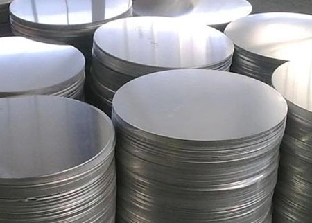
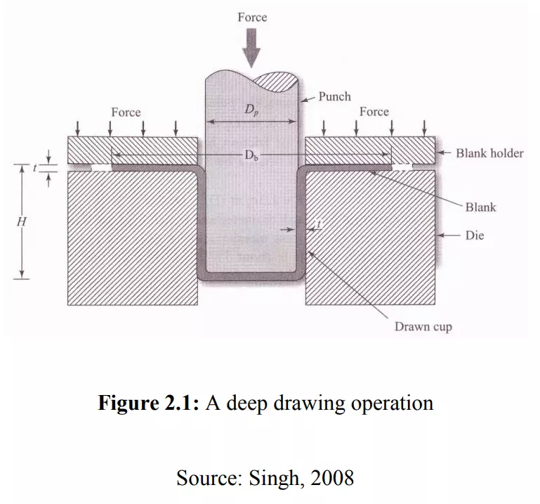
Deep drawing is a metal forming process in which a sheet metal blank is radially drawn into a forming die by the mechanical action of a punch. It is considered “deep” drawing when the depth of the drawn part exceeds its diameter. This process is commonly used to create parts like automotive body panels, kitchen sinks, and various containers.
- Process Overview:
- A blank sheet of metal is placed over a die.
- A punch presses the metal into the die, forcing it to conform to the shape of the die cavity.
- The result is a seamless, hollow component with a consistent wall thickness.
- Materials Used:
- Common materials for deep drawing include steel, aluminum, brass, copper, and various alloys. The material’s ductility and thickness determine the feasibility and success of the deep drawing process.
- Applications:
- Deep drawing is used in manufacturing components like engine parts, household appliances, and packaging materials. It is also crucial in producing components for the aerospace industry, where precision and material integrity are vital.
5.2 Types of Deep Drawing Presses
Deep drawing presses are specialized machines designed to perform the deep drawing process with high precision and efficiency. There are various types of presses used depending on the specific requirements of the part being produced.
5.2.1 Hydraulic Deep Drawing Presses
Hydraulic presses are among the most commonly used machines for deep drawing. They use hydraulic pressure to apply force to the metal blank, pushing it into the die cavity. Hydraulic presses are highly versatile and can be adjusted to apply varying levels of pressure, making them suitable for a wide range of materials and part sizes.
- Advantages:
- Precision: Hydraulic presses offer excellent control over the drawing process, allowing for the production of parts with tight tolerances.
- Versatility: These presses can handle a variety of materials, including high-strength metals and alloys.
- Consistency: Hydraulic systems provide consistent force throughout the drawing process, ensuring uniform wall thickness and part quality.
- Applications:
- Hydraulic deep drawing presses are used in the automotive industry to produce components like fuel tanks, body panels, and exhaust systems. They are also widely used in the production of household appliances and industrial containers.
5.2.2 Mechanical Deep Drawing Presses
Mechanical presses use a flywheel to store energy and release it in a single, powerful stroke. These presses are known for their speed and efficiency, making them ideal for high-volume production runs. Mechanical presses are often used in applications where large quantities of parts need to be produced quickly and consistently.
- Advantages:
- Speed: Mechanical presses operate at high speeds, making them suitable for mass production.
- Cost-Effectiveness: These presses are typically less expensive to operate than hydraulic presses, especially in high-volume production environments.
- Durability: Mechanical presses are built to withstand high levels of stress and are highly durable, requiring minimal maintenance.
- Applications:
- Mechanical deep drawing presses are commonly used in the production of automotive parts, including fenders, hoods, and doors. They are also used in the manufacturing of metal containers, cookware, and industrial components.
5.2.3 Servo-Driven Deep Drawing Presses
Servo-driven presses are a more advanced type of deep drawing press, combining the precision of hydraulic presses with the speed of mechanical presses. These machines use a servo motor to control the movement of the press, offering unparalleled control over the drawing process.
- Advantages:
- Precision: Servo-driven presses provide precise control over the speed and force of the drawing process, allowing for the production of highly complex parts.
- Energy Efficiency: These presses are more energy-efficient than traditional hydraulic or mechanical presses, reducing operating costs.
- Flexibility: The programmable nature of servo-driven presses allows for quick changes between different part designs, making them ideal for environments where product variation is common.
- Applications:
- Servo-driven deep drawing presses are used in the production of high-precision components for the aerospace, automotive, and medical device industries. They are also increasingly used in the production of electronic components, where tight tolerances and complex shapes are required.
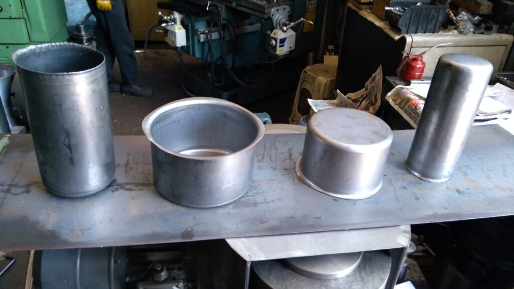
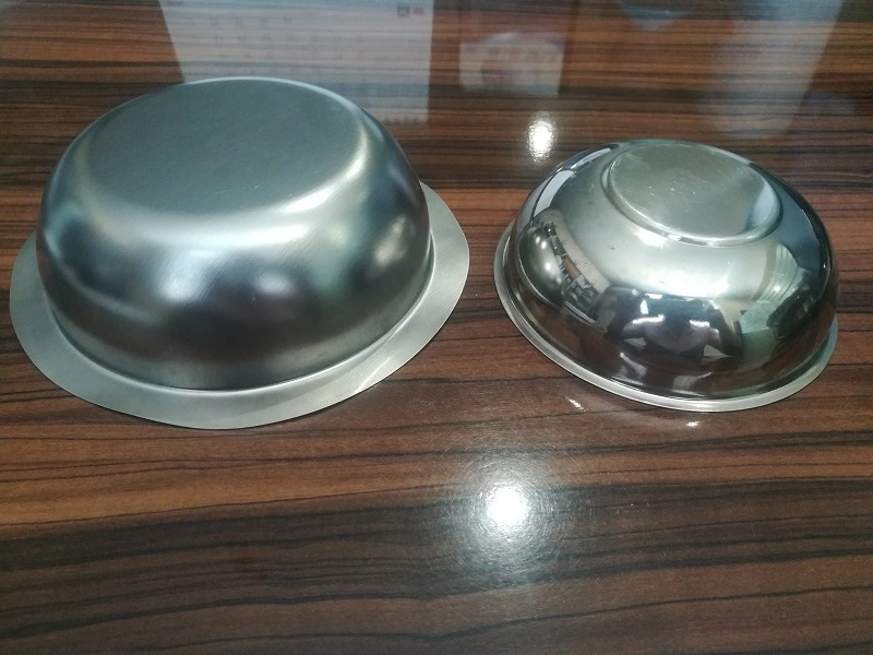
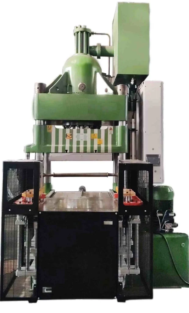
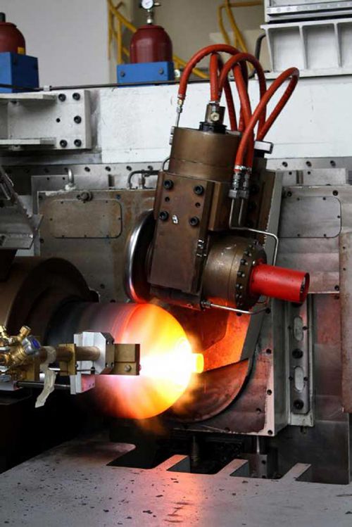
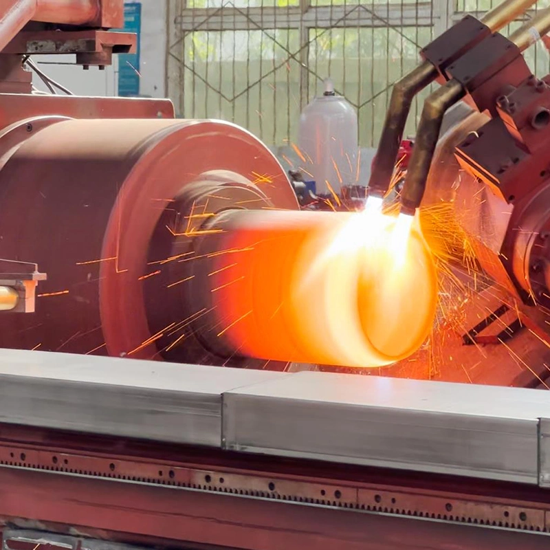
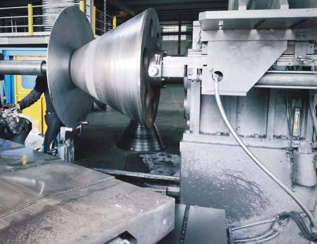
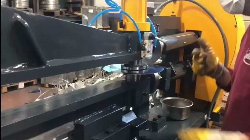
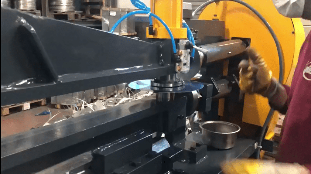
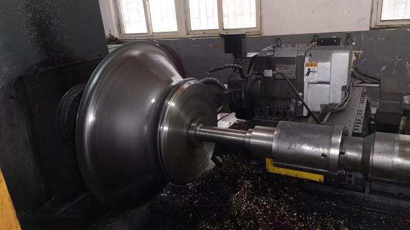
5.3 Spin Forming Machines
Spin forming, also known as metal spinning, is a process that involves rotating a metal disc or tube while applying force to shape it into a symmetrical object. Spin forming machines are used to produce components like wheels, cones, and cylindrical shapes, often used in industries such as aerospace, automotive, and lighting.
- Process Overview:
- The metal blank is placed on a lathe and rotated at high speed.
- A tool presses against the rotating blank, forcing it to take the shape of the tool or mandrel.
- The result is a seamless, strong component with excellent structural integrity.
- Advantages:
- Material Efficiency: Spin forming typically results in minimal material waste, making it a cost-effective manufacturing process.
- Structural Integrity: The continuous nature of the spin forming process enhances the strength and durability of the final product.
- Versatility: Spin forming can be used with various materials, including aluminum, steel, and titanium, and can produce a wide range of shapes.
- Applications:
- In the aerospace industry, spin forming is used to produce parts like rocket nozzles, satellite dishes, and aircraft nose cones. In the automotive industry, it is used for manufacturing wheel rims and other components requiring a high degree of symmetry.
5.4 Deep Drawing Hydraulic Presses
Deep drawing hydraulic presses are specifically designed for the deep drawing process, offering the high force required to shape thick or high-strength materials. These presses are versatile and can be used for both shallow and deep drawing operations, making them a popular choice across various industries.
- Key Features:
- High Force Capacity: Hydraulic presses can apply immense force, making them suitable for deep drawing thick or difficult-to-form materials.
- Controlled Drawing Process: The ability to control the speed and force during the drawing process ensures that the material flows evenly, reducing the risk of tearing or wrinkling.
- Tooling Flexibility: Hydraulic presses can accommodate a wide range of tooling, allowing for the production of parts with varying geometries and sizes.
- Applications:
- These presses are used in the automotive industry to produce components like fuel tanks, chassis parts, and engine housings. They are also used in the production of large industrial containers, kitchen sinks, and other deep-drawn products.
5.5 Transfer Press Stamping
Transfer press stamping is a high-volume manufacturing process where metal blanks are automatically transferred from one stamping station to the next. Each station performs a different operation, such as drawing, trimming, or punching, ultimately producing a finished part.
- Process Overview:
- Metal blanks are fed into the press and automatically moved from station to station, where various forming operations are performed.
- The process is continuous, allowing for high-speed production of complex parts.
- The final product emerges fully formed, with minimal need for secondary operations.
- Advantages:
- High Productivity: Transfer press stamping is highly efficient, capable of producing large quantities of parts in a short period.
- Consistency: The automated nature of the process ensures consistent quality across all parts.
- Cost-Effectiveness: By integrating multiple operations into a single machine, transfer press stamping reduces labor and tooling costs.
- Applications:
- Transfer press stamping is widely used in the automotive industry to produce parts like door panels, structural components, and brackets. It is also used in the manufacturing of appliances, electrical components, and various consumer goods.
5.6 Conclusion
Deep drawing and forming presses are essential tools in modern manufacturing, enabling the production of complex, high-quality metal components with precision and efficiency. Whether it’s the robust capabilities of hydraulic presses, the speed of mechanical presses, or the advanced control of servo-driven presses, these machines play a critical role in industries ranging from automotive to aerospace. Understanding the specific applications and benefits of each type of press allows manufacturers to choose the right equipment for their production needs, ensuring the consistent quality and performance of their products.
6. Specialized Metalworking Machines and Presses
The metalworking industry requires a variety of specialized machines and presses to handle specific tasks that standard equipment may not be able to accomplish efficiently. These specialized machines are designed to address unique challenges in manufacturing processes, offering solutions for complex shapes, precision work, and materials that demand particular handling. This section covers some of the most significant specialized metalworking machines and presses, highlighting their applications, advantages, and roles in modern production environments.
6.1 Transfer Press Stamping
Transfer press stamping is a highly automated process designed for high-volume production, where multiple stamping operations are integrated into a single machine. This technology is widely used in industries where the demand for large quantities of complex parts is high.
6.1.1 Process Overview
Transfer press stamping involves a series of stamping operations performed in succession, with each operation completed at a different station within the same machine. The metal blank is automatically transferred from one station to the next, with each station performing a specific task such as drawing, trimming, piercing, or bending. This allows for the rapid production of finished parts with minimal need for secondary operations.
6.1.2 Advantages
- High Efficiency: Transfer press stamping is capable of producing large quantities of parts quickly, making it ideal for mass production.
- Integrated Operations: By combining multiple stamping operations in a single machine, transfer press stamping reduces the need for multiple setups, lowering labor costs and increasing throughput.
- Consistency: The automated nature of the process ensures that each part is produced to the same specifications, reducing variability and improving quality control.
6.1.3 Applications
- Automotive Industry: Transfer press stamping is commonly used to manufacture automotive components such as body panels, structural parts, and brackets. Its ability to handle complex shapes and large volumes makes it a vital technology in this sector.
- Appliance Manufacturing: The process is also used to produce components for household appliances, including metal housings, brackets, and support structures.
6.2 Flow Forming Lathes
Flow forming lathes are specialized machines used to produce high-precision cylindrical components through a process known as flow forming. This technology is particularly valued in industries where lightweight, strong, and accurate components are required.
6.2.1 Flow Forming Process
Flow forming is a cold-forming process where a metal blank, typically a cylindrical tube or disc, is placed on a rotating mandrel. Rollers apply pressure to the blank as it rotates, gradually shaping it into the desired form. This process is capable of producing thin-walled components with excellent mechanical properties and tight tolerances.
6.2.2 Advantages
- Material Efficiency: Flow forming reduces material waste compared to traditional machining processes, making it a cost-effective method for producing high-strength components.
- Precision: The process allows for the creation of components with precise dimensions and consistent wall thickness, critical for applications in aerospace and automotive industries.
- Enhanced Mechanical Properties: Flow forming improves the material’s grain structure, resulting in components with enhanced strength and durability.
6.2.3 Applications
- Aerospace Industry: Flow forming lathes are used to produce components such as rocket motor casings, aircraft engine components, and structural parts where weight reduction and strength are critical.
- Automotive Industry: The technology is employed to manufacture drive shafts, axles, and other components that require high precision and strength.
- Military Applications: Flow forming is used in the production of military hardware, such as artillery shells and missile casings, where material strength and precision are paramount.
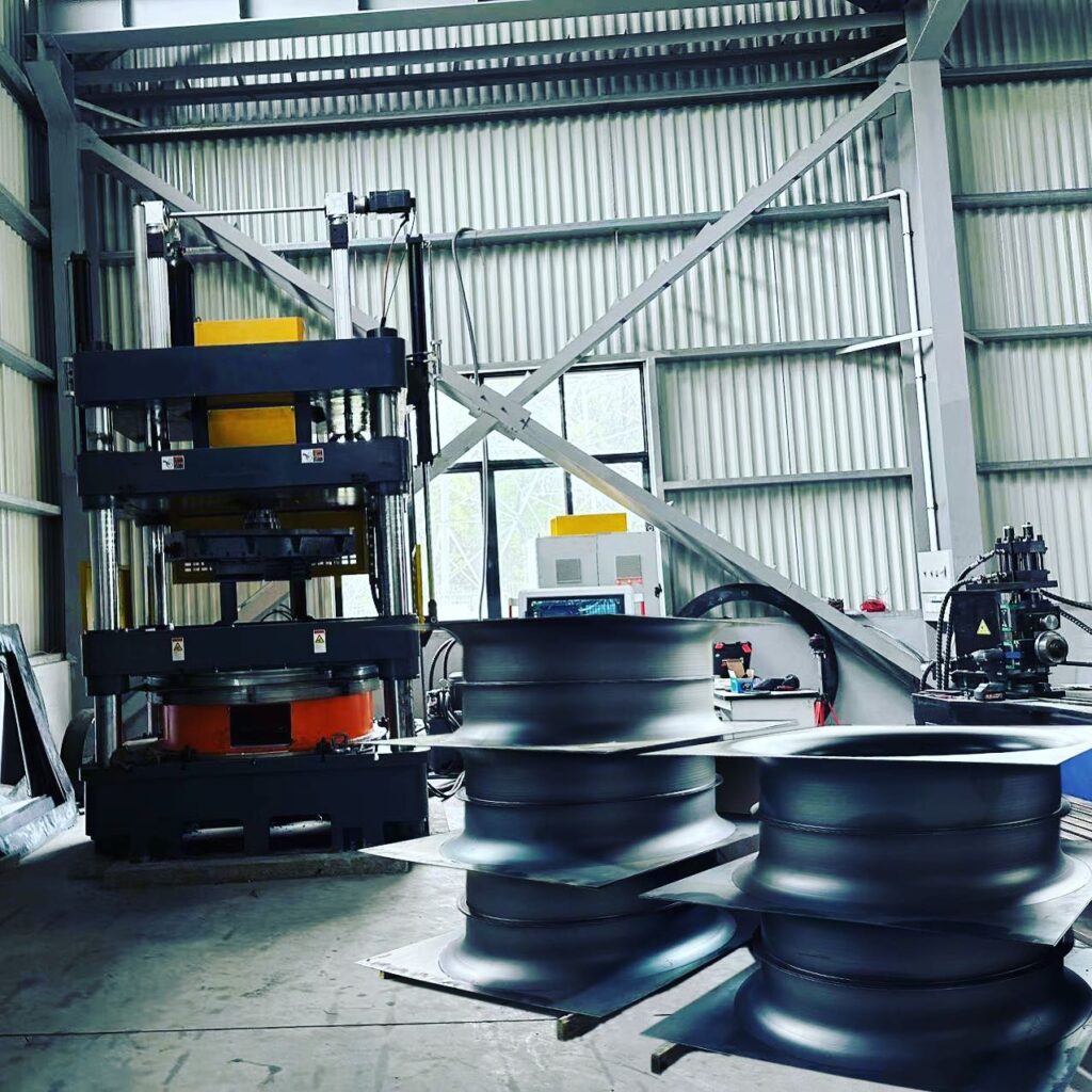
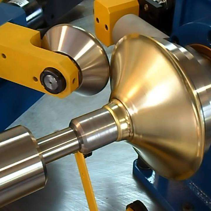
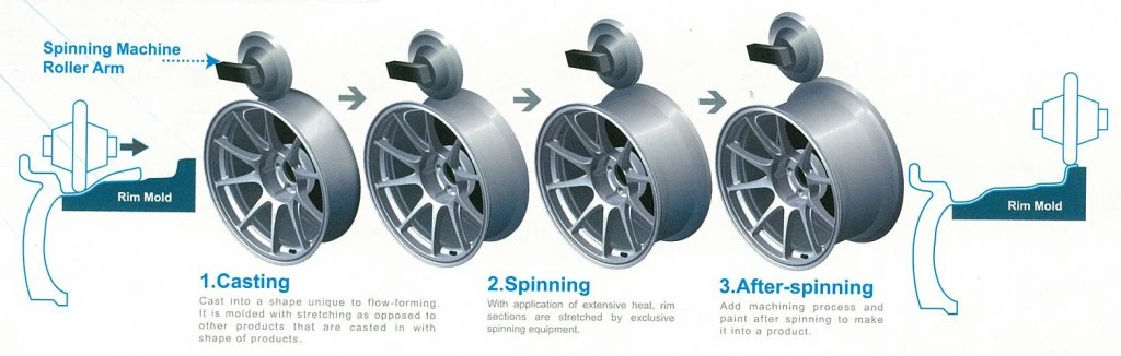
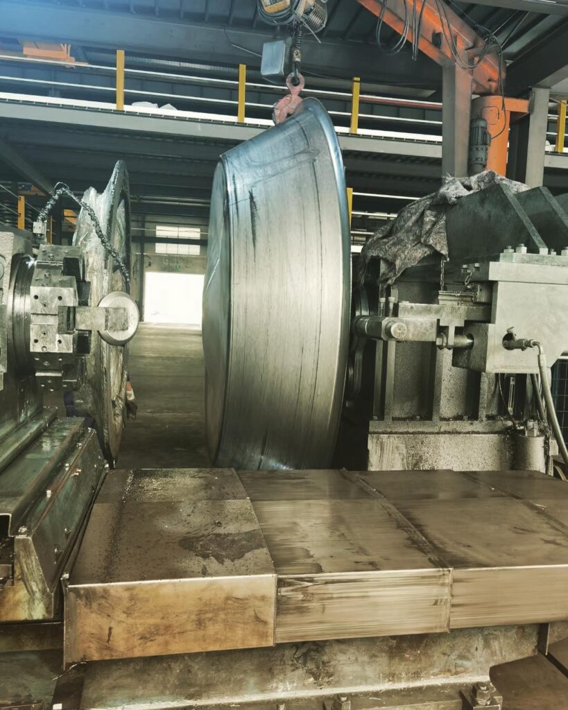
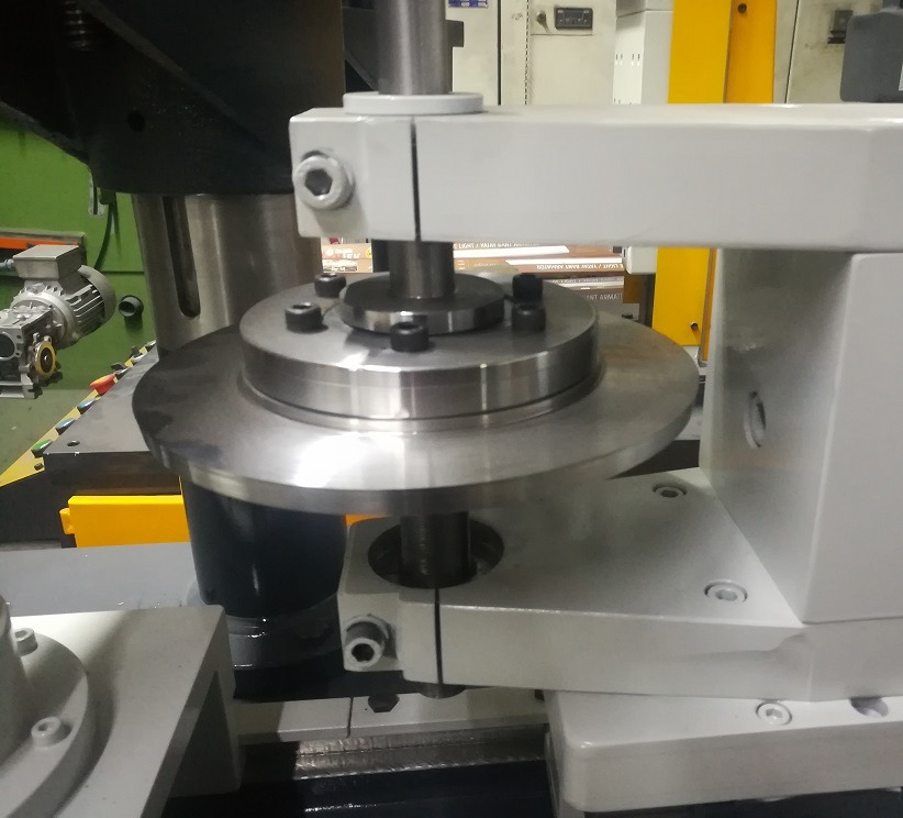
6.3 Rim Spinning Machines
Rim spinning machines are specialized equipment used to manufacture wheel rims for vehicles. The process of rim spinning involves shaping a metal disc into a cylindrical rim, which is then further processed to achieve the desired dimensions and strength.
6.3.1 Rim Spinning Process
Rim spinning starts with a metal disc, which is clamped onto a rotating mandrel. The spinning process shapes the disc into a cylindrical form, creating the basic structure of the wheel rim. Additional operations, such as rolling and finishing, are performed to achieve the final dimensions and surface finish.
6.3.2 Advantages
- Customization: Rim spinning allows for the production of custom wheel designs, catering to the specific needs of automotive manufacturers and aftermarket suppliers.
- Strength and Durability: The spinning process enhances the strength of the metal, producing rims that are both lightweight and durable, essential for high-performance vehicles.
- Efficiency: Rim spinning machines are capable of producing rims at high speeds, making them suitable for mass production.
6.3.3 Applications
- Automotive Industry: Rim spinning is primarily used in the automotive industry to manufacture wheel rims for cars, trucks, and motorcycles. The process is favored for producing rims that meet the stringent safety and performance standards required in this sector.
- Specialty Vehicles: Rim spinning is also used to produce rims for specialty vehicles, such as racing cars and custom-built vehicles, where specific design and performance criteria must be met.
6.4 Rubber and Silicone Presses
Rubber and silicone presses are specialized machines designed for molding rubber and silicone materials into various shapes and components. These presses are essential in industries where rubber and silicone products are widely used, such as automotive, medical, and consumer goods.
6.4.1 Rubber Compression Molding Presses
Rubber compression molding presses are used to shape rubber compounds into final products through the application of heat and pressure. The rubber material is placed in a heated mold cavity, and the press applies pressure to shape it into the desired form.
- Applications: Rubber compression molding presses are used to manufacture products such as seals, gaskets, o-rings, and other rubber components that require precision and durability. These presses are also used in the production of automotive rubber parts, such as bushings and mounts.
6.4.2 Silicone Presses
Silicone presses operate similarly to rubber presses but are specifically designed to handle silicone materials, which have unique properties such as flexibility, heat resistance, and biocompatibility.
- Applications: Silicone presses are used in the medical device industry to produce items such as tubing, seals, and implants. They are also used in the automotive industry to manufacture silicone gaskets, seals, and hoses.
6.4.3 Rubber Compression Molding Presses for Sale
The market for rubber compression molding presses is diverse, with a wide range of machines available for different applications and production scales. When selecting a press, manufacturers consider factors such as the size of the mold, the required pressure and temperature, and the specific properties of the rubber or silicone material being molded.
- New vs. Used: Manufacturers can choose between new and used presses, depending on budget and specific requirements. New presses offer the latest technology and features, while used presses can be a cost-effective option for smaller operations or specific projects.
6.5 Road Sign Profile Cold Bending Machines
Road sign profile cold bending machines are specialized equipment used to manufacture the structural profiles that support road signs. These machines are designed to bend metal profiles into the precise shapes needed to withstand outdoor conditions and provide long-term durability.
6.5.1 Cold Bending Process
Cold bending involves shaping metal profiles at room temperature without the application of heat. This process preserves the material’s mechanical properties, making it suitable for applications where strength and rigidity are important.
- Advantages: Cold bending machines offer high precision and repeatability, ensuring that each profile meets the required specifications. The process is also energy-efficient, as it does not require heating.
6.5.2 Applications
- Road Sign Manufacturing: Cold bending machines are primarily used to produce the support structures for road signs, including poles and brackets. These structures must be durable enough to withstand environmental factors such as wind, rain, and temperature fluctuations.
- Infrastructure Projects: Cold bending is also used in other infrastructure projects where metal profiles are required, such as in the construction of guardrails, bridges, and fencing.
6.6 Punch and Die Design
Punch and die design is a critical aspect of metal forming processes, where precise tools are used to cut, shape, or form metal sheets into specific shapes. The design of these tools is crucial for achieving accurate and consistent results in stamping, punching, and forming operations.
6.6.1 Importance of Precision in Punch and Die Design
The punch and die must be precisely designed to ensure that the metal is cut or shaped correctly. Any deviation in the design can lead to defects in the final product, such as burrs, cracks, or dimensional inaccuracies.
- Material Selection: The materials used for punches and dies must be carefully selected to withstand the stresses of the forming process. Common materials include tool steels and carbide, which offer high hardness and wear resistance.
- Tool Geometry: The geometry of the punch and die is tailored to the specific operation, whether it’s cutting, bending, or drawing. The design must account for factors such as material flow, springback, and tool wear.
6.6.2 Applications
- Automotive Industry: Punch and die sets are extensively used in the automotive industry for manufacturing body panels, brackets, and structural components. Precision in punch and die design is essential for maintaining quality and consistency in high-volume production.
- Aerospace Industry: In the aerospace sector, punch and die tools are used to form lightweight, high-strength components from materials like aluminum and titanium. The precision required in this industry is extremely high, given the safety-critical nature of aerospace components.
6.7 Steel Drum Machines
Steel drum machines are specialized equipment used in the production of steel drums, which are widely used for storing and transporting liquids and other materials. These machines are designed to perform operations such as forming, welding, and finishing the drum body.
6.7.1 Steel Drum Manufacturing Process
The process of manufacturing steel drums involves several steps, including cutting, forming, welding, and finishing. Steel drum machines are designed to handle each of these steps efficiently, ensuring that the drums meet industry standards for durability and safety.
- Cutting and Forming: The steel sheet is first cut to size and then formed into a cylindrical shape. This is typically done using roll forming or bending machines.
- Welding: Once the drum body is formed, the seam is welded to create a leak-proof seal. The welding process must be precise to ensure that the drum can withstand pressure and handling without leaking.
- Finishing: The final steps include adding the drum’s top and bottom, applying any necessary coatings, and performing quality inspections.
6.7.2 Applications
- Industrial Storage: Steel drums are used in various industries, including chemical, pharmaceutical, and food processing, to store and transport liquids and powders. The drums must meet strict standards for safety and durability, particularly when used for hazardous materials.
- Logistics and Transportation: Steel drums are also used in logistics for the safe transportation of materials over long distances. The strength and durability of the drums are critical to ensuring that the contents are protected during transit.
6.8 Conclusion
Specialized metalworking machines and presses play a crucial role in modern manufacturing, providing solutions for tasks that require precision, efficiency, and specialized capabilities. From transfer press stamping for high-volume production to flow forming lathes for high-precision components, these machines enable manufacturers to meet the demanding requirements of industries such as automotive, aerospace, and consumer goods. Understanding the functions and advantages of these specialized machines helps manufacturers select the right equipment for their specific needs, ensuring optimal performance and product quality.
7. Cutting-edge Metalworking Technologies
The field of metalworking is continuously evolving, with advancements in technology driving the development of more efficient, precise, and versatile machines. These cutting-edge technologies are transforming traditional metalworking processes, enabling manufacturers to produce complex components with greater accuracy and consistency. This section explores some of the latest advancements in metalworking technologies, including CNC profile bending machines, hydroforming presses, punch and die design innovations, and improvements in centerless grinding surface finish.
7.1 CNC Profile Bending Machines
CNC (Computer Numerical Control) profile bending machines represent a significant advancement in the metalworking industry, offering unparalleled precision and control in bending operations. These machines use computer-controlled movements to bend metal profiles into complex shapes with high accuracy, making them essential for industries that require precise and repeatable bending processes.
7.1.1 Overview of CNC Profile Bending
CNC profile bending machines automate the bending process by using a computer to control the movement and force applied to the metal. This allows for precise control over the bending angle, radius, and curvature, ensuring that each bend is consistent and accurate.
- Process: The metal profile is fed into the machine, where a series of rollers or a press apply force to bend the material. The CNC system controls the movement of the rollers or press, adjusting the force and angle as needed to achieve the desired shape.
- Materials: CNC profile bending machines can handle a wide range of materials, including aluminum, steel, copper, and alloys, making them versatile tools for various applications.
7.1.2 Advantages of CNC Profile Bending Machines
- Precision: CNC machines offer exceptional precision, with the ability to create complex shapes and tight tolerances that would be difficult or impossible to achieve with manual bending methods.
- Repeatability: Once programmed, CNC machines can produce identical bends across multiple parts, ensuring consistency in mass production.
- Efficiency: CNC profile bending machines reduce the need for manual intervention, speeding up the production process and reducing the potential for human error.
7.1.3 Applications
- Automotive Industry: CNC profile bending machines are used to produce components such as exhaust systems, roll bars, and chassis parts, where precise bending is crucial for performance and safety.
- Aerospace Industry: In aerospace manufacturing, these machines are used to form structural components, fuel lines, and airframe parts that require exact dimensions and shapes.
- Construction and Architecture: CNC profile bending is also employed in the construction and architecture sectors to create custom metal profiles for building facades, railings, and structural elements.
7.2 Hydroforming Press Technology
Hydroforming is a versatile metal forming process that uses high-pressure hydraulic fluid to shape metal into complex forms. Hydroforming presses have become a vital tool in the manufacturing of lightweight, high-strength components, particularly in the automotive and aerospace industries.
7.2.1 The Hydroforming Process
In hydroforming, a metal blank or tube is placed inside a die, and high-pressure hydraulic fluid is applied to form the metal into the shape of the die. The process is particularly effective for creating complex shapes with smooth surfaces and uniform wall thicknesses.
- Types of Hydroforming: There are two main types of hydroforming: tube hydroforming and sheet hydroforming. Tube hydroforming is used to form hollow components like exhaust systems and structural supports, while sheet hydroforming is used for creating complex, shallow components like body panels and enclosures.
- Materials: Hydroforming can be used with various materials, including aluminum, steel, and titanium, making it suitable for a wide range of applications.
7.2.2 Advantages of Hydroforming Presses
- Complex Shapes: Hydroforming allows for the creation of intricate shapes that would be difficult to achieve with traditional stamping or pressing methods.
- Weight Reduction: The process produces lightweight components with high structural integrity, which is particularly important in industries where weight savings are critical, such as automotive and aerospace.
- Surface Quality: Hydroforming produces components with excellent surface finish, reducing the need for additional machining or finishing operations.
7.2.3 Applications
- Automotive Industry: Hydroforming is widely used in the automotive industry to produce lightweight structural components, such as engine cradles, roof rails, and exhaust systems, that contribute to overall vehicle performance and fuel efficiency.
- Aerospace Industry: In aerospace, hydroforming is used to manufacture airframe components, fuel tanks, and other critical parts where weight and strength are key considerations.
- Consumer Electronics: Hydroforming is also employed in the production of consumer electronics enclosures, where the need for sleek, durable designs is paramount.
7.3 Innovations in Punch and Die Design
Punch and die design is at the heart of many metal forming processes, including stamping, punching, and drawing. Recent innovations in punch and die design are improving the efficiency, accuracy, and longevity of these tools, enabling manufacturers to produce higher-quality components with greater consistency.
7.3.1 Advanced Materials for Punch and Die
The materials used in punch and die design have a significant impact on tool performance and lifespan. Innovations in material science are leading to the development of stronger, more durable tool steels and coatings that enhance wear resistance and reduce downtime.
- Tool Steels: High-speed steels (HSS) and powder metallurgy steels are increasingly being used in punch and die manufacturing due to their superior hardness and toughness. These materials are ideal for high-volume production runs where tools are subject to intense wear.
- Coatings: Advanced coatings, such as titanium nitride (TiN) and diamond-like carbon (DLC), are being applied to punches and dies to reduce friction, increase wear resistance, and extend tool life.
7.3.2 Precision Engineering and CNC Machining
CNC machining has revolutionized the manufacturing of punches and dies, allowing for the creation of highly precise tools with complex geometries. This precision is essential for maintaining tight tolerances and ensuring the consistent quality of stamped or punched parts.
- Complex Geometries: CNC machining enables the production of punches and dies with intricate shapes and features that would be difficult or impossible to achieve with traditional machining methods.
- Custom Tooling: CNC technology allows for the rapid prototyping and production of custom punches and dies tailored to specific applications, reducing lead times and improving flexibility in manufacturing.
7.3.3 Applications
- Automotive Manufacturing: Advanced punch and die designs are used in the production of body panels, engine components, and structural parts, where precision and durability are critical.
- Consumer Electronics: The consumer electronics industry relies on precise punch and die tools to create the thin, intricate components used in smartphones, laptops, and other devices.
- Medical Devices: In the medical device industry, punches and dies are used to produce components like surgical instruments and implantable devices, where precision and material integrity are of utmost importance.
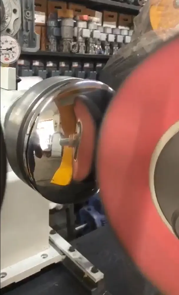
7.4 Centerless Grinding Surface Finish
Centerless grinding is a metal finishing process that removes material from the outer surface of a cylindrical workpiece, producing a smooth, high-quality surface finish. Recent advancements in centerless grinding technology have improved the precision and surface finish achievable with this process, making it a valuable tool in modern manufacturing.
7.4.1 The Centerless Grinding Process
In centerless grinding, the workpiece is supported between two rotating wheels: a grinding wheel and a regulating wheel. The grinding wheel removes material from the workpiece, while the regulating wheel controls its speed and ensures a consistent feed rate. The workpiece is not held in place by a spindle, allowing for continuous grinding and the ability to process long or complex parts.
- Types of Centerless Grinding: There are two main types of centerless grinding: through-feed and in-feed. Through-feed grinding is used for cylindrical parts with a consistent diameter, while in-feed grinding is used for parts with varying diameters or complex shapes.
- Materials: Centerless grinding can be used on a wide range of materials, including steel, aluminum, and alloys, making it a versatile process for various applications.
7.4.2 Advantages of Centerless Grinding
- High Precision: Centerless grinding is capable of producing extremely precise dimensions and tight tolerances, making it ideal for high-precision components.
- Smooth Surface Finish: The process produces a smooth surface finish with minimal defects, reducing the need for additional finishing operations.
- Efficiency: Centerless grinding is a fast and efficient process, capable of handling high volumes of workpieces with consistent quality.
7.4.3 Applications
- Automotive Industry: Centerless grinding is used to produce components like camshafts, crankshafts, and valve stems, where precision and surface finish are critical for performance and durability.
- Aerospace Industry: The aerospace industry uses centerless grinding to produce precision components for engines, landing gear, and other critical systems, where high-quality surface finishes are essential for safety and performance.
- Medical Devices: In the medical device industry, centerless grinding is used to produce components like needles, catheters, and surgical instruments, where precision and surface finish are crucial for functionality and patient safety.
7.5 Conclusion
Cutting-edge metalworking technologies are reshaping the landscape of modern manufacturing, offering new levels of precision, efficiency, and versatility. From CNC profile bending machines and hydroforming presses to advancements in punch and die design and centerless grinding, these technologies enable manufacturers to produce high-quality components that meet the stringent demands of industries such as automotive, aerospace, and medical devices. As these technologies continue to evolve, they will play an increasingly important role in driving innovation and competitiveness in the global manufacturing sector.
8. Industry-specific Applications
The metalworking industry serves a wide range of sectors, each with its unique demands and challenges. The choice of metalworking machines, techniques, and technologies is often dictated by the specific requirements of these industries. From the automotive and aerospace sectors to consumer goods and infrastructure, metalworking plays a crucial role in manufacturing the components that power modern life. This section explores the application of metalworking machinery and processes in various industries, highlighting how specialized equipment and technologies are tailored to meet the distinct needs of each sector.
8.1 Automotive Industry
The automotive industry is one of the largest consumers of metalworking products, requiring a vast array of components that must be manufactured with precision and consistency. The demands of the automotive sector include high-volume production, stringent quality standards, and the need for lightweight, durable components that contribute to overall vehicle performance and safety.
8.1.1 Metalworking in Automotive Manufacturing
The automotive manufacturing process involves the use of several metalworking techniques, including stamping, deep drawing, bending, and polishing. Each of these processes is crucial for producing the components that make up a vehicle’s body, engine, and interior systems.
- Stamping: Transfer press stamping is widely used in automotive manufacturing to produce body panels, structural components, and various brackets. The ability to perform multiple operations in a single press ensures high efficiency and consistency across large production runs.
- Deep Drawing: Deep drawing presses are employed to create complex shapes such as fuel tanks, transmission housings, and engine components. The deep drawing process ensures that these parts are strong, lightweight, and capable of withstanding the rigors of automotive use.
- CNC Bending: CNC profile bending machines are used to form components like exhaust systems, roll cages, and chassis parts. The precision offered by CNC bending ensures that each part meets the exact specifications required for safety and performance.
8.1.2 Aluminum Deburring and Polishing
Aluminum is a key material in automotive manufacturing due to its lightweight properties and corrosion resistance. However, aluminum components often require deburring and polishing to meet the industry’s aesthetic and functional standards.
- Aluminum Deburring: Aluminum deburring machines are used to remove burrs and sharp edges from machined or stamped aluminum parts. This step is essential to ensure that the components fit together smoothly during assembly and do not pose safety risks.
- Polishing: Metal polishing machines are employed to enhance the surface finish of aluminum components, providing a smooth, reflective surface that improves both the appearance and aerodynamics of the vehicle.
8.1.3 Rubber Molding for Automotive Parts
Rubber components, such as seals, gaskets, and bushings, are critical in automotive manufacturing. Rubber compression molding presses are used to produce these parts with precision and consistency.
- Rubber Compression Molding: This process involves placing rubber material into a heated mold, where it is shaped under pressure. The resulting components are durable, flexible, and capable of withstanding extreme temperatures and mechanical stress.
- Applications: Rubber molding is used to produce a variety of automotive parts, including engine mounts, suspension bushings, and seals for doors and windows. These components contribute to the vehicle’s overall durability and comfort.
8.2 Aerospace Industry
The aerospace industry demands the highest levels of precision and quality, as the components produced must meet rigorous safety standards and perform reliably in extreme environments. Metalworking in aerospace involves the use of advanced technologies and materials to create lightweight, high-strength components.
8.2.1 Hydroforming in Aerospace Manufacturing
Hydroforming presses are extensively used in aerospace manufacturing to produce complex, lightweight components that are both strong and aerodynamic.
- Complex Shapes: Hydroforming allows for the creation of intricate shapes with uniform wall thicknesses, making it ideal for producing components such as fuselage panels, wing structures, and engine casings.
- Material Efficiency: The hydroforming process minimizes material waste, which is particularly important in aerospace manufacturing where the cost of materials like titanium and high-strength alloys is significant.
8.2.2 Flow Forming for High-precision Components
Flow forming lathes are used in the aerospace industry to manufacture high-precision cylindrical components, such as aircraft engine parts and structural supports.
- Precision and Strength: The flow forming process enhances the mechanical properties of the material, producing components that are both lightweight and capable of withstanding high stress and pressure.
- Applications: Flow forming is used to produce parts like jet engine cases, landing gear components, and missile casings, where precision and material integrity are critical.
8.2.3 Metal Polishing and Surface Finishing
In aerospace manufacturing, the surface finish of components is of utmost importance, as it can affect the aerodynamics, weight, and overall performance of the aircraft.
- Metal Polishing Machines: These machines are used to achieve a smooth, polished finish on aerospace components, reducing friction and improving the aerodynamic properties of the aircraft.
- Edge Rounding: Edge rounding stainless steel and other metals is essential to remove sharp edges that could cause stress concentrations or interfere with the assembly of critical components.
8.3 Consumer Goods Manufacturing
The consumer goods industry relies heavily on metalworking processes to produce a wide range of products, from household appliances to electronics. The focus in this sector is often on the aesthetic appeal, durability, and functionality of the final products.
8.3.1 Metalworking in Appliance Manufacturing
Appliance manufacturing involves the use of metalworking machines to create components such as enclosures, brackets, and internal structures for products like refrigerators, washing machines, and ovens.
- Deep Drawing Presses: Deep drawing presses are used to form appliance housings and internal components from sheet metal. The deep drawing process ensures that these parts are both strong and lightweight, which is important for product durability and efficiency.
- Metal Polishing and Finishing: The aesthetic appeal of consumer appliances is a key consideration, and metal polishing machines are used to achieve a high-quality finish on visible parts. Polished surfaces not only enhance the appearance but also make the appliances easier to clean and maintain.
8.3.2 Metalworking in Electronics
The electronics industry requires metal components that are not only precise but also have excellent surface finishes to ensure proper function and aesthetic appeal.
- CNC Profile Bending: CNC profile bending machines are used to create the frames, brackets, and enclosures that house electronic components. Precision bending ensures that these parts fit together perfectly and provide adequate protection for sensitive electronics.
- Surface Finishing: In electronics manufacturing, the surface finish of metal parts is critical for both function and appearance. Smooth, polished surfaces are essential for components like smartphone enclosures, laptop frames, and other consumer electronics.
8.4 Infrastructure and Construction
The construction and infrastructure sectors utilize metalworking processes to produce structural components, building materials, and support systems. These industries require durable, high-strength materials that can withstand harsh environmental conditions and provide long-term stability.
8.4.1 Metalworking in Structural Components
Structural components used in construction, such as beams, columns, and trusses, are often manufactured using metalworking techniques like bending, welding, and forming.
- CNC Bending Machines: CNC profile bending machines are used to shape structural components with high precision, ensuring that they meet the specific requirements of building designs. This precision is crucial for maintaining the structural integrity of buildings and infrastructure projects.
- Hydraulic Presses: Hydraulic presses are employed to form and assemble large structural components, providing the force necessary to shape heavy-gauge steel and other materials.
8.4.2 Road Sign Profile Cold Bending
Road signs and other infrastructure elements require precise shaping to ensure they are durable and easily visible.
- Cold Bending Machines: Road sign profile cold bending machines are used to create the structural profiles that support road signs. These machines ensure that the profiles are shaped to the exact specifications required for stability and durability.
- Applications: Cold bending is also used in the construction of guardrails, fencing, and other infrastructure components that must withstand environmental stress and provide long-term reliability.
8.4.3 Steel Drum Manufacturing
Steel drums are essential for storing and transporting materials in the construction and infrastructure sectors. The manufacturing of these drums involves specialized metalworking processes to ensure they are leak-proof and durable.
- Steel Drum Machines: These machines are used to form, weld, and finish steel drums, ensuring they meet the necessary standards for safety and durability. The drums must be able to withstand rough handling and exposure to harsh environmental conditions.
8.5 Conclusion
The application of metalworking machinery and processes varies widely across different industries, each with its unique requirements and challenges. Whether it’s the precision needed in aerospace manufacturing, the high-volume production demands of the automotive industry, or the aesthetic and functional considerations in consumer goods, specialized metalworking technologies are essential for producing the components that drive modern industry. By understanding the specific needs of each sector, manufacturers can select the right metalworking equipment and techniques to optimize production, ensure quality, and meet the demands of their customers.
9. Market Overview and Trends in Metalworking Machinery
The metalworking machinery market is a dynamic and rapidly evolving sector, influenced by technological advancements, changing industry demands, and global economic trends. As manufacturers seek to improve efficiency, precision, and automation in their production processes, the demand for advanced metalworking equipment continues to grow. This section provides an overview of the current market for metalworking machinery, explores key trends shaping the industry, and highlights some of the leading manufacturers and suppliers in the market.
9.1 Current Market Landscape
The global metalworking machinery market is diverse, encompassing a wide range of machines used in cutting, forming, finishing, and assembly processes. The market is characterized by steady growth, driven by increasing industrialization, the expansion of manufacturing sectors, and the ongoing adoption of advanced technologies.
9.1.1 Market Size and Growth
The metalworking machinery market is expected to continue its growth trajectory, supported by the rising demand for high-precision components in industries such as automotive, aerospace, and electronics. The increasing emphasis on automation and Industry 4.0 technologies is also contributing to the expansion of the market.
- Key Regions: Asia-Pacific, particularly China and India, dominates the global metalworking machinery market due to its strong manufacturing base and ongoing investments in industrial infrastructure. North America and Europe are also significant markets, driven by advancements in aerospace and automotive manufacturing.
- Market Segments: The market can be segmented into various categories based on the type of machinery, including CNC machines, stamping presses, forming machines, and finishing equipment. Among these, CNC machines and automated systems are experiencing the fastest growth due to their ability to enhance productivity and precision.
9.2 Trends Shaping the Metalworking Machinery Market
Several key trends are shaping the future of the metalworking machinery market, driven by technological advancements and evolving industry demands. These trends are influencing the way manufacturers invest in machinery and adopt new processes to stay competitive.
9.2.1 Automation and Industry 4.0
The integration of automation and Industry 4.0 technologies is transforming the metalworking industry. Manufacturers are increasingly adopting automated systems and smart machinery to enhance production efficiency, reduce human error, and improve overall operational performance.
- Smart Manufacturing: The use of sensors, IoT (Internet of Things), and data analytics in metalworking machinery allows for real-time monitoring and control of production processes. This leads to better decision-making, predictive maintenance, and optimized resource management.
- Robotics: Robotics is playing an increasingly important role in metalworking, particularly in tasks such as material handling, welding, and assembly. The use of robotic arms and automated guided vehicles (AGVs) is reducing the need for manual labor and increasing production speed.
9.2.2 Additive Manufacturing and Hybrid Machines
Additive manufacturing, also known as 3D printing, is gaining traction in the metalworking industry as a complementary technology to traditional subtractive methods. The development of hybrid machines that combine additive and subtractive processes is opening up new possibilities for complex part manufacturing.
- 3D Printing in Metalworking: Additive manufacturing allows for the creation of intricate geometries and custom components that would be difficult or impossible to produce with traditional methods. This is particularly useful in industries such as aerospace and medical devices, where precision and customization are critical.
- Hybrid Machines: Hybrid machines that integrate additive manufacturing with CNC machining are becoming more popular, offering the flexibility to produce parts with complex internal structures while maintaining high precision and surface quality.
9.2.3 Sustainability and Green Manufacturing
As environmental concerns become increasingly important, the metalworking industry is focusing on sustainability and green manufacturing practices. This includes reducing energy consumption, minimizing waste, and using environmentally friendly materials and processes.
- Energy-efficient Machines: Manufacturers are developing energy-efficient metalworking machines that reduce power consumption and lower the overall environmental impact of production processes. This is achieved through advanced motor technologies, optimized cutting strategies, and improved machine design.
- Recycling and Waste Reduction: The industry is also investing in technologies that enable the recycling of scrap materials and the reduction of waste during production. This not only helps to reduce environmental impact but also lowers material costs.
9.2.4 Customization and Flexibility
The demand for customized products and shorter production runs is driving the need for flexible manufacturing solutions. Metalworking machinery that can quickly adapt to different production requirements is becoming increasingly valuable.
- Modular Machines: Modular metalworking machines that can be reconfigured for different tasks are gaining popularity. These machines offer greater flexibility and allow manufacturers to respond quickly to changing market demands.
- Customization: The ability to produce custom components on-demand is becoming a competitive advantage in industries such as automotive and aerospace, where product differentiation and innovation are key.
9.3 Future Outlook of the Metalworking Machinery Market
The metalworking machinery market is poised for continued growth as industries increasingly rely on advanced manufacturing technologies to stay competitive. The adoption of automation, digitalization, and sustainable practices will be key drivers of this growth, as manufacturers seek to improve efficiency, reduce costs, and meet the evolving demands of their customers.
- Emerging Markets: The expansion of industrial activities in emerging markets such as India, Southeast Asia, and Latin America presents significant opportunities for the metalworking machinery industry. These regions are expected to see increased investment in manufacturing infrastructure, driving demand for advanced machinery.
- Technological Advancements: Ongoing advancements in robotics, AI, and additive manufacturing will continue to shape the future of metalworking machinery, offering new possibilities for precision manufacturing and customization.
- Global Supply Chain: The global nature of the metalworking industry means that supply chain dynamics will play a critical role in market development. Manufacturers will need to navigate challenges such as trade policies, raw material availability, and transportation costs to remain competitive.
9.4 Conclusion
The metalworking machinery market is undergoing significant transformation, driven by technological innovation, automation, and changing industry demands. As manufacturers seek to enhance productivity, reduce costs, and improve sustainability, the demand for advanced metalworking equipment is expected to grow. Companies that embrace these trends and invest in cutting-edge technologies will be well-positioned to thrive in the competitive global market.
EMS Metalworking Machines
We design, manufacture and assembly metalworking machinery such as:
- Hydraulic transfer press
- Glass mosaic press
- Hydraulic deep drawing press
- Casting press
- Hydraulic cold forming press
- Hydroforming press
- Composite press
- Silicone rubber moulding press
- Brake pad press
- Melamine press
- SMC & BMC Press
- Labrotaroy press
- Edge cutting trimming machine
- Edge curling machine
- Trimming beading machine
- Trimming joggling machine
- Cookware production line
- Pipe bending machine
- Profile bending machine
- Bandsaw for metal
- Cylindrical welding machine
- Horizontal pres and cookware
- Kitchenware, hotelware
- Bakeware and cuttlery production machinery
as a complete line as well as an individual machine such as:
- Edge cutting trimming beading machines
- Polishing and grinding machines for pot and pans
- Hydraulic drawing presses
- Circle blanking machines
- Riveting machine
- Hole punching machines
- Press feeding machine
You can check our machinery at work at: EMS Metalworking Machinery – YouTube
Applications:
- Beading and ribbing
- Flanging
- Trimming
- Curling
- Lock-seaming
- Ribbing
- Flange-punching