
We manufacture Hydraulic Press Attachments to bend sheet metal edges. Hydraulic Press Attachments are used in metalworking industries
Hydraulic press attachments are additional tools or accessories that can be used in conjunction with a hydraulic press to expand its capabilities and perform specific tasks. Here are some common hydraulic press attachments:
- V-Dies: V-dies are attachments used for bending and forming sheet metal into V-shaped profiles. They are often used in conjunction with a punch and a die to achieve precise bends in the material.
- U-Dies: U-dies are similar to V-dies but have a U-shaped profile. They are used for bending and forming sheet metal into U-shaped profiles.
- Radius Dies: Radius dies are used to achieve curved bends or radii in sheet metal. They come in various sizes to accommodate different bending requirements.
- Hemming Attachments: Hemming attachments are used for folding and creating hems or flanges in sheet metal. They are commonly used in applications where two edges need to be joined or folded over.
- Punches and Dies: Punches and dies are versatile attachments used for various punching and forming operations. They can be customized to specific shapes and sizes based on the desired application.
- Press Brake Tooling: Press brake tooling includes a range of attachments and tooling sets specifically designed for bending and forming sheet metal. They typically consist of upper and lower dies that can be easily mounted and adjusted on the hydraulic press.
- Tube Bending Attachments: Tube bending attachments allow the hydraulic press to be used for bending and forming tubes or pipes. They provide precise control and accuracy in achieving desired bends in the tubing.
- Cutting Attachments: Some hydraulic presses can be equipped with cutting attachments for shearing or cutting operations. These attachments are designed to cut through various materials, such as metal sheets or bars.
- Flanging Attachments: Flanging attachments are used for creating flanges or raised edges on sheet metal. They are commonly used in automotive or aerospace applications.
- Custom Attachments: Depending on the specific requirements of your application, custom attachments can be designed and fabricated to suit your needs. These can include specialized tooling, fixtures, or adapters that enhance the capabilities of the hydraulic press for unique bending or forming operations.
When considering hydraulic press attachments, it is important to ensure compatibility with your specific hydraulic press model and capacity. Consult with the manufacturer or a knowledgeable expert to ensure the attachments are suitable for your intended applications and meet necessary safety standards.
Hydraulic Press Attachments
Hydraulic press attachments are essential accessories that expand the capabilities of hydraulic press brakes, enabling them to perform a wider range of operations beyond standard bending. These attachments can be easily attached and detached from the press brake, providing versatility and flexibility in metal fabrication applications.
Common Types of Hydraulic Press Attachments
- Shearing Attachment: This attachment converts the press brake into a shearing machine, allowing it to cut sheet metal into various shapes and sizes. It is a cost-effective solution for cutting straight or angled edges in sheet metal.
- Notching Attachment: This attachment enables the press brake to create notches or corner cuts in sheet metal, often used for connecting components or creating clearance holes. It is particularly useful for intricate designs or repetitive notch patterns.
- Beader Attachment: This attachment allows the press brake to form beads or ridges on sheet metal, adding strength and rigidity to the workpiece. Beaded edges can enhance structural integrity and provide a decorative element.
- Flanging Attachment: This attachment enables the press brake to create flanges, which are raised edges or lips on sheet metal, often used for joining or reinforcing components. Flanges provide a stronger connection point and can increase the load-bearing capacity of the sheet metal.
- Embossing Attachment: This attachment allows the press brake to emboss patterns or designs onto sheet metal, creating decorative or functional features. Embossed patterns can add aesthetic appeal or provide texture for specific applications.
- Louvering Attachment: This attachment enables the press brake to create louvers, which are ventilation slits or openings in sheet metal, often used for airflow or heat dissipation. Louvers can be customized in size and pattern to suit specific ventilation requirements.
- Rolling Attachment: This attachment converts the press brake into a rolling mill, allowing it to form curved or cylindrical shapes from sheet metal. Rolling is ideal for creating curved components like ducts, pipes, and tanks.
Benefits of Using Hydraulic Press Attachments
- Increased Versatility: Attachments expand the capabilities of the press brake, enabling it to perform a wider range of operations, reducing the need for additional equipment.
- Cost-Effectiveness: Attachments are often more cost-effective than purchasing dedicated machines for each specific operation.
- Space-Saving: Attachments can be easily removed and stored, reducing the overall footprint of the press brake in the workshop.
- Efficient Metal Fabrication: Attachments allow for efficient and streamlined metal fabrication, reducing the need for multiple setup changes and workpiece transfers.
- Enhanced Productivity: Attachments can increase productivity by enabling faster and more efficient operations compared to hand tools or manual methods.
Considerations for Choosing Hydraulic Press Attachments
- Compatibility: Ensure the attachment is compatible with the specific model and capacity of the press brake.
- Application Needs: Select the attachment that best suits the required operations and the types of sheet metal being processed.
- Quality and Durability: Choose attachments from reputable manufacturers that use high-quality materials and construction for long-lasting performance.
- Safety Features: Verify that the attachment incorporates safety features to protect operators from potential hazards.
- Ease of Use: Consider the ease of attachment and detachment, as well as the user-friendliness of the attachment’s operation.
- Maintenance Requirements: Understand the maintenance requirements of the attachment to ensure proper upkeep and longevity.
By carefully evaluating these factors, metal fabricators can select the most suitable hydraulic press brake attachments to enhance their equipment’s versatility, expand their capabilities, and streamline metal fabrication processes.
Hydraulic Press Attachments: V-Dies
V-Dies are a type of hydraulic press attachment used for bending and forming sheet metal into V-shaped profiles. They consist of two components: an upper die and a lower die. The upper die has a V-shaped groove, while the lower die has a corresponding V-shaped ridge or edge. When the sheet metal is placed between the upper and lower dies and the hydraulic press is activated, the metal is compressed and bent along the V-shaped groove, resulting in a V-shaped bend.
Here are some key features and considerations regarding V-Dies:
- V-Die Sizes: V-Dies are available in various sizes and V-groove angles to accommodate different bending requirements. The size and angle of the V-Die should be selected based on the desired bend radius and the thickness of the sheet metal being bent.
- Compatibility: Ensure that the V-Dies are compatible with your hydraulic press model in terms of size, mounting, and attachment mechanism. Consult the manufacturer’s guidelines or specifications to determine the appropriate V-Die dimensions for your specific press.
- Adjustability: Some V-Dies offer adjustability to accommodate different bend radii or sheet metal thicknesses. These adjustable V-Dies typically have movable inserts or shims that can be positioned to achieve the desired bending results.
- Material Selection: V-Dies are typically made from hardened steel or other durable materials to withstand the high forces involved in the bending process. Consider the material composition of the V-Dies to ensure they are suitable for the type of sheet metal being bent and can withstand repeated use without excessive wear.
- Back Gauge Compatibility: If your hydraulic press is equipped with a back gauge, ensure that the V-Dies are designed to work in conjunction with the back gauge system. The back gauge helps position the sheet metal accurately for consistent bends and can enhance the precision of the bending operation.
- Specialized V-Dies: In addition to standard V-Dies, there are specialized V-Dies available for specific applications. For example, offset V-Dies allow for bends closer to an existing edge or flange, while hemming V-Dies are designed for creating hems or flanges in sheet metal.
- Safety Considerations: When using V-Dies or any hydraulic press attachments, always follow proper safety procedures. Ensure the press is securely mounted and that the V-Dies are properly installed and aligned. Use appropriate personal protective equipment (PPE) and adhere to safe operating practices to minimize the risk of accidents or injuries.
V-Dies are versatile tools that can be used in various industries, including metal fabrication, automotive, aerospace, and construction. They offer precise control over bending operations and can help achieve consistent and accurate V-shaped bends in sheet metal.
Hydraulic Press Attachments: U-Dies
U-Dies are hydraulic press attachments used for bending and forming sheet metal into U-shaped profiles. They are similar to V-Dies but have a U-shaped groove instead of a V-shaped groove. U-Dies are commonly used in metal fabrication, automotive manufacturing, and other industries where U-shaped bends are required.
Here are some key points to know about U-Dies:
- U-Die Construction: U-Dies consist of two components—an upper die and a lower die. The upper die has a U-shaped groove, while the lower die has a corresponding U-shaped ridge or edge. The sheet metal is placed between the upper and lower dies, and when pressure is applied through the hydraulic press, the metal is bent along the U-shaped groove, resulting in a U-shaped bend.
- U-Die Sizes: U-Dies come in various sizes and U-groove configurations to accommodate different bending requirements. The size of the U-Die should be selected based on the desired bend radius and the thickness of the sheet metal being bent.
- Compatibility: Ensure that the U-Dies are compatible with your hydraulic press model in terms of size, mounting, and attachment mechanism. Refer to the manufacturer’s guidelines or specifications to determine the appropriate U-Die dimensions for your specific press.
- Adjustability: Some U-Dies offer adjustability to accommodate different bend radii or sheet metal thicknesses. These adjustable U-Dies typically have movable inserts or shims that can be positioned to achieve the desired bending results.
- Material Selection: U-Dies are typically made from hardened steel or other durable materials to withstand the high forces involved in the bending process. Consider the material composition of the U-Dies to ensure they are suitable for the type of sheet metal being bent and can withstand repeated use without excessive wear.
- Back Gauge Compatibility: If your hydraulic press is equipped with a back gauge, ensure that the U-Dies are designed to work in conjunction with the back gauge system. The back gauge helps position the sheet metal accurately for consistent bends and enhances the precision of the bending operation.
- Safety Considerations: When using U-Dies or any hydraulic press attachments, follow proper safety procedures. Ensure the press is securely mounted, and the U-Dies are properly installed and aligned. Use appropriate personal protective equipment (PPE) and adhere to safe operating practices to minimize the risk of accidents or injuries.
U-Dies offer versatility and precision in creating U-shaped bends in sheet metal. They are valuable tools in metalworking processes where U-shaped profiles are needed, such as creating channels, frames, or brackets. Proper selection and use of U-Dies can result in accurate and consistent U-shaped bends in sheet metal fabrication.
Hydraulic Press Attachments: Radius Dies
Radius dies are hydraulic press attachments used for creating curved bends or radii in sheet metal. They are designed to provide precise and consistent bending results. Radius dies are commonly used in metal fabrication, automotive manufacturing, and other industries where curved or rounded bends are required.
Here are some key points to understand about radius dies:
- Radius Die Construction: Radius dies consist of an upper die and a lower die. The upper die has a curved groove or contour, while the lower die has a corresponding curved ridge or edge. When the sheet metal is placed between the upper and lower dies and pressure is applied through the hydraulic press, the metal is bent along the curved groove, resulting in a curved or rounded bend with a specific radius.
- Radius Options: Radius dies are available in different sizes and radius options to accommodate various bending requirements. The radius size refers to the desired curvature or bend radius of the sheet metal. Common radius options include 1/4″, 1/2″, 1″, and larger radii depending on the specific application.
- Compatibility: Ensure that the radius dies are compatible with your hydraulic press model in terms of size, mounting, and attachment mechanism. Refer to the manufacturer’s guidelines or specifications to determine the appropriate radius die dimensions for your specific press.
- Adjustability: Some radius dies offer adjustability to accommodate different bend radii or sheet metal thicknesses. These adjustable radius dies may have movable inserts or shims that can be positioned to achieve the desired bending results.
- Material Selection: Radius dies are typically made from hardened steel or other durable materials to withstand the forces involved in the bending process. Consider the material composition of the radius dies to ensure they are suitable for the type of sheet metal being bent and can withstand repeated use without excessive wear.
- Safety Considerations: When using radius dies or any hydraulic press attachments, follow proper safety procedures. Ensure the press is securely mounted, and the dies are properly installed and aligned. Use appropriate personal protective equipment (PPE) and adhere to safe operating practices to minimize the risk of accidents or injuries.
Radius dies allow for precise and consistent bending of sheet metal into curved or rounded shapes. They are commonly used in applications where smooth and accurate bends with specific radii are required, such as forming pipes, tubes, or curved components. Proper selection and use of radius dies can help achieve high-quality and aesthetically pleasing curved bends in sheet metal fabrication.
Hydraulic Press Attachments: Hemming Attachments
Hemming attachments are hydraulic press tools used for performing hemming operations on sheet metal. Hemming is a process of folding or bending the edge of a sheet metal component to create a secure and finished edge. It is commonly used in automotive manufacturing, aerospace, and other industries where a clean and aesthetically pleasing edge is desired.
Here are some key points to understand about hemming attachments:
- Hemming Process: The hemming process involves folding or bending the edge of a sheet metal component onto itself. This creates a double-layered edge that provides strength, protection, and a neat appearance. Hemming attachments are designed to facilitate this process by applying the necessary force and forming the hemmed edge.
- Attachment Types: Hemming attachments come in various forms depending on the specific hemming requirements. Some common types include hemming dies, hemming punches, and hemming anvils. These attachments are often customized to match the shape and size of the desired hem.
- Compatibility: Ensure that the hemming attachments are compatible with your hydraulic press model in terms of size, mounting, and attachment mechanism. Refer to the manufacturer’s guidelines or specifications to determine the appropriate hemming attachment dimensions for your specific press.
- Adjustability: Depending on the application, some hemming attachments may offer adjustability to accommodate different sheet metal thicknesses or hemming configurations. This adjustability allows for flexibility and adaptability to different hemming requirements.
- Material Selection: Hemming attachments are typically made from hardened steel or other durable materials to withstand the forces involved in the hemming process. The material should be chosen to ensure longevity and resistance to wear during repeated use.
- Safety Considerations: When using hemming attachments or any hydraulic press tools, it is important to follow proper safety procedures. Ensure the press is securely mounted, and the attachments are properly installed and aligned. Use appropriate personal protective equipment (PPE) and adhere to safe operating practices to minimize the risk of accidents or injuries.
Hemming attachments provide a precise and efficient solution for achieving clean and secure edges in sheet metal components. They are essential tools in various industries where hemming operations are required. Proper selection, compatibility, and use of hemming attachments can contribute to high-quality and visually appealing hemmed edges in sheet metal fabrication.
Punches and Dies
Punches and dies are essential tools used in hydraulic press operations for cutting, forming, and shaping sheet metal and other materials. They are commonly used in metal fabrication, stamping, and other manufacturing processes where precise and repeatable operations are required.
Here are some key points to understand about punches and dies:
- Punch and Die Construction: A punch is a tool with a protruding head or tip, while a die is a tool with a recessed cavity or hole. When the punch is driven into the die, the material placed between them undergoes the desired cutting, forming, or shaping operation.
- Types of Punches: Punches come in various shapes and configurations depending on the specific application. Some common types include round punches, square punches, rectangular punches, oblong punches, and custom-shaped punches. The shape of the punch determines the shape of the cut or form created in the material.
- Types of Dies: Dies are designed to match the shape of the desired cut, form, or shape. Common types include round dies, square dies, rectangular dies, oblong dies, and custom-shaped dies. The die provides the counter surface to the punch and determines the final shape or form of the material being worked on.
- Compatibility: Punches and dies should be compatible with each other in terms of size, shape, and alignment. They should be carefully matched to ensure accurate and consistent results. Refer to the manufacturer’s guidelines or specifications to select the appropriate punches and dies for your specific hydraulic press.
- Material Selection: Punches and dies are typically made from hardened tool steel or other durable materials to withstand the forces involved in the punching or forming process. The material should be chosen based on factors such as the type of material being worked on, the required precision, and the expected tool life.
- Maintenance and Replacement: Punches and dies may wear out over time due to repeated use. Regular inspection, cleaning, and maintenance are important to ensure optimal performance and extend their lifespan. When signs of wear or damage become noticeable, it is necessary to replace the punches or dies to maintain the quality of the operations.
- Safety Considerations: When using punches and dies or any hydraulic press tools, follow proper safety procedures. Ensure the press is securely mounted, and the punches and dies are properly installed and aligned. Use appropriate personal protective equipment (PPE) and adhere to safe operating practices to minimize the risk of accidents or injuries.
Punches and dies are versatile tools that enable a wide range of cutting, forming, and shaping operations in sheet metal fabrication and other manufacturing processes. Proper selection, compatibility, maintenance, and safety measures contribute to achieving accurate and high-quality results when using punches and dies in hydraulic press applications.
Press Brake Tooling
Press brake tooling refers to the set of tools and dies used in a press brake machine for bending and forming sheet metal. Press brake tooling plays a crucial role in achieving precise and accurate bends, shapes, and forms in sheet metal fabrication. It includes various components that work together to apply force and shape the metal according to the desired specifications.
Here are some key points to understand about press brake tooling:
- Punches: Punches are the upper tooling components that apply downward force to the sheet metal during the bending process. They come in different shapes and sizes to create specific bend profiles, such as V-shaped punches for creating V-bends or straight punches for straight bends.
- Dies: Dies are the lower tooling components that provide the forming surface for the sheet metal. They have corresponding profiles to match the desired bend shape. Common types of dies include V-dies, U-dies, radius dies, and specialty dies for complex forms. The choice of die depends on the required bend angle and shape.
- Tool Holders: Tool holders secure the punches and dies in the press brake machine. They ensure proper alignment and stability during the bending process. Tool holders may have different mechanisms for quick tool changes and adjustment, allowing for flexibility in tooling setups.
- Back Gauges: Back gauges are used to position the sheet metal accurately in the press brake machine, ensuring consistent bend locations and angles. They can be manually adjusted or computer-controlled, depending on the level of automation in the press brake system.
- Tooling Accessories: Various accessories can enhance the functionality and versatility of press brake tooling. This includes segmented punches and dies for creating multiple bends in a single stroke, gooseneck punches for reaching into deep profiles, and specialized tooling for specific applications such as hemming or flanging.
- Material Selection: Press brake tooling is typically made from high-quality tool steel or other durable materials. The material should have excellent wear resistance, strength, and durability to withstand the forces involved in bending and forming operations. Hardened and ground tooling surfaces are common to ensure precision and prolong tool life.
- Compatibility and Setup: It is crucial to ensure that the press brake tooling is compatible with the specific press brake machine being used. This includes considerations such as tooling size, mounting system, and clamping mechanism. Proper setup and alignment of the tooling are essential for achieving accurate and consistent results.
- Maintenance and Replacement: Regular maintenance of press brake tooling, such as cleaning, lubrication, and inspection for wear or damage, is important to ensure optimal performance and tool life. When signs of wear or damage are observed, it is necessary to replace the tooling components to maintain quality and accuracy in the bending operations.
Press brake tooling is essential for achieving precise and high-quality bends and forms in sheet metal fabrication. Proper selection, setup, maintenance, and compatibility with the press brake machine are crucial for achieving accurate and consistent results.
Tube Bending Attachment
A tube bending attachment is a tool or accessory that can be used with a hydraulic press or other bending equipment to bend tubes or pipes into desired shapes. It is designed to provide precise and controlled bending of tubes for various applications in industries such as automotive, HVAC, plumbing, and construction.
Here are some key points to understand about tube bending attachments:
- Attachment Types: Tube bending attachments come in different forms depending on the specific bending requirements. Some common types include mandrels, bending dies, wiper dies, and clamp dies. These attachments are designed to support and shape the tube during the bending process.
- Mandrels: Mandrels are used to support the inside of the tube during bending to prevent collapsing or wrinkling. They are inserted into the tube to maintain its shape and prevent deformation. Mandrels can be straight or have a specific contour to achieve different bend radii.
- Bending Dies: Bending dies are used to create the desired bend shape in the tube. They come in various sizes and profiles to accommodate different tube diameters and bend radii. Bending dies are typically made from hardened steel or other durable materials to withstand the forces involved in tube bending.
- Wiper Dies: Wiper dies are used to control the wall thinning and maintain the roundness of the tube during bending. They are positioned close to the point of contact between the tube and the bending die to provide additional support and control.
- Clamp Dies: Clamp dies are used to hold the tube securely in place during bending to prevent slippage or movement. They ensure proper alignment and positioning of the tube within the bending attachment, enabling accurate and repeatable bends.
- Compatibility: Ensure that the tube bending attachment is compatible with your hydraulic press or bending equipment in terms of size, mounting, and attachment mechanism. Refer to the manufacturer’s guidelines or specifications to select the appropriate tube bending attachment for your specific equipment.
- Adjustability: Some tube bending attachments offer adjustability to accommodate different tube diameters, wall thicknesses, and bend angles. This adjustability allows for flexibility and adaptability to various tube bending requirements.
- Safety Considerations: When using tube bending attachments or any bending equipment, it is important to follow proper safety procedures. Ensure the equipment is securely mounted, and the attachments are properly installed and aligned. Use appropriate personal protective equipment (PPE) and adhere to safe operating practices to minimize the risk of accidents or injuries.
Tube bending attachments provide a reliable and efficient solution for bending tubes into precise shapes and configurations. They are essential tools in various industries where tube bending operations are required. Proper selection, compatibility, and use of tube bending attachments can contribute to high-quality and accurate tube bends for different applications.
Cutting Attachments
Cutting attachments are tools or accessories that can be used with a hydraulic press or other cutting equipment to perform cutting operations on various materials. They are designed to provide precise and controlled cutting of different shapes, sizes, and thicknesses of materials such as sheet metal, plates, tubes, and profiles. Here are some common types of cutting attachments:
- Shearing Attachments: Shearing attachments are used for straight cutting of sheet metal or plates. They typically consist of upper and lower blades that perform a scissor-like cutting action to shear the material. Shearing attachments are available in different sizes and configurations to accommodate various material thicknesses and widths.
- Punching Attachments: Punching attachments are used to create holes or other shapes in materials. They typically feature a punch and die set, where the punch applies downward force to penetrate the material and the die provides support underneath. Punching attachments can be customized with different punch and die shapes to achieve specific hole sizes and configurations.
- Notching Attachments: Notching attachments are used to create notches or grooves in materials. They are commonly used for preparing materials for welding or fitting purposes. Notching attachments can have various configurations, including V-notching, corner notching, or custom-shaped notches, depending on the specific cutting requirements.
- Slitting Attachments: Slitting attachments are used to cut long strips or narrow widths of material. They consist of multiple slitting blades arranged in parallel, allowing for precise and continuous slitting operations. Slitting attachments are commonly used in industries such as metal fabrication, roll forming, and packaging.
- Tube and Pipe Cutting Attachments: Tube and pipe cutting attachments are specifically designed to cut tubes and pipes to desired lengths or shapes. They can include cutting wheels, saw blades, or other cutting mechanisms depending on the material and application. These attachments are often adjustable to accommodate different tube or pipe diameters and wall thicknesses.
- Profile Cutting Attachments: Profile cutting attachments are used to cut complex shapes and profiles in materials. They can be used for cutting irregular contours, curves, or specific profiles in materials such as steel, aluminum, or plastic. Profile cutting attachments may utilize CNC technology or other advanced cutting methods to achieve precise and intricate cuts.
- Compatibility and Mounting: Ensure that the cutting attachments are compatible with your hydraulic press or cutting equipment in terms of size, mounting, and attachment mechanism. Follow the manufacturer’s guidelines or specifications to select the appropriate cutting attachment for your specific equipment.
- Safety Considerations: When using cutting attachments or any cutting equipment, it is important to follow proper safety procedures. Ensure the equipment is securely mounted, and the attachments are properly installed and aligned. Use appropriate personal protective equipment (PPE) and adhere to safe operating practices to minimize the risk of accidents or injuries.
Cutting attachments provide a versatile and efficient solution for performing various cutting operations on different materials. They enhance the capabilities of hydraulic presses and cutting equipment, allowing for precise and controlled cuts in a wide range of applications. Proper selection, compatibility, and use of cutting attachments can contribute to accurate and efficient cutting processes.
Flanging Attachments
Flanging attachments are tools or accessories used in conjunction with a hydraulic press or other flanging equipment to create flanges on sheet metal or other materials. Flanging is a process that involves bending or forming a rim or edge on a workpiece to create a raised or folded section. Flanges are commonly used for joining or connecting multiple parts together, providing strength, stability, and a mating surface for fasteners.
Here are some key points to understand about flanging attachments:
- Attachment Types: Flanging attachments come in various forms depending on the specific flanging requirements. Some common types include flanging dies, flanging rolls, flanging punches, and flanging anvils. These attachments are designed to shape and form the material to create the desired flange.
- Flanging Dies: Flanging dies are typically used to create a flat, raised flange around the perimeter of a workpiece. They are mounted on the hydraulic press or flanging machine and exert force to bend the material into the desired flange shape. Flanging dies may have different profiles, such as straight, curved, or custom-shaped, to achieve specific flange designs.
- Flanging Rolls: Flanging rolls are used to roll-form a flange on cylindrical or tubular workpieces. They consist of a set of rolls with specially shaped contours that gradually bend and form the material to create the flange. Flanging rolls are commonly used in industries such as HVAC, automotive, and pipe manufacturing.
- Flanging Punches: Flanging punches are utilized to create punched or pierced flanges on sheet metal or other thin materials. They feature a punch and die set that penetrates the material, creating a hole with a surrounding flange. Flanging punches can be customized with different punch and die shapes to achieve specific flange sizes and configurations.
- Flanging Anvils: Flanging anvils provide support and a mating surface for the flanging operation. They are positioned opposite to the flanging die or punch and assist in shaping the material during the flanging process. Flanging anvils are typically made from hardened steel or other durable materials to withstand the forces involved in flanging.
- Compatibility: Ensure that the flanging attachments are compatible with your hydraulic press or flanging equipment in terms of size, mounting, and attachment mechanism. Refer to the manufacturer’s guidelines or specifications to select the appropriate flanging attachment for your specific equipment.
- Adjustability: Some flanging attachments offer adjustability to accommodate different material thicknesses, flange widths, and flange shapes. This adjustability allows for flexibility and adaptability to various flanging requirements.
- Safety Considerations: When using flanging attachments or any flanging equipment, it is important to follow proper safety procedures. Ensure the equipment is securely mounted, and the attachments are properly installed and aligned. Use appropriate personal protective equipment (PPE) and adhere to safe operating practices to minimize the risk of accidents or injuries.
Flanging attachments provide a reliable and efficient solution for creating flanges on various materials. They are essential tools in industries where flanging operations are required, such as sheet metal fabrication, automotive manufacturing, and aerospace. Proper selection, compatibility, and use of flanging attachments can contribute to high-quality and accurate flanges for different applications.
Custom Attachments
Custom attachments are specialized tools or accessories that are designed and built to meet specific requirements and perform unique functions on a hydraulic press. These attachments are tailored to the specific needs of the application and are not typically available as standard off-the-shelf products. Here are some key considerations when it comes to custom attachments for hydraulic presses:
- Application-specific Design: Custom attachments are designed with the specific application in mind. This involves understanding the requirements, functionality, and desired outcome of the operation. The design process may involve collaboration between engineers, designers, and the end-user to ensure that the attachment meets the exact specifications.
- Material Selection: The choice of materials for custom attachments depends on factors such as the type of operation, the material being processed, and the required strength and durability. Common materials used for custom attachments include hardened steel, tool steel, aluminum alloys, and various high-strength alloys. Material selection is critical to ensure that the custom attachment can withstand the forces, pressures, and wear associated with the specific application.
- Mounting and Compatibility: Custom attachments need to be designed to fit and integrate seamlessly with the hydraulic press. This includes considerations such as the attachment mechanism, mounting points, and compatibility with the existing tooling or accessories. Proper alignment and secure attachment are essential for safe and efficient operation.
- Functionality and Operation: Custom attachments can be designed to perform a wide range of functions, including bending, forming, cutting, punching, embossing, and more. The design should take into account factors such as the required force, stroke length, speed, and precision of the operation. The attachment may include features such as adjustable components, guiding mechanisms, or specialized tooling to achieve the desired function.
- Safety Considerations: Safety is a critical aspect when designing and using custom attachments. The attachment should be designed with appropriate safety features, such as guarding, emergency stop mechanisms, or interlocks to protect operators from potential hazards. It is important to assess potential risks and implement safety measures during the design and operation of the custom attachment.
- Testing and Validation: Before deploying the custom attachment for production or operational use, it is crucial to conduct thorough testing and validation. This ensures that the attachment performs as intended, meets the required specifications, and operates safely and reliably. Testing may involve load testing, functionality checks, and operational trials to verify the performance of the custom attachment.
- Customization and Adaptability: Custom attachments offer the advantage of being tailored to specific needs and can be designed with adjustable or interchangeable components to accommodate different materials, sizes, or operations. This adaptability allows for versatility and flexibility when using the hydraulic press for various applications.
Custom attachments for hydraulic presses provide the ability to perform specialized operations and enhance the capabilities of the equipment. By working with experienced engineers and manufacturers, custom attachments can be designed, built, and integrated seamlessly into existing hydraulic press systems to meet unique requirements and optimize productivity and efficiency in specific applications.
Hydraulic Metal Press
A hydraulic metal press is a powerful industrial tool used to shape and form metal sheets into various components. It utilizes hydraulic pressure to apply a controlled force, enabling precise and efficient bending, forming, and stamping operations. Hydraulic metal presses are widely used in various industries, including metal fabrication, automotive manufacturing, appliance production, and electronics assembly.
Components of a Hydraulic Metal Press
A hydraulic metal press typically consists of the following components:
- Frame: The frame provides the rigid support for the press’s components. It typically consists of a heavy-duty steel structure.
- Hydraulic Ram: The hydraulic ram is the main component that applies force to the metal sheet. It is powered by hydraulic fluid, which is pressurized by a hydraulic pump.
- Hydraulic Pump: The hydraulic pump is responsible for generating the pressurized fluid that powers the hydraulic ram. It can be electric or hydraulically driven.
- Hydraulic Reservoir: The hydraulic reservoir stores the hydraulic fluid that is circulated within the system. It also helps regulate the temperature and pressure of the fluid.
- Control Panel: The control panel allows the operator to control the press’s functions, such as ram speed, force, and stroke length.
- Tooling: Tooling includes dies, punches, and other attachments that are used to shape the metal sheet into the desired form. Tooling is interchangeable, allowing the press to perform various operations.
Types of Hydraulic Metal Presses
There are several types of hydraulic metal presses, each designed for specific applications:
- C-Frame Presses: C-frame presses are the most common type of hydraulic metal press. They offer a simple and versatile design, suitable for a wide range of bending and forming operations.
- H-Frame Presses: H-frame presses are designed for heavy-duty applications, where high tonnage and precise bending are required. They feature a more robust frame and can handle thicker metal sheets.
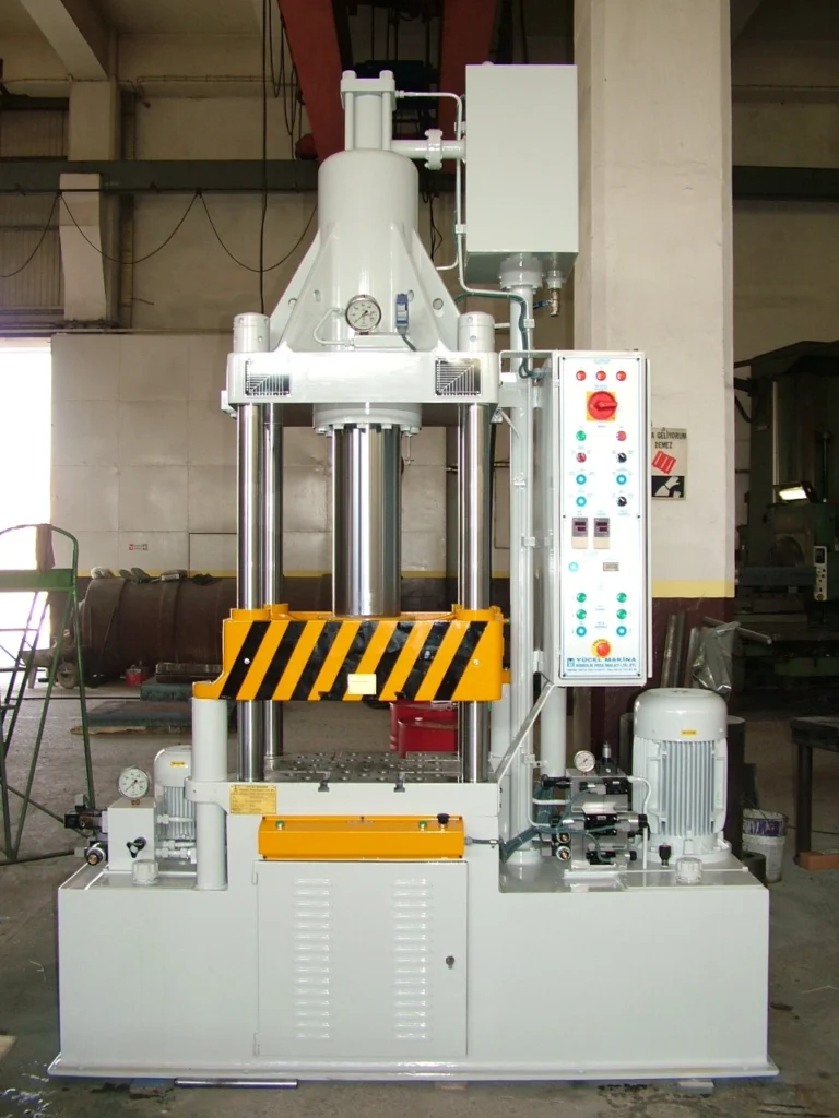
4-Column Presses:** 4-column presses provide exceptional stability and precision, making them ideal for high-precision forming and stamping operations. They feature four vertical columns that support the frame and ensure uniform force distribution.
Applications of Hydraulic Metal Presses
Hydraulic metal presses are used in a wide range of applications, including:
- Bending: Hydraulic presses are commonly used to bend sheet metal into various shapes, such as boxes, enclosures, brackets, and channels.
- Forming: Hydraulic presses can form complex shapes in sheet metal, such as curves, domes, and flanges.
- Stamping: Hydraulic presses are used to stamp out metal parts from sheet metal blanks. Stamping is used to create components with intricate details and precise dimensions.
- Assembling: Hydraulic presses can be used to assemble metal components by pressing them together or inserting fasteners.
- Coining: Hydraulic presses can be used for coining operations, where metal is compressed into a die to create detailed designs or patterns.
Benefits of Using Hydraulic Metal Presses
Hydraulic metal presses offer several advantages over other metal forming methods:
- Precision: Hydraulic presses provide precise and consistent bending and forming operations.
- Force Control: Hydraulic presses allow for controlled application of force, ensuring uniform shaping and minimizing material damage.
- Versatility: Hydraulic presses can be used for a wide range of operations, from simple bending to complex forming and stamping.
- Efficiency: Hydraulic presses offer rapid cycle times, making them efficient for production environments.
- Safety: Hydraulic presses are designed with safety features to protect operators from hazards.
Safety Precautions for Hydraulic Metal Presses
When operating a hydraulic metal press, it is crucial to follow safety precautions to prevent injuries:
- Proper Training: Operators should receive proper training on the operation and safety procedures of the hydraulic press.
- Protective Gear: Wear safety glasses, gloves, and appropriate clothing to protect against flying debris and potential hazards.
- Secure Workpiece: Secure the workpiece firmly to the press bed to prevent movement during operation.
- Maintain Clearance: Keep hands and body clear of moving parts of the press.
- Emergency Stop: Be familiar with the location and operation of the emergency stop button.
- Regular Maintenance: Conduct regular maintenance and inspections to ensure the press is in proper working condition.
Conclusion
Hydraulic metal presses are powerful and versatile tools that play a vital role in various industries. Their ability to apply precise and controlled force makes them ideal for shaping and forming metal sheets into various components. By following proper safety precautions and operating techniques, hydraulic metal presses can be used safely and efficiently to produce high-quality metal parts.
Application Areas
Hydraulic metal presses are used in a wide range of applications, including:
Metal fabrication: Hydraulic presses are commonly used to bend, form, and stamp sheet metal into various components for metal fabrication projects. They are used to create parts for various industries, such as automotive, construction, aerospace, and appliance manufacturing.
Automotive industry: Hydraulic presses are essential tools in the automotive industry, used to produce various components such as body panels, structural supports, and trim pieces. They are also used for stamping out parts such as brackets, hinges, and fasteners.
Construction industry: Hydraulic presses are used in the construction industry to form and shape metal components for structures, such as beams, columns, and roof trusses. They are also used to manufacture components for construction equipment, such as cranes, bulldozers, and excavators.
Aerospace industry: Hydraulic presses play a crucial role in the aerospace industry, used to produce high-precision components for aircraft and spacecraft. They are used for forming and shaping complex shapes in lightweight materials such as aluminum, titanium, and composites.
Appliance manufacturing: Hydraulic presses are widely used in appliance manufacturing to produce components for various appliances, such as refrigerators, ovens, washing machines, and dishwashers. They are used for bending, forming, and stamping sheet metal components.
Electronics industry: Hydraulic presses are used in the electronics industry to create enclosures for electronic devices, such as computers, telecommunications equipment, and consumer electronics. They are also used to form and shape metal components within electronic devices.
Powder metallurgy: Hydraulic presses are used in powder metallurgy to compact and form metal powders into various shapes. This process is used to produce components with high density, precise dimensions, and complex geometries.
Recycling and scrap metal processing: Hydraulic presses are used in recycling and scrap metal processing to compact and compress scrap metal for easier transportation and processing. They are also used to separate different types of scrap metal based on their properties.
These are just a few examples of the many application areas of hydraulic metal presses. Their versatility and ability to apply precise force make them valuable tools in a wide range of industries.
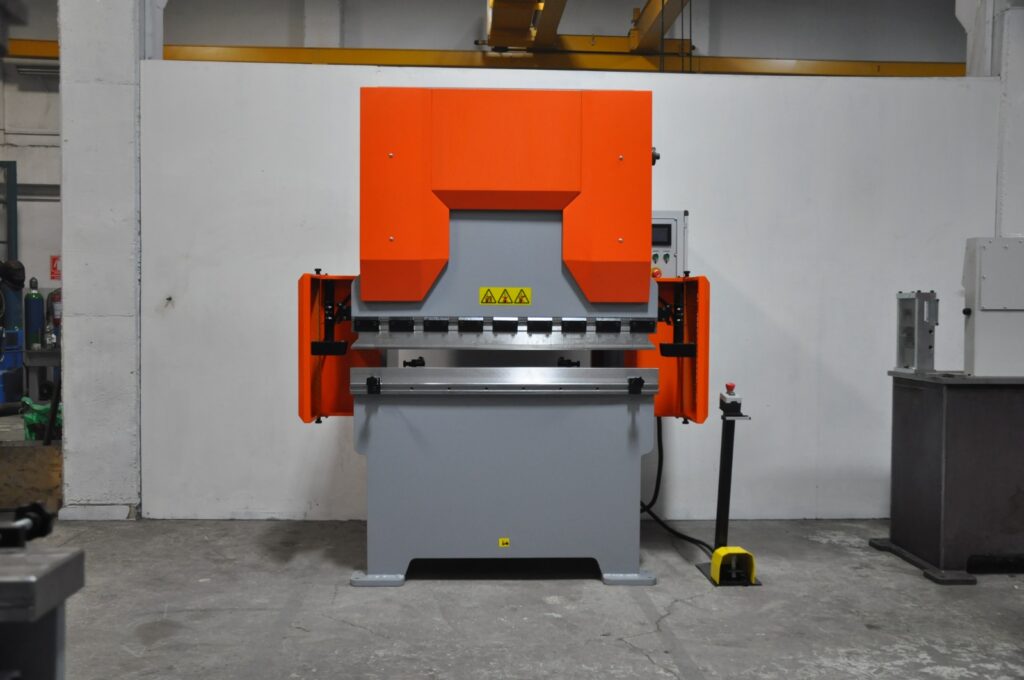
A small press brake machine is a compact tool used for bending sheet metal into various shapes. It’s ideal for small-scale operations or workshops with limited space. Here’s a basic rundown of what to look for and expect:
Key Features:
- Capacity: Check the maximum bending length and thickness it can handle. Small machines are often used for lighter and thinner materials.
- Controls: Modern machines may have manual, hydraulic, or even CNC controls for precision.
- Tooling: Look at the types of dies and punches included or available, as these determine the range of shapes and angles you can create.
- Frame and Build: Ensure it’s robust enough for your needs while still being compact.
- Safety Features: Safety guards and emergency stops are crucial for safe operation.
Applications:
- Prototype Development: Useful for making small runs or prototypes with custom bends.
- Small Batch Production: Ideal for low-volume production runs.
- DIY Projects: Great for hobbyists or small business owners.
Do you need specific recommendations or have any particular requirements for your projects?
A small press brake machine for sheet metal bending consists of several key components that work together to achieve precise bends. Here’s an overview of the main components:
1. Frame
- Description: The frame is the backbone of the press brake, providing structural support and stability. It is typically made of heavy-duty steel to withstand the forces involved in bending.
- Importance: A sturdy frame ensures accuracy and prevents deformation during operation.
2. Ram (or Slide)
- Description: The ram is the moving part of the press brake that holds the upper die and moves vertically to apply force to the sheet metal.
- Types: Can be powered by manual, hydraulic, mechanical, or electric systems, depending on the type of press brake.
- Importance: The ram’s movement and force application are crucial for precise bending.
3. Bed
- Description: The bed is the fixed part of the press brake that holds the lower die. It provides a stable surface against which the sheet metal is bent.
- Importance: The bed must be level and sturdy to ensure accurate bends.
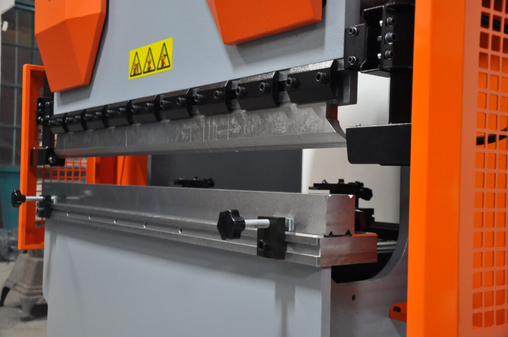
4. Punch and Die
- Punch: The tool attached to the ram that presses the sheet metal into the die.
- Die: The tool attached to the bed that shapes the metal as the punch presses into it.
- Types: Different shapes and sizes for various bending operations (e.g., V-dies, U-dies, offset dies).
- Importance: The choice of punch and die determines the bend shape and angle.
5. Back Gauge
- Description: A mechanical or computerized device that positions the sheet metal accurately for bending.
- Function: Allows for precise placement and repeatability in bends.
- Importance: Ensures consistency in multi-bend operations.
6. Control System
- Manual Controls: Levers and dials used for simple operations.
- CNC Controls: Computerized systems that allow for complex programming and automation of bends.
- Importance: The control system impacts ease of use, precision, and efficiency.
7. Foot Pedal or Control Panel
- Description: A user interface for operating the press brake, typically used to control the movement of the ram.
- Function: Allows the operator to start and stop the bending process safely.
- Importance: Ensures safety and precision in operation.
8. Safety Features
- Safety Guards: Protective barriers to prevent accidental contact with moving parts.
- Emergency Stop Button: Allows for immediate cessation of machine operation in case of emergency.
- Light Curtains or Laser Guards: Sensors that stop the machine if they detect an obstruction in the bending area.
- Importance: Safety features are crucial to protect operators from injury.
9. Hydraulic System (if applicable)
- Description: In hydraulic press brakes, this system uses fluid pressure to move the ram.
- Components: Includes hydraulic pumps, valves, and cylinders.
- Importance: Provides smooth and adjustable force for precise bending.
10. Motor and Drive System
- Description: Powers the movement of the ram and other mechanical components.
- Types: Can be electric or hydraulic, depending on the machine type.
- Importance: Ensures efficient and consistent machine operation.
Conclusion
Understanding these components will help you select the right press brake for your specific needs and ensure proper operation and maintenance. If you have further questions about any of these components or need advice on a specific model, feel free to ask!
Press brakes are machines used to bend and shape sheet metal, and they come in various types to suit different applications and requirements. Each type of press brake has unique characteristics and advantages. Here’s a detailed overview of the main types of press brakes:
1. Mechanical Press Brakes
Description
- Mechanical press brakes use a flywheel powered by an electric motor. The energy stored in the flywheel is transferred to the ram through a clutch and crank mechanism, providing precise and consistent force.
Advantages
- Speed: They are generally faster than hydraulic press brakes, making them suitable for high-production environments.
- Precision: Offers precise control over the bending process, ensuring consistent results.
- Cost-Effective: Often more affordable than other types, both in terms of purchase price and maintenance.
Disadvantages
- Limited Flexibility: Not as versatile as hydraulic models, especially for complex bends.
- Maintenance: Requires regular maintenance of mechanical components like the clutch and crank.
Applications
- Ideal for repetitive tasks and high-volume production of simpler bends.
2. Hydraulic Press Brakes
Description
- Hydraulic press brakes use hydraulic cylinders to move the ram. The hydraulic fluid is pumped into the cylinders, creating pressure that moves the ram downwards for bending.
Advantages
- Versatility: Can handle a wide range of materials and bend angles, including complex and acute bends.
- Adjustable Force: Allows for precise control over the bending force, making it suitable for various materials and thicknesses.
- Safety: Often equipped with advanced safety features and overload protection.
Disadvantages
- Speed: Generally slower than mechanical press brakes.
- Cost: Higher initial cost and maintenance expenses due to hydraulic components.
Applications
- Suitable for a variety of bending tasks, from simple to complex, and used in industries requiring versatility and precision.
3. Pneumatic Press Brakes
Description
- Pneumatic press brakes use compressed air to move the ram. They are generally used for lighter and less demanding applications.
Advantages
- Simplicity: Easier to operate and maintain than hydraulic and mechanical press brakes.
- Cost-Effective: Lower initial and operational costs.
- Environmentally Friendly: Uses air, which is more eco-friendly than hydraulic fluid.
Disadvantages
- Limited Force: Not suitable for heavy-duty applications or thick materials.
- Precision: Less precise compared to hydraulic or mechanical press brakes.
Applications
- Best for light-duty applications and smaller workshops that work with thinner materials.
4. Electric Press Brakes
Description
- Electric press brakes, also known as servo-electric press brakes, use electric motors and ball screws to move the ram.
Advantages
- Efficiency: Highly energy-efficient, consuming power only during operation.
- Precision: Offers excellent accuracy and repeatability in bends.
- Environmentally Friendly: Does not require hydraulic fluid, reducing environmental impact.
Disadvantages
- Cost: Typically more expensive than mechanical or hydraulic models.
- Limited Force: May not be suitable for very heavy-duty applications compared to hydraulic models.
Applications
- Ideal for precision work in industries like electronics, aerospace, and automotive, where accuracy is crucial.
5. CNC Press Brakes
Description
- CNC (Computer Numerical Control) press brakes use computerized controls to automate the bending process. They can be either hydraulic, mechanical, or electric.
Advantages
- Automation: Allows for automated and highly precise bending, reducing manual intervention.
- Versatility: Can handle complex bending tasks with ease, including multi-axis operations.
- Efficiency: Reduces setup time and increases production speed and consistency.
Disadvantages
- Cost: Higher initial investment and maintenance costs due to advanced technology.
- Complexity: Requires skilled operators to program and manage the CNC system.
Applications
- Used in high-precision industries for complex and varied bending tasks, including aerospace, automotive, and manufacturing.
6. Hydro-Mechanical Press Brakes
Description
- Hydro-mechanical press brakes combine hydraulic and mechanical systems. They use a hydraulic system to drive a mechanical linkage, providing the force for bending.
Advantages
- Power: Provides high bending force, suitable for heavy-duty applications.
- Control: Offers precise control over bending operations, similar to hydraulic press brakes.
Disadvantages
- Complexity: More complex than purely mechanical or hydraulic systems, requiring skilled maintenance.
- Cost: Typically more expensive due to the combined system.
Applications
- Suitable for heavy-duty applications requiring both power and precision.
Comparison Summary
| Type | Advantages | Disadvantages | Applications |
|---|---|---|---|
| Mechanical | Fast, precise, cost-effective | Limited flexibility, requires maintenance | High-volume, repetitive tasks |
| Hydraulic | Versatile, adjustable force, safe | Slower, higher cost | Complex bending tasks in various industries |
| Pneumatic | Simple, cost-effective, eco-friendly | Limited force, less precise | Light-duty applications with thin materials |
| Electric | Efficient, precise, eco-friendly | Expensive, limited force | Precision work in electronics, aerospace, etc. |
| CNC | Automated, versatile, efficient | Expensive, complex | High-precision tasks in aerospace, automotive |
| Hydro-Mechanical | Powerful, controlled bending | Complex, expensive | Heavy-duty applications requiring precision |
Conclusion
Choosing the right type of press brake depends on your specific needs, including the type of materials, the complexity of the bends, production volume, and budget constraints. If you need further assistance in selecting a press brake for your specific application, feel free to ask!
General Maintenance Tips
1. Regular Cleaning
- Daily Cleaning: Clean the machine surfaces and components daily to remove dust, metal shavings, and debris. Use a soft brush or cloth to clean sensitive areas.
- Lubrication: Lubricate all moving parts regularly according to the manufacturer’s specifications. This includes the ram, guide rails, and back gauge.
- Hydraulic System: Check for hydraulic fluid leaks and ensure that the hydraulic oil is clean and at the correct level.
2. Inspection and Monitoring
- Visual Inspection: Conduct a visual inspection of the machine before and after each use. Look for signs of wear, damage, or misalignment.
- Check Bolts and Fasteners: Ensure that all bolts, nuts, and fasteners are tight and secure. Loose components can lead to misalignment and damage.
- Monitor Performance: Pay attention to any unusual noises or changes in machine performance, which may indicate potential issues.
3. Electrical System Checks
- Wiring Inspection: Regularly inspect the wiring and electrical connections for signs of wear or damage. Replace any damaged wires immediately.
- Control Panel: Ensure that the control panel and buttons are functioning correctly. Test all safety switches and emergency stop buttons to verify they work properly.
4. Hydraulic System Maintenance
- Oil Quality and Level: Check the hydraulic oil regularly for contamination or degradation. Replace the oil according to the manufacturer’s recommendations.
- Hydraulic Filters: Inspect and replace hydraulic filters as needed to prevent contamination and ensure optimal system performance.
- Check for Leaks: Inspect hoses, seals, and connections for leaks. Repair or replace any faulty components immediately.
5. Tooling Maintenance
- Die and Punch Inspection: Inspect the dies and punches for wear or damage. Ensure they are properly aligned and seated in the machine.
- Tooling Alignment: Regularly check the alignment of the tooling to prevent uneven wear and ensure accurate bends.
- Storage: Store dies and punches in a clean, dry environment to prevent rust and damage.
6. Calibration and Adjustment
- Back Gauge Calibration: Regularly calibrate the back gauge to ensure precise positioning and accurate bends.
- Ram Alignment: Check and adjust the ram alignment periodically to maintain consistent bending accuracy.
- CNC System Calibration: If using a CNC press brake, regularly update and calibrate the CNC system to ensure accurate programming and operation.
Specific Maintenance Tips for Different Types of Press Brakes
Mechanical Press Brakes
- Clutch and Brake Maintenance: Regularly inspect and adjust the clutch and brake mechanisms for wear. Replace any worn components as needed.
- Flywheel Inspection: Check the flywheel for cracks or damage and ensure it spins smoothly without wobbling.
Hydraulic Press Brakes
- Hydraulic Cylinder Inspection: Regularly check the hydraulic cylinders for leaks or damage and ensure they operate smoothly.
- Pressure Settings: Verify that the hydraulic pressure settings are within the manufacturer’s specifications.
Pneumatic Press Brakes
- Air Compressor Maintenance: Regularly inspect and maintain the air compressor, checking for leaks or damage.
- Air Filter Replacement: Replace air filters as needed to ensure clean and efficient air supply.
Electric Press Brakes
- Servo Motor Maintenance: Inspect and maintain servo motors, ensuring they are clean and operating efficiently.
- Ball Screw Inspection: Regularly check ball screws for wear and ensure proper lubrication.
Safety Considerations
- Training: Ensure that all operators are adequately trained in the safe operation and maintenance of the press brake.
- Safety Devices: Regularly test safety devices, such as light curtains, laser guards, and emergency stop buttons, to ensure they function correctly.
- Personal Protective Equipment (PPE): Require operators to wear appropriate PPE, such as gloves, safety glasses, and steel-toed boots.
Scheduled Maintenance
- Daily Maintenance: Perform basic cleaning, inspection, and lubrication tasks daily.
- Weekly Maintenance: Conduct more thorough inspections, including checking hydraulic oil levels and electrical connections.
- Monthly Maintenance: Perform comprehensive inspections, including calibration and alignment checks.
- Annual Maintenance: Schedule a professional service technician to conduct a detailed inspection and maintenance of the machine.
Conclusion
Regular maintenance of press brakes is essential to ensure safe and efficient operation. By following these tips and adhering to the manufacturer’s maintenance schedule, you can extend the life of your press brake and reduce the risk of unexpected breakdowns. If you have any specific maintenance questions or need further assistance, feel free to ask!
Installation Tips for Press Brake Machines

1. Site Preparation
Space Requirements
- Measure the Area: Ensure that the installation area is large enough to accommodate the press brake, including space for operators and maintenance access. Consider the dimensions of the machine and the bending material.
- Ceiling Height: Verify that the ceiling height is sufficient to allow for the full range of motion of the press brake’s ram and any required overhead clearances.
Floor Requirements
- Level Surface: The floor should be level and able to support the weight of the press brake and any associated loads. Use a level to check the surface.
- Foundation: For larger machines, consider a reinforced concrete foundation to prevent vibrations and ensure stability. Follow the manufacturer’s specifications for foundation thickness and reinforcement.
Environmental Conditions
- Temperature and Humidity: The installation area should have a controlled environment to prevent rust and corrosion. Extreme temperatures or humidity levels can affect machine performance.
- Ventilation: Ensure adequate ventilation to remove heat generated by the machine and prevent overheating.
2. Electrical and Power Requirements
Electrical Supply
- Voltage and Amperage: Check the machine’s electrical specifications for required voltage, amperage, and phase. Ensure that the power supply matches these requirements.
- Wiring and Circuit Breakers: Install appropriate wiring and circuit breakers to handle the machine’s electrical load. Use a licensed electrician to ensure compliance with local codes and standards.
Grounding
- Proper Grounding: Ensure the machine is properly grounded to prevent electrical shocks and equipment damage. Use appropriate grounding rods and wires.
3. Hydraulic and Pneumatic Systems
Hydraulic System
- Hydraulic Fluid: Fill the hydraulic system with the recommended hydraulic fluid. Check for leaks and ensure that all hoses and fittings are secure.
- Pressure Settings: Set the hydraulic pressure according to the manufacturer’s specifications. Adjust pressure relief valves as needed.
Pneumatic System (if applicable)
- Air Supply: Ensure a clean, dry air supply for pneumatic systems. Install air filters and dryers to remove moisture and contaminants.
4. Machine Setup and Alignment
Positioning
- Alignment: Use a precision level and alignment tools to ensure the press brake is properly aligned. Check that the ram and bed are parallel and that the back gauge is aligned correctly.
- Anchor the Machine: Secure the press brake to the foundation or floor using anchor bolts, following the manufacturer’s guidelines.
Tooling Installation
- Die and Punch Installation: Carefully install the dies and punches, ensuring they are correctly seated and aligned. Use the correct tools and follow the manufacturer’s instructions for safe installation.
5. Control System Setup
CNC System Initialization (if applicable)
- Software Installation: Install any required software and updates for CNC systems. Ensure compatibility with the control unit.
- Calibration: Calibrate the CNC system, including the back gauge and ram, to ensure accurate operation.
Manual Control Setup
- Control Panel Inspection: Verify that all buttons, switches, and indicators are functioning correctly. Check for any loose connections.
6. Safety Features and Devices
Safety Guards
- Install Guards: Install any provided safety guards, barriers, and light curtains to protect operators from moving parts and pinch points.
- Test Safety Devices: Test all safety devices, such as emergency stop buttons and interlocks, to ensure they function correctly.
Operator Safety Training
- Training Programs: Provide comprehensive training for operators, covering machine operation, safety procedures, and emergency response.
7. Testing and Calibration
Initial Testing
- Test Runs: Conduct initial test runs using scrap material to verify machine performance and accuracy. Check for alignment issues or mechanical problems.
- Adjustments: Make any necessary adjustments to the ram, back gauge, and tooling alignment to ensure accurate bending.
Calibration Checks
- Precision Calibration: Use precision measuring tools to check the accuracy of bends. Adjust settings as needed to achieve desired results.
8. Documentation and Compliance
Manufacturer’s Manual
- Review Documentation: Thoroughly review the manufacturer’s manual and installation guidelines to ensure compliance with all requirements.
- Warranty Registration: Register the machine’s warranty with the manufacturer and keep records of installation and maintenance activities.
Regulatory Compliance
- Local Codes and Standards: Ensure that the installation complies with local building codes, electrical standards, and safety regulations.
Conclusion
Proper installation of a press brake machine is essential for safe and efficient operation. By following these detailed installation tips and adhering to the manufacturer’s instructions, you can ensure a successful setup and minimize the risk of issues during operation. If you have any specific questions or need further assistance, feel free to ask!