
Hydraulic Deep Drawing Presses for Deep Draw Applications: Deep Drawing Presses are specialized machines used in metal forming processes to produce hollow-shaped components from flat sheet metal (called blanks). The process is called “deep drawing” because the depth of the drawn part is typically greater than its diameter.
What Is Deep Drawing?
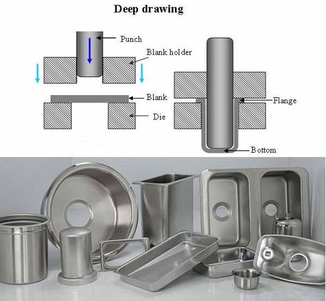
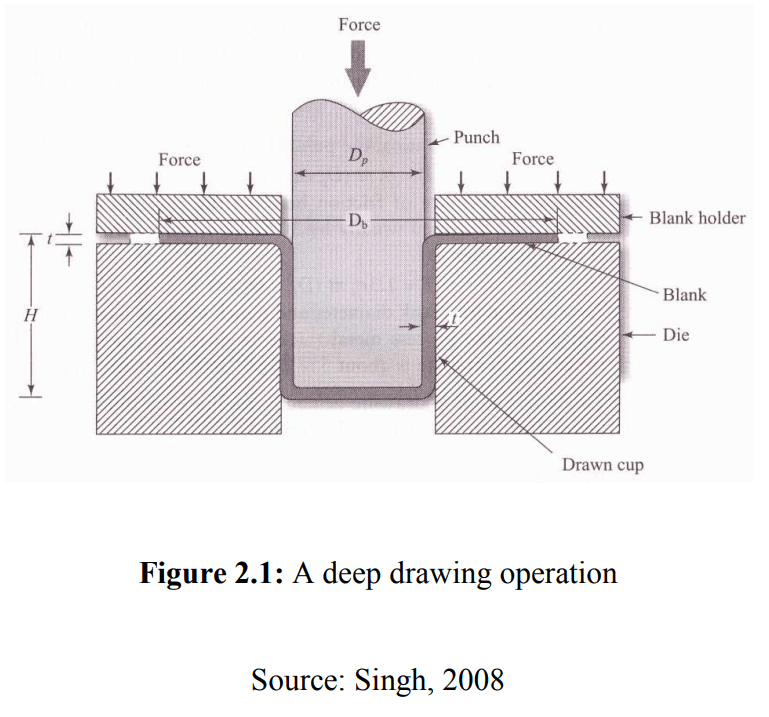
Deep drawing is a cold forming process where a punch forces a sheet metal blank into a die cavity, transforming it into a desired shape — usually cylindrical, box-shaped, or complex contours. It’s commonly used to make automotive parts, kitchen sinks, cans, and appliance housings.
Types of Deep Drawing Presses
- Hydraulic Presses
- Use fluid pressure to generate force.
- Offer adjustable stroke and pressure.
- Ideal for deep and complex parts.
- Slower but more flexible.
- Mechanical Presses
- Operated by crankshaft and flywheel systems.
- Faster than hydraulic presses.
- Best for shallow to medium-depth drawing.
- Less flexible in stroke control.
- Double Action Presses
- Have two rams: one for the blank holder and another for the punch.
- Provide better control over material flow.
- Minimize wrinkles and tearing.
- Servo Presses
- Use servo motors for precise control.
- Highly programmable, energy efficient.
- Good for complex forming operations with tight tolerances.
Key Components
- Punch: Shapes and pushes the blank into the die.
- Die: The cavity into which the metal is drawn.
- Blank Holder (or Binder): Applies pressure to hold the blank in place and prevent wrinkling.
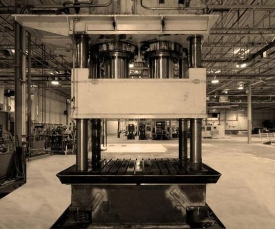
- Press Frame: Supports the entire mechanism and absorbs the forming force.
- Slide or Ram: Carries the punch vertically.
Applications of Deep Drawing Presses
- Automotive: Body panels, fuel tanks, exhaust components.
- Aerospace: Structural components, housings.
- Consumer Goods: Kitchenware, appliances, metal containers.
- Electronics: Enclosures, shields.
Advantages
- High production rates.
- Minimal material waste.
- Excellent surface finish and dimensional accuracy.
- Stronger parts due to work hardening.
Challenges
- Risk of defects like wrinkling, tearing, or earing.
- Requires precise die design and lubrication.
- Limited to ductile materials like aluminum, brass, or low-carbon steel.
Deep drawing presses are essential machines used in metal forming to create hollow, cup-like, or box-shaped components from flat sheet metal. The process involves placing a metal blank over a die and then using a punch to push the metal into the die cavity, causing the material to plastically deform and assume the shape of the die. The operation is called “deep” drawing when the depth of the part exceeds its diameter, and it’s a widely used technique in industries such as automotive, aerospace, household appliances, and electronics.
There are several types of presses used for deep drawing. Hydraulic presses are preferred for their flexibility and ability to apply uniform pressure throughout the stroke, which is especially useful for forming deep or complex parts. They allow precise control of both force and speed but are typically slower than other types. Mechanical presses, driven by a crankshaft and flywheel mechanism, are faster and often used for high-volume production of simpler parts. However, their fixed stroke characteristics limit their adaptability. Double action presses, which feature two independently controlled slides—one for the blank holder and one for the punch—allow better material flow control, reducing the chances of defects like wrinkling or tearing. Servo presses, which use servo motors instead of conventional drive systems, offer the highest degree of control, allowing the user to program ram speeds and positions throughout the stroke for optimal forming conditions.
In all these presses, the essential components include the punch, which shapes the material; the die, which defines the final form; the blank holder, which prevents the metal from wrinkling during the draw; and the press frame, which absorbs the forming forces. Precision in die and punch design, lubrication, and blank holding force is crucial for avoiding common defects like tearing, wrinkling, or earing. The material used must have good ductility—typical choices include low-carbon steels, aluminum, and brass—so it can stretch without breaking under the punch force.
Deep drawing presses are valued for their ability to produce strong, seamless components with excellent surface finish and tight dimensional tolerances. They are suitable for mass production, offering low material waste and relatively low per-part cost once tooling is set up. However, successful operation requires careful attention to process parameters such as punch speed, lubrication, blank size, and die radii to ensure high quality and consistency.
The efficiency and outcome of deep drawing depend heavily on the press setup and process parameters. One key parameter is the drawing ratio, which is the ratio of the blank diameter to the punch diameter. If this ratio is too high, the blank may tear during the drawing process. If it’s too low, excessive material may lead to wrinkling. Generally, a drawing ratio below 2 is considered safe for a single draw. For deeper parts, multiple drawing stages—known as redrawing—may be required, each gradually shaping the part without overstraining the material.
Another crucial factor is lubrication. Proper lubrication reduces friction between the die, blank holder, and the sheet metal, allowing smooth material flow and minimizing tool wear. Common lubricants include oil-based, soap-based, or synthetic compounds, and the choice depends on the material being formed and the press type. In some advanced setups, cushions or cushion pins are integrated to apply controlled blank-holding force, further improving draw quality.
Tooling design plays a central role in deep drawing success. Die corners must have adequate radii to allow smooth metal flow and prevent sharp bends that could cause cracks. Punches must be rigid and wear-resistant, typically made from hardened tool steels or coated carbides for durability. For complex shapes or tighter tolerances, simulation software may be used to optimize tooling geometry and material behavior before production.
With the push toward automation and higher efficiency, many deep drawing presses are integrated into automated production lines. Sheet metal blanks can be fed automatically, and finished parts ejected and conveyed downstream with minimal human intervention. Sensors and control systems monitor pressure, position, and temperature in real-time, ensuring consistent output and alerting operators to potential issues before defects occur.
Despite its many advantages, deep drawing is not suitable for all part geometries. Parts with sharp corners, very deep sections, or non-uniform wall thickness can be challenging or even impossible to draw in one stage. In such cases, alternative methods like hydroforming or incremental sheet forming may be considered. Still, when the design is compatible, deep drawing offers a highly economical solution for producing large quantities of uniform, durable metal components with excellent structural integrity.
Deep Drawing Presses for Kitchen Sinks
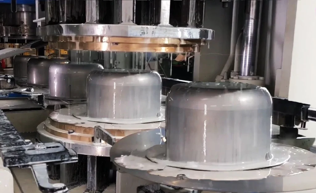
Deep drawing presses are widely used in the manufacture of stainless steel kitchen sinks, a process that demands precision, consistency, and surface quality. The basic principle remains the same: a flat sheet (usually stainless steel) is pressed into a die using a punch to form the deep, bowl-like cavity of a sink. However, due to the specific requirements of kitchen sinks—such as deep draws, smooth finishes, and corrosion resistance—the equipment and process are specially configured for this application.
Hydraulic deep drawing presses are the most commonly used type for kitchen sink production because they offer adjustable force and stroke control, essential for forming deep and complex shapes without tearing or wrinkling the material. These presses can apply consistent pressure throughout the drawing cycle, which is particularly important when working with stainless steel sheets, typically in the 0.6 mm to 1.2 mm thickness range.
The sink is often formed in multiple stages. The first draw creates the general depth and shape. Subsequent redraws or ironing processes refine the shape, improve wall thickness uniformity, and achieve the final dimensions. Each stage may require a different set of dies and precise blank holding force to control material flow. If the blank holder force is too low, wrinkling can occur around the flange; if it’s too high, tearing or thinning in the corner radius may result.
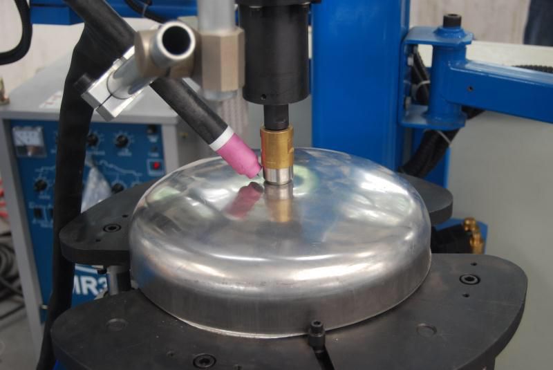
To maintain a high-quality surface finish, which is critical for consumer appeal in kitchen sinks, the tooling surfaces are polished, and high-quality lubrication is used during forming. Lubricants help reduce die wear and prevent galling, a common issue when forming stainless steel. After forming, sinks typically undergo trimming, edge finishing, and polishing, and in some designs, secondary processes like welding or sound-deadening coating application.
Double-action hydraulic presses are often employed, featuring one cylinder for the punch and another for the blank holder. This configuration allows simultaneous control of the two forces, optimizing the deep drawing process. Additionally, many sink manufacturing lines incorporate automated feeding systems, robotic arm handling, and conveyor integration to increase throughput and reduce labor.
In summary, deep drawing presses for kitchen sinks must provide high force, precise control, and smooth operation to handle stainless steel sheets efficiently. The combination of hydraulic technology, multi-stage tooling, and automation allows manufacturers to produce large volumes of uniform, durable, and aesthetically pleasing sinks at competitive costs.
In the production of stainless steel kitchen sinks, the deep drawing process begins with a flat blank, usually cut from a coil of stainless steel. This blank is centered over the die, and a punch moves downward to draw the sheet into the die cavity. Because sinks typically have significant depth relative to their width, the material must undergo substantial deformation, making it crucial to manage strain distribution carefully. To prevent defects like thinning, tearing, or wrinkling, manufacturers carefully control the speed of the punch, the force of the blank holder, and the radii of the die and punch corners.
The first draw forms the basic shape of the sink bowl, but this shape is usually not sufficient in one step. The material’s work hardening during the first draw limits further deformation unless intermediate annealing or redraw steps are applied. Redrawing stages further deepen and refine the shape without compromising the material’s integrity. These stages may involve ironing, a process where the walls are thinned slightly and made more uniform, improving both structural strength and appearance. The final drawn sink typically has a flange at the top, which allows it to be mounted into a countertop or under-mounted from below.
Because consumer expectations for kitchen sinks are high in terms of appearance and durability, the internal surfaces of the sink must be smooth and free of marks. To ensure this, both the punch and die are precision-polished, and high-performance lubricants are applied during drawing to minimize friction and surface defects. Post-forming operations often include trimming excess material from the flange, punching drain holes, and polishing or brushing the sink surface for the final finish. Some sinks also receive sound-deadening coatings or pads on the underside to reduce noise from water impact.
In a production environment, this entire process is highly automated. Blank feeding systems position the sheet metal precisely, while hydraulic or servo-driven presses handle the drawing and redrawing operations. Robotic arms or automatic conveyors transport the parts between stages. Quality control systems—often vision-based or using laser measuring tools—inspect each sink for defects in geometry, surface finish, or dimensional accuracy. The entire workflow is designed for high throughput, minimal human intervention, and consistent part quality.
Because the tool sets for drawing kitchen sinks are expensive and require careful maintenance, the initial investment is high, but the process becomes very economical at high volumes. Tool life is extended through hard coatings and periodic re-polishing. For manufacturers, the key benefits of using deep drawing presses in this context are the ability to produce complex sink shapes from a single sheet with no welding, resulting in seamless, hygienic, and corrosion-resistant products that meet both functional and aesthetic demands in household and commercial kitchens.
The choice of stainless steel as the material for kitchen sinks is driven not just by its corrosion resistance but also by its formability and aesthetic qualities. Austenitic grades such as AISI 304 are preferred due to their excellent ductility, allowing deep draws without cracking, and their ability to achieve a smooth, bright surface finish that resists stains and scratches. These properties make stainless steel highly compatible with the deep drawing process, although its tendency to harden during forming requires careful process control to avoid excessive strain or springback.
As production scales increase, manufacturers often design and use progressive dies or transfer systems. In progressive die setups, multiple operations like drawing, trimming, and hole punching are carried out in a single press cycle, with the blank moving from one station to the next. Transfer systems, on the other hand, involve robotic or mechanical arms moving the part between sequential forming stages. These methods significantly increase productivity and reduce the need for manual intervention, ensuring uniformity and repeatability in each part produced.
Sound dampening is an important consideration in the final stages of sink production. After forming, many sinks are fitted with rubber pads or sprayed with a damping compound on the underside. This step is essential for absorbing vibration and reducing the metallic ringing noise produced by water or dish impact, especially in thinner gauge sinks. This post-processing does not interfere with the structural integrity of the formed bowl and is often performed on the same automated line as the forming and finishing processes.
Tooling maintenance is critical in the deep drawing of kitchen sinks. Even small imperfections in the die or punch surface can leave marks on the final sink, which are not acceptable in consumer products. Regular inspection and re-polishing of tooling surfaces, along with strict lubrication control, are essential to maintain the required finish quality and extend tool life. In some operations, the tools are coated with hard materials like titanium nitride (TiN) to reduce wear and galling, especially when drawing large quantities of high-hardness stainless steel.
From a design standpoint, sink shapes must be optimized for manufacturability. Sharp corners, steep sidewalls, or irregular contours are difficult to achieve in a single draw and may require redesign or additional forming steps. Radii in the corners of the die and punch must be generous enough to allow smooth material flow while also meeting design expectations for modern, angular sink profiles. Engineers often use finite element analysis (FEA) simulations to predict how the metal will behave during forming, helping to optimize tooling and avoid trial-and-error in physical prototyping.
In conclusion, the deep drawing press plays a central role in transforming flat stainless steel blanks into fully formed kitchen sinks, combining power, precision, and speed in a tightly controlled manufacturing environment. The process balances high-strength material deformation, strict surface quality standards, and complex geometries, all while minimizing waste and maximizing throughput. Through continuous advancements in press technology, automation, and tooling design, manufacturers can produce millions of high-quality sinks annually, meeting both industrial efficiency and consumer expectations.
Hydraulic Presses for Cylindrical Cups
Hydraulic presses are especially well-suited for manufacturing cylindrical cups through the deep drawing process due to their ability to apply consistent, adjustable force and accommodate the gradual shaping required for deep or symmetrical parts. The goal in cup drawing is to convert a flat metal blank into a seamless, round-bottomed, vertical-walled container—often used as intermediate components in cans, battery casings, or pressure vessels.
In a typical setup, a round blank is placed over the die cavity. The hydraulic press activates a blank holder that clamps the sheet to control material flow, then the punch descends at a controlled speed to press the material into the die. The pressure is uniform and constant, a key advantage of hydraulic systems, especially for thin-walled or deep cylindrical shapes where precise force distribution prevents tearing or wrinkling. Unlike mechanical presses, hydraulic presses do not rely on a fixed stroke profile; their stroke length, speed, and force can be adjusted during operation, making them highly versatile.
The formation of a cylindrical cup may require multiple drawing stages depending on the desired height-to-diameter ratio. Higher ratios mean the material must flow more, increasing the risk of thinning or cracking. In such cases, redrawing is performed using modified dies with slightly smaller diameters, allowing the cup to deepen incrementally. Between stages, the component may undergo annealing to relieve work hardening.
Material selection is critical. Common choices include aluminum, low-carbon steels, and stainless steel, all of which have high ductility and good drawability. Lubrication is also vital to minimize friction between the die, punch, and blank. Specialized drawing oils or synthetic lubricants help maintain surface integrity and reduce tool wear.
Hydraulic presses often incorporate die cushions or active blank holders that can apply variable force during the press cycle. These features are essential in maintaining control over flange movement, especially for deep cups. For cylindrical geometry, maintaining a consistent wall thickness and avoiding defects like earing—a wavy edge caused by anisotropy in the metal sheet—requires attention to blank quality and press settings.
Because cup drawing benefits from gradual forming and accurate pressure control, hydraulic presses are the preferred choice for low to medium production volumes or when working with complex geometries. For high-speed, high-volume cup production, such as beverage cans, mechanical presses are sometimes used with additional optimization to compensate for their less flexible operation. However, for precision work, prototyping, or varied product lines, hydraulic presses remain the industry standard for cylindrical cup drawing.
Hydraulic presses offer a level of control that is essential for forming cylindrical cups, especially when dealing with deep draws or materials that are sensitive to strain. Unlike mechanical presses, which operate with a fixed stroke and force curve, hydraulic systems can maintain a constant pressure throughout the forming cycle and adjust both the speed and force of the punch in real time. This adaptability is crucial when forming cups with high aspect ratios, where the material needs to stretch significantly without thinning to the point of failure. The press can slow down during critical moments of deformation, particularly as the punch enters deeper into the die cavity, ensuring smoother material flow and minimizing the chances of wrinkling or tearing.
The blank holder plays a vital role in the drawing process. In cup formation, if the holder force is too low, the flange may buckle and form wrinkles; if it’s too high, the material may not flow adequately, leading to tearing near the cup wall. Hydraulic presses equipped with programmable or active blank holders can dynamically adjust this force throughout the stroke, offering a major advantage over fixed-force systems. This ensures optimal forming conditions are maintained at every stage of the process, particularly in applications that require tight dimensional control or high surface quality.
Tooling for cylindrical cups must also be carefully designed to support the forming process. The punch typically has a rounded nose to guide the material smoothly into the die cavity, while the die radius is selected based on the material’s ductility and the depth of the cup. Sharp corners or inadequate radii can lead to excessive thinning or stress concentration, resulting in defects. The entire tool assembly must also be robust enough to withstand repeated cycles, as deep drawing imposes high localized forces, especially at the punch nose and die entry.
Lubrication is another key aspect in ensuring successful cup drawing. The metal must slide smoothly against the die and punch surfaces without galling, scratching, or sticking. In high-precision or high-volume environments, lubricants may be sprayed automatically as part of the cycle, and the press may include a lubrication recovery system to reduce waste and maintain cleanliness. Tool surfaces are often treated or coated with wear-resistant materials to further enhance their longevity, especially when forming abrasive metals like stainless steel.
In multi-stage operations, the initial draw may be followed by one or more redrawing steps, each of which gradually reduces the diameter while increasing the depth of the cup. Between these stages, the part may be annealed to soften the work-hardened material, allowing further deformation without cracking. Each redraw requires its own tooling set with slightly different dimensions and radii, and the hydraulic press must be calibrated to apply the right pressure profile for each operation.
Precision and repeatability are paramount in applications such as battery housings, medical containers, or industrial sleeves, where even slight variations in wall thickness or cup height can lead to functional issues. For this reason, hydraulic presses are often integrated with sensors and feedback systems that monitor parameters like ram position, pressure, and blank holder force in real time. This data can be used to adjust the process dynamically or to flag any anomalies before a defective part is completed. In modern production environments, this setup is often part of a closed-loop control system that maintains consistent quality across thousands or millions of parts.
Ultimately, hydraulic presses are the preferred solution for forming cylindrical cups when precision, flexibility, and part quality are top priorities. Their ability to accommodate varied materials, adapt to complex forming profiles, and maintain tight tolerances makes them indispensable in industries such as electronics, aerospace, and high-end packaging, where cup-shaped components are commonly required.
The forming speed in hydraulic presses can also be fine-tuned to accommodate specific material behaviors during cup drawing. For example, softer materials like aluminum may tolerate faster forming speeds, while harder materials like stainless steel benefit from slower, controlled strokes to avoid rapid strain buildup that could lead to cracking. Some hydraulic presses are equipped with multi-speed capabilities—starting the stroke quickly for cycle efficiency, slowing during the critical drawing phase, and accelerating again during return. This sequencing reduces cycle time without sacrificing part quality, which is especially valuable in small to medium batch production where efficiency and flexibility must be balanced.
In terms of dimensional control, the consistency offered by hydraulic systems leads to highly repeatable cup geometries. This is particularly important for parts that will undergo secondary operations such as flanging, trimming, or even further assembly, where precise outer diameters and wall heights are necessary for downstream fit and function. The walls of a well-drawn cup must not only be consistent in thickness but also free from circumferential defects like lobes or earing, which result from uneven material flow. These are minimized by controlling the press parameters and using blanks with uniform grain orientation or isotropic properties.
In advanced manufacturing settings, hydraulic deep drawing lines may also incorporate automatic inspection systems immediately after the forming operation. These systems use cameras or laser-based sensors to measure cup height, roundness, wall thickness, and surface defects. If a part falls outside tolerance, it is automatically rejected or flagged for rework, ensuring only high-quality components proceed to the next stage. Over time, inspection data can also be used to fine-tune press settings, predict tool wear, or detect trends that suggest material inconsistencies from upstream processes.
For production flexibility, many hydraulic presses feature quick-change tooling systems. These allow different cup sizes or shapes to be formed using the same press, minimizing downtime between product changeovers. This is especially useful in industries like specialty packaging or low-volume precision manufacturing, where short production runs are common. Modular die designs, programmable control systems, and user-friendly interfaces all contribute to the adaptability of hydraulic presses in such environments.
Energy efficiency and maintenance are additional considerations. Although hydraulic systems historically consumed more energy than mechanical counterparts due to continuous pump operation, modern presses now use variable-speed pumps or hybrid systems that adjust motor output based on load, significantly reducing energy consumption. They also include built-in diagnostics to monitor fluid levels, temperatures, valve operation, and seal integrity, helping prevent breakdowns and ensuring the system operates within safe and efficient parameters.
In summary, the use of hydraulic presses for cylindrical cup production is driven by their superior control, adaptability, and ability to produce high-quality, precision-formed components across a wide range of materials and sizes. From single-draw shallow cups to deep, multi-stage forms with tight tolerances, hydraulic systems deliver the performance and consistency needed in demanding applications, making them a critical asset in modern metal forming operations.
Deep Drawing Press for Auto Parts
Deep drawing presses are extensively used in the manufacturing of automotive components, particularly those requiring high strength, complex shapes, and tight tolerances. Automotive parts such as fuel tanks, oil pans, transmission housings, structural reinforcements, door inner panels, and airbag housings are commonly produced using deep drawing because the process enables the transformation of flat metal blanks into three-dimensional, high-integrity components with excellent material utilization and no weld seams.
Hydraulic deep drawing presses are preferred in automotive applications because they provide highly controlled and uniform forming force, which is essential when dealing with high-strength steels, aluminum alloys, or coated materials. These materials are increasingly used in vehicles to reduce weight and improve fuel efficiency, yet they are more challenging to form than traditional mild steel. The flexibility of hydraulic presses allows manufacturers to precisely control the press stroke, speed, and blank holder force, enabling the safe deformation of advanced materials without tearing or excessive thinning.
The deep drawing process for auto parts often involves multiple drawing stages to progressively shape the part. Large or complex parts cannot be formed in a single draw without overstressing the material, so redrawing operations are incorporated, each stage deepening or refining the form. Between these stages, intermediate processes like annealing may be applied to restore ductility in work-hardened materials. Presses may also be equipped with cushion systems beneath the die that apply controlled counter-pressure during the draw, supporting material flow and minimizing wrinkles or distortion.
Tooling in automotive deep drawing is designed for high-volume durability. Dies and punches are made from hardened tool steels or are surface-treated with coatings like nitrides or carbides to resist wear and galling. Precision in die radii, draw beads, and corner transitions is critical for managing metal flow, avoiding surface defects, and maintaining dimensional accuracy. Automotive parts must meet exacting standards for fit, safety, and performance, so even minor flaws can result in rejections or part failure in service.
To meet the automotive industry’s high production demands, deep drawing presses are often integrated into automated press lines, where robots or linear transfer systems feed blanks, move parts between stations, and carry out stacking or unloading. These lines are often synchronized with coil feeding systems, in-line lubrication, and automated inspection stations, creating a continuous and efficient workflow. Presses themselves are fitted with sensors to monitor load, stroke position, and temperature, and are controlled by programmable logic systems that can store parameters for each part type, allowing quick changeovers and real-time quality adjustments.
As automotive designs evolve to accommodate crash performance, aerodynamics, and modular assembly, deep drawing must also handle increasingly complex geometries. Parts may include stiffening ribs, varying wall heights, asymmetrical contours, and integration with mounting features. These complexities are addressed through advanced tooling design and forming simulations that optimize blank shape, material flow, and press cycle timing before physical tools are made. This reduces development time and cost while improving first-pass yield.
In conclusion, deep drawing presses are indispensable in the production of automotive parts due to their ability to form strong, lightweight, and geometrically complex components at high volumes with repeatable precision. Their adaptability to different materials, integration with automated lines, and suitability for both structural and aesthetic parts make them a cornerstone of automotive manufacturing technology.
In automotive deep drawing, the ability to handle a wide variety of materials—from mild steels to advanced high-strength steels (AHSS) and aluminum alloys—is crucial. These materials often have different forming characteristics, such as strain hardening behavior, ductility, and friction properties, which the press and tooling must accommodate. Hydraulic presses provide the necessary flexibility, allowing operators to fine-tune blank holder pressure, punch speed, and draw force according to the specific material and part geometry. This adaptability helps avoid common defects like tearing, wrinkling, or excessive springback, all of which can compromise part integrity and dimensional accuracy.
The complexity of automotive parts also means that deep drawing often incorporates secondary operations within the press line. For example, trimming, piercing, or embossing features such as mounting holes, slots, or stiffening patterns may be performed either in the same press station or in downstream stations integrated into the line. This minimizes handling and reduces overall production time. Additionally, some presses use transfer systems or robotic arms to move parts from one operation to another seamlessly, ensuring precise alignment and reducing the risk of damage or misplacement.
Surface finish is another important consideration in automotive deep drawing. Many visible or exposed parts require smooth, defect-free surfaces that may later be painted or coated. To achieve this, tooling surfaces are polished and maintained to high standards, and specialized lubricants are used during forming to reduce friction and prevent surface scratches or galling. In some cases, presses are equipped with inline cleaning or inspection systems that detect surface flaws immediately after forming, allowing for rapid rejection or rework of defective parts.
The size and stroke capacity of deep drawing presses used for automotive parts vary widely, from smaller presses handling door components or brackets to very large presses capable of forming sizable parts like fuel tanks or body panels. Presses with tonnages ranging from a few hundred tons to several thousand tons are common, depending on the material thickness, complexity, and size of the part. Modern hydraulic presses often feature energy-efficient drive systems, programmable controls, and safety mechanisms that improve productivity while protecting operators and equipment.
Due to the high production volumes in automotive manufacturing, minimizing downtime and maximizing tool life are critical. Tooling is designed for durability, with regular maintenance schedules that include die polishing, lubrication system checks, and component replacement before wear leads to part quality issues. Presses often include diagnostic systems that monitor hydraulic fluid condition, system pressure, and mechanical wear, providing predictive maintenance alerts to avoid unexpected breakdowns.
With increasing focus on sustainability and lightweighting, automotive manufacturers are pushing the boundaries of deep drawing by using ultra-high-strength steels and aluminum-magnesium alloys. These materials require precise forming parameters and often more advanced press technologies, including servo-hydraulic systems that combine the force control of hydraulics with the speed and accuracy of electric drives. Such presses offer enhanced control over the forming profile, enabling the production of thinner, lighter parts without compromising strength or safety.
In essence, deep drawing presses for automotive parts are highly specialized, flexible machines designed to meet demanding production, quality, and efficiency requirements. They play a pivotal role in transforming raw sheet metal into durable, complex components that contribute to vehicle performance, safety, and aesthetics, while supporting the automotive industry’s evolving material and design challenges.
Beyond the forming process itself, the integration of Industry 4.0 technologies is increasingly transforming deep drawing press operations in automotive manufacturing. Modern presses are now equipped with extensive sensor networks that continuously monitor parameters such as ram position, force, temperature, vibration, and lubrication status. This data is fed into centralized control systems and analyzed in real-time to detect any deviations from optimal conditions. Predictive maintenance algorithms use these insights to schedule maintenance before failures occur, reducing downtime and avoiding costly interruptions in production.
Furthermore, digital twins of the deep drawing presses and tooling setups are being developed and utilized. These virtual models simulate the forming process under different conditions, enabling engineers to optimize press parameters, predict tool wear, and adjust production schedules without halting the physical line. By incorporating feedback from actual runs, the digital twin evolves, improving accuracy and facilitating continuous process improvement.
Automation also extends to quality assurance. High-resolution cameras, 3D scanners, and laser measurement devices are integrated into press lines to perform non-contact inspection immediately after forming. These systems can detect surface defects, dimensional inaccuracies, or geometric deviations with micron-level precision. When coupled with machine learning algorithms, inspection systems improve their defect recognition capabilities over time, helping to ensure that only parts meeting stringent automotive standards proceed further along the assembly line.
The trend towards flexible manufacturing cells is another development impacting deep drawing presses for auto parts. Instead of dedicating presses to single part types, manufacturers are designing press lines capable of quick tooling changes and parameter adjustments, allowing rapid shifts between different models or variants. This flexibility supports just-in-time production and reduces inventory costs, which is critical given the automotive industry’s move towards more customized vehicles and shorter product life cycles.
Safety and ergonomics have also improved with advancements in press design. Modern deep drawing presses include comprehensive guarding systems, light curtains, and automatic shutdown features to protect operators from injury. Ergonomic interfaces and remote operation capabilities reduce operator fatigue and improve overall working conditions, which in turn enhance productivity and reduce error rates.
Finally, environmental considerations are influencing deep drawing press technology in automotive production. Efforts to reduce energy consumption have led to the adoption of servo-hydraulic or hybrid press systems that optimize power usage by adjusting pump speed and pressure based on demand. Recycling and reusing hydraulic fluids, as well as implementing closed-loop cooling systems, contribute to greener operations. Moreover, the efficient material usage inherent in deep drawing—producing near-net-shape parts with minimal scrap—aligns with sustainability goals by reducing waste.
Altogether, these technological advancements and operational improvements ensure that deep drawing presses remain at the forefront of automotive manufacturing, capable of meeting the industry’s evolving demands for quality, efficiency, and sustainability.
Smart Deep Drawing Press Technology

Smart deep drawing press technology represents the next evolution in metal forming, combining traditional hydraulic or mechanical press capabilities with advanced digital tools, sensors, and automation to optimize the entire deep drawing process. These presses are equipped with integrated monitoring systems that collect real-time data on force, stroke position, speed, temperature, and lubrication conditions, enabling precise control and adjustment during each forming cycle.
One key feature of smart presses is their closed-loop control systems, which use feedback from sensors to dynamically adjust press parameters such as ram speed, blank holder force, and punch position in real time. This continuous adaptation helps maintain optimal forming conditions, reduces defects like wrinkling or tearing, and improves part consistency—even when material properties or environmental conditions vary. For example, if a sensor detects increased resistance or abnormal strain, the system can slow the stroke or increase lubrication automatically to prevent damage.
Smart presses often incorporate predictive maintenance algorithms powered by machine learning. By analyzing historical and real-time data, these systems can predict when components such as hydraulic seals, pumps, or tooling surfaces will wear out, allowing maintenance to be scheduled proactively rather than reactively. This reduces unplanned downtime and extends tool life, increasing overall equipment effectiveness (OEE).
Integration with Industry 4.0 platforms allows smart deep drawing presses to communicate seamlessly with upstream and downstream equipment, such as blank feeders, robotic transfer systems, and quality inspection stations. This connectivity supports synchronized production flows, real-time quality tracking, and rapid adjustment of process parameters based on feedback from other parts of the manufacturing line.
Advanced digital twin technology further enhances smart press capabilities by creating a virtual replica of the press and tooling setup. Engineers use the digital twin to simulate forming processes, optimize tool design, and plan production runs without interrupting the physical press. When combined with real-time sensor data, the digital twin continuously updates to reflect the actual state of the system, enabling rapid troubleshooting and process refinement.
Smart deep drawing presses also incorporate advanced human-machine interfaces (HMIs) with intuitive touchscreens, augmented reality (AR) overlays, and voice commands to assist operators. These interfaces provide real-time visualization of press status, maintenance alerts, and step-by-step guidance for tool changes or troubleshooting, improving safety and reducing the learning curve for new personnel.
Energy efficiency is another focus area in smart press design. Variable-speed hydraulic pumps, servo-electric drives, and regenerative braking systems adjust energy consumption based on load demand, reducing power usage and environmental impact without compromising performance.
Overall, smart deep drawing press technology offers manufacturers unprecedented control, flexibility, and reliability. By harnessing real-time data, automation, and connectivity, these presses enable higher-quality parts, reduced scrap rates, faster changeovers, and more efficient production—critical advantages in today’s competitive and rapidly evolving manufacturing landscape.
Smart deep drawing presses also improve process traceability by logging detailed production data for every part formed. This data includes information about press parameters, material batch numbers, tooling condition, and operator inputs, creating a comprehensive digital record. Such traceability is especially valuable in industries with strict quality standards, like automotive and aerospace, where being able to track a part’s manufacturing history helps with certification, failure analysis, and continuous improvement initiatives.
Another important aspect is the integration of real-time quality inspection within the smart press environment. Vision systems, laser scanners, or tactile sensors can be incorporated to immediately assess each part for dimensional accuracy, surface defects, or geometric deviations. By linking inspection results directly with press control systems, the process can automatically adapt to correct emerging defects or trigger alarms and reject faulty parts before they move further down the production line. This closed-loop feedback reduces waste and improves first-pass yield.
Smart presses also facilitate rapid changeovers through automated tooling recognition and preset parameter recall. When a new toolset is installed, the press can automatically identify it via RFID tags or sensors and load the correct forming program without manual input. This reduces setup time, minimizes human error, and enables greater flexibility in manufacturing multiple part variants or small batch sizes without sacrificing productivity.
The ability to simulate and optimize forming processes digitally before physical production begins greatly accelerates product development. Smart press systems often work in tandem with computer-aided engineering (CAE) tools that model material flow, stress distribution, and potential failure points. This allows engineers to fine-tune tooling design and press parameters virtually, reducing costly trial-and-error and shortening time-to-market.
From an operational standpoint, smart deep drawing presses support remote monitoring and control capabilities. Plant managers and maintenance teams can access real-time status and diagnostic information from anywhere via secure cloud platforms. This facilitates faster response to issues, coordinated troubleshooting, and even remote software updates or parameter adjustments, enhancing overall equipment uptime.
Finally, the environmental benefits of smart presses are significant. By optimizing process parameters in real time, these systems reduce energy consumption and minimize scrap generation. The integration of energy-efficient components like servo-driven hydraulics and advanced cooling systems further lowers the carbon footprint of deep drawing operations. This aligns with increasing regulatory and corporate sustainability goals, helping manufacturers meet environmental standards while maintaining high productivity.
In essence, smart deep drawing press technology transforms a traditional forming machine into an intelligent, connected, and adaptive system. This evolution not only boosts manufacturing efficiency and product quality but also supports agility, sustainability, and data-driven decision-making across the production lifecycle.
Building on these capabilities, smart deep drawing presses are also enhancing worker safety and ergonomics. Through real-time monitoring and advanced safety systems, presses can detect abnormal operating conditions—such as unexpected force spikes or component misalignment—and automatically halt operations to prevent accidents. Integrated light curtains, proximity sensors, and emergency stop features work together with intelligent control systems to create safer work environments, reducing the risk of injury while maintaining high throughput.
Moreover, augmented reality (AR) and virtual reality (VR) technologies are beginning to be employed alongside smart deep drawing presses to assist operators and maintenance personnel. AR glasses or headsets can overlay critical information directly onto the user’s field of view, providing guidance during setup, tool changes, or troubleshooting without needing to consult manuals or screens. This hands-free access to information speeds up interventions, improves accuracy, and lowers the likelihood of errors.
In the realm of data analytics, smart presses generate vast amounts of process data that feed into advanced analytics platforms. Manufacturers can apply machine learning algorithms to identify subtle patterns or emerging trends that human operators might miss, such as gradual tool wear, shifts in material properties, or deviations in process stability. By acting on these insights proactively, manufacturers reduce scrap rates, extend tooling life, and optimize production schedules.
Smart deep drawing presses also enable greater customization and small-batch manufacturing without sacrificing efficiency. Thanks to programmable controls and rapid tooling change capabilities, manufacturers can economically produce multiple part variants or low-volume specialized components. This flexibility supports the growing demand for personalized products and rapid response to market changes, particularly important in sectors like automotive, aerospace, and consumer electronics.
Furthermore, smart presses are increasingly integrated into broader smart factory ecosystems, communicating with enterprise resource planning (ERP) systems, supply chain management, and production planning tools. This integration ensures that forming operations are closely aligned with inventory levels, delivery schedules, and customer demands, enabling just-in-time manufacturing and reducing inventory carrying costs.
Finally, as artificial intelligence (AI) technologies continue to mature, their role within smart deep drawing presses is expected to grow. AI-driven systems will be able to autonomously optimize press settings, predict failures with higher accuracy, and even suggest design modifications to improve manufacturability. This will further transform deep drawing from a largely manual and experience-based operation into a highly automated, intelligent process delivering superior quality and efficiency.
In summary, smart deep drawing press technology is reshaping metal forming by combining precision engineering with digital intelligence, automation, and connectivity. This convergence empowers manufacturers to produce complex parts faster, more reliably, and more sustainably than ever before, positioning them to meet the challenges of modern manufacturing head-on.
Quality Deep Drawing Hydraulic Press
A quality deep drawing hydraulic press is designed to deliver precise, consistent, and reliable performance for forming complex sheet metal components. It combines robust mechanical construction with advanced hydraulic control systems to provide the exact force, speed, and stroke control necessary for deep drawing processes, ensuring minimal defects and optimal material utilization.
Key features of a quality deep drawing hydraulic press include a rigid frame—often made from high-strength steel or cast iron—to withstand the significant forces involved without distortion. This structural integrity maintains tight tolerances during forming and extends the press’s operational lifespan. The hydraulic system is engineered for smooth, controllable force application, typically featuring variable displacement pumps and proportional valves that allow fine-tuning of ram speed and pressure throughout the stroke.
Accurate blank holder force control is essential in deep drawing to prevent wrinkling or tearing. High-quality presses employ servo or proportional hydraulic valves paired with load sensors to maintain consistent and adjustable blank holder pressure. This capability ensures proper material flow and uniform wall thickness in the drawn parts.
The ram guidance system in a quality press is precision-engineered to minimize lateral movement and maintain alignment between the punch and die, which is crucial to prevent uneven wear on tooling and to produce uniform parts. This often includes hardened guide rails, linear bearings, and anti-friction bushings.
Control systems on these presses are user-friendly and feature programmable logic controllers (PLCs) or CNC interfaces that store multiple forming programs, enable parameter adjustments, and provide real-time monitoring of process variables. Integration with sensors for force, position, and temperature facilitates closed-loop control, improving repeatability and part quality.
Safety is also a major consideration; quality presses incorporate comprehensive guarding, emergency stops, and sensors to protect operators without compromising productivity.
Additional features may include automated lubrication systems, quick tool-change capabilities, and options for integration with robotic handling or inline inspection equipment. Energy-efficient hydraulic components and fluid management systems contribute to lower operating costs and environmental impact.
In summary, a quality deep drawing hydraulic press offers the precision, durability, and control necessary to produce complex, high-quality sheet metal parts consistently. It serves as a critical asset in industries such as automotive, aerospace, appliance manufacturing, and more, where part integrity and repeatability are paramount.
A quality deep drawing hydraulic press also excels in its ability to handle a broad range of materials and part complexities. Whether working with mild steel, stainless steel, aluminum alloys, or advanced high-strength steels, the press must maintain consistent forming conditions to accommodate differing material behaviors like ductility and work hardening. This versatility is often achieved through adjustable hydraulic parameters and customizable tooling setups that optimize metal flow and minimize defects such as cracking, wrinkling, or excessive thinning.
The precision control afforded by modern hydraulic systems allows for fine adjustments of the press stroke speed and pressure throughout each cycle. This means that the forming force can be ramped up or eased off at critical points in the stroke, ensuring gradual deformation and reducing the risk of sudden material failure. Such control is especially important for deep draws where the metal undergoes significant plastic deformation, and for complex shapes that require careful management of strain distribution.
Another hallmark of a quality hydraulic press is its durability and low maintenance requirements. High-quality seals, robust hydraulic components, and well-engineered fluid filtration systems help prevent leaks and contamination, ensuring stable operation over long production runs. Built-in diagnostic tools monitor hydraulic fluid condition, system pressure, and temperature, alerting operators to potential issues before they escalate into costly downtime. Regular preventive maintenance is simplified with accessible components and automated lubrication systems that keep critical parts properly serviced.
In terms of tooling, a quality deep drawing press supports a variety of die designs and accessories, such as blank holders with adjustable pressure zones, draw beads to control material flow, and cushion systems that provide counter-pressure to the die during forming. These tooling components can be precisely calibrated and replaced with minimal downtime, enabling quick changeovers between different part types or production batches.
Ergonomics and operator interaction are also considered in top-tier presses. Intuitive human-machine interfaces (HMIs) with touchscreens, visual process indicators, and programmable controls reduce the learning curve and help maintain consistent operation across shifts. Safety features, including light curtains, emergency stops, and interlocks, protect workers while allowing efficient workflow.
Energy efficiency is increasingly a focus in quality deep drawing hydraulic presses. Variable-speed pumps and servo-hydraulic drives reduce power consumption by adjusting motor speed to match load demands rather than running at constant full speed. Some presses recover energy during ram return strokes, further lowering operational costs and environmental impact.
Ultimately, a quality deep drawing hydraulic press provides the reliability, precision, and flexibility needed for modern manufacturing environments. It enables consistent production of complex parts with tight tolerances, reduced scrap rates, and improved cycle times. Whether in automotive, aerospace, appliance, or general industrial sectors, such presses are indispensable tools for meeting demanding quality standards while optimizing productivity and cost-effectiveness.
In addition to the mechanical and hydraulic features, quality deep drawing hydraulic presses often incorporate advanced automation options that further enhance productivity and consistency. Integration with robotic arms or automated transfer systems allows for continuous feeding of blanks and removal of finished parts, minimizing manual handling and cycle times. This automation also reduces human error, improving overall process reliability and workplace safety.
Modern presses may include smart sensors and IoT connectivity, enabling real-time monitoring of press performance and process variables remotely. This data can be analyzed to optimize production parameters, predict maintenance needs, and quickly identify any deviations that could impact part quality. Such connectivity supports seamless integration into Industry 4.0 manufacturing ecosystems, facilitating coordinated workflows across multiple machines and production stages.
Tooling management is streamlined through features like quick-release clamps, preset tooling offsets stored in control systems, and automated tool identification via RFID or barcode scanning. This reduces setup times and changeover delays, supporting just-in-time manufacturing and smaller batch sizes without sacrificing efficiency.
Additionally, some quality deep drawing hydraulic presses are designed with modular components that allow easy upgrades or customization. For instance, presses can be fitted with optional cushion systems for better control over material flow in particularly challenging draws, or enhanced ram guidance systems for ultra-precision forming applications.
From a materials standpoint, quality presses are capable of handling increasingly advanced and difficult-to-form alloys, including high-strength steels and lightweight aluminum-magnesium blends that are critical for industries focused on weight reduction and fuel efficiency. The precise control and robust construction of these presses ensure that even these challenging materials can be formed without cracking or excessive thinning.
Lastly, manufacturers of high-quality deep drawing hydraulic presses provide comprehensive technical support, training, and service packages. This ensures that customers not only acquire a reliable machine but also have ongoing assistance to maximize uptime, optimize forming processes, and adapt to new production requirements as they arise.
Together, these features and services make quality deep drawing hydraulic presses a cornerstone of modern metal forming operations, enabling manufacturers to produce complex, high-precision parts efficiently, consistently, and with minimal waste.
Efficient Hydraulic Drawing Press Tools
Efficient hydraulic drawing press tools are essential components that directly impact the quality, speed, and cost-effectiveness of the deep drawing process. These tools—including dies, punches, blank holders, and cushions—must be designed and manufactured with precision to ensure smooth metal flow, minimal defects, and long tool life.
One of the primary considerations in efficient tool design is the choice of materials. High-strength tool steels, often through hardened and surface-treated (e.g., nitriding or PVD coatings), provide excellent wear resistance and durability under the intense pressures and friction of deep drawing. Using materials with high toughness and hardness reduces downtime due to tool wear and maintenance, supporting higher production volumes.
The geometry of the tooling is critical to controlling metal flow and preventing common issues such as wrinkling, tearing, or excessive thinning. The die radius, punch profile, and blank holder shape are carefully optimized based on the part design and material properties. For example, a properly sized die radius helps reduce stress concentration and strain during the draw, while adjustable blank holders apply the right amount of pressure to control the sheet metal movement without causing damage.
In addition, efficient tools incorporate features such as draw beads—raised ridges or grooves that create localized resistance to metal flow—helping to regulate material stretching and minimize wrinkling. These beads can be precisely machined into the die or blank holder surfaces and are often adjustable or interchangeable to fine-tune forming conditions.
The integration of cushion systems in hydraulic drawing tools adds another level of control by providing counter-pressure beneath the blank or die during forming. This pressure helps stabilize the material, reducing springback and improving thickness distribution, especially in deep or complex draws.
Advanced tool designs also emphasize ease of maintenance and quick changeover. Modular tooling components with standardized interfaces allow for rapid replacement or adjustment, minimizing press downtime. Some tools are equipped with embedded sensors to monitor temperature, pressure, or wear, feeding data back to the press control system for real-time process optimization.
Lubrication plays a vital role in tool efficiency. Properly applied lubricants reduce friction between the sheet and tooling surfaces, preventing galling and surface damage while extending tool life. Automated lubrication systems integrated into the tooling ensure consistent application, even during high-speed production runs.
Finally, modern toolmaking increasingly leverages computer-aided design (CAD) and finite element analysis (FEA) to simulate forming processes virtually. This allows engineers to optimize tool geometry and anticipate potential failure points before physical manufacturing, reducing development costs and accelerating time to production.
In summary, efficient hydraulic drawing press tools combine high-quality materials, precise geometry, adjustable features, and advanced monitoring capabilities to enhance forming performance. These tools are fundamental to achieving high-quality parts, reducing scrap, and maintaining productive, cost-effective manufacturing operations.
Efficient hydraulic drawing press tools also play a crucial role in adapting to varying production demands and materials. Their design flexibility allows manufacturers to handle different sheet thicknesses, alloys, and complex geometries without extensive retooling. For example, adjustable blank holders with segmented pressure zones enable fine control over material flow across the blank, accommodating variations in material properties or part shape. This adaptability helps maintain consistent quality even when switching between batches or materials.
Tool surface finishes are another important factor contributing to efficiency. Smooth, polished surfaces reduce friction and improve material flow during drawing, while specialized coatings like DLC (diamond-like carbon) or TiN (titanium nitride) enhance wear resistance and reduce the need for frequent regrinding or replacement. This not only extends tool life but also helps maintain part surface quality by minimizing tool marks or scratches.
Incorporating sensor technology directly into tooling is becoming increasingly common in advanced hydraulic drawing operations. Embedded pressure sensors, strain gauges, or temperature sensors provide real-time data about forming conditions at critical points, enabling more precise process control and early detection of tool wear or misalignment. This feedback can trigger automatic adjustments in the press parameters or alert operators to intervene, preventing defects and unplanned downtime.
Ease of maintenance and changeover is emphasized in efficient tooling through modular designs and quick-release mechanisms. Tools designed with standardized mounting interfaces allow operators to swap punches, dies, or blank holders rapidly, reducing setup times and enabling just-in-time production for smaller batch sizes or customized parts. This flexibility supports lean manufacturing practices and helps manufacturers respond swiftly to market demands.
The integration of simulation-driven tool design with actual process data from the press creates a feedback loop that continuously improves tool performance. By comparing predicted material flow and stress patterns with real-world sensor data, engineers can refine tooling geometry or process parameters to further reduce defects and scrap rates. This iterative optimization shortens development cycles and enhances overall production efficiency.
Furthermore, efficient hydraulic drawing press tools contribute to energy savings by enabling smoother forming processes that require less force and reduce cycle times. When tooling is optimized to minimize friction and material resistance, the hydraulic system operates more efficiently, lowering energy consumption and extending the life of press components.
Ultimately, the combination of durable materials, precision engineering, adaptable features, integrated sensing, and maintainability makes hydraulic drawing press tools a vital component in achieving high productivity, superior part quality, and cost-effective manufacturing in sheet metal forming industries.
In addition to these factors, the collaboration between toolmakers, process engineers, and material scientists is essential for developing efficient hydraulic drawing press tools that meet increasingly complex production requirements. By combining expertise in metallurgy, tribology, and mechanical design, teams can tailor tooling solutions that maximize forming performance while minimizing wear and downtime.
Continuous innovation in manufacturing techniques, such as additive manufacturing (3D printing) for tooling components, is opening new possibilities for tool design. Complex internal cooling channels, optimized weight reduction, and integrated sensor housings can now be produced with greater precision and speed than traditional machining methods. These advancements allow for better thermal management during forming and enhanced tool life, especially in high-volume or high-temperature applications.
Environmental considerations also drive improvements in tooling efficiency. Tools designed to minimize lubricant consumption or facilitate the use of environmentally friendly lubricants reduce the environmental footprint of the deep drawing process. Additionally, tool materials and coatings that extend life cycles reduce waste associated with frequent replacements.
As automation becomes more prevalent, tooling must also be compatible with robotic loading and unloading systems. Features like standardized handling points, automated alignment guides, and durable surfaces help ensure reliable and precise tool positioning within the press, which is critical for maintaining repeatability and quality in automated lines.
Training and knowledge transfer are key to sustaining tool efficiency in production environments. Operators and maintenance personnel who understand tool function, wear patterns, and adjustment procedures can proactively address issues before they affect part quality or cause downtime. Manufacturers often provide specialized training programs alongside tooling supply to support this goal.
Finally, the overall efficiency of hydraulic drawing press tools depends on how well they integrate into the complete forming system—press, tooling, lubrication, automation, and quality control. When all these elements are optimized and work in harmony, manufacturers achieve higher throughput, lower scrap rates, and improved product consistency, giving them a competitive edge in demanding markets.
In essence, efficient hydraulic drawing press tools are not just precision components but integral elements of a broader, continuously improving manufacturing ecosystem focused on quality, productivity, and sustainability.
Hydraulic Presses for Sheet Metal
Hydraulic presses for sheet metal are versatile machines widely used in manufacturing to shape, form, and assemble metal sheets through the application of controlled hydraulic force. Unlike mechanical presses that rely on fixed-speed flywheels, hydraulic presses offer precise control over force, speed, and stroke length, making them ideal for a variety of sheet metal operations including deep drawing, bending, punching, and forming complex geometries.
The core advantage of hydraulic presses lies in their ability to apply consistent and adjustable pressure throughout the entire stroke, allowing for smooth metal deformation and reducing the risk of cracking or wrinkling. This makes them particularly well-suited for working with ductile metals like steel, aluminum, and stainless steel, as well as advanced alloys that require careful force management.
Hydraulic sheet metal presses are designed with robust frames—usually constructed from heavy-duty steel—to withstand high tonnage forces while maintaining rigidity and precision. The hydraulic system typically includes pumps, valves, and cylinders that deliver variable pressure, enabling operators to fine-tune forming parameters to suit different materials and part geometries.
Many modern hydraulic presses feature programmable controls and digital interfaces, allowing users to set specific stroke lengths, speeds, and force profiles. This programmability supports repeatability and quick changeovers between different production runs, which is essential for industries requiring high flexibility, such as automotive, aerospace, and appliance manufacturing.
Safety is a key aspect of hydraulic press design. Presses are equipped with comprehensive guarding systems, emergency stops, and sensors to protect operators from injury while maintaining efficient workflow. Some machines also include light curtains or two-hand control systems to ensure safe operation.
Hydraulic presses can range from small benchtop models used for light forming tasks to large, high-tonnage machines capable of handling heavy-gauge sheet metal and complex multi-stage forming operations. Accessories such as automated feeding systems, robotic part handling, and in-line quality inspection can be integrated to enhance productivity and reduce manual labor.
Energy efficiency is increasingly emphasized in hydraulic press design. Variable-speed pumps, servo-hydraulic drives, and regenerative systems reduce power consumption by adapting output to load demands rather than running at constant full power. This not only lowers operating costs but also reduces environmental impact.
In summary, hydraulic presses for sheet metal provide the strength, precision, and flexibility needed to produce high-quality metal components across a wide range of applications. Their adaptability, combined with advanced control and safety features, makes them indispensable tools in modern sheet metal manufacturing.
Hydraulic presses for sheet metal also excel in their ability to handle complex and delicate forming operations that require precise force control and smooth motion. Because the hydraulic system can modulate pressure continuously throughout the stroke, these presses are capable of performing deep draws and intricate bends that would be difficult or impossible with mechanical presses. This flexibility helps reduce material waste and improves part quality by minimizing defects such as tearing, wrinkling, or springback.
The versatility of hydraulic presses extends to their compatibility with various tooling and accessories. Dies can be designed for single or multi-stage operations, and the press can accommodate custom tooling for specialized forming, trimming, or embossing tasks. Integration with blank holders, cushions, and ejector systems further refines metal flow and eases part removal, enhancing overall process efficiency.
From a maintenance perspective, hydraulic presses typically require fewer moving parts than mechanical presses, which can translate to lower maintenance costs and longer service intervals. However, maintaining the hydraulic system itself—such as fluid quality, seals, and valves—is critical to ensuring consistent performance and preventing leaks or pressure losses that could affect part quality.
The control systems in modern hydraulic sheet metal presses often include programmable logic controllers (PLCs) and touch-screen interfaces, allowing operators to store multiple forming programs, monitor system status in real time, and adjust parameters quickly. Advanced models incorporate closed-loop feedback from pressure and position sensors, enabling automated adjustments to maintain optimal forming conditions throughout production runs.
Automation and integration with Industry 4.0 technologies are becoming increasingly common in hydraulic press operations. Remote monitoring, data logging, and predictive maintenance systems help reduce downtime and optimize throughput. This connectivity also facilitates seamless coordination with upstream and downstream processes such as stamping, welding, or assembly, creating efficient and responsive manufacturing lines.
In high-volume production environments, hydraulic presses can be combined with robotic loading and unloading systems to maximize cycle speed and reduce manual labor. Automated tool changers and quick setup features support frequent product changeovers without sacrificing efficiency, which is critical for meeting the demands of just-in-time manufacturing and customized production.
Finally, the adaptability of hydraulic presses allows manufacturers to work with a wide range of sheet metal thicknesses and materials, from thin gauge foils used in electronics to thick, high-strength alloys required in automotive or aerospace structural components. This broad capability makes hydraulic presses a cornerstone technology in metal forming industries, balancing power, precision, and flexibility to meet diverse manufacturing challenges.
Hydraulic presses for sheet metal also offer significant advantages when it comes to handling thicker or harder-to-form materials. Their ability to generate high tonnage forces with precise control means they can effectively shape advanced high-strength steels, aluminum alloys, and other specialized metals increasingly used in industries focused on weight reduction and improved performance. This capability is critical in sectors like automotive and aerospace, where material properties and forming requirements are constantly evolving.
Another important aspect is the customization of hydraulic press systems to fit specific production needs. Manufacturers can select press tonnage, bed size, stroke length, and speed to match the parts being produced, ensuring optimal machine utilization and process efficiency. Options such as dual-action rams or multi-slide setups enable simultaneous forming actions, further expanding the complexity of parts that can be produced in a single cycle.
Hydraulic presses are also favored for their quieter and smoother operation compared to mechanical presses, which can be an advantage in maintaining better workplace environments. Reduced noise and vibration contribute to operator comfort and may lower the need for extensive soundproofing or protective equipment.
In terms of installation and footprint, hydraulic presses often require less space relative to their tonnage capacity, especially when compared to large mechanical presses. This compactness allows for more efficient use of factory floor space and can facilitate the integration of multiple presses within automated production lines.
From a sustainability perspective, modern hydraulic presses incorporate energy-saving features such as variable frequency drives and servo-controlled hydraulics that optimize power consumption based on real-time load demands. This results in reduced electricity costs and a smaller environmental footprint, aligning with the growing focus on green manufacturing practices.
Furthermore, hydraulic presses can be designed for easy maintenance and serviceability, with accessible components and modular hydraulic units that simplify repairs and minimize downtime. Many manufacturers offer comprehensive support packages including training, remote diagnostics, and preventative maintenance programs to ensure presses operate reliably over their service life.
Overall, hydraulic presses for sheet metal combine the strength and precision necessary for demanding forming operations with flexibility, efficiency, and advanced control capabilities. These qualities make them indispensable in producing a wide range of high-quality metal parts across diverse industries, helping manufacturers meet stringent quality standards while optimizing productivity and cost-effectiveness.
Reliable Deep Drawing Hydraulic Presses
Reliable deep drawing hydraulic presses are engineered to deliver consistent, high-quality performance over long production cycles, making them essential for manufacturing complex sheet metal parts with precision and repeatability. These presses combine robust mechanical structures with advanced hydraulic systems designed to provide smooth, controlled force application tailored to the specific requirements of deep drawing processes.
At the heart of their reliability is a sturdy frame constructed from high-strength materials, typically heavy-duty steel, engineered to resist deformation under continuous high-pressure loads. This structural rigidity ensures that tooling alignment remains precise, which is critical to avoid uneven metal flow and prevent defects such as wrinkles or tears during forming.
The hydraulic system in reliable deep drawing presses features high-quality components like variable displacement pumps, proportional valves, and precision cylinders that deliver accurate control of ram speed, pressure, and stroke position. This level of control allows for gradual force application throughout the drawing cycle, minimizing shock loads and reducing stress on both the tooling and the workpiece.
To enhance process stability, these presses often incorporate closed-loop feedback mechanisms using sensors that monitor parameters such as force, position, and velocity in real-time. This data feeds into programmable logic controllers (PLCs) or CNC systems that adjust hydraulic output dynamically, maintaining optimal forming conditions and ensuring repeatability from part to part.
Reliable presses also focus on tooling support systems. Features like adjustable blank holders with fine pressure control prevent material wrinkling by managing the sheet metal flow precisely. Cushioning systems provide counter-pressure to balance forces during deep draws, improving wall thickness uniformity and reducing springback.
Maintenance-friendly design contributes significantly to long-term reliability. Components are arranged for easy access, and robust seals and filtration systems protect hydraulic fluids from contamination, extending the service life of the hydraulic components. Automated lubrication and diagnostic systems help monitor press health, alerting operators to potential issues before they cause downtime.
Safety features are integrated comprehensively to protect operators while maintaining productivity. This includes mechanical guards, light curtains, emergency stops, and interlock systems designed to comply with international safety standards without hindering operational efficiency.
Moreover, reliable deep drawing hydraulic presses are often equipped with user-friendly interfaces and programmable controls that allow operators to store multiple forming programs, facilitating quick changeovers and consistent quality across different product runs. Some systems also support integration with factory automation, enabling robotic material handling and inline quality inspection.
Energy efficiency is another key attribute, with many presses employing servo-hydraulic drives or variable speed pumps that reduce power consumption by matching hydraulic output to load demands rather than operating at full capacity continuously.
In summary, reliable deep drawing hydraulic presses deliver the precision, durability, and control necessary for demanding sheet metal forming applications. Their combination of mechanical strength, advanced hydraulics, intelligent controls, and safety features ensures consistent production of high-quality parts while minimizing downtime and operational costs.
Reliable deep drawing hydraulic presses also excel in their ability to maintain consistent performance even under heavy and continuous production demands. Their design prioritizes durability in both the hydraulic and mechanical components, ensuring that the press can withstand the cyclic stresses and high forces involved in deep drawing without degradation in accuracy or output quality over time. The robustness of the hydraulic system is crucial, as fluctuations in pressure or flow can lead to inconsistencies in part dimensions or surface finish, which reliable presses actively prevent through precise regulation and monitoring.
The integration of advanced sensor technology and real-time feedback systems enables these presses to detect even minor deviations in process parameters, allowing for immediate corrections. This proactive approach to quality control reduces scrap rates and helps maintain tight tolerances required in industries such as automotive and aerospace, where part integrity is critical. Additionally, such feedback loops support predictive maintenance by identifying wear patterns or potential failures before they result in unexpected downtime.
Another aspect contributing to reliability is the modular construction of many deep drawing hydraulic presses. Modular designs allow for easier upgrades, repairs, or component replacements without extensive disassembly, minimizing production interruptions. This flexibility is particularly valuable in dynamic manufacturing environments where process requirements evolve frequently or where presses must be adapted to new part designs.
Operator ergonomics and interface usability are carefully considered to reduce human error and improve efficiency. Intuitive touchscreens, programmable control panels, and guided setup procedures ensure that operators can quickly and accurately configure the press for different tasks, reducing setup times and the risk of incorrect settings that could compromise part quality or machine safety.
Reliable presses also emphasize the compatibility with a wide range of tooling and accessory options, such as specialized blank holders, cushions, and ejectors that enhance forming quality and ease of part removal. These options allow manufacturers to tailor the press to specific application needs, optimizing material flow and minimizing forming defects.
Energy efficiency remains a priority in reliable deep drawing presses, with many incorporating technologies like servo-driven hydraulic pumps that adjust power consumption dynamically according to load demands. This not only lowers operational costs but also supports sustainability initiatives by reducing energy waste and carbon footprint.
Safety systems integrated into reliable presses comply with stringent international standards and often feature multi-layered protections including physical guards, light curtains, safety mats, and emergency stop circuits. These systems protect operators without compromising the press’s operational throughput, creating a safer workplace while maintaining high productivity.
In essence, the combination of mechanical strength, precise hydraulic control, smart monitoring, modularity, user-friendly interfaces, tooling adaptability, energy efficiency, and comprehensive safety features defines what makes a deep drawing hydraulic press truly reliable. These machines form the backbone of many sheet metal forming operations, enabling manufacturers to produce complex, high-precision parts consistently, economically, and safely over extended production lifetimes.
Reliable deep drawing hydraulic presses also benefit greatly from advancements in materials science and manufacturing techniques. The use of high-grade alloys and surface treatments on critical components such as cylinders, pistons, and frame parts enhances wear resistance and fatigue strength, extending the overall lifespan of the press. Precision machining and heat treatment processes ensure tight tolerances and surface finishes that reduce friction and improve the smoothness of press operation.
The incorporation of smart diagnostics and IoT-enabled monitoring systems is increasingly common in reliable hydraulic presses. These systems collect vast amounts of operational data—such as hydraulic pressure, temperature, cycle counts, and vibration levels—and analyze it using machine learning algorithms to predict maintenance needs and optimize performance. This predictive maintenance capability helps prevent unexpected failures and costly downtime by scheduling repairs during planned maintenance windows.
Moreover, these presses are designed to be scalable and customizable to meet the demands of various industries and production volumes. Whether for small-batch prototyping or large-scale manufacturing, reliable deep drawing presses can be configured with different tonnages, bed sizes, and automation levels to match the specific requirements of each application. This scalability ensures that manufacturers invest only in the capacity they need while retaining the ability to grow or adapt over time.
Training and support from press manufacturers also contribute to the reliability of deep drawing hydraulic presses. Comprehensive operator training programs ensure that users understand machine capabilities, proper setup procedures, and maintenance best practices, all of which reduce operator errors and extend machine life. Many manufacturers offer ongoing technical support and software updates to keep presses running at peak efficiency.
In production environments, reliable presses often operate as part of fully integrated manufacturing cells. They work seamlessly with upstream material handling systems and downstream inspection or assembly equipment, creating continuous, automated workflows that enhance throughput and consistency. The presses’ communication protocols enable them to exchange data with other machines, enabling coordinated process adjustments and quality control in real time.
Finally, as sustainability becomes a priority, reliable deep drawing hydraulic presses are increasingly designed with environmental considerations in mind. Energy-efficient components, fluid recycling systems, and noise reduction technologies contribute to greener manufacturing operations. Press manufacturers are also focusing on designs that simplify recycling or disposal of worn components, aligning with circular economy principles.
Altogether, the fusion of durable construction, intelligent control, advanced monitoring, scalability, operator training, automation integration, and environmental responsibility makes reliable deep drawing hydraulic presses indispensable assets for modern metal forming industries. These presses ensure consistent, high-quality production while minimizing downtime, operational costs, and environmental impact, securing their role as essential tools for the future of manufacturing.
Industrial Hydraulic Drawing Equipment
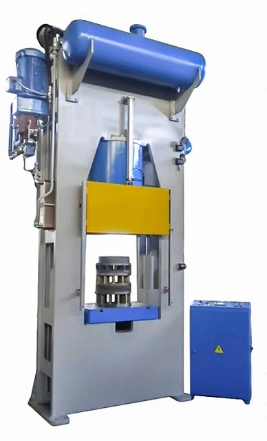
Industrial hydraulic drawing equipment encompasses a range of specialized machines and tools designed to form, shape, and manipulate metal sheets or blanks through controlled hydraulic pressure. These systems are integral to producing complex components with precise dimensions and superior surface finishes across various industries such as automotive, aerospace, appliance manufacturing, and heavy machinery.
At the core of industrial hydraulic drawing equipment are hydraulic presses capable of delivering high tonnage forces with fine control over pressure, speed, and stroke length. These presses are often equipped with customizable tooling—dies, punches, blank holders, and cushions—that work together to guide material flow, control strain distribution, and prevent defects like wrinkling, tearing, or thinning during the drawing process.
Complementing the presses are auxiliary devices such as hydraulic feeders, material handling systems, and automated blank positioning units. These accessories streamline the workflow by ensuring consistent material delivery, precise alignment, and efficient part removal, thereby boosting throughput and reducing operator fatigue.
Modern industrial hydraulic drawing equipment frequently integrates advanced control systems featuring programmable logic controllers (PLCs) or CNC interfaces. These controls enable operators to pre-set forming parameters, store multiple programs for different part designs, and monitor critical process variables in real time. Closed-loop feedback mechanisms using pressure, force, and position sensors help maintain consistent forming conditions and optimize cycle times.
Safety is a paramount concern in industrial environments, and hydraulic drawing equipment is designed with comprehensive protective features. Physical guards, light curtains, emergency stops, and interlocks work together to prevent accidents without hampering operational efficiency.
Energy efficiency is increasingly emphasized, with many systems incorporating variable speed hydraulic pumps, servo-hydraulic drives, and energy recovery technologies that reduce power consumption and operating costs. Additionally, robust filtration and fluid management systems maintain hydraulic oil cleanliness, prolonging equipment life and minimizing maintenance requirements.
Industrial hydraulic drawing equipment can be highly modular and scalable, accommodating different production volumes and part complexities. Integration with robotic systems and factory automation facilitates fully automated forming lines, enabling high precision and repeatability with minimal human intervention.
In summary, industrial hydraulic drawing equipment combines powerful hydraulic technology, precise tooling, advanced controls, and automation to meet the demanding requirements of modern sheet metal forming operations. Its versatility and reliability make it indispensable for producing high-quality metal components efficiently and consistently across a broad spectrum of industries.
Industrial hydraulic drawing equipment also emphasizes flexibility and adaptability to meet the diverse needs of modern manufacturing. The ability to quickly change tooling setups, adjust press parameters, and integrate with various automation solutions allows manufacturers to respond rapidly to evolving product designs and varying batch sizes. This agility is crucial in industries where customization and shorter product life cycles are common.
These systems are designed to handle a wide range of materials and thicknesses, from thin gauge aluminum foils used in electronics to thick, high-strength steels employed in automotive structural parts. The precise control offered by hydraulic pressure and speed adjustments ensures that even difficult-to-form materials can be shaped without defects, preserving material properties and reducing scrap rates.
Maintenance considerations are integral to industrial hydraulic drawing equipment design. Components such as hydraulic pumps, valves, and cylinders are built for durability but are also made accessible for inspection and service to minimize downtime. Advanced diagnostic tools and condition monitoring systems alert maintenance teams to potential issues early, enabling planned interventions rather than reactive repairs.
Operator training and intuitive control interfaces further enhance equipment effectiveness. User-friendly software with graphical displays and step-by-step setup guides help reduce errors during operation and setup, improving overall productivity and part quality. Some systems also feature remote monitoring capabilities, allowing experts to assist operators or troubleshoot issues without being physically present.
Industrial hydraulic drawing equipment increasingly incorporates smart manufacturing principles, linking machines to factory networks and cloud-based analytics platforms. This connectivity provides valuable insights into production performance, energy consumption, and maintenance needs, supporting data-driven decision-making and continuous improvement initiatives.
Safety systems remain a cornerstone of these machines, incorporating multiple layers of protection that comply with international standards. The balance between safety and efficiency is carefully managed to ensure operators are protected while maintaining high throughput and minimal process interruptions.
Overall, industrial hydraulic drawing equipment represents a synergy of robust hydraulic power, precision engineering, advanced controls, and automation technologies. This combination enables manufacturers to produce complex, high-quality sheet metal components efficiently, reliably, and sustainably, meeting the rigorous demands of today’s competitive industrial landscape.
Industrial hydraulic drawing equipment also benefits from ongoing innovations in materials and manufacturing technologies that enhance its performance and durability. For example, the use of advanced alloys and surface treatments on critical components reduces wear and corrosion, extending the service life of presses and tooling. Precision machining techniques ensure tight tolerances and smooth operation, which are essential for maintaining part quality and reducing downtime.
Automation integration continues to evolve, with many hydraulic drawing systems now compatible with robotic handling and vision systems. Robots can load blanks, position parts precisely, and remove finished components, significantly increasing cycle times and reducing manual labor costs. Vision systems add an extra layer of quality control by detecting defects early in the process, enabling real-time adjustments or part rejection to maintain consistent output standards.
The modular design of modern industrial hydraulic drawing equipment allows manufacturers to customize setups easily, scaling capacity or adding features such as multi-stage drawing, trimming, or embossing without replacing the entire system. This modularity supports flexibility in production lines, accommodating different part complexities and volumes while optimizing floor space and capital investment.
Energy consumption and environmental impact are critical considerations driving equipment design improvements. Variable frequency drives, servo-hydraulic systems, and regenerative braking technology help reduce energy waste by matching power use to actual demand. Additionally, many systems incorporate environmentally friendly hydraulic fluids and efficient filtration systems to minimize the ecological footprint and meet increasingly stringent regulations.
Data collection and analysis capabilities embedded within hydraulic drawing equipment facilitate predictive maintenance and process optimization. By monitoring trends in pressure, cycle times, and hydraulic fluid condition, manufacturers can anticipate component wear or failures before they occur, minimizing unexpected downtime and repair costs. Process data also supports continuous improvement efforts by identifying bottlenecks and opportunities to refine forming parameters for better quality or faster production.
Training and technical support from equipment manufacturers ensure that operators and maintenance staff are well-prepared to maximize the benefits of hydraulic drawing technology. Comprehensive training programs, combined with detailed documentation and remote support options, help reduce operational errors and extend machine longevity.
In sum, industrial hydraulic drawing equipment represents a sophisticated blend of power, precision, and intelligence, designed to meet the demanding needs of modern metal forming industries. Its ongoing evolution through technology integration, energy efficiency, and user-centric features ensures that it remains a vital tool for producing high-quality, complex sheet metal components efficiently and sustainably.
Deep Draw Presses for Metal Forming
Deep draw presses for metal forming are specialized machines designed to shape flat metal sheets into complex, hollow shapes by stretching the material into a die cavity. This process, known as deep drawing, is widely used to manufacture items such as automotive body panels, kitchen sinks, beverage cans, and various industrial components. These presses apply controlled force to the metal blank, transforming it into the desired three-dimensional form without compromising material integrity.
Typically, deep draw presses utilize hydraulic or mechanical systems to provide the necessary force and motion. Hydraulic deep draw presses are favored for their precise control over pressure and speed, allowing gradual material deformation that minimizes defects like wrinkling, tearing, or uneven thickness. Mechanical presses, on the other hand, often offer faster cycle times and higher throughput but may lack the same level of control for complex or delicate parts.
The press consists of several key components: the frame, ram or slide, die set, blank holder, and the hydraulic or mechanical drive system. The blank holder plays a critical role by applying pressure on the metal sheet edges to control material flow into the die cavity, preventing excessive thinning or wrinkling during the drawing stroke. Advanced presses may include adjustable or servo-controlled blank holders for optimal force management.
Modern deep draw presses are equipped with programmable controls and sensors that monitor force, stroke position, and speed, enabling operators to fine-tune the process for different materials and part geometries. This automation ensures repeatability and consistent part quality, which is essential for high-volume manufacturing.
Tooling design is equally important in deep drawing. Dies are typically precision-machined to provide smooth metal flow and reduce friction, often incorporating lubrication systems to further minimize wear and improve surface finish. Multi-stage dies can perform sequential drawing operations in a single press cycle, increasing efficiency for complex parts.
Deep draw presses vary widely in size and capacity, from small presses used in laboratory or prototype settings to massive industrial machines capable of exerting thousands of tons of force. Selection depends on factors such as material type, sheet thickness, part complexity, and production volume.
Safety features are integral to deep draw press design, with guards, light curtains, emergency stops, and interlocks protecting operators from injury while maintaining productivity. Ergonomic considerations help reduce operator fatigue, further improving manufacturing efficiency.
In summary, deep draw presses for metal forming are powerful, precise machines essential for producing a vast array of hollow and recessed metal components. Their combination of robust construction, controlled force application, advanced tooling, and automation makes them indispensable in industries demanding high-quality, high-volume metal forming solutions.
Deep draw presses for metal forming also excel in their adaptability to various materials and thicknesses, ranging from thin aluminum sheets used in packaging to thicker steel and stainless steel alloys for automotive and industrial applications. This versatility is crucial as manufacturers seek to optimize weight, strength, and corrosion resistance while maintaining production efficiency. The press’s ability to adjust parameters such as stroke speed, force, and blank holder pressure ensures that different materials can be formed without defects, preserving mechanical properties and surface quality.
The design of deep draw presses often incorporates advanced hydraulic or servo-hydraulic systems that provide precise control over ram movement, enabling smooth acceleration and deceleration during the drawing process. This controlled motion helps reduce metal stress and minimizes the risk of fractures or wrinkling. Servo-driven presses add the benefit of programmability and repeatability, allowing complex motion profiles to be executed consistently across large production runs.
Tooling compatibility and ease of changeover are important considerations for deep draw presses, especially in environments where multiple part designs are produced. Quick-change die systems, modular tooling components, and standardized interfaces reduce downtime during tool swaps and facilitate rapid transitions between production runs. This flexibility supports just-in-time manufacturing and small-batch production without sacrificing efficiency.
Integration with automation and material handling systems enhances the productivity of deep draw presses. Robots and conveyors can automate blank feeding, part unloading, and transfer to subsequent processes like trimming, welding, or assembly. Automated lubrication and cleaning systems help maintain tooling condition, extending die life and ensuring consistent part quality.
From a maintenance standpoint, deep draw presses are engineered for durability and ease of service. Critical components such as hydraulic cylinders, seals, and pumps are designed for long service intervals and are readily accessible for inspection or replacement. Condition monitoring systems track operational parameters and alert maintenance personnel to potential issues, enabling predictive maintenance that reduces unplanned downtime.
Environmental and energy efficiency considerations have led to the adoption of variable frequency drives, servo pumps, and energy recovery technologies in modern deep draw presses. These features optimize power consumption by adjusting energy use according to load requirements, reducing operational costs and supporting sustainability initiatives.
Operator safety remains a top priority, with presses equipped with multiple safety layers including physical barriers, light curtains, two-hand control systems, and emergency stop functions. Ergonomic design of control panels and workstations helps reduce operator fatigue and errors, contributing to higher productivity and safer work environments.
In essence, deep draw presses for metal forming combine mechanical strength, precise hydraulic or servo control, advanced tooling, and automation integration to deliver consistent, high-quality forming results. Their ability to handle diverse materials and part complexities while maintaining efficiency and safety makes them vital assets in modern manufacturing processes.
Deep draw presses also benefit from ongoing advancements in digital technologies, which are increasingly integrated into modern metal forming operations. These include sophisticated process monitoring systems that collect real-time data on force, stroke position, speed, and temperature, enabling manufacturers to analyze and optimize the drawing process continuously. Such data-driven approaches help identify subtle deviations early, allowing for immediate adjustments that prevent defects and improve overall yield.
Furthermore, the use of simulation software during the design phase of both the press and tooling allows engineers to model metal flow, stress distribution, and potential failure points before production begins. This predictive capability reduces trial-and-error in tool development, shortens time to market, and lowers costs associated with scrap and rework.
Deep draw presses are often integrated into larger smart factory ecosystems, communicating with other machines and enterprise systems to synchronize production schedules, track material usage, and ensure traceability of parts. This connectivity supports lean manufacturing principles and enhances responsiveness to changing customer demands.
In response to increasing demands for customization and lower batch sizes, some presses feature flexible automation setups, including robotic tool changers and adaptive control systems that can switch between product variants with minimal downtime. This flexibility helps manufacturers maintain competitiveness by efficiently handling diverse product portfolios.
The focus on sustainability is reflected not only in energy-efficient designs but also in efforts to minimize material waste through optimized forming processes. By precisely controlling material flow and reducing scrap, deep draw presses contribute to more sustainable metalworking operations.
Training and workforce development are also key to maximizing the benefits of deep draw press technology. Manufacturers often provide comprehensive operator education programs and virtual training environments using augmented reality (AR) to simulate press operation and maintenance. This hands-on learning improves operator proficiency and safety awareness, leading to better machine utilization and fewer accidents.
Overall, deep draw presses represent a convergence of mechanical robustness, hydraulic and servo technology, digital intelligence, and automation, forming a cornerstone of advanced metal forming industries. Their continual evolution ensures they meet the stringent demands for quality, efficiency, and sustainability that define modern manufacturing.
Compact Hydraulic Drawing Press Units
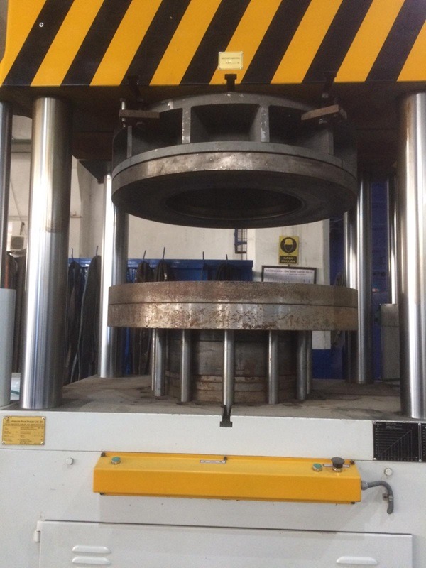
Compact hydraulic drawing press units are specially designed machines that offer the powerful forming capabilities of traditional hydraulic presses but in a smaller, more space-efficient footprint. These units are ideal for manufacturers who need precision deep drawing or metal forming but face constraints related to floor space, production scale, or budget. Despite their reduced size, compact presses maintain the essential features required for high-quality metal forming, including controlled hydraulic force, adjustable stroke, and precise ram positioning.
Typically, these compact units are used for producing smaller parts or components where accuracy and surface finish are critical, such as electrical housings, small automotive parts, or consumer electronics enclosures. Their reduced size makes them well suited for integration into flexible manufacturing cells, laboratory settings, or prototyping environments where versatility and rapid setup are important.
The hydraulic systems in compact drawing presses are engineered to deliver smooth, consistent pressure with adjustable force to accommodate different materials and thicknesses. Many models incorporate servo-hydraulic technology, enabling programmable control over ram speed and pressure profiles, which enhances forming precision and repeatability in small-scale production runs.
Compact hydraulic drawing presses often feature modular tooling mounts and quick-change capabilities, allowing operators to switch dies rapidly and minimize downtime. Their frames are built with rigid, high-strength materials to withstand forming forces while keeping the overall machine weight and size manageable.
User interfaces are typically intuitive and modern, with touchscreen controls and programmable settings that store multiple forming programs for easy recall. This helps streamline operations and reduce setup errors, particularly in environments where multiple part designs are run on the same equipment.
Safety features in compact units include interlocks, emergency stop buttons, and protective guarding to ensure operator protection despite the machine’s reduced size. Additionally, many compact presses are designed for easy maintenance, with accessible hydraulic components and straightforward diagnostics to keep downtime low.
Energy efficiency is also a focus, with compact units using variable displacement pumps and efficient hydraulic circuits to reduce power consumption without sacrificing performance. This makes them not only practical for smaller workshops but also environmentally friendly.
In summary, compact hydraulic drawing press units provide a versatile, precise, and efficient solution for metal forming applications where space, flexibility, and cost are key considerations. They combine the essential strengths of hydraulic forming technology with a streamlined design that fits the needs of modern, agile manufacturing environments.
Compact hydraulic drawing press units continue to gain popularity due to their adaptability and ease of integration into diverse production setups. Their smaller size enables them to be positioned closer to other process equipment or even on mobile platforms, facilitating flexible manufacturing lines that can be quickly reconfigured to accommodate different products or production volumes. This mobility and compactness are particularly beneficial in industries where space is at a premium, such as electronics manufacturing or medical device production.
Despite their reduced scale, these presses do not compromise on precision or control. Advanced hydraulic systems within compact units allow for finely tuned pressure and speed adjustments, which are critical when working with delicate or thin materials that require gentle handling to avoid defects. The programmable controls can execute complex forming sequences with high repeatability, ensuring consistent part quality across multiple production runs.
The tooling options for compact presses are often designed to be versatile and customizable, supporting a wide range of part geometries and materials. Quick-change tooling interfaces minimize downtime between jobs, while modular tool components allow manufacturers to optimize setups for specific forming challenges, such as deep drawing, embossing, or flanging. Some compact presses also support multi-stage operations within a single machine, further enhancing productivity without increasing the machine’s footprint.
Maintenance and reliability are carefully considered in the design of compact hydraulic presses. Key components such as pumps, valves, and cylinders are selected for durability, while the simplified machine layout improves accessibility for routine inspection and servicing. Built-in diagnostic features help detect hydraulic leaks, pressure irregularities, or mechanical wear early, preventing costly breakdowns and extending equipment life.
In terms of energy consumption, compact hydraulic drawing presses benefit from modern hydraulic technologies like load-sensing pumps and variable frequency drives. These features optimize power use by matching hydraulic output to actual process requirements, reducing waste and lowering operating costs—an important advantage for smaller manufacturers or facilities aiming to improve sustainability.
Operator safety and ergonomics remain integral even in compact units. Protective enclosures, safety interlocks, and emergency stop functions are standard, ensuring compliance with industry regulations. Additionally, ergonomic controls and accessible machine interfaces help reduce operator fatigue and errors, contributing to smoother workflow and higher throughput.
The combination of precision control, flexible tooling, efficient hydraulics, and compact design makes these presses ideal for prototyping, short-run production, and applications requiring frequent product changeovers. Their ability to deliver high-quality forming results without the need for large-scale infrastructure opens up opportunities for smaller manufacturers or specialized production niches.
Overall, compact hydraulic drawing press units embody the balance between size, power, and precision needed to meet the evolving demands of modern metal forming. They offer manufacturers a practical and efficient tool for producing intricate metal parts with consistent quality while optimizing space, energy use, and operational flexibility.
In addition to their compact design and precision capabilities, these hydraulic drawing press units are increasingly incorporating smart features to enhance productivity and ease of use. Connectivity options such as Ethernet, USB, and wireless interfaces allow seamless integration with factory automation systems and centralized monitoring platforms. This connectivity enables real-time data collection on press performance, cycle times, and maintenance needs, supporting predictive maintenance and minimizing unplanned downtime.
Many compact presses also feature user-friendly software with graphical interfaces that guide operators through setup, diagnostics, and troubleshooting. Some models offer remote access capabilities, allowing technicians to assist or adjust parameters without being physically present, which is especially valuable for manufacturers with multiple facilities or limited on-site expertise.
The compact hydraulic drawing press market is also responding to growing demands for environmentally sustainable manufacturing. Manufacturers are developing presses with quieter operation, reduced hydraulic fluid consumption, and systems designed to minimize leaks and contamination. Some units use biodegradable hydraulic fluids and incorporate eco-friendly manufacturing practices, aligning with corporate sustainability goals and regulatory requirements.
Customization options for compact presses are expanding as well, with manufacturers offering tailored solutions to meet specific industry needs. For example, presses designed for the medical industry may include ultra-clean hydraulic systems and materials compatible with stringent hygiene standards. Others targeted at aerospace or electronics sectors may prioritize ultra-high precision and repeatability to meet exacting specifications.
Training and support services complement these technological advances, with many suppliers providing virtual reality (VR) or augmented reality (AR) tools to simulate machine operation and maintenance procedures. This immersive training approach improves operator competence and safety awareness while reducing the time required to become proficient with the equipment.
Overall, compact hydraulic drawing press units continue to evolve, blending mechanical strength, advanced hydraulics, digital intelligence, and eco-conscious design. Their combination of space-saving form, precise control, and smart connectivity makes them a vital component of flexible, modern manufacturing environments where efficiency, quality, and adaptability are paramount.
Advanced Deep Drawing Press Solutions
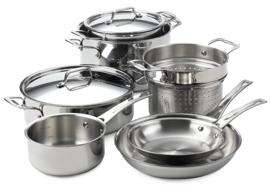
Advanced deep drawing press solutions represent the cutting edge of metal forming technology, combining high-performance machinery with sophisticated control systems and smart manufacturing features. These presses are designed to handle complex part geometries, challenging materials, and demanding production requirements while maximizing efficiency, precision, and repeatability.
At the heart of advanced deep drawing presses are servo-hydraulic or fully electric drives that offer unparalleled control over ram speed, position, and force. This precise actuation enables complex forming sequences with variable speed profiles, reducing material stresses and minimizing defects such as tearing, wrinkling, or thinning. The ability to tailor motion curves and pressure application throughout the stroke is critical for producing intricate shapes and high-strength parts used in automotive, aerospace, and electronics industries.
These presses integrate real-time process monitoring through an array of sensors measuring parameters such as load, position, temperature, and vibration. Data from these sensors feed into intelligent control algorithms that dynamically adjust forming conditions, ensuring consistent part quality despite material or environmental variations. Advanced diagnostics and predictive maintenance features further enhance reliability and uptime by identifying potential issues before failures occur.
Tooling in advanced deep drawing solutions is often modular and highly engineered, incorporating wear-resistant coatings, embedded sensors, and optimized geometries to facilitate smooth material flow and prolong die life. Multi-stage forming stations can be combined within a single press or integrated into automated production lines, enabling complex part fabrication with minimal manual intervention.
Automation plays a key role in advanced deep drawing press systems. Robotic material handling, automated blank feeding, and part extraction reduce cycle times and labor costs while improving safety. Integration with factory-wide control networks and manufacturing execution systems (MES) supports full traceability, production planning, and quality management.
Energy efficiency is addressed through technologies like regenerative drives, variable speed pumps, and servo motors, which reduce power consumption and heat generation. These green features not only lower operating costs but also align with increasingly stringent environmental regulations.
User interfaces on advanced presses are highly intuitive, often featuring touchscreen controls, customizable dashboards, and remote access capabilities. Operators and engineers can quickly set up new programs, monitor process data, and perform troubleshooting with minimal training, enhancing productivity and responsiveness.
In essence, advanced deep drawing press solutions embody the synergy of mechanical robustness, hydraulic and servo control precision, smart sensors, automation, and data intelligence. They empower manufacturers to produce complex, high-quality metal parts at scale while adapting to evolving industry demands for speed, flexibility, and sustainability.
Advanced deep drawing press solutions continue to evolve by integrating more intelligent automation and adaptive control systems, which significantly improve process stability and product consistency. These presses utilize machine learning algorithms and artificial intelligence to analyze vast amounts of production data, detecting subtle patterns and deviations that humans might miss. This enables the system to proactively adjust forming parameters in real time, compensating for material variability or tool wear, thereby reducing scrap rates and increasing overall yield.
The modularity of these presses allows manufacturers to customize machine configurations tailored to specific production needs. For instance, multi-action presses can perform several forming steps within one cycle, such as drawing, ironing, and trimming, streamlining workflows and reducing handling time. This consolidation leads to faster cycle times and lower labor requirements, which is especially beneficial in high-volume manufacturing environments.
Advanced deep drawing presses are increasingly designed to support a wide range of materials, including high-strength steels, aluminum alloys, and even lightweight composites. This versatility is essential as industries pursue weight reduction without sacrificing strength or durability. The presses’ precise force and motion control help manage the unique deformation behaviors of these advanced materials, ensuring high-quality parts that meet stringent performance standards.
Enhanced sensor technologies embedded in the press and tooling monitor not only standard parameters like force and stroke but also material thickness, surface finish, and even microstructural changes during forming. These insights allow for unprecedented process transparency and enable predictive maintenance strategies that minimize downtime and extend the service life of both equipment and tooling.
Integration with broader Industry 4.0 ecosystems is another hallmark of advanced deep drawing presses. They communicate seamlessly with other machines, warehouse systems, and enterprise resource planning (ERP) software, enabling real-time production tracking, inventory management, and quality assurance. This connectivity facilitates agile manufacturing, allowing rapid adjustments to production schedules and better responsiveness to market demands.
Safety remains a critical focus, with advanced presses incorporating multiple redundant systems such as light curtains, pressure-sensitive mats, and sophisticated interlocks. These safety measures are designed to protect operators without hindering productivity, often supported by ergonomic designs and operator assistance features that reduce fatigue and error.
Finally, manufacturers of advanced deep drawing presses provide comprehensive support services, including virtual commissioning, remote diagnostics, and continuous software updates. This ongoing collaboration helps customers maintain optimal performance, adopt new functionalities quickly, and extend the lifespan of their equipment.
Overall, advanced deep drawing press solutions represent a convergence of mechanical engineering excellence, precise hydraulic and servo control, cutting-edge sensor technology, and intelligent automation. They empower manufacturers to produce increasingly complex, high-quality metal components efficiently, flexibly, and sustainably in today’s competitive industrial landscape.
Building on these advancements, deep drawing presses are also leveraging digital twin technology, which creates a virtual replica of the physical press and tooling setup. This digital twin allows engineers to simulate and optimize the forming process before actual production begins, reducing trial runs, minimizing material waste, and accelerating time to market. Real-time synchronization between the digital twin and the physical press also enables ongoing process optimization and rapid troubleshooting when issues arise.
Material science innovations complement the capabilities of advanced deep drawing presses. New coatings, lubricants, and surface treatments for both tools and workpieces improve material flow and reduce friction, which translates into better part quality and longer tooling life. These innovations help presses handle increasingly difficult-to-form alloys and ultra-thin gauges without sacrificing performance.
Collaborative robotics (cobots) are being integrated into deep drawing press cells to enhance flexibility and safety. Unlike traditional industrial robots, cobots can work safely alongside human operators, assisting with tasks like part loading, unloading, inspection, or minor adjustments. This collaboration improves throughput while preserving human judgment and dexterity where it matters most.
Environmental considerations are further driving innovation in press design and operation. Advanced presses feature systems to recycle hydraulic fluid, capture and reuse heat generated during forming, and minimize noise and vibration emissions. These eco-friendly features help manufacturers meet sustainability goals and regulatory requirements without compromising productivity.
User experience is also a focus, with manufacturers developing intuitive interfaces that use augmented reality (AR) to guide operators through complex setups or maintenance tasks. AR can overlay step-by-step instructions or highlight components in need of attention, reducing downtime and skill barriers.
Looking ahead, the integration of artificial intelligence and advanced analytics will deepen, enabling presses to learn from each production cycle and continuously refine their operations autonomously. This will push the boundaries of what is achievable in metal forming, opening new possibilities for design complexity, material efficiency, and customization.
In conclusion, advanced deep drawing press solutions are at the forefront of manufacturing innovation. By combining mechanical precision, smart controls, digitalization, and sustainability, they provide manufacturers with powerful tools to meet the evolving demands of modern industry while improving quality, efficiency, and environmental impact.
Custom Hydraulic Deep Drawing Systems
Custom hydraulic deep drawing systems are tailored metal forming solutions designed to meet specific production requirements, part geometries, and material characteristics. Unlike standard presses, these systems are engineered from the ground up to optimize the deep drawing process for unique applications, whether that means handling unusual materials, producing complex shapes, or integrating with specialized automation setups.
The customization process typically begins with a thorough analysis of the customer’s needs, including part design, production volume, material properties, and desired cycle times. Engineers then design a hydraulic press system that balances force capacity, stroke length, and speed profiles to achieve optimal forming results. This bespoke approach ensures that the press applies the right amount of force at the right speed, reducing the risk of defects such as cracking, wrinkling, or excessive thinning.
Custom hydraulic systems often incorporate advanced servo-hydraulic controls that provide precise and programmable pressure and ram motion. This flexibility is essential for forming complex parts or materials with challenging deformation behavior, such as high-strength steels or aluminum alloys used in aerospace and automotive industries. Programmable controls allow for multi-stage forming sequences within a single stroke, improving efficiency and part accuracy.
Tooling design is an integral part of these custom systems. Dies and blank holders are engineered to match the unique geometry and material flow requirements of each part, often including features like variable blank holder pressure zones or integrated sensors to monitor forming conditions in real time. This level of tooling sophistication helps extend die life and maintain consistent part quality.
Integration with automation and material handling equipment is another hallmark of custom deep drawing systems. Robotic loaders, automated blank feeders, and part transfer systems can be designed into the press cell, enabling seamless, high-throughput production with minimal human intervention. Such integration improves safety, reduces labor costs, and supports just-in-time manufacturing strategies.
Safety systems are customized as well, tailored to the specific operation and workplace environment. This can include specialized guarding, light curtains, and emergency stop systems, ensuring operator protection without compromising accessibility or workflow.
Energy efficiency and sustainability considerations are also embedded in custom hydraulic press designs. Engineers incorporate energy-saving hydraulic circuits, regenerative systems, and eco-friendly materials to reduce operating costs and environmental impact, aligning with corporate sustainability goals.
Support services for custom systems often include comprehensive training, remote diagnostics, and maintenance programs tailored to the specific equipment and application. This ensures long-term reliability and optimal performance throughout the system’s lifecycle.
In summary, custom hydraulic deep drawing systems deliver highly specialized, precise, and efficient forming solutions designed around the unique demands of each manufacturer. Their tailored design and integration capabilities make them indispensable for producing complex, high-quality metal parts in industries where standard presses cannot fully meet technical or operational requirements.
Custom hydraulic deep drawing systems continue to evolve by incorporating the latest advancements in digital control, sensor integration, and automation to further enhance their adaptability and performance. These systems often feature real-time monitoring and closed-loop feedback mechanisms that constantly adjust forming parameters based on sensor data, ensuring optimal process control even as material properties or environmental conditions change. This adaptability minimizes scrap, reduces rework, and maintains consistent part quality throughout long production runs.
The modular nature of many custom systems allows manufacturers to scale their operations or modify press capabilities as product lines evolve. For example, additional forming stations or auxiliary equipment like trimming or flanging units can be integrated into the existing system with minimal disruption. This flexibility supports lean manufacturing principles and helps businesses respond quickly to shifting market demands without significant capital expenditure.
Advanced software platforms accompany these custom presses, offering intuitive interfaces for programming, simulation, and diagnostics. Operators and engineers can model forming sequences, predict potential issues, and fine-tune parameters before initiating production, greatly reducing setup times and material waste. Cloud connectivity further enables remote monitoring and data analysis, allowing experts to support multiple sites and provide proactive maintenance assistance.
Material versatility remains a key advantage of custom hydraulic deep drawing systems. They are often engineered to handle a broad spectrum of metals and alloys, including advanced high-strength steels, aluminum-lithium alloys, and even clad or composite materials. By precisely controlling the forming speed, force, and blank holder pressure, these systems accommodate complex material behaviors such as springback or anisotropy, delivering parts that meet stringent dimensional and mechanical requirements.
Incorporating safety into the design is paramount, with custom systems featuring tailored guarding, access controls, and emergency response mechanisms that comply with the highest industry standards. Ergonomic considerations are also addressed to reduce operator fatigue and improve productivity, including adjustable control panels, enhanced lighting, and noise reduction measures.
Sustainability considerations influence system design choices, with energy-efficient hydraulic components, fluid recycling capabilities, and waste reduction strategies integrated into many custom presses. These features not only reduce environmental impact but also contribute to lower operating costs and improved facility compliance.
Customer support extends beyond installation, with manufacturers offering ongoing training, performance optimization, and rapid response services. This partnership approach ensures that the custom hydraulic deep drawing system continues to operate at peak efficiency, adapts to new production challenges, and maintains high-quality output over its service life.
Ultimately, custom hydraulic deep drawing systems provide manufacturers with highly specialized, reliable, and efficient tools capable of meeting complex forming challenges. Their combination of tailored mechanical design, advanced control technology, and integrated automation positions them as essential assets for producing precision metal parts in competitive and rapidly changing industrial landscapes.
Building further on the strengths of custom hydraulic deep drawing systems, many manufacturers now emphasize seamless integration with Industry 4.0 technologies to create truly smart manufacturing environments. These systems are equipped with IoT-enabled sensors and controllers that continuously collect and transmit data on machine health, process parameters, and product quality. This connectivity allows for advanced analytics and machine learning applications, which can predict maintenance needs, optimize cycle times, and identify subtle process variations before they impact production.
The rise of digital twins is transforming custom hydraulic press operations as well. By developing a virtual replica of the press and tooling, manufacturers can simulate forming processes, test new product designs, and refine parameters without interrupting production. The digital twin also facilitates remote troubleshooting and process optimization, reducing downtime and accelerating problem resolution.
Custom systems increasingly incorporate flexible automation solutions such as collaborative robots and automated material handling tailored to the specific workflow. These additions enhance throughput while improving operator safety by handling repetitive, heavy, or hazardous tasks. The modular design of these robotic integrations allows manufacturers to scale and reconfigure their production lines quickly in response to changing demands or new product introductions.
Energy efficiency remains a priority, with custom hydraulic systems adopting regenerative technologies that capture and reuse energy generated during the forming cycle. Variable displacement pumps and servo-driven hydraulic units help optimize power consumption based on real-time load requirements, reducing both operational costs and environmental footprint.
In response to the demand for greater versatility, many custom presses support multi-material forming, enabling a single system to produce parts from diverse alloys or composite layers without extensive retooling. This capability is crucial for industries like automotive and aerospace, where lightweighting and material innovation are ongoing trends.
Moreover, customer-centric service models have become integral to the success of custom hydraulic deep drawing systems. Manufacturers offer tailored training programs, virtual and augmented reality support tools, and comprehensive maintenance packages that include remote diagnostics and software updates. These services ensure operators maintain high skill levels and that equipment remains aligned with evolving production needs.
Ultimately, custom hydraulic deep drawing systems represent a sophisticated fusion of mechanical engineering, advanced hydraulics, digital intelligence, and automation. Their ability to deliver precise, flexible, and efficient metal forming solutions tailored to unique manufacturing challenges positions them as indispensable assets in the competitive landscape of modern industrial production.
Deep Drawing Hydraulic Press Machines
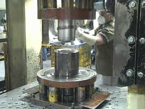
Deep drawing hydraulic press machines are specialized industrial equipment designed to form sheet metal into complex, hollow shapes by applying controlled hydraulic pressure. These machines use a hydraulic cylinder to drive a ram that pushes the metal blank into a die cavity, shaping it into the desired form through plastic deformation. The deep drawing process is essential for manufacturing parts like automotive panels, kitchen sinks, beverage cans, and various household or industrial components.
The hydraulic mechanism provides smooth, consistent force and precise control over ram speed, stroke length, and pressure, which is crucial for handling different materials and thicknesses without causing defects such as tearing or wrinkling. Compared to mechanical presses, hydraulic presses offer greater flexibility in force application and can maintain force throughout the entire stroke, making them especially suited for deep drawing applications where gradual and uniform pressure is needed.
Typically, deep drawing hydraulic presses feature robust frames made from high-strength steel to withstand the significant forces involved. The hydraulic system often includes pumps, valves, and accumulators designed to deliver stable pressure and responsive control. Modern presses incorporate servo-hydraulic technology, enabling programmable ram motion profiles and pressure settings to optimize forming for specific materials and part geometries.
Control systems on these presses range from basic manual controls to advanced computerized interfaces with touchscreen displays, allowing operators to set, monitor, and adjust forming parameters easily. Many machines also include safety features such as emergency stops, safety interlocks, and protective guarding to ensure operator safety during high-force operations.
Tooling plays a critical role in deep drawing hydraulic presses, with precision-engineered dies, punches, and blank holders tailored to the part’s shape and material properties. Advanced tooling designs may include features like variable blank holder pressures, lubrication channels, and sensor integration for process monitoring, all aimed at improving part quality and tool longevity.
Deep drawing hydraulic press machines vary in size and capacity, from compact models used for small parts and prototype development to large presses capable of producing heavy-duty automotive or industrial components. Their versatility and precision make them indispensable across industries such as automotive, aerospace, appliance manufacturing, and packaging.
Energy efficiency is increasingly emphasized in modern hydraulic press designs, with technologies like variable displacement pumps, energy recovery systems, and optimized hydraulic circuits reducing power consumption and operational costs. Additionally, the integration of automation, such as robotic material handling and automated tooling changes, enhances productivity and reduces labor requirements.
Overall, deep drawing hydraulic press machines combine mechanical strength, precise hydraulic control, and advanced automation to provide reliable, high-quality metal forming solutions. They enable manufacturers to produce complex, accurate, and durable parts efficiently, meeting the demanding standards of today’s industrial applications.
Deep drawing hydraulic press machines continue to evolve with advancements in technology that enhance precision, efficiency, and versatility. Modern systems increasingly incorporate servo-hydraulic drives that provide highly accurate control of ram speed, position, and force throughout the forming cycle. This allows for customizable motion profiles that adapt to different materials and complex geometries, minimizing defects and improving part consistency.
Integration with digital control systems and smart sensors enables real-time monitoring of key process parameters such as pressure, stroke, temperature, and vibration. This data is used to maintain optimal forming conditions, quickly detect anomalies, and implement predictive maintenance strategies that reduce downtime and extend machine life. Operators benefit from intuitive user interfaces with touchscreen controls and graphical displays that simplify setup, adjustment, and troubleshooting.
The flexibility of deep drawing hydraulic presses is enhanced by modular designs that allow easy adaptation or expansion of press capabilities. Multi-stage presses can perform sequential forming operations within a single machine, streamlining workflows and increasing throughput. Automated tooling systems, including quick-change mechanisms and adaptive blank holders, reduce setup times and enable rapid product changeovers to support just-in-time manufacturing.
Energy efficiency remains a critical focus, with many presses employing energy-saving components such as variable speed pumps and regenerative circuits that recycle hydraulic energy. These features lower operating costs and help manufacturers meet environmental sustainability goals.
Safety advancements in hydraulic press machines incorporate multiple redundant protective systems, including light curtains, pressure-sensitive mats, and interlocks, which safeguard operators without hindering productivity. Ergonomic design improvements reduce operator fatigue and improve accessibility for maintenance tasks.
Applications for deep drawing hydraulic presses span a wide range of industries, from automotive and aerospace to consumer goods and electronics. Their ability to form complex shapes from various metals—including high-strength steels, aluminum alloys, and stainless steel—makes them indispensable for producing components that require tight tolerances and high structural integrity.
Manufacturers often provide comprehensive support services, including virtual commissioning, remote diagnostics, and ongoing training programs to ensure optimal machine performance and longevity. The combination of mechanical robustness, precise hydraulic control, advanced automation, and digital intelligence positions deep drawing hydraulic press machines as vital tools in modern metal forming operations, enabling efficient production of high-quality, reliable parts at scale.
Further developments in deep drawing hydraulic press machines focus on enhancing adaptability and integration within smart factory environments. Connectivity through industrial protocols like OPC UA and Ethernet/IP allows these presses to communicate seamlessly with other equipment, manufacturing execution systems (MES), and enterprise resource planning (ERP) software. This interconnectedness supports real-time production monitoring, quality control, and data-driven decision-making, enabling manufacturers to optimize workflows and respond swiftly to changing demands.
Advanced simulation and virtual commissioning tools are increasingly employed during the design and setup phases, allowing engineers to model the deep drawing process digitally. This approach reduces trial-and-error on the shop floor, shortens ramp-up times, and improves first-pass yield by identifying potential issues in tooling, material behavior, or press parameters before physical production begins.
Customization options are broadening, with presses tailored to specific industries or part requirements. For example, presses designed for aerospace applications often prioritize ultra-precise force control and cleanliness standards, while those for food or medical components may feature hygienic designs and corrosion-resistant materials.
In addition, the incorporation of collaborative robotics enhances the automation capabilities of hydraulic deep drawing systems. Cobots can safely work alongside human operators to assist with loading, unloading, inspection, or minor adjustments, increasing productivity and reducing ergonomic risks. Flexible robotic cells enable manufacturers to handle variable batch sizes and complex part variants without extensive reconfiguration.
Sustainability is driving innovations such as the use of biodegradable hydraulic fluids, advanced filtration systems to extend fluid life, and press components made from recycled or low-impact materials. These environmentally conscious choices help reduce waste and emissions while maintaining high machine performance.
Operator training is evolving with the use of augmented reality (AR) and virtual reality (VR) technologies, providing immersive, hands-on learning experiences that improve skill acquisition and reduce errors. These tools allow operators to practice setup, maintenance, and troubleshooting in a safe, controlled environment before working on actual machines.
Looking forward, artificial intelligence and machine learning are expected to play larger roles in optimizing deep drawing processes, enabling presses to self-adjust and continuously improve performance based on historical data and live sensor feedback. This evolution promises to further enhance efficiency, quality, and flexibility in metal forming operations.
Overall, deep drawing hydraulic press machines are becoming increasingly intelligent, connected, and sustainable, empowering manufacturers to produce complex, high-quality parts with greater speed and reliability while adapting to the dynamic needs of modern industry.
High-Precision Hydraulic Drawing Presses
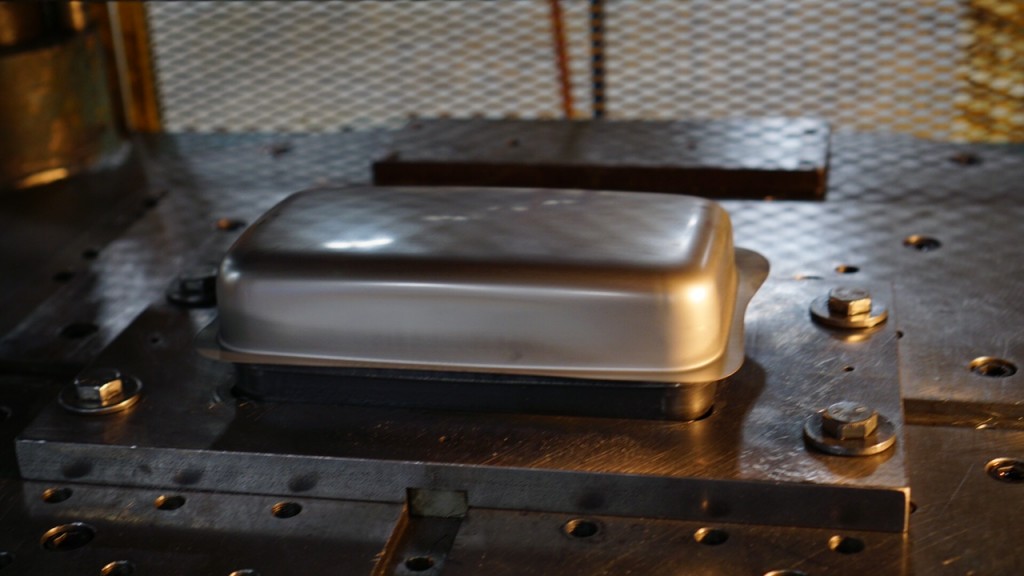
High-precision hydraulic drawing presses are advanced metal forming machines designed to deliver exceptional accuracy, repeatability, and surface quality in deep drawing operations. These presses are engineered to meet the demanding requirements of industries such as aerospace, automotive, electronics, and medical device manufacturing, where tight tolerances and flawless finishes are critical.
At the core of high-precision hydraulic drawing presses is a robust and rigid frame structure, often constructed from high-grade steel or alloy materials, to minimize deflection and vibration during operation. This stability ensures that the ram and tooling maintain perfect alignment, which is essential for producing consistent, defect-free parts with intricate geometries.
The hydraulic systems in these presses feature servo-controlled pumps and valves that provide precise regulation of pressure, speed, and ram position. Servo-hydraulic technology enables programmable motion profiles, allowing the machine to execute complex forming sequences with controlled acceleration and deceleration. This level of control reduces stresses on the material, preventing common issues like tearing, wrinkling, or excessive thinning.
Advanced feedback sensors and real-time monitoring systems track key parameters such as force, displacement, and temperature throughout the forming cycle. Data collected from these sensors is fed into sophisticated control algorithms that dynamically adjust the process, maintaining optimal forming conditions and ensuring repeatability from part to part. This closed-loop control capability is vital for producing high-precision components consistently.
Tooling design is equally important in achieving high precision. Custom-engineered dies, punches, and blank holders are fabricated with tight tolerances and often incorporate integrated sensors to monitor pressure distribution and material flow. Some tooling systems feature variable blank holder pressure zones that can be independently controlled to fine-tune the forming process for complex shapes.
The control interfaces on high-precision hydraulic drawing presses typically include user-friendly touchscreen panels with graphical displays, enabling operators to program, monitor, and adjust process parameters easily. These systems often support recipe management for quick changeovers between different part types, reducing setup time and increasing productivity.
In addition to precision and control, these presses emphasize safety and ergonomics. Multiple safety features such as light curtains, two-hand controls, and safety interlocks protect operators, while ergonomic designs reduce physical strain and improve accessibility for maintenance.
Energy efficiency is addressed through the use of servo-driven hydraulics and energy recovery systems that optimize power consumption based on real-time demand. This not only lowers operational costs but also supports environmental sustainability initiatives.
High-precision hydraulic drawing presses are capable of forming a wide range of materials, including high-strength steels, aluminum alloys, titanium, and specialty metals used in demanding applications. Their ability to produce complex, high-quality parts with minimal scrap makes them invaluable in sectors where component performance and reliability are paramount.
Overall, these presses combine mechanical robustness, advanced hydraulic control, precision tooling, and intelligent automation to deliver superior forming performance. They enable manufacturers to meet stringent quality standards and achieve consistent production of intricate, high-value metal components efficiently and reliably.
High-precision hydraulic drawing presses continue to evolve by integrating cutting-edge technologies that further enhance accuracy, efficiency, and versatility. One significant advancement is the incorporation of real-time adaptive control systems that use machine learning algorithms to analyze sensor data and optimize forming parameters dynamically during each stroke. This capability allows presses to compensate for variations in material properties, tooling wear, and environmental conditions, maintaining consistent quality even in challenging production runs.
The mechanical design of these presses often includes advanced vibration damping systems and precision-ground guideways to ensure smooth, repeatable ram movement. Such features reduce mechanical noise and minimize deviations that could compromise part quality. Additionally, thermal management systems are implemented to maintain stable operating temperatures, as thermal expansion can affect dimensional accuracy in long production cycles.
Tooling innovations complement the press technology, with precision dies manufactured using high-accuracy CNC machining, electrical discharge machining (EDM), or additive manufacturing techniques for complex geometries. Integration of sensors within tooling allows for detailed monitoring of force distribution and material flow, enabling immediate feedback to the control system and early detection of potential defects.
Automation plays a crucial role in maximizing the capabilities of high-precision hydraulic drawing presses. Robotic loading and unloading systems, combined with automated inspection stations using optical or laser measurement technologies, help maintain tight tolerances while increasing throughput. These automated cells can be programmed for flexible production schedules, accommodating small batches or complex part variants without sacrificing efficiency.
User interfaces have become more sophisticated, often featuring augmented reality (AR) overlays that assist operators during setup, maintenance, and troubleshooting. This technology can provide step-by-step guidance or highlight critical components, reducing downtime and improving operator effectiveness.
Sustainability considerations are integrated into press design, with many systems employing energy-efficient servo-hydraulic drives, regenerative braking, and hydraulic fluid management systems that reduce waste and environmental impact. These features align with increasing industry demands for greener manufacturing practices.
In highly regulated industries such as aerospace and medical devices, high-precision hydraulic drawing presses support comprehensive traceability and quality documentation. Integrated software solutions record process data for each part, enabling detailed analysis and compliance with stringent standards.
The combination of mechanical precision, intelligent control, advanced tooling, and automation ensures that high-precision hydraulic drawing presses meet the ever-increasing demands for complex, high-quality metal parts. These presses are essential for manufacturers seeking to maintain competitive advantage through superior product quality, operational efficiency, and adaptability in dynamic production environments.
Building further on these capabilities, high-precision hydraulic drawing presses are increasingly designed with modular architectures that allow easy customization and scalability. This modularity enables manufacturers to tailor the press’s size, force capacity, and stroke length to specific application requirements while facilitating future upgrades or expansions without the need for complete system replacement. Such flexibility is crucial in industries where product lifecycles are short and rapid adaptation to new designs or materials is necessary.
Integration with advanced data analytics platforms empowers users to leverage big data collected from multiple presses and production lines. By analyzing trends and patterns, manufacturers can identify process inefficiencies, predict maintenance needs, and optimize production schedules. This proactive approach minimizes unplanned downtime and improves overall equipment effectiveness (OEE).
Remote monitoring and diagnostics have become standard features, enabling experts to troubleshoot issues and provide support without the delays and costs associated with on-site visits. This connectivity is especially valuable for global manufacturing operations requiring consistent machine performance across multiple locations.
The materials that can be processed on high-precision hydraulic drawing presses continue to expand, including emerging alloys and multi-layer composites. Precise control over forming parameters helps address the unique challenges posed by these advanced materials, such as variable thickness, anisotropic properties, or sensitivity to strain rates.
In addition to traditional metal forming, these presses are increasingly used for hybrid processes that combine deep drawing with secondary operations like embossing, piercing, or trimming within the same cycle. This multifunctionality reduces handling, shortens cycle times, and improves dimensional consistency.
Efforts to improve operator comfort and safety also extend to noise reduction technologies and advanced vibration isolation. These improvements create better working conditions, which can contribute to higher productivity and lower risk of injury.
As sustainability continues to shape industrial priorities, manufacturers are exploring the use of environmentally friendly hydraulic fluids and designing presses for easier maintenance and component recycling. Lifecycle assessments guide material selection and design choices to minimize ecological footprints without sacrificing performance.
Training and skill development remain critical components in maximizing the benefits of high-precision hydraulic drawing presses. Interactive digital platforms, virtual reality simulators, and AI-driven coaching tools help operators and engineers build expertise quickly, ensuring optimal machine setup and operation.
In summary, the ongoing innovation in high-precision hydraulic drawing presses—spanning mechanical design, control systems, materials compatibility, automation, and sustainability—positions these machines at the forefront of modern metal forming technology. Their ability to deliver consistent, high-quality parts with efficiency and flexibility makes them indispensable assets for manufacturers competing in today’s fast-paced, quality-driven markets.
Modern Hydraulic Deep Draw Press Tech
Modern hydraulic deep draw press technology represents the cutting edge of metal forming, combining advanced hydraulic systems with intelligent controls and automation to achieve superior precision, efficiency, and flexibility. These presses are designed to meet the evolving demands of industries such as automotive, aerospace, electronics, and consumer goods, where complex part geometries, high production volumes, and tight tolerances are standard requirements.
At the heart of modern deep draw presses is the integration of servo-hydraulic drives, which replace traditional constant-speed hydraulic pumps with variable-speed, electronically controlled units. This innovation enables precise control of ram speed, pressure, and position throughout the entire stroke, allowing for customizable motion profiles tailored to specific materials and forming stages. The result is smoother material flow, reduced risk of defects like wrinkling or tearing, and improved part quality.
Advanced control systems play a crucial role in modern presses, often featuring real-time monitoring with an array of sensors that track force, displacement, temperature, and vibration. These data streams feed into sophisticated algorithms that adjust forming parameters on-the-fly, maintaining optimal conditions even when variables such as material thickness or temperature fluctuate. This closed-loop feedback loop enhances repeatability and reduces scrap rates.
Automation and robotics are increasingly integrated with hydraulic deep draw presses to streamline workflows and boost productivity. Automated loading and unloading systems, robotic tool changers, and inline inspection stations reduce manual handling and cycle times, while collaborative robots (cobots) work safely alongside operators to assist with tasks that require flexibility and dexterity. These automation solutions support just-in-time manufacturing and small-batch production without sacrificing efficiency.
Energy efficiency is a major focus in modern hydraulic deep draw technology. Innovations such as regenerative hydraulic circuits capture and reuse energy generated during the ram’s return stroke, while variable displacement pumps optimize power consumption based on real-time demand. These features reduce operational costs and environmental impact.
The design of tooling has also advanced, with computer-aided engineering (CAE) and simulation tools enabling precise prediction of material behavior and process outcomes. Tooling often includes integrated sensors and channels for controlled lubrication, further enhancing forming accuracy and tool life.
Connectivity and Industry 4.0 readiness distinguish modern hydraulic deep draw presses, allowing seamless integration with factory networks and cloud-based analytics platforms. This connectivity enables predictive maintenance, remote diagnostics, and continuous process optimization, helping manufacturers maintain high uptime and consistent product quality.
Safety and ergonomics are integral to design, with modern presses incorporating advanced guarding systems, intuitive controls, noise reduction technologies, and operator-friendly layouts that reduce fatigue and improve usability.
Overall, modern hydraulic deep draw press technology represents a sophisticated synergy of mechanical robustness, intelligent hydraulic control, advanced automation, and digital integration. This combination empowers manufacturers to produce complex, high-quality metal parts efficiently and reliably, meeting the stringent demands of today’s competitive industrial landscape.
Building on these advancements, modern hydraulic deep draw press technology increasingly emphasizes flexibility and adaptability to support rapidly changing production requirements. Modular press designs allow manufacturers to customize stroke length, tonnage, and tooling configurations to suit diverse applications, from small intricate parts to large structural components. This modularity also facilitates easier upgrades or expansions, helping companies respond quickly to market shifts without extensive capital investment.
The integration of artificial intelligence (AI) and machine learning (ML) is beginning to transform press operations by enabling systems to learn from historical and real-time data. These intelligent presses can autonomously optimize forming parameters, predict maintenance needs, and detect early signs of tooling wear or process deviations. This predictive capability minimizes downtime, extends tool life, and improves overall production efficiency.
Digital twins—virtual replicas of the physical press and forming process—are being used to simulate and refine operations before actual production begins. This technology helps engineers experiment with process variables, troubleshoot issues, and optimize settings without wasting materials or interrupting manufacturing schedules. Digital twins also support remote training and troubleshooting, enhancing operator readiness and reducing service costs.
Material science advancements complement press technology, with presses now capable of handling increasingly complex and advanced materials such as ultra-high-strength steels, aluminum-lithium alloys, and multi-layer composites. Precise hydraulic control and adaptive forming strategies allow these materials to be shaped without compromising structural integrity, enabling lightweight and high-performance components critical for automotive and aerospace applications.
Automation systems are evolving toward greater intelligence and collaboration. Robots integrated with vision systems and force feedback can handle variable part geometries and adapt to minor process changes, supporting flexible manufacturing lines. Collaborative robots (cobots) work safely alongside human operators, sharing tasks to improve efficiency while maintaining safety and ergonomics.
Energy management continues to be a priority, with innovations like smart hydraulic fluid conditioning systems that monitor fluid quality and temperature to maintain optimal performance and extend maintenance intervals. Energy harvesting technologies capture excess hydraulic energy during operation, feeding it back into the system or auxiliary processes, thereby improving sustainability.
Connectivity and data exchange protocols are standardized to ensure interoperability among different equipment and software platforms, fostering a cohesive digital ecosystem on the factory floor. Cloud-based analytics platforms provide real-time dashboards, alerts, and performance benchmarks, empowering managers to make informed decisions and continuously improve operations.
Safety features in modern hydraulic deep draw presses combine hardware and software solutions, including advanced sensors that monitor operator presence, pressure limits, and machine condition. These systems can automatically pause or adjust operations to prevent accidents or damage, ensuring compliance with strict industrial safety standards.
Training and workforce development leverage immersive technologies such as augmented and virtual reality, allowing operators and technicians to practice setup, maintenance, and troubleshooting in realistic, risk-free environments. This approach accelerates learning curves and enhances overall skill levels, contributing to higher machine uptime and product quality.
In essence, modern hydraulic deep draw press technology is a dynamic blend of precision engineering, intelligent automation, digital innovation, and sustainable practices. It empowers manufacturers to meet increasingly complex design requirements, reduce costs, and enhance responsiveness in a competitive global market.
Continuing this trajectory, modern hydraulic deep draw presses increasingly emphasize seamless integration with broader manufacturing ecosystems, embodying the principles of Industry 4.0. These presses are equipped with advanced sensors and IoT connectivity that continuously stream detailed process data, enabling real-time performance tracking and facilitating closed-loop quality control. This connectivity allows manufacturers to implement adaptive process adjustments on the fly, ensuring consistently high-quality outputs even under varying operational conditions.
In parallel, modular automation platforms paired with flexible robotics are transforming press lines into smart, reconfigurable manufacturing cells. These cells can quickly switch between different product runs with minimal downtime, supporting lean production and mass customization trends. Intelligent scheduling systems coordinate robotic material handling, press operation, and post-processing steps, maximizing throughput and reducing human intervention.
The role of advanced analytics and AI is deepening, with predictive algorithms increasingly capable of forecasting equipment wear and process drift before failures occur. This predictive maintenance approach reduces unplanned downtime and extends press and tooling life. Additionally, AI-driven quality inspection systems use machine vision and pattern recognition to detect defects at early stages, enabling immediate corrective actions and minimizing scrap.
Sustainability remains a core consideration, driving the adoption of eco-friendly hydraulic fluids, energy-efficient components, and systems designed for easy maintenance and recycling. Lifecycle assessments guide equipment design and material selection, aligning with corporate social responsibility goals and regulatory demands.
Furthermore, human-machine interfaces are evolving toward more intuitive, adaptive systems. Voice commands, gesture controls, and augmented reality (AR) assistance provide operators with hands-free interaction, enhancing safety and efficiency. AR overlays can deliver contextual information directly onto the press or tooling, simplifying complex setups and maintenance tasks.
Material handling within these modern systems is becoming smarter, incorporating sensors and AI to optimize blank positioning and minimize waste. This precise handling is critical for high-value materials and complex part geometries, ensuring repeatability and cost-effectiveness.
Collaborative environments where human expertise and automated precision coexist characterize the future of hydraulic deep draw press operations. Operators focus on supervision, quality assurance, and decision-making while automated systems handle repetitive or hazardous tasks.
In conclusion, modern hydraulic deep draw press technology represents a sophisticated convergence of mechanical engineering, digital intelligence, automation, and sustainability. This synergy empowers manufacturers to produce intricate, high-quality metal parts with greater agility, reliability, and environmental responsibility, meeting the challenges of today’s fast-evolving industrial landscape.
Stainless Steel Drawing Press Machines
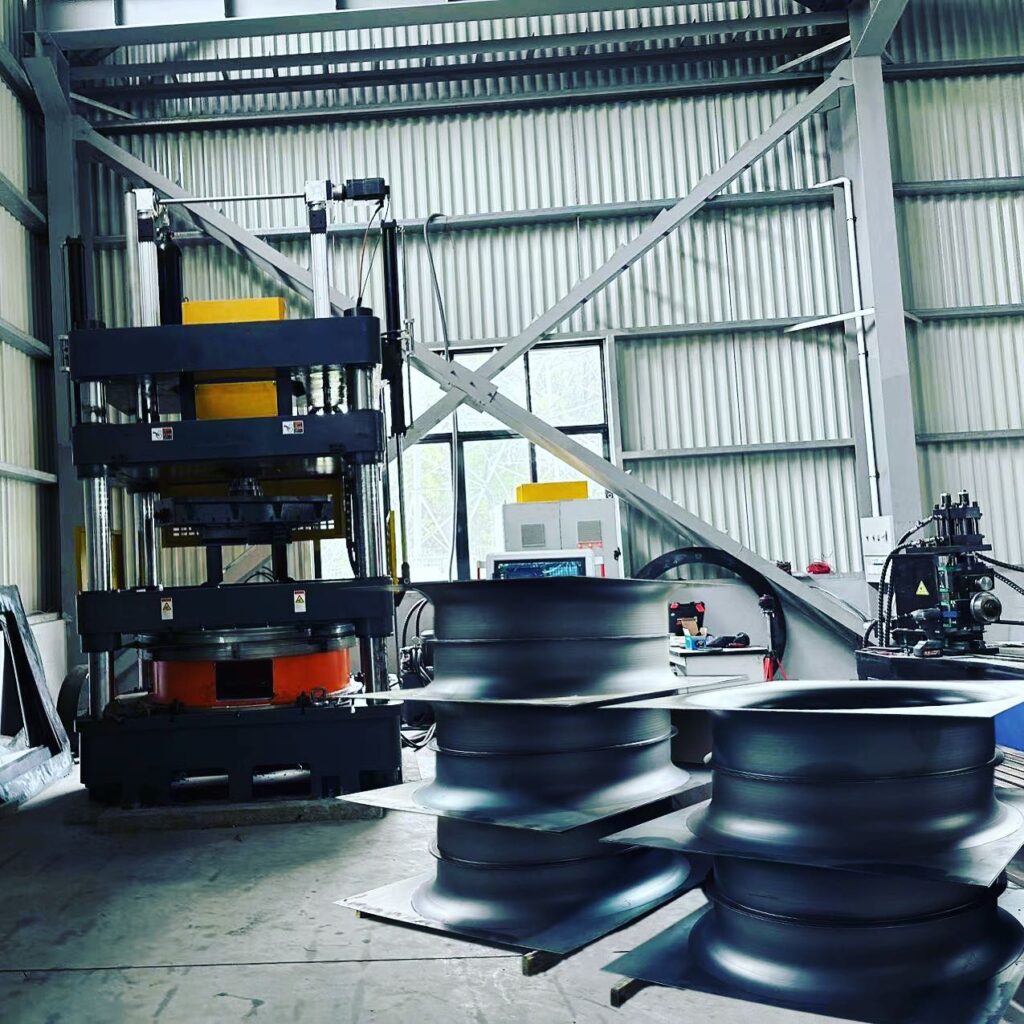
Stainless steel drawing press machines are specialized hydraulic or mechanical presses designed to shape and form stainless steel sheets into desired components through the deep drawing process. Stainless steel, known for its corrosion resistance, strength, and aesthetic appeal, presents unique challenges during forming due to its work-hardening properties and high tensile strength, requiring presses that offer precise control and robust performance.
These drawing press machines feature strong, rigid frames built to withstand the higher forces needed to deform stainless steel without compromising structural integrity or causing vibrations that could affect part quality. Hydraulic systems with servo-driven pumps are commonly employed to provide smooth, adjustable ram motion and controlled pressure, enabling the gradual and uniform material flow essential for preventing cracking or wrinkling.
Tooling for stainless steel drawing presses is typically made from hardened, wear-resistant materials to handle the abrasive nature of stainless steel and maintain tight tolerances. Die and punch surfaces are often polished to reduce friction and improve material drawability, while advanced lubrication systems help minimize galling and tool wear.
The presses incorporate precise control systems that monitor and adjust parameters such as ram speed, pressure, and stroke length in real time to accommodate the specific characteristics of stainless steel grades and thicknesses. This dynamic control reduces the risk of defects like tearing, springback, or surface blemishes, ensuring high-quality finished parts with smooth finishes.
Applications for stainless steel drawing press machines span numerous industries, including kitchenware, automotive trim, medical devices, and architectural components. Common products include sinks, cookware, fuel tanks, and decorative panels, all requiring consistent quality and durability.
Modern stainless steel drawing presses also emphasize energy efficiency and operator safety, integrating features such as regenerative hydraulics, ergonomic designs, and comprehensive guarding systems. Automation options, including robotic loading and unloading, further enhance productivity and repeatability.
Overall, stainless steel drawing press machines combine mechanical strength, precise hydraulic control, specialized tooling, and advanced process management to meet the demanding requirements of forming stainless steel components efficiently and reliably.
Stainless steel drawing press machines continue to evolve with advances in both mechanical design and control technology to better handle the unique challenges posed by stainless steel’s hardness and tendency to work-harden during forming. The presses are engineered to deliver consistent, high tonnage with minimal frame deflection, ensuring precise alignment between the punch and die throughout the stroke. This rigidity is crucial for maintaining dimensional accuracy and preventing defects such as wrinkling or tearing that stainless steel is prone to under uneven stress.
Hydraulic systems in these presses are increasingly sophisticated, featuring servo-controlled pumps and proportional valves that provide smooth and adjustable ram motion. This allows the forming process to be finely tuned, applying force progressively to accommodate variations in material thickness, grade, and blank size. Precise control over ram speed and dwell times improves material flow, reduces strain hardening, and extends tooling life by minimizing shock loads.
Tooling designed for stainless steel drawing presses is specially treated and coated to withstand the abrasive effects of the material and to reduce friction. Surface finishes on dies and punches are optimized to facilitate the metal’s flow and prevent galling, which can cause surface imperfections. Some tooling incorporates micro-texturing or advanced lubrication channels that deliver controlled amounts of lubricant exactly where needed, enhancing the drawability and surface finish of the parts.
Modern stainless steel drawing presses also incorporate real-time monitoring systems using force sensors, displacement transducers, and thermal cameras. These sensors provide immediate feedback to the control system, allowing dynamic adjustments that maintain optimal forming conditions throughout production runs. This closed-loop control enhances repeatability and quality consistency, which are critical in industries such as medical device manufacturing or food processing equipment, where stainless steel parts must meet stringent standards.
Automation is increasingly integrated with stainless steel drawing press operations. Robotic systems handle the loading and unloading of heavy blanks and finished parts, reducing operator fatigue and improving safety. Automated tool changers and in-line inspection stations equipped with machine vision allow for rapid setup changes and ensure dimensional and surface quality without manual intervention. This flexibility supports just-in-time manufacturing and the production of small batches or custom parts with minimal downtime.
Energy efficiency is another focus area, with presses using regenerative hydraulic circuits to capture energy during ram return strokes and servo-driven systems that modulate power use based on real-time demand. These features reduce electricity consumption and operating costs, aligning with growing industry emphasis on sustainable manufacturing.
Safety features on stainless steel drawing presses include comprehensive guarding systems, light curtains, emergency stop mechanisms, and ergonomic operator interfaces that minimize risk and improve usability. Noise reduction technologies and vibration dampening improve working conditions, supporting operator comfort and productivity.
As stainless steel alloys continue to advance with improved strength and corrosion resistance, drawing press machines adapt through enhanced control algorithms and tooling innovations to handle these new materials effectively. The ability to form complex shapes with high precision, minimal scrap, and excellent surface quality makes stainless steel drawing presses indispensable for producing durable, attractive, and high-performance components across diverse sectors.
In summary, stainless steel drawing press machines embody a combination of mechanical robustness, advanced hydraulic control, specialized tooling, and smart automation that enables manufacturers to meet demanding production requirements efficiently. Their continuous technological advancement ensures they remain capable of delivering consistent quality, operational efficiency, and flexibility in forming stainless steel components for a wide array of applications.
Building further on these developments, the integration of digital technologies into stainless steel drawing press machines is accelerating their transformation into smart manufacturing assets. Presses are now often equipped with comprehensive sensor arrays that monitor parameters such as hydraulic pressure, ram velocity, temperature, and vibration in real time. These data streams are fed into centralized control units employing artificial intelligence and machine learning algorithms, which analyze trends and detect subtle deviations indicative of tool wear, material inconsistencies, or potential process failures. This predictive capability enables proactive maintenance and process optimization, reducing downtime and improving overall equipment effectiveness.
The use of digital twins—virtual, real-time simulations of the physical press and forming process—allows engineers to virtually test new tooling designs, process parameters, or material batches before committing to actual production. This capability not only shortens development cycles but also minimizes material waste and tooling damage, which is especially valuable given the high cost of stainless steel materials and tooling components.
Customization and flexibility are increasingly prioritized, with modular press architectures enabling rapid reconfiguration for different part geometries and production volumes. Coupled with automated tool changers and adaptive control systems, these presses can switch between product runs with minimal setup time, supporting lean manufacturing principles and small-batch production without sacrificing throughput.
Advanced lubrication systems tailored for stainless steel forming are becoming standard, incorporating precise delivery of environmentally friendly lubricants that reduce friction, extend tool life, and improve surface finish. Some presses even feature closed-loop lubrication monitoring to ensure optimal application throughout the forming cycle.
Safety and ergonomics continue to evolve with enhanced human-machine interfaces that provide operators with intuitive touchscreens, augmented reality-assisted setup and troubleshooting, and voice-command capabilities. These interfaces reduce training time and enable operators to manage complex processes more effectively, fostering safer and more efficient work environments.
Sustainability considerations influence press design and operation, with a focus on energy-efficient hydraulic components, use of biodegradable hydraulic fluids, and systems engineered for easier disassembly and recycling at end of life. Manufacturers increasingly demand equipment that aligns with corporate social responsibility goals and regulatory requirements related to environmental impact.
In industries where traceability and compliance are critical, such as medical devices and aerospace, stainless steel drawing presses are integrated with comprehensive data logging and quality management systems. This integration ensures every part’s production history is recorded and auditable, facilitating certifications and enhancing customer confidence.
The continued convergence of mechanical engineering, hydraulic precision, digital intelligence, and automation in stainless steel drawing press machines equips manufacturers to meet rising expectations for product quality, production agility, and sustainability. This holistic advancement ensures stainless steel components are formed with exceptional consistency and efficiency, maintaining their vital role in diverse, demanding applications worldwide.
Deep Drawing Machines for Large Parts
Deep drawing machines for large parts are heavy-duty hydraulic or mechanical presses specifically engineered to handle the challenges of forming oversized metal components. These machines are crucial in industries like automotive, aerospace, appliance manufacturing, and industrial equipment, where large, complex shapes such as vehicle body panels, aircraft fuselage sections, large containers, or structural shells require precise and reliable forming.
Such machines feature exceptionally robust frames made from high-strength steel or cast iron to withstand the substantial forces involved in drawing large sheets without deformation or misalignment. The increased size of the press and tooling demands meticulous design to maintain uniform pressure distribution and precise guidance of the ram and die, ensuring consistent metal flow and preventing defects like wrinkling, tearing, or uneven thickness.
Hydraulic deep drawing presses for large parts typically employ high-capacity servo-controlled hydraulic systems that allow fine control over the ram’s speed, position, and pressure throughout the forming cycle. This precision is vital for managing the complex material behavior seen in large blanks, which often experience variable strain rates and thickness changes over wide areas. Programmable motion profiles can be tailored to gradually shape the metal, reducing stress concentrations and extending tool life.
Tooling for large-part deep drawing is custom-engineered to withstand high loads and maintain dimensional accuracy. Dies and punches are fabricated from wear-resistant materials and may include internal cooling channels to manage the heat generated during forming. Tool design often incorporates advanced simulation and finite element analysis (FEA) to predict metal flow and optimize geometry, reducing trial-and-error and ensuring quality from the outset.
Given the scale of these parts, automation and material handling systems are integral components of the overall solution. Overhead cranes, robotic manipulators, or automated guided vehicles (AGVs) assist in loading heavy blanks and unloading finished components safely and efficiently. Some systems feature inline inspection with laser scanners or machine vision to detect surface defects or dimensional deviations immediately after forming.
Large deep drawing presses increasingly integrate digital controls and Industry 4.0 technologies, allowing real-time monitoring of process parameters and predictive maintenance. This connectivity helps reduce downtime, improve part quality, and optimize energy consumption. Regenerative hydraulic systems and energy-efficient components are also commonly used to offset the high power demands typical of large-scale forming.
Operator safety and ergonomics are critical considerations, with presses incorporating extensive guarding, safety interlocks, noise reduction, and operator-friendly control interfaces. Due to the size and weight of components, workstations are designed to minimize physical strain and enhance workflow efficiency.
Applications for large deep drawing machines extend beyond automotive and aerospace to include heavy equipment panels, storage tanks, large kitchen sinks, and industrial enclosures. The ability to reliably form large, high-quality metal parts in fewer operations improves manufacturing efficiency, reduces welding and assembly costs, and enhances structural integrity.
In summary, deep drawing machines for large parts combine heavy-duty mechanical construction, advanced hydraulic control, customized tooling, automation, and digital intelligence to meet the demanding requirements of forming oversized metal components. These presses enable manufacturers to produce large, complex shapes with precision, efficiency, and consistency, supporting high-volume production and stringent quality standards in multiple industries.
Continuing from this foundation, deep drawing machines for large parts are increasingly designed with modularity and scalability in mind, allowing manufacturers to adapt the press size, tonnage, and stroke length according to evolving production needs. This flexibility supports both high-volume mass production and smaller, specialized runs without requiring entirely new equipment, reducing capital expenditure and increasing operational agility.
The hydraulic systems in these presses often incorporate servo-driven pumps and advanced proportional valves to provide smooth, precise control over the forming cycle. This precise control is essential when working with large blanks where uneven material flow or abrupt force application could cause defects or excessive tool wear. Programmable motion profiles allow the press to apply force in stages, gently shaping the metal and reducing internal stresses.
To handle the physical challenges of large-part forming, tooling is engineered not only for strength but also for ease of maintenance and quick changeover. Dies may be designed as modular assemblies, enabling individual components to be replaced or adjusted without disassembling the entire tool. This modularity shortens downtime and allows rapid response to design changes or material variations.
Material handling systems are often integrated into the press setup to manage the weight and size of the blanks and finished parts safely. Automated conveyors, robotic arms, or gantry cranes facilitate precise positioning, minimizing manual labor and the risk of damage or injury. Some facilities incorporate flexible automation cells that can be reconfigured quickly to accommodate different part sizes and production volumes.
Real-time monitoring and control systems are crucial for ensuring consistent quality in large deep drawing operations. Sensors embedded in the press and tooling provide continuous data on pressure, displacement, temperature, and vibration, which are analyzed by control software to detect anomalies early. This data-driven approach supports adaptive process adjustments and predictive maintenance, preventing costly breakdowns and scrap.
Energy efficiency measures are increasingly incorporated into these machines to manage the substantial power consumption associated with large presses. Regenerative hydraulic circuits recover energy during ram return strokes, and variable-speed pumps adjust power usage dynamically based on load requirements. These features contribute to reduced operating costs and environmental impact.
Safety remains paramount due to the scale and power of these presses. Comprehensive guarding, safety light curtains, emergency stop systems, and ergonomic control stations protect operators while facilitating efficient workflow. Noise and vibration reduction technologies improve the working environment, helping maintain operator focus and comfort during long shifts.
The integration of Industry 4.0 concepts transforms large deep drawing machines into smart manufacturing hubs. Connectivity with factory-wide networks allows seamless communication between the press, material handling systems, quality inspection devices, and enterprise resource planning (ERP) software. This integration supports holistic production planning, traceability, and continuous improvement initiatives.
Advanced simulation tools aid in the design and validation of forming processes for large parts, allowing engineers to model metal behavior, predict potential defects, and optimize process parameters virtually. This reduces the need for physical prototyping, accelerates time-to-market, and ensures that first-run parts meet quality expectations.
In industries such as automotive and aerospace, where large formed parts contribute significantly to structural integrity and safety, the precision and reliability of these deep drawing machines are critical. The ability to form complex geometries with consistent thickness and surface quality enhances performance while reducing assembly complexity.
Overall, deep drawing machines for large parts embody a blend of mechanical robustness, hydraulic precision, digital intelligence, and automation that empowers manufacturers to efficiently produce large-scale, high-quality components. Their ongoing development addresses challenges related to scale, material behavior, and production flexibility, ensuring they remain indispensable tools in modern metal forming operations.
Further advancing the capabilities of deep drawing machines for large parts, manufacturers are focusing on enhancing the adaptability and intelligence of these presses to meet the demands of increasingly complex component designs and dynamic production environments. One significant trend is the incorporation of multi-axis control systems that allow subtle adjustments in ram alignment and die positioning during the forming process. This capability helps accommodate slight variations in material properties or blank positioning, ensuring optimal contact and pressure distribution to prevent defects and improve dimensional accuracy.
The integration of real-time adaptive feedback loops is becoming standard, where sensor data on force, displacement, and material behavior is continuously analyzed to fine-tune forming parameters on the fly. Such closed-loop control minimizes process variability and enables the press to “learn” from each cycle, progressively optimizing itself for improved part quality and reduced cycle times.
Another area of innovation is the development of hybrid press systems that combine hydraulic power with mechanical elements like flywheels or servo-electric drives. These hybrids can deliver the high force and stroke flexibility of hydraulics with the energy efficiency and speed of mechanical systems. This combination is especially valuable when forming large parts that require both sustained high pressure and rapid cycle times, improving throughput without excessive energy consumption.
Tooling advancements also play a critical role, with the use of high-performance materials, surface coatings, and smart sensors embedded directly into dies. These sensors monitor wear, temperature, and load distribution in real time, alerting operators or automated systems to intervene before quality is compromised. Additionally, rapid tooling change systems reduce downtime between different product runs, supporting just-in-time manufacturing and customization trends.
In terms of material handling, the deployment of collaborative robots (cobots) alongside traditional automation allows for safer and more flexible interaction between human operators and machinery. Cobots can assist with positioning heavy blanks or removing formed parts, adapting to variable tasks without extensive reprogramming, which is particularly useful in low-volume or mixed-model production environments.
Digitalization extends beyond the press itself, with the formation of integrated manufacturing execution systems (MES) that connect drawing presses with upstream and downstream processes such as blanking, trimming, welding, and surface finishing. This connectivity ensures seamless workflow coordination, traceability, and rapid response to quality issues, enhancing overall production efficiency.
Sustainability is increasingly embedded in machine design, with presses optimized for reduced hydraulic fluid consumption, minimized waste through precision forming, and energy recovery systems that capture and reuse power generated during press movements. Environmental sensors monitor workplace emissions and fluid quality, enabling proactive maintenance and compliance with stringent environmental regulations.
Operator interfaces are evolving into intuitive platforms featuring augmented reality (AR) and virtual reality (VR) applications. These technologies provide immersive training, remote support, and on-the-spot guidance during complex setups or maintenance tasks, improving workforce competence and reducing human error.
As the demand for large, lightweight, and high-strength components grows, deep drawing presses are also adapting to process advanced materials such as aluminum alloys, high-strength steels, and composites. These materials often require specialized forming strategies to prevent cracking or distortion, driving the development of presses with enhanced control precision and adaptable tooling solutions.
Ultimately, the future of deep drawing machines for large parts lies in the synergy of mechanical innovation, digital intelligence, flexible automation, and sustainability. This convergence enables manufacturers to produce ever more complex and demanding components with high quality, efficiency, and environmental responsibility, securing their competitive edge in fast-evolving global markets.
Presses for Complex Deep Drawing Tasks
Presses designed for complex deep drawing tasks are engineered to handle intricate shapes, varying material thicknesses, and challenging forming sequences that standard presses may struggle with. These machines are essential in industries such as aerospace, automotive, electronics, and medical device manufacturing, where precision, repeatability, and the ability to form complex geometries are critical.
Such presses combine advanced hydraulic or servo-electric drive systems with highly responsive control architectures to deliver precise ram movement, variable speeds, and force modulation throughout the drawing process. This level of control allows gradual and customized deformation sequences that accommodate the unique strain distribution and material flow patterns of complex parts, reducing the risk of defects such as tearing, wrinkling, or springback.
The machine frame and guiding systems are built with exceptional rigidity and accuracy, ensuring perfect alignment between the punch and die. This precision is vital when forming parts with tight tolerances or multi-stage operations requiring consistent repositioning. Some presses incorporate adjustable die cushions or multi-zone pressure controls to fine-tune material support during forming, helping manage stresses and improve surface finish.
Tooling for complex deep drawing tasks is often multi-component and highly engineered, featuring segmented dies, collapsible punches, or stretch-forming elements. These tooling innovations allow for the creation of undercuts, re-entrant features, and multi-radius shapes that would be impossible or inefficient with traditional solid tooling. Modular tooling designs facilitate rapid changeover and maintenance, supporting flexible production schedules.
Integration of sensors and real-time monitoring systems enables continuous feedback on forces, displacement, and material behavior during forming. This data is used by advanced control algorithms to adjust process parameters dynamically, ensuring optimal forming conditions are maintained throughout the cycle. Such closed-loop control significantly improves process stability and reduces scrap rates.
Automation plays a key role in complex deep drawing operations, with robotic loading/unloading, automated tool changers, and in-line inspection systems becoming standard. These technologies reduce manual handling, improve repeatability, and speed up production, especially important for high-mix, low-volume manufacturing environments.
Simulation and virtual tryout software are heavily utilized to design and optimize both tooling and process parameters before physical production begins. These digital tools help predict potential issues such as thinning, wrinkling, or material failure, allowing engineers to refine the process and tooling to minimize costly trial-and-error.
Energy efficiency and sustainability are increasingly prioritized, with presses employing servo-driven hydraulics, energy recovery systems, and environmentally friendly lubricants. Enhanced safety features, including advanced guarding, light curtains, and ergonomic operator interfaces, ensure compliance with modern standards while promoting operator well-being.
In essence, presses for complex deep drawing tasks represent a fusion of mechanical strength, precision control, smart tooling, and digital intelligence. They empower manufacturers to produce sophisticated, high-quality components with intricate geometries reliably and efficiently, meeting the exacting demands of advanced industrial applications.
Continuing from this, presses for complex deep drawing tasks are also designed with high adaptability to manage the wide variety of materials and part designs encountered in modern manufacturing. They often feature programmable multi-step forming cycles that can be customized for each part, allowing gradual shaping that reduces material stress and improves dimensional accuracy. This capability is essential when working with advanced alloys, coated materials, or composites that respond differently to deformation compared to traditional steels.
The precision and responsiveness of the press’s hydraulic or servo-electric systems enable subtle variations in speed, force, and position throughout the stroke, tailoring the forming action to specific areas of the blank. For instance, increased force or slower ram speed can be applied in zones where material thinning is a concern, while other regions may benefit from faster movement to optimize cycle time. This level of control helps to minimize defects and maximize part consistency.
Tooling innovations play a crucial role in managing complexity. Segmented dies and collapsible punches allow for intricate shapes to be formed and then released without damaging the part. Some tooling systems incorporate sensors that monitor wear and temperature, providing real-time data that can trigger maintenance alerts or adaptive process adjustments. This proactive approach helps maintain part quality and tooling longevity.
Integration with digital manufacturing systems allows these presses to be part of a connected production environment. Data collected during each forming cycle can be analyzed to detect trends, anticipate tool wear, and optimize process parameters for future runs. This continuous improvement loop reduces downtime and scrap, ultimately lowering production costs.
Automation complements the press’s capabilities by handling material loading, part transfer, and quality inspection. Robotic systems equipped with vision sensors can identify parts and adjust handling strategies dynamically, accommodating variations in part geometry or orientation. Automated tool changers reduce setup times between different jobs, increasing overall equipment utilization and flexibility.
Energy efficiency remains a priority, with many presses incorporating regenerative hydraulic circuits that capture energy during ram retraction and reuse it for subsequent strokes. Servo-driven systems further optimize power consumption by delivering force only as needed, reducing waste and operating expenses.
Operator interfaces are designed to be intuitive and informative, often featuring touchscreen controls with graphical process monitoring and diagnostics. Some systems offer remote monitoring and support capabilities, enabling experts to assist operators or troubleshoot issues without being physically present, which is especially valuable in complex or critical applications.
Safety features are comprehensive, combining physical guards, light curtains, emergency stops, and safety interlocks that ensure operator protection without impeding productivity. Ergonomic design principles are applied to minimize operator fatigue and facilitate quick, safe tool changes and maintenance.
As product designs continue to evolve toward greater complexity and tighter tolerances, presses for complex deep drawing tasks evolve in tandem, incorporating advanced mechanics, digital intelligence, and flexible automation to meet these challenges. Their ability to reliably form intricate components with high precision and repeatability makes them indispensable in industries demanding cutting-edge manufacturing solutions.
Building further on these capabilities, presses for complex deep drawing tasks are increasingly leveraging artificial intelligence (AI) and machine learning (ML) to enhance process control and predictive maintenance. By continuously analyzing sensor data collected during forming cycles, AI algorithms can identify subtle patterns and correlations that may indicate early signs of tool wear, material inconsistencies, or process drift. This enables preemptive adjustments to forming parameters or timely maintenance interventions, reducing downtime and scrap while ensuring consistent part quality.
The rise of digital twins—virtual replicas of the physical press and tooling—allows manufacturers to simulate entire forming processes under varied conditions before actual production. These simulations help optimize tool design, process parameters, and machine settings, reducing costly trial runs and accelerating time-to-market. Digital twins can also be updated in real time with operational data, providing a dynamic platform for ongoing process refinement and troubleshooting.
In response to the demand for mass customization and smaller production batches, presses for complex deep drawing increasingly incorporate quick-change tooling systems and modular press components. This modularity supports rapid reconfiguration, enabling manufacturers to switch between different parts and materials with minimal downtime. Coupled with flexible automation, such systems improve responsiveness to market fluctuations and customer-specific requirements.
Material innovations, such as ultra-high-strength steels, lightweight aluminum alloys, and advanced composites, present new challenges for deep drawing presses. These materials often require specialized forming strategies, including controlled strain paths and multi-stage deformation, which press control systems must accommodate. Enhanced sensor feedback and adaptive control algorithms help ensure these challenging materials are formed without cracking, wrinkling, or other defects.
Environmental sustainability also shapes the evolution of complex deep drawing presses. Energy-efficient components, hydraulic fluids with reduced environmental impact, and systems designed for minimal waste generation align with corporate social responsibility goals and regulatory pressures. Furthermore, presses are increasingly designed for easier maintenance and end-of-life recycling, supporting circular economy principles.
Operator support technologies continue to advance, with augmented reality (AR) and virtual reality (VR) applications providing immersive training, remote assistance, and real-time guidance during setup and maintenance. These tools reduce human error, improve skill transfer, and enhance overall operational safety and efficiency.
In highly regulated industries like aerospace, medical devices, and electronics, the integration of comprehensive traceability systems within presses ensures that every formed part is accompanied by detailed production data. This capability supports stringent quality assurance protocols, audits, and compliance with industry standards.
Ultimately, presses for complex deep drawing tasks represent a sophisticated convergence of mechanical engineering, hydraulic precision, digital intelligence, and flexible automation. Their ongoing development empowers manufacturers to meet the increasing demands for complexity, quality, and efficiency in metal forming, securing a competitive edge in today’s fast-evolving industrial landscape.
Hydraulic Presses for Industrial Drawing
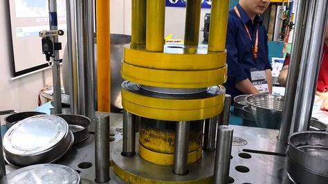
Hydraulic presses for industrial drawing are powerful machines designed to shape and form metal sheets or blanks into desired shapes through controlled pressure application. These presses are widely used across various heavy industries, including automotive, aerospace, appliance manufacturing, and construction, where high-volume and high-precision metal forming is essential.
The core strength of hydraulic presses lies in their ability to deliver consistent and adjustable force over the entire stroke, making them ideal for industrial drawing operations that require precise control of material deformation. Unlike mechanical presses, hydraulic systems can apply force smoothly and maintain it for extended periods, which is critical when working with thicker materials or complex shapes that demand gradual, uniform deformation to avoid defects such as cracking or wrinkling.
Industrial hydraulic drawing presses feature robust frames constructed from high-strength steel or cast iron, designed to withstand significant forces and maintain structural rigidity during operation. The press ram is guided by precision linear bearings or columns to ensure accurate alignment with the tooling, which is essential for consistent part quality and tool longevity.
The hydraulic system typically includes high-capacity pumps, servo or proportional valves, and accumulators that provide stable pressure and rapid response to control commands. Modern presses incorporate advanced electronic controls and programmable logic controllers (PLCs) that enable fine-tuning of pressing speed, force, dwell time, and ram position, allowing complex forming sequences to be executed with repeatability and precision.
Tooling for industrial drawing is custom-engineered for the specific part geometry and material. Dies and punches are made from wear-resistant tool steels and may include cooling channels or surface treatments to extend service life. The tooling setup often includes die cushions or pressure pads that provide back support during forming, helping to control material flow and reduce defects.
Automation is increasingly integrated into industrial hydraulic presses to improve throughput, safety, and consistency. Robotic loading and unloading systems, automated tool changers, and in-line inspection stations reduce manual intervention, enhance process control, and enable high-volume production runs with minimal downtime.
Energy efficiency is addressed through the use of variable displacement pumps, regenerative hydraulic circuits, and servo-driven systems that optimize power consumption based on load demand. These features not only reduce operating costs but also align with environmental sustainability goals.
Safety systems are comprehensive, including physical guards, light curtains, emergency stops, and ergonomic operator interfaces designed to protect personnel while maintaining productivity. Noise reduction and vibration damping technologies contribute to a safer and more comfortable working environment.
Industrial hydraulic drawing presses can handle a broad range of materials, from mild steel to high-strength alloys and specialty metals, making them versatile tools for diverse manufacturing applications. Their ability to deliver controlled, high-pressure forming enables the production of complex shapes with tight tolerances, contributing to product quality and structural integrity.
In summary, hydraulic presses for industrial drawing combine mechanical robustness, hydraulic precision, advanced control systems, and automation to meet the demanding requirements of modern metal forming industries. Their flexibility, reliability, and efficiency make them essential assets for manufacturers aiming to produce high-quality components at scale.
Expanding on this, industrial hydraulic drawing presses are often designed with modular components and scalable capacities to accommodate a wide variety of part sizes and production volumes. This flexibility allows manufacturers to optimize their equipment investments by selecting presses that can be adapted or upgraded as product demands evolve. Some presses feature adjustable stroke lengths and variable force settings, enabling them to handle both light-gauge sheet metal and thicker blanks within the same framework.
The control systems in these presses have evolved significantly, incorporating sophisticated human-machine interfaces (HMIs) that provide operators with real-time data on pressure, position, cycle times, and tool status. These interfaces often include touchscreen displays, graphical process visualization, and diagnostic tools that help reduce setup times and facilitate troubleshooting. Integration with plant-wide manufacturing execution systems (MES) enables seamless data exchange for production planning, quality control, and traceability.
Maintenance considerations are a key aspect of industrial hydraulic press design. Components such as hydraulic seals, pumps, and valves are selected for durability and ease of replacement. Preventive maintenance programs often leverage sensor data and condition monitoring to predict wear and avoid unexpected downtime. This predictive approach improves overall equipment effectiveness (OEE) and supports lean manufacturing principles.
In terms of process capabilities, industrial hydraulic drawing presses support multi-stage operations, where blanks undergo sequential forming steps to achieve complex geometries without compromising material integrity. This staged approach helps control metal flow and strain distribution, essential when working with advanced high-strength materials or difficult-to-form alloys. Some presses are equipped with multi-axis motion control, allowing subtle adjustments to ram alignment and die positioning to improve part accuracy and reduce tooling stress.
Environmental and energy considerations have led to the incorporation of energy-saving technologies such as variable frequency drives (VFDs), load-sensing hydraulic pumps, and energy recovery systems that capture power during ram retraction. These features reduce electricity consumption and minimize the carbon footprint of metal forming operations, aligning with increasingly stringent regulatory requirements.
Safety remains a priority, with modern presses equipped with comprehensive protective measures including safety interlocks, light curtains, two-hand control systems, and emergency stop buttons strategically placed around the machine. Ergonomic designs reduce operator fatigue and risk of injury, supporting a healthier workforce and improving productivity.
The versatility of industrial hydraulic drawing presses extends to their ability to form a wide range of materials beyond traditional steels, including aluminum alloys, copper, brass, and specialty metals. This capability is vital as industries pursue lighter, stronger, and more corrosion-resistant components to meet performance and sustainability goals.
Automation technologies integrated with hydraulic presses—such as robotic part handling, automated tool changers, and vision inspection systems—enhance production speed, repeatability, and quality. These systems reduce manual labor, minimize errors, and allow manufacturers to meet tight delivery schedules and complex customer requirements.
Overall, hydraulic presses for industrial drawing embody a balance of power, precision, flexibility, and reliability. They are critical enablers of modern manufacturing processes, capable of producing complex, high-quality components efficiently and consistently across a broad spectrum of industries and applications.
Further enhancing the capabilities of hydraulic presses for industrial drawing, manufacturers are increasingly integrating smart technologies to create more intelligent and responsive systems. These presses incorporate advanced sensors that monitor pressure, temperature, vibration, and position in real time, feeding data into centralized control units equipped with machine learning algorithms. This connectivity allows for adaptive process optimization, where the press can adjust parameters dynamically based on material behavior and tooling conditions to maintain optimal forming quality.
The rise of Industry 4.0 has also driven the development of networked hydraulic presses that communicate with other machines and factory systems. This interoperability facilitates predictive maintenance by analyzing trends across multiple presses, scheduling repairs before failures occur, and reducing unplanned downtime. It also enables comprehensive traceability, linking every formed part to its production parameters, tooling condition, and operator inputs—crucial for quality assurance in regulated industries.
Hybrid press designs are becoming more common, combining hydraulic power with electric or servo-electric actuation to harness the benefits of both technologies. Such systems offer the high force and flexibility of hydraulics alongside the precision, energy efficiency, and rapid response of electric drives. This hybrid approach improves cycle times, reduces energy consumption, and expands the range of materials and part complexities that can be formed.
Tooling innovation continues to advance in parallel, with modular, quick-change tooling systems reducing setup times and increasing press uptime. Smart tooling embedded with RFID tags or sensors allows automatic recognition and condition monitoring, streamlining tool management and preventing mismatches or errors during production.
Safety technology in hydraulic presses now includes comprehensive digital monitoring of operator zones, using cameras, laser scanners, and proximity sensors to detect human presence and halt operations instantly if necessary. This ensures a safer working environment without sacrificing throughput.
Energy efficiency remains a focal point, with regenerative systems capturing energy during ram return strokes and sophisticated hydraulic circuit designs minimizing fluid losses and heat generation. These improvements contribute to lower operating costs and environmental impact.
In terms of user interaction, modern hydraulic presses feature intuitive graphical user interfaces with touchscreens, customizable control panels, and remote access capabilities. Operators can monitor performance, adjust parameters, and receive real-time alerts from anywhere, enhancing responsiveness and operational flexibility.
The ongoing evolution of hydraulic presses for industrial drawing reflects a broader trend towards smarter, more connected, and highly adaptable manufacturing systems. These presses are not only powerful forming tools but also intelligent machines that enable manufacturers to meet increasingly demanding production requirements with efficiency, precision, and reliability.
Robust Deep Drawing Hydraulic Machines
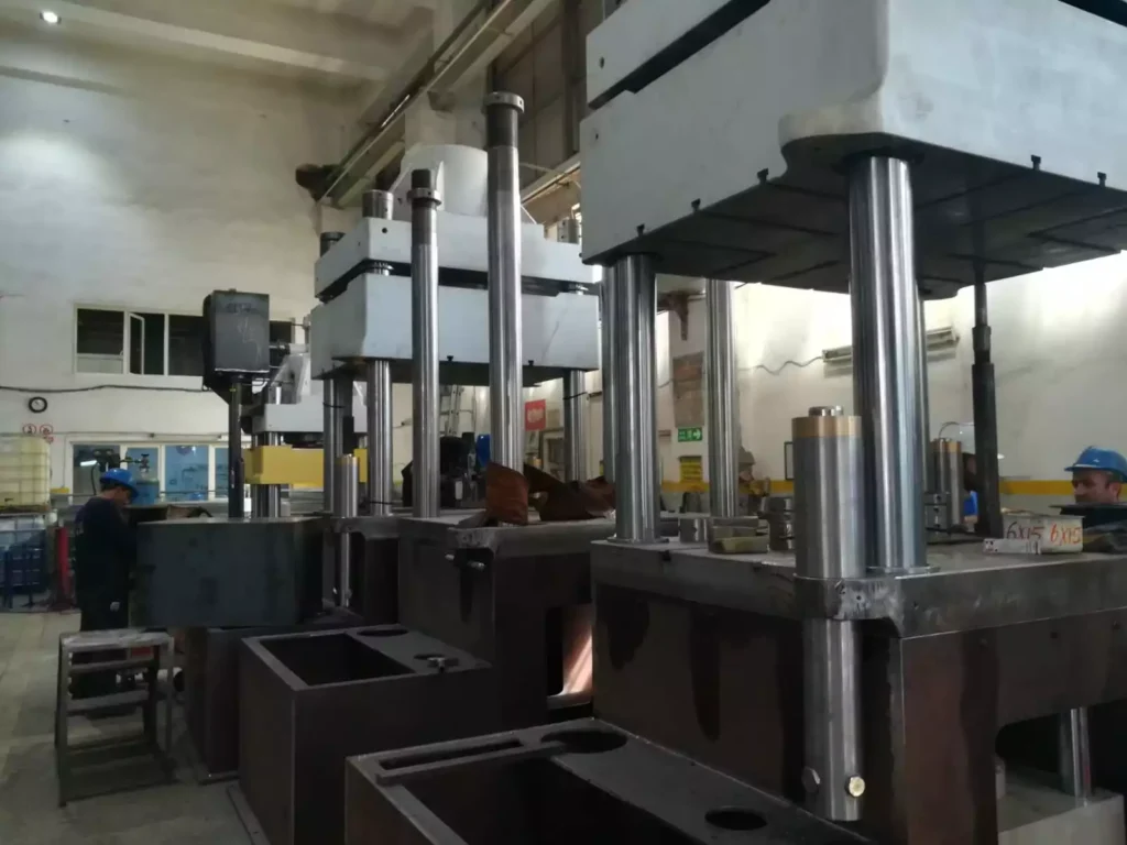
Robust deep drawing hydraulic machines are engineered to deliver exceptional strength, durability, and reliability in demanding metal forming environments. These machines are built to withstand high pressures and continuous operation, making them ideal for heavy-duty applications where consistent performance and long service life are critical.
The structural design of robust deep drawing hydraulic machines typically features a heavy-duty frame constructed from high-grade steel or cast iron, ensuring excellent rigidity and minimal deflection under load. This rigidity is essential to maintain precise alignment between the ram and tooling, preventing misalignment that could cause defects or damage during forming.
Hydraulic systems in these machines employ powerful pumps and high-capacity cylinders capable of generating substantial force while maintaining smooth and controllable ram movement. The hydraulic components are selected for durability and resistance to wear, with advanced sealing technologies minimizing leaks and extending maintenance intervals.
Control systems on robust deep drawing hydraulic machines are designed to provide precise regulation of pressure, speed, and stroke length. Programmable logic controllers (PLCs) and human-machine interfaces (HMIs) enable operators to set and monitor detailed process parameters, ensuring repeatability and allowing for quick adjustments to accommodate different materials or part designs.
Tooling support features such as adjustable die cushions, multi-zone pressure control, and automated lubrication systems help protect tooling and optimize material flow during deep drawing operations. These features reduce tooling wear and improve part quality by evenly distributing forming forces and preventing localized stresses.
Robust machines often include advanced safety mechanisms, including heavy-duty guarding, emergency stop functions, and interlocks that prevent operation unless all safety conditions are met. Ergonomic design considerations help reduce operator fatigue and facilitate safer handling of heavy blanks and finished parts.
Maintenance-friendly design is another hallmark, with accessible components, modular hydraulic units, and built-in diagnostic systems that enable quick identification of issues and reduce downtime. Some machines incorporate condition monitoring sensors that track the health of critical parts and predict maintenance needs.
In industrial settings where production demands are high and parts are often large or complex, these robust deep drawing hydraulic machines deliver reliable performance, handling tough materials and challenging geometries with consistency. Their strength and precision contribute to improved productivity, lower scrap rates, and extended equipment lifespan, making them a valuable investment for manufacturers focused on heavy-duty metal forming.
These machines are particularly suited for operations involving high-strength steel, stainless steel, and other hard-to-form materials, where weaker or less rigid machines might fail or produce inconsistent results. Their ability to maintain steady pressure throughout the drawing stroke ensures that even large, deep, or contoured parts are formed uniformly, which is crucial in industries such as automotive, defense, energy, and heavy equipment manufacturing. The hydraulic power units are often oversized in robust systems, providing not only the required force but also accommodating sustained duty cycles without overheating or performance degradation. Advanced cooling systems, such as heat exchangers or oil chillers, are integrated to maintain optimal hydraulic fluid temperature, preserving system efficiency and preventing premature component wear.
In terms of automation readiness, robust deep drawing hydraulic machines are built to integrate seamlessly with material handling systems, robotics, and inspection technologies. Robotic arms or gantry systems can load and unload heavy blanks, while vision-based inspection tools can verify part dimensions and surface quality before and after forming. This level of automation not only increases throughput but also ensures higher repeatability and reduces labor costs. Some machines are equipped with automatic die change systems, allowing for quick transitions between production runs and making it easier to handle a wide variety of part geometries without significant downtime. This flexibility is crucial in modern manufacturing, where shorter production cycles and increased customization are becoming the norm.
The feedback loop between sensors and control systems in these machines is highly responsive, enabling real-time adjustments during forming. For example, if the system detects abnormal force levels or changes in material resistance, it can automatically adjust ram speed or cushion pressure to compensate. This adaptability reduces the risk of defects like tearing or wrinkling and helps preserve tooling. Over time, data collected from these machines contributes to process optimization, enabling continuous improvement in efficiency, quality, and tool life. Additionally, robust deep drawing hydraulic machines often feature redundant safety systems, ensuring safe shutdown in case of power loss, hydraulic failure, or operator error.
Their construction typically emphasizes longevity, with high-grade components, precision-machined surfaces, and corrosion-resistant materials in critical areas. Heavy-duty bushings, chromed piston rods, and hardened guide rails ensure smooth operation even under high loads and over extended periods. Lubrication systems are often centralized and automated, ensuring consistent coverage and reducing maintenance needs. Many of these machines are also customizable to match specific application requirements, including custom bed sizes, stroke lengths, tonnage capacities, and tooling interfaces, allowing manufacturers to tailor equipment to their exact production needs.
Ultimately, robust deep drawing hydraulic machines are engineered for performance and reliability in the most demanding production settings. Their ability to consistently deliver high-quality results with minimal downtime makes them essential assets in any facility focused on precision metal forming. They embody a blend of engineering strength, control sophistication, and operational efficiency that defines the gold standard in modern deep drawing technology.
As manufacturing environments continue to evolve, robust deep drawing hydraulic machines are increasingly being developed with a focus on smart connectivity and integration with digital manufacturing ecosystems. This includes compatibility with Industrial Internet of Things (IIoT) platforms, which allow real-time monitoring of machine performance, remote diagnostics, and centralized control of production lines. Through cloud connectivity and edge computing, these machines can transmit operational data to management systems, enabling deeper insights into efficiency, utilization rates, and quality trends across the factory floor.
This integration allows not only for more informed decision-making but also for predictive maintenance models that use historical data to forecast component wear and failures before they happen. By minimizing unplanned downtime and maximizing the lifespan of critical components, manufacturers can achieve a higher return on investment and improve overall equipment effectiveness (OEE). Operators and maintenance teams are notified of upcoming service intervals or abnormalities via alerts on their dashboards or mobile devices, further streamlining workflows and reducing the risk of costly disruptions.
Moreover, these presses are often equipped with self-learning capabilities or AI-assisted control systems that refine forming parameters over time. By analyzing the outcomes of previous cycles and detecting variations in material or tooling behavior, the machine can automatically optimize future runs for better repeatability and reduced scrap. This level of automation ensures consistent product quality, even when forming complex geometries or working with variable materials.
Another benefit of advanced robust deep drawing machines is their ability to support sustainability goals. Through intelligent power management and regenerative hydraulic circuits, energy consumption is reduced significantly without sacrificing performance. When the press ram retracts, energy is often recovered and reused within the system, lowering the total energy footprint and helping companies align with environmental regulations and green manufacturing initiatives.
Noise and vibration control features are also a key part of modern robust press design. These improvements not only protect the structural integrity of the machine but also enhance the working conditions for operators. Acoustic enclosures, anti-vibration mounts, and optimized hydraulic circuits contribute to a quieter and more stable operation, which is especially important in facilities running multiple shifts or located in urban or sensitive industrial zones.
Training and usability have not been overlooked. Many manufacturers of robust deep drawing machines provide simulation software and virtual training modules that help new operators learn press functions and troubleshoot without risking downtime. User-friendly interfaces are designed with multiple language options, intuitive graphics, and guided workflows that make complex forming processes more accessible and reduce the learning curve.
In high-volume operations where every second counts, these machines deliver dependable performance day after day. Whether forming automotive body panels, appliance housings, industrial enclosures, or structural components, robust hydraulic deep drawing machines serve as the backbone of metal forming lines. Their ability to combine brute strength with intelligent control and adaptability positions them as critical assets in high-stakes, precision-driven manufacturing environments.
Hydraulic Press for Deep Draw Forming
A hydraulic press for deep draw forming is a specialized machine designed to shape metal sheets into intricate, hollow, or contoured components by applying a consistent and controlled hydraulic force. This process, known as deep drawing, involves pulling a metal blank into a die cavity using a punch, effectively transforming the flat sheet into a three-dimensional shape without tearing or excessive thinning. Hydraulic presses are ideally suited for this process due to their ability to deliver full tonnage throughout the stroke and their fine control over speed and pressure, which are critical for achieving high-quality results.
These presses typically consist of a main hydraulic cylinder (or multiple cylinders), a die cushion to control material flow, and a rigid frame that supports the tooling and maintains precise alignment. The press applies downward force through a ram attached to the punch, drawing the blank into the die. The die cushion provides counterpressure from below, preventing wrinkling and helping to maintain even material distribution throughout the part. The slow, steady motion of the hydraulic system allows for deep and complex draws that might be difficult or impossible with a mechanical press.
Hydraulic deep drawing presses are widely used across industries such as automotive, aerospace, appliance manufacturing, medical device production, and consumer goods. Applications range from forming car body panels, fuel tanks, and engine components to creating kitchen sinks, cookware, and electronic housings. These machines can handle a variety of materials including aluminum, stainless steel, copper, and high-strength alloys, making them highly versatile.
Modern hydraulic presses for deep draw forming are equipped with advanced control systems that allow precise adjustments to stroke length, ram speed, pressure limits, and dwell time. Programmable logic controllers (PLCs) and touch-screen human-machine interfaces (HMIs) make it easy to set and monitor process parameters. This level of control is essential for maintaining part consistency, reducing scrap, and extending tool life.
Some presses are also equipped with multi-point or servo-controlled die cushions that apply variable pressure zones beneath the blank. This enables more complex control over material flow, especially for parts with deep, asymmetric, or multi-draw features. Automation systems such as robotic loaders, part ejectors, and in-line inspection equipment are often integrated to streamline production and improve throughput.
Safety and maintenance are important aspects of hydraulic press design. These machines include robust guarding, interlock systems, and emergency stop functions. Many also feature condition monitoring systems to track hydraulic fluid quality, temperature, pressure fluctuations, and component wear, helping to prevent unplanned downtime and improve reliability.
Overall, a hydraulic press for deep draw forming is a powerful and adaptable solution for manufacturing high-precision, deep-formed metal parts. Its ability to apply uniform pressure, accommodate complex geometries, and process a wide range of materials makes it an essential asset in modern metal forming operations.
The continuous development of hydraulic presses for deep draw forming has introduced numerous enhancements that push both productivity and quality to new levels. One of the key advantages is the ability to achieve consistent force application throughout the entire stroke, unlike mechanical presses that typically reach peak force only near the bottom of the stroke. This consistency is vital for forming parts with deep or complex geometries, where uniform deformation and controlled metal flow are necessary to avoid issues like tearing, wrinkling, or excessive thinning.
In addition to their superior force control, these presses offer tremendous flexibility in cycle programming. Operators can customize speed profiles for each stage of the draw—approach, dwell, forming, and return—which is particularly beneficial for materials that require slow, even deformation or for tools that perform multiple forming stages in a single cycle. Some presses allow for fine-tuned pressure ramping, where hydraulic force gradually increases to avoid sudden impact on the tooling, reducing mechanical stress and extending tool life.
Hydraulic presses are also favored in industries where frequent changeovers are required. Their programmability and modular tooling interfaces enable fast setup and reduced downtime between jobs. Many systems incorporate quick die change mechanisms and self-centering clamping systems, which not only speed up production but also ensure precise alignment and repeatability. With these capabilities, manufacturers can handle smaller batch sizes and a greater variety of parts without compromising efficiency.
Energy consumption, once a drawback of hydraulic systems, has been greatly reduced in modern designs through the use of energy-efficient components like variable-speed pumps, regenerative circuits, and advanced flow control valves. These systems adjust power usage based on demand, reducing idle energy loss and minimizing heat generation. Combined with better hydraulic fluid management and integrated cooling systems, today’s hydraulic presses offer significantly improved thermal stability and operational efficiency.
Automation integration has become standard in high-volume production settings. Robotic arms can be programmed to load blanks, reposition parts during multi-stage forming, and remove finished products—all synchronized with the press cycle. Sensors placed throughout the system provide real-time feedback on positioning, pressure, temperature, and tool wear. This data is processed through smart control systems that alert operators to anomalies and can automatically adjust press parameters to maintain optimal forming conditions.
Another advantage lies in the press’s ability to adapt to different material types and thicknesses. Forming aluminum requires different speeds and cushion pressures than stainless steel, for example, and hydraulic systems can store and recall these parameters for each material type, ensuring consistent results with minimal operator input. This adaptability is essential for facilities that produce components from a wide material spectrum, such as appliance panels, electronics enclosures, and medical trays.
Operator safety and ease of use remain top priorities. Presses are built with safety curtains, lockout-tagout protocols, redundant safety relays, and intuitive emergency stop placements. Modern user interfaces are designed to minimize the risk of operator error through graphical guidance, interactive diagnostics, and password-protected settings that limit access to critical parameters. Maintenance schedules are automated and displayed on-screen, helping keep the system in peak condition and reducing unplanned stoppages.
Ultimately, hydraulic presses for deep draw forming combine brute force with fine control, reliability, and advanced technology. Their ability to produce complex, high-precision parts from a range of materials with repeatable quality and minimal waste makes them indispensable in both mass production and custom fabrication environments. Their evolving design continues to meet the changing demands of modern manufacturing, offering scalable, intelligent, and energy-efficient solutions for deep drawing operations worldwide.
Beyond their core mechanical and hydraulic advantages, modern hydraulic presses for deep draw forming increasingly emphasize integration with digital manufacturing frameworks and smart factory initiatives. These presses are often equipped with sensors and connectivity modules that enable continuous data collection, feeding information into cloud-based platforms for advanced analytics. This connectivity allows manufacturers to track machine performance, production metrics, and maintenance needs in real time, enabling data-driven decisions that optimize productivity and minimize downtime.
Predictive maintenance plays a pivotal role in extending machine life and ensuring consistent output. By monitoring key parameters such as hydraulic fluid condition, temperature fluctuations, pressure stability, and component wear, the system can predict when parts like seals, valves, or pumps require servicing or replacement. This proactive approach reduces unexpected breakdowns and maintenance costs, while improving overall equipment effectiveness (OEE).
Another area of focus is the incorporation of adaptive control systems that leverage artificial intelligence (AI) and machine learning algorithms. These systems analyze process data to identify subtle variations in material behavior or tooling conditions, adjusting forming parameters on the fly to compensate for deviations. The result is improved part quality, reduced scrap rates, and less manual intervention, especially important when working with new or challenging materials.
In terms of hardware innovations, hybrid hydraulic-electric press designs have emerged to combine the force and flexibility of hydraulic actuation with the precision and energy efficiency of electric drives. These hybrid presses can dynamically switch between modes depending on the forming requirements, offering faster cycle times, lower energy consumption, and finer control over ram motion. Such flexibility expands the range of feasible part geometries and materials.
The tooling interfaces have also evolved, with quick-change systems, modular dies, and integrated sensors becoming standard. These features facilitate rapid setup and tool monitoring, ensuring proper alignment and early detection of wear or damage. In some advanced setups, tooling components communicate directly with the press control system, enabling automated verification of tool installation and condition before production starts.
Operator ergonomics and safety continue to improve with enhanced guarding, light curtains, two-hand control systems, and augmented reality (AR)-assisted training and diagnostics. AR technologies help operators visualize machine states, tool setups, and maintenance procedures in real time, reducing errors and speeding up troubleshooting.
Sustainability considerations influence the design of hydraulic presses as well. Energy recovery systems capture hydraulic energy during ram retraction, feeding it back into the power system. Low-leakage valves and biodegradable hydraulic fluids reduce environmental impact, while noise and vibration dampening create better workplace conditions.
Ultimately, hydraulic presses for deep draw forming stand at the intersection of power, precision, and intelligence. Their continual evolution embraces digital transformation and sustainability without sacrificing the robust mechanical foundations essential to deep drawing. As manufacturing demands grow more complex and diversified, these presses provide adaptable, reliable, and efficient solutions that support innovation and competitive advantage across industries.
High-Speed Hydraulic Drawing Equipment
High-speed hydraulic drawing equipment is engineered to combine the power and precision of hydraulic forming with rapid cycle times, meeting the demands of high-volume production environments without compromising part quality. These machines are designed to accelerate the deep drawing process by optimizing hydraulic system responsiveness, reducing non-productive stroke time, and integrating advanced control technologies that enable fast yet controlled metal deformation.
Unlike traditional hydraulic presses that emphasize steady, slower strokes for complex forming, high-speed hydraulic drawing equipment employs powerful variable displacement pumps and fast-acting valves to achieve rapid ram movement while maintaining precise force control. This allows manufacturers to increase throughput significantly, making these machines ideal for industries such as automotive, appliance manufacturing, and consumer electronics, where large quantities of consistent parts are required.
Key to their performance is the balance between speed and forming accuracy. Advanced servo-hydraulic systems provide highly responsive pressure and position control, enabling rapid acceleration and deceleration of the ram with minimal overshoot or shock loading. This precision minimizes tooling wear and reduces the risk of defects such as tearing or wrinkling, even at high operating speeds.
The hydraulic circuits in these presses are often optimized for fast oil flow and efficient energy use, incorporating accumulators and regenerative systems to store and reuse energy during ram return strokes. This not only improves cycle times but also enhances energy efficiency, addressing the traditional criticism of hydraulic presses being less economical than mechanical alternatives.
High-speed hydraulic drawing equipment is commonly equipped with sophisticated control platforms featuring programmable logic controllers (PLCs) and touch-screen human-machine interfaces (HMIs) that allow for flexible programming of speed profiles, pressure ramps, dwell times, and multi-stage forming sequences. Operators can fine-tune processes to match specific materials and part geometries, ensuring repeatability and minimizing scrap.
Integration with automation is another hallmark, with robotic loaders, unloaders, and in-line inspection systems synchronized to the press cycle to maximize uptime and reduce manual handling. Sensors embedded within the tooling and press monitor parameters such as force, displacement, temperature, and vibration, providing real-time feedback to the control system for adaptive adjustments.
Safety features remain paramount despite the increased speeds, with light curtains, safety interlocks, and emergency stop systems designed to protect operators without hindering productivity. Noise reduction technologies and vibration dampening are also incorporated to maintain a comfortable working environment.
In summary, high-speed hydraulic drawing equipment offers a compelling solution for manufacturers seeking to combine the versatility and forming quality of hydraulic presses with the cycle speeds traditionally associated with mechanical presses. These machines enable rapid production of complex, high-precision parts while maintaining the robustness, flexibility, and control that hydraulic systems provide, making them well-suited for modern, high-demand metal forming operations.
High-speed hydraulic drawing equipment achieves its performance through a combination of advanced hydraulic components and intelligent system design. The use of high-capacity variable displacement pumps enables rapid flow rates, allowing the ram to accelerate quickly during the approach and forming phases. Coupled with proportional and servo valves, the system can precisely regulate pressure and flow, ensuring the forming force matches the requirements at every point in the stroke. This precision control helps prevent common defects caused by sudden force spikes or uneven material flow.
The machine frame and structural components are engineered to withstand the dynamic forces generated by rapid cycling. Reinforced steel construction and precision-machined guideways maintain alignment and reduce vibration, which is critical for consistent forming quality and tool longevity. To support continuous high-speed operation, the hydraulic power units are equipped with efficient cooling systems, including heat exchangers and oil filtration, to maintain fluid integrity and prevent overheating.
Cycle time reduction is further enhanced by optimized ram return speeds and rapid die cushion response. The die cushion, which applies counterpressure to control blank flow and prevent wrinkling, must react quickly and accurately at high speeds. Multi-zone die cushions with independent pressure control zones allow for fine adjustment of pressure distribution beneath the blank, enabling complex parts with varying thicknesses or shapes to be formed reliably even at elevated speeds.
Automation and integration with production lines are essential features. High-speed hydraulic drawing presses are often part of fully automated systems, where robotic arms or conveyors feed blanks and remove finished parts in synchronization with the press cycle. This reduces manual intervention, enhances safety, and ensures consistent throughput. Real-time process monitoring through sensors and advanced control software enables quick detection of anomalies such as tool misalignment, material defects, or hydraulic pressure fluctuations. When deviations are detected, the system can pause or adjust the cycle automatically to prevent defective parts from continuing down the line.
Energy efficiency is addressed through regenerative hydraulic circuits that capture energy during the ram’s return stroke and reuse it for the next cycle, lowering overall power consumption. Variable frequency drives (VFDs) control pump motors to match hydraulic demand precisely, avoiding wasted energy during idle or low-load periods. These technologies help manufacturers meet sustainability goals while benefiting from reduced operating costs.
Operator interfaces on high-speed hydraulic presses are designed for ease of use and quick setup. Touchscreen HMIs provide visual feedback on machine status, process parameters, and maintenance alerts. Programmable recipes allow operators to save and recall settings for different parts and materials, speeding up changeovers. Some systems incorporate augmented reality (AR) or virtual reality (VR) tools for operator training and maintenance support, improving knowledge transfer and reducing errors.
Maintenance accessibility is also a priority. Components subject to wear, such as seals, valves, and filters, are designed for quick replacement, minimizing downtime. Condition monitoring systems track hydraulic fluid cleanliness, temperature, and pressure stability, alerting maintenance teams before issues arise.
Ultimately, high-speed hydraulic drawing equipment delivers a unique combination of speed, precision, and adaptability. It meets the demands of modern manufacturing by producing complex, high-quality parts rapidly while maintaining the flexibility to handle varying materials and designs. This makes it a critical asset for industries that require both high output and superior forming accuracy, such as automotive body panels, appliance housings, and electronic enclosures.
Building on these capabilities, high-speed hydraulic drawing equipment continues to evolve with a focus on smart manufacturing and Industry 4.0 integration. Connectivity features enable seamless communication between the press, upstream and downstream equipment, and enterprise resource planning (ERP) systems. This holistic connectivity facilitates just-in-time production, dynamic scheduling, and real-time quality control, ensuring that manufacturing lines operate at peak efficiency.
Advanced analytics and machine learning algorithms analyze the vast amounts of data generated during the forming process. By identifying patterns and correlations, these systems can optimize process parameters automatically, further improving cycle times and product consistency. They can also detect early signs of tool wear or material inconsistencies, prompting preventive adjustments or maintenance before defects occur.
The trend toward modular press designs allows manufacturers to customize their equipment to specific production needs. Modular hydraulic units, interchangeable tooling interfaces, and scalable control systems provide flexibility to adapt to changing product designs or production volumes without investing in entirely new presses. This adaptability is particularly valuable in markets with rapidly evolving consumer demands or frequent product updates.
Ergonomics and user experience are enhanced through intuitive control panels and remote monitoring capabilities. Operators can oversee multiple machines from a centralized control room or even via mobile devices, allowing for quicker response times and more efficient resource allocation. Remote diagnostics and software updates reduce the need for onsite technical support, cutting maintenance costs and downtime.
Furthermore, safety standards are continuously updated and integrated into machine design. High-speed hydraulic presses incorporate multi-level safety systems, including light curtains, presence sensing devices, and interlocked guards. Advanced emergency stop protocols and fail-safe hydraulics ensure rapid and secure shutdowns in case of emergencies.
Environmental considerations also drive innovation in hydraulic system design. The use of eco-friendly hydraulic fluids, minimized leakage technologies, and noise reduction measures contribute to more sustainable and worker-friendly operations. Some presses include energy recovery systems that harness kinetic energy during the ram’s return stroke, feeding it back into the hydraulic circuit to reduce net power consumption.
Training and skill development are supported through virtual reality (VR) and augmented reality (AR) platforms, which provide immersive learning experiences for operators and maintenance personnel. These technologies simulate press operation and troubleshooting scenarios in a safe, controlled environment, accelerating competency development and reducing the risk of errors on the shop floor.
In summary, high-speed hydraulic drawing equipment represents a sophisticated blend of mechanical power, advanced control, and digital intelligence. Its continuous advancements ensure manufacturers can meet the dual challenges of increasing production speed and maintaining high-quality standards, all while supporting operational flexibility, sustainability, and safety. This positions such equipment as a cornerstone technology in modern, competitive metal forming industries.
Cost-Effective Drawing Press Machines
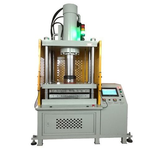
Cost-effective drawing press machines are designed to deliver reliable deep drawing performance while minimizing both initial investment and operating expenses, making them ideal for small to medium-sized manufacturers or operations focused on tight budgets. These presses balance essential functionality with efficient design, providing robust forming capabilities without the complexity or high costs associated with premium or highly automated systems.
Typically, cost-effective drawing presses utilize simpler hydraulic circuits with fixed displacement pumps and basic proportional valves, which reduce manufacturing and maintenance costs. While they may not offer the ultra-fast cycle times or highly advanced control features of top-tier machines, they still provide the precise pressure and stroke control necessary for consistent, quality metal forming.
Frame designs for economical presses are often optimized for standard sheet sizes and typical forming depths, avoiding over-engineering while ensuring sufficient rigidity and durability for common applications such as kitchen sinks, automotive brackets, cookware, and small appliance parts. The structural components are built from high-strength steel but use simpler fabrication and assembly methods to keep costs down.
Control systems on cost-effective presses focus on user-friendly interfaces with essential functionality—basic PLCs and simple HMIs allow operators to set stroke lengths, pressure limits, and cycle speeds without the need for extensive programming. These systems emphasize reliability and ease of maintenance, which is crucial for minimizing downtime and service expenses in budget-conscious operations.
To further reduce costs, many economical presses come with standardized tooling interfaces that accept off-the-shelf or modular die sets, avoiding custom tooling expenses unless specifically required. The machines are designed for straightforward maintenance, with easily accessible components and fewer hydraulic connections to minimize leak points and simplify troubleshooting.
Energy efficiency is addressed through conventional hydraulic designs with fixed-speed motors and standard valves, which may consume more power than variable-speed or servo-driven alternatives but keep upfront equipment and installation costs lower. Operators can still manage energy use by optimizing cycle times and avoiding unnecessary idling.
Safety features comply with essential industrial standards, including mechanical guards, emergency stop buttons, and basic light curtains or interlocks. While they may lack some of the advanced safety technologies found on higher-end machines, these presses provide adequate protection for typical manufacturing environments.
Overall, cost-effective drawing press machines serve as practical solutions for companies that require dependable metal forming capability without heavy capital expenditure. They are well-suited for production runs of moderate volume or simpler parts where speed and automation are less critical than consistent forming quality and ease of use. By focusing on essential features and robust design, these presses enable manufacturers to maintain competitiveness and product quality while controlling operational costs.
Cost-effective drawing press machines often find their niche in workshops and factories where flexibility and return on investment are paramount. Because they emphasize core functionality over cutting-edge features, these presses are easier to operate, which reduces the need for highly specialized training and allows less experienced operators to quickly become productive. This ease of use translates into lower labor costs and faster onboarding.
Maintenance requirements for such machines are generally straightforward. With fewer moving parts and simpler hydraulic circuits, routine servicing like filter changes, seal replacements, and hydraulic fluid checks can be performed quickly and without specialized tools or technicians. The availability of off-the-shelf components further reduces repair times and costs, ensuring that production interruptions are minimized.
Despite their economical design, many cost-effective presses can be upgraded or customized to some extent. Manufacturers may offer options such as enhanced control panels, additional safety devices, or improved hydraulic components that can be added as budgets allow or production demands increase. This scalability offers users the ability to grow their capabilities over time without investing in entirely new equipment.
These presses also benefit from widespread compatibility with a range of standard tooling and accessories, which can be sourced at competitive prices due to their commonality. This compatibility lowers the barriers to tooling changes and enables users to switch between different product lines or part geometries with minimal downtime and cost.
From a production standpoint, cost-effective drawing presses are ideal for small batch runs, prototyping, and operations where precision is important but ultra-high speed or extreme complexity is not. They support a broad array of materials, including mild steel, aluminum, and some stainless steels, allowing manufacturers to serve diverse markets with a single piece of equipment.
In addition, the footprint of these presses tends to be more compact compared to larger, fully automated systems, which can be advantageous for facilities with limited floor space. Their simpler utility requirements, such as standard electrical connections and basic hydraulic power units, further reduce installation costs and complexity.
Ultimately, the value proposition of cost-effective drawing press machines lies in their ability to reliably perform essential metal forming tasks at a reasonable cost, both upfront and throughout the machine’s service life. By focusing on proven technologies and minimizing unnecessary features, these presses provide manufacturers with dependable equipment that supports consistent quality and operational efficiency, helping businesses maintain profitability in competitive markets.
Cost-effective drawing press machines also contribute to sustainability goals by promoting longer equipment lifespans through their durable, straightforward designs. Because they avoid overly complex electronics or specialized components, these machines tend to have fewer failure points and are easier to refurbish or rebuild if necessary. This longevity reduces the frequency of full replacements, conserving resources and minimizing waste.
The initial affordability of these presses opens opportunities for smaller businesses or startups to enter the metal forming market without prohibitive capital barriers. This democratization supports innovation and diversity in manufacturing, allowing more players to develop specialized products or serve niche markets. Additionally, by providing reliable forming capabilities, cost-effective presses help ensure that small and medium enterprises (SMEs) can meet quality standards demanded by larger clients or certification bodies.
Training programs for operators and maintenance personnel on these machines often focus on fundamental hydraulic principles and practical skills rather than advanced programming or troubleshooting. This educational approach equips teams with a solid understanding of machine operation, fostering safer workplaces and more confident handling of equipment.
In terms of market trends, manufacturers of cost-effective drawing presses continue to improve energy efficiency within the constraints of affordability. Efforts include optimizing hydraulic circuit layouts to reduce losses, improving sealing technologies to prevent leaks, and using more efficient electric motors. These incremental enhancements help reduce operational costs and environmental impact without significantly increasing purchase prices.
Furthermore, some cost-effective presses incorporate basic automation options, such as simple timers, pneumatic part ejectors, or manual loading aids. These semi-automated features improve ergonomics and productivity while keeping the system’s complexity—and cost—manageable.
While these machines may not match the cycle speeds or high precision of premium models, their reliability and solid performance make them valuable assets for many manufacturers. They fill a crucial role by delivering consistent results with minimal investment, helping companies maintain competitive pricing and flexibility in their production processes.
In summary, cost-effective drawing press machines combine durability, ease of use, and essential functionality to provide practical metal forming solutions. They balance affordability with quality, enabling a wide range of manufacturers to achieve dependable deep drawing operations that support both business growth and sustainable practices.
Deep Draw Hydraulic Press Manufacturer
A deep draw hydraulic press manufacturer specializes in designing, engineering, and producing hydraulic press machines specifically optimized for deep drawing metal forming processes. These manufacturers focus on delivering equipment that combines powerful hydraulic systems with precise control mechanisms to achieve the complex deformation required in deep drawing, such as creating cup-shaped, cylindrical, or contoured parts from sheet metal.
Leading manufacturers typically offer a range of machines tailored to different production scales and industries, including automotive, kitchenware, electronics, aerospace, and appliance manufacturing. Their product lines often include standard presses as well as customized solutions designed to meet specific customer requirements, such as unique part geometries, material types, or production volumes.
A reputable deep draw hydraulic press manufacturer invests heavily in research and development to incorporate the latest technologies into their machines. This includes advanced servo-hydraulic control systems, energy-efficient pumps, modular tooling interfaces, and smart monitoring capabilities that support Industry 4.0 integration. These innovations help enhance machine performance, reduce cycle times, improve energy efficiency, and ensure consistent product quality.
Manufacturers also provide comprehensive customer support, including installation, operator training, preventive maintenance programs, and rapid technical assistance. Their expertise in hydraulic system design, mechanical engineering, and process optimization enables them to advise customers on the best press configurations, tooling setups, and operating parameters for efficient and defect-free deep drawing.
Furthermore, leading suppliers often comply with international quality and safety standards, ensuring their presses meet stringent regulations and can operate reliably in demanding industrial environments. They may also offer flexible financing options, leasing programs, and after-sales services to accommodate the varied needs of manufacturers worldwide.
In summary, a deep draw hydraulic press manufacturer plays a critical role in enabling metal forming industries to produce complex, high-precision components efficiently. Through their technical expertise, innovative designs, and customer-centric approach, they provide essential equipment that supports modern manufacturing demands and drives operational excellence.
Deep draw hydraulic press manufacturers distinguish themselves by their ability to tailor solutions that address the specific challenges of deep drawing processes, such as material thinning, wrinkling, and springback. They collaborate closely with customers during the design phase to understand production requirements, material characteristics, and part complexity, ensuring that the press system is optimized for both performance and longevity.
These manufacturers typically employ advanced simulation tools and finite element analysis (FEA) to model the deep drawing process and predict potential issues before physical prototyping. This approach reduces development time and costs while improving the precision of the final product. By integrating these simulations with machine design, manufacturers can optimize hydraulic pressures, ram speeds, and die cushion forces to achieve the desired material flow and minimize defects.
Manufacturers also emphasize the use of high-quality components sourced from reputable suppliers, such as precision hydraulic pumps, valves, sensors, and control electronics. The use of robust structural steel frames and precision machining ensures the press maintains alignment and rigidity over long service periods, which is crucial for maintaining tight tolerances in deep drawn parts.
Customer-centric service is another hallmark of successful manufacturers. Beyond delivering the machine, they often provide on-site commissioning to calibrate and validate the press, ensuring it meets performance benchmarks. Training programs for operators and maintenance personnel help maximize machine uptime and product quality. Additionally, many manufacturers offer remote diagnostics and predictive maintenance services leveraging IoT technologies, which help detect early signs of wear or system inefficiencies, reducing unexpected downtime.
Manufacturers often maintain global networks of distributors and service centers to provide timely support and spare parts, which is vital for minimizing production interruptions. Their expertise also extends to assisting customers with tooling design or collaborating with tooling suppliers to ensure that the press and tools work harmoniously.
Sustainability is increasingly important, and manufacturers incorporate energy-saving features such as servo-driven pumps, accumulator systems, and regenerative circuits to reduce the environmental impact of their presses. They also work on reducing noise levels and improving hydraulic fluid management to create safer and more environmentally friendly workplaces.
In terms of innovation, many manufacturers invest in digital solutions that enhance machine intelligence, including adaptive control systems that adjust forming parameters in real-time based on sensor feedback. This leads to higher first-pass yield rates and reduces scrap. Some also develop modular press designs that can be upgraded or reconfigured as production needs evolve, offering long-term flexibility and cost savings.
Overall, deep draw hydraulic press manufacturers play a vital role in advancing metal forming technology by combining mechanical engineering excellence, hydraulic expertise, and digital innovation. Their machines enable manufacturers to meet the growing demands for complex, high-quality parts with efficiency and reliability, supporting industries worldwide in maintaining competitive advantages.
Deep draw hydraulic press manufacturers also focus on building strong partnerships with their clients to foster continuous improvement and innovation. By engaging in ongoing collaboration, they gain insights into evolving industry trends, emerging materials, and new product designs. This close relationship allows them to adapt their equipment offerings quickly, ensuring that presses remain relevant and effective as manufacturing challenges change.
Many manufacturers support research initiatives and pilot projects with key customers, testing novel hydraulic technologies, control algorithms, and material handling systems. These collaborations often lead to breakthroughs in press performance, such as faster cycle times, reduced energy consumption, or the ability to handle more complex geometries. Such innovations then become part of their commercial product lines, benefiting a wider range of users.
Training and education also form a cornerstone of their customer engagement strategy. Manufacturers often provide detailed technical documentation, online resources, and hands-on workshops to help users understand the intricacies of deep drawing hydraulics, tooling interactions, and machine maintenance. This knowledge transfer empowers operators and engineers to troubleshoot issues effectively and optimize their processes, maximizing productivity and minimizing downtime.
On the global stage, many manufacturers adhere to strict export controls and certifications, ensuring that their presses meet international safety, quality, and environmental standards such as ISO, CE, and RoHS. Compliance with these regulations not only assures customers of product reliability but also facilitates seamless integration into multinational production networks.
In response to increasing demand for customization, manufacturers offer flexible design options including press tonnage, stroke length, bed size, and automation levels. This flexibility enables users to select machines perfectly suited to their specific applications—whether producing small, intricate parts or large, heavy-gauge components. Some manufacturers also provide turnkey solutions that include press, tooling, automation, and software integration, delivering a complete production package.
The after-sales support network is another critical aspect. Manufacturers typically maintain dedicated service teams equipped with diagnostic tools and replacement parts to provide rapid response times. Remote monitoring capabilities enable proactive maintenance, allowing issues to be addressed before they escalate into costly failures. This service model enhances machine uptime and extends equipment lifespan, ultimately delivering greater return on investment.
Looking forward, deep draw hydraulic press manufacturers are exploring the integration of artificial intelligence and machine learning to create even smarter presses. These technologies can analyze vast amounts of operational data to optimize forming parameters dynamically, predict maintenance needs with higher accuracy, and adapt to variations in material properties or environmental conditions.
In summary, deep draw hydraulic press manufacturers are not just suppliers of machinery; they are partners in manufacturing excellence. Through technological innovation, comprehensive support, and customer collaboration, they enable manufacturers to meet increasing demands for quality, efficiency, and flexibility in metal forming. This partnership drives progress across multiple industries, helping shape the future of manufacturing.
Forming Presses for Deep Draw Needs
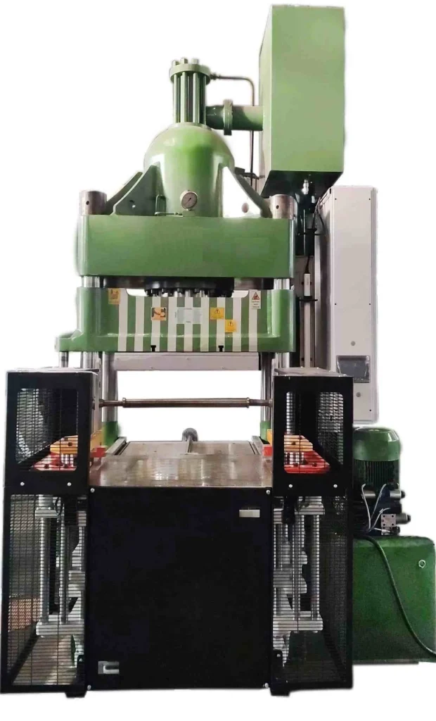
Forming presses for deep draw needs are specialized machines engineered to handle the complex metal deformation processes required to produce deep, hollow, and intricately shaped components from sheet metal. These presses apply controlled, uniform pressure to shape the metal blank into the desired form without compromising material integrity, preventing defects such as tearing, wrinkling, or excessive thinning.
Deep drawing forming presses come in various types, including hydraulic, mechanical, pneumatic, and servo-driven models, each suited to different production volumes, material types, and part complexities. Hydraulic presses are particularly favored for deep drawing due to their ability to deliver consistent force throughout the stroke, precise control over pressure and speed, and adaptability to varying part geometries.
The core design of forming presses for deep drawing emphasizes rigidity and structural strength to withstand high tonnage forces while maintaining dimensional accuracy. Frames are typically constructed from high-strength steel with reinforced cross members to minimize deflection and ensure repeatable results. The press bed size, stroke length, and ram travel are selected based on the size and depth of the parts being produced.
Tooling plays a crucial role in the deep drawing process, and forming presses are designed to accommodate various tooling configurations, including blank holders, draw dies, punches, and ejectors. The press must provide stable and adjustable force application to manage material flow effectively, controlling the balance between drawing force and blank holding to avoid defects.
Modern forming presses integrate advanced control systems that enable precise adjustment of stroke speed, dwell time, and pressure. Programmable logic controllers (PLCs) and human-machine interfaces (HMIs) facilitate easy operation, monitoring, and process optimization. Some presses feature closed-loop feedback systems with sensors to adjust parameters in real time, ensuring consistent quality even with variable input materials.
In high-volume production environments, forming presses are often combined with automated material handling systems, including robotic loading and unloading, in-line inspection, and tool changeover mechanisms. This integration enhances throughput, reduces cycle times, and minimizes operator intervention, improving overall efficiency and safety.
Energy efficiency is an increasing focus in the design of forming presses, with manufacturers incorporating servo-hydraulic drives, energy recovery systems, and optimized hydraulic circuits to reduce power consumption. Noise reduction, ergonomic design, and safety features such as light curtains, interlocks, and emergency stop systems are standard to protect operators and comply with regulations.
Forming presses for deep draw needs find applications across diverse industries, including automotive body panels, aerospace structural components, kitchenware, electrical enclosures, and consumer appliances. Their versatility allows manufacturers to produce parts with complex geometries and stringent dimensional tolerances, meeting both functional and aesthetic requirements.
In summary, forming presses tailored for deep drawing combine robust mechanical design with precise hydraulic or servo control, flexible tooling accommodation, and modern automation capabilities. These machines are essential for achieving the demanding shapes and quality standards required in contemporary metal forming applications.
These forming presses are engineered to handle a wide range of materials, from mild steel and aluminum alloys to stainless steel and other high-strength metals. The choice of press often depends on material properties such as ductility, thickness, and work-hardening behavior, which directly affect the forces required and the process parameters. Manufacturers carefully select or recommend presses based on these considerations to optimize forming efficiency and part quality.
The deep drawing process often involves multiple stages, especially for complex or deep parts, requiring presses that can perform progressive forming operations or be integrated into multi-station production lines. Some forming presses are designed with modular features to enable quick tooling changes and flexible production runs, which is critical in industries where customization and rapid product development are common.
Precision is a key aspect of these presses. They incorporate features like hydraulic cushioning systems and adjustable blank holders to finely tune the pressure distribution across the workpiece, controlling material flow and minimizing the risk of defects. The ability to adjust parameters such as ram speed and force during the stroke helps manage challenges like flange wrinkling or excessive thinning, which can compromise structural integrity or surface finish.
Operators benefit from advanced diagnostic and monitoring tools embedded in modern presses. These systems collect data on each stroke, pressure levels, and cycle times, providing real-time feedback that enables rapid detection of anomalies and process deviations. Such capabilities not only improve product consistency but also support preventive maintenance, reducing downtime and extending equipment life.
Safety remains a paramount concern in the operation of forming presses. Machines are equipped with multiple safety interlocks, light curtains, emergency stop functions, and guarded access points to protect workers from hazards associated with high-tonnage operations. Ergonomic design considerations ensure that operator interactions with the machine are intuitive and reduce fatigue, which further enhances workplace safety and productivity.
Forming presses for deep draw needs are often customized to meet specific customer requirements. Manufacturers work closely with clients to develop presses that address unique challenges, such as forming unusually shaped parts, accommodating specific production speeds, or integrating with existing manufacturing systems. This customer-driven approach results in tailored solutions that deliver optimal performance and return on investment.
In addition to standalone machines, many manufacturers offer complete deep drawing systems that include presses, tooling, automation, and quality control equipment. These turnkey solutions streamline production setup and help customers achieve faster time-to-market while maintaining high-quality standards.
The evolving demands of industries using deep drawing technology drive continuous innovation in forming press design. Developments such as adaptive controls, predictive maintenance enabled by AI, and enhanced material handling systems are increasingly incorporated to improve efficiency, reduce costs, and enable greater process flexibility.
Ultimately, forming presses dedicated to deep drawing needs provide the essential mechanical power, control precision, and operational flexibility required to transform flat metal sheets into complex, high-quality components. Their design and capabilities play a critical role in enabling manufacturers to meet the stringent demands of modern product design and competitive production environments.
These presses also accommodate a variety of production scales, from small prototype runs to high-volume mass production. For smaller batches, flexibility and ease of setup are prioritized, allowing manufacturers to quickly switch between different parts or materials without extensive downtime. In contrast, large-scale operations focus on maximizing throughput and repeatability, often incorporating automation and robotic integration to maintain consistent cycle times and minimize human intervention.
Material handling solutions play a significant role in the efficiency of deep drawing forming presses. Automated feeding systems, conveyors, and robotic arms can precisely position blanks into the press, reducing cycle time and improving repeatability. Likewise, automated part extraction and stacking systems minimize manual labor, reducing the risk of damage and speeding up overall production flow.
Tooling innovation is closely tied to press capabilities. Manufacturers often collaborate with tooling suppliers to develop dies and punches specifically optimized for the press’s force, stroke, and control systems. Advanced tooling materials and coatings help extend tool life, reduce friction, and improve surface finishes on formed parts. Some presses offer quick-change tooling systems to further enhance flexibility and reduce setup time.
Environmental considerations have led to the adoption of cleaner hydraulic fluids and sealed systems to prevent leaks, alongside designs that minimize energy consumption during idle or low-load conditions. Manufacturers also focus on noise reduction and vibration dampening to create safer and more comfortable working environments, complying with increasingly stringent occupational health standards.
Integration with factory automation and smart manufacturing systems is increasingly common. Many forming presses are equipped with sensors and communication protocols that feed data into centralized monitoring systems, allowing operators and managers to track machine status, production metrics, and maintenance needs in real time. This connectivity enables predictive maintenance schedules, reduces unexpected breakdowns, and improves overall equipment effectiveness (OEE).
The versatility of forming presses for deep drawing also allows them to adapt to emerging materials and manufacturing trends, such as lightweight alloys and advanced high-strength steels used in automotive and aerospace applications. Manufacturers continuously refine press designs to accommodate these materials’ unique forming characteristics, ensuring parts meet rigorous strength and durability standards while minimizing weight.
As product designs evolve toward more complex geometries and tighter tolerances, the precision and control capabilities of forming presses become increasingly critical. Features such as multi-axis press motion, servo-controlled ram speeds, and variable blank holding pressures enable the production of intricate shapes with minimal trial-and-error and scrap rates.
Training and support from press manufacturers help ensure operators and maintenance teams fully leverage the machines’ capabilities. Comprehensive programs cover safe operation, routine maintenance, troubleshooting, and process optimization, empowering facilities to maximize productivity and part quality.
In conclusion, forming presses for deep draw needs are complex, highly engineered machines that blend mechanical robustness, advanced control technologies, and flexible design features. They form the backbone of many metal forming operations, enabling the production of a wide array of high-quality components critical to modern manufacturing industries.
Hydraulic Deep Draw for Aerospace Industry
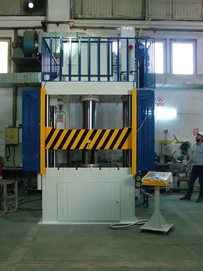
Hydraulic deep draw presses play a vital role in the aerospace industry, where the demand for high-precision, lightweight, and complex-shaped metal components is exceptionally stringent. Aerospace parts often require forming from advanced alloys such as aluminum, titanium, and high-strength stainless steels, materials known for their excellent strength-to-weight ratios but also for their challenging formability. Hydraulic deep drawing presses provide the controlled force and precise deformation necessary to meet these demanding requirements.
The aerospace industry demands exceptional dimensional accuracy and surface finish, as components must fit precisely within tight assembly tolerances and often serve critical structural or aerodynamic functions. Hydraulic deep draw presses excel in this regard by offering smooth, consistent force application throughout the stroke, minimizing defects like wrinkling, tearing, or excessive thinning that could compromise part integrity or performance.
Aerospace parts—such as fuel tanks, engine casings, ducts, and structural brackets—often involve complex geometries and deep drawing depths. Hydraulic presses with customizable stroke lengths, tonnage capacities, and programmable control systems enable manufacturers to tailor the forming process to each part’s unique characteristics, ensuring optimal material flow and structural strength.
In addition, aerospace manufacturing requires repeatability and reliability over long production runs or batch manufacturing with strict quality controls. Hydraulic deep draw presses designed for aerospace applications incorporate advanced sensors and feedback systems that monitor pressure, ram speed, and material behavior in real time. This data allows for immediate adjustments, ensuring consistent quality and reducing scrap rates.
Material handling and tooling solutions in aerospace deep drawing are also highly specialized. Tooling is engineered to withstand high loads and resist wear from forming difficult alloys, often using hardened steels and advanced coatings. Hydraulic presses in this sector are frequently integrated with automation systems, including robotic loading/unloading and in-line inspection, to improve efficiency and meet the rigorous documentation and traceability standards aerospace manufacturers follow.
Energy efficiency and sustainability are growing priorities even in aerospace manufacturing. Hydraulic deep draw presses incorporate energy-saving technologies such as servo-hydraulic drives and variable displacement pumps to reduce power consumption without compromising performance. Noise reduction and improved hydraulic fluid management contribute to safer and cleaner work environments.
Due to the critical nature of aerospace components, manufacturers often require comprehensive validation and certification of their deep drawing processes. Hydraulic presses used in this industry are designed to comply with stringent aerospace standards and regulations, including NADCAP and AS9100 quality systems. Press manufacturers collaborate closely with aerospace clients to develop tailored solutions that meet these exacting criteria.
In summary, hydraulic deep draw presses are indispensable tools in aerospace manufacturing, providing the precision, strength, and flexibility needed to form complex, high-performance components from advanced materials. Their ability to combine robust mechanical design with sophisticated control systems makes them ideal for meeting the aerospace sector’s stringent quality, safety, and efficiency demands.
Hydraulic deep draw presses in the aerospace industry are engineered to handle the unique challenges presented by advanced materials and complex part geometries. The high-strength alloys used often exhibit limited ductility and require precise control of forming parameters to avoid defects such as cracking or excessive thinning. Hydraulic systems offer smooth, controllable pressure application that can be finely tuned throughout the forming stroke, allowing manufacturers to carefully manage metal flow and maintain structural integrity.
These presses often feature customizable stroke lengths and adjustable blank holders, which are critical for accommodating varying part dimensions and controlling material wrinkling or buckling. The ability to program different pressure profiles and ram speeds throughout the draw cycle helps in forming intricate shapes without compromising surface quality or dimensional accuracy.
Given the aerospace industry’s focus on safety and reliability, hydraulic deep draw presses are integrated with sophisticated monitoring and feedback systems. Real-time data collection on parameters like force, position, and speed enables operators to detect deviations early, reducing scrap and ensuring that parts consistently meet tight tolerances. This data can also be used for traceability and quality assurance, essential for aerospace certification processes.
Automation plays a significant role in enhancing the efficiency and repeatability of hydraulic deep drawing in aerospace manufacturing. Robotic loading and unloading systems minimize human error and exposure to heavy materials, while in-line inspection technologies ensure immediate quality verification. This integration supports lean manufacturing principles and helps aerospace manufacturers meet demanding production schedules.
The tooling used in aerospace deep drawing must withstand the stresses of forming high-strength alloys repeatedly without deformation or wear. Press manufacturers collaborate with tooling specialists to develop dies and punches that are durable, precisely machined, and often treated with advanced surface coatings to reduce friction and extend lifespan. Quick-change tooling systems can also be implemented to reduce downtime when switching between different parts or materials.
Environmental considerations are increasingly important, with manufacturers incorporating energy-efficient hydraulic components such as variable displacement pumps and servo-hydraulic drives. These systems reduce power consumption by adjusting output to match demand rather than running at constant full capacity. Additionally, improved hydraulic fluid management and noise reduction features contribute to safer and more sustainable manufacturing environments.
Compliance with aerospace quality and safety standards is a fundamental aspect of press design and operation. Hydraulic deep draw presses are built to meet rigorous certifications, and manufacturers provide extensive documentation, process validation support, and operator training to help aerospace companies maintain regulatory compliance. This ensures that formed components can be confidently used in critical applications where failure is not an option.
Looking ahead, the aerospace industry’s evolving demands continue to drive innovation in hydraulic deep draw press technology. Advances in digitalization, including machine learning and predictive maintenance, enable presses to adapt to subtle changes in material properties or process conditions, further enhancing product quality and operational efficiency. Integration with smart factory systems supports comprehensive data analytics and continuous process improvement.
Overall, hydraulic deep draw presses are indispensable assets for aerospace manufacturing, enabling the production of complex, high-performance parts with the precision, repeatability, and reliability that the industry requires. Their advanced control capabilities, combined with robust mechanical design and automation integration, position them as key enablers of modern aerospace production.
Hydraulic deep draw presses continue to evolve in the aerospace sector by embracing modular and scalable designs, allowing manufacturers to adapt their equipment as production demands change. This flexibility supports not only different part sizes and complexities but also the rapid introduction of new aerospace components driven by innovation cycles in aircraft and spacecraft design.
The presses are increasingly equipped with advanced simulation and digital twin technologies, enabling engineers to model forming processes virtually before physical trials. This reduces development time and material waste by optimizing press parameters and tooling designs upfront. By predicting potential defects or process inefficiencies early, manufacturers can refine setups and ensure smoother production ramp-ups.
Material innovations in aerospace, such as composites and hybrid metal structures, also influence hydraulic deep draw press development. While traditional presses primarily form metals, ongoing research explores how these machines can integrate with hybrid forming techniques that combine deep drawing with additive manufacturing or advanced joining methods, expanding the range of producible aerospace parts.
Maintenance strategies are also shifting toward condition-based and predictive approaches. Embedded sensors and IoT connectivity monitor press health indicators like hydraulic pressure, temperature, vibration, and component wear. Data analytics platforms process this information to forecast maintenance needs, schedule service proactively, and avoid unexpected downtime, all of which are critical in aerospace manufacturing where delays can be costly.
Training and workforce development remain essential as these presses grow more sophisticated. Manufacturers and aerospace companies invest in specialized programs to build operator and technician expertise in both traditional hydraulic press operation and emerging digital tools. This dual knowledge ensures efficient use of the equipment and maximizes its capabilities.
Environmental sustainability is gaining prominence in aerospace manufacturing, pushing press manufacturers to reduce carbon footprints through energy-efficient designs and the use of eco-friendly hydraulic fluids. Recycling and disposal practices for hydraulic oils and press components are also becoming standard considerations to comply with stricter environmental regulations.
Collaborations between press manufacturers, aerospace OEMs, and research institutions foster innovation and knowledge sharing. These partnerships accelerate the adoption of new materials, forming techniques, and digital solutions, ensuring hydraulic deep draw presses remain at the forefront of aerospace production technology.
In essence, hydraulic deep draw presses for the aerospace industry represent a fusion of mechanical strength, precise control, digital intelligence, and sustainability. They are continually refined to meet the exacting standards of aerospace manufacturing, enabling the production of reliable, high-performance components that advance the frontiers of flight and space exploration.
Deep Drawing Presses for Battery Cases
Deep drawing presses for battery cases are specialized machines designed to form precise, durable enclosures essential for housing battery cells in various applications—from electric vehicles (EVs) and portable electronics to energy storage systems. These presses must accommodate the unique requirements of battery case manufacturing, including tight dimensional tolerances, material consistency, and surface integrity, to ensure safety, performance, and longevity.
Battery cases are typically made from metals like aluminum or stainless steel due to their strength, corrosion resistance, and lightweight properties. Deep drawing presses must provide controlled and uniform pressure to shape these materials into complex, often thin-walled geometries without causing defects such as cracks, wrinkles, or excessive thinning. The forming process must preserve material integrity, as any compromise can lead to battery failure or safety hazards.
Hydraulic deep drawing presses are commonly used for battery case production because of their precise force control and ability to maintain consistent pressure throughout the stroke. This precision is crucial for forming the intricate shapes and features—such as corners, flanges, and sealing lips—required for effective battery enclosure design. The presses often feature adjustable stroke lengths and blank holders to accommodate varying case sizes and thicknesses.
Given the critical safety standards for battery systems, deep drawing presses for battery cases are often integrated with advanced monitoring and quality control systems. Sensors track parameters like ram force, speed, and position in real time, enabling immediate adjustments to maintain tight tolerances and reduce scrap rates. In-line inspection systems may also be employed to detect surface defects or dimensional deviations as parts are formed.
Automation is increasingly important in battery case manufacturing to meet high-volume production demands while ensuring consistent quality. Deep drawing presses are often paired with robotic material handling, automated tool changers, and integrated process controls to streamline production workflows, reduce human error, and improve efficiency.
Tooling for battery case deep drawing is specially engineered to handle the delicate balance between strength and flexibility needed to form thin metal sheets without damage. Tools are made from hardened materials with precise surface finishes and may incorporate coatings to reduce friction and extend lifespan, ensuring consistent forming quality over long production runs.
Energy efficiency and environmental considerations influence the design of these presses as well. Manufacturers implement servo-hydraulic drives, energy recovery systems, and optimized hydraulic circuits to minimize power consumption. Additionally, noise reduction features and ergonomic designs contribute to safer, more comfortable working environments.
In summary, deep drawing presses for battery cases combine mechanical robustness, precise hydraulic control, advanced automation, and quality assurance technologies to produce reliable, high-quality battery enclosures. Their role is critical in supporting the rapid growth of battery-powered technologies by enabling efficient, scalable manufacturing of essential protective components.
Deep drawing presses for battery cases must also address the challenges posed by evolving battery designs and materials. As battery technologies advance, cases often require more intricate shapes to accommodate higher energy densities, improved cooling features, and enhanced safety mechanisms. This complexity demands presses capable of handling variable thicknesses and fine details while maintaining consistent forming quality.
The presses are frequently equipped with programmable control systems that allow operators to customize forming parameters for different battery case models or materials without extensive manual adjustments. This flexibility supports rapid product development cycles and enables manufacturers to respond quickly to changing market needs or new battery standards.
Integration with digital manufacturing systems is increasingly common, allowing these presses to communicate with upstream and downstream equipment. This connectivity supports seamless production flow, from blank preparation through forming, inspection, and assembly, improving traceability and reducing bottlenecks.
Due to the critical nature of battery safety, manufacturers often implement stringent process validation and documentation requirements. Deep drawing presses in this context are designed to support comprehensive data logging, capturing detailed records of each forming cycle to ensure full traceability and compliance with industry regulations such as UL or IEC standards.
Maintenance and reliability are paramount given the high production volumes in battery manufacturing. Hydraulic deep drawing presses for this sector incorporate features that facilitate easy access for maintenance, quick tool changes, and diagnostics to minimize downtime. Predictive maintenance technologies, using sensor data and analytics, help anticipate component wear or hydraulic system issues before they lead to failures.
Material handling solutions paired with these presses are designed to protect delicate battery case blanks and formed parts from damage or contamination. Automated feeding, precise positioning, and gentle extraction systems reduce manual handling risks and support cleanroom or controlled environment manufacturing when required.
Environmental sustainability is increasingly emphasized, with presses designed to reduce hydraulic fluid waste and energy consumption. Some manufacturers explore alternative fluids and sealed hydraulic systems to minimize environmental impact while maintaining performance. Noise abatement and ergonomic design considerations further enhance workplace conditions.
The combination of advanced hydraulic control, robust mechanical design, automation, and quality management makes deep drawing presses indispensable for battery case production. They enable manufacturers to meet the rigorous demands for precision, safety, and efficiency that underpin the rapidly expanding battery industry.
As battery technologies continue to evolve, deep drawing presses will likely incorporate further innovations such as adaptive forming controls, real-time defect detection using machine vision, and even greater integration into smart factory ecosystems. These developments will help manufacturers maintain high quality and productivity while addressing the complex challenges of next-generation battery case manufacturing.
Deep drawing presses for battery cases are also adapting to the growing emphasis on lightweighting and sustainability in battery design. As manufacturers strive to reduce overall battery weight to improve energy efficiency and vehicle range, presses must handle thinner gauge materials without compromising strength or durability. This requires precise control of forming pressures and speeds to avoid issues like tearing or wrinkling in ultra-thin metal sheets.
The development of multi-stage deep drawing processes has become common, where the battery case is formed through several progressive steps within the press or across linked press stations. This approach helps manage complex geometries and deep draws more effectively, improving material flow and reducing stress concentrations that can lead to defects. Multi-stage forming also allows tighter control over dimensional accuracy and surface finish, both critical for ensuring proper sealing and assembly of battery modules.
Hydraulic deep drawing presses for battery cases are increasingly equipped with servo-hydraulic systems that combine the power of hydraulics with the precision and energy efficiency of electric servo drives. These hybrid systems enable variable speed and force control during the forming cycle, allowing for optimized pressure profiles tailored to different materials and case designs. The result is improved part quality, reduced cycle times, and lower energy consumption.
Tooling technology advances complement these press improvements. Modular and quick-change tooling systems enable rapid switches between different battery case designs, supporting flexible manufacturing and shorter lead times. Tooling materials with enhanced wear resistance and low-friction coatings extend service life and improve forming consistency.
Quality control remains a top priority. In addition to force and position sensors, some presses incorporate integrated machine vision and laser measurement systems to inspect formed parts immediately after drawing. This real-time inspection detects surface defects, dimensional variances, or tool wear, allowing corrective actions before defects propagate down the production line.
The trend toward automation extends beyond forming and inspection to include logistics and supply chain integration. Smart deep drawing presses communicate with warehouse management and production scheduling systems, optimizing material flow and minimizing inventory. This connectivity supports just-in-time manufacturing, which is increasingly important as battery manufacturers respond to volatile market demands and supply chain constraints.
Safety considerations specific to battery case production also influence press design. Handling and forming potentially reactive materials demand robust safety features, including guarded operation zones, emergency stops, and hydraulic system redundancies. These ensure both operator protection and process reliability in high-stakes manufacturing environments.
Looking ahead, ongoing research explores the use of adaptive control algorithms powered by artificial intelligence to further refine deep drawing processes. These systems could learn from each forming cycle, adjusting parameters dynamically to accommodate subtle variations in material properties or environmental conditions, pushing battery case quality and production efficiency to new levels.
In summary, hydraulic deep drawing presses for battery cases are at the forefront of manufacturing technology, balancing the demands of precision, flexibility, speed, and sustainability. They play a critical role in enabling the mass production of safe, lightweight, and high-performance battery enclosures essential to the global transition toward electrification and renewable energy.
Precision Deep Draw Press Machines
Precision deep draw press machines are specialized hydraulic or mechanical presses designed to form metal sheets into highly accurate, complex shapes with tight tolerances and superior surface finishes. These machines are essential in industries where component quality, consistency, and dimensional accuracy are critical—such as automotive, aerospace, electronics, medical devices, and battery manufacturing.
The hallmark of precision deep draw presses is their ability to deliver controlled, uniform pressure throughout the forming stroke, minimizing common defects like wrinkling, tearing, or uneven thickness. They typically feature advanced hydraulic systems with fine-tuned force regulation and smooth ram movement, allowing delicate control over the metal flow during drawing.
To achieve high precision, these presses are often equipped with servo-hydraulic or electro-hydraulic drives, which combine the power of hydraulics with the exact positioning capabilities of servo motors. This hybrid technology enables variable speed and force profiles within each stroke, adapting dynamically to different materials, thicknesses, and part geometries.
The frame construction of precision deep draw presses emphasizes rigidity and vibration damping to maintain alignment and repeatability over long production runs. Precision-machined components, robust guides, and high-quality bearings contribute to stable and consistent ram movement, which is critical for dimensional accuracy.
Tooling used with precision deep draw presses is engineered with tight clearances and superior surface finishes, often made from hardened tool steels or coated with low-friction materials. Quick-change tooling systems support fast setup times and enable manufacturers to switch between part designs efficiently, boosting production flexibility.
These presses are integrated with advanced control systems featuring programmable logic controllers (PLCs), human-machine interfaces (HMIs), and real-time sensors that monitor force, position, speed, and other parameters. Data logging and analytics capabilities facilitate quality assurance and process optimization, ensuring that every part meets stringent specifications.
Precision deep draw presses often incorporate automated material handling and part removal systems to reduce cycle times and enhance repeatability. Automation also minimizes human error and improves operator safety, which is particularly important when dealing with thin or delicate materials.
Due to their ability to consistently produce parts with tight tolerances and excellent surface quality, precision deep draw presses are indispensable in manufacturing components such as intricate automotive body panels, aerospace structural parts, medical device housings, and electronic enclosures.
In summary, precision deep draw press machines represent the convergence of mechanical strength, advanced hydraulic control, and digital automation. They enable manufacturers to meet the highest standards of accuracy and quality, supporting complex metal forming tasks across a wide range of high-tech industries.
Precision deep draw press machines also emphasize process repeatability, which is crucial for high-volume manufacturing where consistent part quality is non-negotiable. To ensure this, these presses employ closed-loop control systems that continuously monitor and adjust forming parameters in real time. Sensors embedded in the press detect variations in force, stroke position, and speed, allowing the system to compensate immediately for any deviations, thereby reducing scrap and rework.
Material versatility is another key feature. Precision deep draw presses can handle a broad range of metals including stainless steel, aluminum alloys, copper, and specialized high-strength materials. This adaptability is important as different industries require varied materials based on strength, corrosion resistance, weight, or conductivity. The press controls are programmable to optimize the forming process for each material’s unique properties, such as ductility and thickness.
Ergonomics and operator interface design are integral to precision deep draw presses, enabling operators to easily program, monitor, and control the press with minimal training. Touchscreen HMIs provide intuitive control panels where operators can set up forming sequences, adjust parameters, and view live data. Many systems also incorporate alarms and guided troubleshooting to quickly address process issues, minimizing downtime.
Maintenance-friendly design supports the longevity and reliability of precision deep draw presses. Key components like hydraulic cylinders, pumps, and tooling guides are accessible for inspection and servicing. Predictive maintenance features, using data analytics from sensor inputs, help schedule repairs before failures occur, further enhancing uptime.
Advanced versions of precision deep draw presses may integrate machine learning algorithms that analyze process data over time to identify patterns and optimize forming conditions automatically. This approach leads to continual improvement in part quality and process efficiency, aligning with Industry 4.0 principles.
Safety features are comprehensive, with interlocked guarding, emergency stop systems, and pressure relief mechanisms standard on modern machines. These ensure that operators and equipment are protected during operation, particularly when working with high forces and precise movements.
In the context of sustainability, precision deep draw presses often incorporate energy-efficient hydraulic components such as variable displacement pumps and servo-controlled valves that reduce power consumption without compromising performance. Noise reduction technologies and environmentally friendly hydraulic fluids contribute to safer and greener manufacturing environments.
Overall, precision deep draw press machines are sophisticated systems that blend mechanical robustness with cutting-edge control technologies. Their ability to consistently produce complex, high-quality metal parts with minimal waste and downtime makes them vital tools for manufacturers striving for excellence in highly competitive markets.
Precision deep draw press machines also benefit significantly from integration with upstream and downstream manufacturing processes, forming part of a fully automated production line. This integration allows seamless coordination between material feeding, forming, inspection, and packaging, reducing manual handling and speeding up cycle times. For example, automated blank feeders supply sheets or coils precisely positioned for each draw cycle, while robotic arms or conveyors remove finished parts and transfer them to quality control stations or assembly lines.
The use of digital twins is an emerging trend in precision deep drawing, where virtual models of the press and forming process simulate operations before actual production. This simulation helps optimize tool design, press parameters, and material behavior, minimizing trial-and-error and accelerating time-to-market. It also supports troubleshooting by enabling engineers to replicate and analyze issues virtually without interrupting production.
In sectors like aerospace and medical device manufacturing, where traceability is crucial, precision deep draw presses are equipped with advanced data capture and reporting systems. Every press cycle can be logged with detailed information on forming conditions, operator actions, and machine status. This data supports quality audits, regulatory compliance, and continuous improvement initiatives.
Customization of precision deep draw presses is common to meet the specific demands of different industries or part designs. Press manufacturers often work closely with customers to tailor press size, tonnage, stroke length, and control features. Some presses incorporate multi-axis movement or hybrid forming technologies combining deep drawing with other metalworking processes like bending or embossing for enhanced functionality.
Training and support services are integral to maximizing the benefits of precision deep draw presses. Manufacturers typically provide comprehensive operator and maintenance training, process consulting, and remote diagnostics to help customers maintain optimal performance and troubleshoot issues quickly.
As materials evolve, including the use of advanced alloys and composite-metal laminates, precision deep draw presses are continuously adapted with stronger frames, enhanced hydraulic systems, and smarter controls to handle new challenges. This ongoing innovation ensures they remain indispensable tools for producing complex, high-quality components required in modern engineering applications.
In conclusion, precision deep draw press machines represent a sophisticated blend of mechanical design, hydraulic power, digital control, and automation. Their role in producing intricate, dimensionally accurate metal parts with excellent surface quality makes them vital assets across diverse high-tech manufacturing industries, driving efficiency, quality, and innovation forward.
Fast Cycle Hydraulic Drawing Presses
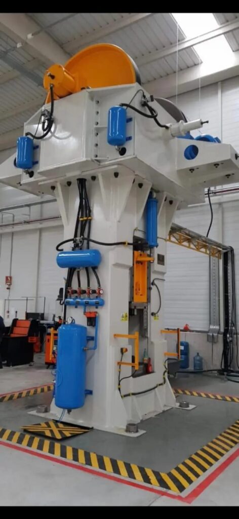
Fast cycle hydraulic drawing presses are specialized machines designed to maximize production speed without compromising the precision and quality of deep-drawn metal parts. These presses are essential in high-volume manufacturing environments where reducing cycle time directly translates to increased throughput, cost efficiency, and competitiveness.
To achieve rapid cycle times, these presses employ advanced hydraulic systems with fast response servo valves and high-flow pumps that enable quick pressurization and depressurization of the hydraulic cylinders. The ram can move swiftly through the forming stroke and return phases, minimizing idle time while maintaining smooth, controlled motion to prevent defects like tearing or wrinkling in the metal sheet.
The design of fast cycle presses focuses on optimizing the press stroke and dwell times. Shortened dwell times—the period during which the ram holds the metal under pressure—are carefully balanced with sufficient force application to ensure proper material flow and part formation. This requires precise control systems capable of dynamically adjusting pressure and speed during each cycle.
To support the increased operational tempo, these presses feature robust frame constructions and components engineered to withstand the stresses of rapid repetitive cycles. High-strength materials and enhanced bearing systems improve durability and reduce wear, thereby extending machine life and maintaining performance consistency.
Automation plays a critical role in fast cycle hydraulic drawing presses. Integration with robotic material handling systems allows seamless loading and unloading of blanks and formed parts, eliminating manual delays and enabling continuous operation. Quick-change tooling systems further reduce setup times between production runs, enhancing overall equipment effectiveness (OEE).
Advanced control software with real-time monitoring and adaptive feedback loops ensures consistent part quality despite the accelerated cycle. Sensors measure force, position, and speed, enabling the system to detect and correct process variations on the fly. Data analytics can identify trends in tooling wear or hydraulic performance, supporting predictive maintenance to minimize unplanned downtime.
Fast cycle presses are widely used in industries such as automotive, electronics, and consumer goods, where large volumes of metal components—like cups, housings, and enclosures—are produced daily. They balance speed with precision, ensuring parts meet stringent dimensional and surface quality requirements.
Energy efficiency is also a consideration; modern fast cycle presses often incorporate servo-hydraulic drives or energy recovery systems that reduce power consumption during rapid cycles. Noise reduction features and ergonomic designs contribute to safer and more comfortable working environments despite the high operational pace.
In essence, fast cycle hydraulic drawing presses combine high-speed hydraulic technology, durable mechanical design, and intelligent automation to deliver rapid, reliable, and high-quality metal forming. They enable manufacturers to meet demanding production schedules without sacrificing the precision and quality critical to their products’ performance.
Fast cycle hydraulic drawing presses also incorporate sophisticated thermal management systems to address the heat generated by rapid, continuous operation. Excessive heat can affect hydraulic fluid viscosity, machine components, and tooling accuracy, so cooling systems—such as oil coolers and temperature sensors—maintain optimal operating conditions, ensuring consistent press performance and prolonging equipment lifespan.
The presses often utilize variable displacement hydraulic pumps paired with energy-efficient servo motors to precisely match the hydraulic flow to the immediate demand. This not only reduces energy consumption during idle or low-load phases but also improves responsiveness during rapid acceleration and deceleration of the ram.
Material handling systems are designed to keep pace with the fast cycles, often employing high-speed conveyors, robotic arms, and vision-guided automation to accurately position blanks and extract finished parts without interrupting the press cycle. These systems minimize the risk of misfeeds or jams, which could cause costly downtime or damage to delicate materials.
Tooling in fast cycle presses is engineered to withstand frequent high-impact loads, using wear-resistant steels and advanced coatings that reduce friction and extend tool life. Quick-change tooling setups enable operators to switch dies swiftly, supporting flexible manufacturing and rapid product changeovers essential in just-in-time production environments.
Real-time process monitoring software is integral to maintaining quality at high speeds. It collects data on every cycle, allowing operators and engineers to detect subtle changes in forming force, speed, or material behavior that could indicate tool wear or process drift. Alerts can trigger preventative maintenance actions before defects occur, thereby reducing scrap and rework.
Safety systems are robust, incorporating light curtains, interlocks, and emergency stop functions designed to operate flawlessly even during rapid press cycles. These protections safeguard operators from injury while maintaining uninterrupted production flow.
Fast cycle hydraulic drawing presses are increasingly integrated into smart factory ecosystems, communicating with other machines and manufacturing execution systems (MES) to optimize scheduling, track production metrics, and support continuous improvement. This connectivity enables manufacturers to respond swiftly to changing demand or quality requirements.
In sum, fast cycle hydraulic drawing presses represent a sophisticated balance of speed, precision, durability, and automation. By combining cutting-edge hydraulic technology with advanced controls and robust mechanical design, these presses enable manufacturers to achieve high throughput without compromising the stringent quality standards required in modern metal forming applications.
Fast cycle hydraulic drawing presses also benefit from innovations in sensor technology and artificial intelligence, which further enhance their speed and reliability. Advanced sensors can monitor parameters such as vibration, pressure fluctuations, and temperature in real time, feeding data into AI-driven control systems that predict and adjust process variables automatically. This adaptive control helps maintain optimal forming conditions at high speeds, reducing defects and improving overall yield.
The integration of machine learning algorithms enables the press to learn from each cycle, gradually refining its operation to accommodate subtle variations in raw material properties or tooling conditions. This continuous self-optimization reduces setup times, minimizes scrap, and extends the life of tooling by avoiding unnecessary strain.
In high-demand production environments, redundancy systems may be implemented to ensure uninterrupted operation. For example, dual hydraulic circuits or backup power supplies can keep the press running smoothly even if one subsystem encounters an issue, reducing costly downtime.
Maintenance strategies for fast cycle presses emphasize predictive and condition-based approaches. By analyzing operational data trends, maintenance teams can anticipate component wear or hydraulic fluid degradation before failures occur. This proactive maintenance scheduling ensures high availability and protects the investment in costly precision equipment.
Environmental considerations are increasingly influencing press design. Manufacturers are adopting biodegradable or less toxic hydraulic fluids and improving sealing technologies to prevent leaks and reduce environmental impact. Energy recovery systems capture and reuse kinetic energy from the ram’s return stroke, further improving the overall energy efficiency of fast cycle presses.
Customization is common, with presses tailored to the specific needs of the product and production volume. Parameters such as tonnage, stroke length, and automation level are matched to application requirements, whether forming deep cylindrical cups, complex automotive panels, or intricate electronic housings.
Ultimately, fast cycle hydraulic drawing presses stand at the intersection of mechanical engineering, digital technology, and sustainable manufacturing. Their ability to deliver high-quality parts at accelerated speeds makes them indispensable in industries striving to meet ever-increasing production demands while maintaining exacting standards for precision and reliability.
Custom Deep Draw Hydraulic Press Builds
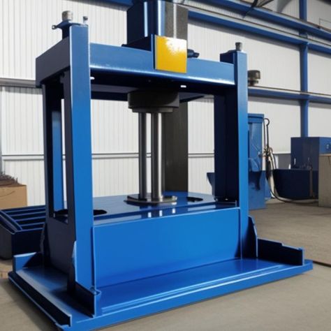
Custom deep draw hydraulic press builds are tailored solutions designed to meet the unique requirements of specific manufacturing applications. Unlike standard presses, these machines are engineered from the ground up or extensively modified to handle specialized part geometries, materials, production volumes, or process complexities that off-the-shelf equipment cannot efficiently address.
The customization process begins with a thorough analysis of the customer’s needs, including part design, material properties, desired cycle times, quality tolerances, and integration requirements with existing production lines. Based on this assessment, engineers develop a press design optimized for the specific deep drawing operation, balancing factors like tonnage capacity, stroke length, ram speed, and frame rigidity.
Custom presses often feature specialized hydraulic systems, such as servo-hydraulic drives for precise force and speed control, or multi-zone pressure control to manage complex forming stages within a single stroke. This allows different areas of the part to be formed with varying pressures and speeds, reducing defects and improving material flow.
Frame construction is adapted to accommodate unique tool sizes or shapes and may incorporate reinforced structures or vibration damping elements to ensure consistent accuracy under heavy or unusual loads. Some custom presses include multi-axis movement capabilities, allowing lateral, rotational, or tilting motion of the ram or tooling to perform compound forming operations without repositioning the workpiece.
Tooling systems are custom designed or modified for quick changeovers and enhanced durability, often with modular components that support various part variants or production scales. Integration of automatic blank feeding, part removal, and inline inspection systems can also be included to create a turnkey manufacturing solution that improves efficiency and reduces manual intervention.
Advanced control systems in custom builds provide tailored user interfaces and programmable logic controllers (PLCs) configured to the specific process parameters and quality checkpoints required by the application. Real-time data acquisition and analysis support adaptive forming strategies, predictive maintenance, and comprehensive quality assurance.
Safety features are incorporated to meet industry standards and customer-specific requirements, often including custom guarding, light curtains, and emergency stop protocols designed around the unique operation and layout of the press.
Custom deep draw hydraulic press builds also account for space constraints, energy consumption targets, and environmental considerations, ensuring the equipment fits seamlessly into the customer’s facility while optimizing operational costs and sustainability.
By offering highly specialized machinery, custom deep draw hydraulic press builds enable manufacturers to achieve superior part quality, reduce scrap rates, increase throughput, and handle complex forming challenges that standard presses cannot manage efficiently.
In essence, these bespoke presses are engineered partnerships between manufacturers and press builders, combining deep domain expertise with precision engineering to deliver optimal forming solutions tailored exactly to the customer’s production goals.
Custom deep draw hydraulic press builds also often involve close collaboration between the press manufacturer, tooling designers, and the end-user to ensure every aspect of the machine aligns perfectly with production needs. This partnership helps anticipate potential challenges in forming difficult materials or complex geometries, allowing for design adjustments before fabrication begins.
Materials used in the construction of custom presses are carefully selected to provide the necessary strength, stiffness, and durability required for the intended application. High-grade steel alloys, precision-machined components, and advanced surface treatments are common to enhance wear resistance and extend machine life, especially in heavy-duty or high-cycle operations.
In many cases, custom presses incorporate modular designs, enabling future upgrades or reconfigurations as production demands evolve. This flexibility can include options for adding automation components, upgrading control systems, or increasing tonnage capacity without replacing the entire press, thereby protecting the customer’s investment over time.
Customization also extends to the software side, with control systems tailored to facilitate ease of use, comprehensive process monitoring, and integration with the customer’s manufacturing execution systems (MES). This integration supports real-time production tracking, quality control, and data analytics, providing valuable insights that drive continuous improvement and operational efficiency.
Ergonomics and operator safety are integral to custom press designs. Controls, displays, and access points are positioned to maximize operator comfort and efficiency while minimizing the risk of accidents. Customized safety interlocks and guarding solutions are designed to fit unique machine layouts, meeting or exceeding industry safety standards.
Energy efficiency is another key focus in custom builds. Designers often incorporate energy-saving technologies such as variable displacement pumps, servo drives, and regenerative hydraulic systems that recover energy during the ram’s return stroke. These features help reduce operational costs and environmental impact, aligning with sustainability goals.
Overall, custom deep draw hydraulic press builds provide a high degree of precision, reliability, and adaptability. They enable manufacturers to tackle complex forming challenges, optimize production workflows, and maintain stringent quality standards, all while ensuring that the equipment remains efficient and cost-effective throughout its service life. This bespoke approach is essential for industries where standard equipment falls short, and performance requirements demand tailored engineering solutions.
Custom deep draw hydraulic press builds frequently include extensive testing and validation phases before delivery to ensure the machine performs exactly as intended under real production conditions. Prototype runs and trial tooling setups allow engineers to fine-tune hydraulic pressures, ram speeds, and control algorithms to achieve optimal forming results while minimizing material stress and tool wear.
During commissioning, technicians often work closely with the customer’s production team to train operators and maintenance personnel on the specific features and nuances of the custom press. This hands-on support helps maximize uptime and product quality from day one, while also building in-house expertise for troubleshooting and routine servicing.
Incorporating feedback loops, the custom press may feature advanced sensors and diagnostics that continuously monitor system health and process variables. This data can be analyzed locally or remotely to predict maintenance needs, identify early signs of component degradation, and prevent unexpected downtime, making the press a critical part of a smart manufacturing ecosystem.
Customization can also extend to meeting regulatory requirements specific to the customer’s industry, such as cleanroom compatibility for medical or semiconductor applications, explosion-proof components for hazardous environments, or compliance with automotive industry quality standards like IATF 16949. This ensures that the press not only meets production goals but also aligns with stringent certification and safety demands.
As manufacturing technologies evolve, custom deep draw presses may be designed to incorporate emerging trends such as hybrid forming methods, combining hydraulic deep drawing with incremental forming, laser assistance, or superplastic forming to expand part design possibilities and improve material utilization.
Ultimately, custom deep draw hydraulic press builds represent a strategic investment for manufacturers seeking competitive advantages through tailored equipment that enhances product quality, production flexibility, and operational efficiency. By leveraging precise engineering, advanced controls, and close collaboration, these bespoke presses empower manufacturers to meet the most demanding forming challenges and future-proof their operations.
Economical Hydraulic Deep Draw Machines
Economical hydraulic deep draw machines are designed to offer reliable performance and quality deep drawing capabilities while minimizing upfront costs and operational expenses. These machines focus on delivering essential features and robust construction without the complexity or high-end customization of premium presses, making them ideal for small to medium-sized manufacturers or those entering deep drawing processes for the first time.
Key design elements of economical hydraulic deep draw machines include simplified hydraulic systems that maintain consistent forming pressure and speed but use standardized components to reduce manufacturing and maintenance costs. These presses often utilize fixed displacement pumps and manual or basic electronic controls rather than advanced servo-hydraulic or fully automated systems, striking a balance between functionality and affordability.
The frame and mechanical components are built to industry-standard specifications, ensuring sufficient strength and rigidity for typical deep drawing tasks while avoiding over-engineering that would drive costs higher. Quality materials and proven manufacturing techniques ensure durability and reasonable lifespan, though without the extensive reinforcement or premium materials seen in high-end models.
Tooling compatibility is prioritized, with the press designed to work efficiently with commonly available dies and accessories. While quick-change tooling systems and multi-axis movements may be limited or absent, these machines support a range of standard deep drawing applications such as cups, pots, pans, and automotive panels.
Economical presses are often manual or semi-automatic, requiring greater operator involvement in setup, loading, and cycle initiation. This approach reduces initial machine complexity and cost but relies on skilled operators to maintain consistent part quality and cycle times. However, basic safety features like guarding and emergency stops are integrated to meet regulatory requirements.
Energy consumption is managed through efficient hydraulic circuit design and the use of off-the-shelf components that keep operating costs reasonable. Maintenance routines are straightforward, with easy access to wear parts and simple hydraulic systems that can be serviced without specialized tools or expertise.
These machines are well-suited for job shops, prototyping, and low-to-medium volume production runs where investment in high-speed automation is not justified. They provide a cost-effective entry point into deep drawing manufacturing with reliable results and a clear upgrade path should production demands grow.
In summary, economical hydraulic deep draw machines offer practical, reliable solutions for manufacturers seeking to balance cost with performance. Their straightforward design, ease of maintenance, and compatibility with standard tooling make them accessible and efficient options for many metal forming applications where premium features and high automation are not critical.
Economical hydraulic deep draw machines typically emphasize ease of installation and operation to minimize downtime and training costs. Their controls are designed with user-friendly interfaces that provide basic monitoring and adjustments without overwhelming the operator with unnecessary complexity. This simplicity helps reduce the learning curve and supports quicker ramp-up times in production environments.
The hydraulic systems in these machines prioritize reliability over cutting-edge technology, using proven components such as fixed-displacement pumps, simple valve arrangements, and manual pressure adjustments. This approach lowers the likelihood of failures and simplifies troubleshooting, contributing to lower maintenance expenses and increased machine uptime.
Because these presses may not include advanced automation, manufacturers often integrate them into existing manual or semi-automated production lines. This flexibility allows economical presses to complement other equipment without requiring major changes to workflow or facility layout. For smaller operations, this means a more manageable capital investment while still enabling the production of quality deep-drawn parts.
Though designed to be cost-effective, economical hydraulic deep draw machines do not entirely sacrifice quality. Robust frame construction and standard safety features ensure safe and stable operation. Many models allow optional upgrades, such as basic automation packages, improved controls, or enhanced tooling compatibility, offering a path to gradually increase capabilities as production needs evolve.
These presses often excel in applications where production volumes are moderate, and part complexity is manageable, such as household goods, agricultural equipment, or basic automotive components. Their ability to consistently produce parts with good dimensional accuracy and surface finish makes them suitable for many everyday manufacturing tasks.
In addition to lower purchase and operational costs, economical machines are typically easier to repair and maintain locally due to the availability of common parts and straightforward designs. This accessibility reduces dependence on specialized technicians or extended downtime waiting for proprietary components.
Overall, economical hydraulic deep draw machines provide a practical balance of affordability, reliability, and functionality. They are an excellent choice for manufacturers looking to enter or expand within the deep drawing market without the financial burden or operational complexity of high-end presses, enabling steady growth and gradual technological advancement as business demands increase.
Economical hydraulic deep draw machines also benefit from their adaptability to a variety of materials, including common sheet metals such as low-carbon steel, aluminum, and stainless steel, enabling manufacturers to produce a wide range of parts without needing highly specialized equipment. This versatility further enhances their value proposition for smaller shops or startups looking to serve diverse markets without investing in multiple machines.
Because they rely on simpler hydraulic and mechanical systems, these machines often have lower noise levels and reduced energy requirements compared to larger, more complex presses. This can contribute to a more comfortable working environment and lower utility costs, which is especially valuable in facilities where space and resources are limited.
Manufacturers of economical deep draw presses frequently provide modular options that allow users to tailor the machine’s basic platform with add-ons such as improved tooling supports, pressure regulators, or semi-automated feeding systems. This modularity offers a cost-effective way to enhance productivity and part quality incrementally, aligning with evolving production targets without a full machine replacement.
Many economical models also emphasize compact footprints, making them suitable for facilities with limited floor space or for mobile manufacturing units where space efficiency is critical. Their relatively lightweight design compared to heavier industrial presses allows for easier relocation or integration within multi-machine production cells.
Despite their lower cost, these machines still comply with essential safety regulations and often include basic guarding, emergency stop buttons, and overload protection features to ensure operator safety during operation. This adherence to safety standards helps users avoid compliance issues while maintaining a secure workplace.
In terms of service and support, economical hydraulic deep draw machines typically come from manufacturers who prioritize accessible customer service, providing straightforward documentation, remote troubleshooting, and locally available spare parts. This support infrastructure is vital for smaller manufacturers that may not have extensive in-house technical resources.
Ultimately, economical hydraulic deep draw machines serve as reliable, flexible, and cost-conscious solutions for manufacturers needing solid deep drawing capabilities without the complexity and investment of advanced hydraulic presses. They enable companies to maintain production quality and efficiency while managing budgets effectively, supporting sustainable growth and competitiveness in a variety of metal forming markets.
Deep Drawing Presses for Utensils
Deep drawing presses for utensils are specialized machines designed to form metal sheets into the precise shapes and sizes required for kitchen and dining tools such as spoons, forks, ladles, and spatulas. These presses must deliver consistent, high-quality results to meet the demanding standards of utensil manufacturers, balancing speed, accuracy, and material handling.
Typically, these presses are built with medium to high tonnage capacity to accommodate the varied thicknesses of stainless steel, aluminum, or other metals commonly used in utensil production. The hydraulic systems provide controlled force and smooth ram movement to avoid surface defects like wrinkles, cracks, or tearing during the deep drawing process, which is critical for achieving the sleek and polished finishes utensils require.
Because utensils often feature complex curves, tapered sections, or hollow handles, presses for these applications may include multi-stage drawing operations or progressive tooling that gradually shapes the metal without overstressing the material. This staged forming helps maintain dimensional accuracy and structural integrity, which are essential for both aesthetics and functionality.
Automation is frequently integrated into deep drawing presses for utensils to optimize production efficiency and reduce manual labor. Robotic loading and unloading systems, combined with precision blank feeders, enable high-speed operation while maintaining part consistency. Vision systems may be employed to inspect parts for surface defects or dimensional deviations in real time, ensuring only compliant pieces proceed down the line.
Tooling for utensil deep drawing presses is typically made from wear-resistant materials with specialized coatings to withstand the repetitive stresses of high-volume production. Quick-change die systems allow manufacturers to switch between different utensil designs or sizes efficiently, supporting flexible manufacturing and rapid product changeovers.
Energy efficiency and precise control are also priorities, with many presses utilizing servo-hydraulic technology to optimize force application and minimize energy consumption. Temperature control systems may be implemented to maintain consistent hydraulic fluid viscosity and tooling temperatures, further enhancing part quality and machine reliability.
Safety measures tailored to utensil presses include ergonomic operator stations and comprehensive guarding, as the machinery often operates at high speeds and requires precise operator intervention during setup and maintenance.
In summary, deep drawing presses for utensils combine robust hydraulic power, precise control, and advanced automation to produce high-quality, durable kitchen tools efficiently. These presses are engineered to handle the unique forming challenges posed by utensil geometries while supporting high throughput and consistent product excellence demanded by manufacturers in this competitive market.
Deep drawing presses for utensils also emphasize consistent repeatability to ensure each piece meets strict quality standards, as slight variations can affect both the functionality and appearance of the final product. Maintaining tight tolerances during high-speed production runs helps manufacturers minimize scrap rates and reduce material waste, which is especially important given the cost of high-grade stainless steel or specialty alloys often used in utensils.
The presses often incorporate real-time monitoring systems that track parameters such as hydraulic pressure, stroke length, and ram speed, providing immediate feedback to operators or automated controls. This data-driven approach enables quick adjustments to compensate for material inconsistencies or tooling wear, maintaining consistent output quality throughout long production cycles.
Given the relatively thin gauges of metal sheets used in utensil manufacturing, these presses also pay special attention to lubrication systems that reduce friction between the metal and tooling surfaces. Effective lubrication prevents surface scratches and extends tool life, directly contributing to the overall efficiency and cost-effectiveness of the manufacturing process.
Furthermore, presses designed for utensils often support multi-stage operations where drawing, ironing, trimming, and sometimes embossing or polishing steps are integrated into a continuous sequence. This integration minimizes handling and aligns with lean manufacturing principles, reducing cycle times and improving throughput.
Because utensil designs can be highly varied, from simple spoons to intricate ladles with ergonomic handles, deep drawing presses may be configured with adaptable tooling platforms or modular components. This flexibility allows manufacturers to quickly switch production lines to new utensil types or update designs without significant downtime or retooling costs.
Maintenance considerations for these presses focus on ease of access to critical components such as hydraulic cylinders, seals, and tooling, enabling quick servicing and reducing production interruptions. Many manufacturers also provide remote diagnostic capabilities or predictive maintenance alerts to help avoid unexpected breakdowns and maintain continuous operation.
The integration of environmentally friendly hydraulic fluids and energy-efficient components reflects growing industry awareness of sustainability. By optimizing hydraulic power usage and reducing waste, manufacturers can lower their environmental footprint while maintaining competitive operating costs.
Ultimately, deep drawing presses tailored for utensil production are sophisticated yet reliable machines that balance precision, speed, and flexibility. They play a vital role in enabling manufacturers to produce high-quality, durable, and aesthetically pleasing utensils at scale, meeting the diverse demands of both commercial and consumer markets.
In addition to their core forming capabilities, deep drawing presses for utensils often include features to enhance surface finish and aesthetics, which are critical in consumer products. Some presses are equipped with integrated polishing or buffing stations, or they are designed to work seamlessly with downstream finishing equipment. This integration ensures that the final utensils not only meet dimensional specifications but also have the smooth, attractive surfaces expected by customers.
Material handling systems are carefully designed to minimize deformation or damage to delicate parts during transfer between stages. Automated conveyors, robotic arms, and precision grippers are commonly employed to handle utensils gently while maintaining production speed and consistency. These systems also help reduce labor costs and improve workplace safety by limiting manual intervention in potentially hazardous operations.
Because utensil manufacturing often requires quick adaptation to market trends or custom designs, deep drawing presses for this sector emphasize rapid tooling changeover and setup efficiency. Manufacturers invest in tooling storage and management systems that facilitate fast retrieval and installation, helping reduce downtime between production runs and support just-in-time manufacturing strategies.
The presses are typically engineered with scalability in mind, allowing manufacturers to start with smaller machines suitable for limited batch sizes or prototyping and later upgrade to higher capacity units as demand grows. This scalability helps businesses manage capital expenditures while gradually expanding their production capabilities.
Compliance with industry and safety standards is paramount. Deep drawing presses for utensils must meet regulations governing machine safety, noise levels, and workplace ergonomics. Manufacturers often incorporate features like light curtains, safety interlocks, and user-friendly control panels designed to minimize operator fatigue and errors.
Training and support services from press manufacturers play a significant role in the successful deployment of deep drawing equipment in utensil production. Comprehensive training programs ensure operators and maintenance staff understand the nuances of the machinery, leading to better machine care, fewer production disruptions, and higher quality output.
As market demands evolve, innovations such as adaptive control systems, real-time quality analytics, and machine learning integration are increasingly being incorporated into deep drawing presses for utensils. These advancements enable smarter, more efficient operations by continuously optimizing forming parameters and predicting maintenance needs, further reducing costs and improving product consistency.
In summary, deep drawing presses for utensils represent a specialized segment of hydraulic forming technology that combines precision engineering, automation, and adaptability to meet the exacting requirements of utensil manufacturers. Their design and functionality reflect a balance between high productivity, product quality, operational efficiency, and flexibility to adapt to changing market needs.
Compact Deep Drawing Hydraulic Units
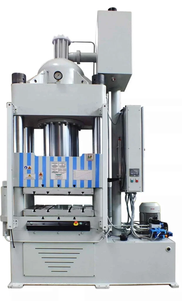
Compact deep drawing hydraulic units are designed to deliver powerful forming capabilities within a smaller footprint, making them ideal for manufacturers with limited floor space or those seeking flexible deployment options. These units combine a robust hydraulic system with a streamlined mechanical structure to efficiently perform deep drawing tasks without the bulk and complexity of larger presses.
The compact design focuses on maximizing space efficiency while maintaining sufficient tonnage to handle a variety of sheet metal thicknesses and materials. By integrating hydraulic power units, cylinders, and control systems into a consolidated frame, these presses reduce installation complexity and enable quicker setup times.
Despite their smaller size, compact deep drawing units often incorporate advanced control features such as programmable logic controllers (PLCs) and user-friendly interfaces that allow precise adjustment of stroke length, pressure, and ram speed. This level of control supports consistent part quality and repeatability even in tight production environments.
These units typically use energy-efficient hydraulic pumps and circuits, minimizing power consumption without compromising forming force. Variable displacement pumps or servo-hydraulic drives may be included to optimize energy use further and provide smooth ram motion, which is essential for preventing defects in deep drawn parts.
The versatility of compact hydraulic presses makes them suitable for a range of applications, from prototyping and small batch production to specialized forming tasks in industries like automotive components, electronics enclosures, and household goods. Their portability also allows manufacturers to reconfigure production lines or relocate equipment easily in response to changing operational needs.
Tooling compatibility is a key consideration, with compact presses designed to accommodate standard deep drawing dies and accessories. Quick-change tooling systems can be integrated to facilitate rapid transitions between jobs, enhancing productivity and flexibility.
Safety and ergonomics remain priorities in compact units, with features such as safety interlocks, emergency stop functions, and guarded access points designed to protect operators. The compact footprint also allows better use of available space while maintaining clear sightlines and easy access for maintenance.
Overall, compact deep drawing hydraulic units offer a practical solution for manufacturers seeking the benefits of hydraulic deep drawing technology without the spatial and financial demands of full-sized presses. Their balance of power, precision, and efficiency makes them valuable assets in diverse manufacturing settings where space constraints and flexibility are critical.
Compact deep drawing hydraulic units often include modular components that allow manufacturers to customize the press according to specific production requirements. This modularity can extend to hydraulic power packs, control systems, and frame configurations, enabling tailored solutions without sacrificing the benefits of a compact footprint. Such flexibility supports incremental upgrades and easier integration with existing manufacturing lines.
These units are designed with maintenance accessibility in mind. Components such as filters, pumps, and valves are strategically positioned for quick inspection and service, reducing downtime and ensuring continuous operation. Many models also feature diagnostic systems that monitor hydraulic fluid conditions and machine performance, alerting operators to potential issues before they result in costly failures.
The precise control afforded by compact hydraulic presses makes them suitable for materials that require delicate handling during forming, such as thin-gauge metals or alloys prone to cracking. Smooth ram movement and adjustable pressure settings minimize stress on the workpiece, helping to maintain material integrity and surface quality.
Because these presses are often deployed in environments where space is at a premium, noise reduction is another important design consideration. Compact units typically incorporate sound-dampening materials and optimized hydraulic circuits to lower operational noise levels, contributing to a safer and more comfortable workplace.
In addition to standalone operation, compact deep drawing hydraulic units can be integrated with automation systems, including robotic part handling and in-line quality inspection. This integration enhances throughput and consistency while enabling lean manufacturing practices by reducing manual intervention and potential errors.
Their relatively lower weight and footprint also make compact units attractive for educational institutions and research facilities focused on metal forming technology. They provide hands-on experience with deep drawing processes without requiring the extensive infrastructure needed for larger industrial presses.
Energy efficiency is often a highlight of these presses, with many models featuring variable speed drives and energy recovery systems. These technologies reduce electricity consumption and heat generation, lowering operational costs and environmental impact.
In summary, compact deep drawing hydraulic units blend the power and precision of larger presses into a smaller, more adaptable form. Their ease of customization, maintenance, and integration with modern manufacturing technologies makes them essential tools for manufacturers aiming to optimize space, improve efficiency, and maintain high-quality production standards in a variety of industries.
Compact deep drawing hydraulic units also excel in supporting rapid product development cycles. Their flexibility and ease of setup allow engineers and designers to quickly test new tooling and materials without committing large amounts of floor space or resources. This agility accelerates innovation and shortens time-to-market for new components, which is especially valuable in industries with fast product turnover or customized production demands.
The reduced physical size of these presses often translates into lower initial capital investment and reduced installation costs. Facilities that might not afford or accommodate large presses can adopt compact units to gain access to hydraulic deep drawing capabilities, democratizing advanced metal forming technology for smaller manufacturers and startups.
Furthermore, the simplified hydraulic and mechanical design of compact presses typically results in fewer failure points and easier troubleshooting. This reliability is critical for operations where continuous uptime is essential but dedicated maintenance teams may be limited. The ability to quickly diagnose and resolve issues helps maintain steady production flow and prevents costly delays.
These presses frequently come with comprehensive software packages that enable detailed process control, data logging, and traceability. Such features support quality management systems and compliance with industry standards, allowing manufacturers to document each production run and identify areas for continuous improvement.
From a safety standpoint, compact units often include interlocked guarding and ergonomic controls designed to minimize operator fatigue and reduce the risk of accidents. Their smaller size makes it easier to implement effective safety zones and emergency access routes within crowded production floors.
Environmental considerations are increasingly integrated into the design of compact hydraulic presses. Manufacturers prioritize the use of biodegradable hydraulic fluids, recyclable materials, and energy-saving components to align with corporate sustainability goals and regulatory requirements.
The ability of compact deep drawing units to operate effectively in varied environments—from clean rooms for electronics manufacturing to rugged industrial settings—further highlights their versatility. Their robustness combined with precision makes them suitable for diverse applications, ranging from delicate medical device components to durable automotive parts.
In conclusion, compact deep drawing hydraulic units provide a highly adaptable, efficient, and cost-effective solution for modern manufacturing challenges. Their blend of precision engineering, user-friendly controls, and compact design empowers manufacturers to optimize production, reduce costs, and innovate rapidly within constrained spaces.
EMS Metalworking Machines
We design, manufacture and assembly metalworking machinery such as:
- Hydraulic transfer press
- Glass mosaic press
- Hydraulic deep drawing press
- Casting press
- Hydraulic cold forming press
- Hydroforming press
- Composite press
- Silicone rubber moulding press
- Brake pad press
- Melamine press
- SMC & BMC Press
- Labrotaroy press
- Edge cutting trimming machine
- Edge curling machine
- Trimming beading machine
- Trimming joggling machine
- Cookware production line
- Pipe bending machine
- Profile bending machine
- Bandsaw for metal
- Cylindrical welding machine
- Horizontal pres and cookware
- Kitchenware, hotelware
- Bakeware and cuttlery production machinery
as a complete line as well as an individual machine such as:
- Edge cutting trimming beading machines
- Polishing and grinding machines for pot and pans
- Hydraulic drawing presses
- Circle blanking machines
- Riveting machine
- Hole punching machines
- Press feeding machine
You can check our machinery at work at: EMS Metalworking Machinery – YouTube
Applications:
Flange-punching
Beading and ribbing
Flanging
Trimming
Curling
Lock-seaming
Ribbing