Burr Removal: Metalworking is an age-old craft that has evolved significantly with advancements in technology and machinery. It involves various processes to shape and fabricate metal components, ranging from cutting, bending, and assembling to finishing and polishing. The success of these processes largely depends on the quality and efficiency of the equipment used, making metalworking machines indispensable to the industry.
1.1 Overview of the Metalworking Industry
The metalworking industry is a cornerstone of modern manufacturing, encompassing a vast array of processes and technologies. These processes are vital in producing components used in automotive, aerospace, construction, and consumer goods. The industry relies heavily on precision, and thus, the machinery involved must be state-of-the-art, providing accurate and repeatable results.
1.2 Importance of High-Quality Equipment in Metalworking
High-quality metalworking equipment ensures not only precision and efficiency but also safety and longevity of the products. Machines such as burr removal machines, metal polishing machines, and deep drawing presses play a crucial role in achieving the desired surface finish and dimensional accuracy. For instance, burr removal is essential in preventing defects that could compromise the structural integrity of the product or even cause safety hazards in its application.
Investing in advanced metalworking equipment is therefore not just about improving production speed but also about ensuring the reliability and quality of the final product. As the demand for intricate and precise metal components continues to rise, so does the need for equipment that can meet these challenges.
1.3 Brief Introduction to Different Types of Metalworking Machines
Metalworking machines come in various forms, each designed for specific tasks within the metalworking process. Some of the key types include:
Burr Removal Machines: These are specialized machines used to remove burrs—small, rough edges or protrusions that form on metal surfaces after cutting or machining. Burr removal is critical for ensuring a smooth finish and preventing potential issues during assembly or use.
Metal Polishing Machines: These machines are used to achieve a fine, smooth finish on metal surfaces. They are essential in industries where appearance and surface quality are paramount, such as in the production of automotive parts, appliances, and consumer electronics.
Deep Drawing Presses: These are used in processes that involve shaping sheet metal into complex shapes, such as automotive body panels and kitchen sinks. Deep drawing presses must be highly precise to maintain the integrity of the metal during the forming process.
Moulding Presses: Moulding presses are crucial in the production of various components, particularly those made from composite materials. They are widely used in industries such as automotive, aerospace, and electronics.
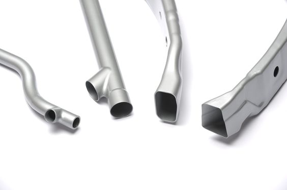
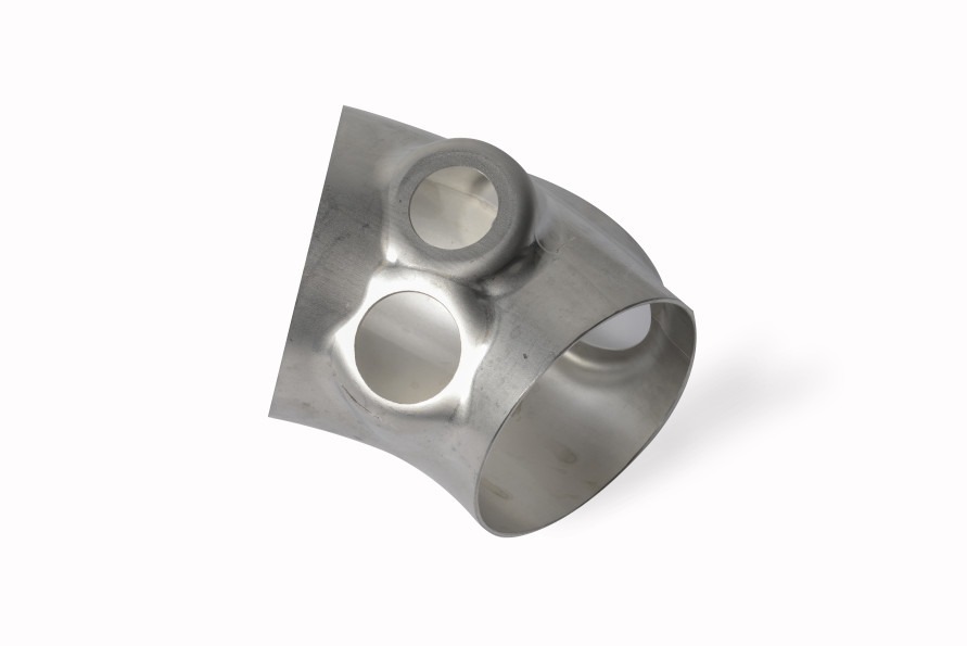
Spin Forming Machines: These machines are used to form metal into cylindrical shapes, such as rims, cones, and tubes. Spin forming is a versatile process that allows for the creation of seamless, strong, and lightweight components.
Each type of machine plays a specific role in the metalworking process, and their combined use ensures the production of high-quality metal components that meet industry standards.
2. The Critical Role of Burr Removal in Metalworking
Types of Deburring Machines
Burr removal is a fundamental aspect of metalworking, often regarded as a critical finishing process that directly impacts the quality, safety, and functionality of the final product. Burrs, the unwanted rough edges or protrusions left on metal surfaces after machining, cutting, or stamping, can lead to various issues if not properly managed. These include compromised product integrity, assembly difficulties, and even safety hazards during usage. Understanding the significance of burr removal and employing effective methods to achieve it is essential for any manufacturer striving for excellence.
2.1 Understanding Burrs and Their Impact
In the metalworking industry, burrs are an inevitable byproduct of machining and manufacturing processes. They can form on almost any metal part during operations like drilling, milling, turning, or shearing. While burrs might seem insignificant, their presence can have detrimental effects on both the manufacturing process and the end product.
Quality Compromise: Burrs can lead to dimensional inaccuracies, which might result in parts that do not fit together correctly. This is particularly problematic in industries like aerospace or automotive, where precision is critical.
Safety Concerns: Sharp burrs pose a risk of injury to workers handling the parts. In addition, burrs can cause issues in the functionality of the product, such as electrical shorts in electronic components or leaks in fluid systems.
Assembly Challenges: Burrs can interfere with the assembly process by causing parts to snag or fit improperly. This can lead to increased production time, higher costs, and potential delays in delivery.
Given these potential issues, burr removal is not just a matter of finishing; it is a critical step in ensuring the overall quality and functionality of metal parts.
2.2 Burr Removal Techniques
There are various techniques for removing burrs from metal parts, ranging from manual methods to advanced automated systems. The choice of technique depends on factors such as the material, part geometry, production volume, and desired finish quality.
Manual Deburring: This traditional method involves using hand tools such as files, scrapers, or abrasive stones to remove burrs. While manual deburring is suitable for small-scale operations or intricate parts, it is labor-intensive and can be inconsistent in terms of finish quality.
Mechanical Deburring: Mechanical methods involve the use of machines such as tumblers, vibratory finishers, or abrasive belts to remove burrs. These methods are more consistent and efficient than manual deburring, making them suitable for larger production runs.
Thermal Deburring: Also known as “thermal energy method” (TEM), this technique uses controlled explosions of gas in a chamber to burn away burrs. Thermal deburring is highly effective for complex parts with internal burrs, as the gas can reach areas that are difficult to access with other methods.
Electrochemical Deburring: This process uses an electrolyte solution and an electric current to dissolve burrs. It is ideal for parts with hard-to-reach burrs and provides a smooth, precise finish.
Cryogenic Deburring: In this method, parts are cooled to extremely low temperatures using liquid nitrogen, making the burrs brittle. The parts are then agitated in a tumbler, causing the burrs to break off. Cryogenic deburring is particularly effective for plastic and rubber parts.
2.3 The Role of Burr Removal Machines
Burr removal machines are specialized equipment designed to automate and streamline the deburring process, ensuring consistent and high-quality results. These machines are essential for industries where precision and repeatability are paramount. Some of the key benefits of using burr removal machines include:
Increased Efficiency: Automated burr removal machines can process multiple parts simultaneously, significantly reducing the time and labor required for deburring.
Consistent Quality: Unlike manual deburring, which can vary depending on the operator’s skill, burr removal machines provide uniform results, ensuring that all parts meet the required specifications.
Cost-effectiveness: While the initial investment in burr removal machines may be high, the long-term savings in labor costs and improved production efficiency make them a cost-effective solution for many manufacturers.
Enhanced Safety: Automated machines reduce the risk of injury associated with manual deburring, as workers are not required to handle sharp parts directly.
2.4 Specialized Burr Removal Machines
There are various types of burr removal machines, each tailored to specific applications and industries. These include:
Aluminium Deburring Machines: These machines are specifically designed to handle aluminum parts, which require a delicate touch to avoid damaging the material. They are commonly used in the automotive and aerospace industries, where aluminum is widely used.
Deburring Machines for Sheet Metal Edges: These machines are designed to remove burrs from the edges of sheet metal, ensuring smooth, clean edges that are safe to handle and meet the required tolerances.
Metal Edge Finishing Machines: These machines are used to finish the edges of metal parts, providing a smooth, rounded edge that improves both the appearance and functionality of the part.
Automatic Burr Removal Machines: These machines are designed for high-volume production environments, where speed and efficiency are critical. They are capable of processing large quantities of parts quickly, with minimal operator intervention.
2.5 Advancements in Burr Removal Technology
The field of burr removal is continuously evolving, with new technologies being developed to improve the efficiency and effectiveness of the process. Some of the latest advancements include:
CNC-controlled Deburring Machines: These machines use computer numerical control (CNC) technology to precisely control the deburring process, ensuring consistent, high-quality results. CNC deburring machines are ideal for complex parts with tight tolerances.
Robotic Deburring: Robotic systems are increasingly being used for deburring, particularly in industries where precision and repeatability are critical. These systems can be programmed to perform complex deburring tasks with a high degree of accuracy.
Laser Deburring: Laser technology is being used to remove burrs with high precision, particularly on small, intricate parts. Laser deburring is contactless, which reduces the risk of damaging delicate components.
Hybrid Deburring Systems: These systems combine multiple deburring techniques, such as mechanical and thermal deburring, to achieve optimal results for complex parts. Hybrid systems are particularly useful for parts with varied geometries and materials.
2.6 The Importance of Proper Burr Removal in Quality Assurance
In today’s competitive manufacturing environment, maintaining high-quality standards is essential for success. Proper burr removal is a key component of quality assurance, as it directly impacts the functionality, safety, and appearance of the final product. Manufacturers that invest in advanced burr removal technologies and processes are better equipped to meet the demanding requirements of their customers and stay ahead of the competition.
Quality assurance in burr removal involves not only the selection of the right techniques and machines but also continuous monitoring and testing to ensure that the process consistently meets the required standards. This can include:
Regular Inspection: Parts should be inspected after deburring to ensure that all burrs have been effectively removed and that the surface finish meets the required specifications.
Testing: In some cases, additional testing, such as pressure testing for fluid systems or electrical testing for electronic components, may be necessary to confirm that the burr removal process has not compromised the integrity of the part.
Documentation: Proper documentation of the burr removal process, including machine settings, inspection results, and corrective actions, is essential for traceability and quality control.
2.7 Conclusion
Burr removal is a critical step in the metalworking process that should not be overlooked. By understanding the impact of burrs on product quality and safety, and by investing in the right burr removal techniques and machines, manufacturers can ensure that their products meet the highest standards. As technology continues to advance, new burr removal methods and machines will further enhance the efficiency and effectiveness of this essential process.
3. Exploring Metalworking Machines and Their Functions
Sheet Metal Machinery
The metalworking industry relies on a diverse array of machines to transform raw materials into finished products. These machines are integral to the manufacturing process, offering precision, efficiency, and versatility across various applications. Each type of metalworking machine serves a specific function, from shaping and forming metal to finishing and polishing it. Understanding the capabilities and applications of these machines is crucial for selecting the right equipment for any given project.
3.1 Overview of Metalworking Machines
Metalworking machines encompass a wide range of equipment designed to perform tasks such as cutting, bending, forming, and finishing metal components. These machines are categorized based on the specific operations they perform, such as pressing, deburring, polishing, and forming. Here’s a broad classification of metalworking machines:
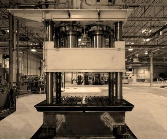
Press Machines: These include various types of presses such as hydraulic presses, deep drawing presses, and moulding presses. Press machines are used to shape metal by applying force to it, typically using a die to form the metal into the desired shape.
Deburring and Finishing Machines: These machines are designed to remove burrs, polish, and finish metal surfaces. Burr removal machines, metal polishing machines, and edge rounding machines fall into this category.
Forming Machines: Machines like spin forming machines, CNC profile bending machines, and cold forming presses are used to bend or shape metal into specific profiles or forms.
Grinding and Cutting Machines: These include centerless grinding machines, which provide a high-quality surface finish by removing material from the outer surface of a metal part.
3.2 Specific Machines and Their Functions
Each type of metalworking machine plays a vital role in the production process, contributing to the creation of precise, high-quality metal components. Let’s delve into the functions and applications of some of the most essential metalworking machines.
3.2.1 Moulding Presses
Moulding presses are pivotal in the manufacturing of components that require precise shapes and forms, especially in industries like automotive and aerospace. These presses are used to shape materials by applying pressure to a mold, which can be made of metal or other durable materials. The types of moulding presses include:
Compression Moulding Presses: These presses are used to shape materials like rubber, plastic, and composites. The material is placed in a heated mold, and the press applies pressure to shape it. Compression molding presses are widely used in the production of automotive parts, electronic components, and industrial equipment.
Rubber Compression Molding Presses: Specifically designed for molding rubber products, these presses are used in the production of items like seals, gaskets, and other rubber components. They offer precise control over temperature and pressure, ensuring high-quality results.
SMC Presses (Sheet Moulding Compound Presses): SMC presses are used to mold composite materials, which are commonly used in the automotive and aerospace industries for their strength and lightweight properties.
3.2.2 SMC Presses
SMC presses are specialized machines designed to mold sheet molding compounds, which are a type of composite material made of a thermosetting resin, glass fibers, and fillers. These presses are widely used in the automotive and aerospace industries to produce lightweight, durable components such as car body panels, aircraft parts, and electrical enclosures.
The advantages of SMC presses include:
High Strength-to-Weight Ratio: SMC components offer excellent strength while remaining lightweight, making them ideal for applications where weight savings are critical.
Complex Shapes: SMC presses can produce complex shapes with high precision, reducing the need for additional machining or finishing.
Corrosion Resistance: SMC materials are inherently resistant to corrosion, making them suitable for use in harsh environments.
3.2.3 Hot Press Systems
Hot press systems are used in various metalworking processes to apply heat and pressure simultaneously to a material, shaping it or bonding it to another material. These systems are commonly used in the production of laminated components, metal bonding, and the forming of composite materials.
Application Areas: Hot press systems are extensively used in the electronics industry for the lamination of circuit boards, in the automotive industry for bonding metal components, and in the aerospace industry for forming composite materials.
Benefits: Hot press systems offer high precision, uniform pressure application, and controlled heating, resulting in consistent and high-quality products.
3.2.4 Cold Forming Presses
Cold forming presses are used to shape metal at room temperature, relying on mechanical force to deform the metal into the desired shape. Unlike hot forming, cold forming does not involve heating the material, which helps maintain the material’s inherent properties and produces a high-quality finish.
Advantages of Cold Forming:
Improved Material Properties: Cold forming strengthens the metal by refining its grain structure, enhancing its mechanical properties.
Cost Efficiency: Cold forming processes typically require less energy and are faster than hot forming processes, reducing overall production costs.
Precision and Surface Finish: Cold forming produces parts with excellent dimensional accuracy and a smooth surface finish, reducing the need for further processing.
3.2.5 Silicone Presses
Silicone presses are used to mold silicone rubber into various shapes and forms, typically in the production of seals, gaskets, medical devices, and other silicone products. These presses operate under controlled temperature and pressure to ensure the silicone material cures properly and achieves the desired properties.
Key Applications:
Medical Devices: Silicone presses are used to produce components such as tubing, seals, and gaskets for medical devices, where biocompatibility and precision are critical.
Automotive Industry: Silicone seals and gaskets produced by silicone presses are widely used in the automotive industry for their durability and resistance to extreme temperatures.
3.3 Advanced Metalworking Machines
As technology advances, the metalworking industry has seen the development of more sophisticated machines designed to enhance precision, efficiency, and flexibility. Some of these advanced machines include:
3.3.1 CNC Profile Bending Machines
CNC (Computer Numerical Control) profile bending machines are advanced systems used to bend metal profiles with a high degree of precision and consistency. These machines are essential in industries where complex shapes and tight tolerances are required, such as in the construction of architectural elements, automotive components, and aerospace structures.
Benefits of CNC Profile Bending:
Precision: CNC control allows for precise bending angles and repeatability, ensuring uniformity across all parts.
Complex Bends: CNC machines can perform complex bends that would be difficult or impossible to achieve with manual methods.
Efficiency: CNC profile bending machines can handle high volumes of work with minimal setup time, making them ideal for mass production.
3.3.2 Spin Forming Machines
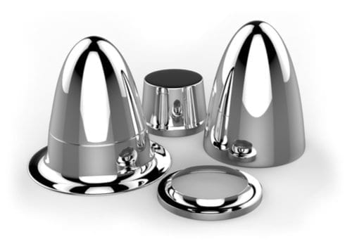
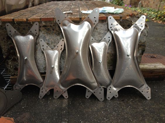
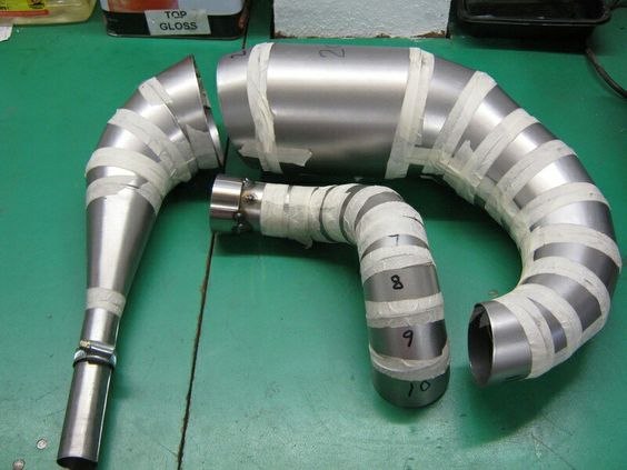
Spin forming, also known as metal spinning, is a process where a metal disc or tube is rotated at high speed and formed into a symmetrical shape using a combination of pressure and heat. Spin forming machines are used to produce components like metal cones, cylinders, and domes.
Applications of Spin Forming:
Aerospace: Spin forming is used to create components such as nose cones, rocket fairings, and other aerodynamic parts.
Automotive: In the automotive industry, spin forming is used to produce parts like wheel rims and exhaust components.
Industrial Equipment: Spin forming is also employed in the production of industrial equipment such as pressure vessels and fluid tanks.
3.3.3 Flow Forming Lathes
Flow forming lathes are specialized machines used to produce high-precision cylindrical components by gradually deforming a metal blank under controlled conditions. This process is particularly useful for producing components with thin walls and high strength, such as automotive drive shafts, aerospace components, and military hardware.
Advantages of Flow Forming:
Precision: Flow forming lathes provide excellent control over wall thickness and dimensions, resulting in highly accurate parts.
Material Efficiency: The process minimizes material waste, making it a cost-effective option for producing high-strength components.
Strength: Flow forming enhances the mechanical properties of the material, producing parts with superior strength and durability.
3.3.4 Hydroforming Presses
Hydroforming is a versatile metal forming process that uses high-pressure hydraulic fluid to shape metal into complex forms. Hydroforming presses are particularly useful for creating lightweight, high-strength components with intricate geometries, making them a popular choice in the automotive and aerospace industries.
Key Features:
Complex Shapes: Hydroforming can produce parts with complex shapes and fine details that would be difficult to achieve with traditional forming methods.
Weight Reduction: The process allows for the creation of lightweight components without sacrificing strength, making it ideal for applications where weight savings are critical.
Material Flexibility: Hydroforming can be used with various metals, including aluminum, steel, and titanium.
3.4 Choosing the Right Metalworking Machine
Selecting the right metalworking machine depends on several factors, including the material being worked on, the complexity of the part, the required precision, and the production volume. For instance:
For Precision Work: CNC profile bending machines and flow forming lathes offer unparalleled precision, making them ideal for aerospace and automotive applications.
For High-Volume Production: Automatic burr removal machines and transfer press stamping systems provide the efficiency needed for mass production environments.
For Complex Geometries: Hydroforming presses and spin forming machines are excellent choices for producing parts with complex shapes and fine details.
Investing in the appropriate metalworking machinery is crucial for optimizing production processes, reducing costs, and ensuring the highest quality of the final product.
4. Metal Polishing and Finishing Machines
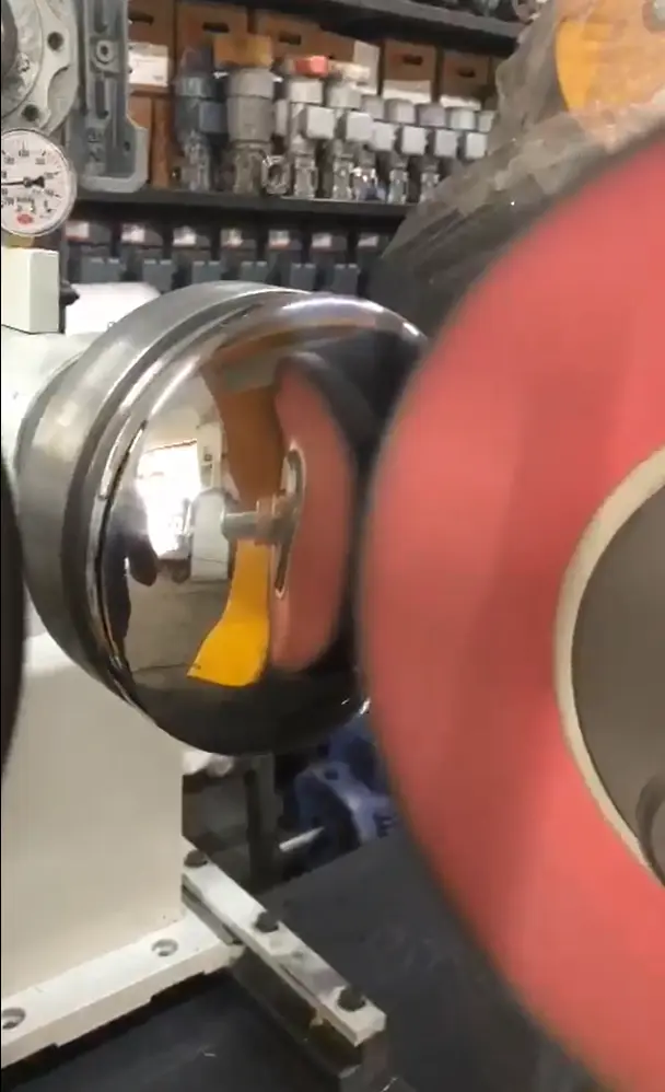
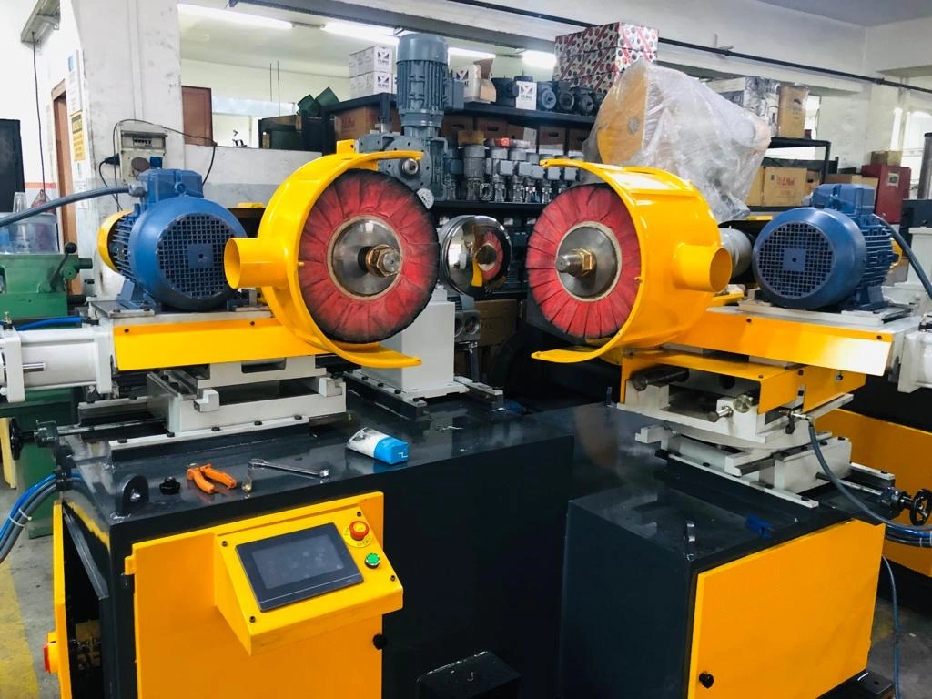
Internal Grinding
Polishing and finishing are critical steps in the metalworking process, ensuring that metal parts not only meet functional requirements but also achieve the desired aesthetic appeal. These processes involve the removal of surface imperfections, the enhancement of surface smoothness, and the creation of a polished or matte finish, depending on the application. Metal polishing and finishing machines are designed to automate these tasks, providing consistent and high-quality results that are essential for industries like automotive, aerospace, and consumer goods.
4.1 Importance of Metal Polishing and Finishing
Polishing and finishing metal components serve multiple purposes, from improving the appearance to enhancing the durability and performance of the final product. The importance of these processes can be summarized as follows:
Surface Quality: A polished surface reduces friction, which is particularly important for moving parts. It also enhances the appearance of the product, making it more appealing to consumers.
Corrosion Resistance: Polishing helps to close surface pores, reducing the likelihood of corrosion, especially in metals like stainless steel and aluminum.
Improved Functionality: Polished surfaces can improve the performance of parts in applications where smooth surfaces are critical, such as in hydraulic systems or sealing surfaces.
Ease of Cleaning: Polished surfaces are easier to clean and maintain, making them ideal for applications in the food, medical, and pharmaceutical industries.
4.2 Types of Metal Polishing Machines
Metal polishing machines are designed to achieve different levels of finish, from a basic smooth surface to a mirror-like polish. Depending on the application and the desired finish, various types of polishing machines are used:
4.2.1 Fine Polishing Machines
Fine polishing machines are used to achieve a high level of smoothness on metal surfaces. These machines are essential in industries where surface quality is paramount, such as in the production of surgical instruments, high-end consumer goods, and precision components.
Applications: Fine polishing machines are commonly used in the medical device industry, the jewelry industry, and the production of luxury items where a flawless finish is required.
Capabilities: These machines can handle a variety of materials, including stainless steel, aluminum, brass, and other non-ferrous metals. They are capable of producing a mirror-like finish that enhances both the appearance and performance of the component.
4.2.2 Automatic Metal Polishing Machines
Automatic metal polishing machines are designed for high-volume production environments where speed and consistency are crucial. These machines can polish multiple parts simultaneously, ensuring uniformity across all pieces.
Efficiency: Automatic polishing machines reduce manual labor, increasing production efficiency and throughput. They are ideal for industries like automotive manufacturing, where large quantities of metal parts need to be polished quickly and consistently.
Customization: Many automatic polishing machines offer customizable settings, allowing manufacturers to adjust the polishing process according to the specific requirements of different parts.
4.2.3 CNC-controlled Polishing Machines
CNC (Computer Numerical Control) polishing machines use advanced technology to control the polishing process with high precision. These machines are essential for applications where tight tolerances and consistent finishes are required.
Precision: CNC polishing machines can follow complex contours and geometries with precision, making them ideal for polishing intricate parts or components with complex shapes.
Repeatability: Once programmed, CNC polishing machines can replicate the same polishing process across multiple parts, ensuring consistency and reducing the likelihood of human error.
4.3 Edge Rounding and Deburring Machines
In addition to polishing, edge rounding and deburring are essential processes in metal finishing. These processes remove sharp edges and burrs that can result from machining, cutting, or stamping, improving the safety, appearance, and functionality of the final product.
4.3.1 Deburring Sheet Metal Edges
Deburring sheet metal edges is a crucial step in preparing metal parts for assembly or final finishing. Burrs, which are unwanted material projections, can compromise the quality of the final product and pose safety risks.
Methods: Deburring sheet metal edges can be done using various methods, including mechanical deburring, abrasive belts, and tumbling. The choice of method depends on the material, part geometry, and production volume.
Benefits: Proper deburring ensures that parts fit together correctly during assembly and reduces the risk of injury from sharp edges. It also improves the aesthetic appeal and prepares the parts for subsequent finishing processes.
4.3.2 Edge Rounding Stainless Steel
Stainless steel, widely used in industries like food processing, medical equipment, and construction, requires careful finishing to ensure both functionality and appearance. Edge rounding is an essential process for stainless steel parts, particularly in applications where sharp edges could cause damage or injury.
Process: Edge rounding involves removing sharp edges from stainless steel parts, either through mechanical means or using specialized edge rounding machines. This process not only enhances safety but also improves the durability and resistance to corrosion.
Applications: Edge rounding is commonly used in the production of stainless steel kitchen appliances, medical instruments, and architectural components where smooth, safe edges are crucial.
4.4 Aluminum Deburring and Finishing Machines
Aluminum is a versatile material used across various industries, including automotive, aerospace, and construction. However, due to its relatively soft nature, aluminum is prone to burrs and surface imperfections during machining. Aluminum deburring and finishing machines are designed to address these issues, ensuring a smooth, clean finish.
4.4.1 Aluminum Deburring Machines
Aluminum deburring machines are specialized to handle the unique properties of aluminum, which can be easily scratched or damaged if not properly deburred. These machines are designed to remove burrs and other imperfections without compromising the material’s integrity.
Applications: Aluminum deburring machines are used in the production of automotive components, aircraft parts, and consumer electronics, where precision and surface quality are critical.
Techniques: These machines use various techniques, such as abrasive belts, brushes, or chemical processes, to achieve a smooth, burr-free surface.
4.4.2 Aluminum Polishing and Finishing
Polishing aluminum requires a delicate balance between removing surface imperfections and achieving a high-quality finish. Aluminum polishing machines are designed to enhance the appearance and functionality of aluminum parts by providing a smooth, reflective surface.
Challenges: Aluminum is prone to oxidation, which can dull the surface if not properly polished and protected. Polishing machines for aluminum often include features to minimize oxidation and maintain the metal’s shine.
End Use: Polished aluminum is commonly used in automotive trim, aircraft interiors, and consumer products like smartphones and laptops, where both appearance and performance are important.
4.5 Industrial Metal Polishing Equipment
For large-scale operations, industrial metal polishing equipment is essential for handling high volumes of work with consistency and precision. This equipment is used in industries ranging from automotive manufacturing to aerospace production, where the quality of the surface finish can significantly impact the performance and longevity of the final product.
4.5.1 Large-Scale Polishing Systems
Industrial polishing systems are designed to handle large components or high volumes of smaller parts. These systems often include multiple polishing stations, automated handling, and integrated quality control to ensure that every part meets the required standards.
Automation: Many industrial polishing systems are fully automated, reducing the need for manual intervention and increasing production speed. This automation also ensures that the polishing process is consistent across all parts.
Customization: Industrial systems can be customized to suit specific applications, with adjustable settings for different materials, finishes, and part geometries.
4.5.2 Safety and Efficiency in Industrial Polishing
Safety is a key concern in industrial polishing operations, where large machines and high-speed processes are involved. Industrial polishing equipment is designed with safety features such as protective enclosures, emergency stops, and dust extraction systems to protect workers and maintain a clean working environment.
Efficiency: Industrial polishing equipment is designed to maximize efficiency, reducing waste and energy consumption while delivering high-quality results. These systems often incorporate energy-efficient motors, optimized polishing media, and recycling systems for consumables.
4.6 Conclusion
Metal polishing and finishing are crucial processes in the metalworking industry, directly affecting the quality, durability, and appearance of the final product. The right polishing and finishing machines can enhance productivity, ensure consistency, and achieve the desired surface characteristics, whether it’s a mirror-like polish or a smooth, rounded edge. As the demand for high-quality metal components continues to grow, investing in advanced polishing and finishing technology becomes increasingly important for manufacturers looking to stay competitive.
5. Deep Drawing and Forming Presses
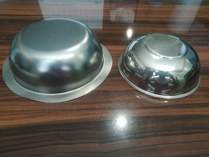
Deep Drawing
Deep drawing and forming processes are fundamental techniques in metalworking, widely used to shape metal sheets into complex geometries with high precision. These processes are particularly important in industries such as automotive, aerospace, and appliance manufacturing, where components with deep, intricate shapes are required. The machines used for deep drawing and forming must be robust, precise, and versatile to handle a variety of materials and thicknesses. This section explores the different types of deep drawing and forming presses, their applications, and the advantages they offer in modern manufacturing.
5.1 Introduction to Deep Drawing Processes
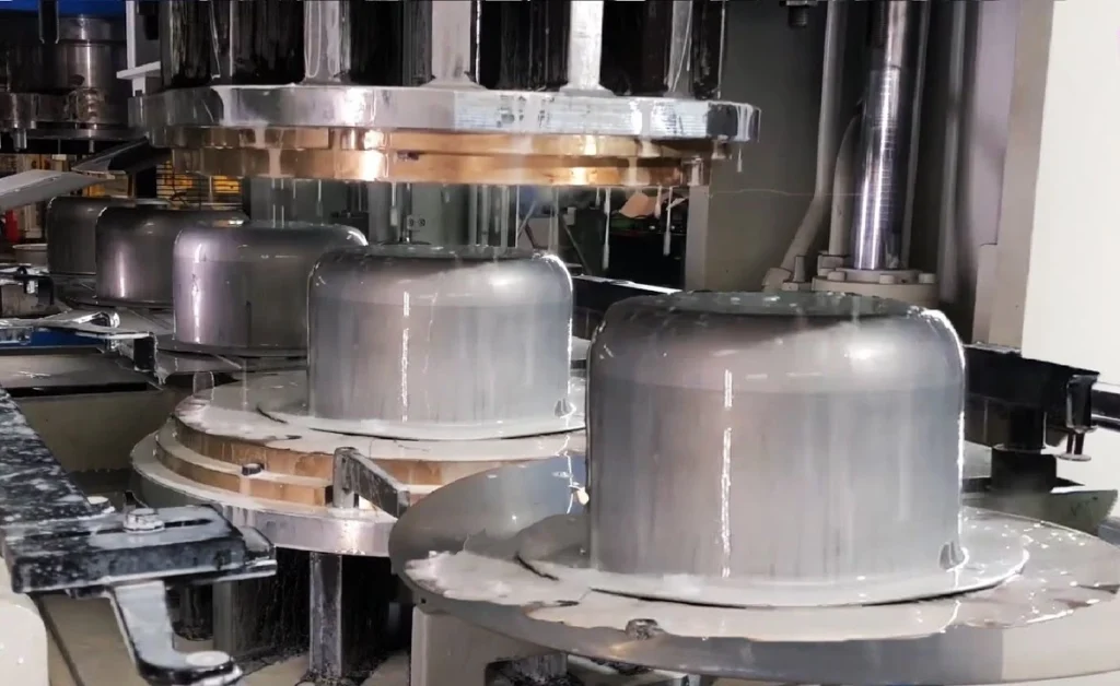
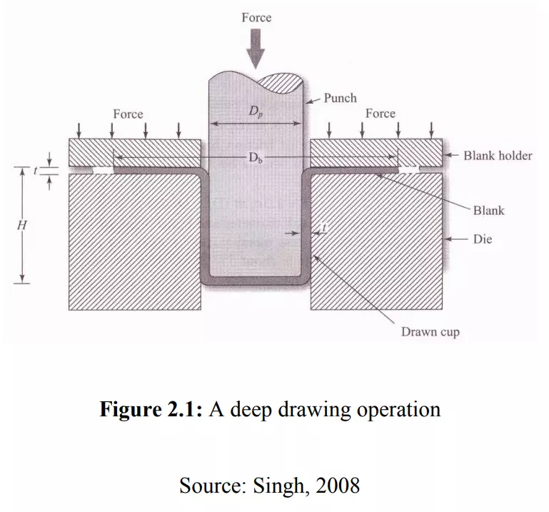
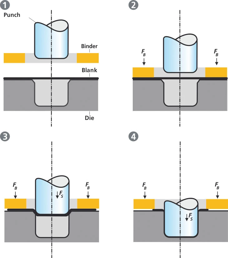
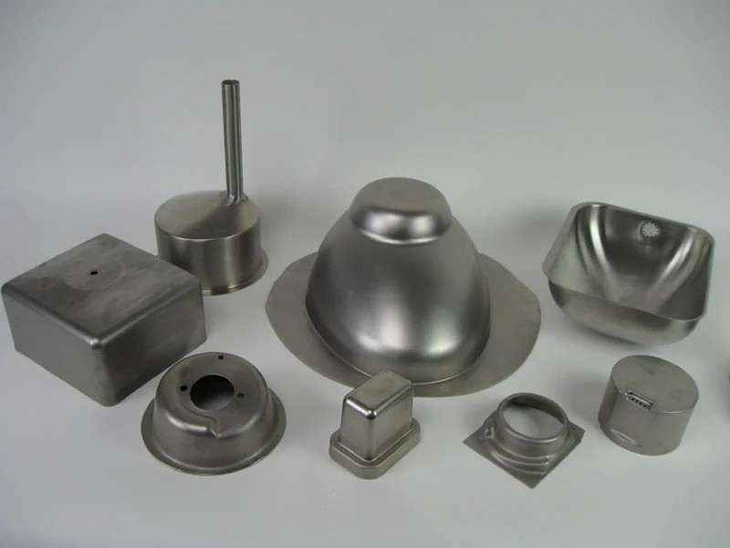
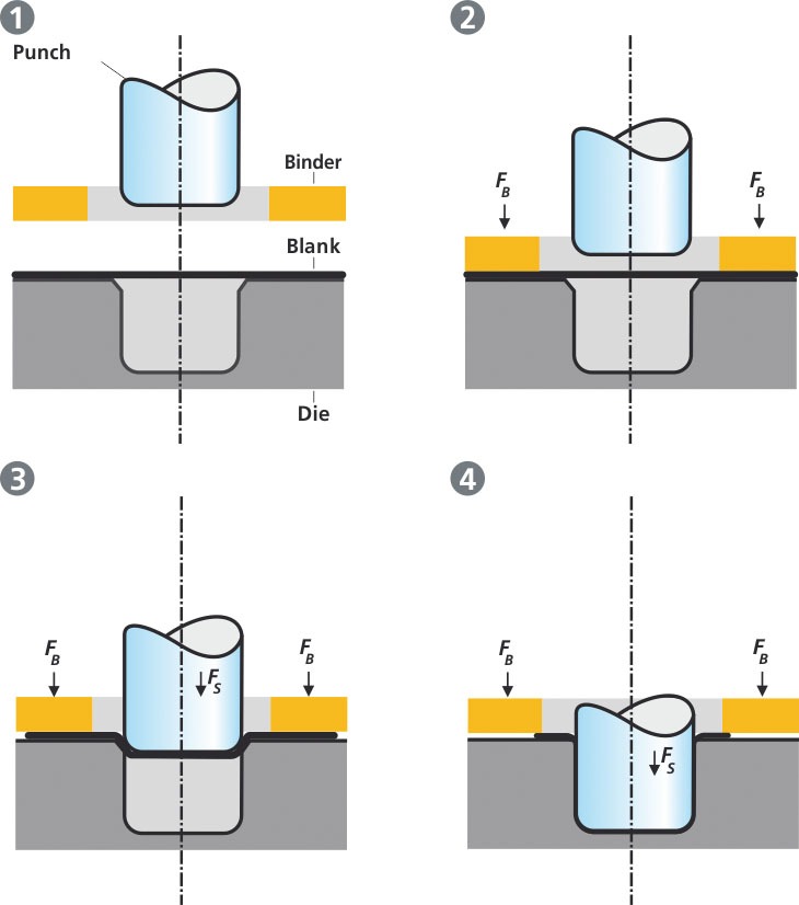
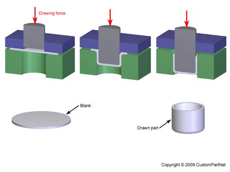
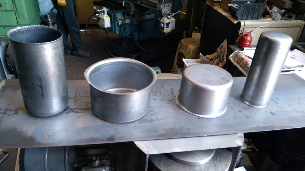
Deep drawing is a metal forming process in which a sheet metal blank is radially drawn into a forming die by the mechanical action of a punch. It is considered “deep” drawing when the depth of the drawn part exceeds its diameter. This process is commonly used to create parts like automotive body panels, kitchen sinks, and various containers.
Process Overview:
A blank sheet of metal is placed over a die.
A punch presses the metal into the die, forcing it to conform to the shape of the die cavity.
The result is a seamless, hollow component with a consistent wall thickness.
Materials Used:
Common materials for deep drawing include steel, aluminum, brass, copper, and various alloys. The material’s ductility and thickness determine the feasibility and success of the deep drawing process.
Applications:
Deep drawing is used in manufacturing components like engine parts, household appliances, and packaging materials. It is also crucial in producing components for the aerospace industry, where precision and material integrity are vital.
5.2 Types of Deep Drawing Presses
Deep drawing presses are specialized machines designed to perform the deep drawing process with high precision and efficiency. There are various types of presses used depending on the specific requirements of the part being produced.
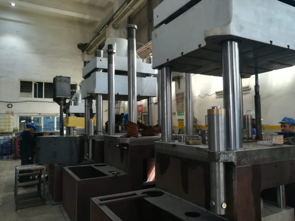
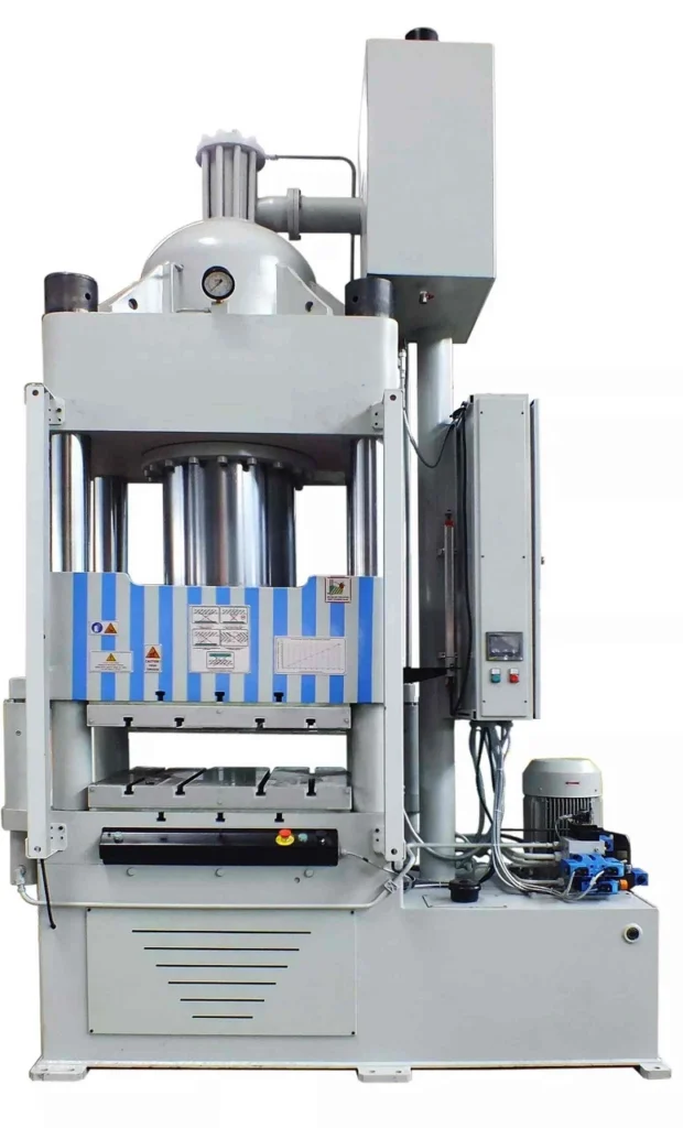
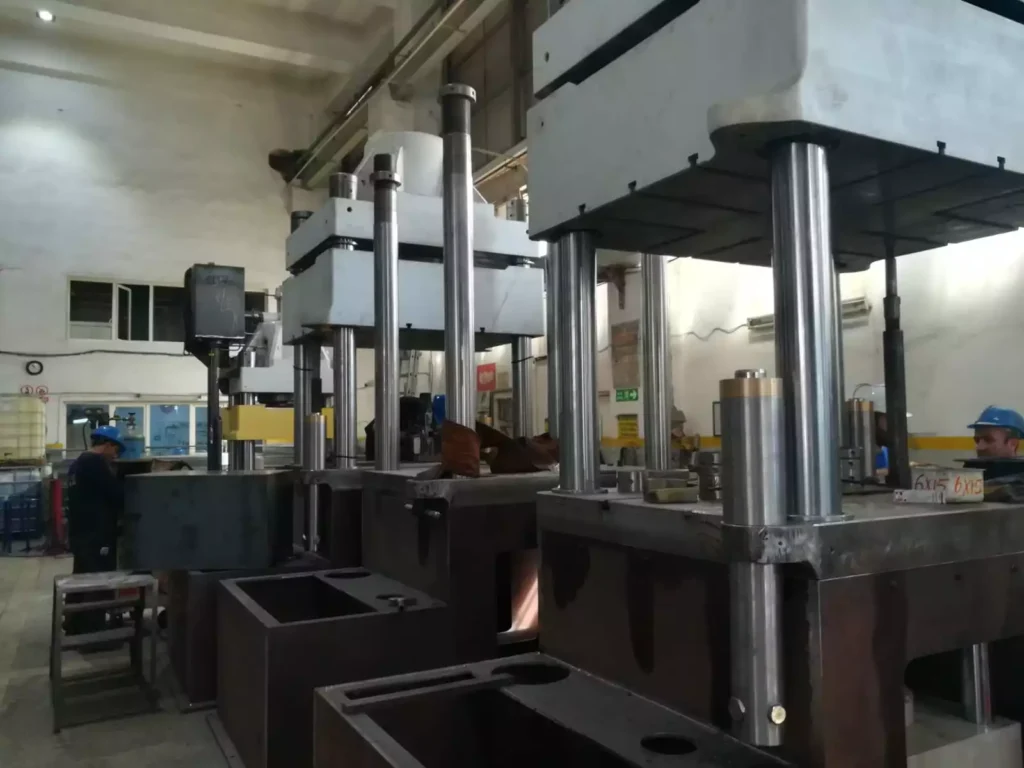
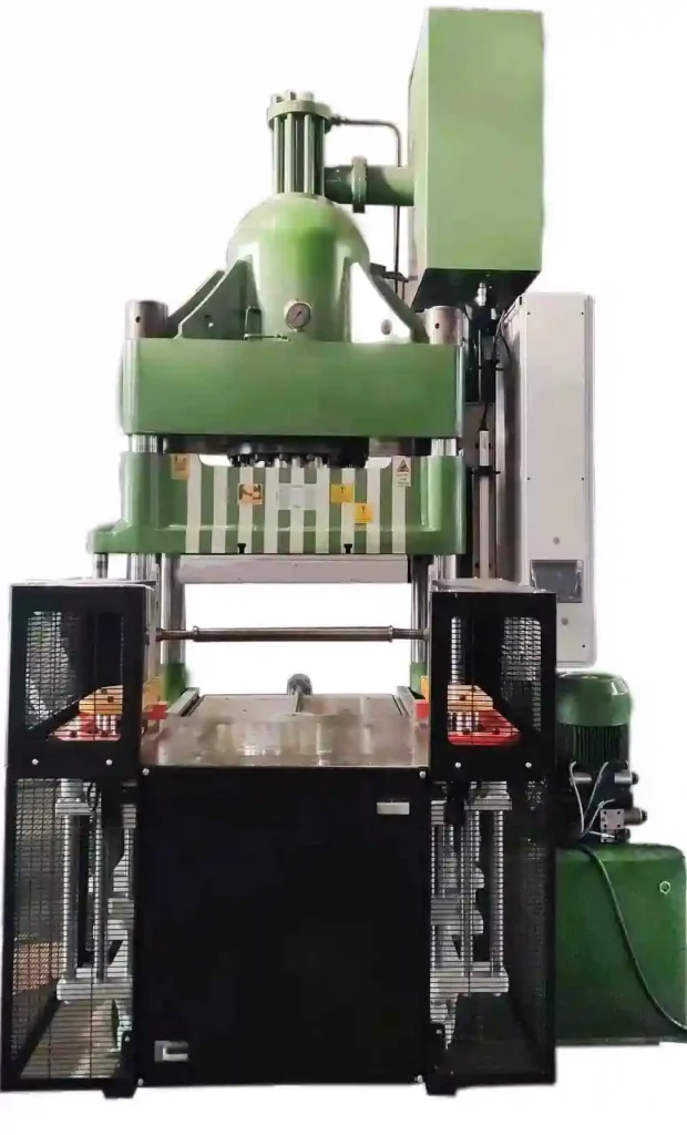
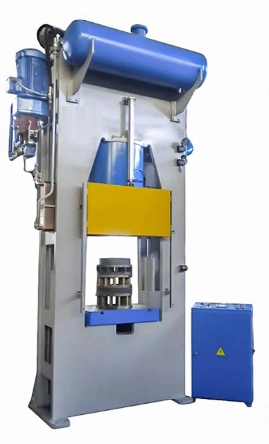
5.2.1 Hydraulic Deep Drawing Presses
Hydraulic presses are among the most commonly used machines for deep drawing. They use hydraulic pressure to apply force to the metal blank, pushing it into the die cavity. Hydraulic presses are highly versatile and can be adjusted to apply varying levels of pressure, making them suitable for a wide range of materials and part sizes.
Advantages:
Precision: Hydraulic presses offer excellent control over the drawing process, allowing for the production of parts with tight tolerances.
Versatility: These presses can handle a variety of materials, including high-strength metals and alloys.
Consistency: Hydraulic systems provide consistent force throughout the drawing process, ensuring uniform wall thickness and part quality.
Applications:
Hydraulic deep drawing presses are used in the automotive industry to produce components like fuel tanks, body panels, and exhaust systems. They are also widely used in the production of household appliances and industrial containers.
5.2.2 Mechanical Deep Drawing Presses
Mechanical presses use a flywheel to store energy and release it in a single, powerful stroke. These presses are known for their speed and efficiency, making them ideal for high-volume production runs. Mechanical presses are often used in applications where large quantities of parts need to be produced quickly and consistently.
Advantages:
Speed: Mechanical presses operate at high speeds, making them suitable for mass production.
Cost-Effectiveness: These presses are typically less expensive to operate than hydraulic presses, especially in high-volume production environments.
Durability: Mechanical presses are built to withstand high levels of stress and are highly durable, requiring minimal maintenance.
Applications:
Mechanical deep drawing presses are commonly used in the production of automotive parts, including fenders, hoods, and doors. They are also used in the manufacturing of metal containers, cookware, and industrial components.
5.2.3 Servo-Driven Deep Drawing Presses
Servo-driven presses are a more advanced type of deep drawing press, combining the precision of hydraulic presses with the speed of mechanical presses. These machines use a servo motor to control the movement of the press, offering unparalleled control over the drawing process.
Advantages:
Precision: Servo-driven presses provide precise control over the speed and force of the drawing process, allowing for the production of highly complex parts.
Energy Efficiency: These presses are more energy-efficient than traditional hydraulic or mechanical presses, reducing operating costs.
Flexibility: The programmable nature of servo-driven presses allows for quick changes between different part designs, making them ideal for environments where product variation is common.
Applications:
Servo-driven deep drawing presses are used in the production of high-precision components for the aerospace, automotive, and medical device industries. They are also increasingly used in the production of electronic components, where tight tolerances and complex shapes are required.
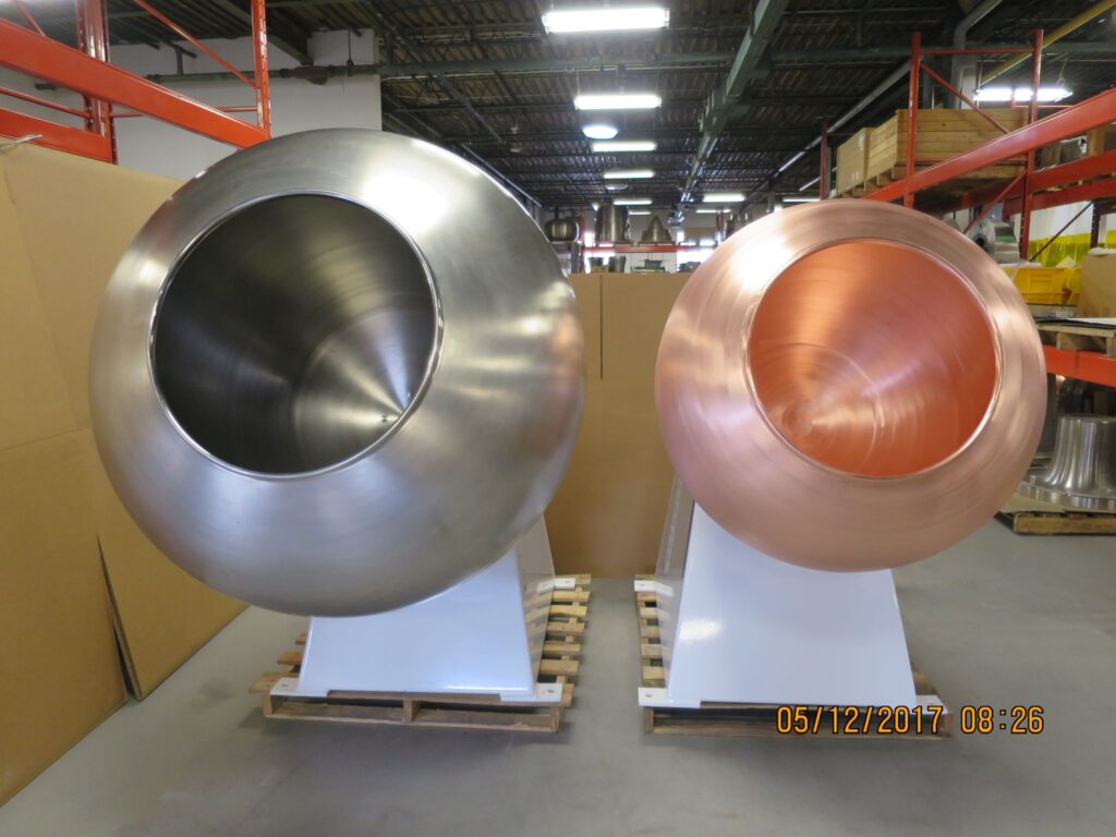
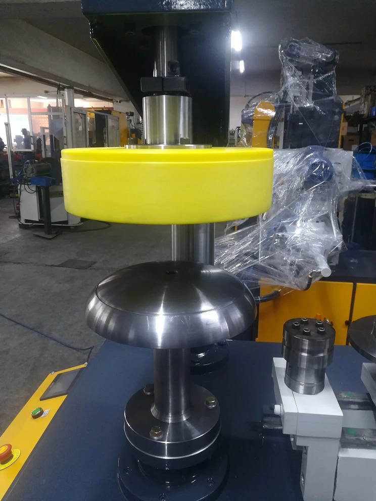
5.3 Spin Forming Machines
Spin forming, also known as metal spinning, is a process that involves rotating a metal disc or tube while applying force to shape it into a symmetrical object. Spin forming machines are used to produce components like wheels, cones, and cylindrical shapes, often used in industries such as aerospace, automotive, and lighting.
Process Overview:
The metal blank is placed on a lathe and rotated at high speed.
A tool presses against the rotating blank, forcing it to take the shape of the tool or mandrel.
The result is a seamless, strong component with excellent structural integrity.
Advantages:
Material Efficiency: Spin forming typically results in minimal material waste, making it a cost-effective manufacturing process.
Structural Integrity: The continuous nature of the spin forming process enhances the strength and durability of the final product.
Versatility: Spin forming can be used with various materials, including aluminum, steel, and titanium, and can produce a wide range of shapes.
Applications:
In the aerospace industry, spin forming is used to produce parts like rocket nozzles, satellite dishes, and aircraft nose cones. In the automotive industry, it is used for manufacturing wheel rims and other components requiring a high degree of symmetry.
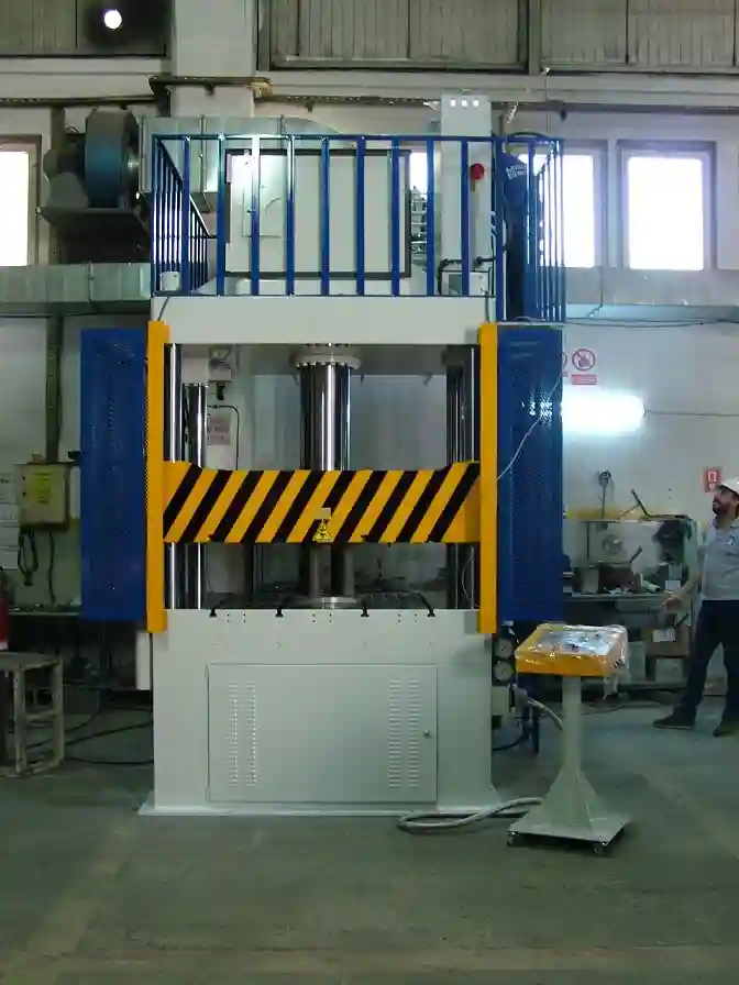
5.4 Deep Drawing Hydraulic Presses
Deep drawing hydraulic presses are specifically designed for the deep drawing process, offering the high force required to shape thick or high-strength materials. These presses are versatile and can be used for both shallow and deep drawing operations, making them a popular choice across various industries.
Key Features:
High Force Capacity: Hydraulic presses can apply immense force, making them suitable for deep drawing thick or difficult-to-form materials.
Controlled Drawing Process: The ability to control the speed and force during the drawing process ensures that the material flows evenly, reducing the risk of tearing or wrinkling.
Tooling Flexibility: Hydraulic presses can accommodate a wide range of tooling, allowing for the production of parts with varying geometries and sizes.
Applications:
These presses are used in the automotive industry to produce components like fuel tanks, chassis parts, and engine housings. They are also used in the production of large industrial containers, kitchen sinks, and other deep-drawn products.
5.5 Transfer Press Stamping
Transfer press stamping is a high-volume manufacturing process where metal blanks are automatically transferred from one stamping station to the next. Each station performs a different operation, such as drawing, trimming, or punching, ultimately producing a finished part.
Process Overview:
Metal blanks are fed into the press and automatically moved from station to station, where various forming operations are performed.
The process is continuous, allowing for high-speed production of complex parts.
The final product emerges fully formed, with minimal need for secondary operations.
Advantages:
High Productivity: Transfer press stamping is highly efficient, capable of producing large quantities of parts in a short period.
Consistency: The automated nature of the process ensures consistent quality across all parts.
Cost-Effectiveness: By integrating multiple operations into a single machine, transfer press stamping reduces labor and tooling costs.
Applications:
Transfer press stamping is widely used in the automotive industry to produce parts like door panels, structural components, and brackets. It is also used in the manufacturing of appliances, electrical components, and various consumer goods.
5.6 Conclusion
Deep drawing and forming presses are essential tools in modern manufacturing, enabling the production of complex, high-quality metal components with precision and efficiency. Whether it’s the robust capabilities of hydraulic presses, the speed of mechanical presses, or the advanced control of servo-driven presses, these machines play a critical role in industries ranging from automotive to aerospace. Understanding the specific applications and benefits of each type of press allows manufacturers to choose the right equipment for their production needs, ensuring the consistent quality and performance of their products.
6. Specialized Metalworking Machines and Presses
Section 4: Applications of Sheet Metal Machinery
The metalworking industry requires a variety of specialized machines and presses to handle specific tasks that standard equipment may not be able to accomplish efficiently. These specialized machines are designed to address unique challenges in manufacturing processes, offering solutions for complex shapes, precision work, and materials that demand particular handling. This section covers some of the most significant specialized metalworking machines and presses, highlighting their applications, advantages, and roles in modern production environments.
6.1 Transfer Press Stamping
Transfer press stamping is a highly automated process designed for high-volume production, where multiple stamping operations are integrated into a single machine. This technology is widely used in industries where the demand for large quantities of complex parts is high.
6.1.1 Process Overview
Transfer press stamping involves a series of stamping operations performed in succession, with each operation completed at a different station within the same machine. The metal blank is automatically transferred from one station to the next, with each station performing a specific task such as drawing, trimming, piercing, or bending. This allows for the rapid production of finished parts with minimal need for secondary operations.
6.1.2 Advantages
High Efficiency: Transfer press stamping is capable of producing large quantities of parts quickly, making it ideal for mass production.
Integrated Operations: By combining multiple stamping operations in a single machine, transfer press stamping reduces the need for multiple setups, lowering labor costs and increasing throughput.
Consistency: The automated nature of the process ensures that each part is produced to the same specifications, reducing variability and improving quality control.
6.1.3 Applications
Automotive Industry: Transfer press stamping is commonly used to manufacture automotive components such as body panels, structural parts, and brackets. Its ability to handle complex shapes and large volumes makes it a vital technology in this sector.
Appliance Manufacturing: The process is also used to produce components for household appliances, including metal housings, brackets, and support structures.
6.2 Flow Forming Lathes
Flow forming lathes are specialized machines used to produce high-precision cylindrical components through a process known as flow forming. This technology is particularly valued in industries where lightweight, strong, and accurate components are required.
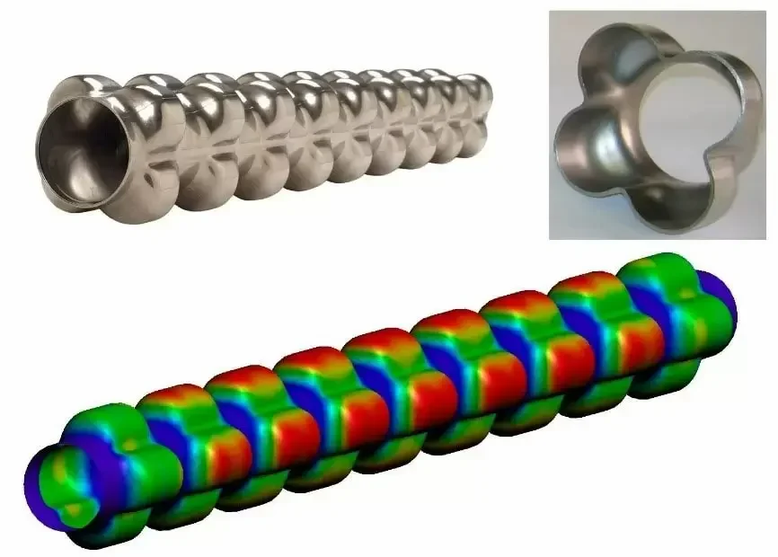
6.2.1 Flow Forming Process
Flow forming is a cold-forming process where a metal blank, typically a cylindrical tube or disc, is placed on a rotating mandrel. Rollers apply pressure to the blank as it rotates, gradually shaping it into the desired form. This process is capable of producing thin-walled components with excellent mechanical properties and tight tolerances.
6.2.2 Advantages
Material Efficiency: Flow forming reduces material waste compared to traditional machining processes, making it a cost-effective method for producing high-strength components.
Precision: The process allows for the creation of components with precise dimensions and consistent wall thickness, critical for applications in aerospace and automotive industries.
Enhanced Mechanical Properties: Flow forming improves the material’s grain structure, resulting in components with enhanced strength and durability.
6.2.3 Applications
Aerospace Industry: Flow forming lathes are used to produce components such as rocket motor casings, aircraft engine components, and structural parts where weight reduction and strength are critical.
Automotive Industry: The technology is employed to manufacture drive shafts, axles, and other components that require high precision and strength.
Military Applications: Flow forming is used in the production of military hardware, such as artillery shells and missile casings, where material strength and precision are paramount.
6.3 Rim Spinning Machines
Rim spinning machines are specialized equipment used to manufacture wheel rims for vehicles. The process of rim spinning involves shaping a metal disc into a cylindrical rim, which is then further processed to achieve the desired dimensions and strength.
6.3.1 Rim Spinning Process
Rim spinning starts with a metal disc, which is clamped onto a rotating mandrel. The spinning process shapes the disc into a cylindrical form, creating the basic structure of the wheel rim. Additional operations, such as rolling and finishing, are performed to achieve the final dimensions and surface finish.
6.3.2 Advantages
Customization: Rim spinning allows for the production of custom wheel designs, catering to the specific needs of automotive manufacturers and aftermarket suppliers.
Strength and Durability: The spinning process enhances the strength of the metal, producing rims that are both lightweight and durable, essential for high-performance vehicles.
Efficiency: Rim spinning machines are capable of producing rims at high speeds, making them suitable for mass production.
6.3.3 Applications
Automotive Industry: Rim spinning is primarily used in the automotive industry to manufacture wheel rims for cars, trucks, and motorcycles. The process is favored for producing rims that meet the stringent safety and performance standards required in this sector.
Specialty Vehicles: Rim spinning is also used to produce rims for specialty vehicles, such as racing cars and custom-built vehicles, where specific design and performance criteria must be met.
6.4 Rubber and Silicone Presses
Rubber and silicone presses are specialized machines designed for molding rubber and silicone materials into various shapes and components. These presses are essential in industries where rubber and silicone products are widely used, such as automotive, medical, and consumer goods.
6.4.1 Rubber Compression Molding Presses
Rubber compression molding presses are used to shape rubber compounds into final products through the application of heat and pressure. The rubber material is placed in a heated mold cavity, and the press applies pressure to shape it into the desired form.
Applications: Rubber compression molding presses are used to manufacture products such as seals, gaskets, o-rings, and other rubber components that require precision and durability. These presses are also used in the production of automotive rubber parts, such as bushings and mounts.
6.4.2 Silicone Presses
Silicone presses operate similarly to rubber presses but are specifically designed to handle silicone materials, which have unique properties such as flexibility, heat resistance, and biocompatibility.
Applications: Silicone presses are used in the medical device industry to produce items such as tubing, seals, and implants. They are also used in the automotive industry to manufacture silicone gaskets, seals, and hoses.
6.4.3 Rubber Compression Molding Presses for Sale
The market for rubber compression molding presses is diverse, with a wide range of machines available for different applications and production scales. When selecting a press, manufacturers consider factors such as the size of the mold, the required pressure and temperature, and the specific properties of the rubber or silicone material being molded.
New vs. Used: Manufacturers can choose between new and used presses, depending on budget and specific requirements. New presses offer the latest technology and features, while used presses can be a cost-effective option for smaller operations or specific projects.
6.5 Road Sign Profile Cold Bending Machines
Road sign profile cold bending machines are specialized equipment used to manufacture the structural profiles that support road signs. These machines are designed to bend metal profiles into the precise shapes needed to withstand outdoor conditions and provide long-term durability.
6.5.1 Cold Bending Process
Cold bending involves shaping metal profiles at room temperature without the application of heat. This process preserves the material’s mechanical properties, making it suitable for applications where strength and rigidity are important.
Advantages: Cold bending machines offer high precision and repeatability, ensuring that each profile meets the required specifications. The process is also energy-efficient, as it does not require heating.
6.5.2 Applications
Road Sign Manufacturing: Cold bending machines are primarily used to produce the support structures for road signs, including poles and brackets. These structures must be durable enough to withstand environmental factors such as wind, rain, and temperature fluctuations.
Infrastructure Projects: Cold bending is also used in other infrastructure projects where metal profiles are required, such as in the construction of guardrails, bridges, and fencing.
6.6 Punch and Die Design
Punch and die design is a critical aspect of metal forming processes, where precise tools are used to cut, shape, or form metal sheets into specific shapes. The design of these tools is crucial for achieving accurate and consistent results in stamping, punching, and forming operations.
6.6.1 Importance of Precision in Punch and Die Design
The punch and die must be precisely designed to ensure that the metal is cut or shaped correctly. Any deviation in the design can lead to defects in the final product, such as burrs, cracks, or dimensional inaccuracies.
Material Selection: The materials used for punches and dies must be carefully selected to withstand the stresses of the forming process. Common materials include tool steels and carbide, which offer high hardness and wear resistance.
Tool Geometry: The geometry of the punch and die is tailored to the specific operation, whether it’s cutting, bending, or drawing. The design must account for factors such as material flow, springback, and tool wear.
6.6.2 Applications
Automotive Industry: Punch and die sets are extensively used in the automotive industry for manufacturing body panels, brackets, and structural components. Precision in punch and die design is essential for maintaining quality and consistency in high-volume production.
Aerospace Industry: In the aerospace sector, punch and die tools are used to form lightweight, high-strength components from materials like aluminum and titanium. The precision required in this industry is extremely high, given the safety-critical nature of aerospace components.
6.7 Steel Drum Machines
Steel drum machines are specialized equipment used in the production of steel drums, which are widely used for storing and transporting liquids and other materials. These machines are designed to perform operations such as forming, welding, and finishing the drum body.
6.7.1 Steel Drum Manufacturing Process
The process of manufacturing steel drums involves several steps, including cutting, forming, welding, and finishing. Steel drum machines are designed to handle each of these steps efficiently, ensuring that the drums meet industry standards for durability and safety.
Cutting and Forming: The steel sheet is first cut to size and then formed into a cylindrical shape. This is typically done using roll forming or bending machines.
Welding: Once the drum body is formed, the seam is welded to create a leak-proof seal. The welding process must be precise to ensure that the drum can withstand pressure and handling without leaking.
Finishing: The final steps include adding the drum’s top and bottom, applying any necessary coatings, and performing quality inspections.
6.7.2 Applications
Industrial Storage: Steel drums are used in various industries, including chemical, pharmaceutical, and food processing, to store and transport liquids and powders. The drums must meet strict standards for safety and durability, particularly when used for hazardous materials.
Logistics and Transportation: Steel drums are also used in logistics for the safe transportation of materials over long distances. The strength and durability of the drums are critical to ensuring that the contents are protected during transit.
6.8 Conclusion
Specialized metalworking machines and presses play a crucial role in modern manufacturing, providing solutions for tasks that require precision, efficiency, and specialized capabilities. From transfer press stamping for high-volume production to flow forming lathes for high-precision components, these machines enable manufacturers to meet the demanding requirements of industries such as automotive, aerospace, and consumer goods. Understanding the functions and advantages of these specialized machines helps manufacturers select the right equipment for their specific needs, ensuring optimal performance and product quality.
7. Cutting-edge Metalworking Technologies
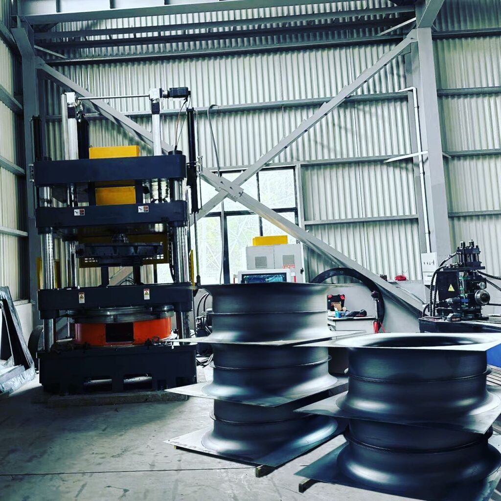
Forming and Shaping with Deep Drawing Press
The field of metalworking is continuously evolving, with advancements in technology driving the development of more efficient, precise, and versatile machines. These cutting-edge technologies are transforming traditional metalworking processes, enabling manufacturers to produce complex components with greater accuracy and consistency. This section explores some of the latest advancements in metalworking technologies, including CNC profile bending machines, hydroforming presses, punch and die design innovations, and improvements in centerless grinding surface finish.
7.1 CNC Profile Bending Machines
CNC (Computer Numerical Control) profile bending machines represent a significant advancement in the metalworking industry, offering unparalleled precision and control in bending operations. These machines use computer-controlled movements to bend metal profiles into complex shapes with high accuracy, making them essential for industries that require precise and repeatable bending processes.
7.1.1 Overview of CNC Profile Bending
CNC profile bending machines automate the bending process by using a computer to control the movement and force applied to the metal. This allows for precise control over the bending angle, radius, and curvature, ensuring that each bend is consistent and accurate.
Process: The metal profile is fed into the machine, where a series of rollers or a press apply force to bend the material. The CNC system controls the movement of the rollers or press, adjusting the force and angle as needed to achieve the desired shape.
Materials: CNC profile bending machines can handle a wide range of materials, including aluminum, steel, copper, and alloys, making them versatile tools for various applications.
7.1.2 Advantages of CNC Profile Bending Machines
Precision: CNC machines offer exceptional precision, with the ability to create complex shapes and tight tolerances that would be difficult or impossible to achieve with manual bending methods.
Repeatability: Once programmed, CNC machines can produce identical bends across multiple parts, ensuring consistency in mass production.
Efficiency: CNC profile bending machines reduce the need for manual intervention, speeding up the production process and reducing the potential for human error.
7.1.3 Applications
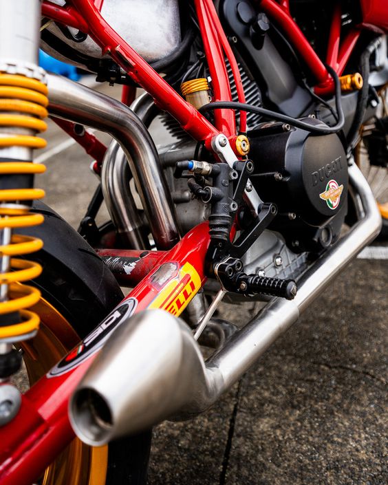
Automotive Industry: CNC profile bending machines are used to produce components such as exhaust systems, roll bars, and chassis parts, where precise bending is crucial for performance and safety.
Aerospace Industry: In aerospace manufacturing, these machines are used to form structural components, fuel lines, and airframe parts that require exact dimensions and shapes.
Construction and Architecture: CNC profile bending is also employed in the construction and architecture sectors to create custom metal profiles for building facades, railings, and structural elements.
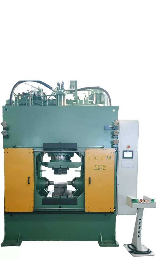
7.2 Hydroforming Press Technology
Hydroforming is a versatile metal forming process that uses high-pressure hydraulic fluid to shape metal into complex forms. Hydroforming presses have become a vital tool in the manufacturing of lightweight, high-strength components, particularly in the automotive and aerospace industries.
7.2.1 The Hydroforming Process
In hydroforming, a metal blank or tube is placed inside a die, and high-pressure hydraulic fluid is applied to form the metal into the shape of the die. The process is particularly effective for creating complex shapes with smooth surfaces and uniform wall thicknesses.
Types of Hydroforming: There are two main types of hydroforming: tube hydroforming and sheet hydroforming. Tube hydroforming is used to form hollow components like exhaust systems and structural supports, while sheet hydroforming is used for creating complex, shallow components like body panels and enclosures.
Materials: Hydroforming can be used with various materials, including aluminum, steel, and titanium, making it suitable for a wide range of applications.
7.2.2 Advantages of Hydroforming Presses
Complex Shapes: Hydroforming allows for the creation of intricate shapes that would be difficult to achieve with traditional stamping or pressing methods.
Weight Reduction: The process produces lightweight components with high structural integrity, which is particularly important in industries where weight savings are critical, such as automotive and aerospace.
Surface Quality: Hydroforming produces components with excellent surface finish, reducing the need for additional machining or finishing operations.
7.2.3 Applications
Automotive Industry: Hydroforming is widely used in the automotive industry to produce lightweight structural components, such as engine cradles, roof rails, and exhaust systems, that contribute to overall vehicle performance and fuel efficiency.
Aerospace Industry: In aerospace, hydroforming is used to manufacture airframe components, fuel tanks, and other critical parts where weight and strength are key considerations.
Consumer Electronics: Hydroforming is also employed in the production of consumer electronics enclosures, where the need for sleek, durable designs is paramount.
7.3 Innovations in Punch and Die Design
Punch and die design is at the heart of many metal forming processes, including stamping, punching, and drawing. Recent innovations in punch and die design are improving the efficiency, accuracy, and longevity of these tools, enabling manufacturers to produce higher-quality components with greater consistency.
7.3.1 Advanced Materials for Punch and Die
The materials used in punch and die design have a significant impact on tool performance and lifespan. Innovations in material science are leading to the development of stronger, more durable tool steels and coatings that enhance wear resistance and reduce downtime.
Tool Steels: High-speed steels (HSS) and powder metallurgy steels are increasingly being used in punch and die manufacturing due to their superior hardness and toughness. These materials are ideal for high-volume production runs where tools are subject to intense wear.
Coatings: Advanced coatings, such as titanium nitride (TiN) and diamond-like carbon (DLC), are being applied to punches and dies to reduce friction, increase wear resistance, and extend tool life.
7.3.2 Precision Engineering and CNC Machining
CNC machining has revolutionized the manufacturing of punches and dies, allowing for the creation of highly precise tools with complex geometries. This precision is essential for maintaining tight tolerances and ensuring the consistent quality of stamped or punched parts.
Complex Geometries: CNC machining enables the production of punches and dies with intricate shapes and features that would be difficult or impossible to achieve with traditional machining methods.
Custom Tooling: CNC technology allows for the rapid prototyping and production of custom punches and dies tailored to specific applications, reducing lead times and improving flexibility in manufacturing.
7.3.3 Applications
Automotive Manufacturing: Advanced punch and die designs are used in the production of body panels, engine components, and structural parts, where precision and durability are critical.
Consumer Electronics: The consumer electronics industry relies on precise punch and die tools to create the thin, intricate components used in smartphones, laptops, and other devices.
Medical Devices: In the medical device industry, punches and dies are used to produce components like surgical instruments and implantable devices, where precision and material integrity are of utmost importance.
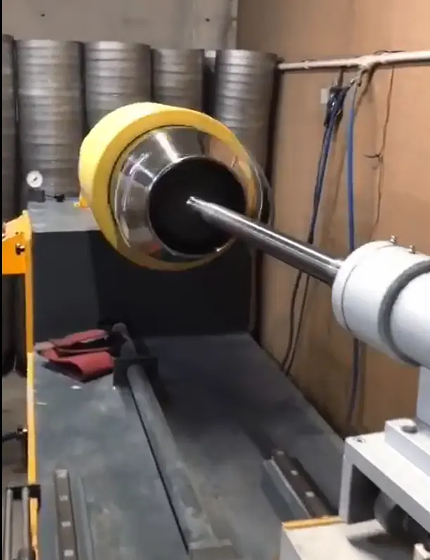
7.4 Centerless Grinding Surface Finish
Centerless grinding is a metal finishing process that removes material from the outer surface of a cylindrical workpiece, producing a smooth, high-quality surface finish. Recent advancements in centerless grinding technology have improved the precision and surface finish achievable with this process, making it a valuable tool in modern manufacturing.
7.4.1 The Centerless Grinding Process
In centerless grinding, the workpiece is supported between two rotating wheels: a grinding wheel and a regulating wheel. The grinding wheel removes material from the workpiece, while the regulating wheel controls its speed and ensures a consistent feed rate. The workpiece is not held in place by a spindle, allowing for continuous grinding and the ability to process long or complex parts.
Types of Centerless Grinding: There are two main types of centerless grinding: through-feed and in-feed. Through-feed grinding is used for cylindrical parts with a consistent diameter, while in-feed grinding is used for parts with varying diameters or complex shapes.
Materials: Centerless grinding can be used on a wide range of materials, including steel, aluminum, and alloys, making it a versatile process for various applications.
7.4.2 Advantages of Centerless Grinding
High Precision: Centerless grinding is capable of producing extremely precise dimensions and tight tolerances, making it ideal for high-precision components.
Smooth Surface Finish: The process produces a smooth surface finish with minimal defects, reducing the need for additional finishing operations.
Efficiency: Centerless grinding is a fast and efficient process, capable of handling high volumes of workpieces with consistent quality.
7.4.3 Applications
Automotive Industry: Centerless grinding is used to produce components like camshafts, crankshafts, and valve stems, where precision and surface finish are critical for performance and durability.
Aerospace Industry: The aerospace industry uses centerless grinding to produce precision components for engines, landing gear, and other critical systems, where high-quality surface finishes are essential for safety and performance.
Medical Devices: In the medical device industry, centerless grinding is used to produce components like needles, catheters, and surgical instruments, where precision and surface finish are crucial for functionality and patient safety.
7.5 Conclusion
Cutting-edge metalworking technologies are reshaping the landscape of modern manufacturing, offering new levels of precision, efficiency, and versatility. From CNC profile bending machines and hydroforming presses to advancements in punch and die design and centerless grinding, these technologies enable manufacturers to produce high-quality components that meet the stringent demands of industries such as automotive, aerospace, and medical devices. As these technologies continue to evolve, they will play an increasingly important role in driving innovation and competitiveness in the global manufacturing sector.
8. Industry-specific Applications
Industrial Applications
The metalworking industry serves a wide range of sectors, each with its unique demands and challenges. The choice of metalworking machines, techniques, and technologies is often dictated by the specific requirements of these industries. From the automotive and aerospace sectors to consumer goods and infrastructure, metalworking plays a crucial role in manufacturing the components that power modern life. This section explores the application of metalworking machinery and processes in various industries, highlighting how specialized equipment and technologies are tailored to meet the distinct needs of each sector.
8.1 Automotive Industry
The automotive industry is one of the largest consumers of metalworking products, requiring a vast array of components that must be manufactured with precision and consistency. The demands of the automotive sector include high-volume production, stringent quality standards, and the need for lightweight, durable components that contribute to overall vehicle performance and safety.
8.1.1 Metalworking in Automotive Manufacturing
The automotive manufacturing process involves the use of several metalworking techniques, including stamping, deep drawing, bending, and polishing. Each of these processes is crucial for producing the components that make up a vehicle’s body, engine, and interior systems.
Stamping: Transfer press stamping is widely used in automotive manufacturing to produce body panels, structural components, and various brackets. The ability to perform multiple operations in a single press ensures high efficiency and consistency across large production runs.
Deep Drawing: Deep drawing presses are employed to create complex shapes such as fuel tanks, transmission housings, and engine components. The deep drawing process ensures that these parts are strong, lightweight, and capable of withstanding the rigors of automotive use.
CNC Bending: CNC profile bending machines are used to form components like exhaust systems, roll cages, and chassis parts. The precision offered by CNC bending ensures that each part meets the exact specifications required for safety and performance.
8.1.2 Aluminum Deburring and Polishing
Aluminum is a key material in automotive manufacturing due to its lightweight properties and corrosion resistance. However, aluminum components often require deburring and polishing to meet the industry’s aesthetic and functional standards.
Aluminum Deburring: Aluminum deburring machines are used to remove burrs and sharp edges from machined or stamped aluminum parts. This step is essential to ensure that the components fit together smoothly during assembly and do not pose safety risks.
Polishing: Metal polishing machines are employed to enhance the surface finish of aluminum components, providing a smooth, reflective surface that improves both the appearance and aerodynamics of the vehicle.
8.1.3 Rubber Molding for Automotive Parts
Rubber components, such as seals, gaskets, and bushings, are critical in automotive manufacturing. Rubber compression molding presses are used to produce these parts with precision and consistency.
Rubber Compression Molding: This process involves placing rubber material into a heated mold, where it is shaped under pressure. The resulting components are durable, flexible, and capable of withstanding extreme temperatures and mechanical stress.
Applications: Rubber molding is used to produce a variety of automotive parts, including engine mounts, suspension bushings, and seals for doors and windows. These components contribute to the vehicle’s overall durability and comfort.
8.2 Aerospace Industry
The aerospace industry demands the highest levels of precision and quality, as the components produced must meet rigorous safety standards and perform reliably in extreme environments. Metalworking in aerospace involves the use of advanced technologies and materials to create lightweight, high-strength components.
8.2.1 Hydroforming in Aerospace Manufacturing
Hydroforming presses are extensively used in aerospace manufacturing to produce complex, lightweight components that are both strong and aerodynamic.
Complex Shapes: Hydroforming allows for the creation of intricate shapes with uniform wall thicknesses, making it ideal for producing components such as fuselage panels, wing structures, and engine casings.
Material Efficiency: The hydroforming process minimizes material waste, which is particularly important in aerospace manufacturing where the cost of materials like titanium and high-strength alloys is significant.
8.2.2 Flow Forming for High-precision Components
Flow forming lathes are used in the aerospace industry to manufacture high-precision cylindrical components, such as aircraft engine parts and structural supports.
Precision and Strength: The flow forming process enhances the mechanical properties of the material, producing components that are both lightweight and capable of withstanding high stress and pressure.
Applications: Flow forming is used to produce parts like jet engine cases, landing gear components, and missile casings, where precision and material integrity are critical.
8.2.3 Metal Polishing and Surface Finishing
In aerospace manufacturing, the surface finish of components is of utmost importance, as it can affect the aerodynamics, weight, and overall performance of the aircraft.
Metal Polishing Machines: These machines are used to achieve a smooth, polished finish on aerospace components, reducing friction and improving the aerodynamic properties of the aircraft.
Edge Rounding: Edge rounding stainless steel and other metals is essential to remove sharp edges that could cause stress concentrations or interfere with the assembly of critical components.
8.3 Consumer Goods Manufacturing
The consumer goods industry relies heavily on metalworking processes to produce a wide range of products, from household appliances to electronics. The focus in this sector is often on the aesthetic appeal, durability, and functionality of the final products.
8.3.1 Metalworking in Appliance Manufacturing
Appliance manufacturing involves the use of metalworking machines to create components such as enclosures, brackets, and internal structures for products like refrigerators, washing machines, and ovens.
Deep Drawing Presses: Deep drawing presses are used to form appliance housings and internal components from sheet metal. The deep drawing process ensures that these parts are both strong and lightweight, which is important for product durability and efficiency.
Metal Polishing and Finishing: The aesthetic appeal of consumer appliances is a key consideration, and metal polishing machines are used to achieve a high-quality finish on visible parts. Polished surfaces not only enhance the appearance but also make the appliances easier to clean and maintain.
8.3.2 Metalworking in Electronics
The electronics industry requires metal components that are not only precise but also have excellent surface finishes to ensure proper function and aesthetic appeal.
CNC Profile Bending: CNC profile bending machines are used to create the frames, brackets, and enclosures that house electronic components. Precision bending ensures that these parts fit together perfectly and provide adequate protection for sensitive electronics.
Surface Finishing: In electronics manufacturing, the surface finish of metal parts is critical for both function and appearance. Smooth, polished surfaces are essential for components like smartphone enclosures, laptop frames, and other consumer electronics.
8.4 Infrastructure and Construction
The construction and infrastructure sectors utilize metalworking processes to produce structural components, building materials, and support systems. These industries require durable, high-strength materials that can withstand harsh environmental conditions and provide long-term stability.
8.4.1 Metalworking in Structural Components
Structural components used in construction, such as beams, columns, and trusses, are often manufactured using metalworking techniques like bending, welding, and forming.
CNC Bending Machines: CNC profile bending machines are used to shape structural components with high precision, ensuring that they meet the specific requirements of building designs. This precision is crucial for maintaining the structural integrity of buildings and infrastructure projects.
Hydraulic Presses: Hydraulic presses are employed to form and assemble large structural components, providing the force necessary to shape heavy-gauge steel and other materials.
8.4.2 Road Sign Profile Cold Bending
Road signs and other infrastructure elements require precise shaping to ensure they are durable and easily visible.
Cold Bending Machines: Road sign profile cold bending machines are used to create the structural profiles that support road signs. These machines ensure that the profiles are shaped to the exact specifications required for stability and durability.
Applications: Cold bending is also used in the construction of guardrails, fencing, and other infrastructure components that must withstand environmental stress and provide long-term reliability.
8.4.3 Steel Drum Manufacturing
Steel drums are essential for storing and transporting materials in the construction and infrastructure sectors. The manufacturing of these drums involves specialized metalworking processes to ensure they are leak-proof and durable.
Steel Drum Machines: These machines are used to form, weld, and finish steel drums, ensuring they meet the necessary standards for safety and durability. The drums must be able to withstand rough handling and exposure to harsh environmental conditions.
8.5 Conclusion
The application of metalworking machinery and processes varies widely across different industries, each with its unique requirements and challenges. Whether it’s the precision needed in aerospace manufacturing, the high-volume production demands of the automotive industry, or the aesthetic and functional considerations in consumer goods, specialized metalworking technologies are essential for producing the components that drive modern industry. By understanding the specific needs of each sector, manufacturers can select the right metalworking equipment and techniques to optimize production, ensure quality, and meet the demands of their customers.
9. Market Overview and Trends in Metalworking Machinery
Working Principle of Hydroforming Press
The metalworking machinery market is a dynamic and rapidly evolving sector, influenced by technological advancements, changing industry demands, and global economic trends. As manufacturers seek to improve efficiency, precision, and automation in their production processes, the demand for advanced metalworking equipment continues to grow. This section provides an overview of the current market for metalworking machinery, explores key trends shaping the industry, and highlights some of the leading manufacturers and suppliers in the market.
9.1 Current Market Landscape
The global metalworking machinery market is diverse, encompassing a wide range of machines used in cutting, forming, finishing, and assembly processes. The market is characterized by steady growth, driven by increasing industrialization, the expansion of manufacturing sectors, and the ongoing adoption of advanced technologies.
9.1.1 Market Size and Growth
The metalworking machinery market is expected to continue its growth trajectory, supported by the rising demand for high-precision components in industries such as automotive, aerospace, and electronics. The increasing emphasis on automation and Industry 4.0 technologies is also contributing to the expansion of the market.
Key Regions: Asia-Pacific, particularly China and India, dominates the global metalworking machinery market due to its strong manufacturing base and ongoing investments in industrial infrastructure. North America and Europe are also significant markets, driven by advancements in aerospace and automotive manufacturing.
Market Segments: The market can be segmented into various categories based on the type of machinery, including CNC machines, stamping presses, forming machines, and finishing equipment. Among these, CNC machines and automated systems are experiencing the fastest growth due to their ability to enhance productivity and precision.
9.2 Trends Shaping the Metalworking Machinery Market
Several key trends are shaping the future of the metalworking machinery market, driven by technological advancements and evolving industry demands. These trends are influencing the way manufacturers invest in machinery and adopt new processes to stay competitive.
9.2.1 Automation and Industry 4.0
The integration of automation and Industry 4.0 technologies is transforming the metalworking industry. Manufacturers are increasingly adopting automated systems and smart machinery to enhance production efficiency, reduce human error, and improve overall operational performance.
Smart Manufacturing: The use of sensors, IoT (Internet of Things), and data analytics in metalworking machinery allows for real-time monitoring and control of production processes. This leads to better decision-making, predictive maintenance, and optimized resource management.
Robotics: Robotics is playing an increasingly important role in metalworking, particularly in tasks such as material handling, welding, and assembly. The use of robotic arms and automated guided vehicles (AGVs) is reducing the need for manual labor and increasing production speed.
9.2.2 Additive Manufacturing and Hybrid Machines
Additive manufacturing, also known as 3D printing, is gaining traction in the metalworking industry as a complementary technology to traditional subtractive methods. The development of hybrid machines that combine additive and subtractive processes is opening up new possibilities for complex part manufacturing.
3D Printing in Metalworking: Additive manufacturing allows for the creation of intricate geometries and custom components that would be difficult or impossible to produce with traditional methods. This is particularly useful in industries such as aerospace and medical devices, where precision and customization are critical.
Hybrid Machines: Hybrid machines that integrate additive manufacturing with CNC machining are becoming more popular, offering the flexibility to produce parts with complex internal structures while maintaining high precision and surface quality.
9.2.3 Sustainability and Green Manufacturing
As environmental concerns become increasingly important, the metalworking industry is focusing on sustainability and green manufacturing practices. This includes reducing energy consumption, minimizing waste, and using environmentally friendly materials and processes.
Energy-efficient Machines: Manufacturers are developing energy-efficient metalworking machines that reduce power consumption and lower the overall environmental impact of production processes. This is achieved through advanced motor technologies, optimized cutting strategies, and improved machine design.
Recycling and Waste Reduction: The industry is also investing in technologies that enable the recycling of scrap materials and the reduction of waste during production. This not only helps to reduce environmental impact but also lowers material costs.
9.2.4 Customization and Flexibility
The demand for customized products and shorter production runs is driving the need for flexible manufacturing solutions. Metalworking machinery that can quickly adapt to different production requirements is becoming increasingly valuable.
Modular Machines: Modular metalworking machines that can be reconfigured for different tasks are gaining popularity. These machines offer greater flexibility and allow manufacturers to respond quickly to changing market demands.
Customization: The ability to produce custom components on-demand is becoming a competitive advantage in industries such as automotive and aerospace, where product differentiation and innovation are key.
9.3 Future Outlook of the Metalworking Machinery Market
The metalworking machinery market is poised for continued growth as industries increasingly rely on advanced manufacturing technologies to stay competitive. The adoption of automation, digitalization, and sustainable practices will be key drivers of this growth, as manufacturers seek to improve efficiency, reduce costs, and meet the evolving demands of their customers.
Emerging Markets: The expansion of industrial activities in emerging markets such as India, Southeast Asia, and Latin America presents significant opportunities for the metalworking machinery industry. These regions are expected to see increased investment in manufacturing infrastructure, driving demand for advanced machinery.
Technological Advancements: Ongoing advancements in robotics, AI, and additive manufacturing will continue to shape the future of metalworking machinery, offering new possibilities for precision manufacturing and customization.
Global Supply Chain: The global nature of the metalworking industry means that supply chain dynamics will play a critical role in market development. Manufacturers will need to navigate challenges such as trade policies, raw material availability, and transportation costs to remain competitive.
9.4 Conclusion
The metalworking machinery market is undergoing significant transformation, driven by technological innovation, automation, and changing industry demands. As manufacturers seek to enhance productivity, reduce costs, and improve sustainability, the demand for advanced metalworking equipment is expected to grow. Companies that embrace these trends and invest in cutting-edge technologies will be well-positioned to thrive in the competitive global market.
Steel Drum Machines: Metalworking is an age-old craft that has evolved significantly with advancements in technology and machinery. It involves various processes to shape and fabricate metal components, ranging from cutting, bending, and assembling to finishing and polishing. The success of these processes largely depends on the quality and efficiency of the equipment used, making metalworking machines indispensable to the industry.
1.1 Overview of the Metalworking Industry
The metalworking industry is a cornerstone of modern manufacturing, encompassing a vast array of processes and technologies. These processes are vital in producing components used in automotive, aerospace, construction, and consumer goods. The industry relies heavily on precision, and thus, the machinery involved must be state-of-the-art, providing accurate and repeatable results.
1.2 Importance of High-Quality Equipment in Metalworking
High-quality metalworking equipment ensures not only precision and efficiency but also safety and longevity of the products. Machines such as burr removal machines, metal polishing machines, and deep drawing presses play a crucial role in achieving the desired surface finish and dimensional accuracy. For instance, burr removal is essential in preventing defects that could compromise the structural integrity of the product or even cause safety hazards in its application.
Investing in advanced metalworking equipment is therefore not just about improving production speed but also about ensuring the reliability and quality of the final product. As the demand for intricate and precise metal components continues to rise, so does the need for equipment that can meet these challenges.
1.3 Brief Introduction to Different Types of Metalworking Machines
Metalworking machines come in various forms, each designed for specific tasks within the metalworking process. Some of the key types include:
Burr Removal Machines: These are specialized machines used to remove burrs—small, rough edges or protrusions that form on metal surfaces after cutting or machining. Burr removal is critical for ensuring a smooth finish and preventing potential issues during assembly or use.
Metal Polishing Machines: These machines are used to achieve a fine, smooth finish on metal surfaces. They are essential in industries where appearance and surface quality are paramount, such as in the production of automotive parts, appliances, and consumer electronics.
Deep Drawing Presses: These are used in processes that involve shaping sheet metal into complex shapes, such as automotive body panels and kitchen sinks. Deep drawing presses must be highly precise to maintain the integrity of the metal during the forming process.
Moulding Presses: Moulding presses are crucial in the production of various components, particularly those made from composite materials. They are widely used in industries such as automotive, aerospace, and electronics.
Spin Forming Machines: These machines are used to form metal into cylindrical shapes, such as rims, cones, and tubes. Spin forming is a versatile process that allows for the creation of seamless, strong, and lightweight components.
Each type of machine plays a specific role in the metalworking process, and their combined use ensures the production of high-quality metal components that meet industry standards.
2. The Critical Role of Burr Removal in Metalworking
Types of Deburring Machines
Burr removal is a fundamental aspect of metalworking, often regarded as a critical finishing process that directly impacts the quality, safety, and functionality of the final product. Burrs, the unwanted rough edges or protrusions left on metal surfaces after machining, cutting, or stamping, can lead to various issues if not properly managed. These include compromised product integrity, assembly difficulties, and even safety hazards during usage. Understanding the significance of burr removal and employing effective methods to achieve it is essential for any manufacturer striving for excellence.
2.1 Understanding Burrs and Their Impact
In the metalworking industry, burrs are an inevitable byproduct of machining and manufacturing processes. They can form on almost any metal part during operations like drilling, milling, turning, or shearing. While burrs might seem insignificant, their presence can have detrimental effects on both the manufacturing process and the end product.
Quality Compromise: Burrs can lead to dimensional inaccuracies, which might result in parts that do not fit together correctly. This is particularly problematic in industries like aerospace or automotive, where precision is critical.
Safety Concerns: Sharp burrs pose a risk of injury to workers handling the parts. In addition, burrs can cause issues in the functionality of the product, such as electrical shorts in electronic components or leaks in fluid systems.
Assembly Challenges: Burrs can interfere with the assembly process by causing parts to snag or fit improperly. This can lead to increased production time, higher costs, and potential delays in delivery.
Given these potential issues, burr removal is not just a matter of finishing; it is a critical step in ensuring the overall quality and functionality of metal parts.
2.2 Burr Removal Techniques
There are various techniques for removing burrs from metal parts, ranging from manual methods to advanced automated systems. The choice of technique depends on factors such as the material, part geometry, production volume, and desired finish quality.
Manual Deburring: This traditional method involves using hand tools such as files, scrapers, or abrasive stones to remove burrs. While manual deburring is suitable for small-scale operations or intricate parts, it is labor-intensive and can be inconsistent in terms of finish quality.
Mechanical Deburring: Mechanical methods involve the use of machines such as tumblers, vibratory finishers, or abrasive belts to remove burrs. These methods are more consistent and efficient than manual deburring, making them suitable for larger production runs.
Thermal Deburring: Also known as “thermal energy method” (TEM), this technique uses controlled explosions of gas in a chamber to burn away burrs. Thermal deburring is highly effective for complex parts with internal burrs, as the gas can reach areas that are difficult to access with other methods.
Electrochemical Deburring: This process uses an electrolyte solution and an electric current to dissolve burrs. It is ideal for parts with hard-to-reach burrs and provides a smooth, precise finish.
Cryogenic Deburring: In this method, parts are cooled to extremely low temperatures using liquid nitrogen, making the burrs brittle. The parts are then agitated in a tumbler, causing the burrs to break off. Cryogenic deburring is particularly effective for plastic and rubber parts.
2.3 The Role of Burr Removal Machines
Burr removal machines are specialized equipment designed to automate and streamline the deburring process, ensuring consistent and high-quality results. These machines are essential for industries where precision and repeatability are paramount. Some of the key benefits of using burr removal machines include:
Increased Efficiency: Automated burr removal machines can process multiple parts simultaneously, significantly reducing the time and labor required for deburring.
Consistent Quality: Unlike manual deburring, which can vary depending on the operator’s skill, burr removal machines provide uniform results, ensuring that all parts meet the required specifications.
Cost-effectiveness: While the initial investment in burr removal machines may be high, the long-term savings in labor costs and improved production efficiency make them a cost-effective solution for many manufacturers.
Enhanced Safety: Automated machines reduce the risk of injury associated with manual deburring, as workers are not required to handle sharp parts directly.
2.4 Specialized Burr Removal Machines
There are various types of burr removal machines, each tailored to specific applications and industries. These include:
Aluminium Deburring Machines: These machines are specifically designed to handle aluminum parts, which require a delicate touch to avoid damaging the material. They are commonly used in the automotive and aerospace industries, where aluminum is widely used.
Deburring Machines for Sheet Metal Edges: These machines are designed to remove burrs from the edges of sheet metal, ensuring smooth, clean edges that are safe to handle and meet the required tolerances.
Metal Edge Finishing Machines: These machines are used to finish the edges of metal parts, providing a smooth, rounded edge that improves both the appearance and functionality of the part.
Automatic Burr Removal Machines: These machines are designed for high-volume production environments, where speed and efficiency are critical. They are capable of processing large quantities of parts quickly, with minimal operator intervention.
2.5 Advancements in Burr Removal Technology
The field of burr removal is continuously evolving, with new technologies being developed to improve the efficiency and effectiveness of the process. Some of the latest advancements include:
CNC-controlled Deburring Machines: These machines use computer numerical control (CNC) technology to precisely control the deburring process, ensuring consistent, high-quality results. CNC deburring machines are ideal for complex parts with tight tolerances.
Robotic Deburring: Robotic systems are increasingly being used for deburring, particularly in industries where precision and repeatability are critical. These systems can be programmed to perform complex deburring tasks with a high degree of accuracy.
Laser Deburring: Laser technology is being used to remove burrs with high precision, particularly on small, intricate parts. Laser deburring is contactless, which reduces the risk of damaging delicate components.
Hybrid Deburring Systems: These systems combine multiple deburring techniques, such as mechanical and thermal deburring, to achieve optimal results for complex parts. Hybrid systems are particularly useful for parts with varied geometries and materials.
2.6 The Importance of Proper Burr Removal in Quality Assurance
In today’s competitive manufacturing environment, maintaining high-quality standards is essential for success. Proper burr removal is a key component of quality assurance, as it directly impacts the functionality, safety, and appearance of the final product. Manufacturers that invest in advanced burr removal technologies and processes are better equipped to meet the demanding requirements of their customers and stay ahead of the competition.
Quality assurance in burr removal involves not only the selection of the right techniques and machines but also continuous monitoring and testing to ensure that the process consistently meets the required standards. This can include:
Regular Inspection: Parts should be inspected after deburring to ensure that all burrs have been effectively removed and that the surface finish meets the required specifications.
Testing: In some cases, additional testing, such as pressure testing for fluid systems or electrical testing for electronic components, may be necessary to confirm that the burr removal process has not compromised the integrity of the part.
Documentation: Proper documentation of the burr removal process, including machine settings, inspection results, and corrective actions, is essential for traceability and quality control.
2.7 Conclusion
Burr removal is a critical step in the metalworking process that should not be overlooked. By understanding the impact of burrs on product quality and safety, and by investing in the right burr removal techniques and machines, manufacturers can ensure that their products meet the highest standards. As technology continues to advance, new burr removal methods and machines will further enhance the efficiency and effectiveness of this essential process.
3. Exploring Metalworking Machines and Their Functions
Sheet Metal Machinery
The metalworking industry relies on a diverse array of machines to transform raw materials into finished products. These machines are integral to the manufacturing process, offering precision, efficiency, and versatility across various applications. Each type of metalworking machine serves a specific function, from shaping and forming metal to finishing and polishing it. Understanding the capabilities and applications of these machines is crucial for selecting the right equipment for any given project.
3.1 Overview of Metalworking Machines
Metalworking machines encompass a wide range of equipment designed to perform tasks such as cutting, bending, forming, and finishing metal components. These machines are categorized based on the specific operations they perform, such as pressing, deburring, polishing, and forming. Here’s a broad classification of metalworking machines:
Press Machines: These include various types of presses such as hydraulic presses, deep drawing presses, and moulding presses. Press machines are used to shape metal by applying force to it, typically using a die to form the metal into the desired shape.
Deburring and Finishing Machines: These machines are designed to remove burrs, polish, and finish metal surfaces. Burr removal machines, metal polishing machines, and edge rounding machines fall into this category.
Forming Machines: Machines like spin forming machines, CNC profile bending machines, and cold forming presses are used to bend or shape metal into specific profiles or forms.
Grinding and Cutting Machines: These include centerless grinding machines, which provide a high-quality surface finish by removing material from the outer surface of a metal part.
3.2 Specific Machines and Their Functions
Each type of metalworking machine plays a vital role in the production process, contributing to the creation of precise, high-quality metal components. Let’s delve into the functions and applications of some of the most essential metalworking machines.
3.2.1 Moulding Presses
Moulding presses are pivotal in the manufacturing of components that require precise shapes and forms, especially in industries like automotive and aerospace. These presses are used to shape materials by applying pressure to a mold, which can be made of metal or other durable materials. The types of moulding presses include:
Compression Moulding Presses: These presses are used to shape materials like rubber, plastic, and composites. The material is placed in a heated mold, and the press applies pressure to shape it. Compression molding presses are widely used in the production of automotive parts, electronic components, and industrial equipment.
Rubber Compression Molding Presses: Specifically designed for molding rubber products, these presses are used in the production of items like seals, gaskets, and other rubber components. They offer precise control over temperature and pressure, ensuring high-quality results.
SMC Presses (Sheet Moulding Compound Presses): SMC presses are used to mold composite materials, which are commonly used in the automotive and aerospace industries for their strength and lightweight properties.
3.2.2 SMC Presses
SMC presses are specialized machines designed to mold sheet molding compounds, which are a type of composite material made of a thermosetting resin, glass fibers, and fillers. These presses are widely used in the automotive and aerospace industries to produce lightweight, durable components such as car body panels, aircraft parts, and electrical enclosures.
The advantages of SMC presses include:
High Strength-to-Weight Ratio: SMC components offer excellent strength while remaining lightweight, making them ideal for applications where weight savings are critical.
Complex Shapes: SMC presses can produce complex shapes with high precision, reducing the need for additional machining or finishing.
Corrosion Resistance: SMC materials are inherently resistant to corrosion, making them suitable for use in harsh environments.
3.2.3 Hot Press Systems
Hot press systems are used in various metalworking processes to apply heat and pressure simultaneously to a material, shaping it or bonding it to another material. These systems are commonly used in the production of laminated components, metal bonding, and the forming of composite materials.
Application Areas: Hot press systems are extensively used in the electronics industry for the lamination of circuit boards, in the automotive industry for bonding metal components, and in the aerospace industry for forming composite materials.
Benefits: Hot press systems offer high precision, uniform pressure application, and controlled heating, resulting in consistent and high-quality products.
3.2.4 Cold Forming Presses
Cold forming presses are used to shape metal at room temperature, relying on mechanical force to deform the metal into the desired shape. Unlike hot forming, cold forming does not involve heating the material, which helps maintain the material’s inherent properties and produces a high-quality finish.
Advantages of Cold Forming:
Improved Material Properties: Cold forming strengthens the metal by refining its grain structure, enhancing its mechanical properties.
Cost Efficiency: Cold forming processes typically require less energy and are faster than hot forming processes, reducing overall production costs.
Precision and Surface Finish: Cold forming produces parts with excellent dimensional accuracy and a smooth surface finish, reducing the need for further processing.
3.2.5 Silicone Presses
Silicone presses are used to mold silicone rubber into various shapes and forms, typically in the production of seals, gaskets, medical devices, and other silicone products. These presses operate under controlled temperature and pressure to ensure the silicone material cures properly and achieves the desired properties.
Key Applications:
Medical Devices: Silicone presses are used to produce components such as tubing, seals, and gaskets for medical devices, where biocompatibility and precision are critical.
Automotive Industry: Silicone seals and gaskets produced by silicone presses are widely used in the automotive industry for their durability and resistance to extreme temperatures.
3.3 Advanced Metalworking Machines
As technology advances, the metalworking industry has seen the development of more sophisticated machines designed to enhance precision, efficiency, and flexibility. Some of these advanced machines include:
3.3.1 CNC Profile Bending Machines
CNC (Computer Numerical Control) profile bending machines are advanced systems used to bend metal profiles with a high degree of precision and consistency. These machines are essential in industries where complex shapes and tight tolerances are required, such as in the construction of architectural elements, automotive components, and aerospace structures.
Benefits of CNC Profile Bending:
Precision: CNC control allows for precise bending angles and repeatability, ensuring uniformity across all parts.
Complex Bends: CNC machines can perform complex bends that would be difficult or impossible to achieve with manual methods.
Efficiency: CNC profile bending machines can handle high volumes of work with minimal setup time, making them ideal for mass production.
3.3.2 Spin Forming Machines
Spin forming, also known as metal spinning, is a process where a metal disc or tube is rotated at high speed and formed into a symmetrical shape using a combination of pressure and heat. Spin forming machines are used to produce components like metal cones, cylinders, and domes.
Applications of Spin Forming:
Aerospace: Spin forming is used to create components such as nose cones, rocket fairings, and other aerodynamic parts.
Automotive: In the automotive industry, spin forming is used to produce parts like wheel rims and exhaust components.
Industrial Equipment: Spin forming is also employed in the production of industrial equipment such as pressure vessels and fluid tanks.
3.3.3 Flow Forming Lathes
Flow forming lathes are specialized machines used to produce high-precision cylindrical components by gradually deforming a metal blank under controlled conditions. This process is particularly useful for producing components with thin walls and high strength, such as automotive drive shafts, aerospace components, and military hardware.
Advantages of Flow Forming:
Precision: Flow forming lathes provide excellent control over wall thickness and dimensions, resulting in highly accurate parts.
Material Efficiency: The process minimizes material waste, making it a cost-effective option for producing high-strength components.
Strength: Flow forming enhances the mechanical properties of the material, producing parts with superior strength and durability.
3.3.4 Hydroforming Presses
Hydroforming is a versatile metal forming process that uses high-pressure hydraulic fluid to shape metal into complex forms. Hydroforming presses are particularly useful for creating lightweight, high-strength components with intricate geometries, making them a popular choice in the automotive and aerospace industries.
Key Features:
Complex Shapes: Hydroforming can produce parts with complex shapes and fine details that would be difficult to achieve with traditional forming methods.
Weight Reduction: The process allows for the creation of lightweight components without sacrificing strength, making it ideal for applications where weight savings are critical.
Material Flexibility: Hydroforming can be used with various metals, including aluminum, steel, and titanium.
3.4 Choosing the Right Metalworking Machine
Selecting the right metalworking machine depends on several factors, including the material being worked on, the complexity of the part, the required precision, and the production volume. For instance:
For Precision Work: CNC profile bending machines and flow forming lathes offer unparalleled precision, making them ideal for aerospace and automotive applications.
For High-Volume Production: Automatic burr removal machines and transfer press stamping systems provide the efficiency needed for mass production environments.
For Complex Geometries: Hydroforming presses and spin forming machines are excellent choices for producing parts with complex shapes and fine details.
Investing in the appropriate metalworking machinery is crucial for optimizing production processes, reducing costs, and ensuring the highest quality of the final product.
4. Metal Polishing and Finishing Machines
Internal Grinding
Polishing and finishing are critical steps in the metalworking process, ensuring that metal parts not only meet functional requirements but also achieve the desired aesthetic appeal. These processes involve the removal of surface imperfections, the enhancement of surface smoothness, and the creation of a polished or matte finish, depending on the application. Metal polishing and finishing machines are designed to automate these tasks, providing consistent and high-quality results that are essential for industries like automotive, aerospace, and consumer goods.
4.1 Importance of Metal Polishing and Finishing
Polishing and finishing metal components serve multiple purposes, from improving the appearance to enhancing the durability and performance of the final product. The importance of these processes can be summarized as follows:
Surface Quality: A polished surface reduces friction, which is particularly important for moving parts. It also enhances the appearance of the product, making it more appealing to consumers.
Corrosion Resistance: Polishing helps to close surface pores, reducing the likelihood of corrosion, especially in metals like stainless steel and aluminum.
Improved Functionality: Polished surfaces can improve the performance of parts in applications where smooth surfaces are critical, such as in hydraulic systems or sealing surfaces.
Ease of Cleaning: Polished surfaces are easier to clean and maintain, making them ideal for applications in the food, medical, and pharmaceutical industries.
4.2 Types of Metal Polishing Machines
Metal polishing machines are designed to achieve different levels of finish, from a basic smooth surface to a mirror-like polish. Depending on the application and the desired finish, various types of polishing machines are used:
4.2.1 Fine Polishing Machines
Fine polishing machines are used to achieve a high level of smoothness on metal surfaces. These machines are essential in industries where surface quality is paramount, such as in the production of surgical instruments, high-end consumer goods, and precision components.
Applications: Fine polishing machines are commonly used in the medical device industry, the jewelry industry, and the production of luxury items where a flawless finish is required.
Capabilities: These machines can handle a variety of materials, including stainless steel, aluminum, brass, and other non-ferrous metals. They are capable of producing a mirror-like finish that enhances both the appearance and performance of the component.
4.2.2 Automatic Metal Polishing Machines
Automatic metal polishing machines are designed for high-volume production environments where speed and consistency are crucial. These machines can polish multiple parts simultaneously, ensuring uniformity across all pieces.
Efficiency: Automatic polishing machines reduce manual labor, increasing production efficiency and throughput. They are ideal for industries like automotive manufacturing, where large quantities of metal parts need to be polished quickly and consistently.
Customization: Many automatic polishing machines offer customizable settings, allowing manufacturers to adjust the polishing process according to the specific requirements of different parts.
4.2.3 CNC-controlled Polishing Machines
CNC (Computer Numerical Control) polishing machines use advanced technology to control the polishing process with high precision. These machines are essential for applications where tight tolerances and consistent finishes are required.
Precision: CNC polishing machines can follow complex contours and geometries with precision, making them ideal for polishing intricate parts or components with complex shapes.
Repeatability: Once programmed, CNC polishing machines can replicate the same polishing process across multiple parts, ensuring consistency and reducing the likelihood of human error.
4.3 Edge Rounding and Deburring Machines
In addition to polishing, edge rounding and deburring are essential processes in metal finishing. These processes remove sharp edges and burrs that can result from machining, cutting, or stamping, improving the safety, appearance, and functionality of the final product.
4.3.1 Deburring Sheet Metal Edges
Deburring sheet metal edges is a crucial step in preparing metal parts for assembly or final finishing. Burrs, which are unwanted material projections, can compromise the quality of the final product and pose safety risks.
Methods: Deburring sheet metal edges can be done using various methods, including mechanical deburring, abrasive belts, and tumbling. The choice of method depends on the material, part geometry, and production volume.
Benefits: Proper deburring ensures that parts fit together correctly during assembly and reduces the risk of injury from sharp edges. It also improves the aesthetic appeal and prepares the parts for subsequent finishing processes.
4.3.2 Edge Rounding Stainless Steel
Stainless steel, widely used in industries like food processing, medical equipment, and construction, requires careful finishing to ensure both functionality and appearance. Edge rounding is an essential process for stainless steel parts, particularly in applications where sharp edges could cause damage or injury.
Process: Edge rounding involves removing sharp edges from stainless steel parts, either through mechanical means or using specialized edge rounding machines. This process not only enhances safety but also improves the durability and resistance to corrosion.
Applications: Edge rounding is commonly used in the production of stainless steel kitchen appliances, medical instruments, and architectural components where smooth, safe edges are crucial.
4.4 Aluminum Deburring and Finishing Machines
Aluminum is a versatile material used across various industries, including automotive, aerospace, and construction. However, due to its relatively soft nature, aluminum is prone to burrs and surface imperfections during machining. Aluminum deburring and finishing machines are designed to address these issues, ensuring a smooth, clean finish.
4.4.1 Aluminum Deburring Machines
Aluminum deburring machines are specialized to handle the unique properties of aluminum, which can be easily scratched or damaged if not properly deburred. These machines are designed to remove burrs and other imperfections without compromising the material’s integrity.
Applications: Aluminum deburring machines are used in the production of automotive components, aircraft parts, and consumer electronics, where precision and surface quality are critical.
Techniques: These machines use various techniques, such as abrasive belts, brushes, or chemical processes, to achieve a smooth, burr-free surface.
4.4.2 Aluminum Polishing and Finishing
Polishing aluminum requires a delicate balance between removing surface imperfections and achieving a high-quality finish. Aluminum polishing machines are designed to enhance the appearance and functionality of aluminum parts by providing a smooth, reflective surface.
Challenges: Aluminum is prone to oxidation, which can dull the surface if not properly polished and protected. Polishing machines for aluminum often include features to minimize oxidation and maintain the metal’s shine.
End Use: Polished aluminum is commonly used in automotive trim, aircraft interiors, and consumer products like smartphones and laptops, where both appearance and performance are important.
4.5 Industrial Metal Polishing Equipment
For large-scale operations, industrial metal polishing equipment is essential for handling high volumes of work with consistency and precision. This equipment is used in industries ranging from automotive manufacturing to aerospace production, where the quality of the surface finish can significantly impact the performance and longevity of the final product.
4.5.1 Large-Scale Polishing Systems
Industrial polishing systems are designed to handle large components or high volumes of smaller parts. These systems often include multiple polishing stations, automated handling, and integrated quality control to ensure that every part meets the required standards.
Automation: Many industrial polishing systems are fully automated, reducing the need for manual intervention and increasing production speed. This automation also ensures that the polishing process is consistent across all parts.
Customization: Industrial systems can be customized to suit specific applications, with adjustable settings for different materials, finishes, and part geometries.
4.5.2 Safety and Efficiency in Industrial Polishing
Safety is a key concern in industrial polishing operations, where large machines and high-speed processes are involved. Industrial polishing equipment is designed with safety features such as protective enclosures, emergency stops, and dust extraction systems to protect workers and maintain a clean working environment.
Efficiency: Industrial polishing equipment is designed to maximize efficiency, reducing waste and energy consumption while delivering high-quality results. These systems often incorporate energy-efficient motors, optimized polishing media, and recycling systems for consumables.
4.6 Conclusion
Metal polishing and finishing are crucial processes in the metalworking industry, directly affecting the quality, durability, and appearance of the final product. The right polishing and finishing machines can enhance productivity, ensure consistency, and achieve the desired surface characteristics, whether it’s a mirror-like polish or a smooth, rounded edge. As the demand for high-quality metal components continues to grow, investing in advanced polishing and finishing technology becomes increasingly important for manufacturers looking to stay competitive.
5. Deep Drawing and Forming Presses
Deep Drawing
Deep drawing and forming processes are fundamental techniques in metalworking, widely used to shape metal sheets into complex geometries with high precision. These processes are particularly important in industries such as automotive, aerospace, and appliance manufacturing, where components with deep, intricate shapes are required. The machines used for deep drawing and forming must be robust, precise, and versatile to handle a variety of materials and thicknesses. This section explores the different types of deep drawing and forming presses, their applications, and the advantages they offer in modern manufacturing.
5.1 Introduction to Deep Drawing Processes
Deep drawing is a metal forming process in which a sheet metal blank is radially drawn into a forming die by the mechanical action of a punch. It is considered “deep” drawing when the depth of the drawn part exceeds its diameter. This process is commonly used to create parts like automotive body panels, kitchen sinks, and various containers.
Process Overview:
A blank sheet of metal is placed over a die.
A punch presses the metal into the die, forcing it to conform to the shape of the die cavity.
The result is a seamless, hollow component with a consistent wall thickness.
Materials Used:
Common materials for deep drawing include steel, aluminum, brass, copper, and various alloys. The material’s ductility and thickness determine the feasibility and success of the deep drawing process.
Applications:
Deep drawing is used in manufacturing components like engine parts, household appliances, and packaging materials. It is also crucial in producing components for the aerospace industry, where precision and material integrity are vital.
5.2 Types of Deep Drawing Presses
Deep drawing presses are specialized machines designed to perform the deep drawing process with high precision and efficiency. There are various types of presses used depending on the specific requirements of the part being produced.
5.2.1 Hydraulic Deep Drawing Presses
Hydraulic presses are among the most commonly used machines for deep drawing. They use hydraulic pressure to apply force to the metal blank, pushing it into the die cavity. Hydraulic presses are highly versatile and can be adjusted to apply varying levels of pressure, making them suitable for a wide range of materials and part sizes.
Advantages:
Precision: Hydraulic presses offer excellent control over the drawing process, allowing for the production of parts with tight tolerances.
Versatility: These presses can handle a variety of materials, including high-strength metals and alloys.
Consistency: Hydraulic systems provide consistent force throughout the drawing process, ensuring uniform wall thickness and part quality.
Applications:
Hydraulic deep drawing presses are used in the automotive industry to produce components like fuel tanks, body panels, and exhaust systems. They are also widely used in the production of household appliances and industrial containers.
5.2.2 Mechanical Deep Drawing Presses
Mechanical presses use a flywheel to store energy and release it in a single, powerful stroke. These presses are known for their speed and efficiency, making them ideal for high-volume production runs. Mechanical presses are often used in applications where large quantities of parts need to be produced quickly and consistently.
Advantages:
Speed: Mechanical presses operate at high speeds, making them suitable for mass production.
Cost-Effectiveness: These presses are typically less expensive to operate than hydraulic presses, especially in high-volume production environments.
Durability: Mechanical presses are built to withstand high levels of stress and are highly durable, requiring minimal maintenance.
Applications:
Mechanical deep drawing presses are commonly used in the production of automotive parts, including fenders, hoods, and doors. They are also used in the manufacturing of metal containers, cookware, and industrial components.
5.2.3 Servo-Driven Deep Drawing Presses
Servo-driven presses are a more advanced type of deep drawing press, combining the precision of hydraulic presses with the speed of mechanical presses. These machines use a servo motor to control the movement of the press, offering unparalleled control over the drawing process.
Advantages:
Precision: Servo-driven presses provide precise control over the speed and force of the drawing process, allowing for the production of highly complex parts.
Energy Efficiency: These presses are more energy-efficient than traditional hydraulic or mechanical presses, reducing operating costs.
Flexibility: The programmable nature of servo-driven presses allows for quick changes between different part designs, making them ideal for environments where product variation is common.
Applications:
Servo-driven deep drawing presses are used in the production of high-precision components for the aerospace, automotive, and medical device industries. They are also increasingly used in the production of electronic components, where tight tolerances and complex shapes are required.
5.3 Spin Forming Machines
Spin forming, also known as metal spinning, is a process that involves rotating a metal disc or tube while applying force to shape it into a symmetrical object. Spin forming machines are used to produce components like wheels, cones, and cylindrical shapes, often used in industries such as aerospace, automotive, and lighting.
Process Overview:
The metal blank is placed on a lathe and rotated at high speed.
A tool presses against the rotating blank, forcing it to take the shape of the tool or mandrel.
The result is a seamless, strong component with excellent structural integrity.
Advantages:
Material Efficiency: Spin forming typically results in minimal material waste, making it a cost-effective manufacturing process.
Structural Integrity: The continuous nature of the spin forming process enhances the strength and durability of the final product.
Versatility: Spin forming can be used with various materials, including aluminum, steel, and titanium, and can produce a wide range of shapes.
Applications:
In the aerospace industry, spin forming is used to produce parts like rocket nozzles, satellite dishes, and aircraft nose cones. In the automotive industry, it is used for manufacturing wheel rims and other components requiring a high degree of symmetry.
5.4 Deep Drawing Hydraulic Presses
Deep drawing hydraulic presses are specifically designed for the deep drawing process, offering the high force required to shape thick or high-strength materials. These presses are versatile and can be used for both shallow and deep drawing operations, making them a popular choice across various industries.
Key Features:
High Force Capacity: Hydraulic presses can apply immense force, making them suitable for deep drawing thick or difficult-to-form materials.
Controlled Drawing Process: The ability to control the speed and force during the drawing process ensures that the material flows evenly, reducing the risk of tearing or wrinkling.
Tooling Flexibility: Hydraulic presses can accommodate a wide range of tooling, allowing for the production of parts with varying geometries and sizes.
Applications:
These presses are used in the automotive industry to produce components like fuel tanks, chassis parts, and engine housings. They are also used in the production of large industrial containers, kitchen sinks, and other deep-drawn products.
5.5 Transfer Press Stamping
Transfer press stamping is a high-volume manufacturing process where metal blanks are automatically transferred from one stamping station to the next. Each station performs a different operation, such as drawing, trimming, or punching, ultimately producing a finished part.
Process Overview:
Metal blanks are fed into the press and automatically moved from station to station, where various forming operations are performed.
The process is continuous, allowing for high-speed production of complex parts.
The final product emerges fully formed, with minimal need for secondary operations.
Advantages:
High Productivity: Transfer press stamping is highly efficient, capable of producing large quantities of parts in a short period.
Consistency: The automated nature of the process ensures consistent quality across all parts.
Cost-Effectiveness: By integrating multiple operations into a single machine, transfer press stamping reduces labor and tooling costs.
Applications:
Transfer press stamping is widely used in the automotive industry to produce parts like door panels, structural components, and brackets. It is also used in the manufacturing of appliances, electrical components, and various consumer goods.
5.6 Conclusion
Deep drawing and forming presses are essential tools in modern manufacturing, enabling the production of complex, high-quality metal components with precision and efficiency. Whether it’s the robust capabilities of hydraulic presses, the speed of mechanical presses, or the advanced control of servo-driven presses, these machines play a critical role in industries ranging from automotive to aerospace. Understanding the specific applications and benefits of each type of press allows manufacturers to choose the right equipment for their production needs, ensuring the consistent quality and performance of their products.
6. Specialized Metalworking Machines and Presses
Section 4: Applications of Sheet Metal Machinery
The metalworking industry requires a variety of specialized machines and presses to handle specific tasks that standard equipment may not be able to accomplish efficiently. These specialized machines are designed to address unique challenges in manufacturing processes, offering solutions for complex shapes, precision work, and materials that demand particular handling. This section covers some of the most significant specialized metalworking machines and presses, highlighting their applications, advantages, and roles in modern production environments.
6.1 Transfer Press Stamping
Transfer press stamping is a highly automated process designed for high-volume production, where multiple stamping operations are integrated into a single machine. This technology is widely used in industries where the demand for large quantities of complex parts is high.
6.1.1 Process Overview
Transfer press stamping involves a series of stamping operations performed in succession, with each operation completed at a different station within the same machine. The metal blank is automatically transferred from one station to the next, with each station performing a specific task such as drawing, trimming, piercing, or bending. This allows for the rapid production of finished parts with minimal need for secondary operations.
6.1.2 Advantages
High Efficiency: Transfer press stamping is capable of producing large quantities of parts quickly, making it ideal for mass production.
Integrated Operations: By combining multiple stamping operations in a single machine, transfer press stamping reduces the need for multiple setups, lowering labor costs and increasing throughput.
Consistency: The automated nature of the process ensures that each part is produced to the same specifications, reducing variability and improving quality control.
6.1.3 Applications
Automotive Industry: Transfer press stamping is commonly used to manufacture automotive components such as body panels, structural parts, and brackets. Its ability to handle complex shapes and large volumes makes it a vital technology in this sector.
Appliance Manufacturing: The process is also used to produce components for household appliances, including metal housings, brackets, and support structures.
6.2 Flow Forming Lathes
Flow forming lathes are specialized machines used to produce high-precision cylindrical components through a process known as flow forming. This technology is particularly valued in industries where lightweight, strong, and accurate components are required.
6.2.1 Flow Forming Process
Flow forming is a cold-forming process where a metal blank, typically a cylindrical tube or disc, is placed on a rotating mandrel. Rollers apply pressure to the blank as it rotates, gradually shaping it into the desired form. This process is capable of producing thin-walled components with excellent mechanical properties and tight tolerances.
6.2.2 Advantages
Material Efficiency: Flow forming reduces material waste compared to traditional machining processes, making it a cost-effective method for producing high-strength components.
Precision: The process allows for the creation of components with precise dimensions and consistent wall thickness, critical for applications in aerospace and automotive industries.
Enhanced Mechanical Properties: Flow forming improves the material’s grain structure, resulting in components with enhanced strength and durability.
6.2.3 Applications
Aerospace Industry: Flow forming lathes are used to produce components such as rocket motor casings, aircraft engine components, and structural parts where weight reduction and strength are critical.
Automotive Industry: The technology is employed to manufacture drive shafts, axles, and other components that require high precision and strength.
Military Applications: Flow forming is used in the production of military hardware, such as artillery shells and missile casings, where material strength and precision are paramount.
6.3 Rim Spinning Machines
Rim spinning machines are specialized equipment used to manufacture wheel rims for vehicles. The process of rim spinning involves shaping a metal disc into a cylindrical rim, which is then further processed to achieve the desired dimensions and strength.
6.3.1 Rim Spinning Process
Rim spinning starts with a metal disc, which is clamped onto a rotating mandrel. The spinning process shapes the disc into a cylindrical form, creating the basic structure of the wheel rim. Additional operations, such as rolling and finishing, are performed to achieve the final dimensions and surface finish.
6.3.2 Advantages
Customization: Rim spinning allows for the production of custom wheel designs, catering to the specific needs of automotive manufacturers and aftermarket suppliers.
Strength and Durability: The spinning process enhances the strength of the metal, producing rims that are both lightweight and durable, essential for high-performance vehicles.
Efficiency: Rim spinning machines are capable of producing rims at high speeds, making them suitable for mass production.
6.3.3 Applications
Automotive Industry: Rim spinning is primarily used in the automotive industry to manufacture wheel rims for cars, trucks, and motorcycles. The process is favored for producing rims that meet the stringent safety and performance standards required in this sector.
Specialty Vehicles: Rim spinning is also used to produce rims for specialty vehicles, such as racing cars and custom-built vehicles, where specific design and performance criteria must be met.
6.4 Rubber and Silicone Presses
Rubber and silicone presses are specialized machines designed for molding rubber and silicone materials into various shapes and components. These presses are essential in industries where rubber and silicone products are widely used, such as automotive, medical, and consumer goods.
6.4.1 Rubber Compression Molding Presses
Rubber compression molding presses are used to shape rubber compounds into final products through the application of heat and pressure. The rubber material is placed in a heated mold cavity, and the press applies pressure to shape it into the desired form.
Applications: Rubber compression molding presses are used to manufacture products such as seals, gaskets, o-rings, and other rubber components that require precision and durability. These presses are also used in the production of automotive rubber parts, such as bushings and mounts.
6.4.2 Silicone Presses
Silicone presses operate similarly to rubber presses but are specifically designed to handle silicone materials, which have unique properties such as flexibility, heat resistance, and biocompatibility.
Applications: Silicone presses are used in the medical device industry to produce items such as tubing, seals, and implants. They are also used in the automotive industry to manufacture silicone gaskets, seals, and hoses.
6.4.3 Rubber Compression Molding Presses for Sale
The market for rubber compression molding presses is diverse, with a wide range of machines available for different applications and production scales. When selecting a press, manufacturers consider factors such as the size of the mold, the required pressure and temperature, and the specific properties of the rubber or silicone material being molded.
New vs. Used: Manufacturers can choose between new and used presses, depending on budget and specific requirements. New presses offer the latest technology and features, while used presses can be a cost-effective option for smaller operations or specific projects.
6.5 Road Sign Profile Cold Bending Machines
Road sign profile cold bending machines are specialized equipment used to manufacture the structural profiles that support road signs. These machines are designed to bend metal profiles into the precise shapes needed to withstand outdoor conditions and provide long-term durability.
6.5.1 Cold Bending Process
Cold bending involves shaping metal profiles at room temperature without the application of heat. This process preserves the material’s mechanical properties, making it suitable for applications where strength and rigidity are important.
Advantages: Cold bending machines offer high precision and repeatability, ensuring that each profile meets the required specifications. The process is also energy-efficient, as it does not require heating.
6.5.2 Applications
Road Sign Manufacturing: Cold bending machines are primarily used to produce the support structures for road signs, including poles and brackets. These structures must be durable enough to withstand environmental factors such as wind, rain, and temperature fluctuations.
Infrastructure Projects: Cold bending is also used in other infrastructure projects where metal profiles are required, such as in the construction of guardrails, bridges, and fencing.
6.6 Punch and Die Design
Punch and die design is a critical aspect of metal forming processes, where precise tools are used to cut, shape, or form metal sheets into specific shapes. The design of these tools is crucial for achieving accurate and consistent results in stamping, punching, and forming operations.
6.6.1 Importance of Precision in Punch and Die Design
The punch and die must be precisely designed to ensure that the metal is cut or shaped correctly. Any deviation in the design can lead to defects in the final product, such as burrs, cracks, or dimensional inaccuracies.
Material Selection: The materials used for punches and dies must be carefully selected to withstand the stresses of the forming process. Common materials include tool steels and carbide, which offer high hardness and wear resistance.
Tool Geometry: The geometry of the punch and die is tailored to the specific operation, whether it’s cutting, bending, or drawing. The design must account for factors such as material flow, springback, and tool wear.
6.6.2 Applications
Automotive Industry: Punch and die sets are extensively used in the automotive industry for manufacturing body panels, brackets, and structural components. Precision in punch and die design is essential for maintaining quality and consistency in high-volume production.
Aerospace Industry: In the aerospace sector, punch and die tools are used to form lightweight, high-strength components from materials like aluminum and titanium. The precision required in this industry is extremely high, given the safety-critical nature of aerospace components.
6.7 Steel Drum Machines
Steel drum machines are specialized equipment used in the production of steel drums, which are widely used for storing and transporting liquids and other materials. These machines are designed to perform operations such as forming, welding, and finishing the drum body.
6.7.1 Steel Drum Manufacturing Process
The process of manufacturing steel drums involves several steps, including cutting, forming, welding, and finishing. Steel drum machines are designed to handle each of these steps efficiently, ensuring that the drums meet industry standards for durability and safety.
Cutting and Forming: The steel sheet is first cut to size and then formed into a cylindrical shape. This is typically done using roll forming or bending machines.
Welding: Once the drum body is formed, the seam is welded to create a leak-proof seal. The welding process must be precise to ensure that the drum can withstand pressure and handling without leaking.
Finishing: The final steps include adding the drum’s top and bottom, applying any necessary coatings, and performing quality inspections.
6.7.2 Applications
Industrial Storage: Steel drums are used in various industries, including chemical, pharmaceutical, and food processing, to store and transport liquids and powders. The drums must meet strict standards for safety and durability, particularly when used for hazardous materials.
Logistics and Transportation: Steel drums are also used in logistics for the safe transportation of materials over long distances. The strength and durability of the drums are critical to ensuring that the contents are protected during transit.
6.8 Conclusion
Specialized metalworking machines and presses play a crucial role in modern manufacturing, providing solutions for tasks that require precision, efficiency, and specialized capabilities. From transfer press stamping for high-volume production to flow forming lathes for high-precision components, these machines enable manufacturers to meet the demanding requirements of industries such as automotive, aerospace, and consumer goods. Understanding the functions and advantages of these specialized machines helps manufacturers select the right equipment for their specific needs, ensuring optimal performance and product quality.
7. Cutting-edge Metalworking Technologies
Forming and Shaping with Deep Drawing Press
The field of metalworking is continuously evolving, with advancements in technology driving the development of more efficient, precise, and versatile machines. These cutting-edge technologies are transforming traditional metalworking processes, enabling manufacturers to produce complex components with greater accuracy and consistency. This section explores some of the latest advancements in metalworking technologies, including CNC profile bending machines, hydroforming presses, punch and die design innovations, and improvements in centerless grinding surface finish.
7.1 CNC Profile Bending Machines
CNC (Computer Numerical Control) profile bending machines represent a significant advancement in the metalworking industry, offering unparalleled precision and control in bending operations. These machines use computer-controlled movements to bend metal profiles into complex shapes with high accuracy, making them essential for industries that require precise and repeatable bending processes.
7.1.1 Overview of CNC Profile Bending
CNC profile bending machines automate the bending process by using a computer to control the movement and force applied to the metal. This allows for precise control over the bending angle, radius, and curvature, ensuring that each bend is consistent and accurate.
Process: The metal profile is fed into the machine, where a series of rollers or a press apply force to bend the material. The CNC system controls the movement of the rollers or press, adjusting the force and angle as needed to achieve the desired shape.
Materials: CNC profile bending machines can handle a wide range of materials, including aluminum, steel, copper, and alloys, making them versatile tools for various applications.
7.1.2 Advantages of CNC Profile Bending Machines
Precision: CNC machines offer exceptional precision, with the ability to create complex shapes and tight tolerances that would be difficult or impossible to achieve with manual bending methods.
Repeatability: Once programmed, CNC machines can produce identical bends across multiple parts, ensuring consistency in mass production.
Efficiency: CNC profile bending machines reduce the need for manual intervention, speeding up the production process and reducing the potential for human error.
7.1.3 Applications
Automotive Industry: CNC profile bending machines are used to produce components such as exhaust systems, roll bars, and chassis parts, where precise bending is crucial for performance and safety.
Aerospace Industry: In aerospace manufacturing, these machines are used to form structural components, fuel lines, and airframe parts that require exact dimensions and shapes.
Construction and Architecture: CNC profile bending is also employed in the construction and architecture sectors to create custom metal profiles for building facades, railings, and structural elements.
7.2 Hydroforming Press Technology
Hydroforming is a versatile metal forming process that uses high-pressure hydraulic fluid to shape metal into complex forms. Hydroforming presses have become a vital tool in the manufacturing of lightweight, high-strength components, particularly in the automotive and aerospace industries.
7.2.1 The Hydroforming Process
In hydroforming, a metal blank or tube is placed inside a die, and high-pressure hydraulic fluid is applied to form the metal into the shape of the die. The process is particularly effective for creating complex shapes with smooth surfaces and uniform wall thicknesses.
Types of Hydroforming: There are two main types of hydroforming: tube hydroforming and sheet hydroforming. Tube hydroforming is used to form hollow components like exhaust systems and structural supports, while sheet hydroforming is used for creating complex, shallow components like body panels and enclosures.
Materials: Hydroforming can be used with various materials, including aluminum, steel, and titanium, making it suitable for a wide range of applications.
7.2.2 Advantages of Hydroforming Presses
Complex Shapes: Hydroforming allows for the creation of intricate shapes that would be difficult to achieve with traditional stamping or pressing methods.
Weight Reduction: The process produces lightweight components with high structural integrity, which is particularly important in industries where weight savings are critical, such as automotive and aerospace.
Surface Quality: Hydroforming produces components with excellent surface finish, reducing the need for additional machining or finishing operations.
7.2.3 Applications
Automotive Industry: Hydroforming is widely used in the automotive industry to produce lightweight structural components, such as engine cradles, roof rails, and exhaust systems, that contribute to overall vehicle performance and fuel efficiency.
Aerospace Industry: In aerospace, hydroforming is used to manufacture airframe components, fuel tanks, and other critical parts where weight and strength are key considerations.
Consumer Electronics: Hydroforming is also employed in the production of consumer electronics enclosures, where the need for sleek, durable designs is paramount.
7.3 Innovations in Punch and Die Design
Punch and die design is at the heart of many metal forming processes, including stamping, punching, and drawing. Recent innovations in punch and die design are improving the efficiency, accuracy, and longevity of these tools, enabling manufacturers to produce higher-quality components with greater consistency.
7.3.1 Advanced Materials for Punch and Die
The materials used in punch and die design have a significant impact on tool performance and lifespan. Innovations in material science are leading to the development of stronger, more durable tool steels and coatings that enhance wear resistance and reduce downtime.
Tool Steels: High-speed steels (HSS) and powder metallurgy steels are increasingly being used in punch and die manufacturing due to their superior hardness and toughness. These materials are ideal for high-volume production runs where tools are subject to intense wear.
Coatings: Advanced coatings, such as titanium nitride (TiN) and diamond-like carbon (DLC), are being applied to punches and dies to reduce friction, increase wear resistance, and extend tool life.
7.3.2 Precision Engineering and CNC Machining
CNC machining has revolutionized the manufacturing of punches and dies, allowing for the creation of highly precise tools with complex geometries. This precision is essential for maintaining tight tolerances and ensuring the consistent quality of stamped or punched parts.
Complex Geometries: CNC machining enables the production of punches and dies with intricate shapes and features that would be difficult or impossible to achieve with traditional machining methods.
Custom Tooling: CNC technology allows for the rapid prototyping and production of custom punches and dies tailored to specific applications, reducing lead times and improving flexibility in manufacturing.
7.3.3 Applications
Automotive Manufacturing: Advanced punch and die designs are used in the production of body panels, engine components, and structural parts, where precision and durability are critical.
Consumer Electronics: The consumer electronics industry relies on precise punch and die tools to create the thin, intricate components used in smartphones, laptops, and other devices.
Medical Devices: In the medical device industry, punches and dies are used to produce components like surgical instruments and implantable devices, where precision and material integrity are of utmost importance.
7.4 Centerless Grinding Surface Finish
Centerless grinding is a metal finishing process that removes material from the outer surface of a cylindrical workpiece, producing a smooth, high-quality surface finish. Recent advancements in centerless grinding technology have improved the precision and surface finish achievable with this process, making it a valuable tool in modern manufacturing.
7.4.1 The Centerless Grinding Process
In centerless grinding, the workpiece is supported between two rotating wheels: a grinding wheel and a regulating wheel. The grinding wheel removes material from the workpiece, while the regulating wheel controls its speed and ensures a consistent feed rate. The workpiece is not held in place by a spindle, allowing for continuous grinding and the ability to process long or complex parts.
Types of Centerless Grinding: There are two main types of centerless grinding: through-feed and in-feed. Through-feed grinding is used for cylindrical parts with a consistent diameter, while in-feed grinding is used for parts with varying diameters or complex shapes.
Materials: Centerless grinding can be used on a wide range of materials, including steel, aluminum, and alloys, making it a versatile process for various applications.
7.4.2 Advantages of Centerless Grinding
High Precision: Centerless grinding is capable of producing extremely precise dimensions and tight tolerances, making it ideal for high-precision components.
Smooth Surface Finish: The process produces a smooth surface finish with minimal defects, reducing the need for additional finishing operations.
Efficiency: Centerless grinding is a fast and efficient process, capable of handling high volumes of workpieces with consistent quality.
7.4.3 Applications
Automotive Industry: Centerless grinding is used to produce components like camshafts, crankshafts, and valve stems, where precision and surface finish are critical for performance and durability.
Aerospace Industry: The aerospace industry uses centerless grinding to produce precision components for engines, landing gear, and other critical systems, where high-quality surface finishes are essential for safety and performance.
Medical Devices: In the medical device industry, centerless grinding is used to produce components like needles, catheters, and surgical instruments, where precision and surface finish are crucial for functionality and patient safety.
7.5 Conclusion
Cutting-edge metalworking technologies are reshaping the landscape of modern manufacturing, offering new levels of precision, efficiency, and versatility. From CNC profile bending machines and hydroforming presses to advancements in punch and die design and centerless grinding, these technologies enable manufacturers to produce high-quality components that meet the stringent demands of industries such as automotive, aerospace, and medical devices. As these technologies continue to evolve, they will play an increasingly important role in driving innovation and competitiveness in the global manufacturing sector.
8. Industry-specific Applications
Industrial Applications
The metalworking industry serves a wide range of sectors, each with its unique demands and challenges. The choice of metalworking machines, techniques, and technologies is often dictated by the specific requirements of these industries. From the automotive and aerospace sectors to consumer goods and infrastructure, metalworking plays a crucial role in manufacturing the components that power modern life. This section explores the application of metalworking machinery and processes in various industries, highlighting how specialized equipment and technologies are tailored to meet the distinct needs of each sector.
8.1 Automotive Industry
The automotive industry is one of the largest consumers of metalworking products, requiring a vast array of components that must be manufactured with precision and consistency. The demands of the automotive sector include high-volume production, stringent quality standards, and the need for lightweight, durable components that contribute to overall vehicle performance and safety.
8.1.1 Metalworking in Automotive Manufacturing
The automotive manufacturing process involves the use of several metalworking techniques, including stamping, deep drawing, bending, and polishing. Each of these processes is crucial for producing the components that make up a vehicle’s body, engine, and interior systems.
Stamping: Transfer press stamping is widely used in automotive manufacturing to produce body panels, structural components, and various brackets. The ability to perform multiple operations in a single press ensures high efficiency and consistency across large production runs.
Deep Drawing: Deep drawing presses are employed to create complex shapes such as fuel tanks, transmission housings, and engine components. The deep drawing process ensures that these parts are strong, lightweight, and capable of withstanding the rigors of automotive use.
CNC Bending: CNC profile bending machines are used to form components like exhaust systems, roll cages, and chassis parts. The precision offered by CNC bending ensures that each part meets the exact specifications required for safety and performance.
8.1.2 Aluminum Deburring and Polishing
Aluminum is a key material in automotive manufacturing due to its lightweight properties and corrosion resistance. However, aluminum components often require deburring and polishing to meet the industry’s aesthetic and functional standards.
Aluminum Deburring: Aluminum deburring machines are used to remove burrs and sharp edges from machined or stamped aluminum parts. This step is essential to ensure that the components fit together smoothly during assembly and do not pose safety risks.
Polishing: Metal polishing machines are employed to enhance the surface finish of aluminum components, providing a smooth, reflective surface that improves both the appearance and aerodynamics of the vehicle.
8.1.3 Rubber Molding for Automotive Parts
Rubber components, such as seals, gaskets, and bushings, are critical in automotive manufacturing. Rubber compression molding presses are used to produce these parts with precision and consistency.
Rubber Compression Molding: This process involves placing rubber material into a heated mold, where it is shaped under pressure. The resulting components are durable, flexible, and capable of withstanding extreme temperatures and mechanical stress.
Applications: Rubber molding is used to produce a variety of automotive parts, including engine mounts, suspension bushings, and seals for doors and windows. These components contribute to the vehicle’s overall durability and comfort.
8.2 Aerospace Industry
The aerospace industry demands the highest levels of precision and quality, as the components produced must meet rigorous safety standards and perform reliably in extreme environments. Metalworking in aerospace involves the use of advanced technologies and materials to create lightweight, high-strength components.
8.2.1 Hydroforming in Aerospace Manufacturing
Hydroforming presses are extensively used in aerospace manufacturing to produce complex, lightweight components that are both strong and aerodynamic.
Complex Shapes: Hydroforming allows for the creation of intricate shapes with uniform wall thicknesses, making it ideal for producing components such as fuselage panels, wing structures, and engine casings.
Material Efficiency: The hydroforming process minimizes material waste, which is particularly important in aerospace manufacturing where the cost of materials like titanium and high-strength alloys is significant.
8.2.2 Flow Forming for High-precision Components
Flow forming lathes are used in the aerospace industry to manufacture high-precision cylindrical components, such as aircraft engine parts and structural supports.
Precision and Strength: The flow forming process enhances the mechanical properties of the material, producing components that are both lightweight and capable of withstanding high stress and pressure.
Applications: Flow forming is used to produce parts like jet engine cases, landing gear components, and missile casings, where precision and material integrity are critical.
8.2.3 Metal Polishing and Surface Finishing
In aerospace manufacturing, the surface finish of components is of utmost importance, as it can affect the aerodynamics, weight, and overall performance of the aircraft.
Metal Polishing Machines: These machines are used to achieve a smooth, polished finish on aerospace components, reducing friction and improving the aerodynamic properties of the aircraft.
Edge Rounding: Edge rounding stainless steel and other metals is essential to remove sharp edges that could cause stress concentrations or interfere with the assembly of critical components.
8.3 Consumer Goods Manufacturing
The consumer goods industry relies heavily on metalworking processes to produce a wide range of products, from household appliances to electronics. The focus in this sector is often on the aesthetic appeal, durability, and functionality of the final products.
8.3.1 Metalworking in Appliance Manufacturing
Appliance manufacturing involves the use of metalworking machines to create components such as enclosures, brackets, and internal structures for products like refrigerators, washing machines, and ovens.
Deep Drawing Presses: Deep drawing presses are used to form appliance housings and internal components from sheet metal. The deep drawing process ensures that these parts are both strong and lightweight, which is important for product durability and efficiency.
Metal Polishing and Finishing: The aesthetic appeal of consumer appliances is a key consideration, and metal polishing machines are used to achieve a high-quality finish on visible parts. Polished surfaces not only enhance the appearance but also make the appliances easier to clean and maintain.
8.3.2 Metalworking in Electronics
The electronics industry requires metal components that are not only precise but also have excellent surface finishes to ensure proper function and aesthetic appeal.
CNC Profile Bending: CNC profile bending machines are used to create the frames, brackets, and enclosures that house electronic components. Precision bending ensures that these parts fit together perfectly and provide adequate protection for sensitive electronics.
Surface Finishing: In electronics manufacturing, the surface finish of metal parts is critical for both function and appearance. Smooth, polished surfaces are essential for components like smartphone enclosures, laptop frames, and other consumer electronics.
8.4 Infrastructure and Construction
The construction and infrastructure sectors utilize metalworking processes to produce structural components, building materials, and support systems. These industries require durable, high-strength materials that can withstand harsh environmental conditions and provide long-term stability.
8.4.1 Metalworking in Structural Components
Structural components used in construction, such as beams, columns, and trusses, are often manufactured using metalworking techniques like bending, welding, and forming.
CNC Bending Machines: CNC profile bending machines are used to shape structural components with high precision, ensuring that they meet the specific requirements of building designs. This precision is crucial for maintaining the structural integrity of buildings and infrastructure projects.
Hydraulic Presses: Hydraulic presses are employed to form and assemble large structural components, providing the force necessary to shape heavy-gauge steel and other materials.
8.4.2 Road Sign Profile Cold Bending
Road signs and other infrastructure elements require precise shaping to ensure they are durable and easily visible.
Cold Bending Machines: Road sign profile cold bending machines are used to create the structural profiles that support road signs. These machines ensure that the profiles are shaped to the exact specifications required for stability and durability.
Applications: Cold bending is also used in the construction of guardrails, fencing, and other infrastructure components that must withstand environmental stress and provide long-term reliability.
8.4.3 Steel Drum Manufacturing
Steel drums are essential for storing and transporting materials in the construction and infrastructure sectors. The manufacturing of these drums involves specialized metalworking processes to ensure they are leak-proof and durable.
Steel Drum Machines: These machines are used to form, weld, and finish steel drums, ensuring they meet the necessary standards for safety and durability. The drums must be able to withstand rough handling and exposure to harsh environmental conditions.
8.5 Conclusion
The application of metalworking machinery and processes varies widely across different industries, each with its unique requirements and challenges. Whether it’s the precision needed in aerospace manufacturing, the high-volume production demands of the automotive industry, or the aesthetic and functional considerations in consumer goods, specialized metalworking technologies are essential for producing the components that drive modern industry. By understanding the specific needs of each sector, manufacturers can select the right metalworking equipment and techniques to optimize production, ensure quality, and meet the demands of their customers.
9. Market Overview and Trends in Metalworking Machinery
Working Principle of Hydroforming Press
The metalworking machinery market is a dynamic and rapidly evolving sector, influenced by technological advancements, changing industry demands, and global economic trends. As manufacturers seek to improve efficiency, precision, and automation in their production processes, the demand for advanced metalworking equipment continues to grow. This section provides an overview of the current market for metalworking machinery, explores key trends shaping the industry, and highlights some of the leading manufacturers and suppliers in the market.
9.1 Current Market Landscape
The global metalworking machinery market is diverse, encompassing a wide range of machines used in cutting, forming, finishing, and assembly processes. The market is characterized by steady growth, driven by increasing industrialization, the expansion of manufacturing sectors, and the ongoing adoption of advanced technologies.
9.1.1 Market Size and Growth
The metalworking machinery market is expected to continue its growth trajectory, supported by the rising demand for high-precision components in industries such as automotive, aerospace, and electronics. The increasing emphasis on automation and Industry 4.0 technologies is also contributing to the expansion of the market.
Key Regions: Asia-Pacific, particularly China and India, dominates the global metalworking machinery market due to its strong manufacturing base and ongoing investments in industrial infrastructure. North America and Europe are also significant markets, driven by advancements in aerospace and automotive manufacturing.
Market Segments: The market can be segmented into various categories based on the type of machinery, including CNC machines, stamping presses, forming machines, and finishing equipment. Among these, CNC machines and automated systems are experiencing the fastest growth due to their ability to enhance productivity and precision.
9.2 Trends Shaping the Metalworking Machinery Market
Several key trends are shaping the future of the metalworking machinery market, driven by technological advancements and evolving industry demands. These trends are influencing the way manufacturers invest in machinery and adopt new processes to stay competitive.
9.2.1 Automation and Industry 4.0
The integration of automation and Industry 4.0 technologies is transforming the metalworking industry. Manufacturers are increasingly adopting automated systems and smart machinery to enhance production efficiency, reduce human error, and improve overall operational performance.
Smart Manufacturing: The use of sensors, IoT (Internet of Things), and data analytics in metalworking machinery allows for real-time monitoring and control of production processes. This leads to better decision-making, predictive maintenance, and optimized resource management.
Robotics: Robotics is playing an increasingly important role in metalworking, particularly in tasks such as material handling, welding, and assembly. The use of robotic arms and automated guided vehicles (AGVs) is reducing the need for manual labor and increasing production speed.
9.2.2 Additive Manufacturing and Hybrid Machines
Additive manufacturing, also known as 3D printing, is gaining traction in the metalworking industry as a complementary technology to traditional subtractive methods. The development of hybrid machines that combine additive and subtractive processes is opening up new possibilities for complex part manufacturing.
3D Printing in Metalworking: Additive manufacturing allows for the creation of intricate geometries and custom components that would be difficult or impossible to produce with traditional methods. This is particularly useful in industries such as aerospace and medical devices, where precision and customization are critical.
Hybrid Machines: Hybrid machines that integrate additive manufacturing with CNC machining are becoming more popular, offering the flexibility to produce parts with complex internal structures while maintaining high precision and surface quality.
9.2.3 Sustainability and Green Manufacturing
As environmental concerns become increasingly important, the metalworking industry is focusing on sustainability and green manufacturing practices. This includes reducing energy consumption, minimizing waste, and using environmentally friendly materials and processes.
Energy-efficient Machines: Manufacturers are developing energy-efficient metalworking machines that reduce power consumption and lower the overall environmental impact of production processes. This is achieved through advanced motor technologies, optimized cutting strategies, and improved machine design.
Recycling and Waste Reduction: The industry is also investing in technologies that enable the recycling of scrap materials and the reduction of waste during production. This not only helps to reduce environmental impact but also lowers material costs.
9.2.4 Customization and Flexibility
The demand for customized products and shorter production runs is driving the need for flexible manufacturing solutions. Metalworking machinery that can quickly adapt to different production requirements is becoming increasingly valuable.
Modular Machines: Modular metalworking machines that can be reconfigured for different tasks are gaining popularity. These machines offer greater flexibility and allow manufacturers to respond quickly to changing market demands.
Customization: The ability to produce custom components on-demand is becoming a competitive advantage in industries such as automotive and aerospace, where product differentiation and innovation are key.
9.3 Future Outlook of the Metalworking Machinery Market
The metalworking machinery market is poised for continued growth as industries increasingly rely on advanced manufacturing technologies to stay competitive. The adoption of automation, digitalization, and sustainable practices will be key drivers of this growth, as manufacturers seek to improve efficiency, reduce costs, and meet the evolving demands of their customers.
Emerging Markets: The expansion of industrial activities in emerging markets such as India, Southeast Asia, and Latin America presents significant opportunities for the metalworking machinery industry. These regions are expected to see increased investment in manufacturing infrastructure, driving demand for advanced machinery.
Technological Advancements: Ongoing advancements in robotics, AI, and additive manufacturing will continue to shape the future of metalworking machinery, offering new possibilities for precision manufacturing and customization.
Global Supply Chain: The global nature of the metalworking industry means that supply chain dynamics will play a critical role in market development. Manufacturers will need to navigate challenges such as trade policies, raw material availability, and transportation costs to remain competitive.
9.4 Conclusion
The metalworking machinery market is undergoing significant transformation, driven by technological innovation, automation, and changing industry demands. As manufacturers seek to enhance productivity, reduce costs, and improve sustainability, the demand for advanced metalworking equipment is expected to grow. Companies that embrace these trends and invest in cutting-edge technologies will be well-positioned to thrive in the competitive global market.
Punch and die Design: Metalworking is an age-old craft that has evolved significantly with advancements in technology and machinery. It involves various processes to shape and fabricate metal components, ranging from cutting, bending, and assembling to finishing and polishing. The success of these processes largely depends on the quality and efficiency of the equipment used, making metalworking machines indispensable to the industry.
1.1 Overview of the Metalworking Industry
The metalworking industry is a cornerstone of modern manufacturing, encompassing a vast array of processes and technologies. These processes are vital in producing components used in automotive, aerospace, construction, and consumer goods. The industry relies heavily on precision, and thus, the machinery involved must be state-of-the-art, providing accurate and repeatable results.
1.2 Importance of High-Quality Equipment in Metalworking
High-quality metalworking equipment ensures not only precision and efficiency but also safety and longevity of the products. Machines such as burr removal machines, metal polishing machines, and deep drawing presses play a crucial role in achieving the desired surface finish and dimensional accuracy. For instance, burr removal is essential in preventing defects that could compromise the structural integrity of the product or even cause safety hazards in its application.
Investing in advanced metalworking equipment is therefore not just about improving production speed but also about ensuring the reliability and quality of the final product. As the demand for intricate and precise metal components continues to rise, so does the need for equipment that can meet these challenges.
1.3 Brief Introduction to Different Types of Metalworking Machines
Metalworking machines come in various forms, each designed for specific tasks within the metalworking process. Some of the key types include:
Burr Removal Machines: These are specialized machines used to remove burrs—small, rough edges or protrusions that form on metal surfaces after cutting or machining. Burr removal is critical for ensuring a smooth finish and preventing potential issues during assembly or use.
Metal Polishing Machines: These machines are used to achieve a fine, smooth finish on metal surfaces. They are essential in industries where appearance and surface quality are paramount, such as in the production of automotive parts, appliances, and consumer electronics.
Deep Drawing Presses: These are used in processes that involve shaping sheet metal into complex shapes, such as automotive body panels and kitchen sinks. Deep drawing presses must be highly precise to maintain the integrity of the metal during the forming process.
Moulding Presses: Moulding presses are crucial in the production of various components, particularly those made from composite materials. They are widely used in industries such as automotive, aerospace, and electronics.
Spin Forming Machines: These machines are used to form metal into cylindrical shapes, such as rims, cones, and tubes. Spin forming is a versatile process that allows for the creation of seamless, strong, and lightweight components.
Each type of machine plays a specific role in the metalworking process, and their combined use ensures the production of high-quality metal components that meet industry standards.
2. The Critical Role of Burr Removal in Metalworking
Types of Deburring Machines
Burr removal is a fundamental aspect of metalworking, often regarded as a critical finishing process that directly impacts the quality, safety, and functionality of the final product. Burrs, the unwanted rough edges or protrusions left on metal surfaces after machining, cutting, or stamping, can lead to various issues if not properly managed. These include compromised product integrity, assembly difficulties, and even safety hazards during usage. Understanding the significance of burr removal and employing effective methods to achieve it is essential for any manufacturer striving for excellence.
2.1 Understanding Burrs and Their Impact
In the metalworking industry, burrs are an inevitable byproduct of machining and manufacturing processes. They can form on almost any metal part during operations like drilling, milling, turning, or shearing. While burrs might seem insignificant, their presence can have detrimental effects on both the manufacturing process and the end product.
Quality Compromise: Burrs can lead to dimensional inaccuracies, which might result in parts that do not fit together correctly. This is particularly problematic in industries like aerospace or automotive, where precision is critical.
Safety Concerns: Sharp burrs pose a risk of injury to workers handling the parts. In addition, burrs can cause issues in the functionality of the product, such as electrical shorts in electronic components or leaks in fluid systems.
Assembly Challenges: Burrs can interfere with the assembly process by causing parts to snag or fit improperly. This can lead to increased production time, higher costs, and potential delays in delivery.
Given these potential issues, burr removal is not just a matter of finishing; it is a critical step in ensuring the overall quality and functionality of metal parts.
2.2 Burr Removal Techniques
There are various techniques for removing burrs from metal parts, ranging from manual methods to advanced automated systems. The choice of technique depends on factors such as the material, part geometry, production volume, and desired finish quality.
Manual Deburring: This traditional method involves using hand tools such as files, scrapers, or abrasive stones to remove burrs. While manual deburring is suitable for small-scale operations or intricate parts, it is labor-intensive and can be inconsistent in terms of finish quality.
Mechanical Deburring: Mechanical methods involve the use of machines such as tumblers, vibratory finishers, or abrasive belts to remove burrs. These methods are more consistent and efficient than manual deburring, making them suitable for larger production runs.
Thermal Deburring: Also known as “thermal energy method” (TEM), this technique uses controlled explosions of gas in a chamber to burn away burrs. Thermal deburring is highly effective for complex parts with internal burrs, as the gas can reach areas that are difficult to access with other methods.
Electrochemical Deburring: This process uses an electrolyte solution and an electric current to dissolve burrs. It is ideal for parts with hard-to-reach burrs and provides a smooth, precise finish.
Cryogenic Deburring: In this method, parts are cooled to extremely low temperatures using liquid nitrogen, making the burrs brittle. The parts are then agitated in a tumbler, causing the burrs to break off. Cryogenic deburring is particularly effective for plastic and rubber parts.
2.3 The Role of Burr Removal Machines
Burr removal machines are specialized equipment designed to automate and streamline the deburring process, ensuring consistent and high-quality results. These machines are essential for industries where precision and repeatability are paramount. Some of the key benefits of using burr removal machines include:
Increased Efficiency: Automated burr removal machines can process multiple parts simultaneously, significantly reducing the time and labor required for deburring.
Consistent Quality: Unlike manual deburring, which can vary depending on the operator’s skill, burr removal machines provide uniform results, ensuring that all parts meet the required specifications.
Cost-effectiveness: While the initial investment in burr removal machines may be high, the long-term savings in labor costs and improved production efficiency make them a cost-effective solution for many manufacturers.
Enhanced Safety: Automated machines reduce the risk of injury associated with manual deburring, as workers are not required to handle sharp parts directly.
2.4 Specialized Burr Removal Machines
There are various types of burr removal machines, each tailored to specific applications and industries. These include:
Aluminium Deburring Machines: These machines are specifically designed to handle aluminum parts, which require a delicate touch to avoid damaging the material. They are commonly used in the automotive and aerospace industries, where aluminum is widely used.
Deburring Machines for Sheet Metal Edges: These machines are designed to remove burrs from the edges of sheet metal, ensuring smooth, clean edges that are safe to handle and meet the required tolerances.
Metal Edge Finishing Machines: These machines are used to finish the edges of metal parts, providing a smooth, rounded edge that improves both the appearance and functionality of the part.
Automatic Burr Removal Machines: These machines are designed for high-volume production environments, where speed and efficiency are critical. They are capable of processing large quantities of parts quickly, with minimal operator intervention.
2.5 Advancements in Burr Removal Technology
The field of burr removal is continuously evolving, with new technologies being developed to improve the efficiency and effectiveness of the process. Some of the latest advancements include:
CNC-controlled Deburring Machines: These machines use computer numerical control (CNC) technology to precisely control the deburring process, ensuring consistent, high-quality results. CNC deburring machines are ideal for complex parts with tight tolerances.
Robotic Deburring: Robotic systems are increasingly being used for deburring, particularly in industries where precision and repeatability are critical. These systems can be programmed to perform complex deburring tasks with a high degree of accuracy.
Laser Deburring: Laser technology is being used to remove burrs with high precision, particularly on small, intricate parts. Laser deburring is contactless, which reduces the risk of damaging delicate components.
Hybrid Deburring Systems: These systems combine multiple deburring techniques, such as mechanical and thermal deburring, to achieve optimal results for complex parts. Hybrid systems are particularly useful for parts with varied geometries and materials.
2.6 The Importance of Proper Burr Removal in Quality Assurance
In today’s competitive manufacturing environment, maintaining high-quality standards is essential for success. Proper burr removal is a key component of quality assurance, as it directly impacts the functionality, safety, and appearance of the final product. Manufacturers that invest in advanced burr removal technologies and processes are better equipped to meet the demanding requirements of their customers and stay ahead of the competition.
Quality assurance in burr removal involves not only the selection of the right techniques and machines but also continuous monitoring and testing to ensure that the process consistently meets the required standards. This can include:
Regular Inspection: Parts should be inspected after deburring to ensure that all burrs have been effectively removed and that the surface finish meets the required specifications.
Testing: In some cases, additional testing, such as pressure testing for fluid systems or electrical testing for electronic components, may be necessary to confirm that the burr removal process has not compromised the integrity of the part.
Documentation: Proper documentation of the burr removal process, including machine settings, inspection results, and corrective actions, is essential for traceability and quality control.
2.7 Conclusion
Burr removal is a critical step in the metalworking process that should not be overlooked. By understanding the impact of burrs on product quality and safety, and by investing in the right burr removal techniques and machines, manufacturers can ensure that their products meet the highest standards. As technology continues to advance, new burr removal methods and machines will further enhance the efficiency and effectiveness of this essential process.
3. Exploring Metalworking Machines and Their Functions
Sheet Metal Machinery
The metalworking industry relies on a diverse array of machines to transform raw materials into finished products. These machines are integral to the manufacturing process, offering precision, efficiency, and versatility across various applications. Each type of metalworking machine serves a specific function, from shaping and forming metal to finishing and polishing it. Understanding the capabilities and applications of these machines is crucial for selecting the right equipment for any given project.
3.1 Overview of Metalworking Machines
Metalworking machines encompass a wide range of equipment designed to perform tasks such as cutting, bending, forming, and finishing metal components. These machines are categorized based on the specific operations they perform, such as pressing, deburring, polishing, and forming. Here’s a broad classification of metalworking machines:
Press Machines: These include various types of presses such as hydraulic presses, deep drawing presses, and moulding presses. Press machines are used to shape metal by applying force to it, typically using a die to form the metal into the desired shape.
Deburring and Finishing Machines: These machines are designed to remove burrs, polish, and finish metal surfaces. Burr removal machines, metal polishing machines, and edge rounding machines fall into this category.
Forming Machines: Machines like spin forming machines, CNC profile bending machines, and cold forming presses are used to bend or shape metal into specific profiles or forms.
Grinding and Cutting Machines: These include centerless grinding machines, which provide a high-quality surface finish by removing material from the outer surface of a metal part.
3.2 Specific Machines and Their Functions
Each type of metalworking machine plays a vital role in the production process, contributing to the creation of precise, high-quality metal components. Let’s delve into the functions and applications of some of the most essential metalworking machines.
3.2.1 Moulding Presses
Moulding presses are pivotal in the manufacturing of components that require precise shapes and forms, especially in industries like automotive and aerospace. These presses are used to shape materials by applying pressure to a mold, which can be made of metal or other durable materials. The types of moulding presses include:
Compression Moulding Presses: These presses are used to shape materials like rubber, plastic, and composites. The material is placed in a heated mold, and the press applies pressure to shape it. Compression molding presses are widely used in the production of automotive parts, electronic components, and industrial equipment.
Rubber Compression Molding Presses: Specifically designed for molding rubber products, these presses are used in the production of items like seals, gaskets, and other rubber components. They offer precise control over temperature and pressure, ensuring high-quality results.
SMC Presses (Sheet Moulding Compound Presses): SMC presses are used to mold composite materials, which are commonly used in the automotive and aerospace industries for their strength and lightweight properties.
3.2.2 SMC Presses
SMC presses are specialized machines designed to mold sheet molding compounds, which are a type of composite material made of a thermosetting resin, glass fibers, and fillers. These presses are widely used in the automotive and aerospace industries to produce lightweight, durable components such as car body panels, aircraft parts, and electrical enclosures.
The advantages of SMC presses include:
High Strength-to-Weight Ratio: SMC components offer excellent strength while remaining lightweight, making them ideal for applications where weight savings are critical.
Complex Shapes: SMC presses can produce complex shapes with high precision, reducing the need for additional machining or finishing.
Corrosion Resistance: SMC materials are inherently resistant to corrosion, making them suitable for use in harsh environments.
3.2.3 Hot Press Systems
Hot press systems are used in various metalworking processes to apply heat and pressure simultaneously to a material, shaping it or bonding it to another material. These systems are commonly used in the production of laminated components, metal bonding, and the forming of composite materials.
Application Areas: Hot press systems are extensively used in the electronics industry for the lamination of circuit boards, in the automotive industry for bonding metal components, and in the aerospace industry for forming composite materials.
Benefits: Hot press systems offer high precision, uniform pressure application, and controlled heating, resulting in consistent and high-quality products.
3.2.4 Cold Forming Presses
Cold forming presses are used to shape metal at room temperature, relying on mechanical force to deform the metal into the desired shape. Unlike hot forming, cold forming does not involve heating the material, which helps maintain the material’s inherent properties and produces a high-quality finish.
Advantages of Cold Forming:
Improved Material Properties: Cold forming strengthens the metal by refining its grain structure, enhancing its mechanical properties.
Cost Efficiency: Cold forming processes typically require less energy and are faster than hot forming processes, reducing overall production costs.
Precision and Surface Finish: Cold forming produces parts with excellent dimensional accuracy and a smooth surface finish, reducing the need for further processing.
3.2.5 Silicone Presses
Silicone presses are used to mold silicone rubber into various shapes and forms, typically in the production of seals, gaskets, medical devices, and other silicone products. These presses operate under controlled temperature and pressure to ensure the silicone material cures properly and achieves the desired properties.
Key Applications:
Medical Devices: Silicone presses are used to produce components such as tubing, seals, and gaskets for medical devices, where biocompatibility and precision are critical.
Automotive Industry: Silicone seals and gaskets produced by silicone presses are widely used in the automotive industry for their durability and resistance to extreme temperatures.
3.3 Advanced Metalworking Machines
As technology advances, the metalworking industry has seen the development of more sophisticated machines designed to enhance precision, efficiency, and flexibility. Some of these advanced machines include:
3.3.1 CNC Profile Bending Machines
CNC (Computer Numerical Control) profile bending machines are advanced systems used to bend metal profiles with a high degree of precision and consistency. These machines are essential in industries where complex shapes and tight tolerances are required, such as in the construction of architectural elements, automotive components, and aerospace structures.
Benefits of CNC Profile Bending:
Precision: CNC control allows for precise bending angles and repeatability, ensuring uniformity across all parts.
Complex Bends: CNC machines can perform complex bends that would be difficult or impossible to achieve with manual methods.
Efficiency: CNC profile bending machines can handle high volumes of work with minimal setup time, making them ideal for mass production.
3.3.2 Spin Forming Machines
Spin forming, also known as metal spinning, is a process where a metal disc or tube is rotated at high speed and formed into a symmetrical shape using a combination of pressure and heat. Spin forming machines are used to produce components like metal cones, cylinders, and domes.
Applications of Spin Forming:
Aerospace: Spin forming is used to create components such as nose cones, rocket fairings, and other aerodynamic parts.
Automotive: In the automotive industry, spin forming is used to produce parts like wheel rims and exhaust components.
Industrial Equipment: Spin forming is also employed in the production of industrial equipment such as pressure vessels and fluid tanks.
3.3.3 Flow Forming Lathes
Flow forming lathes are specialized machines used to produce high-precision cylindrical components by gradually deforming a metal blank under controlled conditions. This process is particularly useful for producing components with thin walls and high strength, such as automotive drive shafts, aerospace components, and military hardware.
Advantages of Flow Forming:
Precision: Flow forming lathes provide excellent control over wall thickness and dimensions, resulting in highly accurate parts.
Material Efficiency: The process minimizes material waste, making it a cost-effective option for producing high-strength components.
Strength: Flow forming enhances the mechanical properties of the material, producing parts with superior strength and durability.
3.3.4 Hydroforming Presses
Hydroforming is a versatile metal forming process that uses high-pressure hydraulic fluid to shape metal into complex forms. Hydroforming presses are particularly useful for creating lightweight, high-strength components with intricate geometries, making them a popular choice in the automotive and aerospace industries.
Key Features:
Complex Shapes: Hydroforming can produce parts with complex shapes and fine details that would be difficult to achieve with traditional forming methods.
Weight Reduction: The process allows for the creation of lightweight components without sacrificing strength, making it ideal for applications where weight savings are critical.
Material Flexibility: Hydroforming can be used with various metals, including aluminum, steel, and titanium.
3.4 Choosing the Right Metalworking Machine
Selecting the right metalworking machine depends on several factors, including the material being worked on, the complexity of the part, the required precision, and the production volume. For instance:
For Precision Work: CNC profile bending machines and flow forming lathes offer unparalleled precision, making them ideal for aerospace and automotive applications.
For High-Volume Production: Automatic burr removal machines and transfer press stamping systems provide the efficiency needed for mass production environments.
For Complex Geometries: Hydroforming presses and spin forming machines are excellent choices for producing parts with complex shapes and fine details.
Investing in the appropriate metalworking machinery is crucial for optimizing production processes, reducing costs, and ensuring the highest quality of the final product.
4. Metal Polishing and Finishing Machines
Internal Grinding
Polishing and finishing are critical steps in the metalworking process, ensuring that metal parts not only meet functional requirements but also achieve the desired aesthetic appeal. These processes involve the removal of surface imperfections, the enhancement of surface smoothness, and the creation of a polished or matte finish, depending on the application. Metal polishing and finishing machines are designed to automate these tasks, providing consistent and high-quality results that are essential for industries like automotive, aerospace, and consumer goods.
4.1 Importance of Metal Polishing and Finishing
Polishing and finishing metal components serve multiple purposes, from improving the appearance to enhancing the durability and performance of the final product. The importance of these processes can be summarized as follows:
Surface Quality: A polished surface reduces friction, which is particularly important for moving parts. It also enhances the appearance of the product, making it more appealing to consumers.
Corrosion Resistance: Polishing helps to close surface pores, reducing the likelihood of corrosion, especially in metals like stainless steel and aluminum.
Improved Functionality: Polished surfaces can improve the performance of parts in applications where smooth surfaces are critical, such as in hydraulic systems or sealing surfaces.
Ease of Cleaning: Polished surfaces are easier to clean and maintain, making them ideal for applications in the food, medical, and pharmaceutical industries.
4.2 Types of Metal Polishing Machines
Metal polishing machines are designed to achieve different levels of finish, from a basic smooth surface to a mirror-like polish. Depending on the application and the desired finish, various types of polishing machines are used:
4.2.1 Fine Polishing Machines
Fine polishing machines are used to achieve a high level of smoothness on metal surfaces. These machines are essential in industries where surface quality is paramount, such as in the production of surgical instruments, high-end consumer goods, and precision components.
Applications: Fine polishing machines are commonly used in the medical device industry, the jewelry industry, and the production of luxury items where a flawless finish is required.
Capabilities: These machines can handle a variety of materials, including stainless steel, aluminum, brass, and other non-ferrous metals. They are capable of producing a mirror-like finish that enhances both the appearance and performance of the component.
4.2.2 Automatic Metal Polishing Machines
Automatic metal polishing machines are designed for high-volume production environments where speed and consistency are crucial. These machines can polish multiple parts simultaneously, ensuring uniformity across all pieces.
Efficiency: Automatic polishing machines reduce manual labor, increasing production efficiency and throughput. They are ideal for industries like automotive manufacturing, where large quantities of metal parts need to be polished quickly and consistently.
Customization: Many automatic polishing machines offer customizable settings, allowing manufacturers to adjust the polishing process according to the specific requirements of different parts.
4.2.3 CNC-controlled Polishing Machines
CNC (Computer Numerical Control) polishing machines use advanced technology to control the polishing process with high precision. These machines are essential for applications where tight tolerances and consistent finishes are required.
Precision: CNC polishing machines can follow complex contours and geometries with precision, making them ideal for polishing intricate parts or components with complex shapes.
Repeatability: Once programmed, CNC polishing machines can replicate the same polishing process across multiple parts, ensuring consistency and reducing the likelihood of human error.
4.3 Edge Rounding and Deburring Machines
In addition to polishing, edge rounding and deburring are essential processes in metal finishing. These processes remove sharp edges and burrs that can result from machining, cutting, or stamping, improving the safety, appearance, and functionality of the final product.
4.3.1 Deburring Sheet Metal Edges
Deburring sheet metal edges is a crucial step in preparing metal parts for assembly or final finishing. Burrs, which are unwanted material projections, can compromise the quality of the final product and pose safety risks.
Methods: Deburring sheet metal edges can be done using various methods, including mechanical deburring, abrasive belts, and tumbling. The choice of method depends on the material, part geometry, and production volume.
Benefits: Proper deburring ensures that parts fit together correctly during assembly and reduces the risk of injury from sharp edges. It also improves the aesthetic appeal and prepares the parts for subsequent finishing processes.
4.3.2 Edge Rounding Stainless Steel
Stainless steel, widely used in industries like food processing, medical equipment, and construction, requires careful finishing to ensure both functionality and appearance. Edge rounding is an essential process for stainless steel parts, particularly in applications where sharp edges could cause damage or injury.
Process: Edge rounding involves removing sharp edges from stainless steel parts, either through mechanical means or using specialized edge rounding machines. This process not only enhances safety but also improves the durability and resistance to corrosion.
Applications: Edge rounding is commonly used in the production of stainless steel kitchen appliances, medical instruments, and architectural components where smooth, safe edges are crucial.
4.4 Aluminum Deburring and Finishing Machines
Aluminum is a versatile material used across various industries, including automotive, aerospace, and construction. However, due to its relatively soft nature, aluminum is prone to burrs and surface imperfections during machining. Aluminum deburring and finishing machines are designed to address these issues, ensuring a smooth, clean finish.
4.4.1 Aluminum Deburring Machines
Aluminum deburring machines are specialized to handle the unique properties of aluminum, which can be easily scratched or damaged if not properly deburred. These machines are designed to remove burrs and other imperfections without compromising the material’s integrity.
Applications: Aluminum deburring machines are used in the production of automotive components, aircraft parts, and consumer electronics, where precision and surface quality are critical.
Techniques: These machines use various techniques, such as abrasive belts, brushes, or chemical processes, to achieve a smooth, burr-free surface.
4.4.2 Aluminum Polishing and Finishing
Polishing aluminum requires a delicate balance between removing surface imperfections and achieving a high-quality finish. Aluminum polishing machines are designed to enhance the appearance and functionality of aluminum parts by providing a smooth, reflective surface.
Challenges: Aluminum is prone to oxidation, which can dull the surface if not properly polished and protected. Polishing machines for aluminum often include features to minimize oxidation and maintain the metal’s shine.
End Use: Polished aluminum is commonly used in automotive trim, aircraft interiors, and consumer products like smartphones and laptops, where both appearance and performance are important.
4.5 Industrial Metal Polishing Equipment
For large-scale operations, industrial metal polishing equipment is essential for handling high volumes of work with consistency and precision. This equipment is used in industries ranging from automotive manufacturing to aerospace production, where the quality of the surface finish can significantly impact the performance and longevity of the final product.
4.5.1 Large-Scale Polishing Systems
Industrial polishing systems are designed to handle large components or high volumes of smaller parts. These systems often include multiple polishing stations, automated handling, and integrated quality control to ensure that every part meets the required standards.
Automation: Many industrial polishing systems are fully automated, reducing the need for manual intervention and increasing production speed. This automation also ensures that the polishing process is consistent across all parts.
Customization: Industrial systems can be customized to suit specific applications, with adjustable settings for different materials, finishes, and part geometries.
4.5.2 Safety and Efficiency in Industrial Polishing
Safety is a key concern in industrial polishing operations, where large machines and high-speed processes are involved. Industrial polishing equipment is designed with safety features such as protective enclosures, emergency stops, and dust extraction systems to protect workers and maintain a clean working environment.
Efficiency: Industrial polishing equipment is designed to maximize efficiency, reducing waste and energy consumption while delivering high-quality results. These systems often incorporate energy-efficient motors, optimized polishing media, and recycling systems for consumables.
4.6 Conclusion
Metal polishing and finishing are crucial processes in the metalworking industry, directly affecting the quality, durability, and appearance of the final product. The right polishing and finishing machines can enhance productivity, ensure consistency, and achieve the desired surface characteristics, whether it’s a mirror-like polish or a smooth, rounded edge. As the demand for high-quality metal components continues to grow, investing in advanced polishing and finishing technology becomes increasingly important for manufacturers looking to stay competitive.
5. Deep Drawing and Forming Presses
Deep Drawing
Deep drawing and forming processes are fundamental techniques in metalworking, widely used to shape metal sheets into complex geometries with high precision. These processes are particularly important in industries such as automotive, aerospace, and appliance manufacturing, where components with deep, intricate shapes are required. The machines used for deep drawing and forming must be robust, precise, and versatile to handle a variety of materials and thicknesses. This section explores the different types of deep drawing and forming presses, their applications, and the advantages they offer in modern manufacturing.
5.1 Introduction to Deep Drawing Processes
Deep drawing is a metal forming process in which a sheet metal blank is radially drawn into a forming die by the mechanical action of a punch. It is considered “deep” drawing when the depth of the drawn part exceeds its diameter. This process is commonly used to create parts like automotive body panels, kitchen sinks, and various containers.
Process Overview:
A blank sheet of metal is placed over a die.
A punch presses the metal into the die, forcing it to conform to the shape of the die cavity.
The result is a seamless, hollow component with a consistent wall thickness.
Materials Used:
Common materials for deep drawing include steel, aluminum, brass, copper, and various alloys. The material’s ductility and thickness determine the feasibility and success of the deep drawing process.
Applications:
Deep drawing is used in manufacturing components like engine parts, household appliances, and packaging materials. It is also crucial in producing components for the aerospace industry, where precision and material integrity are vital.
5.2 Types of Deep Drawing Presses
Deep drawing presses are specialized machines designed to perform the deep drawing process with high precision and efficiency. There are various types of presses used depending on the specific requirements of the part being produced.
5.2.1 Hydraulic Deep Drawing Presses
Hydraulic presses are among the most commonly used machines for deep drawing. They use hydraulic pressure to apply force to the metal blank, pushing it into the die cavity. Hydraulic presses are highly versatile and can be adjusted to apply varying levels of pressure, making them suitable for a wide range of materials and part sizes.
Advantages:
Precision: Hydraulic presses offer excellent control over the drawing process, allowing for the production of parts with tight tolerances.
Versatility: These presses can handle a variety of materials, including high-strength metals and alloys.
Consistency: Hydraulic systems provide consistent force throughout the drawing process, ensuring uniform wall thickness and part quality.
Applications:
Hydraulic deep drawing presses are used in the automotive industry to produce components like fuel tanks, body panels, and exhaust systems. They are also widely used in the production of household appliances and industrial containers.
5.2.2 Mechanical Deep Drawing Presses
Mechanical presses use a flywheel to store energy and release it in a single, powerful stroke. These presses are known for their speed and efficiency, making them ideal for high-volume production runs. Mechanical presses are often used in applications where large quantities of parts need to be produced quickly and consistently.
Advantages:
Speed: Mechanical presses operate at high speeds, making them suitable for mass production.
Cost-Effectiveness: These presses are typically less expensive to operate than hydraulic presses, especially in high-volume production environments.
Durability: Mechanical presses are built to withstand high levels of stress and are highly durable, requiring minimal maintenance.
Applications:
Mechanical deep drawing presses are commonly used in the production of automotive parts, including fenders, hoods, and doors. They are also used in the manufacturing of metal containers, cookware, and industrial components.
5.2.3 Servo-Driven Deep Drawing Presses
Servo-driven presses are a more advanced type of deep drawing press, combining the precision of hydraulic presses with the speed of mechanical presses. These machines use a servo motor to control the movement of the press, offering unparalleled control over the drawing process.
Advantages:
Precision: Servo-driven presses provide precise control over the speed and force of the drawing process, allowing for the production of highly complex parts.
Energy Efficiency: These presses are more energy-efficient than traditional hydraulic or mechanical presses, reducing operating costs.
Flexibility: The programmable nature of servo-driven presses allows for quick changes between different part designs, making them ideal for environments where product variation is common.
Applications:
Servo-driven deep drawing presses are used in the production of high-precision components for the aerospace, automotive, and medical device industries. They are also increasingly used in the production of electronic components, where tight tolerances and complex shapes are required.
5.3 Spin Forming Machines
Spin forming, also known as metal spinning, is a process that involves rotating a metal disc or tube while applying force to shape it into a symmetrical object. Spin forming machines are used to produce components like wheels, cones, and cylindrical shapes, often used in industries such as aerospace, automotive, and lighting.
Process Overview:
The metal blank is placed on a lathe and rotated at high speed.
A tool presses against the rotating blank, forcing it to take the shape of the tool or mandrel.
The result is a seamless, strong component with excellent structural integrity.
Advantages:
Material Efficiency: Spin forming typically results in minimal material waste, making it a cost-effective manufacturing process.
Structural Integrity: The continuous nature of the spin forming process enhances the strength and durability of the final product.
Versatility: Spin forming can be used with various materials, including aluminum, steel, and titanium, and can produce a wide range of shapes.
Applications:
In the aerospace industry, spin forming is used to produce parts like rocket nozzles, satellite dishes, and aircraft nose cones. In the automotive industry, it is used for manufacturing wheel rims and other components requiring a high degree of symmetry.
5.4 Deep Drawing Hydraulic Presses
Deep drawing hydraulic presses are specifically designed for the deep drawing process, offering the high force required to shape thick or high-strength materials. These presses are versatile and can be used for both shallow and deep drawing operations, making them a popular choice across various industries.
Key Features:
High Force Capacity: Hydraulic presses can apply immense force, making them suitable for deep drawing thick or difficult-to-form materials.
Controlled Drawing Process: The ability to control the speed and force during the drawing process ensures that the material flows evenly, reducing the risk of tearing or wrinkling.
Tooling Flexibility: Hydraulic presses can accommodate a wide range of tooling, allowing for the production of parts with varying geometries and sizes.
Applications:
These presses are used in the automotive industry to produce components like fuel tanks, chassis parts, and engine housings. They are also used in the production of large industrial containers, kitchen sinks, and other deep-drawn products.
5.5 Transfer Press Stamping
Transfer press stamping is a high-volume manufacturing process where metal blanks are automatically transferred from one stamping station to the next. Each station performs a different operation, such as drawing, trimming, or punching, ultimately producing a finished part.
Process Overview:
Metal blanks are fed into the press and automatically moved from station to station, where various forming operations are performed.
The process is continuous, allowing for high-speed production of complex parts.
The final product emerges fully formed, with minimal need for secondary operations.
Advantages:
High Productivity: Transfer press stamping is highly efficient, capable of producing large quantities of parts in a short period.
Consistency: The automated nature of the process ensures consistent quality across all parts.
Cost-Effectiveness: By integrating multiple operations into a single machine, transfer press stamping reduces labor and tooling costs.
Applications:
Transfer press stamping is widely used in the automotive industry to produce parts like door panels, structural components, and brackets. It is also used in the manufacturing of appliances, electrical components, and various consumer goods.
5.6 Conclusion
Deep drawing and forming presses are essential tools in modern manufacturing, enabling the production of complex, high-quality metal components with precision and efficiency. Whether it’s the robust capabilities of hydraulic presses, the speed of mechanical presses, or the advanced control of servo-driven presses, these machines play a critical role in industries ranging from automotive to aerospace. Understanding the specific applications and benefits of each type of press allows manufacturers to choose the right equipment for their production needs, ensuring the consistent quality and performance of their products.
6. Specialized Metalworking Machines and Presses
Section 4: Applications of Sheet Metal Machinery
The metalworking industry requires a variety of specialized machines and presses to handle specific tasks that standard equipment may not be able to accomplish efficiently. These specialized machines are designed to address unique challenges in manufacturing processes, offering solutions for complex shapes, precision work, and materials that demand particular handling. This section covers some of the most significant specialized metalworking machines and presses, highlighting their applications, advantages, and roles in modern production environments.
6.1 Transfer Press Stamping
Transfer press stamping is a highly automated process designed for high-volume production, where multiple stamping operations are integrated into a single machine. This technology is widely used in industries where the demand for large quantities of complex parts is high.
6.1.1 Process Overview
Transfer press stamping involves a series of stamping operations performed in succession, with each operation completed at a different station within the same machine. The metal blank is automatically transferred from one station to the next, with each station performing a specific task such as drawing, trimming, piercing, or bending. This allows for the rapid production of finished parts with minimal need for secondary operations.
6.1.2 Advantages
High Efficiency: Transfer press stamping is capable of producing large quantities of parts quickly, making it ideal for mass production.
Integrated Operations: By combining multiple stamping operations in a single machine, transfer press stamping reduces the need for multiple setups, lowering labor costs and increasing throughput.
Consistency: The automated nature of the process ensures that each part is produced to the same specifications, reducing variability and improving quality control.
6.1.3 Applications
Automotive Industry: Transfer press stamping is commonly used to manufacture automotive components such as body panels, structural parts, and brackets. Its ability to handle complex shapes and large volumes makes it a vital technology in this sector.
Appliance Manufacturing: The process is also used to produce components for household appliances, including metal housings, brackets, and support structures.
6.2 Flow Forming Lathes
Flow forming lathes are specialized machines used to produce high-precision cylindrical components through a process known as flow forming. This technology is particularly valued in industries where lightweight, strong, and accurate components are required.
6.2.1 Flow Forming Process
Flow forming is a cold-forming process where a metal blank, typically a cylindrical tube or disc, is placed on a rotating mandrel. Rollers apply pressure to the blank as it rotates, gradually shaping it into the desired form. This process is capable of producing thin-walled components with excellent mechanical properties and tight tolerances.
6.2.2 Advantages
Material Efficiency: Flow forming reduces material waste compared to traditional machining processes, making it a cost-effective method for producing high-strength components.
Precision: The process allows for the creation of components with precise dimensions and consistent wall thickness, critical for applications in aerospace and automotive industries.
Enhanced Mechanical Properties: Flow forming improves the material’s grain structure, resulting in components with enhanced strength and durability.
6.2.3 Applications
Aerospace Industry: Flow forming lathes are used to produce components such as rocket motor casings, aircraft engine components, and structural parts where weight reduction and strength are critical.
Automotive Industry: The technology is employed to manufacture drive shafts, axles, and other components that require high precision and strength.
Military Applications: Flow forming is used in the production of military hardware, such as artillery shells and missile casings, where material strength and precision are paramount.
6.3 Rim Spinning Machines
Rim spinning machines are specialized equipment used to manufacture wheel rims for vehicles. The process of rim spinning involves shaping a metal disc into a cylindrical rim, which is then further processed to achieve the desired dimensions and strength.
6.3.1 Rim Spinning Process
Rim spinning starts with a metal disc, which is clamped onto a rotating mandrel. The spinning process shapes the disc into a cylindrical form, creating the basic structure of the wheel rim. Additional operations, such as rolling and finishing, are performed to achieve the final dimensions and surface finish.
6.3.2 Advantages
Customization: Rim spinning allows for the production of custom wheel designs, catering to the specific needs of automotive manufacturers and aftermarket suppliers.
Strength and Durability: The spinning process enhances the strength of the metal, producing rims that are both lightweight and durable, essential for high-performance vehicles.
Efficiency: Rim spinning machines are capable of producing rims at high speeds, making them suitable for mass production.
6.3.3 Applications
Automotive Industry: Rim spinning is primarily used in the automotive industry to manufacture wheel rims for cars, trucks, and motorcycles. The process is favored for producing rims that meet the stringent safety and performance standards required in this sector.
Specialty Vehicles: Rim spinning is also used to produce rims for specialty vehicles, such as racing cars and custom-built vehicles, where specific design and performance criteria must be met.
6.4 Rubber and Silicone Presses
Rubber and silicone presses are specialized machines designed for molding rubber and silicone materials into various shapes and components. These presses are essential in industries where rubber and silicone products are widely used, such as automotive, medical, and consumer goods.
6.4.1 Rubber Compression Molding Presses
Rubber compression molding presses are used to shape rubber compounds into final products through the application of heat and pressure. The rubber material is placed in a heated mold cavity, and the press applies pressure to shape it into the desired form.
Applications: Rubber compression molding presses are used to manufacture products such as seals, gaskets, o-rings, and other rubber components that require precision and durability. These presses are also used in the production of automotive rubber parts, such as bushings and mounts.
6.4.2 Silicone Presses
Silicone presses operate similarly to rubber presses but are specifically designed to handle silicone materials, which have unique properties such as flexibility, heat resistance, and biocompatibility.
Applications: Silicone presses are used in the medical device industry to produce items such as tubing, seals, and implants. They are also used in the automotive industry to manufacture silicone gaskets, seals, and hoses.
6.4.3 Rubber Compression Molding Presses for Sale
The market for rubber compression molding presses is diverse, with a wide range of machines available for different applications and production scales. When selecting a press, manufacturers consider factors such as the size of the mold, the required pressure and temperature, and the specific properties of the rubber or silicone material being molded.
New vs. Used: Manufacturers can choose between new and used presses, depending on budget and specific requirements. New presses offer the latest technology and features, while used presses can be a cost-effective option for smaller operations or specific projects.
6.5 Road Sign Profile Cold Bending Machines
Road sign profile cold bending machines are specialized equipment used to manufacture the structural profiles that support road signs. These machines are designed to bend metal profiles into the precise shapes needed to withstand outdoor conditions and provide long-term durability.
6.5.1 Cold Bending Process
Cold bending involves shaping metal profiles at room temperature without the application of heat. This process preserves the material’s mechanical properties, making it suitable for applications where strength and rigidity are important.
Advantages: Cold bending machines offer high precision and repeatability, ensuring that each profile meets the required specifications. The process is also energy-efficient, as it does not require heating.
6.5.2 Applications
Road Sign Manufacturing: Cold bending machines are primarily used to produce the support structures for road signs, including poles and brackets. These structures must be durable enough to withstand environmental factors such as wind, rain, and temperature fluctuations.
Infrastructure Projects: Cold bending is also used in other infrastructure projects where metal profiles are required, such as in the construction of guardrails, bridges, and fencing.
6.6 Punch and Die Design
Punch and die design is a critical aspect of metal forming processes, where precise tools are used to cut, shape, or form metal sheets into specific shapes. The design of these tools is crucial for achieving accurate and consistent results in stamping, punching, and forming operations.
6.6.1 Importance of Precision in Punch and Die Design
The punch and die must be precisely designed to ensure that the metal is cut or shaped correctly. Any deviation in the design can lead to defects in the final product, such as burrs, cracks, or dimensional inaccuracies.
Material Selection: The materials used for punches and dies must be carefully selected to withstand the stresses of the forming process. Common materials include tool steels and carbide, which offer high hardness and wear resistance.
Tool Geometry: The geometry of the punch and die is tailored to the specific operation, whether it’s cutting, bending, or drawing. The design must account for factors such as material flow, springback, and tool wear.
6.6.2 Applications
Automotive Industry: Punch and die sets are extensively used in the automotive industry for manufacturing body panels, brackets, and structural components. Precision in punch and die design is essential for maintaining quality and consistency in high-volume production.
Aerospace Industry: In the aerospace sector, punch and die tools are used to form lightweight, high-strength components from materials like aluminum and titanium. The precision required in this industry is extremely high, given the safety-critical nature of aerospace components.
6.7 Steel Drum Machines
Steel drum machines are specialized equipment used in the production of steel drums, which are widely used for storing and transporting liquids and other materials. These machines are designed to perform operations such as forming, welding, and finishing the drum body.
6.7.1 Steel Drum Manufacturing Process
The process of manufacturing steel drums involves several steps, including cutting, forming, welding, and finishing. Steel drum machines are designed to handle each of these steps efficiently, ensuring that the drums meet industry standards for durability and safety.
Cutting and Forming: The steel sheet is first cut to size and then formed into a cylindrical shape. This is typically done using roll forming or bending machines.
Welding: Once the drum body is formed, the seam is welded to create a leak-proof seal. The welding process must be precise to ensure that the drum can withstand pressure and handling without leaking.
Finishing: The final steps include adding the drum’s top and bottom, applying any necessary coatings, and performing quality inspections.
6.7.2 Applications
Industrial Storage: Steel drums are used in various industries, including chemical, pharmaceutical, and food processing, to store and transport liquids and powders. The drums must meet strict standards for safety and durability, particularly when used for hazardous materials.
Logistics and Transportation: Steel drums are also used in logistics for the safe transportation of materials over long distances. The strength and durability of the drums are critical to ensuring that the contents are protected during transit.
6.8 Conclusion
Specialized metalworking machines and presses play a crucial role in modern manufacturing, providing solutions for tasks that require precision, efficiency, and specialized capabilities. From transfer press stamping for high-volume production to flow forming lathes for high-precision components, these machines enable manufacturers to meet the demanding requirements of industries such as automotive, aerospace, and consumer goods. Understanding the functions and advantages of these specialized machines helps manufacturers select the right equipment for their specific needs, ensuring optimal performance and product quality.
7. Cutting-edge Metalworking Technologies
Forming and Shaping with Deep Drawing Press
The field of metalworking is continuously evolving, with advancements in technology driving the development of more efficient, precise, and versatile machines. These cutting-edge technologies are transforming traditional metalworking processes, enabling manufacturers to produce complex components with greater accuracy and consistency. This section explores some of the latest advancements in metalworking technologies, including CNC profile bending machines, hydroforming presses, punch and die design innovations, and improvements in centerless grinding surface finish.
7.1 CNC Profile Bending Machines
CNC (Computer Numerical Control) profile bending machines represent a significant advancement in the metalworking industry, offering unparalleled precision and control in bending operations. These machines use computer-controlled movements to bend metal profiles into complex shapes with high accuracy, making them essential for industries that require precise and repeatable bending processes.
7.1.1 Overview of CNC Profile Bending
CNC profile bending machines automate the bending process by using a computer to control the movement and force applied to the metal. This allows for precise control over the bending angle, radius, and curvature, ensuring that each bend is consistent and accurate.
Process: The metal profile is fed into the machine, where a series of rollers or a press apply force to bend the material. The CNC system controls the movement of the rollers or press, adjusting the force and angle as needed to achieve the desired shape.
Materials: CNC profile bending machines can handle a wide range of materials, including aluminum, steel, copper, and alloys, making them versatile tools for various applications.
7.1.2 Advantages of CNC Profile Bending Machines
Precision: CNC machines offer exceptional precision, with the ability to create complex shapes and tight tolerances that would be difficult or impossible to achieve with manual bending methods.
Repeatability: Once programmed, CNC machines can produce identical bends across multiple parts, ensuring consistency in mass production.
Efficiency: CNC profile bending machines reduce the need for manual intervention, speeding up the production process and reducing the potential for human error.
7.1.3 Applications
Automotive Industry: CNC profile bending machines are used to produce components such as exhaust systems, roll bars, and chassis parts, where precise bending is crucial for performance and safety.
Aerospace Industry: In aerospace manufacturing, these machines are used to form structural components, fuel lines, and airframe parts that require exact dimensions and shapes.
Construction and Architecture: CNC profile bending is also employed in the construction and architecture sectors to create custom metal profiles for building facades, railings, and structural elements.
7.2 Hydroforming Press Technology
Hydroforming is a versatile metal forming process that uses high-pressure hydraulic fluid to shape metal into complex forms. Hydroforming presses have become a vital tool in the manufacturing of lightweight, high-strength components, particularly in the automotive and aerospace industries.
7.2.1 The Hydroforming Process
In hydroforming, a metal blank or tube is placed inside a die, and high-pressure hydraulic fluid is applied to form the metal into the shape of the die. The process is particularly effective for creating complex shapes with smooth surfaces and uniform wall thicknesses.
Types of Hydroforming: There are two main types of hydroforming: tube hydroforming and sheet hydroforming. Tube hydroforming is used to form hollow components like exhaust systems and structural supports, while sheet hydroforming is used for creating complex, shallow components like body panels and enclosures.
Materials: Hydroforming can be used with various materials, including aluminum, steel, and titanium, making it suitable for a wide range of applications.
7.2.2 Advantages of Hydroforming Presses
Complex Shapes: Hydroforming allows for the creation of intricate shapes that would be difficult to achieve with traditional stamping or pressing methods.
Weight Reduction: The process produces lightweight components with high structural integrity, which is particularly important in industries where weight savings are critical, such as automotive and aerospace.
Surface Quality: Hydroforming produces components with excellent surface finish, reducing the need for additional machining or finishing operations.
7.2.3 Applications
Automotive Industry: Hydroforming is widely used in the automotive industry to produce lightweight structural components, such as engine cradles, roof rails, and exhaust systems, that contribute to overall vehicle performance and fuel efficiency.
Aerospace Industry: In aerospace, hydroforming is used to manufacture airframe components, fuel tanks, and other critical parts where weight and strength are key considerations.
Consumer Electronics: Hydroforming is also employed in the production of consumer electronics enclosures, where the need for sleek, durable designs is paramount.
7.3 Innovations in Punch and Die Design
Punch and die design is at the heart of many metal forming processes, including stamping, punching, and drawing. Recent innovations in punch and die design are improving the efficiency, accuracy, and longevity of these tools, enabling manufacturers to produce higher-quality components with greater consistency.
7.3.1 Advanced Materials for Punch and Die
The materials used in punch and die design have a significant impact on tool performance and lifespan. Innovations in material science are leading to the development of stronger, more durable tool steels and coatings that enhance wear resistance and reduce downtime.
Tool Steels: High-speed steels (HSS) and powder metallurgy steels are increasingly being used in punch and die manufacturing due to their superior hardness and toughness. These materials are ideal for high-volume production runs where tools are subject to intense wear.
Coatings: Advanced coatings, such as titanium nitride (TiN) and diamond-like carbon (DLC), are being applied to punches and dies to reduce friction, increase wear resistance, and extend tool life.
7.3.2 Precision Engineering and CNC Machining
CNC machining has revolutionized the manufacturing of punches and dies, allowing for the creation of highly precise tools with complex geometries. This precision is essential for maintaining tight tolerances and ensuring the consistent quality of stamped or punched parts.
Complex Geometries: CNC machining enables the production of punches and dies with intricate shapes and features that would be difficult or impossible to achieve with traditional machining methods.
Custom Tooling: CNC technology allows for the rapid prototyping and production of custom punches and dies tailored to specific applications, reducing lead times and improving flexibility in manufacturing.
7.3.3 Applications
Automotive Manufacturing: Advanced punch and die designs are used in the production of body panels, engine components, and structural parts, where precision and durability are critical.
Consumer Electronics: The consumer electronics industry relies on precise punch and die tools to create the thin, intricate components used in smartphones, laptops, and other devices.
Medical Devices: In the medical device industry, punches and dies are used to produce components like surgical instruments and implantable devices, where precision and material integrity are of utmost importance.
7.4 Centerless Grinding Surface Finish
Centerless grinding is a metal finishing process that removes material from the outer surface of a cylindrical workpiece, producing a smooth, high-quality surface finish. Recent advancements in centerless grinding technology have improved the precision and surface finish achievable with this process, making it a valuable tool in modern manufacturing.
7.4.1 The Centerless Grinding Process
In centerless grinding, the workpiece is supported between two rotating wheels: a grinding wheel and a regulating wheel. The grinding wheel removes material from the workpiece, while the regulating wheel controls its speed and ensures a consistent feed rate. The workpiece is not held in place by a spindle, allowing for continuous grinding and the ability to process long or complex parts.
Types of Centerless Grinding: There are two main types of centerless grinding: through-feed and in-feed. Through-feed grinding is used for cylindrical parts with a consistent diameter, while in-feed grinding is used for parts with varying diameters or complex shapes.
Materials: Centerless grinding can be used on a wide range of materials, including steel, aluminum, and alloys, making it a versatile process for various applications.
7.4.2 Advantages of Centerless Grinding
High Precision: Centerless grinding is capable of producing extremely precise dimensions and tight tolerances, making it ideal for high-precision components.
Smooth Surface Finish: The process produces a smooth surface finish with minimal defects, reducing the need for additional finishing operations.
Efficiency: Centerless grinding is a fast and efficient process, capable of handling high volumes of workpieces with consistent quality.
7.4.3 Applications
Automotive Industry: Centerless grinding is used to produce components like camshafts, crankshafts, and valve stems, where precision and surface finish are critical for performance and durability.
Aerospace Industry: The aerospace industry uses centerless grinding to produce precision components for engines, landing gear, and other critical systems, where high-quality surface finishes are essential for safety and performance.
Medical Devices: In the medical device industry, centerless grinding is used to produce components like needles, catheters, and surgical instruments, where precision and surface finish are crucial for functionality and patient safety.
7.5 Conclusion
Cutting-edge metalworking technologies are reshaping the landscape of modern manufacturing, offering new levels of precision, efficiency, and versatility. From CNC profile bending machines and hydroforming presses to advancements in punch and die design and centerless grinding, these technologies enable manufacturers to produce high-quality components that meet the stringent demands of industries such as automotive, aerospace, and medical devices. As these technologies continue to evolve, they will play an increasingly important role in driving innovation and competitiveness in the global manufacturing sector.
8. Industry-specific Applications
Industrial Applications
The metalworking industry serves a wide range of sectors, each with its unique demands and challenges. The choice of metalworking machines, techniques, and technologies is often dictated by the specific requirements of these industries. From the automotive and aerospace sectors to consumer goods and infrastructure, metalworking plays a crucial role in manufacturing the components that power modern life. This section explores the application of metalworking machinery and processes in various industries, highlighting how specialized equipment and technologies are tailored to meet the distinct needs of each sector.
8.1 Automotive Industry
The automotive industry is one of the largest consumers of metalworking products, requiring a vast array of components that must be manufactured with precision and consistency. The demands of the automotive sector include high-volume production, stringent quality standards, and the need for lightweight, durable components that contribute to overall vehicle performance and safety.
8.1.1 Metalworking in Automotive Manufacturing
The automotive manufacturing process involves the use of several metalworking techniques, including stamping, deep drawing, bending, and polishing. Each of these processes is crucial for producing the components that make up a vehicle’s body, engine, and interior systems.
Stamping: Transfer press stamping is widely used in automotive manufacturing to produce body panels, structural components, and various brackets. The ability to perform multiple operations in a single press ensures high efficiency and consistency across large production runs.
Deep Drawing: Deep drawing presses are employed to create complex shapes such as fuel tanks, transmission housings, and engine components. The deep drawing process ensures that these parts are strong, lightweight, and capable of withstanding the rigors of automotive use.
CNC Bending: CNC profile bending machines are used to form components like exhaust systems, roll cages, and chassis parts. The precision offered by CNC bending ensures that each part meets the exact specifications required for safety and performance.
8.1.2 Aluminum Deburring and Polishing
Aluminum is a key material in automotive manufacturing due to its lightweight properties and corrosion resistance. However, aluminum components often require deburring and polishing to meet the industry’s aesthetic and functional standards.
Aluminum Deburring: Aluminum deburring machines are used to remove burrs and sharp edges from machined or stamped aluminum parts. This step is essential to ensure that the components fit together smoothly during assembly and do not pose safety risks.
Polishing: Metal polishing machines are employed to enhance the surface finish of aluminum components, providing a smooth, reflective surface that improves both the appearance and aerodynamics of the vehicle.
8.1.3 Rubber Molding for Automotive Parts
Rubber components, such as seals, gaskets, and bushings, are critical in automotive manufacturing. Rubber compression molding presses are used to produce these parts with precision and consistency.
Rubber Compression Molding: This process involves placing rubber material into a heated mold, where it is shaped under pressure. The resulting components are durable, flexible, and capable of withstanding extreme temperatures and mechanical stress.
Applications: Rubber molding is used to produce a variety of automotive parts, including engine mounts, suspension bushings, and seals for doors and windows. These components contribute to the vehicle’s overall durability and comfort.
8.2 Aerospace Industry
The aerospace industry demands the highest levels of precision and quality, as the components produced must meet rigorous safety standards and perform reliably in extreme environments. Metalworking in aerospace involves the use of advanced technologies and materials to create lightweight, high-strength components.
8.2.1 Hydroforming in Aerospace Manufacturing
Hydroforming presses are extensively used in aerospace manufacturing to produce complex, lightweight components that are both strong and aerodynamic.
Complex Shapes: Hydroforming allows for the creation of intricate shapes with uniform wall thicknesses, making it ideal for producing components such as fuselage panels, wing structures, and engine casings.
Material Efficiency: The hydroforming process minimizes material waste, which is particularly important in aerospace manufacturing where the cost of materials like titanium and high-strength alloys is significant.
8.2.2 Flow Forming for High-precision Components
Flow forming lathes are used in the aerospace industry to manufacture high-precision cylindrical components, such as aircraft engine parts and structural supports.
Precision and Strength: The flow forming process enhances the mechanical properties of the material, producing components that are both lightweight and capable of withstanding high stress and pressure.
Applications: Flow forming is used to produce parts like jet engine cases, landing gear components, and missile casings, where precision and material integrity are critical.
8.2.3 Metal Polishing and Surface Finishing
In aerospace manufacturing, the surface finish of components is of utmost importance, as it can affect the aerodynamics, weight, and overall performance of the aircraft.
Metal Polishing Machines: These machines are used to achieve a smooth, polished finish on aerospace components, reducing friction and improving the aerodynamic properties of the aircraft.
Edge Rounding: Edge rounding stainless steel and other metals is essential to remove sharp edges that could cause stress concentrations or interfere with the assembly of critical components.
8.3 Consumer Goods Manufacturing
The consumer goods industry relies heavily on metalworking processes to produce a wide range of products, from household appliances to electronics. The focus in this sector is often on the aesthetic appeal, durability, and functionality of the final products.
8.3.1 Metalworking in Appliance Manufacturing
Appliance manufacturing involves the use of metalworking machines to create components such as enclosures, brackets, and internal structures for products like refrigerators, washing machines, and ovens.
Deep Drawing Presses: Deep drawing presses are used to form appliance housings and internal components from sheet metal. The deep drawing process ensures that these parts are both strong and lightweight, which is important for product durability and efficiency.
Metal Polishing and Finishing: The aesthetic appeal of consumer appliances is a key consideration, and metal polishing machines are used to achieve a high-quality finish on visible parts. Polished surfaces not only enhance the appearance but also make the appliances easier to clean and maintain.
8.3.2 Metalworking in Electronics
The electronics industry requires metal components that are not only precise but also have excellent surface finishes to ensure proper function and aesthetic appeal.
CNC Profile Bending: CNC profile bending machines are used to create the frames, brackets, and enclosures that house electronic components. Precision bending ensures that these parts fit together perfectly and provide adequate protection for sensitive electronics.
Surface Finishing: In electronics manufacturing, the surface finish of metal parts is critical for both function and appearance. Smooth, polished surfaces are essential for components like smartphone enclosures, laptop frames, and other consumer electronics.
8.4 Infrastructure and Construction
The construction and infrastructure sectors utilize metalworking processes to produce structural components, building materials, and support systems. These industries require durable, high-strength materials that can withstand harsh environmental conditions and provide long-term stability.
8.4.1 Metalworking in Structural Components
Structural components used in construction, such as beams, columns, and trusses, are often manufactured using metalworking techniques like bending, welding, and forming.
CNC Bending Machines: CNC profile bending machines are used to shape structural components with high precision, ensuring that they meet the specific requirements of building designs. This precision is crucial for maintaining the structural integrity of buildings and infrastructure projects.
Hydraulic Presses: Hydraulic presses are employed to form and assemble large structural components, providing the force necessary to shape heavy-gauge steel and other materials.
8.4.2 Road Sign Profile Cold Bending
Road signs and other infrastructure elements require precise shaping to ensure they are durable and easily visible.
Cold Bending Machines: Road sign profile cold bending machines are used to create the structural profiles that support road signs. These machines ensure that the profiles are shaped to the exact specifications required for stability and durability.
Applications: Cold bending is also used in the construction of guardrails, fencing, and other infrastructure components that must withstand environmental stress and provide long-term reliability.
8.4.3 Steel Drum Manufacturing
Steel drums are essential for storing and transporting materials in the construction and infrastructure sectors. The manufacturing of these drums involves specialized metalworking processes to ensure they are leak-proof and durable.
Steel Drum Machines: These machines are used to form, weld, and finish steel drums, ensuring they meet the necessary standards for safety and durability. The drums must be able to withstand rough handling and exposure to harsh environmental conditions.
8.5 Conclusion
The application of metalworking machinery and processes varies widely across different industries, each with its unique requirements and challenges. Whether it’s the precision needed in aerospace manufacturing, the high-volume production demands of the automotive industry, or the aesthetic and functional considerations in consumer goods, specialized metalworking technologies are essential for producing the components that drive modern industry. By understanding the specific needs of each sector, manufacturers can select the right metalworking equipment and techniques to optimize production, ensure quality, and meet the demands of their customers.
9. Market Overview and Trends in Metalworking Machinery
Working Principle of Hydroforming Press
The metalworking machinery market is a dynamic and rapidly evolving sector, influenced by technological advancements, changing industry demands, and global economic trends. As manufacturers seek to improve efficiency, precision, and automation in their production processes, the demand for advanced metalworking equipment continues to grow. This section provides an overview of the current market for metalworking machinery, explores key trends shaping the industry, and highlights some of the leading manufacturers and suppliers in the market.
9.1 Current Market Landscape
The global metalworking machinery market is diverse, encompassing a wide range of machines used in cutting, forming, finishing, and assembly processes. The market is characterized by steady growth, driven by increasing industrialization, the expansion of manufacturing sectors, and the ongoing adoption of advanced technologies.
9.1.1 Market Size and Growth
The metalworking machinery market is expected to continue its growth trajectory, supported by the rising demand for high-precision components in industries such as automotive, aerospace, and electronics. The increasing emphasis on automation and Industry 4.0 technologies is also contributing to the expansion of the market.
Key Regions: Asia-Pacific, particularly China and India, dominates the global metalworking machinery market due to its strong manufacturing base and ongoing investments in industrial infrastructure. North America and Europe are also significant markets, driven by advancements in aerospace and automotive manufacturing.
Market Segments: The market can be segmented into various categories based on the type of machinery, including CNC machines, stamping presses, forming machines, and finishing equipment. Among these, CNC machines and automated systems are experiencing the fastest growth due to their ability to enhance productivity and precision.
9.2 Trends Shaping the Metalworking Machinery Market
Several key trends are shaping the future of the metalworking machinery market, driven by technological advancements and evolving industry demands. These trends are influencing the way manufacturers invest in machinery and adopt new processes to stay competitive.
9.2.1 Automation and Industry 4.0
The integration of automation and Industry 4.0 technologies is transforming the metalworking industry. Manufacturers are increasingly adopting automated systems and smart machinery to enhance production efficiency, reduce human error, and improve overall operational performance.
Smart Manufacturing: The use of sensors, IoT (Internet of Things), and data analytics in metalworking machinery allows for real-time monitoring and control of production processes. This leads to better decision-making, predictive maintenance, and optimized resource management.
Robotics: Robotics is playing an increasingly important role in metalworking, particularly in tasks such as material handling, welding, and assembly. The use of robotic arms and automated guided vehicles (AGVs) is reducing the need for manual labor and increasing production speed.
9.2.2 Additive Manufacturing and Hybrid Machines
Additive manufacturing, also known as 3D printing, is gaining traction in the metalworking industry as a complementary technology to traditional subtractive methods. The development of hybrid machines that combine additive and subtractive processes is opening up new possibilities for complex part manufacturing.
3D Printing in Metalworking: Additive manufacturing allows for the creation of intricate geometries and custom components that would be difficult or impossible to produce with traditional methods. This is particularly useful in industries such as aerospace and medical devices, where precision and customization are critical.
Hybrid Machines: Hybrid machines that integrate additive manufacturing with CNC machining are becoming more popular, offering the flexibility to produce parts with complex internal structures while maintaining high precision and surface quality.
9.2.3 Sustainability and Green Manufacturing
As environmental concerns become increasingly important, the metalworking industry is focusing on sustainability and green manufacturing practices. This includes reducing energy consumption, minimizing waste, and using environmentally friendly materials and processes.
Energy-efficient Machines: Manufacturers are developing energy-efficient metalworking machines that reduce power consumption and lower the overall environmental impact of production processes. This is achieved through advanced motor technologies, optimized cutting strategies, and improved machine design.
Recycling and Waste Reduction: The industry is also investing in technologies that enable the recycling of scrap materials and the reduction of waste during production. This not only helps to reduce environmental impact but also lowers material costs.
9.2.4 Customization and Flexibility
The demand for customized products and shorter production runs is driving the need for flexible manufacturing solutions. Metalworking machinery that can quickly adapt to different production requirements is becoming increasingly valuable.
Modular Machines: Modular metalworking machines that can be reconfigured for different tasks are gaining popularity. These machines offer greater flexibility and allow manufacturers to respond quickly to changing market demands.
Customization: The ability to produce custom components on-demand is becoming a competitive advantage in industries such as automotive and aerospace, where product differentiation and innovation are key.
9.3 Future Outlook of the Metalworking Machinery Market
The metalworking machinery market is poised for continued growth as industries increasingly rely on advanced manufacturing technologies to stay competitive. The adoption of automation, digitalization, and sustainable practices will be key drivers of this growth, as manufacturers seek to improve efficiency, reduce costs, and meet the evolving demands of their customers.
Emerging Markets: The expansion of industrial activities in emerging markets such as India, Southeast Asia, and Latin America presents significant opportunities for the metalworking machinery industry. These regions are expected to see increased investment in manufacturing infrastructure, driving demand for advanced machinery.
Technological Advancements: Ongoing advancements in robotics, AI, and additive manufacturing will continue to shape the future of metalworking machinery, offering new possibilities for precision manufacturing and customization.
Global Supply Chain: The global nature of the metalworking industry means that supply chain dynamics will play a critical role in market development. Manufacturers will need to navigate challenges such as trade policies, raw material availability, and transportation costs to remain competitive.
9.4 Conclusion
The metalworking machinery market is undergoing significant transformation, driven by technological innovation, automation, and changing industry demands. As manufacturers seek to enhance productivity, reduce costs, and improve sustainability, the demand for advanced metalworking equipment is expected to grow. Companies that embrace these trends and invest in cutting-edge technologies will be well-positioned to thrive in the competitive global market.
Metal Working Machinery: Metalworking is an age-old craft that has evolved significantly with advancements in technology and machinery. It involves various processes to shape and fabricate metal components, ranging from cutting, bending, and assembling to finishing and polishing. The success of these processes largely depends on the quality and efficiency of the equipment used, making metalworking machines indispensable to the industry.
1.1 Overview of the Metalworking Industry
The metalworking industry is a cornerstone of modern manufacturing, encompassing a vast array of processes and technologies. These processes are vital in producing components used in automotive, aerospace, construction, and consumer goods. The industry relies heavily on precision, and thus, the machinery involved must be state-of-the-art, providing accurate and repeatable results.
1.2 Importance of High-Quality Equipment in Metalworking
High-quality metalworking equipment ensures not only precision and efficiency but also safety and longevity of the products. Machines such as burr removal machines, metal polishing machines, and deep drawing presses play a crucial role in achieving the desired surface finish and dimensional accuracy. For instance, burr removal is essential in preventing defects that could compromise the structural integrity of the product or even cause safety hazards in its application.
Investing in advanced metalworking equipment is therefore not just about improving production speed but also about ensuring the reliability and quality of the final product. As the demand for intricate and precise metal components continues to rise, so does the need for equipment that can meet these challenges.
1.3 Brief Introduction to Different Types of Metalworking Machines
Metalworking machines come in various forms, each designed for specific tasks within the metalworking process. Some of the key types include:
Burr Removal Machines: These are specialized machines used to remove burrs—small, rough edges or protrusions that form on metal surfaces after cutting or machining. Burr removal is critical for ensuring a smooth finish and preventing potential issues during assembly or use.
Metal Polishing Machines: These machines are used to achieve a fine, smooth finish on metal surfaces. They are essential in industries where appearance and surface quality are paramount, such as in the production of automotive parts, appliances, and consumer electronics.
Deep Drawing Presses: These are used in processes that involve shaping sheet metal into complex shapes, such as automotive body panels and kitchen sinks. Deep drawing presses must be highly precise to maintain the integrity of the metal during the forming process.
Moulding Presses: Moulding presses are crucial in the production of various components, particularly those made from composite materials. They are widely used in industries such as automotive, aerospace, and electronics.
Spin Forming Machines: These machines are used to form metal into cylindrical shapes, such as rims, cones, and tubes. Spin forming is a versatile process that allows for the creation of seamless, strong, and lightweight components.
Each type of machine plays a specific role in the metalworking process, and their combined use ensures the production of high-quality metal components that meet industry standards.
2. The Critical Role of Burr Removal in Metalworking
Types of Deburring Machines
Burr removal is a fundamental aspect of metalworking, often regarded as a critical finishing process that directly impacts the quality, safety, and functionality of the final product. Burrs, the unwanted rough edges or protrusions left on metal surfaces after machining, cutting, or stamping, can lead to various issues if not properly managed. These include compromised product integrity, assembly difficulties, and even safety hazards during usage. Understanding the significance of burr removal and employing effective methods to achieve it is essential for any manufacturer striving for excellence.
2.1 Understanding Burrs and Their Impact
In the metalworking industry, burrs are an inevitable byproduct of machining and manufacturing processes. They can form on almost any metal part during operations like drilling, milling, turning, or shearing. While burrs might seem insignificant, their presence can have detrimental effects on both the manufacturing process and the end product.
Quality Compromise: Burrs can lead to dimensional inaccuracies, which might result in parts that do not fit together correctly. This is particularly problematic in industries like aerospace or automotive, where precision is critical.
Safety Concerns: Sharp burrs pose a risk of injury to workers handling the parts. In addition, burrs can cause issues in the functionality of the product, such as electrical shorts in electronic components or leaks in fluid systems.
Assembly Challenges: Burrs can interfere with the assembly process by causing parts to snag or fit improperly. This can lead to increased production time, higher costs, and potential delays in delivery.
Given these potential issues, burr removal is not just a matter of finishing; it is a critical step in ensuring the overall quality and functionality of metal parts.
2.2 Burr Removal Techniques
There are various techniques for removing burrs from metal parts, ranging from manual methods to advanced automated systems. The choice of technique depends on factors such as the material, part geometry, production volume, and desired finish quality.
Manual Deburring: This traditional method involves using hand tools such as files, scrapers, or abrasive stones to remove burrs. While manual deburring is suitable for small-scale operations or intricate parts, it is labor-intensive and can be inconsistent in terms of finish quality.
Mechanical Deburring: Mechanical methods involve the use of machines such as tumblers, vibratory finishers, or abrasive belts to remove burrs. These methods are more consistent and efficient than manual deburring, making them suitable for larger production runs.
Thermal Deburring: Also known as “thermal energy method” (TEM), this technique uses controlled explosions of gas in a chamber to burn away burrs. Thermal deburring is highly effective for complex parts with internal burrs, as the gas can reach areas that are difficult to access with other methods.
Electrochemical Deburring: This process uses an electrolyte solution and an electric current to dissolve burrs. It is ideal for parts with hard-to-reach burrs and provides a smooth, precise finish.
Cryogenic Deburring: In this method, parts are cooled to extremely low temperatures using liquid nitrogen, making the burrs brittle. The parts are then agitated in a tumbler, causing the burrs to break off. Cryogenic deburring is particularly effective for plastic and rubber parts.
2.3 The Role of Burr Removal Machines
Burr removal machines are specialized equipment designed to automate and streamline the deburring process, ensuring consistent and high-quality results. These machines are essential for industries where precision and repeatability are paramount. Some of the key benefits of using burr removal machines include:
Increased Efficiency: Automated burr removal machines can process multiple parts simultaneously, significantly reducing the time and labor required for deburring.
Consistent Quality: Unlike manual deburring, which can vary depending on the operator’s skill, burr removal machines provide uniform results, ensuring that all parts meet the required specifications.
Cost-effectiveness: While the initial investment in burr removal machines may be high, the long-term savings in labor costs and improved production efficiency make them a cost-effective solution for many manufacturers.
Enhanced Safety: Automated machines reduce the risk of injury associated with manual deburring, as workers are not required to handle sharp parts directly.
2.4 Specialized Burr Removal Machines
There are various types of burr removal machines, each tailored to specific applications and industries. These include:
Aluminium Deburring Machines: These machines are specifically designed to handle aluminum parts, which require a delicate touch to avoid damaging the material. They are commonly used in the automotive and aerospace industries, where aluminum is widely used.
Deburring Machines for Sheet Metal Edges: These machines are designed to remove burrs from the edges of sheet metal, ensuring smooth, clean edges that are safe to handle and meet the required tolerances.
Metal Edge Finishing Machines: These machines are used to finish the edges of metal parts, providing a smooth, rounded edge that improves both the appearance and functionality of the part.
Automatic Burr Removal Machines: These machines are designed for high-volume production environments, where speed and efficiency are critical. They are capable of processing large quantities of parts quickly, with minimal operator intervention.
2.5 Advancements in Burr Removal Technology
The field of burr removal is continuously evolving, with new technologies being developed to improve the efficiency and effectiveness of the process. Some of the latest advancements include:
CNC-controlled Deburring Machines: These machines use computer numerical control (CNC) technology to precisely control the deburring process, ensuring consistent, high-quality results. CNC deburring machines are ideal for complex parts with tight tolerances.
Robotic Deburring: Robotic systems are increasingly being used for deburring, particularly in industries where precision and repeatability are critical. These systems can be programmed to perform complex deburring tasks with a high degree of accuracy.
Laser Deburring: Laser technology is being used to remove burrs with high precision, particularly on small, intricate parts. Laser deburring is contactless, which reduces the risk of damaging delicate components.
Hybrid Deburring Systems: These systems combine multiple deburring techniques, such as mechanical and thermal deburring, to achieve optimal results for complex parts. Hybrid systems are particularly useful for parts with varied geometries and materials.
2.6 The Importance of Proper Burr Removal in Quality Assurance
In today’s competitive manufacturing environment, maintaining high-quality standards is essential for success. Proper burr removal is a key component of quality assurance, as it directly impacts the functionality, safety, and appearance of the final product. Manufacturers that invest in advanced burr removal technologies and processes are better equipped to meet the demanding requirements of their customers and stay ahead of the competition.
Quality assurance in burr removal involves not only the selection of the right techniques and machines but also continuous monitoring and testing to ensure that the process consistently meets the required standards. This can include:
Regular Inspection: Parts should be inspected after deburring to ensure that all burrs have been effectively removed and that the surface finish meets the required specifications.
Testing: In some cases, additional testing, such as pressure testing for fluid systems or electrical testing for electronic components, may be necessary to confirm that the burr removal process has not compromised the integrity of the part.
Documentation: Proper documentation of the burr removal process, including machine settings, inspection results, and corrective actions, is essential for traceability and quality control.
2.7 Conclusion
Burr removal is a critical step in the metalworking process that should not be overlooked. By understanding the impact of burrs on product quality and safety, and by investing in the right burr removal techniques and machines, manufacturers can ensure that their products meet the highest standards. As technology continues to advance, new burr removal methods and machines will further enhance the efficiency and effectiveness of this essential process.
3. Exploring Metalworking Machines and Their Functions
Sheet Metal Machinery
The metalworking industry relies on a diverse array of machines to transform raw materials into finished products. These machines are integral to the manufacturing process, offering precision, efficiency, and versatility across various applications. Each type of metalworking machine serves a specific function, from shaping and forming metal to finishing and polishing it. Understanding the capabilities and applications of these machines is crucial for selecting the right equipment for any given project.
3.1 Overview of Metalworking Machines
Metalworking machines encompass a wide range of equipment designed to perform tasks such as cutting, bending, forming, and finishing metal components. These machines are categorized based on the specific operations they perform, such as pressing, deburring, polishing, and forming. Here’s a broad classification of metalworking machines:
Press Machines: These include various types of presses such as hydraulic presses, deep drawing presses, and moulding presses. Press machines are used to shape metal by applying force to it, typically using a die to form the metal into the desired shape.
Deburring and Finishing Machines: These machines are designed to remove burrs, polish, and finish metal surfaces. Burr removal machines, metal polishing machines, and edge rounding machines fall into this category.
Forming Machines: Machines like spin forming machines, CNC profile bending machines, and cold forming presses are used to bend or shape metal into specific profiles or forms.
Grinding and Cutting Machines: These include centerless grinding machines, which provide a high-quality surface finish by removing material from the outer surface of a metal part.
3.2 Specific Machines and Their Functions
Each type of metalworking machine plays a vital role in the production process, contributing to the creation of precise, high-quality metal components. Let’s delve into the functions and applications of some of the most essential metalworking machines.
3.2.1 Moulding Presses
Moulding presses are pivotal in the manufacturing of components that require precise shapes and forms, especially in industries like automotive and aerospace. These presses are used to shape materials by applying pressure to a mold, which can be made of metal or other durable materials. The types of moulding presses include:
Compression Moulding Presses: These presses are used to shape materials like rubber, plastic, and composites. The material is placed in a heated mold, and the press applies pressure to shape it. Compression molding presses are widely used in the production of automotive parts, electronic components, and industrial equipment.
Rubber Compression Molding Presses: Specifically designed for molding rubber products, these presses are used in the production of items like seals, gaskets, and other rubber components. They offer precise control over temperature and pressure, ensuring high-quality results.
SMC Presses (Sheet Moulding Compound Presses): SMC presses are used to mold composite materials, which are commonly used in the automotive and aerospace industries for their strength and lightweight properties.
3.2.2 SMC Presses
SMC presses are specialized machines designed to mold sheet molding compounds, which are a type of composite material made of a thermosetting resin, glass fibers, and fillers. These presses are widely used in the automotive and aerospace industries to produce lightweight, durable components such as car body panels, aircraft parts, and electrical enclosures.
The advantages of SMC presses include:
High Strength-to-Weight Ratio: SMC components offer excellent strength while remaining lightweight, making them ideal for applications where weight savings are critical.
Complex Shapes: SMC presses can produce complex shapes with high precision, reducing the need for additional machining or finishing.
Corrosion Resistance: SMC materials are inherently resistant to corrosion, making them suitable for use in harsh environments.
3.2.3 Hot Press Systems
Hot press systems are used in various metalworking processes to apply heat and pressure simultaneously to a material, shaping it or bonding it to another material. These systems are commonly used in the production of laminated components, metal bonding, and the forming of composite materials.
Application Areas: Hot press systems are extensively used in the electronics industry for the lamination of circuit boards, in the automotive industry for bonding metal components, and in the aerospace industry for forming composite materials.
Benefits: Hot press systems offer high precision, uniform pressure application, and controlled heating, resulting in consistent and high-quality products.
3.2.4 Cold Forming Presses
Cold forming presses are used to shape metal at room temperature, relying on mechanical force to deform the metal into the desired shape. Unlike hot forming, cold forming does not involve heating the material, which helps maintain the material’s inherent properties and produces a high-quality finish.
Advantages of Cold Forming:
Improved Material Properties: Cold forming strengthens the metal by refining its grain structure, enhancing its mechanical properties.
Cost Efficiency: Cold forming processes typically require less energy and are faster than hot forming processes, reducing overall production costs.
Precision and Surface Finish: Cold forming produces parts with excellent dimensional accuracy and a smooth surface finish, reducing the need for further processing.
3.2.5 Silicone Presses
Silicone presses are used to mold silicone rubber into various shapes and forms, typically in the production of seals, gaskets, medical devices, and other silicone products. These presses operate under controlled temperature and pressure to ensure the silicone material cures properly and achieves the desired properties.
Key Applications:
Medical Devices: Silicone presses are used to produce components such as tubing, seals, and gaskets for medical devices, where biocompatibility and precision are critical.
Automotive Industry: Silicone seals and gaskets produced by silicone presses are widely used in the automotive industry for their durability and resistance to extreme temperatures.
3.3 Advanced Metalworking Machines
As technology advances, the metalworking industry has seen the development of more sophisticated machines designed to enhance precision, efficiency, and flexibility. Some of these advanced machines include:
3.3.1 CNC Profile Bending Machines
CNC (Computer Numerical Control) profile bending machines are advanced systems used to bend metal profiles with a high degree of precision and consistency. These machines are essential in industries where complex shapes and tight tolerances are required, such as in the construction of architectural elements, automotive components, and aerospace structures.
Benefits of CNC Profile Bending:
Precision: CNC control allows for precise bending angles and repeatability, ensuring uniformity across all parts.
Complex Bends: CNC machines can perform complex bends that would be difficult or impossible to achieve with manual methods.
Efficiency: CNC profile bending machines can handle high volumes of work with minimal setup time, making them ideal for mass production.
3.3.2 Spin Forming Machines
Spin forming, also known as metal spinning, is a process where a metal disc or tube is rotated at high speed and formed into a symmetrical shape using a combination of pressure and heat. Spin forming machines are used to produce components like metal cones, cylinders, and domes.
Applications of Spin Forming:
Aerospace: Spin forming is used to create components such as nose cones, rocket fairings, and other aerodynamic parts.
Automotive: In the automotive industry, spin forming is used to produce parts like wheel rims and exhaust components.
Industrial Equipment: Spin forming is also employed in the production of industrial equipment such as pressure vessels and fluid tanks.
3.3.3 Flow Forming Lathes
Flow forming lathes are specialized machines used to produce high-precision cylindrical components by gradually deforming a metal blank under controlled conditions. This process is particularly useful for producing components with thin walls and high strength, such as automotive drive shafts, aerospace components, and military hardware.
Advantages of Flow Forming:
Precision: Flow forming lathes provide excellent control over wall thickness and dimensions, resulting in highly accurate parts.
Material Efficiency: The process minimizes material waste, making it a cost-effective option for producing high-strength components.
Strength: Flow forming enhances the mechanical properties of the material, producing parts with superior strength and durability.
3.3.4 Hydroforming Presses
Hydroforming is a versatile metal forming process that uses high-pressure hydraulic fluid to shape metal into complex forms. Hydroforming presses are particularly useful for creating lightweight, high-strength components with intricate geometries, making them a popular choice in the automotive and aerospace industries.
Key Features:
Complex Shapes: Hydroforming can produce parts with complex shapes and fine details that would be difficult to achieve with traditional forming methods.
Weight Reduction: The process allows for the creation of lightweight components without sacrificing strength, making it ideal for applications where weight savings are critical.
Material Flexibility: Hydroforming can be used with various metals, including aluminum, steel, and titanium.
3.4 Choosing the Right Metalworking Machine
Selecting the right metalworking machine depends on several factors, including the material being worked on, the complexity of the part, the required precision, and the production volume. For instance:
For Precision Work: CNC profile bending machines and flow forming lathes offer unparalleled precision, making them ideal for aerospace and automotive applications.
For High-Volume Production: Automatic burr removal machines and transfer press stamping systems provide the efficiency needed for mass production environments.
For Complex Geometries: Hydroforming presses and spin forming machines are excellent choices for producing parts with complex shapes and fine details.
Investing in the appropriate metalworking machinery is crucial for optimizing production processes, reducing costs, and ensuring the highest quality of the final product.
4. Metal Polishing and Finishing Machines
Internal Grinding
Polishing and finishing are critical steps in the metalworking process, ensuring that metal parts not only meet functional requirements but also achieve the desired aesthetic appeal. These processes involve the removal of surface imperfections, the enhancement of surface smoothness, and the creation of a polished or matte finish, depending on the application. Metal polishing and finishing machines are designed to automate these tasks, providing consistent and high-quality results that are essential for industries like automotive, aerospace, and consumer goods.
4.1 Importance of Metal Polishing and Finishing
Polishing and finishing metal components serve multiple purposes, from improving the appearance to enhancing the durability and performance of the final product. The importance of these processes can be summarized as follows:
Surface Quality: A polished surface reduces friction, which is particularly important for moving parts. It also enhances the appearance of the product, making it more appealing to consumers.
Corrosion Resistance: Polishing helps to close surface pores, reducing the likelihood of corrosion, especially in metals like stainless steel and aluminum.
Improved Functionality: Polished surfaces can improve the performance of parts in applications where smooth surfaces are critical, such as in hydraulic systems or sealing surfaces.
Ease of Cleaning: Polished surfaces are easier to clean and maintain, making them ideal for applications in the food, medical, and pharmaceutical industries.
4.2 Types of Metal Polishing Machines
Metal polishing machines are designed to achieve different levels of finish, from a basic smooth surface to a mirror-like polish. Depending on the application and the desired finish, various types of polishing machines are used:
4.2.1 Fine Polishing Machines
Fine polishing machines are used to achieve a high level of smoothness on metal surfaces. These machines are essential in industries where surface quality is paramount, such as in the production of surgical instruments, high-end consumer goods, and precision components.
Applications: Fine polishing machines are commonly used in the medical device industry, the jewelry industry, and the production of luxury items where a flawless finish is required.
Capabilities: These machines can handle a variety of materials, including stainless steel, aluminum, brass, and other non-ferrous metals. They are capable of producing a mirror-like finish that enhances both the appearance and performance of the component.
4.2.2 Automatic Metal Polishing Machines
Automatic metal polishing machines are designed for high-volume production environments where speed and consistency are crucial. These machines can polish multiple parts simultaneously, ensuring uniformity across all pieces.
Efficiency: Automatic polishing machines reduce manual labor, increasing production efficiency and throughput. They are ideal for industries like automotive manufacturing, where large quantities of metal parts need to be polished quickly and consistently.
Customization: Many automatic polishing machines offer customizable settings, allowing manufacturers to adjust the polishing process according to the specific requirements of different parts.
4.2.3 CNC-controlled Polishing Machines
CNC (Computer Numerical Control) polishing machines use advanced technology to control the polishing process with high precision. These machines are essential for applications where tight tolerances and consistent finishes are required.
Precision: CNC polishing machines can follow complex contours and geometries with precision, making them ideal for polishing intricate parts or components with complex shapes.
Repeatability: Once programmed, CNC polishing machines can replicate the same polishing process across multiple parts, ensuring consistency and reducing the likelihood of human error.
4.3 Edge Rounding and Deburring Machines
In addition to polishing, edge rounding and deburring are essential processes in metal finishing. These processes remove sharp edges and burrs that can result from machining, cutting, or stamping, improving the safety, appearance, and functionality of the final product.
4.3.1 Deburring Sheet Metal Edges
Deburring sheet metal edges is a crucial step in preparing metal parts for assembly or final finishing. Burrs, which are unwanted material projections, can compromise the quality of the final product and pose safety risks.
Methods: Deburring sheet metal edges can be done using various methods, including mechanical deburring, abrasive belts, and tumbling. The choice of method depends on the material, part geometry, and production volume.
Benefits: Proper deburring ensures that parts fit together correctly during assembly and reduces the risk of injury from sharp edges. It also improves the aesthetic appeal and prepares the parts for subsequent finishing processes.
4.3.2 Edge Rounding Stainless Steel
Stainless steel, widely used in industries like food processing, medical equipment, and construction, requires careful finishing to ensure both functionality and appearance. Edge rounding is an essential process for stainless steel parts, particularly in applications where sharp edges could cause damage or injury.
Process: Edge rounding involves removing sharp edges from stainless steel parts, either through mechanical means or using specialized edge rounding machines. This process not only enhances safety but also improves the durability and resistance to corrosion.
Applications: Edge rounding is commonly used in the production of stainless steel kitchen appliances, medical instruments, and architectural components where smooth, safe edges are crucial.
4.4 Aluminum Deburring and Finishing Machines
Aluminum is a versatile material used across various industries, including automotive, aerospace, and construction. However, due to its relatively soft nature, aluminum is prone to burrs and surface imperfections during machining. Aluminum deburring and finishing machines are designed to address these issues, ensuring a smooth, clean finish.
4.4.1 Aluminum Deburring Machines
Aluminum deburring machines are specialized to handle the unique properties of aluminum, which can be easily scratched or damaged if not properly deburred. These machines are designed to remove burrs and other imperfections without compromising the material’s integrity.
Applications: Aluminum deburring machines are used in the production of automotive components, aircraft parts, and consumer electronics, where precision and surface quality are critical.
Techniques: These machines use various techniques, such as abrasive belts, brushes, or chemical processes, to achieve a smooth, burr-free surface.
4.4.2 Aluminum Polishing and Finishing
Polishing aluminum requires a delicate balance between removing surface imperfections and achieving a high-quality finish. Aluminum polishing machines are designed to enhance the appearance and functionality of aluminum parts by providing a smooth, reflective surface.
Challenges: Aluminum is prone to oxidation, which can dull the surface if not properly polished and protected. Polishing machines for aluminum often include features to minimize oxidation and maintain the metal’s shine.
End Use: Polished aluminum is commonly used in automotive trim, aircraft interiors, and consumer products like smartphones and laptops, where both appearance and performance are important.
4.5 Industrial Metal Polishing Equipment
For large-scale operations, industrial metal polishing equipment is essential for handling high volumes of work with consistency and precision. This equipment is used in industries ranging from automotive manufacturing to aerospace production, where the quality of the surface finish can significantly impact the performance and longevity of the final product.
4.5.1 Large-Scale Polishing Systems
Industrial polishing systems are designed to handle large components or high volumes of smaller parts. These systems often include multiple polishing stations, automated handling, and integrated quality control to ensure that every part meets the required standards.
Automation: Many industrial polishing systems are fully automated, reducing the need for manual intervention and increasing production speed. This automation also ensures that the polishing process is consistent across all parts.
Customization: Industrial systems can be customized to suit specific applications, with adjustable settings for different materials, finishes, and part geometries.
4.5.2 Safety and Efficiency in Industrial Polishing
Safety is a key concern in industrial polishing operations, where large machines and high-speed processes are involved. Industrial polishing equipment is designed with safety features such as protective enclosures, emergency stops, and dust extraction systems to protect workers and maintain a clean working environment.
Efficiency: Industrial polishing equipment is designed to maximize efficiency, reducing waste and energy consumption while delivering high-quality results. These systems often incorporate energy-efficient motors, optimized polishing media, and recycling systems for consumables.
4.6 Conclusion
Metal polishing and finishing are crucial processes in the metalworking industry, directly affecting the quality, durability, and appearance of the final product. The right polishing and finishing machines can enhance productivity, ensure consistency, and achieve the desired surface characteristics, whether it’s a mirror-like polish or a smooth, rounded edge. As the demand for high-quality metal components continues to grow, investing in advanced polishing and finishing technology becomes increasingly important for manufacturers looking to stay competitive.
5. Deep Drawing and Forming Presses
Deep Drawing
Deep drawing and forming processes are fundamental techniques in metalworking, widely used to shape metal sheets into complex geometries with high precision. These processes are particularly important in industries such as automotive, aerospace, and appliance manufacturing, where components with deep, intricate shapes are required. The machines used for deep drawing and forming must be robust, precise, and versatile to handle a variety of materials and thicknesses. This section explores the different types of deep drawing and forming presses, their applications, and the advantages they offer in modern manufacturing.
5.1 Introduction to Deep Drawing Processes
Deep drawing is a metal forming process in which a sheet metal blank is radially drawn into a forming die by the mechanical action of a punch. It is considered “deep” drawing when the depth of the drawn part exceeds its diameter. This process is commonly used to create parts like automotive body panels, kitchen sinks, and various containers.
Process Overview:
A blank sheet of metal is placed over a die.
A punch presses the metal into the die, forcing it to conform to the shape of the die cavity.
The result is a seamless, hollow component with a consistent wall thickness.
Materials Used:
Common materials for deep drawing include steel, aluminum, brass, copper, and various alloys. The material’s ductility and thickness determine the feasibility and success of the deep drawing process.
Applications:
Deep drawing is used in manufacturing components like engine parts, household appliances, and packaging materials. It is also crucial in producing components for the aerospace industry, where precision and material integrity are vital.
5.2 Types of Deep Drawing Presses
Deep drawing presses are specialized machines designed to perform the deep drawing process with high precision and efficiency. There are various types of presses used depending on the specific requirements of the part being produced.
5.2.1 Hydraulic Deep Drawing Presses
Hydraulic presses are among the most commonly used machines for deep drawing. They use hydraulic pressure to apply force to the metal blank, pushing it into the die cavity. Hydraulic presses are highly versatile and can be adjusted to apply varying levels of pressure, making them suitable for a wide range of materials and part sizes.
Advantages:
Precision: Hydraulic presses offer excellent control over the drawing process, allowing for the production of parts with tight tolerances.
Versatility: These presses can handle a variety of materials, including high-strength metals and alloys.
Consistency: Hydraulic systems provide consistent force throughout the drawing process, ensuring uniform wall thickness and part quality.
Applications:
Hydraulic deep drawing presses are used in the automotive industry to produce components like fuel tanks, body panels, and exhaust systems. They are also widely used in the production of household appliances and industrial containers.
5.2.2 Mechanical Deep Drawing Presses
Mechanical presses use a flywheel to store energy and release it in a single, powerful stroke. These presses are known for their speed and efficiency, making them ideal for high-volume production runs. Mechanical presses are often used in applications where large quantities of parts need to be produced quickly and consistently.
Advantages:
Speed: Mechanical presses operate at high speeds, making them suitable for mass production.
Cost-Effectiveness: These presses are typically less expensive to operate than hydraulic presses, especially in high-volume production environments.
Durability: Mechanical presses are built to withstand high levels of stress and are highly durable, requiring minimal maintenance.
Applications:
Mechanical deep drawing presses are commonly used in the production of automotive parts, including fenders, hoods, and doors. They are also used in the manufacturing of metal containers, cookware, and industrial components.
5.2.3 Servo-Driven Deep Drawing Presses
Servo-driven presses are a more advanced type of deep drawing press, combining the precision of hydraulic presses with the speed of mechanical presses. These machines use a servo motor to control the movement of the press, offering unparalleled control over the drawing process.
Advantages:
Precision: Servo-driven presses provide precise control over the speed and force of the drawing process, allowing for the production of highly complex parts.
Energy Efficiency: These presses are more energy-efficient than traditional hydraulic or mechanical presses, reducing operating costs.
Flexibility: The programmable nature of servo-driven presses allows for quick changes between different part designs, making them ideal for environments where product variation is common.
Applications:
Servo-driven deep drawing presses are used in the production of high-precision components for the aerospace, automotive, and medical device industries. They are also increasingly used in the production of electronic components, where tight tolerances and complex shapes are required.
5.3 Spin Forming Machines
Spin forming, also known as metal spinning, is a process that involves rotating a metal disc or tube while applying force to shape it into a symmetrical object. Spin forming machines are used to produce components like wheels, cones, and cylindrical shapes, often used in industries such as aerospace, automotive, and lighting.
Process Overview:
The metal blank is placed on a lathe and rotated at high speed.
A tool presses against the rotating blank, forcing it to take the shape of the tool or mandrel.
The result is a seamless, strong component with excellent structural integrity.
Advantages:
Material Efficiency: Spin forming typically results in minimal material waste, making it a cost-effective manufacturing process.
Structural Integrity: The continuous nature of the spin forming process enhances the strength and durability of the final product.
Versatility: Spin forming can be used with various materials, including aluminum, steel, and titanium, and can produce a wide range of shapes.
Applications:
In the aerospace industry, spin forming is used to produce parts like rocket nozzles, satellite dishes, and aircraft nose cones. In the automotive industry, it is used for manufacturing wheel rims and other components requiring a high degree of symmetry.
5.4 Deep Drawing Hydraulic Presses
Deep drawing hydraulic presses are specifically designed for the deep drawing process, offering the high force required to shape thick or high-strength materials. These presses are versatile and can be used for both shallow and deep drawing operations, making them a popular choice across various industries.
Key Features:
High Force Capacity: Hydraulic presses can apply immense force, making them suitable for deep drawing thick or difficult-to-form materials.
Controlled Drawing Process: The ability to control the speed and force during the drawing process ensures that the material flows evenly, reducing the risk of tearing or wrinkling.
Tooling Flexibility: Hydraulic presses can accommodate a wide range of tooling, allowing for the production of parts with varying geometries and sizes.
Applications:
These presses are used in the automotive industry to produce components like fuel tanks, chassis parts, and engine housings. They are also used in the production of large industrial containers, kitchen sinks, and other deep-drawn products.
5.5 Transfer Press Stamping
Transfer press stamping is a high-volume manufacturing process where metal blanks are automatically transferred from one stamping station to the next. Each station performs a different operation, such as drawing, trimming, or punching, ultimately producing a finished part.
Process Overview:
Metal blanks are fed into the press and automatically moved from station to station, where various forming operations are performed.
The process is continuous, allowing for high-speed production of complex parts.
The final product emerges fully formed, with minimal need for secondary operations.
Advantages:
High Productivity: Transfer press stamping is highly efficient, capable of producing large quantities of parts in a short period.
Consistency: The automated nature of the process ensures consistent quality across all parts.
Cost-Effectiveness: By integrating multiple operations into a single machine, transfer press stamping reduces labor and tooling costs.
Applications:
Transfer press stamping is widely used in the automotive industry to produce parts like door panels, structural components, and brackets. It is also used in the manufacturing of appliances, electrical components, and various consumer goods.
5.6 Conclusion
Deep drawing and forming presses are essential tools in modern manufacturing, enabling the production of complex, high-quality metal components with precision and efficiency. Whether it’s the robust capabilities of hydraulic presses, the speed of mechanical presses, or the advanced control of servo-driven presses, these machines play a critical role in industries ranging from automotive to aerospace. Understanding the specific applications and benefits of each type of press allows manufacturers to choose the right equipment for their production needs, ensuring the consistent quality and performance of their products.
6. Specialized Metalworking Machines and Presses
Section 4: Applications of Sheet Metal Machinery
The metalworking industry requires a variety of specialized machines and presses to handle specific tasks that standard equipment may not be able to accomplish efficiently. These specialized machines are designed to address unique challenges in manufacturing processes, offering solutions for complex shapes, precision work, and materials that demand particular handling. This section covers some of the most significant specialized metalworking machines and presses, highlighting their applications, advantages, and roles in modern production environments.
6.1 Transfer Press Stamping
Transfer press stamping is a highly automated process designed for high-volume production, where multiple stamping operations are integrated into a single machine. This technology is widely used in industries where the demand for large quantities of complex parts is high.
6.1.1 Process Overview
Transfer press stamping involves a series of stamping operations performed in succession, with each operation completed at a different station within the same machine. The metal blank is automatically transferred from one station to the next, with each station performing a specific task such as drawing, trimming, piercing, or bending. This allows for the rapid production of finished parts with minimal need for secondary operations.
6.1.2 Advantages
High Efficiency: Transfer press stamping is capable of producing large quantities of parts quickly, making it ideal for mass production.
Integrated Operations: By combining multiple stamping operations in a single machine, transfer press stamping reduces the need for multiple setups, lowering labor costs and increasing throughput.
Consistency: The automated nature of the process ensures that each part is produced to the same specifications, reducing variability and improving quality control.
6.1.3 Applications
Automotive Industry: Transfer press stamping is commonly used to manufacture automotive components such as body panels, structural parts, and brackets. Its ability to handle complex shapes and large volumes makes it a vital technology in this sector.
Appliance Manufacturing: The process is also used to produce components for household appliances, including metal housings, brackets, and support structures.
6.2 Flow Forming Lathes
Flow forming lathes are specialized machines used to produce high-precision cylindrical components through a process known as flow forming. This technology is particularly valued in industries where lightweight, strong, and accurate components are required.
6.2.1 Flow Forming Process
Flow forming is a cold-forming process where a metal blank, typically a cylindrical tube or disc, is placed on a rotating mandrel. Rollers apply pressure to the blank as it rotates, gradually shaping it into the desired form. This process is capable of producing thin-walled components with excellent mechanical properties and tight tolerances.
6.2.2 Advantages
Material Efficiency: Flow forming reduces material waste compared to traditional machining processes, making it a cost-effective method for producing high-strength components.
Precision: The process allows for the creation of components with precise dimensions and consistent wall thickness, critical for applications in aerospace and automotive industries.
Enhanced Mechanical Properties: Flow forming improves the material’s grain structure, resulting in components with enhanced strength and durability.
6.2.3 Applications
Aerospace Industry: Flow forming lathes are used to produce components such as rocket motor casings, aircraft engine components, and structural parts where weight reduction and strength are critical.
Automotive Industry: The technology is employed to manufacture drive shafts, axles, and other components that require high precision and strength.
Military Applications: Flow forming is used in the production of military hardware, such as artillery shells and missile casings, where material strength and precision are paramount.
6.3 Rim Spinning Machines
Rim spinning machines are specialized equipment used to manufacture wheel rims for vehicles. The process of rim spinning involves shaping a metal disc into a cylindrical rim, which is then further processed to achieve the desired dimensions and strength.
6.3.1 Rim Spinning Process
Rim spinning starts with a metal disc, which is clamped onto a rotating mandrel. The spinning process shapes the disc into a cylindrical form, creating the basic structure of the wheel rim. Additional operations, such as rolling and finishing, are performed to achieve the final dimensions and surface finish.
6.3.2 Advantages
Customization: Rim spinning allows for the production of custom wheel designs, catering to the specific needs of automotive manufacturers and aftermarket suppliers.
Strength and Durability: The spinning process enhances the strength of the metal, producing rims that are both lightweight and durable, essential for high-performance vehicles.
Efficiency: Rim spinning machines are capable of producing rims at high speeds, making them suitable for mass production.
6.3.3 Applications
Automotive Industry: Rim spinning is primarily used in the automotive industry to manufacture wheel rims for cars, trucks, and motorcycles. The process is favored for producing rims that meet the stringent safety and performance standards required in this sector.
Specialty Vehicles: Rim spinning is also used to produce rims for specialty vehicles, such as racing cars and custom-built vehicles, where specific design and performance criteria must be met.
6.4 Rubber and Silicone Presses
Rubber and silicone presses are specialized machines designed for molding rubber and silicone materials into various shapes and components. These presses are essential in industries where rubber and silicone products are widely used, such as automotive, medical, and consumer goods.
6.4.1 Rubber Compression Molding Presses
Rubber compression molding presses are used to shape rubber compounds into final products through the application of heat and pressure. The rubber material is placed in a heated mold cavity, and the press applies pressure to shape it into the desired form.
Applications: Rubber compression molding presses are used to manufacture products such as seals, gaskets, o-rings, and other rubber components that require precision and durability. These presses are also used in the production of automotive rubber parts, such as bushings and mounts.
6.4.2 Silicone Presses
Silicone presses operate similarly to rubber presses but are specifically designed to handle silicone materials, which have unique properties such as flexibility, heat resistance, and biocompatibility.
Applications: Silicone presses are used in the medical device industry to produce items such as tubing, seals, and implants. They are also used in the automotive industry to manufacture silicone gaskets, seals, and hoses.
6.4.3 Rubber Compression Molding Presses for Sale
The market for rubber compression molding presses is diverse, with a wide range of machines available for different applications and production scales. When selecting a press, manufacturers consider factors such as the size of the mold, the required pressure and temperature, and the specific properties of the rubber or silicone material being molded.
New vs. Used: Manufacturers can choose between new and used presses, depending on budget and specific requirements. New presses offer the latest technology and features, while used presses can be a cost-effective option for smaller operations or specific projects.
6.5 Road Sign Profile Cold Bending Machines
Road sign profile cold bending machines are specialized equipment used to manufacture the structural profiles that support road signs. These machines are designed to bend metal profiles into the precise shapes needed to withstand outdoor conditions and provide long-term durability.
6.5.1 Cold Bending Process
Cold bending involves shaping metal profiles at room temperature without the application of heat. This process preserves the material’s mechanical properties, making it suitable for applications where strength and rigidity are important.
Advantages: Cold bending machines offer high precision and repeatability, ensuring that each profile meets the required specifications. The process is also energy-efficient, as it does not require heating.
6.5.2 Applications
Road Sign Manufacturing: Cold bending machines are primarily used to produce the support structures for road signs, including poles and brackets. These structures must be durable enough to withstand environmental factors such as wind, rain, and temperature fluctuations.
Infrastructure Projects: Cold bending is also used in other infrastructure projects where metal profiles are required, such as in the construction of guardrails, bridges, and fencing.
6.6 Punch and Die Design
Punch and die design is a critical aspect of metal forming processes, where precise tools are used to cut, shape, or form metal sheets into specific shapes. The design of these tools is crucial for achieving accurate and consistent results in stamping, punching, and forming operations.
6.6.1 Importance of Precision in Punch and Die Design
The punch and die must be precisely designed to ensure that the metal is cut or shaped correctly. Any deviation in the design can lead to defects in the final product, such as burrs, cracks, or dimensional inaccuracies.
Material Selection: The materials used for punches and dies must be carefully selected to withstand the stresses of the forming process. Common materials include tool steels and carbide, which offer high hardness and wear resistance.
Tool Geometry: The geometry of the punch and die is tailored to the specific operation, whether it’s cutting, bending, or drawing. The design must account for factors such as material flow, springback, and tool wear.
6.6.2 Applications
Automotive Industry: Punch and die sets are extensively used in the automotive industry for manufacturing body panels, brackets, and structural components. Precision in punch and die design is essential for maintaining quality and consistency in high-volume production.
Aerospace Industry: In the aerospace sector, punch and die tools are used to form lightweight, high-strength components from materials like aluminum and titanium. The precision required in this industry is extremely high, given the safety-critical nature of aerospace components.
6.7 Steel Drum Machines
Steel drum machines are specialized equipment used in the production of steel drums, which are widely used for storing and transporting liquids and other materials. These machines are designed to perform operations such as forming, welding, and finishing the drum body.
6.7.1 Steel Drum Manufacturing Process
The process of manufacturing steel drums involves several steps, including cutting, forming, welding, and finishing. Steel drum machines are designed to handle each of these steps efficiently, ensuring that the drums meet industry standards for durability and safety.
Cutting and Forming: The steel sheet is first cut to size and then formed into a cylindrical shape. This is typically done using roll forming or bending machines.
Welding: Once the drum body is formed, the seam is welded to create a leak-proof seal. The welding process must be precise to ensure that the drum can withstand pressure and handling without leaking.
Finishing: The final steps include adding the drum’s top and bottom, applying any necessary coatings, and performing quality inspections.
6.7.2 Applications
Industrial Storage: Steel drums are used in various industries, including chemical, pharmaceutical, and food processing, to store and transport liquids and powders. The drums must meet strict standards for safety and durability, particularly when used for hazardous materials.
Logistics and Transportation: Steel drums are also used in logistics for the safe transportation of materials over long distances. The strength and durability of the drums are critical to ensuring that the contents are protected during transit.
6.8 Conclusion
Specialized metalworking machines and presses play a crucial role in modern manufacturing, providing solutions for tasks that require precision, efficiency, and specialized capabilities. From transfer press stamping for high-volume production to flow forming lathes for high-precision components, these machines enable manufacturers to meet the demanding requirements of industries such as automotive, aerospace, and consumer goods. Understanding the functions and advantages of these specialized machines helps manufacturers select the right equipment for their specific needs, ensuring optimal performance and product quality.
7. Cutting-edge Metalworking Technologies
Forming and Shaping with Deep Drawing Press
The field of metalworking is continuously evolving, with advancements in technology driving the development of more efficient, precise, and versatile machines. These cutting-edge technologies are transforming traditional metalworking processes, enabling manufacturers to produce complex components with greater accuracy and consistency. This section explores some of the latest advancements in metalworking technologies, including CNC profile bending machines, hydroforming presses, punch and die design innovations, and improvements in centerless grinding surface finish.
7.1 CNC Profile Bending Machines
CNC (Computer Numerical Control) profile bending machines represent a significant advancement in the metalworking industry, offering unparalleled precision and control in bending operations. These machines use computer-controlled movements to bend metal profiles into complex shapes with high accuracy, making them essential for industries that require precise and repeatable bending processes.
7.1.1 Overview of CNC Profile Bending
CNC profile bending machines automate the bending process by using a computer to control the movement and force applied to the metal. This allows for precise control over the bending angle, radius, and curvature, ensuring that each bend is consistent and accurate.
Process: The metal profile is fed into the machine, where a series of rollers or a press apply force to bend the material. The CNC system controls the movement of the rollers or press, adjusting the force and angle as needed to achieve the desired shape.
Materials: CNC profile bending machines can handle a wide range of materials, including aluminum, steel, copper, and alloys, making them versatile tools for various applications.
7.1.2 Advantages of CNC Profile Bending Machines
Precision: CNC machines offer exceptional precision, with the ability to create complex shapes and tight tolerances that would be difficult or impossible to achieve with manual bending methods.
Repeatability: Once programmed, CNC machines can produce identical bends across multiple parts, ensuring consistency in mass production.
Efficiency: CNC profile bending machines reduce the need for manual intervention, speeding up the production process and reducing the potential for human error.
7.1.3 Applications
Automotive Industry: CNC profile bending machines are used to produce components such as exhaust systems, roll bars, and chassis parts, where precise bending is crucial for performance and safety.
Aerospace Industry: In aerospace manufacturing, these machines are used to form structural components, fuel lines, and airframe parts that require exact dimensions and shapes.
Construction and Architecture: CNC profile bending is also employed in the construction and architecture sectors to create custom metal profiles for building facades, railings, and structural elements.
7.2 Hydroforming Press Technology
Hydroforming is a versatile metal forming process that uses high-pressure hydraulic fluid to shape metal into complex forms. Hydroforming presses have become a vital tool in the manufacturing of lightweight, high-strength components, particularly in the automotive and aerospace industries.
7.2.1 The Hydroforming Process
In hydroforming, a metal blank or tube is placed inside a die, and high-pressure hydraulic fluid is applied to form the metal into the shape of the die. The process is particularly effective for creating complex shapes with smooth surfaces and uniform wall thicknesses.
Types of Hydroforming: There are two main types of hydroforming: tube hydroforming and sheet hydroforming. Tube hydroforming is used to form hollow components like exhaust systems and structural supports, while sheet hydroforming is used for creating complex, shallow components like body panels and enclosures.
Materials: Hydroforming can be used with various materials, including aluminum, steel, and titanium, making it suitable for a wide range of applications.
7.2.2 Advantages of Hydroforming Presses
Complex Shapes: Hydroforming allows for the creation of intricate shapes that would be difficult to achieve with traditional stamping or pressing methods.
Weight Reduction: The process produces lightweight components with high structural integrity, which is particularly important in industries where weight savings are critical, such as automotive and aerospace.
Surface Quality: Hydroforming produces components with excellent surface finish, reducing the need for additional machining or finishing operations.
7.2.3 Applications
Automotive Industry: Hydroforming is widely used in the automotive industry to produce lightweight structural components, such as engine cradles, roof rails, and exhaust systems, that contribute to overall vehicle performance and fuel efficiency.
Aerospace Industry: In aerospace, hydroforming is used to manufacture airframe components, fuel tanks, and other critical parts where weight and strength are key considerations.
Consumer Electronics: Hydroforming is also employed in the production of consumer electronics enclosures, where the need for sleek, durable designs is paramount.
7.3 Innovations in Punch and Die Design
Punch and die design is at the heart of many metal forming processes, including stamping, punching, and drawing. Recent innovations in punch and die design are improving the efficiency, accuracy, and longevity of these tools, enabling manufacturers to produce higher-quality components with greater consistency.
7.3.1 Advanced Materials for Punch and Die
The materials used in punch and die design have a significant impact on tool performance and lifespan. Innovations in material science are leading to the development of stronger, more durable tool steels and coatings that enhance wear resistance and reduce downtime.
Tool Steels: High-speed steels (HSS) and powder metallurgy steels are increasingly being used in punch and die manufacturing due to their superior hardness and toughness. These materials are ideal for high-volume production runs where tools are subject to intense wear.
Coatings: Advanced coatings, such as titanium nitride (TiN) and diamond-like carbon (DLC), are being applied to punches and dies to reduce friction, increase wear resistance, and extend tool life.
7.3.2 Precision Engineering and CNC Machining
CNC machining has revolutionized the manufacturing of punches and dies, allowing for the creation of highly precise tools with complex geometries. This precision is essential for maintaining tight tolerances and ensuring the consistent quality of stamped or punched parts.
Complex Geometries: CNC machining enables the production of punches and dies with intricate shapes and features that would be difficult or impossible to achieve with traditional machining methods.
Custom Tooling: CNC technology allows for the rapid prototyping and production of custom punches and dies tailored to specific applications, reducing lead times and improving flexibility in manufacturing.
7.3.3 Applications
Automotive Manufacturing: Advanced punch and die designs are used in the production of body panels, engine components, and structural parts, where precision and durability are critical.
Consumer Electronics: The consumer electronics industry relies on precise punch and die tools to create the thin, intricate components used in smartphones, laptops, and other devices.
Medical Devices: In the medical device industry, punches and dies are used to produce components like surgical instruments and implantable devices, where precision and material integrity are of utmost importance.
7.4 Centerless Grinding Surface Finish
Centerless grinding is a metal finishing process that removes material from the outer surface of a cylindrical workpiece, producing a smooth, high-quality surface finish. Recent advancements in centerless grinding technology have improved the precision and surface finish achievable with this process, making it a valuable tool in modern manufacturing.
7.4.1 The Centerless Grinding Process
In centerless grinding, the workpiece is supported between two rotating wheels: a grinding wheel and a regulating wheel. The grinding wheel removes material from the workpiece, while the regulating wheel controls its speed and ensures a consistent feed rate. The workpiece is not held in place by a spindle, allowing for continuous grinding and the ability to process long or complex parts.
Types of Centerless Grinding: There are two main types of centerless grinding: through-feed and in-feed. Through-feed grinding is used for cylindrical parts with a consistent diameter, while in-feed grinding is used for parts with varying diameters or complex shapes.
Materials: Centerless grinding can be used on a wide range of materials, including steel, aluminum, and alloys, making it a versatile process for various applications.
7.4.2 Advantages of Centerless Grinding
High Precision: Centerless grinding is capable of producing extremely precise dimensions and tight tolerances, making it ideal for high-precision components.
Smooth Surface Finish: The process produces a smooth surface finish with minimal defects, reducing the need for additional finishing operations.
Efficiency: Centerless grinding is a fast and efficient process, capable of handling high volumes of workpieces with consistent quality.
7.4.3 Applications
Automotive Industry: Centerless grinding is used to produce components like camshafts, crankshafts, and valve stems, where precision and surface finish are critical for performance and durability.
Aerospace Industry: The aerospace industry uses centerless grinding to produce precision components for engines, landing gear, and other critical systems, where high-quality surface finishes are essential for safety and performance.
Medical Devices: In the medical device industry, centerless grinding is used to produce components like needles, catheters, and surgical instruments, where precision and surface finish are crucial for functionality and patient safety.
7.5 Conclusion
Cutting-edge metalworking technologies are reshaping the landscape of modern manufacturing, offering new levels of precision, efficiency, and versatility. From CNC profile bending machines and hydroforming presses to advancements in punch and die design and centerless grinding, these technologies enable manufacturers to produce high-quality components that meet the stringent demands of industries such as automotive, aerospace, and medical devices. As these technologies continue to evolve, they will play an increasingly important role in driving innovation and competitiveness in the global manufacturing sector.
8. Industry-specific Applications
Industrial Applications
The metalworking industry serves a wide range of sectors, each with its unique demands and challenges. The choice of metalworking machines, techniques, and technologies is often dictated by the specific requirements of these industries. From the automotive and aerospace sectors to consumer goods and infrastructure, metalworking plays a crucial role in manufacturing the components that power modern life. This section explores the application of metalworking machinery and processes in various industries, highlighting how specialized equipment and technologies are tailored to meet the distinct needs of each sector.
8.1 Automotive Industry
The automotive industry is one of the largest consumers of metalworking products, requiring a vast array of components that must be manufactured with precision and consistency. The demands of the automotive sector include high-volume production, stringent quality standards, and the need for lightweight, durable components that contribute to overall vehicle performance and safety.
8.1.1 Metalworking in Automotive Manufacturing
The automotive manufacturing process involves the use of several metalworking techniques, including stamping, deep drawing, bending, and polishing. Each of these processes is crucial for producing the components that make up a vehicle’s body, engine, and interior systems.
Stamping: Transfer press stamping is widely used in automotive manufacturing to produce body panels, structural components, and various brackets. The ability to perform multiple operations in a single press ensures high efficiency and consistency across large production runs.
Deep Drawing: Deep drawing presses are employed to create complex shapes such as fuel tanks, transmission housings, and engine components. The deep drawing process ensures that these parts are strong, lightweight, and capable of withstanding the rigors of automotive use.
CNC Bending: CNC profile bending machines are used to form components like exhaust systems, roll cages, and chassis parts. The precision offered by CNC bending ensures that each part meets the exact specifications required for safety and performance.
8.1.2 Aluminum Deburring and Polishing
Aluminum is a key material in automotive manufacturing due to its lightweight properties and corrosion resistance. However, aluminum components often require deburring and polishing to meet the industry’s aesthetic and functional standards.
Aluminum Deburring: Aluminum deburring machines are used to remove burrs and sharp edges from machined or stamped aluminum parts. This step is essential to ensure that the components fit together smoothly during assembly and do not pose safety risks.
Polishing: Metal polishing machines are employed to enhance the surface finish of aluminum components, providing a smooth, reflective surface that improves both the appearance and aerodynamics of the vehicle.
8.1.3 Rubber Molding for Automotive Parts
Rubber components, such as seals, gaskets, and bushings, are critical in automotive manufacturing. Rubber compression molding presses are used to produce these parts with precision and consistency.
Rubber Compression Molding: This process involves placing rubber material into a heated mold, where it is shaped under pressure. The resulting components are durable, flexible, and capable of withstanding extreme temperatures and mechanical stress.
Applications: Rubber molding is used to produce a variety of automotive parts, including engine mounts, suspension bushings, and seals for doors and windows. These components contribute to the vehicle’s overall durability and comfort.
8.2 Aerospace Industry
The aerospace industry demands the highest levels of precision and quality, as the components produced must meet rigorous safety standards and perform reliably in extreme environments. Metalworking in aerospace involves the use of advanced technologies and materials to create lightweight, high-strength components.
8.2.1 Hydroforming in Aerospace Manufacturing
Hydroforming presses are extensively used in aerospace manufacturing to produce complex, lightweight components that are both strong and aerodynamic.
Complex Shapes: Hydroforming allows for the creation of intricate shapes with uniform wall thicknesses, making it ideal for producing components such as fuselage panels, wing structures, and engine casings.
Material Efficiency: The hydroforming process minimizes material waste, which is particularly important in aerospace manufacturing where the cost of materials like titanium and high-strength alloys is significant.
8.2.2 Flow Forming for High-precision Components
Flow forming lathes are used in the aerospace industry to manufacture high-precision cylindrical components, such as aircraft engine parts and structural supports.
Precision and Strength: The flow forming process enhances the mechanical properties of the material, producing components that are both lightweight and capable of withstanding high stress and pressure.
Applications: Flow forming is used to produce parts like jet engine cases, landing gear components, and missile casings, where precision and material integrity are critical.
8.2.3 Metal Polishing and Surface Finishing
In aerospace manufacturing, the surface finish of components is of utmost importance, as it can affect the aerodynamics, weight, and overall performance of the aircraft.
Metal Polishing Machines: These machines are used to achieve a smooth, polished finish on aerospace components, reducing friction and improving the aerodynamic properties of the aircraft.
Edge Rounding: Edge rounding stainless steel and other metals is essential to remove sharp edges that could cause stress concentrations or interfere with the assembly of critical components.
8.3 Consumer Goods Manufacturing
The consumer goods industry relies heavily on metalworking processes to produce a wide range of products, from household appliances to electronics. The focus in this sector is often on the aesthetic appeal, durability, and functionality of the final products.
8.3.1 Metalworking in Appliance Manufacturing
Appliance manufacturing involves the use of metalworking machines to create components such as enclosures, brackets, and internal structures for products like refrigerators, washing machines, and ovens.
Deep Drawing Presses: Deep drawing presses are used to form appliance housings and internal components from sheet metal. The deep drawing process ensures that these parts are both strong and lightweight, which is important for product durability and efficiency.
Metal Polishing and Finishing: The aesthetic appeal of consumer appliances is a key consideration, and metal polishing machines are used to achieve a high-quality finish on visible parts. Polished surfaces not only enhance the appearance but also make the appliances easier to clean and maintain.
8.3.2 Metalworking in Electronics
The electronics industry requires metal components that are not only precise but also have excellent surface finishes to ensure proper function and aesthetic appeal.
CNC Profile Bending: CNC profile bending machines are used to create the frames, brackets, and enclosures that house electronic components. Precision bending ensures that these parts fit together perfectly and provide adequate protection for sensitive electronics.
Surface Finishing: In electronics manufacturing, the surface finish of metal parts is critical for both function and appearance. Smooth, polished surfaces are essential for components like smartphone enclosures, laptop frames, and other consumer electronics.
8.4 Infrastructure and Construction
The construction and infrastructure sectors utilize metalworking processes to produce structural components, building materials, and support systems. These industries require durable, high-strength materials that can withstand harsh environmental conditions and provide long-term stability.
8.4.1 Metalworking in Structural Components
Structural components used in construction, such as beams, columns, and trusses, are often manufactured using metalworking techniques like bending, welding, and forming.
CNC Bending Machines: CNC profile bending machines are used to shape structural components with high precision, ensuring that they meet the specific requirements of building designs. This precision is crucial for maintaining the structural integrity of buildings and infrastructure projects.
Hydraulic Presses: Hydraulic presses are employed to form and assemble large structural components, providing the force necessary to shape heavy-gauge steel and other materials.
8.4.2 Road Sign Profile Cold Bending
Road signs and other infrastructure elements require precise shaping to ensure they are durable and easily visible.
Cold Bending Machines: Road sign profile cold bending machines are used to create the structural profiles that support road signs. These machines ensure that the profiles are shaped to the exact specifications required for stability and durability.
Applications: Cold bending is also used in the construction of guardrails, fencing, and other infrastructure components that must withstand environmental stress and provide long-term reliability.
8.4.3 Steel Drum Manufacturing
Steel drums are essential for storing and transporting materials in the construction and infrastructure sectors. The manufacturing of these drums involves specialized metalworking processes to ensure they are leak-proof and durable.
Steel Drum Machines: These machines are used to form, weld, and finish steel drums, ensuring they meet the necessary standards for safety and durability. The drums must be able to withstand rough handling and exposure to harsh environmental conditions.
8.5 Conclusion
The application of metalworking machinery and processes varies widely across different industries, each with its unique requirements and challenges. Whether it’s the precision needed in aerospace manufacturing, the high-volume production demands of the automotive industry, or the aesthetic and functional considerations in consumer goods, specialized metalworking technologies are essential for producing the components that drive modern industry. By understanding the specific needs of each sector, manufacturers can select the right metalworking equipment and techniques to optimize production, ensure quality, and meet the demands of their customers.
9. Market Overview and Trends in Metalworking Machinery
Working Principle of Hydroforming Press
The metalworking machinery market is a dynamic and rapidly evolving sector, influenced by technological advancements, changing industry demands, and global economic trends. As manufacturers seek to improve efficiency, precision, and automation in their production processes, the demand for advanced metalworking equipment continues to grow. This section provides an overview of the current market for metalworking machinery, explores key trends shaping the industry, and highlights some of the leading manufacturers and suppliers in the market.
9.1 Current Market Landscape
The global metalworking machinery market is diverse, encompassing a wide range of machines used in cutting, forming, finishing, and assembly processes. The market is characterized by steady growth, driven by increasing industrialization, the expansion of manufacturing sectors, and the ongoing adoption of advanced technologies.
9.1.1 Market Size and Growth
The metalworking machinery market is expected to continue its growth trajectory, supported by the rising demand for high-precision components in industries such as automotive, aerospace, and electronics. The increasing emphasis on automation and Industry 4.0 technologies is also contributing to the expansion of the market.
Key Regions: Asia-Pacific, particularly China and India, dominates the global metalworking machinery market due to its strong manufacturing base and ongoing investments in industrial infrastructure. North America and Europe are also significant markets, driven by advancements in aerospace and automotive manufacturing.
Market Segments: The market can be segmented into various categories based on the type of machinery, including CNC machines, stamping presses, forming machines, and finishing equipment. Among these, CNC machines and automated systems are experiencing the fastest growth due to their ability to enhance productivity and precision.
9.2 Trends Shaping the Metalworking Machinery Market
Several key trends are shaping the future of the metalworking machinery market, driven by technological advancements and evolving industry demands. These trends are influencing the way manufacturers invest in machinery and adopt new processes to stay competitive.
9.2.1 Automation and Industry 4.0
The integration of automation and Industry 4.0 technologies is transforming the metalworking industry. Manufacturers are increasingly adopting automated systems and smart machinery to enhance production efficiency, reduce human error, and improve overall operational performance.
Smart Manufacturing: The use of sensors, IoT (Internet of Things), and data analytics in metalworking machinery allows for real-time monitoring and control of production processes. This leads to better decision-making, predictive maintenance, and optimized resource management.
Robotics: Robotics is playing an increasingly important role in metalworking, particularly in tasks such as material handling, welding, and assembly. The use of robotic arms and automated guided vehicles (AGVs) is reducing the need for manual labor and increasing production speed.
9.2.2 Additive Manufacturing and Hybrid Machines
Additive manufacturing, also known as 3D printing, is gaining traction in the metalworking industry as a complementary technology to traditional subtractive methods. The development of hybrid machines that combine additive and subtractive processes is opening up new possibilities for complex part manufacturing.
3D Printing in Metalworking: Additive manufacturing allows for the creation of intricate geometries and custom components that would be difficult or impossible to produce with traditional methods. This is particularly useful in industries such as aerospace and medical devices, where precision and customization are critical.
Hybrid Machines: Hybrid machines that integrate additive manufacturing with CNC machining are becoming more popular, offering the flexibility to produce parts with complex internal structures while maintaining high precision and surface quality.
9.2.3 Sustainability and Green Manufacturing
As environmental concerns become increasingly important, the metalworking industry is focusing on sustainability and green manufacturing practices. This includes reducing energy consumption, minimizing waste, and using environmentally friendly materials and processes.
Energy-efficient Machines: Manufacturers are developing energy-efficient metalworking machines that reduce power consumption and lower the overall environmental impact of production processes. This is achieved through advanced motor technologies, optimized cutting strategies, and improved machine design.
Recycling and Waste Reduction: The industry is also investing in technologies that enable the recycling of scrap materials and the reduction of waste during production. This not only helps to reduce environmental impact but also lowers material costs.
9.2.4 Customization and Flexibility
The demand for customized products and shorter production runs is driving the need for flexible manufacturing solutions. Metalworking machinery that can quickly adapt to different production requirements is becoming increasingly valuable.
Modular Machines: Modular metalworking machines that can be reconfigured for different tasks are gaining popularity. These machines offer greater flexibility and allow manufacturers to respond quickly to changing market demands.
Customization: The ability to produce custom components on-demand is becoming a competitive advantage in industries such as automotive and aerospace, where product differentiation and innovation are key.
9.3 Future Outlook of the Metalworking Machinery Market
The metalworking machinery market is poised for continued growth as industries increasingly rely on advanced manufacturing technologies to stay competitive. The adoption of automation, digitalization, and sustainable practices will be key drivers of this growth, as manufacturers seek to improve efficiency, reduce costs, and meet the evolving demands of their customers.
Emerging Markets: The expansion of industrial activities in emerging markets such as India, Southeast Asia, and Latin America presents significant opportunities for the metalworking machinery industry. These regions are expected to see increased investment in manufacturing infrastructure, driving demand for advanced machinery.
Technological Advancements: Ongoing advancements in robotics, AI, and additive manufacturing will continue to shape the future of metalworking machinery, offering new possibilities for precision manufacturing and customization.
Global Supply Chain: The global nature of the metalworking industry means that supply chain dynamics will play a critical role in market development. Manufacturers will need to navigate challenges such as trade policies, raw material availability, and transportation costs to remain competitive.
9.4 Conclusion
The metalworking machinery market is undergoing significant transformation, driven by technological innovation, automation, and changing industry demands. As manufacturers seek to enhance productivity, reduce costs, and improve sustainability, the demand for advanced metalworking equipment is expected to grow. Companies that embrace these trends and invest in cutting-edge technologies will be well-positioned to thrive in the competitive global market.
Hydroforming Press Manufacturers: Metalworking is an age-old craft that has evolved significantly with advancements in technology and machinery. It involves various processes to shape and fabricate metal components, ranging from cutting, bending, and assembling to finishing and polishing. The success of these processes largely depends on the quality and efficiency of the equipment used, making metalworking machines indispensable to the industry.
1.1 Overview of the Metalworking Industry
The metalworking industry is a cornerstone of modern manufacturing, encompassing a vast array of processes and technologies. These processes are vital in producing components used in automotive, aerospace, construction, and consumer goods. The industry relies heavily on precision, and thus, the machinery involved must be state-of-the-art, providing accurate and repeatable results.
1.2 Importance of High-Quality Equipment in Metalworking
High-quality metalworking equipment ensures not only precision and efficiency but also safety and longevity of the products. Machines such as burr removal machines, metal polishing machines, and deep drawing presses play a crucial role in achieving the desired surface finish and dimensional accuracy. For instance, burr removal is essential in preventing defects that could compromise the structural integrity of the product or even cause safety hazards in its application.
Investing in advanced metalworking equipment is therefore not just about improving production speed but also about ensuring the reliability and quality of the final product. As the demand for intricate and precise metal components continues to rise, so does the need for equipment that can meet these challenges.
1.3 Brief Introduction to Different Types of Metalworking Machines
Metalworking machines come in various forms, each designed for specific tasks within the metalworking process. Some of the key types include:
Burr Removal Machines: These are specialized machines used to remove burrs—small, rough edges or protrusions that form on metal surfaces after cutting or machining. Burr removal is critical for ensuring a smooth finish and preventing potential issues during assembly or use.
Metal Polishing Machines: These machines are used to achieve a fine, smooth finish on metal surfaces. They are essential in industries where appearance and surface quality are paramount, such as in the production of automotive parts, appliances, and consumer electronics.
Deep Drawing Presses: These are used in processes that involve shaping sheet metal into complex shapes, such as automotive body panels and kitchen sinks. Deep drawing presses must be highly precise to maintain the integrity of the metal during the forming process.
Moulding Presses: Moulding presses are crucial in the production of various components, particularly those made from composite materials. They are widely used in industries such as automotive, aerospace, and electronics.
Spin Forming Machines: These machines are used to form metal into cylindrical shapes, such as rims, cones, and tubes. Spin forming is a versatile process that allows for the creation of seamless, strong, and lightweight components.
Each type of machine plays a specific role in the metalworking process, and their combined use ensures the production of high-quality metal components that meet industry standards.
2. The Critical Role of Burr Removal in Metalworking
Types of Deburring Machines
Burr removal is a fundamental aspect of metalworking, often regarded as a critical finishing process that directly impacts the quality, safety, and functionality of the final product. Burrs, the unwanted rough edges or protrusions left on metal surfaces after machining, cutting, or stamping, can lead to various issues if not properly managed. These include compromised product integrity, assembly difficulties, and even safety hazards during usage. Understanding the significance of burr removal and employing effective methods to achieve it is essential for any manufacturer striving for excellence.
2.1 Understanding Burrs and Their Impact
In the metalworking industry, burrs are an inevitable byproduct of machining and manufacturing processes. They can form on almost any metal part during operations like drilling, milling, turning, or shearing. While burrs might seem insignificant, their presence can have detrimental effects on both the manufacturing process and the end product.
Quality Compromise: Burrs can lead to dimensional inaccuracies, which might result in parts that do not fit together correctly. This is particularly problematic in industries like aerospace or automotive, where precision is critical.
Safety Concerns: Sharp burrs pose a risk of injury to workers handling the parts. In addition, burrs can cause issues in the functionality of the product, such as electrical shorts in electronic components or leaks in fluid systems.
Assembly Challenges: Burrs can interfere with the assembly process by causing parts to snag or fit improperly. This can lead to increased production time, higher costs, and potential delays in delivery.
Given these potential issues, burr removal is not just a matter of finishing; it is a critical step in ensuring the overall quality and functionality of metal parts.
2.2 Burr Removal Techniques
There are various techniques for removing burrs from metal parts, ranging from manual methods to advanced automated systems. The choice of technique depends on factors such as the material, part geometry, production volume, and desired finish quality.
Manual Deburring: This traditional method involves using hand tools such as files, scrapers, or abrasive stones to remove burrs. While manual deburring is suitable for small-scale operations or intricate parts, it is labor-intensive and can be inconsistent in terms of finish quality.
Mechanical Deburring: Mechanical methods involve the use of machines such as tumblers, vibratory finishers, or abrasive belts to remove burrs. These methods are more consistent and efficient than manual deburring, making them suitable for larger production runs.
Thermal Deburring: Also known as “thermal energy method” (TEM), this technique uses controlled explosions of gas in a chamber to burn away burrs. Thermal deburring is highly effective for complex parts with internal burrs, as the gas can reach areas that are difficult to access with other methods.
Electrochemical Deburring: This process uses an electrolyte solution and an electric current to dissolve burrs. It is ideal for parts with hard-to-reach burrs and provides a smooth, precise finish.
Cryogenic Deburring: In this method, parts are cooled to extremely low temperatures using liquid nitrogen, making the burrs brittle. The parts are then agitated in a tumbler, causing the burrs to break off. Cryogenic deburring is particularly effective for plastic and rubber parts.
2.3 The Role of Burr Removal Machines
Burr removal machines are specialized equipment designed to automate and streamline the deburring process, ensuring consistent and high-quality results. These machines are essential for industries where precision and repeatability are paramount. Some of the key benefits of using burr removal machines include:
Increased Efficiency: Automated burr removal machines can process multiple parts simultaneously, significantly reducing the time and labor required for deburring.
Consistent Quality: Unlike manual deburring, which can vary depending on the operator’s skill, burr removal machines provide uniform results, ensuring that all parts meet the required specifications.
Cost-effectiveness: While the initial investment in burr removal machines may be high, the long-term savings in labor costs and improved production efficiency make them a cost-effective solution for many manufacturers.
Enhanced Safety: Automated machines reduce the risk of injury associated with manual deburring, as workers are not required to handle sharp parts directly.
2.4 Specialized Burr Removal Machines
There are various types of burr removal machines, each tailored to specific applications and industries. These include:
Aluminium Deburring Machines: These machines are specifically designed to handle aluminum parts, which require a delicate touch to avoid damaging the material. They are commonly used in the automotive and aerospace industries, where aluminum is widely used.
Deburring Machines for Sheet Metal Edges: These machines are designed to remove burrs from the edges of sheet metal, ensuring smooth, clean edges that are safe to handle and meet the required tolerances.
Metal Edge Finishing Machines: These machines are used to finish the edges of metal parts, providing a smooth, rounded edge that improves both the appearance and functionality of the part.
Automatic Burr Removal Machines: These machines are designed for high-volume production environments, where speed and efficiency are critical. They are capable of processing large quantities of parts quickly, with minimal operator intervention.
2.5 Advancements in Burr Removal Technology
The field of burr removal is continuously evolving, with new technologies being developed to improve the efficiency and effectiveness of the process. Some of the latest advancements include:
CNC-controlled Deburring Machines: These machines use computer numerical control (CNC) technology to precisely control the deburring process, ensuring consistent, high-quality results. CNC deburring machines are ideal for complex parts with tight tolerances.
Robotic Deburring: Robotic systems are increasingly being used for deburring, particularly in industries where precision and repeatability are critical. These systems can be programmed to perform complex deburring tasks with a high degree of accuracy.
Laser Deburring: Laser technology is being used to remove burrs with high precision, particularly on small, intricate parts. Laser deburring is contactless, which reduces the risk of damaging delicate components.
Hybrid Deburring Systems: These systems combine multiple deburring techniques, such as mechanical and thermal deburring, to achieve optimal results for complex parts. Hybrid systems are particularly useful for parts with varied geometries and materials.
2.6 The Importance of Proper Burr Removal in Quality Assurance
In today’s competitive manufacturing environment, maintaining high-quality standards is essential for success. Proper burr removal is a key component of quality assurance, as it directly impacts the functionality, safety, and appearance of the final product. Manufacturers that invest in advanced burr removal technologies and processes are better equipped to meet the demanding requirements of their customers and stay ahead of the competition.
Quality assurance in burr removal involves not only the selection of the right techniques and machines but also continuous monitoring and testing to ensure that the process consistently meets the required standards. This can include:
Regular Inspection: Parts should be inspected after deburring to ensure that all burrs have been effectively removed and that the surface finish meets the required specifications.
Testing: In some cases, additional testing, such as pressure testing for fluid systems or electrical testing for electronic components, may be necessary to confirm that the burr removal process has not compromised the integrity of the part.
Documentation: Proper documentation of the burr removal process, including machine settings, inspection results, and corrective actions, is essential for traceability and quality control.
2.7 Conclusion
Burr removal is a critical step in the metalworking process that should not be overlooked. By understanding the impact of burrs on product quality and safety, and by investing in the right burr removal techniques and machines, manufacturers can ensure that their products meet the highest standards. As technology continues to advance, new burr removal methods and machines will further enhance the efficiency and effectiveness of this essential process.
3. Exploring Metalworking Machines and Their Functions
Sheet Metal Machinery
The metalworking industry relies on a diverse array of machines to transform raw materials into finished products. These machines are integral to the manufacturing process, offering precision, efficiency, and versatility across various applications. Each type of metalworking machine serves a specific function, from shaping and forming metal to finishing and polishing it. Understanding the capabilities and applications of these machines is crucial for selecting the right equipment for any given project.
3.1 Overview of Metalworking Machines
Metalworking machines encompass a wide range of equipment designed to perform tasks such as cutting, bending, forming, and finishing metal components. These machines are categorized based on the specific operations they perform, such as pressing, deburring, polishing, and forming. Here’s a broad classification of metalworking machines:
Press Machines: These include various types of presses such as hydraulic presses, deep drawing presses, and moulding presses. Press machines are used to shape metal by applying force to it, typically using a die to form the metal into the desired shape.
Deburring and Finishing Machines: These machines are designed to remove burrs, polish, and finish metal surfaces. Burr removal machines, metal polishing machines, and edge rounding machines fall into this category.
Forming Machines: Machines like spin forming machines, CNC profile bending machines, and cold forming presses are used to bend or shape metal into specific profiles or forms.
Grinding and Cutting Machines: These include centerless grinding machines, which provide a high-quality surface finish by removing material from the outer surface of a metal part.
3.2 Specific Machines and Their Functions
Each type of metalworking machine plays a vital role in the production process, contributing to the creation of precise, high-quality metal components. Let’s delve into the functions and applications of some of the most essential metalworking machines.
3.2.1 Moulding Presses
Moulding presses are pivotal in the manufacturing of components that require precise shapes and forms, especially in industries like automotive and aerospace. These presses are used to shape materials by applying pressure to a mold, which can be made of metal or other durable materials. The types of moulding presses include:
Compression Moulding Presses: These presses are used to shape materials like rubber, plastic, and composites. The material is placed in a heated mold, and the press applies pressure to shape it. Compression molding presses are widely used in the production of automotive parts, electronic components, and industrial equipment.
Rubber Compression Molding Presses: Specifically designed for molding rubber products, these presses are used in the production of items like seals, gaskets, and other rubber components. They offer precise control over temperature and pressure, ensuring high-quality results.
SMC Presses (Sheet Moulding Compound Presses): SMC presses are used to mold composite materials, which are commonly used in the automotive and aerospace industries for their strength and lightweight properties.
3.2.2 SMC Presses
SMC presses are specialized machines designed to mold sheet molding compounds, which are a type of composite material made of a thermosetting resin, glass fibers, and fillers. These presses are widely used in the automotive and aerospace industries to produce lightweight, durable components such as car body panels, aircraft parts, and electrical enclosures.
The advantages of SMC presses include:
High Strength-to-Weight Ratio: SMC components offer excellent strength while remaining lightweight, making them ideal for applications where weight savings are critical.
Complex Shapes: SMC presses can produce complex shapes with high precision, reducing the need for additional machining or finishing.
Corrosion Resistance: SMC materials are inherently resistant to corrosion, making them suitable for use in harsh environments.
3.2.3 Hot Press Systems
Hot press systems are used in various metalworking processes to apply heat and pressure simultaneously to a material, shaping it or bonding it to another material. These systems are commonly used in the production of laminated components, metal bonding, and the forming of composite materials.
Application Areas: Hot press systems are extensively used in the electronics industry for the lamination of circuit boards, in the automotive industry for bonding metal components, and in the aerospace industry for forming composite materials.
Benefits: Hot press systems offer high precision, uniform pressure application, and controlled heating, resulting in consistent and high-quality products.
3.2.4 Cold Forming Presses
Cold forming presses are used to shape metal at room temperature, relying on mechanical force to deform the metal into the desired shape. Unlike hot forming, cold forming does not involve heating the material, which helps maintain the material’s inherent properties and produces a high-quality finish.
Advantages of Cold Forming:
Improved Material Properties: Cold forming strengthens the metal by refining its grain structure, enhancing its mechanical properties.
Cost Efficiency: Cold forming processes typically require less energy and are faster than hot forming processes, reducing overall production costs.
Precision and Surface Finish: Cold forming produces parts with excellent dimensional accuracy and a smooth surface finish, reducing the need for further processing.
3.2.5 Silicone Presses
Silicone presses are used to mold silicone rubber into various shapes and forms, typically in the production of seals, gaskets, medical devices, and other silicone products. These presses operate under controlled temperature and pressure to ensure the silicone material cures properly and achieves the desired properties.
Key Applications:
Medical Devices: Silicone presses are used to produce components such as tubing, seals, and gaskets for medical devices, where biocompatibility and precision are critical.
Automotive Industry: Silicone seals and gaskets produced by silicone presses are widely used in the automotive industry for their durability and resistance to extreme temperatures.
3.3 Advanced Metalworking Machines
As technology advances, the metalworking industry has seen the development of more sophisticated machines designed to enhance precision, efficiency, and flexibility. Some of these advanced machines include:
3.3.1 CNC Profile Bending Machines
CNC (Computer Numerical Control) profile bending machines are advanced systems used to bend metal profiles with a high degree of precision and consistency. These machines are essential in industries where complex shapes and tight tolerances are required, such as in the construction of architectural elements, automotive components, and aerospace structures.
Benefits of CNC Profile Bending:
Precision: CNC control allows for precise bending angles and repeatability, ensuring uniformity across all parts.
Complex Bends: CNC machines can perform complex bends that would be difficult or impossible to achieve with manual methods.
Efficiency: CNC profile bending machines can handle high volumes of work with minimal setup time, making them ideal for mass production.
3.3.2 Spin Forming Machines
Spin forming, also known as metal spinning, is a process where a metal disc or tube is rotated at high speed and formed into a symmetrical shape using a combination of pressure and heat. Spin forming machines are used to produce components like metal cones, cylinders, and domes.
Applications of Spin Forming:
Aerospace: Spin forming is used to create components such as nose cones, rocket fairings, and other aerodynamic parts.
Automotive: In the automotive industry, spin forming is used to produce parts like wheel rims and exhaust components.
Industrial Equipment: Spin forming is also employed in the production of industrial equipment such as pressure vessels and fluid tanks.
3.3.3 Flow Forming Lathes
Flow forming lathes are specialized machines used to produce high-precision cylindrical components by gradually deforming a metal blank under controlled conditions. This process is particularly useful for producing components with thin walls and high strength, such as automotive drive shafts, aerospace components, and military hardware.
Advantages of Flow Forming:
Precision: Flow forming lathes provide excellent control over wall thickness and dimensions, resulting in highly accurate parts.
Material Efficiency: The process minimizes material waste, making it a cost-effective option for producing high-strength components.
Strength: Flow forming enhances the mechanical properties of the material, producing parts with superior strength and durability.
3.3.4 Hydroforming Presses
Hydroforming is a versatile metal forming process that uses high-pressure hydraulic fluid to shape metal into complex forms. Hydroforming presses are particularly useful for creating lightweight, high-strength components with intricate geometries, making them a popular choice in the automotive and aerospace industries.
Key Features:
Complex Shapes: Hydroforming can produce parts with complex shapes and fine details that would be difficult to achieve with traditional forming methods.
Weight Reduction: The process allows for the creation of lightweight components without sacrificing strength, making it ideal for applications where weight savings are critical.
Material Flexibility: Hydroforming can be used with various metals, including aluminum, steel, and titanium.
3.4 Choosing the Right Metalworking Machine
Selecting the right metalworking machine depends on several factors, including the material being worked on, the complexity of the part, the required precision, and the production volume. For instance:
For Precision Work: CNC profile bending machines and flow forming lathes offer unparalleled precision, making them ideal for aerospace and automotive applications.
For High-Volume Production: Automatic burr removal machines and transfer press stamping systems provide the efficiency needed for mass production environments.
For Complex Geometries: Hydroforming presses and spin forming machines are excellent choices for producing parts with complex shapes and fine details.
Investing in the appropriate metalworking machinery is crucial for optimizing production processes, reducing costs, and ensuring the highest quality of the final product.
4. Metal Polishing and Finishing Machines
Internal Grinding
Polishing and finishing are critical steps in the metalworking process, ensuring that metal parts not only meet functional requirements but also achieve the desired aesthetic appeal. These processes involve the removal of surface imperfections, the enhancement of surface smoothness, and the creation of a polished or matte finish, depending on the application. Metal polishing and finishing machines are designed to automate these tasks, providing consistent and high-quality results that are essential for industries like automotive, aerospace, and consumer goods.
4.1 Importance of Metal Polishing and Finishing
Polishing and finishing metal components serve multiple purposes, from improving the appearance to enhancing the durability and performance of the final product. The importance of these processes can be summarized as follows:
Surface Quality: A polished surface reduces friction, which is particularly important for moving parts. It also enhances the appearance of the product, making it more appealing to consumers.
Corrosion Resistance: Polishing helps to close surface pores, reducing the likelihood of corrosion, especially in metals like stainless steel and aluminum.
Improved Functionality: Polished surfaces can improve the performance of parts in applications where smooth surfaces are critical, such as in hydraulic systems or sealing surfaces.
Ease of Cleaning: Polished surfaces are easier to clean and maintain, making them ideal for applications in the food, medical, and pharmaceutical industries.
4.2 Types of Metal Polishing Machines
Metal polishing machines are designed to achieve different levels of finish, from a basic smooth surface to a mirror-like polish. Depending on the application and the desired finish, various types of polishing machines are used:
4.2.1 Fine Polishing Machines
Fine polishing machines are used to achieve a high level of smoothness on metal surfaces. These machines are essential in industries where surface quality is paramount, such as in the production of surgical instruments, high-end consumer goods, and precision components.
Applications: Fine polishing machines are commonly used in the medical device industry, the jewelry industry, and the production of luxury items where a flawless finish is required.
Capabilities: These machines can handle a variety of materials, including stainless steel, aluminum, brass, and other non-ferrous metals. They are capable of producing a mirror-like finish that enhances both the appearance and performance of the component.
4.2.2 Automatic Metal Polishing Machines
Automatic metal polishing machines are designed for high-volume production environments where speed and consistency are crucial. These machines can polish multiple parts simultaneously, ensuring uniformity across all pieces.
Efficiency: Automatic polishing machines reduce manual labor, increasing production efficiency and throughput. They are ideal for industries like automotive manufacturing, where large quantities of metal parts need to be polished quickly and consistently.
Customization: Many automatic polishing machines offer customizable settings, allowing manufacturers to adjust the polishing process according to the specific requirements of different parts.
4.2.3 CNC-controlled Polishing Machines
CNC (Computer Numerical Control) polishing machines use advanced technology to control the polishing process with high precision. These machines are essential for applications where tight tolerances and consistent finishes are required.
Precision: CNC polishing machines can follow complex contours and geometries with precision, making them ideal for polishing intricate parts or components with complex shapes.
Repeatability: Once programmed, CNC polishing machines can replicate the same polishing process across multiple parts, ensuring consistency and reducing the likelihood of human error.
4.3 Edge Rounding and Deburring Machines
In addition to polishing, edge rounding and deburring are essential processes in metal finishing. These processes remove sharp edges and burrs that can result from machining, cutting, or stamping, improving the safety, appearance, and functionality of the final product.
4.3.1 Deburring Sheet Metal Edges
Deburring sheet metal edges is a crucial step in preparing metal parts for assembly or final finishing. Burrs, which are unwanted material projections, can compromise the quality of the final product and pose safety risks.
Methods: Deburring sheet metal edges can be done using various methods, including mechanical deburring, abrasive belts, and tumbling. The choice of method depends on the material, part geometry, and production volume.
Benefits: Proper deburring ensures that parts fit together correctly during assembly and reduces the risk of injury from sharp edges. It also improves the aesthetic appeal and prepares the parts for subsequent finishing processes.
4.3.2 Edge Rounding Stainless Steel
Stainless steel, widely used in industries like food processing, medical equipment, and construction, requires careful finishing to ensure both functionality and appearance. Edge rounding is an essential process for stainless steel parts, particularly in applications where sharp edges could cause damage or injury.
Process: Edge rounding involves removing sharp edges from stainless steel parts, either through mechanical means or using specialized edge rounding machines. This process not only enhances safety but also improves the durability and resistance to corrosion.
Applications: Edge rounding is commonly used in the production of stainless steel kitchen appliances, medical instruments, and architectural components where smooth, safe edges are crucial.
4.4 Aluminum Deburring and Finishing Machines
Aluminum is a versatile material used across various industries, including automotive, aerospace, and construction. However, due to its relatively soft nature, aluminum is prone to burrs and surface imperfections during machining. Aluminum deburring and finishing machines are designed to address these issues, ensuring a smooth, clean finish.
4.4.1 Aluminum Deburring Machines
Aluminum deburring machines are specialized to handle the unique properties of aluminum, which can be easily scratched or damaged if not properly deburred. These machines are designed to remove burrs and other imperfections without compromising the material’s integrity.
Applications: Aluminum deburring machines are used in the production of automotive components, aircraft parts, and consumer electronics, where precision and surface quality are critical.
Techniques: These machines use various techniques, such as abrasive belts, brushes, or chemical processes, to achieve a smooth, burr-free surface.
4.4.2 Aluminum Polishing and Finishing
Polishing aluminum requires a delicate balance between removing surface imperfections and achieving a high-quality finish. Aluminum polishing machines are designed to enhance the appearance and functionality of aluminum parts by providing a smooth, reflective surface.
Challenges: Aluminum is prone to oxidation, which can dull the surface if not properly polished and protected. Polishing machines for aluminum often include features to minimize oxidation and maintain the metal’s shine.
End Use: Polished aluminum is commonly used in automotive trim, aircraft interiors, and consumer products like smartphones and laptops, where both appearance and performance are important.
4.5 Industrial Metal Polishing Equipment
For large-scale operations, industrial metal polishing equipment is essential for handling high volumes of work with consistency and precision. This equipment is used in industries ranging from automotive manufacturing to aerospace production, where the quality of the surface finish can significantly impact the performance and longevity of the final product.
4.5.1 Large-Scale Polishing Systems
Industrial polishing systems are designed to handle large components or high volumes of smaller parts. These systems often include multiple polishing stations, automated handling, and integrated quality control to ensure that every part meets the required standards.
Automation: Many industrial polishing systems are fully automated, reducing the need for manual intervention and increasing production speed. This automation also ensures that the polishing process is consistent across all parts.
Customization: Industrial systems can be customized to suit specific applications, with adjustable settings for different materials, finishes, and part geometries.
4.5.2 Safety and Efficiency in Industrial Polishing
Safety is a key concern in industrial polishing operations, where large machines and high-speed processes are involved. Industrial polishing equipment is designed with safety features such as protective enclosures, emergency stops, and dust extraction systems to protect workers and maintain a clean working environment.
Efficiency: Industrial polishing equipment is designed to maximize efficiency, reducing waste and energy consumption while delivering high-quality results. These systems often incorporate energy-efficient motors, optimized polishing media, and recycling systems for consumables.
4.6 Conclusion
Metal polishing and finishing are crucial processes in the metalworking industry, directly affecting the quality, durability, and appearance of the final product. The right polishing and finishing machines can enhance productivity, ensure consistency, and achieve the desired surface characteristics, whether it’s a mirror-like polish or a smooth, rounded edge. As the demand for high-quality metal components continues to grow, investing in advanced polishing and finishing technology becomes increasingly important for manufacturers looking to stay competitive.
5. Deep Drawing and Forming Presses
Deep Drawing
Deep drawing and forming processes are fundamental techniques in metalworking, widely used to shape metal sheets into complex geometries with high precision. These processes are particularly important in industries such as automotive, aerospace, and appliance manufacturing, where components with deep, intricate shapes are required. The machines used for deep drawing and forming must be robust, precise, and versatile to handle a variety of materials and thicknesses. This section explores the different types of deep drawing and forming presses, their applications, and the advantages they offer in modern manufacturing.
5.1 Introduction to Deep Drawing Processes
Deep drawing is a metal forming process in which a sheet metal blank is radially drawn into a forming die by the mechanical action of a punch. It is considered “deep” drawing when the depth of the drawn part exceeds its diameter. This process is commonly used to create parts like automotive body panels, kitchen sinks, and various containers.
Process Overview:
A blank sheet of metal is placed over a die.
A punch presses the metal into the die, forcing it to conform to the shape of the die cavity.
The result is a seamless, hollow component with a consistent wall thickness.
Materials Used:
Common materials for deep drawing include steel, aluminum, brass, copper, and various alloys. The material’s ductility and thickness determine the feasibility and success of the deep drawing process.
Applications:
Deep drawing is used in manufacturing components like engine parts, household appliances, and packaging materials. It is also crucial in producing components for the aerospace industry, where precision and material integrity are vital.
5.2 Types of Deep Drawing Presses
Deep drawing presses are specialized machines designed to perform the deep drawing process with high precision and efficiency. There are various types of presses used depending on the specific requirements of the part being produced.
5.2.1 Hydraulic Deep Drawing Presses
Hydraulic presses are among the most commonly used machines for deep drawing. They use hydraulic pressure to apply force to the metal blank, pushing it into the die cavity. Hydraulic presses are highly versatile and can be adjusted to apply varying levels of pressure, making them suitable for a wide range of materials and part sizes.
Advantages:
Precision: Hydraulic presses offer excellent control over the drawing process, allowing for the production of parts with tight tolerances.
Versatility: These presses can handle a variety of materials, including high-strength metals and alloys.
Consistency: Hydraulic systems provide consistent force throughout the drawing process, ensuring uniform wall thickness and part quality.
Applications:
Hydraulic deep drawing presses are used in the automotive industry to produce components like fuel tanks, body panels, and exhaust systems. They are also widely used in the production of household appliances and industrial containers.
5.2.2 Mechanical Deep Drawing Presses
Mechanical presses use a flywheel to store energy and release it in a single, powerful stroke. These presses are known for their speed and efficiency, making them ideal for high-volume production runs. Mechanical presses are often used in applications where large quantities of parts need to be produced quickly and consistently.
Advantages:
Speed: Mechanical presses operate at high speeds, making them suitable for mass production.
Cost-Effectiveness: These presses are typically less expensive to operate than hydraulic presses, especially in high-volume production environments.
Durability: Mechanical presses are built to withstand high levels of stress and are highly durable, requiring minimal maintenance.
Applications:
Mechanical deep drawing presses are commonly used in the production of automotive parts, including fenders, hoods, and doors. They are also used in the manufacturing of metal containers, cookware, and industrial components.
5.2.3 Servo-Driven Deep Drawing Presses
Servo-driven presses are a more advanced type of deep drawing press, combining the precision of hydraulic presses with the speed of mechanical presses. These machines use a servo motor to control the movement of the press, offering unparalleled control over the drawing process.
Advantages:
Precision: Servo-driven presses provide precise control over the speed and force of the drawing process, allowing for the production of highly complex parts.
Energy Efficiency: These presses are more energy-efficient than traditional hydraulic or mechanical presses, reducing operating costs.
Flexibility: The programmable nature of servo-driven presses allows for quick changes between different part designs, making them ideal for environments where product variation is common.
Applications:
Servo-driven deep drawing presses are used in the production of high-precision components for the aerospace, automotive, and medical device industries. They are also increasingly used in the production of electronic components, where tight tolerances and complex shapes are required.
5.3 Spin Forming Machines
Spin forming, also known as metal spinning, is a process that involves rotating a metal disc or tube while applying force to shape it into a symmetrical object. Spin forming machines are used to produce components like wheels, cones, and cylindrical shapes, often used in industries such as aerospace, automotive, and lighting.
Process Overview:
The metal blank is placed on a lathe and rotated at high speed.
A tool presses against the rotating blank, forcing it to take the shape of the tool or mandrel.
The result is a seamless, strong component with excellent structural integrity.
Advantages:
Material Efficiency: Spin forming typically results in minimal material waste, making it a cost-effective manufacturing process.
Structural Integrity: The continuous nature of the spin forming process enhances the strength and durability of the final product.
Versatility: Spin forming can be used with various materials, including aluminum, steel, and titanium, and can produce a wide range of shapes.
Applications:
In the aerospace industry, spin forming is used to produce parts like rocket nozzles, satellite dishes, and aircraft nose cones. In the automotive industry, it is used for manufacturing wheel rims and other components requiring a high degree of symmetry.
5.4 Deep Drawing Hydraulic Presses
Deep drawing hydraulic presses are specifically designed for the deep drawing process, offering the high force required to shape thick or high-strength materials. These presses are versatile and can be used for both shallow and deep drawing operations, making them a popular choice across various industries.
Key Features:
High Force Capacity: Hydraulic presses can apply immense force, making them suitable for deep drawing thick or difficult-to-form materials.
Controlled Drawing Process: The ability to control the speed and force during the drawing process ensures that the material flows evenly, reducing the risk of tearing or wrinkling.
Tooling Flexibility: Hydraulic presses can accommodate a wide range of tooling, allowing for the production of parts with varying geometries and sizes.
Applications:
These presses are used in the automotive industry to produce components like fuel tanks, chassis parts, and engine housings. They are also used in the production of large industrial containers, kitchen sinks, and other deep-drawn products.
5.5 Transfer Press Stamping
Transfer press stamping is a high-volume manufacturing process where metal blanks are automatically transferred from one stamping station to the next. Each station performs a different operation, such as drawing, trimming, or punching, ultimately producing a finished part.
Process Overview:
Metal blanks are fed into the press and automatically moved from station to station, where various forming operations are performed.
The process is continuous, allowing for high-speed production of complex parts.
The final product emerges fully formed, with minimal need for secondary operations.
Advantages:
High Productivity: Transfer press stamping is highly efficient, capable of producing large quantities of parts in a short period.
Consistency: The automated nature of the process ensures consistent quality across all parts.
Cost-Effectiveness: By integrating multiple operations into a single machine, transfer press stamping reduces labor and tooling costs.
Applications:
Transfer press stamping is widely used in the automotive industry to produce parts like door panels, structural components, and brackets. It is also used in the manufacturing of appliances, electrical components, and various consumer goods.
5.6 Conclusion
Deep drawing and forming presses are essential tools in modern manufacturing, enabling the production of complex, high-quality metal components with precision and efficiency. Whether it’s the robust capabilities of hydraulic presses, the speed of mechanical presses, or the advanced control of servo-driven presses, these machines play a critical role in industries ranging from automotive to aerospace. Understanding the specific applications and benefits of each type of press allows manufacturers to choose the right equipment for their production needs, ensuring the consistent quality and performance of their products.
6. Specialized Metalworking Machines and Presses
Section 4: Applications of Sheet Metal Machinery
The metalworking industry requires a variety of specialized machines and presses to handle specific tasks that standard equipment may not be able to accomplish efficiently. These specialized machines are designed to address unique challenges in manufacturing processes, offering solutions for complex shapes, precision work, and materials that demand particular handling. This section covers some of the most significant specialized metalworking machines and presses, highlighting their applications, advantages, and roles in modern production environments.
6.1 Transfer Press Stamping
Transfer press stamping is a highly automated process designed for high-volume production, where multiple stamping operations are integrated into a single machine. This technology is widely used in industries where the demand for large quantities of complex parts is high.
6.1.1 Process Overview
Transfer press stamping involves a series of stamping operations performed in succession, with each operation completed at a different station within the same machine. The metal blank is automatically transferred from one station to the next, with each station performing a specific task such as drawing, trimming, piercing, or bending. This allows for the rapid production of finished parts with minimal need for secondary operations.
6.1.2 Advantages
High Efficiency: Transfer press stamping is capable of producing large quantities of parts quickly, making it ideal for mass production.
Integrated Operations: By combining multiple stamping operations in a single machine, transfer press stamping reduces the need for multiple setups, lowering labor costs and increasing throughput.
Consistency: The automated nature of the process ensures that each part is produced to the same specifications, reducing variability and improving quality control.
6.1.3 Applications
Automotive Industry: Transfer press stamping is commonly used to manufacture automotive components such as body panels, structural parts, and brackets. Its ability to handle complex shapes and large volumes makes it a vital technology in this sector.
Appliance Manufacturing: The process is also used to produce components for household appliances, including metal housings, brackets, and support structures.
6.2 Flow Forming Lathes
Flow forming lathes are specialized machines used to produce high-precision cylindrical components through a process known as flow forming. This technology is particularly valued in industries where lightweight, strong, and accurate components are required.
6.2.1 Flow Forming Process
Flow forming is a cold-forming process where a metal blank, typically a cylindrical tube or disc, is placed on a rotating mandrel. Rollers apply pressure to the blank as it rotates, gradually shaping it into the desired form. This process is capable of producing thin-walled components with excellent mechanical properties and tight tolerances.
6.2.2 Advantages
Material Efficiency: Flow forming reduces material waste compared to traditional machining processes, making it a cost-effective method for producing high-strength components.
Precision: The process allows for the creation of components with precise dimensions and consistent wall thickness, critical for applications in aerospace and automotive industries.
Enhanced Mechanical Properties: Flow forming improves the material’s grain structure, resulting in components with enhanced strength and durability.
6.2.3 Applications
Aerospace Industry: Flow forming lathes are used to produce components such as rocket motor casings, aircraft engine components, and structural parts where weight reduction and strength are critical.
Automotive Industry: The technology is employed to manufacture drive shafts, axles, and other components that require high precision and strength.
Military Applications: Flow forming is used in the production of military hardware, such as artillery shells and missile casings, where material strength and precision are paramount.
6.3 Rim Spinning Machines
Rim spinning machines are specialized equipment used to manufacture wheel rims for vehicles. The process of rim spinning involves shaping a metal disc into a cylindrical rim, which is then further processed to achieve the desired dimensions and strength.
6.3.1 Rim Spinning Process
Rim spinning starts with a metal disc, which is clamped onto a rotating mandrel. The spinning process shapes the disc into a cylindrical form, creating the basic structure of the wheel rim. Additional operations, such as rolling and finishing, are performed to achieve the final dimensions and surface finish.
6.3.2 Advantages
Customization: Rim spinning allows for the production of custom wheel designs, catering to the specific needs of automotive manufacturers and aftermarket suppliers.
Strength and Durability: The spinning process enhances the strength of the metal, producing rims that are both lightweight and durable, essential for high-performance vehicles.
Efficiency: Rim spinning machines are capable of producing rims at high speeds, making them suitable for mass production.
6.3.3 Applications
Automotive Industry: Rim spinning is primarily used in the automotive industry to manufacture wheel rims for cars, trucks, and motorcycles. The process is favored for producing rims that meet the stringent safety and performance standards required in this sector.
Specialty Vehicles: Rim spinning is also used to produce rims for specialty vehicles, such as racing cars and custom-built vehicles, where specific design and performance criteria must be met.
6.4 Rubber and Silicone Presses
Rubber and silicone presses are specialized machines designed for molding rubber and silicone materials into various shapes and components. These presses are essential in industries where rubber and silicone products are widely used, such as automotive, medical, and consumer goods.
6.4.1 Rubber Compression Molding Presses
Rubber compression molding presses are used to shape rubber compounds into final products through the application of heat and pressure. The rubber material is placed in a heated mold cavity, and the press applies pressure to shape it into the desired form.
Applications: Rubber compression molding presses are used to manufacture products such as seals, gaskets, o-rings, and other rubber components that require precision and durability. These presses are also used in the production of automotive rubber parts, such as bushings and mounts.
6.4.2 Silicone Presses
Silicone presses operate similarly to rubber presses but are specifically designed to handle silicone materials, which have unique properties such as flexibility, heat resistance, and biocompatibility.
Applications: Silicone presses are used in the medical device industry to produce items such as tubing, seals, and implants. They are also used in the automotive industry to manufacture silicone gaskets, seals, and hoses.
6.4.3 Rubber Compression Molding Presses for Sale
The market for rubber compression molding presses is diverse, with a wide range of machines available for different applications and production scales. When selecting a press, manufacturers consider factors such as the size of the mold, the required pressure and temperature, and the specific properties of the rubber or silicone material being molded.
New vs. Used: Manufacturers can choose between new and used presses, depending on budget and specific requirements. New presses offer the latest technology and features, while used presses can be a cost-effective option for smaller operations or specific projects.
6.5 Road Sign Profile Cold Bending Machines
Road sign profile cold bending machines are specialized equipment used to manufacture the structural profiles that support road signs. These machines are designed to bend metal profiles into the precise shapes needed to withstand outdoor conditions and provide long-term durability.
6.5.1 Cold Bending Process
Cold bending involves shaping metal profiles at room temperature without the application of heat. This process preserves the material’s mechanical properties, making it suitable for applications where strength and rigidity are important.
Advantages: Cold bending machines offer high precision and repeatability, ensuring that each profile meets the required specifications. The process is also energy-efficient, as it does not require heating.
6.5.2 Applications
Road Sign Manufacturing: Cold bending machines are primarily used to produce the support structures for road signs, including poles and brackets. These structures must be durable enough to withstand environmental factors such as wind, rain, and temperature fluctuations.
Infrastructure Projects: Cold bending is also used in other infrastructure projects where metal profiles are required, such as in the construction of guardrails, bridges, and fencing.
6.6 Punch and Die Design
Punch and die design is a critical aspect of metal forming processes, where precise tools are used to cut, shape, or form metal sheets into specific shapes. The design of these tools is crucial for achieving accurate and consistent results in stamping, punching, and forming operations.
6.6.1 Importance of Precision in Punch and Die Design
The punch and die must be precisely designed to ensure that the metal is cut or shaped correctly. Any deviation in the design can lead to defects in the final product, such as burrs, cracks, or dimensional inaccuracies.
Material Selection: The materials used for punches and dies must be carefully selected to withstand the stresses of the forming process. Common materials include tool steels and carbide, which offer high hardness and wear resistance.
Tool Geometry: The geometry of the punch and die is tailored to the specific operation, whether it’s cutting, bending, or drawing. The design must account for factors such as material flow, springback, and tool wear.
6.6.2 Applications
Automotive Industry: Punch and die sets are extensively used in the automotive industry for manufacturing body panels, brackets, and structural components. Precision in punch and die design is essential for maintaining quality and consistency in high-volume production.
Aerospace Industry: In the aerospace sector, punch and die tools are used to form lightweight, high-strength components from materials like aluminum and titanium. The precision required in this industry is extremely high, given the safety-critical nature of aerospace components.
6.7 Steel Drum Machines
Steel drum machines are specialized equipment used in the production of steel drums, which are widely used for storing and transporting liquids and other materials. These machines are designed to perform operations such as forming, welding, and finishing the drum body.
6.7.1 Steel Drum Manufacturing Process
The process of manufacturing steel drums involves several steps, including cutting, forming, welding, and finishing. Steel drum machines are designed to handle each of these steps efficiently, ensuring that the drums meet industry standards for durability and safety.
Cutting and Forming: The steel sheet is first cut to size and then formed into a cylindrical shape. This is typically done using roll forming or bending machines.
Welding: Once the drum body is formed, the seam is welded to create a leak-proof seal. The welding process must be precise to ensure that the drum can withstand pressure and handling without leaking.
Finishing: The final steps include adding the drum’s top and bottom, applying any necessary coatings, and performing quality inspections.
6.7.2 Applications
Industrial Storage: Steel drums are used in various industries, including chemical, pharmaceutical, and food processing, to store and transport liquids and powders. The drums must meet strict standards for safety and durability, particularly when used for hazardous materials.
Logistics and Transportation: Steel drums are also used in logistics for the safe transportation of materials over long distances. The strength and durability of the drums are critical to ensuring that the contents are protected during transit.
6.8 Conclusion
Specialized metalworking machines and presses play a crucial role in modern manufacturing, providing solutions for tasks that require precision, efficiency, and specialized capabilities. From transfer press stamping for high-volume production to flow forming lathes for high-precision components, these machines enable manufacturers to meet the demanding requirements of industries such as automotive, aerospace, and consumer goods. Understanding the functions and advantages of these specialized machines helps manufacturers select the right equipment for their specific needs, ensuring optimal performance and product quality.
7. Cutting-edge Metalworking Technologies
Forming and Shaping with Deep Drawing Press
The field of metalworking is continuously evolving, with advancements in technology driving the development of more efficient, precise, and versatile machines. These cutting-edge technologies are transforming traditional metalworking processes, enabling manufacturers to produce complex components with greater accuracy and consistency. This section explores some of the latest advancements in metalworking technologies, including CNC profile bending machines, hydroforming presses, punch and die design innovations, and improvements in centerless grinding surface finish.
7.1 CNC Profile Bending Machines
CNC (Computer Numerical Control) profile bending machines represent a significant advancement in the metalworking industry, offering unparalleled precision and control in bending operations. These machines use computer-controlled movements to bend metal profiles into complex shapes with high accuracy, making them essential for industries that require precise and repeatable bending processes.
7.1.1 Overview of CNC Profile Bending
CNC profile bending machines automate the bending process by using a computer to control the movement and force applied to the metal. This allows for precise control over the bending angle, radius, and curvature, ensuring that each bend is consistent and accurate.
Process: The metal profile is fed into the machine, where a series of rollers or a press apply force to bend the material. The CNC system controls the movement of the rollers or press, adjusting the force and angle as needed to achieve the desired shape.
Materials: CNC profile bending machines can handle a wide range of materials, including aluminum, steel, copper, and alloys, making them versatile tools for various applications.
7.1.2 Advantages of CNC Profile Bending Machines
Precision: CNC machines offer exceptional precision, with the ability to create complex shapes and tight tolerances that would be difficult or impossible to achieve with manual bending methods.
Repeatability: Once programmed, CNC machines can produce identical bends across multiple parts, ensuring consistency in mass production.
Efficiency: CNC profile bending machines reduce the need for manual intervention, speeding up the production process and reducing the potential for human error.
7.1.3 Applications
Automotive Industry: CNC profile bending machines are used to produce components such as exhaust systems, roll bars, and chassis parts, where precise bending is crucial for performance and safety.
Aerospace Industry: In aerospace manufacturing, these machines are used to form structural components, fuel lines, and airframe parts that require exact dimensions and shapes.
Construction and Architecture: CNC profile bending is also employed in the construction and architecture sectors to create custom metal profiles for building facades, railings, and structural elements.
7.2 Hydroforming Press Technology
Hydroforming is a versatile metal forming process that uses high-pressure hydraulic fluid to shape metal into complex forms. Hydroforming presses have become a vital tool in the manufacturing of lightweight, high-strength components, particularly in the automotive and aerospace industries.
7.2.1 The Hydroforming Process
In hydroforming, a metal blank or tube is placed inside a die, and high-pressure hydraulic fluid is applied to form the metal into the shape of the die. The process is particularly effective for creating complex shapes with smooth surfaces and uniform wall thicknesses.
Types of Hydroforming: There are two main types of hydroforming: tube hydroforming and sheet hydroforming. Tube hydroforming is used to form hollow components like exhaust systems and structural supports, while sheet hydroforming is used for creating complex, shallow components like body panels and enclosures.
Materials: Hydroforming can be used with various materials, including aluminum, steel, and titanium, making it suitable for a wide range of applications.
7.2.2 Advantages of Hydroforming Presses
Complex Shapes: Hydroforming allows for the creation of intricate shapes that would be difficult to achieve with traditional stamping or pressing methods.
Weight Reduction: The process produces lightweight components with high structural integrity, which is particularly important in industries where weight savings are critical, such as automotive and aerospace.
Surface Quality: Hydroforming produces components with excellent surface finish, reducing the need for additional machining or finishing operations.
7.2.3 Applications
Automotive Industry: Hydroforming is widely used in the automotive industry to produce lightweight structural components, such as engine cradles, roof rails, and exhaust systems, that contribute to overall vehicle performance and fuel efficiency.
Aerospace Industry: In aerospace, hydroforming is used to manufacture airframe components, fuel tanks, and other critical parts where weight and strength are key considerations.
Consumer Electronics: Hydroforming is also employed in the production of consumer electronics enclosures, where the need for sleek, durable designs is paramount.
7.3 Innovations in Punch and Die Design
Punch and die design is at the heart of many metal forming processes, including stamping, punching, and drawing. Recent innovations in punch and die design are improving the efficiency, accuracy, and longevity of these tools, enabling manufacturers to produce higher-quality components with greater consistency.
7.3.1 Advanced Materials for Punch and Die
The materials used in punch and die design have a significant impact on tool performance and lifespan. Innovations in material science are leading to the development of stronger, more durable tool steels and coatings that enhance wear resistance and reduce downtime.
Tool Steels: High-speed steels (HSS) and powder metallurgy steels are increasingly being used in punch and die manufacturing due to their superior hardness and toughness. These materials are ideal for high-volume production runs where tools are subject to intense wear.
Coatings: Advanced coatings, such as titanium nitride (TiN) and diamond-like carbon (DLC), are being applied to punches and dies to reduce friction, increase wear resistance, and extend tool life.
7.3.2 Precision Engineering and CNC Machining
CNC machining has revolutionized the manufacturing of punches and dies, allowing for the creation of highly precise tools with complex geometries. This precision is essential for maintaining tight tolerances and ensuring the consistent quality of stamped or punched parts.
Complex Geometries: CNC machining enables the production of punches and dies with intricate shapes and features that would be difficult or impossible to achieve with traditional machining methods.
Custom Tooling: CNC technology allows for the rapid prototyping and production of custom punches and dies tailored to specific applications, reducing lead times and improving flexibility in manufacturing.
7.3.3 Applications
Automotive Manufacturing: Advanced punch and die designs are used in the production of body panels, engine components, and structural parts, where precision and durability are critical.
Consumer Electronics: The consumer electronics industry relies on precise punch and die tools to create the thin, intricate components used in smartphones, laptops, and other devices.
Medical Devices: In the medical device industry, punches and dies are used to produce components like surgical instruments and implantable devices, where precision and material integrity are of utmost importance.
7.4 Centerless Grinding Surface Finish
Centerless grinding is a metal finishing process that removes material from the outer surface of a cylindrical workpiece, producing a smooth, high-quality surface finish. Recent advancements in centerless grinding technology have improved the precision and surface finish achievable with this process, making it a valuable tool in modern manufacturing.
7.4.1 The Centerless Grinding Process
In centerless grinding, the workpiece is supported between two rotating wheels: a grinding wheel and a regulating wheel. The grinding wheel removes material from the workpiece, while the regulating wheel controls its speed and ensures a consistent feed rate. The workpiece is not held in place by a spindle, allowing for continuous grinding and the ability to process long or complex parts.
Types of Centerless Grinding: There are two main types of centerless grinding: through-feed and in-feed. Through-feed grinding is used for cylindrical parts with a consistent diameter, while in-feed grinding is used for parts with varying diameters or complex shapes.
Materials: Centerless grinding can be used on a wide range of materials, including steel, aluminum, and alloys, making it a versatile process for various applications.
7.4.2 Advantages of Centerless Grinding
High Precision: Centerless grinding is capable of producing extremely precise dimensions and tight tolerances, making it ideal for high-precision components.
Smooth Surface Finish: The process produces a smooth surface finish with minimal defects, reducing the need for additional finishing operations.
Efficiency: Centerless grinding is a fast and efficient process, capable of handling high volumes of workpieces with consistent quality.
7.4.3 Applications
Automotive Industry: Centerless grinding is used to produce components like camshafts, crankshafts, and valve stems, where precision and surface finish are critical for performance and durability.
Aerospace Industry: The aerospace industry uses centerless grinding to produce precision components for engines, landing gear, and other critical systems, where high-quality surface finishes are essential for safety and performance.
Medical Devices: In the medical device industry, centerless grinding is used to produce components like needles, catheters, and surgical instruments, where precision and surface finish are crucial for functionality and patient safety.
7.5 Conclusion
Cutting-edge metalworking technologies are reshaping the landscape of modern manufacturing, offering new levels of precision, efficiency, and versatility. From CNC profile bending machines and hydroforming presses to advancements in punch and die design and centerless grinding, these technologies enable manufacturers to produce high-quality components that meet the stringent demands of industries such as automotive, aerospace, and medical devices. As these technologies continue to evolve, they will play an increasingly important role in driving innovation and competitiveness in the global manufacturing sector.
8. Industry-specific Applications
Industrial Applications
The metalworking industry serves a wide range of sectors, each with its unique demands and challenges. The choice of metalworking machines, techniques, and technologies is often dictated by the specific requirements of these industries. From the automotive and aerospace sectors to consumer goods and infrastructure, metalworking plays a crucial role in manufacturing the components that power modern life. This section explores the application of metalworking machinery and processes in various industries, highlighting how specialized equipment and technologies are tailored to meet the distinct needs of each sector.
8.1 Automotive Industry
The automotive industry is one of the largest consumers of metalworking products, requiring a vast array of components that must be manufactured with precision and consistency. The demands of the automotive sector include high-volume production, stringent quality standards, and the need for lightweight, durable components that contribute to overall vehicle performance and safety.
8.1.1 Metalworking in Automotive Manufacturing
The automotive manufacturing process involves the use of several metalworking techniques, including stamping, deep drawing, bending, and polishing. Each of these processes is crucial for producing the components that make up a vehicle’s body, engine, and interior systems.
Stamping: Transfer press stamping is widely used in automotive manufacturing to produce body panels, structural components, and various brackets. The ability to perform multiple operations in a single press ensures high efficiency and consistency across large production runs.
Deep Drawing: Deep drawing presses are employed to create complex shapes such as fuel tanks, transmission housings, and engine components. The deep drawing process ensures that these parts are strong, lightweight, and capable of withstanding the rigors of automotive use.
CNC Bending: CNC profile bending machines are used to form components like exhaust systems, roll cages, and chassis parts. The precision offered by CNC bending ensures that each part meets the exact specifications required for safety and performance.
8.1.2 Aluminum Deburring and Polishing
Aluminum is a key material in automotive manufacturing due to its lightweight properties and corrosion resistance. However, aluminum components often require deburring and polishing to meet the industry’s aesthetic and functional standards.
Aluminum Deburring: Aluminum deburring machines are used to remove burrs and sharp edges from machined or stamped aluminum parts. This step is essential to ensure that the components fit together smoothly during assembly and do not pose safety risks.
Polishing: Metal polishing machines are employed to enhance the surface finish of aluminum components, providing a smooth, reflective surface that improves both the appearance and aerodynamics of the vehicle.
8.1.3 Rubber Molding for Automotive Parts
Rubber components, such as seals, gaskets, and bushings, are critical in automotive manufacturing. Rubber compression molding presses are used to produce these parts with precision and consistency.
Rubber Compression Molding: This process involves placing rubber material into a heated mold, where it is shaped under pressure. The resulting components are durable, flexible, and capable of withstanding extreme temperatures and mechanical stress.
Applications: Rubber molding is used to produce a variety of automotive parts, including engine mounts, suspension bushings, and seals for doors and windows. These components contribute to the vehicle’s overall durability and comfort.
8.2 Aerospace Industry
The aerospace industry demands the highest levels of precision and quality, as the components produced must meet rigorous safety standards and perform reliably in extreme environments. Metalworking in aerospace involves the use of advanced technologies and materials to create lightweight, high-strength components.
8.2.1 Hydroforming in Aerospace Manufacturing
Hydroforming presses are extensively used in aerospace manufacturing to produce complex, lightweight components that are both strong and aerodynamic.
Complex Shapes: Hydroforming allows for the creation of intricate shapes with uniform wall thicknesses, making it ideal for producing components such as fuselage panels, wing structures, and engine casings.
Material Efficiency: The hydroforming process minimizes material waste, which is particularly important in aerospace manufacturing where the cost of materials like titanium and high-strength alloys is significant.
8.2.2 Flow Forming for High-precision Components
Flow forming lathes are used in the aerospace industry to manufacture high-precision cylindrical components, such as aircraft engine parts and structural supports.
Precision and Strength: The flow forming process enhances the mechanical properties of the material, producing components that are both lightweight and capable of withstanding high stress and pressure.
Applications: Flow forming is used to produce parts like jet engine cases, landing gear components, and missile casings, where precision and material integrity are critical.
8.2.3 Metal Polishing and Surface Finishing
In aerospace manufacturing, the surface finish of components is of utmost importance, as it can affect the aerodynamics, weight, and overall performance of the aircraft.
Metal Polishing Machines: These machines are used to achieve a smooth, polished finish on aerospace components, reducing friction and improving the aerodynamic properties of the aircraft.
Edge Rounding: Edge rounding stainless steel and other metals is essential to remove sharp edges that could cause stress concentrations or interfere with the assembly of critical components.
8.3 Consumer Goods Manufacturing
The consumer goods industry relies heavily on metalworking processes to produce a wide range of products, from household appliances to electronics. The focus in this sector is often on the aesthetic appeal, durability, and functionality of the final products.
8.3.1 Metalworking in Appliance Manufacturing
Appliance manufacturing involves the use of metalworking machines to create components such as enclosures, brackets, and internal structures for products like refrigerators, washing machines, and ovens.
Deep Drawing Presses: Deep drawing presses are used to form appliance housings and internal components from sheet metal. The deep drawing process ensures that these parts are both strong and lightweight, which is important for product durability and efficiency.
Metal Polishing and Finishing: The aesthetic appeal of consumer appliances is a key consideration, and metal polishing machines are used to achieve a high-quality finish on visible parts. Polished surfaces not only enhance the appearance but also make the appliances easier to clean and maintain.
8.3.2 Metalworking in Electronics
The electronics industry requires metal components that are not only precise but also have excellent surface finishes to ensure proper function and aesthetic appeal.
CNC Profile Bending: CNC profile bending machines are used to create the frames, brackets, and enclosures that house electronic components. Precision bending ensures that these parts fit together perfectly and provide adequate protection for sensitive electronics.
Surface Finishing: In electronics manufacturing, the surface finish of metal parts is critical for both function and appearance. Smooth, polished surfaces are essential for components like smartphone enclosures, laptop frames, and other consumer electronics.
8.4 Infrastructure and Construction
The construction and infrastructure sectors utilize metalworking processes to produce structural components, building materials, and support systems. These industries require durable, high-strength materials that can withstand harsh environmental conditions and provide long-term stability.
8.4.1 Metalworking in Structural Components
Structural components used in construction, such as beams, columns, and trusses, are often manufactured using metalworking techniques like bending, welding, and forming.
CNC Bending Machines: CNC profile bending machines are used to shape structural components with high precision, ensuring that they meet the specific requirements of building designs. This precision is crucial for maintaining the structural integrity of buildings and infrastructure projects.
Hydraulic Presses: Hydraulic presses are employed to form and assemble large structural components, providing the force necessary to shape heavy-gauge steel and other materials.
8.4.2 Road Sign Profile Cold Bending
Road signs and other infrastructure elements require precise shaping to ensure they are durable and easily visible.
Cold Bending Machines: Road sign profile cold bending machines are used to create the structural profiles that support road signs. These machines ensure that the profiles are shaped to the exact specifications required for stability and durability.
Applications: Cold bending is also used in the construction of guardrails, fencing, and other infrastructure components that must withstand environmental stress and provide long-term reliability.
8.4.3 Steel Drum Manufacturing
Steel drums are essential for storing and transporting materials in the construction and infrastructure sectors. The manufacturing of these drums involves specialized metalworking processes to ensure they are leak-proof and durable.
Steel Drum Machines: These machines are used to form, weld, and finish steel drums, ensuring they meet the necessary standards for safety and durability. The drums must be able to withstand rough handling and exposure to harsh environmental conditions.
8.5 Conclusion
The application of metalworking machinery and processes varies widely across different industries, each with its unique requirements and challenges. Whether it’s the precision needed in aerospace manufacturing, the high-volume production demands of the automotive industry, or the aesthetic and functional considerations in consumer goods, specialized metalworking technologies are essential for producing the components that drive modern industry. By understanding the specific needs of each sector, manufacturers can select the right metalworking equipment and techniques to optimize production, ensure quality, and meet the demands of their customers.
9. Market Overview and Trends in Metalworking Machinery
Working Principle of Hydroforming Press
The metalworking machinery market is a dynamic and rapidly evolving sector, influenced by technological advancements, changing industry demands, and global economic trends. As manufacturers seek to improve efficiency, precision, and automation in their production processes, the demand for advanced metalworking equipment continues to grow. This section provides an overview of the current market for metalworking machinery, explores key trends shaping the industry, and highlights some of the leading manufacturers and suppliers in the market.
9.1 Current Market Landscape
The global metalworking machinery market is diverse, encompassing a wide range of machines used in cutting, forming, finishing, and assembly processes. The market is characterized by steady growth, driven by increasing industrialization, the expansion of manufacturing sectors, and the ongoing adoption of advanced technologies.
9.1.1 Market Size and Growth
The metalworking machinery market is expected to continue its growth trajectory, supported by the rising demand for high-precision components in industries such as automotive, aerospace, and electronics. The increasing emphasis on automation and Industry 4.0 technologies is also contributing to the expansion of the market.
Key Regions: Asia-Pacific, particularly China and India, dominates the global metalworking machinery market due to its strong manufacturing base and ongoing investments in industrial infrastructure. North America and Europe are also significant markets, driven by advancements in aerospace and automotive manufacturing.
Market Segments: The market can be segmented into various categories based on the type of machinery, including CNC machines, stamping presses, forming machines, and finishing equipment. Among these, CNC machines and automated systems are experiencing the fastest growth due to their ability to enhance productivity and precision.
9.2 Trends Shaping the Metalworking Machinery Market
Several key trends are shaping the future of the metalworking machinery market, driven by technological advancements and evolving industry demands. These trends are influencing the way manufacturers invest in machinery and adopt new processes to stay competitive.
9.2.1 Automation and Industry 4.0
The integration of automation and Industry 4.0 technologies is transforming the metalworking industry. Manufacturers are increasingly adopting automated systems and smart machinery to enhance production efficiency, reduce human error, and improve overall operational performance.
Smart Manufacturing: The use of sensors, IoT (Internet of Things), and data analytics in metalworking machinery allows for real-time monitoring and control of production processes. This leads to better decision-making, predictive maintenance, and optimized resource management.
Robotics: Robotics is playing an increasingly important role in metalworking, particularly in tasks such as material handling, welding, and assembly. The use of robotic arms and automated guided vehicles (AGVs) is reducing the need for manual labor and increasing production speed.
9.2.2 Additive Manufacturing and Hybrid Machines
Additive manufacturing, also known as 3D printing, is gaining traction in the metalworking industry as a complementary technology to traditional subtractive methods. The development of hybrid machines that combine additive and subtractive processes is opening up new possibilities for complex part manufacturing.
3D Printing in Metalworking: Additive manufacturing allows for the creation of intricate geometries and custom components that would be difficult or impossible to produce with traditional methods. This is particularly useful in industries such as aerospace and medical devices, where precision and customization are critical.
Hybrid Machines: Hybrid machines that integrate additive manufacturing with CNC machining are becoming more popular, offering the flexibility to produce parts with complex internal structures while maintaining high precision and surface quality.
9.2.3 Sustainability and Green Manufacturing
As environmental concerns become increasingly important, the metalworking industry is focusing on sustainability and green manufacturing practices. This includes reducing energy consumption, minimizing waste, and using environmentally friendly materials and processes.
Energy-efficient Machines: Manufacturers are developing energy-efficient metalworking machines that reduce power consumption and lower the overall environmental impact of production processes. This is achieved through advanced motor technologies, optimized cutting strategies, and improved machine design.
Recycling and Waste Reduction: The industry is also investing in technologies that enable the recycling of scrap materials and the reduction of waste during production. This not only helps to reduce environmental impact but also lowers material costs.
9.2.4 Customization and Flexibility
The demand for customized products and shorter production runs is driving the need for flexible manufacturing solutions. Metalworking machinery that can quickly adapt to different production requirements is becoming increasingly valuable.
Modular Machines: Modular metalworking machines that can be reconfigured for different tasks are gaining popularity. These machines offer greater flexibility and allow manufacturers to respond quickly to changing market demands.
Customization: The ability to produce custom components on-demand is becoming a competitive advantage in industries such as automotive and aerospace, where product differentiation and innovation are key.
9.3 Future Outlook of the Metalworking Machinery Market
The metalworking machinery market is poised for continued growth as industries increasingly rely on advanced manufacturing technologies to stay competitive. The adoption of automation, digitalization, and sustainable practices will be key drivers of this growth, as manufacturers seek to improve efficiency, reduce costs, and meet the evolving demands of their customers.
Emerging Markets: The expansion of industrial activities in emerging markets such as India, Southeast Asia, and Latin America presents significant opportunities for the metalworking machinery industry. These regions are expected to see increased investment in manufacturing infrastructure, driving demand for advanced machinery.
Technological Advancements: Ongoing advancements in robotics, AI, and additive manufacturing will continue to shape the future of metalworking machinery, offering new possibilities for precision manufacturing and customization.
Global Supply Chain: The global nature of the metalworking industry means that supply chain dynamics will play a critical role in market development. Manufacturers will need to navigate challenges such as trade policies, raw material availability, and transportation costs to remain competitive.
9.4 Conclusion
The metalworking machinery market is undergoing significant transformation, driven by technological innovation, automation, and changing industry demands. As manufacturers seek to enhance productivity, reduce costs, and improve sustainability, the demand for advanced metalworking equipment is expected to grow. Companies that embrace these trends and invest in cutting-edge technologies will be well-positioned to thrive in the competitive global market.
The sheet hydroforming machine is another specialized type of hydroforming equipment designed for shaping flat metal sheets into three-dimensional forms. Unlike traditional press forming, sheet hydroforming applies uniform pressure across the surface of the sheet, allowing for more intricate and precise shaping.
Sheet hydroforming machines are widely used in industries that require high precision and complex part geometries, such as aerospace, automotive, and electronics. The process involves placing a metal sheet over a die and then applying fluid pressure from above, forcing the sheet to conform to the shape of the die. This method is particularly advantageous for forming lightweight materials like aluminum and titanium, which are commonly used in aerospace applications.
The benefits of using a sheet hydroforming machine include the ability to produce parts with a high degree of accuracy, minimal material thinning, and excellent surface finishes. Additionally, the process allows for the production of large, complex parts in a single operation, reducing the need for multiple forming steps and lowering production costs.
Hydropress Forming Machine
A hydropress forming machine is a versatile piece of equipment that can be used for both tube and sheet hydroforming processes. These machines are designed to accommodate a wide range of materials and part geometries, making them a valuable asset in any manufacturing environment that requires flexibility and precision.
Hydropress forming machines operate by using a hydraulic fluid to exert pressure on the workpiece, whether it is a tube or a sheet, forcing it to take the shape of a pre-designed die. The machine’s versatility allows it to handle various materials, from softer metals like aluminum to harder ones like stainless steel, with equal efficiency.
The primary advantage of a hydropress forming machine is its ability to perform multiple types of forming operations with a single piece of equipment. This not only reduces the need for multiple machines but also streamlines the production process, leading to faster turnaround times and lower costs. Furthermore, the precision offered by hydropress forming machines ensures that each part meets strict quality standards, which is crucial in industries such as automotive and aerospace.
Hydroforming is a highly specialized manufacturing process that relies on sophisticated equipment to shape metals with precision and efficiency. The key components of hydroforming systems include the press itself, dies, hydraulic pumps, control systems, and supporting infrastructure. Each of these elements plays a critical role in ensuring the accuracy, repeatability, and quality of the hydroforming process.
The hydroforming press is the centerpiece of the system, where the actual forming of metal components takes place. These presses are designed to withstand the extreme pressures required to shape metals, often exceeding tens of thousands of psi. The press structure must be robust enough to handle these pressures while maintaining precise alignment of the dies to ensure consistent part quality.
Dies are another crucial component in the hydroforming process. They define the final shape of the metal component and are typically made from high-strength tool steels capable of withstanding the stresses of repeated high-pressure forming operations. The design and fabrication of dies require careful consideration of the material properties, desired part geometry, and the specifics of the hydroforming process being employed.
Hydraulic pumps generate the high-pressure fluid needed to form the metal. These pumps must be capable of delivering consistent pressure throughout the forming cycle to ensure uniform shaping of the metal blank. Depending on the specific requirements of the process, pumps may be powered by electric motors, pneumatic systems, or other energy sources.
Control systems are essential for managing the complex interactions between the press, dies, and hydraulic pumps. Modern hydroforming systems use advanced computer-based control systems that monitor and adjust pressure, positioning, and timing in real-time. This level of control is crucial for producing parts with tight tolerances and high repeatability.
Supporting infrastructure, including power supplies, cooling systems, and safety features, ensures that the hydroforming equipment operates reliably and safely. Given the high pressures involved, safety is a paramount concern in hydroforming operations, and systems are typically equipped with multiple layers of redundancy and fail-safes to protect operators and equipment.
Sheet Hydroforming Equipment
Sheet hydroforming equipment is specifically designed to handle the unique requirements of forming flat metal sheets into complex three-dimensional shapes. These machines are engineered to apply uniform pressure across the entire surface of the metal sheet, which is critical for avoiding wrinkles, tears, and other defects that can occur with uneven pressure distribution.
The equipment typically includes a pressure chamber, where the metal sheet is placed over the die, and a flexible membrane or punch that applies the fluid pressure to form the metal. The pressure chamber is often designed to accommodate various die shapes and sizes, allowing for flexibility in production.
One of the key advantages of sheet hydroforming equipment is its ability to form large, intricate parts in a single operation. This capability is particularly valuable in industries such as aerospace, where large panels with complex curves and features are common. The equipment is also designed to minimize material thinning, ensuring that the final product maintains consistent thickness and structural integrity.
Sheet hydroforming equipment often includes advanced features such as automated tool changing, which allows for rapid switching between different dies and materials, and integrated quality control systems, which monitor the forming process in real-time to detect and correct any issues that arise.
Core Keywords: Sheet hydroforming equipment, Hydroform sheet metal machine
Hydroforming Processes and Techniques
Understanding the Hydroforming Process
Hydroforming is a highly versatile and efficient forming process that uses high-pressure fluid to shape metals into complex geometries. This process is primarily employed in two forms: tube hydroforming and sheet hydroforming. Both methods offer unique advantages, making hydroforming a preferred choice in industries where precision, strength, and weight reduction are critical.
At its core, hydroforming involves placing a metal blank or tube into a die and then applying hydraulic pressure to the metal. The pressure forces the metal to conform to the shape of the die, creating a precisely formed part. The process can handle a wide range of materials, including aluminum, steel, stainless steel, and other alloys, each with its specific benefits and challenges.
The key to successful hydroforming lies in carefully controlling the pressure, material flow, and die design to achieve the desired shape without causing defects such as wrinkles, tears, or excessive thinning. This precision is achieved through the use of advanced hydraulic systems, computerized control systems, and meticulously designed dies.
Tube Hydroforming Process
The tube hydroforming process is a specialized technique used to form tubular metal components. This process is particularly valuable in the automotive and aerospace industries, where it is used to create lightweight, structurally sound parts with complex geometries.
In tube hydroforming, a tubular metal blank is placed inside a die, and then internal hydraulic pressure is applied to expand the tube outward until it conforms to the shape of the die. Axial feeding, where the tube is pushed into the die during the forming process, is often used in conjunction with hydraulic pressure to achieve more complex shapes.
The tube hydroforming process can be broken down into several key steps:
Tube Preparation: The process begins with the selection and preparation of the metal tube, which may involve cutting it to length, cleaning, and lubricating the surface.
Tube Insertion: The prepared tube is placed into the die, which is designed to match the desired final shape of the component.
Pressure Application: Hydraulic pressure is applied inside the tube, causing it to expand and conform to the shape of the die. Axial force may also be applied to control the flow of material into the die and ensure uniform wall thickness.
Forming Completion: Once the tube has fully conformed to the die, the pressure is released, and the formed part is removed from the die.
Post-Processing: The formed part may undergo additional processes such as trimming, heat treatment, or surface finishing to meet final specifications.
Tube hydroforming offers several advantages, including the ability to create complex, seamless parts with uniform wall thickness and superior strength. The process is also highly efficient, often combining multiple forming steps into a single operation, which reduces production time and costs.
Sheet Hydroforming Process
The sheet hydroforming process is used to form flat metal sheets into three-dimensional shapes, making it ideal for creating intricate parts with smooth surfaces and fine details. This process is widely used in industries such as aerospace, where the ability to produce lightweight, high-strength components is essential.
In sheet hydroforming, a metal sheet is placed over a die, and hydraulic pressure is applied from above, forcing the sheet to conform to the shape of the die. The pressure is typically applied through a flexible diaphragm or directly by a punch, depending on the specific equipment and application.
The sheet hydroforming process can be summarized in the following steps:
Sheet Preparation: The metal sheet is selected, cut to size, and prepared with any necessary surface treatments such as cleaning or lubrication.
Sheet Placement: The sheet is positioned over the die, which is mounted on the lower part of the press.
Pressure Application: Hydraulic pressure is applied through a diaphragm or punch, forcing the sheet to conform to the shape of the die. The pressure is carefully controlled to ensure even forming and avoid defects.
Forming Completion: Once the sheet has fully conformed to the die, the pressure is released, and the formed part is removed.
Post-Processing: Like tube hydroforming, sheet hydroformed parts may require additional processes such as trimming, heat treatment, or surface finishing.
Sheet hydroforming offers several distinct advantages. The process allows for the creation of large, complex parts with minimal thinning and excellent surface finish. Additionally, sheet hydroforming can accommodate a wide range of materials, including lightweight alloys like aluminum and high-strength materials like titanium and stainless steel.
Innovations in Hydroforming Technology
Hydroforming technology continues to evolve, with ongoing innovations aimed at improving efficiency, precision, and material capabilities. Some of the latest advancements in hydroforming include:
Advanced Simulation and Modeling: Modern hydroforming processes benefit from sophisticated simulation software that allows engineers to model and optimize the forming process before actual production. This reduces trial-and-error and helps achieve better results with less material waste.
Multi-Material Hydroforming: New techniques are being developed to enable the hydroforming of multi-material components, combining metals with different properties to create parts with enhanced performance characteristics.
High-Speed Hydroforming: Advances in hydraulic systems and control technologies have led to the development of high-speed hydroforming processes, which significantly reduce cycle times and increase production rates.
Hydroforming of Advanced Materials: Research is ongoing to expand the range of materials that can be effectively hydroformed, including high-strength steels, magnesium alloys, and composites.
Adaptive Hydroforming: Adaptive control systems that adjust pressure, feed rates, and other parameters in real-time during the forming process are being developed to improve quality and reduce the occurrence of defects.
These innovations are driving the continued adoption of hydroforming in industries where precision, efficiency, and material performance are critical.
Core Keywords: Tube hydroforming machine, Sheet hydroforming machine, Hydroforming metal
Applications of Hydroforming in Various Industries
Working Principle of Hydroforming Press
Automotive Industry
The automotive industry is one of the largest adopters of hydroforming technology, leveraging its unique capabilities to produce lightweight, durable, and complex components. As vehicle manufacturers continuously strive to improve fuel efficiency and meet stringent environmental regulations, hydroforming has become an essential process in automotive production.
Hydroforming is particularly valued for its ability to create high-strength components with complex geometries, often in a single forming step. This ability to consolidate parts not only reduces the overall weight of vehicles but also improves their structural integrity. For example, hydroformed components such as engine cradles, roof rails, and suspension parts are integral to modern automotive designs, contributing to enhanced safety and performance.
Tube hydroforming is widely used in the automotive industry to produce structural components that require both strength and lightness. By using hydroforming to shape tubes into complex forms, manufacturers can create parts that would be difficult or impossible to produce using traditional stamping or welding techniques. These parts often have better load-bearing capacity and can be made with fewer welds, which improves the overall safety of the vehicle.
Another advantage of hydroforming in automotive applications is the reduction in material usage. The process allows for the precise control of material thickness, enabling the production of thinner-walled components without compromising strength. This not only reduces the weight of the vehicle but also leads to material cost savings, making hydroforming an economically attractive option for manufacturers.
Sheet hydroforming is also employed in the automotive sector, particularly for producing body panels and other exterior components that require high precision and surface quality. The ability to form large, intricate shapes with minimal thinning and excellent surface finishes makes sheet hydroforming ideal for creating aesthetically pleasing and aerodynamically efficient vehicle designs.
Aerospace Industry
In the aerospace industry, hydroforming plays a critical role in the fabrication of lightweight, high-precision components that must withstand extreme conditions. The aerospace sector demands materials and processes that offer exceptional strength-to-weight ratios, and hydroforming meets these requirements by enabling the production of complex shapes from high-strength materials like titanium, aluminum, and stainless steel.
Tube hydroforming is used extensively in the aerospace industry to create components such as fuselage sections, engine nacelles, and landing gear parts. These components often require complex shapes and tight tolerances that can be difficult to achieve with conventional forming methods. Hydroforming allows for the creation of seamless, structurally sound parts with uniform wall thickness, which is crucial for maintaining the integrity and performance of aerospace components under high stress.
In addition to structural components, hydroforming is also used to produce intricate parts for aircraft engines, where precision and material integrity are paramount. The ability to form complex geometries with minimal secondary operations reduces the overall weight of the engine, contributing to improved fuel efficiency and performance.
Sheet hydroforming is particularly valuable in the production of large, contoured panels for aircraft bodies and wings. The process allows for the creation of smooth, continuous surfaces with precise curvature, which is essential for aerodynamic performance. The resulting panels are not only lighter but also exhibit superior structural integrity, which is critical for the safety and efficiency of modern aircraft.
Other Industries
Beyond automotive and aerospace, hydroforming is utilized in a variety of other industries where the ability to produce lightweight, durable, and complex components is essential. In the electronics industry, for instance, hydroforming is used to create enclosures and structural parts that require high precision and minimal material usage.
In the HVAC (Heating, Ventilation, and Air Conditioning) sector, hydroforming is employed to produce components such as heat exchangers and ductwork, where the ability to form intricate shapes with thin walls is highly advantageous. The process ensures that these components meet the required performance standards while minimizing material costs and waste.
The furniture industry also benefits from hydroforming, particularly in the production of metal frames and supports for modern furniture designs. The process allows for the creation of sleek, lightweight structures that are both aesthetically pleasing and structurally sound.
In the medical industry, hydroforming is used to produce components for medical devices and equipment, where precision and reliability are critical. The ability to form complex shapes from biocompatible materials like stainless steel and titanium makes hydroforming an ideal choice for medical applications.
Hydroforming’s versatility extends even further, with applications in the production of bicycle frames, exhaust systems, musical instruments, and artistic sculptures. The process’s ability to create strong, lightweight, and intricate components from a wide range of materials continues to open new possibilities across various industries.
Core Keywords: Hydroforming stainless steel, Hydroform sheet metal machine, Hydroforming metal
Advantages and Challenges of Hydroforming
Hydroforming Process
Advantages
Hydroforming offers numerous advantages that make it a preferred manufacturing process in industries where precision, efficiency, and material utilization are critical. Below are some of the key benefits of hydroforming:
Material Efficiency: Hydroforming allows for the production of parts with uniform wall thickness and complex shapes in a single forming step. This efficiency reduces material waste, as the process can precisely control material flow and thinning. The ability to use thinner sheets or tubes without sacrificing strength contributes to significant cost savings, particularly when working with expensive materials like titanium or stainless steel.
Weight Reduction: One of the most significant advantages of hydroforming is its ability to create lightweight components without compromising structural integrity. By optimizing the strength-to-weight ratio of parts, hydroforming enables the production of components that are lighter than those made with traditional methods, making it ideal for applications in the automotive and aerospace industries, where weight reduction is paramount for fuel efficiency and performance.
Enhanced Strength and Durability: The hydroforming process enhances the mechanical properties of the formed parts. The uniform distribution of material and the elimination of welds (common in multi-piece assemblies) result in components with superior strength and durability. This improved structural integrity is especially important in applications where parts are subjected to high stress or harsh operating conditions.
Design Flexibility: Hydroforming offers unparalleled design flexibility, allowing for the creation of complex geometries that would be challenging or impossible to achieve with conventional stamping or machining processes. This flexibility enables manufacturers to design parts with integrated features, such as flanges, ribs, or holes, reducing the need for additional processing steps and assembly operations.
Surface Finish Quality: The high-pressure forming process used in hydroforming ensures excellent surface finishes, which often require little to no post-processing. This is particularly beneficial for parts that require a high degree of aesthetic appeal or where smooth surfaces are essential for performance, such as in aerodynamic components.
Cost-Effectiveness: Despite the initial investment in hydroforming equipment, the process can be highly cost-effective in the long run. The reduction in material waste, elimination of secondary operations, and the ability to produce complex parts in a single step contribute to lower overall production costs. Additionally, the durability of hydroformed parts reduces the need for frequent replacements, further driving down lifecycle costs.
Challenges
While hydroforming offers many advantages, it also presents certain challenges that must be carefully managed to ensure successful implementation:
High Initial Investment: The cost of acquiring and setting up hydroforming equipment can be significant. This includes the cost of the press, dies, hydraulic systems, and control systems, as well as the infrastructure required to support these components. For smaller manufacturers or those producing lower volumes, the initial investment may be a barrier to entry.
Complexity of Tooling: The design and fabrication of hydroforming dies are complex and require a high level of expertise. The dies must be precisely engineered to accommodate the specific material properties, desired part geometry, and the dynamics of the hydroforming process. Any errors in die design can result in defects in the final part, leading to costly rework or scrap.
Material Limitations: While hydroforming is versatile and can handle a wide range of materials, there are limitations. Materials with low ductility or those prone to cracking under high pressure may not be suitable for hydroforming. Additionally, certain materials require specialized handling or processing conditions, which can complicate the hydroforming process.
Process Control: Achieving consistent results in hydroforming requires precise control of process parameters such as pressure, material feed rates, and temperature. Variations in these parameters can lead to defects such as wrinkles, tears, or uneven wall thickness. Advanced control systems and real-time monitoring are essential to maintaining process stability and ensuring the quality of the final parts.
Limited Material Flow: In some cases, the material may not flow sufficiently to fill the entire die cavity, leading to incomplete or malformed parts. This is particularly challenging when forming very complex shapes or when working with materials that have low elongation capabilities. To address this, careful consideration must be given to the design of the dies and the selection of process parameters.
Environmental Impact
Hydroforming has a favorable environmental profile compared to traditional manufacturing processes. The reduction in material waste, energy efficiency, and elimination of welding and other secondary operations contribute to a lower overall environmental impact. Additionally, the ability to produce lightweight components plays a significant role in reducing the fuel consumption and emissions of vehicles and aircraft, contributing to broader sustainability goals.
However, the use of hydraulic fluids and the disposal of used materials must be managed carefully to avoid environmental contamination. Advances in fluid recycling and the development of eco-friendly hydraulic fluids are helping to mitigate these concerns, making hydroforming an increasingly sustainable manufacturing option.
Türkiye has rapidly emerged as a significant player in the global hydroforming industry, leveraging its strategic location, growing industrial base, and skilled workforce. The country’s manufacturing sector, particularly in automotive and aerospace, has embraced hydroforming technology to meet the increasing demand for lightweight, high-strength components. This adoption is driven by both domestic manufacturers and international companies that have established operations in Türkiye to capitalize on its competitive advantages.
The hydroforming industry in Türkiye is characterized by a diverse range of applications, from the production of automotive parts to aerospace components. The automotive sector, in particular, has seen substantial growth, with Turkish manufacturers utilizing hydroforming to produce chassis components, exhaust systems, and structural elements. This growth is supported by Türkiye’s strong automotive industry, which is among the largest in Europe and continues to attract significant foreign investment.
In the aerospace sector, Turkish companies are increasingly adopting hydroforming to manufacture high-precision components such as fuselage panels, engine parts, and landing gear elements. The country’s growing role as a hub for aerospace manufacturing, coupled with its focus on innovation and quality, positions Türkiye as a key player in the global hydroforming landscape.
Key Players and Manufacturers
Several key players have emerged in the Turkish hydroforming industry, ranging from established manufacturers to innovative startups. These companies are driving the adoption of hydroforming technology and contributing to the industry’s growth through investments in advanced equipment, research and development, and workforce training.
Future Prospects
The future of hydroforming in Türkiye looks promising, with several factors contributing to the industry’s expected growth. The increasing demand for lightweight, high-strength components in automotive and aerospace applications is likely to drive further adoption of hydroforming technology. Additionally, Türkiye’s strategic location as a bridge between Europe and Asia makes it an attractive destination for foreign investment, which is expected to bolster the hydroforming industry.
Research and development will play a critical role in the future of hydroforming in Türkiye. Companies and academic institutions are increasingly collaborating on projects aimed at advancing hydroforming techniques, improving material capabilities, and developing more efficient processes. These efforts are expected to lead to innovations that will further enhance the competitiveness of Turkish manufacturers on the global stage.
Moreover, the Turkish government’s support for industrial growth, including incentives for technology adoption and export promotion, is likely to fuel the expansion of the hydroforming industry. As Türkiye continues to strengthen its position as a manufacturing hub, the demand for hydroforming equipment and expertise is expected to rise, creating new opportunities for both domestic and international companies.
In conclusion, Hydroforming in Türkiye is poised for significant growth, driven by the country’s robust industrial base, strategic investments in technology, and a focus on innovation. As the global demand for advanced manufacturing solutions continues to rise, Türkiye’s hydroforming industry is well-positioned to capitalize on these trends and contribute to the future of manufacturing.
Core Keywords: Hydroforming Türkiye, Hydroform sheet metal machine
Selecting the Right Hydroforming Equipment and Press
Hydroforming Press
Factors to Consider
Selecting the right hydroforming equipment and press is a crucial decision that can significantly impact the efficiency, quality, and cost-effectiveness of your manufacturing operations. When choosing hydroforming equipment, several factors must be considered to ensure that the selected system meets the specific needs of your production environment.
Material Type: The type of material you intend to form plays a significant role in determining the appropriate hydroforming equipment. Different materials, such as aluminum, stainless steel, titanium, and high-strength alloys, have varying properties that require specific handling. For example, materials like titanium and stainless steel require presses capable of generating higher pressures to achieve the desired shapes without compromising material integrity.
Production Volume: The scale of production is another critical factor. High-volume production environments may require more robust, automated hydroforming presses that can handle continuous operation with minimal downtime. Conversely, for low-volume or specialized production, a more flexible, adaptable system might be more appropriate, allowing for quick tool changes and customization.
Part Complexity: The complexity of the parts you need to produce will influence the choice of equipment. Highly intricate components with complex geometries may require advanced hydroforming presses with precise control over pressure, material flow, and tooling. Multi-axis control systems and sophisticated die designs are often necessary to achieve the high precision required for these parts.
Tolerances and Precision: If your parts require tight tolerances and high precision, it’s essential to select equipment that offers fine control over the forming process. This includes the ability to adjust pressure and material feed rates in real-time, as well as advanced monitoring systems that can detect and correct any deviations from the desired specifications.
Size and Shape of Parts: The physical size and shape of the parts being produced are also important considerations. Larger parts may require larger presses with greater tonnage capabilities, while smaller, more delicate parts may benefit from equipment designed for precision and gentle handling. The choice of die size and press capacity should align with the dimensions and weight of the components you plan to manufacture.
Customization and Flexibility: Consider whether the hydroforming equipment offers the flexibility to accommodate different materials, part sizes, and geometries. This is particularly important in industries where product designs frequently change or where multiple products are produced using the same equipment. Equipment that allows for quick tool changes and process adjustments can be invaluable in such environments.
Customization and Vendor Selection
Customization is often necessary when selecting hydroforming equipment, as each manufacturing environment has unique requirements. Many equipment manufacturers offer custom solutions tailored to specific industry needs, whether it’s adapting the press for particular materials, integrating automation systems, or designing specialized dies.
When selecting a vendor, consider the following factors:
Experience and Expertise: Choose a vendor with a proven track record in hydroforming technology, particularly in your specific industry. Experienced vendors can provide valuable insights into the best practices and innovations that can enhance your manufacturing process.
Support and Service: Ensure that the vendor offers comprehensive support services, including installation, training, maintenance, and troubleshooting. Reliable after-sales support is critical to minimizing downtime and ensuring the smooth operation of your equipment.
Technology and Innovation: Look for vendors that are at the forefront of hydroforming technology, offering the latest advancements in equipment design, control systems, and process optimization. Cutting-edge technology can provide a competitive advantage by improving efficiency, precision, and product quality.
Customization Options: Assess the vendor’s ability to provide customized solutions that meet your specific needs. This could involve modifying existing equipment or designing entirely new systems to accommodate unique production requirements.
Cost and Return on Investment (ROI): While cost is an important factor, it’s essential to consider the long-term ROI of the equipment. Investing in high-quality, reliable hydroforming equipment may have a higher upfront cost but can result in significant savings over time through improved efficiency, reduced waste, and lower maintenance costs.
By carefully evaluating these factors and selecting the right equipment and vendor, you can optimize your hydroforming operations for maximum efficiency and quality.
In the automotive industry, hydroforming has become a key technology for producing lightweight and durable vehicle components. A prime example of hydroforming’s application can be seen in the manufacturing of engine cradles and subframes for high-performance vehicles.
Background: A leading automotive manufacturer sought to reduce the weight of its vehicles to improve fuel efficiency and performance. The traditional method of assembling subframes involved multiple stamped steel parts welded together, resulting in a heavier structure with numerous potential points of failure.
Hydroforming Solution: The manufacturer adopted tube hydroforming to produce a one-piece engine cradle and subframe. By using hydroforming, the company was able to create complex, hollow structures that were both lighter and stronger than the multi-piece assemblies previously used. The hydroformed parts had fewer welds, which reduced the potential for failure and improved the overall strength and durability of the components.
Outcome: The switch to hydroforming resulted in a 20% reduction in the weight of the subframe, contributing to improved vehicle fuel efficiency and handling. Additionally, the simplified manufacturing process led to cost savings by reducing the number of components and assembly steps. The success of this application has led the manufacturer to expand the use of hydroforming across other vehicle components, further enhancing the performance and efficiency of their vehicles.
Case Study 2: Aerospace Industry
The aerospace industry demands components that are both lightweight and capable of withstanding extreme conditions. A notable case study involves the use of hydroforming in the production of aircraft fuselage panels.
Background: An aerospace manufacturer faced the challenge of producing large, curved fuselage panels that required precise shaping and a high strength-to-weight ratio. The traditional methods of forming these panels involved multiple stages of stamping and welding, which added weight and compromised the structural integrity of the final product.
Hydroforming Solution: The manufacturer implemented sheet hydroforming to produce the fuselage panels. This process allowed for the forming of large, complex shapes in a single operation, with precise control over material thickness and minimal residual stresses. The hydroforming press used was capable of applying uniform pressure across the entire surface of the metal sheet, ensuring a smooth and consistent finish.
Outcome: The hydroformed fuselage panels were significantly lighter than their traditionally manufactured counterparts, leading to an overall reduction in the aircraft’s weight. This reduction translated into improved fuel efficiency and payload capacity. Furthermore, the superior surface finish and dimensional accuracy achieved through hydroforming reduced the need for secondary machining operations, thereby lowering production costs and time.
Additional Real-world Applications
Bicycle Frame Manufacturing: Hydroforming is widely used in the production of lightweight and strong bicycle frames. By using tube hydroforming, manufacturers can create frames with intricate geometries that optimize strength and stiffness while minimizing weight. This has led to the production of high-performance bicycles that are both durable and responsive.
HVAC Systems: In the HVAC industry, hydroforming is used to produce components such as heat exchanger plates and ductwork. The ability to form complex shapes with precise dimensions ensures that these components meet the required performance standards for energy efficiency and durability.
Medical Devices: Hydroforming is employed in the medical industry to manufacture components for medical devices, such as surgical instruments and implants. The process allows for the creation of intricate, biocompatible parts with high precision, which is critical for ensuring the safety and effectiveness of medical devices.
Furniture and Home Appliances: Hydroforming is also used in the production of metal frames for furniture and structural components for home appliances. The process allows for the creation of sleek, modern designs that are both aesthetically pleasing and structurally sound.
These case studies and examples demonstrate the versatility and effectiveness of hydroforming across a wide range of industries. The ability to produce complex, lightweight, and durable components with high precision makes hydroforming an invaluable technology in modern manufacturing.
Hydroforming is a specialized manufacturing process that uses high-pressure hydraulic fluids to shape metals into specific, complex forms. The method is particularly valued for its ability to create lightweight, durable components with intricate shapes that would be difficult or impossible to achieve through traditional metalworking techniques.
A hydroforming press is the machine responsible for this process. These presses use a combination of hydraulic pressure and die molds to shape metals like aluminum, stainless steel, and brass into precise components. Industries that require high precision and strength in their products, such as automotive and aerospace, have widely adopted hydroforming for its ability to produce parts with enhanced structural integrity while maintaining a lighter weight.
The importance of hydroforming presses cannot be overstated in today’s manufacturing world. As industries strive for efficiency, sustainability, and cost-effectiveness, hydroforming presses offer a solution that reduces material waste, minimizes production time, and increases the versatility of product design. Companies focused on manufacturing components for cars, planes, and even home appliances rely on these machines for their ability to create custom, complex shapes that improve product performance and quality.
The hydroforming press has emerged as a critical tool in modern industries due to its ability to simplify the manufacturing process. The press not only helps in creating parts with greater precision but also reduces the need for additional processes such as welding or joining parts. By allowing manufacturers to form entire pieces in a single process, hydroforming technology is a game-changer, leading to improvements in product strength and performance.
History and Evolution of Hydroforming
Hydroforming
Hydroforming as a metal forming technology traces its origins back to the early 20th century. The method was initially developed for the production of complex and lightweight components in the automotive industry. As car manufacturers sought to create more aerodynamic and fuel-efficient vehicles, the need for lightweight metal parts with intricate shapes increased, giving rise to the hydroforming process.
The early stages of hydroforming technology were limited to tube hydroforming, where hollow metal tubes were shaped by hydraulic fluid pressure. This process allowed manufacturers to create lightweight yet strong frames for cars, which became especially important as the automotive industry began to focus on fuel economy and crash safety.
One of the major milestones in the evolution of hydroforming came in the 1950s when General Motors began utilizing the process for mass production of automotive parts. The introduction of the sheet hydroforming process further expanded the possibilities for the technology, allowing manufacturers to shape metal sheets into even more complex geometries. This marked the transition from tube hydroforming to sheet metal applications, broadening the use of the technology across industries such as aerospace and construction.
As materials and hydraulic technologies advanced, so did hydroforming techniques. By the 1990s, high-pressure hydroforming became a standard in automotive manufacturing, providing the precision and efficiency required to mass-produce complex parts such as engine cradles, exhaust systems, and chassis components.
In recent years, hydroforming technology has continued to evolve in response to the demand for more sustainable and efficient manufacturing processes. Today, hydroforming presses are highly automated, integrated with computerized controls and sensors that allow manufacturers to optimize production while reducing material waste. Advances in high-strength materials and digital technology have further enhanced the capabilities of hydroforming, making it one of the most important metal-forming techniques in modern manufacturing.
How Hydroforming Press Works
Hydroforming Press
The hydroforming process, while innovative, is rooted in a simple principle: using hydraulic fluid pressure to mold metal into a die. The hydroforming press applies pressure uniformly, ensuring the metal conforms perfectly to the shape of the die, producing highly precise parts with a smooth surface finish.
Components of a Hydroforming Press
A typical hydroforming press consists of several key components:
Hydraulic System: This is the core of the hydroforming press, responsible for generating the high-pressure fluid required to shape the metal.
Die: The die is the mold into which the metal is shaped. Dies can be custom-designed to create specific geometries and contours.
Blank Holder: This component holds the metal sheet or tube in place during the forming process.
Control System: Modern hydroforming presses are equipped with advanced computerized control systems that monitor and adjust pressure, speed, and timing for optimal results.
The Hydroforming Process
The process typically involves the following steps:
Material Preparation: A metal blank, either a sheet or tube, is placed into the hydroforming press.
Die Closing: The die is closed around the metal, creating a sealed cavity.
Pressurization: Hydraulic fluid is injected into the metal cavity at high pressure, causing the metal to expand and conform to the shape of the die.
Shaping: The metal is held under pressure for a specified time to ensure the material forms to the desired shape.
Release: Once the part is fully formed, the hydraulic pressure is released, and the die opens, allowing the part to be removed.
The precision offered by hydroforming presses is unparalleled. The press can apply uniform pressure across the entire surface of the metal, resulting in parts that are consistent in thickness, free from wrinkles or imperfections, and have a smooth finish. The ability to create complex shapes with minimal secondary processing gives hydroforming an edge over traditional forming methods such as stamping or forging.
Introduction to Hydroforming Press
Hydroforming Press
Hydroforming is a highly specialized and advanced metal forming technique used in the manufacturing industry. The process involves shaping malleable metals into intricate, lightweight, and durable structures using high-pressure hydraulic fluids. By applying uniform pressure on the metal, it allows manufacturers to create precise and complex geometries that are difficult to achieve with traditional methods such as stamping, forging, or casting.
The hydroforming press is the central machine used in this process, employing hydraulic fluid to mold metal sheets or tubes into predefined shapes. The versatility of these presses makes them critical to industries that demand precision and high performance, such as the automotive, aerospace, and construction sectors. Whether it is the creation of lightweight car body panels, aircraft fuselage components, or architectural elements, hydroforming presses are essential for manufacturing parts that combine strength, lightweight properties, and complex design.
Hydroforming has revolutionized modern manufacturing. With a focus on efficiency and sustainability, industries across the globe are turning to hydroforming presses to create stronger, more aerodynamic parts, with fewer components, reduced material waste, and lower production costs. This process is particularly valued for its ability to form entire components from a single metal blank, minimizing the need for welding or joining multiple parts.
The rise in the popularity of hydroforming presses is also driven by the increasing demand for eco-friendly and energy-efficient manufacturing processes. With lighter, stronger components being key to reducing fuel consumption and improving vehicle safety, particularly in the automotive and aerospace industries, the role of the hydroforming press in helping manufacturers meet these goals is indispensable.
In summary, hydroforming presses have emerged as a critical tool in today’s manufacturing landscape. They offer high precision, versatility, and cost-effectiveness while reducing waste and simplifying the production process. As global industries continue to evolve and focus on sustainable practices, hydroforming technology will remain at the forefront of innovation in metal forming.
History and Evolution of Hydroforming
Hydroforming has its roots in the early 20th century when the need for more advanced metal forming techniques began to grow, particularly in the automotive industry. As car manufacturers sought to design vehicles with improved aerodynamics, fuel efficiency, and safety, they needed a metalworking process capable of creating lightweight yet strong components. The hydroforming process provided the ideal solution, enabling manufacturers to form complex shapes from metal sheets and tubes with reduced material waste.
The first significant use of hydroforming was in the automotive sector during the 1930s. Early developments in hydroforming focused on tube hydroforming, where metal tubes were placed inside a die and shaped by hydraulic fluid pressure. This method allowed manufacturers to create vehicle frame components that were both lighter and stronger than those produced through traditional metal forming techniques such as stamping or forging.
The technology evolved significantly in the 1950s when General Motors pioneered its use in mass production. GM used hydroforming presses to create complex automotive parts, such as structural frames and engine cradles, which required high strength and precision. The process proved to be a breakthrough in manufacturing, enabling mass production of lightweight components that were also more durable.
During the 1980s and 1990s, hydroforming technology expanded further into other industries, particularly aerospace, where the demand for lightweight and strong components grew exponentially. Advances in hydraulic systems and materials science allowed manufacturers to utilize hydroforming for sheet metal, enabling them to produce large, intricate structures like fuselage panels, bulkheads, and wing components for aircraft.
The development of high-pressure hydroforming in the 1990s marked another major milestone. This technique allowed manufacturers to use even higher pressures to shape metals like aluminum, titanium, and high-strength steels into more complex shapes. The ability to work with stronger, lighter materials opened new possibilities in industries such as aerospace and automotive, where weight reduction is crucial for improving fuel efficiency and performance.
The 21st century saw further advancements in hydroforming presses, particularly with the rise of Industry 4.0, where digital technologies such as computer-aided design (CAD), computer numerical control (CNC), and automation were integrated into manufacturing. Today, modern hydroforming presses are highly automated, enabling precise control of pressure, timing, and material properties during the forming process. These innovations have not only improved the quality of parts but also reduced production times and costs, making hydroforming an essential technology for mass production.
The evolution of hydroforming continues as researchers and manufacturers explore new materials, techniques, and applications. From its origins in the automotive industry to its current role in aerospace, construction, and other high-tech sectors, hydroforming has proven to be a versatile and sustainable solution for modern manufacturing needs.
How Hydroforming Press Works
Hydroforming is a sophisticated metal forming process that relies on hydraulic fluid pressure to shape malleable metals into complex forms. The process involves using a hydroforming press, a machine that generates the necessary pressure to mold metals such as aluminum, stainless steel, and copper. The ability to form intricate shapes with high precision makes hydroforming an invaluable process in industries that demand structural integrity, lightweight designs, and cost-effective production.
Key Components of a Hydroforming Press
A hydroforming press consists of several essential components that work together to execute the process:
Hydraulic System: The hydraulic system generates the high-pressure fluid required for forming the metal. The hydraulic fluid is typically oil or water-based, depending on the specific application.
Die: The die is a mold designed to shape the metal into the desired form. It consists of two halves—upper and lower—that close around the metal during the process.
Blank Holder: The blank holder holds the metal sheet or tube in place while the hydraulic pressure is applied. It ensures that the metal remains stable throughout the forming process.
Control System: Modern hydroforming presses are equipped with computerized control systems that monitor pressure, temperature, and other variables. These systems ensure precision and consistency during production.
The Hydroforming Process: Step-by-Step
The hydroforming process can be broken down into the following key steps:
Material Preparation: A metal blank, which can either be a flat sheet or a tube, is placed inside the hydroforming press. This blank serves as the raw material that will be shaped into the final part.
Die Closing: The two halves of the die are closed around the metal blank, creating a sealed chamber that defines the shape of the part being formed.
Pressurization: Hydraulic fluid is pumped into the sealed chamber at very high pressure. For tube hydroforming, the fluid is injected inside the tube, causing it to expand outward against the die walls. For sheet hydroforming, the pressure is applied uniformly over the entire sheet, forcing it into the contours of the die.
Shaping: The hydraulic pressure is maintained for a specific amount of time to ensure that the metal fully conforms to the shape of the die. This step requires precise control of pressure and timing to achieve optimal results.
Release: Once the part is fully formed, the hydraulic pressure is released, and the die is opened. The finished part is removed from the press, and the process is repeated for the next blank.
Tube Hydroforming vs. Sheet Hydroforming
There are two main types of hydroforming: tube hydroforming and sheet hydroforming. While both processes rely on hydraulic pressure to shape metal, they differ in the type of material used and the specific applications.
Tube Hydroforming: This process involves shaping hollow metal tubes by injecting hydraulic fluid inside the tube to expand it outward into the shape of the die. Tube hydroforming is widely used in the automotive industry to create components such as exhaust systems, chassis parts, and engine cradles. It is ideal for producing parts with complex cross-sections and varying diameters.
Sheet Hydroforming: In this method, flat metal sheets are placed in the die and formed by applying uniform pressure over the entire sheet. Sheet hydroforming is often used in the aerospace and appliance industries to produce lightweight, high-strength components like aircraft panels, structural supports, and appliance housings.
Advantages of Hydroforming Press
One of the major advantages of hydroforming is its ability to create complex shapes with high precision and minimal waste. Traditional metal forming techniques like stamping or casting often result in uneven thickness, wrinkles, or imperfections, but hydroforming ensures uniform thickness and smooth surfaces. This precision reduces the need for secondary finishing processes, such as machining or welding.
In addition, hydroforming offers significant material savings. By forming parts from a single piece of metal, it eliminates the need for multiple components and reduces the amount of scrap material generated. This makes hydroforming an eco-friendly and cost-effective solution for manufacturers.
Moreover, the strength-to-weight ratio of hydroformed parts is superior to that of parts produced using conventional methods. This is especially important in industries like automotive and aerospace, where reducing weight without compromising strength can improve fuel efficiency and performance.
Types of Hydroforming Presses
How to Smooth Metal
Hydroforming presses come in several types, each designed for specific applications and industries. The two main categories are tube hydroforming and sheet hydroforming, but within these broad categories, different processes and press designs are used to meet various manufacturing requirements. Understanding the types of hydroforming presses available helps manufacturers select the most appropriate technology for their needs.
1. Tube Hydroforming Press
Tube hydroforming is the most commonly used form of hydroforming, particularly in industries such as automotive and aerospace, where hollow components with complex cross-sectional shapes are needed. Tube hydroforming presses are specifically designed to form tubular metal components by using internal hydraulic pressure to force the tube into the shape of the die.
Low-Pressure Tube Hydroforming: In low-pressure tube hydroforming, moderate hydraulic pressures are used, typically under 100 MPa (mega pascals). This method is ideal for forming larger, more straightforward shapes, such as automotive exhaust systems and seat frames. Low-pressure hydroforming presses are less expensive and simpler to operate compared to high-pressure presses.
High-Pressure Tube Hydroforming: High-pressure tube hydroforming involves the use of much higher hydraulic pressures (up to 400 MPa or more) to form intricate parts with tight tolerances and complex geometries. This method is ideal for creating vehicle chassis components, structural supports, and aerospace parts, where precision and strength are crucial. High-pressure presses are equipped with sophisticated control systems to ensure the metal expands uniformly, preventing wrinkling or thinning of the material.
2. Sheet Hydroforming Press
Sheet hydroforming is used to shape metal sheets into precise forms by applying uniform pressure over the entire surface. Sheet hydroforming presses are ideal for producing large, complex components with high strength and minimal weight.
Hydro-mechanical Forming: In hydro-mechanical forming, a punch is used in combination with hydraulic fluid pressure. The punch shapes the sheet metal against a die, while the hydraulic fluid provides the force necessary to form the sheet without causing wrinkles or imperfections. This process is ideal for producing parts with deep draws or complex curves, commonly seen in the aerospace industry.
Fluid-Cell Forming: This type of sheet hydroforming uses a flexible rubber diaphragm instead of a punch. The diaphragm, along with hydraulic fluid, pushes the sheet metal into the die to form the desired shape. Fluid-cell forming presses are often used for smaller-scale production runs or for prototyping new parts. This method is versatile and allows for rapid tool changes, making it ideal for industries that require frequent design adjustments.
3. High-Pressure Hydroforming
In addition to the standard tube and sheet hydroforming presses, some applications require high-pressure hydroforming presses. These presses are capable of exerting extreme hydraulic pressures to shape high-strength materials such as titanium, Inconel, and advanced aluminum alloys. High-pressure hydroforming is essential for industries like aerospace and defense, where lightweight and high-strength components are necessary for optimal performance.
4. Double Action Hydroforming Presses
Double-action presses are a type of hydroforming press equipped with two hydraulic systems, one for the initial shaping and another for applying pressure to fine-tune the component. This is especially useful in forming parts that require precise control over material flow, such as structural members with complex shapes.
Double-action presses offer a high level of control and versatility, making them ideal for applications that require parts with varying wall thicknesses or multiple curves. These presses are used in both tube and sheet hydroforming and are popular in industries that require parts with complex geometries, such as automotive chassis, aircraft fuselage components, and architectural elements.
5. Bladder Hydroforming
Bladder hydroforming is a specialized process where a rubber bladder filled with hydraulic fluid is used to form sheet metal. The bladder presses the sheet into the die, forming the part. Bladder hydroforming is commonly used for forming smaller, high-precision parts such as electronic components or medical devices. This type of press is highly accurate and reduces the risk of surface damage to delicate materials.
Applications of Hydroforming
Hydroforming Process
Hydroforming is used in a wide range of industries, from automotive and aerospace to consumer products and electronics. Its ability to create lightweight, strong, and complex parts has made it a preferred manufacturing method across numerous sectors.
1. Automotive Industry
The automotive industry was one of the first adopters of hydroforming technology, and it remains one of the largest users of hydroforming presses today. Manufacturers use hydroforming to produce key components such as:
Chassis and Structural Components: Hydroformed chassis parts, including engine cradles, subframes, and suspension systems, are designed to be lightweight yet strong. This contributes to better vehicle handling, improved crash safety, and reduced fuel consumption.
Exhaust Systems: Tube hydroforming is extensively used to create exhaust manifolds, mufflers, and catalytic converter systems. The ability to form complex shapes without welding multiple parts reduces assembly time and improves the durability of these systems.
Body Panels: Hydroforming also allows for the creation of aerodynamic body panels with intricate curves and shapes, such as fenders, hoods, and doors. These components are both lightweight and aesthetically pleasing.
The use of hydroformed parts in vehicles improves fuel efficiency by reducing the overall weight of the car. Additionally, hydroformed components offer greater crash protection due to their increased strength and rigidity, which are essential for meeting modern safety standards.
2. Aerospace Industry
In the aerospace sector, weight reduction is critical to improving fuel efficiency and overall performance. Hydroforming is used to create high-strength, lightweight components for aircraft, including:
Fuselage Panels and Bulkheads: Hydroforming presses produce large, thin-walled components that are structurally sound yet light enough to reduce fuel consumption.
Wing Components: Sheet hydroforming allows manufacturers to create complex wing shapes that improve aerodynamics.
Engine Parts: Aerospace engines require components that can withstand extreme temperatures and pressures. High-pressure hydroforming is used to create intricate parts from high-strength materials such as titanium and Inconel.
The precision and strength of hydroformed parts are critical for aircraft performance, safety, and fuel economy. The process also reduces the number of parts needed, simplifying assembly and maintenance.
3. Construction and Architecture
Hydroforming is also used in the construction and architecture industries to create custom, aesthetically complex metal structures. Architectural components such as:
Building Façades: Hydroformed metal panels are used to create unique building exteriors with smooth, flowing lines and curves.
Structural Supports: Hydroforming enables the creation of strong yet lightweight support beams for large structures, reducing the need for heavy materials.
The ability to create customized, visually appealing metal components has made hydroforming a popular choice for architects looking to design modern, innovative buildings.
4. Other Applications
Beyond automotive, aerospace, and construction, hydroforming is also used in:
Medical Devices: Bladder hydroforming is used to create precision components for medical devices, such as surgical instruments and implants, where high accuracy and smooth finishes are essential.
Consumer Electronics: Small, complex metal casings and structural components for electronics are often formed using hydroforming presses. These components are lightweight, durable, and allow for sleek, compact designs.
Sporting Goods: High-performance bicycles, golf clubs, and other sporting equipment often incorporate hydroformed parts that are both lightweight and strong, improving performance and durability.
Advantages of Hydroforming
Tube Hydroforming Machine
Hydroforming offers several key advantages over traditional metal forming methods, making it a preferred manufacturing process for industries that require precision, cost-efficiency, and high-performance components. The following are some of the primary benefits of using hydroforming presses.
1. Precision and Efficiency
One of the standout advantages of hydroforming is its ability to produce highly precise components with uniform thickness and minimal defects. The use of hydraulic fluid pressure ensures that the metal conforms perfectly to the die, resulting in parts with smooth surfaces and consistent dimensions. This level of precision reduces the need for secondary machining processes, such as trimming or welding, which in turn improves overall production efficiency.
The efficiency of hydroforming is further enhanced by its ability to form entire parts from a single piece of metal. Traditional metal forming methods often require multiple steps to achieve complex shapes, whereas hydroforming can produce intricate geometries in a single operation. This reduces production time and minimizes the need for assembly, leading to faster turnaround times and lower labor costs.
2. Cost-Effectiveness
Hydroforming is also a cost-effective manufacturing process. By reducing the number of parts required for assembly and eliminating the need for additional processes such as welding, hydroforming helps manufacturers save on materials and labor costs. Additionally, the high precision of the process reduces waste, as there is less need to discard defective parts or scrap material.
The material savings associated with hydroforming are significant, particularly for industries such as automotive and aerospace, where lightweight metals like aluminum and titanium are used extensively. Hydroforming allows manufacturers to use thinner materials while maintaining the necessary strength and structural integrity of the part, resulting in lower material costs.
Challenges and Limitations
Despite its numerous advantages, hydroforming is not without its challenges and limitations. While the process offers great precision, efficiency, and cost-effectiveness, there are technical and practical factors that manufacturers need to consider before choosing hydroforming presses for their production lines.
1. Material Constraints
Hydroforming works best with malleable materials, such as aluminum, stainless steel, brass, and titanium. However, not all metals respond well to the high-pressure process. For example, materials with low ductility or those that are prone to cracking or splitting under stress may not be suitable for hydroforming. High-strength steels and certain alloys can pose difficulties because they require higher pressures to deform, which may exceed the capacity of the available hydroforming presses.
Additionally, the thickness of the material plays a significant role in determining the feasibility of hydroforming. While hydroforming excels in shaping thin metal sheets and tubes, it is less effective with thicker materials, which may require more force and can lead to uneven shaping or defects such as tearing or thinning of the metal.
2. High Initial Investment
The upfront costs of hydroforming equipment can be substantial, especially for high-pressure or advanced presses equipped with automation and computerized control systems. For smaller manufacturers or those with limited budgets, the cost of purchasing and maintaining hydroforming presses may be a barrier to adopting the technology. Additionally, designing and manufacturing the custom dies required for hydroforming adds to the overall expense.
In many cases, the high initial investment is justified by long-term savings in material and production costs. However, for manufacturers who produce smaller volumes of parts or those with simpler design requirements, traditional metal forming methods such as stamping or forging may be more cost-effective.
3. Complex Tooling and Setup
The design and fabrication of hydroforming dies are complex and require high precision to ensure that the final part meets the desired specifications. The development of these dies can be time-consuming and costly, particularly for highly customized parts with intricate shapes. In some cases, multiple iterations of die design may be required to achieve optimal results, leading to longer lead times and increased costs.
Additionally, setting up and calibrating hydroforming presses requires a high level of expertise and precision. This setup process can be time-consuming, especially when transitioning between different part designs. For manufacturers who need to produce a wide range of parts in quick succession, the setup times for hydroforming may be a limiting factor compared to more straightforward forming processes.
4. Limited Application for Thick Materials
While hydroforming is highly effective for thin-walled materials, it is less suited for forming thick materials or very rigid metals. When working with thick materials, there is a risk of the part not forming evenly, leading to defects like thinning or cracking. Traditional methods such as stamping, casting, or forging may be more appropriate for these applications, where higher forces are needed to shape the material effectively.
Hydroforming vs. Traditional Press Methods
Hydroforming stands out as an advanced metal forming technique, but how does it compare with traditional press methods such as stamping, forging, and casting? While each method has its strengths, hydroforming offers distinct advantages in certain applications. Understanding these differences helps manufacturers decide when hydroforming is the best option.
1. Hydroforming vs. Stamping
Stamping is one of the most common metal forming processes used in manufacturing. It involves using a mechanical or hydraulic press to force a flat sheet of metal into a die to create the desired shape. Stamping is efficient for producing large quantities of simple parts quickly and is widely used in industries like automotive and appliance manufacturing.
Material Usage: Stamping typically results in higher material waste than hydroforming. In stamping, excess material is often trimmed away, creating scrap that must be recycled or discarded. Hydroforming, on the other hand, uses the entire metal blank with minimal material loss, making it a more environmentally friendly process.
Part Complexity: Hydroforming excels in creating parts with complex, three-dimensional shapes that are difficult to achieve with stamping. Stamping is limited to relatively simple geometries and may require additional steps, such as welding or machining, to create more intricate designs. Hydroforming produces these shapes in a single operation, reducing the need for secondary processes.
Precision and Surface Finish: Hydroforming provides a superior surface finish and greater precision than stamping. The hydraulic pressure used in hydroforming evenly distributes forces across the metal, resulting in parts that have uniform thickness and smooth surfaces. Stamped parts often require additional finishing work to correct imperfections and remove rough edges.
2. Hydroforming vs. Forging
Forging involves shaping metal by applying compressive forces, usually by hammering or pressing the metal between dies. It is a process that produces very strong parts and is used extensively in the aerospace, automotive, and heavy machinery industries.
Strength vs. Weight: Forging produces parts with exceptional strength because the metal is shaped under extreme pressure, which aligns its grain structure. However, forged parts are often heavier than those produced through hydroforming. In applications where reducing weight is a priority (such as in automotive and aerospace industries), hydroformed parts offer a better strength-to-weight ratio.
Production Efficiency: Hydroforming is more efficient than forging for producing complex parts in high volumes. Forging may require multiple stages to achieve a final shape, whereas hydroforming can create intricate shapes in a single step. This reduces the number of processes needed, thus speeding up production times and reducing costs.
Material Flexibility: Forging is more versatile in terms of the range of materials that can be used, especially for high-strength metals and alloys. Hydroforming is typically limited to more ductile metals, such as aluminum and stainless steel, which can be shaped without cracking or deforming.
3. Hydroforming vs. Casting
Casting is a process where molten metal is poured into a mold and allowed to solidify into the desired shape. This method is commonly used for creating large, complex parts and components in industries such as automotive, construction, and machinery.
Surface Quality and Precision: Hydroforming provides superior surface quality and precision compared to casting. Cast parts often require extensive post-processing to remove surface defects and ensure dimensional accuracy. Hydroforming produces parts with a smooth finish and consistent thickness without the need for additional machining.
Material Properties: While casting can produce strong and durable parts, hydroformed parts tend to have better mechanical properties, such as higher fatigue strength. The cold-forming process of hydroforming ensures that the material’s grain structure is not disrupted, leading to stronger and more resilient parts.
Cost and Time Efficiency: Casting is a slower process compared to hydroforming and is typically more labor-intensive. While casting is ideal for low-volume production or for creating very large parts, hydroforming is more efficient for high-volume production runs and for parts that require tight tolerances and complex geometries.
In conclusion, while traditional methods like stamping, forging, and casting have their strengths, hydroforming offers distinct advantages when it comes to producing lightweight, complex, and high-precision parts. The choice between these methods ultimately depends on the specific requirements of the project, including material, design complexity, and production volume.
Hydroforming in Industry 4.0
Industry 4.0 represents the integration of digital technologies into manufacturing processes, leading to smarter, more efficient production lines. As manufacturers adopt automation, artificial intelligence (AI), and data analytics, hydroforming technology has also evolved to meet the demands of this new industrial era. The combination of hydroforming presses with advanced digital technologies has improved production efficiency, product quality, and flexibility.
1. Automation and Smart Hydroforming Presses
Modern hydroforming presses are increasingly equipped with automated systems that streamline production and reduce human error. Automated tool change systems allow for rapid transitions between different part designs, minimizing downtime and increasing overall production efficiency. Additionally, automation enhances consistency in the production process, ensuring that each part meets exact specifications.
Smart hydroforming presses are also integrated with sensors and monitoring systems that collect real-time data during the forming process. These sensors track variables such as pressure, temperature, and material flow, allowing manufacturers to make immediate adjustments to optimize performance. If a part shows signs of wrinkling or thinning, for example, the system can automatically adjust the pressure or cycle time to correct the issue.
2. AI and Machine Learning
Artificial intelligence and machine learning are transforming hydroforming by enabling predictive maintenance and process optimization. AI algorithms analyze data from previous production runs to predict potential equipment failures, allowing manufacturers to schedule maintenance before a breakdown occurs. This reduces unplanned downtime and extends the life of the hydroforming press.
Machine learning algorithms also help optimize the hydroforming process by analyzing patterns in production data. These algorithms can identify the most efficient settings for hydraulic pressure, die design, and cycle times, reducing trial and error and improving the quality of the final product.
3. Digital Twins
Digital twin technology is another key innovation in Industry 4.0. A digital twin is a virtual replica of a physical asset, in this case, a hydroforming press. By creating a digital twin of the press, manufacturers can simulate the entire hydroforming process in a virtual environment. This allows them to test different die designs, material properties, and process parameters before physically running the press.
Digital twins help reduce the costs and time associated with prototyping and process optimization. Manufacturers can fine-tune their processes digitally, making adjustments to ensure the best possible outcome without wasting materials or machine time. Once the optimal settings are identified, they can be applied to the physical press for real-world production.
The Future of Hydroforming in Industry 4.0
As Industry 4.0 technologies continue to advance, hydroforming will become even more integrated into smart manufacturing ecosystems. The use of robotic automation, AI-driven optimization, and real-time data analytics will make hydroforming presses more flexible, efficient, and capable of handling complex tasks. Manufacturers will be able to produce a wider range of parts, faster and with greater precision than ever before.
The future of hydroforming lies in its ability to adapt to changing industry needs, especially in sectors like automotive and aerospace, where demands for lightweight, strong, and eco-friendly components are growing. Industry 4.0 will enable hydroforming presses to operate in a more responsive and adaptive way, ensuring that manufacturers can meet the challenges of modern production with greater ease.
Conclusion
The hydroforming press is a pivotal piece of technology in modern manufacturing, offering the ability to create lightweight, strong, and complex components with high precision. Its advantages in terms of material efficiency, cost-effectiveness, and design flexibility make it an indispensable tool across industries such as automotive, aerospace, construction, and electronics.
From its origins in the automotive industry to its current applications in high-tech sectors, hydroforming has evolved to meet the needs of modern manufacturing. The integration of advanced technologies such as automation, AI, and digital twins has further enhanced its capabilities, making hydroforming a key process in the era of Industry 4.0.
As industries continue to focus on sustainability, fuel efficiency, and reducing waste, hydroforming will remain a vital technology in the creation of next-generation products. Its ability to form complex shapes with minimal material use positions it as a leader in environmentally friendly and cost-efficient manufacturing solutions.
In conclusion, the hydroforming press is not just a manufacturing tool, but a critical innovation that continues to shape the future of global production. Its adaptability, precision, and sustainability make it a cornerstone of modern industrial processes, ensuring its relevance for years to come.
Introduction to Hydroforming
Sheet Metal Hydroforming Machine
Hydroforming is a specialized metal forming process that utilizes high-pressure hydraulic fluid to shape metals into complex geometries. The technique is widely used in industries such as automotive, aerospace, and electronics, where lightweight, strong, and intricate components are required. By using hydraulic pressure to form materials such as aluminum, steel, and brass, hydroforming offers several advantages, including the ability to produce lightweight components with uniform thickness and improved structural integrity.
The hydroforming process is a multi-stage procedure, involving precise control of pressure, material properties, and die design to achieve the desired shape. Whether it is sheet hydroforming, where metal sheets are shaped into parts, or tube hydroforming, where hollow tubes are expanded into complex geometries, the process relies on accurate coordination of hydraulic systems, dies, and control mechanisms. The result is a high-quality part that requires minimal secondary operations, such as welding or machining.
This guide will walk through the hydroforming process step by step, covering everything from material preparation and die design to fluid injection and post-processing. The aim is to provide a comprehensive understanding of how hydroforming works, the technology behind it, and the role of each stage in shaping metal components efficiently and precisely.
Material Preparation
The first step in any hydroforming process is material preparation. The choice of material and its initial condition are critical to the success of the process, as the metal must be capable of withstanding high hydraulic pressures while conforming to the complex shapes required by the die.
Material Selection
The materials typically used in hydroforming are metals that exhibit good ductility and malleability, allowing them to stretch or expand without cracking or tearing. Common materials include:
Aluminum: Widely used in automotive and aerospace industries for its lightweight properties.
Stainless Steel: Chosen for its strength and corrosion resistance, often used in medical devices and food-processing equipment.
Brass and Copper: Used for their excellent formability and appearance, common in plumbing and decorative applications.
High-strength Steel: Increasingly used in automotive applications to create parts that need both strength and low weight.
The choice of material depends on the application’s requirements, including factors such as strength, weight, corrosion resistance, and the complexity of the part being formed. Materials with higher ductility are preferred, as they can withstand the stresses imposed during the hydroforming process without failing.
Tube Hydroforming vs. Sheet Hydroforming Materials
Tube Hydroforming: This method is typically used for forming hollow structures, such as automotive frames or exhaust systems. The tubes used in hydroforming must have uniform wall thickness to ensure that the expansion under hydraulic pressure is even across the length of the tube. Pre-cut tubes made of aluminum, steel, or titanium are commonly used, depending on the application.
Sheet Hydroforming: Flat metal sheets are used for creating more complex shapes, such as body panels or enclosures. These sheets are often pre-cut to the required size and are checked for uniform thickness, surface finish, and mechanical properties.
Pre-Treatment of Metals
Before hydroforming can begin, the metal must be properly prepared. This involves cleaning the metal surfaces to remove any oils, contaminants, or debris that could interfere with the forming process or damage the dies. Surface treatment methods include:
Degreasing: Removing any lubricants or oils that may have been applied during previous processes.
Pickling: A chemical process used to remove oxides and scale from the metal’s surface.
Surface Coating: In some cases, a thin layer of lubricant is applied to reduce friction during the forming process.
By ensuring that the metal is clean and properly conditioned, manufacturers can prevent defects and ensure that the material forms correctly during the hydroforming process.
Die Design and Setup
Hydroforming Press
At the core of the hydroforming process is the die, the tool that defines the final shape of the part. The design and setup of the die are critical to ensuring that the part forms correctly and meets the required specifications.
Importance of Die Design in Hydroforming
The die is essentially a mold made of two halves (the upper and lower dies) that close around the metal to form it into the desired shape. During hydroforming, the hydraulic pressure forces the metal to conform to the contours of the die, creating a precise part. Therefore, the accuracy and quality of the die are paramount in determining the success of the process.
When designing a die, several factors need to be considered:
Geometry: The die must accurately reflect the desired shape of the final part, including complex curves, holes, and varying thicknesses. Any imperfections in the die will translate directly into the part.
Tolerances: High precision is required in the die design, especially for parts that will be used in industries like aerospace and automotive, where tight tolerances are essential for safety and performance.
Flow Path: The die must be designed to ensure that the metal flows smoothly under hydraulic pressure, minimizing defects like wrinkles, tears, or thinning.
Types of Dies
There are two main types of dies used in hydroforming:
Rigid Dies: These dies are made from hard materials such as tool steel and are used to create parts with complex, high-precision geometries. Rigid dies are durable and capable of withstanding the high pressures involved in hydroforming. They are commonly used in high-pressure tube hydroforming and sheet hydroforming processes.
Flexible Dies: Also known as fluid dies or bladder dies, these are used in low-pressure hydroforming applications. The flexible die is often a rubber diaphragm or a liquid-filled bladder that presses the material into the shape of a rigid form or cavity. This type of die is useful for producing less complex parts or prototyping.
Die Materials and Manufacturing
Dies are typically manufactured from materials that are strong, wear-resistant, and capable of withstanding the high pressures of hydroforming. Common die materials include:
Tool Steel: Known for its durability and hardness, tool steel is commonly used in dies for high-pressure hydroforming processes.
Alloy Steel: Often used when toughness is required, alloy steel can resist both pressure and thermal stresses, making it suitable for forming tougher materials like high-strength steel.
Carbide: For extremely high wear resistance, carbide-tipped dies are sometimes used, especially in industries like aerospace where precision is critical.
The die-making process involves several stages:
CAD Design: The part is designed using computer-aided design (CAD) software to ensure accuracy and to simulate how the metal will behave during the hydroforming process.
CNC Machining: Once the design is finalized, the die is fabricated using computer numerical control (CNC) machining to achieve the necessary precision and surface finish.
Heat Treatment: Depending on the material, the die may undergo heat treatment to enhance its hardness and durability.
Die setup involves mounting the die into the hydroforming press and ensuring it is properly aligned and calibrated to ensure the metal forms correctly. Any misalignment or imperfections in the die setup can lead to defects in the final part.
Loading and Clamping
Once the material and die are ready, the next step in the hydroforming process is loading the material into the press and clamping it in place. This stage is critical to ensuring that the material remains stable and properly positioned throughout the process.
Loading the Material
Tube Hydroforming: For tube hydroforming, a hollow metal tube is placed inside the die cavity. The tube must be pre-cut to the correct length, and its ends are often sealed to prevent hydraulic fluid from escaping during the forming process. This ensures that the internal pressure can expand the tube uniformly within the die.
Sheet Hydroforming: In sheet hydroforming, a flat sheet of metal is placed on top of the die. The sheet must be positioned carefully to ensure that it aligns with the die’s contours, as even slight misalignment can lead to defects in the final part.
Clamping Mechanisms
Clamping is an essential step in both tube and sheet hydroforming. The purpose of clamping is to hold the material firmly in place, preventing it from moving or shifting as hydraulic pressure is applied. Effective clamping ensures that the metal conforms to the die shape uniformly.
Blank Holders: In sheet hydroforming, a blank holder is used to press the metal sheet against the die. The blank holder applies pressure around the edges of the sheet, preventing it from wrinkling or slipping during the forming process. This ensures that the metal is forced evenly into the die’s contours.
End Plugs: For tube hydroforming, end plugs are inserted into the ends of the tube to seal it and prevent the hydraulic fluid from escaping. These plugs may also apply additional axial pressure to the tube, assisting in the expansion process.
The clamping force must be carefully controlled to ensure that it is sufficient to hold the material in place without deforming or damaging it. If the clamping force is too low, the material may move during the process, resulting in defects. If the force is too high, it can lead to excessive thinning or tearing of the metal.
Fluid Injection
The defining characteristic of hydroforming is the use of hydraulic fluid to apply pressure to the metal. This stage, known as fluid injection, is where the metal is shaped into its final form by forcing it into the die under high pressure.
The Role of Hydraulic Fluid
Hydraulic fluid is the medium through which pressure is applied to the metal in hydroforming. The fluid is typically oil-based, although in some applications water or other specialized fluids are used. The fluid must be able to withstand extremely high pressures without compressing or losing its effectiveness.
Tube Hydroforming: In tube hydroforming, the hydraulic fluid is injected into the hollow interior of the tube. The pressure causes the tube to expand outward until it conforms to the shape of the die. In some cases, additional axial pressure may be applied to the ends of the tube to help control the material flow and prevent thinning or wrinkling.
Sheet Hydroforming: In sheet hydroforming, the hydraulic fluid is applied to the surface of the metal sheet. The fluid exerts uniform pressure over the entire surface, forcing the sheet into the die and forming it into the desired shape.
Pressure Control and Monitoring
The success of the hydroforming process depends on the precise control of hydraulic pressure. Too little pressure may result in incomplete forming, while too much pressure can cause the metal to crack or tear. Modern hydroforming presses are equipped with pressure sensors and control systems that monitor and adjust the pressure in real time to ensure optimal forming conditions.
Initial Pressurization: The process begins with the slow injection of hydraulic fluid into the die or tube. As the pressure builds, the metal begins to deform and take the shape of the die. The rate of pressurization is carefully controlled to prevent sudden deformation, which could lead to defects.
Peak Pressure: Once the metal has begun to conform to the die, the pressure is gradually increased to its peak value. This peak pressure varies depending on the material being formed, the thickness of the metal, and the complexity of the part’s shape. Typical pressures for hydroforming range from 100 MPa to 800 MPa (14,500 to 116,000 psi), with high-pressure hydroforming reaching even higher values.
Pressure Maintenance: In some cases, the hydraulic pressure is maintained for a certain period to ensure that the metal fully conforms to the die and to allow the material’s grain structure to settle. This holding phase is important for achieving uniform thickness and avoiding defects such as spring-back, where the metal tries to return to its original shape.
High-Pressure vs. Low-Pressure Hydroforming Fluid Systems
Low-Pressure Hydroforming: This method uses relatively low hydraulic pressures, typically below 100 MPa. Low-pressure hydroforming is suitable for simpler shapes and is often used for tube hydroforming in automotive applications, such as creating exhaust manifolds and suspension components. The lower pressures reduce the risk of material failure, making it a more cost-effective option for high-volume production.
High-Pressure Hydroforming: High-pressure hydroforming involves pressures exceeding 100 MPa and is used for more complex parts, especially in industries like aerospace where precision is critical. High-pressure systems allow for the formation of more intricate geometries, tighter tolerances, and stronger materials. This method requires advanced control systems and robust dies to withstand the extreme forces involved.
Shaping Process
Hydroforming Process
The shaping process is the most critical stage of hydroforming. It is where the hydraulic pressure applied to the material forces it to conform to the shape of the die, resulting in the desired part. This section provides a detailed look at how the shaping process occurs in sheet hydroforming and tube hydroforming, along with the dynamics of expansion and pressurization.
Sheet Hydroforming Step-by-Step
In sheet hydroforming, a flat sheet of metal is formed into a complex, three-dimensional shape using hydraulic pressure. The process can be broken down into the following steps:
Loading the Metal Sheet: A pre-cut metal sheet is loaded into the hydroforming press, placed over the lower die cavity. The die is designed to represent the negative space of the final part.
Clamping and Sealing: The sheet is clamped tightly around the edges by a blank holder, ensuring it remains in place during the pressurization process. The blank holder also helps control the flow of metal to prevent wrinkling or excessive thinning during forming.
Pressurization Begins: Hydraulic fluid, typically oil, is introduced into the chamber above the sheet. As the fluid fills the chamber, it begins to exert pressure evenly across the entire surface of the sheet. This pressure is what forces the metal down into the contours of the die.
Metal Deformation: As the pressure increases, the metal begins to deform. The sheet stretches and flows into the die cavity, taking on the shape of the mold. The uniform application of pressure ensures that the metal does not wrinkle or develop imperfections as it forms.
Maintaining Pressure: Once the metal sheet has fully conformed to the die, the hydraulic pressure is held at a high level for a specific duration. This holding phase allows the material to settle into its final shape, ensuring that any spring-back (the tendency of the metal to return to its original shape) is minimized.
Decompression and Die Opening: After the part has fully formed, the hydraulic pressure is slowly released. The die is then opened, and the formed part is removed. The final piece will have taken on the exact shape of the die with precise dimensional accuracy and surface quality.
Tube Hydroforming Step-by-Step
Tube hydroforming is slightly different from sheet hydroforming because it deals with hollow tubes instead of flat sheets. The following steps outline the tube hydroforming process:
Inserting the Tube: A pre-cut hollow tube is inserted into the hydroforming press. The tube is placed inside the die, which is designed to mold the tube into the desired shape.
End Sealing and Clamping: The ends of the tube are sealed with end plugs to prevent the hydraulic fluid from escaping. The tube is then clamped securely to ensure that it remains stationary during the forming process.
Hydraulic Fluid Injection: Hydraulic fluid is injected into the sealed tube under high pressure. This fluid fills the interior of the tube, causing it to expand outward against the walls of the die.
Controlled Expansion: As the internal pressure builds, the tube begins to expand. The expansion must be carefully controlled to ensure that the tube forms uniformly and does not develop weak spots or areas of excessive thinning. In many cases, axial pressure is also applied to the ends of the tube to help guide the metal into the die without causing wrinkling or tearing.
Forming the Part: The hydraulic pressure is gradually increased to the point where the tube fully conforms to the shape of the die. In high-pressure tube hydroforming, the internal pressure can reach several hundred MPa, depending on the material and the complexity of the part.
Pressure Holding Phase: Similar to sheet hydroforming, the pressure is maintained for a set period to ensure that the metal settles into its final shape. This phase helps to prevent defects such as spring-back or uneven thickness.
Pressure Release and Part Removal: Once the part has been fully formed, the hydraulic pressure is gradually released. The die opens, and the finished tube is removed. The tube now possesses the complex cross-section or geometric features that were designed into the die.
Expansion and Forming Dynamics
The key dynamic in both sheet and tube hydroforming is the controlled expansion of the metal under hydraulic pressure. Several factors influence how the metal deforms during this process:
Material Properties: The ductility and tensile strength of the metal determine how it will behave under pressure. More ductile materials, such as aluminum, are more likely to expand uniformly without cracking, while higher-strength materials like stainless steel may require more precise control of pressure to avoid defects.
Thickness of the Material: Thinner metals are more likely to wrinkle or tear if not handled properly, while thicker materials can resist deformation but may require higher pressures to shape. The thickness of the metal must be uniform to avoid uneven expansion, which can lead to defects.
Pressure Gradient: The rate at which hydraulic pressure is applied plays a critical role in shaping the part. A slow, controlled increase in pressure allows the metal to expand evenly into the die, while a rapid increase can cause the material to deform too quickly, leading to wrinkles, thinning, or cracking.
Axial Forces in Tube Hydroforming: In tube hydroforming, axial forces are applied to the ends of the tube to control material flow. This helps to distribute the material more evenly and prevents defects such as buckling or wrinkling at the tube’s ends.
Pressurization Timelines and Adjustments
One of the key advantages of hydroforming is the ability to precisely control the pressurization timeline. By adjusting the speed and amount of pressure, manufacturers can control how the material behaves during the forming process. This is critical for achieving the desired shape without defects.
For complex parts, the pressurization timeline may involve multiple stages, where the pressure is increased incrementally and held for short periods at different stages of the forming process. These adjustments are often based on real-time feedback from sensors embedded in the hydroforming press, which monitor the material’s response and adjust the pressure accordingly.
Cooling and Solidification
After the material has been shaped under high pressure, the cooling phase is essential to lock the material into its final shape and ensure its structural integrity. The cooling process helps manage any heat generated during the shaping process, which could otherwise affect the material’s properties.
Role of Cooling in Hydroforming
During hydroforming, especially in high-pressure applications, the material can become heated due to the intense friction and pressure involved in the process. While hydroforming generally does not generate as much heat as processes like welding or forging, the localized heat in certain areas can affect the material’s mechanical properties if not controlled. Cooling ensures that the metal retains its desired characteristics, such as hardness and strength, after forming.
In some cases, manufacturers use active cooling systems within the hydroforming press. These systems circulate coolants through the die or the hydraulic fluid to dissipate heat and regulate the temperature during the process. This is particularly important for materials that are sensitive to heat, such as aluminum or certain high-strength alloys, which may lose their structural integrity if exposed to excessive heat.
Heat Management and Its Impact on Material Integrity
Effective heat management is critical in hydroforming, especially when forming high-strength metals. If the material cools unevenly or too quickly, it can lead to defects such as warping or cracking. On the other hand, cooling too slowly may allow the material to retain residual stresses, which can weaken the part over time.
By carefully controlling the cooling process, manufacturers can ensure that the material retains its desired properties, such as:
Dimensional Stability: Proper cooling prevents the material from shrinking or expanding after the part has been formed, ensuring that it meets the required dimensions.
Surface Finish: Cooling also affects the surface quality of the part. A controlled cooling process helps prevent surface defects, such as oxidation or discoloration, which can occur if the material is exposed to high temperatures for extended periods.
Cooling may be a passive process, where the part is simply allowed to return to room temperature after forming, or it may involve active cooling systems that regulate temperature throughout the process.
Opening the Die and Part Removal
After the shaping and cooling phases are complete, the next step is opening the die and removing the finished part. This step must be done carefully to avoid damaging the part, especially if it has complex geometries or delicate features.
Die Separation Process
In most hydroforming presses, the die consists of two halves: an upper die and a lower die. After the part has been shaped and cooled, the hydraulic pressure is released, and the two halves of the die are slowly separated. This step must be performed with precision, as any sudden movement could damage the part or cause it to become stuck in the die.
Modern hydroforming presses are equipped with sensors and control systems that ensure the die opens evenly and at the right speed. In some cases, the die opening process is automated, allowing for greater consistency and reducing the risk of errors.
Ejecting and Removing the Formed Part
Once the die has been opened, the part must be carefully removed. For simpler parts, this is a straightforward process, where the part is lifted out of the die manually or with the help of automated extraction systems. However, for more complex parts with intricate geometries or sharp angles, removing the part can be more challenging.
Ejection Pins: In some hydroforming processes, ejection pins are used to push the part out of the die. These pins are strategically placed to ensure the part is ejected evenly and without distortion. The location and force of the ejection pins must be carefully controlled to avoid damaging the part.
Robotic Assistance: In advanced hydroforming presses, robotic arms are sometimes used to extract the part from the die. These robotic systems are programmed to handle the part delicately, ensuring that it is removed without damage.
Challenges in Extracting Complex Geometries
For parts with complex geometries, removing the formed part from the die can be difficult. Sharp corners, deep recesses, or intricate curves may cause the part to become stuck in the die. In such cases, specialized tools or techniques, such as vacuum-assisted removal or mechanical extraction devices, may be used to safely remove the part without damaging it.
The die and part removal process must be carefully managed to prevent defects such as:
Scratches or surface damage
Deformation from improper handling
Incomplete part ejection
After the part is removed, it is ready for the next stage of production, which may involve post-processing, finishing, or inspection.
Post-Processing and Inspection
Once the part has been successfully removed from the hydroforming press, it typically undergoes post-processing and inspection to ensure it meets the required specifications and quality standards.
Post-Hydroforming Treatments
Hydroformed parts often require some degree of post-processing to refine their shape, surface finish, or functionality. Common post-hydroforming treatments include:
Trimming: After hydroforming, excess material, such as flash or trim, may remain around the edges of the part. This excess material is typically removed using laser cutting, water jet cutting, or mechanical trimming. Trimming ensures that the part meets the exact dimensions and tolerances required for its application.
Surface Finishing: The surface quality of hydroformed parts is generally quite high, but in some cases, additional finishing may be required to improve the appearance or performance of the part. Surface treatments include:
Polishing: Used to achieve a smooth, reflective surface finish, especially for aesthetic components.
Coating: Parts may be coated with protective layers, such as paint, powder coating, or anodizing, to improve corrosion resistance or enhance appearance.
Heat Treatment: In some cases, heat treatment is used to increase the strength or hardness of the part. This is especially common in parts made from high-strength alloys or materials that require additional hardening after forming.
Welding and Assembly: For parts that require additional components or reinforcement, welding may be performed as part of the post-processing stage. Hydroforming is often used to produce complex subassemblies that are later welded together to create larger structures, such as vehicle frames or aircraft components.
Inspection Techniques
After post-processing, the part undergoes a thorough inspection to ensure it meets all required specifications. Inspection is crucial for maintaining quality control, especially in industries where precision and safety are paramount, such as automotive, aerospace, and medical device manufacturing.
Dimensional Inspection: One of the primary goals of inspection is to ensure that the part meets its dimensional tolerances. This involves measuring the part’s geometry using tools such as calipers, coordinate measuring machines (CMM), or laser scanning systems. CMMs are often used for complex parts that require precise dimensional checks.
Surface Inspection: The surface quality of the part is inspected for defects such as scratches, dents, or blemishes. Surface inspection can be performed visually or using specialized equipment such as optical scanners or microscopes.
Non-Destructive Testing (NDT): For critical components, non-destructive testing (NDT) methods may be used to detect internal defects that are not visible to the naked eye. Common NDT techniques used in hydroforming include:
Ultrasonic Testing: Ultrasonic waves are used to detect internal flaws, such as cracks or voids, within the part.
X-ray or CT Scanning: X-rays or CT scans are used to create detailed images of the part’s internal structure, revealing any hidden defects or inconsistencies.
Material Testing: In some cases, the mechanical properties of the part, such as its hardness, tensile strength, or ductility, may be tested to ensure that it meets the required performance criteria. This is particularly important for parts used in high-stress applications, such as aerospace or automotive components.
Addressing Defects and Process Refinement
If defects are detected during the inspection process, the part may be reworked or scrapped, depending on the severity of the issue. Common defects that can occur during hydroforming include:
Wrinkles: Excessive material can cause wrinkles, especially in deep-drawn parts or parts with complex shapes.
Thinning: Excessive thinning of the material can occur if the pressure is too high or if the material is not properly supported during forming.
Cracks or Tearing: High-pressure hydroforming can sometimes lead to cracking or tearing of the material, particularly if the material is not ductile enough for the process.
To prevent defects, manufacturers continuously refine the hydroforming process, adjusting parameters such as pressure, material properties, and die design to optimize the final product.
Advanced Hydroforming Techniques
Hydroforming Metal
As hydroforming technology has advanced, new techniques have been developed to expand the capabilities of the process and allow for the forming of more complex parts and materials. These advanced techniques are particularly useful in industries where precision, strength, and weight reduction are critical.
Double-Action Hydroforming
One of the most significant advancements in hydroforming is the development of double-action hydroforming presses. These presses are equipped with two hydraulic systems: one that applies pressure to the material and another that controls the axial movement of the material during forming.
In double-action hydroforming, the metal is not only expanded outward by hydraulic pressure but also compressed axially. This allows for better control over the material’s flow, resulting in more uniform thickness and improved precision in complex shapes.
Application: Double-action hydroforming is commonly used in the automotive industry to create complex chassis components, such as engine cradles and subframes, which require high strength and precision.
High-Pressure Hydroforming
High-pressure hydroforming is another advanced technique that involves using extremely high hydraulic pressures (often exceeding 800 MPa) to form complex parts from high-strength materials, such as titanium, Inconel, and advanced aluminum alloys.
Benefits: High-pressure hydroforming allows for the creation of parts with tighter tolerances and more intricate geometries than traditional hydroforming methods. The process also enables the use of stronger, lighter materials, which is particularly important in industries like aerospace, where weight reduction is crucial for fuel efficiency and performance.
Challenges: High-pressure hydroforming requires specialized equipment and robust dies to withstand the extreme forces involved. The process also requires precise control of pressure and material flow to prevent defects.
Hydroforming with Advanced Materials
As the demand for lighter, stronger materials has increased, manufacturers have begun experimenting with hydroforming processes that can accommodate advanced materials, such as high-strength steel, titanium alloys, and composites.
Advanced Metals: Metals like titanium and Inconel offer exceptional strength-to-weight ratios but are notoriously difficult to form using traditional methods. Hydroforming provides a solution by allowing these materials to be shaped into complex parts without cracking or deforming.
Composites: Although hydroforming is traditionally associated with metals, recent advancements have explored its use in shaping composite materials. These materials, which are made from a combination of fibers and resins, offer high strength and low weight, making them ideal for industries such as aerospace and automotive.
Conclusion: Advantages of Hydroforming
The hydroforming process, from material preparation to post-processing, offers manufacturers a highly efficient and versatile way to create complex, lightweight, and strong components. By utilizing hydraulic pressure to shape metal, hydroforming enables the production of parts that would be difficult or impossible to achieve using traditional methods such as stamping or forging.
The advantages of hydroforming include:
Precision: Hydroforming allows for the creation of intricate geometries with high dimensional accuracy, reducing the need for secondary finishing operations.
Material Efficiency: The process minimizes material waste by forming parts from a single piece of metal, reducing the need for welding or assembly.
Cost-Effectiveness: While the initial investment in hydroforming equipment may be high, the long-term savings in material costs, labor, and production time make it an economical choice for mass production.
Flexibility: Hydroforming is suitable for a wide range of materials, from lightweight aluminum to high-strength steel and titanium alloys. This flexibility makes it an ideal process for industries that require both strength and lightness in their products.
In conclusion, the hydroforming process has revolutionized modern manufacturing, offering a precise, efficient, and cost-effective solution for creating high-performance components across a range of industries. As technology continues to evolve, hydroforming will remain a critical tool for manufacturers looking to stay competitive in the era of advanced materials and complex designs.
Introduction to Hydroforming
Hydroforming is an advanced metal forming process that uses high-pressure hydraulic fluids to mold and shape malleable metals like aluminum, steel, and brass into complex geometries. It is a versatile and efficient method widely used in industries such as automotive, aerospace, and electronics, where components need to be lightweight yet strong. The ability of hydroforming to produce intricate, high-precision parts with minimal material waste has made it a preferred manufacturing technique in these industries.
At the heart of the hydroforming process is the hydroforming press, a machine that uses hydraulic pressure to shape metal into predefined dies. By applying uniform pressure across the metal surface, hydroforming produces components with a smoother finish, higher structural integrity, and more complex designs than those achieved through traditional metal forming techniques like stamping or forging.
Hydroforming can be broadly categorized into two types:
Sheet Hydroforming: This involves forming flat metal sheets into three-dimensional shapes.
Tube Hydroforming: This involves shaping hollow tubes into complex, often asymmetric, cross-sectional shapes.
The advantages of hydroforming lie in its ability to create strong, lightweight parts in fewer steps and with greater precision than other manufacturing methods. Unlike stamping or forging, which may require additional processes like welding or assembly, hydroforming allows for the production of seamless, one-piece components. This reduces production time, cost, and material waste while improving the overall quality of the finished product.
In this guide, we will walk through the hydroforming process step by step, starting from material preparation and die design to the final inspection and post-processing stages. Whether for simple or complex parts, the hydroforming process relies on precise control of pressure, timing, and material flow to achieve optimal results. By understanding the intricacies of each stage, manufacturers can harness the full potential of hydroforming technology to meet the demands of modern industrial applications.
Material Preparation
The success of the hydroforming process starts with the proper selection and preparation of the materials. The chosen material must have the right mechanical properties, including ductility, strength, and resistance to deformation under high pressure. Metals commonly used in hydroforming include:
Aluminum: Valued for its lightweight properties and ease of forming, widely used in the automotive and aerospace industries.
Stainless Steel: Known for its strength and corrosion resistance, stainless steel is commonly used in the manufacturing of medical devices, kitchen appliances, and structural components.
Brass and Copper: These materials are used for applications requiring high formability and an attractive appearance, such as plumbing fixtures and decorative items.
High-Strength Steel: Often used in automotive applications, high-strength steel offers a balance between formability and durability, making it ideal for safety-critical components like vehicle frames.
Tube Hydroforming vs. Sheet Hydroforming Materials
Tube hydroforming requires the use of pre-cut metal tubes. The tubes are selected based on the application’s requirements, including wall thickness, diameter, and the material’s ability to expand without cracking. Tubes made from materials like aluminum, steel, or titanium are commonly used for automotive and aerospace parts due to their strength-to-weight ratios.
Sheet hydroforming involves the use of flat metal sheets. These sheets are usually pre-cut to the required size and thickness, ensuring that they are uniform and free from defects. The metal sheets must have high formability and the ability to stretch into complex shapes without tearing or wrinkling.
Pre-Treatment of Metals
Before the metal can be formed in the hydroforming press, it must undergo pre-treatment to ensure it is free from contaminants and surface imperfections that could interfere with the forming process. The most common pre-treatments include:
Cleaning: The metal sheets or tubes are thoroughly cleaned to remove any oils, dust, or dirt that may have accumulated during storage or handling. This step ensures that the metal will form evenly and without any surface defects.
Surface Coating: In some cases, a thin layer of lubricant is applied to the surface of the metal. This reduces friction during the forming process and helps prevent damage to the die and the metal itself.
Heat Treatment: For certain high-strength materials, heat treatment may be necessary to improve their ductility and make them easier to form. This step is particularly important when working with metals like titanium or high-strength steel, which can become brittle if not properly treated.
By carefully selecting and preparing the material, manufacturers can avoid common defects such as cracking, thinning, or uneven deformation during the hydroforming process. Proper material preparation is a critical step that sets the foundation for the rest of the process, ensuring that the metal will respond well to the high-pressure forces involved in hydroforming.
Die Design and Setup
The die plays a central role in the hydroforming process, serving as the mold into which the metal is pressed. Its design and setup are critical for ensuring that the final part meets the required dimensions, tolerances, and surface finish. A well-designed die enables the creation of intricate shapes with high precision, while a poor design can result in defects such as wrinkles, cracks, or uneven thickness.
Importance of Die Design in Hydroforming
The die is a tool made of two halves (upper and lower), between which the metal is placed. In both sheet and tube hydroforming, the hydraulic pressure forces the metal into the die, causing it to conform to the mold’s shape. The design of the die directly impacts the quality of the finished part, as it determines how the metal flows during forming and how the pressure is distributed.
Part Geometry: The complexity of the part’s geometry is a key consideration in die design. Hydroforming excels at producing parts with complex curves, varying cross-sections, and intricate shapes that would be difficult to achieve through traditional forming methods. The die must be carefully designed to accommodate these shapes without causing the material to wrinkle or tear during forming.
Tolerances: Hydroforming allows for tight tolerances, which are critical in industries such as aerospace and automotive. The die must be machined with high precision to ensure that the final part meets these strict dimensional requirements.
Flow Control: The flow of the material during forming is affected by the die design. Features such as draft angles and radii must be optimized to allow the metal to stretch and expand uniformly without causing defects. Sharp edges or abrupt changes in geometry can result in stress concentrations, leading to cracks or thinning in the material.
Types of Dies
There are two main types of dies used in hydroforming: rigid dies and flexible dies, each of which is suited to different applications.
Rigid Dies: These are the most commonly used dies in hydroforming. Made from hard materials such as tool steel, rigid dies are used for forming complex, high-precision parts. They are durable and capable of withstanding the high pressures involved in hydroforming. Rigid dies are typically used in high-pressure tube hydroforming and sheet hydroforming processes for automotive and aerospace components.
Flexible Dies: Flexible dies, also known as bladder dies, use a rubber diaphragm or a fluid-filled bladder to press the metal into a mold. This technique is used in low-pressure hydroforming for less complex parts or in situations where surface finish is less critical. Flexible dies are often used in prototype development or small-batch production, where the ability to quickly change die designs is an advantage.
Die Materials and Manufacturing
The material used to manufacture the die must be strong enough to withstand repeated exposure to the high pressures involved in hydroforming, as well as the wear and tear from the metal’s movement. Common die materials include:
Tool Steel: Known for its hardness and wear resistance, tool steel is often used in dies that will be subjected to high pressures and require long-term durability.
Alloy Steel: Provides excellent toughness and is often used when strength and wear resistance are needed.
Carbide: For extremely high wear resistance and precision, carbide-tipped dies may be used, especially for industries like aerospace, where precision is critical.
Die manufacturing involves several stages:
Design and Simulation: The die is first designed using computer-aided design (CAD) software. Advanced simulations are performed to predict how the material will behave during the hydroforming process, allowing engineers to optimize the die design before manufacturing begins.
CNC Machining: Once the design is finalized, the die is fabricated using computer numerical control (CNC) machines. CNC machining allows for high precision and consistency, ensuring that the die will produce parts with the required tolerances.
Heat Treatment: In some cases, heat treatment is applied to the die to improve its hardness and resistance to wear.
Die Setup in the Press
Once the die has been manufactured, it must be properly installed in the hydroforming press. The setup process involves:
Alignment: The die must be carefully aligned to ensure that the metal will be evenly formed. Even small misalignments can lead to defects in the final part.
Calibration: Modern hydroforming presses are equipped with sensors and control systems that allow for precise calibration of the die setup. These systems ensure that the die closes evenly and that the hydraulic pressure is applied uniformly across the metal surface.
A properly designed and set up die is essential for achieving high-quality results in hydroforming. Careful attention to detail in this stage ensures that the material will flow correctly during forming, minimizing defects and improving the overall quality of the finished part.
Loading and Clamping
Once the material and die are prepared, the next step in the hydroforming process is to load the material into the press and secure it using clamping mechanisms. This stage is critical to ensuring that the material stays in place and is properly positioned throughout the forming process.
Loading the Material
Tube Hydroforming: In tube hydroforming, a hollow metal tube is cut to the desired length and placed inside the die cavity. The tube must be positioned accurately within the die to ensure that it expands uniformly during the pressurization stage. The ends of the tube are typically sealed with end plugs, which prevent hydraulic fluid from escaping and allow pressure to build inside the tube.
Sheet Hydroforming: In sheet hydroforming, a flat metal sheet is placed over the lower half of the die. The sheet must be aligned with the contours of the die to ensure that it forms correctly. Misalignment can result in defects such as wrinkles or tears during forming.
Clamping Mechanisms
Clamping is essential in both sheet and tube hydroforming to hold the material securely in place during the process. Proper clamping ensures that the material remains stationary and forms evenly without shifting or slipping.
Blank Holders: In sheet hydroforming, blank holders are used to apply pressure around the edges of the metal sheet, securing it firmly to the die. The blank holder ensures that the sheet stays in place during the forming process, preventing it from slipping or wrinkling as the hydraulic pressure is applied. The amount of pressure applied by the blank holder is carefully controlled to avoid damaging the material while ensuring that it forms correctly.
End Seals for Tube Hydroforming: In tube hydroforming, end plugs are inserted into the ends of the tube to seal them. These plugs prevent the hydraulic fluid from escaping and ensure that pressure is maintained inside the tube, allowing it to expand properly. The ends of the tube are also clamped securely to prevent any movement during the forming process.
Importance of Proper Clamping
Proper clamping is essential for ensuring that the material forms evenly and without defects. If the clamping force is too low, the material may move during the process, resulting in defects such as wrinkling, tearing, or uneven thickness. If the clamping force is too high, it can cause the material to thin excessively or even crack.
By carefully controlling the clamping process, manufacturers can ensure that the metal forms smoothly into the die, resulting in a high-quality finished part. Modern hydroforming presses are equipped with automated clamping systems that allow for precise control of clamping force and positioning, reducing the risk of defects and improving overall process efficiency.
Fluid Injection
Fluid injection is the key stage of the hydroforming process, where hydraulic fluid is introduced to create the pressure required to form the metal into the desired shape. This stage involves careful control of pressure and flow to ensure that the material expands evenly and fills the die without defects.
The Role of Hydraulic Fluid
Hydraulic fluid serves as the medium through which pressure is applied to the metal. The fluid is typically an oil-based or water-based liquid capable of withstanding high pressures without compressing. The hydraulic fluid’s primary function is to exert even, controlled pressure across the surface of the metal, forcing it into the contours of the die.
Tube Hydroforming: In tube hydroforming, the hydraulic fluid is injected into the hollow tube. As pressure builds inside the tube, it expands outward against the walls of the die, taking on the shape of the mold. The fluid must be introduced at a controlled rate to ensure uniform expansion and avoid defects such as thinning or cracking.
Sheet Hydroforming: In sheet hydroforming, the hydraulic fluid is applied above the metal sheet. As pressure is applied, the sheet is forced downward into the die, conforming to its shape. The uniform application of pressure ensures that the metal deforms evenly, producing a part with consistent thickness and a smooth surface finish.
Pressure Control and Monitoring
Precise control of hydraulic pressure is essential to the success of the hydroforming process. Modern hydroforming presses are equipped with pressure sensors and automated control systems that monitor and adjust the pressure in real time to ensure optimal results.
Initial Pressurization: The hydraulic fluid is introduced gradually to avoid sudden deformation, which could lead to defects such as wrinkling or tearing. The pressure is slowly increased, allowing the material to stretch and flow into the die’s contours. For more complex shapes, a slow pressurization rate helps maintain control over the material’s behavior.
Peak Pressure: Once the material begins to deform, the pressure is gradually increased to its peak value. The peak pressure depends on several factors, including the material being formed, the thickness of the metal, and the complexity of the part’s geometry. Pressures in hydroforming can range from 100 MPa (14,500 psi) to over 800 MPa (116,000 psi) for high-strength materials or complex shapes.
Pressure Holding Phase: After the metal has conformed to the die, the pressure is often held at its peak level for a set period to ensure that the material settles into its final shape. This holding phase allows the material’s grain structure to adjust and helps prevent spring-back, where the metal tries to return to its original shape once the pressure is released.
High-Pressure vs. Low-Pressure Hydroforming
Hydroforming can be performed at both low pressures and high pressures, depending on the application and material.
Low-Pressure Hydroforming: This method is used for simpler shapes and thinner materials. Pressures are typically under 100 MPa, and the process is less demanding on the equipment and the material. Low-pressure hydroforming is often used in automotive applications for parts like exhaust systems, where complex shapes are needed, but extreme precision is not required.
High-Pressure Hydroforming: High-pressure hydroforming, with pressures exceeding 100 MPa, is used for more complex shapes and stronger materials, such as high-strength steel and titanium. This method is common in aerospace applications, where precision and material performance are critical. High-pressure hydroforming allows for the creation of intricate parts with tight tolerances and superior strength.
Shaping Process
Tube Hydroforming Machine
The shaping process is the core of hydroforming, where hydraulic pressure forces the metal into the die, transforming it into the final part. This stage involves careful control over pressure, material flow, and timing to ensure that the metal forms uniformly and without defects.
Sheet Hydroforming Step-by-Step
In sheet hydroforming, a flat metal sheet is shaped into a three-dimensional part. The process involves the following steps:
Placing the Sheet: A pre-cut metal sheet is placed into the press, lying flat over the lower half of the die. The die is designed to mirror the negative shape of the final part.
Clamping: The sheet is securely clamped in place by blank holders around its edges. This prevents any movement during forming and ensures the material flows into the die uniformly.
Pressurization Begins: Hydraulic fluid is injected into the chamber above the sheet, and pressure is applied evenly across its surface. As the pressure increases, the sheet is pushed downward into the die, taking on its shape. The pressurization must be carefully controlled to avoid sudden deformation, which could result in defects.
Material Flow and Stretching: As the pressure increases, the metal begins to flow into the contours of the die, stretching and thinning as needed. The uniform application of pressure ensures that the metal conforms precisely to the die’s shape without wrinkling or tearing.
Final Shaping: Once the metal has fully taken the shape of the die, the hydraulic pressure reaches its peak and is maintained for a short period to ensure the part has fully settled. This step is crucial to preventing spring-back, where the metal tries to revert to its original shape.
Pressure Release and Die Opening: After the part has been fully formed, the hydraulic pressure is slowly released, and the die is opened. The formed sheet is then removed from the press. The final part has the exact shape and dimensions dictated by the die, with a smooth surface finish and consistent thickness.
Tube Hydroforming Step-by-Step
In tube hydroforming, a hollow tube is expanded into the desired shape using internal hydraulic pressure. The process differs from sheet hydroforming in that the hydraulic fluid is injected inside the tube, causing it to expand outward against the walls of the die.
Tube Insertion: A pre-cut hollow tube is placed inside the die, positioned so that it will expand uniformly during forming. The tube must be positioned accurately to ensure even expansion during pressurization.
Sealing and Clamping: The ends of the tube are sealed with end plugs to prevent hydraulic fluid from escaping. These plugs also help control the material flow and assist in maintaining uniform wall thickness. The tube is then clamped securely in place.
Hydraulic Fluid Injection: Hydraulic fluid is injected into the tube, gradually increasing the internal pressure. As the pressure builds, the tube begins to expand outward, filling the contours of the die. The process must be carefully controlled to avoid excessive thinning or tearing of the material.
Controlled Expansion: In tube hydroforming, controlling both internal pressure and axial forces (pressure applied to the ends of the tube) is critical to preventing defects. Axial forces ensure that the material flows evenly into the die and prevent the tube from buckling or wrinkling.
Final Shaping: As with sheet hydroforming, the hydraulic pressure reaches a peak, ensuring that the tube fully conforms to the shape of the die. This step is maintained for a set period to allow the material to settle and prevent spring-back.
Pressure Release and Part Removal: After the part has been fully formed, the hydraulic pressure is released, and the die opens. The newly shaped tube is then removed from the press. The final part has taken on the complex geometry of the die, with consistent wall thickness and structural integrity.
Expansion and Forming Dynamics
The key to successful hydroforming lies in the controlled expansion of the material. Several factors influence how the metal behaves during the shaping process:
Material Properties: Ductile metals, such as aluminum, expand more easily under pressure, while high-strength materials, such as stainless steel or titanium, require more precise control to prevent cracking or tearing. The choice of material impacts the level of pressure needed and the behavior of the metal during forming.
Metal Thickness: Thinner materials are more prone to wrinkling or tearing during forming, while thicker materials require higher pressures to shape. The goal is to achieve a balance where the material stretches evenly without losing structural integrity.
Pressure Gradient: The rate at which hydraulic pressure is applied affects the final part’s quality. Gradual, controlled increases in pressure allow the metal to expand evenly, filling the die without creating weak spots or defects.
Axial Forces (Tube Hydroforming): In tube hydroforming, axial forces are applied to the ends of the tube to help control material flow and ensure uniform wall thickness. Properly managed axial forces prevent buckling or wrinkling and contribute to achieving a well-formed part.
Pressurization Timelines and Adjustments
The hydroforming process is highly dependent on pressurization timelines. The pressure must be adjusted carefully throughout the process to control the rate of material flow, prevent defects, and ensure that the final part is formed correctly.
Gradual Pressurization: In the initial stages, pressure is applied slowly to allow the material to stretch and flow into the die. Sudden pressure increases can cause the material to deform unevenly, resulting in defects such as cracks or thinning.
Peak Pressure Holding: Once the material has fully expanded into the die, the pressure is held at its peak level for a specific amount of time. This allows the material to stabilize and ensures that the part maintains its shape once the pressure is released.
Pressure Adjustments: Depending on the complexity of the part, pressure may need to be adjusted throughout the process. For example, higher pressures may be required for more intricate shapes or stronger materials, while lower pressures may be used for simpler geometries.
Cooling and Solidification
Once the shaping process is complete, the part enters the cooling phase, where it solidifies and retains its final form. The cooling process is critical for maintaining the structural integrity of the part and ensuring that it meets the required specifications.
Role of Cooling in Hydroforming
During the hydroforming process, especially under high pressures, some heat is generated due to friction and the stretching of the metal. Although hydroforming is not as heat-intensive as processes like welding or casting, localized heat can affect the material properties. Controlled cooling helps manage this heat and ensures the material’s final strength, hardness, and dimensional stability.
In some cases, active cooling systems are used in the hydroforming press to dissipate heat quickly and evenly. These systems may involve circulating coolants through the hydraulic fluid or around the die to regulate temperature during and after forming. For materials that are sensitive to heat, such as aluminum and high-strength alloys, proper cooling is essential to avoid defects such as warping or weakening of the material.
Heat Management and Its Impact on Material Integrity
Effective heat management is critical to ensuring that the hydroformed part retains its desired properties. If the part cools too quickly or unevenly, it can lead to defects such as:
Warping or Distortion: Uneven cooling can cause the part to warp, altering its dimensions and potentially rendering it unusable.
Residual Stress: Rapid cooling can trap residual stresses in the material, leading to cracks or failure when the part is subjected to load during its intended use.
Surface Finish Defects: Excessive heat exposure during forming can cause surface defects, such as oxidation or discoloration, especially in metals like aluminum or stainless steel.
The cooling process can be passive, allowing the part to return to room temperature naturally, or active, where coolants are used to manage heat more precisely. For critical components, active cooling ensures that the part retains its shape, strength, and surface finish, meeting the necessary quality standards.
By carefully managing the cooling phase, manufacturers can ensure that the final part is dimensionally accurate, free from defects, and ready for use in its intended application.
Opening the Die and Part Removal
Once the part has been shaped and cooled, the next step is opening the die and carefully removing the formed part. This process must be done with precision to avoid damaging the part, especially when dealing with intricate geometries or delicate materials.
Die Separation Process
The hydroforming press typically consists of two die halves: an upper die and a lower die. After the hydraulic pressure is released and the part has cooled, the two halves of the die are slowly separated. This step must be controlled carefully, as sudden movements or misalignment during die opening can damage the newly formed part or cause it to become stuck in the die.
Modern hydroforming presses often use automated die separation systems, which ensure that the die opens at the right speed and in the correct sequence. These systems are designed to reduce the risk of part deformation or damage during the removal process, improving overall process reliability.
Ejecting and Removing the Formed Part
Once the die has been opened, the part must be safely removed. For simpler parts, this can be done manually or using automated extraction systems. However, for more complex parts with deep recesses, sharp corners, or intricate curves, removing the part can be more challenging.
Ejection Pins: Many hydroforming presses are equipped with ejection pins that push the part out of the die. These pins are strategically placed to ensure that the part is ejected evenly and without distortion. The force and timing of the ejection must be carefully controlled to prevent damaging the part.
Robotic Assistance: In advanced manufacturing settings, robotic arms are used to extract the part from the die. These robotic systems are programmed to handle the part with precision, reducing the risk of surface scratches or deformations that can occur with manual handling.
Challenges in Extracting Complex Geometries
For parts with complex geometries, removing the formed part from the die requires special care. Sharp corners, deep draws, or intricate shapes may cause the part to become stuck in the die, increasing the risk of damage during extraction. In such cases, additional tools or techniques, such as vacuum-assisted removal or mechanical extraction devices, may be employed to ensure safe part removal.
Proper part removal is critical to maintaining the dimensional accuracy and surface finish of the final product. Any damage during this stage could compromise the part’s performance or require costly rework.
Melamine Press Machine: Metalworking is an age-old craft that has evolved significantly with advancements in technology and machinery. It involves various processes to shape and fabricate metal components, ranging from cutting, bending, and assembling to finishing and polishing. The success of these processes largely depends on the quality and efficiency of the equipment used, making metalworking machines indispensable to the industry.
1.1 Overview of the Metalworking Industry
The metalworking industry is a cornerstone of modern manufacturing, encompassing a vast array of processes and technologies. These processes are vital in producing components used in automotive, aerospace, construction, and consumer goods. The industry relies heavily on precision, and thus, the machinery involved must be state-of-the-art, providing accurate and repeatable results.
1.2 Importance of High-Quality Equipment in Metalworking
High-quality metalworking equipment ensures not only precision and efficiency but also safety and longevity of the products. Machines such as burr removal machines, metal polishing machines, and deep drawing presses play a crucial role in achieving the desired surface finish and dimensional accuracy. For instance, burr removal is essential in preventing defects that could compromise the structural integrity of the product or even cause safety hazards in its application.
Investing in advanced metalworking equipment is therefore not just about improving production speed but also about ensuring the reliability and quality of the final product. As the demand for intricate and precise metal components continues to rise, so does the need for equipment that can meet these challenges.
1.3 Brief Introduction to Different Types of Metalworking Machines
Metalworking machines come in various forms, each designed for specific tasks within the metalworking process. Some of the key types include:
Burr Removal Machines: These are specialized machines used to remove burrs—small, rough edges or protrusions that form on metal surfaces after cutting or machining. Burr removal is critical for ensuring a smooth finish and preventing potential issues during assembly or use.
Metal Polishing Machines: These machines are used to achieve a fine, smooth finish on metal surfaces. They are essential in industries where appearance and surface quality are paramount, such as in the production of automotive parts, appliances, and consumer electronics.
Deep Drawing Presses: These are used in processes that involve shaping sheet metal into complex shapes, such as automotive body panels and kitchen sinks. Deep drawing presses must be highly precise to maintain the integrity of the metal during the forming process.
Moulding Presses: Moulding presses are crucial in the production of various components, particularly those made from composite materials. They are widely used in industries such as automotive, aerospace, and electronics.
Spin Forming Machines: These machines are used to form metal into cylindrical shapes, such as rims, cones, and tubes. Spin forming is a versatile process that allows for the creation of seamless, strong, and lightweight components.
Each type of machine plays a specific role in the metalworking process, and their combined use ensures the production of high-quality metal components that meet industry standards.
2. The Critical Role of Burr Removal in Metalworking
Types of Deburring Machines
Burr removal is a fundamental aspect of metalworking, often regarded as a critical finishing process that directly impacts the quality, safety, and functionality of the final product. Burrs, the unwanted rough edges or protrusions left on metal surfaces after machining, cutting, or stamping, can lead to various issues if not properly managed. These include compromised product integrity, assembly difficulties, and even safety hazards during usage. Understanding the significance of burr removal and employing effective methods to achieve it is essential for any manufacturer striving for excellence.
2.1 Understanding Burrs and Their Impact
In the metalworking industry, burrs are an inevitable byproduct of machining and manufacturing processes. They can form on almost any metal part during operations like drilling, milling, turning, or shearing. While burrs might seem insignificant, their presence can have detrimental effects on both the manufacturing process and the end product.
Quality Compromise: Burrs can lead to dimensional inaccuracies, which might result in parts that do not fit together correctly. This is particularly problematic in industries like aerospace or automotive, where precision is critical.
Safety Concerns: Sharp burrs pose a risk of injury to workers handling the parts. In addition, burrs can cause issues in the functionality of the product, such as electrical shorts in electronic components or leaks in fluid systems.
Assembly Challenges: Burrs can interfere with the assembly process by causing parts to snag or fit improperly. This can lead to increased production time, higher costs, and potential delays in delivery.
Given these potential issues, burr removal is not just a matter of finishing; it is a critical step in ensuring the overall quality and functionality of metal parts.
2.2 Burr Removal Techniques
There are various techniques for removing burrs from metal parts, ranging from manual methods to advanced automated systems. The choice of technique depends on factors such as the material, part geometry, production volume, and desired finish quality.
Manual Deburring: This traditional method involves using hand tools such as files, scrapers, or abrasive stones to remove burrs. While manual deburring is suitable for small-scale operations or intricate parts, it is labor-intensive and can be inconsistent in terms of finish quality.
Mechanical Deburring: Mechanical methods involve the use of machines such as tumblers, vibratory finishers, or abrasive belts to remove burrs. These methods are more consistent and efficient than manual deburring, making them suitable for larger production runs.
Thermal Deburring: Also known as “thermal energy method” (TEM), this technique uses controlled explosions of gas in a chamber to burn away burrs. Thermal deburring is highly effective for complex parts with internal burrs, as the gas can reach areas that are difficult to access with other methods.
Electrochemical Deburring: This process uses an electrolyte solution and an electric current to dissolve burrs. It is ideal for parts with hard-to-reach burrs and provides a smooth, precise finish.
Cryogenic Deburring: In this method, parts are cooled to extremely low temperatures using liquid nitrogen, making the burrs brittle. The parts are then agitated in a tumbler, causing the burrs to break off. Cryogenic deburring is particularly effective for plastic and rubber parts.
2.3 The Role of Burr Removal Machines
Burr removal machines are specialized equipment designed to automate and streamline the deburring process, ensuring consistent and high-quality results. These machines are essential for industries where precision and repeatability are paramount. Some of the key benefits of using burr removal machines include:
Increased Efficiency: Automated burr removal machines can process multiple parts simultaneously, significantly reducing the time and labor required for deburring.
Consistent Quality: Unlike manual deburring, which can vary depending on the operator’s skill, burr removal machines provide uniform results, ensuring that all parts meet the required specifications.
Cost-effectiveness: While the initial investment in burr removal machines may be high, the long-term savings in labor costs and improved production efficiency make them a cost-effective solution for many manufacturers.
Enhanced Safety: Automated machines reduce the risk of injury associated with manual deburring, as workers are not required to handle sharp parts directly.
2.4 Specialized Burr Removal Machines
There are various types of burr removal machines, each tailored to specific applications and industries. These include:
Aluminium Deburring Machines: These machines are specifically designed to handle aluminum parts, which require a delicate touch to avoid damaging the material. They are commonly used in the automotive and aerospace industries, where aluminum is widely used.
Deburring Machines for Sheet Metal Edges: These machines are designed to remove burrs from the edges of sheet metal, ensuring smooth, clean edges that are safe to handle and meet the required tolerances.
Metal Edge Finishing Machines: These machines are used to finish the edges of metal parts, providing a smooth, rounded edge that improves both the appearance and functionality of the part.
Automatic Burr Removal Machines: These machines are designed for high-volume production environments, where speed and efficiency are critical. They are capable of processing large quantities of parts quickly, with minimal operator intervention.
2.5 Advancements in Burr Removal Technology
The field of burr removal is continuously evolving, with new technologies being developed to improve the efficiency and effectiveness of the process. Some of the latest advancements include:
CNC-controlled Deburring Machines: These machines use computer numerical control (CNC) technology to precisely control the deburring process, ensuring consistent, high-quality results. CNC deburring machines are ideal for complex parts with tight tolerances.
Robotic Deburring: Robotic systems are increasingly being used for deburring, particularly in industries where precision and repeatability are critical. These systems can be programmed to perform complex deburring tasks with a high degree of accuracy.
Laser Deburring: Laser technology is being used to remove burrs with high precision, particularly on small, intricate parts. Laser deburring is contactless, which reduces the risk of damaging delicate components.
Hybrid Deburring Systems: These systems combine multiple deburring techniques, such as mechanical and thermal deburring, to achieve optimal results for complex parts. Hybrid systems are particularly useful for parts with varied geometries and materials.
2.6 The Importance of Proper Burr Removal in Quality Assurance
In today’s competitive manufacturing environment, maintaining high-quality standards is essential for success. Proper burr removal is a key component of quality assurance, as it directly impacts the functionality, safety, and appearance of the final product. Manufacturers that invest in advanced burr removal technologies and processes are better equipped to meet the demanding requirements of their customers and stay ahead of the competition.
Quality assurance in burr removal involves not only the selection of the right techniques and machines but also continuous monitoring and testing to ensure that the process consistently meets the required standards. This can include:
Regular Inspection: Parts should be inspected after deburring to ensure that all burrs have been effectively removed and that the surface finish meets the required specifications.
Testing: In some cases, additional testing, such as pressure testing for fluid systems or electrical testing for electronic components, may be necessary to confirm that the burr removal process has not compromised the integrity of the part.
Documentation: Proper documentation of the burr removal process, including machine settings, inspection results, and corrective actions, is essential for traceability and quality control.
2.7 Conclusion
Burr removal is a critical step in the metalworking process that should not be overlooked. By understanding the impact of burrs on product quality and safety, and by investing in the right burr removal techniques and machines, manufacturers can ensure that their products meet the highest standards. As technology continues to advance, new burr removal methods and machines will further enhance the efficiency and effectiveness of this essential process.
3. Exploring Metalworking Machines and Their Functions
Sheet Metal Machinery
The metalworking industry relies on a diverse array of machines to transform raw materials into finished products. These machines are integral to the manufacturing process, offering precision, efficiency, and versatility across various applications. Each type of metalworking machine serves a specific function, from shaping and forming metal to finishing and polishing it. Understanding the capabilities and applications of these machines is crucial for selecting the right equipment for any given project.
3.1 Overview of Metalworking Machines
Metalworking machines encompass a wide range of equipment designed to perform tasks such as cutting, bending, forming, and finishing metal components. These machines are categorized based on the specific operations they perform, such as pressing, deburring, polishing, and forming. Here’s a broad classification of metalworking machines:
Press Machines: These include various types of presses such as hydraulic presses, deep drawing presses, and moulding presses. Press machines are used to shape metal by applying force to it, typically using a die to form the metal into the desired shape.
Deburring and Finishing Machines: These machines are designed to remove burrs, polish, and finish metal surfaces. Burr removal machines, metal polishing machines, and edge rounding machines fall into this category.
Forming Machines: Machines like spin forming machines, CNC profile bending machines, and cold forming presses are used to bend or shape metal into specific profiles or forms.
Grinding and Cutting Machines: These include centerless grinding machines, which provide a high-quality surface finish by removing material from the outer surface of a metal part.
3.2 Specific Machines and Their Functions
Each type of metalworking machine plays a vital role in the production process, contributing to the creation of precise, high-quality metal components. Let’s delve into the functions and applications of some of the most essential metalworking machines.
3.2.1 Moulding Presses
Moulding presses are pivotal in the manufacturing of components that require precise shapes and forms, especially in industries like automotive and aerospace. These presses are used to shape materials by applying pressure to a mold, which can be made of metal or other durable materials. The types of moulding presses include:
Compression Moulding Presses: These presses are used to shape materials like rubber, plastic, and composites. The material is placed in a heated mold, and the press applies pressure to shape it. Compression molding presses are widely used in the production of automotive parts, electronic components, and industrial equipment.
Rubber Compression Molding Presses: Specifically designed for molding rubber products, these presses are used in the production of items like seals, gaskets, and other rubber components. They offer precise control over temperature and pressure, ensuring high-quality results.
SMC Presses (Sheet Moulding Compound Presses): SMC presses are used to mold composite materials, which are commonly used in the automotive and aerospace industries for their strength and lightweight properties.
3.2.2 SMC Presses
SMC presses are specialized machines designed to mold sheet molding compounds, which are a type of composite material made of a thermosetting resin, glass fibers, and fillers. These presses are widely used in the automotive and aerospace industries to produce lightweight, durable components such as car body panels, aircraft parts, and electrical enclosures.
The advantages of SMC presses include:
High Strength-to-Weight Ratio: SMC components offer excellent strength while remaining lightweight, making them ideal for applications where weight savings are critical.
Complex Shapes: SMC presses can produce complex shapes with high precision, reducing the need for additional machining or finishing.
Corrosion Resistance: SMC materials are inherently resistant to corrosion, making them suitable for use in harsh environments.
3.2.3 Hot Press Systems
Hot press systems are used in various metalworking processes to apply heat and pressure simultaneously to a material, shaping it or bonding it to another material. These systems are commonly used in the production of laminated components, metal bonding, and the forming of composite materials.
Application Areas: Hot press systems are extensively used in the electronics industry for the lamination of circuit boards, in the automotive industry for bonding metal components, and in the aerospace industry for forming composite materials.
Benefits: Hot press systems offer high precision, uniform pressure application, and controlled heating, resulting in consistent and high-quality products.
3.2.4 Cold Forming Presses
Cold forming presses are used to shape metal at room temperature, relying on mechanical force to deform the metal into the desired shape. Unlike hot forming, cold forming does not involve heating the material, which helps maintain the material’s inherent properties and produces a high-quality finish.
Advantages of Cold Forming:
Improved Material Properties: Cold forming strengthens the metal by refining its grain structure, enhancing its mechanical properties.
Cost Efficiency: Cold forming processes typically require less energy and are faster than hot forming processes, reducing overall production costs.
Precision and Surface Finish: Cold forming produces parts with excellent dimensional accuracy and a smooth surface finish, reducing the need for further processing.
3.2.5 Silicone Presses
Silicone presses are used to mold silicone rubber into various shapes and forms, typically in the production of seals, gaskets, medical devices, and other silicone products. These presses operate under controlled temperature and pressure to ensure the silicone material cures properly and achieves the desired properties.
Key Applications:
Medical Devices: Silicone presses are used to produce components such as tubing, seals, and gaskets for medical devices, where biocompatibility and precision are critical.
Automotive Industry: Silicone seals and gaskets produced by silicone presses are widely used in the automotive industry for their durability and resistance to extreme temperatures.
3.3 Advanced Metalworking Machines
As technology advances, the metalworking industry has seen the development of more sophisticated machines designed to enhance precision, efficiency, and flexibility. Some of these advanced machines include:
3.3.1 CNC Profile Bending Machines
CNC (Computer Numerical Control) profile bending machines are advanced systems used to bend metal profiles with a high degree of precision and consistency. These machines are essential in industries where complex shapes and tight tolerances are required, such as in the construction of architectural elements, automotive components, and aerospace structures.
Benefits of CNC Profile Bending:
Precision: CNC control allows for precise bending angles and repeatability, ensuring uniformity across all parts.
Complex Bends: CNC machines can perform complex bends that would be difficult or impossible to achieve with manual methods.
Efficiency: CNC profile bending machines can handle high volumes of work with minimal setup time, making them ideal for mass production.
3.3.2 Spin Forming Machines
Spin forming, also known as metal spinning, is a process where a metal disc or tube is rotated at high speed and formed into a symmetrical shape using a combination of pressure and heat. Spin forming machines are used to produce components like metal cones, cylinders, and domes.
Applications of Spin Forming:
Aerospace: Spin forming is used to create components such as nose cones, rocket fairings, and other aerodynamic parts.
Automotive: In the automotive industry, spin forming is used to produce parts like wheel rims and exhaust components.
Industrial Equipment: Spin forming is also employed in the production of industrial equipment such as pressure vessels and fluid tanks.
3.3.3 Flow Forming Lathes
Flow forming lathes are specialized machines used to produce high-precision cylindrical components by gradually deforming a metal blank under controlled conditions. This process is particularly useful for producing components with thin walls and high strength, such as automotive drive shafts, aerospace components, and military hardware.
Advantages of Flow Forming:
Precision: Flow forming lathes provide excellent control over wall thickness and dimensions, resulting in highly accurate parts.
Material Efficiency: The process minimizes material waste, making it a cost-effective option for producing high-strength components.
Strength: Flow forming enhances the mechanical properties of the material, producing parts with superior strength and durability.
3.3.4 Hydroforming Presses
Hydroforming is a versatile metal forming process that uses high-pressure hydraulic fluid to shape metal into complex forms. Hydroforming presses are particularly useful for creating lightweight, high-strength components with intricate geometries, making them a popular choice in the automotive and aerospace industries.
Key Features:
Complex Shapes: Hydroforming can produce parts with complex shapes and fine details that would be difficult to achieve with traditional forming methods.
Weight Reduction: The process allows for the creation of lightweight components without sacrificing strength, making it ideal for applications where weight savings are critical.
Material Flexibility: Hydroforming can be used with various metals, including aluminum, steel, and titanium.
3.4 Choosing the Right Metalworking Machine
Selecting the right metalworking machine depends on several factors, including the material being worked on, the complexity of the part, the required precision, and the production volume. For instance:
For Precision Work: CNC profile bending machines and flow forming lathes offer unparalleled precision, making them ideal for aerospace and automotive applications.
For High-Volume Production: Automatic burr removal machines and transfer press stamping systems provide the efficiency needed for mass production environments.
For Complex Geometries: Hydroforming presses and spin forming machines are excellent choices for producing parts with complex shapes and fine details.
Investing in the appropriate metalworking machinery is crucial for optimizing production processes, reducing costs, and ensuring the highest quality of the final product.
4. Metal Polishing and Finishing Machines
Internal Grinding
Polishing and finishing are critical steps in the metalworking process, ensuring that metal parts not only meet functional requirements but also achieve the desired aesthetic appeal. These processes involve the removal of surface imperfections, the enhancement of surface smoothness, and the creation of a polished or matte finish, depending on the application. Metal polishing and finishing machines are designed to automate these tasks, providing consistent and high-quality results that are essential for industries like automotive, aerospace, and consumer goods.
4.1 Importance of Metal Polishing and Finishing
Polishing and finishing metal components serve multiple purposes, from improving the appearance to enhancing the durability and performance of the final product. The importance of these processes can be summarized as follows:
Surface Quality: A polished surface reduces friction, which is particularly important for moving parts. It also enhances the appearance of the product, making it more appealing to consumers.
Corrosion Resistance: Polishing helps to close surface pores, reducing the likelihood of corrosion, especially in metals like stainless steel and aluminum.
Improved Functionality: Polished surfaces can improve the performance of parts in applications where smooth surfaces are critical, such as in hydraulic systems or sealing surfaces.
Ease of Cleaning: Polished surfaces are easier to clean and maintain, making them ideal for applications in the food, medical, and pharmaceutical industries.
4.2 Types of Metal Polishing Machines
Metal polishing machines are designed to achieve different levels of finish, from a basic smooth surface to a mirror-like polish. Depending on the application and the desired finish, various types of polishing machines are used:
4.2.1 Fine Polishing Machines
Fine polishing machines are used to achieve a high level of smoothness on metal surfaces. These machines are essential in industries where surface quality is paramount, such as in the production of surgical instruments, high-end consumer goods, and precision components.
Applications: Fine polishing machines are commonly used in the medical device industry, the jewelry industry, and the production of luxury items where a flawless finish is required.
Capabilities: These machines can handle a variety of materials, including stainless steel, aluminum, brass, and other non-ferrous metals. They are capable of producing a mirror-like finish that enhances both the appearance and performance of the component.
4.2.2 Automatic Metal Polishing Machines
Automatic metal polishing machines are designed for high-volume production environments where speed and consistency are crucial. These machines can polish multiple parts simultaneously, ensuring uniformity across all pieces.
Efficiency: Automatic polishing machines reduce manual labor, increasing production efficiency and throughput. They are ideal for industries like automotive manufacturing, where large quantities of metal parts need to be polished quickly and consistently.
Customization: Many automatic polishing machines offer customizable settings, allowing manufacturers to adjust the polishing process according to the specific requirements of different parts.
4.2.3 CNC-controlled Polishing Machines
CNC (Computer Numerical Control) polishing machines use advanced technology to control the polishing process with high precision. These machines are essential for applications where tight tolerances and consistent finishes are required.
Precision: CNC polishing machines can follow complex contours and geometries with precision, making them ideal for polishing intricate parts or components with complex shapes.
Repeatability: Once programmed, CNC polishing machines can replicate the same polishing process across multiple parts, ensuring consistency and reducing the likelihood of human error.
4.3 Edge Rounding and Deburring Machines
In addition to polishing, edge rounding and deburring are essential processes in metal finishing. These processes remove sharp edges and burrs that can result from machining, cutting, or stamping, improving the safety, appearance, and functionality of the final product.
4.3.1 Deburring Sheet Metal Edges
Deburring sheet metal edges is a crucial step in preparing metal parts for assembly or final finishing. Burrs, which are unwanted material projections, can compromise the quality of the final product and pose safety risks.
Methods: Deburring sheet metal edges can be done using various methods, including mechanical deburring, abrasive belts, and tumbling. The choice of method depends on the material, part geometry, and production volume.
Benefits: Proper deburring ensures that parts fit together correctly during assembly and reduces the risk of injury from sharp edges. It also improves the aesthetic appeal and prepares the parts for subsequent finishing processes.
4.3.2 Edge Rounding Stainless Steel
Stainless steel, widely used in industries like food processing, medical equipment, and construction, requires careful finishing to ensure both functionality and appearance. Edge rounding is an essential process for stainless steel parts, particularly in applications where sharp edges could cause damage or injury.
Process: Edge rounding involves removing sharp edges from stainless steel parts, either through mechanical means or using specialized edge rounding machines. This process not only enhances safety but also improves the durability and resistance to corrosion.
Applications: Edge rounding is commonly used in the production of stainless steel kitchen appliances, medical instruments, and architectural components where smooth, safe edges are crucial.
4.4 Aluminum Deburring and Finishing Machines
Aluminum is a versatile material used across various industries, including automotive, aerospace, and construction. However, due to its relatively soft nature, aluminum is prone to burrs and surface imperfections during machining. Aluminum deburring and finishing machines are designed to address these issues, ensuring a smooth, clean finish.
4.4.1 Aluminum Deburring Machines
Aluminum deburring machines are specialized to handle the unique properties of aluminum, which can be easily scratched or damaged if not properly deburred. These machines are designed to remove burrs and other imperfections without compromising the material’s integrity.
Applications: Aluminum deburring machines are used in the production of automotive components, aircraft parts, and consumer electronics, where precision and surface quality are critical.
Techniques: These machines use various techniques, such as abrasive belts, brushes, or chemical processes, to achieve a smooth, burr-free surface.
4.4.2 Aluminum Polishing and Finishing
Polishing aluminum requires a delicate balance between removing surface imperfections and achieving a high-quality finish. Aluminum polishing machines are designed to enhance the appearance and functionality of aluminum parts by providing a smooth, reflective surface.
Challenges: Aluminum is prone to oxidation, which can dull the surface if not properly polished and protected. Polishing machines for aluminum often include features to minimize oxidation and maintain the metal’s shine.
End Use: Polished aluminum is commonly used in automotive trim, aircraft interiors, and consumer products like smartphones and laptops, where both appearance and performance are important.
4.5 Industrial Metal Polishing Equipment
For large-scale operations, industrial metal polishing equipment is essential for handling high volumes of work with consistency and precision. This equipment is used in industries ranging from automotive manufacturing to aerospace production, where the quality of the surface finish can significantly impact the performance and longevity of the final product.
4.5.1 Large-Scale Polishing Systems
Industrial polishing systems are designed to handle large components or high volumes of smaller parts. These systems often include multiple polishing stations, automated handling, and integrated quality control to ensure that every part meets the required standards.
Automation: Many industrial polishing systems are fully automated, reducing the need for manual intervention and increasing production speed. This automation also ensures that the polishing process is consistent across all parts.
Customization: Industrial systems can be customized to suit specific applications, with adjustable settings for different materials, finishes, and part geometries.
4.5.2 Safety and Efficiency in Industrial Polishing
Safety is a key concern in industrial polishing operations, where large machines and high-speed processes are involved. Industrial polishing equipment is designed with safety features such as protective enclosures, emergency stops, and dust extraction systems to protect workers and maintain a clean working environment.
Efficiency: Industrial polishing equipment is designed to maximize efficiency, reducing waste and energy consumption while delivering high-quality results. These systems often incorporate energy-efficient motors, optimized polishing media, and recycling systems for consumables.
4.6 Conclusion
Metal polishing and finishing are crucial processes in the metalworking industry, directly affecting the quality, durability, and appearance of the final product. The right polishing and finishing machines can enhance productivity, ensure consistency, and achieve the desired surface characteristics, whether it’s a mirror-like polish or a smooth, rounded edge. As the demand for high-quality metal components continues to grow, investing in advanced polishing and finishing technology becomes increasingly important for manufacturers looking to stay competitive.
5. Deep Drawing and Forming Presses
Deep Drawing
Deep drawing and forming processes are fundamental techniques in metalworking, widely used to shape metal sheets into complex geometries with high precision. These processes are particularly important in industries such as automotive, aerospace, and appliance manufacturing, where components with deep, intricate shapes are required. The machines used for deep drawing and forming must be robust, precise, and versatile to handle a variety of materials and thicknesses. This section explores the different types of deep drawing and forming presses, their applications, and the advantages they offer in modern manufacturing.
5.1 Introduction to Deep Drawing Processes
Deep drawing is a metal forming process in which a sheet metal blank is radially drawn into a forming die by the mechanical action of a punch. It is considered “deep” drawing when the depth of the drawn part exceeds its diameter. This process is commonly used to create parts like automotive body panels, kitchen sinks, and various containers.
Process Overview:
A blank sheet of metal is placed over a die.
A punch presses the metal into the die, forcing it to conform to the shape of the die cavity.
The result is a seamless, hollow component with a consistent wall thickness.
Materials Used:
Common materials for deep drawing include steel, aluminum, brass, copper, and various alloys. The material’s ductility and thickness determine the feasibility and success of the deep drawing process.
Applications:
Deep drawing is used in manufacturing components like engine parts, household appliances, and packaging materials. It is also crucial in producing components for the aerospace industry, where precision and material integrity are vital.
5.2 Types of Deep Drawing Presses
Deep drawing presses are specialized machines designed to perform the deep drawing process with high precision and efficiency. There are various types of presses used depending on the specific requirements of the part being produced.
5.2.1 Hydraulic Deep Drawing Presses
Hydraulic presses are among the most commonly used machines for deep drawing. They use hydraulic pressure to apply force to the metal blank, pushing it into the die cavity. Hydraulic presses are highly versatile and can be adjusted to apply varying levels of pressure, making them suitable for a wide range of materials and part sizes.
Advantages:
Precision: Hydraulic presses offer excellent control over the drawing process, allowing for the production of parts with tight tolerances.
Versatility: These presses can handle a variety of materials, including high-strength metals and alloys.
Consistency: Hydraulic systems provide consistent force throughout the drawing process, ensuring uniform wall thickness and part quality.
Applications:
Hydraulic deep drawing presses are used in the automotive industry to produce components like fuel tanks, body panels, and exhaust systems. They are also widely used in the production of household appliances and industrial containers.
5.2.2 Mechanical Deep Drawing Presses
Mechanical presses use a flywheel to store energy and release it in a single, powerful stroke. These presses are known for their speed and efficiency, making them ideal for high-volume production runs. Mechanical presses are often used in applications where large quantities of parts need to be produced quickly and consistently.
Advantages:
Speed: Mechanical presses operate at high speeds, making them suitable for mass production.
Cost-Effectiveness: These presses are typically less expensive to operate than hydraulic presses, especially in high-volume production environments.
Durability: Mechanical presses are built to withstand high levels of stress and are highly durable, requiring minimal maintenance.
Applications:
Mechanical deep drawing presses are commonly used in the production of automotive parts, including fenders, hoods, and doors. They are also used in the manufacturing of metal containers, cookware, and industrial components.
5.2.3 Servo-Driven Deep Drawing Presses
Servo-driven presses are a more advanced type of deep drawing press, combining the precision of hydraulic presses with the speed of mechanical presses. These machines use a servo motor to control the movement of the press, offering unparalleled control over the drawing process.
Advantages:
Precision: Servo-driven presses provide precise control over the speed and force of the drawing process, allowing for the production of highly complex parts.
Energy Efficiency: These presses are more energy-efficient than traditional hydraulic or mechanical presses, reducing operating costs.
Flexibility: The programmable nature of servo-driven presses allows for quick changes between different part designs, making them ideal for environments where product variation is common.
Applications:
Servo-driven deep drawing presses are used in the production of high-precision components for the aerospace, automotive, and medical device industries. They are also increasingly used in the production of electronic components, where tight tolerances and complex shapes are required.
5.3 Spin Forming Machines
Spin forming, also known as metal spinning, is a process that involves rotating a metal disc or tube while applying force to shape it into a symmetrical object. Spin forming machines are used to produce components like wheels, cones, and cylindrical shapes, often used in industries such as aerospace, automotive, and lighting.
Process Overview:
The metal blank is placed on a lathe and rotated at high speed.
A tool presses against the rotating blank, forcing it to take the shape of the tool or mandrel.
The result is a seamless, strong component with excellent structural integrity.
Advantages:
Material Efficiency: Spin forming typically results in minimal material waste, making it a cost-effective manufacturing process.
Structural Integrity: The continuous nature of the spin forming process enhances the strength and durability of the final product.
Versatility: Spin forming can be used with various materials, including aluminum, steel, and titanium, and can produce a wide range of shapes.
Applications:
In the aerospace industry, spin forming is used to produce parts like rocket nozzles, satellite dishes, and aircraft nose cones. In the automotive industry, it is used for manufacturing wheel rims and other components requiring a high degree of symmetry.
5.4 Deep Drawing Hydraulic Presses
Deep drawing hydraulic presses are specifically designed for the deep drawing process, offering the high force required to shape thick or high-strength materials. These presses are versatile and can be used for both shallow and deep drawing operations, making them a popular choice across various industries.
Key Features:
High Force Capacity: Hydraulic presses can apply immense force, making them suitable for deep drawing thick or difficult-to-form materials.
Controlled Drawing Process: The ability to control the speed and force during the drawing process ensures that the material flows evenly, reducing the risk of tearing or wrinkling.
Tooling Flexibility: Hydraulic presses can accommodate a wide range of tooling, allowing for the production of parts with varying geometries and sizes.
Applications:
These presses are used in the automotive industry to produce components like fuel tanks, chassis parts, and engine housings. They are also used in the production of large industrial containers, kitchen sinks, and other deep-drawn products.
5.5 Transfer Press Stamping
Transfer press stamping is a high-volume manufacturing process where metal blanks are automatically transferred from one stamping station to the next. Each station performs a different operation, such as drawing, trimming, or punching, ultimately producing a finished part.
Process Overview:
Metal blanks are fed into the press and automatically moved from station to station, where various forming operations are performed.
The process is continuous, allowing for high-speed production of complex parts.
The final product emerges fully formed, with minimal need for secondary operations.
Advantages:
High Productivity: Transfer press stamping is highly efficient, capable of producing large quantities of parts in a short period.
Consistency: The automated nature of the process ensures consistent quality across all parts.
Cost-Effectiveness: By integrating multiple operations into a single machine, transfer press stamping reduces labor and tooling costs.
Applications:
Transfer press stamping is widely used in the automotive industry to produce parts like door panels, structural components, and brackets. It is also used in the manufacturing of appliances, electrical components, and various consumer goods.
5.6 Conclusion
Deep drawing and forming presses are essential tools in modern manufacturing, enabling the production of complex, high-quality metal components with precision and efficiency. Whether it’s the robust capabilities of hydraulic presses, the speed of mechanical presses, or the advanced control of servo-driven presses, these machines play a critical role in industries ranging from automotive to aerospace. Understanding the specific applications and benefits of each type of press allows manufacturers to choose the right equipment for their production needs, ensuring the consistent quality and performance of their products.
6. Specialized Metalworking Machines and Presses
Section 4: Applications of Sheet Metal Machinery
The metalworking industry requires a variety of specialized machines and presses to handle specific tasks that standard equipment may not be able to accomplish efficiently. These specialized machines are designed to address unique challenges in manufacturing processes, offering solutions for complex shapes, precision work, and materials that demand particular handling. This section covers some of the most significant specialized metalworking machines and presses, highlighting their applications, advantages, and roles in modern production environments.
6.1 Transfer Press Stamping
Transfer press stamping is a highly automated process designed for high-volume production, where multiple stamping operations are integrated into a single machine. This technology is widely used in industries where the demand for large quantities of complex parts is high.
6.1.1 Process Overview
Transfer press stamping involves a series of stamping operations performed in succession, with each operation completed at a different station within the same machine. The metal blank is automatically transferred from one station to the next, with each station performing a specific task such as drawing, trimming, piercing, or bending. This allows for the rapid production of finished parts with minimal need for secondary operations.
6.1.2 Advantages
High Efficiency: Transfer press stamping is capable of producing large quantities of parts quickly, making it ideal for mass production.
Integrated Operations: By combining multiple stamping operations in a single machine, transfer press stamping reduces the need for multiple setups, lowering labor costs and increasing throughput.
Consistency: The automated nature of the process ensures that each part is produced to the same specifications, reducing variability and improving quality control.
6.1.3 Applications
Automotive Industry: Transfer press stamping is commonly used to manufacture automotive components such as body panels, structural parts, and brackets. Its ability to handle complex shapes and large volumes makes it a vital technology in this sector.
Appliance Manufacturing: The process is also used to produce components for household appliances, including metal housings, brackets, and support structures.
6.2 Flow Forming Lathes
Flow forming lathes are specialized machines used to produce high-precision cylindrical components through a process known as flow forming. This technology is particularly valued in industries where lightweight, strong, and accurate components are required.
6.2.1 Flow Forming Process
Flow forming is a cold-forming process where a metal blank, typically a cylindrical tube or disc, is placed on a rotating mandrel. Rollers apply pressure to the blank as it rotates, gradually shaping it into the desired form. This process is capable of producing thin-walled components with excellent mechanical properties and tight tolerances.
6.2.2 Advantages
Material Efficiency: Flow forming reduces material waste compared to traditional machining processes, making it a cost-effective method for producing high-strength components.
Precision: The process allows for the creation of components with precise dimensions and consistent wall thickness, critical for applications in aerospace and automotive industries.
Enhanced Mechanical Properties: Flow forming improves the material’s grain structure, resulting in components with enhanced strength and durability.
6.2.3 Applications
Aerospace Industry: Flow forming lathes are used to produce components such as rocket motor casings, aircraft engine components, and structural parts where weight reduction and strength are critical.
Automotive Industry: The technology is employed to manufacture drive shafts, axles, and other components that require high precision and strength.
Military Applications: Flow forming is used in the production of military hardware, such as artillery shells and missile casings, where material strength and precision are paramount.
6.3 Rim Spinning Machines
Rim spinning machines are specialized equipment used to manufacture wheel rims for vehicles. The process of rim spinning involves shaping a metal disc into a cylindrical rim, which is then further processed to achieve the desired dimensions and strength.
6.3.1 Rim Spinning Process
Rim spinning starts with a metal disc, which is clamped onto a rotating mandrel. The spinning process shapes the disc into a cylindrical form, creating the basic structure of the wheel rim. Additional operations, such as rolling and finishing, are performed to achieve the final dimensions and surface finish.
6.3.2 Advantages
Customization: Rim spinning allows for the production of custom wheel designs, catering to the specific needs of automotive manufacturers and aftermarket suppliers.
Strength and Durability: The spinning process enhances the strength of the metal, producing rims that are both lightweight and durable, essential for high-performance vehicles.
Efficiency: Rim spinning machines are capable of producing rims at high speeds, making them suitable for mass production.
6.3.3 Applications
Automotive Industry: Rim spinning is primarily used in the automotive industry to manufacture wheel rims for cars, trucks, and motorcycles. The process is favored for producing rims that meet the stringent safety and performance standards required in this sector.
Specialty Vehicles: Rim spinning is also used to produce rims for specialty vehicles, such as racing cars and custom-built vehicles, where specific design and performance criteria must be met.
6.4 Rubber and Silicone Presses
Rubber and silicone presses are specialized machines designed for molding rubber and silicone materials into various shapes and components. These presses are essential in industries where rubber and silicone products are widely used, such as automotive, medical, and consumer goods.
6.4.1 Rubber Compression Molding Presses
Rubber compression molding presses are used to shape rubber compounds into final products through the application of heat and pressure. The rubber material is placed in a heated mold cavity, and the press applies pressure to shape it into the desired form.
Applications: Rubber compression molding presses are used to manufacture products such as seals, gaskets, o-rings, and other rubber components that require precision and durability. These presses are also used in the production of automotive rubber parts, such as bushings and mounts.
6.4.2 Silicone Presses
Silicone presses operate similarly to rubber presses but are specifically designed to handle silicone materials, which have unique properties such as flexibility, heat resistance, and biocompatibility.
Applications: Silicone presses are used in the medical device industry to produce items such as tubing, seals, and implants. They are also used in the automotive industry to manufacture silicone gaskets, seals, and hoses.
6.4.3 Rubber Compression Molding Presses for Sale
The market for rubber compression molding presses is diverse, with a wide range of machines available for different applications and production scales. When selecting a press, manufacturers consider factors such as the size of the mold, the required pressure and temperature, and the specific properties of the rubber or silicone material being molded.
New vs. Used: Manufacturers can choose between new and used presses, depending on budget and specific requirements. New presses offer the latest technology and features, while used presses can be a cost-effective option for smaller operations or specific projects.
6.5 Road Sign Profile Cold Bending Machines
Road sign profile cold bending machines are specialized equipment used to manufacture the structural profiles that support road signs. These machines are designed to bend metal profiles into the precise shapes needed to withstand outdoor conditions and provide long-term durability.
6.5.1 Cold Bending Process
Cold bending involves shaping metal profiles at room temperature without the application of heat. This process preserves the material’s mechanical properties, making it suitable for applications where strength and rigidity are important.
Advantages: Cold bending machines offer high precision and repeatability, ensuring that each profile meets the required specifications. The process is also energy-efficient, as it does not require heating.
6.5.2 Applications
Road Sign Manufacturing: Cold bending machines are primarily used to produce the support structures for road signs, including poles and brackets. These structures must be durable enough to withstand environmental factors such as wind, rain, and temperature fluctuations.
Infrastructure Projects: Cold bending is also used in other infrastructure projects where metal profiles are required, such as in the construction of guardrails, bridges, and fencing.
6.6 Punch and Die Design
Punch and die design is a critical aspect of metal forming processes, where precise tools are used to cut, shape, or form metal sheets into specific shapes. The design of these tools is crucial for achieving accurate and consistent results in stamping, punching, and forming operations.
6.6.1 Importance of Precision in Punch and Die Design
The punch and die must be precisely designed to ensure that the metal is cut or shaped correctly. Any deviation in the design can lead to defects in the final product, such as burrs, cracks, or dimensional inaccuracies.
Material Selection: The materials used for punches and dies must be carefully selected to withstand the stresses of the forming process. Common materials include tool steels and carbide, which offer high hardness and wear resistance.
Tool Geometry: The geometry of the punch and die is tailored to the specific operation, whether it’s cutting, bending, or drawing. The design must account for factors such as material flow, springback, and tool wear.
6.6.2 Applications
Automotive Industry: Punch and die sets are extensively used in the automotive industry for manufacturing body panels, brackets, and structural components. Precision in punch and die design is essential for maintaining quality and consistency in high-volume production.
Aerospace Industry: In the aerospace sector, punch and die tools are used to form lightweight, high-strength components from materials like aluminum and titanium. The precision required in this industry is extremely high, given the safety-critical nature of aerospace components.
6.7 Steel Drum Machines
Steel drum machines are specialized equipment used in the production of steel drums, which are widely used for storing and transporting liquids and other materials. These machines are designed to perform operations such as forming, welding, and finishing the drum body.
6.7.1 Steel Drum Manufacturing Process
The process of manufacturing steel drums involves several steps, including cutting, forming, welding, and finishing. Steel drum machines are designed to handle each of these steps efficiently, ensuring that the drums meet industry standards for durability and safety.
Cutting and Forming: The steel sheet is first cut to size and then formed into a cylindrical shape. This is typically done using roll forming or bending machines.
Welding: Once the drum body is formed, the seam is welded to create a leak-proof seal. The welding process must be precise to ensure that the drum can withstand pressure and handling without leaking.
Finishing: The final steps include adding the drum’s top and bottom, applying any necessary coatings, and performing quality inspections.
6.7.2 Applications
Industrial Storage: Steel drums are used in various industries, including chemical, pharmaceutical, and food processing, to store and transport liquids and powders. The drums must meet strict standards for safety and durability, particularly when used for hazardous materials.
Logistics and Transportation: Steel drums are also used in logistics for the safe transportation of materials over long distances. The strength and durability of the drums are critical to ensuring that the contents are protected during transit.
6.8 Conclusion
Specialized metalworking machines and presses play a crucial role in modern manufacturing, providing solutions for tasks that require precision, efficiency, and specialized capabilities. From transfer press stamping for high-volume production to flow forming lathes for high-precision components, these machines enable manufacturers to meet the demanding requirements of industries such as automotive, aerospace, and consumer goods. Understanding the functions and advantages of these specialized machines helps manufacturers select the right equipment for their specific needs, ensuring optimal performance and product quality.
7. Cutting-edge Metalworking Technologies
Forming and Shaping with Deep Drawing Press
The field of metalworking is continuously evolving, with advancements in technology driving the development of more efficient, precise, and versatile machines. These cutting-edge technologies are transforming traditional metalworking processes, enabling manufacturers to produce complex components with greater accuracy and consistency. This section explores some of the latest advancements in metalworking technologies, including CNC profile bending machines, hydroforming presses, punch and die design innovations, and improvements in centerless grinding surface finish.
7.1 CNC Profile Bending Machines
CNC (Computer Numerical Control) profile bending machines represent a significant advancement in the metalworking industry, offering unparalleled precision and control in bending operations. These machines use computer-controlled movements to bend metal profiles into complex shapes with high accuracy, making them essential for industries that require precise and repeatable bending processes.
7.1.1 Overview of CNC Profile Bending
CNC profile bending machines automate the bending process by using a computer to control the movement and force applied to the metal. This allows for precise control over the bending angle, radius, and curvature, ensuring that each bend is consistent and accurate.
Process: The metal profile is fed into the machine, where a series of rollers or a press apply force to bend the material. The CNC system controls the movement of the rollers or press, adjusting the force and angle as needed to achieve the desired shape.
Materials: CNC profile bending machines can handle a wide range of materials, including aluminum, steel, copper, and alloys, making them versatile tools for various applications.
7.1.2 Advantages of CNC Profile Bending Machines
Precision: CNC machines offer exceptional precision, with the ability to create complex shapes and tight tolerances that would be difficult or impossible to achieve with manual bending methods.
Repeatability: Once programmed, CNC machines can produce identical bends across multiple parts, ensuring consistency in mass production.
Efficiency: CNC profile bending machines reduce the need for manual intervention, speeding up the production process and reducing the potential for human error.
7.1.3 Applications
Automotive Industry: CNC profile bending machines are used to produce components such as exhaust systems, roll bars, and chassis parts, where precise bending is crucial for performance and safety.
Aerospace Industry: In aerospace manufacturing, these machines are used to form structural components, fuel lines, and airframe parts that require exact dimensions and shapes.
Construction and Architecture: CNC profile bending is also employed in the construction and architecture sectors to create custom metal profiles for building facades, railings, and structural elements.
7.2 Hydroforming Press Technology
Hydroforming is a versatile metal forming process that uses high-pressure hydraulic fluid to shape metal into complex forms. Hydroforming presses have become a vital tool in the manufacturing of lightweight, high-strength components, particularly in the automotive and aerospace industries.
7.2.1 The Hydroforming Process
In hydroforming, a metal blank or tube is placed inside a die, and high-pressure hydraulic fluid is applied to form the metal into the shape of the die. The process is particularly effective for creating complex shapes with smooth surfaces and uniform wall thicknesses.
Types of Hydroforming: There are two main types of hydroforming: tube hydroforming and sheet hydroforming. Tube hydroforming is used to form hollow components like exhaust systems and structural supports, while sheet hydroforming is used for creating complex, shallow components like body panels and enclosures.
Materials: Hydroforming can be used with various materials, including aluminum, steel, and titanium, making it suitable for a wide range of applications.
7.2.2 Advantages of Hydroforming Presses
Complex Shapes: Hydroforming allows for the creation of intricate shapes that would be difficult to achieve with traditional stamping or pressing methods.
Weight Reduction: The process produces lightweight components with high structural integrity, which is particularly important in industries where weight savings are critical, such as automotive and aerospace.
Surface Quality: Hydroforming produces components with excellent surface finish, reducing the need for additional machining or finishing operations.
7.2.3 Applications
Automotive Industry: Hydroforming is widely used in the automotive industry to produce lightweight structural components, such as engine cradles, roof rails, and exhaust systems, that contribute to overall vehicle performance and fuel efficiency.
Aerospace Industry: In aerospace, hydroforming is used to manufacture airframe components, fuel tanks, and other critical parts where weight and strength are key considerations.
Consumer Electronics: Hydroforming is also employed in the production of consumer electronics enclosures, where the need for sleek, durable designs is paramount.
7.3 Innovations in Punch and Die Design
Punch and die design is at the heart of many metal forming processes, including stamping, punching, and drawing. Recent innovations in punch and die design are improving the efficiency, accuracy, and longevity of these tools, enabling manufacturers to produce higher-quality components with greater consistency.
7.3.1 Advanced Materials for Punch and Die
The materials used in punch and die design have a significant impact on tool performance and lifespan. Innovations in material science are leading to the development of stronger, more durable tool steels and coatings that enhance wear resistance and reduce downtime.
Tool Steels: High-speed steels (HSS) and powder metallurgy steels are increasingly being used in punch and die manufacturing due to their superior hardness and toughness. These materials are ideal for high-volume production runs where tools are subject to intense wear.
Coatings: Advanced coatings, such as titanium nitride (TiN) and diamond-like carbon (DLC), are being applied to punches and dies to reduce friction, increase wear resistance, and extend tool life.
7.3.2 Precision Engineering and CNC Machining
CNC machining has revolutionized the manufacturing of punches and dies, allowing for the creation of highly precise tools with complex geometries. This precision is essential for maintaining tight tolerances and ensuring the consistent quality of stamped or punched parts.
Complex Geometries: CNC machining enables the production of punches and dies with intricate shapes and features that would be difficult or impossible to achieve with traditional machining methods.
Custom Tooling: CNC technology allows for the rapid prototyping and production of custom punches and dies tailored to specific applications, reducing lead times and improving flexibility in manufacturing.
7.3.3 Applications
Automotive Manufacturing: Advanced punch and die designs are used in the production of body panels, engine components, and structural parts, where precision and durability are critical.
Consumer Electronics: The consumer electronics industry relies on precise punch and die tools to create the thin, intricate components used in smartphones, laptops, and other devices.
Medical Devices: In the medical device industry, punches and dies are used to produce components like surgical instruments and implantable devices, where precision and material integrity are of utmost importance.
7.4 Centerless Grinding Surface Finish
Centerless grinding is a metal finishing process that removes material from the outer surface of a cylindrical workpiece, producing a smooth, high-quality surface finish. Recent advancements in centerless grinding technology have improved the precision and surface finish achievable with this process, making it a valuable tool in modern manufacturing.
7.4.1 The Centerless Grinding Process
In centerless grinding, the workpiece is supported between two rotating wheels: a grinding wheel and a regulating wheel. The grinding wheel removes material from the workpiece, while the regulating wheel controls its speed and ensures a consistent feed rate. The workpiece is not held in place by a spindle, allowing for continuous grinding and the ability to process long or complex parts.
Types of Centerless Grinding: There are two main types of centerless grinding: through-feed and in-feed. Through-feed grinding is used for cylindrical parts with a consistent diameter, while in-feed grinding is used for parts with varying diameters or complex shapes.
Materials: Centerless grinding can be used on a wide range of materials, including steel, aluminum, and alloys, making it a versatile process for various applications.
7.4.2 Advantages of Centerless Grinding
High Precision: Centerless grinding is capable of producing extremely precise dimensions and tight tolerances, making it ideal for high-precision components.
Smooth Surface Finish: The process produces a smooth surface finish with minimal defects, reducing the need for additional finishing operations.
Efficiency: Centerless grinding is a fast and efficient process, capable of handling high volumes of workpieces with consistent quality.
7.4.3 Applications
Automotive Industry: Centerless grinding is used to produce components like camshafts, crankshafts, and valve stems, where precision and surface finish are critical for performance and durability.
Aerospace Industry: The aerospace industry uses centerless grinding to produce precision components for engines, landing gear, and other critical systems, where high-quality surface finishes are essential for safety and performance.
Medical Devices: In the medical device industry, centerless grinding is used to produce components like needles, catheters, and surgical instruments, where precision and surface finish are crucial for functionality and patient safety.
7.5 Conclusion
Cutting-edge metalworking technologies are reshaping the landscape of modern manufacturing, offering new levels of precision, efficiency, and versatility. From CNC profile bending machines and hydroforming presses to advancements in punch and die design and centerless grinding, these technologies enable manufacturers to produce high-quality components that meet the stringent demands of industries such as automotive, aerospace, and medical devices. As these technologies continue to evolve, they will play an increasingly important role in driving innovation and competitiveness in the global manufacturing sector.
8. Industry-specific Applications
Industrial Applications
The metalworking industry serves a wide range of sectors, each with its unique demands and challenges. The choice of metalworking machines, techniques, and technologies is often dictated by the specific requirements of these industries. From the automotive and aerospace sectors to consumer goods and infrastructure, metalworking plays a crucial role in manufacturing the components that power modern life. This section explores the application of metalworking machinery and processes in various industries, highlighting how specialized equipment and technologies are tailored to meet the distinct needs of each sector.
8.1 Automotive Industry
The automotive industry is one of the largest consumers of metalworking products, requiring a vast array of components that must be manufactured with precision and consistency. The demands of the automotive sector include high-volume production, stringent quality standards, and the need for lightweight, durable components that contribute to overall vehicle performance and safety.
8.1.1 Metalworking in Automotive Manufacturing
The automotive manufacturing process involves the use of several metalworking techniques, including stamping, deep drawing, bending, and polishing. Each of these processes is crucial for producing the components that make up a vehicle’s body, engine, and interior systems.
Stamping: Transfer press stamping is widely used in automotive manufacturing to produce body panels, structural components, and various brackets. The ability to perform multiple operations in a single press ensures high efficiency and consistency across large production runs.
Deep Drawing: Deep drawing presses are employed to create complex shapes such as fuel tanks, transmission housings, and engine components. The deep drawing process ensures that these parts are strong, lightweight, and capable of withstanding the rigors of automotive use.
CNC Bending: CNC profile bending machines are used to form components like exhaust systems, roll cages, and chassis parts. The precision offered by CNC bending ensures that each part meets the exact specifications required for safety and performance.
8.1.2 Aluminum Deburring and Polishing
Aluminum is a key material in automotive manufacturing due to its lightweight properties and corrosion resistance. However, aluminum components often require deburring and polishing to meet the industry’s aesthetic and functional standards.
Aluminum Deburring: Aluminum deburring machines are used to remove burrs and sharp edges from machined or stamped aluminum parts. This step is essential to ensure that the components fit together smoothly during assembly and do not pose safety risks.
Polishing: Metal polishing machines are employed to enhance the surface finish of aluminum components, providing a smooth, reflective surface that improves both the appearance and aerodynamics of the vehicle.
8.1.3 Rubber Molding for Automotive Parts
Rubber components, such as seals, gaskets, and bushings, are critical in automotive manufacturing. Rubber compression molding presses are used to produce these parts with precision and consistency.
Rubber Compression Molding: This process involves placing rubber material into a heated mold, where it is shaped under pressure. The resulting components are durable, flexible, and capable of withstanding extreme temperatures and mechanical stress.
Applications: Rubber molding is used to produce a variety of automotive parts, including engine mounts, suspension bushings, and seals for doors and windows. These components contribute to the vehicle’s overall durability and comfort.
8.2 Aerospace Industry
The aerospace industry demands the highest levels of precision and quality, as the components produced must meet rigorous safety standards and perform reliably in extreme environments. Metalworking in aerospace involves the use of advanced technologies and materials to create lightweight, high-strength components.
8.2.1 Hydroforming in Aerospace Manufacturing
Hydroforming presses are extensively used in aerospace manufacturing to produce complex, lightweight components that are both strong and aerodynamic.
Complex Shapes: Hydroforming allows for the creation of intricate shapes with uniform wall thicknesses, making it ideal for producing components such as fuselage panels, wing structures, and engine casings.
Material Efficiency: The hydroforming process minimizes material waste, which is particularly important in aerospace manufacturing where the cost of materials like titanium and high-strength alloys is significant.
8.2.2 Flow Forming for High-precision Components
Flow forming lathes are used in the aerospace industry to manufacture high-precision cylindrical components, such as aircraft engine parts and structural supports.
Precision and Strength: The flow forming process enhances the mechanical properties of the material, producing components that are both lightweight and capable of withstanding high stress and pressure.
Applications: Flow forming is used to produce parts like jet engine cases, landing gear components, and missile casings, where precision and material integrity are critical.
8.2.3 Metal Polishing and Surface Finishing
In aerospace manufacturing, the surface finish of components is of utmost importance, as it can affect the aerodynamics, weight, and overall performance of the aircraft.
Metal Polishing Machines: These machines are used to achieve a smooth, polished finish on aerospace components, reducing friction and improving the aerodynamic properties of the aircraft.
Edge Rounding: Edge rounding stainless steel and other metals is essential to remove sharp edges that could cause stress concentrations or interfere with the assembly of critical components.
8.3 Consumer Goods Manufacturing
The consumer goods industry relies heavily on metalworking processes to produce a wide range of products, from household appliances to electronics. The focus in this sector is often on the aesthetic appeal, durability, and functionality of the final products.
8.3.1 Metalworking in Appliance Manufacturing
Appliance manufacturing involves the use of metalworking machines to create components such as enclosures, brackets, and internal structures for products like refrigerators, washing machines, and ovens.
Deep Drawing Presses: Deep drawing presses are used to form appliance housings and internal components from sheet metal. The deep drawing process ensures that these parts are both strong and lightweight, which is important for product durability and efficiency.
Metal Polishing and Finishing: The aesthetic appeal of consumer appliances is a key consideration, and metal polishing machines are used to achieve a high-quality finish on visible parts. Polished surfaces not only enhance the appearance but also make the appliances easier to clean and maintain.
8.3.2 Metalworking in Electronics
The electronics industry requires metal components that are not only precise but also have excellent surface finishes to ensure proper function and aesthetic appeal.
CNC Profile Bending: CNC profile bending machines are used to create the frames, brackets, and enclosures that house electronic components. Precision bending ensures that these parts fit together perfectly and provide adequate protection for sensitive electronics.
Surface Finishing: In electronics manufacturing, the surface finish of metal parts is critical for both function and appearance. Smooth, polished surfaces are essential for components like smartphone enclosures, laptop frames, and other consumer electronics.
8.4 Infrastructure and Construction
The construction and infrastructure sectors utilize metalworking processes to produce structural components, building materials, and support systems. These industries require durable, high-strength materials that can withstand harsh environmental conditions and provide long-term stability.
8.4.1 Metalworking in Structural Components
Structural components used in construction, such as beams, columns, and trusses, are often manufactured using metalworking techniques like bending, welding, and forming.
CNC Bending Machines: CNC profile bending machines are used to shape structural components with high precision, ensuring that they meet the specific requirements of building designs. This precision is crucial for maintaining the structural integrity of buildings and infrastructure projects.
Hydraulic Presses: Hydraulic presses are employed to form and assemble large structural components, providing the force necessary to shape heavy-gauge steel and other materials.
8.4.2 Road Sign Profile Cold Bending
Road signs and other infrastructure elements require precise shaping to ensure they are durable and easily visible.
Cold Bending Machines: Road sign profile cold bending machines are used to create the structural profiles that support road signs. These machines ensure that the profiles are shaped to the exact specifications required for stability and durability.
Applications: Cold bending is also used in the construction of guardrails, fencing, and other infrastructure components that must withstand environmental stress and provide long-term reliability.
8.4.3 Steel Drum Manufacturing
Steel drums are essential for storing and transporting materials in the construction and infrastructure sectors. The manufacturing of these drums involves specialized metalworking processes to ensure they are leak-proof and durable.
Steel Drum Machines: These machines are used to form, weld, and finish steel drums, ensuring they meet the necessary standards for safety and durability. The drums must be able to withstand rough handling and exposure to harsh environmental conditions.
8.5 Conclusion
The application of metalworking machinery and processes varies widely across different industries, each with its unique requirements and challenges. Whether it’s the precision needed in aerospace manufacturing, the high-volume production demands of the automotive industry, or the aesthetic and functional considerations in consumer goods, specialized metalworking technologies are essential for producing the components that drive modern industry. By understanding the specific needs of each sector, manufacturers can select the right metalworking equipment and techniques to optimize production, ensure quality, and meet the demands of their customers.
9. Market Overview and Trends in Metalworking Machinery
Working Principle of Hydroforming Press
The metalworking machinery market is a dynamic and rapidly evolving sector, influenced by technological advancements, changing industry demands, and global economic trends. As manufacturers seek to improve efficiency, precision, and automation in their production processes, the demand for advanced metalworking equipment continues to grow. This section provides an overview of the current market for metalworking machinery, explores key trends shaping the industry, and highlights some of the leading manufacturers and suppliers in the market.
9.1 Current Market Landscape
The global metalworking machinery market is diverse, encompassing a wide range of machines used in cutting, forming, finishing, and assembly processes. The market is characterized by steady growth, driven by increasing industrialization, the expansion of manufacturing sectors, and the ongoing adoption of advanced technologies.
9.1.1 Market Size and Growth
The metalworking machinery market is expected to continue its growth trajectory, supported by the rising demand for high-precision components in industries such as automotive, aerospace, and electronics. The increasing emphasis on automation and Industry 4.0 technologies is also contributing to the expansion of the market.
Key Regions: Asia-Pacific, particularly China and India, dominates the global metalworking machinery market due to its strong manufacturing base and ongoing investments in industrial infrastructure. North America and Europe are also significant markets, driven by advancements in aerospace and automotive manufacturing.
Market Segments: The market can be segmented into various categories based on the type of machinery, including CNC machines, stamping presses, forming machines, and finishing equipment. Among these, CNC machines and automated systems are experiencing the fastest growth due to their ability to enhance productivity and precision.
9.2 Trends Shaping the Metalworking Machinery Market
Several key trends are shaping the future of the metalworking machinery market, driven by technological advancements and evolving industry demands. These trends are influencing the way manufacturers invest in machinery and adopt new processes to stay competitive.
9.2.1 Automation and Industry 4.0
The integration of automation and Industry 4.0 technologies is transforming the metalworking industry. Manufacturers are increasingly adopting automated systems and smart machinery to enhance production efficiency, reduce human error, and improve overall operational performance.
Smart Manufacturing: The use of sensors, IoT (Internet of Things), and data analytics in metalworking machinery allows for real-time monitoring and control of production processes. This leads to better decision-making, predictive maintenance, and optimized resource management.
Robotics: Robotics is playing an increasingly important role in metalworking, particularly in tasks such as material handling, welding, and assembly. The use of robotic arms and automated guided vehicles (AGVs) is reducing the need for manual labor and increasing production speed.
9.2.2 Additive Manufacturing and Hybrid Machines
Additive manufacturing, also known as 3D printing, is gaining traction in the metalworking industry as a complementary technology to traditional subtractive methods. The development of hybrid machines that combine additive and subtractive processes is opening up new possibilities for complex part manufacturing.
3D Printing in Metalworking: Additive manufacturing allows for the creation of intricate geometries and custom components that would be difficult or impossible to produce with traditional methods. This is particularly useful in industries such as aerospace and medical devices, where precision and customization are critical.
Hybrid Machines: Hybrid machines that integrate additive manufacturing with CNC machining are becoming more popular, offering the flexibility to produce parts with complex internal structures while maintaining high precision and surface quality.
9.2.3 Sustainability and Green Manufacturing
As environmental concerns become increasingly important, the metalworking industry is focusing on sustainability and green manufacturing practices. This includes reducing energy consumption, minimizing waste, and using environmentally friendly materials and processes.
Energy-efficient Machines: Manufacturers are developing energy-efficient metalworking machines that reduce power consumption and lower the overall environmental impact of production processes. This is achieved through advanced motor technologies, optimized cutting strategies, and improved machine design.
Recycling and Waste Reduction: The industry is also investing in technologies that enable the recycling of scrap materials and the reduction of waste during production. This not only helps to reduce environmental impact but also lowers material costs.
9.2.4 Customization and Flexibility
The demand for customized products and shorter production runs is driving the need for flexible manufacturing solutions. Metalworking machinery that can quickly adapt to different production requirements is becoming increasingly valuable.
Modular Machines: Modular metalworking machines that can be reconfigured for different tasks are gaining popularity. These machines offer greater flexibility and allow manufacturers to respond quickly to changing market demands.
Customization: The ability to produce custom components on-demand is becoming a competitive advantage in industries such as automotive and aerospace, where product differentiation and innovation are key.
9.3 Future Outlook of the Metalworking Machinery Market
The metalworking machinery market is poised for continued growth as industries increasingly rely on advanced manufacturing technologies to stay competitive. The adoption of automation, digitalization, and sustainable practices will be key drivers of this growth, as manufacturers seek to improve efficiency, reduce costs, and meet the evolving demands of their customers.
Emerging Markets: The expansion of industrial activities in emerging markets such as India, Southeast Asia, and Latin America presents significant opportunities for the metalworking machinery industry. These regions are expected to see increased investment in manufacturing infrastructure, driving demand for advanced machinery.
Technological Advancements: Ongoing advancements in robotics, AI, and additive manufacturing will continue to shape the future of metalworking machinery, offering new possibilities for precision manufacturing and customization.
Global Supply Chain: The global nature of the metalworking industry means that supply chain dynamics will play a critical role in market development. Manufacturers will need to navigate challenges such as trade policies, raw material availability, and transportation costs to remain competitive.
9.4 Conclusion
The metalworking machinery market is undergoing significant transformation, driven by technological innovation, automation, and changing industry demands. As manufacturers seek to enhance productivity, reduce costs, and improve sustainability, the demand for advanced metalworking equipment is expected to grow. Companies that embrace these trends and invest in cutting-edge technologies will be well-positioned to thrive in the competitive global market.
Hydraulic Press
Hydraulic Press
A hydraulic press is a machine that uses a hydraulic cylinder to generate a compressive force. It operates based on Pascal’s Law, which states that when pressure is applied to a confined fluid, the pressure change occurs throughout the entire fluid. In a hydraulic press, this principle is used to multiply the input force applied by the user, producing a much larger output force that can be used for various industrial tasks.
Hydraulic presses are widely employed across different industries due to their ability to exert significant force with great precision and control. These machines are essential for tasks that involve compressing, shaping, or manipulating materials, especially metals. For example, they are often used to form car parts, assemble machinery, and create complex metal shapes that would otherwise require considerable manual labor.
The hydraulic press consists of a few essential components: a hydraulic cylinder, a piston, a hydraulic pump, and hydraulic fluid. The machine functions by pushing hydraulic fluid into the cylinder, which in turn pushes the piston down, applying pressure to the object being worked on. The amount of force the press can apply is determined by the size of the piston and the hydraulic system’s pressure level.
Hydraulic presses are versatile and come in various sizes, ranging from small tabletop units to massive industrial machines capable of generating thousands of tons of force. Their ability to produce immense pressure efficiently has made them invaluable in modern manufacturing and engineering processes. In addition to their use in industries like automotive, aerospace, and manufacturing, hydraulic presses are also found in smaller, more specialized applications such as plastic molding, metal forming, and even recycling industries for crushing waste materials.
The advantages of hydraulic presses are numerous. They are generally more compact than mechanical presses, requiring less space and offering smoother, more controlled operations. Additionally, they provide a higher degree of flexibility and can be used for a wider range of materials, including metals, plastics, and composites.
In summary, hydraulic presses are crucial machines in the modern industrial landscape. Their efficiency, precision, and ability to generate enormous force make them an indispensable tool across a wide array of sectors. As technology continues to advance, hydraulic presses are also evolving, becoming more energy-efficient and integrating with smart manufacturing systems to meet the growing demands of modern industry.
History and Evolution of Hydraulic Presses
2.1. Origins of Hydraulic Technology
The history of hydraulic technology can be traced back to ancient times, long before the invention of the modern hydraulic press. Early civilizations such as the Egyptians, Greeks, and Romans developed rudimentary hydraulic systems to manage water resources, including aqueducts, irrigation channels, and waterwheels. These innovations, while focused primarily on water flow, laid the groundwork for the more sophisticated hydraulic systems that would emerge in later centuries.
However, the application of hydraulics to generate mechanical force didn’t come until much later. It was during the Renaissance that scientists and inventors began to develop a deeper understanding of fluid mechanics. One of the key figures in the development of hydraulic principles was Blaise Pascal, a French mathematician and physicist, who formulated Pascal’s Law in the 17th century. Pascal’s Law states that pressure applied to a confined fluid is transmitted equally in all directions. This principle is foundational to the function of hydraulic presses, enabling them to multiply the force applied to the system.
2.2. The Invention of the Hydraulic Press
The development of the hydraulic press as we know it today is credited to Joseph Bramah, an English inventor, in the late 18th century. Bramah was primarily known for his work on the development of locks, but his interest in hydraulics led him to design the first hydraulic press in 1795. His invention, which was called the Bramah press, was a breakthrough in industrial machinery and provided a practical demonstration of Pascal’s Law.
Bramah’s hydraulic press was revolutionary because it allowed for the exertion of massive amounts of force using only a small input effort. By applying pressure to a small piston, the press could generate a significantly larger force on a larger piston, which was used to compress or shape materials. This principle of force multiplication made Bramah’s hydraulic press far more efficient than any mechanical press that had been developed up until that time.
The Bramah press found immediate use in industrial applications such as metal forming, stamping, and forging. It allowed manufacturers to shape metals and other materials with precision and ease, leading to the widespread adoption of hydraulic presses across a range of industries.
2.3. Evolution through Industrial Revolutions
The hydraulic press underwent significant evolution during the First Industrial Revolution (late 18th to early 19th century). As industries began to expand and new technologies emerged, there was a growing need for more efficient machinery capable of handling the increased demand for mass production. Hydraulic presses were instrumental in this process, as they enabled manufacturers to produce large quantities of goods with greater precision and control than was previously possible.
During the Second Industrial Revolution (late 19th to early 20th century), advances in materials science and engineering led to the development of more powerful and durable hydraulic presses. Steel became the material of choice for constructing hydraulic press frames, replacing the cast iron that had been used previously. Additionally, new hydraulic fluids were developed, improving the efficiency and reliability of the press’s hydraulic systems.
The introduction of electric motors and pumps during this period also revolutionized the hydraulic press. Previously, hydraulic systems had relied on manual pumps or steam engines to generate pressure. With the advent of electric power, hydraulic presses could operate more consistently and at higher pressures, allowing for greater force output and increased production capacity.
2.4. Major Milestones in Hydraulic Press Development
As the 20th century progressed, hydraulic presses continued to evolve and become more specialized. Several key developments marked the ongoing improvement of hydraulic press technology:
Hydraulic Press in Metal Forming (Mid-20th Century) The use of hydraulic presses in metalworking industries expanded significantly during the early to mid-20th century. Presses were now capable of handling extremely high pressures, which made them ideal for tasks like deep drawing, extrusion, and forging. These processes allowed manufacturers to create complex metal parts for industries like automotive, aerospace, and defense.
Advancement in Control Systems (1960s – 1980s) The integration of programmable logic controllers (PLCs) and computerized numerical control (CNC) systems into hydraulic presses in the 1960s and 1970s greatly enhanced their precision and automation capabilities. These developments allowed operators to control the press with high levels of accuracy, ensuring repeatability and reducing errors in production.
Servo-Hydraulic Systems (Late 20th Century) In the late 20th century, servo-hydraulic systems were introduced, which combined hydraulic power with electrical control systems. These systems offered significant advantages in terms of energy efficiency and precision. Servo-hydraulic presses allowed for precise control of speed, force, and position, making them ideal for applications requiring fine control, such as plastic molding or the production of delicate components.
Emergence of Industry 4.0 Integration (21st Century) The 21st century brought with it the rise of Industry 4.0, the concept of smart manufacturing where machines are connected to the internet and can communicate data in real-time. Hydraulic presses have not been exempt from this transformation. Modern presses now feature smart sensors, remote monitoring capabilities, and predictive maintenance algorithms that help optimize performance and reduce downtime.
2.5. The Hydraulic Press Today
Today, hydraulic presses are more advanced than ever, with innovations that allow them to operate with precision, power, and efficiency. Modern presses can exert thousands of tons of force while maintaining tight tolerances, making them indispensable in industries ranging from automotive manufacturing to aerospace and beyond. Additionally, the continued development of energy-efficient systems and sustainable hydraulic fluids reflects the ongoing commitment to making hydraulic presses more environmentally friendly.
The hydraulic press remains a key player in modern industrial processes, and its evolution continues as new technologies such as artificial intelligence, machine learning, and big data are integrated into hydraulic systems to further enhance their capabilities. With this trajectory, hydraulic presses are poised to remain an essential tool in industrial manufacturing for years to come.
Components of a Hydraulic Press
Hydraulic presses are composed of various components that work together to generate and control the immense force required for tasks like metal forming, crushing, and stamping. Understanding the function and role of each part is crucial for grasping how these machines operate. Below, we’ll take an in-depth look at the main components of a hydraulic press.
3.1. Hydraulic System Overview
The hydraulic system is the heart of a hydraulic press. It uses hydraulic fluid to transmit power and amplify force. In essence, this system takes the mechanical input (manual or powered) and converts it into hydraulic pressure, which is used to perform tasks such as compressing, bending, or cutting materials.
A typical hydraulic system includes the following:
Hydraulic fluid reservoir
Hydraulic pump
Cylinder
Piston
Control valves
Pressure gauges
Let’s now examine each component in detail.
3.2. Key Components
3.2.1. Cylinder
The hydraulic cylinder is one of the most critical components of a hydraulic press. It is a mechanical actuator that converts hydraulic energy (pressure from the fluid) into linear motion. The cylinder houses the piston, which moves up and down within it.
Construction: Typically, hydraulic cylinders are made from high-strength materials such as steel to withstand the immense pressures generated during operation.
Single-acting vs. double-acting cylinders: In a single-acting cylinder, hydraulic fluid is applied to only one side of the piston, moving it in one direction, with a spring or other mechanism returning it to its original position. In contrast, a double-acting cylinder has fluid applied to both sides of the piston, allowing it to move in both directions, giving greater control and flexibility.
The force generated by the hydraulic press is directly proportional to the surface area of the cylinder and the pressure applied to the fluid.
3.2.2. Piston
The piston is another key part of the press. It is positioned inside the cylinder and moves up and down as hydraulic pressure is applied. The downward movement of the piston is what creates the compressive force used to shape or press materials.
Force transmission: The piston transfers the hydraulic pressure into mechanical force. The larger the surface area of the piston, the greater the force it can apply. This is why hydraulic presses are capable of exerting much more force than what is applied by the operator or motor driving the system.
Precision and control: Modern presses are equipped with highly responsive pistons, ensuring that they operate smoothly and with precision, even under significant loads.
3.2.3. Hydraulic Fluid
Hydraulic fluid is the medium that transmits force within the hydraulic system. It plays an essential role in the overall functioning of the hydraulic press, acting not only as a power transmitter but also as a lubricant and coolant.
Types of hydraulic fluids: There are various types of hydraulic fluids used in presses, including:
Mineral-based fluids: Most commonly used in general applications due to their affordability and effectiveness.
Water-based fluids: Used in presses requiring fire resistance, as these fluids are less flammable.
Synthetic fluids: Offer superior performance and longer lifespan in extreme conditions, such as high temperatures or where high corrosion resistance is needed.
The properties of hydraulic fluids, such as viscosity, thermal stability, and compressibility, affect the performance of the hydraulic press. Fluids must be regularly maintained and replaced to ensure consistent press operation.
3.2.4. Press Frame
The frame of the hydraulic press is its structural backbone, holding all the components together and providing the necessary rigidity to support the press’s operations. The frame design varies depending on the type of press, but the most common designs include:
H-frame: Shaped like the letter “H”, this frame design provides strong support and is commonly used for heavy-duty applications.
C-frame: Shaped like a “C”, this design is more compact and is typically used for lighter pressing tasks where space is limited.
Four-column frame: This design uses four columns to support the press and is typically found in large presses used for manufacturing automotive or aerospace components.
The frame must be robust and durable to withstand the repeated high pressures that the press generates during operation.
3.2.5. Power Source (Hydraulic Pump)
The hydraulic pump is responsible for converting mechanical power into hydraulic energy by moving hydraulic fluid from the reservoir into the system. The pump creates a flow of fluid that allows the press to operate under pressure.
Types of pumps: There are several different types of hydraulic pumps used in presses:
Gear pumps: Simple and cost-effective, these pumps are suitable for applications with lower pressure requirements.
Vane pumps: Known for being quiet and efficient, these pumps are often used in presses that require moderate pressures.
Piston pumps: These pumps are the most powerful and are typically used in high-pressure hydraulic presses. They offer excellent precision and control.
The pump’s capacity directly affects how quickly the press can build pressure and how much force it can generate.
3.2.6. Valves and Controls
Hydraulic systems in presses use a variety of valves to control the flow and pressure of the fluid, ensuring that the press operates safely and efficiently. The key valves used in a hydraulic press include:
Directional control valves: These valves control the direction of the fluid flow, determining whether the piston will move up or down.
Pressure relief valves: To protect the system from over-pressurization, these valves release excess fluid back into the reservoir when pressure exceeds a safe level.
Flow control valves: These valves regulate the speed of the press by controlling the flow rate of hydraulic fluid into the cylinder.
In modern presses, these valves are often operated electronically, providing precise control over the system’s pressure and motion.
3.2.7. Hydraulic Fluid Reservoir
The reservoir is where the hydraulic fluid is stored when not in use. It is typically a large tank that holds the fluid and allows it to be cooled, filtered, and cleaned before re-entering the hydraulic system.
Cooling and filtering: Hydraulic fluid heats up during use, so the reservoir is equipped with cooling systems to dissipate heat. Additionally, filters remove impurities from the fluid, which could otherwise damage the system.
A well-maintained reservoir is crucial for preventing contamination and ensuring the longevity of the press.
3.2.8. Pressure Gauges and Sensors
Pressure gauges and sensors provide real-time data about the hydraulic system’s performance, allowing operators to monitor the pressure levels during press operation.
Manual vs. digital gauges: Older hydraulic presses often use manual gauges, which require visual inspection. However, modern presses are equipped with digital sensors that feed information directly to the control systems, making monitoring more efficient.
Safety and precision: These sensors are essential for maintaining safe operating conditions and ensuring that the press applies the correct force for each job.
3.3. The Interaction Between Components
All these components work together seamlessly to ensure the efficient operation of the hydraulic press. The pump sends hydraulic fluid from the reservoir into the cylinder, where pressure is applied to the piston. As the piston moves downward, it exerts force on the material placed beneath it. The valves and sensors regulate the flow and pressure of the fluid, while the frame provides structural support to withstand the forces generated by the press.
The effectiveness of a hydraulic press is dependent on the proper functioning and maintenance of each of these components. Any failure in one part of the system can lead to inefficiencies or even dangerous malfunctions. For example, leaks in the hydraulic fluid system can result in a loss of pressure, reducing the press’s ability to perform its tasks.
3.4. Modern Innovations in Hydraulic Components
Recent advancements in hydraulic technology have led to innovations in the components used in presses. Servo-hydraulic systems, for instance, have improved the efficiency and control of hydraulic presses, allowing for faster and more precise operations. Similarly, smart sensors are now being integrated into hydraulic systems, providing real-time feedback on performance and enabling predictive maintenance to avoid breakdowns.
The continuous evolution of these components ensures that hydraulic presses remain a critical tool in industrial processes, offering unmatched force and control for a wide range of applications.
Working Principle of a Hydraulic Press
The hydraulic press operates on the simple yet powerful principle of Pascal’s Law, which states that when pressure is applied to a confined fluid, the pressure is transmitted equally in all directions. This fundamental law of fluid mechanics enables hydraulic presses to amplify a small input force into a much larger output force. By manipulating hydraulic fluid in a sealed system, the hydraulic press can perform tasks such as compressing, bending, shaping, or cutting materials with remarkable efficiency.
In this section, we will explore the detailed working principle of hydraulic presses, focusing on how pressure is generated, how force is amplified, and how hydraulic systems manage energy efficiency and control.
4.1. Pascal’s Law and its Application in Hydraulic Presses
Pascal’s Law is the foundation of hydraulic technology. The law states that the pressure change in an incompressible and confined fluid is uniformly distributed throughout the fluid. The formula for Pascal’s Law is as follows:P=FAP = \frac{F}{A}P=AF
Where:
P is pressure,
F is force,
A is the area over which the force is applied.
In a hydraulic press, this law is applied to multiply force through the use of two pistons—one smaller and one larger—connected by hydraulic fluid within a sealed system. When force is applied to the smaller piston, the pressure created is transmitted through the fluid to the larger piston, which results in a much larger force being exerted.
4.2. How Pressure is Generated
The basic operation of a hydraulic press begins with the generation of hydraulic pressure. This pressure is created by the hydraulic pump, which forces hydraulic fluid from the reservoir into the system. Once the fluid enters the cylinder, it pushes against the piston, causing it to move.
The pump provides the necessary energy to create this pressure. There are several types of hydraulic pumps, including:
Gear pumps (common in smaller presses),
Vane pumps (known for their efficiency),
Piston pumps (used in high-pressure applications).
As the fluid is pushed into the cylinder, it creates a pressurized environment. This pressurized fluid exerts force on the piston, causing it to move in the direction of the applied pressure (usually downwards in most presses).
4.3. Force Amplification: From Small Piston to Large Piston
One of the most important aspects of a hydraulic press is its ability to amplify force. The hydraulic press uses two pistons of different sizes to achieve this amplification. Here’s how it works:
Small piston: This piston has a smaller surface area and is the point at which the input force is applied, either manually (in smaller presses) or via a motor (in larger presses).
Large piston: This piston has a much larger surface area and is responsible for generating the output force applied to the material being pressed.
Because Pascal’s Law states that pressure is constant throughout the system, the pressure generated at the small piston is transferred equally to the larger piston. However, since the larger piston has a greater surface area, the force it generates is proportionally larger.
Let’s break this down with an example:
If you apply 100 Newtons of force to a small piston with a surface area of 1 cm², the pressure created is 100 N/cm².
That same pressure is applied to the larger piston, which has a surface area of 10 cm². Therefore, the force on the larger piston will be 100 N/cm² × 10 cm² = 1000 Newtons.
This ability to amplify force makes hydraulic presses incredibly powerful. Even small input forces can generate thousands of Newtons of pressure, enabling the press to handle tasks like bending thick metal sheets or crushing large objects.
4.4. Hydraulic Fluid and Energy Transmission
The hydraulic fluid plays a crucial role in the transmission of force within the hydraulic press. As an incompressible medium, the fluid transmits pressure efficiently from the pump to the cylinder without significant losses.
Types of hydraulic fluids: Commonly used fluids include mineral oils, water-based fluids, and synthetic fluids. The choice of fluid depends on the operating conditions of the press, including temperature, pressure, and the need for fire resistance.
Hydraulic fluid also acts as a lubricant for the moving parts within the system, reducing wear and tear on components like pistons, seals, and valves. Additionally, the fluid helps dissipate heat generated by the system, ensuring that the press operates efficiently even under high loads.
4.5. Control of Pressure and Force
Controlling the pressure within the hydraulic system is essential for ensuring that the press operates safely and efficiently. The pressure and force applied by the press can be controlled using several methods:
Pressure relief valves: These valves release excess fluid back into the reservoir when the pressure exceeds safe operating limits. This prevents the system from becoming over-pressurized, which could cause damage or pose a safety hazard.
Directional control valves: These valves direct the flow of hydraulic fluid within the system, determining whether the piston moves up or down. They allow the operator to control the direction of force application.
Flow control valves: These valves regulate the flow rate of hydraulic fluid, which in turn controls the speed of the press. By adjusting the flow, operators can ensure that the press moves at the desired speed for each task.
In modern presses, these controls are often automated or managed via computer systems, allowing for precise and repeatable operations. Programmable Logic Controllers (PLCs) and Computer Numerical Control (CNC) systems enable operators to set specific pressure, force, and speed parameters, which the press then follows automatically.
4.6. Energy Efficiency and Conservation in Hydraulic Systems
One of the challenges associated with hydraulic presses is energy efficiency. Traditional hydraulic systems can be relatively inefficient because the pump runs continuously, even when the press is not in operation, consuming energy and generating heat. However, recent innovations have improved the energy efficiency of hydraulic presses:
Variable displacement pumps: These pumps adjust the amount of hydraulic fluid being moved depending on the demand of the system. When the press is idle or requires less pressure, the pump reduces its output, conserving energy.
Servo-hydraulic systems: These systems combine hydraulic power with electrical control. In servo-hydraulic presses, electric motors control the pump, adjusting its speed to match the force and speed requirements of the press. This results in lower energy consumption, reduced noise, and improved precision.
Hydraulic accumulators: These devices store energy in the form of pressurized fluid, which can be released when needed. Accumulators help reduce the load on the pump during peak operation, improving overall system efficiency.
These advancements have made modern hydraulic presses far more energy-efficient than their predecessors, making them more environmentally friendly and cost-effective.
4.7. Advantages of Hydraulic Press Operation
The working principle of hydraulic presses offers several key advantages:
Force multiplication: Hydraulic presses can amplify a relatively small input force into a much larger output force, making them ideal for heavy-duty applications like metal forming and compression.
Precision: Hydraulic presses allow for precise control over pressure and speed, enabling manufacturers to produce complex, high-quality parts.
Versatility: Hydraulic presses can be used for a wide range of materials and processes, from metal forming and plastic molding to recycling and waste management.
Efficiency: Modern presses with servo-hydraulic systems and variable displacement pumps are energy-efficient and can reduce operational costs.
4.8. Limitations of Hydraulic Press Operation
While hydraulic presses offer numerous advantages, they also have some limitations:
Energy consumption: Traditional hydraulic systems can consume significant amounts of energy, especially if the pump runs continuously.
Maintenance: Hydraulic systems require regular maintenance, including checking fluid levels, replacing worn seals, and cleaning filters. Contamination in the hydraulic fluid can reduce system performance and lead to component wear.
Noise: Hydraulic presses, particularly those with older pumps, can generate significant noise during operation, though modern systems are designed to be quieter.
Types of Hydraulic Presses
Hydraulic presses are available in various designs, each suited to specific industrial tasks. Depending on the force required, size, and operational method, different types of hydraulic presses are employed across industries, such as automotive manufacturing, aerospace, metalworking, plastic molding, and recycling. This section will explore the different types of hydraulic presses, comparing their designs and applications.
5.1. Manual Hydraulic Presses
Manual hydraulic presses are the simplest form of hydraulic presses, operated by hand. These presses are typically small, compact, and designed for tasks that require low to moderate pressure, such as small-scale metalworking, pressing bearings, or assembling components. They are often used in workshops, laboratories, and maintenance shops where precision work and control are needed, but high force is not necessary.
Key features:
Operated by a hand pump to generate hydraulic pressure.
Usually consist of a single-acting cylinder that moves in one direction when pressure is applied and returns to its original position using a spring.
Suitable for small, precise tasks like shaping or straightening metal parts, pressing in or removing bearings, and assembling components.
Advantages:
Inexpensive and easy to operate.
No need for external power sources, making them ideal for small workshops or remote locations.
High precision for small-scale jobs.
Limitations:
Limited force output compared to powered presses.
Slower operation due to manual pumping.
Suitable only for light-duty applications.
5.2. Powered Hydraulic Presses
Powered hydraulic presses are larger and more versatile than manual presses. These presses are driven by either electric or pneumatic systems and can generate much higher forces, making them suitable for industrial applications. There are several types of powered hydraulic presses, each designed for specific tasks.
5.2.1. Electric Hydraulic Presses
Electric hydraulic presses use an electric motor to drive the hydraulic pump, which generates pressure in the hydraulic system. These presses are common in manufacturing and metalworking industries, where consistent, high-force applications are required.
Key features:
Powered by an electric motor that drives the hydraulic pump.
Offers precise control over force and speed through adjustable settings.
Can be equipped with CNC or programmable control systems for automation.
Applications:
Metal forming, stamping, and bending.
Deep drawing processes in the automotive and aerospace industries.
Precision tasks in plastic molding or die cutting.
Advantages:
High force generation for heavy-duty applications.
Precise control over force and speed, ideal for complex, high-volume tasks.
Can be integrated into automated production lines for efficiency.
Limitations:
Higher energy consumption compared to manual or pneumatic presses.
Requires regular maintenance of the electrical and hydraulic systems.
Can be expensive to purchase and operate.
5.2.2. Pneumatic Hydraulic Presses
Pneumatic hydraulic presses use compressed air to generate hydraulic pressure. While not as powerful as electric hydraulic presses, they are more energy-efficient and often used in applications that do not require extremely high forces.
Key features:
Powered by compressed air rather than electricity.
Ideal for lighter tasks that still require hydraulic force but do not need the high power output of electric presses.
Used in environments where electrical power may not be readily available or where lower force and speed are acceptable.
Applications:
Assembly lines for light manufacturing tasks.
Punching, bending, and forming lighter materials.
Plastic molding and small-scale metalworking.
Advantages:
More energy-efficient than electric presses for lighter tasks.
Lower operating costs due to reduced energy consumption.
Suitable for environments where electrical systems pose a safety risk (e.g., explosive or flammable environments).
Limitations:
Limited force output compared to electric-powered presses.
Slower operational speeds.
Not suitable for heavy-duty applications.
5.3. Specialized Hydraulic Presses
In addition to manual and powered presses, there are also specialized hydraulic presses designed for specific industrial processes. These presses vary in their frame design, size, and operational capabilities.
5.3.1. H-Frame Presses
H-frame hydraulic presses are named for the shape of their frame, which resembles the letter “H.” They are among the most common hydraulic presses used in industries due to their versatility and ability to handle both light and heavy-duty applications.
Key features:
A strong, rigid frame shaped like an “H,” which provides excellent structural support and stability during operation.
Can be equipped with single or double-acting cylinders.
Available in both manual and powered configurations, making them suitable for a range of applications.
Applications:
Metal forming, stamping, and punching.
Straightening, bending, and assembling large parts.
Automotive repair (e.g., pressing out bearings or bushings).
Advantages:
Versatile and capable of handling both small and large tasks.
High force output, suitable for heavy-duty applications.
Widely used across many industries due to their robust construction.
Limitations:
The larger size of some models can take up significant floor space.
Requires careful alignment during operation to ensure even force distribution.
5.3.2. C-Frame Presses
C-frame hydraulic presses are more compact than H-frame presses and are shaped like the letter “C.” This design provides easy access to the work area from three sides, making C-frame presses ideal for tasks that require loading and unloading materials quickly.
Key features:
Open-front design allows for easy access to the pressing area.
Generally smaller and more compact than H-frame presses.
Ideal for tasks that require frequent adjustments or quick material changes.
Applications:
Light to medium-duty applications such as punching, bending, and forming smaller parts.
Assembling components in the electronics or automotive industries.
Precision pressing tasks where easy access to the workpiece is necessary.
Advantages:
Compact and space-efficient.
Easy access to the pressing area, reducing downtime between tasks.
Precise control over force and speed for smaller applications.
Limitations:
Limited to lighter tasks compared to H-frame presses.
The open design can cause slight deformation under extreme loads, reducing its effectiveness for heavy-duty tasks.
5.3.3. Four-Column Hydraulic Presses
Four-column hydraulic presses have four vertical columns that provide structural support for the press. This design is ideal for applications that require evenly distributed force across a large workpiece.
Key features:
Four vertical columns provide excellent stability and even force distribution.
Can handle large workpieces and high force applications.
Commonly used in heavy-duty industries such as automotive and aerospace manufacturing.
Applications:
Metal forming, die cutting, and large-scale forging.
Deep drawing processes that require precise, even pressure.
Pressing large or heavy workpieces where even force is critical.
Advantages:
Excellent stability and even force distribution, reducing the risk of material deformation.
Capable of handling large workpieces.
High force output, suitable for heavy-duty industrial tasks.
Limitations:
Large and heavy, requiring significant floor space.
Higher energy consumption due to the size and force capabilities of the press.
5.3.4. Bench Presses
Bench hydraulic presses are smaller presses designed to be mounted on a workbench or table. These presses are used for light-duty applications in workshops, laboratories, and small-scale manufacturing environments.
Key features:
Small, compact design that fits on a workbench or tabletop.
Usually operated manually or with a small hydraulic pump.
Ideal for light-duty tasks where precision is more important than force.
Applications:
Assembling small components, such as in electronics or jewelry making.
Light metalworking tasks, such as bending or pressing small parts.
Laboratory testing and material sample preparation.
Advantages:
Compact and easy to use in small workspaces.
Precise control over pressing force.
Inexpensive and suitable for small-scale tasks.
Limitations:
Limited force output, unsuitable for large or heavy-duty applications.
Small size limits the range of tasks that can be performed.
5.4. Comparative Analysis of Hydraulic Press Types
Each type of hydraulic press has its strengths and is suited to particular applications. The following table summarizes the key characteristics of the different press types:
Type
Force Output
Size
Applications
Advantages
Limitations
Manual Press
Low
Small
Light assembly, workshops
Low cost, portable
Limited force, slower operation
Electric Hydraulic Press
High
Medium-Large
Manufacturing, metal forming
High force, precision control, automation
Higher energy consumption, requires maintenance
Pneumatic Press
Moderate
Medium
Assembly lines, lighter manufacturing
Energy efficient, lower operating costs
Limited force output, slower than electric presses
H-Frame Press
High
Large
Metal forming, straightening, heavy-duty tasks
High force, versatile
Requires floor space, careful alignment needed
C-Frame Press
Moderate
Small-Medium
Precision tasks, light to medium duty
Compact, easy access to work area
Limited to lighter tasks, less stable under heavy loads
Four-Column Press
High
Large
Large-scale metal forming, deep drawing
Excellent force distribution, handles large workpieces
Requires significant space, high energy consumption
Bench Press
Low
Small
Small-scale assembly, testing
Compact, precise control, low cost
Limited force output, small work area
Applications of Hydraulic Presses
Hydraulic presses are versatile machines used across a broad range of industries, from automotive manufacturing and aerospace to plastic molding and recycling. Their ability to generate immense force while maintaining precision makes them essential in various industrial processes, including forming, cutting, shaping, and assembling materials. In this section, we’ll explore the key industries and applications where hydraulic presses play a vital role.
6.1. Automotive Industry
The automotive industry heavily relies on hydraulic presses for a variety of tasks, particularly in manufacturing car components, bodywork, and assemblies. The versatility of hydraulic presses allows for the precise and repeatable production of complex metal and plastic parts used in vehicles.
6.1.1. Pressing Car Parts
Hydraulic presses are used to manufacture critical car components such as:
Chassis parts: The frames that provide structural support for vehicles are often formed using hydraulic presses. The high force generated allows the press to mold thick sheets of metal into the desired shapes.
Body panels: Hydraulic presses are essential for creating body panels and hoods, where precise shaping is required to ensure proper fit and finish. The metal stamping process uses high-force hydraulic presses to cut, bend, and shape large sheets of metal into the necessary parts.
6.1.2. Brake and Clutch Plates
In the production of brake and clutch plates, hydraulic presses are used to compress and shape friction materials. These materials need to be highly durable and accurately produced to ensure vehicle safety. The controlled force of a hydraulic press ensures that each component meets the required specifications, contributing to the vehicle’s overall performance and reliability.
6.1.3. Assembly and Fabrication
Hydraulic presses also assist in the assembly of vehicle parts, such as joining or securing metal pieces together through compression. This process is particularly important in tasks like fastening bushings, bearings, and seals into their respective housings.
6.2. Manufacturing Industry
In general manufacturing, hydraulic presses are indispensable for processes like metal forming, stamping, forging, and plastic molding. The precision and power of hydraulic presses make them ideal for handling both lightweight and heavy-duty applications.
6.2.1. Metal Forming, Stamping, and Forging
One of the most significant uses of hydraulic presses is in metal forming, where the press shapes and molds metal into complex parts. Stamping and forging are specific methods within this category:
Stamping: Involves pressing sheet metal into a die to create precise shapes or patterns. Hydraulic presses are used to cut, bend, or punch holes in metal sheets, creating components used in everything from household appliances to industrial machinery.
Forging: Hydraulic presses apply immense force to a piece of metal, shaping it while it is hot. This process is used to create stronger, more durable parts, such as gears, engine components, and tools. Forging under hydraulic pressure ensures consistent material strength and structural integrity.
6.2.2. Plastic Molding
Hydraulic presses are essential in plastic injection molding and compression molding. In these processes, hydraulic presses:
Inject molten plastic into molds to create parts with precise dimensions, such as automotive interiors, medical devices, or packaging components.
In compression molding, plastic material is placed in a mold, and the hydraulic press applies force to shape the plastic. This process is often used to make large plastic components, such as housings or casings.
6.3. Aerospace Industry
The aerospace industry demands highly specialized components with precise dimensions and superior strength-to-weight ratios. Hydraulic presses are essential in forming parts for aircraft, spacecraft, and defense systems.
6.3.1. Shaping Aircraft Parts
In aerospace, hydraulic presses are used for metal forming, extrusion, and deep drawing to shape metal into complex, lightweight parts that meet stringent performance and safety requirements. Examples include:
Fuselage panels: Large hydraulic presses shape the lightweight aluminum or composite materials used in aircraft fuselages.
Wings and structural components: Precision is critical when forming aircraft wings and structural components to ensure they meet aerodynamics and load-bearing specifications.
The ability of hydraulic presses to handle materials like titanium and aluminum alloys, which are commonly used in aerospace due to their strength and low weight, makes them indispensable in aircraft manufacturing.
6.3.2. Assembly of Aerospace Systems
Hydraulic presses are also used in assembling and joining parts in aerospace systems. For example:
Hydraulic riveting presses secure fasteners in aircraft body panels and components.
Assembly presses are used to install precision bearings, bushings, and other critical components.
6.4. Construction and Engineering
In the construction and heavy engineering industries, hydraulic presses are used for various applications, including compressing construction materials, assembling heavy machinery, and shaping structural components.
6.4.1. Compression of Construction Materials
Hydraulic presses are often used to compress and shape materials such as concrete, brick, and tiles. For example:
Pre-cast concrete components: Hydraulic presses shape and compress concrete into pre-cast blocks or panels used in building construction.
Brick and tile production: In this process, the press compresses raw materials like clay or cement into bricks or tiles with consistent shapes and sizes.
6.4.2. Assembly of Heavy Machinery
Hydraulic presses play a crucial role in the assembly of heavy machinery and equipment used in construction. They are often used to press bearings, bushings, or other components into machinery parts like hydraulic cylinders, engines, and gear systems. The controlled application of force ensures that parts are assembled securely and without damaging sensitive components.
6.5. Agricultural Industry
Hydraulic presses also find applications in the agricultural industry, where they are used to process materials and create equipment parts.
6.5.1. Compressing Hay Bales
Hydraulic presses are used in agriculture to compress hay, straw, or other forage into compact bales for easy storage and transport. The press applies significant pressure to reduce the volume of the material while retaining its quality for feeding livestock.
6.5.2. Farm Equipment Assembly
Similar to the automotive and construction industries, hydraulic presses are used in the assembly of farm equipment, such as pressing bearings, bushings, and other components into tractors, plows, and harvesters. The precision of hydraulic presses ensures that the parts are securely and accurately installed, enhancing the reliability of agricultural machinery.
6.6. Recycling Industry
Hydraulic presses play a critical role in the recycling industry, particularly in the processing of scrap materials and waste management. They are used to crush, compact, or bale materials to prepare them for recycling or disposal.
6.6.1. Metal Recycling
In metal recycling, hydraulic presses are used to compress scrap metal into compact blocks or bales for easier transportation and processing. For example:
Car body recycling: Hydraulic presses crush old car bodies into manageable sizes for melting down and recycling.
Scrap metal baling: Loose metal scrap, such as aluminum cans, steel, and copper, is baled using a hydraulic press, reducing its volume and making it easier to transport and store before it is reprocessed.
6.6.2. Waste Management
Hydraulic presses are also used in waste management facilities to compact household and industrial waste into dense, manageable bales. This process reduces the space needed for waste storage and simplifies transportation to recycling or disposal facilities. The ability to compress materials like plastic, cardboard, and paper ensures more efficient waste handling and disposal.
6.7. Home Workshops and DIY
Hydraulic presses are not limited to large industrial applications. Smaller hydraulic presses are commonly used in home workshops and for do-it-yourself (DIY) projects. These compact presses offer hobbyists and small businesses a versatile tool for various applications.
6.7.1. Metalworking
In home workshops, hydraulic presses are frequently used for:
Bending and shaping metal: Small hydraulic presses are used to bend metal bars, rods, or sheets into desired shapes for custom projects, such as making furniture, gates, or decorative items.
Removing or installing bearings: Home mechanics and hobbyists use hydraulic presses to remove old bearings from machines or vehicle parts and press in new ones, ensuring proper fit and function.
6.7.2. Woodworking and Crafting
Hydraulic presses are sometimes used in woodworking and crafting, particularly in tasks that require compression or molding. For example:
Veneer pressing: Hydraulic presses are used to compress thin sheets of wood veneer onto furniture surfaces, creating a smooth, uniform bond.
Custom molds: In crafting, hydraulic presses can be used to create custom molds for making unique items like jewelry, art pieces, or decorative panels.
6.8. Hydraulic Press in Research and Testing
Hydraulic presses are widely used in research and testing environments for materials testing, particularly in laboratories where the mechanical properties of materials are evaluated.
6.8.1. Compression Testing
In materials science, hydraulic presses are used for compression testing to determine the strength and durability of materials. For example, concrete, metals, plastics, and composites are tested to see how much force they can withstand before deforming or breaking. The controlled pressure applied by the hydraulic press allows researchers to study how materials behave under stress.
6.8.2. Product Testing and Prototyping
Hydraulic presses are also used to test the durability and performance of finished products or prototypes. This includes tasks like:
Durability testing: Products like car parts, electronics, or industrial components are subjected to high pressures to determine their durability and resistance to wear.
Prototyping: In the development phase of new products, hydraulic presses can be used to shape or mold prototype parts to ensure that they meet design specifications before mass production begins.
6.9. Other Specialized Applications
Hydraulic presses can also be found in many other specialized applications, ranging from medical device manufacturing to the production of consumer goods.
6.9.1. Medical Device Manufacturing
In the medical field, hydraulic presses are used to manufacture precision components for devices like pacemakers, prosthetics, and surgical tools. The high precision offered by hydraulic presses ensures that each component meets strict medical standards for quality and safety.
6.9.2. Jewelry and Watchmaking
Hydraulic presses are also used in the jewelry and watchmaking industries to create intricate designs and shapes. For example:
Metal stamping: Hydraulic presses are used to stamp designs onto metal sheets for jewelry making.
Shaping watch components: Precision hydraulic presses form parts like watch cases, bezels, and straps, ensuring a perfect fit and high-quality finish.
Outline for Components of a Hydraulic Press
Types of Single-Acting Hydraulic Presses
A hydraulic press is a mechanical machine that uses hydraulic pressure to compress, bend, shape, or cut materials. The core principle behind a hydraulic press is Pascal’s Law, which states that pressure applied to a confined fluid is transmitted equally in all directions. This principle allows hydraulic presses to amplify force, enabling the machine to perform heavy-duty tasks with minimal input force.
At the heart of a hydraulic press is its hydraulic system, which consists of several key components: the hydraulic cylinder, piston, hydraulic fluid, pump, valves, and reservoir. These components work together to generate pressure, transmit force, and control the operation of the press. The hydraulic system allows for smooth, consistent application of force, making the press highly efficient and reliable.
Hydraulic presses are used in a wide range of industries, from automotive manufacturing and metalworking to plastic molding and recycling. Understanding the components of a hydraulic press is essential for maintaining its performance, optimizing its efficiency, and preventing breakdowns. Each part of the hydraulic system plays a critical role in its overall operation, and even minor issues with one component can impact the entire machine.
The hydraulic press system is highly adaptable, with different types of presses and configurations designed for specific applications. From small bench presses used in workshops to massive four-column presses in automotive plants, hydraulic systems can be tailored to the task at hand, whether it involves forming metal parts, shaping plastic components, or compressing scrap materials for recycling.
The efficiency of hydraulic presses has also improved significantly over the years, thanks to innovations in hydraulic fluid, pump design, and control systems. Modern hydraulic presses now integrate smart sensors, programmable controls, and servo-hydraulic systems, allowing operators to control pressure, force, and speed with extreme precision.
Maintaining a hydraulic press involves regular monitoring of components like the hydraulic cylinder, pump, and fluid system. Regular maintenance ensures that the press operates safely and effectively, minimizing downtime and extending the life of the equipment.
In summary, the hydraulic press system is a finely tuned machine composed of various interdependent components. A well-maintained hydraulic system ensures that the press operates efficiently, delivering the force and precision required for industrial applications.
Hydraulic Cylinder
The hydraulic cylinder is one of the most crucial components of a hydraulic press, responsible for converting hydraulic pressure into linear motion. It is the part of the system that directly generates the force required to press, compress, or shape the material. The cylinder houses the piston and is filled with hydraulic fluid, which, when pressurized, pushes the piston forward to perform the desired task.
2.1. Function and Significance of the Hydraulic Cylinder
The primary role of the hydraulic cylinder is to create the force needed to perform the press’s work. When hydraulic fluid is pumped into the cylinder, the resulting pressure pushes against the piston, causing it to move in a linear motion. This movement is transferred to the material being worked on, whether it involves compressing metal, forming plastic, or bending steel.
Hydraulic cylinders are designed to handle immense pressures, often in the range of several hundred to several thousand PSI (pounds per square inch), depending on the size and capacity of the press. The strength of the cylinder, along with its design and material construction, determines the overall force output of the press.
2.2. Types of Hydraulic Cylinders
There are several types of hydraulic cylinders, each designed for specific applications and press designs.
2.2.1. Single-Acting Cylinders
A single-acting cylinder uses hydraulic pressure to move the piston in one direction only. The return stroke is typically powered by a spring or gravity. These cylinders are simpler in design and are often used in presses where the return stroke does not require significant force.
Advantages:
Simple and cost-effective design
Requires less hydraulic fluid and a smaller pump
Commonly used in manual presses or lighter-duty applications
2.2.1. Single-Acting Cylinders (Continued)
Limitations (continued):
The return stroke relies on external forces (such as springs or gravity), which may result in slower or less controlled movements.
They are less suitable for applications requiring consistent force in both directions (pressing and releasing).
Single-acting cylinders are often found in smaller hydraulic presses, especially in tasks such as light pressing, assembling, or simple bending. They are typically used when the return stroke does not need to be fast or forceful, such as in certain assembly line tasks or in small workshops where simplicity and cost-effectiveness are prioritized.
2.2.2. Double-Acting Cylinders
In contrast to single-acting cylinders, double-acting cylinders are designed to exert force in both directions—both during the forward (pressing) and the return strokes. This is achieved by applying hydraulic pressure alternately to either side of the piston. Double-acting cylinders are more versatile and powerful, as they offer full control over the press’s movements.
Advantages:
Force can be applied in both directions, offering greater control over the entire operation.
They are faster and more efficient than single-acting cylinders, as the return stroke can be powered hydraulically rather than relying on gravity or springs.
Ideal for applications that require high precision and speed, such as metal forming, stamping, and forging.
Limitations:
More complex and expensive than single-acting cylinders.
Requires a larger hydraulic pump and more hydraulic fluid to operate effectively.
Double-acting cylinders are commonly used in heavy-duty hydraulic presses, especially those found in large-scale industrial applications like automotive manufacturing and metalworking. Their ability to exert force in both directions makes them ideal for tasks requiring precision and speed, such as deep drawing, metal extrusion, and heavy-duty forging.
2.2.3. Telescopic Cylinders
A telescopic hydraulic cylinder, also known as a multi-stage cylinder, consists of several smaller cylinders nested within each other. These cylinders extend in stages, allowing for a longer stroke in a more compact design. Telescopic cylinders are often used in applications where space is limited, but a long stroke length is required, such as in lifting or pressing operations.
Advantages:
Capable of delivering a very long stroke in a compact form.
Useful for applications where space is limited but the press needs to extend over a large distance.
Commonly used in heavy machinery, dump trucks, and other lifting devices.
Limitations:
More complex design and construction lead to higher costs.
Potential for more frequent maintenance due to the multiple stages of extension and retraction.
In hydraulic presses, telescopic cylinders are typically used when space is a concern, and a longer extension is needed to reach or compress materials. They are often found in construction equipment, large industrial presses, and certain custom-designed presses where long reach is essential.
2.3. Construction of Hydraulic Cylinders
The construction of a hydraulic cylinder is critical to its performance and longevity. The materials and manufacturing methods used must ensure that the cylinder can withstand high pressure, friction, and repeated use without failure.
2.3.1. Materials Used
Most hydraulic cylinders are made from high-strength steel or alloy materials. Steel is favored for its durability and ability to withstand the extreme pressures generated by hydraulic systems. Some components, such as the cylinder’s rod, are often plated with chrome or other anti-corrosive coatings to reduce friction and wear, and to protect the rod from corrosion.
Steel: The primary material used in heavy-duty cylinders due to its high strength and resistance to deformation under pressure.
Composite materials: In some specialized applications, lightweight composite materials may be used to reduce the weight of the cylinder while maintaining strength.
2.3.2. Seals and Rod Coatings
The seals used within hydraulic cylinders are critical to maintaining pressure and preventing fluid leaks. Common types of seals include O-rings, U-cups, and rod seals, all designed to prevent the escape of hydraulic fluid around the piston and rod.
Seals: Typically made from materials like rubber, polyurethane, or PTFE (Teflon), seals are chosen based on their resistance to heat, wear, and hydraulic fluid. High-performance presses may use self-lubricating seals, which reduce the friction between moving parts and extend the lifespan of the cylinder.
Rod coatings: To reduce wear and increase longevity, hydraulic cylinders often have chrome-plated rods. The chrome plating provides a hard, smooth surface that resists corrosion and minimizes friction between the rod and seals.
2.4. Cylinder Dynamics: Fluid Movement and Force Transmission
The movement of the hydraulic fluid within the cylinder is what enables the press to generate force. When the hydraulic pump pushes fluid into the cylinder, it creates pressure behind the piston, causing it to move forward. The size of the cylinder, the amount of hydraulic fluid pumped into it, and the surface area of the piston all affect how much force is generated.
Force transmission: Pascal’s Law is central to the operation of a hydraulic press. The pressure applied to the fluid in the cylinder is transmitted equally in all directions, pushing the piston forward with amplified force. The size of the piston and cylinder determines the force multiplication.
Cylinder size and pressure: Larger cylinders can exert more force because of the greater surface area over which the hydraulic pressure acts. However, the larger the cylinder, the more hydraulic fluid is required to move the piston, which means the press’s pump and reservoir must be appropriately sized.
2.5. Innovations in Cylinder Design for Longevity and Efficiency
Recent advancements in hydraulic cylinder design have focused on improving efficiency, durability, and energy savings. Some innovations include:
Servo-hydraulic systems: These systems allow for more precise control over the movement of the piston, improving the accuracy of the press’s operation and reducing energy consumption. Servo-hydraulic systems adjust the pressure and flow of hydraulic fluid based on the task, resulting in less wasted energy.
Lightweight materials: While most hydraulic cylinders are made from steel, some newer designs use composite materials to reduce the weight of the press without sacrificing strength. This is especially useful in mobile or lightweight presses where portability is a concern.
Improved seal technology: Advances in sealing materials, such as the use of self-lubricating seals, have extended the lifespan of hydraulic cylinders by reducing wear and preventing leaks.
2.6. Common Hydraulic Cylinder Issues
Despite their robust design, hydraulic cylinders can experience problems, often related to wear and tear or improper maintenance.
2.6.1. Leaks
Leaks are one of the most common issues in hydraulic cylinders, often caused by worn or damaged seals. A leaking cylinder will lose pressure, reducing the press’s effectiveness and potentially causing the machine to malfunction. Regular maintenance and timely replacement of seals can prevent leaks.
2.6.2. Pressure Loss
Pressure loss can occur if there is damage to the cylinder or its seals, or if there is air trapped in the hydraulic system. Low pressure reduces the force generated by the press and can lead to uneven or incomplete pressing.
2.6.3. Wear and Tear
Over time, the piston rod, seals, and cylinder walls can become worn due to friction and repeated use. Wear and tear are particularly common in presses that operate under high pressures or in harsh environments. Regular inspection and maintenance are necessary to extend the life of the hydraulic cylinder.
3. Pistons
The piston in a hydraulic press is a critical component responsible for transferring the hydraulic pressure generated in the cylinder to the material being pressed. It is the moving part that directly interacts with the hydraulic fluid and converts this pressure into mechanical force.
3.1. Role of the Piston in a Hydraulic Press
The piston’s primary role is to convert the pressure from the hydraulic fluid into the linear motion required for pressing, forming, or compressing materials. When the hydraulic fluid enters the cylinder, it pushes against the piston, causing it to move. This motion is what allows the press to apply force to the material being worked on, whether it’s bending metal, compressing plastic, or cutting sheet metal.
3.2. Force Transmission: Amplification of Input Force
The piston in a hydraulic press works in tandem with the hydraulic cylinder to amplify the input force. Through Pascal’s Law, the small force applied to the hydraulic fluid at the pump is multiplied when transmitted to the larger piston surface area inside the cylinder. The larger the piston, the greater the force that can be applied to the material.
For example:
In a hydraulic press with a small input piston and a large output piston, even a small amount of pressure at the input results in a much larger force being applied by the output piston. This is the key to the hydraulic press’s ability to generate high forces with minimal input effort.
3.3. Materials and Coatings: Ensuring Durability Under Pressure
The materials used in the construction of the piston are crucial to its durability, as it must withstand high pressures and repeated cycles of movement. Most pistons are made from high-strength steel, with certain coatings applied to reduce friction and prevent corrosion.
Steel pistons: Steel is the most commonly used material for pistons due to its strength and durability. Steel pistons can handle the high pressures typically found in hydraulic presses without deforming or wearing down quickly.
Coatings: To reduce friction and extend the life of the piston, it is often coated with materials such as chrome or nickel. These coatings provide a hard, smooth surface that resists wear and corrosion, allowing the piston to operate smoothly over time.
3.4. Interaction with Hydraulic Fluid: Sealing and Pressure Maintenance
The piston must maintain a perfect seal with the cylinder walls to ensure that hydraulic pressure is contained and transmitted effectively. To achieve this, piston seals are used. These seals prevent hydraulic fluid from leaking past the piston, which would reduce the press’s effectiveness and lead to pressure loss.
Seals: Piston seals are typically made from rubber, PTFE (Teflon), or polyurethane, depending on the press’s operating conditions. These materials are chosen for their ability to withstand high pressures, temperatures, and exposure to hydraulic fluids.
A well-maintained seal ensures that the piston can move freely within the cylinder while maintaining constant pressure on the material being pressed.
3.5. Types of Pistons for Different Press Designs
Different types of pistons are used in hydraulic presses, depending on the press’s design and intended application. Some of the common piston designs include:
Single-piece pistons: These are the most common type of piston used in hydraulic presses. They are made from a single piece of material, typically steel, and are designed for standard pressing tasks.
Telescopic pistons: Used in presses where a longer stroke is needed, telescopic pistons consist of multiple segments that extend outward during operation, allowing the press to apply force over a longer distance.
Custom pistons: In specialized presses, pistons may be custom-designed to meet the unique requirements of the application. These pistons may include additional features, such as integrated sensors or advanced coatings to handle extreme conditions.
3.6. Common Problems with Pistons and Solutions
Like hydraulic cylinders, pistons are subject to wear and tear, and issues can arise if they are not properly maintained. Common problems include:
3.6.1. Wear and Scoring
Over time, the piston can become worn or develop scoring (scratches or grooves) due to friction between the piston and the cylinder walls. This can reduce the piston’s effectiveness and lead to pressure loss. Regular inspection and replacement of worn pistons can prevent this issue.
3.6.2. Seal Failures
If the piston seals wear out or become damaged, hydraulic fluid can leak past the piston, reducing pressure and force. Replacing worn seals regularly and ensuring that the piston is properly lubricated can prevent seal failures.
3.6.3. Piston Deformation
In high-pressure applications, the piston can become deformed if it is not designed to handle the force generated by the press. Deformed pistons can lead to uneven pressure distribution and inefficient operation. Using pistons made from high-strength materials and ensuring that they are correctly sized for the application can prevent deformation.
Hydraulic Fluid
Hydraulic fluid is the lifeblood of any hydraulic press, responsible for transmitting the force generated by the pump to the cylinder and piston. It plays a critical role in ensuring the smooth operation of the press, lubricating moving parts, and dissipating heat generated during operation. The choice of hydraulic fluid has a significant impact on the performance, efficiency, and longevity of the hydraulic system.
4.1. Importance of Hydraulic Fluid in Force Transmission
The primary function of hydraulic fluid is to transmit force within the press. When the hydraulic pump pressurizes the fluid, the pressure is transmitted through the fluid to the cylinder and piston. Hydraulic fluid is incompressible, meaning that any pressure applied to it is transmitted equally throughout the system, ensuring efficient force transmission.
Force transmission: Pascal’s Law is the guiding principle behind the use of hydraulic fluid. The pressure applied to the fluid at the pump is transmitted to the piston, where it is converted into mechanical force. This allows the hydraulic press to exert significant force with relatively low input effort.
Fluid dynamics: The movement of hydraulic fluid within the system must be smooth and consistent to avoid pressure spikes or drops. Proper fluid management, including filtering and temperature control, is essential for maintaining consistent pressure throughout the hydraulic system.
4.2. Types of Hydraulic Fluids
The type of hydraulic fluid used in a press depends on the specific requirements of the application, including operating temperature, pressure, and environmental considerations. The most common types of hydraulic fluids are:
4.2.1. Mineral Oils
Mineral oils are the most commonly used hydraulic fluids in presses due to their affordability, availability, and overall effectiveness. Derived from petroleum, mineral oils offer good lubricating properties and are capable of withstanding the high pressures typically found in hydraulic systems.
Advantages:
Widely available and cost-effective.
Good lubrication and anti-wear properties.
Suitable for a wide range of hydraulic press applications.
Disadvantages:
Mineral oils can degrade at high temperatures.
They are not environmentally friendly and can pose disposal challenges.
4.2.2. Water-Based Fluids
Water-based hydraulic fluids are typically used in applications where fire resistance is a concern. These fluids are less flammable than mineral oils and are often used in presses that operate in environments with high heat or where the risk of fire is present.
Advantages:
Non-flammable, making them ideal for high-heat environments.
Provide good cooling properties due to their water content.
Disadvantages:
Water-based fluids offer less lubrication than mineral oils.
They are prone to corrosion and must be carefully managed to prevent damage to the hydraulic system.
4.2.3. Synthetic Fluids
Synthetic hydraulic fluids are engineered to provide superior performance in extreme conditions, such as high temperatures or environments requiring high resistance to oxidation and wear. These fluids are often used in high-performance hydraulic presses that operate under demanding conditions.
Advantages:
Excellent thermal stability and resistance to oxidation.
Long lifespan and reduced maintenance requirements.
Suitable for high-pressure and high-temperature applications.
Disadvantages:
More expensive than mineral oils and water-based fluids.
Disposal can be more complex due to their chemical composition.
4.2.4. Biodegradable Fluids
Biodegradable hydraulic fluids are gaining popularity due to their reduced environmental impact. These fluids are made from renewable sources, such as vegetable oils, and are designed to degrade naturally without harming the environment.
Advantages:
Environmentally friendly and biodegradable.
Suitable for presses used in environmentally sensitive applications, such as agriculture or marine industries.
Disadvantages:
Biodegradable fluids may not perform as well at extreme temperatures or pressures.
More expensive than traditional mineral oils.
4.3. Properties of Hydraulic Fluid
The properties of hydraulic fluid have a significant impact on the performance and efficiency of the hydraulic press. The most important properties include:
4.3.1. Viscosity
Viscosity refers to the fluid’s resistance to flow. Hydraulic fluids with the proper viscosity ensure smooth operation and efficient force transmission within the system.
Low viscosity: Fluids with low viscosity flow more easily, but may not provide enough lubrication, leading to increased wear on moving parts.
High viscosity: Fluids with high viscosity provide better lubrication but may flow too slowly, resulting in inefficient force transmission.
Selecting a hydraulic fluid with the appropriate viscosity for the operating conditions of the press is essential for maintaining performance and preventing wear.
4.3.2. Compressibility
Hydraulic fluids must be incompressible to effectively transmit force. Any compressibility in the fluid would result in energy loss and reduced efficiency. Fluids designed for hydraulic presses are formulated to minimize compressibility, ensuring that all applied pressure is transferred directly to the piston.
4.3.3. Thermal Stability
Hydraulic presses generate heat during operation, and the hydraulic fluid must be able to withstand high temperatures without breaking down. Thermal stability refers to the fluid’s ability to maintain its properties under heat. Fluids with high thermal stability resist oxidation and degradation, ensuring consistent performance even under heavy loads.
4.3.4. Lubricity
Hydraulic fluids must also act as a lubricant, reducing friction between moving parts within the hydraulic system. Proper lubrication reduces wear and extends the lifespan of components such as the cylinder, piston, and seals.
4.4. Fluid Contamination: Causes, Effects, and Prevention
Contamination of hydraulic fluid is one of the most common causes of hydraulic press failure. Contaminants such as dirt, metal particles, or water can enter the hydraulic system and reduce the effectiveness of the fluid, leading to damage and system failure.
4.4.1. Causes of Contamination
External contamination: Dust, dirt, and debris can enter the hydraulic system through leaks, worn seals, or during fluid changes.
Internal contamination: Wear and tear on the system’s components can generate metal particles or other debris, which then circulate within the fluid.
Water ingress: Moisture can enter the system through condensation or leaks, leading to corrosion and reduced fluid performance.
4.4.2. Effects of Contamination
Reduced fluid efficiency: Contaminants reduce the fluid’s ability to transmit pressure effectively, leading to inefficiencies in force transmission.
Increased wear: Contaminated fluid can accelerate wear on the cylinder, piston, and seals, leading to premature failure of these components.
Corrosion: Water contamination can cause corrosion within the hydraulic system, leading to leaks and system failure.
4.4.3. Preventing Fluid Contamination
Filtration: Installing high-quality filters in the hydraulic system helps remove contaminants before they can cause damage. Regularly changing or cleaning filters is essential for preventing contamination.
Seals and gaskets: Ensuring that seals and gaskets are in good condition prevents external contaminants from entering the system.
Proper fluid handling: When adding or replacing hydraulic fluid, it’s important to ensure that the new fluid is clean and free of contaminants. Using proper containers and handling methods can prevent contamination during fluid changes.
4.5. Hydraulic Fluid Maintenance: Filtering, Cooling, and Fluid Replacement
Maintaining the hydraulic fluid is critical for the press’s long-term performance. This includes regular filtering, cooling, and fluid replacement.
4.5.1. Filtering
Regular filtering removes particles and contaminants from the fluid, preventing them from circulating through the system. Presses are typically equipped with inline filters that capture debris as the fluid moves through the system.
Filter replacement: Filters should be inspected and replaced at regular intervals to ensure that they remain effective. A clogged or worn filter can reduce fluid flow and cause pressure loss.
4.5.2. Cooling
Hydraulic fluid can become hot during operation, leading to degradation and reduced performance. A cooling system, such as a heat exchanger or a reservoir with cooling fins, helps regulate the fluid’s temperature and prevents overheating.
Fluid cooling systems: Some hydraulic presses are equipped with active cooling systems, such as liquid cooling or air-cooled heat exchangers, which help maintain optimal fluid temperatures during operation.
4.5.3. Fluid Replacement
Over time, hydraulic fluid degrades and loses its effectiveness. Regularly replacing the fluid ensures that the press continues to operate efficiently. Fluid replacement intervals depend on the type of fluid used, the operating conditions, and the press’s workload.
5. Press Frame
The press frame is the backbone of a hydraulic press, providing the structural support necessary to handle the immense forces generated during operation. The frame plays a crucial role in maintaining the alignment of the hydraulic cylinder, piston, and other components, ensuring that force is applied evenly to the material being worked on. In this section, we will explore the different types of press frames, their construction materials, and how frame design impacts the performance and durability of a hydraulic press.
5.1. Role of the Press Frame
The primary role of the press frame is to support the components of the hydraulic press and to withstand the forces generated during pressing operations. The frame must be rigid enough to prevent deformation or flexing under pressure, which could lead to misalignment of components and uneven force application. A strong, well-designed frame ensures that the press operates efficiently and safely, especially when handling high-force applications such as metal stamping, forging, or deep drawing.
Additionally, the frame must be designed to accommodate the specific tasks for which the press is used. For example, presses designed for metal forming may require larger, more robust frames to handle the increased stresses, while smaller presses for light assembly work can utilize more compact frames.
5.2. Types of Press Frames
There are several types of hydraulic press frames, each designed for specific applications. The choice of frame design depends on factors such as the size of the press, the force required, and the type of material being worked on.
5.2.1. H-Frame Hydraulic Press
The H-frame press is one of the most common types of hydraulic press frames, named for its resemblance to the letter “H.” This design features two vertical columns (the “legs” of the H) connected by horizontal beams (the “crossbar” of the H). The hydraulic cylinder and piston are mounted in the center of the crossbar, with the workpiece placed between the legs.
Key features:
Versatility: H-frame presses are used in a wide variety of applications, from metal forming and punching to straightening and bending.
Strength: The frame provides excellent structural support, allowing the press to generate high forces without flexing or deforming.
Open design: The open structure of the H-frame allows for easy access to the work area, making it easier to load and unload materials.
Applications: H-frame presses are commonly used in heavy-duty applications such as automotive repair, metal fabrication, and industrial manufacturing.
5.2.2. C-Frame Hydraulic Press
The C-frame press, also known as a gap-frame press, is designed with an open front that resembles the letter “C.” This design provides easy access to the work area from three sides, allowing operators to load and unload materials quickly. C-frame presses are typically more compact than H-frame presses and are often used for smaller, lighter-duty tasks.
Key features:
Compact design: C-frame presses are ideal for applications where space is limited, as they take up less floor space than larger H-frame presses.
Easy access: The open-front design allows operators to access the work area from multiple sides, making it easier to position materials and tools.
Moderate force: While C-frame presses can handle moderate forces, they are generally not suitable for heavy-duty applications.
Applications: C-frame presses are commonly used for tasks such as punching, stamping, and light assembly work. They are often found in workshops, small manufacturing facilities, and maintenance shops.
5.2.3. Four-Column Hydraulic Press
The four-column press features four vertical columns that provide structural support for the press. This design is often used in large, high-force applications where even pressure distribution and structural rigidity are critical. Four-column presses are typically used in industries such as automotive manufacturing, aerospace, and heavy machinery production.
Key features:
Even force distribution: The four-column design ensures that force is applied evenly across the entire workpiece, reducing the risk of material deformation.
Large work area: Four-column presses can accommodate large workpieces, making them ideal for tasks such as metal forming, die cutting, and deep drawing.
High force capacity: These presses are capable of generating extremely high forces, making them suitable for heavy-duty applications.
Applications: Four-column presses are commonly used in large-scale industrial operations, such as metal forming, forging, and deep drawing in the automotive and aerospace industries.
5.2.4. Custom-Designed Frames
In some cases, hydraulic presses are designed with custom frames to meet the specific needs of the application. Custom-designed frames may incorporate elements of H-frame, C-frame, or four-column designs, but are tailored to the unique requirements of the press, such as handling irregularly shaped materials or operating in confined spaces.
Key features:
Tailored design: Custom frames are engineered to meet the specific demands of the task, ensuring optimal performance and efficiency.
Specialized materials: Custom frames may be made from specialized materials or alloys to withstand extreme forces, temperatures, or environmental conditions.
Applications: Custom hydraulic press frames are often used in specialized industries such as medical device manufacturing, electronics production, and advanced materials processing.
5.3. Frame Materials: Steel, Composites, and Lightweight Designs
The materials used in the construction of a press frame have a significant impact on its strength, durability, and performance. Most hydraulic press frames are made from high-strength steel, which offers excellent resistance to deformation under pressure. However, advances in materials science have led to the development of composite materials and lightweight designs that offer similar strength with reduced weight.
5.3.1. Steel Frames
Steel is the most commonly used material in hydraulic press frames due to its high tensile strength, durability, and ability to withstand heavy loads. Steel frames can be manufactured to handle both light and heavy-duty applications, making them versatile and reliable.
Advantages:
High strength and durability.
Suitable for a wide range of applications, from light assembly to heavy metal forming.
Can be easily fabricated into various frame designs (H-frame, C-frame, four-column).
Disadvantages:
Steel frames are heavy, which can make installation and transportation more difficult.
Susceptible to corrosion if not properly treated or maintained.
5.3.2. Composite Materials and Lightweight Frames
In some specialized applications, composite materials are used to reduce the weight of the press frame without sacrificing strength. Composites such as carbon fiber or fiberglass-reinforced plastics offer high strength-to-weight ratios, making them ideal for presses that need to be portable or operate in weight-sensitive environments.
Advantages:
Lightweight, making the press easier to move and install.
Resistant to corrosion and environmental degradation.
Suitable for specialized applications where weight is a concern.
Disadvantages:
More expensive to manufacture than steel frames.
May not offer the same level of durability as steel in heavy-duty applications.
5.4. Stress Distribution and Frame Performance
The design of the press frame plays a crucial role in how well it distributes the forces generated during pressing operations. Stress distribution refers to how evenly the force is spread across the frame and the workpiece. A well-designed frame ensures that the force is applied uniformly, reducing the risk of material deformation and improving the quality of the final product.
5.4.1. Preventing Frame Deformation
Press frames must be designed to resist deformation, which can occur if the frame is not strong enough to handle the forces generated by the hydraulic system. Deformation can lead to misalignment of the hydraulic cylinder and piston, reducing the efficiency of the press and potentially causing damage to the workpiece.
Reinforcement: Frames can be reinforced with additional supports or crossbeams to increase their rigidity and prevent bending or flexing under pressure.
Material selection: Using high-strength materials such as steel or composites can reduce the risk of frame deformation.
5.4.2. Impact on Press Performance
The rigidity and design of the press frame directly impact the performance of the hydraulic press. A strong, well-designed frame ensures that the press operates efficiently and consistently, allowing for precise control over force application. This is particularly important in industries such as automotive and aerospace, where even small deviations in force distribution can affect the quality and safety of the final product.
Power Source: Hydraulic Pump
The hydraulic pump is the heart of the hydraulic press, responsible for generating the hydraulic pressure that powers the press’s operations. The pump converts mechanical energy into hydraulic energy by moving hydraulic fluid from the reservoir into the system, creating the pressure necessary to move the piston and apply force to the material. In this section, we will explore the different types of hydraulic pumps, their efficiency, and recent innovations in pump design.
6.1. Function of the Hydraulic Pump
The primary function of the hydraulic pump is to create a flow of hydraulic fluid that is pressurized and directed into the hydraulic cylinder. The pump determines the amount of force that the press can generate, as the pressure in the system is directly related to the flow rate and the size of the hydraulic cylinder.
When the hydraulic pump is activated, it draws fluid from the reservoir and forces it into the cylinder. As the fluid enters the cylinder, it pushes the piston forward, creating the force needed to press, compress, or shape the material. The amount of pressure generated by the pump is a key factor in determining the overall force output of the hydraulic press.
6.2. Types of Hydraulic Pumps
There are several types of hydraulic pumps used in presses, each with its own advantages and limitations. The choice of pump depends on the specific requirements of the press, such as the desired pressure, flow rate, and energy efficiency.
6.2.1. Gear Pumps
Gear pumps are one of the most common types of hydraulic pumps used in smaller hydraulic presses. They are simple, reliable, and cost-effective, making them ideal for applications where moderate pressure and flow rates are required.
Advantages:
Simple design with few moving parts, reducing the risk of mechanical failure.
Inexpensive and easy to maintain.
Suitable for low to moderate pressure applications.
Disadvantages:
Less efficient than other types of pumps, especially at higher pressures.
Limited pressure output, making them unsuitable for heavy-duty applications.
6.2.2. Vane Pumps
Vane pumps are known for their quiet operation and efficient performance. These pumps use rotating vanes to move fluid through the system, providing smooth, consistent flow. Vane pumps are often used in presses that require moderate pressure and flow rates, such as those found in plastic molding or assembly operations.
Advantages:
Quiet operation and smooth fluid flow.
Efficient and reliable in moderate pressure applications.
Longer lifespan due to reduced wear on components.
Disadvantages:
More expensive than gear pumps.
Not suitable for high-pressure applications.
6.2.3. Piston Pumps
Piston pumps are the most powerful type of hydraulic pump, capable of generating extremely high pressures. These pumps use a series of pistons to move fluid through the system, providing precise control over pressure and flow rate. Piston pumps are commonly used in heavy-duty hydraulic presses, such as those found in metal forging, deep drawing, and large-scale manufacturing.
Advantages:
Capable of generating very high pressures, making them ideal for heavy-duty applications.
Precise control over pressure and flow rate, allowing for accurate operation.
Durable and long-lasting, even under extreme conditions.
Disadvantages:
More complex and expensive than gear or vane pumps.
Requires regular maintenance to prevent wear and mechanical failure.
6.2.4. Fixed vs. Variable Displacement Pumps
Hydraulic pumps can be categorized as either fixed displacement or variable displacement based on how they control the flow of fluid.
Fixed displacement pumps deliver a constant flow of hydraulic fluid at a set rate, regardless of the pressure in the system. These pumps are simpler and less expensive but are less energy-efficient, as they cannot adjust the flow rate to match the demands of the press.
Variable displacement pumps can adjust the flow rate of hydraulic fluid based on the system’s needs. These pumps are more energy-efficient, as they only deliver the amount of fluid necessary to perform the task. Variable displacement pumps are commonly used in modern hydraulic presses, where energy efficiency and precision are important.
6.3. Pump Efficiency: Power-to-Pressure Ratio
The efficiency of a hydraulic pump is determined by its power-to-pressure ratio, which refers to how much mechanical energy is required to generate a given amount of hydraulic pressure. Efficient pumps can generate high pressures with minimal energy input, reducing operating costs and energy consumption.
Energy-efficient pumps: Pumps with variable displacement designs are generally more energy-efficient than fixed displacement pumps, as they can adjust their output based on the press’s needs. This reduces the amount of energy wasted when the press is operating at lower pressures or during idle periods.
Servo-hydraulic pumps: Some modern hydraulic presses use servo-hydraulic pumps, which combine hydraulic power with electrical control. These pumps use a servo motor to control the speed and flow of the hydraulic fluid, allowing for precise pressure control and reduced energy consumption. Servo-hydraulic systems are becoming more common in high-performance presses due to their energy efficiency and improved control.
6.4. Innovations in Pump Design: Energy-Efficient Models
Recent advancements in pump design have focused on improving energy efficiency and reducing the environmental impact of hydraulic presses. Some of the key innovations include:
Servo-hydraulic systems: As mentioned earlier, servo-hydraulic systems offer precise control over the pump’s operation, allowing the press to adjust its pressure and flow rate in real-time based on the task at hand. This leads to significant energy savings and improved performance.
Variable speed pumps: Pumps that can adjust their speed based on the press’s needs are becoming increasingly popular in industrial presses. By reducing the pump’s speed during low-demand periods, these systems reduce energy consumption and heat generation, improving the overall efficiency of the press.
Compact pump designs: Advances in materials and manufacturing techniques have led to the development of compact hydraulic pumps that offer high pressure in a smaller footprint. These pumps are ideal for presses where space is limited, such as portable or bench-mounted presses.
6.5. Pump Maintenance and Common Issues
Hydraulic pumps are subject to wear and tear over time, and regular maintenance is essential for ensuring that the press continues to operate efficiently. Some of the most common issues with hydraulic pumps include:
6.5.1. Wear and Mechanical Failure
Over time, the internal components of the pump, such as gears, vanes, or pistons, can become worn due to friction and heat. This can lead to reduced efficiency, noise, and eventual mechanical failure. Regular inspection and maintenance of the pump’s moving parts are essential for preventing breakdowns.
Preventive maintenance: Replacing worn components and ensuring that the hydraulic fluid is clean and free of contaminants can extend the lifespan of the pump and reduce the risk of mechanical failure.
6.5.2. Fluid Flow Issues
Pumps can experience problems with fluid flow due to blockages, leaks, or air bubbles in the system. These issues can reduce the pump’s efficiency and lead to pressure loss, reducing the overall performance of the press.
Troubleshooting: Regularly checking the hydraulic system for leaks, blockages, and proper fluid levels can help identify and resolve flow issues before they impact the press’s operation.
6.5.3. Noise and Vibration
Excessive noise and vibration are often signs of issues with the hydraulic pump, such as worn bearings or misaligned components. If left unchecked, these problems can lead to mechanical failure and reduced performance.
Inspection: Regularly inspecting the pump for signs of wear, alignment issues, or abnormal noise can help prevent more serious problems from developing.
7. Valves and Controls
Valves and controls are crucial elements of a hydraulic press, managing the flow and pressure of hydraulic fluid to ensure smooth, efficient, and safe operation. These components determine the direction of fluid movement, regulate pressure, and control the flow rate, allowing the hydraulic press to perform precise operations such as pressing, stamping, molding, or forging. This section will cover the types of valves used in hydraulic presses, their function, modern control systems, and common issues related to valves and control mechanisms.
7.1. Control Systems in a Hydraulic Press
The control system in a hydraulic press consists of a series of valves, switches, and sensors that regulate the movement of hydraulic fluid through the system. The operator can adjust these controls to manage the speed, pressure, and direction of the press’s movement. The main components of the control system include:
Valves: These control the flow and pressure of the hydraulic fluid within the system.
Sensors: These monitor the system’s pressure, position, and temperature, providing real-time feedback to the control system.
Programmable Logic Controllers (PLCs): In modern presses, PLCs are used to automate and manage the operation of the press. They allow the operator to program specific tasks and control the press remotely.
Together, these components ensure that the press operates with precision, safety, and efficiency, allowing for repeatable and accurate results in industrial applications.
7.2. Types of Valves in Hydraulic Presses
Hydraulic systems use a variety of valves to control the direction, pressure, and flow rate of the fluid. The main types of valves include directional control valves, pressure relief valves, and flow control valves.
7.2.1. Directional Control Valves
Directional control valves are responsible for directing the flow of hydraulic fluid within the system. These valves determine whether the fluid is sent to the piston to extend or retract the press. Directional control valves can be manually operated or automated, depending on the press’s design.
Types of directional control valves:
Manual valves: Operated by hand, these are typically used in smaller, simpler presses.
Solenoid valves: Electrically operated, solenoid valves are commonly used in modern hydraulic presses for more precise control of fluid direction.
Pilot-operated valves: These valves use hydraulic or pneumatic signals to control the flow of fluid, allowing for faster and more efficient operation.
7.2.2. Pressure Relief Valves
Pressure relief valves play a critical safety role in hydraulic presses by preventing over-pressurization. These valves automatically release hydraulic fluid when the pressure in the system exceeds a predetermined level, protecting the press from damage and ensuring safe operation.
Adjustable pressure relief valves: Operators can adjust the pressure threshold at which the valve opens, allowing for flexibility in different applications.
Safety function: Pressure relief valves prevent damage to the hydraulic system by releasing excess pressure and returning fluid to the reservoir.
7.2.3. Flow Control Valves
Flow control valves regulate the speed at which hydraulic fluid flows through the system. By controlling the flow rate, these valves determine how fast the press moves, ensuring smooth operation and precise control over pressing tasks.
Types of flow control valves:
Throttle valves: These allow the operator to manually adjust the flow rate, providing precise control over the press’s speed.
Pressure-compensated valves: These valves automatically adjust the flow rate based on the system’s pressure, ensuring consistent speed even under varying load conditions.
7.3. Modern Control Innovations
Advancements in hydraulic press technology have led to the development of more sophisticated control systems, including PLCs, CNC integration, and smart sensors. These innovations allow for greater automation, precision, and safety in hydraulic press operations.
7.3.1. Programmable Logic Controllers (PLCs)
PLCs are computerized control systems that allow operators to program and automate the operation of the hydraulic press. PLCs enable the press to perform complex tasks with minimal human intervention, improving efficiency and repeatability in industrial applications.
Automation: PLCs allow operators to program specific pressing sequences, adjust pressure and speed settings, and monitor performance remotely.
Improved accuracy: PLCs ensure that pressing tasks are performed consistently, reducing errors and improving product quality.
7.3.2. CNC Integration
Some hydraulic presses are equipped with CNC (Computer Numerical Control) systems, which provide even greater precision and control over pressing operations. CNC systems allow for highly accurate positioning and force control, making them ideal for tasks such as metal forming, stamping, and precision assembly.
Precision: CNC systems provide real-time feedback and adjustments, ensuring that the press operates within exact tolerances.
Flexibility: CNC-controlled presses can be programmed to handle a wide range of tasks, from simple pressing to complex multi-step operations.
7.3.3. Smart Sensors and Remote Monitoring
Modern hydraulic presses are increasingly equipped with smart sensors that provide real-time data on the system’s pressure, temperature, and position. These sensors allow operators to monitor the press’s performance remotely, enabling predictive maintenance and reducing downtime.
Remote monitoring: Sensors send data to a centralized control system, allowing operators to monitor the press’s performance and detect potential issues before they cause breakdowns.
Predictive maintenance: By analyzing data from smart sensors, operators can schedule maintenance based on the actual condition of the press, reducing the risk of unexpected failures and extending the lifespan of the machine.
7.4. Valve Issues and Maintenance
Valves are subject to wear and tear over time, and issues with valves can lead to poor press performance or system failure. Common problems with valves in hydraulic presses include leaks, blockages, and pressure loss.
7.4.1. Leaks
Leaks in directional control valves or pressure relief valves can cause a drop in hydraulic pressure, reducing the force generated by the press. Leaks are often caused by worn seals, damaged valve components, or contamination in the hydraulic fluid.
Solution: Regular inspection and maintenance of valves can help identify and fix leaks before they lead to larger issues. Replacing worn seals and cleaning valve components are common preventive measures.
7.4.2. Blockages
Blockages in flow control valves can disrupt the smooth movement of hydraulic fluid through the system, causing the press to operate erratically. Blockages are typically caused by dirt, debris, or contamination in the hydraulic fluid.
Solution: Installing high-quality filters in the hydraulic system can prevent contaminants from entering the valves. Regularly cleaning or replacing filters is essential to preventing blockages.
7.4.3. Pressure Loss
Pressure loss in the system can occur if pressure relief valves open prematurely or if directional control valves are not functioning properly. This can result in reduced pressing force and inconsistent operation.
Solution: Calibrating the pressure relief valves and ensuring that all valves are functioning correctly can help maintain consistent pressure levels in the system.
Reservoir and Cooling System
The reservoir and cooling system of a hydraulic press play a crucial role in maintaining the performance and longevity of the machine. The reservoir stores the hydraulic fluid, while the cooling system regulates the fluid’s temperature, preventing overheating and ensuring efficient operation. This section will explore the design and function of the hydraulic reservoir and cooling system, as well as the importance of regular maintenance.
8.1. Role of the Reservoir
The hydraulic reservoir serves as the storage tank for the hydraulic fluid used in the press. Its primary functions include:
Storing hydraulic fluid: The reservoir holds the hydraulic fluid when it is not being circulated through the system, ensuring that there is always a sufficient supply of fluid for the press to operate.
Cooling: As hydraulic fluid passes through the system, it absorbs heat generated by the press’s components. The reservoir allows the fluid to cool before it is recirculated back into the system.
Contamination management: The reservoir also serves as a settling tank where contaminants such as dirt, metal particles, and air bubbles can be removed from the fluid before it re-enters the hydraulic system.
The size and design of the reservoir depend on the size of the press and the amount of fluid required for its operation. Larger presses require larger reservoirs to ensure an adequate supply of fluid and efficient cooling.
8.2. Reservoir Design Considerations
The design of the hydraulic reservoir is critical to the performance of the press. Key design considerations include:
Size and capacity: The reservoir must be large enough to store sufficient hydraulic fluid to keep the press operating smoothly. A well-sized reservoir also allows enough time for the fluid to cool before it is recirculated.
Ventilation: Reservoirs are typically designed with vented lids or breathers to allow air to escape as the fluid level changes. Proper ventilation prevents pressure build-up and reduces the risk of contamination entering the system.
Filtration: Many reservoirs are equipped with filters or strainers to remove contaminants from the fluid. Filtering the fluid before it is recirculated helps prevent damage to the hydraulic system and improves overall performance.
8.3. Cooling Systems
Hydraulic presses generate heat during operation, primarily due to the friction between moving parts and the compression of hydraulic fluid. If the fluid becomes too hot, it can degrade, reducing its effectiveness and causing damage to the hydraulic system. The cooling system is essential for maintaining optimal fluid temperature and ensuring the longevity of the press.
8.3.1. Types of Cooling Systems
There are several types of cooling systems used in hydraulic presses, each designed to manage the heat generated during operation.
Air-Cooled Systems: In air-cooled systems, the hydraulic fluid is circulated through a radiator or cooling fins, where it is cooled by air flow. This type of cooling system is typically used in smaller presses or applications where heat generation is minimal.
Advantages: Simple and cost-effective design. No need for additional coolant.
Disadvantages: Less effective in high-temperature environments or for heavy-duty presses.
Liquid-Cooled Systems: Liquid cooling systems use water or another coolant to absorb heat from the hydraulic fluid. The coolant circulates through a heat exchanger, where it transfers the heat away from the fluid. Liquid-cooled systems are more efficient than air-cooled systems and are typically used in larger or high-performance presses.
Advantages: More effective at managing high heat loads. Suitable for heavy-duty and high-speed presses.
Disadvantages: Requires more complex maintenance, including regular coolant checks and potential leaks.
8.3.2. Heat Exchangers
In many hydraulic presses, heat exchangers are used to transfer heat from the hydraulic fluid to the surrounding air or coolant. These devices are critical in maintaining the optimal operating temperature of the fluid, especially in large or high-speed presses where heat generation is significant.
Plate heat exchangers: These devices use a series of metal plates to transfer heat between the hydraulic fluid and the coolant. Plate heat exchangers are compact and efficient, making them ideal for modern hydraulic systems.
Shell-and-tube heat exchangers: These are larger, more industrial heat exchangers used in heavy-duty presses. They consist of a series of tubes through which the hydraulic fluid and coolant flow, transferring heat between them.
8.4. Reservoir and Cooling System Maintenance
Proper maintenance of the hydraulic reservoir and cooling system is essential for ensuring the longevity and performance of the press. Key maintenance tasks include:
8.4.1. Fluid Level Checks
The hydraulic fluid level in the reservoir should be checked regularly to ensure that there is always sufficient fluid to operate the press. Low fluid levels can lead to overheating, cavitation, and reduced system performance.
Topping off fluid: If the fluid level is low, the reservoir should be topped off with the appropriate hydraulic fluid to prevent damage to the system.
8.4.2. Cleaning and Filtering
The reservoir and cooling system should be cleaned regularly to remove dirt, debris, and contaminants that can degrade the performance of the press. Filters and strainers should be checked and replaced as needed to ensure that the fluid remains clean and free of debris.
Changing filters: Filters should be replaced at regular intervals, as recommended by the manufacturer. Dirty or clogged filters can reduce fluid flow and increase pressure, leading to system inefficiencies.
8.4.3. Coolant Checks
In liquid-cooled systems, the coolant should be checked regularly for proper levels and potential contamination. Leaks in the cooling system can lead to overheating, reducing the performance and lifespan of the press.
Leak prevention: Inspecting hoses, connections, and heat exchangers for signs of leaks or damage is critical to maintaining the effectiveness of the cooling system.
8.5. Impact of Overheating and Fluid Degradation
Overheating can have a detrimental effect on the hydraulic fluid, causing it to degrade and lose its effectiveness. Thermal breakdown of the fluid can lead to reduced lubrication, increased wear on components, and eventual system failure. Regular maintenance of the reservoir and cooling system is essential to preventing overheating and ensuring that the press operates efficiently and reliably.
9. Seals and Gaskets (600 words)
Seals and gaskets play an essential role in maintaining the pressure and fluid integrity of a hydraulic press. These components ensure that the hydraulic fluid is contained within the system, preventing leaks and maintaining consistent pressure. Without effective seals and gaskets, the hydraulic system would suffer from pressure loss, contamination, and inefficient operation, which could lead to damage to the press and costly downtime.
9.1. Importance of Seals in Maintaining Fluid Pressure
The primary function of seals in a hydraulic press is to prevent hydraulic fluid from leaking out of the system. Hydraulic systems operate under extremely high pressure, and even a small leak can lead to significant pressure loss and reduced efficiency. Seals are used in various parts of the press, including the hydraulic cylinder, piston, and valves, to ensure that hydraulic fluid is contained and pressure is maintained.
Seals also play a secondary role in lubricating the moving parts of the press. Many seals are designed to retain a thin film of hydraulic fluid between the moving parts, reducing friction and wear. This ensures that components such as the piston and cylinder walls move smoothly and efficiently without excessive heat or damage.
9.2. Types of Seals Used in Hydraulic Presses
There are several types of seals used in hydraulic presses, each designed for specific functions and operating conditions. The most common types of seals include O-rings, U-cups, rod seals, and piston seals.
9.2.1. O-Rings
O-rings are the most common type of seal used in hydraulic systems. They are typically made from rubber or synthetic materials like Nitrile or Viton and are designed to sit in grooves between two surfaces, creating a tight seal to prevent fluid leakage.
Applications: O-rings are commonly used in static applications, such as sealing the joints between two non-moving components.
Advantages: They are inexpensive, easy to replace, and suitable for a wide range of operating pressures and temperatures.
9.2.2. U-Cups
U-cups are used in dynamic applications, such as sealing the piston or rod in a hydraulic cylinder. Their “U”-shaped design allows them to flex under pressure, providing a tight seal even when the piston or rod is in motion.
Applications: U-cups are often found in the hydraulic cylinder and rod assemblies.
Advantages: Their flexible design ensures a strong seal while allowing for the movement of components.
9.2.3. Rod Seals
Rod seals are used to seal the area where the piston rod exits the hydraulic cylinder. They prevent hydraulic fluid from leaking out of the cylinder and also keep contaminants, such as dirt or dust, from entering the system.
Applications: Found in the rod assembly of hydraulic cylinders.
Advantages: Rod seals ensure long-term performance by preventing leakage while protecting the cylinder from external contamination.
9.2.4. Piston Seals
Piston seals are used to seal the gap between the piston and the cylinder walls, ensuring that hydraulic fluid does not pass from one side of the piston to the other. Piston seals are critical in maintaining pressure within the cylinder and ensuring that the piston moves smoothly and efficiently.
Applications: Installed on the piston head within hydraulic cylinders.
Advantages: Provide a tight seal and reduce friction, improving the efficiency of the hydraulic press.
9.3. Seal Materials: Rubber, Polyurethane, and PTFE
Seals are typically made from materials that offer high durability, resistance to wear, and the ability to withstand the high pressures and temperatures found in hydraulic systems. The most common materials used in hydraulic seals include:
Rubber: Rubber seals are widely used due to their flexibility, resilience, and affordability. However, rubber can degrade over time when exposed to extreme heat or certain types of hydraulic fluid.
Polyurethane: Polyurethane seals are known for their excellent abrasion resistance and durability, making them ideal for applications where seals are subjected to significant wear.
PTFE (Teflon): PTFE seals offer high resistance to heat and chemical degradation, making them ideal for use in hydraulic systems that operate at high temperatures or with aggressive fluids.
9.4. Common Seal Failures: Causes and Prevention
While seals are designed to last, they can wear out or fail over time, leading to leaks and reduced system performance. Common causes of seal failure include:
9.4.1. Wear and Tearing
Seals are subject to wear and tear due to friction between moving parts. Over time, this can cause seals to crack, degrade, or lose their flexibility, leading to leaks. Using high-quality materials and maintaining proper lubrication can help extend the life of seals.
9.4.2. Contamination
Contaminants such as dirt, dust, or metal particles can damage seals by causing them to wear out faster. Installing proper filters and regularly maintaining the hydraulic system can prevent contamination and reduce seal wear.
9.4.3. Improper Installation
Seals that are improperly installed can become pinched, twisted, or damaged during operation. Ensuring that seals are installed correctly and in the right position can prevent these issues.
9.5. Innovations in Seal Technology
Recent advances in seal technology have led to the development of self-lubricating seals and longer-lasting materials, which can help reduce maintenance costs and extend the lifespan of hydraulic presses.
Self-lubricating seals: These seals are made from materials that naturally reduce friction between the moving parts, reducing wear and extending the life of the seal.
Improved materials: Seals made from advanced materials such as PTFE or reinforced polyurethane offer better resistance to heat, wear, and chemical degradation, improving their durability in demanding applications.
Sensors, Gauges, and Monitoring Systems
The integration of sensors, gauges, and monitoring systems into hydraulic presses has revolutionized how these machines operate, providing real-time data on the press’s performance and condition. These components enhance the safety, accuracy, and efficiency of the press by monitoring key parameters such as pressure, temperature, and piston position. In this section, we will explore the role of sensors, gauges, and monitoring systems in hydraulic presses and how they improve the operation and maintenance of the machine.
10.1. Monitoring Systems in Hydraulic Presses
Monitoring systems in hydraulic presses track the system’s performance and provide real-time feedback to operators and control systems. These systems help detect potential issues before they lead to system failure, enabling predictive maintenance and reducing downtime. Monitoring systems also improve the precision of pressing operations by providing accurate data on force, pressure, and piston position.
10.2. Types of Sensors in Hydraulic Presses
Sensors are used throughout the hydraulic press to measure different parameters. The most common types of sensors include pressure sensors, temperature sensors, and position sensors.
10.2.1. Pressure Sensors
Pressure sensors measure the hydraulic pressure within the system, providing real-time data on the force being applied during pressing operations. Pressure sensors ensure that the press is operating within safe limits and help maintain consistent force application.
Application: Pressure sensors are typically placed in the hydraulic cylinder or near the pump to monitor the fluid pressure.
10.2.2. Temperature Sensors
Temperature sensors monitor the temperature of the hydraulic fluid and other components to prevent overheating. If the fluid temperature rises too high, it can degrade the fluid and reduce the efficiency of the system.
Application: Temperature sensors are often installed in the hydraulic reservoir or near heat-generating components such as the pump or cylinder.
10.2.3. Position Sensors
Position sensors track the movement and position of the piston within the hydraulic cylinder. These sensors help ensure that the press applies the correct amount of force over the desired distance, improving the accuracy and repeatability of pressing operations.
Application: Position sensors are typically placed on the hydraulic cylinder to monitor the piston’s movement.
10.3. Pressure Gauges: Analog vs. Digital
Pressure gauges are used to visually monitor the hydraulic pressure within the system. Traditional analog gauges use mechanical components to display the pressure, while modern digital gauges provide more precise, real-time data.
Analog gauges: Simple, reliable, and easy to read, analog gauges are commonly used in smaller or older presses.
Digital gauges: Digital gauges provide more accurate readings and can be integrated with monitoring systems to provide real-time data for automated control.
10.4. Role of Monitoring Systems in Improving Performance and Safety
The integration of sensors and monitoring systems improves the safety, performance, and efficiency of hydraulic presses in several ways:
Real-time feedback: Monitoring systems provide real-time data on key performance metrics, allowing operators to make adjustments on the fly and ensure consistent press operation.
Predictive maintenance: By tracking parameters such as pressure, temperature, and component wear, monitoring systems can help operators schedule maintenance before issues lead to costly breakdowns.
Improved accuracy: Position sensors and digital pressure gauges allow for more precise control over pressing operations, ensuring that the press applies the correct force and completes tasks with high accuracy.
10.5. Predictive Maintenance Using Real-Time Data
One of the most significant benefits of modern monitoring systems is their ability to facilitate predictive maintenance. By analyzing real-time data from sensors, operators can identify potential issues, such as fluid leaks, overheating, or pressure loss, before they lead to system failure.
Predictive maintenance: This approach reduces the risk of unexpected downtime and extends the life of the press by addressing issues early. Monitoring data can also be used to schedule routine maintenance tasks based on the actual wear and condition of components, rather than following a fixed maintenance schedule.
Introduction to Hydraulic Presses
Hydroforming Press Manufacturers
A hydraulic press is a mechanical device that uses hydraulic force to compress, shape, or mold materials into specific forms. It is widely regarded as one of the most important machines in industrial manufacturing due to its ability to apply immense force with precision and control. This force is generated by the hydraulic system, which operates based on Pascal’s Law, allowing a small input force to be multiplied into a much larger output force. Hydraulic presses are used in a variety of industries, including automotive manufacturing, aerospace, metalworking, and plastic molding, where they perform tasks such as metal forming, stamping, deep drawing, and forging.
The working principle of a hydraulic press revolves around the movement of hydraulic fluid under pressure, which is directed into a cylinder to push a piston. This piston, in turn, applies a compressive force on the material placed beneath it. By manipulating the size of the cylinder and piston, hydraulic presses can generate forces ranging from a few tons to thousands of tons, making them highly versatile machines.
Hydraulic presses are favored for their precision and control, enabling manufacturers to produce consistent, high-quality parts. They are also more compact compared to mechanical presses, and their force can be applied more evenly, which is particularly important in tasks requiring smooth, controlled deformation of materials.
This principle of multiplying force has applications far beyond presses. Hydraulic systems are used in a wide range of machinery and tools, including hydraulic lifts, jacks, and braking systems in vehicles. The versatility and efficiency of hydraulic systems make them a cornerstone of modern engineering and manufacturing.
Despite their widespread use and importance, the operation of hydraulic presses remains based on a simple concept—containing and controlling fluid pressure to achieve a desired mechanical outcome. The ability to harness the power of fluid dynamics enables hydraulic presses to perform complex and demanding tasks with minimal input force.
In the following sections, we will explore in detail the scientific principles that underpin hydraulic press operation, the components that make up these systems, and the various types of hydraulic presses used across industries. Additionally, we will delve into the energy efficiency, control mechanisms, and future innovations that continue to make hydraulic presses indispensable in the modern industrial landscape.
Fundamental Science Behind Hydraulic Presses
What is Deep Drawing in Manufacturing Process
The working principle of a hydraulic press is based on the foundational concept of Pascal’s Law, which governs the behavior of fluids in confined spaces. Understanding the physics behind hydraulic systems is essential to grasp how hydraulic presses can generate such significant force with relatively little input.
2.1. Pascal’s Law and Its Application in Hydraulic Systems
Pascal’s Law, named after the French mathematician Blaise Pascal, states that when pressure is applied to a confined fluid, it is transmitted equally in all directions. This means that any change in pressure in one part of a confined fluid is reflected throughout the entire fluid. In a hydraulic press, this principle is used to multiply force and transfer it efficiently across a system.
The mathematical expression of Pascal’s Law is:P=FAP = \frac{F}{A}P=AF
Where:
P is pressure,
F is force, and
A is the area over which the force is applied.
In a hydraulic press, this equation explains how a small input force can be transformed into a much larger output force. By increasing the area of the output piston while keeping the pressure constant, the force exerted by the press can be amplified. This is the fundamental principle behind force multiplication in hydraulic systems.
2.2. Force Multiplication in Hydraulic Systems
To understand how Pascal’s Law applies in a hydraulic press, consider a simple system with two connected cylinders of different sizes. A small input force is applied to the smaller piston (called the master cylinder), creating pressure in the hydraulic fluid. Because pressure is transmitted equally in all directions, this pressure is also applied to the larger piston (called the slave cylinder). Since the area of the larger piston is greater, the force it exerts is proportionally larger, even though the pressure in the system remains constant.
For example, if a 100 Newton force is applied to a small piston with an area of 1 square centimeter, the resulting pressure is 100 N/cm². If this pressure is applied to a larger piston with an area of 10 cm², the force exerted by the larger piston will be 100 N/cm² × 10 cm² = 1,000 Newtons. This ability to multiply force makes hydraulic systems incredibly powerful and efficient.
This concept is the core of how hydraulic presses operate: a small force applied at the input is transformed into a much larger force at the output, allowing for tasks such as metal forming, forging, stamping, and crushing to be carried out with great efficiency.
2.3. How Pressure is Distributed Through a Confined Fluid
In a hydraulic press, the hydraulic fluid plays a critical role in force transmission. Hydraulic fluids are generally incompressible, meaning they do not significantly change in volume when subjected to pressure. This property allows the fluid to transmit force consistently and efficiently.
When pressure is applied to the fluid, the fluid distributes that pressure equally in all directions within the confined space of the hydraulic cylinder. This even distribution is key to ensuring that the press applies uniform pressure across the material being worked on. Whether the press is used to form metal sheets, mold plastics, or perform deep drawing operations, the hydraulic fluid ensures that the force is applied consistently across the entire surface area of the workpiece.
In practical terms, this means that the hydraulic press can handle complex shapes and materials that require smooth, even deformation, such as in metal forming or precision assembly tasks.
2.4. Real-World Examples of Pascal’s Law Beyond Hydraulic Presses
While hydraulic presses are perhaps the most well-known application of Pascal’s Law, this principle is utilized in many other areas of engineering and machinery. Some real-world examples include:
Hydraulic car jacks: Used to lift heavy vehicles with minimal input force. A small pump applies pressure to the hydraulic fluid, lifting the vehicle with the help of a larger piston.
Hydraulic braking systems: Found in cars, trucks, and airplanes, hydraulic brakes use fluid pressure to multiply the force applied by the driver’s foot on the brake pedal, applying enough force to stop the vehicle.
Hydraulic lifts: Commonly used in construction, warehouses, and factories, hydraulic lifts use Pascal’s Law to raise and lower heavy loads with great precision.
In each of these examples, the ability to multiply force using hydraulic systems allows for efficient operation of equipment, reducing the need for manual labor and increasing productivity.
2.5. Hydraulic Force vs. Mechanical Force
Hydraulic presses differ from mechanical presses in how they generate and apply force. While both types of presses are used to deform, shape, or compress materials, the mechanisms they use are quite different.
Hydraulic presses use hydraulic fluid to apply pressure, allowing for smoother and more controlled force application. The force in a hydraulic press is applied uniformly, which is ideal for tasks that require precision, such as metal forming and plastic molding.
Mechanical presses, on the other hand, rely on mechanical linkages and flywheels to generate force. While mechanical presses can be faster and are suitable for repetitive tasks like stamping, they are less versatile when it comes to handling complex shapes or materials.
The key advantage of hydraulic presses is their ability to apply constant pressure over a long stroke length. This makes them ideal for tasks like deep drawing, metal extrusion, and compression molding, where materials need to be shaped gradually and with high precision.
Components of a Hydraulic Press and Their Roles in the Working Principle
Types of Single-Acting Hydraulic Presses
A hydraulic press consists of several key components, each of which plays an essential role in converting hydraulic energy into mechanical force. Understanding how these components function and interact with each other is crucial to comprehending the overall working principle of hydraulic presses. In this section, we will explore the most important components of a hydraulic press and their specific contributions to the system’s operation.
3.1. Hydraulic Cylinder
The hydraulic cylinder is the heart of the hydraulic press. It is responsible for converting hydraulic pressure into linear mechanical force, which is then used to deform or shape the material. The cylinder houses the piston, and the pressurized hydraulic fluid is pumped into the cylinder, creating pressure behind the piston. This pressure causes the piston to move, applying force to the material beneath the press.
Types of Hydraulic Cylinders
Hydraulic cylinders come in different designs depending on the application of the press:
Single-acting cylinders: These cylinders have hydraulic fluid applied to only one side of the piston, causing the piston to move in one direction. The return stroke is powered by external forces, such as springs or gravity.
Double-acting cylinders: In these cylinders, hydraulic fluid is applied to both sides of the piston, allowing it to move in both directions. This design offers more control over the movement of the piston and is commonly used in modern hydraulic presses that require precision and speed.
Function of the Cylinder in the Hydraulic Press
The force generated by the hydraulic press is proportional to the surface area of the cylinder and the pressure applied to the hydraulic fluid. This makes the cylinder’s design critical to determining how much force the press can exert. Larger cylinders can generate more force due to the increased area over which the hydraulic fluid applies pressure.
In a typical operation cycle, the press’s hydraulic pump forces fluid into the cylinder, pushing the piston downward. The material placed beneath the press is deformed or compressed as the piston moves. Once the task is completed, the hydraulic fluid is either released (in single-acting cylinders) or pumped back (in double-acting cylinders) to retract the piston.
3.2. Piston
The piston is another vital component of a hydraulic press, as it is responsible for transferring the hydraulic pressure into mechanical force. The piston moves within the hydraulic cylinder as pressurized fluid is pumped in, causing it to push down on the material being pressed. The force exerted by the piston depends on its size, the pressure of the hydraulic fluid, and the area over which the pressure is applied.
Piston’s Role in Force Transmission
In hydraulic systems, the piston acts as the intermediary between hydraulic pressure and mechanical action. The movement of the piston is what ultimately causes the deformation, compression, or shaping of the material. The larger the surface area of the piston, the greater the force it can exert. For example, a larger piston will apply a higher force to the material even with the same amount of hydraulic pressure.
Pistons are typically made from high-strength materials like steel or cast iron, ensuring they can withstand the immense pressures generated by the hydraulic system. To ensure smooth operation, pistons are often coated with chrome or other wear-resistant materials to reduce friction and prevent corrosion.
Precision and Control
Modern hydraulic presses rely on highly precise pistons that can handle extremely high loads while maintaining smooth, controlled movement. In presses used for precision tasks, such as in the automotive or aerospace industries, the piston’s movement must be carefully controlled to ensure that the material is shaped or pressed accurately. The responsiveness of the piston allows operators to achieve fine control over the force and speed of the press, ensuring high-quality results.
3.3. Hydraulic Fluid
Hydraulic fluid plays a critical role in the operation of a hydraulic press by serving as the medium through which force is transmitted. When hydraulic fluid is pressurized, it transmits this pressure to the piston, causing the piston to move. The properties of hydraulic fluid, such as viscosity, thermal stability, and compressibility, directly impact the performance and efficiency of the press.
Types of Hydraulic Fluids
Several types of hydraulic fluids are used in hydraulic presses, each with different properties suited to specific operating conditions:
Mineral-based hydraulic fluids: These are the most common and cost-effective fluids used in general-purpose presses. They offer good lubrication and heat dissipation properties but may not perform well in extreme temperatures.
Water-based hydraulic fluids: These fluids are used in applications where fire resistance is important. They are less flammable than mineral oils, making them suitable for presses used in environments with a higher risk of fire.
Synthetic hydraulic fluids: These are high-performance fluids designed for extreme conditions, such as high temperatures or heavy loads. They offer superior stability and performance but are more expensive than other types of hydraulic fluids.
Role of Hydraulic Fluid in Energy Transmission
The hydraulic fluid is incompressible, which allows it to transmit force efficiently. When pressurized by the hydraulic pump, the fluid moves through the system and into the cylinder, where it applies pressure to the piston. This pressure causes the piston to move, exerting force on the material. The ability of hydraulic fluid to transmit force without significant loss is what makes hydraulic systems so efficient.
In addition to transmitting force, hydraulic fluid also acts as a lubricant, reducing friction between the moving parts of the press, such as the piston and cylinder walls. It also helps dissipate heat generated during operation, preventing the system from overheating and maintaining consistent performance.
3.4. Hydraulic Pump
The hydraulic pump is responsible for pressurizing the hydraulic fluid and driving the movement of the piston. It converts mechanical energy (from a motor or engine) into hydraulic energy by moving the fluid through the system. The pump is a critical component in determining the overall performance and speed of the hydraulic press, as it directly affects how quickly pressure builds up in the system.
Types of Hydraulic Pumps
Hydraulic presses use several types of pumps, depending on the press’s size, application, and desired performance:
Gear pumps: These are simple, cost-effective pumps that are commonly used in smaller presses or low-pressure applications. They are less efficient than other types of pumps but are reliable and easy to maintain.
Vane pumps: Known for their quiet operation and smooth fluid flow, vane pumps are used in presses that require moderate pressure and efficiency.
Piston pumps: These are the most powerful and efficient hydraulic pumps, capable of generating extremely high pressures. Piston pumps are typically used in heavy-duty industrial presses that require precise control and high force.
Pump’s Role in Generating Pressure
The hydraulic pump draws fluid from the reservoir and forces it into the hydraulic system, creating pressure. This pressure is what drives the movement of the piston, allowing the press to apply force to the material. The pump’s efficiency and capacity determine how quickly pressure builds up in the system and how much force the press can generate.
Modern hydraulic pumps are often designed to adjust their output based on the press’s operating conditions. For example, variable displacement pumps can change the amount of fluid they move depending on the press’s needs, improving energy efficiency and reducing waste.
3.5. Valves and Controls
Valves and control systems in a hydraulic press manage the flow of hydraulic fluid and ensure that pressure is applied safely and efficiently. Valves are used to control the direction, speed, and pressure of the fluid as it moves through the system.
Types of Valves
Directional control valves: These valves control the direction of the hydraulic fluid, determining whether the piston moves up or down. They are essential for controlling the operation of the press.
Pressure relief valves: These valves protect the system from over-pressurization by releasing excess fluid back into the reservoir when the pressure exceeds a safe limit.
Flow control valves: These valves regulate the speed of the press by controlling the flow rate of hydraulic fluid into the cylinder. This allows operators to adjust the press’s speed for different tasks.
Control Systems and Automation
In modern hydraulic presses, valves are often controlled electronically, using Programmable Logic Controllers (PLCs) or Computer Numerical Control (CNC) systems. These control systems allow operators to automate the press’s operation, adjusting parameters such as pressure, speed, and stroke length with high precision.
Automation improves the efficiency and accuracy of hydraulic presses, making them suitable for tasks that require repetitive or precise operations. Smart control systems also enable real-time monitoring of the press’s performance, helping operators identify potential issues before they cause downtime or damage.
3.6. Reservoir and Cooling System
The reservoir stores the hydraulic fluid when it is not in use and provides a place for the fluid to cool before it is recirculated back into the system. The reservoir plays an important role in maintaining the efficiency and longevity of the hydraulic press by ensuring that the fluid remains clean and at an optimal temperature.
Reservoir’s Role in Fluid Management
The hydraulic fluid in the system heats up during operation due to friction and pressure. The reservoir allows the fluid to cool before it is pumped back into the system, preventing overheating and maintaining consistent pressure. In addition, the reservoir often contains filters that remove impurities from the fluid, preventing contamination that could damage the hydraulic components.
Cooling Systems
Some hydraulic presses are equipped with cooling systems, such as heat exchangers or radiators, to further control the temperature of the hydraulic fluid. Keeping the fluid at the correct temperature is essential for maintaining the press’s performance and preventing premature wear on components.
Pascal’s Law in Detail
Pascal’s Law is the fundamental scientific principle behind the operation of hydraulic presses. It explains how hydraulic systems can efficiently multiply force, making hydraulic presses capable of performing heavy-duty tasks such as forming, molding, and cutting with minimal input force. In this section, we will delve deeper into the mathematical foundation of Pascal’s Law, explore the concept of force multiplication in hydraulic systems, and discuss how pressure is transmitted through hydraulic fluid. Understanding Pascal’s Law is crucial to appreciating the inner workings and efficiency of hydraulic presses.
4.1. Mathematics of Pascal’s Law
Pascal’s Law, formulated by the French mathematician Blaise Pascal in the 17th century, states that when pressure is applied to a confined fluid, it is transmitted equally in all directions within the fluid. This simple yet powerful concept is the key to understanding how hydraulic systems work.
The equation for Pascal’s Law can be expressed as:P=FAP = \frac{F}{A}P=AF
Where:
P is the pressure in the system (measured in Pascals, Pa),
F is the force applied (measured in Newtons, N), and
A is the area over which the force is applied (measured in square meters, m²).
This equation shows that pressure in a hydraulic system is a function of the force applied to the fluid and the area over which that force is distributed. By rearranging the formula to solve for force, we get:F=P×AF = P \times AF=P×A
This tells us that the force generated by the hydraulic system is directly proportional to the pressure applied and the surface area of the piston or cylinder. This relationship allows hydraulic presses to generate enormous forces with relatively small input pressures, making them highly efficient and powerful machines.
4.2. Pressure and Force Distribution
In a hydraulic press, Pascal’s Law ensures that the pressure applied to the hydraulic fluid is transmitted uniformly throughout the system. This means that the force generated by the press is distributed evenly across the entire surface area of the piston, resulting in uniform force application to the material being worked on.
For example, consider a hydraulic system with two pistons: a smaller input piston and a larger output piston. When pressure is applied to the input piston, the hydraulic fluid transmits that pressure to the larger output piston. Since pressure is constant throughout the fluid, the larger piston generates a much greater force because it has a larger surface area over which the pressure is applied.
If the input piston has an area of 1 square centimeter and the output piston has an area of 10 square centimeters, the force exerted by the output piston will be 10 times greater than the force applied to the input piston. This is known as force multiplication, and it is the reason why hydraulic presses can generate such large forces with minimal input effort.
The concept of force multiplication can be further illustrated using the example of a car jack. When you pump the handle of a hydraulic jack, you are applying a small force to a small piston. The hydraulic fluid then transmits this pressure to a larger piston, which exerts enough force to lift a car. The principle at work is the same as in a hydraulic press: pressure is distributed evenly, and the force is multiplied based on the difference in piston areas.
4.3. Formula for Force Multiplication
To better understand the concept of force multiplication, let’s break down the calculation:
Consider a hydraulic press with an input piston that has an area of 2 cm² and an output piston with an area of 50 cm². If you apply a force of 100 Newtons to the input piston, we can calculate the pressure applied to the hydraulic fluid using the following formula:P=FA=100 N2 cm2=50 N/cm2P = \frac{F}{A} = \frac{100 \, \text{N}}{2 \, \text{cm}^2} = 50 \, \text{N/cm}^2P=AF=2cm2100N=50N/cm2
This pressure is transmitted equally throughout the hydraulic fluid, so the same pressure (50 N/cm²) is applied to the output piston. To calculate the force exerted by the output piston, we multiply the pressure by the area of the output piston:Foutput=P×Aoutput=50 N/cm2×50 cm2=2500 NF_{\text{output}} = P \times A_{\text{output}} = 50 \, \text{N/cm}^2 \times 50 \, \text{cm}^2 = 2500 \, \text{N}Foutput=P×Aoutput=50N/cm2×50cm2=2500N
In this example, a small input force of 100 N is multiplied into a much larger output force of 2500 N. This illustrates how hydraulic presses can generate extremely high forces by applying relatively small forces at the input.
The ratio of the areas of the pistons is what allows the system to multiply force. In this case, the ratio of the areas is 50 cm² (output piston) to 2 cm² (input piston), or 25:1. This means that for every 1 unit of force applied to the input piston, 25 units of force are generated at the output piston.
4.4. Pressure Applied to Different Pistons
In hydraulic systems, pressure is the same throughout the fluid, regardless of the size of the pistons. However, the force generated at each piston varies depending on the surface area of the piston. This is what allows hydraulic presses to achieve force multiplication.
Let’s take another example where the hydraulic press has two pistons—an input piston with an area of 5 cm² and an output piston with an area of 25 cm². If a force of 200 N is applied to the input piston, the pressure in the system will be:P=FinputAinput=200 N5 cm2=40 N/cm2P = \frac{F_{\text{input}}}{A_{\text{input}}} = \frac{200 \, \text{N}}{5 \, \text{cm}^2} = 40 \, \text{N/cm}^2P=AinputFinput=5cm2200N=40N/cm2
This pressure is transmitted to the output piston, and the force generated by the output piston will be:Foutput=P×Aoutput=40 N/cm2×25 cm2=1000 NF_{\text{output}} = P \times A_{\text{output}} = 40 \, \text{N/cm}^2 \times 25 \, \text{cm}^2 = 1000 \, \text{N}Foutput=P×Aoutput=40N/cm2×25cm2=1000N
As seen here, the output force is five times greater than the input force because the area of the output piston is five times larger than the area of the input piston. This proportional relationship between piston area and output force is the foundation of the hydraulic press’s ability to generate large amounts of force.
4.5. Hydraulic Press Efficiency
One of the key benefits of hydraulic presses is their efficiency in converting input force into output force. Hydraulic systems are typically more efficient than mechanical systems because they transmit force directly through the incompressible fluid. This allows hydraulic presses to maintain consistent pressure and smooth force application over long distances, making them ideal for tasks that require precision and uniformity.
However, the overall efficiency of a hydraulic press depends on several factors, including:
Hydraulic fluid properties: The viscosity and compressibility of the hydraulic fluid can affect how efficiently pressure is transmitted. High-quality hydraulic fluids with low compressibility are essential for maintaining efficient operation.
System leaks: Leaks in the hydraulic system can result in pressure loss, reducing the efficiency of the press. Proper sealing and regular maintenance are necessary to prevent fluid leaks.
Friction and heat: Friction between moving parts can generate heat, which reduces the overall efficiency of the system. Proper lubrication and cooling systems are needed to minimize friction and prevent overheating.
Hydraulic presses are particularly efficient when performing tasks such as deep drawing, forging, and stamping, where smooth and consistent force application is required over extended periods. The ability of hydraulic systems to maintain constant pressure ensures that the material is shaped uniformly, resulting in high-quality products with minimal defects.
4.6. Real-World Applications of Pascal’s Law in Hydraulic Presses
The principles of Pascal’s Law are applied in various industries where hydraulic presses are used to perform tasks that require large amounts of force. Some common applications of hydraulic presses include:
Automotive manufacturing: Hydraulic presses are used to shape metal parts such as car body panels, engine components, and chassis frames.
Aerospace: Hydraulic presses are essential for manufacturing high-strength metal parts used in aircraft, such as wing components, landing gear, and turbine blades.
Metalworking: Hydraulic presses are used in metal forming, stamping, forging, and extrusion processes to shape and mold metals into complex shapes.
Plastic molding: Hydraulic presses are used in the plastic molding industry to shape plastic materials into various products, such as automotive interiors, packaging, and consumer goods.
Recycling: Hydraulic presses are used to compact scrap metal, plastics, and other materials into dense bales for easy transportation and recycling.
Working Process of a Hydraulic Press
Deep Drawing Process in Sheet Metal
The working process of a hydraulic press is a well-orchestrated mechanical and fluid dynamic cycle. It involves the application of pressure through a hydraulic system, causing a piston to move, which in turn applies force to the material being worked on. The entire process revolves around the efficient transmission of force through hydraulic fluid, ensuring that large forces can be applied to the material with precision and control. This section will provide a step-by-step explanation of how a hydraulic press operates, from the input of hydraulic pressure to the final force application on the material.
5.1. Basic Operation Cycle of a Hydraulic Press
The operation of a hydraulic press involves several key steps, each of which plays a vital role in shaping or compressing the material being processed. The entire cycle can be divided into three primary stages: fluid pressurization, piston movement, and material deformation.
Step 1: Pressurizing the Hydraulic Fluid
The first step in the operation of a hydraulic press is pressurizing the hydraulic fluid, which is stored in a reservoir. The hydraulic pump is responsible for drawing the fluid from the reservoir and pressurizing it. This pump can be powered by an electric motor or a pneumatic system, depending on the design of the press.
As the hydraulic pump operates, it forces the hydraulic fluid into the hydraulic cylinder. This fluid, being incompressible, transmits the pressure evenly throughout the cylinder. The pressure applied to the fluid is what creates the force needed to move the piston.
Hydraulic fluid pressurization: The pump applies mechanical energy to the fluid, increasing its pressure. The pressure level depends on the type of press and the amount of force required for the task. For example, in high-force applications such as forging or deep drawing, the pressure might reach thousands of PSI (pounds per square inch).
Step 2: Piston Movement
Once the hydraulic fluid is pressurized, the next step is the movement of the piston within the hydraulic cylinder. The pressurized fluid pushes against the surface area of the piston, causing it to move downward (in the case of a vertical press) or in another direction, depending on the press design.
As the piston moves, it transfers the hydraulic force to the material placed on the press’s bed or anvil. The force is applied uniformly across the material, enabling tasks such as compression, bending, cutting, or molding.
Control over piston movement: The movement of the piston is controlled by directional control valves, which determine whether the fluid enters one side of the piston or the other. For presses that require precision, the flow control valves can also regulate the speed at which the piston moves, ensuring smooth and controlled operation.
Force generation: The force applied by the piston is proportional to the pressure in the hydraulic system and the surface area of the piston. Larger pistons with greater surface areas generate more force, making hydraulic presses highly efficient for heavy-duty applications like metal stamping or forging.
Step 3: Material Deformation
The final stage in the operation of a hydraulic press is the deformation of the material being processed. As the piston applies force to the material, the material is compressed, bent, or shaped according to the specific requirements of the task.
Material behavior under pressure: Different materials respond to pressure in various ways. Metals, for example, deform plastically when subjected to enough force, allowing them to be shaped into desired forms without breaking. Plastics, on the other hand, may require less force but must be handled carefully to avoid cracking or warping.
Even force distribution: One of the advantages of hydraulic presses is their ability to apply force evenly across the surface of the material. This even distribution of force ensures that the material is deformed consistently, reducing the risk of defects such as uneven thickness, cracks, or warping.
Once the task is complete, the hydraulic system reduces the pressure, and the piston retracts, either by releasing the hydraulic fluid or by using a return spring (in single-acting cylinders) or applying pressure to the opposite side of the piston (in double-acting cylinders). This completes the operational cycle.
5.2. Input Force to Output Force: A Detailed Breakdown
One of the key principles behind the working process of a hydraulic press is the multiplication of force. Hydraulic presses are designed to take a small input force and amplify it into a much larger output force, thanks to the mechanics of Pascal’s Law and the difference in surface areas between the input and output pistons.
Let’s break down this process in more detail:
Small input force: In a hydraulic press, the operator or an automated system applies a relatively small input force to the hydraulic fluid, either by operating the hydraulic pump or using a manual lever (in the case of manual presses).
Pressure generation: This input force creates pressure within the hydraulic fluid, which is then transmitted through the system. Since the fluid is incompressible, the pressure is distributed evenly throughout the hydraulic system.
Force amplification: The force applied by the piston to the material is determined by the surface area of the piston and the pressure in the hydraulic system. Because the piston typically has a much larger surface area than the input mechanism, the force exerted by the piston is amplified many times over.
For example, if a hydraulic press has an input piston with an area of 2 square centimeters and an output piston with an area of 50 square centimeters, the output force will be 25 times greater than the input force. This ability to multiply force is what makes hydraulic presses so effective in tasks that require immense force, such as forging, stamping, or metal forming.
5.3. Stroke Length and Speed Control
The stroke length refers to the distance the piston travels during the operation of the hydraulic press. Stroke length is an important parameter in press operation because it determines how far the material is compressed, bent, or shaped. In many applications, precise control over stroke length is necessary to ensure that the material is processed correctly.
Adjusting stroke length: Hydraulic presses are typically equipped with controls that allow operators to adjust the stroke length. For example, when pressing large or thick materials, the stroke length may need to be longer to ensure full compression. In contrast, for smaller, more delicate tasks, a shorter stroke length is often sufficient.
Speed control: The speed at which the piston moves is another critical factor in the operation of a hydraulic press. The speed is controlled by regulating the flow rate of the hydraulic fluid through the system. Flow control valves are used to adjust the fluid flow, allowing operators to slow down or speed up the piston’s movement based on the requirements of the task.
In applications that require precision forming, such as in the automotive or aerospace industries, the ability to control the speed of the press is essential. Slower speeds allow for greater precision and help avoid defects, while faster speeds increase productivity when handling simpler tasks.
5.4. Reverse Stroke: The Return Process
In addition to the pressing stroke, hydraulic presses also have a reverse stroke, where the piston is retracted after the pressing operation is complete. The reverse stroke is essential for resetting the press so that the next operation can be performed.
Single-Acting Cylinders
In hydraulic presses with single-acting cylinders, the piston is powered by hydraulic pressure in only one direction—typically the downward stroke. After the pressing operation is completed, the piston is returned to its starting position using either a return spring or gravity. These systems are simpler but may not offer as much control over the reverse stroke.
Return spring: A spring attached to the piston helps pull it back to the starting position once the hydraulic pressure is released.
Gravity return: In vertical presses, the weight of the piston itself can help it return to the starting position.
Double-Acting Cylinders
In double-acting cylinders, hydraulic pressure is applied to both sides of the piston, allowing for controlled movement in both directions. This means the piston can be powered both during the pressing stroke and the reverse stroke. Double-acting cylinders are more versatile and allow for greater control over the reverse stroke, making them ideal for precision tasks.
Hydraulic return: Pressure is applied to the opposite side of the piston to move it back to its starting position after the operation. This offers more control and ensures that the piston retracts at a consistent speed.
5.5. Hydraulic Press Cycle Time
The cycle time of a hydraulic press refers to the amount of time it takes to complete one full operation, including the pressing stroke, the reverse stroke, and the resetting of the press. Several factors affect the cycle time, including:
Hydraulic pump capacity: The pump’s ability to generate pressure quickly can reduce the cycle time. High-capacity pumps allow for faster pressurization of the hydraulic fluid, resulting in quicker piston movement.
Piston speed: The speed at which the piston moves during both the pressing and reverse strokes also affects the cycle time. Flow control valves help regulate this speed to achieve the desired balance between precision and productivity.
Material properties: The material being pressed can impact cycle time. Harder materials, such as metals, may require more time for compression, while softer materials like plastics can be processed more quickly.
Stroke length: Longer strokes require more time to complete, extending the overall cycle time. Shorter strokes are faster but may not be suitable for all applications.
In high-volume production environments, minimizing cycle time is crucial to maintaining efficiency and productivity. Modern hydraulic presses are designed with automated controls and efficient hydraulic systems to optimize cycle time while maintaining high levels of precision and quality.
Types of Hydraulic Presses and Their Variations in Working Principles
Hydraulic presses come in a wide variety of designs, each tailored to specific applications and industries. While the basic principle of operation—applying hydraulic pressure to a piston to generate force—remains the same, the differences in frame construction, force output, and functionality make each type of hydraulic press suited for particular tasks. In this section, we will explore several common types of hydraulic presses and the variations in their working principles.
6.1. Manual Hydraulic Presses
Manual hydraulic presses are operated by hand, typically using a lever or hand pump to generate hydraulic pressure. These presses are simple in design and do not require external power sources like electricity or pneumatic systems. Manual presses are most commonly used for small-scale tasks where precision and high force are needed but speed is not a priority.
Working Principle of Manual Hydraulic Presses
Hand-powered pump: In a manual press, the operator applies force to a lever or hand pump, which drives the hydraulic fluid into the cylinder. This creates pressure in the hydraulic system and moves the piston to apply force to the material.
Force application: Despite being manually powered, these presses can generate significant force, thanks to Pascal’s Law. The operator can apply a relatively small amount of force, which is multiplied through the hydraulic system, allowing for tasks like pressing bearings, small metal forming, or assembly work.
Control: Manual presses allow for precise control over the amount of force applied, as the operator can stop or adjust the lever or pump as needed. However, the process can be slow compared to automated systems.
Applications
Workshops and laboratories: Manual hydraulic presses are often found in small workshops and laboratories where precision and control are more important than speed. They are used for tasks such as press fitting, bearing insertion, jewelry making, and small metal forming.
Low-volume production: These presses are ideal for low-volume or one-off production runs, as they are cost-effective and easy to operate.
Advantages
Portability: Manual hydraulic presses are often compact and portable, making them easy to move and set up in different locations.
Low cost: They are more affordable than powered hydraulic presses, making them ideal for smaller operations or hobbyists.
Precision: The operator has full control over the amount of force applied, allowing for precise and careful operations.
Limitations
Limited force: While manual presses can generate significant force, they are limited in comparison to powered hydraulic presses. They are not suitable for tasks requiring very high pressure or force.
Slower operation: Manual presses are slower than powered presses, as the operator must manually pump the hydraulic fluid into the cylinder.
6.2. Powered Hydraulic Presses
Powered hydraulic presses use an external power source, such as an electric motor or pneumatic system, to drive the hydraulic pump. This allows for faster and more consistent operation compared to manual presses, making them ideal for industrial applications that require high force and rapid cycle times.
Electric Hydraulic Presses
Electric hydraulic presses are driven by electric motors that power the hydraulic pump, generating fluid pressure automatically. These presses are commonly used in large-scale manufacturing environments where high force and precision are required.
Working Principle of Electric Hydraulic Presses
Electric motor: The electric motor drives the hydraulic pump, which pressurizes the hydraulic fluid. The pressurized fluid is then directed into the cylinder, moving the piston and applying force to the material.
Automated control: Electric presses often feature programmable controls, allowing operators to set specific parameters such as pressure, stroke length, and speed. This automation improves consistency and reduces operator error.
Continuous operation: Unlike manual presses, electric hydraulic presses can operate continuously, making them suitable for high-volume production environments.
Applications
Metal forming and stamping: Electric hydraulic presses are widely used in the metalworking industry, where they perform tasks such as metal stamping, bending, and punching.
Plastic molding: These presses are also used in the plastic molding industry, where they shape plastic materials into various components.
Automotive manufacturing: Electric hydraulic presses are essential in automotive production, where they are used to press car body panels, engine components, and structural elements.
Advantages
High force output: Electric presses can generate much higher force than manual presses, making them suitable for heavy-duty applications.
Precision and automation: Programmable controls allow for precise force application, ensuring consistency and reducing the need for manual intervention.
Faster cycle times: Electric presses operate more quickly than manual presses, allowing for higher productivity in industrial settings.
Limitations
Higher cost: Electric hydraulic presses are more expensive than manual presses, both in terms of initial investment and ongoing energy costs.
Maintenance: These presses require more maintenance due to their complex electrical and hydraulic systems.
Pneumatic Hydraulic Presses
Pneumatic hydraulic presses are driven by compressed air, which is used to power the hydraulic pump. These presses are often used in light industrial applications where lower force is required, but speed and efficiency are still important.
Working Principle of Pneumatic Hydraulic Presses
Compressed air: The press is powered by an air compressor, which provides the energy needed to drive the hydraulic pump. The compressed air creates pressure in the hydraulic fluid, which moves the piston and applies force to the material.
Faster operation: Pneumatic presses are known for their quick operation, making them suitable for tasks that require rapid cycle times.
Applications
Light assembly work: Pneumatic hydraulic presses are often used for assembly line tasks such as pressing bearings, fasteners, and small components into place.
Low to moderate force applications: These presses are ideal for tasks that require moderate force, such as plastic forming, light metal forming, and punching.
Advantages
Energy efficiency: Pneumatic presses are more energy-efficient for light-duty tasks, as they consume less power than electric presses.
Fast operation: These presses offer rapid cycle times, making them ideal for repetitive tasks in assembly lines.
Environmentally friendly: Pneumatic systems are often considered environmentally friendly, as they use compressed air instead of electricity.
Limitations
Lower force output: Pneumatic presses cannot generate the same level of force as electric hydraulic presses, limiting their use in heavy-duty applications.
Air consumption: They require a constant supply of compressed air, which may not be practical in all environments.
6.3. H-Frame Hydraulic Presses
H-frame hydraulic presses are named for their distinctive frame shape, which resembles the letter “H.” This frame design provides excellent stability and force distribution, making H-frame presses one of the most versatile and widely used types of hydraulic presses in manufacturing and repair applications.
Working Principle of H-Frame Hydraulic Presses
H-frame structure: The press consists of two vertical columns (the legs of the “H”) connected by horizontal crossbars. The hydraulic cylinder and piston are mounted in the center of the crossbar, allowing the piston to move vertically and apply force to the material placed between the columns.
High force capacity: H-frame presses are capable of generating large amounts of force, making them suitable for tasks such as metal forming, stamping, bending, and forging. The frame design ensures that the force is evenly distributed across the material, preventing deformation or misalignment.
Manual or powered operation: H-frame presses can be operated manually, with a hand pump, or powered by an electric or pneumatic system, depending on the size and force requirements.
Applications
Metalworking and fabrication: H-frame hydraulic presses are commonly used in the metalworking industry for tasks such as bending, straightening, stamping, and forming metal components.
Automotive repair: These presses are often found in automotive repair shops, where they are used for tasks such as pressing bearings, straightening chassis components, and forming metal parts.
General manufacturing: H-frame presses are versatile machines used in a wide range of manufacturing industries, including construction, aerospace, and machinery production.
Advantages
Versatility: H-frame presses can be used for a wide range of tasks, from small-scale repairs to large-scale industrial manufacturing.
High stability: The H-frame design provides excellent structural stability, ensuring that the force is applied evenly and accurately.
Customizability: H-frame presses can be customized with different hydraulic systems, bed sizes, and accessories to meet specific production needs.
Limitations
Large footprint: H-frame presses require a significant amount of floor space, making them less suitable for small workshops or facilities with limited space.
Heavier: These presses tend to be heavier and more difficult to move compared to other types of hydraulic presses.
6.4. C-Frame Hydraulic Presses
C-frame hydraulic presses are designed with an open-front structure that resembles the letter “C.” This design provides easy access to the work area, making C-frame presses ideal for tasks that require quick loading and unloading of materials. C-frame presses are commonly used for smaller-scale applications where precision and speed are important.
Working Principle of C-Frame Hydraulic Presses
Open-front design: The C-frame design allows for easy access to the pressing area from three sides, making it easier to position and remove materials. The hydraulic cylinder is mounted at the top of the frame, with the piston moving downward to apply force to the material placed on the bed.
Single-point force application: In C-frame presses, the force is applied at a single point directly beneath the piston. While this provides precise control, it can also result in uneven force distribution if the material is not properly aligned.
Applications
Precision metalworking: C-frame presses are often used in precision metalworking tasks such as punching, stamping, and forming small metal components.
Assembly line work: These presses are commonly found in assembly lines for tasks such as pressing fasteners or components into place, particularly in industries like electronics and automotive.
Small part production: C-frame presses are ideal for producing small parts or components that require high precision and frequent handling.
Advantages
Compact and space-efficient: C-frame presses have a smaller footprint than H-frame presses, making them ideal for smaller workshops or production lines with limited space.
Easy access: The open-front design allows for quick and easy loading and unloading of materials, improving productivity in high-volume applications.
Precision: These presses offer excellent precision, making them ideal for tasks that require careful control of force and alignment.
Limitations
Lower force capacity: C-frame presses typically generate less force than H-frame presses, limiting their use in heavy-duty applications.
Frame deformation risk: The open-front design can result in frame deformation under extreme loads, so these presses are best suited for lighter tasks.
Fluid Dynamics in Hydraulic Presses
Fluid dynamics is a critical aspect of hydraulic press operation, governing how hydraulic fluid behaves within the system and ensuring the efficient transmission of force from the hydraulic pump to the piston. The properties of hydraulic fluid—such as viscosity, compressibility, and temperature tolerance—play a significant role in the performance of the hydraulic press. Understanding the principles of fluid dynamics in hydraulic systems helps in optimizing press efficiency, minimizing losses, and maintaining consistent pressure during operation.
In this section, we will explore how hydraulic fluid behaves under pressure, the role of flow rate and pressure regulation, the importance of cooling systems, and the effects of fluid contamination on press performance.
7.1. Understanding Fluid Behavior in Hydraulic Systems
Hydraulic presses rely on hydraulic fluid to transmit force from the pump to the piston. The fluid must be incompressible and able to withstand high pressures without degrading or causing system failures. The key properties of hydraulic fluid, which directly impact the operation of the press, are viscosity, compressibility, and thermal stability.
Viscosity
Viscosity refers to the resistance of a fluid to flow. In hydraulic systems, the viscosity of the hydraulic fluid is crucial because it determines how easily the fluid can move through the system and how effectively it can transmit force.
Low viscosity fluids: Fluids with low viscosity flow easily, which can reduce friction and allow for faster operation of the press. However, if the viscosity is too low, the fluid may not provide sufficient lubrication for the moving parts of the hydraulic system, leading to increased wear and tear.
High viscosity fluids: Fluids with higher viscosity provide better lubrication, which helps protect the components of the hydraulic press from friction and wear. However, high-viscosity fluids flow more slowly, which can reduce the overall speed of the press and cause energy losses due to internal friction in the fluid.
Maintaining the optimal viscosity for the hydraulic fluid is essential for ensuring that the press operates efficiently. The viscosity of the fluid can change with temperature, so hydraulic systems often include temperature control features to keep the fluid within its optimal viscosity range.
Compressibility
Compressibility is the degree to which a fluid can be compressed when subjected to pressure. In hydraulic presses, the ideal hydraulic fluid is incompressible, meaning that it does not significantly change in volume when pressure is applied. Incompressibility allows the fluid to transmit pressure efficiently and consistently across the system.
Incompressible fluids: When the hydraulic fluid is incompressible, the pressure generated by the pump is transmitted directly to the piston, allowing for smooth and precise operation. Most hydraulic fluids are designed to be nearly incompressible, which is why they are effective in generating and transmitting large forces.
Compressible fluids: If the hydraulic fluid were compressible, it would absorb some of the pressure applied by the pump, leading to losses in force transmission. This would result in inefficiencies in the press’s operation and potential inconsistencies in the application of force to the material.
Thermal Stability
Hydraulic fluid absorbs heat generated by the operation of the press, particularly due to the friction between moving parts and the compression of fluid under pressure. Thermal stability refers to the fluid’s ability to maintain its properties, such as viscosity and pressure tolerance, even at elevated temperatures.
Thermally stable fluids: Hydraulic fluids with high thermal stability can withstand high operating temperatures without degrading. This ensures that the fluid continues to transmit force effectively, even during prolonged use or under heavy loads.
Degradation at high temperatures: If the hydraulic fluid is not thermally stable, it may break down at high temperatures, losing its viscosity and becoming less effective at transmitting pressure. This can lead to reduced performance, increased wear on components, and eventual system failure.
For presses that operate at high speeds or under heavy loads, it is important to use hydraulic fluids that can tolerate high temperatures without losing their essential properties.
7.2. Flow Rate and Pressure Regulation
The flow rate and pressure of hydraulic fluid within the system are two of the most important factors that determine the performance of a hydraulic press. The flow rate affects the speed at which the piston moves, while the pressure determines how much force is applied to the material. Proper regulation of both flow and pressure is critical to ensuring that the press operates efficiently and effectively.
Flow Control in Hydraulic Presses
The flow rate of hydraulic fluid refers to how quickly the fluid moves through the system. Flow rate is typically measured in liters per minute (LPM) or gallons per minute (GPM), and it directly influences the speed of the piston.
High flow rate: A higher flow rate allows the hydraulic press to complete its stroke more quickly, increasing the speed of operation. This is particularly useful in high-volume production environments where short cycle times are essential.
Low flow rate: Lower flow rates result in slower piston movement, which can be beneficial in applications that require precise control or gradual deformation of the material, such as deep drawing or precision molding.
Flow control is managed by flow control valves, which adjust the rate at which hydraulic fluid is supplied to the cylinder. These valves allow operators to regulate the speed of the press, ensuring that the flow rate is appropriate for the task at hand. For example, tasks that require high precision may benefit from slower piston movement, while tasks that prioritize speed over precision may require higher flow rates.
Pressure Regulation in Hydraulic Presses
The pressure in a hydraulic system is what generates the force that moves the piston and applies pressure to the material. Pressure is measured in pounds per square inch (PSI) or bars, and it determines the amount of force that the hydraulic press can exert.
High pressure: Higher pressures result in greater force being applied by the piston, allowing the press to handle heavy-duty tasks such as forging, metal forming, and cutting.
Low pressure: Lower pressures may be used for tasks that require less force, such as assembly work, light metal forming, or plastic molding.
Pressure regulation is achieved using pressure control valves, including pressure relief valves and pressure-reducing valves. These valves ensure that the hydraulic system maintains a safe and consistent pressure level, preventing over-pressurization that could damage the press or the material being worked on.
Pressure relief valves: These valves open when the pressure in the system exceeds a certain limit, allowing excess fluid to return to the reservoir. This prevents the system from becoming over-pressurized, which could lead to component failure or safety hazards.
Pressure-reducing valves: These valves reduce the pressure to a specific level required for certain tasks. For example, when working with delicate materials that cannot withstand high pressure, a pressure-reducing valve can lower the force applied by the press to avoid damaging the material.
7.3. Heat Generation and Fluid Cooling
Hydraulic systems generate heat as a result of fluid compression, friction between moving parts, and resistance within the hydraulic lines. If the hydraulic fluid becomes too hot, its viscosity may decrease, leading to reduced efficiency and potential damage to the hydraulic components. Cooling systems are therefore an essential part of most hydraulic presses, ensuring that the fluid remains at an optimal temperature during operation.
Heat Generation in Hydraulic Systems
Several factors contribute to heat generation in hydraulic presses:
Fluid compression: When hydraulic fluid is pressurized, it generates heat. This is particularly true in high-force applications where the fluid is subjected to extreme pressures.
Friction: As the hydraulic fluid moves through the system, it encounters friction between the various components, including valves, hoses, and cylinders. This friction generates heat, particularly in systems that operate at high speeds.
Energy losses: Some of the energy applied to the hydraulic fluid is lost in the form of heat due to internal resistance within the fluid. This is why hydraulic systems are often equipped with cooling systems to dissipate the heat and maintain fluid performance.
Cooling Systems for Hydraulic Presses
To prevent the hydraulic fluid from overheating, most hydraulic presses are equipped with cooling systems. These systems help regulate the temperature of the hydraulic fluid, ensuring that it remains within the optimal range for efficient operation. Common types of cooling systems include:
Air-cooled systems: In air-cooled systems, the hydraulic fluid is passed through a heat exchanger or cooling fins, where it is cooled by ambient air. These systems are simple and cost-effective but may not be sufficient for heavy-duty presses that generate a lot of heat.
Liquid-cooled systems: Liquid cooling systems use water or another coolant to absorb heat from the hydraulic fluid. The coolant is circulated through a heat exchanger, where it transfers the heat away from the fluid. Liquid-cooled systems are more effective at managing high heat loads and are commonly used in large or high-performance presses.
Reservoir cooling: The hydraulic reservoir itself can act as a cooling mechanism by allowing the hydraulic fluid to cool before being recirculated through the system. Larger reservoirs provide more surface area for heat dissipation, improving cooling efficiency.
Maintaining the proper temperature of the hydraulic fluid is critical to preventing performance degradation and prolonging the life of the press. Overheating can cause the fluid to break down, leading to reduced lubrication, increased wear, and potential system failure.
7.4. Fluid Contamination and Its Effect on Performance
One of the most common causes of hydraulic press failure is fluid contamination. Contaminants such as dirt, metal particles, and water can enter the hydraulic system and degrade the performance of the hydraulic fluid. This can lead to inefficiencies in force transmission, increased wear on components, and eventual system failure.
Causes of Fluid Contamination
Contamination of hydraulic fluid can occur for several reasons:
External contamination: Dirt, dust, and other debris can enter the hydraulic system through leaks, damaged seals, or during fluid changes. External contamination is especially common in presses that operate in harsh or dirty environments, such as factories or construction sites.
Internal contamination: Over time, the components of the hydraulic system—such as seals, hoses, and cylinders—can wear down, generating metal particles or other debris. These contaminants then circulate within the fluid, causing further damage to the system.
Water ingress: Water can enter the hydraulic system through condensation, leaks, or improper fluid handling. Water contamination can lead to corrosion of hydraulic components and reduce the effectiveness of the hydraulic fluid.
Effects of Contamination on Hydraulic Press Performance
Fluid contamination can have several negative effects on the performance of a hydraulic press:
Reduced efficiency: Contaminants can reduce the efficiency of the hydraulic fluid by obstructing fluid flow, leading to pressure losses and reduced force output.
Increased wear: Contaminants such as metal particles or dirt can increase the wear on hydraulic components, leading to premature failure of seals, cylinders, and valves.
Corrosion: Water contamination can cause corrosion of the press’s metal components, leading to leaks, reduced pressure, and potential system failure.
Cavitation: If air bubbles enter the hydraulic system, they can cause cavitation, where the air pockets collapse under pressure, damaging the components and reducing system efficiency.
Preventing Fluid Contamination
Proper fluid management is essential to preventing contamination and maintaining the performance of the hydraulic press. Some common preventive measures include:
Using high-quality filters: Installing filters in the hydraulic system helps remove contaminants from the fluid before they can cause damage. Regularly inspecting and replacing filters is crucial to preventing contamination.
Proper fluid handling: When adding or replacing hydraulic fluid, it is important to ensure that the new fluid is clean and free of contaminants. Using clean containers and handling the fluid in a controlled environment can prevent contamination.
Seal maintenance: Ensuring that seals and gaskets are in good condition can prevent external contaminants from entering the system. Regular inspection and replacement of seals are essential for maintaining system integrity.
Appliance Rubber Molding: Metalworking is an age-old craft that has evolved significantly with advancements in technology and machinery. It involves various processes to shape and fabricate metal components, ranging from cutting, bending, and assembling to finishing and polishing. The success of these processes largely depends on the quality and efficiency of the equipment used, making metalworking machines indispensable to the industry.
1.1 Overview of the Metalworking Industry
The metalworking industry is a cornerstone of modern manufacturing, encompassing a vast array of processes and technologies. These processes are vital in producing components used in automotive, aerospace, construction, and consumer goods. The industry relies heavily on precision, and thus, the machinery involved must be state-of-the-art, providing accurate and repeatable results.
1.2 Importance of High-Quality Equipment in Metalworking
High-quality metalworking equipment ensures not only precision and efficiency but also safety and longevity of the products. Machines such as burr removal machines, metal polishing machines, and deep drawing presses play a crucial role in achieving the desired surface finish and dimensional accuracy. For instance, burr removal is essential in preventing defects that could compromise the structural integrity of the product or even cause safety hazards in its application.
Investing in advanced metalworking equipment is therefore not just about improving production speed but also about ensuring the reliability and quality of the final product. As the demand for intricate and precise metal components continues to rise, so does the need for equipment that can meet these challenges.
1.3 Brief Introduction to Different Types of Metalworking Machines
Metalworking machines come in various forms, each designed for specific tasks within the metalworking process. Some of the key types include:
Burr Removal Machines: These are specialized machines used to remove burrs—small, rough edges or protrusions that form on metal surfaces after cutting or machining. Burr removal is critical for ensuring a smooth finish and preventing potential issues during assembly or use.
Metal Polishing Machines: These machines are used to achieve a fine, smooth finish on metal surfaces. They are essential in industries where appearance and surface quality are paramount, such as in the production of automotive parts, appliances, and consumer electronics.
Deep Drawing Presses: These are used in processes that involve shaping sheet metal into complex shapes, such as automotive body panels and kitchen sinks. Deep drawing presses must be highly precise to maintain the integrity of the metal during the forming process.
Moulding Presses: Moulding presses are crucial in the production of various components, particularly those made from composite materials. They are widely used in industries such as automotive, aerospace, and electronics.
Spin Forming Machines: These machines are used to form metal into cylindrical shapes, such as rims, cones, and tubes. Spin forming is a versatile process that allows for the creation of seamless, strong, and lightweight components.
Each type of machine plays a specific role in the metalworking process, and their combined use ensures the production of high-quality metal components that meet industry standards.
2. The Critical Role of Burr Removal in Metalworking
Types of Deburring Machines
Burr removal is a fundamental aspect of metalworking, often regarded as a critical finishing process that directly impacts the quality, safety, and functionality of the final product. Burrs, the unwanted rough edges or protrusions left on metal surfaces after machining, cutting, or stamping, can lead to various issues if not properly managed. These include compromised product integrity, assembly difficulties, and even safety hazards during usage. Understanding the significance of burr removal and employing effective methods to achieve it is essential for any manufacturer striving for excellence.
2.1 Understanding Burrs and Their Impact
In the metalworking industry, burrs are an inevitable byproduct of machining and manufacturing processes. They can form on almost any metal part during operations like drilling, milling, turning, or shearing. While burrs might seem insignificant, their presence can have detrimental effects on both the manufacturing process and the end product.
Quality Compromise: Burrs can lead to dimensional inaccuracies, which might result in parts that do not fit together correctly. This is particularly problematic in industries like aerospace or automotive, where precision is critical.
Safety Concerns: Sharp burrs pose a risk of injury to workers handling the parts. In addition, burrs can cause issues in the functionality of the product, such as electrical shorts in electronic components or leaks in fluid systems.
Assembly Challenges: Burrs can interfere with the assembly process by causing parts to snag or fit improperly. This can lead to increased production time, higher costs, and potential delays in delivery.
Given these potential issues, burr removal is not just a matter of finishing; it is a critical step in ensuring the overall quality and functionality of metal parts.
2.2 Burr Removal Techniques
There are various techniques for removing burrs from metal parts, ranging from manual methods to advanced automated systems. The choice of technique depends on factors such as the material, part geometry, production volume, and desired finish quality.
Manual Deburring: This traditional method involves using hand tools such as files, scrapers, or abrasive stones to remove burrs. While manual deburring is suitable for small-scale operations or intricate parts, it is labor-intensive and can be inconsistent in terms of finish quality.
Mechanical Deburring: Mechanical methods involve the use of machines such as tumblers, vibratory finishers, or abrasive belts to remove burrs. These methods are more consistent and efficient than manual deburring, making them suitable for larger production runs.
Thermal Deburring: Also known as “thermal energy method” (TEM), this technique uses controlled explosions of gas in a chamber to burn away burrs. Thermal deburring is highly effective for complex parts with internal burrs, as the gas can reach areas that are difficult to access with other methods.
Electrochemical Deburring: This process uses an electrolyte solution and an electric current to dissolve burrs. It is ideal for parts with hard-to-reach burrs and provides a smooth, precise finish.
Cryogenic Deburring: In this method, parts are cooled to extremely low temperatures using liquid nitrogen, making the burrs brittle. The parts are then agitated in a tumbler, causing the burrs to break off. Cryogenic deburring is particularly effective for plastic and rubber parts.
2.3 The Role of Burr Removal Machines
Burr removal machines are specialized equipment designed to automate and streamline the deburring process, ensuring consistent and high-quality results. These machines are essential for industries where precision and repeatability are paramount. Some of the key benefits of using burr removal machines include:
Increased Efficiency: Automated burr removal machines can process multiple parts simultaneously, significantly reducing the time and labor required for deburring.
Consistent Quality: Unlike manual deburring, which can vary depending on the operator’s skill, burr removal machines provide uniform results, ensuring that all parts meet the required specifications.
Cost-effectiveness: While the initial investment in burr removal machines may be high, the long-term savings in labor costs and improved production efficiency make them a cost-effective solution for many manufacturers.
Enhanced Safety: Automated machines reduce the risk of injury associated with manual deburring, as workers are not required to handle sharp parts directly.
2.4 Specialized Burr Removal Machines
There are various types of burr removal machines, each tailored to specific applications and industries. These include:
Aluminium Deburring Machines: These machines are specifically designed to handle aluminum parts, which require a delicate touch to avoid damaging the material. They are commonly used in the automotive and aerospace industries, where aluminum is widely used.
Deburring Machines for Sheet Metal Edges: These machines are designed to remove burrs from the edges of sheet metal, ensuring smooth, clean edges that are safe to handle and meet the required tolerances.
Metal Edge Finishing Machines: These machines are used to finish the edges of metal parts, providing a smooth, rounded edge that improves both the appearance and functionality of the part.
Automatic Burr Removal Machines: These machines are designed for high-volume production environments, where speed and efficiency are critical. They are capable of processing large quantities of parts quickly, with minimal operator intervention.
2.5 Advancements in Burr Removal Technology
The field of burr removal is continuously evolving, with new technologies being developed to improve the efficiency and effectiveness of the process. Some of the latest advancements include:
CNC-controlled Deburring Machines: These machines use computer numerical control (CNC) technology to precisely control the deburring process, ensuring consistent, high-quality results. CNC deburring machines are ideal for complex parts with tight tolerances.
Robotic Deburring: Robotic systems are increasingly being used for deburring, particularly in industries where precision and repeatability are critical. These systems can be programmed to perform complex deburring tasks with a high degree of accuracy.
Laser Deburring: Laser technology is being used to remove burrs with high precision, particularly on small, intricate parts. Laser deburring is contactless, which reduces the risk of damaging delicate components.
Hybrid Deburring Systems: These systems combine multiple deburring techniques, such as mechanical and thermal deburring, to achieve optimal results for complex parts. Hybrid systems are particularly useful for parts with varied geometries and materials.
2.6 The Importance of Proper Burr Removal in Quality Assurance
In today’s competitive manufacturing environment, maintaining high-quality standards is essential for success. Proper burr removal is a key component of quality assurance, as it directly impacts the functionality, safety, and appearance of the final product. Manufacturers that invest in advanced burr removal technologies and processes are better equipped to meet the demanding requirements of their customers and stay ahead of the competition.
Quality assurance in burr removal involves not only the selection of the right techniques and machines but also continuous monitoring and testing to ensure that the process consistently meets the required standards. This can include:
Regular Inspection: Parts should be inspected after deburring to ensure that all burrs have been effectively removed and that the surface finish meets the required specifications.
Testing: In some cases, additional testing, such as pressure testing for fluid systems or electrical testing for electronic components, may be necessary to confirm that the burr removal process has not compromised the integrity of the part.
Documentation: Proper documentation of the burr removal process, including machine settings, inspection results, and corrective actions, is essential for traceability and quality control.
2.7 Conclusion
Burr removal is a critical step in the metalworking process that should not be overlooked. By understanding the impact of burrs on product quality and safety, and by investing in the right burr removal techniques and machines, manufacturers can ensure that their products meet the highest standards. As technology continues to advance, new burr removal methods and machines will further enhance the efficiency and effectiveness of this essential process.
3. Exploring Metalworking Machines and Their Functions
Sheet Metal Machinery
The metalworking industry relies on a diverse array of machines to transform raw materials into finished products. These machines are integral to the manufacturing process, offering precision, efficiency, and versatility across various applications. Each type of metalworking machine serves a specific function, from shaping and forming metal to finishing and polishing it. Understanding the capabilities and applications of these machines is crucial for selecting the right equipment for any given project.
3.1 Overview of Metalworking Machines
Metalworking machines encompass a wide range of equipment designed to perform tasks such as cutting, bending, forming, and finishing metal components. These machines are categorized based on the specific operations they perform, such as pressing, deburring, polishing, and forming. Here’s a broad classification of metalworking machines:
Press Machines: These include various types of presses such as hydraulic presses, deep drawing presses, and moulding presses. Press machines are used to shape metal by applying force to it, typically using a die to form the metal into the desired shape.
Deburring and Finishing Machines: These machines are designed to remove burrs, polish, and finish metal surfaces. Burr removal machines, metal polishing machines, and edge rounding machines fall into this category.
Forming Machines: Machines like spin forming machines, CNC profile bending machines, and cold forming presses are used to bend or shape metal into specific profiles or forms.
Grinding and Cutting Machines: These include centerless grinding machines, which provide a high-quality surface finish by removing material from the outer surface of a metal part.
3.2 Specific Machines and Their Functions
Each type of metalworking machine plays a vital role in the production process, contributing to the creation of precise, high-quality metal components. Let’s delve into the functions and applications of some of the most essential metalworking machines.
3.2.1 Moulding Presses
Moulding presses are pivotal in the manufacturing of components that require precise shapes and forms, especially in industries like automotive and aerospace. These presses are used to shape materials by applying pressure to a mold, which can be made of metal or other durable materials. The types of moulding presses include:
Compression Moulding Presses: These presses are used to shape materials like rubber, plastic, and composites. The material is placed in a heated mold, and the press applies pressure to shape it. Compression molding presses are widely used in the production of automotive parts, electronic components, and industrial equipment.
Rubber Compression Molding Presses: Specifically designed for molding rubber products, these presses are used in the production of items like seals, gaskets, and other rubber components. They offer precise control over temperature and pressure, ensuring high-quality results.
SMC Presses (Sheet Moulding Compound Presses): SMC presses are used to mold composite materials, which are commonly used in the automotive and aerospace industries for their strength and lightweight properties.
3.2.2 SMC Presses
SMC presses are specialized machines designed to mold sheet molding compounds, which are a type of composite material made of a thermosetting resin, glass fibers, and fillers. These presses are widely used in the automotive and aerospace industries to produce lightweight, durable components such as car body panels, aircraft parts, and electrical enclosures.
The advantages of SMC presses include:
High Strength-to-Weight Ratio: SMC components offer excellent strength while remaining lightweight, making them ideal for applications where weight savings are critical.
Complex Shapes: SMC presses can produce complex shapes with high precision, reducing the need for additional machining or finishing.
Corrosion Resistance: SMC materials are inherently resistant to corrosion, making them suitable for use in harsh environments.
3.2.3 Hot Press Systems
Hot press systems are used in various metalworking processes to apply heat and pressure simultaneously to a material, shaping it or bonding it to another material. These systems are commonly used in the production of laminated components, metal bonding, and the forming of composite materials.
Application Areas: Hot press systems are extensively used in the electronics industry for the lamination of circuit boards, in the automotive industry for bonding metal components, and in the aerospace industry for forming composite materials.
Benefits: Hot press systems offer high precision, uniform pressure application, and controlled heating, resulting in consistent and high-quality products.
3.2.4 Cold Forming Presses
Cold forming presses are used to shape metal at room temperature, relying on mechanical force to deform the metal into the desired shape. Unlike hot forming, cold forming does not involve heating the material, which helps maintain the material’s inherent properties and produces a high-quality finish.
Advantages of Cold Forming:
Improved Material Properties: Cold forming strengthens the metal by refining its grain structure, enhancing its mechanical properties.
Cost Efficiency: Cold forming processes typically require less energy and are faster than hot forming processes, reducing overall production costs.
Precision and Surface Finish: Cold forming produces parts with excellent dimensional accuracy and a smooth surface finish, reducing the need for further processing.
3.2.5 Silicone Presses
Silicone presses are used to mold silicone rubber into various shapes and forms, typically in the production of seals, gaskets, medical devices, and other silicone products. These presses operate under controlled temperature and pressure to ensure the silicone material cures properly and achieves the desired properties.
Key Applications:
Medical Devices: Silicone presses are used to produce components such as tubing, seals, and gaskets for medical devices, where biocompatibility and precision are critical.
Automotive Industry: Silicone seals and gaskets produced by silicone presses are widely used in the automotive industry for their durability and resistance to extreme temperatures.
3.3 Advanced Metalworking Machines
As technology advances, the metalworking industry has seen the development of more sophisticated machines designed to enhance precision, efficiency, and flexibility. Some of these advanced machines include:
3.3.1 CNC Profile Bending Machines
CNC (Computer Numerical Control) profile bending machines are advanced systems used to bend metal profiles with a high degree of precision and consistency. These machines are essential in industries where complex shapes and tight tolerances are required, such as in the construction of architectural elements, automotive components, and aerospace structures.
Benefits of CNC Profile Bending:
Precision: CNC control allows for precise bending angles and repeatability, ensuring uniformity across all parts.
Complex Bends: CNC machines can perform complex bends that would be difficult or impossible to achieve with manual methods.
Efficiency: CNC profile bending machines can handle high volumes of work with minimal setup time, making them ideal for mass production.
3.3.2 Spin Forming Machines
Spin forming, also known as metal spinning, is a process where a metal disc or tube is rotated at high speed and formed into a symmetrical shape using a combination of pressure and heat. Spin forming machines are used to produce components like metal cones, cylinders, and domes.
Applications of Spin Forming:
Aerospace: Spin forming is used to create components such as nose cones, rocket fairings, and other aerodynamic parts.
Automotive: In the automotive industry, spin forming is used to produce parts like wheel rims and exhaust components.
Industrial Equipment: Spin forming is also employed in the production of industrial equipment such as pressure vessels and fluid tanks.
3.3.3 Flow Forming Lathes
Flow forming lathes are specialized machines used to produce high-precision cylindrical components by gradually deforming a metal blank under controlled conditions. This process is particularly useful for producing components with thin walls and high strength, such as automotive drive shafts, aerospace components, and military hardware.
Advantages of Flow Forming:
Precision: Flow forming lathes provide excellent control over wall thickness and dimensions, resulting in highly accurate parts.
Material Efficiency: The process minimizes material waste, making it a cost-effective option for producing high-strength components.
Strength: Flow forming enhances the mechanical properties of the material, producing parts with superior strength and durability.
3.3.4 Hydroforming Presses
Hydroforming is a versatile metal forming process that uses high-pressure hydraulic fluid to shape metal into complex forms. Hydroforming presses are particularly useful for creating lightweight, high-strength components with intricate geometries, making them a popular choice in the automotive and aerospace industries.
Key Features:
Complex Shapes: Hydroforming can produce parts with complex shapes and fine details that would be difficult to achieve with traditional forming methods.
Weight Reduction: The process allows for the creation of lightweight components without sacrificing strength, making it ideal for applications where weight savings are critical.
Material Flexibility: Hydroforming can be used with various metals, including aluminum, steel, and titanium.
3.4 Choosing the Right Metalworking Machine
Selecting the right metalworking machine depends on several factors, including the material being worked on, the complexity of the part, the required precision, and the production volume. For instance:
For Precision Work: CNC profile bending machines and flow forming lathes offer unparalleled precision, making them ideal for aerospace and automotive applications.
For High-Volume Production: Automatic burr removal machines and transfer press stamping systems provide the efficiency needed for mass production environments.
For Complex Geometries: Hydroforming presses and spin forming machines are excellent choices for producing parts with complex shapes and fine details.
Investing in the appropriate metalworking machinery is crucial for optimizing production processes, reducing costs, and ensuring the highest quality of the final product.
4. Metal Polishing and Finishing Machines
Internal Grinding
Polishing and finishing are critical steps in the metalworking process, ensuring that metal parts not only meet functional requirements but also achieve the desired aesthetic appeal. These processes involve the removal of surface imperfections, the enhancement of surface smoothness, and the creation of a polished or matte finish, depending on the application. Metal polishing and finishing machines are designed to automate these tasks, providing consistent and high-quality results that are essential for industries like automotive, aerospace, and consumer goods.
4.1 Importance of Metal Polishing and Finishing
Polishing and finishing metal components serve multiple purposes, from improving the appearance to enhancing the durability and performance of the final product. The importance of these processes can be summarized as follows:
Surface Quality: A polished surface reduces friction, which is particularly important for moving parts. It also enhances the appearance of the product, making it more appealing to consumers.
Corrosion Resistance: Polishing helps to close surface pores, reducing the likelihood of corrosion, especially in metals like stainless steel and aluminum.
Improved Functionality: Polished surfaces can improve the performance of parts in applications where smooth surfaces are critical, such as in hydraulic systems or sealing surfaces.
Ease of Cleaning: Polished surfaces are easier to clean and maintain, making them ideal for applications in the food, medical, and pharmaceutical industries.
4.2 Types of Metal Polishing Machines
Metal polishing machines are designed to achieve different levels of finish, from a basic smooth surface to a mirror-like polish. Depending on the application and the desired finish, various types of polishing machines are used:
4.2.1 Fine Polishing Machines
Fine polishing machines are used to achieve a high level of smoothness on metal surfaces. These machines are essential in industries where surface quality is paramount, such as in the production of surgical instruments, high-end consumer goods, and precision components.
Applications: Fine polishing machines are commonly used in the medical device industry, the jewelry industry, and the production of luxury items where a flawless finish is required.
Capabilities: These machines can handle a variety of materials, including stainless steel, aluminum, brass, and other non-ferrous metals. They are capable of producing a mirror-like finish that enhances both the appearance and performance of the component.
4.2.2 Automatic Metal Polishing Machines
Automatic metal polishing machines are designed for high-volume production environments where speed and consistency are crucial. These machines can polish multiple parts simultaneously, ensuring uniformity across all pieces.
Efficiency: Automatic polishing machines reduce manual labor, increasing production efficiency and throughput. They are ideal for industries like automotive manufacturing, where large quantities of metal parts need to be polished quickly and consistently.
Customization: Many automatic polishing machines offer customizable settings, allowing manufacturers to adjust the polishing process according to the specific requirements of different parts.
4.2.3 CNC-controlled Polishing Machines
CNC (Computer Numerical Control) polishing machines use advanced technology to control the polishing process with high precision. These machines are essential for applications where tight tolerances and consistent finishes are required.
Precision: CNC polishing machines can follow complex contours and geometries with precision, making them ideal for polishing intricate parts or components with complex shapes.
Repeatability: Once programmed, CNC polishing machines can replicate the same polishing process across multiple parts, ensuring consistency and reducing the likelihood of human error.
4.3 Edge Rounding and Deburring Machines
In addition to polishing, edge rounding and deburring are essential processes in metal finishing. These processes remove sharp edges and burrs that can result from machining, cutting, or stamping, improving the safety, appearance, and functionality of the final product.
4.3.1 Deburring Sheet Metal Edges
Deburring sheet metal edges is a crucial step in preparing metal parts for assembly or final finishing. Burrs, which are unwanted material projections, can compromise the quality of the final product and pose safety risks.
Methods: Deburring sheet metal edges can be done using various methods, including mechanical deburring, abrasive belts, and tumbling. The choice of method depends on the material, part geometry, and production volume.
Benefits: Proper deburring ensures that parts fit together correctly during assembly and reduces the risk of injury from sharp edges. It also improves the aesthetic appeal and prepares the parts for subsequent finishing processes.
4.3.2 Edge Rounding Stainless Steel
Stainless steel, widely used in industries like food processing, medical equipment, and construction, requires careful finishing to ensure both functionality and appearance. Edge rounding is an essential process for stainless steel parts, particularly in applications where sharp edges could cause damage or injury.
Process: Edge rounding involves removing sharp edges from stainless steel parts, either through mechanical means or using specialized edge rounding machines. This process not only enhances safety but also improves the durability and resistance to corrosion.
Applications: Edge rounding is commonly used in the production of stainless steel kitchen appliances, medical instruments, and architectural components where smooth, safe edges are crucial.
4.4 Aluminum Deburring and Finishing Machines
Aluminum is a versatile material used across various industries, including automotive, aerospace, and construction. However, due to its relatively soft nature, aluminum is prone to burrs and surface imperfections during machining. Aluminum deburring and finishing machines are designed to address these issues, ensuring a smooth, clean finish.
4.4.1 Aluminum Deburring Machines
Aluminum deburring machines are specialized to handle the unique properties of aluminum, which can be easily scratched or damaged if not properly deburred. These machines are designed to remove burrs and other imperfections without compromising the material’s integrity.
Applications: Aluminum deburring machines are used in the production of automotive components, aircraft parts, and consumer electronics, where precision and surface quality are critical.
Techniques: These machines use various techniques, such as abrasive belts, brushes, or chemical processes, to achieve a smooth, burr-free surface.
4.4.2 Aluminum Polishing and Finishing
Polishing aluminum requires a delicate balance between removing surface imperfections and achieving a high-quality finish. Aluminum polishing machines are designed to enhance the appearance and functionality of aluminum parts by providing a smooth, reflective surface.
Challenges: Aluminum is prone to oxidation, which can dull the surface if not properly polished and protected. Polishing machines for aluminum often include features to minimize oxidation and maintain the metal’s shine.
End Use: Polished aluminum is commonly used in automotive trim, aircraft interiors, and consumer products like smartphones and laptops, where both appearance and performance are important.
4.5 Industrial Metal Polishing Equipment
For large-scale operations, industrial metal polishing equipment is essential for handling high volumes of work with consistency and precision. This equipment is used in industries ranging from automotive manufacturing to aerospace production, where the quality of the surface finish can significantly impact the performance and longevity of the final product.
4.5.1 Large-Scale Polishing Systems
Industrial polishing systems are designed to handle large components or high volumes of smaller parts. These systems often include multiple polishing stations, automated handling, and integrated quality control to ensure that every part meets the required standards.
Automation: Many industrial polishing systems are fully automated, reducing the need for manual intervention and increasing production speed. This automation also ensures that the polishing process is consistent across all parts.
Customization: Industrial systems can be customized to suit specific applications, with adjustable settings for different materials, finishes, and part geometries.
4.5.2 Safety and Efficiency in Industrial Polishing
Safety is a key concern in industrial polishing operations, where large machines and high-speed processes are involved. Industrial polishing equipment is designed with safety features such as protective enclosures, emergency stops, and dust extraction systems to protect workers and maintain a clean working environment.
Efficiency: Industrial polishing equipment is designed to maximize efficiency, reducing waste and energy consumption while delivering high-quality results. These systems often incorporate energy-efficient motors, optimized polishing media, and recycling systems for consumables.
4.6 Conclusion
Metal polishing and finishing are crucial processes in the metalworking industry, directly affecting the quality, durability, and appearance of the final product. The right polishing and finishing machines can enhance productivity, ensure consistency, and achieve the desired surface characteristics, whether it’s a mirror-like polish or a smooth, rounded edge. As the demand for high-quality metal components continues to grow, investing in advanced polishing and finishing technology becomes increasingly important for manufacturers looking to stay competitive.
5. Deep Drawing and Forming Presses
Deep Drawing
Deep drawing and forming processes are fundamental techniques in metalworking, widely used to shape metal sheets into complex geometries with high precision. These processes are particularly important in industries such as automotive, aerospace, and appliance manufacturing, where components with deep, intricate shapes are required. The machines used for deep drawing and forming must be robust, precise, and versatile to handle a variety of materials and thicknesses. This section explores the different types of deep drawing and forming presses, their applications, and the advantages they offer in modern manufacturing.
5.1 Introduction to Deep Drawing Processes
Deep drawing is a metal forming process in which a sheet metal blank is radially drawn into a forming die by the mechanical action of a punch. It is considered “deep” drawing when the depth of the drawn part exceeds its diameter. This process is commonly used to create parts like automotive body panels, kitchen sinks, and various containers.
Process Overview:
A blank sheet of metal is placed over a die.
A punch presses the metal into the die, forcing it to conform to the shape of the die cavity.
The result is a seamless, hollow component with a consistent wall thickness.
Materials Used:
Common materials for deep drawing include steel, aluminum, brass, copper, and various alloys. The material’s ductility and thickness determine the feasibility and success of the deep drawing process.
Applications:
Deep drawing is used in manufacturing components like engine parts, household appliances, and packaging materials. It is also crucial in producing components for the aerospace industry, where precision and material integrity are vital.
5.2 Types of Deep Drawing Presses
Deep drawing presses are specialized machines designed to perform the deep drawing process with high precision and efficiency. There are various types of presses used depending on the specific requirements of the part being produced.
5.2.1 Hydraulic Deep Drawing Presses
Hydraulic presses are among the most commonly used machines for deep drawing. They use hydraulic pressure to apply force to the metal blank, pushing it into the die cavity. Hydraulic presses are highly versatile and can be adjusted to apply varying levels of pressure, making them suitable for a wide range of materials and part sizes.
Advantages:
Precision: Hydraulic presses offer excellent control over the drawing process, allowing for the production of parts with tight tolerances.
Versatility: These presses can handle a variety of materials, including high-strength metals and alloys.
Consistency: Hydraulic systems provide consistent force throughout the drawing process, ensuring uniform wall thickness and part quality.
Applications:
Hydraulic deep drawing presses are used in the automotive industry to produce components like fuel tanks, body panels, and exhaust systems. They are also widely used in the production of household appliances and industrial containers.
5.2.2 Mechanical Deep Drawing Presses
Mechanical presses use a flywheel to store energy and release it in a single, powerful stroke. These presses are known for their speed and efficiency, making them ideal for high-volume production runs. Mechanical presses are often used in applications where large quantities of parts need to be produced quickly and consistently.
Advantages:
Speed: Mechanical presses operate at high speeds, making them suitable for mass production.
Cost-Effectiveness: These presses are typically less expensive to operate than hydraulic presses, especially in high-volume production environments.
Durability: Mechanical presses are built to withstand high levels of stress and are highly durable, requiring minimal maintenance.
Applications:
Mechanical deep drawing presses are commonly used in the production of automotive parts, including fenders, hoods, and doors. They are also used in the manufacturing of metal containers, cookware, and industrial components.
5.2.3 Servo-Driven Deep Drawing Presses
Servo-driven presses are a more advanced type of deep drawing press, combining the precision of hydraulic presses with the speed of mechanical presses. These machines use a servo motor to control the movement of the press, offering unparalleled control over the drawing process.
Advantages:
Precision: Servo-driven presses provide precise control over the speed and force of the drawing process, allowing for the production of highly complex parts.
Energy Efficiency: These presses are more energy-efficient than traditional hydraulic or mechanical presses, reducing operating costs.
Flexibility: The programmable nature of servo-driven presses allows for quick changes between different part designs, making them ideal for environments where product variation is common.
Applications:
Servo-driven deep drawing presses are used in the production of high-precision components for the aerospace, automotive, and medical device industries. They are also increasingly used in the production of electronic components, where tight tolerances and complex shapes are required.
5.3 Spin Forming Machines
Spin forming, also known as metal spinning, is a process that involves rotating a metal disc or tube while applying force to shape it into a symmetrical object. Spin forming machines are used to produce components like wheels, cones, and cylindrical shapes, often used in industries such as aerospace, automotive, and lighting.
Process Overview:
The metal blank is placed on a lathe and rotated at high speed.
A tool presses against the rotating blank, forcing it to take the shape of the tool or mandrel.
The result is a seamless, strong component with excellent structural integrity.
Advantages:
Material Efficiency: Spin forming typically results in minimal material waste, making it a cost-effective manufacturing process.
Structural Integrity: The continuous nature of the spin forming process enhances the strength and durability of the final product.
Versatility: Spin forming can be used with various materials, including aluminum, steel, and titanium, and can produce a wide range of shapes.
Applications:
In the aerospace industry, spin forming is used to produce parts like rocket nozzles, satellite dishes, and aircraft nose cones. In the automotive industry, it is used for manufacturing wheel rims and other components requiring a high degree of symmetry.
5.4 Deep Drawing Hydraulic Presses
Deep drawing hydraulic presses are specifically designed for the deep drawing process, offering the high force required to shape thick or high-strength materials. These presses are versatile and can be used for both shallow and deep drawing operations, making them a popular choice across various industries.
Key Features:
High Force Capacity: Hydraulic presses can apply immense force, making them suitable for deep drawing thick or difficult-to-form materials.
Controlled Drawing Process: The ability to control the speed and force during the drawing process ensures that the material flows evenly, reducing the risk of tearing or wrinkling.
Tooling Flexibility: Hydraulic presses can accommodate a wide range of tooling, allowing for the production of parts with varying geometries and sizes.
Applications:
These presses are used in the automotive industry to produce components like fuel tanks, chassis parts, and engine housings. They are also used in the production of large industrial containers, kitchen sinks, and other deep-drawn products.
5.5 Transfer Press Stamping
Transfer press stamping is a high-volume manufacturing process where metal blanks are automatically transferred from one stamping station to the next. Each station performs a different operation, such as drawing, trimming, or punching, ultimately producing a finished part.
Process Overview:
Metal blanks are fed into the press and automatically moved from station to station, where various forming operations are performed.
The process is continuous, allowing for high-speed production of complex parts.
The final product emerges fully formed, with minimal need for secondary operations.
Advantages:
High Productivity: Transfer press stamping is highly efficient, capable of producing large quantities of parts in a short period.
Consistency: The automated nature of the process ensures consistent quality across all parts.
Cost-Effectiveness: By integrating multiple operations into a single machine, transfer press stamping reduces labor and tooling costs.
Applications:
Transfer press stamping is widely used in the automotive industry to produce parts like door panels, structural components, and brackets. It is also used in the manufacturing of appliances, electrical components, and various consumer goods.
5.6 Conclusion
Deep drawing and forming presses are essential tools in modern manufacturing, enabling the production of complex, high-quality metal components with precision and efficiency. Whether it’s the robust capabilities of hydraulic presses, the speed of mechanical presses, or the advanced control of servo-driven presses, these machines play a critical role in industries ranging from automotive to aerospace. Understanding the specific applications and benefits of each type of press allows manufacturers to choose the right equipment for their production needs, ensuring the consistent quality and performance of their products.
6. Specialized Metalworking Machines and Presses
Section 4: Applications of Sheet Metal Machinery
The metalworking industry requires a variety of specialized machines and presses to handle specific tasks that standard equipment may not be able to accomplish efficiently. These specialized machines are designed to address unique challenges in manufacturing processes, offering solutions for complex shapes, precision work, and materials that demand particular handling. This section covers some of the most significant specialized metalworking machines and presses, highlighting their applications, advantages, and roles in modern production environments.
6.1 Transfer Press Stamping
Transfer press stamping is a highly automated process designed for high-volume production, where multiple stamping operations are integrated into a single machine. This technology is widely used in industries where the demand for large quantities of complex parts is high.
6.1.1 Process Overview
Transfer press stamping involves a series of stamping operations performed in succession, with each operation completed at a different station within the same machine. The metal blank is automatically transferred from one station to the next, with each station performing a specific task such as drawing, trimming, piercing, or bending. This allows for the rapid production of finished parts with minimal need for secondary operations.
6.1.2 Advantages
High Efficiency: Transfer press stamping is capable of producing large quantities of parts quickly, making it ideal for mass production.
Integrated Operations: By combining multiple stamping operations in a single machine, transfer press stamping reduces the need for multiple setups, lowering labor costs and increasing throughput.
Consistency: The automated nature of the process ensures that each part is produced to the same specifications, reducing variability and improving quality control.
6.1.3 Applications
Automotive Industry: Transfer press stamping is commonly used to manufacture automotive components such as body panels, structural parts, and brackets. Its ability to handle complex shapes and large volumes makes it a vital technology in this sector.
Appliance Manufacturing: The process is also used to produce components for household appliances, including metal housings, brackets, and support structures.
6.2 Flow Forming Lathes
Flow forming lathes are specialized machines used to produce high-precision cylindrical components through a process known as flow forming. This technology is particularly valued in industries where lightweight, strong, and accurate components are required.
6.2.1 Flow Forming Process
Flow forming is a cold-forming process where a metal blank, typically a cylindrical tube or disc, is placed on a rotating mandrel. Rollers apply pressure to the blank as it rotates, gradually shaping it into the desired form. This process is capable of producing thin-walled components with excellent mechanical properties and tight tolerances.
6.2.2 Advantages
Material Efficiency: Flow forming reduces material waste compared to traditional machining processes, making it a cost-effective method for producing high-strength components.
Precision: The process allows for the creation of components with precise dimensions and consistent wall thickness, critical for applications in aerospace and automotive industries.
Enhanced Mechanical Properties: Flow forming improves the material’s grain structure, resulting in components with enhanced strength and durability.
6.2.3 Applications
Aerospace Industry: Flow forming lathes are used to produce components such as rocket motor casings, aircraft engine components, and structural parts where weight reduction and strength are critical.
Automotive Industry: The technology is employed to manufacture drive shafts, axles, and other components that require high precision and strength.
Military Applications: Flow forming is used in the production of military hardware, such as artillery shells and missile casings, where material strength and precision are paramount.
6.3 Rim Spinning Machines
Rim spinning machines are specialized equipment used to manufacture wheel rims for vehicles. The process of rim spinning involves shaping a metal disc into a cylindrical rim, which is then further processed to achieve the desired dimensions and strength.
6.3.1 Rim Spinning Process
Rim spinning starts with a metal disc, which is clamped onto a rotating mandrel. The spinning process shapes the disc into a cylindrical form, creating the basic structure of the wheel rim. Additional operations, such as rolling and finishing, are performed to achieve the final dimensions and surface finish.
6.3.2 Advantages
Customization: Rim spinning allows for the production of custom wheel designs, catering to the specific needs of automotive manufacturers and aftermarket suppliers.
Strength and Durability: The spinning process enhances the strength of the metal, producing rims that are both lightweight and durable, essential for high-performance vehicles.
Efficiency: Rim spinning machines are capable of producing rims at high speeds, making them suitable for mass production.
6.3.3 Applications
Automotive Industry: Rim spinning is primarily used in the automotive industry to manufacture wheel rims for cars, trucks, and motorcycles. The process is favored for producing rims that meet the stringent safety and performance standards required in this sector.
Specialty Vehicles: Rim spinning is also used to produce rims for specialty vehicles, such as racing cars and custom-built vehicles, where specific design and performance criteria must be met.
6.4 Rubber and Silicone Presses
Rubber and silicone presses are specialized machines designed for molding rubber and silicone materials into various shapes and components. These presses are essential in industries where rubber and silicone products are widely used, such as automotive, medical, and consumer goods.
6.4.1 Rubber Compression Molding Presses
Rubber compression molding presses are used to shape rubber compounds into final products through the application of heat and pressure. The rubber material is placed in a heated mold cavity, and the press applies pressure to shape it into the desired form.
Applications: Rubber compression molding presses are used to manufacture products such as seals, gaskets, o-rings, and other rubber components that require precision and durability. These presses are also used in the production of automotive rubber parts, such as bushings and mounts.
6.4.2 Silicone Presses
Silicone presses operate similarly to rubber presses but are specifically designed to handle silicone materials, which have unique properties such as flexibility, heat resistance, and biocompatibility.
Applications: Silicone presses are used in the medical device industry to produce items such as tubing, seals, and implants. They are also used in the automotive industry to manufacture silicone gaskets, seals, and hoses.
6.4.3 Rubber Compression Molding Presses for Sale
The market for rubber compression molding presses is diverse, with a wide range of machines available for different applications and production scales. When selecting a press, manufacturers consider factors such as the size of the mold, the required pressure and temperature, and the specific properties of the rubber or silicone material being molded.
New vs. Used: Manufacturers can choose between new and used presses, depending on budget and specific requirements. New presses offer the latest technology and features, while used presses can be a cost-effective option for smaller operations or specific projects.
6.5 Road Sign Profile Cold Bending Machines
Road sign profile cold bending machines are specialized equipment used to manufacture the structural profiles that support road signs. These machines are designed to bend metal profiles into the precise shapes needed to withstand outdoor conditions and provide long-term durability.
6.5.1 Cold Bending Process
Cold bending involves shaping metal profiles at room temperature without the application of heat. This process preserves the material’s mechanical properties, making it suitable for applications where strength and rigidity are important.
Advantages: Cold bending machines offer high precision and repeatability, ensuring that each profile meets the required specifications. The process is also energy-efficient, as it does not require heating.
6.5.2 Applications
Road Sign Manufacturing: Cold bending machines are primarily used to produce the support structures for road signs, including poles and brackets. These structures must be durable enough to withstand environmental factors such as wind, rain, and temperature fluctuations.
Infrastructure Projects: Cold bending is also used in other infrastructure projects where metal profiles are required, such as in the construction of guardrails, bridges, and fencing.
6.6 Punch and Die Design
Punch and die design is a critical aspect of metal forming processes, where precise tools are used to cut, shape, or form metal sheets into specific shapes. The design of these tools is crucial for achieving accurate and consistent results in stamping, punching, and forming operations.
6.6.1 Importance of Precision in Punch and Die Design
The punch and die must be precisely designed to ensure that the metal is cut or shaped correctly. Any deviation in the design can lead to defects in the final product, such as burrs, cracks, or dimensional inaccuracies.
Material Selection: The materials used for punches and dies must be carefully selected to withstand the stresses of the forming process. Common materials include tool steels and carbide, which offer high hardness and wear resistance.
Tool Geometry: The geometry of the punch and die is tailored to the specific operation, whether it’s cutting, bending, or drawing. The design must account for factors such as material flow, springback, and tool wear.
6.6.2 Applications
Automotive Industry: Punch and die sets are extensively used in the automotive industry for manufacturing body panels, brackets, and structural components. Precision in punch and die design is essential for maintaining quality and consistency in high-volume production.
Aerospace Industry: In the aerospace sector, punch and die tools are used to form lightweight, high-strength components from materials like aluminum and titanium. The precision required in this industry is extremely high, given the safety-critical nature of aerospace components.
6.7 Steel Drum Machines
Steel drum machines are specialized equipment used in the production of steel drums, which are widely used for storing and transporting liquids and other materials. These machines are designed to perform operations such as forming, welding, and finishing the drum body.
6.7.1 Steel Drum Manufacturing Process
The process of manufacturing steel drums involves several steps, including cutting, forming, welding, and finishing. Steel drum machines are designed to handle each of these steps efficiently, ensuring that the drums meet industry standards for durability and safety.
Cutting and Forming: The steel sheet is first cut to size and then formed into a cylindrical shape. This is typically done using roll forming or bending machines.
Welding: Once the drum body is formed, the seam is welded to create a leak-proof seal. The welding process must be precise to ensure that the drum can withstand pressure and handling without leaking.
Finishing: The final steps include adding the drum’s top and bottom, applying any necessary coatings, and performing quality inspections.
6.7.2 Applications
Industrial Storage: Steel drums are used in various industries, including chemical, pharmaceutical, and food processing, to store and transport liquids and powders. The drums must meet strict standards for safety and durability, particularly when used for hazardous materials.
Logistics and Transportation: Steel drums are also used in logistics for the safe transportation of materials over long distances. The strength and durability of the drums are critical to ensuring that the contents are protected during transit.
6.8 Conclusion
Specialized metalworking machines and presses play a crucial role in modern manufacturing, providing solutions for tasks that require precision, efficiency, and specialized capabilities. From transfer press stamping for high-volume production to flow forming lathes for high-precision components, these machines enable manufacturers to meet the demanding requirements of industries such as automotive, aerospace, and consumer goods. Understanding the functions and advantages of these specialized machines helps manufacturers select the right equipment for their specific needs, ensuring optimal performance and product quality.
7. Cutting-edge Metalworking Technologies
Forming and Shaping with Deep Drawing Press
The field of metalworking is continuously evolving, with advancements in technology driving the development of more efficient, precise, and versatile machines. These cutting-edge technologies are transforming traditional metalworking processes, enabling manufacturers to produce complex components with greater accuracy and consistency. This section explores some of the latest advancements in metalworking technologies, including CNC profile bending machines, hydroforming presses, punch and die design innovations, and improvements in centerless grinding surface finish.
7.1 CNC Profile Bending Machines
CNC (Computer Numerical Control) profile bending machines represent a significant advancement in the metalworking industry, offering unparalleled precision and control in bending operations. These machines use computer-controlled movements to bend metal profiles into complex shapes with high accuracy, making them essential for industries that require precise and repeatable bending processes.
7.1.1 Overview of CNC Profile Bending
CNC profile bending machines automate the bending process by using a computer to control the movement and force applied to the metal. This allows for precise control over the bending angle, radius, and curvature, ensuring that each bend is consistent and accurate.
Process: The metal profile is fed into the machine, where a series of rollers or a press apply force to bend the material. The CNC system controls the movement of the rollers or press, adjusting the force and angle as needed to achieve the desired shape.
Materials: CNC profile bending machines can handle a wide range of materials, including aluminum, steel, copper, and alloys, making them versatile tools for various applications.
7.1.2 Advantages of CNC Profile Bending Machines
Precision: CNC machines offer exceptional precision, with the ability to create complex shapes and tight tolerances that would be difficult or impossible to achieve with manual bending methods.
Repeatability: Once programmed, CNC machines can produce identical bends across multiple parts, ensuring consistency in mass production.
Efficiency: CNC profile bending machines reduce the need for manual intervention, speeding up the production process and reducing the potential for human error.
7.1.3 Applications
Automotive Industry: CNC profile bending machines are used to produce components such as exhaust systems, roll bars, and chassis parts, where precise bending is crucial for performance and safety.
Aerospace Industry: In aerospace manufacturing, these machines are used to form structural components, fuel lines, and airframe parts that require exact dimensions and shapes.
Construction and Architecture: CNC profile bending is also employed in the construction and architecture sectors to create custom metal profiles for building facades, railings, and structural elements.
7.2 Hydroforming Press Technology
Hydroforming is a versatile metal forming process that uses high-pressure hydraulic fluid to shape metal into complex forms. Hydroforming presses have become a vital tool in the manufacturing of lightweight, high-strength components, particularly in the automotive and aerospace industries.
7.2.1 The Hydroforming Process
In hydroforming, a metal blank or tube is placed inside a die, and high-pressure hydraulic fluid is applied to form the metal into the shape of the die. The process is particularly effective for creating complex shapes with smooth surfaces and uniform wall thicknesses.
Types of Hydroforming: There are two main types of hydroforming: tube hydroforming and sheet hydroforming. Tube hydroforming is used to form hollow components like exhaust systems and structural supports, while sheet hydroforming is used for creating complex, shallow components like body panels and enclosures.
Materials: Hydroforming can be used with various materials, including aluminum, steel, and titanium, making it suitable for a wide range of applications.
7.2.2 Advantages of Hydroforming Presses
Complex Shapes: Hydroforming allows for the creation of intricate shapes that would be difficult to achieve with traditional stamping or pressing methods.
Weight Reduction: The process produces lightweight components with high structural integrity, which is particularly important in industries where weight savings are critical, such as automotive and aerospace.
Surface Quality: Hydroforming produces components with excellent surface finish, reducing the need for additional machining or finishing operations.
7.2.3 Applications
Automotive Industry: Hydroforming is widely used in the automotive industry to produce lightweight structural components, such as engine cradles, roof rails, and exhaust systems, that contribute to overall vehicle performance and fuel efficiency.
Aerospace Industry: In aerospace, hydroforming is used to manufacture airframe components, fuel tanks, and other critical parts where weight and strength are key considerations.
Consumer Electronics: Hydroforming is also employed in the production of consumer electronics enclosures, where the need for sleek, durable designs is paramount.
7.3 Innovations in Punch and Die Design
Punch and die design is at the heart of many metal forming processes, including stamping, punching, and drawing. Recent innovations in punch and die design are improving the efficiency, accuracy, and longevity of these tools, enabling manufacturers to produce higher-quality components with greater consistency.
7.3.1 Advanced Materials for Punch and Die
The materials used in punch and die design have a significant impact on tool performance and lifespan. Innovations in material science are leading to the development of stronger, more durable tool steels and coatings that enhance wear resistance and reduce downtime.
Tool Steels: High-speed steels (HSS) and powder metallurgy steels are increasingly being used in punch and die manufacturing due to their superior hardness and toughness. These materials are ideal for high-volume production runs where tools are subject to intense wear.
Coatings: Advanced coatings, such as titanium nitride (TiN) and diamond-like carbon (DLC), are being applied to punches and dies to reduce friction, increase wear resistance, and extend tool life.
7.3.2 Precision Engineering and CNC Machining
CNC machining has revolutionized the manufacturing of punches and dies, allowing for the creation of highly precise tools with complex geometries. This precision is essential for maintaining tight tolerances and ensuring the consistent quality of stamped or punched parts.
Complex Geometries: CNC machining enables the production of punches and dies with intricate shapes and features that would be difficult or impossible to achieve with traditional machining methods.
Custom Tooling: CNC technology allows for the rapid prototyping and production of custom punches and dies tailored to specific applications, reducing lead times and improving flexibility in manufacturing.
7.3.3 Applications
Automotive Manufacturing: Advanced punch and die designs are used in the production of body panels, engine components, and structural parts, where precision and durability are critical.
Consumer Electronics: The consumer electronics industry relies on precise punch and die tools to create the thin, intricate components used in smartphones, laptops, and other devices.
Medical Devices: In the medical device industry, punches and dies are used to produce components like surgical instruments and implantable devices, where precision and material integrity are of utmost importance.
7.4 Centerless Grinding Surface Finish
Centerless grinding is a metal finishing process that removes material from the outer surface of a cylindrical workpiece, producing a smooth, high-quality surface finish. Recent advancements in centerless grinding technology have improved the precision and surface finish achievable with this process, making it a valuable tool in modern manufacturing.
7.4.1 The Centerless Grinding Process
In centerless grinding, the workpiece is supported between two rotating wheels: a grinding wheel and a regulating wheel. The grinding wheel removes material from the workpiece, while the regulating wheel controls its speed and ensures a consistent feed rate. The workpiece is not held in place by a spindle, allowing for continuous grinding and the ability to process long or complex parts.
Types of Centerless Grinding: There are two main types of centerless grinding: through-feed and in-feed. Through-feed grinding is used for cylindrical parts with a consistent diameter, while in-feed grinding is used for parts with varying diameters or complex shapes.
Materials: Centerless grinding can be used on a wide range of materials, including steel, aluminum, and alloys, making it a versatile process for various applications.
7.4.2 Advantages of Centerless Grinding
High Precision: Centerless grinding is capable of producing extremely precise dimensions and tight tolerances, making it ideal for high-precision components.
Smooth Surface Finish: The process produces a smooth surface finish with minimal defects, reducing the need for additional finishing operations.
Efficiency: Centerless grinding is a fast and efficient process, capable of handling high volumes of workpieces with consistent quality.
7.4.3 Applications
Automotive Industry: Centerless grinding is used to produce components like camshafts, crankshafts, and valve stems, where precision and surface finish are critical for performance and durability.
Aerospace Industry: The aerospace industry uses centerless grinding to produce precision components for engines, landing gear, and other critical systems, where high-quality surface finishes are essential for safety and performance.
Medical Devices: In the medical device industry, centerless grinding is used to produce components like needles, catheters, and surgical instruments, where precision and surface finish are crucial for functionality and patient safety.
7.5 Conclusion
Cutting-edge metalworking technologies are reshaping the landscape of modern manufacturing, offering new levels of precision, efficiency, and versatility. From CNC profile bending machines and hydroforming presses to advancements in punch and die design and centerless grinding, these technologies enable manufacturers to produce high-quality components that meet the stringent demands of industries such as automotive, aerospace, and medical devices. As these technologies continue to evolve, they will play an increasingly important role in driving innovation and competitiveness in the global manufacturing sector.
8. Industry-specific Applications
Industrial Applications
The metalworking industry serves a wide range of sectors, each with its unique demands and challenges. The choice of metalworking machines, techniques, and technologies is often dictated by the specific requirements of these industries. From the automotive and aerospace sectors to consumer goods and infrastructure, metalworking plays a crucial role in manufacturing the components that power modern life. This section explores the application of metalworking machinery and processes in various industries, highlighting how specialized equipment and technologies are tailored to meet the distinct needs of each sector.
8.1 Automotive Industry
The automotive industry is one of the largest consumers of metalworking products, requiring a vast array of components that must be manufactured with precision and consistency. The demands of the automotive sector include high-volume production, stringent quality standards, and the need for lightweight, durable components that contribute to overall vehicle performance and safety.
8.1.1 Metalworking in Automotive Manufacturing
The automotive manufacturing process involves the use of several metalworking techniques, including stamping, deep drawing, bending, and polishing. Each of these processes is crucial for producing the components that make up a vehicle’s body, engine, and interior systems.
Stamping: Transfer press stamping is widely used in automotive manufacturing to produce body panels, structural components, and various brackets. The ability to perform multiple operations in a single press ensures high efficiency and consistency across large production runs.
Deep Drawing: Deep drawing presses are employed to create complex shapes such as fuel tanks, transmission housings, and engine components. The deep drawing process ensures that these parts are strong, lightweight, and capable of withstanding the rigors of automotive use.
CNC Bending: CNC profile bending machines are used to form components like exhaust systems, roll cages, and chassis parts. The precision offered by CNC bending ensures that each part meets the exact specifications required for safety and performance.
8.1.2 Aluminum Deburring and Polishing
Aluminum is a key material in automotive manufacturing due to its lightweight properties and corrosion resistance. However, aluminum components often require deburring and polishing to meet the industry’s aesthetic and functional standards.
Aluminum Deburring: Aluminum deburring machines are used to remove burrs and sharp edges from machined or stamped aluminum parts. This step is essential to ensure that the components fit together smoothly during assembly and do not pose safety risks.
Polishing: Metal polishing machines are employed to enhance the surface finish of aluminum components, providing a smooth, reflective surface that improves both the appearance and aerodynamics of the vehicle.
8.1.3 Rubber Molding for Automotive Parts
Rubber components, such as seals, gaskets, and bushings, are critical in automotive manufacturing. Rubber compression molding presses are used to produce these parts with precision and consistency.
Rubber Compression Molding: This process involves placing rubber material into a heated mold, where it is shaped under pressure. The resulting components are durable, flexible, and capable of withstanding extreme temperatures and mechanical stress.
Applications: Rubber molding is used to produce a variety of automotive parts, including engine mounts, suspension bushings, and seals for doors and windows. These components contribute to the vehicle’s overall durability and comfort.
8.2 Aerospace Industry
The aerospace industry demands the highest levels of precision and quality, as the components produced must meet rigorous safety standards and perform reliably in extreme environments. Metalworking in aerospace involves the use of advanced technologies and materials to create lightweight, high-strength components.
8.2.1 Hydroforming in Aerospace Manufacturing
Hydroforming presses are extensively used in aerospace manufacturing to produce complex, lightweight components that are both strong and aerodynamic.
Complex Shapes: Hydroforming allows for the creation of intricate shapes with uniform wall thicknesses, making it ideal for producing components such as fuselage panels, wing structures, and engine casings.
Material Efficiency: The hydroforming process minimizes material waste, which is particularly important in aerospace manufacturing where the cost of materials like titanium and high-strength alloys is significant.
8.2.2 Flow Forming for High-precision Components
Flow forming lathes are used in the aerospace industry to manufacture high-precision cylindrical components, such as aircraft engine parts and structural supports.
Precision and Strength: The flow forming process enhances the mechanical properties of the material, producing components that are both lightweight and capable of withstanding high stress and pressure.
Applications: Flow forming is used to produce parts like jet engine cases, landing gear components, and missile casings, where precision and material integrity are critical.
8.2.3 Metal Polishing and Surface Finishing
In aerospace manufacturing, the surface finish of components is of utmost importance, as it can affect the aerodynamics, weight, and overall performance of the aircraft.
Metal Polishing Machines: These machines are used to achieve a smooth, polished finish on aerospace components, reducing friction and improving the aerodynamic properties of the aircraft.
Edge Rounding: Edge rounding stainless steel and other metals is essential to remove sharp edges that could cause stress concentrations or interfere with the assembly of critical components.
8.3 Consumer Goods Manufacturing
The consumer goods industry relies heavily on metalworking processes to produce a wide range of products, from household appliances to electronics. The focus in this sector is often on the aesthetic appeal, durability, and functionality of the final products.
8.3.1 Metalworking in Appliance Manufacturing
Appliance manufacturing involves the use of metalworking machines to create components such as enclosures, brackets, and internal structures for products like refrigerators, washing machines, and ovens.
Deep Drawing Presses: Deep drawing presses are used to form appliance housings and internal components from sheet metal. The deep drawing process ensures that these parts are both strong and lightweight, which is important for product durability and efficiency.
Metal Polishing and Finishing: The aesthetic appeal of consumer appliances is a key consideration, and metal polishing machines are used to achieve a high-quality finish on visible parts. Polished surfaces not only enhance the appearance but also make the appliances easier to clean and maintain.
8.3.2 Metalworking in Electronics
The electronics industry requires metal components that are not only precise but also have excellent surface finishes to ensure proper function and aesthetic appeal.
CNC Profile Bending: CNC profile bending machines are used to create the frames, brackets, and enclosures that house electronic components. Precision bending ensures that these parts fit together perfectly and provide adequate protection for sensitive electronics.
Surface Finishing: In electronics manufacturing, the surface finish of metal parts is critical for both function and appearance. Smooth, polished surfaces are essential for components like smartphone enclosures, laptop frames, and other consumer electronics.
8.4 Infrastructure and Construction
The construction and infrastructure sectors utilize metalworking processes to produce structural components, building materials, and support systems. These industries require durable, high-strength materials that can withstand harsh environmental conditions and provide long-term stability.
8.4.1 Metalworking in Structural Components
Structural components used in construction, such as beams, columns, and trusses, are often manufactured using metalworking techniques like bending, welding, and forming.
CNC Bending Machines: CNC profile bending machines are used to shape structural components with high precision, ensuring that they meet the specific requirements of building designs. This precision is crucial for maintaining the structural integrity of buildings and infrastructure projects.
Hydraulic Presses: Hydraulic presses are employed to form and assemble large structural components, providing the force necessary to shape heavy-gauge steel and other materials.
8.4.2 Road Sign Profile Cold Bending
Road signs and other infrastructure elements require precise shaping to ensure they are durable and easily visible.
Cold Bending Machines: Road sign profile cold bending machines are used to create the structural profiles that support road signs. These machines ensure that the profiles are shaped to the exact specifications required for stability and durability.
Applications: Cold bending is also used in the construction of guardrails, fencing, and other infrastructure components that must withstand environmental stress and provide long-term reliability.
8.4.3 Steel Drum Manufacturing
Steel drums are essential for storing and transporting materials in the construction and infrastructure sectors. The manufacturing of these drums involves specialized metalworking processes to ensure they are leak-proof and durable.
Steel Drum Machines: These machines are used to form, weld, and finish steel drums, ensuring they meet the necessary standards for safety and durability. The drums must be able to withstand rough handling and exposure to harsh environmental conditions.
8.5 Conclusion
The application of metalworking machinery and processes varies widely across different industries, each with its unique requirements and challenges. Whether it’s the precision needed in aerospace manufacturing, the high-volume production demands of the automotive industry, or the aesthetic and functional considerations in consumer goods, specialized metalworking technologies are essential for producing the components that drive modern industry. By understanding the specific needs of each sector, manufacturers can select the right metalworking equipment and techniques to optimize production, ensure quality, and meet the demands of their customers.
9. Market Overview and Trends in Metalworking Machinery
Working Principle of Hydroforming Press
The metalworking machinery market is a dynamic and rapidly evolving sector, influenced by technological advancements, changing industry demands, and global economic trends. As manufacturers seek to improve efficiency, precision, and automation in their production processes, the demand for advanced metalworking equipment continues to grow. This section provides an overview of the current market for metalworking machinery, explores key trends shaping the industry, and highlights some of the leading manufacturers and suppliers in the market.
9.1 Current Market Landscape
The global metalworking machinery market is diverse, encompassing a wide range of machines used in cutting, forming, finishing, and assembly processes. The market is characterized by steady growth, driven by increasing industrialization, the expansion of manufacturing sectors, and the ongoing adoption of advanced technologies.
9.1.1 Market Size and Growth
The metalworking machinery market is expected to continue its growth trajectory, supported by the rising demand for high-precision components in industries such as automotive, aerospace, and electronics. The increasing emphasis on automation and Industry 4.0 technologies is also contributing to the expansion of the market.
Key Regions: Asia-Pacific, particularly China and India, dominates the global metalworking machinery market due to its strong manufacturing base and ongoing investments in industrial infrastructure. North America and Europe are also significant markets, driven by advancements in aerospace and automotive manufacturing.
Market Segments: The market can be segmented into various categories based on the type of machinery, including CNC machines, stamping presses, forming machines, and finishing equipment. Among these, CNC machines and automated systems are experiencing the fastest growth due to their ability to enhance productivity and precision.
9.2 Trends Shaping the Metalworking Machinery Market
Several key trends are shaping the future of the metalworking machinery market, driven by technological advancements and evolving industry demands. These trends are influencing the way manufacturers invest in machinery and adopt new processes to stay competitive.
9.2.1 Automation and Industry 4.0
The integration of automation and Industry 4.0 technologies is transforming the metalworking industry. Manufacturers are increasingly adopting automated systems and smart machinery to enhance production efficiency, reduce human error, and improve overall operational performance.
Smart Manufacturing: The use of sensors, IoT (Internet of Things), and data analytics in metalworking machinery allows for real-time monitoring and control of production processes. This leads to better decision-making, predictive maintenance, and optimized resource management.
Robotics: Robotics is playing an increasingly important role in metalworking, particularly in tasks such as material handling, welding, and assembly. The use of robotic arms and automated guided vehicles (AGVs) is reducing the need for manual labor and increasing production speed.
9.2.2 Additive Manufacturing and Hybrid Machines
Additive manufacturing, also known as 3D printing, is gaining traction in the metalworking industry as a complementary technology to traditional subtractive methods. The development of hybrid machines that combine additive and subtractive processes is opening up new possibilities for complex part manufacturing.
3D Printing in Metalworking: Additive manufacturing allows for the creation of intricate geometries and custom components that would be difficult or impossible to produce with traditional methods. This is particularly useful in industries such as aerospace and medical devices, where precision and customization are critical.
Hybrid Machines: Hybrid machines that integrate additive manufacturing with CNC machining are becoming more popular, offering the flexibility to produce parts with complex internal structures while maintaining high precision and surface quality.
9.2.3 Sustainability and Green Manufacturing
As environmental concerns become increasingly important, the metalworking industry is focusing on sustainability and green manufacturing practices. This includes reducing energy consumption, minimizing waste, and using environmentally friendly materials and processes.
Energy-efficient Machines: Manufacturers are developing energy-efficient metalworking machines that reduce power consumption and lower the overall environmental impact of production processes. This is achieved through advanced motor technologies, optimized cutting strategies, and improved machine design.
Recycling and Waste Reduction: The industry is also investing in technologies that enable the recycling of scrap materials and the reduction of waste during production. This not only helps to reduce environmental impact but also lowers material costs.
9.2.4 Customization and Flexibility
The demand for customized products and shorter production runs is driving the need for flexible manufacturing solutions. Metalworking machinery that can quickly adapt to different production requirements is becoming increasingly valuable.
Modular Machines: Modular metalworking machines that can be reconfigured for different tasks are gaining popularity. These machines offer greater flexibility and allow manufacturers to respond quickly to changing market demands.
Customization: The ability to produce custom components on-demand is becoming a competitive advantage in industries such as automotive and aerospace, where product differentiation and innovation are key.
9.3 Future Outlook of the Metalworking Machinery Market
The metalworking machinery market is poised for continued growth as industries increasingly rely on advanced manufacturing technologies to stay competitive. The adoption of automation, digitalization, and sustainable practices will be key drivers of this growth, as manufacturers seek to improve efficiency, reduce costs, and meet the evolving demands of their customers.
Emerging Markets: The expansion of industrial activities in emerging markets such as India, Southeast Asia, and Latin America presents significant opportunities for the metalworking machinery industry. These regions are expected to see increased investment in manufacturing infrastructure, driving demand for advanced machinery.
Technological Advancements: Ongoing advancements in robotics, AI, and additive manufacturing will continue to shape the future of metalworking machinery, offering new possibilities for precision manufacturing and customization.
Global Supply Chain: The global nature of the metalworking industry means that supply chain dynamics will play a critical role in market development. Manufacturers will need to navigate challenges such as trade policies, raw material availability, and transportation costs to remain competitive.
9.4 Conclusion
The metalworking machinery market is undergoing significant transformation, driven by technological innovation, automation, and changing industry demands. As manufacturers seek to enhance productivity, reduce costs, and improve sustainability, the demand for advanced metalworking equipment is expected to grow. Companies that embrace these trends and invest in cutting-edge technologies will be well-positioned to thrive in the competitive global market.
Transfer Press Stamping: Metalworking is an age-old craft that has evolved significantly with advancements in technology and machinery. It involves various processes to shape and fabricate metal components, ranging from cutting, bending, and assembling to finishing and polishing. The success of these processes largely depends on the quality and efficiency of the equipment used, making metalworking machines indispensable to the industry.
1.1 Overview of the Metalworking Industry
The metalworking industry is a cornerstone of modern manufacturing, encompassing a vast array of processes and technologies. These processes are vital in producing components used in automotive, aerospace, construction, and consumer goods. The industry relies heavily on precision, and thus, the machinery involved must be state-of-the-art, providing accurate and repeatable results.
1.2 Importance of High-Quality Equipment in Metalworking
High-quality metalworking equipment ensures not only precision and efficiency but also safety and longevity of the products. Machines such as burr removal machines, metal polishing machines, and deep drawing presses play a crucial role in achieving the desired surface finish and dimensional accuracy. For instance, burr removal is essential in preventing defects that could compromise the structural integrity of the product or even cause safety hazards in its application.
Investing in advanced metalworking equipment is therefore not just about improving production speed but also about ensuring the reliability and quality of the final product. As the demand for intricate and precise metal components continues to rise, so does the need for equipment that can meet these challenges.
1.3 Brief Introduction to Different Types of Metalworking Machines
Metalworking machines come in various forms, each designed for specific tasks within the metalworking process. Some of the key types include:
Burr Removal Machines: These are specialized machines used to remove burrs—small, rough edges or protrusions that form on metal surfaces after cutting or machining. Burr removal is critical for ensuring a smooth finish and preventing potential issues during assembly or use.
Metal Polishing Machines: These machines are used to achieve a fine, smooth finish on metal surfaces. They are essential in industries where appearance and surface quality are paramount, such as in the production of automotive parts, appliances, and consumer electronics.
Deep Drawing Presses: These are used in processes that involve shaping sheet metal into complex shapes, such as automotive body panels and kitchen sinks. Deep drawing presses must be highly precise to maintain the integrity of the metal during the forming process.
Moulding Presses: Moulding presses are crucial in the production of various components, particularly those made from composite materials. They are widely used in industries such as automotive, aerospace, and electronics.
Spin Forming Machines: These machines are used to form metal into cylindrical shapes, such as rims, cones, and tubes. Spin forming is a versatile process that allows for the creation of seamless, strong, and lightweight components.
Each type of machine plays a specific role in the metalworking process, and their combined use ensures the production of high-quality metal components that meet industry standards.
2. The Critical Role of Burr Removal in Metalworking
Types of Deburring Machines
Burr removal is a fundamental aspect of metalworking, often regarded as a critical finishing process that directly impacts the quality, safety, and functionality of the final product. Burrs, the unwanted rough edges or protrusions left on metal surfaces after machining, cutting, or stamping, can lead to various issues if not properly managed. These include compromised product integrity, assembly difficulties, and even safety hazards during usage. Understanding the significance of burr removal and employing effective methods to achieve it is essential for any manufacturer striving for excellence.
2.1 Understanding Burrs and Their Impact
In the metalworking industry, burrs are an inevitable byproduct of machining and manufacturing processes. They can form on almost any metal part during operations like drilling, milling, turning, or shearing. While burrs might seem insignificant, their presence can have detrimental effects on both the manufacturing process and the end product.
Quality Compromise: Burrs can lead to dimensional inaccuracies, which might result in parts that do not fit together correctly. This is particularly problematic in industries like aerospace or automotive, where precision is critical.
Safety Concerns: Sharp burrs pose a risk of injury to workers handling the parts. In addition, burrs can cause issues in the functionality of the product, such as electrical shorts in electronic components or leaks in fluid systems.
Assembly Challenges: Burrs can interfere with the assembly process by causing parts to snag or fit improperly. This can lead to increased production time, higher costs, and potential delays in delivery.
Given these potential issues, burr removal is not just a matter of finishing; it is a critical step in ensuring the overall quality and functionality of metal parts.
2.2 Burr Removal Techniques
There are various techniques for removing burrs from metal parts, ranging from manual methods to advanced automated systems. The choice of technique depends on factors such as the material, part geometry, production volume, and desired finish quality.
Manual Deburring: This traditional method involves using hand tools such as files, scrapers, or abrasive stones to remove burrs. While manual deburring is suitable for small-scale operations or intricate parts, it is labor-intensive and can be inconsistent in terms of finish quality.
Mechanical Deburring: Mechanical methods involve the use of machines such as tumblers, vibratory finishers, or abrasive belts to remove burrs. These methods are more consistent and efficient than manual deburring, making them suitable for larger production runs.
Thermal Deburring: Also known as “thermal energy method” (TEM), this technique uses controlled explosions of gas in a chamber to burn away burrs. Thermal deburring is highly effective for complex parts with internal burrs, as the gas can reach areas that are difficult to access with other methods.
Electrochemical Deburring: This process uses an electrolyte solution and an electric current to dissolve burrs. It is ideal for parts with hard-to-reach burrs and provides a smooth, precise finish.
Cryogenic Deburring: In this method, parts are cooled to extremely low temperatures using liquid nitrogen, making the burrs brittle. The parts are then agitated in a tumbler, causing the burrs to break off. Cryogenic deburring is particularly effective for plastic and rubber parts.
2.3 The Role of Burr Removal Machines
Burr removal machines are specialized equipment designed to automate and streamline the deburring process, ensuring consistent and high-quality results. These machines are essential for industries where precision and repeatability are paramount. Some of the key benefits of using burr removal machines include:
Increased Efficiency: Automated burr removal machines can process multiple parts simultaneously, significantly reducing the time and labor required for deburring.
Consistent Quality: Unlike manual deburring, which can vary depending on the operator’s skill, burr removal machines provide uniform results, ensuring that all parts meet the required specifications.
Cost-effectiveness: While the initial investment in burr removal machines may be high, the long-term savings in labor costs and improved production efficiency make them a cost-effective solution for many manufacturers.
Enhanced Safety: Automated machines reduce the risk of injury associated with manual deburring, as workers are not required to handle sharp parts directly.
2.4 Specialized Burr Removal Machines
There are various types of burr removal machines, each tailored to specific applications and industries. These include:
Aluminium Deburring Machines: These machines are specifically designed to handle aluminum parts, which require a delicate touch to avoid damaging the material. They are commonly used in the automotive and aerospace industries, where aluminum is widely used.
Deburring Machines for Sheet Metal Edges: These machines are designed to remove burrs from the edges of sheet metal, ensuring smooth, clean edges that are safe to handle and meet the required tolerances.
Metal Edge Finishing Machines: These machines are used to finish the edges of metal parts, providing a smooth, rounded edge that improves both the appearance and functionality of the part.
Automatic Burr Removal Machines: These machines are designed for high-volume production environments, where speed and efficiency are critical. They are capable of processing large quantities of parts quickly, with minimal operator intervention.
2.5 Advancements in Burr Removal Technology
The field of burr removal is continuously evolving, with new technologies being developed to improve the efficiency and effectiveness of the process. Some of the latest advancements include:
CNC-controlled Deburring Machines: These machines use computer numerical control (CNC) technology to precisely control the deburring process, ensuring consistent, high-quality results. CNC deburring machines are ideal for complex parts with tight tolerances.
Robotic Deburring: Robotic systems are increasingly being used for deburring, particularly in industries where precision and repeatability are critical. These systems can be programmed to perform complex deburring tasks with a high degree of accuracy.
Laser Deburring: Laser technology is being used to remove burrs with high precision, particularly on small, intricate parts. Laser deburring is contactless, which reduces the risk of damaging delicate components.
Hybrid Deburring Systems: These systems combine multiple deburring techniques, such as mechanical and thermal deburring, to achieve optimal results for complex parts. Hybrid systems are particularly useful for parts with varied geometries and materials.
2.6 The Importance of Proper Burr Removal in Quality Assurance
In today’s competitive manufacturing environment, maintaining high-quality standards is essential for success. Proper burr removal is a key component of quality assurance, as it directly impacts the functionality, safety, and appearance of the final product. Manufacturers that invest in advanced burr removal technologies and processes are better equipped to meet the demanding requirements of their customers and stay ahead of the competition.
Quality assurance in burr removal involves not only the selection of the right techniques and machines but also continuous monitoring and testing to ensure that the process consistently meets the required standards. This can include:
Regular Inspection: Parts should be inspected after deburring to ensure that all burrs have been effectively removed and that the surface finish meets the required specifications.
Testing: In some cases, additional testing, such as pressure testing for fluid systems or electrical testing for electronic components, may be necessary to confirm that the burr removal process has not compromised the integrity of the part.
Documentation: Proper documentation of the burr removal process, including machine settings, inspection results, and corrective actions, is essential for traceability and quality control.
2.7 Conclusion
Burr removal is a critical step in the metalworking process that should not be overlooked. By understanding the impact of burrs on product quality and safety, and by investing in the right burr removal techniques and machines, manufacturers can ensure that their products meet the highest standards. As technology continues to advance, new burr removal methods and machines will further enhance the efficiency and effectiveness of this essential process.
3. Exploring Metalworking Machines and Their Functions
Sheet Metal Machinery
The metalworking industry relies on a diverse array of machines to transform raw materials into finished products. These machines are integral to the manufacturing process, offering precision, efficiency, and versatility across various applications. Each type of metalworking machine serves a specific function, from shaping and forming metal to finishing and polishing it. Understanding the capabilities and applications of these machines is crucial for selecting the right equipment for any given project.
3.1 Overview of Metalworking Machines
Metalworking machines encompass a wide range of equipment designed to perform tasks such as cutting, bending, forming, and finishing metal components. These machines are categorized based on the specific operations they perform, such as pressing, deburring, polishing, and forming. Here’s a broad classification of metalworking machines:
Press Machines: These include various types of presses such as hydraulic presses, deep drawing presses, and moulding presses. Press machines are used to shape metal by applying force to it, typically using a die to form the metal into the desired shape.
Deburring and Finishing Machines: These machines are designed to remove burrs, polish, and finish metal surfaces. Burr removal machines, metal polishing machines, and edge rounding machines fall into this category.
Forming Machines: Machines like spin forming machines, CNC profile bending machines, and cold forming presses are used to bend or shape metal into specific profiles or forms.
Grinding and Cutting Machines: These include centerless grinding machines, which provide a high-quality surface finish by removing material from the outer surface of a metal part.
3.2 Specific Machines and Their Functions
Each type of metalworking machine plays a vital role in the production process, contributing to the creation of precise, high-quality metal components. Let’s delve into the functions and applications of some of the most essential metalworking machines.
3.2.1 Moulding Presses
Moulding presses are pivotal in the manufacturing of components that require precise shapes and forms, especially in industries like automotive and aerospace. These presses are used to shape materials by applying pressure to a mold, which can be made of metal or other durable materials. The types of moulding presses include:
Compression Moulding Presses: These presses are used to shape materials like rubber, plastic, and composites. The material is placed in a heated mold, and the press applies pressure to shape it. Compression molding presses are widely used in the production of automotive parts, electronic components, and industrial equipment.
Rubber Compression Molding Presses: Specifically designed for molding rubber products, these presses are used in the production of items like seals, gaskets, and other rubber components. They offer precise control over temperature and pressure, ensuring high-quality results.
SMC Presses (Sheet Moulding Compound Presses): SMC presses are used to mold composite materials, which are commonly used in the automotive and aerospace industries for their strength and lightweight properties.
3.2.2 SMC Presses
SMC presses are specialized machines designed to mold sheet molding compounds, which are a type of composite material made of a thermosetting resin, glass fibers, and fillers. These presses are widely used in the automotive and aerospace industries to produce lightweight, durable components such as car body panels, aircraft parts, and electrical enclosures.
The advantages of SMC presses include:
High Strength-to-Weight Ratio: SMC components offer excellent strength while remaining lightweight, making them ideal for applications where weight savings are critical.
Complex Shapes: SMC presses can produce complex shapes with high precision, reducing the need for additional machining or finishing.
Corrosion Resistance: SMC materials are inherently resistant to corrosion, making them suitable for use in harsh environments.
3.2.3 Hot Press Systems
Hot press systems are used in various metalworking processes to apply heat and pressure simultaneously to a material, shaping it or bonding it to another material. These systems are commonly used in the production of laminated components, metal bonding, and the forming of composite materials.
Application Areas: Hot press systems are extensively used in the electronics industry for the lamination of circuit boards, in the automotive industry for bonding metal components, and in the aerospace industry for forming composite materials.
Benefits: Hot press systems offer high precision, uniform pressure application, and controlled heating, resulting in consistent and high-quality products.
3.2.4 Cold Forming Presses
Cold forming presses are used to shape metal at room temperature, relying on mechanical force to deform the metal into the desired shape. Unlike hot forming, cold forming does not involve heating the material, which helps maintain the material’s inherent properties and produces a high-quality finish.
Advantages of Cold Forming:
Improved Material Properties: Cold forming strengthens the metal by refining its grain structure, enhancing its mechanical properties.
Cost Efficiency: Cold forming processes typically require less energy and are faster than hot forming processes, reducing overall production costs.
Precision and Surface Finish: Cold forming produces parts with excellent dimensional accuracy and a smooth surface finish, reducing the need for further processing.
3.2.5 Silicone Presses
Silicone presses are used to mold silicone rubber into various shapes and forms, typically in the production of seals, gaskets, medical devices, and other silicone products. These presses operate under controlled temperature and pressure to ensure the silicone material cures properly and achieves the desired properties.
Key Applications:
Medical Devices: Silicone presses are used to produce components such as tubing, seals, and gaskets for medical devices, where biocompatibility and precision are critical.
Automotive Industry: Silicone seals and gaskets produced by silicone presses are widely used in the automotive industry for their durability and resistance to extreme temperatures.
3.3 Advanced Metalworking Machines
As technology advances, the metalworking industry has seen the development of more sophisticated machines designed to enhance precision, efficiency, and flexibility. Some of these advanced machines include:
3.3.1 CNC Profile Bending Machines
CNC (Computer Numerical Control) profile bending machines are advanced systems used to bend metal profiles with a high degree of precision and consistency. These machines are essential in industries where complex shapes and tight tolerances are required, such as in the construction of architectural elements, automotive components, and aerospace structures.
Benefits of CNC Profile Bending:
Precision: CNC control allows for precise bending angles and repeatability, ensuring uniformity across all parts.
Complex Bends: CNC machines can perform complex bends that would be difficult or impossible to achieve with manual methods.
Efficiency: CNC profile bending machines can handle high volumes of work with minimal setup time, making them ideal for mass production.
3.3.2 Spin Forming Machines
Spin forming, also known as metal spinning, is a process where a metal disc or tube is rotated at high speed and formed into a symmetrical shape using a combination of pressure and heat. Spin forming machines are used to produce components like metal cones, cylinders, and domes.
Applications of Spin Forming:
Aerospace: Spin forming is used to create components such as nose cones, rocket fairings, and other aerodynamic parts.
Automotive: In the automotive industry, spin forming is used to produce parts like wheel rims and exhaust components.
Industrial Equipment: Spin forming is also employed in the production of industrial equipment such as pressure vessels and fluid tanks.
3.3.3 Flow Forming Lathes
Flow forming lathes are specialized machines used to produce high-precision cylindrical components by gradually deforming a metal blank under controlled conditions. This process is particularly useful for producing components with thin walls and high strength, such as automotive drive shafts, aerospace components, and military hardware.
Advantages of Flow Forming:
Precision: Flow forming lathes provide excellent control over wall thickness and dimensions, resulting in highly accurate parts.
Material Efficiency: The process minimizes material waste, making it a cost-effective option for producing high-strength components.
Strength: Flow forming enhances the mechanical properties of the material, producing parts with superior strength and durability.
3.3.4 Hydroforming Presses
Hydroforming is a versatile metal forming process that uses high-pressure hydraulic fluid to shape metal into complex forms. Hydroforming presses are particularly useful for creating lightweight, high-strength components with intricate geometries, making them a popular choice in the automotive and aerospace industries.
Key Features:
Complex Shapes: Hydroforming can produce parts with complex shapes and fine details that would be difficult to achieve with traditional forming methods.
Weight Reduction: The process allows for the creation of lightweight components without sacrificing strength, making it ideal for applications where weight savings are critical.
Material Flexibility: Hydroforming can be used with various metals, including aluminum, steel, and titanium.
3.4 Choosing the Right Metalworking Machine
Selecting the right metalworking machine depends on several factors, including the material being worked on, the complexity of the part, the required precision, and the production volume. For instance:
For Precision Work: CNC profile bending machines and flow forming lathes offer unparalleled precision, making them ideal for aerospace and automotive applications.
For High-Volume Production: Automatic burr removal machines and transfer press stamping systems provide the efficiency needed for mass production environments.
For Complex Geometries: Hydroforming presses and spin forming machines are excellent choices for producing parts with complex shapes and fine details.
Investing in the appropriate metalworking machinery is crucial for optimizing production processes, reducing costs, and ensuring the highest quality of the final product.
4. Metal Polishing and Finishing Machines
Internal Grinding
Polishing and finishing are critical steps in the metalworking process, ensuring that metal parts not only meet functional requirements but also achieve the desired aesthetic appeal. These processes involve the removal of surface imperfections, the enhancement of surface smoothness, and the creation of a polished or matte finish, depending on the application. Metal polishing and finishing machines are designed to automate these tasks, providing consistent and high-quality results that are essential for industries like automotive, aerospace, and consumer goods.
4.1 Importance of Metal Polishing and Finishing
Polishing and finishing metal components serve multiple purposes, from improving the appearance to enhancing the durability and performance of the final product. The importance of these processes can be summarized as follows:
Surface Quality: A polished surface reduces friction, which is particularly important for moving parts. It also enhances the appearance of the product, making it more appealing to consumers.
Corrosion Resistance: Polishing helps to close surface pores, reducing the likelihood of corrosion, especially in metals like stainless steel and aluminum.
Improved Functionality: Polished surfaces can improve the performance of parts in applications where smooth surfaces are critical, such as in hydraulic systems or sealing surfaces.
Ease of Cleaning: Polished surfaces are easier to clean and maintain, making them ideal for applications in the food, medical, and pharmaceutical industries.
4.2 Types of Metal Polishing Machines
Metal polishing machines are designed to achieve different levels of finish, from a basic smooth surface to a mirror-like polish. Depending on the application and the desired finish, various types of polishing machines are used:
4.2.1 Fine Polishing Machines
Fine polishing machines are used to achieve a high level of smoothness on metal surfaces. These machines are essential in industries where surface quality is paramount, such as in the production of surgical instruments, high-end consumer goods, and precision components.
Applications: Fine polishing machines are commonly used in the medical device industry, the jewelry industry, and the production of luxury items where a flawless finish is required.
Capabilities: These machines can handle a variety of materials, including stainless steel, aluminum, brass, and other non-ferrous metals. They are capable of producing a mirror-like finish that enhances both the appearance and performance of the component.
4.2.2 Automatic Metal Polishing Machines
Automatic metal polishing machines are designed for high-volume production environments where speed and consistency are crucial. These machines can polish multiple parts simultaneously, ensuring uniformity across all pieces.
Efficiency: Automatic polishing machines reduce manual labor, increasing production efficiency and throughput. They are ideal for industries like automotive manufacturing, where large quantities of metal parts need to be polished quickly and consistently.
Customization: Many automatic polishing machines offer customizable settings, allowing manufacturers to adjust the polishing process according to the specific requirements of different parts.
4.2.3 CNC-controlled Polishing Machines
CNC (Computer Numerical Control) polishing machines use advanced technology to control the polishing process with high precision. These machines are essential for applications where tight tolerances and consistent finishes are required.
Precision: CNC polishing machines can follow complex contours and geometries with precision, making them ideal for polishing intricate parts or components with complex shapes.
Repeatability: Once programmed, CNC polishing machines can replicate the same polishing process across multiple parts, ensuring consistency and reducing the likelihood of human error.
4.3 Edge Rounding and Deburring Machines
In addition to polishing, edge rounding and deburring are essential processes in metal finishing. These processes remove sharp edges and burrs that can result from machining, cutting, or stamping, improving the safety, appearance, and functionality of the final product.
4.3.1 Deburring Sheet Metal Edges
Deburring sheet metal edges is a crucial step in preparing metal parts for assembly or final finishing. Burrs, which are unwanted material projections, can compromise the quality of the final product and pose safety risks.
Methods: Deburring sheet metal edges can be done using various methods, including mechanical deburring, abrasive belts, and tumbling. The choice of method depends on the material, part geometry, and production volume.
Benefits: Proper deburring ensures that parts fit together correctly during assembly and reduces the risk of injury from sharp edges. It also improves the aesthetic appeal and prepares the parts for subsequent finishing processes.
4.3.2 Edge Rounding Stainless Steel
Stainless steel, widely used in industries like food processing, medical equipment, and construction, requires careful finishing to ensure both functionality and appearance. Edge rounding is an essential process for stainless steel parts, particularly in applications where sharp edges could cause damage or injury.
Process: Edge rounding involves removing sharp edges from stainless steel parts, either through mechanical means or using specialized edge rounding machines. This process not only enhances safety but also improves the durability and resistance to corrosion.
Applications: Edge rounding is commonly used in the production of stainless steel kitchen appliances, medical instruments, and architectural components where smooth, safe edges are crucial.
4.4 Aluminum Deburring and Finishing Machines
Aluminum is a versatile material used across various industries, including automotive, aerospace, and construction. However, due to its relatively soft nature, aluminum is prone to burrs and surface imperfections during machining. Aluminum deburring and finishing machines are designed to address these issues, ensuring a smooth, clean finish.
4.4.1 Aluminum Deburring Machines
Aluminum deburring machines are specialized to handle the unique properties of aluminum, which can be easily scratched or damaged if not properly deburred. These machines are designed to remove burrs and other imperfections without compromising the material’s integrity.
Applications: Aluminum deburring machines are used in the production of automotive components, aircraft parts, and consumer electronics, where precision and surface quality are critical.
Techniques: These machines use various techniques, such as abrasive belts, brushes, or chemical processes, to achieve a smooth, burr-free surface.
4.4.2 Aluminum Polishing and Finishing
Polishing aluminum requires a delicate balance between removing surface imperfections and achieving a high-quality finish. Aluminum polishing machines are designed to enhance the appearance and functionality of aluminum parts by providing a smooth, reflective surface.
Challenges: Aluminum is prone to oxidation, which can dull the surface if not properly polished and protected. Polishing machines for aluminum often include features to minimize oxidation and maintain the metal’s shine.
End Use: Polished aluminum is commonly used in automotive trim, aircraft interiors, and consumer products like smartphones and laptops, where both appearance and performance are important.
4.5 Industrial Metal Polishing Equipment
For large-scale operations, industrial metal polishing equipment is essential for handling high volumes of work with consistency and precision. This equipment is used in industries ranging from automotive manufacturing to aerospace production, where the quality of the surface finish can significantly impact the performance and longevity of the final product.
4.5.1 Large-Scale Polishing Systems
Industrial polishing systems are designed to handle large components or high volumes of smaller parts. These systems often include multiple polishing stations, automated handling, and integrated quality control to ensure that every part meets the required standards.
Automation: Many industrial polishing systems are fully automated, reducing the need for manual intervention and increasing production speed. This automation also ensures that the polishing process is consistent across all parts.
Customization: Industrial systems can be customized to suit specific applications, with adjustable settings for different materials, finishes, and part geometries.
4.5.2 Safety and Efficiency in Industrial Polishing
Safety is a key concern in industrial polishing operations, where large machines and high-speed processes are involved. Industrial polishing equipment is designed with safety features such as protective enclosures, emergency stops, and dust extraction systems to protect workers and maintain a clean working environment.
Efficiency: Industrial polishing equipment is designed to maximize efficiency, reducing waste and energy consumption while delivering high-quality results. These systems often incorporate energy-efficient motors, optimized polishing media, and recycling systems for consumables.
4.6 Conclusion
Metal polishing and finishing are crucial processes in the metalworking industry, directly affecting the quality, durability, and appearance of the final product. The right polishing and finishing machines can enhance productivity, ensure consistency, and achieve the desired surface characteristics, whether it’s a mirror-like polish or a smooth, rounded edge. As the demand for high-quality metal components continues to grow, investing in advanced polishing and finishing technology becomes increasingly important for manufacturers looking to stay competitive.
5. Deep Drawing and Forming Presses
Deep Drawing
Deep drawing and forming processes are fundamental techniques in metalworking, widely used to shape metal sheets into complex geometries with high precision. These processes are particularly important in industries such as automotive, aerospace, and appliance manufacturing, where components with deep, intricate shapes are required. The machines used for deep drawing and forming must be robust, precise, and versatile to handle a variety of materials and thicknesses. This section explores the different types of deep drawing and forming presses, their applications, and the advantages they offer in modern manufacturing.
5.1 Introduction to Deep Drawing Processes
Deep drawing is a metal forming process in which a sheet metal blank is radially drawn into a forming die by the mechanical action of a punch. It is considered “deep” drawing when the depth of the drawn part exceeds its diameter. This process is commonly used to create parts like automotive body panels, kitchen sinks, and various containers.
Process Overview:
A blank sheet of metal is placed over a die.
A punch presses the metal into the die, forcing it to conform to the shape of the die cavity.
The result is a seamless, hollow component with a consistent wall thickness.
Materials Used:
Common materials for deep drawing include steel, aluminum, brass, copper, and various alloys. The material’s ductility and thickness determine the feasibility and success of the deep drawing process.
Applications:
Deep drawing is used in manufacturing components like engine parts, household appliances, and packaging materials. It is also crucial in producing components for the aerospace industry, where precision and material integrity are vital.
5.2 Types of Deep Drawing Presses
Deep drawing presses are specialized machines designed to perform the deep drawing process with high precision and efficiency. There are various types of presses used depending on the specific requirements of the part being produced.
5.2.1 Hydraulic Deep Drawing Presses
Hydraulic presses are among the most commonly used machines for deep drawing. They use hydraulic pressure to apply force to the metal blank, pushing it into the die cavity. Hydraulic presses are highly versatile and can be adjusted to apply varying levels of pressure, making them suitable for a wide range of materials and part sizes.
Advantages:
Precision: Hydraulic presses offer excellent control over the drawing process, allowing for the production of parts with tight tolerances.
Versatility: These presses can handle a variety of materials, including high-strength metals and alloys.
Consistency: Hydraulic systems provide consistent force throughout the drawing process, ensuring uniform wall thickness and part quality.
Applications:
Hydraulic deep drawing presses are used in the automotive industry to produce components like fuel tanks, body panels, and exhaust systems. They are also widely used in the production of household appliances and industrial containers.
5.2.2 Mechanical Deep Drawing Presses
Mechanical presses use a flywheel to store energy and release it in a single, powerful stroke. These presses are known for their speed and efficiency, making them ideal for high-volume production runs. Mechanical presses are often used in applications where large quantities of parts need to be produced quickly and consistently.
Advantages:
Speed: Mechanical presses operate at high speeds, making them suitable for mass production.
Cost-Effectiveness: These presses are typically less expensive to operate than hydraulic presses, especially in high-volume production environments.
Durability: Mechanical presses are built to withstand high levels of stress and are highly durable, requiring minimal maintenance.
Applications:
Mechanical deep drawing presses are commonly used in the production of automotive parts, including fenders, hoods, and doors. They are also used in the manufacturing of metal containers, cookware, and industrial components.
5.2.3 Servo-Driven Deep Drawing Presses
Servo-driven presses are a more advanced type of deep drawing press, combining the precision of hydraulic presses with the speed of mechanical presses. These machines use a servo motor to control the movement of the press, offering unparalleled control over the drawing process.
Advantages:
Precision: Servo-driven presses provide precise control over the speed and force of the drawing process, allowing for the production of highly complex parts.
Energy Efficiency: These presses are more energy-efficient than traditional hydraulic or mechanical presses, reducing operating costs.
Flexibility: The programmable nature of servo-driven presses allows for quick changes between different part designs, making them ideal for environments where product variation is common.
Applications:
Servo-driven deep drawing presses are used in the production of high-precision components for the aerospace, automotive, and medical device industries. They are also increasingly used in the production of electronic components, where tight tolerances and complex shapes are required.
5.3 Spin Forming Machines
Spin forming, also known as metal spinning, is a process that involves rotating a metal disc or tube while applying force to shape it into a symmetrical object. Spin forming machines are used to produce components like wheels, cones, and cylindrical shapes, often used in industries such as aerospace, automotive, and lighting.
Process Overview:
The metal blank is placed on a lathe and rotated at high speed.
A tool presses against the rotating blank, forcing it to take the shape of the tool or mandrel.
The result is a seamless, strong component with excellent structural integrity.
Advantages:
Material Efficiency: Spin forming typically results in minimal material waste, making it a cost-effective manufacturing process.
Structural Integrity: The continuous nature of the spin forming process enhances the strength and durability of the final product.
Versatility: Spin forming can be used with various materials, including aluminum, steel, and titanium, and can produce a wide range of shapes.
Applications:
In the aerospace industry, spin forming is used to produce parts like rocket nozzles, satellite dishes, and aircraft nose cones. In the automotive industry, it is used for manufacturing wheel rims and other components requiring a high degree of symmetry.
5.4 Deep Drawing Hydraulic Presses
Deep drawing hydraulic presses are specifically designed for the deep drawing process, offering the high force required to shape thick or high-strength materials. These presses are versatile and can be used for both shallow and deep drawing operations, making them a popular choice across various industries.
Key Features:
High Force Capacity: Hydraulic presses can apply immense force, making them suitable for deep drawing thick or difficult-to-form materials.
Controlled Drawing Process: The ability to control the speed and force during the drawing process ensures that the material flows evenly, reducing the risk of tearing or wrinkling.
Tooling Flexibility: Hydraulic presses can accommodate a wide range of tooling, allowing for the production of parts with varying geometries and sizes.
Applications:
These presses are used in the automotive industry to produce components like fuel tanks, chassis parts, and engine housings. They are also used in the production of large industrial containers, kitchen sinks, and other deep-drawn products.
5.5 Transfer Press Stamping
Transfer press stamping is a high-volume manufacturing process where metal blanks are automatically transferred from one stamping station to the next. Each station performs a different operation, such as drawing, trimming, or punching, ultimately producing a finished part.
Process Overview:
Metal blanks are fed into the press and automatically moved from station to station, where various forming operations are performed.
The process is continuous, allowing for high-speed production of complex parts.
The final product emerges fully formed, with minimal need for secondary operations.
Advantages:
High Productivity: Transfer press stamping is highly efficient, capable of producing large quantities of parts in a short period.
Consistency: The automated nature of the process ensures consistent quality across all parts.
Cost-Effectiveness: By integrating multiple operations into a single machine, transfer press stamping reduces labor and tooling costs.
Applications:
Transfer press stamping is widely used in the automotive industry to produce parts like door panels, structural components, and brackets. It is also used in the manufacturing of appliances, electrical components, and various consumer goods.
5.6 Conclusion
Deep drawing and forming presses are essential tools in modern manufacturing, enabling the production of complex, high-quality metal components with precision and efficiency. Whether it’s the robust capabilities of hydraulic presses, the speed of mechanical presses, or the advanced control of servo-driven presses, these machines play a critical role in industries ranging from automotive to aerospace. Understanding the specific applications and benefits of each type of press allows manufacturers to choose the right equipment for their production needs, ensuring the consistent quality and performance of their products.
6. Specialized Metalworking Machines and Presses
Section 4: Applications of Sheet Metal Machinery
The metalworking industry requires a variety of specialized machines and presses to handle specific tasks that standard equipment may not be able to accomplish efficiently. These specialized machines are designed to address unique challenges in manufacturing processes, offering solutions for complex shapes, precision work, and materials that demand particular handling. This section covers some of the most significant specialized metalworking machines and presses, highlighting their applications, advantages, and roles in modern production environments.
6.1 Transfer Press Stamping
Transfer press stamping is a highly automated process designed for high-volume production, where multiple stamping operations are integrated into a single machine. This technology is widely used in industries where the demand for large quantities of complex parts is high.
6.1.1 Process Overview
Transfer press stamping involves a series of stamping operations performed in succession, with each operation completed at a different station within the same machine. The metal blank is automatically transferred from one station to the next, with each station performing a specific task such as drawing, trimming, piercing, or bending. This allows for the rapid production of finished parts with minimal need for secondary operations.
6.1.2 Advantages
High Efficiency: Transfer press stamping is capable of producing large quantities of parts quickly, making it ideal for mass production.
Integrated Operations: By combining multiple stamping operations in a single machine, transfer press stamping reduces the need for multiple setups, lowering labor costs and increasing throughput.
Consistency: The automated nature of the process ensures that each part is produced to the same specifications, reducing variability and improving quality control.
6.1.3 Applications
Automotive Industry: Transfer press stamping is commonly used to manufacture automotive components such as body panels, structural parts, and brackets. Its ability to handle complex shapes and large volumes makes it a vital technology in this sector.
Appliance Manufacturing: The process is also used to produce components for household appliances, including metal housings, brackets, and support structures.
6.2 Flow Forming Lathes
Flow forming lathes are specialized machines used to produce high-precision cylindrical components through a process known as flow forming. This technology is particularly valued in industries where lightweight, strong, and accurate components are required.
6.2.1 Flow Forming Process
Flow forming is a cold-forming process where a metal blank, typically a cylindrical tube or disc, is placed on a rotating mandrel. Rollers apply pressure to the blank as it rotates, gradually shaping it into the desired form. This process is capable of producing thin-walled components with excellent mechanical properties and tight tolerances.
6.2.2 Advantages
Material Efficiency: Flow forming reduces material waste compared to traditional machining processes, making it a cost-effective method for producing high-strength components.
Precision: The process allows for the creation of components with precise dimensions and consistent wall thickness, critical for applications in aerospace and automotive industries.
Enhanced Mechanical Properties: Flow forming improves the material’s grain structure, resulting in components with enhanced strength and durability.
6.2.3 Applications
Aerospace Industry: Flow forming lathes are used to produce components such as rocket motor casings, aircraft engine components, and structural parts where weight reduction and strength are critical.
Automotive Industry: The technology is employed to manufacture drive shafts, axles, and other components that require high precision and strength.
Military Applications: Flow forming is used in the production of military hardware, such as artillery shells and missile casings, where material strength and precision are paramount.
6.3 Rim Spinning Machines
Rim spinning machines are specialized equipment used to manufacture wheel rims for vehicles. The process of rim spinning involves shaping a metal disc into a cylindrical rim, which is then further processed to achieve the desired dimensions and strength.
6.3.1 Rim Spinning Process
Rim spinning starts with a metal disc, which is clamped onto a rotating mandrel. The spinning process shapes the disc into a cylindrical form, creating the basic structure of the wheel rim. Additional operations, such as rolling and finishing, are performed to achieve the final dimensions and surface finish.
6.3.2 Advantages
Customization: Rim spinning allows for the production of custom wheel designs, catering to the specific needs of automotive manufacturers and aftermarket suppliers.
Strength and Durability: The spinning process enhances the strength of the metal, producing rims that are both lightweight and durable, essential for high-performance vehicles.
Efficiency: Rim spinning machines are capable of producing rims at high speeds, making them suitable for mass production.
6.3.3 Applications
Automotive Industry: Rim spinning is primarily used in the automotive industry to manufacture wheel rims for cars, trucks, and motorcycles. The process is favored for producing rims that meet the stringent safety and performance standards required in this sector.
Specialty Vehicles: Rim spinning is also used to produce rims for specialty vehicles, such as racing cars and custom-built vehicles, where specific design and performance criteria must be met.
6.4 Rubber and Silicone Presses
Rubber and silicone presses are specialized machines designed for molding rubber and silicone materials into various shapes and components. These presses are essential in industries where rubber and silicone products are widely used, such as automotive, medical, and consumer goods.
6.4.1 Rubber Compression Molding Presses
Rubber compression molding presses are used to shape rubber compounds into final products through the application of heat and pressure. The rubber material is placed in a heated mold cavity, and the press applies pressure to shape it into the desired form.
Applications: Rubber compression molding presses are used to manufacture products such as seals, gaskets, o-rings, and other rubber components that require precision and durability. These presses are also used in the production of automotive rubber parts, such as bushings and mounts.
6.4.2 Silicone Presses
Silicone presses operate similarly to rubber presses but are specifically designed to handle silicone materials, which have unique properties such as flexibility, heat resistance, and biocompatibility.
Applications: Silicone presses are used in the medical device industry to produce items such as tubing, seals, and implants. They are also used in the automotive industry to manufacture silicone gaskets, seals, and hoses.
6.4.3 Rubber Compression Molding Presses for Sale
The market for rubber compression molding presses is diverse, with a wide range of machines available for different applications and production scales. When selecting a press, manufacturers consider factors such as the size of the mold, the required pressure and temperature, and the specific properties of the rubber or silicone material being molded.
New vs. Used: Manufacturers can choose between new and used presses, depending on budget and specific requirements. New presses offer the latest technology and features, while used presses can be a cost-effective option for smaller operations or specific projects.
6.5 Road Sign Profile Cold Bending Machines
Road sign profile cold bending machines are specialized equipment used to manufacture the structural profiles that support road signs. These machines are designed to bend metal profiles into the precise shapes needed to withstand outdoor conditions and provide long-term durability.
6.5.1 Cold Bending Process
Cold bending involves shaping metal profiles at room temperature without the application of heat. This process preserves the material’s mechanical properties, making it suitable for applications where strength and rigidity are important.
Advantages: Cold bending machines offer high precision and repeatability, ensuring that each profile meets the required specifications. The process is also energy-efficient, as it does not require heating.
6.5.2 Applications
Road Sign Manufacturing: Cold bending machines are primarily used to produce the support structures for road signs, including poles and brackets. These structures must be durable enough to withstand environmental factors such as wind, rain, and temperature fluctuations.
Infrastructure Projects: Cold bending is also used in other infrastructure projects where metal profiles are required, such as in the construction of guardrails, bridges, and fencing.
6.6 Punch and Die Design
Punch and die design is a critical aspect of metal forming processes, where precise tools are used to cut, shape, or form metal sheets into specific shapes. The design of these tools is crucial for achieving accurate and consistent results in stamping, punching, and forming operations.
6.6.1 Importance of Precision in Punch and Die Design
The punch and die must be precisely designed to ensure that the metal is cut or shaped correctly. Any deviation in the design can lead to defects in the final product, such as burrs, cracks, or dimensional inaccuracies.
Material Selection: The materials used for punches and dies must be carefully selected to withstand the stresses of the forming process. Common materials include tool steels and carbide, which offer high hardness and wear resistance.
Tool Geometry: The geometry of the punch and die is tailored to the specific operation, whether it’s cutting, bending, or drawing. The design must account for factors such as material flow, springback, and tool wear.
6.6.2 Applications
Automotive Industry: Punch and die sets are extensively used in the automotive industry for manufacturing body panels, brackets, and structural components. Precision in punch and die design is essential for maintaining quality and consistency in high-volume production.
Aerospace Industry: In the aerospace sector, punch and die tools are used to form lightweight, high-strength components from materials like aluminum and titanium. The precision required in this industry is extremely high, given the safety-critical nature of aerospace components.
6.7 Steel Drum Machines
Steel drum machines are specialized equipment used in the production of steel drums, which are widely used for storing and transporting liquids and other materials. These machines are designed to perform operations such as forming, welding, and finishing the drum body.
6.7.1 Steel Drum Manufacturing Process
The process of manufacturing steel drums involves several steps, including cutting, forming, welding, and finishing. Steel drum machines are designed to handle each of these steps efficiently, ensuring that the drums meet industry standards for durability and safety.
Cutting and Forming: The steel sheet is first cut to size and then formed into a cylindrical shape. This is typically done using roll forming or bending machines.
Welding: Once the drum body is formed, the seam is welded to create a leak-proof seal. The welding process must be precise to ensure that the drum can withstand pressure and handling without leaking.
Finishing: The final steps include adding the drum’s top and bottom, applying any necessary coatings, and performing quality inspections.
6.7.2 Applications
Industrial Storage: Steel drums are used in various industries, including chemical, pharmaceutical, and food processing, to store and transport liquids and powders. The drums must meet strict standards for safety and durability, particularly when used for hazardous materials.
Logistics and Transportation: Steel drums are also used in logistics for the safe transportation of materials over long distances. The strength and durability of the drums are critical to ensuring that the contents are protected during transit.
6.8 Conclusion
Specialized metalworking machines and presses play a crucial role in modern manufacturing, providing solutions for tasks that require precision, efficiency, and specialized capabilities. From transfer press stamping for high-volume production to flow forming lathes for high-precision components, these machines enable manufacturers to meet the demanding requirements of industries such as automotive, aerospace, and consumer goods. Understanding the functions and advantages of these specialized machines helps manufacturers select the right equipment for their specific needs, ensuring optimal performance and product quality.
7. Cutting-edge Metalworking Technologies
Forming and Shaping with Deep Drawing Press
The field of metalworking is continuously evolving, with advancements in technology driving the development of more efficient, precise, and versatile machines. These cutting-edge technologies are transforming traditional metalworking processes, enabling manufacturers to produce complex components with greater accuracy and consistency. This section explores some of the latest advancements in metalworking technologies, including CNC profile bending machines, hydroforming presses, punch and die design innovations, and improvements in centerless grinding surface finish.
7.1 CNC Profile Bending Machines
CNC (Computer Numerical Control) profile bending machines represent a significant advancement in the metalworking industry, offering unparalleled precision and control in bending operations. These machines use computer-controlled movements to bend metal profiles into complex shapes with high accuracy, making them essential for industries that require precise and repeatable bending processes.
7.1.1 Overview of CNC Profile Bending
CNC profile bending machines automate the bending process by using a computer to control the movement and force applied to the metal. This allows for precise control over the bending angle, radius, and curvature, ensuring that each bend is consistent and accurate.
Process: The metal profile is fed into the machine, where a series of rollers or a press apply force to bend the material. The CNC system controls the movement of the rollers or press, adjusting the force and angle as needed to achieve the desired shape.
Materials: CNC profile bending machines can handle a wide range of materials, including aluminum, steel, copper, and alloys, making them versatile tools for various applications.
7.1.2 Advantages of CNC Profile Bending Machines
Precision: CNC machines offer exceptional precision, with the ability to create complex shapes and tight tolerances that would be difficult or impossible to achieve with manual bending methods.
Repeatability: Once programmed, CNC machines can produce identical bends across multiple parts, ensuring consistency in mass production.
Efficiency: CNC profile bending machines reduce the need for manual intervention, speeding up the production process and reducing the potential for human error.
7.1.3 Applications
Automotive Industry: CNC profile bending machines are used to produce components such as exhaust systems, roll bars, and chassis parts, where precise bending is crucial for performance and safety.
Aerospace Industry: In aerospace manufacturing, these machines are used to form structural components, fuel lines, and airframe parts that require exact dimensions and shapes.
Construction and Architecture: CNC profile bending is also employed in the construction and architecture sectors to create custom metal profiles for building facades, railings, and structural elements.
7.2 Hydroforming Press Technology
Hydroforming is a versatile metal forming process that uses high-pressure hydraulic fluid to shape metal into complex forms. Hydroforming presses have become a vital tool in the manufacturing of lightweight, high-strength components, particularly in the automotive and aerospace industries.
7.2.1 The Hydroforming Process
In hydroforming, a metal blank or tube is placed inside a die, and high-pressure hydraulic fluid is applied to form the metal into the shape of the die. The process is particularly effective for creating complex shapes with smooth surfaces and uniform wall thicknesses.
Types of Hydroforming: There are two main types of hydroforming: tube hydroforming and sheet hydroforming. Tube hydroforming is used to form hollow components like exhaust systems and structural supports, while sheet hydroforming is used for creating complex, shallow components like body panels and enclosures.
Materials: Hydroforming can be used with various materials, including aluminum, steel, and titanium, making it suitable for a wide range of applications.
7.2.2 Advantages of Hydroforming Presses
Complex Shapes: Hydroforming allows for the creation of intricate shapes that would be difficult to achieve with traditional stamping or pressing methods.
Weight Reduction: The process produces lightweight components with high structural integrity, which is particularly important in industries where weight savings are critical, such as automotive and aerospace.
Surface Quality: Hydroforming produces components with excellent surface finish, reducing the need for additional machining or finishing operations.
7.2.3 Applications
Automotive Industry: Hydroforming is widely used in the automotive industry to produce lightweight structural components, such as engine cradles, roof rails, and exhaust systems, that contribute to overall vehicle performance and fuel efficiency.
Aerospace Industry: In aerospace, hydroforming is used to manufacture airframe components, fuel tanks, and other critical parts where weight and strength are key considerations.
Consumer Electronics: Hydroforming is also employed in the production of consumer electronics enclosures, where the need for sleek, durable designs is paramount.
7.3 Innovations in Punch and Die Design
Punch and die design is at the heart of many metal forming processes, including stamping, punching, and drawing. Recent innovations in punch and die design are improving the efficiency, accuracy, and longevity of these tools, enabling manufacturers to produce higher-quality components with greater consistency.
7.3.1 Advanced Materials for Punch and Die
The materials used in punch and die design have a significant impact on tool performance and lifespan. Innovations in material science are leading to the development of stronger, more durable tool steels and coatings that enhance wear resistance and reduce downtime.
Tool Steels: High-speed steels (HSS) and powder metallurgy steels are increasingly being used in punch and die manufacturing due to their superior hardness and toughness. These materials are ideal for high-volume production runs where tools are subject to intense wear.
Coatings: Advanced coatings, such as titanium nitride (TiN) and diamond-like carbon (DLC), are being applied to punches and dies to reduce friction, increase wear resistance, and extend tool life.
7.3.2 Precision Engineering and CNC Machining
CNC machining has revolutionized the manufacturing of punches and dies, allowing for the creation of highly precise tools with complex geometries. This precision is essential for maintaining tight tolerances and ensuring the consistent quality of stamped or punched parts.
Complex Geometries: CNC machining enables the production of punches and dies with intricate shapes and features that would be difficult or impossible to achieve with traditional machining methods.
Custom Tooling: CNC technology allows for the rapid prototyping and production of custom punches and dies tailored to specific applications, reducing lead times and improving flexibility in manufacturing.
7.3.3 Applications
Automotive Manufacturing: Advanced punch and die designs are used in the production of body panels, engine components, and structural parts, where precision and durability are critical.
Consumer Electronics: The consumer electronics industry relies on precise punch and die tools to create the thin, intricate components used in smartphones, laptops, and other devices.
Medical Devices: In the medical device industry, punches and dies are used to produce components like surgical instruments and implantable devices, where precision and material integrity are of utmost importance.
7.4 Centerless Grinding Surface Finish
Centerless grinding is a metal finishing process that removes material from the outer surface of a cylindrical workpiece, producing a smooth, high-quality surface finish. Recent advancements in centerless grinding technology have improved the precision and surface finish achievable with this process, making it a valuable tool in modern manufacturing.
7.4.1 The Centerless Grinding Process
In centerless grinding, the workpiece is supported between two rotating wheels: a grinding wheel and a regulating wheel. The grinding wheel removes material from the workpiece, while the regulating wheel controls its speed and ensures a consistent feed rate. The workpiece is not held in place by a spindle, allowing for continuous grinding and the ability to process long or complex parts.
Types of Centerless Grinding: There are two main types of centerless grinding: through-feed and in-feed. Through-feed grinding is used for cylindrical parts with a consistent diameter, while in-feed grinding is used for parts with varying diameters or complex shapes.
Materials: Centerless grinding can be used on a wide range of materials, including steel, aluminum, and alloys, making it a versatile process for various applications.
7.4.2 Advantages of Centerless Grinding
High Precision: Centerless grinding is capable of producing extremely precise dimensions and tight tolerances, making it ideal for high-precision components.
Smooth Surface Finish: The process produces a smooth surface finish with minimal defects, reducing the need for additional finishing operations.
Efficiency: Centerless grinding is a fast and efficient process, capable of handling high volumes of workpieces with consistent quality.
7.4.3 Applications
Automotive Industry: Centerless grinding is used to produce components like camshafts, crankshafts, and valve stems, where precision and surface finish are critical for performance and durability.
Aerospace Industry: The aerospace industry uses centerless grinding to produce precision components for engines, landing gear, and other critical systems, where high-quality surface finishes are essential for safety and performance.
Medical Devices: In the medical device industry, centerless grinding is used to produce components like needles, catheters, and surgical instruments, where precision and surface finish are crucial for functionality and patient safety.
7.5 Conclusion
Cutting-edge metalworking technologies are reshaping the landscape of modern manufacturing, offering new levels of precision, efficiency, and versatility. From CNC profile bending machines and hydroforming presses to advancements in punch and die design and centerless grinding, these technologies enable manufacturers to produce high-quality components that meet the stringent demands of industries such as automotive, aerospace, and medical devices. As these technologies continue to evolve, they will play an increasingly important role in driving innovation and competitiveness in the global manufacturing sector.
8. Industry-specific Applications
Industrial Applications
The metalworking industry serves a wide range of sectors, each with its unique demands and challenges. The choice of metalworking machines, techniques, and technologies is often dictated by the specific requirements of these industries. From the automotive and aerospace sectors to consumer goods and infrastructure, metalworking plays a crucial role in manufacturing the components that power modern life. This section explores the application of metalworking machinery and processes in various industries, highlighting how specialized equipment and technologies are tailored to meet the distinct needs of each sector.
8.1 Automotive Industry
The automotive industry is one of the largest consumers of metalworking products, requiring a vast array of components that must be manufactured with precision and consistency. The demands of the automotive sector include high-volume production, stringent quality standards, and the need for lightweight, durable components that contribute to overall vehicle performance and safety.
8.1.1 Metalworking in Automotive Manufacturing
The automotive manufacturing process involves the use of several metalworking techniques, including stamping, deep drawing, bending, and polishing. Each of these processes is crucial for producing the components that make up a vehicle’s body, engine, and interior systems.
Stamping: Transfer press stamping is widely used in automotive manufacturing to produce body panels, structural components, and various brackets. The ability to perform multiple operations in a single press ensures high efficiency and consistency across large production runs.
Deep Drawing: Deep drawing presses are employed to create complex shapes such as fuel tanks, transmission housings, and engine components. The deep drawing process ensures that these parts are strong, lightweight, and capable of withstanding the rigors of automotive use.
CNC Bending: CNC profile bending machines are used to form components like exhaust systems, roll cages, and chassis parts. The precision offered by CNC bending ensures that each part meets the exact specifications required for safety and performance.
8.1.2 Aluminum Deburring and Polishing
Aluminum is a key material in automotive manufacturing due to its lightweight properties and corrosion resistance. However, aluminum components often require deburring and polishing to meet the industry’s aesthetic and functional standards.
Aluminum Deburring: Aluminum deburring machines are used to remove burrs and sharp edges from machined or stamped aluminum parts. This step is essential to ensure that the components fit together smoothly during assembly and do not pose safety risks.
Polishing: Metal polishing machines are employed to enhance the surface finish of aluminum components, providing a smooth, reflective surface that improves both the appearance and aerodynamics of the vehicle.
8.1.3 Rubber Molding for Automotive Parts
Rubber components, such as seals, gaskets, and bushings, are critical in automotive manufacturing. Rubber compression molding presses are used to produce these parts with precision and consistency.
Rubber Compression Molding: This process involves placing rubber material into a heated mold, where it is shaped under pressure. The resulting components are durable, flexible, and capable of withstanding extreme temperatures and mechanical stress.
Applications: Rubber molding is used to produce a variety of automotive parts, including engine mounts, suspension bushings, and seals for doors and windows. These components contribute to the vehicle’s overall durability and comfort.
8.2 Aerospace Industry
The aerospace industry demands the highest levels of precision and quality, as the components produced must meet rigorous safety standards and perform reliably in extreme environments. Metalworking in aerospace involves the use of advanced technologies and materials to create lightweight, high-strength components.
8.2.1 Hydroforming in Aerospace Manufacturing
Hydroforming presses are extensively used in aerospace manufacturing to produce complex, lightweight components that are both strong and aerodynamic.
Complex Shapes: Hydroforming allows for the creation of intricate shapes with uniform wall thicknesses, making it ideal for producing components such as fuselage panels, wing structures, and engine casings.
Material Efficiency: The hydroforming process minimizes material waste, which is particularly important in aerospace manufacturing where the cost of materials like titanium and high-strength alloys is significant.
8.2.2 Flow Forming for High-precision Components
Flow forming lathes are used in the aerospace industry to manufacture high-precision cylindrical components, such as aircraft engine parts and structural supports.
Precision and Strength: The flow forming process enhances the mechanical properties of the material, producing components that are both lightweight and capable of withstanding high stress and pressure.
Applications: Flow forming is used to produce parts like jet engine cases, landing gear components, and missile casings, where precision and material integrity are critical.
8.2.3 Metal Polishing and Surface Finishing
In aerospace manufacturing, the surface finish of components is of utmost importance, as it can affect the aerodynamics, weight, and overall performance of the aircraft.
Metal Polishing Machines: These machines are used to achieve a smooth, polished finish on aerospace components, reducing friction and improving the aerodynamic properties of the aircraft.
Edge Rounding: Edge rounding stainless steel and other metals is essential to remove sharp edges that could cause stress concentrations or interfere with the assembly of critical components.
8.3 Consumer Goods Manufacturing
The consumer goods industry relies heavily on metalworking processes to produce a wide range of products, from household appliances to electronics. The focus in this sector is often on the aesthetic appeal, durability, and functionality of the final products.
8.3.1 Metalworking in Appliance Manufacturing
Appliance manufacturing involves the use of metalworking machines to create components such as enclosures, brackets, and internal structures for products like refrigerators, washing machines, and ovens.
Deep Drawing Presses: Deep drawing presses are used to form appliance housings and internal components from sheet metal. The deep drawing process ensures that these parts are both strong and lightweight, which is important for product durability and efficiency.
Metal Polishing and Finishing: The aesthetic appeal of consumer appliances is a key consideration, and metal polishing machines are used to achieve a high-quality finish on visible parts. Polished surfaces not only enhance the appearance but also make the appliances easier to clean and maintain.
8.3.2 Metalworking in Electronics
The electronics industry requires metal components that are not only precise but also have excellent surface finishes to ensure proper function and aesthetic appeal.
CNC Profile Bending: CNC profile bending machines are used to create the frames, brackets, and enclosures that house electronic components. Precision bending ensures that these parts fit together perfectly and provide adequate protection for sensitive electronics.
Surface Finishing: In electronics manufacturing, the surface finish of metal parts is critical for both function and appearance. Smooth, polished surfaces are essential for components like smartphone enclosures, laptop frames, and other consumer electronics.
8.4 Infrastructure and Construction
The construction and infrastructure sectors utilize metalworking processes to produce structural components, building materials, and support systems. These industries require durable, high-strength materials that can withstand harsh environmental conditions and provide long-term stability.
8.4.1 Metalworking in Structural Components
Structural components used in construction, such as beams, columns, and trusses, are often manufactured using metalworking techniques like bending, welding, and forming.
CNC Bending Machines: CNC profile bending machines are used to shape structural components with high precision, ensuring that they meet the specific requirements of building designs. This precision is crucial for maintaining the structural integrity of buildings and infrastructure projects.
Hydraulic Presses: Hydraulic presses are employed to form and assemble large structural components, providing the force necessary to shape heavy-gauge steel and other materials.
8.4.2 Road Sign Profile Cold Bending
Road signs and other infrastructure elements require precise shaping to ensure they are durable and easily visible.
Cold Bending Machines: Road sign profile cold bending machines are used to create the structural profiles that support road signs. These machines ensure that the profiles are shaped to the exact specifications required for stability and durability.
Applications: Cold bending is also used in the construction of guardrails, fencing, and other infrastructure components that must withstand environmental stress and provide long-term reliability.
8.4.3 Steel Drum Manufacturing
Steel drums are essential for storing and transporting materials in the construction and infrastructure sectors. The manufacturing of these drums involves specialized metalworking processes to ensure they are leak-proof and durable.
Steel Drum Machines: These machines are used to form, weld, and finish steel drums, ensuring they meet the necessary standards for safety and durability. The drums must be able to withstand rough handling and exposure to harsh environmental conditions.
8.5 Conclusion
The application of metalworking machinery and processes varies widely across different industries, each with its unique requirements and challenges. Whether it’s the precision needed in aerospace manufacturing, the high-volume production demands of the automotive industry, or the aesthetic and functional considerations in consumer goods, specialized metalworking technologies are essential for producing the components that drive modern industry. By understanding the specific needs of each sector, manufacturers can select the right metalworking equipment and techniques to optimize production, ensure quality, and meet the demands of their customers.
9. Market Overview and Trends in Metalworking Machinery
Working Principle of Hydroforming Press
The metalworking machinery market is a dynamic and rapidly evolving sector, influenced by technological advancements, changing industry demands, and global economic trends. As manufacturers seek to improve efficiency, precision, and automation in their production processes, the demand for advanced metalworking equipment continues to grow. This section provides an overview of the current market for metalworking machinery, explores key trends shaping the industry, and highlights some of the leading manufacturers and suppliers in the market.
9.1 Current Market Landscape
The global metalworking machinery market is diverse, encompassing a wide range of machines used in cutting, forming, finishing, and assembly processes. The market is characterized by steady growth, driven by increasing industrialization, the expansion of manufacturing sectors, and the ongoing adoption of advanced technologies.
9.1.1 Market Size and Growth
The metalworking machinery market is expected to continue its growth trajectory, supported by the rising demand for high-precision components in industries such as automotive, aerospace, and electronics. The increasing emphasis on automation and Industry 4.0 technologies is also contributing to the expansion of the market.
Key Regions: Asia-Pacific, particularly China and India, dominates the global metalworking machinery market due to its strong manufacturing base and ongoing investments in industrial infrastructure. North America and Europe are also significant markets, driven by advancements in aerospace and automotive manufacturing.
Market Segments: The market can be segmented into various categories based on the type of machinery, including CNC machines, stamping presses, forming machines, and finishing equipment. Among these, CNC machines and automated systems are experiencing the fastest growth due to their ability to enhance productivity and precision.
9.2 Trends Shaping the Metalworking Machinery Market
Several key trends are shaping the future of the metalworking machinery market, driven by technological advancements and evolving industry demands. These trends are influencing the way manufacturers invest in machinery and adopt new processes to stay competitive.
9.2.1 Automation and Industry 4.0
The integration of automation and Industry 4.0 technologies is transforming the metalworking industry. Manufacturers are increasingly adopting automated systems and smart machinery to enhance production efficiency, reduce human error, and improve overall operational performance.
Smart Manufacturing: The use of sensors, IoT (Internet of Things), and data analytics in metalworking machinery allows for real-time monitoring and control of production processes. This leads to better decision-making, predictive maintenance, and optimized resource management.
Robotics: Robotics is playing an increasingly important role in metalworking, particularly in tasks such as material handling, welding, and assembly. The use of robotic arms and automated guided vehicles (AGVs) is reducing the need for manual labor and increasing production speed.
9.2.2 Additive Manufacturing and Hybrid Machines
Additive manufacturing, also known as 3D printing, is gaining traction in the metalworking industry as a complementary technology to traditional subtractive methods. The development of hybrid machines that combine additive and subtractive processes is opening up new possibilities for complex part manufacturing.
3D Printing in Metalworking: Additive manufacturing allows for the creation of intricate geometries and custom components that would be difficult or impossible to produce with traditional methods. This is particularly useful in industries such as aerospace and medical devices, where precision and customization are critical.
Hybrid Machines: Hybrid machines that integrate additive manufacturing with CNC machining are becoming more popular, offering the flexibility to produce parts with complex internal structures while maintaining high precision and surface quality.
9.2.3 Sustainability and Green Manufacturing
As environmental concerns become increasingly important, the metalworking industry is focusing on sustainability and green manufacturing practices. This includes reducing energy consumption, minimizing waste, and using environmentally friendly materials and processes.
Energy-efficient Machines: Manufacturers are developing energy-efficient metalworking machines that reduce power consumption and lower the overall environmental impact of production processes. This is achieved through advanced motor technologies, optimized cutting strategies, and improved machine design.
Recycling and Waste Reduction: The industry is also investing in technologies that enable the recycling of scrap materials and the reduction of waste during production. This not only helps to reduce environmental impact but also lowers material costs.
9.2.4 Customization and Flexibility
The demand for customized products and shorter production runs is driving the need for flexible manufacturing solutions. Metalworking machinery that can quickly adapt to different production requirements is becoming increasingly valuable.
Modular Machines: Modular metalworking machines that can be reconfigured for different tasks are gaining popularity. These machines offer greater flexibility and allow manufacturers to respond quickly to changing market demands.
Customization: The ability to produce custom components on-demand is becoming a competitive advantage in industries such as automotive and aerospace, where product differentiation and innovation are key.
9.3 Future Outlook of the Metalworking Machinery Market
The metalworking machinery market is poised for continued growth as industries increasingly rely on advanced manufacturing technologies to stay competitive. The adoption of automation, digitalization, and sustainable practices will be key drivers of this growth, as manufacturers seek to improve efficiency, reduce costs, and meet the evolving demands of their customers.
Emerging Markets: The expansion of industrial activities in emerging markets such as India, Southeast Asia, and Latin America presents significant opportunities for the metalworking machinery industry. These regions are expected to see increased investment in manufacturing infrastructure, driving demand for advanced machinery.
Technological Advancements: Ongoing advancements in robotics, AI, and additive manufacturing will continue to shape the future of metalworking machinery, offering new possibilities for precision manufacturing and customization.
Global Supply Chain: The global nature of the metalworking industry means that supply chain dynamics will play a critical role in market development. Manufacturers will need to navigate challenges such as trade policies, raw material availability, and transportation costs to remain competitive.
9.4 Conclusion
The metalworking machinery market is undergoing significant transformation, driven by technological innovation, automation, and changing industry demands. As manufacturers seek to enhance productivity, reduce costs, and improve sustainability, the demand for advanced metalworking equipment is expected to grow. Companies that embrace these trends and invest in cutting-edge technologies will be well-positioned to thrive in the competitive global market.
Hydraulic Press
Hydraulic Press
A hydraulic press is a machine that uses a hydraulic cylinder to generate a compressive force. It operates based on Pascal’s Law, which states that when pressure is applied to a confined fluid, the pressure change occurs throughout the entire fluid. In a hydraulic press, this principle is used to multiply the input force applied by the user, producing a much larger output force that can be used for various industrial tasks.
Hydraulic presses are widely employed across different industries due to their ability to exert significant force with great precision and control. These machines are essential for tasks that involve compressing, shaping, or manipulating materials, especially metals. For example, they are often used to form car parts, assemble machinery, and create complex metal shapes that would otherwise require considerable manual labor.
The hydraulic press consists of a few essential components: a hydraulic cylinder, a piston, a hydraulic pump, and hydraulic fluid. The machine functions by pushing hydraulic fluid into the cylinder, which in turn pushes the piston down, applying pressure to the object being worked on. The amount of force the press can apply is determined by the size of the piston and the hydraulic system’s pressure level.
Hydraulic presses are versatile and come in various sizes, ranging from small tabletop units to massive industrial machines capable of generating thousands of tons of force. Their ability to produce immense pressure efficiently has made them invaluable in modern manufacturing and engineering processes. In addition to their use in industries like automotive, aerospace, and manufacturing, hydraulic presses are also found in smaller, more specialized applications such as plastic molding, metal forming, and even recycling industries for crushing waste materials.
The advantages of hydraulic presses are numerous. They are generally more compact than mechanical presses, requiring less space and offering smoother, more controlled operations. Additionally, they provide a higher degree of flexibility and can be used for a wider range of materials, including metals, plastics, and composites.
In summary, hydraulic presses are crucial machines in the modern industrial landscape. Their efficiency, precision, and ability to generate enormous force make them an indispensable tool across a wide array of sectors. As technology continues to advance, hydraulic presses are also evolving, becoming more energy-efficient and integrating with smart manufacturing systems to meet the growing demands of modern industry.
History and Evolution of Hydraulic Presses
2.1. Origins of Hydraulic Technology
The history of hydraulic technology can be traced back to ancient times, long before the invention of the modern hydraulic press. Early civilizations such as the Egyptians, Greeks, and Romans developed rudimentary hydraulic systems to manage water resources, including aqueducts, irrigation channels, and waterwheels. These innovations, while focused primarily on water flow, laid the groundwork for the more sophisticated hydraulic systems that would emerge in later centuries.
However, the application of hydraulics to generate mechanical force didn’t come until much later. It was during the Renaissance that scientists and inventors began to develop a deeper understanding of fluid mechanics. One of the key figures in the development of hydraulic principles was Blaise Pascal, a French mathematician and physicist, who formulated Pascal’s Law in the 17th century. Pascal’s Law states that pressure applied to a confined fluid is transmitted equally in all directions. This principle is foundational to the function of hydraulic presses, enabling them to multiply the force applied to the system.
2.2. The Invention of the Hydraulic Press
The development of the hydraulic press as we know it today is credited to Joseph Bramah, an English inventor, in the late 18th century. Bramah was primarily known for his work on the development of locks, but his interest in hydraulics led him to design the first hydraulic press in 1795. His invention, which was called the Bramah press, was a breakthrough in industrial machinery and provided a practical demonstration of Pascal’s Law.
Bramah’s hydraulic press was revolutionary because it allowed for the exertion of massive amounts of force using only a small input effort. By applying pressure to a small piston, the press could generate a significantly larger force on a larger piston, which was used to compress or shape materials. This principle of force multiplication made Bramah’s hydraulic press far more efficient than any mechanical press that had been developed up until that time.
The Bramah press found immediate use in industrial applications such as metal forming, stamping, and forging. It allowed manufacturers to shape metals and other materials with precision and ease, leading to the widespread adoption of hydraulic presses across a range of industries.
2.3. Evolution through Industrial Revolutions
The hydraulic press underwent significant evolution during the First Industrial Revolution (late 18th to early 19th century). As industries began to expand and new technologies emerged, there was a growing need for more efficient machinery capable of handling the increased demand for mass production. Hydraulic presses were instrumental in this process, as they enabled manufacturers to produce large quantities of goods with greater precision and control than was previously possible.
During the Second Industrial Revolution (late 19th to early 20th century), advances in materials science and engineering led to the development of more powerful and durable hydraulic presses. Steel became the material of choice for constructing hydraulic press frames, replacing the cast iron that had been used previously. Additionally, new hydraulic fluids were developed, improving the efficiency and reliability of the press’s hydraulic systems.
The introduction of electric motors and pumps during this period also revolutionized the hydraulic press. Previously, hydraulic systems had relied on manual pumps or steam engines to generate pressure. With the advent of electric power, hydraulic presses could operate more consistently and at higher pressures, allowing for greater force output and increased production capacity.
2.4. Major Milestones in Hydraulic Press Development
As the 20th century progressed, hydraulic presses continued to evolve and become more specialized. Several key developments marked the ongoing improvement of hydraulic press technology:
Hydraulic Press in Metal Forming (Mid-20th Century) The use of hydraulic presses in metalworking industries expanded significantly during the early to mid-20th century. Presses were now capable of handling extremely high pressures, which made them ideal for tasks like deep drawing, extrusion, and forging. These processes allowed manufacturers to create complex metal parts for industries like automotive, aerospace, and defense.
Advancement in Control Systems (1960s – 1980s) The integration of programmable logic controllers (PLCs) and computerized numerical control (CNC) systems into hydraulic presses in the 1960s and 1970s greatly enhanced their precision and automation capabilities. These developments allowed operators to control the press with high levels of accuracy, ensuring repeatability and reducing errors in production.
Servo-Hydraulic Systems (Late 20th Century) In the late 20th century, servo-hydraulic systems were introduced, which combined hydraulic power with electrical control systems. These systems offered significant advantages in terms of energy efficiency and precision. Servo-hydraulic presses allowed for precise control of speed, force, and position, making them ideal for applications requiring fine control, such as plastic molding or the production of delicate components.
Emergence of Industry 4.0 Integration (21st Century) The 21st century brought with it the rise of Industry 4.0, the concept of smart manufacturing where machines are connected to the internet and can communicate data in real-time. Hydraulic presses have not been exempt from this transformation. Modern presses now feature smart sensors, remote monitoring capabilities, and predictive maintenance algorithms that help optimize performance and reduce downtime.
2.5. The Hydraulic Press Today
Today, hydraulic presses are more advanced than ever, with innovations that allow them to operate with precision, power, and efficiency. Modern presses can exert thousands of tons of force while maintaining tight tolerances, making them indispensable in industries ranging from automotive manufacturing to aerospace and beyond. Additionally, the continued development of energy-efficient systems and sustainable hydraulic fluids reflects the ongoing commitment to making hydraulic presses more environmentally friendly.
The hydraulic press remains a key player in modern industrial processes, and its evolution continues as new technologies such as artificial intelligence, machine learning, and big data are integrated into hydraulic systems to further enhance their capabilities. With this trajectory, hydraulic presses are poised to remain an essential tool in industrial manufacturing for years to come.
Components of a Hydraulic Press
Hydraulic presses are composed of various components that work together to generate and control the immense force required for tasks like metal forming, crushing, and stamping. Understanding the function and role of each part is crucial for grasping how these machines operate. Below, we’ll take an in-depth look at the main components of a hydraulic press.
3.1. Hydraulic System Overview
The hydraulic system is the heart of a hydraulic press. It uses hydraulic fluid to transmit power and amplify force. In essence, this system takes the mechanical input (manual or powered) and converts it into hydraulic pressure, which is used to perform tasks such as compressing, bending, or cutting materials.
A typical hydraulic system includes the following:
Hydraulic fluid reservoir
Hydraulic pump
Cylinder
Piston
Control valves
Pressure gauges
Let’s now examine each component in detail.
3.2. Key Components
3.2.1. Cylinder
The hydraulic cylinder is one of the most critical components of a hydraulic press. It is a mechanical actuator that converts hydraulic energy (pressure from the fluid) into linear motion. The cylinder houses the piston, which moves up and down within it.
Construction: Typically, hydraulic cylinders are made from high-strength materials such as steel to withstand the immense pressures generated during operation.
Single-acting vs. double-acting cylinders: In a single-acting cylinder, hydraulic fluid is applied to only one side of the piston, moving it in one direction, with a spring or other mechanism returning it to its original position. In contrast, a double-acting cylinder has fluid applied to both sides of the piston, allowing it to move in both directions, giving greater control and flexibility.
The force generated by the hydraulic press is directly proportional to the surface area of the cylinder and the pressure applied to the fluid.
3.2.2. Piston
The piston is another key part of the press. It is positioned inside the cylinder and moves up and down as hydraulic pressure is applied. The downward movement of the piston is what creates the compressive force used to shape or press materials.
Force transmission: The piston transfers the hydraulic pressure into mechanical force. The larger the surface area of the piston, the greater the force it can apply. This is why hydraulic presses are capable of exerting much more force than what is applied by the operator or motor driving the system.
Precision and control: Modern presses are equipped with highly responsive pistons, ensuring that they operate smoothly and with precision, even under significant loads.
3.2.3. Hydraulic Fluid
Hydraulic fluid is the medium that transmits force within the hydraulic system. It plays an essential role in the overall functioning of the hydraulic press, acting not only as a power transmitter but also as a lubricant and coolant.
Types of hydraulic fluids: There are various types of hydraulic fluids used in presses, including:
Mineral-based fluids: Most commonly used in general applications due to their affordability and effectiveness.
Water-based fluids: Used in presses requiring fire resistance, as these fluids are less flammable.
Synthetic fluids: Offer superior performance and longer lifespan in extreme conditions, such as high temperatures or where high corrosion resistance is needed.
The properties of hydraulic fluids, such as viscosity, thermal stability, and compressibility, affect the performance of the hydraulic press. Fluids must be regularly maintained and replaced to ensure consistent press operation.
3.2.4. Press Frame
The frame of the hydraulic press is its structural backbone, holding all the components together and providing the necessary rigidity to support the press’s operations. The frame design varies depending on the type of press, but the most common designs include:
H-frame: Shaped like the letter “H”, this frame design provides strong support and is commonly used for heavy-duty applications.
C-frame: Shaped like a “C”, this design is more compact and is typically used for lighter pressing tasks where space is limited.
Four-column frame: This design uses four columns to support the press and is typically found in large presses used for manufacturing automotive or aerospace components.
The frame must be robust and durable to withstand the repeated high pressures that the press generates during operation.
3.2.5. Power Source (Hydraulic Pump)
The hydraulic pump is responsible for converting mechanical power into hydraulic energy by moving hydraulic fluid from the reservoir into the system. The pump creates a flow of fluid that allows the press to operate under pressure.
Types of pumps: There are several different types of hydraulic pumps used in presses:
Gear pumps: Simple and cost-effective, these pumps are suitable for applications with lower pressure requirements.
Vane pumps: Known for being quiet and efficient, these pumps are often used in presses that require moderate pressures.
Piston pumps: These pumps are the most powerful and are typically used in high-pressure hydraulic presses. They offer excellent precision and control.
The pump’s capacity directly affects how quickly the press can build pressure and how much force it can generate.
3.2.6. Valves and Controls
Hydraulic systems in presses use a variety of valves to control the flow and pressure of the fluid, ensuring that the press operates safely and efficiently. The key valves used in a hydraulic press include:
Directional control valves: These valves control the direction of the fluid flow, determining whether the piston will move up or down.
Pressure relief valves: To protect the system from over-pressurization, these valves release excess fluid back into the reservoir when pressure exceeds a safe level.
Flow control valves: These valves regulate the speed of the press by controlling the flow rate of hydraulic fluid into the cylinder.
In modern presses, these valves are often operated electronically, providing precise control over the system’s pressure and motion.
3.2.7. Hydraulic Fluid Reservoir
The reservoir is where the hydraulic fluid is stored when not in use. It is typically a large tank that holds the fluid and allows it to be cooled, filtered, and cleaned before re-entering the hydraulic system.
Cooling and filtering: Hydraulic fluid heats up during use, so the reservoir is equipped with cooling systems to dissipate heat. Additionally, filters remove impurities from the fluid, which could otherwise damage the system.
A well-maintained reservoir is crucial for preventing contamination and ensuring the longevity of the press.
3.2.8. Pressure Gauges and Sensors
Pressure gauges and sensors provide real-time data about the hydraulic system’s performance, allowing operators to monitor the pressure levels during press operation.
Manual vs. digital gauges: Older hydraulic presses often use manual gauges, which require visual inspection. However, modern presses are equipped with digital sensors that feed information directly to the control systems, making monitoring more efficient.
Safety and precision: These sensors are essential for maintaining safe operating conditions and ensuring that the press applies the correct force for each job.
3.3. The Interaction Between Components
All these components work together seamlessly to ensure the efficient operation of the hydraulic press. The pump sends hydraulic fluid from the reservoir into the cylinder, where pressure is applied to the piston. As the piston moves downward, it exerts force on the material placed beneath it. The valves and sensors regulate the flow and pressure of the fluid, while the frame provides structural support to withstand the forces generated by the press.
The effectiveness of a hydraulic press is dependent on the proper functioning and maintenance of each of these components. Any failure in one part of the system can lead to inefficiencies or even dangerous malfunctions. For example, leaks in the hydraulic fluid system can result in a loss of pressure, reducing the press’s ability to perform its tasks.
3.4. Modern Innovations in Hydraulic Components
Recent advancements in hydraulic technology have led to innovations in the components used in presses. Servo-hydraulic systems, for instance, have improved the efficiency and control of hydraulic presses, allowing for faster and more precise operations. Similarly, smart sensors are now being integrated into hydraulic systems, providing real-time feedback on performance and enabling predictive maintenance to avoid breakdowns.
The continuous evolution of these components ensures that hydraulic presses remain a critical tool in industrial processes, offering unmatched force and control for a wide range of applications.
Working Principle of a Hydraulic Press
The hydraulic press operates on the simple yet powerful principle of Pascal’s Law, which states that when pressure is applied to a confined fluid, the pressure is transmitted equally in all directions. This fundamental law of fluid mechanics enables hydraulic presses to amplify a small input force into a much larger output force. By manipulating hydraulic fluid in a sealed system, the hydraulic press can perform tasks such as compressing, bending, shaping, or cutting materials with remarkable efficiency.
In this section, we will explore the detailed working principle of hydraulic presses, focusing on how pressure is generated, how force is amplified, and how hydraulic systems manage energy efficiency and control.
4.1. Pascal’s Law and its Application in Hydraulic Presses
Pascal’s Law is the foundation of hydraulic technology. The law states that the pressure change in an incompressible and confined fluid is uniformly distributed throughout the fluid. The formula for Pascal’s Law is as follows:P=FAP = \frac{F}{A}P=AF
Where:
P is pressure,
F is force,
A is the area over which the force is applied.
In a hydraulic press, this law is applied to multiply force through the use of two pistons—one smaller and one larger—connected by hydraulic fluid within a sealed system. When force is applied to the smaller piston, the pressure created is transmitted through the fluid to the larger piston, which results in a much larger force being exerted.
4.2. How Pressure is Generated
The basic operation of a hydraulic press begins with the generation of hydraulic pressure. This pressure is created by the hydraulic pump, which forces hydraulic fluid from the reservoir into the system. Once the fluid enters the cylinder, it pushes against the piston, causing it to move.
The pump provides the necessary energy to create this pressure. There are several types of hydraulic pumps, including:
Gear pumps (common in smaller presses),
Vane pumps (known for their efficiency),
Piston pumps (used in high-pressure applications).
As the fluid is pushed into the cylinder, it creates a pressurized environment. This pressurized fluid exerts force on the piston, causing it to move in the direction of the applied pressure (usually downwards in most presses).
4.3. Force Amplification: From Small Piston to Large Piston
One of the most important aspects of a hydraulic press is its ability to amplify force. The hydraulic press uses two pistons of different sizes to achieve this amplification. Here’s how it works:
Small piston: This piston has a smaller surface area and is the point at which the input force is applied, either manually (in smaller presses) or via a motor (in larger presses).
Large piston: This piston has a much larger surface area and is responsible for generating the output force applied to the material being pressed.
Because Pascal’s Law states that pressure is constant throughout the system, the pressure generated at the small piston is transferred equally to the larger piston. However, since the larger piston has a greater surface area, the force it generates is proportionally larger.
Let’s break this down with an example:
If you apply 100 Newtons of force to a small piston with a surface area of 1 cm², the pressure created is 100 N/cm².
That same pressure is applied to the larger piston, which has a surface area of 10 cm². Therefore, the force on the larger piston will be 100 N/cm² × 10 cm² = 1000 Newtons.
This ability to amplify force makes hydraulic presses incredibly powerful. Even small input forces can generate thousands of Newtons of pressure, enabling the press to handle tasks like bending thick metal sheets or crushing large objects.
4.4. Hydraulic Fluid and Energy Transmission
The hydraulic fluid plays a crucial role in the transmission of force within the hydraulic press. As an incompressible medium, the fluid transmits pressure efficiently from the pump to the cylinder without significant losses.
Types of hydraulic fluids: Commonly used fluids include mineral oils, water-based fluids, and synthetic fluids. The choice of fluid depends on the operating conditions of the press, including temperature, pressure, and the need for fire resistance.
Hydraulic fluid also acts as a lubricant for the moving parts within the system, reducing wear and tear on components like pistons, seals, and valves. Additionally, the fluid helps dissipate heat generated by the system, ensuring that the press operates efficiently even under high loads.
4.5. Control of Pressure and Force
Controlling the pressure within the hydraulic system is essential for ensuring that the press operates safely and efficiently. The pressure and force applied by the press can be controlled using several methods:
Pressure relief valves: These valves release excess fluid back into the reservoir when the pressure exceeds safe operating limits. This prevents the system from becoming over-pressurized, which could cause damage or pose a safety hazard.
Directional control valves: These valves direct the flow of hydraulic fluid within the system, determining whether the piston moves up or down. They allow the operator to control the direction of force application.
Flow control valves: These valves regulate the flow rate of hydraulic fluid, which in turn controls the speed of the press. By adjusting the flow, operators can ensure that the press moves at the desired speed for each task.
In modern presses, these controls are often automated or managed via computer systems, allowing for precise and repeatable operations. Programmable Logic Controllers (PLCs) and Computer Numerical Control (CNC) systems enable operators to set specific pressure, force, and speed parameters, which the press then follows automatically.
4.6. Energy Efficiency and Conservation in Hydraulic Systems
One of the challenges associated with hydraulic presses is energy efficiency. Traditional hydraulic systems can be relatively inefficient because the pump runs continuously, even when the press is not in operation, consuming energy and generating heat. However, recent innovations have improved the energy efficiency of hydraulic presses:
Variable displacement pumps: These pumps adjust the amount of hydraulic fluid being moved depending on the demand of the system. When the press is idle or requires less pressure, the pump reduces its output, conserving energy.
Servo-hydraulic systems: These systems combine hydraulic power with electrical control. In servo-hydraulic presses, electric motors control the pump, adjusting its speed to match the force and speed requirements of the press. This results in lower energy consumption, reduced noise, and improved precision.
Hydraulic accumulators: These devices store energy in the form of pressurized fluid, which can be released when needed. Accumulators help reduce the load on the pump during peak operation, improving overall system efficiency.
These advancements have made modern hydraulic presses far more energy-efficient than their predecessors, making them more environmentally friendly and cost-effective.
4.7. Advantages of Hydraulic Press Operation
The working principle of hydraulic presses offers several key advantages:
Force multiplication: Hydraulic presses can amplify a relatively small input force into a much larger output force, making them ideal for heavy-duty applications like metal forming and compression.
Precision: Hydraulic presses allow for precise control over pressure and speed, enabling manufacturers to produce complex, high-quality parts.
Versatility: Hydraulic presses can be used for a wide range of materials and processes, from metal forming and plastic molding to recycling and waste management.
Efficiency: Modern presses with servo-hydraulic systems and variable displacement pumps are energy-efficient and can reduce operational costs.
4.8. Limitations of Hydraulic Press Operation
While hydraulic presses offer numerous advantages, they also have some limitations:
Energy consumption: Traditional hydraulic systems can consume significant amounts of energy, especially if the pump runs continuously.
Maintenance: Hydraulic systems require regular maintenance, including checking fluid levels, replacing worn seals, and cleaning filters. Contamination in the hydraulic fluid can reduce system performance and lead to component wear.
Noise: Hydraulic presses, particularly those with older pumps, can generate significant noise during operation, though modern systems are designed to be quieter.
Types of Hydraulic Presses
Hydraulic presses are available in various designs, each suited to specific industrial tasks. Depending on the force required, size, and operational method, different types of hydraulic presses are employed across industries, such as automotive manufacturing, aerospace, metalworking, plastic molding, and recycling. This section will explore the different types of hydraulic presses, comparing their designs and applications.
5.1. Manual Hydraulic Presses
Manual hydraulic presses are the simplest form of hydraulic presses, operated by hand. These presses are typically small, compact, and designed for tasks that require low to moderate pressure, such as small-scale metalworking, pressing bearings, or assembling components. They are often used in workshops, laboratories, and maintenance shops where precision work and control are needed, but high force is not necessary.
Key features:
Operated by a hand pump to generate hydraulic pressure.
Usually consist of a single-acting cylinder that moves in one direction when pressure is applied and returns to its original position using a spring.
Suitable for small, precise tasks like shaping or straightening metal parts, pressing in or removing bearings, and assembling components.
Advantages:
Inexpensive and easy to operate.
No need for external power sources, making them ideal for small workshops or remote locations.
High precision for small-scale jobs.
Limitations:
Limited force output compared to powered presses.
Slower operation due to manual pumping.
Suitable only for light-duty applications.
5.2. Powered Hydraulic Presses
Powered hydraulic presses are larger and more versatile than manual presses. These presses are driven by either electric or pneumatic systems and can generate much higher forces, making them suitable for industrial applications. There are several types of powered hydraulic presses, each designed for specific tasks.
5.2.1. Electric Hydraulic Presses
Electric hydraulic presses use an electric motor to drive the hydraulic pump, which generates pressure in the hydraulic system. These presses are common in manufacturing and metalworking industries, where consistent, high-force applications are required.
Key features:
Powered by an electric motor that drives the hydraulic pump.
Offers precise control over force and speed through adjustable settings.
Can be equipped with CNC or programmable control systems for automation.
Applications:
Metal forming, stamping, and bending.
Deep drawing processes in the automotive and aerospace industries.
Precision tasks in plastic molding or die cutting.
Advantages:
High force generation for heavy-duty applications.
Precise control over force and speed, ideal for complex, high-volume tasks.
Can be integrated into automated production lines for efficiency.
Limitations:
Higher energy consumption compared to manual or pneumatic presses.
Requires regular maintenance of the electrical and hydraulic systems.
Can be expensive to purchase and operate.
5.2.2. Pneumatic Hydraulic Presses
Pneumatic hydraulic presses use compressed air to generate hydraulic pressure. While not as powerful as electric hydraulic presses, they are more energy-efficient and often used in applications that do not require extremely high forces.
Key features:
Powered by compressed air rather than electricity.
Ideal for lighter tasks that still require hydraulic force but do not need the high power output of electric presses.
Used in environments where electrical power may not be readily available or where lower force and speed are acceptable.
Applications:
Assembly lines for light manufacturing tasks.
Punching, bending, and forming lighter materials.
Plastic molding and small-scale metalworking.
Advantages:
More energy-efficient than electric presses for lighter tasks.
Lower operating costs due to reduced energy consumption.
Suitable for environments where electrical systems pose a safety risk (e.g., explosive or flammable environments).
Limitations:
Limited force output compared to electric-powered presses.
Slower operational speeds.
Not suitable for heavy-duty applications.
5.3. Specialized Hydraulic Presses
In addition to manual and powered presses, there are also specialized hydraulic presses designed for specific industrial processes. These presses vary in their frame design, size, and operational capabilities.
5.3.1. H-Frame Presses
H-frame hydraulic presses are named for the shape of their frame, which resembles the letter “H.” They are among the most common hydraulic presses used in industries due to their versatility and ability to handle both light and heavy-duty applications.
Key features:
A strong, rigid frame shaped like an “H,” which provides excellent structural support and stability during operation.
Can be equipped with single or double-acting cylinders.
Available in both manual and powered configurations, making them suitable for a range of applications.
Applications:
Metal forming, stamping, and punching.
Straightening, bending, and assembling large parts.
Automotive repair (e.g., pressing out bearings or bushings).
Advantages:
Versatile and capable of handling both small and large tasks.
High force output, suitable for heavy-duty applications.
Widely used across many industries due to their robust construction.
Limitations:
The larger size of some models can take up significant floor space.
Requires careful alignment during operation to ensure even force distribution.
5.3.2. C-Frame Presses
C-frame hydraulic presses are more compact than H-frame presses and are shaped like the letter “C.” This design provides easy access to the work area from three sides, making C-frame presses ideal for tasks that require loading and unloading materials quickly.
Key features:
Open-front design allows for easy access to the pressing area.
Generally smaller and more compact than H-frame presses.
Ideal for tasks that require frequent adjustments or quick material changes.
Applications:
Light to medium-duty applications such as punching, bending, and forming smaller parts.
Assembling components in the electronics or automotive industries.
Precision pressing tasks where easy access to the workpiece is necessary.
Advantages:
Compact and space-efficient.
Easy access to the pressing area, reducing downtime between tasks.
Precise control over force and speed for smaller applications.
Limitations:
Limited to lighter tasks compared to H-frame presses.
The open design can cause slight deformation under extreme loads, reducing its effectiveness for heavy-duty tasks.
5.3.3. Four-Column Hydraulic Presses
Four-column hydraulic presses have four vertical columns that provide structural support for the press. This design is ideal for applications that require evenly distributed force across a large workpiece.
Key features:
Four vertical columns provide excellent stability and even force distribution.
Can handle large workpieces and high force applications.
Commonly used in heavy-duty industries such as automotive and aerospace manufacturing.
Applications:
Metal forming, die cutting, and large-scale forging.
Deep drawing processes that require precise, even pressure.
Pressing large or heavy workpieces where even force is critical.
Advantages:
Excellent stability and even force distribution, reducing the risk of material deformation.
Capable of handling large workpieces.
High force output, suitable for heavy-duty industrial tasks.
Limitations:
Large and heavy, requiring significant floor space.
Higher energy consumption due to the size and force capabilities of the press.
5.3.4. Bench Presses
Bench hydraulic presses are smaller presses designed to be mounted on a workbench or table. These presses are used for light-duty applications in workshops, laboratories, and small-scale manufacturing environments.
Key features:
Small, compact design that fits on a workbench or tabletop.
Usually operated manually or with a small hydraulic pump.
Ideal for light-duty tasks where precision is more important than force.
Applications:
Assembling small components, such as in electronics or jewelry making.
Light metalworking tasks, such as bending or pressing small parts.
Laboratory testing and material sample preparation.
Advantages:
Compact and easy to use in small workspaces.
Precise control over pressing force.
Inexpensive and suitable for small-scale tasks.
Limitations:
Limited force output, unsuitable for large or heavy-duty applications.
Small size limits the range of tasks that can be performed.
5.4. Comparative Analysis of Hydraulic Press Types
Each type of hydraulic press has its strengths and is suited to particular applications. The following table summarizes the key characteristics of the different press types:
Type
Force Output
Size
Applications
Advantages
Limitations
Manual Press
Low
Small
Light assembly, workshops
Low cost, portable
Limited force, slower operation
Electric Hydraulic Press
High
Medium-Large
Manufacturing, metal forming
High force, precision control, automation
Higher energy consumption, requires maintenance
Pneumatic Press
Moderate
Medium
Assembly lines, lighter manufacturing
Energy efficient, lower operating costs
Limited force output, slower than electric presses
H-Frame Press
High
Large
Metal forming, straightening, heavy-duty tasks
High force, versatile
Requires floor space, careful alignment needed
C-Frame Press
Moderate
Small-Medium
Precision tasks, light to medium duty
Compact, easy access to work area
Limited to lighter tasks, less stable under heavy loads
Four-Column Press
High
Large
Large-scale metal forming, deep drawing
Excellent force distribution, handles large workpieces
Requires significant space, high energy consumption
Bench Press
Low
Small
Small-scale assembly, testing
Compact, precise control, low cost
Limited force output, small work area
Applications of Hydraulic Presses
Hydraulic presses are versatile machines used across a broad range of industries, from automotive manufacturing and aerospace to plastic molding and recycling. Their ability to generate immense force while maintaining precision makes them essential in various industrial processes, including forming, cutting, shaping, and assembling materials. In this section, we’ll explore the key industries and applications where hydraulic presses play a vital role.
6.1. Automotive Industry
The automotive industry heavily relies on hydraulic presses for a variety of tasks, particularly in manufacturing car components, bodywork, and assemblies. The versatility of hydraulic presses allows for the precise and repeatable production of complex metal and plastic parts used in vehicles.
6.1.1. Pressing Car Parts
Hydraulic presses are used to manufacture critical car components such as:
Chassis parts: The frames that provide structural support for vehicles are often formed using hydraulic presses. The high force generated allows the press to mold thick sheets of metal into the desired shapes.
Body panels: Hydraulic presses are essential for creating body panels and hoods, where precise shaping is required to ensure proper fit and finish. The metal stamping process uses high-force hydraulic presses to cut, bend, and shape large sheets of metal into the necessary parts.
6.1.2. Brake and Clutch Plates
In the production of brake and clutch plates, hydraulic presses are used to compress and shape friction materials. These materials need to be highly durable and accurately produced to ensure vehicle safety. The controlled force of a hydraulic press ensures that each component meets the required specifications, contributing to the vehicle’s overall performance and reliability.
6.1.3. Assembly and Fabrication
Hydraulic presses also assist in the assembly of vehicle parts, such as joining or securing metal pieces together through compression. This process is particularly important in tasks like fastening bushings, bearings, and seals into their respective housings.
6.2. Manufacturing Industry
In general manufacturing, hydraulic presses are indispensable for processes like metal forming, stamping, forging, and plastic molding. The precision and power of hydraulic presses make them ideal for handling both lightweight and heavy-duty applications.
6.2.1. Metal Forming, Stamping, and Forging
One of the most significant uses of hydraulic presses is in metal forming, where the press shapes and molds metal into complex parts. Stamping and forging are specific methods within this category:
Stamping: Involves pressing sheet metal into a die to create precise shapes or patterns. Hydraulic presses are used to cut, bend, or punch holes in metal sheets, creating components used in everything from household appliances to industrial machinery.
Forging: Hydraulic presses apply immense force to a piece of metal, shaping it while it is hot. This process is used to create stronger, more durable parts, such as gears, engine components, and tools. Forging under hydraulic pressure ensures consistent material strength and structural integrity.
6.2.2. Plastic Molding
Hydraulic presses are essential in plastic injection molding and compression molding. In these processes, hydraulic presses:
Inject molten plastic into molds to create parts with precise dimensions, such as automotive interiors, medical devices, or packaging components.
In compression molding, plastic material is placed in a mold, and the hydraulic press applies force to shape the plastic. This process is often used to make large plastic components, such as housings or casings.
6.3. Aerospace Industry
The aerospace industry demands highly specialized components with precise dimensions and superior strength-to-weight ratios. Hydraulic presses are essential in forming parts for aircraft, spacecraft, and defense systems.
6.3.1. Shaping Aircraft Parts
In aerospace, hydraulic presses are used for metal forming, extrusion, and deep drawing to shape metal into complex, lightweight parts that meet stringent performance and safety requirements. Examples include:
Fuselage panels: Large hydraulic presses shape the lightweight aluminum or composite materials used in aircraft fuselages.
Wings and structural components: Precision is critical when forming aircraft wings and structural components to ensure they meet aerodynamics and load-bearing specifications.
The ability of hydraulic presses to handle materials like titanium and aluminum alloys, which are commonly used in aerospace due to their strength and low weight, makes them indispensable in aircraft manufacturing.
6.3.2. Assembly of Aerospace Systems
Hydraulic presses are also used in assembling and joining parts in aerospace systems. For example:
Hydraulic riveting presses secure fasteners in aircraft body panels and components.
Assembly presses are used to install precision bearings, bushings, and other critical components.
6.4. Construction and Engineering
In the construction and heavy engineering industries, hydraulic presses are used for various applications, including compressing construction materials, assembling heavy machinery, and shaping structural components.
6.4.1. Compression of Construction Materials
Hydraulic presses are often used to compress and shape materials such as concrete, brick, and tiles. For example:
Pre-cast concrete components: Hydraulic presses shape and compress concrete into pre-cast blocks or panels used in building construction.
Brick and tile production: In this process, the press compresses raw materials like clay or cement into bricks or tiles with consistent shapes and sizes.
6.4.2. Assembly of Heavy Machinery
Hydraulic presses play a crucial role in the assembly of heavy machinery and equipment used in construction. They are often used to press bearings, bushings, or other components into machinery parts like hydraulic cylinders, engines, and gear systems. The controlled application of force ensures that parts are assembled securely and without damaging sensitive components.
6.5. Agricultural Industry
Hydraulic presses also find applications in the agricultural industry, where they are used to process materials and create equipment parts.
6.5.1. Compressing Hay Bales
Hydraulic presses are used in agriculture to compress hay, straw, or other forage into compact bales for easy storage and transport. The press applies significant pressure to reduce the volume of the material while retaining its quality for feeding livestock.
6.5.2. Farm Equipment Assembly
Similar to the automotive and construction industries, hydraulic presses are used in the assembly of farm equipment, such as pressing bearings, bushings, and other components into tractors, plows, and harvesters. The precision of hydraulic presses ensures that the parts are securely and accurately installed, enhancing the reliability of agricultural machinery.
6.6. Recycling Industry
Hydraulic presses play a critical role in the recycling industry, particularly in the processing of scrap materials and waste management. They are used to crush, compact, or bale materials to prepare them for recycling or disposal.
6.6.1. Metal Recycling
In metal recycling, hydraulic presses are used to compress scrap metal into compact blocks or bales for easier transportation and processing. For example:
Car body recycling: Hydraulic presses crush old car bodies into manageable sizes for melting down and recycling.
Scrap metal baling: Loose metal scrap, such as aluminum cans, steel, and copper, is baled using a hydraulic press, reducing its volume and making it easier to transport and store before it is reprocessed.
6.6.2. Waste Management
Hydraulic presses are also used in waste management facilities to compact household and industrial waste into dense, manageable bales. This process reduces the space needed for waste storage and simplifies transportation to recycling or disposal facilities. The ability to compress materials like plastic, cardboard, and paper ensures more efficient waste handling and disposal.
6.7. Home Workshops and DIY
Hydraulic presses are not limited to large industrial applications. Smaller hydraulic presses are commonly used in home workshops and for do-it-yourself (DIY) projects. These compact presses offer hobbyists and small businesses a versatile tool for various applications.
6.7.1. Metalworking
In home workshops, hydraulic presses are frequently used for:
Bending and shaping metal: Small hydraulic presses are used to bend metal bars, rods, or sheets into desired shapes for custom projects, such as making furniture, gates, or decorative items.
Removing or installing bearings: Home mechanics and hobbyists use hydraulic presses to remove old bearings from machines or vehicle parts and press in new ones, ensuring proper fit and function.
6.7.2. Woodworking and Crafting
Hydraulic presses are sometimes used in woodworking and crafting, particularly in tasks that require compression or molding. For example:
Veneer pressing: Hydraulic presses are used to compress thin sheets of wood veneer onto furniture surfaces, creating a smooth, uniform bond.
Custom molds: In crafting, hydraulic presses can be used to create custom molds for making unique items like jewelry, art pieces, or decorative panels.
6.8. Hydraulic Press in Research and Testing
Hydraulic presses are widely used in research and testing environments for materials testing, particularly in laboratories where the mechanical properties of materials are evaluated.
6.8.1. Compression Testing
In materials science, hydraulic presses are used for compression testing to determine the strength and durability of materials. For example, concrete, metals, plastics, and composites are tested to see how much force they can withstand before deforming or breaking. The controlled pressure applied by the hydraulic press allows researchers to study how materials behave under stress.
6.8.2. Product Testing and Prototyping
Hydraulic presses are also used to test the durability and performance of finished products or prototypes. This includes tasks like:
Durability testing: Products like car parts, electronics, or industrial components are subjected to high pressures to determine their durability and resistance to wear.
Prototyping: In the development phase of new products, hydraulic presses can be used to shape or mold prototype parts to ensure that they meet design specifications before mass production begins.
6.9. Other Specialized Applications
Hydraulic presses can also be found in many other specialized applications, ranging from medical device manufacturing to the production of consumer goods.
6.9.1. Medical Device Manufacturing
In the medical field, hydraulic presses are used to manufacture precision components for devices like pacemakers, prosthetics, and surgical tools. The high precision offered by hydraulic presses ensures that each component meets strict medical standards for quality and safety.
6.9.2. Jewelry and Watchmaking
Hydraulic presses are also used in the jewelry and watchmaking industries to create intricate designs and shapes. For example:
Metal stamping: Hydraulic presses are used to stamp designs onto metal sheets for jewelry making.
Shaping watch components: Precision hydraulic presses form parts like watch cases, bezels, and straps, ensuring a perfect fit and high-quality finish.
Outline for Components of a Hydraulic Press
Types of Single-Acting Hydraulic Presses
A hydraulic press is a mechanical machine that uses hydraulic pressure to compress, bend, shape, or cut materials. The core principle behind a hydraulic press is Pascal’s Law, which states that pressure applied to a confined fluid is transmitted equally in all directions. This principle allows hydraulic presses to amplify force, enabling the machine to perform heavy-duty tasks with minimal input force.
At the heart of a hydraulic press is its hydraulic system, which consists of several key components: the hydraulic cylinder, piston, hydraulic fluid, pump, valves, and reservoir. These components work together to generate pressure, transmit force, and control the operation of the press. The hydraulic system allows for smooth, consistent application of force, making the press highly efficient and reliable.
Hydraulic presses are used in a wide range of industries, from automotive manufacturing and metalworking to plastic molding and recycling. Understanding the components of a hydraulic press is essential for maintaining its performance, optimizing its efficiency, and preventing breakdowns. Each part of the hydraulic system plays a critical role in its overall operation, and even minor issues with one component can impact the entire machine.
The hydraulic press system is highly adaptable, with different types of presses and configurations designed for specific applications. From small bench presses used in workshops to massive four-column presses in automotive plants, hydraulic systems can be tailored to the task at hand, whether it involves forming metal parts, shaping plastic components, or compressing scrap materials for recycling.
The efficiency of hydraulic presses has also improved significantly over the years, thanks to innovations in hydraulic fluid, pump design, and control systems. Modern hydraulic presses now integrate smart sensors, programmable controls, and servo-hydraulic systems, allowing operators to control pressure, force, and speed with extreme precision.
Maintaining a hydraulic press involves regular monitoring of components like the hydraulic cylinder, pump, and fluid system. Regular maintenance ensures that the press operates safely and effectively, minimizing downtime and extending the life of the equipment.
In summary, the hydraulic press system is a finely tuned machine composed of various interdependent components. A well-maintained hydraulic system ensures that the press operates efficiently, delivering the force and precision required for industrial applications.
Hydraulic Cylinder
The hydraulic cylinder is one of the most crucial components of a hydraulic press, responsible for converting hydraulic pressure into linear motion. It is the part of the system that directly generates the force required to press, compress, or shape the material. The cylinder houses the piston and is filled with hydraulic fluid, which, when pressurized, pushes the piston forward to perform the desired task.
2.1. Function and Significance of the Hydraulic Cylinder
The primary role of the hydraulic cylinder is to create the force needed to perform the press’s work. When hydraulic fluid is pumped into the cylinder, the resulting pressure pushes against the piston, causing it to move in a linear motion. This movement is transferred to the material being worked on, whether it involves compressing metal, forming plastic, or bending steel.
Hydraulic cylinders are designed to handle immense pressures, often in the range of several hundred to several thousand PSI (pounds per square inch), depending on the size and capacity of the press. The strength of the cylinder, along with its design and material construction, determines the overall force output of the press.
2.2. Types of Hydraulic Cylinders
There are several types of hydraulic cylinders, each designed for specific applications and press designs.
2.2.1. Single-Acting Cylinders
A single-acting cylinder uses hydraulic pressure to move the piston in one direction only. The return stroke is typically powered by a spring or gravity. These cylinders are simpler in design and are often used in presses where the return stroke does not require significant force.
Advantages:
Simple and cost-effective design
Requires less hydraulic fluid and a smaller pump
Commonly used in manual presses or lighter-duty applications
2.2.1. Single-Acting Cylinders (Continued)
Limitations (continued):
The return stroke relies on external forces (such as springs or gravity), which may result in slower or less controlled movements.
They are less suitable for applications requiring consistent force in both directions (pressing and releasing).
Single-acting cylinders are often found in smaller hydraulic presses, especially in tasks such as light pressing, assembling, or simple bending. They are typically used when the return stroke does not need to be fast or forceful, such as in certain assembly line tasks or in small workshops where simplicity and cost-effectiveness are prioritized.
2.2.2. Double-Acting Cylinders
In contrast to single-acting cylinders, double-acting cylinders are designed to exert force in both directions—both during the forward (pressing) and the return strokes. This is achieved by applying hydraulic pressure alternately to either side of the piston. Double-acting cylinders are more versatile and powerful, as they offer full control over the press’s movements.
Advantages:
Force can be applied in both directions, offering greater control over the entire operation.
They are faster and more efficient than single-acting cylinders, as the return stroke can be powered hydraulically rather than relying on gravity or springs.
Ideal for applications that require high precision and speed, such as metal forming, stamping, and forging.
Limitations:
More complex and expensive than single-acting cylinders.
Requires a larger hydraulic pump and more hydraulic fluid to operate effectively.
Double-acting cylinders are commonly used in heavy-duty hydraulic presses, especially those found in large-scale industrial applications like automotive manufacturing and metalworking. Their ability to exert force in both directions makes them ideal for tasks requiring precision and speed, such as deep drawing, metal extrusion, and heavy-duty forging.
2.2.3. Telescopic Cylinders
A telescopic hydraulic cylinder, also known as a multi-stage cylinder, consists of several smaller cylinders nested within each other. These cylinders extend in stages, allowing for a longer stroke in a more compact design. Telescopic cylinders are often used in applications where space is limited, but a long stroke length is required, such as in lifting or pressing operations.
Advantages:
Capable of delivering a very long stroke in a compact form.
Useful for applications where space is limited but the press needs to extend over a large distance.
Commonly used in heavy machinery, dump trucks, and other lifting devices.
Limitations:
More complex design and construction lead to higher costs.
Potential for more frequent maintenance due to the multiple stages of extension and retraction.
In hydraulic presses, telescopic cylinders are typically used when space is a concern, and a longer extension is needed to reach or compress materials. They are often found in construction equipment, large industrial presses, and certain custom-designed presses where long reach is essential.
2.3. Construction of Hydraulic Cylinders
The construction of a hydraulic cylinder is critical to its performance and longevity. The materials and manufacturing methods used must ensure that the cylinder can withstand high pressure, friction, and repeated use without failure.
2.3.1. Materials Used
Most hydraulic cylinders are made from high-strength steel or alloy materials. Steel is favored for its durability and ability to withstand the extreme pressures generated by hydraulic systems. Some components, such as the cylinder’s rod, are often plated with chrome or other anti-corrosive coatings to reduce friction and wear, and to protect the rod from corrosion.
Steel: The primary material used in heavy-duty cylinders due to its high strength and resistance to deformation under pressure.
Composite materials: In some specialized applications, lightweight composite materials may be used to reduce the weight of the cylinder while maintaining strength.
2.3.2. Seals and Rod Coatings
The seals used within hydraulic cylinders are critical to maintaining pressure and preventing fluid leaks. Common types of seals include O-rings, U-cups, and rod seals, all designed to prevent the escape of hydraulic fluid around the piston and rod.
Seals: Typically made from materials like rubber, polyurethane, or PTFE (Teflon), seals are chosen based on their resistance to heat, wear, and hydraulic fluid. High-performance presses may use self-lubricating seals, which reduce the friction between moving parts and extend the lifespan of the cylinder.
Rod coatings: To reduce wear and increase longevity, hydraulic cylinders often have chrome-plated rods. The chrome plating provides a hard, smooth surface that resists corrosion and minimizes friction between the rod and seals.
2.4. Cylinder Dynamics: Fluid Movement and Force Transmission
The movement of the hydraulic fluid within the cylinder is what enables the press to generate force. When the hydraulic pump pushes fluid into the cylinder, it creates pressure behind the piston, causing it to move forward. The size of the cylinder, the amount of hydraulic fluid pumped into it, and the surface area of the piston all affect how much force is generated.
Force transmission: Pascal’s Law is central to the operation of a hydraulic press. The pressure applied to the fluid in the cylinder is transmitted equally in all directions, pushing the piston forward with amplified force. The size of the piston and cylinder determines the force multiplication.
Cylinder size and pressure: Larger cylinders can exert more force because of the greater surface area over which the hydraulic pressure acts. However, the larger the cylinder, the more hydraulic fluid is required to move the piston, which means the press’s pump and reservoir must be appropriately sized.
2.5. Innovations in Cylinder Design for Longevity and Efficiency
Recent advancements in hydraulic cylinder design have focused on improving efficiency, durability, and energy savings. Some innovations include:
Servo-hydraulic systems: These systems allow for more precise control over the movement of the piston, improving the accuracy of the press’s operation and reducing energy consumption. Servo-hydraulic systems adjust the pressure and flow of hydraulic fluid based on the task, resulting in less wasted energy.
Lightweight materials: While most hydraulic cylinders are made from steel, some newer designs use composite materials to reduce the weight of the press without sacrificing strength. This is especially useful in mobile or lightweight presses where portability is a concern.
Improved seal technology: Advances in sealing materials, such as the use of self-lubricating seals, have extended the lifespan of hydraulic cylinders by reducing wear and preventing leaks.
2.6. Common Hydraulic Cylinder Issues
Despite their robust design, hydraulic cylinders can experience problems, often related to wear and tear or improper maintenance.
2.6.1. Leaks
Leaks are one of the most common issues in hydraulic cylinders, often caused by worn or damaged seals. A leaking cylinder will lose pressure, reducing the press’s effectiveness and potentially causing the machine to malfunction. Regular maintenance and timely replacement of seals can prevent leaks.
2.6.2. Pressure Loss
Pressure loss can occur if there is damage to the cylinder or its seals, or if there is air trapped in the hydraulic system. Low pressure reduces the force generated by the press and can lead to uneven or incomplete pressing.
2.6.3. Wear and Tear
Over time, the piston rod, seals, and cylinder walls can become worn due to friction and repeated use. Wear and tear are particularly common in presses that operate under high pressures or in harsh environments. Regular inspection and maintenance are necessary to extend the life of the hydraulic cylinder.
3. Pistons
The piston in a hydraulic press is a critical component responsible for transferring the hydraulic pressure generated in the cylinder to the material being pressed. It is the moving part that directly interacts with the hydraulic fluid and converts this pressure into mechanical force.
3.1. Role of the Piston in a Hydraulic Press
The piston’s primary role is to convert the pressure from the hydraulic fluid into the linear motion required for pressing, forming, or compressing materials. When the hydraulic fluid enters the cylinder, it pushes against the piston, causing it to move. This motion is what allows the press to apply force to the material being worked on, whether it’s bending metal, compressing plastic, or cutting sheet metal.
3.2. Force Transmission: Amplification of Input Force
The piston in a hydraulic press works in tandem with the hydraulic cylinder to amplify the input force. Through Pascal’s Law, the small force applied to the hydraulic fluid at the pump is multiplied when transmitted to the larger piston surface area inside the cylinder. The larger the piston, the greater the force that can be applied to the material.
For example:
In a hydraulic press with a small input piston and a large output piston, even a small amount of pressure at the input results in a much larger force being applied by the output piston. This is the key to the hydraulic press’s ability to generate high forces with minimal input effort.
3.3. Materials and Coatings: Ensuring Durability Under Pressure
The materials used in the construction of the piston are crucial to its durability, as it must withstand high pressures and repeated cycles of movement. Most pistons are made from high-strength steel, with certain coatings applied to reduce friction and prevent corrosion.
Steel pistons: Steel is the most commonly used material for pistons due to its strength and durability. Steel pistons can handle the high pressures typically found in hydraulic presses without deforming or wearing down quickly.
Coatings: To reduce friction and extend the life of the piston, it is often coated with materials such as chrome or nickel. These coatings provide a hard, smooth surface that resists wear and corrosion, allowing the piston to operate smoothly over time.
3.4. Interaction with Hydraulic Fluid: Sealing and Pressure Maintenance
The piston must maintain a perfect seal with the cylinder walls to ensure that hydraulic pressure is contained and transmitted effectively. To achieve this, piston seals are used. These seals prevent hydraulic fluid from leaking past the piston, which would reduce the press’s effectiveness and lead to pressure loss.
Seals: Piston seals are typically made from rubber, PTFE (Teflon), or polyurethane, depending on the press’s operating conditions. These materials are chosen for their ability to withstand high pressures, temperatures, and exposure to hydraulic fluids.
A well-maintained seal ensures that the piston can move freely within the cylinder while maintaining constant pressure on the material being pressed.
3.5. Types of Pistons for Different Press Designs
Different types of pistons are used in hydraulic presses, depending on the press’s design and intended application. Some of the common piston designs include:
Single-piece pistons: These are the most common type of piston used in hydraulic presses. They are made from a single piece of material, typically steel, and are designed for standard pressing tasks.
Telescopic pistons: Used in presses where a longer stroke is needed, telescopic pistons consist of multiple segments that extend outward during operation, allowing the press to apply force over a longer distance.
Custom pistons: In specialized presses, pistons may be custom-designed to meet the unique requirements of the application. These pistons may include additional features, such as integrated sensors or advanced coatings to handle extreme conditions.
3.6. Common Problems with Pistons and Solutions
Like hydraulic cylinders, pistons are subject to wear and tear, and issues can arise if they are not properly maintained. Common problems include:
3.6.1. Wear and Scoring
Over time, the piston can become worn or develop scoring (scratches or grooves) due to friction between the piston and the cylinder walls. This can reduce the piston’s effectiveness and lead to pressure loss. Regular inspection and replacement of worn pistons can prevent this issue.
3.6.2. Seal Failures
If the piston seals wear out or become damaged, hydraulic fluid can leak past the piston, reducing pressure and force. Replacing worn seals regularly and ensuring that the piston is properly lubricated can prevent seal failures.
3.6.3. Piston Deformation
In high-pressure applications, the piston can become deformed if it is not designed to handle the force generated by the press. Deformed pistons can lead to uneven pressure distribution and inefficient operation. Using pistons made from high-strength materials and ensuring that they are correctly sized for the application can prevent deformation.
Hydraulic Fluid
Hydraulic fluid is the lifeblood of any hydraulic press, responsible for transmitting the force generated by the pump to the cylinder and piston. It plays a critical role in ensuring the smooth operation of the press, lubricating moving parts, and dissipating heat generated during operation. The choice of hydraulic fluid has a significant impact on the performance, efficiency, and longevity of the hydraulic system.
4.1. Importance of Hydraulic Fluid in Force Transmission
The primary function of hydraulic fluid is to transmit force within the press. When the hydraulic pump pressurizes the fluid, the pressure is transmitted through the fluid to the cylinder and piston. Hydraulic fluid is incompressible, meaning that any pressure applied to it is transmitted equally throughout the system, ensuring efficient force transmission.
Force transmission: Pascal’s Law is the guiding principle behind the use of hydraulic fluid. The pressure applied to the fluid at the pump is transmitted to the piston, where it is converted into mechanical force. This allows the hydraulic press to exert significant force with relatively low input effort.
Fluid dynamics: The movement of hydraulic fluid within the system must be smooth and consistent to avoid pressure spikes or drops. Proper fluid management, including filtering and temperature control, is essential for maintaining consistent pressure throughout the hydraulic system.
4.2. Types of Hydraulic Fluids
The type of hydraulic fluid used in a press depends on the specific requirements of the application, including operating temperature, pressure, and environmental considerations. The most common types of hydraulic fluids are:
4.2.1. Mineral Oils
Mineral oils are the most commonly used hydraulic fluids in presses due to their affordability, availability, and overall effectiveness. Derived from petroleum, mineral oils offer good lubricating properties and are capable of withstanding the high pressures typically found in hydraulic systems.
Advantages:
Widely available and cost-effective.
Good lubrication and anti-wear properties.
Suitable for a wide range of hydraulic press applications.
Disadvantages:
Mineral oils can degrade at high temperatures.
They are not environmentally friendly and can pose disposal challenges.
4.2.2. Water-Based Fluids
Water-based hydraulic fluids are typically used in applications where fire resistance is a concern. These fluids are less flammable than mineral oils and are often used in presses that operate in environments with high heat or where the risk of fire is present.
Advantages:
Non-flammable, making them ideal for high-heat environments.
Provide good cooling properties due to their water content.
Disadvantages:
Water-based fluids offer less lubrication than mineral oils.
They are prone to corrosion and must be carefully managed to prevent damage to the hydraulic system.
4.2.3. Synthetic Fluids
Synthetic hydraulic fluids are engineered to provide superior performance in extreme conditions, such as high temperatures or environments requiring high resistance to oxidation and wear. These fluids are often used in high-performance hydraulic presses that operate under demanding conditions.
Advantages:
Excellent thermal stability and resistance to oxidation.
Long lifespan and reduced maintenance requirements.
Suitable for high-pressure and high-temperature applications.
Disadvantages:
More expensive than mineral oils and water-based fluids.
Disposal can be more complex due to their chemical composition.
4.2.4. Biodegradable Fluids
Biodegradable hydraulic fluids are gaining popularity due to their reduced environmental impact. These fluids are made from renewable sources, such as vegetable oils, and are designed to degrade naturally without harming the environment.
Advantages:
Environmentally friendly and biodegradable.
Suitable for presses used in environmentally sensitive applications, such as agriculture or marine industries.
Disadvantages:
Biodegradable fluids may not perform as well at extreme temperatures or pressures.
More expensive than traditional mineral oils.
4.3. Properties of Hydraulic Fluid
The properties of hydraulic fluid have a significant impact on the performance and efficiency of the hydraulic press. The most important properties include:
4.3.1. Viscosity
Viscosity refers to the fluid’s resistance to flow. Hydraulic fluids with the proper viscosity ensure smooth operation and efficient force transmission within the system.
Low viscosity: Fluids with low viscosity flow more easily, but may not provide enough lubrication, leading to increased wear on moving parts.
High viscosity: Fluids with high viscosity provide better lubrication but may flow too slowly, resulting in inefficient force transmission.
Selecting a hydraulic fluid with the appropriate viscosity for the operating conditions of the press is essential for maintaining performance and preventing wear.
4.3.2. Compressibility
Hydraulic fluids must be incompressible to effectively transmit force. Any compressibility in the fluid would result in energy loss and reduced efficiency. Fluids designed for hydraulic presses are formulated to minimize compressibility, ensuring that all applied pressure is transferred directly to the piston.
4.3.3. Thermal Stability
Hydraulic presses generate heat during operation, and the hydraulic fluid must be able to withstand high temperatures without breaking down. Thermal stability refers to the fluid’s ability to maintain its properties under heat. Fluids with high thermal stability resist oxidation and degradation, ensuring consistent performance even under heavy loads.
4.3.4. Lubricity
Hydraulic fluids must also act as a lubricant, reducing friction between moving parts within the hydraulic system. Proper lubrication reduces wear and extends the lifespan of components such as the cylinder, piston, and seals.
4.4. Fluid Contamination: Causes, Effects, and Prevention
Contamination of hydraulic fluid is one of the most common causes of hydraulic press failure. Contaminants such as dirt, metal particles, or water can enter the hydraulic system and reduce the effectiveness of the fluid, leading to damage and system failure.
4.4.1. Causes of Contamination
External contamination: Dust, dirt, and debris can enter the hydraulic system through leaks, worn seals, or during fluid changes.
Internal contamination: Wear and tear on the system’s components can generate metal particles or other debris, which then circulate within the fluid.
Water ingress: Moisture can enter the system through condensation or leaks, leading to corrosion and reduced fluid performance.
4.4.2. Effects of Contamination
Reduced fluid efficiency: Contaminants reduce the fluid’s ability to transmit pressure effectively, leading to inefficiencies in force transmission.
Increased wear: Contaminated fluid can accelerate wear on the cylinder, piston, and seals, leading to premature failure of these components.
Corrosion: Water contamination can cause corrosion within the hydraulic system, leading to leaks and system failure.
4.4.3. Preventing Fluid Contamination
Filtration: Installing high-quality filters in the hydraulic system helps remove contaminants before they can cause damage. Regularly changing or cleaning filters is essential for preventing contamination.
Seals and gaskets: Ensuring that seals and gaskets are in good condition prevents external contaminants from entering the system.
Proper fluid handling: When adding or replacing hydraulic fluid, it’s important to ensure that the new fluid is clean and free of contaminants. Using proper containers and handling methods can prevent contamination during fluid changes.
4.5. Hydraulic Fluid Maintenance: Filtering, Cooling, and Fluid Replacement
Maintaining the hydraulic fluid is critical for the press’s long-term performance. This includes regular filtering, cooling, and fluid replacement.
4.5.1. Filtering
Regular filtering removes particles and contaminants from the fluid, preventing them from circulating through the system. Presses are typically equipped with inline filters that capture debris as the fluid moves through the system.
Filter replacement: Filters should be inspected and replaced at regular intervals to ensure that they remain effective. A clogged or worn filter can reduce fluid flow and cause pressure loss.
4.5.2. Cooling
Hydraulic fluid can become hot during operation, leading to degradation and reduced performance. A cooling system, such as a heat exchanger or a reservoir with cooling fins, helps regulate the fluid’s temperature and prevents overheating.
Fluid cooling systems: Some hydraulic presses are equipped with active cooling systems, such as liquid cooling or air-cooled heat exchangers, which help maintain optimal fluid temperatures during operation.
4.5.3. Fluid Replacement
Over time, hydraulic fluid degrades and loses its effectiveness. Regularly replacing the fluid ensures that the press continues to operate efficiently. Fluid replacement intervals depend on the type of fluid used, the operating conditions, and the press’s workload.
5. Press Frame
The press frame is the backbone of a hydraulic press, providing the structural support necessary to handle the immense forces generated during operation. The frame plays a crucial role in maintaining the alignment of the hydraulic cylinder, piston, and other components, ensuring that force is applied evenly to the material being worked on. In this section, we will explore the different types of press frames, their construction materials, and how frame design impacts the performance and durability of a hydraulic press.
5.1. Role of the Press Frame
The primary role of the press frame is to support the components of the hydraulic press and to withstand the forces generated during pressing operations. The frame must be rigid enough to prevent deformation or flexing under pressure, which could lead to misalignment of components and uneven force application. A strong, well-designed frame ensures that the press operates efficiently and safely, especially when handling high-force applications such as metal stamping, forging, or deep drawing.
Additionally, the frame must be designed to accommodate the specific tasks for which the press is used. For example, presses designed for metal forming may require larger, more robust frames to handle the increased stresses, while smaller presses for light assembly work can utilize more compact frames.
5.2. Types of Press Frames
There are several types of hydraulic press frames, each designed for specific applications. The choice of frame design depends on factors such as the size of the press, the force required, and the type of material being worked on.
5.2.1. H-Frame Hydraulic Press
The H-frame press is one of the most common types of hydraulic press frames, named for its resemblance to the letter “H.” This design features two vertical columns (the “legs” of the H) connected by horizontal beams (the “crossbar” of the H). The hydraulic cylinder and piston are mounted in the center of the crossbar, with the workpiece placed between the legs.
Key features:
Versatility: H-frame presses are used in a wide variety of applications, from metal forming and punching to straightening and bending.
Strength: The frame provides excellent structural support, allowing the press to generate high forces without flexing or deforming.
Open design: The open structure of the H-frame allows for easy access to the work area, making it easier to load and unload materials.
Applications: H-frame presses are commonly used in heavy-duty applications such as automotive repair, metal fabrication, and industrial manufacturing.
5.2.2. C-Frame Hydraulic Press
The C-frame press, also known as a gap-frame press, is designed with an open front that resembles the letter “C.” This design provides easy access to the work area from three sides, allowing operators to load and unload materials quickly. C-frame presses are typically more compact than H-frame presses and are often used for smaller, lighter-duty tasks.
Key features:
Compact design: C-frame presses are ideal for applications where space is limited, as they take up less floor space than larger H-frame presses.
Easy access: The open-front design allows operators to access the work area from multiple sides, making it easier to position materials and tools.
Moderate force: While C-frame presses can handle moderate forces, they are generally not suitable for heavy-duty applications.
Applications: C-frame presses are commonly used for tasks such as punching, stamping, and light assembly work. They are often found in workshops, small manufacturing facilities, and maintenance shops.
5.2.3. Four-Column Hydraulic Press
The four-column press features four vertical columns that provide structural support for the press. This design is often used in large, high-force applications where even pressure distribution and structural rigidity are critical. Four-column presses are typically used in industries such as automotive manufacturing, aerospace, and heavy machinery production.
Key features:
Even force distribution: The four-column design ensures that force is applied evenly across the entire workpiece, reducing the risk of material deformation.
Large work area: Four-column presses can accommodate large workpieces, making them ideal for tasks such as metal forming, die cutting, and deep drawing.
High force capacity: These presses are capable of generating extremely high forces, making them suitable for heavy-duty applications.
Applications: Four-column presses are commonly used in large-scale industrial operations, such as metal forming, forging, and deep drawing in the automotive and aerospace industries.
5.2.4. Custom-Designed Frames
In some cases, hydraulic presses are designed with custom frames to meet the specific needs of the application. Custom-designed frames may incorporate elements of H-frame, C-frame, or four-column designs, but are tailored to the unique requirements of the press, such as handling irregularly shaped materials or operating in confined spaces.
Key features:
Tailored design: Custom frames are engineered to meet the specific demands of the task, ensuring optimal performance and efficiency.
Specialized materials: Custom frames may be made from specialized materials or alloys to withstand extreme forces, temperatures, or environmental conditions.
Applications: Custom hydraulic press frames are often used in specialized industries such as medical device manufacturing, electronics production, and advanced materials processing.
5.3. Frame Materials: Steel, Composites, and Lightweight Designs
The materials used in the construction of a press frame have a significant impact on its strength, durability, and performance. Most hydraulic press frames are made from high-strength steel, which offers excellent resistance to deformation under pressure. However, advances in materials science have led to the development of composite materials and lightweight designs that offer similar strength with reduced weight.
5.3.1. Steel Frames
Steel is the most commonly used material in hydraulic press frames due to its high tensile strength, durability, and ability to withstand heavy loads. Steel frames can be manufactured to handle both light and heavy-duty applications, making them versatile and reliable.
Advantages:
High strength and durability.
Suitable for a wide range of applications, from light assembly to heavy metal forming.
Can be easily fabricated into various frame designs (H-frame, C-frame, four-column).
Disadvantages:
Steel frames are heavy, which can make installation and transportation more difficult.
Susceptible to corrosion if not properly treated or maintained.
5.3.2. Composite Materials and Lightweight Frames
In some specialized applications, composite materials are used to reduce the weight of the press frame without sacrificing strength. Composites such as carbon fiber or fiberglass-reinforced plastics offer high strength-to-weight ratios, making them ideal for presses that need to be portable or operate in weight-sensitive environments.
Advantages:
Lightweight, making the press easier to move and install.
Resistant to corrosion and environmental degradation.
Suitable for specialized applications where weight is a concern.
Disadvantages:
More expensive to manufacture than steel frames.
May not offer the same level of durability as steel in heavy-duty applications.
5.4. Stress Distribution and Frame Performance
The design of the press frame plays a crucial role in how well it distributes the forces generated during pressing operations. Stress distribution refers to how evenly the force is spread across the frame and the workpiece. A well-designed frame ensures that the force is applied uniformly, reducing the risk of material deformation and improving the quality of the final product.
5.4.1. Preventing Frame Deformation
Press frames must be designed to resist deformation, which can occur if the frame is not strong enough to handle the forces generated by the hydraulic system. Deformation can lead to misalignment of the hydraulic cylinder and piston, reducing the efficiency of the press and potentially causing damage to the workpiece.
Reinforcement: Frames can be reinforced with additional supports or crossbeams to increase their rigidity and prevent bending or flexing under pressure.
Material selection: Using high-strength materials such as steel or composites can reduce the risk of frame deformation.
5.4.2. Impact on Press Performance
The rigidity and design of the press frame directly impact the performance of the hydraulic press. A strong, well-designed frame ensures that the press operates efficiently and consistently, allowing for precise control over force application. This is particularly important in industries such as automotive and aerospace, where even small deviations in force distribution can affect the quality and safety of the final product.
Power Source: Hydraulic Pump
The hydraulic pump is the heart of the hydraulic press, responsible for generating the hydraulic pressure that powers the press’s operations. The pump converts mechanical energy into hydraulic energy by moving hydraulic fluid from the reservoir into the system, creating the pressure necessary to move the piston and apply force to the material. In this section, we will explore the different types of hydraulic pumps, their efficiency, and recent innovations in pump design.
6.1. Function of the Hydraulic Pump
The primary function of the hydraulic pump is to create a flow of hydraulic fluid that is pressurized and directed into the hydraulic cylinder. The pump determines the amount of force that the press can generate, as the pressure in the system is directly related to the flow rate and the size of the hydraulic cylinder.
When the hydraulic pump is activated, it draws fluid from the reservoir and forces it into the cylinder. As the fluid enters the cylinder, it pushes the piston forward, creating the force needed to press, compress, or shape the material. The amount of pressure generated by the pump is a key factor in determining the overall force output of the hydraulic press.
6.2. Types of Hydraulic Pumps
There are several types of hydraulic pumps used in presses, each with its own advantages and limitations. The choice of pump depends on the specific requirements of the press, such as the desired pressure, flow rate, and energy efficiency.
6.2.1. Gear Pumps
Gear pumps are one of the most common types of hydraulic pumps used in smaller hydraulic presses. They are simple, reliable, and cost-effective, making them ideal for applications where moderate pressure and flow rates are required.
Advantages:
Simple design with few moving parts, reducing the risk of mechanical failure.
Inexpensive and easy to maintain.
Suitable for low to moderate pressure applications.
Disadvantages:
Less efficient than other types of pumps, especially at higher pressures.
Limited pressure output, making them unsuitable for heavy-duty applications.
6.2.2. Vane Pumps
Vane pumps are known for their quiet operation and efficient performance. These pumps use rotating vanes to move fluid through the system, providing smooth, consistent flow. Vane pumps are often used in presses that require moderate pressure and flow rates, such as those found in plastic molding or assembly operations.
Advantages:
Quiet operation and smooth fluid flow.
Efficient and reliable in moderate pressure applications.
Longer lifespan due to reduced wear on components.
Disadvantages:
More expensive than gear pumps.
Not suitable for high-pressure applications.
6.2.3. Piston Pumps
Piston pumps are the most powerful type of hydraulic pump, capable of generating extremely high pressures. These pumps use a series of pistons to move fluid through the system, providing precise control over pressure and flow rate. Piston pumps are commonly used in heavy-duty hydraulic presses, such as those found in metal forging, deep drawing, and large-scale manufacturing.
Advantages:
Capable of generating very high pressures, making them ideal for heavy-duty applications.
Precise control over pressure and flow rate, allowing for accurate operation.
Durable and long-lasting, even under extreme conditions.
Disadvantages:
More complex and expensive than gear or vane pumps.
Requires regular maintenance to prevent wear and mechanical failure.
6.2.4. Fixed vs. Variable Displacement Pumps
Hydraulic pumps can be categorized as either fixed displacement or variable displacement based on how they control the flow of fluid.
Fixed displacement pumps deliver a constant flow of hydraulic fluid at a set rate, regardless of the pressure in the system. These pumps are simpler and less expensive but are less energy-efficient, as they cannot adjust the flow rate to match the demands of the press.
Variable displacement pumps can adjust the flow rate of hydraulic fluid based on the system’s needs. These pumps are more energy-efficient, as they only deliver the amount of fluid necessary to perform the task. Variable displacement pumps are commonly used in modern hydraulic presses, where energy efficiency and precision are important.
6.3. Pump Efficiency: Power-to-Pressure Ratio
The efficiency of a hydraulic pump is determined by its power-to-pressure ratio, which refers to how much mechanical energy is required to generate a given amount of hydraulic pressure. Efficient pumps can generate high pressures with minimal energy input, reducing operating costs and energy consumption.
Energy-efficient pumps: Pumps with variable displacement designs are generally more energy-efficient than fixed displacement pumps, as they can adjust their output based on the press’s needs. This reduces the amount of energy wasted when the press is operating at lower pressures or during idle periods.
Servo-hydraulic pumps: Some modern hydraulic presses use servo-hydraulic pumps, which combine hydraulic power with electrical control. These pumps use a servo motor to control the speed and flow of the hydraulic fluid, allowing for precise pressure control and reduced energy consumption. Servo-hydraulic systems are becoming more common in high-performance presses due to their energy efficiency and improved control.
6.4. Innovations in Pump Design: Energy-Efficient Models
Recent advancements in pump design have focused on improving energy efficiency and reducing the environmental impact of hydraulic presses. Some of the key innovations include:
Servo-hydraulic systems: As mentioned earlier, servo-hydraulic systems offer precise control over the pump’s operation, allowing the press to adjust its pressure and flow rate in real-time based on the task at hand. This leads to significant energy savings and improved performance.
Variable speed pumps: Pumps that can adjust their speed based on the press’s needs are becoming increasingly popular in industrial presses. By reducing the pump’s speed during low-demand periods, these systems reduce energy consumption and heat generation, improving the overall efficiency of the press.
Compact pump designs: Advances in materials and manufacturing techniques have led to the development of compact hydraulic pumps that offer high pressure in a smaller footprint. These pumps are ideal for presses where space is limited, such as portable or bench-mounted presses.
6.5. Pump Maintenance and Common Issues
Hydraulic pumps are subject to wear and tear over time, and regular maintenance is essential for ensuring that the press continues to operate efficiently. Some of the most common issues with hydraulic pumps include:
6.5.1. Wear and Mechanical Failure
Over time, the internal components of the pump, such as gears, vanes, or pistons, can become worn due to friction and heat. This can lead to reduced efficiency, noise, and eventual mechanical failure. Regular inspection and maintenance of the pump’s moving parts are essential for preventing breakdowns.
Preventive maintenance: Replacing worn components and ensuring that the hydraulic fluid is clean and free of contaminants can extend the lifespan of the pump and reduce the risk of mechanical failure.
6.5.2. Fluid Flow Issues
Pumps can experience problems with fluid flow due to blockages, leaks, or air bubbles in the system. These issues can reduce the pump’s efficiency and lead to pressure loss, reducing the overall performance of the press.
Troubleshooting: Regularly checking the hydraulic system for leaks, blockages, and proper fluid levels can help identify and resolve flow issues before they impact the press’s operation.
6.5.3. Noise and Vibration
Excessive noise and vibration are often signs of issues with the hydraulic pump, such as worn bearings or misaligned components. If left unchecked, these problems can lead to mechanical failure and reduced performance.
Inspection: Regularly inspecting the pump for signs of wear, alignment issues, or abnormal noise can help prevent more serious problems from developing.
7. Valves and Controls
Valves and controls are crucial elements of a hydraulic press, managing the flow and pressure of hydraulic fluid to ensure smooth, efficient, and safe operation. These components determine the direction of fluid movement, regulate pressure, and control the flow rate, allowing the hydraulic press to perform precise operations such as pressing, stamping, molding, or forging. This section will cover the types of valves used in hydraulic presses, their function, modern control systems, and common issues related to valves and control mechanisms.
7.1. Control Systems in a Hydraulic Press
The control system in a hydraulic press consists of a series of valves, switches, and sensors that regulate the movement of hydraulic fluid through the system. The operator can adjust these controls to manage the speed, pressure, and direction of the press’s movement. The main components of the control system include:
Valves: These control the flow and pressure of the hydraulic fluid within the system.
Sensors: These monitor the system’s pressure, position, and temperature, providing real-time feedback to the control system.
Programmable Logic Controllers (PLCs): In modern presses, PLCs are used to automate and manage the operation of the press. They allow the operator to program specific tasks and control the press remotely.
Together, these components ensure that the press operates with precision, safety, and efficiency, allowing for repeatable and accurate results in industrial applications.
7.2. Types of Valves in Hydraulic Presses
Hydraulic systems use a variety of valves to control the direction, pressure, and flow rate of the fluid. The main types of valves include directional control valves, pressure relief valves, and flow control valves.
7.2.1. Directional Control Valves
Directional control valves are responsible for directing the flow of hydraulic fluid within the system. These valves determine whether the fluid is sent to the piston to extend or retract the press. Directional control valves can be manually operated or automated, depending on the press’s design.
Types of directional control valves:
Manual valves: Operated by hand, these are typically used in smaller, simpler presses.
Solenoid valves: Electrically operated, solenoid valves are commonly used in modern hydraulic presses for more precise control of fluid direction.
Pilot-operated valves: These valves use hydraulic or pneumatic signals to control the flow of fluid, allowing for faster and more efficient operation.
7.2.2. Pressure Relief Valves
Pressure relief valves play a critical safety role in hydraulic presses by preventing over-pressurization. These valves automatically release hydraulic fluid when the pressure in the system exceeds a predetermined level, protecting the press from damage and ensuring safe operation.
Adjustable pressure relief valves: Operators can adjust the pressure threshold at which the valve opens, allowing for flexibility in different applications.
Safety function: Pressure relief valves prevent damage to the hydraulic system by releasing excess pressure and returning fluid to the reservoir.
7.2.3. Flow Control Valves
Flow control valves regulate the speed at which hydraulic fluid flows through the system. By controlling the flow rate, these valves determine how fast the press moves, ensuring smooth operation and precise control over pressing tasks.
Types of flow control valves:
Throttle valves: These allow the operator to manually adjust the flow rate, providing precise control over the press’s speed.
Pressure-compensated valves: These valves automatically adjust the flow rate based on the system’s pressure, ensuring consistent speed even under varying load conditions.
7.3. Modern Control Innovations
Advancements in hydraulic press technology have led to the development of more sophisticated control systems, including PLCs, CNC integration, and smart sensors. These innovations allow for greater automation, precision, and safety in hydraulic press operations.
7.3.1. Programmable Logic Controllers (PLCs)
PLCs are computerized control systems that allow operators to program and automate the operation of the hydraulic press. PLCs enable the press to perform complex tasks with minimal human intervention, improving efficiency and repeatability in industrial applications.
Automation: PLCs allow operators to program specific pressing sequences, adjust pressure and speed settings, and monitor performance remotely.
Improved accuracy: PLCs ensure that pressing tasks are performed consistently, reducing errors and improving product quality.
7.3.2. CNC Integration
Some hydraulic presses are equipped with CNC (Computer Numerical Control) systems, which provide even greater precision and control over pressing operations. CNC systems allow for highly accurate positioning and force control, making them ideal for tasks such as metal forming, stamping, and precision assembly.
Precision: CNC systems provide real-time feedback and adjustments, ensuring that the press operates within exact tolerances.
Flexibility: CNC-controlled presses can be programmed to handle a wide range of tasks, from simple pressing to complex multi-step operations.
7.3.3. Smart Sensors and Remote Monitoring
Modern hydraulic presses are increasingly equipped with smart sensors that provide real-time data on the system’s pressure, temperature, and position. These sensors allow operators to monitor the press’s performance remotely, enabling predictive maintenance and reducing downtime.
Remote monitoring: Sensors send data to a centralized control system, allowing operators to monitor the press’s performance and detect potential issues before they cause breakdowns.
Predictive maintenance: By analyzing data from smart sensors, operators can schedule maintenance based on the actual condition of the press, reducing the risk of unexpected failures and extending the lifespan of the machine.
7.4. Valve Issues and Maintenance
Valves are subject to wear and tear over time, and issues with valves can lead to poor press performance or system failure. Common problems with valves in hydraulic presses include leaks, blockages, and pressure loss.
7.4.1. Leaks
Leaks in directional control valves or pressure relief valves can cause a drop in hydraulic pressure, reducing the force generated by the press. Leaks are often caused by worn seals, damaged valve components, or contamination in the hydraulic fluid.
Solution: Regular inspection and maintenance of valves can help identify and fix leaks before they lead to larger issues. Replacing worn seals and cleaning valve components are common preventive measures.
7.4.2. Blockages
Blockages in flow control valves can disrupt the smooth movement of hydraulic fluid through the system, causing the press to operate erratically. Blockages are typically caused by dirt, debris, or contamination in the hydraulic fluid.
Solution: Installing high-quality filters in the hydraulic system can prevent contaminants from entering the valves. Regularly cleaning or replacing filters is essential to preventing blockages.
7.4.3. Pressure Loss
Pressure loss in the system can occur if pressure relief valves open prematurely or if directional control valves are not functioning properly. This can result in reduced pressing force and inconsistent operation.
Solution: Calibrating the pressure relief valves and ensuring that all valves are functioning correctly can help maintain consistent pressure levels in the system.
Reservoir and Cooling System
The reservoir and cooling system of a hydraulic press play a crucial role in maintaining the performance and longevity of the machine. The reservoir stores the hydraulic fluid, while the cooling system regulates the fluid’s temperature, preventing overheating and ensuring efficient operation. This section will explore the design and function of the hydraulic reservoir and cooling system, as well as the importance of regular maintenance.
8.1. Role of the Reservoir
The hydraulic reservoir serves as the storage tank for the hydraulic fluid used in the press. Its primary functions include:
Storing hydraulic fluid: The reservoir holds the hydraulic fluid when it is not being circulated through the system, ensuring that there is always a sufficient supply of fluid for the press to operate.
Cooling: As hydraulic fluid passes through the system, it absorbs heat generated by the press’s components. The reservoir allows the fluid to cool before it is recirculated back into the system.
Contamination management: The reservoir also serves as a settling tank where contaminants such as dirt, metal particles, and air bubbles can be removed from the fluid before it re-enters the hydraulic system.
The size and design of the reservoir depend on the size of the press and the amount of fluid required for its operation. Larger presses require larger reservoirs to ensure an adequate supply of fluid and efficient cooling.
8.2. Reservoir Design Considerations
The design of the hydraulic reservoir is critical to the performance of the press. Key design considerations include:
Size and capacity: The reservoir must be large enough to store sufficient hydraulic fluid to keep the press operating smoothly. A well-sized reservoir also allows enough time for the fluid to cool before it is recirculated.
Ventilation: Reservoirs are typically designed with vented lids or breathers to allow air to escape as the fluid level changes. Proper ventilation prevents pressure build-up and reduces the risk of contamination entering the system.
Filtration: Many reservoirs are equipped with filters or strainers to remove contaminants from the fluid. Filtering the fluid before it is recirculated helps prevent damage to the hydraulic system and improves overall performance.
8.3. Cooling Systems
Hydraulic presses generate heat during operation, primarily due to the friction between moving parts and the compression of hydraulic fluid. If the fluid becomes too hot, it can degrade, reducing its effectiveness and causing damage to the hydraulic system. The cooling system is essential for maintaining optimal fluid temperature and ensuring the longevity of the press.
8.3.1. Types of Cooling Systems
There are several types of cooling systems used in hydraulic presses, each designed to manage the heat generated during operation.
Air-Cooled Systems: In air-cooled systems, the hydraulic fluid is circulated through a radiator or cooling fins, where it is cooled by air flow. This type of cooling system is typically used in smaller presses or applications where heat generation is minimal.
Advantages: Simple and cost-effective design. No need for additional coolant.
Disadvantages: Less effective in high-temperature environments or for heavy-duty presses.
Liquid-Cooled Systems: Liquid cooling systems use water or another coolant to absorb heat from the hydraulic fluid. The coolant circulates through a heat exchanger, where it transfers the heat away from the fluid. Liquid-cooled systems are more efficient than air-cooled systems and are typically used in larger or high-performance presses.
Advantages: More effective at managing high heat loads. Suitable for heavy-duty and high-speed presses.
Disadvantages: Requires more complex maintenance, including regular coolant checks and potential leaks.
8.3.2. Heat Exchangers
In many hydraulic presses, heat exchangers are used to transfer heat from the hydraulic fluid to the surrounding air or coolant. These devices are critical in maintaining the optimal operating temperature of the fluid, especially in large or high-speed presses where heat generation is significant.
Plate heat exchangers: These devices use a series of metal plates to transfer heat between the hydraulic fluid and the coolant. Plate heat exchangers are compact and efficient, making them ideal for modern hydraulic systems.
Shell-and-tube heat exchangers: These are larger, more industrial heat exchangers used in heavy-duty presses. They consist of a series of tubes through which the hydraulic fluid and coolant flow, transferring heat between them.
8.4. Reservoir and Cooling System Maintenance
Proper maintenance of the hydraulic reservoir and cooling system is essential for ensuring the longevity and performance of the press. Key maintenance tasks include:
8.4.1. Fluid Level Checks
The hydraulic fluid level in the reservoir should be checked regularly to ensure that there is always sufficient fluid to operate the press. Low fluid levels can lead to overheating, cavitation, and reduced system performance.
Topping off fluid: If the fluid level is low, the reservoir should be topped off with the appropriate hydraulic fluid to prevent damage to the system.
8.4.2. Cleaning and Filtering
The reservoir and cooling system should be cleaned regularly to remove dirt, debris, and contaminants that can degrade the performance of the press. Filters and strainers should be checked and replaced as needed to ensure that the fluid remains clean and free of debris.
Changing filters: Filters should be replaced at regular intervals, as recommended by the manufacturer. Dirty or clogged filters can reduce fluid flow and increase pressure, leading to system inefficiencies.
8.4.3. Coolant Checks
In liquid-cooled systems, the coolant should be checked regularly for proper levels and potential contamination. Leaks in the cooling system can lead to overheating, reducing the performance and lifespan of the press.
Leak prevention: Inspecting hoses, connections, and heat exchangers for signs of leaks or damage is critical to maintaining the effectiveness of the cooling system.
8.5. Impact of Overheating and Fluid Degradation
Overheating can have a detrimental effect on the hydraulic fluid, causing it to degrade and lose its effectiveness. Thermal breakdown of the fluid can lead to reduced lubrication, increased wear on components, and eventual system failure. Regular maintenance of the reservoir and cooling system is essential to preventing overheating and ensuring that the press operates efficiently and reliably.
9. Seals and Gaskets (600 words)
Seals and gaskets play an essential role in maintaining the pressure and fluid integrity of a hydraulic press. These components ensure that the hydraulic fluid is contained within the system, preventing leaks and maintaining consistent pressure. Without effective seals and gaskets, the hydraulic system would suffer from pressure loss, contamination, and inefficient operation, which could lead to damage to the press and costly downtime.
9.1. Importance of Seals in Maintaining Fluid Pressure
The primary function of seals in a hydraulic press is to prevent hydraulic fluid from leaking out of the system. Hydraulic systems operate under extremely high pressure, and even a small leak can lead to significant pressure loss and reduced efficiency. Seals are used in various parts of the press, including the hydraulic cylinder, piston, and valves, to ensure that hydraulic fluid is contained and pressure is maintained.
Seals also play a secondary role in lubricating the moving parts of the press. Many seals are designed to retain a thin film of hydraulic fluid between the moving parts, reducing friction and wear. This ensures that components such as the piston and cylinder walls move smoothly and efficiently without excessive heat or damage.
9.2. Types of Seals Used in Hydraulic Presses
There are several types of seals used in hydraulic presses, each designed for specific functions and operating conditions. The most common types of seals include O-rings, U-cups, rod seals, and piston seals.
9.2.1. O-Rings
O-rings are the most common type of seal used in hydraulic systems. They are typically made from rubber or synthetic materials like Nitrile or Viton and are designed to sit in grooves between two surfaces, creating a tight seal to prevent fluid leakage.
Applications: O-rings are commonly used in static applications, such as sealing the joints between two non-moving components.
Advantages: They are inexpensive, easy to replace, and suitable for a wide range of operating pressures and temperatures.
9.2.2. U-Cups
U-cups are used in dynamic applications, such as sealing the piston or rod in a hydraulic cylinder. Their “U”-shaped design allows them to flex under pressure, providing a tight seal even when the piston or rod is in motion.
Applications: U-cups are often found in the hydraulic cylinder and rod assemblies.
Advantages: Their flexible design ensures a strong seal while allowing for the movement of components.
9.2.3. Rod Seals
Rod seals are used to seal the area where the piston rod exits the hydraulic cylinder. They prevent hydraulic fluid from leaking out of the cylinder and also keep contaminants, such as dirt or dust, from entering the system.
Applications: Found in the rod assembly of hydraulic cylinders.
Advantages: Rod seals ensure long-term performance by preventing leakage while protecting the cylinder from external contamination.
9.2.4. Piston Seals
Piston seals are used to seal the gap between the piston and the cylinder walls, ensuring that hydraulic fluid does not pass from one side of the piston to the other. Piston seals are critical in maintaining pressure within the cylinder and ensuring that the piston moves smoothly and efficiently.
Applications: Installed on the piston head within hydraulic cylinders.
Advantages: Provide a tight seal and reduce friction, improving the efficiency of the hydraulic press.
9.3. Seal Materials: Rubber, Polyurethane, and PTFE
Seals are typically made from materials that offer high durability, resistance to wear, and the ability to withstand the high pressures and temperatures found in hydraulic systems. The most common materials used in hydraulic seals include:
Rubber: Rubber seals are widely used due to their flexibility, resilience, and affordability. However, rubber can degrade over time when exposed to extreme heat or certain types of hydraulic fluid.
Polyurethane: Polyurethane seals are known for their excellent abrasion resistance and durability, making them ideal for applications where seals are subjected to significant wear.
PTFE (Teflon): PTFE seals offer high resistance to heat and chemical degradation, making them ideal for use in hydraulic systems that operate at high temperatures or with aggressive fluids.
9.4. Common Seal Failures: Causes and Prevention
While seals are designed to last, they can wear out or fail over time, leading to leaks and reduced system performance. Common causes of seal failure include:
9.4.1. Wear and Tearing
Seals are subject to wear and tear due to friction between moving parts. Over time, this can cause seals to crack, degrade, or lose their flexibility, leading to leaks. Using high-quality materials and maintaining proper lubrication can help extend the life of seals.
9.4.2. Contamination
Contaminants such as dirt, dust, or metal particles can damage seals by causing them to wear out faster. Installing proper filters and regularly maintaining the hydraulic system can prevent contamination and reduce seal wear.
9.4.3. Improper Installation
Seals that are improperly installed can become pinched, twisted, or damaged during operation. Ensuring that seals are installed correctly and in the right position can prevent these issues.
9.5. Innovations in Seal Technology
Recent advances in seal technology have led to the development of self-lubricating seals and longer-lasting materials, which can help reduce maintenance costs and extend the lifespan of hydraulic presses.
Self-lubricating seals: These seals are made from materials that naturally reduce friction between the moving parts, reducing wear and extending the life of the seal.
Improved materials: Seals made from advanced materials such as PTFE or reinforced polyurethane offer better resistance to heat, wear, and chemical degradation, improving their durability in demanding applications.
Sensors, Gauges, and Monitoring Systems
The integration of sensors, gauges, and monitoring systems into hydraulic presses has revolutionized how these machines operate, providing real-time data on the press’s performance and condition. These components enhance the safety, accuracy, and efficiency of the press by monitoring key parameters such as pressure, temperature, and piston position. In this section, we will explore the role of sensors, gauges, and monitoring systems in hydraulic presses and how they improve the operation and maintenance of the machine.
10.1. Monitoring Systems in Hydraulic Presses
Monitoring systems in hydraulic presses track the system’s performance and provide real-time feedback to operators and control systems. These systems help detect potential issues before they lead to system failure, enabling predictive maintenance and reducing downtime. Monitoring systems also improve the precision of pressing operations by providing accurate data on force, pressure, and piston position.
10.2. Types of Sensors in Hydraulic Presses
Sensors are used throughout the hydraulic press to measure different parameters. The most common types of sensors include pressure sensors, temperature sensors, and position sensors.
10.2.1. Pressure Sensors
Pressure sensors measure the hydraulic pressure within the system, providing real-time data on the force being applied during pressing operations. Pressure sensors ensure that the press is operating within safe limits and help maintain consistent force application.
Application: Pressure sensors are typically placed in the hydraulic cylinder or near the pump to monitor the fluid pressure.
10.2.2. Temperature Sensors
Temperature sensors monitor the temperature of the hydraulic fluid and other components to prevent overheating. If the fluid temperature rises too high, it can degrade the fluid and reduce the efficiency of the system.
Application: Temperature sensors are often installed in the hydraulic reservoir or near heat-generating components such as the pump or cylinder.
10.2.3. Position Sensors
Position sensors track the movement and position of the piston within the hydraulic cylinder. These sensors help ensure that the press applies the correct amount of force over the desired distance, improving the accuracy and repeatability of pressing operations.
Application: Position sensors are typically placed on the hydraulic cylinder to monitor the piston’s movement.
10.3. Pressure Gauges: Analog vs. Digital
Pressure gauges are used to visually monitor the hydraulic pressure within the system. Traditional analog gauges use mechanical components to display the pressure, while modern digital gauges provide more precise, real-time data.
Analog gauges: Simple, reliable, and easy to read, analog gauges are commonly used in smaller or older presses.
Digital gauges: Digital gauges provide more accurate readings and can be integrated with monitoring systems to provide real-time data for automated control.
10.4. Role of Monitoring Systems in Improving Performance and Safety
The integration of sensors and monitoring systems improves the safety, performance, and efficiency of hydraulic presses in several ways:
Real-time feedback: Monitoring systems provide real-time data on key performance metrics, allowing operators to make adjustments on the fly and ensure consistent press operation.
Predictive maintenance: By tracking parameters such as pressure, temperature, and component wear, monitoring systems can help operators schedule maintenance before issues lead to costly breakdowns.
Improved accuracy: Position sensors and digital pressure gauges allow for more precise control over pressing operations, ensuring that the press applies the correct force and completes tasks with high accuracy.
10.5. Predictive Maintenance Using Real-Time Data
One of the most significant benefits of modern monitoring systems is their ability to facilitate predictive maintenance. By analyzing real-time data from sensors, operators can identify potential issues, such as fluid leaks, overheating, or pressure loss, before they lead to system failure.
Predictive maintenance: This approach reduces the risk of unexpected downtime and extends the life of the press by addressing issues early. Monitoring data can also be used to schedule routine maintenance tasks based on the actual wear and condition of components, rather than following a fixed maintenance schedule.
Introduction to Hydraulic Presses
Hydroforming Press Manufacturers
A hydraulic press is a mechanical device that uses hydraulic force to compress, shape, or mold materials into specific forms. It is widely regarded as one of the most important machines in industrial manufacturing due to its ability to apply immense force with precision and control. This force is generated by the hydraulic system, which operates based on Pascal’s Law, allowing a small input force to be multiplied into a much larger output force. Hydraulic presses are used in a variety of industries, including automotive manufacturing, aerospace, metalworking, and plastic molding, where they perform tasks such as metal forming, stamping, deep drawing, and forging.
The working principle of a hydraulic press revolves around the movement of hydraulic fluid under pressure, which is directed into a cylinder to push a piston. This piston, in turn, applies a compressive force on the material placed beneath it. By manipulating the size of the cylinder and piston, hydraulic presses can generate forces ranging from a few tons to thousands of tons, making them highly versatile machines.
Hydraulic presses are favored for their precision and control, enabling manufacturers to produce consistent, high-quality parts. They are also more compact compared to mechanical presses, and their force can be applied more evenly, which is particularly important in tasks requiring smooth, controlled deformation of materials.
This principle of multiplying force has applications far beyond presses. Hydraulic systems are used in a wide range of machinery and tools, including hydraulic lifts, jacks, and braking systems in vehicles. The versatility and efficiency of hydraulic systems make them a cornerstone of modern engineering and manufacturing.
Despite their widespread use and importance, the operation of hydraulic presses remains based on a simple concept—containing and controlling fluid pressure to achieve a desired mechanical outcome. The ability to harness the power of fluid dynamics enables hydraulic presses to perform complex and demanding tasks with minimal input force.
In the following sections, we will explore in detail the scientific principles that underpin hydraulic press operation, the components that make up these systems, and the various types of hydraulic presses used across industries. Additionally, we will delve into the energy efficiency, control mechanisms, and future innovations that continue to make hydraulic presses indispensable in the modern industrial landscape.
Fundamental Science Behind Hydraulic Presses
What is Deep Drawing in Manufacturing Process
The working principle of a hydraulic press is based on the foundational concept of Pascal’s Law, which governs the behavior of fluids in confined spaces. Understanding the physics behind hydraulic systems is essential to grasp how hydraulic presses can generate such significant force with relatively little input.
2.1. Pascal’s Law and Its Application in Hydraulic Systems
Pascal’s Law, named after the French mathematician Blaise Pascal, states that when pressure is applied to a confined fluid, it is transmitted equally in all directions. This means that any change in pressure in one part of a confined fluid is reflected throughout the entire fluid. In a hydraulic press, this principle is used to multiply force and transfer it efficiently across a system.
The mathematical expression of Pascal’s Law is:P=FAP = \frac{F}{A}P=AF
Where:
P is pressure,
F is force, and
A is the area over which the force is applied.
In a hydraulic press, this equation explains how a small input force can be transformed into a much larger output force. By increasing the area of the output piston while keeping the pressure constant, the force exerted by the press can be amplified. This is the fundamental principle behind force multiplication in hydraulic systems.
2.2. Force Multiplication in Hydraulic Systems
To understand how Pascal’s Law applies in a hydraulic press, consider a simple system with two connected cylinders of different sizes. A small input force is applied to the smaller piston (called the master cylinder), creating pressure in the hydraulic fluid. Because pressure is transmitted equally in all directions, this pressure is also applied to the larger piston (called the slave cylinder). Since the area of the larger piston is greater, the force it exerts is proportionally larger, even though the pressure in the system remains constant.
For example, if a 100 Newton force is applied to a small piston with an area of 1 square centimeter, the resulting pressure is 100 N/cm². If this pressure is applied to a larger piston with an area of 10 cm², the force exerted by the larger piston will be 100 N/cm² × 10 cm² = 1,000 Newtons. This ability to multiply force makes hydraulic systems incredibly powerful and efficient.
This concept is the core of how hydraulic presses operate: a small force applied at the input is transformed into a much larger force at the output, allowing for tasks such as metal forming, forging, stamping, and crushing to be carried out with great efficiency.
2.3. How Pressure is Distributed Through a Confined Fluid
In a hydraulic press, the hydraulic fluid plays a critical role in force transmission. Hydraulic fluids are generally incompressible, meaning they do not significantly change in volume when subjected to pressure. This property allows the fluid to transmit force consistently and efficiently.
When pressure is applied to the fluid, the fluid distributes that pressure equally in all directions within the confined space of the hydraulic cylinder. This even distribution is key to ensuring that the press applies uniform pressure across the material being worked on. Whether the press is used to form metal sheets, mold plastics, or perform deep drawing operations, the hydraulic fluid ensures that the force is applied consistently across the entire surface area of the workpiece.
In practical terms, this means that the hydraulic press can handle complex shapes and materials that require smooth, even deformation, such as in metal forming or precision assembly tasks.
2.4. Real-World Examples of Pascal’s Law Beyond Hydraulic Presses
While hydraulic presses are perhaps the most well-known application of Pascal’s Law, this principle is utilized in many other areas of engineering and machinery. Some real-world examples include:
Hydraulic car jacks: Used to lift heavy vehicles with minimal input force. A small pump applies pressure to the hydraulic fluid, lifting the vehicle with the help of a larger piston.
Hydraulic braking systems: Found in cars, trucks, and airplanes, hydraulic brakes use fluid pressure to multiply the force applied by the driver’s foot on the brake pedal, applying enough force to stop the vehicle.
Hydraulic lifts: Commonly used in construction, warehouses, and factories, hydraulic lifts use Pascal’s Law to raise and lower heavy loads with great precision.
In each of these examples, the ability to multiply force using hydraulic systems allows for efficient operation of equipment, reducing the need for manual labor and increasing productivity.
2.5. Hydraulic Force vs. Mechanical Force
Hydraulic presses differ from mechanical presses in how they generate and apply force. While both types of presses are used to deform, shape, or compress materials, the mechanisms they use are quite different.
Hydraulic presses use hydraulic fluid to apply pressure, allowing for smoother and more controlled force application. The force in a hydraulic press is applied uniformly, which is ideal for tasks that require precision, such as metal forming and plastic molding.
Mechanical presses, on the other hand, rely on mechanical linkages and flywheels to generate force. While mechanical presses can be faster and are suitable for repetitive tasks like stamping, they are less versatile when it comes to handling complex shapes or materials.
The key advantage of hydraulic presses is their ability to apply constant pressure over a long stroke length. This makes them ideal for tasks like deep drawing, metal extrusion, and compression molding, where materials need to be shaped gradually and with high precision.
Components of a Hydraulic Press and Their Roles in the Working Principle
Types of Single-Acting Hydraulic Presses
A hydraulic press consists of several key components, each of which plays an essential role in converting hydraulic energy into mechanical force. Understanding how these components function and interact with each other is crucial to comprehending the overall working principle of hydraulic presses. In this section, we will explore the most important components of a hydraulic press and their specific contributions to the system’s operation.
3.1. Hydraulic Cylinder
The hydraulic cylinder is the heart of the hydraulic press. It is responsible for converting hydraulic pressure into linear mechanical force, which is then used to deform or shape the material. The cylinder houses the piston, and the pressurized hydraulic fluid is pumped into the cylinder, creating pressure behind the piston. This pressure causes the piston to move, applying force to the material beneath the press.
Types of Hydraulic Cylinders
Hydraulic cylinders come in different designs depending on the application of the press:
Single-acting cylinders: These cylinders have hydraulic fluid applied to only one side of the piston, causing the piston to move in one direction. The return stroke is powered by external forces, such as springs or gravity.
Double-acting cylinders: In these cylinders, hydraulic fluid is applied to both sides of the piston, allowing it to move in both directions. This design offers more control over the movement of the piston and is commonly used in modern hydraulic presses that require precision and speed.
Function of the Cylinder in the Hydraulic Press
The force generated by the hydraulic press is proportional to the surface area of the cylinder and the pressure applied to the hydraulic fluid. This makes the cylinder’s design critical to determining how much force the press can exert. Larger cylinders can generate more force due to the increased area over which the hydraulic fluid applies pressure.
In a typical operation cycle, the press’s hydraulic pump forces fluid into the cylinder, pushing the piston downward. The material placed beneath the press is deformed or compressed as the piston moves. Once the task is completed, the hydraulic fluid is either released (in single-acting cylinders) or pumped back (in double-acting cylinders) to retract the piston.
3.2. Piston
The piston is another vital component of a hydraulic press, as it is responsible for transferring the hydraulic pressure into mechanical force. The piston moves within the hydraulic cylinder as pressurized fluid is pumped in, causing it to push down on the material being pressed. The force exerted by the piston depends on its size, the pressure of the hydraulic fluid, and the area over which the pressure is applied.
Piston’s Role in Force Transmission
In hydraulic systems, the piston acts as the intermediary between hydraulic pressure and mechanical action. The movement of the piston is what ultimately causes the deformation, compression, or shaping of the material. The larger the surface area of the piston, the greater the force it can exert. For example, a larger piston will apply a higher force to the material even with the same amount of hydraulic pressure.
Pistons are typically made from high-strength materials like steel or cast iron, ensuring they can withstand the immense pressures generated by the hydraulic system. To ensure smooth operation, pistons are often coated with chrome or other wear-resistant materials to reduce friction and prevent corrosion.
Precision and Control
Modern hydraulic presses rely on highly precise pistons that can handle extremely high loads while maintaining smooth, controlled movement. In presses used for precision tasks, such as in the automotive or aerospace industries, the piston’s movement must be carefully controlled to ensure that the material is shaped or pressed accurately. The responsiveness of the piston allows operators to achieve fine control over the force and speed of the press, ensuring high-quality results.
3.3. Hydraulic Fluid
Hydraulic fluid plays a critical role in the operation of a hydraulic press by serving as the medium through which force is transmitted. When hydraulic fluid is pressurized, it transmits this pressure to the piston, causing the piston to move. The properties of hydraulic fluid, such as viscosity, thermal stability, and compressibility, directly impact the performance and efficiency of the press.
Types of Hydraulic Fluids
Several types of hydraulic fluids are used in hydraulic presses, each with different properties suited to specific operating conditions:
Mineral-based hydraulic fluids: These are the most common and cost-effective fluids used in general-purpose presses. They offer good lubrication and heat dissipation properties but may not perform well in extreme temperatures.
Water-based hydraulic fluids: These fluids are used in applications where fire resistance is important. They are less flammable than mineral oils, making them suitable for presses used in environments with a higher risk of fire.
Synthetic hydraulic fluids: These are high-performance fluids designed for extreme conditions, such as high temperatures or heavy loads. They offer superior stability and performance but are more expensive than other types of hydraulic fluids.
Role of Hydraulic Fluid in Energy Transmission
The hydraulic fluid is incompressible, which allows it to transmit force efficiently. When pressurized by the hydraulic pump, the fluid moves through the system and into the cylinder, where it applies pressure to the piston. This pressure causes the piston to move, exerting force on the material. The ability of hydraulic fluid to transmit force without significant loss is what makes hydraulic systems so efficient.
In addition to transmitting force, hydraulic fluid also acts as a lubricant, reducing friction between the moving parts of the press, such as the piston and cylinder walls. It also helps dissipate heat generated during operation, preventing the system from overheating and maintaining consistent performance.
3.4. Hydraulic Pump
The hydraulic pump is responsible for pressurizing the hydraulic fluid and driving the movement of the piston. It converts mechanical energy (from a motor or engine) into hydraulic energy by moving the fluid through the system. The pump is a critical component in determining the overall performance and speed of the hydraulic press, as it directly affects how quickly pressure builds up in the system.
Types of Hydraulic Pumps
Hydraulic presses use several types of pumps, depending on the press’s size, application, and desired performance:
Gear pumps: These are simple, cost-effective pumps that are commonly used in smaller presses or low-pressure applications. They are less efficient than other types of pumps but are reliable and easy to maintain.
Vane pumps: Known for their quiet operation and smooth fluid flow, vane pumps are used in presses that require moderate pressure and efficiency.
Piston pumps: These are the most powerful and efficient hydraulic pumps, capable of generating extremely high pressures. Piston pumps are typically used in heavy-duty industrial presses that require precise control and high force.
Pump’s Role in Generating Pressure
The hydraulic pump draws fluid from the reservoir and forces it into the hydraulic system, creating pressure. This pressure is what drives the movement of the piston, allowing the press to apply force to the material. The pump’s efficiency and capacity determine how quickly pressure builds up in the system and how much force the press can generate.
Modern hydraulic pumps are often designed to adjust their output based on the press’s operating conditions. For example, variable displacement pumps can change the amount of fluid they move depending on the press’s needs, improving energy efficiency and reducing waste.
3.5. Valves and Controls
Valves and control systems in a hydraulic press manage the flow of hydraulic fluid and ensure that pressure is applied safely and efficiently. Valves are used to control the direction, speed, and pressure of the fluid as it moves through the system.
Types of Valves
Directional control valves: These valves control the direction of the hydraulic fluid, determining whether the piston moves up or down. They are essential for controlling the operation of the press.
Pressure relief valves: These valves protect the system from over-pressurization by releasing excess fluid back into the reservoir when the pressure exceeds a safe limit.
Flow control valves: These valves regulate the speed of the press by controlling the flow rate of hydraulic fluid into the cylinder. This allows operators to adjust the press’s speed for different tasks.
Control Systems and Automation
In modern hydraulic presses, valves are often controlled electronically, using Programmable Logic Controllers (PLCs) or Computer Numerical Control (CNC) systems. These control systems allow operators to automate the press’s operation, adjusting parameters such as pressure, speed, and stroke length with high precision.
Automation improves the efficiency and accuracy of hydraulic presses, making them suitable for tasks that require repetitive or precise operations. Smart control systems also enable real-time monitoring of the press’s performance, helping operators identify potential issues before they cause downtime or damage.
3.6. Reservoir and Cooling System
The reservoir stores the hydraulic fluid when it is not in use and provides a place for the fluid to cool before it is recirculated back into the system. The reservoir plays an important role in maintaining the efficiency and longevity of the hydraulic press by ensuring that the fluid remains clean and at an optimal temperature.
Reservoir’s Role in Fluid Management
The hydraulic fluid in the system heats up during operation due to friction and pressure. The reservoir allows the fluid to cool before it is pumped back into the system, preventing overheating and maintaining consistent pressure. In addition, the reservoir often contains filters that remove impurities from the fluid, preventing contamination that could damage the hydraulic components.
Cooling Systems
Some hydraulic presses are equipped with cooling systems, such as heat exchangers or radiators, to further control the temperature of the hydraulic fluid. Keeping the fluid at the correct temperature is essential for maintaining the press’s performance and preventing premature wear on components.
Pascal’s Law in Detail
Pascal’s Law is the fundamental scientific principle behind the operation of hydraulic presses. It explains how hydraulic systems can efficiently multiply force, making hydraulic presses capable of performing heavy-duty tasks such as forming, molding, and cutting with minimal input force. In this section, we will delve deeper into the mathematical foundation of Pascal’s Law, explore the concept of force multiplication in hydraulic systems, and discuss how pressure is transmitted through hydraulic fluid. Understanding Pascal’s Law is crucial to appreciating the inner workings and efficiency of hydraulic presses.
4.1. Mathematics of Pascal’s Law
Pascal’s Law, formulated by the French mathematician Blaise Pascal in the 17th century, states that when pressure is applied to a confined fluid, it is transmitted equally in all directions within the fluid. This simple yet powerful concept is the key to understanding how hydraulic systems work.
The equation for Pascal’s Law can be expressed as:P=FAP = \frac{F}{A}P=AF
Where:
P is the pressure in the system (measured in Pascals, Pa),
F is the force applied (measured in Newtons, N), and
A is the area over which the force is applied (measured in square meters, m²).
This equation shows that pressure in a hydraulic system is a function of the force applied to the fluid and the area over which that force is distributed. By rearranging the formula to solve for force, we get:F=P×AF = P \times AF=P×A
This tells us that the force generated by the hydraulic system is directly proportional to the pressure applied and the surface area of the piston or cylinder. This relationship allows hydraulic presses to generate enormous forces with relatively small input pressures, making them highly efficient and powerful machines.
4.2. Pressure and Force Distribution
In a hydraulic press, Pascal’s Law ensures that the pressure applied to the hydraulic fluid is transmitted uniformly throughout the system. This means that the force generated by the press is distributed evenly across the entire surface area of the piston, resulting in uniform force application to the material being worked on.
For example, consider a hydraulic system with two pistons: a smaller input piston and a larger output piston. When pressure is applied to the input piston, the hydraulic fluid transmits that pressure to the larger output piston. Since pressure is constant throughout the fluid, the larger piston generates a much greater force because it has a larger surface area over which the pressure is applied.
If the input piston has an area of 1 square centimeter and the output piston has an area of 10 square centimeters, the force exerted by the output piston will be 10 times greater than the force applied to the input piston. This is known as force multiplication, and it is the reason why hydraulic presses can generate such large forces with minimal input effort.
The concept of force multiplication can be further illustrated using the example of a car jack. When you pump the handle of a hydraulic jack, you are applying a small force to a small piston. The hydraulic fluid then transmits this pressure to a larger piston, which exerts enough force to lift a car. The principle at work is the same as in a hydraulic press: pressure is distributed evenly, and the force is multiplied based on the difference in piston areas.
4.3. Formula for Force Multiplication
To better understand the concept of force multiplication, let’s break down the calculation:
Consider a hydraulic press with an input piston that has an area of 2 cm² and an output piston with an area of 50 cm². If you apply a force of 100 Newtons to the input piston, we can calculate the pressure applied to the hydraulic fluid using the following formula:P=FA=100 N2 cm2=50 N/cm2P = \frac{F}{A} = \frac{100 \, \text{N}}{2 \, \text{cm}^2} = 50 \, \text{N/cm}^2P=AF=2cm2100N=50N/cm2
This pressure is transmitted equally throughout the hydraulic fluid, so the same pressure (50 N/cm²) is applied to the output piston. To calculate the force exerted by the output piston, we multiply the pressure by the area of the output piston:Foutput=P×Aoutput=50 N/cm2×50 cm2=2500 NF_{\text{output}} = P \times A_{\text{output}} = 50 \, \text{N/cm}^2 \times 50 \, \text{cm}^2 = 2500 \, \text{N}Foutput=P×Aoutput=50N/cm2×50cm2=2500N
In this example, a small input force of 100 N is multiplied into a much larger output force of 2500 N. This illustrates how hydraulic presses can generate extremely high forces by applying relatively small forces at the input.
The ratio of the areas of the pistons is what allows the system to multiply force. In this case, the ratio of the areas is 50 cm² (output piston) to 2 cm² (input piston), or 25:1. This means that for every 1 unit of force applied to the input piston, 25 units of force are generated at the output piston.
4.4. Pressure Applied to Different Pistons
In hydraulic systems, pressure is the same throughout the fluid, regardless of the size of the pistons. However, the force generated at each piston varies depending on the surface area of the piston. This is what allows hydraulic presses to achieve force multiplication.
Let’s take another example where the hydraulic press has two pistons—an input piston with an area of 5 cm² and an output piston with an area of 25 cm². If a force of 200 N is applied to the input piston, the pressure in the system will be:P=FinputAinput=200 N5 cm2=40 N/cm2P = \frac{F_{\text{input}}}{A_{\text{input}}} = \frac{200 \, \text{N}}{5 \, \text{cm}^2} = 40 \, \text{N/cm}^2P=AinputFinput=5cm2200N=40N/cm2
This pressure is transmitted to the output piston, and the force generated by the output piston will be:Foutput=P×Aoutput=40 N/cm2×25 cm2=1000 NF_{\text{output}} = P \times A_{\text{output}} = 40 \, \text{N/cm}^2 \times 25 \, \text{cm}^2 = 1000 \, \text{N}Foutput=P×Aoutput=40N/cm2×25cm2=1000N
As seen here, the output force is five times greater than the input force because the area of the output piston is five times larger than the area of the input piston. This proportional relationship between piston area and output force is the foundation of the hydraulic press’s ability to generate large amounts of force.
4.5. Hydraulic Press Efficiency
One of the key benefits of hydraulic presses is their efficiency in converting input force into output force. Hydraulic systems are typically more efficient than mechanical systems because they transmit force directly through the incompressible fluid. This allows hydraulic presses to maintain consistent pressure and smooth force application over long distances, making them ideal for tasks that require precision and uniformity.
However, the overall efficiency of a hydraulic press depends on several factors, including:
Hydraulic fluid properties: The viscosity and compressibility of the hydraulic fluid can affect how efficiently pressure is transmitted. High-quality hydraulic fluids with low compressibility are essential for maintaining efficient operation.
System leaks: Leaks in the hydraulic system can result in pressure loss, reducing the efficiency of the press. Proper sealing and regular maintenance are necessary to prevent fluid leaks.
Friction and heat: Friction between moving parts can generate heat, which reduces the overall efficiency of the system. Proper lubrication and cooling systems are needed to minimize friction and prevent overheating.
Hydraulic presses are particularly efficient when performing tasks such as deep drawing, forging, and stamping, where smooth and consistent force application is required over extended periods. The ability of hydraulic systems to maintain constant pressure ensures that the material is shaped uniformly, resulting in high-quality products with minimal defects.
4.6. Real-World Applications of Pascal’s Law in Hydraulic Presses
The principles of Pascal’s Law are applied in various industries where hydraulic presses are used to perform tasks that require large amounts of force. Some common applications of hydraulic presses include:
Automotive manufacturing: Hydraulic presses are used to shape metal parts such as car body panels, engine components, and chassis frames.
Aerospace: Hydraulic presses are essential for manufacturing high-strength metal parts used in aircraft, such as wing components, landing gear, and turbine blades.
Metalworking: Hydraulic presses are used in metal forming, stamping, forging, and extrusion processes to shape and mold metals into complex shapes.
Plastic molding: Hydraulic presses are used in the plastic molding industry to shape plastic materials into various products, such as automotive interiors, packaging, and consumer goods.
Recycling: Hydraulic presses are used to compact scrap metal, plastics, and other materials into dense bales for easy transportation and recycling.
Working Process of a Hydraulic Press
Deep Drawing Process in Sheet Metal
The working process of a hydraulic press is a well-orchestrated mechanical and fluid dynamic cycle. It involves the application of pressure through a hydraulic system, causing a piston to move, which in turn applies force to the material being worked on. The entire process revolves around the efficient transmission of force through hydraulic fluid, ensuring that large forces can be applied to the material with precision and control. This section will provide a step-by-step explanation of how a hydraulic press operates, from the input of hydraulic pressure to the final force application on the material.
5.1. Basic Operation Cycle of a Hydraulic Press
The operation of a hydraulic press involves several key steps, each of which plays a vital role in shaping or compressing the material being processed. The entire cycle can be divided into three primary stages: fluid pressurization, piston movement, and material deformation.
Step 1: Pressurizing the Hydraulic Fluid
The first step in the operation of a hydraulic press is pressurizing the hydraulic fluid, which is stored in a reservoir. The hydraulic pump is responsible for drawing the fluid from the reservoir and pressurizing it. This pump can be powered by an electric motor or a pneumatic system, depending on the design of the press.
As the hydraulic pump operates, it forces the hydraulic fluid into the hydraulic cylinder. This fluid, being incompressible, transmits the pressure evenly throughout the cylinder. The pressure applied to the fluid is what creates the force needed to move the piston.
Hydraulic fluid pressurization: The pump applies mechanical energy to the fluid, increasing its pressure. The pressure level depends on the type of press and the amount of force required for the task. For example, in high-force applications such as forging or deep drawing, the pressure might reach thousands of PSI (pounds per square inch).
Step 2: Piston Movement
Once the hydraulic fluid is pressurized, the next step is the movement of the piston within the hydraulic cylinder. The pressurized fluid pushes against the surface area of the piston, causing it to move downward (in the case of a vertical press) or in another direction, depending on the press design.
As the piston moves, it transfers the hydraulic force to the material placed on the press’s bed or anvil. The force is applied uniformly across the material, enabling tasks such as compression, bending, cutting, or molding.
Control over piston movement: The movement of the piston is controlled by directional control valves, which determine whether the fluid enters one side of the piston or the other. For presses that require precision, the flow control valves can also regulate the speed at which the piston moves, ensuring smooth and controlled operation.
Force generation: The force applied by the piston is proportional to the pressure in the hydraulic system and the surface area of the piston. Larger pistons with greater surface areas generate more force, making hydraulic presses highly efficient for heavy-duty applications like metal stamping or forging.
Step 3: Material Deformation
The final stage in the operation of a hydraulic press is the deformation of the material being processed. As the piston applies force to the material, the material is compressed, bent, or shaped according to the specific requirements of the task.
Material behavior under pressure: Different materials respond to pressure in various ways. Metals, for example, deform plastically when subjected to enough force, allowing them to be shaped into desired forms without breaking. Plastics, on the other hand, may require less force but must be handled carefully to avoid cracking or warping.
Even force distribution: One of the advantages of hydraulic presses is their ability to apply force evenly across the surface of the material. This even distribution of force ensures that the material is deformed consistently, reducing the risk of defects such as uneven thickness, cracks, or warping.
Once the task is complete, the hydraulic system reduces the pressure, and the piston retracts, either by releasing the hydraulic fluid or by using a return spring (in single-acting cylinders) or applying pressure to the opposite side of the piston (in double-acting cylinders). This completes the operational cycle.
5.2. Input Force to Output Force: A Detailed Breakdown
One of the key principles behind the working process of a hydraulic press is the multiplication of force. Hydraulic presses are designed to take a small input force and amplify it into a much larger output force, thanks to the mechanics of Pascal’s Law and the difference in surface areas between the input and output pistons.
Let’s break down this process in more detail:
Small input force: In a hydraulic press, the operator or an automated system applies a relatively small input force to the hydraulic fluid, either by operating the hydraulic pump or using a manual lever (in the case of manual presses).
Pressure generation: This input force creates pressure within the hydraulic fluid, which is then transmitted through the system. Since the fluid is incompressible, the pressure is distributed evenly throughout the hydraulic system.
Force amplification: The force applied by the piston to the material is determined by the surface area of the piston and the pressure in the hydraulic system. Because the piston typically has a much larger surface area than the input mechanism, the force exerted by the piston is amplified many times over.
For example, if a hydraulic press has an input piston with an area of 2 square centimeters and an output piston with an area of 50 square centimeters, the output force will be 25 times greater than the input force. This ability to multiply force is what makes hydraulic presses so effective in tasks that require immense force, such as forging, stamping, or metal forming.
5.3. Stroke Length and Speed Control
The stroke length refers to the distance the piston travels during the operation of the hydraulic press. Stroke length is an important parameter in press operation because it determines how far the material is compressed, bent, or shaped. In many applications, precise control over stroke length is necessary to ensure that the material is processed correctly.
Adjusting stroke length: Hydraulic presses are typically equipped with controls that allow operators to adjust the stroke length. For example, when pressing large or thick materials, the stroke length may need to be longer to ensure full compression. In contrast, for smaller, more delicate tasks, a shorter stroke length is often sufficient.
Speed control: The speed at which the piston moves is another critical factor in the operation of a hydraulic press. The speed is controlled by regulating the flow rate of the hydraulic fluid through the system. Flow control valves are used to adjust the fluid flow, allowing operators to slow down or speed up the piston’s movement based on the requirements of the task.
In applications that require precision forming, such as in the automotive or aerospace industries, the ability to control the speed of the press is essential. Slower speeds allow for greater precision and help avoid defects, while faster speeds increase productivity when handling simpler tasks.
5.4. Reverse Stroke: The Return Process
In addition to the pressing stroke, hydraulic presses also have a reverse stroke, where the piston is retracted after the pressing operation is complete. The reverse stroke is essential for resetting the press so that the next operation can be performed.
Single-Acting Cylinders
In hydraulic presses with single-acting cylinders, the piston is powered by hydraulic pressure in only one direction—typically the downward stroke. After the pressing operation is completed, the piston is returned to its starting position using either a return spring or gravity. These systems are simpler but may not offer as much control over the reverse stroke.
Return spring: A spring attached to the piston helps pull it back to the starting position once the hydraulic pressure is released.
Gravity return: In vertical presses, the weight of the piston itself can help it return to the starting position.
Double-Acting Cylinders
In double-acting cylinders, hydraulic pressure is applied to both sides of the piston, allowing for controlled movement in both directions. This means the piston can be powered both during the pressing stroke and the reverse stroke. Double-acting cylinders are more versatile and allow for greater control over the reverse stroke, making them ideal for precision tasks.
Hydraulic return: Pressure is applied to the opposite side of the piston to move it back to its starting position after the operation. This offers more control and ensures that the piston retracts at a consistent speed.
5.5. Hydraulic Press Cycle Time
The cycle time of a hydraulic press refers to the amount of time it takes to complete one full operation, including the pressing stroke, the reverse stroke, and the resetting of the press. Several factors affect the cycle time, including:
Hydraulic pump capacity: The pump’s ability to generate pressure quickly can reduce the cycle time. High-capacity pumps allow for faster pressurization of the hydraulic fluid, resulting in quicker piston movement.
Piston speed: The speed at which the piston moves during both the pressing and reverse strokes also affects the cycle time. Flow control valves help regulate this speed to achieve the desired balance between precision and productivity.
Material properties: The material being pressed can impact cycle time. Harder materials, such as metals, may require more time for compression, while softer materials like plastics can be processed more quickly.
Stroke length: Longer strokes require more time to complete, extending the overall cycle time. Shorter strokes are faster but may not be suitable for all applications.
In high-volume production environments, minimizing cycle time is crucial to maintaining efficiency and productivity. Modern hydraulic presses are designed with automated controls and efficient hydraulic systems to optimize cycle time while maintaining high levels of precision and quality.
Types of Hydraulic Presses and Their Variations in Working Principles
Hydraulic presses come in a wide variety of designs, each tailored to specific applications and industries. While the basic principle of operation—applying hydraulic pressure to a piston to generate force—remains the same, the differences in frame construction, force output, and functionality make each type of hydraulic press suited for particular tasks. In this section, we will explore several common types of hydraulic presses and the variations in their working principles.
6.1. Manual Hydraulic Presses
Manual hydraulic presses are operated by hand, typically using a lever or hand pump to generate hydraulic pressure. These presses are simple in design and do not require external power sources like electricity or pneumatic systems. Manual presses are most commonly used for small-scale tasks where precision and high force are needed but speed is not a priority.
Working Principle of Manual Hydraulic Presses
Hand-powered pump: In a manual press, the operator applies force to a lever or hand pump, which drives the hydraulic fluid into the cylinder. This creates pressure in the hydraulic system and moves the piston to apply force to the material.
Force application: Despite being manually powered, these presses can generate significant force, thanks to Pascal’s Law. The operator can apply a relatively small amount of force, which is multiplied through the hydraulic system, allowing for tasks like pressing bearings, small metal forming, or assembly work.
Control: Manual presses allow for precise control over the amount of force applied, as the operator can stop or adjust the lever or pump as needed. However, the process can be slow compared to automated systems.
Applications
Workshops and laboratories: Manual hydraulic presses are often found in small workshops and laboratories where precision and control are more important than speed. They are used for tasks such as press fitting, bearing insertion, jewelry making, and small metal forming.
Low-volume production: These presses are ideal for low-volume or one-off production runs, as they are cost-effective and easy to operate.
Advantages
Portability: Manual hydraulic presses are often compact and portable, making them easy to move and set up in different locations.
Low cost: They are more affordable than powered hydraulic presses, making them ideal for smaller operations or hobbyists.
Precision: The operator has full control over the amount of force applied, allowing for precise and careful operations.
Limitations
Limited force: While manual presses can generate significant force, they are limited in comparison to powered hydraulic presses. They are not suitable for tasks requiring very high pressure or force.
Slower operation: Manual presses are slower than powered presses, as the operator must manually pump the hydraulic fluid into the cylinder.
6.2. Powered Hydraulic Presses
Powered hydraulic presses use an external power source, such as an electric motor or pneumatic system, to drive the hydraulic pump. This allows for faster and more consistent operation compared to manual presses, making them ideal for industrial applications that require high force and rapid cycle times.
Electric Hydraulic Presses
Electric hydraulic presses are driven by electric motors that power the hydraulic pump, generating fluid pressure automatically. These presses are commonly used in large-scale manufacturing environments where high force and precision are required.
Working Principle of Electric Hydraulic Presses
Electric motor: The electric motor drives the hydraulic pump, which pressurizes the hydraulic fluid. The pressurized fluid is then directed into the cylinder, moving the piston and applying force to the material.
Automated control: Electric presses often feature programmable controls, allowing operators to set specific parameters such as pressure, stroke length, and speed. This automation improves consistency and reduces operator error.
Continuous operation: Unlike manual presses, electric hydraulic presses can operate continuously, making them suitable for high-volume production environments.
Applications
Metal forming and stamping: Electric hydraulic presses are widely used in the metalworking industry, where they perform tasks such as metal stamping, bending, and punching.
Plastic molding: These presses are also used in the plastic molding industry, where they shape plastic materials into various components.
Automotive manufacturing: Electric hydraulic presses are essential in automotive production, where they are used to press car body panels, engine components, and structural elements.
Advantages
High force output: Electric presses can generate much higher force than manual presses, making them suitable for heavy-duty applications.
Precision and automation: Programmable controls allow for precise force application, ensuring consistency and reducing the need for manual intervention.
Faster cycle times: Electric presses operate more quickly than manual presses, allowing for higher productivity in industrial settings.
Limitations
Higher cost: Electric hydraulic presses are more expensive than manual presses, both in terms of initial investment and ongoing energy costs.
Maintenance: These presses require more maintenance due to their complex electrical and hydraulic systems.
Pneumatic Hydraulic Presses
Pneumatic hydraulic presses are driven by compressed air, which is used to power the hydraulic pump. These presses are often used in light industrial applications where lower force is required, but speed and efficiency are still important.
Working Principle of Pneumatic Hydraulic Presses
Compressed air: The press is powered by an air compressor, which provides the energy needed to drive the hydraulic pump. The compressed air creates pressure in the hydraulic fluid, which moves the piston and applies force to the material.
Faster operation: Pneumatic presses are known for their quick operation, making them suitable for tasks that require rapid cycle times.
Applications
Light assembly work: Pneumatic hydraulic presses are often used for assembly line tasks such as pressing bearings, fasteners, and small components into place.
Low to moderate force applications: These presses are ideal for tasks that require moderate force, such as plastic forming, light metal forming, and punching.
Advantages
Energy efficiency: Pneumatic presses are more energy-efficient for light-duty tasks, as they consume less power than electric presses.
Fast operation: These presses offer rapid cycle times, making them ideal for repetitive tasks in assembly lines.
Environmentally friendly: Pneumatic systems are often considered environmentally friendly, as they use compressed air instead of electricity.
Limitations
Lower force output: Pneumatic presses cannot generate the same level of force as electric hydraulic presses, limiting their use in heavy-duty applications.
Air consumption: They require a constant supply of compressed air, which may not be practical in all environments.
6.3. H-Frame Hydraulic Presses
H-frame hydraulic presses are named for their distinctive frame shape, which resembles the letter “H.” This frame design provides excellent stability and force distribution, making H-frame presses one of the most versatile and widely used types of hydraulic presses in manufacturing and repair applications.
Working Principle of H-Frame Hydraulic Presses
H-frame structure: The press consists of two vertical columns (the legs of the “H”) connected by horizontal crossbars. The hydraulic cylinder and piston are mounted in the center of the crossbar, allowing the piston to move vertically and apply force to the material placed between the columns.
High force capacity: H-frame presses are capable of generating large amounts of force, making them suitable for tasks such as metal forming, stamping, bending, and forging. The frame design ensures that the force is evenly distributed across the material, preventing deformation or misalignment.
Manual or powered operation: H-frame presses can be operated manually, with a hand pump, or powered by an electric or pneumatic system, depending on the size and force requirements.
Applications
Metalworking and fabrication: H-frame hydraulic presses are commonly used in the metalworking industry for tasks such as bending, straightening, stamping, and forming metal components.
Automotive repair: These presses are often found in automotive repair shops, where they are used for tasks such as pressing bearings, straightening chassis components, and forming metal parts.
General manufacturing: H-frame presses are versatile machines used in a wide range of manufacturing industries, including construction, aerospace, and machinery production.
Advantages
Versatility: H-frame presses can be used for a wide range of tasks, from small-scale repairs to large-scale industrial manufacturing.
High stability: The H-frame design provides excellent structural stability, ensuring that the force is applied evenly and accurately.
Customizability: H-frame presses can be customized with different hydraulic systems, bed sizes, and accessories to meet specific production needs.
Limitations
Large footprint: H-frame presses require a significant amount of floor space, making them less suitable for small workshops or facilities with limited space.
Heavier: These presses tend to be heavier and more difficult to move compared to other types of hydraulic presses.
6.4. C-Frame Hydraulic Presses
C-frame hydraulic presses are designed with an open-front structure that resembles the letter “C.” This design provides easy access to the work area, making C-frame presses ideal for tasks that require quick loading and unloading of materials. C-frame presses are commonly used for smaller-scale applications where precision and speed are important.
Working Principle of C-Frame Hydraulic Presses
Open-front design: The C-frame design allows for easy access to the pressing area from three sides, making it easier to position and remove materials. The hydraulic cylinder is mounted at the top of the frame, with the piston moving downward to apply force to the material placed on the bed.
Single-point force application: In C-frame presses, the force is applied at a single point directly beneath the piston. While this provides precise control, it can also result in uneven force distribution if the material is not properly aligned.
Applications
Precision metalworking: C-frame presses are often used in precision metalworking tasks such as punching, stamping, and forming small metal components.
Assembly line work: These presses are commonly found in assembly lines for tasks such as pressing fasteners or components into place, particularly in industries like electronics and automotive.
Small part production: C-frame presses are ideal for producing small parts or components that require high precision and frequent handling.
Advantages
Compact and space-efficient: C-frame presses have a smaller footprint than H-frame presses, making them ideal for smaller workshops or production lines with limited space.
Easy access: The open-front design allows for quick and easy loading and unloading of materials, improving productivity in high-volume applications.
Precision: These presses offer excellent precision, making them ideal for tasks that require careful control of force and alignment.
Limitations
Lower force capacity: C-frame presses typically generate less force than H-frame presses, limiting their use in heavy-duty applications.
Frame deformation risk: The open-front design can result in frame deformation under extreme loads, so these presses are best suited for lighter tasks.
Fluid Dynamics in Hydraulic Presses
Fluid dynamics is a critical aspect of hydraulic press operation, governing how hydraulic fluid behaves within the system and ensuring the efficient transmission of force from the hydraulic pump to the piston. The properties of hydraulic fluid—such as viscosity, compressibility, and temperature tolerance—play a significant role in the performance of the hydraulic press. Understanding the principles of fluid dynamics in hydraulic systems helps in optimizing press efficiency, minimizing losses, and maintaining consistent pressure during operation.
In this section, we will explore how hydraulic fluid behaves under pressure, the role of flow rate and pressure regulation, the importance of cooling systems, and the effects of fluid contamination on press performance.
7.1. Understanding Fluid Behavior in Hydraulic Systems
Hydraulic presses rely on hydraulic fluid to transmit force from the pump to the piston. The fluid must be incompressible and able to withstand high pressures without degrading or causing system failures. The key properties of hydraulic fluid, which directly impact the operation of the press, are viscosity, compressibility, and thermal stability.
Viscosity
Viscosity refers to the resistance of a fluid to flow. In hydraulic systems, the viscosity of the hydraulic fluid is crucial because it determines how easily the fluid can move through the system and how effectively it can transmit force.
Low viscosity fluids: Fluids with low viscosity flow easily, which can reduce friction and allow for faster operation of the press. However, if the viscosity is too low, the fluid may not provide sufficient lubrication for the moving parts of the hydraulic system, leading to increased wear and tear.
High viscosity fluids: Fluids with higher viscosity provide better lubrication, which helps protect the components of the hydraulic press from friction and wear. However, high-viscosity fluids flow more slowly, which can reduce the overall speed of the press and cause energy losses due to internal friction in the fluid.
Maintaining the optimal viscosity for the hydraulic fluid is essential for ensuring that the press operates efficiently. The viscosity of the fluid can change with temperature, so hydraulic systems often include temperature control features to keep the fluid within its optimal viscosity range.
Compressibility
Compressibility is the degree to which a fluid can be compressed when subjected to pressure. In hydraulic presses, the ideal hydraulic fluid is incompressible, meaning that it does not significantly change in volume when pressure is applied. Incompressibility allows the fluid to transmit pressure efficiently and consistently across the system.
Incompressible fluids: When the hydraulic fluid is incompressible, the pressure generated by the pump is transmitted directly to the piston, allowing for smooth and precise operation. Most hydraulic fluids are designed to be nearly incompressible, which is why they are effective in generating and transmitting large forces.
Compressible fluids: If the hydraulic fluid were compressible, it would absorb some of the pressure applied by the pump, leading to losses in force transmission. This would result in inefficiencies in the press’s operation and potential inconsistencies in the application of force to the material.
Thermal Stability
Hydraulic fluid absorbs heat generated by the operation of the press, particularly due to the friction between moving parts and the compression of fluid under pressure. Thermal stability refers to the fluid’s ability to maintain its properties, such as viscosity and pressure tolerance, even at elevated temperatures.
Thermally stable fluids: Hydraulic fluids with high thermal stability can withstand high operating temperatures without degrading. This ensures that the fluid continues to transmit force effectively, even during prolonged use or under heavy loads.
Degradation at high temperatures: If the hydraulic fluid is not thermally stable, it may break down at high temperatures, losing its viscosity and becoming less effective at transmitting pressure. This can lead to reduced performance, increased wear on components, and eventual system failure.
For presses that operate at high speeds or under heavy loads, it is important to use hydraulic fluids that can tolerate high temperatures without losing their essential properties.
7.2. Flow Rate and Pressure Regulation
The flow rate and pressure of hydraulic fluid within the system are two of the most important factors that determine the performance of a hydraulic press. The flow rate affects the speed at which the piston moves, while the pressure determines how much force is applied to the material. Proper regulation of both flow and pressure is critical to ensuring that the press operates efficiently and effectively.
Flow Control in Hydraulic Presses
The flow rate of hydraulic fluid refers to how quickly the fluid moves through the system. Flow rate is typically measured in liters per minute (LPM) or gallons per minute (GPM), and it directly influences the speed of the piston.
High flow rate: A higher flow rate allows the hydraulic press to complete its stroke more quickly, increasing the speed of operation. This is particularly useful in high-volume production environments where short cycle times are essential.
Low flow rate: Lower flow rates result in slower piston movement, which can be beneficial in applications that require precise control or gradual deformation of the material, such as deep drawing or precision molding.
Flow control is managed by flow control valves, which adjust the rate at which hydraulic fluid is supplied to the cylinder. These valves allow operators to regulate the speed of the press, ensuring that the flow rate is appropriate for the task at hand. For example, tasks that require high precision may benefit from slower piston movement, while tasks that prioritize speed over precision may require higher flow rates.
Pressure Regulation in Hydraulic Presses
The pressure in a hydraulic system is what generates the force that moves the piston and applies pressure to the material. Pressure is measured in pounds per square inch (PSI) or bars, and it determines the amount of force that the hydraulic press can exert.
High pressure: Higher pressures result in greater force being applied by the piston, allowing the press to handle heavy-duty tasks such as forging, metal forming, and cutting.
Low pressure: Lower pressures may be used for tasks that require less force, such as assembly work, light metal forming, or plastic molding.
Pressure regulation is achieved using pressure control valves, including pressure relief valves and pressure-reducing valves. These valves ensure that the hydraulic system maintains a safe and consistent pressure level, preventing over-pressurization that could damage the press or the material being worked on.
Pressure relief valves: These valves open when the pressure in the system exceeds a certain limit, allowing excess fluid to return to the reservoir. This prevents the system from becoming over-pressurized, which could lead to component failure or safety hazards.
Pressure-reducing valves: These valves reduce the pressure to a specific level required for certain tasks. For example, when working with delicate materials that cannot withstand high pressure, a pressure-reducing valve can lower the force applied by the press to avoid damaging the material.
7.3. Heat Generation and Fluid Cooling
Hydraulic systems generate heat as a result of fluid compression, friction between moving parts, and resistance within the hydraulic lines. If the hydraulic fluid becomes too hot, its viscosity may decrease, leading to reduced efficiency and potential damage to the hydraulic components. Cooling systems are therefore an essential part of most hydraulic presses, ensuring that the fluid remains at an optimal temperature during operation.
Heat Generation in Hydraulic Systems
Several factors contribute to heat generation in hydraulic presses:
Fluid compression: When hydraulic fluid is pressurized, it generates heat. This is particularly true in high-force applications where the fluid is subjected to extreme pressures.
Friction: As the hydraulic fluid moves through the system, it encounters friction between the various components, including valves, hoses, and cylinders. This friction generates heat, particularly in systems that operate at high speeds.
Energy losses: Some of the energy applied to the hydraulic fluid is lost in the form of heat due to internal resistance within the fluid. This is why hydraulic systems are often equipped with cooling systems to dissipate the heat and maintain fluid performance.
Cooling Systems for Hydraulic Presses
To prevent the hydraulic fluid from overheating, most hydraulic presses are equipped with cooling systems. These systems help regulate the temperature of the hydraulic fluid, ensuring that it remains within the optimal range for efficient operation. Common types of cooling systems include:
Air-cooled systems: In air-cooled systems, the hydraulic fluid is passed through a heat exchanger or cooling fins, where it is cooled by ambient air. These systems are simple and cost-effective but may not be sufficient for heavy-duty presses that generate a lot of heat.
Liquid-cooled systems: Liquid cooling systems use water or another coolant to absorb heat from the hydraulic fluid. The coolant is circulated through a heat exchanger, where it transfers the heat away from the fluid. Liquid-cooled systems are more effective at managing high heat loads and are commonly used in large or high-performance presses.
Reservoir cooling: The hydraulic reservoir itself can act as a cooling mechanism by allowing the hydraulic fluid to cool before being recirculated through the system. Larger reservoirs provide more surface area for heat dissipation, improving cooling efficiency.
Maintaining the proper temperature of the hydraulic fluid is critical to preventing performance degradation and prolonging the life of the press. Overheating can cause the fluid to break down, leading to reduced lubrication, increased wear, and potential system failure.
7.4. Fluid Contamination and Its Effect on Performance
One of the most common causes of hydraulic press failure is fluid contamination. Contaminants such as dirt, metal particles, and water can enter the hydraulic system and degrade the performance of the hydraulic fluid. This can lead to inefficiencies in force transmission, increased wear on components, and eventual system failure.
Causes of Fluid Contamination
Contamination of hydraulic fluid can occur for several reasons:
External contamination: Dirt, dust, and other debris can enter the hydraulic system through leaks, damaged seals, or during fluid changes. External contamination is especially common in presses that operate in harsh or dirty environments, such as factories or construction sites.
Internal contamination: Over time, the components of the hydraulic system—such as seals, hoses, and cylinders—can wear down, generating metal particles or other debris. These contaminants then circulate within the fluid, causing further damage to the system.
Water ingress: Water can enter the hydraulic system through condensation, leaks, or improper fluid handling. Water contamination can lead to corrosion of hydraulic components and reduce the effectiveness of the hydraulic fluid.
Effects of Contamination on Hydraulic Press Performance
Fluid contamination can have several negative effects on the performance of a hydraulic press:
Reduced efficiency: Contaminants can reduce the efficiency of the hydraulic fluid by obstructing fluid flow, leading to pressure losses and reduced force output.
Increased wear: Contaminants such as metal particles or dirt can increase the wear on hydraulic components, leading to premature failure of seals, cylinders, and valves.
Corrosion: Water contamination can cause corrosion of the press’s metal components, leading to leaks, reduced pressure, and potential system failure.
Cavitation: If air bubbles enter the hydraulic system, they can cause cavitation, where the air pockets collapse under pressure, damaging the components and reducing system efficiency.
Preventing Fluid Contamination
Proper fluid management is essential to preventing contamination and maintaining the performance of the hydraulic press. Some common preventive measures include:
Using high-quality filters: Installing filters in the hydraulic system helps remove contaminants from the fluid before they can cause damage. Regularly inspecting and replacing filters is crucial to preventing contamination.
Proper fluid handling: When adding or replacing hydraulic fluid, it is important to ensure that the new fluid is clean and free of contaminants. Using clean containers and handling the fluid in a controlled environment can prevent contamination.
Seal maintenance: Ensuring that seals and gaskets are in good condition can prevent external contaminants from entering the system. Regular inspection and replacement of seals are essential for maintaining system integrity.
Press Deep Drawing: Metalworking is an age-old craft that has evolved significantly with advancements in technology and machinery. It involves various processes to shape and fabricate metal components, ranging from cutting, bending, and assembling to finishing and polishing. The success of these processes largely depends on the quality and efficiency of the equipment used, making metalworking machines indispensable to the industry.
1.1 Overview of the Metalworking Industry
The metalworking industry is a cornerstone of modern manufacturing, encompassing a vast array of processes and technologies. These processes are vital in producing components used in automotive, aerospace, construction, and consumer goods. The industry relies heavily on precision, and thus, the machinery involved must be state-of-the-art, providing accurate and repeatable results.
1.2 Importance of High-Quality Equipment in Metalworking
High-quality metalworking equipment ensures not only precision and efficiency but also safety and longevity of the products. Machines such as burr removal machines, metal polishing machines, and deep drawing presses play a crucial role in achieving the desired surface finish and dimensional accuracy. For instance, burr removal is essential in preventing defects that could compromise the structural integrity of the product or even cause safety hazards in its application.
Investing in advanced metalworking equipment is therefore not just about improving production speed but also about ensuring the reliability and quality of the final product. As the demand for intricate and precise metal components continues to rise, so does the need for equipment that can meet these challenges.
1.3 Brief Introduction to Different Types of Metalworking Machines
Metalworking machines come in various forms, each designed for specific tasks within the metalworking process. Some of the key types include:
Burr Removal Machines: These are specialized machines used to remove burrs—small, rough edges or protrusions that form on metal surfaces after cutting or machining. Burr removal is critical for ensuring a smooth finish and preventing potential issues during assembly or use.
Metal Polishing Machines: These machines are used to achieve a fine, smooth finish on metal surfaces. They are essential in industries where appearance and surface quality are paramount, such as in the production of automotive parts, appliances, and consumer electronics.
Deep Drawing Presses: These are used in processes that involve shaping sheet metal into complex shapes, such as automotive body panels and kitchen sinks. Deep drawing presses must be highly precise to maintain the integrity of the metal during the forming process.
Moulding Presses: Moulding presses are crucial in the production of various components, particularly those made from composite materials. They are widely used in industries such as automotive, aerospace, and electronics.
Spin Forming Machines: These machines are used to form metal into cylindrical shapes, such as rims, cones, and tubes. Spin forming is a versatile process that allows for the creation of seamless, strong, and lightweight components.
Each type of machine plays a specific role in the metalworking process, and their combined use ensures the production of high-quality metal components that meet industry standards.
2. The Critical Role of Burr Removal in Metalworking
Types of Deburring Machines
Burr removal is a fundamental aspect of metalworking, often regarded as a critical finishing process that directly impacts the quality, safety, and functionality of the final product. Burrs, the unwanted rough edges or protrusions left on metal surfaces after machining, cutting, or stamping, can lead to various issues if not properly managed. These include compromised product integrity, assembly difficulties, and even safety hazards during usage. Understanding the significance of burr removal and employing effective methods to achieve it is essential for any manufacturer striving for excellence.
2.1 Understanding Burrs and Their Impact
In the metalworking industry, burrs are an inevitable byproduct of machining and manufacturing processes. They can form on almost any metal part during operations like drilling, milling, turning, or shearing. While burrs might seem insignificant, their presence can have detrimental effects on both the manufacturing process and the end product.
Quality Compromise: Burrs can lead to dimensional inaccuracies, which might result in parts that do not fit together correctly. This is particularly problematic in industries like aerospace or automotive, where precision is critical.
Safety Concerns: Sharp burrs pose a risk of injury to workers handling the parts. In addition, burrs can cause issues in the functionality of the product, such as electrical shorts in electronic components or leaks in fluid systems.
Assembly Challenges: Burrs can interfere with the assembly process by causing parts to snag or fit improperly. This can lead to increased production time, higher costs, and potential delays in delivery.
Given these potential issues, burr removal is not just a matter of finishing; it is a critical step in ensuring the overall quality and functionality of metal parts.
2.2 Burr Removal Techniques
There are various techniques for removing burrs from metal parts, ranging from manual methods to advanced automated systems. The choice of technique depends on factors such as the material, part geometry, production volume, and desired finish quality.
Manual Deburring: This traditional method involves using hand tools such as files, scrapers, or abrasive stones to remove burrs. While manual deburring is suitable for small-scale operations or intricate parts, it is labor-intensive and can be inconsistent in terms of finish quality.
Mechanical Deburring: Mechanical methods involve the use of machines such as tumblers, vibratory finishers, or abrasive belts to remove burrs. These methods are more consistent and efficient than manual deburring, making them suitable for larger production runs.
Thermal Deburring: Also known as “thermal energy method” (TEM), this technique uses controlled explosions of gas in a chamber to burn away burrs. Thermal deburring is highly effective for complex parts with internal burrs, as the gas can reach areas that are difficult to access with other methods.
Electrochemical Deburring: This process uses an electrolyte solution and an electric current to dissolve burrs. It is ideal for parts with hard-to-reach burrs and provides a smooth, precise finish.
Cryogenic Deburring: In this method, parts are cooled to extremely low temperatures using liquid nitrogen, making the burrs brittle. The parts are then agitated in a tumbler, causing the burrs to break off. Cryogenic deburring is particularly effective for plastic and rubber parts.
2.3 The Role of Burr Removal Machines
Burr removal machines are specialized equipment designed to automate and streamline the deburring process, ensuring consistent and high-quality results. These machines are essential for industries where precision and repeatability are paramount. Some of the key benefits of using burr removal machines include:
Increased Efficiency: Automated burr removal machines can process multiple parts simultaneously, significantly reducing the time and labor required for deburring.
Consistent Quality: Unlike manual deburring, which can vary depending on the operator’s skill, burr removal machines provide uniform results, ensuring that all parts meet the required specifications.
Cost-effectiveness: While the initial investment in burr removal machines may be high, the long-term savings in labor costs and improved production efficiency make them a cost-effective solution for many manufacturers.
Enhanced Safety: Automated machines reduce the risk of injury associated with manual deburring, as workers are not required to handle sharp parts directly.
2.4 Specialized Burr Removal Machines
There are various types of burr removal machines, each tailored to specific applications and industries. These include:
Aluminium Deburring Machines: These machines are specifically designed to handle aluminum parts, which require a delicate touch to avoid damaging the material. They are commonly used in the automotive and aerospace industries, where aluminum is widely used.
Deburring Machines for Sheet Metal Edges: These machines are designed to remove burrs from the edges of sheet metal, ensuring smooth, clean edges that are safe to handle and meet the required tolerances.
Metal Edge Finishing Machines: These machines are used to finish the edges of metal parts, providing a smooth, rounded edge that improves both the appearance and functionality of the part.
Automatic Burr Removal Machines: These machines are designed for high-volume production environments, where speed and efficiency are critical. They are capable of processing large quantities of parts quickly, with minimal operator intervention.
2.5 Advancements in Burr Removal Technology
The field of burr removal is continuously evolving, with new technologies being developed to improve the efficiency and effectiveness of the process. Some of the latest advancements include:
CNC-controlled Deburring Machines: These machines use computer numerical control (CNC) technology to precisely control the deburring process, ensuring consistent, high-quality results. CNC deburring machines are ideal for complex parts with tight tolerances.
Robotic Deburring: Robotic systems are increasingly being used for deburring, particularly in industries where precision and repeatability are critical. These systems can be programmed to perform complex deburring tasks with a high degree of accuracy.
Laser Deburring: Laser technology is being used to remove burrs with high precision, particularly on small, intricate parts. Laser deburring is contactless, which reduces the risk of damaging delicate components.
Hybrid Deburring Systems: These systems combine multiple deburring techniques, such as mechanical and thermal deburring, to achieve optimal results for complex parts. Hybrid systems are particularly useful for parts with varied geometries and materials.
2.6 The Importance of Proper Burr Removal in Quality Assurance
In today’s competitive manufacturing environment, maintaining high-quality standards is essential for success. Proper burr removal is a key component of quality assurance, as it directly impacts the functionality, safety, and appearance of the final product. Manufacturers that invest in advanced burr removal technologies and processes are better equipped to meet the demanding requirements of their customers and stay ahead of the competition.
Quality assurance in burr removal involves not only the selection of the right techniques and machines but also continuous monitoring and testing to ensure that the process consistently meets the required standards. This can include:
Regular Inspection: Parts should be inspected after deburring to ensure that all burrs have been effectively removed and that the surface finish meets the required specifications.
Testing: In some cases, additional testing, such as pressure testing for fluid systems or electrical testing for electronic components, may be necessary to confirm that the burr removal process has not compromised the integrity of the part.
Documentation: Proper documentation of the burr removal process, including machine settings, inspection results, and corrective actions, is essential for traceability and quality control.
2.7 Conclusion
Burr removal is a critical step in the metalworking process that should not be overlooked. By understanding the impact of burrs on product quality and safety, and by investing in the right burr removal techniques and machines, manufacturers can ensure that their products meet the highest standards. As technology continues to advance, new burr removal methods and machines will further enhance the efficiency and effectiveness of this essential process.
A hydraulic press is a mechanical device that uses a hydraulic cylinder to generate a compressive force. It operates based on Pascal’s Law, which states that pressure applied to a confined fluid is transmitted equally in all directions. This principle allows hydraulic presses to exert significant force with minimal input, making them essential tools in industries requiring high-pressure applications.
A single-acting hydraulic press uses hydraulic pressure to move the piston in one direction, typically the downward or compressive stroke. After the press completes this action, the piston returns to its original position using an external force such as a spring or the weight of the cylinder. This differs from a double-acting hydraulic press, where hydraulic pressure is applied in both the forward and return strokes.
The simplicity and cost-effectiveness of single-acting hydraulic presses make them ideal for a variety of applications, including small to medium-scale production, metal fabrication, and mechanical testing. These presses are widely used in industries such as automotive, aerospace, manufacturing, and even laboratories for precision tasks.
The core advantage of a single-acting hydraulic press lies in its simplicity. Fewer moving parts and a straightforward design reduce both the initial cost and ongoing maintenance requirements. However, the trade-off is that the press lacks the stroke control and power range of more complex systems, limiting its effectiveness in higher-end or more precise applications.
How Single-Acting Hydraulic Presses Work
Deep Drawing Hydraulic Press Machine for Kitchen Sink Production Line
The fundamental operation of a single-acting hydraulic press relies on Pascal’s Law, which underpins all hydraulic systems. According to this principle, when a force is applied to a fluid inside a closed system, the pressure is transmitted evenly throughout the fluid. In a hydraulic press, this means that the force generated by a pump acting on a small volume of hydraulic fluid can be magnified to create a much larger output force.
Key Components of a Single-Acting Hydraulic Press:
Cylinder and Piston: The hydraulic cylinder contains a piston that moves up and down. In a single-acting press, hydraulic fluid forces the piston downwards, creating the press action.
Hydraulic Pump: The pump generates pressure within the hydraulic system, pushing the fluid into the cylinder to drive the piston.
Reservoir: This stores hydraulic fluid, which is pumped into the cylinder during operation.
Valves: Control the flow of hydraulic fluid, directing it into the cylinder for the pressing stroke.
Return Mechanism: In single-acting systems, this is usually a spring or gravitational force that returns the piston to its original position after the pressing action.
Pressing and Return Process:
Pressing: When the press operator activates the system, hydraulic fluid is pumped into the cylinder. The increase in pressure forces the piston downward, applying force to the material placed under the press head. The force can range from several tons to hundreds of tons, depending on the press’s specifications.
Return Stroke: Once the pressing action is complete, the external force—usually a spring or gravity—returns the piston to its starting position. Unlike double-acting presses, where hydraulic pressure can control both strokes, single-acting presses rely on this mechanical or natural return.
Advantages and Limitations:
Advantages: Single-acting presses are simple, affordable, and easy to maintain. They are ideal for tasks that do not require precise control over the return stroke or where the pressing force is the primary concern.
Limitations: The primary limitation is the lack of control over the piston’s return stroke, which can make single-acting presses less suited to precision applications. Additionally, since only one stroke is powered, these presses are less efficient in tasks requiring continuous motion or high-speed operation.
Types of Single-Acting Hydraulic Presses
Types of Single-Acting Hydraulic Presses
Single-acting hydraulic presses come in several varieties, each suited to different applications and operational needs.
1. Manually Operated Hydraulic Presses:
These presses are powered by a hand-operated pump, which provides the hydraulic pressure needed to move the piston. They are ideal for small-scale applications or environments where electricity is not available. These presses are portable and commonly used in repair shops, garages, or remote field locations. Their affordability and ease of use make them popular for light-duty tasks like pressing bearings or removing shafts.
2. Electric-Powered Hydraulic Presses:
Electric-powered hydraulic presses use an electric motor to drive the hydraulic pump, offering greater efficiency and consistency compared to manual models. These presses are suitable for more intensive industrial applications where higher force or faster operation is required. They are commonly found in manufacturing plants, where they can be integrated into production lines for repetitive tasks such as stamping, forging, or cutting.
3. Air-Driven Hydraulic Presses:
In these systems, compressed air is used to generate hydraulic pressure. They are commonly used in industrial environments where compressed air is readily available. Air-driven hydraulic presses are often employed in applications where speed and convenience are critical, and they offer a middle ground between manually operated and electric-powered presses in terms of power and cost.
Applications of Each Type:
Manually Operated: Ideal for low-volume tasks, repair work, or environments lacking electrical infrastructure.
Electric-Powered: Suitable for continuous, heavy-duty applications in factories and production environments.
Air-Driven: Often used in automotive workshops and for lighter industrial tasks where compressed air is available.
Applications of Single-Acting Hydraulic Presses
Manufacturing of Fire Extinguishers
Single-acting hydraulic presses are versatile tools used across a wide range of industries for different applications.
1. Metal Forming and Fabrication:
In the metalworking industry, hydraulic presses are used to shape, bend, punch, and cut metal sheets and components. Single-acting presses are especially useful in tasks where the return stroke is less critical, such as metal stamping or bending. These presses are commonly used in fabrication shops, tool and die manufacturing, and custom metalwork projects.
2. Press Fitting and Assembly Tasks:
Single-acting presses are commonly employed in press fitting, where parts are mechanically forced together using high pressure. This includes tasks such as pressing bushings, bearings, gears, and other components into place. These presses are widely used in the automotive industry for assembly operations, as well as in machinery and equipment manufacturing.
3. Material Testing and Laboratory Uses:
In laboratories, single-acting hydraulic presses are often used for testing materials under compressive force. For example, engineers and scientists may use hydraulic presses to measure the compressive strength of materials like concrete, metals, or plastics. The simplicity of single-acting presses makes them ideal for controlled experiments where large forces are required without complex control systems.
4. Automotive and Aerospace Industries:
In the automotive sector, single-acting hydraulic presses play a crucial role in various assembly and maintenance tasks, such as pressing in bushings, removing bearings, and straightening parts. Their use extends to aerospace industries for tasks such as forming lightweight components, shaping metal parts, or assembling intricate systems that require precise force application.
Examples of Practical Applications:
Metal Stamping: Single-acting presses are used to punch or stamp metal parts for various industries, including automotive and electronics.
Bearing Installation: Presses ensure that bearings are seated correctly without causing damage to delicate components.
Cutting and Trimming: Hydraulic presses can be used to cut metal, plastic, or composite materials, making them essential in production environments.
Advantages of Single-Acting Hydraulic Presses
Single-acting hydraulic presses have several advantages, making them a popular choice in a variety of applications.
1. Simplicity and Cost-Effectiveness:
Due to their basic design, single-acting hydraulic presses are more affordable than their double-acting counterparts. They have fewer moving parts and require less complex control systems, reducing both the upfront cost and the likelihood of mechanical failure. This makes them ideal for smaller operations or businesses looking for cost-effective solutions.
2. Efficiency in Force Delivery:
Despite their simplicity, single-acting hydraulic presses can deliver tremendous force, making them suitable for heavy-duty tasks like metal forming or assembly. They can generate forces ranging from a few tons to several hundred tons, depending on the size and type of the press, enabling them to handle a wide range of materials and tasks.
3. Reduced Maintenance:
With fewer components, single-acting presses are easier and less costly to maintain. Routine maintenance is generally limited to inspecting seals, checking hydraulic fluid levels, and ensuring that the return mechanism (spring or gravity) is functioning properly.
4. Portability and Space Efficiency:
Single-acting presses are typically more compact than double-acting presses, making them easier to move and install in smaller workspaces. This portability is especially valuable in environments where space is limited, such as small workshops or laboratories.
Challenges and Limitations of Single-Acting Hydraulic Presses
Applications in Various Industries
While single-acting hydraulic presses offer many benefits, they also have certain limitations that can affect their performance in specific applications.
1. Limited Stroke Control and Precision:
Because the return stroke is not powered by hydraulics, single-acting presses lack the precise control over the piston’s movement during the return phase. This makes them less suitable for applications requiring fine control of both the forward and return strokes.
2. External Force Required for Return Stroke:
The reliance on springs or gravity for the return stroke introduces limitations. Springs can wear out over time, reducing the efficiency of the press, and gravitational return may be too slow for certain high-speed applications.
3. Power Limitations:
Single-acting presses typically have less power and speed compared to double-acting systems. For tasks requiring high force or rapid cycling, a double-acting press may be more appropriate.
4. Environmental Considerations:
Hydraulic systems, including single-acting presses, can pose environmental risks if not properly maintained. Leaking hydraulic fluid, for instance, can cause environmental contamination, making proper maintenance and disposal of used fluids critical.
Maintenance and Safety Considerations
Proper maintenance and adherence to safety protocols are essential to ensure the safe and efficient operation of single-acting hydraulic presses.
Maintenance Procedures:
Hydraulic Fluid Levels: Regularly check and maintain the hydraulic fluid to ensure smooth operation. Low fluid levels can reduce press efficiency and lead to mechanical wear.
Seals and Hoses: Inspect seals and hoses for wear and tear, as leaks can cause pressure loss and reduce the effectiveness of the press.
Return Mechanism: Check the spring or gravity-based return system for signs of fatigue or failure. Over time, springs may lose tension, reducing the effectiveness of the return stroke.
Safety Protocols:
Personal Protective Equipment (PPE): Operators should wear appropriate PPE, including safety goggles, gloves, and hearing protection.
Proper Training: Ensure that all operators are trained in the correct use of the press and are aware of potential hazards.
Emergency Stops: Hydraulic presses should be equipped with emergency stop buttons to allow operators to quickly halt the machine in case of malfunction or danger.
Future of Single-Acting Hydraulic Presses
Choosing the Right Trimming Beading Machine
Advancements in technology are opening new possibilities for single-acting hydraulic presses. As industries evolve, the demand for more efficient and eco-friendly machinery is growing.
1. Advancements in Hydraulic Technology:
Innovations in hydraulic systems are leading to more efficient and powerful single-acting presses. For instance, new hydraulic fluids with better thermal stability and lower environmental impact are being developed, reducing the ecological footprint of hydraulic systems.
2. Energy Efficiency Improvements:
Modern hydraulic presses are being designed with energy efficiency in mind. Enhanced pump designs, variable speed motors, and more efficient control systems are reducing energy consumption and operational costs.
3. Integration with Automation:
The future of hydraulic presses lies in their integration with automated and smart systems. Automated single-acting presses equipped with sensors and computer control systems can adjust force, speed, and stroke in real time, enhancing precision and adaptability.
4. Future Applications and Innovations:
As industries continue to demand more from hydraulic systems, single-acting presses are likely to be used in new applications such as additive manufacturing (3D printing) and precision engineering. The increasing focus on sustainability may also drive the development of greener, more energy-efficient presses.
Introduction to Double-Acting Hydraulic Presses
Deep Draw Presses
Hydraulic presses are mechanical devices that use fluid pressure to generate significant force, commonly employed in industries where large-scale pressing, forming, or molding is required. They operate on Pascal’s Law, which states that pressure applied to a fluid in a confined space is transmitted equally in all directions. This principle allows hydraulic presses to amplify force, making them crucial in metalworking, manufacturing, automotive industries, and beyond.
A double-acting hydraulic press differs from its single-acting counterpart in that it applies hydraulic pressure in both directions—both for the pressing stroke and the return stroke. In contrast, a single-acting press relies on external forces, like springs or gravity, for the return motion, which limits control and precision.
The use of double-acting hydraulic presses has revolutionized several industrial processes due to the enhanced control and precision they offer. With powered movement in both directions, these presses are capable of handling more complex and demanding tasks, such as deep drawing, forging, or any process where high precision and consistent force are essential. These presses are widely used in automotive production, aerospace manufacturing, and large-scale industrial operations.
How Double-Acting Hydraulic Presses Work
Deep Drawing Hydraulic Press Machine for Kitchen Sink Production Line
Double-acting hydraulic presses function based on hydraulic principles, which utilize fluid power to amplify force. The critical difference from single-acting presses is that double-acting presses can apply hydraulic pressure in both the pressing and return strokes. This provides enhanced control and versatility.
Core Components of a Double-Acting Hydraulic Press:
Cylinder and Piston: A double-acting press has a hydraulic cylinder with a piston that moves in two directions. Hydraulic fluid is directed into the cylinder on either side of the piston to control both the downward and upward strokes.
Hydraulic Pump: The hydraulic pump provides pressure by moving hydraulic fluid into the cylinder. In double-acting presses, the pump must be capable of routing the fluid to either side of the piston, depending on whether it is the pressing or return stroke.
Valves and Control Systems: Double-acting presses require more sophisticated valve systems to control the flow of hydraulic fluid. These valves direct fluid pressure to either side of the piston, enabling the precise control of both strokes.
Power Source: These presses can be powered by manual pumps, electric motors, or pneumatic systems, depending on the scale and application of the press.
The Pressing and Return Strokes:
Pressing Stroke: The hydraulic pump directs fluid into the top of the cylinder, pushing the piston downward. This downward force can range from a few tons to hundreds of tons, depending on the press’s size and design. The press head applies this force to the material being processed, whether it’s for stamping, molding, or cutting.
Return Stroke: After the pressing operation, hydraulic pressure is redirected to the bottom of the piston. This lifts the piston back to its starting position, ensuring precise and controlled movement. The ability to hydraulically control both strokes eliminates the reliance on gravity or springs, allowing for faster cycle times and more complex tasks.
Precision and Control:
The ability to control both strokes of the piston provides greater accuracy in industrial processes. Unlike single-acting presses, where the return stroke can vary in speed and efficiency, double-acting presses offer consistent performance across all movements. This precision makes them ideal for complex forming processes, deep drawing, and precision cutting operations, where both the force and the return timing must be tightly controlled.
Types of Double-Acting Hydraulic Presses
Double-acting hydraulic presses come in various forms, each tailored for specific industrial applications. Here are some of the main types:
1. Manual Double-Acting Hydraulic Presses:
Manual versions of double-acting presses are powered by hand-operated hydraulic pumps. These are typically used in small workshops or repair facilities where tasks like pressing, bending, or assembling components do not require extensive automation. These presses are portable, cost-effective, and often used in low-production environments.
Electric-powered double-acting presses are more common in industrial settings where high force and consistent operation are required. The hydraulic pump is driven by an electric motor, allowing for automated control of both strokes. These presses are essential for high-volume operations, such as metal stamping, die forming, and precision cutting. The electric-powered system allows for greater precision, repeatability, and faster cycle times.
3. Pneumatic Double-Acting Hydraulic Presses:
Pneumatic-powered double-acting presses use compressed air to drive the hydraulic fluid in both strokes. These presses are favored in industries where pneumatic systems are already integrated into the production environment, such as in automotive assembly lines. Pneumatic systems provide rapid action, and the integration with hydraulics ensures the generation of high forces, making them suitable for mid-sized industrial applications.
4. Specialized Double-Acting Presses:
Some double-acting hydraulic presses are designed for specific applications, such as hydraulic press brakes used in bending and shaping metal sheets. These presses provide precise control over the angle and force applied, making them ideal for custom metal fabrication. Another example includes forging presses, where high tonnage and precise control are required to shape metal components.
Applications of Double-Acting Hydraulic Presses
Applications in Various Industries
Double-acting hydraulic presses are widely employed across a variety of industries due to their versatility and ability to handle complex tasks with precision. Here are some of the key applications:
1. Metal Forming and Deep Drawing:
One of the primary uses of double-acting hydraulic presses is in metal forming, particularly deep drawing. Deep drawing is a manufacturing process where a sheet metal blank is radially drawn into a forming die by the mechanical action of a punch. Double-acting presses provide the precise control necessary to form complex shapes in metals like aluminum, steel, and copper without cracking or deforming the material.
2. Punching, Forging, and Die Forming:
In punching and forging operations, double-acting presses apply controlled force to deform or cut metal parts. This is commonly used in the automotive and aerospace industries, where high-strength materials are forged into critical components like gears, axles, and structural parts. The ability to control both the pressing and return strokes ensures consistent quality and reduces the risk of material damage.
3. Composite Material Molding:
As industries increasingly adopt composite materials, double-acting hydraulic presses have become essential for forming and molding these materials. Composites, such as carbon fiber or fiberglass, require careful handling during the molding process to maintain their strength and durability. Double-acting presses allow for precise pressure application during both the pressing and release phases, making them indispensable in industries like aerospace and automotive, where lightweight, high-strength components are essential.
4. Automotive and Aerospace Industries:
The automotive industry relies heavily on double-acting hydraulic presses for the production of body panels, frames, and engine components. The precision and repeatability of these presses ensure that every part is manufactured to exact specifications. In the aerospace industry, where weight, strength, and safety are critical, double-acting presses are used to form lightweight components like aircraft skin panels, structural parts, and engine elements.
5. Examples of Industrial Applications:
Automotive: Deep drawing for body panels, stamping parts like hoods, doors, and roofs.
Aerospace: Forming of lightweight metal and composite parts for aircraft and spacecraft.
Heavy Machinery: Forging of large components for construction equipment and industrial machinery.
Consumer Electronics: Precision forming of metal casings and components.
Advantages of Double-Acting Hydraulic Presses
Double-acting hydraulic presses offer several significant advantages that make them indispensable in many industries.
1. Precise Control Over Both Strokes:
The ability to apply hydraulic force in both the pressing and return strokes gives double-acting presses greater control over the entire operation. This precision is particularly valuable in tasks that require consistent force and motion, such as deep drawing, forging, and punching. Both strokes can be finely adjusted to meet the exact requirements of the material and application, leading to superior product quality.
2. Higher Efficiency in Repetitive Operations:
In manufacturing environments where tasks must be repeated at high speed, double-acting presses outperform single-acting models. Since both the press and return strokes are powered, cycle times are faster, and operators have more control over the movement of the piston, which boosts productivity in high-volume production lines.
3. Versatility in Complex Tasks:
Double-acting presses are incredibly versatile, able to handle a wide variety of materials and tasks. They can be used for pressing, forming, bending, cutting, and molding, which makes them highly adaptable to different industries and processes. Whether the task requires the shaping of metals, molding of composites, or assembly of mechanical components, these presses can be fine-tuned to meet the needs of the job.
4. Suitability for Heavy-Duty and Continuous Use:
Double-acting hydraulic presses are built for heavy-duty applications and continuous use in industrial settings. The ability to power both strokes ensures that even the toughest materials, such as steel and titanium, can be shaped and formed without compromising on speed or accuracy. Their robust design and advanced control systems make them ideal for industries where durability and long-term performance are critical.
Challenges and Limitations of Double-Acting Hydraulic Presses
Despite their advantages, double-acting hydraulic presses also come with challenges and limitations that must be considered before implementation.
1. Higher Cost and Complexity:
Double-acting hydraulic presses are generally more expensive than single-acting presses due to their more complex design and the additional control systems required to power both strokes. This can make them less appealing for small-scale operations or businesses with tight budgets.
2. Increased Maintenance Requirements:
With more moving parts and components to manage, double-acting presses require more frequent and thorough maintenance than their single-acting counterparts. Components like seals, valves, and hydraulic lines must be regularly inspected and serviced to prevent leaks and ensure optimal performance. This adds to the operational costs over the lifespan of the machine.
3. Space and Energy Requirements:
Double-acting hydraulic presses tend to be larger and consume more energy than simpler presses. This means they require more space and have higher energy costs, which can be a limiting factor in smaller workshops or facilities with limited energy resources.
4. Specialized Training and Safety Considerations:
Operators of double-acting hydraulic presses must be thoroughly trained to handle the complex control systems and high pressures involved. The increased force and speed of these presses mean that strict safety protocols must be followed to prevent accidents and equipment damage.
Maintenance and Safety Considerations
Proper maintenance and safety protocols are crucial for ensuring the long-term operation and safety of double-acting hydraulic presses.
Maintenance Procedures:
Hydraulic Fluid Levels: Maintaining appropriate hydraulic fluid levels is essential for the proper operation of both strokes. Low fluid levels can result in uneven pressure distribution and lead to damage.
Seal and Hose Inspections: Double-acting presses have more seals and hoses than single-acting models, which makes regular inspections critical. Leaks in these components can cause a loss of pressure, reduced efficiency, and safety hazards.
System Pressure Checks: Monitoring and adjusting the system’s pressure levels ensures that the press operates within its designed parameters, preventing over-pressurization and component failure.
Safety Protocols:
Operator Training: Given the complexity of double-acting presses, operators must be trained in their safe use. They should understand the machine’s control systems, emergency stop features, and troubleshooting procedures.
Regular Inspections: Presses should be inspected regularly for signs of wear or malfunction. Safety devices like pressure relief valves and emergency stops should be tested to ensure they are functioning properly.
Personal Protective Equipment (PPE): Operators should always wear appropriate PPE, including gloves, goggles, and ear protection, especially in high-noise environments.
Future Trends in Double-Acting Hydraulic Press Technology
As technology evolves, double-acting hydraulic presses are expected to undergo several advancements that will enhance their performance and broaden their applications.
1. Technological Advancements:
Innovations in hydraulic control systems, such as the integration of proportional valves and servo-driven pumps, are improving the precision and efficiency of double-acting presses. These systems allow for finer control of pressure and movement, resulting in higher-quality output and reduced material waste.
2. Energy Efficiency:
One of the key areas of development is the push for more energy-efficient hydraulic systems. With the increasing focus on sustainability, new technologies are emerging that reduce energy consumption, such as variable-speed pumps that adjust output based on demand. These advancements not only lower operational costs but also reduce the environmental impact of hydraulic presses.
3. Automation and Industry 4.0:
The integration of double-acting hydraulic presses with automation and smart manufacturing systems is another significant trend. By connecting presses to factory networks, manufacturers can monitor machine performance in real-time, predict maintenance needs, and optimize press cycles. This leads to increased productivity and minimizes downtime due to unexpected equipment failure.
4. Future Innovations:
Looking ahead, double-acting presses may see further improvements in force capacity, miniaturization for precise applications, and modular designs that allow presses to be easily reconfigured for different tasks. Additionally, advancements in green hydraulic fluids will reduce the environmental risks associated with hydraulic systems.
Triple Action Deep Drawing Press
Triple Action Deep Drawing Pres
Deep drawing is a popular metal forming process used to shape flat sheet metal into cylindrical or box-like shapes. The process involves placing a metal blank over a die and pressing it into the die cavity with a punch. This transforms the flat blank into a three-dimensional shape, making it essential for producing components like automotive body panels, kitchen sinks, and various enclosures. The process can be repeated to achieve more complex shapes with greater depth, but the challenges increase as the material undergoes severe deformation.
A Triple Action Deep Drawing Press is a specialized machine designed to address the complexity of the deep drawing process. Unlike conventional single-acting or double-acting presses, a triple action press incorporates three independent force mechanisms:
Blank Holder Action: Keeps the metal blank firmly in place, controlling material flow and preventing wrinkling.
Punch Action: The primary force that shapes the blank by pushing it into the die.
Ejector Action: Removes the finished part from the die after the drawing process is complete.
This triple-action mechanism provides greater control over the deep drawing process, allowing for the production of more complex shapes, with fewer defects, and better efficiency. The ability to control all three forces independently is particularly important in producing deep-drawn components for industries like automotive, aerospace, and consumer goods, where precision and quality are critical.
How Triple Action Deep Drawing Presses Work (500 words)
To understand how triple action deep drawing presses function, it’s essential to break down the mechanics of the deep drawing process and how each action contributes to shaping the material.
The Deep Drawing Process:
The deep drawing process transforms a flat metal blank into a three-dimensional component. The key stages include:
Blank Placement: A flat metal blank is placed over the die cavity.
Blank Holder Engagement: The blank holder clamps the blank around its edges, preventing movement or wrinkling during drawing.
Punch Stroke: The punch moves downward, pressing the blank into the die cavity, forming the desired shape. This action stretches and deforms the material, thinning it in certain areas.
Ejection: Once the part is formed, the ejector mechanism releases the part from the die, ready for the next cycle.
Components of a Triple Action Deep Drawing Press:
Blank Holder: The blank holder is crucial in controlling material flow. Its force must be precisely regulated to avoid wrinkling, which can occur if the material is allowed to move too freely. At the same time, too much force from the blank holder can result in tearing.
Punch: The punch is the main shaping tool. In triple-action presses, the punch force is adjustable, allowing for greater flexibility in handling different materials or thicknesses. As the punch presses the blank into the die, it forms the desired shape.
Ejector: The ejector action ensures the formed part is smoothly removed from the die without causing damage to the component or slowing down the production process. The ejector often uses hydraulic or mechanical systems to push the part upward, releasing it from the die.
Key Advantages of the Triple Action System:
Independent Control of Forces: One of the main benefits of triple action presses is that each force (blank holder, punch, ejector) can be independently controlled. This ensures optimal pressure at each stage, reducing the risk of defects such as wrinkling, tearing, or excessive thinning.
Complex Shapes: By using all three actions in a coordinated manner, triple action presses can produce complex, deep-drawn components that would be difficult or impossible with a standard press.
Minimized Defects: The precise control over material flow, punch pressure, and ejection force allows manufacturers to achieve higher-quality products with fewer defects, making triple-action presses ideal for high-precision industries.
Types of Triple Action Deep Drawing Presses
Triple action deep drawing presses come in various types, each suited to different applications and production environments. The main types include mechanical, hydraulic, and servo-electric presses.
1. Mechanical Triple Action Presses:
Mechanical triple action presses use mechanical linkages, cams, and gears to generate and control the forces required for the blank holder, punch, and ejector. These presses are known for their high speed and are commonly used in high-volume production environments, such as automotive manufacturing. However, they tend to offer less precision than hydraulic presses, making them less suitable for complex or precision deep drawing applications.
2. Hydraulic Triple Action Presses:
Hydraulic presses are the most common type of triple action deep drawing presses. These machines use hydraulic cylinders to apply force independently to the blank holder, punch, and ejector. Hydraulic presses are favored for their precision and the ability to control force and speed at every stage of the process. This makes them ideal for deep drawing applications that require complex shapes, deep draws, or challenging materials. Additionally, hydraulic systems can apply constant force throughout the entire stroke, providing a smooth and consistent draw.
3. Servo-Electric Triple Action Presses:
Servo-electric presses use electric motors to control the movement of the blank holder, punch, and ejector. These presses offer the highest level of precision and flexibility, allowing manufacturers to program specific force and speed profiles for different stages of the drawing process. Servo-electric presses are energy-efficient and offer precise control, making them ideal for applications requiring high precision, such as aerospace components and medical devices.
Comparison of Press Types:
Mechanical: Best for high-speed, large-volume production; less precise.
Hydraulic: Ideal for precision deep drawing, complex shapes, and variable materials; slower but more controlled.
Servo-Electric: Offers the highest precision and flexibility, with energy efficiency; often used in highly specialized applications.
Applications of Triple Action Deep Drawing Presses
Applications in Various Industries
The versatility and precision of triple action deep drawing presses make them indispensable across a wide range of industries. Their ability to form complex, deep-drawn parts with minimal defects and high repeatability is a key reason for their widespread use.
1. Automotive Industry:
In the automotive sector, deep drawing presses are essential for producing a wide array of components, including body panels, fuel tanks, and engine components. Triple action presses are particularly well-suited for forming large, complex parts such as car doors, hoods, and trunk lids, which require high precision to ensure they meet the industry’s stringent safety and performance standards.
For example, the ability to control the blank holder force ensures that body panels are formed without wrinkling, a common defect in deep drawing. Additionally, the precision of triple-action presses allows for tight tolerances in the production of complex components like fuel tanks, which must be leak-proof and structurally sound.
2. Aerospace Industry:
In the aerospace industry, the demand for lightweight yet strong components is paramount. Triple action deep drawing presses are used to form aircraft skin panels, engine housings, and other structural components. The ability to control every aspect of the drawing process, including the exact force applied by the blank holder and punch, ensures that aerospace parts meet the high standards required for safety and performance.
Additionally, the triple action mechanism is crucial for working with materials like titanium, aluminum, and composites, which are commonly used in the aerospace industry but can be difficult to form due to their strength and tendency to crack under stress.
3. Consumer Goods:
Triple action deep drawing presses are widely used to manufacture various consumer goods, particularly in the production of kitchenware (e.g., stainless steel sinks, pots, and pans) and household appliances (e.g., washing machine drums, microwave enclosures). The ability to form deep, complex shapes in materials like stainless steel or aluminum with smooth surfaces and minimal defects is essential for consumer products where aesthetics and durability are key selling points.
4. Industrial Containers and Enclosures:
Industries requiring industrial containers, cylindrical tanks, or enclosures for sensitive equipment often rely on triple action deep drawing presses. These presses allow for the formation of durable, uniform containers with precise dimensions, ensuring that they meet stringent industry standards for storage and protection.
Case Studies and Real-World Examples:
Automotive: A major automotive manufacturer uses triple action presses to produce seamless body panels for luxury vehicles, ensuring high quality and eliminating the need for secondary finishing processes.
Aerospace: Leading aerospace companies utilize triple action deep drawing presses for the production of lightweight, high-strength structural components, ensuring aircraft performance while reducing weight.
Consumer Goods: A well-known kitchenware brand uses triple action presses to manufacture stainless steel cookware with flawless surfaces and uniform thickness, enhancing both performance and aesthetics.
Advantages of Triple Action Deep Drawing Presses
Triple action deep drawing presses offer numerous advantages that make them essential in industries requiring precision metal forming.
1. Enhanced Control Over the Deep Drawing Process:
One of the most significant advantages of a triple action press is the ability to independently control the blank holder, punch, and ejector forces. This precision control allows for adjustments throughout the deep drawing process, ensuring consistent material flow and reducing the risk of defects such as wrinkling, tearing, or excessive thinning.
2. Ability to Form Complex, Precise Shapes:
The precise control offered by triple action presses enables the formation of intricate shapes and deep-drawn components. The ability to fine-tune the force applied at each stage ensures that even challenging materials can be drawn without damage. This is especially important in industries like aerospace and automotive, where components must meet exacting standards for performance and safety.
3. Minimization of Defects:
Triple action presses significantly reduce common defects in the deep drawing process, such as wrinkling, cracking, and material thinning. The blank holder’s independent force ensures that the material is held securely, while the punch and ejector forces can be adjusted to optimize material flow. This results in higher-quality parts and reduced scrap, making triple action presses more efficient and cost-effective in large-scale production.
4. High Efficiency for Large-Scale Production:
Triple action presses are ideal for high-volume production, offering fast cycle times and repeatable precision. The automation of these presses allows for continuous operation, reducing downtime and increasing throughput. This efficiency is critical in industries where large quantities of parts must be produced quickly and to tight tolerances, such as automotive manufacturing.
Challenges and Limitations of Triple Action Deep Drawing Presses
Despite their numerous advantages, triple action deep drawing presses also present certain challenges and limitations.
1. High Initial Investment and Complexity:
Triple action deep drawing presses are more expensive than single or double-action presses due to their complexity and advanced control systems. The cost of purchasing and setting up a triple action press can be prohibitive for smaller operations or manufacturers with limited budgets. Additionally, these presses require more sophisticated control systems and software, which can increase the initial investment.
2. Greater Maintenance Requirements:
The complexity of triple action presses means that they require more frequent and thorough maintenance compared to simpler presses. The hydraulic systems, punch, blank holder, and ejector mechanisms all need regular inspection and servicing to prevent breakdowns and ensure the press operates at peak efficiency. Maintenance costs and downtime can be a challenge, especially in high-production environments.
3. Limitations in Smaller-Scale Operations:
For smaller-scale manufacturers or those producing limited quantities of deep-drawn parts, the high cost and complexity of triple action presses may not be justified. These presses are best suited to large-scale operations where the benefits of increased precision, efficiency, and reduced scrap outweigh the higher costs.
4. Energy and Space Requirements:
Triple action presses require significant amounts of energy to operate, especially hydraulic models, which need continuous power to maintain pressure. They are also large machines that require a substantial amount of floor space, limiting their use in smaller production facilities or workshops.
Maintenance and Safety Considerations
Proper maintenance and safety protocols are essential to ensure the longevity and safe operation of triple action deep drawing presses.
Maintenance Procedures:
Hydraulic System Maintenance: Hydraulic presses rely on clean, properly pressurized fluid systems to function efficiently. Regular checks of hydraulic fluid levels, cleanliness, and pressure are necessary. Dirty or low fluid can cause increased wear on components or lead to system failure.
Lubrication: Proper lubrication of moving parts, including the punch, blank holder, and ejector, is critical to reduce friction and wear. Over time, insufficient lubrication can lead to damage and expensive repairs.
Seal and Hose Inspections: Hydraulic seals and hoses should be regularly inspected for wear and leaks. Any signs of leakage must be addressed immediately to prevent pressure loss, damage to components, or safety hazards.
Alignment Checks: Regular alignment checks for the punch, die, and blank holder ensure that parts are being formed accurately and uniformly. Misalignment can lead to defective parts and increased machine wear.
Safety Protocols:
Operator Training: Operators should be thoroughly trained in the use of triple action presses, including how to safely load blanks, adjust controls, and handle finished parts. Understanding how to safely manage the hydraulic systems and high forces involved is critical for preventing accidents.
Emergency Stops and Safety Guards: Triple action presses should be equipped with emergency stop systems and safety guards to protect operators. These features ensure that the machine can be immediately stopped in the event of a malfunction or danger.
Personal Protective Equipment (PPE): Operators must wear appropriate PPE, including gloves, goggles, and protective clothing, to reduce the risk of injury from moving parts, flying debris, or hydraulic fluid leaks.
Future Trends in Triple Action Deep Drawing Press Technology
The future of triple action deep drawing presses is being shaped by advancements in technology, materials, and manufacturing processes.
1. Innovations in Press Control Systems:
As manufacturing becomes more automated and digital, the control systems used in triple action presses are becoming more sophisticated. Proportional hydraulic control valves and servo-driven systems are allowing for even more precise control over the forces applied during the deep drawing process. This enhanced control not only improves part quality but also reduces waste and increases efficiency.
2. Material Advancements:
As industries increasingly demand stronger, lighter, and more durable materials, triple action presses are evolving to handle these new challenges. Advances in high-strength steel, aluminum alloys, and composites are pushing the limits of what deep drawing presses can do. Modern presses are being designed with enhanced force capabilities and precision to work with these advanced materials, enabling the production of lightweight, high-strength components for the automotive, aerospace, and electronics industries.
3. Integration with Industry 4.0:
The integration of Industry 4.0 technologies, such as sensors, real-time data monitoring, and predictive maintenance systems, is helping manufacturers optimize the performance of their triple action presses. Smart systems can monitor machine performance in real-time, automatically adjust press settings, and even predict when maintenance is needed, reducing downtime and improving overall productivity.
4. Environmental Sustainability and Energy Efficiency:
Energy efficiency is becoming a priority for manufacturers using triple action presses. New designs are focusing on reducing energy consumption through variable-speed hydraulic pumps, energy recovery systems, and servo-electric technologies. These advancements not only reduce operational costs but also help companies meet their environmental sustainability goals by reducing the energy footprint of their manufacturing processes.
Double-Acting Hydraulic Presses
Double-acting hydraulic presses provide more control and flexibility during the deep drawing process, particularly for applications that require more complex or deeper shapes. In a double-acting press, two separate hydraulic systems work in tandem—one controls the downward motion of the punch, while the other operates the blank holder, applying force independently to hold the material in place.
Structure: The press has two rams or cylinders—one for the punch and another for the blank holder. This setup allows for precise control of both the drawing force and the holding force, preventing material slippage or wrinkling during the drawing process.
Applications: Double-acting presses are commonly used in automotive, aerospace, and household appliance manufacturing, where complex shapes and deeper draws are required. For instance, components like fuel tanks, car body panels, and aircraft parts are often made using double-acting hydraulic presses.
Advantages: The independent control over the punch and blank holder forces allows for more precise and uniform drawing, reducing the risk of defects such as tearing or wrinkling. These presses are suitable for larger and more intricate parts and offer greater flexibility in handling a variety of materials and shapes.
Triple-Action Hydraulic Presses
For the most demanding and complex deep drawing applications, triple-action hydraulic presses provide unparalleled performance. These presses add a third hydraulic system to control additional movements or processes during the drawing operation.
Structure: In addition to the punch and blank holder, triple-action presses feature a third force, often applied from the bottom of the press. This additional motion allows for processes like reverse drawing or extrusion, enabling the machine to handle extremely deep or complex shapes that require multiple stages of forming.
Applications: Triple-action presses are typically used in highly specialized industries such as aerospace and defense, where precision and complexity are paramount. Components like deep drawn fuel cells, engine components, and structural parts for aircraft or heavy machinery are ideal for these machines.
Advantages: These presses provide maximum control and precision, allowing manufacturers to produce parts with extreme depth or complexity without compromising on quality. They also offer higher productivity by enabling multiple forming operations in a single press cycle.
Automated vs. Manual Hydraulic Presses
Automation is an important factor in modern manufacturing, and hydraulic deep drawing presses are no exception. Buyers can choose between manual presses, which require human intervention for loading, unloading, and controlling the operation, or automated presses, which integrate robotic systems and computerized controls to manage the entire process.
Manual Hydraulic Presses: These presses are operated by technicians who manually load the blank, initiate the drawing process, and remove the formed part. While manual presses are typically less expensive and easier to maintain, they are best suited for low-volume production runs or applications where flexibility is required.
Automated Hydraulic Presses: Automated presses use Programmable Logic Controllers (PLCs) or Computer Numerical Control (CNC) systems to control the drawing process. Automation allows for higher precision, increased production speed, and greater consistency in the final product. Automated presses are ideal for high-volume production environments where efficiency and accuracy are critical.
Specialized Hydraulic Presses for Tailor-Made Applications
In addition to the standard configurations, there are specialized hydraulic presses designed for specific industries or applications. These machines are often custom-built to meet unique production requirements, such as forming particular shapes, materials, or sizes. For example:
Automotive Industry: Hydraulic presses tailored for producing large, complex automotive parts, such as chassis components, doors, and structural parts.
Aerospace Industry: Presses designed for handling high-strength alloys and lightweight materials, where the precision and complexity of the shapes are critical.
Consumer Goods: Smaller, more compact hydraulic presses used to produce kitchenware, metal containers, and packaging components.
3. Exploring Metalworking Machines and Their Functions
Sheet Metal Machinery
The metalworking industry relies on a diverse array of machines to transform raw materials into finished products. These machines are integral to the manufacturing process, offering precision, efficiency, and versatility across various applications. Each type of metalworking machine serves a specific function, from shaping and forming metal to finishing and polishing it. Understanding the capabilities and applications of these machines is crucial for selecting the right equipment for any given project.
3.1 Overview of Metalworking Machines
Metalworking machines encompass a wide range of equipment designed to perform tasks such as cutting, bending, forming, and finishing metal components. These machines are categorized based on the specific operations they perform, such as pressing, deburring, polishing, and forming. Here’s a broad classification of metalworking machines:
Press Machines: These include various types of presses such as hydraulic presses, deep drawing presses, and moulding presses. Press machines are used to shape metal by applying force to it, typically using a die to form the metal into the desired shape.
Deburring and Finishing Machines: These machines are designed to remove burrs, polish, and finish metal surfaces. Burr removal machines, metal polishing machines, and edge rounding machines fall into this category.
Forming Machines: Machines like spin forming machines, CNC profile bending machines, and cold forming presses are used to bend or shape metal into specific profiles or forms.
Grinding and Cutting Machines: These include centerless grinding machines, which provide a high-quality surface finish by removing material from the outer surface of a metal part.
3.2 Specific Machines and Their Functions
Each type of metalworking machine plays a vital role in the production process, contributing to the creation of precise, high-quality metal components. Let’s delve into the functions and applications of some of the most essential metalworking machines.
3.2.1 Moulding Presses
Moulding presses are pivotal in the manufacturing of components that require precise shapes and forms, especially in industries like automotive and aerospace. These presses are used to shape materials by applying pressure to a mold, which can be made of metal or other durable materials. The types of moulding presses include:
Compression Moulding Presses: These presses are used to shape materials like rubber, plastic, and composites. The material is placed in a heated mold, and the press applies pressure to shape it. Compression molding presses are widely used in the production of automotive parts, electronic components, and industrial equipment.
Rubber Compression Molding Presses: Specifically designed for molding rubber products, these presses are used in the production of items like seals, gaskets, and other rubber components. They offer precise control over temperature and pressure, ensuring high-quality results.
SMC Presses (Sheet Moulding Compound Presses): SMC presses are used to mold composite materials, which are commonly used in the automotive and aerospace industries for their strength and lightweight properties.
3.2.2 SMC Presses
SMC presses are specialized machines designed to mold sheet molding compounds, which are a type of composite material made of a thermosetting resin, glass fibers, and fillers. These presses are widely used in the automotive and aerospace industries to produce lightweight, durable components such as car body panels, aircraft parts, and electrical enclosures.
The advantages of SMC presses include:
High Strength-to-Weight Ratio: SMC components offer excellent strength while remaining lightweight, making them ideal for applications where weight savings are critical.
Complex Shapes: SMC presses can produce complex shapes with high precision, reducing the need for additional machining or finishing.
Corrosion Resistance: SMC materials are inherently resistant to corrosion, making them suitable for use in harsh environments.
3.2.3 Hot Press Systems
Hot press systems are used in various metalworking processes to apply heat and pressure simultaneously to a material, shaping it or bonding it to another material. These systems are commonly used in the production of laminated components, metal bonding, and the forming of composite materials.
Application Areas: Hot press systems are extensively used in the electronics industry for the lamination of circuit boards, in the automotive industry for bonding metal components, and in the aerospace industry for forming composite materials.
Benefits: Hot press systems offer high precision, uniform pressure application, and controlled heating, resulting in consistent and high-quality products.
3.2.4 Cold Forming Presses
Cold forming presses are used to shape metal at room temperature, relying on mechanical force to deform the metal into the desired shape. Unlike hot forming, cold forming does not involve heating the material, which helps maintain the material’s inherent properties and produces a high-quality finish.
Advantages of Cold Forming:
Improved Material Properties: Cold forming strengthens the metal by refining its grain structure, enhancing its mechanical properties.
Cost Efficiency: Cold forming processes typically require less energy and are faster than hot forming processes, reducing overall production costs.
Precision and Surface Finish: Cold forming produces parts with excellent dimensional accuracy and a smooth surface finish, reducing the need for further processing.
3.2.5 Silicone Presses
Silicone presses are used to mold silicone rubber into various shapes and forms, typically in the production of seals, gaskets, medical devices, and other silicone products. These presses operate under controlled temperature and pressure to ensure the silicone material cures properly and achieves the desired properties.
Key Applications:
Medical Devices: Silicone presses are used to produce components such as tubing, seals, and gaskets for medical devices, where biocompatibility and precision are critical.
Automotive Industry: Silicone seals and gaskets produced by silicone presses are widely used in the automotive industry for their durability and resistance to extreme temperatures.
3.3 Advanced Metalworking Machines
As technology advances, the metalworking industry has seen the development of more sophisticated machines designed to enhance precision, efficiency, and flexibility. Some of these advanced machines include:
3.3.1 CNC Profile Bending Machines
CNC (Computer Numerical Control) profile bending machines are advanced systems used to bend metal profiles with a high degree of precision and consistency. These machines are essential in industries where complex shapes and tight tolerances are required, such as in the construction of architectural elements, automotive components, and aerospace structures.
Benefits of CNC Profile Bending:
Precision: CNC control allows for precise bending angles and repeatability, ensuring uniformity across all parts.
Complex Bends: CNC machines can perform complex bends that would be difficult or impossible to achieve with manual methods.
Efficiency: CNC profile bending machines can handle high volumes of work with minimal setup time, making them ideal for mass production.
3.3.2 Spin Forming Machines
Spin forming, also known as metal spinning, is a process where a metal disc or tube is rotated at high speed and formed into a symmetrical shape using a combination of pressure and heat. Spin forming machines are used to produce components like metal cones, cylinders, and domes.
Applications of Spin Forming:
Aerospace: Spin forming is used to create components such as nose cones, rocket fairings, and other aerodynamic parts.
Automotive: In the automotive industry, spin forming is used to produce parts like wheel rims and exhaust components.
Industrial Equipment: Spin forming is also employed in the production of industrial equipment such as pressure vessels and fluid tanks.
3.3.3 Flow Forming Lathes
Flow forming lathes are specialized machines used to produce high-precision cylindrical components by gradually deforming a metal blank under controlled conditions. This process is particularly useful for producing components with thin walls and high strength, such as automotive drive shafts, aerospace components, and military hardware.
Advantages of Flow Forming:
Precision: Flow forming lathes provide excellent control over wall thickness and dimensions, resulting in highly accurate parts.
Material Efficiency: The process minimizes material waste, making it a cost-effective option for producing high-strength components.
Strength: Flow forming enhances the mechanical properties of the material, producing parts with superior strength and durability.
3.3.4 Hydroforming Presses
Hydroforming is a versatile metal forming process that uses high-pressure hydraulic fluid to shape metal into complex forms. Hydroforming presses are particularly useful for creating lightweight, high-strength components with intricate geometries, making them a popular choice in the automotive and aerospace industries.
Key Features:
Complex Shapes: Hydroforming can produce parts with complex shapes and fine details that would be difficult to achieve with traditional forming methods.
Weight Reduction: The process allows for the creation of lightweight components without sacrificing strength, making it ideal for applications where weight savings are critical.
Material Flexibility: Hydroforming can be used with various metals, including aluminum, steel, and titanium.
3.4 Choosing the Right Metalworking Machine
Selecting the right metalworking machine depends on several factors, including the material being worked on, the complexity of the part, the required precision, and the production volume. For instance:
For Precision Work: CNC profile bending machines and flow forming lathes offer unparalleled precision, making them ideal for aerospace and automotive applications.
For High-Volume Production: Automatic burr removal machines and transfer press stamping systems provide the efficiency needed for mass production environments.
For Complex Geometries: Hydroforming presses and spin forming machines are excellent choices for producing parts with complex shapes and fine details.
Investing in the appropriate metalworking machinery is crucial for optimizing production processes, reducing costs, and ensuring the highest quality of the final product.
4. Metal Polishing and Finishing Machines
Internal Grinding
Polishing and finishing are critical steps in the metalworking process, ensuring that metal parts not only meet functional requirements but also achieve the desired aesthetic appeal. These processes involve the removal of surface imperfections, the enhancement of surface smoothness, and the creation of a polished or matte finish, depending on the application. Metal polishing and finishing machines are designed to automate these tasks, providing consistent and high-quality results that are essential for industries like automotive, aerospace, and consumer goods.
4.1 Importance of Metal Polishing and Finishing
Polishing and finishing metal components serve multiple purposes, from improving the appearance to enhancing the durability and performance of the final product. The importance of these processes can be summarized as follows:
Surface Quality: A polished surface reduces friction, which is particularly important for moving parts. It also enhances the appearance of the product, making it more appealing to consumers.
Corrosion Resistance: Polishing helps to close surface pores, reducing the likelihood of corrosion, especially in metals like stainless steel and aluminum.
Improved Functionality: Polished surfaces can improve the performance of parts in applications where smooth surfaces are critical, such as in hydraulic systems or sealing surfaces.
Ease of Cleaning: Polished surfaces are easier to clean and maintain, making them ideal for applications in the food, medical, and pharmaceutical industries.
4.2 Types of Metal Polishing Machines
Metal polishing machines are designed to achieve different levels of finish, from a basic smooth surface to a mirror-like polish. Depending on the application and the desired finish, various types of polishing machines are used:
4.2.1 Fine Polishing Machines
Fine polishing machines are used to achieve a high level of smoothness on metal surfaces. These machines are essential in industries where surface quality is paramount, such as in the production of surgical instruments, high-end consumer goods, and precision components.
Applications: Fine polishing machines are commonly used in the medical device industry, the jewelry industry, and the production of luxury items where a flawless finish is required.
Capabilities: These machines can handle a variety of materials, including stainless steel, aluminum, brass, and other non-ferrous metals. They are capable of producing a mirror-like finish that enhances both the appearance and performance of the component.
4.2.2 Automatic Metal Polishing Machines
Automatic metal polishing machines are designed for high-volume production environments where speed and consistency are crucial. These machines can polish multiple parts simultaneously, ensuring uniformity across all pieces.
Efficiency: Automatic polishing machines reduce manual labor, increasing production efficiency and throughput. They are ideal for industries like automotive manufacturing, where large quantities of metal parts need to be polished quickly and consistently.
Customization: Many automatic polishing machines offer customizable settings, allowing manufacturers to adjust the polishing process according to the specific requirements of different parts.
4.2.3 CNC-controlled Polishing Machines
CNC (Computer Numerical Control) polishing machines use advanced technology to control the polishing process with high precision. These machines are essential for applications where tight tolerances and consistent finishes are required.
Precision: CNC polishing machines can follow complex contours and geometries with precision, making them ideal for polishing intricate parts or components with complex shapes.
Repeatability: Once programmed, CNC polishing machines can replicate the same polishing process across multiple parts, ensuring consistency and reducing the likelihood of human error.
4.3 Edge Rounding and Deburring Machines
In addition to polishing, edge rounding and deburring are essential processes in metal finishing. These processes remove sharp edges and burrs that can result from machining, cutting, or stamping, improving the safety, appearance, and functionality of the final product.
4.3.1 Deburring Sheet Metal Edges
Deburring sheet metal edges is a crucial step in preparing metal parts for assembly or final finishing. Burrs, which are unwanted material projections, can compromise the quality of the final product and pose safety risks.
Methods: Deburring sheet metal edges can be done using various methods, including mechanical deburring, abrasive belts, and tumbling. The choice of method depends on the material, part geometry, and production volume.
Benefits: Proper deburring ensures that parts fit together correctly during assembly and reduces the risk of injury from sharp edges. It also improves the aesthetic appeal and prepares the parts for subsequent finishing processes.
4.3.2 Edge Rounding Stainless Steel
Stainless steel, widely used in industries like food processing, medical equipment, and construction, requires careful finishing to ensure both functionality and appearance. Edge rounding is an essential process for stainless steel parts, particularly in applications where sharp edges could cause damage or injury.
Process: Edge rounding involves removing sharp edges from stainless steel parts, either through mechanical means or using specialized edge rounding machines. This process not only enhances safety but also improves the durability and resistance to corrosion.
Applications: Edge rounding is commonly used in the production of stainless steel kitchen appliances, medical instruments, and architectural components where smooth, safe edges are crucial.
4.4 Aluminum Deburring and Finishing Machines
Aluminum is a versatile material used across various industries, including automotive, aerospace, and construction. However, due to its relatively soft nature, aluminum is prone to burrs and surface imperfections during machining. Aluminum deburring and finishing machines are designed to address these issues, ensuring a smooth, clean finish.
4.4.1 Aluminum Deburring Machines
Aluminum deburring machines are specialized to handle the unique properties of aluminum, which can be easily scratched or damaged if not properly deburred. These machines are designed to remove burrs and other imperfections without compromising the material’s integrity.
Applications: Aluminum deburring machines are used in the production of automotive components, aircraft parts, and consumer electronics, where precision and surface quality are critical.
Techniques: These machines use various techniques, such as abrasive belts, brushes, or chemical processes, to achieve a smooth, burr-free surface.
4.4.2 Aluminum Polishing and Finishing
Polishing aluminum requires a delicate balance between removing surface imperfections and achieving a high-quality finish. Aluminum polishing machines are designed to enhance the appearance and functionality of aluminum parts by providing a smooth, reflective surface.
Challenges: Aluminum is prone to oxidation, which can dull the surface if not properly polished and protected. Polishing machines for aluminum often include features to minimize oxidation and maintain the metal’s shine.
End Use: Polished aluminum is commonly used in automotive trim, aircraft interiors, and consumer products like smartphones and laptops, where both appearance and performance are important.
4.5 Industrial Metal Polishing Equipment
For large-scale operations, industrial metal polishing equipment is essential for handling high volumes of work with consistency and precision. This equipment is used in industries ranging from automotive manufacturing to aerospace production, where the quality of the surface finish can significantly impact the performance and longevity of the final product.
4.5.1 Large-Scale Polishing Systems
Industrial polishing systems are designed to handle large components or high volumes of smaller parts. These systems often include multiple polishing stations, automated handling, and integrated quality control to ensure that every part meets the required standards.
Automation: Many industrial polishing systems are fully automated, reducing the need for manual intervention and increasing production speed. This automation also ensures that the polishing process is consistent across all parts.
Customization: Industrial systems can be customized to suit specific applications, with adjustable settings for different materials, finishes, and part geometries.
4.5.2 Safety and Efficiency in Industrial Polishing
Safety is a key concern in industrial polishing operations, where large machines and high-speed processes are involved. Industrial polishing equipment is designed with safety features such as protective enclosures, emergency stops, and dust extraction systems to protect workers and maintain a clean working environment.
Efficiency: Industrial polishing equipment is designed to maximize efficiency, reducing waste and energy consumption while delivering high-quality results. These systems often incorporate energy-efficient motors, optimized polishing media, and recycling systems for consumables.
4.6 Conclusion
Metal polishing and finishing are crucial processes in the metalworking industry, directly affecting the quality, durability, and appearance of the final product. The right polishing and finishing machines can enhance productivity, ensure consistency, and achieve the desired surface characteristics, whether it’s a mirror-like polish or a smooth, rounded edge. As the demand for high-quality metal components continues to grow, investing in advanced polishing and finishing technology becomes increasingly important for manufacturers looking to stay competitive.
5. Deep Drawing and Forming Presses
Deep Drawing
Deep drawing and forming processes are fundamental techniques in metalworking, widely used to shape metal sheets into complex geometries with high precision. These processes are particularly important in industries such as automotive, aerospace, and appliance manufacturing, where components with deep, intricate shapes are required. The machines used for deep drawing and forming must be robust, precise, and versatile to handle a variety of materials and thicknesses. This section explores the different types of deep drawing and forming presses, their applications, and the advantages they offer in modern manufacturing.
5.1 Introduction to Deep Drawing Processes
Deep drawing is a metal forming process in which a sheet metal blank is radially drawn into a forming die by the mechanical action of a punch. It is considered “deep” drawing when the depth of the drawn part exceeds its diameter. This process is commonly used to create parts like automotive body panels, kitchen sinks, and various containers.
Process Overview:
A blank sheet of metal is placed over a die.
A punch presses the metal into the die, forcing it to conform to the shape of the die cavity.
The result is a seamless, hollow component with a consistent wall thickness.
Materials Used:
Common materials for deep drawing include steel, aluminum, brass, copper, and various alloys. The material’s ductility and thickness determine the feasibility and success of the deep drawing process.
Applications:
Deep drawing is used in manufacturing components like engine parts, household appliances, and packaging materials. It is also crucial in producing components for the aerospace industry, where precision and material integrity are vital.
5.2 Types of Deep Drawing Presses
Deep drawing presses are specialized machines designed to perform the deep drawing process with high precision and efficiency. There are various types of presses used depending on the specific requirements of the part being produced.
5.2.1 Hydraulic Deep Drawing Presses
Hydraulic presses are among the most commonly used machines for deep drawing. They use hydraulic pressure to apply force to the metal blank, pushing it into the die cavity. Hydraulic presses are highly versatile and can be adjusted to apply varying levels of pressure, making them suitable for a wide range of materials and part sizes.
Advantages:
Precision: Hydraulic presses offer excellent control over the drawing process, allowing for the production of parts with tight tolerances.
Versatility: These presses can handle a variety of materials, including high-strength metals and alloys.
Consistency: Hydraulic systems provide consistent force throughout the drawing process, ensuring uniform wall thickness and part quality.
Applications:
Hydraulic deep drawing presses are used in the automotive industry to produce components like fuel tanks, body panels, and exhaust systems. They are also widely used in the production of household appliances and industrial containers.
5.2.2 Mechanical Deep Drawing Presses
Mechanical presses use a flywheel to store energy and release it in a single, powerful stroke. These presses are known for their speed and efficiency, making them ideal for high-volume production runs. Mechanical presses are often used in applications where large quantities of parts need to be produced quickly and consistently.
Advantages:
Speed: Mechanical presses operate at high speeds, making them suitable for mass production.
Cost-Effectiveness: These presses are typically less expensive to operate than hydraulic presses, especially in high-volume production environments.
Durability: Mechanical presses are built to withstand high levels of stress and are highly durable, requiring minimal maintenance.
Applications:
Mechanical deep drawing presses are commonly used in the production of automotive parts, including fenders, hoods, and doors. They are also used in the manufacturing of metal containers, cookware, and industrial components.
5.2.3 Servo-Driven Deep Drawing Presses
Servo-driven presses are a more advanced type of deep drawing press, combining the precision of hydraulic presses with the speed of mechanical presses. These machines use a servo motor to control the movement of the press, offering unparalleled control over the drawing process.
Advantages:
Precision: Servo-driven presses provide precise control over the speed and force of the drawing process, allowing for the production of highly complex parts.
Energy Efficiency: These presses are more energy-efficient than traditional hydraulic or mechanical presses, reducing operating costs.
Flexibility: The programmable nature of servo-driven presses allows for quick changes between different part designs, making them ideal for environments where product variation is common.
Applications:
Servo-driven deep drawing presses are used in the production of high-precision components for the aerospace, automotive, and medical device industries. They are also increasingly used in the production of electronic components, where tight tolerances and complex shapes are required.
5.3 Spin Forming Machines
Spin forming, also known as metal spinning, is a process that involves rotating a metal disc or tube while applying force to shape it into a symmetrical object. Spin forming machines are used to produce components like wheels, cones, and cylindrical shapes, often used in industries such as aerospace, automotive, and lighting.
Process Overview:
The metal blank is placed on a lathe and rotated at high speed.
A tool presses against the rotating blank, forcing it to take the shape of the tool or mandrel.
The result is a seamless, strong component with excellent structural integrity.
Advantages:
Material Efficiency: Spin forming typically results in minimal material waste, making it a cost-effective manufacturing process.
Structural Integrity: The continuous nature of the spin forming process enhances the strength and durability of the final product.
Versatility: Spin forming can be used with various materials, including aluminum, steel, and titanium, and can produce a wide range of shapes.
Applications:
In the aerospace industry, spin forming is used to produce parts like rocket nozzles, satellite dishes, and aircraft nose cones. In the automotive industry, it is used for manufacturing wheel rims and other components requiring a high degree of symmetry.
5.4 Deep Drawing Hydraulic Presses
Deep drawing hydraulic presses are specifically designed for the deep drawing process, offering the high force required to shape thick or high-strength materials. These presses are versatile and can be used for both shallow and deep drawing operations, making them a popular choice across various industries.
Key Features:
High Force Capacity: Hydraulic presses can apply immense force, making them suitable for deep drawing thick or difficult-to-form materials.
Controlled Drawing Process: The ability to control the speed and force during the drawing process ensures that the material flows evenly, reducing the risk of tearing or wrinkling.
Tooling Flexibility: Hydraulic presses can accommodate a wide range of tooling, allowing for the production of parts with varying geometries and sizes.
Applications:
These presses are used in the automotive industry to produce components like fuel tanks, chassis parts, and engine housings. They are also used in the production of large industrial containers, kitchen sinks, and other deep-drawn products.
5.5 Transfer Press Stamping
Transfer press stamping is a high-volume manufacturing process where metal blanks are automatically transferred from one stamping station to the next. Each station performs a different operation, such as drawing, trimming, or punching, ultimately producing a finished part.
Process Overview:
Metal blanks are fed into the press and automatically moved from station to station, where various forming operations are performed.
The process is continuous, allowing for high-speed production of complex parts.
The final product emerges fully formed, with minimal need for secondary operations.
Advantages:
High Productivity: Transfer press stamping is highly efficient, capable of producing large quantities of parts in a short period.
Consistency: The automated nature of the process ensures consistent quality across all parts.
Cost-Effectiveness: By integrating multiple operations into a single machine, transfer press stamping reduces labor and tooling costs.
Applications:
Transfer press stamping is widely used in the automotive industry to produce parts like door panels, structural components, and brackets. It is also used in the manufacturing of appliances, electrical components, and various consumer goods.
5.6 Conclusion
Deep drawing and forming presses are essential tools in modern manufacturing, enabling the production of complex, high-quality metal components with precision and efficiency. Whether it’s the robust capabilities of hydraulic presses, the speed of mechanical presses, or the advanced control of servo-driven presses, these machines play a critical role in industries ranging from automotive to aerospace. Understanding the specific applications and benefits of each type of press allows manufacturers to choose the right equipment for their production needs, ensuring the consistent quality and performance of their products.
6. Specialized Metalworking Machines and Presses
Section 4: Applications of Sheet Metal Machinery
The metalworking industry requires a variety of specialized machines and presses to handle specific tasks that standard equipment may not be able to accomplish efficiently. These specialized machines are designed to address unique challenges in manufacturing processes, offering solutions for complex shapes, precision work, and materials that demand particular handling. This section covers some of the most significant specialized metalworking machines and presses, highlighting their applications, advantages, and roles in modern production environments.
6.1 Transfer Press Stamping
Transfer press stamping is a highly automated process designed for high-volume production, where multiple stamping operations are integrated into a single machine. This technology is widely used in industries where the demand for large quantities of complex parts is high.
6.1.1 Process Overview
Transfer press stamping involves a series of stamping operations performed in succession, with each operation completed at a different station within the same machine. The metal blank is automatically transferred from one station to the next, with each station performing a specific task such as drawing, trimming, piercing, or bending. This allows for the rapid production of finished parts with minimal need for secondary operations.
6.1.2 Advantages
High Efficiency: Transfer press stamping is capable of producing large quantities of parts quickly, making it ideal for mass production.
Integrated Operations: By combining multiple stamping operations in a single machine, transfer press stamping reduces the need for multiple setups, lowering labor costs and increasing throughput.
Consistency: The automated nature of the process ensures that each part is produced to the same specifications, reducing variability and improving quality control.
6.1.3 Applications
Automotive Industry: Transfer press stamping is commonly used to manufacture automotive components such as body panels, structural parts, and brackets. Its ability to handle complex shapes and large volumes makes it a vital technology in this sector.
Appliance Manufacturing: The process is also used to produce components for household appliances, including metal housings, brackets, and support structures.
6.2 Flow Forming Lathes
Flow forming lathes are specialized machines used to produce high-precision cylindrical components through a process known as flow forming. This technology is particularly valued in industries where lightweight, strong, and accurate components are required.
6.2.1 Flow Forming Process
Flow forming is a cold-forming process where a metal blank, typically a cylindrical tube or disc, is placed on a rotating mandrel. Rollers apply pressure to the blank as it rotates, gradually shaping it into the desired form. This process is capable of producing thin-walled components with excellent mechanical properties and tight tolerances.
6.2.2 Advantages
Material Efficiency: Flow forming reduces material waste compared to traditional machining processes, making it a cost-effective method for producing high-strength components.
Precision: The process allows for the creation of components with precise dimensions and consistent wall thickness, critical for applications in aerospace and automotive industries.
Enhanced Mechanical Properties: Flow forming improves the material’s grain structure, resulting in components with enhanced strength and durability.
6.2.3 Applications
Aerospace Industry: Flow forming lathes are used to produce components such as rocket motor casings, aircraft engine components, and structural parts where weight reduction and strength are critical.
Automotive Industry: The technology is employed to manufacture drive shafts, axles, and other components that require high precision and strength.
Military Applications: Flow forming is used in the production of military hardware, such as artillery shells and missile casings, where material strength and precision are paramount.
6.3 Rim Spinning Machines
Rim spinning machines are specialized equipment used to manufacture wheel rims for vehicles. The process of rim spinning involves shaping a metal disc into a cylindrical rim, which is then further processed to achieve the desired dimensions and strength.
6.3.1 Rim Spinning Process
Rim spinning starts with a metal disc, which is clamped onto a rotating mandrel. The spinning process shapes the disc into a cylindrical form, creating the basic structure of the wheel rim. Additional operations, such as rolling and finishing, are performed to achieve the final dimensions and surface finish.
6.3.2 Advantages
Customization: Rim spinning allows for the production of custom wheel designs, catering to the specific needs of automotive manufacturers and aftermarket suppliers.
Strength and Durability: The spinning process enhances the strength of the metal, producing rims that are both lightweight and durable, essential for high-performance vehicles.
Efficiency: Rim spinning machines are capable of producing rims at high speeds, making them suitable for mass production.
6.3.3 Applications
Automotive Industry: Rim spinning is primarily used in the automotive industry to manufacture wheel rims for cars, trucks, and motorcycles. The process is favored for producing rims that meet the stringent safety and performance standards required in this sector.
Specialty Vehicles: Rim spinning is also used to produce rims for specialty vehicles, such as racing cars and custom-built vehicles, where specific design and performance criteria must be met.
6.4 Rubber and Silicone Presses
Rubber and silicone presses are specialized machines designed for molding rubber and silicone materials into various shapes and components. These presses are essential in industries where rubber and silicone products are widely used, such as automotive, medical, and consumer goods.
6.4.1 Rubber Compression Molding Presses
Rubber compression molding presses are used to shape rubber compounds into final products through the application of heat and pressure. The rubber material is placed in a heated mold cavity, and the press applies pressure to shape it into the desired form.
Applications: Rubber compression molding presses are used to manufacture products such as seals, gaskets, o-rings, and other rubber components that require precision and durability. These presses are also used in the production of automotive rubber parts, such as bushings and mounts.
6.4.2 Silicone Presses
Silicone presses operate similarly to rubber presses but are specifically designed to handle silicone materials, which have unique properties such as flexibility, heat resistance, and biocompatibility.
Applications: Silicone presses are used in the medical device industry to produce items such as tubing, seals, and implants. They are also used in the automotive industry to manufacture silicone gaskets, seals, and hoses.
6.4.3 Rubber Compression Molding Presses for Sale
The market for rubber compression molding presses is diverse, with a wide range of machines available for different applications and production scales. When selecting a press, manufacturers consider factors such as the size of the mold, the required pressure and temperature, and the specific properties of the rubber or silicone material being molded.
New vs. Used: Manufacturers can choose between new and used presses, depending on budget and specific requirements. New presses offer the latest technology and features, while used presses can be a cost-effective option for smaller operations or specific projects.
6.5 Road Sign Profile Cold Bending Machines
Road sign profile cold bending machines are specialized equipment used to manufacture the structural profiles that support road signs. These machines are designed to bend metal profiles into the precise shapes needed to withstand outdoor conditions and provide long-term durability.
6.5.1 Cold Bending Process
Cold bending involves shaping metal profiles at room temperature without the application of heat. This process preserves the material’s mechanical properties, making it suitable for applications where strength and rigidity are important.
Advantages: Cold bending machines offer high precision and repeatability, ensuring that each profile meets the required specifications. The process is also energy-efficient, as it does not require heating.
6.5.2 Applications
Road Sign Manufacturing: Cold bending machines are primarily used to produce the support structures for road signs, including poles and brackets. These structures must be durable enough to withstand environmental factors such as wind, rain, and temperature fluctuations.
Infrastructure Projects: Cold bending is also used in other infrastructure projects where metal profiles are required, such as in the construction of guardrails, bridges, and fencing.
6.6 Punch and Die Design
Punch and die design is a critical aspect of metal forming processes, where precise tools are used to cut, shape, or form metal sheets into specific shapes. The design of these tools is crucial for achieving accurate and consistent results in stamping, punching, and forming operations.
6.6.1 Importance of Precision in Punch and Die Design
The punch and die must be precisely designed to ensure that the metal is cut or shaped correctly. Any deviation in the design can lead to defects in the final product, such as burrs, cracks, or dimensional inaccuracies.
Material Selection: The materials used for punches and dies must be carefully selected to withstand the stresses of the forming process. Common materials include tool steels and carbide, which offer high hardness and wear resistance.
Tool Geometry: The geometry of the punch and die is tailored to the specific operation, whether it’s cutting, bending, or drawing. The design must account for factors such as material flow, springback, and tool wear.
6.6.2 Applications
Automotive Industry: Punch and die sets are extensively used in the automotive industry for manufacturing body panels, brackets, and structural components. Precision in punch and die design is essential for maintaining quality and consistency in high-volume production.
Aerospace Industry: In the aerospace sector, punch and die tools are used to form lightweight, high-strength components from materials like aluminum and titanium. The precision required in this industry is extremely high, given the safety-critical nature of aerospace components.
6.7 Steel Drum Machines
Steel drum machines are specialized equipment used in the production of steel drums, which are widely used for storing and transporting liquids and other materials. These machines are designed to perform operations such as forming, welding, and finishing the drum body.
6.7.1 Steel Drum Manufacturing Process
The process of manufacturing steel drums involves several steps, including cutting, forming, welding, and finishing. Steel drum machines are designed to handle each of these steps efficiently, ensuring that the drums meet industry standards for durability and safety.
Cutting and Forming: The steel sheet is first cut to size and then formed into a cylindrical shape. This is typically done using roll forming or bending machines.
Welding: Once the drum body is formed, the seam is welded to create a leak-proof seal. The welding process must be precise to ensure that the drum can withstand pressure and handling without leaking.
Finishing: The final steps include adding the drum’s top and bottom, applying any necessary coatings, and performing quality inspections.
6.7.2 Applications
Industrial Storage: Steel drums are used in various industries, including chemical, pharmaceutical, and food processing, to store and transport liquids and powders. The drums must meet strict standards for safety and durability, particularly when used for hazardous materials.
Logistics and Transportation: Steel drums are also used in logistics for the safe transportation of materials over long distances. The strength and durability of the drums are critical to ensuring that the contents are protected during transit.
6.8 Conclusion
Specialized metalworking machines and presses play a crucial role in modern manufacturing, providing solutions for tasks that require precision, efficiency, and specialized capabilities. From transfer press stamping for high-volume production to flow forming lathes for high-precision components, these machines enable manufacturers to meet the demanding requirements of industries such as automotive, aerospace, and consumer goods. Understanding the functions and advantages of these specialized machines helps manufacturers select the right equipment for their specific needs, ensuring optimal performance and product quality.
7. Cutting-edge Metalworking Technologies
Forming and Shaping with Deep Drawing Press
The field of metalworking is continuously evolving, with advancements in technology driving the development of more efficient, precise, and versatile machines. These cutting-edge technologies are transforming traditional metalworking processes, enabling manufacturers to produce complex components with greater accuracy and consistency. This section explores some of the latest advancements in metalworking technologies, including CNC profile bending machines, hydroforming presses, punch and die design innovations, and improvements in centerless grinding surface finish.
7.1 CNC Profile Bending Machines
CNC (Computer Numerical Control) profile bending machines represent a significant advancement in the metalworking industry, offering unparalleled precision and control in bending operations. These machines use computer-controlled movements to bend metal profiles into complex shapes with high accuracy, making them essential for industries that require precise and repeatable bending processes.
7.1.1 Overview of CNC Profile Bending
CNC profile bending machines automate the bending process by using a computer to control the movement and force applied to the metal. This allows for precise control over the bending angle, radius, and curvature, ensuring that each bend is consistent and accurate.
Process: The metal profile is fed into the machine, where a series of rollers or a press apply force to bend the material. The CNC system controls the movement of the rollers or press, adjusting the force and angle as needed to achieve the desired shape.
Materials: CNC profile bending machines can handle a wide range of materials, including aluminum, steel, copper, and alloys, making them versatile tools for various applications.
7.1.2 Advantages of CNC Profile Bending Machines
Precision: CNC machines offer exceptional precision, with the ability to create complex shapes and tight tolerances that would be difficult or impossible to achieve with manual bending methods.
Repeatability: Once programmed, CNC machines can produce identical bends across multiple parts, ensuring consistency in mass production.
Efficiency: CNC profile bending machines reduce the need for manual intervention, speeding up the production process and reducing the potential for human error.
7.1.3 Applications
Automotive Industry: CNC profile bending machines are used to produce components such as exhaust systems, roll bars, and chassis parts, where precise bending is crucial for performance and safety.
Aerospace Industry: In aerospace manufacturing, these machines are used to form structural components, fuel lines, and airframe parts that require exact dimensions and shapes.
Construction and Architecture: CNC profile bending is also employed in the construction and architecture sectors to create custom metal profiles for building facades, railings, and structural elements.
7.2 Hydroforming Press Technology
Hydroforming is a versatile metal forming process that uses high-pressure hydraulic fluid to shape metal into complex forms. Hydroforming presses have become a vital tool in the manufacturing of lightweight, high-strength components, particularly in the automotive and aerospace industries.
7.2.1 The Hydroforming Process
In hydroforming, a metal blank or tube is placed inside a die, and high-pressure hydraulic fluid is applied to form the metal into the shape of the die. The process is particularly effective for creating complex shapes with smooth surfaces and uniform wall thicknesses.
Types of Hydroforming: There are two main types of hydroforming: tube hydroforming and sheet hydroforming. Tube hydroforming is used to form hollow components like exhaust systems and structural supports, while sheet hydroforming is used for creating complex, shallow components like body panels and enclosures.
Materials: Hydroforming can be used with various materials, including aluminum, steel, and titanium, making it suitable for a wide range of applications.
7.2.2 Advantages of Hydroforming Presses
Complex Shapes: Hydroforming allows for the creation of intricate shapes that would be difficult to achieve with traditional stamping or pressing methods.
Weight Reduction: The process produces lightweight components with high structural integrity, which is particularly important in industries where weight savings are critical, such as automotive and aerospace.
Surface Quality: Hydroforming produces components with excellent surface finish, reducing the need for additional machining or finishing operations.
7.2.3 Applications
Automotive Industry: Hydroforming is widely used in the automotive industry to produce lightweight structural components, such as engine cradles, roof rails, and exhaust systems, that contribute to overall vehicle performance and fuel efficiency.
Aerospace Industry: In aerospace, hydroforming is used to manufacture airframe components, fuel tanks, and other critical parts where weight and strength are key considerations.
Consumer Electronics: Hydroforming is also employed in the production of consumer electronics enclosures, where the need for sleek, durable designs is paramount.
7.3 Innovations in Punch and Die Design
Punch and die design is at the heart of many metal forming processes, including stamping, punching, and drawing. Recent innovations in punch and die design are improving the efficiency, accuracy, and longevity of these tools, enabling manufacturers to produce higher-quality components with greater consistency.
7.3.1 Advanced Materials for Punch and Die
The materials used in punch and die design have a significant impact on tool performance and lifespan. Innovations in material science are leading to the development of stronger, more durable tool steels and coatings that enhance wear resistance and reduce downtime.
Tool Steels: High-speed steels (HSS) and powder metallurgy steels are increasingly being used in punch and die manufacturing due to their superior hardness and toughness. These materials are ideal for high-volume production runs where tools are subject to intense wear.
Coatings: Advanced coatings, such as titanium nitride (TiN) and diamond-like carbon (DLC), are being applied to punches and dies to reduce friction, increase wear resistance, and extend tool life.
7.3.2 Precision Engineering and CNC Machining
CNC machining has revolutionized the manufacturing of punches and dies, allowing for the creation of highly precise tools with complex geometries. This precision is essential for maintaining tight tolerances and ensuring the consistent quality of stamped or punched parts.
Complex Geometries: CNC machining enables the production of punches and dies with intricate shapes and features that would be difficult or impossible to achieve with traditional machining methods.
Custom Tooling: CNC technology allows for the rapid prototyping and production of custom punches and dies tailored to specific applications, reducing lead times and improving flexibility in manufacturing.
7.3.3 Applications
Automotive Manufacturing: Advanced punch and die designs are used in the production of body panels, engine components, and structural parts, where precision and durability are critical.
Consumer Electronics: The consumer electronics industry relies on precise punch and die tools to create the thin, intricate components used in smartphones, laptops, and other devices.
Medical Devices: In the medical device industry, punches and dies are used to produce components like surgical instruments and implantable devices, where precision and material integrity are of utmost importance.
7.4 Centerless Grinding Surface Finish
Centerless grinding is a metal finishing process that removes material from the outer surface of a cylindrical workpiece, producing a smooth, high-quality surface finish. Recent advancements in centerless grinding technology have improved the precision and surface finish achievable with this process, making it a valuable tool in modern manufacturing.
7.4.1 The Centerless Grinding Process
In centerless grinding, the workpiece is supported between two rotating wheels: a grinding wheel and a regulating wheel. The grinding wheel removes material from the workpiece, while the regulating wheel controls its speed and ensures a consistent feed rate. The workpiece is not held in place by a spindle, allowing for continuous grinding and the ability to process long or complex parts.
Types of Centerless Grinding: There are two main types of centerless grinding: through-feed and in-feed. Through-feed grinding is used for cylindrical parts with a consistent diameter, while in-feed grinding is used for parts with varying diameters or complex shapes.
Materials: Centerless grinding can be used on a wide range of materials, including steel, aluminum, and alloys, making it a versatile process for various applications.
7.4.2 Advantages of Centerless Grinding
High Precision: Centerless grinding is capable of producing extremely precise dimensions and tight tolerances, making it ideal for high-precision components.
Smooth Surface Finish: The process produces a smooth surface finish with minimal defects, reducing the need for additional finishing operations.
Efficiency: Centerless grinding is a fast and efficient process, capable of handling high volumes of workpieces with consistent quality.
7.4.3 Applications
Automotive Industry: Centerless grinding is used to produce components like camshafts, crankshafts, and valve stems, where precision and surface finish are critical for performance and durability.
Aerospace Industry: The aerospace industry uses centerless grinding to produce precision components for engines, landing gear, and other critical systems, where high-quality surface finishes are essential for safety and performance.
Medical Devices: In the medical device industry, centerless grinding is used to produce components like needles, catheters, and surgical instruments, where precision and surface finish are crucial for functionality and patient safety.
7.5 Conclusion
Cutting-edge metalworking technologies are reshaping the landscape of modern manufacturing, offering new levels of precision, efficiency, and versatility. From CNC profile bending machines and hydroforming presses to advancements in punch and die design and centerless grinding, these technologies enable manufacturers to produce high-quality components that meet the stringent demands of industries such as automotive, aerospace, and medical devices. As these technologies continue to evolve, they will play an increasingly important role in driving innovation and competitiveness in the global manufacturing sector.
8. Industry-specific Applications
Industrial Applications
The metalworking industry serves a wide range of sectors, each with its unique demands and challenges. The choice of metalworking machines, techniques, and technologies is often dictated by the specific requirements of these industries. From the automotive and aerospace sectors to consumer goods and infrastructure, metalworking plays a crucial role in manufacturing the components that power modern life. This section explores the application of metalworking machinery and processes in various industries, highlighting how specialized equipment and technologies are tailored to meet the distinct needs of each sector.
8.1 Automotive Industry
The automotive industry is one of the largest consumers of metalworking products, requiring a vast array of components that must be manufactured with precision and consistency. The demands of the automotive sector include high-volume production, stringent quality standards, and the need for lightweight, durable components that contribute to overall vehicle performance and safety.
8.1.1 Metalworking in Automotive Manufacturing
The automotive manufacturing process involves the use of several metalworking techniques, including stamping, deep drawing, bending, and polishing. Each of these processes is crucial for producing the components that make up a vehicle’s body, engine, and interior systems.
Stamping: Transfer press stamping is widely used in automotive manufacturing to produce body panels, structural components, and various brackets. The ability to perform multiple operations in a single press ensures high efficiency and consistency across large production runs.
Deep Drawing: Deep drawing presses are employed to create complex shapes such as fuel tanks, transmission housings, and engine components. The deep drawing process ensures that these parts are strong, lightweight, and capable of withstanding the rigors of automotive use.
CNC Bending: CNC profile bending machines are used to form components like exhaust systems, roll cages, and chassis parts. The precision offered by CNC bending ensures that each part meets the exact specifications required for safety and performance.
8.1.2 Aluminum Deburring and Polishing
Aluminum is a key material in automotive manufacturing due to its lightweight properties and corrosion resistance. However, aluminum components often require deburring and polishing to meet the industry’s aesthetic and functional standards.
Aluminum Deburring: Aluminum deburring machines are used to remove burrs and sharp edges from machined or stamped aluminum parts. This step is essential to ensure that the components fit together smoothly during assembly and do not pose safety risks.
Polishing: Metal polishing machines are employed to enhance the surface finish of aluminum components, providing a smooth, reflective surface that improves both the appearance and aerodynamics of the vehicle.
8.1.3 Rubber Molding for Automotive Parts
Rubber components, such as seals, gaskets, and bushings, are critical in automotive manufacturing. Rubber compression molding presses are used to produce these parts with precision and consistency.
Rubber Compression Molding: This process involves placing rubber material into a heated mold, where it is shaped under pressure. The resulting components are durable, flexible, and capable of withstanding extreme temperatures and mechanical stress.
Applications: Rubber molding is used to produce a variety of automotive parts, including engine mounts, suspension bushings, and seals for doors and windows. These components contribute to the vehicle’s overall durability and comfort.
8.2 Aerospace Industry
The aerospace industry demands the highest levels of precision and quality, as the components produced must meet rigorous safety standards and perform reliably in extreme environments. Metalworking in aerospace involves the use of advanced technologies and materials to create lightweight, high-strength components.
8.2.1 Hydroforming in Aerospace Manufacturing
Hydroforming presses are extensively used in aerospace manufacturing to produce complex, lightweight components that are both strong and aerodynamic.
Complex Shapes: Hydroforming allows for the creation of intricate shapes with uniform wall thicknesses, making it ideal for producing components such as fuselage panels, wing structures, and engine casings.
Material Efficiency: The hydroforming process minimizes material waste, which is particularly important in aerospace manufacturing where the cost of materials like titanium and high-strength alloys is significant.
8.2.2 Flow Forming for High-precision Components
Flow forming lathes are used in the aerospace industry to manufacture high-precision cylindrical components, such as aircraft engine parts and structural supports.
Precision and Strength: The flow forming process enhances the mechanical properties of the material, producing components that are both lightweight and capable of withstanding high stress and pressure.
Applications: Flow forming is used to produce parts like jet engine cases, landing gear components, and missile casings, where precision and material integrity are critical.
8.2.3 Metal Polishing and Surface Finishing
In aerospace manufacturing, the surface finish of components is of utmost importance, as it can affect the aerodynamics, weight, and overall performance of the aircraft.
Metal Polishing Machines: These machines are used to achieve a smooth, polished finish on aerospace components, reducing friction and improving the aerodynamic properties of the aircraft.
Edge Rounding: Edge rounding stainless steel and other metals is essential to remove sharp edges that could cause stress concentrations or interfere with the assembly of critical components.
8.3 Consumer Goods Manufacturing
The consumer goods industry relies heavily on metalworking processes to produce a wide range of products, from household appliances to electronics. The focus in this sector is often on the aesthetic appeal, durability, and functionality of the final products.
8.3.1 Metalworking in Appliance Manufacturing
Appliance manufacturing involves the use of metalworking machines to create components such as enclosures, brackets, and internal structures for products like refrigerators, washing machines, and ovens.
Deep Drawing Presses: Deep drawing presses are used to form appliance housings and internal components from sheet metal. The deep drawing process ensures that these parts are both strong and lightweight, which is important for product durability and efficiency.
Metal Polishing and Finishing: The aesthetic appeal of consumer appliances is a key consideration, and metal polishing machines are used to achieve a high-quality finish on visible parts. Polished surfaces not only enhance the appearance but also make the appliances easier to clean and maintain.
8.3.2 Metalworking in Electronics
The electronics industry requires metal components that are not only precise but also have excellent surface finishes to ensure proper function and aesthetic appeal.
CNC Profile Bending: CNC profile bending machines are used to create the frames, brackets, and enclosures that house electronic components. Precision bending ensures that these parts fit together perfectly and provide adequate protection for sensitive electronics.
Surface Finishing: In electronics manufacturing, the surface finish of metal parts is critical for both function and appearance. Smooth, polished surfaces are essential for components like smartphone enclosures, laptop frames, and other consumer electronics.
8.4 Infrastructure and Construction
The construction and infrastructure sectors utilize metalworking processes to produce structural components, building materials, and support systems. These industries require durable, high-strength materials that can withstand harsh environmental conditions and provide long-term stability.
8.4.1 Metalworking in Structural Components
Structural components used in construction, such as beams, columns, and trusses, are often manufactured using metalworking techniques like bending, welding, and forming.
CNC Bending Machines: CNC profile bending machines are used to shape structural components with high precision, ensuring that they meet the specific requirements of building designs. This precision is crucial for maintaining the structural integrity of buildings and infrastructure projects.
Hydraulic Presses: Hydraulic presses are employed to form and assemble large structural components, providing the force necessary to shape heavy-gauge steel and other materials.
8.4.2 Road Sign Profile Cold Bending
Road signs and other infrastructure elements require precise shaping to ensure they are durable and easily visible.
Cold Bending Machines: Road sign profile cold bending machines are used to create the structural profiles that support road signs. These machines ensure that the profiles are shaped to the exact specifications required for stability and durability.
Applications: Cold bending is also used in the construction of guardrails, fencing, and other infrastructure components that must withstand environmental stress and provide long-term reliability.
8.4.3 Steel Drum Manufacturing
Steel drums are essential for storing and transporting materials in the construction and infrastructure sectors. The manufacturing of these drums involves specialized metalworking processes to ensure they are leak-proof and durable.
Steel Drum Machines: These machines are used to form, weld, and finish steel drums, ensuring they meet the necessary standards for safety and durability. The drums must be able to withstand rough handling and exposure to harsh environmental conditions.
8.5 Conclusion
The application of metalworking machinery and processes varies widely across different industries, each with its unique requirements and challenges. Whether it’s the precision needed in aerospace manufacturing, the high-volume production demands of the automotive industry, or the aesthetic and functional considerations in consumer goods, specialized metalworking technologies are essential for producing the components that drive modern industry. By understanding the specific needs of each sector, manufacturers can select the right metalworking equipment and techniques to optimize production, ensure quality, and meet the demands of their customers.
9. Market Overview and Trends in Metalworking Machinery
Working Principle of Hydroforming Press
The metalworking machinery market is a dynamic and rapidly evolving sector, influenced by technological advancements, changing industry demands, and global economic trends. As manufacturers seek to improve efficiency, precision, and automation in their production processes, the demand for advanced metalworking equipment continues to grow. This section provides an overview of the current market for metalworking machinery, explores key trends shaping the industry, and highlights some of the leading manufacturers and suppliers in the market.
9.1 Current Market Landscape
The global metalworking machinery market is diverse, encompassing a wide range of machines used in cutting, forming, finishing, and assembly processes. The market is characterized by steady growth, driven by increasing industrialization, the expansion of manufacturing sectors, and the ongoing adoption of advanced technologies.
9.1.1 Market Size and Growth
The metalworking machinery market is expected to continue its growth trajectory, supported by the rising demand for high-precision components in industries such as automotive, aerospace, and electronics. The increasing emphasis on automation and Industry 4.0 technologies is also contributing to the expansion of the market.
Key Regions: Asia-Pacific, particularly China and India, dominates the global metalworking machinery market due to its strong manufacturing base and ongoing investments in industrial infrastructure. North America and Europe are also significant markets, driven by advancements in aerospace and automotive manufacturing.
Market Segments: The market can be segmented into various categories based on the type of machinery, including CNC machines, stamping presses, forming machines, and finishing equipment. Among these, CNC machines and automated systems are experiencing the fastest growth due to their ability to enhance productivity and precision.
9.2 Trends Shaping the Metalworking Machinery Market
Several key trends are shaping the future of the metalworking machinery market, driven by technological advancements and evolving industry demands. These trends are influencing the way manufacturers invest in machinery and adopt new processes to stay competitive.
9.2.1 Automation and Industry 4.0
The integration of automation and Industry 4.0 technologies is transforming the metalworking industry. Manufacturers are increasingly adopting automated systems and smart machinery to enhance production efficiency, reduce human error, and improve overall operational performance.
Smart Manufacturing: The use of sensors, IoT (Internet of Things), and data analytics in metalworking machinery allows for real-time monitoring and control of production processes. This leads to better decision-making, predictive maintenance, and optimized resource management.
Robotics: Robotics is playing an increasingly important role in metalworking, particularly in tasks such as material handling, welding, and assembly. The use of robotic arms and automated guided vehicles (AGVs) is reducing the need for manual labor and increasing production speed.
9.2.2 Additive Manufacturing and Hybrid Machines
Additive manufacturing, also known as 3D printing, is gaining traction in the metalworking industry as a complementary technology to traditional subtractive methods. The development of hybrid machines that combine additive and subtractive processes is opening up new possibilities for complex part manufacturing.
3D Printing in Metalworking: Additive manufacturing allows for the creation of intricate geometries and custom components that would be difficult or impossible to produce with traditional methods. This is particularly useful in industries such as aerospace and medical devices, where precision and customization are critical.
Hybrid Machines: Hybrid machines that integrate additive manufacturing with CNC machining are becoming more popular, offering the flexibility to produce parts with complex internal structures while maintaining high precision and surface quality.
9.2.3 Sustainability and Green Manufacturing
As environmental concerns become increasingly important, the metalworking industry is focusing on sustainability and green manufacturing practices. This includes reducing energy consumption, minimizing waste, and using environmentally friendly materials and processes.
Energy-efficient Machines: Manufacturers are developing energy-efficient metalworking machines that reduce power consumption and lower the overall environmental impact of production processes. This is achieved through advanced motor technologies, optimized cutting strategies, and improved machine design.
Recycling and Waste Reduction: The industry is also investing in technologies that enable the recycling of scrap materials and the reduction of waste during production. This not only helps to reduce environmental impact but also lowers material costs.
9.2.4 Customization and Flexibility
The demand for customized products and shorter production runs is driving the need for flexible manufacturing solutions. Metalworking machinery that can quickly adapt to different production requirements is becoming increasingly valuable.
Modular Machines: Modular metalworking machines that can be reconfigured for different tasks are gaining popularity. These machines offer greater flexibility and allow manufacturers to respond quickly to changing market demands.
Customization: The ability to produce custom components on-demand is becoming a competitive advantage in industries such as automotive and aerospace, where product differentiation and innovation are key.
9.3 Future Outlook of the Metalworking Machinery Market
The metalworking machinery market is poised for continued growth as industries increasingly rely on advanced manufacturing technologies to stay competitive. The adoption of automation, digitalization, and sustainable practices will be key drivers of this growth, as manufacturers seek to improve efficiency, reduce costs, and meet the evolving demands of their customers.
Emerging Markets: The expansion of industrial activities in emerging markets such as India, Southeast Asia, and Latin America presents significant opportunities for the metalworking machinery industry. These regions are expected to see increased investment in manufacturing infrastructure, driving demand for advanced machinery.
Technological Advancements: Ongoing advancements in robotics, AI, and additive manufacturing will continue to shape the future of metalworking machinery, offering new possibilities for precision manufacturing and customization.
Global Supply Chain: The global nature of the metalworking industry means that supply chain dynamics will play a critical role in market development. Manufacturers will need to navigate challenges such as trade policies, raw material availability, and transportation costs to remain competitive.
9.4 Conclusion
The metalworking machinery market is undergoing significant transformation, driven by technological innovation, automation, and changing industry demands. As manufacturers seek to enhance productivity, reduce costs, and improve sustainability, the demand for advanced metalworking equipment is expected to grow. Companies that embrace these trends and invest in cutting-edge technologies will be well-positioned to thrive in the competitive global market.
Hydraulic Press
Hydraulic Press
A hydraulic press is a machine that uses a hydraulic cylinder to generate a compressive force. It operates based on Pascal’s Law, which states that when pressure is applied to a confined fluid, the pressure change occurs throughout the entire fluid. In a hydraulic press, this principle is used to multiply the input force applied by the user, producing a much larger output force that can be used for various industrial tasks.
Hydraulic presses are widely employed across different industries due to their ability to exert significant force with great precision and control. These machines are essential for tasks that involve compressing, shaping, or manipulating materials, especially metals. For example, they are often used to form car parts, assemble machinery, and create complex metal shapes that would otherwise require considerable manual labor.
The hydraulic press consists of a few essential components: a hydraulic cylinder, a piston, a hydraulic pump, and hydraulic fluid. The machine functions by pushing hydraulic fluid into the cylinder, which in turn pushes the piston down, applying pressure to the object being worked on. The amount of force the press can apply is determined by the size of the piston and the hydraulic system’s pressure level.
Hydraulic presses are versatile and come in various sizes, ranging from small tabletop units to massive industrial machines capable of generating thousands of tons of force. Their ability to produce immense pressure efficiently has made them invaluable in modern manufacturing and engineering processes. In addition to their use in industries like automotive, aerospace, and manufacturing, hydraulic presses are also found in smaller, more specialized applications such as plastic molding, metal forming, and even recycling industries for crushing waste materials.
The advantages of hydraulic presses are numerous. They are generally more compact than mechanical presses, requiring less space and offering smoother, more controlled operations. Additionally, they provide a higher degree of flexibility and can be used for a wider range of materials, including metals, plastics, and composites.
In summary, hydraulic presses are crucial machines in the modern industrial landscape. Their efficiency, precision, and ability to generate enormous force make them an indispensable tool across a wide array of sectors. As technology continues to advance, hydraulic presses are also evolving, becoming more energy-efficient and integrating with smart manufacturing systems to meet the growing demands of modern industry.
History and Evolution of Hydraulic Presses
2.1. Origins of Hydraulic Technology
The history of hydraulic technology can be traced back to ancient times, long before the invention of the modern hydraulic press. Early civilizations such as the Egyptians, Greeks, and Romans developed rudimentary hydraulic systems to manage water resources, including aqueducts, irrigation channels, and waterwheels. These innovations, while focused primarily on water flow, laid the groundwork for the more sophisticated hydraulic systems that would emerge in later centuries.
However, the application of hydraulics to generate mechanical force didn’t come until much later. It was during the Renaissance that scientists and inventors began to develop a deeper understanding of fluid mechanics. One of the key figures in the development of hydraulic principles was Blaise Pascal, a French mathematician and physicist, who formulated Pascal’s Law in the 17th century. Pascal’s Law states that pressure applied to a confined fluid is transmitted equally in all directions. This principle is foundational to the function of hydraulic presses, enabling them to multiply the force applied to the system.
2.2. The Invention of the Hydraulic Press
The development of the hydraulic press as we know it today is credited to Joseph Bramah, an English inventor, in the late 18th century. Bramah was primarily known for his work on the development of locks, but his interest in hydraulics led him to design the first hydraulic press in 1795. His invention, which was called the Bramah press, was a breakthrough in industrial machinery and provided a practical demonstration of Pascal’s Law.
Bramah’s hydraulic press was revolutionary because it allowed for the exertion of massive amounts of force using only a small input effort. By applying pressure to a small piston, the press could generate a significantly larger force on a larger piston, which was used to compress or shape materials. This principle of force multiplication made Bramah’s hydraulic press far more efficient than any mechanical press that had been developed up until that time.
The Bramah press found immediate use in industrial applications such as metal forming, stamping, and forging. It allowed manufacturers to shape metals and other materials with precision and ease, leading to the widespread adoption of hydraulic presses across a range of industries.
2.3. Evolution through Industrial Revolutions
The hydraulic press underwent significant evolution during the First Industrial Revolution (late 18th to early 19th century). As industries began to expand and new technologies emerged, there was a growing need for more efficient machinery capable of handling the increased demand for mass production. Hydraulic presses were instrumental in this process, as they enabled manufacturers to produce large quantities of goods with greater precision and control than was previously possible.
During the Second Industrial Revolution (late 19th to early 20th century), advances in materials science and engineering led to the development of more powerful and durable hydraulic presses. Steel became the material of choice for constructing hydraulic press frames, replacing the cast iron that had been used previously. Additionally, new hydraulic fluids were developed, improving the efficiency and reliability of the press’s hydraulic systems.
The introduction of electric motors and pumps during this period also revolutionized the hydraulic press. Previously, hydraulic systems had relied on manual pumps or steam engines to generate pressure. With the advent of electric power, hydraulic presses could operate more consistently and at higher pressures, allowing for greater force output and increased production capacity.
2.4. Major Milestones in Hydraulic Press Development
As the 20th century progressed, hydraulic presses continued to evolve and become more specialized. Several key developments marked the ongoing improvement of hydraulic press technology:
Hydraulic Press in Metal Forming (Mid-20th Century) The use of hydraulic presses in metalworking industries expanded significantly during the early to mid-20th century. Presses were now capable of handling extremely high pressures, which made them ideal for tasks like deep drawing, extrusion, and forging. These processes allowed manufacturers to create complex metal parts for industries like automotive, aerospace, and defense.
Advancement in Control Systems (1960s – 1980s) The integration of programmable logic controllers (PLCs) and computerized numerical control (CNC) systems into hydraulic presses in the 1960s and 1970s greatly enhanced their precision and automation capabilities. These developments allowed operators to control the press with high levels of accuracy, ensuring repeatability and reducing errors in production.
Servo-Hydraulic Systems (Late 20th Century) In the late 20th century, servo-hydraulic systems were introduced, which combined hydraulic power with electrical control systems. These systems offered significant advantages in terms of energy efficiency and precision. Servo-hydraulic presses allowed for precise control of speed, force, and position, making them ideal for applications requiring fine control, such as plastic molding or the production of delicate components.
Emergence of Industry 4.0 Integration (21st Century) The 21st century brought with it the rise of Industry 4.0, the concept of smart manufacturing where machines are connected to the internet and can communicate data in real-time. Hydraulic presses have not been exempt from this transformation. Modern presses now feature smart sensors, remote monitoring capabilities, and predictive maintenance algorithms that help optimize performance and reduce downtime.
2.5. The Hydraulic Press Today
Today, hydraulic presses are more advanced than ever, with innovations that allow them to operate with precision, power, and efficiency. Modern presses can exert thousands of tons of force while maintaining tight tolerances, making them indispensable in industries ranging from automotive manufacturing to aerospace and beyond. Additionally, the continued development of energy-efficient systems and sustainable hydraulic fluids reflects the ongoing commitment to making hydraulic presses more environmentally friendly.
The hydraulic press remains a key player in modern industrial processes, and its evolution continues as new technologies such as artificial intelligence, machine learning, and big data are integrated into hydraulic systems to further enhance their capabilities. With this trajectory, hydraulic presses are poised to remain an essential tool in industrial manufacturing for years to come.
Components of a Hydraulic Press
Hydraulic presses are composed of various components that work together to generate and control the immense force required for tasks like metal forming, crushing, and stamping. Understanding the function and role of each part is crucial for grasping how these machines operate. Below, we’ll take an in-depth look at the main components of a hydraulic press.
3.1. Hydraulic System Overview
The hydraulic system is the heart of a hydraulic press. It uses hydraulic fluid to transmit power and amplify force. In essence, this system takes the mechanical input (manual or powered) and converts it into hydraulic pressure, which is used to perform tasks such as compressing, bending, or cutting materials.
A typical hydraulic system includes the following:
Hydraulic fluid reservoir
Hydraulic pump
Cylinder
Piston
Control valves
Pressure gauges
Let’s now examine each component in detail.
3.2. Key Components
3.2.1. Cylinder
The hydraulic cylinder is one of the most critical components of a hydraulic press. It is a mechanical actuator that converts hydraulic energy (pressure from the fluid) into linear motion. The cylinder houses the piston, which moves up and down within it.
Construction: Typically, hydraulic cylinders are made from high-strength materials such as steel to withstand the immense pressures generated during operation.
Single-acting vs. double-acting cylinders: In a single-acting cylinder, hydraulic fluid is applied to only one side of the piston, moving it in one direction, with a spring or other mechanism returning it to its original position. In contrast, a double-acting cylinder has fluid applied to both sides of the piston, allowing it to move in both directions, giving greater control and flexibility.
The force generated by the hydraulic press is directly proportional to the surface area of the cylinder and the pressure applied to the fluid.
3.2.2. Piston
The piston is another key part of the press. It is positioned inside the cylinder and moves up and down as hydraulic pressure is applied. The downward movement of the piston is what creates the compressive force used to shape or press materials.
Force transmission: The piston transfers the hydraulic pressure into mechanical force. The larger the surface area of the piston, the greater the force it can apply. This is why hydraulic presses are capable of exerting much more force than what is applied by the operator or motor driving the system.
Precision and control: Modern presses are equipped with highly responsive pistons, ensuring that they operate smoothly and with precision, even under significant loads.
3.2.3. Hydraulic Fluid
Hydraulic fluid is the medium that transmits force within the hydraulic system. It plays an essential role in the overall functioning of the hydraulic press, acting not only as a power transmitter but also as a lubricant and coolant.
Types of hydraulic fluids: There are various types of hydraulic fluids used in presses, including:
Mineral-based fluids: Most commonly used in general applications due to their affordability and effectiveness.
Water-based fluids: Used in presses requiring fire resistance, as these fluids are less flammable.
Synthetic fluids: Offer superior performance and longer lifespan in extreme conditions, such as high temperatures or where high corrosion resistance is needed.
The properties of hydraulic fluids, such as viscosity, thermal stability, and compressibility, affect the performance of the hydraulic press. Fluids must be regularly maintained and replaced to ensure consistent press operation.
3.2.4. Press Frame
The frame of the hydraulic press is its structural backbone, holding all the components together and providing the necessary rigidity to support the press’s operations. The frame design varies depending on the type of press, but the most common designs include:
H-frame: Shaped like the letter “H”, this frame design provides strong support and is commonly used for heavy-duty applications.
C-frame: Shaped like a “C”, this design is more compact and is typically used for lighter pressing tasks where space is limited.
Four-column frame: This design uses four columns to support the press and is typically found in large presses used for manufacturing automotive or aerospace components.
The frame must be robust and durable to withstand the repeated high pressures that the press generates during operation.
3.2.5. Power Source (Hydraulic Pump)
The hydraulic pump is responsible for converting mechanical power into hydraulic energy by moving hydraulic fluid from the reservoir into the system. The pump creates a flow of fluid that allows the press to operate under pressure.
Types of pumps: There are several different types of hydraulic pumps used in presses:
Gear pumps: Simple and cost-effective, these pumps are suitable for applications with lower pressure requirements.
Vane pumps: Known for being quiet and efficient, these pumps are often used in presses that require moderate pressures.
Piston pumps: These pumps are the most powerful and are typically used in high-pressure hydraulic presses. They offer excellent precision and control.
The pump’s capacity directly affects how quickly the press can build pressure and how much force it can generate.
3.2.6. Valves and Controls
Hydraulic systems in presses use a variety of valves to control the flow and pressure of the fluid, ensuring that the press operates safely and efficiently. The key valves used in a hydraulic press include:
Directional control valves: These valves control the direction of the fluid flow, determining whether the piston will move up or down.
Pressure relief valves: To protect the system from over-pressurization, these valves release excess fluid back into the reservoir when pressure exceeds a safe level.
Flow control valves: These valves regulate the speed of the press by controlling the flow rate of hydraulic fluid into the cylinder.
In modern presses, these valves are often operated electronically, providing precise control over the system’s pressure and motion.
3.2.7. Hydraulic Fluid Reservoir
The reservoir is where the hydraulic fluid is stored when not in use. It is typically a large tank that holds the fluid and allows it to be cooled, filtered, and cleaned before re-entering the hydraulic system.
Cooling and filtering: Hydraulic fluid heats up during use, so the reservoir is equipped with cooling systems to dissipate heat. Additionally, filters remove impurities from the fluid, which could otherwise damage the system.
A well-maintained reservoir is crucial for preventing contamination and ensuring the longevity of the press.
3.2.8. Pressure Gauges and Sensors
Pressure gauges and sensors provide real-time data about the hydraulic system’s performance, allowing operators to monitor the pressure levels during press operation.
Manual vs. digital gauges: Older hydraulic presses often use manual gauges, which require visual inspection. However, modern presses are equipped with digital sensors that feed information directly to the control systems, making monitoring more efficient.
Safety and precision: These sensors are essential for maintaining safe operating conditions and ensuring that the press applies the correct force for each job.
3.3. The Interaction Between Components
All these components work together seamlessly to ensure the efficient operation of the hydraulic press. The pump sends hydraulic fluid from the reservoir into the cylinder, where pressure is applied to the piston. As the piston moves downward, it exerts force on the material placed beneath it. The valves and sensors regulate the flow and pressure of the fluid, while the frame provides structural support to withstand the forces generated by the press.
The effectiveness of a hydraulic press is dependent on the proper functioning and maintenance of each of these components. Any failure in one part of the system can lead to inefficiencies or even dangerous malfunctions. For example, leaks in the hydraulic fluid system can result in a loss of pressure, reducing the press’s ability to perform its tasks.
3.4. Modern Innovations in Hydraulic Components
Recent advancements in hydraulic technology have led to innovations in the components used in presses. Servo-hydraulic systems, for instance, have improved the efficiency and control of hydraulic presses, allowing for faster and more precise operations. Similarly, smart sensors are now being integrated into hydraulic systems, providing real-time feedback on performance and enabling predictive maintenance to avoid breakdowns.
The continuous evolution of these components ensures that hydraulic presses remain a critical tool in industrial processes, offering unmatched force and control for a wide range of applications.
Working Principle of a Hydraulic Press
The hydraulic press operates on the simple yet powerful principle of Pascal’s Law, which states that when pressure is applied to a confined fluid, the pressure is transmitted equally in all directions. This fundamental law of fluid mechanics enables hydraulic presses to amplify a small input force into a much larger output force. By manipulating hydraulic fluid in a sealed system, the hydraulic press can perform tasks such as compressing, bending, shaping, or cutting materials with remarkable efficiency.
In this section, we will explore the detailed working principle of hydraulic presses, focusing on how pressure is generated, how force is amplified, and how hydraulic systems manage energy efficiency and control.
4.1. Pascal’s Law and its Application in Hydraulic Presses
Pascal’s Law is the foundation of hydraulic technology. The law states that the pressure change in an incompressible and confined fluid is uniformly distributed throughout the fluid. The formula for Pascal’s Law is as follows:P=FAP = \frac{F}{A}P=AF
Where:
P is pressure,
F is force,
A is the area over which the force is applied.
In a hydraulic press, this law is applied to multiply force through the use of two pistons—one smaller and one larger—connected by hydraulic fluid within a sealed system. When force is applied to the smaller piston, the pressure created is transmitted through the fluid to the larger piston, which results in a much larger force being exerted.
4.2. How Pressure is Generated
The basic operation of a hydraulic press begins with the generation of hydraulic pressure. This pressure is created by the hydraulic pump, which forces hydraulic fluid from the reservoir into the system. Once the fluid enters the cylinder, it pushes against the piston, causing it to move.
The pump provides the necessary energy to create this pressure. There are several types of hydraulic pumps, including:
Gear pumps (common in smaller presses),
Vane pumps (known for their efficiency),
Piston pumps (used in high-pressure applications).
As the fluid is pushed into the cylinder, it creates a pressurized environment. This pressurized fluid exerts force on the piston, causing it to move in the direction of the applied pressure (usually downwards in most presses).
4.3. Force Amplification: From Small Piston to Large Piston
One of the most important aspects of a hydraulic press is its ability to amplify force. The hydraulic press uses two pistons of different sizes to achieve this amplification. Here’s how it works:
Small piston: This piston has a smaller surface area and is the point at which the input force is applied, either manually (in smaller presses) or via a motor (in larger presses).
Large piston: This piston has a much larger surface area and is responsible for generating the output force applied to the material being pressed.
Because Pascal’s Law states that pressure is constant throughout the system, the pressure generated at the small piston is transferred equally to the larger piston. However, since the larger piston has a greater surface area, the force it generates is proportionally larger.
Let’s break this down with an example:
If you apply 100 Newtons of force to a small piston with a surface area of 1 cm², the pressure created is 100 N/cm².
That same pressure is applied to the larger piston, which has a surface area of 10 cm². Therefore, the force on the larger piston will be 100 N/cm² × 10 cm² = 1000 Newtons.
This ability to amplify force makes hydraulic presses incredibly powerful. Even small input forces can generate thousands of Newtons of pressure, enabling the press to handle tasks like bending thick metal sheets or crushing large objects.
4.4. Hydraulic Fluid and Energy Transmission
The hydraulic fluid plays a crucial role in the transmission of force within the hydraulic press. As an incompressible medium, the fluid transmits pressure efficiently from the pump to the cylinder without significant losses.
Types of hydraulic fluids: Commonly used fluids include mineral oils, water-based fluids, and synthetic fluids. The choice of fluid depends on the operating conditions of the press, including temperature, pressure, and the need for fire resistance.
Hydraulic fluid also acts as a lubricant for the moving parts within the system, reducing wear and tear on components like pistons, seals, and valves. Additionally, the fluid helps dissipate heat generated by the system, ensuring that the press operates efficiently even under high loads.
4.5. Control of Pressure and Force
Controlling the pressure within the hydraulic system is essential for ensuring that the press operates safely and efficiently. The pressure and force applied by the press can be controlled using several methods:
Pressure relief valves: These valves release excess fluid back into the reservoir when the pressure exceeds safe operating limits. This prevents the system from becoming over-pressurized, which could cause damage or pose a safety hazard.
Directional control valves: These valves direct the flow of hydraulic fluid within the system, determining whether the piston moves up or down. They allow the operator to control the direction of force application.
Flow control valves: These valves regulate the flow rate of hydraulic fluid, which in turn controls the speed of the press. By adjusting the flow, operators can ensure that the press moves at the desired speed for each task.
In modern presses, these controls are often automated or managed via computer systems, allowing for precise and repeatable operations. Programmable Logic Controllers (PLCs) and Computer Numerical Control (CNC) systems enable operators to set specific pressure, force, and speed parameters, which the press then follows automatically.
4.6. Energy Efficiency and Conservation in Hydraulic Systems
One of the challenges associated with hydraulic presses is energy efficiency. Traditional hydraulic systems can be relatively inefficient because the pump runs continuously, even when the press is not in operation, consuming energy and generating heat. However, recent innovations have improved the energy efficiency of hydraulic presses:
Variable displacement pumps: These pumps adjust the amount of hydraulic fluid being moved depending on the demand of the system. When the press is idle or requires less pressure, the pump reduces its output, conserving energy.
Servo-hydraulic systems: These systems combine hydraulic power with electrical control. In servo-hydraulic presses, electric motors control the pump, adjusting its speed to match the force and speed requirements of the press. This results in lower energy consumption, reduced noise, and improved precision.
Hydraulic accumulators: These devices store energy in the form of pressurized fluid, which can be released when needed. Accumulators help reduce the load on the pump during peak operation, improving overall system efficiency.
These advancements have made modern hydraulic presses far more energy-efficient than their predecessors, making them more environmentally friendly and cost-effective.
4.7. Advantages of Hydraulic Press Operation
The working principle of hydraulic presses offers several key advantages:
Force multiplication: Hydraulic presses can amplify a relatively small input force into a much larger output force, making them ideal for heavy-duty applications like metal forming and compression.
Precision: Hydraulic presses allow for precise control over pressure and speed, enabling manufacturers to produce complex, high-quality parts.
Versatility: Hydraulic presses can be used for a wide range of materials and processes, from metal forming and plastic molding to recycling and waste management.
Efficiency: Modern presses with servo-hydraulic systems and variable displacement pumps are energy-efficient and can reduce operational costs.
4.8. Limitations of Hydraulic Press Operation
While hydraulic presses offer numerous advantages, they also have some limitations:
Energy consumption: Traditional hydraulic systems can consume significant amounts of energy, especially if the pump runs continuously.
Maintenance: Hydraulic systems require regular maintenance, including checking fluid levels, replacing worn seals, and cleaning filters. Contamination in the hydraulic fluid can reduce system performance and lead to component wear.
Noise: Hydraulic presses, particularly those with older pumps, can generate significant noise during operation, though modern systems are designed to be quieter.
Types of Hydraulic Presses
Hydraulic presses are available in various designs, each suited to specific industrial tasks. Depending on the force required, size, and operational method, different types of hydraulic presses are employed across industries, such as automotive manufacturing, aerospace, metalworking, plastic molding, and recycling. This section will explore the different types of hydraulic presses, comparing their designs and applications.
5.1. Manual Hydraulic Presses
Manual hydraulic presses are the simplest form of hydraulic presses, operated by hand. These presses are typically small, compact, and designed for tasks that require low to moderate pressure, such as small-scale metalworking, pressing bearings, or assembling components. They are often used in workshops, laboratories, and maintenance shops where precision work and control are needed, but high force is not necessary.
Key features:
Operated by a hand pump to generate hydraulic pressure.
Usually consist of a single-acting cylinder that moves in one direction when pressure is applied and returns to its original position using a spring.
Suitable for small, precise tasks like shaping or straightening metal parts, pressing in or removing bearings, and assembling components.
Advantages:
Inexpensive and easy to operate.
No need for external power sources, making them ideal for small workshops or remote locations.
High precision for small-scale jobs.
Limitations:
Limited force output compared to powered presses.
Slower operation due to manual pumping.
Suitable only for light-duty applications.
5.2. Powered Hydraulic Presses
Powered hydraulic presses are larger and more versatile than manual presses. These presses are driven by either electric or pneumatic systems and can generate much higher forces, making them suitable for industrial applications. There are several types of powered hydraulic presses, each designed for specific tasks.
5.2.1. Electric Hydraulic Presses
Electric hydraulic presses use an electric motor to drive the hydraulic pump, which generates pressure in the hydraulic system. These presses are common in manufacturing and metalworking industries, where consistent, high-force applications are required.
Key features:
Powered by an electric motor that drives the hydraulic pump.
Offers precise control over force and speed through adjustable settings.
Can be equipped with CNC or programmable control systems for automation.
Applications:
Metal forming, stamping, and bending.
Deep drawing processes in the automotive and aerospace industries.
Precision tasks in plastic molding or die cutting.
Advantages:
High force generation for heavy-duty applications.
Precise control over force and speed, ideal for complex, high-volume tasks.
Can be integrated into automated production lines for efficiency.
Limitations:
Higher energy consumption compared to manual or pneumatic presses.
Requires regular maintenance of the electrical and hydraulic systems.
Can be expensive to purchase and operate.
5.2.2. Pneumatic Hydraulic Presses
Pneumatic hydraulic presses use compressed air to generate hydraulic pressure. While not as powerful as electric hydraulic presses, they are more energy-efficient and often used in applications that do not require extremely high forces.
Key features:
Powered by compressed air rather than electricity.
Ideal for lighter tasks that still require hydraulic force but do not need the high power output of electric presses.
Used in environments where electrical power may not be readily available or where lower force and speed are acceptable.
Applications:
Assembly lines for light manufacturing tasks.
Punching, bending, and forming lighter materials.
Plastic molding and small-scale metalworking.
Advantages:
More energy-efficient than electric presses for lighter tasks.
Lower operating costs due to reduced energy consumption.
Suitable for environments where electrical systems pose a safety risk (e.g., explosive or flammable environments).
Limitations:
Limited force output compared to electric-powered presses.
Slower operational speeds.
Not suitable for heavy-duty applications.
5.3. Specialized Hydraulic Presses
In addition to manual and powered presses, there are also specialized hydraulic presses designed for specific industrial processes. These presses vary in their frame design, size, and operational capabilities.
5.3.1. H-Frame Presses
H-frame hydraulic presses are named for the shape of their frame, which resembles the letter “H.” They are among the most common hydraulic presses used in industries due to their versatility and ability to handle both light and heavy-duty applications.
Key features:
A strong, rigid frame shaped like an “H,” which provides excellent structural support and stability during operation.
Can be equipped with single or double-acting cylinders.
Available in both manual and powered configurations, making them suitable for a range of applications.
Applications:
Metal forming, stamping, and punching.
Straightening, bending, and assembling large parts.
Automotive repair (e.g., pressing out bearings or bushings).
Advantages:
Versatile and capable of handling both small and large tasks.
High force output, suitable for heavy-duty applications.
Widely used across many industries due to their robust construction.
Limitations:
The larger size of some models can take up significant floor space.
Requires careful alignment during operation to ensure even force distribution.
5.3.2. C-Frame Presses
C-frame hydraulic presses are more compact than H-frame presses and are shaped like the letter “C.” This design provides easy access to the work area from three sides, making C-frame presses ideal for tasks that require loading and unloading materials quickly.
Key features:
Open-front design allows for easy access to the pressing area.
Generally smaller and more compact than H-frame presses.
Ideal for tasks that require frequent adjustments or quick material changes.
Applications:
Light to medium-duty applications such as punching, bending, and forming smaller parts.
Assembling components in the electronics or automotive industries.
Precision pressing tasks where easy access to the workpiece is necessary.
Advantages:
Compact and space-efficient.
Easy access to the pressing area, reducing downtime between tasks.
Precise control over force and speed for smaller applications.
Limitations:
Limited to lighter tasks compared to H-frame presses.
The open design can cause slight deformation under extreme loads, reducing its effectiveness for heavy-duty tasks.
5.3.3. Four-Column Hydraulic Presses
Four-column hydraulic presses have four vertical columns that provide structural support for the press. This design is ideal for applications that require evenly distributed force across a large workpiece.
Key features:
Four vertical columns provide excellent stability and even force distribution.
Can handle large workpieces and high force applications.
Commonly used in heavy-duty industries such as automotive and aerospace manufacturing.
Applications:
Metal forming, die cutting, and large-scale forging.
Deep drawing processes that require precise, even pressure.
Pressing large or heavy workpieces where even force is critical.
Advantages:
Excellent stability and even force distribution, reducing the risk of material deformation.
Capable of handling large workpieces.
High force output, suitable for heavy-duty industrial tasks.
Limitations:
Large and heavy, requiring significant floor space.
Higher energy consumption due to the size and force capabilities of the press.
5.3.4. Bench Presses
Bench hydraulic presses are smaller presses designed to be mounted on a workbench or table. These presses are used for light-duty applications in workshops, laboratories, and small-scale manufacturing environments.
Key features:
Small, compact design that fits on a workbench or tabletop.
Usually operated manually or with a small hydraulic pump.
Ideal for light-duty tasks where precision is more important than force.
Applications:
Assembling small components, such as in electronics or jewelry making.
Light metalworking tasks, such as bending or pressing small parts.
Laboratory testing and material sample preparation.
Advantages:
Compact and easy to use in small workspaces.
Precise control over pressing force.
Inexpensive and suitable for small-scale tasks.
Limitations:
Limited force output, unsuitable for large or heavy-duty applications.
Small size limits the range of tasks that can be performed.
5.4. Comparative Analysis of Hydraulic Press Types
Each type of hydraulic press has its strengths and is suited to particular applications. The following table summarizes the key characteristics of the different press types:
Type
Force Output
Size
Applications
Advantages
Limitations
Manual Press
Low
Small
Light assembly, workshops
Low cost, portable
Limited force, slower operation
Electric Hydraulic Press
High
Medium-Large
Manufacturing, metal forming
High force, precision control, automation
Higher energy consumption, requires maintenance
Pneumatic Press
Moderate
Medium
Assembly lines, lighter manufacturing
Energy efficient, lower operating costs
Limited force output, slower than electric presses
H-Frame Press
High
Large
Metal forming, straightening, heavy-duty tasks
High force, versatile
Requires floor space, careful alignment needed
C-Frame Press
Moderate
Small-Medium
Precision tasks, light to medium duty
Compact, easy access to work area
Limited to lighter tasks, less stable under heavy loads
Four-Column Press
High
Large
Large-scale metal forming, deep drawing
Excellent force distribution, handles large workpieces
Requires significant space, high energy consumption
Bench Press
Low
Small
Small-scale assembly, testing
Compact, precise control, low cost
Limited force output, small work area
Applications of Hydraulic Presses
Hydraulic presses are versatile machines used across a broad range of industries, from automotive manufacturing and aerospace to plastic molding and recycling. Their ability to generate immense force while maintaining precision makes them essential in various industrial processes, including forming, cutting, shaping, and assembling materials. In this section, we’ll explore the key industries and applications where hydraulic presses play a vital role.
6.1. Automotive Industry
The automotive industry heavily relies on hydraulic presses for a variety of tasks, particularly in manufacturing car components, bodywork, and assemblies. The versatility of hydraulic presses allows for the precise and repeatable production of complex metal and plastic parts used in vehicles.
6.1.1. Pressing Car Parts
Hydraulic presses are used to manufacture critical car components such as:
Chassis parts: The frames that provide structural support for vehicles are often formed using hydraulic presses. The high force generated allows the press to mold thick sheets of metal into the desired shapes.
Body panels: Hydraulic presses are essential for creating body panels and hoods, where precise shaping is required to ensure proper fit and finish. The metal stamping process uses high-force hydraulic presses to cut, bend, and shape large sheets of metal into the necessary parts.
6.1.2. Brake and Clutch Plates
In the production of brake and clutch plates, hydraulic presses are used to compress and shape friction materials. These materials need to be highly durable and accurately produced to ensure vehicle safety. The controlled force of a hydraulic press ensures that each component meets the required specifications, contributing to the vehicle’s overall performance and reliability.
6.1.3. Assembly and Fabrication
Hydraulic presses also assist in the assembly of vehicle parts, such as joining or securing metal pieces together through compression. This process is particularly important in tasks like fastening bushings, bearings, and seals into their respective housings.
6.2. Manufacturing Industry
In general manufacturing, hydraulic presses are indispensable for processes like metal forming, stamping, forging, and plastic molding. The precision and power of hydraulic presses make them ideal for handling both lightweight and heavy-duty applications.
6.2.1. Metal Forming, Stamping, and Forging
One of the most significant uses of hydraulic presses is in metal forming, where the press shapes and molds metal into complex parts. Stamping and forging are specific methods within this category:
Stamping: Involves pressing sheet metal into a die to create precise shapes or patterns. Hydraulic presses are used to cut, bend, or punch holes in metal sheets, creating components used in everything from household appliances to industrial machinery.
Forging: Hydraulic presses apply immense force to a piece of metal, shaping it while it is hot. This process is used to create stronger, more durable parts, such as gears, engine components, and tools. Forging under hydraulic pressure ensures consistent material strength and structural integrity.
6.2.2. Plastic Molding
Hydraulic presses are essential in plastic injection molding and compression molding. In these processes, hydraulic presses:
Inject molten plastic into molds to create parts with precise dimensions, such as automotive interiors, medical devices, or packaging components.
In compression molding, plastic material is placed in a mold, and the hydraulic press applies force to shape the plastic. This process is often used to make large plastic components, such as housings or casings.
6.3. Aerospace Industry
The aerospace industry demands highly specialized components with precise dimensions and superior strength-to-weight ratios. Hydraulic presses are essential in forming parts for aircraft, spacecraft, and defense systems.
6.3.1. Shaping Aircraft Parts
In aerospace, hydraulic presses are used for metal forming, extrusion, and deep drawing to shape metal into complex, lightweight parts that meet stringent performance and safety requirements. Examples include:
Fuselage panels: Large hydraulic presses shape the lightweight aluminum or composite materials used in aircraft fuselages.
Wings and structural components: Precision is critical when forming aircraft wings and structural components to ensure they meet aerodynamics and load-bearing specifications.
The ability of hydraulic presses to handle materials like titanium and aluminum alloys, which are commonly used in aerospace due to their strength and low weight, makes them indispensable in aircraft manufacturing.
6.3.2. Assembly of Aerospace Systems
Hydraulic presses are also used in assembling and joining parts in aerospace systems. For example:
Hydraulic riveting presses secure fasteners in aircraft body panels and components.
Assembly presses are used to install precision bearings, bushings, and other critical components.
6.4. Construction and Engineering
In the construction and heavy engineering industries, hydraulic presses are used for various applications, including compressing construction materials, assembling heavy machinery, and shaping structural components.
6.4.1. Compression of Construction Materials
Hydraulic presses are often used to compress and shape materials such as concrete, brick, and tiles. For example:
Pre-cast concrete components: Hydraulic presses shape and compress concrete into pre-cast blocks or panels used in building construction.
Brick and tile production: In this process, the press compresses raw materials like clay or cement into bricks or tiles with consistent shapes and sizes.
6.4.2. Assembly of Heavy Machinery
Hydraulic presses play a crucial role in the assembly of heavy machinery and equipment used in construction. They are often used to press bearings, bushings, or other components into machinery parts like hydraulic cylinders, engines, and gear systems. The controlled application of force ensures that parts are assembled securely and without damaging sensitive components.
6.5. Agricultural Industry
Hydraulic presses also find applications in the agricultural industry, where they are used to process materials and create equipment parts.
6.5.1. Compressing Hay Bales
Hydraulic presses are used in agriculture to compress hay, straw, or other forage into compact bales for easy storage and transport. The press applies significant pressure to reduce the volume of the material while retaining its quality for feeding livestock.
6.5.2. Farm Equipment Assembly
Similar to the automotive and construction industries, hydraulic presses are used in the assembly of farm equipment, such as pressing bearings, bushings, and other components into tractors, plows, and harvesters. The precision of hydraulic presses ensures that the parts are securely and accurately installed, enhancing the reliability of agricultural machinery.
6.6. Recycling Industry
Hydraulic presses play a critical role in the recycling industry, particularly in the processing of scrap materials and waste management. They are used to crush, compact, or bale materials to prepare them for recycling or disposal.
6.6.1. Metal Recycling
In metal recycling, hydraulic presses are used to compress scrap metal into compact blocks or bales for easier transportation and processing. For example:
Car body recycling: Hydraulic presses crush old car bodies into manageable sizes for melting down and recycling.
Scrap metal baling: Loose metal scrap, such as aluminum cans, steel, and copper, is baled using a hydraulic press, reducing its volume and making it easier to transport and store before it is reprocessed.
6.6.2. Waste Management
Hydraulic presses are also used in waste management facilities to compact household and industrial waste into dense, manageable bales. This process reduces the space needed for waste storage and simplifies transportation to recycling or disposal facilities. The ability to compress materials like plastic, cardboard, and paper ensures more efficient waste handling and disposal.
6.7. Home Workshops and DIY
Hydraulic presses are not limited to large industrial applications. Smaller hydraulic presses are commonly used in home workshops and for do-it-yourself (DIY) projects. These compact presses offer hobbyists and small businesses a versatile tool for various applications.
6.7.1. Metalworking
In home workshops, hydraulic presses are frequently used for:
Bending and shaping metal: Small hydraulic presses are used to bend metal bars, rods, or sheets into desired shapes for custom projects, such as making furniture, gates, or decorative items.
Removing or installing bearings: Home mechanics and hobbyists use hydraulic presses to remove old bearings from machines or vehicle parts and press in new ones, ensuring proper fit and function.
6.7.2. Woodworking and Crafting
Hydraulic presses are sometimes used in woodworking and crafting, particularly in tasks that require compression or molding. For example:
Veneer pressing: Hydraulic presses are used to compress thin sheets of wood veneer onto furniture surfaces, creating a smooth, uniform bond.
Custom molds: In crafting, hydraulic presses can be used to create custom molds for making unique items like jewelry, art pieces, or decorative panels.
6.8. Hydraulic Press in Research and Testing
Hydraulic presses are widely used in research and testing environments for materials testing, particularly in laboratories where the mechanical properties of materials are evaluated.
6.8.1. Compression Testing
In materials science, hydraulic presses are used for compression testing to determine the strength and durability of materials. For example, concrete, metals, plastics, and composites are tested to see how much force they can withstand before deforming or breaking. The controlled pressure applied by the hydraulic press allows researchers to study how materials behave under stress.
6.8.2. Product Testing and Prototyping
Hydraulic presses are also used to test the durability and performance of finished products or prototypes. This includes tasks like:
Durability testing: Products like car parts, electronics, or industrial components are subjected to high pressures to determine their durability and resistance to wear.
Prototyping: In the development phase of new products, hydraulic presses can be used to shape or mold prototype parts to ensure that they meet design specifications before mass production begins.
6.9. Other Specialized Applications
Hydraulic presses can also be found in many other specialized applications, ranging from medical device manufacturing to the production of consumer goods.
6.9.1. Medical Device Manufacturing
In the medical field, hydraulic presses are used to manufacture precision components for devices like pacemakers, prosthetics, and surgical tools. The high precision offered by hydraulic presses ensures that each component meets strict medical standards for quality and safety.
6.9.2. Jewelry and Watchmaking
Hydraulic presses are also used in the jewelry and watchmaking industries to create intricate designs and shapes. For example:
Metal stamping: Hydraulic presses are used to stamp designs onto metal sheets for jewelry making.
Shaping watch components: Precision hydraulic presses form parts like watch cases, bezels, and straps, ensuring a perfect fit and high-quality finish.
Outline for Components of a Hydraulic Press
Types of Single-Acting Hydraulic Presses
A hydraulic press is a mechanical machine that uses hydraulic pressure to compress, bend, shape, or cut materials. The core principle behind a hydraulic press is Pascal’s Law, which states that pressure applied to a confined fluid is transmitted equally in all directions. This principle allows hydraulic presses to amplify force, enabling the machine to perform heavy-duty tasks with minimal input force.
At the heart of a hydraulic press is its hydraulic system, which consists of several key components: the hydraulic cylinder, piston, hydraulic fluid, pump, valves, and reservoir. These components work together to generate pressure, transmit force, and control the operation of the press. The hydraulic system allows for smooth, consistent application of force, making the press highly efficient and reliable.
Hydraulic presses are used in a wide range of industries, from automotive manufacturing and metalworking to plastic molding and recycling. Understanding the components of a hydraulic press is essential for maintaining its performance, optimizing its efficiency, and preventing breakdowns. Each part of the hydraulic system plays a critical role in its overall operation, and even minor issues with one component can impact the entire machine.
The hydraulic press system is highly adaptable, with different types of presses and configurations designed for specific applications. From small bench presses used in workshops to massive four-column presses in automotive plants, hydraulic systems can be tailored to the task at hand, whether it involves forming metal parts, shaping plastic components, or compressing scrap materials for recycling.
The efficiency of hydraulic presses has also improved significantly over the years, thanks to innovations in hydraulic fluid, pump design, and control systems. Modern hydraulic presses now integrate smart sensors, programmable controls, and servo-hydraulic systems, allowing operators to control pressure, force, and speed with extreme precision.
Maintaining a hydraulic press involves regular monitoring of components like the hydraulic cylinder, pump, and fluid system. Regular maintenance ensures that the press operates safely and effectively, minimizing downtime and extending the life of the equipment.
In summary, the hydraulic press system is a finely tuned machine composed of various interdependent components. A well-maintained hydraulic system ensures that the press operates efficiently, delivering the force and precision required for industrial applications.
Hydraulic Cylinder
The hydraulic cylinder is one of the most crucial components of a hydraulic press, responsible for converting hydraulic pressure into linear motion. It is the part of the system that directly generates the force required to press, compress, or shape the material. The cylinder houses the piston and is filled with hydraulic fluid, which, when pressurized, pushes the piston forward to perform the desired task.
2.1. Function and Significance of the Hydraulic Cylinder
The primary role of the hydraulic cylinder is to create the force needed to perform the press’s work. When hydraulic fluid is pumped into the cylinder, the resulting pressure pushes against the piston, causing it to move in a linear motion. This movement is transferred to the material being worked on, whether it involves compressing metal, forming plastic, or bending steel.
Hydraulic cylinders are designed to handle immense pressures, often in the range of several hundred to several thousand PSI (pounds per square inch), depending on the size and capacity of the press. The strength of the cylinder, along with its design and material construction, determines the overall force output of the press.
2.2. Types of Hydraulic Cylinders
There are several types of hydraulic cylinders, each designed for specific applications and press designs.
2.2.1. Single-Acting Cylinders
A single-acting cylinder uses hydraulic pressure to move the piston in one direction only. The return stroke is typically powered by a spring or gravity. These cylinders are simpler in design and are often used in presses where the return stroke does not require significant force.
Advantages:
Simple and cost-effective design
Requires less hydraulic fluid and a smaller pump
Commonly used in manual presses or lighter-duty applications
2.2.1. Single-Acting Cylinders (Continued)
Limitations (continued):
The return stroke relies on external forces (such as springs or gravity), which may result in slower or less controlled movements.
They are less suitable for applications requiring consistent force in both directions (pressing and releasing).
Single-acting cylinders are often found in smaller hydraulic presses, especially in tasks such as light pressing, assembling, or simple bending. They are typically used when the return stroke does not need to be fast or forceful, such as in certain assembly line tasks or in small workshops where simplicity and cost-effectiveness are prioritized.
2.2.2. Double-Acting Cylinders
In contrast to single-acting cylinders, double-acting cylinders are designed to exert force in both directions—both during the forward (pressing) and the return strokes. This is achieved by applying hydraulic pressure alternately to either side of the piston. Double-acting cylinders are more versatile and powerful, as they offer full control over the press’s movements.
Advantages:
Force can be applied in both directions, offering greater control over the entire operation.
They are faster and more efficient than single-acting cylinders, as the return stroke can be powered hydraulically rather than relying on gravity or springs.
Ideal for applications that require high precision and speed, such as metal forming, stamping, and forging.
Limitations:
More complex and expensive than single-acting cylinders.
Requires a larger hydraulic pump and more hydraulic fluid to operate effectively.
Double-acting cylinders are commonly used in heavy-duty hydraulic presses, especially those found in large-scale industrial applications like automotive manufacturing and metalworking. Their ability to exert force in both directions makes them ideal for tasks requiring precision and speed, such as deep drawing, metal extrusion, and heavy-duty forging.
2.2.3. Telescopic Cylinders
A telescopic hydraulic cylinder, also known as a multi-stage cylinder, consists of several smaller cylinders nested within each other. These cylinders extend in stages, allowing for a longer stroke in a more compact design. Telescopic cylinders are often used in applications where space is limited, but a long stroke length is required, such as in lifting or pressing operations.
Advantages:
Capable of delivering a very long stroke in a compact form.
Useful for applications where space is limited but the press needs to extend over a large distance.
Commonly used in heavy machinery, dump trucks, and other lifting devices.
Limitations:
More complex design and construction lead to higher costs.
Potential for more frequent maintenance due to the multiple stages of extension and retraction.
In hydraulic presses, telescopic cylinders are typically used when space is a concern, and a longer extension is needed to reach or compress materials. They are often found in construction equipment, large industrial presses, and certain custom-designed presses where long reach is essential.
2.3. Construction of Hydraulic Cylinders
The construction of a hydraulic cylinder is critical to its performance and longevity. The materials and manufacturing methods used must ensure that the cylinder can withstand high pressure, friction, and repeated use without failure.
2.3.1. Materials Used
Most hydraulic cylinders are made from high-strength steel or alloy materials. Steel is favored for its durability and ability to withstand the extreme pressures generated by hydraulic systems. Some components, such as the cylinder’s rod, are often plated with chrome or other anti-corrosive coatings to reduce friction and wear, and to protect the rod from corrosion.
Steel: The primary material used in heavy-duty cylinders due to its high strength and resistance to deformation under pressure.
Composite materials: In some specialized applications, lightweight composite materials may be used to reduce the weight of the cylinder while maintaining strength.
2.3.2. Seals and Rod Coatings
The seals used within hydraulic cylinders are critical to maintaining pressure and preventing fluid leaks. Common types of seals include O-rings, U-cups, and rod seals, all designed to prevent the escape of hydraulic fluid around the piston and rod.
Seals: Typically made from materials like rubber, polyurethane, or PTFE (Teflon), seals are chosen based on their resistance to heat, wear, and hydraulic fluid. High-performance presses may use self-lubricating seals, which reduce the friction between moving parts and extend the lifespan of the cylinder.
Rod coatings: To reduce wear and increase longevity, hydraulic cylinders often have chrome-plated rods. The chrome plating provides a hard, smooth surface that resists corrosion and minimizes friction between the rod and seals.
2.4. Cylinder Dynamics: Fluid Movement and Force Transmission
The movement of the hydraulic fluid within the cylinder is what enables the press to generate force. When the hydraulic pump pushes fluid into the cylinder, it creates pressure behind the piston, causing it to move forward. The size of the cylinder, the amount of hydraulic fluid pumped into it, and the surface area of the piston all affect how much force is generated.
Force transmission: Pascal’s Law is central to the operation of a hydraulic press. The pressure applied to the fluid in the cylinder is transmitted equally in all directions, pushing the piston forward with amplified force. The size of the piston and cylinder determines the force multiplication.
Cylinder size and pressure: Larger cylinders can exert more force because of the greater surface area over which the hydraulic pressure acts. However, the larger the cylinder, the more hydraulic fluid is required to move the piston, which means the press’s pump and reservoir must be appropriately sized.
2.5. Innovations in Cylinder Design for Longevity and Efficiency
Recent advancements in hydraulic cylinder design have focused on improving efficiency, durability, and energy savings. Some innovations include:
Servo-hydraulic systems: These systems allow for more precise control over the movement of the piston, improving the accuracy of the press’s operation and reducing energy consumption. Servo-hydraulic systems adjust the pressure and flow of hydraulic fluid based on the task, resulting in less wasted energy.
Lightweight materials: While most hydraulic cylinders are made from steel, some newer designs use composite materials to reduce the weight of the press without sacrificing strength. This is especially useful in mobile or lightweight presses where portability is a concern.
Improved seal technology: Advances in sealing materials, such as the use of self-lubricating seals, have extended the lifespan of hydraulic cylinders by reducing wear and preventing leaks.
2.6. Common Hydraulic Cylinder Issues
Despite their robust design, hydraulic cylinders can experience problems, often related to wear and tear or improper maintenance.
2.6.1. Leaks
Leaks are one of the most common issues in hydraulic cylinders, often caused by worn or damaged seals. A leaking cylinder will lose pressure, reducing the press’s effectiveness and potentially causing the machine to malfunction. Regular maintenance and timely replacement of seals can prevent leaks.
2.6.2. Pressure Loss
Pressure loss can occur if there is damage to the cylinder or its seals, or if there is air trapped in the hydraulic system. Low pressure reduces the force generated by the press and can lead to uneven or incomplete pressing.
2.6.3. Wear and Tear
Over time, the piston rod, seals, and cylinder walls can become worn due to friction and repeated use. Wear and tear are particularly common in presses that operate under high pressures or in harsh environments. Regular inspection and maintenance are necessary to extend the life of the hydraulic cylinder.
3. Pistons
The piston in a hydraulic press is a critical component responsible for transferring the hydraulic pressure generated in the cylinder to the material being pressed. It is the moving part that directly interacts with the hydraulic fluid and converts this pressure into mechanical force.
3.1. Role of the Piston in a Hydraulic Press
The piston’s primary role is to convert the pressure from the hydraulic fluid into the linear motion required for pressing, forming, or compressing materials. When the hydraulic fluid enters the cylinder, it pushes against the piston, causing it to move. This motion is what allows the press to apply force to the material being worked on, whether it’s bending metal, compressing plastic, or cutting sheet metal.
3.2. Force Transmission: Amplification of Input Force
The piston in a hydraulic press works in tandem with the hydraulic cylinder to amplify the input force. Through Pascal’s Law, the small force applied to the hydraulic fluid at the pump is multiplied when transmitted to the larger piston surface area inside the cylinder. The larger the piston, the greater the force that can be applied to the material.
For example:
In a hydraulic press with a small input piston and a large output piston, even a small amount of pressure at the input results in a much larger force being applied by the output piston. This is the key to the hydraulic press’s ability to generate high forces with minimal input effort.
3.3. Materials and Coatings: Ensuring Durability Under Pressure
The materials used in the construction of the piston are crucial to its durability, as it must withstand high pressures and repeated cycles of movement. Most pistons are made from high-strength steel, with certain coatings applied to reduce friction and prevent corrosion.
Steel pistons: Steel is the most commonly used material for pistons due to its strength and durability. Steel pistons can handle the high pressures typically found in hydraulic presses without deforming or wearing down quickly.
Coatings: To reduce friction and extend the life of the piston, it is often coated with materials such as chrome or nickel. These coatings provide a hard, smooth surface that resists wear and corrosion, allowing the piston to operate smoothly over time.
3.4. Interaction with Hydraulic Fluid: Sealing and Pressure Maintenance
The piston must maintain a perfect seal with the cylinder walls to ensure that hydraulic pressure is contained and transmitted effectively. To achieve this, piston seals are used. These seals prevent hydraulic fluid from leaking past the piston, which would reduce the press’s effectiveness and lead to pressure loss.
Seals: Piston seals are typically made from rubber, PTFE (Teflon), or polyurethane, depending on the press’s operating conditions. These materials are chosen for their ability to withstand high pressures, temperatures, and exposure to hydraulic fluids.
A well-maintained seal ensures that the piston can move freely within the cylinder while maintaining constant pressure on the material being pressed.
3.5. Types of Pistons for Different Press Designs
Different types of pistons are used in hydraulic presses, depending on the press’s design and intended application. Some of the common piston designs include:
Single-piece pistons: These are the most common type of piston used in hydraulic presses. They are made from a single piece of material, typically steel, and are designed for standard pressing tasks.
Telescopic pistons: Used in presses where a longer stroke is needed, telescopic pistons consist of multiple segments that extend outward during operation, allowing the press to apply force over a longer distance.
Custom pistons: In specialized presses, pistons may be custom-designed to meet the unique requirements of the application. These pistons may include additional features, such as integrated sensors or advanced coatings to handle extreme conditions.
3.6. Common Problems with Pistons and Solutions
Like hydraulic cylinders, pistons are subject to wear and tear, and issues can arise if they are not properly maintained. Common problems include:
3.6.1. Wear and Scoring
Over time, the piston can become worn or develop scoring (scratches or grooves) due to friction between the piston and the cylinder walls. This can reduce the piston’s effectiveness and lead to pressure loss. Regular inspection and replacement of worn pistons can prevent this issue.
3.6.2. Seal Failures
If the piston seals wear out or become damaged, hydraulic fluid can leak past the piston, reducing pressure and force. Replacing worn seals regularly and ensuring that the piston is properly lubricated can prevent seal failures.
3.6.3. Piston Deformation
In high-pressure applications, the piston can become deformed if it is not designed to handle the force generated by the press. Deformed pistons can lead to uneven pressure distribution and inefficient operation. Using pistons made from high-strength materials and ensuring that they are correctly sized for the application can prevent deformation.
Hydraulic Fluid
Hydraulic fluid is the lifeblood of any hydraulic press, responsible for transmitting the force generated by the pump to the cylinder and piston. It plays a critical role in ensuring the smooth operation of the press, lubricating moving parts, and dissipating heat generated during operation. The choice of hydraulic fluid has a significant impact on the performance, efficiency, and longevity of the hydraulic system.
4.1. Importance of Hydraulic Fluid in Force Transmission
The primary function of hydraulic fluid is to transmit force within the press. When the hydraulic pump pressurizes the fluid, the pressure is transmitted through the fluid to the cylinder and piston. Hydraulic fluid is incompressible, meaning that any pressure applied to it is transmitted equally throughout the system, ensuring efficient force transmission.
Force transmission: Pascal’s Law is the guiding principle behind the use of hydraulic fluid. The pressure applied to the fluid at the pump is transmitted to the piston, where it is converted into mechanical force. This allows the hydraulic press to exert significant force with relatively low input effort.
Fluid dynamics: The movement of hydraulic fluid within the system must be smooth and consistent to avoid pressure spikes or drops. Proper fluid management, including filtering and temperature control, is essential for maintaining consistent pressure throughout the hydraulic system.
4.2. Types of Hydraulic Fluids
The type of hydraulic fluid used in a press depends on the specific requirements of the application, including operating temperature, pressure, and environmental considerations. The most common types of hydraulic fluids are:
4.2.1. Mineral Oils
Mineral oils are the most commonly used hydraulic fluids in presses due to their affordability, availability, and overall effectiveness. Derived from petroleum, mineral oils offer good lubricating properties and are capable of withstanding the high pressures typically found in hydraulic systems.
Advantages:
Widely available and cost-effective.
Good lubrication and anti-wear properties.
Suitable for a wide range of hydraulic press applications.
Disadvantages:
Mineral oils can degrade at high temperatures.
They are not environmentally friendly and can pose disposal challenges.
4.2.2. Water-Based Fluids
Water-based hydraulic fluids are typically used in applications where fire resistance is a concern. These fluids are less flammable than mineral oils and are often used in presses that operate in environments with high heat or where the risk of fire is present.
Advantages:
Non-flammable, making them ideal for high-heat environments.
Provide good cooling properties due to their water content.
Disadvantages:
Water-based fluids offer less lubrication than mineral oils.
They are prone to corrosion and must be carefully managed to prevent damage to the hydraulic system.
4.2.3. Synthetic Fluids
Synthetic hydraulic fluids are engineered to provide superior performance in extreme conditions, such as high temperatures or environments requiring high resistance to oxidation and wear. These fluids are often used in high-performance hydraulic presses that operate under demanding conditions.
Advantages:
Excellent thermal stability and resistance to oxidation.
Long lifespan and reduced maintenance requirements.
Suitable for high-pressure and high-temperature applications.
Disadvantages:
More expensive than mineral oils and water-based fluids.
Disposal can be more complex due to their chemical composition.
4.2.4. Biodegradable Fluids
Biodegradable hydraulic fluids are gaining popularity due to their reduced environmental impact. These fluids are made from renewable sources, such as vegetable oils, and are designed to degrade naturally without harming the environment.
Advantages:
Environmentally friendly and biodegradable.
Suitable for presses used in environmentally sensitive applications, such as agriculture or marine industries.
Disadvantages:
Biodegradable fluids may not perform as well at extreme temperatures or pressures.
More expensive than traditional mineral oils.
4.3. Properties of Hydraulic Fluid
The properties of hydraulic fluid have a significant impact on the performance and efficiency of the hydraulic press. The most important properties include:
4.3.1. Viscosity
Viscosity refers to the fluid’s resistance to flow. Hydraulic fluids with the proper viscosity ensure smooth operation and efficient force transmission within the system.
Low viscosity: Fluids with low viscosity flow more easily, but may not provide enough lubrication, leading to increased wear on moving parts.
High viscosity: Fluids with high viscosity provide better lubrication but may flow too slowly, resulting in inefficient force transmission.
Selecting a hydraulic fluid with the appropriate viscosity for the operating conditions of the press is essential for maintaining performance and preventing wear.
4.3.2. Compressibility
Hydraulic fluids must be incompressible to effectively transmit force. Any compressibility in the fluid would result in energy loss and reduced efficiency. Fluids designed for hydraulic presses are formulated to minimize compressibility, ensuring that all applied pressure is transferred directly to the piston.
4.3.3. Thermal Stability
Hydraulic presses generate heat during operation, and the hydraulic fluid must be able to withstand high temperatures without breaking down. Thermal stability refers to the fluid’s ability to maintain its properties under heat. Fluids with high thermal stability resist oxidation and degradation, ensuring consistent performance even under heavy loads.
4.3.4. Lubricity
Hydraulic fluids must also act as a lubricant, reducing friction between moving parts within the hydraulic system. Proper lubrication reduces wear and extends the lifespan of components such as the cylinder, piston, and seals.
4.4. Fluid Contamination: Causes, Effects, and Prevention
Contamination of hydraulic fluid is one of the most common causes of hydraulic press failure. Contaminants such as dirt, metal particles, or water can enter the hydraulic system and reduce the effectiveness of the fluid, leading to damage and system failure.
4.4.1. Causes of Contamination
External contamination: Dust, dirt, and debris can enter the hydraulic system through leaks, worn seals, or during fluid changes.
Internal contamination: Wear and tear on the system’s components can generate metal particles or other debris, which then circulate within the fluid.
Water ingress: Moisture can enter the system through condensation or leaks, leading to corrosion and reduced fluid performance.
4.4.2. Effects of Contamination
Reduced fluid efficiency: Contaminants reduce the fluid’s ability to transmit pressure effectively, leading to inefficiencies in force transmission.
Increased wear: Contaminated fluid can accelerate wear on the cylinder, piston, and seals, leading to premature failure of these components.
Corrosion: Water contamination can cause corrosion within the hydraulic system, leading to leaks and system failure.
4.4.3. Preventing Fluid Contamination
Filtration: Installing high-quality filters in the hydraulic system helps remove contaminants before they can cause damage. Regularly changing or cleaning filters is essential for preventing contamination.
Seals and gaskets: Ensuring that seals and gaskets are in good condition prevents external contaminants from entering the system.
Proper fluid handling: When adding or replacing hydraulic fluid, it’s important to ensure that the new fluid is clean and free of contaminants. Using proper containers and handling methods can prevent contamination during fluid changes.
4.5. Hydraulic Fluid Maintenance: Filtering, Cooling, and Fluid Replacement
Maintaining the hydraulic fluid is critical for the press’s long-term performance. This includes regular filtering, cooling, and fluid replacement.
4.5.1. Filtering
Regular filtering removes particles and contaminants from the fluid, preventing them from circulating through the system. Presses are typically equipped with inline filters that capture debris as the fluid moves through the system.
Filter replacement: Filters should be inspected and replaced at regular intervals to ensure that they remain effective. A clogged or worn filter can reduce fluid flow and cause pressure loss.
4.5.2. Cooling
Hydraulic fluid can become hot during operation, leading to degradation and reduced performance. A cooling system, such as a heat exchanger or a reservoir with cooling fins, helps regulate the fluid’s temperature and prevents overheating.
Fluid cooling systems: Some hydraulic presses are equipped with active cooling systems, such as liquid cooling or air-cooled heat exchangers, which help maintain optimal fluid temperatures during operation.
4.5.3. Fluid Replacement
Over time, hydraulic fluid degrades and loses its effectiveness. Regularly replacing the fluid ensures that the press continues to operate efficiently. Fluid replacement intervals depend on the type of fluid used, the operating conditions, and the press’s workload.
5. Press Frame
The press frame is the backbone of a hydraulic press, providing the structural support necessary to handle the immense forces generated during operation. The frame plays a crucial role in maintaining the alignment of the hydraulic cylinder, piston, and other components, ensuring that force is applied evenly to the material being worked on. In this section, we will explore the different types of press frames, their construction materials, and how frame design impacts the performance and durability of a hydraulic press.
5.1. Role of the Press Frame
The primary role of the press frame is to support the components of the hydraulic press and to withstand the forces generated during pressing operations. The frame must be rigid enough to prevent deformation or flexing under pressure, which could lead to misalignment of components and uneven force application. A strong, well-designed frame ensures that the press operates efficiently and safely, especially when handling high-force applications such as metal stamping, forging, or deep drawing.
Additionally, the frame must be designed to accommodate the specific tasks for which the press is used. For example, presses designed for metal forming may require larger, more robust frames to handle the increased stresses, while smaller presses for light assembly work can utilize more compact frames.
5.2. Types of Press Frames
There are several types of hydraulic press frames, each designed for specific applications. The choice of frame design depends on factors such as the size of the press, the force required, and the type of material being worked on.
5.2.1. H-Frame Hydraulic Press
The H-frame press is one of the most common types of hydraulic press frames, named for its resemblance to the letter “H.” This design features two vertical columns (the “legs” of the H) connected by horizontal beams (the “crossbar” of the H). The hydraulic cylinder and piston are mounted in the center of the crossbar, with the workpiece placed between the legs.
Key features:
Versatility: H-frame presses are used in a wide variety of applications, from metal forming and punching to straightening and bending.
Strength: The frame provides excellent structural support, allowing the press to generate high forces without flexing or deforming.
Open design: The open structure of the H-frame allows for easy access to the work area, making it easier to load and unload materials.
Applications: H-frame presses are commonly used in heavy-duty applications such as automotive repair, metal fabrication, and industrial manufacturing.
5.2.2. C-Frame Hydraulic Press
The C-frame press, also known as a gap-frame press, is designed with an open front that resembles the letter “C.” This design provides easy access to the work area from three sides, allowing operators to load and unload materials quickly. C-frame presses are typically more compact than H-frame presses and are often used for smaller, lighter-duty tasks.
Key features:
Compact design: C-frame presses are ideal for applications where space is limited, as they take up less floor space than larger H-frame presses.
Easy access: The open-front design allows operators to access the work area from multiple sides, making it easier to position materials and tools.
Moderate force: While C-frame presses can handle moderate forces, they are generally not suitable for heavy-duty applications.
Applications: C-frame presses are commonly used for tasks such as punching, stamping, and light assembly work. They are often found in workshops, small manufacturing facilities, and maintenance shops.
5.2.3. Four-Column Hydraulic Press
The four-column press features four vertical columns that provide structural support for the press. This design is often used in large, high-force applications where even pressure distribution and structural rigidity are critical. Four-column presses are typically used in industries such as automotive manufacturing, aerospace, and heavy machinery production.
Key features:
Even force distribution: The four-column design ensures that force is applied evenly across the entire workpiece, reducing the risk of material deformation.
Large work area: Four-column presses can accommodate large workpieces, making them ideal for tasks such as metal forming, die cutting, and deep drawing.
High force capacity: These presses are capable of generating extremely high forces, making them suitable for heavy-duty applications.
Applications: Four-column presses are commonly used in large-scale industrial operations, such as metal forming, forging, and deep drawing in the automotive and aerospace industries.
5.2.4. Custom-Designed Frames
In some cases, hydraulic presses are designed with custom frames to meet the specific needs of the application. Custom-designed frames may incorporate elements of H-frame, C-frame, or four-column designs, but are tailored to the unique requirements of the press, such as handling irregularly shaped materials or operating in confined spaces.
Key features:
Tailored design: Custom frames are engineered to meet the specific demands of the task, ensuring optimal performance and efficiency.
Specialized materials: Custom frames may be made from specialized materials or alloys to withstand extreme forces, temperatures, or environmental conditions.
Applications: Custom hydraulic press frames are often used in specialized industries such as medical device manufacturing, electronics production, and advanced materials processing.
5.3. Frame Materials: Steel, Composites, and Lightweight Designs
The materials used in the construction of a press frame have a significant impact on its strength, durability, and performance. Most hydraulic press frames are made from high-strength steel, which offers excellent resistance to deformation under pressure. However, advances in materials science have led to the development of composite materials and lightweight designs that offer similar strength with reduced weight.
5.3.1. Steel Frames
Steel is the most commonly used material in hydraulic press frames due to its high tensile strength, durability, and ability to withstand heavy loads. Steel frames can be manufactured to handle both light and heavy-duty applications, making them versatile and reliable.
Advantages:
High strength and durability.
Suitable for a wide range of applications, from light assembly to heavy metal forming.
Can be easily fabricated into various frame designs (H-frame, C-frame, four-column).
Disadvantages:
Steel frames are heavy, which can make installation and transportation more difficult.
Susceptible to corrosion if not properly treated or maintained.
5.3.2. Composite Materials and Lightweight Frames
In some specialized applications, composite materials are used to reduce the weight of the press frame without sacrificing strength. Composites such as carbon fiber or fiberglass-reinforced plastics offer high strength-to-weight ratios, making them ideal for presses that need to be portable or operate in weight-sensitive environments.
Advantages:
Lightweight, making the press easier to move and install.
Resistant to corrosion and environmental degradation.
Suitable for specialized applications where weight is a concern.
Disadvantages:
More expensive to manufacture than steel frames.
May not offer the same level of durability as steel in heavy-duty applications.
5.4. Stress Distribution and Frame Performance
The design of the press frame plays a crucial role in how well it distributes the forces generated during pressing operations. Stress distribution refers to how evenly the force is spread across the frame and the workpiece. A well-designed frame ensures that the force is applied uniformly, reducing the risk of material deformation and improving the quality of the final product.
5.4.1. Preventing Frame Deformation
Press frames must be designed to resist deformation, which can occur if the frame is not strong enough to handle the forces generated by the hydraulic system. Deformation can lead to misalignment of the hydraulic cylinder and piston, reducing the efficiency of the press and potentially causing damage to the workpiece.
Reinforcement: Frames can be reinforced with additional supports or crossbeams to increase their rigidity and prevent bending or flexing under pressure.
Material selection: Using high-strength materials such as steel or composites can reduce the risk of frame deformation.
5.4.2. Impact on Press Performance
The rigidity and design of the press frame directly impact the performance of the hydraulic press. A strong, well-designed frame ensures that the press operates efficiently and consistently, allowing for precise control over force application. This is particularly important in industries such as automotive and aerospace, where even small deviations in force distribution can affect the quality and safety of the final product.
Power Source: Hydraulic Pump
The hydraulic pump is the heart of the hydraulic press, responsible for generating the hydraulic pressure that powers the press’s operations. The pump converts mechanical energy into hydraulic energy by moving hydraulic fluid from the reservoir into the system, creating the pressure necessary to move the piston and apply force to the material. In this section, we will explore the different types of hydraulic pumps, their efficiency, and recent innovations in pump design.
6.1. Function of the Hydraulic Pump
The primary function of the hydraulic pump is to create a flow of hydraulic fluid that is pressurized and directed into the hydraulic cylinder. The pump determines the amount of force that the press can generate, as the pressure in the system is directly related to the flow rate and the size of the hydraulic cylinder.
When the hydraulic pump is activated, it draws fluid from the reservoir and forces it into the cylinder. As the fluid enters the cylinder, it pushes the piston forward, creating the force needed to press, compress, or shape the material. The amount of pressure generated by the pump is a key factor in determining the overall force output of the hydraulic press.
6.2. Types of Hydraulic Pumps
There are several types of hydraulic pumps used in presses, each with its own advantages and limitations. The choice of pump depends on the specific requirements of the press, such as the desired pressure, flow rate, and energy efficiency.
6.2.1. Gear Pumps
Gear pumps are one of the most common types of hydraulic pumps used in smaller hydraulic presses. They are simple, reliable, and cost-effective, making them ideal for applications where moderate pressure and flow rates are required.
Advantages:
Simple design with few moving parts, reducing the risk of mechanical failure.
Inexpensive and easy to maintain.
Suitable for low to moderate pressure applications.
Disadvantages:
Less efficient than other types of pumps, especially at higher pressures.
Limited pressure output, making them unsuitable for heavy-duty applications.
6.2.2. Vane Pumps
Vane pumps are known for their quiet operation and efficient performance. These pumps use rotating vanes to move fluid through the system, providing smooth, consistent flow. Vane pumps are often used in presses that require moderate pressure and flow rates, such as those found in plastic molding or assembly operations.
Advantages:
Quiet operation and smooth fluid flow.
Efficient and reliable in moderate pressure applications.
Longer lifespan due to reduced wear on components.
Disadvantages:
More expensive than gear pumps.
Not suitable for high-pressure applications.
6.2.3. Piston Pumps
Piston pumps are the most powerful type of hydraulic pump, capable of generating extremely high pressures. These pumps use a series of pistons to move fluid through the system, providing precise control over pressure and flow rate. Piston pumps are commonly used in heavy-duty hydraulic presses, such as those found in metal forging, deep drawing, and large-scale manufacturing.
Advantages:
Capable of generating very high pressures, making them ideal for heavy-duty applications.
Precise control over pressure and flow rate, allowing for accurate operation.
Durable and long-lasting, even under extreme conditions.
Disadvantages:
More complex and expensive than gear or vane pumps.
Requires regular maintenance to prevent wear and mechanical failure.
6.2.4. Fixed vs. Variable Displacement Pumps
Hydraulic pumps can be categorized as either fixed displacement or variable displacement based on how they control the flow of fluid.
Fixed displacement pumps deliver a constant flow of hydraulic fluid at a set rate, regardless of the pressure in the system. These pumps are simpler and less expensive but are less energy-efficient, as they cannot adjust the flow rate to match the demands of the press.
Variable displacement pumps can adjust the flow rate of hydraulic fluid based on the system’s needs. These pumps are more energy-efficient, as they only deliver the amount of fluid necessary to perform the task. Variable displacement pumps are commonly used in modern hydraulic presses, where energy efficiency and precision are important.
6.3. Pump Efficiency: Power-to-Pressure Ratio
The efficiency of a hydraulic pump is determined by its power-to-pressure ratio, which refers to how much mechanical energy is required to generate a given amount of hydraulic pressure. Efficient pumps can generate high pressures with minimal energy input, reducing operating costs and energy consumption.
Energy-efficient pumps: Pumps with variable displacement designs are generally more energy-efficient than fixed displacement pumps, as they can adjust their output based on the press’s needs. This reduces the amount of energy wasted when the press is operating at lower pressures or during idle periods.
Servo-hydraulic pumps: Some modern hydraulic presses use servo-hydraulic pumps, which combine hydraulic power with electrical control. These pumps use a servo motor to control the speed and flow of the hydraulic fluid, allowing for precise pressure control and reduced energy consumption. Servo-hydraulic systems are becoming more common in high-performance presses due to their energy efficiency and improved control.
6.4. Innovations in Pump Design: Energy-Efficient Models
Recent advancements in pump design have focused on improving energy efficiency and reducing the environmental impact of hydraulic presses. Some of the key innovations include:
Servo-hydraulic systems: As mentioned earlier, servo-hydraulic systems offer precise control over the pump’s operation, allowing the press to adjust its pressure and flow rate in real-time based on the task at hand. This leads to significant energy savings and improved performance.
Variable speed pumps: Pumps that can adjust their speed based on the press’s needs are becoming increasingly popular in industrial presses. By reducing the pump’s speed during low-demand periods, these systems reduce energy consumption and heat generation, improving the overall efficiency of the press.
Compact pump designs: Advances in materials and manufacturing techniques have led to the development of compact hydraulic pumps that offer high pressure in a smaller footprint. These pumps are ideal for presses where space is limited, such as portable or bench-mounted presses.
6.5. Pump Maintenance and Common Issues
Hydraulic pumps are subject to wear and tear over time, and regular maintenance is essential for ensuring that the press continues to operate efficiently. Some of the most common issues with hydraulic pumps include:
6.5.1. Wear and Mechanical Failure
Over time, the internal components of the pump, such as gears, vanes, or pistons, can become worn due to friction and heat. This can lead to reduced efficiency, noise, and eventual mechanical failure. Regular inspection and maintenance of the pump’s moving parts are essential for preventing breakdowns.
Preventive maintenance: Replacing worn components and ensuring that the hydraulic fluid is clean and free of contaminants can extend the lifespan of the pump and reduce the risk of mechanical failure.
6.5.2. Fluid Flow Issues
Pumps can experience problems with fluid flow due to blockages, leaks, or air bubbles in the system. These issues can reduce the pump’s efficiency and lead to pressure loss, reducing the overall performance of the press.
Troubleshooting: Regularly checking the hydraulic system for leaks, blockages, and proper fluid levels can help identify and resolve flow issues before they impact the press’s operation.
6.5.3. Noise and Vibration
Excessive noise and vibration are often signs of issues with the hydraulic pump, such as worn bearings or misaligned components. If left unchecked, these problems can lead to mechanical failure and reduced performance.
Inspection: Regularly inspecting the pump for signs of wear, alignment issues, or abnormal noise can help prevent more serious problems from developing.
7. Valves and Controls
Valves and controls are crucial elements of a hydraulic press, managing the flow and pressure of hydraulic fluid to ensure smooth, efficient, and safe operation. These components determine the direction of fluid movement, regulate pressure, and control the flow rate, allowing the hydraulic press to perform precise operations such as pressing, stamping, molding, or forging. This section will cover the types of valves used in hydraulic presses, their function, modern control systems, and common issues related to valves and control mechanisms.
7.1. Control Systems in a Hydraulic Press
The control system in a hydraulic press consists of a series of valves, switches, and sensors that regulate the movement of hydraulic fluid through the system. The operator can adjust these controls to manage the speed, pressure, and direction of the press’s movement. The main components of the control system include:
Valves: These control the flow and pressure of the hydraulic fluid within the system.
Sensors: These monitor the system’s pressure, position, and temperature, providing real-time feedback to the control system.
Programmable Logic Controllers (PLCs): In modern presses, PLCs are used to automate and manage the operation of the press. They allow the operator to program specific tasks and control the press remotely.
Together, these components ensure that the press operates with precision, safety, and efficiency, allowing for repeatable and accurate results in industrial applications.
7.2. Types of Valves in Hydraulic Presses
Hydraulic systems use a variety of valves to control the direction, pressure, and flow rate of the fluid. The main types of valves include directional control valves, pressure relief valves, and flow control valves.
7.2.1. Directional Control Valves
Directional control valves are responsible for directing the flow of hydraulic fluid within the system. These valves determine whether the fluid is sent to the piston to extend or retract the press. Directional control valves can be manually operated or automated, depending on the press’s design.
Types of directional control valves:
Manual valves: Operated by hand, these are typically used in smaller, simpler presses.
Solenoid valves: Electrically operated, solenoid valves are commonly used in modern hydraulic presses for more precise control of fluid direction.
Pilot-operated valves: These valves use hydraulic or pneumatic signals to control the flow of fluid, allowing for faster and more efficient operation.
7.2.2. Pressure Relief Valves
Pressure relief valves play a critical safety role in hydraulic presses by preventing over-pressurization. These valves automatically release hydraulic fluid when the pressure in the system exceeds a predetermined level, protecting the press from damage and ensuring safe operation.
Adjustable pressure relief valves: Operators can adjust the pressure threshold at which the valve opens, allowing for flexibility in different applications.
Safety function: Pressure relief valves prevent damage to the hydraulic system by releasing excess pressure and returning fluid to the reservoir.
7.2.3. Flow Control Valves
Flow control valves regulate the speed at which hydraulic fluid flows through the system. By controlling the flow rate, these valves determine how fast the press moves, ensuring smooth operation and precise control over pressing tasks.
Types of flow control valves:
Throttle valves: These allow the operator to manually adjust the flow rate, providing precise control over the press’s speed.
Pressure-compensated valves: These valves automatically adjust the flow rate based on the system’s pressure, ensuring consistent speed even under varying load conditions.
7.3. Modern Control Innovations
Advancements in hydraulic press technology have led to the development of more sophisticated control systems, including PLCs, CNC integration, and smart sensors. These innovations allow for greater automation, precision, and safety in hydraulic press operations.
7.3.1. Programmable Logic Controllers (PLCs)
PLCs are computerized control systems that allow operators to program and automate the operation of the hydraulic press. PLCs enable the press to perform complex tasks with minimal human intervention, improving efficiency and repeatability in industrial applications.
Automation: PLCs allow operators to program specific pressing sequences, adjust pressure and speed settings, and monitor performance remotely.
Improved accuracy: PLCs ensure that pressing tasks are performed consistently, reducing errors and improving product quality.
7.3.2. CNC Integration
Some hydraulic presses are equipped with CNC (Computer Numerical Control) systems, which provide even greater precision and control over pressing operations. CNC systems allow for highly accurate positioning and force control, making them ideal for tasks such as metal forming, stamping, and precision assembly.
Precision: CNC systems provide real-time feedback and adjustments, ensuring that the press operates within exact tolerances.
Flexibility: CNC-controlled presses can be programmed to handle a wide range of tasks, from simple pressing to complex multi-step operations.
7.3.3. Smart Sensors and Remote Monitoring
Modern hydraulic presses are increasingly equipped with smart sensors that provide real-time data on the system’s pressure, temperature, and position. These sensors allow operators to monitor the press’s performance remotely, enabling predictive maintenance and reducing downtime.
Remote monitoring: Sensors send data to a centralized control system, allowing operators to monitor the press’s performance and detect potential issues before they cause breakdowns.
Predictive maintenance: By analyzing data from smart sensors, operators can schedule maintenance based on the actual condition of the press, reducing the risk of unexpected failures and extending the lifespan of the machine.
7.4. Valve Issues and Maintenance
Valves are subject to wear and tear over time, and issues with valves can lead to poor press performance or system failure. Common problems with valves in hydraulic presses include leaks, blockages, and pressure loss.
7.4.1. Leaks
Leaks in directional control valves or pressure relief valves can cause a drop in hydraulic pressure, reducing the force generated by the press. Leaks are often caused by worn seals, damaged valve components, or contamination in the hydraulic fluid.
Solution: Regular inspection and maintenance of valves can help identify and fix leaks before they lead to larger issues. Replacing worn seals and cleaning valve components are common preventive measures.
7.4.2. Blockages
Blockages in flow control valves can disrupt the smooth movement of hydraulic fluid through the system, causing the press to operate erratically. Blockages are typically caused by dirt, debris, or contamination in the hydraulic fluid.
Solution: Installing high-quality filters in the hydraulic system can prevent contaminants from entering the valves. Regularly cleaning or replacing filters is essential to preventing blockages.
7.4.3. Pressure Loss
Pressure loss in the system can occur if pressure relief valves open prematurely or if directional control valves are not functioning properly. This can result in reduced pressing force and inconsistent operation.
Solution: Calibrating the pressure relief valves and ensuring that all valves are functioning correctly can help maintain consistent pressure levels in the system.
Reservoir and Cooling System
The reservoir and cooling system of a hydraulic press play a crucial role in maintaining the performance and longevity of the machine. The reservoir stores the hydraulic fluid, while the cooling system regulates the fluid’s temperature, preventing overheating and ensuring efficient operation. This section will explore the design and function of the hydraulic reservoir and cooling system, as well as the importance of regular maintenance.
8.1. Role of the Reservoir
The hydraulic reservoir serves as the storage tank for the hydraulic fluid used in the press. Its primary functions include:
Storing hydraulic fluid: The reservoir holds the hydraulic fluid when it is not being circulated through the system, ensuring that there is always a sufficient supply of fluid for the press to operate.
Cooling: As hydraulic fluid passes through the system, it absorbs heat generated by the press’s components. The reservoir allows the fluid to cool before it is recirculated back into the system.
Contamination management: The reservoir also serves as a settling tank where contaminants such as dirt, metal particles, and air bubbles can be removed from the fluid before it re-enters the hydraulic system.
The size and design of the reservoir depend on the size of the press and the amount of fluid required for its operation. Larger presses require larger reservoirs to ensure an adequate supply of fluid and efficient cooling.
8.2. Reservoir Design Considerations
The design of the hydraulic reservoir is critical to the performance of the press. Key design considerations include:
Size and capacity: The reservoir must be large enough to store sufficient hydraulic fluid to keep the press operating smoothly. A well-sized reservoir also allows enough time for the fluid to cool before it is recirculated.
Ventilation: Reservoirs are typically designed with vented lids or breathers to allow air to escape as the fluid level changes. Proper ventilation prevents pressure build-up and reduces the risk of contamination entering the system.
Filtration: Many reservoirs are equipped with filters or strainers to remove contaminants from the fluid. Filtering the fluid before it is recirculated helps prevent damage to the hydraulic system and improves overall performance.
8.3. Cooling Systems
Hydraulic presses generate heat during operation, primarily due to the friction between moving parts and the compression of hydraulic fluid. If the fluid becomes too hot, it can degrade, reducing its effectiveness and causing damage to the hydraulic system. The cooling system is essential for maintaining optimal fluid temperature and ensuring the longevity of the press.
8.3.1. Types of Cooling Systems
There are several types of cooling systems used in hydraulic presses, each designed to manage the heat generated during operation.
Air-Cooled Systems: In air-cooled systems, the hydraulic fluid is circulated through a radiator or cooling fins, where it is cooled by air flow. This type of cooling system is typically used in smaller presses or applications where heat generation is minimal.
Advantages: Simple and cost-effective design. No need for additional coolant.
Disadvantages: Less effective in high-temperature environments or for heavy-duty presses.
Liquid-Cooled Systems: Liquid cooling systems use water or another coolant to absorb heat from the hydraulic fluid. The coolant circulates through a heat exchanger, where it transfers the heat away from the fluid. Liquid-cooled systems are more efficient than air-cooled systems and are typically used in larger or high-performance presses.
Advantages: More effective at managing high heat loads. Suitable for heavy-duty and high-speed presses.
Disadvantages: Requires more complex maintenance, including regular coolant checks and potential leaks.
8.3.2. Heat Exchangers
In many hydraulic presses, heat exchangers are used to transfer heat from the hydraulic fluid to the surrounding air or coolant. These devices are critical in maintaining the optimal operating temperature of the fluid, especially in large or high-speed presses where heat generation is significant.
Plate heat exchangers: These devices use a series of metal plates to transfer heat between the hydraulic fluid and the coolant. Plate heat exchangers are compact and efficient, making them ideal for modern hydraulic systems.
Shell-and-tube heat exchangers: These are larger, more industrial heat exchangers used in heavy-duty presses. They consist of a series of tubes through which the hydraulic fluid and coolant flow, transferring heat between them.
8.4. Reservoir and Cooling System Maintenance
Proper maintenance of the hydraulic reservoir and cooling system is essential for ensuring the longevity and performance of the press. Key maintenance tasks include:
8.4.1. Fluid Level Checks
The hydraulic fluid level in the reservoir should be checked regularly to ensure that there is always sufficient fluid to operate the press. Low fluid levels can lead to overheating, cavitation, and reduced system performance.
Topping off fluid: If the fluid level is low, the reservoir should be topped off with the appropriate hydraulic fluid to prevent damage to the system.
8.4.2. Cleaning and Filtering
The reservoir and cooling system should be cleaned regularly to remove dirt, debris, and contaminants that can degrade the performance of the press. Filters and strainers should be checked and replaced as needed to ensure that the fluid remains clean and free of debris.
Changing filters: Filters should be replaced at regular intervals, as recommended by the manufacturer. Dirty or clogged filters can reduce fluid flow and increase pressure, leading to system inefficiencies.
8.4.3. Coolant Checks
In liquid-cooled systems, the coolant should be checked regularly for proper levels and potential contamination. Leaks in the cooling system can lead to overheating, reducing the performance and lifespan of the press.
Leak prevention: Inspecting hoses, connections, and heat exchangers for signs of leaks or damage is critical to maintaining the effectiveness of the cooling system.
8.5. Impact of Overheating and Fluid Degradation
Overheating can have a detrimental effect on the hydraulic fluid, causing it to degrade and lose its effectiveness. Thermal breakdown of the fluid can lead to reduced lubrication, increased wear on components, and eventual system failure. Regular maintenance of the reservoir and cooling system is essential to preventing overheating and ensuring that the press operates efficiently and reliably.
9. Seals and Gaskets (600 words)
Seals and gaskets play an essential role in maintaining the pressure and fluid integrity of a hydraulic press. These components ensure that the hydraulic fluid is contained within the system, preventing leaks and maintaining consistent pressure. Without effective seals and gaskets, the hydraulic system would suffer from pressure loss, contamination, and inefficient operation, which could lead to damage to the press and costly downtime.
9.1. Importance of Seals in Maintaining Fluid Pressure
The primary function of seals in a hydraulic press is to prevent hydraulic fluid from leaking out of the system. Hydraulic systems operate under extremely high pressure, and even a small leak can lead to significant pressure loss and reduced efficiency. Seals are used in various parts of the press, including the hydraulic cylinder, piston, and valves, to ensure that hydraulic fluid is contained and pressure is maintained.
Seals also play a secondary role in lubricating the moving parts of the press. Many seals are designed to retain a thin film of hydraulic fluid between the moving parts, reducing friction and wear. This ensures that components such as the piston and cylinder walls move smoothly and efficiently without excessive heat or damage.
9.2. Types of Seals Used in Hydraulic Presses
There are several types of seals used in hydraulic presses, each designed for specific functions and operating conditions. The most common types of seals include O-rings, U-cups, rod seals, and piston seals.
9.2.1. O-Rings
O-rings are the most common type of seal used in hydraulic systems. They are typically made from rubber or synthetic materials like Nitrile or Viton and are designed to sit in grooves between two surfaces, creating a tight seal to prevent fluid leakage.
Applications: O-rings are commonly used in static applications, such as sealing the joints between two non-moving components.
Advantages: They are inexpensive, easy to replace, and suitable for a wide range of operating pressures and temperatures.
9.2.2. U-Cups
U-cups are used in dynamic applications, such as sealing the piston or rod in a hydraulic cylinder. Their “U”-shaped design allows them to flex under pressure, providing a tight seal even when the piston or rod is in motion.
Applications: U-cups are often found in the hydraulic cylinder and rod assemblies.
Advantages: Their flexible design ensures a strong seal while allowing for the movement of components.
9.2.3. Rod Seals
Rod seals are used to seal the area where the piston rod exits the hydraulic cylinder. They prevent hydraulic fluid from leaking out of the cylinder and also keep contaminants, such as dirt or dust, from entering the system.
Applications: Found in the rod assembly of hydraulic cylinders.
Advantages: Rod seals ensure long-term performance by preventing leakage while protecting the cylinder from external contamination.
9.2.4. Piston Seals
Piston seals are used to seal the gap between the piston and the cylinder walls, ensuring that hydraulic fluid does not pass from one side of the piston to the other. Piston seals are critical in maintaining pressure within the cylinder and ensuring that the piston moves smoothly and efficiently.
Applications: Installed on the piston head within hydraulic cylinders.
Advantages: Provide a tight seal and reduce friction, improving the efficiency of the hydraulic press.
9.3. Seal Materials: Rubber, Polyurethane, and PTFE
Seals are typically made from materials that offer high durability, resistance to wear, and the ability to withstand the high pressures and temperatures found in hydraulic systems. The most common materials used in hydraulic seals include:
Rubber: Rubber seals are widely used due to their flexibility, resilience, and affordability. However, rubber can degrade over time when exposed to extreme heat or certain types of hydraulic fluid.
Polyurethane: Polyurethane seals are known for their excellent abrasion resistance and durability, making them ideal for applications where seals are subjected to significant wear.
PTFE (Teflon): PTFE seals offer high resistance to heat and chemical degradation, making them ideal for use in hydraulic systems that operate at high temperatures or with aggressive fluids.
9.4. Common Seal Failures: Causes and Prevention
While seals are designed to last, they can wear out or fail over time, leading to leaks and reduced system performance. Common causes of seal failure include:
9.4.1. Wear and Tearing
Seals are subject to wear and tear due to friction between moving parts. Over time, this can cause seals to crack, degrade, or lose their flexibility, leading to leaks. Using high-quality materials and maintaining proper lubrication can help extend the life of seals.
9.4.2. Contamination
Contaminants such as dirt, dust, or metal particles can damage seals by causing them to wear out faster. Installing proper filters and regularly maintaining the hydraulic system can prevent contamination and reduce seal wear.
9.4.3. Improper Installation
Seals that are improperly installed can become pinched, twisted, or damaged during operation. Ensuring that seals are installed correctly and in the right position can prevent these issues.
9.5. Innovations in Seal Technology
Recent advances in seal technology have led to the development of self-lubricating seals and longer-lasting materials, which can help reduce maintenance costs and extend the lifespan of hydraulic presses.
Self-lubricating seals: These seals are made from materials that naturally reduce friction between the moving parts, reducing wear and extending the life of the seal.
Improved materials: Seals made from advanced materials such as PTFE or reinforced polyurethane offer better resistance to heat, wear, and chemical degradation, improving their durability in demanding applications.
Sensors, Gauges, and Monitoring Systems
The integration of sensors, gauges, and monitoring systems into hydraulic presses has revolutionized how these machines operate, providing real-time data on the press’s performance and condition. These components enhance the safety, accuracy, and efficiency of the press by monitoring key parameters such as pressure, temperature, and piston position. In this section, we will explore the role of sensors, gauges, and monitoring systems in hydraulic presses and how they improve the operation and maintenance of the machine.
10.1. Monitoring Systems in Hydraulic Presses
Monitoring systems in hydraulic presses track the system’s performance and provide real-time feedback to operators and control systems. These systems help detect potential issues before they lead to system failure, enabling predictive maintenance and reducing downtime. Monitoring systems also improve the precision of pressing operations by providing accurate data on force, pressure, and piston position.
10.2. Types of Sensors in Hydraulic Presses
Sensors are used throughout the hydraulic press to measure different parameters. The most common types of sensors include pressure sensors, temperature sensors, and position sensors.
10.2.1. Pressure Sensors
Pressure sensors measure the hydraulic pressure within the system, providing real-time data on the force being applied during pressing operations. Pressure sensors ensure that the press is operating within safe limits and help maintain consistent force application.
Application: Pressure sensors are typically placed in the hydraulic cylinder or near the pump to monitor the fluid pressure.
10.2.2. Temperature Sensors
Temperature sensors monitor the temperature of the hydraulic fluid and other components to prevent overheating. If the fluid temperature rises too high, it can degrade the fluid and reduce the efficiency of the system.
Application: Temperature sensors are often installed in the hydraulic reservoir or near heat-generating components such as the pump or cylinder.
10.2.3. Position Sensors
Position sensors track the movement and position of the piston within the hydraulic cylinder. These sensors help ensure that the press applies the correct amount of force over the desired distance, improving the accuracy and repeatability of pressing operations.
Application: Position sensors are typically placed on the hydraulic cylinder to monitor the piston’s movement.
10.3. Pressure Gauges: Analog vs. Digital
Pressure gauges are used to visually monitor the hydraulic pressure within the system. Traditional analog gauges use mechanical components to display the pressure, while modern digital gauges provide more precise, real-time data.
Analog gauges: Simple, reliable, and easy to read, analog gauges are commonly used in smaller or older presses.
Digital gauges: Digital gauges provide more accurate readings and can be integrated with monitoring systems to provide real-time data for automated control.
10.4. Role of Monitoring Systems in Improving Performance and Safety
The integration of sensors and monitoring systems improves the safety, performance, and efficiency of hydraulic presses in several ways:
Real-time feedback: Monitoring systems provide real-time data on key performance metrics, allowing operators to make adjustments on the fly and ensure consistent press operation.
Predictive maintenance: By tracking parameters such as pressure, temperature, and component wear, monitoring systems can help operators schedule maintenance before issues lead to costly breakdowns.
Improved accuracy: Position sensors and digital pressure gauges allow for more precise control over pressing operations, ensuring that the press applies the correct force and completes tasks with high accuracy.
10.5. Predictive Maintenance Using Real-Time Data
One of the most significant benefits of modern monitoring systems is their ability to facilitate predictive maintenance. By analyzing real-time data from sensors, operators can identify potential issues, such as fluid leaks, overheating, or pressure loss, before they lead to system failure.
Predictive maintenance: This approach reduces the risk of unexpected downtime and extends the life of the press by addressing issues early. Monitoring data can also be used to schedule routine maintenance tasks based on the actual wear and condition of components, rather than following a fixed maintenance schedule.
Introduction to Hydraulic Presses
Hydroforming Press Manufacturers
A hydraulic press is a mechanical device that uses hydraulic force to compress, shape, or mold materials into specific forms. It is widely regarded as one of the most important machines in industrial manufacturing due to its ability to apply immense force with precision and control. This force is generated by the hydraulic system, which operates based on Pascal’s Law, allowing a small input force to be multiplied into a much larger output force. Hydraulic presses are used in a variety of industries, including automotive manufacturing, aerospace, metalworking, and plastic molding, where they perform tasks such as metal forming, stamping, deep drawing, and forging.
The working principle of a hydraulic press revolves around the movement of hydraulic fluid under pressure, which is directed into a cylinder to push a piston. This piston, in turn, applies a compressive force on the material placed beneath it. By manipulating the size of the cylinder and piston, hydraulic presses can generate forces ranging from a few tons to thousands of tons, making them highly versatile machines.
Hydraulic presses are favored for their precision and control, enabling manufacturers to produce consistent, high-quality parts. They are also more compact compared to mechanical presses, and their force can be applied more evenly, which is particularly important in tasks requiring smooth, controlled deformation of materials.
This principle of multiplying force has applications far beyond presses. Hydraulic systems are used in a wide range of machinery and tools, including hydraulic lifts, jacks, and braking systems in vehicles. The versatility and efficiency of hydraulic systems make them a cornerstone of modern engineering and manufacturing.
Despite their widespread use and importance, the operation of hydraulic presses remains based on a simple concept—containing and controlling fluid pressure to achieve a desired mechanical outcome. The ability to harness the power of fluid dynamics enables hydraulic presses to perform complex and demanding tasks with minimal input force.
In the following sections, we will explore in detail the scientific principles that underpin hydraulic press operation, the components that make up these systems, and the various types of hydraulic presses used across industries. Additionally, we will delve into the energy efficiency, control mechanisms, and future innovations that continue to make hydraulic presses indispensable in the modern industrial landscape.
Fundamental Science Behind Hydraulic Presses
What is Deep Drawing in Manufacturing Process
The working principle of a hydraulic press is based on the foundational concept of Pascal’s Law, which governs the behavior of fluids in confined spaces. Understanding the physics behind hydraulic systems is essential to grasp how hydraulic presses can generate such significant force with relatively little input.
2.1. Pascal’s Law and Its Application in Hydraulic Systems
Pascal’s Law, named after the French mathematician Blaise Pascal, states that when pressure is applied to a confined fluid, it is transmitted equally in all directions. This means that any change in pressure in one part of a confined fluid is reflected throughout the entire fluid. In a hydraulic press, this principle is used to multiply force and transfer it efficiently across a system.
The mathematical expression of Pascal’s Law is:P=FAP = \frac{F}{A}P=AF
Where:
P is pressure,
F is force, and
A is the area over which the force is applied.
In a hydraulic press, this equation explains how a small input force can be transformed into a much larger output force. By increasing the area of the output piston while keeping the pressure constant, the force exerted by the press can be amplified. This is the fundamental principle behind force multiplication in hydraulic systems.
2.2. Force Multiplication in Hydraulic Systems
To understand how Pascal’s Law applies in a hydraulic press, consider a simple system with two connected cylinders of different sizes. A small input force is applied to the smaller piston (called the master cylinder), creating pressure in the hydraulic fluid. Because pressure is transmitted equally in all directions, this pressure is also applied to the larger piston (called the slave cylinder). Since the area of the larger piston is greater, the force it exerts is proportionally larger, even though the pressure in the system remains constant.
For example, if a 100 Newton force is applied to a small piston with an area of 1 square centimeter, the resulting pressure is 100 N/cm². If this pressure is applied to a larger piston with an area of 10 cm², the force exerted by the larger piston will be 100 N/cm² × 10 cm² = 1,000 Newtons. This ability to multiply force makes hydraulic systems incredibly powerful and efficient.
This concept is the core of how hydraulic presses operate: a small force applied at the input is transformed into a much larger force at the output, allowing for tasks such as metal forming, forging, stamping, and crushing to be carried out with great efficiency.
2.3. How Pressure is Distributed Through a Confined Fluid
In a hydraulic press, the hydraulic fluid plays a critical role in force transmission. Hydraulic fluids are generally incompressible, meaning they do not significantly change in volume when subjected to pressure. This property allows the fluid to transmit force consistently and efficiently.
When pressure is applied to the fluid, the fluid distributes that pressure equally in all directions within the confined space of the hydraulic cylinder. This even distribution is key to ensuring that the press applies uniform pressure across the material being worked on. Whether the press is used to form metal sheets, mold plastics, or perform deep drawing operations, the hydraulic fluid ensures that the force is applied consistently across the entire surface area of the workpiece.
In practical terms, this means that the hydraulic press can handle complex shapes and materials that require smooth, even deformation, such as in metal forming or precision assembly tasks.
2.4. Real-World Examples of Pascal’s Law Beyond Hydraulic Presses
While hydraulic presses are perhaps the most well-known application of Pascal’s Law, this principle is utilized in many other areas of engineering and machinery. Some real-world examples include:
Hydraulic car jacks: Used to lift heavy vehicles with minimal input force. A small pump applies pressure to the hydraulic fluid, lifting the vehicle with the help of a larger piston.
Hydraulic braking systems: Found in cars, trucks, and airplanes, hydraulic brakes use fluid pressure to multiply the force applied by the driver’s foot on the brake pedal, applying enough force to stop the vehicle.
Hydraulic lifts: Commonly used in construction, warehouses, and factories, hydraulic lifts use Pascal’s Law to raise and lower heavy loads with great precision.
In each of these examples, the ability to multiply force using hydraulic systems allows for efficient operation of equipment, reducing the need for manual labor and increasing productivity.
2.5. Hydraulic Force vs. Mechanical Force
Hydraulic presses differ from mechanical presses in how they generate and apply force. While both types of presses are used to deform, shape, or compress materials, the mechanisms they use are quite different.
Hydraulic presses use hydraulic fluid to apply pressure, allowing for smoother and more controlled force application. The force in a hydraulic press is applied uniformly, which is ideal for tasks that require precision, such as metal forming and plastic molding.
Mechanical presses, on the other hand, rely on mechanical linkages and flywheels to generate force. While mechanical presses can be faster and are suitable for repetitive tasks like stamping, they are less versatile when it comes to handling complex shapes or materials.
The key advantage of hydraulic presses is their ability to apply constant pressure over a long stroke length. This makes them ideal for tasks like deep drawing, metal extrusion, and compression molding, where materials need to be shaped gradually and with high precision.
Components of a Hydraulic Press and Their Roles in the Working Principle
Types of Single-Acting Hydraulic Presses
A hydraulic press consists of several key components, each of which plays an essential role in converting hydraulic energy into mechanical force. Understanding how these components function and interact with each other is crucial to comprehending the overall working principle of hydraulic presses. In this section, we will explore the most important components of a hydraulic press and their specific contributions to the system’s operation.
3.1. Hydraulic Cylinder
The hydraulic cylinder is the heart of the hydraulic press. It is responsible for converting hydraulic pressure into linear mechanical force, which is then used to deform or shape the material. The cylinder houses the piston, and the pressurized hydraulic fluid is pumped into the cylinder, creating pressure behind the piston. This pressure causes the piston to move, applying force to the material beneath the press.
Types of Hydraulic Cylinders
Hydraulic cylinders come in different designs depending on the application of the press:
Single-acting cylinders: These cylinders have hydraulic fluid applied to only one side of the piston, causing the piston to move in one direction. The return stroke is powered by external forces, such as springs or gravity.
Double-acting cylinders: In these cylinders, hydraulic fluid is applied to both sides of the piston, allowing it to move in both directions. This design offers more control over the movement of the piston and is commonly used in modern hydraulic presses that require precision and speed.
Function of the Cylinder in the Hydraulic Press
The force generated by the hydraulic press is proportional to the surface area of the cylinder and the pressure applied to the hydraulic fluid. This makes the cylinder’s design critical to determining how much force the press can exert. Larger cylinders can generate more force due to the increased area over which the hydraulic fluid applies pressure.
In a typical operation cycle, the press’s hydraulic pump forces fluid into the cylinder, pushing the piston downward. The material placed beneath the press is deformed or compressed as the piston moves. Once the task is completed, the hydraulic fluid is either released (in single-acting cylinders) or pumped back (in double-acting cylinders) to retract the piston.
3.2. Piston
The piston is another vital component of a hydraulic press, as it is responsible for transferring the hydraulic pressure into mechanical force. The piston moves within the hydraulic cylinder as pressurized fluid is pumped in, causing it to push down on the material being pressed. The force exerted by the piston depends on its size, the pressure of the hydraulic fluid, and the area over which the pressure is applied.
Piston’s Role in Force Transmission
In hydraulic systems, the piston acts as the intermediary between hydraulic pressure and mechanical action. The movement of the piston is what ultimately causes the deformation, compression, or shaping of the material. The larger the surface area of the piston, the greater the force it can exert. For example, a larger piston will apply a higher force to the material even with the same amount of hydraulic pressure.
Pistons are typically made from high-strength materials like steel or cast iron, ensuring they can withstand the immense pressures generated by the hydraulic system. To ensure smooth operation, pistons are often coated with chrome or other wear-resistant materials to reduce friction and prevent corrosion.
Precision and Control
Modern hydraulic presses rely on highly precise pistons that can handle extremely high loads while maintaining smooth, controlled movement. In presses used for precision tasks, such as in the automotive or aerospace industries, the piston’s movement must be carefully controlled to ensure that the material is shaped or pressed accurately. The responsiveness of the piston allows operators to achieve fine control over the force and speed of the press, ensuring high-quality results.
3.3. Hydraulic Fluid
Hydraulic fluid plays a critical role in the operation of a hydraulic press by serving as the medium through which force is transmitted. When hydraulic fluid is pressurized, it transmits this pressure to the piston, causing the piston to move. The properties of hydraulic fluid, such as viscosity, thermal stability, and compressibility, directly impact the performance and efficiency of the press.
Types of Hydraulic Fluids
Several types of hydraulic fluids are used in hydraulic presses, each with different properties suited to specific operating conditions:
Mineral-based hydraulic fluids: These are the most common and cost-effective fluids used in general-purpose presses. They offer good lubrication and heat dissipation properties but may not perform well in extreme temperatures.
Water-based hydraulic fluids: These fluids are used in applications where fire resistance is important. They are less flammable than mineral oils, making them suitable for presses used in environments with a higher risk of fire.
Synthetic hydraulic fluids: These are high-performance fluids designed for extreme conditions, such as high temperatures or heavy loads. They offer superior stability and performance but are more expensive than other types of hydraulic fluids.
Role of Hydraulic Fluid in Energy Transmission
The hydraulic fluid is incompressible, which allows it to transmit force efficiently. When pressurized by the hydraulic pump, the fluid moves through the system and into the cylinder, where it applies pressure to the piston. This pressure causes the piston to move, exerting force on the material. The ability of hydraulic fluid to transmit force without significant loss is what makes hydraulic systems so efficient.
In addition to transmitting force, hydraulic fluid also acts as a lubricant, reducing friction between the moving parts of the press, such as the piston and cylinder walls. It also helps dissipate heat generated during operation, preventing the system from overheating and maintaining consistent performance.
3.4. Hydraulic Pump
The hydraulic pump is responsible for pressurizing the hydraulic fluid and driving the movement of the piston. It converts mechanical energy (from a motor or engine) into hydraulic energy by moving the fluid through the system. The pump is a critical component in determining the overall performance and speed of the hydraulic press, as it directly affects how quickly pressure builds up in the system.
Types of Hydraulic Pumps
Hydraulic presses use several types of pumps, depending on the press’s size, application, and desired performance:
Gear pumps: These are simple, cost-effective pumps that are commonly used in smaller presses or low-pressure applications. They are less efficient than other types of pumps but are reliable and easy to maintain.
Vane pumps: Known for their quiet operation and smooth fluid flow, vane pumps are used in presses that require moderate pressure and efficiency.
Piston pumps: These are the most powerful and efficient hydraulic pumps, capable of generating extremely high pressures. Piston pumps are typically used in heavy-duty industrial presses that require precise control and high force.
Pump’s Role in Generating Pressure
The hydraulic pump draws fluid from the reservoir and forces it into the hydraulic system, creating pressure. This pressure is what drives the movement of the piston, allowing the press to apply force to the material. The pump’s efficiency and capacity determine how quickly pressure builds up in the system and how much force the press can generate.
Modern hydraulic pumps are often designed to adjust their output based on the press’s operating conditions. For example, variable displacement pumps can change the amount of fluid they move depending on the press’s needs, improving energy efficiency and reducing waste.
3.5. Valves and Controls
Valves and control systems in a hydraulic press manage the flow of hydraulic fluid and ensure that pressure is applied safely and efficiently. Valves are used to control the direction, speed, and pressure of the fluid as it moves through the system.
Types of Valves
Directional control valves: These valves control the direction of the hydraulic fluid, determining whether the piston moves up or down. They are essential for controlling the operation of the press.
Pressure relief valves: These valves protect the system from over-pressurization by releasing excess fluid back into the reservoir when the pressure exceeds a safe limit.
Flow control valves: These valves regulate the speed of the press by controlling the flow rate of hydraulic fluid into the cylinder. This allows operators to adjust the press’s speed for different tasks.
Control Systems and Automation
In modern hydraulic presses, valves are often controlled electronically, using Programmable Logic Controllers (PLCs) or Computer Numerical Control (CNC) systems. These control systems allow operators to automate the press’s operation, adjusting parameters such as pressure, speed, and stroke length with high precision.
Automation improves the efficiency and accuracy of hydraulic presses, making them suitable for tasks that require repetitive or precise operations. Smart control systems also enable real-time monitoring of the press’s performance, helping operators identify potential issues before they cause downtime or damage.
3.6. Reservoir and Cooling System
The reservoir stores the hydraulic fluid when it is not in use and provides a place for the fluid to cool before it is recirculated back into the system. The reservoir plays an important role in maintaining the efficiency and longevity of the hydraulic press by ensuring that the fluid remains clean and at an optimal temperature.
Reservoir’s Role in Fluid Management
The hydraulic fluid in the system heats up during operation due to friction and pressure. The reservoir allows the fluid to cool before it is pumped back into the system, preventing overheating and maintaining consistent pressure. In addition, the reservoir often contains filters that remove impurities from the fluid, preventing contamination that could damage the hydraulic components.
Cooling Systems
Some hydraulic presses are equipped with cooling systems, such as heat exchangers or radiators, to further control the temperature of the hydraulic fluid. Keeping the fluid at the correct temperature is essential for maintaining the press’s performance and preventing premature wear on components.
Pascal’s Law in Detail
Pascal’s Law is the fundamental scientific principle behind the operation of hydraulic presses. It explains how hydraulic systems can efficiently multiply force, making hydraulic presses capable of performing heavy-duty tasks such as forming, molding, and cutting with minimal input force. In this section, we will delve deeper into the mathematical foundation of Pascal’s Law, explore the concept of force multiplication in hydraulic systems, and discuss how pressure is transmitted through hydraulic fluid. Understanding Pascal’s Law is crucial to appreciating the inner workings and efficiency of hydraulic presses.
4.1. Mathematics of Pascal’s Law
Pascal’s Law, formulated by the French mathematician Blaise Pascal in the 17th century, states that when pressure is applied to a confined fluid, it is transmitted equally in all directions within the fluid. This simple yet powerful concept is the key to understanding how hydraulic systems work.
The equation for Pascal’s Law can be expressed as:P=FAP = \frac{F}{A}P=AF
Where:
P is the pressure in the system (measured in Pascals, Pa),
F is the force applied (measured in Newtons, N), and
A is the area over which the force is applied (measured in square meters, m²).
This equation shows that pressure in a hydraulic system is a function of the force applied to the fluid and the area over which that force is distributed. By rearranging the formula to solve for force, we get:F=P×AF = P \times AF=P×A
This tells us that the force generated by the hydraulic system is directly proportional to the pressure applied and the surface area of the piston or cylinder. This relationship allows hydraulic presses to generate enormous forces with relatively small input pressures, making them highly efficient and powerful machines.
4.2. Pressure and Force Distribution
In a hydraulic press, Pascal’s Law ensures that the pressure applied to the hydraulic fluid is transmitted uniformly throughout the system. This means that the force generated by the press is distributed evenly across the entire surface area of the piston, resulting in uniform force application to the material being worked on.
For example, consider a hydraulic system with two pistons: a smaller input piston and a larger output piston. When pressure is applied to the input piston, the hydraulic fluid transmits that pressure to the larger output piston. Since pressure is constant throughout the fluid, the larger piston generates a much greater force because it has a larger surface area over which the pressure is applied.
If the input piston has an area of 1 square centimeter and the output piston has an area of 10 square centimeters, the force exerted by the output piston will be 10 times greater than the force applied to the input piston. This is known as force multiplication, and it is the reason why hydraulic presses can generate such large forces with minimal input effort.
The concept of force multiplication can be further illustrated using the example of a car jack. When you pump the handle of a hydraulic jack, you are applying a small force to a small piston. The hydraulic fluid then transmits this pressure to a larger piston, which exerts enough force to lift a car. The principle at work is the same as in a hydraulic press: pressure is distributed evenly, and the force is multiplied based on the difference in piston areas.
4.3. Formula for Force Multiplication
To better understand the concept of force multiplication, let’s break down the calculation:
Consider a hydraulic press with an input piston that has an area of 2 cm² and an output piston with an area of 50 cm². If you apply a force of 100 Newtons to the input piston, we can calculate the pressure applied to the hydraulic fluid using the following formula:P=FA=100 N2 cm2=50 N/cm2P = \frac{F}{A} = \frac{100 \, \text{N}}{2 \, \text{cm}^2} = 50 \, \text{N/cm}^2P=AF=2cm2100N=50N/cm2
This pressure is transmitted equally throughout the hydraulic fluid, so the same pressure (50 N/cm²) is applied to the output piston. To calculate the force exerted by the output piston, we multiply the pressure by the area of the output piston:Foutput=P×Aoutput=50 N/cm2×50 cm2=2500 NF_{\text{output}} = P \times A_{\text{output}} = 50 \, \text{N/cm}^2 \times 50 \, \text{cm}^2 = 2500 \, \text{N}Foutput=P×Aoutput=50N/cm2×50cm2=2500N
In this example, a small input force of 100 N is multiplied into a much larger output force of 2500 N. This illustrates how hydraulic presses can generate extremely high forces by applying relatively small forces at the input.
The ratio of the areas of the pistons is what allows the system to multiply force. In this case, the ratio of the areas is 50 cm² (output piston) to 2 cm² (input piston), or 25:1. This means that for every 1 unit of force applied to the input piston, 25 units of force are generated at the output piston.
4.4. Pressure Applied to Different Pistons
In hydraulic systems, pressure is the same throughout the fluid, regardless of the size of the pistons. However, the force generated at each piston varies depending on the surface area of the piston. This is what allows hydraulic presses to achieve force multiplication.
Let’s take another example where the hydraulic press has two pistons—an input piston with an area of 5 cm² and an output piston with an area of 25 cm². If a force of 200 N is applied to the input piston, the pressure in the system will be:P=FinputAinput=200 N5 cm2=40 N/cm2P = \frac{F_{\text{input}}}{A_{\text{input}}} = \frac{200 \, \text{N}}{5 \, \text{cm}^2} = 40 \, \text{N/cm}^2P=AinputFinput=5cm2200N=40N/cm2
This pressure is transmitted to the output piston, and the force generated by the output piston will be:Foutput=P×Aoutput=40 N/cm2×25 cm2=1000 NF_{\text{output}} = P \times A_{\text{output}} = 40 \, \text{N/cm}^2 \times 25 \, \text{cm}^2 = 1000 \, \text{N}Foutput=P×Aoutput=40N/cm2×25cm2=1000N
As seen here, the output force is five times greater than the input force because the area of the output piston is five times larger than the area of the input piston. This proportional relationship between piston area and output force is the foundation of the hydraulic press’s ability to generate large amounts of force.
4.5. Hydraulic Press Efficiency
One of the key benefits of hydraulic presses is their efficiency in converting input force into output force. Hydraulic systems are typically more efficient than mechanical systems because they transmit force directly through the incompressible fluid. This allows hydraulic presses to maintain consistent pressure and smooth force application over long distances, making them ideal for tasks that require precision and uniformity.
However, the overall efficiency of a hydraulic press depends on several factors, including:
Hydraulic fluid properties: The viscosity and compressibility of the hydraulic fluid can affect how efficiently pressure is transmitted. High-quality hydraulic fluids with low compressibility are essential for maintaining efficient operation.
System leaks: Leaks in the hydraulic system can result in pressure loss, reducing the efficiency of the press. Proper sealing and regular maintenance are necessary to prevent fluid leaks.
Friction and heat: Friction between moving parts can generate heat, which reduces the overall efficiency of the system. Proper lubrication and cooling systems are needed to minimize friction and prevent overheating.
Hydraulic presses are particularly efficient when performing tasks such as deep drawing, forging, and stamping, where smooth and consistent force application is required over extended periods. The ability of hydraulic systems to maintain constant pressure ensures that the material is shaped uniformly, resulting in high-quality products with minimal defects.
4.6. Real-World Applications of Pascal’s Law in Hydraulic Presses
The principles of Pascal’s Law are applied in various industries where hydraulic presses are used to perform tasks that require large amounts of force. Some common applications of hydraulic presses include:
Automotive manufacturing: Hydraulic presses are used to shape metal parts such as car body panels, engine components, and chassis frames.
Aerospace: Hydraulic presses are essential for manufacturing high-strength metal parts used in aircraft, such as wing components, landing gear, and turbine blades.
Metalworking: Hydraulic presses are used in metal forming, stamping, forging, and extrusion processes to shape and mold metals into complex shapes.
Plastic molding: Hydraulic presses are used in the plastic molding industry to shape plastic materials into various products, such as automotive interiors, packaging, and consumer goods.
Recycling: Hydraulic presses are used to compact scrap metal, plastics, and other materials into dense bales for easy transportation and recycling.
Working Process of a Hydraulic Press
Deep Drawing Process in Sheet Metal
The working process of a hydraulic press is a well-orchestrated mechanical and fluid dynamic cycle. It involves the application of pressure through a hydraulic system, causing a piston to move, which in turn applies force to the material being worked on. The entire process revolves around the efficient transmission of force through hydraulic fluid, ensuring that large forces can be applied to the material with precision and control. This section will provide a step-by-step explanation of how a hydraulic press operates, from the input of hydraulic pressure to the final force application on the material.
5.1. Basic Operation Cycle of a Hydraulic Press
The operation of a hydraulic press involves several key steps, each of which plays a vital role in shaping or compressing the material being processed. The entire cycle can be divided into three primary stages: fluid pressurization, piston movement, and material deformation.
Step 1: Pressurizing the Hydraulic Fluid
The first step in the operation of a hydraulic press is pressurizing the hydraulic fluid, which is stored in a reservoir. The hydraulic pump is responsible for drawing the fluid from the reservoir and pressurizing it. This pump can be powered by an electric motor or a pneumatic system, depending on the design of the press.
As the hydraulic pump operates, it forces the hydraulic fluid into the hydraulic cylinder. This fluid, being incompressible, transmits the pressure evenly throughout the cylinder. The pressure applied to the fluid is what creates the force needed to move the piston.
Hydraulic fluid pressurization: The pump applies mechanical energy to the fluid, increasing its pressure. The pressure level depends on the type of press and the amount of force required for the task. For example, in high-force applications such as forging or deep drawing, the pressure might reach thousands of PSI (pounds per square inch).
Step 2: Piston Movement
Once the hydraulic fluid is pressurized, the next step is the movement of the piston within the hydraulic cylinder. The pressurized fluid pushes against the surface area of the piston, causing it to move downward (in the case of a vertical press) or in another direction, depending on the press design.
As the piston moves, it transfers the hydraulic force to the material placed on the press’s bed or anvil. The force is applied uniformly across the material, enabling tasks such as compression, bending, cutting, or molding.
Control over piston movement: The movement of the piston is controlled by directional control valves, which determine whether the fluid enters one side of the piston or the other. For presses that require precision, the flow control valves can also regulate the speed at which the piston moves, ensuring smooth and controlled operation.
Force generation: The force applied by the piston is proportional to the pressure in the hydraulic system and the surface area of the piston. Larger pistons with greater surface areas generate more force, making hydraulic presses highly efficient for heavy-duty applications like metal stamping or forging.
Step 3: Material Deformation
The final stage in the operation of a hydraulic press is the deformation of the material being processed. As the piston applies force to the material, the material is compressed, bent, or shaped according to the specific requirements of the task.
Material behavior under pressure: Different materials respond to pressure in various ways. Metals, for example, deform plastically when subjected to enough force, allowing them to be shaped into desired forms without breaking. Plastics, on the other hand, may require less force but must be handled carefully to avoid cracking or warping.
Even force distribution: One of the advantages of hydraulic presses is their ability to apply force evenly across the surface of the material. This even distribution of force ensures that the material is deformed consistently, reducing the risk of defects such as uneven thickness, cracks, or warping.
Once the task is complete, the hydraulic system reduces the pressure, and the piston retracts, either by releasing the hydraulic fluid or by using a return spring (in single-acting cylinders) or applying pressure to the opposite side of the piston (in double-acting cylinders). This completes the operational cycle.
5.2. Input Force to Output Force: A Detailed Breakdown
One of the key principles behind the working process of a hydraulic press is the multiplication of force. Hydraulic presses are designed to take a small input force and amplify it into a much larger output force, thanks to the mechanics of Pascal’s Law and the difference in surface areas between the input and output pistons.
Let’s break down this process in more detail:
Small input force: In a hydraulic press, the operator or an automated system applies a relatively small input force to the hydraulic fluid, either by operating the hydraulic pump or using a manual lever (in the case of manual presses).
Pressure generation: This input force creates pressure within the hydraulic fluid, which is then transmitted through the system. Since the fluid is incompressible, the pressure is distributed evenly throughout the hydraulic system.
Force amplification: The force applied by the piston to the material is determined by the surface area of the piston and the pressure in the hydraulic system. Because the piston typically has a much larger surface area than the input mechanism, the force exerted by the piston is amplified many times over.
For example, if a hydraulic press has an input piston with an area of 2 square centimeters and an output piston with an area of 50 square centimeters, the output force will be 25 times greater than the input force. This ability to multiply force is what makes hydraulic presses so effective in tasks that require immense force, such as forging, stamping, or metal forming.
5.3. Stroke Length and Speed Control
The stroke length refers to the distance the piston travels during the operation of the hydraulic press. Stroke length is an important parameter in press operation because it determines how far the material is compressed, bent, or shaped. In many applications, precise control over stroke length is necessary to ensure that the material is processed correctly.
Adjusting stroke length: Hydraulic presses are typically equipped with controls that allow operators to adjust the stroke length. For example, when pressing large or thick materials, the stroke length may need to be longer to ensure full compression. In contrast, for smaller, more delicate tasks, a shorter stroke length is often sufficient.
Speed control: The speed at which the piston moves is another critical factor in the operation of a hydraulic press. The speed is controlled by regulating the flow rate of the hydraulic fluid through the system. Flow control valves are used to adjust the fluid flow, allowing operators to slow down or speed up the piston’s movement based on the requirements of the task.
In applications that require precision forming, such as in the automotive or aerospace industries, the ability to control the speed of the press is essential. Slower speeds allow for greater precision and help avoid defects, while faster speeds increase productivity when handling simpler tasks.
5.4. Reverse Stroke: The Return Process
In addition to the pressing stroke, hydraulic presses also have a reverse stroke, where the piston is retracted after the pressing operation is complete. The reverse stroke is essential for resetting the press so that the next operation can be performed.
Single-Acting Cylinders
In hydraulic presses with single-acting cylinders, the piston is powered by hydraulic pressure in only one direction—typically the downward stroke. After the pressing operation is completed, the piston is returned to its starting position using either a return spring or gravity. These systems are simpler but may not offer as much control over the reverse stroke.
Return spring: A spring attached to the piston helps pull it back to the starting position once the hydraulic pressure is released.
Gravity return: In vertical presses, the weight of the piston itself can help it return to the starting position.
Double-Acting Cylinders
In double-acting cylinders, hydraulic pressure is applied to both sides of the piston, allowing for controlled movement in both directions. This means the piston can be powered both during the pressing stroke and the reverse stroke. Double-acting cylinders are more versatile and allow for greater control over the reverse stroke, making them ideal for precision tasks.
Hydraulic return: Pressure is applied to the opposite side of the piston to move it back to its starting position after the operation. This offers more control and ensures that the piston retracts at a consistent speed.
5.5. Hydraulic Press Cycle Time
The cycle time of a hydraulic press refers to the amount of time it takes to complete one full operation, including the pressing stroke, the reverse stroke, and the resetting of the press. Several factors affect the cycle time, including:
Hydraulic pump capacity: The pump’s ability to generate pressure quickly can reduce the cycle time. High-capacity pumps allow for faster pressurization of the hydraulic fluid, resulting in quicker piston movement.
Piston speed: The speed at which the piston moves during both the pressing and reverse strokes also affects the cycle time. Flow control valves help regulate this speed to achieve the desired balance between precision and productivity.
Material properties: The material being pressed can impact cycle time. Harder materials, such as metals, may require more time for compression, while softer materials like plastics can be processed more quickly.
Stroke length: Longer strokes require more time to complete, extending the overall cycle time. Shorter strokes are faster but may not be suitable for all applications.
In high-volume production environments, minimizing cycle time is crucial to maintaining efficiency and productivity. Modern hydraulic presses are designed with automated controls and efficient hydraulic systems to optimize cycle time while maintaining high levels of precision and quality.
Types of Hydraulic Presses and Their Variations in Working Principles
Hydraulic presses come in a wide variety of designs, each tailored to specific applications and industries. While the basic principle of operation—applying hydraulic pressure to a piston to generate force—remains the same, the differences in frame construction, force output, and functionality make each type of hydraulic press suited for particular tasks. In this section, we will explore several common types of hydraulic presses and the variations in their working principles.
6.1. Manual Hydraulic Presses
Manual hydraulic presses are operated by hand, typically using a lever or hand pump to generate hydraulic pressure. These presses are simple in design and do not require external power sources like electricity or pneumatic systems. Manual presses are most commonly used for small-scale tasks where precision and high force are needed but speed is not a priority.
Working Principle of Manual Hydraulic Presses
Hand-powered pump: In a manual press, the operator applies force to a lever or hand pump, which drives the hydraulic fluid into the cylinder. This creates pressure in the hydraulic system and moves the piston to apply force to the material.
Force application: Despite being manually powered, these presses can generate significant force, thanks to Pascal’s Law. The operator can apply a relatively small amount of force, which is multiplied through the hydraulic system, allowing for tasks like pressing bearings, small metal forming, or assembly work.
Control: Manual presses allow for precise control over the amount of force applied, as the operator can stop or adjust the lever or pump as needed. However, the process can be slow compared to automated systems.
Applications
Workshops and laboratories: Manual hydraulic presses are often found in small workshops and laboratories where precision and control are more important than speed. They are used for tasks such as press fitting, bearing insertion, jewelry making, and small metal forming.
Low-volume production: These presses are ideal for low-volume or one-off production runs, as they are cost-effective and easy to operate.
Advantages
Portability: Manual hydraulic presses are often compact and portable, making them easy to move and set up in different locations.
Low cost: They are more affordable than powered hydraulic presses, making them ideal for smaller operations or hobbyists.
Precision: The operator has full control over the amount of force applied, allowing for precise and careful operations.
Limitations
Limited force: While manual presses can generate significant force, they are limited in comparison to powered hydraulic presses. They are not suitable for tasks requiring very high pressure or force.
Slower operation: Manual presses are slower than powered presses, as the operator must manually pump the hydraulic fluid into the cylinder.
6.2. Powered Hydraulic Presses
Powered hydraulic presses use an external power source, such as an electric motor or pneumatic system, to drive the hydraulic pump. This allows for faster and more consistent operation compared to manual presses, making them ideal for industrial applications that require high force and rapid cycle times.
Electric Hydraulic Presses
Electric hydraulic presses are driven by electric motors that power the hydraulic pump, generating fluid pressure automatically. These presses are commonly used in large-scale manufacturing environments where high force and precision are required.
Working Principle of Electric Hydraulic Presses
Electric motor: The electric motor drives the hydraulic pump, which pressurizes the hydraulic fluid. The pressurized fluid is then directed into the cylinder, moving the piston and applying force to the material.
Automated control: Electric presses often feature programmable controls, allowing operators to set specific parameters such as pressure, stroke length, and speed. This automation improves consistency and reduces operator error.
Continuous operation: Unlike manual presses, electric hydraulic presses can operate continuously, making them suitable for high-volume production environments.
Applications
Metal forming and stamping: Electric hydraulic presses are widely used in the metalworking industry, where they perform tasks such as metal stamping, bending, and punching.
Plastic molding: These presses are also used in the plastic molding industry, where they shape plastic materials into various components.
Automotive manufacturing: Electric hydraulic presses are essential in automotive production, where they are used to press car body panels, engine components, and structural elements.
Advantages
High force output: Electric presses can generate much higher force than manual presses, making them suitable for heavy-duty applications.
Precision and automation: Programmable controls allow for precise force application, ensuring consistency and reducing the need for manual intervention.
Faster cycle times: Electric presses operate more quickly than manual presses, allowing for higher productivity in industrial settings.
Limitations
Higher cost: Electric hydraulic presses are more expensive than manual presses, both in terms of initial investment and ongoing energy costs.
Maintenance: These presses require more maintenance due to their complex electrical and hydraulic systems.
Pneumatic Hydraulic Presses
Pneumatic hydraulic presses are driven by compressed air, which is used to power the hydraulic pump. These presses are often used in light industrial applications where lower force is required, but speed and efficiency are still important.
Working Principle of Pneumatic Hydraulic Presses
Compressed air: The press is powered by an air compressor, which provides the energy needed to drive the hydraulic pump. The compressed air creates pressure in the hydraulic fluid, which moves the piston and applies force to the material.
Faster operation: Pneumatic presses are known for their quick operation, making them suitable for tasks that require rapid cycle times.
Applications
Light assembly work: Pneumatic hydraulic presses are often used for assembly line tasks such as pressing bearings, fasteners, and small components into place.
Low to moderate force applications: These presses are ideal for tasks that require moderate force, such as plastic forming, light metal forming, and punching.
Advantages
Energy efficiency: Pneumatic presses are more energy-efficient for light-duty tasks, as they consume less power than electric presses.
Fast operation: These presses offer rapid cycle times, making them ideal for repetitive tasks in assembly lines.
Environmentally friendly: Pneumatic systems are often considered environmentally friendly, as they use compressed air instead of electricity.
Limitations
Lower force output: Pneumatic presses cannot generate the same level of force as electric hydraulic presses, limiting their use in heavy-duty applications.
Air consumption: They require a constant supply of compressed air, which may not be practical in all environments.
6.3. H-Frame Hydraulic Presses
H-frame hydraulic presses are named for their distinctive frame shape, which resembles the letter “H.” This frame design provides excellent stability and force distribution, making H-frame presses one of the most versatile and widely used types of hydraulic presses in manufacturing and repair applications.
Working Principle of H-Frame Hydraulic Presses
H-frame structure: The press consists of two vertical columns (the legs of the “H”) connected by horizontal crossbars. The hydraulic cylinder and piston are mounted in the center of the crossbar, allowing the piston to move vertically and apply force to the material placed between the columns.
High force capacity: H-frame presses are capable of generating large amounts of force, making them suitable for tasks such as metal forming, stamping, bending, and forging. The frame design ensures that the force is evenly distributed across the material, preventing deformation or misalignment.
Manual or powered operation: H-frame presses can be operated manually, with a hand pump, or powered by an electric or pneumatic system, depending on the size and force requirements.
Applications
Metalworking and fabrication: H-frame hydraulic presses are commonly used in the metalworking industry for tasks such as bending, straightening, stamping, and forming metal components.
Automotive repair: These presses are often found in automotive repair shops, where they are used for tasks such as pressing bearings, straightening chassis components, and forming metal parts.
General manufacturing: H-frame presses are versatile machines used in a wide range of manufacturing industries, including construction, aerospace, and machinery production.
Advantages
Versatility: H-frame presses can be used for a wide range of tasks, from small-scale repairs to large-scale industrial manufacturing.
High stability: The H-frame design provides excellent structural stability, ensuring that the force is applied evenly and accurately.
Customizability: H-frame presses can be customized with different hydraulic systems, bed sizes, and accessories to meet specific production needs.
Limitations
Large footprint: H-frame presses require a significant amount of floor space, making them less suitable for small workshops or facilities with limited space.
Heavier: These presses tend to be heavier and more difficult to move compared to other types of hydraulic presses.
6.4. C-Frame Hydraulic Presses
C-frame hydraulic presses are designed with an open-front structure that resembles the letter “C.” This design provides easy access to the work area, making C-frame presses ideal for tasks that require quick loading and unloading of materials. C-frame presses are commonly used for smaller-scale applications where precision and speed are important.
Working Principle of C-Frame Hydraulic Presses
Open-front design: The C-frame design allows for easy access to the pressing area from three sides, making it easier to position and remove materials. The hydraulic cylinder is mounted at the top of the frame, with the piston moving downward to apply force to the material placed on the bed.
Single-point force application: In C-frame presses, the force is applied at a single point directly beneath the piston. While this provides precise control, it can also result in uneven force distribution if the material is not properly aligned.
Applications
Precision metalworking: C-frame presses are often used in precision metalworking tasks such as punching, stamping, and forming small metal components.
Assembly line work: These presses are commonly found in assembly lines for tasks such as pressing fasteners or components into place, particularly in industries like electronics and automotive.
Small part production: C-frame presses are ideal for producing small parts or components that require high precision and frequent handling.
Advantages
Compact and space-efficient: C-frame presses have a smaller footprint than H-frame presses, making them ideal for smaller workshops or production lines with limited space.
Easy access: The open-front design allows for quick and easy loading and unloading of materials, improving productivity in high-volume applications.
Precision: These presses offer excellent precision, making them ideal for tasks that require careful control of force and alignment.
Limitations
Lower force capacity: C-frame presses typically generate less force than H-frame presses, limiting their use in heavy-duty applications.
Frame deformation risk: The open-front design can result in frame deformation under extreme loads, so these presses are best suited for lighter tasks.
Fluid Dynamics in Hydraulic Presses
Fluid dynamics is a critical aspect of hydraulic press operation, governing how hydraulic fluid behaves within the system and ensuring the efficient transmission of force from the hydraulic pump to the piston. The properties of hydraulic fluid—such as viscosity, compressibility, and temperature tolerance—play a significant role in the performance of the hydraulic press. Understanding the principles of fluid dynamics in hydraulic systems helps in optimizing press efficiency, minimizing losses, and maintaining consistent pressure during operation.
In this section, we will explore how hydraulic fluid behaves under pressure, the role of flow rate and pressure regulation, the importance of cooling systems, and the effects of fluid contamination on press performance.
7.1. Understanding Fluid Behavior in Hydraulic Systems
Hydraulic presses rely on hydraulic fluid to transmit force from the pump to the piston. The fluid must be incompressible and able to withstand high pressures without degrading or causing system failures. The key properties of hydraulic fluid, which directly impact the operation of the press, are viscosity, compressibility, and thermal stability.
Viscosity
Viscosity refers to the resistance of a fluid to flow. In hydraulic systems, the viscosity of the hydraulic fluid is crucial because it determines how easily the fluid can move through the system and how effectively it can transmit force.
Low viscosity fluids: Fluids with low viscosity flow easily, which can reduce friction and allow for faster operation of the press. However, if the viscosity is too low, the fluid may not provide sufficient lubrication for the moving parts of the hydraulic system, leading to increased wear and tear.
High viscosity fluids: Fluids with higher viscosity provide better lubrication, which helps protect the components of the hydraulic press from friction and wear. However, high-viscosity fluids flow more slowly, which can reduce the overall speed of the press and cause energy losses due to internal friction in the fluid.
Maintaining the optimal viscosity for the hydraulic fluid is essential for ensuring that the press operates efficiently. The viscosity of the fluid can change with temperature, so hydraulic systems often include temperature control features to keep the fluid within its optimal viscosity range.
Compressibility
Compressibility is the degree to which a fluid can be compressed when subjected to pressure. In hydraulic presses, the ideal hydraulic fluid is incompressible, meaning that it does not significantly change in volume when pressure is applied. Incompressibility allows the fluid to transmit pressure efficiently and consistently across the system.
Incompressible fluids: When the hydraulic fluid is incompressible, the pressure generated by the pump is transmitted directly to the piston, allowing for smooth and precise operation. Most hydraulic fluids are designed to be nearly incompressible, which is why they are effective in generating and transmitting large forces.
Compressible fluids: If the hydraulic fluid were compressible, it would absorb some of the pressure applied by the pump, leading to losses in force transmission. This would result in inefficiencies in the press’s operation and potential inconsistencies in the application of force to the material.
Thermal Stability
Hydraulic fluid absorbs heat generated by the operation of the press, particularly due to the friction between moving parts and the compression of fluid under pressure. Thermal stability refers to the fluid’s ability to maintain its properties, such as viscosity and pressure tolerance, even at elevated temperatures.
Thermally stable fluids: Hydraulic fluids with high thermal stability can withstand high operating temperatures without degrading. This ensures that the fluid continues to transmit force effectively, even during prolonged use or under heavy loads.
Degradation at high temperatures: If the hydraulic fluid is not thermally stable, it may break down at high temperatures, losing its viscosity and becoming less effective at transmitting pressure. This can lead to reduced performance, increased wear on components, and eventual system failure.
For presses that operate at high speeds or under heavy loads, it is important to use hydraulic fluids that can tolerate high temperatures without losing their essential properties.
7.2. Flow Rate and Pressure Regulation
The flow rate and pressure of hydraulic fluid within the system are two of the most important factors that determine the performance of a hydraulic press. The flow rate affects the speed at which the piston moves, while the pressure determines how much force is applied to the material. Proper regulation of both flow and pressure is critical to ensuring that the press operates efficiently and effectively.
Flow Control in Hydraulic Presses
The flow rate of hydraulic fluid refers to how quickly the fluid moves through the system. Flow rate is typically measured in liters per minute (LPM) or gallons per minute (GPM), and it directly influences the speed of the piston.
High flow rate: A higher flow rate allows the hydraulic press to complete its stroke more quickly, increasing the speed of operation. This is particularly useful in high-volume production environments where short cycle times are essential.
Low flow rate: Lower flow rates result in slower piston movement, which can be beneficial in applications that require precise control or gradual deformation of the material, such as deep drawing or precision molding.
Flow control is managed by flow control valves, which adjust the rate at which hydraulic fluid is supplied to the cylinder. These valves allow operators to regulate the speed of the press, ensuring that the flow rate is appropriate for the task at hand. For example, tasks that require high precision may benefit from slower piston movement, while tasks that prioritize speed over precision may require higher flow rates.
Pressure Regulation in Hydraulic Presses
The pressure in a hydraulic system is what generates the force that moves the piston and applies pressure to the material. Pressure is measured in pounds per square inch (PSI) or bars, and it determines the amount of force that the hydraulic press can exert.
High pressure: Higher pressures result in greater force being applied by the piston, allowing the press to handle heavy-duty tasks such as forging, metal forming, and cutting.
Low pressure: Lower pressures may be used for tasks that require less force, such as assembly work, light metal forming, or plastic molding.
Pressure regulation is achieved using pressure control valves, including pressure relief valves and pressure-reducing valves. These valves ensure that the hydraulic system maintains a safe and consistent pressure level, preventing over-pressurization that could damage the press or the material being worked on.
Pressure relief valves: These valves open when the pressure in the system exceeds a certain limit, allowing excess fluid to return to the reservoir. This prevents the system from becoming over-pressurized, which could lead to component failure or safety hazards.
Pressure-reducing valves: These valves reduce the pressure to a specific level required for certain tasks. For example, when working with delicate materials that cannot withstand high pressure, a pressure-reducing valve can lower the force applied by the press to avoid damaging the material.
7.3. Heat Generation and Fluid Cooling
Hydraulic systems generate heat as a result of fluid compression, friction between moving parts, and resistance within the hydraulic lines. If the hydraulic fluid becomes too hot, its viscosity may decrease, leading to reduced efficiency and potential damage to the hydraulic components. Cooling systems are therefore an essential part of most hydraulic presses, ensuring that the fluid remains at an optimal temperature during operation.
Heat Generation in Hydraulic Systems
Several factors contribute to heat generation in hydraulic presses:
Fluid compression: When hydraulic fluid is pressurized, it generates heat. This is particularly true in high-force applications where the fluid is subjected to extreme pressures.
Friction: As the hydraulic fluid moves through the system, it encounters friction between the various components, including valves, hoses, and cylinders. This friction generates heat, particularly in systems that operate at high speeds.
Energy losses: Some of the energy applied to the hydraulic fluid is lost in the form of heat due to internal resistance within the fluid. This is why hydraulic systems are often equipped with cooling systems to dissipate the heat and maintain fluid performance.
Cooling Systems for Hydraulic Presses
To prevent the hydraulic fluid from overheating, most hydraulic presses are equipped with cooling systems. These systems help regulate the temperature of the hydraulic fluid, ensuring that it remains within the optimal range for efficient operation. Common types of cooling systems include:
Air-cooled systems: In air-cooled systems, the hydraulic fluid is passed through a heat exchanger or cooling fins, where it is cooled by ambient air. These systems are simple and cost-effective but may not be sufficient for heavy-duty presses that generate a lot of heat.
Liquid-cooled systems: Liquid cooling systems use water or another coolant to absorb heat from the hydraulic fluid. The coolant is circulated through a heat exchanger, where it transfers the heat away from the fluid. Liquid-cooled systems are more effective at managing high heat loads and are commonly used in large or high-performance presses.
Reservoir cooling: The hydraulic reservoir itself can act as a cooling mechanism by allowing the hydraulic fluid to cool before being recirculated through the system. Larger reservoirs provide more surface area for heat dissipation, improving cooling efficiency.
Maintaining the proper temperature of the hydraulic fluid is critical to preventing performance degradation and prolonging the life of the press. Overheating can cause the fluid to break down, leading to reduced lubrication, increased wear, and potential system failure.
7.4. Fluid Contamination and Its Effect on Performance
One of the most common causes of hydraulic press failure is fluid contamination. Contaminants such as dirt, metal particles, and water can enter the hydraulic system and degrade the performance of the hydraulic fluid. This can lead to inefficiencies in force transmission, increased wear on components, and eventual system failure.
Causes of Fluid Contamination
Contamination of hydraulic fluid can occur for several reasons:
External contamination: Dirt, dust, and other debris can enter the hydraulic system through leaks, damaged seals, or during fluid changes. External contamination is especially common in presses that operate in harsh or dirty environments, such as factories or construction sites.
Internal contamination: Over time, the components of the hydraulic system—such as seals, hoses, and cylinders—can wear down, generating metal particles or other debris. These contaminants then circulate within the fluid, causing further damage to the system.
Water ingress: Water can enter the hydraulic system through condensation, leaks, or improper fluid handling. Water contamination can lead to corrosion of hydraulic components and reduce the effectiveness of the hydraulic fluid.
Effects of Contamination on Hydraulic Press Performance
Fluid contamination can have several negative effects on the performance of a hydraulic press:
Reduced efficiency: Contaminants can reduce the efficiency of the hydraulic fluid by obstructing fluid flow, leading to pressure losses and reduced force output.
Increased wear: Contaminants such as metal particles or dirt can increase the wear on hydraulic components, leading to premature failure of seals, cylinders, and valves.
Corrosion: Water contamination can cause corrosion of the press’s metal components, leading to leaks, reduced pressure, and potential system failure.
Cavitation: If air bubbles enter the hydraulic system, they can cause cavitation, where the air pockets collapse under pressure, damaging the components and reducing system efficiency.
Preventing Fluid Contamination
Proper fluid management is essential to preventing contamination and maintaining the performance of the hydraulic press. Some common preventive measures include:
Using high-quality filters: Installing filters in the hydraulic system helps remove contaminants from the fluid before they can cause damage. Regularly inspecting and replacing filters is crucial to preventing contamination.
Proper fluid handling: When adding or replacing hydraulic fluid, it is important to ensure that the new fluid is clean and free of contaminants. Using clean containers and handling the fluid in a controlled environment can prevent contamination.
Seal maintenance: Ensuring that seals and gaskets are in good condition can prevent external contaminants from entering the system. Regular inspection and replacement of seals are essential for maintaining system integrity.
Industrial Metal Polishing Equipment: Metalworking is an age-old craft that has evolved significantly with advancements in technology and machinery. It involves various processes to shape and fabricate metal components, ranging from cutting, bending, and assembling to finishing and polishing. The success of these processes largely depends on the quality and efficiency of the equipment used, making metalworking machines indispensable to the industry.
1.1 Overview of the Metalworking Industry
The metalworking industry is a cornerstone of modern manufacturing, encompassing a vast array of processes and technologies. These processes are vital in producing components used in automotive, aerospace, construction, and consumer goods. The industry relies heavily on precision, and thus, the machinery involved must be state-of-the-art, providing accurate and repeatable results.
1.2 Importance of High-Quality Equipment in Metalworking
High-quality metalworking equipment ensures not only precision and efficiency but also safety and longevity of the products. Machines such as burr removal machines, metal polishing machines, and deep drawing presses play a crucial role in achieving the desired surface finish and dimensional accuracy. For instance, burr removal is essential in preventing defects that could compromise the structural integrity of the product or even cause safety hazards in its application.
Investing in advanced metalworking equipment is therefore not just about improving production speed but also about ensuring the reliability and quality of the final product. As the demand for intricate and precise metal components continues to rise, so does the need for equipment that can meet these challenges.
1.3 Brief Introduction to Different Types of Metalworking Machines
Metalworking machines come in various forms, each designed for specific tasks within the metalworking process. Some of the key types include:
Burr Removal Machines: These are specialized machines used to remove burrs—small, rough edges or protrusions that form on metal surfaces after cutting or machining. Burr removal is critical for ensuring a smooth finish and preventing potential issues during assembly or use.
Metal Polishing Machines: These machines are used to achieve a fine, smooth finish on metal surfaces. They are essential in industries where appearance and surface quality are paramount, such as in the production of automotive parts, appliances, and consumer electronics.
Deep Drawing Presses: These are used in processes that involve shaping sheet metal into complex shapes, such as automotive body panels and kitchen sinks. Deep drawing presses must be highly precise to maintain the integrity of the metal during the forming process.
Moulding Presses: Moulding presses are crucial in the production of various components, particularly those made from composite materials. They are widely used in industries such as automotive, aerospace, and electronics.
Spin Forming Machines: These machines are used to form metal into cylindrical shapes, such as rims, cones, and tubes. Spin forming is a versatile process that allows for the creation of seamless, strong, and lightweight components.
Each type of machine plays a specific role in the metalworking process, and their combined use ensures the production of high-quality metal components that meet industry standards.
2. The Critical Role of Burr Removal in Metalworking
Types of Deburring Machines
Burr removal is a fundamental aspect of metalworking, often regarded as a critical finishing process that directly impacts the quality, safety, and functionality of the final product. Burrs, the unwanted rough edges or protrusions left on metal surfaces after machining, cutting, or stamping, can lead to various issues if not properly managed. These include compromised product integrity, assembly difficulties, and even safety hazards during usage. Understanding the significance of burr removal and employing effective methods to achieve it is essential for any manufacturer striving for excellence.
2.1 Understanding Burrs and Their Impact
In the metalworking industry, burrs are an inevitable byproduct of machining and manufacturing processes. They can form on almost any metal part during operations like drilling, milling, turning, or shearing. While burrs might seem insignificant, their presence can have detrimental effects on both the manufacturing process and the end product.
Quality Compromise: Burrs can lead to dimensional inaccuracies, which might result in parts that do not fit together correctly. This is particularly problematic in industries like aerospace or automotive, where precision is critical.
Safety Concerns: Sharp burrs pose a risk of injury to workers handling the parts. In addition, burrs can cause issues in the functionality of the product, such as electrical shorts in electronic components or leaks in fluid systems.
Assembly Challenges: Burrs can interfere with the assembly process by causing parts to snag or fit improperly. This can lead to increased production time, higher costs, and potential delays in delivery.
Given these potential issues, burr removal is not just a matter of finishing; it is a critical step in ensuring the overall quality and functionality of metal parts.
2.2 Burr Removal Techniques
There are various techniques for removing burrs from metal parts, ranging from manual methods to advanced automated systems. The choice of technique depends on factors such as the material, part geometry, production volume, and desired finish quality.
Manual Deburring: This traditional method involves using hand tools such as files, scrapers, or abrasive stones to remove burrs. While manual deburring is suitable for small-scale operations or intricate parts, it is labor-intensive and can be inconsistent in terms of finish quality.
Mechanical Deburring: Mechanical methods involve the use of machines such as tumblers, vibratory finishers, or abrasive belts to remove burrs. These methods are more consistent and efficient than manual deburring, making them suitable for larger production runs.
Thermal Deburring: Also known as “thermal energy method” (TEM), this technique uses controlled explosions of gas in a chamber to burn away burrs. Thermal deburring is highly effective for complex parts with internal burrs, as the gas can reach areas that are difficult to access with other methods.
Electrochemical Deburring: This process uses an electrolyte solution and an electric current to dissolve burrs. It is ideal for parts with hard-to-reach burrs and provides a smooth, precise finish.
Cryogenic Deburring: In this method, parts are cooled to extremely low temperatures using liquid nitrogen, making the burrs brittle. The parts are then agitated in a tumbler, causing the burrs to break off. Cryogenic deburring is particularly effective for plastic and rubber parts.
2.3 The Role of Burr Removal Machines
Burr removal machines are specialized equipment designed to automate and streamline the deburring process, ensuring consistent and high-quality results. These machines are essential for industries where precision and repeatability are paramount. Some of the key benefits of using burr removal machines include:
Increased Efficiency: Automated burr removal machines can process multiple parts simultaneously, significantly reducing the time and labor required for deburring.
Consistent Quality: Unlike manual deburring, which can vary depending on the operator’s skill, burr removal machines provide uniform results, ensuring that all parts meet the required specifications.
Cost-effectiveness: While the initial investment in burr removal machines may be high, the long-term savings in labor costs and improved production efficiency make them a cost-effective solution for many manufacturers.
Enhanced Safety: Automated machines reduce the risk of injury associated with manual deburring, as workers are not required to handle sharp parts directly.
2.4 Specialized Burr Removal Machines
There are various types of burr removal machines, each tailored to specific applications and industries. These include:
Aluminium Deburring Machines: These machines are specifically designed to handle aluminum parts, which require a delicate touch to avoid damaging the material. They are commonly used in the automotive and aerospace industries, where aluminum is widely used.
Deburring Machines for Sheet Metal Edges: These machines are designed to remove burrs from the edges of sheet metal, ensuring smooth, clean edges that are safe to handle and meet the required tolerances.
Metal Edge Finishing Machines: These machines are used to finish the edges of metal parts, providing a smooth, rounded edge that improves both the appearance and functionality of the part.
Automatic Burr Removal Machines: These machines are designed for high-volume production environments, where speed and efficiency are critical. They are capable of processing large quantities of parts quickly, with minimal operator intervention.
2.5 Advancements in Burr Removal Technology
The field of burr removal is continuously evolving, with new technologies being developed to improve the efficiency and effectiveness of the process. Some of the latest advancements include:
CNC-controlled Deburring Machines: These machines use computer numerical control (CNC) technology to precisely control the deburring process, ensuring consistent, high-quality results. CNC deburring machines are ideal for complex parts with tight tolerances.
Robotic Deburring: Robotic systems are increasingly being used for deburring, particularly in industries where precision and repeatability are critical. These systems can be programmed to perform complex deburring tasks with a high degree of accuracy.
Laser Deburring: Laser technology is being used to remove burrs with high precision, particularly on small, intricate parts. Laser deburring is contactless, which reduces the risk of damaging delicate components.
Hybrid Deburring Systems: These systems combine multiple deburring techniques, such as mechanical and thermal deburring, to achieve optimal results for complex parts. Hybrid systems are particularly useful for parts with varied geometries and materials.
2.6 The Importance of Proper Burr Removal in Quality Assurance
In today’s competitive manufacturing environment, maintaining high-quality standards is essential for success. Proper burr removal is a key component of quality assurance, as it directly impacts the functionality, safety, and appearance of the final product. Manufacturers that invest in advanced burr removal technologies and processes are better equipped to meet the demanding requirements of their customers and stay ahead of the competition.
Quality assurance in burr removal involves not only the selection of the right techniques and machines but also continuous monitoring and testing to ensure that the process consistently meets the required standards. This can include:
Regular Inspection: Parts should be inspected after deburring to ensure that all burrs have been effectively removed and that the surface finish meets the required specifications.
Testing: In some cases, additional testing, such as pressure testing for fluid systems or electrical testing for electronic components, may be necessary to confirm that the burr removal process has not compromised the integrity of the part.
Documentation: Proper documentation of the burr removal process, including machine settings, inspection results, and corrective actions, is essential for traceability and quality control.
2.7 Conclusion
Burr removal is a critical step in the metalworking process that should not be overlooked. By understanding the impact of burrs on product quality and safety, and by investing in the right burr removal techniques and machines, manufacturers can ensure that their products meet the highest standards. As technology continues to advance, new burr removal methods and machines will further enhance the efficiency and effectiveness of this essential process.
3. Exploring Metalworking Machines and Their Functions
Sheet Metal Machinery
The metalworking industry relies on a diverse array of machines to transform raw materials into finished products. These machines are integral to the manufacturing process, offering precision, efficiency, and versatility across various applications. Each type of metalworking machine serves a specific function, from shaping and forming metal to finishing and polishing it. Understanding the capabilities and applications of these machines is crucial for selecting the right equipment for any given project.
3.1 Overview of Metalworking Machines
Metalworking machines encompass a wide range of equipment designed to perform tasks such as cutting, bending, forming, and finishing metal components. These machines are categorized based on the specific operations they perform, such as pressing, deburring, polishing, and forming. Here’s a broad classification of metalworking machines:
Press Machines: These include various types of presses such as hydraulic presses, deep drawing presses, and moulding presses. Press machines are used to shape metal by applying force to it, typically using a die to form the metal into the desired shape.
Deburring and Finishing Machines: These machines are designed to remove burrs, polish, and finish metal surfaces. Burr removal machines, metal polishing machines, and edge rounding machines fall into this category.
Forming Machines: Machines like spin forming machines, CNC profile bending machines, and cold forming presses are used to bend or shape metal into specific profiles or forms.
Grinding and Cutting Machines: These include centerless grinding machines, which provide a high-quality surface finish by removing material from the outer surface of a metal part.
3.2 Specific Machines and Their Functions
Each type of metalworking machine plays a vital role in the production process, contributing to the creation of precise, high-quality metal components. Let’s delve into the functions and applications of some of the most essential metalworking machines.
3.2.1 Moulding Presses
Moulding presses are pivotal in the manufacturing of components that require precise shapes and forms, especially in industries like automotive and aerospace. These presses are used to shape materials by applying pressure to a mold, which can be made of metal or other durable materials. The types of moulding presses include:
Compression Moulding Presses: These presses are used to shape materials like rubber, plastic, and composites. The material is placed in a heated mold, and the press applies pressure to shape it. Compression molding presses are widely used in the production of automotive parts, electronic components, and industrial equipment.
Rubber Compression Molding Presses: Specifically designed for molding rubber products, these presses are used in the production of items like seals, gaskets, and other rubber components. They offer precise control over temperature and pressure, ensuring high-quality results.
SMC Presses (Sheet Moulding Compound Presses): SMC presses are used to mold composite materials, which are commonly used in the automotive and aerospace industries for their strength and lightweight properties.
3.2.2 SMC Presses
SMC presses are specialized machines designed to mold sheet molding compounds, which are a type of composite material made of a thermosetting resin, glass fibers, and fillers. These presses are widely used in the automotive and aerospace industries to produce lightweight, durable components such as car body panels, aircraft parts, and electrical enclosures.
The advantages of SMC presses include:
High Strength-to-Weight Ratio: SMC components offer excellent strength while remaining lightweight, making them ideal for applications where weight savings are critical.
Complex Shapes: SMC presses can produce complex shapes with high precision, reducing the need for additional machining or finishing.
Corrosion Resistance: SMC materials are inherently resistant to corrosion, making them suitable for use in harsh environments.
3.2.3 Hot Press Systems
Hot press systems are used in various metalworking processes to apply heat and pressure simultaneously to a material, shaping it or bonding it to another material. These systems are commonly used in the production of laminated components, metal bonding, and the forming of composite materials.
Application Areas: Hot press systems are extensively used in the electronics industry for the lamination of circuit boards, in the automotive industry for bonding metal components, and in the aerospace industry for forming composite materials.
Benefits: Hot press systems offer high precision, uniform pressure application, and controlled heating, resulting in consistent and high-quality products.
3.2.4 Cold Forming Presses
Cold forming presses are used to shape metal at room temperature, relying on mechanical force to deform the metal into the desired shape. Unlike hot forming, cold forming does not involve heating the material, which helps maintain the material’s inherent properties and produces a high-quality finish.
Advantages of Cold Forming:
Improved Material Properties: Cold forming strengthens the metal by refining its grain structure, enhancing its mechanical properties.
Cost Efficiency: Cold forming processes typically require less energy and are faster than hot forming processes, reducing overall production costs.
Precision and Surface Finish: Cold forming produces parts with excellent dimensional accuracy and a smooth surface finish, reducing the need for further processing.
3.2.5 Silicone Presses
Silicone presses are used to mold silicone rubber into various shapes and forms, typically in the production of seals, gaskets, medical devices, and other silicone products. These presses operate under controlled temperature and pressure to ensure the silicone material cures properly and achieves the desired properties.
Key Applications:
Medical Devices: Silicone presses are used to produce components such as tubing, seals, and gaskets for medical devices, where biocompatibility and precision are critical.
Automotive Industry: Silicone seals and gaskets produced by silicone presses are widely used in the automotive industry for their durability and resistance to extreme temperatures.
3.3 Advanced Metalworking Machines
As technology advances, the metalworking industry has seen the development of more sophisticated machines designed to enhance precision, efficiency, and flexibility. Some of these advanced machines include:
3.3.1 CNC Profile Bending Machines
CNC (Computer Numerical Control) profile bending machines are advanced systems used to bend metal profiles with a high degree of precision and consistency. These machines are essential in industries where complex shapes and tight tolerances are required, such as in the construction of architectural elements, automotive components, and aerospace structures.
Benefits of CNC Profile Bending:
Precision: CNC control allows for precise bending angles and repeatability, ensuring uniformity across all parts.
Complex Bends: CNC machines can perform complex bends that would be difficult or impossible to achieve with manual methods.
Efficiency: CNC profile bending machines can handle high volumes of work with minimal setup time, making them ideal for mass production.
3.3.2 Spin Forming Machines
Spin forming, also known as metal spinning, is a process where a metal disc or tube is rotated at high speed and formed into a symmetrical shape using a combination of pressure and heat. Spin forming machines are used to produce components like metal cones, cylinders, and domes.
Applications of Spin Forming:
Aerospace: Spin forming is used to create components such as nose cones, rocket fairings, and other aerodynamic parts.
Automotive: In the automotive industry, spin forming is used to produce parts like wheel rims and exhaust components.
Industrial Equipment: Spin forming is also employed in the production of industrial equipment such as pressure vessels and fluid tanks.
3.3.3 Flow Forming Lathes
Flow forming lathes are specialized machines used to produce high-precision cylindrical components by gradually deforming a metal blank under controlled conditions. This process is particularly useful for producing components with thin walls and high strength, such as automotive drive shafts, aerospace components, and military hardware.
Advantages of Flow Forming:
Precision: Flow forming lathes provide excellent control over wall thickness and dimensions, resulting in highly accurate parts.
Material Efficiency: The process minimizes material waste, making it a cost-effective option for producing high-strength components.
Strength: Flow forming enhances the mechanical properties of the material, producing parts with superior strength and durability.
3.3.4 Hydroforming Presses
Hydroforming is a versatile metal forming process that uses high-pressure hydraulic fluid to shape metal into complex forms. Hydroforming presses are particularly useful for creating lightweight, high-strength components with intricate geometries, making them a popular choice in the automotive and aerospace industries.
Key Features:
Complex Shapes: Hydroforming can produce parts with complex shapes and fine details that would be difficult to achieve with traditional forming methods.
Weight Reduction: The process allows for the creation of lightweight components without sacrificing strength, making it ideal for applications where weight savings are critical.
Material Flexibility: Hydroforming can be used with various metals, including aluminum, steel, and titanium.
3.4 Choosing the Right Metalworking Machine
Selecting the right metalworking machine depends on several factors, including the material being worked on, the complexity of the part, the required precision, and the production volume. For instance:
For Precision Work: CNC profile bending machines and flow forming lathes offer unparalleled precision, making them ideal for aerospace and automotive applications.
For High-Volume Production: Automatic burr removal machines and transfer press stamping systems provide the efficiency needed for mass production environments.
For Complex Geometries: Hydroforming presses and spin forming machines are excellent choices for producing parts with complex shapes and fine details.
Investing in the appropriate metalworking machinery is crucial for optimizing production processes, reducing costs, and ensuring the highest quality of the final product.
4. Metal Polishing and Finishing Machines
Internal Grinding
Polishing and finishing are critical steps in the metalworking process, ensuring that metal parts not only meet functional requirements but also achieve the desired aesthetic appeal. These processes involve the removal of surface imperfections, the enhancement of surface smoothness, and the creation of a polished or matte finish, depending on the application. Metal polishing and finishing machines are designed to automate these tasks, providing consistent and high-quality results that are essential for industries like automotive, aerospace, and consumer goods.
4.1 Importance of Metal Polishing and Finishing
Polishing and finishing metal components serve multiple purposes, from improving the appearance to enhancing the durability and performance of the final product. The importance of these processes can be summarized as follows:
Surface Quality: A polished surface reduces friction, which is particularly important for moving parts. It also enhances the appearance of the product, making it more appealing to consumers.
Corrosion Resistance: Polishing helps to close surface pores, reducing the likelihood of corrosion, especially in metals like stainless steel and aluminum.
Improved Functionality: Polished surfaces can improve the performance of parts in applications where smooth surfaces are critical, such as in hydraulic systems or sealing surfaces.
Ease of Cleaning: Polished surfaces are easier to clean and maintain, making them ideal for applications in the food, medical, and pharmaceutical industries.
4.2 Types of Metal Polishing Machines
Metal polishing machines are designed to achieve different levels of finish, from a basic smooth surface to a mirror-like polish. Depending on the application and the desired finish, various types of polishing machines are used:
4.2.1 Fine Polishing Machines
Fine polishing machines are used to achieve a high level of smoothness on metal surfaces. These machines are essential in industries where surface quality is paramount, such as in the production of surgical instruments, high-end consumer goods, and precision components.
Applications: Fine polishing machines are commonly used in the medical device industry, the jewelry industry, and the production of luxury items where a flawless finish is required.
Capabilities: These machines can handle a variety of materials, including stainless steel, aluminum, brass, and other non-ferrous metals. They are capable of producing a mirror-like finish that enhances both the appearance and performance of the component.
4.2.2 Automatic Metal Polishing Machines
Automatic metal polishing machines are designed for high-volume production environments where speed and consistency are crucial. These machines can polish multiple parts simultaneously, ensuring uniformity across all pieces.
Efficiency: Automatic polishing machines reduce manual labor, increasing production efficiency and throughput. They are ideal for industries like automotive manufacturing, where large quantities of metal parts need to be polished quickly and consistently.
Customization: Many automatic polishing machines offer customizable settings, allowing manufacturers to adjust the polishing process according to the specific requirements of different parts.
4.2.3 CNC-controlled Polishing Machines
CNC (Computer Numerical Control) polishing machines use advanced technology to control the polishing process with high precision. These machines are essential for applications where tight tolerances and consistent finishes are required.
Precision: CNC polishing machines can follow complex contours and geometries with precision, making them ideal for polishing intricate parts or components with complex shapes.
Repeatability: Once programmed, CNC polishing machines can replicate the same polishing process across multiple parts, ensuring consistency and reducing the likelihood of human error.
4.3 Edge Rounding and Deburring Machines
In addition to polishing, edge rounding and deburring are essential processes in metal finishing. These processes remove sharp edges and burrs that can result from machining, cutting, or stamping, improving the safety, appearance, and functionality of the final product.
4.3.1 Deburring Sheet Metal Edges
Deburring sheet metal edges is a crucial step in preparing metal parts for assembly or final finishing. Burrs, which are unwanted material projections, can compromise the quality of the final product and pose safety risks.
Methods: Deburring sheet metal edges can be done using various methods, including mechanical deburring, abrasive belts, and tumbling. The choice of method depends on the material, part geometry, and production volume.
Benefits: Proper deburring ensures that parts fit together correctly during assembly and reduces the risk of injury from sharp edges. It also improves the aesthetic appeal and prepares the parts for subsequent finishing processes.
4.3.2 Edge Rounding Stainless Steel
Stainless steel, widely used in industries like food processing, medical equipment, and construction, requires careful finishing to ensure both functionality and appearance. Edge rounding is an essential process for stainless steel parts, particularly in applications where sharp edges could cause damage or injury.
Process: Edge rounding involves removing sharp edges from stainless steel parts, either through mechanical means or using specialized edge rounding machines. This process not only enhances safety but also improves the durability and resistance to corrosion.
Applications: Edge rounding is commonly used in the production of stainless steel kitchen appliances, medical instruments, and architectural components where smooth, safe edges are crucial.
4.4 Aluminum Deburring and Finishing Machines
Aluminum is a versatile material used across various industries, including automotive, aerospace, and construction. However, due to its relatively soft nature, aluminum is prone to burrs and surface imperfections during machining. Aluminum deburring and finishing machines are designed to address these issues, ensuring a smooth, clean finish.
4.4.1 Aluminum Deburring Machines
Aluminum deburring machines are specialized to handle the unique properties of aluminum, which can be easily scratched or damaged if not properly deburred. These machines are designed to remove burrs and other imperfections without compromising the material’s integrity.
Applications: Aluminum deburring machines are used in the production of automotive components, aircraft parts, and consumer electronics, where precision and surface quality are critical.
Techniques: These machines use various techniques, such as abrasive belts, brushes, or chemical processes, to achieve a smooth, burr-free surface.
4.4.2 Aluminum Polishing and Finishing
Polishing aluminum requires a delicate balance between removing surface imperfections and achieving a high-quality finish. Aluminum polishing machines are designed to enhance the appearance and functionality of aluminum parts by providing a smooth, reflective surface.
Challenges: Aluminum is prone to oxidation, which can dull the surface if not properly polished and protected. Polishing machines for aluminum often include features to minimize oxidation and maintain the metal’s shine.
End Use: Polished aluminum is commonly used in automotive trim, aircraft interiors, and consumer products like smartphones and laptops, where both appearance and performance are important.
4.5 Industrial Metal Polishing Equipment
For large-scale operations, industrial metal polishing equipment is essential for handling high volumes of work with consistency and precision. This equipment is used in industries ranging from automotive manufacturing to aerospace production, where the quality of the surface finish can significantly impact the performance and longevity of the final product.
4.5.1 Large-Scale Polishing Systems
Industrial polishing systems are designed to handle large components or high volumes of smaller parts. These systems often include multiple polishing stations, automated handling, and integrated quality control to ensure that every part meets the required standards.
Automation: Many industrial polishing systems are fully automated, reducing the need for manual intervention and increasing production speed. This automation also ensures that the polishing process is consistent across all parts.
Customization: Industrial systems can be customized to suit specific applications, with adjustable settings for different materials, finishes, and part geometries.
4.5.2 Safety and Efficiency in Industrial Polishing
Safety is a key concern in industrial polishing operations, where large machines and high-speed processes are involved. Industrial polishing equipment is designed with safety features such as protective enclosures, emergency stops, and dust extraction systems to protect workers and maintain a clean working environment.
Efficiency: Industrial polishing equipment is designed to maximize efficiency, reducing waste and energy consumption while delivering high-quality results. These systems often incorporate energy-efficient motors, optimized polishing media, and recycling systems for consumables.
4.6 Conclusion
Metal polishing and finishing are crucial processes in the metalworking industry, directly affecting the quality, durability, and appearance of the final product. The right polishing and finishing machines can enhance productivity, ensure consistency, and achieve the desired surface characteristics, whether it’s a mirror-like polish or a smooth, rounded edge. As the demand for high-quality metal components continues to grow, investing in advanced polishing and finishing technology becomes increasingly important for manufacturers looking to stay competitive.
5. Deep Drawing and Forming Presses
Deep Drawing
Deep drawing and forming processes are fundamental techniques in metalworking, widely used to shape metal sheets into complex geometries with high precision. These processes are particularly important in industries such as automotive, aerospace, and appliance manufacturing, where components with deep, intricate shapes are required. The machines used for deep drawing and forming must be robust, precise, and versatile to handle a variety of materials and thicknesses. This section explores the different types of deep drawing and forming presses, their applications, and the advantages they offer in modern manufacturing.
5.1 Introduction to Deep Drawing Processes
Deep drawing is a metal forming process in which a sheet metal blank is radially drawn into a forming die by the mechanical action of a punch. It is considered “deep” drawing when the depth of the drawn part exceeds its diameter. This process is commonly used to create parts like automotive body panels, kitchen sinks, and various containers.
Process Overview:
A blank sheet of metal is placed over a die.
A punch presses the metal into the die, forcing it to conform to the shape of the die cavity.
The result is a seamless, hollow component with a consistent wall thickness.
Materials Used:
Common materials for deep drawing include steel, aluminum, brass, copper, and various alloys. The material’s ductility and thickness determine the feasibility and success of the deep drawing process.
Applications:
Deep drawing is used in manufacturing components like engine parts, household appliances, and packaging materials. It is also crucial in producing components for the aerospace industry, where precision and material integrity are vital.
5.2 Types of Deep Drawing Presses
Deep drawing presses are specialized machines designed to perform the deep drawing process with high precision and efficiency. There are various types of presses used depending on the specific requirements of the part being produced.
5.2.1 Hydraulic Deep Drawing Presses
Hydraulic presses are among the most commonly used machines for deep drawing. They use hydraulic pressure to apply force to the metal blank, pushing it into the die cavity. Hydraulic presses are highly versatile and can be adjusted to apply varying levels of pressure, making them suitable for a wide range of materials and part sizes.
Advantages:
Precision: Hydraulic presses offer excellent control over the drawing process, allowing for the production of parts with tight tolerances.
Versatility: These presses can handle a variety of materials, including high-strength metals and alloys.
Consistency: Hydraulic systems provide consistent force throughout the drawing process, ensuring uniform wall thickness and part quality.
Applications:
Hydraulic deep drawing presses are used in the automotive industry to produce components like fuel tanks, body panels, and exhaust systems. They are also widely used in the production of household appliances and industrial containers.
5.2.2 Mechanical Deep Drawing Presses
Mechanical presses use a flywheel to store energy and release it in a single, powerful stroke. These presses are known for their speed and efficiency, making them ideal for high-volume production runs. Mechanical presses are often used in applications where large quantities of parts need to be produced quickly and consistently.
Advantages:
Speed: Mechanical presses operate at high speeds, making them suitable for mass production.
Cost-Effectiveness: These presses are typically less expensive to operate than hydraulic presses, especially in high-volume production environments.
Durability: Mechanical presses are built to withstand high levels of stress and are highly durable, requiring minimal maintenance.
Applications:
Mechanical deep drawing presses are commonly used in the production of automotive parts, including fenders, hoods, and doors. They are also used in the manufacturing of metal containers, cookware, and industrial components.
5.2.3 Servo-Driven Deep Drawing Presses
Servo-driven presses are a more advanced type of deep drawing press, combining the precision of hydraulic presses with the speed of mechanical presses. These machines use a servo motor to control the movement of the press, offering unparalleled control over the drawing process.
Advantages:
Precision: Servo-driven presses provide precise control over the speed and force of the drawing process, allowing for the production of highly complex parts.
Energy Efficiency: These presses are more energy-efficient than traditional hydraulic or mechanical presses, reducing operating costs.
Flexibility: The programmable nature of servo-driven presses allows for quick changes between different part designs, making them ideal for environments where product variation is common.
Applications:
Servo-driven deep drawing presses are used in the production of high-precision components for the aerospace, automotive, and medical device industries. They are also increasingly used in the production of electronic components, where tight tolerances and complex shapes are required.
5.3 Spin Forming Machines
Spin forming, also known as metal spinning, is a process that involves rotating a metal disc or tube while applying force to shape it into a symmetrical object. Spin forming machines are used to produce components like wheels, cones, and cylindrical shapes, often used in industries such as aerospace, automotive, and lighting.
Process Overview:
The metal blank is placed on a lathe and rotated at high speed.
A tool presses against the rotating blank, forcing it to take the shape of the tool or mandrel.
The result is a seamless, strong component with excellent structural integrity.
Advantages:
Material Efficiency: Spin forming typically results in minimal material waste, making it a cost-effective manufacturing process.
Structural Integrity: The continuous nature of the spin forming process enhances the strength and durability of the final product.
Versatility: Spin forming can be used with various materials, including aluminum, steel, and titanium, and can produce a wide range of shapes.
Applications:
In the aerospace industry, spin forming is used to produce parts like rocket nozzles, satellite dishes, and aircraft nose cones. In the automotive industry, it is used for manufacturing wheel rims and other components requiring a high degree of symmetry.
5.4 Deep Drawing Hydraulic Presses
Deep drawing hydraulic presses are specifically designed for the deep drawing process, offering the high force required to shape thick or high-strength materials. These presses are versatile and can be used for both shallow and deep drawing operations, making them a popular choice across various industries.
Key Features:
High Force Capacity: Hydraulic presses can apply immense force, making them suitable for deep drawing thick or difficult-to-form materials.
Controlled Drawing Process: The ability to control the speed and force during the drawing process ensures that the material flows evenly, reducing the risk of tearing or wrinkling.
Tooling Flexibility: Hydraulic presses can accommodate a wide range of tooling, allowing for the production of parts with varying geometries and sizes.
Applications:
These presses are used in the automotive industry to produce components like fuel tanks, chassis parts, and engine housings. They are also used in the production of large industrial containers, kitchen sinks, and other deep-drawn products.
5.5 Transfer Press Stamping
Transfer press stamping is a high-volume manufacturing process where metal blanks are automatically transferred from one stamping station to the next. Each station performs a different operation, such as drawing, trimming, or punching, ultimately producing a finished part.
Process Overview:
Metal blanks are fed into the press and automatically moved from station to station, where various forming operations are performed.
The process is continuous, allowing for high-speed production of complex parts.
The final product emerges fully formed, with minimal need for secondary operations.
Advantages:
High Productivity: Transfer press stamping is highly efficient, capable of producing large quantities of parts in a short period.
Consistency: The automated nature of the process ensures consistent quality across all parts.
Cost-Effectiveness: By integrating multiple operations into a single machine, transfer press stamping reduces labor and tooling costs.
Applications:
Transfer press stamping is widely used in the automotive industry to produce parts like door panels, structural components, and brackets. It is also used in the manufacturing of appliances, electrical components, and various consumer goods.
5.6 Conclusion
Deep drawing and forming presses are essential tools in modern manufacturing, enabling the production of complex, high-quality metal components with precision and efficiency. Whether it’s the robust capabilities of hydraulic presses, the speed of mechanical presses, or the advanced control of servo-driven presses, these machines play a critical role in industries ranging from automotive to aerospace. Understanding the specific applications and benefits of each type of press allows manufacturers to choose the right equipment for their production needs, ensuring the consistent quality and performance of their products.
6. Specialized Metalworking Machines and Presses
Section 4: Applications of Sheet Metal Machinery
The metalworking industry requires a variety of specialized machines and presses to handle specific tasks that standard equipment may not be able to accomplish efficiently. These specialized machines are designed to address unique challenges in manufacturing processes, offering solutions for complex shapes, precision work, and materials that demand particular handling. This section covers some of the most significant specialized metalworking machines and presses, highlighting their applications, advantages, and roles in modern production environments.
6.1 Transfer Press Stamping
Transfer press stamping is a highly automated process designed for high-volume production, where multiple stamping operations are integrated into a single machine. This technology is widely used in industries where the demand for large quantities of complex parts is high.
6.1.1 Process Overview
Transfer press stamping involves a series of stamping operations performed in succession, with each operation completed at a different station within the same machine. The metal blank is automatically transferred from one station to the next, with each station performing a specific task such as drawing, trimming, piercing, or bending. This allows for the rapid production of finished parts with minimal need for secondary operations.
6.1.2 Advantages
High Efficiency: Transfer press stamping is capable of producing large quantities of parts quickly, making it ideal for mass production.
Integrated Operations: By combining multiple stamping operations in a single machine, transfer press stamping reduces the need for multiple setups, lowering labor costs and increasing throughput.
Consistency: The automated nature of the process ensures that each part is produced to the same specifications, reducing variability and improving quality control.
6.1.3 Applications
Automotive Industry: Transfer press stamping is commonly used to manufacture automotive components such as body panels, structural parts, and brackets. Its ability to handle complex shapes and large volumes makes it a vital technology in this sector.
Appliance Manufacturing: The process is also used to produce components for household appliances, including metal housings, brackets, and support structures.
6.2 Flow Forming Lathes
Flow forming lathes are specialized machines used to produce high-precision cylindrical components through a process known as flow forming. This technology is particularly valued in industries where lightweight, strong, and accurate components are required.
6.2.1 Flow Forming Process
Flow forming is a cold-forming process where a metal blank, typically a cylindrical tube or disc, is placed on a rotating mandrel. Rollers apply pressure to the blank as it rotates, gradually shaping it into the desired form. This process is capable of producing thin-walled components with excellent mechanical properties and tight tolerances.
6.2.2 Advantages
Material Efficiency: Flow forming reduces material waste compared to traditional machining processes, making it a cost-effective method for producing high-strength components.
Precision: The process allows for the creation of components with precise dimensions and consistent wall thickness, critical for applications in aerospace and automotive industries.
Enhanced Mechanical Properties: Flow forming improves the material’s grain structure, resulting in components with enhanced strength and durability.
6.2.3 Applications
Aerospace Industry: Flow forming lathes are used to produce components such as rocket motor casings, aircraft engine components, and structural parts where weight reduction and strength are critical.
Automotive Industry: The technology is employed to manufacture drive shafts, axles, and other components that require high precision and strength.
Military Applications: Flow forming is used in the production of military hardware, such as artillery shells and missile casings, where material strength and precision are paramount.
6.3 Rim Spinning Machines
Rim spinning machines are specialized equipment used to manufacture wheel rims for vehicles. The process of rim spinning involves shaping a metal disc into a cylindrical rim, which is then further processed to achieve the desired dimensions and strength.
6.3.1 Rim Spinning Process
Rim spinning starts with a metal disc, which is clamped onto a rotating mandrel. The spinning process shapes the disc into a cylindrical form, creating the basic structure of the wheel rim. Additional operations, such as rolling and finishing, are performed to achieve the final dimensions and surface finish.
6.3.2 Advantages
Customization: Rim spinning allows for the production of custom wheel designs, catering to the specific needs of automotive manufacturers and aftermarket suppliers.
Strength and Durability: The spinning process enhances the strength of the metal, producing rims that are both lightweight and durable, essential for high-performance vehicles.
Efficiency: Rim spinning machines are capable of producing rims at high speeds, making them suitable for mass production.
6.3.3 Applications
Automotive Industry: Rim spinning is primarily used in the automotive industry to manufacture wheel rims for cars, trucks, and motorcycles. The process is favored for producing rims that meet the stringent safety and performance standards required in this sector.
Specialty Vehicles: Rim spinning is also used to produce rims for specialty vehicles, such as racing cars and custom-built vehicles, where specific design and performance criteria must be met.
6.4 Rubber and Silicone Presses
Rubber and silicone presses are specialized machines designed for molding rubber and silicone materials into various shapes and components. These presses are essential in industries where rubber and silicone products are widely used, such as automotive, medical, and consumer goods.
6.4.1 Rubber Compression Molding Presses
Rubber compression molding presses are used to shape rubber compounds into final products through the application of heat and pressure. The rubber material is placed in a heated mold cavity, and the press applies pressure to shape it into the desired form.
Applications: Rubber compression molding presses are used to manufacture products such as seals, gaskets, o-rings, and other rubber components that require precision and durability. These presses are also used in the production of automotive rubber parts, such as bushings and mounts.
6.4.2 Silicone Presses
Silicone presses operate similarly to rubber presses but are specifically designed to handle silicone materials, which have unique properties such as flexibility, heat resistance, and biocompatibility.
Applications: Silicone presses are used in the medical device industry to produce items such as tubing, seals, and implants. They are also used in the automotive industry to manufacture silicone gaskets, seals, and hoses.
6.4.3 Rubber Compression Molding Presses for Sale
The market for rubber compression molding presses is diverse, with a wide range of machines available for different applications and production scales. When selecting a press, manufacturers consider factors such as the size of the mold, the required pressure and temperature, and the specific properties of the rubber or silicone material being molded.
New vs. Used: Manufacturers can choose between new and used presses, depending on budget and specific requirements. New presses offer the latest technology and features, while used presses can be a cost-effective option for smaller operations or specific projects.
6.5 Road Sign Profile Cold Bending Machines
Road sign profile cold bending machines are specialized equipment used to manufacture the structural profiles that support road signs. These machines are designed to bend metal profiles into the precise shapes needed to withstand outdoor conditions and provide long-term durability.
6.5.1 Cold Bending Process
Cold bending involves shaping metal profiles at room temperature without the application of heat. This process preserves the material’s mechanical properties, making it suitable for applications where strength and rigidity are important.
Advantages: Cold bending machines offer high precision and repeatability, ensuring that each profile meets the required specifications. The process is also energy-efficient, as it does not require heating.
6.5.2 Applications
Road Sign Manufacturing: Cold bending machines are primarily used to produce the support structures for road signs, including poles and brackets. These structures must be durable enough to withstand environmental factors such as wind, rain, and temperature fluctuations.
Infrastructure Projects: Cold bending is also used in other infrastructure projects where metal profiles are required, such as in the construction of guardrails, bridges, and fencing.
6.6 Punch and Die Design
Punch and die design is a critical aspect of metal forming processes, where precise tools are used to cut, shape, or form metal sheets into specific shapes. The design of these tools is crucial for achieving accurate and consistent results in stamping, punching, and forming operations.
6.6.1 Importance of Precision in Punch and Die Design
The punch and die must be precisely designed to ensure that the metal is cut or shaped correctly. Any deviation in the design can lead to defects in the final product, such as burrs, cracks, or dimensional inaccuracies.
Material Selection: The materials used for punches and dies must be carefully selected to withstand the stresses of the forming process. Common materials include tool steels and carbide, which offer high hardness and wear resistance.
Tool Geometry: The geometry of the punch and die is tailored to the specific operation, whether it’s cutting, bending, or drawing. The design must account for factors such as material flow, springback, and tool wear.
6.6.2 Applications
Automotive Industry: Punch and die sets are extensively used in the automotive industry for manufacturing body panels, brackets, and structural components. Precision in punch and die design is essential for maintaining quality and consistency in high-volume production.
Aerospace Industry: In the aerospace sector, punch and die tools are used to form lightweight, high-strength components from materials like aluminum and titanium. The precision required in this industry is extremely high, given the safety-critical nature of aerospace components.
6.7 Steel Drum Machines
Steel drum machines are specialized equipment used in the production of steel drums, which are widely used for storing and transporting liquids and other materials. These machines are designed to perform operations such as forming, welding, and finishing the drum body.
6.7.1 Steel Drum Manufacturing Process
The process of manufacturing steel drums involves several steps, including cutting, forming, welding, and finishing. Steel drum machines are designed to handle each of these steps efficiently, ensuring that the drums meet industry standards for durability and safety.
Cutting and Forming: The steel sheet is first cut to size and then formed into a cylindrical shape. This is typically done using roll forming or bending machines.
Welding: Once the drum body is formed, the seam is welded to create a leak-proof seal. The welding process must be precise to ensure that the drum can withstand pressure and handling without leaking.
Finishing: The final steps include adding the drum’s top and bottom, applying any necessary coatings, and performing quality inspections.
6.7.2 Applications
Industrial Storage: Steel drums are used in various industries, including chemical, pharmaceutical, and food processing, to store and transport liquids and powders. The drums must meet strict standards for safety and durability, particularly when used for hazardous materials.
Logistics and Transportation: Steel drums are also used in logistics for the safe transportation of materials over long distances. The strength and durability of the drums are critical to ensuring that the contents are protected during transit.
6.8 Conclusion
Specialized metalworking machines and presses play a crucial role in modern manufacturing, providing solutions for tasks that require precision, efficiency, and specialized capabilities. From transfer press stamping for high-volume production to flow forming lathes for high-precision components, these machines enable manufacturers to meet the demanding requirements of industries such as automotive, aerospace, and consumer goods. Understanding the functions and advantages of these specialized machines helps manufacturers select the right equipment for their specific needs, ensuring optimal performance and product quality.
7. Cutting-edge Metalworking Technologies
Forming and Shaping with Deep Drawing Press
The field of metalworking is continuously evolving, with advancements in technology driving the development of more efficient, precise, and versatile machines. These cutting-edge technologies are transforming traditional metalworking processes, enabling manufacturers to produce complex components with greater accuracy and consistency. This section explores some of the latest advancements in metalworking technologies, including CNC profile bending machines, hydroforming presses, punch and die design innovations, and improvements in centerless grinding surface finish.
7.1 CNC Profile Bending Machines
CNC (Computer Numerical Control) profile bending machines represent a significant advancement in the metalworking industry, offering unparalleled precision and control in bending operations. These machines use computer-controlled movements to bend metal profiles into complex shapes with high accuracy, making them essential for industries that require precise and repeatable bending processes.
7.1.1 Overview of CNC Profile Bending
CNC profile bending machines automate the bending process by using a computer to control the movement and force applied to the metal. This allows for precise control over the bending angle, radius, and curvature, ensuring that each bend is consistent and accurate.
Process: The metal profile is fed into the machine, where a series of rollers or a press apply force to bend the material. The CNC system controls the movement of the rollers or press, adjusting the force and angle as needed to achieve the desired shape.
Materials: CNC profile bending machines can handle a wide range of materials, including aluminum, steel, copper, and alloys, making them versatile tools for various applications.
7.1.2 Advantages of CNC Profile Bending Machines
Precision: CNC machines offer exceptional precision, with the ability to create complex shapes and tight tolerances that would be difficult or impossible to achieve with manual bending methods.
Repeatability: Once programmed, CNC machines can produce identical bends across multiple parts, ensuring consistency in mass production.
Efficiency: CNC profile bending machines reduce the need for manual intervention, speeding up the production process and reducing the potential for human error.
7.1.3 Applications
Automotive Industry: CNC profile bending machines are used to produce components such as exhaust systems, roll bars, and chassis parts, where precise bending is crucial for performance and safety.
Aerospace Industry: In aerospace manufacturing, these machines are used to form structural components, fuel lines, and airframe parts that require exact dimensions and shapes.
Construction and Architecture: CNC profile bending is also employed in the construction and architecture sectors to create custom metal profiles for building facades, railings, and structural elements.
7.2 Hydroforming Press Technology
Hydroforming is a versatile metal forming process that uses high-pressure hydraulic fluid to shape metal into complex forms. Hydroforming presses have become a vital tool in the manufacturing of lightweight, high-strength components, particularly in the automotive and aerospace industries.
7.2.1 The Hydroforming Process
In hydroforming, a metal blank or tube is placed inside a die, and high-pressure hydraulic fluid is applied to form the metal into the shape of the die. The process is particularly effective for creating complex shapes with smooth surfaces and uniform wall thicknesses.
Types of Hydroforming: There are two main types of hydroforming: tube hydroforming and sheet hydroforming. Tube hydroforming is used to form hollow components like exhaust systems and structural supports, while sheet hydroforming is used for creating complex, shallow components like body panels and enclosures.
Materials: Hydroforming can be used with various materials, including aluminum, steel, and titanium, making it suitable for a wide range of applications.
7.2.2 Advantages of Hydroforming Presses
Complex Shapes: Hydroforming allows for the creation of intricate shapes that would be difficult to achieve with traditional stamping or pressing methods.
Weight Reduction: The process produces lightweight components with high structural integrity, which is particularly important in industries where weight savings are critical, such as automotive and aerospace.
Surface Quality: Hydroforming produces components with excellent surface finish, reducing the need for additional machining or finishing operations.
7.2.3 Applications
Automotive Industry: Hydroforming is widely used in the automotive industry to produce lightweight structural components, such as engine cradles, roof rails, and exhaust systems, that contribute to overall vehicle performance and fuel efficiency.
Aerospace Industry: In aerospace, hydroforming is used to manufacture airframe components, fuel tanks, and other critical parts where weight and strength are key considerations.
Consumer Electronics: Hydroforming is also employed in the production of consumer electronics enclosures, where the need for sleek, durable designs is paramount.
7.3 Innovations in Punch and Die Design
Punch and die design is at the heart of many metal forming processes, including stamping, punching, and drawing. Recent innovations in punch and die design are improving the efficiency, accuracy, and longevity of these tools, enabling manufacturers to produce higher-quality components with greater consistency.
7.3.1 Advanced Materials for Punch and Die
The materials used in punch and die design have a significant impact on tool performance and lifespan. Innovations in material science are leading to the development of stronger, more durable tool steels and coatings that enhance wear resistance and reduce downtime.
Tool Steels: High-speed steels (HSS) and powder metallurgy steels are increasingly being used in punch and die manufacturing due to their superior hardness and toughness. These materials are ideal for high-volume production runs where tools are subject to intense wear.
Coatings: Advanced coatings, such as titanium nitride (TiN) and diamond-like carbon (DLC), are being applied to punches and dies to reduce friction, increase wear resistance, and extend tool life.
7.3.2 Precision Engineering and CNC Machining
CNC machining has revolutionized the manufacturing of punches and dies, allowing for the creation of highly precise tools with complex geometries. This precision is essential for maintaining tight tolerances and ensuring the consistent quality of stamped or punched parts.
Complex Geometries: CNC machining enables the production of punches and dies with intricate shapes and features that would be difficult or impossible to achieve with traditional machining methods.
Custom Tooling: CNC technology allows for the rapid prototyping and production of custom punches and dies tailored to specific applications, reducing lead times and improving flexibility in manufacturing.
7.3.3 Applications
Automotive Manufacturing: Advanced punch and die designs are used in the production of body panels, engine components, and structural parts, where precision and durability are critical.
Consumer Electronics: The consumer electronics industry relies on precise punch and die tools to create the thin, intricate components used in smartphones, laptops, and other devices.
Medical Devices: In the medical device industry, punches and dies are used to produce components like surgical instruments and implantable devices, where precision and material integrity are of utmost importance.
7.4 Centerless Grinding Surface Finish
Centerless grinding is a metal finishing process that removes material from the outer surface of a cylindrical workpiece, producing a smooth, high-quality surface finish. Recent advancements in centerless grinding technology have improved the precision and surface finish achievable with this process, making it a valuable tool in modern manufacturing.
7.4.1 The Centerless Grinding Process
In centerless grinding, the workpiece is supported between two rotating wheels: a grinding wheel and a regulating wheel. The grinding wheel removes material from the workpiece, while the regulating wheel controls its speed and ensures a consistent feed rate. The workpiece is not held in place by a spindle, allowing for continuous grinding and the ability to process long or complex parts.
Types of Centerless Grinding: There are two main types of centerless grinding: through-feed and in-feed. Through-feed grinding is used for cylindrical parts with a consistent diameter, while in-feed grinding is used for parts with varying diameters or complex shapes.
Materials: Centerless grinding can be used on a wide range of materials, including steel, aluminum, and alloys, making it a versatile process for various applications.
7.4.2 Advantages of Centerless Grinding
High Precision: Centerless grinding is capable of producing extremely precise dimensions and tight tolerances, making it ideal for high-precision components.
Smooth Surface Finish: The process produces a smooth surface finish with minimal defects, reducing the need for additional finishing operations.
Efficiency: Centerless grinding is a fast and efficient process, capable of handling high volumes of workpieces with consistent quality.
7.4.3 Applications
Automotive Industry: Centerless grinding is used to produce components like camshafts, crankshafts, and valve stems, where precision and surface finish are critical for performance and durability.
Aerospace Industry: The aerospace industry uses centerless grinding to produce precision components for engines, landing gear, and other critical systems, where high-quality surface finishes are essential for safety and performance.
Medical Devices: In the medical device industry, centerless grinding is used to produce components like needles, catheters, and surgical instruments, where precision and surface finish are crucial for functionality and patient safety.
7.5 Conclusion
Cutting-edge metalworking technologies are reshaping the landscape of modern manufacturing, offering new levels of precision, efficiency, and versatility. From CNC profile bending machines and hydroforming presses to advancements in punch and die design and centerless grinding, these technologies enable manufacturers to produce high-quality components that meet the stringent demands of industries such as automotive, aerospace, and medical devices. As these technologies continue to evolve, they will play an increasingly important role in driving innovation and competitiveness in the global manufacturing sector.
8. Industry-specific Applications
Industrial Applications
The metalworking industry serves a wide range of sectors, each with its unique demands and challenges. The choice of metalworking machines, techniques, and technologies is often dictated by the specific requirements of these industries. From the automotive and aerospace sectors to consumer goods and infrastructure, metalworking plays a crucial role in manufacturing the components that power modern life. This section explores the application of metalworking machinery and processes in various industries, highlighting how specialized equipment and technologies are tailored to meet the distinct needs of each sector.
8.1 Automotive Industry
The automotive industry is one of the largest consumers of metalworking products, requiring a vast array of components that must be manufactured with precision and consistency. The demands of the automotive sector include high-volume production, stringent quality standards, and the need for lightweight, durable components that contribute to overall vehicle performance and safety.
8.1.1 Metalworking in Automotive Manufacturing
The automotive manufacturing process involves the use of several metalworking techniques, including stamping, deep drawing, bending, and polishing. Each of these processes is crucial for producing the components that make up a vehicle’s body, engine, and interior systems.
Stamping: Transfer press stamping is widely used in automotive manufacturing to produce body panels, structural components, and various brackets. The ability to perform multiple operations in a single press ensures high efficiency and consistency across large production runs.
Deep Drawing: Deep drawing presses are employed to create complex shapes such as fuel tanks, transmission housings, and engine components. The deep drawing process ensures that these parts are strong, lightweight, and capable of withstanding the rigors of automotive use.
CNC Bending: CNC profile bending machines are used to form components like exhaust systems, roll cages, and chassis parts. The precision offered by CNC bending ensures that each part meets the exact specifications required for safety and performance.
8.1.2 Aluminum Deburring and Polishing
Aluminum is a key material in automotive manufacturing due to its lightweight properties and corrosion resistance. However, aluminum components often require deburring and polishing to meet the industry’s aesthetic and functional standards.
Aluminum Deburring: Aluminum deburring machines are used to remove burrs and sharp edges from machined or stamped aluminum parts. This step is essential to ensure that the components fit together smoothly during assembly and do not pose safety risks.
Polishing: Metal polishing machines are employed to enhance the surface finish of aluminum components, providing a smooth, reflective surface that improves both the appearance and aerodynamics of the vehicle.
8.1.3 Rubber Molding for Automotive Parts
Rubber components, such as seals, gaskets, and bushings, are critical in automotive manufacturing. Rubber compression molding presses are used to produce these parts with precision and consistency.
Rubber Compression Molding: This process involves placing rubber material into a heated mold, where it is shaped under pressure. The resulting components are durable, flexible, and capable of withstanding extreme temperatures and mechanical stress.
Applications: Rubber molding is used to produce a variety of automotive parts, including engine mounts, suspension bushings, and seals for doors and windows. These components contribute to the vehicle’s overall durability and comfort.
8.2 Aerospace Industry
The aerospace industry demands the highest levels of precision and quality, as the components produced must meet rigorous safety standards and perform reliably in extreme environments. Metalworking in aerospace involves the use of advanced technologies and materials to create lightweight, high-strength components.
8.2.1 Hydroforming in Aerospace Manufacturing
Hydroforming presses are extensively used in aerospace manufacturing to produce complex, lightweight components that are both strong and aerodynamic.
Complex Shapes: Hydroforming allows for the creation of intricate shapes with uniform wall thicknesses, making it ideal for producing components such as fuselage panels, wing structures, and engine casings.
Material Efficiency: The hydroforming process minimizes material waste, which is particularly important in aerospace manufacturing where the cost of materials like titanium and high-strength alloys is significant.
8.2.2 Flow Forming for High-precision Components
Flow forming lathes are used in the aerospace industry to manufacture high-precision cylindrical components, such as aircraft engine parts and structural supports.
Precision and Strength: The flow forming process enhances the mechanical properties of the material, producing components that are both lightweight and capable of withstanding high stress and pressure.
Applications: Flow forming is used to produce parts like jet engine cases, landing gear components, and missile casings, where precision and material integrity are critical.
8.2.3 Metal Polishing and Surface Finishing
In aerospace manufacturing, the surface finish of components is of utmost importance, as it can affect the aerodynamics, weight, and overall performance of the aircraft.
Metal Polishing Machines: These machines are used to achieve a smooth, polished finish on aerospace components, reducing friction and improving the aerodynamic properties of the aircraft.
Edge Rounding: Edge rounding stainless steel and other metals is essential to remove sharp edges that could cause stress concentrations or interfere with the assembly of critical components.
8.3 Consumer Goods Manufacturing
The consumer goods industry relies heavily on metalworking processes to produce a wide range of products, from household appliances to electronics. The focus in this sector is often on the aesthetic appeal, durability, and functionality of the final products.
8.3.1 Metalworking in Appliance Manufacturing
Appliance manufacturing involves the use of metalworking machines to create components such as enclosures, brackets, and internal structures for products like refrigerators, washing machines, and ovens.
Deep Drawing Presses: Deep drawing presses are used to form appliance housings and internal components from sheet metal. The deep drawing process ensures that these parts are both strong and lightweight, which is important for product durability and efficiency.
Metal Polishing and Finishing: The aesthetic appeal of consumer appliances is a key consideration, and metal polishing machines are used to achieve a high-quality finish on visible parts. Polished surfaces not only enhance the appearance but also make the appliances easier to clean and maintain.
8.3.2 Metalworking in Electronics
The electronics industry requires metal components that are not only precise but also have excellent surface finishes to ensure proper function and aesthetic appeal.
CNC Profile Bending: CNC profile bending machines are used to create the frames, brackets, and enclosures that house electronic components. Precision bending ensures that these parts fit together perfectly and provide adequate protection for sensitive electronics.
Surface Finishing: In electronics manufacturing, the surface finish of metal parts is critical for both function and appearance. Smooth, polished surfaces are essential for components like smartphone enclosures, laptop frames, and other consumer electronics.
8.4 Infrastructure and Construction
The construction and infrastructure sectors utilize metalworking processes to produce structural components, building materials, and support systems. These industries require durable, high-strength materials that can withstand harsh environmental conditions and provide long-term stability.
8.4.1 Metalworking in Structural Components
Structural components used in construction, such as beams, columns, and trusses, are often manufactured using metalworking techniques like bending, welding, and forming.
CNC Bending Machines: CNC profile bending machines are used to shape structural components with high precision, ensuring that they meet the specific requirements of building designs. This precision is crucial for maintaining the structural integrity of buildings and infrastructure projects.
Hydraulic Presses: Hydraulic presses are employed to form and assemble large structural components, providing the force necessary to shape heavy-gauge steel and other materials.
8.4.2 Road Sign Profile Cold Bending
Road signs and other infrastructure elements require precise shaping to ensure they are durable and easily visible.
Cold Bending Machines: Road sign profile cold bending machines are used to create the structural profiles that support road signs. These machines ensure that the profiles are shaped to the exact specifications required for stability and durability.
Applications: Cold bending is also used in the construction of guardrails, fencing, and other infrastructure components that must withstand environmental stress and provide long-term reliability.
8.4.3 Steel Drum Manufacturing
Steel drums are essential for storing and transporting materials in the construction and infrastructure sectors. The manufacturing of these drums involves specialized metalworking processes to ensure they are leak-proof and durable.
Steel Drum Machines: These machines are used to form, weld, and finish steel drums, ensuring they meet the necessary standards for safety and durability. The drums must be able to withstand rough handling and exposure to harsh environmental conditions.
8.5 Conclusion
The application of metalworking machinery and processes varies widely across different industries, each with its unique requirements and challenges. Whether it’s the precision needed in aerospace manufacturing, the high-volume production demands of the automotive industry, or the aesthetic and functional considerations in consumer goods, specialized metalworking technologies are essential for producing the components that drive modern industry. By understanding the specific needs of each sector, manufacturers can select the right metalworking equipment and techniques to optimize production, ensure quality, and meet the demands of their customers.
9. Market Overview and Trends in Metalworking Machinery
Working Principle of Hydroforming Press
The metalworking machinery market is a dynamic and rapidly evolving sector, influenced by technological advancements, changing industry demands, and global economic trends. As manufacturers seek to improve efficiency, precision, and automation in their production processes, the demand for advanced metalworking equipment continues to grow. This section provides an overview of the current market for metalworking machinery, explores key trends shaping the industry, and highlights some of the leading manufacturers and suppliers in the market.
9.1 Current Market Landscape
The global metalworking machinery market is diverse, encompassing a wide range of machines used in cutting, forming, finishing, and assembly processes. The market is characterized by steady growth, driven by increasing industrialization, the expansion of manufacturing sectors, and the ongoing adoption of advanced technologies.
9.1.1 Market Size and Growth
The metalworking machinery market is expected to continue its growth trajectory, supported by the rising demand for high-precision components in industries such as automotive, aerospace, and electronics. The increasing emphasis on automation and Industry 4.0 technologies is also contributing to the expansion of the market.
Key Regions: Asia-Pacific, particularly China and India, dominates the global metalworking machinery market due to its strong manufacturing base and ongoing investments in industrial infrastructure. North America and Europe are also significant markets, driven by advancements in aerospace and automotive manufacturing.
Market Segments: The market can be segmented into various categories based on the type of machinery, including CNC machines, stamping presses, forming machines, and finishing equipment. Among these, CNC machines and automated systems are experiencing the fastest growth due to their ability to enhance productivity and precision.
9.2 Trends Shaping the Metalworking Machinery Market
Several key trends are shaping the future of the metalworking machinery market, driven by technological advancements and evolving industry demands. These trends are influencing the way manufacturers invest in machinery and adopt new processes to stay competitive.
9.2.1 Automation and Industry 4.0
The integration of automation and Industry 4.0 technologies is transforming the metalworking industry. Manufacturers are increasingly adopting automated systems and smart machinery to enhance production efficiency, reduce human error, and improve overall operational performance.
Smart Manufacturing: The use of sensors, IoT (Internet of Things), and data analytics in metalworking machinery allows for real-time monitoring and control of production processes. This leads to better decision-making, predictive maintenance, and optimized resource management.
Robotics: Robotics is playing an increasingly important role in metalworking, particularly in tasks such as material handling, welding, and assembly. The use of robotic arms and automated guided vehicles (AGVs) is reducing the need for manual labor and increasing production speed.
9.2.2 Additive Manufacturing and Hybrid Machines
Additive manufacturing, also known as 3D printing, is gaining traction in the metalworking industry as a complementary technology to traditional subtractive methods. The development of hybrid machines that combine additive and subtractive processes is opening up new possibilities for complex part manufacturing.
3D Printing in Metalworking: Additive manufacturing allows for the creation of intricate geometries and custom components that would be difficult or impossible to produce with traditional methods. This is particularly useful in industries such as aerospace and medical devices, where precision and customization are critical.
Hybrid Machines: Hybrid machines that integrate additive manufacturing with CNC machining are becoming more popular, offering the flexibility to produce parts with complex internal structures while maintaining high precision and surface quality.
9.2.3 Sustainability and Green Manufacturing
As environmental concerns become increasingly important, the metalworking industry is focusing on sustainability and green manufacturing practices. This includes reducing energy consumption, minimizing waste, and using environmentally friendly materials and processes.
Energy-efficient Machines: Manufacturers are developing energy-efficient metalworking machines that reduce power consumption and lower the overall environmental impact of production processes. This is achieved through advanced motor technologies, optimized cutting strategies, and improved machine design.
Recycling and Waste Reduction: The industry is also investing in technologies that enable the recycling of scrap materials and the reduction of waste during production. This not only helps to reduce environmental impact but also lowers material costs.
9.2.4 Customization and Flexibility
The demand for customized products and shorter production runs is driving the need for flexible manufacturing solutions. Metalworking machinery that can quickly adapt to different production requirements is becoming increasingly valuable.
Modular Machines: Modular metalworking machines that can be reconfigured for different tasks are gaining popularity. These machines offer greater flexibility and allow manufacturers to respond quickly to changing market demands.
Customization: The ability to produce custom components on-demand is becoming a competitive advantage in industries such as automotive and aerospace, where product differentiation and innovation are key.
9.3 Future Outlook of the Metalworking Machinery Market
The metalworking machinery market is poised for continued growth as industries increasingly rely on advanced manufacturing technologies to stay competitive. The adoption of automation, digitalization, and sustainable practices will be key drivers of this growth, as manufacturers seek to improve efficiency, reduce costs, and meet the evolving demands of their customers.
Emerging Markets: The expansion of industrial activities in emerging markets such as India, Southeast Asia, and Latin America presents significant opportunities for the metalworking machinery industry. These regions are expected to see increased investment in manufacturing infrastructure, driving demand for advanced machinery.
Technological Advancements: Ongoing advancements in robotics, AI, and additive manufacturing will continue to shape the future of metalworking machinery, offering new possibilities for precision manufacturing and customization.
Global Supply Chain: The global nature of the metalworking industry means that supply chain dynamics will play a critical role in market development. Manufacturers will need to navigate challenges such as trade policies, raw material availability, and transportation costs to remain competitive.
9.4 Conclusion
The metalworking machinery market is undergoing significant transformation, driven by technological innovation, automation, and changing industry demands. As manufacturers seek to enhance productivity, reduce costs, and improve sustainability, the demand for advanced metalworking equipment is expected to grow. Companies that embrace these trends and invest in cutting-edge technologies will be well-positioned to thrive in the competitive global market.