Joggle Bending: Metal forming is a critical process in manufacturing that involves shaping metal materials into desired forms by applying force. This process transforms raw metal materials, such as sheets, rods, or bars, into components used in various industries, including automotive, aerospace, construction, and electronics. Metal forming is a versatile technique that can create complex shapes with high precision and repeatability, making it an essential part of modern manufacturing.
Overview of Metal Forming Processes
Metal forming encompasses a wide range of techniques, each suited for specific applications and materials. The most common metal forming processes include:
- Rolling: Rolling is a process in which metal is passed through a pair of rolls to reduce its thickness and make it uniform. This process is used to produce sheets, plates, and strips of metal, and it is commonly used for materials like steel, aluminum, and copper.
- Forging: Forging involves shaping metal by applying compressive forces, usually with a hammer or press. This process is used to create components with high strength and durability, such as automotive parts, aerospace components, and tools.
- Extrusion: Extrusion is a process in which metal is forced through a die to create a continuous shape with a uniform cross-section. This process is used to produce long components like rods, tubes, and profiles, and is commonly used for aluminum, copper, and plastics.
- Drawing: Drawing involves pulling metal through a die to reduce its diameter and increase its length. This process is used to create wires, rods, and tubes, and it is commonly used for materials like steel, copper, and aluminum.
- Stamping: Stamping involves cutting and shaping metal using a press and dies. This process is used to create components with intricate shapes and fine details, such as automotive body panels, electronic enclosures, and household appliances.
- Bending: Bending is a process in which metal is deformed to create a specific angle or shape. This process is used to create components like brackets, frames, and pipes, and is commonly used for materials like steel, aluminum, and copper.
- Deep Drawing: Deep drawing involves forming a flat sheet of metal into a three-dimensional shape by pulling it into a die. This process is used to create components like cups, cans, and enclosures, and is commonly used for materials like aluminum, copper, and stainless steel.
- Hydroforming: Hydroforming is a process in which metal is shaped using high-pressure fluid. This process is used to create complex shapes with smooth surfaces, such as automotive body panels, aerospace components, and kitchen sinks.
Metal Forming Machines
Metal forming machines are specialized equipment designed to perform various metal forming processes. These machines are essential tools in modern manufacturing, providing the precision, efficiency, and repeatability needed to produce high-quality metal components. Below is an overview of some of the most common metal forming machines:
1. Rolling Machines
Rolling machines are used to reduce the thickness of metal sheets, plates, and strips by passing them through a pair of rolls. These machines come in various configurations, including:
- Hot Rolling Mills: Hot rolling mills are used to shape metal at high temperatures, typically above the metal’s recrystallization temperature. This process is used to produce large sheets, plates, and strips of metal with improved mechanical properties.
- Cold Rolling Mills: Cold rolling mills are used to shape metal at room temperature, resulting in a smoother surface finish and tighter tolerances. This process is used to produce thin sheets, strips, and foils with high precision.
- Plate Rolling Machines: Plate rolling machines are used to roll metal plates into cylindrical or conical shapes, commonly used in the production of tanks, pipes, and pressure vessels.
2. Forging Presses
Forging presses are used to shape metal by applying compressive forces, usually with a hammer or press. These machines come in various types, including:
- Mechanical Presses: Mechanical presses use mechanical energy to drive a ram that applies force to the metal, shaping it into the desired form. These presses are commonly used for high-volume production of small to medium-sized components.
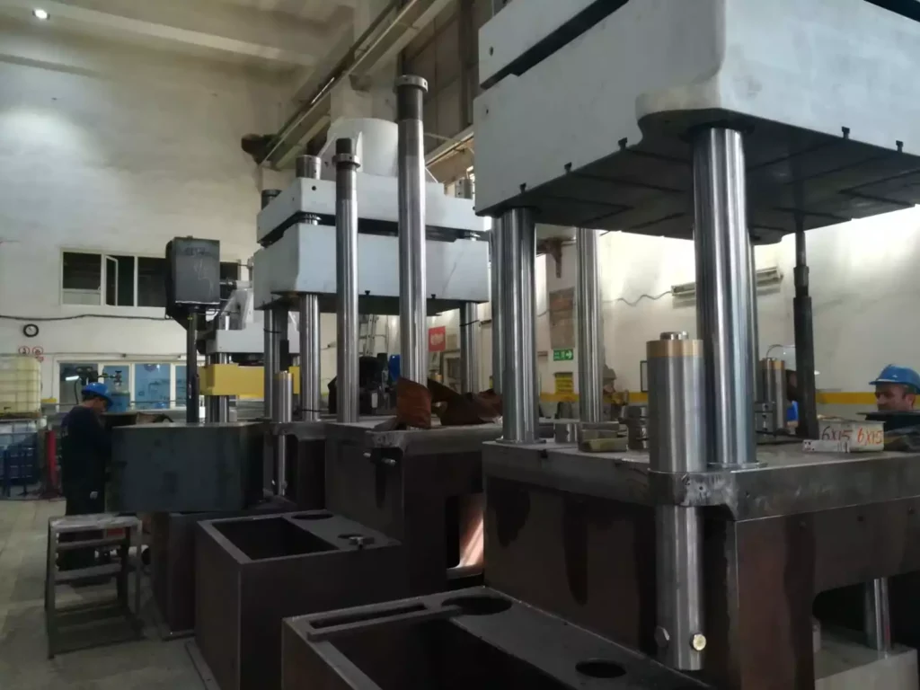
- Hydraulic Presses: Hydraulic presses use hydraulic fluid to generate force, providing greater control and precision. These presses are used for large, complex components and can apply significant force to shape metal.
- Screw Presses: Screw presses use a screw mechanism to generate force, providing high precision and control. These presses are commonly used for forging complex shapes with tight tolerances.
3. Extrusion Machines
Extrusion machines are used to create continuous shapes with uniform cross-sections by forcing metal through a die. These machines come in two main types:
- Direct Extrusion Machines: In direct extrusion, the metal billet is forced through a die in the same direction as the applied force. This process is used to produce long components like rods, tubes, and profiles.
- Indirect Extrusion Machines: In indirect extrusion, the die moves toward the stationary billet, reducing friction and allowing for the production of complex shapes with tighter tolerances.
4. Drawing Machines
Drawing machines are used to reduce the diameter of metal wires, rods, and tubes by pulling them through a die. These machines come in various configurations, including:
- Wire Drawing Machines: Wire drawing machines are used to produce thin wires with precise diameters, commonly used in electrical wiring, cables, and fasteners.
- Tube Drawing Machines: Tube drawing machines are used to produce thin-walled tubes with high precision, commonly used in automotive, aerospace, and medical applications.
- Rod Drawing Machines: Rod drawing machines are used to produce long rods with uniform diameters, commonly used in construction, machinery, and toolmaking.
5. Stamping Presses
Stamping presses are used to cut and shape metal using a press and dies. These machines come in various types, including:
- Mechanical Stamping Presses: Mechanical stamping presses use mechanical energy to drive a ram that cuts and shapes the metal. These presses are commonly used for high-volume production of small to medium-sized components.
- Hydraulic Stamping Presses: Hydraulic stamping presses use hydraulic fluid to generate force, providing greater control and precision. These presses are used for large, complex components and can apply significant force to shape metal.
- Transfer Presses: Transfer presses are used in high-volume production lines, where the metal is transferred from one station to the next, with each station performing a specific forming operation. These presses are used to produce complex components with multiple features.
6. Bending Machines
Bending machines are used to deform metal to create specific angles or shapes. These machines come in various configurations, including:
- Press Brakes: Press brakes are used to bend metal sheets and plates into specific angles, commonly used in the production of brackets, frames, and enclosures.
- Tube Bending Machines: Tube bending machines are used to bend metal tubes into specific shapes, commonly used in the production of automotive exhaust systems, pipelines, and furniture.
- Roll Bending Machines: Roll bending machines are used to create cylindrical or conical shapes by passing metal sheets or plates through a series of rolls, commonly used in the production of tanks, pipes, and pressure vessels.
7. Deep Drawing Presses
Deep drawing presses are used to form flat sheets of metal into three-dimensional shapes by pulling the metal into a die. These machines are commonly used in the production of components like cups, cans, and enclosures.
- Hydraulic Deep Drawing Presses: Hydraulic deep drawing presses use hydraulic fluid to generate force, providing greater control and precision. These presses are used for large, complex components that require tight tolerances.
- Mechanical Deep Drawing Presses: Mechanical deep drawing presses use mechanical energy to drive a ram that pulls the metal into the die. These presses are commonly used for high-volume production of small to medium-sized components.
8. Hydroforming Machines
Hydroforming machines are used to shape metal using high-pressure fluid. These machines are commonly used in the production of complex shapes with smooth surfaces, such as automotive body panels, aerospace components, and kitchen sinks.
- Sheet Hydroforming Machines: Sheet hydroforming machines are used to form metal sheets into complex shapes by applying high-pressure fluid on one side of the sheet, commonly used in the automotive and aerospace industries.
- Tube Hydroforming Machines: Tube hydroforming machines are used to form metal tubes into complex shapes by applying high-pressure fluid inside the tube, commonly used in the production of automotive exhaust systems, chassis components, and bicycle frames.
Advanced Metal Forming Techniques
In addition to the traditional metal forming processes, several advanced techniques have been developed to meet the increasing demands for precision, efficiency, and complex shapes in modern manufacturing. These techniques include:
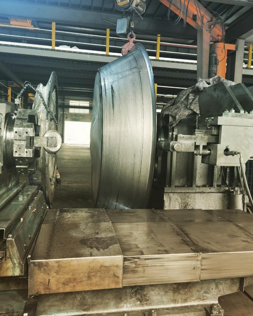
1. Flow Forming
Flow forming is an advanced metal forming process used to produce thin-walled, cylindrical components with high precision and strength. This process involves rotating the metal workpiece while applying pressure with rollers, gradually shaping the metal into the desired form. Flow forming is commonly used in the production of automotive wheels, aerospace components, and pressure vessels.
- Single-Stage Flow Forming: Single-stage flow forming involves shaping the metal in a single operation, where the rollers apply pressure to the metal as it rotates, creating the desired shape in one pass.
- Multi-Stage Flow Forming: Multi-stage flow forming involves shaping the metal in multiple operations, where the rollers gradually apply pressure in successive passes, creating the desired shape in stages. This technique is used to produce components with more complex geometries and tighter tolerances.
2. Hot Press Forming
Hot press forming, also known as hot stamping or press hardening, is an advanced metal forming process used to produce high-strength components with complex shapes. This process involves heating the metal to a high temperature and then forming it using a press. The metal is then rapidly cooled, or quenched, to achieve the desired mechanical properties. Hot press forming is commonly used in the automotive and aerospace industries to produce safety-critical components like structural parts, reinforcements, and impact beams.
- Direct Hot Press Forming: In direct hot press forming, the metal is heated and then formed in a single operation, where the press shapes the metal while it is still hot. This process is used to produce components with high strength and complex geometries.
- Indirect Hot Press Forming: In indirect hot press forming, the metal is pre-formed at room temperature and then heated and quenched to achieve the desired mechanical properties. This process is used to produce components with simpler geometries and less demanding mechanical requirements.
3. Superplastic Forming
Superplastic forming is an advanced metal forming process used to produce components with extremely complex shapes and fine details. This process involves heating the metal to a temperature where it becomes superplastic, meaning it can undergo large deformations without breaking. The metal is then formed using a press, often with the assistance of a vacuum or gas pressure, to create the desired shape. Superplastic forming is commonly used in the aerospace, automotive, and medical industries to produce lightweight, high-strength components like aircraft panels, automotive body parts, and medical implants.
- Gas-Assisted Superplastic Forming: Gas-assisted superplastic forming involves using gas pressure to form the metal into the desired shape, often in combination with a press. This technique is used to produce components with complex geometries and fine details.
- Vacuum-Assisted Superplastic Forming: Vacuum-assisted superplastic forming involves using a vacuum to form the metal into the desired shape, often in combination with a press. This technique is used to produce components with intricate shapes and smooth surfaces.
Advantages and Challenges of Metal Forming
Metal forming offers several advantages, making it a preferred choice for manufacturing a wide range of components:
Advantages
- Versatility: Metal forming processes can produce a wide range of shapes and sizes, from simple components like brackets and beams to complex components like automotive body panels and aerospace structures.
- Precision: Metal forming processes can achieve high precision and repeatability, ensuring that components meet tight tolerances and specifications.
- Material Efficiency: Metal forming processes typically involve minimal material waste, making them cost-effective and environmentally friendly.
- Strength and Durability: Metal forming processes can enhance the mechanical properties of the material, resulting in components with high strength, durability, and resistance to wear and fatigue.
- Surface Finish: Metal forming processes can produce components with smooth surfaces and fine details, reducing the need for additional finishing operations.
Challenges
- High Initial Costs: Metal forming machines and tools can be expensive, requiring significant upfront investment. However, these costs can be offset by the long-term benefits of high production efficiency and precision.
- Complexity: Metal forming processes can be complex and require specialized knowledge and expertise to operate and maintain the machines and tools.
- Material Limitations: Not all materials are suitable for metal forming processes. Some materials may require additional treatments, such as heat treatment or lubrication, to achieve the desired results.
- Tooling Wear: Metal forming tools, such as dies and punches, can wear out over time, requiring regular maintenance and replacement to ensure consistent quality and precision.
Applications of Metal Forming
Metal forming processes are used in a wide range of industries to produce components for various applications:
1. Automotive Industry
The automotive industry relies heavily on metal forming processes to produce components like body panels, chassis parts, engine components, and suspension systems. Metal forming processes, such as stamping, bending, and hot press forming, are used to create lightweight, high-strength components that meet the demanding requirements of modern vehicles.
2. Aerospace Industry
The aerospace industry uses metal forming processes to produce components like aircraft panels, structural parts, and engine components. Metal forming processes, such as superplastic forming and hydroforming, are used to create complex, lightweight components with high precision and strength.
3. Construction Industry
The construction industry uses metal forming processes to produce components like beams, columns, and structural supports. Metal forming processes, such as rolling and bending, are used to create components with the required strength and durability for building structures.
4. Electronics Industry
The electronics industry uses metal forming processes to produce components like enclosures, connectors, and heat sinks. Metal forming processes, such as stamping and drawing, are used to create components with fine details and tight tolerances for electronic devices.
5. Medical Industry
The medical industry uses metal forming processes to produce components like surgical instruments, implants, and medical devices. Metal forming processes, such as superplastic forming and drawing, are used to create components with high precision and biocompatibility.
Conclusion
Metal forming is a critical process in modern manufacturing, enabling the production of high-quality components with complex shapes, high precision, and enhanced mechanical properties. Metal forming machines, such as rolling mills, forging presses, extrusion machines, and stamping presses, play a vital role in the manufacturing process, providing the tools needed to shape metal materials into the desired forms.
As industries continue to demand higher levels of precision, efficiency, and complexity, advanced metal forming techniques, such as flow forming, hot press forming, and superplastic forming, have emerged to meet these challenges. These techniques offer significant advantages in terms of material efficiency, strength, and surface finish, making them essential tools in the production of modern components.
Despite the challenges associated with metal forming, such as high initial costs and complexity, the benefits far outweigh the drawbacks. Metal forming processes are indispensable in industries like automotive, aerospace, construction, electronics, and medical, where the quality and performance of the final product are critical.
In conclusion, metal forming and metal forming machines are at the heart of modern manufacturing, enabling the production of components that meet the demands of today’s industries. As technology continues to evolve, metal forming processes will continue to play a crucial role in shaping the future of manufacturing, driving innovation and growth across various sectors.
Metals Used in Metal Forming Applications
Metal forming processes are versatile and can be applied to a wide range of metals, each chosen for its specific properties that make it suitable for particular applications. The selection of metal is crucial as it influences the manufacturing process, the performance of the final product, and its suitability for specific industries. Here’s an overview of the most common metals used in metal forming applications:
1. Steel
Carbon Steel
- Description: Carbon steel is one of the most commonly used metals in metal forming due to its strength, ductility, and affordability. It primarily consists of iron and carbon, with varying carbon content determining its hardness and strength.
- Applications: Carbon steel is widely used in construction (e.g., beams, structural components), automotive (e.g., body panels, engine components), and manufacturing (e.g., tools, machinery parts).
Stainless Steel
- Description: Stainless steel is an alloy of iron with a minimum of 10.5% chromium, which gives it corrosion resistance. It often contains other elements like nickel and molybdenum to enhance its properties.
- Applications: Stainless steel is used in applications requiring high corrosion resistance, such as in food processing equipment, medical devices, chemical processing plants, and kitchen utensils.
Tool Steel
- Description: Tool steel is a variety of carbon and alloy steels that are particularly well-suited for making tools. It has high hardness, resistance to abrasion, and the ability to retain shape at elevated temperatures.
- Applications: Tool steel is commonly used in the manufacture of cutting tools, dies, and molds for metal forming processes.
2. Aluminum
Aluminum Alloys
- Description: Aluminum is a lightweight, corrosion-resistant metal with excellent thermal and electrical conductivity. Aluminum alloys are typically made by adding elements like copper, magnesium, or zinc to improve strength and other properties.
- Applications: Aluminum alloys are extensively used in the aerospace industry for components like aircraft frames and skin panels, in the automotive industry for lightweight body panels, and in consumer electronics for casings and heat sinks.
3. Copper
Pure Copper
- Description: Copper is known for its excellent electrical and thermal conductivity, ductility, and corrosion resistance. It is relatively soft and can be easily shaped through various metal forming processes.
- Applications: Pure copper is used in electrical applications such as wiring, connectors, and heat exchangers. It is also used in plumbing and architectural applications.
Copper Alloys (e.g., Brass, Bronze)
- Description: Copper alloys, such as brass (copper-zinc) and bronze (copper-tin), offer enhanced strength, wear resistance, and corrosion resistance compared to pure copper.
- Applications: Copper alloys are used in applications such as bearings, bushings, valves, and decorative items, as well as in electrical connectors and musical instruments.
4. Titanium
Titanium Alloys
- Description: Titanium is a strong, lightweight metal with excellent corrosion resistance and the ability to withstand high temperatures. Titanium alloys are made by adding elements like aluminum and vanadium to improve their strength and workability.
- Applications: Titanium is extensively used in aerospace for critical components like engine parts and airframes, in the medical field for implants and surgical instruments, and in the automotive industry for high-performance parts.
5. Nickel and Nickel Alloys
Nickel
- Description: Nickel is a corrosion-resistant metal with high toughness and the ability to maintain strength at high temperatures. It is often alloyed with other metals to enhance its properties.
- Applications: Nickel is used in the production of stainless steel, corrosion-resistant alloys, and superalloys used in aerospace and chemical processing equipment.
Nickel Alloys (e.g., Inconel, Monel)
- Description: Nickel alloys like Inconel and Monel are known for their excellent strength, corrosion resistance, and ability to withstand extreme temperatures. These alloys are used in highly demanding environments.
- Applications: Nickel alloys are used in the aerospace industry for turbine blades, in the chemical industry for reactor components, and in marine applications for propeller shafts and other parts exposed to seawater.
6. Magnesium
Magnesium Alloys
- Description: Magnesium is the lightest structural metal available, with a high strength-to-weight ratio. Magnesium alloys typically include elements like aluminum, zinc, and manganese to improve strength and corrosion resistance.
- Applications: Magnesium alloys are used in the automotive industry for lightweight components, in aerospace for structural parts, and in electronics for casing and structural components where weight reduction is critical.
7. Zinc
Zinc Alloys
- Description: Zinc is a versatile metal often alloyed with aluminum, copper, and magnesium to improve its mechanical properties. Zinc alloys are known for their excellent castability, dimensional stability, and corrosion resistance.
- Applications: Zinc alloys are widely used in die casting for automotive parts, electronics housings, and hardware like locks and hinges.
8. Lead
Lead Alloys
- Description: Lead is a dense metal with high corrosion resistance and low melting point. Lead is often alloyed with other metals like tin and antimony to improve its hardness and mechanical properties.
- Applications: Lead and its alloys are used in applications like batteries, radiation shielding, and in the production of solder and bearings.
9. Precious Metals
Gold, Silver, Platinum
- Description: Precious metals like gold, silver, and platinum are valued for their conductivity, corrosion resistance, and aesthetic appeal. These metals are often used in their pure form or alloyed with other metals to enhance their properties.
- Applications: Precious metals are used in high-end electronics, jewelry, medical devices, and in industries where corrosion resistance and reliability are critical, such as aerospace and defense.
10. High-Performance Alloys (Superalloys)
Superalloys
- Description: Superalloys are advanced materials designed to withstand extreme conditions, such as high temperatures, high stress, and corrosive environments. They are typically based on nickel, cobalt, or iron and are alloyed with elements like chromium, molybdenum, and titanium.
- Applications: Superalloys are used in aerospace for turbine blades and other critical engine components, in power generation for gas turbines, and in the chemical industry for reactors and heat exchangers.
Conclusion
The choice of metal in metal forming applications is influenced by factors such as the material’s mechanical properties, corrosion resistance, workability, and cost. Different metals and alloys are selected based on the specific requirements of the application, ensuring that the final product meets the desired performance and durability standards. As metal forming technology continues to evolve, the use of advanced materials like superalloys and titanium alloys is expected to grow, driven by the increasing demand for high-performance components in industries such as aerospace, automotive, and medical.
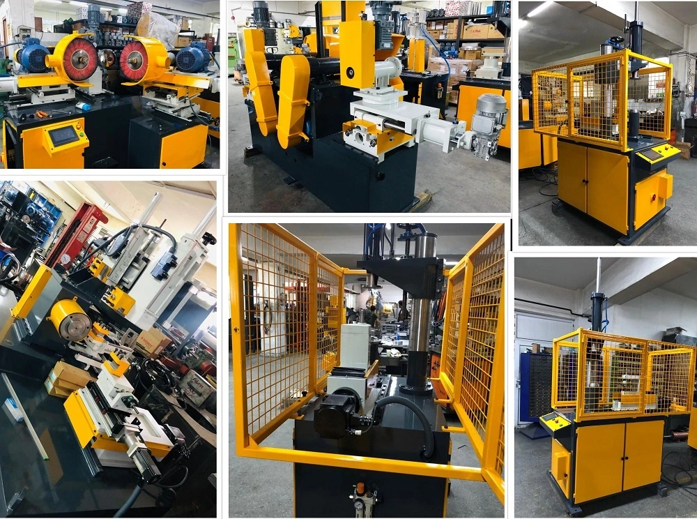
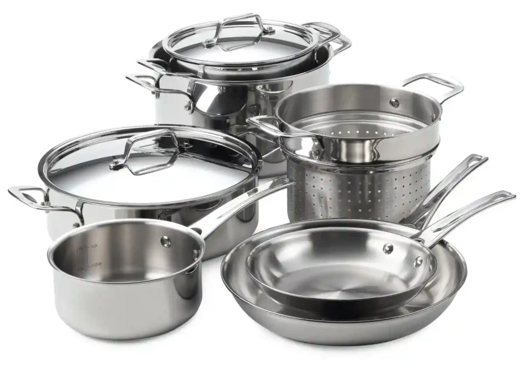
Stainless Steel Utensils Manufacturing Machine
- Introduction to the Machinery Used: Stainless steel utensils are a staple in modern kitchens due to their durability, resistance to corrosion, and aesthetic appeal. The manufacturing of these utensils involves a variety of specialized machines designed to handle the specific properties of stainless steel. These machines include high-precision cutting tools, forming machines, and surface finishing equipment, all of which ensure that the final product meets stringent quality standards.
- Advances in Technology: Over the years, advancements in manufacturing technology have significantly improved the efficiency and precision of stainless steel utensil production. Automation has played a key role, reducing the need for manual labor and minimizing errors. Modern machines are equipped with computer numerical control (CNC) systems that allow for intricate designs and consistent quality across large production runs.
- Key Features and Benefits of Modern Machines: Today’s stainless steel utensil manufacturing machines are designed with features such as high-speed operation, energy efficiency, and ease of maintenance. These machines can handle a wide range of tasks, from cutting and forming to polishing and finishing, making the production process faster and more cost-effective.
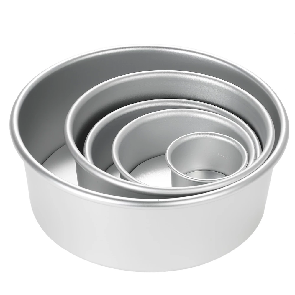
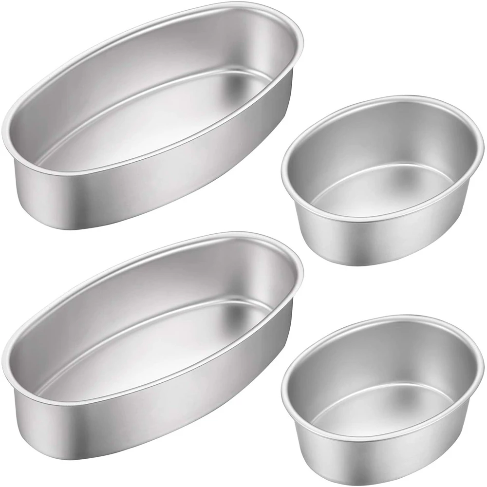
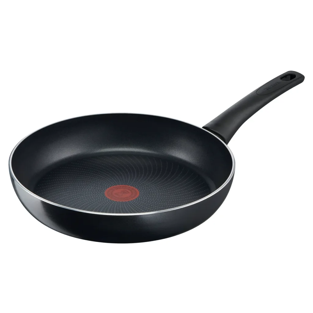
Procedure for Obtaining Pan
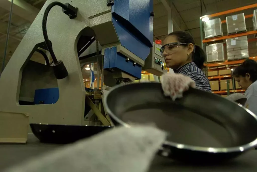
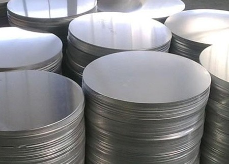
- Material Selection: The process begins with the selection of high-quality stainless steel sheets. The material must have the appropriate thickness and grade to ensure durability and heat resistance.
- Cutting and Shaping: The stainless steel sheet is cut into circular blanks using a circle cutting machine. These blanks are then subjected to deep drawing, where the metal is stretched and shaped into a pan.
- Forming and Trimming: After the basic shape is formed, the edges are trimmed to remove any excess material. This step ensures that the pan has a smooth, uniform edge.
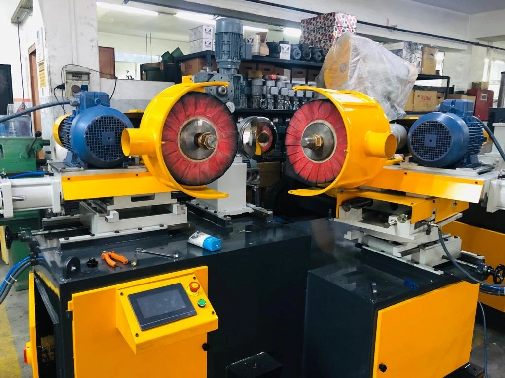
- Polishing and Surface Finishing: The formed pan undergoes several stages of polishing, using both manual and automatic polishing machines. This gives the pan a smooth, shiny surface that is both aesthetically pleasing and easy to clean.
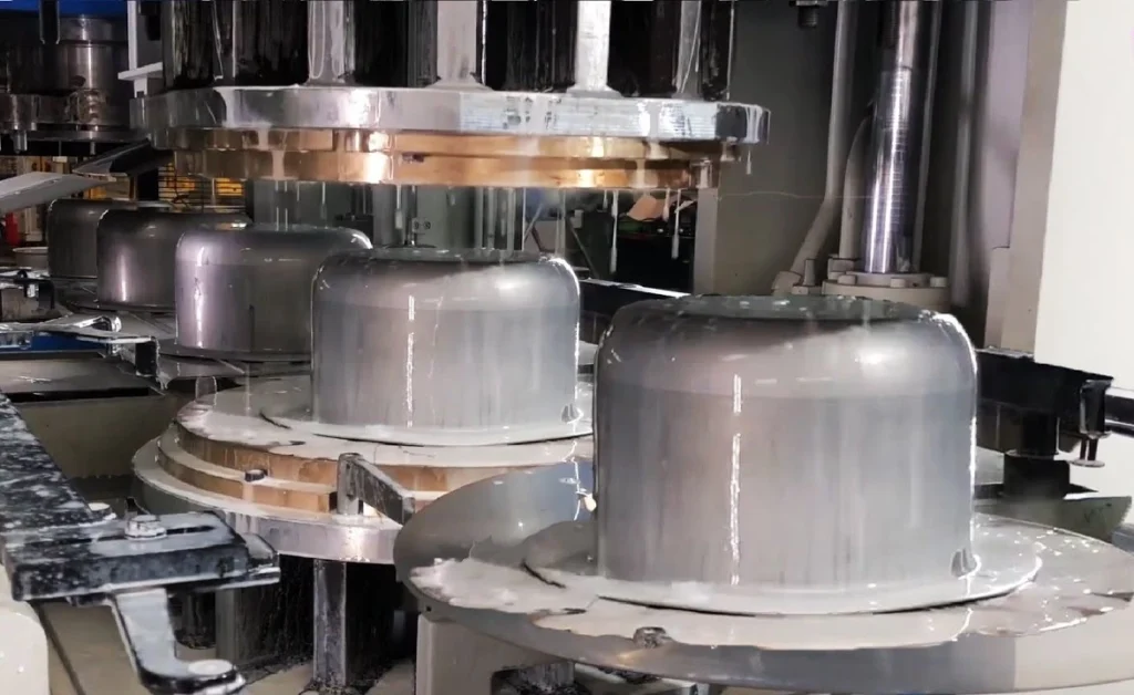
Pressure Cooker Manufacturing Process
- Raw Material Preparation: The process starts with the selection of high-strength stainless steel, which is essential for withstanding the high pressures inside a pressure cooker.
- Forming the Body: The stainless steel is shaped into the body of the pressure cooker using a combination of deep drawing and forming processes. This step ensures that the cooker can handle high pressure without deforming.
- Lid and Safety Mechanisms: The lid of the pressure cooker is manufactured separately and equipped with safety mechanisms such as pressure release valves. These components are critical for ensuring the safety and functionality of the pressure cooker.
- Assembly and Testing: Once all components are manufactured, they are assembled and tested for pressure resistance, safety, and durability. Quality control is stringent at this stage to ensure that each pressure cooker meets industry standards.
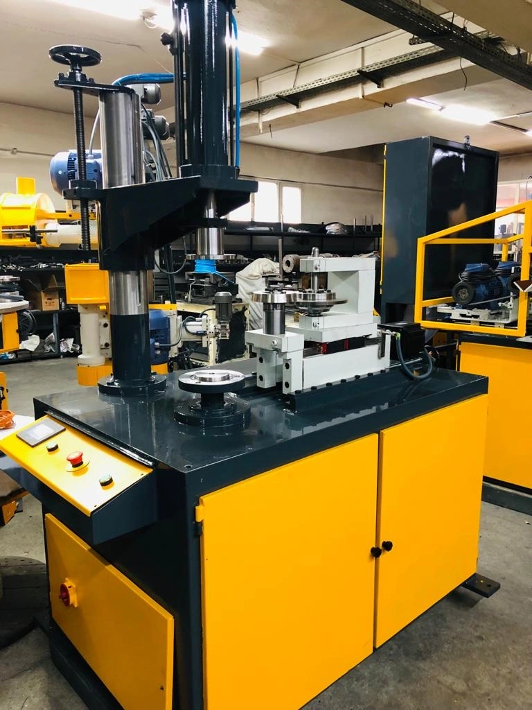
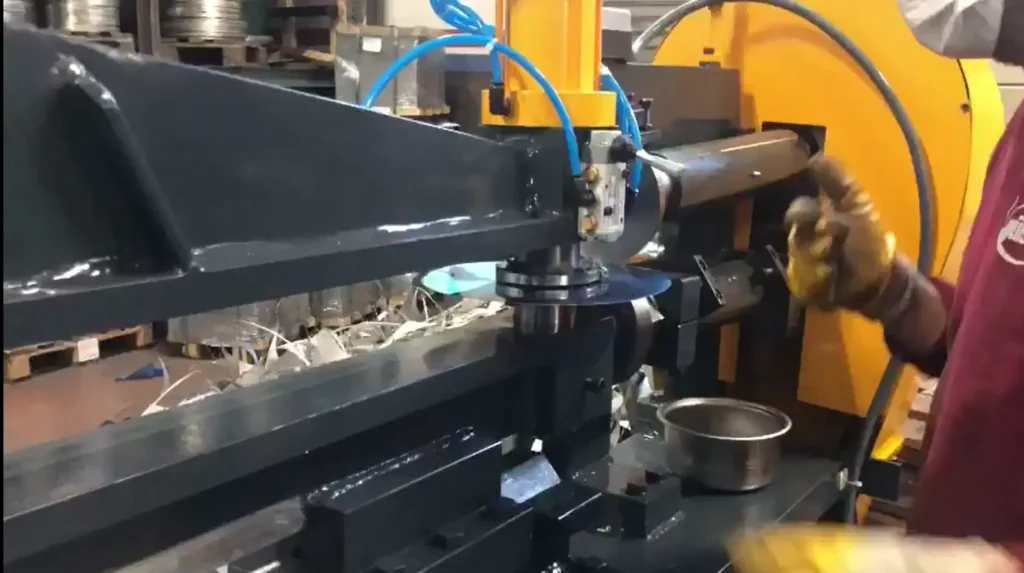
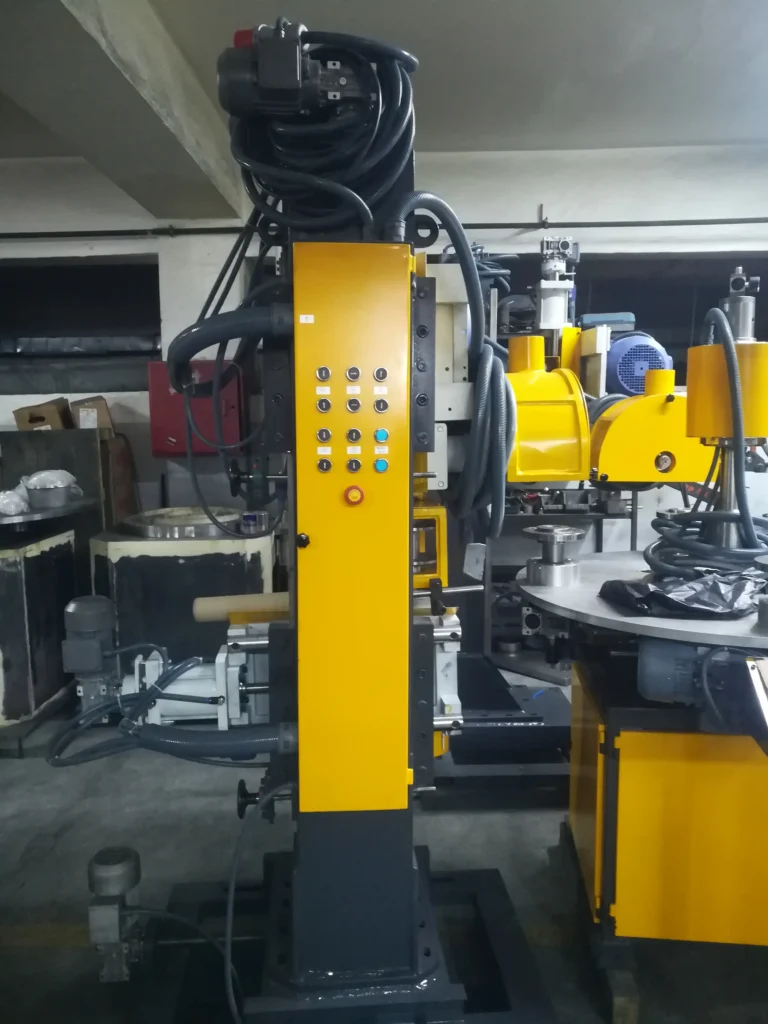
Automatic Beading Machine

- Purpose and Functionality: An automatic beading machine is used to create a bead or raised edge around the rim of a stainless steel utensil. This bead increases the utensil’s structural integrity and improves its aesthetic appeal.
- Operation: The machine operates by feeding the utensil into a set of rotating dies, which press and shape the metal into a continuous bead. The process is fully automated, allowing for high-speed production with consistent results.
- Applications: Beading is commonly used in the manufacturing of pots, pans, and lids, where a strong and smooth edge is necessary for both functionality and safety.
Curling Operation in Sheet Metal
- Overview: Curling is a process where the edge of a sheet metal part is rolled or curled to form a rounded edge. This operation is crucial in creating a smooth, safe edge on metal components, such as kitchen utensils.
- Process Details: The curling operation involves feeding the sheet metal through a curling die, where it is gradually bent and formed into a curl. This can be done using either manual or automatic curling machines, depending on the production volume.
- Applications in Utensil Manufacturing: In the context of utensil manufacturing, curling is often used on the edges of pots, pans, and lids to prevent sharp edges and to add strength to the product.
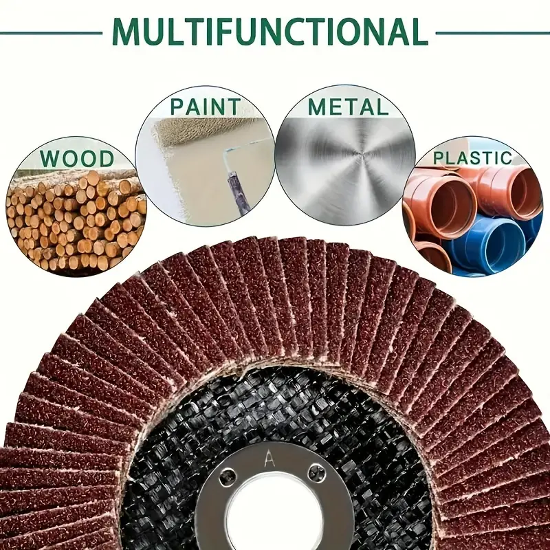
Stainless Steel Pot Polishing Machine
- Functionality: Polishing machines are used to create a smooth, reflective surface on stainless steel pots. These machines use abrasive belts, wheels, or pads to remove surface imperfections and achieve the desired finish.
- Types of Polishing Machines: There are various types of polishing machines, including manual, semi-automatic, and fully automatic models. The choice of machine depends on the production requirements and the level of finish needed.
- Importance in the Manufacturing Process: Polishing is a critical step in the manufacturing of stainless steel pots, as it not only enhances the appearance of the product but also improves its corrosion resistance and ease of cleaning.
Automatic Cookware Polishing Machine
- Advanced Polishing Techniques: Automatic cookware polishing machines are designed to handle large volumes of cookware with minimal human intervention. These machines use a combination of mechanical and chemical polishing techniques to achieve a high-gloss finish.
- Efficiency and Consistency: The automation of the polishing process ensures that each piece of cookware has a uniform finish, reducing the likelihood of defects and rework. This also increases the overall efficiency of the production line.
- Applications: These machines are used in the final stages of cookware production, where a flawless surface finish is essential for both aesthetic and functional reasons.
Edge Crimping Machine
- Purpose: An edge crimping machine is used to fold or crimp the edge of a metal sheet, creating a secure and smooth edge. This is particularly important in the production of metal containers and utensils.
- Process: The machine uses a series of rollers to gradually fold the edge of the metal, creating a crimp that enhances the strength and durability of the product. The crimping process also helps in eliminating sharp edges, making the product safer to handle.
- Applications in Manufacturing: Edge crimping is widely used in the manufacturing of pots, lids, and other kitchen utensils, where a strong, finished edge is required.
- Function and Mechanism: Metal crimping machines are designed to join or secure two pieces of metal together by deforming one or both pieces. The machine applies pressure to create a crimped joint, which is strong and durable.
- Types of Crimping Machines: There are various types of crimping machines, including hydraulic, pneumatic, and manual models. Each type is suited for different applications, depending on the materials being crimped and the required strength of the joint.
- Industrial Applications: Metal crimping is used in a variety of industries, including cookware manufacturing, where it is essential for creating secure joints between different components of a utensil or container.
Circle Welder
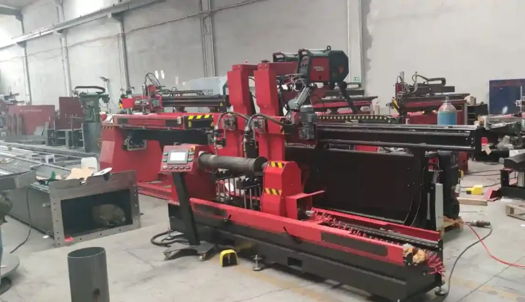
- Introduction: A circle welder is a specialized welding machine used to join circular or cylindrical metal components. It is commonly used in the manufacturing of cookware, barrels, and drums.
- Welding Process: The machine uses a rotating fixture to hold the metal components in place while the welding head moves along the circumference, creating a strong, continuous weld. This process ensures that the joint is uniform and free from defects.
- Applications: Circle welders are essential in the production of items that require a seamless, circular weld, such as pressure cookers, barrels, and metal drums.
Cold Press Moulding
- Definition and Importance: Cold press moulding is a process used to shape metal parts without the application of heat. It involves the use of high-pressure machines to press metal sheets into a mould, creating the desired shape.
- Process Details: The metal is placed in a mould and subjected to high pressure, which forces it to conform to the shape of the mould. This process is often used for creating components that require high strength and precision.
- Advantages and Applications: Cold press moulding is advantageous because it avoids the thermal stresses associated with hot forming processes. It is widely used in the production of metal components for cookware, automotive parts, and other industries.
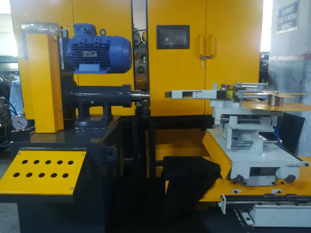
Circle Cutting Machine for Metal
- Purpose and Design: Circle cutting machines are designed to cut perfect circles from metal sheets. These machines are essential in industries where circular components are needed, such as cookware manufacturing.
- Operation: The machine uses a rotating cutting tool that moves along a predefined path to cut the metal sheet into a precise circular shape. The process is highly efficient and produces minimal waste.
- Applications in Manufacturing: Circle cutting machines are used to create blanks for items such as pots, lids, and other circular metal components. The accuracy of the cut is critical for ensuring that the final product fits together correctly and performs as expected.
Curling in Sheet Metal
- Overview of Curling Process: Curling in sheet metal involves rolling the edge of a metal sheet to form a curved or rounded edge. This is done to eliminate sharp edges and to add strength and rigidity to the part.
- Equipment Used: The curling process is typically performed using a curling machine, which gradually bends the edge of the metal into the desired shape. The machine may use rollers or dies to achieve the curl.
- Applications: Curling is commonly used in the production of metal containers, lids, and cookware, where a smooth, rounded edge is necessary for both safety and aesthetic reasons.
- Round Shape Cutting Machine
- Introduction: A round shape cutting machine is specifically designed to cut metal sheets into round shapes with precision. This type of machine is used in various industries, including the manufacturing of kitchen utensils and industrial components.
- Operation and Features: The machine operates by rotating the metal sheet under a cutting tool, which precisely cuts out the round shape. Features such as adjustable cutting diameters and automated feeding systems enhance the machine’s versatility and efficiency.
- Industrial Uses: These machines are essential in the production of items like pot lids, circular discs, and other round metal parts that require high precision and consistency.
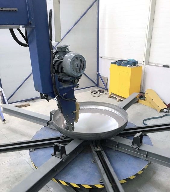
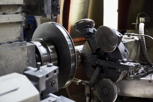
Dished End Polishing Machine
- Purpose and Functionality: A dished end polishing machine is used to polish the concave or convex surfaces of dished ends, which are often used in pressure vessels, tanks, and cookware.
- Polishing Process: The machine uses abrasive pads or belts to polish the surface, removing any imperfections and creating a smooth, reflective finish. This process is crucial for ensuring the durability and aesthetic quality of the dished end.
- Applications: Dished end polishing is particularly important in industries such as cookware manufacturing, where the appearance and hygiene of the product are critical.
Sheet Metal Circle Cutter Machine
- Design and Operation: A sheet metal circle cutter machine is used to cut circular shapes from metal sheets with high precision. It is a vital tool in industries that require circular components, such as the cookware and automotive sectors.
- Process Details: The machine typically uses a rotating blade or cutting tool that follows a circular path, cutting the metal sheet into a perfect circle. The machine may be manually operated or fully automated, depending on the production requirements.
- Applications: This machine is widely used to produce blanks for pots, lids, and other circular metal parts. The precision of the cut is essential for ensuring that the final product meets the required specifications.
Polishing Machine Metal
- Introduction: Polishing machines are used to smooth and finish metal surfaces, enhancing their appearance and resistance to corrosion. These machines are an essential part of the manufacturing process for stainless steel utensils and other metal products.
- Types of Polishing Machines: There are several types of polishing machines, including rotary, vibratory, and belt-driven models. Each type is suited to different types of metal and desired finishes.
- Importance in Manufacturing: Polishing is a critical step in metal manufacturing, as it not only improves the appearance of the product but also enhances its durability and ease of maintenance.
Transfer Line in Manufacturing
- Definition and Function: A transfer line in manufacturing is a production system where workpieces are transferred automatically from one machine to another through a series of processes. This system is highly efficient and is commonly used in high-volume production environments.
- Components and Operation: The transfer line consists of several machines connected by conveyors or other transfer mechanisms. Each machine performs a specific operation, such as cutting, forming, or polishing, as the workpiece moves along the line.
- Applications in Industry: Transfer lines are widely used in the automotive, cookware, and consumer goods industries, where they allow for the rapid and efficient production of complex products.
- Machining Transfer Lines
- Introduction: Machining transfer lines are specialized transfer lines designed for machining operations, such as drilling, milling, and turning. These lines are used in the mass production of metal components with high precision.
- Process and Benefits: The machining transfer line automates the movement of workpieces through various machining operations, reducing the need for manual handling and improving production speed. This leads to consistent quality and lower production costs.
- Applications: Machining transfer lines are used in industries such as aerospace, automotive, and manufacturing, where high-precision metal parts are required in large quantities.
Industrial Beading Machine

- Purpose and Functionality: Industrial beading machines are used to create beads or raised edges on metal components. These machines are essential in the production of items such as pots, pans, and barrels, where a strong, smooth edge is required.
- Operation: The machine uses a set of dies or rollers to press the metal into a bead, which adds strength and rigidity to the part. The process can be fully automated, allowing for high-speed production with minimal manual intervention.
- Applications: Industrial beading machines are commonly used in the cookware and container manufacturing industries, where they ensure that the products have durable, finished edges.
Steel Circle Cutting Machine
- Overview: A steel circle cutting machine is designed to cut steel sheets into circular shapes with high precision. These machines are essential in the production of items such as pots, lids, and other round components.
- Operation and Features: The machine operates by rotating the steel sheet under a cutting tool, which precisely cuts out the circular shape. Features such as adjustable cutting diameters and automated feeding systems enhance the machine’s efficiency and versatility.
- Applications in Industry: Steel circle cutting machines are widely used in the manufacturing of cookware, automotive parts, and other industrial components that require precise circular shapes.
Drum Manufacturing Process
- Introduction: The drum manufacturing process involves several stages, including cutting, forming, welding, and surface finishing. Drums are commonly used for storing and transporting liquids, chemicals, and other bulk materials.
- Key Steps in the Process: The process begins with cutting steel sheets into the required shapes, followed by forming the drum body and ends. The components are then welded together, and the drum undergoes surface finishing to ensure durability and corrosion resistance.
- Quality Control and Testing: Drums are subjected to rigorous testing to ensure that they meet industry standards for strength, leak resistance, and durability. This is especially important for drums used in hazardous materials transport.
How Steel Utensils Are Made
- Raw Material Selection: The production of steel utensils begins with the selection of high-quality stainless steel, known for its durability, corrosion resistance, and ease of cleaning.
- Manufacturing Process: The process involves cutting the steel into blanks, forming the blanks into the desired shape using pressing and deep drawing techniques, and polishing the final product to achieve a smooth finish. Additional processes such as beading, crimping, and welding may also be involved, depending on the design of the utensil.
- Finishing and Quality Control: The final step in the manufacturing process is the polishing and finishing of the utensil, followed by rigorous quality control to ensure that each piece meets the required standards for functionality and appearance.
Trim and Form Machine
- Purpose and Functionality: A trim and form machine is used to trim excess material from metal parts and to form the parts into the desired shape. This machine is essential in the production of items such as lids, caps, and other metal components.
- Operation: The machine uses a set of dies to trim the edges of the metal part, removing any excess material. It then forms the part into the required shape, ensuring that it meets the necessary specifications.
- Applications in Industry: Trim and form machines are used in a variety of industries, including cookware, automotive, and packaging, where precise trimming and forming are required for product quality and consistency.
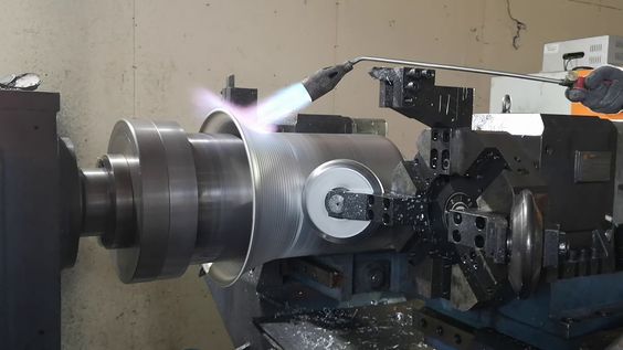
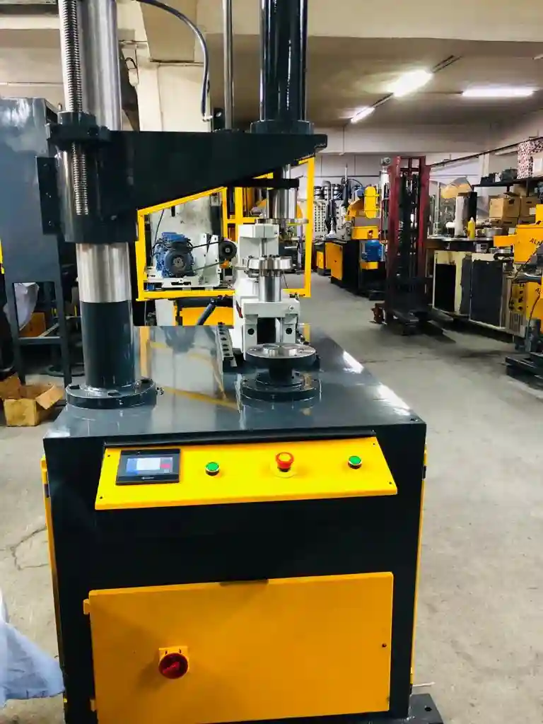
Flow Form Machine
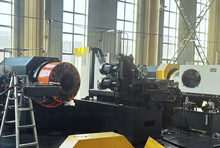
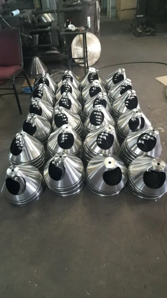
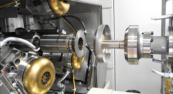
- Introduction: A flow form machine is used to shape metal by applying pressure and rotating the workpiece. This process, known as flow forming, is used to create thin-walled, cylindrical components with high precision.
- Process and Advantages: The metal blank is placed on a rotating mandrel and subjected to pressure from a roller, which gradually shapes it into the desired form. Flow forming allows for the production of complex shapes with minimal material waste and high strength.
- Applications: Flow form machines are used in the aerospace, automotive, and cookware industries to produce components such as wheels, cylinders, and pressure vessels.
Metal Flow Forming Machine
- Functionality: A metal flow forming machine is designed to shape metal components through the flow forming process. This machine is essential for producing thin-walled, cylindrical parts with high precision and strength.
- Process Details: The machine operates by applying pressure to the metal blank while it is rotated on a mandrel. This pressure deforms the metal, shaping it into the desired form while maintaining high accuracy.
- Industrial Applications: Metal flow forming machines are used in industries such as aerospace, automotive, and cookware manufacturing, where precision and strength are critical for the final product.
1. Stainless Steel Utensils Manufacturing Machine
- Introduction: Stainless steel utensils manufacturing machines are specialized equipment designed to process stainless steel sheets into finished kitchenware products. These machines handle various stages of production, including cutting, forming, welding, and polishing.
- Types of Machines: The key machines involved in this process include circle cutting machines, deep drawing presses, beading machines, and polishing machines. Each plays a crucial role in transforming raw stainless steel into high-quality kitchen utensils.
- Automation and Precision: Modern manufacturing machines are often equipped with automation and CNC (Computer Numerical Control) systems. These technologies ensure high precision in manufacturing, reduce labor costs, and improve the consistency of the final products.
- Applications: These machines are used to produce a wide range of utensils, such as pots, pans, pressure cookers, and other kitchen items, ensuring they meet industry standards for durability and hygiene.
2. Procedure for Obtaining Pan
- Material Selection: The process begins with choosing the appropriate grade of stainless steel, which offers corrosion resistance, durability, and thermal conductivity.
- Cutting and Shaping: A circle cutting machine is used to cut the stainless steel sheet into circular blanks. These blanks are then fed into a deep drawing press, where they are shaped into the basic form of a pan.
- Forming: After initial shaping, the pan undergoes additional forming processes, such as edge trimming, curling, and beading, to finalize its structure.
- Surface Finishing: The pan is then polished using various polishing machines to achieve a smooth, shiny surface that is easy to clean and visually appealing.
- Quality Control: The final step involves inspecting the pan for any defects and ensuring it meets the required standards for thickness, strength, and finish.
3. Pressure Cooker Manufacturing Process
- Raw Material Preparation: High-strength stainless steel is selected for its ability to withstand the high pressure and temperatures involved in cooking.
- Body Formation: The stainless steel is deep drawn into the cylindrical shape of the pressure cooker body. This process requires precise control to ensure the material’s thickness remains uniform.
- Lid Manufacturing: The lid, which must create a perfect seal, is manufactured separately using similar deep drawing techniques. It is then fitted with safety features such as pressure release valves.
- Welding and Assembly: The body and lid are welded and assembled, ensuring all parts fit perfectly and are airtight.
- Testing: Each pressure cooker undergoes rigorous testing, including pressure tests, to ensure it can safely operate under high pressure without risk of failure.
4. Automatic Beading Machine
- Functionality: An automatic beading machine is used to form a bead around the rim of a utensil. This bead enhances the utensil’s structural integrity and improves its aesthetics.
- Operation: The machine automates the beading process, where the utensil is rotated while a set of rollers press and shape the metal into a consistent bead.
- Benefits: Automation ensures uniformity and precision, which is crucial for maintaining the quality of the utensil, especially in high-volume production environments.
- Applications: Beading is commonly applied to the rims of pots, pans, and lids to prevent sharp edges and add strength to the utensil.
5. Curling Operation in Sheet Metal
- Overview: Curling is the process of rolling the edge of a metal sheet to form a rounded, reinforced edge, which is essential for both safety and durability in utensils.
- Process: The sheet metal is fed into a curling machine, where it is gradually bent around a die to form the curled edge. The operation can be manual or automated, depending on the production scale.
- Applications: Curling is typically used in the production of lids and containers to eliminate sharp edges and add strength to the rim.
6. Stainless Steel Pot Polishing Machine
- Purpose: Polishing machines are used to create a smooth, reflective finish on stainless steel pots. This not only enhances their appearance but also makes them easier to clean and more resistant to corrosion.
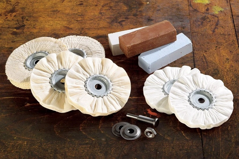
- Types of Polishing Machines: Various polishing machines are used, including belt polishers, buffing wheels, and vibratory polishers. Each type is suited to different stages of the polishing process, from rough polishing to final finishing.
- Process: The pot is passed through several polishing stages, where different abrasives are used to progressively refine the surface, removing scratches and imperfections.
- Importance: A well-polished pot is more hygienic, as the smooth surface prevents food particles and bacteria from adhering to the metal. It also enhances the pot’s marketability by providing a visually appealing, mirror-like finish.
7. Automatic Cookware Polishing Machine
- Functionality: This machine automates the polishing process, ensuring consistent, high-quality finishes across large batches of cookware. It uses a combination of mechanical and chemical polishing methods.
- Efficiency: Automatic machines can handle large volumes of cookware, significantly reducing the time and labor required compared to manual polishing.
- Applications: These machines are essential in the final stages of cookware production, ensuring that each piece is polished to a high standard before packaging and distribution.
8. Edge Crimping Machine
- Purpose: An edge crimping machine folds or crimps the edge of a metal sheet to create a secure, finished edge. This is particularly important in creating leak-proof seals in containers and adding structural integrity to the product.
- Operation: The machine uses rollers or dies to apply pressure along the edge of the metal, folding it over in a precise manner. The crimping process can be tailored to different materials and thicknesses.
- Applications: Crimping is commonly used in the production of lids, drums, and other metal containers where a strong, smooth edge is required.
9. Metal Crimping Machine
- Function and Design: Metal crimping machines are designed to join two pieces of metal by deforming them to create a tight bond. This is essential for creating durable, leak-proof seals in various products.
- Operation: The machine applies pressure to the metal pieces, creating a crimped joint. This joint is strong and often used in situations where welding or adhesives are not suitable.
- Applications: Metal crimping is widely used in the manufacture of containers, automotive parts, and various types of kitchenware, where a reliable and strong connection between metal components is essential.
10. Circle Welder
- Introduction: A circle welder is a specialized machine used to weld circular or cylindrical components, ensuring a continuous, defect-free weld. This is particularly important for items that need to withstand high pressure or stress.
- Welding Process: The circle welder uses a rotating fixture to hold the components in place while the welding head moves along the circumference. This ensures a consistent weld around the entire perimeter of the component.
- Applications: Circle welders are crucial in the production of items like pressure cookers, metal drums, and other cylindrical containers where a strong, uniform weld is necessary.
11. Cold Press Moulding
- Definition: Cold press moulding is a process where metal is shaped without the application of heat. It involves pressing metal sheets into a mould using high pressure, resulting in precisely shaped parts.
- Process Details: The metal is placed in a mould, and a press applies force to shape it into the desired form. This process is often used to create components that require high precision and strength without altering the material’s properties through heating.
- Advantages: Cold press moulding is beneficial for creating complex shapes with minimal material waste and maintaining the material’s mechanical properties.
- Applications: This process is used in the production of cookware, automotive parts, and other precision metal components.
12. Circle Cutting Machine for Metal
- Purpose: A circle cutting machine is used to cut circular shapes from metal sheets with high precision, which is essential in various industries including cookware manufacturing.
- Operation: The machine uses a rotating cutting tool to cut the metal sheet into a precise circular shape. The process can be automated to increase efficiency and accuracy.
- Applications: Circle cutting machines are used to create blanks for items such as pot lids, circular discs, and other round components in the manufacturing of kitchen utensils and industrial products.
13. Curling in Sheet Metal
- Overview: Curling in sheet metal is the process of rolling the edge of a metal sheet to form a rounded, reinforced edge. This operation is critical for enhancing the durability and safety of the final product.
- Equipment: Curling is typically performed using a curling machine, which uses a series of rollers or a die to gradually bend the metal edge into a curl.
- Applications: Curling is used in the production of metal containers, cookware, and lids to eliminate sharp edges and strengthen the product.
14. Round Shape Cutting Machine
- Introduction: A round shape cutting machine is designed to cut precise round shapes from metal sheets. These machines are vital for producing components such as lids and circular blanks for cookware.
- Operation: The machine typically operates by rotating the metal sheet under a cutting tool, which precisely cuts out the desired round shape. Advanced models may include automation features to enhance efficiency.
- Applications: This machine is essential in industries where precise circular components are required, such as cookware manufacturing and automotive part production.
15. Dished End Polishing Machine
- Purpose and Functionality: A dished end polishing machine is used to polish the concave or convex surfaces of dished ends, which are often used in pressure vessels, tanks, and cookware.
- Polishing Process: The machine uses abrasive pads or belts to polish the surface, removing any imperfections and creating a smooth, reflective finish. This process is crucial for ensuring the durability and aesthetic quality of the dished end.
- Applications: Dished end polishing is particularly important in industries such as cookware manufacturing, where the appearance and hygiene of the product are critical.
16. Sheet Metal Circle Cutter Machine
- Design and Operation: A sheet metal circle cutter machine is used to cut circular shapes from metal sheets with high precision. It is a vital tool in industries that require circular components, such as the cookware and automotive sectors.
- Process Details: The machine typically uses a rotating blade or cutting tool that follows a circular path, cutting the metal sheet into a perfect circle. The machine may be manually operated or fully automated, depending on the production requirements.
- Applications: This machine is widely used to produce blanks for pots, lids, and other circular metal parts. The precision of the cut is essential for ensuring that the final product meets the required specifications.
17. Polishing Machine Metal
- Introduction: Polishing machines are used to smooth and finish metal surfaces, enhancing their appearance and resistance to corrosion. These machines are an essential part of the manufacturing process for stainless steel utensils and other metal products.
- Types of Polishing Machines: There are several types of polishing machines, including rotary, vibratory, and belt-driven models. Each type is suited to different types of metal and desired finishes.
- Importance in Manufacturing: Polishing is a critical step in metal manufacturing, as it not only improves the appearance of the product but also enhances its durability and ease of maintenance.
18. Transfer Line in Manufacturing
- Definition and Function: A transfer line in manufacturing is a production system where workpieces are transferred automatically from one machine to another through a series of processes. This system is highly efficient and is commonly used in high-volume production environments.
- Components and Operation: The transfer line consists of several machines connected by conveyors or other transfer mechanisms. Each machine performs a specific operation, such as cutting, forming, or polishing, as the workpiece moves along the line.
- Applications in Industry: Transfer lines are widely used in the automotive, cookware, and consumer goods industries, where they allow for the rapid and efficient production of complex products.
19. Machining Transfer Lines
- Introduction: Machining transfer lines are specialized transfer lines designed for machining operations, such as drilling, milling, and turning. These lines are used in the mass production of metal components with high precision.
- Process and Benefits: The machining transfer line automates the movement of workpieces through various machining operations, reducing the need for manual handling and improving production speed. This leads to consistent quality and lower production costs.
- Applications: Machining transfer lines are used in industries such as aerospace, automotive, and manufacturing, where high-precision metal parts are required in large quantities.
20. Industrial Beading Machine
- Purpose and Functionality: Industrial beading machines are used to create beads or raised edges on metal components. These machines are essential in the production of items such as pots, pans, and barrels, where a strong, smooth edge is required.
- Operation: The machine uses a set of dies or rollers to press the metal into a bead, which adds strength and rigidity to the part. The process can be fully automated, allowing for high-speed production with minimal manual intervention.
- Applications: Industrial beading machines are commonly used in the cookware and container manufacturing industries, where they ensure that the products have durable, finished edges.
21. Steel Circle Cutting Machine
- Overview: A steel circle cutting machine is designed to cut steel sheets into circular shapes with high precision. These machines are essential in the production of items such as pots, lids, and other round components.
- Operation and Features: The machine operates by rotating the steel sheet under a cutting tool, which precisely cuts out the circular shape. Features such as adjustable cutting diameters and automated feeding systems enhance the machine’s efficiency and versatility.
- Applications in Industry: Steel circle cutting machines are widely used in the manufacturing of cookware, automotive parts, and other industrial components that require precise circular shapes.
22. Drum Manufacturing Process
- Introduction: The drum manufacturing process involves several stages, including cutting, forming, welding, and surface finishing. Drums are commonly used for storing and transporting liquids, chemicals, and other bulk materials.
- Key Steps in the Process: The process begins with cutting steel sheets into the required shapes, followed by forming the drum body and ends. The components are then welded together, and the drum undergoes surface finishing to ensure durability and corrosion resistance.
- Quality Control and Testing: Drums are subjected to rigorous testing to ensure that they meet industry standards for strength, leak resistance, and durability. This is especially important for drums used in hazardous materials transport.
23. How Steel Utensils Are Made
- Raw Material Selection: The production of steel utensils begins with the selection of high-quality stainless steel, known for its durability, corrosion resistance, and ease of cleaning.
- Manufacturing Process: The process involves cutting the steel into blanks, forming the blanks into the desired shape using pressing and deep drawing techniques, and polishing the final product to achieve a smooth finish. Additional processes such as beading, crimping, and welding may also be involved, depending on the design of the utensil.
- Finishing and Quality Control: The final step in the manufacturing process is the polishing and finishing of the utensil, followed by rigorous quality control to ensure that each piece meets the required standards for functionality and appearance.
24. Trim and Form Machine
- Purpose and Functionality: A trim and form machine is used to trim excess material from metal parts and to form the parts into the desired shape. This machine is essential in the production of items such as lids, caps, and other metal components.
- Operation: The machine uses a set of dies to trim the edges of the metal part, removing any excess material. It then forms the part into the required shape, ensuring that it meets the necessary specifications.
- Applications in Industry: Trim and form machines are used in a variety of industries, including cookware, automotive, and packaging, where precise trimming and forming are required for product quality and consistency.
25. Flow Form Machine
- Introduction: A flow form machine is used to shape metal by applying pressure and rotating the workpiece. This process, known as flow forming, is used to create thin-walled, cylindrical components with high precision.
- Process and Advantages: The metal blank is placed on a rotating mandrel and subjected to pressure from a roller, which gradually shapes it into the desired form. Flow forming allows for the production of complex shapes with minimal material waste and high strength.
- Applications: Flow form machines are used in the aerospace, automotive, and cookware industries to produce components such as wheels, cylinders, and pressure vessels.
26. Metal Flow Forming Machine
- Functionality: A metal flow forming machine is designed to shape metal components through the flow forming process. This machine is essential for producing thin-walled, cylindrical parts with high precision and strength.
- Process Details: The machine operates by applying pressure to the metal blank while it is rotated on a mandrel. This pressure deforms the metal, shaping it into the desired form while maintaining high accuracy.
- Industrial Applications: Metal flow forming machines are used in industries such as aerospace, automotive, and cookware manufacturing, where precision and strength are critical for the final product.
1. Stainless Steel Utensils Manufacturing Machine
- Overview: Stainless steel utensils manufacturing machines are highly specialized equipment designed to transform stainless steel sheets into various kitchen utensils like pots, pans, and pressure cookers. These machines are integral to the production line, handling everything from cutting and forming to polishing and finishing.
- Types of Machines:
- Circle Cutting Machines: Used to cut circular blanks from stainless steel sheets, which are then formed into utensils.
- Deep Drawing Presses: Shape the metal blanks into the desired utensil shape, such as a pan or a pot.
- Automatic Beading Machines: Form a reinforced edge on utensils, enhancing their structural integrity.
- Polishing Machines: Provide the final finish, making the utensils smooth and shiny.
- Automation and Precision: Many modern manufacturing machines incorporate automation and CNC (Computer Numerical Control) technology. This allows for high precision in the production process, ensuring that each utensil meets stringent quality standards.
- Applications: These machines are used across various stages of utensil manufacturing, ensuring that products are produced efficiently, consistently, and to a high standard.
2. Procedure for Obtaining Pan
- Material Selection: The first step in making a stainless steel pan is selecting the appropriate grade of stainless steel, which must be durable, corrosion-resistant, and suitable for cooking.
- Cutting: The stainless steel sheet is cut into a circular blank using a circle cutting machine. This blank will become the base of the pan.
- Deep Drawing: The blank is then placed into a deep drawing press. Here, the blank is drawn into a deep mold to form the basic shape of the pan. This process involves stretching the metal without thinning it excessively, ensuring the pan retains its strength and durability.
- Trimming and Beading: Once the pan’s shape is formed, the edges are trimmed to the desired size. An automatic beading machine may then be used to create a reinforced edge, which adds strength and prevents warping during use.
- Curling and Crimping: The edges of the pan are curled and crimped to smooth out sharp edges, making the pan safer to handle and more aesthetically pleasing.
- Polishing: The pan undergoes several stages of polishing, where abrasives are used to smooth and finish the surface, giving it a shiny, mirror-like appearance. This also makes the pan easier to clean and resistant to staining.
- Quality Control: Finally, the pan is inspected for any defects or irregularities. Quality control checks ensure the pan meets industry standards for thickness, weight, and surface finish before it is packaged for sale.
3. Pressure Cooker Manufacturing Process
- Material Selection: Pressure cookers require high-strength stainless steel, typically with higher chromium and nickel content, to withstand high pressure and temperatures.
- Cutting and Deep Drawing: The process begins with cutting stainless steel sheets into circular blanks, which are then deep drawn to form the body and lid of the pressure cooker. The deep drawing process must be carefully controlled to maintain the material’s thickness and ensure it can handle the stress of high-pressure cooking.
- Forming the Lid: The lid, which must create a perfect seal, is formed separately. Special attention is given to the lid’s design, as it includes features such as a pressure release valve and locking mechanisms. The lid undergoes additional processes like curling and beading to ensure it fits securely on the cooker body.
- Welding and Assembly: Once the body and lid are formed, they are welded together with other components, such as handles and safety valves. The welding process must be flawless to prevent leaks and ensure the cooker’s durability.
- Surface Finishing: After assembly, the pressure cooker is polished to remove any rough spots and give it a smooth, shiny finish. This not only improves the cooker’s appearance but also enhances its resistance to corrosion and staining.
- Testing: Each pressure cooker undergoes rigorous testing to ensure it can safely withstand the high pressures and temperatures encountered during cooking. Tests include pressure tests, leak tests, and safety valve inspections.
- Final Inspection: The final inspection checks the overall quality of the pressure cooker, ensuring all parts function correctly and that the cooker meets all safety and performance standards before it is packaged for sale.
4. Automatic Beading Machine
- Functionality: An automatic beading machine is used to create a bead, or a small, raised ridge, around the edge of metal parts like lids, pots, and pans. The bead adds strength to the edge, helps prevent warping, and gives the utensil a finished appearance.
- Operation: In the beading process, the utensil is held in place while rollers or dies apply pressure to the edge, forming the bead. The automatic nature of the machine ensures that the bead is consistent around the entire edge of the utensil, which is essential for both functionality and aesthetics.
- Benefits: Automatic beading machines improve efficiency in the manufacturing process, as they can bead the edges of large batches of utensils quickly and with high precision. This reduces the need for manual labor and ensures that each piece is uniform.
- Applications: Beading is commonly used in the manufacture of cookware, especially for items like pots, pans, and lids, where a strong, smooth edge is necessary. The beading process also plays a role in enhancing the overall durability of the utensil, making it more resistant to damage and wear over time.
5. Curling Operation in Sheet Metal
- Definition: Curling in sheet metal refers to the process of rolling the edge of a metal sheet into a curved, rounded shape. This operation is critical for creating a safe, finished edge that is free from sharp corners.
- Process: The curling operation is typically carried out using a curling machine. The metal sheet is fed into the machine, where it is gradually bent around a die or roller to form the curled edge. The process may be done in several stages to achieve the desired curl without causing the metal to crack or weaken.
- Purpose: Curling serves multiple purposes in manufacturing:
- Safety: By eliminating sharp edges, curling reduces the risk of cuts and injuries when handling the metal parts.
- Strength: Curling adds structural integrity to the edge of the metal part, making it more resistant to deformation.
- Aesthetics: A curled edge provides a more finished, professional look to the final product.
- Applications: Curling is widely used in the production of kitchen utensils, lids, and containers. It is also commonly used in other industries, such as automotive and aerospace, where smooth, strong edges are essential.
1. Stainless Steel Pot Polishing Machine
- Functionality: Stainless steel pot polishing machines are designed to polish the surfaces of stainless steel pots, enhancing their appearance, smoothness, and resistance to corrosion. Polishing is a critical step in the manufacturing process as it determines the final finish of the product.
- Process: The polishing process involves using abrasive materials, such as belts, wheels, or pads, to remove surface imperfections like scratches and weld marks. The machine may use different grades of abrasives to achieve a mirror-like finish.
- Automation: Advanced machines are fully automated, allowing for consistent polishing across batches of products with minimal manual intervention. Automation also speeds up the process and reduces labor costs.
- Applications: These machines are used in the cookware industry to polish pots, pans, and other utensils, ensuring that they meet aesthetic and functional standards. High-quality polishing not only enhances the look of the cookware but also improves its durability and ease of cleaning.
2. Automatic Cookware Polishing Machine
- Purpose and Features: Automatic cookware polishing machines are specialized equipment used to polish various types of cookware, including pots, pans, and lids. These machines are designed to handle different shapes and sizes of cookware, ensuring a uniform and high-quality finish.
- Operation: The machine operates by rotating the cookware while applying abrasive materials to its surface. The automatic nature of the machine ensures that the polishing process is consistent, even across complex shapes and curves. The machine can be programmed to adjust the pressure and speed according to the type of cookware being polished.
- Benefits: Automatic polishing machines improve efficiency by reducing the time and labor required for manual polishing. They also ensure a consistent finish, which is essential for maintaining the quality and appearance of the cookware.
- Applications: These machines are widely used in large-scale cookware manufacturing operations where high-volume production and consistent quality are paramount.
3. Edge Crimping Machine
- Functionality: An edge crimping machine is used to fold or bend the edges of metal parts to create a strong, finished edge. This process is essential for products like lids, cans, and containers, where a secure edge is necessary for functionality and safety.
- Operation: The machine works by applying pressure to the edge of the metal part, folding it over to create a crimp. The crimp adds strength to the edge, preventing it from unraveling or becoming sharp. In cookware manufacturing, crimping is often used to create a smooth, rounded edge on lids and pots.
- Automation and Precision: Many edge crimping machines are automated, allowing for high-speed production with precise control over the crimping process. This ensures uniformity and reduces the risk of defects.
- Applications: Edge crimping is widely used in the manufacture of cookware, food containers, and automotive parts, where a durable, finished edge is crucial for both performance and safety.
4. Metal Crimping Machine
- Overview: Metal crimping machines are similar to edge crimping machines but are designed to handle a broader range of metalworking tasks. They can be used to join two pieces of metal by creating a crimp or to form a crimped edge on a single piece of metal.
- Operation: The machine applies force to the metal, compressing it into the desired shape. This can involve folding, bending, or pressing the metal, depending on the specific requirements of the task. Metal crimping machines often come with interchangeable dies, allowing them to perform various crimping tasks.
- Applications: These machines are used in a wide range of industries, including cookware manufacturing, automotive, and aerospace, where they are used to create strong, durable connections between metal parts or to form finished edges.
5. Circle Welder
- Functionality: A circle welder is a specialized welding machine used to weld circular components, such as the edges of pots, pans, and other round metal parts. The welding process is crucial for ensuring that the joints are strong and leak-proof.
- Operation: The circle welder rotates the metal part while applying a welding torch to the joint, creating a continuous, even weld around the entire circumference of the part. The machine can be programmed to control the speed, heat, and pressure of the weld, ensuring consistent results.
- Automation and Precision: Modern circle welders are highly automated, which reduces the need for manual labor and ensures that each weld is of consistent quality. The precision of the welding process is essential for preventing leaks and ensuring the durability of the final product.
- Applications: Circle welders are commonly used in the manufacture of cookware, pressure vessels, and other round metal parts that require strong, leak-proof joints.
6. Cold Press Moulding
- Definition: Cold press molding is a process used to shape metal parts without the application of heat. Instead, the metal is pressed into a mold at room temperature, relying on mechanical force to achieve the desired shape.
- Process: The metal blank is placed in a mold, and a press applies force to shape the metal into the mold’s contours. This process is suitable for materials that are malleable at room temperature, such as certain grades of stainless steel.
- Advantages: Cold press molding is energy-efficient, as it does not require heating the metal. It also produces parts with a high degree of dimensional accuracy and a good surface finish.
- Applications: This process is used in the production of various metal parts, including cookware, where it is used to form complex shapes like pot bodies and lids.
7. Circle Cutting Machine for Metal
- Purpose and Functionality: A circle cutting machine is designed to cut precise circular shapes from metal sheets. This is an essential step in the production of cookware and other round metal parts.
- Operation: The machine operates by rotating the metal sheet while a cutting tool follows a circular path, cutting out the desired shape. Advanced machines may include features like automated feeding, adjustable cutting diameters, and CNC control for enhanced precision.
- Applications: Circle cutting machines are used in various industries, including cookware manufacturing, automotive, and industrial equipment production, where precise circular components are required.
8. Curling in Sheet Metal
- Process Overview: Curling in sheet metal involves rolling the edge of a metal sheet into a curved shape, typically to create a safe, finished edge. This process is vital for products like lids and containers, where a smooth, strong edge is necessary.
- Method: The metal sheet is fed into a curling machine, where it is gradually bent around a die or roller to form the curl. The process can be done in multiple stages to prevent the metal from cracking or weakening.
- Advantages: Curling adds strength to the edge of the metal part and eliminates sharp edges, improving safety and handling. It also enhances the aesthetic appeal of the product by providing a smooth, finished edge.
- Applications: Curling is commonly used in cookware manufacturing, automotive parts, and containers, where a durable and safe edge is essential.
9. Round Shape Cutting Machine
- Functionality: A round shape cutting machine is used to cut circular or rounded shapes from metal sheets with high precision. This machine is critical in manufacturing processes where exact round shapes are required, such as in making pot lids, bases, and other cookware components.
- Operation: The machine typically involves a rotating cutting tool that follows a programmed path to cut the metal sheet into the desired round shape. Advanced models may include CNC control for precise cutting and automated feeding systems to improve efficiency.
- Applications: These machines are widely used in cookware manufacturing, as well as in the production of automotive parts, industrial equipment, and other products that require precise round components.
10. Dished End Polishing Machine
- Purpose: A dished end polishing machine is used to polish the curved surfaces of dished ends, which are often found in pressure vessels, tanks, and cookware.
- Operation: The machine uses abrasive pads or belts to polish the surface of the dished end, removing imperfections and creating a smooth, reflective finish. The polishing process is critical for both the aesthetic quality and the durability of the dished end.
- Automation and Precision: These machines are often automated, ensuring consistent polishing across the entire surface of the dished end. Precision is vital to achieve the desired smoothness and shine, which also improves the dished end’s resistance to corrosion.
- Applications: Dished end polishing machines are used in industries where polished surfaces are essential, such as in cookware manufacturing, pressure vessel production, and food processing equipment.
1. Sheet Metal Circle Cutter Machine
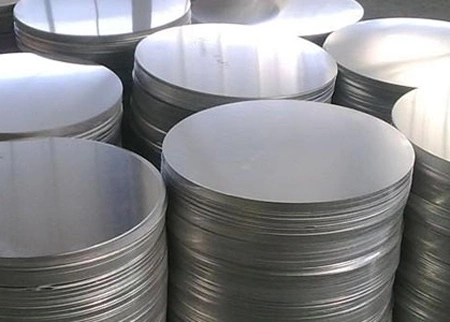
- Overview: A sheet metal circle cutter machine is a specialized tool used to cut precise circular shapes from sheets of metal. These circular blanks are often the starting point for many products, including pots, pans, lids, and other round utensils.
- Operation: The machine works by securing a metal sheet and rotating either the sheet or the cutting tool in a circular motion. A sharp cutting tool, often controlled by CNC (Computer Numerical Control) for precision, follows the circular path to cut out the metal blank.
- Key Features:
- CNC Control: Advanced machines feature CNC systems that allow for precise control over the diameter and shape of the circles, ensuring uniformity across production batches.
- Adjustable Cutting Diameter: Many machines allow for adjustments in the cutting diameter, enabling the production of various sizes of circular blanks.
- Applications: These machines are extensively used in the cookware industry to create the base materials for items like pots, pans, and lids. They are also used in industries like automotive and aerospace, where circular metal components are essential.
2. Polishing Machine Metal
- Purpose: Metal polishing machines are essential for finishing metal surfaces by removing imperfections and creating a smooth, shiny finish. This process enhances both the appearance and durability of the metal, making it resistant to corrosion and easier to clean.
- Types of Polishing:
- Mechanical Polishing: Uses abrasive belts, wheels, or pads to physically remove material from the metal surface.
- Electropolishing: A chemical process that smooths and brightens the metal surface by removing a thin layer of material.
- Operation: The metal is passed through the polishing machine, where abrasives are applied to smooth the surface. The process can involve several stages, each using finer abrasives to gradually achieve the desired finish.
- Applications: Metal polishing machines are widely used in the production of stainless steel cookware, automotive parts, and decorative metal components. The polished finish not only improves the aesthetic appeal but also adds to the functional longevity of the product.
3. Transfer Line in Manufacturing
- Definition: A transfer line in manufacturing refers to a series of interconnected machines and processes that sequentially transfer a workpiece from one stage of production to the next. Each station in the transfer line performs a specific operation, contributing to the final product.
- Operation: The workpiece is moved along the line, often on a conveyor or by robotic arms, passing through various machining, forming, and finishing stations. Each station is typically automated and synchronized to ensure continuous production flow.
- Advantages:
- Efficiency: Transfer lines are highly efficient, allowing for the mass production of items with minimal downtime between stages.
- Consistency: Automation ensures that each part of the production process is consistent, resulting in uniform products.
- Applications: Transfer lines are commonly used in the automotive industry, electronics manufacturing, and large-scale cookware production, where high-volume output and consistent quality are critical.
4. Machining Transfer Lines
- Overview: Machining transfer lines are a type of transfer line specifically designed for machining operations. They consist of multiple machining stations, each performing a different operation, such as drilling, milling, or turning.
- Operation: Workpieces are automatically transferred from one machine to the next along the line. Each machine is programmed to perform a specific machining operation on the workpiece. The integration of CNC technology allows for precise control over each operation.
- Benefits:
- High Productivity: Machining transfer lines are ideal for high-volume production, significantly reducing cycle times and labor costs.
- Precision: The use of CNC machines ensures that each operation is performed with high precision, which is crucial for parts that require tight tolerances.
- Applications: These lines are widely used in manufacturing components for the automotive industry, aerospace parts, and precision cookware items that require multiple machining operations.
5. Industrial Beading Machine
- Functionality: An industrial beading machine is used to form beads or raised ridges on metal components, such as the edges of pots, pans, and lids. The beading process adds structural strength to the metal part and enhances its durability.
- Operation: The machine operates by applying pressure to the edge of the metal, forcing it into a die or roller that shapes the bead. The process can be automated to ensure consistency across large production runs.
- Types:
- Rotary Beading Machines: These machines rotate the metal part while forming the bead, ideal for round components like cookware.
- Linear Beading Machines: Used for beading along straight edges or on irregularly shaped parts.
- Applications: Industrial beading machines are commonly used in the cookware industry, as well as in the production of automotive and aerospace components where edge reinforcement is necessary.
6. Steel Circle Cutting Machine
- Overview: A steel circle cutting machine is specifically designed to cut circular shapes from steel sheets. This machine is integral in the production of items that require round steel components, such as cookware bases and industrial flanges.
- Operation: The machine uses a cutting tool, often controlled by a CNC system, to cut precise circles from steel sheets. The cutting tool can be adjusted to produce different diameters, making the machine versatile for various applications.
- Advantages:
- Precision: The use of CNC technology ensures that each circle is cut to exact specifications, with minimal material waste.
- Versatility: These machines can cut a wide range of steel thicknesses and diameters, making them suitable for different industrial needs.
- Applications: Steel circle cutting machines are used in cookware manufacturing, where they produce the base blanks for pots and pans. They are also used in the production of flanges, gaskets, and other circular steel components.
7. Drum Manufacturing Process
- Overview: The drum manufacturing process involves creating large cylindrical containers, often used for storing and transporting liquids and bulk materials. Drums can be made from various materials, including steel, plastic, and fiber.
- Steps Involved:
- Material Cutting: Steel sheets are cut into the required dimensions for the drum body and ends.
- Forming: The cut steel sheets are rolled into a cylindrical shape for the body and pressed into the appropriate shape for the drum ends.
- Welding: The seams of the cylindrical body are welded to create a leak-proof container. The ends are then welded or crimped onto the body.
- Beading and Flanging: The drum body may undergo beading and flanging to add strength and facilitate stacking.
- Surface Treatment: The drums are often coated or painted to prevent corrosion and meet safety standards.
- Quality Control: Each drum is tested for leaks and structural integrity to ensure it meets safety and performance standards.
- Applications: Steel drums are widely used in industries such as chemicals, petroleum, and food processing for the safe storage and transportation of liquids and powders.
8. How Steel Utensils Are Made
- Material Selection: The process begins with selecting the appropriate grade of stainless steel, known for its durability, corrosion resistance, and suitability for food contact.
- Cutting: Stainless steel sheets are cut into circular blanks using circle cutting machines. These blanks form the basis of pots, pans, and other utensils.
- Forming: The blanks are then formed into the desired shape using deep drawing presses. The drawing process involves stretching the metal into a mold to create the utensil’s shape.
- Edge Processing: The edges of the utensils are often curled or crimped to remove sharp edges and improve durability. This is done using curling and crimping machines.
- Polishing: The utensils are polished to remove surface imperfections and give them a shiny, attractive finish. This process also enhances the utensil’s resistance to corrosion.
- Final Assembly: Additional components, such as handles and lids, are attached to complete the utensil. These are often welded or mechanically fastened.
- Quality Control: Each utensil undergoes rigorous quality checks to ensure it meets safety and performance standards before packaging and distribution.
9. Trim and Form Machine
- Functionality: A trim and form machine is used to trim excess material from a metal part and then form it into the final shape. This machine is essential in manufacturing processes where precision is key, such as in producing lids, gaskets, and other metal components.
- Operation: The machine trims any excess material from the workpiece and then forms the part into its final shape, often using dies or molds. The process can be automated for high-volume production, ensuring consistent results.
- Advantages:
- Precision: Ensures that each part is trimmed and formed to exact specifications, reducing material waste and improving product quality.
- Versatility: Can be used for a wide range of metal forming tasks, making it a valuable tool in various industries.
- Applications: Trim and form machines are used in the production of cookware, automotive parts, and electronics, where precise trimming and forming are essential for the final product’s functionality and appearance.
Modern Manufacturing

In the rapidly evolving landscape of modern manufacturing, precision and efficiency have become the cornerstones of success. Industries that rely on metalworking processes, such as automotive, aerospace, and heavy machinery, continuously seek innovations that enhance product quality while reducing production time and costs. Among the critical advancements in this field are the sophisticated machines and processes designed to refine and perfect the manipulation and finishing of metal components.
Central to these advancements is the use of specialized machinery like flow form machines, which have revolutionized how manufacturers shape and mold metal. These machines are not only vital for creating intricate shapes with high accuracy but also for ensuring that the physical properties of metals are maintained or even enhanced during the manufacturing process.
Equally important are the metal surface finishing machines, which play a pivotal role in ensuring that the final product meets the stringent standards required in various industries. The automated deburring and polishing processes integrated into these machines help in achieving a flawless surface finish, which is essential for both aesthetic and functional purposes.
As we delve deeper into the world of metal forming and finishing, it becomes evident that the technologies and machines employed—from edge beading machines to hot press forming hydraulic presses—are fundamental to the efficiency and quality of modern manufacturing. Each machine and process, whether it’s the precision of a rotary deburring machine or the power of a hydraulic press, contributes to the overall success of the manufacturing cycle.
Industrial Manufacturing Machinery
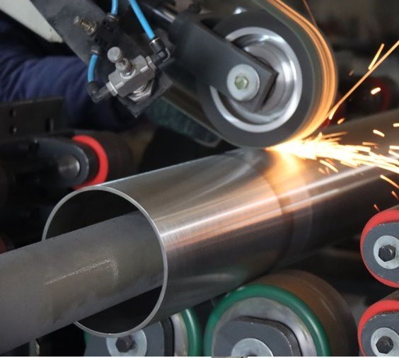
In the rapidly advancing landscape of industrial manufacturing, precision and efficiency have emerged as the two primary drivers of innovation. As industries like automotive, aerospace, and heavy machinery production evolve, the need for more sophisticated and accurate metalworking processes becomes increasingly apparent. The use of advanced machinery in metal forming and finishing is not only a trend but a necessity to meet the high demands of modern production. The integration of machines like flow form machines, metal surface finishing machines, and hydraulic presses into production lines has significantly enhanced the quality and speed of manufacturing processes.
The relevance of these machines cannot be overstated. Flow form machines, for instance, have dramatically transformed how metals are shaped and formed, allowing manufacturers to create complex, high-precision components with remarkable consistency. Similarly, metal surface finishing machines have set new standards in ensuring that metal components meet the aesthetic and functional requirements demanded by various industries.
This comprehensive guide will delve into the intricate details of these machines, providing insights into their operations, applications, and the critical roles they play in modern manufacturing. From the precise flow forming process to the critical function of edge beading machines and the importance of automated deburring and polishing, each section will explore how these technologies contribute to the overall efficiency and success of manufacturing operations.
Flow Form Machines
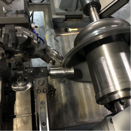
What is a Flow Form Machine?
A flow form machine is a specialized piece of equipment used to shape metal components through a process known as flow forming. This technique involves gradually shaping a metal blank, usually in the form of a tube, by applying pressure with one or more rollers. The rollers work the metal against a rotating mandrel, progressively reducing the wall thickness and elongating the metal into a precise shape. This process is highly controlled, allowing for the production of components with tight tolerances and complex geometries.
Flow form machines are crucial in industries where precision is paramount. The aerospace sector, for instance, relies heavily on flow forming to produce components like jet engine parts, where even the slightest deviation from the specified dimensions can have significant consequences. Automotive manufacturers also use flow forming to create high-strength, lightweight components that improve vehicle performance and fuel efficiency.
Applications of Metal Flow Forming Machines
The applications of metal flow forming machines are vast and varied, spanning multiple industries. In the aerospace industry, these machines are used to manufacture critical components such as jet engine casings, missile bodies, and structural parts that require high strength-to-weight ratios. The automotive industry uses flow forming to produce components like wheel rims, drive shafts, and fuel tanks, where durability and precision are essential.
The medical device industry also benefits from flow forming, particularly in the production of components that require exacting standards of cleanliness and precision, such as implantable devices and surgical instruments. The defense industry uses flow forming for the production of high-precision ammunition and other military hardware that demands reliability and accuracy under extreme conditions.
Benefits and Key Features
The benefits of using flow form machines are numerous. One of the primary advantages is the ability to produce components with excellent mechanical properties. The flow forming process enhances the grain structure of the metal, resulting in components with improved strength, hardness, and fatigue resistance. This makes flow-formed parts ideal for applications that require high performance under stress.
Another significant advantage is the material efficiency of the process. Flow forming minimizes waste by reducing the amount of metal removed during shaping, which is a common issue in other forming processes like machining. This not only lowers material costs but also contributes to more sustainable manufacturing practices.
Key features of flow form machines include precision control systems that allow for the accurate regulation of roller pressure, mandrel speed, and other critical parameters. These machines are often equipped with advanced monitoring systems that provide real-time feedback on the forming process, ensuring that the final product meets the desired specifications. Additionally, flow form machines are designed to handle a wide range of materials, from aluminum and steel to titanium and other high-strength alloys.
The Flow Forming Process
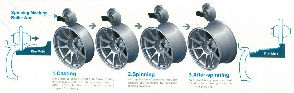
Detailed Explanation of the Flow Forming Process
The flow forming process is a highly controlled metalworking technique that involves the application of radial and axial forces to a metal blank, usually in the form of a tube. The process begins with the placement of the metal blank onto a rotating mandrel, which serves as the shaping tool. One or more rollers are then brought into contact with the blank, applying pressure to deform the metal against the mandrel.
As the mandrel rotates, the rollers move along the length of the blank, gradually thinning the wall and elongating the material. This controlled deformation process allows for the precise shaping of the metal into complex geometries with tight tolerances. The process can be repeated multiple times with different roller settings to achieve the desired final dimensions and properties.
Flow forming can be performed in both forward and backward directions. In forward flow forming, the rollers move in the same direction as the rotation of the mandrel, while in backward flow forming, the rollers move in the opposite direction. Each method has its advantages, with forward flow forming being more efficient for certain shapes and backward flow forming providing better control over wall thickness.
Materials Used in the Flow Forming Process
The flow forming process is versatile and can be applied to a wide range of materials, including both ferrous and non-ferrous metals. Common materials used in flow forming include:
- Aluminum: Known for its lightweight and excellent corrosion resistance, aluminum is widely used in the aerospace and automotive industries for components that require high strength-to-weight ratios.
- Steel: Steel is a common choice for flow forming due to its strength and durability. It is used in various applications, including automotive parts, structural components, and military hardware.
- Titanium: Titanium is prized for its high strength, low density, and excellent corrosion resistance. It is commonly used in aerospace and medical applications where weight savings and biocompatibility are critical.
- Nickel Alloys: Nickel-based alloys, such as Inconel, are used in high-temperature applications, particularly in the aerospace industry. These materials offer exceptional strength and resistance to heat and oxidation.
- Copper: Copper and its alloys, such as brass and bronze, are used in applications that require good electrical conductivity and corrosion resistance.
Advantages Over Traditional Methods
Flow forming offers several advantages over traditional metalworking methods, such as machining, stamping, and extrusion. One of the most significant advantages is the ability to produce components with superior mechanical properties. The flow forming process refines the grain structure of the metal, resulting in parts with enhanced strength, hardness, and fatigue resistance.
Another advantage is the precision of the process. Flow forming allows for the production of components with tight tolerances and complex geometries that would be difficult or impossible to achieve with other methods. This precision is particularly important in industries like aerospace and medical devices, where even small deviations from the specified dimensions can have serious consequences.
Flow forming is also more material-efficient than many traditional methods. Because the process involves deforming the metal rather than cutting or removing material, there is less waste, resulting in lower material costs and more sustainable manufacturing practices.
Finally, flow forming is a highly flexible process that can be adapted to produce a wide range of component shapes and sizes. This versatility makes it an attractive option for manufacturers looking to produce high-quality parts in small to medium production runs.
Metal Surface Finishing Machines
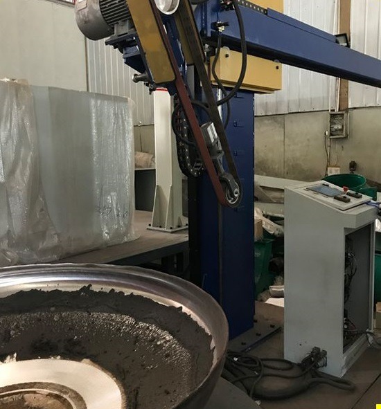
Importance of Surface Finishing in Metalwork
Surface finishing is a critical step in the manufacturing process that affects the appearance, performance, and durability of metal components. A well-finished surface not only enhances the aesthetic appeal of a product but also improves its resistance to corrosion, wear, and fatigue. In many industries, such as aerospace, automotive, and medical devices, the quality of the surface finish is a key factor in determining the overall performance and reliability of the final product.
Surface finishing involves several processes, including polishing, buffing, deburring, and coating. These processes are designed to remove surface imperfections, such as burrs, scratches, and tool marks, and to achieve the desired level of smoothness, reflectivity, and cleanliness. The choice of surface finishing method depends on the material, the intended use of the component, and the required surface characteristics.
Types of Metal Surface Finishing Machines
Metal surface finishing machines come in various types, each designed to perform specific finishing tasks. Some of the most common types of surface finishing machines include:
- Polishing Machines: Polishing machines use abrasive wheels, belts, or discs to smooth and shine metal surfaces. These machines are commonly used in the automotive, aerospace, and jewelry industries to achieve a high-gloss finish on metal parts.
- Buffing Machines: Buffing machines use soft, abrasive pads or wheels to create a smooth, reflective surface on metal components. Buffing is often the final step in the surface finishing process, providing a mirror-like finish that enhances the appearance of the product.
- Deburring Machines: Deburring machines are used to remove burrs—small, sharp edges or ridges—left on metal parts after machining or cutting. Deburring is essential for improving the safety and functionality of metal components, as burrs can cause injury or interfere with the assembly of parts.
- Rotary Deburring Machines: Rotary deburring machines use rotating tools or brushes to remove burrs from the edges and surfaces of metal components. These machines are particularly effective for deburring complex shapes and hard-to-reach areas.
- Flat Surface Finishing Machines: Flat surface finishing machines are designed to create smooth, even surfaces on flat metal components. These machines use abrasive belts, discs, or brushes to achieve the desired surface finish and are commonly used in the production of sheet metal parts.
- Belt Polishing Machines: Belt polishing machines use abrasive belts to remove surface imperfections and achieve a smooth finish on metal components. These machines are often used in the production of large, flat surfaces, such as metal sheets and plates.
Automated Deburring and Polishing
Automated deburring and polishing processes have revolutionized metal surface finishing by increasing efficiency, consistency, and precision. These processes use computer-controlled machines to perform deburring and polishing tasks with a high degree of accuracy, reducing the need for manual labor and minimizing the risk of human error.
Automated deburring machines use rotating brushes, abrasive wheels, or cutting tools to remove burrs from metal components. The machines are programmed to follow precise paths, ensuring that all burrs are removed without damaging the surrounding material. Automated deburring is particularly beneficial for high-volume production, where consistency and speed are critical.
Automated polishing machines use computer-controlled abrasive wheels, belts, or pads to achieve a smooth, reflective surface on metal components. The machines can be programmed to apply the exact amount of pressure and speed needed to achieve the desired finish, resulting in a consistent, high-quality surface. Automated polishing is commonly used in industries where the appearance and performance of the final product are critical, such as automotive, aerospace, and consumer electronics.
The benefits of automated deburring and polishing include increased production speed, improved consistency, reduced labor costs, and enhanced product quality. These processes are essential for manufacturers looking to produce high-quality metal components in large quantities.
Edge Beading and Joggle Bending
Role of Edge Beading in Metal Forming
Edge beading is a metal forming process that involves creating a reinforced edge or bead along the perimeter of a metal component. This process is commonly used to strengthen the edges of sheet metal parts, prevent deformation, and improve the overall durability of the component. Edge beading is particularly important in applications where the edges of the metal are subject to stress or impact, such as in automotive body panels, aircraft components, and structural parts.
The edge beading process is typically performed using a specialized edge beading machine, which uses rollers or dies to form the bead along the edge of the metal. The machine applies pressure to the metal, gradually shaping it into the desired bead profile. The process can be performed on a wide range of materials, including aluminum, steel, and titanium.
Edge beading offers several advantages, including improved structural integrity, enhanced appearance, and reduced risk of edge damage. The beaded edge is less likely to warp or crack under stress, making it ideal for components that require high strength and durability.
Tools for Joggle Bending and Their Applications
Joggle bending is a metal forming process that involves creating a step or offset in a sheet metal component. This process is used to allow two overlapping pieces of metal to fit together flush, without creating a gap or interfering with the overall assembly. Joggle bending is commonly used in the aerospace and automotive industries, where precise fitment and alignment of metal components are critical.
The process of joggle bending is typically performed using a joggle bending tool or a joggle sheet metal tool. These tools are designed to create a consistent and precise joggle, ensuring that the two pieces of metal fit together seamlessly. The joggle tool applies pressure to the metal, creating the desired offset while maintaining the integrity of the material.
Joggle bending is essential in applications where the alignment and fitment of metal components are critical, such as in aircraft fuselage panels, automotive body panels, and structural assemblies. The process allows for the creation of strong, lightweight joints that are resistant to stress and vibration.
The Sheet Metal Joggle Tool and Its Significance
The sheet metal joggle tool is a specialized tool used in the joggle bending process. This tool is designed to create precise joggles in sheet metal components, ensuring that the two pieces of metal fit together flush. The joggle tool is commonly used in the aerospace and automotive industries, where precise fitment and alignment of metal components are critical.
The significance of the sheet metal joggle tool lies in its ability to create consistent and precise joggles, ensuring that the final assembly meets the required specifications. The tool is designed to apply pressure evenly across the metal, preventing deformation and ensuring that the joggle is uniform and accurate.
The use of a sheet metal joggle tool is essential in applications where the alignment and fitment of metal components are critical. The tool allows for the creation of strong, lightweight joints that are resistant to stress and vibration, making it an important tool in the manufacturing process.
Transfer Presses and Barrel Manufacturing Machines
Functionality of Transfer Presses in Production Lines
Transfer presses are a type of metal forming machine used in high-volume production lines to produce complex metal components with high precision and efficiency. These presses use a series of dies and tools to shape and form metal parts as they move along the production line. The metal is transferred from one station to the next, with each station performing a specific forming operation, such as cutting, bending, or stamping.
Transfer presses are commonly used in the automotive, aerospace, and appliance industries, where large quantities of complex metal components are required. The presses are designed to handle a wide range of materials, including steel, aluminum, and copper, and can produce parts with tight tolerances and intricate geometries.
The functionality of transfer presses lies in their ability to perform multiple forming operations in a single production cycle, reducing the need for manual labor and minimizing the risk of human error. The presses are highly automated, with computer-controlled systems that ensure the precise alignment and timing of each operation. This results in high-quality components that meet the required specifications.
Overview of Barrel Manufacturing Machines
Barrel manufacturing machines are specialized machines used to produce barrels and drums for various industries, including the chemical, petroleum, and food industries. These machines are designed to handle the unique challenges of barrel production, such as forming the cylindrical shape, creating the necessary openings, and ensuring the structural integrity of the final product.
The barrel manufacturing process typically involves several steps, including cutting and shaping the metal, forming the cylindrical body, creating the ends, and assembling the final product. Barrel manufacturing machines are equipped with tools and dies that perform these operations with high precision, ensuring that the final product meets the required standards.
The importance of barrel manufacturing machines lies in their ability to produce high-quality barrels and drums that meet the specific needs of various industries. The machines are designed to handle a wide range of materials, including steel, aluminum, and plastic, and can produce barrels in various sizes and shapes.
Steel Drum Machines and Their Impact on the Industry
Steel drum machines are a specific type of barrel manufacturing machine used to produce steel drums for the chemical, petroleum, and food industries. These machines are designed to handle the unique challenges of steel drum production, such as forming the cylindrical body, creating the necessary openings, and ensuring the structural integrity of the final product.
The impact of steel drum machines on the industry has been significant, as they have enabled the mass production of high-quality steel drums that meet the specific needs of various industries. The machines are designed to handle the unique properties of steel, such as its strength and durability, and can produce drums that are resistant to corrosion, impact, and environmental factors.
Steel drum machines are essential in industries where the safe and reliable transportation and storage of hazardous materials are critical. The machines ensure that the final product meets the required standards, providing peace of mind for both manufacturers and consumers.
Buffing and Polishing in Manufacturing
The Buffing Process in Manufacturing
Buffing is a finishing process used to create a smooth, reflective surface on metal components. The process involves the use of soft, abrasive pads or wheels that are applied to the surface of the metal, gradually removing surface imperfections and creating a high-gloss finish. Buffing is often the final step in the surface finishing process and is used to enhance the appearance and performance of metal components.
The buffing process is commonly used in industries such as automotive, aerospace, and consumer electronics, where the appearance and performance of the final product are critical. The process is also used in the production of jewelry and decorative metalwork, where a high-gloss finish is desired.
Buffing offers several advantages, including improved aesthetics, enhanced corrosion resistance, and increased durability. The process also helps to remove surface imperfections, such as scratches and tool marks, that can affect the performance and longevity of the component.
Buffing and Polishing Machine Manufacturers
Buffing and polishing machine manufacturers play a critical role in the production of high-quality metal components. These manufacturers design and produce machines that are used in various industries to achieve smooth, reflective surfaces on metal parts. The machines are designed to handle a wide range of materials, including steel, aluminum, brass, and copper, and can be used for both small-scale and large-scale production.
Leading buffing and polishing machine manufacturers offer a range of machines, including bench-top models for small-scale operations and large, automated systems for high-volume production. These machines are equipped with advanced features, such as variable speed controls, adjustable pressure settings, and precision monitoring systems, ensuring that the final product meets the required specifications.
Buffing and polishing machine manufacturers are essential partners for companies looking to produce high-quality metal components with smooth, reflective surfaces. The machines they produce are used in various industries, including automotive, aerospace, jewelry, and consumer electronics, helping to ensure that the final product meets the desired standards.
Belt Polishing Machines and Sheet Polishing Machines
Belt polishing machines and sheet polishing machines are specialized machines used to achieve smooth, even surfaces on metal components. These machines use abrasive belts or discs to remove surface imperfections, such as scratches, burrs, and tool marks, and create a smooth, reflective finish.
Belt polishing machines are commonly used in the production of large, flat surfaces, such as metal sheets and plates. The machines use abrasive belts that are moved across the surface of the metal, gradually removing material and creating a smooth finish. Belt polishing machines are often used in the automotive, aerospace, and appliance industries, where the appearance and performance of the final product are critical.
Sheet polishing machines are designed to achieve a smooth finish on sheet metal components. These machines use abrasive belts, discs, or brushes to remove surface imperfections and create a smooth, reflective finish. Sheet polishing machines are commonly used in the production of metal panels, enclosures, and decorative metalwork, where a high-quality finish is essential.
Both belt polishing machines and sheet polishing machines offer several advantages, including improved aesthetics, enhanced corrosion resistance, and increased durability. These machines are essential tools for companies looking to produce high-quality metal components with smooth, reflective surfaces.
Hot Press Forming and Hydraulic Presses
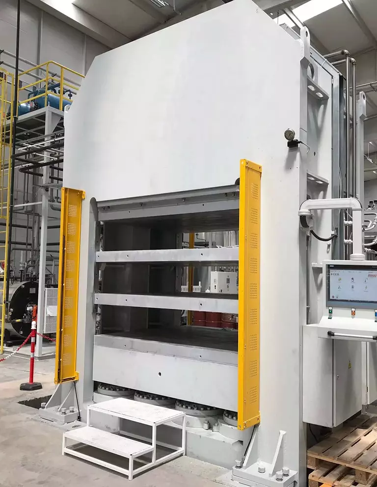
Hot Press Forming Hydraulic Press
Hot press forming is a metal forming process that involves heating the metal to a high temperature and then shaping it using a hydraulic press. The process is commonly used to produce complex, high-strength components that require precise dimensions and tight tolerances. Hot press forming is often used in the automotive, aerospace, and defense industries, where the performance and durability of the final product are critical.
The hot press forming process begins by heating the metal to a temperature where it becomes malleable. The heated metal is then placed into a hydraulic press, which applies pressure to shape the metal into the desired form. The press can be programmed to apply the exact amount of pressure needed to achieve the desired shape, ensuring that the final product meets the required specifications.
Hot press forming offers several advantages, including the ability to produce complex shapes with tight tolerances, improved mechanical properties, and reduced material waste. The process is particularly beneficial for producing high-strength components that require precise dimensions and tight tolerances.
Hydraulic presses are essential tools in the hot press forming process, providing the necessary force and control to shape the metal accurately. These presses are designed to handle a wide range of materials, including steel, aluminum, and titanium, and can be used to produce components in various sizes and shapes.
Removing Sharp Edges from Metal
Removing sharp edges from metal is an essential step in the manufacturing process, as sharp edges can pose a safety hazard and affect the functionality of the final product. Sharp edges are often created during cutting, machining, or forming operations, and they must be removed to ensure the safety and performance of the metal component.
Several methods can be used to remove sharp edges from metal, including deburring, grinding, and filing. Deburring is the most common method, involving the use of a deburring machine or tool to remove the sharp edges and create a smooth, rounded surface. Grinding is another effective method, using abrasive wheels or belts to remove the sharp edges and create a smooth finish.
The process of removing sharp edges is essential in industries where the safety and functionality of the final product are critical, such as automotive, aerospace, and medical devices. Sharp edges can cause injury during handling or assembly and can interfere with the fitment and performance of the component.
The Role of Buffing and Polishing in Edge Finishing
Buffing and polishing play a crucial role in edge finishing, helping to create smooth, rounded edges that enhance the appearance and safety of metal components. These processes are often used as the final step in edge finishing, following deburring or grinding, to achieve a high-quality finish.
Buffing involves the use of soft, abrasive pads or wheels to create a smooth, reflective surface on the edges of metal components. The process is particularly effective for removing fine scratches and tool marks, creating a smooth, rounded edge that is safe to handle and visually appealing.
Polishing is a similar process that uses abrasive belts, discs, or brushes to achieve a smooth, reflective finish on the edges of metal components. Polishing is often used in combination with buffing to achieve a high-quality finish that meets the required specifications.
The role of buffing and polishing in edge finishing is essential in industries where the appearance and safety of the final product are critical. These processes help to ensure that the edges of metal components are smooth, rounded, and free from sharp edges, enhancing the overall quality and performance of the product.
Conclusion
The world of metal forming and finishing is vast and complex, with a wide range of machines and processes designed to meet the specific needs of various industries. From flow form machines and edge beading machines to transfer presses and steel drum machines, each piece of equipment plays a critical role in the manufacturing process.
These machines and processes offer several advantages, including improved precision, enhanced mechanical properties, and increased efficiency. They are essential tools for companies looking to produce high-quality metal components that meet the demands of modern production.
The importance of surface finishing in metalwork cannot be overstated, as it affects the appearance, performance, and durability of the final product. Automated deburring and polishing processes have revolutionized surface finishing, providing manufacturers with the tools they need to achieve consistent, high-quality finishes.
In conclusion, the integration of advanced machinery and processes into manufacturing operations is essential for meeting the high demands of modern production. These tools and techniques enable manufacturers to produce high-quality metal components that meet the specific needs of various industries, ensuring the success and growth of their operations.
EMS Metalworking Machines
We design, manufacture and assembly metalworking machinery such as:
- Hydraulic transfer press
- Glass mosaic press
- Hydraulic deep drawing press
- Casting press
- Hydraulic cold forming press
- Hydroforming press
- Composite press
- Silicone rubber moulding press
- Brake pad press
- Melamine press
- SMC & BMC Press
- Labrotaroy press
- Edge cutting trimming machine
- Edge curling machine
- Trimming beading machine
- Trimming joggling machine
- Cookware production line
- Pipe bending machine
- Profile bending machine
- Bandsaw for metal
- Cylindrical welding machine
- Horizontal pres and cookware
- Kitchenware, hotelware
- Bakeware and cuttlery production machinery
as a complete line as well as an individual machine such as:
- Edge cutting trimming beading machines
- Polishing and grinding machines for pot and pans
- Hydraulic drawing presses
- Circle blanking machines
- Riveting machine
- Hole punching machines
- Press feeding machine
You can check our machinery at work at: EMS Metalworking Machinery – YouTube
Applications:
Flange-punching
Beading and ribbing
Flanging
Trimming
Curling
Lock-seaming
Ribbing